Embed Size (px)
Citation preview

2100
, 215
0, 2
300,
234
0 1
0007
12-
15 E
M
Operation
– Float measuring principle
Application
– Control panels– Pilot plants– Water treatment– Pharmaceutical industry– Chemical processes– Heat treatment
Features
– Easy installation– Small size– No damping zone necessary– Horizontal inlet and outlet– Low pressure dropOptions:– Adjustable limit switches– Controller RCA and RCD (constant flow regulation with differential pressure)
Installation information
– The operating instructions for flowmeter series 2100, 2150, 2300 and 2340 must be observed!– Download: www.meister-flow.com
OVERVIEW
Flowmeter
2100, 2150,
2300, 2340
2100
, 215
0, 2
300,
234
0 2
0007
12-
15 E
M
Read-off point
Read-off point
MEASURING RANGESOperating pressure, max. 15 bar
Pressure drop refer to tables on pages 6 and 7
Media temperature -20 °C - 80 °C
Ambient temperature -20 °C - 80 °C
Measuring accuracy (1)
2100 3,5 % (qG = 50 %)
2150 3,0 % (qG = 50 %)
2300 1,6 % (qG = 50 %)
2340 1,6 % (qG = 50 %)
(1) In accordance with VDI / VDE 3513
OPERATING DATA
MATERIALSRefer to table on page 3
FLOAT TYPES
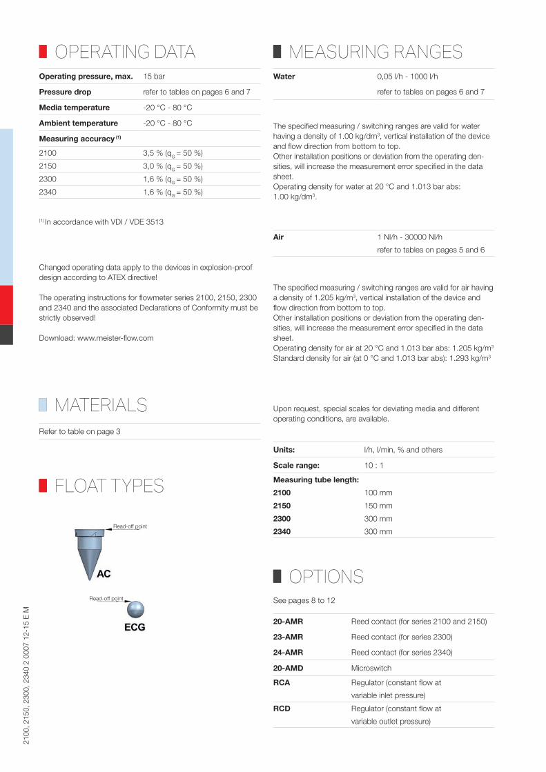
Water 0,05 l/h - 1000 l/h
refer to tables on pages 6 and 7
The specified measuring / switching ranges are valid for water having a density of 1.00 kg/dm3, vertical installation of the device and flow direction from bottom to top.Other installation positions or deviation from the operating den-sities, will increase the measurement error specified in the data sheet.Operating density for water at 20 °C and 1.013 bar abs: 1.00 kg/dm3.
Air 1 Nl/h - 30000 Nl/h
refer to tables on pages 5 and 6
The specified measuring / switching ranges are valid for air having a density of 1.205 kg/m3, vertical installation of the device and flow direction from bottom to top.Other installation positions or deviation from the operating den-sities, will increase the measurement error specified in the data sheet.Operating density for air at 20 °C and 1.013 bar abs: 1.205 kg/m3 Standard density for air (at 0 °C and 1.013 bar abs): 1.293 kg/m3
Upon request, special scales for deviating media and different operating conditions, are available.
OPTIONS
Units: l/h, l/min, % and others
Scale range: 10 : 1
Measuring tube length:
2100 100 mm
2150 150 mm
2300 300 mm
2340 300 mm
20-AMR Reed contact (for series 2100 and 2150)
23-AMR Reed contact (for series 2300)
24-AMR Reed contact (for series 2340)
20-AMD Microswitch
RCA Regulator (constant flow at
variable inlet pressure)
RCD Regulator (constant flow at
variable outlet pressure)
See pages 8 to 12
Changed operating data apply to the devices in explosion-proof design according to ATEX directive!
The operating instructions for flowmeter series 2100, 2150, 2300 and 2340 and the associated Declarations of Conformity must be strictly observed!
Download: www.meister-flow.com

2100
, 215
0, 2
300,
234
0 3
0007
12-
15 E
M
ASSEMBLY DRAWINGFlowmeter Flow regulator
MATERIALS/PARTSDESCRIPTIONFlowmeter
Item Description Material
01 Frame: 1.4404
02 Upper connector: 1.4404
03 Piston gasket: NBR / FKM / EPDM
04 Piston: 1.4404
05 Upper tube gasket: NBR / FKM / EPDM
06 Upper float stop: 1.4319
07 Protection: Polycarbonate (2)
08 Flow tube: Borosilicate glass
09 Float:1.4404GlassAluminum
10 Lower float stop: 1.4319
11 Lower tube gasket: NBR / FKM / EPDM
12 Lower valve connector: 1.4404
13 Valve knob: Plastic
14 Valve guide: PTFE
15 Valve shaft: 1.4404
16 Valve gasket: NBR / FKM / EPDM
17 Valve seat: PTFE
18 Lower connector: 1.4404
(2) Model 2340, without protection
Regulator RCA / RCD
Item Description Material
01 Membrane body: 1.4404
02 Valve body: 1.4404
03 Membrane: NBR / FKM / PTFE
04 Valve guide: 1.4404
05 Regulating valve: 1.4404
06 Gasket: NBR / PTFE
07 Spring support: 1.4404
08 Valve spring: 1.4319
09 Membrane disk: 1.4404
10 Membrane spring: 1.4319
11 Screws: 1.4401
12 Connector union: 1.4401

2100
, 215
0, 2
300,
234
0 4
0007
12-
15 E
M
TECHNICALDRAWING2100, 2150 and 2300 2340
SUMMARY OF TYPESType Overall dimensions (mm) Weight
Connection (internal thread) Flowmeter Flow regulator
G Type L DR approx. [g] approx. [g]
2100 1/4" BSP/NPT 158 136 700 2500
2150 1/4" BSP/NPT 208 186 850 2500
2300 1/4" BSP/NPT 358 336 850 2500
2340 1/2" BSP/NPT 390 346 1800 3000
2100
, 215
0, 2
300,
234
0 5
0007
12-
15 E
M
TECHNICALDRAWING
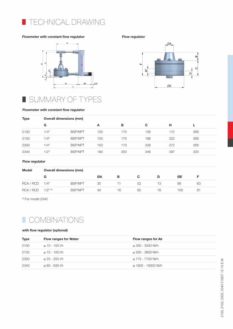
Flowmeter with constant flow regulator Flow regulator
SUMMARY OF TYPES
Type Overall dimensions (mm)
G A B C H L
2100 1/4" BSP/NPT 150 170 136 172 266
2150 1/4" BSP/NPT 150 170 186 222 266
2300 1/4" BSP/NPT 150 170 336 372 266
2340 1/2" BSP/NPT 180 200 346 397 320
Flowmeter with constant flow regulator
Model Overall dimensions (mm)
G ØA B C D ØE F
RCA / RCD 1/4" BSP/NPT 35 11 52 13 88 63
RCA / RCD 1/2" (3) BSP/NPT 40 16 65 18 100 81
(3) For model 2340
Flow regulator
COMBINATIONS
Type Flow ranges for Water Flow ranges for Air
2100 ≤ 10 - 100 l/h ≤ 300 - 3500 Nl/h
2150 ≤ 10 - 100 l/h ≤ 300 - 3600 Nl/h
2300 ≤ 25 - 250 l/h ≤ 770 - 7700 Nl/h
2340 ≤ 60 - 630 l/h ≤ 1900 - 19000 Nl/h
with flow regulator (optional)

2100
, 215
0, 2
300,
234
0 6
0006
12-
15 E
M
FLOW RANGESType Tube length Flow ranges Flow ranges Δp
H2O at 20 °C Air at 1,013 bar abs. and 20 °C
1.4404 (4) Glass (4)1.4404 (4)
Nl/h
Glass (4)
mm l/h l/h Nl/h mbar
Model 2100
C110/0001 100 0,1 – 1 0,05 – 0,5 4 – 40 1 – 15 5
C110/0002 100 0,2 – 2,5 0,1 – 1 8 – 80 4 – 40 10
C111/0005 100 0,5 – 5 0,2 – 2 15 – 160 7 – 70 15
C111/0010 100 1 – 10 0,4 – 4 30 – 350 10 – 210 20
C111/0016 100 1,6 – 16 0,6 – 6 40 – 490 20 – 250 35
C112/0025 100 2,5 – 25 1 – 10 80 – 840 40 – 420 40
C113/0040 100 4 – 40 1,6 – 16 120 – 1200 70 – 700 45
C114/0060 100 6 – 60 2 – 20 200 – 2200 100 – 1200 50
C115/0100 100 10 – 100 (5) 4 – 40 300 – 3500 150 – 1800 55
Model 2150
C210/0001 150 0,1 – 1 0,05 – 0,5 3 – 30 1 – 12 5
C210/0002 150 0,2 – 2,5 0,1 – 1 10 – 110 4 – 40 10
C211/0005 150 0,5 – 5 0,2 – 2 15 – 180 8 – 80 15
C211/0010 150 1 – 10 0,4 – 4 30 – 350 15 – 180 20
C211/0016 150 1,6 – 16 0,6 – 6 50 – 510 25 – 260 35
C212/0025 150 2,5 – 25 1 – 10 80 – 830 40 – 440 40
C213/0040 150 4 – 40 1,6 – 16 130 – 1300 70 – 700 45
C214/0060 150 6 – 60 2 – 20 150 – 2100 100 – 1100 50
C215/0100 150 10 – 100 (5) 4 – 40 300 – 3600 150 – 1900 55
(4) Float type ECG
(5) Also available with type AC float

2100
, 215
0, 2
300,
234
0 7
0004
12-
15 E
M
FLOW RANGESType Tube length Flow ranges Flow ranges Δp
H2O at 20 °C Air at 1,013 bar abs. and 20 °C
mm 1.4404 (6) Glass (7) 1.4404 (6) Aluminum (6)
l/h l/h Nl/h Nl/h mbar
Model 2300
C311/0025 300 2,5 – 25 1 – 10 120 – 860 60 – 490 55
C311/0040 300 4 – 40 1,6 – 16 150 – 1300 80 – 800 80
C311/0060 300 6 – 60 2 – 20 150 – 2000 100 – 1100 110
C312/0100 300 10 – 100 300 – 3000 180 – 1800 130
C312/0160 300 16 – 160 490 – 4900 300 – 2900 160
C312/0250 300 25 – 250 770 – 7700 460 – 4600 180
Model 2340
C313/0400 300 40 – 400 1200 – 12000 740 – 7300 90
C313/0630 300 60 – 630 1900 – 19000 1100 – 11000 200
C313/1000 300 100 – 1000 3000 – 30000 1800 – 18000 300
(6) Float type AC
(7) Float type ECG

2100
, 215
0, 2
300,
234
0 8
0004
12-
15 E
M
OPTIONS,LIMITSWITCHCONTACTS
FUNCTIONALPRINCIPLEMedia
Water: from 10 - 100 l/h (8)
Air: from 300 - 3000 Nl/h (8)
(8) Stainless steel float, type AC
ELECTRICAL CONNECTIONConnector in compliance with EN 175301-803, Form A
(DIN 43650, Form A)
Ingress Protection IP65
Ambient temperature -25 °C - 80 °C
Output rating 250V AC· 0,5A · 12VA
Hysteresis ±5 % of full scale value
Models:20-AMR1 1 adjustable limit switch20-AMR2 2 adjustable limit switches
for models 2100 and 215023-AMR1 1 adjustable limit switch23-AMR2 2 adjustable limit switches
for model 230024-AMR1 1 adjustable limit switch24-AMR2 2 adjustable limit switches
for model 2340
20-AMR/23-AMR/24-AMR
The magnet inside the float activates a bi-stable Reed contact inside the PVC switch housing. Please specify Normally Open (NOC) or Change Over (COC) when ordering.
Available only with flowmeters without protective shield
Infinitely variable switch point adjustment by operator
MEASURING RANGES

2100
, 215
0, 2
300,
234
0 9
0001
12-
15 E
M
Slot initiator, 3.5 mm (activated by vane in the housing)
NAMUR (EN 60947-5-6)
ATEX certificate Ex ia IIC T4...T6 Ga / Ex ia IIIC T85°C Da
Power supply 8V DC across control relay
Ambient temperature -25 °C - 70 °C
Models:
20-AMD1 1 adjustable limit switch
20-AMD2 2 adjustable limit switches
for models 2100 and 2150
Control relay (on request)
NAMUR (EN 60947-5-6) for 1 or 2 inductive detectors
Power supply 24...253 V AC 50-60 Hz
24...300 V DC
Input Namur Ex ia IIC
Output 1 or 2 relay contacts
Output rating 250V AC· 2A · 100VA
24V DC· 1A
Ambient temperature -25 °C - 70 °C
20-AMD
The magnet inside the float activates a bi-stable inductive contact inside an aluminum housing.
Infinitely variable switch point adjustment by operator
FUNCTIONALPRINCIPLE
ELECTRICAL CONNECTION
Media
Water: to 6 - 60 l/h (9)
Air: to 200 - 2200 Nl/h (9)
(9) Stainless steel float, type ECG
MEASURING RANGES

2100
, 215
0, 2
300,
234
0 10
000
1 12
-15
E M
REGULATORRCAThe design of the series 2000 flowmeters enable the use of RCA or RCD type controllers, which maintain a constant flow, even at fluctuating pressure.
Type RCA is used for gases and liquids with variable inlet pressure and constant outlet pressure.
FUNCTIONALPRINCIPLE
TECHNICALDRAWING
The media flows, with variable input pressure P0, through the connector (1), past the regulating valve (2) into the regulator chamber (3), where light pressure is exerted on the diaphragm (4). The regulating valve, which is connected to the diaphragm (4), is held open by force of the spring (5). When the media passes through the regulating valve (7) into the measuring tube (8) and flows through the outlet (9), the constant counter-pressure (P2) there acts on the diaphragm (4).The springs (5 and 6) are designed to open the valve, when inlet pressure P0 decreases, and close the valve when P0 increases. This maintains a constant flow rate at the regulating valve (7).For proper operation of the regulator, and to ensure correct function of the springs (5 and 6), the differential pressure between P0 and P2 must always be higher than 350 - 450 mbar (depending on flowmeter model).

2100
, 215
0, 2
300,
234
0 11
000
1 12
-15
E M
REGULATORRCA
FLOWCURVESThe flow curves show the relationship between the inlet pressure P0 and the counter pressure P2 in the RCA regulator.The different flow rates are adjusted by means of the regulating valve (7) of the flowmeter. The counter pressure P2, in this cases, corres-ponds to the atmospheric pressure.
DIAGRAMSRegulator RCA at low flow
Regulator RCA at high flow
Q Air (Nl/h)
P0 = Inlet pressure (bar)
Variation of flow
ohne Druckregler
mit Druckregler
Q Air (Nl/h)
P0 = Inlet pressure (bar)
Variation of flow
with regulator
Variation of flow
without regulator

2100
, 215
0, 2
300,
234
0 12
000
1 12
-15
E M
REGULATORRCDThe design of the series 2000 flowmeter allows the use of RCA or RCD type regulators, which maintain a constant flow, even when pressure fluctuations occur.
RCD type regulators are used in applications for gases, where the inlet pressure is constant and outlet pressure is variable.
FUNCTIONALPRINCIPLE
TECHNICALDRAWING
RCD type regulators operate reversely from RCA type regulators. The change in position of the valve (2) depends on the outlet pressure and the set value on the control valve (7).
DIAGRAMS
P2 = Outlet pressure (bar)
Q Air (Nl/h)
Variation of flow
Meister Strömungstechnik GmbH • Im Gewerbegebiet 2 • 63831 Wiesen / GermanyTel. +49 (0) 6096 9720-0 • Fax +49 (0) 6096 9720-30 • [email protected] • www.meister-flow.comThe general business terms of Meister Strömungstechnik GmbH are valid • All rights reserved