Embed Size (px)
DESCRIPTION
hvac water systems
Citation preview


SYSTEM DESIGN MANUAL
SUMMARY OF PART ELEVEN
This air-water system are for use in perimeter rooms ofmulti-story, multi-room buildings where cooling or heating may berequired simultaneously in adjacent rooms and where space allottedfor ductwork is at a minimum.
This part of the System Design Manual presents data andengineering procedures to guide the engineer in the practicaldesigning of air-water systems.
The text of this Manual is offered as a general guide forthe use of industry and of consulting engineers in designing systems.Judgment is required for application to specific installation, andCarrier is not responsible for any uses made of this text.
induction unit system 1
INDEX
primary air fan-coil system 2

Part 11. Air-Water System | Chapter 1. Induction Unit System
CHAPTER 1. INDUCTION UNIT SYSTEMThe induction unit system is designed for use in
perimeter rooms of multi-story, multi-room building such as office buildings, hotels, hospital patient rooms and apartments. Specifically, it is designed for buildings that have reversing sensible heat characteristics in which cooling may be required in one room and heating may be required in a adjacent room. In addition, it is especially adapted to handle the loads of modern skyscrapers with minimum space requirements for mechanical equipment.
This chapter includes System Description, System Features, Design Considerations, Engineering Procedure for designing the system, Controls and System Modifications.SYSTEM FEATURES
Some of the features of the induction unit system arethe following:
1. Small Space Requirements — The use of water toprovide a major portion of the room coolingrequirements reduces the air quantity distributed toeach space when compared to the air quantitydistributed in an all-air system. Thus, less space isrequired for both the air distribution system and thecentral air handling apparatus. At the same timeadequate and constant room air circulation is maintained by the high induction of the secondary airfrom the room. In addition, the smaller primary airquantity can be distributed at high velocity withoutany increase in power requirements over systemsusing much more air with conventional distributionductwork.
2. Individual Room Control — Zoning problems aresolved since each room is a zone. Simultaneousheating or cooling is available in adjacent roomswhen required.
3. Winter Downdraft Eliminated — The unit designpermits under-the-window installation, eliminatingdowndrafts at the windows during severe winterweather.
4. Minimum Service — No individual fans or motorsto create maintenance or servicing in the rooms.Most maintenance is centralized.
5. Central Dehumidification — Since all dehu-midification occurs at the central apparatus,condensation on the room unit coil is eliminated.Thus, odor retention and corrosion problems at theunit are minimized.
6. Quiet Operation — All fans and other rotatingequipment are remotely located.
SYSTEM DESCRIPTIONA typical induction unit system is shown in Fig. 1.
Although the arrangement may differ for each application, this illustration includes the basic components common to most induction unit systems. The following description is for a nonchangeover system.
Outdoor air for ventilation is drawn into the central apparatus thru a louver, screen and damper. Return air may be introduced into the system if the total required primary air quantity is more than the minimum ventilation requirement. The preheater tempers the air in winter to increase the capacity of the air to absorb moisture and to prevent freezing air from entering the dehumidifier. The filters remove entrained dust and dirt particles from the air. The sprayed coil dehumidifier cools and dehumidifies the air during the warm weather; during cool weather the recirculation sprays may be used to add moisture to the air. The reheater heats the air to offset the building transmission losses. The high pressure fan delivers the conditioned air thru high velocity ducts to the induction units. A sound absorber on the leaving side of the fan is normally required to reduce the noise generated by the fan. Chilled water from a central refrigeration plant is circulated by the primary pump thru the dehumidifier coils in the apparatus. The secondary water pump circulates water to the induction unit coils.
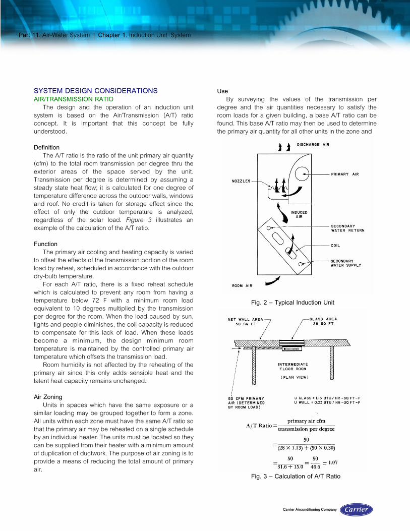
The induction unit (Fig. 2) is supplied with high pressure primary air which is discharged within the unit thru nozzles. This air induces room air across the coil which is supplied with water from the secondary water pump. The induced air is heated or cooled depending on the temperature of the secondary water, and the mixture of primary air and induced air is discharged to the room.
The function of the primary air is to provide ventilation air, to offset the transmission loads, to provide dehumidification to offset the latent loads, and to provide the motivating force for induction and circulation of room air. The secondary water circuit functions to offset the heat gain from sun, lights and people. The primary air is tempered according to a reheat schedule to prevent the room temperature from falling below 72 F when there is a minimum load in the room.
On some applications it may be desirable to operate the system during the winter season with hot water supplied to the coil and cold primary air. This is known as the change-over system which is explained under System Modifications.

Part 11. Air-Water System | Chapter 1. Induction Unit System
Fig. 1 – Typical Induction Unit System
Part 11. Air-Water System | Chapter 1. Induction Unit System
SYSTEM DESIGN CONSIDERATIONSAIR/TRANSMISSION RATIO
The design and the operation of an induction unit system is based on the Air/Transmission (A/T) ratio concept. It is important that this concept be fully understood.Definition
The A/T ratio is the ratio of the unit primary air quantity (cfm) to the total room transmission per degree thru the exterior areas of the space served by the unit. Transmission per degree is determined by assuming a steady state heat flow; it is calculated for one degree of temperature difference across the outdoor walls, windows and roof. No credit is taken for storage effect since the effect of only the outdoor temperature is analyzed, regardless of the solar load. Figure 3 illustrates an example of the calculation of the A/T ratio.Function
The primary air cooling and heating capacity is varied to offset the effects of the transmission portion of the room load by reheat, scheduled in accordance with the outdoor dry-bulb temperature.
For each A/T ratio, there is a fixed reheat schedule which is calculated to prevent any room from having a temperature below 72 F with a minimum room load equivalent to 10 degrees multiplied by the transmission per degree for the room. When the load caused by sun, lights and people diminishes, the coil capacity is reduced to compensate for this lack of load. When these loads become a minimum, the design minimum room temperature is maintained by the controlled primary air temperature which offsets the transmission load.
Room humidity is not affected by the reheating of the primary air since this only adds sensible heat and the latent heat capacity remains unchanged.Air Zoning
Units in spaces which have the same exposure or a similar loading may be grouped together to form a zone. All units within each zone must have the same A/T ratio so that the primary air may be reheated on a single schedule by an individual heater. The units must be located so they can be supplied from their heater with a minimum amount of duplication of ductwork. The purpose of air zoning is to provide a means of reducing the total amount of primary air.
UseBy surveying the values of the transmission per
degree and the air quantities necessary to satisfy the room loads for a given building, a base A/T ratio can be found. This base A/T ratio may then be used to determine the primary air quantity for all other units in the zone and
Fig. 2 – Typical Induction Unit
Fig. 3 – Calculation of A/T Ratio

Part 11. Air-Water System | Chapter 1. Induction Unit System
to establish the reheat schedule for the units. The primary air quantity determined by using the base A/T ratio may be higher for some units than necessary if the units are selected to satisfy only the room sensible heat load
ENGINEERING PROCEDUREThe following is an engineering procedure for
designing an induction unit system:1. Survey
Preliminary Layout3. Room Cooling Load Calculations4. Unit Selection5. Room Heating Load Calculation6. Apparatus Selection7. Refrigeration Load8. Duct Design9. Piping Design10.Water Heater Selection
SURVEY AND PRELIMINARY LAYOUTAn accurate survey of the load components, available
space and services is a basic requirement for a system design. Refer to Part 1 for a complete list of the items to be considered.
In conjunction with the survey a preliminary layout should be made. Consideration should be given to the arrangement and number of units around the building perimeter and to the location of the following items:
1. Primary Air Risers2. Primary Air Apparatus3. Primary Air Headers4. Secondary Water Pump(s)5. Secondary Water Risers and Headers6. Return Air System (if used)7. Interior Zone Apparatus8. Refrigeration EquipmentThe primary air apparatus may be located in a
penthouse on the roof, in the basement, or on inter-mediate floors of a building, with horizontal headers feeding a vertical riser system at the exterior face. In modern buildings with large glass areas and little wall space between windows, a horizontal duct distribution may have to be used in place of the vertical risers.
For reasons of economy it is usually desirable to limit the number of floors included in a water piping system so that the static head plus the pumping head does not cause the total pressure in the system to exceed that allowable for standard weight piping and fittings.
The location of interior zone equipment should be considered with respect to the chilled water piping if the
equipment is to obtain its refrigeration from the same central source as the induction unit system. Return air (if used) for the primary air apparatus may be taken thru the interior zone return air system for reasons of economy. Therefore, interior zone equipment should be located close to the primary air apparatus.
Location of the refrigeration machine in relation to its condenser water source (cooling tower, etc.) and the primary air apparatus (Fig. 4) may depend on these economic factors:
1. Insulated chilled water piping vs. condenser water piping costs.
2. Electric wiring vs. water piping costs.However, when locating a given type of refrigeration
equipment (centrifugal, absorption or reciprocating), there may be special engineering considerations involved such as structural reinforcement and vibration isolation on upper floors.
2.
Fig. 4 – Relative LocationAnd Costs of Pipe and Wiring

Part 11. Air-Water System | Chapter 1. Induction Unit System
BASIS OF TABLE 1The data in Table 1 is based on these conditions:Outdoor design dry-bulb temperature = 95 FRoom design dry-bulb temperature = 75 FDaily temperature range = 20 deg
Yearly temperature range,20° latitude = 75 deg30° latitude = 85 deg
40° latitude = 100 deg50°latitude = 115 deg
Light construction, wall – 40 lb/sq ft wall arearoof – 20 lb/sq ft roof area
room – 30 lb/sq ft floor area
TABLE 1 – ROOM DESIGN LOAD FACTORS
EXPOSURE NORTH NORTHEAST* NORTHEAST EAST SOUTHEASTLATITUDE (North) 20 30 40 50 20 30 40 50 20 30 40 50 20 30 40 50 20 30 40 50
L I G H T C O N S T R U C T I O N
1. Design Sun Time MonthHour
June5 p.m.
June7
a.m.July
7 a.m.June
8a.m.
July8 a.m.
July9 a.m.
Oct.9
a.m.Sept.9 a.m.
2. Outdoor Design Dry-bulb (F) 92 90 90 89 79 80 80 80 80 81 81 81 83 83 83 83 76 78 77 753. Solar Heat Gain Thru Glass
Btu / (hr) (sq ft)12-hour Operation 15 11 10 9 65 55 54 49 74 75 75 74 70 66 71 7116-hour Operation 15 11 9 9 63 54 52 48 72 73 73 72 67 64 68 6924-hour Operation 15 11 9 9 66 56 54 50 63 54 52 48 72 73 73 72 67 64 68 69
4. Equivalent Temp Diff (F)Glass 17 15 15 14 4 5 5 5 5 6 6 6 8 8 8 8 1 3 2 0Wall 16 14 14 13 13 12 11 11 17 15 15 14 32 32 32 32 19 20 21 19Roof 49 47 45 42 3 4 4 4 2 3 3 3 4 4 4 4 -3 -1 -2 -4
M E D I U M C O N S T R U C T I O N
1. Design Sun Time MonthHour
June5 p.m.
June7
a.m.July
7 a.m.June
8a.m.
July8 a.m.
July9 a.m.
Oct.9
a.m.Sept.9 a.m.
2. Outdoor Design Dry-bulb (F) 92 90 90 89 79 80 80 80 80 81 81 81 83 83 83 83 76 78 77 753. Solar Heat Gain Thru Glass
Btu / (hr) (sq ft)12-hour Operation 14 11 9 9 55 47 46 42 64 64 64 64 63 60 63 6416-hour Operation 13 10 9 8 53 45 43 40 61 62 62 61 59 56 60 6024-hour Operation 13 10 9 8 52 44 43 39 49 42 41 37 57 58 58 57 55 52 55 56
4. Equivalent Temp Diff (F)Glass 17 15 15 14 4 5 5 5 5 6 6 6 8 8 8 8 1 3 2 0Wall 9 7 7 6 7 8 8 8 9 9 9 9 13 13 13 13 6 7 7 5Roof 46 44 42 39 8 8 8 7 6 7 7 6 8 8 8 8 0 2 1 -2
H E A V Y C O N S T R U C T I O N
1. Design Sun Time MonthHour
June5 p.m.
June7
a.m.July
7 a.m.June
8a.m.
July8 a.m.
July9 a.m.
Oct.9
a.m.Sept.9 a.m.
2. Outdoor Design Dry-bulb (F) 92 90 90 89 79 80 80 80 80 81 81 81 83 83 83 83 76 78 77 753. Solar Heat Gain Thru Glass
Btu / (hr) (sq ft)12-hour Operation 14 11 9 8 54 46 44 41 61 62 62 61 63 60 63 6416-hour Operation 13 10 8 8 51 43 42 39 58 59 59 58 59 56 60 6024-hour Operation 13 10 8 8 50 42 41 38 47 40 38 35 54 54 54 54 53 50 53 54
4. Equivalent Temp Diff (F)Glass 17 15 15 14 4 5 5 5 5 6 6 6 8 8 8 8 1 3 2 0Wall 7 5 5 4 10 10 10 10 11 11 11 11 14 14 14 14 8 10 9 7Roof 44 42 41 37 14 14 13 12 11 11 11 10 13 13 12 11 4 6 4 9
* These factors are used for systems required to operate 24 hours continuously, as in hospitals, hotels and apartment houses.

Part 11. Air-Water System | Chapter 1. Induction Unit System
BASIS OF TABLE 1 (Cont’d)Medium
construction, wall – 100 lb/sq ft wall arearoof – 40 lb/sq ft roof arearoom – 100 lb/sq ft floor area
Heavy construction, wall – 140 lb/sq ft wall arearoof – 60 lb/sq ft roof arearoom – 150 lb/sq ft floor area
Standard single-glazed double hung windows with venetian blinds.
TABLE 1 – ROOM DESIGN LOAD FACTORS (Contd.)
EXPOSURE SOUTH SOUTHWEST WEST NORTHWESTLATITUDE(North) 20 30 40 50 20 30 40 50 20 30 40 50 20 30 40 50
L I G T H C O N S T R U C T I O N
1. Design Sun TimeMonthHour
Nov.Noon
Oct.Noon
Oct.3 p.m
Sept.3 p.m.
July4 p.m.
June 5 p.m.
July5 p.m.
2. Outdoor Design Dry-bulb (F) 75 74 74 70 88 90 89 87 94 94 94 94 92 93 93 933. Solar Heat Gain Thru Glass
Btu/(hr) (sq ft)12-hour Operation16-hour Operation24-hour Operation
717070
737272
818080
848282
787777
747373
797878
807979
757474
757575
757575
757474
696969
595959
575757
525252
4. Equivalent Temp Diff (F)GlassWallRoof
02316
-12215
-12611
-5234
133232
153334
143430
123225
193848
193848
193846
193844
173449
183350
183248
183145
M E D I U M C O N S T R U C T I O N
1. Design Sun Time MonthHour
Nov. 2 p.m.
Oct.2 p.m.
Oct.3 p.m.
Sept.3 p.m.
July4 p.m.
June 5 p.m.
July5 p.m.
2. Outdoor Design Dry-bulb (F) 79 78 78 74 88 90 89 87 94 94 94 94 92 93 93 933. Solar Heat Gain Thru Glass
Btu/(hr) (sq ft)12-hour Operation16-hour Operation24-hour Operation
615555
635656
706363
726565
696363
666060
706363
706464
666060
666161
666161
666060
605656
514848
504646
464343
4. Equivalent Temp Diff (F)GlassWallRoof
41213
31212
3158
-1119
131330
151433
141429
121223
191745
191744
191743
191741
171446
181447
181445
181442
H E A V Y C O N S T R U C T I O N
1. Design Sun Time MonthHour
Nov.2 p.m.
Oct.2 p.m.
Oct. 3 p.m.
Sept.3 p.m.
July4 p.m.
June 5 p.m.
July5 p.m.
2. Outdoor Design Dry-bulb (F) 79 78 78 74 88 90 89 87 94 94 94 94 92 93 93 933. Solar Heat Gain Thru Glass
Btu/(hr) (sq ft)12-hour Operation16-hour Operation24-hour Operation
585151
595252
665858
686060
685959
635656
676060
686060
655858
655858
655858
655858
585353
494545
484343
444040
4. Equivalent Temp Diff (F)GlassWallRoof
4-212
3-511
3-26
-1-5-2
13726
15829
14825
12619
191542
191542
191540
191537
171244
181245
181243
181240

Part 11. Air-Water System | Chapter 1. Induction Unit System
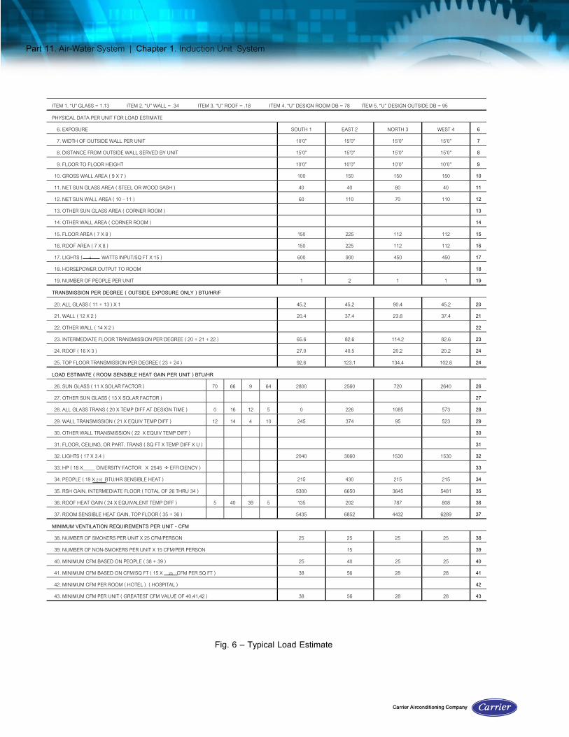
Example I — Typical Load EstimateGiven:
Typical floor plan (Fig.5)Wall U = 0.34 Btu/(hr)(sq ft)(deg F temp diff)
Wt = 100 11)/sq ft (approx) Windows - double hung wooden sash, single-glazed. venetian blinds, light color
Construction - medium, 100 lb/sq ftNormal operation — 12 hours
Find:For the numbered areas:
Transmission per degreeRoom sensible heat gainMinimum ventilation requirements:
Solution:Fill out all appropriate columns using a form similar to that shown in Fig. 6.
Fig. 5 – Typical Floor
Part 11. Air-Water System | Chapter 1. Induction Unit System
ITEM 1. “U" GLASS = 1.13 ITEM 2. “U” WALL = .34 ITEM 3. “U” ROOF = .18 ITEM 4. “U” DESIGN ROOM DB = 78 ITEM 5. “U” DESIGN OUTSIDE DB = 95PHYSICAL DATA PER UNIT FOR LOAD ESTIMATE
6. EXPOSURE SOUTH 1 EAST 2 NORTH 3 WEST 4 6 7. WIDTH OF OUTSIDE WALL PER UNIT 10’0” 15’0” 15’0” 15’0” 7 8. DISTANCE FROM OUTSIDE WALL SERVED BY UNIT 15’0” 15’0” 15’0” 15’0” 8
9. FLOOR TO FLOOR HEIGHT 10’0” 10’0” 10’0” 10’0” 910. GROSS WALL AREA ( 9 X 7 ) 100 150 150 150 1011. NET SUN GLASS AREA ( STEEL OR WOOD SASH ) 40 40 80 40 1112. NET SUN WALL AREA ( 10 – 11 ) 60 110 70 110 1213. OTHER SUN GLASS AREA ( CORNER ROOM ) 1314. OTHER WALL AREA ( CORNER ROOM ) 14
15. FLOOR AREA ( 7 X 8 ) 150 225 112 112 1516. ROOF AREA ( 7 X 8 ) 150 225 112 112 1617. LIGHTS ( 4 WATTS INPUT/SQ FT X 15 ) 600 900 450 450 1718. HORSEPOWER OUTPUT TO ROOM 1819. NUMBER OF PEOPLE PER UNIT 1 2 1 1 19
TRANSMISSION PER DEGREE ( OUTSIDE EXPOSURE ONLY ) BTU/HR/F
20. ALL GLASS ( 11 + 13 ) X 1 45.2 45.2 90.4 45.2 2021. WALL ( 12 X 2 ) 20.4 37.4 23.8 37.4 2122. OTHER WALL ( 14 X 2 ) 2223. INTERMEDIATE FLOOR TRANSMISSION PER DEGREE ( 20 + 21 + 22 ) 65.6 82.6 114.2 82.6 2324. ROOF ( 16 X 3 ) 27.0 40.5 20.2 20.2 24
25. TOP FLOOR TRANSMISSION PER DEGREE ( 23 + 24 ) 92.6 123.1 134.4 102.8 24
LOAD ESTIMATE ( ROOM SENSIBLE HEAT GAIN PER UNIT ) BTU/HR26. SUN GLASS ( 11 X SOLAR FACTOR ) 70 66 9 64 2800 2560 720 2640 2627. OTHER SUN GLASS ( 13 X SOLAR FACTOR ) 2728. ALL GLASS TRANS ( 20 X TEMP DIFF AT DESIGN TIME ) 0 16 12 5 0 226 1085 573 28
29. WALL TRANSMISSION ( 21 X EQUIV TEMP DIFF ) 12 14 4 10 245 374 95 523 2930. OTHER WALL TRANSMISSION ( 22 X EQUIV TEMP DIFF ) 30 31. FLOOR, CEILING, OR PART. TRANS ( SQ FT X TEMP DIFF X U ) 3132. LIGHTS ( 17 X 3.4 ) 2040 3060 1530 1530 3233. HP ( 18 X DIVERSITY FACTOR X 2545 ÷ EFFICIENCY ) 3334. PEOPLE ( 19 X 215 BTU/HR SENSIBLE HEAT ) 215 430 215 215 34
35. RSH GAIN, INTERMEDIATE FLOOR ( TOTAL OF 26 THRU 34 ) 5300 6650 3645 5481 3536. ROOF HEAT GAIN ( 24 X EQUIVALENT TEMP DIFF ) 5 40 39 5 135 202 787 808 3637. ROOM SENSIBLE HEAT GAIN, TOP FLOOR ( 35 + 36 ) 5435 6852 4432 6289 37
MINIMUM VENTILATION REQUIREMENTS PER UNIT - CFM38. NUMBER OF SMOKERS PER UNIT X 25 CFM/PERSON 25 25 25 25 38
39. NUMBER OF NON-SMOKERS PER UNIT X 15 CFM/PER PERSON 15 3940. MINIMUM CFM BASED ON PEOPLE ( 38 + 39 ) 25 40 25 25 4041. MINIMUM CFM BASED ON CFM/SQ FT ( 15 X . 25 CFM PER SQ FT ) 38 56 28 28 4142. MINIMUM CFM PER ROOM ( HOTEL ) ( HOSPITAL ) 4243. MINIMUM CFM PER UNIT ( GREATEST CFM VALUE OF 40,41,42 ) 38 56 28 28 43
Fig. 6 – Typical Load Estimate
Part 11. Air-Water System | Chapter 1. Induction Unit System
ROOM COOLING LOAD CALCULATIONSLoads should be calculated on the basis of the area to
be conditioned by the unit. Table 1 may be used for solarheat gain and transmission load temperature differences.If these values do not apply as they are presented, theymay be adjusted to suit the design conditions, or data forcalculating these loads may be obtained from Part 1.Design conditions, ventilation requirements and internalloads from people, lights and appliances may be found inPart 1. As the loads are calculated, certain items shouldbe noted.
1. Transmission per degree — the summation of thetransmission loads thru the outdoor walls, windowsand roof, calculated on the basis of a one-degreetemperature difference.
2. Room sensible heat gain — the summation of solarheat, transmission, lights, people and applianceloads.
3. Minimum ventilation required — the largest of the airquantities calculated on a person or square footbasis.
The solar heat gain is usually the major load in theroom and should be calculated with accuracy.UNIT SELECTION
The induction units selected for a given space must beable to:
1. Supply a quantity of air to the space in a fixedproportion to the transmission per degree of thespace. The outdoor air portion of the supply airmust equal or exceed the ventilation requirement.
2. Produce a total cooling capacity that equals orexceeds calculated room sensible heat gain.
3. Operate at a nozzle pressure consistent with anacceptable sound level.
In addition to the above three conditions that must bemet, there are three temperatures which must be knownto select an induction unit.
1. Room temperature2. Primary air temperature3. Secondary water temperatureThe room temperature is selected from the design
conditions. This is the maximum room temperature whichis acceptable at peak design load.
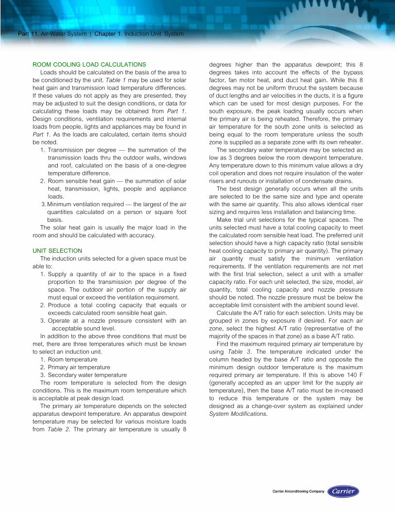
The primary air temperature depends on the selectedapparatus dewpoint temperature. An apparatus dewpointtemperature may be selected for various moisture loadsfrom Table 2. The primary air temperature is usually 8
degrees higher than the apparatus dewpoint; this 8degrees takes into account the effects of the bypassfactor, fan motor heat, and duct heat gain. While this 8degrees may not be uniform thruout the system becauseof duct lengths and air velocities in the ducts, it is a figurewhich can be used for most design purposes. For thesouth exposure, the peak loading usually occurs whenthe primary air is being reheated. Therefore, the primaryair temperature for the south zone units is selected asbeing equal to the room temperature unless the southzone is supplied as a separate zone with its own reheater.
The secondary water temperature may be selected aslow as 3 degrees below the room dewpoint temperature.Any temperature down to this minimum value allows a drycoil operation and does not require insulation of the waterrisers and runouts or installation of condensate drains.
The best design generally occurs when all the unitsare selected to be the same size and type and operatewith the same air quantity. This also allows identical risersizing and requires less installation and balancing time.
Make trial unit selections for the typical spaces. Theunits selected must have a total cooling capacity to meetthe calculated room sensible heat load. The preferred unitselection should have a high capacity ratio (total sensibleheat cooling capacity to primary air quantity). The primaryair quantity must satisfy the minimum ventilationrequirements. If the ventilation requirements are not metwith the first trial selection, select a unit with a smallercapacity ratio. For each unit selected, the size, model, airquantity, total cooling capacity and nozzle pressureshould be noted. The nozzle pressure must be below theacceptable limit consistent with the ambient sound level.
Calculate the A/T ratio for each selection. Units may begrouped in zones by exposure if desired. For each airzone, select the highest A/T ratio (representative of themajority of the spaces in that zone) as a base A/T ratio.
Find the maximum required primary air temperature byusing Table 3. The temperature indicated under thecolumn headed by the base A/T ratio and opposite theminimum design outdoor temperature is the maximumrequired primary air temperature. If this is above 140 F(generally accepted as an upper limit for the supply airtemperature), then the base A/T ratio must be in-creasedto reduce this temperature or the system may bedesigned as a change-over system as explained underSystem Modifications.
Part 11. Air-Water System | Chapter 1. Induction Unit System
TABLE 2 - DEHUMIDIFIER APPARATUS DEWPOINT SELECTION GUIDE
Dehumidifier Dewpoint*8-Row Coil
Primary Air ( cfm / sq ft )6-Row Coil
Primary Air ( cfm / sq ft )
Max. DesignRoom Temp
AndPercent RH
NormalRoom Temp
AndPercent RH
SuggestedRoom
Dewpoint
DesignPeopleLoading
Sq Ft/ Person .2 .3 .4 .5 .6 .2 .3 .4 .5 .6
125 50.2 52.5 53.6 54.3 54.8 49.5 52.0 53.4 54.3 54.880 F 45% 77 F 50% 56.6 100 48.4 51.4 52.8 53.6 54.1 47.7 51.0 52.6 53.6 54.2
75 49.5 51.4 52.5 53.2 48.6 51.0 52.4 53.250 48.6 50.2 51.0 48.0 49.5 51.1125 48.0 50.2 51.4 52.0 52.4 46.3 49.8 51.4 52.4 53.0
78 F 45% 75 F 50% 55.0 100 46.2 49.2 50.6 51.6 52.0 48.4 50.3 51.4 52.175 47.2 49.0 50.2 51.0 46.4 48.6 50.0 51.050 46.0 47.8 49.0 47.4 49.0125 47.8 49.2 50.0 50.5 47.3 49.0 50.0 50.5
76 F 45% 73 F 50% 53.5 100 46.6 48.1 49.0 49.5 46.0 48.0 49.1 49.875 46.8 48.0 48.8 46.6 48.0 48.850 46.8 46.2125 46.6 48.0 48.8 49.5 46.2 47.7 48.6 49.2
75 F 45% 72 F 50% 52.0 100 46.9 48.1 49.0 46.6 47.7 48.575 46.8 47.5 46.4 47.550 45.5 46.0
*Apparatus dewpoint are based on: 8-row coil – 100% outside air bypass factor = .03 6-row coil – 0.1 cfm per sq ft ventilation air bypass factor = .1 Outside design conditions 95 F db, 75F wb
Calculate the design primary air quantity for each unitby multiplying the final selected base A/T ratio by thetransmission per degree for each space making sure thatthe ventilation requirements are met.
Make the final unit selections using this design primaryair quantity. The total cooling capacity of the units mustmeet the calculated room sensible heat load, and thenozzle pressure must be below the limit consistent withthe ambient sound level.
In cases where the base A/T ratio is exceeded, theremay be the possibility of overheating during low outdoortemperatures. To prevent this condition, the unit shouldbe selected with sufficient coil capacity to handle theroom load plus the excess reheatROOM HEATING LOAD CALCULATION
If provision is to be made for gravity heating, thegravity heating load must be calculated for each typicalunit. This load consists only of the trans mission heat lossbut, on tall buildings, may include infiltration.
Calculate the water temperature required to meet the
gravity heating load by using the ratings for the unitsselected. If the required water temperature is above apractical limit of 190 F , then the units may be increasedin size of , more practically, the primary air fan can beoperated during the periods of low outdoor temperaturesoccurring whe gravity heating is required.
If the system is operated as a change-over system withhot water supplied to the units during periods of lowoutdoor temperatures, the total room heating load mustbe calculated. This load includes the transmission heatloss plus the amount of heat necessary to raise primaryair to room temperature.
This may be required where the system operates for 12to 16 hours daily and where a means must be provided towarm up the building fater an overnight or weekendshutdown.Calculate the water temperature required to meet the total room heating load for each typical space. The highest temperature required is the design temperature for the water heater.
Part 11. Air-Water System | Chapter 1. Induction Unit System
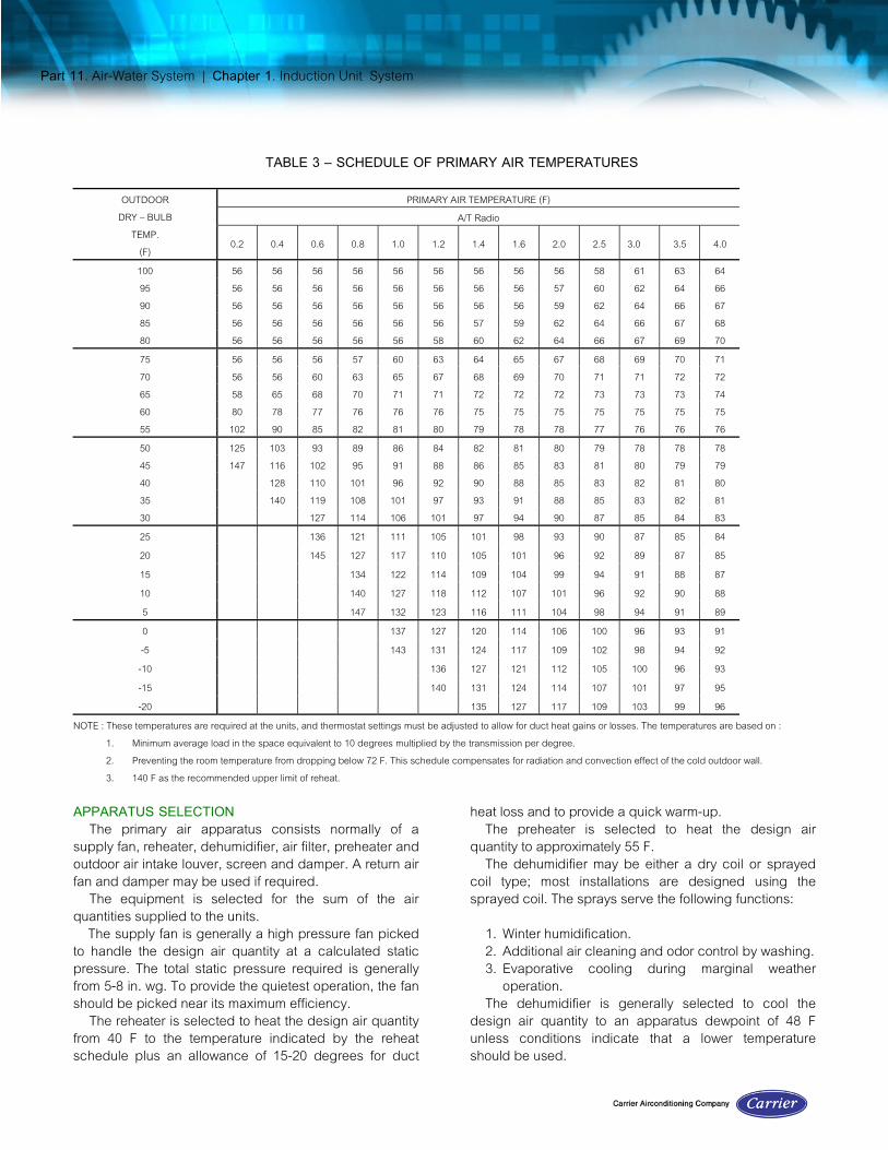
TABLE 3 – SCHEDULE OF PRIMARY AIR TEMPERATURES
PRIMARY AIR TEMPERATURE (F)A/T Radio
OUTDOORDRY – BULB
TEMP.(F) 0.2 0.4 0.6 0.8 1.0 1.2 1.4 1.6 2.0 2.5 3.0 3.5 4.0
100 56 56 56 56 56 56 56 56 56 58 61 63 6495 56 56 56 56 56 56 56 56 57 60 62 64 6690 56 56 56 56 56 56 56 56 59 62 64 66 6785 56 56 56 56 56 56 57 59 62 64 66 67 6880 56 56 56 56 56 58 60 62 64 66 67 69 7075 56 56 56 57 60 63 64 65 67 68 69 70 7170 56 56 60 63 65 67 68 69 70 71 71 72 7265 58 65 68 70 71 71 72 72 72 73 73 73 7460 80 78 77 76 76 76 75 75 75 75 75 75 7555 102 90 85 82 81 80 79 78 78 77 76 76 7650 125 103 93 89 86 84 82 81 80 79 78 78 7845 147 116 102 95 91 88 86 85 83 81 80 79 7940 128 110 101 96 92 90 88 85 83 82 81 8035 140 119 108 101 97 93 91 88 85 83 82 8130 127 114 106 101 97 94 90 87 85 84 8325 136 121 111 105 101 98 93 90 87 85 8420 145 127 117 110 105 101 96 92 89 87 8515 134 122 114 109 104 99 94 91 88 8710 140 127 118 112 107 101 96 92 90 885 147 132 123 116 111 104 98 94 91 890 137 127 120 114 106 100 96 93 91-5 143 131 124 117 109 102 98 94 92-10 136 127 121 112 105 100 96 93-15 140 131 124 114 107 101 97 95-20 135 127 117 109 103 99 96
NOTE : These temperatures are required at the units, and thermostat settings must be adjusted to allow for duct heat gains or losses. The temperatures are based on :1. Minimum average load in the space equivalent to 10 degrees multiplied by the transmission per degree.2. Preventing the room temperature from dropping below 72 F. This schedule compensates for radiation and convection effect of the cold outdoor wall.3. 140 F as the recommended upper limit of reheat.
APPARATUS SELECTIONThe primary air apparatus consists normally of a
supply fan, reheater, dehumidifier, air filter, preheater andoutdoor air intake louver, screen and damper. A return airfan and damper may be used if required.
The equipment is selected for the sum of the airquantities supplied to the units.
The supply fan is generally a high pressure fan pickedto handle the design air quantity at a calculated staticpressure. The total static pressure required is generallyfrom 5-8 in. wg. To provide the quietest operation, the fanshould be picked near its maximum efficiency.
The reheater is selected to heat the design air quantityfrom 40 F to the temperature indicated by the reheatschedule plus an allowance of 15-20 degrees for duct
heat loss and to provide a quick warm-up.The preheater is selected to heat the design air
quantity to approximately 55 F.The dehumidifier may be either a dry coil or sprayed
coil type; most installations are designed using thesprayed coil. The sprays serve the following functions:
1. Winter humidification.2. Additional air cleaning and odor control by washing.3. Evaporative cooling during marginal weather
operation.The dehumidifier is generally selected to cool the
design air quantity to an apparatus dewpoint of 48 Funless conditions indicate that a lower temperatureshould be used.
Part 11. Air-Water System | Chapter 1. Induction Unit System
The dehumidifier load is found from the formula:Load = cfmda X 4.45 x (1 — BF) (h ea— h adp)
Where:cfm da = dehumidified air quantityh ea = entering air enthalpyhadp = apparatus dewpoint enthalpyBF = dehumidifier bypass factor
The required apparatus dewpoint can be checked on anindividual room basis by the formula:
where:
WadP = apparatus dewpoint specific humidity (gr/lb)Wrm = room specific humidity (grub) Wea = air entering dehumidifier specific humidity (gr/lb)RLH = room latent heat loadcf mda = dehumidified air quantityBF = dehumidifier bypass factor.
From the psychrometric chart the apparatus dew-pointtemperature is found equal to the saturation temperaturecorresponding to Wadp.
Example 2 — Apparatus Dew point Calculation
Given:Room specific humidity = 64 gr/lbSpecific humidity, air entering dehumidifier = 118 gr/lbDehumidifier bypass factor = .05Room latent heat = 235 Btu/hrRoom air quantity = 40 cfm
Find:Apparatus dewpoint
Solution:
From the psychrometric chart at a specific humidity of52.2 gr/Ib, the apparatus dewpoint is found as 49.5 F.
The air filter is selected to handle the design airquantity at a high efficiency.
The outdoor air louver, screen and damper areselected for the design air quantity and a face velocitybetween 500 and 800 fpm. The higher values arenormally used when there is a return air duct systemwithout a fan.DUCT DESIGN
The duct distribution system is made up of headersand risers to supply the induction units with a constantvolume of air. High velocities are generally used, up to3000 fpm in the headers and 4000-5000 fpm in the risers.Because the air distribution system is subject to highstatic pressures, tightness is essential. Therefore, rigidspiral conduit is generally used in place of conventionalductwork. Welded fittings are used for elbows and take-offs. Ducts must be carefully sealed to prevent airleakage.
The static regain method of duct sizing isrecommended for this system. Details of duct design maybe found in Part 2.
The duct distribution system generally includes asound absorbing section at the fan discharge to attenuatethe sound level of the high pressure fan. The attenuationrequired must be calculated and depends on the soundgenerated by the fan, the natural attenuation of the ducts,and the sound generated by other sources in the ductsystem.
The headers installed in unconditioned spaces shouldbe insulated and vapor-sealed to prevent excessive heatgain and sweating. The risers should be insulated toreduce the temperature loss in winter to a minimum of20% of the difference between the room temperature andthe desired primary air temperature.
Since the risers are normally within the conditionedspace, there is no need to use a vapor barrier or to sealthe surface of the insulation in any way.REFRIGERATION LOADDesign Peak Building Load
When calculating the refrigeration load, the building asa whole should be considered. From a design viewpoint,the maximum demand for refrigeration is assumed tooccur at the time of instantaneous building peak. Thecalculation of this load bears no relation to the room loadcalculated for unit selection as the design peak buildingload is not the sum of the individual room peak loads.
The time of day at which the building peak occursdepends on the relative amounts of east, south and westexposures. Where these exposures are of about the samemagnitude, the building peak usually occurs in theafternoon when the sun is on the west side and the
Wadp =Wrm – (Wea x BF) –
RLH.68 x cfmda
1 – BF
=
64 – (118 x .05) – 235.68 x 40
1 – .05
=64 – 5.9 – 8.6
.95 =
49.5
.95 = 52.2 gr/lb
Wadp =Wrm – (Wea x BF) – RLH
.68 x cfmda
1 – BF

Part 11. Air-Water System | Chapter 1. Induction Unit System
outdoor wet-bulb is high.The refrigeration load is determined as follows:
1. Calculate the room sensible heat for the entirebuilding at the time of peak load.
2. Add the total heat load of the primary air. Theoutdoor air is taken from outdoor conditions at thetime of peak load to the required dewpointtemperature leaving the dehumidifier. Return air(when used) is taken from room conditions to therequired leaving air dewpoint temperature.
3. Subtract the credit for primary air sensible coolingbetween room temperature and primary airtemperature at the unit.
The room sensible heat includes the solar,transmission, lights and people sensible load, assumingpeak zone rooms are at the design temperature; all otherrooms are at their thermostat setting, usually taken as Sdegrees below design.
The refrigeration load can be reduced at peak loadingby operating the equipment longer and taking advantageof storage and precooling. Refer to Part 1 forexplanations of storage and precooling.Example 3 — Refrigeration Load CalculationGiven:
A typical building oriented with the largest exposures facing eastand west.
Time of estimate — 4 p.m. during JulyOutdoor dry-bulb temp = 95 FOutdoor wet-bulb temp = 75 FIndoor design dry-bulb temp = 78 FIndoor design relative humidity = 45%Apparatus dewpoint = 48 FLatitude = 40 ° NDaily range of temperature = 14 degLength of operation = 16 hoursOrdinary glass double hung, wood sash, light colored venetian blindsWall construction, U = .34, wt = 100 lb/sq ftRoof construction, U = .18, wt = 40 lb/sq ftRoom temperatures, W exposure = 78 F
N, E, S exposures = 75 FAir quantities
Exposure Outdoor Air Return AirWest 5060 cfm 4716 cfmEast 5300 4936North 1720 1604South 2160 2022
14240 cfm 13278 cfm
Find: Refrigeration load
Solution:
BUILDING SENSIBLE HEAT LOADSolar Gain — Glass
Sq Ft Heat Storage Shade Area Btu/hrGain Factor Factor Factor
W Glass, 5100 X 164 X .66 X .56 X 1/.85= 364,000E Glass, 5100 X 164 X .16 X .56 X 1/.85= 88,200N Glass, 2270 X 15 X .88 X .56 X 1/.85 = 19,750S Glass, 2270 X 69 X .45 X .56 X 1/.85 = 46,500
Solar and Transmission Gain — Walls and RoofSq Ft Trans Temp Btu/hr
Factor DillW waIl, 9800 X .34 X (12 + 5) = 56,600E wall, 9800 X .34 X (18 + 8) = 86,600N wall, 5180 X .34 X ( 4 + 8) = 21,150S wall, 5180 X .34 X (16 + 8) = 42,300Roof, 6336 X .18 X (38 + 8) = 52,500
Transmission Gain — GlassSq Ft Trans Temp Btu/hr
Factor DillW Glass, 5100 X 1.13 X 16 = 92,000E-N-S Glass, 9640 X 1.13 X 19 = 206,000
Internal Heat Gain Heat Storage FactorGain Factor Div Btu/hr
People, 600 X 215 X .89 X .9 = 103,200Lights, 130,000 X 3.4 X .89 X .85 = 334,000
Subtotal 1,512,800
StorageSq Ft Storage Temp Btu/hr
Factor DiffW zone, 19,000 X1.25 X(—3) =71,200Building sensible heat =1,441,600
PRIMARY AIR LOADCfm Conv Enthalpy Contact Btu/hr
Outdoor Air Factor Diff Factor14,240 X 4.45 X (38.62 — 19..22) (1 — .05) =
1,168,000Return Air, W zone
4,716 X 4.45 X (28.79 — 19..22) (1 — .05) =190,000Return Air, E-N.S zones
8,562 X 4.45 X (28.11 — 19.22) (1 — .05) = 321,000Primary air load 1,679,000
Subtotal = 3,120,600

Part 11. Air-Water System | Chapter 1. Induction Unit System
CREDIT FOR PRIMARY AIR COOLING
Cf m Conv Temp Btu/hrFactor Diff
W zone, 9,776 X 1.08 X (78—56) = - 232,500N.S-E zones, 17,742 X 1.08 X (75—56) = - 364,000
Credit subtotal = - 596,500Net refrigeration load = 2,524,100
Notes: 1. All the values for the heat gain calculations may be obtained from Part 1.
2. Judgment must be used in estimating the diversity factors.
PIPING DESIGNWater and steam piping arrangements and sizing may
be found in Part 3.The water distribution system (Fig. 7) consists of two
interconnected circuits, the primary water and thesecondary water circuits.
The primary water piping connects the dehumidifier in theprimary air apparatus, the refrigeration machine, and theprimary chilled water pump.
The secondary water piping connects the induction unitcoils, the secondary water pump, the three-way controlvalve, and the hot water heater. One side of the three-wayvalve is connected to the primary water circuit.
The secondary water piping is usually designed as acomplete reverse return system, but may also bedesigned with reverse return headers and direct returnrisers where it is more convenient or more economical.
Proper allowances must be made for the expansion ofall piping. Horizontal runouts from risers to units shouldhave a minimum lehgth of two feet to absorb the verticalexpansion of the riser.
The primary chilled water pump should be selected forthe total water quantity required by the dehumidifier(s).The pump head is the sum of the friction losses for thecooler, dehumidifier and primary circuit piping withmaximum flow.
The secondary chilled water pump should be selectedfor the total water quantity required by the induction unitsmultiplied by a diversity factor (if applicable). Diversitywhich is explained in Part 3 may be used when more thanone exposure is served by a common secondary watercircuit and automatic modulating valves are used tocontrol flow. Diversity cannot be used when there are noautomatic modulating control valves used in the system.The pump head is determined by the total pressure dropthru the piping system, induction unit, valves, strainersand other accessories using the water quantity requiredby the pump.
The secondary water system should have an opentype expansion tank to permit air venting, to provide forexpansion with a rising temperature, and to provide astatic head on the suction of the secondary pump.
When units use water throttling as a control means andthe valves are partially closed, the water flow in the risersis reduced, as is the pressure drop. This tends toincrease the pressure difference across the valves. Toassure satisfactory control when many of the units arethrottled, the system should be so designed that thepump head does not exceed the maximum pressurerecommended by the valve manufacturer for valve close-off. It is desirable to select a pump with a flat headcharacteristic so excessive pressures do not result duringreduced flow.
Air vents should be provided at system high pointswhich cannot vent to the expansion tank. Pitch all pipingupward to avoid air pockets so that air is carried alongand vented.
All chilled water piping including valves and fittingsother than the secondary water supply and return risers
Fig. 7 – Water Distribution System

Part 11. Air-Water System | Chapter 1. Induction Unit System
and runouts should be covered with not less than anequivalent of one-inch wool felt insulation with sealedcanvas covering and an adequate vapor seal. If thedesign secondary water temperature is no more than 3degrees below the design room dewpoint, it is notnecessary to insulate the supply and return riser group.However, when omitting insulation from these risers, theymust be sealed from unconditioned spaces, (basement orattic). If the 3 degree limitation is exceeded, supply andreturn risers should have a minimum of 1/2 inch ofinsulation with an adequate vapor seal. Under thiscondition the runouts to the units may be insulated withany insulation that provides a vapor seal.
Condensate drain piping from the induction units isusually not required if the secondary water temperature ismaintained above a minimum of 3 degrees below theroom dewpoint. When there is an unusually high latentload in a space such as a hotel or motel room with anadjoining shower bath or a room adjacent to a kitchen,condensate drains may be required. If there is anyindication that the room dewpoint cannot be maintainedby the primary air, drains should be installed. Size thedrains as recommended in Part 3.
WATER HEATERThe water heater should be selected to have a
capacity equal to the sum of the following three items:1. The calculated transmission load of the zone or
building.2. Twenty percent of the transmission load to allow for
quick warm-up.3. The primary air load, calculated as the heat
required to raise the temperature of the primary airfrom approximately 40 F to room temperature.
The water temperature leaving the heater isdetermined from the unit selections by using the highestwater temperature required for the units in the zoneserved by the heater.Example 4 — Water Heater SelecHonGiven:
Room temperature = 75 FOutdoor temperature = 0 FSecondary water quantity = 570 gpmRequired hot water temperature = 131 F
Same building as used in Example 2Find: Total heat load for selecting water heater
Duty specifications for water heaterSolution:
TRANSMISSION LOSSESSq Ft Temp Trans Btu/hr
Duff FactorRoof 6,336 X (75 —0) X .18 = 85,500
Windows 14,720 X (75—0) X 1.13 = 1,247,000Walls 29,970 X (75 —0) X .34 = 764,000
Subtotal = 2,096,50020% for warm-up = 419,500
PRIMARY AIR LOAD Cf m Conv Temp
Factor Diff27,518 X 1.08 X (75—40) = 1,040,000
Total Heat Load = 3,556,000
Select a water heater to heat 570 gpm from 118.5 F to 131.0 F witha water pressure drop not to exceed 5 psi and with afouling factorallowance of 0.001.
Temperature rise = 500 X gpmTotal heat
== 500 X 5703,556,000 12.5
Fig. 8 – Induction Unit System Control

Part 11. Air-Water System | Chapter 1. Induction Unit System
CONTROLSThe following description gives a recommended
control sequence for a typical system. Figure 8 is aschematic control diagram for the basic components ofthe system shown in Fig. 1. It is based on a system for anoffice building on 12-hour operation with 100% outdoorair utilizing the primary air dehumidifier to cool thesecondary water during the winter season. Provision ismade to change over the system to hot water whenneeded for winter heating or gravity heating.PRIMARY AIR DAMPER
A momentary contact push button in the primary air fanstarter energizes the electric-pneumatic switch which inturn causes damper motor M1 to open the normally closedoutdoor air damper. When the damper has traveled to apredetermined position, it energizes a limit switch to startthe fan motor. With this arrangement the fan operates onlywhen the dampers are open, thus preventing damage tothe apparatus casing because of a vacuum.PRIMARY AIR PREHEATER
A direct acting thermostat T1 located after the preheatercontrols the preheater steam valve. The thermostat is setto control at 50 F since a lower setting may cause thedehumidifier sprays to freeze.PRIMARY AIR REHEATER
The reheater is controlled according to a reheatschedule from Table 3. A master outdoor thermostat T2located in the outdoor air intake resets the control point ofthe submaster fan discharge air thermostat T3 whichcontrols the reheat, valve. A manual switch is provided sothe valve can be operated in a full open position if a quickwarm-up is needed at start-up on cold mornings. Whenactuated by the change-over switch, relay R1 allows valveV2 to assume its normally closed position.SECONDARY CHILLED WATER
A three-way mixing valve V3 is controlled by direct-acting thermostat T4 which has its thermal bulb located inthe secondary chilled water line. The thermostat regulatesvalve V3 to mix the proper amounts of chilled water andreturn water, satisfying the thermostat setting. Whenactuated by the change-over switch, relay R2 allows valveV3 to assume the position of full water flow thru the heater.WATER HEATER
The water heater is normally inoperative but, whenrelay R3 is actuated by the change-over switch,thermostat T5 controls valve V4 supplying steam to thewater heater.
ROOM TEMPERATURE CONTROLThe room control is generally automatic, usually either
pneumatic or self-contained.When pneumatic control is used, a normally open
control valve is provided. The control thermostatoperation is direct-acting with hot water in the circuit, andis reverse-acting with cold water in the circuit. Thereversing of the action of the thermostat is accomplishedby varying the main air pressure to the thermostat. Forgravity heating the control air pressure is bled to zero andthe control valves assume their normally open position.
The self-contained control may be either a watercontrol valve or a coil face and bypass damper. Thecontrol thermostats reverse their action depending on thewater temperature available.SAFETY THERMOSTAT
Safety thermostat T6 located in the water line leavingthe dehumidifier shuts down the primary air fan when thechilled water temperature drops to 35 F. This may occur ifthe preheater fails during outdoor temperatures belowfreezing.SYSTEM MODIFICATIONS
This section points out certain variations that may beincorporated in the induction unit system. In this sectionare also included the calculation of the off-season coolingrequirements, some sources of the off-season cooling, anexplanation of the changeover system and the use ofreturn air.OFF-SEASON COOLING
As the outdoor temperature decreases, a point isreached where the main refrigeration system may be shutdown and other sources used to cool the secondarywater.
The total net cooling load on the secondary water isdetermined at the outdoor temperature (when the mainrefrigeration system is shut down), by making a blockestimate for the exterior zone as is done to determine thedesign refrigeration load in summer.
When calculating the solar heat gain and light load,the storage load factors for 24-hour operation should beused, regardless of the length of time the system isoperated.
Example 5 shows the calculations for the total netsecondary coil load for summer operation and for twodifferent periods of off-season operation.Example 5 — Off-Season Refrigeration RequirementGiven:
Same building as in Example 2Find:Off-season refrigeration loadsSolution:

Part 11. Air-Water System | Chapter 1. Induction Unit System
July, 4 P.M. October, 2 P.M. April, 4 P.M.Outdoor Temperature 94 48 48Room Temp – Peak zone W 78 S 78 W 78 - Other zones E-N-S 75 E-W-N 75 E-N-S 75Primary Air Temperature 56 88 88Hours of operation 16 24 (equiv.) 24 (equiv.)Solar Gain – Glass
Sq Ft Shade Area Heat Storage Btu / hrHeat Storage Btu /
hr Heat Storage Btu / hr
Factor Factor Gain Factor Gain Factor Gain FactorWest 5100 X .56 X 1/.85 X 164 X .66 364,000 X 122 X .36 147,500 X 162 X .66 359,000East 5100 X .56 X 1/.85 X 164 X .16 88,200 X 127 X .20 82,000 X 162 X .16 87,000North 2270 X .56 X 1/.85 X 15 X .88 19,750 X 7 X .85 8,920 X 11 X .88 14,500South 2270 X .56 X 1/.85 X 69 X .45 46,500 X 162 X .89 168,000 X 102 X .45 69,000Transmission Gain – Wall and Roof
Sq Ft Trans Temp Btu / hr Temp Btu / hr Temp Btu / hrFactor Diff Diff Diff
West 9800 X .34 X 17 56,600 X -32 -106,500 X -30 -100,000East 9800 X .34 X 26 86,600 X -20 - 66,650 X -21 - 70,000North 5180 X .34 X 12 21,150 X -37 - 65,100 X -35 - 61,700South 5180 X .34 X 24 42,300 X -16 - 28,200 X -17 - 29,900Roof 6336 X .18 X 46 52,500 X -20 - 22,800 X - 3 - 3,420Transmission Gain - Glass
Sq Ft Trans Temp Btu / hr Temp Btu / hr Temp Btu / hrFactor Diff Diff Diff
West 5100 X 1.13 X 16 92,000 X -27 -155,500 X -30 -173,000South 2270 X 1.13 X 19 48,000 X -30 - 77,000 X -27 - 69,300Other 7370 X 1.13 X 19 158,000 X -27 -225,000 X -27 -225,000Internal Heat Gain
Heat Div Storage Btu / hr Storage Btu / hr Storage Btu / hrGain Factor Factor Factor Factor
600 people X 215 X .9 X .89 103,200 X .83 96,300 X .87 101,000130,000 watts X 3.4 X .85 X .89 334,000 X .83 312,000 X .87 327,000
SUBTOTAL 1,512,800 68,020 225,000Storage – Temp Swing
Sq Ft Temp Storage Btu / hr Storage Btu / hr Storage Btu / hr Diff Factor Factor Factor
W Zone 19,000 X 3 X-1.25 71,200 X-1.4 80,000S Zone 9,500 X 3 X -1.4 40,000
BUILDING SENSEBLE HEAT 1,441,600 28,020 145,180Primary Air LoadCfm Conv Temp Btu / hr Temp Btu / hr Temp Btu/ hr
Factor Diff Diff DiffWest 9776 X 1.18 X (56 – 78) -232,500 X (88 – 75) 137,300 X (88 – 78) 105,500South 4182 X 1.08 X (56 – 75) - 85,800 X (88 – 78) 45,200 X (88 – 75) 58,700Other 13,560 X 1.08 X (56 – 75) -278,200 X (88 – 75) 190,200 X (88 – 75) 190,200
NET REFRIGERATION LOAD 845,100* 400,720 499,580* Does not include outdoor air load. NOTES : 1. Temperature differences for walls are corrected for solar radiation and for outdoor temperature. Daily range is 14 degrees. 2. All values for heat gain calculation may be obtained in Part 1.

Part 11. Air-Water System | Chapter 1. Induction Unit System
Example 5 shows that the off-season load is stillsubstantial even though it has been greatly reduced fromthe summer peak.SOURCES OF OFF-SEASON COOLING
Since a year-round source of cooling is required andsince it is desirable to shut down the main refrigerationsystem during the winter months, an alternate economicalmeans of cooling the secondary water must be provided.
One method is by using the outdoor air as a source ofcooling in the primary air apparatus. When the outdoor airhas enough capacity to cool the secondary water, themain refrigeration machine can be shut down and thesecondary water circulated thru the coils of the primaryair dehumidifier. By means of evaporative cooling, aconsiderable amount of heat can be removed from thesecondary water and added to the primary air.
Although a considerable amount of cooling of thesecondary water can be obtained from the primary airdehumidifier, it may not be sufficient to handle the entireoff-season cooling load. Under such circumstances theinterior zone dehumidifier becomes a supplementarycooling source which may be combined with the primaryair dehumidifier to provide sufficient capacity.
Both interior zone and primary air dehumidifiers areavailable in most buildings, and can usually be usedwithout any addition in first cost. The chilled water pipingis the same as is used in summer operation, except thatthe refrigeration machine must be bypassed and theprimary water quantity is made equal to the secondarywater quantity. Figure 9 shows the chilled water pipingwhen using the dehumidifiers for the off-season coolingsource.
Since water may be circulated thru the dehumidifierswhen the outdoor temperature is below freezing, it isnecessary to protect the coil from freezing.
The most common method of freeze-up protection isthe use of a conventional nonfreeze steam coil as apreheater. Normal precautions should be used to insureeven temperature distribution, good steam distribution,and proper condensate removal. Another methodinvolves the use of a hot water preheat coil (Fig. 10). Thewater circuit should be protected with an antifreezesolution. The water coil provides a more accurate control,and eliminates most of the stratification problems.
Air wet-bulb temperatures entering the dehumidifiercoils must be maintained high enough to prevent freezingof sprays and dehumidifier; they must be low enough toprovide cooling of the water supplied to the inductionunits. The entering air dry-bulb temperature is usuallycontrolled at 50 F. This provides a wet-bulb temperatureabove freezing, and with the sprays providingevaporative cooling the temperature of the air enteringthe coils is generally low enough to provide the necessarywater cooling.
If the interior zone dehumidifier is used as a coolingsource, a reheater should be supplied to preventovercooling of the interior spaces.
Another economical method of handling the off
Fig. 10 – Hot Water Preheat Coil
Fig. 9 – Off-Season Cooling Using Primary AirCoils Plus Interior Zone Dehumidifier Coils
Part 11. Air-Water System | Chapter 1. Induction Unit System
season load is by using a supplementary refrigerationsystem as a heat pump. The heat removed from thesecondary water is used to reheat the primary air bymeans of a condenser water reheat coil.
The heat pump unit may be a small package waterchiller with only the capacity required to supplement thecooling available from the primary air dehumidifier, or itmay be a centrifugal machine large enough to handle agood share of the peak summer load.
When selecting the most economical heat pumparrangement, several factors must be considered, themost important of which is the relative cost ofconventional heating (steam, hot water) versus anelectrically-driven heat pump.
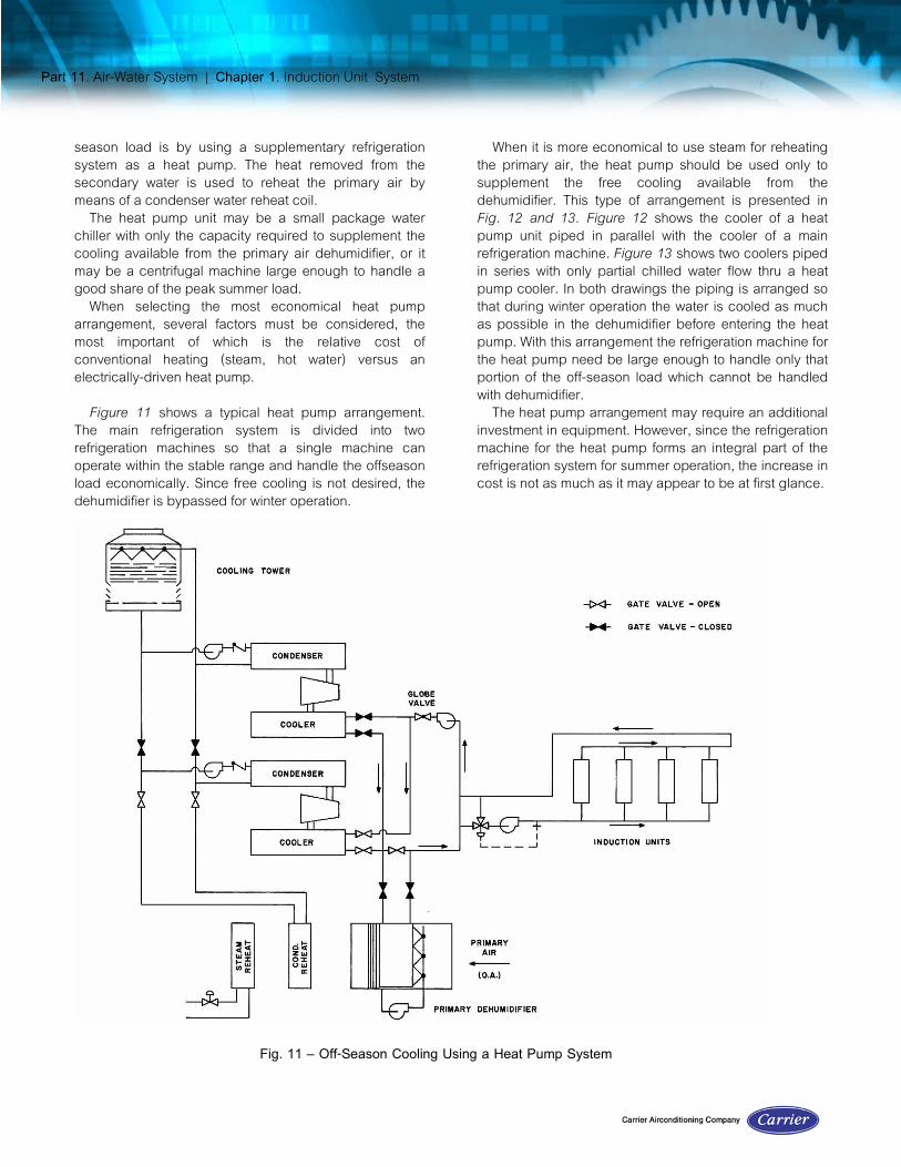
Figure 11 shows a typical heat pump arrangement.The main refrigeration system is divided into tworefrigeration machines so that a single machine canoperate within the stable range and handle the offseasonload economically. Since free cooling is not desired, thedehumidifier is bypassed for winter operation.
When it is more economical to use steam for reheatingthe primary air, the heat pump should be used only tosupplement the free cooling available from thedehumidifier. This type of arrangement is presented inFig. 12 and 13. Figure 12 shows the cooler of a heatpump unit piped in parallel with the cooler of a mainrefrigeration machine. Figure 13 shows two coolers pipedin series with only partial chilled water flow thru a heatpump cooler. In both drawings the piping is arranged sothat during winter operation the water is cooled as muchas possible in the dehumidifier before entering the heatpump. With this arrangement the refrigeration machine forthe heat pump need be large enough to handle only thatportion of the off-season load which cannot be handledwith dehumidifier.
The heat pump arrangement may require an additionalinvestment in equipment. However, since the refrigerationmachine for the heat pump forms an integral part of therefrigeration system for summer operation, the increase incost is not as much as it may appear to be at first glance.
Fig. 11 – Off-Season Cooling Using a Heat Pump System
Part 11. Air-Water System | Chapter 1. Induction Unit System
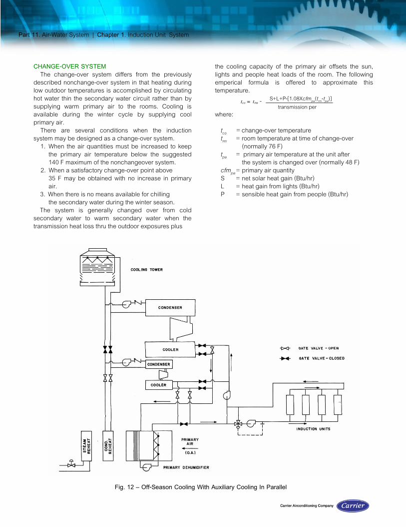
CHANGE-OVER SYSTEMThe change-over system differs from the previously
described nonchange-over system in that heating duringlow outdoor temperatures is accomplished by circulatinghot water thin the secondary water circuit rather than bysupplying warm primary air to the rooms. Cooling isavailable during the winter cycle by supplying coolprimary air.
There are several conditions when the inductionsystem may be designed as a change-over system.
1. When the air quantities must be increased to keepthe primary air temperature below the suggested140 F maximum of the nonchangeover system.
2. When a satisfactory change-over point above35 F may be obtained with no increase in primaryair.
3. When there is no means available for chilling the secondary water during the winter season.The system is generally changed over from cold
secondary water to warm secondary water when thetransmission heat loss thru the outdoor exposures plus
the cooling capacity of the primary air offsets the sun,lights and people heat loads of the room. The followingemperical formula is offered to approximate thistemperature.
where:tco = change-over temperaturetrm = room temperature at time of change-over
(normally 76 F)tpa = primary air temperature at the unit after
the system is changed over (normally 48 F)cfmpa = primary air quantityS = net solar heat gain (Btu/hr)L = heat gain from lights (Btu/hr)P = sensible heat gain from people (Btu/hr)
tco = trm - S+L+P-[1.08Xcfmpa(trm-tpa)]transmission per
Fig. 12 – Off-Season Cooling With Auxiliary Cooling In Parallel

Part 11. Air-Water System | Chapter 1. Induction Unit System
Figure 1.4 indicates the general pattern of outdoortemperatures during the year. It can be seen that thechange-over temperature can occur many times duringthe year. It normally takes a period of several hours tochange over a system; therefore, the number of change-overs should be limited and the system changed overonly when outdoor conditions remain such that thesystem need not be changed back againfor some time.
The actual outdoor temperature at which the operatorchanges over the system (either from cold to warm orfrom warm to cold water) is generally found byexperience in operating the system. The change-overpoint is usually considered as a range of temperatures(approximately 5 degrees) rather than one specifictemperature. This range decreases the number of timesthe system must be changed over during the intermediateseasons.
For example, if the calculated change-overtemperature is 45 F and the system has been operatingon the summer cycle (cold water in the secondary) andthe temperature is expected to drop to around 40 F forseveral days and then warm up again, the system shouldnot be changed over. But if the forecast predicts atemperature down to 30 F with high temperatures of 50 Fduring this period, then the system should be changedover. The reverse applies when the system is operated onthe winter cycle.
Figure 15 shows graphically a temperature schedule
Fig. 13 – Off-Season Cooling With Auxiliary Cooling In Series
Fig. 14 – Outdoor Temperature Pattern

Part 11. Air-Water System | Chapter 1. Induction Unit System
for an induction system. This indicates the relativetemperatures of the primary air and secondary waterthruout the year, and also the change-over temperaturerange. The solid arrows show the temperature variationwhen changing over from summer cycle to winter cycle,and the open arrows show the temperature variationwhen going from winter cycle to summer cycle.
In the calculation of the primary air quantity for the unitsof a change-over system, a deviation from the base A/Tratio may be used. This deviation is an experience factorwhich allows a closer matching of the unit capacity to thetotal cooling load of the space. The deviation allows aminimum temperature swing in the room. The maximumdeviation (down to 0.7 multiplier) may be taken forbuildings with heavy construction and small glass areas.For buildings with all glass or curtain wall construction, adeviation should not be used since there is a quickerresponse to the effects of outdoor temperature changes.
After the final unit selections are made, the watertemperatures required by the units for winter heating arecalculated when the units are operated with primary airand when the units are used as gravity convectors. Alower room is usually used for the gravity heatingrequirements.
The reheat coil is selected with an enteringtemperature of 40 F. The leaving temperature is based onthe primary air temperature specified by the reheatschedule (Table 3) at the calculated changeovertemperature. The leaving air temperature used for theselection should be 25 degrees higher to allow for ductheat losses. This also provides a reserve capacity for aquick warm-up of the building and for any requiredadjustment of the reheat schedule.
With a change-over system, insulation is generally notrequired on the air risers, provided all openings in thefloors are sealed to prevent stack effect and to retardcirculation within the furred space. It is sometimesdesirable to insulate the last two sections of the riserbecause the air quantities are small and the velocities arelow; these low velocities allow a significant heat loss fromthese sections. As an alternate to insulating the risers, theair quantity of the units on the next to last floor may beselected on the basis of the base A/T ratio plus 10%, andthe last units on the basis of the base A/T ratio plus 20%.RETURN AIR
Room air may be returned to the primary air apparatuswhen the unit selections indicate that the primary airquantity exceeds the minimum ventilation requirementsand when space is readily available for return air ducts.
When return air is used, it is possible to reduce theoutdoor air quantity at peak loads only to 0.1 cfm persquare foot, providing that the total primary air suppliedto the units exceeds a minimum of 0.4 cfm per squarefoot. This provides a means to reduce the refrigerationrequirement at peak loads. When the refrigerationmachine can handle the load, the outdoor air quantityshould be again operated at the design quantity.
When a return air system is used, the air is generallyreturned to the primary air apparatus by a return air fan.This fan operates at a static pressure to overcome theresistance of the return air system. This fan may also beused as an exhaust fan when the primary air system isoperated with more than the minimum outdoor airquantity.
Fig. 15 – Temperature Schedule

Part 11. Air-Water System | Chapter 2. Primary Air Fan-Coil System
CHAPTER 2. PRIMARY AIR FAN-COIL SYSTEM
The primary air fan-coil system is in many ways similarto an induction unit system; the essential difference is thesubstitution of a fan-coil unit for the induction unit. Themost suitable applications for the system are multi-roombuildings such as hotels, hospitals and apartmenthouses, where the units need not be operated asconvectors in winter.
This is a basic fan-coil system to which is added asecond source of heating or cooling and positiveventilation. Its over-all performance is comparable to thatof a change-over induction unit system. Whenperformance is of more concern than first cost, thissystem may be considered. However, because of its firstcost, an evaluation of an induction unit system may beadvantageous before making a system choice.
Fan-coil units may be located along the perimeter of abuilding with the primary air supplied directly to the units(Fig. 16a) or from a corridor duct directly into the room(Fig. 16b). Where the climate permits, the units may besuspended from the ceiling with the primary air suppliedfrom a corridor duct (Fig. 16c).The latter arrangementmay be less costly than that with the units along theperimeter of the building because of the more compactnature of the ductwork and piping layout.
This chapter includes System Description, SystemFeatures, Controls and Engineering Procedure fordesigning a complete primary air fan-coil system.SYSTEM FEATURES
The primary air fan-coil system has the followingfeatures:
1. Simultaneous Heating and Cooling — The systemprovides two sources of capacity during thesummer and winter seasons. In winter or below thechange-over point, hot water is supplied to theroom units and cool air is supplied from theprimary air system. During the summer or abovethe change-over point, cold water is supplied to.the room units and the primary air is heatedaccording to a reheat schedule.
2. Individual Room Temperature Control — Thesystem is ideally adapted to individual roomtemperature control because each unit has anintegral cooling and heating coil designed forchilled and hot water.
3. Confined Room Air Circulation — Each unitrecirculates room air only. Recirculation of airbetween rooms is kept at a minimum.
4. Positive Ventilation At All Times—A constantsupply of outdoor air is delivered to each fan-coilunit after being properly conditioned, filtered,humidified or dehumidified, and heated or cooledin the central apparatus.
5. Under-The-Window Air Distribution — Under-the-window, upward air distribution is available and issuperior to other types for small rooms, particularlyin areas with low winter outdoor designtemperatures.
Fig. 16 – Primary Air Fan-Coil Arrangements

Part 11. Air-Water System | Chapter 2. Primary Air Fan-Coil System
SYSTEM DESCRIPTIONFigure 17 is a sketch of the system
CENTRAL APPARATUSThe central apparatus is either a built-up apparatus or
a packaged fan-coil unit which conditions the outdoor airand supplies it to the room unit or directly to the room by
Fig. 17 – Primary Air Fan-Coil System

Part 11. Air-Water System | Chapter 2. Primary Air Fan-Coil System
a corridor duct. The air distribution system may be eitherlow or high velocity. A low velocity system is normallyused if the primary air is discharged from a corridor ductdirectly into the room or supplied to units suspended fromthe ceiling. With space available a low velocity systemresults in the greatest economy of owning and operatingcosts.
The apparatus contains filters to cleanse the air,preheaters (when required) to temper the air, and ahumidifier or dehumidifier to add humidification or removeexcess moisture from the warm humid air. It also containsreheaters to heat the air from a predetermined scheduleas the outdoor temperature falls to the change-overtemperature. The primary air is held at a constantminimum temperature when the outdoor temperature isbelow the change-over temperature. When the primary airis supplied directly to the room, its minimum temperatureis maintained sufficiently high to prevent drafts. Outdoorair to the apparatus is admitted thin a louver and screen.
Chilled water from a central refrigeration plant iscirculated thru the dehumidifier coils in the centralapparatus, an(l then mixes with recirculated water fromthe secondary water circuit to maintain a constant watertemperature to the fan-coil units.FAN-COIL UNIT
Figure 18 illustrates the basic elements of the fan-coilunit, including a recirculated air inlet, primary air inlet(optional), filter, fan, cooling and heating coil, anddischarge air outlet.
The unit is supplied with cold or hot water dependingon the outdoor temperature.
Room temperatures are maintained by thermostaticallycontrolling the water flow.ENGINEERING PROCEDURE
The following procedure is offered to assure a practicaloperating air conditioning system. A survey andpreliminary layout are required as outlined in Part 1.Room loads and minimum ventilation air quantities arealso determined from Part 1.
ROOM COOLING LOADCalculate the sensible and latent heat loads for all
typical exposures: east, west, north, south, and anyspace that has unusual loads. It may be necessary toallow some flexibility in these calculations to allow forfuture partition changes, depending on the type ofapplication. In most multi-room applications 8 to 16 roomload calculations required.ROOM HEATING LOAD
Calculate the room heating loads. They include theheating requirements to offset transmission and infiltrationand also sufficient heat to temper the primary air from thetemperature entering the room to the room winter designtemperature.PRIMARY AIR QUANTITY
Determine the ventilation air required for each unit fromPart 1.
The primary air quantity should be determined inaccordance with the A/T ratio concept as explained inChapter 1. For each unit, calculate an A/T ratio which isthe ratio of the unit ventilation air quantity to the totaltransmission per degree thru the outside exposed areasof the space served by the unit. Select the highestcalculated A/T ratio as a base A/T ratio. Calculate thedesign primary air quantity for each unit by multiplyingthe base A/T ratio by the transmission per degree for thespace served by each unit. The total primary air quantityfor the system equals the sum of the primary air quantitiesrequired for each unit.UNIT SELECTION
Select room units to satisfy these requirements:1. Maximum room sensible load with a credit for the
primary air cooling.2. Maximum room and primary air heating load.Unit selections can be made from a manufacturer’s
catalog.The unit is normally adequate for zone depths of
approximately 20 feet. Vertical air distribution from theperimeter unit spreads out in blanketing the exterior walland travels along the ceiling for a distance of 15 to 20
Fig. 18 – Typical Fan-Coil Unit

Part 11. Air-Water System | Chapter 2. Primary Air Fan-Coil System
feet before falling toward the floor in return air circulation.The secondary water temperature should be selected
to provide the required sensible heat capacity of the unit.In some cases the water temperature may be low
enough to provide some latent heat removal. This mayallow a higher apparatus dewpoint selection for thedehumidifier.
The water flow rate is dependent on the unit selectionand cooling load, but should not be below the minimumflow which maintains turbulent conditions. Turbulentconditions for a 3/8, 1/2 and 5/8 inch OD tube isapproximately 0.5, 0.7 and 0.9 gpm respectively.
The same water rate is used for heating as is used forcooling. The hot water temperature is calculated for eachunit selection and the maximum temperature is used asthe design.DUCT DESIGN
High or low pressure ductwork can be used for theprimary air system. Refer to Part 2 for the design andsizing of the ductwork.
Although other methods of duct sizing such as equalfriction or velocity reduction may be used, the staticregain method is preferred. A system designed for staticregain is nearly self-balancing because it is designed forthe same static pressure at each terminal. Static regaindesign minimizes field balancing, aids the maintenanceof system stability, and reduces fan horsepowerrequirements.
PIPING DESIGNA single piping system is used to circulate chilled or
hot water to the fan-coil unit. Normal design practiceshould be followed in system layout as shown in Part 3.Either a direct return or a reverse return system may beused. However, a reverse return system (Fig. 19) ispreferred and should be used whenever practical since itis an inherently balanced system.
Drain piping should be sized as recommended in Part3.
Secondary chilled water riser piping and unit run-outinsulation is not required when chilled water temperaturesare no lower than 3 degrees below the room dewpointand when the risers are furred in.CENTRAL APPARATUS
Select the central air handling apparatus for the totalprimary air quantity.
The dehumidifier load is determined from the formula:Load = cfmda X 4.45 X (1 — BF) (hea — hadp)
where:cfmda = dehumidifier air quantityh ea = entering air enthalpyhadp = apparatus dewpoint enthalpyBF = dehumidifier bypass factor
The required apparatus dewpoint can be determinedon an individual room basis by using the formula:
where:
Wadp = apparatus dewpoint specific humidity (gr/lb)Wrm = room specific humidity (gr/lb))Wea = air entering (lehUmidiher specific humidity (gr/lb)RLH = room latent heat loadcf mda = dehumidified air quantity supplied to roomBF = dehumidifier bypass factor
The selected apparatus dewpoint should berepresentative of the majority of the spaces.
If this selected apparatus dewpoint is lower thanapproximately 48 F, an adjustment may be necessary inthe selected secondary water temperature so the fan-coilunits can accommodate part of the latent load. A fewdegrees drop in the secondary water temperature canprovide a considerable amount of latent heat removal inthe fan-coil unit.
Wadp =
Wrm – (Wea x BF) -
1 - BF
.68 X cfmda
RLH
Fig. 19 – Schematic of Water Piping, Primary AirFan-Coil System

Part 11. Air-Water System | Chapter 2. Primary Air Fan-Coil System
Select the reheat coil to heat the primary air quantityfrom 40 F to a temperature based on the primary airtemperature required at the change-over temperature(Table 2, Chapter 1). The leaving air temperature usedfor the selection should be increased by 25 degrees toprovide for duct heat losses and reserve capacity forquick warm-up of the building. Change-over temperatureand the reheat schedule are determined as in Chapter 1.
The preheater coil is selected to heat the primary airfrom the minimum outdoor design temperature to about50-55 F.
The fan is selected for the primary air quantity and astatic pressure sufficient to overcome the resistance inthe apparatus and ductwork.
The filter is selected for the design air quantity an(lshould have a good efficiency of about 85-95% based onthe weight method of testing filters.REFRIGERATION LOAD
The refrigeration load is equal to the sum of the peakbuilding (or block estimate) sensible heat load and thedehumidifier load, less a credit for the primary air coolingof the conditioned spaces.WATER HEATER
The water heater is selected as in Chapter 1.
CONTROLSA basic control arrangement for the fan-coil unit,
primary air apparatus and secondary water circuit isillustrated in Fig. 20 and 21. The controls are similar tothose required for an induction system except at the fan-coil unit.UNIT CONTROL
The fan-coil unit capacity is controlled by varying thewater flow to the coil within the unit.
The room thermostat should be located on the roomwall and not at the unit when primary air is admitteddirectly to the unit.
When provision is made to shut off fans, the water flowmust also be shut off at the same time to prevent damagefrom condensation. If the chilled water is permitted toflow, the entire unit can approach the temperature of thechilled water including the condensate pan and drainline. This can lead to condensation problems such aswater spotting and mildew.
Fig. 21 - Control Package, Fan-Coil Unit,Manual Three-Speed Fan Control With
Automatic On-Off Waterflow
Fig. 20 – Typical Control Diagram PneumaticPrimary Air Fan-Coil System

Part 11. Air-Water System | Chapter 2. Primary Air Fan-Coil System
SECONDARY WATER CIRCUIT AND PRIMARY AIRAPPARATUS CONTROLS
The secondary water circuit and primary air apparatuscontrols are similar to those used with the induction unitsystem and the control sequence is the same asdescribed in Chapter 1.
A
Air quantity calculationinduction unit systemprimary air fan-coil system
Air/transmission ratioair zoningcalculationfig. 3definitionfunctionuse
Air zoninginduction unit system
Apparatus components, descriptioninduction unit systemair filterdehumidifieroutdoor air intake louverpreheaterreheatersupply fanprimary air fan-coil system airfilterdehumidifieroutdoor air intake louver
preheaterreheater
Apparatus controlinduction unit system
primary air fan- oil systemApparatus dewpoint, calculation
induction unit systemprimary air fan-coil systems
Applicationinduction unit systemsprimary air fan-coil systems
A/T ratio, see air/transmissionratio
C
Central apparatus, descriptioninduction unit systemprimary air fan-coil system
Central apparatus, selectioninduction unit systemprimary air fan-coil system
Changeover induction unitsystem
fig. 14fig. 15
A/T ratioinsulation requirementprimary air quantitycalculationreheat coil selectionwater temperature selection
Changeover temperature,calculation
Condensate drain pipinginduction unit system
Controlsinduction unit systemprimary air damperprimary air preheaterprimary air reheaterroom temperaturesafetysecondary chilled waterwater heaterprimary air fan-coil systemprimary apparatusroom temperaturesecondary water
DDehumidifier apparatus dewpoint

selection guidetable 2
Dehumidifier, selectioninduction unit system
primary air fan-coil systemDuct design
induction unit systemprimary air fan-coil system
E
Engineering procedureinduction unit systemapparatus selectionduct designpiping designpreliminary layoutrefrigeration loadroom cooling loadroom heating loadsurveyunit selectionwater heaterprimary air fan-coil systemapparatus selectionduct designpiping designprimary air quantityrefrigeration loadroom cooling loadroom heating loadunit selection
water heaterExpansion, piping
induction unit system
F
Fan-coil unitcontrolsdescriptionselection
Filters, airdescriptioninduction unit systemprimary air fan-coilsystemselectioninduction unit systemprimary air fan-coilsystem
Freeze protection, dehumidifierconventional nonfreeze steam coilhot water preheat coil
H
Hot water preheat coilfig. 10
I
Induction unitcontrolsdescription
selectionInduction unit system
controlsengineering proceduremodificationssystem designconsiderations,system descriptionsystem features
Insulationductwater piping
M
Modificationsinduction unit systemchangeover systemoff-season cooling loadcalculationreturn airsources of off-seasoncooling
O
Off-season cooling loadcalculationsOff-season cooling, sources
outdoor airsupplementaryrefrigeration system
P

Piping designinduction unit systemprimary air fan-coil system
Primary air damper Controlinduction unit systemPrimary air fan-coil systemcontrolsengineering proceduresystem descriptionsystem featuresPrimary air preheater controlinduction unit systemPrimary air quantitycalculationinduction unit systemprimary air fan-coil systemPrimary air reheater controlinduction unit systemPrimary air temperaturescheduletable 3Primary water piping
R
Refrigeration load calculationinduction unit systemprimary air fan-coil systemRoom cooling loadinduction unit systemprimary air fan-coil systemRoom design load factorstable 1
Room heating loadinduction unit systemprimary air fan-coil system,
Room temperature controlinduction unit systemprimary air fan-coil system
S
Safety thermostatinduction unit systemSecondary chilled watercontrolinduction unit systemSystem descriptioninduction unit systemcentral apparatusinduction unitprimary air fan-coil unitcentral apparatusan-coil unitSystem design considerationsair/transmission ratioair zoningSystem featuresinduction unit systemprimary air fan-coil systems
U
Unit selectioninduction unit systemprimary air fan-coil system
W
Water heatercalculation
induction unit systemprimary air fan-coilsystemcontrolsinduction unit, systemselectioninduction unit systemprimary air fan-coilsystem

Fig. 1 Typical Induction Unit System
Fig. 2 Typical Induction Unit
Fig. 3 Calculation of A/T Ratio
Fig. 4 Relative Locations and Costs of Piping and Wiring
Fig. 5 Typical Floor Plan
Fig. 6 Typical Load Estimate
Fig. 7 Water Distribution System
Fig. 8 Induction Unit System Control
Fig. 9 Off-Season Cooling Using Primary Air Coils Plus Interior Zone Dehumidifier Coils
Fig. 10 Hot Water Preheat Coil
Fig. 11 Off- Season Cooling Using a Heat Pump System Coil
Fig. 12 Off- Season Cooling With Auxiliary Coolers In Parallel
Fig. 13 Off- Season Cooling With Auxiliary Coolers In Series
Fig. 14 Outdoor Temperature Pattern
Fig. 15 Temperature Schedule
Fig. 16 Primary Air Fan-Coil Arrangement
Fig. 17 Primary Air Fan-Coil System
Fig. 18 Typical Fan-Coil Unit
Fig. 19 Schematic of Water Piping, Primary Air Fan-Coil System
Fig. 20 Typical Control Diagram Pneumatic Primary Air Fan-Coil System
Fig. 21 Control Package, Fan-Coil Unit, Manual Three-Speed Fan Control With Automatic
On-Off Water flow

Table. 1 – ROOM DESIGN LOAD FACTORS
Table. 1 – ROOM DESIGN LOAD FACTORS (Contd.)
Table. 2 – DEHUMIDIFIER APPARATUS DEWPOINT SELECTION GUIDE
Table. 3 – SCHEDULE OF PRIMARY AIR TEMPERATURES


![[Carrier] HVAC Handbook - New Edition - Part.7 - Refrigeration Equipment](https://img.dokumen.tips/doc/110x75/577cd6151a28ab9e789bc232/carrier-hvac-handbook-new-edition-part7-refrigeration-equipment.jpg)