Embed Size (px)
Citation preview

8/6/2019 202D Manual
http://slidepdf.com/reader/full/202d-manual 1/48
FIELD MOUNTEDRATE TOTALISER
MODEL 202D
19 April 2000

8/6/2019 202D Manual
http://slidepdf.com/reader/full/202d-manual 2/48

8/6/2019 202D Manual
http://slidepdf.com/reader/full/202d-manual 3/48
CONTENTS
1. Introduction 11.1 Model Number Designation 3
1.2 Intrinsic Safety Considerations 4
2. Specification 6
3. Operation 8
3.1 Display 8
3.2 Test Mode 9
3.3 Filtering 103.4 Calculation of Rate and Total 12
3.5 Total Conversion 13
3.6 Frequency Cutoff 14
4. Programming 15
4.1 Program Steps 16
5. Example 19
6. Versions 20
6.1 Battery Powered Version 21
6.2 DC Power Version 22
6.3 Relay and 4-20mA Output Version 24
7. Flowmeter Input 26
8. Intrinsic Safety Connections 31
8.1 Coils 31
8.2 Simple Apparatus 32
8.3 Namur Proximity Switches 32
8.4 Alarm Outputs 35

8/6/2019 202D Manual
http://slidepdf.com/reader/full/202d-manual 4/48
9. Installation 37
9.1 Wall Mounting 37
9.2 Panel Mount Version 38
9.3 Removing the Front Panel 39
9.4 The Main Electronics 419.5 Wiring 42
9.6 Terminal Designations 43
Index 44

8/6/2019 202D Manual
http://slidepdf.com/reader/full/202d-manual 5/48
Introduction 1
1. INTRODUCTION
The Model 202D Rate Totaliser is a microprocessor based instrument whichaccepts a frequency or pulse input from a wide range of flowmeters. The
instrument displays flow Rate, a Resettable Total and an Accumulated Total
directly in engineering units.
The instrument is compatible with a wide range of flowmeters. Links on the input
board enable the circuit to be configured for millivolt signals, reed switches, pulse
trains and most other signal types.
Three different versions of the Model 202D are available:
1. A Battery Powered Version with no output.
2. A DC Powered Version with either:
i. high and low flow alarms or
ii. a low flow alarm and pulse output.
3. A Loop Powered Version with 4-20mA output and alarms as above.
The instrument is fully programmable from the front panel; the user can program
scaling factors, decimal point positions, filter constants and timebase.
The Model 202D is an upgraded version of the Contrec Model 202. The following
improvements have been made in the Model 202D:
♦ The 202D output board can have both ALARMS and a 4-20mA OUTPUT.
♦ The voltage drop across the alarm outputs in the 202D is ONLY 0.8 VOLTS.
♦ The voltage supply for the DC and loop powered versions can go AS LOW AS
9 VOLTS.
♦ The 202D has an overall LOWER CURRENT CONSUMPTION than theprevious model with an IMPROVED BATTERY LIFE - the battery life in the
new model is typically 5 years regardless of the time the unit spends in
totalising mode.
♦ In the 4-20mA output version of the 202D, the ACCURACY HAS BEEN
IMPROVED to 0.05% of span and the linearity to 0.05% of span at 25°C.
♦ The millivolt input can accept signals AS LOW AS 15mV P-P.
♦ The 202D has a WIDE FREQUENCY RANGE - 0.01Hz to 10kHz.
♦ The 202D has a WIDER K-FACTOR RANGE - K-factors from 0.000001 to
999,999 can be programmed.

8/6/2019 202D Manual
http://slidepdf.com/reader/full/202d-manual 6/48
Introduction2
♦ Unlike the previous Model 202, the 202D has an additional mounting option - it
is available in a PANEL MOUNT version.
The Model 202D Rate Totaliser conforms to the EMC-Directive of the Council of
European Communities 89/336/EEC and the following standards:
Generic Emission Standard EN 50081-1 Residential, Commercial & Light
Industry Environment.
Generic Emission Standard EN 50081-2 Industrial Environment.
Generic Immunity Standard EN 50082-1 Residential, Commercial & Light
Industry Environment.
Generic Immunity Standard EN 50082-2 Industrial Environment.
In order to comply with these standards, the wiring instructions in Section 9.5 must
be adhered to.

8/6/2019 202D Manual
http://slidepdf.com/reader/full/202d-manual 7/48
Introduction 3
1.1 MODEL NUMBER DESIGNATION
The Model Number of the 202D describes the power & output options installed
and the mounting options.
Model 202D . 2 3
Mounting options Version
0 No holes drilled for cable entry 0 Battery powered version
1 Panel mount
2 Wall mount (standard) 3 DC powered with battery backup
4 Turbine adaptor and alarm outputs
6 2" pipe mount (galvanised)
4 Loop powered with 4-20mA output,
alarm outputs and backup batteries

8/6/2019 202D Manual
http://slidepdf.com/reader/full/202d-manual 8/48
Introduction4
1.2 INTRINSIC SAFETY CONSIDERATIONS
The Model 202D is certified for use in hazardous areas and has both CENELEC
and CSA NRTL/C approvals.
The Model 202D certification details are:
CENELEC Approval: Kema 98.E.1873.
Type of Protection: Ex ia.
Group: IIB.
Temperature Class: T4 at ambient temperature of 60°C.
CSA NRTL/C Approval
File Number: LR 104 840-5.
Type: Class 1, Groups C and D.
When installing in hazardous areas, the instrument must be installed according to
the guidelines in Section 8 and in accordance with standards for wiring and
installation in hazardous areas.
4-20mA/DC Power
The input can be connected to IS circuits with the following maximum values:
Ui = 28V
Ii = 93mA
Pi = 653mW
The internal capacitance and inductance seen on these terminals is 0.1uF and
0mH.

8/6/2019 202D Manual
http://slidepdf.com/reader/full/202d-manual 9/48
Introduction 5
Relay Outputs
The outputs can be connected to IS circuits with the following maximum
values:
Ui = 28V
Ii = 93mA
Pi = 653mW
The internal capacitance and inductance seen on these terminals is 0.1uF and
0mH.
Flowmeter Input
Entity parameters on the flowmeter enable connection to a wide range of
approved sensors.
Input parameters are:
Ui = 24V
Ii = 20mA
Pi = 320mW
The internal capacitance and inductance seen on these terminals is 0.002uF and
0mH.
Output parameters are:
Uo = 10.0V
Io = 9.0mA
Maximum allowed external capacitance is 60µF.
Maximum allowed external inductance is 1.5H.

8/6/2019 202D Manual
http://slidepdf.com/reader/full/202d-manual 10/48
Specification6
2. SPECIFICATION
General
Display: LCD which is continuously powered.
Resettable Total: 7 digits with 10mm (0.4") high digits. Resettable
from front panel.
Accumulated Total: Displayed when the ACCUM TOTAL button is
pressed.
Rate: 4½ digits with 8.5mm (0.33") high digits.
K-factor: The pulses per unit of measure (eg. pulses/gallon)
is programmable in the range 0.000001 to 999,999.Decimal Points: Decimal point positions are fully programmable for
both rate and total.
Timebase: Rate can be displayed in units per second, minute,
hour or day.
Frequency Range: 0.01Hz to 10kHz.
Signal Type: Link settable for sinewave (15mV P-P minimum),
open collector, reed switch, pulse or Namur
proximity switch.
Battery Powered Version
Type: Two lithium battery packs.
Battery Life: 5 years typical.
Loop Powered 4-20mA Output Version
Scale: The 4mA and 20mA points are programmable.
Resolution and Linearity: 0.05% of span.
Accuracy: 0.05% of span at 25°C.
0.1% (typ) of span, full temperature range.
Update Time: 0.5 second.
Connection: Two-wire.
Loop Power Supply: 9-28 Volts.
Supply Backup: Lithium battery.

8/6/2019 202D Manual
http://slidepdf.com/reader/full/202d-manual 11/48
Specification 7
DC Power/Alarm Version
Outputs: Two open collector outputs suitable for driving DC
solenoids or external relays. The outputs can be
programmed to provide high and low flow alarmsor pulse output and low flow alarm.
Switching Power: 200mA. 30VDC maximum.
DC Power Input: 9-28 Volt at 4mA maximum.
Supply Backup: Lithium battery.
Pulse Duration: 1ms if CAL0 = 2 (unscaled pulse output).
If CAL0 = 1 (scaled pulse output) the duration of
the pulse automatically adjusts to the output
frequency:
a. 1ms if output > 50Hz.b. 10ms if output = 5...50Hz.
c. 100ms if output < 5Hz.
Physical
Temperature: Operating temperature: -20°C to 60°C.
Dimensions: 97mm (3.8") high x 150mm (5.9") wide x 41mm
(1.6") deep (cable glands not included).
Protection: Sealed to Nema 4X or IP67 standards.Cable Entry: By cable glands.
Wall Mounting: Universal mounting bracket supplied as standard.
Pipe Mounting: A galvanised metal bracket is available which
enables the Model 202D to be attached to a 2"
vertical or horizontal pipe.
Turbine Meter Adaptor: An optional mounting stem is available for
mounting the Model 202D directly on turbine
flowmeters which have a 1" NPT boss or 1" BSP
boss.Panel Mounting: Supplied with mounting brackets. Terminals
accessible from rear. The panel mount version is
not watertight.
Cutout: 141mm (5.6") wide x 87mm (3.4" high).

8/6/2019 202D Manual
http://slidepdf.com/reader/full/202d-manual 12/48
Operation8
3. OPERATION
The Model 202D Rate Totaliser accepts a frequency or pulse input from a widerange of flowmeters. The instrument is fully programmable with all operating
parameters and calculation constants programmable from the front panel. The
setup parameters are stored in a non-volatile memory and are retained for at least
40 years in the event of a power loss.
3.1 DISPLAY
The Model 202D displays: Rate
Resettable Total
Accumulated Total
Both the Rate and Resettable Total are displayed continuously. The Accumulated
Total is displayed only when the ACCUM TOTAL key is pressed.
The keys on the front of the 202D have the following functions:
Pressing this key will display the
Accumulated Total.
This key resets the Resettable Total
at any time.
This key is used during the Program
Mode.
RESET
PROGRAM
ACCUMTOTAL

8/6/2019 202D Manual
http://slidepdf.com/reader/full/202d-manual 13/48
Operation 9
3.2 TEST MODE
The 202D has a Test Mode which can be entered by simultaneously pressing all 3
front panel keys. The tests are as follows:
Low Test By pressing the ACCUM TOTAL key, the low
alarm output (if installed) will go low. If a 4-
20mA option is installed, the output will go to
4mA.
High Test By pressing the RESET key, and depending on the
programmed pulse output mode, the high alarm
output (if installed):
a. will go low if CAL0 = 0 (high alarm output).
b. will output 100ms pulses every 0.5 sec if CAL0
= 1 (scaled pulse output).
c. will output 1ms pulses every 0.5 sec if CAL0 =
2 (unscaled pulse output).
If a 4-20mA option is installed, the output will go
to 20mA.
Display Test By pressing the PROGRAM key, all segments of
the display will flash.
To exit Test Mode, all three front panel keys are pressed simultaneously.

8/6/2019 202D Manual
http://slidepdf.com/reader/full/202d-manual 14/48
Operation10
3.3 FILTERING
Frequency fluctuations caused by pulsating flow through a flowmeter can interfere
with the precision of the rate. For this reason, the Model 202D has a digital filter
which will average out these fluctuations and enable accurate readings.
The degree of filtering of the input signal can be adjusted depending on the amount
of fluctuation and the particular application. Values from 1 to 99 can be
programmed where 1 corresponds to no filtering and 99 corresponds to heavy
filtering. Such flexibility in filtering means that highly accurate and stable
readings can be obtained.
When programming the degree of filtering, it is advisable to start with no filtering
(the factor equals 1) and gradually increase until a steady reading is obtained. It is
important that the filtering is not too heavy because this will cause an overdamped
response.
The following graph shows the time to reach 90% and 99% of a new reading for a
step change in input signal.

8/6/2019 202D Manual
http://slidepdf.com/reader/full/202d-manual 15/48
Operation 11
Filter Factor vs Time to Reach New Reading
(for a step change in input signal)
0
20
40
60
80
100
120
0 10 20 30 40 50 60 70 80 90 100
Filter Factor
T
i m e t o R e a c h % o
f
N e w R e a d i n g ( s e c o n d s )
90% of New Reading 99% of New Reading

8/6/2019 202D Manual
http://slidepdf.com/reader/full/202d-manual 16/48
Operation12
3.4 CALCULATION OF RATE AND TOTAL
The flow rate, R, is calculated as follows:
where f is the input frequency in Hz (pulses/second).
H is the timebase of rate and is 1 for seconds, 60 for minutes, 3600 for
hours and 86,400 for days.
S is the scaling factor (pulses/unit volume).
The scaling factor, S, is equal to the K-factor of the flowmeter expressed in pulsesper unit volume. The K-factor is flowmeter dependant and is supplied with the
flowmeter. It will be either on a calibration certificate or stamped on the body of
the meter.
The user programs the scaling factor and selects the timebase during the
programming procedure.
R f x H
S=

8/6/2019 202D Manual
http://slidepdf.com/reader/full/202d-manual 17/48
Operation 13
3.5 TOTAL CONVERSION
The Total Conversion Factor is programmed to enable the rate to be displayed in
one engineering unit and the totals to be displayed in another. For example, the
rate can be displayed in gallons/minute and the totals in barrels.
The Total Conversion Factor is a division factor which is used to convert the totals
to a different unit. Therefore, it only affects the totals (both resettable and
accumulated).
Example.
If the Rate is required in gallons/minute:
1. The Scaling Factor would be programmed as pulses per gallon.
2. The Timebase would be programmed as minutes.
If the Totals are required in barrels:
1. The Total Conversion Factor is programmed as 42 because there are 42
gallons in a barrel. All totals will now totalise in barrels.
Below is a table containing common units and their corresponding TotalConversion constants:
Rate/Unit Time Totals Total Conversion Factor
Gallons (US)/Unit Time Barrels (oil) 42.000
Litres/Unit Time Kilolitres 1000
Litres/Unit Time m3 1000
ml/Unit Time Litres 1000
Mgallons/Unit Time Acre-feet 0.32587

8/6/2019 202D Manual
http://slidepdf.com/reader/full/202d-manual 18/48
Operation14
3.6 FREQUENCY CUTOFF
A frequency cutoff can be programmed below which flow rate is not registered.
Input frequencies at or below the cutoff are totalised, however, the rate is displayed
as zero.
The frequency cutoff has a default value of 0.25Hz. The cutoff should be left as
0.25Hz unless the flowmeter in use has a lower frequency.
Note that a low cutoff frequency will result in a correspondingly low response of
flow rate update. For example, if the cutoff is set to 0.01Hz the 202D will continue
to display the flow rate for 100 seconds even if the signal stops. This is because a
cutoff frequency of 0.01Hz means that the time interval between signals is 100
seconds (period = 1/frequency). Therefore, the Model 202D must wait 100
seconds before it can determine that the flow has actually stopped.

8/6/2019 202D Manual
http://slidepdf.com/reader/full/202d-manual 19/48
Programming 15
4. PROGRAMMING
The Model 202D is fully programmable with all parameters being stored in non-volatile memory.
The Program Mode can be entered in one of two ways:
1. By removing the lower cover strip (ie. the dark grey strip along the bottom
of the enclosure) and replacing it the wrong side up. This brings a small
magnet on the inside of the cover strip in contact with a reed switch inside
the instrument.
2. By removing the front section of the enclosure which contains the main
processor board and batteries.
The PROGRAM switch is used to step through the program (CAL sequences) and
the ACCUM TOTAL and RESET keys on the front panel are used to change and
increment the flashing digits. Note that only flashing digits can be changed.
Up to nineteen CAL steps are accessible depending on which options are installed.
The CAL number is displayed on the lower display and the parameter is displayed
above it.

8/6/2019 202D Manual
http://slidepdf.com/reader/full/202d-manual 20/48
Programming16
4.1 PROGRAM STEPS
Step Comment
CAL 0 Pulse Output (applies to DC Power/Alarm version only).
0 = No pulse output, low and high alarms.
1 = Scaled pulse output and low alarm.
2 = Unscaled pulse output and low alarm.
CAL 1 Scaling Factor - whole numbers.
CAL 2 Scaling Factor - digits after the decimal point.
The scaling factor is the pulses per unit of measure (eg.
pulses/litre, pulses/gallon, etc). The scaling factor can be
programmed in the range of 0.000001 - 999,999.
See Section 3.4.
CAL 3 Cutoff Frequency.
This determines the cutoff frequency in the range of 0.01 -0.99Hz. The default setting is 0.25HZ.
Note that care must be taken when programming this value
because a low value may cause a slow update time.
CAL 4 Decimal Point for Rate Display.
The flow rate can be displayed with 0, 1, 2 or 3 decimal point
places.
CAL 5 Timebase for Rate.
The rate can be displayed in units per second, minute, hour or
day.
0 = second
1 = minute
2 = hour
3 = day

8/6/2019 202D Manual
http://slidepdf.com/reader/full/202d-manual 21/48
Programming 17
Step Comment
CAL 6 Filter.
The filter constant for filtering the input signal.
1 No filtering.
to
99 Very heavy filtering.
CAL 7 Decimal Point for Total Display.
The totals can be displayed with 0, 1, 2 or 3 decimal points.
CAL 8 Total Conversion Factor - whole numbers.
CAL 9 Total Conversion Factor - digits after the decimal point.
The total conversion factor enables the rate to be displayed in
one engineering unit and the totals to be displayed in another
engineering unit. The total conversion factor can be
programmed in the range of 0.000001 - 999,999.
Set to 1.000 if totals and rate are in the same unit, eg. litres.
See Section 3.5.
CAL 10 Low Alarm - whole numbers.
CAL 11 Low Alarm - digits after the decimal point.
CAL 10 to CAL 13 are displayed regardless of whether thehigh and low alarms are installed. If the high and low alarms
are not installed, these parameters can be ignored.
CAL 10 & 11 program the flow rate below which the low
alarm relay will close. The value can be programmed in the
range 0 to 999,999.
8/6/2019 202D Manual
http://slidepdf.com/reader/full/202d-manual 22/48
Programming18
Step Comment
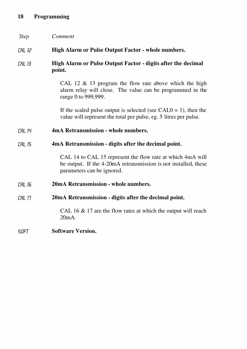
CAL 12 High Alarm or Pulse Output Factor - whole numbers.
CAL 13 High Alarm or Pulse Output Factor - digits after the decimal
point.
CAL 12 & 13 program the flow rate above which the high
alarm relay will close. The value can be programmed in the
range 0 to 999,999.
If the scaled pulse output is selected (see CAL0 = 1), then the
value will represent the total per pulse, eg. 5 litres per pulse.
CAL 14 4mA Retransmission - whole numbers.
CAL 15 4mA Retransmission - digits after the decimal point.
CAL 14 to CAL 15 represent the flow rate at which 4mA will
be output. If the 4-20mA retransmission is not installed, these
parameters can be ignored.
CAL 16 20mA Retransmission - whole numbers.
CAL 17 20mA Retransmission - digits after the decimal point.
CAL 16 & 17 are the flow rates at which the output will reach
20mA.
SOFT Software Version.

8/6/2019 202D Manual
http://slidepdf.com/reader/full/202d-manual 23/48
Example 19
5. EXAMPLE
A flowmeter produces 20.538 pulses per litre and has a maximum output frequencyon 200Hz. It is required to display the flow rate in litres/min with 1 decimal point
and the total in litres with no decimals. A 4-20mA output is installed and 4mA is
to represent 0 litres/m and 20mA is to represent 500 litres/m. The instrument is
then programmed as follows:
Calibration mode is entered by removing the lower cover strip (ie. the dark grey
strip along the bottom of the enclosure) and replacing it the wrong side up.
The following values are then entered:
Step
Value of
Parameter Description
CAL00 0 No Pulse Output
CAL01 00020 Scaling Factor (whole numbers)
CAL02 5380 Scaling Factor (decimals)
Cal03 0.25 Cutoff Frequency
Cal04 1 Rate decimal positionCal05 1 Timebase
Cal06 01 Filter disabled
Cal07 0 Total decimal position
Cal08 0001 Total Conversion (set to 1.0000)
Cal09 0000 Total Conversion (decimals)
Cal10 00000 Low Alarm (not installed)
cal11 0000 Low Alarm (not installed)
Cal12 00000 High Alarm (not installed)
Cal13 0000 High Alarm (not installed)Cal14 00000 4mA Output (whole numbers)
Cal15 0000 4mA Output (decimals)
Cal16 00500 20mA Output (whole numbers)
Cal17 0000 20mA Output (decimals)
SOFT 1.01 Software Version

8/6/2019 202D Manual
http://slidepdf.com/reader/full/202d-manual 24/48
Versions20
6. VERSIONS
The following table summarises the features of each of the different versions of theModel 202D:
Model Number 202D.X0 202D.X3 202D.X4
VersionBattery powered
version
DC powered
version
Loop powered
version
Power Lithium batteries
DC powered;
9-28Volts at
4mA maximum
Loop powered;
9-28 Volts with
4-20mA out
Output None
Alarms - two open collector outputs
OR
Pulse output and low flow alarm
Supply Backup None Lithium batteries Lithium batteries
Where X denotes the mounting options and will be replaced by one of the
following numbers:
0 No holes drilled for cable entry1 Panel mount
2 Wall mount (standard)
4 Turbine adaptor
6 2" pipe mount (galvanised)

8/6/2019 202D Manual
http://slidepdf.com/reader/full/202d-manual 25/48
Versions 21
6.1 BATTERY POWERED VERSION
The battery powered version of the Model 202D is designed for operation in the
field without external power sources. Lithium batteries provide sufficient power to
operate the instruments for up to 5 years and the operator is warned of a low power
condition by a message on the LCD display.
New batteries can be purchased via Contrec or our distributors and replaced in the
field without compromising the IS approvals. There are two battery packs in each
instrument and care must be taken to replace only one pack at a time so that there
is always power connected to the memory. Failure to do this may result in loss of
totals.

8/6/2019 202D Manual
http://slidepdf.com/reader/full/202d-manual 26/48
Versions22
6.2 DC POWER VERSION
The DC power version will operate from an external power source between 9-
28VDC and draws no more than 4mA. This enables the instrument to be powered
from AC mains adaptors and eliminates the need to run mains voltages in the field.
The instrument uses lithium batteries for backup if the DC power is interrupted.
However, alarms and/or pulse outputs are not supported if the DC power is
interrupted.
Open collector outputs are also provided for high and low flow rate alarms. If a
pulse output is programmed, terminals 6 and 5 will act as a pulse out. The output
can sink up to 200mA and can be used to power external relays, lights or audible
alarms. The outputs are internally protected against voltage spikes caused by
relays and coils.
Both outputs are separately isolated via opto-isolators.
The switching points can be programmed during the setup mode and the low flow
alarm will switch on whenever the flow rate drops below the programmed flow
rate. Similarly, the high alarm switches on whenever the flow exceeds the high
setpoint.
If a scaled pulse output is programmed, a pulse will be output every preset value of
the total. For example, if the total is in litres, then programming 5 will output one
pulse every 5 litres. If an unscaled pulse output is programmed, output pulses will
follow input frequency from a flowmeter.

8/6/2019 202D Manual
http://slidepdf.com/reader/full/202d-manual 27/48
Versions 23
Specification for Alarm Outputs
Maximum Current (sink): 200mA.
Maximum Voltage: 30Vdc.
Saturation Voltage: 0.8Vdc across outputs when in the "on" state.Isolation: Both outputs are separately isolated.
Pulse Frequency: 500Hz maximum.
Pulse Duration: 1ms if CAL0 = 2 (unscaled pulse output).
If CAL0 = 1 (scaled pulse output) the duration of
the pulse automatically adjusts to the output
frequency:
a. 1ms if output > 50Hz.
b. 10ms if output = 5...50Hz.
c. 100ms if output < 5Hz.

8/6/2019 202D Manual
http://slidepdf.com/reader/full/202d-manual 28/48
Versions24
6.3 RELAY AND 4-20mA OUTPUT VERSION
This version combines features of the DC powered with a 4-20mA output.
The 4-20mA output provides a two-wire retransmission of the flow rate. Both the
4mA and 20mA points are fully programmable so that the output can span across
the entire operating range or, alternatively, across a small section of the operating
range.
The instrument draws its operating power from the 4-20mA loop and uses lithium
batteries for backup if the 4-20mA loop is interrupted. The alarm/pulse outputs are
not supported if the 4-20mA loop is interrupted.
Specification
Resolution and Linearity: 0.05% of span.
Accuracy: 0.05% of span at 25°C.
0.1% (typ) of span, full temperature range.
Response (4-20mA): 0.5 second.
Loop Power Supply: 9-28 Volts.
Since the 4-20mA output is designed to provide power to the Model 202D, it is not
isolated from the input. Hence, all sensors must be self-powering (such as reed
switches and coils). If external power is required to power the sensor (eg. Namur
switches, Hall effect sensors or opto-sensors), the power supply delivering the
external power must be isolated from the 4-20mA loop supply.

8/6/2019 202D Manual
http://slidepdf.com/reader/full/202d-manual 29/48
Versions 25
Typical Connection
Connection to a Sensor requiring External Power

8/6/2019 202D Manual
http://slidepdf.com/reader/full/202d-manual 30/48
Flowmeter Input26
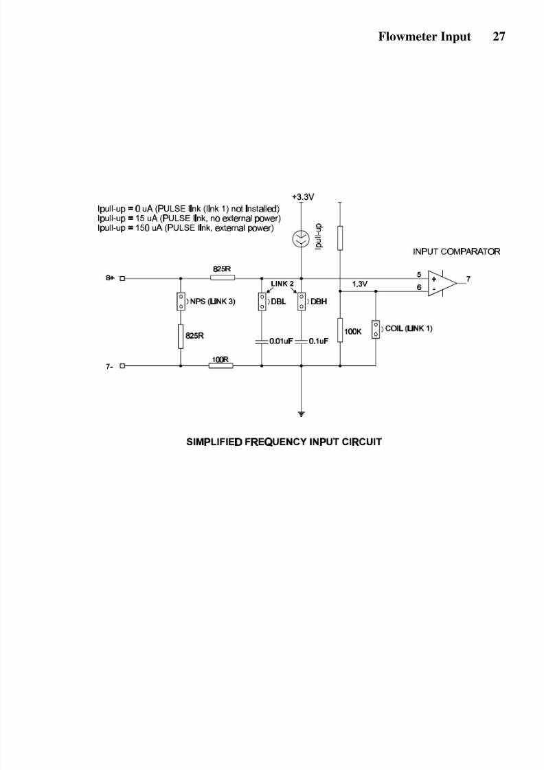
7. FLOWMETER INPUT
The Model 202D has an input conditioning circuit which will accept signals frommost pulse or frequency producing flowmeters. Links on the rear panel enable the
input circuit to be configured for different signal types.
The input will interface directly to:
♦ Turbine flowmeters.
♦ Open collector outputs.
♦ Reed switches.
♦ Logic signals.♦ Two-wire proximity switches.
The following pages give examples of interconnection to various signal outputs. A
circuit diagram of the input is also provided.
For pulse or logic type signals, the input switching threshold is 1.3 volts. That is,
the input signal must have a "low" voltage of less than 1.2 volts and a "high"
voltage of greater than 1.4 volts.
For flowmeters with coils, the minimum input voltage is 15mV P-P.
All inputs are protected for over voltage up to 28 volts.
8/6/2019 202D Manual
http://slidepdf.com/reader/full/202d-manual 31/48
Flowmeter Input 27

8/6/2019 202D Manual
http://slidepdf.com/reader/full/202d-manual 32/48
Flowmeter Input28
1. Squarewave, CMOS or Pulse
2. Open Collector
With 15µA/150µA internal pull up current
3. Reed Switch - Battery PoweredWith 15µA internal pull up current
Note: For a switch or reed input with contact bounce link DBL can be switched "on". This will
eliminate the effect of switch bounce while limiting the input frequency to 200Hz.
Link Settings
Link 1
Link 2
Link 3
COIL PULSE
DB DBH
NPS
Switching threshold voltage is 1.3 volts.
Link Settings
Link 1
Link 2
Link 3
COIL PULSE
DBL DBH
NPS
Link Settings
Link 1
Link 2
Link 3
COIL PULSE
DBL DBH
NPS
eg. Positive displacement flowmeters
with reed switch outputs.

8/6/2019 202D Manual
http://slidepdf.com/reader/full/202d-manual 33/48
Flowmeter Input 29
4. Reed Switch - External DC PowerWith 150µA internal pull up current
Note: For a switch or reed input with contact bounce link DBH can be switched "on". This will
eliminate the effect of switch bounce while limiting the input frequency to 200Hz.
5. Coils
Note: If the input has a very high impedance,
the following link settings should be used:
Link Settings
Link 1
Link 2
Link 3
COIL PULSE
DBL DBH
NPS
Link Settings
Link 1
Link 2
Link 3
COIL PULSE
DB DBH
NPS
825R input impedance
eg. Millivolt signal from paddlewheel
or turbine (15mV P-P minimum).
Link Settings
Link 1
Link 2
Link 3
COIL PULSE
DBL DBH
NPS

8/6/2019 202D Manual
http://slidepdf.com/reader/full/202d-manual 34/48
Flowmeter Input30
6. Namur Proximity Switch
Note: Use this connection for a DC powered version of the Model 202D.
7. Namur Proximity Switch - External DC Power
Note: Use this connection for battery or loop powered versions of the Model 202D.If a 4-20mA output is installed, the supply to the proximity switch must be isolated.
Link Settings
Link 1
Link 2
Link 3
COIL PULSE
DBL DBH
NPS
825R input impedance
For IS connections of Namur switches
see Section 8.
Link Settings
Link 1
Link 2
Link 3
COIL PULSE
DBL DBH
NPS
825R input impedance
For IS connections of Namur switches
see Section 8.

8/6/2019 202D Manual
http://slidepdf.com/reader/full/202d-manual 35/48
Intrinsic Safety Connections 31
8. INTRINSIC SAFETY
CONNECTIONSWhen installing the Model 202D in hazardous areas, the wiring and installation
must comply with appropriate installation standards.
The approval uses entity parameters on the input for connections to the flowmeter
and associated apparatus type approval for the 4-20mA output. The 4-20mA
output must, therefore, only be connected to barriers with the specified safety
parameters as shown on the following page.
8.1 COILS
The Model 202D will connect directly to a turbine flowmeter or paddlewheel with
a certified Intrinsically Safe (IS) coil or other certified IS sensor which produce a
pulse input provided they do not exceed the following input parameters:
Ui = 24V
Ii = 20mAPi = 320mW
The maximum allowed capacitance and inductance of the pulse or coil including
the cabling is:
Cext = 60µF
Lext = 1.5H
The internal capacitance and inductance of the Model 202D seen on the input arenegligibly small with Ci = 0.02uF and Li = 0mH. The maximum voltage and
current produced by the Model 202D on its inputs (terminals 8 & 7) are:
Uo = 10.0V (open circuit)
Io = 9.0mA (short circuit)

8/6/2019 202D Manual
http://slidepdf.com/reader/full/202d-manual 36/48
Intrinsic Safety Connections32
8.2 SIMPLE APPARATUS
Devices such as reed switches which can be classed as "simple apparatus", as
defined in the CENELEC standards EN50020, can be connected to the Model
202D without certification.
8.3 NAMUR PROXIMITY SWITCHES
Connection to certified Namur proximity switches is permitted as shown on the
following page with the following maximum input parameters:
Ui = 24VIi = 20mA
Pi = 320mW

8/6/2019 202D Manual
http://slidepdf.com/reader/full/202d-manual 37/48
Intrinsic Safety Connections 33

8/6/2019 202D Manual
http://slidepdf.com/reader/full/202d-manual 38/48
Intrinsic Safety Connections34

8/6/2019 202D Manual
http://slidepdf.com/reader/full/202d-manual 39/48
Intrinsic Safety Connections 35
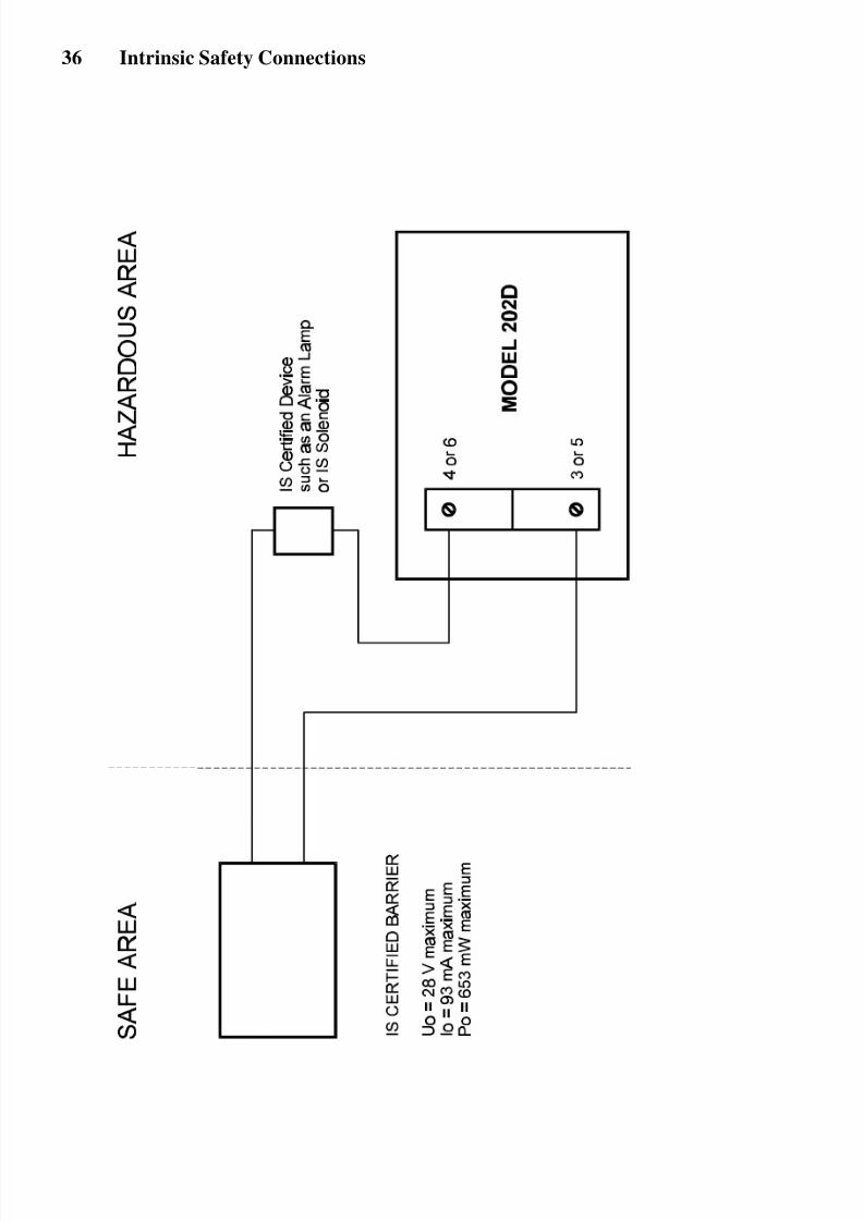
8.4 ALARM OUTPUTS
The low alarm and high alarm/pulse output can be connected to suitably certified
devices providing the circuit is protected with a barrier with the maximum safety
parameters:
Uo = 28V
Io = 93mA
Pmax = 0.653W
The input capacitance on these terminals is 0.1uF max and the inductance is
negligible.
Note that the two alarm outputs must be kept as independent IS circuits and each
protected with their own barrier. It is not permissible to connect these circuits via a
common barrier.
8/6/2019 202D Manual
http://slidepdf.com/reader/full/202d-manual 40/48
Intrinsic Safety Connections36

8/6/2019 202D Manual
http://slidepdf.com/reader/full/202d-manual 41/48
Installation 37
9. INSTALLATION
9.1 WALL MOUNTING
A wall mounting bracket is supplied with each instrument. Round head screws
should be used to attach the bracket to the wall (countersunk screws should not be
used). The bracket is mounted first with the tray section at the bottom. The
instrument is then mounted on the bracket with two screws as shown below.

8/6/2019 202D Manual
http://slidepdf.com/reader/full/202d-manual 42/48
Installation38
9.2 PANEL MOUNT VERSION
The panel mount version of the Model 202D is supplied with two panel mount
brackets and plug-in terminals which are accessible from the rear of the instrument.
A diagram of the rear panel is shown below:
Rear View of 202D Panel Mount Case
The cutout for the panel mount version is 141mm (5.55") wide x 87mm (3.43")
high.

8/6/2019 202D Manual
http://slidepdf.com/reader/full/202d-manual 43/48
Installation 39
9.3 REMOVING THE FRONT PANEL
The front panel should be removed as follows:
1. Remove the top and bottom cover strips (ie. the dark plastic strip) by
levering a screwdriver under one end.
2. Undo the screws retaining the front. Do not remove the screws, they are
retained by O-rings.
3. Remove the front panel from the housing.
To replace the front cover, follow the above procedure in reverse. Ensure that the
front panel is aligned at connector points before tightening the screws.

8/6/2019 202D Manual
http://slidepdf.com/reader/full/202d-manual 44/48
Installation40

8/6/2019 202D Manual
http://slidepdf.com/reader/full/202d-manual 45/48
Installation 41
9.4 THE MAIN ELECTRONICS
The front section of the housing contains the microprocessor and display. It is
possible to adjust the display contrast via a small potentiometer on the board. The
Display Contrast is shown below and this can be adjusted for optimum contrast.
Adjacent to this control is a RESET switch which can be used to reset the
microprocessor. Note that pressing this button will set all totals to zero.
BATTERY BATTERY
Battery Connector
Battery Connector
Display Contrast RESET
C O N T R E C
S Y S T E M S

8/6/2019 202D Manual
http://slidepdf.com/reader/full/202d-manual 46/48
Installation42
9.5 WIRING
When connecting the 202D it is good practice to use shielded cable. The shield
should be connected to earth at one end of the cable. The other end of the shield
should not be connected.
This wiring practice is mandatory in order to comply with the requirements for
Electromagnetic Compatibility as per EMC-Directive 89/336/EEC of the Council
of the European Community.

8/6/2019 202D Manual
http://slidepdf.com/reader/full/202d-manual 47/48
Installation 43
9.6 TERMINAL DESIGNATIONS
All versions
7 Pulse (-) / Coil Input
8 Pulse (+) / Coil Input
5 High Alarm (-) or Pulse Output (-) if installed
6 High Alarm (+) or Pulse Output (+) if installed
3 Low Alarm (-) if installed
4 Low Alarm (+) if installed
4-20mA Output
2 4-20mA (+)
1 4-20mA (-)
DC Power Versions
2 DC Power +9 to 28V1 DC Power 0V

8/6/2019 202D Manual
http://slidepdf.com/reader/full/202d-manual 48/48
Index44
Index4-20mA Output, 24
A
Accumulated Total, 8
Alarm Outputs, 35
B
Battery Powered, 21
C
CAL Sequences, 15
Cutoff Frequency, 16
D
DC Power, 22Decimal Point, 16, 17
Display, 6, 8
Display Test, 9
F
Filtering, 10
Flow Rate, 12
Frequency Cutoff, 14
H
High Alarm, 18
High Test, 9
I
L
Link Settings, 28
Low Alarm, 17
Low Test, 9
M
Model Number, 3
O
Operating
Temperature, 7Operation, 8
P
Panel Mount, 36
Programming, 15
Protection, 7
Pulse Output, 16
R
Rate, 8
Removing the Front
Panel, 37
Resettable Total, 8
S
Scaling Factor, 12, 16
Specification, 6
T
Temperature, 9
Terminal
Designations 41
W
Wall Mounting, 35