Embed Size (px)
Citation preview

Read this manual carefully before operating thisoutboard motor.
OWNER’S MANUAL
F9.9T9.9
LIT-18626-12-346DR-28199-38-E0
U6DR38E0.book Page 1 Tuesday, November 27, 2018 2:08 PM
©2021 Yamaha Motor Corporation

This productcan expose you to chemicalsincluding engine exhaust, whichis known to the State of Californiato cause cancer, and carbonmonoxide, which is known to theState of California to cause birthdefects or other reproductive harm.For more information go towww.P65Warnings.ca.gov.
WARNING:
Ce produit peut vous exposer à des produits chimiques y compris aux gaz d’échappement, qui sont considérés par l’état de Californie comme étant cancérigènes, et au monoxyde de carbone, qui est considéré par l’état de Californie comme un facteur de malformations congénitales ou d’autres troubles de la reproduction. Pour plus d’informations, rendez-vous sur www.P65Warnings.ca.gov.
ZMU08844
Read this manual carefully before operating this outboard motor. Keep thismanual onboard in a waterproof bag when boating. This manual should staywith the outboard motor if it is sold.
U6DR38E0.book Page 1 Tuesday, November 27, 2018 2:08 PM
©2021 Yamaha Motor Corporation

Important manual informationEMU44141
To the ownerThank you for selecting a Yamaha outboardmotor. This Owner’s Manual contains infor-mation needed for proper operation, mainte-nance and care. A thorough understanding ofthese simple instructions will help you obtainmaximum enjoyment from your new Yamaha.If you have any question about the operationor maintenance of your outboard motor,please consult a Yamaha dealer.In this Owner’s Manual particularly importantinformation is distinguished in the followingways.
: This is the safety alert symbol. It is usedto alert you to potential personal injury haz-ards. Obey all safety messages that followthis symbol to avoid possible injury or death.
WARNINGEWM00782
A WARNING indicates a hazardous situa-tion which, if not avoided, could result indeath or serious injury.
NOTICEECM00702
A NOTICE indicates special precautionsthat must be taken to avoid damage to theoutboard motor or other property.
TIP:A TIP provides key information to make pro-cedures easier or clearer.
Yamaha continually seeks advancements inproduct design and quality. Therefore, whilethis manual contains the most current prod-uct information available at the time of print-ing, there may be minor discrepancies
between your machine and this manual. Ifthere is any question concerning this manual,please consult your Yamaha dealer.To ensure long product life, Yamaha recom-mends that you use the product and performthe specified periodic inspections and main-tenance by correctly following the instruc-tions in the owner’s manual. Any damageresulting from neglect of these instructions isnot covered by warranty.Some countries have laws or regulations re-stricting users from taking the product out ofthe country where it was purchased, and itmay be impossible to register the product inthe destination country. Additionally, the war-ranty may not apply in certain regions. Whenplanning to take the product to another coun-try, consult the dealer where the product waspurchased for further information.If you purchased this outboard motor used,see your Yamaha dealer to have it registeredin your name in Yamaha records.
TIP:The F9.9MHB, F9.9EHB, F9.9EB, T9.9MHB,T9.9PHB, T9.9EB, T9.9PB, T9.9WHB and thestandard accessories are used as a base forthe explanations and illustrations in this man-ual. Therefore some items may not apply toevery model.EMU44152
F9.9, T9.9OWNER’S MANUAL
©2019 by Yamaha Motor Co., Ltd.1st Edition, October 2018
All rights reserved.Any reprinting or unauthorized usewithout the written permission of
Yamaha Motor Co., Ltd.is expressly prohibited.
Printed in Japan
U6DR38E0.book Page 1 Tuesday, November 27, 2018 2:08 PM
©2021 Yamaha Motor Corporation

Table of contents
Safety information.............................1Outboard motor safety.................... 1
Propeller ............................................. 1Rotating parts..................................... 1Hot parts ............................................ 1Electric shock..................................... 1Power tilt ............................................ 1Engine shut-off cord (lanyard) ............ 1Gasoline ............................................. 1Gasoline exposure and spills ............. 2Carbon monoxide .............................. 2Modifications...................................... 2
Boating safety ................................. 2Alcohol and drugs .............................. 2Personal flotation devices (PFDs) ...... 2People in the water ............................ 2Passengers......................................... 2Overloading........................................ 2Avoid collisions .................................. 3Collisions with floating or submerged
objects ............................................ 3Weather .............................................. 3Accident reporting.............................. 4Boat education and training............... 4Passenger training ............................. 4Boating safety publications................ 4Laws and regulations ......................... 4
Boating organizations ..................... 5Basic boating rules (Rules of the
road) ............................................. 5Steering and sailing rules and sound
signals............................................. 5Rules when encountering vessels...... 6Other special situations...................... 7
General information ..........................9Identification numbers record ......... 9
Outboard motor serial number........... 9Key number........................................ 9
Compliance mark label ................... 9Read manuals and labels.............. 11
Warning labels ................................. 11
Specifications and requirements ................................... 15
Specifications ............................... 15Installation requirements .............. 16
Boat horsepower rating.................... 16Mounting outboard motor ................ 17
Remote control requirements ....... 17Battery requirements .................... 17
Specifications of Battery .................. 17To install the battery......................... 17
Propeller selection ........................ 18Start-in-gear protection ................ 18Engine oil requirements ................ 19Fuel requirements ......................... 19
Gasoline ........................................... 19Gasoline Additives............................ 20
Muddy or acidic water .................. 21Anti-fouling paint .......................... 21Outboard motor disposal
requirements.............................. 22Emergency equipment.................. 22Emission control information ....... 22
Star labels ........................................ 22
Components.................................... 24Components diagram ................... 24
Fuel tank........................................... 26Fuel joint ........................................... 27Pressure relief tab ............................ 27Fuel tank cap.................................... 27Air vent screw................................... 27Remote control box.......................... 27Remote control lever ........................ 27Neutral interlock trigger.................... 28Neutral throttle lever......................... 28Choke switch.................................... 28Tiller handle ..................................... 28Gear shift lever ................................ 28Throttle grip ..................................... 29Throttle indicator ............................. 29Throttle friction adjuster ................... 29Engine shut-off cord (lanyard) and
clip ................................................ 30
U6DR38E0.book Page 1 Tuesday, November 27, 2018 2:08 PM
©2021 Yamaha Motor Corporation

Table of contents
Engine stop button .......................... 30Pull-type choke knob ....................... 31Manual starter handle ...................... 31Starter button ................................... 31Main switch ...................................... 31Power tilt switch............................... 32Steering friction adjuster .................. 32Trim rod (tilt pin) ............................... 33Tilt lock mechanism ......................... 33Tilt support knob .............................. 33Tilt support bar................................. 34Power tilt unit ................................... 34Cowling lock lever ............................ 34Flushing device ................................ 35Alert indicator .................................. 35
Instruments and indicators ............ 36Indicators ..................................... 36
Low oil pressure-alert indicator........ 36
Engine control system .................... 37Alert system .................................. 37
Low oil pressure alert ....................... 37
Installation .......................................38Installation ..................................... 38
Mounting the outboard motor .......... 38Clamping the outboard motor.......... 40
Operation ......................................... 41First-time operation....................... 41
Fill engine oil .................................... 41Breaking in engine............................ 41Getting to know your boat ............... 41
Checks before starting engine ...... 41Fuel level .......................................... 42Removing top cowling ..................... 42Fuel system ...................................... 42Controls............................................ 42Engine shut-off cord (lanyard) .......... 42Engine oil.......................................... 43Outboard motor ............................... 43Flushing device ................................ 43Install top cowling ............................ 44
Checking power tilt system.............. 44Battery.............................................. 45
Filling fuel...................................... 45Operating engine .......................... 47
Sending fuel (portable tank) ............. 47Starting engine ................................. 48
Checks after starting engine......... 56Cooling water ................................... 56
Warming up engine....................... 56Manual start and electric start
models .......................................... 56Checks after engine warm up....... 56
Shifting ............................................. 56Stop switches................................... 56
Shifting.......................................... 57Stopping boat ............................... 58Stopping engine............................ 58
Procedure......................................... 58Procedure......................................... 59
Trimming outboard motor............. 60Adjusting trim angle for manual tilt
models .......................................... 60Adjusting trim angle (power tilt
models) ......................................... 61Adjusting boat trim ........................... 62
Tilting up and down ...................... 62Procedure for tilting up (manual tilt
models) ......................................... 63Procedure for tilting up (power tilt
models) ......................................... 64Procedure for tilting down (manual
tilt models) .................................... 65Procedure for tilting down (power
tilt models) .................................... 65Shallow water .............................. 66
Cruising in shallow water (manual tilt models) .................................... 66
Power tilt models.............................. 67
U6DR38E0.book Page 2 Tuesday, November 27, 2018 2:08 PM
©2021 Yamaha Motor Corporation
Table of contents
Cruising in other conditions .......... 68
Maintenance .................................... 69Transporting and storing outboard
motor.......................................... 69Dismounting the outboard motor..... 69Storing outboard motor.................... 71Conditioning and stabilizing
gasoline......................................... 71Procedure......................................... 72Lubrication ....................................... 73Cleaning and anticorrosion
measures ...................................... 73Flushing power unit .......................... 73Cleaning the outboard motor ........... 74Checking painted surface of
outboard motor............................. 74Periodic maintenance ................... 75
Replacement parts ........................... 75Maintenance interval guidelines....... 75Maintenance chart 1 ........................ 76Maintenance chart 2 ........................ 78Greasing........................................... 79Cleaning and adjusting spark plug... 80Checking fuel filter ........................... 81Inspecting idle speed ....................... 81Changing engine oil.......................... 81Why Yamalube ................................. 83Inspecting wiring and connectors .... 84Checking propeller ........................... 84Removing propeller .......................... 84Installing propeller ............................ 85Changing gear oil ............................. 87Inspecting and replacing anode(s) ... 88Checking battery (for electric start
models) ......................................... 89Connecting the battery..................... 89Disconnecting the battery ................ 90
Trouble Recovery ............................ 91Troubleshooting ............................ 91Temporary action in emergency ... 94
Impact damage ................................ 94Replacing fuse ................................. 94
Power tilt will not operate................. 95Starter will not operate ..................... 95Emergency starting engine............... 96
Engine fails to operate .................. 97Emergency engine operation ........... 97
Treatment of submerged motor.... 97
Consumer information ................... 98YAMAHA FOUR-STROKE
OUTBOARD MOTOR THREE-YEAR LIMITED WARRANTY............................... 98
IMPORTANT WARRANTY INFORMATION IF YOU USE YOUR YAMAHA OUTSIDE THE U.S.A. OR CANADA................. 100
INDEX............................................. 101
U6DR38E0.book Page 3 Tuesday, November 27, 2018 2:08 PM
©2021 Yamaha Motor Corporation
1
Safety informationEMU33623
Outboard motor safetyObserve these precautions at all times.EMU36502
PropellerPeople can be injured or killed if they come incontact with the propeller. The propeller cankeep moving even when the motor is in neu-tral, and sharp edges of the propeller can cuteven when stationary. Stop the engine when a person is in the
water near you.Keep people out of reach of the propeller,
even when the engine is off.EMU40272
Rotating partsHands, feet, hair, jewelry, clothing, personalflotation device (PFD) straps, etc., can be-come entangled with internal rotating parts ofthe engine, resulting in serious injury ordeath.Keep the top cowling in place whenever pos-sible. Do not remove or replace the top cowl-ing with the engine running.Only operate the engine with the top cowlingremoved according to the specific instruc-tions in the manual. Keep hands, feet, hair,jewelry, clothing, PFD straps, etc., away fromany exposed moving parts.EMU33641
Hot partsDuring and after operation, engine parts arehot enough to cause burns. Avoid touchingany parts under the top cowling until the en-gine has cooled.EMU33651
Electric shockDo not touch any electrical parts while start-ing or operating the engine. They can causeshock or electrocution.
EMU34791
Power tiltBody parts can be crushed between the mo-tor and the clamp bracket when the motor istrimmed or tilted. Keep body parts out of thisarea at all times. Be sure no one is in this areabefore operating the power tilt mechanism.The power tilt switches operate even whenthe main switch is off. Keep people be awayfrom the switches whenever working aroundthe motor.Never get under the lower unit while it is tilted,even when the tilt support lever or knob islocked. Severe injury could occur if the out-board motor accidentally falls.EMU33672
Engine shut-off cord (lanyard)Attach the engine shut-off cord so that theengine stops if the operator falls overboard orleaves the helm. This prevents the boat fromrunning away under power and leaving peo-ple stranded, or running over people or ob-jects.Always attach the engine shut-off cord to asecure place on your clothing or your arm orleg while operating. Do not remove it to leavethe helm while the boat is moving. Do not at-tach the cord to clothing that could tearloose, or route the cord where it could be-come entangled, preventing it from function-ing.Do not route the cord where it is likely to beaccidentally pulled out. If the cord is pulledduring operation, the engine will shut off andyou will lose most steering control. The boatcould slow rapidly, throwing people and ob-jects forward.EMU33811
GasolineGasoline and its vapors are highly flamma-ble and explosive. Always, refuel accordingto the procedure on page 47 to reduce therisk of fire and explosion.
U6DR38E0.book Page 1 Tuesday, November 27, 2018 2:08 PM
©2021 Yamaha Motor Corporation

Safety information
2
EMU33821
Gasoline exposure and spillsTake care not to spill gasoline. If gasolinespills, wipe it up immediately with dry rags.Dispose of rags properly.If any gasoline spills onto your skin, immedi-ately wash with soap and water. Changeclothing if gasoline spills on it.If you swallow gasoline, inhale a lot of gaso-line vapor, or get gasoline in your eyes, getimmediate medical attention. Never siphonfuel by mouth.EMU33901
Carbon monoxideThis product emits exhaust gases which con-tain carbon monoxide, a colorless, odorlessgas which may cause brain damage or deathwhen inhaled. Symptoms include nausea,dizziness, and drowsiness. Keep cockpit andcabin areas well ventilated. Avoid blockingexhaust outlets.EMU33781
ModificationsDo not attempt to modify this outboard mo-tor. Modifications to your outboard motormay reduce safety and reliability, and renderthe outboard unsafe or illegal to use.EMU33742
Boating safetyThis section includes a few of the many im-portant safety precautions that you shouldfollow when boating.EMU33711
Alcohol and drugsNever operate after drinking alcohol or takingdrugs. Intoxication is one of the most com-mon factors contributing to boating fatalities.EMU40281
Personal flotation devices (PFDs)Have an approved PFD on board for everyoccupant. Yamaha recommends that youmust wear a PFD whenever boating. At aminimum, children and non-swimmers
should always wear PFDs, and everyoneshould wear PFDs when there are potentiallyhazardous boating conditions.EMU33732
People in the waterAlways watch carefully for people in the wa-ter, such as swimmers, skiers, or divers,whenever the engine is running. When some-one is in the water near the boat, shift intoneutral and stop the engine.Stay away from swimming areas. Swimmerscan be hard to see.The propeller can keep moving even whenthe motor is in neutral. Stop the engine whena person is in the water near you.EMU33752
PassengersConsult your boat manufacturer’s instruc-tions for details about appropriate passengerlocations in your boat and be sure all passen-gers are positioned properly before acceler-ating and when operating above an idlespeed. Standing or sitting in non-designatedlocations may result in being thrown eitheroverboard or within the boat due to waves,wakes, or sudden changes in speed or direc-tion. Even when people are positioned prop-erly, alert your passengers if you must makeany unusual maneuver. Always avoid jump-ing waves or wakes.EMU33763
OverloadingDo not overload the boat. Consult the boatcapacity plate or boat manufacturer for max-imum weight and number of passengers. Besure that weight is properly distributed ac-cording to the boat manufacturer’s instruc-tions. Overloading or incorrect weightdistribution can compromise the boat’s han-dling and lead to an accident, capsizing orswamping.
U6DR38E0.book Page 2 Tuesday, November 27, 2018 2:08 PM
©2021 Yamaha Motor Corporation

Safety information
3
EMU33773
Avoid collisionsScan constantly for people, objects, and oth-er boats. Be alert for conditions that limit yourvisibility or block your vision of others.
Operate defensively at safe speeds and keepa safe distance away from people, objects,and other boats.Do not follow directly behind other boats or
waterskiers. Avoid sharp turns or other maneuvers that
make it hard for others to avoid you or un-derstand where you are going.
Avoid areas with submerged objects orshallow water.
Ride within your limits and avoid aggres-sive maneuvers to reduce the risk of loss ofcontrol, ejection, and collision.
Take early action to avoid collisions. Re-member, boats do not have brakes, andstopping the engine or reducing throttlecan reduce the ability to steer. If you are notsure that you can stop in time before hittingan obstacle, apply throttle and turn in an-other direction.
EMU48100
Collisions with floating or submerged objectsIf the outboard motor hits a floating object oran obstacle in the water while cruising, thefollowing could occur:
The passengers and any loose equipmentor luggage could be thrown forward due tothe sudden deceleration.
Parts of the outboard motor could comeloose as a result of the impact and could bethrown into the boat.
The boat or outboard motor could be dam-aged as a result of the impact.
When you operate the boat in an area wherethere might be floating objects or obstacles inthe water, be sure to adjust the trim angle ofthe outboard motor, slow down, and operatecarefully. For further information, see page66.If the outboard motor hits a floating object oran obstacle in the water, make sure that thereare no abnormalities with the boat and theoutboard motor. If anything abnormal isfound, return to the nearest harbor at lowspeed and have a Yamaha dealer inspect theoutboard motor.
EMU33791
WeatherStay informed about the weather. Checkweather forecasts before boating. Avoidboating in hazardous weather.
ZMU06025
U6DR38E0.book Page 3 Tuesday, November 27, 2018 2:08 PM
©2021 Yamaha Motor Corporation

Safety information
4
EMU44161
Accident reportingBoat operators are required by law to file aBoating Accident Report with their boatinglaw enforcement agency if their boat is in-volved in any of the following accidents:1. There is loss of life or probable loss of
life.2. There is personal injury that requires
medical attention beyond first aid.3. There is property damage to boats or
other property over a certain amount.4. There is complete loss of a boat.Contact local law enforcement personnel if areport is necessary.EMU44172
Boat education and trainingFor U.S.A.Operators should take a boating safetycourse. This may be required in your state.Many of the organizations listed in the nextsection can provide information about cours-es in your area.You may also want to consider an Internet-based program for basic boater education.The Online Boating Safety Course providedby the BoatU.S. Foundation, is approved bythe National Association of State BoatingLaw Administrators (NASBLA) and recog-nized by the United States Coast Guard.Most, but not all, states accept this course tomeet their minimum requirements. While itcannot replace an in-depth course such asone offered by the U.S. Coast Guard, U.S.Power Squadron, or other organization, thisonline course does provide a general over-view of the basics in boating safety, require-ments, navigation, and operation. Uponsuccessful completion of the course, the usercan download a certificate of completion im-
mediately or, for a small charge, request oneby mail. To take this free course, go to boa-tus.org.For CanadaAll operators of pleasure craft must illustratecompetency by means of a Pleasure CraftOperators Card with the exception of Person-al Water Craft used for rental purposes whichrequire a rental checklist be completed. Plea-sure Craft Operators Cards can be obtainedfollowing the completion of a competencycourse, with an online option. Details can befound on Transport Canada’s website.www.tc.gc.caEMU33881
Passenger trainingMake sure at least one other passenger istrained to operate the boat in the event of anemergency.EMU33891
Boating safety publicationsBe informed about boating safety. Additionalpublications and information can be obtainedfrom many boating organizations.EMU33592
Laws and regulationsKnow the marine laws and regulations whereyou will be boating—and obey them. Severalsets of rules prevail according to geographiclocation, but all are basically the same as theInternational Rules of the Road. The rulespresented in the following section are con-densed—and have been provided for yourconvenience only.Contact the U.S. Coast Guard, the NationalAssociation of State Boating Law Administra-tors, or your local Power Squadron for a com-plete set of rules governing the waters inwhich you will be using your boat.
U6DR38E0.book Page 4 Tuesday, November 27, 2018 2:08 PM
©2021 Yamaha Motor Corporation

Safety information
5
EMU44182
Boating organizationsThe following organizations provide boatingsafety training and information about boatingsafety and laws.
In the U.S.A.United States Coast GuardConsumer Affairs Staff (G-BC)Office of Boating, Public, and Consumer Af-fairsU.S. Coast Guard HeadquartersWashington, D.C. 20593-0001http://www.uscgboating.org/
United States Power Squadrons1-888-FOR-USPS (1-888-367-8777)http://www.usps.org/
Boat Owners Association of The UnitedStates1-800-336-BOAT (1-800-336-2628)http://www.boatus.com/
National Association of State Boating LawAdministrators (NASBLA)1500 Leestown Road, Suite 330Lexington, KY 40511 859-225-9497http://www.nasbla.org/
National Marine Manufacturers Associa-tion (NMMA)200 East Randolph DriveSuite 5100Chicago, IL 60601http://www.nmma.org/
Marine Retailers Association of America155 N. Michigan Ave. Chicago,IL 60304http://www.mraa.com/
In CanadaNational Marine Manufacturers Associa-tion Canada14 McEwan DriveSuite 8Bolton, ONL7E 1H1http://www.nmma.org/
EMU33692
Basic boating rules (Rules of the road)
Just as there are rules that apply when youare driving on streets and highways, there arewaterway rules that apply when you are driv-ing your boat. These rules are used interna-tionally. (For U.S.A.: and are also enforced bythe United States Coast Guard and localagencies.) You should be aware of theserules, and follow them whenever you encoun-ter another vessel on the water.EMU33702
Steering and sailing rules and sound signalsWhenever two vessels on the water meet oneanother, one vessel has the right-of-way; it iscalled the “stand-on” vessel. The vessel thatdoes not have the right-of-way is called the“give-way” or “burdened” vessel. These rulesdetermine which vessel has the right-of-way,and what each vessel should do.
Stand-on vesselThe vessel with the right-of-way has the dutyto continue its course and speed, except toavoid an immediate collision. When youmaintain your direction and speed, the othervessel will be able to determine how best toavoid you.
U6DR38E0.book Page 5 Tuesday, November 27, 2018 2:08 PM
©2021 Yamaha Motor Corporation
Safety information
6
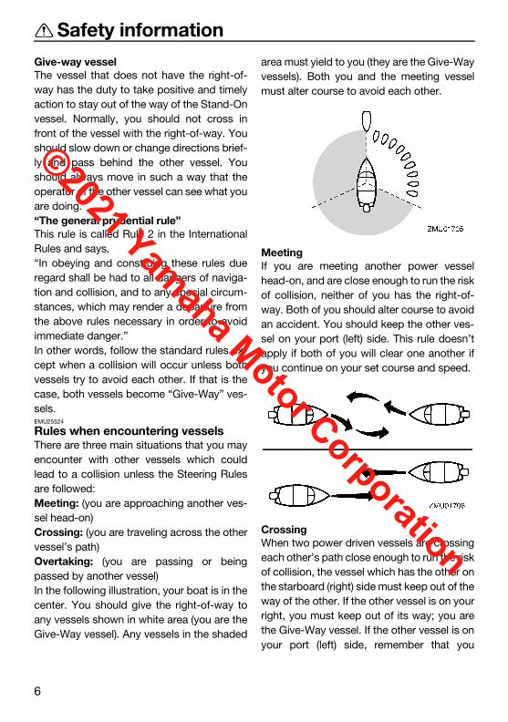
Give-way vesselThe vessel that does not have the right-of-way has the duty to take positive and timelyaction to stay out of the way of the Stand-Onvessel. Normally, you should not cross infront of the vessel with the right-of-way. Youshould slow down or change directions brief-ly and pass behind the other vessel. Youshould always move in such a way that theoperator of the other vessel can see what youare doing.“The general prudential rule”This rule is called Rule 2 in the InternationalRules and says,“In obeying and construing these rules dueregard shall be had to all dangers of naviga-tion and collision, and to any special circum-stances, which may render a departure fromthe above rules necessary in order to avoidimmediate danger.”In other words, follow the standard rules ex-cept when a collision will occur unless bothvessels try to avoid each other. If that is thecase, both vessels become “Give-Way” ves-sels.EMU25524
Rules when encountering vesselsThere are three main situations that you mayencounter with other vessels which couldlead to a collision unless the Steering Rulesare followed:Meeting: (you are approaching another ves-sel head-on)Crossing: (you are traveling across the othervessel’s path)Overtaking: (you are passing or beingpassed by another vessel)In the following illustration, your boat is in thecenter. You should give the right-of-way toany vessels shown in white area (you are theGive-Way vessel). Any vessels in the shaded
area must yield to you (they are the Give-Wayvessels). Both you and the meeting vesselmust alter course to avoid each other.
MeetingIf you are meeting another power vesselhead-on, and are close enough to run the riskof collision, neither of you has the right-of-way. Both of you should alter course to avoidan accident. You should keep the other ves-sel on your port (left) side. This rule doesn’tapply if both of you will clear one another ifyou continue on your set course and speed.
CrossingWhen two power driven vessels are crossingeach other’s path close enough to run the riskof collision, the vessel which has the other onthe starboard (right) side must keep out of theway of the other. If the other vessel is on yourright, you must keep out of its way; you arethe Give-Way vessel. If the other vessel is onyour port (left) side, remember that you
U6DR38E0.book Page 6 Tuesday, November 27, 2018 2:08 PM
©2021 Yamaha Motor Corporation
Safety information
7
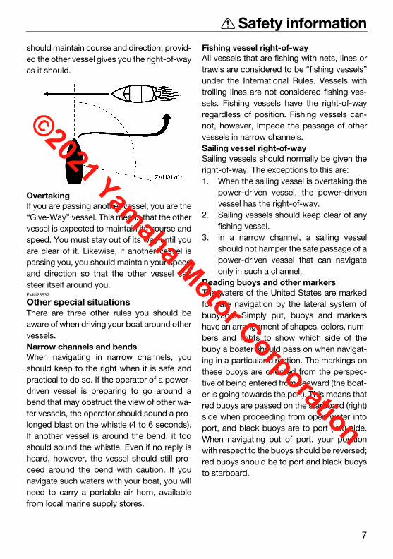
should maintain course and direction, provid-ed the other vessel gives you the right-of-wayas it should.
OvertakingIf you are passing another vessel, you are the“Give-Way” vessel. This means that the othervessel is expected to maintain its course andspeed. You must stay out of its way until youare clear of it. Likewise, if another vessel ispassing you, you should maintain your speedand direction so that the other vessel cansteer itself around you.EMU25532
Other special situationsThere are three other rules you should beaware of when driving your boat around othervessels.Narrow channels and bendsWhen navigating in narrow channels, youshould keep to the right when it is safe andpractical to do so. If the operator of a power-driven vessel is preparing to go around abend that may obstruct the view of other wa-ter vessels, the operator should sound a pro-longed blast on the whistle (4 to 6 seconds).If another vessel is around the bend, it tooshould sound the whistle. Even if no reply isheard, however, the vessel should still pro-ceed around the bend with caution. If younavigate such waters with your boat, you willneed to carry a portable air horn, availablefrom local marine supply stores.
Fishing vessel right-of-wayAll vessels that are fishing with nets, lines ortrawls are considered to be “fishing vessels”under the International Rules. Vessels withtrolling lines are not considered fishing ves-sels. Fishing vessels have the right-of-wayregardless of position. Fishing vessels can-not, however, impede the passage of othervessels in narrow channels.Sailing vessel right-of-waySailing vessels should normally be given theright-of-way. The exceptions to this are:1. When the sailing vessel is overtaking the
power-driven vessel, the power-drivenvessel has the right-of-way.
2. Sailing vessels should keep clear of anyfishing vessel.
3. In a narrow channel, a sailing vesselshould not hamper the safe passage of apower-driven vessel that can navigateonly in such a channel.
Reading buoys and other markersThe waters of the United States are markedfor safe navigation by the lateral system ofbuoyage. Simply put, buoys and markershave an arrangement of shapes, colors, num-bers and lights to show which side of thebuoy a boater should pass on when navigat-ing in a particular direction. The markings onthese buoys are oriented from the perspec-tive of being entered from seaward (the boat-er is going towards the port). This means thatred buoys are passed on the starboard (right)side when proceeding from open water intoport, and black buoys are to port (left) side.When navigating out of port, your positionwith respect to the buoys should be reversed;red buoys should be to port and black buoysto starboard.
U6DR38E0.book Page 7 Tuesday, November 27, 2018 2:08 PM
©2021 Yamaha Motor Corporation

Safety information
8
Many bodies of water used by boaters areentirely within the boundaries of a particularstate. The Uniform State Waterway MarkingSystem has been devised for these waters.This system uses buoys and signs with dis-tinctive shapes and colors to show regulatoryor advisory information. These markers are
white with black letters and orange boarders.They signify speed zones, restricted areas,danger areas, and general information.Remember, markings may vary by geograph-ic location. Always consult local boating au-thorities before driving your boat in unfamiliarwaters.
ZMU01708
U6DR38E0.book Page 8 Tuesday, November 27, 2018 2:08 PM
©2021 Yamaha Motor Corporation
General information
9
EMU25172
Identification numbers recordEMU25186
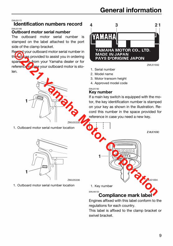
Outboard motor serial numberThe outboard motor serial number isstamped on the label attached to the portside of the clamp bracket.Record your outboard motor serial number inthe spaces provided to assist you in orderingspare parts from your Yamaha dealer or forreference in case your outboard motor is sto-len.
EMU25192
Key numberIf a main key switch is equipped with the mo-tor, the key identification number is stampedon your key as shown in the illustration. Re-cord this number in the space provided forreference in case you need a new key.
EMU46133
Compliance mark labelEngines affixed with this label conform to theregulations for each country.This label is affixed to the clamp bracket orswivel bracket.
1. Outboard motor serial number location
1. Outboard motor serial number location
1
ZMU05335
1
ZMU05336
1. Serial number2. Model name3. Motor transom height4. Approved model code
1. Key number
34 12
ZMU01692
1
ZMU01694
U6DR38E0.book Page 9 Tuesday, November 27, 2018 2:08 PM
©2021 Yamaha Motor Corporation

General information
10
Regulatory Compliance Mark (RCM)Engines affixed with this mark conform tocertain portion(s) of the Australian RadioCommunications Act.
ICES-002 Compliance LabelEngines affixed with this mark meet all re-quirements of the Canadian InterferenceCausing Equipment Regulations.
1. Compliance mark label location
1. Regulatory Compliance Mark (RCM)
1. ICES-002 Compliance Label
ZMU081901
ZMU08191
1
U6DR38E0.book Page 10 Tuesday, November 27, 2018 2:08 PM
©2021 Yamaha Motor Corporation

General information
11
EMU33524
Read manuals and labelsBefore operating or working on this outboard motor:Read this manual.Read any manuals supplied with the boat.Read all labels on the outboard motor and the boat.If you need any additional information, contact your Yamaha dealer.EMU33836
Warning labels If these labels are damaged or missing, contact your Yamaha dealer for replacements.F9.9MHB, T9.9MHB, T9.9WHB
U6DR38E0.book Page 11 Tuesday, November 27, 2018 2:08 PM
©2021 Yamaha Motor Corporation

General information
12
F9.9EHB, F9.9EB, T9.9PHB, T9.9EB, T9.9PB
U6DR38E0.book Page 12 Tuesday, November 27, 2018 2:08 PM
©2021 Yamaha Motor Corporation

General information
13
EMU33913
Contents of labelsThe above warning labels mean as follows.1
WARNINGEWM01692
Emergency starting does not have start-in-gear protection. Ensure shift control isin neutral before starting engine.
2
WARNINGEWM01682
Keep hands, hair, and clothing awayfrom rotating parts while the engine isrunning.
Do not touch or remove electrical partswhen starting or during operation.
3
WARNINGEWM01672
Read Owner’s Manuals and labels.Wear an approved personal flotation de-
vice (PFD).Attach engine shut-off cord (lanyard) to
your PFD, arm, or leg so the enginestops if you accidentally leave the helm,which could prevent a runaway boat.
6EE-G2794-40
6EE-H1994-406EE-H1995-40
1 2
3
6EE-G2794-50
6EE-H1994-506EE-H1995-50
ZMU05740
U6DR38E0.book Page 13 Tuesday, November 27, 2018 2:08 PM
©2021 Yamaha Motor Corporation
General information
14
EMU35133
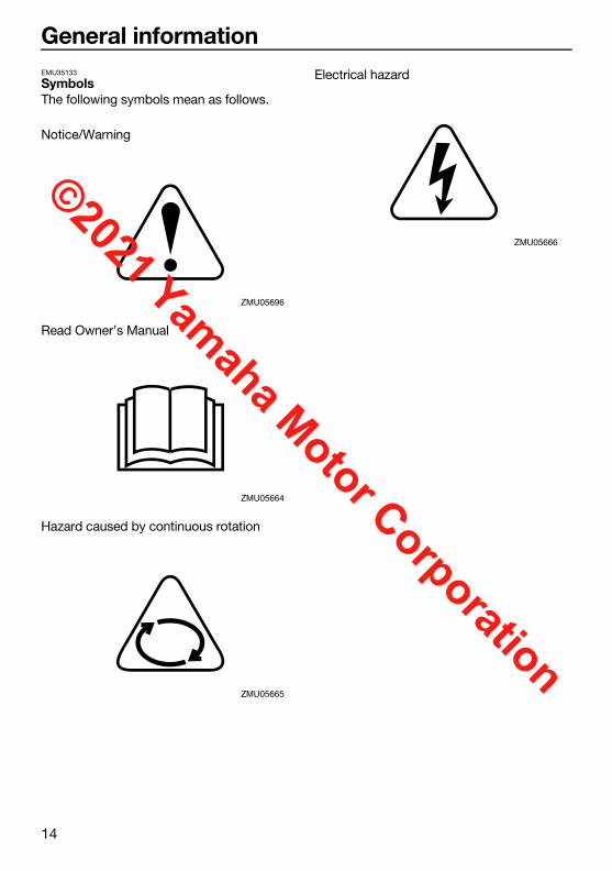
SymbolsThe following symbols mean as follows.
Notice/Warning
Read Owner’s Manual
Hazard caused by continuous rotation
Electrical hazard
ZMU05696
ZMU05664
ZMU05665
ZMU05666
U6DR38E0.book Page 14 Tuesday, November 27, 2018 2:08 PM
©2021 Yamaha Motor Corporation

Specifications and requirements
15
EMU38092
SpecificationsTIP:“(AL)” stated in the specification data belowrepresents the numerical value for the alumi-num propeller installed.EMU2821Z
Dimension and weight:Overall length:
1043 mm (41.1 in) (T9.9MHB, T9.9PHB, T9.9WHB)557 mm (21.9 in) (F9.9EB, T9.9EB, T9.9PB)983 mm (38.7 in) (F9.9EHB, F9.9MHB)
Overall width:333 mm (13.1 in) (F9.9EB, T9.9EB, T9.9PB)371 mm (14.6 in) (T9.9MHB, T9.9PHB, T9.9WHB)373 mm (14.7 in) (F9.9EHB, F9.9MHB)
Overall height S:1008 mm (39.7 in) (F9.9EB, F9.9EHB, F9.9MHB)
Overall height L:1135 mm (44.7 in) (F9.9EHB, F9.9MHB)1195 mm (47.0 in) (T9.9EB, T9.9MHB, T9.9PB, T9.9PHB, T9.9WHB)
Overall height X:1263 mm (49.7 in) (T9.9EB, T9.9PB, T9.9PHB, T9.9WHB)
Motor transom height S:431 mm (17.0 in) (F9.9EB, F9.9EHB, F9.9MHB)
Motor transom height L:552 mm (21.7 in) (T9.9EB, T9.9MHB, T9.9WHB)557 mm (21.9 in) (T9.9PB, T9.9PHB)558 mm (22.0 in) (F9.9EHB, F9.9MHB)
Motor transom height X:620 mm (24.4 in) (T9.9EB, T9.9WHB)625 mm (24.6 in) (T9.9PB, T9.9PHB)
Dry weight (AL) S:40 kg (88 lb) (F9.9MHB)42 kg (93 lb) (F9.9EB)44 kg (97 lb) (F9.9EHB)
Dry weight (AL) L:41 kg (90 lb) (F9.9MHB)45 kg (99 lb) (F9.9EHB, T9.9EB, T9.9MHB)47 kg (104 lb) (T9.9WHB)49 kg (108 lb) (T9.9PB)52 kg (115 lb) (T9.9PHB)
Dry weight (AL) X:46 kg (101 lb) (T9.9EB)48 kg (106 lb) (T9.9WHB)50 kg (110 lb) (T9.9PB)53 kg (117 lb) (T9.9PHB)
Performance:Full throttle operating range:
5000–6000 r/minRated power:
7.3 kW (9.9 HP)Idle speed (in neutral):
1000–1100 r/minPower unit:
Type:4-stroke SOHC L2 4 valves
Total displacement:212 cm³ (12.9 c.i.)
Bore × stroke:56.0 × 43.0 mm (2.20 × 1.69 in)
Ignition system:CDI
Spark plug (NGK):BR6HS-10
Spark plug gap:0.9–1.0 mm (0.035–0.039 in)
Steering system:Remote steering (F9.9EB, T9.9EB, T9.9PB)Tiller handle (F9.9EHB, F9.9MHB, T9.9MHB, T9.9PHB, T9.9WHB)
U6DR38E0.book Page 15 Tuesday, November 27, 2018 2:08 PM
©2021 Yamaha Motor Corporation

Specifications and requirements
16
Starting system:Electric starter (F9.9EB, F9.9EHB, T9.9EB, T9.9PB, T9.9PHB)Manual starter (F9.9MHB, T9.9MHB)Manual starter and Electric starter (T9.9WHB)
Starting carburetion system:Choke valve
Valve clearance IN (cold engine):0.15–0.20 mm (0.0059–0.0079 in)
Valve clearance EX (cold engine):0.20–0.25 mm (0.0079–0.0098 in)
Battery rating (CCA/SAE):245–433 A
Battery rating (MCA/ABYC):323–520 A
Battery rating (RC/SAE):52 minutes
Maximum generator output:6 A
Lower unit:Gear shift positions:
Forward-neutral-reverseGear ratio:
2.08 (27/13) (F9.9EB, F9.9EHB, F9.9MHB)2.92 (38/13) (T9.9EB, T9.9MHB, T9.9PB, T9.9PHB, T9.9WHB)
Trim and tilt system:Manual tilt (F9.9EB, F9.9EHB, F9.9MHB, T9.9EB, T9.9MHB, T9.9WHB)Power tilt (T9.9PB, T9.9PHB)
Propeller mark:N (F9.9EB, F9.9EHB, F9.9MHB)R (T9.9EB, T9.9MHB, T9.9PB, T9.9PHB, T9.9WHB)
Fuel and oil:Recommended fuel:
Regular unleaded gasoline
Min. pump octane number (PON):86
Fuel tank capacity:12 L (3.17 US gal, 2.64 Imp.gal)
Recommended engine oil:YAMALUBE 4M FC-W or 4-stroke outboard motor oil
Recommended engine oil grade 1:SAE 10W-30/10W-40/5W-30 API SE/SF/SG/SH/SJ/SL
Engine oil quantity:0.8 L (0.85 US qt, 0.70 Imp.qt)
Lubrication system:Wet sump
Recommended gear oil:Yamalube Marine Gearcase Lube or Hypoid gear oil
Recommended gear oil grade:SAE 90 API GL-4
Gear oil quantity:0.150 L (0.159 US qt, 0.132 Imp.qt) (F9.9EB, F9.9EHB, F9.9MHB)0.370 L (0.391 US qt, 0.326 Imp.qt) (T9.9EB, T9.9MHB, T9.9PB, T9.9PHB, T9.9WHB)
EMU33556
Installation requirementsEMU33566
Boat horsepower rating
WARNINGEWM01561
Overpowering a boat can cause severe in-stability.
Before installing the outboard motor(s), con-firm that the total horsepower of your out-board motor(s) does not exceed the boat’smaximum horsepower rating. See the boat’scapacity plate or contact the manufacturer.
U6DR38E0.book Page 16 Tuesday, November 27, 2018 2:08 PM
©2021 Yamaha Motor Corporation

Specifications and requirements
17
EMU40491
Mounting outboard motor
WARNINGEWM02501
Improper mounting of the outboard mo-tor could result in hazardous conditionssuch as poor handling, loss of control,or fire hazards.
Because the outboard motor is veryheavy, special equipment and training isrequired to mount it safely.
Your dealer or other person experienced inproper rigging should mount the outboardmotor using correct equipment and completerigging instructions. For further information,see page 38.EMU33582
Remote control requirements
WARNINGEWM01581
If the engine starts in gear, the boat canmove suddenly and unexpectedly, pos-sibly causing a collision or throwingpassengers overboard.
If the engine ever starts in gear, thestart-in-gear protection device is notworking correctly and you should dis-continue using the outboard. Contactyour Yamaha dealer.
The remote control unit must be equippedwith a start-in-gear protection device(s). Thisdevice prevents the engine from starting un-less it is in neutral.EMU25695
Battery requirementsEMU25717
Specifications of BatteryUse a fully charged battery that meets the fol-lowing specifications. The engine cannot bestarted if battery voltage is too low.
NOTICEECM01064
Do not use a battery that does not meetthe specified capacity. If a battery thatdoes not meet specifications is used,the electric system could perform poor-ly or be overloaded, causing electricsystem damage.
Do not use a battery which exceeds themaximum CCA rating. If the batteriesare used in parallel circuit, use new bat-teries of the same type and make surethat the total battery rating never ex-ceeds the maximum CCA rating.
EMU36293
Mounting batteryMount the battery holder securely in a dry,well-ventilated, vibration-free location in theboat. WARNING! Do not put flammableitems, or loose heavy or metal objects inthe same compartment as the battery.Fire, explosion or sparks could result.[EWM01821]
Battery cableThe battery cable size and length are critical.Consult your Yamaha dealer about the bat-tery cable size and length.EMU44771
To install the battery
NOTICEECM01091
A battery cannot be connected to modelsthat do not have a rectifier or RectifierRegulator.
Battery rating (CCA/SAE):245–433 A
Battery rating (MCA/ABYC):323–520 A
Battery rating (RC/SAE):52 minutes
U6DR38E0.book Page 17 Tuesday, November 27, 2018 2:08 PM
©2021 Yamaha Motor Corporation

Specifications and requirements
18
If you wish to use a battery, your outboardmotor must be equipped with the followingparts.Rectifier or Rectifier Regulator Lighting coilIf you do not know if your outboard motor isequipped with these parts, consult yourYamaha dealer.Install an optional Rectifier Regulator or useaccessories rated to withstand 18 volts orhigher with the above models. Consult yourYamaha dealer for details on installing an op-tional Rectifier Regulator.EMU34196
Propeller selectionNext to selecting an outboard motor, select-ing the right propeller is one of the most im-portant purchasing decisions a boater canmake. The type, size, and design of your pro-peller have a direct impact on acceleration,top speed, fuel economy, and even enginelife. Yamaha designs and manufactures pro-pellers for every Yamaha outboard motor andevery application.Your outboard motor came with a Yamahapropeller selected to perform well over arange of applications, but there may be useswhere a different propeller would be moreappropriate.Your Yamaha dealer can help you select theright propeller for your boating needs. Selecta propeller that will allow the engine to reachthe middle or upper half of the operatingrange at full throttle with the maximum boat-load. Generally, select a larger pitch propellerfor a smaller operating load and a smallerpitch propeller for a heavier load. If you carryloads that vary widely, select the propellerthat lets the engine run in the proper range foryour maximum load but remember that you
may need to reduce your throttle setting tostay within the recommended engine speedrange when carrying lighter loads.To check the propeller, see page 84.
EMU25771
Start-in-gear protectionYamaha outboard motors or Yamaha-ap-proved remote control units are equippedwith start-in-gear protection device(s). Thisfeature permits the engine to be started onlywhen it is in neutral. Always select neutral be-fore starting the engine.
1. Propeller diameter in inches2. Propeller pitch in inches3. Type of propeller (propeller mark)
1. Propeller diameter in inches2. Propeller pitch in inches3. Type of propeller (propeller mark)
ZMU04606
-x1 2 3
ZMU04604
-x1 2 3
U6DR38E0.book Page 18 Tuesday, November 27, 2018 2:08 PM
©2021 Yamaha Motor Corporation

Specifications and requirements
19
EMU39693
Engine oil requirementsSelect an oil grade according to the averagetemperatures in the area where the outboardmotor will be used.
If oil grades listed under Recommended en-gine oil grade 1 are not available, select an al-ternative oil grade listed underRecommended engine oil grade 2.Recommended engine oil grade 1
Recommended engine oil grade 2
EMU36361
Fuel requirementsEMU41333
GasolineUse a good quality gasoline that meets theminimum octane requirement. If knocking orpinging occurs, use a different brand of gas-oline or premium unleaded fuel. Yamaha rec-ommends that you use alcohol-free gasoline(see Gasoline with Ethanol) whenever possi-ble.The use of a poor quality gasoline may resultin starting and running problems. If you en-counter drivability problems, which you sus-pect could be related to the fuel you areusing, Yamaha recommends that you switchto a recognized high quality brand of gaso-line, such as a gasoline that is advertised asTop Tier Detergent Gasoline. NOTICE: Fail-ure to comply with these recommenda-tions may also result in unscheduledmaintenance, fuel system damage, and in-ternal engine damage. [ECM04480]
NOTICEECM01982
Do not use leaded gasoline. Leadedgasoline can seriously damage the en-gine.
Avoid getting water and contaminants inthe fuel tank. Contaminated fuel cancause poor performance or engine dam-age. Use only fresh gasoline that hasbeen stored in clean containers.
Gasoline with EthanolTwo types of gasoline are commonly avail-able in the U.S.A. and Canada for use in au-tomobiles and boats: conventional gasoline
Recommended engine oil:YAMALUBE 4M FC-W or 4-stroke outboard motor oil
Recommended engine oil grade 1:SAE 10W-30/10W-40/5W-30 API SE/SF/SG/SH/SJ/SL
Recommended engine oil grade 2:SAE 15W-40/20W-40/20W-50 API SH/SJ/SL
Engine oil quantity:0.8 L (0.85 US qt, 0.70 Imp.qt)
ZMU06854
122˚F
50˚C
104
40
86
30
68
SAE API
SESFSGSHSJSL
20
50
10
32
0
14
-10
-4
-20
10W–30
10W–40
5W–30
ZMU06855
122˚F
50˚C
104
40
86
30
68
SAE API
SHSJSL
20
50
10
32
0
14
-10
-4
-20
15W–40
20W–40
20W–50
Recommended fuel:Regular unleaded gasoline
Min. pump octane number (PON):86
U6DR38E0.book Page 19 Tuesday, November 27, 2018 2:08 PM
©2021 Yamaha Motor Corporation

Specifications and requirements
20
without Ethanol and gasoline with Ethanol,which is typically referred to as E10 gasoline.According to federal regulations, E10 gaso-line may contain up to 10% Ethanol.A high quality gasoline without Ethanol is thepreferred fuel for your Yamaha outboard mo-tor. However, if gasoline with Ethanol is theonly fuel available in your area, your Yamahaoutboard motor is calibrated to run properlyon fresh E10 gasoline that meets the mini-mum octane requirement specified for thismodel.
NOTICEECM02402
Never use a gasoline for your outboardmotor that contains more than 10% Etha-nol, such as E15 which contains 15% Eth-anol or E85 which contains 85% Ethanol,or gasoline containing any amount ofMethanol. These fuels can cause startingand running problems, as well as seriousfuel system and internal engine damage.
Gasoline containing ethanol has severalproperties that may cause boat fuel systemproblems. Ethanol is a strong solvent (cleaning agent)
that can clean gum and varnish depositsfrom a boat’s fuel system, particularly inolder boats, as well as tanks and pipesused in gasoline distribution. These re-leased deposits contaminate the fuel andcan cause problems, such as clogged fuelfilters, carburetors, or fuel injectors, whichcould result in engine damage.
Ethanol may dissolve resins used in theconstruction of fiberglass fuel tanks. Thedissolved resins contaminate the fuel andcan cause problems, such as clogged fuelfilters, carburetors, or fuel injectors, whichcould result in engine damage.
Ethanol is hygroscopic (has a strong at-traction to water). Therefore, any water thatinadvertently enters the fuel system, in-cluding moisture that is absorbed from theair, will mix with the ethanol in the gasoline.If the amount of water is excessive, the eth-anol and water mixture will separate fromthe gasoline in a layer at the bottom of thefuel tank. This ethanol and water mixture isvery corrosive to aluminum fuel tanks andfuel system components.
The usable life span of E10 gasoline maybe shorter than the normal length of off-season boat storage, causing starting andrunning problems related to stale fuel.
For more information on using fuel containingethanol, visit: http://www.yamaha-mo-tor.comGasoline FiltrationYamaha outboard motors are equipped withinternal fuel filters. However, excessive wateror debris entering your engine’s fuel systemcould prematurely clog the internal filters,causing starting and running problems, fuelsystem damage, and internal engine dam-age. Therefore, it is recommended that an ex-ternal 10-micron water-separating fuel filterbe installed on your boat and serviced fre-quently. Consult your authorized Yamahadealer for a 10-micron filter that meets yourengine’s requirements.EMU41342
Gasoline AdditivesGasoline blends change to meet automobileemission regulations and economic condi-tions. Additives, added by gasoline distribu-tors, necessary for proper automobile engineoperation and durability, may not be suffi-cient for typical boat applications. Intakevalve and combustion chamber depositsmay accumulate in boat engines more rapidlythan encountered in automotive use. In addi-
U6DR38E0.book Page 20 Tuesday, November 27, 2018 2:08 PM
©2021 Yamaha Motor Corporation

Specifications and requirements
21
tion, gasoline used for boating will typicallyage longer between refills than gasoline usedin automobiles, resulting in stale and unus-able gasoline that may cause starting andrunning problems, fuel system damage, andinternal engine damage.Yamaha recommends the use of twoYamalube gasoline additives to reduce inter-nal deposits and extend the storage life ofgasoline. Continuous use of Yamalube RingFree Fuel Additive Plus reduces harmful inter-nal deposits. Yamalube Fuel Stabilizer &Conditioner Plus added to fresh gasoline willhelp protect the fuel system from varnishingwhile helping to keep the gasoline’s octanelevel from decreasing excessively duringstorage. Other additives may also be avail-able on the market that may have varying de-grees of effectiveness. Consult your Yamahadealer concerning what may work best forthe locally available gasoline and environ-mental conditions.EMU36881
Muddy or acidic waterYamaha strongly recommends that you haveyour dealer install the optional chromium-plated water pump kit if you use the outboardmotor in muddy or acidic water conditions.However, depending on the model it mightnot be required.EMU41354
Anti-fouling paintA clean hull is required to maintain yourboat’s performance. Boats moored in the wa-ter should be protected from marine growth(barnacles, mussels, and marine plants). Ifapproved by regulations for your area, thebottom of the hull can be coated with an anti-fouling paint to inhibit marine growth.Anti-fouling paints specifically formulated foruse on aluminum may be applied to the out-board motor. The original Yamaha paint sur-
face may be scuffed lightly before applyinganti-fouling paint, but do not remove the orig-inal paint. Removal of the original paint will in-crease the rate of corrosion.
NOTICEECM04821
Anti-fouling paint for fiberglass andwood may contain materials, such ascopper, graphite, and tin, that can causecorrosion if applied to aluminum boatsand outboard motor components. Neverapply these types of paint to your out-board motor because rapid corrosiondamage could occur.
Anti-fouling paint can increase drag(friction) between the boat and the wa-ter, and possibly affect performance. Ifthe effects are too great, reducing pro-peller pitch may be necessary.
Sacrificial anodes are attached to the out-board motor to provide corrosion protectionand must never be painted.Sacrificial anodes made from a different ma-terial may be necessary for maximum corro-sion protection due to your local waterconditions. Please consult your Yamahadealer.
U6DR38E0.book Page 21 Tuesday, November 27, 2018 2:08 PM
©2021 Yamaha Motor Corporation

Specifications and requirements
22
NOTICEECM02421
Painted sacrificial anodes will not providecorrosion protection.
EMU40302
Outboard motor disposal re-quirements
Never illegally discard (dump) the outboardmotor. Yamaha recommends consulting thedealer about discarding the outboard motor.EMU36353
Emergency equipmentKeep the following items onboard in casethere is trouble with the outboard motor. A tool kit with assorted screwdrivers, pliers,
wrenches (including metric sizes), andelectrical tape.
Waterproof flashlight with extra batteries. An extra engine shut-off cord (lanyard) with
clip. Spare parts, such as an extra set of spark
plugs.Consult your Yamaha dealer for details.EMU25223
Emission control information EMU25232
This engine conforms to U.S. EnvironmentalProtection Agency (EPA) regulations for ma-rine SI engines. See the label affixed to yourengine for details.EMU25245
Approval label of emission control certifi-cateThis label is attached at the location shown.New Technology; (4-stroke/HPDI) EM
EMU25275
Star labelsYour outboard motor is labeled with a Califor-nia Air Resources Board (CARB) star label.See below for a description of your particularlabel.
1. Approval label location
1. Star label location
1
ZMU07795
EMISSION CONTROL INFORMATION
THIS ENGINE CONFORMS TO CALIFORNIA EXHAUST AND U.S. EPA EXHAUST AND EVAP REGULATIONS
FOR SI MARINE ENGINES. REFER TO OWNER’S MANUAL FOR MAINTENANCE SPECIFICATIONS AND ADJUSTMENTS.
FAMILY: MAX POWER: kW DISPLACEMENT: liters EPA/CA FEL: HC + NOx
, CO
g/kW
-h
YAMAHA MOTOR CO.,LTD.
1
ZMU07797
U6DR38E0.book Page 22 Tuesday, November 27, 2018 2:08 PM
©2021 Yamaha Motor Corporation

Specifications and requirements
23
EMU40331
One Star—Low EmissionThe one-star label identifies engines thatmeet the Air Resources Board’s PersonalWatercraft and Outboard marine engine 2001exhaust emission standards. Engines meet-ing these standards have 75% lower emis-sions than conventional carbureted two-stroke engines. These engines are equivalentto the U.S. EPA’s 2006 standards for marineengines.
EMU40341
Two Stars—Very Low EmissionThe two-star label identifies engines thatmeet the Air Resources Board’s PersonalWatercraft and Outboard marine engine 2004exhaust emission standards. Engines meet-ing these standards have 20% lower emis-sions than One Star-Low-Emission engines.
EMU40351
Three Stars—Ultra Low EmissionThe three-star label identifies engines thatmeet the Air Resources Board’s PersonalWatercraft and Outboard marine engine 2008exhaust emission standards or the Sterndriveand Inboard marine engine 2003-2008 ex-haust emission standards. Engines meetingthese standards have 65% lower emissionsthan One Star-Low-Emission engines.
EMU33862
Four Stars—Super Ultra Low EmissionThe four-star label identifies engines thatmeet the Air Resources Board’s Sterndriveand Inboard marine engine 2009 exhaustemission standards. Personal Watercraft andOutboard marine engines may also complywith these standards. Engines meeting thesestandards have 90% lower emissions thanOne Star-Low-Emission engines.
ZMU01702
ZMU01703
ZMU01704
ZMU05663
U6DR38E0.book Page 23 Tuesday, November 27, 2018 2:08 PM
©2021 Yamaha Motor Corporation

Components
24
EMU46722
Components diagramTIP:* May not be exactly as shown; also may not be included as standard equipment on all models(order from dealer).F9.9MHB, F9.9EHB, F9.9EB
1
7
8
9
2
3
4
5
6
11
10
1. Top cowling2. Clamp bracket3. Trim rod4. Drain screw5. Cooling water inlet6. Propeller7. Cowling lock lever8. Idle hole9. Anti-cavitation plate10.Remote control box (side mount type)*11.Fuel tank*
U6DR38E0.book Page 24 Tuesday, November 27, 2018 2:08 PM
©2021 Yamaha Motor Corporation

Components
25
T9.9MHB, T9.9PHB, T9.9EB, T9.9PB, T9.9WHB
1
2 8
9
10
3
4
5
6
7
12
11
1. Top cowling2. Power tilt switch*3. Clamp bracket4. Trim rod*5. Drain screw6. Cooling water inlet7. Propeller8. Cowling lock lever9. Idle hole10.Anti-cavitation plate11.Remote control box (side mount type)*12.Fuel tank*
U6DR38E0.book Page 25 Tuesday, November 27, 2018 2:08 PM
©2021 Yamaha Motor Corporation

Components
26
EMU25804
Fuel tankIf your model was equipped with a portablefuel tank, its function is as follows.
WARNINGEWM00021
The fuel tank supplied with this engine isits dedicated fuel reservoir and must notbe used as a fuel storage container. Com-mercial users should conform to relevantlicensing or approval authority regula-tions.
1
92 12 14 13 15
10 11
152
34
5
76
12 13 14
1716 14
8ZMU07890
1. Manual starter handle*2. Choke knob*3. Flushing device4. Steering friction adjuster*5. Tilt lock lever*6. Tilt support knob*7. Restraint cable attachment8. Clamp screw9. Starter button*10.Alert indicator11.Starter button*12.Engine stop button*13.Gear shift lever*14.Throttle friction adjuster*15.Throttle grip*16.Power tilt switch*17.Engine shut-off cord (lanyard)
U6DR38E0.book Page 26 Tuesday, November 27, 2018 2:08 PM
©2021 Yamaha Motor Corporation

Components
27
EMU25831
Fuel jointThis joint is used to connect the fuel line.EMU43151
Pressure relief tabThis is attached to the filler hole of the fueltank.EMU43131
Fuel tank capThis cap seals the fuel tank. To loosen thecap, press and hold the pressure relief taband turn the cap counterclockwise.EMU43142
Air vent screwThis screw is on the fuel tank cap. When turn-ing the air vent screw counterclockwise, it isloosened and the pressure in the fuel tank isreleased to a certain pressure. Air is allowedto enter the fuel tank while operating the en-gine.EMU26182
Remote control boxThe remote control lever actuates both theshifter and the throttle. The electrical switch-es are mounted on the remote control box.
EMU26191
Remote control leverMoving the lever forward from the neutral po-sition engages forward gear. Pulling the leverback from neutral engages reverse. The en-gine will continue to run at idle until the leveris moved about 35° (a detent can be felt).Moving the lever farther opens the throttle,and the engine will begin to accelerate.
1. Fuel joint2. Pressure relief tab3. Fuel tank cap4. Air vent screw
3 4
1
2
1. Power tilt switch2. Remote control lever3. Neutral interlock trigger4. Neutral throttle lever5. Main switch / choke switch6. Engine shut-off switch7. Throttle friction adjuster
1. Neutral “ ”2. Forward “ ”3. Reverse “ ”4. Shift5. Fully closed6. Throttle7. Fully open
12 3
5
4
6
7
ZMU01723
12 34 4
556
6 7
7
FN
R
ZMU01725
U6DR38E0.book Page 27 Tuesday, November 27, 2018 2:08 PM
©2021 Yamaha Motor Corporation

Components
28
EMU26202
Neutral interlock triggerTo shift out of neutral, first pull the neutral in-terlock trigger up.
EMU26213
Neutral throttle leverTo open the throttle without shifting into ei-ther forward or reverse, put the remote con-trol lever in the neutral position and lift theneutral throttle lever.
TIP:The neutral throttle lever will operate onlywhen the remote control lever is in neutral.The remote control lever will operate onlywhen the neutral throttle lever is in the closedposition.
EMU26222
Choke switchTo activate the choke system, press in themain switch while the key is turned to the“ ” (on) or “ ” (start) position. Thechoke system will then supply the rich fuelmixture required to start the engine. Whenthe key is released, the choke will switch offautomatically.
EMU25914
Tiller handle To change direction, move the tiller handle tothe left or right as necessary.
EMU25925
Gear shift lever Move the gear shift lever forward to engagethe forward gear or rearward to engage thereverse gear.
1. Neutral interlock trigger
1. Fully open2. Fully closed
1
ZMU01727
1
2
N
ZMU01728
ONSTARTOFF
ZMU02206
ZMU07800
U6DR38E0.book Page 28 Tuesday, November 27, 2018 2:08 PM
©2021 Yamaha Motor Corporation

Components
29
EMU25943
Throttle grip The throttle grip is on the tiller handle. Turnthe grip counterclockwise to increase speedand clockwise to decrease speed.
EMU25963
Throttle indicator The fuel consumption curve on the throttle in-dicator shows the relative amount of fuel con-sumed for each throttle position. Choose thesetting that offers the best performance andfuel economy for the desired operation.
EMU25978
Throttle friction adjusterA friction device provides adjustable resis-tance to movement of the throttle grip or theremote control lever, and can be set accord-ing to operator preference.To increase resistance, turn the adjusterclockwise. To decrease resistance, turn theadjuster counterclockwise. WARNING! Donot overtighten the friction adjuster. Ifthere is too much resistance, it could bedifficult to move the remote control leveror throttle grip, which could result in anaccident. [EWM00033]
1. Forward “ ”2. Neutral “ ”3. Reverse “ ”
1. Throttle indicator
ZMU05338
1
ZMU01714
U6DR38E0.book Page 29 Tuesday, November 27, 2018 2:08 PM
©2021 Yamaha Motor Corporation

Components
30
When constant speed is desired, tighten theadjuster to maintain the desired throttle set-ting.EMU25996
Engine shut-off cord (lanyard) and clipThe clip must be attached to the engine shut-off switch for the engine to run. The cordshould be attached to a secure place on theoperator’s clothing, or arm or leg. Should theoperator fall overboard or leave the helm, thecord will pull out the clip, stopping ignition tothe engine. This will prevent the boat fromrunning away under power. WARNING! At-tach the engine shut-off cord to a secureplace on your clothing, or your arm or legwhile operating. Do not attach the cord toclothing that could tear loose. Do notroute the cord where it could become en-tangled, preventing it from functioning.Avoid accidentally pulling the cord duringnormal operation. Loss of engine powermeans the loss of most steering control.Also, without engine power, the boatcould slow rapidly. This could cause peo-ple and objects in the boat to be thrownforward. [EWM00123]
EMU26004
Engine stop button The engine stop button stops the enginewhen the button is pushed.
ZMU05342
1. Engine shut-off cord (lanyard)2. Clip3. Engine shut-off switch
1. Engine shut-off cord (lanyard)2. Clip3. Engine shut-off switch
ZMU01716
1
2
3
U6DR38E0.book Page 30 Tuesday, November 27, 2018 2:08 PM
©2021 Yamaha Motor Corporation

Components
31
EMU26015
Pull-type choke knobPull the choke knob to supply a rich fuel mix-ture to the engine.
EMU26075
Manual starter handleThe manual starter handle is used to crankand start the engine.
EMU26083
Starter buttonTo start the engine with the electric starter,push the starter button.
EMU26092
Main switchThe main switch controls the ignition system;its operation is described below. “ ” (off)With the main switch in the “ ” (off) posi-tion, the electrical circuits are off, and the keycan be removed. “ ” (on)With the main switch in the “ ” (on) position,the electrical circuits are on, and the key can-not be removed. “ ” (start)With the main switch in the “ ” (start) po-sition, the starter motor turns to start the en-gine. When the key is released, it returnsautomatically to the “ ” (on) position.
1. Choke knob
1
ZMU07807
ZMU07888
U6DR38E0.book Page 31 Tuesday, November 27, 2018 2:08 PM
©2021 Yamaha Motor Corporation

Components
32
EMU26103
Power tilt switchThe power tilt system adjusts the outboardmotor angle in relation to the transom. Push-ing the switch “ ” (up) tilts the outboard mo-tor up. Pressing the switch “ ” (down) tiltsthe outboard motor down. When the switch isreleased, the outboard motor will stop in itscurrent position.
TIP:For instructions on using the power tiltswitch, see pages 60 and 62.EMU31433
Steering friction adjusterA friction device provides adjustable resis-tance to the steering mechanism, and can beset according to operator preference. An ad-juster lever is located on the bottom of the til-ler handle bracket.To increase resistance, turn the lever to theport side “A”.To decrease resistance, turn the lever to thestarboard side “B”.
WARNINGEWM00041
Do not overtighten the friction adjuster. Ifthere is too much resistance, it could bedifficult to steer, which could result in anaccident.
ONSTARTOFF
ZMU01718
DNUP
ZMU01720
U6DR38E0.book Page 32 Tuesday, November 27, 2018 2:08 PM
©2021 Yamaha Motor Corporation

Components
33
If the resistance does not increase even whenthe lever is turned to the port side “A”, makesure that the nut is tightened to the specifiedtorque.
TIP: Steering movement is blocked when the
adjuster lever is set to the “A” position.Check the tiller handle for smooth move-
ment when the lever is turned to the star-board side “B”.
Do not apply lubricants such as grease tothe friction areas of the steering friction ad-juster.
EMU26263
Trim rod (tilt pin)The position of the trim rod determines theminimum trim angle of the outboard motor inrelation to the transom.
EMU30531
Tilt lock mechanismThe tilt lock mechanism is used to prevent theoutboard motor from lifting out of the waterwhen in reverse gear.
To lock it, set the tilt lock lever in the lock po-sition. To release, push the tilt lock lever in therelease position.EMU26323
Tilt support knobTo keep the outboard motor in the tilted upposition, push the tilt support knob under theswivel bracket.
1. Nut
Nut tightening torque:8 N·m (0.8 kgf·m, 5.9 lb·ft)
1. Trim rod
1. Tilt lock lever
1 ZMU07813
1
ZMU07814
U6DR38E0.book Page 33 Tuesday, November 27, 2018 2:08 PM
©2021 Yamaha Motor Corporation
Components
34
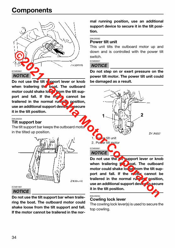
NOTICEECM00661
Do not use the tilt support lever or knobwhen trailering the boat. The outboardmotor could shake loose from the tilt sup-port and fall. If the motor cannot betrailered in the normal running position,use an additional support device to secureit in the tilt position.
EMU26334
Tilt support barThe tilt support bar keeps the outboard motorin the tilted up position.
NOTICEECM01661
Do not use the tilt support bar when traile-ring the boat. The outboard motor couldshake loose from the tilt support and fall.If the motor cannot be trailered in the nor-
mal running position, use an additionalsupport device to secure it in the tilt posi-tion.
EMU26362
Power tilt unitThis unit tilts the outboard motor up anddown and is controlled with the power tiltswitch.
NOTICEECM00631
Do not step on or exert pressure on thepower tilt motor. The power tilt unit couldbe damaged as a result.
NOTICEECM00661
Do not use the tilt support lever or knobwhen trailering the boat. The outboardmotor could shake loose from the tilt sup-port and fall. If the motor cannot betrailered in the normal running position,use an additional support device to secureit in the tilt position.
EMU39264
Cowling lock leverThe cowling lock lever(s) is used to secure thetop cowling.
1. Power tilt unit2. Power tilt motor
U6DR38E0.book Page 34 Tuesday, November 27, 2018 2:08 PM
©2021 Yamaha Motor Corporation

Components
35
EMU26464
Flushing deviceThis device is used to clean the cooling waterpassages of the motor using a garden hoseand tap water.
TIP:For details on usage, see page 73.EMU26305
Alert indicator If the engine develops a condition which iscause for alert, the indicator lights up. For de-tails on how to read the alert indicator, seepage 37.
1. Cowling lock lever
1. Flushing device
1
ZMU07818 1. Low oil pressure-alert indicator
1
ZMU07820
U6DR38E0.book Page 35 Tuesday, November 27, 2018 2:08 PM
©2021 Yamaha Motor Corporation

Instruments and indicators
36
EMU36016
Indicators EMU36026
Low oil pressure-alert indicatorIf oil pressure drops too low, this indicator willlight up. For further information, see page 37.
NOTICEECM00024
Do not continue to run the engine if thelow oil pressure-alert indicator is on andthe engine oil level is lower. Serious en-gine damage will occur.
The low oil pressure-alert indicator doesnot indicate the engine oil level. Use theoil dipstick to check the oil level. For fur-ther information, see page 43.
1. Low oil pressure-alert indicator
1
ZMU07820
U6DR38E0.book Page 36 Tuesday, November 27, 2018 2:08 PM
©2021 Yamaha Motor Corporation
Engine control system
37
EMU26806
Alert system
NOTICEECM00093
Do not continue to operate the engine if analert device has activated. Consult yourYamaha dealer if the problem cannot belocated and corrected.
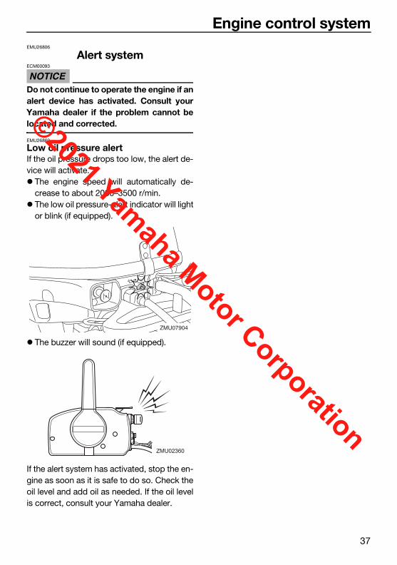
EMU26869
Low oil pressure alertIf the oil pressure drops too low, the alert de-vice will activate. The engine speed will automatically de-
crease to about 2000–3500 r/min. The low oil pressure-alert indicator will light
or blink (if equipped).
The buzzer will sound (if equipped).
If the alert system has activated, stop the en-gine as soon as it is safe to do so. Check theoil level and add oil as needed. If the oil levelis correct, consult your Yamaha dealer.
ZMU07904
ZMU02360
U6DR38E0.book Page 37 Tuesday, November 27, 2018 2:08 PM
©2021 Yamaha Motor Corporation

Installation
38
EMU26903
InstallationThe information presented in this section isintended as reference only. It is not possibleto provide complete instructions for everypossible boat and motor combination. Propermounting depends in part on experience andthe specific boat and motor combination.
WARNINGEWM01591
Overpowering a boat could cause se-vere instability. Do not install an out-board motor with more horsepowerthan the maximum rating on the capaci-ty plate of the boat. If the boat does nothave a capacity plate, consult the boatmanufacturer.
Improper mounting of the outboard mo-tor could result in hazardous conditionssuch as poor handling, loss of control,or fire hazards. For permanently mount-ed models, your dealer or other personexperienced in proper rigging shouldmount the motor.
EMU34802
Mounting the outboard motor
NOTICEECM01681
Do not hold the top cowling when mount-ing or dismounting the outboard motor.The top cowling could come off, causingthe outboard motor to fall.
1. Be sure to mount the outboard motorwhile the boat is on land. If the boat is onthe water, move it to an area on land.
2. To prevent steering movement, turn theadjuster lever to “A” (if equipped with theadjuster lever). To hold the steeringbracket easily, raise the tiller handle tothe vertical position (if equipped with thetiller handle).
3. Hold the handgrip and steering bracketas shown in the illustration and lift up theoutboard motor using two people.
1. Steering bracket2. Handgrip
1
2ZMU07878
U6DR38E0.book Page 38 Tuesday, November 27, 2018 2:08 PM
©2021 Yamaha Motor Corporation

Installation
39
4. Mount the outboard motor on the centerline (keel line) of the boat, and ensure thatthe boat itself is well balanced. Other-wise the boat will be hard to steer. Forboats without a keel or which are asym-metrical, consult your dealer.
EMU26926
Mounting heightTo run your boat at optimum efficiency, thewater resistance (drag) of the boat and out-board motor must be made as little as possi-ble. The mounting height of the outboardmotor greatly affects the water resistance. Ifthe mounting height is too high, cavitationtends to occur, thus reducing the propulsion;and if the propeller tips cut the air, the engine
speed will rise abnormally and cause the en-gine to overheat. If the mounting height is toolow, the water resistance will increase andthereby reduce engine efficiency. Mount theoutboard motor so that the anti-cavitationplate is between the bottom of the boat anda level 25 mm (1 in) below it.
NOTICEECM01635
Make sure that the idle hole is highenough to prevent water from enteringthe engine even if the boat is stationarywith the maximum load.
Incorrect engine height or obstructionsto the smooth flow of water (such as thedesign or condition of the boat, or ac-cessories, such as transom ladders ordepth finder transducers) can create air-borne water spray while the boat iscruising. If the outboard motor is oper-ated continuously in the presence of air-borne water spray, enough water couldenter the engine through the air intakeopening in the top cowling to cause se-vere engine damage. Remove the causeof the airborne water spray.
TIP: The optimum mounting height of the out-
board motor is affected by the boat andmotor combination and the desired use.
1. Center line (keel line)
1
U6DR38E0.book Page 39 Tuesday, November 27, 2018 2:08 PM
©2021 Yamaha Motor Corporation

Installation
40
Test runs at different heights can help de-termine the optimum mounting height.Consult your Yamaha dealer or boat man-ufacturer for further information on deter-mining the proper mounting height.
For instructions on setting the trim angle ofthe outboard motor, see page 60.
EMU26974
Clamping the outboard motor1. Place the outboard motor on the tran-
som so that it is positioned as close tothe center as possible. Tighten the tran-som clamp screws evenly and securely.Occasionally check the clamp screws fortightness during operation of the out-board motor because they could be-come loose due to engine vibration.WARNING! Loose clamp screws couldallow the outboard motor to fall off ormove on the transom. This couldcause loss of control and serious inju-ry. Make sure the clamp screws aretightened securely. Occasionallycheck the screws for tightness duringoperation. [EWM00643]
2. If the restraint cable attachment isequipped on your engine, a restraint ca-ble or chain should be used. Attach oneend to the restraint cable attachment andthe other to a secure mounting point on
the boat. Otherwise the engine could becompletely lost if it accidentally falls offthe transom.
3. Secure the clamp bracket to the transomusing the bolts provided with the out-board (if packed). For details, consultyour Yamaha dealer. WARNING! Avoidusing bolts, nuts or washers otherthan those contained in the enginepackaging. If used, they must be of atleast the same quality of material andstrength and must be tightened se-curely. After tightening, test run theengine and check their tightness.[EWM00652]
ZMU02012
1. Bolts
ZMU02013
1
ZMU03806
U6DR38E0.book Page 40 Tuesday, November 27, 2018 2:08 PM
©2021 Yamaha Motor Corporation

Operation
41
EMU36382
First-time operationEMU36393
Fill engine oilThe engine is shipped from the factory with-out engine oil. If your dealer did not fill the oil,you must fill it before starting the engine.NOTICE: Check that the engine is filledwith oil before first-time operation to avoidsevere engine damage. [ECM01782]
The engine is shipped with the following tag,which should be removed after engine oil isfilled for the first time. For more informationon checking the engine oil level, see page 43.
EMU30175
Breaking in engineYour new engine requires a period of break-in to allow mating surfaces of moving parts towear in evenly. Correct break-in will help en-sure proper performance and longer enginelife. NOTICE: Failure to follow the break-inprocedure could result in reduced enginelife or even severe engine damage. [ECM00802]
EMU27086
Procedure for 4-stroke modelsYour new engine requires a period of 10hours break-in to allow mating surfaces ofmoving parts to wear in evenly.
TIP:Run the engine in the water, under load (ingear with a propeller installed) as follows. For10 hours for breaking in engine avoid extend-ed idling, rough water and crowded areas.1. For the first hour of operation:
Run the engine at varying speeds up to2000 r/min or approximately half throttle.
2. For the second hour of operation:Increase engine speed as much as nec-essary to put the boat on plane (butavoid full-throttle operation), then backoff on the throttle while keeping the boatat a planing speed.
3. Remaining 8 hours:Run the engine at any speed. However,avoid operating at full throttle for morethan 5 minutes at a time.
4. After the first 10 hours:Operate the engine normally.
EMU36402
Getting to know your boatAll boats have unique handling characteris-tics. Operate cautiously while you learn howyour boat handles under different conditionsand various trim angles (see page 60).EMU36414
Checks before starting engine
WARNINGEWM01922
If any item in “Checks before starting en-gine” is not working properly, have it in-spected and repaired before operating theoutboard motor. Otherwise, an accidentcould occur.
ZMU01710
U6DR38E0.book Page 41 Tuesday, November 27, 2018 2:08 PM
©2021 Yamaha Motor Corporation

Operation
42
NOTICEECM00121
Do not start the engine out of water. Over-heating and serious engine damage canoccur.
EMU36561
Fuel levelBe sure you have plenty of fuel for your trip. Agood rule is to use 1/3 of your fuel to get tothe destination, 1/3 to return, and to keep 1/3as an emergency reserve. With the boat levelon a trailer or in the water, check the fuel lev-el. For fuel filling instructions, see page 45.EMU39841
Removing top cowlingFor the following checks, remove the topcowling from the bottom cowling.To remove the top cowling, pull the cowlinglock lever up and lift up the top cowling.
EMU36443
Fuel system
WARNINGEWM00061
Gasoline and its vapors are highly flamma-ble and explosive. Keep away from sparks,cigarettes, flames, or other sources of ig-nition.
WARNINGEWM00911
Leaking fuel can result in fire or explosion.Check for fuel leakage regularly.
If any fuel leakage is found, the fuel sys-tem must be repaired by a qualified me-chanic. Improper repairs can make theoutboard unsafe to operate.
EMU36453
Check for fuel leaksCheck for fuel leaks or gasoline fumes in
the boat.Check for fuel leakage from the fuel sys-
tem.Check the fuel tank and fuel lines for
cracks, swellings, or other damage.EMU36903
ControlsTiller handle models:Move the tiller handle fully to the left and
right to make sure operation is smooth. Turn the throttle grip from the fully closed
to the fully open position. Make sure that itturns smoothly and that it completely re-turns to the fully closed position.
Look for loose or damaged connections ofthe throttle and shift cables.
Remote control models: Turn the steering wheel full-right and full-
left. Make sure operation is smooth and un-restricted throughout the whole range withno binding or excessive free play.
Operate the throttle levers several times tomake sure there is no hesitation in theirtravel. Operation should be smooth overthe complete range of motion, and each le-ver should return completely to the idle po-sition.
Look for loose or damaged connections ofthe throttle and shift cables.
EMU36484
Engine shut-off cord (lanyard)Inspect the engine shut-off cord and clip fordamage, such as cuts, breaks, and wear.
1. Cowling lock lever
1
ZMU07824
U6DR38E0.book Page 42 Tuesday, November 27, 2018 2:08 PM
©2021 Yamaha Motor Corporation

Operation
43
EMU27168
Engine oil1. Put the outboard motor in an upright po-
sition (not tilted). NOTICE: If the motoris not level, the oil level indicated onthe dipstick may not be accurate.[ECM01791]
2. Remove oil dipstick and wipe it clean.
3. Insert the dipstick and remove it again.Be sure to completely insert the dipstickinto the dipstick guide, otherwise the oillevel measurement will be incorrect.
4. Check the oil level using the dipstick tobe sure the level falls between the upperand lower marks. Fill with oil if it is belowthe lower mark, or drain to the specifiedlevel if it is above the upper mark.
EMU40412
Outboard motorCheck that the outboard motor is mounted
properly and check the outboard motormounting bolts for looseness.
Check the propeller for damage.Check for engine oil leaks.EMU36494
Flushing deviceCheck that the flushing device’s garden hoseconnector is securely screwed on to the fit-ting on the bottom cowling. NOTICE: If thegarden hose connector is not properlyconnected, cooling water can leak out andthe engine can overheat during operation.[ECM01802]
1. Clip2. Engine shut-off cord (lanyard)
1. Oil dipstick
ZMU06873
1
2
1
ZMU07825
1. Oil dipstick2. Upper mark3. Lower mark
1. Fitting2. Garden hose connector3. Flushing device
3 2 1
ZMU07792
123
ZMU06070
U6DR38E0.book Page 43 Tuesday, November 27, 2018 2:08 PM
©2021 Yamaha Motor Corporation
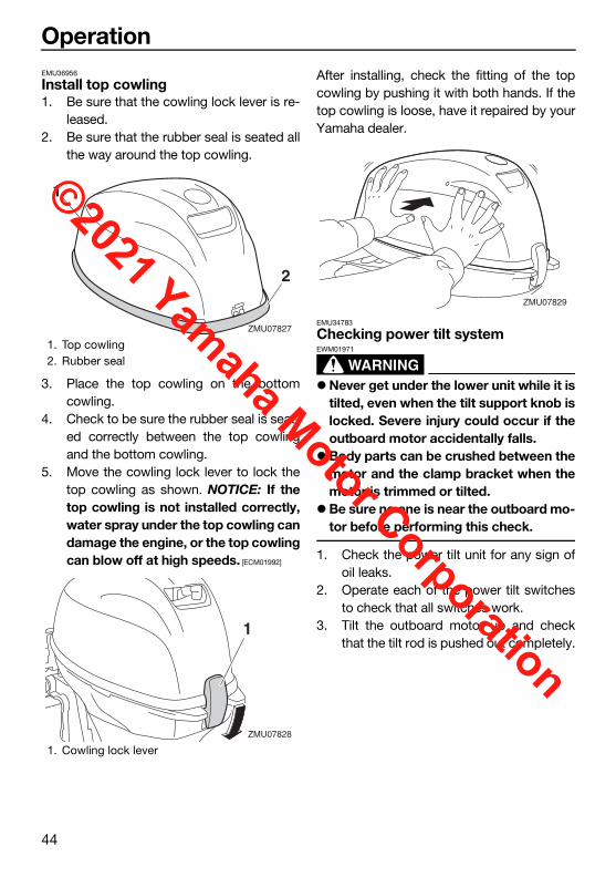
Operation
44
EMU36956
Install top cowling1. Be sure that the cowling lock lever is re-
leased.2. Be sure that the rubber seal is seated all
the way around the top cowling.
3. Place the top cowling on the bottomcowling.
4. Check to be sure the rubber seal is seat-ed correctly between the top cowlingand the bottom cowling.
5. Move the cowling lock lever to lock thetop cowling as shown. NOTICE: If thetop cowling is not installed correctly,water spray under the top cowling candamage the engine, or the top cowlingcan blow off at high speeds. [ECM01992]
After installing, check the fitting of the topcowling by pushing it with both hands. If thetop cowling is loose, have it repaired by yourYamaha dealer.
EMU34783
Checking power tilt system
WARNINGEWM01971
Never get under the lower unit while it istilted, even when the tilt support knob islocked. Severe injury could occur if theoutboard motor accidentally falls.
Body parts can be crushed between themotor and the clamp bracket when themotor is trimmed or tilted.
Be sure no one is near the outboard mo-tor before performing this check.
1. Check the power tilt unit for any sign ofoil leaks.
2. Operate each of the power tilt switchesto check that all switches work.
3. Tilt the outboard motor up and checkthat the tilt rod is pushed out completely.
1. Top cowling2. Rubber seal
1. Cowling lock lever
1
2
ZMU07827
1
ZMU07828
ZMU07829
U6DR38E0.book Page 44 Tuesday, November 27, 2018 2:08 PM
©2021 Yamaha Motor Corporation

Operation
45
4. Check that the tilt rod is free of corrosionor other flaws.
5. Tilt the outboard motor down. Checkthat the tilt rod operates smoothly.
EMU36585
BatteryCheck the battery’s charge. If your boat isequipped with a Yamaha digital speedome-ter, the voltmeter and low battery alert func-tions will help you monitor the battery’scharge. A battery in good condition will pro-vide a minimum of 12 volts. Check that thebattery connections are clean, secure andcovered by insulating covers. The electricalconnections of the battery and cables mustbe clean and properly connected or the bat-tery will not start the engine.If the battery needs charging, consult yourYamaha dealer or the battery manufacturer’sinstructions.EMU43164
Filling fuel
WARNINGEWM01831
Gasoline and its vapors are highly flam-mable and explosive. Always refuel ac-cording to this procedure to reduce therisk of fire and explosion.
Gasoline is poisonous and can cause in-jury or death. Handle gasoline with care.Never siphon gasoline by mouth. If you
should swallow some gasoline or inhalea lot of gasoline vapor, or get some gas-oline in your eyes, see your doctor im-mediately. If gasoline spills on your skin,wash with soap and water. If gasolinespills on your clothing, change yourclothes.
Before refueling, check the following points: Ensure the engine is stopped. Securely moor the boat in a well-ventilated
area and stop the engine. If the boat istrailered, ensure it is stable.
Do not smoke and keep away from sparks,flames, static electric discharges, or othersources of ignition.
If you use a portable container to store anddispense fuel, use only a locally approvedGASOLINE container.
To prevent electrostatic sparks, dischargeany built-up static electricity from yourbody before refueling.
1. Disconnect the fuel hose from the fueljoint on the fuel tank.
2. Turn the air vent screw clockwise toclose it.
1. Tilt rod
ZMU06621
U6DR38E0.book Page 45 Tuesday, November 27, 2018 2:08 PM
©2021 Yamaha Motor Corporation

Operation
46
3. Remove the fuel tank from the boat.4. To loosen the air vent screw, turn it coun-
terclockwise until it stops.
5. While pressing and holding the pressurerelief tab under the fuel tank cap, slowlyturn the fuel tank cap counterclockwise1/4 turn.
TIP:Release the fuel vapor contained in the fueltank.6. While pressing and holding the pressure
relief tab under the fuel tank cap again,turn the fuel tank cap counterclockwiseto remove it.
7. Fill the fuel tank with fuel. WARNING! Donot overfill. Otherwise fuel can expandand overflow if the temperature in-creases. [EWM02611]
TIP:Wipe up any spilled gasoline immediately
with dry rags.
1. Air vent screw
1. Air vent screw
1. Pressure relief tab2. Fuel tank cap
1
ZMU07444
1
ZMU07445
1
2
ZMU07446
1. Pressure relief tab2. Fuel tank cap
Fuel tank capacity:12 L (3.17 US gal, 2.64 Imp.gal)
1
2
ZMU07447
U6DR38E0.book Page 46 Tuesday, November 27, 2018 2:08 PM
©2021 Yamaha Motor Corporation
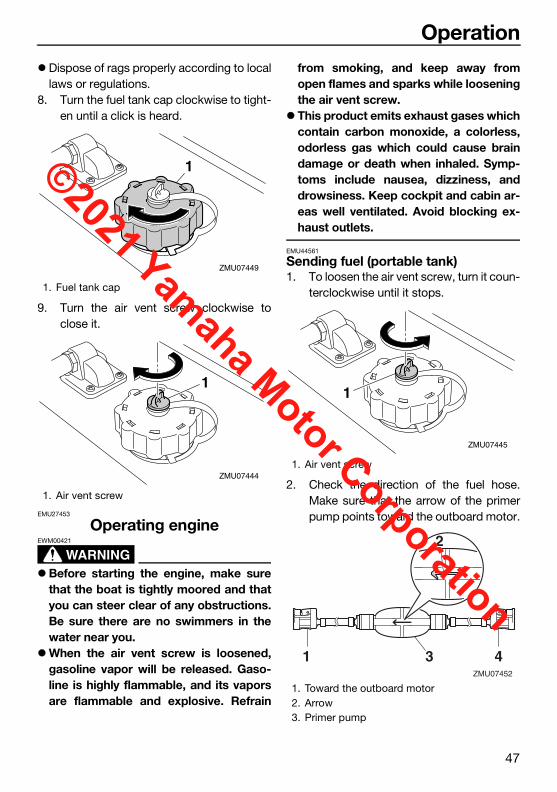
Operation
47
Dispose of rags properly according to locallaws or regulations.
8. Turn the fuel tank cap clockwise to tight-en until a click is heard.
9. Turn the air vent screw clockwise toclose it.
EMU27453
Operating engine
WARNINGEWM00421
Before starting the engine, make surethat the boat is tightly moored and thatyou can steer clear of any obstructions.Be sure there are no swimmers in thewater near you.
When the air vent screw is loosened,gasoline vapor will be released. Gaso-line is highly flammable, and its vaporsare flammable and explosive. Refrain
from smoking, and keep away fromopen flames and sparks while looseningthe air vent screw.
This product emits exhaust gases whichcontain carbon monoxide, a colorless,odorless gas which could cause braindamage or death when inhaled. Symp-toms include nausea, dizziness, anddrowsiness. Keep cockpit and cabin ar-eas well ventilated. Avoid blocking ex-haust outlets.
EMU44561
Sending fuel (portable tank)1. To loosen the air vent screw, turn it coun-
terclockwise until it stops.
2. Check the direction of the fuel hose.Make sure that the arrow of the primerpump points toward the outboard motor.
1. Fuel tank cap
1. Air vent screw
1
ZMU07449
1
ZMU074441. Air vent screw
1. Toward the outboard motor2. Arrow3. Primer pump
1
ZMU07445
ZMU07452
1 43
2
U6DR38E0.book Page 47 Tuesday, November 27, 2018 2:08 PM
©2021 Yamaha Motor Corporation

Operation
48
3. Align the fuel joint on the fuel hose withthe fuel joint on the outboard motor andfirmly connect the fuel hose to the jointwhile pinching the joint.
4. Firmly connect the other end of the fuelhose to the joint on the fuel tank.
5. Wipe up any spilled gasoline immediate-ly with dry rags.
TIP:Dispose of rags properly according to locallaws or regulations.6. Squeeze the primer pump, with the ar-
row pointing up, until you feel it becomefirm. During engine operation, place thetank horizontally, otherwise fuel cannotbe drawn from the fuel tank.
EMU27495
Starting engine
WARNINGEWM01601
Before starting the engine, make sure thatthe boat is tightly moored and that you cansteer clear of any obstructions. Be surethere are no swimmers in the water nearyou.
EMU34815
Manual start models (tiller control)
WARNINGEWM01842
Failure to attach the engine shut-offcord could result in a runaway boat ifoperator is ejected. Attach the engineshut-off cord to a secure place on yourclothing, or your arm or leg while oper-ating. Do not attach the cord to clothingthat could tear loose. Do not route thecord where it could become entangled,preventing it from functioning.
Avoid accidentally pulling the cord dur-ing normal operation. Loss of enginepower means the loss of most steeringcontrol. Also, without engine power, theboat could slow rapidly. This couldcause people and objects in the boat tobe thrown forward.
4. Toward the fuel tank
1. Fuel joint2. Fuel hose
ZMU07905
2
1
ZMU07585
1. Arrow2. Primer pump
U6DR38E0.book Page 48 Tuesday, November 27, 2018 2:08 PM
©2021 Yamaha Motor Corporation

Operation
49
Starting procedure (cold engine)1. Place the gear shift lever in neutral.
TIP:The start-in-gear protection device preventsthe engine from starting except when in neu-tral.2. Attach the engine shut-off cord to a se-
cure place on your clothing, or your armor leg. Then install the clip on the otherend of the cord into the engine shut-offswitch.
3. Place the throttle grip in the “ ”(start) position.
4. Pull out the choke knob fully.
5. Pull the manual starter handle slowly un-til you feel resistance. Then give a strongpull straight out to crank and start the en-gine.
6. After the engine starts, slowly return themanual starter handle to its original posi-tion before releasing it.
7. Slowly return the throttle grip to the fullyclosed position.
STARTZMU07886
U6DR38E0.book Page 49 Tuesday, November 27, 2018 2:08 PM
©2021 Yamaha Motor Corporation

Operation
50
8. Return the choke knob to the home posi-tion gradually.
TIP: If the choke knob is left in the “ ” (start)
position while the engine is running, the en-gine will run poorly or stall.
When the engine is cold, for example,when the ambient temperature is low inwinter, it needs to be warmed up. For fur-ther information, see page 56.
Do not turn the throttle grip unnecessarilyto open and close the throttle before start-ing the engine, otherwise the engine maybe difficult to start. If the engine is difficultto start, place the throttle grip in the“ ” (warm engine) position andtry again.
Starting procedure (warm engine)1. Place the gear shift lever in neutral.
2. Attach the engine shut-off cord to a se-cure place on your clothing, or your armor leg. Then install the clip on the otherend of the cord into the engine shut-offswitch.
3. Place the throttle grip in the “ ”(start) position.
4. Pull the manual starter handle slowly un-til you feel resistance. Then give a strongpull straight out to crank and start the en-gine.
ZMU02030
U6DR38E0.book Page 50 Tuesday, November 27, 2018 2:08 PM
©2021 Yamaha Motor Corporation

Operation
51
TIP: If the engine does not start, place the throt-
tle grip in the “ ” (warm engine)position and try again.
It is not necessary to use the choke whenstarting a warm engine.
5. After the engine starts, slowly return themanual starter handle to its original posi-tion before releasing it.
6. Slowly return the throttle grip to the fullyclosed position.
EMU34926
Electric start models (tiller control)
WARNINGEWM01842
Failure to attach the engine shut-offcord could result in a runaway boat ifoperator is ejected. Attach the engineshut-off cord to a secure place on yourclothing, or your arm or leg while oper-ating. Do not attach the cord to clothingthat could tear loose. Do not route thecord where it could become entangled,preventing it from functioning.
Avoid accidentally pulling the cord dur-ing normal operation. Loss of enginepower means the loss of most steeringcontrol. Also, without engine power, theboat could slow rapidly. This couldcause people and objects in the boat tobe thrown forward.
Starting procedure (cold engine)1. Place the gear shift lever in neutral.
TIP:The start-in-gear protection device preventsthe engine from starting except when in neu-tral.2. Attach the engine shut-off cord to a se-
cure place on your clothing, or your armor leg. Then install the clip on the otherend of the cord into the engine shut-offswitch.ZMU02030
U6DR38E0.book Page 51 Tuesday, November 27, 2018 2:08 PM
©2021 Yamaha Motor Corporation
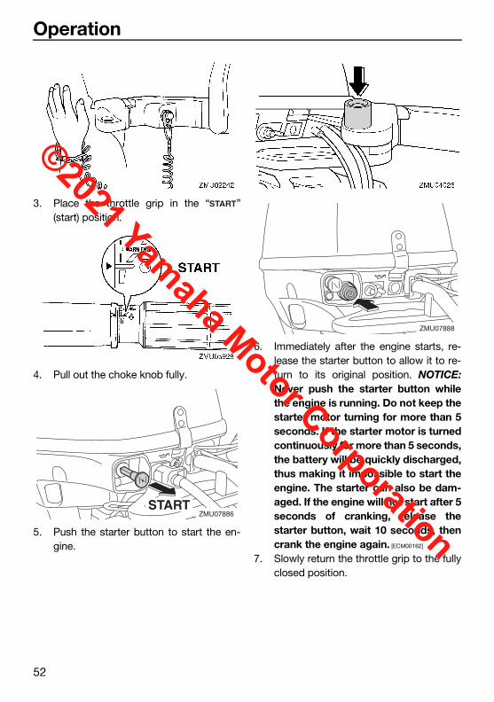
Operation
52
3. Place the throttle grip in the “ ”(start) position.
4. Pull out the choke knob fully.
5. Push the starter button to start the en-gine.
6. Immediately after the engine starts, re-lease the starter button to allow it to re-turn to its original position. NOTICE:Never push the starter button whilethe engine is running. Do not keep thestarter motor turning for more than 5seconds. If the starter motor is turnedcontinuously for more than 5 seconds,the battery will be quickly discharged,thus making it impossible to start theengine. The starter can also be dam-aged. If the engine will not start after 5seconds of cranking, release thestarter button, wait 10 seconds, thencrank the engine again. [ECM00162]
7. Slowly return the throttle grip to the fullyclosed position.
STARTZMU07886
ZMU07888
U6DR38E0.book Page 52 Tuesday, November 27, 2018 2:08 PM
©2021 Yamaha Motor Corporation

Operation
53
8. Return the choke knob to the home posi-tion gradually.
TIP: If the choke knob is left in the “ ” (start)
position while the engine is running, the en-gine will run poorly or stall.
When the engine is cold, for example,when the ambient temperature is low inwinter, it needs to be warmed up. For fur-ther information, see page 56.
Starting procedure (warm engine)1. Place the gear shift lever in neutral.
2. Attach the engine shut-off cord to a se-cure place on your clothing, or your armor leg. Then install the clip on the otherend of the cord into the engine shut-offswitch.
3. Place the throttle grip in the “ ”(start) position.
4. Push the starter button to start the en-gine.
ZMU02030
U6DR38E0.book Page 53 Tuesday, November 27, 2018 2:08 PM
©2021 Yamaha Motor Corporation

Operation
54
TIP: If the engine does not start, place the throt-
tle grip in the “ ” (warm engine)position and try again.
It is not necessary to use the choke whenstarting a warm engine.
5. Immediately after the engine starts, re-lease the starter button to allow it to re-turn to its original position.
6. Slowly return the throttle grip to the fullyclosed position.
EMU34934
Electric start models (remote control)
WARNINGEWM01842
Failure to attach the engine shut-offcord could result in a runaway boat ifoperator is ejected. Attach the engineshut-off cord to a secure place on yourclothing, or your arm or leg while oper-ating. Do not attach the cord to clothingthat could tear loose. Do not route thecord where it could become entangled,preventing it from functioning.
Avoid accidentally pulling the cord dur-ing normal operation. Loss of enginepower means the loss of most steeringcontrol. Also, without engine power, theboat could slow rapidly. This couldcause people and objects in the boat tobe thrown forward.
1. Place the remote control lever in neutral.
TIP:The start-in-gear protection device preventsthe engine from starting except when in neu-tral.2. Attach the engine shut-off cord to a se-
cure place on your clothing, or your armor leg. Then install the clip on the otherend of the cord into the engine shut-offswitch.
ZMU07888
ZMU02030
N
ZMU01771
U6DR38E0.book Page 54 Tuesday, November 27, 2018 2:08 PM
©2021 Yamaha Motor Corporation

Operation
55
3. Turn the main switch to “ ” (on).
4. Open the throttle slightly without shiftingusing the neutral throttle lever.
TIP:The neutral throttle lever can only be usedwhen the remote control lever is in neutral.5. Press in and hold the main switch to op-
erate the remote choke system. (The re-mote choke system operates only whenthe main switch is pressed in fully.)
TIP:It is not necessary to use the choke whenstarting a warm engine.6. Turn the main switch to “ ” (start) to
start the engine.
7. Immediately after the engine starts, re-lease the main switch and allow it to re-turn to “ ” (on). The remote chokesystem stops operating when the mainswitch is released. NOTICE: Never turnthe main switch to “ ” (start) whilethe engine is running. Do not keep thestarter motor turning for more than 5seconds. If the starter motor is turnedcontinuously for more than 5 seconds,the battery will be quickly discharged,thus making it impossible to start theengine. The starter can also be dam-aged. If the engine will not start after 5
ZMU01772
ONOFF
ZMU01880
ZMU02252
N
ONSTARTOFF
ZMU02206
ONSTART
ZMU01774
U6DR38E0.book Page 55 Tuesday, November 27, 2018 2:08 PM
©2021 Yamaha Motor Corporation

Operation
56
seconds of cranking, return the mainswitch to “ ” (on), wait 10 seconds,then crank the engine again. [ECM00193]
8. Return the neutral throttle lever to theoriginal position.
TIP:When the engine is cold, for example, whenthe ambient temperature is low in winter, itneeds to be warmed up. For further informa-tion, see page 56.EMU36511
Checks after starting engineEMU36524
Cooling waterCheck for a steady flow of water from thecooling water pilot hole. A continuous flow ofwater from the pilot hole indicates that thewater pump is pumping water through thecooling water passages. If the cooling waterpassages are frozen, it may take a while forwater to start flowing out of the pilot hole.
NOTICEECM01811
If water is not flowing out of the pilot holeat all times while the engine is running,overheating and serious damage couldoccur. Stop the engine and check whetherthe cooling water inlet on the lower caseor the cooling water pilot hole is blocked.Consult your Yamaha dealer if the prob-lem cannot be located and corrected.
EMU27671
Warming up engineEMU27718
Manual start and electric start models1. After starting the engine, allow it to idle
for 3 minutes to warm up. NOTICE: Fail-ure to do so will shorten engine life.[ECM04550]
2. Be sure the low oil pressure-alert indica-tor goes off after starting the engine.NOTICE: If the low oil pressure-alertindicator blinks after the engine starts,stop the engine. Otherwise, seriousengine damage could occur. Checkthe oil level and add engine oil if nec-essary. Consult your Yamaha dealer ifthe cause for the low oil pressure alertcannot be found. [ECM01832]
EMU36532
Checks after engine warm upEMU36542
ShiftingWhile the boat is tightly moored, and withoutapplying throttle, confirm that the engineshifts smoothly into forward and reverse, andback to neutral.EMU36981
Stop switches Turn the main switch to “ ”, or press the
engine stop button and make sure the en-gine stops.
1. Cooling water pilot hole
1
ZMU07830
U6DR38E0.book Page 56 Tuesday, November 27, 2018 2:08 PM
©2021 Yamaha Motor Corporation

Operation
57
Confirm that removing the clip from the en-gine shut-off switch stops the engine.
Confirm that the engine cannot be startedwith the clip removed from the engine shut-off switch.
EMU34563
Shifting
WARNINGEWM00181
Before shifting, make sure there are noswimmers or obstacles in the water nearyou.
NOTICEECM01611
Warm up the engine before shifting intogear. Until the engine is warm, the idlespeed may be higher than normal. Highidle speed can prevent you from shiftingback to neutral. If this occurs, stop the en-gine, shift to neutral, then restart the en-gine and allow it to warm up.
To shift out of neutral1. Pull the neutral interlock trigger up (if
equipped).
2. Move the remote control lever / gear shiftlever firmly and crisply forward (for for-ward gear) or backward (for reverse gear)[about 35° (a detent can felt) for remotecontrol models]. Be sure to check that
the tilt lock lever is in the lock/down po-sition (if equipped) before operating in re-verse.
TIP:Tiller handle models: The gear shift lever op-erates only when the throttle grip is in the fullyclosed position.To shift from in gear (forward/reverse) to neu-tral1. Close the throttle so that the engine
slows to idle speed.
1. Neutral interlock trigger
1
ZMU01727
FN
R32˚ 32˚
ZMU05460
ZMU07892
U6DR38E0.book Page 57 Tuesday, November 27, 2018 2:08 PM
©2021 Yamaha Motor Corporation

Operation
58
2. After the engine is at idle speed in gearmove the remote control lever / gear shiftlever firmly and crisply into the neutralposition.
EMU31743
Stopping boat
WARNINGEWM01511
Do not use the reverse function to slowdown or stop the boat as it could causeyou to lose control, be ejected, or im-pact the steering wheel or other parts ofthe boat. This could increase the risk ofserious injury. It could also damage theshift mechanism.
Do not shift into reverse while travelingat planing speeds. Loss of control, boatswamping, or damage to the boat couldoccur.
The boat is not equipped with a separatebraking system. Water resistance stops it af-ter the throttle lever is moved back to idle.The stopping distance varies depending ongross weight, water surface conditions, andwind direction.EMU27822
Stopping engineBefore stopping the engine, first let it cool offfor a few minutes at idle or low speed. Stop-ping the engine immediately after operatingat high speed is not recommended.EMU43432
Procedure1. Push and hold the engine stop button
until the engine comes to a completestop.
RF
ZMU05462
ZMU02030
N
ZMU01771
U6DR38E0.book Page 58 Tuesday, November 27, 2018 2:08 PM
©2021 Yamaha Motor Corporation
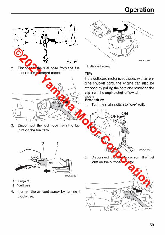
Operation
59
2. Disconnect the fuel hose from the fueljoint on the outboard motor.
3. Disconnect the fuel hose from the fueljoint on the fuel tank.
4. Tighten the air vent screw by turning itclockwise.
TIP:If the outboard motor is equipped with an en-gine shut-off cord, the engine can also bestopped by pulling the cord and removing theclip from the engine shut-off switch.EMU43442
Procedure1. Turn the main switch to “ ” (off).
2. Disconnect the fuel hose from the fueljoint on the outboard motor.
1. Fuel joint2. Fuel hose
ZMU07906
ZMU08310
12
1. Air vent screw
1
ZMU07444
ONOFF
ZMU01779
ZMU07906
U6DR38E0.book Page 59 Tuesday, November 27, 2018 2:08 PM
©2021 Yamaha Motor Corporation

Operation
60
3. Disconnect the fuel hose from the fueljoint on the fuel tank.
4. Tighten the air vent screw by turning itclockwise.
5. When using the fuel tank on a boat, closethe fuel valve.
TIP:Check the boat’s manual for the position ofthe fuel valve.6. Remove the key if the boat will be left un-
attended.
TIP:The engine can also be stopped by pullingthe cord and removing the clip from the en-gine shut-off switch, then turning the mainswitch to “ ” (off).
EMU27865
Trimming outboard motor
WARNINGEWM00741
Excessive trim for the operating condi-tions (either trim up or trim down) cancause boat instability and can make steer-ing the boat more difficult. This increasesthe possibility of an accident. If the boatbegins to feel unstable or is hard to steer,slow down and/or readjust the trim angle.
The trim angle of the outboard motor helpsdetermine the position of the bow of the boatin the water. Correct trim angle will help im-prove performance and fuel economy whilereducing strain on the engine. Correct trimangle depends upon the combination ofboat, engine, and propeller. Correct trim isalso affected by variables such as the load inthe boat, sea conditions, and running speed.
EMU27873
Adjusting trim angle for manual tilt modelsThere are 4 or 5 holes provided in the clampbracket to adjust the outboard motor trim an-gle.1. Stop the engine.2. Tilt the outboard motor up, and then re-
move the trim rod from the clamp brack-et.
1. Fuel joint2. Fuel hose
1. Air vent screw
ZMU08310
12
1
ZMU07444
1. Trim operating angle
U6DR38E0.book Page 60 Tuesday, November 27, 2018 2:08 PM
©2021 Yamaha Motor Corporation

Operation
61
3. Reposition the rod in the desired hole.To raise the bow (“trim-out”), move the rodaway from the transom.To lower the bow (“trim-in”), move the rod to-ward the transom.Make test runs with the trim set to differentangles to find the position that works best foryour boat and operating conditions.
WARNINGEWM00401
Stop the engine before adjusting thetrim angle.
Use care to avoid being pinched whenremoving or installing the rod.
Use caution when trying a trim positionfor the first time. Increase speed gradu-ally and watch for any signs of instabilityor control problems. Improper trim an-gle can cause loss of control.
TIP:The outboard motor trim angle can bechanged approximately 4 degrees by shiftingthe trim rod one hole.
EMU27906
Adjusting trim angle (power tilt mod-els)
WARNINGEWM00754
Be sure all people are clear of the out-board motor when adjusting the trim an-gle. Body parts can be crushed betweenthe motor and the clamp bracket whenthe motor is trimmed or tilted.
Use caution when trying a trim positionfor the first time. Increase speed gradu-ally and watch for any signs of instabilityor control problems. Improper trim an-gle can cause loss of control.
If equipped with a power trim and tiltswitch located on the bottom cowling,use the switch only when the boat is at acomplete stop with the engine off. Donot adjust the trim angle with this switchwhile the boat is moving.
1. Move the gear shift lever to the neutralposition.
TIP:While the boat is moving, it may be difficult toadjust the trim angle due to water pressure.Before adjusting the trim angle, reduce theboat speed and shift into neutral.2. Tilt the outboard motor to the desired an-
gle using the power tilt switch.
1. Trim rod1 ZMU07831
DNUP
ZMU01720
U6DR38E0.book Page 61 Tuesday, November 27, 2018 2:08 PM
©2021 Yamaha Motor Corporation

Operation
62
To raise the bow (“trim-out”), tilt the outboardmotor up.To lower the bow (“trim-in”), tilt the outboardmotor down.Make test runs with the trim set to differentangles to find the position that works best foryour boat and operating conditions.
TIP:Stay within the trim operating angle whentrimming the outboard motor using the powertilt system.EMU27913
Adjusting boat trimWhen the boat is on plane, a bow-up attituderesults in less drag, greater stability and effi-ciency. This is generally when the keel line ofthe boat is up about 3 to 5 degrees. With thebow up, the boat may have a greater tenden-cy to steer to one side or the other. Compen-sate for this as you steer. When the bow ofthe boat is down, it is easier to acceleratefrom a standing start onto plane.
Bow UpToo much trim-out puts the bow of the boattoo high in the water. Performance and econ-omy are decreased because the hull of theboat is pushing the water and there is moreair drag. Excessive trim-out can also causethe propeller to ventilate, which reduces per-formance further, and the boat may “por-poise” (hop in the water), which could throwthe operator and passengers overboard.
Bow DownToo much trim-in causes the boat to “plow”through the water, decreasing fuel economyand making it hard to increase speed. Oper-ating with excessive trim-in at higher speedsalso makes the boat unstable. Resistance atthe bow is greatly increased, heightening thedanger of “bow steering” and making opera-tion difficult and dangerous.
TIP:Depending on the type of boat, the outboardmotor trim angle may have little effect on thetrim of the boat when operating.EMU27936
Tilting up and downIf the engine will be stopped for some time orif the boat is moored in shallows, the out-board motor should be tilted up to protect thepropeller and lower casing from damage bycollision with obstructions, and also to re-duce salt corrosion.
U6DR38E0.book Page 62 Tuesday, November 27, 2018 2:08 PM
©2021 Yamaha Motor Corporation
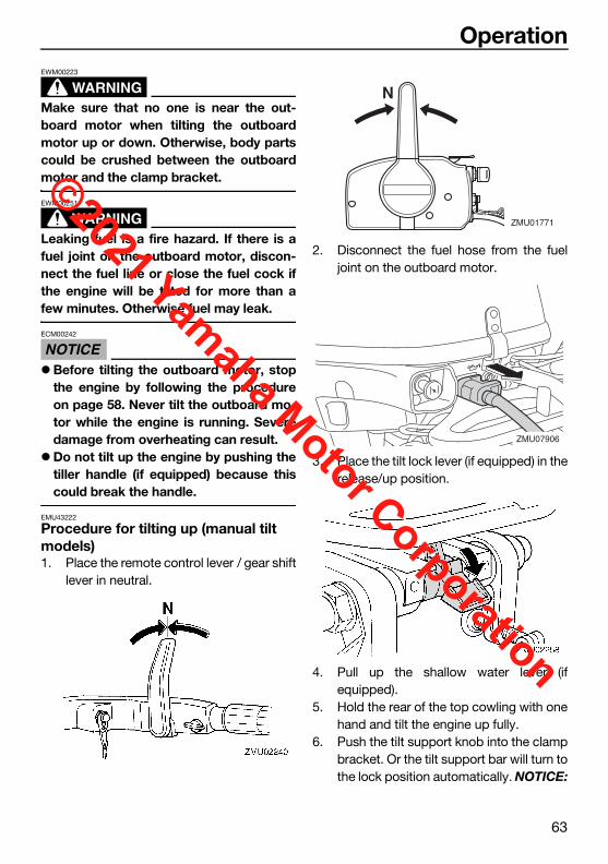
Operation
63
WARNINGEWM00223
Make sure that no one is near the out-board motor when tilting the outboardmotor up or down. Otherwise, body partscould be crushed between the outboardmotor and the clamp bracket.
WARNINGEWM00251
Leaking fuel is a fire hazard. If there is afuel joint on the outboard motor, discon-nect the fuel line or close the fuel cock ifthe engine will be tilted for more than afew minutes. Otherwise fuel may leak.
NOTICEECM00242
Before tilting the outboard motor, stopthe engine by following the procedureon page 58. Never tilt the outboard mo-tor while the engine is running. Severedamage from overheating can result.
Do not tilt up the engine by pushing thetiller handle (if equipped) because thiscould break the handle.
EMU43222
Procedure for tilting up (manual tilt models)1. Place the remote control lever / gear shift
lever in neutral.
2. Disconnect the fuel hose from the fueljoint on the outboard motor.
3. Place the tilt lock lever (if equipped) in therelease/up position.
4. Pull up the shallow water lever (ifequipped).
5. Hold the rear of the top cowling with onehand and tilt the engine up fully.
6. Push the tilt support knob into the clampbracket. Or the tilt support bar will turn tothe lock position automatically. NOTICE:
N
ZMU01771
ZMU07906
U6DR38E0.book Page 63 Tuesday, November 27, 2018 2:08 PM
©2021 Yamaha Motor Corporation

Operation
64
Do not use the tilt support lever orknob when trailering the boat. Theoutboard motor could shake loosefrom the tilt support and fall. If the mo-tor cannot be trailered in the normalrunning position, use an additionalsupport device to secure it in the tiltposition. For more detailed informa-tion, see page 69. [ECM01642]
EMU44650
Procedure for tilting up (power tilt models)1. Place the remote control lever / gear shift
lever in neutral.
2. Press the power tilt switch “ ” (up) untilthe outboard motor has tilted up com-pletely.
N
ZMU01771
UP
ZMU01787
U6DR38E0.book Page 64 Tuesday, November 27, 2018 2:08 PM
©2021 Yamaha Motor Corporation

Operation
65
3. Push the tilt support knob into the clampbracket to support the engine.WARNING! After tilting the outboardmotor, be sure to support it with thetilt support knob or tilt support lever.Otherwise the outboard motor couldfall back down suddenly if oil in thepower trim and tilt unit or in the powertilt unit loses pressure. [EWM00263]
NOTICE: Do not use the tilt support le-ver or knob when trailering the boat.The outboard motor could shakeloose from the tilt support and fall. Ifthe motor cannot be trailered in thenormal running position, use an addi-tional support device to secure it inthe tilt position. For more detailed in-formation, see page 69. [ECM01642]
EMU30193
Procedure for tilting down (manual tilt models)1. Place the tilt lock lever in the lock posi-
tion.
2. Slightly tilt the engine up until the tilt sup-port bar is automatically released.
3. Slowly tilt the engine down.EMU44620
Procedure for tilting down (power tilt models)1. Push the power tilt switch “ ” (up) until
the outboard motor is supported by thetilt rod and the tilt support knob becomesfree.
2. Pull out the tilt support knob.
3. Push the power tilt switch “ ” (down) tolower the outboard motor to the desiredposition.
ZMU07892
U6DR38E0.book Page 65 Tuesday, November 27, 2018 2:08 PM
©2021 Yamaha Motor Corporation

Operation
66
EMU28063
Shallow water EMU28074
Cruising in shallow water (manual tilt models)
WARNINGEWM01782
Run the boat at the lowest possiblespeed when using the shallow watercruising system. The tilt lock mecha-nism does not work while the shallowwater cruising system is being used. Hit-
ting an underwater obstacle couldcause the outboard motor to lift out ofthe water, resulting in loss of control.
Use extra care when operating in re-verse. Too much reverse thrust cancause the outboard motor to lift out ofthe water, increasing the chance of ac-cident and personal injury.
NOTICEECM00261
Do not tilt the outboard motor up so thatthe cooling water inlet on the lower unit isabove the surface of the water when set-ting up for and cruising in shallow water.Otherwise severe damage from overheat-ing can result.
EMU28126
Procedure1. Place the remote control lever / gear shift
lever in neutral.
DN
ZMU01936
U6DR38E0.book Page 66 Tuesday, November 27, 2018 2:08 PM
©2021 Yamaha Motor Corporation

Operation
67
2. Place the tilt lock lever in the release/upposition.
3. Slightly tilt the outboard motor up. The tiltsupport bar will lock automatically, sup-porting the outboard motor in a partiallyraised position. This outboard motor has2 positions for shallow water cruising.
4. To return the outboard motor to the nor-mal running position, place the remotecontrol lever / gear shift lever in neutral.
5. Place the tilt lock lever in the lock/downposition, then slightly tilt the outboardmotor up until the tilt support bar auto-matically returns to the free position.
6. Slowly lower the outboard motor to thenormal position.
EMU32862
Power tilt modelsThe outboard motor can be tilted up partiallyto allow operation in shallow water.
NOTICEECM00261
Do not tilt the outboard motor up so thatthe cooling water inlet on the lower unit isabove the surface of the water when set-ting up for and cruising in shallow water.Otherwise severe damage from overheat-ing can result.
EMU32943
Procedure for power tilt models1. Place the remote control lever / gear shift
lever in neutral.
N
ZMU01771
ZMU07892
N
ZMU01771
U6DR38E0.book Page 67 Tuesday, November 27, 2018 2:08 PM
©2021 Yamaha Motor Corporation

Operation
68
2. Slightly tilt the outboard motor up to thedesired position using the power tiltswitch. WARNING! Using the power tiltswitch on the bottom cowling whilethe boat is moving or engine is oncould increase the risk of falling over-board and could distract the operator,increasing the risk of collision with an-other boat or an obstacle. [EWM01961]
3. To return the outboard motor to the nor-mal running position, press the power tiltswitch and slowly tilt the outboard motordown.
EMU28196
Cruising in other conditionsCruising in salt waterAfter operating in salt water, flush the coolingwater passages with fresh water to preventthem from becoming clogged. Also rinse theoutside of the outboard motor with fresh wa-ter.Cruising in muddy, turbid, or acidic waterYamaha strongly recommends that you usethe optional chromium-plated water pump kit(see page 21) if you use the outboard motorin acidic water or water with a lot of sedimentin it, such as muddy or turbid (cloudy) water.After operating in such water, flush the cool-ing passages with fresh water to prevent cor-rosion. Also rinse the outside of the outboardmotor with fresh water.
UP
ZMU01935
U6DR38E0.book Page 68 Tuesday, November 27, 2018 2:08 PM
©2021 Yamaha Motor Corporation

Maintenance
69
EMU43253
Transporting and storing out-board motor
WARNINGEWM02621
USE CARE when transporting fuel tank,whether in a boat or car.
DO NOT fill fuel container to maximumcapacity. Gasoline will expand consider-ably as it warms up and can build uppressure in the fuel container. This cancause fuel leakage and a potential firehazard.
Leaking fuel is a fire hazard. Whentransporting and storing the outboardmotor, disconnect the fuel line from theoutboard motor to prevent fuel fromleaking.
Never get under the outboard motorwhile it is tilted. Severe injury could oc-cur if the outboard motor accidentallyfalls.
Do not use the tilt support lever or knobwhen trailering the boat. The outboardmotor could shake loose from the tiltsupport and fall. If the outboard motorcannot be trailered in the normal run-ning position, use an additional supportdevice to secure it in the tilt position.
When storing or transporting the outboardmotor, make sure to follow the procedure list-ed below.Disconnect the fuel hose from the fuel joint
on the outboard motor. Tighten the fuel tank cap and its air vent
screw. Store the fuel tank in a well-ventilated
place. Store the fuel tank in a place that is stable
and not exposed to shocks.
When the outboard motor is tilted for a pro-longed time for mooring or trailering the boat,make sure to follow the procedure listed be-low.Disconnect the fuel hose from the fuel joint
on the outboard motor. Tighten the fuel tank cap and its air vent
screw.The outboard motor should be transportedand stored in the normal running position. Ifthere is insufficient road clearance in this po-sition, then trailer the outboard motor in thetilt position using a motor support devicesuch as a transom saver bar. Consult yourYamaha dealer for further details.EMU43452
Dismounting the outboard motor
NOTICEECM01681
Do not hold the top cowling when mount-ing or dismounting the outboard motor.The top cowling could come off, causingthe outboard motor to fall.
1. Stop the engine and land the boat.2. Disconnect the fuel hose from the fuel
joint on the outboard motor.3. For electric start models, disconnect the
battery cables from the battery terminals.4. To prevent steering movement, turn the
adjuster lever to “A” (if equipped with theadjuster lever). To hold the steeringbracket easily, raise the tiller handle tothe vertical position (if equipped with thetiller handle).
U6DR38E0.book Page 69 Tuesday, November 27, 2018 2:08 PM
©2021 Yamaha Motor Corporation

Maintenance
70
5. Loosen the clamp screw(s).6. Hold the handgrip and steering bracket
as shown in the illustration and lift up theoutboard motor to dismount it from theboat.
7. When transporting or storing the out-board motor while removed from a boat,keep the outboard motor in the attitudeshown or use an outboard motor stand.
1. Steering bracket2. Handgrip
1
2ZMU07878
ZMU02263
ZMU02487
U6DR38E0.book Page 70 Tuesday, November 27, 2018 2:08 PM
©2021 Yamaha Motor Corporation

Maintenance
71
TIP:When transporting the outboard motor in ahorizontal position, place a towel or some-thing similar under the outboard motor toprotect it from damage.EMU28242
Storing outboard motorWhen storing your Yamaha outboard motorfor prolonged periods of time (2 months orlonger), several important procedures mustbe performed to prevent excessive damage.It is advisable to have your outboard motorserviced by an authorized Yamaha dealer pri-or to storage. However, you, the owner, witha minimum of tools, can perform the follow-ing procedures.
NOTICEECM01081
To prevent problems which can becaused by oil entering the cylinder fromthe sump, keep the outboard motor inthe attitude shown when transportingand storing it. If storing or transportingthe outboard motor on its side (not up-right), put it on a cushion after drainingthe engine oil.
Do not place the outboard motor on itsside before the cooling water hasdrained from it completely, otherwisewater may enter the cylinder through theexhaust port and cause engine trouble.
Store the outboard motor in a dry, well-ventilated place, not in direct sunlight.
EMU41382
Conditioning and stabilizing gasolineWhen preparing to store a boat for extendedperiods (2 months or longer) it is best to com-pletely remove all gasoline from the boat’sfuel tank(s). If it is not possible to remove thegasoline, add one ounce of “Yamalube FuelStabilizer & Conditioner Plus” to each gallonof gasoline in a full tank of gasoline to providefuel stability and corrosion protection.
TIP:Do not fill the fuel tank(s) to the point of over-flowing. Approximately 7/8 full will allowenough space in the fuel tank to prevent gas-oline purging from the fuel tank vent due toexpansion with temperature changes.Do not cap the fuel tank vent. Excessivepressure could damage the boat and motor’sfuel systems.A partially filled fuel tank, less than 7/8 full butnot completely empty, is not recommended.Air space above the gasoline allows airmovement which can bring in water throughcondensation as the air temperature chang-es.Condensation inside the fuel tank can causecorrosion problems and phase separation ofgasoline containing ethanol.Consult your Yamaha dealer concerning pre-ventative measures that may work best forthe gasoline and environmental conditions inyour area.
ZMU08291
U6DR38E0.book Page 71 Tuesday, November 27, 2018 2:08 PM
©2021 Yamaha Motor Corporation

Maintenance
72
EMU28306
ProcedureEMU43333
Flushing in a test tank
NOTICEECM00302
Before starting the engine, make sure tosupply water to the cooling water passag-es. Otherwise, the engine could overheatand be damaged.
1. Dismount the outboard motor from theboat. For further details, see page 69.
2. Wash the outboard motor body usingfresh water. NOTICE: Do not spray wa-ter into the air intake. [ECM01841] For furtherinformation, see page 74.
3. Fill the fuel tank with fresh fuel and addone ounce of “Yamaha Fuel Conditionerand Stabilizer” to each gallon of fuel.
TIP:The use of “Yamaha Fuel Conditioner andStabilizer” eliminates the need to drain thefuel system. Consult your Yamaha dealer orother qualified mechanic if the fuel system isto be drained instead.4. Disconnect the fuel hose from the fuel
joint on the outboard motor.5. Remove the top cowling and silencer
cover (if equipped). Remove the propel-ler. For further details, see page 84.
6. Position the outboard motor on a watertank. For further details, see page 38.
7. Fill the tank with fresh water to above thelevel of the anti-cavitation plate.NOTICE: If the fresh water level is be-low the level of the anti-cavitationplate, or if the water supply is insuffi-cient, engine seizure may occur.[ECM00292]
8. Cooling system flushing is essential toprevent the cooling system from clog-ging up with salt, sand, or dirt. In addi-tion, fogging of the engine is mandatoryto prevent excessive engine damage dueto rust. Perform the flushing and foggingat the same time. WARNING! Do nottouch or remove electrical parts whenstarting or during operation. Keephands, hair, and clothes away fromthe flywheel and other rotating partswhile the engine is running. [EWM00092]
9. Run the engine at a fast idle for 10–15minutes in neutral position.
10. Just prior to turning off the engine, quick-ly spray “Yamaha Stor-Rite Engine Fog-ging Oil” alternately into each carburetoror the fogging hole of the silencer cover,if equipped. When properly done, the en-gine will smoke excessively and almoststall.
1. Water surface2. Lowest water level
ZMU02051
1
2
U6DR38E0.book Page 72 Tuesday, November 27, 2018 2:08 PM
©2021 Yamaha Motor Corporation
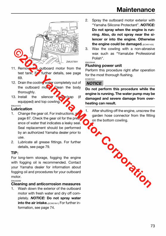
Maintenance
73
11. Remove the outboard motor from thetest tank. For further details, see page69.
12. Drain the cooling water completely out ofthe outboard motor. Clean the bodythoroughly.
13. Install the silencer cover/cap (ifequipped) and top cowling.
EMU41072
Lubrication1. Change the gear oil. For instructions, see
page 87. Check the gear oil for the pres-ence of water that indicates a leaky seal.Seal replacement should be performedby an authorized Yamaha dealer prior touse.
2. Lubricate all grease fittings. For furtherdetails, see page 79.
TIP:For long-term storage, fogging the enginewith fogging oil is recommended. Contactyour Yamaha dealer for information aboutfogging oil and procedures for your outboardmotor.EMU30269
Cleaning and anticorrosion measures1. Wash down the exterior of the outboard
motor with fresh water and dry off com-pletely. NOTICE: Do not spray waterinto the air intake. [ECM01841] For further in-formation, see page 74.
2. Spray the outboard motor exterior with“Yamaha Silicone Protectant”. NOTICE:Do not spray when the engine is run-ning. Also, do not spray near the si-lencer or into the engine. Otherwisethe engine could be damaged. [ECM01403]
3. Wax the cowling with a non-abrasivewax such as “Yamalube ProfessionalPolish”.
EMU28446
Flushing power unitPerform this procedure right after operationfor the most thorough flushing.
NOTICEECM01531
Do not perform this procedure while theengine is running. The water pump may bedamaged and severe damage from over-heating can result.
1. After shutting off the engine, unscrew thegarden hose connector from the fittingon the bottom cowling.
ZMU07891
U6DR38E0.book Page 73 Tuesday, November 27, 2018 2:08 PM
©2021 Yamaha Motor Corporation

Maintenance
74
2. Screw the garden hose adapter onto agarden hose, which is connected to afresh water supply, and then connect itto the garden hose connector.
3. With the engine off, turn on the water tapand let the water flush through the cool-ing passages for about 15 minutes. Turnoff the water and disconnect the gardenhose adapter from the garden hose con-nector.
4. Reinstall the garden hose connectoronto the fitting on the bottom cowling.Tighten the connector securely.NOTICE: Do not leave the garden hoseconnector loose on the bottom cowl-ing fitting or let the hose hang freeduring normal operation. Water willleak out of the connector instead of
cooling the engine, which can causeserious overheating. Be sure the con-nector is tightened securely on the fit-ting after flushing the engine. [ECM00542]
TIP:When flushing the engine with the boat in
the water, tilting up the outboard motor un-til it is completely out of the water willachieve better results.
For cooling system flushing instructions,see page 69.
EMU44342
Cleaning the outboard motorWhen cleaning the outboard motor, the topcowling must be installed.1. Wash the exterior of the outboard motor
using fresh water. NOTICE: Do notspray water into the air intake. [ECM01841]
2. Drain the cooling water completely out ofthe outboard motor. Clean the bodythoroughly.
EMU28463
Checking painted surface of outboard motorCheck the outboard motor for scratches,nicks, or flaking paint. Areas with damagedpaint are more likely to corrode. If necessary,clean and paint the areas. Touch-up paint isavailable from your Yamaha dealer.
1. Fitting2. Garden hose connector3. Garden hose adapter
1. Air intake
1
ZMU07862
U6DR38E0.book Page 74 Tuesday, November 27, 2018 2:08 PM
©2021 Yamaha Motor Corporation
Maintenance
75
EMU37015
Periodic maintenance
WARNINGEWM01943
These procedures require mechanicalskills, tools, and supplies. If you do nothave the proper skills, tools, or supplies toperform a maintenance procedure, have aYamaha dealer or other qualified mechan-ic do the work.The procedures involve disassembling themotor and exposing dangerous parts. Toreduce the risk of injury from moving, hot,or electrical parts: Turn off the engine and keep the key(s)
and engine shut-off cord (lanyard) withyou when you perform maintenance un-less otherwise specified.
The power tilt switch operate even whenthe ignition key is off. Keep people awayfrom the switches whenever workingaround the motor. When the motor istilted, keep away from the area under itor between it and the clamp bracket. Besure no one is in this area before operat-ing the power tilt mechanism.
Allow the engine to cool before handlinghot parts or fluids.
Always completely reassemble the mo-tor before operation.
Maintenance, replacement, or repair ofthe emission control devices and systemsmay be performed by any marine enginerepair establishment or individual. All war-ranty repairs, however, including those tothe emission control system, must be per-formed by an authorized Yamaha marinedealership.
A service manual is available for purchasethrough your Yamaha dealer for owners whohave the mechanical skills, tools, and otherequipment necessary to perform mainte-nance not covered by this owner’s manual.EMU28512
Replacement partsIf replacement parts are necessary, use onlygenuine Yamaha parts or parts of equivalentdesign and quality. Any part of inferior qualitymay malfunction, and the resulting loss ofcontrol could endanger the operator and pas-sengers. Yamaha genuine parts and acces-sories are available from your Yamaha dealer.EMU35522
Maintenance interval guidelinesThe service intervals provided in the Mainte-nance Chart were developed based upon“typical” use that includes operating at variedspeeds, with sufficient time for engine warmup and cool-down, a medium to light load,and an average cruising speed near the 3000to 4000 rpm range. As with any engine, how-ever, if your normal operating conditions aredifferent, you should consider service moreoften than shown, especially how often youchange your engine oil and gear oil. Exam-ples might include extended wide-open-throttle use or long periods of trolling oridling, carrying heavy loads, or frequent start-ing and stopping or shifting. More frequentmaintenance will often pay off many timesover in increased engine life and greater own-er satisfaction. Consult your Yamaha dealerfor additional maintenance recommenda-tions.
U6DR38E0.book Page 75 Tuesday, November 27, 2018 2:08 PM
©2021 Yamaha Motor Corporation

Maintenance
76
EMU46073
Maintenance chart 1TIP:Refer to the sections in this chapter for explanations of each owner-specific action. The maintenance cycle on these charts assume usage of 100 hours per year and regular
flushing of the cooling water passages. Maintenance frequency should be adjusted whenoperating the engine under adverse conditions such as extended trolling.
Disassembly or repairs may be necessary depending on the outcome of maintenancechecks.
Expendable or consumable parts and lubricants will lose their effectiveness over time andthrough normal usage regardless of the warranty period.
When operating in salt water, muddy, other turbid (cloudy), acidic water, the engine shouldbe flushed with clean water after each use.
The “ ” symbol indicates the check-ups which you may carry out yourself.The “ ” symbol indicates work to be carried out by your Yamaha dealer.
Item Actions
Initial Every
Page20 hours (3
months)
100 hours (1 year)
300 hours (3 years)
500 hours (5 years)
Anode(s) (external)Inspection or re-placement as nec-essary
88
Anode(s) (internal) *1
Inspection or re-placement as nec-essary
—
Anode(s) (internal) *2 Replacement —
Battery (electro-lyte level, terminal) Inspection 89
Battery (electro-lyte level, terminal)
Fill, charging or re-placing as neces-sary
—
Cooling water leakage
Inspection or re-placement as nec-essary
—
Cowling lock lever Inspection 42, 44
Engine starting condition/noise Inspection 47
Engine idle speed/noise Inspection 81
Engine oil Replacement 81
Engine oil filter (built into oil pan)
Inspection, clean-ing or replacement as necessary
—
U6DR38E0.book Page 76 Tuesday, November 27, 2018 2:08 PM
©2021 Yamaha Motor Corporation

Maintenance
77
Fuel filter (disposal type) Replacement —
Fuel line Inspection —
Fuel lineInspection or re-placement as nec-essary
—
Fuel pump Inspection or re-placement as nec-essary
—
Fuel/engine oil leakage Inspection —
Gear oil Replacement 87
Greasing points Greasing 79
Clamp bracket bolt (through tube)
Inspection and greasing —
Impeller/water pump housing
Inspection or re-placement as nec-essary
—
Impeller/water pump housing Replacement —
Power tilt unit Inspection 44
Propeller/propeller nut/cotter pin
Inspection or re-placement as nec-essary
84
Shift link/shift ca-ble
Inspection, adjust-ment or replace-ment as necessary
—
Spark plug(s)Inspection or re-placement as nec-essary
80
Spark plug caps/spark plug wires
Inspection or re-placement as nec-essary
—
Water from the cooling water pilot hole
Inspection 56
Throttle link/throt-tle cable
Inspection, adjust-ment or replace-ment as necessary
—
ThermostatInspection or re-placement as nec-essary
—
Item Actions
Initial Every
Page20 hours (3
months)
100 hours (1 year)
300 hours (3 years)
500 hours (5 years)
U6DR38E0.book Page 77 Tuesday, November 27, 2018 2:08 PM
©2021 Yamaha Motor Corporation

Maintenance
78
EMU46010
*1 cylinder head*2 cylinder headEMU46082
Maintenance chart 2
Timing beltInspection or re-placement as nec-essary
—
Valve clearance Inspection and ad-justment —
Cooling water inlet Inspection 24
Main switch/stop switch/choke switch
Inspection or re-placement as nec-essary
—
Wire harness con-nections/wire cou-pler connections
Inspection or re-placement as nec-essary
—
Fuel tank (optional Yamaha portable fuel tank)
Inspection and cleaning as neces-sary
—
Item ActionsEvery
Page1000 hours
Exhaust guide/ex-haust manifold
Inspection or re-placement as nec-essary
—
Timing belt Replacement —
Item Actions
Initial Every
Page20 hours (3
months)
100 hours (1 year)
300 hours (3 years)
500 hours (5 years)
U6DR38E0.book Page 78 Tuesday, November 27, 2018 2:08 PM
©2021 Yamaha Motor Corporation

Maintenance
79
EMU41303
GreasingYamalube Marine Grease
ZMU06671
U6DR38E0.book Page 79 Tuesday, November 27, 2018 2:08 PM
©2021 Yamaha Motor Corporation

Maintenance
80
EMU44492
Cleaning and adjusting spark plugThe spark plug is an important engine com-ponent and is easy to inspect. The conditionof the spark plug can indicate somethingabout the condition of the engine. For exam-ple, if the center electrode porcelain is verywhite, this could indicate an intake air leak orcarburetion problem in that cylinder. Do notattempt to diagnose any problems yourself.Instead, take the outboard motor to aYamaha dealer. You should periodically re-move and inspect the spark plug becauseheat and deposits will cause the spark plug toslowly break down and erode.1. Remove the spark plug caps from the
spark plugs.
2. Remove the spark plug. If electrode ero-sion becomes excessive, or if carbonand other deposits are excessive, youshould replace the spark plug with an-other of the correct type. WARNING!When removing or installing a sparkplug, be careful not to damage the in-sulator. A damaged insulator could al-low external sparks, which could leadto explosion or fire. [EWM00562]
3. Be sure to use the specified spark plug,otherwise the engine may not operateproperly. Before fitting the spark plug,measure the electrode gap with a wirethickness gauge; replace it if out of spec-ification.
4. When fitting the plug, wipe off any dirtfrom the threads, and then screw it in tothe correct torque.
TIP:If a torque-wrench is not available when youare reinstalling a spark plug, a good estimateof the correct torque is 1/12 turn past finger-tight. When you are installing a new sparkplug, a good estimate of the correct torque is1/2 to 2/3 turn past finger-tight.
1. Spark plug cap
Standard spark plug:BR6HS-10
1
ZMU07835
1. Spark plug gap2. Spark plug part number3. Spark plug I.D. mark (NGK)
Spark plug gap:0.9–1.0 mm (0.035–0.039 in)
Spark plug torque:24 N·m (2.4 kgf·m, 18 lb·ft)
U6DR38E0.book Page 80 Tuesday, November 27, 2018 2:08 PM
©2021 Yamaha Motor Corporation

Maintenance
81
EMU28992
Checking fuel filterCheck the fuel filter periodically. The fuel filteris a one piece, disposable type. If foreignmatter is found in the filter, replace it. For re-placement of the fuel filter, consult yourYamaha dealer.
EMU29045
Inspecting idle speed
WARNINGEWM00452
Do not touch or remove electrical partswhen starting or during operation.
Keep hands, hair, and clothes awayfrom the flywheel and other rotatingparts while the engine is running.
NOTICEECM00491
This procedure must be performed whilethe outboard motor is in the water. A flush-ing attachment or test tank can be used.
If the boat is not equipped with a tachometerfor the outboard motor, use a diagnostic ta-chometer for this procedure. Results mayvary depending on whether testing is con-ducted with the flushing attachment, in a testtank, or with the outboard motor in the water.1. Start the engine and allow it to warm up
fully in neutral until it is running smoothly.
2. Once the engine has warmed up, verifywhether the idle speed is set to specifi-cation. For idle speed specifications, seepage 15. If you have difficulty verifyingthe idle speed, or the idle speed requiresadjustment, consult a Yamaha dealer orother qualified mechanic.
EMU38808
Changing engine oil
WARNINGEWM00761
Avoid draining the engine oil immediate-ly after stopping the engine. The oil ishot and should be handled with care toavoid burns.
Be sure the outboard motor is securelyfastened to the transom or a stablestand.
NOTICEECM01711
Change the engine oil after the first 20hours of operation or 3 months, and every100 hours or at 1-year intervals thereafter.Otherwise the engine will wear quickly.
To prevent spilling oil where it could causedamage to nature, it is strongly recommend-ed that you use an oil changer to change theengine oil. If an oil changer is not available,drain the engine oil by removing the drainscrew. If you are not familiar with the proce-dure for changing the engine oil, consult yourYamaha dealer.1. Put the outboard motor in an upright po-
sition (not tilted). NOTICE: If the out-board motor is not level, the oil levelindicated on the oil dipstick may notbe accurate. [ECM01862]
1. Fuel filter
1
ZMU07836
U6DR38E0.book Page 81 Tuesday, November 27, 2018 2:08 PM
©2021 Yamaha Motor Corporation
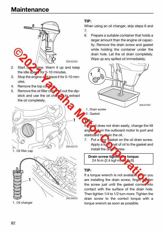
Maintenance
82
2. Start the engine. Warm it up and keepthe idle speed for 5-10 minutes.
3. Stop the engine and leave it for 5-10 min-utes.
4. Remove the top cowling.5. Remove the oil filler cap. Pull out the dip-
stick and use the oil changer to extractthe oil completely.
TIP:When using an oil changer, skip steps 6 and7.6. Prepare a suitable container that holds a
larger amount than the engine oil capac-ity. Remove the drain screw and gasketwhile holding the container under thedrain hole. Let the oil drain completely.Wipe up any spilled oil immediately.
TIP:If the oil does not drain easily, change the tiltangle or turn the outboard motor to port andstarboard to drain the oil.7. Put a new gasket on the oil drain screw.
Apply a light coat of oil to the gasket andinstall the drain screw.
TIP:If a torque wrench is not available when youare installing the drain screw, finger tightenthe screw just until the gasket comes intocontact with the surface of the drain hole.Then tighten 1/4 to 1/2 turn more. Tighten thedrain screw to the correct torque with atorque wrench as soon as possible.
1. Oil filler cap
1. Oil changer
ZMU02263
1
ZMU02270
ZMU06620
1
1. Drain screw2. Gasket
Drain screw tightening torque:24 N·m (2.4 kgf·m, 18 lb·ft)
21
ZMU07967
U6DR38E0.book Page 82 Tuesday, November 27, 2018 2:08 PM
©2021 Yamaha Motor Corporation

Maintenance
83
8. Add the correct amount of oil through thefiller hole. Put back the filler cap and thedipstick. NOTICE: Overfilling the oilcould cause leakage or damage. If theoil level is above the upper level mark,drain until the level meets the speci-fied capacity. [ECM01851]
9. Leave the outboard motor for 5-10 min-utes.
10. Remove the oil dipstick and wipe itclean.
11. Insert the dipstick and remove it again.Be sure to completely insert the dipstickinto the dipstick guide, otherwise the oillevel measurement will be incorrect.
12. Recheck the oil level using the dipstick tobe sure the level falls between the upperand lower marks. Consult your Yamahadealer if the oil level is out of specifiedlevel.
13. Start the engine and make sure that thelow oil pressure-alert indicator remainsoff. Also, make sure that there are no oil
leaks. NOTICE: If the low oil pressure-alert indicator comes on or if there areoil leaks, stop the engine and find thecause. Continued operation with aproblem could cause severe enginedamage. Consult your Yamaha dealerif the problem cannot be located andcorrected. [ECM01623]
14. Install the top cowling.15. Dispose of used oil according to local
regulations.
TIP: For more information on the disposal of
used oil, consult your Yamaha dealer.Change the oil more often when operating
the engine under adverse conditions suchas extended trolling.
EMU48060
Why YamalubeYAMALUBE oil is a Genuine YAMAHA Partborn of the engineers’ passion and belief thatengine oil is an important liquid engine com-ponent. We form teams of specialists in thefields of mechanical engineering, chemistry,electronics and track testing, and have themdevelop the engine together with the oil it willuse. Yamalube oils take full advantage of thebase oil’s qualities and blend in the ideal bal-ance of additives to make sure the final oilclears our performance standards. Thus,Yamalube mineral, semisynthetic and syn-thetic oils have their own distinct charactersand value. Yamaha’s experience gained overmany years of research and developmentinto oil since the 1960’s helps makeYamalube the best choice for your Yamahaengine.
Recommended engine oil:YAMALUBE 4M FC-W or 4-stroke outboard motor oil
Engine oil quantity:0.8 L (0.85 US qt, 0.70 Imp.qt)
1. Oil dipstick2. Upper mark3. Lower mark
3 2 1
ZMU07792
U6DR38E0.book Page 83 Tuesday, November 27, 2018 2:08 PM
©2021 Yamaha Motor Corporation

Maintenance
84
EMU29116
Inspecting wiring and connectors Inspect that each connector is engaged se-
curely. Inspect that each ground lead is properly
secured.
EMU32113
Checking propeller
WARNINGEWM01882
You could be seriously injured if the en-gine accidentally starts when you are nearthe propeller. Before inspecting, remov-ing, or installing the propeller, place theshift control in neutral, turn the mainswitch to “ ” (off) and remove the key,and remove the clip from the engine shut-off switch. Turn off the battery cut-offswitch if your boat has one.
Do not use your hand to hold the propellerwhen loosening or tightening the propellernut. Put a wood block between the anti-cavi-tation plate and the propeller to prevent thepropeller from turning.
CheckpointsCheck each of the propeller blades for ero-
sion from cavitation or ventilation, or otherdamage.
Check the propeller shaft for damage.Check the splines for wear or damage.Check for fish line tangled around the pro-
peller shaft.
Check the propeller shaft oil seal for dam-age.
EMU30663
Removing propellerEMU29198
Spline models1. Straighten the cotter pin and pull it out
using a pair of pliers.2. Remove the propeller nut, washer, and
spacer (if equipped). WARNING! Do notuse your hand to hold the propellerwhen loosening the propeller nut.[EWM01891]
ZMU07837
ZMU07969
ZMU07970
U6DR38E0.book Page 84 Tuesday, November 27, 2018 2:08 PM
©2021 Yamaha Motor Corporation

Maintenance
85
3. Remove the propeller, washer (ifequipped), and thrust washer.
EMU46500
Dual thrust models1. Straighten the cotter pin and pull it out
using a pair of pliers.2. Remove the propeller nut, washer, and
spacer. WARNING! Do not use yourhand to hold the propeller when loos-ening the propeller nut. [EWM01891]
3. Remove the propeller, washer, andthrust washer.
EMU30673
Installing propellerEMU29237
Spline models
NOTICEECM00502
Make sure to use a new cotter pin andbend the ends over securely. Otherwise,the propeller could come off during oper-ation and be lost.
1. Apply Yamaha marine grease or a corro-sion resistant grease to the propellershaft.
2. Install the spacer (if equipped), thrustwasher, washer (if equipped), and pro-peller on the propeller shaft. NOTICE:Make sure to install the thrust washerbefore installing the propeller. Other-wise, the lower case and propellerboss could be damaged. [ECM01882]
3. Install the spacer (if equipped) and thewasher. Tighten the propeller nut to thespecified torque.
1. Cotter pin2. Propeller nut3. Washer4. Propeller5. Thrust washer
1. Cotter pin2. Propeller nut3. Washer4. Spacer5. Propeller6. Thrust washer
23
5
4
1
ZMU08166
6 3
234
5
1
ZMU081671. Cotter pin2. Propeller nut3. Washer4. Propeller5. Thrust washer
Propeller nut tightening torque:17 N·m (1.7 kgf·m, 13 lb·ft)
23
5
4
1
ZMU08169
U6DR38E0.book Page 85 Tuesday, November 27, 2018 2:08 PM
©2021 Yamaha Motor Corporation

Maintenance
86
4. Align the propeller nut with the propellershaft hole. Insert a new cotter pin in thehole and bend the cotter pin ends.NOTICE: Do not reuse the cotter pin.Otherwise, the propeller can come offduring operation. [ECM01892]
TIP:If the propeller nut does not align with thepropeller shaft hole after tightening to thespecified torque, tighten the nut further toalign it with the hole.EMU46512
Dual thrust models
NOTICEECM00502
Make sure to use a new cotter pin andbend the ends over securely. Otherwise,the propeller could come off during oper-ation and be lost.
1. Apply Yamaha marine grease or a corro-sion resistant grease to the propellershaft.
2. Install the thrust washer, washer, andpropeller on the propeller shaft. NOTICE:Make sure to install the thrust washerbefore installing the propeller. Other-wise, the lower case and propellerboss could be damaged. [ECM01882]
3. Install the spacer and the washer. Tight-en the propeller nut to the specifiedtorque.
4. Align the propeller nut with the propellershaft hole. Insert a new cotter pin in thehole and bend the cotter pin ends.NOTICE: Do not reuse the cotter pin.Otherwise, the propeller can come offduring operation. [ECM01892]
TIP:If the propeller nut does not align with thepropeller shaft hole after tightening to thespecified torque, tighten the nut further toalign it with the hole.
1. Cotter pin2. Propeller nut3. Washer4. Spacer5. Propeller6. Thrust washer
Propeller nut tightening torque:21 N·m (2.1 kgf·m, 15 lb·ft)
6 3
234
5
1
ZMU08170
ZMU02063
U6DR38E0.book Page 86 Tuesday, November 27, 2018 2:08 PM
©2021 Yamaha Motor Corporation

Maintenance
87
EMU47070
Changing gear oil
WARNINGEWM00801
Be sure the outboard motor is securelyfastened to the transom or a stablestand. You could be severely injured ifthe outboard motor falls on you.
Never get under the lower unit while it istilted, even when the tilt support lever orknob is locked. Severe injury could oc-cur if the outboard motor accidentallyfalls.
1. Tilt the outboard motor so that the gearoil drain screw is at the lowest point pos-sible.
2. Place a suitable container under the gearcase.
3. Remove the gear oil drain screw andgasket. NOTICE: If there is an exces-sive quantity of metal particles on themagnetic gear oil drain screw, thiscan indicate lower unit problem. Con-sult your Yamaha dealer. [ECM01901]
TIP: If a magnetic gear oil drain screw is
equipped, remove all metal particles fromthe screw before installing it.
Always use new gaskets. Do not reuse theremoved gaskets.
4. Remove the oil level plug and gasket toallow the oil to drain completely.NOTICE: Check the used gear oil afterit has been drained. If the gear oil ismilky or contains water or a largeamount of metal particles, the gearcase may be damaged. Have aYamaha dealer check and repair theoutboard motor. [ECM00714]
TIP:For disposal of used oil, consult your Yamahadealer.5. Put the outboard motor in a vertical posi-
tion. Using a flexible or pressurized fillingdevice, inject the gear oil into the gear oildrain screw hole.
1. Gear oil drain screw2. Oil level plug
ZMU06685
2
1
Recommended gear oil:Yamalube Marine Gearcase Lube or Hypoid gear oil
Recommended gear oil grade:SAE 90 API GL-4
Gear oil quantity:0.150 L (0.159 US qt, 0.132 Imp.qt) (F9.9EB, F9.9EHB, F9.9MHB)0.370 L (0.391 US qt, 0.326 Imp.qt) (T9.9EB, T9.9MHB, T9.9PB, T9.9PHB, T9.9WHB)
ZMU06686
U6DR38E0.book Page 87 Tuesday, November 27, 2018 2:08 PM
©2021 Yamaha Motor Corporation

Maintenance
88
6. Put a new gasket on the oil level plug.When the oil begins to flow out of the oillevel plug hole, insert and tighten the oillevel plug.
TIP:Apply a light coat of gear oil to the oil levelplug thread and gasket before installation.
7. Put a new gasket on the gear oil drainscrew. Insert and tighten the gear oildrain screw.
TIP:Apply a light coat of gear oil to the gear oildrain screw thread and gasket before instal-lation.
EMU29318
Inspecting and replacing anode(s)Yamaha outboard motors are protected fromcorrosion by sacrificial anodes. Inspect theexternal anodes periodically. Remove scalesfrom the surfaces of the anodes. Consult aYamaha dealer for replacement of externalanodes.
NOTICEECM00721
Do not paint anodes, as this would renderthem ineffective.
TIP:Inspect ground leads attached to external an-odes on equipped models. Consult aYamaha dealer for inspection and replace-ment of internal anodes attached to the pow-er unit.
Tightening torque:7 N·m (0.7 kgf·m, 5.2 lb·ft)
Tightening torque:7 N·m (0.7 kgf·m, 5.2 lb·ft)
1. Anode
1. Anode
1. Anode
1
ZMU07838
1
ZMU07879
1ZMU07880
U6DR38E0.book Page 88 Tuesday, November 27, 2018 2:08 PM
©2021 Yamaha Motor Corporation
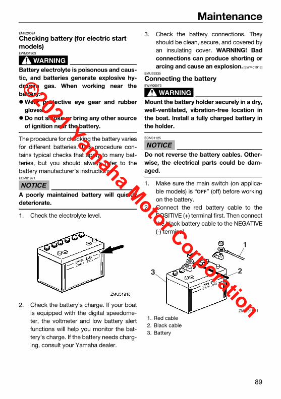
Maintenance
89
EMU29324
Checking battery (for electric start models)
WARNINGEWM01903
Battery electrolyte is poisonous and caus-tic, and batteries generate explosive hy-drogen gas. When working near thebattery:Wear protective eye gear and rubber
gloves.Do not smoke or bring any other source
of ignition near the battery.
The procedure for checking the battery variesfor different batteries. This procedure con-tains typical checks that apply to many bat-teries, but you should always refer to thebattery manufacturer’s instructions.
NOTICEECM01921
A poorly maintained battery will quicklydeteriorate.
1. Check the electrolyte level.
2. Check the battery’s charge. If your boatis equipped with the digital speedome-ter, the voltmeter and low battery alertfunctions will help you monitor the bat-tery’s charge. If the battery needs charg-ing, consult your Yamaha dealer.
3. Check the battery connections. Theyshould be clean, secure, and covered byan insulating cover. WARNING! Badconnections can produce shorting orarcing and cause an explosion. [EWM01913]
EMU29335
Connecting the battery
WARNINGEWM00573
Mount the battery holder securely in a dry,well-ventilated, vibration-free location inthe boat. Install a fully charged battery inthe holder.
NOTICEECM01125
Do not reverse the battery cables. Other-wise, the electrical parts could be dam-aged.
1. Make sure the main switch (on applica-ble models) is “ ” (off) before workingon the battery.
2. Connect the red battery cable to thePOSITIVE (+) terminal first. Then connectthe black battery cable to the NEGATIVE(-) terminal.
1. Red cable2. Black cable3. Battery
ZMU01811
1
23
U6DR38E0.book Page 89 Tuesday, November 27, 2018 2:08 PM
©2021 Yamaha Motor Corporation

Maintenance
90
3. The electrical contacts of the battery andcables must be clean and properly con-nected, or the battery will not start theengine.
EMU29372
Disconnecting the battery1. Turn off the battery cut-off switch (if
equipped) and main switch. NOTICE: Ifthey are left on, the electrical systemcan be damaged. [ECM01931]
2. Disconnect the negative cable(s) fromthe negative (-) terminal. NOTICE: Al-ways disconnect all negative (-) cablesfirst to avoid a short circuit and dam-age to the electrical system. [ECM01941]
3. Disconnect the positive cable(s) and re-move the battery from the boat.
4. Clean, maintain, and store the batteryaccording to the manufacturer’s instruc-tions.
U6DR38E0.book Page 90 Tuesday, November 27, 2018 2:08 PM
©2021 Yamaha Motor Corporation

Trouble Recovery
91
EMU29428
TroubleshootingA problem in the fuel, compression, or igni-tion systems can cause poor starting, loss ofpower, or other problems. This section de-scribes basic checks and possible remedies,and covers all Yamaha outboard motors.Therefore some items may not apply to yourmodel.If your outboard motor requires repair, bringit to your Yamaha dealer.If the engine trouble-alert indicator is flashing,consult your Yamaha dealer.
Starter will not operate.Q. Is battery capacity weak or low?A. Check battery condition. Use battery ofrecommended capacity.
Q. Are battery connections loose or corrod-ed?A. Tighten battery cables and clean batteryterminals.
Q. Is fuse for electric start relay or electric cir-cuit blown?A. Check for cause of electric overload andrepair. Replace fuse with one of correct am-perage.
Q. Are starter components faulty?A. Have serviced by a Yamaha dealer.
Q. Is shift lever in gear?A. Shift to neutral.
Engine will not start (starter operates).Q. Is fuel tank empty?A. Fill tank with clean, fresh fuel.
Q. Is fuel contaminated or stale?
A. Fill tank with clean, fresh fuel.
Q. Is fuel filter clogged?A. Clean or replace filter.
Q. Is starting procedure incorrect?A. See page 48.
Q. Has fuel pump malfunctioned?A. Have serviced by a Yamaha dealer.
Q. Are spark plug(s) fouled or of incorrecttype?A. Inspect spark plug(s). Clean or replacewith recommended type.
Q. Are spark plug cap(s) fitted incorrectly?A. Check and re-fit cap(s).
Q. Is ignition wiring damaged or poorly con-nected?A. Check wires for wear or breaks. Tighten allloose connections. Replace worn or brokenwires.
Q. Are ignition parts faulty?A. Have serviced by a Yamaha dealer.
Q. Is engine shut-off cord (lanyard) not at-tached?A. Attach cord.
Q. Are engine inner parts damaged?A. Have serviced by a Yamaha dealer.
Engine idles irregularly or stalls.Q. Are spark plug(s) fouled or of incorrecttype?A. Inspect spark plug(s). Clean or replacewith recommended type.
U6DR38E0.book Page 91 Tuesday, November 27, 2018 2:08 PM
©2021 Yamaha Motor Corporation

Trouble Recovery
92
Q. Is fuel system obstructed?A. Check for pinched or kinked fuel line orother obstructions in fuel system.
Q. Is fuel contaminated or stale?A. Fill tank with clean, fresh fuel.
Q. Is fuel filter clogged?A. Clean or replace filter.
Q. Have ignition parts failed?A. Have serviced by a Yamaha dealer.
Q. Has alert system activated?A. Find and correct cause of alert.
Q. Is spark plug gap incorrect?A. Inspect and adjust as specified.
Q. Is ignition wiring damaged or poorly con-nected?A. Check wires for wear or breaks. Tighten allloose connections. Replace worn or brokenwires.
Q. Is specified engine oil not being used?A. Check and replace oil as specified.
Q. Is thermostat faulty or clogged?A. Have serviced by a Yamaha dealer.
Q. Are carburetor adjustments incorrect?A. Have serviced by a Yamaha dealer.
Q. Is fuel pump damaged?A. Have serviced by a Yamaha dealer.
Q. Is air vent screw on fuel tank closed?A. Open air vent screw.
Q. Is choke knob pulled out?
A. Return to home position.
Q. Is motor angle too high?A. Return to normal operating position.
Q. Is carburetor clogged?A. Have serviced by a Yamaha dealer.
Q. Is fuel joint connection incorrect?A. Connect correctly.
Q. Is throttle valve adjustment incorrect?A. Have serviced by a Yamaha dealer.
Q. Is battery cable disconnected?A. Connect securely.
Alert buzzer sounds or indicator lights.Q. Is cooling system clogged?A. Check water intake for restriction.
Q. Is engine oil level low?A. Fill oil tank with specified engine oil.
Q. Is heat range of spark plug incorrect?A. Inspect spark plug and replace it with rec-ommended type.
Q. Is specified engine oil not being used?A. Check and replace oil with specified type.
Q. Is engine oil contaminated or deteriorat-ed?A. Replace oil with fresh, specified type.
Q. Is oil filter clogged?A. Have serviced by a Yamaha dealer.
Q. Has oil feed/injection pump malfunc-tioned?
U6DR38E0.book Page 92 Tuesday, November 27, 2018 2:08 PM
©2021 Yamaha Motor Corporation

Trouble Recovery
93
A. Have serviced by a Yamaha dealer.
Q. Is load on boat improperly distributed?A. Distribute load to place boat on an evenplane.
Q. Is water pump or thermostat faulty?A. Have serviced by a Yamaha dealer.
Q. Is there excess water in fuel filter cup?A. Drain filter cup.
Engine power loss.Q. Is propeller damaged?A. Have propeller repaired or replaced.
Q. Is propeller pitch or diameter incorrect?A. Install correct propeller to operate out-board at its recommended speed (r/min)range.
Q. Is trim angle incorrect?A. Adjust trim angle to achieve most efficientoperation.
Q. Is motor mounted at incorrect height ontransom?A. Have motor adjusted to proper transomheight.
Q. Has alert system activated?A. Find and correct cause of alert.
Q. Is boat bottom fouled with marine growth?A. Clean boat bottom.
Q. Are spark plug(s) fouled or of incorrecttype?A. Inspect spark plug(s). Clean or replacewith recommended type.
Q. Are weeds or other foreign matter tangledon gear housing?A. Remove foreign matter and clean lowerunit.
Q. Is fuel system obstructed?A. Check for pinched or kinked fuel line orother obstructions in fuel system.
Q. Is fuel filter clogged?A. Clean or replace filter.
Q. Is fuel contaminated or stale?A. Fill tank with clean, fresh fuel.
Q. Is spark plug gap incorrect?A. Inspect and adjust as specified.
Q. Is ignition wiring damaged or poorly con-nected?A. Check wires for wear or breaks. Tighten allloose connections. Replace worn or brokenwires.
Q. Have electrical parts failed?A. Have serviced by a Yamaha dealer.
Q. Is specified fuel not being used?A. Replace fuel with specified type.
Q. Is specified engine oil not being used?A. Check and replace oil with specified type.
Q. Is thermostat faulty or clogged?A. Have serviced by a Yamaha dealer.
Q. Is air vent screw closed?A. Open the air vent screw.
Q. Is fuel pump damaged?
U6DR38E0.book Page 93 Tuesday, November 27, 2018 2:08 PM
©2021 Yamaha Motor Corporation

Trouble Recovery
94
A. Have serviced by a Yamaha dealer.
Q. Is fuel joint connection incorrect?A. Connect correctly.
Q. Is heat range of spark plug incorrect?A. Inspect spark plug and replace it with rec-ommended type.
Q. Is high pressure fuel pump drive belt bro-ken?A. Have serviced by a Yamaha dealer.
Q. Is engine not responding properly to shiftlever position?A. Have serviced by a Yamaha dealer.
Engine vibrates excessively.Q. Is propeller damaged?A. Have propeller repaired or replaced.
Q. Is propeller shaft damaged?A. Have serviced by a Yamaha dealer.
Q. Are weeds or other foreign matter tangledon propeller?A. Remove and clean propeller.
Q. Is motor mounting bolt loose?A. Tighten bolt.
Q. Is steering pivot loose or damaged?A. Tighten or have serviced by a Yamahadealer.
EMU29435
Temporary action in emergen-cy
EMU29442
Impact damage
WARNINGEWM00871
The outboard motor can be seriouslydamaged by a collision while operating ortrailering. Damage could make the out-board motor unsafe to operate.
If the outboard motor hits an object in the wa-ter, follow the procedure below.
1. Stop the engine immediately.2. Check the control system and all compo-
nents for damage. Also, check the boatfor damage.
3. Whether damage is found or not, returnto the nearest harbor slowly and careful-ly.
4. Have a Yamaha dealer check the out-board motor before operating it again.
EMU30684
Replacing fuseIf a fuse has blown, open the fuse holder andremove the fuse with a fuse puller. Replace itwith a spare one of the proper amperage.
U6DR38E0.book Page 94 Tuesday, November 27, 2018 2:08 PM
©2021 Yamaha Motor Corporation

Trouble Recovery
95
WARNINGEWM00632
Substituting an incorrect fuse or a piece ofwire could allow excessive current flow.This could cause electric system damageand a fire hazard.
Consult your Yamaha dealer if the new fuseimmediately blows again.
EMU32131
Power tilt will not operateIf the engine cannot be tilted up or down withthe power tilt because of a discharged bat-tery or a failure with the power tilt unit, the en-gine can be tilted manually.
1. Loosen the manual valve screw by turn-ing it counterclockwise until it stops.
2. Put the engine in the desired position,then tighten the manual valve screw byturning it clockwise.
EMU29534
Starter will not operateIf the starter mechanism does not operate(the engine cannot be cranked with the start-er), the engine can be started with an emer-gency starter rope.
WARNINGEWM01023
Use this procedure only in an emergen-cy to return to the nearest port for re-pairs.
When the emergency starter rope isused to start the engine, the start-in-gear protection device does not oper-ate. Make sure the remote control leveris in neutral. Otherwise the boat couldunexpectedly start to move, which couldresult in an accident.
Attach the engine shut-off cord to a se-cure place on your clothing, or your armor leg while operating the boat.
Do not attach the cord to clothing thatcould tear loose. Do not route the cordwhere it could become entangled, pre-venting it from functioning.
1. Cover2. Fuse (10 A)3. Spare fuse (10 A)4. Fuse puller
1. Fuse puller
1
ZMU04337
1. Manual valve screw
U6DR38E0.book Page 95 Tuesday, November 27, 2018 2:08 PM
©2021 Yamaha Motor Corporation

Trouble Recovery
96
Avoid accidentally pulling the cord dur-ing normal operation. Loss of enginepower means the loss of most steeringcontrol. Also, without engine power, theboat could slow rapidly. This couldcause people and objects in the boat tobe thrown forward.
Make sure no one is standing behindyou when pulling the starter rope. Itcould whip behind you and injure some-one.
An unguarded, rotating flywheel is verydangerous. Keep loose clothing andother objects away when starting theengine. Use the emergency starter ropeonly as instructed. Do not touch the fly-wheel or other moving parts when theengine is running. Do not install thestarter mechanism or top cowling afterthe engine is running.
Do not touch the ignition coil, spark plugwire, spark plug cap, or other electricalcomponents when starting or operatingthe motor. You could get an electricalshock.
EMU29563
Emergency starting engine1. Remove the top cowling.2. Remove the start-in-gear protection ca-
ble from the starter, if equipped.
3. Remove the starter/flywheel cover afterremoving the bolt(s).
4. Prepare the engine for starting. For fur-ther information, see page 48. Be surethe engine is in neutral and that the clip isattached to the engine shut-off switch.The main switch must be “ ” (on), ifequipped.
5. If equipped the choke knob, pull out itwhen the engine is cold. After the enginestarts, gradually return the choke knob toits home position as the engine warmsup.
1. Start-in-gear protection cable
ONOFF
ZMU01880
U6DR38E0.book Page 96 Tuesday, November 27, 2018 2:08 PM
©2021 Yamaha Motor Corporation

Trouble Recovery
97
6. Insert the knotted end of the emergencystarter rope into the notch in the flywheelrotor and wind the rope several turnsaround the flywheel clockwise.
7. Give a strong pull straight out to crankand start the engine. Repeat if neces-sary.
EMU29672
Engine fails to operateEMU35322
Emergency engine operationIf the battery voltage is low or in the unlikelyevent of an ignition system malfunction, theengine speed may become erratic or the en-gine may stop. In such a situation, follow theprocedure below.Disconnect the yellow cord (emergency cir-cuit) of the CDI unit.Run the engine at low speed and return toport. NOTICE: Follow this procedure onlyin an emergency and just long enough toreturn to port for repairs. [ECM00382]
EMU33502
Treatment of submerged motorIf the outboard motor is submerged, immedi-ately take it to a Yamaha dealer. Otherwisesome corrosion may begin almost immedi-ately. NOTICE: Do not attempt to run theoutboard motor until it has been com-pletely inspected. [ECM00402]
ZMU07907
1. Yellow cord
U6DR38E0.book Page 97 Tuesday, November 27, 2018 2:08 PM
©2021 Yamaha Motor Corporation

Consumer information
98
EMU29837
YAMAHA FOUR-STROKE OUTBOARD MOTOR THREE-YEAR LIMITED WARRANTY
ZMU07048
Yamaha Motor Corporation, U.S.A. and Yamaha Motor Canada Ltd. (“Yamaha”) hereby warrant that new Yamaha four-stroke outboard motors will be free from defects in material and workmanship for the period of time stated herein, subject to certain stated limitations.
PERIOD OF WARRANTY. Any new Yamaha four-stroke outboard motor purchased from an authorized Yamaha dealer in the customer’s country of residence (United States or Canada) and registered with Yamaha will be warranted against defects in material or workmanship, subject to exclusions noted herein, for the following applicable period determined by type of use:
The second and third year of warranty (if applicable) shall be limited to covering the cost of parts and labor for major components only. The major components covered are:
WARRANTY REGISTRATION. To be eligible for warranty coverage, the outboard motor must be registered with Yamaha in the country of residence. Warranty registration can be accomplished by any authorized Yamaha Outboard Motor Dealer.
OBTAINING REPAIRS UNDER WARRANTY. During the period of warranty, any authorized Yamaha Outboard Motor Dealer in the country of residence will, free of charge, repair or replace, at Yamaha’s option, any parts adjudged defective by Yamaha due to faulty workmanship or material from the factory. All replaced parts will become the property of Yamaha. If the customer is temporarily using a U.S.-registered outboard motor in Canada, or a Canada-registered outboard motor in the United States, and it needs warranty repairs, the owner should contact a nearby authorized Yamaha Outboard Motor Dealer for assistance. The local dealer will contact Yamaha on the owner’s behalf so that needed repairs can be made as quickly as possible.
CUSTOMER’S RESPONSIBILITY. Under the terms of this warranty, the customer will be responsible for ensuring that the outboard motor is properly operated, maintained, and stored as specified in the applicable Owner’s Manual. The owner of the outboard motor shall give notice to an authorized Yamaha Outboard Motor Dealer of any and all apparent defects within ten (10) days of discovery and make the motor available at that time for inspection and repairs at the dealer’s place of business.
Replacement parts used in warranty repairs will be warranted for the balance of the applicable warranty period.
• Pleasure use – three (3) years from the date of purchase.
Power Unit Section• Power Head• Intake Manifold• Carburetor Assembly and its Related Components• Fuel Injection System and its Related Components• Fuel and Oil Pump Assemblies• Ignition System (Standard and Microcomputer)Lower Unit Section Bracket Section• Exhaust System• Bracket System• Upper Casing• Power Trim and Tilt Assembly• Lower Unit Assembly
• Commercial application – one (1) year from the date of purchase. A commercial application is defined as any use of the outboard motor to generate income (excluding tournament fishing) or support business operations in any way during the warranty period, without regard to the type or percentage of commercial use. Yamaha reserves the right to modify incorrect registration data and reduce the warranty period to reflect commercial use.
• Yamaha peripheral equipment included with the motor, such as gauges, fuel tanks, and hoses, remote control boxes, and wiring external from the motor unit, will be warranted for one (1) year from the date of purchase for either pleasure or commercial use.
U6DR38E0.book Page 98 Tuesday, November 27, 2018 2:08 PM
©2021 Yamaha Motor Corporation

Consumer information
99
ZMU07047
SPECIFIC PARTS EXCLUDED FROM WARRANTY. Parts replaced due to normal wear or routine maintenance such as oil, spark plugs, shear pins, propellers, hubs, fuel and oil filters, brushes for the starter motor and power tilt motor, water pump impellers, and anodes, are not covered by warranty. Charges for removal of the motor from a boat and transporting the motor to and from an authorized Yamaha Outboard Motor Dealer are excluded from warranty coverage.
EMISSION CONTROL WARRANTY (United States only). Yamaha warrants to the ultimate purchaser and any subsequent owner, that the emission control components on this engine are designed, built and equipped so as to conform at the time of sale with applicable regulations under section 213 of the Clean Air Act and that this engine is covered against defects in materials and workmanship which cause said engine to fail to conform with applicable exhaust emission regulations for five (5) years from the date of purchase or 175 hours of operation, whichever comes first. Evaporative components (e.g., hoses, fuel tank, fuel cap) are two (2) years from the date of purchase. Some states have different emission control warranty provisions. As these vary from state to state, consult your Yamaha dealer or contact Yamaha Customer Relations at 1-866-894-1626 for more information.
TRANSFER OF WARRANTY Transfer of the warranty from the original purchaser to any subsequent purchaser is possible by having the motor inspected by an authorized Yamaha Outboard Motor Dealer and requesting the dealer to submit a change of registration to Yamaha within ten (10) days of the transfer.
THIS WARRANTY GIVES YOU SPECIFIC LEGAL RIGHTS, AND YOU MAY ALSO HAVE OTHER RIGHTS WHICH VARY FROM STATE TO STATE/PROVINCE TO PROVINCE.
YAMAHA MAKES NO OTHER WARRANTY OF ANY KIND, EXPRESSED OR IMPLIED. ALL IMPLIED WARRANTIES OF MERCHANTABILITY AND FITNESS FOR A PARTICULAR PURPOSE WHICH EXCEED THE OBLIGATIONS AND TIME LIMITS STATED IN THIS WARRANTY ARE HEREBY DISCLAIMED BY YAMAHA AND EXCLUDED FROM THIS WARRANTY. SOME STATES/PROVINCES DO NOT ALLOW LIMITATIONS ON HOW LONG AN IMPLIED WARRANTY LASTS, SO THE ABOVE LIMITATIONS MAY NOT APPLY TO YOU. ALSO EXCLUDED FROM THIS WARRANTY ARE ANY INCIDENTAL OR CONSEQUENTIAL DAMAGES INCLUDING LOSS OF USE. SOME STATES/PROVINCES DO NOT ALLOW THE EXCLUSION OR LIMITATION OF INCIDENTAL OR CONSEQUENTIAL DAMAGES, SO THE ABOVE EXCLUSION MAY NOT APPLY TO YOU.
GENERAL EXCLUSIONS FROM WARRANTY. This warranty will not cover the repair of damage if the damage is a result of abuse or neglect of the product. Examples of abuse and neglect include, but are not limited to:1. Racing or competition use, modification of original parts, abnormal strain.2. Lack of proper maintenance and off season storage as described in the Owner’s Manual; installation of parts or accessories that are
not equivalent in design and quality to genuine Yamaha parts.3. Operation of the motor at an rpm other than specified, use of lubricants or oils that are not suitable for outboard motor use.4. Damage as a result of accidents, collisions, contact with foreign materials, or submersion.5. Growth of marine organism on motor surfaces.6. Normal deterioration.
Specific parts excluded from the second and third year of warranty (if applicable) are:• Top and Bottom Cowling• Electric Components (other than ignition system)• Rubber Components (such as hoses, tubes, rubber seals, fittings, and clamps)
U6DR38E0.book Page 99 Tuesday, November 27, 2018 2:08 PM
©2021 Yamaha Motor Corporation

Consumer information
100
EMU29846
IMPORTANT WARRANTY INFORMATION IF YOU USE YOUR YAMAHA OUTSIDE THE U.S.A. OR CANADA
Welcome to the Yamaha Family!
Congratulations on the purchase of your new Yamaha products. Yamaha is commit-ted to exceptional customer satisfaction and we want your ownership experience to be a satisfying one. Please read the following warranty information to help ensure satisfaction with your Yamaha.
This model was manufactured with specifications appropriate for sale and use in the U.S.A. and Canada. Please note the following information:
Your Yamaha model may not be sold in some countries. Therefore, a Yamaha dealer outside the United States or Canada may not have all of the replacement parts or technical information available to provide proper service. This may unavoidably delay repairs. Thank you for your understanding should this happen.
TIP:
1. As explained in the Limited Warranty Statement, the Yamaha warranty covers your Yamaha when it is registered and used in your country of residence. If you are temporarily using a U.S.-registered outboard motor in Canada, or a Canada-registered outboard motor in the United States, and it needs warranty repairs, you should contact a nearby authorized Yamaha Outboard Motor Dealer for assistance. The local dealer will contact Yamaha on the owner’s behalf so that needed repairs can be made as quickly as possible.
2. If you need repairs while temporarily using your Yamaha in another country, contact the local authorized Yamaha distributor for that country. Yamaha will work with that distributor to make the needed repairs as quickly as possible. If you have to pay for a repair that you believe your warranty would have covered at home, present all repair orders, receipts, or other related documents to your local dealer when you return home. He will be able to contact Yamaha on your behalf to see if any refund can be provided.
3. If your Yamaha is registered or used primarily outside the United States or Canada, the warranty printed in this manual does not apply to you. Contact the dealer who sold the Yamaha marine power unit to you for customer support information.
ZMU05199
U6DR38E0.book Page 100 Tuesday, November 27, 2018 2:08 PM
©2021 Yamaha Motor Corporation

101
INDEX
AAccident reporting .................................. 4Alcohol and drugs................................... 2Alert indicator ....................................... 35Alert system.......................................... 37Anode(s), inspecting and replacing ...... 88Anti-fouling paint .................................. 21Approval label of emission control
certificate............................................ 22Avoid collisions....................................... 3
BBasic boating rules (Rules of the road)... 5Battery .................................................. 45Battery, checking (electric start
models)............................................... 89Battery, connecting .............................. 89Battery, disconnecting.......................... 90Battery requirements ............................ 17Boat education and training ................... 4Boat horsepower rating ........................ 16Boating organizations............................. 5Boating safety......................................... 2Boating safety publications .................... 4Breaking in engine ................................ 41
CCarbon monoxide................................... 2Checks after engine warm up............... 56Checks after starting engine................. 56Checks before starting engine.............. 41Choke knob .......................................... 31Choke switch........................................ 28Clamping the outboard motor .............. 40Cleaning and anticorrosion
measures............................................ 73Cleaning the outboard motor ............... 74Collisions with floating or submerged
objects.................................................. 3Compliance mark label ........................... 9Components diagram........................... 24Control functions, checking.................. 42Cooling water ....................................... 56Cowling lock lever ................................ 34
Cruising in salt water or other conditions........................................... 68
DDismounting the outboard motor ......... 69
EElectric shock ......................................... 1Emergency engine operation................ 97Emergency equipment.......................... 22Emergency starting engine ................... 96Emergency, temporary action in........... 94Emission control information ................ 22Engine fails to operate .......................... 97Engine oil .............................................. 43Engine oil, changing ............................. 81Engine oil, filling.................................... 41Engine oil requirements ........................ 19Engine shut-off cord (lanyard) .......... 1, 42Engine shut-off cord (lanyard) and
clip ...................................................... 30Engine stop button ............................... 30
FFilling fuel.............................................. 45First-time operation .............................. 41Flushing device............................... 35, 43Flushing in a test tank........................... 72Flushing power unit .............................. 73Fuel filter, checking............................... 81Fuel leaks, checking for ........................ 42Fuel level............................................... 42Fuel requirements ................................. 19Fuel system........................................... 42Fuel tank ............................................... 26Fuse, replacing ..................................... 94
GGasoline............................................ 1, 19Gasoline Additives ................................ 20Gasoline exposure and spills.................. 2Gear oil, changing................................. 87Gear shift lever...................................... 28Greasing ............................................... 79
U6DR38E0.book Page 101 Tuesday, November 27, 2018 2:08 PM
©2021 Yamaha Motor Corporation

INDEX
102
HHot parts................................................. 1
IIdentification numbers record................. 9Idle speed, inspecting .......................... 81Impact damage..................................... 94Installation requirements ...................... 16Instruments and indicators ................... 36
KKey number ............................................ 9
LLaws and regulations.............................. 4Low oil pressure alert ........................... 37Low oil pressure-alert indicator ............ 36Lubrication............................................ 73
MMain switch .......................................... 31Maintenance chart 1............................. 76Maintenance chart 2............................. 78Maintenance interval guidelines ........... 75Manual starter handle........................... 31Modifications .......................................... 2Mounting height.................................... 39Mounting outboard motor .................... 17Mounting the outboard motor .............. 38Muddy or acidic water.......................... 21
NNeutral interlock trigger ........................ 28Neutral throttle lever ............................. 28
OOperating engine .................................. 47Outboard motor, checking ................... 43Outboard motor disposal
requirements ...................................... 22Outboard motor (painted surface),
checking............................................. 74Outboard motor safety ........................... 1Outboard motor serial number ............... 9
Overloading ............................................ 2
PPassenger training .................................. 4Passengers ............................................. 2People in the water ................................. 2Periodic maintenance ........................... 75Personal flotation devices (PFDs) ........... 2Power tilt................................................. 1Power tilt switch ................................... 32Power tilt system, checking.................. 44Power tilt unit ........................................ 34Power tilt will not operate ..................... 95Propeller ................................................. 1Propeller, checking............................... 84Propeller, installing ............................... 85Propeller, removing............................... 84Propeller selection ................................ 18
RRead manuals and labels ..................... 11Remote control box .............................. 27Remote control lever ............................ 27Remote control requirements ............... 17Replacement parts ............................... 75Rotating parts ......................................... 1Rules when encountering vessels .......... 6
SSending fuel (portable tank).................. 47Shallow water ....................................... 66Shifting.................................................. 57Shifting (checks after engine warm
up)....................................................... 56Spark plug, cleaning and adjusting ...... 80Specifications ....................................... 15Star labels ............................................. 22Starter button........................................ 31Starter will not operate ......................... 95Starting engine...................................... 48Start-in-gear protection ........................ 18Steering and sailing rules and sound
signals .................................................. 5Steering friction adjuster....................... 32
U6DR38E0.book Page 102 Tuesday, November 27, 2018 2:08 PM
©2021 Yamaha Motor Corporation

INDEX
103
Stop switches ....................................... 56Stopping boat....................................... 58Stopping engine ................................... 58Storing outboard motor ........................ 71Submerged outboard motor................. 97
TThrottle friction adjuster........................ 29Throttle grip .......................................... 29Throttle indicator .................................. 29Tiller handle .......................................... 28Tilt lock mechanism.............................. 33Tilt support bar ..................................... 34Tilt support knob .................................. 33Tilting up and down .............................. 62To install the battery ............................. 17Top cowling, installing .......................... 44Top cowling, removing ......................... 42Transporting and storing outboard
motor .................................................. 69Trim rod (tilt pin).................................... 33Trimming outboard motor..................... 60Troubleshooting.................................... 91
WWarming up engine .............................. 56Warning labels ...................................... 11Warranty information (use outside
the U.S.A. or Canada) ...................... 100Warranty, limited................................... 98Weather .................................................. 3Wiring and connectors, inspecting....... 84
YYamalube.............................................. 83
U6DR38E0.book Page 103 Tuesday, November 27, 2018 2:08 PM
©2021 Yamaha Motor Corporation

U6DR38E0.book Page 104 Tuesday, November 27, 2018 2:08 PM
©2021 Yamaha Motor Corporation

EMU43024
For your best ownership experience, think Genuine Yamaha!
Genuine Yamaha Parts — Genuine Yamaha replacement parts are the exact same partsas the ones originally equipped on your vehicle, providing you with the performance and du-rability you have come to expect. Why settle for aftermarket parts that may not provide fullconfidence and satisfaction?
Genuine Yamaha Accessories — Yamaha only offers accessories that meet our high stan-dards for quality and performance. Buy with confidence, knowing your Genuine Yamaha Ac-cessories will fit right and perform right — right out of the box.
Yamalube — Take care of your Yamaha with legendary Yamalube oils, lubricants, and careproducts. They’re formulated and approved by the toughest judges we know: the Yamahaengineering teams that know your Yamaha from the inside out.
Genuine Yamaha Service Manuals — Get the same factory manual for your vehicle thatthe technicians at your authorized Yamaha dealer use. Service manuals are availablethrough your Yamaha dealer or you can order them directly through yamahapubs.com (USAonly).
Genuine Yamaha products are available only from your Yamaha dealer.
Find out more at www.yamaha–motor in your country of residence.
U6DR38E0.book Page 1 Tuesday, November 27, 2018 2:08 PM
©2021 Yamaha Motor Corporation

Printed on recycled paperPrinted in JapanDecember 2018–1.2 × 1 CR
U6DR38E0.book Page 1 Tuesday, November 27, 2018 2:08 PM
©2021 Yamaha Motor Corporation