Embed Size (px)
Citation preview

i i
BULLETIN OH-1
AS
HC
RO
FT
® PR
ES
SU
RE
& T
EM
PE
RA
TU
RE
INS
TR
UM
EN
T O
RD
ER
ING
HA
ND
BO
OK
PRESSURE & TEMPERATURE INSTRUMENT ORDERING HANDBOOK
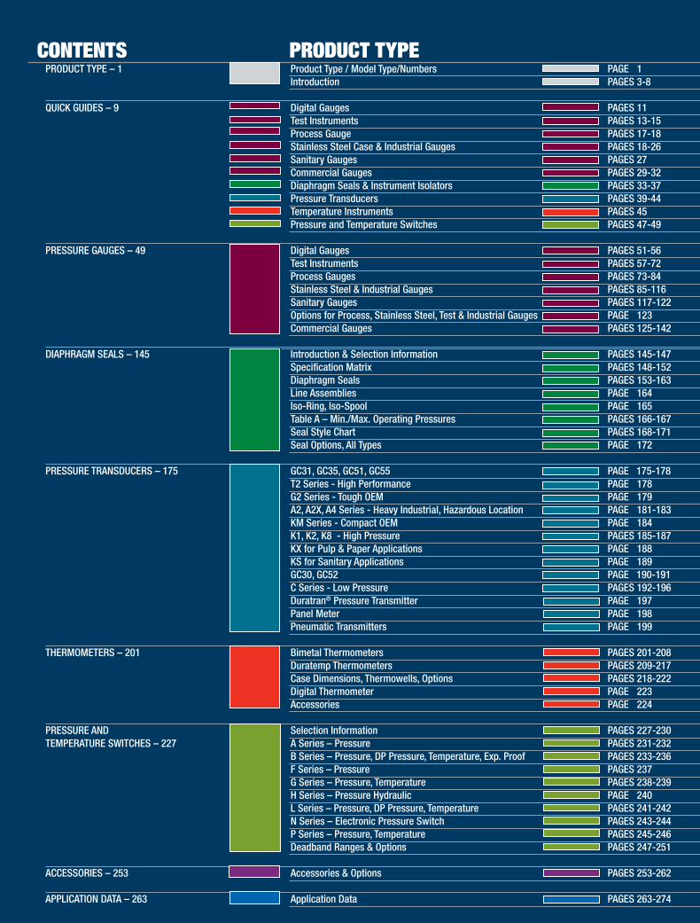
PRODUCT TYPE – 1 Product Type / Model Type/Numbers PAGES 1 Introduction PAGES 3-8
QUICK GUIDES – 9 Digital Gauges PAGES 11 Test Instruments PAGES 13-15 Process Gauge PAGES 17-18 Stainless Steel Case & Industrial Gauges PAGES 18-26 Sanitary Gauges PAGES 27 Commercial Gauges PAGES 29-32 Diaphragm Seals & Instrument Isolators PAGES 33-37 Pressure Transducers PAGES 39-44 Temperature Instruments PAGES 45 Pressure and Temperature Switches PAGES 47-49
PRESSURE GAUGES – 49 Digital Gauges PAGES 51-56 2030, 2089, 2086, 2084, 2074, 2174, 2274, D1005P, Test Instruments PAGES 57-72 A4A, 1082, 1084, ATE-100, ST-2A, 1305D, 1327D, 1327CM, PT, AVC-1000 Process Gauges PAGES 73-84 1259, 1279, 1377, 1379, 2462 Stainless Steel & Industrial Gauges PAGES 85-116 T5500, T6500, 1008S, 1009 , 1109, 1010, 1017, 1220, 1020S, 1038, 1339, 1125, 1125A, 1127, 1128, 1130, 1131, 1132, 1133, 1134, 5503, 5509, 1150H, 1122, 1187, 1188, 1189, 1490, 1495 Sanitary Gauges PAGES 117-122 Series, 1032, 1036, 1037, 2030 Options for Process, Stainless Steel, Test & Industrial Gauges PAGES 123 Commercial Gauges PAGES 125-142 D1005PS, 1005/1005P/1005S, 1001T, 1001TXOR, 1008A/AL, 3005/3005P, 1005MXRG, 1005PXUL, 1007PXOR, 1000/2071A, 23DDG, 40/50DDG, 12/15DDG, MFXDIAPHRAGM SEALS – 145 Introduction & Selection Information PAGES 145-147 Specification Matrix PAGES 148-152 Diaphragm Seals PAGES 153-163 Line Assemblies PAGES 164 100-108, 200-207, 300-304, 310, 311/312, 315, 320, 321, 330, 500/501, 510/511, 740/747,702/703, T205 Iso-Ring, Iso-Spool PAGES 165 1115A, 111P5 Table A – Min./Max. Operating Pressures PAGES 166-167 80, 81, 85, 86 Seal Style Chart PAGES 168-171 Seal Options, All Types PAGES 172 PRESSURE TRANSDUCERS – 175 GC31, GC35, GC51, GC55 PAGE 175-178 GC31, GC35, GC51, GC55 T2 Series - High Performance PAGES 178 T2 G2 Series - Tough OEM PAGES 179 G2 A2, A2X, A4 Series - Heavy Industrial, Hazardous Location PAGES 181-183 A2, A2X, A4 KM Series - Compact OEM PAGES 184 KM10 K1, K2, K8 - High Pressure PAGES 185-187 K1, K2, K8 KX for Pulp & Paper Applications PAGES 188 KX KS for Sanitary Applications PAGES 189 KS GC30, GC52 PAGE 190-191 GC30, GC52 C Series - Low Pressure PAGES 192-196 XLdp, IXLdp, RXLdp, DXLdp, CXLdp Duratran® Pressure Transmitter PAGES 197 2269 Panel Meter PAGES 198 2279 Pneumatic Transmitters PAGES 199 4080, 4480 THERMOMETERS – 201 Bimetal Thermometers PAGES 201-208 EI, CI, EL, Case Dimensions Duratemp Thermometers PAGES 209-217 600A-01, 600A-02, 600A-03, 600A-04, 600H-45, 600B Case Dimensions, Thermowells, Options PAGES 218-222 Digital Thermometer PAGES 223 2400E, 2410E Accessories PAGES 224
PRESSURE AND Selection Information PAGES 227-230 TEMPERATURE SWITCHES – 227 A Series – Pressure PAGES 231-232 A-Series Miniature Watertight Brass Body, Stainless Steel Miniature Watertight or Explosion Proof B Series – Pressure, DP Pressure, Temperature, Exp. Proof PAGES 233-236 B-Series Type 400 Watertight Enclosure, Type 700 Explosion Proof F Series – Pressure PAGES 237 F-Series Anodized Aluminum, Compact, Explosion Proof G Series – Pressure, Temperature PAGES 238-239 G-Series Watertight, 316 Stainless Steel Enclosure H Series – Pressure Hydraulic PAGES 240 H-Series Hydraulic, Watertight Enclosure L Series – Pressure, DP Pressure, Temperature PAGES 241-242 L-Series Watertight Enclosure N Series – Electronic Pressure Switch PAGES 243-244 N-Series Type 700 Explosion Proof, Watertight or Explosion Proof Type 400 Watertight with Pressure Indications P Series – Pressure, Temperature PAGES 245-246 P-Series Watertight Enclosure or Explosion Proof Enclosure, Dual Chamber Deadband Ranges & Options PAGES 247-251
ACCESSORIES – 253 Accessories & Options PAGES 253-262
APPLICATION DATA – 263 Application Data PAGES 263-274
CONTENTS PRODUCT TYPE
33
Ordering Handbook Introduction
The Ashcroft® Ordering Handbook is a guide for ordering Ashcroft pressure, temperature and control instruments, accessories and options. Each product is represented with a description of its general characteristics. For each major product there are selection tables for the important variables that must be consid-ered when selecting an instrument. Each product line description contains an example of a simple ordering code that will make it easier for you to order Ashcroft products.
Ashcroft Gold ServiceSM
Ashcroft Gold ServiceSM guarantees shipment of specific Ashcroft instru-ments in five working days or less. Those products are identified through-out this catalog by a Gold Service Seal. This unique service allows Ashcroft Inc. to deliver the Ashcroft product you need, when you need it. For recent additions to the Ashcroft Gold Service Program, contact Customer Service.
Ashcroft Inc. Trademarks Ashcroft Inc. maintains a variety of globally Registered Trademarks and Service Marks, many of which appear in this Ordering Handbook. The following Trademarks and Service Marks are the property of Ashcroft Inc. and should not be used without its permission on any product or service: Ashcroft®Duradrive™ pressure gaugeDuragauge®PLUS! pressure gaugeDuragauge® pressure gaugeDuralife® pressure gaugeDuralife®PLUS! pressure gaugeDuraShield™ instrument assemblyDuratemp® thermometerDuratran® pressure transmitterDuratran®PLUS! pressure transmitterDuratube™ system Easy Zero™ adjustmentEveryangle™ connection FlutterGuard™ optionHeise®
Maxivision® dialMicroSpan™ adjustment MiniGauge® pressure gauge
PLUS!™ Performance option PowerFlex™ movement Quick-Select™ calibratorSi-Glas™ sensorSpoolCal™ actuatorTrue Zero™ indicationWeksler® Willy®
Ashcroft Inc. Service MarksActionLineSM Ashcroft ActionLineSM
Ashcroft Gold ServiceSM
Gold ServiceSM
Heise ActionLineSM
Heise Gold ServiceSM
Other Trademarks These non-Ashcroft trademarks are used throughout the book and are the property of their respective owners:
Product Information For additional product information contact us at: Ashcroft Inc. Customer Service Dept. 250 East Main Street Stratford, CT 06614-5145 Phone: 203-378-8281 email: [email protected]
or call the Ashcroft® ActionLineSM at 1-800-328-8258 or visit our web site at: www.ashcroft.com
AMINCO®
Bendix®
Buna N®
Carpenter 20®
Cherry Burrell®Dacron®
Decrin®
Duratherm 600®
Grafoil®Halar®
Halocarbon®
HastelloyHirschmann®
Inconel®Iso-Ring®
Iso-Spool®Kalrez®
Kynar®
Micro-Bean®
Monel®Neoprene®
Nicrobraze®
Noryl®Syltherm®
Teflon®
Tri-Clamp®
Ultrafil®VCO®
VCR®
Viton®
ISO 9000 Certification The company-wide commitment to world class quality standards at Ashcroft Inc. has been recognized by the International Standard ization Organization ISO 9000 system audit procedure. All Ashcroft Inc. instrument operations worldwide have received ISO 9001 or ISO 9002 certification for their procedures. These worldwide manufacturing operations have made the ISO Standard their guideline for doing business. With world-class quality systems in place at all operations, customers can be assured that their buying decisions can be made every day with a higher level of supplier confidence.

44
55
FlutterGuard™
Regular gauges on high vibration/pulsation applications have a lot of pointer flutter. So much, in fact, that sometimes it’s hard to get an accurate reading. And all that extra-neous motion puts excessive wear on gauge internals. So what’s the answer? Ashcroft gauges with Flut-terGuard. FlutterGuard provides smooth, steady pointer motion that makes our gauges easy to read and longer lasting. You benefit from a performance similar to a liquid- filled gauge, without the worry of potential leakage. And no fill reduces weight and shipping costs. That’s why we say, with FlutterGuard, it’s…
True Zero™
“True Zero” means “True Confidence!”
Just because a gauge reads zero, it doesn’t mean there isn’t any pres-sure on it. For example, a damaged conventional gauge might read zero, even in a pressurized system. The dial pin won’t allow the pointer to fall below zero. With True Zero, there’s no dial pin. So when a gauge with True Zero reads zero, that’s just what there is – zero pressure. This gives you big benefits, including increased safety, reduced manufacturing and replace-ment costs.
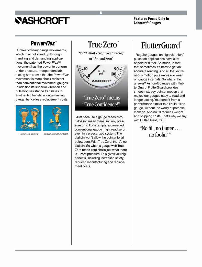
PowerFlex™
CONVENTIONAL MOVEMENT ASHCROFT POWERFLEX MOVEMENT
Unlike ordinary gauge movements, which may not stand up to rough handling and demanding applica-tions, the patented PowerFlex™ movement has the power to perform under pressure. Independent lab testing has shown that the PowerFlex movement is more shock resistant than conventional movement gauges. In addition its superior vibration and pulsation resistance translates to another big benefit: a longer-lasting gauge, hence less replacement costs.
Not “Almost Zero,” “Nearly Zero,” or “Around Zero”
“No fill, no flutter . . . no foolin’ ’’
Features Found Only In Ashcroft® Gauges
66
PLUS!™ Performance Option
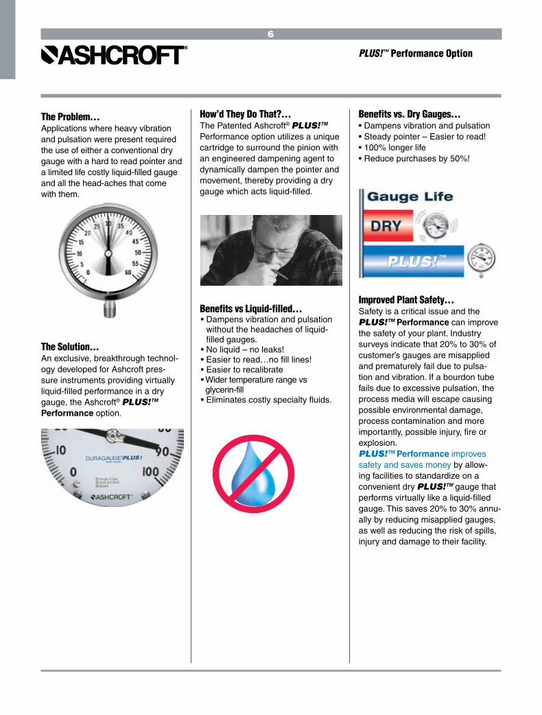
The Problem… Applications where heavy vibration and pulsation were present required the use of either a conventional dry gauge with a hard to read pointer and a limited life costly liquid-filled gauge and all the head-aches that come with them.
The Solution...An exclusive, breakthrough technol-ogy developed for Ashcroft pres-sure instruments providing virtually liquid-filled performance in a dry gauge, the Ashcroft® PLUS!™ Performance option.
How’d They Do That?…The Patented Ashcroft® PLUS!™ Performance option utilizes a unique cartridge to surround the pinion with an engineered dampening agent to dynamically dampen the pointer and movement, thereby providing a dry gauge which acts liquid-filled.
Benefits vs Liquid-filled…• Dampens vibration and pulsation
without the headaches of liquid- filled gauges.
• No liquid – no leaks!• Easier to read…no fill lines! • Easier to recalibrate• Wider temperature range vs glycerin-fill• Eliminates costly specialty fluids.
Benefits vs. Dry Gauges…• Dampens vibration and pulsation• Steady pointer – Easier to read!• 100% longer life• Reduce purchases by 50%!
Improved Plant Safety…Safety is a critical issue and the PLUS!™ Performance can improve the safety of your plant. Industry surveys indicate that 20% to 30% of customer’s gauges are misapplied and prematurely fail due to pulsa-tion and vibration. If a bourdon tube fails due to excessive pulsation, the process media will escape causing possible environmental damage, process contamination and more importantly, possible injury, fire or explosion.PLUS!™ Performance improves safety and saves money by allow-ing facilities to standardize on a convenient dry PLUS!™ gauge that performs virtually like a liquid-filled gauge. This saves 20% to 30% annu-ally by reducing misapplied gauges, as well as reducing the risk of spills, injury and damage to their facility.

77
PLUS!™ Performance Option
A. Are PLUS!™ Performance gauges “new” gauges? A. No. We simply enhanced the industry leading Ashcroft products you’ve grown to trust
with a fluid clutch dampener. The mechanical system is unchanged.
Q. Does PLUS!™ Performance affect accuracy? A. No. The only difference is that the response time is similar to liquid-filled gauges.
Q. Can these gauges be oxygen cleaned? A. Yes. Our process cleans the system to meet AMSE B40.1, Level IV.
Q. What temperature range is possible? A. –40°F to 300°F, –40°C to 149°C
Q. Can I use PLUS!™ Performance instead of Halocarbon fill? A. Yes!
Q.Can this be used in paint applications or others requiring no silicone? A. The standard PLUS!™ Performance cannot be used in silicone-free applications.
However, PLUS!™ is available in a silicone-free version.
Order as XNS for silicone-free.
Q. Does the throttle plug do all the work? A. No. Throttle plugs are designed only to fight pulsation. Vibration requires either a
liquid-filled gauge or PLUS!™ Performance.
Q. Does our competition have anything similar? A. No. Some competitors use a liquidless gauge with poor results. Their design
utilized a dashpot which caused premature failures versus even dry gauges.
Gauges with PLUS!™ Performance utilize a completely different approach over
coming their design problem.
Q. Will this gauge last forever? A. No gauge will last forever under conditions of severe pulsation and vibration.
The PLUS!™ Performance gauges simply last significantly longer than traditional
dry gauges with the benefits outlined above. There are a few applications, chiefly severe high frequency pulsation, where a liquid-filled gauge or a remote mounted gauge is necessary. With a few exceptions, customers have found the performance
to rival liquid-filled gauges in life expectancy without any of the headaches of liquid-
filled gauges.
Q. How Do I Order? A. The product variation “XLL” designates PLUS!™ Performance in all
Duragauge,® 1279, 1379, 1377, Duralife® and 1009, 1008S
type pressure gauges and Duratran® transmitters.
Any Questions?

88

DIGITAL GAUGES
TEST INSTRUMENTS, TEST GAUGES & EQUIPMENT
PROCESS GAUGES
STAINLESS STEEL CASE & INDUSTRIAL GAUGES
SANITARY GAUGES
ASHCROFT® PRODUCT QUICK GUIDES
Type 2089, 2086, 2084 Test Gauge .............. 11Type 2074, 2174, 2274 Industrial Gauge ..... 11Type D1005PS General Purpose Gauge ....... 11Series 2300 Digital Sanitary Gauge ..............11
Type 1084 Test Gauge .................................. 13Type 1082 Test Gauge .................................. 13Type 2089, 2086, 2084 Test Gauge .............. 13Type ATE-100 LCD Digital Calibrator ............ 13Type ST-2A LCD Digital Indicator ................. 14Type 1305D Deadweight Tester ................... 14Type 1327D, 1327CM Gauge Comparator .... 14Type PT LCD Digital Indicator ....................... 14Type AVC-1000 & 3000 Volume Controller ... 15Type A4A Precision Dial Pressure Gauge ..... 15
Type 5500 & 6500 Stainless Steel Case ...... 18Type 1008S Duralife® Pressure Gauge
40 & 50mm ............................................... 19 63 & 100mm ............................................. 19
Type 1008S/SL Back Connect Gauges..........19 Type 1009 Duralife® Pressure Gauge .......... 19Type 1009 Stainless Steel Case ................... 20Type 1109 General Service Gauge ............... 20Type 1009, 1010, 1017, 1220
Hydraulic Gauges ...................................... 20Type 1009, 1010, 1017, 1220
Receiver Gauges ....................................... 20Type 1009, 1010, 1017, 1220
Refrigeration Gauge .................................. 21Type 1010 General Service Gauge ............... 21Type 1017 General Service Gauge ............... 21Type 1220 .................................................... 21Type 1020S Xmas Tree Gauge ..................... 22Type 1038, 1039 Duplex Gauge ................... 22Type 1125, 1125A Differential Gauge .......... 22Type 1127, 1128 Differential Gauge ............ 22Type 1130 Differential Gauge ...................... 23Type 1131 Differential Gauge ...................... 23Type 1132 Differential Gauge ...................... 23Type 1133 Differential Gauge ...................... 23Type 1134 Differential Gauge ...................... 24Type 5503 Differential Gauge ...................... 24Type 5509 Differential Gauge ...................... 24Type 1150H Reid Vapor Gauge ..................... 24Type 1122 Movementless Gauge................. 25Type 1187, 1188, 1189 LP Bellowsl Gauge .. 25Type 1490 LP Diaphragm Gauge ................. 25Type 1495 LP Receiver Gauge ..................... 25Type 2074, 2174, 2274 Industrial Gauge ..... 26
Series 2300 Digital Sanitary Gauge ..............27Type 1032 Fractional Sanitary Gauge .......... 27Type 1032 Sanitary Gauge ........................... 27 Type 1036 w/1037 Instrument Fitting ......... 27
Type 1279 Duragauge® Pressure Gauge ..... 17Type 1377 Duragauge® Pressure Gauge ..... 17Type 1379 Duragauge® Pressure Gauge ..... 17Type 2462 Pressure Gauge .......................... 17Type 1259 Pressure Gauge .......................... 18Type 1279,1379,1377, 2462 Receiver Gauge . 18Type 2279 Duratran® Pressure Transmitters . 18
10
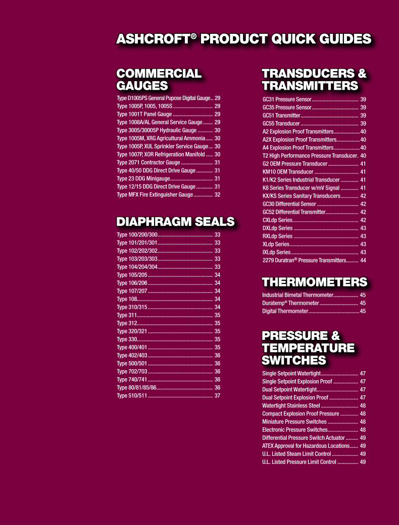
Type 100/200/300 ........................................ 33Type 101/201/301 ........................................ 33Type 102/202/302 ........................................ 33Type 103/203/303 ........................................ 33Type 104/204/304 ........................................ 33Type 105/205 ............................................... 34Type 106/206 ............................................... 34Type 107/207 ............................................... 34Type 108....................................................... 34Type 310/315 ............................................... 34Type 311....................................................... 35Type 312....................................................... 35Type 320/321 ............................................... 35Type 330....................................................... 35Type 400/401 ............................................... 35Type 402/403 ............................................... 36Type 500/501 ............................................... 36Type 702/703 ............................................... 36Type 740/741 ............................................... 36Type 80/81/85/86......................................... 36Type 510/511 ............................................... 37
DIAPHRAGM SEALS
Single Setpoint Watertight ........................... 47Single Setpoint Explosion Proof .................. 47Dual Setpoint Watertight .............................. 47Dual Setpoint Explosion Proof ..................... 47Watertight Stainless Steel ........................... 48Compact Explosion Proof Pressure ............. 48Miniature Pressure Switches ...................... 48Electronic Pressure Switches ...................... 48Differential Pressure Switch Actuator ......... 49ATEX Approval for Hazardous Locations ...... 49U.L. Listed Steam Limit Control ................... 49U.L. Listed Pressure Limit Control ............... 49
PRESSURE &TEMPERATURESWITCHES
GC31 Pressure Sensor .................................. 39GC35 Pressure Sensor .................................. 39GC51 Transmitter .......................................... 39GC55 Transducer .......................................... 39A2 Explosion Proof Transmitters ...................40A2X Explosion Proof Transmitters .................40A4 Explosion Proof Transmitters ...................40T2 High Performance Pressure Transducer . 40G2 OEM Pressure Transducer ...................... 41KM10 OEM Transducer ................................ 41K1/K2 Series Industrial Transducer ............. 41K8 Series Transducer w/mV Signal ............. 41KX/KS Series Sanitary Transducers ............. 42GC30 Differential Sensor .............................. 42GC52 Differential Transmitter ........................ 42CXLdp Series................................................ 42DXLdp Series ............................................... 43RXLdp Series ............................................... 43XLdp Series .................................................. 43IXLdp Series ................................................. 432279 Duratran® Pressure Transmitters ......... 44
TRANSDUCERS & TRANSMITTERS
Industrial Bimetal Thermometer.................. 45Duratemp® Thermometer ............................ 45Digital Thermometer .....................................45
THERMOMETERS
Type D1005PS General Pupose Digital Gauge .. 29Type 1005P, 1005, 1005S ............................. 29Type 1001T Panel Gauge ............................. 29Type 1008A/AL General Service Gauge ....... 29Type 3005/30005P Hydraulic Gauge ........... 30Type 1005M, XRG Agricultural Ammonia ..... 30Type 1005P, XUL Sprinkler Service Gauge ... 30Type 1007P, XOR Refrigeration Manifold ..... 30Type 2071 Contractor Gauge ....................... 31Type 40/50 DDG Direct Drive Gauge ............ 31Type 23 DDG Minigauge ............................... 31Type 12/15 DDG Direct Drive Gauge ............ 31Type MFX Fire Extinguisher Gauge .............. 32
COMMERCIAL GAUGES
ASHCROFT® PRODUCT QUICK GUIDES
11
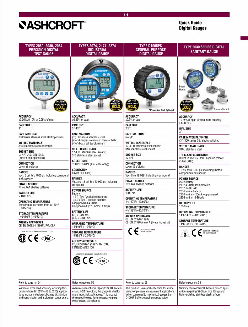
TYPES 2089, 2086, 2084 TYPES 2074, 2174, 2274 TYPE D1005PS PRECISION DIGITAL INDUSTRIAL GENERAL PURPOSE TEST GAUGE DIGITAL GAUGE DIGITAL GAUGE
Quick GuideDigital Gauges
Refer to page no. 54
With total error band accuracy including tem-perature from 0/150°F (–18 to 63°C) applica-tions include metrology labs, gas distribution and transmission and analog test gauge users.
Refer to page no. 55
Available with optional (1) or (2) SPDT switch-es and 4-20mA output, this gauge is ideal for many industrial applications. This product eliminates the need for unnecessary piping, switches and transducers.
Refer to page no. 56
This product is an excellent choice for a wide variety of pressure measurement applications. When compared to mechanical gauges the D1005PS offers overall enhanced value.
ACCURACY: ±0.25% of span
CASE SIZE 3, 41/2˝
CASE MATERIAL (3˝) 300 series stainless steel (41/2˝) fiberglass reinforced thermoplastic (41/2˝) black painted aluminum
WETTED MATERIALS 17-4 PH stainless steel sensor; 316 stainless steel socket
SOCKET SIZE 1/4 NPT, 1/2 NPT (41/2˝ case only))
CONNECTION Lower (6 o’clock)
RANGES Vac. and 15 psi thru 20,000 psi including compound
POWER SOURCE Battery ( 3˝) Two AA alkaline batteries (41/2 ) Two C alkaline batteries Loop powered 4-20mA Line powered, (12-36 Vdc, 1 amp)
BATTERY LIFE (3˝) >1000 hrs. (41/2˝) >3600 hrs.
OPERATING TEMPERATURE 14/140°F (–10/60°C)
STORAGE TEMPERATURE –4/158°F (–20/70°C)
AGENCY APPROVALS CE, EN 50082-1 (1997), FM, CSA, CENELEC-ATEX 100
ACCURACY ±0.5% of span
CASE SIZE 21/2˝
CASE MATERIAL Noryl®
WETTED MATERIALS 17-4 PH stainless steel sensor; 316 stainless steel socket
SOCKET SIZE 1/4 NPT
CONNECTION Lower (6 o’clock)
RANGES Vac. thru 19,999, including compound
POWER SOURCE Two AAA alkaline batteries
BATTERY LIFE 1000 hrs.
OPERATING TEMPERATURE 14/140°F (–10/60°C)
STORAGE TEMPERATURE –4/158°F (–20/70°C)
AGENCY APPROVALS CE, EN 61326 (1998) CE, EN 61326 Annex A (heavy industrial)
ACCURACY ±0.05%, 0.10% or 0.25% of span
CASE SIZE 3˝
CASE MATERIAL 300 Series stainless steel, electropolished
WETTED MATERIALS 316 stainless steel connection
SOCKET SIZE 1/4 NPT JIS, DIN, SAE, (others on application)
CONNECTION Lower (6 o’clock)
RANGES Vac., 5 psi thru 7000 psi including compound and absolute
POWER SOURCE Three AAA alkaline batteries
BATTERY LIFE > 1000 hrs.
OPERATING TEMPERATURE Temperature corrected from 0/150°F (–18/63°C)
STORAGE TEMPERATURE –40/180°F (–40/82°C)
AGENCY APPROVALS CE, EN 50082-1 (1997), FM, CSA
*Protective Boot Optional
Refer to page no. 53
Sanitary pharmaceutical, biotech or food appli-cations requiring Tri-Clover type fittings and highly polished stainless steel surfaces.
ACCURACY ±0.25% of span terminal point accuracy (.13 BFSL)
DIAL SIZE 3˝
CASE MATERIAL/FINISH (3˝) 300 series SS, electropolished
WETTED MATERIALS 316L stainless steel
TRI-CLAMP CONNECTION Direct, in-line 1.5˝, 2.0˝; Ashcroft remote in-line (XRE)
RANGES 15 psi thru 1000 psi including metric, compound and vacuum
POWER SOURCE 2032 Battery 2132 4-20mA loop powered 2232 12-36 Vdc 2036 In-line battery 2136 In-line 4-20mA loop powered 2236 In-line 12-36Vdc
BATTERY LIFE 1000 hrs.
OPERATING TEMPERATURE 14°F/140°F (–10°C/60°C)
STORAGE TEMPERATURE –4°F/158°F (–20°C/70°C)
TYPE 2030 SERIES DIGITALSANITARY GAUGE
Direct Mount
Remote Mount
FM
LOOK FOR THESE MARKS ON OUR PRODUCTS
FM
LOOK FOR THESE MARKS ON OUR PRODUCTS
LOOK FOR THIS MARK ON OUR PRODUCT LOOK FOR THIS MARK
ON OUR PRODUCT

12
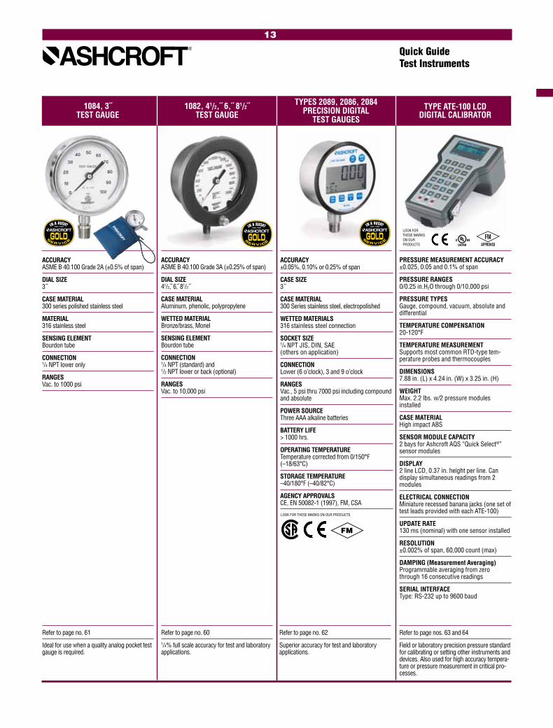
TYPES 2089, 2086, 2084 TYPE ATE-100 LCD 1084, 3˝ 1082, 41/2,˝ 6,˝ 81/2˝ PRECISION DIGITAL TEST GAUGE TEST GAUGE TEST GAUGES DIGITAL CALIBRATOR
Refer to page no. 61
Ideal for use when a quality analog pocket test gauge is required.
Quick GuideTest Instruments
Refer to page no. 60
1/4% full scale accuracy for test and laboratory applications.
Refer to page no. 62
Superior accuracy for test and laboratory applications.
Refer to page nos. 63 and 64
Field or laboratory precision pressure standard for calibrating or setting other instruments and devices. Also used for high accuracy tempera-ture or pressure measurement in critical pro-cesses.
ACCURACY ASME B 40.100 Grade 2A (±0.5% of span)
DIAL SIZE 3˝
CASE MATERIAL 300 series polished stainless steel
MATERIAL 316 stainless steel
SENSING ELEMENT Bourdon tube
CONNECTION 1/4 NPT lower only
RANGES Vac. to 1000 psi
ACCURACY ASME B 40.100 Grade 3A (±0.25% of span)
DIAL SIZE 41/2, 6, 81/2˝
CASE MATERIAL Aluminum, phenolic, polypropylene
WETTED MATERIAL Bronze/brass, Monel
SENSING ELEMENT Bourdon tube
CONNECTION 1/4 NPT (standard) and 1/2 NPT lower or back (optional)
RANGES Vac. to 10,000 psi
ACCURACY ±0.05%, 0.10% or 0.25% of span
CASE SIZE 3˝
CASE MATERIAL 300 Series stainless steel, electropolished
WETTED MATERIALS 316 stainless steel connection
SOCKET SIZE 1/4 NPT JIS, DIN, SAE (others on application)
CONNECTION Lower (6 o’clock), 3 and 9 o’clock
RANGES Vac., 5 psi thru 7000 psi including compound and absolute
POWER SOURCE Three AAA alkaline batteries
BATTERY LIFE > 1000 hrs.
OPERATING TEMPERATURE Temperature corrected from 0/150°F (–18/63°C)
STORAGE TEMPERATURE –40/180°F (–40/82°C)
AGENCY APPROVALS CE, EN 50082-1 (1997), FM, CSA
PRESSURE MEASUREMENT ACCURACY ±0.025, 0.05 and 0.1% of span
PRESSURE RANGES 0/0.25 in.H2O through 0/10,000 psi
PRESSURE TYPES Gauge, compound, vacuum, absolute and differential
TEMPERATURE COMPENSATION 20-120°F
TEMPERATURE MEASUREMENT Supports most common RTD-type tem-perature probes and thermocouples
DIMENSIONS 7.88 in. (L) x 4.24 in. (W) x 3.25 in. (H)
WEIGHT Max. 2.2 lbs. w/2 pressure modules installed
CASE MATERIAL High impact ABS
SENSOR MODULE CAPACITY 2 bays for Ashcroft AQS “Quick Select®” sensor modules
DISPLAY 2 line LCD, 0.37 in. height per line. Can display simultaneous readings from 2 modules
ELECTRICAL CONNECTION Miniature recessed banana jacks (one set of test leads provided with each ATE-100)
UPDATE RATE 130 ms (nominal) with one sensor installed
RESOLUTION ±0.002% of span, 60,000 count (max)
DAMPING (Measurement Averaging) Programmable averaging from zero through 16 consecutive readings
SERIAL INTERFACE Type: RS-232 up to 9600 baud
LOOK FOR THESE MARKS ON OUR PRODUCTS
FM
LOOK FOR THESE MARKS ON OUR PRODUCTS
13
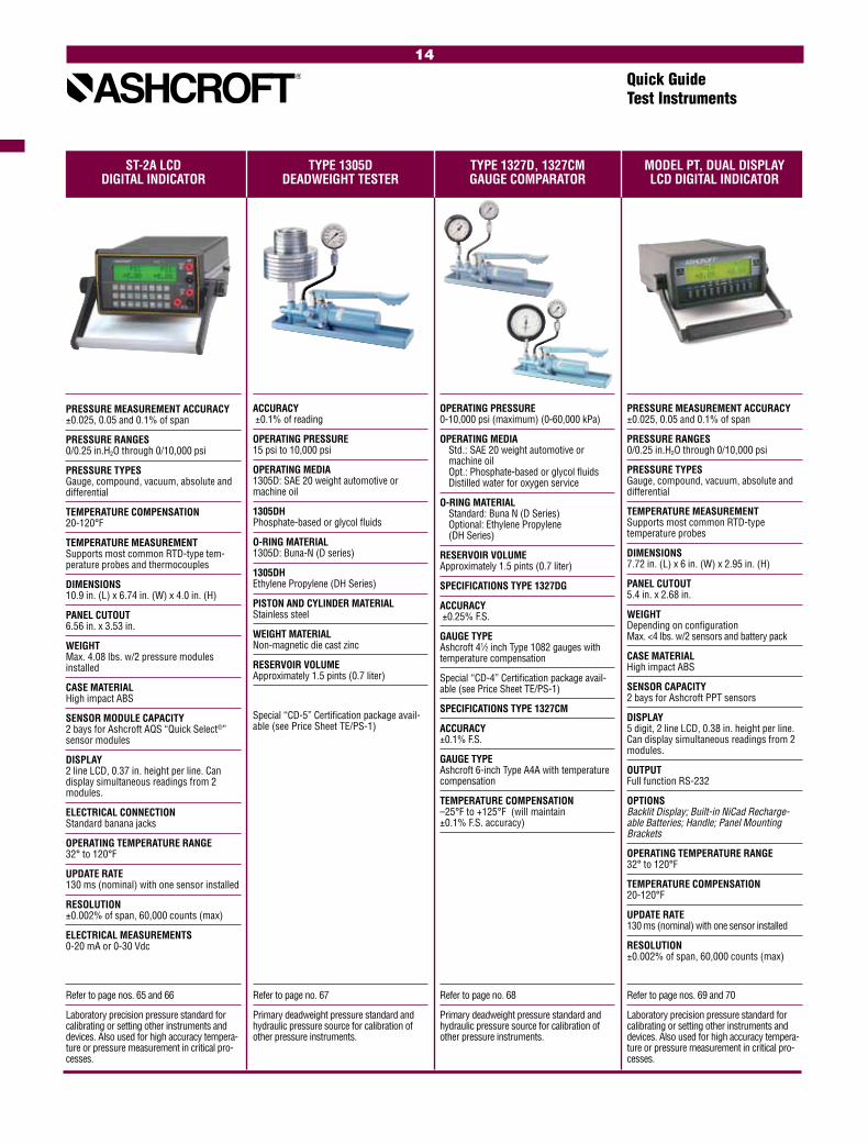
Refer to page nos. 69 and 70
Laboratory precision pressure standard for calibrating or setting other instruments and devices. Also used for high accuracy tempera-ture or pressure measurement in critical pro-cesses.
ST-2A LCD TYPE 1305D TYPE 1327D, 1327CM MODEL PT, DUAL DISPLAY DIGITAL INDICATOR DEADWEIGHT TESTER GAUGE COMPARATOR LCD DIGITAL INDICATOR
Quick GuideTest Instruments
Refer to page nos. 65 and 66
Laboratory precision pressure standard for calibrating or setting other instruments and devices. Also used for high accuracy tempera-ture or pressure measurement in critical pro-cesses.
Refer to page no. 67
Primary deadweight pressure standard and hydraulic pressure source for calibration of other pressure instruments.
Refer to page no. 68
Primary deadweight pressure standard and hydraulic pressure source for calibration of other pressure instruments.
PRESSURE MEASUREMENT ACCURACY ±0.025, 0.05 and 0.1% of span
PRESSURE RANGES 0/0.25 in.H2O through 0/10,000 psi
PRESSURE TYPES Gauge, compound, vacuum, absolute and differential
TEMPERATURE COMPENSATION 20-120°F
TEMPERATURE MEASUREMENT Supports most common RTD-type tem-perature probes and thermocouples
DIMENSIONS 10.9 in. (L) x 6.74 in. (W) x 4.0 in. (H)
PANEL CUTOUT 6.56 in. x 3.53 in.
WEIGHT Max. 4.08 lbs. w/2 pressure modules installed
CASE MATERIAL High impact ABS
SENSOR MODULE CAPACITY 2 bays for Ashcroft AQS “Quick Select®” sensor modules
DISPLAY 2 line LCD, 0.37 in. height per line. Can display simultaneous readings from 2 modules.
ELECTRICAL CONNECTION Standard banana jacks
OPERATING TEMPERATURE RANGE 32° to 120°F
UPDATE RATE 130 ms (nominal) with one sensor installed
RESOLUTION ±0.002% of span, 60,000 counts (max)
ELECTRICAL MEASUREMENTS 0-20 mA or 0-30 Vdc
ACCURACY ±0.1% of reading
OPERATING PRESSURE 15 psi to 10,000 psi
OPERATING MEDIA 1305D: SAE 20 weight automotive or machine oil
1305DH Phosphate-based or glycol fluids
O-RING MATERIAL 1305D: Buna-N (D series)
1305DH Ethylene Propylene (DH Series)
PISTON AND CYLINDER MATERIAL Stainless steel
WEIGHT MATERIAL Non-magnetic die cast zinc
RESERVOIR VOLUME Approximately 1.5 pints (0.7 liter)
Special ‘‘CD-5” Certification package avail-able (see Price Sheet TE/PS-1)
OPERATING PRESSURE 0-10,000 psi (maximum) (0-60,000 kPa)
OPERATING MEDIA Std.: SAE 20 weight automotive or machine oil Opt.: Phosphate-based or glycol fluids Distilled water for oxygen service
O-RING MATERIAL Standard: Buna N (D Series) Optional: Ethylene Propylene (DH Series)
RESERVOIR VOLUME Approximately 1.5 pints (0.7 liter)
SPECIFICATIONS TYPE 1327DG
ACCURACY ±0.25% F.S.
GAUGE TYPE Ashcroft 41⁄2 inch Type 1082 gauges with temperature compensation
Special ‘‘CD-4” Certification package avail-able (see Price Sheet TE/PS-1)
SPECIFICATIONS TYPE 1327CM
ACCURACY ±0.1% F.S.
GAUGE TYPE Ashcroft 6-inch Type A4A with temperature compensation
TEMPERATURE COMPENSATION –25°F to +125°F (will maintain ±0.1% F.S. accuracy)
PRESSURE MEASUREMENT ACCURACY ±0.025, 0.05 and 0.1% of span
PRESSURE RANGES 0/0.25 in.H2O through 0/10,000 psi
PRESSURE TYPES Gauge, compound, vacuum, absolute and differential
TEMPERATURE MEASUREMENT Supports most common RTD-type temperature probes
DIMENSIONS 7.72 in. (L) x 6 in. (W) x 2.95 in. (H)
PANEL CUTOUT 5.4 in. x 2.68 in.
WEIGHT Depending on configuration Max. <4 lbs. w/2 sensors and battery pack
CASE MATERIAL High impact ABS
SENSOR CAPACITY 2 bays for Ashcroft PPT sensors
DISPLAY 5 digit, 2 line LCD, 0.38 in. height per line. Can display simultaneous readings from 2 modules.
OUTPUT Full function RS-232
OPTIONS Backlit Display; Built-in NiCad Recharge-able Batteries; Handle; Panel Mounting Brackets
OPERATING TEMPERATURE RANGE 32° to 120°F
TEMPERATURE COMPENSATION 20-120°F
UPDATE RATE 130 ms (nominal) with one sensor installed
RESOLUTION ±0.002% of span, 60,000 counts (max)
14

TYPE AVC-1000 & 3000 TYPE A4A PRECISION VOLUME CONTROLLER DIAL PRESSURE GAUGE
Quick GuideTest Instruments
Refer to page no. 71
Added to any pneumatic calibration system, the VC works as a ‘‘fine tune” device to achieve specific test points not easily attained with the use of a regulator alone. Used in the calibration of any pneumatic pressure instrument up to 3000 psi.
Refer to page no. 59
TYPE AVC-1000 / AVC-3000
RANGE (psi) vacuum-1000 / vacuum-3000
RESOLUTION (psi) 0.00025 / 0.0005
VOLUME CHANGE (cubic inches) 3.5 / 2.5
MECHANICAL ROTATION (turns) 31 / 61
PROOF PRESSURE (psi) 3000 / 6000
BURST PRESSURE (psi) 6000 min / 12,000 min
OPERATING TEMPERATURE RANGE 20-120°F / 20-120°F
OPERATING MEDIA Clean, dry noncorrosive gas such as com-pressed air or nitrogen
CONSTRUCTION Aluminum body, stainless steel, brass Teflon, Delrin and Buna N
ACCURACY ±0.10% of span – ASME B40.1, Grade 4A
CASE Cast aluminum solid front
DIAL SIZE 6˝, 81/2˝, 12˝ & 16˝
POINTER TRAVEL 350° (15-30,000 psi) 300° (40,000-50,000 psi) 270° (60,000-100,000 psi)
BOURDON TUBE Bleeder tipped
RANGES Gauge, compound, vacuum & absolute 0-15-0/100,000 psi
15

16

1279 DURAGAUGE® 1377 DURAGAUGE® 1379 DURAGAUGE® 2462 DURAGAUGE®
PRESSURE GAUGE PRESSURE GAUGE PRESSURE GAUGE PRESSURE GAUGE
Refer to page no. 76
Usage requiring 1/2% full scale accuracy in chemical, petrochemical, refinery, oil prodution, other process, power and`general industry.
Quick GuideProcess Gauges
Refer to page nos. 77 and 81
Usage requiring 1/2% full scale accuracy in chemical, petrochemical, refinery, oil prodution, other process, power and`general industry.
Refer to page nos. 80 and 83
Usage requiring 1/2% full scale accuracy in chemical, petrochemical, refinery, oil production, other process, power and`general industry.
Refer to page nos. 78 and 81
Usage requiring 1/2% full scale accuracy in chemical, petrochemical, refinery, oil production, other process, power and`general industry.
ACCURACY ASME B 40.100 Grade 2A (±0.5% of span)
DIAL SIZE 41/2, 6, 81/2˝
CASE MATERIAL Aluminum
WETTED MATERIAL 316 stainless steel, bronze/brass, Monel, Inconel
SENSING ELEMENT Bourdon tube
CONNECTION 1/2 NPT (standard) lower or back 1/4 NPT (optional) 1/4˝ HP connection over 30,000 psi
RANGES Vacuum, 15 to 100,000 psi, compound
ACCURACY ASME B 40.100 Grade 2A (±0.5% of span)
DIAL SIZE 41/2, 6, 81/2˝
CASE MATERIAL Aluminum
WETTED MATERIAL 316 stainless steel, bronze/brass, Monel
SENSING ELEMENT Bourdon tube
CONNECTION 1/2 NPT (standard) lower or back 1/4 NPT (optional)
RANGES Vacuum, 15 to 30,000 psi, compound
ACCURACY ASME B 40.100 Grade 2A (±0.5% of span)
DIAL SIZE 41/2˝
CASE MATERIAL Phenolic
WETTED MATERIAL 316 stainless steel, bronze/brass, Monel
SENSING ELEMENT Bourdon tube
CONNECTION 1/2 NPT (standard) lower or back 1/4 NPT (optional)
RANGES Vacuum, 15 to 30,000 psi, compound
ACCURACY ASME B 40.100 Grade 2A (±0.5% of span)
DIAL SIZE 6˝
CASE MATERIAL Polypropylene
WETTED MATERIAL 316 stainless steel, bronze/brass, steel, Monel
SENSING ELEMENT Bourdon tube
CONNECTION 1/2 NPT (standard) lower or back 1/4 NPT (optional)
RANGES Vacuum, 15 to 30,000 psi, compound
17

1259 PROCESS 1279, 1379, 1377, 2462 2279 DURATRAN® T5500 & T6500 PRESSURE GAUGE RECEIVER GAUGES PRESSURE TRANSMITTER PRESSURE GAUGE
Refer to page no. 80
Usage requiring 1/2% full scale accuracy in chemical, petrochemical, refinery, oil production, other process, power and`general industry.
Quick GuideStainless Steel Case & Industrial Gauges
ACCURACY ASME B 40.100 Grade 2A (±0.5% of span)
DIAL SIZE 41/2˝
CASE MATERIAL Polypropylene
WETTED MATERIAL 316 stainless steel, Monel
SENSING ELEMENT Bourdon tube
CONNECTION 1/2 NPT (standard) lower 1/4 NPT (optional)
RANGES Vacuum, 15 to 20,000 psi, compound
ACCURACY ±0.5%
DIAL SIZE 41/2˝ analog
CASE MATERIAL Phenolic
WETTED MATERIAL 316 stainless steel, Monel
SENSING ELEMENT Bourdon tube
CONNECTION – NPT 1/2 NPT (standard) lower
RANGES Vacuum and compound, 12 to 20,000 psi
ELECTRONIC OUTPUT • ±.5%Accuracy • 4-20mA • FM Class I, Div. 2 • Zero/Span adjust
Refer to page no. 197
Two instruments in one! Provides local indication and 4-20mA signal for many indus-trial applications.
Type 1279
Type 2462
ACCURACY ASME B 40.100 Grade 2A (±0.5% of span)
DIAL SIZES 1279AS-XPR – 41/2˝ 1377AS-XPR – 41/2˝, 6˝, 81/2˝ 1379AS-XPR – 41/2˝, 6˝, 81/2˝ 2462AS-XPR – 6˝
CASE MATERIAL 1279AS-XPR – Phenolic 1377AS-XPR – Aluminum 1379AS-XPR – Aluminum 2462AS-XPR – Polypropylene
SENSING ELEMENT Bourdon tube
CONNECTION 1/2 NPT (standard) 1/4 NPT (optional)
CASE MATERIAL 1279AS-XPR – Lower/Back, Back 1377AS-XPR – Back, Lower/Back 1379AS-XPR – Back, Lower/Back 2462AS-XPR – Lower/Back, Back
RANGES 3-15 & 3-27
Refer to page no. 81
Quick GuideProcess Gauges
Refer to page no. 88
The Ashcroft® T5500 and T6500 all stainless steel process pressure gauge is one of the finest production gauges on the market for industrial use where precise indications are required
T5500
T6500
ACCURACY Std. Class 1, 1% full scale
DIAL SIZE 100mm, 160mm
CASE MATERIAL 304 stainless steel, 316 stainless steel
MOVEMENT 304/303 stainless steel
SENSING ELEMENT Bourdon tube
CONNECTION T5500 – lower or back T6500 – lower only
RANGES Vacuum, compound, pressure psi: –30in. Hg–0, 0-36,000 bar: –1-0, 0-2500
18
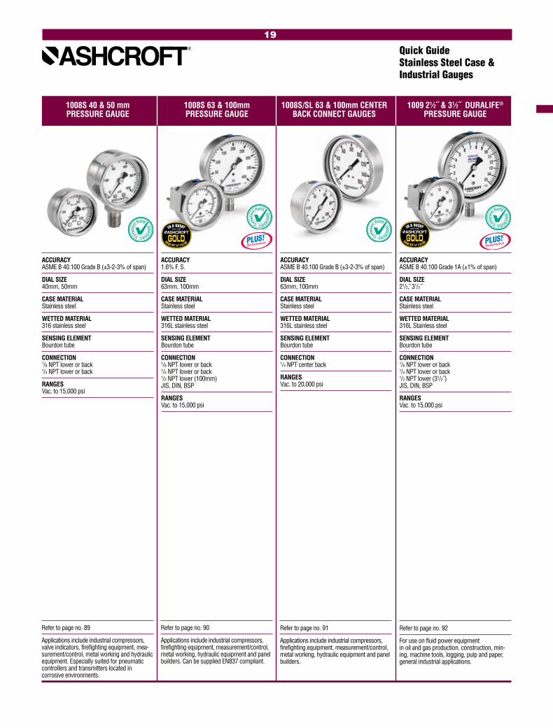
Refer to page no. 89
Applications include industrial compressors, valve indicators, firefighting equipment, mea-surement/control, metal working and hydraulic equipment. Especially suited for pneumatic controllers and transmitters located in corrosive environments.
Refer to page no. 90
Applications include industrial compressors, firefighting equipment, measurement/control, metal working, hydraulic equipment and panel builders. Can be supplied EN837 compliant.
Refer to page no. 92
For use on fluid power equipment in oil and gas production, construction, min-ing, machine tools, logging, pulp and paper, general industrial applications.
1008S 40 & 50 mm 1008S 63 & 100mm 1008S/SL 63 & 100mm CENTER 1009 21⁄2˝ & 31⁄2˝ DURALIFE®
PRESSURE GAUGE PRESSURE GAUGE BACK CONNECT GAUGES PRESSURE GAUGE
Quick GuideStainless Steel Case & Industrial Gauges
ACCURACY ASME B 40.100 Grade B (±3-2-3% of span)
DIAL SIZE 40mm, 50mm
CASE MATERIAL Stainless steel
WETTED MATERIAL 316 stainless steel
SENSING ELEMENT Bourdon tube
CONNECTION 1/8 NPT lower or back 1/4 NPT lower or back
RANGES Vac. to 15,000 psi
ACCURACY 1.6% F. S.
DIAL SIZE 63mm, 100mm
CASE MATERIAL Stainless steel
WETTED MATERIAL 316L stainless steel
SENSING ELEMENT Bourdon tube
CONNECTION 1/8 NPT lower or back 1/4 NPT lower or back 1/2 NPT lower (100mm) JIS, DIN, BSP
RANGES Vac. to 15,000 psi
ACCURACY ASME B 40.100 Grade 1A (±1% of span)
DIAL SIZE 21/2, 31/2˝
CASE MATERIAL Stainless steel
WETTED MATERIAL 316L Stainless steel
SENSING ELEMENT Bourdon tube
CONNECTION 1/8 NPT lower or back 1/4 NPT lower or back 1/2 NPT lower (31/2˝) JIS, DIN, BSP
RANGES Vac. to 15,000 psi
Refer to page no. 91
Applications include industrial compressors, firefighting equipment, measurement/control, metal working, hydraulic equipment and panel builders.
ACCURACY ASME B 40.100 Grade B (±3-2-3% of span)
DIAL SIZE 63mm, 100mm
CASE MATERIAL Stainless steel
WETTED MATERIAL 316L stainless steel
SENSING ELEMENT Bourdon tube
CONNECTION 1/4 NPT center back
RANGES Vac. to 20,000 psi
19

Refer to page no. 94
Stainless steel case Type 1109 applications include water jet or water blasting equipment, offshore platform, etc.
Refer to page no. 95
Uniquely designed for rigorous hydraulic services.
1009 41⁄2˝ & 6˝ 1109 41⁄2˝ 1009, 1010, 1017, 1220 1009, 1010, 1017, 1220 STAINLESS STEEL CASE GENERAL SERVICE GAUGE HYDRAULIC GAUGES RECEIVER GAUGES
Quick GuideStainless Steel Case & Industrial Gauges
Refer to page no. 96
For monitoring pneumatic systems requiring percentage or root readings.
ACCURACY ASME B 40.100 Grade 1A (±1% of span)
DIAL SIZE 41/2˝
CASE MATERIAL Stainless Steel
TUBE MATERIAL SD – 316 stainless steel WD – Inconel
SENSING ELEMENT Bourdon tube
CONNECTION SD – 1/2 NPT lower, 1/4 NPT lower (optional) WD – 1/4 NPT lower high pressure
RANGES SD – Vac. to 1500 psi / 2000-20,000 psi WD – 50,000-100,000 psi
ACCURACY ASME B 40.100 Grade 1A (±1% of span)
DIAL SIZE 1009 – 41/2, 6˝ 1010 – 41/2, 6, 81/2, 12˝ 1017 – 41/2, 6˝ 1220 – 41/2, 6, 81/2˝
CASE MATERIAL Stainless steel, aluminum, phenolic
TUBE MATERIAL Bronze, 316 stainless steel, Monel
SENSING ELEMENT Bourdon tube
CONNECTION 1/4 NPT lower or back 1/2 NPT lower or back
RANGES Vac. to 30,000 psi
ACCURACY ASME B 40.100 Grade 1A (±1% of span)
DIAL SIZE 1009 – 41/2, 6˝ 1010 – 41/2, 6, 81/2, 12˝ 1017 – 41/2, 6˝ 1220 – 41/2, 6, 81/2˝
CASE MATERIAL Stainless steel, aluminum, phenolic
TUBE MATERIAL Bronze, 316 stainless steel, Monel
SENSING ELEMENT Bourdon tube
CONNECTION 1/4 NPT lower or back 1/2 NPT lower or back
RANGES 3/15 and 3/27 psi
1010 GAUGE SHOWN 1220 GAUGE SHOWN
Refer to page no. 93
Stainless steel case Type 1009 applications include boilers, com pressors, water blasting equipment, pharmaceutical and food process-ing equipment.
ACCURACY ASME B 40.100 Grade 1A (±1% of span)
DIAL SIZE 41/2, 6˝
CASE MATERIAL Stainless Steel
TUBE MATERIAL Bronze, 316 stainless steel, Monel
SENSING ELEMENT Bourdon tube
CONNECTION 1/4 NPT lower or back 1/2 NPT lower or back
RANGES Vac. to 30,000 psi
20
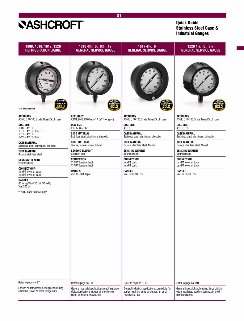
1009, 1010, 1017, 1220 1010 41⁄2,˝ 6,˝ 81⁄2,˝ 12˝ 1017 41⁄2,˝ 6˝ 1220 41⁄2,˝ 6,˝ 81⁄2˝ REFRIGERATION GAUGE GENERAL SERVICE GAUGE GENERAL SERVICE GAUGE GENERAL SERVICE GAUGE
Quick GuideStainless Steel Case & Industrial Gauges
Refer to page no. 97
For use on refrigeration equipment utilizing ammonia, freon or other refrigerants.
Refer to page no. 99
General industrial applications requiring larger dials. Applications include oil monitoring, repair and compressors, etc.
Refer to page no. 100
General industrial applications, large dials for easier readings. used on pumps, air or oil monitoring, etc.
Refer to page no. 101
General industrial applications, large dials for easier readings. used on pumps, air or oil monitoring, etc.
ACCURACY ASME B 40.100 Grade 1A (±1% of span)
DIAL SIZE 1009 – 41/2, 6˝ 1010 – 41/2, 6, 81/2, 12˝ 1017 – 41/2, 6˝ 1220 – 41/2, 6, 81/2˝
CASE MATERIAL Stainless steel, aluminum, phenolic
TUBE MATERIAL Bronze, stainless steel
SENSING ELEMENT Bourdon tube
CONNECTION(1) 1/4 NPT lower or back 1/2 NPT lower or back
RANGES 30 in.Hg Vac/150 psi, 30 in.Hg Vac/300 psi
(1) 1017 back connect only
ACCURACY ASME B 40.100 Grade 1A (±1% of span)
DIAL SIZE 41/2, 6, 81/2, 12˝
CASE MATERIAL Stainless steel, aluminum, phenolic
TUBE MATERIAL Bronze, stainless steel, Monel
SENSING ELEMENT Bourdon tube
CONNECTION 1/4 NPT lower or back 1/2 NPT lower or back
RANGES Vac. to 30,000 psi
ACCURACY ASME B 40.100 Grade 1A (±1% of span)
DIAL SIZE 41/2, 6˝
CASE MATERIAL Stainless steel, aluminum, phenolic
TUBE MATERIAL Bronze, stainless steel, Monel
SENSING ELEMENT Bourdon tube
CONNECTION 1/4 NPT back 1/2 NPT back
RANGES Vac. to 30,000 psi
ACCURACY ASME B 40.100 Grade 1A (±1% of span)
DIAL SIZE 41/2, 6, 81/2˝
CASE MATERIAL Stainless steel, aluminum, phenolic
TUBE MATERIAL Bronze, stainless steel, Monel
SENSING ELEMENT Bourdon tube
CONNECTION 1/4 NPT lower or back 1/2 NPT lower or back
RANGES Vac. to 30,000 psi
1010 GAUGE SHOWN
21

1020S 41⁄2˝ 1038, 1339 31⁄2,˝ 41⁄2,˝ 1125, 1125A 41⁄2˝ 1127, 1128 41⁄2,˝ 6˝ XMAS TREE GAUGE DUPLEX GAUGE DIFFERENTIAL GAUGE DIFFERENTIAL GAUGE
Quick GuideStainless Steel Case & Industrial Gauges
Refer to page no. 103
Uniquely designed to indicate two related pres-sures on the same dial.
Refer to page no. 104
Application include fills, monitors, flow, leak and level measurements.
Refer to page no. 105
Application include fills, monitors, flow, leak and level measurements.
ACCURACY ASME B 40.100 Grade A (±2-1-2% of span)
DIAL SIZE 31/2, 41/2˝
CASE MATERIAL Aluminum, cast iron
TUBE MATERIAL Bronze
SENSING ELEMENT Bourdon tube
CONNECTION Lower/back
RANGES 1038A – 31/2, 41/2˝– 1/4 NPT 30/1000 psi 1339A – 41/2˝ – 1/4 NPT 30/1000 psi
Back conn. only
ACCURACY ASME B 40.100 Grade A (±2-1-2% of span)
DIAL SIZE 41/2, 6˝
CASE MATERIAL Aluminum
TUBE MATERIAL Bronze
SENSING ELEMENT Bourdon tube
CONNECTION Lower/back
RANGES 1125 – 41/2, 6 (1) – 1/4 NPT 20/1000 psi 1125A – 41/2, 6 (1) – 1/4 NPT 10/0/10 psi-
500/0/500 psi
(1) Lower connect only
ACCURACY ASME B 40.100 Grade A (±2-1-2% of span)
DIAL SIZE 41/2, 6˝
CASE MATERIAL Aluminum
TUBE MATERIAL 316 stainless steel
SENSING ELEMENT Bourdon tube
CONNECTION Lower
RANGES 1127 – 41/2, 6˝ – 1/4 NPT 10/1000 psi 1128 – 41/2, 6˝ – 1/4 NPT 10/0/00 psi-
400/0/400 psi
1038 GAUGES SHOWN
Refer to page no. 102
Uniquely designed to meet rugged oil field applications.
ACCURACY ASME B 40.100 Grade 1A (±1% of span)
DIAL SIZE 41/2˝
CASE MATERIAL Stainless steel
TUBE MATERIAL 316 stainless steel
SENSING ELEMENT Bourdon tube
CONNECTION Lower
RANGES 1000/20,000 psi – 1/2 NPT, 1/4 NPT
22
EXPLOSION PROOF
SWITCH ENCLOSURES
AVAILABLEEXPLOSION PROOF
SWITCH ENCLOSURES
AVAILABLEEXPLOSION PROOF
SWITCH ENCLOSURES
AVAILABLE
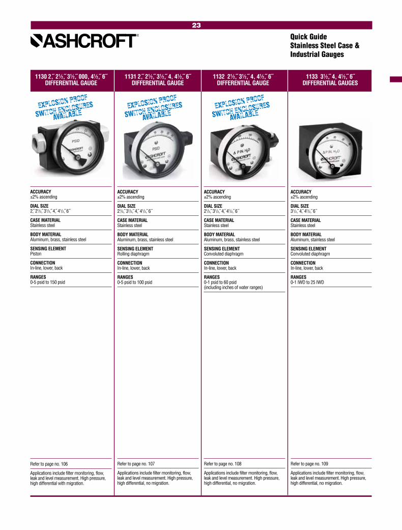
1130 2, 21⁄2, 31⁄2, 000, 41⁄2, 6˝ 1131 2, 21⁄2, 31⁄2, 4, 41⁄2, 6˝ 1132 21⁄2, 31⁄2, 4, 41⁄2, 6˝ 1133 31⁄2, 4, 41⁄2, 6˝ DIFFERENTIAL GAUGE DIFFERENTIAL GAUGE DIFFERENTIAL GAUGE DIFFERENTIAL GAUGES
Quick GuideStainless Steel Case & Industrial Gauges
Refer to page no. 106
Applications include filter monitoring, flow, leak and level measurement. High pressure, high differential with migration.
Refer to page no. 107
Applications include filter monitoring, flow, leak and level measurement. High pressure, high differential, no migration.
Refer to page no. 108
Applications include filter monitoring, flow, leak and level measurement. High pressure, high differential, no migration.
Refer to page no. 109
Applications include filter monitoring, flow, leak and level measurement. High pressure, high differential, no migration.
ACCURACY ±2% ascending
DIAL SIZE 21/2, 31/2, 4, 41/2, 6˝
CASE MATERIAL Stainless steel
BODY MATERIAL Aluminum, brass, stainless steel
SENSING ELEMENT Rolling diaphragm
CONNECTION In-line, lower, back
RANGES 0-5 psid to 100 psid
ACCURACY ±2% ascending
DIAL SIZE 2, 21/2, 31/2, 4, 41/2, 6˝
CASE MATERIAL Stainless steel
BODY MATERIAL Aluminum, brass, stainless steel
SENSING ELEMENT Piston
CONNECTION In-line, lower, back
RANGES 0-5 psid to 150 psid
ACCURACY ±2% ascending
DIAL SIZE 21/2, 31/2, 4, 41/2, 6˝
CASE MATERIAL Stainless steel
BODY MATERIAL Aluminum, brass, stainless steel
SENSING ELEMENT Convoluted diaphragm
CONNECTION In-line, lower, back
RANGES 0-1 psid to 60 psid (including inches of water ranges)
ACCURACY ±2% ascending
DIAL SIZE 31/2, 4, 41/2, 6˝
CASE MATERIAL Stainless steel
BODY MATERIAL Aluminum, stainless steel
SENSING ELEMENT Convoluted diaphragm
CONNECTION In-line, lower, back
RANGES 0-1 IWD to 25 IWD
23
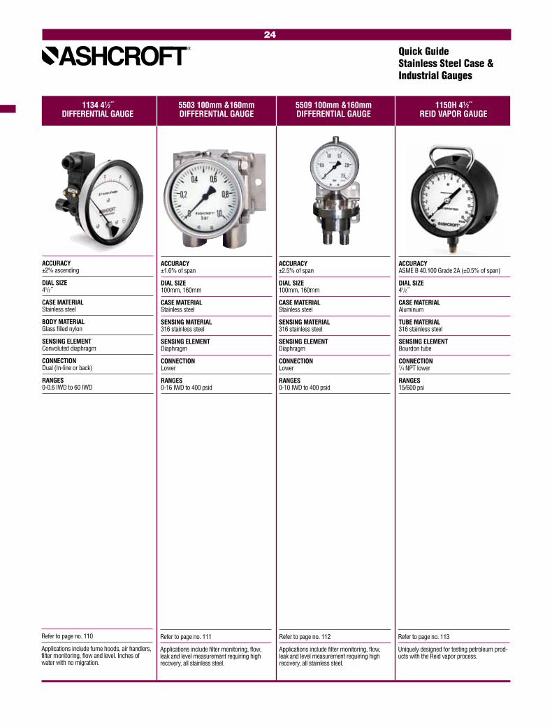
1134 41⁄2˝ 5503 100mm &160mm 5509 100mm &160mm 1150H 41⁄2˝ DIFFERENTIAL GAUGE DIFFERENTIAL GAUGE DIFFERENTIAL GAUGE REID VAPOR GAUGE
Quick GuideStainless Steel Case & Industrial Gauges
Refer to page no. 111
Applications include filter monitoring, flow, leak and level measurement requiring high recovery, all stainless steel.
Refer to page no. 112
Applications include filter monitoring, flow, leak and level measurement requiring high recovery, all stainless steel.
Refer to page no. 113
Uniquely designed for testing petroleum prod-ucts with the Reid vapor process.
ACCURACY ±1.6% of span
DIAL SIZE 100mm, 160mm
CASE MATERIAL Stainless steel
SENSING MATERIAL 316 stainless steel
SENSING ELEMENT Diaphragm
CONNECTION Lower
RANGES 0-16 IWD to 400 psid
ACCURACY ±2.5% of span
DIAL SIZE 100mm, 160mm
CASE MATERIAL Stainless steel
SENSING MATERIAL 316 stainless steel
SENSING ELEMENT Diaphragm
CONNECTION Lower
RANGES 0-10 IWD to 400 psid
ACCURACY ASME B 40.100 Grade 2A (±0.5% of span)
DIAL SIZE 41/2˝
CASE MATERIAL Aluminum
TUBE MATERIAL 316 stainless steel
SENSING ELEMENT Bourdon tube
CONNECTION 1/4 NPT lower
RANGES 15/600 psi
Refer to page no. 110
Applications include fume hoods, air handlers, filter monitoring, flow and level. Inches of water with no migration.
ACCURACY ±2% ascending
DIAL SIZE 41/2˝
CASE MATERIAL Stainless steel
BODY MATERIAL Glass filled nylon
SENSING ELEMENT Convoluted diaphragm
CONNECTION Dual (In-line or back)
RANGES 0-0.6 IWD to 60 IWD
24
Quick GuideStainless Steel Case & Industrial Gauges
Refer to page no. 114
Low pressure monitoring for general indus-trial applications on air, liquids or gases.
Refer to page no. 115
Low pressure monitoring of gases including ovens, burners or medical applications.
Refer to page no. 116
Low pressure monitoring of pneumatic or air handling systems requiring linear or square root readings.
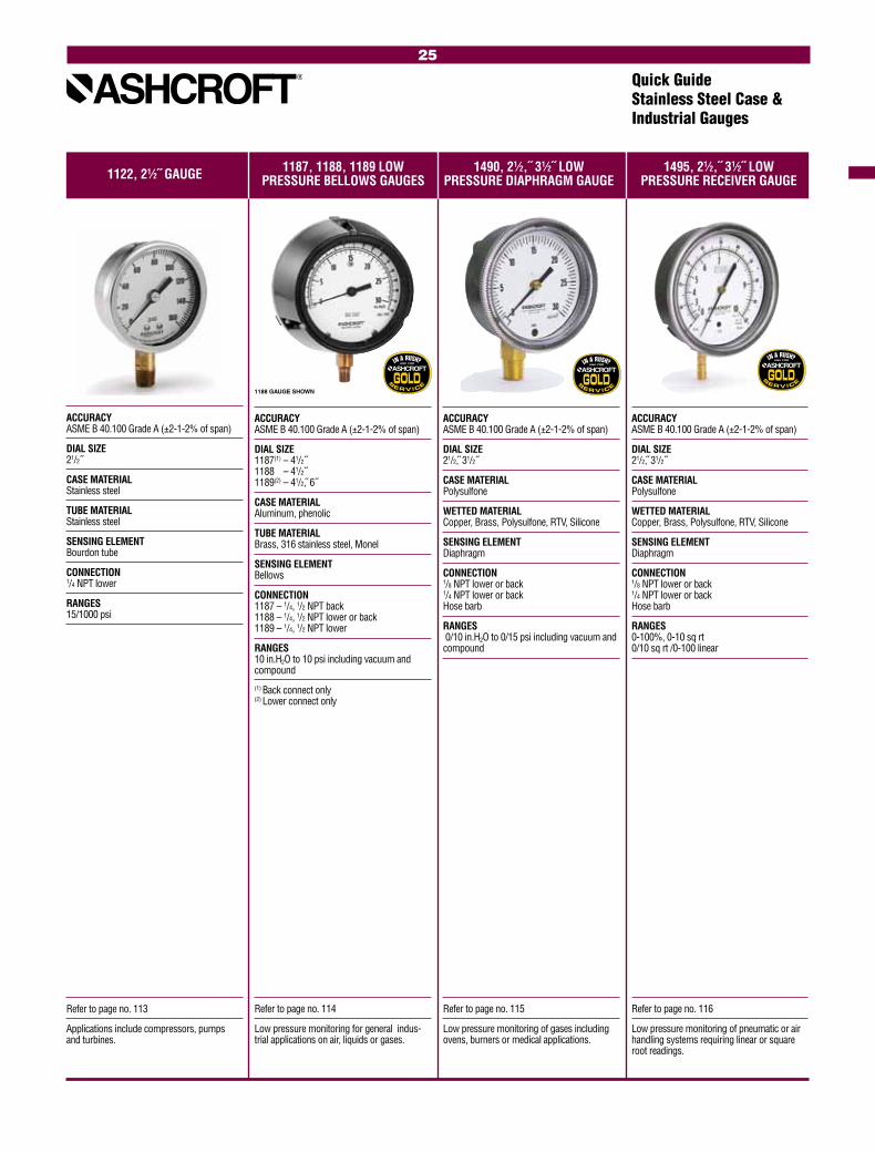
1122, 21⁄2˝ GAUGE 1187, 1188, 1189 LOW 1490, 21⁄2,˝ 31⁄2˝ LOW 1495, 21⁄2,˝ 31⁄2˝ LOW PRESSURE BELLOWS GAUGES PRESSURE DIAPHRAGM GAUGE PRESSURE RECEIVER GAUGE
Refer to page no. 113
Applications include compressors, pumps and turbines.
ACCURACY ASME B 40.100 Grade A (±2-1-2% of span)
DIAL SIZE 1187(1) – 41/2˝ 1188(1) – 41/2˝ 1189(2) – 41/2, 6˝
CASE MATERIAL Aluminum, phenolic
TUBE MATERIAL Brass, 316 stainless steel, Monel
SENSING ELEMENT Bellows
CONNECTION 1187 – 1/4, 1/2 NPT back 1188 – 1/4, 1/2 NPT lower or back 1189 – 1/4, 1/2 NPT lower
RANGES 10 in.H2O to 10 psi including vacuum and compound
(1) Back connect only (2) Lower connect only
ACCURACY ASME B 40.100 Grade A (±2-1-2% of span)
DIAL SIZE 21/2, 31/2˝
CASE MATERIAL Polysulfone
WETTED MATERIAL Copper, Brass, Polysulfone, RTV, Silicone
SENSING ELEMENT Diaphragm
CONNECTION 1/8 NPT lower or back 1/4 NPT lower or back Hose barb
RANGES 0/10 in.H2O to 0/15 psi including vacuum and compound
ACCURACY ASME B 40.100 Grade A (±2-1-2% of span)
DIAL SIZE 21/2, 31/2˝
CASE MATERIAL Polysulfone
WETTED MATERIAL Copper, Brass, Polysulfone, RTV, Silicone
SENSING ELEMENT Diaphragm
CONNECTION 1/8 NPT lower or back 1/4 NPT lower or back Hose barb
RANGES 0-100%, 0-10 sq rt 0/10 sq rt /0-100 linear
ACCURACY ASME B 40.100 Grade A (±2-1-2% of span)
DIAL SIZE 21/2˝
CASE MATERIAL Stainless steel
TUBE MATERIAL Stainless steel
SENSING ELEMENT Bourdon tube
CONNECTION 1/4 NPT lower
RANGES 15/1000 psi
1188 GAUGE SHOWN
25
Quick GuideStainless Steel Case & Industrial Gauges
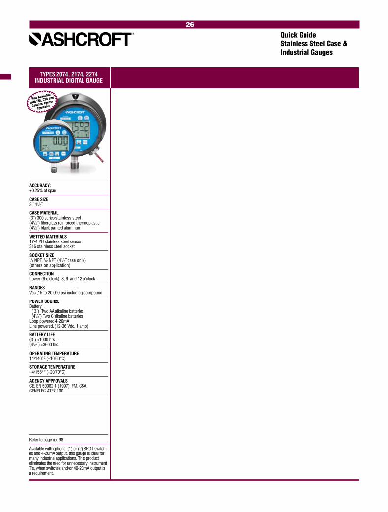
TYPES 2074, 2174, 2274INDUSTRIAL DIGITAL GAUGE
Now Available
with FM, CSA and
Cenelec Agency
Approvals
26
Refer to page no. 98
Available with optional (1) or (2) SPDT switch-es and 4-20mA output, this gauge is ideal for many industrial applications. This product eliminates the need for unnecessary instrument T’s, when switches and/or 40-20mA output is a requirement.
ACCURACY: ±0.25% of span
CASE SIZE 3, 41/2˝
CASE MATERIAL (3˝) 300 series stainless steel (41/2˝) fiberglass reinforced thermoplastic (41/2˝) black painted aluminum
WETTED MATERIALS 17-4 PH stainless steel sensor; 316 stainless steel socket
SOCKET SIZE 1/4 NPT, 1/2 NPT (41/2˝ case only) (others on application)
CONNECTION Lower (6 o’clock), 3, 9 and 12 o’clock
RANGES Vac.,15 to 20,000 psi including compound
POWER SOURCE Battery ( 3˝) Two AA alkaline batteries (41/2 ) Two C alkaline batteries Loop powered 4-20mA Line powered, (12-36 Vdc, 1 amp)
BATTERY LIFE (3˝) >1000 hrs. (41/2˝) >3600 hrs.
OPERATING TEMPERATURE 14/140°F (–10/60°C)
STORAGE TEMPERATURE –4/158°F (–20/70°C)
AGENCY APPROVALS CE, EN 50082-1 (1997), FM, CSA, CENELEC-ATEX 100
DIRECTMOUNT
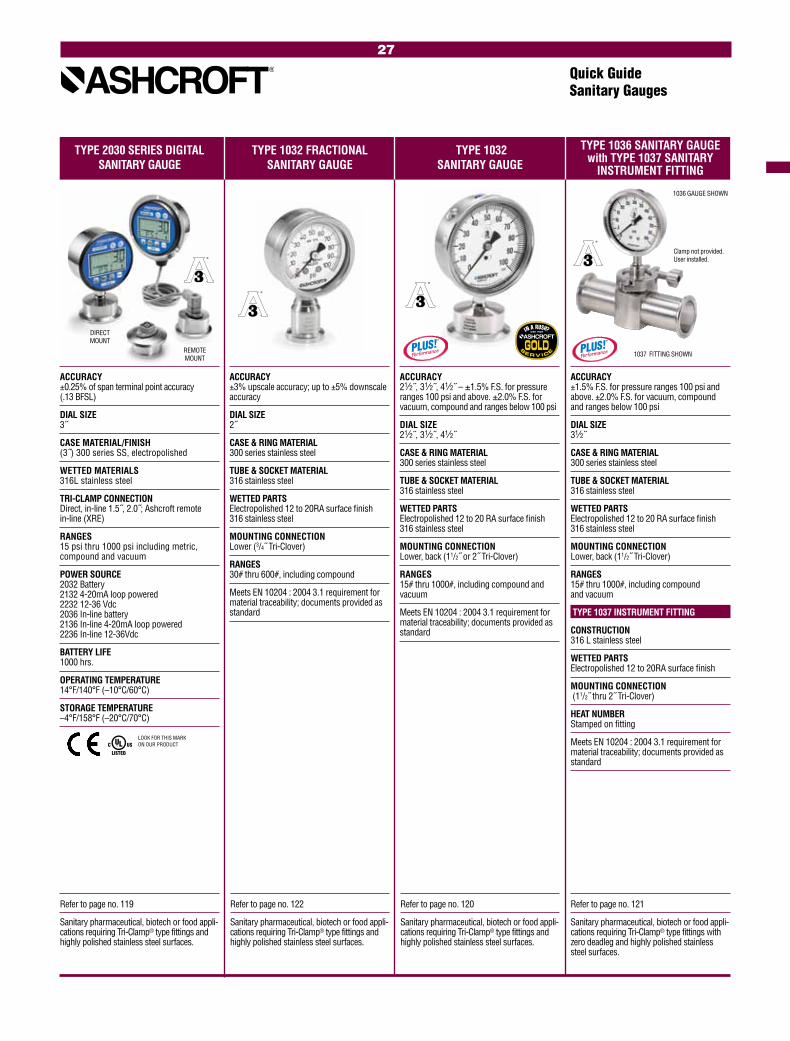
Quick GuideSanitary Gauges
TYPE 2030 SERIES DIGITAL TYPE 1032 FRACTIONAL TYPE 1032 SANITARY GAUGE SANITARY GAUGE SANITARY GAUGE
TYPE 1036 SANITARY GAUGE with TYPE 1037 SANITARY
INSTRUMENT FITTING
Refer to page no. 122
Sanitary pharmaceutical, biotech or food appli-cations requiring Tri-Clamp® type fittings and highly polished stainless steel surfaces.
Refer to page no. 120
Sanitary pharmaceutical, biotech or food appli-cations requiring Tri-Clamp® type fittings and highly polished stainless steel surfaces.
Refer to page no. 121
Sanitary pharmaceutical, biotech or food appli-cations requiring Tri-Clamp® type fittings with zero deadleg and highly polished stainless steel surfaces.
Refer to page no. 119
Sanitary pharmaceutical, biotech or food appli-cations requiring Tri-Clamp® type fittings and highly polished stainless steel surfaces.
ACCURACY ±3% upscale accuracy; up to ±5% downscale accuracy
DIAL SIZE 2˝
CASE & RING MATERIAL 300 series stainless steel
TUBE & SOCKET MATERIAL 316 stainless steel
WETTED PARTS Electropolished 12 to 20RA surface finish 316 stainless steel
MOUNTING CONNECTION Lower (3/4˝ Tri-Clover)
RANGES 30# thru 600#, including compound
Meets EN 10204 : 2004 3.1 requirement for material traceability; documents provided as standard
ACCURACY 21⁄2˝, 31⁄2˝, 41⁄2˝ – ±1.5% F.S. for pressure ranges 100 psi and above. ±2.0% F.S. for vacuum, compound and ranges below 100 psi
DIAL SIZE 21⁄2˝, 31⁄2˝, 41⁄2˝
CASE & RING MATERIAL 300 series stainless steel
TUBE & SOCKET MATERIAL 316 stainless steel
WETTED PARTS Electropolished 12 to 20 RA surface finish 316 stainless steel
MOUNTING CONNECTION Lower, back (11/2˝ or 2˝ Tri-Clover)
RANGES 15# thru 1000#, including compound and vacuum
Meets EN 10204 : 2004 3.1 requirement for material traceability; documents provided as standard
ACCURACY ±1.5% F.S. for pressure ranges 100 psi and above. ±2.0% F.S. for vacuum, compound and ranges below 100 psi
DIAL SIZE 31⁄2˝
CASE & RING MATERIAL 300 series stainless steel
TUBE & SOCKET MATERIAL 316 stainless steel
WETTED PARTS Electropolished 12 to 20 RA surface finish 316 stainless steel
MOUNTING CONNECTION Lower, back (11/2˝ Tri-Clover)
RANGES 15# thru 1000#, including compound and vacuum
TYPE 1037 INSTRUMENT FITTING
CONSTRUCTION 316 L stainless steel
WETTED PARTS Electropolished 12 to 20RA surface finish
MOUNTING CONNECTION (11/2˝ thru 2˝ Tri-Clover)
HEAT NUMBER Stamped on fitting
Meets EN 10204 : 2004 3.1 requirement for material traceability; documents provided as standard
Clamp not provided. User installed.
ACCURACY ±0.25% of span terminal point accuracy (.13 BFSL)
DIAL SIZE 3˝
CASE MATERIAL/FINISH (3˝) 300 series SS, electropolished
WETTED MATERIALS 316L stainless steel
TRI-CLAMP CONNECTION Direct, in-line 1.5˝, 2.0˝; Ashcroft remote in-line (XRE)
RANGES 15 psi thru 1000 psi including metric, compound and vacuum
POWER SOURCE 2032 Battery 2132 4-20mA loop powered 2232 12-36 Vdc 2036 In-line battery 2136 In-line 4-20mA loop powered 2236 In-line 12-36Vdc
BATTERY LIFE 1000 hrs.
OPERATING TEMPERATURE 14°F/140°F (–10°C/60°C)
STORAGE TEMPERATURE –4°F/158°F (–20°C/70°C)
1036 GAUGE SHOWN
1037 FITTING SHOWNREMOTEMOUNT
LOOK FOR THIS MARK ON OUR PRODUCT
27

28
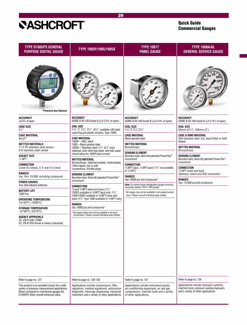
Quick GuideCommercial Gauges
Refer to page no. 128-130
Applications include compressors, filter regulators, medical equipment, automotive diagnostic, beverage dispensing, industrial machinery and a variety of other applications.
Refer to page no. 131
Applications include instrument panels, air-conditioning equipment, air and gas compressors, machine tools and a variety of other applications.
ACCURACY ASME B 40.100 Grade B (±3-2-3% of span)
DIAL SIZE 11⁄2, 2, 21⁄2, 31⁄2˝
CASE MATERIAL Black painted steel
WETTED MATERIAL Bronze/brass.
SENSING ELEMENT Bourdon tube; Ashcroft patented PowerFlex™ movement
CONNECTION 1⁄8 NPT back, 1⁄4 NPT back (11⁄2˝ not available in 1⁄4 NPT)
RANGES Vac.-6000 psi and compound*
Note: For panel mount refrigeration gauge (recovery, recycling) specify 1001T, XRR gauge
* All ranges may not be available in all ranges/connec-tions. Please consult individual spec sheets.
ACCURACY ASME B 40.100 Grade B (±3-2-3% of span)
DIAL SIZE 11⁄2, 2, 21⁄2, 31⁄2˝ (41⁄2˝ available with steel case/ring and plastic window, Type 1000)
CASE MATERIAL 1005P – ABS, black 1005 – Black painted steel 1005S – Stainless steel (11⁄2˝ & 2˝ only) Optional, color other than black, vent hole, panel mount sleeve for 1005P back connect
WETTED MATERIAL Bronze/brass. Optional sockets, nickel plated, Teflon taped, top or side connections, throttle plugs
SENSING ELEMENT Bourdon tube; Ashcroft patented PowerFlex™ movement
CONNECTION 1⁄8 and 1⁄4 NPT back and lower (11⁄2˝ 1005S available in 1⁄8 NPT back only; 11⁄2˝ 1005/1005P available in 1⁄8 NPT lower and back; 41⁄2˝ Type 1000 available in 1⁄4 NPT only)
RANGES Vac.-6000 psi and compound*
* All ranges listed may not be available in all sizes/connections. Please consult individual spec sheets.
ACCURACY ±0.5% of span
CASE SIZE 21/2˝
CASE MATERIAL Noryl®
WETTED MATERIALS 17-4 PH stainless steel sensor; 316 stainless steel socket
SOCKET SIZE 1/4 NPT
CONNECTION Lower (6 o’clock), 3, 9 and 12 o’clock
RANGES Vac. thru 19,999, including compound
POWER SOURCE Two AAA alkaline batteries
BATTERY LIFE 1000 hrs.
OPERATING TEMPERATURE 14/140°F (–10/60°C)
STORAGE TEMPERATURE –4/158°F (–20/70°C)
AGENCY APPROVALS CE, EN 61326 (1998) CE, EN 61326 Annex A (heavy industrial)
TYPE D1005PS GENERAL TYPE 1005P/1005/1005S TYPE 1001T TYPE 1008A/AL PURPOSE DIGITAL GAUGE PANEL GAUGE GENERAL SERVICE GAUGE
Refer to page no. 134
Applications include hydraulic systems, machine tools, pressure washers/sprayers and a variety of other applications.
ACCURACY ASME B 40.100 Grade B (±3-2-3% of span)
DIAL SIZE 63mm (21⁄2˝), 100mm (4˝)
CASE & RING MATERIAL 304 stainless steel, dry, liquid filled or field fillable
WETTED MATERIAL Bronze/brass
SENSING ELEMENT Bourdon tube; Ashcroft patented PowerFlex™ movement
CONNECTION 1⁄4 NPT lower and back Optional, metric and SAE connection
RANGES Vac.-15,000 psi and compound
*Protective Boot Optional
29
Refer to page no. 127
This product is an excellent choice for a wide variety of pressure measurement applications. When compared to mechanical gauges the D1005PS offers overall enhanced value.

TYPE 3005/3005P TYPE 1005M, XRG TYPE 1005P, XUL TYPE 1007P, XOR HYDRAULIC GAUGE AGRICULTURAL AMMONIA SPRINKLER SERVICE GAUGE REFRIGERATION MANIFOLD
Quick GuideCommercial Gauges
Refer to page no. 133
This product was designed to withstand rugged agricultural applications. Features include stainless tube and socket, in addition to glass window, necessary for anhydrous ammonia applications.
ACCURACY ASME B 40.100 Grade B (±3-2-3% of span)
DIAL SIZE 21⁄2˝
CASE MATERIAL Black painted steel
WETTED MATERIAL 316 stainless steel/steel
SENSING ELEMENT Bourdon tube; Ashcroft patented PowerFlex™ movement
CONNECTION 1⁄4 NPT lower Optional, 0.020”orifice stainless steel throttle plug
RANGES 0/60 psi, 0/150 psi, 0/400 psi
Refer to page no. 132
These gauges are UL-393 listed, UL of Canada listed and FM approved for fire protection sprinkler service for either water or air systems.
Refer to page no. 137
Typical applications include checking or servicing refrigerant levels in automotive, residential or industrial air-conditioning units; refrigerant recovery and reclamation units; refrigerant transport systems and large scale air-conditioning and chilling equipment.
Refer to page no. 135
Applications include hydraulic systems, machine tools, pressure washers/sprayers, compressors, irrigation equiptment and a variety of other applications.
ACCURACY ASME B 40.100 Grade B (±3-2-3% of span)
DIAL SIZE 63mm (21⁄2˝)
CASE MATERIAL 3005 – 304 stainless steel, dry, liquid filled or field fillable 3005P – Black ABS dry or glycerine filled
WETTED MATERIAL Bronze/brass
SENSING ELEMENT Bourdon tube; Ashcroft patented PowerFlex™ movement
CONNECTION 3005 – 1⁄4 NPT lower and back 3005P – 1⁄4 NPT lower Optional, metric and SAE connection
RANGES Vac.-15,000 psi and compound
ACCURACY ±1% at zero, ±2% three fourths of scale, ±5% last fourth of scale
DIAL SIZE 21⁄2˝
CASE MATERIAL ABS, red (high pressure) ABS, blue (low pressure) Optional, black, ABS
WETTED MATERIAL Bronze/brass
SENSING ELEMENT Bourdon tube; Ashcroft patented PowerFlex™ movement with FlutterGuard™
CONNECTION 1⁄8 NPT lower
RANGES Vac/0/120 psi retard to 250 psi, 0/500 psi Vac/0/500 psi retard to 800 psi, 0/800 psi Optional, alternate refrigerant ranges
Note: for panel mount refrigeration gauges (recovery, recycling) see Type 1001T gauge. Specify 1001T, XRR gauge
ACCURACY ASME B 40.100 Grade B (±3-2-3% of span)
DIAL SIZE 31⁄2˝
CASE MATERIAL ABS/polycarbonate blend
WETTED MATERIAL Bronze/brass
SENSING ELEMENT Bourdon tube; Ashcroft patented PowerFlex™ movement
CONNECTION 1⁄4 NPT lower
RANGES 0-300 psi (water), 0-80 psi retard to 250 psi (air)
LOOK FOR THESE MARKS ON OUR PRODUCTS
FlutterGuard™
standard feature
of this product
30

TYPE 2071 TYPE 40DDG/50DDG TYPE 23DDG MINIGAUGE® TYPE 12DDG/15DDG CONTRACTOR GAUGE DIRECT DRIVE GAUGE PRESSURE GAUGE DIRECT DRIVE GAUGE
Quick GuideCommercial Gauges
Refer to page no. 136
These gauges are designed to meet the needs of heating, ventilating, plumbing and air-conditioning contractors.
Refer to page no. 139
Typical applications include filter regulator lubricators, portable compressors, air tanks, industrial machinery and a variety of other applications. Excellent shock resistance.
ACCURACY ASME B 40.100 Grade A (±2-1-2% of span)
DIAL SIZE 41⁄2˝
CASE & RING MATERIAL Aluminum with back-flange case, painted black; chrome plated ring
WETTED MATERIAL Bronze/brass soldered, siphon required for steam service
SENSING ELEMENT Bourdon tube; Ashcroft patented PowerFlex™ movement
CONNECTION 1⁄4 NPT lower Optional, throttle plugs
RANGES Vac-600 psi and compound
ACCURACY ASME B 40.100 Grade B (±3-2-3% of span)
DIAL SIZE 40mm (11⁄2˝) or 50mm (2˝)
CASE MATERIAL ABS polycarbonate blend, black
WETTED MATERIAL Beryllium copper coil, silicone dampened Integral ABS polycarbonate blend socket Optional, 1⁄8 NPT or 1⁄4 NPT brass, throttle plug
SENSING ELEMENT Spiral wound Bourdon tube
CONNECTION 40mm – 1⁄8 NPT back 50mm – 1⁄8 NPT or 1⁄4 NPT back
RANGES 0-60 psi (180° arc); 0-100 psi, 0-160 psi, 0-200 psi, 0-300 psi, 0-400 psi (235° arc) For optimum gauge life, select a gauge with a full scale pressure range of approximately twice the maximum excursion pressure
Consult factory for high cycle life applications
Refer to page no. 138
These gauges are perfect for a multitude of applications where a 11/2˝ conventional size gauge is too large, such as mini-FRL’s, pneumatic stack valves, air compressors and accessories.
ACCURACY ±5% of span
DIAL SIZE 23mm (0.906˝)
CASE MATERIAL ABS blend, black
WETTED MATERIAL Beryllium copper tube/brass socket
SENSING ELEMENT Spiral wound Bourdon tube
CONNECTION 1⁄8 NPT back with 15mm (9/16˝) wrench flats. Optional, throttle plugs, PT 1⁄8˝ (JIS) and R 1⁄8˝ (BSPT) threads
RANGES 60 psi-100 psi (180° dial arc) 160 psi-300 psi (235° dial arc)
Consult factory for high cycle life applications
Refer to page no. 140
Applications include pumps, air compres-sors, portable tire inflators, portable oxy-gen equipment, self-contained breathing apparatus, portable industrial gas cylinders and a variety of other applications.
ACCURACY Standard: ±2% at setpoint (setpoint is normally 50% of range) UL listed: ±3.5% of span of middle three-fifths of scale
DIAL SIZE 11⁄4, 11⁄2˝
CASE MATERIAL Stainless steel, sealed
WETTED MATERIAL Beryllium copper tube/brass socket
SENSING ELEMENT Spiral wound Bourdon tube Optional, silicone dampened tube, silicone-filled tube
CONNECTION 1⁄8 NPT back, safety plug in 1500 psi-4000 psi ranges. Optional, 1⁄4 NPT back, throttle plugs
RANGES 0/60 psi (180° arc) 0/100 psi, 0/160 psi, 0/200 psi, 0/300 psi, (235° arc) 0/700 psi (200° arc) 0/1,200 psi (180° arc) 0/1,500 psi 0/2,000 psi, 0/3,000 psi, 0/4,000 psi (165° arc)
Consult factory for high cycle life applications
31

Quick GuideCommercial Gauges
TYPE MFX FIRE EXTINGUISHER GAUGE
Refer to page no. 141These products are designed for use on portable fire extin-guishers and systems.
ACCURACY Conforms to applicable UL specs*
DIAL SIZE 11⁄4, 11⁄2˝
CASE MATERIAL Stainless steel, sealed
WETTED MATERIAL Beryllium copper/brass
SENSING ELEMENT Spiral wound Bourdon tube Optional, silicone-filled tube Spiral tube, beryllium copper
CONNECTION 1⁄8 NPT back Optional, special socket configurations
RANGES Maximum scale pressure from 200 psi to 1200 psi
*UL 299 UL 626 UL 1058 UL 1093
32
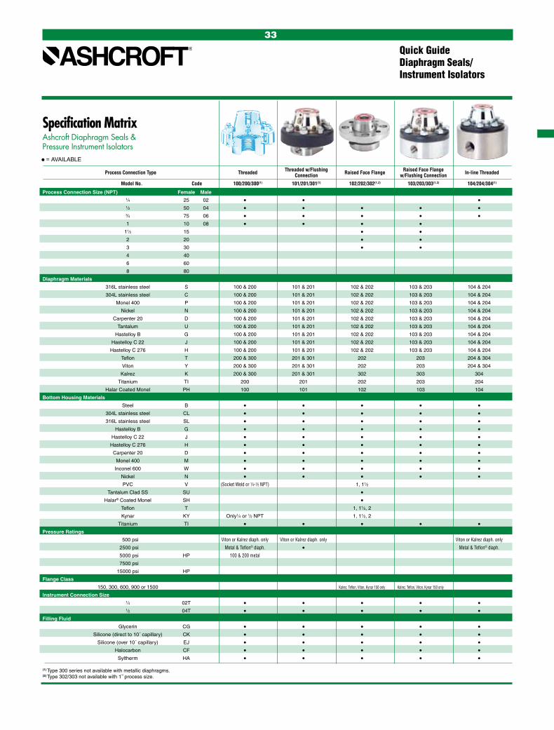
Specification MatrixAshcroft Diaphragm Seals & Pressure Instrument Isolators
• = AVAILABLE
(1) Type 300 series not available with metallic diaphragms.(2) Type 302/303 not available with 1˝ process size.
Process Connection Type Threaded Threaded w/Flushing Raised Face Flange Raised Face Flange In-line Threaded Connection w/Flushing Connection
Model No. Code 100/200/300(1) 101/201/301(1) 102/202/302(1,2) 103/203/303(1,2) 104/204/304(1)
Process Connection Size (NPT) Female Male
1⁄4 25 02 • • • 1⁄2 50 04 • • • • • 3⁄4 75 06 • • • • • 1 10 08 • • • • 11⁄2 15 • • 2 20 • • 3 30 • • 4 40
6 60
8 80
Diaphragm Materials
316L stainless steel S 100 & 200 101 & 201 102 & 202 103 & 203 104 & 204
304L stainless steel C 100 & 200 101 & 201 102 & 202 103 & 203 104 & 204
Monel 400 P 100 & 200 101 & 201 102 & 202 103 & 203 104 & 204
Nickel N 100 & 200 101 & 201 102 & 202 103 & 203 104 & 204
Carpenter 20 D 100 & 200 101 & 201 102 & 202 103 & 203 104 & 204
Tantalum U 100 & 200 101 & 201 102 & 202 103 & 203 104 & 204
Hastelloy B G 100 & 200 101 & 201 102 & 202 103 & 203 104 & 204
Hastelloy C 22 J 100 & 200 101 & 201 102 & 202 103 & 203 104 & 204
Hastelloy C 276 H 100 & 200 101 & 201 102 & 202 103 & 203 104 & 204
Teflon T 200 & 300 201 & 301 202 203 204 & 304
Viton Y 200 & 300 201 & 301 202 203 204 & 304
Kalrez K 200 & 300 201 & 301 302 303 304
Titanium TI 200 201 202 203 204
Halar Coated Monel PH 100 101 102 103 104
Bottom Housing Materials
Steel B • • • • • 304L stainless steel CL • • • • • 316L stainless steel SL • • • • • Hastelloy B G • • • • • Hastelloy C 22 J • • • • • Hastelloy C 276 H • • • • • Carpenter 20 D • • • • • Monel 400 M • • • • • Inconel 600 W • • • • • Nickel N • • • • • PVC V (Socket Weld or 1⁄4-1⁄2 NPT) 1, 11⁄2
Tantalum Clad SS SU • Halar® Coated Monel SH • Teflon T 1, 11⁄2, 2
Kynar KY Only1⁄4 or 1⁄2 NPT 1, 11⁄2, 2
Titanium TI • • • • • Pressure Ratings
500 psi Viton or Kalrez diaph. only Viton or Kalrez diaph. only Viton or Kalrez diaph. only
2500 psi Metal & Teflon® diaph. • Metal & Teflon® diaph.
5000 psi HP 100 & 200 metal
7500 psi
15000 psi HP
Flange Class
150, 300, 600, 900 or 1500 Kalrez, Teflon, Viton, Kynar 150 only Kalrez, Teflon, Viton, Kynar 150 only
Instrument Connection Size
1⁄4 02T • • • • • 1⁄2 04T • • • • • Filling Fluid
Glycerin CG • • • • • Silicone (direct to 10´ capillary) CK • • • • • Silicone (over 10´ capillary) EJ • • • • • Halocarbon CF • • • • • Syltherm HA • • • • •
Quick GuideDiaphragm Seals/ Instrument Isolators
33
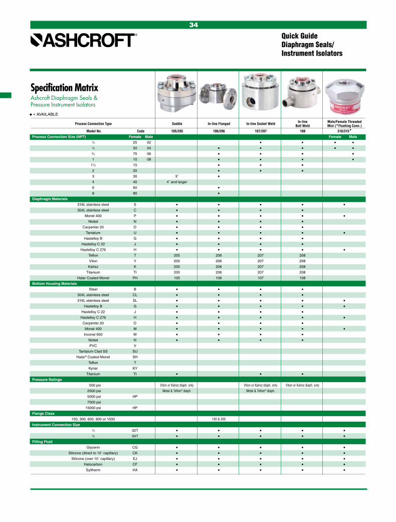
Specification MatrixAshcroft Diaphragm Seals & Pressure Instrument Isolators
• = AVAILABLE
Process Connection Type Saddle In-line Flanged In-line Socket Weld In-line Male/Female Threaded Butt Weld Mini (*Flushing Conn.) Model No. Code 105/205 106/206 107/207 108 310/315* Process Connection Size (NPT) Female Male Female Male
1⁄4 25 02 • • • • 1⁄2 50 04 • • • • • 3⁄4 75 06 • • • • 1 10 08 • • • • 11⁄2 15 • • • 2 20 • • • 3 30 3˝ • 4 40 4˝ and larger 6 60 • 8 80 • Diaphragm Materials
316L stainless steel S • • • • • 304L stainless steel C • • • • Monel 400 P • • • • • Nickel N • • • • Carpenter 20 D • • • • Tantalum U • • • • • Hastelloy B G • • • • Hastelloy C 22 J • • • • Hastelloy C 276 H • • • • • Teflon T 205 206 207 208
Viton Y 205 206 207 208
Kalrez K 205 206 207 208
Titanium TI 205 206 207 208
Halar Coated Monel PH 105 106 107 108
Bottom Housing Materials
Steel B • • • • 304L stainless steel CL • • • • 316L stainless steel SL • • • • • Hastelloy B G • • • • • Hastelloy C 22 J • • • • Hastelloy C 276 H • • • • • Carpenter 20 D • • • • Monel 400 M • • • • • Inconel 600 W • • • • Nickel N • • • • PVC V
Tantalum Clad SS SU
Halar® Coated Monel SH
Teflon T
Kynar KY
Titanium TI • • • Pressure Ratings
500 psi Viton or Kalrez diaph. only Viton or Kalrez diaph. only Viton or Kalrez diaph. only
2500 psi Metal & Teflon® diaph. Metal & Teflon® diaph.
5000 psi HP
7500 psi
15000 psi HP
Flange Class
150, 300, 600, 900 or 1500 150 & 300
Instrument Connection Size
1⁄4 02T • • • • • 1⁄2 04T • • • • • Filling Fluid
Glycerin CG • • • • • Silicone (direct to 10´ capillary) CK • • • • • Silicone (over 10´ capillary) EJ • • • • • Halocarbon CF • • • • • Syltherm HA • • • • •
Quick GuideDiaphragm Seals/ Instrument Isolators
34
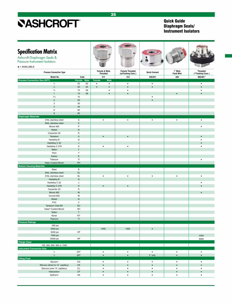
Specification MatrixAshcroft Diaphragm Seals & Pressure Instrument Isolators
• = AVAILABLE
Process Connection Type Female & Male Female Threaded Quick Connect 1˝ Male Threaded Threaded (w/Flushing Conn.) Flush Mini (*Flushing Conn.)
Model No. Code 311 312 320/321 330 400/401*
Process Connection Size (NPT) Female Male Female Male
1⁄4 25 02 • • • • • 1⁄2 50 04 • • • • • 3⁄4 75 06 • • • 1 10 08 • • • • 11⁄2 15 • 2 20 • 3 30 4 40
6 60
8 80
Diaphragm Materials
316L stainless steel S • • • • • 304L stainless steel C Monel 400 P • Nickel N Carpenter 20 D Tantalum U • • • Hastelloy B G • Hastelloy C 22 J • Hastelloy C 276 H • • • Teflon T Viton Y Kalrez K Titanium TI • Halar Coated Monel PH
Bottom Housing Materials
Steel B 304L stainless steel CL 316L stainless steel SL • • • • • Hastelloy B G Hastelloy C 22 J • Hastelloy C 276 H • • • Carpenter 20 D Monel 400 M • Inconel 600 W Nickel N PVC V
Tantalum Clad SS SU
Halar® Coated Monel SH
Teflon T
Kynar KY
Titanium TI Pressure Ratings
500 psi 2500 psi 1000 1000 • 5000 psi HP
7500 psi 4400
15000 psi HP 9000
Flange Class
150, 300, 600, 900 or 1500
Instrument Connection Size
1⁄4 02T • • • • • 1⁄2 04T • • 2˝ only • • Filling Fluid
Glycerin CG • • • • • Silicone (direct to 10´ capillary) CK • • • • • Silicone (over 10´ capillary) EJ • • • • • Halocarbon CF • • • • • Syltherm HA • • • • •
Quick GuideDiaphragm Seals/ Instrument Isolators
35

Quick GuideDiaphragm Seals/ Instrument Isolators
Specification MatrixAshcroft Diaphragm Seals & Pressure Instrument Isolators• = AVAILABLE
Process Connection Type Raised Face Flange Threaded Low Pressure Flanged Low Pressure Threaded Isolation Ring (*Flushing Conn.) (*Flushing Conn.) (*w/Flushing Conn.) (*w/Flushing Conn.)
Model No. Code 402/403* 500/501* 702/703* 740/741* 80/81/85/86
Process Connection Size (NPT) Female Male Pipe Size
1⁄4 25 02 • 1.0˝ 14.0˝ 1⁄2 50 04 • • • • 1.5˝ 16.0˝ 3⁄4 75 06 • • • • 2.0˝ 18.0˝ 1 10 08 • • • • 3.0˝ 20.0˝ 11⁄2 15 • • 4.0˝ 2 20 • • 5.0˝ 3 30 • • 6.0˝
4 40 8.0˝
6 60 10.0˝
8 80 12.0˝
Diaphragm Materials Liner Materials / Code
316L stainless steel S • • • • Buna N (E) 304L stainless steel C Teflon (T)
Monel 400 P • • • • Viton (Y)
Nickel N Nordell EPDM (EP)
Carpenter 20 D White Neoprene (CR)
Tantalum U • • • • Natural Rubber (NP)
Hastelloy B G • • • Hastelloy C 22 J • •
Hastelloy C 276 H • • • • Teflon T
Viton Y
Kalrez K
Titanium TI • • • Halar Coated Monel PH
Bottom Housing Materials Ass’y Flanges / Code
Steel B • • Carbon Steel (B)
304L stainless steel CL 316 SS (S)
316L stainless steel SL • • • • CPVC (CP)
Hastelloy B G • • Teflon Enveloped (CT)
Hastelloy C 22 J • • Polypropylene (PP)
Hastelloy C 276 H • • • • Carpenter 20 D • • Monel 400 M • • • • Inconel 600 W
Nickel N
PVC V
Tantalum Clad SS SU
Halar® Coated Monel SH
Teflon T
Kynar KY
Titanium TI • • • Pressure Ratings Instrument Conn / Code
500 psi • 750 750 1/4 NPT (02T)
2500 psi 1/2 NPT (0 4T)
5000 psi HP
7500 psi
15000 psi HP
Flange Class
150, 300, 600, 900 or 1500 • 150-600
Instrument Connection Size
1⁄4 02T • • • • 1⁄2 04T • • • • Filling Fluid
Glycerin CG • • • • • Silicone (direct to 10´ capillary) CK • • • • • Silicone (over 10´ capillary) EJ • • • • • Halocarbon CF • • • • • Syltherm HA • • • • •
36

37
Specification MatrixAshcroft Diaphragm Seals & Pressure Instrument Isolators• = AVAILABLE
Process Connection Type Diaphragm Seal Diaphragm Seal Diaphragm Seal Diaphragm Seal (w/Flushing Conn.) (w/Flushing Conn.) Model No. Code 510 510HP 511 511HP
Process Connection Size (NPT) Female Male
1⁄4 25 02
1⁄2 50 04 • • • • 3⁄4 75 06
1 10 08
11⁄2 15
2 20
3 30
4 40
6 60
8 80
Diaphragm Materials
316L stainless steel S • • • • 304L stainless steel C
Monel 400 P • • • • Nickel N
Carpenter 20 D
Tantalum U
Hastelloy B G
Hastelloy C 22 J • • • • Hastelloy C 276 H
Teflon T
Viton Y
Kalrez K
Titanium TI
Halar Coated Monel PH
Bottom Housing Materials
Steel B
304L stainless steel CL
316L stainless steel SL • • • • Hastelloy B G
Hastelloy C 22 J
Hastelloy C 276 H
Carpenter 20 D
Monel 400 M • • • • Inconel 600 W
Nickel N
PVC V
Tantalum Clad SS SU
Halar® Coated Monel SH
Teflon T
Kynar KY
Titanium TI
Pressure Ratings (1)
500 psi
2500 psi 1500 1500
5000 psi HP • • 7500 psi
9000 psi HP
Flange Class
150, 300, 600, 900 or 1500
Instrument Connection Size
1⁄4 02T
1⁄2 04T • • • • Filling Fluid
Glycerin CG • • • • Silicone (direct to 10´ capillary) CK • • • • Silicone (over 10´ capillary) EJ • • • • Halocarbon CF • • • • Syltherm HA • • • •
(1) See Table A on pages 166-167 for instrument compatibility. Minimum pressure is determined by the instrument that will be attached to the diaphram seal.

38
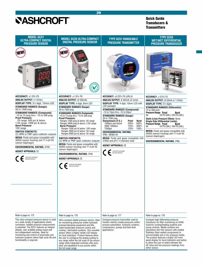
Quick GuideTransducers & Transmitters
TYPE GC51 RANGEABLE PRESSURE TRANSMITTER
ACCURACY: ±0.25% FS (URL)0ANALOG OUTPUT: 4-20mA (2-wire)DISPLAY TYPE: 4 digit, 10mm LCD with LED backlightSTANDARD RANGES (Compound): –15 to 15psi thru –15 to 50psiSTANDARD RANGES (Gauge): 50 to 7500 psig Overpressure (F.S.): Proof Burst 1500psi and below 200% 500% 3000, 5000psi 150% 300% 7500psi 120% 150%ENVIRONMENTAL RATING: IP65 / NEMA 4XMEDIA: Fluids and gases compatible with 316SS and pH17-4 stainless steel
AGENCY APPROVALS: CE
MODEL GC31ULTRA-COMPACT DIGITAL
PRESSURE SENSORMODEL GC35 ULTRA-COMPACT
DIGITAL PRESSURE SENSOR
ACCURACY: ±1.0% FSANALOG OUTPUT: (1-5Vdc)DISPLAY TYPE: 31⁄2 digit, 10mm LEDSTANDARD RANGES (Gauge): 50 to 1500 psigSTANDARD RANGES (Compound): −15 to 15 psig thru −15 to 300 psig Proof Pressure: 2X range: 500 psi & below 1.5X range: 1000 psi & above Burst Pressure: 10X rangeSWITCH CONTACTS: (2) NPN or PNP open collector outputsMEDIA: Fluids and gases compatible with 304SS (sensor housing) and 17-4 pH SS (sensor diaphragm)
ENVIRONMENTAL RATING: IP40
AGENCY APPROVALS: CE
ACCURACY: ±1.0% FSANALOG OUTPUT: (4-20mA)DISPLAY TYPE: 4 digit, 8mm LEDSTANDARD RANGES (Gauge): 50 to 7500 psigSTANDARD RANGES (Compound): –15 to 75 psig thru –15 to 300 psig Proof Pressure: Ranges 1500 psig & below: 4X range Ranges 3000 psig & above: 2.5X range Burst Pressure: Ranges 1500 psi & below: 10X range Ranges 3000 psi & below: 5X range Ranges 5000 psi & above: 3X range
SWITCH CONTACTS: (2) NPN or PNP open collector outputsMEDIA: Fluids and gases compatible with 304SS (sensor housing) and 17-4 pH SS (sensor diaphragm)
ENVIRONMENTAL RATING: IP40
AGENCY APPROVALS: CE
TYPE GC55WET/WET DIFFERENTIALPRESSURE TRANSDUCER
ACCURACY: ± 0.5% FS ANALOG OUTPUT: (4-20mA or 1-5Vdc)DISPLAY TYPE: 31⁄2 digitsSTANDARD RANGES (Differential): 75 to 300 psid Pressure Range Proof Burst All 2X FS (URL) 10X FS (URL)Static (Line) Pressure Effects: NoneSingle Side (Differential Limits): Pressure Range Proof Burst All 2X FS (URL) 10X FS (URL)
MEDIA: Fluids and gases compatible with 304SS (sensor housing) and 17-4 pH SS (sensor diaphragm)
ENVIRONMENTAL RATING: IP66
NEW! NEW!
LOOK FOR THIS MARK ON OUR PRODUCT
LOOK FOR THIS MARK ON OUR PRODUCT
LOOK FOR THIS MARK ON OUR PRODUCT
Refer to page no. 175
This ultra-compact pressure sensor is used on a wide variety of applications where consistent, reliable pressure measurement is essential. The GC31 features an integral display, user scalable analog ouput and two independent switches. Ideal for monitoring and control of pneumatic and hydraulic systems where high cycle life and functionality is required.
Refer to page no. 176
Ultra-compact digital pressure sensor, ideal for monitoring pressures within hydraulic presses/stamping equipment and lifts, water/wastewater pressure control and cooling / lubrication systems. This versatile sensor offers a highly visible LED display for local indication. Product features allow the user to configure the analog scaling to any range within the full scale of the sensor range while integrated switches offer actu-ation and deadband to any points within the full scale range.
39
Refer to page no. 177
Compact pressure transmitter used to monitor wet/dry media pressures within process automation, hydraulic systems, compressors, pumps and tank level applications.
Refer to page no. 178
Compact high-differential pressure transducer for filter monitoring on HVAC hydronic cooling/heating systems and pump controls. Model contains two polysilicon thin film sensors with welded Stainless Steel wetted components to accommodate wet or dry pressure media. The product features a bright LED front panel display for local indication and button to allow the user to select between the dP value and line pressure readings from either sensor.

ACCURACY: ±0.25% of Span
OUTPUT: 4-20mA, 0-5Vdc, 0-10Vdc, 1-5Vdc, 1-6Vdc, 0.5-4.5Vdc (ratiometric)
STANDARD RANGES: Pressure Ranges (F.S.): 30 to 20,000 psig, compound to 300 psig Overpressure: (Varies w/pressure range) Proof: up to 3 x F.S. Burst: up to 10 x F.S.
ENVIRONMENTAL RATING: NEMA 4X, IP65
AGENCY APPROVALS: CE
Refer to page no. 179
A robust pressure transducer designed for industrial applications featuring Ashcroft’s proven polysilicon thin film pressure sensing element. Product features include voltage and current outputs, a variety of pressure ports and electrical terminations to international standards with excellent accuracy and perfor-mance over –40 to 125°C, (–40 to 257°F).
Refer to page no. 181
A highly configurable transmitter designed for hazardous location and heavy industrial appli-cations. High performance accuracy and ther-mal capability over –40/125°C (–40/257°F) with additional option of zero and span pots.
Quick GuideTransducers & Transmitters
ACCURACY: ±0.25, ±0.5, ±1.0% span
OUTPUT: 4-20mA, 0-5Vdc, 0-10Vdc, 1-5Vdc, 1-6Vdc, 0.5-4.5Vdc (ratiometric)
STANDARD RANGES: 15 to 7500 psi absolute, 5 to 10,000 psig, compound to 100 psig Overpressure: (Varies w/pressure range) Proof: up to 2 x F.S. Burst: up to 4 x F.S.
ENVIRONMENTAL RATING: IP65, IP67, NEMA 4X, 6, 7, 9AGENCY APPROVALS: CE
A2 HEAVY INDUSTRIAL AND A2X EXPLOSION/FLAME PROOF T2 HIGH PERFORMANCE EXPLOSION PROOF TRANSMITTERS PRESSURE TRANSMITTER PRESSURE TRANSDUCER
A4 INTRINSICALLY SAFE & NON-INCENDIVE
PRESSURE TRANSMITTER
ACCURACY: ±0.25, ±0.5, ±1.0% spanOUTPUT: 4-20mA, 0-5Vdc, 0-10Vdc, 1-5Vdc, 1-6Vdc, 0.5-4.5Vdc (ratiometric)STANDARD RANGES (psig): 0-5 psi through 0-10,000 psigENVIRONMENTAL RATING: Ingress Protection Rating: IP65; NEMA 7,9AGENCY APPROVALS: Explosion Proof – cUL (USL/CNL): Flame Proof – ATEX: Intrinsically Safe – FM (4-20mA) – CE
ACCURACY: ±.25, ±0.5, ±1.0% spanOUTPUT: 4-20mASTANDARD RANGES: 15 to 7500 psi absolute, 5 to 10,000 psig, compound to 100 psig Overpressure: (Varies w/pressure range) Proof: up to 2 x F.S. Burst: up to 4 x F.S.
ENVIRONMENTAL RATING: Basic IP65, NEMA 4X All Welded* IP67, NEMA 6 *(w/o Z/S)
AGENCY APPROVALS: CE Non-Incendive – FM/CSA:
LOOK FOR THIS MARK ON OUR PRODUCT
FM
LOOK FOR THESE MARKS ON OUR PRODUCTS LOOK FOR THIS MARK ON OUR PRODUCT
LOOK FOR THESE MARKS ON OUR PRODUCTS
FM
Refer to page no. 182
The Ashcroft® A2X is ideal for a broad spectrum of pressure sensing applications where explosion/flameproof hazardous location ratings are required. The A2X pressure transmitter offers all 316L SS wetted materials and features excellent accuracy and stability for reliable measurements over the life of the instrument.
Refer to page no. 183
The Ashcroft® A4 pressure transmitter is ideal for a broad spectrum of pressure sensing requirements where Intrinsically Safe or Non-Incendive hazardous location ratings are required. Designed / manufactured to provide the user with accurate, reliable, and stable output data using an on-board microprocessor programmed during a unique digital compensation process; providing a product that supplies extremely linear and precise performance.
40
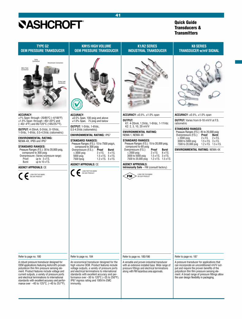
TYPE G2 KM15 HIGH VOLUME K1/K2 SERIES K8 SERIES OEM PRESSURE TRANSDUCER OEM PRESSURE TRANSDUCER INDUSTRIAL TRANSDUCER TRANSDUCER w/mV SIGNAL
Quick GuideTransducers & Transmitters
ACCURACY: ±1% Span: through –20/85°C (–4/185°F) ±1.5% Span: through –40/–20°C and (–40/–4°F) and 85/125°C (185/257°F).
OUTPUT: 4-20mA, 0-5Vdc, 0-10Vdc, 1-5Vdc, 1-6Vdc, 0.5-4.5Vdc (ratiometric)
ENVIRONMENTAL RATING: NEMA 4X, IP65 and IP67
STANDARD RANGES: Pressure Ranges (F.S.): 30 to 20,000 psig, compound to 300 psig Overpressure: (Varies w/pressure range) Proof: up to 3 x F.S. Burst: up to 10 x F.S.
AGENCY APPROVALS: CE
ACCURACY: ±0.5%, ±1.0% span
OUTPUT: K1: 4-20mA, 1,5Vdc, 1-6Vdc, 1-11Vdc K2: 2, 3, 10, 20 mV/V
ENVIRONMENTAL RATING: NEMA 1, NEMA 4X
STANDARD RANGES: Pressure Ranges (F.S.): 15 to 20,000 psig, compound to 60 psig Overpressure (F.S.): Proof Burst ≤ 2000 psig 2 x F.S. 8 x F.S. 3000 to 5000 psig 1.5 x F.S. 3 x F.S. 7500 to 20,000 psig 1.2 x F.S. 1.5 x F.S
AGENCY APPROVALS: Intrinsically Safe – FM (consult factory)
Refer to page no. 185/186
A versatile and proven industrial transducer with an extensive installed base. Wide range of pressure fittings and electrical terminations along with FM hazardous area approvals.
ACCURACY: ±0.5% Span, 100 psig and above ±1.0% Span, 75 psig and below
OUTPUT: 1-5Vdc, 1-6Vdc, 0.5-4.5Vdc (ratiometric)
ENVIRONMENTAL RATING: IP67
STANDARD RANGES: Pressure Ranges (F.S.): 15 to 7500 psig/s, compound to 300 psig Overpressure (F.S.): Proof Burst ≤ 3000 psig 2 x F.S. 5 x F.S. 5000 psig 1.5 x F.S. 5 x F.S. 7500 tpsig 1.2 x F.S. 5 x F.S.
AGENCY APPROVALS: CE
Refer to page no. 184
An economical transducer designed for the high volume OEM. Product features include voltage outputs, a variety of pressure ports and electrical terminations to international standards with excellent accuracy and per-formance over –30 to 120°C (–25 to 250°F). IP67 ingress rating and 100V/m EMC immunity.
Metri-Pack Connection
Hirschmann Connection
Cable Connection
Flying Lead Connection
ACCURACY: ±0.5%, ±1.0% span
OUTPUT: Varies from 6-18 mV/V at F.S. ratiometric
STANDARD RANGES: Pressure Ranges (F.S.): 45 to 20,000 psig Overpressure (F.S.): Proof Burst ≤ 2000 psig 2 x F.S. 2 x F.S. 3000 to 5000 psig 1.5 x F.S. 3 x F.S. 7500 to 20,000 psig 1.2 x F.S. 1.5 x F.S.
ENVIRONMENTAL RATING: NEMA 4X
Refer to page no. 187
A pressure transducer for applications that can incorporate an unconditioned mV/V out-put and require the proven benefits of the polysilicon thin film pressure sensing ele-ment. A broad range of pressure fittings allow the user design flexibility in packaging.
LOOK FOR THIS MARK ON OUR PRODUCT
LOOK FOR THIS MARK ON OUR PRODUCT
Refer to page no. 180
A robust pressure transducer designed for OEM applications featuring Ashcroft’s proven polysilicon thin film pressure sensing ele-ment. Product features include voltage and current outputs, a variety of pressure ports and electrical terminations to international standards with excellent accuracy and perfor-mance over –40 to 125°C, (–40 to 257°F).
FMLOOK FOR THIS MARK ON OUR PRODUCT
41
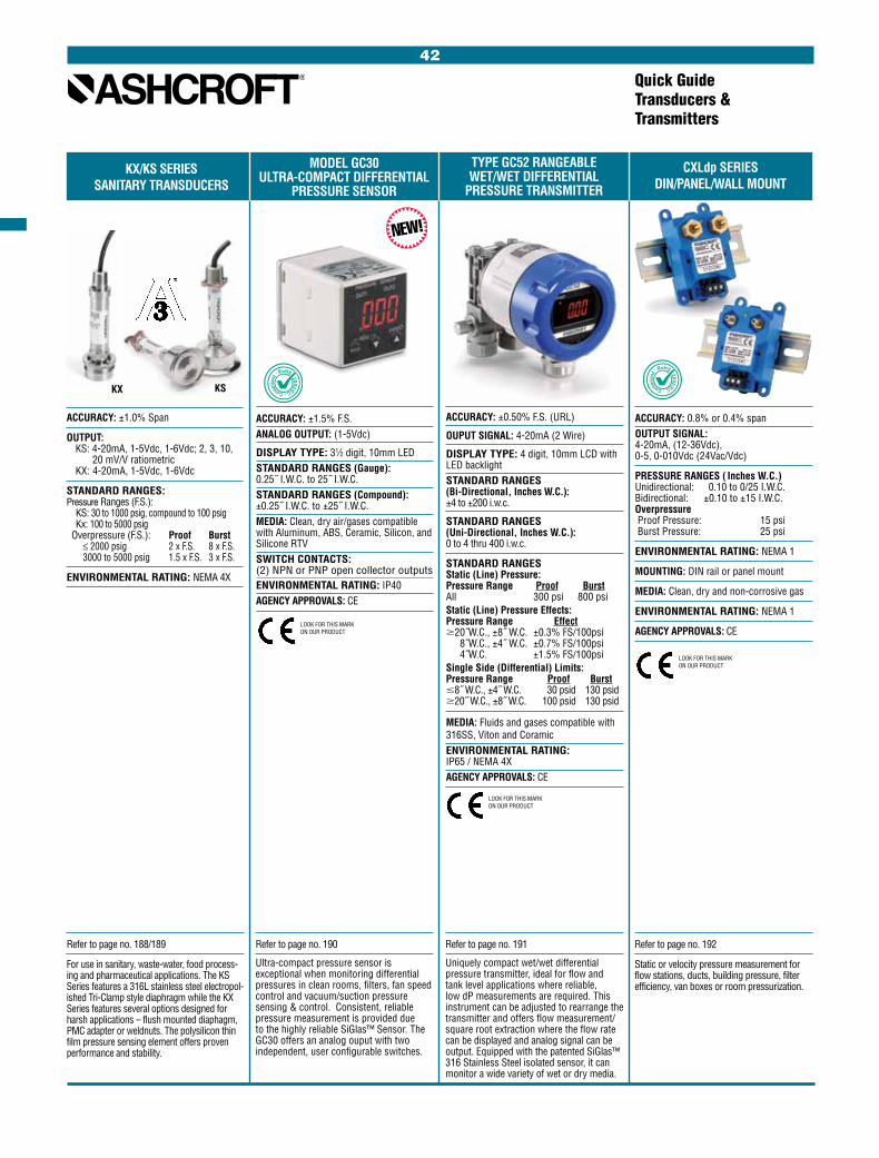
Quick GuideTransducers & Transmitters
KX/KS SERIES CXLdp SERIES SANITARY TRANSDUCERS DIN/PANEL/WALL MOUNT
ACCURACY: 0.8% or 0.4% spanOUTPUT SIGNAL: 4-20mA, (12-36Vdc), 0-5, 0-010Vdc (24Vac/Vdc)
PRESSURE RANGES ( Inches W.C.) Unidirectional: 0.10 to 0/25 I.W.C. Bidirectional: ±0.10 to ±15 I.W.C. Overpressure Proof Pressure: 15 psi Burst Pressure: 25 psi
ENVIRONMENTAL RATING: NEMA 1
MOUNTING: DIN rail or panel mount
MEDIA: Clean, dry and non-corrosive gas
ENVIRONMENTAL RATING: NEMA 1
AGENCY APPROVALS: CE
NEW!
Refer to page no. 192
Static or velocity pressure measurement for flow stations, ducts, building pressure, filter efficiency, van boxes or room pressurization.
ACCURACY: ±0.50% F.S. (URL)
OUPUT SIGNAL: 4-20mA (2 Wire)
DISPLAY TYPE: 4 digit, 10mm LCD with LED backlightSTANDARD RANGES (Bi-Directional, Inches W.C.): ±4 to ±200 i.w.c.
STANDARD RANGES (Uni-Directional, Inches W.C.): 0 to 4 thru 400 i.w.c.
STANDARD RANGES Static (Line) Pressure: Pressure Range Proof Burst All 300 psi 800 psiStatic (Line) Pressure Effects: Pressure Range Effect $20˝W.C., ±8˝ W.C. ±0.3% FS/100psi
8˝W.C., ±4˝ W.C. ±0.7% FS/100psi 4˝W.C. ±1.5% FS/100psi
Single Side (Differential) Limits: Pressure Range Proof Burst #8˝ W.C., ±4˝ W.C. 30 psid 130 psid $20˝ W.C., ±8˝ W.C. 100 psid 130 psid
MEDIA: Fluids and gases compatible with 316SS, Viton and Coramic ENVIRONMENTAL RATING: IP65 / NEMA 4XAGENCY APPROVALS: CE
TYPE GC52 RANGEABLEWET/WET DIFFERENTIAL
PRESSURE TRANSMITTER
MODEL GC30ULTRA-COMPACT DIFFERENTIAL
PRESSURE SENSOR
ACCURACY: ±1.5% F.S.ANALOG OUTPUT: (1-5Vdc)
DISPLAY TYPE: 31⁄2 digit, 10mm LEDSTANDARD RANGES (Gauge): 0.25˝ I.W.C. to 25˝ I.W.C.STANDARD RANGES (Compound): ±0.25˝ I.W.C. to ±25˝ I.W.C.MEDIA: Clean, dry air/gases compatible with Aluminum, ABS, Ceramic, Silicon, and Silicone RTVSWITCH CONTACTS: (2) NPN or PNP open collector outputsENVIRONMENTAL RATING: IP40AGENCY APPROVALS: CE
KSKX
ACCURACY: ±1.0% Span
OUTPUT: KS: 4-20mA, 1-5Vdc, 1-6Vdc; 2, 3, 10, 20 mV/V ratiometric KX: 4-20mA, 1-5Vdc, 1-6Vdc
STANDARD RANGES: Pressure Ranges (F.S.): KS: 30 to 1000 psig, compound to 100 psig Kx: 100 to 5000 psig Overpressure (F.S.): Proof Burst ≤ 2000 psig 2 x F.S. 8 x F.S. 3000 to 5000 psig 1.5 x F.S. 3 x F.S.
ENVIRONMENTAL RATING: NEMA 4X
Refer to page no. 188/189
For use in sanitary, waste-water, food process-ing and pharmaceutical applications. The KS Series features a 316L stainless steel electropol-ished Tri-Clamp style diaphragm while the KX Series features several options designed for harsh applications – flush mounted diaphagm, PMC adapter or weldnuts. The polysilicon thin film pressure sensing element offers proven performance and stability.
NEW!
LOOK FOR THIS MARK ON OUR PRODUCT
LOOK FOR THIS MARK ON OUR PRODUCT
LOOK FOR THIS MARK ON OUR PRODUCT
Refer to page no. 190
Ultra-compact pressure sensor is exceptional when monitoring differential pressures in clean rooms, filters, fan speed control and vacuum/suction pressure sensing & control. Consistent, reliable pressure measurement is provided due to the highly reliable SiGlas™ Sensor. The GC30 offers an analog ouput with two independent, user configurable switches.
Refer to page no. 191
Uniquely compact wet/wet differential pressure transmitter, ideal for flow and tank level applications where reliable, low dP measurements are required. This instrument can be adjusted to rearrange the transmitter and offers flow measurement/square root extraction where the flow rate can be displayed and analog signal can be output. Equipped with the patented SiGlas™ 316 Stainless Steel isolated sensor, it can monitor a wide variety of wet or dry media.
42

3 YEAR WARRANTY3 YEAR
WARRANTY
Refer to page no. 194
A compact transmitter for comfort control and other HVAC applications.
Refer to page no. 195
High performance dp transmitter with proven reliability and stability. Excellent for air han-dling applications including fume hood control and room pressurization.
DXLdp SERIES RXLdp SERIES XLdp SERIES IXLdp SERIES DIN MOUNT REDUCED SIZE HIGH PERFORMANCE INDUSTRIAL
ACCURACY: 0.25%, 0.50% or 1.00% span
OUTPUT SIGNAL: 4-20mA, 1-5Vdc, 1-6Vdc, 0-5Vdc, 0-10Vdc
PRESSURE RANGES ( Inches W.C.): Unidirectional: 0.10 to 50 I.W.C. Bidirectional: ±0.05 to ±25 I.W.C. Overpressure Proof Pressure: 15 psi Burst Pressure: 25 psi Max. static (line) pressure: 25 psi
MOUNTING: DIN rail mount: EN50022 EN50035 EN50045
MEDIA Clean, dry and non-corrosive gas (consult factory for use on other media)
NOT FOR USE ON LIQUIDS
ENVIRONMENTAL RATING: NEMA 1
AGENCY APPROVALS: CE
Refer to page no. 193
Designed for ease of installation and system calibration, the DXLdp is ideal for pharmaceu-tical plants and other installations where large numbers of air flow and dp measurements are being monitored.
Quick GuideTransducers & Transmitters
3 YEAR WARRANTY
Refer to page no. 196
A rugged low pressure transmitter in cast 300 series stainless steel enclosure. A good choice for dp monitoring in pollution con-trol, combustion control, and other applica-tions where precision sensing is needed in a tough environment.
LOOK FOR THIS MARK ON OUR PRODUCT
ACCURACY: 1.00% span
OUTPUT SIGNAL: 4-20mA, 1-5Vdc, 1-6Vdc, 0-5Vdc, 0-10Vdc
PRESSURE RANGES ( Inches W.C.): Unidirectional: 0.10 to 50 I.W.C. Bidirectional: ±0.05 to ±25 I.W.C. Overpressure Proof Pressure: 15 psi Burst Pressure: 25 psi Max. static (line) pressure: 25 psi
MEDIA Clean, dry and non-corrosive gas (consult factory for use on other media)
NOT FOR USE ON LIQUIDS
ENVIRONMENTAL RATING: NEMA 1
AGENCY APPROVALS: CE
LOOK FOR THIS MARK ON OUR PRODUCT
ACCURACY: 0.25% or 0.50% span
OUTPUT SIGNAL: 4-20mA, 1-5Vdc, 1-6Vdc
PRESSURE RANGES ( Inches W.C.): Unidirectional: 0.10 to 50 I.W.C. Bidirectional: ±0.05 to ±25 I.W.C. Overpressure Proof Pressure: 15 psi Burst Pressure: 25 psi Max. static (line) pressure: 25 psi
MEDIA Clean, dry and non-corrosive gas (consult factory for use on other media)
NOT FOR USE ON LIQUIDS
ENVIRONMENTAL RATING: NEMA 2
AGENCY APPROVALS: CE
ACCURACY: 0.25% or 0.50% span
OUTPUT SIGNAL: 4-20mA, 1-5Vdc, 1-6Vdc, ±5Vdc, ±2.5Vdc
PRESSURE RANGES ( Inches W.C.): Unidirectional: 0.10 to 200 I.W.C. Bidirectional: ±0.05 to ±100 I.W.C. Overpressure Proof Pressure: 20 psi Burst Pressure: 50 psi Max. static (line) pressure: 100 psi
MEDIA Clean, dry and non-corrosive gas (consult factory for use on other media)
NOT FOR USE ON LIQUIDS
ENVIRONMENTAL RATING: NEMA 4X
AGENCY APPROVALS: FM
LOOK FOR THIS MARK ON OUR PRODUCT FM
LOOK FOR THIS MARK ON OUR PRODUCT
43

2279 DURATRAN DIGITAL PANEL METER 2269 TYPE 4480, 4480 PRESSURE TRANSMITTER WITH ALARM BOARD OPTION PNEUMATIC TRANSMITTER
Quick GuideTransducers & Transmitters
Refer to page no. 197
Product combines a reliable, local, analog pressure indication with 4-20mA transmit-ter. The wide selection of system materials and corrosion-proof housing meet a variety of demanding applications including those with vibration and pulsation
ACCURACY: ±0.50% of span
OUTPUT SIGNAL: 4-20mA
PRESSURE RANGES: Vacuum and compound, 12 to 20,000 psi
DIAL SIZE: 41⁄2˝ analog
CASE MATERIAL: Phenolic
SENSING ELEMENT: Bourdon tube
WETTED MATERIAL: 316 SS, Monel
AGENCY APPROVALS: FM
FMLOOK FOR THIS MARK ON OUR PRODUCT
ACCURACY: ±0.05% of calibrated span
INPUT IMPEDANCE:Voltage ranges, greater than 100k ohms. Current range, 100 ohms
POWER: 115 Vac or 230 Vac ± 10%, 50/60 Hz, 10 VA
ENVIRONMENTAL: Operating temperature range: –10°C to +65°C Storage temperature range: –40°C to +75°C Relative humidity: 0 to 90% noncondensing
ENCLOSURE: 1/8 DIN, ABS plastic, UL 94V-O
CONNECTIONS: Removable screw terminal block (provided)
ALARM POINTS: Two, any combination of high or low alarms
ALARM STATUS INDICATION: Front panel LED
ALARM DEADBAND: 0-100%, user selectable
Refer to page no. 198
The new Ashcroft® Digital Panel Meter 2269 is a high-performance, easy-to-use industri-al-grade microprocessor digital process meter. It accepts all the standard process signals: 4-20mA, 1-5V, 0-5V and 0-10V from transmitters and transducers, and dis-plays these signals in engineering units on a 41/2 digit display. The display includes an extra zero which may be used to handle numbers up to 199,990.
Refer to page no. 199
The Ashcroft transmitter is a self-nulling motion- balance instrument, using a pneu-matic relay operating on the nonbleed force balance principle for converting input pres-sures into proportional low air pressure signals for transmittal to remote indicators or controllers.
Note: Vacuum application: The transmitted air pressure increases as the mea-sured vacuum approaches zero
OUTPUT RANGES, PSI: 3-15 & 3-27 (see note below for vacuum application)
SUPPLY AIR REQUIREMENTS: 18-20 psi for 3-15 psi range; 30-35 psi for 3-27 psi range
AIR CONSUMPTION SCFM: 0.1
SPEED OF RESPONSE: Time constant of 4 seconds per 500 ft of tubing
AIR CONNECTION: 1⁄4 NPT Female
ACCESSORIES: See optional features and accessories
TRANSMISSION DISTANCE: 1000 ft
MOUNTING WEIGHT: Approximate weight 9 lb
REPEATABILITY % OF SPAN: 0.15
ACTUATION: Bourdon Tube
INPUT SENSING ELEMENT MATERIAL: 316 SS
AMBIENT TEMPERATURE EFFECT: 1⁄2% per 50°F
PROCESS CONNECTION: 1⁄2 NPT (ordering code 04L)
44
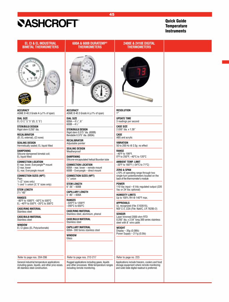
EI, CI & EL INDUSTRIAL 600A & 600B DURATEMP® 2400E & 2410E DIGITAL BIMETAL THERMOMETERS THERMOMETERS THERMOMETERS
Quick GuideTemperature Instruments
General industrial temperature applications including gases, liquids, and other proc-esses. All stainless steel construction.
Rugged applications including gases, liquids and other processes. Wide temperature ranges including remote monitoring.
Applications include freezers, coolers and food storage equipment where remote monitoring and solid state digital readout is preferred.
ACCURACY ASME B 40.3 Grade A (±1% of span)
DIAL SIZE EI, CI 2, 3, 5˝ (EL 3, 5˝)
STEM/BULB DESIGN Rigid stem 0.250˝ dia.
RECALIBRATOR (EI, EL external), (CI none)
SEALING DESIGN Hermetically sealed; EL liquid filled
DAMPENING Silicone-dampened bimetal coil; EL liquid filled
CONNECTION LOCATION EI rear, lower, Everyangle™ mount CI rear, lower EL rear, Everyangle mount
CONNECTION SIZES (NPT) Plain 1/4 (2˝ sizes only) 1/2 and 1/2 union (3, 5˝ sizes only)
STEM LENGTH 21/2˝-60˝
RANGES –80°F to 1000°F, –50°C to 500°C EL –40°F to 550°F, –20°C to 300°C
CASE/RING MATERIAL Stainless steel
CASE/BULB MATERIAL Stainless steel
WINDOW EI, CI glass (EL Polycarbonate)
ACCURACY ASME B 40.3 Grade A (±1% of span)
DIAL SIZE 600A – 41/2˝, 6˝ 600B – 41/2˝
STEM/BULB DESIGN Rigid stem 0.375˝ dia. (600B) Bendable 0.375˝ dia. (600A)
RECALIBRATOR Adjustable pointer
SEALING DESIGN Weatherproof
DAMPENING Silicone-encapsulated helical Bourdon tube
CONNECTION LOCATION 600A – rear, lower – remote mount 600B – Everyangle – direct mount
CONNECTION SIZES (NPT) 1/2˝ union
STEM LENGTH 6˝-36˝ – 600B
CAPILLARY LENGTH 5´-80´ – 600A
RANGES –320°F to 1200°F –200°C to 650°C
CASE/RING MATERIAL Stainless steel, aluminum, phenol
CASE/BULB MATERIAL Stainless steel
CAPILLARY MATERIAL 600A– 300 Series stainless steel
WINDOW Glass
RESOLUTION 1°
UPDATE TIME 3 readings per second
CASE SIZE 2.030˝ dia. x 1.39˝
CASE ABS and acrylic
VIBRATION 50 to 200 Hz @ 2.5g no effect
RANGE –40°F to 199°F, 0°F to 250°F, –40°C to 120°C
AMBIENT TEMP. LIMIT –30°F to 160°F (–34°C to 71°C)
ZERO & SPAN ±10% of operating range through two single-turn potentiometers located on the back of the thermometer’s module
POWER 110 Vac input – 6 Vdc regulated output (220 Vac or 24 Vac optional)
HUMIDITY LIMITS Up to 100% RH @ 140°F max.
APPROVALS UL recognized (File: E103515), NSF C-2, CSA (File: Natl/C, LR 76285-2)
SENSOR Laser trimmed 2000 ohm RTD 0.250˝ dia. x 2.54˝ long 300 series stainless steel with 8´ wire cable
WEIGHT Display – 35g (0.08lb) Power Supply – 211g (0.5lb)
Refer to page nos. 204-206 Refer to page nos. 212-217 Refer to page no. 223
45

Quick GuideTemperature Instruments
46
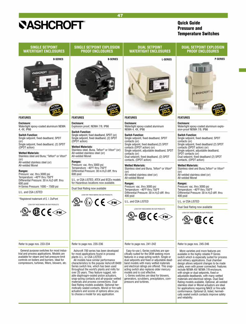
SINGLE SETPOINT SINGLE SETPOINT EXPLOSION DUAL SETPOINT DUAL SETPOINT EXPLOSION WATERTIGHT ENCLOSURES PROOF ENCLOSURES WATERTIGHT ENCLOSURES PROOF ENCLOSURES
Quick GuidePressure and Temperature Switches
B-SERIES L-SERIES P-SERIES
FEATURES
Enclosure: Watertight epoxy-coated aluminum NEMA 4, 4X, IP66
Switch Function: Single setpoint, fixed deadband, SPDT (or) Single setpoint, fixed deadband, (2) SPDT (DPDT action)
Wetted Materials: Stainless steel and Buna,*Teflon® or Viton® (or) All-welded stainless steel (or) All-welded Monel
Ranges: Pressure: vac. thru 3000 psi Temperature: –40°F thru 750°F Differential Pressure: 30 in.H2O diff. thru 600 psid H-Series Pressure: 1000 – 7500 psi
U.L. and CSA LISTED
*Registered trademark of E. I. DuPont
FEATURES
Enclosure: Explosion proof, NEMA 7/9, IP66
Switch Function: Single setpoint, fixed deadband, SPDT (or) Single setpoint, fixed deadband, (2) SPDT (DPDT action)
Wetted Materials: Stainless steel, Buna, Teflon® or Viton® (or) All-welded stainless steel (or) All-welded Monel
Ranges: Pressure: vac. thru 3000 psi Temperature: –40°F thru 750°F Differential Pressure: 30 in.H2O diff. thru 600 psid
U.L. or CSA LISTED, ATEX and IECEx models for Hazardous locations now available.
Dual Seal Rating now available
FEATURES
Enclosure: Watertight epoxy-coated aluminum NEMA 4, 4X, IP66
Switch Function: Single setpoint, fixed deadband, SPDT contacts (or) Single setpoint, fixed deadband,(2) SPDT contacts (DPDT action) (or) Single setpoint, adjustable deadband, SPDT contacts (or) Dual setpoint, fixed deadband, (2) SPDT contacts, (DPDT action)
Wetted Materials: Stainless steel and Buna, Teflon® or Viton® (or) All-welded stainless steel (or) All-welded Monel
Ranges: Pressure: vac. thru 3000 psi Temperature: –40°F thru 750°F Differential Pressure: 30 in.H2O diff. thru 400 psid
U.L. and CSA LISTED
FEATURES
Enclosure: Watertight epoxy-coated aluminum explo-sion-proof NEMA 7/9, IP66
Switch Function: Single setpoint, fixed deadband, SPDT contacts (or) Single setpoint, fixed deadband (2) SPDT contacts (DPDT action) (or) Single setpoint, adjustable deadband, SPDT contacts (or) Dual setpoint, fixed deadband (2) SPDT contacts, (DPDT action)
Wetted Materials: Stainless steel and Buna,Teflon® or Viton® (or) All-welded stainless steel (or) All-welded Monel
Ranges: Pressure: vac. thru 3000 psi Temperature: –40°F thru 750°F Differential Pressure: 30 in.H2O diff. thru 400 psid
U.L. or CSA LISTED
Dual Seal Rating now available
General purpose switches for most indus-trial and process applications. Models are available for steam and fuel pressure-limit controls on boilers and burners. Ideal for compressors, turbines, filters, blowers, etc.
Ashcroft 700 series has been developed for most applications found in process plants U.L. or CSA LISTED.
All models have similar performance characteristics to the popular Ashcroft B400 Series switch line, which has been used throughout the world’s plants and mills for over 25 years. They feature rugged, reli-able diaphragm-sealed piston actuators, snap-acting contacts and all-popular wetted materials and process connections. Dual Seal Rating models available. Optional her-metically sealed contacts, Monel or fire-safe actuators and scores of options allow you to choose a model for any application.
Easy-to-use L-Series switches are spe-cifically suited for the OEM seeking more features in a snap-acting switch. Single or dual setpoints and fixed or adjustable dead-band models with many wetted materials and electrical ratings are offered. This snap-acting switch also replaces older mercury models and is cost effective. L-Series switches are ideal for blowers, generators, scrubbers, precipitators, com-pressors and turbines.
More varieties and more features are available in the highly reliable P-Series switch which is especially suited for process and refinery applications. Dual chamber design allows setpoint changes to be made safely, even with power connected. Features include NEMA 4X/ NEMA 7/9 enclosure, with single or dual setpoints, fixed or adjustable deadbands, with many wetted materials and electrical ratings. Dual Seal Rating models available. Optional, all-welded stainless steel or Monel actuators are ideal for applications requiring NACE or fire-safe conformance. Optional UL listed, hermeti-cally sealed switch contacts improve safety and reliability.
Refer to page nos. 233-234 Refer to page nos. 235-236 Refer to page nos. 241-242 Refer to page nos. 245-246
LOOK FOR THESE MARKS ON OUR PRODUCTS
FM
LOOK FOR THESE MARKS ON OUR PRODUCTS
LOOK FOR THESE MARKS ON OUR PRODUCTS
FMLOOK FOR THESE MARKS ON OUR PRODUCTS
FM
B-SERIES
47

Quick GuidePressure and Temperature Switches
G-SERIES F-SERIESA-SERIES N-SERIES
FEATURES
Enclosure: Watertight 316 stainless steel NEMA 4, 4X, IP65
Switch Function: Single setpoint, fixed deadband, SPDT contacts (or) Single setpoint, fixed deadband (2) SPDT contacts (DPDT action) (or) Single setpoint, adjustable deadband, SPDT contacts (or) Dual setpoint, fixed deadband (2) SPDT contacts (DPDT action)
Wetted Materials: Stainless steel and Buna, Teflon® or Viton® (or) All-welded stainless steel (or) All-welded Monel
Ranges: Pressure: vac. thru 3000 psi Temperature: –40°F thru 750°F Differential Pressure: 30 in.H2O diff. thru 400 psid
U.L. and CSA LISTED
FEATURES
Enclosure (Body): Explosion-proof, anodized aluminum NEMA 7/9, IP66
Switch Function: Single setpoint, field-adjustable fixed dead-band, SPDT contacts (or) Single setpoint, field-adjustable fixed dead-band, (2) SPDT contacts (DPDT action)
Wetted Materials: 316 stainless steel pressure connection and choice of: Buna N, Teflon® or Viton® diaphragm and O-ring (or) All-welded 316 stainless steel diaphragm
Ranges: Pressure: vac. thru 4000 psi
U.L. and CSA LISTED
FEATURES
Enclosure: NEMA 4X watertight or NEMA 7/9 explosion proof, IP66
Switch Function: Single setpoint with adjustable deadband
Wetted Material: Stainless steel
Ranges: 60 thru 20,000 psi. Deadbands as low as 0.1% of range.
Optional process and setpoint indication and 4-20mA transmitter ouput now available.
The stainless steel enclosure offers greater corrosion protection for this high-performance switch in breweries, dairies, chemical and petrochemical plants, offshore rigs and pulp and paper mills. Our standard diaphragm-sealed piston actuators and a variety of wetted materials are available in these pressure, temperature and differential pressure switches.
Compact size facilitates mounting in panels and other installations where space is a premium. Standard hermetically sealed switch element and sealed conduit connection eliminate the possibility of condensation entering the enclosure from the conduit. Standard 1/ 2 NPTF pressure connection makes retrofit on existing installations quick and easy.
You should consider Ashcroft A-Series pressure switches for use on heavy vehicles, engines and compressors, elec-tronics processing and medical equipment, food and beverage processing equipment, garbage compactors, machine tools, or any equipment where space is a consideration. This series is especially suitable for OEM configuration.
The Ashcroft N-Series electronic pressure switch combines the popular K-Series poly-silicon thin film pressure transducer sensor and rugged, epoxy-coated enclosures. The result is a highly reliable pressure switch that is ideal for high cycle, high pressure, or difficult deadband applications.
Typical applications include: machine tools, injection molding machines, presses, pumps, hydraulic systems, turbines, and compressors.
FEATURES
Enclosure: NEMA 4X watertight or NEMA 7/9 explosion proof, IP66
Switch Function: Single setpoint, fixed deadband, factory set SPDT contacts (or) Single setpoint, fixed deadband, field-adjustable SPDT contacts
Wetted Material: Brass (Buna N, Viton® or Teflon® actuator) Stainless steel
Ranges: Vac thru 2000 psi.
U.L. and CSA LISTED
Refer to page nos. 238-239 Refer to page no. 237 Refer to page nos. 231-232 Refer to page no. 244
LOOK FOR THESE MARKS ON OUR PRODUCTS
LOOK FOR THESE MARKS ON OUR PRODUCTS
LOOK FOR THESE MARKS ON OUR PRODUCTS
WATERTIGHT STAINLESS COMPACT EXPLOSION MINIATURE PRESSURE ELECTRONIC PRESSURE STEEL ENCLOSURES PROOF PRESSURE SWITCHES SWITCHES
(Stainless Steel Enclosure)
48
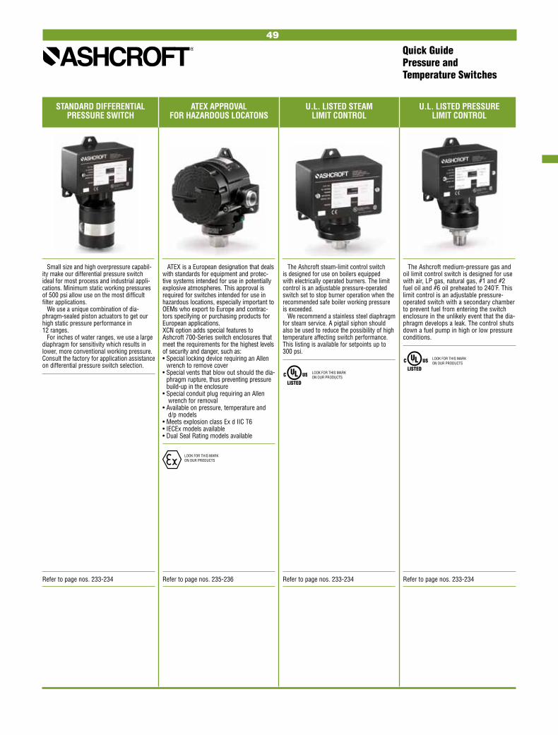
STANDARD DIFFERENTIAL ATEX APPROVAL U.L. LISTED STEAM U.L. LISTED PRESSURE PRESSURE SWITCH FOR HAZARDOUS LOCATONS LIMIT CONTROL LIMIT CONTROL
Small size and high overpressure capabil-ity make our differential pressure switch ideal for most process and industrial appli-cations. Minimum static working pressures of 500 psi allow use on the most difficult filter applications.
We use a unique combination of dia-phragm-sealed piston actuators to get our high static pressure performance in 12 ranges.
For inches of water ranges, we use a large diaphragm for sensitivity which results in lower, more conventional working pressure. Consult the factory for application assistance on differential pressure switch selection.
ATEX is a European designation that deals with standards for equipment and protec-tive systems intended for use in potentially explosive atmospheres. This approval is required for switches intended for use in hazardous locations, especially important to OEMs who export to Europe and contrac-tors specifying or purchasing products for European applications. XCN option adds special features to Ashcroft 700-Series switch enclosures that meet the requirements for the highest levels of security and danger, such as: • Special locking device requiring an Allen
wrench to remove cover• Special vents that blow out should the dia-
phragm rupture, thus preventing pressure build-up in the enclosure
• Special conduit plug requiring an Allen wrench for removal
• Available on pressure, temperature and d/p models
• Meets explosion class Ex d IIC T6• IECEx models available• Dual Seal Rating models available
The Ashcroft steam-limit control switch is designed for use on boilers equipped with electrically operated burners. The limit control is an adjustable pressure-operated switch set to stop burner operation when the recommended safe boiler working pressure is exceeded.
We recommend a stainless steel diaphragm for steam service. A pigtail siphon should also be used to reduce the possibility of high temperature affecting switch performance. This listing is available for setpoints up to 300 psi.
The Ashcroft medium-pressure gas and oil limit control switch is designed for use with air, LP gas, natural gas, #1 and #2 fuel oil and #6 oil preheated to 240°F. This limit control is an adjustable pressure-operated switch with a secondary chamber to prevent fuel from entering the switch enclosure in the unlikely event that the dia-phragm develops a leak. The control shuts down a fuel pump in high or low pressure conditions.
Quick GuidePressure and Temperature Switches
Refer to page nos. 233-234 Refer to page nos. 235-236 Refer to page nos. 233-234 Refer to page nos. 233-234
LOOK FOR THIS MARK ON OUR PRODUCTS
LOOK FOR THIS MARK ON OUR PRODUCTS
LOOK FOR THIS MARK ON OUR PRODUCTS
49

50

51
ASME B 40.1 Grade 2A (±0.5% of span) Type 2030 Series Digital Sanitary Gauge ............................... 53
Type 2089, 2086, 2084 Digital Test Gauge ... 54
Type 2074, 2174, 2274 Digital Industrial Gauge ............................. 55
Type D1005PS General Purpose Digital Gauge ............................................. 56
DIGITAL GAUGES

52

53
SPECIFICATION Type: Conventional Tri-clamp: 2032 (battery),
2132(1) (4-20mA), 2232(1) (line) In-line Tri-clamp: 2036 (battery), 2136 (4-20mA),
2232 (line)Accuracy: Terminal point Full Scale: .25% F.S. accuracyCase Size: 3˝Case Material/Finish: (3˝) 300 series SS, ElectropolishedCase Enclosure Rating: Weatherproof, IP65, NEMA 4Wetted Parts: 316 SSTri-Clamp Connection: Direct, in-line 11⁄2 ˝, 2 ˝, Ashcroft remote in-line (XRE),Seal Surface Finish: 12-20RaConnection Location: LowerRanges: 15 psi thru 1,000 psi including metric, compound & vacProcess Temp. Limits(2): 14°F / 275°F (–10°C / 135°C) to withstand clean in place (CIP) & steam in place (SIP)Ambient Temp. Limits(3): 14°F / 140°F (–10°C / 60°C)Temperature Error: ±.22% per 10°F, (12°F) (Span and Zero shift can be eliminated by rezeroing the gauge at operating temperatures. Temperatures must be within process temperature limits)Storage Temperature: –4°F / 158°F (–20°C / 70°C)Overrange Pressure: 2x range of gauge DISPLAYType: LCDDisplay Digits: 5 digitsCharacter Height: .60˝Backlite: Off by defaultBar Graph: YesBattery Life: 1000 Hrs., Battery Life Indicator – standard
Features• 4/20mA Output• (1) or (2) SPDT Switches• .25% F.S. Terminal Point Accuracy (.13
BFSL)• IP 65 Weatherproof Case Suitable For
Wash Downs• Extra Large Display• Easy-to-Use Password Protected Menu
With: - 5 Backlite Display Options - 12 Engineering Units - Menu Configure Feature - Update Rate - Dampen Rate - Auto-Off
• Material Traceability Certification to EN 10204: 2004 3.1*
Type 2030 Series Digital Sanitary Gauge 3˝
Agency Approvals: CE (excludes XRE variation)Material Traceability Certification to EN 10204: 2004 3.1 standard KEYBOARD FUNCTIONSOn/Off: Manually turns unit on & off (auto off options in menu)Zero/Clear: Zeros display or clears min/max values when displayedMin/Max Arrow Key: Stores min & max values, arrow key allows for scrolling thru menu itemsMenu: Allows for changes to default settings (see below)Backlite (optional) Arrow Key: Manually turns backlite on & off (auto off options in menu), arrow key allows for scrolling thru menu itemsEnter: Selects items in the menu MENU MODEEngineering Units (Units): Allows scrolling through menu to select available options. 10 units of measurement are available; psi, inH2O with 3 temp. options: 20°C, 60°F, 4°C*, mmHg, ftH2O, mPa, kPa, kg/cm2 & barConfiguration Mode (Config): Allows for changes to default settings of gaugeBar Graph (Graph): Allows for adjustment of bargraph & 4-20Auto Off (Off): Allows for changes to auto off of gauge: 5 options:, 30 min., 10 min., 5 min., 2 min., never Update Rate (Update): 4 options: 100mili-sec, 1 sec, 500mili-sec, 200mili-sec,
HOW TO ORDER
30 2032 SD 15L 160# REDial Size: 3˝Case Type Number: 2032 Battery
2132 4-20mA loop powered 2232 12-36 Vdc 2036 In-line battery 2136 In-line 4-20mA loop powered 2236 In-line 12-36Vdc
Wetted Parts: 316L SSProcess Connection: 1.5,˝ 2.0˝ Tri-ClampRange: 160 psiVariations: RE remote mount in-line design
DIRECTMOUNT
REMOTEMOUNT
AT LAST, A MULTI-FUNCTIONAL SANITARY GAUGE FROM THE EXPERTS IN PRESSURE MEASUREMENTThe new Ashcroft® sanitary digital
gauge saves money, time and space. Now, one digital pressure gauge can replace three instru-ments… a mechanical pressure gauge, a transducer and a switch! Save space, installation costs and the cost of additional instruments and pipe cut-outs.
Dampening (Damp): 6 options: none, average 8, 6, 4, 2 times per 100msBacklite Lit (optional): 5 options: NEVER, 10 sec, 30, sec, 1 min, 5 min. Zero Disable: Zero “lockout” featureField Recalibration: Zero, span & midscale (password protected)Calibration: Allows for recalibration of zero & span (includes factory default calibration) OPTIONS4-20mA Display Line Powered: 12-36 Vdc Switching: (XU1 code) (1) or (XU@ code) (2) SPDT switches, (requires line power), (max. contact 30Vdc, 1 amp, 125Vac, .5 Amp) switches adjustable to 100% of rangeRemote Mount Seal: (RE code) standard with 10´ shielded cable NOTES(1) 3´ shielded cable standard.(2) Rezero gauge often after exposure to elevated
temperatures and use.(3) The 2030 Series Digital Gauge is not suitable for
an autoclave. RANGES psi in. Hg Comp. mmHg in. Hg in. H2O (Vacuum) (psi) (pressure) (pressure) 15 30 –15/0/15 800 30 400 30 –15/0/30 1000 60 800 60 –15/0/60 2000 100 1000 100 –15/0/100 3000 160 160 5000 200 200 10,000 300 300 400 600 600 800 800 1000
mBar ft. H2O mPa kPa Bar/ KSC 1000 60 1 100 1 1500 160 1.6 160 1.6 2000 200 2.5 250 2.5 2500 300 4 400 4 4000 400 6 600 6 5000 600 10 1000 10 8000 1000 16 1600 16 10,000 25 2500 25 15,000 40 4000 40 20,000 60 6000 60
Consult factory for guidance in product selectionPhone (203) 378-8281 or visit our web site at www.ashcroft.com
*Excludes 2036 Series
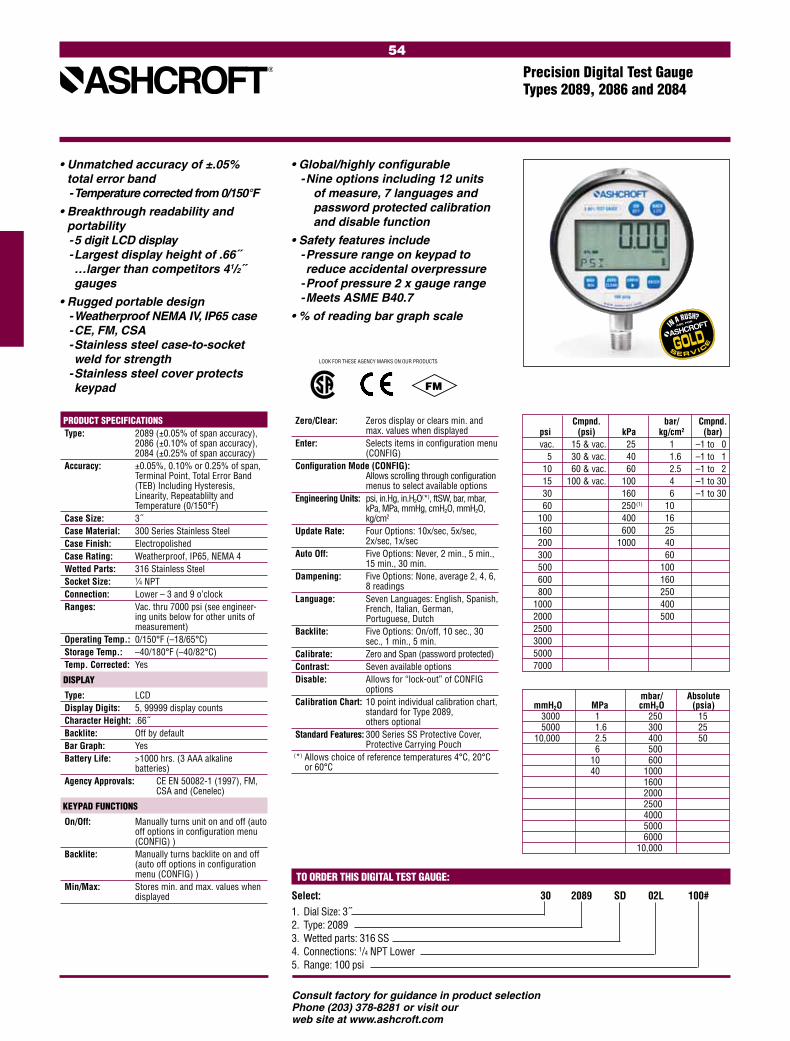
54
Cmpnd. bar/ Cmpnd. psi (psi) kPa kg/cm2 (bar) vac. 15 & vac. 25 1 –1 to 0 5 30 & vac. 40 1.6 –1 to 1 10 60 & vac. 60 2.5 –1 to 2 15 100 & vac. 100 4 –1 to 30 30 160 6 –1 to 30 60 250.(1) 10 100 400 16 160 600 25 200. 1000 40 300 60 500 100 600 160 800 250 1000 400. 2000 500 2500 3000. 5000 7000
mbar/ Absolute mmH2O MPa cmH2O (psia) 3000 1 250 15 5000 1.6 300 25. 10,000 2.5. 400 50 6 500 10 600 40 1000 1600 2000. 2500 4000 5000 6000 10,000
Precision Digital Test Gauge Types 2089, 2086 and 2084
Consult factory for guidance in product selectionPhone (203) 378-8281 or visit our web site at www.ashcroft.com
• Unmatched accuracy of ±.05% total error band - Temperature corrected from 0/150°F
• Breakthrough readability and portability - 5 digit LCD display - Largest display height of .66˝ …larger than competitors 41/2˝ gauges
• Rugged portable design - Weatherproof NEMA IV, IP65 case - CE, FM, CSA - Stainless steel case-to-socket weld for strength - Stainless steel cover protects keypad
• Global/highly configurable - Nine options including 12 units
of measure, 7 languages and password protected calibration and disable function
• Safety features include - Pressure range on keypad to reduce accidental overpressure - Proof pressure 2 x gauge range - Meets ASME B40.7
• % of reading bar graph scale
PRODUCT SPECIFICATIONS Type: 2089 (±0.05% of span accuracy),
2086 (±0.10% of span accuracy), 2084 (±0.25% of span accuracy)
Accuracy: ±0.05%, 0.10% or 0.25% of span, Terminal Point, Total Error Band (TEB) Including Hysteresis, Linearity, Repeatablilty and Temperature (0/150°F)
Case Size: 3˝ Case Material: 300 Series Stainless Steel Case Finish: Electropolished Case Rating: Weatherproof, IP65, NEMA 4 Wetted Parts: 316 Stainless Steel Socket Size: 1⁄4 NPT Connection: Lower – 3 and 9 o’clock Ranges: Vac. thru 7000 psi (see engineer-
ing units below for other units of measurement)
Operating Temp.: 0/150°F (–18/65°C) Storage Temp.: –40/180°F (–40/82°C) Temp. Corrected: Yes
DISPLAY
Type: LCD Display Digits: 5, 99999 display counts Character Height: .66˝ Backlite: Off by default Bar Graph: Yes Battery Life: >1000 hrs. (3 AAA alkaline
batteries) Agency Approvals: CE EN 50082-1 (1997), FM,
CSA and (Cenelec)
KEYPAD FUNCTIONS
On/Off: Manually turns unit on and off (auto off options in configuration menu (CONFIG) )
Backlite: Manually turns backlite on and off (auto off options in configuration menu (CONFIG) )
Min/Max: Stores min. and max. values when displayed
Zero/Clear: Zeros display or clears min. and max. values when displayed
Enter: Selects items in configuration menu (CONFIG)
Configuration Mode (CONFIG): Allows scrolling through configuration
menus to select available options Engineering Units: psi, in.Hg, in.H2O(*), ftSW, bar, mbar, kPa, MPa, mmHg, cmH2O, mmH2O, kg/cm2
Update Rate: Four Options: 10x/sec, 5x/sec, 2x/sec, 1x/sec
Auto Off: Five Options: Never, 2 min., 5 min., 15 min., 30 min.
Dampening: Five Options: None, average 2, 4, 6, 8 readings
Language: Seven Languages: English, Spanish, French, Italian, German, Portuguese, Dutch
Backlite: Five Options: On/off, 10 sec., 30 sec., 1 min., 5 min.
Calibrate: Zero and Span (password protected) Contrast: Seven available options Disable: Allows for “lock-out” of CONFIG
options Calibration Chart: 10 point individual calibration chart,
standard for Type 2089, others optional
Standard Features: 300 Series SS Protective Cover, Protective Carrying Pouch
(*) Allows choice of reference temperatures 4°C, 20°C or 60°C
TO ORDER THIS DIGITAL TEST GAUGE:
Select: 30 2089 SD 02L 100# 1. Dial Size: 3˝2. Type: 2089 3. Wetted parts: 316 SS 4. Connections: 1/4 NPT Lower5. Range: 100 psi
FM
LOOK FOR THESE AGENCY MARKS ON OUR PRODUCTS
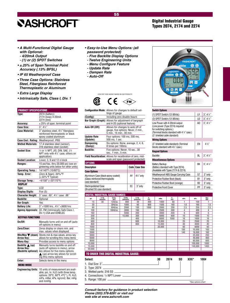
55
PRODUCT SPECIFICATIONSType: 2074 (battery)
2174 (loop) 4-20mA 2274 (line)
Accuracy: ±.25% of span, terminal point Case Size: 3˝, 41⁄2˝Case Material: 3˝ stainless steel, 41⁄2˝ fiberglass
reinforced thermoplastic or black epoxy coated aluminum
Case Encl. Rating: Weatherproof, IP65Wetted Materials: 17-4 stainless steel (sensor), 316 stainless steel (socket)Socket Size: 1⁄4 or 1⁄2 NPT, JIS, DIN, SAE, (1⁄2
NPT only with 41⁄2˝ case, others on application)
Socket Location: Lower, 3, 9 and 12 o’clockRanges: 15 psi/Vac. thru 20,000 psi (see en-
gineering units below for other units) Operating Temp.: 14/140°F (10/60°C)Temp. Error: (Zero & Span) .04%/°F
(<.02%°F Typical)Storage Temp.: –4/158° (–20°/70°F) DISPLAYType: LCDDisplay Digits: Five (5)Character Height: 3˝ case: .60˝, 41⁄2˝ case: .88˝ Backlite: OptionalBar Graph: YesBattery Life: 3˝ >1000 hrs., 41⁄2˝ >3600 hrs.Agency Approvals: CE, FM (Intrinsically Safe Class I,
Div 1) CSA and CENELEC
KEYPAD FUNCTIONS
On/Off: Manually turns unit on and off (auto off options in menu)
Zero/Clear: Zeros display or clears min. and max. values when displayed
Min/Max (down) Stores min & max values, arrow key Arrow Key: allows for scrolling thru menu items Menu Key: Provides access to menu optionsBacklite (up) Manually turns backlite on and off Arrow Key: (auto off options in menu), arrow (Backlite optional) key allows for five menu options.
(up) arrow key allows for scroll-ing thru menu options
Enter: Selects items in the menu
MENU MODE
Engineering Units: 10 units of measurement are avail-able; psi, In. H2O (with three temp. options: 20°C, 60°F, 4°C*), Ft. H2O, mPa, mBar, kPa, kg/cm2, Bar, inHg and mmHg
Configuration Mode: Allows for changes to default set-tings of gauge
(Config): Including zero disable feaureBar Graph (Graph): Allows for adjustment of bargraph
and 4-20 (optional feature)Auto Off (Off): Allows for changes to auto off of
gauge, five options: Never, 2 min., 5 min., 15 min., 30 min.
Update Rate Four options: 100 ms, 200 ms, (Update): 500 ms, 1 secDampening Six options: None, average, 2, 4, 6, (Damp): 8 times per 100msBacklite: Five options: Never, 10 sec., 30
sec., 1 min., 5 min.Field Recalibration: Allows for recalibration of zero, mid-
scale and span (password protected) OPTIONS
Description Code Case Size
Case Options
Aluminum Case (black epoxy coated) AY 41⁄2 only (Glass reinforced thermoplastic case standard)
Electropolished Case EC 3 only (Brushed SS case standard)
• A Multi-Functional Digital Gauge with Optional: - 4/20mA Output - (1) or (2) SPDT Switches
• ±.25% of Span Terminal Point Accuracy (.13% BFSL)
• IP 65 Weatherproof Case
• Three Case Options: Stainless Steel, Fiberglass Reinforced Thermoplastic or Aluminum
• Extra Large Display
• Intrinsically Safe, Class I, Div. 1
• Easy-to-Use Menu Options: (all password protected) - Five Backlite Display Options - Twelve Engineering Units - Menu Configure Feature - Update Rate - Dampen Rate - Auto-Off
Digital Industrial Gauge Types 2074, 2174 and 2274
TO ORDER THIS DIGITAL INDUSTRIAL GAUGE:
Select: 30 2074 SD XXX* 100# 1. Dial Size: 3˝2. Type: 2074 3. Wetted parts: 316 SS 4. Connections: 1/4 NPT Lower5. Range: 100 psi
*See options chart
Consult factory for guidance in product selectionPhone (203) 378-8281 or visit our web site at www.ashcroft.com
Switch Options
(1) SPDT Switch (12-36Vdc) U1 3 , 4 1⁄2˝
(2) SPDT Switch (12-36Vdc) U2 3 , 4 1⁄2˝
Line Power with 4-20mA output AO 3 , 4 1⁄2˝ (Line power (Type 2274) required for switching options.) (Terminal blocks standard with 4 1⁄2 case.) (3 shielded cable standard)
Wiring Options
(3 shielded cable standard) (Terminal EN 4 1⁄2˝ blocks standard with 41⁄2 case.)
Keypad Options
Backlite BL 3 , 4 1⁄2˝
Miscellaneous Options
Battery Backup BK 3 , 4 1⁄2˝ (Battery standard with Type 2074) (Available with Types 2174 & 2274)
Weatherproof ABS Gauge Carrying Case S7 3 only
Protective Rubber Boot (black) B1 3 only
Protective Rubber Boot (orange) B2 3 only
Protective Front Cover PP 3 only
in.Hg Comp. mmHg in.Hg in. ft. Bar/ psi (vacuum) (psi) (pressure) (pressure) H2O mBar H2O mPa kPa KSC
15 30 15#&Vac 800 30 400 1000 60 1 100 1 30 30#&Vac 1000 60 800 1500 160 1.6 160 1.6 60 60#&Vac 2000 100 1000 2000 200 2.5 250 2.5 100 100#&Vac 3000 160 2500 300 4 400 4 160 5000 200 4000 400 6 600 6 200 10,000 300 5000 600 10 1000 10 300 400 6000 1000 16 1600 16 600 600 10,000 25 2500 25 800 800 15,000 40 4000 40 1000 20,000 60 6000 60 1500 100 10,000 100 2000 140 16,000 160 3000 25,000 250 5000 40,000 400 8000 60,000 600 10,000 100,000 1000 15,000 140,000 1400 20,000
DIGITAL INDUSTRIAL GAUGE RANGES:
FM
LOOK FOR THESE AGENCY MARKS ON OUR PRODUCTS

56
***
The Ashcroft® Type D1005PS offers 0.5% of span accuracy, while the stainless steel sensor and socket make this product suitable not only for dry air applications but for other media as well. This product offers selectable units of measure so rather than purchasing one gauge for each unit of measure required, the solution is one gauge for multiple units of measure. The D1005PS is standard with many features not offered, or offered only as options, on competitor’s digital gauge products, such as peak hold and 41/2 digit display. When compared to mechanical gauges the
• Enhanced value versus mechanical gauges
• No-nonsense accuracy – ±0.5% full scale accuracy
• Easy-to-read – 41/2 digit display with 1/2 character size, optional backlite display feature to enhance visibility
• Versatile – 9 engineering units and stainless steel sensor suitable for a variety of applications
• Standard features – max.-pressure indication; ranges from vacuum to 19,999 psi, including compound
• Competitively priced and can be customized for OEM applications
General Purpose Digital GaugeType D1005PS, ±1/2% of Span Terminal Point Accuracy
D1005PS offers overall enhanced value.
PRODUCT SPECIFICATIONS
Type no.: D1005PSAccuracy: ±0.5% of spanCase Size: 21⁄2˝Case Material: Noryl®
Wetted Parts: 17-4 PH stainless steel sensor; 316 stainless steel socket
Socket Size: 1⁄4 NPT Connection: LowerRanges: Vac. thru 19,999 psi (see engineer-
ing units below for other units of measurement)
Battery: Two AAA alkaline batteries; approxi-mately 1000 hours battery life
Overpressure: Vac. 0/3000- 0/1000 0/5000 0/19,999 Proof: 200% 150% 120%
Burst: 800% 300% 150%Cycle Life: 108 cycles 20/80% F.S. with negli-
gible performance lossVibration: Less than ±0.1% F.S. effect for
0/2000 Hz at 20 g’s in any axisShock: Less than ±0.05% F.S. effect for 100
g’s, 20msec shock in any axisOperating Temp.: –10°C to 60°C
(14°F to 140°F)Storage Temp.: –20°C to 70°C
(-4°F to 158°F) (maximum temperature shift is .028% per °F from –20°F to 180°F starting at 68°F. For vacuum and 30 psi ranges the maximum temperature shift is .04%)
Update Rate: 100msAgency Approvals: CE EN 61326 (1998); CE EN 61326
Annex A (heavy industrial)Packaging: Individual cartonOpt’l. Features: ±0.25% of span accuracy; backlite;
3, 9, 12 o’clock connections; Alter-nate socket configurations – upon application; Customized keypad; Protective boot; Bulk packaging
DISPLAY Type: LCD Display Digits: 41/2
Display Full Scale Display Resolution: Numerical Value Resolution >=-15>0 –XX.000 >0 <2 X.0000 >=2 <20 XX.000 >=20 <200 XXX.00 >=200 <2000 XXXX.0 >=2000 <19,999 XXXXX Character Height: 0.5˝ Backlight: OFF by default Battery: Four-level battery indication
KEYPAD FUNCTIONS On/Off: Manually turns unit on and off (four
options: never, 5 min., 10 min., 20 min.)
Backlite (optional): Manually turns backlite on and off (four programmable auto on/off options)
Maximum (Peak Hold): Displays max. value when activatedZero/Clear: Zeros display or clears max. value
when activatedEngineering Units: psi, in.Hg, cmHg, mmHg, kPa, MPa,
bar, kg/cm2, ftH2OField Calibration: Zero and span
TO ORDER THIS TYPE D1005PS GAUGE:
Select: 25 D1005PS 02L 100#1. Dial Size: 21⁄2˝2. Case Type Number: D1005PS3. Wetted Parts: Stainless Steel4. Connection: 1⁄4 NPT lower5. Range: 0/100 psi
STANDARD RANGES
*Shown with Optional Protective Boot
Consult factory for guidance in product selectionPhone (203) 378-8281 or visit our web site at www.ashcroft.com
Vacuum in.Hg kPa cmHg Bar kg/cm2 mmHg –30/0 –100/0 –76/0 –1/0 –1/0 –760/0 Compound in.Hg/psi kPa mPa Bar kg/cm2 ft H2O –30/300 –100/2000 – –1/20 –1/20 –35/700 –30/600 –100/4000 – –1/20 –1/20 –35/140 –30/100 –100/7000 – –1/20 –1/20 –35/230 –30/150 –100/1050 – –1/11 –1/11 –35/350 –30/300 –100/2100 – –1/21 –1/21 –35/700 Pressure psi kPa mPa Bar kg/cm2 ft H2O 0/30000 0/2000 – 0/200 0/200 0/700 0/60000 0/4000 – 0/400 0/400 0/140 0/10000 0/7000 – 0/700 0/700 0/230 0/20000 0/1400 – 0/140 0/140 0/460 0/30000 0/2100 – 0/210 0/210 0/700 0/50000 0/3500 – 0/350 0/350 – 0/10000 0/7000 – 0/700 0/700 – 0/15000 – 0/100 0/105 0/105 – 0/20000 – 0/140 0/140 0/140 – 0/30000 – 0/210 0/210 0/210 – 0/50000 – 0/350 0/350 0/350 – 0/10,000 – 0/700 0/700 0/700 – 0/15,000 – 0/100 0/1000 0/1000 – 0/19,999 – 0/140 0/1400 0/1400 –

57
Consult factory for guidance in product selectionPhone (203) 378-8281 or visit our web site at www.ashcroft.com
TEST GAUGES& EQUIPMENT
ASME B 40.100 Grade 3A (±0.25% of span)ASME B 40.100 Grade 2A (±0.5% of span) ASME B 40.100 Grade 4A (±0.1% of span)
Type A4A Dial Pressure Gauge ......................59
±0.25% Type 1082 Analog Test Gauge ......... 60
±0.5% Type 1084 Pocket Test Gauge ........... 61
Types 2089, 2086 & 2084 Precision Digital Test Gauges (±.05%, ±.10%, ±.25%) .............................62
ATE-100 Handheld Calibrator ................. 63-64
ST-2A Digital Indicator ........................... 65-66
Type 1305D Deadweight Tester .................. 67
Type 1327D/1327CM Pressure Gauge Comparator ................... 68
PT Digital Pressure Indicator .................. 69-70
Type AVC1000/3000 Volume Controller ..................................... 71

58
Consult factory for guidance in product selectionPhone (203) 378-8281 or visit our web site at www.ashcroft.com

59
MILLIMETERS MERCURY STANDARD BOURDON TUBE
STANDARD RANGE
MATERIAL** MILLIMETERS MERCURY
0-760
BERYLLIUM 0-1000
COPPER
0-1250 0-1500 0-2000
403 0-2500
STAINLESS
0-3000
STEEL 0-4000
0-5000 bar kg/cm2 kPa MPa kp/cm2
0-1 0-100 –
BERYLLIUM 0-1.6 0-160 –
COPPER
0-2 0-200 – 0-2.5 0-250 – 0-3 0-300 – 0-4 0-400 – 0-5 0-500 – 0-6 0-600 – 0-7.5 0-750 – 0-10 0-1000 0-1 0-12 0-1200 0-1.5 0-16 0-1600 0-1.6 0-20 0-2000 0-2 0-25 0-2600 0-2.5 0-30 0-3000 0-3 0-40 0-4000 0-4 0-50 0-5000 0-5
403 0-60 0-6000 0-6
STAINLESS
0-75 0-7500 0-7.5
STEEL 0-100 0-10,000 0-10
0-125 – 0-12.5 0-160 – 0-16 0-200 – 0-20 0-250 – 0-25 0-400 – 0-40 0-500 – 0-50 0-600 – 0-60 0-750 – 0-75 0-1000 – 0-100 0-1250 – 0-125 0-1600 – 0-160 0-2500 – 0-250 0-4000 *– 0-400 0-6000 *– 0-600 0-7000 *– 0-700 VACUUM BERYLLIUM –1 to 0 – – COPPER
Ashcroft Precision Dial Pressure Gauge Type A4A
• ±0.1% F.S. accuracy – ASME B40.100, Grade 4A
• Ranges from 15-100,000 psi• Solid front protective case• High and low pressure limit stops• Mirror band dial to eliminate
parallax reading error• Optional temperature compensa-
tion maintains 0.1% accuracy from –25 to +125°F
The Ashcroft precision pressure gauge yields consistent, reliable accuracy through the use of state-of-
STANDARD FEATURES & SPECIFICATIONS Total Accuracy ±0.1% F.S. Includes Certificate of NIST traceabilityRepeatability ±0.02% F.S.Hysteresis ±0.1% F.S.Dial White, high resolution with mirror bandPointer Knife edge pointer to eliminate parallax errors
Bourdon Tube Bleeder tipped for easy flushing or purgingCase Cast aluminum solid frontBlowout rear coverIntegral panel mounting flangeRanges Available in Gauge, Compound, Vacuum and Absolute (requires manual barometric compensa-tion)
• 1/4 NPT female fitting (ranges up to and including 10,000 psi)
• 9/16-18 UNF-2B high pressure for 1/4˝ O.D. high pressure tubing (ranges over 10,000 psi)
• 1/4 NPT female fitting (standard with back location)
• 1/4 NPT male• 1/8 NPT male or female• 9/16-18 UNF-2B high pressure for
1/4˝ O.D. high pressure tubing• MS33656-4 male (7/16-20, 37°
flare for 1/4˝ flare tubing)• AND10050-4/MS33649-4 female
(7/16-20, 37° flare for 1/4˝ flare tubing)
INLETS AND BOURDON TUBES (STANDARD VS. OPTIONS)
OPTIONAL FEATURES (PROVIDED ONLY WHEN SPECIFIED)• Custom scales/units of measure• Thermal compensation (maintains 0.1% accuracy from –25 to
+125°F)• Slotted link (protects movement during sudden pressure release)• Wall mounting brackets• Peak load indicator• Dual scale dial
A4APointer Travel 350° (15-30,000 psi) 300° (40,000-50,000 psi) 270° (60,000-100,000 psi)
Ranges 0/15-0/100,000 psi
Dial Sizes 6, 81/2, 12˝ & 16˝
*Available in 81/2, 12, 16˝. Dial face diameters only.**For optional Bourdon Tube Materials consult factory.
psi STANDARD STANDARD BOURDON TUBE RANGE MATERIAL** psi
0-15 BERYLLIUM 0-20 COPPER 0-25 0-30 0-40 0-50 0-60 0-75 0-100 0-150 0-200 0-250 0-300 0-400 0-500 0-600 0-750 403 0-1000 STAINLESS 0-1500 STEEL 0-2000 0-2500 0-3000 0-4000 0-5000 0-6000 0-7500 0-10,000 0-15,000 0-20,000 0-25,000 0-30,000 0-40,000 0-50,000 0-60,000* 0-75,000* 0-100,000*
INCHES MERCURY STANDARD BOURDON TUBE
STANDARD RANGE
MATERIAL** INCHES MERCURY
0-30
BERYLLIUM 0-40
COPPER
0-50 0-60 0-75 0-100 0-125 0-150 403 0-200 STAINLESS 0-250 STEEL 0-300 0-400 0-500 0-600 0-750 0-1000
VACUUM
BERYLLIUM –30 to 0 COPPER
COMPOUND VACUUM-PRESSURE
BERYLLIUM 15 in.Hg - 15 in.Hg COPPER 30 in.Hg - 30 in.Hg 30 in.Hg - 60 in.Hg 403 30 in.Hg - 100 in.Hg STAINLESS STEEL 30 in.Hg - 150 in.Hg BERYLLIUM 30 in.Hg - 15 psi COPPER 30 in.Hg - 30 psi
403 30 in.Hg - 60 psi
STAINLESS
30 in.Hg - 100 psi
STEEL 30 in.Hg - 150 psi
30 in.Hg - 300 psi
INCHES WATER 0-450 BERYLLIUM 0-500 COPPER 0-600 0-750 0-800 0-1000
the-art precision machining and the world’s most refined Bourdon tube technology. This eliminates the need for a power source and precludes the associated problems such as susceptibility to electronic line noise, power outage or potential fire hazard. In addition, this mechanical instrument is simple to operate, easy to troubleshoot, and can be readily flushed or purged to remove foreign matter or trapped gas. Accurate and reliable, the Ashcroft A4A sets a new standard for precision test gauges.
• Beryllium copper (through 40 psi)• 403 SS (50 psi and above)
• Beryllium copper (50-10,000 psi)• 403 SS (below 50 psi)
Material and Range
*Available in 81/2, 12, 16˝. Dial face diameters only.
STANDARD OPTIONAL
Inlet Location
Back Fittings Bottom or Back Fittings
Consult factory for guidance in product selectionPhone (203) 378-8281 or visit our web site at www.ashcroft.com
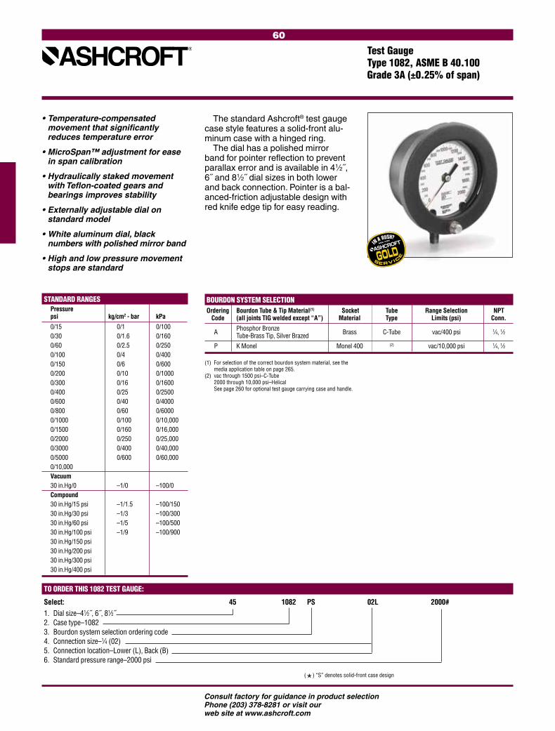
60
Consult factory for guidance in product selectionPhone (203) 378-8281 or visit our web site at www.ashcroft.com
STANDARD RANGES Pressure psi kg/cm2 - bar kPa 0/15 0/1 0/100 0/30 0/1.6 0/160 0/60 0/2.5 0/250 0/100 0/4 0/400 0/150 0/6 0/600 0/200 0/10 0/1000 0/300 0/16 0/1600 0/400 0/25 0/2500 0/600 0/40 0/4000 0/800 0/60 0/6000 0/1000 0/100 0/10,000 0/1500 0/160 0/16,000 0/2000 0/250 0/25,000 0/3000 0/400 0/40,000 0/5000 0/600 0/60,000 0/10,000 Vacuum 30 in.Hg/0 –1/0 –100/0 Compound 30 in.Hg/15 psi –1/1.5 –100/150 30 in.Hg/30 psi –1/3 –100/300 30 in.Hg/60 psi –1/5 –100/500 30 in.Hg/100 psi –1/9 –100/900 30 in.Hg/150 psi 30 in.Hg/200 psi 30 in.Hg/300 psi 30 in.Hg/400 psi
(*) “S” denotes solid-front case design
The standard Ashcroft® test gauge case style features a solid-front alu-minum case with a hinged ring.
The dial has a polished mirror band for pointer reflection to prevent parallax error and is available in 41⁄2˝, 6˝ and 81⁄2˝ dial sizes in both lower and back connection. Pointer is a bal-anced-friction adjustable design with red knife edge tip for easy reading.
• Temperature-compensated movement that significantly reduces temperature error
• MicroSpan™ adjustment for ease in span calibration
• Hydraulically staked movement with Teflon-coated gears and bearings improves stability
• Externally adjustable dial on standard model
• White aluminum dial, black numbers with polished mirror band
• High and low pressure movement stops are standard
(1) For selection of the correct bourdon system material, see the media application table on page 265.
(2) vac through 1500 psi–C-Tube 2000 through 10,000 psi–Helical See page 260 for optional test gauge carrying case and handle.
BOURDON SYSTEM SELECTIONOrdering Bourdon Tube & Tip Material(1) Socket Tube Range Selection NPT Code (all joints TIG welded except “A”) Material Type Limits (psi) Conn.
A Phosphor Bronze Brass C-Tube vac/400 psi 1⁄4, 1⁄2 Tube-Brass Tip, Silver Brazed
P K Monel Monel 400 (2) vac/10,000 psi 1⁄4, 1⁄2
TO ORDER THIS 1082 TEST GAUGE:
Select: 45 1082 PS 02L 2000#1. Dial size–41⁄2˝, 6˝, 81⁄2˝2. Case type–10823. Bourdon system selection ordering code4. Connection size–1⁄4 (02) 5. Connection location–Lower (L), Back (B)6. Standard pressure range–2000 psi
Test GaugeType 1082, ASME B 40.100 Grade 3A (±0.25% of span)

61
Consult factory for guidance in product selectionPhone (203) 378-8281 or visit our web site at www.ashcroft.com
STANDARD RANGES Pressure psi kg/cm2 - bar kPa 0/15 0/1 0/100 0/30 0/2 0/200 0/60 0/3 0/300 0/100 0/4 0/400 0/150 0/7 0/700 0/200 0/11 0/1100 0/300 0/14 0/1400 0/400 0/20 0/2000 0/600 0/28 0/2800 0/1000 0/40 0/4000 0/70 0/7000 Vacuum 30 in.Hg/0 –1/0 –100/0 Compound 30 in.Hg/15 psi –1/1 –100/100 30 in.Hg/30 psi –1/3 –100/300 30 in.Hg/60 psi –1/6 –100/600 30 in.Hg/100 psi –1/10 –100/1000 30 in.Hg/150 psi 30 in.Hg/300 psi
With an accuracy of ±0.5%, Grade 2A, plus rugged stainless steel con-struction, the Ashcroft® Type 1084 more than exceeds the requirements for on-the-spot inspections. To improve
• Available in a 3˝ dial size
• Stainless steel movement with Teflon-coated bearings and pinion gear
• Black, adjustable pointer with red-painted knife-edge tip
• Stainless steel construction
• Zero-adjustable white aluminum dial with polished mirror band
• 1⁄4 NPT lower connection only
TO ORDER THIS 1084 POCKET TEST GAUGE:
Select: 30 1084 S 02L 0/1000# 1. Dial size–3˝2. Case type–10843. Bourdon system selection ordering code4. Connection size–1⁄4 (02) 5. Connection location–Lower (L)6. Standard pressure range–1000 psi
BOURDON SYSTEM SELECTION Ordering Bourdon Tube & Tip Material(1) Socket Tube Range Selection NPT Code (all joints TIG welded) Material Type Limits (psi) Conn.
S 316 stainless steel 316 stainless steel C-Tube vac/1000 psi 1⁄4
accuracy, stability and socket thread life, the Bourdon tube and socket assembly is made of type 316 stainless steel with all-welded construction; this system is standard for all ranges.
To make reading easier and faster, each unit is provided with a new, highly readable dial. Reading error caused by parallax is eliminated by aligning the knife-edge tip pointer with its reflec-tion in the mirror band on the dial. Also available is a stainless steel cover that fits securely over the window and protects the gauge from damage while being carried in a tool box or pocket. An attractive, cushioned Nylon fabric pouch with carrying strap is offered as standard equipment.
Pocket Test GaugeType 1084, ASME B 40.100 Grade 2A (±0.5% of span)

62
Precision Digital Test Gauge Types 2089, 2086 and 2084
• Unmatched accuracy of ±.05% total error band - Temperature corrected from 0/150°F
• Breakthrough readability and portability - 5 digit LCD display - Largest display height of .66˝ …larger than competitors 41/2˝ gauges
• Rugged portable design - Weatherproof NEMA IV, IP65 case - CE, FM, CSA - Stainless steel case-to-socket weld for strength - Stainless steel cover protects keypad
• Global/highly configurable - Nine options including 12 units
of measure, 7 languages and password protected calibration and disable function
• Safety features include - Pressure range on keypad to reduce accidental overpressure - Proof pressure 2 x gauge range - Meets ASME B40.7
• % of reading bar graph
FM
LOOK FOR THESE AGENCY MARKS ON OUR PRODUCTS
mmH2O mPa mBar/cmH2O kPa Temp. Gauge Gauge Gauge Gauge Options 3000 1 250. 25 4°C 5000 1.6 300 40 20°C 10,000 2.5. 400 60 60°F 6 500 100 10 600 160 40 1000 250 1600 400 2000. 600 2500. 1000 4000 5000 6000 10,000
PRODUCT SPECIFICATIONS Type: 2089 (0.05% F.S. accuracy),
2086 (0.10% F.S. accuracy), 2084 (0.25% F.S. accuracy)
Accuracy: 0.05%, 0.10% or 0.25% all Full Scale, Terminal Point, Total Error Band (TEB) Including Hysteresis, Linearity, Repeatablilty and Tem-perature (0/150°F)
Case Size: 3˝ Case Material: 300 Series Stainless Steel Case Finish: Electropolished Case Rating: Weatherproof, IP65, NEMA 4 Wetted Parts: 316 Stainless Steel Inlet Fittings: 1⁄4 NPT Male, JIS, DIN, SAE, (others
on application) Connection: Lower – 6 o’clock standard, 3 and 9 o’clock optional Ranges: Vac. thru 7000 psi (see engineering
units below for other units of measurement)
Units: psi =# bar=BR kPa=KP mPa=MP inHg=IM inH2O=IW mmH2O=MMW cmH2O=CMW millibar=MB kg/cm2=KSC Operating Temp.: 0/150°F (–18/65°C) Storage Temp.: –40/180°F (–40/82°C) Temp. Corrected: YesDISPLAY Type: LCD Display Digits: 5, 99999 display counts Character Height: .66˝ Backlite: Off by default Bar Graph: Yes Battery Life: >1000 hrs. (3 AAA alkaline batteries) Agency Approvals: CE EN 50082-1 (1997), FM,
CSA and (Cenelec)KEYPAD FUNCTIONS On/Off: Manually turns unit on and off (auto
off options in configuration menu Backlite: Manually turns backlite on and off (auto
off options in configuration menu) Min/Max: Stores min. and max. values when
displayed
Zero/Clear: Zeros display or clears min. and max. values when displayed
Enter: Selects items in configuration menu Configuration Allows scrolling through configura Mode: tion menus to select available options Engineering Units: psi,˝Hg, ˝H2O*, ftSW, Bar, mBar,
kPa, mPa, mmHg, cmH2O, mmH2O, kg/cm2 (*Allows choice of reference temperatures 4°C, 20°C or 60°F)
Update Rate: Four Selections: 10x/sec, 5x/sec, 2x/sec, 1x/sec
Auto Off: Five Options: Never, 2 min., 5 min., 15 min., 30 min.
Dampening: Five Selections: None, average 2, 4, 6, 8 readings
Language: Seven Languages: English, Spanish, French, Italian, German, Portuguese, Dutch
Backlite: Five Selections: On/off, 10 sec., 30 sec., 1 min., 5 min.
Calibrate: Zero and Span (password protected) Contrast: Seven available options Disable: Locks in current configuration
settings. Calibration Chart: 10 point individual calibration chart,
standard for Type 3089, others optional
Standard Features: 300 Series SS Protective Cover, Protective Carrying Pouch
Optional Features: Flange for Panel Mounting = FF, Metal Tag Wired to Case = NH, Paper Tag Wired to Case = NN, Protective Rubber Boot = B1, Certificate of Conformance = C1, Calibration Certificate (2084 & 2086 only. Standard w/2089) = C4, Weatherproof ABS Carrying Case = S7, Clean for Gaseous Oxygen Service = 6B, Clean for Liquid Oxygen Service = 6D
psi psi psi bar/kb/cm2 bar Gauge Compound Absolute Gauge Compound vac. 15 & vac. 25 1 –1 to 0 5 30 & vac. 40 1.6 –1 to 1 10 60 & vac. 60 2.5 –1 to 2 15 100 & vac. 100 4 –1 to 30 30 160 6 –1 to 30 60 250.(1) 10 100 400 16 160 600 25 200. 1000 40 300 60 500 100 600 160 800 250 1000 400. 2000 500 2500 3000. 5000 700
TO ORDER THIS DIGITAL TEST GAUGE:Select: Example: 30 2089 SD 02L 100# B1, 6B1. Dial Size: 3˝ = 302. Model: 2084, 2086, 2089 3. Case: 316 SS = SD 4. Connections: 1/4 NPT Male Lower = 02L5. Range Value: (see range chart) Unit of Measurement: (see “Units” list) 6. Options: (see “Optional Features” list)
Consult factory for guidance in product selectionPhone (203) 378-8281 or visit our web site at www.ashcroft.com

63
Consult factory for guidance in product selectionPhone (203) 378-8281 or visit our web site at www.ashcroft.com
FM
Handheld LCD Digital Calibrator Type ATE-100 Pressure, Temperature, Voltage and Current Measurement
• Interchangeable pressure and temperature modules
• Pressure measurement accuracies of ±0.025,0.05 and 0.10%, or .06/.07%
• Pressure ranges from 0.25 in.H2O to 10000 psi
• Supports most standard RTD probes and thermocouples
• Min/max, tare, flow, leak, program-mable damping, percent function, trip detect, all standard
• High static DP measurement capability• Optional:
FM Approval for Class I, Div. 1, Groups A, B, C & D hazardous areas Datalogging, Hi/low alarm relays
The Ashcroft® ATE-100 is a calibra-tion system with a vast array of capa-bilities. These capabilities extend far beyond those of precision pressure measurement. The base unit con-tains a wide variety of application-specific firmware as well as the abil-ity to measure both current and volt-age inputs. In addition, this unit has the ability to interface the system with a computer, data acquisition system or dumb terminal via the standard RS232 interface.
PRODUCT SPECIFICATIONS
BASE UNIT PHYSICAL SPECIFICATIONSDimensions 7.88 in. (L) x 4.24 in. (W) x 3.25 in. (H)Weight Max. 2.2 lbs. w/2 pressure modules installedCase Material High impact ABSSensor Module Capacity 2 bays for Ashcroft AQS “Quick Select®” sensor modulesDisplay 2 line LCD, 0.37 in. height per line. Can display simultaneous readings from 2 modulesElectrical Connection Miniature recessed banana jacks (one set of test leads provided with each ATE-100)
BASE UNIT OPERATING SPECIFICATIONSOperating Temperature Range Standard: 32° to 120°F Optional: –4 to 120°FStorage Temperature –4° to 158°FUpdate Rate 130 ms (nominal) with one sensor installedResolution ±0.002% of span, 60,000 count (max)Warm-Up 5 minutes for rated accuracyDamping (Measurement Averaging) Programmable averaging from zero through 16 consecutive readingsElectrical Measurements 0-20 mA or 0-30 VdcInput (volts) Accuracy 0/10 Vdc ±0.025% FS 0/30 Vdc ±0.10% FS 0/20mA ±0.03% FS
Temperature Effect; Electrical Measurement ±.001% of Span per °F over compensated rangeSerial Interface Type: RS-232 Baud Rate: 300, 1200, 2400 or 9600 selectableField Calibration Both Quick Select pressure modules and base unit electronics can be calibrated in the field via prompted keypad commandsOptions Datalogging with Hi-Lo Relay Feature – Data-logging manually or automatically stores up to 715 measured values for upload to PC. Includes upload utility software. Hi-Lo relay feature allows programming of setpoints for activation of alarms or control valves. (Hi-Lo not available with FM approval.) Enhanced LCD – For –4 to 120°F operating range FM Approval – Class 1, Div. 1, Groups A,B,C & D (Not available with CE Mark) CE Mark – EMI/RFI immunity rating (not available with FM approval)Power Requirements Standard: (2) 9Vdc Alkaline Batteries (provides up to 30 hours operation per set) Optional: 110 or 220 Vac transformer to power calibrator from line powerCertification N.I.S.T. Traceable certification document provided for base display unit and sensor modules
PRESSURE SENSOR MODULE SPECIFICATIONS AQS-1 Pressure Types Gauge, differential & compoundAvailable Ranges (See Chart)Available Accuracies ±0.06 (0/1-0/200 in. H2O), ±0.07 (0/0.25-0/.5 in. H2O) or 0.1% of SpanCompensated Temperature Range 20°F to 120°F
Temperature Effect ±.004% of Span per °F over compensated range (from reference temperature range of 70° ±3°)Repeatability ±0.01% of span (range 0/1 in. H2O or higher) ±0.02% of span (ranges below 0/1 in. H2O)Sensitivity ±0.002% of span (typical)Media Compatibility Clean, dry, non-conductive, non-corrosive gas Under/Overpressure Capability –15 to 50 psiMaximum Static (line) Pressure 100 psiProcess Connection Standard: 1/8 NPT female Other Options FM Approved (for use with FM approved base unit) CE Mark (for use with CE Mark rated base unit)AQS-2Pressure Types Gauge, absolute, compound & vacuumAvailable Ranges (See Chart)Available Accuracies ±0.025, 0.05 or 0.1 % of Span (±0.025 & 0.05% not available on 0/10,000 psi range)Compensated Temperature Range 20°F to 120°FTemperature Effect Standard: ±.004% of Span per °F over the compensated range (from reference temperature range of 70° ±3°) Optional: No additional error due to temperature over the compensated range Repeatability ±0.01% of span Sensitivity ±0.002% of span (typical)
MADE IN U.S.A.
LOOK FOR THESE AGENCY MARKS ON OUR PRODUCTS

64
Consult factory for guidance in product selectionPhone (203) 378-8281 or visit our web site at www.ashcroft.com
Media Compatibility 0/5-0/10,000 psi ranges: Any medium compatible with 316 stainless steel isolation. Optional: Cleaned for Oxygen Service Overpressure Capability 200% for ranges up to 1000 psi 150% for ranges over 1000 psiProcess Connection Standard: 1/8 NPT female Optional: 1/8 NPT female with flush port Welded VCR fitting with standard finish (ranges up to and including 5000 psi)Other Options FM Approved (for use with FM approved base unit) CE Mark (for use with CE Mark rated base unit)
TEMPERATURE INTERFACE MODULES AQS-RT Series (RTD)AQS-RT1 and AQS-RT2 interface modules allow the ATE-100 to measure temperature with an RTDAQS-RT1: Accommodates Pt100, Ni120, Cu120 and other common 2, 3 or 4 wire probes with resistance outputs of 400 ohms or less. AQS-RT2: Accommodates Pt1000 and other common 2, 3 or 4 wire probes with resistance outputs of 4000 ohms or less.Selectable Units of Measure °C, °F, °K, °R and ohms
Input Receptacle Accepts TA4F type RTD connectorRTD Probes Available Pt-100 probes, 6˝ or 12˝ length, with or without handle. DIN Class A accuracy. Includes mating TA4F connector. Consult factory for details and availability.Options FM approved (for use with FM approved base unit) (CE) not availableAQS-TC1 (Thermocouple)The AQS-TC1 interface module allows the ATE-100 to measure temperature with a thermocoupleCompatibility Programmed to provide direct temperature readout from types J, K, T, E, R, S, B & N ther-mocouples or direct millivolt readout from any thermocouple.Reference Junction Automatic internal or manual external Resolution Automatic or manually selectable, up to .01°Units of Measure Selectable; °C, °F, °K, °R and millivoltsReceptacle Accepts “miniature thermocouple connector”, Omega® type SMPOptions FM approved (for use with FM approved base unit) (CE) not available
Base Display Unit 1) Specify Model: ATE-100 2) Specify Options: (Datalogging, Enhanced LCD, FM Approval, CE Mark)
Sensor Modules 3) Type (AQS-1 or AQS-2) 4) Pressure Range and Unit of Measure (see range chart) 5) Pressure Type (see specifications) 6) Accuracy (see specifications) 7) Specify Options a) “zero temperature error over compensated range” (AQS-2 only)
b) Optional fitting (see specifications) c) Clean for Oxygen Service (AQS-2 only) d) FM approval or CE Mark
Temperature Interface Module 8) Type (AQS-RT1, AQS-RT2 or AQS-TC1) a) Specify FM approval if required 9) RTD Probe Type (when required. Consult factory for probe P/N)
Accessories10) Specify required accessories
TO ORDER
0.25* 0.5* 1.0* 2.0* 3.0* 5.0* 10* 15* 25* 50* 100* 150* 200*
psi in.H2O in.Hg ftSW bar
mbar kPa MPa
mmHg cmH2O mmH2O kg/cm2
User Selectable
**Note: Engineering units identified above are acces-sible through the unit select feature. However, readout will default to the primary unit of measure on start-up. Sensor modules scaled in primary units other than in. H2O (AQS-1) or psi (AQS-2) are also avail-able. Consult factory.
±0.125* ±0.25* ±0.5* ±1.0* ±1.5* ±2.5* ±5.0* ±7.5* ±12.5* ±25.* ±50.* ±75.* ±100.*
STANDARD RANGES AQS-2 AQS-1 psi in.H2O (gauge and (gauge/ Other Engineering Units** absolute differential pressure) pressure)
5 10 15 20 25 30 50 60 100 150 200 250 300 500 600 1000 1500 2000 2500 3000 5000 6000 7500 10,000 vacuum 5 10 15 compound ±5 ±10 ±15 –15/+30 –15/+60
* Non-isolated, for clean dry gas only
Handheld LCD Digital Calibrator Type ATE-100, Pressure, Temperature, Voltage and Current Measurement
Model ATE-100 with AQS “Quick Select” Modules
Model ATE-100 with AQS-RT1 and RTD Probe installed
MADE IN U.S.A.
ACCESSORIES110Vac/60 Hz ac Adapter 220Vac/50 Hz ac Adapter Contoured protective case Soft carrying case Hard carrying case External 24vdc Loop Power Supply – to power transducers and pressure switch test circuit SM-1 Voltage Adapter – allows ATE-100 to be used to check “live” pressure switches

65
Consult factory for guidance in product selectionPhone (203) 378-8281 or visit our web site at www.ashcroft.comMADE IN U.S.A.
Standard Features• Dual display – simultaneous mea-
surement and display of pressure, temperature, voltage or current in any combination
• Accuracy ratings of ±0.1%, ±0.05% and ±0.025 of span (pressure)
• Pressure ranges from 0.25 inches of water to 10,000 psi
• Interchangeable pressure and temperature modules
• Multiple engineering units – 12 • High static DP measurement
capability• Temperature measurement with
most common RTDs and thermocouples
• Programmable damping• Tare capability • Display hold
The ST-2A is the perfect bench companion product to the Ashcroft® ATE-100 field handheld calibrator. This bench top (or panel mounting) pack-age shares the same pressure and temperature modules and interfaces with the same software package as the
Ashcroft ATE-100. An intuitive, menu-driven user interface puts all of the ST-2A’s power at the simple press of a key. It uses the AQS (Ashcroft Quick-Select™) modular sensor system to provide the ultimate in measurement flexibility.
PRODUCT SPECIFICATIONS
PHYSICAL SPECIFICATIONSDimensions 10.9 in. (L) x 6.74 in. (W) x 4.0 in. (H)Panel Cutout 6.56 in. x 3.53 in.Weight Max. 4.08 lbs. w/2 pressure modules installedCase Material High impact ABSSensor Module Capacity 2 bays for Ashcroft AQS “Quick Select®” sensor modulesDisplay 2 line LCD, 0.37 in. height per line. Can display simultaneous readings from 2 modules.Electrical Connection Standard banana jacks
BASE UNIT OPERATING SPECIFICATIONSOperating Temperature Range 32° to 120°FStorage Temperature –4° to 158°FUpdate Rate 130 ms (nominal) with one sensor installedResolution ±0.002% of span, 60,000 counts (max)Warm-Up 5 minutes for rated accuracyElectrical Measurements 0-20 mA or 0-30 Vdc Options Datalogging with Hi-Lo Relay Feature – Datalog-ging manually or automatically stores up to 643 measured values for upload to PC. Includes upload utility software. Hi-Lo relay feature allows
programming of setpoints for activation of alarms or control valves. Backlit Display Built-in NiCad Rechargeable Battery Pack Built-in 24Vdc Loop Power Supply Handle Panel Mounting BracketsPower Requirements Standard: ac adapter provided for 110Vac/60 Hz Available: ac adapter provided for 220Vac/50 Hz ac adapter provided for 100Vac/60 Hz Optional: Built-in rechargeable NiCad Battery Pack* *(Life: 20 hours nominal without backlit LCD, 2 hours nominal with backlit LCD. Activating RS232 results in approximately 30% reduction in battery life.)
Certification N.I.S.T. Traceable certification document provided for base display unit and sensor modules
PRESSURE SENSOR MODULE SPECIFICATIONS AQS-1 Pressure Types Gauge, differential & compoundAvailable Ranges (See Chart)Available Accuracies ±0.06 (0/1-0/200 in. H2O), ±0.07 (0/0.25-0/0.5 in. H2O) or 0.1% of SpanCompensated Temperature Range 20°F to 120°FTemperature Effect ±.004% of Span per °F over compensated range (from reference temperature range of 70° ±3°)Repeatability ±0.01% of span (range 0/1 in. H2O or higher) ±0.02% of span (ranges below 0/1 in. H2O)Sensitivity
±0.002% of span (typical)Media Compatibility Clean, dry, non-conductive, non-corrosive gas Under/Overpressure Capability –15 to 50 psiMaximum Static (line) Pressure 100 psiProcess Connection Standard: 1/8 NPT female AQS-2Pressure Types Gauge, absolute, compound and vacuumAvailable Ranges (See Chart)Available Accuracies ±0.025, 0.05 or 0.1 % of Span (±0.025 & 0.05% not available on 0/10,000 psi range)Compensated Temperature Range 20°F to 120°FTemperature Effect Standard: ±.004% of Span per °F over the compensated range (from reference temperature range of 70° ±3°) Optional: No additional error due to temperature over the compensated range Repeatability ±0.01% of span Sensitivity ±0.002% of span (typical)Media Compatibility 0/5 -0/10,000 psi ranges: Any medium compat-ible with 316 SS isolation. Optional: Cleaned for Oxygen Service
• RS232 two way communications• Standard NIST traceable certificate
of calibration
Optional Features • 24 Vdc power supply• Data logging – Automatic, manual
and delayed actuation• Relays – hi/lo programmable con-
figurations – N/O and N/C• Battery power – 5 AA NiCads with
built-in charger
LCD Digital Indicator,Type ST-2APressure, Temperature, Voltageand Current Measurement

66
Consult factory for guidance in product selectionPhone (203) 378-8281 or visit our web site at www.ashcroft.com
STANDARD RANGES AQS-2 AQS-1 psi in.H2O Other Engineering Units** (gauge and (gauge/ absolute differential pressure) pressure)
5 10 15 30 50 60 100 150 200 250 300 500 600 1000 1500 2000 2500 3000 5000 6000 7500 10,000 vacuum 5 10 15 compound ±5 ±10 ±15 –15/+30 –15/+60
* Non-isolated, for clean dry gas only
TEMPERATURE INTERFACE MODULES AQS-RT1 and AQS-RT2 interface modules allow the ST-2A to measure temperature with an RTD:AQS-RT1: Accommodates Pt100, Ni120, Cu120 and other common 2, 3 or 4 wire probes with resistance outputs of 400 ohms or less. AQS-RT2: Accommodates Pt1000 and other common 2, 3 or 4 wire probes with resistance outputs of 4000 ohms or less.Selectable Units of Measure °C, °F, °K, °R and ohmsInput Receptacle Accepts TA4F type RTD connector
Base Unit 1) Specify Model: ST-2A 2) Specify Power Requirements: 110, 220 or 100Vac 3) Specify Options: (Datalogging, Backlit Display, etc.)
Sensor Modules 4) Type (AQS-1 or AQS-2) 5) Pressure Range and Unit of Measure (see range chart) 6) Pressure Type (see specifications) 7) Accuracy (see specifications) 8) Specify Options a) “zero temperature error over compen- sated range” (AQS-2 only) b) Optional fitting (see specifications) c) Clean for Oxygen Service (AQS-2 only)
TO ORDER
Overpressure Capability 200% for ranges up to 1000 psi 150% for ranges over 1000 psiProcess Connection Standard: 1/8 NPT female Optional: 1/8 NPT female with flush port Welded VCR fitting with standard finish (ranges up to and including 5000 psi).
0.25* 0.5* 1.0* 2.0* 3.0* 5.0* 10* 15* 25* 50* 100* 150* 200*
psi in.H2O in.Hg ftSW bar
mbar kPa MPa
mmHg cmH2O mmH2O kg/cm2
User Selectable
**Note: Engineering units identified above are accessible through the unit select feature. How-ever, readout will default to the primary unit of measure on start-up. Sensor modules scaled in primary units other than in. H2O (AQS-1) or psi (AQS-2) are also avail-able. Consult factory.
±0.125* ±0.25* ±0.5* ±1.0* ±1.5* ±2.5* ±5.0* ±7.5* ±12.5* ±25.* ±50.* ±75.* ±100.*
RTD Probes Available Pt-100 probes, 6˝ or 12˝ length, with or without handle. DIN Class A accuracy. Includes mating TA4F connector. Consult factory for details and availability.The AQS-TC1 interface module allows the ST-2A to measure temperature with a thermocouple:AQS-TC1Compatibility Programmed to provide direct temperature read-out from types J, K, T, E, R, S, B & N ther-mocouples or direct millivolt readout from any thermocouple.Reference Junction Automatic internal or manual external Resolution Automatic or manually selectable, up to .01°Units of Measure Selectable; °C, °F, °K, °R and millivoltsReceptacle Accepts “miniature thermocouple connector”, Omega® type SMP
ACCESSORIES110Vac/60 Hz ac Adapter 220Vac/50 Hz ac Adapter
LCD Digital Indicator, Type ST-2APressure, Temperature, Voltageand Current Measurement
Temperature Interface Module 9) Type (AQS-RT1, AQS-RT2 or AQS-TC1) 10) RTD Probe Type (when required. Consult factory for probe P/N)
Accessories11) Specify required accessories

67
Consult factory for guidance in product selectionPhone (203) 378-8281 or visit our web site at www.ashcroft.com
Deadweight TesterType 1305D, Accuracy (±0.1% of reading)
Ashcroft® Type 1305D deadweight tes-ters provide an easy means of precisely generating pressure to an accuracy of 0.1% of reading. Ashcroft 1305D units are available for operating ranges up to 10,000 psi. They are ideal for use in cali-brating, setting, testing and repairing pres-sure measurement and control devices. Each 1305D unit is traceable to the National Institute of Standards and Tech-nology, assuring instrument accuracy.
These pressure systems are designed to be field portable. A single carrying case holds the pressure generation pump as well as all the necessary tools and acces-sories. A second box contains the weights used for pressure generation (10,000 psi units require two boxes of weights). Ashcroft deadweight testers qualify as pri-mary standards for pressure calibration.
The pump is a two-stage hydraulic pressure generator. A built-in shuttle valve allows for rapid pressure increase at low pressures. The rate of increase per pump cycle can be reduced at higher pressures to minimize resistance. This is accom-plished by simply repositioning the two- position shuttle valve. With the shuttle valve in the high-pressure position,
• Accuracy: 0.1% of reading
• Operating Pressure: 15 psi to 10,000 psi
• Operating Media: 1305D: SAE 20 weight automotive or machine oil
1305DH: Phosphate-based or glycol fluids
• O-ring Material: 1305D: Buna-N (D series)
• 1305DH: Ethylene Propylene (DH Series)
• Piston and Cylinder Material: Stainless steel
• Weight Material: Non-magnetic die cast zinc
• Reservoir Volume: Approximately 1.5 pints (0.7 liter)
• Special ‘‘CD-5” Certification pack- age available (see Price Sheet TE/PS-1)
increasing pressure even when near the 10,000 psi upper limit can be accom-plished quickly and easily. Final, precise adjustment is accomplished through the use of an integral vernier-adjustment knob.
The 1305D is provided with two-piston cylinder assemblies. A low-pressure piston for pressure ranges from 15 to 2000 psi and a high-pressure unit for pressures from 75 to 10,000 psi. The high-pressure piston has an area of 1⁄80th of a square inch while the low pressure piston has an area of 1⁄16th of a square inch. Weights are provided for pressure increments of 5, 10, 20, 25, 40, 50, 100, 200 and 500 psi (depending on piston in use). Ashcroft 1305D testers can be used anywhere within their operational range without any change in accuracy. The same weights are used with both piston and cylinder assemblies.
Ashcroft 1305 units are available for psi ranges. Each unit comes complete with a hand jack set (for removal of pointers on gauges being calibrated), spare O-rings and all tools, accessories and fittings required for normal use.
MADE IN U.S.A.
Piston Assembly Net Pressure Range Piston Value Number of Weights by Value Weight
L-5 L-10 L-20 L-40 L-100 psi Type Low High Low High H-25 H-50 H-100 H-200 H-500 lb kg 1305D-10 15/200 75/1000 5 25 1 3 2 3 - 60 27 1305D-20 15/400 75/2000 5 25 1 3 2 3 2 70 32 1305D-30 15/600 75/3000 5 25 1 3 2 3 4 85 39 1305D-50 15/1000 75/5000 5 25 1 3 2 3 8 105 48 1305D-100 15/2000 75/10,000 5 25 1 3 2 3 18 175 80
1305D STANDARD PRESSURE RANGES

68
Consult factory for guidance in product selectionPhone (203) 378-8281 or visit our web site at www.ashcroft.com
Unit Net of Type Gauge Range(s) Included Weight Measure lb kg
psig 1327DG-2 0/150 — — — 36 16 1327DG-6 0/150 0/600 — — 38 17 1327DG-50 0/150 0/600 0/5000 — 40 18 1327DG-100 0/150 0/600 0/5000 0/10000 42 19
kg/cm2 1327DMG-10 0/10 — — — 36 16 1327DMG-40 0/10 0/40 — — 38 17 1327DMG-250 0/10 0/40 0/250 — 40 18 1327DMG-600 0/10 0/40 0/250 0/600 42 19
bar 1327DBG-10 0/10 — — — 36 16 1327DBG-40 0/10 0/40 — — 38 17 1327DBG-250 0/10 0/40 0/250 — 40 18 1327DBG-600 0/10 0/40 0/250 0/600 42 19
kPa 1327DAG-1000 0/1000 — — — 36 16 1327DAG-4000 0/1000 0/4000 — — 38 17 1327DAG-25000 0/1000 0/4000 0/25000 — 40 18 1327DAG-60000 0/1000 0/4000 0/25000 0/60000 42 19
Pressure Gauge ComparatorType 1327D, Accuracy (±0.25%) Type 1327CM, Accuracy (±0.1%)
Ashcroft® Types 1327D and 1327CM are designed to be field- portable pressure generation and test systems. A single carrying case holds the pump used to generate pressure as well as the gauges selected as the test standard.
Both units include an Ashcroft two- stage hydraulic pressure pump. A built-in shuttle valve allows for rapid pressure increase at low pressures. The rate of increase per pump cycle can be reduced at higher pressures in order to minimize resistance. This is accomplished by simply reposi-tioning the two-position shuttle valve. With the shuttle valve in the high-pressure position, increasing pres-sure even when near 10,000 psi can be accomplished quickly and easily. Final adjustment is accom-plished through the use of an integral vernier-adjustment knob.
Type 1327CMThe Ashcroft Type 1327CM is a
precision gauge comparator which is provided with 6-inch Ashcroft ±0.1% F.S. accuracy Type A4A gauges. The gauges provided include temperature compensation which maintains the
±0.1% F.S. accuracy over an operating range of –25°F to +125°F. Available ranges include 30, 100, 500, 1000, 5000 and 10,000 psi.
Type 1327DThe Ashcroft 1327D is available
with between one and four Ashcroft gauges covering the operating range of 0 through 10,000 psi. Metric range models are also available.
The 1327DG is provided with 41⁄2˝ Ashcroft Type 1082 test gauges. These gauges provide an accuracy of ±0.25% F.S. The Ashcroft test gauges include temperature compen-sation and have a maximum thermal error of 0.005% F.S. per degree F.
Ashcroft Types 1327CM and 1327D are ideally suited for use as in-field pressure standards. Both come with temperature-compensated gauges, further enhancing their field worthi-ness. A single carrying case holds everything needed to take full advan-tage of the capabilities of the test set. psi and metric ranges are available for either system. Both systems are traceable to NIST with the 1327CM provided with calibration certificates for each gauge selected.
1327D STANDARD PRESSURE RANGES
For hydraulic fluid service (phosphate base and glycols) specify 1327DH, DMGH, DBGH or DAGH.For oxygen service (distilled water) specify 1327DGO, DMGO, DBGO or DAGO.
TYPE 1327D
TYPE 1327CM
• Operating Pressure: 0-10,000 psi (maximum) (0-60,000 kPa)
• Operating Media: Standard: SAE 20 weight automotive or machine oil Optional: Phosphate-based or glycol fluids Distilled water for oxygen service
• O-ring Material: Standard: Buna N (D Series) Optional: Ethylene Propylene (DH Series)
• Reservoir Volume: Approximately 1.5 pints (0.7 liter)
SPECIFICATIONS TYPE 1327DG
• Accuracy: ±0.25% F.S.
• Gauge Type: Ashcroft 41⁄2 inch Type 1082 gauges with temperature compensation
• Special ‘‘CD-4” Certification pack- age available (see Price Sheet TE/PS-1)
SPECIFICATIONS TYPE 1327CM
• Accuracy: ±0.1% F.S.
• Gauge Type: Ashcroft 6-inch Type A4A with temperature compensation
• Temperature Compensation: –25°F to +125°F (will maintain ±0.1% F.S. accuracy)
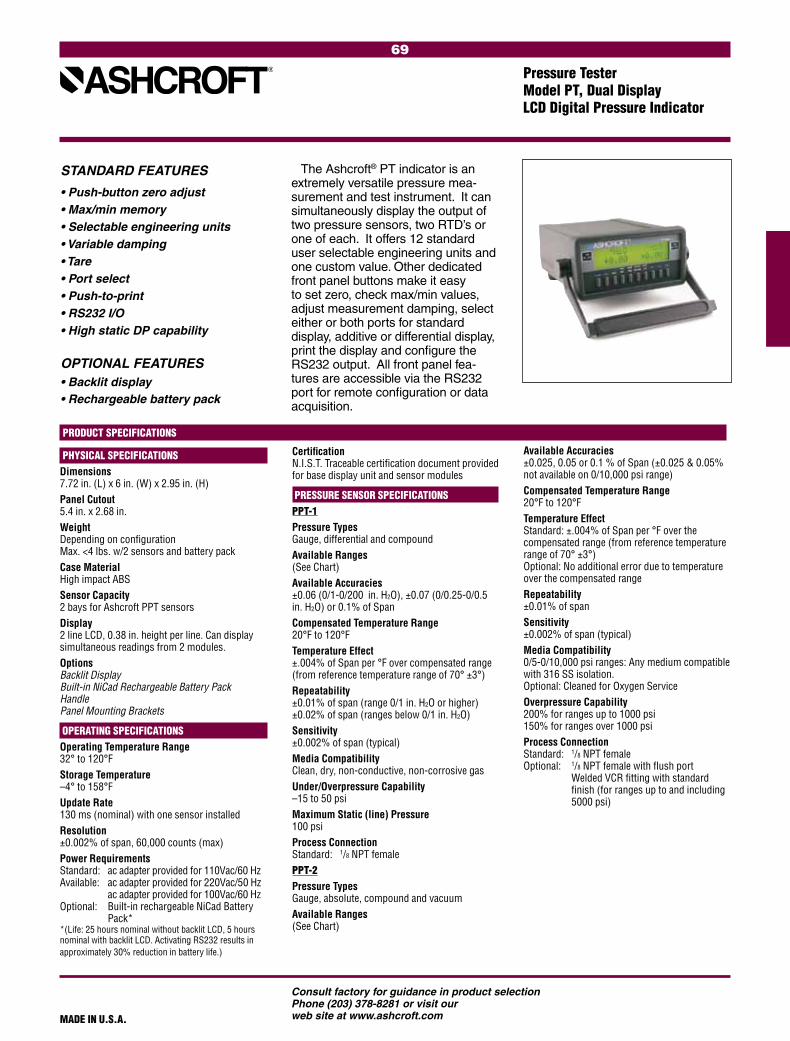
69
Consult factory for guidance in product selectionPhone (203) 378-8281 or visit our web site at www.ashcroft.com
The Ashcroft® PT indicator is an extremely versatile pressure mea-surement and test instrument. It can simultaneously display the output of two pressure sensors, two RTD’s or one of each. It offers 12 standard user selectable engineering units and one custom value. Other dedicated front panel buttons make it easy to set zero, check max/min values, adjust measurement damping, select either or both ports for standard display, additive or differential display, print the display and configure the RS232 output. All front panel fea-tures are accessible via the RS232 port for remote configuration or data acquisition.
Pressure Tester Model PT, Dual Display LCD Digital Pressure Indicator
STANDARD FEATURES
• Push-button zero adjust• Max/min memory• Selectable engineering units• Variable damping• Tare• Port select• Push-to-print• RS232 I/O• High static DP capability
OPTIONAL FEATURES
• Backlit display• Rechargeable battery pack
PRODUCT SPECIFICATIONS
PHYSICAL SPECIFICATIONSDimensions 7.72 in. (L) x 6 in. (W) x 2.95 in. (H)Panel Cutout 5.4 in. x 2.68 in.Weight Depending on configuration Max. <4 lbs. w/2 sensors and battery packCase Material High impact ABSSensor Capacity 2 bays for Ashcroft PPT sensorsDisplay 2 line LCD, 0.38 in. height per line. Can display simultaneous readings from 2 modules.Options Backlit Display Built-in NiCad Rechargeable Battery Pack Handle Panel Mounting Brackets
OPERATING SPECIFICATIONSOperating Temperature Range 32° to 120°FStorage Temperature –4° to 158°FUpdate Rate 130 ms (nominal) with one sensor installedResolution ±0.002% of span, 60,000 counts (max)Power Requirements Standard: ac adapter provided for 110Vac/60 Hz Available: ac adapter provided for 220Vac/50 Hz ac adapter provided for 100Vac/60 Hz Optional: Built-in rechargeable NiCad Battery Pack* *(Life: 25 hours nominal without backlit LCD, 5 hours nominal with backlit LCD. Activating RS232 results in approximately 30% reduction in battery life.)
Certification N.I.S.T. Traceable certification document provided for base display unit and sensor modules
PRESSURE SENSOR SPECIFICATIONS PPT-1 Pressure Types Gauge, differential and compoundAvailable Ranges (See Chart)Available Accuracies ±0.06 (0/1-0/200 in. H2O), ±0.07 (0/0.25-0/0.5 in. H2O) or 0.1% of SpanCompensated Temperature Range 20°F to 120°FTemperature Effect ±.004% of Span per °F over compensated range (from reference temperature range of 70° ±3°)Repeatability ±0.01% of span (range 0/1 in. H2O or higher) ±0.02% of span (ranges below 0/1 in. H2O)Sensitivity ±0.002% of span (typical)Media Compatibility Clean, dry, non-conductive, non-corrosive gas Under/Overpressure Capability –15 to 50 psiMaximum Static (line) Pressure 100 psiProcess Connection Standard: 1/8 NPT female PPT-2Pressure Types Gauge, absolute, compound and vacuumAvailable Ranges (See Chart)
Available Accuracies ±0.025, 0.05 or 0.1 % of Span (±0.025 & 0.05% not available on 0/10,000 psi range)Compensated Temperature Range 20°F to 120°FTemperature Effect Standard: ±.004% of Span per °F over the compensated range (from reference temperature range of 70° ±3°) Optional: No additional error due to temperature over the compensated range Repeatability ±0.01% of span Sensitivity ±0.002% of span (typical)Media Compatibility 0/5-0/10,000 psi ranges: Any medium compatible with 316 SS isolation. Optional: Cleaned for Oxygen Service Overpressure Capability 200% for ranges up to 1000 psi 150% for ranges over 1000 psiProcess Connection Standard: 1/8 NPT female Optional: 1/8 NPT female with flush port Welded VCR fitting with standard finish (for ranges up to and including 5000 psi)
MADE IN U.S.A.

70
Consult factory for guidance in product selectionPhone (203) 378-8281 or visit our web site at www.ashcroft.comMADE IN U.S.A.
STANDARD RANGES PPT-2 PPT-1 psi in.H2O Other Engineering Units** (gauge and (gauge/ absolute differential pressure) pressure)
5 10 15 30 50 60 100 150 200 250 300 500 600 1000 1500 2000 2500 3000 5000 6000 7500 10,000 vacuum 5 10 15 compound ±5 ±10 ±15 –15/+30 –15/+60
* Non-isolated, for clean dry gas only
0.25* 0.5* 1.0* 2.0* 3.0* 5.0* 10* 15* 25* 50* 100* 150* 200*
psi in.H2O in.Hg ftSW bar
mbar kPa MPa
mmHg cmH2O mmH2O kg/cm2
User Selectable
**Note: Engineering units identified above are accessible through the unit select feature. How-ever, readout will default to the primary unit of measure on start-up. Sensor modules scaled in primary units other than in. H2O (PPT-1) or psi (PPT-2) are also avail-able. Consult factory.
±0.125* ±0.25* ±0.5* ±1.0* ±1.5* ±2.5* ±5.0* ±7.5* ±12.5* ±25.* ±50.* ±75.* ±100.*
RTD INTERFACE ASSEMBLYPPT-RT1: Accommodates Pt100, Ni120, Cu120 and other common 2, 3 or 4 wire probes with resistance outputs of 400 ohms or less. PPT-RT2: Accommodates Pt1000 and other common 2, 3 or 4 wire probes with resistance outputs of 4000 ohms or less.Input Receptacle Accepts TA4F type RTD connectorRTD Probes Available Pt-100 probes, 6˝ or 12˝ length, with or without handle. DIN Class A accuracy. Includes mating TA4F connector. Consult factory for details and availability.
Base Display Unit 1) Specify Model: PT 2) Specify Power Requirements: 110, 220 or 100Vac 3) Specify Options: (Backlit, NiCad Battery Pack, Handle, Panel Mounting Brackets)
Sensors (Base Display Unit can hold a total of 1 or 2 pressure sensors or RTD interface assemblies simultaneously. Sensors and interface assem-blies will be installed into the base display unit at the factory.)
4) Type (PPT-1 or PPT-2) 5) Pressure Range and Unit of Measure (see range chart) 6) Pressure Type (see specifications) 7) Accuracy (see specifications) 8) Specify Options a) “zero temperature error over compen- sated range” (PPT-2 only) b) Optional fitting (see specifications) c) Clean for Oxygen Service (PPT-2 only)
TO ORDER
Rear view of Model PT with 2 pressure sensors installed
Pressure Tester Model PT, Dual Display LCD Digital Pressure Indicator
RTD Interface Assembly 9) Type (PPT-RT1 or PPT-RT2) 10) Probe Type (when required. Consult factory for probe P/N)

71
Consult factory for guidance in product selectionPhone (203) 378-8281 or visit our web site at www.ashcroft.com
Volume Controller Type AVC-1000 & 3000
Ashcroft® precision-pressure volume controllers provide a quick-and-easy method for precisely set-ting a pressure in a closed pneumatic system. They are ideal for use with Ashcroft test gauges for the calibra-tion of other pressure-measurement and control devices.
The AVC unit consists of a volume chamber with an internal piston assembly. The piston seals across the diameter of the chamber. Once the AVC unit is connected to a pneu-matic system, the volume of the chamber becomes part of the volume of the system. The pressure- adjust knob at the front of the unit reposi-tions the piston within the chamber through interaction with a precision-machined lead screw. Piston move-ment within the chamber increases or decreases the volume of the system, depending on the direction of move-ment. In a closed system where gas cannot leak out upon compression or be drawn in upon expansion, this volume change results in a change in the internal pressure. Increasing the volume by moving the piston toward the front of the AVC unit will decrease the pressure. Conversely, decreasing the volume by moving the piston to-ward the rear of the unit will increase the pressure. The pressure change
generated by a given amount of piston travel is proportional to the change in volume as compared to the total system volume.
AVC units are available for pres-sures up to 3000 psi. The AVC-1000 can be used to set pressures from vacuum through 1000 psi while the AVC-3000 can be used for pressures from vacuum through 3000 psi.
An integral balance valve provides a means for equalizing pressure on both sides of the piston prior to making the final adjustments when setting the pressure. This minimizes the resistance encountered when repositioning the piston and assures ease of pressure setting, even at 3000 psi. The balance valve also serves as a pressure-relief valve, assuring that the differential pressure across the piston does not reach unsafe levels.
AVC units can also be used without a compressed air source for the gen-eration of moderate levels of positive pressure and vacuum. The high res-olution of the AVC, combined with the ability to generate pressure and vacuum, make it an ideal tool for low-pressure (below 1 psi) calibration and test as well as higher pressure cali-bration and test activities.
GENERAL SPECIFICATIONS Type AVC-1000 AVC-3000Range (psi) vacuum-1000 vacuum-3000 Resolution (psi) 0.00025 0.0005Volume Change (cubic inches) 3.5 2.5Mechanical Rotation (turns) 31 61Proof Pressure (psi) 3000 6000 Burst Pressure (psi) 6000 min 12,000 minOperating Temperature Range 20-120°F 20-120°FOperating Media Clean, dry noncorrosive gas such as compressed air or nitrogenConstruction Aluminum body, stainless steel, brass Teflon, Delrin and Buna N

72
Consult factory for guidance in product selectionPhone (203) 378-8281 or visit our web site at www.ashcroft.com
73
Consult factory for guidance in product selectionPhone (203) 378-8281 or visit our web site at www.ashcroft.com
Product Selection Information ..................... 75
Type 1279 Duragauge® Pressure Gauge ...... 76
Type 1377 Duragauge® Pressure Gauge ...... 77
Type 1379 Duragauge® Pressure Gauge ...... 78
Type 2462 Duragauge® Pressure Gauge ...... 79
Type 1259 Process Pressure Gauge............. 80
Type 1279, 1379, 1377, 2462
Receiver Gauges ....................................... 81
Range Tables .......................................... 82-83
PROCESS GAUGES

74
Consult factory for guidance in product selectionPhone (203) 378-8281 or visit our web site at www.ashcroft.com

75
Consult factory for guidance in product selectionPhone (203) 378-8281 or visit our web site at www.ashcroft.com
Screws
Rear Cover
GasketRotaryGearedMovement
Socket O-RingPhenolic Case
Bourdon Tube System
Dial
MicrometerPointer
Gasket
Window
Threaded Ring
WARNING: Pressure gauges should be selected by considering media and ambient operating conditions to prevent misapplica-tion. Improper application can be detrimental to the gauge, causing failure and possible personal injury or property damage. The information contained in this catalog is offered as a guide to assist in making the proper selection of a pressure gauge. For additional information contact the factory.
Pressure Ranges: Select a gauge with a full-scale pressure range of approximately twice the normal operating pressure. The maxi-mum operating pressure should not exceed 75% of the full-scale range. Failure to select a gauge within these criteria may ultimately result in fatigue failure of the Bourdon tube.
Operating Conditions: The operating condi-tions to which a gauge will be subjected must be considered. If the gauge will be subjected to severe vibrations or pressure pulsation, liquid-filling the gauge or the PLUS!™ option may be necessary to obtain normal product life. Other than discoloration of the dial and hardening of the gasketing that may occur as ambient temperatures exceed 150°F, non liquid-filled Type 1279 (phenolic case), 1377 and 1379 (aluminum case) Duragauge® gauges with standard glass windows, can withstand continuous operating tempera-tures up to 250°F. Liquid-filled gauges can withstand 200°F but glycerin fill and acrylic window will tend to yellow. Accuracy will be affected by approximately 1.5% per 100°F. Gauges with welded joints will withstand 750°F (450°F with silver brazed joints) for short times without rupture, although other
parts of the gauge will be destroyed and calibration will be lost. Proper selection of the Bourdon system material is dependent on the process fluid to which the system will be subjected. If the correct material is not available, the use of a diaphragm seal may be necessary to protect the system from the process fluid. Liquid-filled gauges are recom-mended for the discharge side of positive displacement pumps.
Cases: Many styles and different materials are offered. Two types are available, open and solid front. Solid front cases have a solid wall between the Bourdon tube and the window. Open-front cases have the dial between the Bourdon tube and the window.
Rings: The ring, which retains the window, is threaded, bayonet (cam), friction, snap-on or hinged, depending upon case type.
Pressure Elements: Available in a wide vari-ety of materials, including: brass, phosphor bronze, alloy steel, 316 stainless steel, Monel and Inconel. Proper selection of the Bourdon system or bellows material depends upon the process fluid to which the system will be subjected. If the correct material is not available, the use of a diaphragm seal may be necessary to protect the system from the process fluid. If the gauge is subject to severe vibration or pressure pulsation, a liquid-filled gauge is recommended.
Duragauge® PLUS!™ Pressure Gauge: An exclusive, optional feature provides virtually liquid-filled performance in a dry gauge. The PLUS!™ Performance feature is a patented design incorporated into the industry-standard
Ashcroft pressure gauge. PLUS!™ is available in any Duragauge® gauge case style material or range. Historically, pulsation and vibration have reduced gauge life and made gauges difficult to read. Customers have had no alternative to liquid-filled gauges to solve vibration and pulsation problems, until now!
Movements: Movements are designed and materials of construction selected to reduce friction and extend wear life. For example, commercial gauges have the unique PowerFlex™ brass movement with polyester segment, whereas the stainless steel movement of the Duragauge® gauge is a rotary-geared design with Teflon-coated wear parts. Other movements are stainless steel with bronze pinion and segment or bronze bushed.
Dials: Dials are uniformly graduated and have highly legible black markings. White-coated or brushed aluminum backgrounds are available.
Windows: The standard is glass, plastic or polycarbonate, depending on the type of the gauge. Options are laminated safety glass, nonglare glass or plastic, depending on the type of gauge.
Pointers: Duragauge® pressure gauges have micrometer adjustable pointers which can be repositioned without removal. Type 1009 gauges have adjustable pointers. Many other gauges are supplied with nonadjustable pointers which can be reset by removing the ring, and removing and resetting the pointer. Adjustable pointers are available as an option on these gauges.
Product Selection InformationConsult ASME B40.100 for guidance in gauge selection
Type 1279 Duragauge® pressure gauge shown
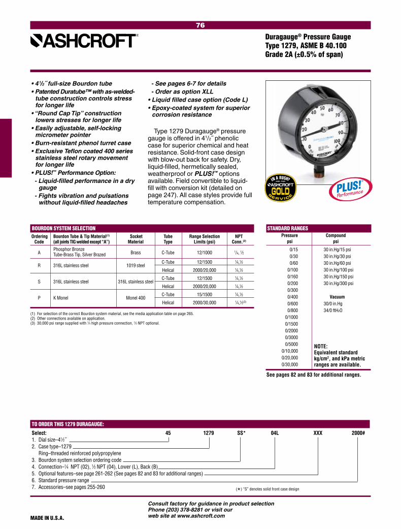
76
Consult factory for guidance in product selectionPhone (203) 378-8281 or visit our web site at www.ashcroft.com
STANDARD RANGES Pressure Compound
psi psi 0/15 30 in.Hg/15 psi 0/30 30 in.Hg/30 psi 0/60 30 in.Hg/60 psi 0/100 30 in.Hg/100 psi 0/160 30 in.Hg/150 psi 0/200 30 in.Hg/300 psi 0/300 0/400 Vacuum 0/600 30/0 in.Hg 0/800 34/0 ft H2O 0/1000 0/1500 0/2000 0/3000 0/5000 0/10,000 0/20,000 0/30,000
BOURDON SYSTEM SELECTION
Ordering Bourdon Tube & Tip Material(1) Socket Tube Range Selection NPT Code (all joints TIG welded except “A”) Material Type Limits (psi) Conn.(2)
A Phosphor Bronze
Brass C-Tube 12/1000 1/4, 1⁄2 Tube-Brass Tip, Silver Brazed
R 316L stainless steel 1019 steel C-Tube 12/1500 1⁄4,1⁄2
Helical 2000/20,000 1⁄4,1⁄2
S 316L stainless steel 316L stainless steel C-Tube 12/1500 1⁄4,1⁄2
Helical 2000/20,000 1⁄4,1⁄2
P K Monel Monel 400
C-Tube 15/1500 1⁄4,1⁄2
Helical 2000/30,000 1⁄4,1⁄2(3)
Type 1279 Duragauge® pressure gauge is offered in 41/2˝ phenolic case for superior chemical and heat resistance. Solid-front case design with blow-out back for safety. Dry, liquid-filled, hermetically sealed, weatherproof or PLUS!™ options available. Field convertible to liquid-fill with conversion kit (detailed on page 247). All case styles provide full temperature compensation.
• 41/2˝ full-size Bourdon tube• Patented Duratube™ with as-welded-
tube construction controls stress for longer life
• “Round Cap Tip” construction lowers stresses for longer life
• Easily adjustable, self-locking micrometer pointer
• Burn-resistant phenol turret case• Exclusive Teflon coated 400 series
stainless steel rotary movement for longer life
• PLUS!™ Performance Option:- Liquid-filled performance in a dry
gauge- Fights vibration and pulsations
without liquid-filled headaches
MADE IN U.S.A.
Duragauge® Pressure Gauge Type 1279, ASME B 40.100 Grade 2A (±0.5% of span)
(1) For selection of the correct Bourdon system material, see the media application table on page 265.(2) Other connections available on application.(3) 30,000 psi range supplied with 1⁄4 high pressure connection, 1⁄2 NPT optional.
NOTE: Equivalent standard kg/cm2, and kPa metric ranges are available.
(*) “S” denotes solid front case design
TO ORDER THIS 1279 DURAGAUGE:
Select: 45 1279 SS* 04L XXX 2000#1. Dial size–41⁄2˝2. Case type–1279 Ring–threaded reinforced polypropylene 3. Bourdon system selection ordering code 4. Connection–1⁄4 NPT (02), 1⁄2 NPT (04), Lower (L), Back (B)5. Optional features–see page 261-262 (See pages 82 and 83 for additional ranges)6. Standard pressure range 7. Accessories–see pages 255-260
- See pages 6-7 for details- Order as option XLL
• Liquid filled case option (Code L) • Epoxy-coated system for superior
corrosion resistance
See pages 82 and 83 for additional ranges.

77
Consult factory for guidance in product selectionPhone (203) 378-8281 or visit our web site at www.ashcroft.com
Type 1377 Duragauge® pressure gauge is offered in 41/2˝, 6˝ and 81/2˝ dial sizes.
Designed for flush mounting, this solid-front gauge is ideal for panel board applications. Its black epoxy coating and its tough aluminum weatherproof case easily allow application in a variety of climatic conditions.
MADE IN U.S.A.
Duragauge® Pressure GaugeType 1377, ASME B 40.100 Grade 2A (±0.5% of span)
TO ORDER THIS 1377 DURAGAUGE:
Select: 45 1377 AS* 04B XXX 2000#1. Dial size–41⁄2˝2. Case type–1377 Ring–steel, black enamel finish 3. Bourdon system selection ordering code 4. Connection–1⁄4 NPT (02), 1⁄2 NPT (04), Lower (L), Back (B)5. Optional features–see page 261-262 (See pages 82 and 83 for additional ranges)6. Standard pressure range 7. Accessories–see pages 255-260 (*) “S” denotes solid front case design
STANDARD RANGES Pressure Compound
psi psi 0/15 30 in.Hg/15 psi 0/30 30 in.Hg/30 psi 0/60 30 in.Hg/60 psi 0/100 30 in.Hg/100 psi 0/160 30 in.Hg/150 psi 0/200 30 in.Hg/300 psi 0/300 0/400 Vacuum 0/600 30/0 in.Hg 0/800 34/0 ft H2O 0/1000 0/1500 0/2000 0/3000 0/5000 0/10,000 0/20,000 0/30,000
NOTE: Equivalent standard kg/cm2, and kPa metric ranges are available.
BOURDON SYSTEM SELECTION
Ordering Bourdon Tube & Tip Material(1) Socket Tube Range Selection NPT Code (all joints TIG welded except “A”) Material Type Limits (psi) Conn.(2)
A Phosphor Bronze
Brass C-Tube 12/1000 1/4, 1⁄2 Tube-Brass Tip, Silver Brazed
R(4) 316L stainless steel 1018 steel C-Tube 12/1500 1/4, 1⁄2
Helical 2000/20,000 1/4, 1⁄2
S 316L stainless steel 316 stainless steel C-Tube 12/1500 1/4, 1⁄2
Helical 2000/20,000 1/4, 1⁄2
P(3) K Monel Monel 400
C-Tube 15/1500 1/4, 1⁄2
Helical 2000/30,000 1/4, 1⁄2(5)
• 41/2˝ full-size Bourdon tube• Patented Duratube™ with as-welded-
tube construction controls stress for longer life
• “Round Cap Tip” construction lowers stresses for longer life
• Easily adjustable, self-locking micrometer pointer
• Exclusive Teflon coated 400 series stainless steel rotary movement for longer life
• PLUS!™ Performance Option:- Liquid-filled performance in a dry
gauge- Fights vibration and pulsations
without liquid-filled headaches- Order as option XLL
• Epoxy-coated system for superior corrosion resistance
(1) For selection of the correct Bourdon system material, see the media application table on page 265.(2) Other connections available on application.(3) See Ashcroft product information page ASH/PI-60A for compliance to NACE.(4) “R” Bourdon system not available in 81⁄2˝ dial size.(5) 30,000 psi range supplied with 1⁄4 high pressure connection, 1⁄2 NPT optional.
See pages 82 and 83 for additional ranges.

78
Consult factory for guidance in product selectionPhone (203) 378-8281 or visit our web site at www.ashcroft.com
BOURDON SYSTEM SELECTION
Ordering Bourdon Tube & Tip Material(1) Socket Tube Range Selection NPT Code (all joints TIG welded except “A”) Material Type Limits (psi) Conn.(2)
A Phosphor Bronze
Brass C-Tube 12/1000 1/4, 1⁄2 Tube-Brass Tip, Silver Brazed
R 316L stainless steel 1019 steel C-Tube 12/1500 1/4, 1⁄2
Helical 2000/20,000 1/4, 1⁄2
S 316L stainless steel 316 stainless steel C-Tube 12/1500 1/4, 1⁄2
Helical 2000/20,000 1/4, 1⁄2
P K Monel Monel 400
C-Tube 15/1500 1/4, 1⁄2
Helical 2000/30,000 1/4, 1⁄2(4)
WW Inconel 718 316 stainless steel Helical 50/80/100,000(3)(5) 1⁄4 high press.
Type 1379 Duragauge® pressure gauge is offered in 41⁄2, 6˝ and 81⁄2˝ dials sizes.
This rugged, solid-front aluminum case gauge is tops in its field. It is available as a weatherproof hermet-ically sealed or liquid-filled version in 41⁄2˝ and 6˝ sizes in pressures to 30,000 psi. Like the 1279, it can be easily field converted from the weath-erproof version to either the sealed or liquid-filled version using an optional kit. Ranges 50,000, 80,000 and 100,000 psi are available in 6˝ hermetically sealed and liquid-filled cases. All size cases are coated with black epoxy which will withstand most environmental conditions.
MADE IN U.S.A.
Duragauge® Pressure GaugeType 1379, ASME B 40.100 Grade 2A (±0.5% of span)
TO ORDER THIS 1379 DURAGAUGE:
Select: 45 1379 SS* 04L XXX 100#1. Dial size–41⁄2˝, 6˝, or 81⁄2˝2. Case type–1379 Ring–threaded reinforced polypropylene 3. Bourdon system selection ordering code 4. Connection–1⁄4 NPT (02), 1⁄2 NPT (04), Lower (L), Back (B)5. Optional features–see page 261-262 (See pages 82 and 83 for additional ranges)6. Standard pressure range 7. Accessories–see pages 255-260 (*) “S” denotes solid front case design
STANDARD RANGES Pressure Compound
psi psi 0/15 30 in.Hg/15 psi 0/30 30 in.Hg/30 psi 0/60 30 in.Hg/60 psi 0/100 30 in.Hg/100 psi 0/160 30 in.Hg/150 psi 0/200 30 in.Hg/300 psi 0/300 0/400 Vacuum 0/600 30/0 in.Hg 0/800 34/0 ft H2O 0/1000 0/1500 0/2000 0/3000 0/5000 0/10,000 0/20,000 0/30,000 0/50,000 0/80,000 0/100,000
NOTE: Equivalent standard kg/cm2, and kPa metric ranges are available.
(4) 30,000 psi offered with 1⁄4 high pressure connection, 1⁄2 NPT optional.(5) Offered hermetically sealed as standard. Liquid fillable optional.
(1) For selection of the correct Bourdon system material, see the media application table on page 265.(2) Other connections available on application.(3) 50,000-100,000 psi available in 6˝ 1379 lower and back connection only.
• 41/2˝ full-size Bourdon tube• Patented Duratube™ with as-welded-
tube construction controls stress for longer life
• “Round Cap Tip” construction lowers stresses for longer life
• Easily adjustable, self-locking micrometer pointer
• Exclusive Teflon coated 400 series stainless steel rotary movement for longer life
• PLUS!™ Performance Option:- Liquid-filled performance in a dry
gauge- Fights vibration and pulsations
without liquid-filled headaches- Order as option XLL
• Liquid filled case option (Code L) • Epoxy-coated system for superior
corrosion resistance
See pages 82 and 83 for additional ranges.
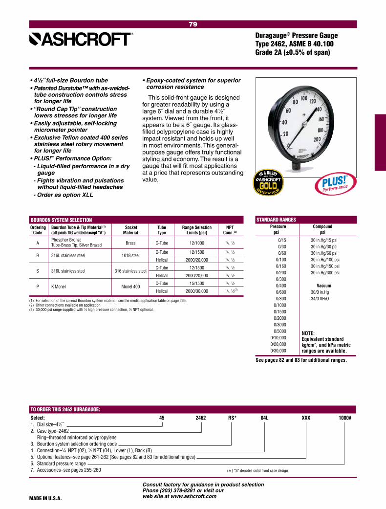
79
Consult factory for guidance in product selectionPhone (203) 378-8281 or visit our web site at www.ashcroft.com
BOURDON SYSTEM SELECTION
Ordering Bourdon Tube & Tip Material(1) Socket Tube Range Selection NPT Code (all joints TIG welded except “A”) Material Type Limits (psi) Conn.(2)
A Phosphor Bronze
Brass C-Tube 12/1000 1/4, 1⁄2 Tube-Brass Tip, Silver Brazed
R 316L stainless steel 1018 steel C-Tube 12/1500 1/4, 1⁄2
Helical 2000/20,000 1/4, 1⁄2
S 316L stainless steel 316 stainless steel C-Tube 12/1500 1/4, 1⁄2
Helical 2000/20,000 1/4, 1⁄2
P K Monel Monel 400
C-Tube 15/1500 1/4, 1⁄2
Helical 2000/30,000 1/4, 1⁄2(3)
This solid-front gauge is designed for greater readability by using a large 6˝ dial and a durable 41⁄2˝ system. Viewed from the front, it appears to be a 6˝ gauge. Its glass-filled polypropylene case is highly impact resistant and holds up well in most environments. This general-purpose gauge offers truly functional styling and economy. The result is a gauge that will fit most applications at a price that represents outstanding value.
MADE IN U.S.A.
Duragauge® Pressure GaugeType 2462, ASME B 40.100 Grade 2A (±0.5% of span)
(1) For selection of the correct Bourdon system material, see the media application table on page 265.(2) Other connections available on application.(3) 30,000 psi range supplied with 1⁄4 high pressure connection, 1⁄2 NPT optional.
STANDARD RANGES Pressure Compound
psi psi 0/15 30 in.Hg/15 psi 0/30 30 in.Hg/30 psi 0/60 30 in.Hg/60 psi 0/100 30 in.Hg/100 psi 0/160 30 in.Hg/150 psi 0/200 30 in.Hg/300 psi 0/300 0/400 Vacuum 0/600 30/0 in.Hg 0/800 34/0 ft H2O 0/1000 0/1500 0/2000 0/3000 0/5000 0/10,000 0/20,000 0/30,000
NOTE: Equivalent standard kg/cm2, and kPa metric ranges are available.
(*) “S” denotes solid front case design
TO ORDER THIS 2462 DURAGAUGE:
Select: 45 2462 RS* 04L XXX 1000#1. Dial size–41⁄2˝2. Case type–2462 Ring–threaded reinforced polypropylene 3. Bourdon system selection ordering code 4. Connection–1⁄4 NPT (02), 1⁄2 NPT (04), Lower (L), Back (B)5. Optional features–see page 261-262 (See pages 82 and 83 for additional ranges)6. Standard pressure range 7. Accessories–see pages 255-260
• 41/2˝ full-size Bourdon tube• Patented Duratube™ with as-welded-
tube construction controls stress for longer life
• “Round Cap Tip” construction lowers stresses for longer life
• Easily adjustable, self-locking micrometer pointer
• Exclusive Teflon coated 400 series stainless steel rotary movement for longer life
• PLUS!™ Performance Option:- Liquid-filled performance in a dry
gauge- Fights vibration and pulsations
without liquid-filled headaches- Order as option XLL
• Epoxy-coated system for superior corrosion resistance
See pages 82 and 83 for additional ranges.

80
Consult factory for guidance in product selectionPhone (203) 378-8281 or visit our web site at www.ashcroft.com
BOURDON SYSTEM SELECTION
Ordering Bourdon Tube & Tip Material(1) Socket Tube Range Selection NPT Code (all joints TIG welded except “A”) Material Type Limits (psi) Conn.(2)
S 316L stainless steel 316 stainless steel C-Tube 12/1500 1/4, 1⁄2
Helical 2000/20,000 1/4, 1⁄2
P(3) Monel Monel C-Tube 12/1000 1/4, 1⁄2
Helical 1500/20,000 1/4, 1⁄2
TO ORDER THIS 1259 PROCESS GAUGE:
Select: 45 1259 SD 04L XXX 1000#1. Dial size–41⁄2˝2. Case type–1259 Ring–threaded reinforced polypropylene 3. Bourdon system selection ordering code 4. Connection–1⁄4 NPT (02), 1⁄2 NPT (04), Lower (L)5. Optional features–see page 261-2626. Standard pressure range 7. Accessories–see pages 255-260
The Type 1259 process gauge is offered with an as-welded Bourdon tube to ensure safety and a longer life than competitive gauges. Meeting ASME B40.100, the Type 1259 pro-cess gauge has been engineered to meet marketplace requirements.
Process Pressure GaugeType 1259, ASME B 40.100 Grade 2A (±0.5% of span)
(1) For selection of the correct Bourdon system material, see the media application table on page 265.(2) Other connections available on application.(3) See Ashcroft product information page ASH/PI-60A for compliance to NACE.
STANDARD RANGES Pressure Compound
psi psi 0/15 30 in.Hg/15 psi 0/30 30 in.Hg/30 psi 0/60 30 in.Hg/60 psi 0/100 30 in.Hg/100 psi 0/160 30 in.Hg/150 psi 0/200 30 in.Hg/300 psi 0/300 0/400 Vacuum 0/600 30/0 in.Hg 0/800 34/0 ft H2O 0/1000 0/1500 0/2000 0/3000 0/5000 0/10,000 0/20,000
NOTE: Equivalent standard kg/cm2, and kPa metric ranges are available.
• Solid front safety case• Accuracy complies with
ASME B 40.100 Grade 2A (±0.5% of span)
• As-welded Bourdon Tube for safety and longer life
• Easily adjustable, self-locking micrometer pointer
• Adjustable movement • Ranges: vac to 20,000 psi• Date coded socket to ensure
pedigree• Wetted part material printed
on dial• Liquid filled case option (Code L)

81
Consult factory for guidance in product selectionPhone (203) 378-8281 or visit our web site at www.ashcroft.com
Receiver Gauge Types 1279, 1379, 1377 & 2462, ASME B 40.100 Grade 2A (±0.5% of span)
MADE IN U.S.A.
Ashcroft® receiver gauges are used in conjuction with pneu-matic transmitters to indicate pressure, temperature, flow or other process parameters that can be transmitted by proportional variations in air pressure. Available in standard transmitter-output air pressure ranges of 3-15 and 3-27 psi.
GAUGE TYPE NUMBER DIAL SIZES CONNECTION LOCATION MOUNTING TYPE MOUNTING METHOD MOUNTING METHOD CODE
1279AS-XPR 41⁄2 Lower/Back Stem/Surface — —
Back Flush 1278M Ring — 1377AS-XPR 41⁄2, 6, 81⁄2 Back Flush — — Lower/Back Stem/Surface — —
1379AS-XPR 41⁄2, 6, 81⁄2 Back Flush —
Lower/Back Stem — —
2462AS-XPR 6 Lower/Back Surface Surface mounting ring XBF
Back Flush Flush mounting bracket XBQ
41⁄2 & 6, 1278M Ring – 81⁄2, Wide Ring std.
Case 1279AS-XPR 41⁄2 Phenolic, black Ring Polypropylene, threaded, black Case 1377AS-XPR 41⁄2, 6, 81⁄2 Aluminum, black epoxy Ring Phosphor Rotary geared, ASME Hinged, steel, black bronze 3-15 Black, stainless steel, B 40.1 Case Bourdon tube, and micrometer Teflon® coated
1⁄2 Grade 2A Aluminum, black epoxy brass socket; 3-27 adjustable pinion gear and (1⁄4 Opt) (±0.5% 1379AS-XPR 41⁄2, 6, 81⁄2 Ring (316 stainless segment shaft of span) Threaded polypropylene 41⁄2, 6 steel optional) Hinged, steel, black 81⁄2 Case 2462AS-XPR 6 Polypropylene, black Ring Polypropylene, bayonet lock, black
GAUGE TYPE DIAL SIZES CASE/RING SYSTEM RANGE POINTER MOVEMENT NPT ACCURACY NUMBER MATERIAL ASSEMBLY psi CONN.
TO ORDER THESE TYPES 1279/1379/1377/2462 RECEIVER GAUGES:
Select: 45 1279 AS 04 L XPR 3-15 psi1. Dial size2. Case type 3. Tube & socket material4. Connection size, 1⁄4 (02), or 1⁄2 (04) 5. Connection location, (L–Lower), (B–Back)6. Optional features (XPR always appears in code for receiver gauge) 7. Range of transmitted signal (also specify the scale to be shown on the dial face)
• 41/2˝ full-size Bourdon tube• Patented Duratube™ with as-welded-
tube construction controls stress for longer life
• “Round Cap Tip” construction lowers stresses for longer life
• Easily adjustable, self-locking micrometer pointer
• Exclusive Teflon coated 400 series stainless steel rotary movement for longer life
• PLUS!™ Performance Option:- Liquid-filled performance in a dry
gauge- Fights vibration and pulsations
without liquid-filled headaches- Order as option XLL
• Epoxy-coated system for superior corrosion resistance
Type 1279

82
Consult factory for guidance in product selectionPhone (203) 378-8281 or visit our web site at www.ashcroft.com
All Ashcroft® dials have various total graduation marks, figure intervals and minor graduations. Standard dual scale metric ranges have a dominant metric inner scale. The outer scale is specified in psi. Some examples are shown. Dura-gauge gauges are made in accordance with ASME B40.1 entitled, “Gauges, Pressure, Indicating Dial Type – Elastic Element,” Accuracy grade 2A (±0.5% of span).
Range TablesDuragauge® Pressure Gauge
Pressure – psi Range Figure interval Minor graduation
0/15 1 0.1 0/30 5 0.2 0/60 5 0.5 0/100 10 1 0/160 20 2 0/200 20 2 0/300 50 2 0/400 50 5 0/600 50 5 0/800 100 10 0/1000 100 10 0/1500 200 20 0/2000 200 20 0/3000 500 20 0/5000 500 50 0/6000 500 50 0/10,000 1000 100 0/20,000 2000 200 0/30,000 5000 200 0/50,000 5000 500 0/80,000 10,000 1000 0/100,000 10,000 1000
Compound Range Figure interval Minor graduation
in Hg psi in Hg psi
30˝ Hg/15 psi 5 3 0.5 0.2 30˝ Hg/30 psi 10 5 1 0.5 30˝ Hg/60 psi 10 10 1 1 30˝ Hg/100 psi 10 10 2 1 30˝ Hg/150 psi 10 20 5 2 30˝ Hg/200 psi 30 20 5 2 30˝ Hg/300 psi 30 50 5 2 30˝ Hg/400 psi 30 50 5 5 30˝ Hg/500 psi 30 50 5 5 30˝ Hg/600 psi 30 50 10 5
Combination Range Figure interval Minor graduation
inner–psi outer–ft H2O psi ft H2O psi ft H2O
0/15 0/34 3 5 0.5 0.5 0/30 0/70 5 10 0.5 1 0/60 0/140 5 20 0.5 5 0/100 0/230 10 20 1 2 0/160 0/370 20 50 2 5 0/200 0/460 20 50 5 5 0/300 0/690 25 100 5 10
Retard Range Figure interval Minor graduation
0/15 psi retard to 30 psi 1 psi-30 psi 0.25 psi-5 psi 0/30 psi retard to 60 psi 2 psi-60 psi 0.2 psi-10 psi 0/60 psi retard to 100 psi 2 psi-100 psi 0.5 psi-10 psi 30˝ Hg vac/75 psi 5˝ Hg/15 psi-150 psi 1˝ Hg/1 psi-5psi retard to 150 psi 10˝ Hg vac/5 psi 2˝ Hg/1 psi 0.2˝ Hg/0.1 psi retard to 30˝ Hg vac 30˝ Hg 5˝ Hg retard to 30 psi 30 psi 5 psi
Minor Graduation
Vacuum Range Figure interval Minor graduation
30/0 in. Hg 5 in 0.2 in 34/0 ft H2O 5 ft 0.5 ft
Pressure –kg/cm2 and bar Range Figure Minor Outer scale interval graduation in psi
0/1 0.1 0.01 0/14 0/1.6 0.2 0.02 0/22 0/2.5 0.5 0.02 0/35 0/4 0.5 0.05 0/55 0/6 0.5 0.05 0/85 0/10 1 0.1 0/140 0/16 2 0.2 0/220 0/25 5 0.2 0/350 0/40 5 0.5 0/550 0/60 5 0.5 0/850 0/100 10 1 0/1400 0/160 20 2 0/2200 0/250 50 2 0/3500 0/400 50 5 0/5500 0/600 50 5 0/8500 0/1000 100 10 0/14,000 0/1600 200 20 0/22,000 0/2500 500 20 0/35,000 0/4000 500 50 0/55,000 0/6000 1000 50 0/85,000Compound – kg/cm2 and bar Range Figure Minor Outer scale interval graduation in psi
–1/0/1.5 0.2 0.02 30˝ Hg/20 –1/0/3 0.5 0.05 30˝ Hg/40 –1/0/5 0.5 0.05 30˝ Hg/70 –1/0/9 1 0.01 30˝ Hg/125 –1/0/15 2 0.02 30˝ Hg/215 –1/0/24 5 0.02 30˝ Hg/340
Vacuum – kg/cm2 and bar Range Figure Minor Outer scale interval graduation
–1/0 0.1 0.01 30˝ Hg
Graduations and figure intervals
Total Graduation
Figure Intervals
STANDARD RANGES METRIC RANGES
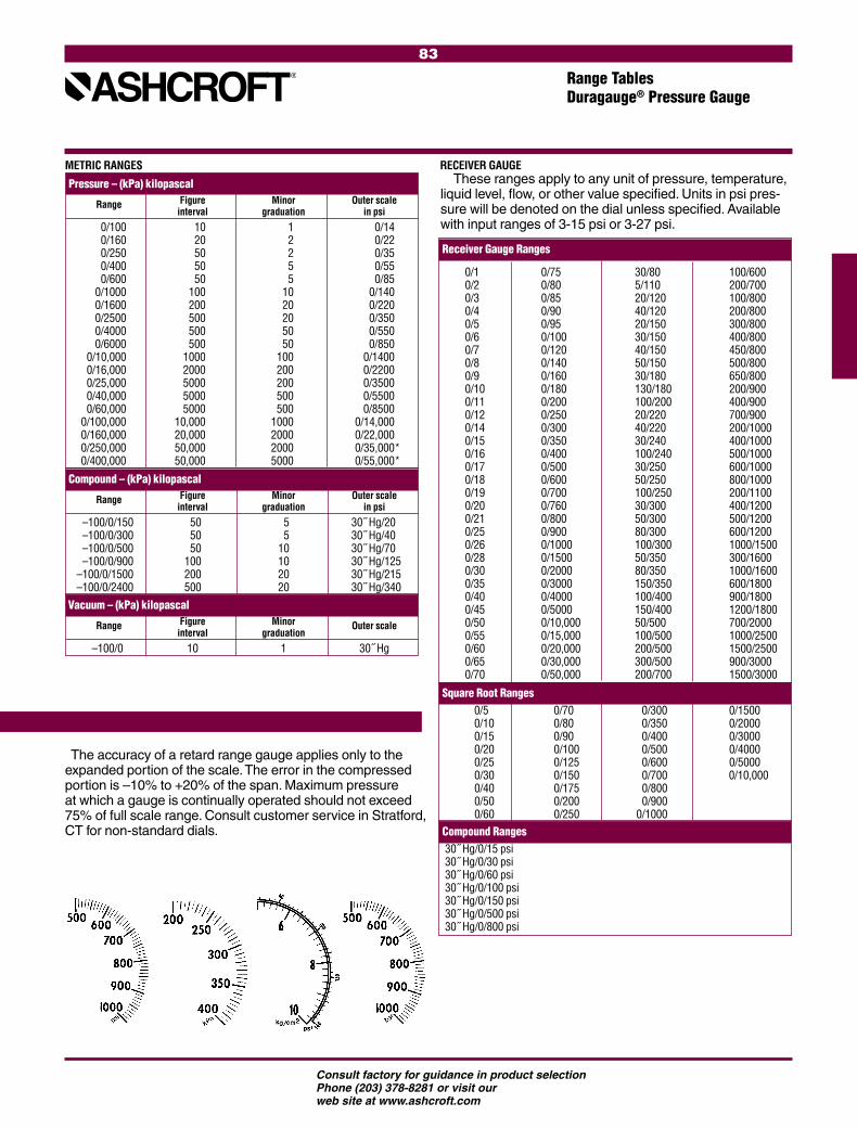
83
Consult factory for guidance in product selectionPhone (203) 378-8281 or visit our web site at www.ashcroft.com
Receiver Gauge Ranges
The accuracy of a retard range gauge applies only to the expanded portion of the scale. The error in the compressed portion is –10% to +20% of the span. Maximum pressure at which a gauge is continually operated should not exceed 75% of full scale range. Consult customer service in Stratford, CT for non-standard dials.
Graduations and figure intervals
METRIC RANGES RECEIVER GAUGE
Pressure – (kPa) kilopascal Range Figure Minor Outer scale interval graduation in psi
0/100 10 1 0/14 0/160 20 2 0/22 0/250 50 2 0/35 0/400 50 5 0/55 0/600 50 5 0/85 0/1000 100 10 0/140 0/1600 200 20 0/220 0/2500 500 20 0/350 0/4000 500 50 0/550 0/6000 500 50 0/850 0/10,000 1000 100 0/1400 0/16,000 2000 200 0/2200 0/25,000 5000 200 0/3500 0/40,000 5000 500 0/5500 0/60,000 5000 500 0/8500 0/100,000 10,000 1000 0/14,000 0/160,000 20,000 2000 0/22,000 0/250,000 50,000 2000 0/35,000* 0/400,000 50,000 5000 0/55,000*
Compound – (kPa) kilopascal Range Figure Minor Outer scale interval graduation in psi
–100/0/150 50 5 30˝ Hg/20 –100/0/300 50 5 30˝ Hg/40 –100/0/500 50 10 30˝ Hg/70 –100/0/900 100 10 30˝ Hg/125 –100/0/1500 200 20 30˝ Hg/215 –100/0/2400 500 20 30˝ Hg/340 Vacuum – (kPa) kilopascal Range Figure Minor Outer scale interval graduation
–100/0 10 1 30˝ Hg
Range TablesDuragauge® Pressure Gauge
These ranges apply to any unit of pressure, temperature, liquid level, flow, or other value specified. Units in psi pres-sure will be denoted on the dial unless specified. Available with input ranges of 3-15 psi or 3-27 psi.
0/10/20/30/40/50/60/70/80/90/100/110/120/140/150/160/170/180/190/200/210/250/260/280/300/350/400/450/500/550/600/650/70
0/750/800/850/900/950/1000/1200/1400/1600/1800/2000/2500/3000/3500/4000/5000/6000/7000/7600/8000/9000/10000/15000/20000/30000/40000/50000/10,0000/15,0000/20,0000/30,0000/50,000
30/805/11020/12040/12020/15030/15040/15050/15030/180130/180100/20020/22040/22030/240100/24030/25050/250100/25030/30050/30080/300100/30050/35080/350150/350100/400150/40050/500100/500200/500300/500200/700
100/600200/700100/800200/800300/800400/800450/800500/800650/800200/900400/900700/900200/1000400/1000500/1000600/1000800/1000200/1100400/1200500/1200600/12001000/1500300/16001000/1600600/1800900/18001200/1800700/20001000/25001500/2500900/30001500/3000
Square Root Ranges 0/5 0/70 0/300 0/1500 0/10 0/80 0/350 0/2000 0/15 0/90 0/400 0/3000 0/20 0/100 0/500 0/4000 0/25 0/125 0/600 0/5000 0/30 0/150 0/700 0/10,000 0/40 0/175 0/800 0/50 0/200 0/900 0/60 0/250 0/1000Compound Ranges 30˝ Hg/0/15 psi 30˝ Hg/0/30 psi 30˝ Hg/0/60 psi 30˝ Hg/0/100 psi 30˝ Hg/0/150 psi 30˝ Hg/0/500 psi 30˝ Hg/0/800 psi

84
Consult factory for guidance in product selectionPhone (203) 378-8281 or visit our web site at www.ashcroft.com

85
Consult factory for guidance in product selectionPhone (203) 378-8281 or visit our web site at www.ashcroft.com
PRESSURE INSTRUMENTS
PROCESS GAUGES
INDUSTRIAL GAUGES
STAINLESS STEEL CASE GAUGES
SANITARY GAUGES
TEST INSTRUMENTS
DIAPHRAGM SEALS/INSTRUMENT ISOLATORS
COMMERCIAL GAUGES
SPECIAL APPLICATION COMMERCIAL GAUGES
PRESSURE TRANSDUCERS/TRANSMITTERS
TEMPERATURE INSTRUMENTS
BIMETAL THERMOMETERS
DIRECT-READING THERMOMETERS
HANDHELD THERMOMETERS
REMOTE-READING GAS THERMOMETERS
DIGITAL THERMOMETERS
REMOTE-READING VAPOR THERMOMETERS
TEMPERATURE REGULATORS
THERMOWELLS
PRESSURE/TEMPERATURE SWITCHES
PRESSURE SWITCHES
TEMPERATURE SWITCHES
ACCESSORIES & OPTIONS
APPLICATION DATA
ASME B40.100 Grade 1A (±1.0% of span)ASME B40.100 Grade 2A (±0.5% of span)ASME B40.100 Grade A (±2-1-2% of span)ASME B40.100 Grade B (±3-2-3% of span)
Product Selection ........................................ 87Type 5500 & 6500 Stainless Steel Case ...... 88Type 1008 40/50 mm Gauges ...................... 89Type 1008S 63/100 mm Gauges ................. 90Type 1008S/SL 63/100 mm
Back Connect Gauges ............................ 91Type 1009 21/2˝ and 31/2˝ Duralife® Gauges .. 92Type 1009 41/2˝ and 6˝ Gauges .................... 93Type 1109 41/2˝ and 6˝ Gauges .................... 94 Type 1009, 1010, 1017 & 1220
Hydraulic Gauges .................................. 95Type 1009, 1010, 1017 & 1220
Receiver Gauges ................................... 96Type 1009, 1010, 1017 & 1220
Refrigeration and Ammonia Gauges ..... 97Type 2074, 2174, 2274
Digital Industrial Gauges ....................... 98Type 1010 General Service Gauge ................99Type 1017 General Service Gauge ..............100Type 1220 General Service Gauge ..............101Type 1020S Christmas Tree Gauge .............102Type 1038, 1339 Duplex Gauges ................103Type 1125, 1125A DP Gauges .....................104 Type 1127/1128 DP Gauges .......................105Type 1130 DP Gauges .................................106Type 1131 DP Gauges .................................107Type 1132 DP Gauges .................................108Type 1133 DP Gauges .................................109 Type 1134 DP Gauges .................................110 Type 5503 DP Gauges .................................111Type 5509 DP Gauges .................................112Type 1150H, 1122 Special Application
Gauges ..................................................113Type 1187, 1188 & 1189 Low Pressure
Bellows Gauges.....................................114Type 1490 Low Pressure
Diaphragm Gauge .................................115Type 1495 Receiver Diaphragm Gauge ......116
STAINLESS STEEL CASE GAUGES &INDUSTRIAL GAUGES

86
Consult factory for guidance in product selectionPhone (203) 378-8281 or visit our web site at www.ashcroft.com

87
Consult factory for guidance in product selectionPhone (203) 378-8281 or visit our web site at www.ashcroft.com
Product Selection InformationStainless Steel Case Pressure Gauges
Consult ASME B40.100 for guidance in gauge selection
WARNING: To prevent misapplication, pressure gauges should be selected considering media and ambient operating conditions. Improper application can be detrimental to the gauge, causing failure and possible personal injury or property damage. The information contained in this catalog is offered as a guide to assist in making the proper selection of a pressure gauge. Additional information is available from Ashcroft Inc. or www.ashcroft.com. Pressure Ranges: As recommended by ASME B40.100, select a gauge with a full scale pressure range of approximately twice the normal operating pressure. The maximum oper-ating pressure should not exceed approxi-mately 75% of the full scale range. Failure to select a gauge range within these crite-ria may ultimately result in fatigue failure of the Bourdon tube.Operating Conditions: The operating conditions to which a gauge will be subjected must be consid-ered. If the gauge will be subjected to severe vibration or pressure pulsation, liquid filling the gauge will be necessary to obtain normal product life. Other than discoloration of the dial and hardening of the gasketing that may occur as ambient temperatures exceed 150°F, stainless steel gauges (that are not
liquid filled) can withstand continuous ambient temperatures as high as 200°F. Liquid-filled gauges can withstand ambi-ent temperatures up to 150°F. Accuracy will be affected by approximately 1.5% per 100°F. Gauges with welded joints will withstand 750°F (450°F with silver brazed joints) for short times without rupture, although other parts of the gauge will be destroyed and calibration will be lost. Proper selection of the Bourdon system material is dependent on the process fluid to which the system will be subjected. If the correct material is not available, the use of a diaphragm seal may be necessary to protect the system from the process fluid. Liquid filled gauges with throttle plugs are recommended for the discharge side of positive displacement pumps.Pressure Elements: Available in a wide variety of materials, including: phosphor bronze, alloy steel, 316 stainless steel and K Monel.Cases: Ashcroft® stainless steel case gauges have 304 stainless steel cases. The 21⁄2˝, 31⁄2˝, 1009 and the 63mm and 100mm 1008 are field liquid fillable. These gauges can be converted to hermetically sealed, weatherproof or liquid filled by changing the fill plug and adding a throttle plug. The 40mm and 50mm 1008 gauges can be furnished from the factory hermetically sealed, weatherproof or liquid fillable. Specify the XLJ variation.
Rings: The ring, which retains the window, is push-in, crimped or bayonet (cam) depending on the type number.Movements: Movements are designed and materials of construction selected to reduce friction and extend wear life.Dials: Dials are uniformly graduated and have highly legible black markings. All gauges have a white dial with black markings.Windows: Depending on the size and type, Ashcroft® stainless steel case gauges are available with polycarbonate, acrylic, shatterproof glass or glass windows.Pointers: Depending on the type, Ashcroft® stain-less steel gauges are available with adjustable or fixed pointers.
21/2˝ 1009SW Shown

88
Consult factory for guidance in product selectionPhone (203) 378-8281 or visit our web site at www.ashcroft.com
Stainless Steel-Case GaugesType T5500 & T6500
• Open or solid front design
• Dry, liquid filled or PLUS!™ Performance option.
• 100mm or 160mm case size
• Protection IP65.
• Optional ATEX approval II 2 GDc.
• Monel wetted system optional
• 100mm or 160mm case size
• Overload protection 130%
• Optional electrical contacts
The Ashcroft® T5500 and T6500 product line offers either open or solid front design depending on your safety requirements. Available are 100 or 160mm case sizes, stainless steel or Monel wetted sytems, psi or metric pressure ranges. Industries served include chemical, petrochemical, power, machine, pulp, paper, food and beverage applications.
SPECIFICATIONS
Model No.: T5500/T6500Accuracy: Standard: Class 1, 1% full scale Optional: 1⁄2% full scale Ranges: Vacuum, compound, pressure
psi: –30in. Hg–0, 0-36,000 bar: –1-0, 0-2500
Dial Size: 100mm or 160mm diameter Case Material: 304 stainless steel, 316 stainless steel optional T5500: open front, rear
blowout disk T6500: solid front, rear
blowout backRing: 304 stainless steel 316 stainless steel optionalWindow: T5500: Standard: glass,
Optional: laminated-safety glass or acrylic
T6500: Standard: laminated safety glass Optional: acrylic
Dial: Aluminum, white background, black figures and intervals.Pointer: Standard: aluminum black Optional: adjustable micrometer,
red set hand, maximum pointerMovement: 304/303 stainless steelBourdon Tube and Socket: Standard: 316L stainless steel Optional: Monel Connection Size: ¼ NPT male, ½ NPT male
G ¼ B male, G ½ B maleConnection Location: T5500: Lower or back T6500: Lower onlyWeather Protection: IP54: Dry case IP65: Liquid filled or
hermetically sealed caseTemperature: Ambient: –40-200°F
Process: Max. 200°F dry Max. 100°C liquid filled
Storage: –40-60°C
Weight T5500: 100mm 2 lbs (dry/filled) kg: 160mm 4 lbs T6500: 100mm 2 lbs
160mm 4 lbsMounting: Standard: stem Optional: flush or surface
OPTIONAL FEATURES
Fill: L-Glycerin-Standard XGV-Silicone -Optional XGX-Halocarbon-Optional PLUS! Performance: XLLShatter Proof Glass Window: XSGAcrylic Window: XPDSet Hand: XSHMaximum Pointer: XEP
TO ORDER THIS T5500/T6500 PRESSURE GAUGE:
Dial System Case Process Connection Range Engineering Size Type Material Type Connection Location psi Unit(1) Fill(2) Options
10 T5500 (S) 316L SS (D) Dry (02) 1/4 NPT male (LJ) Lower 0/15 psi (GV) Siliconeww (YW) Case Material 316L 100mm T6500 (P) Monel 400 (L) Liquid (04) 1/2 NPT male (B) Back 0/30 BAR (GX) Halocarbon (NH) Wire Tag 16 (13) G 1/4 NPT B male 0/60 ww (TU) Throttle Plug SS 160mm (15) G 1/2 NPT B male 0/100 (68) Oxygen Cleaned
0/160 (MP) Micrometer Pointer 0/200 (PD) Acrylic Glass 0/300 (SG) Safety Glass 0/400 (FX) Front Flange 0/600 (FW) Back Flange 0/800 (UF) U-Clamp 0/1000 (LJ) Field Fillable 0/1500 (AJ) Calibration 0.5% F.S. 0/2000 (LL) PLUS! Performance 0/3000 Silicone Free 0/5000 (AT4) Atex Listed, T4 0/6000 (AT5) Atex Listed, T5 0/10,000 (AT6) Atex Listed, T6 0/20,000
T5500
T6500
(1) Others on application
(2) Glycerin fill standard when liquid filled gauge is specified.
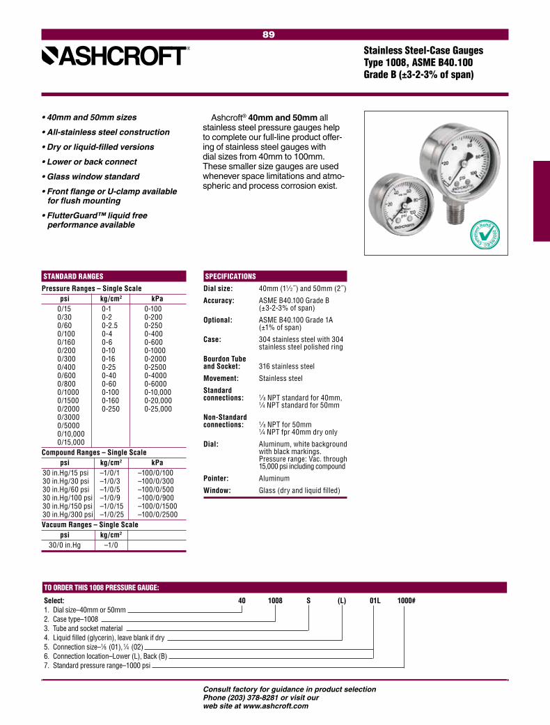
89
Consult factory for guidance in product selectionPhone (203) 378-8281 or visit our web site at www.ashcroft.com
STANDARD RANGES
Pressure Ranges – Single Scale psi kg/cm2 kPa 0/15 0-1 0-100 0/30 0-2 0-200 0/60 0-2.5 0-250 0/100 0-4 0-400 0/160 0-6 0-600 0/200 0-10 0-1000 0/300 0-16 0-2000 0/400 0-25 0-2500 0/600 0-40 0-4000 0/800 0-60 0-6000 0/1000 0-100 0-10,000 0/1500 0-160 0-20,000 0/2000 0-250 0-25,000 0/3000 0/5000 0/10,000 0/15,000Compound Ranges – Single Scale psi kg/cm2 kPa 30 in.Hg/15 psi –1/0/1 –100/0/100 30 in.Hg/30 psi –1/0/3 –100/0/300 30 in.Hg/60 psi –1/0/5 –100/0/500 30 in.Hg/100 psi –1/0/9 –100/0/900 30 in.Hg/150 psi –1/0/15 –100/0/1500 30 in.Hg/300 psi –1/0/25 –100/0/2500Vacuum Ranges – Single Scale psi kg/cm2
30/0 in.Hg –1/0
Stainless Steel-Case GaugesType 1008, ASME B40.100 Grade B (±3-2-3% of span)
SPECIFICATIONS
Dial size: 40mm (11⁄ 2˝ ) and 50mm (2˝)
Accuracy: ASME B40.100 Grade B (±3-2-3% of span)
Optional: ASME B40.100 Grade 1A (±1% of span)
Case: 304 stainless steel with 304 stainless steel polished ring
Bourdon Tube and Socket: 316 stainless steel
Movement: Stainless steel
Standard connections: 1⁄ 8 NPT standard for 40mm,
1⁄4 NPT standard for 50mm
Non-Standard connections: 1⁄ 8 NPT for 50mm
1⁄4 NPT fpr 40mm dry only
Dial: Aluminum, white background with black markings. Pressure range: Vac. through 15,000 psi including compound
Pointer: Aluminum
Window: Glass (dry and liquid filled)
TO ORDER THIS 1008 PRESSURE GAUGE:
Select: 40 1008 S (L) 01L 1000# 1. Dial size–40mm or 50mm2. Case type–10083. Tube and socket material4. Liquid filled (glycerin), leave blank if dry 5. Connection size–1⁄8 (01), 1⁄4 (02) 6. Connection location–Lower (L), Back (B)7. Standard pressure range–1000 psi
• 40mm and 50mm sizes
• All-stainless steel construction
• Dry or liquid-filled versions
• Lower or back connect
• Glass window standard
• Front flange or U-clamp available for flush mounting
• FlutterGuard™ liquid free performance available
Ashcroft® 40mm and 50mm all stainless steel pressure gauges help to complete our full-line product offer-ing of stainless steel gauges with dial sizes from 40mm to 100mm. These smaller size gauges are used whenever space limitations and atmo-spheric and process corrosion exist.

90
Consult factory for guidance in product selectionPhone (203) 378-8281 or visit our web site at www.ashcroft.com
BOURDON SYSTEM SELECTION(1)
Ordering Bourdon Tube Socket Tube Range Selection NPT Code & Tip Material(1) Material Type Limits (psi) Conn.(3)
S 316 stainless steel 316 stainless steel C-Tube Vac/800 1⁄8 , 1⁄4 & 1⁄2(2)
S 316 stainless steel 316 stainless steel Helical 1000/15,000 1⁄8 , 1⁄4 & 1⁄2(2)
DUAL-SCALE AMMONIA RANGES Compound in Hg/psi °F Outer Arc Vac/150 –40/84°F Vac/300 –40/125°F
(1) For selection of the correct Bourdon system material, see the media application table on page 265.(2) 1⁄2 NPT available 100mm lower only.(3) 1⁄4" JIS, BSP or DIN threads available on application.
TO ORDER THIS 1008 PRESSURE GAUGE:Select: 63 1008 S (L) 02L XXX 1000#1. Dial size–63mm or 100mm2. Case type–10083. Tube and socket material4. Liquid filled (glycerin), leave blank if dry5. Connection size–1⁄8 (01), 1⁄4 (02), 1⁄2 (04) 6. Connection location–Lower (L), Lower Back (B)7. Optional Features–see page 261-2628. Standard pressure range–1000 psi
STANDARD RANGES Single-Scale Dial Dual-Scale Dial
psi psi Inner Arc kPa Outer Arc
0/15 0/15 0/100 0/30 0/30 0/200 0/60 0/60 0/400 0/100 0/100 0/700 0/160 0/160 0/1100 0/200 0/200 0/1400 0/300 0/300 0/2000 0/400 0/400 0/2800 0/600 0/600 0/4000 0/1000 0/1000 0/7000 0/1500 0/1500 0/10,000 0/2000 0/2000 0/14,000 0/3000 0/3000 0/20,000 0/5000 0/5000 0/34,000 0/6000 0/6000 0/40,000 0/7500 0/7500 0/50,000 0/10,000 0/10,000 0/70,000 0/15,000 0/15,000 0/100,000 Vacuum in.Hg in.Hg Vacuum 30/0 30/0 –100/0 Comp. in.Hg/psi in.Hg/psi kPa 30/15 30/15 –100/100
30/30 30/30 –100/200 30/60 30/60 –100/400
30/100 30/100 –100/700 30/150 30/150 –100/1000
30/300 30/300 –100/2000
Stainless Steel-Case Gauge Type 1008S, 1.6% F.S.
• Patented PowerFlex™ movement isolates movement from shock and vibration for longer life
• All stainless, all-welded construc-tion for long life
• New PLUS!™ Performance Option:- Liquid-filled performance in a dry
gauge (option XLL)- Fights vibration and pulsations
without liquid-fill headaches• True Zero™ pointer indication – no
stop pin to mask false zero reading – ensures safety and process control
Available in 63mm and 100mm dials sizes, 1008S pressure gauges are field liquid fillable and field con-vertible for panel mounting. The gauge is available dry, liquid-filled weather-proof or hermetically sealed with PLUS!™ performance option.

91
Consult factory for guidance in product selectionPhone (203) 378-8281 or visit our web site at www.ashcroft.com
TO ORDER THIS 1008 PRESSURE GAUGE:Select: 63 1008 S (L) 02C 100#1. Dial size–63mm (63) or 100mm (10)2. Case type–10083. Tube and socket material–316 SS4. Liquid filled (glycerin), leave blank if dry5. Connection size– 1⁄4 (02)6. Connection location–Center Back (C)7. Pressure Range–0/100 psi
PRODUCT SPECIFICATIONS Ashcroft Type No.: 1008SSizes: 63mm, 100mmCase: 304SS Ring: 304SS crimpedWindow: PolycarbonateDial: Black figures on white background,
aluminumPointer: Black, aluminumBourdon Tube: 316 SS Bourdon tube and socket TIG
welded. Throttle plug standard for all liquid
gauges and dry gauges above 1000 psi.Socket: 316 SS, Buna-N O-ring sealMovement: Stainless steel, gear type.Mounting: Stem mounting or panel mounting with
U-Clamp or Front Flange. All gauges have rear weld nuts for U-clamp mounting.
Connections: 1⁄4 NPT center back Ranges: From Vac-10,000 psi and compoundAccuracy: ASME 3-2-3% grade B Fill Plug: Buna-N ventable designProtection: Nema 4X / IP65 plug sealed
Nema 3 / IP54 plug ventedAmbient Temperature: –40°F to 200°F dry
+20°F to 150°F glycerin filled(based on standard polycarbonate window)
OPTIONAL FEATURESLiquid fill: GlycerinMounting: - Flush panel mounting 3 hole flange - Panel mounting clamps - Retrofit kit for oversized panel holes.
Includes U-clamp and spacer flange.
Stainless Steel-Case Gauge Type 1008S/SL, ASME B40.100 Grade B (±3-2-3% of span) Center Back Design
• ASME 3-2-3% grade B accuracy• True Zero™ pointer indication – no
stop pin to mask false zero reading – ensures safety and process control
• RoHS compliant
Available in 63mm and 100mm dial sizes, 1008S/SL are center back connection pressure gauges, field liquid fillable and field convertible for panel mounting. ASME Grade B, 3-2-3% accuracy is standard. The gauge is available dry, liquid-filled weatherproof or hermetically sealed.option.
63 mm back connection
100 mm back connection
63 mm U-clamp 63 mm U-clampkit #101A164-01
63 mm retrofit kit 63 mm retrofit kit with spacerflange kit #101A140-06
63 mm front flange kit#101A140-03 push on flange
STANDARD RANGES psi 0/30 0/60 0/100 0/200 0/300 0/400 0/600 0/1000 0/2000 0/3000 0/5000
These ranges are in stock. Other ranges available on application up to 20,000 psi
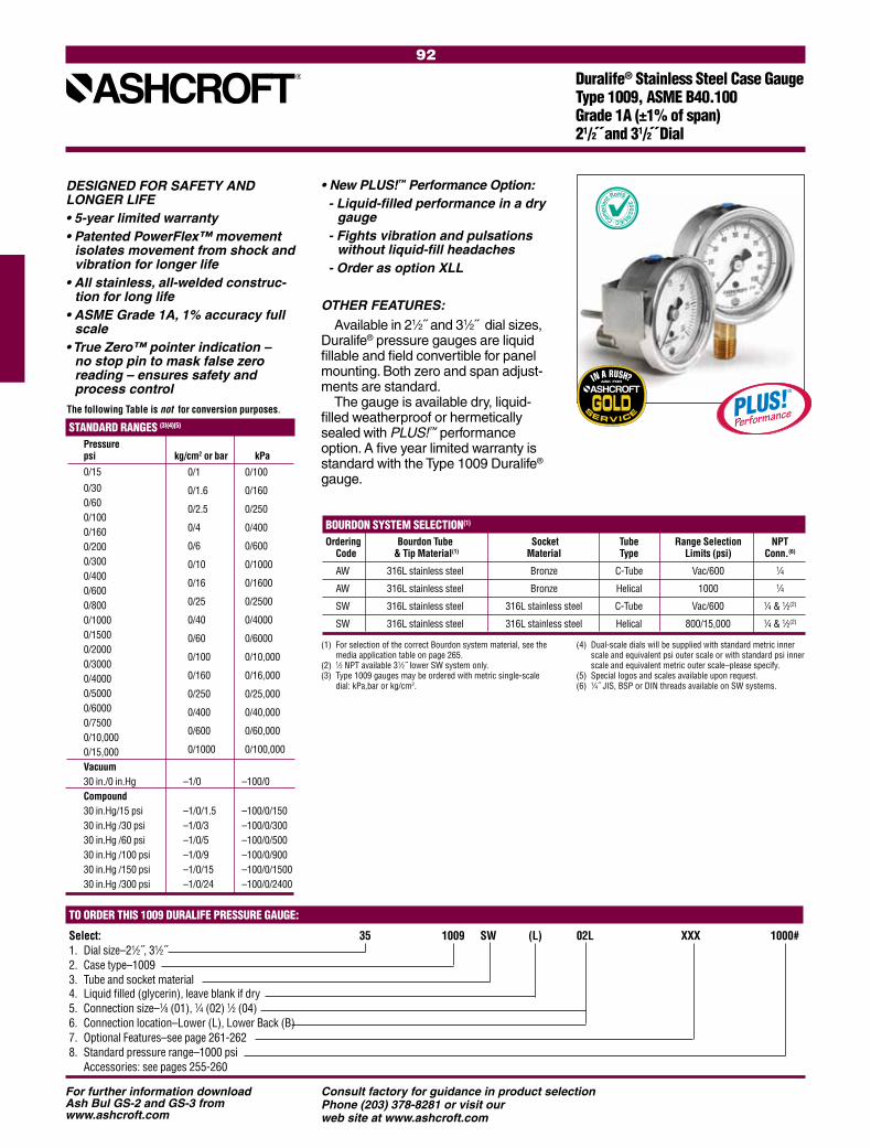
92
Consult factory for guidance in product selectionPhone (203) 378-8281 or visit our web site at www.ashcroft.com
STANDARD RANGES (3)(4)(5) Pressure psi kg/cm2 or bar kPa 0/15
0/30 0/60 0/100 0/160 0/200 0/300 0/400 0/600 0/800 0/1000 0/1500 0/2000 0/3000 0/4000 0/5000 0/6000 0/7500 0/10,000 0/15,000 Vacuum 30 in./0 in.Hg –1/0 –100/0 Compound 30 in.Hg/15 psi –1/0/1.5 –100/0/150 30 in.Hg /30 psi –1/0/3 –100/0/300 30 in.Hg /60 psi –1/0/5 –100/0/500 30 in.Hg /100 psi –1/0/9 –100/0/900 30 in.Hg /150 psi –1/0/15 –100/0/1500 30 in.Hg /300 psi –1/0/24 –100/0/2400
BOURDON SYSTEM SELECTION(1)
Ordering Bourdon Tube Socket Tube Range Selection NPT Code & Tip Material(1) Material Type Limits (psi) Conn.(6)
AW 316L stainless steel Bronze C-Tube Vac/600 1⁄4
AW 316L stainless steel Bronze Helical 1000 1⁄4
SW 316L stainless steel 316L stainless steel C-Tube Vac/600 1⁄4 & 1⁄2(2)
SW 316L stainless steel 316L stainless steel Helical 800/15,000 1⁄4 & 1⁄2(2)
(1) For selection of the correct Bourdon system material, see the media application table on page 265.
(2) 1⁄2 NPT available 31⁄2˝ lower SW system only.(3) Type 1009 gauges may be ordered with metric single-scale
dial: kPa,bar or kg/cm2.
(4) Dual-scale dials will be supplied with standard metric inner scale and equivalent psi outer scale or with standard psi inner scale and equivalent metric outer scale–please specify.
(5) Special logos and scales available upon request.(6) 1⁄4˝ JIS, BSP or DIN threads available on SW systems.
TO ORDER THIS 1009 DURALIFE PRESSURE GAUGE:
Select: 35 1009 SW (L) 02L XXX 1000#1. Dial size–21⁄2˝, 31⁄2˝2. Case type–10093. Tube and socket material4. Liquid filled (glycerin), leave blank if dry5. Connection size–1⁄8 (01), 1⁄4 (02) 1⁄2 (04) 6. Connection location–Lower (L), Lower Back (B)7. Optional Features–see page 261-262 8. Standard pressure range–1000 psi Accessories: see pages 255-260
0/1 0/100
0/1.6 0/160
0/2.5 0/250
0/4 0/400
0/6 0/600
0/10 0/1000
0/16 0/1600
0/25 0/2500
0/40 0/4000
0/60 0/6000
0/100 0/10,000
0/160 0/16,000
0/250 0/25,000
0/400 0/40,000
0/600 0/60,000
0/1000 0/100,000
The following Table is not for conversion purposes.
DESIGNED FOR SAFETY AND LONGER LIFE• 5-year limited warranty• Patented PowerFlex™ movement
isolates movement from shock and vibration for longer life
• All stainless, all-welded construc-tion for long life
• ASME Grade 1A, 1% accuracy full scale
• True Zero™ pointer indication – no stop pin to mask false zero reading – ensures safety and process control
• New PLUS!™ Performance Option:- Liquid-filled performance in a dry
gauge- Fights vibration and pulsations
without liquid-fill headaches- Order as option XLL
OTHER FEATURES:
Available in 21⁄2˝ and 31⁄2˝ dial sizes, Duralife® pressure gauges are liquid fillable and field convertible for panel mounting. Both zero and span adjust-ments are standard.
The gauge is available dry, liquid- filled weatherproof or hermetically sealed with PLUS!™ performance option. A five year limited warranty is standard with the Type 1009 Duralife® gauge.
Duralife® Stainless Steel Case Gauge Type 1009, ASME B40.100 Grade 1A (±1% of span)21/2˝ and 31/2˝ Dial
For further information download Ash Bul GS-2 and GS-3 from www.ashcroft.com

93
Consult factory for guidance in product selectionPhone (203) 378-8281 or visit our web site at www.ashcroft.com
STANDARD RANGES (4) Pressure psi kg/cm2 - bar kPa 0/15 0/30 0/60 0/100 0/160 0/200 0/300 0/400 0/600 0/800 0/1000 0/1500 0/2000 0/3000 0/4000 0/5000 0/6000 0/7500 0/10,000 0/15,000 0/20,000 0/30,000 Vacuum 30 in. /0 in.Hg –1/0 –100/0 Compound 30 in.Hg/15 psi –1/0/1.5 –100/0/150 30 in.Hg /30 psi –1/0/3 –100/0/300 30 in.Hg /60 psi –1/0/5 –100/0/500 30 in.Hg/100 psi –1/0/9 –100/0/900 30 in.Hg /150 psi –1/0/15 –100/0/1500 30 in.Hg/300 psi –1/0/24 –100/0/2400
The 41⁄2˝ and 6˝ Ashcroft® Type 1009 gauges are suitable where ambient corrosion is a major con-cern. Its stainless steel case and ring offer good appearance and excellent resistance to chemical, weather and corrosion attack. This 1009 has many optional features that allow a user to develop a basic or special product specification. The 1009 is part of the extensive line of Ashcroft stainless steel pressure gauges.
The gauge is available dry, liquid- filled weatherproof or hermetically sealed and now with PLUS!™ perfor-mance option.
• 41⁄2˝ and 6˝ stainless steel gauges
• Dry and liquid-filled versions
• Micrometer adjustable pointer
• Variety of Bourdon tube materials
• ASME Grade 1A, ±1% of span accuracy
• New PLUS!™ Performance Option:- Liquid-filled performance in a dry
gauge
TO ORDER THIS 1009 DURALIFE PRESSURE GAUGE:
Select: 45 1009 S 02L XXX 1000# 1. Dial size–41⁄2˝, 6˝2. Case type –10093. Tube and socket material4. Connection size–1⁄4 (02), 1⁄2 (04) 5. Connection location–Lower (L), Back (B)6. Optional features–see page 261-2627. Standard pressure range–1000 psi Accessories–see pages 255-260
Stainless Steel Case Gauge Type 1009, ASME B40.100 Grade 1A (±1% of span)41/2˝ and 6˝ Dial
0/1 0/100
0/1.6 0/160
0/2.5 0/250
0/4 0/400
0/6 0/600
0/10 0/1000
0/16 0/1600
0/25 0/2500
0/40 0/4000
0/60 0/6000
0/100 0/10,000
0/160 0/16,000
0/250 0/25,000
0/400 0/40,000
0/600 0/60,000
0/1000 0/100,000
0/1600 0/160,000
The following Table is not for conversion purposes.
BOURDON SYSTEM SELECTION(1)
Ordering Bourdon Tube & Tip Socket Tube Range Selection NPT Code Material(1) (all joints TIG Material Type Limits (psi) Conn.(2)
welded except “A”)
A Phosphor Bronze
Brass C-Tube 12/1000 1⁄4 Brass Tip, Silver Brazed
S 316 stainless steel 316 stainless steel
C-Tube 12/1500 1⁄4
Helical 2000/20,000 1⁄2
P(3)(5) K Monel Monel 400
C-Tube 15/1500 1⁄4
Helical 2000/30,000(6) 1⁄2
(1) For selection of the correct Bourdon system material, see the media application table on page 265.(2) Optional connections available: 1⁄2 NPT where 1⁄4 NPT is standard, 1⁄4 NPT where 1⁄2 NPT is standard.
(3) Use for applications where NACE Standard MR-01-75 is specified.(4) Single-scale and dual-scale ranges available . (5) 6˝ dial not available with monel or steel systems.(6) High pressure AMINCO connection only (09 code)
- Fights vibration and pulsations without liquid-fill headaches
- Order as option XLL

94
Consult factory for guidance in product selectionPhone (203) 378-8281 or visit our web site at www.ashcroft.com
• Solid front case design with full blowout back
• Temperature compensated case• 41/2˝ dial size• ASME B40.100 Grade 1A, (±1% of
span) accuracy• 300 Series SS case and ring• Ranges from vacuum through
100,000 psi• New PLUS!™ Performance Option:- Liquid-filled performance in a dry
gauge- Fights vibration and pulsations
without liquid-fill headaches- Order as option XLL
The Type 1109 Ashcroft® solid front stainless steel case offers many fea-tures not available elsewhere. With a true 41/2˝ dial size, a fully temperature compensated case and blowout back for safety, the Type 1109 offers superior readability compared to the competitive 100mm case gauges. The Type 1109 has been designed to meet the needs of both the offshore platform market and also the waterblaster or waterjet markets.
For offshore platforms the Type 1109 is available dry, liquid-filled(3) or with the revolutionary PLUS!™ performance option. The rugged design of the Type 1109 with ranges to 100,000 psi, is well suited to meet the needs of the waterblaster or waterjet market. With the PLUS!™ performance standard on ranges above 30,000 psi this gauge offers superior readability and elimi-nates the headaches often associated with liquid-filled gauges.
Stainless Steel Case Gauge Type 1109, ASME B40.100 Grade 1A (±1% of span) Solid Front
BOURDON SYSTEM SELECTION(1)
Ordering Bourdon Tube Socket Tube Range Selection NPT Code & Tip Material(1) Material Type Limits (psi) Conn.
SD
316 stainless steel 316 stainless steel C-Tube Vac/1500 1⁄2 (2)
316 stainless steel 316 stainless steel Helical 2k-20k 1⁄2 (2)
WD Inconel 718 316 stainless steel Helical 50k-100k 1⁄4 high pressure
(1) For selection of the correct Bourdon system material, see the media application table on page 265.(2) 1⁄4 NPT optional, lower connection only.(3) Liquid fill available on ranges 20,000 psi and below.
TO ORDER THIS 1009 DURALIFE PRESSURE GAUGE:
Select: 45 1109 SD 04L XXX 0/100#1. Dial size–41⁄2˝2. Case type–11093. Bourdon system selection ordering code4. Connection–1⁄4 (02), 1⁄2 (04), 1⁄4 high pressure (09), Lower (L)5. Optional Features–see page 261-262 6. Standard pressure range 7. Accessories–see pages 255-260
STANDARD RANGES Pressure psi 0/15 0/30 0/60 0/100 0/160 0/200 0/300 0/400 0/600 0/800 0/1000 0/1500 0/2000 0/3000 0/5000 0/10,000 0/20,000 0/30,000 0/50,000 0/80,000 0/100,000
Compound psi 30 in.Hg/15 psi 30 in.Hg /30 psi 30 in.Hg /60 psi 30 in.Hg /100 psi 30 in.Hg /150 psi 30 in.Hg /300 psi
NOTE:Equivalent standard kg/cm2, and kPa metric ranges are available.

95
Consult factory for guidance in product selectionPhone (203) 378-8281 or visit our web site at www.ashcroft.com
Gauge Type Dial Size Connection Mounting Method Number (Inches) Location
1009-XS4TS 41⁄2˝, 6˝ Lower/Back Stem, Surface, Flush –
1010-XS4TS 41⁄2˝-12˝ Lower/Back Stem, Surface –
1017-XS4TS 41⁄2˝, 6˝ Lower/Back Flush Back Flange, Flush 1220-XS4TS 41⁄2˝-81⁄2˝ Lower/Back Stem Mounting Ring
Hydraulic Gauges, Types 1009, 1010, 1017 & 1220, ASME B40.100 Grade 1A (±1% of span)
• 41⁄2˝ through 12˝ dials available
• Stainless steel, aluminum and phenolic case materials
• Wide range of types to combine specifics and price
• Slotted link and throttle screw standard
The Ashcroft® line of pressure gauges offers a product that is uniquely designed for rigorous hydraulic services.
Hydraulic gauges are supplied with a slotted link movement to avoid gear wear. All models are supplied with throttle devices as standard.
Type 1009
Select: 45 1009 S 02L XS4TS 1000#1. Dial size– 41⁄2˝, 6˝2. Case code: 10103. Tube and socket material, (see chart above)4. Connection size–1⁄4 (02), 1⁄2 (04)5. Connection location–Lower (L), Back (B)6. Options–see page 261-2627. Standard pressure range–1000 psi
Range Figure Minor psi Interval Graduation
0/1000 100 10 0/1500 200 20 0/2000 200 20 0/3000 500 50 0/5000 1000 50 0/6000 1000 100 0/7500 1000 100 0/10,000 1000 100 0/15,000 2000 200 0/20,000 2000 200
STANDARD psi RANGES(4)
Note: Dual-scale dials showing psi and tons on ram are available on application
Range Dial Graduations
kg/cm2 Figure Minor kilograms per bar Interval Graduation sq. cm.
0/60 0/60 5 1 0/100 0/100 10 1 0/160 0/160 20 2 0/250 0/250 50 5 0/400 0/400 50 5 0/600 0/600 50 10 0/1000 0/1000 100 10 0/1600 0/1600 200 20
Range Dial Graduation Outer scale when dual kPa Figure Minor range specified (kilopascal) Interval Graduation psi
0/6000 500 100 0/850 0/10,000 1000 100 0/1400 0/16,000 2000 200 0/2200 0/25,000 5000 500 0/3500 0/40,000 5000 500 0/5500 0/60,000 5000 1000 0/8500 0/100,000 10,000 1000 0/14,000 0/160,000 20,000 2000 0/22,000
STANDARD METRIC RANGES(4)
HOW TO ORDER THESE HYDRAULIC GAUGES:
BOURDON SYSTEM SELECTION
Dial Bourdon Tube & Tip Size Order Material(1) (all joints TIG Socket Tube Range Selection NPT (Inches) Code welded except “A”)(1) Material Type Limits (psi) Conn.(2)
41/2˝, 6˝, A
Phosphor Bronze Brass C-Tube 12/1000 1⁄4 81/2˝ Tube-Brass Tip, Silver Brazed
41/2˝, 6˝, S 316 stainless steel 316 stainless C-Tube 12/1500 1⁄4 81/2˝, 12˝ steel Helical 2000/20,000 1⁄2
41/2˝, 12˝ P(3) K Monel Monel 400 C-Tube 15/1500 1⁄4
Helical 2000/30,000 1⁄2
(1) For selection of the correct Bourdon system material, see the media application table on page 265.(2) Optional connections available: 1⁄2 NPT where 1⁄4 NPT is standard, 1⁄4 NPT where 1⁄2 NPT is standard.
(3) Use for applications where NACE standard MR-01-75 is specified.(4) Single-scale and dual-scale ranges available.
SPECIFICATIONS

96
Consult factory for guidance in product selectionPhone (203) 378-8281 or visit our web site at www.ashcroft.com
• 41⁄2˝ through 12˝
• Many case styles to choose from
• Panel mount, stem mount and wall mount
• Bronze systems standard (1)
• Open-front case style
• 3-15 psi input with optional 3-27 psi input (1) Stainless Steel (S); Monel (P) optional
Receiver Gauges, Types 1009, 1010, 1017 & 1220, ASME B40.100 Grade 1A (±1% of span)
TO ORDER THESE RECEIVER GAUGES:
Select: 45 1009 A 02 L XPR 3-15#1. Dial size2. Case type 3. Tube and socket material4. Connection size, 1⁄4 (02), 1⁄2 (04)5. Connection location, (L-Lower), (B-Back)6. Optional features (XPR always appears in code for receiver gauge) 7. Range of transmitted signal (also specify the scale to be shown on the dial face)
Type 1009
Ashcroft® receiver gauges are used in conjunction with pneumatic trans-mitters to indicate pressure, tempera-ture, flow or other process parameters that can be transmitted by proportional variations in air pressure.
1009A-XPR Case Phosphor ASME 1010A-XPR 41⁄2˝-12˝
Aluminum, black epoxy with bronze 3/15 Rotary geared, B 40.1 1017A-XPR Steel slip, black epoxy, Bourdon tube and Black, stainless steel 1⁄4 Grade1A 1220A-XPR stainless steel, phenolic, brass socket, 3/27 adjustable pinion and (±1% of span) depending on case type silver brazed segment shaft
Gauge Type Dial Sizes(1) Case/ring System Pressure Pointer Movement Npt Accuracy Number Material Assembly Range-psi Conn.
STANDARD RANGES(1)
0-10 sq rt/0-100 linear dual-scale0-10 square root0-100 linear
(1) Other ranges on request.
(1) Not all dial sizes available in all case types. Type 1009 – 41⁄2˝, 6˝; Type 1010 – 41⁄2˝-12˝; Type 1017 – 41⁄2˝, 6˝; Type 1220 – 41⁄2˝-81⁄2˝
SPECIFICATIONS
(1) Not all dial sizes available in all case types. Type 1009 – 41⁄2˝, 6˝; Type 1010 – 41⁄2˝-12˝; Type 1017 – 41⁄2˝, 6˝; Type 1220 – 41⁄2˝-81⁄2˝
Gauge Type Dial Size(1) Connection Mounting Method Number (Inches) Location
1009-XPR Lower/Back Stem, Surface, Flush –
1010-XPR Lower/Back Stem, Surface –
1017-XPR 41/2, 6, 81/2, 12
Lower/Back Flush Back Flange, Flush 1220-XPR Lower/Back Stem Mounting Ring

97
Consult factory for guidance in product selectionPhone (203) 378-8281 or visit our web site at www.ashcroft.com
Select: 45 1010 A 02L XR5 30 in.Hg Vac/150#1. Dial size–41⁄2˝, 6˝2. Case Type–10103. Tube and socket material–A, S4. Connection size–1⁄4 (02), 1⁄2 (04)5. Connection location–Lower (L), Back (B)6. Optional features including refrigerant (see page 261-262)7. Standard pressure range–30˝HgVac/150 psi Accessories–see pages 255-260
(1) Not all dial sizes available in all case types. Type 1009 – 41⁄2˝, 6˝; Type 1010 – 41⁄2˝-12˝; Type 1017 – 41⁄2˝, 6˝; Type 1220 – 41⁄2˝-81⁄2˝
Refrigeration & Ammonia Gauges Types 1009/1010/1017/1220 ASME B40.100 Grade 1A (±1% of span)
Ashcroft® refrigeration and ammo-nia gauges are used to display pres-sure and temperature when measur-ing various sealed refrigeration sys-tems. This dual-scale dial gauge has an inner pressure scale with black numerals and an outer temperature scale with red numerals. A selection of models exists to meet specifica-tion and price parameters.
• 41⁄2˝ through 12˝ dials
• Stainless steel, phenolic and aluminum case materials
• Dual-scale dials with pressure and temperature indication
• Wide range of refrigerant scales, including refrigerant 134A and ammonia
Type 1010
Gauge(1) Refrigerant Dial Size Case & Ring Bourdon Tube & Socket Range Pointer Movement NPT Type Number (inches) Material Finish Tip Material Material Connection
1010333A-XR1 R-11 41⁄2˝, 12˝ Case: Aluminum Phosphor Brass 30 in.HgVac/ Black Stainless Steel 1⁄4 1010333A-XR2 R-12 Black Epoxy Bronze 150 psi adjustable with Teflon (1⁄2 optional) 1033310A-XR3 R-22 Coated Tip: Brass or coated pinion 1010333A-XR4 R-502 Stainless Steel or (all joints 30 in.HgVac/ and segment 1013330A-XR6 R-114 Phenolic, depending silver brazed) 300 psi shaft, rotary 1013330A-XR7 R-500 on Case Type geared 1013330A-XR8 R-134A 1013330A-XR9 R-123 1010XR5 Ammonia 41⁄2˝, 12˝ Case: Aluminum 316 30 in.HgVac/ Black Stainless Steel 1⁄4 Black Epoxy Coated stainless steel 316 150 psi adjustable with Teflon (1⁄2 optional) Stainless Steel or (all joints stainless steel or coated pinion Phenolic, depending TIG welded) 30 in.HgVac/ and segment on Case Type 300 psi shaft, rotary geared
CASE STYLES
1009101010171220
RANGE DIAL GRADUATIONS RANGE DIAL GRADUATIONS
kg/cm2 bar Figure Minor kPa Figure Minor Interval Graduation (kilopascal) Interval Graduation –1/9 –1/9 1 0.1 –100/900 100 10 –1/24 –1/24 2 0.2 –100/2400 500 20
STANDARD METRIC RANGES
Figure Minor Range Interval Graduation Inches psi Inches psi Mercury Mercury
30˝HgVac/150 psi 10 25 2 5 30˝HgVac/300 psi 30 25 5 5
STANDARD RANGES
TO ORDER THESE REFRIGERATION GAUGES:
Gauge Type Dial Size(1) Connection Mounting Method Number (Inches) Location
Lower/Back Stem —
41⁄2, 6, 81⁄2, 12 Lower Surface Back Flange
Back Surface or Flush Back Flange, Flush Mounting Ring
SPECIFICATIONS
1009
1010
1017
1220
(1) Not all dial sizes available in all case types. Type 1009 – 41⁄2˝, 6˝; Type 1010 – 41⁄2˝-12˝; Type 1017 – 41⁄2˝, 6˝; Type 1220 – 41⁄2˝-81⁄2˝

98
Consult factory for guidance in product selectionPhone (203) 378-8281 or visit our web site at www.ashcroft.com
PRODUCT SPECIFICATIONSType: 2074 (battery)
2174 (loop), 2274 (line)
Accuracy: ±.25% of span, terminal point Case Size: 3˝, 41⁄2˝Case Material: 3˝ SS, 41⁄2˝ fiberglass reinforced
thermoplastic or black epoxy coated aluminum
Case Encl. Rating: Weatherproof, IP65Wetted Materials: 17-4 SS (sensor), 316SS (socket)Socket Size: 1⁄4 or 1⁄2 NPT, JIS, DIN, SAE, (1⁄2
NPT only with 41⁄2˝ case, others on application)
Socket Location: Lower, 3, 9 and 12 o’clockRanges: Vac. thru 20,000 psi (see engineer-
ing units below for other units) Operating Temp.: 14/140°F (10/60°C)Temp. Error: (Zero & Span) .04%/°F
(<.02%°F Typical)Storage Temp.: –4/158° (–20°/70°F) DISPLAYType: LCDDisplay Digits: Five (5)Character Height: 3˝ case: .60˝, 41⁄2˝ case: .88˝ Backlite: OptionalBar Graph: YesBattery Life: 3˝ >1000 hrs., 41⁄2˝ >3600 hrs.Agency Approvals: CE, FM (Intrinsically Safe Class I,
Div 1), CSA and CENELEC)
KEYPAD FUNCTIONSOn/Off: Manually turns unit on and off (auto
off options in menu)Zero/Clear: Zeros display or clears min. and
max. values when displayedMin/Max (down) Stores min and max values, arrow Arrow Key: key allows for scrolling thru menu
items Menu Key: Provides access to menu optionsBacklite (up) Manually turns backlite on and off Arrow Key: (auto off options in menu), arrow (Backlite optional) key allows for five menu options.
(up) arrow key allows for scroll-ing thru menu options
Enter: Selects items in the menu
MENU MODEEngineering Units: 10 units of measurement are avail-
able; psi, In. H2O (with three temp. options: 20°C, 60°F, 4°C*), Ft. H2O, mPa, mBar, kPa, kg/cm2, Bar, inHg and mmHg
Configuration Mode: Allows for changes to default set-tings of gauge
(Config): Including zero disable feaureBar Graph (Graph): Allows for adjustment of bargraph
and 4-20 (optional feature)Auto Off (Off): Allows for changes to auto off of
gauge, five options: Never, 2 min., 5 min., 15 min., 30 min.
Update Rate Four options: 100 ms, 200 ms, (Update): 500 ms, 1 secDampening Six options: None, average, 2, 4, 6, (Damp): 8 times per 100msBacklite: Five options: Never, 10 sec., 30
sec., 1 min., 5 min.Field Recalibration: Allows for recalibration of zero,
midscale and span (password protected)
• A Multi-Functional Digital Gauge with Optional: - 4/20mA Output - (1) or (2) SPDT Switches
• ±.25% of Span Terminal Point Accuracy (.13% BFSL)
• IP 65 Weatherproof Case
• Three Case Options: Stainless Steel, Fiberglass Reinforced Thermoplastic or Aluminum
• Extra Large Display
• Intrinsically Safe, Class I, Div. 1, pending
• Easy-to-Use Menu Options: (all password protected) - Five Backlite Display Options - Twelve Engineering Units - Menu Configure Feature - Update Rate - Dampen Rate - Auto-Off
Digital Industrial Gauge Types 2074, 2174 and 2274ASME B40.100 Grade 3A (±0.25% of span)
TO ORDER THIS DIGITAL INDUSTRIAL GAUGE:
Select: 30 2074 SD XXX* 100# 1. Dial Size: 3˝2. Type: 2074 3. Wetted parts: 316 SS 4. Connections: 1/4 NPT Lower5. Range: 100 psi
OPTIONS Description Code Case SizeCase Options Aluminum Case (black epoxy coated) AY 41⁄2˝ only (Glass reinforced thermoplastic case standard)Electropolished Case EC 3˝ only (Brushed SS case standard)
Switch Options(1) SPDT Switch (12-36Vdc) U1 3˝, 4 1⁄2˝ (2) SPDT Switch (12-36Vdc) U2 3˝, 4 1⁄2˝ Line Power with 4-20mA output AO 3˝, 4 1⁄2˝ (Line power (Type 2274) required for switching options.) (Terminal blocks standard with 4 1⁄2˝ case.) (Shielded cable standard with 3˝ case.)
Wiring Options Shielded cable (Terminal blocks standard EN 4 1⁄2˝ with 41⁄2˝ case.) Shielded cable standard with 3˝ case.
Keypad Options Backlite BL 3˝, 4 1⁄2˝
Miscellaneous Options Battery Backup BK 3˝, 4 1⁄2˝ (Battery standard with Type 2074) (Available with Types 2174 & 2274) Weatherproof ABS Gauge Carrying Case S7 3˝ onlyProtective Rubber Boot (black) B1 3˝ onlyProtective Rubber Boot (orange) B2 3˝ onlyProtective Front Cover PP 3˝ only
*See options chart
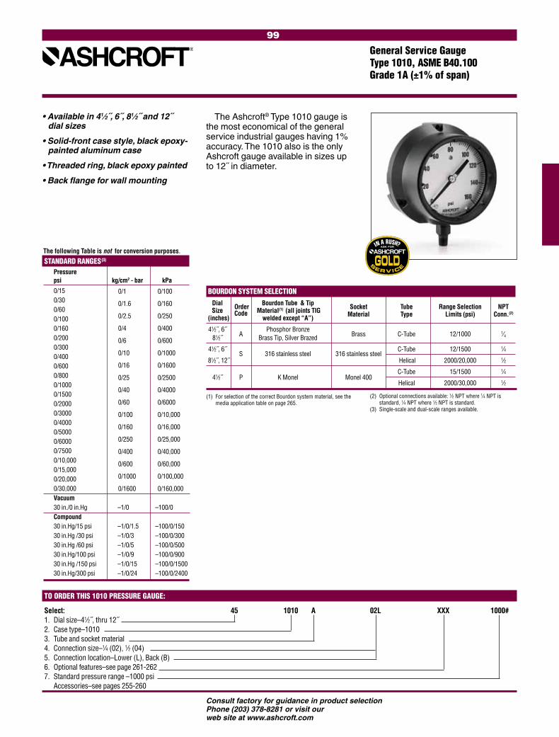
99
Consult factory for guidance in product selectionPhone (203) 378-8281 or visit our web site at www.ashcroft.com
General Service Gauge Type 1010, ASME B40.100 Grade 1A (±1% of span)
The Ashcroft® Type 1010 gauge is the most economical of the general service industrial gauges having 1% accuracy. The 1010 also is the only Ashcroft gauge available in sizes up to 12˝ in diameter.
• Available in 41⁄2˝, 6˝, 81⁄2˝ and 12˝ dial sizes
• Solid-front case style, black epoxy-painted aluminum case
• Threaded ring, black epoxy painted
• Back flange for wall mounting
STANDARD RANGES(3) Pressure psi kg/cm2 - bar kPa 0/15 0/30 0/60 0/100 0/160 0/200 0/300 0/400 0/600 0/800 0/1000 0/1500 0/2000 0/3000 0/4000 0/5000 0/6000 0/7500 0/10,000 0/15,000 0/20,000 0/30,000 Vacuum 30 in./0 in.Hg –1/0 –100/0 Compound 30 in.Hg/15 psi –1/0/1.5 –100/0/150 30 in.Hg /30 psi –1/0/3 –100/0/300 30 in.Hg /60 psi –1/0/5 –100/0/500 30 in.Hg/100 psi –1/0/9 –100/0/900 30 in.Hg /150 psi –1/0/15 –100/0/1500 30 in.Hg/300 psi –1/0/24 –100/0/2400
0/1 0/100
0/1.6 0/160
0/2.5 0/250
0/4 0/400
0/6 0/600
0/10 0/1000
0/16 0/1600
0/25 0/2500
0/40 0/4000
0/60 0/6000
0/100 0/10,000
0/160 0/16,000
0/250 0/25,000
0/400 0/40,000
0/600 0/60,000
0/1000 0/100,000
0/1600 0/160,000
The following Table is not for conversion purposes.
Select: 45 1010 A 02L XXX 1000# 1. Dial size –41⁄2˝, thru 12˝2. Case type–10103. Tube and socket material4. Connection size –1⁄4 (02), 1⁄2 (04) 5. Connection location–Lower (L), Back (B)6. Optional features–see page 261-262 7. Standard pressure range –1000 psi Accessories–see pages 255-260
(1) For selection of the correct Bourdon system material, see the media application table on page 265.
(2) Optional connections available: 1⁄2 NPT where 1⁄4 NPT is standard, 1⁄4 NPT where 1⁄2 NPT is standard.(3) Single-scale and dual-scale ranges available.
BOURDON SYSTEM SELECTION Dial Order Bourdon Tube & Tip Socket Tube Range Selection NPT Size Code Material(1) (all joints TIG Material Type Limits (psi) Conn.(2) (inches) welded except “A”) 41⁄2˝, 6˝
A Phosphor Bronze
Brass C-Tube 12/1000 1⁄4 81⁄2˝ Brass Tip, Silver Brazed
41⁄2˝, 6˝ S 316 stainless steel 316 stainless steel
C-Tube 12/1500 1⁄4
81⁄2˝, 12˝ Helical 2000/20,000 1⁄2
41⁄2˝ P K Monel Monel 400 C-Tube 15/1500 1⁄4
Helical 2000/30,000 1⁄2
TO ORDER THIS 1010 PRESSURE GAUGE:

100
Consult factory for guidance in product selectionPhone (203) 378-8281 or visit our web site at www.ashcroft.com
STANDARD RANGES(3) Pressure psi kg/cm2 - bar kPa 0/15 0/30 0/60 0/100 0/160 0/200 0/300 0/400 0/600 0/800 0/1000 0/1500 0/2000 0/3000 0/4000 0/5000 0/6000 0/7500 0/10,000 0/15,000 0/20,000 Vacuum 30 in./0 in.Hg –1/0 –100/0 Compound 30 in.Hg/15 psi –1/0/1.5 –100/0/150 30 in.Hg /30 psi –1/0/3 –100/0/300 30 in.Hg /60 psi –1/0/5 –100/0/500 30 in.Hg/100 psi –1/0/9 –100/0/900 30 in.Hg /150 psi –1/0/15 –100/0/1500 30 in.Hg/300 psi –1/0/24 –100/0/2400
The Ashcroft® Type 1017 gauge is the most economical of the general service gauges when flush panel-mounting is required.
• Available in 41⁄2˝ and 6˝ dial sizes
• Solid-front case style, black epoxy- painted aluminum case
• Hinged-steel black enamel texture finish panel ring
(1) For selection of the correct Bourdon system material, see the media application table on page 265.
(2) Optional connections available: 1⁄2 NPT where 1⁄4 NPT is standard, 1⁄4 NPT where 1⁄2 NPT is standard.
(3) Single-scale and dual-scale ranges available. (4) 6˝ dial not available with monel system.
BOURDON SYSTEM SELECTION Ordering Bourdon Tube & Tip Socket Range Selection NPT Code Material(1) (all joints TIG Material Tube Type Conn.(2) Conn.(2) welded except “A”)
A Phosphor Bronze
Brass C-Tube 12/1000 1⁄4 Brass Tip, Silver Brazed
S 316 stainless steel 316 stainless steel
C-Tube 12/1500 1⁄4
Helical 2000/20,000 1⁄2
P(4) K Monel Monel 400
C-Tube 15/1500 1⁄4
Helical 2000/30,000 1⁄2
General Service Gauge Type 1017, ASME B40.100 Grade 1A (±1% of span)
0/1 0/100
0/1.6 0/160
0/2.5 0/250
0/4 0/400
0/6 0/600
0/10 0/1000
0/16 0/1600
0/25 0/2500
0/40 0/4000
0/60 0/6000
0/100 0/10,000
0/160 0/16,000
0/250 0/25,000
0/400 0/40,000
0/600 0/60,000
0/1000 0/100,000
The following Table is not for conversion purposes.
Select: 45 1017 A 02B XXX 1000# 1. Dial size –41⁄2˝, 6˝2. Case type–10173. Tube and socket material4. Connection size –1⁄4 (02), 1⁄2 (04) 5. Connection location–Back (B) only6. Optional features–see page 261-262 7. Standard pressure range –1000 psi Accessories–see pages 255-260
TO ORDER THIS 1017 PRESSURE GAUGE:
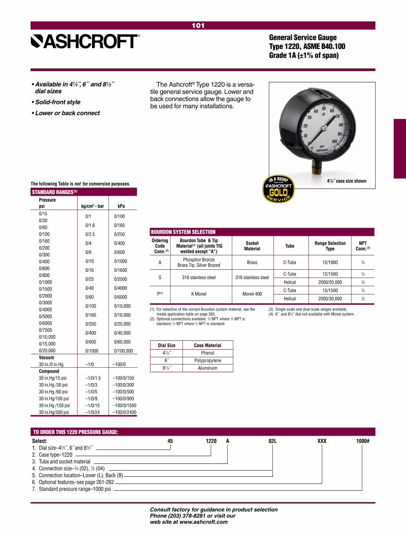
101
Consult factory for guidance in product selectionPhone (203) 378-8281 or visit our web site at www.ashcroft.com
STANDARD RANGES(3) Pressure psi kg/cm2 - bar kPa 0/15 0/30 0/60 0/100 0/160 0/200 0/300 0/400 0/600 0/800 0/1000 0/1500 0/2000 0/3000 0/4000 0/5000 0/6000 0/7500 0/10,000 0/15,000 0/20,000 Vacuum 30 in./0 in.Hg –1/0 –100/0 Compound 30 in.Hg/15 psi –1/0/1.5 –100/0/150 30 in.Hg /30 psi –1/0/3 –100/0/300 30 in.Hg /60 psi –1/0/5 –100/0/500 30 in.Hg/100 psi –1/0/9 –100/0/900 30 in.Hg /150 psi –1/0/15 –100/0/1500 30 in.Hg/300 psi –1/0/24 –100/0/2400
The Ashcroft® Type 1220 is a versa-tile general service gauge. Lower and back connections allow the gauge to be used for many installations.
• Available in 41⁄2˝, 6˝ and 81⁄2˝ dial sizes
• Solid-front style
• Lower or back connect
General Service Gauge Type 1220, ASME B40.100 Grade 1A (±1% of span)
TO ORDER THIS 1220 PRESSURE GAUGE:
Select: 45 1220 A 02L XXX 1000# 1. Dial size–41⁄2˝, 6˝ and 81⁄2˝2. Case type–12203. Tube and socket material4. Connection size–1⁄4 (02), 1⁄2 (04) 5. Connection location–Lower (L), Back (B)6. Optional features–see page 261-262 7. Standard pressure range–1000 psi
0/1 0/100
0/1.6 0/160
0/2.5 0/250
0/4 0/400
0/6 0/600
0/10 0/1000
0/16 0/1600
0/25 0/2500
0/40 0/4000
0/60 0/6000
0/100 0/10,000
0/160 0/16,000
0/250 0/25,000
0/400 0/40,000
0/600 0/60,000
0/1000 0/100,000
The following Table is not for conversion purposes.
(1) For selection of the correct Bourdon system material, see the media application table on page 265.
(2) Optional connections available: 1⁄2 NPT where 1⁄4 NPT is standard, 1⁄4 NPT where 1⁄2 NPT is standard.
(3) Single-scale and dual-scale ranges available. (4) 6˝ and 81⁄2˝ dial not available with Monel system.
BOURDON SYSTEM SELECTION Ordering Bourdon Tube & Tip Socket Range Selection NPT Code Material(1) (all joints TIG Material Tube Type Conn.(2) Conn.(2) welded except “A”)
A Phosphor Bronze
Brass C-Tube 12/1000 1⁄4 Brass Tip, Silver Brazed
S 316 stainless steel 316 stainless steel
C-Tube 12/1500 1⁄4
Helical 2000/20,000 1⁄2
P(4) K Monel Monel 400
C-Tube 15/1500 1⁄4
Helical 2000/30,000 1⁄2
Dial Size Case Material
41/2˝ Phenol
6˝ Polypropylene
81/2˝ Aluminum
41/2˝ case size shown

102
Consult factory for guidance in product selectionPhone (203) 378-8281 or visit our web site at www.ashcroft.com
CASE TYPE Gauge Dial Size Case & Ring Bourdon Tube & Socket Pressure Pointer Movement NPT Type Number (inches) Material Finish Tip Material Material Range (psi) Connection
XMAS TREE 41⁄2 Case: Stainless 316 316 1000/20,000 Micrometer Stainless Steel 1⁄2 1020S Steel Stainless Steel Stainless Adjustable Teflon coated 1⁄4 optional Ring: Bayonet (all joints Steel pinion and Lock TIG welded) sector shaft, Stainless Steel rotary geared Both polished
STANDARD RANGES Type 1020S Pressure (psi) Range Figure Minor Interval Graduation
0/1000 100 10 0/2000 200 20 0/3000 300 50 0/5000 500 50 0/10,000 1000 100 0/20,000 2000 200
Ashcroft® Type 1020S Christmas Tree gauges are designed to the specific needs of oil fields where rugged construction and minimal maintenance is important.
TO ORDER THIS TYPE 1020R CHRISTMAS TREE GAUGE:
Christmas Tree GaugesType 1020S, ASME B40.100 Grade 1A (±1% of span)
Select: 45 1020 S 04L XXX 1000#1. Dial size–41⁄2˝2. Case type–10203. Tube and socket material–see charts above4. Connection size–1⁄4 (02), 1⁄2 (04)5. Connection location–Lower (L) only6. Optional features–see page 261-2627. Standard pressure range–1000 psi
• Available in 41⁄2˝ dial size only
• All-stainless steel case and ring
• 316 stainless steel Bourdon tube
• Micrometer-adjustable pointer
ANDARD METRIC RANGES Outer RangeWhen Dual
Range Specifiedpsi
STANDARD METRIC RANGES
Type
1020S
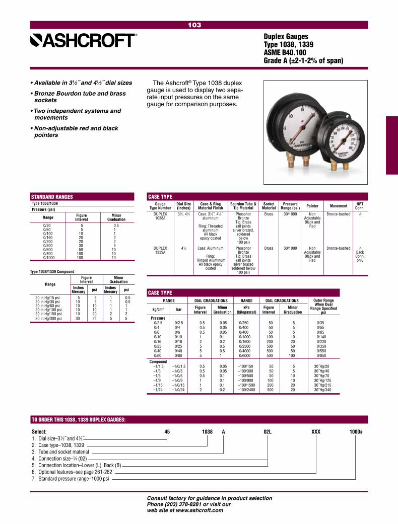
103
Consult factory for guidance in product selectionPhone (203) 378-8281 or visit our web site at www.ashcroft.com
Type 1038/1339 Compound Figure Minor
Range Interval Graduation
Inches psi Inches psi Mercury Mercury 30 in.Hg/15 psi 5 3 1 0.5 30 in.Hg/30 psi 10 5 1 0.5 30 in.Hg/60 psi 10 10 1 1 30 in.Hg/100 psi 10 10 1 1 30 in.Hg/150 psi 10 20 2 2 30 in.Hg/300 psi 30 25 5 5
CASE TYPE Gauge Dial Size Case & Ring Bourdon Tube & Socket Pressure Pointer Movement NPT Type Number (inches) Material Finish Tip Material Material Range (psi) Conn. DUPLEX 31⁄2, 41⁄2 Case: 31⁄2˝, 41⁄2˝ Phosphor Brass 30/1000 Non Bronze-bushed 1⁄4 1038A aluminum Bronze Adjustable Tip: Brass Black and Ring: Threaded (all joints Red aluminum silver brazed, All black soldered epoxy coated below 100 psi) DUPLEX 41⁄2 Case: Aluminum Phosphor Brass 30/1000 Non Bronze-bushed 1⁄4 1339A Bronze Adjustable Back Ring: Tip: Brass Black and Conn. Hinged Aluminum (all joints Red only All black epoxy silver brazed coated soldered below 100 psi)
Duplex GaugesType 1038, 1339 ASME B40.100 Grade A (±2-1-2% of span)
The Ashcroft® Type 1038 duplex gauge is used to display two sepa-rate input pressures on the same gauge for comparison purposes.
• Available in 31⁄2˝ and 41⁄2˝ dial sizes
• Bronze Bourdon tube and brass sockets
• Two independent systems and movements
• Non-adjustable red and black pointers
STANDARD RANGES Type 1038/1339 Pressure (psi) Figure Minor Range Interval Graduation 0/30 5 0.5 0/60 5 1 0/100 10 1 0/160 20 2 0/200 20 2 0/300 30 5 0/600 50 10 0/800 100 10 0/1000 100 10
CASE TYPE RANGE DIAL GRADUATIONS RANGE DIAL GRADUATIONS
kg/cm2 bar Figure Minor kPa Figure Minor Interval Graduation (kilopascal) Interval Graduation Pressure 0/2.5 0/2.5 0.5 0.05 0/250 50 5 0/35 0/4 0/4 0.5 0.05 0/400 50 5 0/55 0/6 0/6 0.5 0.05 0/400 50 5 0/85 0/10 0/10 1 0.1 0/1000 100 10 0/140 0/16 0/16 2 0.2 0/1600 200 20 0/220 0/25 0/25 5 0.5 0/2500 500 50 0/350 0/40 0/40 5 0.5 0/4000 500 50 0/550 0/60 0/60 5 1 0/6000 500 100 0/850 Compound –1/1.5 –1/0/1.5 0.5 0.05 –100/150 50 5 30˝Hg/20 –1/3 –1/0/3 0.5 0.05 –100/300 50 5 30˝Hg/40 –1/5 –1/0/5 0.5 0.1 –100/500 50 10 30˝Hg/70 –1/9 –1/0/9 1 0.1 –100/900 100 10 30˝Hg/125 –1/15 –1/0/15 1 0.1 –100/1500 200 20 30˝Hg/215 –1/24 –1/0/24 2 0.2 –100/2400 500 20 30˝Hg/340
Outer RangeWhen Dual
Range Specifiedpsi
TO ORDER THIS 1038, 1339 DUPLEX GAUGES:
Select: 45 1038 A 02L XXX 1000# 1. Dial size–31⁄2˝ and 41⁄2˝2. Case type–1038, 13393. Tube and socket material4. Connection size–1⁄4 (02) 5. Connection location–Lower (L), Back (B)6. Optional features–see page 261-262 7. Standard pressure range–1000 psi
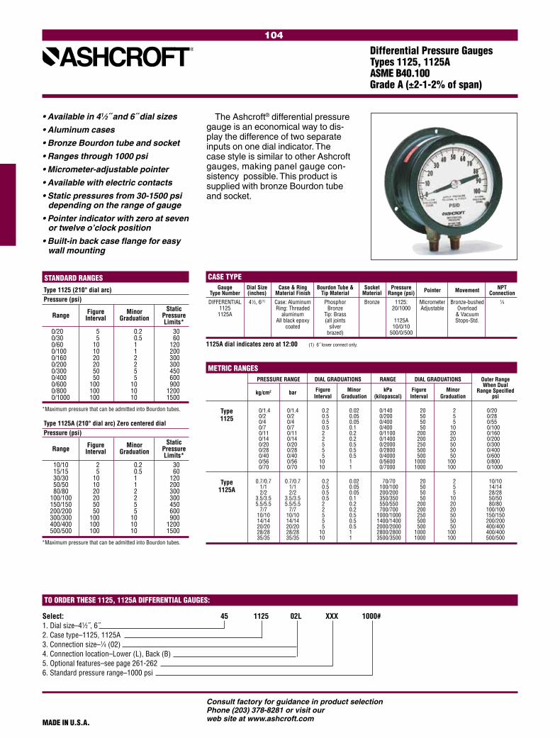
104
Consult factory for guidance in product selectionPhone (203) 378-8281 or visit our web site at www.ashcroft.com
Differential Pressure GaugesTypes 1125, 1125AASME B40.100 Grade A (±2-1-2% of span)
• Available in 41⁄2˝ and 6˝ dial sizes
• Aluminum cases
• Bronze Bourdon tube and socket
• Ranges through 1000 psi
• Micrometer-adjustable pointer
• Available with electric contacts
• Static pressures from 30-1500 psi depending on the range of gauge
• Pointer indicator with zero at seven or twelve o’clock position
• Built-in back case flange for easy wall mounting
The Ashcroft® differential pressure gauge is an economical way to dis-play the difference of two separate inputs on one dial indicator. The case style is similar to other Ashcroft gauges, making panel gauge con-sistency possible. This product is supplied with bronze Bourdon tube and socket.
Select: 45 1125 02L XXX 1000#1. Dial size–41⁄2˝, 6˝2. Case type–1125, 1125A3. Connection size–1⁄4 (02)4. Connection location–Lower (L), Back (B)5. Optional features–see page 261-2626. Standard pressure range–1000 psi
TO ORDER THESE 1125, 1125A DIFFERENTIAL GAUGES:
Type 1125A (210° dial arc) Zero centered dial Pressure (psi) Figure Minor Static Range Interval Graduation Pressure Limits* 10/10 2 0.2 30 15/15 5 0.5 60 30/30 10 1 120 50/50 10 1 200 80/80 20 2 300 100/100 20 2 300 150/150 50 5 450 200/200 50 5 600 300/300 100 10 900 400/400 100 10 1200 500/500 100 10 1500
*Maximum pressure that can be admitted into Bourdon tubes.
Type 1125 (210° dial arc) Pressure (psi) Figure Minor Static Range Interval Graduation Pressure Limits* 0/20 5 0.2 30 0/30 5 0.5 60 0/60 10 1 120 0/100 10 1 200 0/160 20 2 300 0/200 20 2 300 0/300 50 5 450 0/400 50 5 600 0/600 100 10 900 0/800 100 10 1200 0/1000 100 10 1500
*Maximum pressure that can be admitted into Bourdon tubes.
STANDARD RANGES
PRESSURE RANGE DIAL GRADUATIONS RANGE DIAL GRADUATIONS
kg/cm2 bar Figure Minor kPa Figure Minor Interval Graduation (kilopascal) Interval Graduation 0/1.4 0/1.4 0.2 0.02 0/140 20 2 0/20 0/2 0/2 0.5 0.05 0/200 50 5 0/28 0/4 0/4 0.5 0.05 0/400 50 5 0/55 0/7 0/7 0.5 0.1 0/400 50 10 0/100 0/11 0/11 2 0.2 0/1100 200 20 0/160 0/14 0/14 2 0.2 0/1400 200 20 0/200 0/20 0/20 5 0.5 0/2000 250 50 0/300 0/28 0/28 5 0.5 0/2800 500 50 0/400 0/40 0/40 5 0.5 0/4000 500 50 0/600 0/56 0/56 10 1 0/5600 1000 100 0/800 0/70 0/70 10 1 0/7000 1000 100 0/1000 0.7/0.7 0.7/0.7 0.2 0.02 70/70 20 2 10/10 1/1 1/1 0.5 0.05 100/100 50 5 14/14 2/2 2/2 0.5 0.05 200/200 50 5 28/28 3.5/3.5 3.5/3.5 0.5 0.1 350/350 50 10 50/50 5.5/5.5 5.5/5.5 2 0.2 550/550 200 20 80/80 7/7 7/7 2 0.2 700/700 200 20 100/100 10/10 10/10 5 0.5 1000/1000 250 50 150/150 14/14 14/14 5 0.5 1400/1400 500 50 200/200 20/20 20/20 5 0.5 2000/2000 500 50 400/400 28/28 28/28 10 1 2800/2800 1000 100 400/400 35/35 35/35 10 1 3500/3500 1000 100 500/500
Outer RangeWhen Dual
Range Specifiedpsi
METRIC RANGES
Type1125A
Type1125
Gauge Dial Size Case & Ring Bourdon Tube & Socket Pressure Pointer Movement NPT Type Number (inches) Material Finish Tip Material Material Range (psi) Connection
DIFFERENTIAL 41⁄2, 6(1) Case: Aluminum Phosphor Bronze 1125: Micrometer Bronze-bushed 1⁄4 1125 Ring: Threaded Bronze 20/1000 Adjustable Overload 1125A aluminum Tip: Brass & Vacuum All black epoxy (all joints 1125A Stops-Std. coated silver 10/0/10 brazed) 500/0/500
1125A dial indicates zero at 12:00 (1) 6˝ lower connect only.
CASE TYPE
MADE IN U.S.A.

105
Consult factory for guidance in product selectionPhone (203) 378-8281 or visit our web site at www.ashcroft.com
Select: 45 1127 SD 02L XXX 100#1. Dial size–41⁄2˝, 6˝2. Case type–1127, 11283. Tube and socket material–(SD) Stainless4. Connection size–1⁄4 (02)5. Connection location–Lower (L)6. Optional features–see page 261-2627. Standard pressure range–1000 psi
Differential Pressure GaugesTypes 1127, 1128ASME B40.100 Grade A (±2-1-2% of span)
• 316 stainless steel wetted parts
• Available in 41⁄2˝ or 6˝ dial sizes
• Ranges from 10 psi-1000 psi
• Static pressures from 45 psi-1200 psi depending on the range of the gauge
• Pointer indicator with zero at seven (1127) or twelve o’clock position (1128)
• Built-in back case flange for easy wall mounting
When the process is corrosive to gauges with bronze/brass wetted parts an alternative was to isolate the gauge from the process with capil-lary and isolators or diaphragm seals. Now, when the process is compatible with 316 stainless steel, the user can select Types 1127 or 1128 differential pressure gauges with 41/2˝ or 6˝ dials.
TO ORDER THESE 1127, 1128 DIFFERENTIAL PRESSURE GAUGES:
MADE IN U.S.A.
Type 1128 (270° dial arc) Zero centered dial Pressure Figure Minor Static Range Interval Graduation Pressure (psi) Limits*
10/0/10 2 0.5 45 15/0/15 3 0.2 45 30/0/30 5 1 90 50/0/50 10 1 130 100/0/100 20 2 260 200/0/200 50 5 520 300/0/300 100 10 780 400/0/400 100 10 1040
*Maximum pressure that can be admitted into Bourdon tubes.
STANDARD RANGES Type 1127 (270° dial arc) Pressure Figure Minor Static Range Interval Graduation Pressure (psi) Limits*
0/10 5 0.2 45 0/20 5 0.2 45 0/30 5 0.5 45 0/60 10 1 90 0/100 10 1 130 0/160 20 2 208 0/200 20 2 260 0/300 50 5 390 0/400 50 5 520 0/600 100 10 780 0/800 100 10 1040 0/1000 100 10 1200*Maximum pressure that can be admitted into Bourdon tubes.
Type 1127 (270° dial arc) PRESSURE RANGE DIAL GRADUATIONS Figure Minor kg/cm2 bar Interval Graduation
0/1 0/1 0.2 0.02 0/2 0/2 0.5 0.05 0/4 0/4 0.5 0.05 0/7 0/7 0.5 0.05 0/11 0/11 2 0.2 0/14 0/14 2 0.2 0/21 0/21 5 0.5 0/28 0/28 5 0.5 0/42 0/42 5 0.5 0/56 0/56 10 1 0/70 0/70 10 1
Type 1128 (210° dial arc) Zero centered dial PRESSURE RANGE DIAL GRADUATIONS Figure Minor kg/cm2 bar Interval Graduation
1/0/1 1/0/1 0.5 0.05 2/0/2 2/0/2 0.1 0.01 3.5/0/3.5 3.5/0/3.5 0.5 0.1 5.5/0/5.5 5.5/0/5.5 2 0.2 7/0/7 7/0/7 2 0.2 10.5/0/10.5 10.5/0/10.5 5 0.5 14/0/14 14/0/14 5 0.5 21/0/21 21/0/21 5 0.5 28/0/28 28/0/28 10 1 35/0/35 35/0/35 10 1
METRIC RANGES
(1.) 6˝ case available with lower connection only.
Dial Size Case & Ring Bourdon Tube & Socket (inches) Material Finish Tip Material Material
41⁄2, 6 (1) Case: Aluminum 316 316 Ring: Threaded stainless steel stainless steel aluminum All black epoxy coated
Pressure Pointer Movement NPT Range (psi) Connection
10/1000 Adjustable Bronze-brushed 1⁄4 Overload & Vacuum Stops-Std.
CASE TYPE – Differential 1127, 1128

106
Consult factory for guidance in product selectionPhone (203) 378-8281 or visit our web site at www.ashcroft.com
SPECIFICATIONS Type 1130 RATINGS FOR BOTH STANDARD & EXPLOSION PROOF SWITCHES:
EXPLOSION-PROOF SWITCH INFORMATION:
TO ORDER THIS 1130 DIFFERENTIAL PRESSURE GAUGES:
Differential Pressure GaugesType 1130±2% Ascending Accuracy
• Piston actuator• Stainless steel case• Ranges from 5 psid-150 psid• Static pressures up to 6000 psi(5)
• Aluminum(4), brass or stainless steel bodies(1)
• Buna-N O-rings (others available)• Superior magnets for smoother
pointer motion• Standard or explosion-proof reed
switches available• 5-year warranty
The Type 1130 uses a piston design where small migration of the process media is permissible.(2) It is recommended for high differential and high static pressures, up to 6000 psi. Body materials are available in Aluminum, Brass and Stainless Steel, with Buna, Viton or EPDM seals.(3)
(1), (2) Not for use with incompatible media.(3) Other wetted parts include stainless steel,
Teflon and ceramic.(4) Aluminum bodies not to be used with water or
corrosive applications.(5) Static pressure over 3000 psi in SS only.
Accuracy (Ascending) ±2% Migration Minor Range Limits 0-5 psid to 150 psid Maximum Static Pressure 3000 psi (6000 psi for SS) Actuator Piston Case Material Stainless Steel Dial Size 2˝ (20), 21⁄2˝ (25), 31⁄2˝ (35), 4˝ (40), 41⁄2˝ (45), 6˝ (60) Maximum Process Temperature 175°F / 80°C Body Materials Aluminum (F), Brass (A), Stainless Steel (S) O-Rings Buna-N Connection Size (Female) 1⁄4 NPT (25) Connection Location In-Line (S), Lower (L), Back (B) Window Glass Warranty Five Years OPTIONS 1⁄8 NPT Female Adapter (XGE) Available Switches(1,2) NEMA-4 Available Front Flange (XFF) Available Viton O-Rings (XVD) Available EPDM O-Rings (XEM) Available Glycerin Fill (L) Standard Fill Option Silicone Fill (XGV) Available Plastic Window (XPD) Available Explosion Proof (XEK) Available(3)
(1) Applicable to Switches (XV1) 1 SPST with DIN Plug (XV5) 1 SPDT with DIN Plug (XV2) 1 SPST with Terminal Strip (XV6) 1 SPDT with Terminal Strip (XV3) 2 SPST with DIN Plug (XV7) 2 SPDT with DIN Plug (XV4) 2 SPST with Terminal Strip (XV8) 2 SPDT with Terminal Strip
(2) Ajustable from 40-100% of range
(3) Specify lower or back connection for gauge (not available in-line or with 2˝-21/2˝ dials) and switch type (terminal strip) XV2, XV4, XV6, XV8.
SPST SWITCHSpecifications: Contact Rating 10 VA ac (rms) or dc (max) Switching Current 0.5 Amp ac (rms) or dc (max) Switch Voltage 100 Vac/Vdc (max)
SPDT SWITCHSpecifications: Contact Rating 3 VA ac (rms) or dc (max) Switching Current .3 Amp ac (rms) or dc (max) Switch Voltage 30 Vac/Vdc (max)
Switches and electrical connections are mounted in an explosion-proof enclosure with UL, CSA, Cenelec and FM approval. The enclosure meets Class 1, Groups B, C, D, Class 2 Groups E, F, G, Class 3, NEMA 7 & 9 and IP 66. Two 3/4˝ electrical conduit connections.
STANDARD RANGES – Type 1130
psi 0-5 0-8 0-10 0-15 0-20 0-25 0-30
kPa 0-25 0-50 0-75 0-100 0-160 0-200 0-250
kg/cm2-bar 0-0.25 0-0.5 0-0.75 0-1 0-1.6 0-2 0-2.5
psi 0-40 0-50 0-60 0-80 0-100 150
kPa 0-300 0-400 0-500 0-600 0-700 0-900 0-1000
kg/cm2-bar 0-3 0-4 0-5 0-6 0-7 0-9 0-10
Select: 25 1130 FD 25S XXX 30#1. Dial size–2, 21⁄2, 31⁄2, 4, 41⁄2, 6˝2. Case type–11303. Body material4. Connection size–1⁄4 NPTF (25)5. Connection location–In-line (S), Lower (L), Back (B)6. Optional features–see above7. Standard pressure range
EXPLOSION PROOF SWITCH
ENCLOSURE AVAILABLE

107
Consult factory for guidance in product selectionPhone (203) 378-8281 or visit our web site at www.ashcroft.com
Differential Pressure GaugesType 1131±2% Ascending Accuracy
• Rolling diaphragm actuator • Stainless steel case• Ranges from 5 psid-100 psid• Static pressures up to 3000 psi• Aluminum(3), brass or stainless
steel bodies(1)
• Buna-N O-rings (others available)• Superior magnets for smoother
power motion• Standard or explosion-proof reed
switches available• 5-year warranty
The Type 1131 is utilized for applications where migration of the process media is not permissible. The Type 1131 uses a rolling dia-phragm design to separate the high and low-pressure ports to isolate the media and can see up to 3000 psi static pressures. Body materials are available in Aluminum, Brass and Stainless Steel, with Buna, Viton or EPDM seals.(2)
(1) Not for use with incompatable media.(2) Other wetted parts include stainless steel,
Teflon and ceramic.(3) Aluminum bodies not to be used with water or
corrosive applications.
Accuracy (Ascending) ±2% Migration Zero Range Limits 0-5 psid to 100 psid Maximum Static Pressure 3000 psi (all) Actuator Rolling Diaphragm Case Material Stainless Steel Dial Size 21⁄2˝ (25), 31⁄2˝ (35), 4˝ (40), 41⁄2˝ (45), 6˝ (60) Maximum Process Temperature 175°F / 80°C Body Materials Aluminum (F), Brass (A), Stainless Steel (S) Diaphragm/O-Rings Buna-N Connection Size (Female) 1⁄4 NPT (25) Connection Location In-Line (S), Lower (L) Back (B) Window Glass Warranty Five Years OPTIONS 1⁄8 NPT Female Adapter (XGE) Available Switches(1,2) NEMA-4 Available Front Flange (XFF) Available Viton Seals/O-Rings (XVD) Available EPDM Seals/O-Rings (XEM) Available Glycerin Fill (L) Standard Fill Option Silicone Fill (XGV) Available Plastic Window (XPD) Available Explosion Proof (XEK) Available(3)
SPECIFICATIONS Type 1131
(1) Applicable to Switches (XV1) 1 SPST with DIN Plug (XV5) 1 SPDT with DIN Plug (XV2) 1 SPST with Terminal Strip (XV6) 1 SPDT with Terminal Strip (XV3) 2 SPST with DIN Plug (XV7) 2 SPDT with DIN Plug (XV4) 2 SPST with Terminal Strip (XV8) 2 SPDT with Terminal Strip
(2) Ajustable from 40-100% of range
(3) Specify lower or back connection for gauge (not available in-line or with 2˝-21/2˝ dials) and switch type (terminal strip) XV2, XV4, XV6, XV8.
SPST SWITCHSpecifications: Contact Rating 10 VA ac (rms) or dc (max) Switching Current 0.5 Amp ac (rms) or dc (max) Switch Voltage 100 Vac/Vdc (max)
RATINGS FOR BOTH STANDARD & EXPLOSION PROOF SWITCHES:
SPDT SWITCHSpecifications: Contact Rating 3 VA ac (rms) or dc (max) Switching Current .3 Amp ac (rms) or dc (max) Switch Voltage 30 Vac/Vdc (max)
EXPLOSION-PROOF SWITCH INFORMATION:
Switches and electrical connections are mounted in an explosion-proof enclosure with UL, CSA, Cenelec and FM approval. The enclosure meets Class 1, Groups B, C, D, Class 2 Groups E, F, G, Class 3, NEMA 7 & 9 and IP 66. Two 3/4˝ electrical conduit connections.
STANDARD RANGES – Type 1131
psi 0-5 0-7 0-10 0-15 0-25 0-30 0-40 0-60 0-100
kPa 0-25 0-50 0-75 0-100 0-200 0-250 0-400 0-700
kg/cm2-bar 0-0.25 0-0.5 0-0.75 0-1 0-2 0-2.5 0-4 0-7
Select: 25 1131 FD 25S XXX 30#1. Dial size– 21⁄2, 31⁄2, 4, 41⁄2, 6˝2. Case type–11313. Body material4. Connection size–1⁄4 NPTF (25)5. Connection location–In-line (S), Lower (L), Back (B)6. Optional features–see above7. Standard pressure range
TO ORDER THIS 1131 DIFFERENTIAL PRESSURE GAUGES:
EXPLOSION PROOF SWITCH
ENCLOSURE AVAILABLE

108
Consult factory for guidance in product selectionPhone (203) 378-8281 or visit our web site at www.ashcroft.com
Differential Pressure GaugesType 1132±2% Ascending Accuracy
• Small convoluted diaphragm actuator
• Stainless steel case• Ranges from 1 psid-60 psid• Static pressures up to 1500 psi• Aluminum(3), brass or stainless
steel bodies(1)
• Buna-N seals (others available)• Superior magnets for smoother
power motion• Standard or explosion-proof reed
switches available• 5-year warranty
The Type 1132 uses a convoluted-diaphragm design with no migration of the process media. It is recom-mended for lower differential and high static pressures, up to 1500 psi. Body materials are available in Alu-minum, Brass and Stainless Steel, with Buna, Viton or EPDM seals.(2)
(1) Not for use with incompatible media.(2) Other wetted parts include stainless steel,
Teflon and ceramic.(3) Aluminum bodies not to be used with water or
corrosive applications.
Accuracy (Ascending) ±2% Migration Zero Range Limits 0-1 psid to 60 psid Maximum Static Pressure 1500 psi (all) Actuator Convoluted Diaphragm Case Material Stainless Steel Dial Size 21⁄2˝ (25), 31⁄2˝ (35), 4˝ (40), 41⁄2˝ (45), 6˝ (60) Maximum Process Temperature 175°F / 80°C Body Materials Aluminum (F), Brass (A), Stainless Steel (S) Seals Buna-N Connection Size (Female) 1⁄4 NPT (25) Connection Location In-Line (S), Lower (L) Back (B) Window Glass Warranty Five Years OPTIONS 1⁄8 NPT Female Adapter (XGE) Available Switches(1,2) NEMA-4 Available Front Flange (XFF) Available Viton Seals/O-Rings (XVD) Available EPDM Seals/O-Rings (XEM) Available Glycerin Fill (L) Standard Fill Option Silicone Fill (XGV) Available Plastic Window (XPD) Available Explosion Proof (XEK) Available(3)
SPECIFICATIONS Type 1132
(1) Applicable to Switches (XV1) 1 SPST with DIN Plug (XV5) 1 SPDT with DIN Plug (XV2) 1 SPST with Terminal Strip (XV6) 1 SPDT with Terminal Strip (XV3) 2 SPST with DIN Plug (XV7) 2 SPDT with DIN Plug (XV4) 2 SPST with Terminal Strip (XV8) 2 SPDT with Terminal Strip
(2) Ajustable from 40-100% of range
(3) Specify lower or back connection for gauge (not available in-line or with 2˝-21/2˝ dials) and switch type (terminal strip) XV2, XV4, XV6, XV8.
SPST SWITCHSpecifications: Contact Rating 10 VA ac (rms) or dc (max) Switching Current 0.5 Amp ac (rms) or dc (max) Switch Voltage 100 Vac/Vdc (max)
RATINGS FOR BOTH STANDARD & EXPLOSION PROOF SWITCHES:
SPDT SWITCHSpecifications: Contact Rating 3 VA ac (rms) or dc (max) Switching Current .3 Amp ac (rms) or dc (max) Switch Voltage 30 Vac/Vdc (max)
EXPLOSION-PROOF SWITCH INFORMATION:
Switches and electrical connections are mounted in an explosion-proof enclosure with UL, CSA, Cenelec and FM approval. The enclosure meets Class 1, Groups B, C, D, Class 2 Groups E, F, G, Class 3, NEMA 7 & 9 and IP 66. Two 3/4˝ electrical conduit connections.
STANDARD RANGES – Type 1132
psi 0-1 0-5 0-8 0-15 0-20 0-25 0-30 0-40 0-50 0-60
in.H2O 0-25 0-100 0-200 0-400 0-500
kPa 0-25 0-50 0-75 0-100 0-160 0-200 0-250 0-300 0-400
kg/cm2-bar 0-0.075 0-0.25 0-0.5 0-0.75 0-1 0-1.6 0-2 0-2.5 0-3 0-4
mbar 0-75 0-250
Select: 25 1132 FD 25S XXX 30#1. Dial size– 21⁄2, 31⁄2, 4, 41⁄2, 6˝2. Case type–11323. Body material4. Connection size–1⁄4 NPTF (25)5. Connection location–In-line (S), Lower (L) and Back (B)6. Optional features–see above7. Standard pressure range
TO ORDER THIS 1132 DIFFERENTIAL PRESSURE GAUGES:
EXPLOSION PROOF SWITCH
ENCLOSURE AVAILABLE
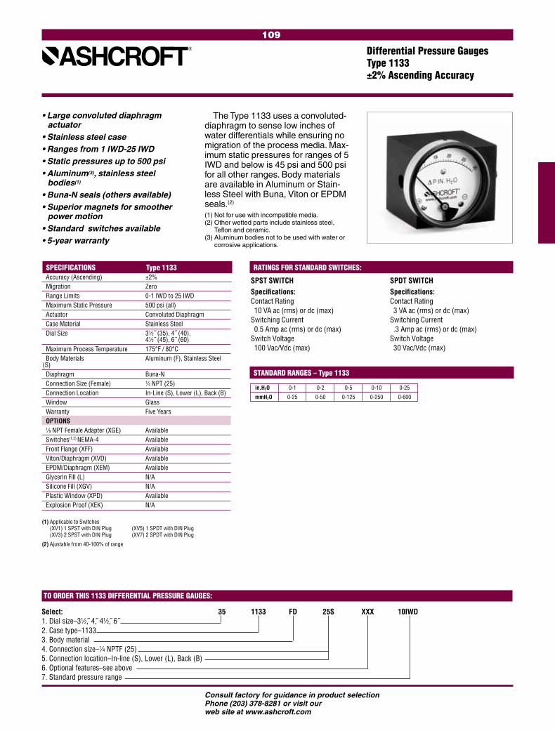
109
Consult factory for guidance in product selectionPhone (203) 378-8281 or visit our web site at www.ashcroft.com
Differential Pressure GaugesType 1133±2% Ascending Accuracy
• Large convoluted diaphragm actuator
• Stainless steel case• Ranges from 1 IWD-25 IWD• Static pressures up to 500 psi• Aluminum(3), stainless steel
bodies(1)
• Buna-N seals (others available)• Superior magnets for smoother
power motion• Standard switches available• 5-year warranty
The Type 1133 uses a convoluted-diaphragm to sense low inches of water differentials while ensuring no migration of the process media. Max-imum static pressures for ranges of 5 IWD and below is 45 psi and 500 psi for all other ranges. Body materials are available in Aluminum or Stain-less Steel with Buna, Viton or EPDM seals.(2)
(1) Not for use with incompatible media.(2) Other wetted parts include stainless steel,
Teflon and ceramic.(3) Aluminum bodies not to be used with water or
corrosive applications.
Accuracy (Ascending) ±2% Migration Zero Range Limits 0-1 IWD to 25 IWD Maximum Static Pressure 500 psi (all) Actuator Convoluted Diaphragm Case Material Stainless Steel Dial Size 31⁄2˝ (35), 4˝ (40), 41⁄2˝ (45), 6˝ (60) Maximum Process Temperature 175°F / 80°C Body Materials Aluminum (F), Stainless Steel (S) Diaphragm Buna-N Connection Size (Female) 1⁄4 NPT (25) Connection Location In-Line (S), Lower (L), Back (B) Window Glass Warranty Five Years OPTIONS 1⁄8 NPT Female Adapter (XGE) Available Switches(1,2) NEMA-4 Available Front Flange (XFF) Available Viton/Diaphragm (XVD) Available EPDM/Diaphragm (XEM) Available Glycerin Fill (L) N/A Silicone Fill (XGV) N/A Plastic Window (XPD) Available Explosion Proof (XEK) N/A
SPECIFICATIONS Type 1133
(1) Applicable to Switches (XV1) 1 SPST with DIN Plug (XV5) 1 SPDT with DIN Plug (XV3) 2 SPST with DIN Plug (XV7) 2 SPDT with DIN Plug
(2) Ajustable from 40-100% of range
SPST SWITCHSpecifications: Contact Rating 10 VA ac (rms) or dc (max) Switching Current 0.5 Amp ac (rms) or dc (max) Switch Voltage 100 Vac/Vdc (max)
RATINGS FOR STANDARD SWITCHES:
SPDT SWITCHSpecifications: Contact Rating 3 VA ac (rms) or dc (max) Switching Current .3 Amp ac (rms) or dc (max) Switch Voltage 30 Vac/Vdc (max)
STANDARD RANGES – Type 1133
in.H2O 0-1 0-2 0-5 0-10 0-25
mmH2O 0-25 0-50 0-125 0-250 0-600
Select: 35 1133 FD 25S XXX 10IWD1. Dial size–31⁄2, 4, 41⁄2, 6˝2. Case type–11333. Body material4. Connection size–1⁄4 NPTF (25)5. Connection location–In-line (S), Lower (L), Back (B)6. Optional features–see above7. Standard pressure range
TO ORDER THIS 1133 DIFFERENTIAL PRESSURE GAUGES:
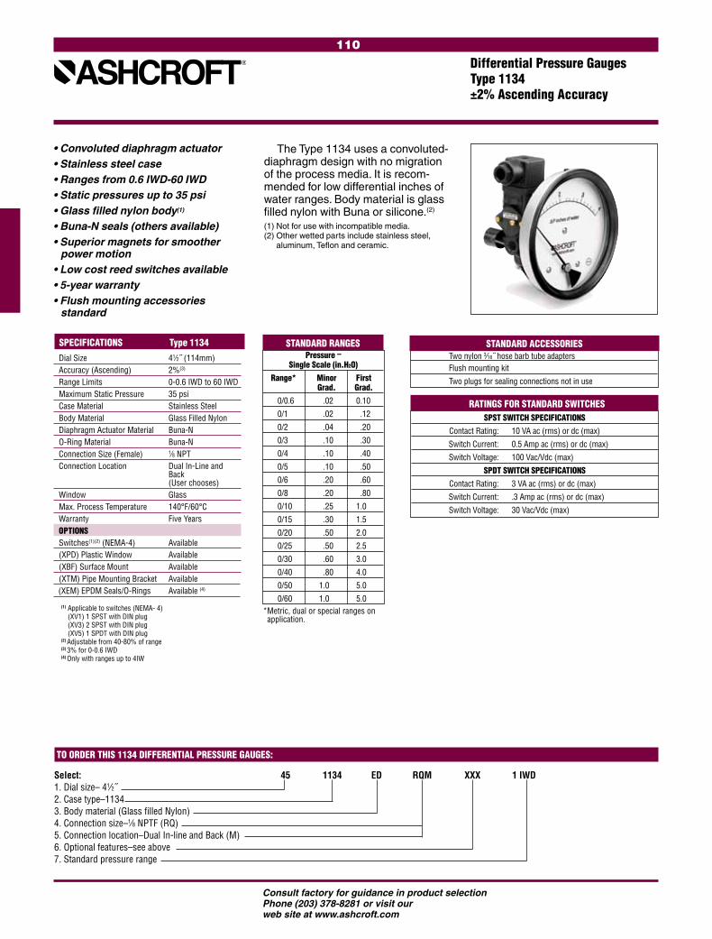
110
Consult factory for guidance in product selectionPhone (203) 378-8281 or visit our web site at www.ashcroft.com
Differential Pressure GaugesType 1134±2% Ascending Accuracy
• Convoluted diaphragm actuator • Stainless steel case• Ranges from 0.6 IWD-60 IWD• Static pressures up to 35 psi• Glass filled nylon body(1)
• Buna-N seals (others available)• Superior magnets for smoother
power motion• Low cost reed switches available• 5-year warranty• Flush mounting accessories
standard
The Type 1134 uses a convoluted-diaphragm design with no migration of the process media. It is recom-mended for low differential inches of water ranges. Body material is glass filled nylon with Buna or silicone.(2)
(1) Not for use with incompatible media.(2) Other wetted parts include stainless steel,
aluminum, Teflon and ceramic.
Dial Size 41⁄2˝ (114mm) Accuracy (Ascending) 2%(3) Range Limits 0-0.6 IWD to 60 IWD Maximum Static Pressure 35 psi Case Material Stainless Steel Body Material Glass Filled Nylon Diaphragm Actuator Material Buna-N O-Ring Material Buna-N Connection Size (Female) 1⁄8 NPT Connection Location Dual In-Line and Back (User chooses) Window Glass Max. Process Temperature 140°F/60°C Warranty Five Years OPTIONS Switches(1)(2) (NEMA-4) Available (XPD) Plastic Window Available (XBF) Surface Mount Available (XTM) Pipe Mounting Bracket Available (XEM) EPDM Seals/O-Rings Available (4)
SPECIFICATIONS Type 1134
(1) Applicable to switches (NEMA- 4) (XV1) 1 SPST with DIN plug (XV3) 2 SPST with DIN plug (XV5) 1 SPDT with DIN plug
(2) Adjustable from 40-80% of range(3) 3% for 0-0.6 IWD(4) Only with ranges up to 4IW
Select: 45 1134 ED RQM XXX 1 IWD1. Dial size– 41⁄2˝2. Case type–11343. Body material (Glass filled Nylon)4. Connection size–1⁄8 NPTF (RQ)5. Connection location–Dual In-line and Back (M)6. Optional features–see above7. Standard pressure range
TO ORDER THIS 1134 DIFFERENTIAL PRESSURE GAUGES:
SPST SWITCH SPECIFICATIONS
Contact Rating: 10 VA ac (rms) or dc (max)
Switch Current: 0.5 Amp ac (rms) or dc (max)
Switch Voltage: 100 Vac/Vdc (max)
SPDT SWITCH SPECIFICATIONS
Contact Rating: 3 VA ac (rms) or dc (max)
Switch Current: .3 Amp ac (rms) or dc (max)
Switch Voltage: 30 Vac/Vdc (max)
Two nylon 3⁄16˝ hose barb tube adapters Flush mounting kit
Two plugs for sealing connections not in use
Pressure – Single Scale (in.H2O)
Range* Minor First Grad. Grad.
0/0.6 .02 0.10
0/1 .02 .12
0/2 .04 .20
0/3 .10 .30
0/4 .10 .40
0/5 .10 .50
0/6 .20 .60
0/8 .20 .80
0/10 .25 1.0
0/15 .30 1.5
0/20 .50 2.0
0/25 .50 2.5
0/30 .60 3.0
0/40 .80 4.0
0/50 1.0 5.0
0/60 1.0 5.0* Metric, dual or special ranges on application.
RATINGS FOR STANDARD SWITCHES
STANDARD ACCESSORIES STANDARD RANGES
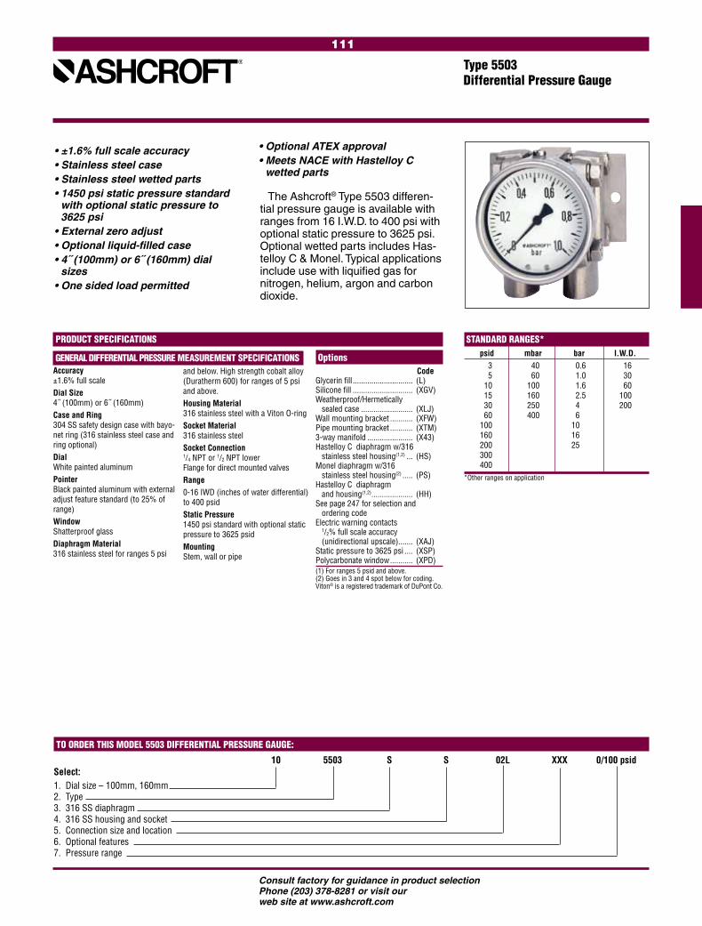
111
Consult factory for guidance in product selectionPhone (203) 378-8281 or visit our web site at www.ashcroft.com
Type 5503 Differential Pressure Gauge
• ±1.6% full scale accuracy• Stainless steel case• Stainless steel wetted parts• 1450 psi static pressure standard
with optional static pressure to 3625 psi
• External zero adjust• Optional liquid-filled case• 4˝ (100mm) or 6˝ (160mm) dial
sizes• One sided load permitted
The Ashcroft® Type 5503 differen-tial pressure gauge is available with ranges from 16 I.W.D. to 400 psi with optional static pressure to 3625 psi. Optional wetted parts includes Has-telloy C & Monel. Typical applications include use with liquified gas for nitrogen, helium, argon and carbon dioxide.
PRODUCT SPECIFICATIONS
Accuracy±1.6% full scaleDial Size4˝ (100mm) or 6˝ (160mm)Case and Ring304 SS safety design case with bayo-net ring (316 stainless steel case and ring optional)DialWhite painted aluminumPointerBlack painted aluminum with external adjust feature standard (to 25% of range)WindowShatterproof glassDiaphragm Material316 stainless steel for ranges 5 psi
and below. High strength cobalt alloy (Duratherm 600) for ranges of 5 psi and above.Housing Material316 stainless steel with a Viton O-ringSocket Material316 stainless steelSocket Connection1/4 NPT or 1/2 NPT lower Flange for direct mounted valvesRange0-16 IWD (inches of water differential) to 400 psidStatic Pressure1450 psi standard with optional static pressure to 3625 psidMountingStem, wall or pipe
STANDARD RANGES* psid mbar bar I.W.D. 3 40 0.6 16 5 60 1.0 30 10 100 1.6 60 15 160 2.5 100 30 250 4 200 60 400 6 100 10 160 16 200 25 300 400*Other ranges on application
TO ORDER THIS MODEL 5503 DIFFERENTIAL PRESSURE GAUGE:
Select: 10 5503 S S 02L XXX 0/100 psid
1. Dial size – 100mm, 160mm2. Type3. 316 SS diaphragm4. 316 SS housing and socket5. Connection size and location6. Optional features7. Pressure range
Options CodeGlycerin fill ............................. (L) Silicone fill ............................. (XGV) Weatherproof/Hermetically sealed case ......................... (XLJ) Wall mounting bracket ........... (XFW) Pipe mounting bracket ........... (XTM) 3-way manifold ...................... (X43) Hastelloy C diaphragm w/316 stainless steel housing(1,2) ... (HS) Monel diaphragm w/316 stainless steel housing(2) ..... (PS) Hastelloy C diaphragm and housing(1,2) .................... (HH) See page 247 for selection and ordering code Electric warning contacts
1/2% full scale accuracy (unidirectional upscale) ....... (XAJ) Static pressure to 3625 psi .... (XSP) Polycarbonate window ........... (XPD)(1) For ranges 5 psid and above. (2) Goes in 3 and 4 spot below for coding. Viton® is a registered trademark of DuPont Co.
GENERAL DIFFERENTIAL PRESSURE MEASUREMENT SPECIFICATIONS
• Optional ATEX approval• Meets NACE with Hastelloy C
wetted parts

112
Consult factory for guidance in product selectionPhone (203) 378-8281 or visit our web site at www.ashcroft.com
Type 5509Differential Pressure Gauges
• ±2.5% full scale accuracy• Stainless steel case• 316 stainless steel wetted parts• Inches of water differential ranges• Static pressure for ranges
160IW & lower – 145 psi above 160IW – 360 psi
• External zero adjust• Available with open or solid front
case styles• Optional liquid-filled case• 4˝ (100mm) or 6˝ (160mm) dial
sizes
The Ashcroft® Type 5509 differ-ential pressure gauge comes stan-dard with 316SS wetted parts. This rugged gauge features an external zero adjust feature standard. Static pressure up to 360 psi.
Accuracy±2.5% full scaleDial Size4˝ (100mm) or 6˝ (160mm) Zero adjust at top of caseCase and Ring304 stainless steel open front case with a bayonet ring (solid front optional)DialWhite painted aluminum with black markingsPointerBlack painted aluminum with external adjust feature standard (to 25% of range)WindowShatterproof glassWetted PartsBellows 316 SS Diaphragm Material316 stainless steel for ranges 15 psi and below. High strength cobalt alloy (Duratherm 600) for ranges above 15 psi.
Housing Material316 stainless steel with a Viton O-ringSocket Connection1/4 NPT or 1/2 NPT lowerRange0-10 IWD (inches of water differen- tial) to 400 psidStatic PressureFrom 10 IWD to 3 psi – static pressure 145 psi 5 psi and above – static pressure 360 psiMountingStem, wall or pipeIngress Protection IP54 (digital), IP65 (liquid filled), optional IP65 (dry case)
Options CodeGlycerin fill ............................. (L) Silicone fill ............................. (XGV) Weatherproof/Hermetically sealed case (IP65) .............. (XLJ) Wall mounting bracket ........... (XFW) Pipe mounting bracket ........... (XTM) 3-way manifold(1) ................... (X43) Electric warning contacts See page 247 for selection and ordering code Polycarbonate window ........... (XPD) Solid front .............................. (S)
(1) Requires additional piping (not supplied). Viton® is a registered trademark of DuPont Co.
TO ORDER THIS MODEL 5509 DIFFERENTIAL PRESSURE GAUGE:
Select: 10 5509 S 02L XXX 0/100 psid
1. Dial size – 100mm, 160mm2. Type3. 316 SS diaphragm, housing and socket4. For solid front option add (S), otherwise leave blank 5. Connection size and location6. Optional features7. Pressure range
PRODUCT SPECIFICATIONS STANDARD RANGES* psid mBar bar I.W.D. 3 25 0.6 10 5 40 1.0 30 10 60 1.6 60 15 100 2.5 100 30 160 4 200 60 250 6 100 400 10 160 16 200 25 300 400*Other ranges on application
GENERAL DIFFERENTIAL PRESSURE MEASUREMENT SPECIFICATIONS
MEASURING PRINCIPLE
Diaphragm
Bellows
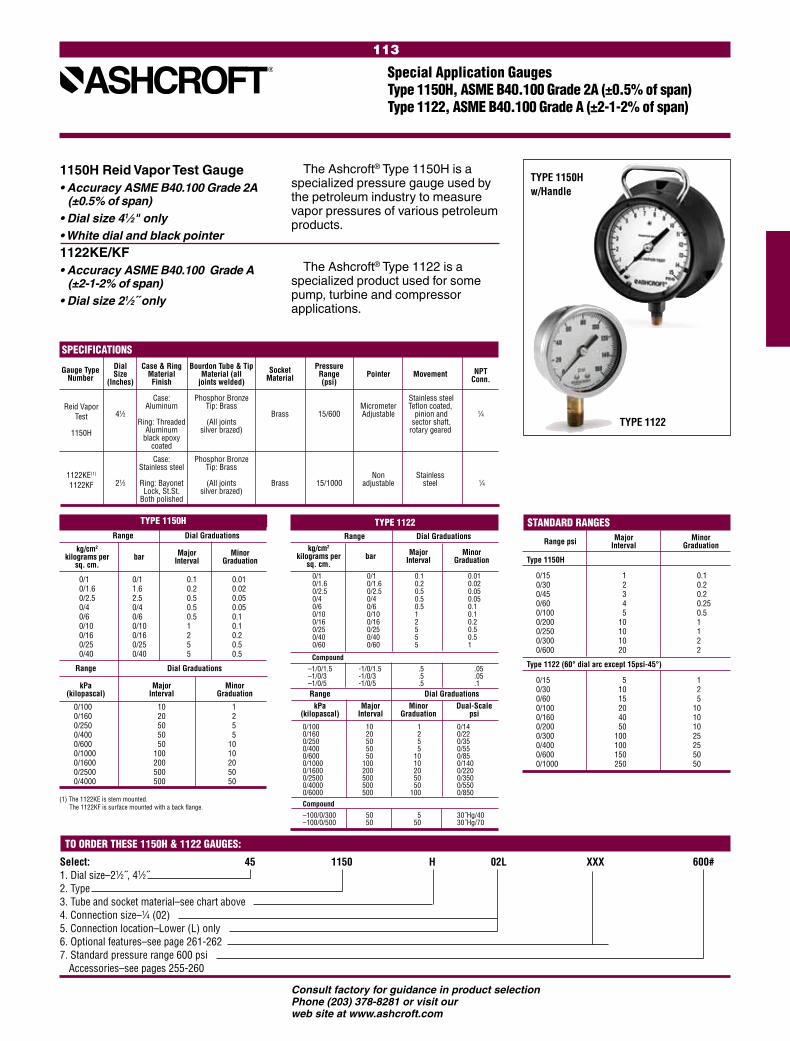
113
Consult factory for guidance in product selectionPhone (203) 378-8281 or visit our web site at www.ashcroft.com
Select: 45 1150 H 02L XXX 600#1. Dial size–21⁄2˝, 41⁄2˝2. Type 3. Tube and socket material–see chart above4. Connection size –1⁄4 (02)5. Connection location–Lower (L) only6. Optional features–see page 261-2627. Standard pressure range 600 psi Accessories–see pages 255-260
1150H Reid Vapor Test Gauge• Accuracy ASME B40.100 Grade 2A
(±0.5% of span)• Dial size 41⁄2" only• White dial and black pointer1122KE/KF• Accuracy ASME B40.100 Grade A
(±2-1-2% of span)• Dial size 21⁄2˝ only
The Ashcroft® Type 1150H is a specialized pressure gauge used by the petroleum industry to measure vapor pressures of various petroleum products.
The Ashcroft® Type 1122 is a specialized product used for some pump, turbine and compressor applications.
TO ORDER THESE 1150H & 1122 GAUGES:
Range Dial Graduations
kg/cm2 Major Minor kilograms per bar Interval Graduation sq. cm.
0/1 0/1 0.1 0.01 0/1.6 1.6 0.2 0.02 0/2.5 2.5 0.5 0.05 0/4 0/4 0.5 0.05 0/6 0/6 0.5 0.1 0/10 0/10 1 0.1 0/16 0/16 2 0.2 0/25 0/25 5 0.5 0/40 0/40 5 0.5
Range Dial Graduations
kPa Major Minor (kilopascal) Interval Graduation
0/100 10 1 0/160 20 2 0/250 50 5 0/400 50 5 0/600 50 10 0/1000 100 10 0/1600 200 20 0/2500 500 50 0/4000 500 50
TYPE 1150H TYPE 1122 Range Dial Graduations kg/cm2 Major Minor kilograms per bar Interval Graduation sq. cm. 0/1 0/1 0.1 0.01 0/1.6 0/1.6 0.2 0.02 0/2.5 0/2.5 0.5 0.05 0/4 0/4 0.5 0.05 0/6 0/6 0.5 0.1 0/10 0/10 1 0.1 0/16 0/16 2 0.2 0/25 0/25 5 0.5 0/40 0/40 5 0.5 0/60 0/60 5 1
Compound –1/0/1.5 -1/0/1.5 .5 .05 –1/0/3 -1/0/3 .5 .05 –1/0/5 -1/0/5 .5 .1 Range Dial Graduations kPa Major Minor Dual-Scale (kilopascal) Interval Graduation psi
0/100 10 1 0/14 0/160 20 2 0/22 0/250 50 5 0/35 0/400 50 5 0/55 0/600 50 10 0/85 0/1000 100 10 0/140 0/1600 200 20 0/220 0/2500 500 50 0/350 0/4000 500 50 0/550 0/6000 500 100 0/850 Compound –100/0/300 50 5 30˝Hg/40 –100/0/500 50 50 30˝Hg/70
(1) The 1122KE is stem mounted. The 1122KF is surface mounted with a back flange.
Major Minor Range psi Interval Graduation
Type 1150H
0/15 1 0.1 0/30 2 0.2 0/45 3 0.2 0/60 4 0.25 0/100 5 0.5 0/200 10 1 0/250 10 1 0/300 10 2 0/600 20 2
Type 1122 (60° dial arc except 15psi-45°)
0/15 5 1 0/30 10 2 0/60 15 5 0/100 20 10 0/160 40 10 0/200 50 10 0/300 100 25 0/400 100 25 0/600 150 50 0/1000 250 50
STANDARD RANGES
Dial Case & Ring Bourdon Tube & Tip Pressure NPT
Gauge Type Size Material Material (all Socket Range Pointer Movement Conn.
Number (Inches) Finish joints welded) Material (psi) Case: Phosphor Bronze Stainless steel Aluminum Tip: Brass Micrometer Teflon coated, 41⁄2 Brass 15/600 Adjustable pinion and 1⁄4 Ring: Threaded (All joints sector shaft, Aluminum silver brazed) rotary geared black epoxy coated
Case: Phosphor Bronze Stainless steel Tip: Brass Non Stainless 21⁄2 Ring: Bayonet (All joints Brass 15/1000 adjustable steel 1⁄4 Lock, St.St. silver brazed) Both polished
SPECIFICATIONS
Reid Vapor Test
1150H
1122KE(1)
1122KF
TYPE 1122
Special Application GaugesType 1150H, ASME B40.100 Grade 2A (±0.5% of span)Type 1122, ASME B40.100 Grade A (±2-1-2% of span)
TYPE 1150H w/Handle
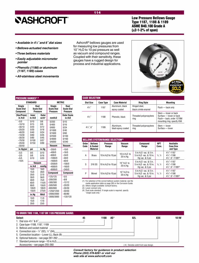
114
Consult factory for guidance in product selectionPhone (203) 378-8281 or visit our web site at www.ashcroft.com
BELLOWS SYSTEM/RANGE SELECTION(1)
Order Bellows Pressure Vacuum Compound NPT Available Code & Socket Range Range Range Conn. Case Size Material and Type 10 in.H2O to 5 in.H2O vac. & 5 in. 41⁄2˝–1187 A Brass 10 in.H2O to 10 psi 20 in.Hg 5 in.H2O vac. & 10 in. 1⁄4, 1⁄2 41⁄2˝–1188 Hg vac. & 5 psi 41⁄2˝, 6˝–1189(3)
10˝ H2O to 5 in.H2O vac. & 5 in. 41⁄2˝–1187 S 316 SS 10 in.H2O to 10 psi 20 in.Hg 5 in.H2O vac. & 10 in. 1⁄4, 1⁄2 41⁄2˝–1188 Hg vac. & 5 psi 41⁄2˝, 6˝–1189(3)
10˝ H2O to 5 in.H2O vac. & 5 in. 41⁄2˝–1187 P Monel 10 in.H2O to 10 psi 20 in.Hg 5 in.H2O vac. & 10 in. 1⁄4, 1⁄2 41⁄2˝–1188 Hg vac. & 5 psi 41⁄2˝, 6˝–1189(3)
PRESSURE RANGES(2,4)
STANDARD
Single Dual Scale Dial Scale Dial Compound Pressure
(Vac/Press) Inner Outer
in.H2O in.H2O oz/in2
–5/5 0/10 0/6 –10/10 0/15 0/9 –30/10 0/20 0/12–20/20 0/30 0/18–40/20 0/40 0/24–10/30 0/60 0/35–30/30 0/80 0/45–70/30 0/100 0/57–20/40 0/150 0/90–50/50 in.Hg/psi psi in.Hg
–5/3 0/5 0/10–2/5 0/8 0/16–5/5 0/10 0/20–10/5
Vacuum in.H20 mmHg 10/0 18/0 15/0 28/0 20/0 37/0 30/0 56/0 40/0 75/0 60/0 110/0 80/0 150/0 100/0 180/0 150/0 270/0
in.Hg ftH20
10/0 11/0 15/0 17/0 20/0 23/0
Low Pressure Bellows Gauge Type 1187, 1188 & 1189 ASME B40.100 Grade A (±2-1-2% of span)
Ashcroft® bellows gauges are used for measuring low pressures from 10˝ H2O to 10 psi pressure as well as vacuum and compound ranges. Coupled with their sensitivity, these gauges have a rugged design for process and industrial applications.
• Available in 41⁄2˝ and 6˝ dial sizes
• Bellows-actuated mechanism
• Three bellows materials
• Easily adjustable micrometer pointer
• Phenolic (1188) or aluminum (1187, 1189) cases
• All-stainless steel movements
CASE SELECTION
Dial Size Case Type Case Material Ring Style Mounting
41⁄2˝ 1187 Aluminum, black Hinged steel, Flush — back only epoxy coated black crinkle enamel Stem — lower or back 41⁄2˝ 1188 Phenolic, black Threaded polypropylene Surface — lower or back ring Flush— back, order 1278M mounting ring, specify X56 Aluminum, Threaded polypropylene Stem — lower 41⁄2˝, 6˝ 1189 black epoxy coated ring Surface — lower
(1) For selection of the correct bellows system material, see the media application table on page 265 or the Corrosion Guide.
(2) Others ranges available: Consult factory.(3) Lower connect only.(4) Dual scale standard. If single scale is required, specify
“single scale only.”
METRIC
Single Dual Scale Dial Scale Dial Pressure Pressure
Outer Scale mmH2O in.H20
0/250 0/10 0/400 0/16 0/600 0/24 0/1000 0/40 0/1600 0/60 0/2500 0/100 0/4000 0/160 0/6000 0/240
Vacuum Vacuum
–250/0 –10/0 –400/0 –16/0 –600/0 –24/0 –1000/0 –40/0 –1600/0 –60/0 –2500/0 –100/0 –4000/0 –160/0 –6000/0 –240/0 Compound Compound
–125/125 –5/5 –200/200 –8/8 –300/300 –12/12 –500/500 –20/20 –800/800 –30/30 –1250/1250 –50/50 –2000/2000 –80/80 –3000/3000 –120/120
(*) Denotes solid-front case design.
TO ORDER THIS 1188, 1187 OR 1189 PRESSURE GAUGE:
Select: 45 1188 AS* 02L XXX 10 IW1. Dial size –41⁄2˝ & 6˝2. Case type–1188, 1187, 11893. Bellows and socket material4. Connection size – 1⁄4˝ (02), 1⁄2˝ (04) 5. Connection location – Lower (L), Back (B)6. Optional features – see page 261-262 7. Standard pressure range –10 in.H2O Accessories – see pages 255-260

115
Consult factory for guidance in product selectionPhone (203) 378-8281 or visit our web site at www.ashcroft.com
Select: 25 1490 A 02L XXX 10 IW1. Dial size – 21⁄2 (25), 31⁄2 (35)2. Case type3. Wetted material4. Connection size – 1⁄4 (02), 1⁄8 (01)5. Connection location – Lower (L), Back (B)6. Optional features – see page 261-2627. Standard pressure range – 10 in.H2O
• 21⁄2˝ and 31⁄2˝ dial size• Glass-filled polysulfone case
material, won’t rust or dent• Beryllium copper diaphragm• Brass socket• Wetted materials of beryllium
copper, brass, polysulfone and RTV siliconeThe Ashcroft® Type 1490 low pres-
sure diaphragm gauge is designed to measure pressure from 10 in.H2O to 15 psi, both positive and negative pres-sures. This gauge uses a very sensitive
TO ORDER THESE LOW PRESSURE DIAPHRAGM GAUGES:
diaphragm capsule to measure low pressure and vacuum. The gauge is specifically designed for use whenever the pressure medium is a gas that is not corrosive to beryllium copper, brass, polysulfone and RTV silicone. The polysufone case is suitable for intermittent or continuous service on natural gas provided a .013˝ throttle plug is installed in the socket. Typical applications are, but not limited to, vacuum pumps, gas leak detectors, air compressors, air filters, gas burners, gas measurement, vacuum ovens, suction regulators and respirators.
SELECTION TABLE DIAL SIZE TYPE WETTED MATERIAL CONN. SIZE & TYPE CONNECTION LOCATION RANGES OPTIONAL FEATURES
Code Desc. Code Description Code Description Code Description Code Description Code Description Code Description
25 21/2˝ 1490 Low Pressure A Beryllium Copper 01 1/8 NPT L Lower 10 IW 0 to 10 in.H2O XAN 1% Opt. Accuracy 35 31/2˝ Diaphragm Gauge Brass 02 1/4 NPT B Center Back XDA Dial Marking Polysulfone HD 1/8˝ I.D.Tubing Hose Barb(2,3) T Top See Chart for XNH Stain. Steel Tag RTV Silicone HE 3/16˝ I.D.Tubing Hose Barb(2,3) D 3 O’Clock Entire List of XNN Paper Tag HF 1/4˝ I.D.Tubing Hose Barb(2,3) E 9 O’Clock Ranges XTU(1,3) Throttle Plug HG 1/4 O.D. Polytube Hose Barb(2,3) XTS(4) Throttle Screw HH 10-32-2B Female Thread(2,3,4) XUC(2) U-clamp XZY FlutterGuard™(1) A throttle plug must be installed in the socket whenever the gauge is used for intermittent or continuous service on natural gas. (2) U-clamp furnished when hose barb or female thread is specified. EXAMPLES: 25 1490A 02L 10 IW XNH (3) Throttle plug not available with hose barb or female thread connections.(4) .020 throttle screw available with HH connection only.
Pressure Figure Intervals Minor Graduation 0/60 cm. H2O 10 1 0/2.5 kPa 0.5 0.05 0/4 kPa 1 0.1 0/10 kPa 1 0.1 0/16 kPa 2 0.2 0/25 kPa 5 0.5 0/40 kPa 10 1 0/100 kPa 10 1 Vacuum 2.5/0 kPa 0.5 0.05 4/0 kPa 1 0.1 10/0 kPa 1 0.1 16/0 kPa 2 0.2 25/0 kPa 5 0.5 40/0 kPa 10 1 100/0 kPa 10 1 Compound –10/60 cm H2O 10 1 –10/80 cm H2O 10 1 –20/40 cm H2O 10 1 –10/100 cm H2O 10 1 –10/120 cm H2O 20 2
STANDARD METRIC RANGES Pressure Figure Intervals Minor Graduation 0/10 in.H2O 1 0.1
0/15 in.H2O 5 0.2
0/30 in.H2O 5 0.5
0/60 in.H2O 10 1
0/100 in.H2O 10 1
0/160 in.H2O 20 2
0/200 in.H2O 20 2
0/300 in.H2O 50 5 0/10 oz./in.2 1 0.1 0/15 oz./in.2 5 0.2 0/30 oz./in.2 5 0.5 0/60 oz./in.2 10 1 0/100 oz./in.2 10 1 0/160 oz./in.2 20 2 0/250 oz./in.2 50 5 0/3 psi 0.5 0.05 0/5 psi 1 0.1 0/10 psi 1 0.1 0/15 psi 5 0.2
STANDARD RANGESVacuum Figure Intervals Minor Graduation
15/0 in.H2O 5 0.2 30/0 in.H2O 5 0.5 60/0 in.H2O 10 1100/0 in.H2O 10 1200/0 in.H2O 20 2 15/0 oz./in.2 5 0.2 30/0 oz./in.2 5 0.5 60/0 oz./in.2 10 1100/0 oz./in.2 10 1Compound –30/30 in.H2O 10 1–30/30 in.oz./in.2 10 1 –10/10 in.H2O 2 0.2 Dual Scale
Graduations
Range Inner Scale Outer Scale
Inner Scale Outer Scale Figure Minor Figure Minor Intervals Grad. Intervals Grad. 0/9 oz./in.2 0/15 in.H2O 1 0.2 5 0.2 0/20 oz./in.2 0/35 in.H2O 5 0.5 5 0.5 0/35 oz./in.2 0/60 in.H2O 5 0.5 10 1 0/60 oz./in.2 0/100 in.H2O 10 1 10 1
Other ranges available on request. Consult factory.
STANDARD RANGES (Cont.)
Low Pressure Diaphragm GaugeSeries 1490, ASME B40.100 Grade A (±2-1-2% of span)

116
Consult factory for guidance in product selectionPhone (203) 378-8281 or visit our web site at www.ashcroft.com
• Sensitive diaphragm element results in smooth pointer motion
• One-piece polycarbonate window is easy to remove
• Re-zero screw allows easy pointer adjustment
• Slotted U-clamp for panel mounting makes installation easy
The Ashcroft® Type 1495 receiver gauge uses a diaphragm capsule as its sensing element rather than a Bourdon tube. The sensitivity of the diaphragm promotes smooth pointer motion that makes minor pressure changes easy to read.
OPTIONSCode Description
XAN 1% optional accuracyXDA Dial markingXNH Stainless steel tagXNN Paper tagXTU(1,3) Throttle plugXTS(4) Throttle screwXUC(2) U-clampXZY FlutterGuard™
Dial Size: 21/2˝ and 31/2˝
CaseMaterial: Glass-filled polysulfone
SensingElement: Beryllium copper diaphragm
WettedMaterials: Beryllium copper, brass,
polysulfone and RTV silicone
SPECIFICATIONS
(1) A throttle plug must be installed in the socket whenever the gauge is used for intermittent or continuous service on natural gas. (2) U-clamp furnished when hose barb or female thread is specified. (3) Throttle plug not available with hose barb or female thread connections. (4) .020 throttle screw available on HH connection only.
TO ORDER THIS TYPE 1495 RECEIVER GAUGE:
Select: 3535 1495A5 0235 B535 XUC5 3-15 psi35 Range51. Dial size – 31⁄2˝2. Case type – 1495 and wetted material3. Connection size – 1⁄4 (02), 1⁄8 (01) 4. Connection location – Lower (L), Back (B)5. Variation for U-clamp6. Basic model code for 3-15# signal 7. Actual dial range required; i.e, 0-100%, 0-10 sq rt, etc.
The Type 1495 receiver gauge is the ideal product where the standard ASME B40.100 Grade A (±2-1-2% of span) accuracy or the optional ASME B40.100 Grade 1A (±1% of span) accuracy and smaller dial sizes are specified. The long pointer, smooth-operating sensing element, easily removable window and re-zero adjust-ment screw make specification and installation of this receiver gauge quick and easy. The polysulfone case is suit-able for intermittent or continuous service on natural gas provided a .013˝ throttle plug is installed in the socket.
RANGES Figure Minor Pressure Intervals Graduations
0-100% 10 1 0-10 sq rt 1 0.1 0-10 sq rt/0-100 Linear (5)
(5) This dial is standard and will be supplied unless otherwise ordered. Figure/minor intervals same as single case.
SPECIFICATIONS Dial Size Gauge Type Wetted Material Connection Size & Type Connection Location
Code Desc. Code Description Code Description Code Description Code Description
25 21/2˝ 1495 Diaphragm A Beryllium Copper 01 1/8 NPT L Lower 35 31/2˝ Receiver Gauge Brass 02 1/4 NPT B Center Back Polysulfone HD 1/8˝ I.D. Tubing Hose Barb(2,3) T Top RTV Silicone HE 3/16˝ I.D. Tubing Hose Barb(2,3) D 3 O'Clock HF 1/4˝ I.D. Tubing Hose Barb(2,3) E 9 O'Clock HG 1/4˝ O.D. Polytube Hose Barb(2,3) HH 10-32-2B Female Thread(2,3,4)
Diaphragm Receiver Gauges Type 1495, ASME B40.100 Grade A (±2-1-2% of span)
117
Consult factory for guidance in product selectionPhone (203) 378-8281 or visit our web site at www.ashcroft.com
Type 2030 Digital Sanitary Gauge .............119
Type 1032, 21/2˝, 31/2˝ and 41/2˝ Gauge ........120
Type 1036 31/2˝ Gauge
w/Type 1037 Sanitary Fitting ..................121
Type 1032, 2˝ Fractional Gauge ..................122
Options for Process, Stainless Steel,
Test and Industrial Pressure Gauges.......123
SANITARYPRESSURE GAUGES

118
Consult factory for guidance in product selectionPhone (203) 378-8281 or visit our web site at www.ashcroft.com
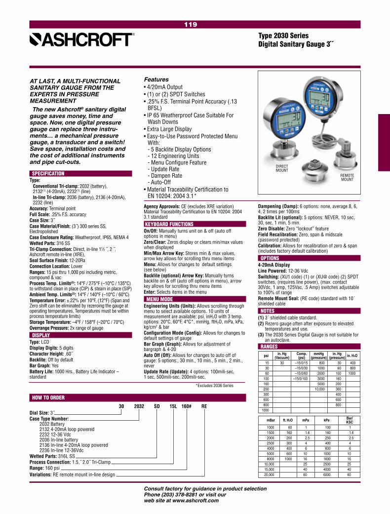
119
Consult factory for guidance in product selectionPhone (203) 378-8281 or visit our web site at www.ashcroft.com
SPECIFICATION Type: Conventional Tri-clamp: 2032 (battery),
2132(1) (4-20mA), 2232(1) (line) In-line Tri-clamp: 2036 (battery), 2136 (4-20mA),
2232 (line)Accuracy: Terminal point Full Scale: .25% F.S. accuracyCase Size: 3˝Case Material/Finish: (3˝) 300 series SS, ElectropolishedCase Enclosure Rating: Weatherproof, IP65, NEMA 4Wetted Parts: 316 SSTri-Clamp Connection: Direct, in-line 11⁄2 ˝, 2 ˝, Ashcroft remote in-line (XRE),Seal Surface Finish: 12-20RaConnection Location: LowerRanges: 15 psi thru 1,000 psi including metric, compound & vacProcess Temp. Limits(2): 14°F / 275°F (–10°C / 135°C) to withstand clean in place (CIP) & steam in place (SIP)Ambient Temp. Limits(3): 14°F / 140°F (–10°C / 60°C)Temperature Error: ±.22% per 10°F, (12°F) (Span and Zero shift can be eliminated by rezeroing the gauge at operating temperatures. Temperatures must be within process temperature limits)Storage Temperature: –4°F / 158°F (–20°C / 70°C)Overrange Pressure: 2x range of gauge DISPLAYType: LCDDisplay Digits: 5 digitsCharacter Height: .60˝Backlite: Off by defaultBar Graph: YesBattery Life: 1000 Hrs., Battery Life Indicator – standard
Features• 4/20mA Output• (1) or (2) SPDT Switches• .25% F.S. Terminal Point Accuracy (.13
BFSL)• IP 65 Weatherproof Case Suitable For
Wash Downs• Extra Large Display• Easy-to-Use Password Protected Menu
With: - 5 Backlite Display Options - 12 Engineering Units - Menu Configure Feature - Update Rate - Dampen Rate - Auto-Off
• Material Traceability Certification to EN 10204: 2004 3.1*
Type 2030 Series Digital Sanitary Gauge 3˝
Agency Approvals: CE (excludes XRE variation)Material Traceability Certification to EN 10204: 2004 3.1 standard KEYBOARD FUNCTIONSOn/Off: Manually turns unit on & off (auto off options in menu)Zero/Clear: Zeros display or clears min/max values when displayedMin/Max Arrow Key: Stores min & max values, arrow key allows for scrolling thru menu itemsMenu: Allows for changes to default settings (see below)Backlite (optional) Arrow Key: Manually turns backlite on & off (auto off options in menu), arrow key allows for scrolling thru menu itemsEnter: Selects items in the menu MENU MODEEngineering Units (Units): Allows scrolling through menu to select available options. 10 units of measurement are available; psi, inH2O with 3 temp. options: 20°C, 60°F, 4°C*, mmHg, ftH2O, mPa, kPa, kg/cm2 & barConfiguration Mode (Config): Allows for changes to default settings of gaugeBar Graph (Graph): Allows for adjustment of bargraph & 4-20Auto Off (Off): Allows for changes to auto off of gauge: 5 options:, 30 min., 10 min., 5 min., 2 min., never Update Rate (Update): 4 options: 100mili-sec, 1 sec, 500mili-sec, 200mili-sec,
HOW TO ORDER
30 2032 SD 15L 160# REDial Size: 3˝Case Type Number: 2032 Battery
2132 4-20mA loop powered 2232 12-36 Vdc 2036 In-line battery 2136 In-line 4-20mA loop powered 2236 In-line 12-36Vdc
Wetted Parts: 316L SSProcess Connection: 1.5,˝ 2.0˝ Tri-ClampRange: 160 psiVariations: RE remote mount in-line design
DIRECTMOUNT
REMOTEMOUNT
AT LAST, A MULTI-FUNCTIONAL SANITARY GAUGE FROM THE EXPERTS IN PRESSURE MEASUREMENTThe new Ashcroft® sanitary digital
gauge saves money, time and space. Now, one digital pressure gauge can replace three instru-ments… a mechanical pressure gauge, a transducer and a switch! Save space, installation costs and the cost of additional instruments and pipe cut-outs.
Dampening (Damp): 6 options: none, average 8, 6, 4, 2 times per 100msBacklite Lit (optional): 5 options: NEVER, 10 sec, 30, sec, 1 min, 5 min. Zero Disable: Zero “lockout” featureField Recalibration: Zero, span & midscale (password protected)Calibration: Allows for recalibration of zero & span (includes factory default calibration) OPTIONS4-20mA Display Line Powered: 12-36 Vdc Switching: (XU1 code) (1) or (XU@ code) (2) SPDT switches, (requires line power), (max. contact 30Vdc, 1 amp, 125Vac, .5 Amp) switches adjustable to 100% of rangeRemote Mount Seal: (RE code) standard with 10´ shielded cable NOTES(1) 3´ shielded cable standard.(2) Rezero gauge often after exposure to elevated
temperatures and use.(3) The 2030 Series Digital Gauge is not suitable for
an autoclave. RANGES psi in. Hg Comp. mmHg in. Hg in. H2O (Vacuum) (psi) (pressure) (pressure) 15 30 –15/0/15 800 30 400 30 –15/0/30 1000 60 800 60 –15/0/60 2000 100 1000 100 –15/0/100 3000 160 160 5000 200 200 10,000 300 300 400 600 600 800 800 1000
mBar ft. H2O mPa kPa Bar/ KSC 1000 60 1 100 1 1500 160 1.6 160 1.6 2000 200 2.5 250 2.5 2500 300 4 400 4 4000 400 6 600 6 5000 600 10 1000 10 8000 1000 16 1600 16 10,000 25 2500 25 15,000 40 4000 40 20,000 60 6000 60
*Excludes 2036 Series
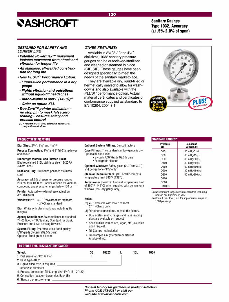
120
Consult factory for guidance in product selectionPhone (203) 378-8281 or visit our web site at www.ashcroft.com
STANDARD RANGES(4)
Pressure Compound psi Vacuum/psi
0/15 30 in.Hg/0 psi 0/30 30 in.Hg/15 psi 0/60 30 in.Hg/30 psi 0/100 30 in.Hg/60 psi 0/160 30 in.Hg/100 psi 0/200 30 in.Hg/150 psi 0/300 30 in.Hg/300 psi 0/400 0/600 0/1000(5)
Select: 35 1032S L 15L 100# 1. Dial size–21⁄2˝, 31⁄2˝ & 41⁄2˝2. Case type–10323. Liquid-filled case, if required otherwise eliminate4. Process connection Tri-Clamp size–11⁄2˝ (15), 2˝ (20)5. Connection location–Lower (L), Back (B)6. Standard pressure range
TO ORDER THIS 1032 SANITARY GAUGE:
Sanitary Gauges Type 1032, Accuracy (±1.5%-2.0% of span)
PRODUCT SPECIFICATIONS
Dial Sizes: 21/2˝ , 31/2˝ and 41/2˝ (2)
Process Connection: 11/2˝ and 2˝ Tri-Clamp lower and back(3)
Diaphragm Material and Surface Finish: Electropolished 316L stainless steel 12-20RA (Micro-inch)
Case and Ring: 300 series polished stainless steel
Accuracy: ±1.5% of span for pressure ranges 200 psi thru 1000 psi. ±2.0% of span for vacuum, compound and pressure ranges below 100 psi
Pointer: Adjustable (external zero adjust on 31/2˝ dial size)
Windows: 21/2˝, 31/2˝–Polycarbonate standard 41/2˝–Glass standard
Dial: White with black markings including 3A insignia
Agency Compliance: 3A compliance to standard 74-03 titled – “3A Sanitary Standard for Liquid Pressure and Level sensing Devices”
System Filling: Pharmacuetical/food quality USP grade glycerin (99.5% pure) Optional: Food grade silicone
Optional System Fillings: Consult factory
Case Fillings: The standard sanitary gauge is dry Optional fills include: • Glycerin USP Grade 99.5% pure) • Food grade silicone
Optional Windows: Safety glass (21/2˝ and 31/2˝) and polysulfone (31/2˝ only).
Clean or Steam in Place: (CIP or SIP) Process temperature limit 280°F (138°C).
Autoclave or Sterilize: Ambient temperature limit of 300°F (149°C) when supplied with polysulfone window (31/2˝ dry gauge only).
Notes: (2) 41/2˝ available with lower-connect
2˝ Tri-Clamp only.(3) For other connections, consult the factory. • Dual scales, metric ranges and false reading
dials are available on request. • Special dials with colors, logos, etc., available
upon request. • Tri-Clamps not included. • Tri-Clamp is a regstered trademark of Alfa Laval Inc.
(4) Nonstandard ranges available standard including units in bar, kg/cm2 and kPa.
(5) Consult Tri-Clover, Inc. for appropriate clamps on 1000 psi range.
DESIGNED FOR SAFETY AND LONGER LIFE• Patented PowerFlex™ movement
isolates movement from shock and vibration for longer life
• All stainless, all-welded construc-tion for long life
• New PLUS!™ Performance Option:- Liquid-filled performance in a dry
gauge- Fights vibration and pulsations
without liquid-fill headaches- Autoclavable to 300°F (149°C)(1)
- Order as option XLL• True Zero™ pointer indication –
no stop pin to mask false zero reading – ensures safety and process control
(1) Available in 31/2˝ 1032 only with option XPS polysulfone window..
OTHER FEATURES:
Available in 21/2, 31/2˝ and 41/2˝ dial sizes, 1032 sanitary pressure gauges can be autoclaved/sterilized and cleaned or steamed in place (CIP, SIP). These gauges have been designed specifically to meet the needs of the sanitary marketplace.
They are available dry, liquid-filled or hermetically sealed to allow for wash-downs and also available with the PLUS!™ performance option. Actual material certificates and certificates of conformance supplied as standard to EN 10204: 2004 3.1.

121
Consult factory for guidance in product selectionPhone (203) 378-8281 or visit our web site at www.ashcroft.com
STANDARD RANGES(2)
Pressure Compound psi Vacuum/psi
0/15 30 in.Hg/0 psi 0/30 30 in.Hg/15 psi 0/60 30 in.Hg/30 psi 0/100 30 in.Hg/60 psi 0/160 30 in.Hg/100 psi 0/200 30 in.Hg/150 psi 0/300 30 in.Hg/300 psi 0/400 0/600 0/1000(3)
Select: 35 1036 SD 15L XXX 100# 1. Dial size–31⁄2˝2. Family–10363. System material/fill–SS/dry4. Connection size/location–1.5˝ seal/lower5. X variations6. Range
TO ORDER THIS 1036 SANITARY GAUGE:
In-Line Sanitary Gauges Type 1036 with Type 1037 Sanitary Instrument Fitting
PRODUCT SPECIFICATIONS
Dial Size: 31/2˝ Accuracy: ±1.5% of span for pressure ranges 100 psi thru 1000 psi. ±2.0% of span for vacuum, compound and pressure ranges below 100 psiCase and Ring: 300 series stainless steelRing Type: BayonetBourdon Tube and Socket: 316L stainless steel Diaphragm Material and Surface Finish: 316L SS Electropolished 12-20RA (Micro-inch)Diaphragm O-Ring: Buna-N(1)
Connection: LowerSystem Fill: USP food grade glycerinWindows: PolycarbonatePointer: Black-painted aluminum with external zero adjust (Easy Zero™)Dial: White with black markings including 3A insigniaMovement: 300 series stainless steelAgency Approvals: 3A compliance to sanitary standard 74-03Ranges: 15# thru 1000#, including compound and vacuumClean or Steam in Place: (CIP or SIP) Process temperature limit 280°F (138°C).
Autoclave or Sterilize: Ambient temperature limit of 300°F (149°C) when supplied with polysulfone window (31/2˝ dry gauge only).
We recommend a polysulfone window for auto-clave/sterilization. Specify the XPS variation. Available 31/2˝ 1032 only
ASHCROFT® TYPE 1037 INSTRUMENT FITTINGFeature Code316L SS construction StandardWetted parts electropolished to 12-20RA (Micro-inch) StandardHeat number stamped on fitting StandardSizes:1/2˝ Tri-Clamp connection 503/4˝ Tri-Clamp connection 75 1˝ Tri-Clamp connection 1011/2˝ Tri-Clamp connection 15 2˝ Tri-Clamp connection 20
To Ensure Cleanliness(1) Prior to reinstalling the Type 1036 into the Type 1037 instrument fitting, we recommend replacing the O-ring (P/N 185A106-75)
TYPE 1036 SANITARY GAUGE• All-welded stainless steel Bourdon tube• Field liquid-fillable gauge case• True Zero™ pointer indication• PowerFlex™ movement for extended life• Easy Zero™ external pointer
adjustment standard• Retrofits Anderson Instrument CPM design• New PLUS!™ Performance Option:
- Liquid-filled performance in a dry gauge- Fights vibration and pulsations without
liquid-fill headaches- Order as option XLL
TYPE 1037 INSTRUMENT FITTING• Tubing O.D. size from 1/2˝ thru 2˝• 316L SS• Electropolished 12-20RA (Micro-inch)
internal surface finish• Heat number stamped on each fitting
Ashcroft® Type 1036 in-line sani-tary pressure gauge and Type 1037 sanitary instrument fitting virtually eliminate process deadleg. The design of the Type 1036 sanitary gauge and instrument fitting allows for the dia-phragm of the gauge to be positioned at the gauge instrument fitting, elimi-nating the pocket or deadleg that may cause contamination.
The Type 1036 sanitary gauge and Type 1037 instrument fitting utilize a 11/2˝ Tri-Clover-type mating connec-tion. This feature offers flexibility to use the Ashcroft Type 1036 with the Type 1037 instrument fitting on sanitary instrument fitting for tube sizes from 1/2˝ thru 2˝.
TO ORDER 1037 FITTING:
75 – 1037
50 – 1/2˝ Tri-Clamp connection 75 – 3/4˝ Tri-Clamp connection 10 – 1˝ Tri-Clamp connection 15 – 11/2˝ Tri-Clamp connection20 – 2˝ Tri-Clamp connection
(2) Nonstandard ranges available standard including units in bar, kg/cm2 and kPa.
(3) For high pressure Tri-Clamps® consult Alfa Laval Inc.
1036 Gauge
1037 Fitting

122
Consult factory for guidance in product selectionPhone (203) 378-8281 or visit our web site at www.ashcroft.com
The Ashcroft® Type 1032 fractional sanitary gauge is designed for appli-cations in the food, pharmaceutical, and biotechnical industries where small size and sanitary conditions are a priority. This compact 2˝ gauge features all-stainless steel construction, temperature-vented case, built-in pressure damping and a self-draining case to facilitate washdowns. The Type 1032 can also be cleaned or steamed in place. Available in a wide variety of pressure ranges from 30 psi, including compound.
TO ORDER THIS 1032 SANITARY GAUGE:
STANDARD RANGES(1)
Pressure Compound psi Vacuum/psi
0/30 30 in.Hg/30 psi 0/60 30 in.Hg/45 psi 0/100 30 in.Hg/60 psi 0/160 30 in.Hg/100 psi 0/200 30 in.Hg/150 psi 0/300 30 in.Hg/300 psi 0/400 0/600
Fractional Sanitary Pressure Gauge, Type 1032 Accuracy (±2.0% of span)
• For use with 3⁄4˝ Tri-Clamp connections
• 2˝ gauge size suitable for limited-space applications
• 316L stainless steel process wetted parts
• Self-draining case designed for washdowns
• Small diaphragm to minimize process deadleg
• Autoclavable
• Unit can be steamed or cleaned- in-place (SIP or CIP)
PRODUCT SPECIFICATIONS
Size: 2˝ (50mm)Process Connection: 3/4˝ Tri-Clamp, lower connectionDiaphragm & Housing: 316 stainless steel electropolished 12-20Ra (micro-inch)Accuracy: Upscale accuracy ±2% of span to
±3% of span depending on range. Downscale accuracy up to 5%
Pointer: NonadjustableWindow: Glass standardDial: White with black markingsAccuracy: 2˝ (50mm)System Filling: Pharmaceutical/food quality USP grade glycerin (99.5% pure)
Notes: • Dual-scale, metric ranges and special dials with logos are available on request• The Type 1032 sanitary gauge can be pro- duced in many other pressure ranges• The Ashcroft sanitary gauge can be recalibrated at the factory• Tri-Clamp is a registered trademark of Tri-Clover, Inc.• Gasket material and clamp torque tightness may effect gauge accuracy. The Ashcroft Type 1032 fractional sanitary pressure gauge is calibrated at the factory using a Buna gasket. The Tri-Clamp type of clamp is tightened to 25 inch pounds during calibration as recom- mended by the clamp manufacturer. Specify gasket material if other than Buna when order- ing the Ashcroft 1032 fractional pressure gauge.
Select: 20 1032 S 75L 100#
1. Dial size–2˝2. Case type–10323. Diaphragm–316L stainless steel4. Process connection Tri-Clamp size–3⁄4˝ (75)5. Connection location–Lower (L)6. Pressure range
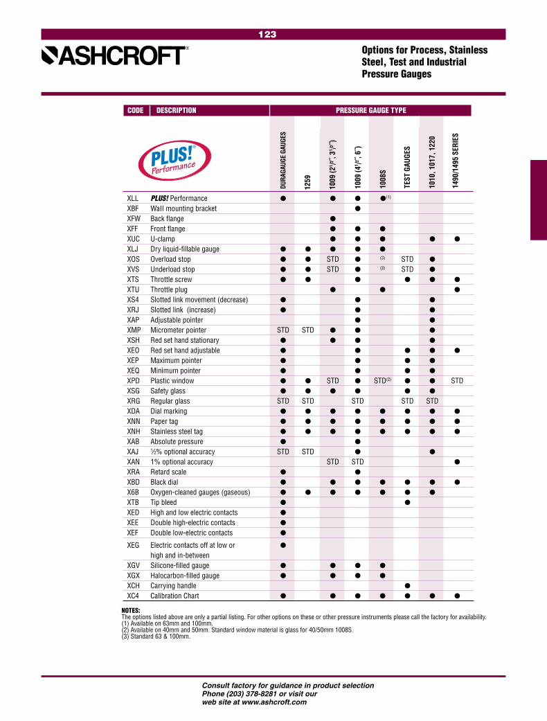
123
Consult factory for guidance in product selectionPhone (203) 378-8281 or visit our web site at www.ashcroft.com
Options for Process, Stainless Steel, Test and Industrial Pressure Gauges
TEST
GAU
GES
1008
S
1010
, 101
7, 1
220
1490
/149
5 SE
RIES
1009
(41 /2
, 6˝)
1009
(21 /2
, 31 /2 ˝
)
DURA
GAUG
E GA
UGES
CODE DESCRIPTION PRESSURE GAUGE TYPE
NOTES: The options listed above are only a partial listing. For other options on these or other pressure instruments please call the factory for availability.(1) Available on 63mm and 100mm.(2) Available on 40mm and 50mm. Standard window material is glass for 40/50mm 1008S.(3) Standard 63 & 100mm.
XLL PLUS! Performance (1)
XBF WaII mounting bracket XFW Back flange
XFF Front flange XUC U-clamp
XLJ Dry liquid-fillable gauge
XOS Overload stop STD (3) STD
XVS Underload stop STD (3) STD
XTS Throttle screw
XTU Throttle plug
XS4 Slotted link movement (decrease)
XRJ Slotted link (increase)
XAP Adjustable pointer
XMP Micrometer pointer STD STD
XSH Red set hand stationary
XEO Red set hand adjustable
XEP Maximum pointer
XEQ Minimum pointer
XPD Plastic window STD STD(2) STD XSG Safety glass
XRG Regular glass STD STD STD STD STD XDA Dial marking
XNN Paper tag
XNH Stainless steel tag
XAB Absolute pressure
XAJ 1⁄2% optional accuracy STD STD
XAN 1% optional accuracy STD STD
XRA Retard scale
XBD Black dial
X6B Oxygen-cleaned gauges (gaseous)
XTB Tip bleed XED High and low electric contacts
XEE Double high-electric contacts
XEF Double low-electric contacts
XEG Electric contacts off at low or high and in-between
XGV Silicone-filled gauge
XGX Halocarbon-filled gauge
XCH Carrying handle
XC4 Calibration Chart
1259

124
Consult factory for guidance in product selectionPhone (203) 378-8281 or visit our web site at www.ashcroft.com

125
Consult factory for guidance in product selectionPhone (203) 378-8281 or visit our web site at www.ashcroft.com
(Generally ASME B 40.1 Grade B (±3-2-3% of span), accuracy , review section for exceptions)
Type D1005PS .............................................127Type 1005 ....................................................128Type 1005P ..................................................129Type 1005S ..................................................130Type 1001T Panel Gauges ...........................131Type 1005P, XUL Sprinkler Gauges ..............132Type 1005M, XRG Agricultural Ammonia Gauges ....................................133Type 1008A/AL General Service Gauges .....134Type 3005/3005P Hydraulic Gauges ...........135Type 1000 and Type 2071A Contractor Gauges ...................................136Type 1007P, XOR; Type 1001T, XOR Refrigeration Gauges ................................137Type 23DDG MiniGauge® Pressure Gauge ..138 Type 40DDG, 50DDG Direct Drive Gauges ...139 Type 12DDG, 15DDG Direct Drive Gauges ...140 Type MFX, Fire Extinguisher Gauges ...........141
COMMERCIALGAUGES

126
Consult factory for guidance in product selectionPhone (203) 378-8281 or visit our web site at www.ashcroft.com

127
Consult factory for guidance in product selectionPhone (203) 378-8281 or visit our web site at www.ashcroft.com
The Ashcroft® Type D1005PS offers 0.5% of span accuracy, while the stainless steel sensor and socket make this product suitable not only for dry air applications but for other media as well. This product offers selectable units of measure so rather than purchasing one gauge for each unit of measure required, the solution is one gauge for multiple units of measure. The D1005PS is standard with many features not offered, or offered only as options, on competitor’s digital gauge products, such as peak hold and 41/2 digit display. When compared to mechanical gauges the D1005PS offers overall enhanced value.
• Enhanced value versus mechanical gauges
• No-nonsense accuracy – ±0.5% full scale accuracy
• Easy-to-read – 41/2 digit display with 1/2 character size, optional backlite display feature to enhance visibility
• Versatile – 9 engineering units and stainless steel sensor suitable for a variety of applications
• Standard features – max.-pressure indication; ranges from vacuum to 19,999 psi, including compound
• Competitively priced and can be customized for OEM applications
General Purpose Digital GaugeType D1005PS, ±1/2% of Span Terminal Point Accuracy
PRODUCT SPECIFICATIONS
Type no.: D1005PSAccuracy: ±0.5% of spanCase Size: 21⁄2˝Case Material: Noryl®
Wetted Parts: 17-4 PH stainless steel sensor; 316 stainless steel socket
Socket Size: 1⁄4 NPT Connection: LowerRanges: Vac. thru 19,999 psi (see standard
ranges for other units of measurement)Battery: Two AAA alkaline batteries; approxi-
mately 1000 hours battery lifeOverpressure: Vac. 0/3000- 0/1000 0/5000 0/19,999 Proof: 200% 150% 120%
Burst: 800% 300% 150%Cycle Life: 108 cycles 20/80% F.S. with negli-
gible performance lossVibration: Less than ±0.1% F.S. effect for
0/2000 Hz at 20 g’s in any axisShock: Less than ±0.05% F.S. effect for 100
g’s, 20msec shock in any axisOperating Temp.: –10°C to 60°C
(14°F to 140°F)Storage Temp.: –20°C to 70°C
(-4°F to 158°F) (maximum temperature shift is .028% per °F from –20°F to 180°F starting at 68°F. For vacuum and 30 psi ranges the maximum temperature shift is .04%)
Update Rate: 100msAgency Approvals: CE EN 61326 (1998); CE EN 61326
Annex A (heavy industrial)Packaging: Individual cartonOpt’l. Features: ±0.25% of span accuracy; backlite;
3, 9, 12 o’clock connections; Alter-nate socket configurations – upon application; Customized keypad; Protective boot; Bulk packaging
DISPLAY Type: LCD Display Digits: 1/2
Display Full Scale Display Resolution: Numerical Value Resolution >=-15>0 –XX.000 >0 <2 X.0000 >=2 <20 XX.000 >=20 <200 XXX.00 >=200 <2000 XXXX.0 >=2000 <19,999 XXXXX Character Height: 0.5˝ Backlight: OFF by default Battery: Four-level battery indication
KEYPAD FUNCTIONS On/Off: Manually turns unit on and off (four
options: never, 5, 10 and 20 min.)Backlite (optional): Manually turns backlite on and off
(four programmable auto on/off options)
Maximum (Peak Hold): Displays max. value when activatedZero/Clear: Zeros display or clears max. value
when activatedEngineering Units: psi, in.Hg, cmHg, mmHg, kPa, MPa,
bar, kg/cm2, ftH2OField Calibration: Zero and span
TO ORDER THIS TYPE D1005PS GAUGE:
Select: 25 D1005PS 02L 100#1. Dial Size: 21⁄2˝2. Case Type Number: D1005PS3. Wetted Parts: Stainless Steel4. Connection: 1⁄4 NPT lower5. Range: 0/100 psi
*Protective Boot Optional
STANDARD RANGES Vacuum in.Hg kPa cmHg Bar kg/cm2 mmHg –30/0 –100/0 –76/0 –1/0 –1/0 –760/0 Compound in.Hg/psi kPa mPa Bar kg/cm2 ft H2O –30/300 –100/2000 – –1/20 –1/20 –35/700 –30/600 –100/4000 – –1/20 –1/20 –35/140 –30/100 –100/7000 – –1/20 –1/20 –35/230 –30/150 –100/1050 – –1/11 –1/11 –35/350 –30/300 –100/2100 – –1/21 –1/21 –35/700 Pressure psi kPa mPa Bar kg/cm2 ft H2O 0/30000 0/2000 – 0/200 0/200 0/700 0/60000 0/4000 – 0/400 0/400 0/140 0/10000 0/7000 – 0/700 0/700 0/230 0/20000 0/1400 – 0/140 0/140 0/460 0/30000 0/2100 – 0/210 0/210 0/700 0/50000 0/3500 – 0/350 0/350 – 0/10000 0/7000 – 0/700 0/700 – 0/15000 – 0/100 0/105 0/105 – 0/20000 – 0/140 0/140 0/140 – 0/30000 – 0/210 0/210 0/210 – 0/50000 – 0/350 0/350 0/350 – 0/10,000 – 0/700 0/700 0/700 – 0/15,000 – 0/100 0/1000 0/1000 – 0/19,999 – 0/140 0/1400 0/1400 –
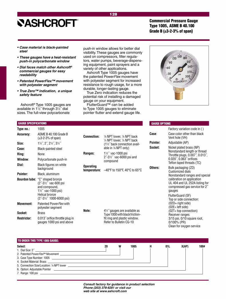
128
Consult factory for guidance in product selectionPhone (203) 378-8281 or visit our web site at www.ashcroft.com
Type no.: 1005
Accuracy: ASME B 40.100 Grade B (±3-2-3% of span)
Size: 11⁄2˝, 2˝, 21⁄2˝, 31⁄2˝
Case: Black-painted steel
Ring: None
Window: Polycarbonate push-in
Dial: Black figures on white background
Pointer: Black, aluminum
Bourdon tube: “C” shaped bronze (2˝-31⁄2˝ vac-600 psi and compound, 11⁄2˝ vac-1000 psi) Helical bronze (2˝-31⁄2˝ 1000-6000 psi)
Movement: Patented PowerFlex with polyester segment
Socket: Brass
Restrictor: 0.013˝ orifice throttle plug in gauges 1000 psi and above
Ashcroft® Type 1005 gauges are available in 11⁄2˝ through 31⁄2˝ dial sizes. The full-view polycarbonate
• Case material is black-painted steel
• These gauges have a heat-resistant push-in polycarbonate window
• Dial faces match other Ashcroft®
commercial gauges for easy readability
• Patented PowerFlex™ movement with polyester segment
• True Zero™ indication, a unique safety feature
Factory variation code in ( )Case: Case color other than black Vent hole (VH)Pointer: Adjustable (AP)Socket: Nickel plated brass (NP) Nonstandard length or thread Throttle plugs, 0.007˝, 0.013˝, 0.020˝, 0.063˝ orifices Teflon taped threads (TC)Others: Bulk packaging (ZO)
Customized dials Nonstandard ranges and special calibration on application UL 404 and UL 252A listing for compressed gas service for 2˝ gauges
FlutterGuard (SF) Top or side connection: (02D= right side) (02E= left side) (02T= top connection) Receiver ranges: 3/15 psi, 0/10 square root, 0/100% (PR) Clean for oxygen service
Commercial Pressure GaugeType 1005, ASME B 40.100 Grade B (±3-2-3% of span)
Connection: 1⁄8 NPT lower, 1⁄8 NPT back 1⁄4 NPT lower, 1⁄4 NPT back (11⁄2˝ back connection avail-
able in 1⁄8 NPT only)
Ranges: 11⁄2˝ vac-1000 psi 2˝-31⁄2˝ vac-6000 psi and compound
Operating temperature: –40°F to 150°F, 40°C to 65°C
Note: 41⁄2˝ gauges are available as Type 1000 with black friction- fit ring and plastic window. Refer to Bulletin CG-10
TO ORDER THIS TYPE 1005 GAUGE:
Select: 20 W 1005 H 01L X(AP) 100#1. Dial Size: 2˝2. Patented PowerFlex™ Movement3. Case Type Number: 1005 4. Socket Material: Brass5. Connection Size/Location: 1⁄8 NPT lower6. Option: Adjustable Pointer 7. Range: 100 psi
push-in window allows for better dial visibility. These gauges are commonly used on compressors, filter regula-tors, water pumps, beverage-dispens-ing equipment, paint sprayers and a variety of other applications.
Ashcroft Type 1005 gauges have the patented PowerFlex movement with polyester segment for increased resistance to rough usage, for a more durable, longer-lasting gauge.
True Zero indication reduces the potential risk of installing a damaged gauge on your equipment.
FlutterGuard™ can be added to Type 1005 gauges to eliminate pointer flutter and extend gauge life.
GAUGE SPECIFICATIONS GAUGE OPTIONS

129
Consult factory for guidance in product selectionPhone (203) 378-8281 or visit our web site at www.ashcroft.com
Type no.: 1005P
Accuracy: ASME B 40.100 Grade B (±3-2-3% of span)
Size: 11⁄2˝, 2˝, 21⁄2˝, 31⁄2˝
Case: ABS
Ring: None
Window: Polycarbonate snap-in
Dial: Black figures on white background
Pointer: Black, aluminum
Bourdon tube: “C” shaped bronze (2˝-31⁄2˝ vac-600 psi and compound, 11⁄2˝ vac-1000 psi) Helical bronze (2˝-31⁄2˝ 1000-6000 psi)
Movement: Patented PowerFlex with polyester segment
Socket: Brass
Restrictor: 0.013˝ orifice throttle plug in gauges 1000 psi and above
The Ashcroft® Type 1005P case is made of ABS (Acrylonitrile Butadiene Styrene), which is ideal for rugged applications and harsh environmental conditions. The 1005P gauge has a
• Case material is ABS
• Heat-resistant polycarbonate window
• Excellent for applications where corrosion or impact resistance is a necessity
• Patented PowerFlex™ movement with polyester segment
• True Zero™ indication, a unique safety feature
Factory variation code in ( )Case: Panel mount conversion kit (XUC) Case color other than black Vent hole (VH)Pointer: Adjustable (AP)Socket: Nonstandard length or thread Throttle plugs, 0.007˝, 0.013˝,
0.020˝, 0.063˝ orifices Nickel plated brass (NP) Teflon taped threads (TC)
Others: Bulk packaging (ZO) Customized dials FlutterGuard (SF) Clean for oxygen service Nonstandard ranges and spe-cial calibration on application Top or side connection: Panel mount conversion kit Receiver ranges: 3/15 psi, 0/10 square root, 0/100% (PR) UL 404 and UL 252A listing for compressed gas service for 2˝ gauges
Commercial Pressure GaugeType 1005P, ASME B 40.100 Grade B (±3-2-3% of span)
Connection: 1⁄8 NPT lower, 1⁄8 NPT back 1⁄4 NPT lower, 1⁄4 NPT back (11⁄2˝ back connection avail-
able in 1⁄8 NPT only)
Ranges: 11⁄2˝ vac-1000 psi 2˝-31⁄2˝ vac-6000 psi and compound
Operating temperature: –40°F to 150°F, 40°C to 65°C
TO ORDER THIS TYPE 1005P GAUGE:
Select: 20 W 1005 P H 01B X(AP) 100#
1. Dial Size: 2˝2. Patented PowerFlex™ Movement3. Case Type Number: 1005 4. Case Material: ABS5. Socket: Brass6. Connection Size/Location: 1⁄8 NPT back7. Option: Adjustable Pointer 8. Range: 100 psi
GAUGE SPECIFICATIONS GAUGE OPTIONS
full-view polycarbonate window for better dial visibility. For applications requiring a high degree of corrosion resistance (where a more expensive stainless steel case is specified), the Type 1005P gauge is ideal. The new panel mount conversion kits allows the user to convert any back connect gauge into a panel mount gauge.
The PowerFlex movement in these gauges offers superior shock, vibration and pulsation resistance.
True Zero indication reduces the potential risk of installing a damaged gauge on your equipment.
FlutterGuard™ can be added to Type 1005P gauges to eliminate pointer flutter and extend gauge life.
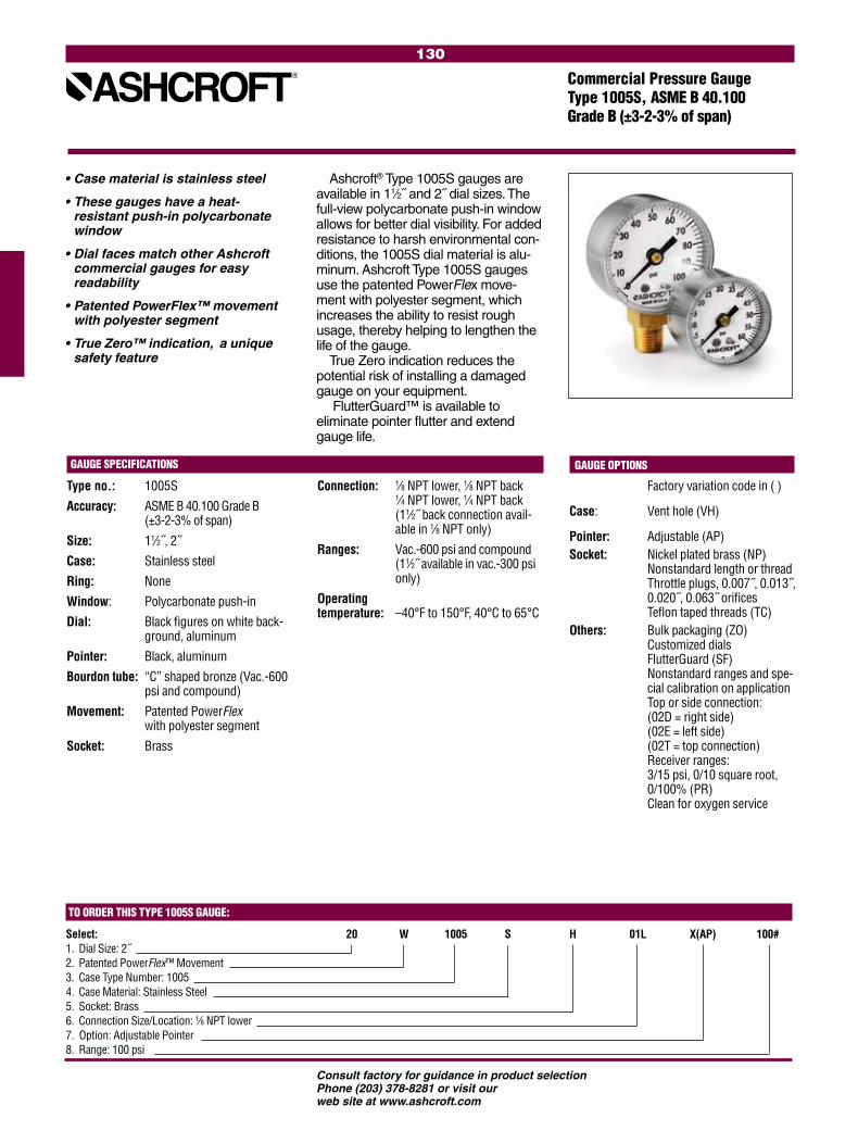
130
Consult factory for guidance in product selectionPhone (203) 378-8281 or visit our web site at www.ashcroft.com
Type no.: 1005S
Accuracy: ASME B 40.100 Grade B (±3-2-3% of span)
Size: 11⁄2˝, 2˝
Case: Stainless steel
Ring: None
Window: Polycarbonate push-in
Dial: Black figures on white back-ground, aluminum
Pointer: Black, aluminum
Bourdon tube: “C” shaped bronze (Vac.-600 psi and compound)
Movement: Patented PowerFlex with polyester segment
Socket: Brass
Ashcroft® Type 1005S gauges are available in 11⁄2˝ and 2˝ dial sizes. The full-view polycarbonate push-in window allows for better dial visibility. For added resistance to harsh environmental con-ditions, the 1005S dial material is alu-minum. Ashcroft Type 1005S gauges use the patented PowerFlex move-ment with polyester segment, which increases the ability to resist rough usage, thereby helping to lengthen the life of the gauge.
True Zero indication reduces the potential risk of installing a damaged gauge on your equipment.
FlutterGuard™ is available to eliminate pointer flutter and extend gauge life.
• Case material is stainless steel
• These gauges have a heat- resistant push-in polycarbonate window
• Dial faces match other Ashcroft commercial gauges for easy readability
• Patented PowerFlex™ movement with polyester segment
• True Zero™ indication, a unique safety feature
Factory variation code in ( )
Case: Vent hole (VH)
Pointer: Adjustable (AP)Socket: Nickel plated brass (NP) Nonstandard length or thread Throttle plugs, 0.007˝, 0.013˝, 0.020˝, 0.063˝ orifices Teflon taped threads (TC)Others: Bulk packaging (ZO)
Customized dials FlutterGuard (SF) Nonstandard ranges and spe- cial calibration on application Top or side connection: (02D = right side)
(02E = left side) (02T = top connection) Receiver ranges: 3/15 psi, 0/10 square root, 0/100% (PR) Clean for oxygen service
Connection: 1⁄8 NPT lower, 1⁄8 NPT back 1⁄4 NPT lower, 1⁄4 NPT back (11⁄2˝ back connection avail-able in 1⁄8 NPT only)
Ranges: Vac.-600 psi and compound (11⁄2˝ available in vac.-300 psi only)
Operating temperature: –40°F to 150°F, 40°C to 65°C
TO ORDER THIS TYPE 1005S GAUGE:
Select: 20 W 1005 S H 01L X(AP) 100#1. Dial Size: 2˝2. Patented PowerFlex™ Movement3. Case Type Number: 1005 4. Case Material: Stainless Steel5. Socket: Brass6. Connection Size/Location: 1⁄8 NPT lower7. Option: Adjustable Pointer 8. Range: 100 psi
Commercial Pressure GaugeType 1005S, ASME B 40.100 Grade B (±3-2-3% of span)
GAUGE SPECIFICATIONS GAUGE OPTIONS

131
Consult factory for guidance in product selectionPhone (203) 378-8281 or visit our web site at www.ashcroft.com
Commercial Panel GaugeType 1001T, ASME B 40.100 Grade B (±3-2-3% of span)
Movement: Patented PowerFlex with polyester segment
Socket: Brass
Restrictor: 0.013 orifice throttle plug in gauges 1000 psi and above
Connection: 1⁄8 NPT Back, 1⁄4 NPT Back (11⁄2 available in 1⁄8 NPT only)
Ranges: Vac.-6000 psi and compound (11⁄2˝ available in vac-1000 psi only)
Operating temperature: –40°F to 150°F, 40°C to 65°C
Ashcroft® panel gauges offer attrac-tive design, excellent readability, and a variety of dial sizes with a broad pressure range selection. The 1⁄4 turn heat-resistant polycarbonate window is available with a hot-stamped mirror band to simulate chrome to further enhance your equipment. The patented PowerFlex™ movement with polyester segment offers superior resistance to shock, vibration and pulsation.
True Zero™ indication, a standard feature on these gauges, reduces the potential risk of installing a damaged gauge on your equipment.
FlutterGuard™ is available to eliminate pointer flutter and extend gauge life.
• Available in 11⁄2˝, 2˝, 21⁄2˝ and 31⁄2˝ dial sizes
• Standard panel-mounting with U-clamp design — front flange mounting available for 2˝ and 21⁄2˝ gauges
• Attractively designed 1⁄4 turn polycarbonate window for better visibility and easy removal
• Patented PowerFlex™ movement with polyester segment
• True Zero™ indication, a unique safety feature
Factory variation code in ( )
Case: Vent hole (VH)Mounting: Front flange (FF) (available in 2˝ and 21⁄2˝ only)
Window: Simulated chrome trim (KL)
Pointer: Adjustable (AP)Socket: Nonstandard length or thread Throttle plugs, 0.007˝, 0.013˝, 0.020˝, 0.063˝ orifices Teflon taped threads (TC)Others: Bulk packaging (ZO)
Customized dials FlutterGuard (SF) Nonstandard ranges and spe-cial calibration on application Receiver ranges: 3-15 psi, 0-10 square root, 0-100% (PR) Clean for oxygen service
Type no.: 1001T
Accuracy: ASME B 40.100 Grade B (±3-2-3% of span)
Size: 11⁄2˝, 2˝, 21⁄2˝, 31⁄2˝
Case: Black-painted steel
Mounting: U-clamp (UC)
Ring: None
Window: 1⁄4 turn threaded polycarbonate
Dial: Black figures on white back-ground
Pointer: Black, aluminum
Bourdon tube: “C” shaped bronze (2˝- 31⁄2˝ vac-600 psi, 11⁄2˝ vac-1000 psi) Helical bronze (2˝- 31⁄2˝ 1000-6000 psi)
TO ORDER THIS TYPE 1001T GAUGE:
Select: 20 W 1001 T H 02B X(UC) 100# 1. Dial Size: 2˝2. Patented PowerFlex™ Movement3. Case Type Number: 10014. 1⁄4 Turn window 5. Socket Material: Brass6. Connection Size/Location: 1⁄4 NPT Back7. Mounting: U-clamp8. Range: 100 psi
GAUGE SPECIFICATIONS GAUGE OPTIONS

132
Consult factory for guidance in product selectionPhone (203) 378-8281 or visit our web site at www.ashcroft.com
Fire Protection, Sprinkler Service Gauge Type 1005P, XUL ASME B 40.100 Grade B (±3-2-3% of span)
• Underwriters Laboratory listed and Factory Mutual approved
• Corrosion-resistant ABS case
• Heat-resistant polycarbonate push-in window
• Patented PowerFlex™ movement with polyester segment
• True Zero™ indication, a unique safety feature
Type no.: 1005P, XUL
Accuracy: ASME B 40.100 Grade B (±3-2-3% of span)
Size: 31⁄2˝
Case: ABS (Polycarbonate blend)
Ring: None
Window: Polycarbonate, push-in
Dial: Black figures on white back-ground
Pointer: Black, aluminum
Bourdon tube: “C” shaped bronze
Movement: Patented PowerFlex with polyester segment
Socket: Brass
Restrictor: None
Ashcroft® fire protection sprinkler gauges are Underwriters Laboratory listed and Factory Mutual approved for fire protection sprinkler service. The case material on Type 1005P, XUL
NOTES
Customized dials
Other UL listed ranges on application
Operating temperature: –40°F to 150°F, 40°C to 65°C
Connection: 1⁄4 NPT lower
Ranges: 0-300 psi (water) 0-80 retard to 250 psi (air) UL 393 Listed, UL of Canada
Listed and FM approved. Equivalent (single or dual scale) metric scales are available
TO ORDER THIS TYPE 1005P, XUL GAUGE:
Select: 35 W 1005 P H 02L XUL 300# 1. Dial Size: 31⁄2˝2. Patented PowerFlex™ Movement3. Case Type Number: 10054. Case Type Material: ABS 5. Socket Material: Brass6. Connection Size/Location: 1⁄4 NPT lower7. UL listed, FM approved8. Range: 300 psi
gauges is ABS. The 0-300 psi pres-sure Arange is used on “wet” systems where water is available to the sprin-kler heads. The 0-80 retard to 250 psi pressure range is used on dry systems where the lines are filled with air pres-sure until system activation.
The patented PowerFlex™ move-ment with polyester segment is designed to provide unequalled shock and vibration resistance resulting in superior performance and extended gauge life.
True Zero™ indication, a standard feature on these gauges, reduces the potential risk of installing a damaged gauge on your equipment.
GAUGE SPECIFICATIONS GAUGE OPTIONS
FMLOOK FOR THESE AGENCY
MARKS ON OUR PRODUCTS

133
Consult factory for guidance in product selectionPhone (203) 378-8281 or visit our web site at www.ashcroft.com
Agricultural Ammonia GaugeType 1005M, XRG ASME B 40.100 Grade B (±3-2-3% of span)
• Available in black-painted steel case
• Steel socket, stainless steel bourdon tube
• Soldered tube-to-socket, and tube- to-tip joints
• Patented PowerFlex™ stainless steel movement with polyester segment
• True Zero™ indication, a unique safety feature
The Ashcroft® Type 1005M, XRG agricultural ammonia gauge is designed to withstand rugged agri-cultural applications. The patented PowerFlex™ movement and state-of-the-art manufacturing processes provide superior gauge performance and extended gauge life. Gauges are tested to ensure leak integrity to 2.8 x 10⁻⁴ cc per second of gas at rated pressure. The glass window eliminates the fogging that occurs when plastic windows are exposed to ammonia.
True Zero™ indication reduces the potential risk of installing a damaged gauge on your equipment.
GAUGE SPECIFICATIONS
Type no.: 1005M, XRG
Accuracy: ASME B 40.100 Grade B (±3-2-3% of span)
Size: 21⁄2˝
Case: Black painted steel
Ring: Black painted steel
Window: Glass
Dial: Black figures on white background
Pointer: Black, aluminum
Bourdon tube: “C” shaped 316 stainless steel
Movement: Patented PowerFlex stainless steel movement with polyester segment
Socket: Steel
Restrictor: None
Connection: 1⁄4 NPT lower
Construction: Soldered tube/socket and tube/tip joints
Ranges: 0/60 psi, 0/150 psi, 0/400 psi
Operating temperature: –40°F to 150°F, 40°C to 65°C
TO ORDER THIS TYPE 1005M, XRG GAUGE:Select: 25 W 1005 M 02L XRG 400#
1. Dial Size: 21⁄2˝2. Patented PowerFlex™ Movement3. Case Type Number: 1005 4. Socket Material: Steel5. Connection Size/Location: 1⁄4 NPT lower6. Glass window and retaining ring7. Range: 400 psi
GAUGE OPTIONS
Window: Push-in polycarbonate (exclude XRG
Socket: Throttle plug, stainless steel, 0.020˝ orifice
Others: Bulk packaging (ZO) Special calibration on application Customized dials FlutterGuard™

134
Consult factory for guidance in product selectionPhone (203) 378-8281 or visit our web site at www.ashcroft.com
TO ORDER THIS TYPE 1008A/AL GAUGE:
Select: 63 1008 A L 02B XUC 1000#1. Dial Size: 63mm or 100mm2. Case Type: 10083. Socket Material: Brass4. Liquid Filled (Glycerin), leave blank if dry5. Connection Size: 1⁄4 NPT6. Connection Location: Lower (L), Back (B)7. Optional Features: XUC = Panel Mounting Kit8. Range: 1000 psi
Ashcroft® Type 1008A gauges are synonymous with durability, flexibility and exceptional quality. The Type 1008A gauge enclosure is sealed
• 63mm (21/2 ) and 100mm (4 ) case sizes• Soldered brass socket and bronze tube design• Corrosion-resistant stainless steel case/ring• Dry, field-fillable or liquid-filled versions• Patented PowerFlex™ movement • True Zero™ indication, a unique safety feature• Two-year warranty on liquid-filled gauges
Type no.: 1008A/AL
Accuracy: ASME B 40.100 Grade B (±3-2-3% of span)
Size: 63mm (21/2˝), 100mm (4˝)
Case: 304 stainless steel, dry (1008A), or liquid filled (1008AL)
Fill Fluid: Glycerin
Ring: 304 stainless steel, crimped
Window: Polycarbonate
Dial: Black figures on white back-ground, aluminum
Pointer: Black, aluminum
Bourdon Tube: “C” shaped bronze (vac.-600 psi and compound)
Helical bronze (1000 psi-6000 psi)
Helical stainless steel (10,000 psi-15,000 psi)
GAUGE OPTIONSCase: Sealed case, field-fillable (LJ)
Silicone filled (GV)MountingHardware: U-clamp (UC), front flange
(FF), retrofit flange (RF)Socket: Throttle plugs, 0.007, 0.020,
0.063˝Connections: JIS, DIN, metric, SAE and
other connections on application
Others: Customized dials Nonstandard ranges FlutterGuard (SF) Special calibration on
application Clean for oxygen service –
dry gauges only
Movement: Patented PowerFlex with polyester segment
Socket: Brass, with O-ring case seal
Restrictor: Brass throttle plug, 0.013˝ orifice in all ranges (except vacuum and 15# psi ranges)
Connection: 1/4 NPT lower and back
Ranges: Vac. thru 15,000 psi and compound. Equivalent metric ranges available
Operating Temperature: Dry gauge:
–40°F to 150°F, 40°C to 65°C Glycerine filled: 20°F to 150°F
GAUGE SPECIFICATIONS
to provide maximum protection in adverse environmental conditions. Both 63mm and 100mm Type 1008A gauges are available dry, field-fillable, glycerin filled or silicone filled. Acces-sory kits are available for panel mount-ing, front flange mounting or retrofit mounting back connection gauges. The patented PowerFlex™ movement pro-vides a higher level of shock, vibration and pulsation resistance than conven-tional movement gauges.
The True Zero™ feature helps to assure a quality process and reduces manufacturing and inspection costs.
FlutterGuard™ is available for dry gauges to eliminate pointer flutter and extend gauge life.
Stainless Steel Case GaugeType 1008A/AL, 63mm and 100mm ASME B 40.100 Grade B (±3-2-3% of span)
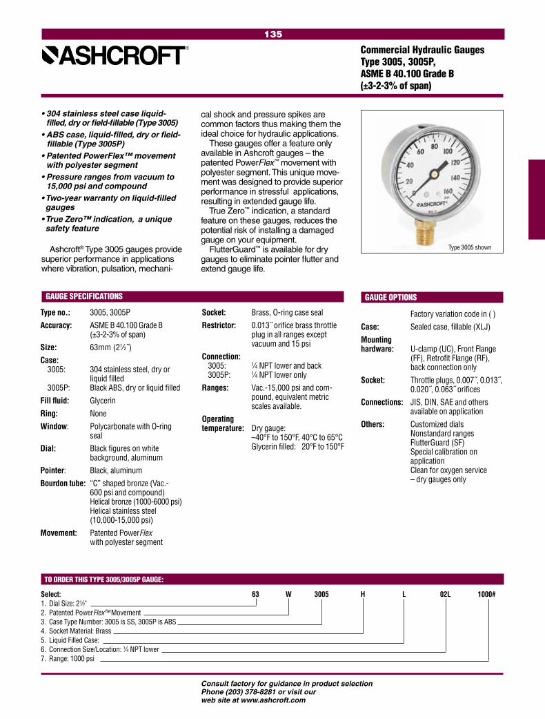
135
Consult factory for guidance in product selectionPhone (203) 378-8281 or visit our web site at www.ashcroft.com
GAUGE OPTIONS
Factory variation code in ( )
Case: Sealed case, fillable (XLJ)
Mounting hardware: U-clamp (UC), Front Flange (FF), Retrofit Flange (RF), back connection only
Socket: Throttle plugs, 0.007˝, 0.013˝, 0.020˝, 0.063˝ orifices
Connections: JIS, DIN, SAE and others available on application
Others: Customized dials Nonstandard ranges FlutterGuard (SF) Special calibration on application Clean for oxygen service
– dry gauges only
Socket: Brass, O-ring case seal
Restrictor: 0.013˝ orifice brass throttle plug in all ranges except vacuum and 15 psi
Connection: 3005: 1⁄4 NPT lower and back 3005P: 1⁄4 NPT lower only
Ranges: Vac.-15,000 psi and com- pound, equivalent metric scales available.
Operatingtemperature: Dry gauge: –40°F to 150°F, 40°C to 65°C Glycerin filled: –20°F to 150°F
Type no.: 3005, 3005P
Accuracy: ASME B 40.100 Grade B (±3-2-3% of span)
Size: 63mm (21⁄2˝)
Case: 3005: 304 stainless steel, dry or liquid filled 3005P: Black ABS, dry or liquid filled
Fill fluid: Glycerin
Ring: None
Window: Polycarbonate with O-ring seal
Dial: Black figures on white background, aluminum
Pointer: Black, aluminum
Bourdon tube: “C” shaped bronze (Vac.- 600 psi and compound) Helical bronze (1000-6000 psi) Helical stainless steel (10,000-15,000 psi)
Movement: Patented PowerFlex with polyester segment
Ashcroft® Type 3005 gauges provide superior performance in applications where vibration, pulsation, mechani-
• 304 stainless steel case liquid- filled, dry or field-fillable (Type 3005)
• ABS case, liquid-filled, dry or field-fillable (Type 3005P)
• Patented PowerFlex™ movement with polyester segment
• Pressure ranges from vacuum to 15,000 psi and compound
• Two-year warranty on liquid-filled gauges
• True Zero™ indication, a unique safety feature
Commercial Hydraulic GaugesType 3005, 3005P, ASME B 40.100 Grade B (±3-2-3% of span)
TO ORDER THIS TYPE 3005/3005P GAUGE:
Select: 63 W 3005 H L 02L 1000# 1. Dial Size: 21⁄2"2. Patented PowerFlex™ Movement3. Case Type Number: 3005 is SS, 3005P is ABS 4. Socket Material: Brass5. Liquid Filled Case:6. Connection Size/Location: 1⁄4 NPT lower 7. Range: 1000 psi
cal shock and pressure spikes are common factors thus making them the ideal choice for hydraulic applications.
These gauges offer a feature only available in Ashcroft gauges – the patented PowerFlex™ movement with polyester segment. This unique move-ment was designed to provide superior performance in stressful applications, resulting in extended gauge life.
True Zero™ indication, a standard feature on these gauges, reduces the potential risk of installing a damaged gauge on your equipment.
FlutterGuard™ is available for dry gauges to eliminate pointer flutter and extend gauge life.
3005 shown
GAUGE SPECIFICATIONS
Type 3005 shown

136
Consult factory for guidance in product selectionPhone (203) 378-8281 or visit our web site at www.ashcroft.com
Ashcroft® Type 1000 gauges have a black steel case and ring with a plastic window. These gauges are appropriate for general industrial applications and can be customized to complement your equipment.
Type 2071A Contractor gauge shown
• Type 2071A contractor gauge offers aluminum-back flange case (black), with attractive chrome-plated steel ring
• Type 1000 gauge offers black steel case with black ring and acrylic window
• Adjustable pointer is standard on contractor gauges
• Patented PowerFlex™ movement with polyester segment
• True Zero™ indication, a unique safety feature
GAUGE SPECIFICATIONS TYPE 1000 TYPE 2071A
Size: 41⁄2˝ 41⁄2˝
Accuracy: ASME B 40.100, Grade B (±3-2-3% of span) ASME B 40.100, Grade A (±2-1-2% of span)
Case: Black-painted steel Aluminum with back flange, painted black.
Ring: Black-painted steel, friction fit Chrome-plated steel, friction fitWindow: Plastic GlassDial: Black figures on white background Black figures on white backgroundPointer: Black, aluminum Adjustable, black, aluminumBourdon tube: Bronze, soldered Bronze, soldered (siphon required for steam service) Movement: Patented PowerFlex with polyester segment Patented PowerFlex with polyester segmentSocket: Brass BrassConnection: 1⁄4 NPT lower 1⁄4 NPT lowerRanges: Vacuum through 600 psi and compound Vacuum through 600 psi and compound
Operating temperature: –40°F to 150°F, 40°C to 65°C –40°F to 150°F, 40°C to 65°COptions: Case color other than black
Glass window (XRG) Chrome ring (13)FlutterGuard (SF) Adjustable pointer (AP)Nickel-plated socket (NP)Customized dialsThrottle plugs: 0.007˝, 0.013˝, 0.020˝, 0.063˝ orificesSpecial calibration on application
Case color other than black Plastic window (PD)Nickel-plated socket (NP)FlutterGuard (SF) Black steel ring Customized dialsThrottle plugs: 0.007˝, 0.013˝, 0.020˝, 0.063˝ orificesSpecial calibration on application
TO ORDER THIS TYPE 1000/2071A GAUGE:
Select: 45 W 2071A 02L 300#1. Dial Size: 41⁄2˝2. Patented PowerFlex™ Movement3. Case Type Number: 2071A4. Connection Size/Location: 1⁄4 NPT lower5. Range: 300 psi
Ashcroft contractor gauges (Type 2071A) are lightweight, highly sensi-tive and accurate. These gauges are designed to meet the needs of HVAC and plumbing contractors, and are tested against strict industry specifi-cations. The aluminum case provides corrosion resistance.
The patented PowerFlex™ move-ment, in both Types 1000 and 2071A, provides the shock resistance needed for rough treatment.
True Zero™ indication reduces the potential risk of installing a damaged gauge on your equipment.
FlutterGuard™ is available to eliminate pointer flutter and extend gauge life.
41⁄2˝ GaugesType 1000, ASME B 40.100 Grade B (±3-2-3% of span)Type 2071A, ASME B 40.100 Grade A (±2-1-2% of span)

137
Consult factory for guidance in product selectionPhone (203) 378-8281 or visit our web site at www.ashcroft.com
• Standard dials offer four refriger-ant scales (R12, R22, R502, 134A)
• FlutterGuard™ eliminates pointer flutter
• Patented PowerFlex™ movement with polyester segment
TO ORDER THIS TYPE 1001T, XOR / 1007P, XOR/ 1005, XOR GAUGE:
Select: 25 W 1007 P H 01L X(OR) 140#/V1. Dial Size: 21⁄2˝2. Patented PowerFlex™ Movement3. Case Type Number: 10074. Case material: ABS 5. Socket Material: Brass6. Connection Size/Location: 1⁄8 NPT lower7. Refrigeration Application8. Range: 30˝Hg vac./0/120 psi retard to 250 psi
Ashcroft® Types 1001T, XOR 1007P, XOR and 1005, XOR are designed to meet the unique require-ments of the HVAC, automotive and refrigeration industries. Ashcroft Type 1001T, XOR gauges are designed for refrigerant recovery and recycling units. All gauges for
this service are tested for leaks as small as 2.8 x 10⁻⁴ cc per second to ensure superior integrity. Optional connections eliminate potential leaks at threaded joints and also eliminate customer cost for extra fittings.
Ashcroft Type 1007P, XOR gauges are designed for installation on refrig-eration manifolds used in testing automotive, industrial and residential air-conditioning units. The ABS case offers rugged durability and corrosion resistance.
FlutterGuard,™ a standard feature in these gauges, eliminates pointer flutter and extends gauge life.
Refrigeration GaugeType 1007P, XOR (see below) Type 1001T, XOR Type 1005, XOR
GAUGE SPECIFICATIONS
TYPE 1001T, XOR TYPE 1007P, XOR
Size: 21⁄2˝, 31⁄2˝ 21⁄2˝ Accuracy: 1% at zero, 2% three fourths of scale, 1% at zero, 2% three fourths of scale, 5% last fourth of scale 5% last fourth of scaleCase: Black steel with studs and U-clamp Red ABS - high pressure for panel mounting Blue ABS - low pressureRing: None NoneWindow: 1⁄4 turn polycarbonate, threaded Polycarbonate, threadedDial: Refrigerant scales R12, R22, R502, Refrigerant scales R12, R22, R502, R134A, 410A R134A, 410APointer: Black, aluminum Black, aluminumBourdon tube: Bronze Bronze Movement: Patented PowerFlex with polyester seg- Patented PowerFlex with polyester seg- ment and FlutterGuard; slotted span ment and FlutterGuard; slotted span screw for minor span adjustments screw for minor span adjustmentsSocket: Brass BrassRestrictor: 0.013˝ orifice throttle plug 0.020˝ orifice throttle plugConnection: 1⁄8 NPT back, 1⁄4 NPT back 1⁄8 NPT lowerRanges: 30 in.Hg vac./0/120 psi retard to 30 in.Hg vac./0/120 psi retard to 250 psi; 0-500 psi; 30 in.Hg vac./0/350 psi 250 psi; 0-500 psi; 30 in.Hg vac./0/350 psi retard to 500 psi; 0-800 psi retard to 500 psi; 0-800 psiOperating temp.: –40°F to 150°F, 40°C to 65°C –40°F to 150°F, 40°C to 65°COptions: Nonstandard ranges Nonstandard ranges Alternate refrigerant ranges Alternate refrigerant ranges SAE Flare, solder bib and ferrule Case color connections, Customized dials Customized dials
1007P, XOR gauge shown
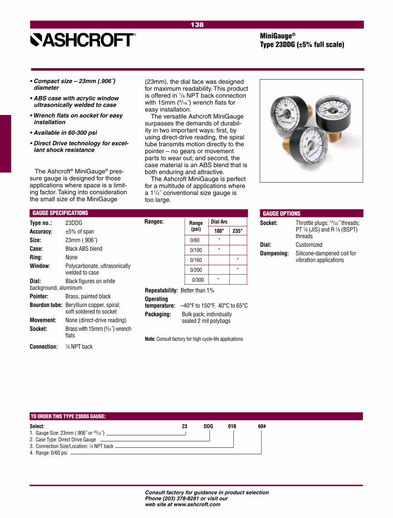
138
Consult factory for guidance in product selectionPhone (203) 378-8281 or visit our web site at www.ashcroft.com
• Compact size – 23mm (.906˝) diameter
• ABS case with acrylic window ultrasonically welded to case
• Wrench flats on socket for easy installation
• Available in 60-300 psi
• Direct Drive technology for excel-lant shock resistance
The Ashcroft® MiniGauge® pres-sure gauge is designed for those applications where space is a limit-ing factor. Taking into consideration the small size of the MiniGauge
(23mm), the dial face was designed for maximum readability. This product is offered in 1/8 NPT back connection with 15mm (9/16˝) wrench flats for easy installation.
The versatile Ashcroft MiniGauge surpasses the demands of durabil-ity in two important ways: first, by using direct-drive reading, the spiral tube transmits motion directly to the pointer – no gears or movement parts to wear out; and second, the case material is an ABS blend that is both enduring and attractive.
The Ashcroft MiniGauge is perfect for a multitude of applications where a 11/2˝ conventional size gauge is too large.
GAUGE SPECIFICATIONS
Type no.: 23DDGAccuracy: ±5% of spanSize: 23mm (.906˝)Case: Black ABS blend Ring: NoneWindow: Polycarbonate, ultrasonically welded to caseDial: Black figures on white background, aluminumPointer: Brass, painted blackBourdon tube: Beryllium copper, spiral; soft soldered to socketMovement: None (direct-drive reading)Socket: Brass with 15mm (9⁄16˝) wrench flats
Connection: 1⁄8 NPT back
Repeatability: Better than 1%Operating temperature: –40°F to 150°F, 40°C to 65°CPackaging: Bulk pack; individually sealed 2 mil polybags
Note: Consult factory for high cycle-life applications
GAUGE OPTIONSSocket: Throttle plugs; 10/32˝ threads; PT 1⁄8 (JIS) and R 1⁄8 (BSPT) threadsDial: CustomizedDampening: Silicone-dampened coil for
vibration applications
TO ORDER THIS TYPE 23DDG GAUGE:
Select: 23 DDG 01B 60# 1. Gauge Size: 23mm (.906˝ or 29/32˝)2. Case Type: Direct Drive Gauge3. Connection Size/Location: 1⁄8 NPT back4. Range: 0/60 psi
MiniGauge®
Type 23DDG (±5% full scale)
Ranges: Range Dial Arc
(psi) 180° 235°
0/60 *
0/100 *
0/160 *
0/200 *
0/300 *
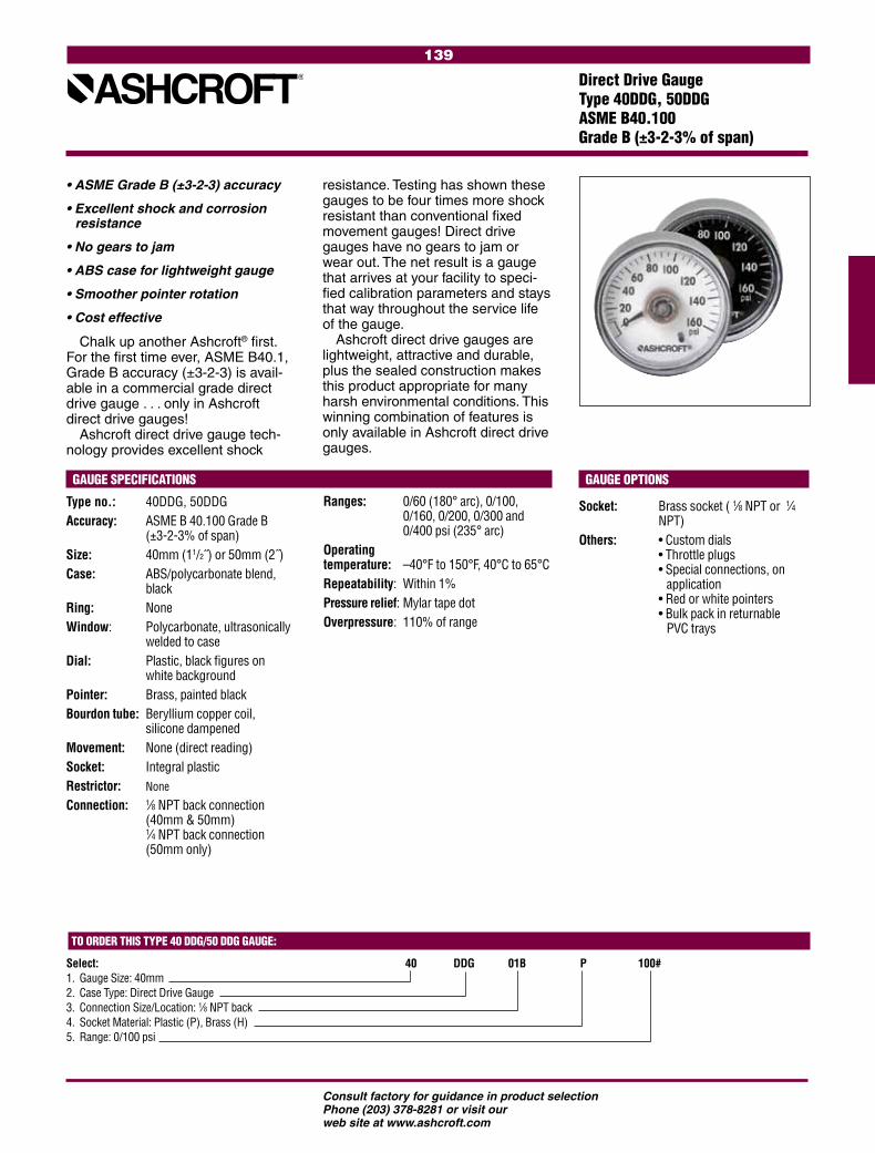
139
Consult factory for guidance in product selectionPhone (203) 378-8281 or visit our web site at www.ashcroft.com
• ASME Grade B (±3-2-3) accuracy
• Excellent shock and corrosion resistance
• No gears to jam
• ABS case for lightweight gauge
• Smoother pointer rotation
• Cost effective
Chalk up another Ashcroft® first. For the first time ever, ASME B40.1, Grade B accuracy (±3-2-3) is avail-able in a commercial grade direct drive gauge . . . only in Ashcroft direct drive gauges!
Ashcroft direct drive gauge tech-nology provides excellent shock
GAUGE SPECIFICATIONS
Type no.: 40DDG, 50DDGAccuracy: ASME B 40.100 Grade B
(±3-2-3% of span)Size: 40mm (11/2˝) or 50mm (2˝)Case: ABS/polycarbonate blend,
black Ring: NoneWindow: Polycarbonate, ultrasonically
welded to caseDial: Plastic, black figures on
white backgroundPointer: Brass, painted blackBourdon tube: Beryllium copper coil,
silicone dampenedMovement: None (direct reading)Socket: Integral plasticRestrictor: None
Connection: 1⁄8 NPT back connection (40mm & 50mm) 1⁄4 NPT back connection (50mm only)
Ranges: 0/60 (180° arc), 0/100, 0/160, 0/200, 0/300 and 0/400 psi (235° arc)Operatingtemperature: –40°F to 150°F, 40°C to 65°CRepeatability: Within 1%Pressure relief: Mylar tape dotOverpressure: 110% of range
GAUGE OPTIONS
Socket: Brass socket ( 1⁄8 NPT or 1⁄4 NPT)
Others: • Custom dials • Throttle plugs • Special connections, on application • Red or white pointers • Bulk pack in returnable PVC trays
resistance. Testing has shown these gauges to be four times more shock resistant than conventional fixed movement gauges! Direct drive gauges have no gears to jam or wear out. The net result is a gauge that arrives at your facility to speci-fied calibration parameters and stays that way throughout the service life of the gauge.
Ashcroft direct drive gauges are lightweight, attractive and durable, plus the sealed construction makes this product appropriate for many harsh environmental conditions. This winning combination of features is only available in Ashcroft direct drive gauges.
TO ORDER THIS TYPE 40 DDG/50 DDG GAUGE:
Select: 40 DDG 01B P 100# 1. Gauge Size: 40mm2. Case Type: Direct Drive Gauge3. Connection Size/Location: 1⁄8 NPT back4. Socket Material: Plastic (P), Brass (H)5. Range: 0/100 psi
Direct Drive GaugeType 40DDG, 50DDG ASME B40.100 Grade B (±3-2-3% of span)

140
Consult factory for guidance in product selectionPhone (203) 378-8281 or visit our web site at www.ashcroft.com
Available Ranges Dial Arc
(psi)
165° 180° 200° 235° 0/60 • 0/100* • 0/160 • 0/200 • 0/300 • 0/700 • 0/1200 • 0/1500 • 0/2000 • 0/3000 • 0/4000 •
Ashcroft® DDG, direct drive gauges are constructed for strenu-ous use under severe environmen-tal conditions and can withstand excessive levels of shock and vibra-tion—an excellent choice for outdoor applications. Optional features to enhance the performance of these gauges are silicone-damped tubes for excessive vibration applications and silicone-filled tubes for corrosion protection.
• Sealed stainless steel case pro-vides a weatherproof, dustproof corrosion-resistant gauge
• Spiral tube transmits motion directly to the pointer— no gears or bearings to wear out
• High impact-resistant polycar-bonate window
• UL 404 listed for compressed gas (including oxygen) for 1500 psi, 2000 psi, 3000 psi and 4000 psi
*12DDG available in 180° arc.
Note: Consult factory for high cycle-life applications
GAUGE OPTIONS
Socket: 1/4 NPT; throttle plugs, 0.007˝, 0.013˝, 0.020˝, 0.063˝ orifice
Others: Customized dials Metric and dual ranges available Silicone-damped spiral tube for vibration service Silicone-filled spiral tube for corrosion protection UL listed for compressed gas (including oxygen); 1500 psi, 2000 psi, 3000 psi, 4000 psi
TO ORDER THIS TYPE DDG GAUGE:
Select: 15 DDG 01B 100# 1. Dial Size: 11⁄2˝2. Case Type: DDG3. Connection Size/Location: 1⁄8 NPT back = 01B4. Range: 100 psi
GAUGE SPECIFICATIONS
Type no.: 12DDG, 15DDG
Accuracy: Standard ±2% at setpoint (setpoint is normally 50% of range; other setpoints upon application). UL listed –3.5% of span in middle three-fifths of scale.
Size: 11⁄4˝ - 12DDG 11⁄2˝ - 15DDG
Case: Stainless steel, sealed
Ring: None
Window: High impact-resistant poly-carbonate
Dial: Black figures on white back-ground
Pointer: Black, integral with bourdon tube
Bourdon tube: Beryllium copper, spiral; soft soldered to socket
Movement: None (direct reading)
Socket: Brass
Restrictor: Safety plug-in 1500-4000 psi ranges
Connection: 1⁄8 NPT back, standard
Repeatability: Better than 1%
Operating Temperature: –40°F to 150°F, –40°C to65°C
Direct Drive GaugeType 12DDG, 15DDG Accuracy (±2% at setpoint)
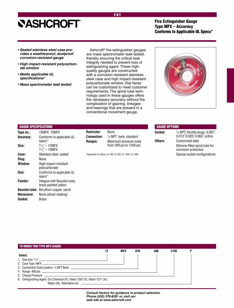
141
Consult factory for guidance in product selectionPhone (203) 378-8281 or visit our web site at www.ashcroft.com
TO ORDER THIS TYPE MFX GAUGE:
Select: 12 MFX 01B 400 C195 P
1. Dial Size: 11⁄4˝2. Case Type: MFX3. Connection Size/Location: 1⁄8 NPT Back4. Range: 400 psi 5. Charge Pressure6. Extinguishing Agent: Dry Chemical (P), Halon 1301 (F), Halon 1211 (H), 5. Extinguishing Agent: Water (W), Alternative (A)
Ashcroft® fire extinguisher gauges are mass spectrometer leak tested, thereby ensuring the critical leak integrity needed to prevent loss of extinguishing agent. These high-quality gauges are constructed with a corrosion-resistant stainless steel case and high impact-resistant polycarbonate window. Dial faces can be customized to meet customer requirements. The spiral tube tech-nology used in these gauges offers the necessary accuracy without the complication of gearing, linkages and bearings that are present in a conventional movement gauge.
• Sealed stainless steel case pro-vides a weatherproof, dustproof corrosion-resistant gauge
• High impact-resistant polycarbon-ate window
• Meets applicable UL specifications*
• Mass spectrometer leak tested
GAUGE SPECIFICATIONSType no.: 12MFX, 15MFXAccuracy: Conforms to applicable UL
specs*Size: 11/4˝ – 12MFX
11/2˝ – 15MFXCase: Stainless steel, sealedRing: NoneWindow: High impact-resistant
polycarbonateDial: Conforms to applicable UL
specs*Pointer: Integral with Bourdon tube,
brass painted yellowBourdon tube: Beryllium copper, spiralMovement: None (direct reading)Socket: Brass
GAUGE OPTIONSSocket: 1/4 NPT; throttle plugs, 0.007,
0.013, 0.020, 0.063˝ orificeOthers: Customized dials Silicone-filled spiral tube for
corrosion protection Special socket configurations
Restrictor: NoneConnection: 1/8 NPT back, standardRanges: Maximum pressure scale
from 200 psi to 1200 psi
*Applicable UL Specs: UL 299, UL 626, UL 1058, UL 1093
Fire Extinguisher GaugeType MFX – Accuracy Conforms to Applicable UL Specs*

142
Consult factory for guidance in product selectionPhone (203) 378-8281 or visit our web site at www.ashcroft.com

Consult factory for guidance in product selection Phone (203) 378-8281 or visit our web site at www.ashcroft.com
143
DIAPHRAGM SEALS AND ISOLATORS (Per ASME B40.2 add 0.5% to the accuracy of
an attached instrument. The exceptions are
T-310/311/312/330 seals which add 1.0%)
Introduction & Selection Information . 145-147
Specification Matrix ............................ 148-152
Diaphragm Seals
Type 100 ...................................................153
Type 200 ...................................................154
Type 300 ...................................................155
Type 310, 315 ...........................................156
Type 320 ...................................................157
Types 400/500 .........................................158
Types 510/511 .........................................159
Type 330 ...................................................160
Types 311/312 .........................................161
Types 740/741/702/703 ...........................162
Type 205 ...................................................163
Line Assemblies ..........................................164
Type 80, 81, 85, 86 Iso-Ring, Iso-Spool .......165
Table A (Min. & Max. Pressure for Diaphragm Seals) ............................. 166-167
Seal Style Chart ................................. 168-172
Seal Options All Types ................................172

Consult factory for guidance in product selection Phone (203) 378-8281 or visit our web site at www.ashcroft.com
144
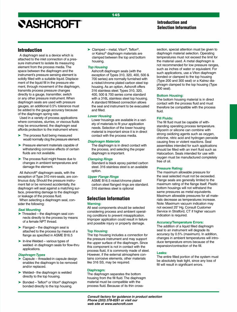
Consult factory for guidance in product selection Phone (203) 378-8281 or visit our web site at www.ashcroft.com
145
Introduction A diaphragm seal is a device which is attached to the inlet connection of a pres-sure instrument to isolate its measuring element from the process media. The space between the diaphragm and the instrument’s pressure sensing element is solidly filled with a suitable liquid. Displace-ment of the liquid fill in the pressure ele-ment, through movement of the diaphragm, transmits process pressure changes directly to a gauge, transmitter, switch or any other pressure instrument. When diaphragm seals are used with pressure gauges, an additional 0.5% tolerance must be added to the gauge accuracy because of the diaphragm spring rate. Used in a variety of process applications where corrosives, slurries, or viscous fluids may be encountered, the diaphragm seal affords protection to the instrument where:
The process fluid being measured would normally clog the pressure element.
Pressure element materials capable of withstanding corrosive effects of certain fluids are not available.
The process fluid might freeze due to changes in ambient temperatures and damage the element.
All Ashcroft® diaphragm seals, with the exception of Type 310 mini-seals, are con-tinuous duty. Should the pressure instru-ment fail or be removed accidentally, the diaphragm will seat against a matching sur-face, preventing damage to the diaphragm or leakage of the process fluid. When selecting a diaphragm seal, con-sider the following:
Seal MountingThreaded – the diaphragm seal con-
nects directly to the process by means of a female NPT thread.
Flanged – the diaphragm seal is attached to the process by means of a flange as specified in ASME B16.5
In-line Welded – various types of welded -in diaphragm seals for flow-thru applications.
Diaphragm Types Capsule – threaded-in capsule design
enables the diaphragm to be removed and/or replaced.
Welded– the diaphragm is welded directly to the top housing.
Bonded – Teflon® or Viton® diaphragm bonded directly to the top housing.
Clamped – metal, Viton®, Teflon®, or Kalrez® diaphragm materials are clamped between the top and bottom housing.
Top Housing Ashcroft diaphragm seals (with the exception of Types 310, 320, 400, 500 & 700 series) are normally furnished with a nickel/chrome plated carbon steel top housing. As an option, Ashcroft offers 316 stainless steel. Types 310, 320, 400, 500 & 700 series come standard with a 316L stainless steel top housing. A standard fill/bleed connection allows the seal and instrument to be evacuated and filled.
Lower Housing Lower housings are available in a vari-ety of materials to fit your application needs. Selection of the lower housing material is important since it is in direct contact with the process media.
Diaphragm Materials The diaphragm is in direct contact with the process, and selecting the proper diaphragm is important.
Clamping Rings Standard is black epoxy painted carbon steel. 316 stainless steel is an available option.
Upper Flange Rings ASME B16.5 nickel/chrome plated carbon steel flanged rings are standard. 316 stainless steel is optional
Selection InformationWarning: All seal components should be selected considering process and ambient operat-ing conditions to prevent misapplication. Improper application could result in failure and possible injury or property damage.
Top Housing: The top housing includes a connection for the pressure instrument and may support the upper surface of the diaphragm. Since this component is not in contact with the process fluid, it is commonly made of steel. However, if the external atmosphere con-tains corrosive elements, other materials like 316 SS, may be required.
Diaphragm: The diaphragm separates the bottom housing from the fill fluid. The diaphragm material must be compatible with the process fluid. Because of its thin cross-
Introduction and Selection Information
section, special attention must be given to diaphragm material selection. Operating temperatures must not exceed the limit for the material used. A metal diaphragm is not recommended for low pressure ranges, such as inches of water or equivalent. For such applications, use a Viton diaphragm bonded or clamped to the top housing (Type 200 and 300 seal) or a Kalrez dia-phragm clamped to the top housing (Type 300 seal).
Bottom Housing: The bottom housing material is in direct contact with the process fluid and must therefore be compatible with the process fluid.
Fill Fluids: The fill fluid must be capable of with-standing operating process temperature. Glycerin or silicone can combine with strong oxidizing agents such as oxygen, chlorine, nitric acid and hydrogen peroxide causing fires or violent reactions. Seal assemblies intended for such applications should be filled with an inert fluid such as Halocarbon. Seals intended for use with oxygen must be manufactured completely free of oil.
Pressure Rating: The maximum allowable pressure for the seal selected must not be exceeded. Flange seals are generally limited to the maximum rating of the flange itself. Plastic bottom housings will not withstand the same pressures as metal equivalents. Maximum allowable pressures for all mate-rials decrease as temperatures increase. Note: Maximum vacuum indication may not exceed 25” Hg. Consult Customer Service in Stratford, CT if higher vacuum indication is required.
Accuracy/Temperature Errors: The addition of a liquid filled diaphragm seal to an instrument will degrade its accuracy by 0.5% (maximum). In addition, changes in ambient temperatures will intro-duce temperature errors because of the expansion/contraction of the fill.
Leaks: The entire filled portion of the system must be absolutely leak tight, since any loss of fill will result in significant errors.
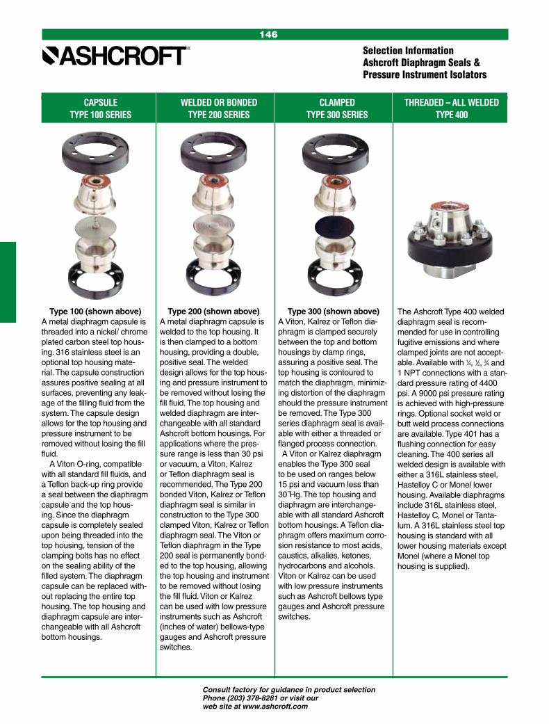
Consult factory for guidance in product selection Phone (203) 378-8281 or visit our web site at www.ashcroft.com
146
CAPSULE WELDED OR BONDED CLAMPED THREADED – ALL WELDED TYPE 100 SERIES TYPE 200 SERIES TYPE 300 SERIES TYPE 400
Type 100 (shown above) A metal diaphragm capsule is threaded into a nickel/ chrome plated carbon steel top hous-ing. 316 stainless steel is an optional top housing mate-rial. The capsule construction assures positive sealing at all surfaces, preventing any leak-age of the filling fluid from the system. The capsule design allows for the top housing and pressure instrument to be removed without losing the fill fluid. A Viton O-ring, compatible with all standard fill fluids, and a Teflon back-up ring provide a seal between the diaphragm capsule and the top hous-ing. Since the diaphragm capsule is completely sealed upon being threaded into the top housing, tension of the clamping bolts has no effect on the sealing ability of the filled system. The diaphragm capsule can be replaced with-out replacing the entire top housing. The top housing and diaphragm capsule are inter-changeable with all Ashcroft bottom housings.
Type 200 (shown above) A metal diaphragm capsule is welded to the top housing. It is then clamped to a bottom housing, providing a double, positive seal. The welded design allows for the top hous-ing and pressure instrument to be removed without losing the fill fluid. The top housing and welded diaphragm are inter-changeable with all standard Ashcroft bottom housings. For applications where the pres-sure range is less than 30 psi or vacuum, a Viton, Kalrez or Teflon diaphragm seal is recommended. The Type 200 bonded Viton, Kalrez or Teflon diaphragm seal is similar in construction to the Type 300 clamped Viton, Kalrez or Teflon diaphragm seal. The Viton or Teflon diaphragm in the Type 200 seal is permanently bond-ed to the top housing, allowing the top housing and instrument to be removed without losing the fill fluid. Viton or Kalrez can be used with low pressure instruments such as Ashcroft (inches of water) bellows-type gauges and Ashcroft pressure switches.
Type 300 (shown above)A Viton, Kalrez or Teflon dia-phragm is clamped securely between the top and bottom housings by clamp rings, assuring a positive seal. The top housing is contoured to match the diaphragm, minimiz-ing distortion of the diaphragm should the pressure instrument be removed. The Type 300 series diaphragm seal is avail-able with either a threaded or flanged process connection. A Viton or Kalrez diaphragm enables the Type 300 seal to be used on ranges below 15 psi and vacuum less than 30˝Hg. The top housing and diaphragm are interchange-able with all standard Ashcroft bottom housings. A Teflon dia-phragm offers maximum corro-sion resistance to most acids, caustics, alkalies, ketones, hydrocarbons and alcohols. Viton or Kalrez can be used with low pressure instruments such as Ashcroft bellows type gauges and Ashcroft pressure switches.
The Ashcroft Type 400 welded diaphragm seal is recom-mended for use in controlling fugitive emissions and where clamped joints are not accept-able. Available with 1⁄4, 1⁄2, 3⁄4 and 1 NPT connections with a stan-dard pressure rating of 4400 psi. A 9000 psi pressure rating is achieved with high-pressure rings. Optional socket weld or butt weld process connections are available. Type 401 has a flushing connection for easy cleaning. The 400 series all welded design is available with either a 316L stainless steel, Hastelloy C or Monel lower housing. Available diaphragms include 316L stainless steel, Hastelloy C, Monel or Tanta-lum. A 316L stainless steel top housing is standard with all lower housing materials except Monel (where a Monel top housing is supplied).
Selection InformationAshcroft Diaphragm Seals & Pressure Instrument Isolators
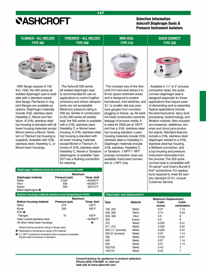
Consult factory for guidance in product selection Phone (203) 378-8281 or visit our web site at www.ashcroft.com
147
FLANGED – ALL WELDED THREADED – ALL WELDED MINI-SEAL QUICK CONNECT TYPE 402 TYPE 500 TYPE 310 TYPE 320
Diaphragm material pressure and temperature limits
Maximum Diaphragm material Pressure (psi) Temp. limit Teflon 2,500 –40/400°F Viton 500 –40/350°F Kalrez 500 30/212°F Metal diaphragms
Bottom housing material pressure and temperature limits
Maximum Bottom housing material Pressure (psi) Temp. limit Teflon 270 130°F Kynar 200 180°F PVC: Flanged 75 100°F Halar coated stainless steel –40/300°F All other metal lower housings
Diaphragm seal displacement
Maximum Displacement Type Material Cubic Cubic inches centimeters 100, 200 Metal 0.07 1.14 200, 300 Teflon 0.14 2.23 200, 300 Viton 0.5 8 300 Kalrez 0.5 8 310 Metal 0.025 0.41 311, 312 Metal 0.032 0.52 320 (11⁄2˝ process) Metal 0.025 0.41 320 (2˝ process) Metal 0.07 1.14 330 Metal 0.018 0.41 400 Metal 0.07 1.14 500 Metal 0.07 1.14 702/703 Metal 0.43 7 740/741 Metal 0.43 7
With flange classes of 150 thru 1500, the 402 series all welded diaphragm seal is avail-able with a standard raised-face flange. Flat-faced or ring joint flanges are available as options. Diaphragm materials include 316L stainless steel, Hastelloy C, Monel and Tan-talum. A 316L stainless steel top housing is standard with all lower housing materials except Monel (where a Monel, Tanta-lum or Titanium top housing is supplied). Available with 316L stainless steel, Hastelloy C, or Monel lower housings.
The Ashcroft 500 series all welded diaphragm seal is recommended for use on applications to control fugitive emissions and where clamped joints are not acceptable. Maximum pressure rating is 500 psi. Similar in construction to the 400 series all welded seal, the 500 series is available with a 316L stainless steel, Hastelloy C or Monel lower housing. A 316L stainless steel top housing is standard with all lower housing materials except Monel or Titanium. A choice of 316L stainless steel, Hastelloy C, Monel or Tantalum diaphragms, is available. Type 501 has a flushing connection for cleaning.
The compact size of the Ash-croft 310 mini-seal allows it to fit into space-restricted areas and is designed to protect transducers, mini-switches, and 31⁄2˝ or smaller dial size pres-sure gauges from corrosion, plugging or freeze- up. All weld-ed metal construction prevents leakage of process media. It is rated for 2500 psi at 100°F and has a 316L stainless steel top housing standard. Lower housing materials include 316L stainless steel or Hastelloy C. Diaphragm materials include 316L stainless, Hastelloy C or Tantalum. 1⁄8 NPT-1˝ NPT process connection sizes are available. Instrument connec-tion is 1⁄4 NPT only.
Available in 11⁄2˝ or 2˝ process connection sizes, the quick-connect diaphragm seal is designed especially for those applications that require ease of dismantling and re-assembly. Typical applications include the pharmaceutical, dairy, food processing, biotechnology, and filtration markets. Also included are breweries, distilleries, win-eries and citrus juice produc-tion plants. Standard features include a 316L stainless steel diaphragm welded to a 316L stainless steel top housing, a fill/bleed connection, and a top housing and pressure instrument removable from the process. The 320 quick- connect seal is compatible with Tri-clamp® and Cherry Burrell S line® connections. For applica-tions required to meet 3A sani-tary standard 37-01, consult Customer Service.
Determined by pressure rating or flange class. Restricted to temperature range of fill material.A 1⁄2 NPT (maximum) threaded bottom housing is available. Socket weld connection is standard.
Selection InformationAshcroft Diaphragm Seals & Pressure Instrument Isolators

Consult factory for guidance in product selection Phone (203) 378-8281 or visit our web site at www.ashcroft.com
148
Specification MatrixAshcroft Diaphragm Seals & Pressure Instrument Isolators
• = AVAILABLE
(2) Type 300 series not available with metallic diaphragms.(3) Type 302/303 not available with 1˝ process size.
Process Connection Type Threaded Threaded w/Flushing Raised Face Flange Raised Face Flange In-line Threaded Connection w/Flushing Connection Model No. Code 100/200/300(1) 101/201/301(1) 102/202/302(2,3) 103/203/303(2,3) 104/204/304(1)
Process Connection Size (NPT) Female
1⁄4 25 • • • 1⁄2 50 • • • • • 3⁄4 75 • • • • • 1 10 • • • • 11⁄2 15 • • 2 20 • • 3 30 • • 4 40
6 60
8 80
Diaphragm Materials
316L stainless steel S 100 & 200 101 & 201 102 & 202 103 & 203 104 & 204
304L stainless steel C 100 & 200 101 & 201 102 & 202 103 & 203 104 & 204
Monel 400 P 100 & 200 101 & 201 102 & 202 103 & 203 104 & 204
Nickel N 100 & 200 101 & 201 102 & 202 103 & 203 104 & 204
Carpenter 20 D 100 & 200 101 & 201 102 & 202 103 & 203 104 & 204
Tantalum U 100 & 200 101 & 201 102 & 202 103 & 203 104 & 204
Hastelloy B G 100 & 200 101 & 201 102 & 202 103 & 203 104 & 204
Hastelloy C 22 J 100 & 200 101 & 201 102 & 202 103 & 203 104 & 204
Hastelloy C 276 H 100 & 200 101 & 201 102 & 202 103 & 203 104 & 204
Teflon T 200 & 300 201 & 301 202 203 204 & 304
Viton Y 200 & 300 201 & 301 202 203 204 & 304
Kalrez K 200 & 300 201 & 301 302 303 304
Titanium TI 200 201 202 203 204
Halar Coated Monel R 100 101 102 103 104
Bottom Housing Materials
Steel B • • • • • 304L stainless steel CL • • • • • 316L stainless steel SL • • • • • Hastelloy B G • • • • • Hastelloy C 22 J • • • • • Hastelloy C 276 H • • • • • Carpenter 20 D • • • • • Monel 400 M • • • • • Inconel 600 W • • • • • Nickel N • • • • • PVC V (Socket Weld or 1⁄4-1⁄2 NPT) 1, 11⁄2
Tantalum Clad SS SU • Halar® Coated Monel BH • Teflon T 1, 11⁄2, 2
Kynar KY Only1⁄4 or 1⁄2 NPT 1, 11⁄2, 2
Titanium TI • • • • • Pressure Ratings (1)
500 psi Viton or Kalrez diaph. only Viton or Kalrez diaph. only Viton or Kalrez diaph. only
2500 psi Metal & Teflon® diaph. • Metal & Teflon® diaph.
5000 psi HP 100 & 200 metal
7500 psi
9000 psi HP
Flange Class
150, 300, 600, 900 or 1500 Kalrez, Teflon, Viton, Kynar 150 only Kalrez, Teflon, Viton, Kynar 150 only
Instrument Connection Size
1⁄4 02T • • • • • 1⁄2 04T • • • • • Filling Fluid
Glycerin CG • • • • • Silicone (direct to 10´ capillary) CK • • • • • Silicone (over 10´ capillary) EJ • • • • • Halocarbon CF • • • • • Syltherm HA • • • • •
(1) See Table A on pasges 166-167 for instrument compatibility. Minimum pressure is determined by the instrument that will be attached to the diaphram seal.

Consult factory for guidance in product selection Phone (203) 378-8281 or visit our web site at www.ashcroft.com
149
Specification MatrixAshcroft Diaphragm Seals & Pressure Instrument Isolators
• = AVAILABLE Process Connection Type Saddle In-line Flanged In-line Socket Weld In-line Male/Female Threaded Butt Weld Mini (*Flushing Conn.) Model No. Code 105/205 106/206 107/207 108 310/315* Process Connection Size (NPT) Female Female Male
1⁄4 25 • • • • 1⁄2 50 • • • • • 3⁄4 75 • • • • 1 10 • • • • 11⁄2 15 • • • 2 20 • • • 3 30 3˝ • 4 40 4˝ and larger 6 60 • 8 80 • Diaphragm Materials
316L stainless steel S • • • • • 304L stainless steel C • • • • Monel 400 P • • • • • Nickel N • • • • Carpenter 20 D • • • • Tantalum U • • • • • Hastelloy B G • • • • Hastelloy C 22 J • • • • Hastelloy C 276 H • • • • • Teflon T 205 206 207 208
Viton Y 205 206 207 208
Kalrez K 205 206 207 208
Titanium TI 205 206 207 208
Halar Coated Monel PH 105 106 107 108
Bottom Housing Materials
Steel B • • • • 304L stainless steel CL • • • • 316L stainless steel SL • • • • • Hastelloy B G • • • • • Hastelloy C 22 J • • • • Hastelloy C 276 H • • • • • Carpenter 20 D • • • • Monel 400 M • • • • • Inconel 600 W • • • • Nickel N • • • • PVC V
Tantalum Clad SS SU
Halar® Coated Monel SH
Teflon T
Kynar KY
Titanium TI • • • Pressure Ratings (1)
500 psi Viton or Kalrez diaph. only Viton or Kalrez diaph. only Viton or Kalrez diaph. only
2500 psi Metal & Teflon® diaph. Metal & Teflon® diaph.
5000 psi HP
7500 psi
15000 psi HP
Flange Class
150, 300, 600, 900 or 1500 150 & 300
Instrument Connection Size
1⁄4 02T • • • • • 1⁄2 04T • • • • • Filling Fluid
Glycerin CG • • • • • Silicone (direct to 10´ capillary) CK • • • • • Silicone (over 10´ capillary) EJ • • • • • Halocarbon CF • • • • • Syltherm HA • • • • •
(1) See Table A on pages 166-167 for instrument compatibility. Minimum pressure is determined by the instrument that will be attached to the diaphram seal.
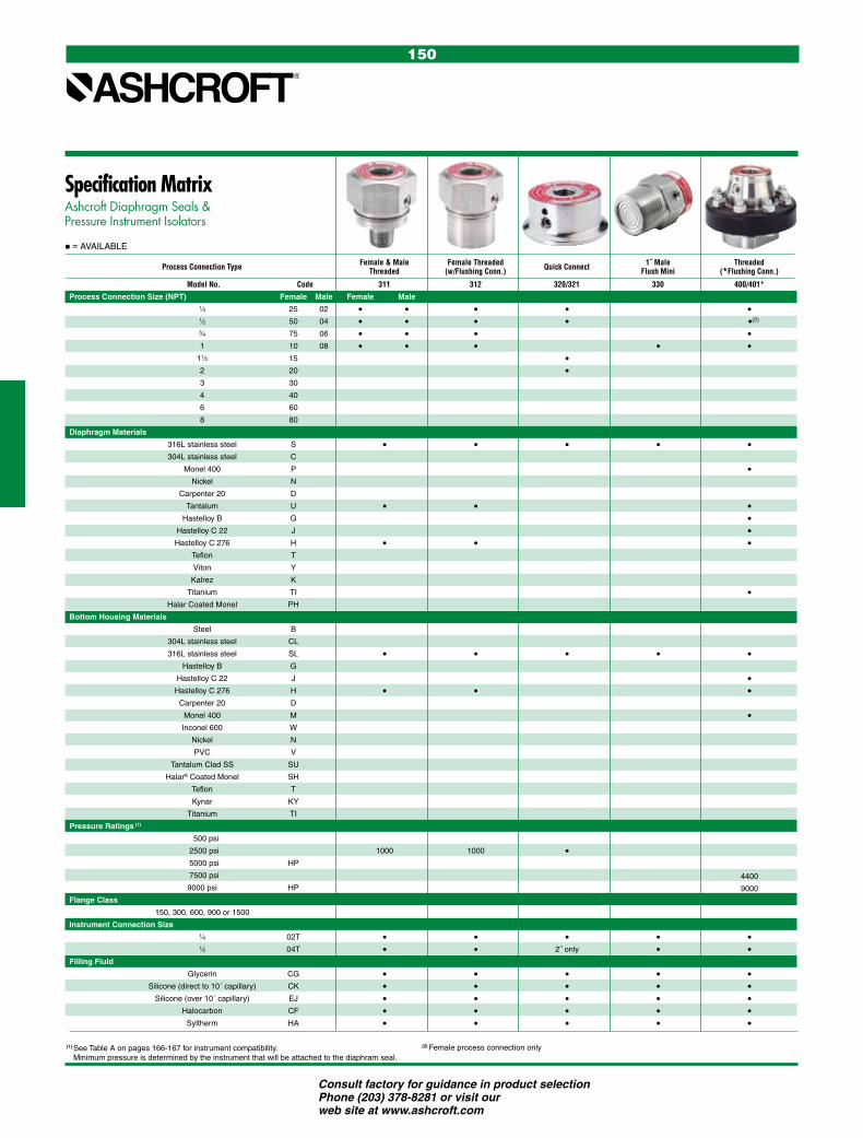
Consult factory for guidance in product selection Phone (203) 378-8281 or visit our web site at www.ashcroft.com
150
Specification MatrixAshcroft Diaphragm Seals & Pressure Instrument Isolators
• = AVAILABLE
Process Connection Type Female & Male Female Threaded Quick Connect 1˝ Male Threaded Threaded (w/Flushing Conn.) Flush Mini (*Flushing Conn.)
Model No. Code 311 312 320/321 330 400/401*
Process Connection Size (NPT) Female Male Female Male
1⁄4 25 02 • • • • • 1⁄2 50 04 • • • • •(2)
3⁄4 75 06 • • • • 1 10 08 • • • • • 11⁄2 15 • 2 20 • 3 30 4 40
6 60
8 80
Diaphragm Materials
316L stainless steel S • • • • • 304L stainless steel C Monel 400 P • Nickel N Carpenter 20 D Tantalum U • • • Hastelloy B G • Hastelloy C 22 J • Hastelloy C 276 H • • • Teflon T Viton Y Kalrez K Titanium TI • Halar Coated Monel PH
Bottom Housing Materials
Steel B 304L stainless steel CL 316L stainless steel SL • • • • • Hastelloy B G Hastelloy C 22 J • Hastelloy C 276 H • • • Carpenter 20 D Monel 400 M • Inconel 600 W Nickel N PVC V
Tantalum Clad SS SU
Halar® Coated Monel SH
Teflon T
Kynar KY
Titanium TI Pressure Ratings (1)
500 psi 2500 psi 1000 1000 • 5000 psi HP
7500 psi 4400
9000 psi HP 9000
Flange Class
150, 300, 600, 900 or 1500
Instrument Connection Size
1⁄4 02T • • • • • 1⁄2 04T • • 2˝ only • • Filling Fluid
Glycerin CG • • • • • Silicone (direct to 10´ capillary) CK • • • • • Silicone (over 10´ capillary) EJ • • • • • Halocarbon CF • • • • • Syltherm HA • • • • •
(1) See Table A on pages 166-167 for instrument compatibility. Minimum pressure is determined by the instrument that will be attached to the diaphram seal.
(2) Female process connection only

Consult factory for guidance in product selection Phone (203) 378-8281 or visit our web site at www.ashcroft.com
151
Specification MatrixAshcroft Diaphragm Seals & Pressure Instrument Isolators
• = AVAILABLE
Process Connection Type Raised Face Flange Threaded Low Pressure Flanged Low Pressure Threaded Isolation Ring (*Flushing Conn.) (*Flushing Conn.) (*w/Flushing Conn.) (*w/Flushing Conn.)
Model No. Code 402/403* 500/501* 702/703* 740/741* 80/81/85/86
Process Connection Size (NPT) Female Pipe Size
1⁄4 25 • 1.0˝ 14.0˝ 1⁄2 50 • • • • 1.5˝ 16.0˝ 3⁄4 75 • • • • 2.0˝ 18.0˝ 1 10 • • • • 3.0˝ 20.0˝ 11⁄2 15 • • 4.0˝ 2 20 • • 5.0˝ 3 30 • • 6.0˝
4 40 8.0˝
6 60 10.0˝
8 80 12.0˝
Diaphragm Materials Liner Materials / Code
316L stainless steel S • • • • Buna N (E) 304L stainless steel C Teflon (T)
Monel 400 P • • • • Viton (Y)
Nickel N Nordell EPDM (EP)
Carpenter 20 D White Neoprene (CR)
Tantalum U • • • • Natural Rubber (NP)
Hastelloy B G • • • Hastelloy C 22 J • •
Hastelloy C 276 H • • • • Teflon T
Viton Y
Kalrez K
Titanium TI • • • Halar Coated Monel PH
Bottom Housing Materials Ass’y Flanges / Code
Steel B • • Carbon Steel (B)
304L stainless steel CL 316 SS (S)
316L stainless steel SL • • • • CPVC (CP)
Hastelloy B G • • Teflon Enveloped (CT)
Hastelloy C 22 J • • Polypropylene (PP)
Hastelloy C 276 H • • • • Carpenter 20 D • • Monel 400 M • • • • Inconel 600 W
Nickel N
PVC V
Tantalum Clad SS SU
Halar® Coated Monel SH
Teflon T
Kynar KY
Titanium TI • • • Pressure Ratings (1) Instrument Conn / Code
500 psi • 750 750 1/4 NPT (02T)
2500 psi 1/2 NPT (0 4T)
5000 psi HP
7500 psi
9000 psi HP
Flange Class
150, 300, 600, 900 or 1500 • 150-600
Instrument Connection Size
1⁄4 02T • • • • 1⁄2 04T • • • • Filling Fluid
Glycerin CG • • • • • Silicone (direct to 10´ capillary) CK • • • • • Silicone (over 10´ capillary) EJ • • • • • Halocarbon CF • • • • • Syltherm HA • • • • •
(1) See Table A on pages 166-167 for instrument compatibility. Minimum pressure is determined by the instrument that will be attached to the diaphram seal.
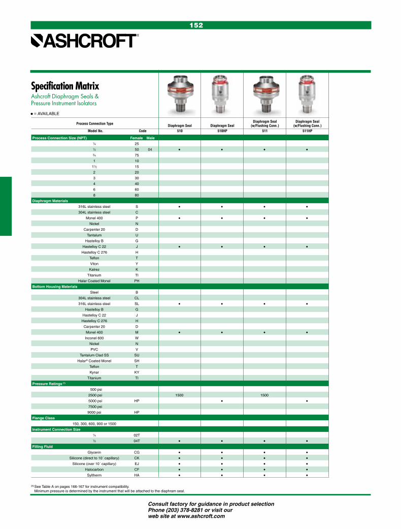
Consult factory for guidance in product selection Phone (203) 378-8281 or visit our web site at www.ashcroft.com
152
Specification MatrixAshcroft Diaphragm Seals & Pressure Instrument Isolators
• = AVAILABLE
Process Connection Type Diaphragm Seal Diaphragm Seal Diaphragm Seal Diaphragm Seal (w/Flushing Conn.) (w/Flushing Conn.) Model No. Code 510 510HP 511 511HP
Process Connection Size (NPT) Female Male
1⁄4 25
1⁄2 50 04 • • • • 3⁄4 75
1 10
11⁄2 15
2 20
3 30
4 40
6 60
8 80
Diaphragm Materials
316L stainless steel S • • • • 304L stainless steel C
Monel 400 P • • • • Nickel N
Carpenter 20 D
Tantalum U
Hastelloy B G
Hastelloy C 22 J • • • • Hastelloy C 276 H
Teflon T
Viton Y
Kalrez K
Titanium TI
Halar Coated Monel PH
Bottom Housing Materials
Steel B
304L stainless steel CL
316L stainless steel SL • • • • Hastelloy B G
Hastelloy C 22 J
Hastelloy C 276 H
Carpenter 20 D
Monel 400 M • • • • Inconel 600 W
Nickel N
PVC V
Tantalum Clad SS SU
Halar® Coated Monel SH
Teflon T
Kynar KY
Titanium TI
Pressure Ratings (1)
500 psi
2500 psi 1500 1500
5000 psi HP • • 7500 psi
9000 psi HP
Flange Class
150, 300, 600, 900 or 1500
Instrument Connection Size
1⁄4 02T
1⁄2 04T • • • • Filling Fluid
Glycerin CG • • • • Silicone (direct to 10´ capillary) CK • • • • Silicone (over 10´ capillary) EJ • • • • Halocarbon CF • • • • Syltherm HA • • • •
(1) See Table A on pages 166-167 for instrument compatibility. Minimum pressure is determined by the instrument that will be attached to the diaphram seal.

Consult factory for guidance in product selection Phone (203) 378-8281 or visit our web site at www.ashcroft.com
153
• A Viton O-ring, compatible with all standard fill fluids, and a Teflon back-up ring provide a seal between the diaphragm capsule and the top housing.
• A thin Teflon PTFE gasket between the diaphragm and bottom housing assures a leak-tight corrosion resis-tant seal even at high pressure.
• Top housing and pressure instru-ment are removable.
• Continuous-duty design will prevent loss of process fluid if pressure in-strument is removed or fails.
The comprehensive line of Ashcroft® diaphragm seals will meet a wide va-riety of application or installation re-quirements. Over 30,000 variations are possible with the types, connections and materials available.• The top housing and diaphragm
capsule are interchangeable with all Ashcroft bottom housings.
• A fill/bleed connection is standard, which permits filling the seal and instrument simultaneously after evacuation and allows the fill to flow into the completed unit.
Table B – Process Connection/Type Number Process Connection Size/Code—Inches Type Number
Size 1⁄4 1⁄2 3⁄4 1 11⁄2 2 3 4 6 8
Process Connection Code 25 50 75 10 15 20 30 40 60 80 Capsule
Threaded–female NPT • • • • • 100
Threaded–female NPT (with flushing connection) • • • • • 101
Flanged(1) • • • • • • 102
Flanged (with flushing connection) • • • • • • 103
In-line—threaded NPT • • • • 104
Saddle • AND LARGER 105
In-line—butt weld • • • • • • 108
In-line—flanged(2) • • • • • • • • • 106
In-line—socket weld • • • • • • 107
Table F – Filling Fluid Filling Service Connection to Instrument Temperature Range °F Code
Glycerin Pressure Direct Only 0/400 CG
Silicone Pressure/Vacuum Direct or Flexible Line –40/600 CK
Halocarbon Pressure/Vacuum in presence of strong oxidizing agent Direct or Flexible Line –70/300 CF
Syltherm Pressure/Vacuum Direct or Flexible Line –40/750 HA
TO ORDER THIS TYPE 100 SERIES DIAPHRAGM SEAL:
SELECTION TABLES*
Table C Diaphragm Material Material Code 316L stainless steel S 304 stainless steel C Monel 400 P Nickel N Carpenter 20 D Tantalum U Hastelloy B G Hastelloy C 22(7) J Hastelloy C 276(7) H Halar Coated Monel PH Gold Plated 304 st. stl. W
Table D Bottom Housing Materials Material Code Steel B 304L stainless steel C 316L stainless steel S Hastelloy B G Hastelloy C 22(7) J Hastelloy C 276(7) H Carpenter 20 D Monel “400” M Inconel “600” W Nickel N PVC(8) V Tantalum clad stainless steel(9) SU Halar coated monel(10) BH Teflon flanged steel(11) T Kynar(13)(14) KY Titanium(13) TI
NOTES:
(1) 150, 300, 600, 900, 1500 & 2500 class flanges.
(2) 1˝ 150 thru 8˝ 300 class flanges only.
(7) Use on applications where NACE standard MR-01-75 2003 is specified.
(8) Maximum Press./Temp. Threaded: 200 psi/74°F, 125 psi/125°F, 80 psi/150°F. Flanged: 75 psi/100°F.
(9) Type 102 only.
(10) Type 102 only – Temp. Limits: –40/300°F.
(11) Only available in 1˝, 1 1⁄2˝, & 2˝ 150 class, Types 102. Max. Press./Temp. – 270 psi and 150°F. Consult factory for conditions beyond these limits.
(13) On application.
(14) Maximum Pressure/Temp.: 200 psi and 180°F. Table E Instrument Connection Size – NPT Code
1⁄4 02T 1⁄2 04T
Pressure Ratings—All 2500 psi except flanged seals are per ASME B 16.5, temperature limit determined by diaphragm, bottom housing and/or filling fluid.
Diaphragm SealType 100 Series, Capsule
* See Table A on pages 166-167 for instrument compatibility. Minimum pressure is determined by the instrument that will be attached to the diaphram seal.
1. From Table A…(pgs. 166-167) based on MIN/MAX OPERATING PRESSURE select, limit, process connection type and instrument attached to seal. 2. From Table B… select PROCESS CONNECTION SIZE/ TYPE NUMBER (eg., Threaded/1˝ clamped – code- 10 100) 3. From Table C… select DIAPHRAGM MATERIAL (eg., 316L stainless steel – code S)4. From Table D… select BOTTOM HOUSING MATERIAL (eg., 316L stainless steel – code S)5. From Table E… select INSTRUMENT CONNECTION SIZE (eg., 1/4 NPT – code 02T)6. From Table F… select FILLING FLUID (if attached to instrument) (eg., Glycerin – code CG) Coded order: 10–100SS–02T–CG

Consult factory for guidance in product selection Phone (203) 378-8281 or visit our web site at www.ashcroft.com
154
Table D Bottom Housing Materials Material Code Steel B 304L stainless steel C 316L stainless steel S Hastelloy B G Hastelloy C 22(7) J Hastelloy C 276(7) H Carpenter 20 D Monel “400”(7) M Inconel “600” W Nickel N PVC(8) V Tantalum clad stainless steel(9) SU Halar coated monel(10) BH Teflon flanged steel(11) T Kynar(13) KY Titanium) TI
Diaphragm SealType 200 Series, Welded or Bonded
Type 200 Welded• Teflon gasketed, continuous-duty
diaphragm capsule is welded to the top housing, which is then clamped to a bottom housing.
• Fill/bleed connection is standard.• Top housing and pressure instru-
ment are removable.• Available in same process connec-
tions, materials, types and sizes as the Type 100 capsule design.
• Top housing is interchangeable with all standard Ashcroft® bottom housings.
Type 200 Bonded Viton, Kalrez and TeflonSimilar in construction, materials, and product features to the Type 300 clamped diaphragm seal on page 142, the diaphragm in the Type 200 seal is bonded permanently to the top housing – and is the removable type.
Table B – Process Connection/Type Number Process Connection Size/Code—Inches Type Number
Size 1⁄4 1⁄2 3⁄4 1 11⁄2 2 3 4 6 8 Welded &
Process Connection Code 25 50 75 10 15 20 30 40 60 80 Bonded(3)
Threaded–female NPT • • • • • 200
Threaded–female NPT (with flushing connection) • • • • • 201
Flanged(1) • • • • • • 202
Flanged (with flushing connection) • • • • • • 203
In-line—threaded NPT • • • • 204
Saddle • AND LARGER 205
In-line—butt weld • • • • • • 208
In-line—flanged(2) • • • • • • • • • 206
In-line—socket weld • • • • • • 207
Table F – Filling Fluid Filling Service Connection to Instrument Temperature Range °F Code
Glycerin Pressure Direct Only 0/400 CG
Silicone Pressure/Vacuum Direct or Flexible Line –40/600 CK
Halocarbon Pressure/Vacuum in presence of strong oxidizing agent Direct or Flexible Line –70/300 CF
Syltherm Pressure/Vacuum Direct or Flexible Line –40/750 HA
1. From Table A…(pgs. 166-167) based on MIN/MAX OPERATING PRESSURE select, limit, process connection type and instrument attached to seal. 2. From Table B… select PROCESS CONNECTION SIZE/ TYPE NUMBER (eg., Threaded/1˝ clamped – code- 10 100) 3. From Table C… select DIAPHRAGM MATERIAL (eg., 316L stainless steel – code S)4. From Table D… select BOTTOM HOUSING MATERIAL (eg., 316L stainless steel – code S)5. From Table E… select INSTRUMENT CONNECTION SIZE (eg., 1/4 NPT – code 02T)6. From Table F… select FILLING FLUID (if attached to instrument) (eg., Glycerin – code CG)Coded order: 10–200SS–02T–CG
TO ORDER THIS TYPE 200 SERIES DIAPHRAGM SEAL:
SELECTION TABLES*
Table C Diaphragm Material Material Code
316L stainless steel S 304 stainless steel C Monel 400 P Nickel N Carpenter 20 D Tantalum U Hastelloy B G Hastelloy C 22(7) J Hastelloy C 276(7) H Teflon(5) T Viton(6) Y Kalrez(12) K Titanium TI
NOTES:
(1) 150, 300, 600, 900, 1500 & 2500 class flanges.
(2) 1˝ 150 thru 8˝ 300 class flanges only.
(3) Metal diaphragms welded; Teflon, Kalrez & Viton diaphragms bonded.
(5) Temp. Limits: –40/400°F.
(6) Max. Pressure: 500 psi. Temp. Limits: –40/350°F.
(7) Use on applications where NACE standard MR-01-75 2003 is specified.
(8) Maximum Press./Temp. Threaded: 200 psi/74°F, 125 psi/125°F, 80 psi/150°F. Flanged: 75 psi/100°F.
(9) Type 202 only.
(10) Temp. Limits: –40/300°F.
(11) Only available in 1˝, 1 1⁄2˝, & 2˝ 150 class, Type 202. Max. Press./Temp. – 270 psi and 150°F. Consult factory for conditions beyond these limits.
(12) Max. Pressure: 500 psi Temp. Limits: 30/212°F.
(13) Maximum Pressure/Temp.: 200 psi and 180°F.
Table E Instrument Connection Size – NPT Code
1⁄4 02T 1⁄2 04T
Pressure Ratings—All 2500 psi except flanged seals are per ASME B 16.5, temperature limit determined by diaphragm, bottom housing and/or filling fluid.
* See Table A on pages 166-167 for instrument compatibility.. Minimum pressure is determined by the instrument that will be attached to the diaphram seal.

Consult factory for guidance in product selection Phone (203) 378-8281 or visit our web site at www.ashcroft.com
155
Table D Bottom Housing Materials Material Code
Steel B 304L stainless steel C 316L stainless steel S Hastelloy B G Hastelloy C 22(7) J Hastelloy C 276(7) H Carpenter 20 D Monel “400” M Inconel “600” W Nickel N PVC(8)(15) V Tantalum clad stainless steel(9) SU Halar coated monel(10) BH Teflon flanged steel(11) T Kynar(13)(14)(15) KY Titanium(13) TI
Diaphragm SealType 300 Series, Clamped
• Broad selection of materials for meeting various service applications, including Teflon, Viton and Kalrez diaphragms.
• Elastomeric diaphragm is clamped securely between the top and bottom housings by clamp rings, assuring positive seal.
• Top housing is contoured to match diaphragm, minimizing distortion of the diaphragm should the pressure instrument be removed.
• Continuous duty.• Fill/bleed connection is standard.• Top housing and diaphragm are
nonremovable.• Teflon, Viton and Kalrez diaphragms
available in threaded and flanged inlet connections.
1. From Table A…(pgs. 166-167) based on MIN/MAX OPERATING PRESSURE select, limit, process connection type and instrument attached to seal. 2. From Table B… select PROCESS CONNECTION SIZE/ TYPE NUMBER (eg., Threaded/1˝ clamped – code- 10 100) 3. From Table C… select DIAPHRAGM MATERIAL (eg., 316L stainless steel – code S)4. From Table D… select BOTTOM HOUSING MATERIAL (eg., 316L stainless steel – code S)5. From Table E… select INSTRUMENT CONNECTION SIZE (eg., 1/4 NPT – code 02T)6. From Table F… select FILLING FLUID (if attached to instrument) (eg., Glycerin – code CG)Coded order: 10–300SS–02T–CG
TO ORDER THIS TYPE 300 SERIES DIAPHRAGM SEAL:
NOTES:
(1) 150, 300, 600, 900, 1500 & 2500 class flanges except 1˝ 1.50.
(4) Viton diaphragm in Types 302 & 303 limited to 2˝ – 150 class flange.
(5) Temp. Limits: –40/400°F.
(6) Max. Pressure: 500 psi. Temp. Limits: –40/350°F.
(7) Use on applications where NACE standard MR-01-75 2003 is specified.
(8) Maximum Press./Temp. Threaded: 200 psi/74°F, 125 psi/125°F, 80 psi/150°F. Flanged: 75 psi/100°F.
(9) Type 302 only.
(10) Type 302 only – Temp. Limits: –40/300°F.
(11) Only available in 1˝, 1 1⁄2˝, & 2˝ 150 class, Type 302. Max. Press./Temp. – 270 psi and 150°F. Consult factory for conditions beyond these limits.
(12) Max. Pressure: 500 psi Temp. Limits: 30/212°F.
(13) On application.
(14) Maximum Pressure/Temp.: 200 psi and 180°F.
(15) Types 300/301 not available for 3/4˝ and larger process connection size.
Table B – Process Connection/Type Number Process Connection Size/Code—Inches Type Number
Size 1⁄4 1⁄2 3⁄4 1 11⁄2 2 3 4 6 8 Clamped
(4)
Process Connection Code 25 50 75 10 15 20 30 40 60 80
Threaded–female NPT • • • • • 300
Threaded–female NPT (with flushing connection) • • • • • 301
Flanged(1) • • • • • • 302
Flanged (with flushing connection) • • • • • • 303
In-line—threaded NPT • • • • 304
Table F – Filling Fluid Filling Service Connection to Instrument Temperature Range °F Code
Glycerin Pressure Direct Only 0/400 CG
Silicone Pressure/Vacuum Direct or Flexible Line –40/600 CK
Halocarbon Pressure/Vacuum in presence of strong oxidizing agent Direct or Flexible Line –70/300 CF
Syltherm Pressure/Vacuum Direct or Flexible Line –40/750 HA
SELECTION TABLES*
Table C Diaphragm Material Material Code
Teflon(5) T Viton(6) Y Kalrez(12) K
Table E Instrument Connection Size – NPT Code
1⁄4 02T 1⁄2 04T
Pressure Ratings—All 2500 psi except flanged seals are per ASME B 16.5, temperature limit determined by diaphragm, bottom housing and/or filling fluid.
* See Table A on pages 166-167 for instrument compatibility. Minimum pressure is determined by the instrument that will be attached to the diaphram seal.

Consult factory for guidance in product selection Phone (203) 378-8281 or visit our web site at www.ashcroft.com
156
• Compact size to fit space-restricted areas
• Designed to protect transducers, miniswitches and 31⁄2 or smaller pressure gauges from corrosion, plugging or freeze-up
• All-welded metal construction prevents leakage of process media
• Rated for 2500 psi at 100°F• Fill/bleed connection is standard
NOTES:(1) For use with most 31⁄2˝ and smaller gauges.
Movementless gauge 41⁄2˝ (exception).(2) Other bottom housing materials on application.(3) Top housing material is 316L SS (standard).
Monel mini-seal standard with monel top housing.(4) Not available with monel bottom housing.
“Mini” Diaphragm Seal Type 310, 315 All-Welded
1. From Table A…(pgs. 166-167) based on MIN/MAX OPERATING PRESSURE select, limit, process connection type and instrument attached to seal. 2. From Table B… select PROCESS CONNECTION SIZE/ TYPE NUMBER (eg., Threaded/1˝ clamped – code- 10 100) 3. From Table C… select DIAPHRAGM MATERIAL (eg., 316L stainless steel – code S)4. From Table D… select BOTTOM HOUSING MATERIAL (eg., 316L stainless steel – code S)5. From Table E… select INSTRUMENT CONNECTION SIZE (eg., 1/4 NPT – code 02T)6. From Table F… select FILLING FLUID (if attached to instrument) (eg., Glycerin – code CG)Coded order: 25-310SS-02T-CG
TO ORDER THIS TYPE 310 DIAPHRAGM SEAL:
Table B – Process Connection/Type Number Process Connection Size/Code—Inches
Size 1⁄8 1⁄4 1⁄2 3⁄4 1 11⁄2 2 3 4 6 8 Type Number Pressure Rating(1)
Process Connection Code 12 25 50 75 10 15 20 30 40 60 80
Threaded–female NPT • • 310 2500 psi @ 100°F All-welded mini-seal
Threaded–female NPT • • 315 2500 psi @ 100°F All-welded mini-seal with flushing connection
Size 1⁄8 1⁄4 1⁄2 3⁄4 1 Type Number Pressure Rating(1)
Process Connection Code 01 02 04 06 08
Threaded–male NPT • • • • • 310 2500 psi @ 100°F
Table F – Filling Fluid Filling Service Connection to Instrument Temperature Range °F Code
Glycerin Pressure Direct Only 0/400 CG
Silicone Pressure/Vacuum Direct or Flexible Line –40/600 CK
Halocarbon Pressure/Vacuum in presence of strong oxidizing agent Direct or Flexible Line –70/300 CF
Syltherm Pressure/Vacuum Direct or Flexible Line –40/750 HA
SELECTION TABLES*
Table C Diaphragm Material Material Code
316L stainless steel S Hastelloy C 276 H Tantalum (6) U Monel P
Table D Housing Materials Bottom Material(2) Code Top Material(3)
316L SS S 316L SS Hastelloy C 276 H 316L SS Monel M Monel Hastelloy B G 316 SS
Table E Instrument Connection Size – NPT Code
1⁄4 02T 1⁄8 01T
* See Table A on pages 166-167 for instrument compatibility. Minimum pressure is determined by the instrument that will be attached to the diaphram seal.

Consult factory for guidance in product selection Phone (203) 378-8281 or visit our web site at www.ashcroft.com
157
Diaphragm SealType 320 Quick-Connect
The Ashcroft® Type 320 quick- connect diaphragm seal is designed especially for those applications that require ease of dismantling and re-assembly and do not require a 3A standard rating in accordance with sanitary standard 74-00. Typical applications include the pharmaceutical, dairy, food process-ing, biotechnology, and filtration mar-kets. Also included are breweries, distilleries, wineries and citrus juice production plants.
1. From Table A…(pgs. 166-167) based on MIN/MAX OPERATING PRESSURE select, limit, process connection type and instrument attached to seal. 2. From Table B… select PROCESS CONNECTION SIZE/ TYPE NUMBER (eg., Threaded/1˝ clamped – code- 10 100) 3. From Table C… select DIAPHRAGM MATERIAL (eg., 316L stainless steel – code S)4. From Table D… select BOTTOM HOUSING MATERIAL (eg., 316L stainless steel – code S)5. From Table E… select INSTRUMENT CONNECTION SIZE (eg., 1/4 NPT – code 02T)6. From Table F… select FILLING FLUID (if attached to instrument) (eg., Glycerin – code CG)Coded order: 15-320SX-02T-CG
TO ORDER THIS TYPE 320 DIAPHRAGM SEAL:
Standard features include:
• 316L stainless steel diaphragm welded to a 316L stainless steel top housing.
• Fill/bleed connection
• Top housing and pressure instru- ment removable from process.
• Compatible with Tri-Clover and Cherry Burrell S line connections.
SPECIFICATIONS*
Type Piping Top Housing Diaphragm Instrument Number System Code Materials(2) Code Material Code Connection Code 320 11⁄2˝(1) 15 316L SS S 316L SS S 1⁄4 NPT 02T
320 2˝ 20 316L SS S 316L SS S 1⁄4 NPT 02T
1⁄2 NPT 04T
Table A – Piping System/Type Number
PRODUCT INFORMATION:
• The 11⁄2˝-Type 320 is for use on most 31⁄2˝ and smaller size gauges; the 2˝-Type 320 can be attached to gauges up through 41⁄2˝ size.
• Quick-connect clamps, gaskets or bottom housings are not supplied.
• Can be used with pressure instruments such as gauges, switches and transducers.
• Replaces Ashcroft Type 110 series quick-connect diaphragm seals.
• Maximum operating pressure and temperature is determined by the gaskets and clamping devices used in the piping system.
NOTES:
(1) For use with most 31⁄2˝ and smaller gauges. Movement-less gauge 41⁄2˝ (exception).
(2) Top housing material is 316L SS (standard). Monel mini-seal standard with monel top housing.
Table B – Filling Fluid Filling Service Connection to Instrument Temperature Range °F Code
Glycerin Pressure Direct Only 0/400 CG
Silicone Pressure/Vacuum Direct or Flexible Line –40/600 CK
Halocarbon Pressure/Vacuum in presence of strong oxidizing agent Direct or Flexible Line –70/300 CF
Syltherm Pressure/Vacuum Direct or Flexible Line –40/750 HA
* Minimum pressure is determined by the instrument that will be attached to the diaphram seal.
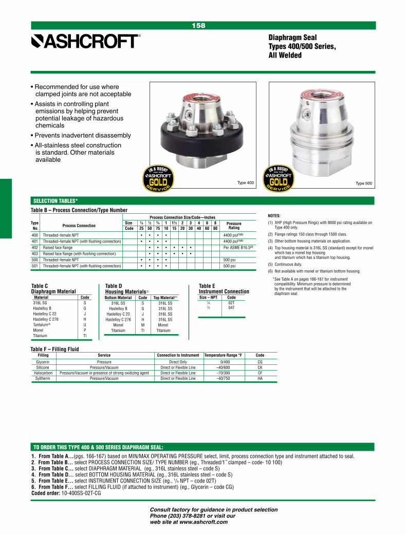
Consult factory for guidance in product selection Phone (203) 378-8281 or visit our web site at www.ashcroft.com
158
Table CDiaphragm Material Material Code 316L SS S Hastelloy B G Hastelloy C 22 J Hastelloy C 276 H Tantalum(6) U Monel P Titanium TI
Table B – Process Connection/Type Number Process Connection Size/Code—InchesType Size 1⁄4 1⁄2 3⁄4 1 11⁄2 2 3 4 6 8 Pressure No.
Process Connection Code 25 50 75 10 15 20 30 40 60 80 Rating
400 Threaded–female NPT • • • • 4400 psi(1)(5)
401 Threaded–female NPT (with flushing connection) • • • • 4400 psi(1)(5)
402 Raised face flange • • • • • • Per ASME B16.5(2)
403 Raised face flange (with flushing connection) • • • • • • 500 Threaded–female NPT • • • • 500 psi 501 Threaded–female NPT (with flushing connection) • • • • 500 psi
Diaphragm Seal Types 400/500 Series, All Welded
• Recommended for use where clamped joints are not acceptable
• Assists in controlling plant emissions by helping prevent potential leakage of hazardous chemicals
• Prevents inadvertent disassembly
• All-stainless steel construction is standard. Other materials available
1. From Table A…(pgs. 166-167) based on MIN/MAX OPERATING PRESSURE select, limit, process connection type and instrument attached to seal. 2. From Table B… select PROCESS CONNECTION SIZE/ TYPE NUMBER (eg., Threaded/1˝ clamped – code- 10 100) 3. From Table C… select DIAPHRAGM MATERIAL (eg., 316L stainless steel – code S)4. From Table D… select BOTTOM HOUSING MATERIAL (eg., 316L stainless steel – code S)5. From Table E… select INSTRUMENT CONNECTION SIZE (eg., 1/4 NPT – code 02T)6. From Table F… select FILLING FLUID (if attached to instrument) (eg., Glycerin – code CG)Coded order: 10-400SS-02T-CG
TO ORDER THIS TYPE 400 & 500 SERIES DIAPHRAGM SEAL:
Table D Housing Materials(3)
Bottom Material Code Top Material(4)
316L SS S 316L SS Hastelloy B G 316L SS Hastelloy C 22 J 316L SS Hastelloy C 276 H 316L SS Monel M Monelnel Titanium TI Titaniumne
NOTES:
(1) XHP (High Pressure Rings) with 9000 psi rating available on Type 400 only.
(2) Flange ratings 150 class through 1500 class.
(3) Other bottom housing materials on application.
(4) Top housing material is 316L SS (standard) except for monel which has a monel top housing and titanium which has a titanium top housing.
(5) Continuous duty.
(6) Not available with monel or titanium bottom housing.
Type 400 Type 500
Table F – Filling Fluid Filling Service Connection to Instrument Temperature Range °F Code
Glycerin Pressure Direct Only 0/400 CG Silicone Pressure/Vacuum Direct or Flexible Line –40/600 CK Halocarbon Pressure/Vacuum in presence of strong oxidizing agent Direct or Flexible Line –70/300 CF Syltherm Pressure/Vacuum Direct or Flexible Line –40/750 HA
Table E Instrument Connection Size – NPT Code 1⁄4 02T 1⁄2 04T
SELECTION TABLES*
* See Table A on pages 166-167 for instrument compatibility. Minimum pressure is determined by the instrument that will be attached to the diaphram seal.

Consult factory for guidance in product selection Phone (203) 378-8281 or visit our web site at www.ashcroft.com
159
Diaphragm Seal Types 510/511 Series, All Welded
This compact isolator is small enough in design to be used in con-fined spaces, but provides sufficient displacement to drive a wide variety of instrumentation. Its all-welded tamper proof design prevents pos-sible process media leakage.
FEATURES:• Compact size• Light weight• All-welded design• 1500 psi rating standard, 5000 psi
rating optional• Continuous duty design• Minimized fill volume• Male connections eliminate
adapters/fittings• Available flushing connection
(Type 511)• Dual inch and metric wrench flats
ADDITIONAL SPECIFICATIONSPressure Rating Standard Vac. to 1500 psi @ 100°F Optional 1500 to 5000 psi @ 100°F (XHP)Top Housing material 316L Stainless SteelAccuracy (typical) Seal will add 1⁄2% to the stated full scale accuracy of the instrument attached.
Table A – Process ConnectionProcess Connection Code
Threaded – 1/2 NPT male 04
Table B – Diaphragm MaterialsMaterial Code
316L stainless steel S
Hastelloy C276 H
Table C – Bottom Housing MaterialsMaterial Code
316L stainless steel S
Table D – Instrument ConnectionSize-NPT Code 1/2 04T
Table E – Filling Fluid Fill Service Connection to Instrument Temperature Range °F Code
Glycerin Pressure Direct Only 000/400 CG Silicone Pressure/Vacuum Direct or Flexible Line –40/600 CK Halocarbon Pressure/Vacuum in presence of Direct or Flexible Line –70/300 CF strong oxidizing agent Syltherm Pressure Direct or Flexible Line –40/750 HA
TO ORDER THIS TYPE 510/511 DIAPHRAGM SEAL:
1. From Table A…(pgs. 166-167) based on MIN/MAX OPERATING PRESSURE select, limit, process connection type and instrument attached to seal. 2. From Table B… select PROCESS CONNECTION SIZE/ TYPE NUMBER (eg., Threaded/1˝ clamped – code- 10 100) 3. From Table C… select DIAPHRAGM MATERIAL (eg., 316L stainless steel – code S)4. From Table D… select BOTTOM HOUSING MATERIAL (eg., 316L stainless steel – code S)5. From Table E… select INSTRUMENT CONNECTION SIZE (eg., 1/4 NPT – code 02T)6. From Table F… select FILLING FLUID (if attached to instrument) (eg., Glycerin – code CG)Coded order: 10-400SS-02T-CG
SELECTION TABLES*
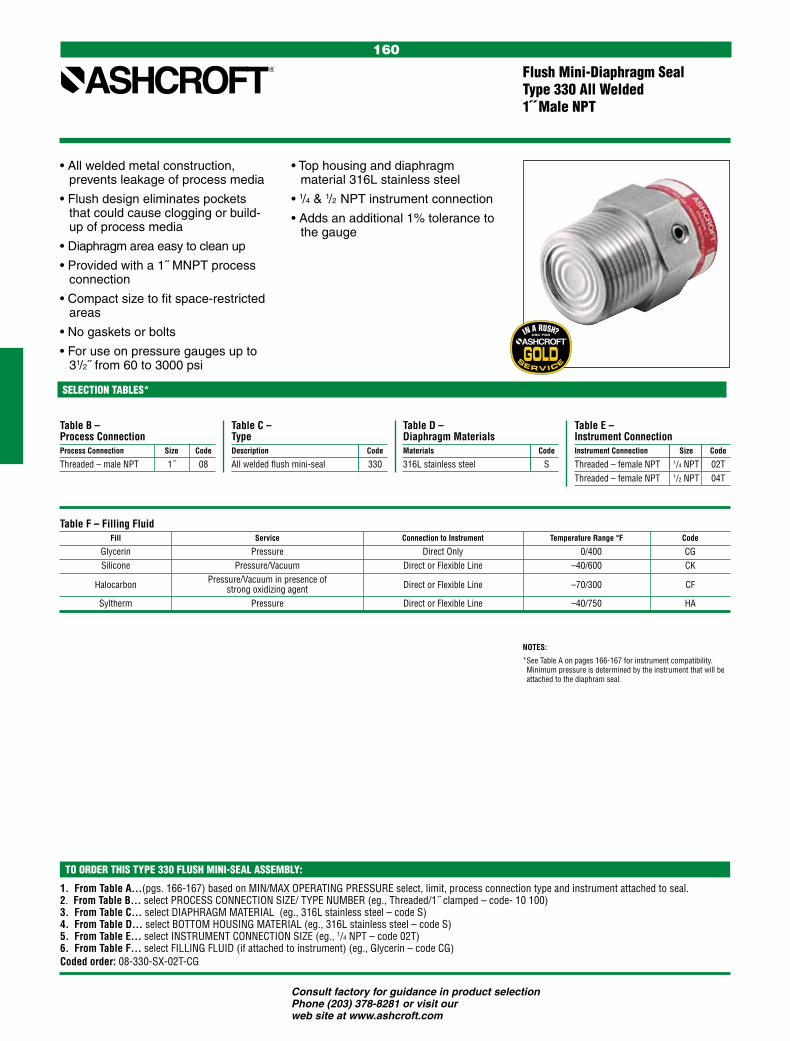
Consult factory for guidance in product selection Phone (203) 378-8281 or visit our web site at www.ashcroft.com
160
TO ORDER THIS TYPE 330 FLUSH MINI-SEAL ASSEMBLY:
• All welded metal construction, prevents leakage of process media
• Flush design eliminates pockets that could cause clogging or build-up of process media
• Diaphragm area easy to clean up
• Provided with a 1˝ MNPT process connection
• Compact size to fit space-restricted areas
• No gaskets or bolts
• For use on pressure gauges up to 31/2˝ from 60 to 3000 psi
Flush Mini-Diaphragm Seal Type 330 All Welded 1˝ Male NPT
• Top housing and diaphragm material 316L stainless steel
• 1/4 & 1/2 NPT instrument connection
• Adds an additional 1% tolerance to the gauge
Table B – Process ConnectionProcess Connection Size Code
Threaded – male NPT 1˝ 08
Table C – TypeDescription Code
All welded flush mini-seal 330
Table D – Diaphragm MaterialsMaterials Code
316L stainless steel S
Table E – Instrument ConnectionInstrument Connection Size Code
Threaded – female NPT 1/4 NPT 02TThreaded – female NPT 1/2 NPT 04T
Table F – Filling Fluid Fill Service Connection to Instrument Temperature Range °F Code
Glycerin Pressure Direct Only 000/400 CG Silicone Pressure/Vacuum Direct or Flexible Line –40/600 CK Halocarbon Pressure/Vacuum in presence of Direct or Flexible Line –70/300 CF strong oxidizing agent Syltherm Pressure Direct or Flexible Line –40/750 HA
1. From Table A…(pgs. 166-167) based on MIN/MAX OPERATING PRESSURE select, limit, process connection type and instrument attached to seal. 2. From Table B… select PROCESS CONNECTION SIZE/ TYPE NUMBER (eg., Threaded/1˝ clamped – code- 10 100) 3. From Table C… select DIAPHRAGM MATERIAL (eg., 316L stainless steel – code S)4. From Table D… select BOTTOM HOUSING MATERIAL (eg., 316L stainless steel – code S)5. From Table E… select INSTRUMENT CONNECTION SIZE (eg., 1/4 NPT – code 02T)6. From Table F… select FILLING FLUID (if attached to instrument) (eg., Glycerin – code CG)Coded order: 08-330-SX-02T-CG
NOTES:
* See Table A on pages 166-167 for instrument compatibility. Minimum pressure is determined by the instrument that will be attached to the diaphram seal.
SELECTION TABLES*

Consult factory for guidance in product selection Phone (203) 378-8281 or visit our web site at www.ashcroft.com
161
• All welded metal construction, prevents leakage of process media
• No gaskets or bolts
• For use on pressure gauges up to 31/2˝ from 60 to 1000 psi and 41/2˝ gauges 100 psi to 1000 psi
• Top housing material 316L stainless steel standard
• Diaphragm materials in 316L stainless steel, hastelloy C and tantalum
• Bottom housing materials in 316L stainless steel and Hastelloy C
Midi-Diaphragm Seal Type 311/312 All Welded
• 1/4 NPT or 1/2 NPT instrument connections
• Type 312 furnished with 1/8 NPT flushing connection
• Type 312 not available in male process connections
Table B – Process ConnectionProcess Connection Size Code
Threaded – male NPT(1) 1/4 02Threaded – male NPT(1) 1/2 04Threaded – male NPT(1) 3/4 06Threaded – male NPT(1) 1 08Threaded – female NPT 1/4 25Threaded – female NPT 1/2 50.
Table C – TypeDescription Code
All welded midi-seal 311All welded midi-seal w/flushing connection 312
Table D – Diaphragm MaterialsMaterials Code
316L stainless steel STantalum UHastelloy C 276 H
Table E – Bottom Housing MaterialsMaterials Code
316L stainless steel SHastelloy C-276 H
Table G – Filling Fluid Fill Service Connection to Instrument Temperature Range °F Code
Glycerin Pressure Direct Only 000/400 CG Silicone Pressure/Vacuum Direct or Flexible Line –40/600 CK Halocarbon Pressure/Vacuum in presence of Direct or Flexible Line –70/300 CF strong oxidizing agent Syltherm Pressure Direct or Flexible Line –40/750 HA
1. From Table A…(pgs. 166-167) based on MIN/MAX OPERATING PRESSURE select, limit, process connection type and instrument attached to seal. 2. From Table B… select PROCESS CONNECTION SIZE/ TYPE NUMBER (eg., Threaded/1˝ clamped – code- 10 100) 3. From Table C… select DIAPHRAGM MATERIAL (eg., 316L stainless steel – code S)4. From Table D… select BOTTOM HOUSING MATERIAL (eg., 316L stainless steel – code S)5. From Table E… select INSTRUMENT CONNECTION SIZE (eg., 1/4 NPT – code 02T)6. From Table F… select FILLING FLUID (if attached to instrument) (eg., Glycerin – code CG)Coded order: 50-311-UH-02T-CG
Table F – Instrument ConnectionInstrument Connection Size Code
Threaded – female NPT 1/4 NPT 02TThreaded – female NPT 1/2 NPT 04T
NOTES:
(1) Not available on Type 312.
* See Table A on pages 166-167 for instrument compatibility. Minimum pressure is determined by the instrument that will be attached to the diaphram seal.
TO ORDER THIS TYPE 311/12 MIDI-SEAL ASSEMBLY:
SELECTION TABLES*
Type 311
Type 312

Consult factory for guidance in product selection Phone (203) 378-8281 or visit our web site at www.ashcroft.com
162
Table DBottom Housing Materials Material Code
316L stainless steel S Hastelloy B G Hastelloy C 276 H Carpenter 20 D Monel M Titanium TI
• For pressure instruments ranging from 30˝ H2O to 750 psi
• Used in instruments with large displacement actuators
• For applications requiring an impermeable metallic diaphragm
• Available in many material combinations
• Diaphragm electron beam welded to isolator body
• Furnished with fill/bleed connection
Table CDiaphragm Materials(3)
Material Code Top Material
316L stainless steel S 316L SS Hastelloy B G 316L SS Hastelloy C 276 H 316L SS Tantalum U 316L SS K-Monel P Monel 400 Titanium TI Titanium
Instrument Isolator Type 740, 741, 702, 703High Displacement
1. From Table A…(pgs. 166-167) based on MIN/MAX OPERATING PRESSURE select, limit, process connection type and instrument attached to seal. 2. From Table B… select PROCESS CONNECTION SIZE/ TYPE NUMBER (eg., Threaded/1˝ clamped – code- 10 100) 3. From Table C… select DIAPHRAGM MATERIAL (eg., 316L stainless steel – code S)4. From Table D… select BOTTOM HOUSING MATERIAL (eg., 316L stainless steel – code S)5. From Table E… select INSTRUMENT CONNECTION SIZE (eg., 1/4 NPT – code 02T)6. From Table F… select FILLING FLUID (if attached to instrument) (eg., Glycerin – code CG)Coded order: 50-740-UH-04T-CF
TO ORDER THIS TYPE 740 DIAPHRAGM SEAL:
Table F – Filling Fluid Filling Service Connection to Instrument Temperature Range °F Code
Glycerin(4) Pressure Direct Only 0/400 CG
Silicone Pressure/Vacuum Direct or Flexible Line –40/600 CK Halocarbon(5) Pressure/Vacuum in presence of strong oxidizing agents Direct or Flexible Line –70/300 CF
Syltherm Pressure/Vacuum Direct or Flexible Line –40/750 HA
Table E Instrument Connection Size – NPT Code
1⁄4 02T 1⁄2 04T
Table B – Process Connection/Type Number Process Connection Size/Code – Inches(1)(2) Size 1⁄4 1⁄2 3⁄4 1 11⁄2 2 3 4 6 8
Type No. Pressure
Process Connection Code 25 50 75 10 15 20 30 40 60 80 Rating(1,6)
Threaded–female NPT • • • • 740 30 in.H2O to 750 psiThreaded–female NPT (with flushing connection)(2) • • • • 741 30 in.H2O to 750 psi Type No. Flange RatingRaised Face Flange • • • • • • 702 150 to 600 classRaised Face Flange (with flushing connection)(2) • • • • • • 703 150 to 600 class
SELECTION TABLES*
Type 740 Type 702
NOTES:
(1) Per ASME B16.5.
(2) 741 and 703 seal supplied with 1/4˝ flushing connection.
(3) Diaphragms welded to top housing.
(4) Glycerin not recommended for vacuum, compound or inches of water ranges.
(5) Halocarbon required on applications involving strong oxidiz-ing agents.
(6) Type 5503 Differential Pressure gauge only. 10 psi min.
* See Table A on pages 166-167 for instrument compatibility. Minimum pressure is determined by the instrument that will be attached to the diaphram seal.

Consult factory for guidance in product selection Phone (203) 378-8281 or visit our web site at www.ashcroft.com
163
M&G Replacement Saddle T-205 3˝ and 4˝ and Larger Flange Extended, All Welded
• Ashcroft® replacement assembles directly into M&G lower housings that are welded in existing piping systems
• All welded metal construction
• For use on pressure gauges up to 41/2˝ from vac. to 2500 psi
• Top housing material 316L stainless steel standard
• Diaphragm materials in 316L stainless steel, Hastelloy C and tatalum
• Continuous-duty design will prevent loss of process fluid if pressure instrument is removed or fails
• 1/4 or 1/2 NPT instrument connections
• Adds an additional 1/2% tolerance to the gauge
Table A – Process ConnectionProcess Connection Size Code
3˝ 30 4˝ & 40 larger
Table B – TypeDescription Code
M&G replacement saddle 205
Table C – Diaphragm MaterialsMaterials Code
316L stainless steel STantalum UHastelloy C-276 H
1. From Table A...select PROCESS CONNECTION SIZE (e.g., 30 for 3˝ size)2. From Table B...select TYPE (e.g., 205 for M&G replacement top housing assembly)3. From Table C...select DIAPHRAGM MATERIAL (e.g., S for 316L stainless steel)4. From Table D...insert (X) which indicates no lower housing 5. From Table E...select INSTRUMENT CONNECTION SIZE (e.g., 02T for 1⁄4˝ female NPT)6. Insert (#2584) on the suffixCoded order: 30-205-X-02T-#2584
Table F – Instrument ConnectionInstrument Connection Size Code
Threaded – female NPT 1/4 02TThreaded – female NPT 1/2 04T
Table D – Bottom Housing MaterialsMaterials Code
Non Required X
TO ORDER THIS TYPE M&G REPLACEMENT SADDLE T-205 ASSEMBLY:
SELECTION TABLES

Consult factory for guidance in product selection Phone (203) 378-8281 or visit our web site at www.ashcroft.com
164
Ashcroft® line assemblies are offered in a wide variety of configurations to suit all of your applications. Our standard assembly is in an all welded design of 300 series stainless components. The capillary is 304 stainless steel with an O.D. of 125 x .062 I.D. A spiral wound armor shields the assembly.
1/4˝ or 1/2˝ male or female connections are available. Other connections available upon request. PVC jacketed line assemblies are also available. When a gauge is installed on a process line containing hot liquid or gas, one solu-tion to protect the gauge from damage and/or accuracy degradation from elevated temperature is to simply include an extra five feet of capillary (to 600°F process) between the process media and the gauge. The slow rate of heat transfer through the added capillary and dead-ended process fluid will generally protect the gauge from damage and/or accuracy degradation.
• All welded construction
• Type 1115A is our standard stainless steel armored capillary
• Type 1115P stainless steel armored capillary, with the addition of PVC sheathing for maximum corrosion resistance
• The assemblies have standard line lengths of five feet in increments of five feet
• Line lengths in one foot increments are available with one foot being the minimum allowed, 100 feet being the maximum
• Maximum working pressure 10,000 psi
• Temperature limits: –300°F to 750°F
Line AssembliesType 1115A/1115P All Welded
Table D – Example LengthsExample Lengths Feet Code
Increments of 01 001Increments of 05 005Increments of 25 025Increments of 1000 100
1. From Table A...select capillary to instrument size & type (1⁄4˝ or 1⁄2,˝ male or female NPT) CONNECTION SIZE2. From Table B...select TYPE (e.g., 1115A for stainless steel armored)3. From Table C...select capillary to process connection size & type (1⁄4˝ or 1⁄2,˝ male or female NPT)CONNECTION SIZE4. From Table D...determine DESIRED LENGTH (e.g., 005 for five foot long assembly)Coded order: 50-1115A-04-005
TO ORDER THIS TYPE 1115 LINE ASSEMBLY:
Table A – Instrument Connection NPT Code 1/4 Female 02 1/2 Female 04 1/4 Male 25 1/2 Male 50
Table B – TypeDescription Code
Stainless steel armored capillary 1115AStainless steel armored capillary w/PVC sheathing 1115P
Table C – Process Connection NPT Code 1/4 Female 02 1/2 Female 04 1/4 Male 25 1/2 Male 50
SELECTION TABLES*

Consult factory for guidance in product selection Phone (203) 378-8281 or visit our web site at www.ashcroft.com
165
Table B Inner Flexible Wall(5)
Material Code Temp. Limits
Buna N E up to 225°F (107°) Teflon(3) T up to 350°F (177°) Silicone(4) SI up to 450°F (232°) Viton Y up to 350°F (177°) Natural Rubber NR up to 225°F (107°)
Iso-Ring, Iso-Spool Types 80/81/85/86
1. From Table A...select TYPE NUMBER based on Type number and pipe size (e.g., Type 80/6˝–code-8006)2. From Table B...select INNER FLEXIBLE WALL (e.g., Buna N–code E)3. From Table C...select ASSEMBLY FLANGE MATERIAL. (e.g., AISI 316 stainless steel–code S)4. From Table D...select INSTRUMENT CONNECTION size. (e.g., 1⁄4 NPT–code 02T)5. From Table E...select FILLING FLUID, if Iso-Ring/Spool will be attached to instrument. (e.g., Glycerin–code CG)Coded order: 8006-ES-02T-CG
TO ORDER THIS ISO-RING/ISO-SPOOL:
With the Ashcroft® isolation ring, the instrument is in contact with the fill fluid, not directly with the process flow. Clogging or fouling is never a problem. The Iso-Ring has a flexible inner cyl-inder, behind which is the fill fluid. As process liquid flows through the pipe, it exerts pressure. The pressure ex-erted by the fill fluid is then monitored by the instrument-sensing element. A 360-degree flexible cylinder means no plugging, assuring reliable and ac-curate pressure readings. A built-in threaded needle valve is provided as standard. This permits the removal of a pressure instrument for calibration, repair, or replacement without shutting down the process flow.
Adaptable to a variety of process conditions and applications, the
Ashcroft Iso-Ring can be used for protection of instrumentation such as pressure gauges, switches, trans-mitters, recorders and transducers. The Iso-Ring fits between customer- supplied piping flanges like many but-terfly valves, and is available for piping diameters from 2˝ to 20˝. It can be used at any pressure within the limitations of ASME classes 150 and 300, and even in most vacuum applications.
Ashcroft® Type 85 and 86 Iso-Spools are used for small-diameter piping. Designed to provide a large sensing area in the smaller pipe diameters from 1˝ to 2˝, the patented Iso-Spool is of-fered in either NPT threaded or flanged models. Type 86 is available with flat or raised-face flanges.
Table C Assembly Flanges Material Code
Carbon steel B 316 stainless steel S Chlorinated Polyvinyl Chloride CP Teflon Enveloped CT Polypropylene PP
NOTES:(1) Female threaded ends.(2) Flanged ends.(3) Not available in sizes 12˝ or larger.(4) Iso-Spool only.(5) Temperature limits of both wall and fill fluid must not be exceeded.
SELECTION TABLES Table A – Pipe Size/Type Number Pipe Size/Code—Inches Size 1 11⁄2 2 3 4 6 8 10 12 14 16 18 20 Type Housing Code 01 15 02 03 04 06 08 10 12 14 16 18 20 Number Material • • • • • • • • • • • 800 • • 85(1) Carbon • • • 86(2) Steel
• • • • • • 810
Type 80 Iso-Ring (Wafer) Type 81 Iso-Ring (Bolt Thru)
Type 86 Iso-Spool (Flanged)
Table D Instrument Connection Size – NPT Code
1⁄4 02T 1⁄2 04T
Table E – Filling Fluid Filling Service Connection to Instrument Temperature Range °F Code
Glycerin Pressure Direct Only 0/400 CG
Silicone Pressure/Vacuum Direct or Flexible Line –40/600 CK
Halocarbon Pressure/Vacuum in presence of strong oxidizing agent Direct or Flexible Line –70/300 CF
Syltherm Pressure/Vacuum Direct or Flexible Line –40/750 HA
Type 85 Iso-Spool (Threaded)
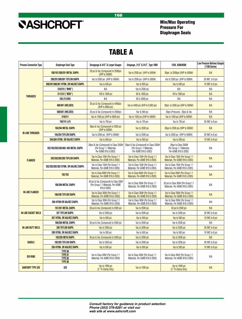
Consult factory for guidance in product selection Phone (203) 378-8281 or visit our web site at www.ashcroft.com
166
Min/Max OperatingPressure ForDiaphragm Seals
TABLE AProcess Connection Type Diaphragm Seal Type Duragauge & 41⁄2˝ & Larger Gauges Unigauge, 21⁄2˝ & 31⁄2˝, Type 1009 1259, 5500/6500 Low Pressure Bellows Gauges
(1188 Series)
THREADED
100/101/200/201 METAL DIAPH. 30 psi & Vac (Compound) to 2500psi (XHP to 5000#) Vac to 2500 psi (XHP to 5000#) 30psi to 2500psi (XHP to 5000#) N/A
200/201/300/301 TEFLON DIAPH. Vac to 2500 psi (XHP to 5000#) Vac to 2500 psi (XHP to 5000#) Vac to 2500 psi (XHP to 5000#) 30 IWC to 8 psi
200/201/300/301 VIT0N, OR KALREZ DIAPH. Vac to 500 psi Vac to 500 psi Vac to 500 psi 10 IWC to 8 psi
310/315 (“MINI”) N/A Vac to 2500 psi N/A N/A
311/312 (“MIDI”) 100 to 1000 psi 60 to 1000 psi 60 to 1000 psi N/A
330 (FLUSH) N/A 60 to 3000 psi N/A N/A
400/401 (WELDED) 30 psi & Vac (Compound) to 4400psi (XHP to 9000 psi) Vac to 4400 psi (XHP to 9,000 psi) 30psi to 2500 psi (XHP to 5000#) N/A
500/501 (WELDED) 30 psi & Vac (Compound) to 2500psi Vac to 500 psi 30psi (Pressure), 30psi & Vac N/A
510/511 Vac to 1500 psi (XHP to 5000 psi) Vac to 1500 psi (XHP to 5000#) Vac to 1500 psi (XHP to 5000#) N/A
740/741 (LP) Vac to 750 psi Vac to 750 psi Vac to 750 psi 30 IWC to 8 psi
IN-LINE THREADED
104/204 METAL DIAPH. 30psi & Vac (Compound) to 2500 psi (XHP to 5000#) Vac to 2500 psi 30psi to 2500 psi (XHP to 5000#) N/A
104/204 TEFLON DIAPH. Vac to 2500 psi (XHP to 5000#) Vac to 2500 psi Vac to 2500 psi (XHP to 5000#) 30 IWC to 8 psi
204/304 VIT0N, OR KALREZ DIAPH. Vac to 500 psi Vac to 500 psi Vac to 500 psi 10 IWC to 8 psi
FLANGED
102/103/202/203/402/ 403 METAL DIAPH. 30psi & Vac (Compound) to Class 2500#
(Per Group 1.1 Materials,Per ASME B16.5-2003)
30psi & Vac (Compound) to Class 2500# (Per Group 1.1 Materials,Per ASME B16.5-2003)
30psi to Class 2500#(Per Group 1.1 Materials,Per ASME B16.5-2003)
N/A
202/203/302/303 TEFLON DIAPH. Vac to Class 150# (Per Group 1.1 Materials, Per ASME B16.5-2003)
Vac to Class 150# (Per Group 1.1 Materials, Per ASME B16.5-2003)
Vac to Class 150# (Per Group 1.1 Materials, Per ASME B16.5-2003) N/A
202/203/302/303 VIT0N, OR KALREZ DIAPH. Vac to Class 150# (Per Group 1.1 Materials, Per ASME B16.5-2003)
Vac to Class 150# (Per Group 1.1 Materials, Per ASME B16.5-2003)
Vac to Class 150# (Per Group 1.1 Materials, Per ASME B16.5-2003) N/A
702/703 Vac to Class 600# (Per Group 1.1 Materials, Per ASME B16.5-2003)
Vac to Class 600# (Per Group 1.1 Materials, Per ASME B16.5-2003)
Vac to Class 600# (Per Group 1.1 Materials, Per ASME B16.5-2003) N/A
IN-LINE FLANGED
106/206-METAL DIAPH. 30 psi & Vac (Compound) to Class 300#
(Per Group 1.1 Materials, Per ASME B16.5-2003)
Vac to Class 300# (Per Group 1.1 Materials, Per ASME B16.5-2003)
30 psi to Class 300# (Per Group 1.1 Materials, Per ASME B16.5-2003) N/A
106/206 TEFLON DIAPH. Vac to Class 300# (Per Group 1.1 Materials, Per ASME B16.5-2003)
Vac to Class 300# (Per Group 1.1 Materials, Per ASME B16.5-2003)
Vac to Class 300# (Per Group 1.1 Materials, Per ASME B16.5-2003) N/A
206-VIT0N OR KALREZ DIAPH. Vac to Class 300# (Per Group 1.1 Materials, Per ASME B16.5-2003)
Vac to Class 300# (Per Group 1.1 Materials, Per ASME B16.5-2003)
Vac to Class 300# (Per Group 1.1 Materials, Per ASME B16.5-2003) N/A
IN-LINE SOCKET WELD
107/207-METAL DIAPH. 30 psi & Vac (Compound) to 2500 psi Vac to 2500 psi 30 psi to 2500 psi N/A
207 TEFLON DIAPH. Vac to 2500 psi Vac to 2500 psi Vac to 2500 psi 30 IWC to 8 psi
207 VIT0N, OR KALREZ DIAPH. Vac to 500 psi Vac to 500 psi Vac to 500 psi 10 IWC to 8 psi
IN-LINE BUTT WELD
108/208-METAL DIAPH. 30 psi & Vac (Compound) to 2500 psi Vac to 2500 psi Vac to 2500 psi N/A
208 TEFLON DIAPH. Vac to 2500 psi Vac to 2500 psi Vac to 2500 psi 30 IWC to 8 psi
208 VIT0N, OR KALREZ DIAPH. Vac to 500 psi Vac to 500 psi Vac to 500 psi 10 IWC to 8 psi
SADDLE
105/205 META DIAPH. 30 psi & Vac (Compound) to 2500 psi Vac to 2500 psi Vac to 2500 psi N/A
105/205 TEFLON DIAPH. Vac to 2500 psi Vac to 2500 psi Vac to 2500 psi 30 IWC to 8 psi
205-VIT0N, OR KALREZ DIAPH. Vac to 500 psi Vac to 500 psi Vac to 500 psi 10 IWC to 8 psi
ISO-RING
TYPE 80Vac to Class 300# (Per Group 1.1 Materials, Per ASME B16.5-2003)
Vac to Class 300# (Per Group 1.1 Materials, Per ASME B16.5-2003)
Vac to Class 300# (Per Group 1.1 Materials, Per ASME B16.5-2003) N/ATYPE 81
TYPE 85TYPE 86
SANITARY TYPE 320 320 Vac to 1000 psi(2˝ Tri-Clamp Only) Vac to 1000 psi Vac to 1000 psi
(2˝ Tri-Clamp Only) N/A
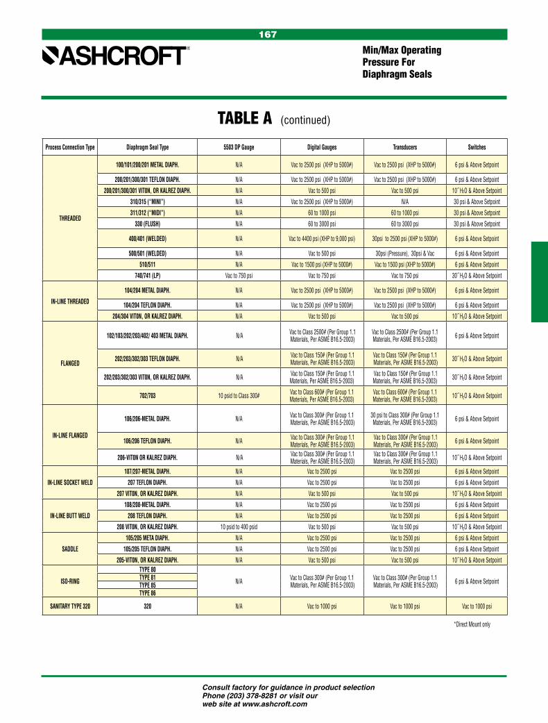
Consult factory for guidance in product selection Phone (203) 378-8281 or visit our web site at www.ashcroft.com
167
Min/Max OperatingPressure ForDiaphragm Seals
TABLE A (continued)
Process Connection Type Diaphragm Seal Type 5503 DP Gauge Digital Gauges Transducers Switches
THREADED
100/101/200/201 METAL DIAPH. N/A Vac to 2500 psi (XHP to 5000#) Vac to 2500 psi (XHP to 5000#) 6 psi & Above Setpoint
200/201/300/301 TEFLON DIAPH. N/A Vac to 2500 psi (XHP to 5000#) Vac to 2500 psi (XHP to 5000#) 6 psi & Above Setpoint
200/201/300/301 VIT0N, OR KALREZ DIAPH. N/A Vac to 500 psi Vac to 500 psi 10˝ H2O & Above Setpoint
310/315 (“MINI”) N/A Vac to 2500 psi (XHP to 5000#) N/A 30 psi & Above Setpoint
311/312 (“MIDI”) N/A 60 to 1000 psi 60 to 1000 psi 30 psi & Above Setpoint
330 (FLUSH) N/A 60 to 3000 psi 60 to 3000 psi 30 psi & Above Setpoint
400/401 (WELDED) N/A Vac to 4400 psi (XHP to 9,000 psi) 30psi to 2500 psi (XHP to 5000#) 6 psi & Above Setpoint
500/501 (WELDED) N/A Vac to 500 psi 30psi (Pressure), 30psi & Vac 6 psi & Above Setpoint
510/511 N/A Vac to 1500 psi (XHP to 5000#) Vac to 1500 psi (XHP to 5000#) 6 psi & Above Setpoint
740/741 (LP) Vac to 750 psi Vac to 750 psi Vac to 750 psi 30˝ H2O & Above Setpoint
IN-LINE THREADED
104/204 METAL DIAPH. N/A Vac to 2500 psi (XHP to 5000#) Vac to 2500 psi (XHP to 5000#) 6 psi & Above Setpoint
104/204 TEFLON DIAPH. N/A Vac to 2500 psi (XHP to 5000#) Vac to 2500 psi (XHP to 5000#) 6 psi & Above Setpoint
204/304 VIT0N, OR KALREZ DIAPH. N/A Vac to 500 psi Vac to 500 psi 10˝ H2O & Above Setpoint
FLANGED
102/103/202/203/402/ 403 METAL DIAPH. N/A Vac to Class 2500# (Per Group 1.1 Materials, Per ASME B16.5-2003)
Vac to Class 2500# (Per Group 1.1 Materials, Per ASME B16.5-2003) 6 psi & Above Setpoint
202/203/302/303 TEFLON DIAPH. N/A Vac to Class 150# (Per Group 1.1 Materials, Per ASME B16.5-2003)
Vac to Class 150# (Per Group 1.1 Materials, Per ASME B16.5-2003) 30˝ H2O & Above Setpoint
202/203/302/303 VIT0N, OR KALREZ DIAPH. N/A Vac to Class 150# (Per Group 1.1 Materials, Per ASME B16.5-2003)
Vac to Class 150# (Per Group 1.1 Materials, Per ASME B16.5-2003) 30˝ H2O & Above Setpoint
702/703 10 psid to Class 300# Vac to Class 600# (Per Group 1.1 Materials, Per ASME B16.5-2003)
Vac to Class 600# (Per Group 1.1 Materials, Per ASME B16.5-2003) 10˝ H2O & Above Setpoint
IN-LINE FLANGED
106/206-METAL DIAPH. N/A Vac to Class 300# (Per Group 1.1 Materials, Per ASME B16.5-2003)
30 psi to Class 300# (Per Group 1.1 Materials, Per ASME B16.5-2003) 6 psi & Above Setpoint
106/206 TEFLON DIAPH. N/A Vac to Class 300# (Per Group 1.1 Materials, Per ASME B16.5-2003)
Vac to Class 300# (Per Group 1.1 Materials, Per ASME B16.5-2003) 6 psi & Above Setpoint
206-VIT0N OR KALREZ DIAPH. N/A Vac to Class 300# (Per Group 1.1 Materials, Per ASME B16.5-2003)
Vac to Class 300# (Per Group 1.1 Materials, Per ASME B16.5-2003) 10˝ H2O & Above Setpoint
IN-LINE SOCKET WELD
107/207-METAL DIAPH. N/A Vac to 2500 psi Vac to 2500 psi 6 psi & Above Setpoint
207 TEFLON DIAPH. N/A Vac to 2500 psi Vac to 2500 psi 6 psi & Above Setpoint
207 VIT0N, OR KALREZ DIAPH. N/A Vac to 500 psi Vac to 500 psi 10˝ H2O & Above Setpoint
IN-LINE BUTT WELD
108/208-METAL DIAPH. N/A Vac to 2500 psi Vac to 2500 psi 6 psi & Above Setpoint
208 TEFLON DIAPH. N/A Vac to 2500 psi Vac to 2500 psi 6 psi & Above Setpoint
208 VIT0N, OR KALREZ DIAPH. 10 psid to 400 psid Vac to 500 psi Vac to 500 psi 10˝ H2O & Above Setpoint
SADDLE
105/205 META DIAPH. N/A Vac to 2500 psi Vac to 2500 psi 6 psi & Above Setpoint
105/205 TEFLON DIAPH. N/A Vac to 2500 psi Vac to 2500 psi 6 psi & Above Setpoint
205-VIT0N, OR KALREZ DIAPH. N/A Vac to 500 psi Vac to 500 psi 10˝ H2O & Above Setpoint
ISO-RING
TYPE 80
N/A Vac to Class 300# (Per Group 1.1 Materials, Per ASME B16.5-2003)
Vac to Class 300# (Per Group 1.1 Materials, Per ASME B16.5-2003) 6 psi & Above SetpointTYPE 81
TYPE 85TYPE 86
SANITARY TYPE 320 320 N/A Vac to 1000 psi Vac to 1000 psi Vac to 1000 psi
*Direct Mount only
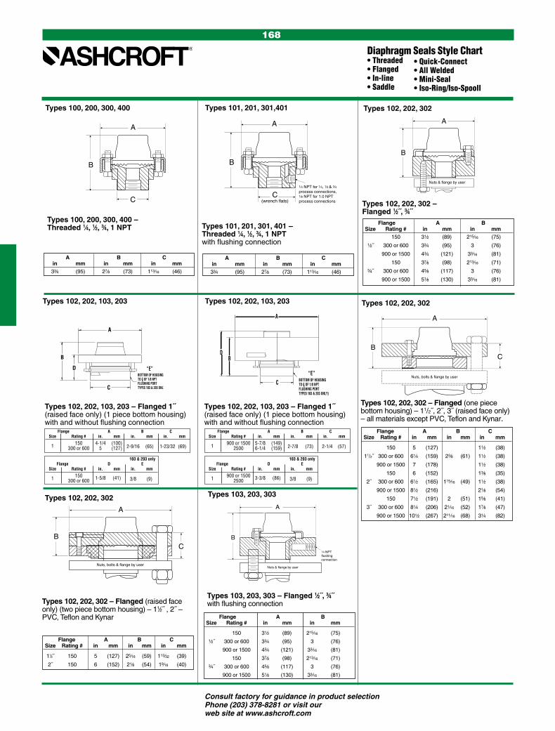
Consult factory for guidance in product selection Phone (203) 378-8281 or visit our web site at www.ashcroft.com
168
Diaphragm Seals Style Chart• Threaded• Flanged• In-line• Saddle
• Quick-Connect• All Welded• Mini-Seal• Iso-Ring/Iso-Spooll
A
B
C
Types 100, 200, 300, 400
A
B
C(wrench flats)
1⁄4 NPT for 1⁄4, 1⁄2 & 3⁄4 process connections,1⁄8 NPT for 1.0 NPT process connections
Types 101, 201, 301,401
A
B
Nuts & flange by user
Types 100, 200, 300, 400 – Threaded 1⁄4, 1⁄2, 3⁄4, 1 NPT
Types 102, 202, 302 – Flanged 1⁄2˝, 3⁄4˝
Types 102, 202, 302
Types 101, 201, 301, 401 – Threaded 1⁄4, 1⁄2, 3⁄4, 1 NPT with flushing connection
Types 102, 202, 302
B
A
C
Nuts, bolts & flange by user
Types 102, 202, 302
Types 102, 202, 302 – Flanged (raised face only) (two piece bottom housing) – 11⁄2˝ , 2˝ – PVC, Teflon and Kynar
A
BC
Nuts, bolts & flange by user
Types 102, 202, 302 – Flanged (one piece bottom housing) – 11/2˝, 2˝, 3˝ (raised face only) – all materials except PVC, Teflon and Kynar.
A
B
Nuts & flange by user
1⁄4 NPT flushing connection
Types 103, 203, 303
Types 103, 203, 303 – Flanged 1⁄2˝, 3⁄4˝ with flushing connection
A B C in mm in mm in mm 33⁄4 (95) 27⁄8 (73) 113⁄16 (46)
A B C in mm in mm in mm 33⁄4 (95) 27⁄8 (73) 113⁄16 (46)
Flange A B Size Rating # in mm in mm 150 31⁄2 (89) 215⁄16 (75)
1⁄2˝ 300 or 600 33⁄4 (95) 3 (76)
900 or 1500 43⁄4 (121) 33⁄16 (81)
150 37⁄8 (98) 213⁄16 (71)
3⁄4˝ 300 or 600 45⁄8 (117) 3 (76)
900 or 1500 51⁄8 (130) 33⁄16 (81)
Flange A B C Size Rating # in mm in mm in mm
11⁄2˝ 150 5 (127) 25⁄16 (59) 113⁄32 (39)
2˝ 150 6 (152) 21⁄8 (54) 19⁄16 (40)
Flange A B C Size Rating # in mm in mm in mm
150 5 (127) 11⁄2 (38)
11/2˝ 300 or 600 61⁄4 (159) 23⁄8 (61) 11⁄2 (38)
900 or 1500 7 (178) 11⁄2 (38)
150 6 (152) 13⁄8 (35)
2˝ 300 or 600 61⁄2 (165) 115⁄16 (49) 11⁄2 (38)
900 or 1500 81⁄2 (216) 21⁄8 (54)
150 71⁄2 (191) 2 (51) 15⁄8 (41)
3˝ 300 or 600 81⁄4 (206) 21⁄16 (52) 17⁄8 (47)
900 or 1500 101⁄2 (267) 211⁄16 (68) 31⁄4 (82)
Flange A B Size Rating # in mm in mm
150 31⁄2 (89) 215⁄16 (75)
1⁄2˝ 300 or 600 33⁄4 (95) 3 (76)
900 or 1500 43⁄4 (121) 33⁄16 (81)
150 37⁄8 (98) 213⁄16 (71)
3⁄4˝ 300 or 600 45⁄8 (117) 3 (76)
900 or 1500 51⁄8 (130) 33⁄16 (81)
“E”
A
DB
C BOTTOM OF HOUSINGTO C OF 1/8 NPTFLUSHING PORTTYPES 103 & 203 ONLY)
NOTE: NUTS, BOLTS, AND LOWER FLANGE BY USERTypes 102, 202, 103 & 203 – Flanged 1˝ (raised face only)(1 piece bottom housing) – with and without flushing connection.
L
“E”BOTTOM OF HOUSINGTO C OF 1/8 NPTFLUSHING PORTTYPES 103 & 203 ONLY)
NOTE: NUTS, BOLTS, AND LOWER FLANGE BY USERTypes 102, 202, 103 & 203 – Flanged 1˝ (raised face only)(1 piece bottom housing) – with and without flushing connection.
L
B
A
D
C
Flange A B C Size Rating # in. mm in. mm in. mm
1 150 4-1/4 (100) 300 or 600 5 (127) 2-9/16 (65) 1-23/32 (69)
103 & 203 only Flange D E Size Rating # in. mm in. mm
1 150 300 or 600 1-5/8 (41) 3/8 (9)
Flange A B C Size Rating # in. mm in. mm in. mm
1 900 or 1500 5-7/8 (149) 2500 6-1/4 (159) 2-7/8 (73) 2-1/4 (57)
103 & 203 only Flange D E Size Rating # in. mm in. mm
1 900 or 1500 2500 3-3/8 (86) 3/8 (9)
Types 102, 202, 103, 203 – Flanged 1˝ (raised face only) (1 piece bottom housing)with and without flushing connection
Types 102, 202, 103, 203
Types 102, 202, 103, 203 – Flanged 1˝ (raised face only) (1 piece bottom housing)with and without flushing connection
Types 102, 202, 103, 203
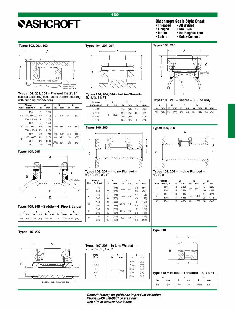
Consult factory for guidance in product selection Phone (203) 378-8281 or visit our web site at www.ashcroft.com
169
Diaphragm Seals Style Chart• Threaded• Flanged• In-line• Saddle
• All Welded• Mini-Seal• Iso-Ring/Iso-Spool• Quick-Connect
A
BC
Nuts, bolts & flange by user
Flushing connection1⁄8 NPT for 11⁄2"1⁄4 NPT for 2" & 3"
A
BC
A
BC
E
D
Top of pipe
A
C
E
Top of pipe
D
B
Flange A B C Size Rating # in mm in mm in mm
150 5 (127)
11⁄2˝ 300 or 600 61⁄4 (159) 3 (76) 21⁄16 (52)
900 or 1500 7 (178)
150 6 (152)
2˝ 300 or 600 61⁄2 (165) 311⁄32 (84) 23⁄8 (60)
900 or 1500 81⁄2 (215)
150 71⁄2 (191) 33⁄32 (79) 27⁄32 (56)
3˝
300 or 600 81⁄4 (210) 33⁄16 (81) 27⁄32 (57)
900 91⁄2 (241) 323⁄32 (94) 23⁄4 (70)
1500 101⁄2 (267)
A B C D E in mm in mm in mm in mm in mm
31⁄2 (89) 21⁄4 (57) 17⁄8 (48) 13⁄4 (44) 21⁄8 (54)
Process A B C Connection in mm in mm in mm
1⁄4 NPT
25⁄8 (67) 21⁄8 (54)
1⁄2 NPT 4
(102) 35⁄8 (92) 23⁄4 (70)
3⁄4 NPT 37⁄8 (98) 3 (76)
1 NPT 37⁄8 (98) 3 (76)
Flange A B C Size Rating # in mm in mm in mm 150 13 (330) 9 (229)
4˝
300 14 (356) 33⁄8 (86)
10 (254)
150 16 (406) 11 (279)
6˝
300 17 (432) 47⁄16 (113)
121⁄2 (318)
8˝ 150 16 (406) 57⁄16 (138) 131⁄2 (343)
Flange A B C Size Rating # in mm in mm in mm
150 7 (178) 31⁄2 (89) 1⁄2˝
300 7 (178) 27⁄16 (62)
37⁄8 (98)
150 7 (178) 41⁄4 (108)
1˝
300 8 (203) 27⁄16 (62)
47⁄8 (123)
150 8 (203) 5 (127)
11⁄2 ˝
300 9 (229) 211⁄16 (68)
61⁄8 (155)
150 9 (229) 6 (152)
2˝
300 10 (254) 215⁄16 (75)
61⁄2 (165)
150 11 (279) 71⁄2 (229)
3˝
300 12 (305) 35⁄8 (92)
81⁄4 (254)
A B C D E in mm in mm in mm in mm in mm
31⁄2 (89) 115⁄16 (50) 13⁄16 (31) 3 (76) 231⁄32 (75)
Pipe A B Size in mm in mm
1⁄4˝ 211⁄32 (60)
1⁄2˝, 3⁄4˝ 211⁄32 (60)
1˝ 215⁄32 (63)
11⁄2˝ 4 (102)
223⁄32 (69)
2˝ 231⁄32 (75) A B C in mm in mm in mm
11⁄2 (38) 13⁄16 (30) 111⁄32 (34)
Types 103, 203, 303 – Flanged 11⁄2, 2˝, 3˝ (raised face only) (one piece bottom housing with flushing connection)
Types 103, 203, 303
Types 104, 204, 304 – In-Line Threaded 1⁄4, 1⁄2, 3⁄4, 1 NPT
Types 104, 204, 304
Types 105, 205 – Saddle – 3˝ Pipe only
Types 105, 205
A
C
B
A
C
B
Types 106, 206 – In-Line Flanged – 1⁄2˝, 1˝, 11⁄2˝, 2˝, 3˝
Types 106, 206 Types 106, 206
Types 106, 206 – In-Line Flanged – 4˝, 6˝, 8˝
A
B
PIPE & WELD BY USER
A
B
C
Types 107, 207 – In-Line Welded – 1⁄4˝, 1⁄2˝, 3⁄4˝, 1˝, 11⁄2˝, 2˝
Types 107, 207
Types 105, 205 – Saddle – 4˝ Pipe & Larger
Types 105, 205
Type 310
Type 310 Mini-seal – Threaded – 1⁄4, 1⁄2 NPT

Consult factory for guidance in product selection Phone (203) 378-8281 or visit our web site at www.ashcroft.com
170
A
B
C
A B C in mm in mm in mm
21⁄2˝ (63) 27⁄8 (73) 113⁄16 (46)
Types 702, 703 – Flanged – 1⁄2˝ through 3˝ TYPES 702 & 703 L – THREADED
(with and without flushing connection)
“D”Bottom of Housingto C of 1/4 NPTFlushing Port(Type 703 only)
L
A
B
C
Types 702, 703*
*with flushing connection
Rating # 150# 703 Only, All Sizes A B C D Size in. mm in. mm in. mm in. mm
1/2˝ 5-5/16 (135) 2-9/16 (65) 1-15/32 (37) 1-1/16 (27) 3/4˝ 5-5/16 (135) 2-9/16 (65) 1-15/32 (37) 1-1/16 (27) 1˝ 5-5/16 (135) 2-1/2 (64) 1-15/32 (37) 1 (25) 1-1/2˝ 5-5/16 (135) 2-1/2 (64) 1-15/32 (37) 1 (25) 2˝ 6 (152) 2-5/8 (67) 2-1/16 (52) 1-1/8 (29) 2-1/2˝ 7-1/2 (191) 2-1/2 (64) 2-1/16 (52) 1 (25) 3˝ 7-1/2 (191) 2-3/8 (60) 2-1/16 (52) 1-1/16 (27)
Rating # 300# 703 Only, All Sizes A B C D Size in. mm in. mm in. mm in. mm
1/2˝ 5-5/16 (135) 2-9/16 (65) 1-15/32 (37) 1-1/16 (27) 3/4˝ 5-5/16 (135) 2-3/4 (70) 2-1/16 (52) 1-1/16 (27) 1˝ 5-5/16 (135) 2-3/4 (70) 2-1/16 (52) 1 (25) 1-1/2˝ 6-1/2 (165) 2-3/4 (70) 2-11/16 (68) 1 (25) 2˝ 6-1/2 (165) 2-5/8 (67) 2-1/16 (52) 1-1/8 (29) 2-1/2˝ 7-1/2 (191) 2-5/8 (67) 2-11/16 (68) 1 (25) 3˝ 8-1/2 (216) 2-5/8 (67) 2-11/16 (68) 1-1/16 (27)
Rating # 600# 703 Only, All Sizes A B C D Size in. mm in. mm in. mm in. mm
1/2˝ 5-5/16 (135) 2-3/4 (70) 1-15/32 (37) 1-1/16 (27) 3/4˝ 5-5/16 (135) 2-3/4 (70) 1-15/32 (37) 1-1/16 (27) 1˝ 5-5/16 (135) 2-3/4 (70) 1-15/32 (37) 1 (25) 1-1/2˝ 6-1/2 (165) 2-3/4 (70) 1-15/32 (37) 1 (25) 2˝ 6-1/2 (165) 2-5/8 (67) 2-1/16 (52) 1-1/8 (29) 2-1/2˝ 7-1/2 (191) 2-5/8 (67) 2-1/16 (52) 1 (25) 3˝ 8-1/2 (216) 2-5/8 (67) 2-1/16 (52) 1-1/16 (27)
A
TYPE 311 MIDI-SEALMALE NPT PROCESS CONNECTION
C
B
TYPE 311 & 312 MIDI-SEAL –THREADED 1/4, 1/2 NPT
(with and without flushing connection)
C
D
A
BBottom of Housingto C of 1/8 NPTFlushing Port(Type 312 only)
L
TYPE 330 FLUSH MINI-SEAL –THREADED 1/4 & 1/2
INSTRUMENT CONNECTION
C
A
B
1 NPT
A B C Size Code in mm in mm in mm
1/4 02 1/2 04 3/4 06 2 (51) 13/8 (35) 13/4 (44)
1 08
Type 311 Midi-Seal – Male NPT Process Connection
Type 311
Types 311 & 312 – Female NPT Process Connection
Types 311 & 312
Type 330 Flush Mini-Seal – Threaded 1⁄4˝ & 1⁄2˝ Instrument Connection
Type 330
Type 500 All Welded – 1⁄4, 1⁄2, 3⁄4, 1 NPT
Type 500 All Welded
C
A
B
Type 320
Type 320 Quick Connect – 1⁄4, 1⁄2 NPT A B C Size* in mm in mm in mm
11⁄2˝ 121⁄32 (42) 7⁄8 (22) 2 (50)
2˝ 2 (51) 11⁄8 (29) 21⁄2 (63)
Diaphragm Seals Style Chart• Threaded• Flanged• In-line• Saddle
• Quick-Connect• All Welded• Mini-Seal• Iso-Ring/Iso-Spool
A B C D in mm in mm in mm in mm
2.00 (51) 2.65 (67) 1.75 (44) 0.94 (24)
A B C in mm in mm in mm
111⁄32˝ (34) 24⁄64 (54) 13⁄8 (35)
A
TYPE 205 (M&G REPLACEMENT)
D
C
B
Type 205 M&G Replacement Saddle 3˝ (4˝ and Larger)
Type 205
A B C D Size* in mm in mm in mm in mm
3˝ 1.35 (34)
4˝ 3.44 (87) 2.44 (62)
2.05 (52) 0.57 (14)
Type 402 Type 403 Flange A B C A B C Size Rating (#) in mm in mm in mm in mm in mm in mm 150 41⁄4 (108) 13⁄16 (30) 41⁄4 (108) 115⁄16 (49) 1´ 300 or 600 5 (127) 21⁄8 (54) 11⁄4 (32) 5 (127) 27⁄8 (73) 2 (51) 900 or 1500 6 (152) 11⁄4 (32) 6 (152) 2 (51) 150 5 (127) 5 (127) 17⁄8 (48) 11⁄2´ 300 or 600 61⁄4 (159) 27⁄16 (62) 27⁄16 (62) 61⁄4 (159) 215⁄16 (75) 900 or 1500 7 (178) 7 (178) 150 6 (152) 6 (152) 23⁄16 (56) 2´ 300 or 600 61⁄2 (165) 215⁄32 (63) 215⁄32 (63) 61⁄2 (165) 215⁄16 (75) 900 or 1500 81⁄2 (216) 81⁄2 (216)
Types 402, 403 Raised Face – Flanged – 1˝, 11⁄2˝, 2˝
Types 402, 403
A
B
C
C
A
B(Type 741 Only)
Bottom of Housingto CL of 1/4 NPTFlushing Port
D
Types 740, 741
Types 740, 741 – High Displacement –
Threaded – 1⁄4˝, 1⁄2˝, 3⁄4˝, 1˝
A B C D in mm in mm in mm in mm
5.25 (133) 1.5 (38) 2.0 (51) 0.437 (11)
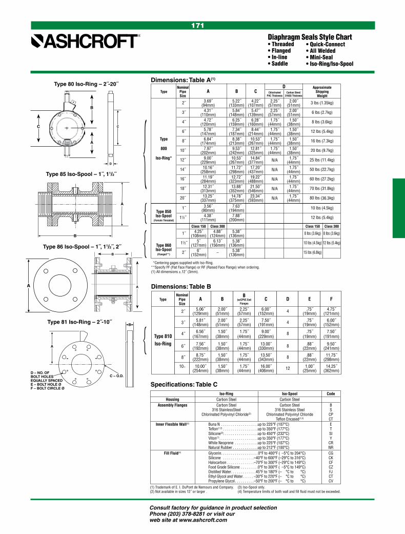
Consult factory for guidance in product selection Phone (203) 378-8281 or visit our web site at www.ashcroft.com
171
Diaphragm Seals Style Chart• Threaded• Flanged• In-line• Saddle
• Quick-Connect• All Welded• Mini-Seal• Iso-Ring/Iso-Spool
**Centering gages supplied with Iso-Ring.**Specify FF (Flat Face Flange) or RF (Raised Face Flange) when ordering.(1) All dimensions ±.12˝ (3mm).
Nominal D Approximate Type Pipe A B C Chlorinated Carbon Steel/ Shipping Size PVC Thickness 316SS Thickness Weight 2˝ 3.69˝ 5.22˝ 4.22˝ 2.25˝ 2.00˝ 3 lbs (1.35kg) (94mm) (133mm) (107mm) (57mm) (51mm) 3˝ 4.31˝ 5.84˝ 5.47˝ 2.25˝ 2.00˝ 6 lbs (2.7kg) (110mm) (148mm) (139mm) (57mm) (51mm) 4˝ 4.72˝ 6.25˝ 6.28˝ 1.75˝ 1.50˝ 8 lbs (3.6kg) (120mm) (159mm) (160mm) (44mm) (38mm) 6˝ 5.78˝ 7.34˝ 8.44˝ 1.75˝ 1.50˝ 12 lbs (5.4kg) (147mm) (187mm) (214mm) (44mm) (38mm) Type 8˝ 6.84˝ 8.38˝ 10.53˝ 1.75˝ 1.50˝ 16 lbs (7.3kg) (174mm) (213mm) (267mm) (44mm) (38mm) 800 10˝ 7.97˝ 9.53˝ 12.81˝ 1.75˝ 1.50˝ 20 lbs (9.7kg) (202mm) (242mm) (325mm) (44mm) (38mm) Iso-Ring* 12˝ 9.00˝ 10.53˝ 14.84˝ N/A 1.75˝ 25 lbs (11.4kg) (229mm) (267mm) (377mm) (44mm) 14˝ 10.16˝ 11.72˝ 17.20˝ N/A 1.75˝ 50 lbs (22.7kg) (258mm) (298mm) (437mm) (44mm) 16˝ 11.19˝ 12.72˝ 19.22˝ N/A 1.75˝ 60 lbs (27.2kg) (284mm) (323mm) (488mm) (44mm) 18˝ 12.31˝ 13.88˝ 21.50˝ N/A 1.75˝ 70 lbs (31.8kg) (313mm) (352mm) (546mm) (44mm) 20˝ 13.25˝ 14.78˝ 23.34˝ N/A 1.75˝ 80 lbs (36.3kg) (337mm) (375mm) (593mm) (44mm) 1˝ 3.56˝ 7.63˝ 10 lbs (4.5kg) (90mm) (194mm) 11⁄2˝ 4.38˝ 7.88˝ 12 lbs (5.4kg) (Female Threaded) (111mm) (200mm) Class 150 Class 300 Class 150 Class 300 1˝ 4.25˝ 4.88˝ 5.38˝ 8 lbs (3.6kg) 8 lbs (3.6kg) (108mm) (124mm) (136mm) 11⁄2˝ 5˝ 6.13˝ 5.38˝ 10 lbs (4.5kg) 12 lbs (5.4kg) (127mm) (156mm) (136mm) 2˝ 6˝ – 5.38˝ 15 lbs (6.8kg) (152mm) (136mm)
Type 850 Iso-Spool
Type 860 Iso-Spool
(Flanged**)
Specifications: Table C Iso-Ring Iso-Spool Code Housing Carbon Steel Carbon Steel Assembly Flanges Carbon Steel Carbon Steel B 316 StainlessSteel 316 Stainless Steel S Chlorinated Polyvinyl Chloride(2) Chlorinated Polyvinyl Chloride CP Teflon Encased(1,3) CT Inner Flexible Wall(4) Buna N . . . . . . . . . . . . . . . . . . .up to 225°F (107°C) E Teflon(1,2) . . . . . . . . . . . . . . . . . .up to 350°F (177°C) T Silicone(3). . . . . . . . . . . . . . . . . .up to 450°F (232°C) SI Viton(1). . . . . . . . . . . . . . . . . . . .up to 350°F (177°C) Y White Neoprene . . . . . . . . . . . .up to 225°F (107°C) CR Natural Rubber . . . . . . . . . . . . .up to 212°F (100°C) NR Fill Fluid(4) Glycerin. . . . . . . . . . . . . . . . . . . 0°F to 400°F ( –5°C to 204°C) CG Silicone . . . . . . . . . . . . . . . .–40°F to 600°F (–29°C to 316°C) CK Halocarbon . . . . . . . . . . . . . .–70°F to 300°F (–29°C to 149°C) CF Food Grade Silicone . . . . . . . . .0°F to 300°F ( –5°C to 149°C) CZ Distilled Water. . . . . . . . . . . . .45°F to 180°F (– °C to °C) FJ Ethyl Glycol and Water. . . . . . –30°F to 220°F (– °C to °C) CT Propylene Glycol. . . . . . . . . .–50°F to 200°F (– °C to °C) CV(1) Trademark of E. I. DuPont de Nemours and Company. (2) Not available in sizes 12˝ or larger .
(3) Iso-Spool only.(4) Temperature limits of both wall and fill fluid must not be exceeded.
Dimensions: Table A(1)
Dimensions: Table B Nominal B Type Pipe A B (w/CPVC End C D E F Size Flanges
2˝ 5.06˝ 2.00˝ 2.25˝ 6.00˝ 4 .75˝ 4.75˝ (129mm) (51mm) (57mm) (152mm) (19mm) (121mm)
3˝ 5.81˝ 2.00˝ 2.25˝ 7.50˝ 4 .75˝ 6.00˝ (148mm) (51mm) (57mm) (191mm) (19mm) (152mm)
4˝ 6.56˝ 1.50˝ 1.75˝ 9.00˝ 8 .75˝ 7.50˝ Type 810 (167mm) (38mm) (44mm) (229mm) (19mm) (191mm)
Iso-Ring 6˝ 7.56˝ 1.50˝ 1.75˝ 13.00˝ 8 .88˝ 9.50˝ (192mm) (38mm) (44mm) (330mm) (22mm) (241mm)
8˝ 8.75˝ 1.50˝ 1.75˝ 13.50˝ 8 .88˝ 11.75˝ (222mm) (38mm) (44mm) (343mm) (22mm) (298mm)
10˝ 10.00˝ 1.50˝ 1.75˝ 16.00˝ 12 1.00˝ 14.25˝ (254mm) (38mm) (44mm) (406mm) (25mm) (362mm)
Type 85 Iso-Spool – 1˝, 11/2˝
Type 86 Iso-Spool – 1˝, 11/2˝, 2˝
A
B
A
B
Type 80 Iso-Ring – 2˝-20˝
C
B
A
D – NO. OFBOLT HOLESEQUALLY SPACEDE – BOLT HOLE ØF – BOLT CIRCLE Ø
C – O.D.
A
B
A
Type 81 Iso-Ring – 2˝-10˝
D
C

Consult factory for guidance in product selection Phone (203) 378-8281 or visit our web site at www.ashcroft.com
172
Optional Features Code
316 stainless steel top housing YT
Stainless steel clamp rings and flanged ring – includes 300 stainless steel clamping bolts SE (1500 psi max)
300 series stainless steel clamping bolts (maximum pressure is 1500 psi) SB
Pipe plugs for flushing connections – pipe plugs are available in the same materials as bottom PU housings per Table C – see pages 64-66
5000 psi pressure rating – (Type 100/200 only) threaded inlet only, no flushing connection HP (metal diaphragm only) 7500 psi pressure rating (T-400)
Welded instrument to diaphragm seal DU
Dual flushing connections (1/2 NPT) (Limited to 2˝ thru 3˝ flanged seals DB
Ring joint RJ
Flat face FF
No Teflon gasket. Special matching on bottom housing (2) NX
Clean for gaseous oxygen or strong oxidizing agent applications (3) 6B
For accessories – see pages 255-260 —
Code Description
XH3 02L Gauge Connection, 1/4 NPT Transducer, 02T Seal Connection
XH5 04L Gauge Connection, 1/2 NPT Switch, 02T Seal Connection
XH6 04L Gauge Connection, (2) 1/2 NPT Switches, 02T Seal Connection
XH7 02L Gauge Connection, 1/4 NPT Female Switch, 02T Seal Connection
XH8 02L Gauge Connection, (2) 1/4 NPT Instruments, 02T Seal Connection
XH9 02L Gauge Connection, 1/2 NPT Female Switch, 04T Seal Connection
XL3 02L Gauge Connection, 1/4 NPT Female Switch, 02T Seal Connection, 1/4 NPT Snubber (separate line item)
Multiple Instruments Attached to Diaphragm Seals
Diaphragm SealsOptions all Types
Diaphragm Seals Style Chart• Threaded• Flanged• In-line• Saddle
• Quick-Connect• All Welded• Mini-Seal• Iso-Ring/Iso-Spool
510 Process Connection Thread Code1/2 NPT Female 04T
510 Process Connection Thread Code1/2 NPT Male 04
Type 510 Diaphragm Seal
Ø31 mm1.22˝
Ø37.5 mm1.48˝
1/2 NPTInstrumentConnection
1/2 NPTProcessConnection
Across Flats SW27 mm / 1.06˝
Across Flats SW28.6 mm / 1.13˝
86.5
mm
3.41
˝
33 m
m1.
30˝
23 m
m0.
91˝
1/2 NPT InstrumentConnection
1/2 NPTProcessConnection
Across Flats SW27 mm / 1.06˝
Ø57.5 mm2.26˝
Ø31 mm1.22˝
Across Flats SW28.6 mm / 1.13˝
Ø50 mm1.97˝
64.4
mm
2.54
˝106.
6 m
m4.
20˝
33 m
m1.
30˝
23 m
m0.
91˝
81 mm3.188˝
57 mm2.244˝
1/2 NPT Instrument Connection
1/2 NPT Process Connection
Lower Housing
Upper Housing
Type 510 High Pressure Diaphragm Seal Type 511 Low Pressure Diaphragm Seal with Flushing Connection
510 Process Connection Thread Code1/2 NPT Female 04T
510 Process Connection Thread Code1/2 NPT Male 04
173
Consult factory for guidance in product selection Phone (203) 378-8281 or visit our web site at www.ashcroft.com
(Refer to product specifications for accuracies)
HIGH PRESSURE
GC31 Digital Pressure Sensor ....................175
GC35 Digital Pressure Sensor ....................176
GC51 Rangeable Pressure Transmitter ......177
GC55 Wet/Wet Differential Pressure Transmitter ...............................178
T2 High Performance Pressure Transducer 179
G2 Pressure Transducer ..............................180
A2 Pressure Transmitter ..............................181
A2X Pressure Transmitter ............................182
A4 Pressure Transmitter ..............................183
KM15 Pressure Transducer .........................184
K1 Pressure Transducer/Transmitter ..........185
K2 Pressure Transducer .............................186
K8 Pressure Transducer ..............................187
KX Pressure Transducer/Transmitter ..........188
KS Sanitary Pressure Transducer/ Transmitter ...............................................189
LOW PRESSURE
GC30 Digital Differential Pressure Sensor .190
GC52 Rangeable Wet/Wet Differential Pressure Transmitter ............191
CXLdp Differential Pressure Transmitter .....192
DXLdp Ultra-Low Pressure Differential Transducer/Transmitter ............................193
RXLdp Ultra-Low Differential Pressure Transducer/Transmitter ...........................194
XLdp Ultra-Low Differential PressureTransducer/Transmitter..............195
IXLdp Industrial Ultra-Low Differential Pressure Transducer/Transmitter .............196
ANALOG DISPLAY
Type 2279 Duratran® Transmitter ...............197
Type 2269 Panel Meter................................198
Type 4080, 4480 Pneumatic Transmitters ...199
PRESSURE TRANSDUCERS/ TRANSMITTERS

174
Consult factory for guidance in product selection Phone (203) 378-8281 or visit our web site at www.ashcroft.com

175
Consult factory for guidance in product selection Phone (203) 378-8281 or visit our web site at www.ashcroft.com
Model GC31 Ultra-Compact Digital Pressure Sensor
FEATURES • Ultra-compact design 1.2˝ x 1.2˝
(30mm x 30mm) • Combined three-in-one digital
pressure gauge, switch and transducer
• Simple “Push-Button” configurability allows user to adjust switch settings, analog scaling
• Numerous standard ranges available
PERFORMANCE SPECIFICATIONSAnalog Output (1-5Vdc):Accuracy: ± 1.0% FS
(accuracy includes effects of linearity, hysteresis and repeatability)
Response Time: 50msecOutput Resolution: 25mVAnalog Scaling: User may configure analog output
scaling to any range within full scale of sensor range
Pressure Switch Output:Type: NPN or PNP open collector up to 30Vdc/80maSetting Accuacy: ±1.0% F.S.Number of Contacts: 2 Time Delay: 5 msec –2.0 sec (by user)Hysteresis: Variable (by user)Switch Setting: User may adjust switch actuation
and deadband to any points within full scale sensor range
Display:Type: 31⁄2 digit, 10mm LEDAccuracy: ± 1.0% F.S. ± last digitDisplay Setting: User may re-configure display
scaling, set to capture MIN or MAX value, and adjust display update rate
PSI Ranges: Standard Ranges (Gauge):
0 to 50 psig, 100 psig, 150 psig, 300 psig, 500 psig, 1000 psig, 1500 psig
Standard Ranges (Compound): −15 to 75 psig −15 to 150 psig, −15 to 300 psig
APPLICATIONSThe GC31 utilizes Ashcroft’s field proven thin film sensor which provides high cycle life and output stability, typically required in: • Hydraulic presses, stamping equip-
ment, lifts • Tire press vulcanization, pressure
monitoring • Water, refrigerant or ammonia based
cooling systems • Pressure monitoring on lubrication
systems
ENVIRONMENTAL SPECIFICATIONSTemperature Limits:Storage: –22 to 140°F (–30 to 60°C)Operating: –4 to 140°F (–20 to 60°C)Compensated: 14 to 122°F (–10 to 50°C)Temperature Effects:Zero/Span: ±0.03% F.S./F (±0.05% F.S./C) from
73°F (23°C) reference temperatureHumidity: 0-85% RH (Non-Condensing) FUNCTIONAL SPECIFICATIONSProof Pressure: 2X range: 500 psi & below
1.5X range: 1000 psi & aboveBurst Pressure: 8X rangeCE Compliance: EN61326-1 2006, EN61326-2-3
2006 ELECTRICAL SPECIFICATIONSPower Supply Requirements:Supply Voltage: 11-27VdcCurrent Consumption: 30mA (max)Switch Contacts: (2) NPN or PNP open collector
outputs NPN Type: 30Vdc / 80mA (max) PNP Type: voltage drop 1Vdc (max)/80mA (max)
LOOK FOR THIS MARK ON OUR PRODUCTS
MECHANICAL SPECIFICATIONSPressure Connection: 1⁄4 NPT (Male) Enclosure: ABS, polycarbonate, aluminumEnvironmental Rating: IP40Electrical Connection: 6ft (2m) cable pigtailWeight: Approx. 110 gramsMounting: Panel mounting bracket included
(back connect only)Media: Fluids and gases compatible with 304 SS
(sensor housing) and 17-4 pH SS (sensor diapragm)RTV
Compound:(75#&V) −15 to 75 psig(150#&V) −15 to 150 psig(300#&V) −15 to 300 psig
G C 3 1
F 4 X 7Type
(GC31) Connection
(M02L) 1⁄4 NPT Male w/lower connect
(MO2B) 1⁄4 NPT Male w/back connec
Electrical Connection
(F4) 6´ (2m) cable
Accuracy (7) ±1.0%
OptionsXRH
9 pt. NIST traceable calibration certificate
TO ORDER THE GC31 ULTRA-COMPACT DIGITAL PRESSURE SENSOR:
Output Signal(1N) 1-5Vdc:
Analog w/2X NPN Type switches (1P) 1-5Vdc:
Analog w/2X PNP Type switches
Pressure Ranges Gauge:(50#G) 0/50 psig (100#G) 0/100 psig(150#G) 0/150 psig(300#G) 0/300 psig(500#G) 0/500 psig(1000#G) 0/1000 psig(1500#G) 0/1500 psig.

176
Consult factory for guidance in product selection Phone (203) 378-8281 or visit our web site at www.ashcroft.com
Model GC35 Ultra-Compact Digital Pressure Sensor
FEATURES • Combined 3-in-1 digital pressure
gauge, switch and transducer • High overpressure capability • All stainless steel wetted materials • Simple “Push-Button” configurability
allows user to adjust switch settings, analog scaling
• Rugged aluminum housing
PERFORMANCE SPECIFICATIONSAnalog Output (4-20mA):Accuracy: ± 1.0% FS (Accuracy includes the effects of linearity, hysteresis, repeatability, zero offset and span setting errors)Response Time: 30msec–10sec (by user)Output Resolution: ±0.05% FSAnalog Scaling: User may configure analog output scaling to any range within −100 to +150% Full Scale of the sensor rangePressure Switch Output: Type: NPN or PNP open collector up to 80maSetting Accuracy: ±1.0% FSResponse Time: 5msec – 10.0 sec (by user) Hysteresis: Variable (by user)Switch Setting: User may adjust switch actuation and deadband to any points within Full Scale sensor rangeDisplay:Type: 4 digit, 8mm LEDAccuracy: ±1.0% FS (URL) + last digitDisplay Update Rate: 200msec−10.0 sec (by user)Display Setting: User may re-configure display scaling, set to capture MIN or MAX value and adjust display update rate Standard Ranges (Gauge): 0 to 50 psig, 100 psig, 150 psig, 300 psig, 500 psig, 1000 psig, 1500 psig, 3000 psig, 5000 psig, 7500 psigStandard Ranges (Compound): –15 to 75 psig, –15 to 150 psig –15 to 300 psig, ENVIRONMENTAL SPECIFICATIONSTemperature Limits:Storage: –20 to 70°C (–4 to 158°F)Operating: –20 to 70°C (–4 to 158°F)Compensated: –20 to 70°C (–4 to 158°F)Temperature Effects:Zero/Span: ±0.1%FS/°C (from 23°C reference temp.)Humidity: 0-85% RH (Ranges 150 psi & below) 0-100% RH (Ranges 300 psi & above)
APPLICATIONSThe GC35 utilizes Ashcroft’s field proven thin film sensing technology in a design to provide exceptional overpressure and cycle life, typically required in: • Hydraulic presses, stamping
equipment, lifts • Water/wastewater pressure control • Water, refrigerant or ammonia based
cooling systems • Pressure monitoring on lubrication
systems
FUNCTIONAL SPECIFICATIONSProof Pressure: 4X Range (ranges 1500 psi & below) 2.5X Range (ranges 3000 psi & above)Burst Pressure: 10X Range (ranges 1500 psi & below) 5X Range (ranges 3000 psi & below) 3X Range (ranges 5000 psi & above)Withstand Voltage: 350Vac 1 minuteInsulation Voltage: 50Vdc 100MV minCE Compliance: EN61326-1: 2006, EN61326-2-3: 2006 EU RoHS ComplianceStability: ±0.25% FS/year ELECTRICAL SPECIFICATIONSPower Supply Requirements:Supply Voltage: 16-36Vdc (with analog output option) 11-36Vdc (switch output version only)Current Consumption: 50mAdc maxSwitch Contacts: User selectable NPN or PNP open collector outputs NPN Type: 30Vdc / 80mA (max) PNP Type: Supply Voltage 80mA (max)
Voltage Drop 1Vdc (max) MECHANICAL SPECIFICATIONSPressure Connection: 1⁄4 NPT (Male)Connection Location: Lower, backEnclosure: Nickel plated aluminumEnvironmental Rating: IP65 (ranges 150 psi and below); IP67 (ranges 300 psi and above)Electrical Connection: M12 connector (4 pin)Weight: Approx. 150 gramsMedia: Fluids and gases compatible with 316SS
GloBand Display Full 360° Visability
User configurable LED light ring changes color with switch setpoints
G C 3 5
E W X 7Type
(GC35) Connection
(M02L) 1⁄4 NPT Male w/lower connect
(MO2B) 1⁄4 NPT Male w/back connec
Electrical Connection*
(EW) M12 Type (4 pin)
Accuracy (7) ±1.0%
OptionsXRH
Traceable 9 Point Calibration Report
TO ORDER THE GC35 ULTRA-COMPACT DIGITAL PRESSURE SENSOR:
Output Signal(41) 4-20mA & 1X switch
(N2) 2X switch (no 4-20mA output)
Pressure Ranges Gauge:(50#G) 0/50 psig (100#G) 0/100 psig(150#G) 0/150 psig(300#G) 0/300 psig(500#G) 0/500 psig(1000#G) 0/1000 psig(1500#G) 0/1500 psig(3000#G) 0/3000 psig(5000#G) 0/5000 psig(7500#G) 0/7500 psig. Compound:(75#&V) −15 to 75 psig(150#&V) −15 to 150 psig(300#&V) −15 to 300 psig
* To obtain M12 mating connection (3 ft.) order part number 611C175-03.
LOOK FOR THIS MARK ON OUR PRODUCTS
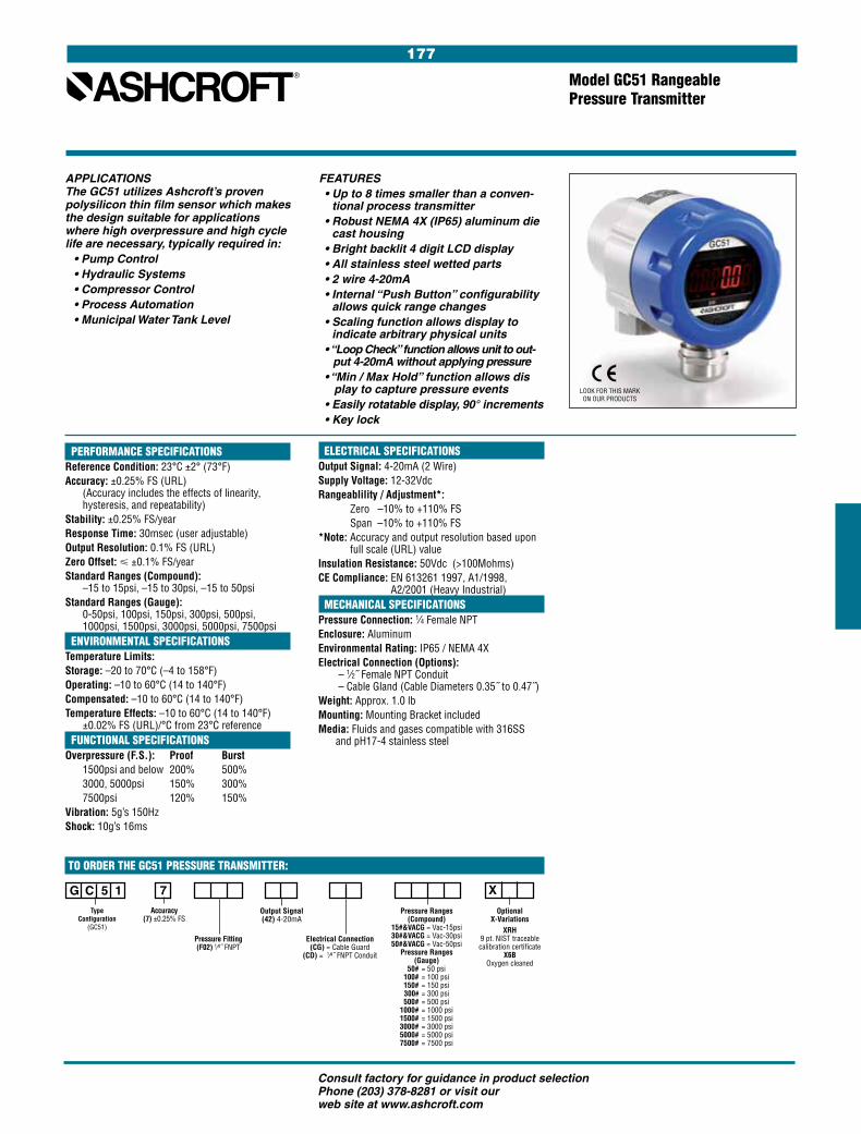
177
Consult factory for guidance in product selection Phone (203) 378-8281 or visit our web site at www.ashcroft.com
Model GC51 Rangeable Pressure Transmitter
FEATURES • Up to 8 times smaller than a conven-
tional process transmitter • Robust NEMA 4X (IP65) aluminum die
cast housing • Bright backlit 4 digit LCD display • All stainless steel wetted parts • 2 wire 4-20mA • Internal “Push Button” configurability
allows quick range changes • Scaling function allows display to
indicate arbitrary physical units • “Loop Check” function allows unit to out-
put 4-20mA without applying pressure • “Min / Max Hold” function allows dis
play to capture pressure events • Easily rotatable display, 90° increments • Key lock
PERFORMANCE SPECIFICATIONSReference Condition: 23°C ±2° (73°F)Accuracy: ±0.25% FS (URL)
(Accuracy includes the effects of linearity, hysteresis, and repeatability)
Stability: ±0.25% FS/yearResponse Time: 30msec (user adjustable)Output Resolution: 0.1% FS (URL)Zero Offset: < ±0.1% FS/yearStandard Ranges (Compound):
–15 to 15psi, –15 to 30psi, –15 to 50psiStandard Ranges (Gauge):
0-50psi, 100psi, 150psi, 300psi, 500psi, 1000psi, 1500psi, 3000psi, 5000psi, 7500psi
ENVIRONMENTAL SPECIFICATIONSTemperature Limits:Storage: –20 to 70°C (–4 to 158°F)Operating: –10 to 60°C (14 to 140°F)Compensated: –10 to 60°C (14 to 140°F)Temperature Effects: –10 to 60°C (14 to 140°F)
±0.02% FS (URL)/°C from 23°C reference FUNCTIONAL SPECIFICATIONSOverpressure (F.S.): Proof Burst
1500psi and below 200% 500%3000, 5000psi 150% 300%7500psi 120% 150%
Vibration: 5g’s 150HzShock: 10g’s 16ms
APPLICATIONSThe GC51 utilizes Ashcroft’s proven polysilicon thin film sensor which makes the design suitable for applications where high overpressure and high cycle life are necessary, typically required in: • Pump Control • Hydraulic Systems • Compressor Control • Process Automation • Municipal Water Tank Level
ELECTRICAL SPECIFICATIONSOutput Signal: 4-20mA (2 Wire)Supply Voltage: 12-32VdcRangeablility / Adjustment*: Zero –10% to +110% FS Span –10% to +110% FS*Note: Accuracy and output resolution based upon
full scale (URL) valueInsulation Resistance: 50Vdc (>100Mohms)CE Compliance: EN 613261 1997, A1/1998,
A2/2001 (Heavy Industrial) MECHANICAL SPECIFICATIONSPressure Connection: 1⁄4 Female NPTEnclosure: AluminumEnvironmental Rating: IP65 / NEMA 4XElectrical Connection (Options):
– 1⁄2˝ Female NPT Conduit – Cable Gland (Cable Diameters 0.35˝ to 0.47˝)
Weight: Approx. 1.0 lbMounting: Mounting Bracket includedMedia: Fluids and gases compatible with 316SS
and pH17-4 stainless steel
G C 5 1
X 7Type
Configuration (GC51)
Pressure Fitting(F02) 1⁄4˝ FNPT
Electrical Connection(CG) = Cable Guard
(CD) = 1⁄4˝ FNPT Conduit
Accuracy (7) ±0.25% FS
Pressure Ranges(Compound)
15#&VACG = Vac-15psi30#&VACG = Vac-30psi50#&VACG = Vac-50psi
Pressure Ranges(Gauge)
50# = 50 psi 100# = 100 psi 150# = 150 psi 300# = 300 psi 500# = 500 psi 1000# = 1000 psi 1500# = 1500 psi 3000# = 3000 psi 5000# = 5000 psi 7500# = 7500 psi
Optional X-Variations
XRH9 pt. NIST traceable calibration certificate
X6B Oxygen cleaned
TO ORDER THE GC51 PRESSURE TRANSMITTER:
Output Signal(42) 4-20mA
LOOK FOR THIS MARK ON OUR PRODUCTS
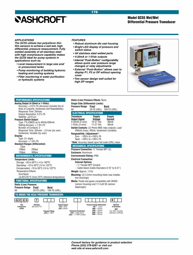
178
Consult factory for guidance in product selection Phone (203) 378-8281 or visit our web site at www.ashcroft.com
PERFORMANCE SPECIFICATIONSAnalog Output (4-20mA or 1-5Vdc):
Accuracy: ± 0.5% FS (Accuracy includes the ef-fects of Linearity, Hysteresis and Repeatability) Response Time: 20msec Output Resolution: 0.2% FS Stability: ±0.5%/yr
Pressure Switch Output: Type: TTL/CMOS up to 40Vdc/200mA Setting Accuacy: ± 1.0% FS Number of Contacts: 2 Response Time: 20msec – 2.0 sec (by user) Hysteresis: Variable (by user)
Display: Type: 31⁄2 digits Accuracy: ± 1.0% FS
Standard Ranges (Differential): 75psi 100psi 250psi 150psi 300psi ENVIRONMENTAL SPECIFICATIONSTemperature Limits: Storage: –20 to 60°C (–4 to 140°F) Operating: –10 to 50°C (14 to 122°F) Compensated: –10 to 50°C (14 to 122°F) Temperature Effects:
Zero/Span: ±0.05%FS/°C (from 23°C reference temperature)
FUNCTIONAL SPECIFICATIONSStatic (Line) Pressure: Pressure Range Proof Burst All 2X FS (URL) 10X FS (URL)
FEATURES• Robust aluminum die cast housing• Bright LED display of pressure and
switch status• All stainless steel wetted parts• 4-20mA or 1-5Vdc outputs• Internal “Push-Button” configurability
allows quick user pressure range changes or relay adjustments
• External “Push-Button” allows user to display P1, P2 or DP without opening cover
• Two sensor design well suited for high DP ranges
APPLICATIONSThe GC55 utilizes two polysilicon thin film sensors to achieve a wet-wet, high differential, pressure measurement. Fully welded assembly of all stainless steel with high overpressure capability makes the GC55 ideal for pump systems in applications such as: • Level measurement in large size and/
or pressurized tanks • Pump monitoring of building hydronic
heating and cooling systems • Filter monitoring in water purification
or hydraulic systems
G C 5 5
X 7Type
Configuration (GC55)
Pressure Fitting(F01) 1⁄8˝ FNPT
Electrical Connection(CG) = Cable Guard
(CD) = 1⁄2˝ FNPT Conduit
Accuracy (7) ±0.25% FS
Pressure Range Differential 70# = 75 psi 100# = 100 psi 150# = 150 psi 250# = 250 psi 300# = 300 psi
Optional X-Variations
XRH9 pt. NIST traceable calibration certificate
TO ORDER THE GC55 PRESSURE TRANSDUCER:
Output Signal(15) 1-5Vdc (42) 4-20mA
Model GC55 Wet/Wet Differential Pressure Transducer
Static (Line) Pressure Effects: NoneSingle Side (Differential Limits): Pressure Range Proof Burst All 2X FS (URL) 10X FS (URL) ELECTRICAL SPECIFICATIONSTransducer Supply Supply Output Signal Voltage Current 4-20mA (3 wire) 15-27 Vdc 80mA 1-5Vdc (3 wire) 11-27 Vdc 60mASwitch Contacts: (2) Photo M0S relay outputs; Load
200mA (max), 40Vdc; Hysteresis (variable)Rangeablility / Adjustment*:
Zero –105% to +105% FS Span –105% to +105% FS
*Note: Accuracy based upon full scale (URL) value MECHANICAL SPECIFICATIONSPressure Connection: 1⁄8˝ Female NPT (2)Enclosure: AluminumEnvironmental Rating: IP66Electrical Connection:
External Options: – 1⁄2˝ Female NPT Conduit – Cable Gland (Cable Diameters 0.16˝ to 0.31˝)
Weight: Approx. 1.0 lbMounting: (2) 5.2mm mounting holes (see installa-
tion drawings)Media: Fluids and gases compatible with 304SS
(sensor housing) and 17-4 pH SS (sensor diaphragm)

179
Consult factory for guidance in product selection Phone (203) 378-8281 or visit our web site at www.ashcroft.com
APPLICATIONS: An Ashcroft pressure transducer to meet demanding requirements in general industrial applications:
• Process automation • Compressor control • Hydraulic systems • Engine monitoring • Pump control • Pneumatics • Refrigeration equipment • Presses • Machine Tools • Other general industrial applications
Type T2 – High Performance Pressure Transducer for General Industrial Applications
Important features include:• 0.25% accuracy class • Ranges 30 psi through 20,000 psi • Broad temperature capability • All-welded pressure construction • Proven polysilicon thin film sensor • Precision ASIC based electronics • High EMI/RFI immunity rating • Highly configurable • Voltage and current outputs • Choice of electrical connections • Optional panel meter digital display –
see Ashcroft model 2269
PERFORMANCE SPECIFICATIONSRef. Temperature, 21°C ±1°C (70°F, ±2°F) Accuracy:
Static Accuracy Class: ±0.25% of span (BFSL Method) including non-linearity, hysteresis, non- repeatability at reference temperature
Temperature Effect: –20°C to 85ºC <±1% of Span – Total Error Band –40°C to –20ºC <±1.5% of Span – Total Error Band –85°C to 125ºC <±1.5% of Span – Total Error Band Total Error Band includes the combined effects of non-linearity (Terminal Point Method), hysteresis, non-repeat-ability, temperatureand zero offset and span setting errors. For higher performance availability consult factoryStability: Less than ±0.25% span/yearDurability: Tested to 50 million cycles
ENVIRONMENTAL SPECIFICATIONSTemperature: Compensated –40 to 125°C (–40 to 257°F)Operating –40 to 125°C (–40 to 257°F)Storage –40 to 125°C (–40 to 257°F)Humidity: 0 to 100% R.H., no effect
FUNCTIONAL SPECIFICATIONSSelect from over 25 pressure ranges starting at 30 psi and running through 20,000 psi. Compound (vacuum & pressure) ranges are also available, see below.Overpressure (F.S.): Proof Burst750 psi & below 200% FS 1000% FS 1500 psi 200% FS 500% FS 3000 psi 200% FS 500% FS 5000 psi 150% FS 500% FS 7500 psi 120% FS 500% FS 10,000 psi 120% FS 240% FS 20,000 psi 120% FS 240% FS
Vibration: Random vibration (20 g) over temperature range (–40° to 125°C). Exceeds typical MIL. STD. requirementsShock: 100gs, 6 msDrop Test: Withstands 1 meter on concrete 3 axisResponse Time: Less than 1 msecWarm-up Time: Less than 500 msec typicalPosition Effect: Less than ±0.01% span, typical
ELECTRICAL SPECIFICATIONSOutput Signals Available: Supply Voltage Output Excitation Current 0-5 Vdc, 3 wire 9-36 Vdc 5mA 0-10 Vdc, 3 wire 14-36 Vdc 5mA 1-5 Vdc, 3 wire 9-36 Vdc 4mA 1-6 Vdc, 3 wire 9-36 Vdc 4mA Ratiometric Output 0.5-4.5 Vdc, 3 wire 5 Vdc ±0.5 Vdc 3.5mA Current Output 4-20mA, 2 wire 9-36 Vdc Reverse Polarity & Miswired Protected: YesInsulation Breakdown Voltage: 100 VacInsulation Resistance: Greater than 100 megohms at 100 VdcCE Compliance: Per EN 61326: 1997 + A1: 1998 + A2: 2001, Annex A (Heavy Industrial)
PHYSICAL SPECIFICATIONSPressure Connection: 304 stainless steelSensor Material: 17-4PH SSHousing: 20% Glass Reinforced Nylon, Fire retardant to UL94 V1Available Process Connections (Male): 1⁄8 NPT, 1⁄4 BSP, 1⁄4 NPT, G1⁄4 B, 7⁄16-20 UNF-2AFor other connections consult factoryEnvironmental Rating: Enclosure meets NEMA 4X, IP65
ELECTRICAL TERMINATION• Pigtail: 3 feet of shielded cable, PVC jacket, 24 AWG
leads• DIN 43 650-A• Bendix style 4 pin, PTO 2A-8-4P or similar• M12 x 1, 4 pin, circular style
TO ORDER THE T2 PRESSURE TRANSDUCER:
M12 and Bendix style termination designs share similar dimensions to those shown above.
DIMENSION DRAWINGS
X T 2
7
Type Configuration
(T2)
Pressure Connection
Electrical Connection
Accuracy ±0.25% Static Accuracy Class (BFSL)±1.00% Total Error Band –20°C to +85°C ±1.50% Total Error Band –40°C to –20°C, 85°C to 125°C
05= 0-5 Vdc 10 = 0-10 Vdc 15 = 1-5 Vdc16 = 1-6 Vdc42 = 4-20mARM = 0.5-4.5 Vdc
Ratio Metric to 5Vdc supply
Consult factory for available options
Pressure Ranges Optional X-Variations
M01 1⁄8 NPT-maleM02 1⁄4 NPT-maleMEK 7⁄16-20 SAE-maleMS2 1⁄4-19 BSP male MG2 G 1⁄4 B male Consult Factory Other Connections
psi Ranges 30# = 30 psi 50# = 50 psi 60# = 60 psi 100# = 100 psi 150# = 150 psi 200# = 200 psi 300# = 300 psi 500# = 500 psi 750# = 750 psi 1000# = 1000 psi 1500# = 1500 psi 2000# = 2000 psi 3000# = 3000 psi 5000# = 5000 psi 6000# = 6000 psi 7500# = 7500 psi 10000# = 10000 psi 20000# = 20000 psi
Compound Ranges 30# & vac = 30 psi/-14.7 psi 45# & vac = 45 psi/-14.7 psi 60# & vac = 60 psi/-14.7psi 85# & vac = 85 psi/-14.7 psi 100# & vac = 100 psi/-14.7 psi150# & vac = 150 psi/-14.7 psi200# & vac = 200 psi/-14.7 psi300# & vac = 300 psi/-14.7 psi
DIN 43 650-A – Mates to Hirschmann GDM 3009 or similar DN = no mating conn. D0 = w/mating conn., no cable D2 = w/mating conn. 3´ shielded cableM12 – Mates to Hirschmann 933 172-100 or similar EW = no mating conn.E0 = w/mating conn. no cable E2 = w/mating conn. & 3´ shielded cableCircular 4 Pin – Mates to Amphenol Bendix PTO6A-8-4S-SR or similarB4 = no mating conn. H1 = w/mating conn., no cable L1 = w/mating conn. 3´ shielded cablePigtail – Shielded cable with PVC Jacket and 24 AWG leads F2 = w/3´ cable lengthP1 = w/3´ cable lengthF3 = w/6´ cable lengthConsult factory for additional cable lengths
Output Signal
G
Measurement Type
G = Gauge pressure, vented housing For sealed housing (PSIS) consult factory
Ranges in bar, kPa and mPa are also available
MATING CONNECTOR LOCATION AND SIZE
"L"
.23
.32
2.03
27mm 1.06˝ HEX
SHIELDED CABLE
ø 1.32
.75
.30
3.450
1.063 27
2.04
.23
MATING CONNECTOR LOCATION AND SIZE
1.32
DIN FORM-A
ø
PVC Jacket, 3´ Length Standard, 24 AWG Leads
Mates to HirschmannGDM 3009 or similar
LOOK FOR THIS MARK ON OUR PRODUCTS
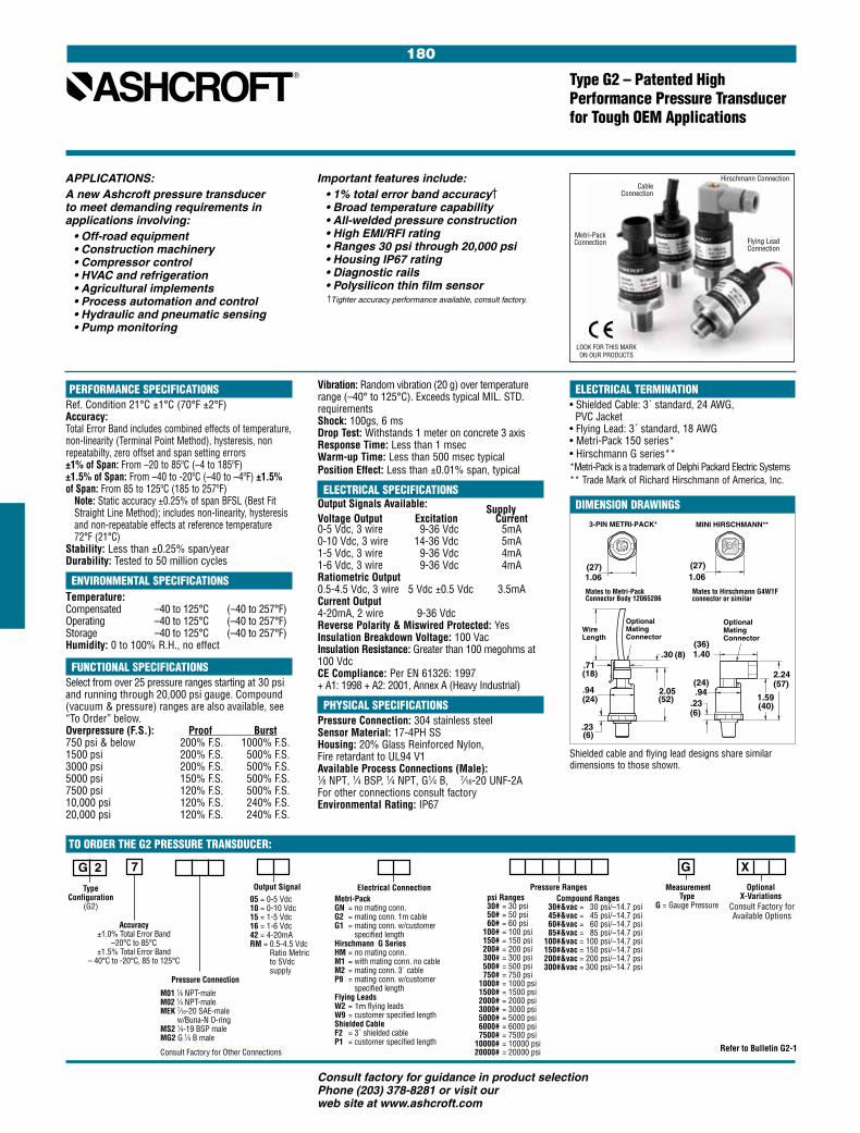
180
Consult factory for guidance in product selection Phone (203) 378-8281 or visit our web site at www.ashcroft.com
APPLICATIONS: A new Ashcroft pressure transducer to meet demanding requirements in applications involving:
• Off-road equipment• Construction machinery• Compressor control• HVAC and refrigeration• Agricultural implements• Process automation and control• Hydraulic and pneumatic sensing• Pump monitoring
Type G2 – Patented High Performance Pressure Transducer for Tough OEM Applications
Important features include:• 1% total error band accuracy†• Broad temperature capability• All-welded pressure construction• High EMI/RFI rating• Ranges 30 psi through 20,000 psi• Housing IP67 rating• Diagnostic rails• Polysilicon thin film sensor
† Tighter accuracy performance available, consult factory.
PERFORMANCE SPECIFICATIONSRef. Condition 21°C ±1°C (70°F ±2°F) Accuracy:Total Error Band includes combined effects of temperature, non-linearity (Terminal Point Method), hysteresis, non repeatabilty, zero offset and span setting errors ±1% of Span: From –20 to 85ºC (–4 to 185ºF)±1.5% of Span: From –40 to -20ºC (–40 to –4ºF) ±1.5% of Span: From 85 to 125ºC (185 to 257ºF)
Note: Static accuracy ±0.25% of span BFSL (Best Fit Straight Line Method); includes non-linearity, hysteresis and non-repeatable effects at reference temperature 72°F (21°C)
Stability: Less than ±0.25% span/yearDurability: Tested to 50 million cycles
ENVIRONMENTAL SPECIFICATIONSTemperature: Compensated –40 to 125°C (–40 to 257°F)Operating –40 to 125°C (–40 to 257°F)Storage –40 to 125°C (–40 to 257°F)Humidity: 0 to 100% R.H., no effect
FUNCTIONAL SPECIFICATIONSSelect from over 25 pressure ranges starting at 30 psi and running through 20,000 psi gauge. Compound (vacuum & pressure) ranges are also available, see “To Order” below.Overpressure (F.S.): Proof Burst750 psi & below 200% F.S. 1000% F.S. 1500 psi 200% F.S. 500% F.S. 3000 psi 200% F.S. 500% F.S. 5000 psi 150% F.S. 500% F.S. 7500 psi 120% F.S. 500% F.S. 10,000 psi 120% F.S. 240% F.S. 20,000 psi 120% F.S. 240% F.S.
Vibration: Random vibration (20 g) over temperature range (–40° to 125°C). Exceeds typical MIL. STD. requirementsShock: 100gs, 6 msDrop Test: Withstands 1 meter on concrete 3 axisResponse Time: Less than 1 msecWarm-up Time: Less than 500 msec typicalPosition Effect: Less than ±0.01% span, typical
ELECTRICAL SPECIFICATIONSOutput Signals Available: Supply Voltage Output Excitation Current 0-5 Vdc, 3 wire 9-36 Vdc 5mA 0-10 Vdc, 3 wire 14-36 Vdc 5mA 1-5 Vdc, 3 wire 9-36 Vdc 4mA 1-6 Vdc, 3 wire 9-36 Vdc 4mA Ratiometric Output 0.5-4.5 Vdc, 3 wire 5 Vdc ±0.5 Vdc 3.5mA Current Output 4-20mA, 2 wire 9-36 Vdc Reverse Polarity & Miswired Protected: YesInsulation Breakdown Voltage: 100 VacInsulation Resistance: Greater than 100 megohms at 100 VdcCE Compliance: Per EN 61326: 1997 + A1: 1998 + A2: 2001, Annex A (Heavy Industrial)
PHYSICAL SPECIFICATIONSPressure Connection: 304 stainless steelSensor Material: 17-4PH SSHousing: 20% Glass Reinforced Nylon, Fire retardant to UL94 V1Available Process Connections (Male): 1⁄8 NPT, 1⁄4 BSP, 1⁄4 NPT, G1⁄4 B, 7⁄16-20 UNF-2AFor other connections consult factoryEnvironmental Rating: IP67
ELECTRICAL TERMINATION• Shielded Cable: 3´ standard, 24 AWG, PVC Jacket • Flying Lead: 3´ standard, 18 AWG• Metri-Pack 150 series*• Hirschmann G series** *Metri-Pack is a trademark of Delphi Packard Electric Systems** Trade Mark of Richard Hirschmann of America, Inc.
.71
WireLength
.30
.23
2.05.94
3-PIN METRI-PACK*
(27)
(8)
1.06
(18)
(24)
(6)
(52)
Mates to Metri-Pack Connector Body 12065286
OptionalMatingConnector
G 2
X 7
Type Configuration
(G2)
Pressure Connection
Electrical Connection
Accuracy ±1.0% Total Error Band
–20°C to 85°C ±1.5% Total Error Band
– 40°C to -20°C, 85 to 125°C
05 = 0-5 Vdc 10 = 0-10 Vdc 15 = 1-5 Vdc16 = 1-6 Vdc42 = 4-20mARM = 0.5-4.5 Vdc
Ratio Metric to 5Vdc supply
Pressure Ranges Optional X-Variations
M01 1⁄8 NPT-maleM02 1⁄4 NPT-maleMEK 7⁄16-20 SAE-male
w/Buna-N O-ringMS2 1⁄4-19 BSP male MG2 G 1⁄4 B male
Consult Factory for Other Connections
psi Ranges 30# = 30 psi 50# = 50 psi 60# = 60 psi 100# = 100 psi 150# = 150 psi 200# = 200 psi 300# = 300 psi 500# = 500 psi 750# = 750 psi 1000# = 1000 psi 1500# = 1500 psi 2000# = 2000 psi 3000# = 3000 psi 5000# = 5000 psi 6000# = 6000 psi 7500# = 7500 psi 10000# = 10000 psi 20000# = 20000 psi
Compound Ranges 30#&vac = 30 psi /–14.7 psi 45#&vac = 45 psi /–14.7 psi 60#&vac = 60 psi /–14.7 psi 85#&vac = 85 psi /–14.7 psi100#&vac = 100 psi /–14.7 psi150#&vac = 150 psi /–14.7 psi200#&vac = 200 psi /–14.7 psi300#&vac = 300 psi /–14.7 psi
Metri-Pack GN = no mating conn. G2 = mating conn. 1m cable G1 = mating conn. w/customer
specified lengthHirschmann G Series HM = no mating conn. M1 = with mating conn. no cable M2 = mating conn. 3´ cable P9 = mating conn. w/customer
specified length Flying Leads W2 = 1m flying leadsW9 = customer specified length Shielded Cable F2 = 3´ shielded cable P1 = customer specified length
Measurement Type
G = Gauge Pressure
TO ORDER THE G2 PRESSURE TRANSDUCER:
Output Signal
1.40
2.24
1.59.23.94
1.06(27)
(36)
MINI HIRSCHMANN**
(24) (57)
(6)(40)
Optional MatingConnector
Mates to Hirschmann G4W1F connector or similar
Shielded cable and flying lead designs share similar dimensions to those shown.
Refer to Bulletin G2-1
DIMENSION DRAWINGS
G
Metri-Pack Connection
Cable Connection
Hirschmann Connection
Flying Lead Connection
Consult Factory for Available Options
LOOK FOR THIS MARK ON OUR PRODUCTS
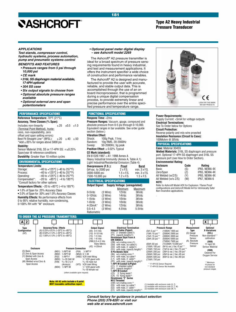
181
Consult factory for guidance in product selection Phone (203) 378-8281 or visit our web site at www.ashcroft.com
PERFORMANCE SPECIFICATIONSReference Temperature: 70°F (21°C)Accuracy, Three Classes (% Span):Includes non-linearity ±.25 ±0.5 ±1.0 (Terminal Point Method), hyste- resis, non-repeatability, zero offset and span setting errors) Best Fit Straight Line* (BFSL): ±.20 ±.40 ±.50 *Add ±.05% for ranges above 5000 psiStability: Sensor Material 316L SS or 17-4PH SS: #±0.25% Span/year @ reference conditionsDurability: Greater than 10 million cycles
ENVIRONMENTAL SPECIFICATIONSTemperature Limits: Storage: –40 to +125°C (–40 to 257°F) Process: –40 to +125°C (–40 to 257°F) Operating: –40 to +125°C (–40 to 257°F) Compensated*: –20 to +85°C ( –4 to 185°F) *Consult factory for other optionsTemperature Effects: –20 to +85°C (–4 to 185°F)• 1.0% of Span for .25% Accuracy Class • 2.0% of Span for .50% and 1.0% Accuracy ClassesHumidity Effects: No performance effects from 0 to 95% relative humidity, non-condensing, 0-100% RH with “W” enclosure.
TO ORDER THE A2 PRESSURE TRANSMITTERS:
Type A2 Heavy Industrial Pressure Transducer
FUNCTIONAL SPECIFICATIONSRespone Time: <2msPressure Ranges: Vacuum, gauge, compound and absolute pressure from 0-5 psi through 0-10,000. Equivalent ranges in bar available. See order guide section (below.)Vibration Effect: Shock: 100g Peak, 11ms Random: 10g RMS, 20-2000Hz Sweep: 50-2000Hz, 5g peak Position Effect: ± 0.02% TypicalCE Mark (standard): EN 61326:1997 + A1: 1998 Annex A Heavy Industrial Immunity (Annex A, Table A.1) Light Industrial/Residential Emission (Table 4)Overpressure (F.S.): Proof Burst0#/vac. to 2000 psi 2 x F.S. min. 3 x F.S.3000-5000 psi 1.5 x F.S. min. 3 x F.S.7500-10,000 psi 1.2 x F.S. 1.5 x F.S.
ELECTRICAL SPECIFICATIONSOutput Signal: Supply Voltage: (unregulated) Minimum Maximum0-5Vdc (3 Wire) 12Vdc 36Vdc0-10Vdc (3 Wire) 14Vdc 36Vdc1-5Vdc (3 Wire) 10Vdc 36Vdc 1-6Vdc (3 Wire) 10Vdc 36Vdc4-20mA* (2 Wire) 12Vdc 36Vdc0.5-4.5 (3 Wire) 4.5Vdc 5.5VdcRatiometric
Power Requirements: Supply Current: <5mA for voltage outputsElectrical Terminations: See To Order below for OptionsCircuit Protection: Reverse polarity and mis-wire proectedInsulation Resisance (Circuit to Case): 100Mohm @ 30Vdc PHYSICAL SPECIFICATIONSCase: Material 304SS Wetted Materials: 316L SS diaphragm and pressure port. Optional 17-4PH SS diaphragm and 316L SS pressure port (see How to Order Section).Environmental Rating:Enclosure Code Rating Basic (S) IP65, NEMA 4X Zero/Span (Z) IP65, NEMA 4X All Welded (w/Z/S) (Y) IP65, NEMA 4X All Welded (w/o Z/S) (W) IP67, NEMA 6NOTE:Refer to Ashcroft Model A2X for Explosion / Flame Proof configurations and Ashcroft Model A4 for Intrinsically Safe/Non-Incendive applications.
.
The Ashcroft® A2 pressure transmitter is ideal for a broad spectrum of pressure sens-ing requirements found in heavy industrial, and test and measurement applications. It offers the instrument specifier a wide choice of construction and performance variables.
The Ashcroft® A2 is designed and manu-factured to provide the user with accurate, reliable, and stable output data. This is accomplished through the use of an on board microprocessor, that is programmed during a unique digital compensation process, to provide extremely linear and precise performance over the entire speci-fied pressure and temperature range.
A 2
X
Type Configuration
(A2)
Pressure Connection
Electrical Termination Accuracy/Temp. Effects (A) 0.25%/≤0.5% (–20°C to +85°C)(B) 0.50%/≤1.0% (–20°C to +85°C)(C) 1.00%/≤1.0% (–20°C to +85°C)
Enclosure(S) Basic (Z) Zero & Span Access(Y) Welded with Zero &
Span Access(W) Welded w/out Zero &
Span Access
(05) 0-5 Vdc (10) 0-10 Vdc (15) 1-5 Vdc(16) 1-6 Vdc(RM) 0.5-4.5 Vdc
Ratio Metric(42) 4-20mA
Pressure Range Optional X-Variations
(XCL) Non-standard**
calibration(XK8)
17-4pH SS Sensor Material
(X6B) Cleaned For
Oxygen Service
(M01) 1⁄8 NPT-M(M02) 1⁄4 NPT-M(F02) 1⁄4 NPT-F(MEK) 7⁄16-20 SAE-M(F09) 9⁄16-18 (1⁄4)-F
(Aminco)(M04) 1⁄2 NPT-M
(5#) 5 psi** (10#) 10 psi**(15#) 15 psi** (30#) 30 psi**
(60#) 60 psi(100#) 100 psi(150#) 150 psi(200#) 200 psi(300#) 300 psi(500#) 500 psi(750#) 750 psi
(1000#) 1000 psi(2000#) 2000 psi(3000#) 3000 psi(5000#) 5000 psi(7500#) 7500 psi(10,000#) 10,000 psi*(0# & vac.) Vac./0 psi**(15# & vac.) Vac./15 psi**(30# & vac.) Vac./30 psi*(45# & vac.) Vac./45 psi(60# & vac.) Vac./60 psi
Integral Cable (Pigtail) (F2) 3´ shielded cable(1)(P1) (specify length)(1)Hirschmann Style Form ADIN 43650-A (DN) w/o mating conn.(1)(D0) with mate, no cable(1)(D2) with mate, 3´ cable(1)(D1) with mate, (specify length)(1)
4-Pin Bendix Style (B4) w/o mating conn.(2)
(H1) with mate, no cable(2)
(L1) with mate, 3´ cable(2)
(P2) with mate, (specify length)(2)
1⁄2 NPT-M Conduit w/Pigtail (C1) 3´ shielded cable(3)
(P7) (specify length)(3)
1⁄2 NPT-M Conduit (C2) 3´ flying leads(3)
(C4) 15´ flying leads(3)
Hirschmann “E” Series M12 Threaded (EW) w/o mating conn.(1)
(E0) with male, no cable(1)
(E2) with male, 3´ cable(1)
(E1) with male, (specify length)(1)
(F04) 1⁄2 NPT-F(MG4) G 1⁄2 M(VM2) VCR inlet fitting
1⁄4˝ VCR gland with 9⁄16-18 male nut
(VF2) VCR inlet fitting 1⁄4˝ VCR gland with 9⁄16-18 female nut
Output Signal Measurement Type(G) Gauge
Pressure Sensor
(A) Absolute Pressure Sensor
** 17-4PH SS Sensor Required ** 17-4PH SS Sensor Not Available
**Minimum 10 pieces for non-standard
pressure ranges
LOOK FOR THIS MARK ON OUR PRODUCTS
(others available upon request)
(1) Available with enclosure code (S, Z)(2) Available with enclosure code (S, Z, W)(3) Available with enclosure code (W, Y)
Note: All A2 units include a 9 point NIST traceable calibration report.
APPLICATIONSTest stands, compressor control, hydraulic systems, process automation, pump and pneumatic systems controlBENEFITS AND FEATURES
• Pressure ranges from 5 psi through 10,000 psi
• CE mark • 316L SS diaphragm material available, 17-4PH optional
• 304 SS case • Six output signals to choose from• Optional absolute pressure ranges
available• Optional external zero and span
potentiometers
• Optional panel meter digital display – see Ashcroft model 2269

182
Consult factory for guidance in product selection Phone (203) 378-8281 or visit our web site at www.ashcroft.com
LOOK FOR THESE MARKS ON OUR PRODUCTS
1⁄2 NPT-M Conduit
Flying Leads(C2) with 3´leads(C3) with customer
defined length(C4) with 15´leads
Shielded Cable(C1) with 3´cable(C6) with 15´cable(C7) with 30´cable(P7) with customer
defined length
Type Configuration
(A2X)
APPLICATIONSOil field equipment, upstream oil and gas production, natural gas compression and transfer control, alternative energy projects
BENEFITS AND FEATURES• cUL and ATEX listed• FM intrinsically safe approvals (see
note under Optional Hazardous Area Classifications below)
• CSA intrinsically safe approvals (see note under Optional Hazardous Area Classifications below)
• Choice of 0.25, 0.50 or 1.0% accuracy• Pressure ranges from 5 psi through
10,000 psi• CE mark• 316L SS wetted materials, 17-4 PH optional
PERFORMANCE SPECIFICATIONSReference Temperature: 70°F (21°C)Accuracy, Three Classes (% Span):Includes non-linearity ±.25 ±0.5 ±1.0 (Terminal Point Method), hyste- resis, non-repeatability, zero offset and span setting errors) Best Fit Straight Line* (BFSL): ±.20 ±.40 ±.50 *Add ±.05% for ranges above 5000 psiStability: Sensor Material 316L SS or 17-4PH SS: #±0.25% Span/year @ reference conditionsDurability: Greater than 10 million cycles
ENVIRONMENTAL SPECIFICATIONSTemperature Limits: Storage: –40 to +125°C (–40 to 257°F) Process: –40 to +125°C (–40 to 257°F) Operating: –40 to +125°C (–40 to 257°F) Compensated*: –20 to +85°C ( –4 to 185°F) *Consult factory for other optionsTemperature Effects: –20 to +85°C (–4 to 185°F)• 1.0% of Span for .25% Accuracy Class • 2.0% of Span for .50% and 1.0% Accuracy ClassesHumidity Effects: No performance effects from 0 to 95% relative humidity, non-condensing, 0-100% RH with “W” enclosure.
TO ORDER THE A2X EXPLOSION/FLAME PROOF PRESSURE TRANSMITTERS:
Type A2X Explosion/Flame Proof Pressure Transmitter
FUNCTIONAL SPECIFICATIONSRespone Time: <2msPressure Ranges: Vacuum, gauge, compound and absolute pressure from 0-5 psi through 0-10,000. Equivalent ranges in bar available. See order guide section (below.)Vibration Effect: Shock: 100g Peak, 11ms Random: 10g RMS, 20-2000Hz Sweep: 50-2000Hz, 5g peak Position Effect: ±0.02% TypicalCE Mark (standard): EN 61326:1997 + A1: 1998 Annex A Heavy Industrial Immunity (Annex A, Table A.1) Light Industrial/Residential Emission (Table 4)Overpressure (F.S.): Proof Burst0#/vac. to 2000 psi 2 x F.S. min. 3 x F.S.3000-5000 psi 1.5 x F.S. min. 3 x F.S.7500-10,000 psi 1.2 x F.S. 1.5 x F.S.
ELECTRICAL SPECIFICATIONSOutput Signal: Supply Voltage: (unregulated) Minimum Maximum0-5Vdc (3 Wire) 12Vdc 36Vdc0-10Vdc (3 Wire) 14Vdc 36Vdc1-5Vdc (3 Wire) 10Vdc 36Vdc 1-6Vdc (3 Wire) 10Vdc 36Vdc4-20mA* (2 Wire) 12Vdc 36Vdc*0.5-4.5 (3 Wire) 4.5Vdc 5.5VdcRatiometric*30Vdc max for Intrinsically Safe installations
The Ashcroft® AX2 pressure transmitter is ideal for a broad spectrum of pressure sensing requirements requiring approvals for explosion/flame proof.
The Ashcroft® A2X is designed and manufactured to provide the user with accu-rate, reliable, and stable output data. This is accomplished through the use of an on board microprocessor, that is programmed during a unique digital compensation process, to provide extremely linear and precise performance over the entire speci-fied pressure and temperature range.
A 2 X
X
Pressure Connection
Electrical Termination Accuracy/Temp. Effects (A) 0.25%/≤0.5% (–20°C to +85°C)(B) 0.50%/≤1.0% (–20°C to +85°C)(C) 1.00%/≤1.0% (–20°C to +85°C)
(05) 0-5 Vdc (10) 0-10 Vdc (15) 1-5 Vdc(16) 1-6 Vdc(RM) 0.5-4.5 Vdc
Ratio Metric(42) 4-20mA
Pressure Range Optional X-Variations
(XCL) Non-standard**
calibration(XK8)
17-4pH SS Sensor Material
(X6B) Cleaned For
Oxygen Service
(M01) 1⁄8 NPT-M(M02) 1⁄4 NPT-M(F02) 1⁄4 NPT-F(MEK) 7⁄16-20 SAE-M(F09) 9⁄16-18 (1⁄4)-F
(Aminco)(M04) 1⁄2 NPT-M(F04) 1⁄2 NPT-F
(5#) 5 psi** (10#) 10 psi**(15#) 15 psi** (30#) 30 psi**
(60#) 60 psi(100#) 100 psi(150#) 150 psi(200#) 200 psi(300#) 300 psi(500#) 500 psi(750#) 750 psi
(1000#) 1000 psi(2000#) 2000 psi(3000#) 3000 psi(5000#) 5000 psi(7500#) 7500 psi(10,000#) 10,000 psi*(0# & vac.) Vac./0 psi**(15# & vac.) Vac./15 psi**(30# & vac.) Vac./30 psi(45# & vac.) Vac./45 psi(60# & vac.) Vac./60 psi
(MG4) G 1⁄2 M(VM2) VCR inlet fitting
1⁄4˝ VCR gland with 9⁄16-18 male nut
(VF2) VCR inlet fitting 1⁄4˝ VCR gland with 9⁄16-18 female nut
Output Signal Measurement Type(G) Gauge
Pressure Sensor
(A) Absolute Pressure Sensor
*17-4PH SS Sensor Required **17-4PH SS Sensor Not Available **Minimum 10 pieces
for non-standard pressure ranges.
Power Requirements: Supply Current: <5mA for voltage outputsElectrical Terminations: See To Order below for OptionsCircuit Protection: Reverse polarity and mis-wire proectedInsulation Resisance (Circuit to Case): 100Mohm @ 30Vdc PHYSICAL SPECIFICATIONSCase: Material 304SS Wetted Materials: 316L SS diaphragm and pressure port. Optional 17-4PH SS diaphragm and 316L SS pressure port (see How to Order Section).Environmental Rating: IP65; NEMA 7,9
OPTIONAL HAZARDOUS AREA CERTIFICATIONSExplosion Proof – cUL (USL/CNL): Class I, Div. 1 & 2, Groups A, B, C and D Class II, Div. 1 & 2, Groups E, F and GFlame Proof – ATEX: Specify A2X II 2 GD Ex d IIC T4NOTE: For 4-20mA units following approvals also apply: Intrinsically Safe – FM/CSA: Class I, Div. 1 Class I, Div. 2, Non-Incendive Refer to Ashcroft drawing #825A022 for wiring and installation requirements.NOTE: Refer to Ashcroft Model A2 for Heavy Industrial, non-Hazardous rated configurations and Ashcroft Model A4 for Intrinsically Safe/non-Incendive applications.
Note: All A2X pressure transmitters include a 9 pt. NIST traceable calibration certificate
• 304 SS case • Six output signals to choose from• Optional absolute pressure ranges available
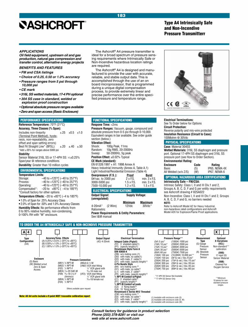
183
Consult factory for guidance in product selection Phone (203) 378-8281 or visit our web site at www.ashcroft.com
Integral Cable (Pigtail) (F2) 3´ shielded cable(1)(P1) (specify length)(1)Hirschmann Style Form ADIN 43650-A (DN) w/o mating conn.(1)(D0) with mate, no cable(1)(D2) with mate, 3´ cable(1)(D1) with mate, (specify length)(1)
4-Pin Bendix Style (B4) w/o mating conn.(2)
(H1) with mate, no cable(2)
(L1) with mate, 3´ cable(2)
(P2) with mate, (specify length)(2)
1⁄2 NPT-M Conduit w/Pigtail (C1) 3´ shielded cable(3)
(P7) (specify length)(3)
1⁄2 NPT-M Conduit w/Leads (C2) 3´ flying leads(3)
(C4) 15´ flying leads(3)
Hirschmann E Series M12 Threaded (EW) w/o mating conn.(1)
(E0) with male, no cable(1)
(E2) with male, 3´ cable(1)
(E1) with male, (specify length)(1)
Type Configuration
(A4)
APPLICATIONSOil field equipment, upstream oil and gas production, natural gas compression and transfer control, alternative energy projects
BENEFITS AND FEATURES• FM and CSA listings • Choice of 0.25, 0.50 or 1.0% accuracy• Pressure ranges from 5 psi through
10,000 psi• CE mark• 316L SS wetted materials, 17-4 PH optional• 304 SS case in standard, welded or
explosion proof construction• Optional absolute pressure ranges available• Zero and span access (Basic Enclosure)
PERFORMANCE SPECIFICATIONSReference Temperature: 70°F (21°C)Accuracy, Three Classes (% Span):Includes non-linearity ±.25 ±0.5 ±1.0 (Terminal Point Method), hyste- resis, non-repeatability, zero offset and span setting errors) Best Fit Straight Line* (BFSL): ±.20 ±.40 ±.50 *Add ±.05% for ranges above 5000 psiStability: Sensor Material 316L SS or 17-4PH SS: #±0.25% Span/year @ reference conditionsDurability: Greater than 10 million cycles
ENVIRONMENTAL SPECIFICATIONSTemperature Limits: Storage: –40 to +125°C (–40 to 257°F) Process: –40 to +125°C (–40 to 257°F) Operating: –40 to +125°C (–40 to 257°F) Compensated*: –20 to +85°C ( –4 to 185°F) *Consult factory for other optionsTemperature Effects: –20 to +85°C (–4 to 185°F)• 1.0% of Span for .25% Accuracy Class • 2.0% of Span for .50% and 1.0% Accuracy ClassesHumidity Effects: No performance effects from 0 to 95% relative humidity, non-condensing, 0-100% RH with “W” enclosure.
TO ORDER THE A4 INTRINSICALLY SAFE & NON-INCENDIVE PRESSURE TRANSMITTER
Type A4 Intrinsically Safe and Non-Incendive Pressure Transmitterr
FUNCTIONAL SPECIFICATIONSRespone Time: <2msPressure Ranges: Vacuum, gauge, compound and absolute pressure from 0-5 psi through 0-10,000. Equivalent ranges in bar available. See order guide section (below.)Vibration Effect: Shock: 100g Peak, 11ms Random: 10g RMS, 20-2000Hz Sweep: 50-2000Hz, 5g peak Position Effect: ±0.02% TypicalCE Mark (standard): EN 61326:1997 + A1: 1998 Annex A Heavy Industrial Immunity (Annex A, Table A.1) Light Industrial/Residential Emission (Table 4)Overpressure (F.S.): Proof Burst0#/vac. to 2000 psi 2 x F.S. min. 3 x F.S.3000-5000 psi 1.5 x F.S. min. 3 x F.S.7500-10,000 psi 1.2 x F.S. 1.5 x F.S.
ELECTRICAL SPECIFICATIONSOutput Signal: Supply Voltage: (unregulated) Minimum Maximum4-20mA* (2 Wire) 12Vdc 30Vdc*RatiometricPower Requirements & Entity Parameters: See I&M manual
The Ashcroft® A4 pressure transmitter is ideal for a broad spectrum of pressure sens-ing requirements where Intrinsically Safe or Non-Incendive hazardous location ratings are required.
The Ashcroft® A4 is designed and manu-factured to provide the user with accurate, reliable, and stable output data. This is accomplished through the use of an on board microprocessor, that is programmed during a unique digital compensation process, to provide extremely linear and precise performance over the entire speci-fied pressure and temperature range.
A 4
X
Pressure Connection
Electrical Termination Accuracy/Temp. Effects (A) 0.25%/#0.5% (–20°C to +85°C)(B) 0.50%/#1.0% (–20°C to +85°C)(C) 1.00%/#1.0% (–20°C to +85°C)
Enclosure(S) Basic (W) Welded w/out
Zero & Span Access
(42) 4-20mAPressure Range** Optional
X-Variations(XCL)
Non-standard** calibration
(XK8) 17-4pH SS
Sensor Material(X6B)
Cleaned For Oxygen Service
(M01) 1⁄8 NPT-M(M02) 1⁄4 NPT-M(F02) 1⁄4 NPT-F(MEK) 7⁄16-20 SAE-M(F09) 9⁄16-18 (1⁄4)-F
(Aminco)(M04) 1⁄2 NPT-M(F04) 1⁄2 NPT-F
(5#) 5 psi* (10#) 10 psi*(15#) 15 psi* (30#) 30 psi*(60#) 60 psi(100#) 100 psi(150#) 150 psi(200#) 200 psi(300#) 300 psi(500#) 500 psi(750#) 750 psi
(1000#) 1000 psi(2000#) 2000 psi(3000#) 3000 psi(5000#) 5000 psi(7500#) 7500 psi(10,000#) 10,000 psi**(0# & vac.) Vac./0 psi*(15# & vac.) Vac./15 psi*(30# & vac.) Vac./30 psi(45# & vac.) Vac./45 psi(60# & vac.) Vac./60 psi
(MG4) G 1⁄2 M(VM2) VCR inlet fitting
1⁄4˝ VCR gland with 9⁄16-18 male nut
(VF2) VCR inlet fitting 1⁄4˝ VCR gland with 9⁄16-18 female nut
Output Signal Measurement Type(G) Gauge
Pressure Sensor
(A) Absolute Pressure Sensor
*17-4PH SS Sensor Not Available **17-4PH SS Sensor Only **Minimum
10 pieces for non-standard pressure
ranges.
Electrical Terminations: See To Order below for OptionsCircuit Protection: Reverse polarity and mis-wire protectedInsulation Resisance (Circuit to Case): 100Mohm @ 30Vdc PHYSICAL SPECIFICATIONSCase: Material 304SS Wetted Materials: 316L SS diaphragm and pressure port. Optional 17-4PH SS diaphragm and 316L SS pressure port (see How to Order Section).Environmental Rating:Enclosure Code Rating Basic (S) IP65, NEMA 4X All Welded (w/o Z/S) (W) IP67, NEMA 6
OPTIONAL HAZARDOUS AREA CERTIFICATIONSIntrinsically Safe – FM/CSA: Intrinsic Safety: Class I, II and III Div.1 and 2, Groups A, B, C, D, F and G per entity requirements see Ashcroft drawing # 825A022Non-Incendive: Class I, II and III Div.1 and 2, Groups A, B, C, D, F and G, no barriers neededNOTE:Refer to Ashcroft Model A2 for Heavy Industrial, non-hazardous rated configurations and Ashcroft Model A2X for Explosion/Flame Proof applications.
Others available upon request
LOOK FOR THESE MARKS ON OUR PRODUCTS
(1) Available with enclosure code (S)(2) Available with enclosure code (S, W)(3) Available with enclosure code (W)
Note: All A4 units include a 9 point NIST traceable calibration report

184
Consult factory for guidance in product selection Phone (203) 378-8281 or visit our web site at www.ashcroft.com
Type KM15 Rugged, Compact Transducer for the High Volume OEM
APPLICATIONS: High Volume Pressure Sensing in: Off Road Equipment, Construction Machin-ery, Compressors, Pump Control
BENEFITS & FEATURES• RoHS compliant• Compact size• All welded sensor• –40/120°C operating temp• Rugged SS construction• IP 67 ingress rating• Ranges through 7500 psi
The Ashcroft® KM15 Pressure Trans-ducer is the ideal choice for the high volume OEM who requires an economi-cal yet durable pressure transducer. The KM15 marries a proven polysilicon thin film sensor to a high performance ASIC to provide a highly accurate, stable, and rugged pressure sensing instrument.
PERFORMANCE SPECIFICATIONSRef. Condition 23°C ±2° (73°F) Accuracy: Includes non-linearity, hysteresis, non-repeatability, zero offset and span setting errors – Terminal Point method: ±0.5% Span, 100 psig F.S. and above ±1.0% Span, 75 psig F.S. and below Stability: ±0.25% Span/yearInterchangeability: < .5% SpanDurability: Tested to 50 million cycles
ENVIRONMENTAL SPECIFICATIONSTemperature: Storage –40/120°C (–40/250°F)Operating –40/120°C (–40/250°F)Compensated –30/120°C (–25/250°F)Humidity: 0/100%R.H., no effectThermal Coefficients: –30 to 120°C (–25 to +250°F) Zero Span ±0.01%/°C (±0.0055%/°F) ±0.01%/°C (±0.0055%/°F)
FUNCTIONAL SPECIFICATIONSRanges:
Overpressure (F.S.): Proof Burst750 psi & below 2 x range 10 x range1500 psi 2 x range 5 x range3000 psi 2 x range 5 x range5000 psi 1.5 x range 5 x range7500 psi 1.2 x range 5 x rangeVibration: Random to 1 KHz, 20 g’sShock: 50 g’s, 11 msecDrop Test: No effect 1 meter drop on concreteResponse Time: Less than 1msecPosition Effect: Less than 0.01% F.S.
ELECTRICAL SPECIFICATIONSOutput Signal Options: Supply Output Excitation Current 0.5-4.5 Vdc
5 Vdc ± .5 Vdc 10mA typical
(ratiometric) 1-5 Vdc 8-32 Vdc 10mA typical 1-6 Vdc 10-32 Vdc 10mA typical Reverse Polarity Protection: YesInsulation Breakdown Voltage: (Circuit to case) 150 Vac/1 min.Insulation Resistance: (Circuit to Case) 100M ohm min.@50 Vdc.Warm-up Time: <25 msec
PHYSICAL SPECIFICATIONSPressure Connection Options: see “To Order” belowPressure Connection: 304 SSHousing: 304 SSSensor Material: 17-4 PH SSElectrical Termination: see “To Order” below• Metri Pack 150 Series • Shielded Cable
• Flying Lead • Sumitomo HW090Environmental Rating: IP67Weight: Approx. 2 oz. (60g)
OPTIONSThrottle screws Custom mating harness Special cleaning (for O2) Non-standard pressure ranges Alternate process connections Special calibration/accuracy
Shielded cable termination and flying lead termination is also available.
K M 1 5
# X
Model Type (KM10)
Pressure Connection (MO1) 1⁄8 NPT-M(MO2) 1⁄4 NPT-M(M38) 3⁄8-24 UNF-2A(MEK) 7⁄16-20 UNF-2A(FRW) 7⁄16-20 UNF-2B(M10) M10 x 1(M14) M14 x 1.5(MR3) R 3⁄8(MR2) R 1⁄4(MG3) G 3⁄8(MG2) G 1⁄4
Accuracy Class (5) 0.50%
(100 psi & above) (7) 1.0%
(75 psi & below)
Output Signal(15) 1-5 Vdc (RM) Ratiometric
0.5-4.5 Vdc
Pressure Range Special Features(XTS) Throttle
(X6B) Oxygen cleaning
Electrical TerminationFor Metri-Pack 150 Series Integral Connector(GN) No mating connector(G2) Mating connector
w/36˝ cable(G1) Mating connector
w/custom lengthFor Shielded Cable(F2) 36˝PVC sheath(P1) Other lengthFor Flying Leads(12) 12 inch length (24) 24 inch length (36) 36 inch length
PSI*0/1000/1500/2000/3000/5000/7500/10000/15000/20000/30000/50000/7500
PSI Vac./0 Vac./15 Vac./30 Vac./50 Vac./75 Vac./100 Vac./150 Vac./200 Vac./300 0/15 0/30 0/50 0/75
TO ORDER THE KM10 PRESSURE TRANSDUCER:
*Sealed Sensor
METRI-PACK 150 Series
OUTPUT(+) POWER(+)
COMMON
(25 DIA.)
(7)
(14.
5)
(71.
6)
.27˝
.57˝
2.8˝
.98˝ DIA.
MATES TO OPTIONAL METRI-PACK CONNECTOR 12065287
vac/0 psi* vac/15 psi* vac/30 psi* vac/50 psi* vac/75 psi*
vac/100 psi* vac/150 psi* vac/200 psi* vac/300 psi*
0/15 psi 0/30 psi 0/50 psi 0/75 psi
0/100 psi 0/200 psi 0/300 psi 0/500 psi 0/750 psi
0/1000 psi 0/1500 psi 0/2000 psi 0/3000 psi 0/5000 psi 0/7500 psi
Dimensions: Inches (mm )
LOOK FOR THIS MARK ON OUR PRODUCTS

185
Consult factory for guidance in product selection Phone (203) 378-8281 or visit our web site at www.ashcroft.com
Type K1 Thin Film Pressure Transducer/Transmitter For Industrial Applications
APPLICATIONS:Hydraulic, refrigeration, machine tool, test/measurement, pump control, HVAC, medical, construction equipment and all general purpose industrial process applications
BENEFITS & FEATURES:• 0.5% and 1.0% accuracy• Vac.-20,000 psi pressure range• FM approved (optional)• Superior long-term stability and repeatability• Stainless steel NEMA 4X enclosure• Current/voltage output• Wide range of electrical connections available• Optional panel meter digital display –
see Ashcroft model 2269
to the Nationa I Institute of Standards and Tech nology and specifications are conservatively stated. A calibra tion test certificate is available with each transmitter.
The Ashcroft® K1 is a proven and ver-satile pressure transducer/transmitter incorporating polysilicon thin film tech-nology. Modern low-pressure chemical vapor deposition methods provide simple, stable molecular bonds between a proven metal diaphragm and a polysilicon strain gage bridge. There are no epoxies or bonding agents to contribute to signal instability or drift.
The integral metal diaphragm and poly-silicon bridge are virtually unaffected by shock, vibration or mounting.
These transmitters are offered in many standard pressure ranges with either current or voltage output signals. Trans-mitter performance is directly traceable
Overpressure Limits (F.S.): 15- 3000- 7500- 2000 5000 20,000 Proof 200% 150% 120% Burst 800% 300% 150%Vibration Sweep: Less than ±0.1%F.S. effect for 0-2000 Hz at 20 g’s in any axisShock: Less than ±0.05% F.S. effect for 100 g's, 20ms shock in any axisResponse Time: Less than 5 msPosition Effect: Less than 0.01% F.S.
ELECTRICAL SPECIFICATIONSOutput Signal (consult factory for options): 4-20mA (2 wire) 1-5 Vdc (3 wire) 1-6 Vdc (3 wire) 1-11 Vdc (3 wire) (minimum excitation 15 Vdc)Power Requirements: 10-36 Vdc unregulated, <3mA for voltage output
PHYSICAL SPECIFICATIONSEnvironmental Rating: NEMA 4X (NEMA 1 only if <500 psig if electrical termination is Bendix® or Hirschmann®)Weight: 2 oz. (approx. w/o cable)
PERFORMANCE SPECIFICATIONSAccuracy Class (Span):See page 258-259 for definitionsIncludes non-linearity ±.5% ±1.0% (Terminal Point Method), hystere- sis, non-repeatability, zero offset and span setting errors Best Fit Straight Line (BFSL) ±.25% ±.4% (Includes non-linearity, hysteresis and non-repeatability errors) Interchangeability ±.25% ±.6%Durability: 108 cycles with negligible performance change Stability: ±0.5% Span/yr
ENVIRONMENTAL SPECIFICATIONSTemperature Limits: Storage: –54 to 121°C (–65 to +250°F) Operating: –28 to 82°C (–20 to +180°F) Comp. Range: –28 to 71°C (–20 to +160°F) Thermal Coefficients: (68°F (20°C) ref.) % Span/°F Standard: 0.5% 1% ZERO ±0.028% ±0.04% SPAN ±0.028% ±0.04%Optional: ZERO ±0.014% N/A SPAN ±0.014% N/AMultiply thermal zero coefficients by 1.5 on 0/30 psi, vac/15 range and by 3 on 0/15 and vac/0 rangesHumidity: No performance effect at 95% relative humidity-noncondensing
FUNCTIONAL SPECIFICATIONSStandard Ranges (psi) gauge, compound: 0/15* 0/300 0/5000* vac./60* 0/30* 0/500 0/7500* vac./45* 0/60* 0/750 0/10,000* vac./30* 0/100 0/1000 0/15,000* vac./15* 0/150 0/2000 0/20,000* vac./0* 0/200 0/3000 * 1% accuracy ranges only.
Consult factory for nonstandard ranges.
Reverse Polarity ProtectedSupply Current: <3mA for voltage outputMATERIALS:Case: 300 series stainless steelCable: No. 24 AWG, 36˝ PVC, shielded, vented, UL approvedDiaphragm: 17-4 PH stainless steelStandard Process Connections: (316 stainless steel) 1/8 NPT male or female 1/4 NPT male or female 1/4 SAE-J-514 (male) 1/4 AMINCO (female) required for pressures over 10,000 psi Other connections available
HAZARDOUS LOCATION CERTIFICATIONSFactory Mutual Approvals* Intrinsically Safe for use in:Class I, II, III, Div. 1, Groups A, B, C,D, F, G when used with safety barriers in accordance with Ash-croft drawing 71B212 Sht (1-3).Nonincendive for: Class I, Div. 2, Groups A, B, C, DSpecial Protection for: Class II, III, Div. 2, Group F, G*Note: Available with 4-20mA output only
TO ORDER THIS TYPE K1 TRANSDUCER/TRANSMITTER:Select: 1. Type Configuration (K1)
2. Accuracy/TC (3) 0.50%, ±0.014%/°F (5) 0.50%, ±0.028%/°F (7) 1.0%, ±0.040%/°F 3. Pressure Connection (M01) 1/8 NPT-M (F01) 1/8 NPT-F (M02) 1/4 NPT-M (F02) 1/4 NPT-F (MEK) 7/16 -20-M (FO9) aminco 9/16-18-Female 4. Output Signal (42) 4-20mA (15) 1/5 Vdc (16) 1/6 Vdc (11) 1/11 Vdc 5. Electrical Termination (F2) 36˝ cable, shielded, PVC sheathing (B4) Bendix 4-pin # PT02A-8-4P* (HM) Hirschmann (B6) Bendix 6-pin # PT02A-10-6P* (B8) WP Bendix 4-pin # PT02E-8-4P* miniature (B9) WP Bendix 6-pin # PT02E-10-6P* (C1) 1/2 NPT-M Conduit w/36˝ Cable 6. Pressure Range (Vac./0) Vac./0 through (20000) 20,000 psi (see standard ranges). Call for more options. 7. Hazardous Area Approvals (XFM) FM Approval Option: 4-20mA output only
K 1
*Mating connector available as necessary
FM
LOOK FOR THIS MARK ON OUR PRODUCTS
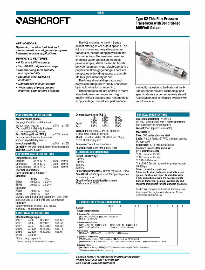
186
Consult factory for guidance in product selection Phone (203) 378-8281 or visit our web site at www.ashcroft.com
Type K2 Thin Film Pressure Transducer with Conditioned MilliVolt Output
APPLICATIONS:Hydraulic, machine tool, test and measurement, and all general pur-pose industrial process applications
BENEFITS & FEATURES:• 0.5% and 1.0% accuracy• Vac.-20,000 psi pressure range• Superior long-term stability
and repeatability• Stainless steel NEMA 4X
enclosure• Conditioned millivolt output• Wide range of pressure and
electrical connections available
The K2 is similar to the K1 Series except offering mV/V output options. The K2 is a proven and versatile pressure transducer incorporating polysilicon thin film technology. Modern low- pressure chemical vapor deposition methods provide simple, stable molecular bonds between a proven metal diaphragm and a polysilicon strain gage bridge. There are no epoxies or bonding agents to contrib-ute to signal instability or drift.
The integral metal diaphragm and polysilicon bridge are virtually unaffected by shock, vibration or mounting.
These transducers are offered in many standard pressure ranges with high-quality millivolt output signal ratiometric to supply voltage. Transducer performance
PHYSICAL SPECIFICATIONSEnvironmental Rating: NEMA 4X (NEMA 1 only if <500 psig if electrical termina-tion is Bendix® or Hirschmann®)Weight: 2 oz. (approx. w/o cable)MATERIALS:Case: 300 series stainless steelCable: No. 24 AWG, 36˝ PVC, shielded, vented, UL approvedDiaphragm: 17-4 PH stainless steelStandard Process Connections: (316 stainless steel) 1/8 NPT male or female 1/4 NPT male or female 1/4 SAE-J-514 male 1/4 AMINCO female required for pressures over 10,000 psi Other connections available Shunt calibration feature is available as an option. Calibration report is standard with 0.5% and optional with 1% accuracy units. Consult factory for pricing, availability and required minimums for nonstandard products.
Bendix® is a registered trademark of Amphenol Corp.Hirschmann® is a registered trademark of Richard Hirschmann of America Inc.
is directly traceable to the National Insti-tute of Standards and Technology and specifications are conservatively stated. A calibration test certificate is available with each transducer.
PERFORMANCE SPECIFICATIONSAccuracy Class (Span):See page 258-259 for definitionsIncludes non-linearity ±.5% ±1.0% (Terminal Point Method), hystere- sis, non-repeatability errors Best Fit Straight Line (BFSL) ±.25% ±.4% (Includes non-linearity, hysteresis and non-repeatability errors) Interchangeability ±.5% ±1.0%Durability: 108 with negligible performance change Stability: ±0.5% Span/yr
ENVIRONMENTAL SPECIFICATIONSTemperature Limits: Storage: –54 to 121°C (–65 to +250°F) Operating: –28 to 82°C (–20 to +180°F) Comp. Range: –28 to 71°C (–20 to +160°F) Thermal Coefficients: (68°F (20°C) ref.) %Span/°F Standard: 0.5% 1% ZERO ±0.028% ±0.04% SPAN ±0.028% ±0.04%Optional: ZERO ±0.014% N/A SPAN ±0.014% N/A Multiply zero thermal coefficients by 1.5 on 0/30 psi range and by 3 and 0/15 and vac/0 rangesHumidity: No performance effect at 95% relative humidity – noncondensing
FUNCTIONAL SPECIFICATIONSStandard Ranges (psi) 0/15* 0/300 0/5000* vac./60* 0/30* 0/500 0/7500* vac./45* 0/60* 0/750 0/10,000* vac./30* 0/100 0/1000 0/15,000* vac./15* 0/150 0/2000 0/20,000* vac./0* 0/200 0/3000 * 1% accuracy ranges only.
Consult factory for nonstandard ranges.
Overpressure Limits (F.S.): 15- 3000- 7500- 2000 5000 20,000 Proof 200% 150% 120% Burst 800% 300% 150%
Vibration: Less than ±0.1%F.S. effect for 0-2000 Hz at 20 g’s in any axisShock: Less than ±0.05 F.S. effect for 100 g’s, 20 ms shock in any axisResponse Time: Less than 5 msPosition Effect: Less than 0.01% Span ELECTRICAL SPECIFICATIONSOutput (Sensitivity): 2mV/V 3mV/V 10mV/V 20mV/VPower Requirements: 5-10 Vdc regulated, <3mAZero Offset: ±0.5% Span or ±1.0% Span dependent on accuracy classCircuit to Case Insulation Resistance: 100 M ohms @ 50 Vdc
TO ORDER THIS TYPE K2 TRANSDUCER:
Select: 1. Type Configuration (K2)
2. Accuracy/TC (3) 0.50%, ±0.014%/°F (5) 0.50%, ±0.028%/°F (7) 1.0%, ±0.040%/°F
3. Pressure Connection (M01) 1/8 NPT-M (F01) 1/8 NPT-F (M02) 1/4 NPT-M (F02) 1/4 NPT-F (MEK) 7/16-20 SAE-J-514 (FO9) aminco 9/16-18-Female
4. Sensitivity (02) 2mV/V (03) 3mV/V (10) 10mV/V (20) 20mV/V
5. Electrical Termination (F2) 36˝ cable, shielded, PVC sheathing (B4) Bendix 4-pin # PT02A-8-4P* (B6) Bendix 6-pin # PT02A-10-6P* (C1) 1/2 NPT-M Conduit w/36˝ cable (HM) Hirschmann miniature
6. Pressure Range (Vac./0) Vac./0 through (20000) 20,000 psi (see standard ranges). Call for more options. *Mating connector available as necessary
K 2
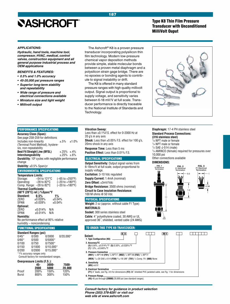
187
Consult factory for guidance in product selection Phone (203) 378-8281 or visit our web site at www.ashcroft.com
Vibration Sweep: Less than ±0.1%F.S. effect for 0-2000 Hz at 20 g’s in any axisShock: Less than ±0.05% F.S. effect for 100 g’s, 20ms shock in any axisResponse Time: Less than 5 msPosition Effect: Less than 0.01% F.S.
ELECTRICAL SPECIFICATIONSOutput Sensitivity: Output signal varies from 6-18mv/V at full scale, output proportional to supply voltage.Excitation: 3-10 Vdc regulatedSupply Current: 1.4mA (nominal)Zero Offset: ±3mV/Vdc Bridge Resistance: 3500 ohms (nominal) Circuit to Case Insulation Resistance: 100 M ohms @ 50 Vdc
PHYSICAL SPECIFICATIONSWeight: 2 oz (approx. without cable F1 Type)MATERIALS:Socket: 300 series stainless steelCable: 4˝ polyethylene coated, 30 AWG or UL approved 36˝, shielded, vented cable (24 AWG)
Diaphragm: 17-4 PH stainless steelStandard Process Connections: (316 stainless steel) 1/8 NPT male or female 1/4 NPT male or female 1/4 SAE-J-514 (male) 1/4 AMINCO (female) required for pressures over 10,000 psi Other connections availableDIMENSIONS:
Type K8 Thin Film Pressure Transducer with Unconditioned MilliVolt Ouput
APPLICATIONS:Hydraulic, hand tools, machine tool, compressor, HVAC, medical, control valves, construction equipment and all general purpose industrial process and OEM applications
BENEFITS & FEATURES:• 0.5% and 1.0% accuracy• 45-20,000 psi pressure ranges• Superior long-term stability and repeatability• Wide range of pressure and electrical connections available• Miniature size and light weight• Millivolt output
The Ashcroft® K8 is a proven pressure transducer incorporating polysilicon thin film technology. Modern low-pressure chemical vapor deposition methods provide simple, stable molecular bonds between a proven metal diaphragm and a polysilicon strain gage bridge. There are no epoxies or bonding agents to contrib-ute to signal instability or drift.
The K8 is offered in many standard pressure ranges with high quality millivolt output. Signal output is proportional to supply voltage, and sensitivity varies between 6-18 mV/V at full scale. Trans-ducer performance is directly traceable to the National Institute of Standards and Technology.
K 8 M V
TO ORDER THIS TYPE K8 TRANSDUCER:
Select: 1. Type Configuration (K8)
2. Accuracy/TC (3) 0.50%, ±0.014%/°F (5) 0.50%, ±0.028%/°F (7) 1.0%, ±0.040%/°F
3. Pressure Connection (M01) 1/8 NPT-M (F01) 1/8 NPT-F (M02) 1/4 NPT-M (F02) 1/4 NPT-F
(MEK) 7/16-20 SAE-J-514 (FO9) 9/16-18 UNF (T01) 1/4 Comp. Fit (000) None
4. Sensitivity (MV) mV/V
5. Electrical Termination (F1) 4˝ leads, see Fig. 2/3 for dimensions (F2) 36˝ shielded PVC jacketed cable, see Fig. 1 for dimensions
6. Pressure Range (45) 45 psi through (20000) 20,000 psi (see standard ranges).
PERFORMANCE SPECIFICATIONSAccuracy Class (Span):See page 258-259 for definitionsIncludes non-linearity ±.5% ±1.0% (Terminal Point Method), hystere- sis, non-repeatabilityBest Fit Straight Line (BFSL) ±.25% ±.4% Interchangeability ±.25% ±.6%Durability: 108 cycles with negligible performance change Stability: ±0.5% Span/yr
ENVIRONMENTAL SPECIFICATIONSTemperature Limits: Storage: –54 to 121°C (–65 to +250°F) Operating: –28 to 82°C (–20 to +180°F) Comp. Range: –28 to 82°C (–20 to +180°F) Thermal Coefficients: (68°F (20°C) ref.) %Span/°FStandard: 0.5% 1% ZERO ±0.028% ±0.04% SPAN ±0.028% ±0.04%Optional: ZERO ±0.014% N/A SPAN ±0.014% N/AHumidity: No performance effect at 95% relative humidity – noncondensing
FUNCTIONAL SPECIFICATIONSStandard Ranges (psi) 0/45* 0/300 0/3000 0/20,000* 0/60* 0/500 0/5000* 0/100 0/750 0/7500* 0/150 0/1000 0/10,000* 0/200 0/2000 0/15,000* *1% accuracy ranges only. Consult factory for nonstandard ranges.
Overpressure Limits (F.S.): 45- 3000- 7500- 2000 5000 20,000 Proof 200% 150% 120% Burst 800% 300% 150%
2.2
5/8HEX
FIG. 1F2 ElectricalTermination
0.5
0.34
FIG. 3F1 ElectricalTermination
0.5
1.2
FIG. 2F1 ElectricalTermination

188
Consult factory for guidance in product selection Phone (203) 378-8281 or visit our web site at www.ashcroft.com
MATERIALSCase: 300 series stainless steelConnection: 316 stainless steelCable: No. 24 AWG, 36 PVC, shielded, vented, UL approved
Diaphragm: 316Ti stainless steel
Standard Process Connection: G-1/2 metric pipe thread* O-ring seal (max. 150 psi) 1/2 NPT male pipe thread used in conjunction with XWB, XWC and XWE screw-on adapters *Mating connector available upon request
OPTIONSFlush weldnut (XWB) Recessed weldnut (XWC) Weldnut plug (XWD) Paper mill adapter (shown in photo) (XWE) Halocarbon fill (XWG)Warning: Sensitive Diaphragm
Type KX Flush Mount Thin Film Pressure Transducer/Transmitter For Pulp and Paper Applications
APPLICATIONS:Pulp/paper, waste water, spray booths and all heavy medium pumping pro-cesses
BENEFITS & FEATURES:• Available with PMC adapter (shown)• Flush-mounted integral 316 stainless steel diaphragm• Stainless steel NEMA 4X enclosure• Current /voltage output
tribute to signal instability or drift.The flush sensing element is provided
by an integral, silicone filled stainless steel diaphragm seal. The small sensing area and low internal volume ensure accurate measurement under severe conditions.
The polysilicon strain resistors combine very low noise levels with very high signal output. There are no semiconductor (p-n) junctions to change with temperature, time or use. The integral metal diaphragm and polysilicon bridge are virtually unaffected by shock, vibration or mounting position.
These transmitters are offered in many standard pressure ranges with either cur-rent or voltage output signals. Transmitter performance is directly traceable to the National Institute of Standards and Tech nology and specifications are conservatively stated.
The Ashcroft® KX transmitter combines the proven benefits of poly-silicon thin film performance with the utility of a flush-mounting sensing diaphragm. Modern low-pressure chemical vapor deposition methods provide simple, stable molecular bonds between a proven metal diaphragm and a polysilicon strain gage bridge. There are no epoxies or bonding agents to con-
PERFORMANCE SPECIFICATIONSAccuracy Class (Span): Includes non-linearity, ±1% (Terminal Point Method), hystere- sis, non-repeatability, zero offset and span setting errors) Best fit straight line (BFSL) ±0.75%
ENVIRONMENTAL SPECIFICATIONSTemperature Storage –65/+250°F Operating –20/+180°F Compensated –20/+160°FThermal Coefficients: (68°F ref.) %F.S./°F Standard: ZERO ±0.04% SPAN ±0.04%Humidity: No performance effect at 95% relative humidity – noncondensing
FUNCTIONAL SPECIFICATIONSStandard Ranges (psi) 0/100 0/500 0/3000 0/150 0/750 0/5000 0/200 0/1000 0/300 0/2000 Consult factory for nonstandard ranges.
Overpressure: (F.S.) 0/100- 0/3000 0/2000 0/5000 Proof 200% 150% Burst 800% 300%
Vibration Sweep: Less than ±0.1%F.S. effect for 0-400 Hz at 20 g’s in any axisShock: Less than ±0.1%F.S. effect for 20 g’s 20ms shock in any axis
ELECTRICAL SPECIFICATIONSOutput Signal: 4-20mA (2 wire) 1-5 Vdc (3 wire) 1-6 Vdc (3 wire)
Power Requirements: 10-36 Vdc unregulated
Supply Current: Less than 3mA for voltage output
Output Impedance: 100 ohms
Circuit to Case Insulation Resistance: 100 M ohms @ 50 Vdc
PHYSICAL SPECIFICATIONSEnvironmental Rating: NEMA 4X
Weight: 10 oz (approx. without cable)
TO ORDER THIS TYPE KX TRANSDUCER/TRANSMITTER:
Select: 1. Type Configuration (KX)
2. Accuracy (7)1.0%, ±0.04%/°F
3. Pressure Connection (MG4) G 1/2 (RS1) O-Ring Seal (max. 150 psi) (M04) 1/2 NPT M
4. Output Signal (15) 1-5 Vdc (16) 1-6 Vdc (42) 4-20mA
5. Electrical Termination (C1) 1/2 NPT-M Conduit w/36˝ cable (DN) 43650 connector (RT) 1/2 NPT with RTD Head (4-20mA only) (M1) DIN 43650 with mating connector G4WIF (M2) DIN 43650 with mating connector G4WIF w/36˝ cable
6. Pressure Range (See standard ranges)
7. Optional X-Variations (See above options)
K X 7 #
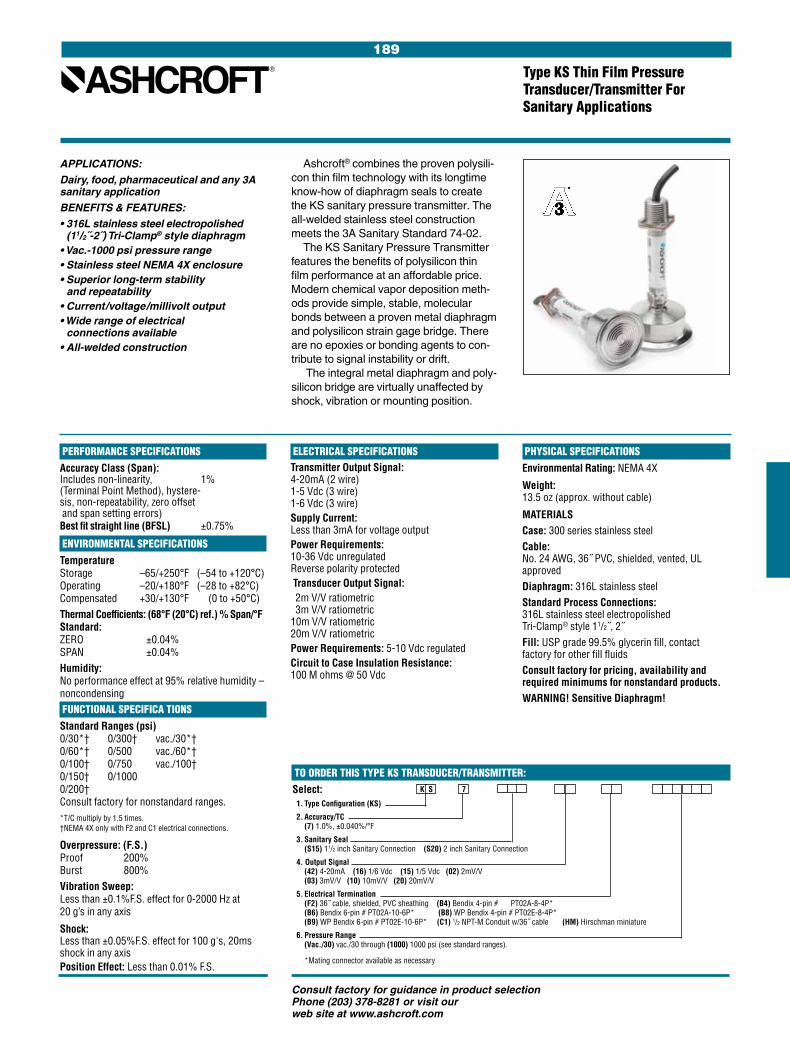
189
Consult factory for guidance in product selection Phone (203) 378-8281 or visit our web site at www.ashcroft.com
ELECTRICAL SPECIFICATIONSTransmitter Output Signal: 4-20mA (2 wire) 1-5 Vdc (3 wire) 1-6 Vdc (3 wire)Supply Current: Less than 3mA for voltage outputPower Requirements: 10-36 Vdc unregulated Reverse polarity protected Transducer Output Signal: 2m V/V ratiometric 3m V/V ratiometric 10m V/V ratiometric 20m V/V ratiometricPower Requirements: 5-10 Vdc regulatedCircuit to Case Insulation Resistance: 100 M ohms @ 50 Vdc
Type KS Thin Film Pressure Transducer/Transmitter For Sanitary Applications
APPLICATIONS:
Dairy, food, pharmaceutical and any 3A sanitary application
BENEFITS & FEATURES:
• 316L stainless steel electro polished (11/2˝-2˝) Tri-Clamp® style diaphragm
• Vac.-1000 psi pressure range• Stainless steel NEMA 4X enclosure• Superior long-term stability
and repeatability• Current/voltage/millivolt output• Wide range of electrical
connections available• All-welded construction
Ashcroft® combines the proven polysili-con thin film technology with its longtime know-how of diaphragm seals to create the KS sanitary pressure transmitter. The all-welded stainless steel construction meets the 3A Sanitary Standard 74-02.
The KS Sanitary Pressure Transmitter features the benefits of polysilicon thin film performance at an affordable price. Modern chemical vapor deposition meth-ods provide simple, stable, molecular bonds between a proven metal diaphragm and polysilicon strain gage bridge. There are no epoxies or bonding agents to con-tribute to signal instability or drift.
The integral metal diaphragm and poly-silicon bridge are virtually unaffected by shock, vibration or mounting position.
PERFORMANCE SPECIFICATIONSAccuracy Class (Span): Includes non-linearity, 1% (Terminal Point Method), hystere- sis, non-repeatability, zero offset and span setting errors) Best fit straight line (BFSL) ±0.75%
ENVIRONMENTAL SPECIFICATIONSTemperature Storage –65/+250°F (–54 to +120°C) Operating –20/+180°F (–28 to +82°C) Compensated +30/+130°F (0 to +50°C)Thermal Coefficients: (68°F (20°C) ref.) % Span/°F Standard: ZERO ±0.04% SPAN ±0.04%Humidity: No performance effect at 95% relative humidity – noncondensing FUNCTIONAL SPECIFICA TIONSStandard Ranges (psi) 0/30*† 0/300† vac./30*† 0/60*† 0/500 vac./60*† 0/100† 0/750 vac./100† 0/150† 0/1000 0/200† Consult factory for nonstandard ranges. *T/C multiply by 1.5 times.
†NEMA 4X only with F2 and C1 electrical connections.
Overpressure: (F.S.) Proof 200% Burst 800%Vibration Sweep: Less than ±0.1%F.S. effect for 0-2000 Hz at 20 g’s in any axis
Shock: Less than ±0.05%F.S. effect for 100 g's, 20ms shock in any axisPosition Effect: Less than 0.01% F.S.
PHYSICAL SPECIFICATIONSEnvironmental Rating: NEMA 4X
Weight: 13.5 oz (approx. without cable)
MATERIALSCase: 300 series stainless steelCable: No. 24 AWG, 36˝ PVC, shielded, vented, UL approvedDiaphragm: 316L stainless steelStandard Process Connections: 316L stainless steel electropolished Tri-Clamp® style 11/2˝, 2˝Fill: USP grade 99.5% glycerin fill, contact factory for other fill fluidsConsult factory for pricing, availability and required minimums for nonstandard products.WARNING! Sensitive Diaphragm!
Select: 1. Type Configuration (KS)
2. Accuracy/TC (7) 1.0%, ±0.040%/°F
3. Sanitary Seal (S15) 11/2 inch Sanitary Connection (S20) 2 inch Sanitary Connection
4. Output Signal (42) 4-20mA (16) 1/6 Vdc (15) 1/5 Vdc (02) 2mV/V (03) 3mV/V (10) 10mV/V (20) 20mV/V
5. Electrical Termination (F2) 36˝ cable, shielded, PVC sheathing (B4) Bendix 4-pin # PT02A-8-4P* (B6) Bendix 6-pin # PT02A-10-6P* (B8) WP Bendix 4-pin # PT02E-8-4P* (B9) WP Bendix 6-pin # PT02E-10-6P* (C1) 1/2 NPT-M Conduit w/36˝ cable (HM) Hirschman miniature
6. Pressure Range (Vac./30) vac./30 through (1000) 1000 psi (see standard ranges).
*Mating connector available as necessary
K S 7
TO ORDER THIS TYPE KS TRANSDUCER/TRANSMITTER:
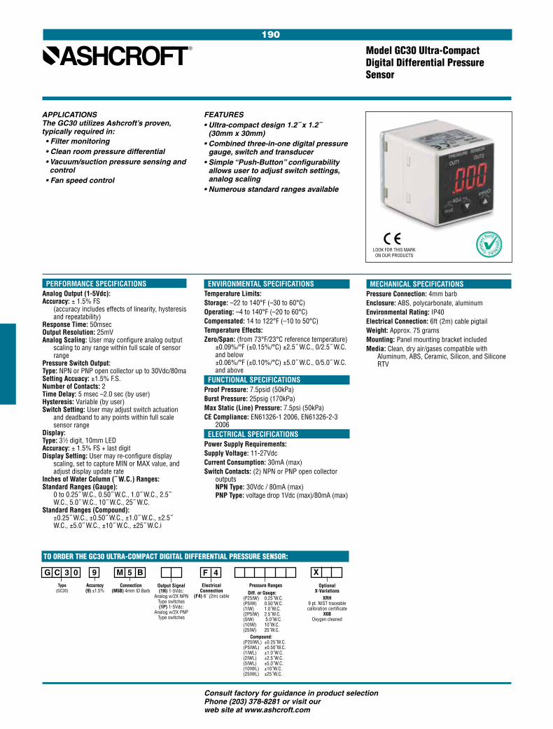
190
Consult factory for guidance in product selection Phone (203) 378-8281 or visit our web site at www.ashcroft.com
Model GC30 Ultra-Compact Digital Differential Pressure Sensor
FEATURES• Ultra-compact design 1.2˝ x 1.2˝
(30mm x 30mm)• Combined three-in-one digital pressure
gauge, switch and transducer• Simple “Push-Button” configurability
allows user to adjust switch settings, analog scaling
• Numerous standard ranges available
PERFORMANCE SPECIFICATIONSAnalog Output (1-5Vdc):Accuracy: ± 1.5% FS
(accuracy includes effects of linearity, hysteresis and repeatability)
Response Time: 50msecOutput Resolution: 25mVAnalog Scaling: User may configure analog output
scaling to any range within full scale of sensor range
Pressure Switch Output:Type: NPN or PNP open collector up to 30Vdc/80maSetting Accuacy: ±1.5% F.S.Number of Contacts: 2 Time Delay: 5 msec –2.0 sec (by user)Hysteresis: Variable (by user)Switch Setting: User may adjust switch actuation
and deadband to any points within full scale sensor range
Display:Type: 31⁄2 digit, 10mm LEDAccuracy: ± 1.5% FS + last digitDisplay Setting: User may re-configure display
scaling, set to capture MIN or MAX value, and adjust display update rate
Inches of Water Column (˝ W.C.) Ranges: Standard Ranges (Gauge):
0 to 0.25˝ W.C., 0.50˝ W.C., 1.0˝ W.C., 2.5˝ W.C., 5.0˝ W.C., 10˝ W.C., 25˝ W.C.
Standard Ranges (Compound): ±0.25˝ W.C., ±0.50˝ W.C., ±1.0˝ W.C., ±2.5˝ W.C., ±5.0˝ W.C., ±10˝ W.C., ±25˝ W.C.i
APPLICATIONSThe GC30 utilizes Ashcroft’s proven, typically required in:• Filter monitoring• Clean room pressure differential• Vacuum/suction pressure sensing and control
• Fan speed control
ENVIRONMENTAL SPECIFICATIONSTemperature Limits:Storage: –22 to 140°F (–30 to 60°C)Operating: –4 to 140°F (–20 to 60°C)Compensated: 14 to 122°F (–10 to 50°C)Temperature Effects:Zero/Span: (from 73°F/23°C reference temperature)
±0.09%/°F (±0.15%/°C) ±2.5˝ W.C., 0/2.5˝ W.C. and below ±0.06%/°F (±0.10%/°C) ±5.0˝ W.C., 0/5.0˝ W.C. and above
FUNCTIONAL SPECIFICATIONSProof Pressure: 7.5psid (50kPa)Burst Pressure: 25psig (170kPa)Max Static (Line) Pressure: 7.5psi (50kPa)CE Compliance: EN61326-1 2006, EN61326-2-3
2006 ELECTRICAL SPECIFICATIONSPower Supply Requirements:Supply Voltage: 11-27VdcCurrent Consumption: 30mA (max)Switch Contacts: (2) NPN or PNP open collector
outputs NPN Type: 30Vdc / 80mA (max) PNP Type: voltage drop 1Vdc (max)/80mA (max)
LOOK FOR THIS MARK ON OUR PRODUCTS
MECHANICAL SPECIFICATIONSPressure Connection: 4mm barb Enclosure: ABS, polycarbonate, aluminum Environmental Rating: IP40Electrical Connection: 6ft (2m) cable pigtailWeight: Approx. 75 gramsMounting: Panel mounting bracket includedMedia: Clean, dry air/gases compatible with
Aluminum, ABS, Ceramic, Silicon, and Silicone RTV
M 5 B G C 3 0
F 4 X 9Type
(GC30) Connection
(M5B) 4mm ID BarbElectrical
Connection(F4) 6´ (2m) cable
Accuracy (9) ±1.5%
Optional X-Variations
XRH9 pt. NIST traceable calibration certificate
X6B Oxygen cleaned
TO ORDER THE GC30 ULTRA-COMPACT DIGITAL DIFFERENTIAL PRESSURE SENSOR:
Output Signal(1N) 1-5Vdc:
Analog w/2X NPN Type switches (1P) 1-5Vdc:
Analog w/2X PNP Type switches
Pressure Ranges Diff. or Gauge:(P25IW) 0.25˝W.C.(P5IW) 0.50˝W.C.(1IW) 1.0˝W.C.(2P5IW) 2.5˝W.C.(5IW) 5.0˝W.C.(10IW) 10˝W.C.(25IW) 25˝W.C. Compound:(P25IWL) ±0.25˝W.C.(P5IWL) ±0.50˝W.C.(1IWL) ±1.0˝W.C.(2IWL) ±2.5˝W.C.(5IWL) ±5.0˝W.C.(10IWL) ±10˝W.C.(25IWL) ±25˝W.C.
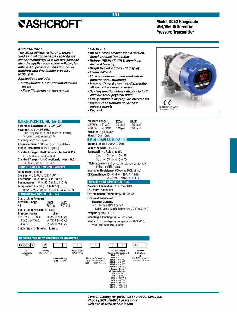
191
Consult factory for guidance in product selection Phone (203) 378-8281 or visit our web site at www.ashcroft.com
Model GC52 Rangeable Wet/Wet Differential Pressure Transmitter
FEATURES• Up to 8 times smaller than a conven-
tional process transmitter• Robust NEMA 4X (IP65) aluminum
die cast housing• Bright backlit 4 digit LCD display • 2 Wire 4-20mA• Flow measurement and totalization
(square root extraction)• Internal “Push Button” configurability
allows quick range changes• Scaling function allows display to indi-
cate arbitrary physical units• Easily rotatable display, 90° increments• Square root extractions for flow
measurements• Key lock
PERFORMANCE SPECIFICATIONSReference Condition: 23°C ±2° (73°F)Accuracy: ±0.50% FS (URL)
(Accuracy includes the effects of linearity, hysteresis, and repeatability)
Stability: ±0.25% FS/yearResponse Time: 100msec (user adjustable)Output Resolution: 0.1% FS (URL)Standard Ranges (Bi-Directional, Inches W.C.):
±4, ±8, ±20, ±40, ±80, ±200Standard Ranges (Uni-Directional, Inches W.C.):
0-4, 8, 20, 40, 80, 200, 400 ENVIRONMENTAL SPECIFICATIONSTemperature Limits:Storage: –15 to 65°C (5 to 150°F)Operating: –10 to 60°C (14 to 140°F)Compensated: –10 to 60°C (14 to 140°F)Temperature Effects (–10 to 60°C):
±0.03% FS/C° (from reference, 23°C (73°F) FUNCTIONAL SPECIFICATIONSStatic (Line) Pressure: Pressure Range Proof Burst All 300 psi 800 psiStatic (Line) Pressure Effects: Pressure Range Effect $20˝W.C., ±8˝ W.C. ±0.3% FS/100psi
8˝W.C., ±4˝ W.C. ±0.7% FS/100psi 4˝W.C. ±1.5% FS/100psi
Single Side (Differential) Limits:
APPLICATIONSThe GC52 utilizes Ashcroft’s proven Si-Glas™ silicon variable capacitance sensor technology in a wet-wet package ideal for applications where reliable, low differential pressure measurement is required with line (static) pressure to 300 psi. Applications include: • Pressurized & non-pressurized tank levels • Flow (liquid/gas) measurement
G C 5 2
X 7Type
Configuration (GC52)
Pressure Fitting(F02) 1⁄4˝ FNPT
Electrical Connection(CG) = Cable Gland
(CD) = 1⁄4˝ FNPT Conduit
Accuracy (7) ±0.25% FS
Pressure Ranges(Compound/Bidirectional) 4IWL = ±4˝ W.C. 8IWL = ±8˝ W.C. 20IWL = ±20˝ W.C. 40IWL = ±40˝ W.C. 80IWL = ±80˝ W.C. 200IWL = ±200˝ W.C.
Pressure Range(Differential Gauge)
4IW = 0-4˝ W.C. 8IW = 0-8˝ W.C. 20IW = 0-20˝ W.C. 40IW = 0-40˝ W.C. 80IW = 0-80˝ W.C. 200IW = 0-200˝ W.C. 400IW = 0-400˝ W.C.
Optional X-Variations
XRH9 pt. NIST traceable calibration certificate
TO ORDER THE GC52 PRESSURE TRANSMITTER:
Output Signal(42) 4-20mA
Pressure Range Proof Burst #8˝ W.C., ±4˝ W.C. 30 psid 130 psid $20˝ W.C., ±8˝ W.C. 100 psid 130 psid Vibration: 5g’s 150Hz Shock: 10g’s 16ms ELECTRICAL SPECIFICATIONSOutput Signal: 4-20mA (2 Wire)Supply Voltage: 12-32VdcRangeablility / Adjustment*: Zero –10% to +110% FS Span –10% to +110% FS*Note: Accuracy and output resolution based upon
full scale (URL) valueInsulation Resistance: 50Vdc (>100Mohms)CE Compliance: EN 613261 1997, A1/1998,
A2/2001 (Heavy Industrial) MECHANICAL SPECIFICATIONSPressure Connection: 1⁄4˝ Female NPTEnclosure: AluminumEnvironmental Rating: IP65 / NEMA 4XElectrical Connection:
External Options: – 1⁄2˝ Female NPT Conduit – Cable Gland (Cable Diameters 0.35˝ to 0.47˝)
Weight: Approx. 1.0 lbMounting: Mounting Bracket includedMedia: Fluids and gases compatible with 316SS,
Viton and Alumina Ceramic
LOOK FOR THIS MARK ON OUR PRODUCTS

192
Consult factory for guidance in product selection Phone (203) 378-8281 or visit our web site at www.ashcroft.com
CXLdp Differential Pressure Transmitter
The Ashcroft® CXLdp transmitter uses the patented Ashcroft Si-Glas™ variable capacitance sensor. This MEMS sensor provides extraordinary sensitivity and long term stability. New digital compensation is accomplished using a highly reliable applica-tion specific integrated circuit (ASIC).
APPLICATIONSStatic or velocity pressure measurement for four stations, ducts, building pres-sure, filter efficiency, VAV boxes or room pressurizationEXCLUSIVE CXLdp FEATURES:• Rugged ABS package capable
of DIN rail or standard panel mounting• LED power status indicator to assist
in trouble shooting, correct wiring or quickly locating the instrument on a duct
• Detachable Euro style terminal block reduces wiring errors and field wiring time
• 20 standard pressure ranges all capable of withstanding 15 psi without damage or calibration change
• Digitally compensated. NIST traceable 0.4% F.S. and 0.8% F.S. accuracy models
• RoHS compliant
PERFORMANCE SPECIFICATIONSReference Temperature: 70°F ±2°F (21°C ±1°C)Accuracy Class (F.S.): ±0.8% ±0.4% Includes non-linearity, hysteresis, non-repeatability, zero offset and span setting errors.Stability – Max. Change (F.S./year): ±0.25% ±0.25%Standard Ranges (Inches W.C.) Unidirectional Ranges: Differential 0/0.1 0/1.0 0/5.0 0/0.25 0/2.0 0/10.0 0/0.5 0/2.5 0/15.0 0/0.75 0/3.0 0/25.0Bidirectional Ranges: Compound ±0.1 ±1.0 ±10.0 ±0.25 ±2.0 ±15.0 ±0.5 ±5.0 Response Time: 250 msec ENVIRONMENTAL SPECIFICATIONSTemperature Limits: Storage –40 to 180°F Operating +0 to 160°F Compensated Range +35 to 130°F (10-95% R.H. non-condensing)Temperature Coefficients: Zero & Span ±0.03%F.S./°F EMC: CE Compliant to EN61326: 1997+A1: 1998+A2: 2001 Annex A (Heavy Industrial)
FUNCTIONAL SPECIFICATIONSOverpressure Limits: Proof Pressure 15 psid Burst Pressure 25 psid Mounting Position Effect: ±1% /g (lowest range) Note: Calibration in vertical position is standard. ELECTRICAL SPECIFICATIONSOutput Signal: Power: 4-20mA (2 wire) 12-36 Vdc (unregulated) 0-10Vdc (3 Wire)* 24Vdc/24Vac Output signal is independent of power supply changes Reverse Wiring Protected Zero and Span Adjustment: Externally accessible Zero: ±5%F.S. Span: ±5%F.S. PHYSICAL SPECIFICATIONSPressure Connections: 1⁄4˝ brass barbed fittings 1⁄8 NPT Female brass Electrical Connection: Euro style pluggable ter-minal block accepts 12-26 gauge wire Environmental Rating: NEMA Type 1 Fire- retardant ABS (meets UL 94-5VA)
LED visual indicator standard Weight: Approx. 2.5 oz Media: Clean, dry and non-corrosive gas Mounting: Threaded fastener and 35mm DIN rail mount standard Option: 1⁄2˝ plenum/conduit mounting bracket and cover kit (order part #101A213-01) XRH: (9 point NIST Calibration Certification)
HOW TO ORDER THIS CXLdp TRANSDUCER/TRANSMITTER:
Select: 1. Type Configuration (CXLdp)
2. Accuracy/TC (8) 0.8%, ±0.03%/°F (4) 0.4%, ±0.03%/°F
3. Pressure Connection (MB2) 1/4 Barbed Male (FO1) 1/8 NPT Female
4. Output Signal (10) 0-10Vdc* (42) 4-20mA
5. Pressure Range Diff. or Gauge: (P1IW) 0.10˝ W.C. (P25IW) 0.25˝ W.C. (P5IW) 0.50˝ W.C. (P75IW) 0.75˝ W.C. (1IW) 1.00˝ W.C. (2IW) 2.00˝ W.C. (2P5IW) 2.50˝ W.C. (3IW) 3.00˝ W.C. (5IW) 5.00˝ W.C. (10IW) 10.00˝ W.C. (15IW) 15.00˝ W.C. (25IW) 25.00˝ W.C.
Compound: (P1IWL) ±0.10˝ W.C. (P25IWL) ±0.25˝ W.C. (P5IWL) ±0.5˝ W.C. (1IWL) ±1.0˝ W.C. (2IWL) ±2.0˝ W.C. (5IWL) ±5.00˝ W.C. (10IWL) ±10.00˝ W.C. (15IWL) ±15.00˝ W.C.
*User selectable 0-5Vdc output
C X
3 Year Warranty
LOOK FOR THIS MARK ON OUR PRODUCTS

193
Consult factory for guidance in product selection Phone (203) 378-8281 or visit our web site at www.ashcroft.com
OPTIONS• Option XDL: LED for quick process diagnostics:
Zero Pressure.........Center Amber LED In Range ± .............Adjacent Green LED’s Out of Range ± ......Adjacent Red LED’s Includes: front access test jacks for on-line data access without disturbing wiring
• Option XNL: Front access jacks without LED’s• Option XPV: SpoolCal™ process valve actua-
tor provides in-place system calibration without disturbing process tubes. From Off position the removable SpoolCal™ actuator tool provides the following functions: - A 90 degree clockwise rotation puts the DXLdp in
the CAL mode isolating it from the process and allowing direct external pressure input
- A 90 degree counter clockwise rotation puts the DXLdp in the MONITOR mode to tee the process pressure to the DXLdp sensor and out, providing external measure-ment or recording capabilities. Includes SpoolCal™ actuator tool with 7˝ silicon tubing (as shown in front photo). (Refer to Ashcroft® ATE series cali-brator for data collection and instrumentation)
• Option X21: 2:1 turn down, 0.25% accuracy is maintained on initialized range
• Option XCL: Special range calibration• Option XX1: Fast response (10msec)• Option XX2: Slow response (1sec)
DXLdp Low Pressure Differential Transducer/Transmitter
PERFORMANCE SPECIFICATIONSReference Temperature: 70°F ±2°F (21°C ±1°C) Accuracy Class (F.S.): 0.25% 0.5% 1.0% Non-linearity Best fit straight line (BFSL) ±0.15 ±0.3% ±0.6% Hysteresis ±0.02 ±0.02% ±0.05% Non-repeatability ±0.03 ±0.05% ±0.10%Stability – Max. Change (F.S./year): ±0.25% Standard Ranges (Inches W.C.) Unidirectional Ranges: Differential or Gauge 0/0.1 0/1.0 0/3.0 0/20.0 0/0.25 0/1.5 0/5.0 0/25.0 0/0.5 0/2.0 0/10.0 0/50.0 0/0.75 0/2.5 0/15.0 Bidirectional Ranges: Compound ±0.05 ±0.5 ±2.0 ±5.0 ±0.1 ±0.75 ±2.5 ±10.0 ±0.25 ±1.0 ±3.0 ±25.0 Custom Ranges: Special range calibration, (XCL) – Consult factoryStandard Response Time: 250m sec (Consult factory for optional damping times) ENVIRONMENTAL SPECIFICATIONSTemperature Limits: Storage: –40 to 180°F Operating: –20 to 160°F (10-95% R.H. noncondensing) Compensated Range: +35 to 135°F Thermal Coefficients: ZERO ±0.02%F.S./°F SPAN ±0.02%F.S./°F FUNCTIONAL SPECIFICATIONSOverpressure Limits: Proof 15 psid Burst 25 psidMax. Static Line Pressure: 25 psiMounting Position Effect: 0.5˝ W.C. and higher 0.1% F.S./g Below 0.5˝ W.C. 0.25% F.S/g.Note: Mounting Position Effect easily corrected with zero potentiometer.
ELECTRICAL SPECIFICATIONSOutput Signal: Power: 4-20mA (2 wire) 12-36 Vdc 1-5 Vdc 12-36 Vdc 1-6 Vdc 12-36 Vdc 0-5 Vdc 12-36 Vdc 0-10 Vdc 12-36 Vdc Output signal is independent of power supply changes: 12-36 Vdc range without effect on output signalReverse Wiring ProtectedZero and Span Potentiometers: Front accessible, non-interactiveZero: ±5%F.S. Span: ±3%F.S.Supply Current: < 10mA for voltageWarm-up Time: 5 sec. max. to meet stated speci-fications from initial power-up
PHYSICAL SPECIFICATIONSPressure Connections: 1⁄8 NPT FemaleWeight: 4.5 oz.Environmental Rating: NEMA 1 CaseMATERIALS:Enclosure: Glass-filled polycarbonate (UL94-V-1)Media: Clean, dry and non-corrosive gas (consult factory for use on other media).NOT FOR USE ON LIQUIDSMounting: DIN rail types EN50022, 35 & 45
APPLICATIONS: High reliability HVAC, bio-pharm, bio-tech, room pressurization and control, velocity pressure BENEFITS AND FEATURES:• The exclusive patented Ashcroft® Spool-Cal™ actuator provides in-place system calibration without disturbing process tubes
• Front access test jacks provide on-line signal reference without removing wiring
• LED range status indicators for instant troubleshooting information
• DIN Rail Mount – dramatically reduces installation and calibration costs
• 2:1 range turndown options• CE standard with all outputs• On-board voltage regulation allows
use of lower cost, unregulated power supply
HOW TO ORDER THIS DXLdp TRANSDUCER/TRANSMITTER:
Select: 1. Type Configuration (DXLdp) 2. Accuracy/TC (3) 0.25%, ±0.02%/°F (5) 0.50%, ±0.02%/°F3. Pressure Connection (FO1) 1/8 NPT Female 4. Output Signal (05) 0/5 Vdc (10) 0/10 Vdc (15) 1/5 Vdc (16) 1/6 Vdc (42) 4-20mA 5. Output Connection (ST) Screw Terminal 6. Pressure Range Diff. or Gauge: (P1IW) 0.10˝ W.C. (P25IW) 0.25˝ W.C. (P5IW) 0.50˝ W.C. (P75IW) 0.75˝ W.C. (1IW) 1.00˝ W.C. (1P5IW) 1.5˝ W.C. (2IW) 2.00˝ W.C. (2P5IW) 2.50˝ W.C. (3IW) 3.00˝ W.C. (5IW) 5.00˝ W.C. (10IW) 10.00˝ W.C. (25IW) 25.00˝ W.C. (50IW) 50.00˝ W.C. Compound: (P05WL) ±0.05˝ W.C. (P1WL) ±0.10˝ W.C. (P25IWL) ±0.25˝ W.C. (P5IWL) ±0.5˝ W.C. (P75IWL) ±0.75˝ W.C. (1IWL) ±1.0˝ W.C. (2IWL) ±2.0˝ W.C. (2P5IWL) ±2.5˝ W.C. (5IWL) ±5.00˝ W.C. (10IWL) ±10.00˝ W.C. (25IWL) ±25.00˝ W.C.7. Optional Variation (XDL) LED (XPV) SpoolCal™ Process Valve Actuator (X21) 2:1 Turn Down (XNL) Test Jacks (XCL) Special Range Calibration (XX1) Fast Response (10msec) (XX2) Slow Response (1sec)
D X F O 1 S T X
stands extreme overpressure as well as severe shock and vibration.
The Ashcroft® DXLdp is a variable capacitance sensor within a glass-clad silicon chip. The patented Si-Glas™ tech-nology combines the inherent high sensi-tivity of a variable capacitance transducer with the repeatability of a micro-machined, ultra-thin silicon diaphragm.
The Ashcroft Si-Glas sensor enables precise measurement and control of very low pressure. Although the ultra-thin sili-con diaphragm deflects only a micron, the sensor is 100 times more sensitive to pres-sure than available silicon piezo-resistive pressure sensors.
The Si-Glas sensor is composed of only sputtered metals and glass molecularly bonded to silicon. There are no epoxies or other organics in the sensor to contribute to drift or mechanical degradation over time. The glass-clad silicon diaphragm with-
3 Year Warranty LOOK FOR THIS MARK ON OUR PRODUCTS
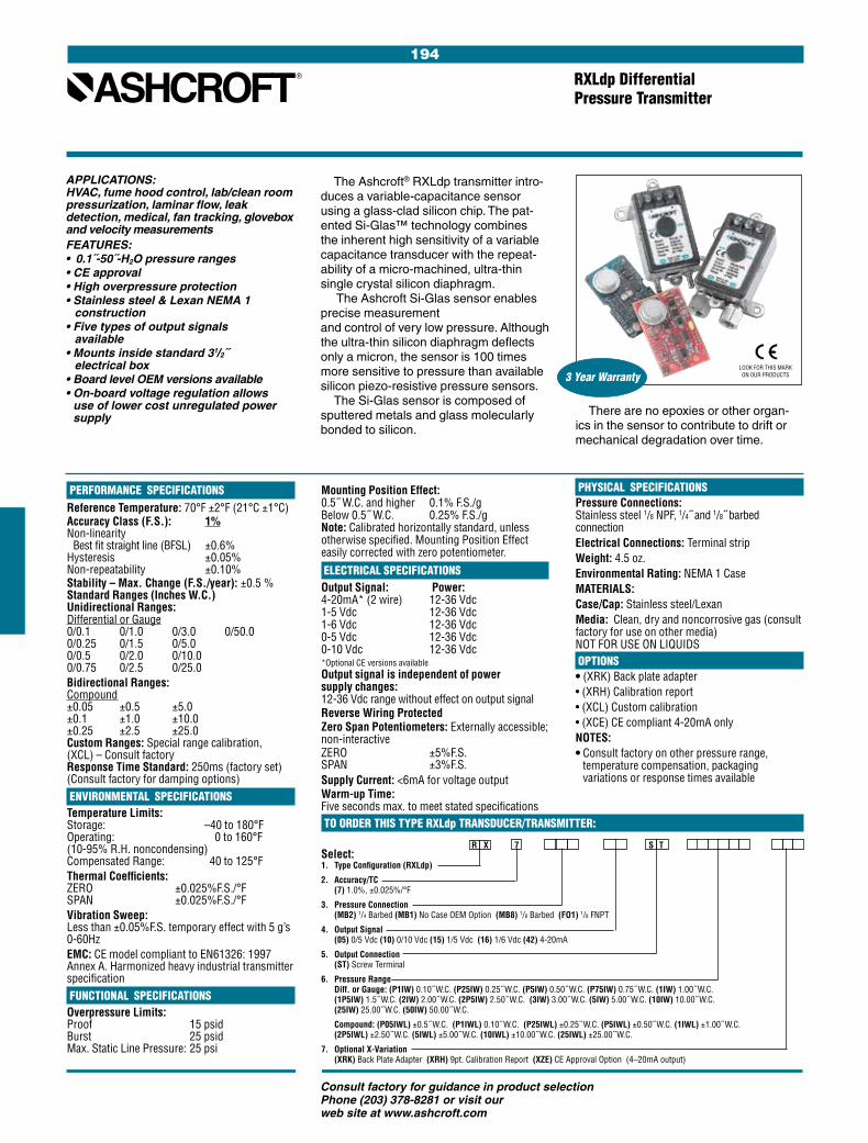
194
Consult factory for guidance in product selection Phone (203) 378-8281 or visit our web site at www.ashcroft.com
TO ORDER THIS TYPE RXLdp TRANSDUCER/TRANSMITTER:
Select: 1. Type Configuration (RXLdp)
2. Accuracy/TC (7) 1.0%, ±0.025%/°F
3. Pressure Connection (MB2) 1/4 Barbed (MB1) No Case OEM Option (MB8) 1/8 Barbed (FO1) 1/8 FNPT
4. Output Signal (05) 0/5 Vdc (10) 0/10 Vdc (15) 1/5 Vdc (16) 1/6 Vdc (42) 4-20mA
5. Output Connection (ST) Screw Terminal
6. Pressure Range Diff. or Gauge: (P1IW) 0.10˝ W.C. (P25IW) 0.25˝ W.C. (P5IW) 0.50˝ W.C. (P75IW) 0.75˝ W.C. (1IW) 1.00˝ W.C. (1P5IW) 1.5˝ W.C. (2IW) 2.00˝ W.C. (2P5IW) 2.50˝ W.C. (3IW) 3.00˝ W.C. (5IW) 5.00˝ W.C. (10IW) 10.00˝ W.C. (25IW) 25.00˝ W.C. (50IW) 50.00˝ W.C.
Compound: (P05IWL) ±0.5˝ W.C. (P1IWL) 0.10˝ W.C. (P25IWL) ±0.25˝ W.C. (P5IWL) ±0.50˝ W.C. (1IWL) ±1.00˝ W.C. (2P5IWL) ±2.50˝ W.C. (5IWL) ±5.00˝ W.C. (10IWL) ±10.00˝ W.C. (25IWL) ±25.00˝ W.C.
7. Optional X-Variation (XRK) Back Plate Adapter (XRH) 9pt. Calibration Report (XZE) CE Approval Option (4–20mA output)
PHYSICAL SPECIFICATIONSPressure Connections: Stainless steel 1/8 NPF, 1/4˝ and 1/8˝ barbed connectionElectrical Connections: Terminal stripWeight: 4.5 oz.Environmental Rating: NEMA 1 CaseMATERIALS:Case/Cap: Stainless steel/LexanMedia: Clean, dry and noncorrosive gas (consult factory for use on other media) NOT FOR USE ON LIQUIDS OPTIONS• (XRK) Back plate adapter • (XRH) Calibration report • (XCL) Custom calibration • (XCE) CE compliant 4-20mA onlyNOTES:• Consult factory on other pressure range,
temperature compensation, packaging variations or response times available
RXLdp Differential Pressure Transmitter
APPLICATIONS:HVAC, fume hood control, lab/clean room pressurization, laminar flow, leak detection, medical, fan tracking, glovebox and velocity measurementsFEATURES:• 0.1˝-50˝-H2O pressure ranges• CE approval• High overpressure protection• Stainless steel & Lexan NEMA 1 construction• Five types of output signals available• Mounts inside standard 31/2˝ electrical box• Board level OEM versions available• On-board voltage regulation allows
use of lower cost unregulated power supply
There are no epoxies or other organ-ics in the sensor to contribute to drift or mechanical degradation over time.
The Ashcroft® RXLdp transmitter intro-duces a variable-capacitance sensor using a glass-clad silicon chip. The pat-ented Si-Glas™ technology combines the inherent high sensitivity of a variable capacitance transducer with the repeat-ability of a micro-machined, ultra-thin single crystal silicon diaphragm.
The Ashcroft Si-Glas sensor enables precise measurement and control of very low pressure. Although the ultra-thin silicon diaphragm deflects only a micron, the sensor is 100 times more sensitive to pressure than available silicon piezo-resistive pressure sensors.
The Si-Glas sensor is composed of sputtered metals and glass molecularly bonded to silicon.
PERFORMANCE SPECIFICATIONSReference Temperature: 70°F ±2°F (21°C ±1°C)Accuracy Class (F.S.): 1% Non-linearity Best fit straight line (BFSL) ±0.6%Hysteresis ±0.05%Non-repeatability ±0.10%Stability – Max. Change (F.S./year): ±0.5 %Standard Ranges (Inches W.C.) Unidirectional Ranges: Differential or Gauge 0/0.1 0/1.0 0/3.0 0/50.0 0/0.25 0/1.5 0/5.0 0/0.5 0/2.0 0/10.0 0/0.75 0/2.5 0/25.0Bidirectional Ranges: Compound ±0.05 ±0.5 ±5.0 ±0.1 ±1.0 ±10.0 ±0.25 ±2.5 ±25.0 Custom Ranges: Special range calibration, (XCL) – Consult factoryResponse Time Standard: 250ms (factory set) (Consult factory for damping options) ENVIRONMENTAL SPECIFICATIONSTemperature Limits: Storage: –40 to 180°F Operating: 0 to 160°F (10-95% R.H. noncondensing) Compensated Range: 40 to 125°F Thermal Coefficients: ZERO ±0.025%F.S./°F SPAN ±0.025%F.S./°FVibration Sweep: Less than ±0.05%F.S. temporary effect with 5 g’s 0-60HzEMC: CE model compliant to EN61326: 1997 Annex A. Harmonized heavy industrial transmitter specification FUNCTIONAL SPECIFICATIONSOverpressure Limits: Proof 15 psid Burst 25 psidMax. Static Line Pressure: 25 psi
Mounting Position Effect: 0.5˝ W.C. and higher 0.1% F.S./g Below 0.5˝ W.C. 0.25% F.S./g Note: Calibrated horizontally standard, unless otherwise specified. Mounting Position Effect easily corrected with zero potentiometer.
ELECTRICAL SPECIFICATIONSOutput Signal: Power: 4-20mA* (2 wire) 12-36 Vdc 1-5 Vdc 12-36 Vdc 1-6 Vdc 12-36 Vdc 0-5 Vdc 12-36 Vdc 0-10 Vdc 12-36 Vdc *Optional CE versions availableOutput signal is independent of power supply changes: 12-36 Vdc range without effect on output signalReverse Wiring ProtectedZero Span Potentiometers: Externally accessible; non-interactiveZERO ±5%F.S. SPAN ±3%F.S.Supply Current: <6mA for voltage outputWarm-up Time: Five seconds max. to meet stated specifications
R X 7 S T
3 Year WarrantyLOOK FOR THIS MARK ON OUR PRODUCTS
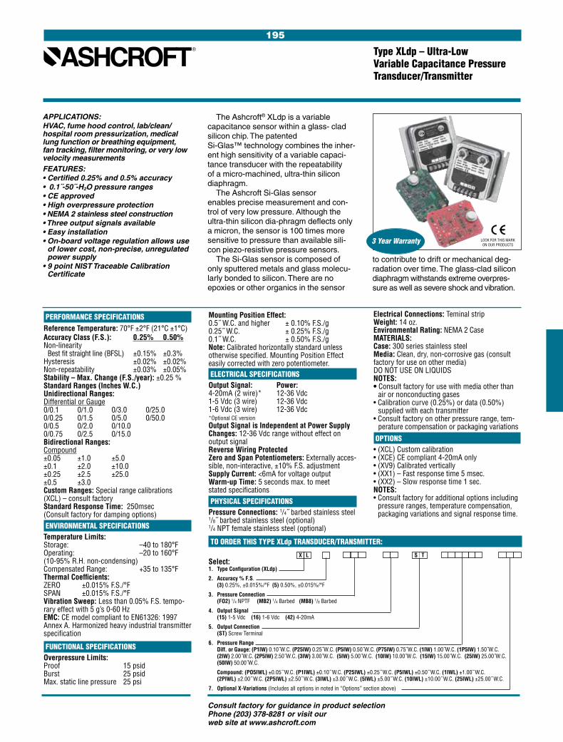
195
Consult factory for guidance in product selection Phone (203) 378-8281 or visit our web site at www.ashcroft.com
TO ORDER THIS TYPE XLdp TRANSDUCER/TRANSMITTER:
Select: 1. Type Configuration (XLdp)
2. Accuracy % F.S. (3) 0.25%, ±0.015%/°F (5) 0.50%, ±0.015%/°F
3. Pressure Connection (FO2) 1/4 NPTF (MB2) 1/4 Barbed (MB8) 1/8 Barbed
4. Output Signal (15) 1-5 Vdc (16) 1-6 Vdc (42) 4-20mA
5. Output Connection (ST) Screw Terminal
6. Pressure Range Diff. or Gauge: (P1IW) 0.10˝W.C. (P25IW) 0.25˝W.C. (P5IW) 0.50˝W.C. (P75IW) 0.75˝W.C. (1IW) 1.00˝W.C. (1P5IW) 1.50˝W.C. (2IW) 2.00˝W.C. (2P5IW) 2.50˝W.C. (3IW) 3.00˝W.C. (5IW) 5.00˝W.C. (10IW) 10.00˝W.C. (15IW) 15.00˝W.C. (25IW) 25.00˝W.C. (50IW) 50.00˝W.C.
Compound: (PO5IWL) ±0.05˝ W.C. (P1IWL) ±0.10˝ W.C. (P25IWL) ±0.25˝ W.C. (P5IWL) ±0.50˝ W.C. (1IWL) ±1.00˝ W.C. (2PIWL) ±2.00˝ W.C. (2P5IWL) ±2.50˝ W.C. (3IWL) ±3.00˝ W.C. (5IWL) ±5.00˝ W.C. (10IWL) ±10.00˝ W.C. (25IWL) ±25.00˝ W.C.
7. Optional X-Variations (Includes all options in noted in “Options” section above)
Type XLdp – Ultra-Low Variable Capacitance Pressure Transducer/Transmitter
APPLICATIONS:HVAC, fume hood control, lab/clean/hospital room pressurization, medical lung function or breathing equipment, fan tracking, filter monitoring, or very low velocity measurementsFEATURES:• Certified 0.25% and 0.5% accuracy• 0.1˝-50˝-H2O pressure ranges• CE approved• High overpressure protection• NEMA 2 stainless steel construction• Three output signals available• Easy installation• On-board voltage regulation allows use
of lower cost, non-precise, unregulated power supply
• 9 point NIST Traceable Calibration Certificate
to contribute to drift or mechanical deg-radation over time. The glass-clad silicon diaphragm withstands extreme overpres-sure as well as severe shock and vibration.
The Ashcroft® XLdp is a variable capacitance sensor within a glass- clad silicon chip. The patented Si-Glas™ technology combines the inher-ent high sensitivity of a variable capaci-tance transducer with the repeatability of a micro-machined, ultra-thin silicon diaphragm.
The Ashcroft Si-Glas sensor enables precise measurement and con-trol of very low pressure. Although the ultra-thin silicon dia-phragm deflects only a micron, the sensor is 100 times more sensitive to pressure than available sili-con piezo-resistive pressure sensors.
The Si-Glas sensor is composed of only sputtered metals and glass molecu-larly bonded to silicon. There are no epoxies or other organics in the sensor
Electrical Connections: Teminal stripWeight: 14 oz.Environmental Rating: NEMA 2 CaseMATERIALS:Case: 300 series stainless steelMedia: Clean, dry, non-corrosive gas (consult factory for use on other media) DO NOT USE ON LIQUIDSNOTES:• Consult factory for use with media other than
air or nonconducting gases• Calibration curve (0.25%) or data (0.50%)
supplied with each transmitter • Consult factory on other pressure range, tem-
perature compensation or packaging variations
OPTIONS• (XCL) Custom calibration • (XCE) CE compliant 4-20mA only• (XV9) Calibrated vertically • (XX1) – Fast response time 5 msec.• (XX2) – Slow response time 1 sec.NOTES: • Consult factory for additional options including
pressure ranges, temperature compensation, packaging variations and signal response time.
X L
PERFORMANCE SPECIFICATIONSReference Temperature: 70°F ±2°F (21°C ±1°C)Accuracy Class (F.S.): 0.25% 0.50% Non-linearity Best fit straight line (BFSL) ±0.15% ±0.3%Hysteresis ±0.02% ±0.02%Non-repeatability ±0.03% ±0.05%Stability – Max. Change (F.S./year): ±0.25 %Standard Ranges (Inches W.C.)Unidirectional Ranges:Differential or Gauge 0/0.1 0/1.0 0/3.0 0/25.00/0.25 0/1.5 0/5.0 0/50.00/0.5 0/2.0 0/10.0 0/0.75 0/2.5 0/15.0Bidirectional Ranges:Compound ±0.05 ±1.0 ±5.0±0.1 ±2.0 ±10.0±0.25 ±2.5 ±25.0±0.5 ±3.0 Custom Ranges: Special range calibrations (XCL) – consult factoryStandard Response Time: 250msec (Consult factory for damping options) ENVIRONMENTAL SPECIFICATIONSTemperature Limits:Storage: –40 to 180°FOperating: –20 to 160°F(10-95% R.H. non-condensing)Compensated Range: +35 to 135°F Thermal Coefficients:ZERO ±0.015% F.S./°FSPAN ±0.015% F.S./°FVibration Sweep: Less than 0.05% F.S. tempo-rary effect with 5 g’s 0-60 HzEMC: CE model compliant to EN61326: 1997 Annex A. Harmonized heavy industrial transmitter specification
FUNCTIONAL SPECIFICATIONSOverpressure Limits:Proof 15 psidBurst 25 psidMax. static line pressure 25 psi
Mounting Position Effect:0.5˝ W.C. and higher ± 0.10% F.S./g0.25˝ W.C. ± 0.25% F.S./g0.1˝ W.C. ± 0.50% F.S./g Note: Calibrated horizontally standard unless otherwise specified. Mounting Position Effect easily corrected with zero potentiometer. ELECTRICAL SPECIFICATIONSOutput Signal: Power:4-20mA (2 wire)* 12-36 Vdc1-5 Vdc (3 wire) 12-36 Vdc1-6 Vdc (3 wire) 12-36 Vdc *Optional CE versionOutput Signal is Independent at Power Supply Changes: 12-36 Vdc range without effect on output signalReverse Wiring Protected Zero and Span Potentiometers: Externally acces-sible, non-interactive, ±10% F.S. adjustmentSupply Current: <6mA for voltage outputWarm-up Time: 5 seconds max. to meet stated specifications PHYSICAL SPECIFICATIONSPressure Connections: 1/4˝ barbed stainless steel 1/8˝ barbed stainless steel (optional) 1/4 NPT female stainless steel (optional)
S T
3 Year Warranty LOOK FOR THIS MARK ON OUR PRODUCTS

196
Consult factory for guidance in product selection Phone (203) 378-8281 or visit our web site at www.ashcroft.com
TO ORDER THIS TYPE IXLdp TRANSDUCER/TRANSMITTER:
Select: 1. Type Configuration (XLdp) 2. Accuracy/TC (3) 0.25%, ±0.01%/°F (5) 0.50%, ±0.02%/°F 3. Pressure Connection (F02) 1/4 NPT-Female 4. Output Signal (05) 0/5 Vdc (15) 1/5 Vdc (16) 1/6 Vdc (25) ±2.5 Vdc (50) ±5.0 Vdc (42) 4-20mA5. Electrical Terminal (ST) Screw Termination 6. Pressure Range Diff. or Gauge: (P1IW) 0.10˝ W.C. (P25IW) 0.25˝ W.C. (P5IW) 0.50˝ W.C. (1IW) 1.00˝ W.C. (2IW) 2.00˝ W.C. (2P5IW) 2.50˝ W.C. (3IW) 3.00˝ W.C. (5IW) 5.00˝ W.C. (10IW) 10.00˝ W.C. (15IW) 15.00˝ W.C. (20IW) 20.00˝ W.C. (25IW) 25.00˝ W.C. (50IW) 50.00˝ W.C. (100IW) 100.00˝ W.C. (150IW) 150.00˝ W.C. (200IW) 200.00˝ W.C. Compound: (P05IWL) ±0.05˝ W.C. (P1IWL) ±0.10˝ W.C. (P2IWL) ±0.20˝ W.C. (P25IWL) ±0.25˝ W.C. (P5IWL) ±0.5˝ W.C. (1IWL) ±1.00˝ W.C. (2IWL) ±2.00˝ W.C. (2P5IWL) ±2.50˝ W.C. (3IWL) ±3.00˝ W.C. (5IWL) ±5.00˝ W.C. (10IWL) ±10.0˝ W.C. (15IWL) ±15.00˝ W.C. (20IWL) ±20.00˝ W.C. (25IWL) ±25.00˝ W.C. (50IWL) ±50.00˝ W.C. (100IWL) ±100.00˝ W.C.7. Optional X-Variation (XFM) FM Approval Option (Includes all options in list)
0.1˝ W.C. 0.8% F.S./gNote: Calibrated horizontally standard unless otherwise specified. Mounting Position Effect easily corrected with zero potentiometer. ELECTRICAL SPECIFICATIONSOutput Signal: Current: 4-20mA two wire current loop Voltage: All voltage outputs are 3 wire
0-5 Vdc 1-6 Vdc ±5 Vdc 1-5 Vdc ±2.5 Vdc
Output Signal is Independent of Power Supply Changes: 12-36 Vdc range without effect on output signalReverse Wiring ProtectedInternal Zero and Span: ±10% F.S. AdjustmentSupply Current: 2.6mA typical for voltage outputWarm-up Time: Full specification: Less than one secondFast Response, Turndown & Variable Damping Optional PHYSICAL SPECIFICATIONSEnclosure: 300 series stainless steelProcess Connections: Two 1⁄4 NPT femaleEnvironmental Rating: NEMA 4X CaseElectrical Connections: Two 1⁄2˝ female electrical conduit connections isolated from the electronics.
Industrial IXLdp Ultra-Low Variable Capacitance Pressure Transmitter
APPLICATIONS:HVAC, fume hood control, lab/clean room pressurization, laminar flow, furnace/stack draft, leak detection, or pollution monitoring, medical equipment, fan tracking, filter moni- toring and velocity measurementsBENEFITS & FEATURES:• Certified 0.25% and 0.5% accuracy• 0.1˝-200˝-H2O pressure ranges• High overload protection• FM approved for hazardous locations• NEMA 4X metal construction• Six types of output signals available• 5:1 turndown option• Variable dampening option• On-board voltage regulation allows use
of lower cost, non-precise, unregulated power supply
• Hazardous environments
molecularly bonded to silicon. There are no epoxies or other organics in the sensor to contribute to drift or mechanical degradation over time.
The Ashcroft® Industrial IXLdp was designed for the measurement and control of very low pressure and flow in industrial and process plant environ-ments. The Industrial IXLdp transmitter features a rugged NEMA 4X enclosure, built-in electrical terminal box isolated from the electronics and threaded pro-cess connections.
The Ashcroft IXLdp transmitter utilizes a state-of-the-art variable capacitance sensor with a glass-clad silicon chip. The Si-GlasTM technology combines the inher-ent high sensitivity of a variable capaci-tance transducer with the repeatability of a micro-machined, single-crystal silicon diaphragm. The Si-Glas sensor is com-posed of sputtered metals and glass
PERFORMANCE SPECIFICATIONSReference Temperature: 70°F ±2°F (21°C ±1°C) Accuracy Class (F.S.): 0.25% 0.50% Non-linearity Terminal point ±0.2% ±0.4% Best fit straight line (BFSL) ±0.15% ±0.3%Hysteresis ±0.02% ±0.02%Non-repeatability ±0.03% ±0.05%Stability – Max. Change (F.S./year): ±0.25 %Standard Ranges (Inches W.C.)Unidirectional Ranges:Differential or Gauge 0/0.1 0/2.0 0/10 0/500/0.25 0/2.5 0/15 0/1000/0.50 0/3.0 0/20 0/1500/1.0 0/5.0 0/25 0/200Bidirectional Ranges:Compound ±0.05 ±0.5 ± 5.0 ± 25.0±0.10 ±1.0 ±10.0 ± 50.0±0.20 ±2.0 ±15.0 ±100.0±0.25 ±2.5 ±20.0 Custom Ranges: Special range calibrations (XCL) – consult factoryResponse Time: Standard: 250ms (Consult factory for damping options) Optional variable damping (0-30 sec) (X1D) ENVIRONMENTAL SPECIFICATIONSTemperature Limits:Storage: –40 to 210°FOperating: –20 to 185°F (0-95% relative humidity)Compensated: 0 to 160°F Thermal Coefficients: 0.25% Acc. 0.5% Acc. ZERO ±0.01%F.S./°F ±0.02%F.S./°FSPAN ±0.01%F.S./°F ±0.02%F.S./°FVibration Sweep: Less than 0.2%F.S./g temporary effect 10-130 Hz FUNCTIONAL SPECIFICATIONSOverpressure Limits:Proof: 20 psidBurst differential pressure: 50 psidMaximum static (line) pressure: 100 psiStatic pressure effect: less than 0.5% F.S.Mounting Position Effect:1˝ W.C. and higher 0.1% F.S./g0.25˝ up to 0.5” W.C. 0.5% F.S./g
I X F 0 2 S T X F M
3 Year Warranty
Separate access cover for terminal connectionsMedia: Clean, dry and noncorrosive gas (consult factory for use on other media) NOT FOR USE ON LIQUIDS OPTIONS(XX1) – Fast Response: 8 ms(X41) – 5:1 Turndown(X1D) – Variable damping (0-30 sec.)(XNH) – Paper tag(XCL) – Custom pressure range calibration(XFM) – FM approval• Consult factory on other pressure range,
temperature compensation, packaging variations or response times
Factory Mutual intrinsically safe approvals for use in (specify XFM* option noted above): Intrinsically Safe: Class I, II, III: Div. 1 & 2, Groups A - G, when
wired in accordance with Ashcroft dwgs 71B241 (pages 1-3)
Non-incendive: Class I, Div. 2, Groups A - D Class I I, Div. 2, Groups F, G Class I II * FM option (XFM) cannot be combined options
X41 or X1D
FM
LOOK FOR THIS MARK ON OUR PRODUCTS

197
Consult factory for guidance in product selection Phone (203) 378-8281 or visit our web site at www.ashcroft.com
Bourdon Tube and Tip Material Ordering (all joints Socket Pressure Range Code TIG welded) Material Type (psi) NPT Connection Drawn 12/1500 S 316 stainless steel 316 stainless steel “C” Tube 1⁄2 Drawn 2000/20,000 Helical Tube
Drawn 12/1500 P K Monel Monel 400 “C” Tube 1⁄2 Drawn 2000/20,000 Helical Tube
Duratran® Transmitter Type 2279, ASME B 40.1 Grade 2A (±0.5% of span)
Duratran® Transmitter/Gauge, takes the place of an electronic transmitter and a mechanical gauge• FM approved to 10,000 psi• 4-20mA, 2 wire output• Zero and span adjustments• 41/2˝ solid-front phenolic case• Accuracy: ±0.5% full scale including
linearity, hysteresis and repeatabilityNew Duratran®PLUS! Option:
- Liquid-filled performance in a dry gauge- Fights vibration and pulsations without
liquid-filled headaches- Order as option XLL
The result is reliable, local, analog pres-sure indication with an economical trans-mitter . . . A niche solution for any facility
TO ORDER THIS TYPE 2279 DURATRAN TRANSMITTER:
TABLE B – STANDARD psi RANGES TABLE A – BOURDON TUBE SELECTION
SPECIFICATIONSFunctional Service: Liquid, gas or vaporRanges: See Table BOutput: 4-20mA, 2 wirePower Supply: 12/40 VdcZero Adjustment: ±20% of full scaleSpan Adjustment: ±10% of full scaleTemperature Limit: –40°F to 160°FOverpressure Limits: 130% of range without damage to tubeHumidity Limits: Up to 90% relative humidity noncondensingSignal Damping: Fixed electronic damping time constant of 0.2 secondsTurn On Time: Less than 1 secondEnvironmental Rating: Similar to NEMA 4
AGENCY APPROVALFactory Mutual approved as intrinsically safe for Class I, II and III, Division 1, applicable Groups A, B, C, D, E and G in accordance with Dresser drawing 71B185 and entity requirements; nonincendive for Class I, II, III, Division 2, Groups A, B, C, D and G hazardous locations.
PERFORMANCEAccuracy: ±0.5% including linearity, hysteresis, and repeatabilityStability: ±0.25% F.S. for 6 monthsTemperature Effect: Less than 0.02% of span/°F Position Effect: Vertical mounting recommended May be re-zeroed to correct error in other positions
PHYSICALDial Size: 41⁄2˝Case: Solid front, black phenolic hermetically sealedRing: Threaded, glass-filled polypropyleneMounting: Stem, surface, flush (with 1278 M ring)Pressure Connection: 1⁄2 NPTWindow: Laminated safety glassCalibration: Transmitter—Span and zero adjustment on dial Gauge—Zero adjustment with micrometer pointerElectrical Connection: 30˝ #18 wire AWG, 1⁄2 NPT liquid tight conduit connection at caseWeight: 3 lb
The Duratran® solution is a reliable Duragauge® pressure gauge fitted with optical circuitry to provide a 4-20mA output.
The 41/2˝ phenolic case is hermetically sealed, chemical and heat resistant.
The wide selection of system materials and corrosion-proof housing meets a vari-ety of demanding applications . . . even those with vibration and pulsation.
This transmitter/gauge allows you to save money, replacing two instruments with one Duratran.
0/120/150/300/600/1000/1600/2000/3000/400
0/6000/8000/10000/15000/20000/30000/50000/10,0000/20,000*
*Not FM approved range
MADE IN U.S.A.
Select: 41⁄2˝ 2279 (S)SH 04L XFM w/1278M Ring 0/100 psi1. Dial Size2. Case Type Number3. Bourdon System (ordering code)—Table A4. Connection: Location & Size—1/2 NPT (04) Lower (L)5. Factory Mutual Approval6. Mounting Accessory or Variation (if required)7. Range—Table B

198
Consult factory for guidance in product selection Phone (203) 378-8281 or visit our web site at www.ashcroft.com
Select 2269 A — XK4 Complete Type Number
1. Type–Ashcroft Digital Panel Meter2. Supply Voltage– A=110 Vac
B=220 Vac3. Alarm Board/Screw terminal Conn.– — = None
T = Alarm Board w/screw terminal Conn.4. Variations– XJ6=Factory Set Alarm (1)
XK4=Factory Calibrated meter (2)
• Easy single-button scaling with lockout feature
• 4-20mA, 1-5V, 0-5V or 0-10V field- selectable inputs
• 24V transmitter power supply standard
• Steady, accurate display to ±199,990
• 41/2 digit and extra zero
• NEMA 4X front panel
• Two relay-output options
Inputs: Field-selectable 4-20mA, 1-5V, 0-5V, 0-10V
Display: Bright, large, 0.56˝ (14.2mm) high efficiency red or green LED. 41/2 digits + extra zero; ±19999(0), (0) may be switched on to display 199,990
Front Panel: NEMA 4X, panel gasket provided
Calibration Range: 4mA, (1V) input may be set to display anywhere in range of meter. 20mA (5V) input may be set anywhere above or below 4mA input
Lockout: Jumper 3 at rear of instrument restricts modi-fication of calibration values
Loop Power: Isolated 24 Vdc at 20mA regulated. Noise less than 10mV p-p. Max. loop resistance of 1200 ohms
Hold Reading: Connect terminals HLD and COM
TO ORDER THIS TYPE 2269 DIGITAL PANEL METER:
Note 1: When ordering XJ6 also specify XK4. Supply the meter range and the high and low setpoints.Note 2: Calibrated range must be specified when ordering.
Digital Panel Meter 2269 with Alarm Board Option
The new Ashcroft® Digital Panel Meter 2269 is a high-performance, easy-to-use industrial-grade microprocessor digital process meter. It accepts all the standard process signals: 4-20mA, 1-5V, 0-5V and 0-10V from transmitters and transducers, and displays these signals in engineering units on a 41/2 digit display. The display includes an extra zero which may be used to handle numbers up to 199,990.
Accuracy: ±0.05% of calibrated span
Input Impedance: Voltage ranges, greater than 100k ohms. Current range, 100 ohms
Power: 115 Vac or 230 Vac ± 10%, 50/60 Hz, 10 VA
Environmental: Operating temperature range: –10°C to +65°C Storage temperature range: –40°C to +75°C Relative humidity: 0 to 90% noncondensing
Enclosure: 1/8 DIN, ABS plastic, UL 94V-O
Connections: Removable screw terminal block (provided)
Alarm Points: Two, any combination of high or low alarms
Alarm Status Indication: Front panel LED
Alarm Deadband: 0-100%, user selectable
SPECIFICATIONS
MADE IN U.S.A.
2269 AT PANEL METER WITH ALARM BOARD OPTION SPECIFICATIONSRating: 2 relays; 2 amp SPDT (form C). The contacts are rated 2 amp @ 30 Vdc or 2 amp @ 250Vac resistive load; 1/14 hp @ 125/250 Vac for NC contacts and 1/10 hp @ 125/250 Vac for NO contacts, inductive loadReset: User selectable1. Automatically when the input passes the
reset point2. Automatically + manually (via user-supplied
switch or front panel ACK button)Failsafe Operation: The relay coils are energized in the nonalarm condition. In the case of a power failure, the relays will go to the alarm stateAuto Initialization: When power is applied to the meter, the relays will always reflect the state of the input to the meterDeadband: 0-100%, user selectable

199
Consult factory for guidance in product selection Phone (203) 378-8281 or visit our web site at www.ashcroft.com
ProcessConnection Pressure
0/200 psi 0/3000 psi 0/8 psi* 0/300 psi 0/5000 psi 0/10 psi* 0/400 psi 0/10,000 psi* 0/15 psi 0/600 psi 0/20,000 psi 0/30 psi 0/800 psi 0/60 psi 0/1000 psi 0/100 psi 0/1500 psi 0/160 psi 0/2000 psi*
Note: Vacuum application: The transmitted air pressure increases as the measured vacuum approaches zero.
TO ORDER THESE TYPE 4080, 4480 PNEUMATIC TRANSMITTERS:
Pressure transmitters (specify the following):1. Type number: 4080 indicating, 4480 nonindicating2. Bourdon Tube material. Specify material ordering code letter3. Range or span (process pressure)4. Output range. The standard 3-15 psi range will be supplied unless specified otherwise 5. Accessories (see page 255-260) or optional features (see page 261-262) Example: 4480S-04L, 3-15# Range 0/100 psi
Providing plus-values which will coor-dinate key functional areas in your plant, this Ashcroft® pneumatic transmitter serves pressure applications throughout all industries. A positive report of process fluid and media performance is provided at designated operational check points by a signal accurately transmitted with maximum efficiency, assuring operating economies and safety.
SPECIFICATIONS STANDARD RANGES Types 4080 4480
Ranges see Standard Ranges
Output ranges, psi 3-15 & 3-27 (see note below for vacuum application) Supply air requirements 18-20 psi for 3-15 psi range; 30-35 psi for 3-27 psi range
Air consumption SCFM 0.1
Speed of response time constant of 4 seconds per 500 ft of tubing
Air connection 1⁄4 NPT Female
Calibration adjustments 5 2
Accessories see optional features and accessories
Transmission distance 1000 ft
Mounting weight approximate weight 9 lb
Accuracy ±% of span 1.0 0.5
Sensitivity ±% of span 0.1 0.001
Repeatability % of span 0.15
Actuation Bourdon tube
Input sensing element material 316 SS Ambient temperature effect 1⁄2% per 50°F
Process connection 1⁄2 NPT (ordering code 04L)
TUBE MATERIALS
1⁄2 MaleNPT
Lower
* Applies to 4480 only.
Type Number Range Limits Ordering Code Bourdon Tube Material
Vacuum to 20,000 psi S 316 stainless steel
4080(indicating)
4480(nonindicating)
Vacuum Compound
10/0 in.Hg* 30 in.Hg/15 psi 15/0 in.Hg* 30 in.Hg/30 psi 20/0 in.Hg* 30 in.Hg/60 psi 30/0 in.Hg 30 in.Hg/100 psi 30 in.Hg/150 psi 30 in.Hg/200 psi 30 in.Hg/300 psi
MADE IN U.S.A.
Pneumatic Transmitter, Type 4080, ASME B 40.1 Grade 1A (±1.0% of span) Type 4480, ASME B 40.1 Grade 2A (±0.5% of span)
The Ashcroft transmitter is a self-nulling motion- balance instrument, using a pneumatic relay operating on the nonbleed force balance principle for con-verting input pressures into proportional low air pressure signals for transmittal to remote indicators or controllers.

200
Consult factory for guidance in product selection Phone (203) 378-8281 or visit our web site at www.ashcroft.com
201
Consult factory for guidance in product selection Phone (203) 378-8281 or visit our web site at www.ashcroft.com
DIRECT
BIMETAL THERMOMETERS
Product Selection Information .................... 203
Bimetal Thermometers EI Series .............. 204
Bimetal Thermometers CI Series .............. 205
Bimetal Thermometers EL Series ............. 206
Bimetal Thermometers Case Dimensions 207
Options and Thermowells ................... 220-224
BIMETALTHERMOMETERS

202
Consult factory for guidance in product selection Phone (203) 378-8281 or visit our web site at www.ashcroft.com
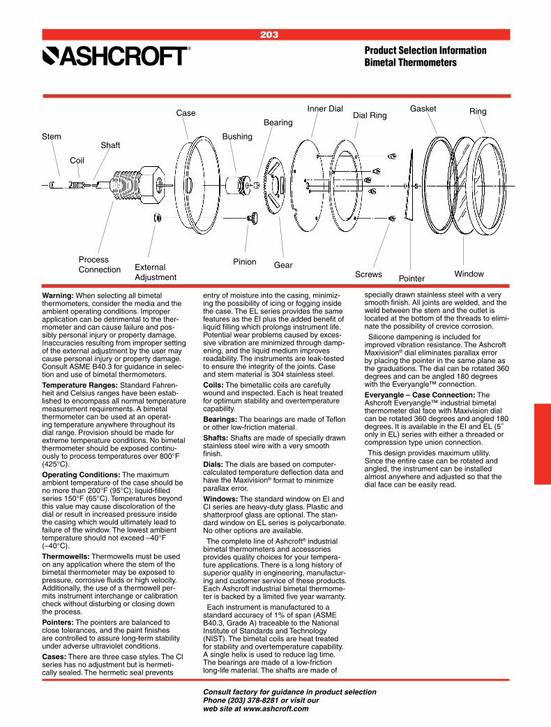
203
Product Selection InformationBimetal Thermometers
Consult factory for guidance in product selection Phone (203) 378-8281 or visit our web site at www.ashcroft.com
Warning: When selecting all bimetal thermometers, consider the media and the ambient operating conditions. Improper application can be detrimental to the ther-mometer and can cause failure and pos-sibly personal injury or property damage. Inaccuracies resulting from improper setting of the external adjustment by the user may cause personal injury or property damage. Consult ASME B40.3 for guidance in selec-tion and use of bimetal thermometers.Temperature Ranges: Standard Fahren-heit and Celsius ranges have been estab-lished to encompass all normal temperature measurement requirements. A bimetal thermometer can be used at an operat-ing temperature anywhere throughout its dial range. Provision should be made for extreme temperature conditions. No bimetal thermometer should be exposed continu-ously to process temperatures over 800°F (425°C).Operating Conditions: The maximum ambient temperature of the case should be no more than 200°F (95°C); liquid-filled series 150°F (65°C). Temperatures beyond this value may cause discoloration of the dial or result in increased pressure inside the casing which would ultimately lead to failure of the window. The lowest ambient temperature should not exceed –40°F (–40°C).Thermowells: Thermowells must be used on any application where the stem of the bimetal thermometer may be exposed to pressure, corrosive fluids or high velocity. Additionally, the use of a thermowell per-mits instrument interchange or calibration check without disturbing or closing down the process.Pointers: The pointers are balanced to close tolerances, and the paint finishes are controlled to assure long-term stability under adverse ultraviolet conditions.Cases: There are three case styles. The Cl series has no adjustment but is hermeti-cally sealed. The hermetic seal prevents
entry of moisture into the casing, minimiz-ing the possibility of icing or fogging inside the case. The EL series provides the same features as the El plus the added benefit of liquid filling which prolongs instrument life. Potential wear problems caused by exces-sive vibration are minimized through damp-ening, and the liquid medium improves readability. The instruments are leak-tested to ensure the integrity of the joints. Case and stem material is 304 stainless steel.Coils: The bimetallic coils are carefully wound and inspected. Each is heat treated for optimum stability and overtemperature capability.Bearings: The bearings are made of Teflon or other low-friction material.Shafts: Shafts are made of specially drawn stainless steel wire with a very smooth finish.Dials: The dials are based on computer-calculated temperature deflection data and have the Maxivision® format to minimize parallax error.Windows: The standard window on EI and CI series are heavy-duty glass. Plastic and shatterproof glass are optional. The stan-dard window on EL series is polycarbonate. No other options are available. The complete line of Ashcroft® industrial bimetal thermometers and accessories provides quality choices for your tempera-ture applications. There is a long history of superior quality in engineering, manufactur-ing and customer service of these products. Each Ashcroft industrial bimetal thermome-ter is backed by a limited five year warranty. Each instrument is manufactured to a standard accuracy of 1% of span (ASME B40.3, Grade A) traceable to the National Institute of Standards and Technology (NIST). The bimetal coils are heat treated for stability and overtemperature capability. A single helix is used to reduce lag time. The bearings are made of a low-friction long-life material. The shafts are made of
Stem
Coil
Shaft
Process Connection External
Adjustment
Case
Bushing
Pinion Gear
Bearing
Inner DialDial Ring
Gasket Ring
Screws Pointer Window
specially drawn stainless steel with a very smooth finish. All joints are welded, and the weld between the stem and the outlet is located at the bottom of the threads to elimi-nate the possibility of crevice corrosion. Silicone dampening is included for improved vibration resistance. The Ashcroft Maxivision® dial eliminates parallax error by placing the pointer in the same plane as the graduations. The dial can be rotated 360 degrees and can be angled 180 degrees with the Everyangle™ connection.Everyangle – Case Connection: The Ashcroft Everyangle™ industrial bimetal thermometer dial face with Maxivision dial can be rotated 360 degrees and angled 180 degrees. It is available in the EI and EL (5˝ only in EL) series with either a threaded or compression type union connection. This design provides maximum utility. Since the entire case can be rotated and angled, the instrument can be installed almost anywhere and adjusted so that the dial face can be easily read.
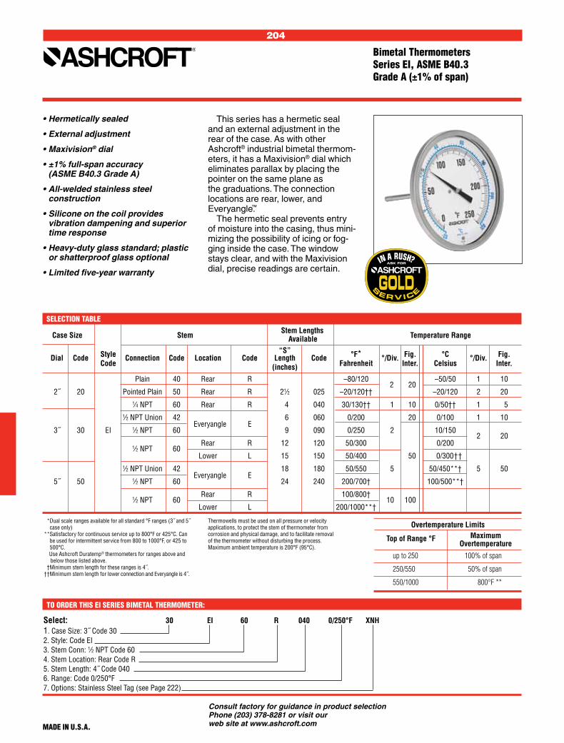
204
Consult factory for guidance in product selection Phone (203) 378-8281 or visit our web site at www.ashcroft.com
Overtemperature Limits
Top of Range °F
up to 250 100% of span
250/550 50% of span
550/1000 800°F **
Case Size Stem Stem Lengths Temperature Range Available “S” Dial Code Style Connection Code Location Code Length Code °F*
°/Div. Fig. °C °/Div. Fig.
Code (inches) Fahrenheit Inter. Celsius Inter.
Plain 40 Rear R –80/120 2 20
–50/50 1 10
2˝ 20 Pointed Plain 50 Rear R 21⁄2 025 –20/120†† –20/120 2 20
1⁄4 NPT 60 Rear R 4 040 30/130†† 1 10 0/50†† 1 5
1⁄2 NPT Union 42 Everyangle E
6 060 0/200 20 0/100 1 10
3˝ 30 EI 1⁄2 NPT 60 9 090 0/250 2 10/150 2 20
1⁄2 NPT 60
Rear R 12 120 50/300 0/200
Lower L 15 150 50/400 50 0/300 † †
1⁄2 NPT Union 42 Everyangle E
18 180 50/550 5 50/450**† 5 50
5˝ 50 1⁄2 NPT 60 24 240 200/700† 100/500**†
1⁄2 NPT 60
Rear R 100/800† 10 100
Lower L 200/1000**†
Select: 30 EI 60 R 040 0/250°F XNH1. Case Size: 3˝ Code 302. Style: Code EI3. Stem Conn: 1⁄2 NPT Code 604. Stem Location: Rear Code R5. Stem Length: 4˝ Code 0406. Range: Code 0/250°F7. Options: Stainless Steel Tag (see Page 222)
• Hermetically sealed
• External adjustment
• Maxivision® dial
• ±1% full-span accuracy (ASME B40.3 Grade A)
• All-welded stainless steel construction
• Silicone on the coil provides vibration dampening and superior time response
• Heavy-duty glass standard; plastic or shatterproof glass optional
• Limited five-year warranty
SELECTION TABLE
TO ORDER THIS EI SERIES BIMETAL THERMOMETER:
MaximumOvertemperature
** Dual scale ranges available for all standard °F ranges (3˝ and 5˝ case only)
** Satisfactory for continuous service up to 800°F or 425°C. Can be used for intermittent service from 800 to 1000°F, or 425 to 500°C.
Use Ashcroft Duratemp® thermometers for ranges above and below those listed above.†† Minimum stem length for these ranges is 4˝.†† Minimum stem length for lower connection and Everyangle is 4˝.
Thermowells must be used on all pressure or velocity applications, to protect the stem of thermometer from corrosion and physical damage, and to facilitate removal of the thermometer without disturbing the process.Maximum ambient temperature is 200°F (95°C).
This series has a hermetic seal and an external adjustment in the rear of the case. As with other Ashcroft® industrial bimetal thermom-eters, it has a Maxivision® dial which eliminates parallax by placing the pointer on the same plane as the graduations. The connection locations are rear, lower, and Everyangle.™
The hermetic seal prevents entry of moisture into the casing, thus mini-mizing the possibility of icing or fog-ging inside the case. The window stays clear, and with the Maxivision dial, precise readings are certain.
MADE IN U.S.A.
Bimetal ThermometersSeries EI, ASME B40.3 Grade A (±1% of span)

205
Consult factory for guidance in product selection Phone (203) 378-8281 or visit our web site at www.ashcroft.com
Select: 30 CI 60 R 040 0/250°F XNH1. Case Size: 3˝ Code 302. Style: Code CI3. Stem Conn: 1⁄2 NPT Code 604. Stem Location: Rear Code R5. Stem Length: 4˝ Code 0406. Range: Code 0/250°F7. Options: Stainless Steel Tag (see Page 222)
Overtemperature Limits
Top of Range °F
up to 250 100% of span
250/550 50% of span
550/1000 800°F **
Case Size Stem Stem Lengths Temperature Range Available “S” Dial Code Style Connection Code Location Code Length Code °F*
°/Div. Fig. °C °/Div. Fig.
Code (inches) Fahrenheit Inter. Celsius Inter.
Plain 40 Rear R –80/120 2 20
–50/50 1 10
2˝ 20 Pointed Plain 50 Rear R 21⁄2 025 –20/120†† –20/120 2 20
1⁄4 NPT 60 Rear R 4 040 30/130†† 1 10 0/50†† 1 5
3˝ 30 CI
60
Rear R 6 060 0/200 20 0/100 1 10
Lower L 9 090 0/250 2 10/150 2 20
12 120 50/300 0/200
Rear R 15 150 50/400 50 0/300 † †
5˝ 50 1⁄2 NPT 60 18 180 50/550 5 50/450**† 5 50
24 240 200/700† 100/500**†
Lower L 100/800† 10 100
200/1000**†
MaximumOvertemperature
** Dual scale ranges available for all standard °F ranges (3˝ and 5˝ case only)
** Satisfactory for continuous service up to 800°F or 425°C. Can be used for intermittent service from 800 to 1000°F, or 425 to 500°C.
Use Ashcroft Duratemp® thermometers for ranges above and below those listed above.††Minimum stem length for these ranges is 4˝.†† Minimum stem length for lower connection is 4˝.
Thermowells must be used on all pressure or velocity applications, to protect the stem of thermometer from corrosion and physical damage, and to facilitate removal of the thermometer without disturbing the process.Maximum ambient temperature is 200°F (95°C).
TO ORDER THIS CI SERIES BIMETAL THERMOMETER:
1⁄2 NPT
MADE IN U.S.A.
SELECTION TABLE
• Hermetically sealed
• Tamper resistant
• Maxivision® dial
• ±1% full-span accuracy (ASME B40.3 Grade A)
• All-welded stainless steel construction
• Silicone on the coil provides vibration dampening and superior time response
• Heavy-duty glass standard; plastic or shatterproof glass optional
• Limited five-year warranty
Bimetal ThermometersSeries CI, ASME B40.3 Grade A (±1% of span)
This series is tamper proof, her-metically sealed and has the Maxivi-sion® dial. The connection locations are rear and lower. The CI series of Ashcroft® industrial bimetal thermom-eters was designed for applications where external adjustment or pointer reset are not desired.
The hermetic seal prevents entry of moisture into the casing, thus mini-mizing the possibility of fogging inside the case. The Maxivision dial provides accurate temperature readings.

206
Consult factory for guidance in product selection Phone (203) 378-8281 or visit our web site at www.ashcroft.com
Overtemperature Limits
Top of Range °F
up to 160 100% of span
160/300 300°F
300/550 550°F
Select: 30 EL 60 R 040 0/250°F XNH1. Case Size: 3˝ Code 302. Style: Code EL3. Stem Conn: 1⁄2 NPT Code 604. Stem Location: Rear Code R5. Stem Length: 4˝ Code 0406. Range: Code 0/250°F7. Options: Stainless Steel Tag (see Page 222)
Case Size Stem Stem Lengths Temperature Range Available “S” Dial Code Style Connection Code Location Code Length Code °F*
°/Div. Fig. °C °/Div. Fig.
Code (inches) Fahrenheit Inter. Celsius Inter.
3˝ 30 1⁄2 NPT 60 Rear R 21⁄2 025 –40/160 2 20 –20/120 2 20
4 040 –20/120† 2 20 –10/110 2 10
6 060 30/130† 1 10
EL 1⁄2 NPT 42 9 090 0/200 2 20 0/50† 1 5
Union
Everyangle E
12 120 0/250 2 50 0/100 1 10
5˝ 50 60 15 150 50/300 2 50 10/150 2 20
18 180 50/550 5 50 0/300 † 5 50
60 Rear R 24 240
This series – liquid filled – is available in 3˝ rear, 5˝ rear and 5˝ Everyangle™ connections. The exter-nal adjustment is standard.
The Ashcroft® liquid-filled thermo-meter provides the same features as the EI style with the added benefit of liquid filling.
The potential wear problem caused by excessive vibration is minimized through dampening and the instrument life is prolonged. The liquid medium also improves readability.
SELECTION TABLE
TO ORDER THIS EL SERIES BIMETAL THERMOMETER:
• Silicone liquid filled
• External adjustment
• Durable polycarbonate window
• Maxivision® dial
• ±1% full-span accuracy (ASME B40.3 Grade A)
• All-welded stainless steel construction
• Limited five-year warranty
* Dual scale ranges available for all standard °F ranges.† Minimum stem length for Everyangle connection is 4˝.• Use Ashcroft Duratemp® thermometers for ranges above and below those listed above.
MaximumOvertemperature
1⁄2 NPT
1⁄2 NPT
MADE IN U.S.A.
• Thermowells must be used on all pressure or velocity applications, to protect the stem of thermometer from corrosion and physical damage, and to facilitate removal of the thermometer without disturbing the process. Maximum ambient temperature is 150°F (65°C).
Bimetal Thermometer Series EL, ASME B40.3 Grade A (±1% of span)

207
Consult factory for guidance in product selection Phone (203) 378-8281 or visit our web site at www.ashcroft.com
A
B
D
E
S
Weight in ounces3 S – 21⁄2˝
Case Series
Case Dial Connection Series Size Location
A B C D E G H S NPT Hex CI EI EL
CI, EI 2˝ Rear 23⁄32 3⁄8 5⁄16 – – – – –2 – 11⁄16 41⁄2 41⁄2 – (Plain) (53) (10) (8)
CI, EI 2˝ Rear (Plain, 23⁄32 3⁄8 5⁄16 – – – – –2 – 11⁄16 41⁄2 41⁄2 – pointed stem) (53) (10) (8)
CI, EI 2˝ Rear 23⁄32 3⁄8 5⁄16 – – – – –2 1⁄4 11⁄16 41⁄2 41⁄2 – (Threaded) (53) (10) (8)
CI, EI, EL 3˝ Rear 35⁄32 19⁄32 5⁄16 – – – – –2 1⁄2 7⁄8 7 7 8 (80) (15) (8)
CI, EI 3˝ Lower 35⁄32 127⁄32 – 25⁄8 1⁄4 – – –2 1⁄2 7⁄8 11 11 – (80) (47) (67) (6)
EI 3˝ Everyangle 35⁄32 19⁄32 – – – 121⁄32 37⁄16 –2 1⁄2 7⁄8 – 10 – (80) (15) (42) (87)
CI, EI, EL 5˝ Rear 51⁄32 23⁄32 5⁄16 – – – – –2 1⁄2 7⁄8 15 16 18 (128) (18) (8)
CI, EI 5˝ Lower 51⁄32 115⁄16 – 35⁄8 1⁄4 – – –2 1⁄2 7⁄8 24 26 – (128) (49) (92) (6)
EI, EL 5˝ Everyangle 51⁄16 23⁄32 – – – 17⁄8 39⁄16 –2 1⁄2 7⁄8 – 25 28 (128) (18) (48) (91)
NOTES1 Figures in parenthesis ( ) are in millimeters. All other dimensions are in inches.2 Standard “S” dimensions are 21⁄2, 4, 6, 9, 12, 15, 18 and 24 inches.
Standard stem diameter is 1⁄4 inch.3 Add 1 oz. for every 2 inches of stem length.
S
CB
A
20EI60R
S
C
B
A
20EI50R
S
CB
A
20CI60R
S
CB
A
30EI60R30EL60R50EI60R50EL60R
S
A
C
B
30CI60R50CI60R
G
B
H
S
A
30EI60E50EI60E50EL60E
G B
H
S
A
1.00"
30EI42E50EI42E50EL42E
Case Dimensions
S
C
B
A
20CI50R
S
CB
A20EI40R
A
B
D
S
E
30CI60L50CI60L
30EI60L50EI60L
S
CB
A
20CI40R

208
Consult factory for guidance in product selection Phone (203) 378-8281 or visit our web site at www.ashcroft.com

209
Consult factory for guidance in product selection Phone (203) 378-8281 or visit our web site at www.ashcroft.com
REMOTE READING THERMOMETERS
Product Selection Information .................... 211
Duratemp Thermometer, Remote Mount, 600A-01 Series ......................................... 212
Duratemp Thermometer, Remote Mount, 600A-02 Series ....................................... 213
Duratemp Thermometer, Remote Mount, 600A-03 Series ........................................ 214
Duratemp Thermometer, Remote Mount, 600A-04 Series ........................................ 215
Duratemp Thermometer, Remote Mount, 600H-45 Series ........................................ 216
DIRECT READING THERMOMETERS
Duratemp Thermometer, Direct Mount, 600B Series ............................................. 217
Duratemp Thermometer, Case, Bulb and Armor Dimensions .................... 218
Case Dimensions ............................. 219-220
Thermowells .............................................. 221
Bimetal and Duratemp® Thermometer Options.............................. 222
Type 2400E and 2410E Digital Thermometers ............................... 223
Accessories ................................................ 224
DURATEMP® THERMOMETERS

210
Consult factory for guidance in product selection Phone (203) 378-8281 or visit our web site at www.ashcroft.com
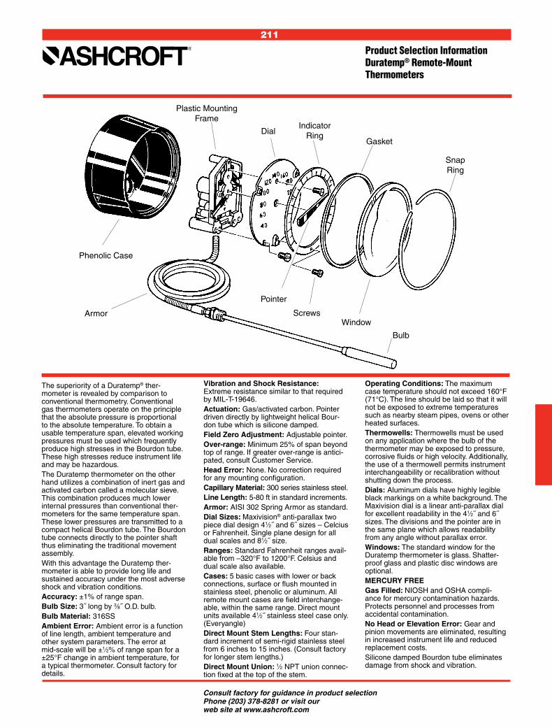
211
Consult factory for guidance in product selection Phone (203) 378-8281 or visit our web site at www.ashcroft.com
Phenolic Case
Armor
Plastic Mounting Frame
DialIndicator
RingGasket
Pointer
ScrewsWindow
Bulb
SnapRing
The superiority of a Duratemp® ther-mometer is revealed by comparison to conventional thermometry. Conventional gas thermometers operate on the principle that the absolute pressure is proportional to the absolute temperature. To obtain a usable temperature span, elevated working pressures must be used which frequently produce high stresses in the Bourdon tube. These high stresses reduce instrument life and may be hazardous.The Duratemp thermometer on the other hand utilizes a combination of inert gas and activated carbon called a molecular sieve. This combination produces much lower internal pressures than conventional ther-mometers for the same temperature span. These lower pressures are transmitted to a compact helical Bourdon tube. The Bourdon tube connects directly to the pointer shaft thus eliminating the traditional movement assembly.With this advantage the Duratemp ther-mometer is able to provide long life and sustained accuracy under the most adverse shock and vibration conditions.Accuracy: ±1% of range span.Bulb Size: 3˝ long by 3⁄8˝ O.D. bulb.Bulb Material: 316SSAmbient Error: Ambient error is a function of line length, ambient temperature and other system parameters. The error at mid-scale will be ±1⁄2% of range span for a ±25°F change in ambient temperature, for a typical thermometer. Consult factory for details.
Vibration and Shock Resistance: Extreme resistance similar to that required by MIL-T-19646.Actuation: Gas/activated carbon. Pointer driven directly by lightweight helical Bour-don tube which is silicone damped.Field Zero Adjustment: Adjustable pointer.Over-range: Minimum 25% of span beyond top of range. If greater over-range is antici-pated, consult Customer Service.Head Error: None. No correction required for any mounting configuration.Capillary Material: 300 series stainless steel.Line Length: 5-80 ft in standard increments.Armor: AISI 302 Spring Armor as standard.Dial Sizes: Maxivision® anti-parallax two piece dial design 41⁄2˝ and 6˝ sizes – Celcius or Fahrenheit. Single plane design for all dual scales and 81⁄2˝ size.Ranges: Standard Fahrenheit ranges avail-able from –320°F to 1200°F. Celsius and dual scale also available.Cases: 5 basic cases with lower or back connections, surface or flush mounted in stainless steel, phenolic or aluminum. All remote mount cases are field interchange-able, within the same range. Direct mount units available 41⁄2˝ stainless steel case only. (Everyangle)Direct Mount Stem Lengths: Four stan-dard increment of semi-rigid stainless steel from 6 inches to 15 inches. (Consult factory for longer stem lengths.)Direct Mount Union: 1⁄2 NPT union connec-tion fixed at the top of the stem.
Operating Conditions: The maximum case temperature should not exceed 160°F (71°C). The line should be laid so that it will not be exposed to extreme temperatures such as nearby steam pipes, ovens or other heated surfaces.Thermowells: Thermowells must be used on any application where the bulb of the thermometer may be exposed to pressure, corrosive fluids or high velocity. Additionally, the use of a thermowell permits instrument interchangeability or recalibration without shutting down the process.Dials: Aluminum dials have highly legible black markings on a white background. The Maxivision dial is a linear anti-parallax dial for excellent readability in the 41⁄2˝ and 6˝ sizes. The divisions and the pointer are in the same plane which allows readability from any angle without parallax error.Windows: The standard window for the Duratemp thermometer is glass. Shatter-proof glass and plastic disc windows are optional.MERCURY FREEGas Filled: NIOSH and OSHA compli-ance for mercury contamination hazards. Protects personnel and processes from accidental contamination.No Head or Elevation Error: Gear and pinion movements are eliminated, resulting in increased instrument life and reduced replacement costs.Silicone damped Bourdon tube eliminates damage from shock and vibration.
Product Selection InformationDuratemp® Remote-Mount Thermometers

212
Consult factory for guidance in product selection Phone (203) 378-8281 or visit our web site at www.ashcroft.com
• Exclusive movementless design resists shock and vibration – no gears to wear or misalign resulting in increased instrument life
• Gas-operated molecular sieve
• No elevation error
• Mercury free
• One bulb size for all ranges
• ±1% full-span accuracy
• Maxivision® dial
• Limited five-year warranty
A high impact-resistant polished stainless steel case. Bayonet ring facilitates easy removal for glass replacement and pointer adjustment. A versatile case that enables sur-face or flush mounting. Available in 41⁄2˝ dial size.
SELECTION TABLE
MADE IN U.S.A.
Duratemp® Thermometer Series 600A-01Accuracy (±1% F.S.)
Select: 600A 01 C01 B01 A1 L07 AK XNH1. Case Style: Stainless Steel/Bayonet Ring Table 1 2. Case Size & Mounting: 41⁄2˝ Surface, Lower Table 2 3. Bulb Style: 12˝ Bendable Extension with Union Connection Table 3 4. Armor Style: Stainless Steel Spring Table 4 5. Line Length: 20 feet Table 5 6. Temperature Range: 20/240°F Table 6 7. Options: Stainless Steel Tag (See Page 222)
TO ORDER THIS DURATEMP 600A-01 THERMOMETER:
600A 01 C01 B01 A1 L07 AK
Table 1 Table 2 Table 3 Table 4 Table 5 Table 6 CASE STYLE CASE SIZE MOUNTING CODE DESCRIPTION CODE SIZE
MOUNTING CONNECTION SURFACE FLUSH LOWER REAR 01 C01 41/2
C11 41/2
ST. ST.BA YONETRING
CE
CF
DT
DR
ARMOR STYLE
CODE DESCRIPTION
A1 Stainless Steel Spring
LINE LENGTH
CODE LINE LENGTH
L01 5´
L03 10´
L07 20´
L09 30´
L13 50´
L19 80´
BULB STYLES*
CODE DESCRIPTION
B01
B03
B08
B17
B18
RANGES
CODE SINGLE RANGES AB –320/200°F AE –100/100°F AG –40/180°F AK 20/240°F AL 50/300°F AN 50/550°F AR 50/750°F AT 400/1200°F AY –200/100°C BL –80/40°C BN –40/80°C BS 0/120°C BT 10/150°C BU 0/300°C BW 0/400°C BJ 200/650°C DUAL RANGES 20/240°F 0/120°C 50/550°F 0/300°C 50/300°F 10/150°C –40/180°F –40/80°C
600A
12˝ Bendableextensionwith 1⁄2 NPT union connection
24˝ Bendableextensionwith 1⁄2 NPT union connection
18˝ Bendableextensionwith 1⁄2 NPT union connection
Plain bulb withrigid extension,1⁄2 NPT union on armor
Plain bulbwith rigidextension,no union
*Minimum recommended insertion length (“u” dimension) in liquids is 4 inches and in gases is 6 inches for standard 3/8 x 3˝ bulb
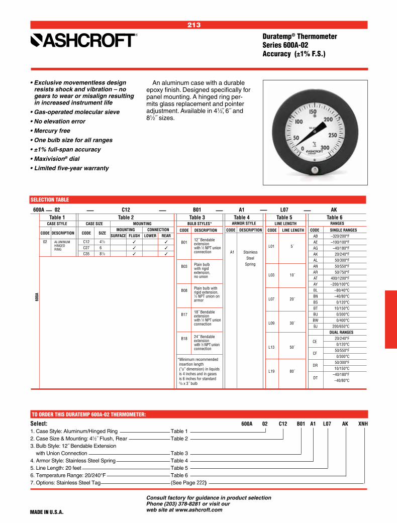
213
Consult factory for guidance in product selection Phone (203) 378-8281 or visit our web site at www.ashcroft.com
An aluminum case with a durable epoxy finish. Designed specifically for panel mounting. A hinged ring per-mits glass replacement and pointer adjustment. Available in 41⁄2, 6˝ and 81⁄2˝ sizes.
• Exclusive movementless design resists shock and vibration – no gears to wear or misalign resulting in increased instrument life
• Gas-operated molecular sieve
• No elevation error
• Mercury free
• One bulb size for all ranges
• ±1% full-span accuracy
• Maxivision® dial
• Limited five-year warranty
MADE IN U.S.A.
Duratemp® Thermometer Series 600A-02Accuracy (±1% F.S.)
SELECTION TABLE
600A 02 C12 B01 A1 L07 AK
Table 1 Table 2 Table 3 Table 4 Table 5 Table 6 CASE STYLE CASE SIZE MOUNTING CODE DESCRIPTION CODE SIZE
MOUNTING CONNECTION SURFACE FLUSH LOWER REAR 02 C12 41/2
C27 61/2
C35 81/2
CE
CF
DT
DR
ARMOR STYLE
CODE DESCRIPTION
A1 Stainless Steel Spring
LINE LENGTH
CODE LINE LENGTH
L01 5´
L03 10´
L07 20´
L09 30´
L13 50´
L19 80´
BULB STYLES*
CODE DESCRIPTION
B01
B03
B08
B17
B18
RANGES
CODE SINGLE RANGES AB –320/200°F AE –100/100°F AG –40/180°F AK 20/240°F AL 50/300°F AN 50/550°F AR 50/750°F AT 400/1200°F AY –200/100°C BL –80/40°C BN –40/80°C BS 0/120°C BT 10/150°C BU 0/300°C BW 0/400°C BJ 200/650°C DUAL RANGES 20/240°F 0/120°C 50/550°F 0/300°C 50/300°F 10/150°C –40/180°F –40/80°C
600A
12˝ Bendableextensionwith 1⁄2 NPT union connection
24˝ Bendableextensionwith 1⁄2 NPT union connection
18˝ Bendableextensionwith 1⁄2 NPT union connection
Plain bulb withrigid extension,1⁄2 NPT union on armor
Plain bulbwith rigidextension,no union
*Minimum recommended insertion length (“u” dimension) in liquids is 4 inches and in gases is 6 inches for standard 3/8 x 3˝ bulb
Select: 600A 02 C12 B01 A1 L07 AK XNH1. Case Style: Aluminum/Hinged Ring Table 1 2. Case Size & Mounting: 41⁄2˝ Flush, Rear Table 2 3. Bulb Style: 12˝ Bendable Extension with Union Connection Table 3 4. Armor Style: Stainless Steel Spring Table 4 5. Line Length: 20 feet Table 5 6. Temperature Range: 20/240°F Table 6 7. Options: Stainless Steel Tag (See Page 222)
TO ORDER THIS DURATEMP 600A-02 THERMOMETER:
ALUMINUMHINGEDRING
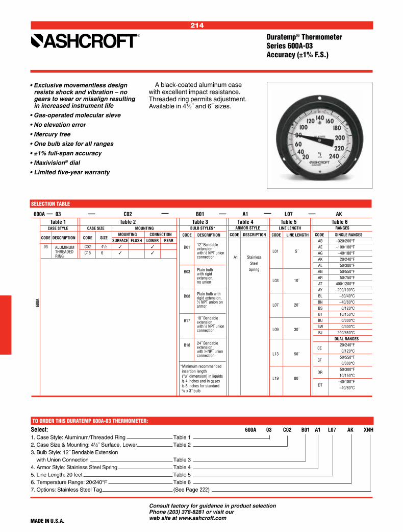
214
Consult factory for guidance in product selection Phone (203) 378-8281 or visit our web site at www.ashcroft.com
Duratemp® Thermometer Series 600A-03Accuracy (±1% F.S.)
A black-coated aluminum case with excellent impact resistance. Threaded ring permits adjustment. Available in 41⁄2˝ and 6˝ sizes.
• Exclusive movementless design resists shock and vibration – no gears to wear or misalign resulting in increased instrument life
• Gas-operated molecular sieve
• No elevation error
• Mercury free
• One bulb size for all ranges
• ±1% full-span accuracy
• Maxivision® dial
• Limited five-year warranty
MADE IN U.S.A.
SELECTION TABLE
600A 03 C02 B01 A1 L07 AK
Table 1 Table 2 Table 3 Table 4 Table 5 Table 6 CASE STYLE CASE SIZE MOUNTING CODE DESCRIPTION CODE SIZE
MOUNTING CONNECTION SURFACE FLUSH LOWER REAR 03 C02 41/2
C15 61/2
CE
CF
DT
DR
ARMOR STYLE
CODE DESCRIPTION
A1 Stainless Steel Spring
LINE LENGTH
CODE LINE LENGTH
L01 5´
L03 10´
L07 20´
L09 30´
L13 50´
L19 80´
BULB STYLES*
CODE DESCRIPTION
B01
B03
B08
B17
B18
RANGES
CODE SINGLE RANGES AB –320/200°F AE –100/100°F AG –40/180°F AK 20/240°F AL 50/300°F AN 50/550°F AR 50/750°F AT 400/1200°F AY –200/100°C BL –80/40°C BN –40/80°C BS 0/120°C BT 10/150°C BU 0/300°C BW 0/400°C BJ 200/650°C DUAL RANGES 20/240°F 0/120°C 50/550°F 0/300°C 50/300°F 10/150°C –40/180°F –40/80°C
600A
12˝ Bendableextensionwith 1⁄2 NPT union connection
24˝ Bendableextensionwith 1⁄2 NPT union connection
18˝ Bendableextensionwith 1⁄2 NPT union connection
Plain bulb withrigid extension,1⁄2 NPT union on armor
Plain bulbwith rigidextension,no union
*Minimum recommended insertion length (“u” dimension) in liquids is 4 inches and in gases is 6 inches for standard 3/8 x 3˝ bulb
Select: 600A 03 C02 B01 A1 L07 AK XNH1. Case Style: Aluminum/Threaded Ring Table 1 2. Case Size & Mounting: 41⁄2˝ Surface, Lower Table 2 3. Bulb Style: 12˝ Bendable Extension with Union Connection Table 3 4. Armor Style: Stainless Steel Spring Table 4 5. Line Length: 20 feet Table 5 6. Temperature Range: 20/240°F Table 6 7. Options: Stainless Steel Tag (See Page 222)
TO ORDER THIS DURATEMP 600A-03 THERMOMETER:
ALUMINUM THREADED RING

215
Consult factory for guidance in product selection Phone (203) 378-8281 or visit our web site at www.ashcroft.com
• Exclusive movementless design resists shock and vibration – no gears to wear or misalign resulting in increased instrument life
• Gas-operated molecular sieve
• No elevation error
• Mercury free
• One bulb size for all ranges
• ±1% full-span accuracy
• Maxivision® dial
• Limited five-year warranty
Duratemp® Thermometer Series 600A-04Accuracy (±1% F.S.)
The phenolic case construction is ideal for most ambient conditions. Flush or surface mounting. Snap ring permits pointer adjustment. Available in 41⁄2˝ and 6˝sizes.
MADE IN U.S.A.
SELECTION TABLE
600A 04 C03 B01 A1 L07 AK
Table 1 Table 2 Table 3 Table 4 Table 5 Table 6 CASE STYLE CASE SIZE MOUNTING CODE DESCRIPTION CODE SIZE
MOUNTING CONNECTION SURFACE FLUSH LOWER REAR 04 C03 41/2
C08 41/2
C38 41/2
C16 61/2
CE
CF
DT
DR
ARMOR STYLE
CODE DESCRIPTION
A1 Stainless Steel Spring
LINE LENGTH
CODE LINE LENGTH
L01 5´
L03 10´
L07 20´
L09 30´
L13 50´
L19 80´
BULB STYLES*
CODE DESCRIPTION
B01
B03
B08
B17
B18
RANGES
CODE SINGLE RANGES AB –320/200°F AE –100/100°F AG –40/180°F AK 20/240°F AL 50/300°F AN 50/550°F AR 50/750°F AT 400/1200°F AY –200/100°C BL –80/40°C BN –40/80°C BS 0/120°C BT 10/150°C BU 0/300°C BW 0/400°C BJ 200/650°C DUAL RANGES 20/240°F 0/120°C 50/550°F 0/300°C 50/300°F 10/150°C –40/180°F –40/80°C
600A
12˝ Bendableextensionwith 1⁄2 NPT union connection
24˝ Bendableextensionwith 1⁄2 NPT union connection
18˝ Bendableextensionwith 1⁄2 NPT union connection
Plain bulb withrigid extension,1⁄2 NPT union on armor
Plain bulbwith rigidextension,no union
*Minimum recommended insertion length (“u” dimension) in liquids is 4 inches and in gases is 6 inches for standard 3/8 x 3˝ bulb
Select: 600A 04 C03 B01 A1 L07 AK XNH1. Case Style: Phenolic Snap Ring Table 1 2. Case Size & Mounting: 41⁄2˝ Surface, Lower Table 2 3. Bulb Style: 12˝ Bendable Extension with Union Connection Table 3 4. Armor Style: Stainless Steel Spring Table 4 5. Line Length: 20 feet Table 5 6. Temperature Range: 20/240°F Table 6 7. Options: Stainless Steel Tag (See Page 222)
TO ORDER THIS DURATEMP 600A-04 THERMOMETER:
PHENOLIC SNAPRING

216
Consult factory for guidance in product selection Phone (203) 378-8281 or visit our web site at www.ashcroft.com
• Exclusive movementless design resists shock and vibration – no gears to wear or misalign resulting in increased instrument life
• Gas-operated molecular sieve
• No elevation error
• Mercury free
• One bulb size for all ranges
• ±1% full-span accuracy
• Maxivision® dial
• Limited five-year warranty
MADE IN U.S.A.
Duratemp® Thermometer Series 600H-45Accuracy (±1% F.S.)
This hermetically sealed case is designed for applications where extreme moisture or dust is present. Available in a 41⁄2˝ solid front phenolic turret case, lower connection.
SELECTION TABLE
Select: 600H 45 C60 B01 A1 L07 AK XNH1. Case Style: Phenolic Hermetically Sealed Table 1 2. Case Size & Mounting: 41⁄2˝ Surface, Lower Table 2 3. Bulb Style: 12˝ Bendable Extension with Union Connection Table 3 4. Armor Style: Stainless Steel Spring Table 4 5. Line Length: 20 feet Table 5 6. Temperature Range: 20/240°F Table 6 7. Options: Stainless Steel Tag (See Page 222)
TO ORDER THIS DURATEMP 600H-45 THERMOMETER:
600H 45 C60 B01 A1 L07 AK
Table 1 Table 2 Table 3 Table 4 Table 5 Table 6 CASE STYLE CASE SIZE MOUNTING CODE DESCRIPTION CODE SIZE
MOUNTING CONNECTION SURFACE FLUSH LOWER REAR 45
C60 41/2 PHENOLIC HERMETICALLY SEALED
CE
CF
DT
DR
ARMOR STYLE
CODE DESCRIPTION
A1 Stainless Steel Spring
LINE LENGTH
CODE LINE LENGTH
L01 5´
L03 10´
L07 20´
L09 30´
L13 50´
L19 80´´
BULB STYLES*
CODE DESCRIPTION
B01
B03
B08
B17
B18
RANGES
CODE SINGLE RANGES AB –320/200°F AE –100/100°F AG –40/180°F AK 20/240°F AL 50/300°F AN 50/550°F AR 50/750°F AT 400/1200°F AY –200/100°C BL –80/40°C BN –40/80°C BS 0/120°C BT 10/150°C BU 0/300°C BW 0/400°C BJ 200/650°C DUAL RANGES 20/240°F 0/120°C 50/550°F 0/300°C 50/300°F 10/150°C –40/180°F –40/80°C
600H
12˝ Bendableextensionwith 1⁄2 NPT union connection
24˝ Bendableextensionwith 1⁄2 NPT union connection
18˝ Bendableextensionwith 1⁄2 NPT union connection
Plain bulb withrigid extension,1⁄2 NPT union on armor
Plain bulbwith rigidextension,no union
*Minimum recommended insertion length (“u” dimension) in liquids is 4 inches and in gases is 6 inches for standard 3/8 x 3˝ bulb

217
Consult factory for guidance in product selection Phone (203) 378-8281 or visit our web site at www.ashcroft.com
SELECT 600B 01 AB XNH
1. Stem Length: Length: 6˝ Table 12. Temperature Range: –320/200°F Table 2 3. Options: Stainless Steel Tag (See Page 222)
MADE IN U.S.A.
TO ORDER THIS 600B DURATEMP THERMOMETER:
Duratemp® Thermometer Direct-Mounted Series 600BAccuracy (1% F.S.)
The Everyangle™ Duratemp® ther-mometer may be rotated 360° for readability and the stem turned 180° for the most challeng-ing installations.
• Exclusive movementless design resists shock and vibration – no gears to wear out – or misalign resulting in increased instrument life
• Gas-operated molecular sieve
• Mercury free
• 1% full-span accuracy
• Everyangle Duratemp® thermome-ter can be rotated 360° and can be angled 180°, ensuring readability in any installation
• Maxivision® dial
• Limited five-year warranty
The direct-reading thermometer (stainless steel case only) offers the same unique features of the Ashcroft® Duratemp® remote-reading thermome-ter for those critical applications where only a direct-connected instrument can be used. Available in 41⁄2˝ dial size.
SELECTION TABLE
600B — 01 — AB
Type
600B
DIRE CT - M O U N T E D
* For these ranges a minimum “S” dimension (stem length) of 9 inches is required. This removes case from exposure to high temperature which may damage the instrument.
CODE DUAL RANGES
CE
20/240°F 0/120°C
CF
50/550°F 0/300°C
DR
50/300°F 10/150°C
DT
–40/180°F –40/80°C
Table 2
CODE SINGLE RANGES AB –320/200°F AE –100/100°F AG –40/180°F AK 20/240°F AL 50/300°F AN 50/550°F AR 50/750°F* AT 400/1200°F* AY –200/100°C BL –80/40°C BN –40/80°C BS 0/120°C BT 10/150°C BU 0/300°C BW 0/400°C* BJ 200/650°C*
Table 1
CODE STEM LENGTH 01 Semirigid Stainless Steel 6˝
02 Semirigid Stainless Steel 9˝
03 Semirigid Stainless Steel 12˝
04 Semirigid Stainless Steel 15˝
05 Semirigid Stainless Steel 18˝
06 Semirigid Stainless Steel 24˝
07 Semirigid Stainless Steel 30˝
08 Semirigid Stainless Steel 36˝
NOTE: Thermowells must be used whenever an Ashcroft Duratemp® thermometer is installed on a pressurized application or where fluid velocity or corrosive media is present.

218
Consult factory for guidance in product selection Phone (203) 378-8281 or visit our web site at www.ashcroft.com
Style B01, B17 and B18Bendable Extension, Union Connection
600B Everyangle
Style B03Plain
Style B08Long Extension, Locking Fitting
Bulb Bulb Code Size “B” “A” “S” Max. “S” Min.
B01 3 12 15 4 (76) (305) (381) (102)
B17 3 18 21 4 (76) (457) (533) (102)
B18 3 24 27 4 (76) (610) (686) (102)
FOR TEMPERATURES BELOW 750°F
U-Dimension S (Insertion Length)
6 41⁄2 (152) (114)
9 71⁄2 (229) (191)
12 101⁄2 (305) (268)
FOR TEMPERATURES 750°F AND ABOVE USE WELL WITH 3˝ LAG
U-Dimension S Well Lag (Insertion Length)
9 41⁄2 (229) 3 (114)
12 71⁄2 (305) 3 (191)
15 101⁄2 (381) 3 (268)
Dial Size A B C D E F G H Inches
41⁄2
423⁄32 21⁄16 51⁄32 311⁄64 413⁄16 3 1 3⁄8 (120) (52) (128) (81) (122) (76) (25) (10)
NOTE: Dimensions in inches, ( ) are miliimeters.
Bulb and Armor Dimensions
7/16 Hex (11)Adjustable Union Connector5/8 Wrench Flats (16)1/2 NPT15/16 (24) Clearance Hole
3/16 (4,7) Dia.
Bendable ExtensionA
B
S
3/8 (10) Dia.
Sensitive Portion
13-1/4˝(336)
3˝(66)SensitivePortion
3/8˝ Dia.(10)
S
13/16 Hex (21)
7/8 Hex (22)
1/2˝ NPT1-1/16˝ (27)Dia.ClearanceHole
Min. 7-1/4˝(184)
Max. LineLength
7-1/4˝(184)
3˝(76)
SensitivePortion
3/8˝ Dia.(10)
AdjustableUnionConnectionon Armor
B
D
CCCA
E
F
G
S
H
7/8˝ Hex(22)
1/2 NPT

219
Consult factory for guidance in product selection Phone (203) 378-8281 or visit our web site at www.ashcroft.com
Dial Size A B C D E F J M S U AA CC DD FF EE HH JJ Inches
41⁄2
423⁄32 23⁄16 51⁄8 11⁄16 7⁄32 15⁄8 1⁄16 425⁄32 7⁄16 17⁄16 25⁄8 #10-32
1 21⁄4 15⁄8 3 31⁄2 (120) (56) (130) (27) (6) (141) (2) (121) (11) (37) (67) (25) (57) (41) (76) (89)
Case Size A B C E F K M S U CC LL Inches
41⁄2
4.75 23⁄16 6.03 53⁄8 15⁄8 11⁄16 47⁄8 5⁄8 3⁄4 10-24
1⁄8 1⁄2 (120.7) (56) (153) (137) (41) (27) (124) (16) (19) (3) (13)
6
4.87 21⁄4 7.50 7 21⁄8 11⁄16 61⁄2 5⁄8 3⁄4 1⁄4-20 1⁄8 1⁄2
(123.7) (57) (190.5) (178) (54) (27) (165) (16) (19) (3) (13)
81⁄2
4.75 21⁄4 9.96 95⁄8 21⁄8 11⁄16 9 5⁄8 3⁄4 1⁄4-20 1⁄8 1⁄2
(120.7) (57) (253) (244) (54) (27) (229) (16) (19) (3) (13)
600A-01 Stainless Steel Case
600A-02 Hinged Ring Case
NOTE: Dimensions in inches, ( ) are miliimeters.
Case Dimensions
HH2-E Dia.Holes D
J
B
JJ
C
AA
A
V
SURFACE MOUNTING
C
FF
F
HH
MDia. holein panel
S
U
FLUSH PANEL MOUNTING
A
CCEE
DD
NOTE: Dimensions in inches, ( ) are miliimeters.
C
3 Mounting studs CC threadedequally spaced on E dia. B.C.
PD
B
A
S
B
FMHole in panel
Nuts & washersnot supplied by Ashcroft
KLL
B
3 Mounting studs CC threadedequally spaced on E dia. B.C.
Nuts & washersnot supplied byAshcroft
S
F
MDia. holein panel
LL
U
FLUSH PANEL MOUNTING
C
B
3 Mounting studs CC threadedequally spaced on E dia. B.C.
Nuts & washersnot supplied byAshcroft
S
F
MDia. holein panel
LLK
A
U
FLUSH PANEL MOUNTING
C
FLUSH PANEL MOUNTING
41⁄2˝ and 6˝ Back Connection 81⁄2˝ Back Connection

220
Consult factory for guidance in product selection Phone (203) 378-8281 or visit our web site at www.ashcroft.com
600A-04, 600H-45 Phenolic Case
Case Size A B C D E F J L V Inches
41⁄2
513⁄16 23⁄8 51⁄32 17⁄32 53⁄8 15⁄8 5⁄8 7⁄32 23⁄8 (148) (57) (126) (24) (137) (41) (10) (5,5) (60)
6 75⁄8 21⁄4 61⁄2 15⁄16 7 21⁄8 7⁄16 9⁄32 31⁄8
(194) (57) (165) (24) (178) (54) (11) (7) (79)
NOTE: Dimensions in inches, ( ) are miliimeters.
600A-03 Aluminum-Threaded Ring Case
Case Dimensions
C
D
BJ
F
A
V
3-L dia. holeson E dia. B.C.
A
D
3-L dia. holeson E dia. B.C.
F
B
C
J
V
MHole inpanel
SLL
CC
Mounting hardwaresupplied by Ashcroft
AA
SURFACE MOUNTING FLUSH MOUNTING
Case Model Size A B C D E F J L S V AA M LL PP Inches
41⁄2
513⁄16 25⁄16 51⁄16 1 53⁄8 15⁄8 9⁄16 7⁄32 3⁄16 25⁄8 6 537⁄64 1⁄16 -1⁄2 #10-24 x 7⁄8 600A-04
(148) (59) (129) (25) (137) (41) (14) (5,5) (5) (67) (154) (148) (2)-(13)
6 75⁄8 23⁄8 65⁄8 11⁄16 7 21⁄8 5⁄8 9⁄32 3⁄16 31⁄2 73⁄4 717⁄64 1⁄16 -1⁄2 #1⁄4-20 x 7⁄8
(194) (60) (168) (27) (178) (54) (16) (7) (5) (89) (197) (185) (2)-(13)
600H-45
41⁄2
513⁄16 33⁄8 51⁄16 15⁄8 53⁄8 1 7⁄32 3⁄16 25⁄8 6 537⁄64 1⁄16 -1⁄2 #10-24 x 7⁄8 (148) (86) (129) (41) (137)
— (25) (5,5) (5) (67) (154) (148) (2)-(13)
APPROXIMATE WEIGHT (LBS.)FOR ALL REMOTE READINGDURATEMP THERMOMETERS
Line Case Size
Length 41⁄2˝ 6˝ 81⁄2˝ 5´ 1.75 2.55 3.40 10´ 2.05 2.85 3.70 20´ 2.65 3.45 4.30 30´ 3.25 4.05 4.90 50´ 4.45 5.25 6.10 80´ 6.25 7.05 7.90
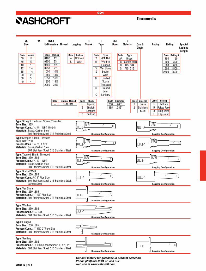
221
Consult factory for guidance in product selection Phone (203) 378-8281 or visit our web site at www.ashcroft.com
Code Material 1 Brass 2 Stainless Steel
Code Diameter 260 .260˝ 385 .385˝
75 W 0750 H T 260 C Size U-Dimesion Thread Lagging Shank Type Bore Material Cap & Facing Rating Special Chain Lagging Length
Code Inches – Without L With
Code Inches 0162 15⁄8 0250 21⁄2 0450 41⁄2 0750 71⁄2 1050 101⁄2 1350 131⁄2 1650 161⁄2 1950 191⁄2 2250 221⁄2
Code Facing F Flat Face R Raised Face J Ring Joint L Lap Joint
Code Type T NPT Thd. W Weld-in F Flanged V Van Stone S Socket Weld M Limited Space Threaded G Ground Joint C Sanitary
Code Type AA Brass B Carbon Steel C AISI 304 S AISI 316
Thermowells
Code Internal Thread – 1⁄2 NPSM
Code Shank H Tapered S Straight R Stepped B Built-up
Code Rating # 150 150 300 300 600 600 1500 1500 2500 2500
Type: Straight (Uniform) Shank, ThreadedBore Size: .385Process Conn.: 1⁄2, 3⁄4, 1 NPT, Wed-In Materials: Brass, Carbon Steel
304 Stainless Steel, 316 Stainless SteelType: Stepped Shank, ThreadedBore Size: .260Process Conn.: 1⁄2, 3⁄4, 1 NPTMaterials: Brass, Carbon Steel
304 Stainless Steel, 316 Stainless Steel
Type: Socket WeldBore Size: .260, .385Process Conn.: 3⁄4, 1˝ Pipe SizeMaterials: 304 Stainless Steel, 316 Stainless Steel,
Carbon Steel
Type: Tapered Shank, ThreadedBore Size: .260, .385Process Conn.: 1⁄2, 3⁄4, 1 NPTMaterials: Brass, Carbon Steel
304 Stainless Steel, 316 Stainless Steel
Type: Van StoneBore Size: .260, .385Process Conn.: 1, 11⁄2˝ Pipe SizeMaterials: 304 Stainless Steel, 316 Stainless Steel
Type: Weld-inBore Size: .260, .385Process Conn.: 11⁄2˝ Dia.Materials: 304 Stainless Steel, 316 Stainless Steel
Type: FlangedBore Size: 260, .385Process Conn.: 1, 11⁄2, 2˝ Pipe SizeMaterials: 304 Stainless Steel, 316 Stainless Steel
Lagging ConfigurationStandard Configuration
Lagging ConfigurationStandard Configuration
Lagging ConfigurationStandard Configuration
Lagging ConfigurationStandard Configuration
Standard Configuration
Standard Configuration
Standard Configuration
Standard Configuration Lagging Configuration
MADE IN U.S.A.
Type: SanitaryBore Size: .260, .385Process Conn.: Tri-Clamp connection® 1, 11⁄2, 2˝ Materials: 304 Stainless Steel, 316 Stainless Steel
Code Inches 50 1⁄2 75 3⁄4 10 1 12 11⁄4 15 11⁄2 20 2 30 3 40 4

222
Consult factory for guidance in product selection Phone (203) 378-8281 or visit our web site at www.ashcroft.com
DURATEMP AND BIMETAL OPTIONS Code Description Bimetal Duratemp
XCS1 Dual scale
XDM Dial marking
XED2 High and low electric contacts
XEE2 Double high-electric contacts
XEF2 Double low-electric contacts
XEG2 Electric contacts off at low or high and on in-between
XEO Externally adjustable red set hand
XEP Externally adjustable maximum pointer
XEQ Externally adjustable minimum pointer
XNG Nonglare
XNN Paper tag
XNH Stainless steel tag
XPD3 Plastic window
XSG3 Shatterproof glass
XSH Stationary red set hand
XTK Tank car thermometer
X3B4 3⁄8˝ stem diameter with 1⁄2 NPT
X025 1⁄4 NPT when 1⁄2 NPT is standard
Bimetal Thermometer and Duratemp® Thermometer Options
1. 3˝ and 5˝ case only. 2. 41/2˝ and 6˝ – 600A02, 600A03 and 600A04 styles only. 3. Not available on EL liquid filled thermometers. Polycarbonate is the standard window on EL series. 4. Not available on 2˝ case. 5. Only available on rear connect.

223
Consult factory for guidance in product selection Phone (203) 378-8281 or visit our web site at www.ashcroft.com
Code Desc. Code Desc. Code Desc. Code Desc. Range Code Code Desc.
2400 Panel mount E LED A 110 Vac 080 8 feet –40/199°F XJ7(2) 21⁄2˝ mounting plate B 220 Vac XXX Special 0/250°F 2410 2˝ Panel mount C 24 Vac Length(4) –40/120°C XJ8(2) 2˝ mounting plate w/u clamp
• Watertight ultrasonic-sealed case
• Solid state design
• LED display with 1⁄2˝ high numerals
• Reverse-polarity protection
• Detachable sensors
• Retrofits 2˝ and 21⁄2˝ vapor thermometers
• Accessible zero and span adjustment
• NSF approval
• UL-recognized power supply
• Accuracy ±2°F per NSF C-2
SELECTION TABLE 2400 E A 080 –40/199°F XJ8
Table 1 Table 2 Table 3 Table 4 Table 5 Table 6 Model Display Power Supply(1) Line Length(3) Options
(1) If power supply is not required change model number 2400 to 2401 or 2410 to 2411.(2) Not available on 2410 case.(3) Stainless steel probe dimension, 0.250˝ dia. x 2.54˝ long.(4) Maximum line length is 30 feet.
TO ORDER THIS TYPE 2400E/2410E DIGITAL THERMOMETER:
Select: 2400 E A 080 –40/199°F XJ81. Type: Display w/power pack Table 1 2. Display: LED Table 2 3. Power: 110 Vac Table 34. Line Length: 8´ Table 4 5. Temperature Range: –40/199°F Table 5 6. Option: 2˝ Mounting Plate Table 6
The Ashcroft® 2400E and 2410E digital thermometers are compact, solid state temperature measure-ment and display devices. The 2400E measures temperature with a laser-trimmed 2000 ohm RTD contained in a stainless steel probe. The signal from the RTD is conditioned and sent through an analog-to-digital con-verter and is shown on a LED display. The unit is powered by 6 Vdc, which is delivered through a power supply that operates on 110 Vac (220 Vac and 24 Vac are optional). When more than one indicator is required, two thermometers can be operated by one 110 Vac supply. The power supply is UL recognized and the complete unit is NSF approved for class C-2 applications.
Digital Thermometer Type 2400E and 2410EAccuracy (±2° NSF per C-2)
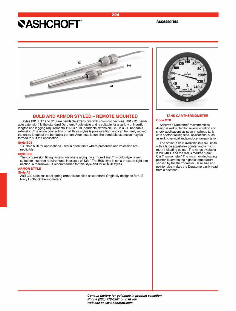
224
Consult factory for guidance in product selection Phone (203) 378-8281 or visit our web site at www.ashcroft.com
BULB AND ARMOR STYLED – REMOTE MOUNTEDStyles B01, B17 and B18 are bendable extensions with union connections. B01 (12˝ bend-
able extension) is the standard Duratemp® bulb style and is suitable for a variety of insertion lengths and lagging requirements. B17 is a 18˝ bendable extension, B18 is a 24˝ bendable extension. The union connection on all three styles is pressure tight and can be freely moved the entire length of the bendable portion. After installation, the bendable extension may be formed to suit the application.S tyle B03
13˝ plain bulb for applications used in open tanks where pressures and velocities are negligible.
S tyle B08 The compression fitting fastens anywhere along the armored line. This bulb style is well suited for insertion requirements in excess of 131⁄2˝. The B08 style is not a pressure tight con-nection. A thermowell is recommended for this style and for all bulb styles.
ARMOR STYLES tyle A1
AISI 302 stainless steel spring armor is supplied as standard. Originally designed for U.S. Navy Hi Shock thermometers.
TANK CAR THERMOMETERCode XTK
Ashcroft’s Duratemp® movementless design is well suited for severe vibration and shock applications as seen in railroad tank cars or other rolling stock apllications, such as milk, chemical and produce transportation.
The option XTK is available in a 81⁄2˝ case with a large adjustable pointer and a maxi-mum indicating pointer. The range available is 20/240°F and the dial is marked “Tank Car Thermometer.” The maximum indicating pointer illustrates the highest temperature sensed by the thermometer. Case size and pointer size makes the Duratemp easily read from a distance.
Accessories
B03B08
A1

225
Consult factory for guidance in product selectionPhone (203) 378-8281 or visit our web site at www.ashcroft.com
Switch Selection Information ............ 227-228 Additional Application Information ... 229-230
PRESSURE, DIFFERENTIAL PRESSURE & TEmPERATURE SWITcHES
(Watertight construction for industrial applications. Explosion-proof construction for hazardous locations)
A-Series, Miniature Pressure, Brass Body . 231 A-Series, Miniature Pressure, Stainless Body ........................................ 232B400 B-Series, Pressure & Differential Pressure, Watertight .......... 233B400 B-Series, Temperature, Watertight .... 234B700 B-Series, Pressure & Differential Pressure, Explosion-Proof ....................... 235B700 B-Series, Temperature, Explosion- Proof Enclosure ....................................... 236F-Series, Pressure, Compact Explosion-Proof ........................ 237G-Series, Pressure & Differential Pressure, Watertight Stainless Steel ....... 238G-Series, Temperature, Watertight Stainless Steel ....................... 239H-Series, Pressure, Watertight ................... 240L-Series, Pressure & Differential Pressure, Watertight ................................ 241L-Series, Temperature, Watertight ............. 242N-Series, Pressure, Electronic ................... 243N-Series, Pressure, Electronic with Indication ......................................... 244P-Series, Pressure & Differential Pressure, Explosion-Proof or Watertight . 245P-Series, Temperature, Explosion-Proof or Watertight ................. 246Deadbands and Ranges, B-Series ............ 247Deadbands and Ranges, P-Series ............. 248Deadbands and Ranges, L- and G-Series ..... 249Options .............................................. 250-251
PRESSURE AND TEMPERATURESWITCHES

226
Consult factory for guidance in product selectionPhone (203) 378-8281 or visit our web site at www.ashcroft.com
227
Consult factory for guidance in product selectionPhone (203) 378-8281 or visit our web site at www.ashcroft.com
Product Selection Information
PRESSURE, TEMPERATURE AND DIFFERENTIAL PRESSURE SWITCH SELECTION
Before making your selection, consider the following:
1. Actuator The actuator responds to changes in pressure, temperature or differential pressure and operates the switch element in response to these changes.
The actuator is normally exposed to process fluid and must therefore be chemically compatible with it. The following may be used to help select actuator type:
For nominal pressure ranges 0-15 psi through 0-3000 psi, the standard actuator is a diaphragm-sealed piston. In this actuator, process pressure acting on the piston area causes it to overcome the adjustment spring force and actuate a snap-action switch. A diaphragm and O-ring seal the process media from this mechanism. These are available in various materials, i.e.: Buna N, Teflon and Viton. The standard process connection is stainless steel. Optional monel pressure connec-tion is available.
For H2O Pressure and Differential Pressure Ranges, a diaphragm actuator is used. In this design, the standard pressure connections are carbon steel. Diaphragms are available in Viton, Buna N and Teflon. Always review process tem-perature limits before making seal selections.
Optional stainless steel pressure connections are available (option XTA).
For High Differential Pressure Actuator Ranges, 3-15 to 60-600 psid, a Dual Diaphragm-Sealed Piston Actuator is used. This actuator is designed to for high static-pressure applications. The stan-dard pressure connections are nickel-plated brass. Diaphragms are available in Viton, Buna N and Teflon. Always review process temperature limits before making seal selections. Optional stainless steel pressure connections are available (option XUD).
For all temperature ranges the standard Ashcroft® temperature actuator operates on the vapor pressure principle: the vapor pressure in a sealed thermal system is applied to a sensing element, which in turn actuates a switch. This is known as a SAMA Class II system. Various filling materials are used, including Propane, Butane, Methyl Alcohol, N Propyl Alcohol and Xylene. High overtem perature capability is possible with this type of system. The interface between liquid and vapor is the point at which sensing occurs. This is the “sensitive” portion of the bulb. Bulb extensions and capillary are normally filled with vapor, and have little effect on the setpoint, regardless of ambient temperature variations; therefore, no ambient compensation is required. For best results, the bulb should be mounted within 60 degrees of vertical to assure the liquid remains in the bulb.
2. Enclosure The enclosure protects the switch element and mechanism from the environment and has provi-sions for mounting and wiring. All Ashcroft switch enclosures are epoxy-coated aluminum or stainless steel for maximum corrosion resistance. Choose between watertight NEMA 4, 4X for most industrial applications and explosion-proof NEMA 7/9 for most process applications.
Ashcroft enclosures include watertight cover gas-kets, external mounting holes and one or two 3/4 NPT electrical conduit holes for ease of installa-tion. Pressure switches may also be mounted directly to the process by means of the standard 1/4 NPTF or optional 1/2 NPT pressure connection.
Note: When installing Ashcroft switches, refer to instruction sheets included with each switch, the National Electrical Code, and any other local codes or requirements to assure safety.
3. The Switching Function Next, consider the switching function. Most appli-cations for alarm and shutdown are satisfied by single setpoint, fixed deadband models. For high/low or alarm and shutdown, the dual setpoint models may be selected. For pump, compressor, level and other control applications, an adjustable deadband model is often the best choice.
4. The Switch Element Finally, the electrical switching element must be compatible with the electrical load being switched. For ease of selection, all electrical
228
Consult factory for guidance in product selectionPhone (203) 378-8281 or visit our web site at www.ashcroft.com
switching elements are snap acting, SPDT (single pole-double throw), or 2 (SPDT). Select a switch element with electrical rating that exceeds the electrical rating of the device being controlled by the switch. For better reliability and safety, optional Hermetically Sealed switching elements may be specified.
ADDITIONAL SWITCH TERMINOLOGY
Accuracy – (See repeatability) Accuracy normally refers to conformity of an indicated value to an accepted standard value. There is no indication in switch products; thus, instead, the term repeat-ability is used as the key performance measure. Ashcroft switch accuracy is 1% of nominal range.
Automatic Reset Switch – Switch which returns to normal state when actuating variable (Pres-sure or Temperature) is reduced.
Adjustable or Operating Range – That part of the nominal range over which the switch setpoint may be adjusted. Normally about 15% to 100% of the nominal range for pressure and differential pressure switches and the full span for tempera-ture switches.
Burst Pressure – The maximum pressure that may be applied to a pressure switch without causing leakage or rupture. This is normally at least 400% of nominal range for Ashcroft switches. Switches subjected to pressures above the nominal range can be permanently damaged.
Deadband – The difference between the setpoint and the reset point, normally expressed in units of the actuating variable. Sometimes referred to as differential.
Division 1 – A National Electrical Code Classifica-tion of hazardous locations. In Division 1 loca-tions, hazardous concentrations of flammable gases or vapors exist continuously, intermittently or periodically under normal conditions; fre-quently because of repair or maintenance operation/leakage or due to breakdown or faulty operation of equipment or processes which might also cause simultaneous failure of electri-cal equipment. Explosion-proof NEMA 7/9 enclo-sures are required in Division 1 locations.
Division 2 – A National Electrical Code Classifica-tion of Hazardous locations. In Division 2 hazard-ous locations, flammable or volatile liquid or flammable gases are handled, processed or used, but will normally be confined within closed containers or closed systems from which they can escape only in case of accidental rupture or breakdown or in case of abnormal operation of equipment. Either Nema 7/9 explosion-proof enclosures or any enclosure with hermetically sealed switch contacts may be used in Division 2 locations.
Explosion Proof – A term commonly used in industry referring to enclosures capable of with-standing an internal explosion of a specified gas without igniting surrounding gases. Strict instal-lation practices in accordance with the national electrical code are also required for safety.Fixed Deadband – The difference between the setpoint and the reset point of a pressure or tem-perature switch. It further signifies that this dead-band is a fixed function of the pressure switch and not adjustable.Hermetically Sealed Switch – A switch element whose contacts are completely sealed from the environment to provide additional safety and reli-ability. Contact arc cannot cause an explosion and atmospheric corrosive elements cannot affect the contacts.Manual Reset Switch – Pressure or Tempera-ture switch in which contacts remain actuated even after the actuating variable returns to normal. On Ashcroft manual reset switches, a button must be pushed to reset the contacts.National Electrical Manufacturers Association (NEMA) – This group has defined several catego-ries of enclosures, usually referred to as “types.” Further, they designate certain features and capa-bilities each type must include. For example, among other features, a NEMA 4 enclosure must include a threaded conduit connector, external mounting provision and cover gaskets. When selecting a NEMA 4 enclosure from any manu-facturer, a buyer is assured of receiving these features.NEMA 4 – Watertight and dusttight enclosures intended for use indoors or outdoors to pro-tect the equipment against splashing, falling or hose-directed water, external condensation and water seepage. They are also sleet- resistant.NEMA 4X – Watertight, dusttight and corrosion-resistant enclosures with same qualifications as NEMA 4, but with added corrosion resistance.NEMA 7 – Enclosures for indoor Class I, Division 1 hazardous locations with gas or vapor atmospheres.NEMA 9 – Enclosures for indoor Class II, Division 1 hazardous locations with combustible dust atmospheres.Normal Switch Position – Contact position before actuating pressure (or variable) is applied. Normally closed contacts open when the switch is actuated. Normally open contacts close when the switch is actuated. Normally Closed – Refers to switch contacts that are closed in the normal switch state or posi-tion (unactuated). A pressure change opens the contacts.Normally Open Switch – Refers to the contacts that are open in the normal switch state or posi-tion (unactuated). A pressure change closes the contacts.
Overpressure Rating(s) – A nonspecific term that could refer to either burst or proof pressure, or both.
Proof Pressure – The maximum pressure which may be applied without causing damage. This is determined under strict laboratory conditions including controlled rate of change and tem-perature: This value is for reference only. Consult factory for applications where switch must oper-ate at pressures above nominal range or refer-ence temperature (70°F).
Repeatability (Accuracy) – The closeness of agreement among a number of consecutive mea-surements of the output setpoint for the same value of the input under the same operating con-ditions, approaching from the same direction, for full-range traverses. Ashcroft switch repeatabil-ity is 1% of nominal range.
Note: It is usually measured as nonrepeatabil-ity and expressed as repeatability in percent of span or nominal range. It does not include hysteresis or deadband.
Reset Point – The reset point is the Pressure, Temperature or Differential Pressure Value where the electrical switch contacts will return to their original or normal position after the switch has activated.
Setpoint – The setpoint is the Pressure, Tem-perature or Differential Pressure value at which the electrical circuit of a switch will change state or actuate. It should be specified either on increase or decrease of that variable. (See also reset point.)
Single-Pole Double Throw (SPDT) Switching Element – A SPDT switching element has one normally open, one normally closed, and one common terminal. The switch can be wired with the circuit either normally open (N/O) or normally closed (N/C). SPDT is standard with most Ashcroft pressure and temperature switches.
Snap Action – In switch terminology, snap action generally refers to the action of contacts in the switch element. These contacts open and close quickly and snap closed with sufficient pressure to firmly establish an electrical circuit. The term distinguishes products from mercury bottle types that were subject to vibration problems.
Static Pressure – For differential pressure switches, static pressure refers to the lower of the two pressures applied to the actuator.
Product Selection Information

229
Consult factory for guidance in product selectionPhone (203) 378-8281 or visit our web site at www.ashcroft.com
DIFFICULT PROCESS MEDIA
When specifying pressure or temperature switches, the material in contact with media must be compatible with it. Otherwise, fail-ure could occur, resulting in leakage, injury, loss of life, property or production. The user should review prior experience with materials of construction in the process for guidance in material selection. If this is not appropri-ate, contact Customer Service for assistance. Relevant information such as process media, concentration of each constituent, tempera-ture, pressure, the presence of contaminants, particulate, vibration or pulsation is necessary to make the best recommendation.
Some applications are best handled by adding an Ashcroft diaphragm seal to isolate the fluid media from the pressure or differential pres-sure switch.
Diaphragm seals are recommended where:
• The process media being sensed could clog the pressure element.
• The process media temperature is above or below the ratings of the actuator seal materials.
• The application calls a for sanitary process connection.
Note: The addition of a diaphragm seal may increase the deadband and response time of the pressure switch to process pressure changes. Please consult Customer Service for details.
OXIDIZING MEDIA
When specifying a pressure switch for use in oxidizing media, such as chlorine, oxygen and several other chemical compounds, the wetted materials must be compatible with the media, and the switch should be cleaned for oxygen service. This is necessary to remove any residue that might react violently with the oxidizing media. Specify option X6B (clean for oxygen service).
STEAM SERVICE
In order to prevent live steam from coming into contact with the switch actuator, a siphon filled with water should be installed between the switch and the process line. We recom-mend the optional stainless steel welded pro-cess connection and diaphragm even though viton is rated for use with steam. Experience has shown that in many steam applications, the 300°F high temperature limit of viton is exceeded by steam under pressure.
In some boiler applications, a special U.L. list-ing, “MBPR,” which requires unique features is needed. Ashcroft offers these features with option XG8.
NACE
NACE is the acronym for the National Associa-tions of Corrosion Engineers. Their standard MRO175-93 titled “Sulfide Stress Cracking Resistant Metallic Materials for Oilfield Equip-ment,” is cited when ordering instruments for oilfield applications involving sour oil or gas with traces of hydrogen sulfide. It is a legal requirement in many states. NACE instruments are also suitable for use in sewage treatment plants and other applications with traces of hydrogen sulfide in the process.
For high concentrations of hydrogen sulfide in a diaphragm seal should be used; a Tanta-lum diaphragm and Hastelloy C (C276) lower housing are recommended. For over 3% or 30,000ppm, a seal is essential.
HIGH TEMPERATURE PROCESS
Refer to the actuator seal table for process temperature limits for pressure switch actua-tors. Pressure switches mounted directly to the process can withstand up to 300°F when equipped with optional viton, stainless steel or monel wetted parts. If process temperature exceeds 300°F, four feet of 1/2˝ tubing between the process and the switch will generally pro-tect the switch from damage.
Alternatively, an Ashcroft diaphragm seal, can be used to isolate the switch from the hot process.
VIBRATION
Generally, vibration will not harm Ashcroft pressure switches. However, premature trip-ping may occur under severe conditions. This tends to be annoying, but repeatable for a given situation and might be in the order of 5% to 10% of switch range from the setpoint, i.e. a 100 psi switch set at 50 psi on increasing pressure might trip somewhere between 40 and 45 psi on increasing pressure. This would not reduce the life of the pressure switch.The best approach in this type of application is to mount the switch remotely, connecting the switch to the process or equipment with flex-ible tubing. If this is not possible, consider the use of the Belleville actuator, option XG3.
PULSATION
Pressure pulsation below the range of the pressure switch will not harm it. However,
because the switch can react to pressure pulses less than one second duration, it might be desirable to include a dampening device. Several Ashcroft accessories, such as snub-bers address this situation. Consult Customer Service for more information.
MOUNTING
All Ashcroft pressure, temperature and differential pressure switches with snap acting contacts may be mounted in any position. This includes the sensing bulbs of temperature switches. This is an important advantage of snap acting switch designs.
SWITCH ELEMENT SELECTION
B-Series switches are available with a wide variety of snap acting switch elements to meet most electrical requirements. The standard contact arrangement is single pole, double throw (SPDT). This includes both normally open and normally closed contacts. Standard contact material is fine silver which generally is suitable for switching 8 volts or more, up to the rating in the Switch Element Selection Table. When switching less than 8 volts, optional Gold Alloy contacts are recommended.
Optional Dual, or 2 SPDT contacts may be sup-plied in B-Series enclosures for applications requiring two switch functions at the same setpoint. These contacts are technically not double pole, double throw (DPDT). They are synchronized at the factory to actuate within 1% of nominal range of each other. For simul-taneous actuation of 2 SPDT contacts, option XG3 should be ordered.
Additional Pressure and Temperature Switch Application Information
230
Consult factory for guidance in product selectionPhone (203) 378-8281 or visit our web site at www.ashcroft.com
Additional Pressure and Temperature Switch Application Information
INFORMATION & GUIDELINES FOR SETTING ASHCROFT PRESSURE, TEMPERATURE AND DIFFERENTIAL PRESSURE SWITCHES
All Ashcroft pressure, temperature and dif-ferential pressure switches can be set at any point between about 15% and 100% of the range as designated on the label or the nomi-nal range table.
Ashcroft pressure and temperature switches can be either set in the field or ordered from the factory preset to your requirements. When set at the factory, the specification is ±1% of the nominal range.
Factory setting, or XFS, is a very popular option, and as a result, we often get orders that do not have enough information or have incorrect information.
HOW TO ORDER
When “XFS” is desired:
1. Setpoint must be indicated.
2. Increasing or decreasing pressure must be indicated.
Ex: B424B XFS 100# Set: 60# decreasing
3. For differential pressure switches, static operating pressure must be given also.
Ashcroft is the leader in providing pressure and temperature switches for alarm, shutdown and control in hazardous locations.
Models are available with single or dual set-points, fixed or adjustable deadbands.
Choose from standard, miniature or compact enclosures, construction of epoxy coated alu-minum or stainless steel.
HAZARDOUS LOCATIONS a. Division I.
Ashcroft 700 series or other explosion proof enclosures are required to meet the requirements of Division I Hazard-ous Locations as defined by the National Electrical Code.
b. Division II. These enclosures also meet the less strin-gent requirements for Division II Hazard-ous Locations. Alternatively, Ashcroft 400 series or other watertight enclosures, with hermetically sealed switch elements are approved for use in Division II hazardous locations.
c. Intrinsic Safety. Any Ashcroft pressure or temperature switch may be used with an approved barrier in most intrinsically safe systems. These switches do not create or store energy and are therefore designated “simple devices’’ in these systems. Exception: Ashcroft N series electronic pressure switches require power and may not be suitable for use in all intrinsically safe systems.
c. ATEX. ATEX is a European designation that deals with standards for equipment and protective systems intended for use in potentially explosive atmospheres. This approval is required for switches intended for use in hazardous locations, especially important to OEMs who export to Europe and contractors specifying or purchasing products for European applications.
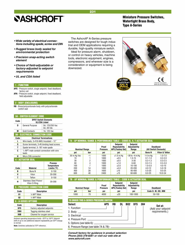
231
Consult factory for guidance in product selectionPhone (203) 378-8281 or visit our web site at www.ashcroft.com
Select: APS RB DL BO2 XFS 30# 1. Function: 2. Body: 3. Electrical: 4. Pressure Port: 5. Options (see table 6): 6. Pressure Range (see table 7A & 7B):
7B - AP NOMINAL RANGE & PERFORMANCE TABLE – CODE H ACTUATOR SEAL Setpoint Setpoint Proof Repeatability Adjustability Nominal Range Pressure APS (Factory Set) Range Deadband psi bar psi psi psi Code D, M, DD, MM 1000 70 4000 ±20. 100-1000 50-100
The Ashcroft® A-Series pressure switches are designed for tough indus-trial and OEM applications requiring a durable, high-quality miniature switch.
Ideal for pressure alarm, shutdown, or control on heavy vehicles, machine tools, electronic equipment, engines, compressors, and wherever size is a consideration or equipment is being downsized.
• Wide variety of electrical connec-tions including spade, screw and DIN
• Rugged brass body sealed for environmental protection
• Precision snap-acting switch element
• Choice of field-adjustable or factory-adjusted to setpoint requirements
• UL and CSA listed
Set at: (Add your setpoint
requirements.)
7A - AP NOMINAL RANGE & PERFORMANCE TABLE – CODES B, V, T ACTUATOR SEAL Setpoint Setpoint Proof Repeatability Adjustability Deadband Nominal Range Pressure APS (Factory Set) Range (All Switch Elements) psi bar psi psi psi Buna N Viton & Teflon 30 in.Hg Vac –1 1000 ±1.0 in.Hg –30 to –4 in.Hg 1-5 in.Hg 1.0-7.0 15 1 1000 ±0.5 1.5-150 0.1-1.0 0.2-2.0 30 2 1000 ±0.5 3-30 0.2-1.3 0.3-2.5 60 4 1000 ±1.0 6-60 0.3-1.5 0.5-3.0 100 7 1000 ±2.0 10-100 1.0-5.0 4.0-10. 200 14 1000 ±5.0 20-200 4.0-12. 5.0-18. 400 28 1600 ±10. 40-400 5.0-20. 8.0-25. 600 40 2400 ±15. 60-600 8.0-25. 10.0-34...
1 - FUNCTIONAPS - Pressure switch, single setpoint, fixed deadband,
factory setAPA - Pressure switch, single setpoint, fixed deadband,
field adjustable
2 - BODY (ENCLOSURE)RB - Brass/polycarbonate body with polycarbonate
switch seal
3A - SWITCH ELEMENT CODE SPDT Switch Elements Code UL/CSA Listed D General Purpose 5A, 125/250 Vac 5A, 28 Vdc M Gold Contacts 1A, 125 Vac
3B - ELECTRICAL CONNECTION CODE Code Electrical Terminations L Wire leads, 3-#18 AWG Insulated – 12˝ S Screw terminals, 3-#6 binding head screws T Spade terminal, 3-.187 male spade C 1/2 NPT male conduit connection with wire leads H Micro DIN connector
4 - ACTUATOR SEAL Process Temperature Code Material Limits (°F) B Buna N 0-150 V Viton 20-200 T Teflon 0-150 H Stainless Steel Piston/ 20-200 Viton O-Ring
5 - PRESSURE CONNECTION CODE
Code Description 01 1⁄8 NPT Male 02 1⁄4 NPT Male
6 - A-SERIES OPTIONS Code Description XFS Factory adjusted setpoints XNH Tagging stainless steel X6B Cleaned for oxygen service
Ambient operating temperature limits –20°F to 150°F. Setpoint shift of up to one additional setpoint repeatability per 50°F change is normal.Note: Switches calibrated at 70°F reference.
TO ORDER THIS A-SERIES PRESSURE SWITCH:
Miniature Pressure Switches, Watertight Brass Body, Type A-Series
LOOK FOR THIS AGENCY MARK ON OUR PRODUCTS
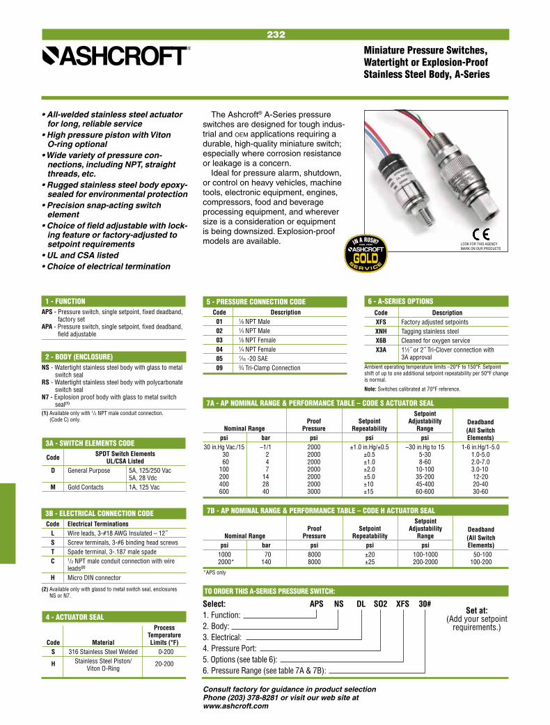
232
Consult factory for guidance in product selectionPhone (203) 378-8281 or visit our web site at www.ashcroft.com
Miniature Pressure Switches, Watertight or Explosion-Proof Stainless Steel Body, A-Series
The Ashcroft® A-Series pressure switches are designed for tough indus-trial and oeM applications requiring a durable, high-quality miniature switch; especially where corrosion resistance or leakage is a concern.
Ideal for pressure alarm, shutdown, or control on heavy vehicles, machine tools, electronic equipment, engines, compressors, food and beverage processing equipment, and wherever size is a consideration or equipment is being downsized. Explosion-proof models are available.
• All-welded stainless steel actuator for long, reliable service
• High pressure piston with Viton O-ring optional
• Wide variety of pressure con-nections, including NPT, straight threads, etc.
• Rugged stainless steel body epoxy-sealed for environmental protection
• Precision snap-acting switch element
• Choice of field adjustable with lock-ing feature or factory-adjusted to setpoint requirements
• UL and CSA listed• Choice of electrical termination
Set at: (Add your setpoint
requirements.)
TO ORDER THIS A-SERIES PRESSURE SWITCH:
Select: APS NS DL SO2 XFS 30# 1. Function: 2. Body: 3. Electrical: 4. Pressure Port: 5. Options (see table 6): 6. Pressure Range (see table 7A & 7B):
1 - FUNCTIONAPS - Pressure switch, single setpoint, fixed deadband,
factory setAPA - Pressure switch, single setpoint, fixed deadband,
field adjustable
2 - BODY (ENCLOSURE)NS - Watertight stainless steel body with glass to metal
switch sealRS - Watertight stainless steel body with polycarbonate
switch sealN7 - Explosion proof body with glass to metal switch
seal(1)
(1) Available only with 1/2 NPT male conduit connection. (Code C) only.
3A - SWITCH ELEMENTS CODE SPDT Switch Elements Code UL/CSA Listed D General Purpose 5A, 125/250 Vac 5A, 28 Vdc M Gold Contacts 1A, 125 Vac
4 - ACTUATOR SEAL Process Temperature Code Material Limits (°F) S 316 Stainless Steel Welded 0-200 H Stainless Steel Piston/ 20-200 Viton O-Ring
7A - AP NOMINAL RANGE & PERFORMANCE TABLE – CODE S ACTUATOR SEAL Setpoint Proof Setpoint Adjustability Deadband Nominal Range Pressure Repeatability Range (All Switch psi bar psi psi psi Elements) 30 in.Hg Vac./15 –1/1 2000 ±1.0 in.Hg/±0.5 –30 in.Hg to 15 1-6 in.Hg/1-5.0 30 2 2000 ±0.5 5-30 1.0-5.0 60 4 2000 ±1.0 8-60 2.0-7.0 100 7 2000 ±2.0 10-100 3.0-10. 200 14 2000 ±5.0 35-200 12-20 400 28 2000 ±10. 45-400 20-40 600 40 3000 ±15. 60-600 30-60
5 - PRESSURE CONNECTION CODE Code Description 01 1⁄8 NPT Male 02 1⁄4 NPT Male 03 1⁄8 NPT Female 04 1⁄4 NPT Female 05 7⁄16 -20 SAE 09 3⁄4 Tri-Clamp Connection
7B - AP NOMINAL RANGE & PERFORMANCE TABLE – CODE H ACTUATOR SEAL Setpoint Proof Setpoint Adjustability Deadband Nominal Range Pressure Repeatability Range (All Switch psi bar psi psi psi Elements) 1000 70 8000 ±20 100-1000 50-100 2000* 140 8000 ±25 200-2000 100-200
*APS only
6 - A-SERIES OPTIONS Code Description XFS Factory adjusted setpoints XNH Tagging stainless steel X6B Cleaned for oxygen service X3A 11⁄2˝ or 2˝ Tri-Clover connection with 3A approvalAmbient operating temperature limits –20°F to 150°F. Setpoint shift of up to one additional setpoint repeatability per 50°F change is normal.
Note: Switches calibrated at 70°F reference.
3B - ELECTRICAL CONNECTION CODE Code Electrical Terminations L Wire leads, 3-#18 AWG Insulated – 12˝ S Screw terminals, 3-#6 binding head screws T Spade terminal, 3-.187 male spade C 1/2 NPT male conduit connection with wire leads(2)
H Micro DIN connector
(2) Available only with glassd to metal switch seal, enclosures NS or N7.
LOOK FOR THIS AGENCY MARK ON OUR PRODUCTS

233
Consult factory for guidance in product selectionPhone (203) 378-8281 or visit our web site at www.ashcroft.com
Code Process Range
& Temp.(6) Vac 0-600 1000 2000- Material Limits in.H2O psi psi 3000 °F psi B-Buna N 0 to 150
V-Viton 20 to 300
T-Teflon 0 to 150
S-SS(5)(10) 0 to 300
P-Monel(5)(10) 0 to 300
NOTES: 1. Standard switch. 2. Dual switches are 2 SPDT snap-action switches not
independently adjustable. 3. Estimated dc rating, 2.5A, 28 Vdc (not UL listed). 4. Estimated dc rating, .4A, 120 Vdc (not UL listed). 5. Available on pressure only. 6. Ambient operating temperature limits –20 to 150°F,
all styles. Setpoint shift of ±1% of range per 50°F is normal. Switch calibrated at 70°F reference.
7. Items are wetted by process fluid. 8. Refer to Option Table. 9. Order Option XUD, stainless steel process connection.10. On differential switches, stainless steel is available in 15, 30, 60 and 90 psid ranges only. Includes Teflon O-ring and 316 SS connection.
TO ORDER THIS B-SERIES PRESSURE SWITCH:
Select: B4 20 B XPK 600# 1. Enclosure: 2. Switch Element: 3. Actuator Seal: 4. Options (See pages 250-251): 5. Pressure Range (See page 247):
Pressure and Differential Pressure Switches, Watertight Enclosure, Type 400, B-Series
• Choice of actuators, including designs for fire-safe and NACE applications(8)
• Readily available
• Standard pressure connection materials:
Pressure psi ranges - 316L stainless steel
Differential psid ranges - Nickel-plated brass(9)
Pressure and differential inches of water ranges - Epoxy coated carbon steel
1 - ENCLOSUREB4 - Pressure switch, type 400, watertight
enclosure meets NEMA 3, 4, 4X and 13, IP66 requirements
D4 - Differential pressure switch, type 400, watertight enclosure meets NEMA 3, 4, 4X and 13, IP66 requirements
This general purpose Ashcroft® switch series is ideal for use in virtually all Industrial and OEM applications.
• Watertight NEMA 4X enclosure, IP66
• Choice of switch elements for all applications, including hermeti-cally sealed
• Wide choice of wetted materials, including all-welded Monel or stainless steel
• Fixed or limited adjustable deadband
• Approved for UL, CSA and FM(8) ratings
• Setpoints adjustable from 15-100% of range
4 - OPTIONS(See pages 250-251)
5 - STANDARD PRESSURE RANGES(See page 247)
3 - ACTUATOR SEAL(7)
2 - SWITCH ELEMENTS Order Description/Maximum Electrical Ratings Code UL/CSA Listed SPDT 20(4) Narrow deadband 15A, 125/250 Vac 21(9) Ammonia service 5A, 125/250 Vac Hermetically sealed 22(3) switch, narrow 5A, 125/250 Vac deadband 23 Heavy duty ac 20A,125/250 Vac 15A,125/250/480 Vac 24(1) General purpose 1/2A, 125 Vdc 1/4A, 250 Vdc 25 Heavy duty dc 10A,125/ Vac or dc 1/8HP 125/ Vac or dc 26(4) Sealed environment 15A, 125/250 Vac proof 27 High temp. 300°F 15A, 125/250 Vac 28 Manual reset trip 15A, 125/250 Vac on increasing 29 Manual reset trip 15A, 125/250 Vac on decreasing 31 Low level (gold) 1A,125/250 Vac contacts Hermetically sealed 32 switch, general 11A, 125/250 Vac purpose 5A, 30 Vdc 50 Variable deadband 15A,125/250 Vac UL/CSA Listed Dual SPDT(2)
61(4) Dual narrow deadband 15A, 125/250 Vac 62(4) Dual narrow environ- 15A, 125/250 Vac ment proof 63 Dual high temp. 300°F 15A, 125/250 Vac 15A,125/250/480 Vac 64 Dual general purpose 1/2A, 125 Vdc 1/4A, 250 Vdc 65 Dual ammonia service 5A, 125/250/480
HERMETICALLY SEALED SWITCHWe recommend hermetically sealed switch elements for improved reliability. The hermetically sealed switch provides uncompromising contact protection in harsh or corrosive environments. The Ashcroft 400 Series is also approved for installation in Division II hazardous areas when supplied with hermetically sealed contacts.Features:• UL-recognized component,
guide WSQ2, File E85076• All-stainless steel welded
construction
LOOK FOR THIS AGENCY MARK ON OUR PRODUCTS
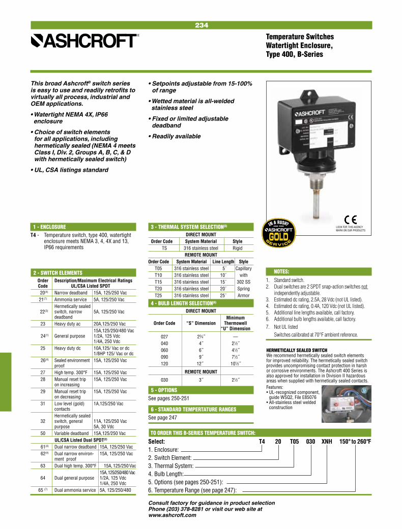
234
Consult factory for guidance in product selectionPhone (203) 378-8281 or visit our web site at www.ashcroft.com
Temperature SwitchesWatertight Enclosure,Type 400, B-Series
This broad Ashcroft® switch series is easy to use and readily retrofits to virtually all process, industrial and OEM applications.
• Watertight NEMA 4X, IP66 enclosure
• Choice of switch elements for all applications, including hermetically sealed (NEMA 4 meets Class I, Div. 2, Groups A, B, C, & D with hermetically sealed switch)
• UL, CSA listings standard
• Setpoints adjustable from 15-100% of range
• Wetted material is all-welded stainless steel
• Fixed or limited adjustable deadband
• Readily available
1 - ENCLOSURET4 - Temperature switch, type 400, watertight
enclosure meets NEMA 3, 4, 4X and 13, IP66 requirements
5 - OPTIONSSee pages 250-251
6 - STANDARD TEMPERTATURE RANGESSee page 247
4 - BULB LENGTH SELECTION(6)
DIRECT MOUNT Minimum Order Code “S” Dimension Thermowell “U” Dimension
027 23⁄4˝ — 040 4˝ 21⁄2˝ 060 6˝ 41⁄2˝ 090 9˝ 71⁄2˝ 120 12˝ 101⁄2˝
REMOTE MOUNT
030 3˝ 21⁄2˝
NOTES:
1. Standard switch.2. Dual switches are 2 SPDT snap-action switches not independently adjustable. 3. Estimated dc rating, 2.5A, 28 Vdc (not UL listed).4. Estimated dc rating, 0.4A, 120 Vdc (not UL listed).5. Additional line lengths available, call factory.6. Additional bulb lengths available, call factory.7. Not UL listed Switches calibrated at 70°F ambient reference.
TO ORDER THIS B-SERIES TEMPERATURE SWITCH:
Select: T4 20 T05 030 XNH 150° to 260°F1. Enclosure: 2. Switch Element: 3. Thermal System: 4. Bulb Length: 5. Options (see pages 250-251): 6. Temperature Range (see page 247):
3 - THERMAL SYSTEM SELECTION(5)
DIRECT MOUNT Order Code System Material Style TS 316 stainless steel Rigid REMOTE MOUNT Order Code System Material Line Length Style T05 316 stainless steel 5´ Capillary T10 316 stainless steel 10´ with T15 316 stainless steel 15´ 302 SS T20 316 stainless steel 20´ Spring T25 316 stainless steel 25´ Armor
2 - SWITCH ELEMENTS Order Description/Maximum Electrical Ratings Code UL/CSA Listed SPDT 20(4) Narrow deadband 15A, 125/250 Vac 21(7) Ammonia service 5A, 125/250 Vac Hermetically sealed 22(3) switch, narrow 5A, 125/250 Vac deadband 23 Heavy duty ac 20A,125/250 Vac 15A,125/250/480 Vac 24(1) General purpose 1/2A, 125 Vdc 1/4A, 250 Vdc 25 Heavy duty dc 10A,125/ Vac or dc 1/8HP 125/ Vac or dc 26(4) Sealed environment 15A, 125/250 Vac proof 27 High temp. 300°F 15A, 125/250 Vac 28 Manual reset trip 15A, 125/250 Vac on increasing 29 Manual reset trip 15A, 125/250 Vac on decreasing 31 Low level (gold) 1A,125/250 Vac contacts Hermetically sealed 32 switch, general 11A, 125/250 Vac purpose 5A, 30 Vdc 50 Variable deadband 15A,125/250 Vac UL/CSA Listed Dual SPDT(2)
61(4) Dual narrow deadband 15A, 125/250 Vac 62(4) Dual narrow environ- 15A, 125/250 Vac ment proof 63 Dual high temp. 300°F 15A, 125/250 Vac 15A,125/250/480 Vac 64 Dual general purpose 1/2A, 125 Vdc 1/4A, 250 Vdc 65 (7) Dual ammonia service 5A, 125/250/480
HERMETICALLY SEALED SWITCHWe recommend hermetically sealed switch elements for improved reliability. The hermetically sealed switch provides uncompromising contact protection in harsh or corrosive environments. The Ashcroft 400 Series is also approved for installation in Division II hazardous areas when supplied with hermetically sealed contacts.Features:• UL-recognized component,
guide WSQ2, File E85076• All-stainless steel welded
construction
LOOK FOR THIS AGENCY MARK ON OUR PRODUCTS
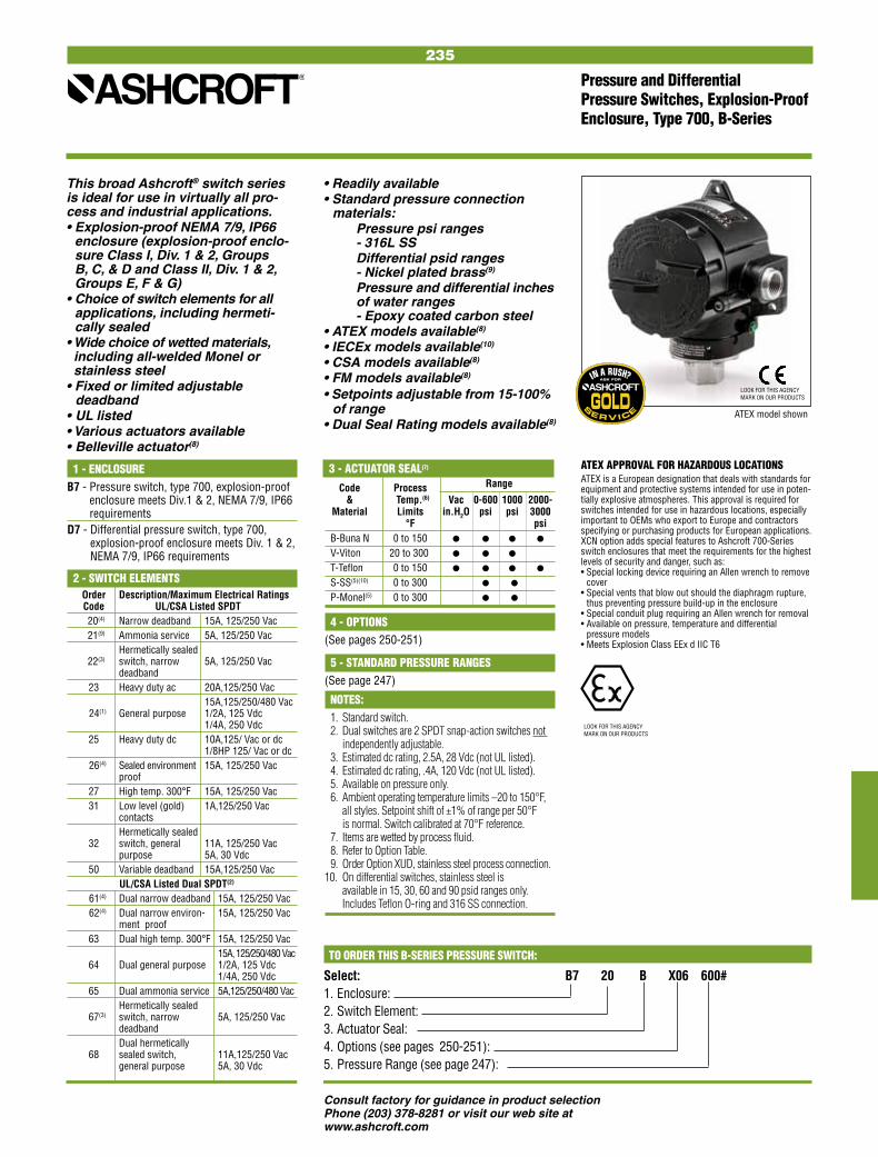
235
Consult factory for guidance in product selectionPhone (203) 378-8281 or visit our web site at www.ashcroft.com
2 - SWITCH ELEMENTS Order Description/Maximum Electrical Ratings Code UL/CSA Listed SPDT 20(4) Narrow deadband 15A, 125/250 Vac 21(9) Ammonia service 5A, 125/250 Vac Hermetically sealed 22(3) switch, narrow 5A, 125/250 Vac deadband 23 Heavy duty ac 20A,125/250 Vac 15A,125/250/480 Vac 24(1) General purpose 1/2A, 125 Vdc 1/4A, 250 Vdc 25 Heavy duty dc 10A,125/ Vac or dc 1/8HP 125/ Vac or dc 26(4) Sealed environment 15A, 125/250 Vac proof 27 High temp. 300°F 15A, 125/250 Vac 31 Low level (gold) 1A,125/250 Vac contacts Hermetically sealed 32 switch, general 11A, 125/250 Vac purpose 5A, 30 Vdc 50 Variable deadband 15A,125/250 Vac UL/CSA Listed Dual SPDT(2)
61(4) Dual narrow deadband 15A, 125/250 Vac 62(4) Dual narrow environ- 15A, 125/250 Vac ment proof 63 Dual high temp. 300°F 15A, 125/250 Vac 15A,125/250/480 Vac 64 Dual general purpose 1/2A, 125 Vdc 1/4A, 250 Vdc 65 Dual ammonia service 5A,125/250/480 Vac Hermetically sealed 67(3) switch, narrow 5A, 125/250 Vac deadband Dual hermetically 68 sealed switch, 11A,125/250 Vac general purpose 5A, 30 Vdc
TO ORDER THIS B-SERIES PRESSURE SWITCH:
Select: B7 20 B X06 600# 1. Enclosure: 2. Switch Element: 3. Actuator Seal: 4. Options (see pages 250-251): 5. Pressure Range (see page 247):
This broad Ashcroft® switch series is ideal for use in virtually all pro-cess and industrial applications.• Explosion-proof NEMA 7/9, IP66
enclosure (explosion-proof enclo-sure Class I, Div. 1 & 2, Groups B, C, & D and Class II, Div. 1 & 2, Groups E, F & G)
• Choice of switch elements for all applications, including hermeti-cally sealed
• Wide choice of wetted materials, including all-welded Monel or stainless steel
• Fixed or limited adjustable deadband• UL listed• Various actuators available• Belleville actuator(8)
• Readily available• Standard pressure connection materials: Pressure psi ranges - 316L SS Differential psid ranges - Nickel plated brass(9)
Pressure and differential inches of water ranges - Epoxy coated carbon steel• ATEX models available(8)
• IECEx models available(10)
• CSA models available(8)
• FM models available(8)
• Setpoints adjustable from 15-100% of range
• Dual Seal Rating models available(8)
Pressure and Differential Pressure Switches, Explosion-Proof Enclosure, Type 700, B-Series
1 - ENCLOSUREB7 - Pressure switch, type 700, explosion-proof
enclosure meets Div.1 & 2, NEMA 7/9, IP66 requirements
D7 - Differential pressure switch, type 700, explosion-proof enclosure meets Div. 1 & 2, NEMA 7/9, IP66 requirements
ATEX APPROVAL FOR HAZARDOUS LOCATIONSATEX is a European designation that deals with standards for equipment and protective systems intended for use in poten-tially explosive atmospheres. This approval is required for switches intended for use in hazardous locations, especially important to OEMs who export to Europe and contractors specifying or purchasing products for European applications.XCN option adds special features to Ashcroft 700-Series switch enclosures that meet the requirements for the highest levels of security and danger, such as:• Special locking device requiring an Allen wrench to remove
cover• Special vents that blow out should the diaphragm rupture,
thus preventing pressure build-up in the enclosure• Special conduit plug requiring an Allen wrench for removal• Available on pressure, temperature and differential
pressure models• Meets Explosion Class EEx d IIC T6
ATEX model shown
LOOK FOR THIS AGENCY MARK ON OUR PRODUCTS
Code Process Range
& Temp.(6) Vac 0-600 1000 2000- Material Limits in.H2O psi psi 3000 °F psi B-Buna N 0 to 150
V-Viton 20 to 300
T-Teflon 0 to 150
S-SS(5)(10) 0 to 300
P-Monel(5) 0 to 300
NOTES: 1. Standard switch. 2. Dual switches are 2 SPDT snap-action switches not
independently adjustable. 3. Estimated dc rating, 2.5A, 28 Vdc (not UL listed). 4. Estimated dc rating, .4A, 120 Vdc (not UL listed). 5. Available on pressure only. 6. Ambient operating temperature limits –20 to 150°F,
all styles. Setpoint shift of ±1% of range per 50°F is normal. Switch calibrated at 70°F reference.
7. Items are wetted by process fluid. 8. Refer to Option Table. 9. Order Option XUD, stainless steel process connection.10. On differential switches, stainless steel is available in 15, 30, 60 and 90 psid ranges only. Includes Teflon O-ring and 316 SS connection.
4 - OPTIONS(See pages 250-251)
5 - STANDARD PRESSURE RANGES(See page 247)
3 - ACTUATOR SEAL(7)
LOOK FOR THIS AGENCY MARK ON OUR PRODUCTS

236
Consult factory for guidance in product selectionPhone (203) 378-8281 or visit our web site at www.ashcroft.com
Temperature SwitchesExplosion-Proof Enclosure,Type 700, B-Series
5 - OPTIONSSee pages 250-251 6 - STANDARD TEMPERTATURE RANGESSee page 247
4 - BULB LENGTH SELECTION(6)
DIRECT MOUNT Minimum Order Code “S” Dimension Thermowell “U” Dimension
027 23⁄4˝ — 040 4˝ 21⁄2˝ 060 6˝ 41⁄2˝ 090 9˝ 71⁄2˝ 120 12˝ 101⁄2˝
REMOTE MOUNT
030 3˝ 21⁄2˝
NOTES:1. Standard switch.2. Dual switches are 2 SPDT snap-action switches
not independently adjustable. 3. Estimated dc rating, 2.5A, 28 Vdc (not UL listed).4. Estimated dc rating, 0.4A, 120 Vdc (not UL
listed).5. Additional line lengths available, call factory.6. Additional bulb lengths available, call factory.7. Refer to Options Table. Switches calibrated at 70°F ambient reference.
TO ORDER THIS B-SERIES TEMPERATURE SWITCH:
Select: T7 20 T05 030 XNH 150° to 260°F1. Enclosure: 2. Switch Element: 3. Thermal System: 4. Bulb Length: 5. Options (see pages 250-251): 6. Temperature Range (see page 247):
1 - ENCLOSURET7 - Temperature switch, type 700, explosion
proof enclosure meets Div. 1 & 2, NEMA 7/9, IP66 requirements
2 - SWITCH ELEMENTS Order Description/Maximum Electrical Ratings Code UL/CSA Listed SPDT 20(4) Narrow deadband 15A, 125/250 Vac 21 Ammonia service 5A, 125/250 Vac Hermetically sealed 22(3) switch, narrow 5A, 125/250 Vac deadband 23 Heavy duty ac 20A,125/250 Vac 15A,125/250/480 Vac 24(1) General purpose 1/2A, 125 Vdc 1/4A, 250 Vdc 25 Heavy duty dc 10A,125/ Vac or dc 1/8HP 125/ Vac or dc 26(4) Sealed environment 15A, 125/250 Vac proof 27 High temp. 300°F 15A, 125/250 Vac 31 Low level (gold) 1A,125/250 Vac contacts Hermetically sealed 32 switch, general 11A, 125/250 Vac purpose 5A, 30 Vdc 50 Variable deadband 15A,125/250 Vac UL/CSA Listed Dual SPDT(2)
61(4) Dual narrow deadband 15A, 125/250 Vac 62(4) Dual narrow environ- 15A, 125/250 Vac ment proof 63 Dual high temp. 300°F 15A, 125/250 Vac 15A,125/250/480 Vac 64 Dual general purpose 1/2A, 125 Vdc 1/4A, 250 Vdc 65 Dual ammonia service 5A, 125/250/480 Hermetically sealed 67(3) switch, narrow 5A, 125/250 Vac deadband Dual hermetically 68 sealed switch, 11A,125/250 Vac general purpose 5A, 30 Vdc
This broad Ashcroft® switch series ideal for use in virtually all process, industrial and OEM applications.• Explosion-proof NEMA 7/9, IP66
enclosures• Choice of switch elements
for all applications, including hermetically sealed
• Fixed or limited adjustable deadband
• Readily available• UL listings standard• CSA listings available(7)
• ATEX models available(7)
• Setpoints adjustable from 15-100% of range
• IECEx models available(7)
HERMETICALLY SEALED SWITCHWe recommend hermetically sealed switch elements for improved reliability. The hermetically sealed switch provides uncompromising contact protection in harsh or corrosive environments. Features:• UL-recognized component,
guide WSQ2, File E85076• All-stainless steel welded
construction
3 - THERMAL SYSTEM SELECTION(5)
DIRECT MOUNT Order Code System Material Style TS 316 stainless steel Rigid REMOTE MOUNT Order Code System Material Line Length Style T05 316 stainless steel 5´ Capillary T10 316 stainless steel 10´ with T15 316 stainless steel 15´ 302 SS T20 316 stainless steel 20´ Spring T25 316 stainless steel 25´ Armor
LOOK FOR THIS AGENCY MARK ON OUR PRODUCTS

237
Consult factory for guidance in product selectionPhone (203) 378-8281 or visit our web site at www.ashcroft.com
7A - NOMINAL RANGE & PERFORMANCE TABLE – BUNA (CODE B) Nominal Range Proof Pressure Deadband (by Switch Element) psi bar psi Code J Code P,L 30 in.Hg Vac.† –1 1000 1.8-8.0 0.4-5.00 30 2 1000 0.2-1.5 0.1-1.30 60 4 1000 0.2-2.5 0.3-1.50 100 7 1000 0.5-4.0 0.5-2.50 200 14 1000 1.5-8.0 0.5-5.00 400 28 1600 1.0-15.00 1.5-9.00 600 40 2400 4.0-28.00 2.0-15.000 10000 70 4000 6.0-50.00 3.0-30.000
7B - NOMINAL RANGE & PERFORMANCE TABLE – HIGH PRESSURE (CODE H) 1000 70 12,000 50-100 N/A 2000 140 12,000 100-200 N/A 3000 210 12,000 150-300 N/A 4000 280 16,000 150-350 N/A
7C - NOMINAL RANGE & PERFORMANCE TABLE – WELDED SS (CODE S) 30 2 1000 1.0-4.50 0.5-3.50 60 4 1000 1.0-5.00 0.5-4.00 100 7 1000 1.5-10.0 1.0-6.00 200 14 1000 2.0-18.0 1.0-12.0 400 28 1600 5.0-32.0 2.0-20.0 600 40 2400 9.0-50.0 4.0-30.0 10000 70 4000 15.0-80.00 7.0-50.0
7D - NOMINAL RANGE & PERFORMANCE TABLE – BUNA (CODE V, T, R) 30 in.Hg Vac.† –1 1000 1.5-10.0 0.5-7.00 30 2 1000 0.5-3.50 0.2-2.500 60 4 1000 0.5-4.00 0.5-3.00 100 7 1000 1.0-7.00 1.0-4.50 200 14 1000 12.5-12.00 1.0-8.50 400 28 1600 5.0-30.0 2.0-17.00 600 40 2400 8.0-48.0 4.0-34.0 10000 70 4000 10.0-80.00 5.0-55.0
Note: Switches calibrated at 70°F reference.
Special features:• Diaphragm-sealed piston actuator
for long, reliable service• Choice of wetted materials and
pressure connections for all applications
• Watertight anodized aluminum body for environmental protection
• Hermetically sealed snap-acting switch element
• Field adjustable• Standard 1/2 NPT Male electrical
conduit connection• Factory sealed leads• Directly interchangeable with many
similar models for convenience• UL and CSA listed standard• Setpoints adjustble from 15-100%
of range. Exception: stainless steel welded (codes) adjustable from 20-100%
Compact Pressure Switch Explosion-Proof BodyF-Series
Ideal for pressure alarm, shutdown, control on:
• Engines and compressors
• Process applications
• Offshore applications
• Panels
• Pipelines
• Hazardous locations
• Corrosive environments
• Machine tools
• Replacement and retrofit
• Where size is a consideration or equipment is being downsized
TO ORDER THIS F-SERIES PRESSURE SWITCH:
Select: FPS N7 P B 07 XFS 30#1. Function: 2. Body: 3. Switch Element (Table 3): 4. Actuator Seal (Table 4): 5. Pressure Port: Standard 1/2 NPTF6. Options (see table 6): 7. Nominal Range (see Tables 7A, 7B, 7C, 7D):
1 - FUNCTIONFPS - Pressure switch, single setpoint, fixed deadband,
field adjustable
2 - ENCLOSURE (BODY)N7 - NEMA 3, 4, 7 & 9, IP66
Anodized aluminum for hazardous locations
3 - SWITCH ELEMENT CODE SPDT Switch Elements Code UL/CSA Listed P Hermetically Sealed, 5A, 125/250 Vac Narrow Deadband J Hermetically Sealed, 11A, 125/250 Vac General Purpose 5A, 30 Vdc L Hermetically Sealed, 1A, 125 Vac Gold Contacts
LOOK FOR THIS AGENCY MARK ON OUR PRODUCTS
6 - F-SERIES OPTIONS Code Description XFP Fungus proofing XFS Factory adjusted setpoint XK3 Terminal blocks XNH Tagging stainless steel X6B Cleaned for oxygen service
4 - ACTUATOR SEAL Proc. Temp. Code Material Limits (°F) B Buna N 0-150 V Viton 20-200 T Teflon 0-150 R SS Diaphragm/Viton O-Ring 0-150 S 316 SS Welded 0-200 H SS Piston/Viton O-Ring 20-200
5 - PRESSURE CONNECTION Code Description 25 1⁄4 NPT Female 07 1⁄2 NPT Female (Standard)

238
Consult factory for guidance in product selectionPhone (203) 378-8281 or visit our web site at www.ashcroft.com
Code Process Range
& Temp.(2) Vac. 0-600 1000 2000- Material Limits in.H2O psi psi 3000 °F psi
B-Buna N 0 to 150
V-Viton 20 to 300
T-Teflon 0 to 150
S-SS(6) 0 to 300
P-Monel(6) 0 to 300
3 - SWITCH ELEMENTS FOR GPA & GDA CONTROLS
Description/Maximum Electrical Ratings Code UL/CSA Listed
10A,125/250 Vac H General purpose 1/2A, 125 Vdc 1/4A, 250 Vdc Hermetically sealed J switch, general 11A, 125/250 Vac purpose 5A, 30 Vdc
SWITCH ELEMENTS FOR GPD, GPS, GDD & GDS CONTROLS
Code Switch Elements Single Dual UL/CSA ListedS
(GS) (GD) K(4) KK Narrow deadband 15A, 125/250 Vac F(4) FF Sealed environment 15A, 125/250 Vac proof 15A, 125/250/480 Vac G(5) GG General purpose 1/2A, 125 Vdc 1/4A, 250 Vdc Hermetically sealed P(3) PP switch, narrow 5A, 125/250 Vac deadband Hermetically sealed J JJ switch, general 11A,125/250 Vac purpose 5A, 30 Vdc
TO ORDER THIS G-SERIES PRESSURE SWITCH:
Select: GPD N4 GG B 25 X07 30#1. Function: 2. Enclosure: 3. Switch Element: 4. Actuator Seal: 5. Pressure Port: 6. Options (see pages 250-251): 7. Pressure Range (see page 249):
designs for fire-safe and NACE applications(7)
• Standard pressure connection materials:
Pressure psi ranges - 316L stainless steelDifferential psid ranges - 316 stainless steel standardPressure and differential inches of water ranges - 316 stainless steel standard
• Readily available• 3A sanitary connection available(7)
• Setpoints adjustable from 15-100% of range
This broad Ashcroft® switch series is easy to use and readily retrofits to virtually all process, industrial and OEM applications.• Single or dual independently
adjustable setpoints meet all setpoint requirements
• Watertight NEMA 4X, IP65 enclosure• 316 SS construction• Choice of switch elements for all
applications, including hermetically sealed
• Fixed or fully adjustable deadband• Approved for UL and CSA ratings• Wide choice of actuators, including
Pressure and Differential Pressure Switches, Watertight 316 SS Enclosure, G-Series
1 - FUNCTIONGPA - Pressure control, single setpoint, adjustable deadbandGPD - Pressure control, two independently adjustable setpoints, fixed deadband GPS - Pressure control, single setpoint, fixed deadbandGDA - Differential pressure control, single setpoint, adjustable deadbandGDD - Differential pressure control, two inde- pendently adjustable setpoints, fixed deadbandGDS - Differential pressure control, single setpoint, fixed deadband
2 - ENCLOSUREN4 - NEMA 4/4X, IP65
(watertight and corrosion resistant) 6 - OPTIONSSee pages 250-251
7 - STANDARD PRESSURE RANGESSee page 249 NOTES:
1. These items are wetted by process fluid.2. Ambient operating temperature limits –20 to 150°F,
all styles. Setpoint shift of ±1% of range per 50°F temperature change is normal. Switches calibrated at 70°F reference.
3. Estimated dc rating, 2.5A, 28 Vdc (not UL listed).4. Estimated dc rating, .4A, 120 Vdc (not UL listed).5. Not UL listed at 480 Vac.6. Available on pressure only.7. Refer to Option Table.
4 - ACTUATOR SEAL(1)
5 - PRESSURE PORT(1)
Order Code
25 1⁄4 NPT Female
1⁄4 NPT Female and
06 1⁄2 NPT Male Combination
07 1⁄2 NPT Female
HERMETICALLY SEALED SWITCHWe recommend hermetically sealed switch elements for improved reliability. The hermetically sealed switch pro-vides uncompromising contact protection in harsh or corrosive environments. The Ashcroft G Series is also approved for installation in Division II hazardous areas when supplied with hermetically sealed contacts.Features:• UL-recognized component,
guide WSQ2, File E85076• All-stainless steel welded
construction
LOOK FOR THIS AGENCY MARK ON OUR PRODUCTS

239
Consult factory for guidance in product selectionPhone (203) 378-8281 or visit our web site at www.ashcroft.com
Temperature Switches, Watertight 316 Stainless Steel Enclosure, G-Series
This Ashcroft® specialty switch series is ideally suited for harsh and corrosive environments often found in many process, industrial and OEM applications.
• Watertight NEMA 4X, IP65 enclosure
• 316 SS construction
• Choice of switch elements for all applications, including hermetically sealed (NEMA 4 meets Class I, Div. 2, Groups A, B, C, & D with hermetically sealed switch
• Single or dual independently adjustable setpoints meet all setpoint requirements
• Fixed or fully adjustable deadband
• Readily available
• UL, CSA listings standard
• Setpoints adjustable from 15-100% of range
NOTES:
1. Estimated dc rating, 2.5A, 28 Vdc (not UL listed).2. Estimated dc rating, 0.4A, 120 Vdc (not UL listed).3. Not UL listed at 480 Vac.4. Additional line lengths available, call factory.5. Additional bulb lengths available, call factory. Switches calibrated at 70°F ambient reference.
TO ORDER THIS G-SERIES TEMPERATURE SWITCH:
Select: GTA N4 H 05 A7 030 XNH 150° to 260°F1. Function: 2. Enclosure: 3. Switch Element: 4. Line Length: 5. Thermal System: 6. Bulb Length: 7. Options (see pages 250-251):8. Temperature Range (see page 249):
4 - LINE LENGTH SELECTION(4)
DIRECT MOUNT Order Code Line Style Length ft
00 Not Applicable Rigid
REMOTE MOUNT
05 5 Capillary 10 10 with 15 15 Armor 20 20 (Std.) 25 25
1 - FUNCTIONGTA - Temperature control, single setpoint, adjustable deadbandGTD - Temperature control, two independently adjustable setpoints, fixed deadband GTS - Temperature control, single setpoint, fixed deadband
3 - SWITCH ELEMENTS FOR PTA CONTROLS
Order Description/Maximum Electrical Ratings Code UL/CSA Listed
10A,125/250 Vac H General purpose 1/2A, 125 Vdc 1/4A, 250 Vdc Hermetically sealed J switch, general 11A, 125/250 Vac purpose 5A, 30 Vdc
SWITCH ELEMENTS FOR GTD & GTS CONTROLS
Code Switch Elements Single Dual UL/CSA ListedS
(GS) (GD) K(2) KK Narrow deadband 15A, 125/250 Vac F(2) FF Sealed environment 15A, 125/250 Vac proof 15A, 125/250/480 Vac G(3) GG General purpose 1/2A, 125 Vdc 1/4A, 250 Vdc Hermetically sealed P(1) PP switch, narrow 5A, 125/250 Vac deadband Hermetically sealed J JJ switch, general 11A,125/250 Vac purpose 5A, 30 Vdc
2 - ENCLOSUREN4 - NEMA 4/4X, IP65
(watertight and corrosion resistant)
7 - OPTIONSSee pages 250-251
8 - STANDARD TEMPERTATURE RANGESSee page 249
6 - BULB LENGTH SELECTION(5)
DIRECT MOUNT Minimum Order Code “S” Dimension Thermowell “U” Dimension
027 23⁄4˝ — 040 4˝ 21⁄2˝ 060 6˝ 41⁄2˝ 090 9˝ 71⁄2˝ 120 12˝ 101⁄2˝
REMOTE MOUNT
030 3˝ 21⁄2˝ 5 - THERMAL SYSTEM SELECTION
LINE MATERIALDIRECT MOUNT
Order Code Description No entry required for Direct Mount
REMOTE MOUNT A7 Stainless Steel Armor (Std.)
HERMETICALLY SEALED SWITCHWe recommend hermetically sealed switch elements for improved reliability. The hermetically sealed switch pro-vides uncompromising contact protection in harsh or corrosive environments. The Ashcroft G Series is also approved for installation in Division II hazardous areas when supplied with hermetically sealed contacts.Features:• UL-recognized component,
guide WSQ2, File E85076• All-stainless steel welded
construction
LOOK FOR THIS AGENCY MARK ON OUR PRODUCTS
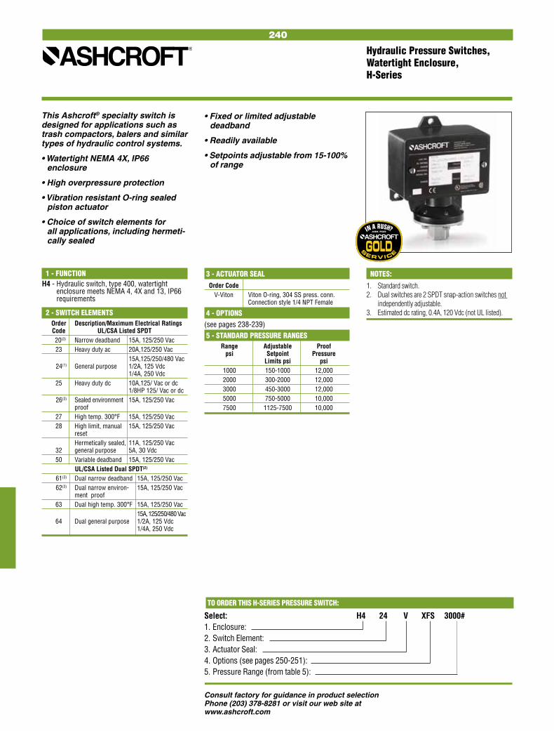
• Fixed or limited adjustable deadband
• Readily available
• Setpoints adjustable from 15-100% of range
240
Consult factory for guidance in product selectionPhone (203) 378-8281 or visit our web site at www.ashcroft.com
This Ashcroft® specialty switch is designed for applications such as trash compactors, balers and similar types of hydraulic control systems.
• Watertight NEMA 4X, IP66 enclosure
• High overpressure protection
• Vibration resistant O-ring sealed piston actuator
• Choice of switch elements for all applications, including hermeti-cally sealed
Hydraulic Pressure Switches, Watertight Enclosure, H-Series
3 - ACTUATOR SEAL Order Code V-Viton Viton O-ring, 304 SS press. conn. Connection style 1/4 NPT Female
4 - OPTIONS(see pages 238-239) 5 - STANDARD PRESSURE RANGES Range Adjustable Proof psi Setpoint Pressure Limits psi psi 1000 150-1000 12,000 2000 300-2000 12,000 3000 450-3000 12,000 5000 750-5000 10,000 7500 1125-7500 10,000
1 - FUNCTIONH4 - Hydraulic switch, type 400, watertight
enclosure meets NEMA 4, 4X and 13, IP66 requirements
2 - SWITCH ELEMENTS Order Description/Maximum Electrical Ratings Code UL/CSA Listed SPDT 20(3) Narrow deadband 15A, 125/250 Vac 23 Heavy duty ac 20A,125/250 Vac 15A,125/250/480 Vac 24(1) General purpose 1/2A, 125 Vdc 1/4A, 250 Vdc 25 Heavy duty dc 10A,125/ Vac or dc 1/8HP 125/ Vac or dc 26(3) Sealed environment 15A, 125/250 Vac proof 27 High temp. 300°F 15A, 125/250 Vac 28 High limit, manual 15A, 125/250 Vac reset Hermetically sealed, 11A, 125/250 Vac 32 general purpose 5A, 30 Vdc 50 Variable deadband 15A, 125/250 Vac UL/CSA Listed Dual SPDT(2)
61(3) Dual narrow deadband 15A, 125/250 Vac 62(3) Dual narrow environ- 15A, 125/250 Vac ment proof 63 Dual high temp. 300°F 15A, 125/250 Vac 15A,125/250/480 Vac 64 Dual general purpose 1/2A, 125 Vdc 1/4A, 250 Vdc
NOTES:
1. Standard switch.2. Dual switches are 2 SPDT snap-action switches not
independently adjustable.3. Estimated dc rating, 0.4A, 120 Vdc (not UL listed)..
TO ORDER THIS H-SERIES PRESSURE SWITCH:
Select: H4 24 V XFS 3000# 1. Enclosure: 2. Switch Element: 3. Actuator Seal: 4. Options (see pages 250-251): 5. Pressure Range (from table 5):

241
Consult factory for guidance in product selectionPhone (203) 378-8281 or visit our web site at www.ashcroft.com
Code Process Range
& Temp.(2) Vac. 0-600 1000 2000- Material Limits in.H2O psi psi 3000 °F psi
B-Buna N 0 to 150
V-Viton 20 to 300
T-Teflon 0 to 150
S-SS(6),(8) 0 to 300
P-Monel(6) 0 to 300
TO ORDER THIS L-SERIES PRESSURE SWITCH:
Select: LPD N4 GG B 25 XK3 30#1. Function: 2. Enclosure: 3. Switch Element: 4. Actuator Seal: 5. Pressure Port: 6. Options (see pages 250-251): 7. Pressure Range (see page 249):
Pressure psi ranges - 316L SSDifferential psid ranges - Nickel-plated brass(7)
Pressure and differential inches of water ranges - Epoxy coated carbon steel
• Approved for UL, CSA and FM (7) ratings
• Wide choice of actuators, including designs for fire-safe and NACE applications(7)
• Readily available• Setpoints adjustable from 15-100%
of range
This broad Ashcroft® switch series is easy to use and readily retrofits to virtually all process, industrial and OEM applications.• Single or dual independently
adjustable setpoints meet all setpoint requirements
• Watertight NEMA 4X, IP66 enclosure• Choice of switch elements for all
applications, including hermetically sealed
• Fixed or adjustable deadband• Standard pressure connection
materials:
Pressure and Differential Pressure Switches, Watertight Enclosure, L-Series
1 - FUNCTIONLPA - Pressure control, single setpoint, adjustable deadbandLPD - Pressure control, two independently adjustable setpoints, fixed deadband LPS - Pressure control, single setpoint, fixed deadbandLDA - Differential pressure control, single setpoint, adjustable deadbandLDD - Differential pressure control, two inde- pendently adjustable setpoints, fixed deadbandLDS - Differential pressure control, single setpoint, fixed deadband
3 - SWITCH ELEMENTS FOR LPA & LDA CONTROLS
Description/Maximum Electrical Ratings Code UL/CSA Listed
10A,125/250 Vac H General purpose 1/2A, 125 Vdc 1/4A, 250 Vdc Hermetically sealed J switch, general 11A, 125/250 Vac purpose 5A, 30 Vdc
SWITCH ELEMENTS FOR LPD, LPS, LDD & LDS CONTROLS
Code Switch Elements Single Dual UL/CSA ListedS
(PS) (PD) K(4) KK Narrow deadband 15A, 125/250 Vac F(4) FF Sealed environment 15A, 125/250 Vac proof 15A, 125/250/480 Vac G(5) GG General purpose 1/2A, 125 Vdc 1/4A, 250 Vdc Hermetically sealed P(3) PP switch, narrow 5A, 125/250 Vac deadband Hermetically sealed J JJ switch, general 11A,125/250 Vac purpose 5A, 30 Vdc
2 - ENCLOSUREN4 - NEMA 4/4X, IP66
(watertight and corrosion resistant) 6 - OPTIONSSee pages 250-251
7 - STANDARD PRESSURE RANGESSee page 249
4 - ACTUATOR SEAL(1)
5 - PRESSURE PORT(1)
Order Code
25 1⁄4 NPT Female
1⁄4 NPT Female and
06 1⁄2 NPT Male Combination
07 1⁄2 NPT Female
HERMETICALLY SEALED SWITCHWe recommend hermetically sealed switch elements for improved reliability. The hermetically sealed switch provides uncompromising contact protection in harsh or corrosive environments. The Ashcroft L Series is also approved for installation in Division II hazardous areas when supplied with hermetically sealed contacts.Features:• UL-recognized component,
guide WSQ2, File E85076• All-stainless steel welded
construction
NOTES:1. These items are wetted by process fluid.2. Ambient operating temperature limits –20 to 150°F,
all styles. Setpoint shift of ±1% of range per 50°F temperature change is normal. Switches calibrated at 70°F reference.
3. Estimated dc rating, 2.5A, 28 Vdc (not UL listed).4. Estimated dc rating, .4A, 120 Vdc (not UL listed).5. Not UL listed at 480 Vac.6. Available on pressure only.7. Refer to Option Table. 8. Order Option XUD, stainless steel process connection.
LOOK FOR THIS AGENCY MARK ON OUR PRODUCTS

242
Consult factory for guidance in product selectionPhone (203) 378-8281 or visit our web site at www.ashcroft.com
6 - BULB LENGTH SELECTION(5)
DIRECT MOUNT Minimum Order Code “S” Dimension Thermowell “U” Dimension
027 23⁄4˝ — 040 4˝ 21⁄2˝ 060 6˝ 41⁄2˝ 090 9˝ 71⁄2˝ 120 12˝ 101⁄2˝
REMOTE MOUNT
030 3˝ 21⁄2˝
4 - LINE LENGTH SELECTION(4)
DIRECT MOUNT Order Code Line Style Length ft
00 Not Applicable Rigid
REMOTE MOUNT
05 5 Capillary 10 10 with 15 15 Armor 20 20 (Std.) 25 25
Temperature Switches, Watertight Enclosure, L-Series
This broad Ashcroft® switch series is easy to use and readily retrofits to virtually all process, industrial and OEM applications.
• Single or dual independently adjustable setpoint(s) meet all setpoint requirements
• Watertight NEMA 4X, IP66 enclosure
• Choice of switch elements for all applications, including hermetically sealed (NEMA 4 meets Class I, Div. 2, Groups A, B, C, & D with hermeti-cally sealed switch
• Fixed or fully adjustable deadband
• Readily available
• UL, CSA listings standard
• Setpoints adjustable from 15-100% of range
NOTES:
1. Estimated dc rating, 2.5A, 28 Vdc (not UL listed).2. Estimated dc rating, 0.4A, 120 Vdc (not UL listed).3. Not UL listed at 480 Vac.4. Additional line lengths available, call factory.5. Additional bulb lengths available, call factory. Switches calibrated at 70°F ambient reference.
TO ORDER THIS L-SERIES TEMPERATURE SWITCH:
Select: LTA N4 H 05 A7 030 XNH 150° to 260°F1. Function: 2. Enclosure: 3. Switch Element: 4. Line Length: 5. Thermal System: 6. Bulb Length: 7. Options (see pages 250-251):8. Temperature Range (see page 249):
1 - FUNCTIONLTA - Temperature control, single setpoint, adjustable deadbandLTD - Temperature control, two independently adjustable setpoints, fixed deadband LTS - Temperature control, single setpoint, fixed deadband
3 - SWITCH ELEMENTS FOR LTA CONTROLS
Order Description/Maximum Electrical Ratings Code UL/CSA Listed
10A,125/250 Vac H General purpose 1/2A, 125 Vdc 1/4A, 250 Vdc Hermetically sealed J switch, general 11A, 125/250 Vac purpose 5A, 30 Vdc
SWITCH ELEMENTS FOR LTD & LTS CONTROLS
Code Switch Elements Single Dual UL/CSA ListedS
(LS) (LD) K(2) KK Narrow deadband 15A, 125/250 Vac F(2) FF Sealed environment 15A, 125/250 Vac proof 15A, 125/250/480 Vac G(3) GG General purpose 1/2A, 125 Vdc 1/4A, 250 Vdc Hermetically sealed P(1) PP switch, narrow 5A, 125/250 Vac deadband Hermetically sealed J JJ switch, general 11A,125/250 Vac purpose 5A, 30 Vdc
2 - ENCLOSUREN4 - NEMA 4/4X, IP66
(watertight and corrosion resistant)
7 - OPTIONSSee pages 250-251
8 - STANDARD TEMPERTATURE RANGESSee page 249
5 - THERMAL SYSTEM SELECTIONLINE MATERIALDIRECT MOUNT
Order Code Description No entry required for Direct Mount
REMOTE MOUNT A7 Stainless Steel Armor (Std.)
HERMETICALLY SEALED SWITCHWe recommend hermetically sealed switch elements for improved reliability. The hermetically sealed switch provides uncompromising contact protection in harsh or corrosive environments. The Ashcroft L Series is also approved for installation in Division II hazardous areas when supplied with hermetically sealed contacts.Features:• UL-recognized component,
guide WSQ2, File E85076• All-stainless steel welded
construction
LOOK FOR THIS AGENCY MARK ON OUR PRODUCTS
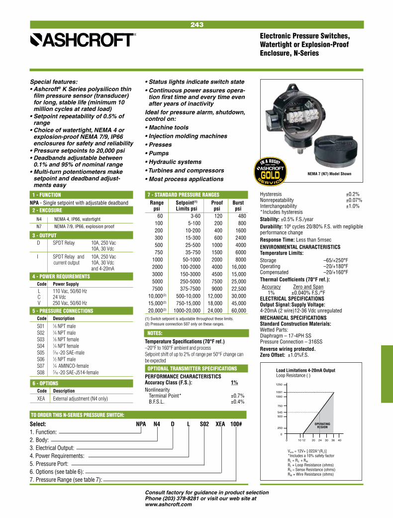
243
Consult factory for guidance in product selectionPhone (203) 378-8281 or visit our web site at www.ashcroft.com
Electronic Pressure Switches, Watertight or Explosion-Proof Enclosure, N-Series
Special features:• Ashcroft® K Series polysilicon thin
film pressure sensor (transducer) for long, stable life (minimum 10 million cycles at rated load)
• Setpoint repeatability of 0.5% of range
• Choice of watertight, NEMA 4 or explosion-proof NEMA 7/9, IP66 enclosures for safety and reliability
• Pressure setpoints to 20,000 psi• Deadbands adjustable between
0.1% and 95% of nominal range• Multi-turn potentiometers make
setpoint and deadband adjust-ments easy
• Status lights indicate switch state• Continuous power assures opera-
tion first time and every time even after years of inactivity
Ideal for pressure alarm, shutdown, control on:• Machine tools• Injection molding machines• Presses• Pumps• Hydraulic systems• Turbines and compressors• Most process applications
7 - STANDARD PRESSURE RANGES Range Setpoint(1) Proof Burst psi Limits psi psi psi 60 3-60 120 480 100 5-100 200 800 200 10-200 400 1600 300 15-300 600 2400 500 25-500 1000 4000 750 35-750 1500 6000 1000 50-1000 2000 8000 2000 100-2000 4000 16,000 3000 150-3000 4500 15,000 5000 250-5000 7500 25,000 7500 375-7500 9000 22,500 10,000(2) 500-10,000 12,000 30,000 15,000(2) 750-15,000 18,000 45,000 20,000(2) 1000-20,000 24,000 60,000
1 - FUNCTIONNPA - Single setpoint with adjustable deadband
(1) Switch setpoint is adjustable throughout these limits.(2) Pressure connection S07 only on these ranges.
2 - ENCOSURE
N4 NEMA 4, IP66, watertight
N7 NEMA 7/9, IP66, explosion proof
3 - OUTPUT D SPDT Relay 10A, 250 Vac 10A, 30 Vdc I SPDT Relay and 10A, 250 Vac current output 10A, 30 Vdc and 4-20mA 4 - POWER REQUIREMENTS Code Power Supply
L 110 Vac, 50/60 Hz C 24 Vdc V 250 Vac, 50/60 Hz 5 - PRESSURE CONNECTIONS Code Description
S01 1⁄8 NPT male S02 1⁄4 NPT male S03 1⁄8 NPT female S04 1⁄4 NPT female S05 7⁄16 -20 SAE-male S06 1⁄2 NPT male S07 1⁄4 AMINCO-female S08 7⁄16 -20 SAE-J514-female
TO ORDER THIS N-SERIES PRESSURE SWITCH:
Select: NPA N4 D L S02 XEA 100#1. Function: 2. Body: 3. Electrical Output: 4. Power Requirements:5. Pressure Port: 6. Options (see table 6): 7. Pressure Range (see table 7):
OPTIONAL TRANSMITTER SPECIFICATIONSPERFORMANCE CHARACTERISTICS Accuracy Class (F.S.): 1%Nonlinearity Terminal Point* ±0.7% B.F.S.L. ±0.4%
6 - OPTIONS Code Description
XEA External adjustment (N4 only)
Load Limitations 4-20mA OutputLoop Resistance Ω
0 10 12 20 24 30 36 40
0
250
500
750
1000
1250
1091
OPERATINGREGION
545
Vmin = 12V+ [.022A*(RL)] *Includes a 10% safety factor RL = RS + RW RL = Loop Resistance (ohms) RS = Sense Resistance (ohms) RW = Wire Resistance (ohms)
Load Limitations 4-20mA Output Loop Resistance (Ω)
NOTES:
Temperature Specifications (70°F ref.) –20°F to 160°F ambient and process Setpoint shift of up to 2% of range per 50°F change can be expected
NEMA 7 (N7) Model Shown
Hysteresis ±0.2% Nonrepeatability ±0.07% Interchangeability ±1.0% *Includes hysteresisStability: ±0.5% F.S./yearDurability: 108 cycles 20/80% F.S. with negligible performance changeResponse Time: Less than 5msecENVIRONMENTAL CHARACTERISTICS Temperature Limits:Storage –65/+250°F Operating –20/+180°F Compensated –20/+160°FThermal Coefficients (70°F ref.): Accuracy Zero and Span 1% ±0.040% F.S./°F ELECTRICAL SPECIFICATIONS Output Signal: Supply Voltage: 4-20mA (2 wire) 12-36 Vdc unregulatedMECHANICAL SPECIFICATIONS Standard Construction Materials: Wetted Parts: Diaphragm – 17-4PH SS Pressure Connection – 316SSReverse wiring protected. Zero Offset: ±1.0%F.S.
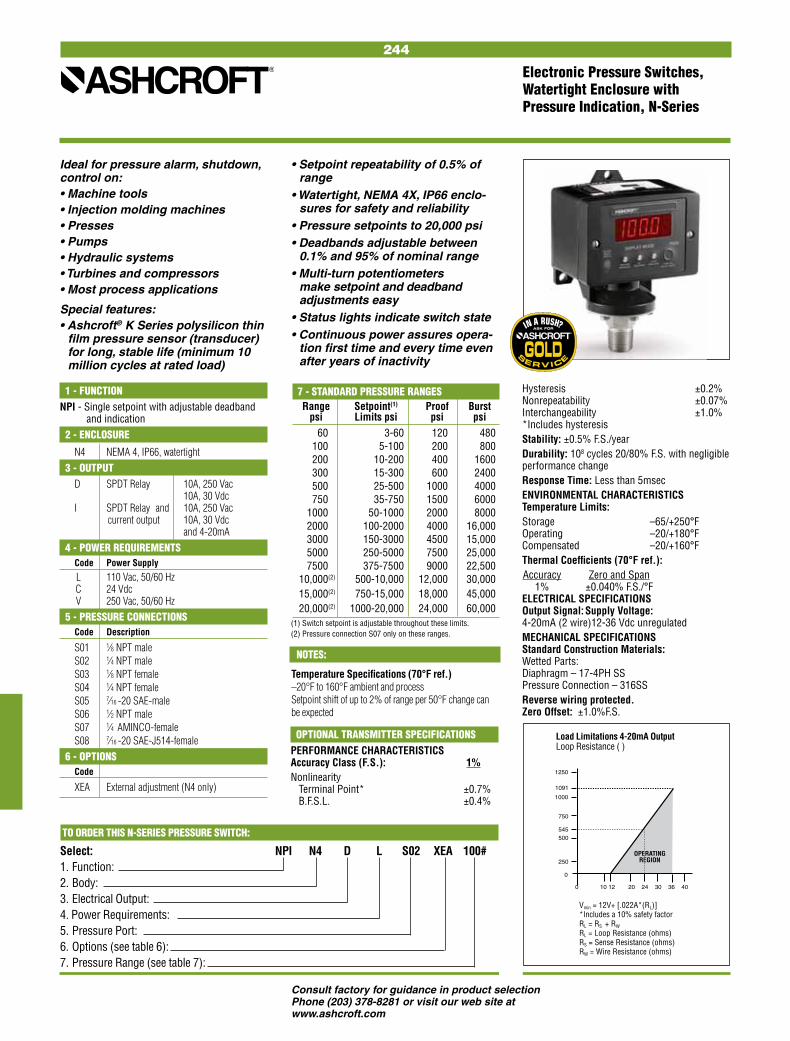
244
Consult factory for guidance in product selectionPhone (203) 378-8281 or visit our web site at www.ashcroft.com
1 - FUNCTIONNPI - Single setpoint with adjustable deadband and indication 2 - ENCLOSURE
N4 NEMA 4, IP66, watertight 3 - OUTPUT D SPDT Relay 10A, 250 Vac 10A, 30 Vdc I SPDT Relay and 10A, 250 Vac current output 10A, 30 Vdc and 4-20mA 4 - POWER REQUIREMENTS Code Power Supply
L 110 Vac, 50/60 Hz C 24 Vdc V 250 Vac, 50/60 Hz 5 - PRESSURE CONNECTIONS Code Description
S01 1⁄8 NPT male S02 1⁄4 NPT male S03 1⁄8 NPT female S04 1⁄4 NPT female S05 7⁄16 -20 SAE-male S06 1⁄2 NPT male S07 1⁄4 AMINCO-female S08 7⁄16 -20 SAE-J514-female 6 - OPTIONS Code
XEA External adjustment (N4 only)
Electronic Pressure Switches, Watertight Enclosure with Pressure Indication, N-Series
Ideal for pressure alarm, shutdown, control on:• Machine tools• Injection molding machines• Presses• Pumps• Hydraulic systems• Turbines and compressors• Most process applications
Special features:• Ashcroft® K Series polysilicon thin
film pressure sensor (transducer) for long, stable life (minimum 10 million cycles at rated load)
7 - STANDARD PRESSURE RANGES Range Setpoint(1) Proof Burst psi Limits psi psi psi 60 3-60 120 480 100 5-100 200 800 200 10-200 400 1600 300 15-300 600 2400 500 25-500 1000 4000 750 35-750 1500 6000 1000 50-1000 2000 8000 2000 100-2000 4000 16,000 3000 150-3000 4500 15,000 5000 250-5000 7500 25,000 7500 375-7500 9000 22,500 10,000(2) 500-10,000 12,000 30,000 15,000(2) 750-15,000 18,000 45,000 20,000(2) 1000-20,000 24,000 60,000(1) Switch setpoint is adjustable throughout these limits.(2) Pressure connection S07 only on these ranges.
TO ORDER THIS N-SERIES PRESSURE SWITCH:
Select: NPI N4 D L S02 XEA 100#1. Function: 2. Body: 3. Electrical Output: 4. Power Requirements:5. Pressure Port: 6. Options (see table 6): 7. Pressure Range (see table 7):
• Setpoint repeatability of 0.5% of range
• Watertight, NEMA 4X, IP66 enclo-sures for safety and reliability
• Pressure setpoints to 20,000 psi• Deadbands adjustable between
0.1% and 95% of nominal range• Multi-turn potentiometers
make setpoint and deadband adjustments easy
• Status lights indicate switch state• Continuous power assures opera-
tion first time and every time even after years of inactivity
Load Limitations 4-20mA OutputLoop Resistance Ω
0 10 12 20 24 30 36 40
0
250
500
750
1000
1250
1091
OPERATINGREGION
545
Vmin = 12V+ [.022A*(RL)] *Includes a 10% safety factor RL = RS + RW RL = Loop Resistance (ohms) RS = Sense Resistance (ohms) RW = Wire Resistance (ohms)
Load Limitations 4-20mA Output Loop Resistance (Ω)
OPTIONAL TRANSMITTER SPECIFICATIONSPERFORMANCE CHARACTERISTICS Accuracy Class (F.S.): 1%Nonlinearity Terminal Point* ±0.7% B.F.S.L. ±0.4%
Hysteresis ±0.2% Nonrepeatability ±0.07% Interchangeability ±1.0% *Includes hysteresisStability: ±0.5% F.S./yearDurability: 108 cycles 20/80% F.S. with negligible performance changeResponse Time: Less than 5msecENVIRONMENTAL CHARACTERISTICS Temperature Limits:Storage –65/+250°F Operating –20/+180°F Compensated –20/+160°FThermal Coefficients (70°F ref.): Accuracy Zero and Span 1% ±0.040% F.S./°F ELECTRICAL SPECIFICATIONS Output Signal: Supply Voltage: 4-20mA (2 wire) 12-36 Vdc unregulatedMECHANICAL SPECIFICATIONS Standard Construction Materials: Wetted Parts: Diaphragm – 17-4PH SS Pressure Connection – 316SSReverse wiring protected. Zero Offset: ±1.0%F.S.
NOTES:
Temperature Specifications (70°F ref.) –20°F to 160°F ambient and process Setpoint shift of up to 2% of range per 50°F change can be expected
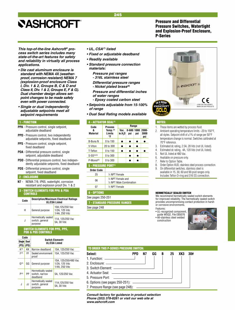
245
Consult factory for guidance in product selectionPhone (203) 378-8281 or visit our web site at www.ashcroft.com
Code Process Range
& Temp.(2) Vac. 0-600 1000 2000- Material Limits in.H2O psi psi 3000 °F psi
B-Buna N 0 to 150
V-Viton 20 to 300
T-Teflon 0 to 150
S-SS(6)(9) 0 to 300
P-Monel(6) 0 to 300
3 - SWITCH ELEMENTS FOR PPA & PDA CONTROLS
Description/Maximum Electrical Ratings Code UL/CSA Listed
10A,125/250 Vac H General purpose 1/2A, 125 Vdc 1/4A, 250 Vdc Hermetically sealed J switch, general 11A, 125/250 Vac purpose 5A, 30 Vdc
SWITCH ELEMENTS FOR PPD, PPS, PDD & PDS CONTROLS
Code Switch Elements Single Dual UL/CSA ListedS
(PS) (PD) K(4) KK Narrow deadband 15A, 125/250 Vac F(4) FF Sealed environment 15A, 125/250 Vac proof 15A, 125/250/480 Vac G(5) GG General purpose 1/2A, 125 Vdc 1/4A, 250 Vdc Hermetically sealed P(3) PP switch, narrow 5A, 125/250 Vac deadband Hermetically sealed J JJ switch, general 11A,125/250 Vac purpose 5A, 30 Vdc
TO ORDER THIS P-SERIES PRESSURE SWITCH:
Select: PPD N7 GG B 25 XK3 30#1. Function: 2. Enclosure: 3. Switch Element: 4. Actuator Seal: 5. Pressure Port: 6. Options (see pages 250-251): 7. Pressure Range (see page 248):
Pressure and Differential Pressure Switches, Watertight and Explosion-Proof Enclosure, P-Series
• UL, CSA(7) listed• Fixed or adjustable deadband• Readily available• Standard pressure connection
materials:Pressure psi ranges - 316L stainless steelDifferential pressure ranges - Nickel plated brass(8)
Pressure and differential inches of water ranges - Epoxy coated carbon steel
• Setpoints adjustable from 15-100% of range
• Dual Seal Rating models available
This top-of-the-line Ashcroft® pro-cess switch series includes many state-of-the-art features for safety and reliability in virtually all process applications.• Die cast aluminum enclosure is
standard with NEMA 4X (weather-proof, corrosion resistant) NEMA 7 (explosion-proof enclosure Class I, Div. 1 & 2, Groups B, C & D and Class II, Div. 1 & 2, Groups E, F & G). Dual chamber design allows set-point changes to be made safely even with power connected.
• Single or dual independently adjustable setpoints meet all setpoint requirements
1 - FUNCTIONPPA - Pressure control, single setpoint, adjustable deadbandPPD - Pressure control, two independently adjustable setpoints, fixed deadband PPS - Pressure control, single setpoint, fixed deadbandPDA - Differential pressure control, single setpoint, adjustable deadbandPDD - Differential pressure control, two indepen-
dently adjustable setpoints, fixed deadbandPDS - Differential pressure control, single setpoint, fixed deadband 2 - ENCLOSUREN7 - NEMA 7/9, IP65, watertight, corrosion
resistant and explosion proof Div. 1 & 2
6 - OPTIONSSee pages 250-251
7 - STANDARD PRESSURE RANGESSee page 248
4 - ACTUATOR SEAL(1)
5 - PRESSURE PORT(1)
Order Code
25 1⁄4 NPT Female
1⁄4 NPT Female and
06 1⁄2 NPT Male Combination
07 1⁄2 NPT Female
HERMETICALLY SEALED SWITCHWe recommend hermetically sealed switch elements for improved reliability. The hermetically sealed switch provides uncompromising contact protection in harsh or corrosive environments. Features:• UL-recognized component,
guide WSQ2, File E85076• All-stainless steel welded
construction
LOOK FOR THIS AGENCY MARK ON OUR PRODUCTS
NOTES:
1. These items are wetted by process fluid.2. Ambient operating temperature limits –20 to 150°F,
all styles. Setpoint shift of ±1% of range per 50°F temperature change is normal. Switches calibrated at 70°F reference.
3. Estimated dc rating, 2.5A, 28 Vdc (not UL listed).4. Estimated dc rating, .4A, 120 Vdc (not UL listed).5. Not UL listed at 480 Vac.6. Available on pressure only.7. Refer to Option Table.8. Order Option XUD, stainless steel process connection.9. On differential switches, stainless steel is available in 15, 30, 60 and 90 psid ranges only. Includes Teflon O-ring and 316 SS connection.
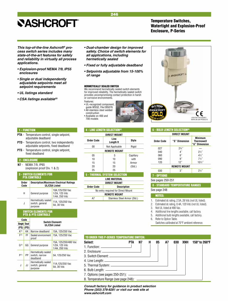
246
Consult factory for guidance in product selectionPhone (203) 378-8281 or visit our web site at www.ashcroft.com
6 - BULB LENGTH SELECTION(5)
DIRECT MOUNT Minimum Order Code “S” Dimension Thermowell “U” Dimension
027 23⁄4˝ — 040 4˝ 21⁄2˝ 060 6˝ 41⁄2˝ 090 9˝ 71⁄2˝ 120 12˝ 101⁄2˝
REMOTE MOUNT
030 3˝ 21⁄2˝
This top-of-the-line Ashcroft® pro-cess switch series includes many state-of-the-art features for safety and reliability in virtually all process applications.
• Explosion-proof NEMA 7/9, IP55 enclosures
• Single or dual independently adjustable setpoints meet all setpoint requirements
• UL listings standard
• CSA listings available(6)
• Dual-chamber design for improved safety. Choice of switch elements for all applications, including hermetically sealed
• Fixed or fully adjustable deadband
• Setpoints adjustable from 15-100% of range
Temperature Switches, Watertight and Explosion-Proof Enclosure, P-Series
NOTES:
1. Estimated dc rating, 2.5A, 28 Vdc (not UL listed).2. Estimated dc rating, 0.4A, 120 Vdc (not UL listed).3. Not UL listed at 480 Vac.4. Additional line lengths available, call factory.5. Additional bulb lengths available, call factory.6. Refer to Option Table. Switches calibrated at 70°F ambient reference.
TO ORDER THIS P-SERIES TEMPERATURE SWITCH:
Select: PTA N7 H 05 A7 030 XNH 150° to 260°F1. Function: 2. Enclosure: 3. Switch Element: 4. Line Length: 5. Thermal System: 6. Bulb Length: 7. Options (see pages 250-251):8. Temperature Range (see page 248):
4 - LINE LENGTH SELECTION(4)
DIRECT MOUNT Order Code Line Style Length ft
00 Not Applicable Rigid
REMOTE MOUNT
05 5 Capillary 10 10 with 15 15 Armor 20 20 (Std.) 25 25
1 - FUNCTIONPTA - Temperature control, single setpoint, adjustable deadbandPTD - Temperature control, two independently adjustable setpoints, fixed deadband PTS - Temperature control, single setpoint, fixed deadband
3 - SWITCH ELEMENTS FOR PTA CONTROLS
Order Description/Maximum Electrical Ratings Code UL/CSA Listed
10A,125/250 Vac H General purpose 1/2A, 125 Vdc 1/4A, 250 Vdc Hermetically sealed J switch, general 11A, 125/250 Vac purpose 5A, 30 Vdc
SWITCH ELEMENTS FOR PTD & PTS CONTROLS
Code Switch Elements Single Dual UL/CSA ListedS
(PS) (PD) K(2) KK Narrow deadband 15A, 125/250 Vac F(2) FF Sealed environment 15A, 125/250 Vac proof 15A, 125/250/480 Vac G(3) GG General purpose 1/2A, 125 Vdc 1/4A, 250 Vdc Hermetically sealed P(1) PP switch, narrow 5A, 125/250 Vac deadband Hermetically sealed J JJ switch, general 11A,125/250 Vac purpose 5A, 30 Vdc
2 - ENCLOSUREN7 - NEMA 7/9, IP65
(explosion proof Div. 1 & 2)
7 - OPTIONSSee pages 250-251
8 - STANDARD TEMPERTATURE RANGESSee page 248
5 - THERMAL SYSTEM SELECTIONLINE MATERIALDIRECT MOUNT
Order Code Description No entry required for Direct Mount
REMOTE MOUNT A7 Stainless Steel Armor (Std.)
HERMETICALLY SEALED SWITCHWe recommend hermetically sealed switch elements for improved reliability. The hermetically sealed switch provides uncompromising contact protection in harsh or corrosive environments. Features:• UL-recognized component,
guide WSQ2, File E85076• All-stainless steel welded
construction• Available on 400 and
700 models LOOK FOR THIS AGENCY MARK ON OUR PRODUCTS

247
Consult factory for guidance in product selectionPhone (203) 378-8281 or visit our web site at www.ashcroft.com
NOTES:1. Switches may generally be set between 15% and 100%
of nominal range on increasing pressure. Consult fac-tory for applications where setpoints must be lower.
2. All deadbands are given in English units as shown in the nominal range column. Deadbands shown are for switches with Buna N diaphragm.
Approximate deadbands for optional diaphragms: Viton: Multiply Buna N value by 1.4 Teflon: Multiply Buna N value by 1.2 Stainless Steel: Multiply Buna N value by 1.7 Monel: Multiply Buna N value by 1.73. Available with remote mount thermal system only.
DIFFERENTIAL PRESSURE SWITCHES Overpressure Ratings Approximate Deadband(2,4) Switch Element (Buna-N Diaphragm)
Nominal Range (1) Static psi Proof psi 20, 26, 27 21, 24, 31 50 22 32, 42
30 in.H2Od 750 mmH2O 7.5 kPa 5.4 21.6 0.3-0.6 1.5-2.5 0.45-2.0 0.5-2.0 2.1-3.5 60 in.H2Od 1500 mmH2O 15 kPa 5.4 21.6 0.5-1.3 1.5-3.5 0.9-2.5 0.7-3.0 2.1-5.0 100 in.H2Od 2500 mmH2O 25 kPa 5.4 21.6 0.6-1.6 2.5-5.5 1.1-4.0 1.0-4.0 3.5-7.7 150 in.H2Od 3750 mmH2O 37 kPa 5.4 21.6 1.0-2.5 4.5-8.5 1.8-6.5 2.0-6.0 6.3-12.0 15 psid 1 kg/cm2 100 kPa 500 2000 0.5-1.0 2.0-5.0 0.7-3.5 0.7-1.4 2.8-7.0 30 psid 2.5 kg/cm2 200 kPa 500 2000 1.0-2.0 2.0-5.0 1.5-3.5 1.4-2.8 2.8-7.0 60 psid 4 kg/cm2 400 kPa 500 2000 2.0-4.0 3.0-6.0 3.0-4.5 2.8-5.6 4.2-8.5 100 psid 7 kg/cm2 700 kPa 1000 4000 4.0-10.0 11.0-20.0 7.0-15.0 6.0-14.0 16.0-28.0 200 psid 14 kg/cm2 1400 kPa 1000 4000 5.0-15.0 12.0-40.0 10.0-86.0 7.0-21.0 17.0-56.0 400 psid 28 kg/cm2 2800 kPa 1000 8000 10.0-20.0 20.0-60.0 15.0-40.0 14.0-28.0 28.0-84.0 600 psid 42 kg/cm2 4200 kPa 1000 8000 20.0-40.0 80.0-150.0 30.0-115.0 30.0-56.0 112.0-210.0
TEMPERATURE RANGE SELECTION Adjustable Range Max. Temp. Approximate Deadband(6) Switch Element
°F °C °F 20, 26, 27 21, 24, 31 50 22 32, 42
–40 to 60 –40 to16 400 1.0-2.0 3.0-8.0 1.5-5.5 1.4-6.0 8.0-16.0 0 to 100 –20 to 40 400 1.5-3.0 5.0-12.0 2.2-8.5 1.5-7.5 9.0-20.0 75 to 205 20 to 95 400 1.5-3.5 8.0-16.0 2.5-12.0 2.0-9.0 10.0-24.0 150 to 260 65 to125 400 1.5-3.0 5.0-12.0 2.2-8.5 2.0-9.0 10.0-24.0 235 to 375 110 to 190 500 1.5-3.5 5.0-12.0 2.2-8.5 2.0-9.0 10.0-24.0 350 to 525(7) 175 to 275 700 2.0-4.5 8.0-16.0 3.2-12.0 2.5-10.0 15.0-34.0 500 to 750(3) 260 to 400 900 4.0-8.0 16.0-30.0 7.0-24.0 5.0-23.0 30.0-50.0
PRESSURE/VACUUM SWITCHES Overpressure Ratings Approximate Deadband(2) Switch Element (Buna-N Diaphragm)
Nominal Range (1) Proof psi Burst psi 20, 26, 27 21, 24, 31 50 22 32, 42
Vacuum –30 in.Hg –760 mmHg –100 kPa 250 400 0.3-0.7 1.5-4.0 0.5-2.2 0.4-1.5 2.1-4.2
Compound –15 in.H2O/ –375 mmH2O/ –3.7 kPa 20 35 0.15-0.75/ 1.5-2.5/ .45-2.0/ 0.5-1.2/ 2.1-3.5/ 15 in.H2O 375 mmH2O 3.7 kPa 0.15-0.75 1.5-2.5 0.45-2.0 0.5-1.2 .2.1-3.5 –30 in.H2O –760 mmH2O/ –7.5 kPa 20 35 0.30-0.60/ 1.5-2.5/ 0.45-2.0/ 0.5-1.5/ 2.1-3.5/ 30 in.H2O 760 mmH2O 7.5 kPa 0.30-0.60 1.5-2.5 0.45-2.0 0.5-1.5 2.1-3.5 –30 in.Hg/ –760 mmHg/ –100 kPa 250 400 0.5-1.0/ 2.0-3.5/ 0.75-2.5/ 0.7-1.8/ 2.8-4.2/ 15 psi 1.0 kg/cm2 100 kPa 0.3-0.7 0.5-2.0 0.5-1.0 0.5-1.4 0.7-2.1 –30 in.Hg/ –760 mmHg/ –100 kPa 250 400 1.0-1.5/ 3.0-6.0/ 1.2-4.5/ 1.4-2.4/ 4.2-8.4/ 30 psi 2.0 kg/cm2 200 kPa 0.3-0.8 1.0-2.0 0.7-1.5 0.4-1.3 1.4-2.8 –30 in.Hg/ –760m mmHg/ –100 kPa 250 400 2.0-3.0 5.0-9.0 2.5-7.0 2.8-4.5/ 7.0-12.0 60 psi 4.0 kg/cm2 400 kPa 0.7-1.5 3.0-5.0 1.1-4.0 1.0-2.3 4.2-7.0
Pressure 10 in.H2O 250 mmH2O 2.5 kPa 20 35 0.2-0.5 1.0-2.0 0.35-1.5 0.4-1.0 1.4-2.8 30 in.H2O 750 mmH2O 7.5 kPa 20 35 0.3-0.6 1.5-2.5 4.5-2.0 0.5-2.0 2.1-3.5 60 in.H2O 1500m mmH2O 15 kPa 20 35 0.5-1.3 1.5-3.5 0.9-2.5 0.7-3.0 2.1-5.0 100 in.H2O 2500 mmH2O 25 kPa 20 35 0.6-1.6 2.5-5.5 1.1-4.0 1.0-4.0 3.5-7.7 150 in.H2O 3750 mmH2O 37 kPa 20 35 1.0-2.5 4.5-8.5 1.7-6.5 2.0-6.0 6.0-12.0 15 psi 1.0 kg/cm2 100 kPa 500 1500 0.1-.35 0.5-1.5 0.2-1.0 0.4-1.0 0.7-2.1 30 psi 2.5 kg/cm2 200 kPa 500 1500 0.1-.50 0.5-1.5 0.3-1.0 0.4-1.0 0.7-2.1 60 psi 4.0 kg/cm2 400 kPa 500 1500 0.3-1.0 1.0-3.5 0.7-2.5 0.6-2.0 1.4-5.0 100 psi 7.0 kg/cm2 700 kPa 1000 3000 0.5-1.7 1.5-5.0 1.1-3.5 1.0-4.5 2.1-7.0 200 psi 14 kg/cm2 1400 kPa 1000 3000 1-3 5-13 2-9 3.0-7.5 7.0-18.2 400 psi 28 kg/cm2 2800 kPa 2400 3000 4-7.5 5-24 5.5-15 4.0-11.0 7.0-33.6 600 psi 42 kg/cm2 4200 kPa 2400 3000 4-11 9-30 7-20 5.0-23.0 12.6-42 1000 psi (8) 70 kg/cm2 7000 kPa 12000 18000 7-30 30-110 18-70 15.0-60 42-154 3000 psi 210 kg/cm2 21000 kPa 12000 18000 15-60 80-235 37-160 30.0-130.0 112-329
4. Deadbands given are for zero static working pressure.5. For approximate deadbands for dual switch elements,
multiply the single switch element by 1.6.6. All deadbands given in °F.7. Not available with 23/4˝ stem.8. Proof pressure is 4000 psi with stainless steel and monel
welded diaphragms.
Nominal Ranges and Deadbands Pressure and Temperature Switches, B-Series

248
Consult factory for guidance in product selectionPhone (203) 378-8281 or visit our web site at www.ashcroft.com
NOTES:1. Switches may generally be set between 15% and 100%
of nominal range on increasing pressure. Consult fac-tory for applications where setpoints must be lower.
2. All deadbands are given in English units as shown in the nominal range column. Deadbands shown are for switches with Buna N diaphragm.
4. Deadbands for PPS, PPD, PDS, PDD, PTD, and PDS models are fixed within the range of values shown.
5. Available with remote mount thermal system only.6. Deadbands given are for zero static working pressure.7. All deadbands given in °F.8. Not available with 23/4˝ stem.9. Proof pressure is 4000 psi with stainless steel and
monel welded diaphragms.
Approximate deadbands for optional diaphragms: Viton: Multiply Buna N value by 1.4 Teflon: Multiply Buna N value by 1.2 Stainless Steel: Multiply Buna N value by 1.7 Monel: Multiply Buna N value by 1.73. Deadbands for PTA, PPA and PDA are adjustable between the values shown.
DIFFERENTIAL PRESSURE SWITCHES Overpressure Approximate Deadband(2,6) Switch Element (Buna-N Diaphragm)
Ratings PDA(3) PDS(4) PDD(4)
Static Working Proof Switch Element
Nominal Range (1) Pressure psi psi J, H G J, H K, F P GG JJ, HH KK,FF PP
30 in.H2Od 750 mmH2O 5.4 21.6 5.5-27 3-5 4-6.5 0.5-1 .5-2 3-5 4-6.5 0.5-1 1.0-2.8 60 in.H2Od 1500 mmH2O 5.4 21.6 5.5-54 3-5 4.5-6.5 0.5-2 1-2 3-5 4.-6.5 0.5-2 1.0-2.8 100 in.H2Od 2500 mmH2O 5.4 21.6 8.5-90 4-6 4.0-8.5 1-2 1-3 4-7 4.-8.5 1-2 2.0-4.2 150 in.H2Od 3750 mmH2O 5.4 21.6 18-135 5-11 10-18 1.5-3 2-6 8-14 10-18 1.5-3. 3.0-8.4 15 psid 2 kg/cm2 500 2000 2.5-13 1-2 1-3 0.5-1 0.5-2 1-2 1-3 0.5-1 1.0-2.8 30 psid 2 kg/cm2 500 2000 3.5-27 1-2.5 2-4.5 0.5-1 1-2 1-2.5 2-4.5 0.5-1.5 1.0-2.8 60 psid 4 kg/cm2 500 2000 6.5-54 2-4 4-7 1-1.5 1-2.5 1-2.4 4-7 1-2 1.0-3.5 100 psid 7 kg/cm2 500 2000 10-90 5-7 5-10 1-2.5 2-4 5-7 5-10 1-2.5 2.0-5.6 200 psid 14 kg/cm2 1000 4000 20-180 10-1 5 10-18 1-4 5-8 10-20 10-18 3-6 3.0-11.2 400 psid 28 kg/cm2 1000 8000 45-360 16-30 16-45 4-8 5-15 16-30 16-45 4-8 40.-21.0
TEMPERATURE RANGE SELECTION Approximate Deadband (Buna N Diaphragm)(2)
Nominal Range Max. PTA(3) PTS(4) PTD(4)
Temp. Switch Element
°F °C °F
J, H G J, H K, F P GG JJ, HH KK, FF PP –40 to 60 –40 to16 400 18-90 2-10 9-18 1-2 1-5 2-10 9-18 1-2 2.0-7.0 0 to 100 –20 to 40 400 30-90 2-15 10-30 1-3 1.5-7 2-15 10-30 1.5-3 3.0-10.0 75 to 205 20 to 95 400 34-120 2-17 10-34 1.5-3.5 1.5-8 2-17 10-34 1.5-3.5 3.0-12.0 150 to 260 65 to125 400 25-100 2.5-12 9-25 1-2.5 1-7 2.5-12 9-25 1-2.5 3.0-10.0 235 to 375 110 to 190 500 35-130 2-18 10-35 1-3.5 1.5-8 2-18 10-35 1-3.5 3.0-12.0 350 to 525(8) 175 to 275 700 40-165 3-25 15-40 2-4.5 2.5-11 3-25 15-40 2-4.5 4.0-15.5 500 to 750(5) 200 to 400 900 50-200 20-36 36-60 5-10 6-21 20-36 36-60 5-10 7.0-30.0
PRESSURE/VACUUM SWITCHES Overpressure Approximate Deadband(2) Switch Element (Buna-N Diaphragm)
Ratings PPA(3) PPS(4) PPD(4)
Proof Burst Switch Element
Nominal Range (1) psi psi J, H G J, H K, F P GG JJ, HH KK,FF PP
Vacuum
–30 in.Hg –760 mmHg –100 kPa 250 400 7-26 3-5 3-6.5 1-2 1-2.5 3-5 3-6.5 1-2 1.0-3.5
Compound
–30 in.Hg/ –760 mmHg/ –100 kPa 250 400 10-25 3-5 2.5-3.5 1-2 1-2.5 3-5 2.5-4.5 1-2 1.0-3.5/ 15 psi 1.0 kg/cm2 100 kPa 4-13 1-2 1-3 0.5-2 0.5-2 2-4 1-3 0.5-1 1.0-2.8
Pressure 30 in.H2O 750 mmH2O 7.5 kPa 20 35 4.-27 1.5-3.5 2-5 0.5-1 0.5-2 1.5-3.5 2-5 0.5-1 1.0-2.8 60 in.H2O 1500 mmH2O 15 kPa 20 35 5-54 1.5-3.5 2.5-5 0.5-2.0 1-2 1.5-3.5 2.5-5.0 .0.5-2.0 1.0-2.8 100 in.H2O 2500 mmH2O 25 kPa 20 35 8.5-90 4-6 4-8.5 1-2 1-3 4-7 4-8.5 1-2 2.0-4.2 150 in.H2O 3750 mmH2O 37 kPa 20 35 18-135 5-11 10-18 1.5-3 2-6 8-14 10-18 1.5-3 3.0-8.4 15 psi 1 kg/cm2 100 kPa 500 1500 2.5-13 1-2 1-0.5 0.5-1 0.5-2 1-2 1-3.0 0.5-1 1.0-2.8 30 psi 2.5 kg/cm2 200 kPa 500 1500 3.5-26 1-2.5 2-4.5 0.5-1.5 0.5-1.5 1-2.5 2-4.5 0.5-1.5 1.0-3.0 60 psi 4 kg/cm2 400 kPa 500 1500 6.5-54 2-4 4-7 1-2 1-2.5 2-4 4-7 1-2 2.0-3.5 100 psi 7 kg/cm2 700 kPa 1000 3000 10-90 5-7 5-10 1-2.5 2-4 5-7 5-10 1-2.5 2.0-5.6 200 psi 14 kg/cm2 1400 kPa 1000 3000 20-180 10-15 10-18 1-4 5-15 10-20 15-25 3-6 4.0-12.0 400 psi 28 kg/cm2 2800 kPa 2400 3000 45-360 16-30 16-45 4-8 5.0-15 16-30 16-45 4-8 5.0-21.0 600 psi 42 kg/cm2 4200 kPa 2400 3000 75-540 16-50 20-75 5-8 6-25 16-50 20-75 5-15 8.0-35.0 1000 psi (9) 70 kg/cm2 7000 kPa 12000 14000 160-900 75-130 50-160 7-30 10-85 75-130 50-160 7-30 20.0-119.0 2000 psi 140 kg/cm2 14000 kPa 12000 14000 350-1800 150-200 150-350 20-50 25-110 150-200 150-350 20-50 35.0-154.0 3000 psi 210 kg/cm2 21000 kPa 12000 14000 400-2600 180-250 180-400 30-70 30-190 180-250 180-400 30-70 40.0-266.0
Nominal Ranges and Deadbands Pressure and Temperature Switches, P-Series

249
Consult factory for guidance in product selectionPhone (203) 378-8281 or visit our web site at www.ashcroft.com
Nominal Ranges and Deadbands Pressure and Temperature Switches, L- and G-Series
NOTES:1. Switches may generally be set between 15% and 100%
of nominal range on increasing pressure. Consult fac-tory for applications where setpoints must be lower.
2. All deadbands are given in English units as shown in the nominal range column. Deadbands shown are for switches with Buna N diaphragm. Approximate deadbands for optional diaphragms:
Viton: Multiply Buna N value by 1.4 Teflon: Multiply Buna N value by 1.2 Stainless Steel: Multiply Buna N value by 1.7 Monel: Multiply Buna N value by 1.73. Deadbands for LTA, LPA and LDA are adjustable
between the values shown for all diaphragm materials.4. Deadbands for LPS, LPD, LDS, LDD, LTD, and LDS
models are fixed within the range of values shown.
5. Switches can be set at increase or decrease through-out the nominal range.
6. Available with remote mount thermal system only. 7. Deadbands given are for zero static working pressure. 8. All deadbands given in °F. 9. Not available with 23/4˝ stem. 10. Proof pressure is 4000 psi with stainless steel and
monel welded diaphragms.
DIFFERENTIAL PRESSURE SWITCHES
Overpressure Approximate Deadband(2,7) Switch Element (Buna-N Diaphragm)
Ratings LDA-GDA(3) LDS-GDS(4) LDD-GDD(4)
Static psi
Minimum Switch Element
Nominal Range (1) Proof psi J, H G J, H K, F P GG JJ, HH KK,FF PP
Pressure 30 in.H2Od 750 mmH2O 5.4 21.6 4.0-27 1.5-3.5 2.0-4.0 0.5-1.0 0.7-2.0 2.1-4.9 2.8-5.6 0.7-1.4 0.7-2.8 60 in.H2Od 1500 mmH2O 5.4 21.6 5.0-54 1.5-4.0 2.5-5.0 0.5-1.4 1.0-2.5 2.5-6 3.5-7.0 0.7-2.0 2-3.5 100 in.H2Od 2500 mmH2O 5.4 21.6 8.5-90 4.0-5.5 4.0-8.5 1.0-2.0 1.4-3.0 5.6-7.7 5.6-11.9 1.4-2.8 2-4.2 150 in.H2Od 3750 mmH2O 5.4 21.6 18-135 5.0-11 10-18 1.5-3.0 2.0-6.0 7.0-15.4 14-25.2 2.1-4.2 2.8-8.4 30 psid 2 kg/cm2 500 2000 3.0-27 1.0-2.5 1.0-3.0 1.0-1.5 1.0-1.8 2-5 3-6 1-2.1 1.4-2.4 60 psid 4 kg/cm2 500 2000 5-54 2-4 2-4.5 1-2 1-2.5 3-7 4-8 1.4-2.8 1.4-3.5 200 psid 14 kg/cm2 1000 4000 18-180 10-15 10-18 1.0-4.0 5.0-8.0 14-23 14-30 1.4-5.6 7.0-11.2 400 psid 28 kg/cm2 1000 8000 45-360 16-30 16-45 4.0-8.0 5.0-15 22.4-42 22.4-36 5.6-11.2 7.0-21.0
TEMPERATURE RANGE SELECTION Approximate Deadband(8) Switch Element
Adjustable Range Max. LTA-GTA(3) LTS-GTS(4) LTD-GTD(4)
Temp. Switch Element
°F °C °F
J, H G J, H K, F P GG JJ, HH KK,FF PP –40 to 60 –40 to16 400 18-90 4.0-10 9.0-18 1.5-3 2-5 4-10 9.0-18 1.5-3 2-5 0 to 100 –20 to 40 400 30-90 5.0-15 10-30 1.5-5.5 3-7 5-15 10-30 1.5-4.5 3-7 75 to 205 20 to 95 400 34-120 6.0-18 10-34 3-5.5 3-8 6-18 10-34 3-5.5 3-8 150 to 260 65 to125 400 25-100 3-13 9.0-25 1.5-4 3-7 3-13 9.0-25 1.5-4 3-7 235 to 375 110 to 190 500 35-130 6-19 10-35 2-5.5 3-8 6-17 10-35 2-5.5 3-8 350 to 525(9) 175 to 275 700 40-165 5-27 15-40 3-7 3.5-11 5-27 15-40 3-7 3.5-11 500 to 750(6) 260 to 400 900 50-200 20-36 5-10 6-21 20-36 20-36 36-60 5-10 6-21
PRESSURE/VACUUM SWITCHES
Overpressure Approximate Deadband(2) Switch Element (Buna-N Diaphragm)
Ratings LPA-GPA(3) LPS-GPS(4) LPD-GPD(4)
Proof psi
Minimum Switch Element
Nominal Range (1) Burst psi J, H G J, H K, F P GG JJ, HH KK,FF PP
Vacuum
–30 in.Hg –760 mmHg 250 400 6-24 2.5-4 4-6 1-2 1-2.5 3-5.5 4-6.5 1-2 1-2.5
Compound
–30 in.Hg/ –760 mmHg/ 250 400 6-24 2.5-4 4-6 1-2 1-2.5 3-5.5 4-6.5 1-2 1-2.5 15 psi0 1.0 kg/cm2 3-12 1-2.5 1-3.5 0.5-1.5 0.5-2 1.5-3.5 1.5-4 1-2 1-2
Pressure 30 in.H2O 750 mmH2O 20 35 4.0-27 1.5-3.5 2.0-4.0 0.5-1.0 0.7-2.0 2.1-4.9 2.8-5.6 0.7-1.4 0.7-2.8 60 in.H2O 1500 mmH2O 20 35 5.0-54 1.5-4. 2.5-5.0 0.5-1.4 1.0-2.5 3-5.6 3.5-7.0 0.7-2.0 2-3.5 100 in.H2O 2500 mmH2O 20 35 8.5-90 2.0-5.5 4.0-8.5 1.0-2.0 1.4-3.0 4-7.7 5.6-11.7 1.4-2.8 2-4.2 150 in.H2O 3750 mmH2O 20 35 18-135 5.0-11 10-18 1.5-3.0 2.0-6.0 7.0-16 14-25.1 2.1-4.2 5-9.2 15 psi 1 kg/cm2 500 1500 2.5-13 1.0-1.5 1.0-2.5 0.5-1.0 0.75-1.5 1.4-2.1 1.4-3.5 .7-1.4 1-1.4 30 psi 2 kg/cm2 500 1500 3.0-27 1.0-2.8 1.0-3.2 .75-1.5 1-1.8 1.4-5 3-6 1-2.1 1.4-2.5 60 psi 4 kg/cm2 500 1500 5.0-54 2.0-4.0 2.0-4.5 1.0-2.0 1.0-2.5 3-7 4-8 1.4-2.8 1.4-3.5 100 psi 7 kg/cm2 1000 3000 10-90 3-6 5.0-10 1.0-2.5 1.4-3.2 7-12 7.0-14 1.4-3.5 3-7 200 psi 14 kg/cm2 1000 3000 18-180 7-14 10-18 1.0-4.0 5.0-8.0 10-23 14-25 1.4-5.6 7.0-11.2 400 psi 28 kg/cm2 2400 3000 45-360 16-30 16-45 4.0-8.0 5.0-15 22-42 22-63 5.6-11.2 7.0-21 600 psi 42 kg/cm2 2400 3000 75-540 16-50 20-75 5.0-15 6.0-25 22-70 28-105 7.0-21 8.0-35 1000 psi (10) 70 kg/cm2 12000 14000 160-900 75-130 50-160 7.0-30 10-85 70-180 70-223 10-42 14-119 2000 psi 140 kg/cm2 12000 14000 350-1800 150-200 150-350 20-50 25-110 209-279 209-488 28-70 35-154 3000 psi 210 kg/cm2 12000 14000 400-2600 180-250 180-400 30-70 30-190 251-349 251-558 42-98 42-226
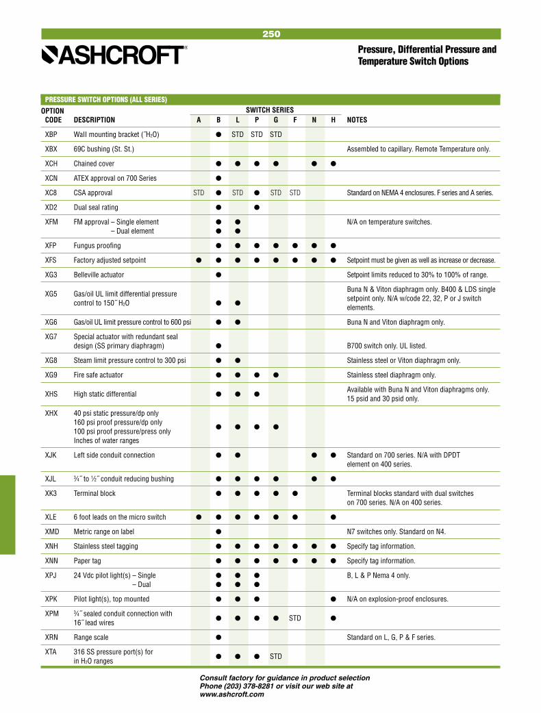
250
Consult factory for guidance in product selectionPhone (203) 378-8281 or visit our web site at www.ashcroft.com
Pressure, Differential Pressure and Temperature Switch Options
PRESSURE SWITCH OPTIONS (ALL SERIES)OPTION SWITCH SERIES CODE DESCRIPTION A B L P G F N H NOTES
XBP WaII mounting bracket (˝H2O) STD STD STD
XBX 69C bushing (St. St.) Assembled to capillary. Remote Temperature only.
XCH Chained cover
XCN ATEX approval on 700 Series
XC8 CSA approval STD STD STD STD Standard on NEMA 4 enclosures. F series and A series.
XD2 Dual seal rating
XFM FM approval – Single element N/A on temperature switches. XFM FM approval – Dual element
XFP Fungus proofing
XFS Factory adjusted setpoint Setpoint must be given as well as increase or decrease.
XG3 Belleville actuator Setpoint limits reduced to 30% to 100% of range.
XG5 Gas/oil UL limit differential pressure Buna N & Viton diaphragm only. B400 & LDS single
control to 150˝ H2O setpoint only. N/A w/code 22, 32, P or J switch elements.
XG6 Gas/oil UL limit pressure control to 600 psi Buna N and Viton diaphragm only.
XG7 Special actuator with redundant seal design (SS primary diaphragm) B700 switch only. UL listed.
XG8 Steam limit pressure control to 300 psi Stainless steel or Viton diaphragm only.
XG9 Fire safe actuator Stainless steel diaphragm only.
XHS High static differential Available with Buna N and Viton diaphragms only. 15 psid and 30 psid only.
XHX 40 psi static pressure/dp only 160 psi proof pressure/dp only
100 psi proof pressure/press only
Inches of water ranges
XJK Left side conduit connection Standard on 700 series. N/A with DPDT element on 400 series.
XJL 3⁄4˝ to 1⁄2˝ conduit reducing bushing
XK3 Terminal block Terminal blocks standard with dual switches on 700 series. N/A on 400 series.
XLE 6 foot leads on the micro switch
XMD Metric range on label N7 switches only. Standard on N4.
XNH Stainless steel tagging Specify tag information.
XNN Paper tag Specify tag information.
XPJ 24 Vdc pilot light(s) – Single B, L & P Nema 4 only. XPJ 24 Vdc pilot light(s) – Dual
XPK Pilot light(s), top mounted N/A on explosion-proof enclosures.
XPM 3⁄4˝ sealed conduit connection with 16˝ lead wires STD
XRN Range scale Standard on L, G, P & F series.
XTA 316 SS pressure port(s) for in H2O ranges STD

251
Consult factory for guidance in product selectionPhone (203) 378-8281 or visit our web site at www.ashcroft.com
Pressure, Differential Pressure and Temperature Switch Options
PRESSURE SWITCH OPTIONS (ALL SERIES)OPTION SWITCH SERIES CODE DESCRIPTION A B L P G F N H NOTES
XTM 2˝ pipe mounting bracket
XUD 316 stainless steel diff. press. conn. STD
XUX IECEx approval (700 series)
XO6 Pressure connection: 1⁄2 NPT male, Standard with 1000, 2000 and 3000 psi ranges. 1⁄4 NPT female combination
N/A Bottom connection only on D/P ˝H2O ranges.
XO7 Pressure connection: 1⁄2 NPT female STD
X2C DPDT with single setpoint adjustment Available with LPS, LDS, LTS, GPS, GTS and GDS models.
X3A Sanitary seal approved by 3A council Select either 11/2˝ or 2˝ Tri-Clamp seal.
X6B Cleaned for oxygen service N/A with Buna N diaphragm.
Diaphragm seals

252
Consult factory for guidance in product selectionPhone (203) 378-8281 or visit our web site at www.ashcroft.com
253
Consult factory for guidance in product selection Phone (203) 378-8281 or visit our web site at www.ashcroft.com
PRESSURE INSTRUMENTS
PROCESS GAUGES
INDUSTRIAL GAUGES
STAINLESS STEEL CASE GAUGES
SANITARY GAUGES
TEST INSTRUMENTS
DIAPHRAGM SEALS/INSTRUMENT ISOLATORS
COMMERCIAL GAUGES
SPECIAL APPLICATION COMMERCIAL GAUGES
PRESSURE TRANSDUCERS/TRANSMITTERS
TEMPERATURE INSTRUMENTS
BIMETAL THERMOMETERS
DIRECT-READING THERMOMETERS
HANDHELD THERMOMETERS
REMOTE-READING GAS THERMOMETERS
DIGITAL THERMOMETERS
REMOTE-READING VAPOR THERMOMETERS
TEMPERATURE REGULATORS
THERMOWELLS
PRESSURE/TEMPERATURE SWITCHES
PRESSURE SWITCHES
TEMPERATURE SWITCHES
ACCESSORIES & OPTIONS
APPLICATION DATA
AccESSORIES AND OPTIONSThrottle Screws ........................................... 255 Pulsation Dampener .................................... 255 Pressure Snubber........................................ 255 Steel Needle Valve ....................................... 256 Siphons ....................................................... 256 Chemiquip Valve Snubber ........................... 257 Chemiquip Limiting Valve ........................... 257 Diaphragm Seals ......................................... 257 Electric Warning Contacts ........................... 258Conversion Kit ............................................. 258 41/2˝ Ring Wrench, Type A-1285 ................... 259 6˝ Ring Wrench, Type A-1286 ...................... 259Pointer Puller Screw/Pin 112A381-01 ........ 259Pointer Puller Body 292A133-01 ................. 259Pointer Staker 188A101-01 ........................ 259Span Wrench 266A137-01 .......................... 25921/2˝ Ring Wrench Old Design 266B135-01 . 25931/2˝ Ring Wrench Old Design 266B134-01 . 25921/2˝ / 31/2˝ Nest Old Design 266B136-01 .... 25921/2˝ Ring Removal Current Design 101B221-02 ............................................. 25931/2˝ Ring Removal Current Design 101B221-01 ............................................. 25921/2˝ Nest Current Design 101B220-02 ....... 25931/2˝ Nest Current Design 101B220-01 ....... 259Cone Tool, Type A-1287 ............................... 260 Tool Kit, Type 1105T ..................................... 260 Hand Jack Set, Type 3220 ........................... 260 Cocks, 1092 ................................................. 260 Cocks, 1094 ................................................. 260 Cocks, 1095 ................................................. 260 Test Gauge Carrying Case 2005 .................. 260Options .................................................261-262
ACCESSORIES& OPTIONS

254
Consult factory for guidance in product selection Phone (203) 378-8281 or visit our web site at www.ashcroft.com

255
Consult factory for guidance in product selection Phone (203) 378-8281 or visit our web site at www.ashcroft.com
Ashcroft® Accessories
Throttling DevicesA throttling device should be used when a pressure gauge is subjected to rapid pressure fluctuations, which make the gauge difficult to read because of rapid pointer movement. Such a device reduces pressure impact, slows the speed and range of pointer movement, and prolongs gauge life. Throttling effect is obtained by installing a restricting orifice between the gauge socket connection and the Bourdon tube. Severe service applications are characterized by the presence of significant levels of pressure pulsation and/or vibration. Gauges
should be protected from severe pressure pulsation by the inclu-sion of a dampener such as a throttle plug/screw or porous metal snubber. If the pulsation is extreme, a liquid-filled gauge, with dampener, should be used. A liquid-filled gauge will also last significantly longer than a comparable dry gauge when vibration is present. If the vibration levels are extreme, the only solution may be to remotely mount the gauge away from the source of vibration. In that case capillary tubing may be used to connect the gauge to the pressure source.
The simplest means of providing a restriction in the socket, a throttle screw, should be ordered with the gauge. Threaded or pressed into an instrument socket, the throttle screw orifice selected is based on the vis-cosity of the pressure fluid, rapidity of pressure fluctuations, and the amount of dampening effect desired. A smaller orifice should be used for low viscosities, high frequencies, high
pressure and reduced pointer ampli-tude. To accommodate these variables, throttle screws are available in these sizes: 0.0135, 0.020, 0.031, 0.040, and 0.070 inches, in brass and stain-less steel. When orifice size or service condition is not specified, a 0.020-inch orifice will be supplied on Duragauge® pressure gauges 0.0135, on 25-35 1009 and 63 and 100mm 1008S.
THROTTLE SCREWS
Throttle screw
Type NPT Material Weight Number Conn. (oz.)
25-1106B 1⁄4 Brass 4 50-1106B 1⁄2 Brass 8 25-1106D 1⁄4 Steel* 4 50-1106D 1⁄2 Steel* 8
25-1106S 1⁄4 Stainless steel 4
50-1106S 1⁄2 Stainless steel 8
* Internal parts are stainless steel.
Threads onto a gauge socket and pro-vides restriction by means of a moving pin, which may be placed in either of five different sized holes, and thus allows the user to vary the amount of dampening to suit requirements. The pulsating pressure moves the pin up and down, providing a self-cleaning action. Dampeners are shipped with a pin in the “middle” hole, and may be used in either a vertical or horizontal po-sition. Maximum pressure is 5000 psi.
PULSATION DAMPENER
Porosity
Max Pore Cap. CFH at 1 psi For use with
Opening (Inches) Diff. Press.
D 0.005 6.5
E 0.0025 3.0
G 0.0008 1.1
HX 0.0006 0.4
Used for dampening and filter-ing, the snubber has a metal disc available in four standard grades of porosity. The one best suited for the application can be selected from the chart, using the same guidelines as for throttle screws. Due to the large filter area, the snubber has less tendency to clog than orifice-type devices. All-metal construc-tion permits the snubber to be washed in a variety of common solvents.
Oil(50 to 500 S.S.U.)
Air, Steam and Gases
MercuryManomometers
Water & Light Oils(Under 50 S.S.U.)
Type NPT Material Max psi Number Conn. Housing Filter Disc Rating 25-1112B 1⁄4
Brass 316 10,000 50-1112B 1⁄2 stainless steel 25-1112S 1⁄4 303 316 15,000 50-1112S 1⁄2 stainless steel stainless steel 25-1112M 1⁄4
R Monel Monel 15,000 50-1112M 1⁄2
PRESSURE SNUBBER

256
Consult factory for guidance in product selection Phone (203) 378-8281 or visit our web site at www.ashcroft.com
Type NPT Number Conn. Material Capacity
25-1098 I 1⁄4 Iron 500 psi @ 400°F
25-1098 B 1⁄4 Brass 250 psi @ 400°F
25-1098 S 1⁄4 ASTM A-106 seamless steel, 338 psi @ 1000° to 3360 psi Grade A from –20° to 400°F
50-1098 S 1⁄2 ASTM A-106 seamless steel, 333 psi @ 1000°F to 3000 psi Grade A from –20° to 400°F
50-1098 SD 1⁄2 ASTM A-106 seamless steel, 420 psi @ 1000°F to 3740 psi Grade A from –20° to 400°F
50-1098 CD 1⁄2 ASTM A-213 seamless steel, 1048 psi @ 1200°F to 9550 psi Grade T 22 from –20° to 400°F
50-1098 NS 1⁄2 Seamless stainless 294 psi @ 1500°F to steel, Type 316 3981 psi from –20 to 100°F
50-1098 ND 1⁄2 Seamless stainless 336 psi @ 1500°F steel, Type 316 5840 psi from –20° to 100°F
25-1100 A 1⁄4 Stainless steel
25-1100 I 1⁄4 Iron – 63⁄8˝ Long 500 psi @ 400°F
25-1100 IL 1⁄4 Iron – 8˝ Long
25-1100 IN 1⁄4 Iron – Angle
25-1100 B 1⁄4 Brass – 53⁄8˝ Long 250 psi @ 400°F
25-1100 BL 1⁄4 Brass – 8˝ Long
condensing hot vapors (not just steam) are present.
• Pig Tail Siphon–Number 1100 Series, 1⁄4˝ sizes: to 500 psi and 400°F.
• Coil Pipe Siphon –Number 1098 Series, 1⁄4, 1⁄2˝ sizes: to 9550 psi and 400°F.
In order to prevent live steam from entering a pressure gauge Bourdon tube, a siphon filled with water should be installed between the gauge and the process line. If freezing of the condensate in the loop of a siphon is a possibility, a diaphragm seal should be used to isolate the gauge from the process steam. Also use siphons whenever
SIPHONS
Type 1100
Type 1098
Ashcroft® Accessories
The steel needle valve is an economical, adjustable throttling device for any severe gauge application. It provides the most practical means for varying the orifice to determine the exact orifice for any specific service condition. The valve has an internal seat and is of bar stock construction.
STEEL NEEDLE VALVE
Type Numbers Pressure Ratings NPT Lock Bonnet Material Noncorrosive Service (psi)
Conn. Type Valves 100°F 550°F 850°F 1000°F
Carbon steel 1⁄4 25-7001L with 12-14% chrome
10,000 7735 — — 1⁄2 50-7001L Stainless steel stem 1⁄4 25-7004L 316 stainless 1⁄2 50-7004L steel 7000 4500 3895 3535 B-Max
C-Max
A PipeConn.
D
E-CLOSEDF-OPEN
Dimension – Inches
A NPT Conn. B C D – min. E F Weight oz.
1⁄4 21⁄8 7⁄8 21⁄2 3 31⁄8 8
1⁄2 21⁄4 11⁄4 21⁄2 31⁄16 33⁄16 21

257
Consult factory for guidance in product selection Phone (203) 378-8281 or visit our web site at www.ashcroft.com
Ashcroft® Accessories
Protects pressure instruments against surges and pulsations. Provides automatic posi-tive protection and accurate, repeatable performance. Automatic pressure shut-off. Built-in snubber enhances instrument, protecting performance.
Type Number Conn. Material Available Ranges(1) Style
100-800 psi L
25-5460 1⁄4 NPTF 303 SS 800-2500 psi M
2500-10,000 psi N
50-5500 1⁄2 NPTF 303 SS 10,000-18,000 psi O
(1) Use code XFS for factory setting.
CHEMIQUIP PRESSURE LIMITING VALVE (4)
Porosity Type of Service Designations
High viscous fluids (over 500 S.S.U.) C Oil (225-500 S.S.U.) D Water and light oils (30-225 S.S.U.) E Vapor and low viscosity fluids (Below 30 S.S.U.) F Air or other gases G Extreme gas pulsations HX
DIAPHRAGM SEALS
Designed for use with pressure gauges or switches or transmitters on process applications where:
• Process element materials capable of withstanding corrosive effects of certain fluids are not available.
• The process fluid being measured would normally clog the pressure measuring element.
• The process fluid in the measuring element might freeze due to changes in ambient temperatures.
A diaphragm assembly fabricated of materials that will withstand various corrosive media encountered, separates the measuring element from the process fluid. Since the space between the diaphragm and the measur-ing element is solidly filled with liquid, any movement of the diaphragm caused by a change in the process pressure will be indicated by the instrument.Ashcroft diaphragm seals are normally mounted directly to the socket of an instrument. A flexible stainless steel armored line assembly, is avail-able for mounting the gauge at some point away from the seal location to provide easy reading or to limit the temperature at the gauge to 150°F maximum. Diaphragm seals (isolators) with filled, capillary line assemblies are another good solution to the problem of hot liquid and gas lines. Due to the small diameter of the flexible line (capillary) a five foot line length will usually assure that the temperature of the gauge connection does not exceed 150°F. This solution is also superior to a siphon on steam service where the water filled siphon might freeze.
Assures positive, repeatable performance of the instrument by protecting against surges and pulsations. Automatically shuts off when overpressure occurs and is restored when pressure falls below preset values.
(1) Cannot be used with Ashcroft diaphragm seals.(2) Specify porosity designation.(3) Use code XFS for factory setting. (4) Meets NACE MR01-75 requirements.
Type Number Conn. Material Available Ranges
25-255B(2) 1⁄4 NPTF Brass 10-150 psi(3)
25-255S(2) 1⁄4 NPTF 303 SS 150-500 psi
50-2550D(4) 1⁄2 NPTF 316 SS 500-1000 psi
1000-3000 psi
CHEMIQUIP PRESSURE LIMITING VALVE SNUBBER(1)

258
Consult factory for guidance in product selection Phone (203) 378-8281 or visit our web site at www.ashcroft.com
FOR: 41⁄2˝ 1279, lower connected – order part no. 101A202-01.41⁄2˝ 1279, back connected – order part no. 101A2023-01.41⁄2˝ 1379, lower connected – order type A1280 Kit.41⁄2˝ 1379, back connected – order type A1283 Kit.6˝ 1379, lower & back connected – order type A1284 Kit.
HOW TO ORDER THIS CONVERSION KIT
Availability Use with Code Mounting Ashcroft Description 45 60 Model No. 41⁄2˝ 6˝ Stem Flush Dial Dial 1279 Duragauge X — X X(1)
1377 pressure X X — X 1379 gauge X X X X(1)
1125 D/P gauge X X X X Surface Flush 600A-02 Duratemp X X — X 600A-03 remote X X X X 600A-04 thermometer X X X X
“O” Ring
Elastomeric Diaphragm With Integral “O” Ring
Acrylic Window
Threaded Ring
Rear Cover
For field converting 41⁄2˝ 1279(*)S and 41⁄2˝ and 6˝ 1379(*)S Duragauge® gauges to a sealed case design suitable for either hermetic sealing or liquid filling. Kit includes (Typical A1280 kit shown):• O-ring for front case seal.• Acrylic window.• Elastomeric diaphragm (Buna-N) for
rear case seal.• Glass filled polypropylene threaded
ring for rear of case.• 302 stainless steel rear cover
and mounting screws.• 303 stainless steel and Monel
throttle screws.
CONVERSION KIT
Model Code Contact arrangements
XED High and low contact
2265
XEE Double high contact
XEF Double low contact
XEG “OFF” at low and high, and “ON” in between
The Ashcroft® 2265 electric contact is an ideal accessory to turn on a signal light, sound an alarm, or operate a pump or valve. The contacts can easily be set so that a circuit can be closed or opened at a desired pressure or temperature. Settings can be easily made in the field without removing the instrument from service. Contact adjustment is made externally with a removable key to make the instrument virtually tamper proof. The contact is designed for easy installation on Types 1279, 1377 and 1379 Duragauge pressure gauges (either stem or flush mounted), Type 1125 differential pressure gauges, or Type 600A Duratemp dial thermometers. Contacts are equipped with adjustable magnets to eliminate chatter caused by vibration. A plug-in connector with five feet of electrical cable is standard.
(1) Flush mounting requires type 1278 flush mounting ring. All specifications are subject to change without notice.
Indicating accuracy of Ashcroft Duragauge, above 300 psi with contact: Pointer not carrying contact – 1.0%.Pointer carrying contact – 1.5%. For ranges below 30 psi, add an additional 1⁄2% to indicating accuracies.
ELECTRIC WARNING CONTACTS
Ashcroft® Accessories
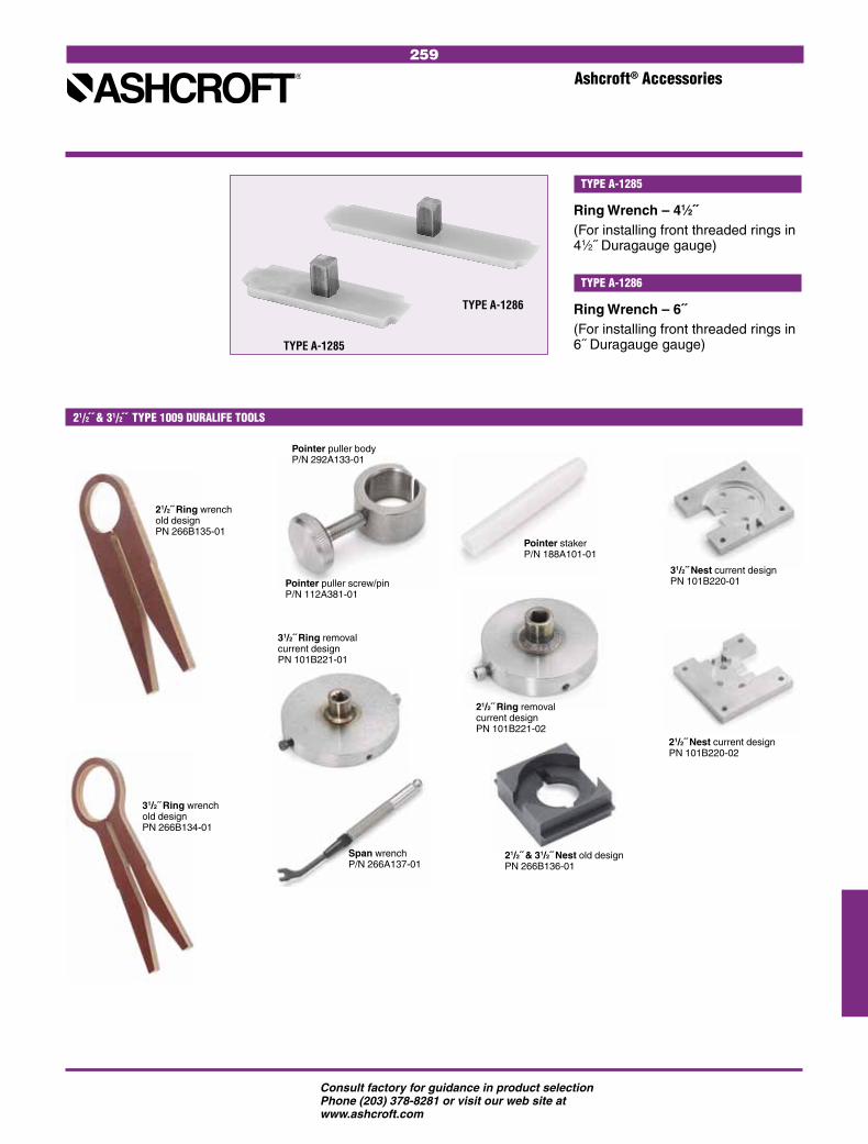
259
Consult factory for guidance in product selection Phone (203) 378-8281 or visit our web site at www.ashcroft.com
Ashcroft® Accessories
21/2˝ & 31/2˝ TYPE 1009 DURALIFE TOOLS
Pointer puller screw/pin P/N 112A381-01
Pointer puller body P/N 292A133-01
Pointer staker P/N 188A101-01
Span wrench P/N 266A137-01
21/2˝ Ring wrench old design PN 266B135-01
31/2˝ Ring wrench old design PN 266B134-01
21/2˝ Ring removal current design PN 101B221-02
31/2˝ Ring removal current design PN 101B221-01
21/2˝ & 31/2˝ Nest old design PN 266B136-01
21/2˝ Nest current design PN 101B220-02
31/2˝ Nest current design PN 101B220-01
Ring Wrench – 41⁄2˝(For installing front threaded rings in 41⁄2˝ Duragauge gauge)
TYPE A-1285
Ring Wrench – 6˝(For installing front threaded rings in 6˝ Duragauge gauge)
TYPE A-1286
TYPE A-1286
TYPE A-1285

260
Consult factory for guidance in product selection Phone (203) 378-8281 or visit our web site at www.ashcroft.com
Ashcroft® Accessories
Cone Tool
For installing diaphragm and garter spring on back connected liquid-filled or hermetic sealed Duragauge® gauges.
TYPE A-1287
TYPE A-1287
This rugged blow-molded high-density polyethylene carrying case accom-modates the standard 41⁄2, 6 & 81⁄2˝ Ashcroft Type 1082 analog test gauge. It accepts both lower and back connect gauges. A foam insert protects the gauge when not in use. Type No. 2505.
TEST GAUGE CARRYING CASE
• 1⁄4˝ brass Tee Handle Cock No. 1092 – Wgt. 3 oz.
• 1⁄4˝ brass Lever Handle Union Cock No. 1094 – Wgt. 10 oz.
• 1⁄4˝ brass Lever Handle Cock No. 1095 – Wgt. 4 oz.
• All rated 100 psi air.
COCKS
TYPE NO. 1092TYPE NO. 1095
TYPE NO. 1094
Hand Jack Set – gauge pointer remover and a pointer set to secure pointer to the shaft. Type No. 3220.
Gauge Tool Kit – A complete kit for gauge maintenance. Includes hand jack set, screw driver, five reamers, pin vise holder, wiggler and tweezer all packed in a neat carrying case. Ideal for a gauge maintenance shop. Type No. 1105T.
TYPE NO. 3220
TYPE NO. 1105T TOOLS
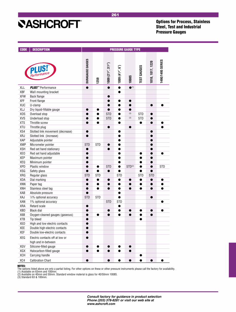
261
Consult factory for guidance in product selection Phone (203) 378-8281 or visit our web site at www.ashcroft.com
Options for Process, Stainless Steel, Test and Industrial Pressure Gauges
TEST
GAU
GES
1008
S
1010
, 101
7, 1
220
1490
/149
5 SE
RIES
1009
(41 /2
, 6˝)
1009
(21 /2
, 31 /2 ˝
)
DURA
GAUG
E GA
UGES
CODE DESCRIPTION PRESSURE GAUGE TYPE
NOTES: The options listed above are only a partial listing. For other options on these or other pressure instruments please call the factory for availability.(1) Available on 63mm and 100mm.(2) Available on 40mm and 50mm. Standard window material is glass for 40/50mm 1008S.(3) Standard 63 & 100mm.
XLL PLUS!™ Performance (1)
XBF WaII mounting bracket XFW Back flange
XFF Front flange XUC U-clamp
XLJ Dry liquid-fillable gauge
XOS Overload stop STD (3) STD
XVS Underload stop STD (3) STD
XTS Throttle screw
XTU Throttle plug
XS4 Slotted link movement (decrease)
XRJ Slotted link (increase)
XAP Adjustable pointer
XMP Micrometer pointer STD STD
XSH Red set hand stationary
XEO Red set hand adjustable
XEP Maximum pointer
XEQ Minimum pointer
XPD Plastic window STD STD(2) STD XSG Safety glass
XRG Regular glass STD STD STD STD STD XDA Dial marking
XNN Paper tag
XNH Stainless steel tag
XAB Absolute pressure
XAJ 1⁄2% optional accuracy STD STD
XAN 1% optional accuracy STD STD
XRA Retard scale
XBD Black dial
X6B Oxygen-cleaned gauges (gaseous)
XTB Tip bleed XED High and low electric contacts
XEE Double high-electric contacts
XEF Double low-electric contacts
XEG Electric contacts off at low or high and in-between XGV Silicone-filled gauge
XGX Halocarbon-filled gauge
XCH Carrying handle
XC4 Calibration Chart
1259

262
Consult factory for guidance in product selection Phone (203) 378-8281 or visit our web site at www.ashcroft.com
Ashcroft® Options
CAPILLARY BLEED
of the Bourdon tube. It may be used as a pressure testing tap for gauge inspection without removing the gauge from service. Capillary bleeders are available in bottom connected gauges only. The capillary bleeder is available in 300 Series stainless steel and limited to 41/2˝ 1379(S)S case with 316 stainless steel system. Capillary bleeders are available to 1000 psi.
These bleeders allow trapped air to be removed from the Bourdon tube. They can also be used for back-flushing or clean-ing the system. The tip bleed is available with 316 stainless steel systems. It is accessible by removing the pressure relief back. Tip bleeders are available to 23,000 psi. The capillary bleeder provides an external case connection to the internals
TIP BLEEDER
Used to flush-mount gauge types 1188, 1220, 1279 and 1379. Standard finish is black; polished stainless steel finish is available at an extra charge, 41⁄2˝ and 6.
Gauge Ring A “B”-Three Screws Size O.D. Dia. (inches) (inches) (inches) Size
41⁄2 6.000 5.625 #10-24 x 15⁄8˝
6 7.765 7.25 1⁄4-20 x 11⁄2˝
CAPILLARY BLEEDER
Maximum Pointeravailable for gauges 41⁄2˝ size and larger. Indicates maximum pressure attained. Can be reset by a knob on outside of window.
Plastic Disc – optional for glass windowLaminated Safety Glass – optional for glass windowNonglare Glass – optional for glass window
Vacuum Stopto protect low range gauges against vacuum.
MAXIMUM POINTER VACUUM STOP
Stationary Red Set Handto indicate a specific pressure. Ring must be removed to move the hand.
Special Dialranges different from standards, or custom artwork, available on application.
Overload Stopto protect gauge system against extreme overpressure.
STATIONARY RED SET HAND OVERLOAD STOP SPECIAL DIAL
TYPE 1278M FLUSH MOUNTING RING
TIP BLEED
OPTIONAL WINDOWS
263
Consult factory for guidance in product selectionPhone (203) 378-8281, Fax (203) 385-0499 or visit our web site at www.ashcroft.com
PRESSURE INSTRUMENTS
PROCESS GAUGES
INDUSTRIAL GAUGES
STAINLESS STEEL CASE GAUGES
SANITARY GAUGES
TEST INSTRUMENTS
DIAPHRAGM SEALS/INSTRUMENT ISOLATORS
COMMERCIAL GAUGES
SPECIAL APPLICATION COMMERCIAL GAUGES
PRESSURE TRANSDUCERS/TRANSMITTERS
TEMPERATURE INSTRUMENTS
BIMETAL THERMOMETERS
DIRECT-READING THERMOMETERS
HANDHELD THERMOMETERS
REMOTE-READING GAS THERMOMETERS
DIGITAL THERMOMETERS
REMOTE-READING VAPOR THERMOMETERS
TEMPERATURE REGULATORS
THERMOWELLS
PRESSURE/TEMPERATURE SWITCHES
PRESSURE SWITCHES
TEMPERATURE SWITCHES
ACCESSORIES & OPTIONS
APPLICATION DATA
Pressure Element Selection Media Application ..................................... 265
Conversion Factors for Units of Pressure ...................................... 266
Mechanical Pressure Gauge Accuracy Definitions ................................. 267
Bimetal Thermometer Accuracy Definitions ................................. 268
NEMA Chart ................................................. 269
Pressure Transducers/Transmitters Accuracy Definitions ......................... 270-271
APPLICATION DATA

264
Consult factory for guidance in product selectionPhone (203) 378-8281, Fax (203) 385-0499 or visit our web site at www.ashcroft.com

265
(1) Monel and 316 stainless steel are acceptable for oxygen service, provided the instrument has been cleaned for service and is free from oil. Order variation X6B.
(2) Over 1000 psi–entire system must be 316 stainless steel.
Pressure Element Selection Media Application
The media being measured must be compatible with the wetted parts of the pressure instrument. To use the chart below, locate the media whose pressure is to be measured and select a suitable material from those available. This is a simplified chart and assumes the media temperature is below
200°F except for media with a ‘‘*’’ which must be below 100°F. PLUS!™ option, throttling devices and/or a liquid-filled instru-ment are recommended in applications with pulsation or vibration. These recom-mendations are only a guide, as service life is dependent on temperature, concentra-
tions, catalysts that may be added, or other conditions beyond our control. Consult Stratford, CT customer service for specific applications and any media not listed. More complete corrosion data is available on our web site, www.ashcroft.com in Technical Information.
MEDIAAPPLICATION
MEDIAAPPLICATION
MEDIAAPPLICATION
*Media temperature must be below 100°F. ** Any standard Bourdon tube or bellows material may be used in conjunction with a diaphragm seal
(with bellows use a Viton or Kalrez diaphragm ), but the gauge selection should take into considera-tion the corrosive environment in which it is to operate.
Bras
s or
bro
nze
Stee
l
316
SS
Mon
el
Diap
hrag
m s
eals
**
Bras
s or
bro
nze
Stee
l
316
SS
Mon
el
Diap
hrag
m s
eals
**
Bras
s or
bro
nze
Stee
l
316
SS
Mon
el
Diap
hrag
m s
eals
**
Acetic Acid <40% •Acetic Anhydride •Acetone* • • • Acetylene (Dry) • •Acrolein 100% •Air • • • •Alcohol, Ethyl • • •Alum. Chloride* •Alum. Sulfate* <60% •Ammonia Gas (Dry) • •Ammonium Chloride <40% •Ammonium Nitrate <50% •Ammonium Sulfate <60% •Aniline>99% •Beer •Benzene <50% • •Benzidine >99% •Benzoic Acid <70% •Boric Acid <25% •Bromine (Dry) >99% •Butane • • • • Butyric Acid <10% •Calcium Chloride <80% •Calcium Hydroxide <50% •Carbon Dioxide* (Wet) • •Carbon Monoxide (Dry) >99% • • •Chlorine (Dry) •Chlorine (Moist) •Chloroform (Dry) • •Chromic Acid •Citric Acid 10-50% •Crude Oil (Sour) •Crude Oil (Sweet) • •Ethyl Acetate • • •
Pressure InstrumentMaterial
Pressure InstrumentMaterial
Pressure InstrumentMaterial
Ethylene Oxide >99%* • • •Ferric Chloride <40% •Ferric Sulfate <10% •Ferrous Chloride <30% •Ferrous Sulfate <50% •Fluorine Gas (Dry) No Air • Formaldehyde <90% • •Formic Acid* •Furfural <10% •Gasoline (Flowing) • •Glycerin >99% • • • •Hydrobromic Acid •Hydrochloric Acid •Hydrofluoric Acid •Hydrofluosilic Acid •Hydrogen(2) • • Hydrogen Peroxide* <30% •Kerosene • • • •Lactic Acid <70%*(2) •Magnesium Chloride <40% •Mercury >99% • Milk •Naphtha >99% • • • •Naphthalene >99% • •Nickel Chloride >99% •Nitric Acid <95%* •Oleic Acid •Oxalic Acid* •Oxygen (Gas)(1) • • •Palmitic Acid >99%* •Phosphoric Acid <60%* •Picric Acid <10% •Propane (Dry) DOT Quality • • • •Sea Water (Flowing) •
Silver Nitrate <70% •Sodium Bicarbonate <20% • •Sodium Bisulfate <30% •Sodium Carbonate <40% • •Sodium Chromate <60% • • • •Sodium Cyanide* • •Sodium Hydroxide < 40% •Sodium Hypochlorite <25% •Sodium Phosphate,Tri <60% • • •Sodium Silicate <50% • • •Sodium Sulfide <50% •Stannous Chloride <10% •Steam (Use siphon) • • • •Stearic Acid • Sulfur Dioxide (Dry) >99% •Sulfur Trioxide (Dry) >99% •Sulfuric Acid •Tannic Acid <80% • • •Tartaric Acid <50% • •Tin Chloride (ous) <10% •Toluene >99% • • • •Turpentine >98% • • • •

266
Conversion Factors for Units of Pressure
TO CONVERT cmH2O inH2O ftH2O mmHg inHg ft sea FROM TO psi mbar bar atm Pa kPa @ 20°C @ 20°C @ 20°C @ 0°C @ 0°C kg/cm2 water
psi 1 68.9476 0.0689476 0.0680460 6894.76 6.8947 70.433 27.730 2.3108 51.7149 2.03602 0.07030686 2.2457
mbar 0.0145038 1 0.001 9.86923 100 0.100 1.0215 0.40218 0.03352 0.75006 0.0295300 0.00101972 032571
bar 14.5038 1000 1 0.986923 100000 100 1021.5 402.18 33.52 750.06 29.5300 1.019716 32.571
atm 14.6959 1013.25 1.01325 1 101325 101.325 1035.08 407.511 35.959 760.0 29.9213 1.033227 33.002
Pa 1,45038 0.01 0.00001 9.86923 1 0.001 0.010215 0.0040218 3.352 7.5006 2.95300 1.019716 3.2571
kPa 0.145038 10.0 0.010 0.0098692 1000 1 10.215 4.02118 0.3352 7.5006 0.295300 0.0101972 0.32571
cmH2O @ 20°C 0.014198 0.97891 9.7891 9.66105 97.891 0.097891 1 0.3937 0.035281 0.73424 0.028907 9.9821 0.031884
inH2O @ 20°C 0.036063 2.4864 0.0024864 2.45392 248.64 0.24864 2.5400 1 0.083333 1.8650 0.073424 0.0025354 0.080986
ftH2O @ 20°C 0.432756 29.8368 0.0298368 0.0294470 2983.68 2.98368 30.480 12 1 22.380 0.881089 0.030425 0.97183
mmHg @ 0°C 0.0193368 1.33322 0.0013322 0.00131579 133.322 0.133322 1.3619 0.53620 0.04468 1 0.03937 0.00135951 0.043424
inHg @ 0°C 0.491154 33.8639 0.0338639 0.0334211 3386.39 3.38639 34.593 13.619 1.13491 25.400 1 0.0345316 1.1030
kg/cm2 14.2233 980.665 0.980665 0.967842 98060.5 98.0665 1001.8 394.41 32.868 735.559 28.959 1 31.9410
ft sea water 0.4453 30.702 0.030702 0.030301 3070.2 3.0702 31.3638 12.3482 1.02900 23.029 0.90664 0.031308 1
x 10-4
x 10-6
x 10-4
x 10-3
x 10-4
x 10-4
x 10-4 x 10-3 x 10-4 x 10-5 x 10-4
x 10-4

267
Mechanical Pressure Accuracy Definitions
ACCURACY: Accuracy – the conformity of indica-tion to an accepted standard or true value. Accuracy is the difference (error) between the true value and the indi-cation expressed as a percent of the span. It includes the combined effects of method, observer, apparatus and environment. Accuracy error includes hysteresis and repeatability errors but not friction error. It is determined under specific conditions. (Normal position, 73.4°F (23°C), and 29.92 in Hg barometric pressure.) The following tables define the ASME B40.1* accuracy grades used by Ashcroft products.
Accuracy of a pressure gauge may be expressed as percent of span or per-cent of indicated reading. Percent of span is the most common method. Percent of indicated reading is usually limited to precision test gauges and unless specifically spelled out, it may be assumed that an accuracy of ±1⁄2% means ±1⁄2% of span.
GRADE 4A: gauges offer the highest accuracy and are calibrated to ±0.1% of span over
the entire range of the gauge. The gauges are called laboratory precision test gauges and are generally 81⁄2˝, 12˝ or 16˝ dials. These high-accuracy gauges may be temperature compen-sated. They must be handled carefully in order to retain accuracy.
GRADE 3A: gauges are calibrated to an accuracy of ±0.25% of span over the entire range of the gauge. The gauges are called test gauges and are generally 41⁄2˝, 6˝ or 81⁄2˝ dials. The gauges are generally not temperature compen-sated (except Ashcroft Type 1082).
GRADE 2A: gauges are calibrated to an accuracy of ±0.5% of span over the entire range of the gauge. These gauges are gen-erally used by the petrochemical indus-try for process pressure measurement. They are often referred to as process gauges and are usually supplied as 41⁄2˝ and 6˝ cases and are not tempera-ture compensated.
GRADE 1A: gauges are calibrated to an accuracy of ±1% over the entire range of the gauge. These gauges are high-quality industrial gauges and are supplied in 21⁄2˝, 31⁄2˝ and 41⁄2˝ sizes.
GRADE A: gauges are calibrated to an accuracy of ±1% of span over the middle half
GRADE A
± 2%APPX 68°
± 2%APPX 68°
± 1%APPX 135°
GRADE B
± 3%APPX 68°
± 3%APPX 68°
± 2%APPX 135°
of the scale and ±2% of span over the first and last quarters of the scale. These gauges are often referred to as industrial gauges and are usually sup-plied in 21⁄2˝, 31⁄2˝ and 41⁄2˝ case sizes.
GRADE B: gauges are calibrated to an accuracy of ±2% of span over the middle half of the scale and ±3% of span over the first and last quarters of the scale. This accuracy of gauge represents the majority of those manufactured and used for pressure measurement on water pumps, swimming pool filters, air compressors, filter regulations, etc. These gauges are often referred to as commercial or utility gauges and are supplied in 11⁄2˝, 2˝, 21⁄2˝, 31⁄2˝ and 41⁄2˝ case sizes.
GRADE C: gauges are calibrated to an accuracy of ±3% of span over the middle half of the scale and ±4% of span over the first and last quarters of the scale. These are used in similar applications as Grade B gauges except that they are less accurate.
GRADE D: gauges are calibrated to an accuracy of ±5% of span over the entire scale. These 5% gauges are used as indi cators when minimal accuracy is required for application on water pumps and pool filters.
ACCURACY EXAMPLES Accuracy Permissible Error
Range Span Grade % of Span
Dial Units
0/100 psi 100 psi 1A 1.0 1 psi 0/400 kPa 400 kPa 2A 0.5 2 kPa 0/1000 bar 1000 bar B 3 (0/250 & 750/1000 bar) 30 bar 2 (250/750 bar) 20 bar –100/400 400 kPa 2A 0.5 2 kPa 30 in.Hg/ 44.7 psi 4A 0.1 .045 psi
30 psi .022 in.Hg
The last item (30 in. Hg/30 psi) deserves some explanation. The span is defined as the algebraic difference between the limits of the scale. 30 in. Hg = –14.7 psi Span = 30 psi -(–14.7) = 44.7 psi. 0.1% of 44.7 psi = .045 psi or .022 Hg.
ACCURACY EXAMPLES Permissible Error % of Span
Type of Lower Middle Upper Max. Friction Gauge Grade 25% 50% 25% (% of Span)Precision 4A 0.1 0.1 0.1 See Note Test (A4A) Test 3A 0.25 0.25 0.25 0.25 (1082)Process 2A 0.5 0.5 0.5 0.5 (1279)Industrial/ Hydraulic 1A 1.0 1.0 1.0 1.0 (1009)Industrial/ Hydraulic A 2.0 1.0 2.0 1.0 (1010, 1188, 1490)Commercial/ Utility B 3.0 2.0 3.0 2.0 (1005, 3005, 1008)
Note: Grade 4A gauges must remain within 0.1% before and after being lightly tapped.
* ASME B40.1 may be ordered from: American Society of Mechanical Engineers Three Park Avenue, New York, NY 10016

268
Bimetal Thermometer Accuracy Definitions
ASME B40.3* STANDARD ACCURACIES:
Example #1: Range 0/250°F Grade A Span = 250-0 = 250°FAccuracy at 20% of span (50°F) = ±1% = ±2.5°FAccuracy at 50% of span (125°F) = ±1% = ±2.5°FAccuracy at 100% of span (250°F) = ±1% = ±2.5°F
Example #2: –40/160°F Grade E Span = 160-(–40) = 200°FAccuracy at 20% of span (0°F) = ±3.4% = ±6.8°FAccuracy at 50% of span (60°F) = ±1% = ±2.0°FAccuracy at 100% of span (160°F) = ±5% - ±10.0°F
Example #3: Range 50/300°F Grade AA Span = 300-(–50) = 250°FAccuracy at 0% of span (50°F) = ±1% = ±2.5°FAccuracy at 50% of span (175°F) = ±0.5% = ±1.25°FAccuracy at 70% of span (225°F) = ±0.7% = ±1.75°F
ACCURACY:Thermometer accuracy is graded as shown in the table below.Adjustment of the case of a thermometer, with an adjustable angle connection, may affect its accuracy. This effect should not exceed 0.5% of span .
*ASME B40.3 may be ordered from: American Society of Mechanical Engineers Three Park Avenue New York, NY 10016
MID POINT
HIGHPOINT
LOW POINT
GRADE D
GRADE C
GRADE B
GRADE A
GRADE AA
10 20 30 40 50 60 70 80 90 100 PERCENT OF SPAN
GRADE B
GRADE A
GRADE AA
+5
+4
+3
+2
+1
0
-1
-2
-3
-4
-5
PER
MIS
SIBL
E ER
RO
R –
PER
CEN
T O
F SP
AN GRADE C
GRADE B
GRADE D
GRADE C
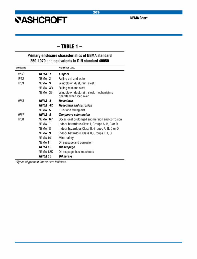
269
NEMA Chart
– TABLE 1 –
Primary enclosure characteristics of NEMA standard250-1979 and equivalents in DIN standard 40050
STANDARDS PROTECTION LEVEL
IP2O NEMA 1 Fingers IP22 NEMA 2 Falling dirt and water IP53 NEMA 3 Windblown dust, rain, sleet NEMA 3R Falling rain and sleet NEMA 3S Windblown dust, rain, sleet, mechanisims operate when iced over IP65 NEMA 4 Hosedown NEMA 4X Hosedown and corrosion NEMA 5 Dust and falling dirt IP67 NEMA 6 Temporary submersion IP68 NEMA 6P Occasional prolonged submersion and corrosion NEMA 7 Indoor hazardous Class I, Groups A, B, C or D NEMA 8 Indoor hazardous Class II, Groups A, B, C or D NEMA 9 Indoor hazardous Class II, Groups E, F, G NEMA 10 Mine safety NEMA 11 Oil seepage and corrosion NEMA 12 Oil seepage NEMA 12K Oil seepage, has knockouts NEMA 10 Oil sprays
*Types of greatest interest are italicized.

270
ACCURACY: Accuracy is defined as the degree of conformity of a measure to an accept-ed standard or true value. It is a mea-sure of the actual output deviation from the standard or true value reported as a percentage (±) of output span. Accuracy does account for the effects of linearity, hysteresis and repeatabil-ity. In addition, the maximum errors of these effects for Ashcroft Transducers are reported separately.
LINEARITY – BEST FIT STRAIGHT LINE (B.F.S.L.) The linearity defined as the maximum deviation of the calibration curve (aver-age of upscale and downscale read-ings) from a straight line so positioned as to minimize the maximum deviation. It is specified as ±% of span.
Pressure Transducers/ Transmitters Accuracy Definitions
LINEARITY – TERMINAL POINT (T.P.) The linearity defined as the maximum deviation of the calibration curve (aver-age of upscale and downscale read-ings) from a straight line positioned to pass through the upper and lower range values. It is specified as ±% of span.
OUTPUT
BEST FITSTRAIGHTLINE
MAXIMUM ± DEVIATIONSARE MINIMIZED AND EQUAL
INPUT
0 100%
ACTUAL CALIBRATION CURVE(AVERAGE OF UPSCALE ANDDOWNSCALE READINGS)
SPAN
OUTPUT
UPPERRANGEVALUE
LOWER RANGEVALUE
INPUT
0 100%
ACTUAL CALIBRATION CURVE(AVERAGE OF UPSCALE ANDDOWNSCALE READINGS)
SPAN
TERMINAL BASEDSTRAIGHT LINE
MAXIMUMDEVIATION
HYSTERESIS The maximum difference in output (“a” below) within the range when the value is approached with increasing pressure and then with decreasing pressure for full range traverses. It is specified as ±% of span.
REPEATABILITY The closeness of agreement among a number of consecutive measure-ments of the output for the same value of the input under the same operating conditions, approaching from the same direction, for full range traverses. It is specified as ±% of span.
OUTPUT
FULL RANGE
INPUT
0 100%T R A V E L
“a”
OUTPUT
INPUT
0 100%FULL RANGE TRAVERSE
MAXIMUMREPEATABILITY
DOWNSCALECALIBRATIONCURVES
REPEATABILITY
UPSCALECALIBRATIONCURVES
TEMPERATURE ERROR The maximum change in output at any input value within the range when the product is changed from room (refer-ence) temperature to specified tem-perature extremes. Temperature errors are specified in two ways defined as follows:

271
Pressure Transducers/ Transmitters Accuracy Definitions
SpanError
SpanError
ZeroError °F
180°F68°FReference Temp.
–20°F
– Error
+ Error
ZeroErrorBand
SpanErrorBand
180°F68°FReference Temp.
–20°F– Error
+ Error
SpanErrorBand
THERMAL COEFFICIENT DATA Thermal Coefficient of Zero – the zero shift due to changes in temperature from room (reference) temperature to the specified limits of the operating range. Specified as ±% of span/°F. (over a temperature range).
Thermal Coefficient of Span – the span shift due to changes in temperature from room (reference) temperature to the specified limits of the operating range. Specified as ±% of span/°F. (over a temperature range).
THERMAL ERROR DATAThermal Error of Zero – the zero shift due to changes in temperature from room (reference) temperature to the specified limits of the operating range. Specified as ±% of span (over a temperature range).
Thermal Error of Span – the span shift due to changes in temperature from room (reference) temperature to the specified limits of the operating range. Specified as ±% of reading (over a temperature range).
Note: Definitions are in accordance with: ANSI/ISA S51.1 - 1993 “Process Instrumentation Terminology” ANSI/ISA S37.1 - 1982 “Electrical Transducer Terminology”

272

273

All specifications are subject to change without notice. All sales subject to standard terms and conditions. © Ashcroft Inc., 1P6/84 20M 13P09/10, on-line version revised 6/11
For a complete listing of our worldwide locations visit our web site at www.ashcroft.com
World Headquarters
Ashcroft Inc. 250 East Main StreetStratford, CT 06614-5145 U.S.A.Tel: (203) 378-8281Fax: (203) 385-0408 email: [email protected] www.ashcroft.com

273

All specifications are subject to change without notice. All sales subject to standard terms and conditions. © Ashcroft Inc., 1P6/84 20M 13P09/10
For a complete listing of our worldwide locations visit our web site at www.ashcroft.com
World Headquarters
Ashcroft Inc. 250 East Main StreetStratford, CT 06614-5145 U.S.A.Tel: (203) 378-8281Fax: (203) 385-0408 email: [email protected] www.ashcroft.com