Embed Size (px)
Citation preview

ENTSO-E AISBL • Avenue de Cortenbergh 100 • 1000 Brussels • Belgium • Tel + 32 2 741 09 50 • Fax + 32 2 741 09 51 • [email protected] • www. entsoe.eu
HVDC Links in System Operations Technical paper
2 December 2019

HVDC Links in System Operations
ENTSO-E AISBL • Avenue de Cortenbergh 100 • 1000 Brussels • Belgium • Tel + 32 2 741 09 50 • Fax + 32 2 741 09 51 • [email protected] • www.entsoe.eu
2
Executive Summary High-voltage direct current (HVDC) is an increasingly important technology for transferring electrical power in the European transmission grid. New HVDC links play a key role in future development plans for the European transmission grid and internal market. The use of the advanced functionalities of these HVDC links in system operations is essential for the secure and efficient operation of the grid.
ENTSO-E recognizes the importance of the functionalities and ancillary services that can be provided by HVDC links. Several of these functionalities are inherent within the HVDC technology and therefore the power system can benefit from the efficiency they can readily provide. The use of the functionalities of the HVDC links in system operations contributes to meeting current and future challenges, such as decarbonisation and large scale integration of Renewable Energy Sources (RES) which are largely connected via Power Electronics (PE). Such technologies result in the decommissioning of classic rotating power plants and the disappearance of the physical characteristics the power system was built on. In addition, the HVDC technology may support the realisation of an integrated European energy market and the sharing of ancillary services between countries and synchronous areas.
Today HVDC links are typically used for connecting two asynchronous, non-embedded AC systems and for long-distance bulk power transmission using both overhead land lines and submarine cables. The main advantages of HVDC over AC are the elimination of the reactive power requirement, lower operational losses, higher power transfer and the possibility of active power control. There are also disadvantages: several assets like transformers, circuit breakers and protection equipment are more complex and due to the inclusion of PE the cost of construction is high and therefore not economically feasible below the break-even transmission distance.
This paper is of special interest for stakeholders looking to get a high-level view on the use of HVDC links, for TSOs operating HVDC links and in particular for TSOs that plan to operate HVDC links in the near future. This paper focuses on HVDC links embedded in synchronous areas and those connecting separate synchronous areas. Offshore wind farms connected by HVDC links are out of this paper’s scope. This paper describes the current state of the technology, the feasible advanced functionalities, the need for coordination and the impact on operational staff. It summarises the current practice and demonstrates the added value of using HVDC links to provide ancillary services in system operations. Aside from the benefits, the challenges are also addressed.
Two HVDC technologies are available: the classic Line Commutated Converter (LCC) technology and the much newer Voltage Source Converter (VSC) technology. Both technologies have many features in common but also have key difference: LCC needs a highly stable AC grid while VSC is capable of operating in very weak or even passive AC systems. This makes it possible for VSC to provide black start capability; VSC is also able to control active and reactive power independently to the needs of the operator and can even work as a STATCOM. This does not mean that VSC is always the best solution; LCC still is the preferred technology in certain situations due to its lower operational losses (see Chapter 2).

HVDC Links in System Operations
ENTSO-E AISBL • Avenue de Cortenbergh 100 • 1000 Brussels • Belgium • Tel + 32 2 741 09 50 • Fax + 32 2 741 09 51 • [email protected] • www.entsoe.eu
3
The TSOs owning and operating HVDC links will deliver ancillary services efficiently, since the functionalities come automatically with the HVDC technology.
Thus, several functionalities of HVDC technology will greatly profit the power system, often at little or no extra cost, and the associated ancillary services delivered by TSOs in their role as asset owners will efficiently support the operation of the power system. Nevertheless, some functionalities (e.g., synthetic inertia) require further research and development by the manufacturers before they can be used operationally.
The functionalities are primarily delivered by the converters (see Chapter 3). Here there is a difference in the capabilities of the LCC and VSC technologies: some are only available in cases of embedded HVDC links while others are only available with non-embedded HVDC links, though many are available in both cases. Some functionalities cannot be activated simultaneously with others as they cancel each other out, and therefore a priority ranking is required (HVDC Network Code, Article 35 [24] describes the priority ranking of control and protection schemes). It is important to remember that in case the transmission asset HVDC link is lost due to a contingency, some or all functionalities and services will be lost at the same time. The table in Chapter 3 shows the functionalities and indicates for which technology they are available and if they can be used for embedded HVDC links and/or for non-embedded HVDC links.
For all power flow-controlling devices, including HVDC links, there is a need to coordinate the actual use of certain functionalities (see Chapter 5). Since HVDC links are controllable devices that can significantly influence the flow in AC grids, coordination with other controllable devices and services is important to avoid the inefficient use of the infrastructure. Which parties to involve in the coordination will depend on the situation: sometimes only two TSOs are affected but in other cases more TSOs, DSOs and producers might be involved. Different functionalities may affect different parties. Coordination is needed in all time frames from the operational planning phase to actual real-time operation.
The impact on the operators (see Chapter 6) of using the HVDC links and their advanced functionalities and services is difficult to quantify. There is no reason to think that the operators require a different level of education, but the operator training will certainly need to be updated to include the new technology. Many functions will be automated and operators will have to rely on them; in case of disturbances of either the hardware or software there will be very few possibilities for the operators to solve this problem. System operations must go on using the remaining assets while specialists repair the disturbance.
Most functionalities and services for advanced use of HVDC links in system operations are already available today and used somewhere in the world; use cases and experiences are listed in the report (see Chapter 4). It must be kept in mind that many services do not come automatically, they must be specified to the vendor and of course they come at a cost. Prioritisation of the use of different options is important: some of the options cannot be used at the same time. The use of several advanced functionalities must be coordinated in all timeframes, from design to real-time operation, between the parties and equipment involved. Currently, the final design and operation of HVDC links is very project-specific, there is little standardisation, due to the ongoing rapid development of the technology.

HVDC Links in System Operations
ENTSO-E AISBL • Avenue de Cortenbergh 100 • 1000 Brussels • Belgium • Tel + 32 2 741 09 50 • Fax + 32 2 741 09 51 • [email protected] • www.entsoe.eu
4
Content
Glossary ........................................................................................................................................... 6 1 Introduction ............................................................................................................................... 8 2 The state of HVDC technologies .............................................................................................. 9
2.1 Introduction ........................................................................................................................ 9 2.2 Technology overview ....................................................................................................... 11 2.3 Operational principles and features ................................................................................. 15 2.4 Comparison between technologies ................................................................................. 19
3 Advanced operational functionalities and services ................................................................. 20 3.1 Introduction ...................................................................................................................... 20 3.2 HVDC Scheduling ........................................................................................................... 20 3.3 HVDC real-time operation ............................................................................................... 28 3.4 HVDC Benefits ................................................................................................................ 49
4 Use cases where advanced operational services are applied ................................................ 50 4.1 Introduction ...................................................................................................................... 50 4.2 BritNed ............................................................................................................................ 50 4.3 EWIC ............................................................................................................................... 50 4.4 INELFE ............................................................................................................................ 50 4.5 IFA 2000 .......................................................................................................................... 51 4.6 Skagerrak ........................................................................................................................ 51 4.7 NorNed ............................................................................................................................ 51 4.8 KONTEK and KF CGS .................................................................................................... 51 4.9 SAPEI & SACOI .............................................................................................................. 51 4.10 Summary of applied advanced operational services ....................................................... 52
5 Needs for operational coordination to obtain the advanced operational functionalities and services .......................................................................................................................................... 54
5.1 Introduction ...................................................................................................................... 54 5.2 Coordination scope and general principles ..................................................................... 54 5.3 Involved parties ............................................................................................................... 55 5.4 Time frames .................................................................................................................... 55 5.5 Coordination of functionalities ......................................................................................... 56
6 Impact on operational staff ..................................................................................................... 62 6.1 Introduction ...................................................................................................................... 62 6.2 Operational input to planning, decision and investment stages ...................................... 62 6.3 Level of automation ......................................................................................................... 63 6.4 Daily activity of operational staff ...................................................................................... 63 6.5 Conclusions ..................................................................................................................... 65

HVDC Links in System Operations
ENTSO-E AISBL • Avenue de Cortenbergh 100 • 1000 Brussels • Belgium • Tel + 32 2 741 09 50 • Fax + 32 2 741 09 51 • [email protected] • www.entsoe.eu
5
7 Essential non-technical provisions for concept implementation ............................................. 66 7.1 Introduction ...................................................................................................................... 66 7.2 Non-technical provisions ................................................................................................. 66
8 Next steps ............................................................................................................................... 68 Appendix ........................................................................................................................................ 69 References .................................................................................................................................... 80 Related relevant documents .......................................................................................................... 81

HVDC Links in System Operations
ENTSO-E AISBL • Avenue de Cortenbergh 100 • 1000 Brussels • Belgium • Tel + 32 2 741 09 50 • Fax + 32 2 741 09 51 • [email protected] • www.entsoe.eu
6
Glossary The following abbreviations and terms are used in the report:
AGSOM Agreement on System Operation Management BALIT Balancing Inter-TSO CACM Capacity Allocation & Congestion Management CB Circuit Breakers CBB Cross Border Balancing CCC Capacitor Commutated Converters CCR Capacity Calculation Region CEA Constant Extinction Angle CFII Commutation Failure Immunity Index CNTC Coordinated Net Transmission Capacity CSC-HVDC Current Source Converter HVDC D2CF 2-Days Ahead Congestion Forecast DG Distributed Generation DSO Distribution System Operator EBGL European Electricity Balancing Guideline EMS Energy Management System EPC Emergency Power Control FACTS Flexible Alternating Current Transmission System FB Flow Based FCR Frequency Containment Reserve FRR Frequency Restoration Reserve FTP Full Time Personnel GLDPM Generation& Load Data Provision Methodology GPS Global Positioning System HB Half-Bridge HVDC High Voltage Direct Current IDCF Intraday Congestion Forecast IGBT Insulated Gate Bipolar Transistor IGCC International Grid Control Cooperation IGD Implementation Guidance Document IGM Individual Grid Model IN Imbalance Netting LCC Line Commutated Converter LFSM Limited Sensitive Frequency Mode LOM Loss of Mains MARI Manually Activated Reserves Initiative MLQG Modular Linear Quadratic Gaussian MMC Modular Multilevel Converter NCER Network Code on Electricity Emergency & Restoration NETSO National Electricity Transmission System Operator
HVDC Links in System Operations
ENTSO-E AISBL • Avenue de Cortenbergh 100 • 1000 Brussels • Belgium • Tel + 32 2 741 09 50 • Fax + 32 2 741 09 51 • [email protected] • www.entsoe.eu
7
NGESO National Grid Electricity System Operator NGIL National Grid Interconnectors Ltd PCC Point of Common Coupling PLL Phase Lock Loop PE Power Electronics PMU Phasor Measurement Unit POD Power Oscillation Damping PODP Power Oscillation Damping active power PODQ Power Oscillation Damping reactive power PODP+Q Power Oscillation Damping active and reactive power. PSS Power System Stabilizer PST Phase Shifting Transformer PTDF Power Transfer Distribution Factors PWM Pulse Wide Modulation RES Renewables Energy RFI Redirection of Flows Over Interconnectors RGCE Regional Group Continental Europe RoCoF Rate of Change of Frequency RR Replacement Reserve RSC Regional Security Coordinator
SAOA Synchronous Area Operation Agreement SCADA Supervisory Control and Data Acquisition SCL Short Circuit Level SCR Short Circuit Ratio SGU Significant Grid User SOA System Operation Agreement SOGL System Operator Guideline SONI System Operator of Northern Ireland SPS Special Protection Scheme SSD Sub Synchronous Damping SVC Static VAR Compensator TERRE Trans European Replacement Reserve Exchange TSI Total System Inertia TSO Transmission System Operation UHVDC Ultra-High Voltage DC Links VDCOL Voltage Dependent Current Order Limiter VSC Voltage Source Converter WAMS Wide Area Monitoring System

HVDC Links in System Operations
ENTSO-E AISBL • Avenue de Cortenbergh 100 • 1000 Brussels • Belgium • Tel + 32 2 741 09 50 • Fax + 32 2 741 09 51 • [email protected] • www.entsoe.eu
8
1 Introduction
ENTSO-E has determined that the use of HVDC links is of special interest for system operators since the specific characteristics included in the HVDC technology can help meet future challenges experienced in system operations. This is the case both for HVDC links connecting different synchronous areas and HVDC links embedded in an AC grid and thus operating parallel to AC lines.
The increasing use of HVDC links in the transmission grids makes it necessary to operate HVDC links in the best possible manner. This should contribute to the purpose of ENTSO-E, as stated in the Articles of Association, "to promote the reliable operation, optimal management and sound technical evolution of the European electricity transmission system as to ensure security of supply and to meet the needs of the Internal Energy Market”.
The use of the most appropriate control strategies will become increasingly important since the transmission grids will be operated closer to their limits in the future due to the increasing use of dispersed, renewable generation. Operating HVDC links and using the services it can offer requires a certain level of coordination both with other HVDC links and also with other sources and controllable devices, for instance, phase shifter transformers.
This report summarises all aspects of HVDC links in system operations. It is important to stress that it provides an overview of the current state and best practices, not rules or recommendations.
The report has chapters on:
• HVDC technologies and the state of the technology
• Advanced operational functionalities and services
• Use cases
• Need for coordination
• Impact on operational staff
• Essential non-technical provisions
All synchronous areas in Europe have HVDC links in operation and are connected to other synchronous areas using HVDC links. Several HVDC links are under construction while a number of HVDC links are under consideration. This report does not address offshore wind farms that are connected via HVDC to the mainland AC grid.
Some attention is given to aspects not covered and subjects that could be further investigated.

HVDC Links in System Operations
ENTSO-E AISBL • Avenue de Cortenbergh 100 • 1000 Brussels • Belgium • Tel + 32 2 741 09 50 • Fax + 32 2 741 09 51 • [email protected] • www.entsoe.eu
9
2 The state of HVDC technologies
2.1 Introduction Developments in advanced power electronic devices and fully-controlled semiconductors have had an immense impact on the development of HVDC technology. As a result, HVDC is now one of the best transmission solutions for the transfer of bulk power over long distances [1] and has been increasingly used in many parts of the world, such as China and India, where energy resources are dispersed a great distance from the load centres.
In addition, a greater level of interconnection provides greater diversity of potential supplies, which helps with intermittency issues posed by renewable generation and consequently the security of the electricity supply. It also facilitates competition in the European market and assists in the transition to a low-carbon energy sector by integrating various renewable sources.
2.1.1 Primary advantages of HVDC links over HVAC lines The primary advantages [2] of HVDC links over HVAC links are:
• The elimination of reactive power for power transmission purposes. Power can be transferred over long distances with constant voltage at the receiving end and therefore can enable full utilisation of the conductors for active power transmission. When using long AC cables, compensating devices such as SVCs or STATCOMs are required to maintain the allowed AC voltage level.
• Higher power transfer with the same size and insulation level of DC lines compared to AC lines. The effective voltage can be higher and the wires can be larger (wire diameter is limited for AC lines due to the skin effect whereas a DC line can accommodate any diameter).
• Lower losses on DC lines, however, for total loss calculation, HVDC converter stations must be taken into account as well.
• HVDC links allow for bars of asynchronous AC grids to be connected; they then can be used for market purposes as well as for system support by means of ancillary services. In general, there is no need for a parallel interconnected AC grid.
• As explained above, HVDC overhead lines can transport significantly more power for the same size compared to HVAC lines. This allows for smaller cable sizes in the DC system, therefore the required ground area and support towers are smaller.
• System operations can actively control the power flow. This is due to the fact that HVDC links can rapidly control the transmitted power. This may be challenging from an operational point of view, however, an adequate complementary control system can be used along with the HVDC lines in a coordinated manner to support system operation, for example, by reducing the number of required remedial actions for assuring system security as well as by improving transient stability and damping oscillations in the power system. This in turn will allow the system operator to utilize the existing AC network more efficiently.

HVDC Links in System Operations
ENTSO-E AISBL • Avenue de Cortenbergh 100 • 1000 Brussels • Belgium • Tel + 32 2 741 09 50 • Fax + 32 2 741 09 51 • [email protected] • www.entsoe.eu
10
2.1.2 Primary disadvantages of HVDC links vs. HVAC lines The primary disadvantages of HVDC links over HVAC links are:
• Transformers for voltage stepping and circuit breakers are less complex and expensive for HVAC than those for HVDC transmission. The development of DC circuit breakers (CBs) for VSC-HVDC links is also challenging due to the complexity in the design of the DC CBs, especially at high power levels.
• There is a higher cost of construction due to the power electronics and converter transformers. However, beyond a certain (see next paragraph) distance, the investment costs of HVDC links are lower than those of AC transmission lines since a bipolar system (without metallic return) has only two lines compared to three lines in an AC system. This results in lower costs in tower design and construction to deliver the same capacity of power. In bipolar design, the method used for the return path of current would affect the cost-benefit and system continuity to supply power flow on DC links.
2.1.3 Typical applications of HVDC links Interconnecting two asynchronous AC systems or two AC systems with different frequencies: HVDC has the ability to interconnect two separate asynchronous AC systems as a tie line, for example, where one operates at a frequency of 50 Hz and the other at 60 Hz (such as the back-to-back 500 MW HVDC link between Uruguay and Brazil) or where the two systems operate at the same frequency but different phase angles (such as the back-to-back HVDC link connecting the asynchronous Eastern and Western American system and many HVDC connections between central Europe and the Nordic region). This is primarily because DC power is independent of the frequency and phase angle of the AC system.
Submarine power transmission: For long-distance cable connections from a certain point (breakeven point in the order of 40-150 km), depending on the voltage level, HVDC cables are a more economical solution [10]. Additionally, submarine HVDC cables can be used for embedded HVDC as well as for interconnectors between asynchronous AC grids.
Long distance bulk power delivery: Similarly, for overhead lines, from a certain distance, a HVDC link is a more economical solution. In the literature, break-even distances on the order of 500-800 km are found for overhead lines. HVDC links also perform well in long distance bulk power delivery, while in AC systems the reactive power flow limits the transmission distance and consequently are more costly [2], [10]. However, break-even distances are highly project-dependent.
Embedded HVDC links: Links operating along the AC power system for power transfer and area control: a good example of an embedded HVDC link is the Western HVDC link connecting Scotland to England/Wales.
Ancillary services: HVDC links can provide ancillary services; a typical example is the France-England Interconnector (IFA).
Ultra-high voltage DC links (UHVDC): The requirement for bulk power transmission over long distances (5-10 GW) in China, Asia and South America has resulted in the development of UHVDC. For example, the first commercial UHVDC, a 6400 MW, 800 kV UHVDC, was

HVDC Links in System Operations
ENTSO-E AISBL • Avenue de Cortenbergh 100 • 1000 Brussels • Belgium • Tel + 32 2 741 09 50 • Fax + 32 2 741 09 51 • [email protected] • www.entsoe.eu
11
commissioned between Xiangjiaba and Shanghai in 2010. The main challenges in the development of UHVDC links are:
• Improved insulation
• Transformer development
• Development of a test centre for UHVDC
2.2 Technology overview
2.2.1 LCC-based HVDC technology Line-Commutated Converter (LCC) HVDC is a mature technology with the highest power and efficiency rating used for more than 50 years for bulk power transfer. LCC-HVDC technology employs line-commutated thyristor valve converters which rely on a stable AC system voltage for a reliable commutation. LCC-HVDC technical capabilities, combined with its economic advantages and low operating losses, make it a widely used solution for enlarging or enhancing power system interconnections.
2.2.1.1 LCC-HVDC converter station design and main components [4], [5]
Converters: DC/AC and AC/DC conversion is performed in the rectifier and inverter units. Each unit typically has a 12-pulse arrangement consisting of two 6-pulse thyristor bridges (consisting of 6 thyristor valves) connected in series on the DC side.
Converter transformers: Transformers with tap changers to adjust the supplied AC voltage to the valve bridges ensure optimisation of HVDC operation and are designed to work with high harmonic currents and withstand AC/DC voltage stresses. The transformer for a 12-pulse bridge has a star-star-delta three-winding configuration and typically has a leakage reactance to limit the current during a short-circuit fault of the bridge arm.
AC and DC side filters: Converter operation generates harmonic currents and voltages on the AC and DC sides, respectively. Common issues with high harmonics include machine heating, insulation stress, overloading of capacitor banks and interference with communication equipment. In a 12-pulse converter, all harmonics of the order 12k ± 1 (k=0, 1, 2 etc.) appear on the AC side. Therefore, a typical 12-pulse thyristor terminal requires an 11th, 13th, 23rd, 25th etc. filter on the AC side. Some HVDC designs with overhead lines also implement a DC filter. DC filters are not required in cable transmission or back-to-back schemes.
Reactive power compensation: A LCC-HVDC link has a high reactive power demand that varies with DC power. Typically, a large percentage of reactive power compensation is required, up to 60% of the DC power rating, and is provided by filter banks and switchable capacitor banks or FACTS-based devices such as a STATCOM or SVC. If the converter unit is located in a weak AC grid it may be necessary to install synchronous condensers to increase the short circuit level and improve the voltage control.
Control system: The rectifier and inverter include various hierarchical control systems which are explained in Appendix A1.

HVDC Links in System Operations
ENTSO-E AISBL • Avenue de Cortenbergh 100 • 1000 Brussels • Belgium • Tel + 32 2 741 09 50 • Fax + 32 2 741 09 51 • [email protected] • www.entsoe.eu
12
Smoothing reactors: The DC side of the converter consists of smoothing reactors, which are primarily required to reduce harmonics on the DC side, prevent commutation failures and protect valves after DC faults [5].
DC connections: Cables or overhead lines are always present on the pole connections, except in back-to-back systems. DC faults can be managed with LCC-HVDC technologies and only cause transit disturbances, whereas in VSC-HVDC systems DC faults could be more critical.
Figure 1: LCC-HVDC Converter Station
2.2.2 VSC-based HVDC technology In 1997 the first Voltage Source Converter (VSC)-HVDC system was commissioned with a voltage of ±10 kV and a transmission capacity of 3 MW. Today, VSC-HVDC systems with voltages above ±500 kV and 2 GW are feasible, but there has been no operating experience with them thus far. The INELFE VSC-HVDC system between France and Spain with a voltage of ±320 kV and a DC power of 2x1 GW is at present the VSC system with the highest transmission capability [8].
The first converter generation technologies were based on two- or three-level technology. The newest generation applies a modular concept (Modular Multilevel Converter, MMC) with an arbitrary number of voltage levels (dependent on the manufacturer concept), which leads to reduced losses and an improved harmonic behaviour. Aside from the converter generation, the general operation principle of the different concepts is the same.
The turn-on and -off capabilities of Insulated Gate Bipolar Transistors (IGBTs) enable voltage generation on the AC side with a specific amplitude and phase angle. These parameters are derived by set points (active/reactive power, voltage etc.) given by the operator. Because of the control concept, active and reactive power can be controlled independently of each other.
Voltage source converters are able to operate in weaker, and even in passive, AC systems. In case of blackouts, the system can be restored if the grid at the other end of the HVDC system is still active and the VSC link is equipped with black start capability.
PCC
AC filter
converter transformer
DC filter
DC filter
DC line
DC line
+
-
AC grid
converter
smoothing reactor
capacitor bank

HVDC Links in System Operations
ENTSO-E AISBL • Avenue de Cortenbergh 100 • 1000 Brussels • Belgium • Tel + 32 2 741 09 50 • Fax + 32 2 741 09 51 • [email protected] • www.entsoe.eu
13
In the following sub-chapters, the general operation principle of VSC-HVDC systems is presented. It is the basis for the development of strategies for advanced applications of HVDC systems. Additional information is given in Appendix A2.
2.2.2.1 VSC-HVDC converter station design and main components
Converter: A VSC-HVDC system (point-to-point connection) consists of two converters (rectifier and inverter) at both ends in monopolar or bipolar configuration. The modular concept – with many series of connected submodules (half-bridge or full-bridge modules) in each arm – enables generation of an almost perfect sinusoidal voltage on the AC side of the converter.
Converter transformer: Conventional two- or three-winding transformers are applied in VSC-HVDC systems to adapt the AC system voltage to an appropriate level for the operation of the converter. Tap-changers could be used in addition to the reactive power control of the converter to support voltage control.
Arm inductance: The arm inductance determines the active and reactive power exchange between the AC system and the converter. Additionally, the inductances keep the loop currents between the parallel converter legs to a low level.
AC and DC side filters: Generally, AC and DC filters can be omitted, as the voltage of the converter is almost perfectly sinusoidal and therefore the harmonic content is very low. In special cases, such as the application of overhead lines, DC filters are installed if required.
Control system: The active and reactive power exchange is controlled by an outer and inner control loop. The outer loop calculates the reference values for the inner loop, which determines subsequently the firing pulses for the IGBTs (see Appendix A2).
DC capacitors: The large DC capacitors of two- or three-level converters are – in cases of modular multilevel converters – distributed in the submodules along the converter arms.
HVDC Links in System Operations
ENTSO-E AISBL • Avenue de Cortenbergh 100 • 1000 Brussels • Belgium • Tel + 32 2 741 09 50 • Fax + 32 2 741 09 51 • [email protected] • www.entsoe.eu
14
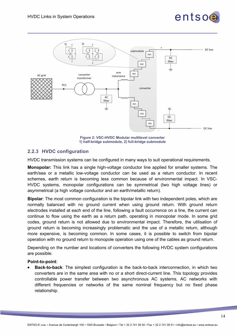
Figure 2: VSC-HVDC Modular multilevel converter 1) half-bridge submodule, 2) full-bridge submodule
2.2.3 HVDC configuration HVDC transmission systems can be configured in many ways to suit operational requirements. Monopolar: This link has a single high-voltage conductor line applied for smaller systems. The earth/sea or a metallic low-voltage conductor can be used as a return conductor. In recent schemes, earth return is becoming less common because of environmental impact. In VSC-HVDC systems, monopolar configurations can be symmetrical (two high voltage lines) or asymmetrical (a high voltage conductor and an earth/metallic return).
Bipolar: The most common configuration is the bipolar link with two independent poles, which are normally balanced with no ground current when using ground return. With ground return electrodes installed at each end of the line, following a fault occurrence on a line, the current can continue to flow using the earth as a return path, operating in monopolar mode. In some grid codes, ground return is not allowed due to environmental impact. Therefore, the utilisation of ground return is becoming increasingly problematic and the use of a metallic return, although more expensive, is becoming common. In some cases, it is possible to switch from bipolar operation with no ground return to monopole operation using one of the cables as ground return.
Depending on the number and locations of converters the following HVDC system configurations are possible:
Point-to-point: • Back-to-back: The simplest configuration is the back-to-back interconnection, in which two
converters are in the same area with no or a short direct-current line. This topology provides controllable power transfer between two asynchronous AC systems, AC networks with different frequencies or networks of the same nominal frequency but no fixed phase relationship.
PCC
SM1
AC filter
SM2
SMx
SM1
SM2
SMx
converter transformer
DC filter
DC filter
DC line
DC line
+
-
arm inductanceAC grid
1) 2)
submodule
converter
HVDC Links in System Operations
ENTSO-E AISBL • Avenue de Cortenbergh 100 • 1000 Brussels • Belgium • Tel + 32 2 741 09 50 • Fax + 32 2 741 09 51 • [email protected] • www.entsoe.eu
15
• Long distance: Two converters at different locations are connected by overhead lines or cables.
Multi-terminal: This system has more than two sets of converters operating independently and each converter can operate as either a rectifier or an inverter. The different DC side topologies and their characteristics are shown in Appendix A3.
2.3 Operational principles and features
2.3.1 Operational features of LCC-based HVDC link
2.3.1.1 Advanced control application
LCC-HVDC links can be used to provide the following advanced control functions using a complementary control system:
• Power oscillation damping (POD)
• Sub-synchronous damping (SSD)
• Emergency power control (EPC)
2.3.1.2 Technical requirements at Point of Common Coupling
Due to susceptibility of LCC-HVDC systems to commutation failures caused by disturbances on the AC side, it must be connected to sufficiently strong AC networks. Disturbances which are likely to cause commutation failures include sudden AC voltage depressions, for example during AC system faults, and voltage waveform distortions. AC system strength in relation to a connected HVDC system is characterised by the Short Circuit Ratio (SCR), as shown in Equation (1), which is the ratio of the Short Circuit Level (SCL) at the Point of Common Coupling (PCC) to the DC power rating Pdc of the HVDC system [6].
A strong system has an SCR > 3. An SCR of 2 is generally required as a minimum for successful LCC-HVDC operation:
SCR =SCL𝑃'(
(1)
The robustness of an LCC-HVDC system connected to an AC system of a particular strength can be characterised by its Commutation Failure Immunity Index (CFII):
CFII =𝐶𝑟𝑖𝑡𝑖𝑐𝑎𝑙𝑓𝑎𝑢𝑙𝑡𝑙𝑒𝑣𝑒𝑙
𝑃'(∗ 100(2)
Studies show that reducing power flow increases the CFII index, as it effectively increases the SCR of the AC system. This suggests that in contingency situations where the strength of the AC system has been reduced, for example by some planned or unplanned generation outages, the power flow of the LCC-HVDC could be reduced to improve the CFII. The CFII is also generally slightly improved with an SVC connected at the PCC [6].

HVDC Links in System Operations
ENTSO-E AISBL • Avenue de Cortenbergh 100 • 1000 Brussels • Belgium • Tel + 32 2 741 09 50 • Fax + 32 2 741 09 51 • [email protected] • www.entsoe.eu
16
2.3.1.2.1 Possible solutions for connection of LCC-HVDC systems to AC systems with low SCR
A weak AC system with high impedance (2<SCR<3) and low inertia has an impact on the operation of HVDC links and could cause operating issues. Some of the main issues that could occur in such a weak system include:
• Voltage instability
• Small-signal instability
• Commutation failure
• Harmonic resonance
• Limitation on power transfer
The simplest solution to mitigate the above problems is to employ synchronous condensers or VAR compensators such as SVC and STATCOM in an AC system with a low SCR.
Capacitor Commutated Converters (CCC) which use series connected capacitors on the valve side can also be implemented to provide more stable commutating voltages with less dependency on the AC grid. CCC provides reactive power supply proportional to the line current. Therefore, less reactive power compensation is required and the possibility of commutation failures is reduced.
In a low inertia system, HVDC operation will not be affected by frequency deviations since a Phase Lock Loop (PLL) can track the AC frequency and phase shift. However, the maximum HVDC output relies on system inertia.
2.3.1.2.2 Impact of AC or DC faults
LCC-HVDC technology is capable of controlling DC fault currents by limiting the DC current and changing DC voltage polarity. AC faults at the rectifier side result in DC current reduction and AC faults at the inverter side will result in commutation failures.
2.3.2 Operational features of VSC-based HVDC link In point-to-point HVDC systems one converter operates as a rectifier (sending end) and the other one as an inverter (receiving end). To keep the power balance (power at sending end = power at receiving end + losses), one converter controls the DC voltage and the other one controls the active power flow. On the AC side the voltage is controlled at both ends by a given reference value for the AC voltage, cos (φ) or reactive power.
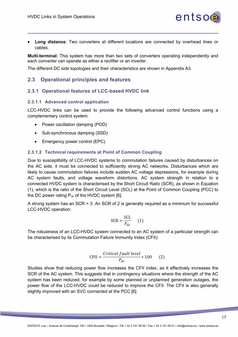
The power capability (active and reactive power) of a VSC converter can be specified by a PQ diagram as shown in Figure 3. In general, the limits depend on the rating of the converter and the conditions in the corresponding AC system. In the diagram:
• Converter rating (IGBTs) determines the size of the circle (blue line).
• Maximum active power transmission capacity is given by the rated current of the cable or overhead line (green line).
HVDC Links in System Operations
ENTSO-E AISBL • Avenue de Cortenbergh 100 • 1000 Brussels • Belgium • Tel + 32 2 741 09 50 • Fax + 32 2 741 09 51 • [email protected] • www.entsoe.eu
17
• Maximum reactive power (capacitive) capability is limited by the amplitude of the AC voltage of the grid (red line).
The HVDC system is designed by the manufacturer in such a way that the PQ-diagram fulfils the requirements of the system operator/owner.
The power capability of the HVDC system defines the limits of the current controller and consequently determines possible control actions and strategies. The control principle and the fundamental control functions are described in Appendix A2.
Figure 3: PQ-diagram of a Voltage Source Converter [7]
2.3.2.1 Advanced Control Applications
Based on the fundamental control functions for active and reactive power, more advanced applications can be developed which partly rely on additional system information:
• Power oscillation damping (POD)
• Sub-synchronous damping (SSD)
• Emergency power control (EPC)
• Frequency containment reserves (FCR)
• Synthetic inertia
• AC line emulation
• Reactive power boost
The functions are either constantly active or automatically activated by system conditions such as line outages. They improve the system behaviour dynamically and/or in steady state.
2.3.2.2 Impact of AC or DC faults
During AC faults the voltage drops at the PCC and consequently the converter supplies a voltage-dependent reactive current to stabilize the voltage. At AC short circuits next to the HVDC system the converter is capable to supply a short-circuit current up to the rating of the converter.
The behaviour at DC faults depends on the submodule concept. In half-bridge (HB) submodules the IGBTs are blocked and the AC circuit breakers at both ends have to be tripped to interrupt the

HVDC Links in System Operations
ENTSO-E AISBL • Avenue de Cortenbergh 100 • 1000 Brussels • Belgium • Tel + 32 2 741 09 50 • Fax + 32 2 741 09 51 • [email protected] • www.entsoe.eu
18
fault current for a long time (a few seconds). This procedure is detrimental to half-bridge VSC-HVDC systems with overhead lines as such systems are more prone to DC faults. In full-bridge submodules, the fault current can be controlled similarly to LCC-based systems. It is important to note that some VSC designs require the complete discharge of capacitors before the converter can change the operating state, for instance, from normal power transfer to STATCOM operation. In some cases, any type of fault that requires the opening of AC breakers will result in a long discharge period before operation can be resumed (up to 90 minutes).

HVDC Links in System Operations
ENTSO-E AISBL • Avenue de Cortenbergh 100 • 1000 Brussels • Belgium • Tel + 32 2 741 09 50 • Fax + 32 2 741 09 51 • [email protected] • www.entsoe.eu
19
2.4 Comparison between technologies Table 1: Comparison between LCC and VSC technology [9]
LCC VSC Thyristor-based technology IGBT-based technology The semiconductor can withstand voltage in either polarity Can withstand current in either direction
Constant current direction (power reversal by changing voltage polarity) Current direction changes with power
Energy is stored inductively Capacitive energy storage Turned on by a gate pulse but relies on an external circuit for its turn off
Both turn on and off are carried out without the help of an external circuit
High power capability per converter Lower power capability per converter Strong overload capability Weak overload capability
Requires stronger AC systems for excellent performance Operates well in weak AC systems Requires additional equipment for black start operation such as a synchronous condenser Possesses black start capability
Requires AC and DC harmonic filters for removal of distortion and harmonics
Requires no filters because it generates an insignificant level of harmonics
Limited in reactive power control (filters may be needed for operation) Good reactive power control
Large site area, dominated by harmonic filters A more compact site area Requires converter transformer Conventional transformer is used Lower station losses (approx. 0.7%) Higher station losses (approx. 1%) More mature long existing technology Technology still relatively new Higher voltage capability of over 1000 kV Lower voltage capability of around 600 kV The inverter side suffers commutation failures (active power = 0 for a few hundred ms) as a result of a sudden drop in the amplitude or phase shift in the AC voltage, which result in a temporal DC overcurrent. This happens even if the voltage drop is small, and even if it occurs on one phase, and therefore also occurs as a result of AC single-phase faults far from the HVDC. The commutation failure could be a significant problem for the AC system when the transmitted DC power is very high compared to the total demand of the interconnected AC networks
Ability to be turned on as well as off, makes it immune to any voltage dips or transient AC disturbances; therefore, it does not suffer commutation failures
Low number of LCC in multi-terminal systems High number of VSC in a multi-terminal system possible (needs to be investigated)
During short circuits on the DC line, control of the firing angle of the thyristor valves stops the increase of the DC fault current. This converter control prevents the damage caused by the fault current. During overhead line faults, power transmission is stopped for arc deionization, after which power transmission is resumed. This is not a critical point
Continuous conduction in the diode of half-bridge submodules will cause an increase in DC fault current even when the IGBTs are turned off. The AC circuit breakers at both ends must be opened to stop the diode conduction. The HVDC link must be re-started after the fault has been removed. This is a critical point
Need for minimum active power transmission No need for minimum active power transmission
Need for short circuit power Short circuit power during normal operation and/or in STATCOM operation and/or in black start operation may be required
Power reversal is critical Power reversal is not critical

HVDC Links in System Operations
ENTSO-E AISBL • Avenue de Cortenbergh 100 • 1000 Brussels • Belgium • Tel + 32 2 741 09 50 • Fax + 32 2 741 09 51 • [email protected] • www.entsoe.eu
20
3 Advanced operational functionalities and services
3.1 Introduction The advanced operational functionalities and services that are available, or are expected to become available in the near future, can help solve the challenges that will be faced by (or already face) system operations. In this chapter, functionalities and services are described and ways to solve challenges are explored. The focus is on the technical possibilities only; financial consequences are outside the scope of this paper. At the end of the chapter there is a table listing all discussed functionalities, illustrating if a functionality is available with LCC or VSC technology (or both) and indicating if a functionality can be used on embedded, non-embedded or both types of HVDC links. In the descriptions, a distinction is made between the scheduling phase and the real-time phase of system operations.
This paper describes various functionalities available in the advanced use of HVDC. By using them, system operations obtain a higher degree of freedom in order to enable more innovative operational strategies. Nonetheless, it should be noted that not all functionalities can be used at the same time; a level of prioritisation is required. The priority ranking of control and protection schemes for HVDC systems are discussed in the HVDC Network Code, Article 35 [19]. By attempting to use several functionalities at once, the capability of a single functionality could be reduced compared to an operation with this functionality only. These reductions are mainly due to system design issues, and they must be accounted for at all operational stages, from network planning to operational planning up to real-time operation, in order to ensure enough reserves for system operation.
3.2 HVDC Scheduling In many cases active power schedules are given to HVDC converters/links. These schedules are drafted during the operational planning phase and may be influenced by several operational planning processes as well as by the various purposes of the link. Schedules may be derived from market results or as a solution to an optimisation problem focusing on several physical targets. Normally schedules are time-discrete: valid for a certain time period. Ramping rules are used to define a transition from one scheduled value to the next one.
Besides active power, reactive power schedules might be defined during operational planning phases because:
• Reactive power may limit the use of active power (restricting the active power schedules)
• Reactive power contribution of a converter when providing active power may need to be planned according to a given schedule
3.2.1 Active Power Transmission capacity of embedded or non-embedded HVDC links can be used for scheduling the entire capacity or a specific amount, reserving some capacity for other purposes.

HVDC Links in System Operations
ENTSO-E AISBL • Avenue de Cortenbergh 100 • 1000 Brussels • Belgium • Tel + 32 2 741 09 50 • Fax + 32 2 741 09 51 • [email protected] • www.entsoe.eu
21
3.2.1.1 Scheduling based on market only
Market-based scheduling of HVDC can be applied to calculate set points for HVDC links that connect two different bidding zones (which may not necessarily lie in two different countries). The bidding zones thus coupled can be located in one synchronous area or in two different synchronous areas. The methodologies described here apply to both cases.
The set points can be calculated within a price-coupling algorithm designed to maximise welfare economic surplus in the power market within a system security framework. From a methodological point of view, we distinguish between two capacity calculation approaches:
• The Coordinated Net Transmission Capacity (CNTC) approach means the capacity calculation method based on the principle of assessing and defining ex ante (to the market clearing step) a maximum energy exchange between adjacent bidding zones.
• The second approach has been a pilot on the BritNed link between the Netherlands and Great Britain (GB), where 100 MW of FCR was available to support frequency in the UK. In this special case it was agreed that the service would be cancelled if the continental Europe frequency was 150 mHz or more from the target frequency. This pilot showed that this method of using frequency support has very good results (and can be very fast) compared to traditional generation units. At the same time, the influence on the frequency in the much larger continental Europe system is relatively small and consistent due to the fact that normal frequency deviations are random, thus in half the time the frequency in both systems is improved. It should be noted that capacity needs to be available for such support; in the BritNed pilot the available overload capacity was used. Importantly, the BritNed pilot was in one direction. As opposed to a standard AC connection, a DC connection provides the ability to precisely control the power flow. The implication is that no transit flows are induced on the DC connection by any trades elsewhere in the system. From both a market and a physical point of view, if all connections were DC, there would be no reason to go beyond the CNTC methodology. In other words, a DC line is in a way the physical reality of a CNTC as the line is fully controllable, and that is exactly what the allocation mechanism in the CNTC case assumes.
In theory, in a FB approach it would even be possible to calculate set points for embedded HVDC links with the market coupling algorithm. This would then lead to a HVDC schedule that maximises available cross-border capacities on those borders that maximise social welfare. Such an approach has not been applied up to now, because embedded HVDC links are rare and TSOs might use at least a part of the DC transmission capacity to support their own AC grid (for example, by optimisation strategies, see Chapter 3.2.1.2) instead of only providing services to the market or maximising cross border capacities.
The challenges of multiple HVDC interconnectors landing in a single bidding zone will require some allocation between HVDC interconnectors. From a social welfare perspective, it is logical to give capacity or ramping ability to the HVDC cable with the largest price delta to maximise overall welfare. Currently the optimisation of capacity and ramping is usually managed on a single cable only.
In the market coupling algorithm beneath the contingency constraints (physical capacity of lines in n and n-1 state) further HVDC specific constraints can be included, for example:

HVDC Links in System Operations
ENTSO-E AISBL • Avenue de Cortenbergh 100 • 1000 Brussels • Belgium • Tel + 32 2 741 09 50 • Fax + 32 2 741 09 51 • [email protected] • www.entsoe.eu
22
• Replacement reserve (RR) is a post gate-closure cross-border balancing (CBB) service which is available between RTE and NGESO. This service is facilitated through BALIT (Balancing Inter-TSO) which is an electronic platform that gives participants access to the CBB service. The BALIT process includes NGESO, RTE, REN and REE. BALIT cannot provide any indication of transmission constraint limitations. In addition, this non-firm service can only be requested for periods when the IFA intra-day nomination gate is closed. For each CBB hour, each TSO may submit 10 upward and 10 downward submissions in 50 MW increments with associated prices. There is no visibility of these prices to either party until 50 minutes prior to commencement of the delivery hour. Additionally, the volumes of reserve only become available 50 minutes prior to delivery commencement.
• In future, current ‘replacement reserve balancing products’ between RTE and NGESO will be replaced by the TERRE project which is a key implementation initiative for the European Electricity Balancing Guideline (EBGL) to establish a pan-European market for balancing energy. The main objective of the TERRE project is to design and develop a central platform to facilitate the close to real-time (30-min. lead time) exchange of RR between TSOs in Europe.
Transmission losses of the HVDC links can either be modelled and procured within the market coupling algorithm itself or excluded from the market coupling. If losses are not taken into in account in the algorithm, they have to be procured by the involved TSOs (for example, following an agreed bilateral procurement alignment).
A description of standard hybrid market coupling can be found in the Appendix A4.
BritNed and NorNed are operated using market-based schedules only (see Chapter 4).
3.2.1.2 Scheduling based on physical optimisation strategies
In the operational planning process, TSOs must calculate and coordinate HVDC schedules. Especially in cases of HVDC links within one bidding zone, where schedules might not be completely determined by the market but rather, for example, through D2CF/Flow-Based capacity calculation in a direct manner, system operation is able to benefit from optimised HVDC schedules.
The schedule of the HVDC link is determined according to certain criteria and aims at optimising a given objective function. Examples of objective functions include but are not limited to:
• Maximum active power transmission of the HVDC
• Minimal overall (AC + DC) losses
• Preventive congestion management, such as minimal (n-1) constraints
• Minimum voltage angle difference
• Pre-defined cross-border flow execution

HVDC Links in System Operations
ENTSO-E AISBL • Avenue de Cortenbergh 100 • 1000 Brussels • Belgium • Tel + 32 2 741 09 50 • Fax + 32 2 741 09 51 • [email protected] • www.entsoe.eu
23
Moreover, a combination of two or more objective functions is conceivable where a weighting between the different objectives is possible, such as achieving both minimal active power losses and minimal (n-1) constraints
Other power flow-influencing equipment, such as phase shifting transformers, should also be considered in HVDC scheduling. In general, there are two options to consider:
• Predefined phase shifting transformer (PST) settings for HVDC optimisation
• Both PST settings and HVDC schedules in one optimisation
Further developments are necessary to integrate embedded HVDC links in existing operational planning processes. In general, the more equipment involved with mutual interaction on active power load flow (not only HVDCs but also PSTs and even FACTS), the more advanced the optimisation algorithms will need to be. From a system operations perspective, robustness, efficiency of calculation results and compliance with time constraints due to other processes are all important.
3.2.1.3 Ramping methods and limitations
3.2.1.3.1 Conventional ramping
Today, several different ramping rules are used, the most common being fixed-period ramping.
Fixed-period ramping will normally result in a symmetrical ramp starting and ending an equal number of minutes before and after the operating hour (Figure 4/Figure 5).
Figure 4: Symmetrical fixed-period ramping, 10-minute period (±5 minutes around the hour shift)
Different ramping periods can be applied in fixed-period ramping, a 30-minute ramping period is also quite common.

HVDC Links in System Operations
ENTSO-E AISBL • Avenue de Cortenbergh 100 • 1000 Brussels • Belgium • Tel + 32 2 741 09 50 • Fax + 32 2 741 09 51 • [email protected] • www.entsoe.eu
24
Figure 5: Symmetrical fixed-period ramping, 30-minute period (±15 minutes around the hour shift)
It is important to understand that the larger the number of HVDC links, the larger the problems caused by ramping issues. If a given area has several interconnectors, using different ramping rate rules can generate quite huge imbalances in cases of non-embedded HVDC links or unscheduled fluctuations on AC lines in cases of embedded HVDC links. The problem will be partly solved by new rules to be established in the Synchronous Area Operation Agreement (SAOA). Below is an example showing power transits through the Danish system, the blue curve shows the imbalance caused by the transit:
Figure 6: Imbalances caused by different ramp rates
Examples of conventional ramping are BritNed and IFA2000 (see Chapter 4).
3.2.1.3.2 Continuous ramping
The main objective behind continuous ramping is to improve frequency quality (in non-embedded links) and increase the market capacity, accommodate faster change from high price area to low-price area and level out price differences between price areas. In the example above, the

HVDC Links in System Operations
ENTSO-E AISBL • Avenue de Cortenbergh 100 • 1000 Brussels • Belgium • Tel + 32 2 741 09 50 • Fax + 32 2 741 09 51 • [email protected] • www.entsoe.eu
25
continuous ramping principle results in the lowest ramp speed possible, allowing a higher change in energy from hour to hour. The EB GL stipulates a 15-minute imbalance settlement period to be implemented in the near future; as a result the hourly step will become a quarterly step and the resulting ramping will move closer to being continuous.
If the ramping rate itself is the limitation, it is clear that the longer the ramping can be performed, the higher the change in power is from hour to hour. In Figure 7, different ramping approaches are illustrated:
Figure 7: Power exchange with different ramping principles and a ramp limit of 30 MW/min
If ramp limits apply they can lead to ‘wrong’ power directions and reduced load factors on the tie lines, meaning the link will never reach the maximum in one direction before it has to change direction again.
A problem with continuous ramping is that since it will only be used on interconnectors, to a large extent the load is changing continuously, however since the day-ahead market is based on hourly energy, generators will not follow the same ramping principles and this can lead to imbalances.
Continuous ramping might replace the current +/- 10-minute ramping period between the Nordic region and continental Europe.

HVDC Links in System Operations
ENTSO-E AISBL • Avenue de Cortenbergh 100 • 1000 Brussels • Belgium • Tel + 32 2 741 09 50 • Fax + 32 2 741 09 51 • [email protected] • www.entsoe.eu
26
A previous ENTSO-E/Eurelectric report [11] has concluded that continuous ramping is the best principle, out of five principles investigated, to handle frequency deviations around the change of the hour:
Higher time resolutions, such as 15-minute resolutions in day-ahead and intraday markets will have a similar effect. Today, continuous ramping is not used anywhere but a pilot project between Norway, Denmark and Germany is under consideration.
3.2.1.3.3 Ramping limitations
Growth in interconnectors can present an operational challenge in some transmission systems with low system inertia. Interconnectors can vary their import/export power flows either in response to wholesale market price swings or to provide valuable ancillary services in place of declining conventional generation. This could result in large and fast changes to interconnectors’ power flows beyond the capability of the system to manage the rate of change of frequency in transmission systems. This could imply an overall combined ramping limit for existing and future interconnectors in order to manage the system security efficiently. For example, the System Operability Framework published by the UK electricity transmission operator [12] has investigated the overall GB system ramping capability and demonstrated that the transmission network has an inherent limit that changes with system conditions. Faster ramping limits could be facilitated at
Figure 8: Deterministic frequency deviations due to ramping

HVDC Links in System Operations
ENTSO-E AISBL • Avenue de Cortenbergh 100 • 1000 Brussels • Belgium • Tel + 32 2 741 09 50 • Fax + 32 2 741 09 51 • [email protected] • www.entsoe.eu
27
higher operational costs, therefore, a smart solution is required to balance such an increase in operational costs [13].
The imbalances due to ramping could be mitigated by specific algorithms in tools that calculate HVDC link schedules. They could:
• Minimise gaps between the nomination program and HVDC link schedules (sum of |energy| for each half-hour period), with – when possible – gentle slopes, HVDC link schedules in a band near the nomination program, trying to avoid stop and start, and respecting many constraints (including software constraints).
• Trade-off between losses (balanced BP program) and equipment strain (stop/start), with small and restricted imbalances, respecting the link program and many constraints (including idle time), and avoiding variations when the link does not move.
3.2.2 Reactive Power HVDC converters or related filters can provide reactive power on the AC side of each converter when specified accordingly. Beside active power scheduling of HVDC, sufficient reactive power availability is mandatory for real-time operation in order to have sufficient reactive power for voltage stability and AC power transmission in a steady state.
When a situation is foreseen where the available reactive power (such as from running generation units) is insufficient, additional reactive power sources must be used. When it is specified accordingly, VSC can provide both active and reactive power, but the total apparent power is limited (Figure 9). When additional reactive power support is foreseen to be mandatory, active power can be limited in order to have more reactive power available (this may also depend on the AC voltage). This additional active power restriction must be respected in active power scheduling or alternatively by using reactive emergency power, EPC-Q (for example, KF CGS – see Chapter 4). It must also be noted that this reduced active power availability might also reduce capacity for the market.
Figure 9: Simplified P-Q-capability chart of VSC converters
p
q
1p.u.
-1p.u.1p.u. ind.
1p.u. cap.
uAC < 1p.u.
uAC > 1p.u.uAC = 1p.u.
Simplified capability of VSC converts
Usual specification of VSC converters
p
q
1p.u.
-1p.u.1p.u. ind.
1p.u. cap.
Reduction of active power for more reactive power capability

HVDC Links in System Operations
ENTSO-E AISBL • Avenue de Cortenbergh 100 • 1000 Brussels • Belgium • Tel + 32 2 741 09 50 • Fax + 32 2 741 09 51 • [email protected] • www.entsoe.eu
28
It is advisable to take into consideration only a part of the available reactive power capability of a HVDC converter/filter during the operational planning/scheduling phase. This allows for meeting short-term needs that have not been forecast.
3.3 HVDC real-time operation
3.3.1 Active Power
3.3.1.1 Frequency control
HVDC links can either be used to connect asynchronous grids with each other or can be embedded within a single synchronous AC grid.
3.3.1.1.1 Non–Embedded HVDC
When asynchronous AC grids are connected via a HVDC link, both can support each other by means of providing balancing power when needed. An asynchronous AC grid could also be an offshore wind farm that is connected via a HVDC system to the mainland, or a storage connected to the AC grid via a HVDC could provide the balancing service. A HVDC system can balance power by means of three different mechanisms. When choosing a mechanism of balancing power, different implementation strategies should be considered. There are three different balancing power mechanisms that can be transmitted via HVDC between asynchronous grids:
Frequency Containment Reserve: Frequency is measured at both HVDC converters between which the Frequency Containment Reserve shall be exchanged (both converters must be connected on the DC side). Based on the difference between frequency deviations (reference frequency minus measured frequency) on both sides, the need for Frequency Containment Reserve exchange can be derived. A dead band may be included here in order to avoid activation of Frequency Containment Reserve during small frequency differences.
Once the need for Frequency Containment Reserve is identified, a balancing power transmission can be initiated automatically by multiplication of the frequency deviation difference with a droop factor. The result equals the active power reference value change in the converters. The droop factor is aligned between the operators of both asynchronous grids. This approach also works in a multi-terminal HVDC system.
Alternatively, the frequency deviation is evaluated on each HVDC-converter AC bus individually. The other converters connected to the same DC system will balance the DC power exchange when one converter receives balancing power. Therefore, the balancing power provision is shared between all converters participating in the DC energy balance. A balancing power exchange between dedicated converters (as in the first solution) is not automatic but depends on the control settings of the converter control regarding the DC energy balance.
Further fine-tuning is possible in order to define the dynamic characteristics of Frequency Containment Reserve. Depending on the fine-tuning, any characteristic of inertia can be emulated.
Frequency support from one synchronous zone to another can be provided via HVDC. In such cases the ‘receiving’ area's frequency is the input for the controller. When the frequency is high in

HVDC Links in System Operations
ENTSO-E AISBL • Avenue de Cortenbergh 100 • 1000 Brussels • Belgium • Tel + 32 2 741 09 50 • Fax + 32 2 741 09 51 • [email protected] • www.entsoe.eu
29
the receiving area the flow on the HVDC link towards that area will go down and vice versa. See Chapter 3.2.1.1.
Automatic Frequency Restoration Reserve: In Automatic Frequency Restoration Reserve, a signal is actively sent to the converter station as it would for a generating unit. The amount of needed Frequency Restoration Reserve with regard to the HVDC converters is determined and sent to the converters as an active power reference value change.
Manual Frequency Restoration Reserve and Replacement Reserve: For manual frequency restoration reserve, the same applies as for RR but with a 15-min. lead time. This is handled by the MARI project. Examples are BritNed; Inelfe, KF CGS, SAPEI and SACOI (see Chapter 4). In future, current ‘replacement reserve balancing products’ between RTE and NGET will be replaced by the TERRE project which is a key implementation initiative for the European Electricity Balancing Guideline (EB GL) to establish a pan-European market for balancing energy. The main objective of the TERRE project is to design and develop a central platform to facilitate the close to real-time (30-min. lead time) exchange of RR between TSOs in Europe. [16].
3.3.1.1.2 Embedded HVDC
A HVDC system cannot provide balancing power as it is not itself a source of energy. However, an embedded HVDC can still transmit balancing power within a synchronous AC grid, for example, balancing power can be transmitted over long distances via the HVDC system. As with the transmission of balancing power between synchronous grids, participation in transmitting balancing power flows by embedded HVDCs can be triggered by an operator command or by an automatic command towards the converter control adapting the active power reference. An automatic command can, for instance, be based on the identification of both the requesting and providing area for balancing power and the determination of the most suitable embedded HVDC connection.
Any kind of storage which is connected to the DC side of a HVDC system can be used to provide balancing power from a HVDC.
Implementation Guidance Document (IGD): All embedded HVDC links are required to have FSM and LFSM control functionalities on frequency setting requirements for embedded HVDC systems, according to IGD. However, this functionality could be disabled by SOs as required.
The design and implementation of such functionality for embedded HVDC links may prove more challenging than frequency response employment on power generating modules. This is because a generator’s frequency response is based on measurement on only one connection point whereas with a HVDC link within synchronous areas, active frequency response is based on frequency deviations measured on both connection points, and in case of a system split, no action from the embedded HVDC system is expected. Therefore, an asynchronous operation detection algorithm is required to identify any system split. The design of such a split detection algorithm Error! Reference source not found.could be based on:
• Measuring and comparing frequencies in both points
• Monitoring states of line breakers
• Filtering of frequency measurements to ensure robustness of the algorithm

HVDC Links in System Operations
ENTSO-E AISBL • Avenue de Cortenbergh 100 • 1000 Brussels • Belgium • Tel + 32 2 741 09 50 • Fax + 32 2 741 09 51 • [email protected] • www.entsoe.eu
30
International grid control cooperation (IGCC): Embedded HVDC links are able to contribute to the imbalance netting using the IGCC mechanism. There are no examples yet but, at least theoretically, it is possible for the IGCC optimization module to calculate the needed change in flow on the HVDC link between two TSOs in order to avoid counter-activation of reserves. To do this there must be capacity available on the link and the possible ramping speed of the link must be high enough. Actual changing of the flow would happen by adding the IGCC signal as a delta value to the scheduled flow on the link. Currently, there are plans to improve the IGCC optimization algorithm, so that besides the calculation of set-point changes, ramping limits can also be taken into account.
AC line emulation control: An AC emulation control aims to reproduce the behaviour of an AC line by means of a function of the difference between angles in both converter stations in HVDC links embedded within a single synchronous AC grid. For changes in the phase angle on either station, the response of this control is to ‘emulate the behaviour of an AC line’ in both steady and transient states.
The AC line emulation approach is also possible in combination with an active power schedule. A certain power (ΔP) is then added to the given active power schedule based on the angle difference between the two converters.
The AC emulation control needs measurement signals for the angles at both ends of the HVDC. In practice, the angle difference is measured by built-in devices in the converters and the synchronization of angle measurements on both stations is done by means of GPS. In case of a loss of satellite reception, the HVDC link still remains in AC emulation mode for an additional length of time, running the angle measurement from an internal quartz clock. As an alternative to the above, the angle difference measurement could also be obtained from an approach based on PMUs. Once the angle difference is measured, the HVDC control system calculates the active power set point and applies it. Some delays for measurement, transmission, conversion and processing of the signals are unavoidable, which leads to an active power set point delay. Delays due to the transmission and processing of the signal are pure delays which could cause an active power oscillation when the HVDC is in parallel to several AC lines, depending on the grid architecture and power flow situations.
The oscillatory nature of the phenomenon requires a filter within the AC emulation to damp such oscillations created by the pure delay that constitutes the transmission and signal processing. This filter introduces a delay in the response of the AC emulation control of the HVDC link, in such a way that it is less sensitive to transient events. Nevertheless, this delayed response does not interfere in the operational advantages of this active power control. Additionally, once oscillations due to internal HVDC control are mitigated and compatible with a stability margin, further settings could be implemented in the filter to improve the damping of inter-area oscillations.
The main benefits of AC emulation are:
• Notably simpler real-time operation. The HVDC adapts its active power without requiring any manual action from operators according to real-time system changes.
• Significantly less need for coordination between control centres to manage HVDC flows.
HVDC Links in System Operations
ENTSO-E AISBL • Avenue de Cortenbergh 100 • 1000 Brussels • Belgium • Tel + 32 2 741 09 50 • Fax + 32 2 741 09 51 • [email protected] • www.entsoe.eu
31
• Fast response to events in the network. AC emulation automatically reacts to changes in load/generation and grid topology.
• Automatic reaction to the trip of a line as a curative remedial action.
• No loop flows.
• Ramping proportional to AC line’s ramping. This reduces additional stress to the grid that might be introduced by fast HVDC set point changes.
The main challenges of this strategy are:
• Fall-back mode is needed in case of failure of the AC line emulation in order to send manual or optimised set points via the control centre to fulfil the security criteria in real-time operation.
• A typical HVDC characteristic – power flows that can be actively defined independent of AC voltage (angles) – is lost using this approach.
• Active power flow damping must be actively added where needed.
An example is INELFE (see Chapter 4).
3.3.1.2 Remedial Actions in real-time operation
As in many cases, the load flow situation between planning phase and real-time operation differs, thus there may need to be an adjustment of the HVDC set points in real time to avoid congestion in the surrounding AC grids. This chapter discusses preventive remedial actions.
3.3.1.2.1 Embedded HVDC
Adapting the set point of an embedded HVDC can, as a first step, be an inexpensive grid-related measure. Therefore, grid operators will take this step first, before the application of market-related (more costly) measures in case of congestion.
If AC line emulation is applied, the set points will be adjusted automatically. The dynamic adjustment of the proportional factor in the AC line emulation settings can be applied as a grid-related preventive remedial action.
If the HVDC is operated according to a power schedule, a new HVDC set point must be actively calculated and sent to the HVDC. HVDC set points can be determined by optimising an objective function under the constraints of grid security with the actual real-time grid model in place. The active power change on the converter can be performed manually (operator sends a command to the HVDC control system) or automatically (advanced algorithm sends a command from the control centre to the HVDC control system).
The main features and challenges of this approach are:
• This approach requires a robust and advanced optimisation tool to find the optimal power set point, and its computation time must be compatible with the real-time needs of the control centre. The optimisation tool has to send power set points to the HVDC control

HVDC Links in System Operations
ENTSO-E AISBL • Avenue de Cortenbergh 100 • 1000 Brussels • Belgium • Tel + 32 2 741 09 50 • Fax + 32 2 741 09 51 • [email protected] • www.entsoe.eu
32
system periodically1. The frequency of new set point calculation and transmission to the HVDC has to be analysed by the respective TSOs. Special attention should be given to the ramping intervals (e.g. +/- 5 min to each quarter-hour in CE).
• This approach needs coordination between control centres to agree on power set points for HVDCs located at borders or surrounding areas.
• TSOs must analyse the best ways to consider exceptional contingencies.
• A fallback mode should be designed in case of optimisation tool or telecommunications failure. Fallback mode would send manual set points from the operator to fulfil the security criteria in real-time operation.
3.3.1.2.2 Non-Embedded HVDC
With non-embedded HVDC interconnectors between synchronous areas, congestion management in the AC grid is also possible. The approach described for the adaptation of the HVDC set points in embedded HVDC is also applicable to non-embedded HVDC.
It is important to note that the modification of the HVDC link active-power set point leads to an imbalance in the net positions of the connected AC grids that must be compensated by market-related actions if not it influences the frequency and reserves will be activated.
3.3.1.2.3 The concept of DC loop flow
There is one special concept which does not require market-related actions called DC loop flow.
This concept is an inexpensive, grid-related remedial action. Congestions can be voltage- as well as current-related. DC loop flows transfer a power flow that causes congestions from one AC grid node to another AC grid node via at least two DC lines and at least one asynchronous AC grid. In effect, DC loop flows move power within an AC grid without loading AC equipment, thus avoiding costly congestion management.
At least two non-embedded HVDC links between at least two asynchronous zones (which may include more than a single TSO each) are needed. It is mandatory that the involved asynchronous AC grids together with the HVDC links can transmit power in a loop (Figure 10).
1 E.g., each time a new State Estimation is available in the EMS

HVDC Links in System Operations
ENTSO-E AISBL • Avenue de Cortenbergh 100 • 1000 Brussels • Belgium • Tel + 32 2 741 09 50 • Fax + 32 2 741 09 51 • [email protected] • www.entsoe.eu
33
Figure 10: Principle of DC loop flow with non-embedded HVDC links
a) Example with two involved asynchronous zones and two HVDC links where DC loop flow is possible b) Example with three involved asynchronous zones and four HVDC links where DC loop flow is possible
DC loop flow is performed as follows:
• Based on the market result for the respective HVDC link, the requesting TSO identifies how much DC loop flow potential via the HVDC link is available in each direction (the market-based HVDC schedule can be reduced or increased up to the physically possible power transfer limit for DC loop flow).
• The requesting TSO (the TSO with AC congestion) asks a TSO on the other side of the HVDC link (with multiple TSO involved, the TSO closest to the congested TSO in the direction of power flow is approached) whether a DC loop flow for a defined time period with a certain amount of power is feasible. Further TSOs will be approached with the same question until loop is closed, which means that each involved TSO agrees to the DC loop flow measure.
• DC loop flow starts at an agreed point in time.
• DC loop flow stops at agreed point in time or the requesting TSO informs all involved parties about an earlier stop.
DC loop flow is typically initiated after-market closure, in order to be certain of the available capacity for DC loop flow. Examples are KF CGS and KONTEK (see Chapter 4).
3.3.2 Reactive power and voltage control Voltage control is the manual or automatic control action to maintain the set voltage level or the set value of reactive power. Voltage control is important both because it is a contractual obligation of the Grid Code and for proper insulation. Voltage control may also be useful to minimise losses and increase network stability. HVDC provides supplementary and regulated reactive power in order to contribute to these objectives either in steady-state or during dynamic disturbances.
HVDC reactive capabilities allow it to compensate for the decrease of reactive power supply due to generators (power plant availability or reactive power capacity reduction), the decrease of the
Synchronous AC grid 1
Synchronous AC grid 2
HVDC link congestion
Synchronous AC grid 1
Synchronous AC grid 2
Synchronous AC grid 3
a) b)
DC loop flow

HVDC Links in System Operations
ENTSO-E AISBL • Avenue de Cortenbergh 100 • 1000 Brussels • Belgium • Tel + 32 2 741 09 50 • Fax + 32 2 741 09 51 • [email protected] • www.entsoe.eu
34
power short-circuit level, and the increasing impact of grid elements on reactive power (with more and more cables in the grid, loads, etc.).
3.3.2.1 Static control
Three control modes are available: reactive power control (Q-Mode), AC voltage control (U-Mode) and power factor control (PF-Mode). Each of them can be either a constant value control or a droop control which adapts the reactive power provision proportional to the deviation from the reference value, thus contributing to the maintenance of the system in a safety domain.
Q-mode (Reactive power control): The reactive power injected or withdrawn by the converter terminal is controlled by a converter reactive power controller that realises the set point value. The set point is applied by the operator.
If the actual voltage at the terminals exceeds the limits set for the voltage, the controller will react and adjust the reactive power consumption/production until the voltage is again within the defined limits.
U-mode (AC voltage control): A function for controlling the AC voltage on the network side of its converter transformer. In order to provide an AC voltage control, a set point for the converter station could be established.
The link will provide reactive power in order to contribute to the network voltage support, within the capability limits defined for the converter.
Similar to active power/frequency control for synchronous generators, the voltage control shall respect a droop characteristic:
𝑼𝒕𝒂𝒓𝒈𝒆𝒕 = 𝑼𝒏𝒆𝒕𝒘𝒐𝒓𝒌 + 𝝀 × 𝑸
Where: 𝑼𝒕𝒂𝒓𝒈𝒆𝒕 is a voltage settable by the operator (or an external signal) in kV
𝑼𝒏𝒆𝒕𝒘𝒐𝒓𝒌 is the voltage measured at the point of common coupling in kV
Q is the reactive power at the point of common coupling in Mvar λ is a free parameter, controlled by the operator within kV/Mvar Using this kind of control, particularly with an independent control loop and set point, the HVDC remains under PCC voltage control in the event of a HVDC trip,
U-mode (secondary voltage control, advanced use): The secondary voltage control is an external global voltage control on a large area. The aim is to control the voltage on relevant points in the area, in a coordinated and optimised way, in order to ensure some of the objectives quoted in the Introduction such as decreasing losses and ensuring stability.
The principle of secondary voltage control is to control the primary voltage controller via the secondary voltage system. To achieve this, the link must be designed to be able to receive a set point ULMN calculated by an external tool issued by the control centre (Figure 11).
ULMN shall be used to determine and modify the set point UOPLQMO applied to the primary voltage controller. In order for the HVDC link to support the secondary voltage regulation, the HVDC control must be able to cope with voltage orders (change in ULMN).

HVDC Links in System Operations
ENTSO-E AISBL • Avenue de Cortenbergh 100 • 1000 Brussels • Belgium • Tel + 32 2 741 09 50 • Fax + 32 2 741 09 51 • [email protected] • www.entsoe.eu
35
Figure 11: Voltage Control Scheme
PF-mode (Power factor control): The power is controlled according to the active power schedule.
3.3.2.2 Dynamic Control
In normal operation, the HVDC converter will give priority to the active power over the reactive power. During a disruption, this priority might shift depending on the situation in order to prevent deterioration of the system state. In order to avoid alert state or emergency state, the HVDC systems have a fault ride-through capability with a required AC network voltage drop and overvoltage profile which can withstand a voltage-drop profile and continue stable operation without blocking, tripping or result in mal-operations, abnormal situations or untimely alarms during symmetrical and asymmetrical faults. Each HVDC converter is able to withstand several consecutive voltage-drop profiles.
The HVDC converter station is capable of providing an additional reactive current contribution at the point of common coupling (such as a fast reactive current injection) during a period of faults or voltage collapse. The magnitude of this additional reactive current can be proportional to the positive sequence value of the voltage at the point of common coupling.
When the HVDC converter station provides a fast additional reactive current, the priority is given to the reactive current and the active power of the HVDC link may be reduced
In addition, in case of asymmetrical faults, the HVDC converter is also capable of providing an additional negative current contribution at the PCC. The behaviour of this additional current coordinates with the reactive current injection.
Furthermore, the provision of reactive power is limited during faults on the DC side of the HVDC transmission system. In an embedded HVDC transmission system, the HVAC power grid will show the most urgent need for reactive power when the HVDC transmission system is lost (e.g., due to a DC line fault) and the active power (formerly transmitted by the HVDC transmission system) skips to the HVAC power grid. Consequently, the reactive-power demand of the HVAC power grid will rise while at the same time the HVDC converters may not be available anymore due to an inappropriate fault clearing strategy on the DC side (e.g., opening of AC circuit breakers

HVDC Links in System Operations
ENTSO-E AISBL • Avenue de Cortenbergh 100 • 1000 Brussels • Belgium • Tel + 32 2 741 09 50 • Fax + 32 2 741 09 51 • [email protected] • www.entsoe.eu
36
or converter blocking). It therefore needs to be explicitly specified if the TSO wants to have reactive-power support during DC faults.
An example is INELFE (see Chapter 4).
3.3.3 Special Protection Schemes Special protection schemes (SPS) are possible curative remedial actions. SPSs are either automatically or with manual approval executed to sustain a stable and secure system state after the occurrence of contingencies. Once a disturbance in the grid is detected and clearly identified, an appropriate action is derived by a decision function based on the disturbance type or a clearly identified disturbance scenario and corresponding measurements. The action is then automatically activated. Basic conditions for the application of SPSs are a fast and accurate disturbance detection system and a robust SPS design. The general structure and working principle of an SPS is shown in Figure 12.
Figure 12: General structure of a Special Protection Scheme (SPS)
The advanced control functions of a HVDC system offer the possibility of integrating the converters in a special protection scheme such as emergency power control. Depending on the disturbance, curative measures are activated to have a local or global2 remedial effect on the system, such as [14]:
• Preventing thermal overloading of assets next to the HVDC link (local)
• Preventing a voltage collapse next to the converter (local)
• Containing a frequency deviation (global)
If the detected disturbance fits into the predefined fault scheme, corresponding actions are introduced by the converters, such as:
• full run-back of active power
2 Regarding physical units, local physical units are voltage and current whereas the global physical unit is frequency.
Disturbance
Power System
Action DecisionProcess Input
Special Protection Scheme
electric variables
detection

HVDC Links in System Operations
ENTSO-E AISBL • Avenue de Cortenbergh 100 • 1000 Brussels • Belgium • Tel + 32 2 741 09 50 • Fax + 32 2 741 09 51 • [email protected] • www.entsoe.eu
37
• full run-up of active power
• inductive/capacitive reactive power boost
• run to a specific active and/or reactive power operating point that was calculated for the specific disturbance beforehand
• parameter modification of power control (e.g., AC line emulation)
A major challenge in the planning phase will be the robust design of the SPS, considering all relevant disturbance scenarios and taking into account other events that might take place in parallel which potentially endanger the application of a SPS countermeasure. If such a risk exists, an automatic SPS should not be applied. Possible disturbances include an AC line trip, power plant outage or even a trip of another HVDC line.
For the decision-making process, different approaches can be implemented, such as:
• Current-based:
o In a chosen area, circuits to be ‘protected’ are related to the SPS of the HVDC system. These circuits are typically located next to the PCC of the corresponding converter. If such a circuit trips and at the same time the pre-fault current of that circuit exceeds a specified limit, the converter automatically executes a predefined action (e.g., full reduction of active power to zero or to a specific limit).
o Based on the actual grid situation in a wider area around the HVDC system, the ‘best’ post-fault reaction is determined by means of (n-1)-calculations for all relevant contingencies beforehand. If a contingency actually happens, the pre-calculated strategy (operating points for active and reactive power) for the corresponding event is activated. This approach is more advanced, as the required post-fault reaction of the HVDC is updated continuously independent of the grid situation, and therefore the HVDC can also support the system during unforeseen events.
• Voltage-based: Depending on the voltage drop or rise after contingencies, a predefined action is initialised (e.g., a reactive power boost). See also Chapter 3.2.
• Frequency-based: Depending on the frequency deviation after contingencies, a predefined action is initialised (e.g., active power to zero or maximum active power). This approach applies for non-embedded HVDC interconnectors.
If the evaluation of a number of measurements from different locations is not possible or is not possible within a sufficient period of time, a disturbance event might also be identified based on time-course measurements at the converter. Here it is of special importance to ensure a clear identification of the disturbance. This approach may also be applied to a wider area with multiple HVDC links.
Besides automatic actions after contingencies/disturbances that were considered before they occurred, the HVDC link can also be applied to automatically support the AC system during unintended significant power flow changes (e.g., due to an unexpected wind front). This can be

HVDC Links in System Operations
ENTSO-E AISBL • Avenue de Cortenbergh 100 • 1000 Brussels • Belgium • Tel + 32 2 741 09 50 • Fax + 32 2 741 09 51 • [email protected] • www.entsoe.eu
38
done similarly to the normal operation mode of INELFE but as an additional offset to the normal set point of the converters.
Examples for implemented special protection schemes in existing HVDC configurations can be found in the Appendix.
For executing SPS, runback and EPC (implemented for example in KONTEK, KF CGS, BritNed, INELFE and Skagerrak 4; see Chapter 4) modules within the converter control are normally triggered and used.
3.3.4 Synthetic Inertia System inertia is a crucial quantity for frequency stability. It determines the initial rate of change of frequency (RoCoF) and the minimum (or maximum) nadir3 in case of imbalances. Typical values for the Total System Inertia (TSI) are in the order of 5-6s for a synchronous generator-dominated system. Weaker systems have a TSI of < 2s. Each TSO should define its minimum level of system inertia that allows secure system operation.
Due to the increasing number of power electronic devices and the decreasing number of conventional synchronous generators, less inertia will be available in the future. Synthetic inertia (SI) provided by HVDC systems could help to partially compensate the decreasing TSI of affected synchronous areas. Synthetic inertia especially applies to systems with a low TSI and a high penetration of RES, which have a larger effect on frequency stability.
According to the RfG, synthetic inertia is a facility provided by a power park module or HVDC to replace the effect of the inertia of a synchronous generator to a certain degree. In NC HVDC Article 14, it is written that HVDC converters shall be capable, if specified, of providing synthetic inertia in response to frequency changes to limit the rate of change of frequency (RoCoF). In ENTSO-E under the Network Code Implementation Program, the above requirements are addressed while under the System Operations Committee, a project has begun which will focus on ‘inertia management’ . Furthermore, the EU funded MIGRATE [20] project is investigating the possibility of implementing synthetic inertia from Type 4 wind generators.
The principle challenges of synthetic inertia are:
• Limiting the initial rate of change of frequency (RoCoF) – df/dt: The RoCoF should not exceed the maximum withstand capability of demand and power generation units to ensure control system robustness, the possibility of island detection and the correct operation of Loss of Mains (LOM) protection. A contribution of SI immediately after a disturbance is required to limit the RoCoF and to ensure reliable operation, in particular in a system with high penetration of power electronic devices.
• Limiting the lower/higher nadir of the frequency to avoid demand/generation disconnection: A fast activation of active power is necessary to reduce the df/dt and consequently reduce the nadir, which could prevent the disconnection of demand and generation.
The principles are shown in Figure 13.
3 Minimum/maximum frequency after a disturbance.
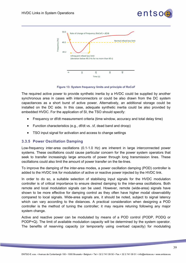
HVDC Links in System Operations
ENTSO-E AISBL • Avenue de Cortenbergh 100 • 1000 Brussels • Belgium • Tel + 32 2 741 09 50 • Fax + 32 2 741 09 51 • [email protected] • www.entsoe.eu
39
Figure 13: System frequency limits and principle of RoCoF
The required active power to provide synthetic inertia by a HVDC could be supplied by another synchronous area in cases with interconnectors or could be also drawn from the DC system capacitances as a short burst of active power. Alternatively, an additional storage could be installed on the DC side. In this case, adequate synthetic inertia could be also provided by embedded HVDC. For the application of SI, the TSO should specify:
• Frequency or df/dt measurement criteria (time window, accuracy and total delay time)
• Function characteristics (e.g., df/dt vs. ∆f, dead band and droop)
• TSO input signal for activation and access to change settings
3.3.5 Power Oscillation Damping Low-frequency inter-area oscillations (0.1-1.0 Hz) are inherent in large interconnected power systems. These oscillations could cause particular concern for the power system operators that seek to transfer increasingly large amounts of power through long transmission lines. These oscillations could also limit the amount of power transfer on the tie-lines.
To improve the damping of the inter-area modes, a power oscillation damping (POD) controller is added to the HVDC link for modulation of active or reactive power injected by the HVDC link.
In order to do so, a suitable selection of stabilising input signals for the HVDC modulation controller is of critical importance to ensure desired damping to the inter-area oscillations. Both remote and local modulation signals can be used. However, remote (wide-area) signals have shown to be more effective for damping control as they often have higher modal observability compared to local signals. Wide-area signals are, it should be noted, subject to signal latency which can vary according to the distances. A practical consideration when designing a POD controller is the method of tuning the controller; it may require retuning following any major system change.
Active and reactive power can be modulated by means of a POD control (PODP, PODQ or PODP+Q). The limit of available modulation capacity will be determined by the system operator. The benefits of reserving capacity (or temporarily using overload capacity) for modulating
Normal infeed loss limit
50.0
Freq
uenc
y (H
z)
49.5
49.2
Rate of change of frequency (RoCoF) = df/dt
Infrequent infeed loss limit(deviation below 49.5 Hz for no more than 60 s)
Time (s)
0 10 20 30 40
HVDC Links in System Operations
ENTSO-E AISBL • Avenue de Cortenbergh 100 • 1000 Brussels • Belgium • Tel + 32 2 741 09 50 • Fax + 32 2 741 09 51 • [email protected] • www.entsoe.eu
40
purposes following system disturbances must be compared with the costs of reducing the power transfer capability through the HVDC line.
Supplementary POD controllers can be designed based on different techniques such as:
• Power system stabiliser (PSS)-based POD control
• Model-based POD control such as MLQG (Modular Linear Quadratic Gaussian)
This functionality is implemented at INELFE, for example (see Chapter 4).
3.3.6 Operation with special DC-side topology HVDC links can have various DC side topologies as described in MS1 (Appendix A3). A bipole topology (including metallic return) is the most flexible topology when it comes to the N-1 conditions of DC conductors, as the metallic return can replace a faulty pole conductor either as a metallic return isolated for nominal voltage (no DC power reduction in a N-1 situation needed) or as a metallic return isolated on medium voltage (DC power transmission to be reduced to 50% of nominal power of the DC link in case of a N-1 situation). Depending on environmental requirements, ground return may be permitted instead of a dedicated metallic return isolated on medium voltage. Both bipole configurations (with dedicated metallic return and without dedicated metallic return/ground return) are partly redundant regarding the N-1 conditions of the converters, as it is possible to continue operation to a maximum of half of the nominal power in such a scenario. In both cases an appropriate substation design is required.
To increase efficiency, it is advantageous to automatically reconfigure the DC side topology to continue operation with full- or half-transmission capacity in a short period of time after the N-1 situation, or even without any disturbance of DC power transmission. This requires automatic fault identification. The time of unavailable DC transmission during reconfiguration of the DC side after an N-1 event is a design factor.
After fault identification and isolation of the faulted DC conductor by DC circuit breakers or DC disconnectors (in combination with full-bridge VSC or AC circuit breakers), a switching sequence is initiated automatically to change the DC side topology accordingly. Energising or de-energising steps have to be considered. To continue bipole operation after a conductor N-1 event, the metallic return (isolated on nominal voltage) has to be charged first. The reconfiguration is done synchronously in both converter stations.
During converter faults (outage of one pole in a bipole system), an automatic reconfiguration to use the metallic return in the power transmission path is beneficial to continue operation in a monopolar configuration as soon as possible. Without metallic return, the de-energising of a pole conductor is also necessary before continuing operation.
This functionality is implemented in Skagerrak 4 and INELFE, for example (see Chapter 4).
3.3.7 Island Operation There are two situations to consider in island operation, first, the restoration of the service in an island that is in a blackout and second, the needs of an island connected with another area via a HVDC link. Both situations are described below:

HVDC Links in System Operations
ENTSO-E AISBL • Avenue de Cortenbergh 100 • 1000 Brussels • Belgium • Tel + 32 2 741 09 50 • Fax + 32 2 741 09 51 • [email protected] • www.entsoe.eu
41
3.3.7.1 Restoration and connecting asynchronous AC grids
Restoration obligations are defined in the Emergency and Restoration guideline. A TSO and a synchronous area are required to have a restoration plan for blackout and other island conditions. The restoration process is introduced in case of a partial or total blackout. The following strategies can be distinguished:
1. Top-down restoration strategy
2. Bottom-up restoration strategy
Each strategy can be implemented and shall be chosen depending on the following considerations:
• Blackout extension
• Status of the neighbouring grid
• Availability of house-loaded units and black start units within its control area
• Availability of HVDC interconnections
3.3.7.1.1 Top-down strategy
The top-down strategy uses external voltage sources. This means that an electrical area, and in particular a neighbouring TSO, which remained secure and stable, can re-energise step-by-step an isolated area in blackout conditions starting from tie-lines, in order to facilitate the acceleration of the restoration procedure. If a re-energised high-voltage AC path is very long it can help to have shunt reactors for voltage control.
The VSC type HVDC can create a restoration path on its own using frequency and voltage control without the need for short-circuit power. In this control mode the VSC is grid-forming, thus, a VSC HVDC can be used in the top-down strategy.
Even though the LCC type can control the frequency as well, it needs a high value of short-circuit power and a minimum value of active power transmission (technical minimum) is needed. However, unlike the VSC, LCC is not able to be grid-forming by itself, and therefore LCC is not used for the top-down restoration strategy.
Black start capability is implemented in KF CGS, Skagerrak 4 and INELFE (see Chapter 4).
3.3.7.1.2 Bottom-up strategy
The bottom-up restoration strategy is based on the capabilities of internal sources. Starting from the generators with black start capabilities (e.g. hydro-generators) the aim is to reach the units’ in-house load operation.
Figure 14 shows a block diagram and working principles of restoration strategies and HVDC technology:

HVDC Links in System Operations
ENTSO-E AISBL • Avenue de Cortenbergh 100 • 1000 Brussels • Belgium • Tel + 32 2 741 09 50 • Fax + 32 2 741 09 51 • [email protected] • www.entsoe.eu
42
Figure 14: Working principle of restoration strategies and HVDC technology
During the restoration phase, the black start generators, with the help of ballast loads, provide the ability to control reactive power/voltage and speed/frequency.
Figure 15: Restoration based on a bottom-up strategy
The use of ballast loads can be a problem given the high presence of distributed generation (DG) on LV and MV networks. It presents a risk of failure building the restoration path: After a blackout, there could be a loss of DG that causes a load ‘increase’ with potential stability problems for the group in black start.
SynchronizationVSC
YES
NO
Black start
Hydro Generator
Islanding
LCC
YES
NO
Start from Hydro
Generator
Sinchronous Condenser
Target Generator in House Load
Meshing with Other Restoration
Paths
Loads
Bottom-up strategy
Top-down strategy

HVDC Links in System Operations
ENTSO-E AISBL • Avenue de Cortenbergh 100 • 1000 Brussels • Belgium • Tel + 32 2 741 09 50 • Fax + 32 2 741 09 51 • [email protected] • www.entsoe.eu
43
Figure 16: Restoration based on a bottom-up strategy (loss of DG)
During the restoration phase, the automatic reconnection of DG can change the load/generation equilibrium on the islanded restoration path.
Figure 17: Restoration based on a bottom-up strategy (automatic reconnection of DG)
Both HVDC types, VSC and LCC, can be used for the bottom-up strategy, working as a target ‘group/load’ with a large regulation capacity. LCC technology requires a high short-circuit power (e.g., by means of synchronous condenser).
Figure 18: Restoration based on a bottom-up strategy including HVDC

HVDC Links in System Operations
ENTSO-E AISBL • Avenue de Cortenbergh 100 • 1000 Brussels • Belgium • Tel + 32 2 741 09 50 • Fax + 32 2 741 09 51 • [email protected] • www.entsoe.eu
44
Functionalities of HVDC:
• Black start capability: ‘Black start capability’ refers to a HVDC converter and its associated set of equipment with the ability to be started without electric supply from the power system. A black start-capable converter generally has the ability to energise a bus, to sustain the frequency and voltage transients (e.g., power ramps, step loads, synchronisation with other groups) and to provide active and reactive power capability in order to satisfy the TSOs’ requirements regarding the power system restoration plan. Black start capability is a typical characteristic of a voltage source converter.
• Ability to adjust the voltage target to 0.9 Un, then up to Un (bottom-up strategy): Once the HVDC is energised at the receiving end, it must be possible to ramp up voltage from a low value (as close as possible to 0) to 0.9 Un within approximately 3-5s to avoid Ferro-resonances. This can either provide a power plant with auxiliary power as quickly as possible, or provide power on a long network with large power transformers. The complete transmission corridor between the HVDC and the power plant or network will be energised at once, reducing the need for sequential switching. The HVDC must be able to make successive attempts to ramp up voltage from a low value to 0.9 Un in case of failure in the previous attempt.
• STATCOM and reactive power/voltage control (e.g., KF CGS, INELEFE and Skagerrak 4, see Chapter 4): The use of a HVDC as STATCOM in the restoration process depends on its technical characteristics. Only the VSC technology can provide reactive power capability that allows both reactive power and voltage control of the restoration path. It can be used in the restoration strategies by means of nearby hydro- or turbo-gas generation plants or, if properly sized, by means of an internal source, depending on the required minimum short-circuit power level. It can also be used in a top-down strategy to stabilise the voltage profile on the AC corridors at the first stage of restoration when HVDC is energised from a neighbouring TSO. It is, however, important to remember that the VSC technology might require discharge of power modules every time the converter changes state, so if the operator wishes to go from power transmission to STATCOM operation it may require a complete discharge of all power modules first, which may take between 5-90 minutes. Fast discharge functions are available if specified, as well as the ability to go directly from power transmission to STATCOM.
• Both types of HVDC links, VSC and LCC, can control the primary frequency providing a very fast active power regulation.
• Synchronisation: Due to the increase in distributed generation, more islands may be formed which can survive after a blackout. After a blackout, the electric islands which are a result of the restoration phase must be synchronised, in order to re-establish a common synchronised grid. Thus it is recommended to limit the number of potential islands and design them in a way that facilitates synchronisation, e.g., by using HVDC links connecting them.
• For synchronisation itself, frequency, voltage and angle differences must be decreased to a level that allows connection of the former islands . The use of HVDC capability for
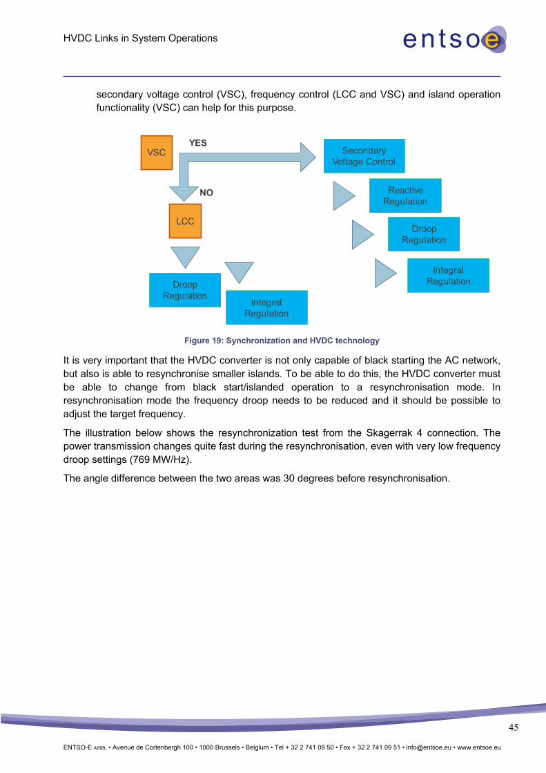
HVDC Links in System Operations
ENTSO-E AISBL • Avenue de Cortenbergh 100 • 1000 Brussels • Belgium • Tel + 32 2 741 09 50 • Fax + 32 2 741 09 51 • [email protected] • www.entsoe.eu
45
secondary voltage control (VSC), frequency control (LCC and VSC) and island operation functionality (VSC) can help for this purpose.
Figure 19: Synchronization and HVDC technology
It is very important that the HVDC converter is not only capable of black starting the AC network, but also is able to resynchronise smaller islands. To be able to do this, the HVDC converter must be able to change from black start/islanded operation to a resynchronisation mode. In resynchronisation mode the frequency droop needs to be reduced and it should be possible to adjust the target frequency.
The illustration below shows the resynchronization test from the Skagerrak 4 connection. The power transmission changes quite fast during the resynchronisation, even with very low frequency droop settings (769 MW/Hz).
The angle difference between the two areas was 30 degrees before resynchronisation.
VSCYES
NO
LCCDroop
Regulation
Integral Regulation
Secondary Voltage Control
Droop Regulation
Integral Regulation
Reactive Regulation

HVDC Links in System Operations
ENTSO-E AISBL • Avenue de Cortenbergh 100 • 1000 Brussels • Belgium • Tel + 32 2 741 09 50 • Fax + 32 2 741 09 51 • [email protected] • www.entsoe.eu
46
Figure 20: Resynchronisation
3.3.7.1.3 Operating an island and asynchronous AC grids
It might also be of interest for a TSO to operate an island using HVDC, whether via the connection of an offshore wind farm or the intended (short- or long-term) de-meshing of the AC transmission grid. Depending on the HVDC technology, LCC or VSC, both are possible:
• Detection of unintended islanding:
o Topology-based detection of the state of specific breakers can be used if the network is not highly meshed, for instance if the HVDC line is parallel to a limited number of AC lines. If all parallel AC lines are disconnected the system can be declared ‘split’.
o Frequency-based detection, comparing the frequency in both HVDC substations and declaring a system split if there is a frequency deviation for longer than a certain time limit (not lower than the normal fault clearing time, approx. 100 ms) is another option. For this purpose, the converter controls the frequency and calculates the rate of change of frequency on each side and compares it to the other’s. If the pre-determined criteria are reached, then the control will activate the passive network regulation (U, f).
As described above, converters are able to detect a passive (islanded) network and change the control from active power to voltage and frequency regulation (U, f) which is also called ‘island operation of a converter’.
• Operating an electrical island, where the HVDC is the frequency master:
If the HVDC link is defined as the frequency master on one side, it will try to maintain a fixed frequency, typically with a high-frequency response. Island operation is typically
30,0024,0018,0012,006,000-0,000 [s]
755,5
581,3
407,1
232,9
58,63
-115,6
[MW]
P3 ACTIVE POWERP4 ACTIVE POWER
30,0024,0018,0012,006,000-0,000 [s]
281,8
224,6
167,4
110,1
52,88
-4,362
[MVAR]
Q SK3Q SK4

HVDC Links in System Operations
ENTSO-E AISBL • Avenue de Cortenbergh 100 • 1000 Brussels • Belgium • Tel + 32 2 741 09 50 • Fax + 32 2 741 09 51 • [email protected] • www.entsoe.eu
47
performed on remote offshore wind farms and during AC grid restoration/black start procedures based on HVDC.
• Connecting asynchronous AC grids that are connected by a HVDC which is not the frequency master (VSC and, depending on short-circuit power, also LCC):
Intentional continuous AC grid de-meshing. The former ENTSO-E WG ISA launched the proposal to split the continental Europe synchronous area into 2 parts using back-to-back HVDC converters. The main benefit of doing this is to act as a ‘fire gap’ that prevents certain phenomena like oscillations to propagate through the whole synchronous area while at the same time the back-to-back HVDC converters are able to provide ancillary services like FCR, FRR, RR etc. from one side to the other.
Converters in the following HVDC projects are examples of ones capable of running an island: KF CGS and Skagerrak 4 (see Chapter 4).
3.3.8 Overloading The ability to operate HVDC above its rated power improves the stability of the AC system and has the potential for economic benefits. HVDC overloading may therefore be a desirable feature for operators and owners of installations, if the additional costs of its implementation are technically or economically justified.
Basic parameters as nominal power, voltage levels and both temporary and continued overload are defined before the design process starts. Each installation has certain inherent overload capability but in some cases it can be extended – ideally during the design stage but also in devices already in operation. If new circumstances arise, overloading capability can be significantly increased. The weakest points in overloading are the valves. Thyristor valves used for current source converters (LCC or CCC) are much more immune to over-currents and over-voltages compared to transistors used for VSC applications, thus inherent overloading of thyristor converters exceeds that of installations where transistors are applied.
In the emergency situation, overloading capability could be utilised for:
• increasing stability limits of parallel AC lines • exchanging reserves • supporting frequency • minimising power reduction in case of one pole’s outage (for bipole configuration).
During steady state, overloading could be used for:
• covering peak loads • additional financial profits when an unusual market opportunity appears.
A HVDC link is composed of many elements that when considering overloading capability can be grouped into three categories:
• Overloading is inadmissible or very limited: This applies most of all to power electronics. Transistors-based installations, where overloading is expected, can be equipped with larger-than-necessary modules for their rated power amount, or with modules with
HVDC Links in System Operations
ENTSO-E AISBL • Avenue de Cortenbergh 100 • 1000 Brussels • Belgium • Tel + 32 2 741 09 50 • Fax + 32 2 741 09 51 • [email protected] • www.entsoe.eu
48
oversized capacity. For thyristor valves, where expected overloading is rather limited, increased cooling might be sufficient.
• Overloading is acceptable provided that extra measures are taken: This applies for instance to transformers, where additional cooling must be ensured.
• Overloading is an inherent attribute and no extra measures are necessary: In this group we can find conductors, cables, switching devices and resistors. For those elements, thermal restrictions generally apply and should be monitored.
Apart from HVDC hardware, control software also provides an opportunity to increase rated power. By implementing advanced methods of power modulation and dedicated monitoring and protection techniques, suppliers are able to deliver over nominal capacity. Nevertheless, investors expecting overload ability in their HVDCs should also expect additional costs of installation.

HVDC Links in System Operations
ENTSO-E AISBL • Avenue de Cortenbergh 100 • 1000 Brussels • Belgium • Tel + 32 2 741 09 50 • Fax + 32 2 741 09 51 • [email protected] • www.entsoe.eu
49
3.4 HVDC Benefits Below is the list containing the benefits of HVDC, both LCC and VSC, operating as either embedded or non-embedded, in synchronous power systems. Some of the functionalities might be the subject of exchange between TSOs or could be purchased as system services from HVDC owners. Some functionalities cannot be activated simultaneously with others as they can cancel each other out.
Table 2: Comparison of LCC and VSC HVDC Technology
Functionality Embedded Non-embedded LCC VSC
1 Voltage control x x − x 2 Static and dynamic reactive power
control x x − x 3 Active power control4 x x x* x 4 Frequency control – FCR delivery − x x* x 5 Frequency control – FRR delivery − x x* x 6 Frequency control – RR delivery − x x* x 7 Power oscillation damping (POD) x x x x 8 Sub-synchronous damping x x x x 9 Emergency Power Control x x x x 10 AC line emulation x − x x 11 SPS x x x x 12 DC Loop Flow − x x x 13 Operating an island − x − x 14 System restoration − x x5 x 15 Synthetic Inertia (SI) x** x − x
4 Active power control in normal operation (preventive congestion management, scheduling etc.) * Minimum power transfer via converter needed ** only with additional storage equipment on DC side 5 LCC can support system restoration, it cannot restore (black start capability) on its own

HVDC Links in System Operations
ENTSO-E AISBL • Avenue de Cortenbergh 100 • 1000 Brussels • Belgium • Tel + 32 2 741 09 50 • Fax + 32 2 741 09 51 • [email protected] • www.entsoe.eu
50
4 Use cases where advanced operational services are applied
4.1 Introduction In this chapter, a number of cases are described where advanced operational functionalities and services are used. As many examples as possible of the actual use of advanced operational functionalities and services are included, however, the total number of cases is limited.
A short description of each of the projects is followed by a comprehensive overview of which functionality is applied in each.
4.2 BritNed The BritNed interconnector is a commercial 1000 MW HVDC link between the UK and the Netherlands which was commissioned in 2011. Electricity can be transmitted in both directions through a pair of sub-sea cables between the Isle of Grain in Kent, England and Maasvlakte near Rotterdam in the Netherlands. BritNed consists of 2 monopoles.
Operating procedures for the BritNed link have been agreed upon by BritNed Development Limited, National Grid Electricity Transmission PLC and TenneT TSO. The BritNed technical data are summarised in Table 3.
4.3 EWIC The East West Interconnector (EWIC) is a 500 MW HVDC link connecting the British and Irish electricity transmission systems. EWIC is owned by EirGrid Interconnector Designated Activity Company (EIDAC) and operated by EirGrid plc. EWIC connects to the Irish transmission system via Portan converter station and to the GB transmission system via Shotton converter station situated in Wales. EirGrid is the system operator in Ireland and National Grid ESO is the system operator in GB.
EWIC IC can provide the following cross-border services:
• Cross-border Balancing (CBB) service
• Emergency Assistance (EA) service
• Emergency Instruction (EI) service
• Frequency Response service
• Reactive Power Mandatory service
• Black Start service
4.4 INELFE INELFE is a 2000 MW HVDC link between France and Spain using VSC technology commissioned in 2015. The HVDC INELFE connects the 400 kV Baixas French substation with the 400 kV Santa Llogaia Spanish substation by means of a VSC link through the eastern Pyrenees. INELFE consists of 2x320 kV monopoles.

HVDC Links in System Operations
ENTSO-E AISBL • Avenue de Cortenbergh 100 • 1000 Brussels • Belgium • Tel + 32 2 741 09 50 • Fax + 32 2 741 09 51 • [email protected] • www.entsoe.eu
51
4.5 IFA 2000 IFA 2000 is HVDC link between France and the UK using LCC technology commissioned in 1986. The valves and the control were renewed in 2011. IFA 2000 is made up of 2 bipoles of 1000 MW each with a DC voltage of 270 kV.
4.6 Skagerrak The Skagerrak 4 is a monopole 700 MW VSC commissioned in 2014. The connection is operated in a bipole configuration with the Skagerrak 3 (Skagerrak 34) connection, a 500 MW LCC from 1993.
4.7 NorNed The NorNed link is a 700 MW HVDC using LCC technology and connecting the Eemshaven substation in the north of the Netherlands with the Feda substation in the south of Norway.
4.8 KONTEK and KF CGS The KONTEK link was commissioned in 1996 using LCC technology connecting the Danish substation Bjæverskov and the German substation Bentwisch as a 600 MW monopole. In parallel, another link will be commissioned at the beginning of 2020: Kriegers Flak Combined Grid Solution (KF CGS). While the link itself is AC, it is connected to Germany using a 410 MW back-to-back (BtB) converter to synchronise the frequency of the eastern Danish power system and the continental European power system.
4.9 SAPEI & SACOI SAPEI and SACOI are 2 HVDC links using LCC technology with an overall power rating of 1300 MW that connect Sardinia to Italian peninsula (directly in the first case, through Corse in the second one).
4.9.1 SAPEI The first pole of the 500 kV 1000 MW bipole SAPEI between Fiumesanto (Sardinia) and Latina (Italian peninsula) has been in operation since 2009. Since 2011, the second pole is also in operation.
4.9.2 SACOI SACOI was built in 1967 as a 200 kV 200 MW HVDC link between Codrongianos (Sardinia) and Suvereto (Tuscany). In 1987, a third terminal with 50 MW was added to the link in Lucciana (Corse). In 1992, an upgrade to the thyristor-based technology of the two converter stations in Codrongianos and Suvereto took place together with an increase of installed power to 300 MW.
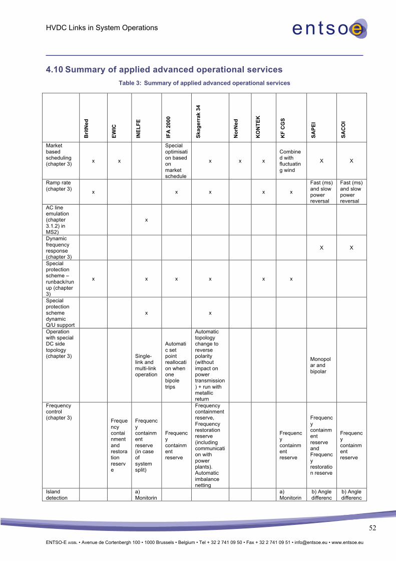
HVDC Links in System Operations
ENTSO-E AISBL • Avenue de Cortenbergh 100 • 1000 Brussels • Belgium • Tel + 32 2 741 09 50 • Fax + 32 2 741 09 51 • [email protected] • www.entsoe.eu
52
4.10 Summary of applied advanced operational services Table 3: Summary of applied advanced operational services
Brit
Ned
EWIC
INEL
FE
IFA
200
0
Skag
erra
k 34
Nor
Ned
KO
NTE
K
KF
CG
S
SAPE
I
SAC
OI
Market based scheduling (chapter 3) x x
Special optimisation based on market schedule
x x x
Combined with fluctuating wind
X X
Ramp rate (chapter 3) x x x x x
Fast (ms) and slow power reversal
Fast (ms) and slow power reversal
AC line emulation (chapter 3.1.2) in MS2)
x
Dynamic frequency response (chapter 3)
X X
Special protection scheme – runback/runup (chapter 3)
x x x x x x
Special protection scheme dynamic Q/U support
x x
Operation with special DC side topology (chapter 3)
Single-link and multi-link operation
Automatic set point reallocation when one bipole trips
Automatic topology change to reverse polarity (without impact on power transmission) + run with metallic return
Monopolar and bipolar
Frequency control (chapter 3)
Frequency containment and restoration reserve
Frequency containment reserve (in case of system split)
Frequency containment reserve
Frequency containment reserve, Frequency restoration reserve (including communication with power plants). Automatic imbalance netting
Frequency containment reserve
Frequency containment reserve and Frequency restoration reserve
Frequency containment reserve
Island detection a)
Monitorin a) Monitorin
b) Angle differenc
b) Angle differenc

HVDC Links in System Operations
ENTSO-E AISBL • Avenue de Cortenbergh 100 • 1000 Brussels • Belgium • Tel + 32 2 741 09 50 • Fax + 32 2 741 09 51 • [email protected] • www.entsoe.eu
53
Brit
Ned
EWIC
INEL
FE
IFA
200
0
Skag
erra
k 34
Nor
Ned
KO
NTE
K
KF
CG
S
SAPE
I
SAC
OI
(3 ways) g tie-line breakers b) Angle difference exceeds limit c) Triggered by operator
g tie-line breakers b) Angle difference exceeds limit c) Triggered by operator
e exceeds
limit
e exceeds
limit
Black start (chapter 3)
x x
Skagerrak 4 (including re-synchronisation)
x
Restoration support x x
Static Q/U-support (chapter 3)
x x x
POD (chapter 3)
POD-P and POD-Q-mode
SPS – Emergency Power control (chapter 3)
x x
EPC-P and EPC-Q (higher priority for Q)
EPC-P
EPC-P and EPC-Q (higher priority for Q)
Included in the
defence system
Included in the
defence system
DC loop flow (chapter 3)
x x x
Automatic system operation
a) Capacity calculation b) P and UAC online set point adaptation c) Identification and trigger of counter-trade

HVDC Links in System Operations
ENTSO-E AISBL • Avenue de Cortenbergh 100 • 1000 Brussels • Belgium • Tel + 32 2 741 09 50 • Fax + 32 2 741 09 51 • [email protected] • www.entsoe.eu
54
5 Needs for operational coordination to obtain the advanced operational functionalities and services
5.1 Introduction For all power flow-controlling devices, including HVDC links, there is a need to coordinate certain functionalities, especially set points. HVDC links are controllable devices that can significantly influence the flows in the AC grid, even across national and TSO borders. A lack of coordination between multiple HVDC links and other controllable devices (such as PSTs) can lead to inefficient use of the existing infrastructure, and also to operational problems in the grid, such as loop flows and congestion. Furthermore, a coordination of controllable devices can help to maximise commercial cross-border capacities to be provided to the market.
5.2 Coordination scope and general principles Coordination of HVDC is an established method of cooperation between organizational units – mostly TSOs – in order to ensure compliance with various objectives. There are certain groups of HVDC functionalities that can be the subject of coordination and, depending on their nature and the purpose of their application, cooperation can be considered in the following circumstances:
• If a link is located inside an area of a single TSO’s network and does not significantly affect any other TSO, it may be operated as a ‘stand-alone operation’ (without agreements).
• Bilateral coordination is required if two TSOs are affected by a controllable asset such as a HVDC.
• If more than two TSOs are affected, then regional or even cross-regional multilateral coordination is applied.
• Besides the above, there is also a need for operative coordination and agreements such as the Agreement on System Operation Management (AGSOM) and the System Operation Agreement (SOA), that include definitions of demarcations of the grid, permission-granting procedures, operative processes, roles and responsibilities etc. regarding the management of the single HVDC link itself. This only concerns the HVDC operating parties (max. 2 in a point-to-point setup). This kind of ‘operative coordination’ or organisation is not in the focus of this chapter.
Coordination (especially regarding PST operation) has already been discussed within ENTSO-E and a high-level basic concept for the coordination and integration of the remedial actions portfolio was described.
Also, from a legal and regulatory perspective, a coordination of HVDC links regarding set points and other structural data is required by
• Regulation (EU) 2015/1222 of 24 July 2015 establishing a guideline on capacity allocation and congestion management (CACM) and
• Regulation (EU) 2017/1485 of 2 August 2017 establishing a guideline on electricity transmission system operation (SOGL).

HVDC Links in System Operations
ENTSO-E AISBL • Avenue de Cortenbergh 100 • 1000 Brussels • Belgium • Tel + 32 2 741 09 50 • Fax + 32 2 741 09 51 • [email protected] • www.entsoe.eu
55
The regulations are not concrete regarding questions of what and how to coordinate, but TSOs are at minimum asked to share (HVDC) data and to assess, in coordination with the affected TSOs, the impact on remedial actions. Moreover, Capacity Calculation Regions (CCRs) are obliged by regulations to prepare methodologies which will result in coordination of tasks between CCRs.
The proposal for a ‘Generation and Load Data Provision Methodology’ (GLDPM) is a common proposal of all TSOs in accordance with Article 16 of Regulation 2015/1222 (CACM). It defines the generation and load data which may be required by TSOs in order to establish the common grid model. In this document it is established that each TSO has the right but not the obligation to obtain the following HVDC-related data from other TSOs:
• Active power targets
• Control settings including operating mode (inverter/rectifier), voltage control settings (e.g., voltage target), reactive power settings etc.
• The SOGL also defines HVDC-related data that must be exchanged by concerned TSOs in different chapters and articles
5.3 Involved parties In general, if coordination is necessary, HVDC operation shall be coordinated between TSOs. In specific cases, for example during the day-ahead scheduling phase, RSCs may play a role in this coordination.
The operation of a HVDC link needs to be coordinated, in case other TSOs are affected by the actions (planned schedule, schedule changes, behaviour in case of contingencies etc.) of the corresponding HVDC link. If, for example, the HVDC link is located in the observability area of another TSO, it is very likely that the operation of the link will affect the system state of this TSO.
If the operation of a HVDC link has an effect only on the local state within the TSO’s control area, HVDC actions do not need to be coordinated between TSOs (Article 23 (5), System Operation Guideline).
Depending on the applied functionalities and the location of the HVDC there may be an additional need for coordination between TSOs and DSOs or TSOs and significant grid users.
5.4 Time frames Coordination of HVDC functionalities and other operational issues related to HVDC (e.g., outage planning) takes place in different time frames from year-ahead up to real-time. The coordination can be bilateral or multilateral as described above. Table 4 and Figure 21 give an overview of HVDC functionalities/issues and corresponding time frames for coordination:

HVDC Links in System Operations
ENTSO-E AISBL • Avenue de Cortenbergh 100 • 1000 Brussels • Belgium • Tel + 32 2 741 09 50 • Fax + 32 2 741 09 51 • [email protected] • www.entsoe.eu
56
Table 4: Coordination requirements regarding HVDC in the different time frames
Time frame Year- to week-ahead Week- to day-ahead Intraday to close to real-time • Outages • Set points
assignment • Black start units • Outages • Remedial actions • Special protection
schemes
• Set points assignment • V/Q control settings; • Damping • Remedial actions • Balancing services, HVDC
functions in IGCC • Special protection schemes
Figure 21: Time frames for coordination
5.5 Coordination of functionalities This chapter addresses the HVDC functionalities to be coordinated in the operational processes described in Chapter 5.4. Depending on the functionalities, different parties could be involved. In most cases coordination is only required between TSOs, though in a few cases DSOs or other significant grid users are also involved in coordination, if they are affected by the operation of the HVDC or if information from them is necessary for the correct performance of the functionalities.
Typically, coordination is done by exchanging information in an automated way (real-time and operational planning). Additionally, some functionalities/issues are coordinated via e-mail or phone calls, for example during unplanned events. In operational planning, information/data is also exchanged via FTP servers.
Some functionalities, such as active power set points, need to be coordinated frequently . Others require coordination only once or on a very seldom/event-driven basis.
5.5.1 Switching status and sequences Start-up, operation and stop of a HVDC link are based on predefined states and sequences. Unlike an AC line, the management of a HVDC link is much more complex and depends on two main aspects: coordination between both converter stations, which is inherent to their control
year ahead week ahead day ahead (close to) real time
planned outages
black start planning issues
set point assignment
special protection schemes
balancing services
V/Q control settings
damping

HVDC Links in System Operations
ENTSO-E AISBL • Avenue de Cortenbergh 100 • 1000 Brussels • Belgium • Tel + 32 2 741 09 50 • Fax + 32 2 741 09 51 • [email protected] • www.entsoe.eu
57
design, and additional coordination necessitated when converter stations are managed by different TSOs.
This coordination at the Control Centres is necessary to minimise times of operational unavailability, including re-energisation delays (after planned outages or after tripping), which impacts system operation, or delays on shut-down and withdrawal from service of the link, which impacts maintenance work. Ad-hoc joint coordination trainings and agreements between all involved parties are important to ensure quick management of switching sequences.
At least two TSOs are involved in switching coordination. A third party could be also involved if the HVDC ownership does not belong to the TSOs or the HVDC link is located next to the control area border of another TSO.
The active power set points of the HVDC link must be explicitly determined even when local controls (e.g., AC angle control) are available. If two different parties own the HVDC link, they must coordinate the active power set point bilaterally.
The determined and coordinated active power set points must be assigned to the HVDC link. If two or more parties own and operate the HVDC link, it must be coordinated which party provides the active power set points to the HVDC link. Depending on the integration of the HVDC in the transmission system, the active power set point assignment could also affect neighbouring TSOs or subordinate DSOs. This requires multilateral coordination.
Coordination in active power management takes place in operational planning, close to real-time and real-time processes.
5.5.2 Black start Black start is the capability to supply electric power and energise a bus without any connection to a live network. A black start resource is a resource, such as a generating unit, with the ability to establish a path (the cranking path) and provide start-up supplies to a major generating unit. The HVDC can be used in the restoration strategies to aid energisation of the cranking path.
The network code on electricity emergency and restoration (NCER) sets forth that each TSO should establish a restoration plan through the following three steps: a design phase, consisting of defining the detailed content of the plan; an implementation phase, consisting of the development and installation of all necessary means and services for the activation of the plan; and an activation phase, consisting of operational use of one or more measures from the same plan. The design phase expects a restoration plan designed in consultation with relevant DSOs, significant grid users (SGUs), national regulatory authorities, neighbouring TSOs and other TSOs in that synchronous area. In this phase, TSOs shall consider their behaviour, load and generation capabilities, the specific needs of the high priority SGUs and the characteristics of its network as well as the characteristics of the underlying DSO networks. The restoration plan shall include the conditions and the instructions under which the restoration plan is activated and plans for real-time consultation or coordination with identified parties, together with the deadlines for implementation of required actions.

HVDC Links in System Operations
ENTSO-E AISBL • Avenue de Cortenbergh 100 • 1000 Brussels • Belgium • Tel + 32 2 741 09 50 • Fax + 32 2 741 09 51 • [email protected] • www.entsoe.eu
58
5.5.3 V/Q control As long as voltage/reactive power control of a HVDC converter does not influence another TSO (a local control issue), a coordination of control settings is not mandatory. However, voltage limits especially can affect other TSOs with respect to possible active power transfer or mutual support. In such cases, respective control parameters must be aligned between the affected parties. Voltage and reactive power control is usually a local issue with no or little effect on neighbouring TSOs. If a HVDC converter is electrically close to another TSO voltage, reactive power limits may need to be coordinated between the affected parties.
Reactive power provisions in a HVDC converter could also reduce its maximum active power. In normal operation, the design of the converter should ensure that active power and reactive power do not influence each other. However, increasing reactive power limits during emergency situations is an option, and that would affect the maximum active power. Such issues are to be coordinated between the affected TSOs.
Coordination of V/Q control settings takes place in close to real-time and real-time processes.
5.5.4 Planned outages As HVDC links often highly influence power flows in the AC grid, they may be considered a so-called ‘relevant asset’ for the regional outage planning processes. Therefore, planned outages of HVDC links that are ‘relevant assets’ must be coordinated by TSOs and RSCs to avoid planning incompatibilities (see SOGL, Art. 83 ff, [23]).
Coordination of planned outages takes place in year-ahead processes.
5.5.5 Frequency control Regarding frequency control support from an asynchronous network by a HVDC link, the following must be agreed upon between the connected TSOs:
• Maximum amount of balancing power (for each direction)
• Ramp rates of active power change (start and stop of support)
• Trigger for activating balancing power support
• Trigger for deactivating balancing power support
• Preconditions for providing balancing power support (for each network)
• Amount of balancing power determined during support
• Special control parameters (if needed) such as dead bands, time delays etc.
Regarding transmission of balancing power via the HVDC (support of a parallel AC network) the following must be agreed upon between all affected parties (all TSOs that are affected by HVDC power transmission):
• Method of activating balancing power transport via the HVDC link
• Method of determining the amount of balancing power to be transferred by the HVDC link

HVDC Links in System Operations
ENTSO-E AISBL • Avenue de Cortenbergh 100 • 1000 Brussels • Belgium • Tel + 32 2 741 09 50 • Fax + 32 2 741 09 51 • [email protected] • www.entsoe.eu
59
• Maximum and minimum ramp rates introduced (to the AC and/or HVDC system) by balancing power transport via the HVDC
• Maximum balancing power to be transmitted via the HVDC (for each direction)
A set of rules is required to set down how interconnecting HVDC links can be included in the IGCC. As the power flow of a DC link will not – in contrast to AC lines – automatically change when imbalances are netted, an active signal for imbalance netting (IN) must be sent to the converter. This value must be calculated considering several parameters and netting priority rules in the central IGCC optimiser and then must be sent to the TSO controlling the respective HVDC link (Master-TSO). The TSO can then route this signal in an automated process with high resolution (e.g., 3s) to the converter station in order to adjust the power flow over the HVDC link according to the IN. Because of the high resolution of set point changes (e.g., 3s) the amount of power provided for the IN service may be small for HVDC links with a small ramping limit.
Coordination of balancing services takes place in close to real-time and real-time processes.
5.5.6 Dynamic stability A traditional way of damping oscillations is with the use of a power system stabiliser (PSS), which modulates the excitation and thus the output voltage of the generator. Setting the PSSs in a coordinated way is a difficult and complex task; they should work reliably in a wide range of operation conditions and provide the best possible performance.
HVDC can be very efficiently used to dampen power oscillations. By detecting the frequency, magnitude, range and source of oscillations, a proper active-power modulation via HVDC is able to reduce power swings. Proper coordination of settings with generating units is necessary to ensure efficient and reliable performance of HVDC damping functions.
In the interconnected grid there are naturally-occurring inter-area oscillations, which are in some cases poorly damped. Some examples of poorly-damped inter-area oscillations detected by wide-area monitoring systems (WAMS) are shown in [21] and [22]. In addition to properly tuning all relevant power plant controllers, HVDC links can also contribute to the overall system damping. Design of WAMS-based HVDC power oscillation damping controllers within a power system requires coordination on:
• The selection of a suitable robust controller
• The detailed modelling of the controllers
• The selection of suitable input signals implementing real-time digital simulators with PMU data measurements to ensure confidence in the controller design
Mitigation measures to improve damping could be taken close to real-time. Coordination is required.
System stability is becoming more reliant on new, dynamic active and reactive power control devices and their dynamic behaviour must be carefully analysed. Therefore, all TSOs should set up dynamic models of their systems with an appropriate level of simplification to ensure sufficient model accuracy, performance and numerical robustness. In addition to the exchange of detailed

HVDC Links in System Operations
ENTSO-E AISBL • Avenue de Cortenbergh 100 • 1000 Brussels • Belgium • Tel + 32 2 741 09 50 • Fax + 32 2 741 09 51 • [email protected] • www.entsoe.eu
60
system dynamic data between neighbouring TSOs, dynamic models of the CE power system able to reliably reproduce the system’s oscillatory behaviour may be required.
5.5.7 Ramping rates Ramping rates can affect the behaviour of the power system in several ways, including not only frequency and imbalances of the power system but also voltage control and stability. The effect on a given power system is highly dependent on the size and topology of the system, thus acceptable ramping rates can be quite different from system to system.
Ramping rate limits are always based on a mutual agreement between affected TSO´s.
For practical reasons, the enforcement of the limit restrictions will be handled by the market operators.
5.5.8 Special protection schemes In cases of special protection schemes, other TSOs, DSOs, power plant operators or other significant grid users could be involved or affected depending on the SPS’s concept. Here, ‘SPS’ applies to schemes in which the HVDC is part of the SPS.
If the HVDC system connects two control areas, at least two TSOs will be affected by a SPS. The TSO which applies the SPS should provide the following information so that the SPS can be appropriately considered in the TSO’s operational security assessments:
• Status of the SPS (deactivated, activated, triggered)
• Reaction of the HVDC in case of triggering (change of active power set point, converter tripping etc.)
• Conditions for activation and triggering
If other TSOs are affected by the SPS – even if the system is embedded in a single control area – this information should be exchanged. Besides the reaction of the HVDC converters, additional actions (e.g., power plant tripping) could be included in a SPS concept. Information about such reactions should also be provided to all affected TSOs.
In real-time, the information should be exchanged automatically via the SCADA system. Unplanned events (topology changes, outages etc.) which affect the SPS could be coordinated by telephone or e-mail. In operational planning, coordination can be also done by RSCs.
Coordination between TSOs and DSOs is necessary if infeeds or distribution grid loads are included in the SPS or if load flows in the DSO’s grid are significantly influenced by the SPS. In those cases the DSO should provide information to the TSO during operational planning about the forecasted values (load and infeed) and the status of the plants/loads in real-time operation. The TSO should provide information about the status of the SPS to the DSO. In real-time operation, the information should be automatically exchanged by the SCADA system. Unplanned events (topology changes, outages etc.) which affect the SPS could be coordinated by telephone or e-mail.
If a power plant is part of the scheme, the status of the SPS should be provided by the TSO to the operator of the plant. If the power plant affects the SPS in an unintended manner (e.g., unplanned

HVDC Links in System Operations
ENTSO-E AISBL • Avenue de Cortenbergh 100 • 1000 Brussels • Belgium • Tel + 32 2 741 09 50 • Fax + 32 2 741 09 51 • [email protected] • www.entsoe.eu
61
outages) the power plant operator should inform the TSO. This also applies for significant grid users (e.g., industrial load users) if they are a part of the SPS. The status of the SPS should be exchanged via the SCADA system. Unplanned events (topology changes, outages etc.) which affect the SPS could be coordinated by telephone or e-mail.

HVDC Links in System Operations
ENTSO-E AISBL • Avenue de Cortenbergh 100 • 1000 Brussels • Belgium • Tel + 32 2 741 09 50 • Fax + 32 2 741 09 51 • [email protected] • www.entsoe.eu
62
6 Impact on operational staff
6.1 Introduction In this chapter, the impact of HVDC on operational staff is assessed. The activities are divided into two categories: first, project-based involvement of operational staff, mainly related to the planning and investment stages. Second the daily routines of the operational staff when operating the HVDC link.
6.2 Operational input to planning, decision and investment stages In this stage answers to the following questions are found:
• What needs are satisfied by the installation?
• What problems in the system are solved?
If a HVDC link is the optimal or even the only way to solve an existing problem, the basic properties of the link, such as location, power, type and necessary functionalities, are determined. At this stage, the planners work closely with operational experts to determine the features of the HVDC link.
6.2.1 Consultations with suppliers Consultations with suppliers give valuable information on the capabilities of existing devices and the experience of using already-commissioned installations. Suppliers often give support to development divisions to help determine optimal solutions for the power system problems to be solved.
6.2.2 Order specification Order specification is prepared based on academic and consultant knowledge, the experiences of operational staff of TSOs with other existing installations and the experiences of other TSOs and suppliers. In order to prepare a detailed technical specification, a highly skilled and engaged team of operational staff must be consulted. Order specification takes into consideration power system specifics and operation supporting systems as SCADA, EMS, etc.
6.2.3 Initial training The first training of operational personnel usually begins during the construction phase. During initial training, the staff is familiarised with all functionalities and parameters of the installation.
6.2.4 Test run and commissioning At this stage, discrepancies between specifications and real devices are encountered. Often, the same experts who were involved in preparing the specification also work on the test runs and commissioning.

HVDC Links in System Operations
ENTSO-E AISBL • Avenue de Cortenbergh 100 • 1000 Brussels • Belgium • Tel + 32 2 741 09 50 • Fax + 32 2 741 09 51 • [email protected] • www.entsoe.eu
63
6.2.5 Updates to existing processes The commissioning of a new HVDC installation will influence existing processes related to operation and maintenance. Existing procedures and documentation will require updates as new positions on the list of TSO activity appears.
6.3 Level of automation It seems clear that the more processes of HVDC operation are automated the less involvement of operational staff is necessary for reliable, secure and efficient daily control of the installation. Although it may seem desirable to automate as many processes as possible, and to the highest possible level, it should be noted that such a strategy will likely decrease the overall security of the operation. When a process requires a quick reaction, often beyond human capabilities, or is composed of long and complex sequences, a high level of automation is unavoidable. In other cases, a proper balance is necessary in order to ensure knowledge of the control staff which will help to avoid threats resulting from atypical situations.
6.4 Daily activity of operational staff
6.4.1 Outage planning Outage planning must be coordinated between parties as soon as possible. Outages can affect market capacity and physical behaviour as well as the entire scheduling process.
Especially in situations where several HVDC links are in the same market corridor, it is critical to have well established procedures in case of outages, since both capacities and individual pole distribution may change.
6.4.2 Security analysis HVDC connections should be modelled in all tools used for security analysis. It is very important to remember to model system protection schemes in cases where such functions are implemented.
6.4.3 Control of active power set point It is very important that all security analysis tasks performed in near real-time, from D-1 until real-time operation, are performed with the correct HVDC physical schedule values. Any change in the scheduled exchange should be reflected in all future calculations. A change in the schedule could also include unplanned outages such as a trip of connection.
This information should also be included within the DACF and IDCF processes, and in future IGMs.
6.4.4 Voltage control Depending on the operational strategy, it may be necessary for the operators to adjust the voltage reference for each HVDC connection. The strategy will normally be highly dependent on the type of HVDC links and the topology of the grid. For VSC-type HVDC converters, it is generally a good strategy to optimise the network to ensure that maximum dynamic capacity is available, and

HVDC Links in System Operations
ENTSO-E AISBL • Avenue de Cortenbergh 100 • 1000 Brussels • Belgium • Tel + 32 2 741 09 50 • Fax + 32 2 741 09 51 • [email protected] • www.entsoe.eu
64
optimise switch reactors and capacitors to ensure that the VSC converter operates in an Mvar-neutral state.
For LCC type converters, the optimization strategy will need to account for the converters’ minimum filter requirements, however there is often some possibility to either generate or absorb reactive power.
6.4.5 Emergency situations Emergency situations can often be a good indicator of the effectiveness of emergency tools and procedures as well as operations staff skills. Under normal conditions, the control objectives are to operate the power system as efficiently as possible with a sufficient stability margin, keeping frequency and voltages within the range of nominal values. For abnormal conditions, a set of actions must be initiated in order to bring the system back to its normal state.
As presented in previous chapters, HVDC offers many conventional and advanced features that can be utilised in effective ways during abnormal conditions. During emergency situations the skills of operational staff are tested to the highest degree, proving the importance of training, education and experience.
6.4.6 Failures of DC links DC links, when used as multifunctional element of power system during failures, are much more challenging than other elements that only have a single or only a few functionalities such as transmission lines, shunt reactors or capacitor banks. During failure, some or all functions are not available or are limited. Operational staff’s role is to either replace necessary functions by using other elements in operation or to run the system without certain services. To do so, excellent knowledge of power system specifics and capabilities is necessary.
6.4.7 Reporting Reporting functions in the control room already exist and may comprise documentation of measures prepared or carried out by the operator due to (N-1)-constraints in the security analysis or commenting on equipment in the field. The methods of reporting are diverse, depending on the TSO. Nonetheless, by introducing HVDC, these reporting functions could be expanded.
6.4.8 Continuous training Operational staff responsibilities must include undergoing regular trainings. The scope of trainings include topics and skills that are well-known to operational staff but need to refreshed as well as new topics introduced by newly-implemented tools or procedures. During the trainings, past events are analysed, and experiences and lessons learned are discussed. Valuable input is often delivered by sharing experiences with other HVDC operators, especially TSOs sharing the same installation as an interconnection. Apart from analysing past events, potential situations could also be the subjects of trainings. An advanced way of training based on potential situations involves training simulators where HVDC and its functionalities are modelled.
Power system operation is a 24/7 business for operational staff, therefore continuous training must be carefully planned and fit in to daily duties.

HVDC Links in System Operations
ENTSO-E AISBL • Avenue de Cortenbergh 100 • 1000 Brussels • Belgium • Tel + 32 2 741 09 50 • Fax + 32 2 741 09 51 • [email protected] • www.entsoe.eu
65
6.5 Conclusions Currently it is not possible to reach final conclusions regarding the impact on operational staff as a consequence of the more advanced possibilities of the HVDC links in the system operations. As stated above, it is a good idea to involve operational staff in all stages of the planning process; this is a relatively low investment with little impact that can help a great deal by improving efficiency in the day-to-day routines once the HVDC link is in operation. Furthermore it is clear that a high level of automation is needed to support the operational staff,
There is no reason to believe that the level of education for operational staff should change, nor that there should be more staff involved. The latter conclusion, however, was part of a survey recently performed among TSOs that operate HVDC links which generated a very wide variety of responses, some TSOs advocated for one extra FTE while others advocated for as many as 11. The reason for this wide variety of responses is not clear.

HVDC Links in System Operations
ENTSO-E AISBL • Avenue de Cortenbergh 100 • 1000 Brussels • Belgium • Tel + 32 2 741 09 50 • Fax + 32 2 741 09 51 • [email protected] • www.entsoe.eu
66
7 Essential non-technical provisions for concept implementation
7.1 Introduction Besides the practical and operational aspects of advanced operation of HVDC links, there are also non-technical provisions to be fulfilled. By their nature, such issues are not the specialty of the system operations department but are more for the attention of the legal, customer service and marketing departments. In the next paragraphs, some non-technical topics are presented, but this is not intended to be an exhaustive list, rather a start to inspire further work in the future. It is clear that the non-technical provisions are crucial; disagreements on the legal or financial side can prove detrimental to successful operation.
7.2 Non-technical provisions The non-technical provisions include legal, financial, stakeholder etc. concerns. Below, a number of such items are listed and some of the topics are then elaborated on:
• Cost coverage
• Financial agreement and assessment
• Stakeholder management
• Legal framework (including national and European law, other rules and regulations)
• Procedures for commercial links
• Introduction and coordination of CCRs
• Introduction of pan-European markets for reserves (MARI Project, Picasso Project, TERRE Project etc.)
• Contractual frameworks and inter-TSO operation agreements (including system operation agreements)
One non-technical provision is the set of requirements, procedures and responsibilities of the TSOs in relation to common HVDC interconnections agreed upon in system operation agreements (SOAs). Apart from the clearly technical aspects of SOAs including normal and emergency operation of the HVDC link with control of set point, switching operations and outage planning, other non-technical provisions are included, such as the following rights and obligations:
Ownership – If the interconnection is co-owned between two or more TSOs, it is necessary to describe the division of ownership. In most cases, the division is at a point over a state border or in an agreed point of international territory when an undersea cable is part of the interconnection.
Maintenance – Division of responsibility for maintenance does not have to be identical to ownership division. For instance, when unplanned maintenance caused by the physical damage of infrastructure is necessary, it is reasonable to agree to maintenance boundaries on more convenient points like line conductor joints at the tower rather than the middle of the line border span.

HVDC Links in System Operations
ENTSO-E AISBL • Avenue de Cortenbergh 100 • 1000 Brussels • Belgium • Tel + 32 2 741 09 50 • Fax + 32 2 741 09 51 • [email protected] • www.entsoe.eu
67
Exchange of knowledge and common trainings – In order to improve operational cooperation and knowledge exchange during both normal and disturbance situations, parties to an SOA very often agree to perform joint operational staff trainings or workshops.
Merchant lines:
The large majority of projects are promoted by TSOs, with regulators approving or setting the tariffs. Some projects are promoted by private parties, these projects are called merchant lines. These tend to recoup their costs from price differences between the connected areas.
In this case, the owners of HVDCs and relevant system operators, in coordination with relevant TSOs, should agree on which advanced services could be implemented to allow more efficient use of the network and resources for the benefit of consumers. Hence, a cost-benefit analysis is needed focused on the following principles: investment return, electricity market benefits and security of supply improvement.
From a legal point of view, the Network Code on HVDC covers first, the general requirements for active power control and frequency support as well as requirements for reactive power control and voltage support which are in line with the advanced services identified in Chapter 2. Second, the Network Code lets relevant system operators require that HVDC merchant line owners provide additional services in order to improve social welfare, such as ensuring system security and market benefits.
Moreover, according to Art. 51 (Operation of HVDC systems): ‘each HVDC converter unit of a HVDC system shall be equipped with an automatic controller capable of receiving instructions from the relevant system operator and from the relevant TSO.’ This statement covers the potential coordination gap between relevant system operators and the HVDC owner.

HVDC Links in System Operations
ENTSO-E AISBL • Avenue de Cortenbergh 100 • 1000 Brussels • Belgium • Tel + 32 2 741 09 50 • Fax + 32 2 741 09 51 • [email protected] • www.entsoe.eu
68
8 Next steps
In order to get access to and obtain the benefits of system operations, investigations should be conducted in more detail to establish which non-technical issues still need to be fulfilled. This should most probably be a cross-committee work.
Further subjects to be looked into include the operation of multi-terminal systems, the involvement of vendors and the determination of the financial value of different benefits.

HVDC Links in System Operations
ENTSO-E AISBL • Avenue de Cortenbergh 100 • 1000 Brussels • Belgium • Tel + 32 2 741 09 50 • Fax + 32 2 741 09 51 • [email protected] • www.entsoe.eu
69
Appendix
A.1 LCC-HVDC control functions and operation modes
A.1.1 Control functions/strategies and inputs and measured system quantities Under normal conditions, the rectifier end operates in constant current control mode to control the DC current Idc, while the inverter controls the DC voltage Vdc. Idc and Vdc are controlled in order to maintain the desired power transfer on the DC link. It is essential therefore to continuously measure the required system quantities such as Idc, Vdc, the firing delay angle α and inverter extinction angle γ. The roles of converters could reverse under abnormal operating conditions such as reduced AC voltage or a fault occurrence. This is further explained in the next section.
A.1.1.1 Rectifier control mode The rectifier of a LCC-HVDC link typically operates at constant current control mode. However, the rectifier voltage can be increased until the firing angle reaches the minimum firing angle limit of α = 2°. Under this condition, the rectifier moves to constant firing angle mode where α = constant.
A.1.1.2 Inverter control mode The inverter could operate in three different control modes depending on system conditions:
• In normal operating conditions, the inverter operates at constant Vdc mode to stabilise the system while the rectifier is controlling Idc.
• If the AC voltage at the rectifier side reduces, the rectifier assists in improving the voltage reduction by reducing its firing angle until it reaches the firing angle limit. From that point on operates in α = constant mode. Whereas the inverter keeps the Idc constant and operates at constant current control with current reference, Iref, reduced by a current margin, Imargin. Therefore, there is a 10-15% margin between Iorder at the rectifier side and Iorder at the inverter side.
• If the AC voltage at the inverter side is reduced, the rectifier carries on controlling the Idc and the inverter moves to constant extinction angle (CEA) mode to prevent commutation failure.
Overall, the LCC-HVDC system is not desirable for maintaining the rated DC current, Idc, when the AC voltage drops more than 25%. This is because following the AC voltage depression, the rectifier firing angle reaches its minimum limit to compensate for the AC voltage drop. If there are further AC voltage drops, the rectifier moves to constant mode and Idc will be controlled by the inverter at the reduced level. Since Vdc is not controlled by any of the converters, Vdc might drop further. Therefore, the Voltage Dependent Current Order Limiter (VDCOL) control is implemented to reduce the maximum allowable DC current when the voltage drops below a predetermined value. The VDCOL characteristics may be a function of Vdc or the AC commutating voltage [5].

HVDC Links in System Operations
ENTSO-E AISBL • Avenue de Cortenbergh 100 • 1000 Brussels • Belgium • Tel + 32 2 741 09 50 • Fax + 32 2 741 09 51 • [email protected] • www.entsoe.eu
70
All of the operating control modes are designed to ensure DC system stability and minimum reactive power consumption, as high firing angles or extinction angles result in high reactive power absorption.
A.1.2 Hierarchy control system for the LCC-HVDC link An overview of a LCC-HVDC link’s control hierarchy is illustrated in Figure 22. In a bidirectional HVDC link, the inverter and rectifier can interchange modes rapidly. The inverter provides three control modes, including constant DC or AC voltage control mode, CEA (constant extinction angle) mode and constant current control mode. In inversion mode, it is critical to maintain the minimum extinction angle to avoid commutation failures, therefore the CEA is the default control mode at the inverter side. However, this mode of control is less stable during a disturbance or in cases where the DC link is connected to a weak AC network. In those cases, DC or AC voltage control is the main control at the inverter side using a proportional integral (PI) feedback control to maintain the voltage at the reference level.
The Idc or active power control is not active throughout normal operation. This back-up control is very favourable during a fault on the DC side or when the rectifier loses its Idc control during a depressed AC voltage at the rectifier side following any disturbance. The inverter constant current control controller compares Iorder with a reference current (Iref) reduced by a margin current (Iref = Iorder - Imargin, with Imargin = 0.1 p.u.).
A hierarchy master level control, as presented in Figure 22, is provided at the rectifier side, which provides the current reference (Iref) to the main DC current controller. The rectifier also facilitates the power control by continuously calculating the DC power at the DC voltage reference value and outputs the scheduled Iorder [5].
As shown in Figure 22, frequency control and power oscillation damping can be employed at the rectifier side. Power oscillation damping can be implemented to improve the stability of networks with poorly damped oscillations. This signal is usually added to Iorder. Additionally, the active power order override is provided, which can be implemented for post-fault action and other events. All three controllers calculate the firing angle and the lowest outputs from these controllers are selected through minimum Gamma logic selection to determine the firing pulses for the inverter valves. The firing angle is limited between 110º and 170º to reduce the possibility of commutation failure and at the same time to avoid unplanned switchover to the rectification mode.

HVDC Links in System Operations
ENTSO-E AISBL • Avenue de Cortenbergh 100 • 1000 Brussels • Belgium • Tel + 32 2 741 09 50 • Fax + 32 2 741 09 51 • [email protected] • www.entsoe.eu
71
Min (Mode) Selector
Switch Firing
Idc refIdc m
argin
Idc meas
PI
Vdc ref
Vdc m
eas
VAC ref
VAC m
eas
+-
++
--
PI
Extinction angle Control
PI +-
Linearise
Vdc /V
AC
Control Inv.
gref
g
PLLLLq
aVbVcV
Min (Mode) Selector
Switch Firing
Linearise
PLL
PI
W ref r
W r
Pdc ref
PI
Freq Control R
ec.W
i
PI
Active Pow
er/Idc Control R
ec.
Vdc ref
÷
Power order O
verride
Oscillation Dam
ping Control
+ -
W ref i
LLq
Idc meas
Idc ref+
aVbVcV
Converters
-
Inverter control Rectifier control
Idc Control InvIdc Control Inv
Figure 22: Schematic of the hierarchy control for the LCC-HVDC link at rectifier and inverter side

HVDC Links in System Operations
ENTSO-E AISBL • Avenue de Cortenbergh 100 • 1000 Brussels • Belgium • Tel + 32 2 741 09 50 • Fax + 32 2 741 09 51 • [email protected] • www.entsoe.eu
72
A.2 VSC-HVDC control functions and operation modes
A.2.1 Control principle The control system is based on vector control (dq-frame, direct/quadrature) in order to decouple the control of active and reactive power. Additionally, the current limits can be set directly based on the power capability of the HVDC system.
A general control scheme of a VSC-HVDC system is shown in Figure 23. The controller consists of an inner and outer control loop. The outer loop determines the reference values (d- and q-axis currents) and the inner loop determines the voltage which is generated by the converter modules on the AC side. The switching signals of the IGBTs are calculated by pulse-wide modulation (PWM). Modular multilevel converters have additional inner control loops to maintain the voltage of the submodules and to suppress the loop currents between the converter arms.
The approach for deriving the reference values for the inner controller (d- and q-axis currents) is chosen based on the requirements of the AC system. The different approaches for active and reactive power control are described in the following subchapters.
Figure 23: Control scheme of a VSC-HVDC system
A.2.2 Active power flow control (active power infeed/consumption) The active power flow is determined by the d-axis current, which is derived by reference values of the following parameters:
• Active power (PCC)
• DC voltage
• AC system frequency
Either the active power at the PCC, the DC voltage or the AC system frequency is controlled by adapting the active power flow of the converter. The control functions are coordinated between the converter stations (e.g., active power ó DC voltage).
Active Power
Controller
+
-
+
-
PWM
PLL
Inner Current
ControllerReactive Power
Controller
AC Voltage
ControllerV*AC
Q*
P*Active Power
Controller
PWM
PLL
Inner Current
ControllerReactive Power
Controller
AC Voltage
ControllerV*AC
Q*
P*
VAC
iACP QVDC2VDC1
DC Voltage
Controller
DC Voltage
Controller
iAC PQ3 3
=
=~
~ VAC

HVDC Links in System Operations
ENTSO-E AISBL • Avenue de Cortenbergh 100 • 1000 Brussels • Belgium • Tel + 32 2 741 09 50 • Fax + 32 2 741 09 51 • [email protected] • www.entsoe.eu
73
A.2.3 Reactive power control (reactive power infeed/consumption) The reactive power is determined by the q-axis current, which is derived by reference values of the following parameters:
• Reactive power (PCC)
• AC voltage (PCC)
• cos (φ) (PCC)
When there is a high number of HVDC converters in a specific area, it is reasonable to coordinate the reactive power (voltage) control of the converters by, for example.], using droop approaches,
A.2.4 Relevant parameters Input parameters (measurements and reference values):
• DC voltage (ref./meas.)
• AC voltage at PCC (ref./meas.)
• AC current at PCC (meas.)
• AC voltage angle at PCC (meas.)
• Frequency of the AC system (ref./meas.)
• Rate of change of frequency (meas.)
Output parameters:
• AC voltage at converter
• AC voltage angle at converter
Limitations:
• Rated current of the converter
• Rated current of the cable/line
• Maximum DC voltage
• Maximum dp/dt
A.3 HVDC configurations HVDC systems can have various DC side topologies as shown in Figure 24. Decisions are usually made based on economic, redundancy/availability, environmental requirements/needs and necessary transmission capacity factors (assuming a fixed maximum voltage level), which are normally in competition with each other (see Figure 22). The determination of the most suitable DC side topology is highly dependent on specific project needs.

HVDC Links in System Operations
ENTSO-E AISBL • Avenue de Cortenbergh 100 • 1000 Brussels • Belgium • Tel + 32 2 741 09 50 • Fax + 32 2 741 09 51 • [email protected] • www.entsoe.eu
74
Figure 24: DC side topologies
Table 5 shows that a bipole topology (including metallic return) is the only high flexible topology when it comes to the N-1 conditions of the lines, as the metallic return can replace a faulty line (to a maximum of 50% or 100%). Both bipole configurations are partly redundant with regard to the N-1 conditions of the converters, as it is possible to continue operation to a maximum of half the nominal power in such a scenario. In both cases an appropriate substation design is required.
Table 5: Characteristics of different DC side topologies
Topology Costs Redundancy (availability)
Environmental impact
Transmission
capacity Line Converter Earth current
Number of lines
Bipole high yes (medium/high)6
yes (medium)
low high high
Rigid bipole medium no (low)
yes (medium)
low medium high
Asymmetrical monopole (MR)
medium no (low)
no (low)
low medium low
Asymmetrical monopole
low no (low)
no (low)
high low low
Symmetrical monopole
medium no (low)
no (low)
low medium low
6 Metallic return may be designed for either nominal current and nominal voltage (full N-1 redundancy) or nominal current only, which results in a kind of redundancy that covers half of the nominal power.
c) asymmetrical monopole (metalic return) d) asymmetrical monopole
a) bipole b) rigid bipole
e) symmetrical monopole

HVDC Links in System Operations
ENTSO-E AISBL • Avenue de Cortenbergh 100 • 1000 Brussels • Belgium • Tel + 32 2 741 09 50 • Fax + 32 2 741 09 51 • [email protected] • www.entsoe.eu
75
A.4 Standard hybrid market coupling The mixture of AC and DC elements (FB and CNTC) in a single allocation mechanism is often referred to as ‘hybrid coupling’. When mixing DC with AC, the FB methodology is beneficial as it allows for a fair competition between the AC and DC exchanges for the possibly scarce capacity in the AC grid. The difference in functionality and manageability of AC and DC links calls for a consideration of how to handle DC links within the FB methodology. In principle there are two possible ways to do this:
1. Standard hybrid market coupling: Reserve capacity on the AC connections (margin of the FB constraints) for the DC link exchanges, i.e., DC line exchanges receive priority access to the AC grid.
2. Advanced hybrid market coupling: Compute PTDF factors at the nodes where the DC link is connected, making the sending and receiving end of the DC link act as two virtual bidding zones. DC link exchanges are directly linked to the margins of the FB constraints.
In both solutions, the DC links are treated as CNTCs in the allocation mechanism. The main difference is whether the impact of the DC exchanges on the remaining available margins (RAMs) is taken into account in the algorithm or whether it is given ex ante priority by the TSO.
Standard Hybrid Market Coupling
FB capacity calculation and allocation is applied in the four bidding zones A, B, C, and D. Bidding zone D is interconnected with the other three bidding zones by means of DC links. Standard hybrid market coupling is applied.
Figure 25: Four-area power system with standard hybrid coupling
The overall net position is defined as the sum of the ‘flow-based net position’ (resulting from the FB constraints) and the outgoing CNTC exchanges (on the DC lines):
𝑆𝑒𝑙𝑙S − 𝐵𝑢𝑦S = 𝑁𝑃S = 𝑁𝑃SXY + 𝐸𝑥𝑐ℎ𝑎𝑛𝑔𝑒S_`
𝑆𝑒𝑙𝑙Y − 𝐵𝑢𝑦Y = 𝑁𝑃Y = 𝑁𝑃YXY
𝑆𝑒𝑙𝑙a − 𝐵𝑢𝑦a = 𝑁𝑃a = 𝑁𝑃aXY + 𝐸𝑥𝑐ℎ𝑎𝑛𝑔𝑒a_`
𝑆𝑒𝑙𝑙` − 𝐵𝑢𝑦` = 𝑁𝑃 = 𝑁𝑃XY − 𝐸𝑥𝑐ℎ𝑎𝑛𝑔𝑒S_` − 𝐸𝑥𝑐ℎ𝑎𝑛𝑔𝑒a_`
The variables 𝑁𝑃XY have to satisfy the FB constraints, whereas the variables Exchange need to satisfy the CNTC constraints.
• Area D is DC connected
• Three areas are AC connected
• The numbers refer to net positions and flows

HVDC Links in System Operations
ENTSO-E AISBL • Avenue de Cortenbergh 100 • 1000 Brussels • Belgium • Tel + 32 2 741 09 50 • Fax + 32 2 741 09 51 • [email protected] • www.entsoe.eu
76
CNTC constraints:
−𝐶𝑁𝑇𝐶`_S ≤ 𝐸𝑥𝑐ℎ𝑎𝑛𝑔𝑒S_` ≤ 𝐶𝑁𝑇𝐶S_`
−𝐶𝑁𝑇𝐶`_a ≤ 𝐸𝑥𝑐ℎ𝑎𝑛𝑔𝑒a_` ≤ 𝐶𝑁𝑇𝐶a_` FB constraints:
𝑃𝑇𝐷𝐹 ∗ 𝑁𝑃XY ≤ 𝑅𝐴𝑀 We can clearly see that the CNTC exchanges over the DC links do not have a link to the margins of the FB constraints. Indeed, the example is rather extreme, as there is only a cross-zonal exchange possible for bidding zone D by means of the DC links. As such, there is a ‘FB net position’ of zero for bidding zone D.
A.5 Examples of special protection schemes HVDC systems are considered for Special Protection Schemes all over the world.
• Murraylink: Murraylink is an embedded VSC-HVDC link in Australia. The link comprises two run-back schemes, which are activated if specific AC lines trip or voltage levels next to the feeding converter are low. The fast run-back prevents thermal overloading and voltage collapses and is initiated within a few seconds. The slow run-back results in a partial reduction of the active power in case of low voltages after a predefined time delay. The SPS concept is applied on both sides of the HVDC link.
• Basslink: Basslink is a monopolar HVDC link, which connects the Australian island state of Tasmania with the state of Victoria. The converter on the Tasmanian side is incorporated in a special protection scheme to prevent thermal overloading of specific AC lines in case of line tripping by reducing the power of the converter automatically. In total, 17 AC circuits are observed. Based on the pre-loading of the AC lines and the network topology, the necessary action of the converter to maintain N-1 security curatively is determined every four seconds in the SCADA system. If a line actually trips in the observability area of the SPS the pre-calculated action of the converter is initiated. As the activation relies on the tripping signal, the concept is very reliable. Consideration of changing grid topology (planned outages etc.) in the calculation algorithm of post-fault converter set-points is very challenging.
• INELFE: INELFE has implemented several SPSs. First, the AC emulation line control (by means of monitoring angle difference between both converter stations) can be considered an SPS in itself due to the fact that the HVDC control system changes power flow through it under external contingencies/variations on the AC network. Special measurement equipment has been developed to monitor angle difference between converters.
Similarly, the U-mode voltage control implemented on both sides let TSOs have an automatic reactive power support not only in steady state but also in case of dynamic disturbance. On the other hand, REE is already operating with some SPSs as curative remedial actions to increase the transfer capacity on the Spanish-French border (or to avoid applying costly remedial actions) by means of preventing a thermal overloading of AC circuits next to the HVDC (a local approach). The activation of any of REE’s SPSs are linked to an N-1 contingency and are activated by means of physically detecting the opening of the lines

HVDC Links in System Operations
ENTSO-E AISBL • Avenue de Cortenbergh 100 • 1000 Brussels • Belgium • Tel + 32 2 741 09 50 • Fax + 32 2 741 09 51 • [email protected] • www.entsoe.eu
77
(protection equipment checks the opening status of circuit breakers in the two ends of the line). Hence, REE assures that the activation of SPSs is correct. Notice that in some scenarios several SPSs could be activated at the same time. However, REE tools assess the impact of the activation of several SPSs at the same time to assess the behaviour of the grid and guarantee the security of the network. Additionally, when running in AC emulation line control mode, INELFE SPSs let TSOs two options: 1) Keep running as AC emulation line, with the possibility to modify K and/or capability
ranges at the same time. 2) Changing from AC emulation mode to constant mode and modifying the final value of
active power (the classical approach).
Typically, the tripping times of REE’s SPS for INELFE are around 1s to let AC lines reclose before activating SPSs.
• Great Belt HVDC: In this SPS already working in Denmark, the limitation is the capacity on two corridors, one going east and one going west. During normal operation, with an intact network, there are no problems. If traditional N-1 security needs to be applied it would be necessary to limit both the east and the west corridor in situations with high transits between Germany and Denmark East. To avoid this situation, a very simple SPS was designed. In principle, the only criteria is that reduction of power on the Great Belt HVDC connection will reduce flow on remaining lines after a trip of the 400 kV line KAS-LAG.
Direction EAST SPS: This SPS will be armed if the flow on the HVDC connection is going EAST and the flow on the critical 400 kV line KAS-LAG is NORTH (prior to the fault). During a breaker trip on 400 kV line KAS-LAG, the Great Belt HVDC connection will initiate a runback power limitation to 250 MW.
Direction WEST SPS: This SPS will be armed if the flow on the HVDC connection is going WEST and the flow on the critical 400 kV line KAS-LAG is SOUTH (prior to the fault). During a breaker trip on 400 kV line KAS-LAG, the Great Belt HVDC connection will initiate a runback power limitation to 250 MW.
Changes in power transmission should be initiated no later than 50 ms after the trip signal has been sent to breakers (from protection equipment or manually), and the ramp speed is 999 MW/s. The only alternatives to this SPS would be either reinforcing the grid, limitations on transmission capacity from Germany, limitations on transmission capacity between Denmark East and West or a redispatch on all power plants.
• HVDC stop ramping function: This special function was developed to stop or delay ramping on HVDC links if the consequences of the ramping to either of the affected systems were too high. This function stops ramping temporarily if the frequency in the exporting area becomes too low or the frequency in the importing area becomes too high. During problems such as low frequency in both areas, the stop ramping function will be blocked and the ramping will be performed in accordance with the normal ramping rules. This function has already been implemented to several HVDC links but the effect of this added functionality has not been thoroughly investigated.

HVDC Links in System Operations
ENTSO-E AISBL • Avenue de Cortenbergh 100 • 1000 Brussels • Belgium • Tel + 32 2 741 09 50 • Fax + 32 2 741 09 51 • [email protected] • www.entsoe.eu
78
A.6 Management of the HVDC link as an AC line plus a fixed power set-point The HVDC power can be expressed with the following formula: Phvdc = P0 + K*Δδ = P0 + K*(δend1 – δend2)
Where:
P0: Fixed parameter which represents a constant term which can be adapted depending on the operational conditions by either operators or more advanced tools.
K: Proportional parameter which can be adapted in response to operational requirements by either operators or more advanced tools.
Δδ: Difference in phase angle measured between the two substations of the HVDC line. The synchronisation of angle measurements on both stations is done by means of GPS.
The term K*Δδ comes from the transmitted active power through an AC line equation [P=(U1*U2/X)*sin(δ1-δ2)] under the assumption of small angle differences and constant voltages on both sides. This term allows the network to naturally react according to the evolution of operating conditions without the need for an order from the operators. This means that during a contingency the HVDC will automatically and dynamically change its active power as an AC line, so the system will be in a generally better position after the contingency.
In any case, unlike a classical AC line behaviour, Phvdc remains inside its power range capability.
On the other hand, some circumstances can lead HVDC to be unable to run in AC emulation control, for instance a lack of AC network synchronicity or even telecommunication issues between both converter stations (because of unrealistic Δδ). If one of these conditions is presented, AC emulation does not make sense anymore and the HVDC control system will commutate automatically to the fall-back mode (typically constant power control) and maintain the active power value just before the contingency.
A.7 Examples of real-time coordination required for certain services and functionalities from interconnectors:
A.7.1 IFA Operational Tripping Scheme (OTS) (Mandatory service) The OTS monitors the status of various NG 400kV circuits and switchgear near Sellindge. Certain combinations of outages and faults on NG’s AC network may require a bipole to be tripped for system security reasons. The following stages of coordination are involved:
Availability:
NGIL (National Grid Interconnectors Limited) will inform other parties including NG and RTE that the Intertrip facility is available or unavailable. If no message has been received, it should be assumed that the Intertrip facility is available.
Arming:

HVDC Links in System Operations
ENTSO-E AISBL • Avenue de Cortenbergh 100 • 1000 Brussels • Belgium • Tel + 32 2 741 09 50 • Fax + 32 2 741 09 51 • [email protected] • www.entsoe.eu
79
NG will request Emergency Reallocation to be switched in or out of service. NGIL or RTE (whoever is in control) will confirm whether Emergency Reallocation is switched in or out.
NG may wish to request unequal load sharing. This will be confirmed by NGIL or RTE (whoever is in control). NG will then inform other parties that Intertrip is armed, specifying which bipole is armed on.
Triggering:
If the Intertrip is triggered, the new power level will be held until NG issues a new Mid Channel Reference Program (MCRP-C.). NG will also notify the other parties that the Intertrip has triggered. If OTS is no longer required, NG will disarm it.
A.7.2 Coordination on voltage and reactive power control by Moyle The provision of reactive power control at the operational reference point is available at all times unless the net technical capability (NTC) is equal to zero. Both auto voltage and Mvar output control is available. Any changes to the mode of Mvar control will be made via a telephone call from NG to System Operator of Northern Ireland (SONI). SONI will enact the mode change as soon as reasonably practicable.
Auto Voltage control mode:
Moyle Interconnector will maintain the voltage at Auchencrosh (GB side) between 98% and 105% of 275 kV by switching in/out a capacitor bank.
Auto Var control mode:
When instructed to operate in this mode, the control systems for the Moyle Interconnector will maintain the reactive power transfer to the network at Auchencrosh between +/- 45Mvar.
A.7.3 Operational planning and outage coordination of IFA To gain maximum benefit from the link, outage requirements and other factors likely to affect the operation of the link will be coordinated from a period of ten days to five years ahead.
Outage coordination is required to ensure:
• Loss of trading benefits for both parties (NG and RTE) are minimised.
• Normal operating conditions are re-established as quickly as possible, especially in a case of an unplanned outage.
• Recognition by the joint outage planning of the link of the technical requirements of both parties’ power systems.
A.7.4 Redirection of flows over interconnectors (RFIs) post market closure RFIs are a means to relieve network constraints, irrespective of origin. When available, they provide a very efficient way to recover and maintain AC system security under strained conditions. The method can also help reduce balancing costs for the HVDC link owners in the event of a HVDC link failure and can help reduce system operational costs for TSOs post gate closure. RFIs when implemented have no impact on the power market and the market based power flows.

HVDC Links in System Operations
ENTSO-E AISBL • Avenue de Cortenbergh 100 • 1000 Brussels • Belgium • Tel + 32 2 741 09 50 • Fax + 32 2 741 09 51 • [email protected] • www.entsoe.eu
80
RFIs yield no power balance, frequency or price consequences in the AC synchronous areas involved.
The high-level benefits of implementing RFIs have been examined by the participating parties:
• For NGESO, the key benefit is enabling small flow changes to take place that allow filter banks to be switched and so ease high voltages at night. It is also a useful tool for pre- and post-fault control and can be used to decrease overloads on transmission elements in the South East GB area.
• For TenneT TSO B.V., the key benefit is allowing more control of filter bank switching to, especially, alleviate high voltage events. It is also a useful tool for pre/post-fault control, augmenting the PST coordination between Germany, Belgium, the Netherlands and France.
• For Elia, the key benefit is in pre- and post-fault control, augmenting the PST coordination between Germany, Belgium, the Netherlands and France.
• For RTE, NGIL and BritNed, the key benefit is the reduction of imbalance following the trip of an interconnector, using redirection in the operational phase in one (or more) of at least two neighbouring AC synchronous areas, connected by at least two HVDC links.
References
[1] G.G.K. Jicheng Yu, ‘Applications of Embedded HVDC in Power System Transmission,’ IEEE Trans. Power Syst., pp. 2–7, 2012.
[2] N. Flourentzou, V.G. Agelidis, and G.D. Demetriades, ‘VSC-Based HVDC Power Transmission Systems: An Overview,’ IEEE Trans. Power Electron., vol. 24, no. 3, pp. 592–602, 2009.
[3] Prabha-Kundur, Power System Stability and Control, 1st ed. New York; McGraw- Hill. [4] D. Jovcic and K. Ahmed, ‘High-Voltage Direct Current Transmission: Converters,
Systems and DC Grids.’ Wiley 2015, 201AD. [5] J. Burr, S. Finney, C. Booth, ‘Comparison of Different Technologies for Improving
Commutation Failure Immunity Index for LCC HVDC in Weak AC Systems,’ 11th IET International Conference on AC and DC Power Transmission, 2015.
[6] S.G. Johansson, G. Asplund, E. Jannson and R. Rudervall, ‘Power System Stability Benefits with VSC DC-Transmission Systems,’ Cigré Conference, B4-204, 2004.
[7] P.L. Francos, S.S. Verdugo, S. Guyomarch, ‘New French-Spanish VSC link,’ Cigré Conference, B4-110, 2012.
[8] Oluwafemi E. Oni, Innocent E. Davidso, Kamati N.I. Mbangula ‘A Review of LCC-HVDC and VSC-HVDC Technologies and Applications’ 978-1-5090-2320-2016 IEEE
[9] Cigré Working Group B4.37. VSC Transmission. Cigré Brochure 269. Paris, 2005.
[10] G.F. Reed, H.A. Al Hassan, M.J. Korytowski, P.T. Lewis, and B.M. Grainger, ‘Comparison of HVAC and HVDC solutions for offshore wind farms with a procedure for system economic evaluation,’ 2013 IEEE Energytech, Energytech 2013, 2013.
HVDC Links in System Operations
ENTSO-E AISBL • Avenue de Cortenbergh 100 • 1000 Brussels • Belgium • Tel + 32 2 741 09 50 • Fax + 32 2 741 09 51 • [email protected] • www.entsoe.eu
81
[11] Deterministic frequency deviations – root causes and proposals for potential solutions - A joint EURELECTRIC – ENTSO-E response paper, December 2011
[12] System Operability Framework 2016 [13] Interconnector Guide [14] Power Systems Engineering Research Centre, ‘System Protection Schemes: Limitations,
Risks and Management’, 2010. [15] Electricity Commission, ‘Development and Implementation of Special Protection
Schemes’, 2009. [16] https://consultations.entsoe.eu/markets/terre/user_uploads/20160307__terre_consultatio
n.pdf [17] https://www.elexon.co.uk/mod-proposal/p344/ [18] https://www.nationalgrid.com/uk/electricity/codes/grid-code/modifications/gc0097-grid-
code- [19] https://electricity.network-codes.eu/network_codes/hvdc/ [20] https://www.h2020-migrate.eu/ [21] ENTSO-E, Analysis of CE inter-area oscillations of 19 and 24 February 2011
https://www.entsoe.eu/fileadmin/user_upload/_library/publications/entsoe/RG_SOC_CE/Top7_110913_CE_inter-area-oscil_feb_19th_24th_final.pdf
[22] ENTSO-E, Analysis of CE inter-area oscillations of 1st December 2016 https://www.entsoe.eu/Documents/SOC%20documents/Regional_Groups_Continental_Europe/2017/CE_inter-area_oscillations_Dec_1st_2016_PUBLIC_V7.pdf
[23] https://electricity.network-codes.eu/network_codes/sys-ops/
Related relevant documents
• HVDC code: https://electricity.network-codes.eu/network_codes/hvdc/
• SOGL: https://electricity.network-codes.eu/network_codes/sys-ops/