Embed Size (px)
Citation preview

2 0 1 8 U S E R G U I D E
18
GU
-92
6-A
AA
LFA
RO
MEO
STE
LVIO
Seco
nd E
diti
onU
ser G
uide
©2017 FCA US LLC. All Rights Reserved. ALFA ROMEO is a registered trademark of FCA Group Marketing S.p.A., used with permission.
Get warranty and other information online – you can review and print or download a copy of documents for your vehicle provided by FCA US LLC by visiting these links. For Owner’s Manual and Information and Entertainment System Manual, visit alfaromeousa.com/owners/owners-service-manual, and for the Limited Warranties, visit alfaromeousa.com/owners/warranty. Click on the applicable link and follow the instructions to select the applicable year, make and model for your vehicle.
Whether it’s providing information about specific product features, taking a tour through your vehicle’s heritage, knowing what steps to take following an accident, or scheduling your next appointment, we know you’ll find the app an important extension of your Alfa Romeo vehicle. Simply download the app, select your make and model and enjoy the ride. To get this app, go directly to the App Store or Google Play and enter the search keyword “Alfa Romeo” (U.S. market only).
Download a FREE electronic copy of the most up-to-date documents by visiting these links:
Owner’s Manual and Media:www.alfaromeousa.com/owners/owners-service-manual (U.S. residents); www.owners.mopar.ca (Canadian residents).
Warranty Booklet:www.alfaromeousa.com/owners/warranty (U.S. residents); www.owners.mopar.ca (Canadian residents).
2825671_18b_Alfa_Romeo_Stelvio_UG_070517.indd 1 7/5/17 5:14 PM
This guide has been prepared to help you get quickly acquainted with your new Alfa Romeo and to provide a convenient reference source for common questions. However, it is not a substitute for your Owner’s Manual.
For complete operational instructions, maintenance procedures and important safety messages, please consult your Owner’s Manual, Information and Entertainment System Manual found on the website on the back cover and other Warning Labels in your vehicle.
Not all features shown in this guide may apply to your vehicle. For additional information on accessories to help personalize your vehicle, visit alfaromeousa.com or your local Alfa Romeo dealer.
D R I V I N G A N D A L C O H O LDrunken driving is one of the most frequent causes of accidents. Your driving ability can be seriously impaired with blood alcohol levels far below the legal minimum. If you are drinking, don’t drive. Ride with a designated non-drinking driver, call a cab, a friend, or use public transportation.
W A R N I N G !Driving after drinking can lead to an accident. Your perceptions are less sharp, your reflexes are slower, and your judgment is impaired when you have been drinking. Never drink and then drive.
If you have any questions about your vehicle or need assistance, please call Alfa Romeo Customer Care at 1 844 253-2872 (U.S.) or 1 800 387-1143 (Canada).
I M P O R T A N T
Get warranty and other information online – you can review and print or download a copy of documents for your vehicle provided by FCA US LLC by visiting these links. For Owner’s Manual and Information and Entertainment System Manual, visit alfaromeousa.com/owners/owners-service-manual, and for the limited warranties, visit alfaromeousa.com/owners/warranty. Click on the applicable link and follow the instructions to select the applicable year, make and model for your vehicle.
This User Guide is intended to familiarize you with the important features of your vehicle. Your Owner’s Manual, Radio Manual and Warranty Booklet can be found by visiting the website on the back cover of your User Guide. We hope you find these resources useful. U.S. residents can purchase replacement kits by visiting www.techauthority.com and Canadian residents can purchase replacement kits by calling 1 800 387-1143.
The driver’s primary responsibility is the safe operation of the vehicle. Driving while distracted can result in loss of vehicle control, resulting in a collision and personal injury. FCA US LLC strongly recommends that the driver use extreme caution when using any device or feature that may take their attention off the road. Use of any electrical devices, such as cellular telephones, computers, portable radios, vehicle navigation or other devices, by the driver while the vehicle is moving is dangerous and could lead to a serious collision. Texting while driving is also dangerous and should never be done while the vehicle is moving. If you find yourself unable to devote your full attention to vehicle operation, pull off the road to a safe location and stop your vehicle. Some states or provinces prohibit the use of cellular telephones or texting while driving. It is always the driver’s responsibility to comply with all local laws.
2825671_18b_Alfa_Romeo_Stelvio_UG_070517.indd 2 7/5/17 5:14 PM

DEAR CUSTOMERDear Customer,
We would like to congratulate and thank you for choosing Alfa Romeo.
We have written this User Guide to help you get to know all the features of your vehicle and use it in the best possible way.
Here you will find information, advice, and important warnings regarding vehicle use, and how to achieve the best performance fromthe technical features of your Alfa Romeo. Please take your time in reading this guide, and familiarize yourself with all the dynamicfeatures of your vehicle.
You are advised to read through the User Guide before taking it on the road for the first time. It is important to become comfortablewith the controls of your vehicle, especially with sections concerning the brakes, handling, transmission, and vehicle behavior ondifferent road surfaces.
Additionally, this User Guide provides a description of special features and tips, as well as essential information for the safe driving,care, and maintenance of your Alfa Romeo over time.
In the provided Warranty Booklet, you will also find the description of the services that Alfa Romeo offers to its customers. The NewVehicle Limited Warranty will detail the terms and conditions for maintaining its validity.
After reading through the User Guide, you are advised to keep the User Guide inside the vehicle as an easy reference, and to makesure it remains on board should the vehicle be sold.
We are sure that these will help you to appreciate and get in touch with your new vehicle, as well as the service provided by thepeople at Alfa Romeo.
Note: This User Guide describes all vehicle models. Optional contents or equipment meant for specific Markets or particularversions are not identified as such in the text: you need to consider only the information related to the version you own. Anycontent introduced throughout the production of the model, outside the specific request of options at the time of purchase,will be identified with the wording (if equipped). All data contained in this User Guide is intended to help you use your vehiclein the best possible way. FCA US LLC aims at a constant improvement of the vehicles produced. For this reason, it reserves theright to make changes to the model described for technical and/or commercial reasons. For further information, contact yourauthorized dealer.
For questions or comments pertaining to your vehicle, please contact the Alfa Romeo Customer Care Center:
P.O. Box 21–8004
Auburn Hills, MI 48321–8004
Phone: 1-844-Alfa-USA (1-844-253-2872)

2 0 1 8 U S E R G U I D E
18
GU
-92
6-A
AA
LFA
RO
MEO
STE
LVIO
Seco
nd E
diti
onU
ser G
uide
©2017 FCA US LLC. All Rights Reserved. ALFA ROMEO is a registered trademark of FCA Group Marketing S.p.A., used with permission.
Get warranty and other information online – you can review and print or download a copy of documents for your vehicle provided by FCA US LLC by visiting these links. For Owner’s Manual and Information and Entertainment System Manual, visit alfaromeousa.com/owners/owners-service-manual, and for the Limited Warranties, visit alfaromeousa.com/owners/warranty. Click on the applicable link and follow the instructions to select the applicable year, make and model for your vehicle.
Whether it’s providing information about specific product features, taking a tour through your vehicle’s heritage, knowing what steps to take following an accident, or scheduling your next appointment, we know you’ll find the app an important extension of your Alfa Romeo vehicle. Simply download the app, select your make and model and enjoy the ride. To get this app, go directly to the App Store or Google Play and enter the search keyword “Alfa Romeo” (U.S. market only).
Download a FREE electronic copy of the most up-to-date documents by visiting these links:
Owner’s Manual and Media:www.alfaromeousa.com/owners/owners-service-manual (U.S. residents); www.owners.mopar.ca (Canadian residents).
Warranty Booklet:www.alfaromeousa.com/owners/warranty (U.S. residents); www.owners.mopar.ca (Canadian residents).
2825671_18b_Alfa_Romeo_Stelvio_UG_070517.indd 1 7/5/17 5:14 PM

This guide has been prepared to help you get quickly acquainted with your new Alfa Romeo and to provide a convenient reference source for common questions. However, it is not a substitute for your Owner’s Manual.
For complete operational instructions, maintenance procedures and important safety messages, please consult your Owner’s Manual, Information and Entertainment System Manual found on the website on the back cover and other Warning Labels in your vehicle.
Not all features shown in this guide may apply to your vehicle. For additional information on accessories to help personalize your vehicle, visit alfaromeousa.com or your local Alfa Romeo dealer.
D R I V I N G A N D A L C O H O LDrunken driving is one of the most frequent causes of accidents. Your driving ability can be seriously impaired with blood alcohol levels far below the legal minimum. If you are drinking, don’t drive. Ride with a designated non-drinking driver, call a cab, a friend, or use public transportation.
W A R N I N G !Driving after drinking can lead to an accident. Your perceptions are less sharp, your reflexes are slower, and your judgment is impaired when you have been drinking. Never drink and then drive.
If you have any questions about your vehicle or need assistance, please call Alfa Romeo Customer Care at 1 844 253-2872 (U.S.) or 1 800 387-1143 (Canada).
I M P O R T A N T
Get warranty and other information online – you can review and print or download a copy of documents for your vehicle provided by FCA US LLC by visiting these links. For Owner’s Manual and Information and Entertainment System Manual, visit alfaromeousa.com/owners/owners-service-manual, and for the limited warranties, visit alfaromeousa.com/owners/warranty. Click on the applicable link and follow the instructions to select the applicable year, make and model for your vehicle.
This User Guide is intended to familiarize you with the important features of your vehicle. Your Owner’s Manual, Radio Manual and Warranty Booklet can be found by visiting the website on the back cover of your User Guide. We hope you find these resources useful. U.S. residents can purchase replacement kits by visiting www.techauthority.com and Canadian residents can purchase replacement kits by calling 1 800 387-1143.
The driver’s primary responsibility is the safe operation of the vehicle. Driving while distracted can result in loss of vehicle control, resulting in a collision and personal injury. FCA US LLC strongly recommends that the driver use extreme caution when using any device or feature that may take their attention off the road. Use of any electrical devices, such as cellular telephones, computers, portable radios, vehicle navigation or other devices, by the driver while the vehicle is moving is dangerous and could lead to a serious collision. Texting while driving is also dangerous and should never be done while the vehicle is moving. If you find yourself unable to devote your full attention to vehicle operation, pull off the road to a safe location and stop your vehicle. Some states or provinces prohibit the use of cellular telephones or texting while driving. It is always the driver’s responsibility to comply with all local laws.
2825671_18b_Alfa_Romeo_Stelvio_UG_070517.indd 2 7/5/17 5:14 PM
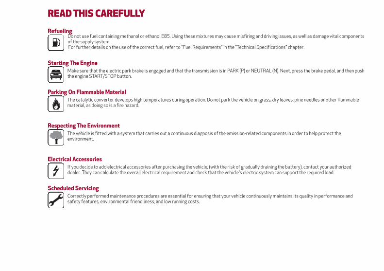
READ THIS CAREFULLYRefueling
Do not use fuel containing methanol or ethanol E85. Using these mixtures may cause misfiring and driving issues, as well as damage vital componentsof the supply system.For further details on the use of the correct fuel, refer to "Fuel Requirements" in the "Technical Specifications" chapter.
Starting The EngineMake sure that the electric park brake is engaged and that the transmission is in PARK (P) or NEUTRAL (N). Next, press the brake pedal, and then pushthe engine START/STOP button.
Parking On Flammable MaterialThe catalytic converter develops high temperatures during operation. Do not park the vehicle on grass, dry leaves, pine needles or other flammablematerial, as doing so is a fire hazard.
Respecting The EnvironmentThe vehicle is fitted with a system that carries out a continuous diagnosis of the emission-related components in order to help protect theenvironment.
Electrical AccessoriesIf you decide to add electrical accessories after purchasing the vehicle, (with the risk of gradually draining the battery), contact your authorizeddealer. They can calculate the overall electrical requirement and check that the vehicle's electric system can support the required load.
Scheduled ServicingCorrectly performed maintenance procedures are essential for ensuring that your vehicle continuously maintains its quality in performance andsafety features, environmental friendliness, and low running costs.

HOW TO USE THIS MANUALOperating InstructionsEach time an instruction is given that concerns direction (left/right or forward/backward), it is written to be read from theperspective of an occupant in the driver's seat. If a direction is written from a different perspective, it will be specified as such in thetext as appropriate.The figures in the manual are only examples: this might imply that some details of the image do not correspond to the actualarrangement of your vehicle.To identify the chapter with the information necessary, you can consult the index at the end of this manual.Chapters can be rapidly identified with dedicated graphic tabs, located at the side of each odd page. There is also a key for getting toknow the chapter order and the relevant symbols in the tabs. Additionally, there is a textual indication of each current chapter at theside of each even page.
Warnings And CautionsWhile reading this User Guide you will find a series of WARNINGS that must be carefully followed to prevent incorrect use of thecomponents of the vehicle, which could cause accidents or injuries.There are also CAUTIONS to prevent procedures that could damage your vehicle.Therefore all WARNINGS and CAUTIONS must always be carefully followed.WARNINGS and CAUTIONS are recalled in the text with the following symbols:Personal Safety:Vehicle Safety:
Note:
This User Guide describes all vehicle models. Optional equipment meant for specific markets or particular models are notidentified as such in the text: you need to consider only the information related to the model you own. Any content introducedthroughout the production of the model, outside the specific request of options at the time of purchase, will be identified bythe indicator: — if equipped.
The data contained in this publication is intended to help you use your vehicle in the best possible way. FCA US LLC aims forconstant improvement of the vehicles produced. For this reason, it reserves the right to make changes to the model describedfor technical and/or commercial reasons.
For further information, contact your authorized dealer.

SymbolsSome vehicle components have colored labels with symbols indicating precautions to be observed when using this component.It is important to follow all warnings when operating your vehicle. See below for a brief description of each symbol.
READ THE OWNERHANDBOOK
DO NOT TOUCH WITHHANDS
COMPONENT CAN STARTAUTOMATICALLY ALSO
WHEN ENGINE IS OFF
PROTECT YOUR EYESDO NOT OPEN THE CAPWHEN THE ENGINE IS
HOT
DO NOT OPEN: HIGHPRESSURE GAS
KEEP CHILDREN AT ADISTANCE
BURSTINGMOVING PARTS KEEP PARTS
OF YOUR BODY ANDCLOTHES AWAY
DO NOT APPROACHFLAMES
CORROSIVE LIQUID HIGH VOLTAGE
4

VEHICLE CHANGES / ALTERATIONS
Note:
Any change or alteration of the vehicle might seriously affect its safety and road holding, which could cause accidents resulting infatal injury.
The use of these devices inside the passenger compartment (without an external antenna) may cause the electrical systems tomalfunction. This could compromise the safety of the vehicle, in addition to constituting a potential hazard for passengers' health.
If mobile phones/laptops/smartphones/tablets are inside the car and/or close to the electronic key, a reduced performance ofthe Passive Entry/Keyless Start system may occur.

This page is intentionally left blank

GETTING TO KNOW YOUR VEHICLE
GETTING TO KNOW YOUR INSTRUMENT PANEL
SAFETY
STARTING AND OPERATING
IN CASE OF EMERGENCY
SERVICING AND MAINTENANCE
TECHNICAL SPECIFICATIONS
MULTIMEDIA
CUSTOMER ASSISTANCE
INDEX


GETTING TO KNOW YOUR VEHICLE
In this section, you will find importantinformation to help you become familiarwith the features needed to operate yourvehicle, and how they function.
KEYS . . . . . . . . . . . . . . . . . . . .10IGNITION SYSTEM . . . . . . . . . . . .11SECURITY ALARM SYSTEM — IFEQUIPPED . . . . . . . . . . . . . . . . .12DOORS . . . . . . . . . . . . . . . . . . .13SEATS . . . . . . . . . . . . . . . . . . . .17HEAD RESTRAINTS . . . . . . . . . . .21STEERING WHEEL . . . . . . . . . . . .23MIRRORS . . . . . . . . . . . . . . . . . .24EXTERIOR LIGHTS . . . . . . . . . . . .26INTERIOR LIGHTS . . . . . . . . . . . .28WINDSHIELD WIPERS . . . . . . . . . .29CLIMATE CONTROL . . . . . . . . . . .31POWER WINDOWS . . . . . . . . . . . .33POWER SUNROOF — IF EQUIPPED . .34HOOD . . . . . . . . . . . . . . . . . . . .36POWER LIFTGATE . . . . . . . . . . . .37INTERNAL EQUIPMENT . . . . . . . . .39
9

KEYSKey FobYour vehicle uses a keyless ignitionsystem. This system includes a key foband a keyless push button ignition.
The Remote Keyless Entry key fob allowsyou to lock or unlock the doors andliftgate or activate the Panic Alarm froma distance. The key fob does not need tobe pointed at the vehicle to activate thesystem.
PANIC Function
The key fob contains a PANIC button.Should you ever feel threatened, pushthis button and the vehicle security alarmwill sound.
To activate the PANIC function, push andhold the PANIC button for at least onesecond. When the panic alarm is active,
the headlights turn on, the turn signalsflash, the horn honks intermittently, andall interior adjustable lights turn on. Thepanic alarm will remain active for threeminutes, and can be deactivated:
By pushing the PANIC button again.
Automatically if the vehicle speedexceeds 5 mph (8 km/h).
In both cases, the panic alarm isimmediately deactivated.
Warning!
Before exiting a vehicle, always shift theautomatic transmission into PARK, apply theparking brake, turn the engine OFF, removethe key fob from the vehicle and lock yourvehicle.
Never leave children alone in a vehicle, orwith access to an unlocked vehicle.
Allowing children to be in a vehicleunattended is dangerous for a number ofreasons. A child or others could be seriouslyor fatally injured. Children should be warnednot to touch the parking brake, brake pedalor the gear selector.
Do not leave the key fob in or near thevehicle, or in a location accessible tochildren. A child could operate powerwindows, other controls, or move the vehicle.
Do not leave children or animals insideparked vehicles in hot weather. Interior heatbuild-up may cause serious injury or death.
Request For Additional KeysIf you need a replacement key fob,contact your authorized dealer.
General InformationThe following regulatory statementapplies to all radio frequency (RF)devices equipped in this vehicle:
This device complies with Part 15 of theFCC Rules and with Industry Canadalicense-exempt RSS standard(s).Operation is subject to the following twoconditions:
1. This device may not cause harmfulinterference, and
2. This device must accept anyinterference received, includinginterference that may cause undesiredoperation.
Note:
Changes or modifications not expresslyapproved by the party responsible forcompliance could void the user’sauthority to operate the equipment.
Key Fob
10
GE
TT
ING
TOK
NO
WY
OU
RV
EH
ICLE

IGNITION SYSTEMOperationTo activate the keyless ignition, the keyfob must be inside the vehicle.
The keyless ignition has the followingmodes:
STOP: engine off, steering locked.Some electrical devices (e.g. central doorlocking system, alarm, etc.) are stillavailable.
ON: all electrical devices are available.This state can be entered by pushing theignition button once, without pressing thebrake pedal.
AVV: engine starting. This state can beentered by pushing the ignition buttononce while pressing the brake pedal.
Note:
With the keyless ignition in the ONposition: if 30 minutes pass with the gearselector in P (Park) and the enginestopped, the keyless ignition willautomatically reset to the STOP position.
With the engine started, it is possibleto remove the key fob from the vehicle.The engine will remain running and theinstrument cluster will indicate theabsence of the key fob when the door isclosed.
For more information on engine start-up,refer to "Starting The Engine" in "StartingAnd Operating."
Warning!
Never use the PARK position as asubstitute for the parking brake. Alwaysapply the parking brake fully when parked toguard against vehicle movement andpossible injury or damage.
When exiting the vehicle, always make surethe ignition is in the OFF mode, remove the keyfob from the vehicle, and lock your vehicle.
Never leave children alone in a vehicle, orwith access to an unlocked vehicle. Allowingchildren to be in a vehicle unattended isdangerous for a number of reasons. A childor others could be seriously or fatally injured.
Children should be warned not to touch theparking brake, brake pedal or thetransmission gear selector.
Do not leave the key fob in or near thevehicle, (or in a location accessible tochildren), and do not leave the ignition in theAVV or ON/RUN mode. A child could operatepower windows, other controls, or move thevehicle.
Be sure the parking brake is fullydisengaged before driving; failure to do socan lead to brake failure and a collision.
Always fully apply the parking brakewhen leaving your vehicle, or it may roll andcause damage or injury. Also be certain toleave the transmission in PARK. Failure to doso may allow the vehicle to roll and causedamage or injury.
Driving the vehicle with the parking brakeengaged, or repeated use of the parkingbrake to slow the vehicle may cause seriousdamage to the brake system.
Caution!
If the Brake System Warning Light remainson with the parking brake released, a brakesystem malfunction is indicated. Have thebrake system serviced by an authorizeddealer immediately.
Keyless Ignition START/STOP Button
11

Starting With A Discharged Key FobBatteryIf the key fob battery is discharged,proceed as follows to start the vehicle:
1. Lift the front armrest.
2. Lay the key fob on the key fob outlinefound on the floor of the armrestcompartment while pushing theSTART/STOP button to start the ignition.
General InformationThe following regulatory statementapplies to all radio frequency (RF)devices equipped in this vehicle:
This device complies with Part 15 of theFCC Rules and with Industry Canadalicense-exempt RSS standard(s).Operation is subject to the following twoconditions:
1. This device may not cause harmfulinterference, and
2. This device must accept anyinterference received, includinginterference that may cause undesiredoperation.
Note:
Changes or modifications not expresslyapproved by the party responsible forcompliance could void the user’sauthority to operate the equipment.
SECURITY ALARM SYSTEM —IF EQUIPPEDTo Arm The AlarmWith the doors, hood, and liftgate closedand the keyless ignition system placed inthe STOP position, push and release thelock button on the key fob. The alarm canalso be armed by pushing the PassiveEntry door handle button, located on theexterior door handle. Refer to "Doors" in"Getting To Know Your Vehicle” forfurther information.
When the alarm is armed, the warninglights on the door handle trim remain on.
Key Fob Placement Location
Lock/Unlock Switches
12
GE
TT
ING
TOK
NO
WY
OU
RV
EH
ICLE

To Disarm The AlarmPush the unlock button on the key fob todisarm the alarm. While disarming, thefollowing operations are performed:
Two brief flashes of the turn signals (ifprogrammed).
Two brief acoustic signals (ifprogrammed).
Doors are unlocked.
Anti-Lift Protection — If EquippedThe vehicle security alarm systemmonitors the doors and liftgate forunauthorized entry and the ignitionswitch for unauthorized operation.
To ensure the correct operation of theprotection, completely close the sidewindows. If a perimeter violation triggersthe security system, the alarm will soundand the exterior lights will flash.
To ensure the correct operation of theVolumetric/Anti-Lift Protection system,completely close the side windows.
To disable the function, push theVolumetric/Anti-Lift Protection buttonbefore activating the alarm.
When the function is disabled, this isindicated by the light on theVolumetric/Anti-Lift Protection buttonflashing for several seconds.
Any disabling of the Volumetric/Anti-LiftProtection must be repeated each timethe ignition is cycled off.
To Disarm The Alarm Using PassiveEntryTo completely deactivate the alarm (e.g.during a long period of vehicle inactivity),insert the blade of the emergency key,found inside the key fob, into the doorhandle lock cylinder and turn theemergency key to the right (clockwise) tolock the door(s).
DOORSLocking And Unlocking Doors From TheInsideIf all doors are closed properly, they willautomatically lock once the vehicle hasexceeded approximately 12 MPH(20 km/h) (“Auto Relock” function active).
Push the interior lock button on the driveror passenger side door panel trim to lockthe doors.
Push the interior lock button on the reardoor panel trim to lock the rear doorsonly.
With doors locked, push the unlockbutton on the interior trim panel tounlock the doors.
Volumetric/Anti-Lift Protection Button
Door Lock And Unlock Switch Panel
13

Warning!
Do not leave children or animals insideparked vehicles in hot weather. Interior heatbuild-up may cause serious injury or death.
For personal security and safety in theevent of a collision, lock the vehicle doors asyou drive as well as when you park and leavethe vehicle.
Before exiting a vehicle, always shift theautomatic transmission into PARK, apply theparking brake, turn the engine OFF, removethe key fob from the vehicle and lock yourvehicle.
Never leave children alone in a vehicle, orwith access to an unlocked vehicle.
Allowing children to be in a vehicleunattended is dangerous for a number ofreasons. A child or others could be seriouslyor fatally injured. Children should be warnednot to touch the parking brake, brake pedalor the gear selector.
Do not leave the key fob in or near thevehicle, or in a location accessible tochildren. A child could operate powerwindows, other controls, or move the vehicle.
Caution!
An unlocked vehicle is an invitation. Alwaysremove the key from the ignition and lock allof the doors when leaving the vehicleunattended.
Locking/Unlocking Doors From TheOutsideWhen locking the doors from the outsidewith the doors closed, push the lockbutton on the key fob.
The door lock can be activated with alldoors locked and the liftgate open. Whenthe lock button on the key fob is pushed,all locks are activated, including theliftgate if it is open. The liftgate will belocked when it is closed.
When unlocking the doors from theoutside, push the unlock button on thekey fob.
Locking/Unlocking Doors From TheOutside In An Emergency
If the battery is discharged or the key fobis inoperable, you can lock or unlock thedoors from the outside by inserting theblade of the emergency key, found insidethe key fob, into the door handle lockcylinder and turn the emergency key asfollows.
Lock — Turn the emergency key to theright (clockwise)
Unlock — Turn the emergency key tothe left (counter clockwise)
Passive EntryThe Passive Entry system can identifythe presence of a key fob near the doorsand liftgate.
The system enables the doors andliftgate to be locked or unlocked withoutpushing any button on the key fob.
The key fob is detected only after thesystem recognizes the presence of ahand on one of the front door handles. Ifthe detected key fob is valid, the doorsand the liftgate are unlocked (refer to theInformation and Entertainment SystemOwner’s Manual Supplement for PassiveEntry Settings)
Note:
The key fob may not be able to bedetected by the vehicle keyless-gosystem if it is located next to a mobilephone, laptop or other electronic device;these devices may block the key fob’swireless signal and prevent thekeyless-go system from starting thevehicle.
Grasping the handle of the driver's doorunlocks the driver's side door, or all doorsdepending on the mode set using theInformation and Entertainment System14
GE
TT
ING
TOK
NO
WY
OU
RV
EH
ICLE

(refer to the Information andEntertainment System Owner’s ManualSupplement for Passive Entry Settings).
Door Locking
To lock the doors, proceed as follows:
1. Make sure that you have the key foband are close to the driver or passengerside door handle.
2. Push the Passive Entry door handlebutton or the Passive Entry liftgatebutton, located next to the externalliftgate release button. This will lock alldoors and the liftgate. Door locking willactivate the alarm as well.
Note:
After pushing the Passive Entry doorhandle button, you must wait twoseconds before the doors can beunlocked again using the passive entrydoor handle button. This feature makes itpossible to check whether the vehicle hasbeen locked correctly by pulling the doorhandle within two seconds. The doors willnot be unlocked again.
The vehicle doors and liftgate can belocked by pushing the lock button on thekey fob or on the interior door panel.
Driver Side Door Emergency Opening
If the key fob does not work, e.g. becauseits battery is discharged or the vehiclebattery is discharged, the emergency keyinside the key fob can be used to unlockthe driver side door.
To remove the emergency key, proceedas follows:
1. Push the sides of the key fob inwardand extract the cover pulling downwards.
2. Remove the emergency key from thekey fob housing.
3. Insert the emergency key in the driverside door lock cylinder and turn it to theleft (counter clockwise) to unlock the door.
Passive Entry Door Handle Button
Passive Entry Liftgate Button
Key Fob Cover Removal
15
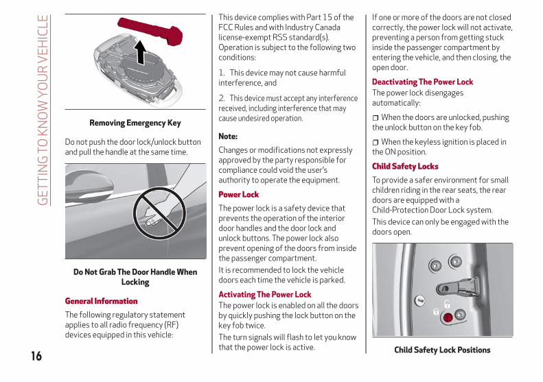
Do not push the door lock/unlock buttonand pull the handle at the same time.
General InformationThe following regulatory statementapplies to all radio frequency (RF)devices equipped in this vehicle:
This device complies with Part 15 of theFCC Rules and with Industry Canadalicense-exempt RSS standard(s).Operation is subject to the following twoconditions:
1. This device may not cause harmfulinterference, and
2. This device must accept any interferencereceived, including interference that maycause undesired operation.
Note:
Changes or modifications not expresslyapproved by the party responsible forcompliance could void the user’sauthority to operate the equipment.
Power LockThe power lock is a safety device thatprevents the operation of the interiordoor handles and the door lock andunlock buttons. The power lock alsoprevent opening of the doors from insidethe passenger compartment.
It is recommended to lock the vehicledoors each time the vehicle is parked.
Activating The Power Lock
The power lock is enabled on all the doorsby quickly pushing the lock button on thekey fob twice.
The turn signals will flash to let you knowthat the power lock is active.
If one or more of the doors are not closedcorrectly, the power lock will not activate,preventing a person from getting stuckinside the passenger compartment byentering the vehicle, and then closing, theopen door.
Deactivating The Power Lock
The power lock disengagesautomatically:
When the doors are unlocked, pushingthe unlock button on the key fob.
When the keyless ignition is placed inthe ON position.
Child Safety LocksTo provide a safer environment for smallchildren riding in the rear seats, the reardoors are equipped with aChild-Protection Door Lock system.
This device can only be engaged with thedoors open.
Removing Emergency Key
Do Not Grab The Door Handle WhenLocking
Child Safety Lock Positions16
GE
TT
ING
TOK
NO
WY
OU
RV
EH
ICLE

Lock position: device locked (dooropened from exterior only)
Unlock position: device unlocked (doormay be opened from the inside)
The Child Safety Locks remain lockedeven if the doors are unlocked.
Note:
The rear doors cannot be opened fromthe inside when the Child Safety Lock isengaged.
Unlocking The Doors With A DischargedBatteryProceed as follows to unlock the doors ifthe vehicle battery is discharged.
1. With the doors unlocked insert theemergency key from the key fob into thedoor lock manual release lock cylinder.
2. Turn the manual release lock cylinderclockwise for the right door locks orcounterclockwise for the left door locks.
3. Remove the key/screwdriver from themanual release lock.
Proceed in one of the following ways torealign the door lock device (only whenthe battery charge has been restored):
Push the lock button on the electronickey
Push the unlock button on the doorpanel
Unlock driver’s door lock with theemergency key
Operate the internal door handle
Note:
For the rear doors, if the Child SafetyLocks are engaged, and the previouslydescribed locking procedure is carriedout, operating the internal handle will notopen the door. Instead, it will only realignthe lock release device. To open the door,the outside handle must be used. Thedoor central locking/unlocking buttonsare not deactivated when the emergencylock is engaged.
SEATSThe front seats can be adjusted to ensuremaximum comfort for the occupants.When adjusting the driver’s seat, keepthe shoulders resting firmly against thebackrest, the wrists within reach of thetop of the steering wheel, and the seatclose enough to allow the driver to fullydepress the brake pedal.
Warning!
It is dangerous to ride in a cargo area,inside or outside of a vehicle. In a collision,people riding in these areas are more likelyto be seriously injured or killed.
Do not allow people to ride in any area ofyour vehicle that is not equipped with seatsand seat belts. In a collision, people riding inthese areas are more likely to be seriouslyinjured or killed.
Be sure everyone in your vehicle is in aseat and using a seat belt properly.
Power Front SeatsOn models equipped with power seats,the switch is located on the outboard sideof the seat near the floor. Use this switchto move the driver's seat up, down,forward, and rearward, or to recline theseatback.
Door Lock Manual Release LockCylinder
17

Caution!
Do not place any article under a power seator impede its ability to move as it may causedamage to the seat controls. Seat travelmay become limited if movement is stoppedby an obstruction in the seat's path.
Forward/Rearward Adjustment
Push the seat switch forward or rearwardto adjust to your desired position.
Seatback Recline
The angle of the seatback can beadjusted forward or rearward. Push theseatback switch forward or rearward,and the seat will move in the direction ofthe switch. Release the switch when thedesired position is reached.
Power Lumbar — If Equipped
Vehicles equipped with power driver orpassenger seats may also be equippedwith power lumbar. The power lumbarswitch is located on the outboard side ofthe power seat. Push the switch forwardor rearward to increase or decrease thelumbar support. Push the switch upwardor downward to raise or lower the lumbarsupport.
Height Adjustment
The height of the seats can be adjustedup or down. Pull upward or pushdownward on the seat switch, and theseat will move in the direction of theswitch. Release the switch when thedesired position is reached.
Seat Angle Adjustment (Tilting) — IfEquipped
The seat angle can be adjusted in fourdirections. Lift or push the front part ofseat switch to move the front part of theseat in the corresponding direction.Release the seat switch when the seathas reached the desired position.
Power Bolster Adjustment — IfEquipped
Push the power bolster adjustmentbuttons to regulate the width of thebackrest through the lateral padding.
Seat Cushion Extension — If Equipped
Lift the adjustment lever and push thefront of the cushion forward or backwardto extend the cushion by a few inches(centimeters).
Driver Memory Seat
The driver memory seat buttons allowthe driver to store and recall threedifferent driver’s seat positions, as wellas outside power mirror positions.Storing and recalling can be done with theignition in the ON mode and the driver’sside door closed, or for 3 minutes after
Power Seat Adjustment
1 — Seat Switch (Forward/Rearward/Height)2 — Seatback Switch3 — Lumbar Adjustment4 — Power Adjustable Bolster Buttons— If Equipped
Seat Cushion Extension
6 — Adjustment Lever
18
GE
TT
ING
TOK
NO
WY
OU
RV
EH
ICLE

having opened the driver's side door. Toset a memory profile, first adjust yourseat (and power mirror position ifdesired). Then, push the memory buttonyou want to assign the set position to for1.5 seconds. To recall a memorizedposition, push the assigned buttonbriefly.
Warning!
Adjusting a seat while driving may bedangerous. Moving a seat while driving couldresult in loss of control which could cause acollision and serious injury or death.
Seats should be adjusted beforefastening the seat belts and while the vehicleis parked. Serious injury or death could resultfrom a poorly adjusted seat belt.
Do not ride with the seatback reclined sothat the shoulder belt is no longer restingagainst your chest. In a collision you couldslide under the seat belt, which could result inserious injury or death.
Heated Seats — If EquippedWith the engine in the ON position, pushthe heated seat buttons on theinstrument panel.
You can select three heating levels:
Maximum — three orange indicatorsilluminated on the buttons
Average — two orange indicatorsilluminated on the buttons
Minimum — one orange indicatorilluminated on the buttons
After selecting a heating level, heat willbe felt within a few minutes.
A quick push of the heated seat buttonwill select the heat levels in order ofhighest to lowest. A fourth push of thebutton will turn the heated seat off.
The “minimum” setting is automaticallydeactivated once a certain period of timehas elapsed. This varies on acase-by-case basis, in accordance withthe specific operating conditions.
Note:
To preserve the battery charge, thisfunction cannot be activated when theengine is OFF.
Warning!
Persons who are unable to feel pain to theskin because of advanced age, chronicillness, diabetes, spinal cord injury,medication, alcohol use, exhaustion or otherphysical condition must exercise care whenusing the seat heater. It may cause burnseven at low temperatures, especially if usedfor long periods of time
Driver Memory Seat Buttons Location
5 — Driver Memory Seat Buttons
Heated Seat Buttons
19

Do not place anything on the seat orseatback that insulates against heat, suchas a blanket or cushion. This may cause theseat heater to overheat. Sitting in a seatthat has been overheated could causeserious burns due to the increased surfacetemperature of the seat.
Rear SeatsThe rear seats allow for threepassengers.
The seats and the seat belts areconsidered components of the vehicle’sOccupant Restraint System.
Note:
Refer to the "Seat Belt Systems" in the"Safety" chapter for the properpositioning of the seat belts.
Split Folding Rear SeatPartial Extension Of The LuggageCompartment (40/20/40)
Extending the right side of the luggagecompartment allows you to carry twopassengers on the left part of the rearseat, while extending the left side allowsyou to carry one passenger.
Proceed as follows:
1. Completely lower the rear seat headrestraints.
2. Place the seatbelt so that it doesn'timpede the movement of the backrestwhile tilting it.
3. Pull the left-hand seat back releaselever (inside the luggage compartment orthe release at the base of the rear seataccessible from the rear doors) to folddown the left side, or the right-hand seatback release lever to fold down the rightside of the backrest. It will fold forwardautomatically. If necessary, assist thebackrest during the initial stage of tilting.
It is also possible to disengage thesections of the rear seat from inside theluggage compartment or by using one ofthe two levers located below the rear
seat. Each lever folds down the section ofthe backrest on the same side.
Repositioning The Backrests
Move the seat belts to the side, makingsure that they are correctly extended andnot twisted. Also make sure that they arenot caught on anything behind thebackrests of the seats. Then, lift thebackrests by pushing them rearward untilyou hear the lock click into place on bothattachment mechanisms.
Warning!
Be certain that the seatback is securelylocked into position. If the seatback is notsecurely locked into position the seat willnot provide the proper stability for childseats and/or passengers. An improperlylatched seat could cause serious injury.
Seat Back Release Lever In LuggageCompartment
1 — Seat Back Release Lever
Seat Back Release Lever Below Rear Seat
20
GE
TT
ING
TOK
NO
WY
OU
RV
EH
ICLE

HEAD RESTRAINTSHead restraints are designed to reducethe risk of injury by restricting headmovement in the event of a rear impact.Head restraints should be adjusted sothat the top of the head restraint islocated above the top of your ear.
Warning!
A loose head restraint thrown forward ina collision or hard stop could cause seriousinjury or death to occupants of the vehicle.Always securely stow removed headrestraints in a location outside the occupantcompartment.
ALL the head restraints MUST bereinstalled in the vehicle to properly protectthe occupants. Follow the re-installationinstructions above prior to operating thevehicle or occupying a seat.
Do not place items over the top of theReactive Head Restraint, such as coats, seatcovers or portable DVD players. These itemsmay interfere with the operation of theReactive Head Restraint in the event of acollision and could result in serious injury ordeath.
Front Head Restraints (Adjustments)The front head restraints may beheight-adjustable. To adjust them,operate as follows:
Upward adjustment: Pull upward onthe head restraint until it clicks intoplace.
Downward adjustment: Push theadjustment button and lower the headrestraint at the same time.
Warning!
All occupants, including the driver, shouldnot operate a vehicle or sit in a vehicle’s seatuntil the head restraints are placed in theirproper positions in order to minimize the riskof neck injury in the event of a crash.
Head restraints should never be adjustedwhile the vehicle is in motion. Driving avehicle with the head restraints improperlyadjusted or removed could cause seriousinjury or death in the event of a collision.
Note:
To allow for maximum visibility for thedriver, if a seat is not occupied by apassenger, the head restraint can belowered to the fully lowered position.
Rear Head Restraints (Adjustments)
Warning!
All occupants, including the driver, shouldnot operate a vehicle or sit in a vehicle’s seatuntil the head restraints are placed in theirproper positions in order to minimize the riskof neck injury in the event of a crash.
Front Head Restraint
1 — Release Button2 — Adjustment Button
21

Head restraints should never be adjustedwhile the vehicle is in motion. Driving avehicle with the head restraints improperlyadjusted or removed could cause seriousinjury or death in the event of a collision.
The height of the outboard headrestraints can be adjusted. The headrestraint of the center seat, if equipped,cannot be adjusted, only removed.
For upward adjustment, pull upward onthe head restraint until it clicks intoplace.
For downward adjustment, push in theadjustment button and lower the headrestraint at the same time to the desiredheight.
Note:
To allow for maximum visibility for thedriver, if a seat is not occupied by apassenger, the head restraint should belowered to the fully lowered position.
Head Restraints (Removal)To remove the head restraints, proceedas follows:
1. Raise the head restraints to theirmaximum height.
2. Push the adjustment button and therelease button at the side of the twosupports at the same time.
3. Pull upward on the head restraint tofully remove it.
To reinstall the head restraints, proceedas follows:
1. Hold down both the adjustmentbutton and release button while placingthe head restraint post into the holes.
2. Then, reposition the head restraint tothe appropriate height for thepassengers.
Warning!
A loose head restraint thrown forward ina collision or hard stop could cause seriousinjury or death to occupants of the vehicle.Always securely stow removed headrestraints in a location outside the occupantcompartment.
ALL the head restraints MUST bereinstalled in the vehicle to properly protectthe occupants. Follow the re-installationinstructions above prior to operating thevehicle or occupying a seat.
Rear Head Restraint
1 — Release Button2 — Adjustment Button
Rear Head Restraint
1 — Release Button2 — Adjustment Button
22
GE
TT
ING
TOK
NO
WY
OU
RV
EH
ICLE

STEERING WHEELSteering Wheel AdjustmentsThe steering column is able to be tiltedupward or downward. It also allows youto lengthen or shorten the steeringcolumn. The tilt/telescoping lever islocated below the steering wheel at theend of the steering column.
Warning!
Do not adjust the steering column whiledriving. Adjusting the steering column whiledriving or driving with the steering columnunlocked, could cause the driver to losecontrol of the vehicle. Failure to follow thiswarning may result in serious injury or death.
To Adjust The Position:
1. Pull the Tilt/Telescoping ControlHandle down to the open position.
2. Adjust the steering wheel to thedesired position.
3. Lock the desired position by pushingthe Tilt/Telescoping Control Handle tothe closed position.
Warning!
It is absolutely forbidden to carry out anyafter-market operation involving steeringsystem or steering column modifications(e.g. installation of anti-theft device) thatcould adversely affect performance. Doingso could void the New Vehicle LimitedWarrant, cause SERIOUS SAFETYPROBLEMS INCLUDING INJURY, and alsoresult in the vehicle not meetingtype-approval requirements.
Steering Wheel Adjustment
1 — Tilt/Telescoping Control Handle2 — Closed3 — Open4 — Tilt Movement5 — Telescoping Movement
23
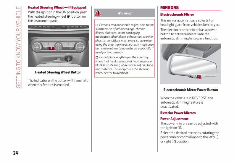
Heated Steering Wheel — If EquippedWith the ignition in the ON position, pushthe heated steering wheel button onthe instrument panel.
The indicator on the button will illuminatewhen this feature is enabled.
Warning!
Persons who are unable to feel pain to theskin because of advanced age, chronicillness, diabetes, spinal cord injury,medication, alcohol use, exhaustion, or otherphysical conditions must exercise care whenusing the steering wheel heater. It may causeburns even at low temperatures, especially ifused for long periods.
Do not place anything on the steeringwheel that insulates against heat, such as ablanket or steering wheel covers of any typeand material. This may cause the steeringwheel heater to overheat.
MIRRORSElectrochromic MirrorThis mirror automatically adjusts forheadlight glare from vehicles behind you.
The electrochromic mirror has a powerbutton to activate/deactivate theautomatic dimming/anti-glare function.
When the vehicle is in REVERSE, theautomatic dimming feature isdeactivated.
Exterior Power MirrorsPower Adjustment
The power mirrors can be adjusted withthe ignition ON .
Select the desired mirror by rotating thepower mirror control knob to the left (L)or right (R) position.
Heated Steering Wheel Button
Electrochromic Mirror Power Button
24
GE
TT
ING
TOK
NO
WY
OU
RV
EH
ICLE
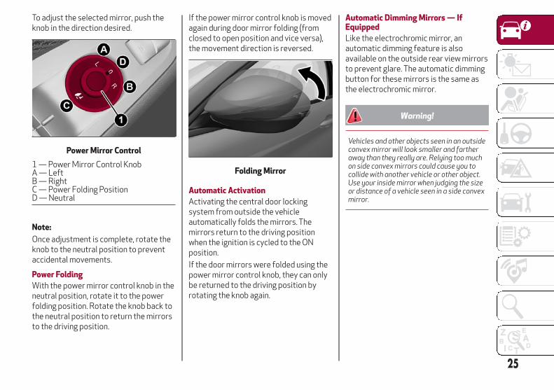
To adjust the selected mirror, push theknob in the direction desired.
Note:
Once adjustment is complete, rotate theknob to the neutral position to preventaccidental movements.
Power Folding
With the power mirror control knob in theneutral position, rotate it to the powerfolding position. Rotate the knob back tothe neutral position to return the mirrorsto the driving position.
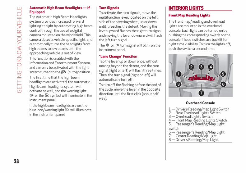
If the power mirror control knob is movedagain during door mirror folding (fromclosed to open position and vice versa),the movement direction is reversed.
Automatic Activation
Activating the central door lockingsystem from outside the vehicleautomatically folds the mirrors. Themirrors return to the driving positionwhen the ignition is cycled to the ONposition.
If the door mirrors were folded using thepower mirror control knob, they can onlybe returned to the driving position byrotating the knob again.
Automatic Dimming Mirrors — IfEquipped
Like the electrochromic mirror, anautomatic dimming feature is alsoavailable on the outside rear view mirrorsto prevent glare. The automatic dimmingbutton for these mirrors is the same asthe electrochromic mirror.
Warning!
Vehicles and other objects seen in an outsideconvex mirror will look smaller and fartheraway than they really are. Relying too muchon side convex mirrors could cause you tocollide with another vehicle or other object.Use your inside mirror when judging the sizeor distance of a vehicle seen in a side convexmirror.
Power Mirror Control
1 — Power Mirror Control KnobA — LeftB — RightC — Power Folding PositionD — Neutral
Folding Mirror
25

EXTERIOR LIGHTSHeadlight SwitchThe headlight switch is located to the leftof the steering wheel on the instrumentpanel. This switch controls the operationof the headlights, parking lights,instrument panel lights, instrument panellight dimming, interior lights and rear foglights.
In addition, there are buttons for parkingsensors deactivation and stop/start.Refer to “Starting And Operating” forfurther information.
The exterior lights can be activated onlywhen the ignition is in the ON mode,except for the parking lights. Refer to"Parking Lights" in this section for moreinformation.
The instrument panel and the variouscontrols on the dashboard will beilluminated when the exterior lights areturned on.
Automatic HeadlightsThis system automatically turns theheadlights on or off according to ambientlight levels.
Function Activation
From the O (off) position, rotate the lightswitch to the (auto) position.
Note:
The function can only operate with theignition position cycled to ON.
Function Deactivation
To deactivate the function, rotate thelight switch to a position other than the
(auto) position.
Daytime Running Lights (DRL)With the ignition cycled to ON, and thelight switch turned to the position, ifthe dusk sensor detects sufficientexternal light, the Daytime RunningLights will turn on automatically while theother lights remain off.
If the turn signals are operated, thebrightness of the corresponding DaytimeRunning Lights will be decreased for aslong as the turn signals are on.
If equipped, the DRL can beactivated/deactivated from theInformation and Entertainment System,by selecting the following functions insequence on the main MENU:
1. “Settings.”
2. “Lights.”
3. “Daytime Lights.”
Note:The Daytime Running Lights cannotbe deactivated in Canadian markets.
Rear Fog LightsThe rear fog light switch is located withinthe headlight switch.
Push the button, located in the centerof the headlight switch, to turn the rearfog lights on/off.
The rear fog lights turn on only when theheadlights or parking lights are alsoturned on. The lights can be turned off bypushing the button again or by turningthe headlight switch to the O (off)position.
When the engine is stopped with the rearfog lights on, they will be off the nexttime the engine is started.
Headlight Switch
1 — Parking Sensors Deactivation Button2 — Parking Light, Daylight RunningLights, Headlight Switch3 — Instrument Panel Dimmer4 — Rear Fog Light Button5 — Stop/Start Button
26
GE
TT
ING
TOK
NO
WY
OU
RV
EH
ICLE

Parking LightsWith the ignition in STOP mode, rotatethe headlight switch to the position toturn the parking lights on. All of theparking lights will turn on for eightminutes, and opening the door activatesan audible warning.
To leave only the lights on one side(right/left) illuminated, you must movethe multifunction lever (located on theleft side of the steering wheel) to the sidethat you want to remain on. With theparking lights on, the warning light onthe instrument panel will illuminate.
Note:
Cycling the ignition to ON mode turns offthe parking lights, which were onlyilluminated on one side.
Headlight Off DelayThe “Headlight Off Delay” function delaysthe turning off of the headlights after thevehicle’s engine has been stopped.
The function can be activated from theInformation and Entertainment Systemby selecting the following functions insequence on the main menu:
1. “Settings.”
2. “Lights.”
3. “Headlight Off Delay.”
The side lights and the headlights stay onfor a time that can be set between 30,60, and 90 seconds.
Function Activation
With the headlights on, cycle the ignitionto STOP mode and the timer will start.
Note:
To activate this function, the headlightsmust be deactivated within two minutesafter the ignition has been cycled to theSTOP mode.
Function Deactivation
This function is deactivated by turning onthe headlights, the side lights, or bycycling the ignition to ON mode.
High Beam HeadlightsTo activate the fixed high beamheadlights, push the multifunction lever,located on the left side of the steeringwheel, towards the instrument panel. Theheadlight switch must first be turned tothe (auto) or (on) position.
With high beam headlights on, theHigh Beam Indicator on the
instrument panel will illuminate.
The high beam headlights are turned offby pulling the lever rearward to itsoriginal position. The High Beam Indicator
will turn off in the instrument panelwhen the headlights are turned off.
Flashing The Headlights
Pulling the multifunction lever toward thesteering wheel will activate the highbeam headlights manually. The lights willremain on as long as the lever is held.Once the lever is released, the lights willresume the previous setting.
Multifunction Lever
27
Automatic High Beam Headlights — IfEquipped
The Automatic High Beam Headlightssystem provides increased forwardlighting at night by automating high beamcontrol through the use of a digitalcamera mounted on the windshield. Thiscamera detects vehicle specific light, andautomatically turns the headlights fromhigh beams to low beams until theapproaching vehicle is out of view.
This function is enabled with theInformation and Entertainment System,and can only be activated with the lightswitch turned to the (auto) position.
The first time that the high beamheadlights are activated, the AutomaticHigh Beam Headlights system willactivate as well, and the warning light
or the symbol will illuminate in theinstrument panel.
If the high beam headlights are on, theblue icon/warning light will illuminatein the instrument panel.
Turn SignalsTo activate the turn signals, move themultifunction lever, located on the leftside of the steering wheel, up or downuntil it reaches the detent. Moving thelever upward flashes the right turn signaland moving the lever downward will flashthe left turn signal.
The or turn signal will blink on theinstrument panel.
“Lane Change” Function
Tap the lever up or down once, withoutmoving beyond the detent, and the turnsignal (right or left) will flash three times.Then, the turn signal (right or left) willautomatically turn off.
To turn off the flashing before the end ofthe cycle, move the lever in the oppositedirection until the first click (about halfway).
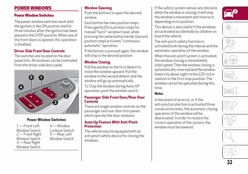
INTERIOR LIGHTSFront Map Reading LightsThe front map/reading and overheadlights are mounted in the overheadconsole. Each light can be turned on bypushing the corresponding switch on theconsole. These switches are backlit fornight time visibility. To turn the lights off,push the switch a second time.
Overhead Console
1 — Driver’s Reading/Map Light Switch2 — Rear Overhead Lights Switch3 — Overhead Lights Switch4 — Front Map Reading Lights Switch5 — Passenger’s Reading/Map LightSwitch6 — Passenger’s Reading/Map Light7 — Center Reading/Map Light8 — Driver’s Reading/Map Light
28
GE
TT
ING
TOK
NO
WY
OU
RV
EH
ICLE

Note:
Before exiting the vehicle, ensure thatthe overhead lights are off. This willprevent the battery from dischargingonce the doors are closed. If a light is lefton accidently, the overhead lights turn offautomatically approximately 15 minutesafter the engine has been cycled OFF.
Overhead Light Timing
On certain models, to assist getting inand out of the vehicle at night or inpoorly-lit areas, two timed modes havebeen provided.
WINDSHIELD WIPERSWindshield Wiper/Washers
Operation: The switch on the wiperstalk can be set to the followingpositions:
Windshield Wiper Off.
Low Sensitivity Rain Sensing.
High Sensitivity Rain Sensing.
Low Continuous Wiper Speed.
High Continuous Wiper Speed.
Windshield Washer Operation
Pull the stalk toward the steering wheelto operate the windshield washer.
Keep the stalk pulled to activate both thewindshield washer jet and the windshieldwiper with a single movement. The wipersand washers will continue to operate untilstalk is released.
The windshield wiper stops working threestrokes after the stalk is released,followed by a final stroke six secondslater to complete the cycle.
Mist
Use this feature when weatherconditions make occasional usage of thewipers necessary. Push the stalk upwardto the MIST position and release for asingle wiping cycle. This function is usefulto remove small deposits of dust fromthe windshield or morning dew.
Note:
This function does not activate thewindshield washer. To spray windshieldwasher fluid onto the windshield, thewashing function must be used.
Windshield Wiper Switch
29

Warning!
Sudden loss of visibility through thewindshield could lead to a collision. Youmight not see other vehicles or otherobstacles. To avoid sudden icing of thewindshield during freezing weather, warmthe windshield with the defroster before andduring windshield washer use.
Rain SensorThe Rain Sensor feature senses moistureon the windshield and automaticallyactivates the wipers for the driver. Thefeature is especially useful for roadsplash or over spray from the windshieldwashers of the vehicle ahead.
Activation/Deactivation
Rotating the wiper switch to positionor activates the rain sensor.
The activation of the rain sensor systemis done by tapping the wiper stalkupwards while the switch is in the or
position.
To deactivate the system, use the wiperswitch or cycle the ignition to STOPmode.
Rear Window Wiper/WasherShifting the vehicle into REVERSE withthe windshield wiper operating, activatesa single cycle of the rear window wiper.
Activation of the rear windowwiper/washer can be done by moving thestalk to one of the following positions:
Pushing the stalk towards theinstrument panel activates the rearwindow washer (a brief push activatesone washing cycle, keeping the stalkpushed washes continuously until thestalk is released).
Pushing the stalk downwardactivates/deactivates continuous rearwiper operation.
30
GE
TT
ING
TOK
NO
WY
OU
RV
EH
ICLE

CLIMATE CONTROLAutomatic Dual-Zone Climate Control SystemControls
Automatic Climate Control System
1 — Driver Temperature AdjustmentKnob
6 — Rear Defrost Button 11 — Passenger Heated Seat Button — IfEquipped
2 — Driver Side AUTO Button (Auto-matic Operation)
7 — Passenger Side Air DistributionSelection Button
12 — Air Conditioning Button
3 — Driver Side Air Distribution Selec-tion Button
8 — Passenger Side AUTO Button (Au-tomatic Operation)
13 — Steering Wheel Heater Button — IfEquipped
4 — Max Defrost Button 9 — Passenger Temperature Adjust-ment Knob
14 — Driver Side Heated Seat Button —If Equipped
5 — Blower Speed Adjustment Knob 10 — SYNC Button (Set TemperatureAlignment) Driver/Passenger Side
15 — Air Recirculation Button
31

Caution!
The system uses R1234yf refrigerant, whichdoes not pollute the environment in theevent of accidental leakage. Under nocircumstances, use R134a and R12 fluids,which are incompatible with the componentsof this system.
Air Distribution SelectionPush the Air Distribution Selectionbutton on the faceplate to change themode of air distribution. The followselectable option are explained below:
Air flow to the windshield anddemister window vents todemist/defrost them.Air flow at the central and sidedashboard vents to ventilate thechest and the face.Air flow to the front and rear floorvents. This setting heats thepassenger compartment thequickest.
Air flow distributed between thefloor vents (hotter air) and thecentral and side dashboard vents(cooler air). This air distributionsetting is useful on sunny daysduring spring and autumn.Air flow distributed between thefloor vents, windshield, and frontside window defrosting/demistingvents. This distribution settingwarms the passenger compartmentwhile preventing the windows fromfogging up.Air flow distribution between thewindshield demisting/defrostingvents, and side/central dashboardvents. This distribution settingsends air to the windshield in sunnyconditions.Air flow distribution to all vents onthe vehicle.
In AUTO mode, the Climate Controlsautomatically manage the airdistribution. When set manually, therespective symbols on the Informationand Entertainment System indicate theair distribution setting.
Stop/StartThe Stop/Start system shuts off theengine when vehicle speed is 0 mph(0 km/h), and the climate control systemwill continue to maintain comfort withinthe vehicle.
Stop/Start will deactivate in thefollowing scenarios:
The climate control system is in AUTOmode (indicator illuminated), and thevehicle has yet to reach the settemperature
The climate control system is in LOmaximum cooling
The climate control system is in HImaximum heating
The climate control system is in theMAX-DEF status
When the Stop/Start system is active,the engine will restart if the insidetemperature changes significantly, or ifthe LO setting, or MAX-DEF setting, isactivated.
32
GE
TT
ING
TOK
NO
WY
OU
RV
EH
ICLE
POWER WINDOWSPower Window SwitchesThe power window switches work withthe ignition in the ON position and forthree minutes after the ignition has beenplaced in the STOP position. When one ofthe front doors is opened, this operationis disabled.
Driver Side Front Door Controls
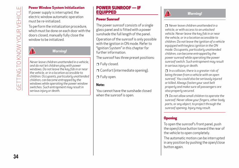
The switches are located on the doorpanel trim. All windows can be controlledfrom the driver side door panel.
Window Opening
Push the buttons to open the desiredwindow.
Each button has two position steps.Press gently (first position step) formanual "burst" window travel, whilepressing the same button harder (secondposition step) activates "continuousautomatic" operation.
If the button is pressed again, the windowwill stop in the desired position.
Window Closing
Pull the window to the first detent tomove the window upward. Pull thewindow to the second detent, and thewindow will go up automatically.
To Stop the window during Auto-UPoperation, push the window switch.
Passenger Side Front Door/Rear DoorControls
There are single window controls on thepassenger and rear door trim panelswhich operate the door windows.
Auto-Up Feature With Anti-PinchProtection
The vehicle may be equipped with ananti-pinch safety device for closing thewindows.
If the safety system senses any obstaclewhile the window is closing, it will stopthe window’s movement and reverse it,depending on its position.
This device is also useful if the windowsare activated accidentally by children onboard the vehicle.
The anti-pinch safety function isactivated both during the manual and theautomatic operation of the window.
When the anti-pinch system is activated,the window closing is immediatelyinterrupted. Then the window closing isautomatically reversed and the windowlowers by about eight inches (20 cm) inrelation to the first stop position. Thewindow cannot be operated during thistime.
Note:
In the event of an error, or if theanti-pinch protection is activated threeconsecutive times, the automatic closingoperation of the window will bedeactivated. In order to restore thecorrect operation of the system, thewindow must be lowered.
Power Window Switches
1 — Front LeftWindow Switch
4 — WindowLockout Switch
2 — Front RightWindow Switch
5 — Rear LeftWindow Switch
3 — Rear RightWindow Switch
33
Power Window System Initialization
If power supply is interrupted, theelectric window automatic operationmust be re-initialized.
To perform the initialization procedure,which must be done on each door with thedoors closed, manually fully close thewindow to be initialized.
Warning!
Never leave children unattended in a vehicle,and do not let children play with powerwindows. Do not leave the key fob in or nearthe vehicle, or in a location accessible tochildren. Occupants, particularly unattendedchildren, can become entrapped by thewindows while operating the power windowswitches. Such entrapment may result inserious injury or death.
POWER SUNROOF — IFEQUIPPEDPower SunroofThe power sunroof consists of a singleglass panel and is fitted with a powersunshade the full length of the panel.
Operation of the sunroof is only possiblewith the ignition in ON mode. Refer to“Ignition System” in this chapter forfurther information.
The sunroof has three preset positions:
Fully closed.
Comfort (intermediate opening).
Fully open.
Note:
You cannot have the sunshade closedwhen the sunroof is open.
Warning!
Never leave children unattended in avehicle, or with access to an unlockedvehicle. Never leave the key fob in or nearthe vehicle, or in a location accessible tochildren. Do not leave the ignition of a vehicleequipped with keyless ignition in the ONmode. Occupants, particularly unattendedchildren, can become entrapped by thepower sunroof while operating the powersunroof switch. Such entrapment may resultin serious injury or death.
In a collision, there is a greater risk ofbeing thrown from a vehicle with an opensunroof. You could also be seriously injuredor killed. Always fasten your seat beltproperly and make sure all passengers arealso properly secured.
Do not allow small children to operate thesunroof. Never allow your fingers, other bodyparts, or any object, to project through thesunroof opening. Injury may result.
OpeningTo open the sunroof’s front panel, pushthe open/close button toward the rear ofthe vehicle to open completely.
The automatic motion can be interruptedin any position by pushing the open/closebutton again.
34
GE
TT
ING
TOK
NO
WY
OU
RV
EH
ICLE

Caution!
Do not open the sun roof if a roof rack orcrossbars are fitted. Do not open the sunroof if there is snow or ice on it: you maydamage it.
ClosingFrom the complete open position, pushthe open/close button toward the frontof the vehicle. The roof will closecompletely.
The automatic motion can be interruptedin any position by pushing the open/closebutton again.
Vent OpeningTo bring the roof into vent position, pushand release the vent button.
This type of vent opening can beactivated regardless of the position ofthe sunroof. When starting with the roofin the closed position, pushing the ventbutton automatically causes the sunroofto open to the vent position. If the roof isalready open, the button must be helduntil the roof reaches the vent-openingposition.
Pushing the vent button again duringautomatic movement of the roof willstop it.
Power Sun ShadeThe sunshade is power operated.
Push the Power Shade open/close buttontoward the rear of the vehicle to open thesun shade.
Push the Power Shade open/close buttontoward the front of the vehicle to closethe sun shade.
The automatic motion can be interruptedin any position by pushing the PowerShade on/off button again.
Pinch Protect FeatureThe sunroof has an anti-pinch safetysystem capable of detecting thepresence of an obstacle during theclosing movement. If an obstacle is
detected, the system intervenes and themovement of the sunroof is immediatelyreversed into opening.
Initialization ProcedureAutomatic operation of the sunroof mustbe initialized again in case of faultysunroof operation. It may also benecessary to initialize the sunroof afterthe vehicle’s battery as beendisconnected and then reconnected.
Proceed as follows:
1. Push the open/close button to bringthe roof into the completely closedposition.
2. Cycle the ignition to STOP mode andwait at least ten seconds.
3. Cycle the ignition to AVV mode. Referto “Ignition System” in this chapter forfurther information.
4. Hold the open/close button down forat least ten seconds. You should thenhear the mechanical stop of the roofmotor.
5. Within five seconds, hold theopen/close button down. The roof willperform a complete opening and closingcycle (to indicate that the initializationprocedure has been successful). If thisdoes not occur, the procedure must berestarted from the beginning.
Sunroof And Power Shade Buttons
1 — Power Shade Open/Close2 — Open/Close Button3 — Vent Open/Close
35

HOODOpening The HoodTo open the hood, proceed as follows:
1. Pull the release lever located on thedriver’s side kick panel.
2. Move to the outside of the vehicle andposition yourself in front of the grille.
3. Lift the hood slightly.
4. Move the under-hood latch from rightto left to release the hood.
5. Raise the hood completely. Theoperation is assisted by the addition oftwo gas props which hold it in the openposition.
Note:
Use both hands to lift the hood.Before lifting, check that the windshieldwiper arms are not raised from thewindshield or in operation. Also, ensurethat the vehicle is stationary and thatthe electric park brake is engaged.
Do not tamper with the props.
Assist the hood while lifting it.
Closing The HoodTo close, lower the hood toapproximately 16 inches (40 cm) fromthe engine compartment then let it drop.Make sure that the hood is completelyclosed and fully latched. Do this by tryingto open it. If it is not perfectly closed, donot try to push the hood lid down, butopen it and repeat the procedure.
Note:
Always check that the hood is closedcorrectly to prevent it from opening whilethe vehicle is traveling. Since the hood isequipped with a double locking system,one for each side, you must check that itis closed on both its side ends.
Warning!
Be sure the hood is fully latched beforedriving your vehicle. If the hood is not fullylatched, it could open when the vehicle is inmotion and block your vision. Failure tofollow this warning could result in seriousinjury or death.
Hood Release Lever
Hood Latch Location
36
GE
TT
ING
TOK
NO
WY
OU
RV
EH
ICLE

POWER LIFTGATEUnlocking of the liftgate is electricallyoperated and is deactivated when thevehicle is in motion.
If anything obstructs the power liftgatewhile it is closing or opening, the liftgatewill automatically reverse to the closedor open position, provided it meetssufficient resistance.
The liftgate height is adjustable to avoiddifficulties in tight spaces. To customizethe liftgate opening position, proceed asfollows:
1. Open the liftgate.
2. Manually move the liftgate to thedesired position.
3. Push one of the closing buttons for atleast five seconds (successfulprogramming is indicated by the turnsignals flashing three times).
The liftgate is now programmed to opento the set position.
This function can be selected on theInformation and Entertainment System.
To set the liftgate opening height, referto the Information and EntertainmentSystem Owner’s Manual Supplement forfurther information.
OpeningOpening From The Outside
When unlocked, the liftgate can beopened from outside the vehicle bypushing the external liftgate releaseswitch. Push the switch until you hear a“click.”
The liftgate can also be opened byquickly pushing the external liftgaterelease button on the key fob twice.
The turn signal indicators will blink andthe interior lights will turn on when theliftgate is opened. They turn offautomatically when the liftgate is closed.
The lights turn off automatically after afew minutes if the liftgate is left open.
Opening From The Inside
When the liftgate is locked, it can beopened from inside the vehicle by lifting
the interior liftgate release button on thedriver’s door panel trim.
Note:
A signal will chime while the liftgate isopening or closing.
You can stop the liftgate from moving bypushing the interior liftgate releasebutton again.
ClosingClosing From Outside
It is possible to close the liftgate bypushing:
The power liftgate switch.
The power lock switch located on theliftgate (all the doors, including theliftgate, will be locked).
External Liftgate Release Switch
Interior Liftgate Release
1 — Interior Liftgate Release Switch
37

The liftgate button on the key fobtwice.
The Passive Entry liftgate switch onthe liftgate.
Note:
It is possible to stop the liftgate frommoving with any of the Power Liftgateswitches.
Closing From Inside
Push the power liftgate switch on thedriver’s door panel trim and hold until theoperation is complete.
Note:
It is possible to stop the liftgate frommoving by releasing the switch.
Customizing The Liftgate OpeningHeight
To avoid difficulties in tight spaces, youcan set the height at which the liftgateopens to.
To customize the liftgate openingposition, follow the steps below:
1. Open the liftgate manually and moveit to the position that you want theliftgate to open to.
2. Press and hold one of the closingbuttons for at least five seconds(successful acquisition is indicated by theturn signals flashing three times).
The liftgate is now programmed to opento the set position.
Hands Free Liftgate — If Equipped
To operate the Hands Free LiftgateSystem:
1. If the doors are locked, the systemmust detect the electronic key near theliftgate.
2. If the doors are unlocked, the systemdoes not have to detect the electronickey near the liftgate.
3. Go to the rear of the vehicle, in thecenter and about 3 feet (1 m) from theliftgate.
4. Move your foot under the bumper,simulating a kick. When you havecompleted this movement, withdraw yourleg. To activate the liftgate, both sensorsmust detect your leg.
If it is closed, the Hands Free Liftgateunlocks and opens completely, and withanother movement of the foot, it stops. Afurther movement of the foot reversesthe direction and closes the liftgatecompletely, if you do not stop it again.
If it is open, with a movement of the foot,the Hands Free Liftgate closescompletely, and with another movementof the foot, it stops. If the liftgate isstopped, another movement of the footwill reverse the direction and open itcompletely.
Power Liftgate/Lock Switches
1 — Power Liftgate Switch2 — Power Door Lock Switch
Hands Free Liftgate Activation Zone
38
GE
TT
ING
TOK
NO
WY
OU
RV
EH
ICLE

Note:
To conserve the battery charge, avoidperforming this operation repeatedlywith the engine off.
You can activate/deactivate the HandsFree Liftgate on the Information andEntertainment System by pushing theMENU button to select the Main menu,and selecting the following items:
1. Settings
2. Doors And Locks
3. Automatic Liftgate Opening Selectthem by turning the Rotary Pad andpushing it.
Warning!
Driving with the liftgate open can allowpoisonous exhaust gases into your vehicle.You and your passengers could be injured bythese fumes. Keep the liftgate closed whenyou are operating the vehicle.
If you are required to drive with theliftgate open, make sure that all windows areclosed, and the climate control blower switchis set at high speed. Do not use therecirculation mode.
Warning!
During power operation, personal injury orcargo damage may occur. Ensure theliftgate travel path is clear. Make sure theliftgate is closed and latched before drivingaway.
Liftgate InitializationNote:
Automatic operation of the liftgate mustbe initialized again in case of faultyliftgate operation. Proceed as follows:
1. Close all the doors and the liftgate.
2. Push the lock button on the key fob.
3. Push the unlock button on the key fob.
INTERNAL EQUIPMENTHomelinkDescription
Homelink is a fixed system installed onthe vehicle. It can sync up to threedifferent devices that activate garagedoors, gates, lighting systems, and homeor office alarm systems.
Programming
Warning!
Vehicle exhaust contains carbonmonoxide, a dangerous gas. Do not run yourvehicle in the garage while programming thetransceiver. Exhaust gas can cause seriousinjury or death.
Your motorized door or gate will open andclose while you are programming theuniversal transceiver. Do not program thetransceiver if people, pets or other objectsare in the path of the door or gate. Only usethis transceiver with a garage door openerthat has a “stop and reverse” feature asrequired by Federal safety standards. Thisincludes most garage door opener modelsmanufactured after 1982. Do not use agarage door opener without these safetyfeatures. Call toll-free 1-800-355-3515 or,on the Internet at HomeLink.com for safetyinformation or assistance.
39

Note:
Without starting the engine, activate theelectric park brake and place the ignitionin the ON position.
The following operation will delete themanufacture’s standard codes and doesnot need to be repeated during thesubsequent button programming:
Push and hold the outer buttons (1 and3). After about ten seconds, the lightedindicators will start to flash. Release bothbuttons.
Note:
Follow the steps below to beginprogramming your remote control to oneof the HomeLink buttons:
1. Push and hold the desired HomeLinkbutton (1, 2 or 3).When the HomeLinkindicator begins to flash slowly,move the portable remote controlone to three inches from theHomeLink system (keeping theprogrammable button pushed down).
2. If the indicator does not begin to flashquickly, change the distance between theHomeLink and the portable remotecontrol and try the procedure again.
3. The HomeLink indicator flashes, firstslowly and then quickly. When theindicator starts to flash quickly, releaseboth buttons.
Using The Homelink System
The HomeLink system activates thegarage door or gate motor, just like theportable remote control. The vehiclemust be within the range of the garagedoor and the ignition must be in the ONposition.
Push the programmed button (1, 2 or 3).While the signal is being transmitted, theindicator is lit and the system (garagedoor, gate, etc.) will respond.
If the HomeLink system does notoperate, the original portable remotecontrol may be equipped with analternative code (refer to “AlternativeCode Synchronization”).
If necessary, the original remote controlcan still be used to operate the system.
Alternative Code Synchronization
To check whether the garage door or gatemotor has an alternative code, proceedas follows:
1. Read the garage door or gate motormanufacturer manual.
2. The portable remote control seems tohave programmed to the HomeLinksystem, but the garage door or gate canbe neither opened or closed.
3. Push the programmed button andkeep it pushed (1, 2 or 3). With analternative code system, the indicatorflashes briefly, and then remains off fortwo seconds. This sequence is repeatedfor 20 seconds.
Warning!
Vehicle exhaust contains carbonmonoxide, a dangerous gas. Do not run yourvehicle in the garage while programming thetransceiver. Exhaust gas can cause seriousinjury or death.
Garage Door Opener (Homelink)Buttons
1 — Homelink Button 12 — Homelink Button 23 — Homelink Button 34 — Homelink Indicator
40
GE
TT
ING
TOK
NO
WY
OU
RV
EH
ICLE

Your motorized door or gate will open andclose while you are programming theuniversal transceiver. Do not program thetransceiver if people, pets or other objectsare in the path of the door or gate. Only usethis transceiver with a garage door openerthat has a “stop and reverse” feature asrequired by Federal safety standards. Thisincludes most garage door opener modelsmanufactured after 1982. Do not use agarage door opener without these safetyfeatures. Call toll-free 1-800-355-3515 or,on the Internet at HomeLink.com for safetyinformation or assistance.
Note:
To program Homelink using anAlternative Code, the vehicle must bewithin range of the garage door. Activatethe electric park brake and turn theignition to ON, without starting theengine.
Proceed as follows:
1. Locate the “Learn” or “Train” button onthe garage door or gate motor. The colorand position may vary depending on themanufacturer (consult the garage door orgate manual). Push the “Learn” or “Train”button (this normally activates thesetting warning light).
2. Push the desired HomeLink button (1,2 or 3). When the HomeLink indicatorbegins to flash slowly, move the portableremote control one to three inches fromthe HomeLink system (keeping theprogrammable button pushed down).
3. Within 30 seconds, push theprogrammed key (1, 2 or 3) and release it.Push the programmed button a secondtime and release it to conclude theoperation. For some motors, theoperation will probably have to berepeated a third time to end the setting.
The motor should now be capable ofrecognizing the signal transmitted byHomeLink and then open/close the dooror gate.
Programming A Single Key
It is possible to program another originalremote control on an alreadyprogrammed HomeLink key by cancelingthe previously stored frequency.
Warning!
Vehicle exhaust contains carbonmonoxide, a dangerous gas. Do not run yourvehicle in the garage while programming thetransceiver. Exhaust gas can cause seriousinjury or death.
Your motorized door or gate will open andclose while you are programming theuniversal transceiver. Do not program thetransceiver if people, pets or other objectsare in the path of the door or gate. Only usethis transceiver with a garage door openerthat has a “stop and reverse” feature asrequired by Federal safety standards. Thisincludes most garage door opener modelsmanufactured after 1982. Do not use agarage door opener without these safetyfeatures. Call toll-free 1-800-355-3515 or,on the Internet at HomeLink.com for safetyinformation or assistance.
Note:
Activate the electric park brake and placethe ignition to ON without starting theengine.
Proceed as follows:
1. Push the desired HomeLink buttonand keep it pushed (1, 2 or 3). Do notrelease the button until the lastoperation has been performed.
2. When the HomeLink indicator beginsto flash slowly, move the portable remotecontrol 1 to 3 inches from the system(keeping the programmable buttonpressed down).
If the indicator does not begin to flashquickly, change the distance between theHomeLink and the portable remotecontrol and try the procedure again. 41

The HomeLink indicator flashes, firstslowly and then quickly. When theindicator starts to flash quickly, releaseboth buttons on the remote control.
The system previously programmed toHomeLink has now been deleted and thenew system is ready to use. This does notaffect the other two HomeLink buttons inany way.
Deleting Programmed Keys
It is recommended to delete HomeLinkprogramming before selling the vehicle.
All three keys are deletedsimultaneously.
Proceed as follows:
1. Push and hold the outer buttons(1 and 3). After about ten seconds, theindicator will start to flash.
2. Release both keys.
Technical Information For After SalesService
If you are unable to set up HomeLinksuccessfully after following the aboveinstructions, contact After Sales Service(HomeLink free hotline number1-800-355-3515 ) with the followinginformation:
Vehicle make and model, includingmanufacturing year and country ofpurchase;
Make, model, age and frequency of useof the original portable remote control (ifknown).
General Information
The following regulatory statementapplies to all Radio Frequency (RF)devices equipped in this vehicle:
This device complies with Part 15 of theFCC Rules and with Industry Canadalicense-exempt RSS standard(s).Operation is subject to the following twoconditions:
1. This device may not cause harmfulinterference, and
2. This device must accept anyinterference received, includinginterference that may cause undesiredoperation.
Note:
Changes or modifications not expresslyapproved by the party responsible forcompliance could void the user’sauthority to operate the equipment.
Power OutletsThe Instrument Panel Power Outlet islocated under the air conditioning controlpanel. It will only operate when theignition is ON.
Note:
Do not connect devices, with a powerrating higher than 180 W, to the outlet.Do not use power adaptors that do not fitthe outlet as this may damage it.
Instrument Panel Power Outlet
42
GE
TT
ING
TOK
NO
WY
OU
RV
EH
ICLE

Luggage Compartment Power Outlet
The Luggage Compartment Power Outletis located on the left side of the luggagecompartment and only works with theignition device in the ON position.
Note:
Do not connect devices with powershigher than 150 W to the socket. Do notdamage the outlet by using unsuitableadaptors.
115 Volt Power Inverter — If Equipped
The Power Inverter is located on the rightside of the luggage compartment. It canbe used for small battery-poweredelectrical appliances with powers up to150 W (e.g. cameras, video camera,tablets, razors, etc.)
Note:
Do not connect devices with powershigher than 150 W to the socket. Do notdamage the socket by using unsuitableadaptors.
Luggage Compartment Power Outlet
Power Inverter
43

44
This page is intentionally left blank

GETTING TO KNOW YOUR INSTRUMENT PANEL
This section gives you all the informationyou need to understand and usethe instrument panel correctly.
INSTRUMENT PANEL FEATURES . . .46INSTRUMENT CLUSTER DISPLAY . .47WARNING LIGHTS AND MESSAGES ONTHE INSTRUMENT PANEL. . . . . . . .49ONBOARD DIAGNOSTIC SYSTEM . . .70
45

INSTRUMENT PANEL FEATURESInstrument Cluster
Instrument Cluster
1 — Tachometer 2 — Digital Engine Oil Temperature Gauge WithOverheating Warning Light
3 — Instrument Cluster Display 4 — Digital Fuel Level Gauge5 — Speedometer
46
GE
TT
ING
TOK
NO
WY
OU
RIN
ST
RU
ME
NT
PAN
EL
INSTRUMENT CLUSTER DISPLAYInstrument Cluster Display DescriptionThis vehicle is equipped with a driver-interactive display that is located in the instrument cluster.
When one or more of the doors have been opened or closed and the ignition is in the OFF position, the instrument cluster will displaythe vehicle mileage for a few seconds.
47
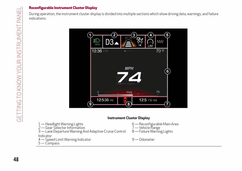
Reconfigurable Instrument Cluster DisplayDuring operation, the instrument cluster display is divided into multiple sections which show driving data, warnings, and failureindications.
Instrument Cluster Display
1 — Headlight Warning Lights 6 — Reconfigurable Main Area2 — Gear Selector Information 7 — Vehicle Range3 — Lane Departure Warning And Adaptive Cruise ControlIndicator
8 — Failure Warning Lights
4 — Speed Limit Warning Indicator 9 — Odometer5 — Compass
48
GE
TT
ING
TOK
NO
WY
OU
RIN
ST
RU
ME
NT
PAN
EL

WARNING LIGHTS ANDMESSAGES ON THEINSTRUMENT PANELThe following pages consist of warninglights and messages.
Note:
The warning light turns on togetherwith a dedicated message and/or chimewhen applicable. These indications areprecautionary and as such must not beconsidered as exhaustive and/oralternative to the information containedin the Owner’s Manual, which you areadvised to read carefully in all cases.Always refer to the information in thissection in the event of a failureindication.
The failure indicators appearing onthe display are divided into twocategories: very serious and less seriousfaults. Serious faults are indicated by arepeated and prolonged warning "cycle.”Less serious faults are indicated by awarning "cycle" with a shorter duration.You can stop the warning cycle in bothcases by pushing the button located onthe windshield wiper stalk. Theinstrument panel warning light will stayon until the cause of the failure iseliminated.
49

Red Warning Lights
Warning Light What It Means What To Do
INSUFFICIENT BRAKE FLUID/ELECTRIC PARK BRAKEONThis light monitors various brake functions, includingbrake fluid level and parking brake application. If thebrake light turns on it may indicate that the parkingbrake is applied, that the brake fluid level is low, or thatthere is a problem with the anti-lock brake systemreservoir.If the light remains on when the parking brake has beendisengaged, and the fluid level is at the full mark on themaster cylinder reservoir, it indicates a possible brakehydraulic system malfunction or that a problem with theBrake Booster has been detected by the Anti-Lock BrakeSystem (ABS) / Electronic Stability Control (ESC)system. In this case, the light will remain on until thecondition has been corrected. If the problem is related tothe Brake Booster, the ABS pump will run when applyingthe brake, and a brake pedal pulsation may be felt duringeach stop.
For low brake fluid level, go to an authorized dealer tohave the system checked as soon as possible.Release the electric park brake, then check that thewarning light has turned off.If the warning light stays on, contact an authorizeddealer.
ELECTRONIC BRAKING FORCE DISTRIBUTION (EBD)FAILUREThe simultaneous turning on of the BRAKE (red) and
(amber) warning lights with the engine on indicateseither a failure of the EBD system or that the system isnot available. In this case, the rear wheels may suddenlylock and the vehicle may swerve when braking abruptly.
Drive very carefully to the nearest authorized dealer tohave the system inspected immediately.
50
GE
TT
ING
TOK
NO
WY
OU
RIN
ST
RU
ME
NT
PAN
EL

Warning Light What It Means What To Do
AIR BAG WARNING LIGHTThis light will turn on for four to eight seconds as a bulbcheck when the ignition is placed in the ON/RUNposition. If the light is either not on during startup, stayson, or turns on while driving, have the system inspectedat an authorized dealer as soon as possible. This light willilluminate with a single chime when a fault with the AirBag Warning Light has been detected, it will stay on untilthe fault is cleared. If the light comes on intermittently orremains on while driving, have an authorized dealerservice the vehicle immediately.
If the problem persists, contact an authorized dealer.
SEAT BELT REMINDER WARNING LIGHTWhen the ignition is first placed in the ON/RUN position,if the driver’s seat belt is unbuckled, a chime will soundand the light will turn on. When driving, if the driver orfront passenger seat belt remains unbuckled, the SeatBelt Reminder Light will flash or remain on continuouslyand a chime will sound. Refer to “Occupant Restraints” in“Safety” for further information.
Always wear your seat belt when operating the vehicle.
OIL TEMPERATURE WARNING LIGHTThis telltale indicates engine oil temperature is high.
Stop the vehicle and shut off the engine as soon aspossible. If the problem persists, contact an authorizeddealer.
Warning!
The fault of the warning light is signaled by the turning on of the icon on the instrument panel. In this case, the warning light may not indicate anyfaults with the restraint systems. Before proceeding, contact an authorized dealer to have the system checked immediately.
If the warning light does not turn on when the ignition device is moved to ON or if it stays on when driving (together with the message on thedisplay), there might be a fault in the restraint systems; in this case, the air bags or pretensioners may not deploy in the event of an accident or, in alower number of cases, they could deploy erroneously. Before proceeding, contact an authorized dealer to have the system checked immediately.
51
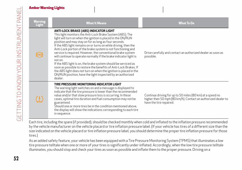
Amber Warning Lights
WarningLight What It Means What To Do
ANTI-LOCK BRAKE (ABS) INDICATOR LIGHTThis light monitors the Anti-Lock Brake System (ABS). Thelight will turn on when the ignition is placed in the ON/RUNposition and may stay on for as long as four seconds.If the ABS light remains on or turns on while driving, then theAnti-Lock portion of the brake system is not functioning andservice is required. However, the conventional brake systemwill continue to operate normally if the brake indicator light isnot on.If the ABS light is on, the brake system should be serviced assoon as possible to restore the benefits of Anti-Lock Brakes. Ifthe ABS light does not turn on when the ignition is placed in theON/RUN position, have the light inspected by an authorizeddealer.
Drive carefully and contact an authorized dealer as soon aspossible.
TIRE PRESSURE MONITORING INDICATOR LIGHTThe warning light switches on and a message is displayed toindicate that the tire pressure is lower than the recommendedvalue and/or that slow pressure loss is occurring. In thesecases, optimal tire duration and fuel consumption may not beguaranteed.Should one or more tires be in the condition mentioned above,the display will show the indications corresponding to each tirein sequence.
Continue driving for up to 50 miles (80 km) at a speed nohigher then 50 mph (80 km/h). Contact an authorized dealer tohave the tire repaired.
Each tire, including the spare (if provided), should be checked monthly when cold and inflated to the inflation pressure recommendedby the vehicle manufacturer on the vehicle placard or tire inflation pressure label. (If your vehicle has tires of a different size than thesize indicated on the vehicle placard or tire inflation pressure label, you should determine the proper tire inflation pressure for thosetires.)
As an added safety feature, your vehicle has been equipped with a Tire Pressure Monitoring System (TPMS) that illuminates a lowtire pressure telltale when one or more of your tires is significantly under-inflated. Accordingly, when the low tire pressure telltaleilluminates, you should stop and check your tires as soon as possible and inflate them to the proper pressure. Driving on a
52
GE
TT
ING
TOK
NO
WY
OU
RIN
ST
RU
ME
NT
PAN
EL

significantly under-inflated tire causes the tire to overheat and can lead to tire failure. Under-inflation also reduces fuel efficiencyand tire tread life, and may affect the vehicle’s handling and stopping ability.
Please note that the TPMS is not a substitute for proper tire maintenance, and it is the driver’s responsibility to maintain correct tirepressure, even if under-inflation has not reached the level to trigger illumination of the TPMS low tire pressure telltale.
Your vehicle has also been equipped with a TPMS malfunction indicator to indicate when the system is not operating properly. TheTPMS malfunction indicator is combined with the low tire pressure telltale. When the system detects a malfunction, the telltale willflash for approximately one minute and then remain continuously illuminated. This sequence will continue upon subsequent vehiclestart-ups as long as the malfunction exists. When the malfunction indicator is illuminated, the system may not be able to detect orsignal low tire pressure as intended. TPMS malfunctions may occur for a variety of reasons, including the installation of replacementor alternate tires or wheels on the vehicle that prevent the TPMS from functioning properly. Always check the TPMS malfunctiontelltale after replacing one or more tires or wheels on your vehicle, to ensure that the replacement or alternate tires and wheels allowthe TPMS to continue to function properly.
Caution!
The TPMS has been optimized for the original equipment tires and wheels. TPMS pressures and warning have been established for the tire sizeequipped on your vehicle. Undesirable system operation or sensor damage may result when using replacement equipment that is not of the samesize, type, and/or style. Aftermarket wheels can cause sensor damage. Using aftermarket tire sealants may cause the Tire Pressure MonitoringSystem (TPMS) sensor to become inoperable. After using an aftermarket tire sealant it is recommended that you take your vehicle to anauthorized dealership to have your sensor function checked.
Warning Light What It Means What To Do
Tire Pressure LowThe indicator light will illuminate to indicate that the tirepressure is lower than the recommended value and/or thatslow pressure loss is occurring. In these cases, optimal tireduration and fuel consumption may not be guaranteed.
In any situation in which the message on the display is "SeeManual", it is ESSENTIAL to refer to “Auxiliary DrivingSystems” in “Safety,” strictly complying with theindications that you find there.
53

Warning Light What It Means What To Do
ELECTRONIC STABILITY CONTROL (ESC) INDICATORLIGHTWhen the ignition is cycled to ON, the indicator lightilluminates, but should turn off as soon as the engine isstarted.ESC System Intervention: Intervention by the system isindicated by the flashing of the indicator light: itindicates that the vehicle is in critical stability and gripconditions.
ESC System Failure: If the indicator light does not turnoff, or if it stays on with the engine running, a failure wasfound in the ESC system. In these cases, contact an authorized dealer as soon as
possible.Hill Start Assist System Failure: The illumination of theindicator light indicates a Hill Start Assist system failure.
ELECTRONIC STABILITY CONTROL (ESC) OFFINDICATOR LIGHTWhen the ignition is cycled to ON, the indicator lightilluminates, but should turn off as soon as the engine isstarted.The indicator light illuminates to indicate that someactive safety systems have been partially or totallydeactivated.For further details about the active safety systems, referto “Active Safety Systems” in “Safety.” When the activesafety systems are reactivated, the indicator light turnsoff.
REAR FOG LIGHTThe indicator illuminates when the rear fog light isactivated.
54
GE
TT
ING
TOK
NO
WY
OU
RIN
ST
RU
ME
NT
PAN
EL

Warning Light What It Means What To Do
ENGINE CHECK/MALFUNCTION INDICATORLIGHT (MIL)In normal conditions, when the ignition is cycled to ON,the indicator light illuminates, but it should turn off assoon as the engine is started.The operation of the indicator light may be checked bythe traffic police using specific devices. Comply with thelaws and regulations of the country where you aredriving.
Under these conditions, the vehicle can continuetravelling at moderate speed but without demandingexcessive effort from the engine or high speed.Prolonged use of the vehicle with the indicator light onconstantly may cause damage. Contact an authorizeddealer as soon as possible.
Caution!
If, turning the ignition device to ON, the warning light does not turn on or if it turns on steadily or flashing when travelling (on some versionstogether with the message on the display), contact an authorized dealer as soon as possible.
Warning Light What It Means What To Do
FORWARD COLLISION WARNING SYSTEM (FCW) — IFEQUIPPEDThis indicator light informs the driver that the frontalcollision alarm function is not enabled.
Drive carefully and contact an authorized dealer as soonas possible.
FUEL RESERVE / LIMITED RANGEThe indicator light (or the symbol in the display)illuminates when about 2.4 gallons (9 liters) of fuel is leftin the tank.
Refuel the vehicle.
Warning!
If the warning light (or the icon on the display) flashes while driving, contact an authorized dealer.
55

Green Telltale Indicator Lights
Indicator light What It Means What To Do
PARK/HEADLIGHT ON INDICATOR LIGHTThis indicator will illuminate when the park lights orheadlights are turned on.
Headlight Off DelayThis function allows the headlights to remain on for 30,60 or 90 seconds after the ignition was placed in theSTOP position.
LEFT TURN SIGNALThe instrument cluster directional arrow will flashindependently for the left turn signal as selected, as wellas the exterior turn signal lamp(s) (front and rear) asselected when the multifunction lever is moved down(left). This directional arrow will flash in conjunction withthe right directional arrow when the hazard warning lightbutton is pushed.
RIGHT TURN SIGNALThe instrument cluster directional arrow will flashindependently for the right turn signal as selected, as wellas the exterior turn signal lamp(s) (front and rear) asselected when the multifunction lever is moved up (right).This directional arrow will flash in conjunction with the leftdirectional arrow when the hazard warning light button ispushed.
AUTOMATIC HIGH BEAM HEADLIGHTS — IF EQUIPPEDThis indicator light will illuminate when the automatic highbeam headlights are activated.
56
GE
TT
ING
TOK
NO
WY
OU
RIN
ST
RU
ME
NT
PAN
EL

Blue Telltale Indicator Light
Indicator Light What It Means What To Do
HIGH BEAM HEADLIGHTSThis indicator shows that the high beam headlights areon. Push the multifunction control lever away from youto switch the headlights to high beam. Push the lever asecond time to switch the headlights back to low beam.Pull the lever toward you for a temporary high beam on,“flash to pass” scenario.
Red Symbols
Warning Light What It Means What To Do
LOW ENGINE OIL PRESSUREThis telltale indicates low engine oil pressure. If thetelltale turns on while driving, stop the vehicle and shutoff the engine as soon as possible. A chime will soundwhen this telltale turns on. Do not operate the vehicleuntil the cause is corrected. This telltale does notindicate how much oil is in the engine.
Note:Do not use the vehicle until the failure has been solved.The illumination of the telltale does not indicate theamount of oil in the engine: the oil level can be checked onthe display upon entering the vehicle and also byactivating the "Oil level" function on the Information andEntertainment System.
Contact an authorized dealer as soon as possible.
Caution!
If the LOW ENGINE OIL PRESSURE symbol switches on when driving, stop the engine immediately and contact an authorized dealer.
57

Warning Light What It Means What To Do
ENGINE TEMPERATURE WARNING LIGHTThis telltale warns of an overheated engine condition. Ifthe engine coolant temperature is too high, this indicatorwill illuminate and a single chime will sound. If thetemperature reaches the upper limit, a continuous chimewill be sound for four minutes or until the engine isallowed to cool whichever comes first.
In normal driving conditions: stop the vehicle, shut offthe engine and check that the coolant level in thereservoir is not below the MIN mark. In this case, wait forthe engine to cool down, then slowly and carefully openthe cap, top offwith coolant and check that the level isbetween the MIN and MAX marks on the reservoir itself.Also check visually for any fluid leaks. Contact anauthorized dealer if the telltale comes on when theengine is started again.If the vehicle is used under demanding conditions (e.g. inhigh-performance driving): slow down and, if the telltalestays on, stop the vehicle. Stop for two or three minuteswith the engine running and slightly accelerated tofacilitate better coolant circulation, then turn the engineoff. Check that the coolant level is correct as describedabove.
POWER STEERING FAILUREIf the telltale remains on, you could not have steeringassistance and the effort required to operate thesteering wheel could be increased; steering is, however,possible.
Note:
After the battery is disconnected, the steering wheel mustbe initialized. The Power Steering Failure light on theinstrument panel will illuminate to indicate this. To carryout this procedure, simply turn the steering wheel all theway from one end to the other, and then turn in back to thecentral position.
Contact an authorized dealer as soon as possible.
DOOR OPEN INDICATOR LIGHTThe telltale illuminates when one or more doors are notcompletely shut. An chime will signal when the doors isopen and the vehicle is moving.
Close all the doors properly.
58
GE
TT
ING
TOK
NO
WY
OU
RIN
ST
RU
ME
NT
PAN
EL

Warning Light What It Means What To Do
HOOD OPEN INDICATOR LIGHTThe telltale turns on when the hood is not properlyclosed, along with the icon, an image of the vehicle withan open hood appears on the display.A buzzer is heard when the hood is open and the vehicleis moving.
Fully close the hood.
LIFTGATE OPEN INDICATOR LIGHTThe telltale turns on when the liftgate is not properlyclosed, along with the icon, an image of the vehicle withan open liftgate appears on the display.A buzzer is heard when the liftgate is open and thevehicle is moving.
Close the liftgate.
AUTOMATIC TRANSMISSION FAILUREThe telltale illuminates, together with a buzzer warning,to indicate that the automatic transmission is faulty.
Contact an authorized dealer as soon as possible.
Caution!
Driving the vehicle with this symbol on may severely damage the gearbox, with resulting breakage. The oil may also overheat: contact with hotengine or with exhaust components at high temperature could cause fires.
Warning Light What It Means What To Do
ELECTRONIC THROTTLE CONTROL (ETC) WARNINGLIGHTSThis telltale, along with the related message, signals afailure in the electronic throttle control system (ETC).If a failure is detected, the telltale illuminates while theengine is running.If the telltale flashes with the engine running, immediateintervention is required. A loss of performance,irregular/high idling speed or engine stopping might takeplace and the vehicle may need to be towed.
Place the gear selector in the park position and turn thevehicle off: the telltale should switch off. Start thevehicle. If the telltale remains solid (the telltale does notflash) with engine running, the vehicle can still be drivenuntil proper maintenance can be performed. If thetelltale flashes with the engine running, do not drive thevehicle.Contact an authorized dealer as soon as possible to havethe failure eliminated.
59

Warning Light What It Means What To Do
LOW ENGINE OIL LEVELThis telltale appears on the panel when the engine oillevel falls below the minimum recommended value.OIL OVER MAXIMUM LEVELThe telltale turns on, along with the respective messageon the instrument cluster display, to indicate that theengine oil level is too high.
Contact an authorized dealer to have the systemchecked. Run the engine under 3000 RPM during thistime.
ALFA STEERING TORQUE (AST) FAILUREThe illumination of the telltale signals a failure in theautomatic steering correction system.
Contact an authorized dealer to have the systemchecked.
ALTERNATOR FAILUREThe illumination of the telltale with engine oncorresponds to an alternator failure.
Contact an authorized dealer as soon as possible.
BRAKE DISC TEMPERATUREWhen the telltale illuminates, it indicates an excessivetemperature of the brake discs.
Let the brake system cool down by reducing the vehicle’sspeed.
60
GE
TT
ING
TOK
NO
WY
OU
RIN
ST
RU
ME
NT
PAN
EL
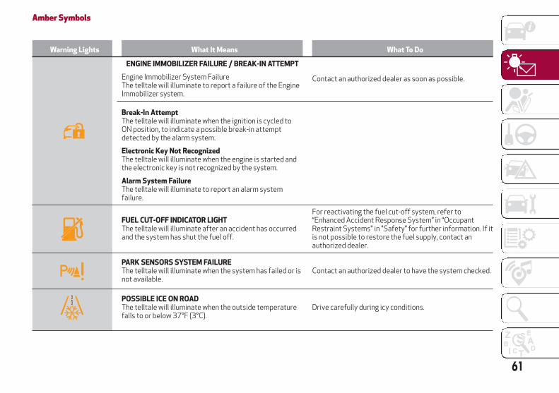
Amber Symbols
Warning Lights What It Means What To Do
ENGINE IMMOBILIZER FAILURE / BREAK-IN ATTEMPT
Engine Immobilizer System FailureThe telltale will illuminate to report a failure of the EngineImmobilizer system.
Contact an authorized dealer as soon as possible.
Break-In AttemptThe telltale will illuminate when the ignition is cycled toON position, to indicate a possible break-in attemptdetected by the alarm system.
Electronic Key Not RecognizedThe telltale will illuminate when the engine is started andthe electronic key is not recognized by the system.
Alarm System FailureThe telltale will illuminate to report an alarm systemfailure.
FUEL CUT-OFF INDICATOR LIGHTThe telltale will illuminate after an accident has occurredand the system has shut the fuel off.
For reactivating the fuel cut-off system, refer to“Enhanced Accident Response System” in “OccupantRestraint Systems" in "Safety” for further information. If itis not possible to restore the fuel supply, contact anauthorized dealer.
PARK SENSORS SYSTEM FAILUREThe telltale will illuminate when the system has failed or isnot available.
Contact an authorized dealer to have the system checked.
POSSIBLE ICE ON ROADThe telltale will illuminate when the outside temperaturefalls to or below 37°F (3°C).
Drive carefully during icy conditions.
61

Warning Lights What It Means What To Do
ENGINE OIL CHANGE REQUIRED — IF EQUIPPEDThe telltale is illuminated only for a limited time.
Note:After the first indication, each time the engine is startedthe symbol will continue to illuminate as described aboveuntil the oil is changed.If the telltale flashes, this does not mean that there is afault on the vehicle, rather it simply reports that it is nownecessary to change the oil as a result of regular use of thevehicle. The deterioration of engine oil is accelerated byusing the vehicle for short drives, preventing the enginefrom reaching operating temperature.
Contact an authorized dealer as soon as possible.
Caution!
Deteriorated engine oil should be replaced as soon as possible after the symbol is switched on, and never more than 500 miles (805 km) after itfirst switches on. Failure to observe the above may result in severe damage to the engine and invalidate the New Vehicle Limited Warranty. Whenthis symbol comes on, it does not mean that the level of engine oil is low, so if it flashes you do not need to top up the engine oil.
Warning Light What It Means What To Do
ENGINE OIL PRESSURE SENSOR FAILUREThe telltale will illuminate in the event of engine oilpressure sensor failure.
Contact an authorized dealer as soon as possible.
ENGINE OIL LEVEL SENSOR FAILUREThe telltale will illuminate in the event of engine oil levelsensor failure.
Contact an authorized dealer as soon as possible.
FORWARD COLLISION WARNING (FCW) SYSTEMFAILUREThe telltale will illuminate in the case of failure of theForward Collision Warning system.
Contact an authorized dealer as soon as possible.
62
GE
TT
ING
TOK
NO
WY
OU
RIN
ST
RU
ME
NT
PAN
EL

Warning Light What It Means What To Do
START & STOP SYSTEM FAILUREThis telltale will illuminate to report a Stop & Startsystem failure.
Contact an authorized dealer as soon as possible to havethe failure eliminated.
RAIN SENSOR FAILUREThe telltale will illuminate in the case of failure of theautomatic windshield wiper.
Contact an authorized dealer as soon as possible.
DUSK SENSOR FAILUREThe telltale will illuminate in the case of failure of theautomatic low beam alignment.
Contact an authorized dealer as soon as possible.
BLIND SPOT MONITORING SYSTEM FAILUREThe telltale will illuminate in the event of a Blind SpotMonitoring system failure.
Contact an authorized dealer as soon as possible.
FUEL LEVEL SENSOR FAILUREThe telltale will illuminate in the event of fuel levelsensor failure.
Contact an authorized dealer as soon as possible.
EXTERIOR LIGHTS FAILUREThe telltale will illuminate to indicate a failure on thefollowing lights: daytime running lights (DRLs) / parkinglights / trailer turn signal indicators (if present) / trailerlights (if present) / side lights / turn signal indicators /rear fog light / reversing light / brake lights / licenseplate lights.
The failure may be caused by a blown bulb, a blownprotection fuse, or an interruption of the electricalconnection.Replace the bulb or the relevant fuse. Contact anauthorized dealer.
63

Warning Light What It Means What To Do
KEYLESS SYSTEM FAILUREThe telltale will illuminate in the event of keyless systemfailure.
Contact an authorized dealer as soon as possible.
FUEL CUT-OFF SYSTEM FAILUREThe telltale will illuminate in the event of fuel cut-offsystem failure.
Contact an authorized dealer as soon as possible.
LANE DEPARTURE WARNING (LDW) SYSTEM FAILUREThe telltale will illuminate in the event of a fault in theLane Departure Warning system.
Contact an authorized dealer as soon as possible.
AUTOMATIC HIGH BEAM HEADLIGHTS FAILURE — IFEQUIPPEDThe telltale will illuminate to report a failure of theautomatic high beam headlights.
Contact an authorized dealer as soon as possible to havethe failure eliminated.
64
GE
TT
ING
TOK
NO
WY
OU
RIN
ST
RU
ME
NT
PAN
EL

Warning Light What It Means What To Do
AUTOMATIC TRANSMISSION FLUID OVERHEATINGThe telltale will illuminate in the case of transmissionoverheating, after a particularly demanding use. In thiscase an engine performance limitation is carried out.
Wait for the telltale to turn off with the engine off oridling.
AUDIO SYSTEM FAILUREThe telltale will illuminate to report a failure of the audiosystem.
Contact an authorized dealer as soon as possible to havethe failure eliminated.
SPEED LIMITER SYSTEM FAILUREWhile driving, the telltale will illuminate to signal a SpeedLimiter system failure.
Contact an authorized dealer as soon as possible to havethe failure eliminated.
LOOSE FUEL FILLER CAPLights up if the fuel tank cap is open or not properlyclosed.
Tighten the cap properly.
ELECTRIC PARKING BRAKE FAILUREThe telltale will illuminate and a message will display tosignal a failure in the electric park brake system.This failure may partially or completely block the vehiclebecause the park brake could remain activated even ifautomatically or manually disengaged using the relevantcontrols. In these circumstances, you can disengage thepark brake following the emergency disengagementprocedure described in “In Case Of Emergency.”
If you are still able to drive the vehicle (park brake is notengaged), drive to the nearest authorized dealer andremember, when executing any maneuvers/commands,that the electric park brake is not operational.
Warning Light What It Means What To Do
LOW COOLANT LEVEL — IF EQUIPPEDThis telltale will illuminate to indicate that the vehiclecoolant level is low.
Top up, as described in "Servicing And Maintenance.”
65

Warning Light What It Means What To Do
SERVICE ADAPTIVE CRUISE CONTROL SYSTEMThis light will illuminate when the Adaptive CruiseControl (ACC) is not operating and needs service.
Contact an authorized dealer to have the systemchecked.
WEAR ON BRAKE PADSThis light will illuminate when the brake pads havereached their wear limit.
Contact an authorized dealer as soon as possible.
Note:
Always use genuine parts or similar because theIntegrated Brake System (IBS) system could detectanomalies.
WEAR ON CCB BRAKE DISCS — IF EQUIPPEDThis light will illuminate when the carbon ceramic brakediscs have reached their wear limit.
Contact an authorized dealer as soon as possible.
Warning!
It is recommended to use only OEM brake pads in order to ensure the original performance of the braking system.
Warning Light What It Means What To Do
DYNAMIC DRIVE CONTROL SYSTEM FAILUREThe telltale will illuminate to signal a failure in thedynamic drive control system.
Contact an authorized dealer.
WINDSHIELD WIPER FAILURESignals a windshield wiper failure.
Contact an authorized dealer.
66
GE
TT
ING
TOK
NO
WY
OU
RIN
ST
RU
ME
NT
PAN
EL

Warning Light What It Means What To Do
GENERIC INDICATIONSignals information and failures.The accompanying messages describe the failure.
Contact an authorized dealer.
FOUR WHEEL DRIVE FAILUREThis telltale will illuminate to report a four wheel drivesystem failure.
Contact an authorized dealer as soon as possible to havethe failure eliminated.
AFS SYSTEM FAILUREThe telltale will illuminate to indicate the automaticdirectional light system failure.
Go to an authorized dealer to have the system checked.
SOFT SUSPENSION CALIBRATION INSERTION — IFEQUIPPEDThe telltale will illuminate when the most comfortablesuspension setting is activated.
SHOCK ABSORBERS FAILURE (ADC) — IF EQUIPPEDWhile driving, if the telltale illuminates, it signals a failurein the suspension system.
Contact an authorized dealer to have the systemchecked.
WINDSHIELD WASHER LIQUID LEVELThe telltale will illuminate to indicate that the level of thewindshield and headlight washing fluid (if any) is low.
To refill the liquid, refer to “Engine Compartment” in“Servicing And Maintenance.” Always use liquid with thefeatures indicated in the “Fluids And Lubricants” sectionin “Technical Specifications.”
TRAILER LIGHT CONTROL UNIT FAILUREThe telltale illuminates to indicate that there has been afailure in the control unit that manages the trailer lights.
Check that the trailer light is correctly connected to thesocket. If the fault persists the next time you start theengine, contact an authorized dealer to have the systemchecked.
LIFTGATE ELECTRIC OPENING/CLOSING FAILUREThe telltale illuminates to indicate a liftgate electricopening/closing system failure.
Contact an authorized dealer as soon as possible to havethe failure eliminated.
67

Green Symbols
Symbol What It Means
HEADLIGHTSThe telltale will illuminate when the headlights are turned on.
AUTOMATIC HEADLIGHTSThe symbol lights up when the automatic headlights are on.
START & STOP OPERATIONThe telltale will illuminate in the case of Start & Stop system intervention (stopping the engine).When the engine is restarted, the telltale will shut off (for the engine restarting modes refer to “Stop/Start” in “Starting AndOperating”).
SPEED CONTROL ACTIVATEDThe telltale will illuminate when the Speed Control system is activated.
ADAPTIVE CRUISE CONTROL SYSTEMThe symbol comes on when the Adaptive Cruise Control system is activated.
HILL DESCENT CONTROL (HDC) SYSTEMThe telltale illuminates when the HDC system intervenes.
68
GE
TT
ING
TOK
NO
WY
OU
RIN
ST
RU
ME
NT
PAN
EL

Blue Symbols
Symbol What it means
AUTOMATIC HIGH BEAM HEADLIGHTS — IF EQUIPPEDThe telltale will illuminate when the automatic high beam headlights are activated.
HIGH BEAM HEADLIGHTSThe telltale will illuminate when the high beam headlights are activated.
69

ONBOARD DIAGNOSTICSYSTEMOperation
The OBD (Onboard Diagnostic system)carries out a continuous diagnosis of thecomponents of the vehicle related toemissions.
It also alerts the driver of when thesecomponents are no longer in peakcondition by switching on the warninglight on the instrument panel (see“Warning Lights And Messages”paragraph in this chapter).
The aim of the OBD system (OnboardDiagnostic) is to:
Monitor the efficiency of the systemIndicate an increase in emissionsIndicate the need to replace damaged
components
The vehicle also has a connector, whichcan interface with appropriate tools, thatmakes it possible to read the error codesstored in the electronic control unitstogether with a series of specificparameters for engine operation anddiagnosis. This check can be carried outby your authorized dealer.
Note:
After eliminating a fault, to check thesystem completely, your authorizeddealer is obliged to run tests and, ifnecessary certain road tests.
Onboard Diagnostic System (OBD II)CybersecurityYour vehicle is required to have anOnboard Diagnostic system (OBD II) anda connection port to allow access toinformation related to the performanceof your emissions controls. Authorizedservice technicians may need to accessthis information to assist with thediagnosis and service of your vehicle andemissions system.
Warning!
ONLY an authorized service technicianshould connect equipment to the OBD IIconnection port in order to diagnose orservice your vehicle.
If unauthorized equipment is connectedto the OBD II connection port, such as adriver-behavior tracking device, it may:
– Be possible that vehicle systems,including safety related systems, could beimpaired or a loss of vehicle control couldoccur that may result in an accidentinvolving serious injury or death.– Access, or allow others to access,information stored in your vehicle systems,including personal information.
For further information, refer to“Cybersecurity” in “Multimedia”.
70
GE
TT
ING
TOK
NO
WY
OU
RIN
ST
RU
ME
NT
PAN
EL

SAFETY
This very important section describesthe safety systems that your vehicle maybe equipped with, and providesinstructions on how to use themcorrectly.
ACTIVE SAFETY SYSTEMS . . . . . . .72AUXILIARY DRIVING SYSTEMS . . . .76OCCUPANT RESTRAINT SYSTEMS . .86SAFETY TIPS . . . . . . . . . . . . . .113
71

ACTIVE SAFETY SYSTEMSThe vehicle may be equipped with thefollowing active safety devices:
Anti-Lock Braking (ABS) System
Drive Train Control (DTC) System
Electronic Stability Control (ESC)System
Traction Control System (TCS)
Panic Brake Assist (PBA) System
Hill Start Assist (HSA) System
Dynamic Steering Torque (DST)System
Hill Descent Control (HDC) System
For the operation of the systems, see thefollowing pages.
Anti-Lock Braking (ABS) SystemAn integral part of the braking system,the ABS prevents one or more wheelsfrom locking and slipping in all roadsurface conditions, regardless of theintensity of the braking action. Thesystem ensures that the vehicle can becontrolled even during emergencybraking, allowing the driver to optimizestopping distances.
The system intervenes during brakingwhen the wheels are about to lock,typically in emergency braking or
low-grip conditions where locking may bemore frequent.
The system also improves control andstability of the vehicle when braking on asurface where the grip of the left andright wheels varies, such as in a corner.
The Electronic Braking Force Distribution(EBD) system works with the ABS,allowing the brake force to be distributedbetween the front and rear wheels.
System Intervention
The ABS equipped on this vehicle isprovided with the "Brake-By-Wire"(Integrated Brake System - IBS) function.With this system, the command given bypressing the brake pedal is nottransmitted hydraulically, but electrically.Therefore, the light pulsation that is felton the pedal with the traditional systemis no longer noticeable.
Warning!
The ABS contains sophisticatedelectronic equipment that may besusceptible to interference caused byimproperly installed or high output radiotransmitting equipment. This interferencecan cause possible loss of anti-lock brakingcapability. Installation of such equipmentshould be performed by qualifiedprofessionals.
Pumping of the Anti-Lock Brakes willdiminish their effectiveness and may lead toa collision. Pumping makes the stoppingdistance longer. Just press firmly on yourbrake pedal when you need to slow down orstop.
The ABS cannot prevent the natural lawsof physics from acting on the vehicle, nor canit increase braking or steering efficiencybeyond that afforded by the condition of thevehicle brakes and tires or the tractionafforded.
The ABS cannot prevent collisions,including those resulting from excessivespeed in turns, following another vehicle tooclosely, or hydroplaning.
The capabilities of an ABS equippedvehicle must never be exploited in a recklessor dangerous manner that could jeopardizethe user’s safety or the safety of others.
Drive Train Control (DTC) SystemSome models of this vehicle are equippedwith an All-Wheel Drive system (AWD),which offers an optimal drive forcountless driving conditions and roadsurfaces. The system reduces theslipping of the tires to a minimum,automatically redistributing the torqueto the front and rear wheels as needed.
To maximize fuel savings, the vehicle withAWD automatically passes to rear-wheeldrive (RWD) when the road andenvironmental conditions are such that72
SA
FE
TY

they wouldn't cause the tires to slip.When the road and environmentalconditions require better traction, thevehicle automatically goes to AWD mode.
Note:
There may be a brief delay in shiftingto AWD mode after a tire slipping eventoccurs.
If the system failure symbol switcheson, after starting the engine or whiledriving, it means that the AWD system isnot working properly. If the warningmessage activates frequently, it isrecommended to carry out themaintenance operations.
Electronic Stability Control (ESC)SystemThe ESC system improves the directionalcontrol and stability of the vehicle invarious driving conditions.
The ESC system corrects the vehicle’sundersteer and oversteer, distributingthe brake force on the appropriatewheels. The torque supplied by theengine can also be reduced in order tomaintain control of the vehicle.
The ESC system uses sensors installedon the vehicle to determine the path thatthe driver intends to follow andcompares it with the vehicle’s effectivepath. When the real path deviates fromthe desired path, the ESC system
intervenes to counter the vehicle’sundersteer or oversteer.
Oversteer occurs when the vehicle isturning more than it should according tothe angle of the steering wheel.
Understeer occurs when the vehicle isturning less than it should according tothe angle of the steering wheel.
System Intervention
The intervention of the system isindicated by the flashing of the ESCwarning light on the instrument panel, toinform the driver that the vehiclestability and grip are critical.
Warning!
Electronic Stability Control (ESC) cannotprevent the natural laws of physics fromacting on the vehicle, nor can it increase thetraction afforded by prevailing roadconditions. ESC cannot prevent accidents,including those resulting from excessive speedin turns, driving on very slippery surfaces, orhydroplaning. ESC also cannot preventaccidents resulting from loss of vehicle controldue to inappropriate driver input for theconditions. Only a safe, attentive, and skillfuldriver can prevent accidents. The capabilitiesof an ESC equipped vehicle must never beexploited in a reckless or dangerous mannerwhich could jeopardize the user’s safety or thesafety of others.
Vehicle modifications, or failure toproperly maintain your vehicle, may changethe handling characteristics of your vehicle,and may negatively affect the performanceof the ESC system. Changes to the steeringsystem, suspension, braking system, tiretype and size or wheel size may adverselyaffect ESC performance. Improperly inflatedand unevenly worn tires may also degradeESC performance. Any vehicle modificationor poor vehicle maintenance that reducesthe effectiveness of the ESC system canincrease the risk of loss of vehicle control,vehicle rollover, personal injury and death.
Traction Control System (TCS)The system automatically operates in theevent of slipping, loss of grip on wetroads (hydroplaning), and acceleration onone or both drive wheels on roads thatare slippery, snowy, icy, etc. Dependingon the slipping conditions, two differentcontrol systems are activated:
If the slipping involves both drivewheels, the system intervenes, reducingthe power transmitted by the engine.
If the slipping only involves one of thedrive wheels, the Brake LimitedDifferential (BLD) function is activated,automatically braking the wheel which isslipping (the behavior of a self-lockingdifferential is simulated). This willincrease the engine torque transferred tothe wheel which isn't slipping.
73

System Intervention
The intervention of the system isindicated by the flashing of the ESCwarning light on the instrument panel, toinform the driver that the vehiclestability and grip are critical.
Panic Brake Assist (PBA) SystemThe PBA system is designed to improvethe vehicle’s braking capacity duringemergency braking.
The system detects emergency brakingby monitoring the speed and force withwhich the brake pedal is pressed, andconsequently applies the optimal brakepressure. This can reduce the brakingdistance: the PBA system thereforecomplements the ABS.
Maximum assistance from the PBAsystem is obtained by pressing the brakepedal very quickly. In addition, the brakepedal should be pressed continuouslyduring braking, avoiding intermittentpresses, to get the most out of thesystem. Do not reduce pressure on thebrake pedal until braking is no longernecessary.
The PBA system is deactivated when thebrake pedal is released.
Warning!
The Panic Brake Assist (PBA) cannotprevent the natural laws of physics fromacting on the vehicle, nor can it increase thetraction afforded by prevailing roadconditions. PBA cannot prevent collisions,including those resulting from excessivespeed in turns, driving on very slipperysurfaces, or hydroplaning. The capabilitiesof a PBA-equipped vehicle must never beexploited in a reckless or dangerous manner,which could jeopardize the user's safety orthe safety of others.
Hill Start Assist (HSA) SystemThis is an integral part of the ESC systemand facilitates starting on slopes,activating automatically in the followingcases:
Uphill: the vehicle is stationary on aroad with a gradient higher than 5%, theengine is running, the brake is pressed,and the transmission is in NEUTRAL (N)or a gear other than REVERSE (R) isengaged.
Downhill: the vehicle is stationary on aroad with a gradient higher than 5%, theengine is running, the brake is pressed,and the transmission is in REVERSE (R).
When setting off, the ESC system controlunit maintains the braking pressure onthe wheels until the engine torquenecessary for starting is reached, or in
any case for a maximum of two seconds,allowing your right foot to be movedeasily from the brake pedal to theaccelerator.
The system will automatically deactivateafter two seconds without starting,gradually releasing the braking pressure.During this release stage, it is possible tohear a typical mechanical brake releasenoise, indicating the imminent movementof the vehicle.
Warning!
There may be situations where the Hill StartAssist (HSA) will not activate and slightrolling may occur, such as on minor hills orwith a loaded vehicle, or while pulling atrailer. HSA is not a substitute for activedriving involvement. It is always the driver’sresponsibility to be attentive to distance toother vehicles, people, and objects, and mostimportantly brake operation to ensure safeoperation of the vehicle under all roadconditions. Your complete attention isalways required while driving to maintainsafe control of your vehicle. Failure to followthese warnings can result in a collision orserious personal injury.
Dynamic Steering Torque (DST) SystemThe DST function uses the integration ofthe ESC system with the electric powersteering to increase the safety level ofthe whole vehicle.74
SA
FE
TY

In critical situations for example (brakingon surfaces with different gripconditions), the ESC system controls thesteering through the DST function toimplement an additional torquecontribution on the steering wheel inorder to suggest the most correctmaneuver to the driver.
The coordinated action of the brakes andsteering increases the safety and controlof the vehicle.
Note:
The DST feature is only meant to help thedriver realize the correct course of actionthrough small torques on the steeringwheel, which means the effectiveness ofthe DST feature is highly dependent onthe driver’s sensitivity and overallreaction to the applied torque. It is veryimportant to realize that this feature willnot steer the vehicle, meaning the driveris still responsible for steering thevehicle.
Hill Descent Control (HDC) SystemThe HDC function is an integral part ofthe ESC system, keeping the vehicle at aconstant speed while descending a hill byactively controlling the brakes.
HDC aims to create vehicle stability andsafer driving in various situations,including poor grip conditions and steepdescents.
The system has three different modes:
Off: the system is deactivated
Enabled: the system is enabled andready to intervene when the activationconditions are met
Active: the system actively controlsthe vehicle speed
Enabling The System
To enable the system, push the HDCswitch located on the steering wheel.
The system is only enabled if the vehiclespeed is below 22 mph (35 km/h).
Activation of the HDC system isindicated by the white icon appearingin the instrument cluster display.
Activation Of The System
Once enabled, the HDC system willactivate automatically if the vehicle isdriven on a downhill slope with sufficientgradient, greater than 10%.
The speed set for the HDC system can beadjusted using the SET switch located onthe steering wheel.
HDC Switch
HDC Symbol
HDC Speed SET Switch
75

Once the desired speed has beenreached, release the SET switch and theHDC system will maintain the set speed.After set speed is established, the HDCsystem will automatically brake to keepthe vehicle at the set speed if theaccelerator pedal is released and thevehicle gets close to the set speed.
It is possible to reduce the set speed withthe brake pedal. When the pedal isreleased, the system will adjust the setspeed to the new current speed.
Note:
Vehicle set speed can only be set whiletraveling between 4 mph (6 km/h) and13 mph (25 km/h), and the feature willonly apply to a set speed placed in therange of 6 mph (10 km/h) to 37 mph(60 km/h).
The driver can cancel HDC systemintervention at any time by pressing theaccelerator pedal.
System Deactivation
The HDC system will be deactivated, butremain available, if any of the followingconditions are met:
The vehicle is traveling on a downhillslope with a gradient less than 10%, on alevel surface, or on an uphill grade.
PARK (P) mode is engaged.
Disabling The System
The system is disabled if any of thefollowing conditions are met:
The HDC switch is pressed.
Cruise Control / Active Cruise Controlis activated.
A vehicle speed of 37 mph (60 km/h) isexceeded.
System deactivation is shown by the iconon the display turning off.
Warning!
HDC is only intended to assist the driver incontrolling vehicle speed when descendinghills. The driver must remain attentive to thedriving conditions and is responsible formaintaining a safe vehicle speed.
AUXILIARY DRIVING SYSTEMSThe following auxiliary driving systemsare available in this vehicle:
Blind Spot Monitoring (BSM) — IfEquipped
Forward Collision Warning Plus(FCW+) — If Equipped
Tire Pressure Monitoring System(TPMS)
Blind Spot Monitoring (BSM) System— If EquippedThe Blind Spot Monitoring (BSM) systemuses two radar sensors, located in therear bumper (one on each side), to detectthe presence of other vehicles in the rearside blind spots of your vehicle.
The system warns the driver about thepresence of other vehicles in the
Rear Sensor Location
76
SA
FE
TY
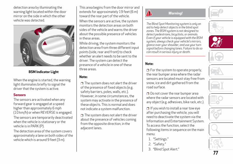
detection area by illuminating thewarning light located within the doormirror on the side in which the othervehicle was detected.
When the engine is started, the warninglight illuminates briefly to signal thedriver that the system is active.
Sensors
The sensors are activated when anyforward gear is engaged at a speedhigher than approximately 6 mph(10 km/h) or when REVERSE is engaged.
The sensors are temporarily deactivatedwhen the vehicle is stationary or thevehicle is in PARK (P).
The detection area of the system coversapproximately a lane on both sides of thevehicle which is around 9 feet (3 m).
This area begins from the door mirror andextends for approximately 19 feet (6 m)toward the rear part of the vehicle.
When the sensors are active, the systemmonitors the detection areas on bothsides of the vehicle and warns the driverabout the possible presence of vehiclesin these areas.
While driving, the system monitors thedetection area from three different inputpoints (side, rear and front) to checkwhether an alert needs to be sent to thedriver. The system can detect thepresence of a vehicle in one of thesethree areas.
Note:
The system does not alert the driverof the presence of fixed objects (e.g.safety barriers, poles, walls, etc.).However, in some circumstances, thesystem may activate in the presence ofthese objects. This is normal and doesnot indicate a system malfunction.
The system does not alert the driverabout the presence of vehicles comingfrom the opposite direction, in theadjacent lanes.
Warning!
The Blind Spot Monitoring system is only anaid to help detect objects in the blind spotzones. The BSM system is not designed todetect pedestrians, bicyclists, or animals.Even if your vehicle is equipped with the BSMsystem, always check your vehicle’s mirrors,glance over your shoulder, and use your turnsignal before changing lanes. Failure to do socan result in serious injury or death.
Note:
For the system to operate properly,the rear bumper area where the radarsensors are located must stay free fromsnow, ice and dirt gathered from theroad surface.
Do not cover the rear bumper areawhere the radar sensors are located withany object (e.g. adhesives, bike rack, etc.).
If you wish to install a rear tow eyeafter purchasing the vehicle, you willneed to deactivate the system via theInformation and Entertainment System.To access the function, select thefollowing items in sequence on the mainmenu:
1. “Settings.”
2. “Safety.”
3. “Blind Spot Alert.”
BSM Indicator Light
77

Rear View
The system detects vehicles coming fromthe rear part of your vehicle on both sidesand entering the rear detection area witha difference in speed of less than 31 mph(50 km/h) in relation to your vehicle.
Overtaking Vehicles
If another vehicle is overtaken slowly,with a difference in speed of less thanapproximately 15 mph (25 km/h) and thevehicle stays in the blind spot forapproximately 1.5 seconds, the warninglight on the door mirror of thecorresponding side illuminates.
If the difference in speed between thetwo vehicles is greater thanapproximately 15 mph (25 km/h), thewarning light does not illuminate.
Rear Cross Path Detection (RCP)System
This system assists the driver duringreverse maneuvers in the case of reducedvisibility.
The RCP system monitors the reardetection areas on both sides of thevehicle to detect objects moving towardthe sides of the vehicle, with a minimumspeed between approximately 1 mph(1 km/h) and 2 mph (3 km/h) and objectsmoving at a maximum speed of 21 mph(35 km/h), in areas such as parking lots.
The system activation is signaled to thedriver by an audible warning.
Note:
If the sensors are covered by objects orvehicles, the system may not work asintended.
Warning!
Rear Cross Path Detection (RCP) is not aback up aid system. It is intended to be usedto help a driver detect an oncoming vehiclein a parking lot situation. Drivers must becareful when backing up, even when usingRCP. Always check carefully behind yourvehicle, look behind you, and be sure tocheck for pedestrians, animals, othervehicles, obstructions, and blind spotsbefore backing up. Failure to do so can resultin serious injury or death.
Operating Mode
The system may be activated/deactivated via the Information andEntertainment System. To access thefunction, select the following items onthe main menu in sequence:
1. “Settings.”
2. “Safety.”
3. “Blind Spot Alert.”
"Blind Spot Alert", "Visual" Mode
When the system is enabled, the warninglight within the door mirror on the side ofthe detected object illuminates.
The visual warning on the mirror will blinkif the driver activates the turn signals,thus indicating the intention to changelane.
The warning light will be constant if thedriver stays in the same lane.
"Blind Spot Alert" FunctionDeactivation
When the system is deactivated ("BlindSpot Alert" mode off), the BSM or RCPsystems will not emit neither an acousticnor visual warning.
The BSM system will store the operatingmode that was active when the enginewas stopped. Each time the engine isstarted, the operating mode last set willbe recalled and used.
General Information
This vehicle has systems that operate onradio frequency that comply with Part15 of the Federal CommunicationsCommission (FCC) rules and withIndustry Canada Standards RSS-GEN/210/220/310.
78
SA
FE
TY

Operation is subject to the following twoconditions:
1. The device may not cause harmfulinterference.
2. The device must accept anyinterference received, includinginterference that may cause undesiredoperation of the device.
Changes or modifications to any of thesesystems by other than an authorizedservice facility could void authorizationto use this equipment.
Forward Collision Warning (FCW)System — If EquippedThis is a driving assistance systemcomposed of a radar located behind thefront bumper and a camera located in thecenter of the windshield.
In the event of an imminent collision, thesystem intervenes by automaticallyapplying the vehicle’s brakes to prevent acollision or reduce its effects.
The system provides the driver withaudible and visual signals throughspecific messages on the instrumentcluster display.
The system may lightly brake to warn thedriver if a possible frontal accident isdetected (limited braking). Signals andlimited braking are intended to allow thedriver to react promptly, in order toprevent or reduce the effects of apotential accident.
In situations with the risk of collision, ifthe system detects no intervention bythe driver, it provides automatic brakingto help slow the vehicle and mitigate thepotential frontal collision (automaticbraking). If intervention by the driver on
the brake pedal is detected, but notdeemed sufficient, the system mayintervene in order to improve thereaction of the braking system, thereforereducing vehicle speed further(additional assistance in braking stage).
The system will intervene automaticallyin case of imminent collision or impactagainst a pedestrian crossing the road(speed under 31 mph (50 km/h).
Note:
For safety reasons, when the vehicle hasstopped, the brake calipers may remainblocked for about two seconds. Makesure you press the brake pedal if thevehicle moves slightly forward.
Warning!
Forward Collision Warning (FCW) is notintended to avoid a collision on its own, norcan FCW detect every type of potentialcollision. The driver has the responsibility toavoid a collision by controlling the vehiclevia braking and steering. Failure to followthis warning could lead to serious injury ordeath.
Engagement/Disengagement
The following functions can be selectedin sequence using the Information andEntertainment System:
1. “Settings.”
Front Bumper Radar Location
Windshield Camera Location
79

2. “Safety.”
3. “Forward Collision Warning.”
4. “Mode.”
Select from among three operatingmodes:
Warning and brake: the system (ifactive), in addition to the visual andaudible warnings, provides limitedbraking, automatic braking and additionalassistance in braking stage, where thedriver does not brake sufficiently in theevent of a potential frontal impact.
Only warning: the system (if active),does not provide limited braking, butguarantees automatic braking oradditional assistance in braking stage,where the driver does not brake at all ornot sufficiently in the event of a potentialfrontal impact.
Disable: the system does not providevisual and audible warnings, limitedbraking, automatic braking or additionalassistance in braking stage. The systemwill therefore provide no indication of apossible collision.
Activation/Deactivation
The Forward Collision Warning system isactivated whenever the engine is startedregardless of what is shown in theInformation and Entertainment System.
Following a deactivation, the system willnot warn the driver about the possiblecollision with a preceding vehicle,regardless of the setting selected in theInformation and Entertainment System.
Note:
Each time the engine is started, thesystem is activated regardless of whatsetting was selected when the enginewas turned OFF.
This function is not active at a speedlower than 4 mph (7 km/h) or higher than124 mph (200 km/h).
The system is active:
Each time the engine is started.
In the Information and EntertainmentSystem.
When the ignition is in the ON position.
When the vehicle speed is between4 mph (7 km/h) and 124 mph (200 km/h).
When the front seat belts arefastened.
Changing The System Sensitivity
The sensitivity of the system can bechanged through the Information andEntertainment System menu, choosingfrom one of the following three options:"Near", "Med" or "Far". Refer to thedescription in the Information and
Entertainment System Supplement forhow to change the settings.
The default setting is "Med". With thissetting, the system warns the driver of apossible collision with the vehicle in frontwhen that vehicle is at a standarddistance, between that of the other twosettings.
With the system sensitivity set to "Far",the system will warn the driver of apossible collision with the vehicle in frontwhen that vehicle is at a greater distance,thus providing the possibility of acting onthe brakes more lightly and gradually.This setting provides the drivers with themaximum possible reaction time toprevent a potential accident.
With the option set to "Near", the systemwill alert the driver of a possible collisionwith the vehicle in front when that vehicleis close. This setting offers the driver alower reaction time compared to the"Med" and "Far" settings, in the event of apotential collision, but permits moredynamic driving of the vehicle.
The system sensitivity setting is kept inthe memory when the engine is turnedOFF.
System Limited Operation Warning
If a dedicated message is displayed, acondition limiting the system operationmay have occurred. The possible reasons
80
SA
FE
TY

of this limitation are something isblocking the camera view or a fault.
If an obstruction is signaled, clean thearea of the radar on the front bumper,and the camera area on the windshield.
If a fault in the system is occurring, it willstill be possible to drive the vehiclenormally, but automatic braking will notbe available in the event of an impendingcollision.
When the conditions limiting the systemfunctions end, this will go back to normaland complete operation. Should the faultpersist, contact your authorized dealer.
System Failure Signaling
If the system turns off and a dedicatedmessage is shown on the display, itmeans that there is a fault with thesystem.
In this case, it is still possible to drive thevehicle, but you are advised to contactyour authorized dealer as soon aspossible.
Radar Indication Not Available
If conditions are such that the radarcannot detect obstacles correctly, thesystem is deactivated and a dedicatedmessage appears on the display. Thisgenerally occurs in the event of poorvisibility, such as when it is snowing orraining heavily.
The function of this system can also betemporarily reduced due to obstructionssuch as mud, dirt or ice on the bumper. Insuch cases, a dedicated message will beshown on the display and the system willbe deactivated. This message cansometimes appear in conditions of highreflectivity (e.g. tunnels with reflectivetiles or ice or snow). When the conditionslimiting the system functions end, it willgo back to normal and completeoperation.
In certain cases, this dedicated messagecould be displayed when the radar is notdetecting any vehicles or objects withinits view range.
If atmospheric conditions are not thereason behind this message, check if thesensor is dirty. It could be necessary toclean or remove any obstructions in thearea.
If the message appears frequently, evenin the absence of atmospheric conditionssuch as snow, rain, mud or otherobstructions, contact your authorizeddealer for a sensor alignment check.
In the absence of visible obstructions,manually removing the decorative covertrim and cleaning the radar surface couldbe required. Have this operationperformed at your authorized dealer.
Note:
It is recommended that you do not installdevices, accessories or aerodynamicattachments in front of the sensor ordarken it in any way, as this cancompromise the correct functioning ofthe system.
Frontal Collision Alarm With ActiveBraking — If Equipped
If this function is selected, the brakes areoperated to reduce the speed of thevehicle in the event of potential frontalimpact.
This function applies an additionalbraking pressure if the braking pressureapplied by the driver does not suffice toprevent potential frontal impact.
The function is active with speed above4 mph (7 km/h).
Driving In Special Conditions
In certain driving conditions, systemintervention might be unexpected ordelayed. The driver must therefore bevery careful, keeping control of thevehicle to drive in complete safety.
Driving close to a bend.
The vehicle ahead is leaving aroundabout.
Vehicles with small dimensions and/ornot aligned in the driving lane.
81

Lane change by other vehicles.
Vehicles traveling at right angles to thevehicle.
Note:
In particularly complex traffic conditions,the driver can deactivate the systemmanually through the Information andEntertainment System.
Driving Close To A Bend
When entering or leaving a wide bend, thesystem may detect a vehicle in front you,but not driving in the same driving lane. Incases such as these, the system mayintervene.
The Vehicle Ahead Is Leaving ARoundabout
On a roundabout, the system couldintervene when it detects a vehicle aheadthat is leaving the roundabout.
Vehicles With Small DimensionsAnd/Or Not Aligned In The Driving Lane
The system cannot detect vehicles infront of the vehicle if they are outside therange of the radar sensor or may notreact to small vehicles, such as bicyclesor motorcycles.
Lane Change By Other Vehicles
Vehicles suddenly changing lanes to enterthe same lane as your vehicle within theoperating range of the radar sensor, maycause the system to intervene.
Driving Around Wide Curves
Driving In Roundabouts
Driving Near Small Vehicles
Other Vehicles Changing Lanes
82
SA
FE
TY

Vehicles Traveling At Right Angles ToThe Vehicle
The system could temporarily react to avehicle that is passing at right anglesthrough the radar sensor’s operatingrange.
Warning!
The system has not been designed toprevent impacts and cannot detect possibleconditions leading to an accident in advance.Failure to take into account this warningmay lead to serious or fatal injuries.
The system may activate, assessing thetrajectory of the vehicle, for the presence ofreflecting metal objects different from othervehicles, such as safety barriers, road signs,barriers before parking lots, tollgates, levelcrossings, gates, railways, objects near roadconstructions sites or higher than the vehicle(e.g. a fly-over). In the same way, the systemmay intervene inside multi-story parking lotsor tunnels, or due to a glare on the roadsurface. These possible activations are aconsequence of the real driving scenariocoverage by the system and must not beregarded as faults.
The system has been designed for roaduse only. If the vehicle is driven on a track,the system must be deactivated to avoidunnecessary warnings. Automaticdeactivation is signaled by the dedicatedwarning light/symbol switching on in theinstrument panel (refer to the instructions inthe "Warning Lights And Messages On TheInstrument Panel" in "Getting To Know YourInstrument Panel" for further information).
Tire Pressure Monitoring System(TPMS)The vehicle is equipped with a TirePressure Monitoring System (TPMS) thatsends the inflation pressure informationof each tire to the control unit, and willsignal the driver in the event ofinsufficient tire pressure.
Tire pressure will vary with temperatureby approximately 1 psi (7 kPa) for every12°F (6.5°C). This means that when theoutside temperature decreases, the tirepressure will also decrease. Tire pressureshould always be set based on coldinflation tire pressure. This is defined asthe tire pressure after the vehicle has notbeen driven for at least three hours, ordriven less than 1 mile (1.6 km) after athree hour period. The cold tire inflationpressure must not exceed the maximuminflation pressure molded into the tiresidewall. Refer to “Tires” in “ServicingAnd Maintenance” for information onhow to properly inflate the vehicle’s tires.The tire pressure will also increase as thevehicle is driven. This is normal, and thereshould be no adjustment for thisincreased pressure.
The TPMS will signal the driver ifpressure falls below the warning limit forany reason, including the effects of lowtemperature and normal loss of pressurefrom the tire.
The TPMS will stop indicating insufficienttire pressure when pressure is equal to orgreater than the prescribed cold inflationlevel. Therefore, if insufficient tirepressure is indicated by the ( ) warninglight displaying in the instrument cluster,increase the inflation pressure up to theprescribed cold inflation value.
Other Vehicle Passing Through RadarRange
83

The system will automatically update,and the “Tire Pressure MonitoringWarning Light” will turn off once thesystem receives the updated tirepressures. The vehicle may need to bedriven for up to 20 minutes above15 mph (24 km/h) in order for the TPMSto receive this information.
Operating Example
For example, your vehicle may have arecommended cold (parked for more thanthree hours) placard pressure of 33 psi(227 kPa). If the ambient temperature is68°F (20°C), and the measured tirepressure is 28 psi (193 kPa), atemperature drop to 20°F (-7°C) willdecrease the tire pressure toapproximately 24 psi (165 kPa). This tirepressure is low enough to turn on the“Tire Pressure Monitoring Warning Light.”Driving the vehicle may cause the tirepressure to rise to approximately 28 psi(193 kPa), but the “Tire PressureMonitoring Warning Light” will still be on.In this situation, the “Tire PressureMonitoring Warning Light” will turn offonly after the tires are inflated to thevehicle’s recommended cold placardpressure value.
Caution!
The TPMS has been optimized for theoriginal equipment tires and wheels. TPMSpressures and warning have beenestablished for the tire size equipped on yourvehicle. Undesirable system operation orsensor damage may result when usingreplacement equipment that is not of thesame size, type, and/or style. The TPMsensor is not designed for use onaftermarket wheels and may contribute to apoor overall system performance or sensordamage. Customers are encouraged to useOEM wheels to assure proper TPM featureoperation.
Using aftermarket tire sealants maycause the Tire Pressure Monitoring System(TPMS) sensor to become inoperable. Afterusing an aftermarket tire sealant it isrecommended that you take your vehicle toyour authorized dealer to have your sensorfunction checked.
After inspecting or adjusting the tirepressure always reinstall the valve stem cap.This will prevent moisture and dirt fromentering the valve stem, which could damagethe TPMS sensor.
INSUFFICIENT TIRE PRESSUREINDICATION
If an insufficient pressure value isdetected on one or more tires, the
warning light in the instrument clusterwill display alongside the dedicatedmessages, the system will highlight thetire or tires with insufficient pressuregraphically, and an acoustic signal will beemitted.
In this case, stop the vehicle, check theinflation pressure of each tire, and inflatethe necessary tire or tires to the correctcold inflation pressure value, shown onthe display or in the dedicated TPMSmenu.
TPMS TEMPORARILY DISABLED
TPMS Check Message
When a system fault is detected, the “TirePressure Monitoring Warning Light” willflash on and off for 75 seconds, and thenremain on solid. The system fault will alsosound a chime. If the ignition is cycled,this sequence will repeat, provided thatthe system fault still exists. The “TirePressure Monitoring Warning Light” willturn off when the fault condition nolonger exists. A system fault can occurdue to any of the following:
Jamming due to electronic devices ordriving next to facilities emitting thesame radio frequencies as the TPMSsensors.
Installing some form of aftermarketwindow tinting that affects radio wavesignals.
84
SA
FE
TY

Packed snow or ice around the wheelsor wheel housings.
Using tire chains on the vehicle.
Using wheels/tires not equipped withTPMS sensors.
After the punctured tire has beenrepaired with the original tire sealantcontained in the TireKit, the previouscondition must be restored so that the
warning light is off during normaldriving.
TPMS Deactivation
The TPMS can be deactivated byreplacing all four wheel and tireassemblies (road tires) with wheel andtire assemblies that do not have TPMSSensors, such as when installing winterwheel and tire assemblies on yourvehicle.
To deactivate the TPMS, first replace allfour wheel and tire assemblies (roadtires) with tires not equipped with TirePressure Monitoring (TPM) Sensors.Then, drive the vehicle for 20 minutesabove 15 mph (24 km/h). The TPMS willchime, the "TPMS Warning Light" willflash on and off for 75 seconds and thenremain on. The instrument cluster willdisplay the “SERVICE TPM SYSTEM”message and then display dashes (--) inplace of the pressure values.
Beginning with the next ignition switchcycle, the TPMS will no longer chime ordisplay the “SERVICE TPM SYSTEM”message in the instrument cluster.Instead, dashes (--) will remain in place ofthe pressure values.
To reactivate the TPMS, replace all fourwheel and tire assemblies (road tires) withtires equipped with TPM sensors. Then,drive the vehicle for up to 20 minutesabove 15 mph (24 km/h). The TPMS willchime, the "TPM Warning Light" will flashon and off for 75 seconds and then turnoff. The instrument cluster will display the“SERVICE TPM SYSTEM” message andthen display pressure values in place of thedashes. On the next ignition switch cyclethe "SERVICE TPM SYSTEM" message willno longer be displayed, as long as nosystem fault exists.
Note:
The TPMS is not intended to replacenormal tire care and maintenance, or toprovide warning of a tire failure orcondition.
The TPMS should not be used as atire pressure gauge while adjusting yourtire pressure.
Driving on a significantlyunderinflated tire will cause the tire tooverheat, and can lead to tire failure.Underinflation also reduces fuelefficiency and tire tread life, and mayaffect the vehicle’s handling andstopping ability.
The TPMS is not a substitute forproper tire maintenance, and it is thedriver’s responsibility to maintaincorrect tire pressure using an accuratetire pressure gauge, even ifunderinflation has not reached the levelto trigger illumination of the “TirePressure Monitoring Warning Light”.
Seasonal temperature changes willaffect tire pressure, and the TPMS willmonitor the actual tire pressure in thetire.
85

General Information
The following regulatory statementapplies to all radio frequency (RF)devices equipped in this vehicle:
This device complies with Part 15 of theFCC rules and RSS-210 of IndustryCanada. Operation is subject to thefollowing two conditions:
(1) This device may not cause harmfulinterference.
(2) This device must accept anyinterference received, includinginterference that may cause undesiredoperation.
Note:
Changes or modifications not expresslyapproved by the party responsible forcompliance could void the user’sauthority to operate the equipment.
OCCUPANT RESTRAINTSYSTEMSSome of the most important safetyfeatures in your vehicle are the restraintsystems:
Occupant Restraint Systems FeaturesSeat Belt Systems
Supplemental Restraint Systems(SRS) Air Bags
Child Restraints
Some of the safety features described inthis section may be standard equipmenton some models, or may be optionalequipment on others. If you are not sure,ask your authorized dealer.
Important Safety PrecautionsPlease pay close attention to theinformation in this section. It tells youhow to use your restraint systemproperly, to keep you and yourpassengers as safe as possible.
Here are some simple steps you can taketo minimize the risk of harm from adeploying air bag:
1. Children 12 years old and undershould always ride buckled up in a vehiclewith a rear seat.
2. If a child from 2 to 12 years old (not ina rear-facing child restraint) must ride inthe front passenger seat, move the seatas far back as possible and use theproper child restraint (refer to “ChildRestraints” in this section for furtherinformation).
3. Children that are not big enough towear the vehicle seat belt properly (referto “Child Restraints” in this section forfurther information) should be secured ina vehicle with a rear seat in childrestraints or belt-positioning boosterseats. Older children who do not use childrestraints or belt-positioning boosterseats should ride properly buckled up in avehicle with a rear seat.
4. Never allow children to slide theshoulder belt behind them or under theirarm.
5. You should read the instructionsprovided with your child restraint tomake sure that you are using it properly.
6. All occupants should always weartheir lap and shoulder belts properly.
7. The driver and front passenger seatsshould be moved back as far as practicalto allow the front air bags room to inflate.
86
SA
FE
TY

8. Do not lean against the door orwindow. If your vehicle has side air bags,and deployment occurs, the side air bagswill inflate forcefully into the spacebetween occupants and the door andoccupants could be injured.
9. If the air bag system in this vehicleneeds to be modified to accommodate adisabled person, refer to the “CustomerAssistance” section for customer servicecontact information.
Warning!
Never place a rear-facing child restraintin front of an air bag. A deploying passengerfront air bag can cause death or seriousinjury to a child 12 years or younger,including a child in a rear-facing childrestraint.
Only use a rear-facing child restraint in avehicle with a rear seat.
Seat Belt SystemsBuckle up even though you are anexcellent driver, even on short trips.Someone on the road may be a poordriver and could cause a collision thatincludes you. This can happen far awayfrom home or on your own street.
Research has shown that seat belts savelives, and they can reduce the
seriousness of injuries in a collision.Some of the worst injuries happen whenpeople are thrown from the vehicle. Seatbelts reduce the possibility of ejectionand the risk of injury caused by strikingthe inside of the vehicle. Everyone in amotor vehicle should be belted at alltimes.
Enhanced Seat Belt Use ReminderSystem (BeltAlert)
Driver and Passenger BeltAlert (ifequipped) – No Deactivation
BeltAlert is a feature intended toremind the driver and outboard frontseat passenger (if equipped withoutboard front passenger seat BeltAlert)to buckle their seat belts. The Belt Alertfeature is active whenever the ignitionswitch is in the START or ON/RUNposition.
Initial Indication
If the driver is unbuckled when theignition switch is first in the START orON/RUN position, a chime will signal for afew seconds. If the driver or outboardfront seat passenger (if equipped withoutboard front passenger seat BeltAlert)is unbuckled when the ignition switch isfirst in the START or ON/RUN positionthe Seat Belt Reminder Light will turn onand remain on until both outboard frontseat belts are buckled. The outboardfront passenger seat BeltAlert is not
active when an outboard front passengerseat is unoccupied.
BeltAlert Warning Sequence
The BeltAlert warning sequence isactivated when the vehicle is movingabove a specified vehicle speed rangeand the driver or outboard front seatpassenger is unbuckled (if equipped withoutboard front passenger seat BeltAlert)(the outboard front passenger seatBeltAlert is not active when the outboardfront passenger seat is unoccupied). TheBeltAlert warning sequence starts byblinking the Seat Belt Reminder Light andsounding an intermittent chime. Once theBeltAlert warning sequence hascompleted, the Seat Belt Reminder Lightwill remain on until the seat belts arebuckled. The BeltAlert warning sequencemay repeat based on vehicle speed untilthe driver and occupied outboard frontseat passenger seat belts are buckled.The driver should instruct all occupantsto buckle their seat belts.
Change of Status
If the driver or outboard front seatpassenger (if equipped with outboardfront passenger seat BeltAlert)unbuckles their seat belt while thevehicle is traveling, the BeltAlert warningsequence will begin until the seat beltsare buckled again.
87

The outboard front passenger seatBeltAlert is not active when the outboardfront passenger seat is unoccupied.BeltAlert may be triggered when ananimal or other items are placed on theoutboard front passenger seat or whenthe seat is folded flat (if equipped). It isrecommended that pets be restrained inthe rear seat (if equipped) in petharnesses or pet carriers that aresecured by seat belts, and cargo isproperly stowed.
Lap/Shoulder Belts
All seating positions in your vehicle areequipped with lap/shoulder belts.
The seat belt webbing retractor will lockonly during very sudden stops orcollisions. This feature allows theshoulder part of the seat belt to movefreely with you under normal conditions.However, in a collision the seat belt willlock and reduce your risk of striking theinside of the vehicle or being thrown outof the vehicle.
Warning!
Relying on the air bags alone could lead tomore severe injuries in a collision. The airbags work with your seat belt to restrain youproperly. In some collisions, the air bagswon’t deploy at all. Always wear your seatbelt even though you have air bags.
In a collision, you and your passengerscan suffer much greater injuries if you arenot properly buckled up. You can strike theinterior of your vehicle or other passengers,or you can be thrown out of the vehicle.Always be sure you and others in your vehicleare buckled up properly.
It is dangerous to ride in a cargo area,inside or outside of a vehicle. In a collision,people riding in these areas are more likelyto be seriously injured or killed.
Do not allow people to ride in any area ofyour vehicle that is not equipped with seatsand seat belts.
Be sure everyone in your vehicle is in aseat and using a seat belt properly.Occupants, including the driver, shouldalways wear their seat belts whether or notan air bag is also provided at their seatingposition to minimize the risk of severe injuryor death in the event of a crash.
Wearing your seat belt incorrectly couldmake your injuries in a collision much worse.You might suffer internal injuries, or youcould even slide out of the seat belt. Followthese instructions to wear your seat beltsafely and to keep your passengers safe,too.
Two people should never be belted into asingle seat belt. People belted together cancrash into one another in a collision, hurtingone another badly. Never use a lap/shoulderbelt or a lap belt for more than one person,no matter what their size.
Warning!
A lap belt worn too high can increase therisk of injury in a collision. The seat beltforces won’t be at the strong hip and pelvicbones, but across your abdomen. Alwayswear the lap part of your seat belt as low aspossible and keep it snug.
A twisted seat belt may not protect youproperly. In a collision, it could even cut intoyou. Be sure the seat belt is flat against yourbody, without twists. If you can’t straighten aseat belt in your vehicle, take it to yourauthorized dealer immediately and have itfixed.
88
SA
FE
TY

A seat belt that is buckled into the wrongbuckle will not protect you properly. The lapportion could ride too high on your body,possibly causing internal injuries. Alwaysbuckle your seat belt into the buckle nearestyou.
A seat belt that is too loose will notprotect you properly. In a sudden stop, youcould move too far forward, increasing thepossibility of injury. Wear your seat beltsnugly.
A seat belt that is worn under your arm isdangerous. Your body could strike the insidesurfaces of the vehicle in a collision,increasing head and neck injury. A seat beltworn under the arm can cause internalinjuries. Ribs aren’t as strong as shoulderbones. Wear the seat belt over your shoulderso that your strongest bones will take theforce in a collision.
A shoulder belt placed behind you will notprotect you from injury during a collision. Youare more likely to hit your head in a collisionif you do not wear your shoulder belt. The lapand shoulder belt are meant to be usedtogether.
A frayed or torn seat belt could rip apartin a collision and leave you with noprotection. Inspect the seat belt systemperiodically, checking for cuts, frays, or looseparts. Damaged parts must be replacedimmediately. Do not disassemble or modifythe seat belt system. Seat belt assembliesmust be replaced after a collision.
Lap/Shoulder Belt OperatingInstructions
1. Enter the vehicle and close the door.Sit back and adjust the seat.
2. The seat belt latch plate is above theback of the front seat, and next to yourarm in the rear seat (for vehiclesequipped with a rear seat). Grasp thelatch plate and pull out the seat belt.Slide the latch plate up the webbing asfar as necessary to allow the seat belt togo around your lap.
3. When the seat belt is long enough tofit, insert the latch plate into the buckleuntil you hear a “click.”
4. Position the lap belt so that it is snugand lies low across your hips, below yourabdomen. To remove slack in the lap beltportion, pull up on the shoulder belt. Toloosen the lap belt if it is too tight, tilt thelatch plate and pull on the lap belt. A snugseat belt reduces the risk of sliding underthe seat belt in a collision.
5. Position the shoulder belt across theshoulder and chest with minimal, if anyslack so that it is comfortable and notresting on your neck. The retractor willwithdraw any slack in the shoulder belt.
6. To release the seat belt, push the redbutton on the buckle. The seat belt willautomatically retract to its stowedposition. If necessary, slide the latchplate down the webbing to allow the seatbelt to retract fully.
Lap/Shoulder Belt UntwistingProcedure
Use the following procedure to untwist atwisted lap/shoulder belt.
1. Position the latch plate as close aspossible to the anchor point.
2. At about 6 to 12 inches (15 to 30 cm)above the latch plate, grasp and twist theseat belt webbing 180 degrees to createa fold that begins immediately above thelatch plate.
Seat Belt Latch Plate Inserted Into SeatBelt Buckle
89

3. Slide the latch plate upward over thefolded webbing. The folded webbingmust enter the slot at the top of the latchplate.
4. Continue to slide the latch plate upuntil it clears the folded webbing and theseat belt is no longer twisted.
Adjustable Upper Shoulder BeltAnchorage
In the driver and front passenger seats,the top of the shoulder belt can beadjusted upward or downward to positionthe seat belt away from your neck. Pushor squeeze the anchorage button torelease the anchorage, and move it up ordown to the position that serves youbest.
As a guide, if you are shorter thanaverage, you will prefer the shoulder beltanchorage in a lower position, and if youare taller than average, you will prefer theshoulder belt anchorage in a higherposition. After you release the anchoragebutton, try to move it up or down to makesure that it is locked in position.
Note:
The adjustable upper shoulder beltanchorage is equipped with an Easy Upfeature. This feature allows the shoulderbelt anchorage to be adjusted in theupward position without pushing orsqueezing the release button. To verifythe shoulder belt anchorage is latched,pull downward on the shoulder beltanchorage until it is locked into position.
Warning!
Wearing your seat belt incorrectly couldmake your injuries in a collision much worse.You might suffer internal injuries, or you couldeven slide out of the seat belt. Follow theseinstructions to wear your seat belt safely andto keep your passengers safe, too.
Position the shoulder belt across theshoulder and chest with minimal, if any slackso that it is comfortable and not resting onyour neck. The retractor will withdraw anyslack in the shoulder belt.
Misadjustment of the seat belt couldreduce the effectiveness of the safety belt ina crash.
Seat Belts And Pregnant Women
Seat belts must be worn by all occupantsincluding pregnant women: the risk ofinjury in the event of an accident isreduced for the mother and the unbornchild if they are wearing a seat belt.
Position the lap belt snug and low belowthe abdomen and across the strongbones of the hips. Place the shoulder beltacross the chest and away from the neck.Never place the shoulder belt behind theback or under the arm.
Adjustable Upper Shoulder BeltAnchorage
4 — Adjustable Anchorage
Pregnant Women And Seat Belts
90
SA
FE
TY

Seat Belt Pretensioner
The front seat belt system is equippedwith pretensioning devices that aredesigned to remove slack from the seatbelt in the event of a collision. Thesedevices may improve the performance ofthe seat belt by removing slack from theseat belt early in a collision.Pretensioners work for all sizeoccupants, including those in childrestraints.
Note:
These devices are not a substitute forproper seat belt placement by theoccupant. The seat belt still must be wornsnugly and positioned properly.
The pretensioners are triggered by theOccupant Restraint Controller (ORC).Like the air bags, the pretensioners aresingle use items. A deployedpretensioner or a deployed air bag mustbe replaced immediately.
Energy Management Feature
The front seat belt system is equippedwith an Energy Management feature thatmay help further reduce the risk of injuryin the event of a collision. The seat beltsystem has a retractor assembly that isdesigned to release webbing in acontrolled manner.
Switchable Automatic LockingRetractors (ALR)
The seat belts in the passenger seatingpositions are equipped with a SwitchableAutomatic Locking Retractor (ALR) whichis used to secure a child restraint system.For additional information, refer to“Installing Child Restraints Using TheVehicle Seat Belt” under the “ChildRestraints” section of this manual. Thefigure below illustrates the lockingfeature for each seating position.
If the passenger seating position isequipped with an ALR and is being usedfor normal usage, only pull the seat beltwebbing out far enough to comfortablywrap around the occupant’s mid-sectionso as to not activate the ALR. If the ALRis activated, you will hear a clicking soundas the seat belt retracts. Allow thewebbing to retract completely in this
case and then carefully pull out only theamount of webbing necessary tocomfortably wrap around the occupant’smid-section. Slide the latch plate into thebuckle until you hear a "click."
In Automatic Locking Mode, the shoulderbelt is automatically pre-locked. The seatbelt will still retract to remove any slackin the shoulder belt. Use the AutomaticLocking Mode anytime a child restraint isinstalled in a seating position that has aseat belt with this feature. Children12 years old and under should always beproperly restrained in a vehicle with arear seat.
Warning!
Never place a rear-facing child restraintin front of an air bag. A deploying passengerfront air bag can cause death or seriousinjury to a child 12 years or younger,including a child in a rear-facing childrestraint.
Only use a rear-facing child restraint in avehicle with a rear seat.
ALR — Switchable Automatic LockingRetractor
91

How To Engage The Automatic LockingMode
1. Buckle the combination lap andshoulder belt.
2. Grasp the shoulder portion and pulldownward until the entire seat belt isextracted.
3. Allow the seat belt to retract. As theseat belt retracts, you will hear a clickingsound. This indicates the seat belt is nowin the Automatic Locking Mode.
How To Disengage The AutomaticLocking Mode
Unbuckle the combination lap/shoulderbelt and allow it to retract completely todisengage the Automatic Locking Modeand activate the vehicle sensitive(emergency) locking mode.
Warning!
The seat belt assembly must be replacedif the switchable Automatic LockingRetractor (ALR) feature or any other seatbelt function is not working properly whenchecked according to the procedures in theService Manual.
Failure to replace the seat belt assemblycould increase the risk of injury in collisions.
Do not use the Automatic Locking Modeto restrain occupants who are wearing theseat belt or children who are using boosterseats. The locked mode is only used to installrear-facing or forward-facing childrestraints that have a harness forrestraining the child.
Supplemental Restraint Systems(SRS)Some of the safety features described inthis section may be standard equipmenton some models, or may be optionalequipment on others. If you are not sure,ask your authorized dealer.
The air bag system must be ready toprotect you in a collision. The OccupantRestraint Controller (ORC) monitors theinternal circuits and interconnectingwiring associated with the electrical AirBag System Components. Your vehiclemay be equipped with the following AirBag System Components:
Air Bag System Components
Occupant Restraint Controller (ORC)
Air Bag Warning Light
Steering Wheel and Column
Instrument Panel
Knee Impact Bolsters
Driver and Front Passenger Air Bags
Seat Belt Buckle Switch
Supplemental Side Air Bags
Supplemental Knee Air Bags
Front and Side Impact Sensors
Seat Belt Pretensioners
Seat Track Position Sensors
Air Bag Warning Light
The ORC monitors the readiness ofthe electronic parts of the air bag systemwhenever the ignition switch is in theSTART or ON/RUN position. If the ignitionswitch is in the OFF position or in the ACCposition, the air bag system is not on andthe air bags will not inflate.
The ORC contains a backup power supplysystem that may deploy the air bagsystem even if the battery loses power orit becomes disconnected prior todeployment.
The ORC turns on the Air Bag WarningLight in the instrument panel forapproximately four to eight seconds for aself-check when the ignition switch is firstin the ON/RUN position. After theself-check, the Air Bag Warning Light willturn off. If the ORC detects a malfunctionin any part of the system, it turns on the AirBag Warning Light, either momentarily orcontinuously. A single chime will sound to
92
SA
FE
TY

alert you if the light comes on again afterinitial startup.
The ORC also includes diagnostics thatwill illuminate the instrument panel AirBag Warning Light if a malfunction isdetected that could affect the air bagsystem. The diagnostics also record thenature of the malfunction. While the airbag system is designed to bemaintenance free, if any of the followingoccurs, have an authorized dealer servicethe air bag system immediately.
The Air Bag Warning Light does notcome on during the four to eight secondswhen the ignition switch is first in theON/RUN position.
The Air Bag Warning Light remains onafter the four to eight-second interval.
The Air Bag Warning Light comes onintermittently or remains on whiledriving.
Note:
If the speedometer, tachometer, or anyengine related gauges are not working,the Occupant Restraint Controller (ORC)may also be disabled. In this condition theair bags may not be ready to inflate foryour protection. Have an authorizeddealer service the air bag systemimmediately.
Warning!
Ignoring the Air Bag Warning Light in yourinstrument panel could mean you won’t havethe air bag system to protect you in acollision. If the light does not come on as abulb check when the ignition is first turnedon, stays on after you start the vehicle, or ifit comes on as you drive, have an authorizeddealer service the air bag systemimmediately.
Redundant Air Bag Warning Light
If a fault with the Air Bag Warning Light isdetected, which could affect theSupplemental Restraint System (SRS),the Redundant Air Bag Warning Light willilluminate on the instrument panel. TheRedundant Air Bag Warning Light willstay on until the fault is cleared. Inaddition, a single chime will sound to alertyou that the Redundant Air Bag WarningLight has come on and a fault has beendetected. If the Redundant Air BagWarning Light comes on intermittently orremains on while driving have anauthorized dealer service the vehicleimmediately. For additional informationregarding the Redundant Air Bag WarningLight refer to “Getting To Know YourInstrument Panel” section of this manual.
93

Front Air Bags
This vehicle has front air bags andlap/shoulder belts for both the driver andfront passenger. The front air bags are asupplement to the seat belt restraintsystems. The driver front air bag ismounted in the center of the steeringwheel. The passenger front air bag ismounted in the instrument panel, abovethe glove compartment. The words “SRSAIRBAG” or “AIRBAG” are embossed onthe air bag covers.
Warning!
Being too close to the steering wheel orinstrument panel during front air bagdeployment could cause serious injury,including death. Air bags need room toinflate. Sit back, comfortably extending yourarms to reach the steering wheel orinstrument panel.
Never place a rear-facing child restraintin front of an air bag. A deploying passengerfront air bag can cause death or seriousinjury to a child 12 years or younger,including a child in a rear-facing childrestraint.
Only use a rear-facing child restraint in avehicle with a rear seat.
Driver Front Air Bag/Knee BolsterLocation
Passenger Front Air Bag/Knee BolsterLocation
Driver Knee Air Bag Location
Passenger Knee Air Bag Location
94
SA
FE
TY

Driver And Passenger Front Air BagFeatures
The Advanced Front Air Bag system hasmultistage driver and front passenger airbags. This system provides outputappropriate to the severity and type ofcollision as determined by the OccupantRestraint Controller (ORC), which mayreceive information from the frontimpact sensors (if equipped) or othersystem components.
The first stage inflator is triggeredimmediately during an impact thatrequires air bag deployment. A lowenergy output is used in less severecollisions. A higher energy output is usedfor more severe collisions.
This vehicle may be equipped with adriver and/or front passenger seat beltbuckle switch that detects whether thedriver or front passenger seat belt isbuckled. The seat belt buckle switch mayadjust the inflation rate of the AdvancedFront Air Bags.
This vehicle may be equipped with driverand/or front passenger seat trackposition sensors that may adjust theinflation rate of the Advanced Front AirBags based upon seat position.
Warning!
No objects should be placed over or nearthe air bag on the instrument panel orsteering wheel because any such objectscould cause harm if the vehicle is in acollision severe enough to cause the air bagto inflate.
Do not put anything on or around the airbag covers or attempt to open themmanually. You may damage the air bags andyou could be injured because the air bagsmay no longer be functional. The protectivecovers for the air bag cushions are designedto open only when the air bags are inflating.
Relying on the air bags alone could lead tomore severe injuries in a collision. The airbags work with your seat belt to restrain youproperly. In some collisions, air bags won’tdeploy at all. Always wear your seat beltseven though you have air bags.
Front Air Bag Operation
Front Air Bags are designed to provideadditional protection by supplementingthe seat belts. Front air bags are notexpected to reduce the risk of injury inrear, side, or rollover collisions. The frontair bags will not deploy in all frontalcollisions, including some that mayproduce substantial vehicle damage —
for example, some pole collisions, truckunderrides, and angle offset collisions.
On the other hand, depending on the typeand location of impact, front air bags maydeploy in crashes with little vehiclefront-end damage but that produce asevere initial deceleration.
Because air bag sensors measure vehicledeceleration over time, vehicle speed anddamage by themselves are not goodindicators of whether or not an air bagshould have deployed.
Seat belts are necessary for yourprotection in all collisions, and also areneeded to help keep you in position, awayfrom an inflating air bag.
When the ORC detects a collisionrequiring the front air bags, it signals theinflator units. A large quantity ofnon-toxic gas is generated to inflate thefront air bags.
The steering wheel hub trim cover andthe upper right side of the instrumentpanel separate and fold out of the way asthe air bags inflate to their full size. Thefront air bags fully inflate in less timethan it takes to blink your eyes. The frontair bags then quickly deflate whilehelping to restrain the driver and frontpassenger.
95

Knee Impact Bolsters
The Knee Impact Bolsters help protectthe knees of the driver and frontpassenger, and position the frontoccupants for improved interaction withthe front air bags.
Warning!
Do not drill, cut, or tamper with the kneeimpact bolsters in any way.
Do not mount any accessories to the kneeimpact bolsters such as alarm lights,stereos, citizen band radios, etc.
Supplemental Driver And FrontPassenger Knee Air Bags
This vehicle is equipped with aSupplemental Driver Knee Air Bagmounted in the instrument panel belowthe steering column and a SupplementalPassenger Knee Air Bag mounted in theinstrument panel below the glovecompartment. The Supplemental KneeAir Bags provide enhanced protectionduring a frontal impact by workingtogether with the seat belts,pretensioners, and front air bags.
Supplemental Side Air Bags
Supplemental Seat-Mounted Side AirBags (SABs)
This vehicle is equipped withSupplemental Seat-Mounted Side AirBags (SABs).
Supplemental Seat-Mounted Side AirBags (SABs) are located in the outboardside of the front seats. The SABs aremarked with a “SRS AIRBAG” or“AIRBAG” label sewn into the outboardside of the seats.
The SABs may help to reduce the risk ofoccupant injury during certain sideimpacts, in addition to the injuryreduction potential provided by the seatbelts and body structure.
When the SAB deploys, it opens the seamon the outboard side of the seatback’s
trim cover. The inflating SAB deploysthrough the seat seam into the spacebetween the occupant and the door. TheSAB moves at a very high speed and withsuch a high force that it could injureoccupants if they are not seatedproperly, or if items are positioned in thearea where the SAB inflates. Children areat an even greater risk of injury from adeploying air bag.
Warning!
Do not use accessory seat covers or placeobjects between you and the Side Air Bags;the performance could be adverselyaffected and/or objects could be pushedinto you, causing serious injury.
Supplemental Side Air Bag InflatableCurtains (SABICs)
This vehicle is equipped withSupplemental Side Air Bag InflatableCurtains (SABICs).
Supplemental Side Air Bag InflatableCurtains (SABICs) are located above theside windows. The trim covering the
Front Supplemental Seat-Mounted SideAir Bag
96
SA
FE
TY

SABICs is labeled “SRS AIRBAG” or“AIRBAG.”
SABICs may help reduce the risk of headand other injuries to front and rear seatoutboard occupants in certain sideimpacts, in addition to the injuryreduction potential provided by the seatbelts and body structure.
The SABIC deploys downward, coveringthe side windows. An inflating SABICpushes the outside edge of the headlinerout of the way and covers the window.The SABICs inflate with enough force toinjure occupants if they are not beltedand seated properly, or if items arepositioned in the area where the SABICsinflate. Children are at an even greaterrisk of injury from a deploying air bag.
The SABICs may help reduce the risk ofpartial or complete ejection of vehicle
occupants through side windows incertain side impact events.
Warning!
Do not mount equipment, or stackluggage or other cargo up high enough toblock the deployment of the SABICs. Thetrim covering above the side windows wherethe SABIC and its deployment path arelocated should remain free from anyobstructions.
In order for the SABICs to work asintended, do not install any accessory itemsin your vehicle which could alter the roof. Donot add an aftermarket sunroof to yourvehicle. Do not add roof racks that requirepermanent attachments (bolts or screws) forinstallation on the vehicle roof. Do not drillinto the roof of the vehicle for any reason.
Side Impacts
The Side Air Bags are designed toactivate in certain side impacts. TheOccupant Restraint Controller (ORC)determines whether the deployment ofthe Side Air Bags in a particular impactevent is appropriate, based on theseverity and type of collision. The sideimpact sensors aid the ORC indetermining the appropriate response toimpact events. The system is calibratedto deploy the Side Air Bags on the impact
side of the vehicle during impacts thatrequire Side Air Bag occupant protection.In side impacts, the Side Air Bags deployindependently; a left side impact deploysthe left Side Air Bags only and aright-side impact deploys the right SideAir Bags only. Vehicle damage by itself isnot a good indicator of whether or notSide Air Bags should have deployed.
The Side Air Bags will not deploy in allside collisions, including some collisionsat certain angles, or some side collisionsthat do not impact the area of thepassenger compartment. The Side AirBags may deploy during angled or offsetfrontal collisions where the front air bagsdeploy.
Side Air Bags are a supplement to theseat belt restraint system. Side Air Bagsdeploy in less time than it takes to blinkyour eyes.
Warning!
Occupants, including children, who are upagainst or very close to Side Air Bags can beseriously injured or killed. Occupants,including children, should never lean on orsleep against the door, side windows, or areawhere the side air bags inflate, even if theyare in an infant or child restraint.
Supplemental Side Air Bag InflatableCurtain (SABIC) Location
97

Seat belts (and child restraints whereappropriate) are necessary for yourprotection in all collisions. They also helpkeep you in position, away from an inflatingSide Air Bag. To get the best protection fromthe Side Air Bags, occupants must wear theirseat belts properly and sit upright with theirbacks against the seats. Children must beproperly restrained in a child restraint orbooster seat that is appropriate for the sizeof the child.
Warning!
Side Air Bags need room to inflate. Do notlean against the door or window. Sit uprightin the center of the seat.
Being too close to the Side Air Bagsduring deployment could cause you to beseverely injured or killed.
Relying on the Side Air Bags alone couldlead to more severe injuries in a collision. TheSide Air Bags work with your seat belt torestrain you properly. In some collisions, SideAir Bags won’t deploy at all. Always wearyour seat belt even though you have Side AirBags.
Note:
Air bag covers may not be obvious in theinterior trim, but they will open during airbag deployment.
Rollover Events
Side Air Bags are designed to activate incertain rollover events. The ORCdetermines whether the deployment ofthe Side Air Bags in a particular rolloverevent is appropriate, based on theseverity and type of collision. Vehicledamage by itself is not a good indicatorof whether or not Side Air Bags shouldhave deployed.
The Side Air Bags will not deploy in allrollover events. The rollover sensingsystem determines if a rollover eventmay be in progress and whetherdeployment is appropriate. In the eventthe vehicle experiences a rollover or nearrollover event, and deployment of theSide Air Bags is appropriate, the rolloversensing system will also deploy the seatbelt pretensioners on both sides of thevehicle.
The SABICs may help reduce the risk ofpartial or complete ejection of vehicleoccupants through side windows incertain rollover or side impact events.
Air Bag System Components
Note:
The Occupant Restraint Controller (ORC)monitors the internal circuits andinterconnecting wiring associated with
electrical Air Bag System Componentslisted below:
Occupant Restraint Controller (ORC)
Air Bag Warning Light
Steering Wheel and Column
Instrument Panel
Knee Impact Bolsters
Driver and Front Passenger Air Bags
Seat Belt Buckle Switch
Supplemental Side Air Bags
Supplemental Knee Air Bags
Front and Side Impact Sensors
Seat Belt Pretensioners
Seat Track Position Sensors
If A Deployment Occurs
The front air bags are designed to deflateimmediately after deployment.
Note:
Front and/or side air bags will not deployin all collisions. This does not meansomething is wrong with the air bagsystem.
If you do have a collision which deploysthe air bags, any or all of the followingmay occur:
98
SA
FE
TY

The air bag material may sometimescause abrasions and/or skin reddening tothe occupants as the air bags deploy andunfold. The abrasions are similar tofriction rope burns or those you might getsliding along a carpet or gymnasium floor.They are not caused by contact withchemicals. They are not permanent andnormally heal quickly. However, if youhaven’t healed significantly within a fewdays, or if you have any blistering, seeyour doctor immediately.
As the air bags deflate, you may seesome smoke-like particles. The particlesare a normal by-product of the processthat generates the non-toxic gas used forair bag inflation. These airborne particlesmay irritate the skin, eyes, nose, orthroat. If you have skin or eye irritation,rinse the area with cool water. For noseor throat irritation, move to fresh air. Ifthe irritation continues, see your doctor.If these particles settle on your clothing,follow the garment manufacturer’sinstructions for cleaning.
Do not drive your vehicle after the airbags have deployed. If you are involved inanother collision, the air bags will not bein place to protect you.
Warning!
Deployed air bags and seat beltpretensioners cannot protect you in anothercollision. Have the air bags, seat beltpretensioners, and the seat belt retractorassemblies replaced by an authorized dealerimmediately. Also, have the OccupantRestraint Controller System serviced aswell.
Note:
Air bag covers may not be obvious inthe interior trim, but they will openduring air bag deployment.
After any collision, the vehicle shouldbe taken to an authorized dealerimmediately.
Enhanced Accident Response System
In the event of an impact, if thecommunication network remains intact,and the power remains intact, dependingon the nature of the event, the ORC willdetermine whether to have the EnhancedAccident Response System perform thefollowing functions:
Cut off fuel to the engine.
Flash hazard lights as long as thebattery has power or until the hazardlight button is pressed. The hazard lights
can be deactivated by pressing thehazard light button.
Turn on the interior lights, whichremain on as long as the battery haspower or for 15 minutes from theintervention of the Enhanced AccidentResponse System.
Unlock the power door locks.
Turn off the Fuel Pump Heater (ifequipped).
Turn off the HVAC Blower Motor.
Cut off battery power to the:
– Engine
– Electric power steering
– Brake booster
– Electric park brake
– Automatic transmission gearselector
– Horn
– Front wiper
– Headlamp washer pump
99

Enhanced Accident Response SystemReset Procedure
After the event occurs, when the systemis active, a message regarding fuel cutoffis displayed. Turn the ignition switch fromignition AVV/START or MAR/ACC/ON/RUN to ignition STOP/OFF/LOCK.
Carefully check the vehicle for fuel leaksin the engine compartment and on theground near the engine compartment andfuel tank before resetting the system andstarting the engine.
Depending on the nature of the event theleft and right turn signal lights, located in
the instrument panel, may both beblinking and will continue to blink. In orderto move your vehicle to the side of theroad, you must follow the system resetprocedure.
Customer Action Customer Will See
Note:
Each step MUST BE held for at least two seconds
1. Turn ignition STOP/OFF/LOCK. (Turn Signal Must be placed inNeutral State).
2. Turn ignition MAR/ACC/ON/RUN.Right turn light BLINKS.Left turn light is OFF.
3. Turn right turn signal switch ON.Right turn light is ON SOLID.Left turn light BLINKS.
4. Place turn signal in neutral state.Right turn light is OFF.Left turn light BLINKS.
5. Turn left turn signal switch ON.Right turn light BLINKS.Left turn light is ON SOLID.
6. Place turn signal in neutral state.Right turn light BLINKS.Left turn light is OFF.
7. Turn right turn signal switch ON.Right turn light is ON SOLID.Left turn light BLINKS.
100
SA
FE
TY

Customer Action Customer Will See
Note:
Each step MUST BE held for at least two seconds
8. Place turn signal in neutral state.Right turn light is OFF.Left turn light BLINKS.
9. Turn left turn signal switch ON.Right turn light is ON SOLID.Left turn light is ON SOLID.
10. Turn left turn signal switch OFF. (Turn Signal Switch Must be placedin Neutral State).
Right turn light is OFF.Left turn light is OFF.
11. Turn ignition STOP/OFF/LOCK.
12. Turn ignition MAR/ACC/ON/RUN. (Entire sequence needs to becompleted within one minute or sequence will need to be repeated).
System is now reset and the engine may be started.
Turn hazard flashers OFF (Manually).
If a reset procedure step is not completed within 60 seconds, then the turn signal lights will blink and the reset procedure must beperformed again in order to be successful.
101

Maintaining Your Air Bag System
Warning!
Modifications to any part of the air bagsystem could cause it to fail when you needit. You could be injured if the air bag systemis not there to protect you. Do not modify thecomponents or wiring, including adding anykind of badges or stickers to the steeringwheel hub trim cover or the upper right sideof the instrument panel. Do not modify thefront bumper, vehicle body structure, or addaftermarket side steps or running boards.
It is dangerous to try to repair any part ofthe air bag system yourself. Be sure to tellanyone who works on your vehicle that it hasan air bag system.
Do not attempt to modify any part of yourair bag system. The air bag may inflateaccidentally or may not function properly ifmodifications are made. Take your vehicle toan authorized dealer for any air bag systemservice. If your seat, including your trimcover and cushion, needs to be serviced inany way (including removal orloosening/tightening of seat attachmentbolts), take the vehicle to your authorizeddealer. Only manufacturer approved seataccessories may be used. If it is necessary tomodify the air bag system for persons withdisabilities, contact your authorized dealer.
Event Data Recorder (EDR)
This vehicle is equipped with an eventdata recorder (EDR). The main purpose ofan EDR is to record, in certain crash ornear crash-like situations, such as an airbag deployment or hitting a roadobstacle, data that will assist inunderstanding how a vehicle’s systemsperformed. The EDR is designed torecord data related to vehicle dynamicsand safety systems for a short period oftime, typically 30 seconds or less. TheEDR in this vehicle is designed to recordsuch data as:
How various systems in your vehiclewere operating;
Whether or not the driver andpassenger safety belts werebuckled/fastened;
How far (if at all) the driver wasdepressing the accelerator and/or brakepedal; and,
How fast the vehicle was traveling.
These data can help provide a betterunderstanding of the circumstances inwhich crashes and injuries occur.
Note:
EDR data are recorded by your vehicleonly if a non-trivial crash situation occurs;no data are recorded by the EDR undernormal driving conditions and no personaldata (e.g., name, gender, age, and crashlocation) are recorded. However, otherparties, such as law enforcement, couldcombine the EDR data with the type ofpersonally identifying data routinelyacquired during a crash investigation.
To read data recorded by an EDR, specialequipment is required, and access to thevehicle or the EDR is needed. In additionto the vehicle manufacturer, otherparties, such as law enforcement, thathave the special equipment, can read theinformation if they have access to thevehicle or the EDR.
Child RestraintsEveryone in your vehicle needs to bebuckled up at all times, including babiesand children. Every state in the UnitedStates, and every Canadian province,requires that small children ride in properrestraint systems. This is the law, and youcan be prosecuted for ignoring it.
Children 12 years or younger should rideproperly buckled up in a rear seat, ifavailable. According to crash statistics,
102
SA
FE
TY

children are safer when properlyrestrained in the rear seats rather than inthe front.
Warning!
In a collision, an unrestrained child canbecome a projectile inside the vehicle. Theforce required to hold even an infant on yourlap could become so great that you could nothold the child, no matter how strong you are.The child and others could be badly injuredor killed. Any child riding in your vehicleshould be in a proper restraint for the child’ssize.
There are different sizes and types ofrestraints for children from newborn sizeto the child almost large enough for anadult safety belt. Always check the childseat Owner’s Manual to make sure youhave the correct seat for your child.Carefully read and follow all theinstructions and warnings in the childrestraint Owner’s Manual and on all thelabels attached to the child restraint.
Before buying any restraint system,make sure that it has a label certifyingthat it meets all applicable SafetyStandards. You should also make surethat you can install it in the vehicle whereyou will use it.
Note:
For additional information, refer towww.safercar.gov/parents/index.htm orcall: 1–888–327–4236
Canadian residents should refer toTransport Canada’s website foradditional information:http://www.tc.gc.ca/eng/motorvehiclesafety/safedrivers-childsafety-index-53.htm
Summary Of Recommendations For Restraining Children In Vehicles
Child Size, Height, Weight Or Age Recommended Type Of Child Restraint
Infants and ToddlersChildren who are two years old or younger andwho have not reached the height or weightlimits of their child restraint
Either an Infant Carrier or a Convertible ChildRestraint, facing rearward in the rear seat ofthe vehicle
Small ChildrenChildren who are at least two years old or whohave outgrown the height or weight limit oftheir rear-facing child restraint
Forward-Facing Child Restraint with afive-point Harness, facing forward in the rearseat of the vehicle
Larger ChildrenChildren who have outgrown theirforward-facing child restraint, but are toosmall to properly fit the vehicle’s seat belt
Belt Positioning Booster Seat and the vehicleseat belt, seated in the rear seat of thevehicle
Children Too Large for Child RestraintsChildren 12 years old or younger, who haveoutgrown the height or weight limit of theirbooster seat
Vehicle Seat Belt, seated in the rear seat ofthe vehicle
103

Infant And Child Restraints
Safety experts recommend that childrenride rear-facing in the vehicle until theyare two years old or until they reacheither the height or weight limit of theirrear-facing child restraint. Two types ofchild restraints can be used rear-facing:infant carriers and convertible childseats.
The infant carrier is only used rear-facingin the vehicle. It is recommended forchildren from birth until they reach theweight or height limit of the infant carrier.Convertible child seats can be used eitherrear-facing or forward-facing in thevehicle. Convertible child seats oftenhave a higher weight limit in therear-facing direction than infant carriersdo, so they can be used rear-facing bychildren who have outgrown their infantcarrier but are still less than at least twoyears old. Children should remainrear-facing until they reach the highestweight or height allowed by theirconvertible child seat.
Warning!
Never place a rear-facing child restraintin front of an air bag. A deploying passengerfront air bag can cause death or seriousinjury to a child 12 years or younger,including a child in a rear-facing childrestraint.
Only use a rear-facing child restraint in avehicle with a rear seat.
Older Children And Child Restraints
Children who are two years old or whohave outgrown their rear-facingconvertible child seat can rideforward-facing in the vehicle.Forward-facing child seats andconvertible child seats used in theforward-facing direction are for childrenwho are over two years old or who haveoutgrown the rear-facing weight orheight limit of their rear-facingconvertible child seat. Children shouldremain in a forward-facing child seat witha harness for as long as possible, up tothe highest weight or height allowed bythe child seat.
All children whose weight or height isabove the forward-facing limit for thechild seat should use a belt-positioningbooster seat until the vehicle’s seat belts
fit properly. If the child cannot sit withknees bent over the vehicle’s seatcushion while the child’s back is againstthe seatback, they should use abelt-positioning booster seat. The childand belt-positioning booster seat areheld in the vehicle by the seat belt.
Warning!
Improper installation can lead to failureof an infant or child restraint. It could comeloose in a collision. The child could be badlyinjured or killed. Follow the child restraintmanufacturer’s directions exactly wheninstalling an infant or child restraint.
After a child restraint is installed in thevehicle, do not move the vehicle seat forwardor rearward because it can loosen the childrestraint attachments. Remove the childrestraint before adjusting the vehicle seatposition. When the vehicle seat has beenadjusted, reinstall the child restraint.
When your child restraint is not in use,secure it in the vehicle with the seat belt orLATCH anchorages, or remove it from thevehicle. Do not leave it loose in the vehicle. Ina sudden stop or accident, it could strike theoccupants or seatbacks and cause seriouspersonal injury.
104
SA
FE
TY

Children Too Large For Booster Seats
Children who are large enough to wearthe shoulder belt comfortably, and whoselegs are long enough to bend over thefront of the seat when their back isagainst the seatback, should use the seatbelt in a rear seat. Use this simple 5-steptest to decide whether the child can usethe vehicle’s seat belt alone:
1. Can the child sit all the way backagainst the back of the vehicle seat?
2. Do the child’s knees bend comfortablyover the front of the vehicle seat – whilethe child is still sitting all the way back?
3. Does the shoulder belt cross thechild’s shoulder between their neck andarm?
4. Is the lap part of the belt as low aspossible, touching the child’s thighs andnot the stomach?
5. Can the child stay seated like this forthe whole trip?
If the answer to any of these questionswas “no,” then the child still needs to use abooster seat in this vehicle. If the child isusing the lap/shoulder belt, check seatbelt fit periodically and make sure theseat belt buckle is latched. A child’ssquirming or slouching can move the belt
out of position. If the shoulder beltcontacts the face or neck, move the childcloser to the center of the vehicle, or usea booster seat to position the seat belton the child correctly.
Warning!
Never allow a child to put the shoulder beltunder an arm or behind their back. In a crash,the shoulder belt will not protect a childproperly, which may result in serious injuryor death. A child must always wear both thelap and shoulder portions of the seat beltcorrectly.
Recommendations For Attaching Child Restraints
Restraint TypeCombined Weight
of the Child + ChildRestraint
Use Any Attachment Method Shown With An “X” Below
LATCH – LowerAnchors Only
Seat Belt OnlyLATCH – LowerAnchors + TopTether Anchor
Seat Belt + TopTether Anchor
Rear-Facing ChildRestraint
Up to 65 lbs(29.5 kg)
X X
Rear-Facing ChildRestraint
More than 65 lbs(29.5 kg)
X
Forward-FacingChild Restraint
Up to 65 lbs(29.5 kg)
X X
Forward-FacingChild Restraint
More than 65 lbs(29.5 kg)
X
105

Lower Anchors And Tethers ForCHildren (LATCH) Restraint System
Your vehicle is equipped with the childrestraint anchorage system calledLATCH, which stands for Lower Anchorsand Tethers for CHildren. The LATCHsystem has three vehicle anchor pointsfor installing LATCH-equipped childseats. There are two lower anchorageslocated at the back of the seat cushionwhere it meets the seatback and one toptether anchorage located behind theseating position. These anchorages areused to install LATCH-equipped childseats without using the vehicle’s seatbelts. Some seating positions may have atop tether anchorage but no loweranchorages. In these seating positions,the seat belt must be used with the toptether anchorage to install the childrestraint. Please see the following tablefor more information.
LATCH Positions For Installing ChildRestraints In This Vehicle
Frequently Asked Questions About Installing Child Restraints With LATCH
What is the weight limit (child’s weight +weight of the child restraint) for using theLATCH anchorage system to attach the childrestraint?
65 lbs (29.5 kg)
Use the LATCH anchorage system until thecombined weight of the child and the childrestraint is 65 lbs (29.5 kg). Use the seat beltand tether anchor instead of the LATCHsystem once the combined weight is morethan 65 lbs (29.5 kg).
LATCH Label
LATCH Positions
Lower Anchorage Symbol(2 Anchorages Per Seating Position)
Top Tether Anchorage Symbol
106
SA
FE
TY

Frequently Asked Questions About Installing Child Restraints With LATCH
Can the LATCH anchorages and the seat beltbe used together to attach a rear-facing orforward-facing child restraint?
No
Do not use the seat belt when you use theLATCH anchorage system to attach arear-facing or forward-facing child restraint.Booster seats may be attached to the LATCHanchorages if allowed by the booster seatmanufacturer. See your booster seat owner’smanual for more information.
Can a child seat be installed in the centerposition using the inner LATCH loweranchorage?
NoUse the seat belt and tether anchor to install achild seat in the center seating position.
Can two child restraints be attached using acommon lower LATCH anchorage?
No
Never “share” a LATCH anchorage with two ormore child restraints. If the center positiondoes not have dedicated LATCH loweranchorages, use the seat belt to install a childseat in the center position next to a child seatusing the LATCH anchorages in an outboardposition.
Can the rear-facing child restraint touch theback of the front passenger seat?
Yes
The child seat may touch the back of the frontpassenger seat if the child restraintmanufacturer also allows contact. See yourchild restraint owner’s manual for moreinformation.
Can the head restraints be removed? Yes All head restraints are removable.
107

Locating The LATCH Anchorages
The lower anchorages are round bars thatare found at the rear of the seat cushionwhere it meets the seatback. Eachanchorage is under a cover with theanchorage symbol on it. Lift the cover toaccess the lower anchorage.
Locating The Upper Tether Anchorages
There are tether strap anchoragesbehind each rear seating position locatedon the back of the seat.
LATCH-compatible child restraintsystems will be equipped with a rigid baror a flexible strap on each side. Each willhave a hook or connector to attach to thelower anchorage and a way to tighten theconnection to the anchorage.Forward-facing child restraints and somerear-facing child restraints will also beequipped with a tether strap. The tetherstrap will have a hook at the end to attachto the top tether anchorage and a way totighten the strap after it is attached tothe anchorage.
Center Seat LATCH
Warning!
Do not install a child restraint in thecenter position using the LATCH system. Thisposition is not approved for installing childseats using the LATCH attachments. Youmust use the seat belt and tether anchor toinstall a child seat in the center seatingposition.
Never use the same lower anchorage toattach more than one child restraint. Pleaserefer to “To Install A LATCH-CompatibleChild Restraint” for typical installationinstructions.
Always follow the directions of the childrestraint manufacturer when installingyour child restraint. Not all child restraintsystems will be installed as describedhere.
LATCH Anchorage Locations
1 — LATCH Anchorage Bar2 — LATCH Anchorage Locations
Tether Strap Anchorage Locations
3 — Tether Strap Anchorages
108
SA
FE
TY

To Install A LATCH-Compatible ChildRestraint
If the selected seating position has aSwitchable Automatic Locking Retractor(ALR) seat belt, stow the seat belt,following the instructions below. See thesection “Installing Child Restraints Usingthe Vehicle Seat Belt” to check what typeof seat belt each seating position has.
1. Loosen the adjusters on the lowerstraps and on the tether strap of the childseat so that you can more easily attachthe hooks or connectors to the vehicleanchorages.
2. Place the child seat between thelower anchorages for that seatingposition. For some second row seats, youmay need to recline the seat and / or raisethe head restraint to get a better fit. Ifthe rear seat can be moved forward andrearward in the vehicle, you may wish tomove it to its rear-most position to makeroom for the child seat. You may alsomove the front seat forward to allowmore room for the child seat.
3. Attach the lower hooks or connectorsof the child restraint to the loweranchorages in the selected seatingposition.
4. If the child restraint has a tetherstrap, connect it to the top tetheranchorage. See the section “InstallingChild Restraints Using the Top TetherAnchorage” for directions to attach atether anchor.
5. Tighten all of the straps as you pushthe child restraint rearward anddownward into the seat. Remove slack inthe straps according to the child restraintmanufacturer’s instructions.
6. Test that the child restraint isinstalled tightly by pulling back and forthon the child seat at the belt path. It shouldnot move more than 1 inch (25.4 mm) inany direction.
How To Stow An Unused Switchable-ALR (ALR) Seat Belt:
When using the LATCH attaching systemto install a child restraint, stow all ALRseat belts that are not being used byother occupants or being used to securechild restraints. An unused belt couldinjure a child if they play with it andaccidentally lock the seat belt retractor.Before installing a child restraint usingthe LATCH system, buckle the seat beltbehind the child restraint and out of thechild’s reach. If the buckled seat beltinterferes with the child restraintinstallation, instead of buckling it behindthe child restraint, route the seat belt
through the child restraint belt path andthen buckle it. Do not lock the seat belt.Remind all children in the vehicle that theseat belts are not toys and that theyshould not play with them.
Warning!
Improper installation of a child restraintto the LATCH anchorages can lead to failureof the restraint. The child could be badlyinjured or killed. Follow the child restraintmanufacturer’s directions exactly wheninstalling an infant or child restraint.
Child restraint anchorages are designedto withstand only those loads imposed bycorrectly-fitted child restraints. Under nocircumstances are they to be used for adultseat belts, harnesses, or for attaching otheritems or equipment to the vehicle.
109

Installing Child Restraints Using TheVehicle Seat Belt
Child restraint systems are designed tobe secured in vehicle seats by lap belts orthe lap belt portion of a lap/shoulder belt.
Warning!
Improper installation or failure toproperly secure a child restraint can lead tofailure of the restraint. The child could bebadly injured or killed.
Follow the child restraint manufacturer’sdirections exactly when installing an infantor child restraint.
The seat belts in the passenger seatingpositions are equipped with a SwitchableAutomatic Locking Retractor (ALR) thatis designed to keep the lap portion of theseat belt tight around the child restraintso that it is not necessary to use a lockingclip. The ALR retractor can be “switched”into a locked mode by pulling all of thewebbing out of the retractor and thenletting the webbing retract back into theretractor. If it is locked, the ALR will makea clicking noise while the webbing ispulled back into the retractor. Refer tothe “Automatic Locking Mode”description in “Switchable AutomaticLocking Retractors (ALR)” under“Occupant Restraint Systems” foradditional information on ALR.
Please see the table below and thefollowing sections for more information.
Lap/Shoulder Belt Systems ForInstalling Child Restraints In ThisVehicle
Frequently Asked Questions About Installing Child Restraints With Seat Belts
What is the weight limit (child’s weight +weight of the child restraint) for using theTether Anchor with the seat belt to attach aforward facing child restraint?
Weight limit of the Child Restraint
Always use the tether anchor when using theseat belt to install a forward facing childrestraint, up to the recommended weight limitof the child restraint.
Can the rear-facing child restraint touch theback of the front passenger seat?
YesContact between the front passenger seatand the child restraint is allowed, if the childrestraint manufacturer also allows contact.
Automatic Locking Retractor (ALR)Locations
ALR = Switchable Automatic LockingRetractor
Top Tether Anchorage Symbol
110
SA
FE
TY
Frequently Asked Questions About Installing Child Restraints With Seat Belts
Can the head restraints be removed? Yes All head restraints can be removed.
Can the buckle stalk be twisted to tighten theseat belt against the belt path of the childrestraint?
NoDo not twist the buckle stalk in a seatingposition with an ALR retractor.
Installing A Child Restraint With ASwitchable Automatic LockingRetractor (ALR):
Child restraint systems are designed tobe secured in vehicle seats by lap belts orthe lap belt portion of a lap/shoulder belt.
Warning!
Improper installation or failure toproperly secure a child restraint can lead tofailure of the restraint. The child could bebadly injured or killed.
Follow the child restraint manufacturer’sdirections exactly when installing an infantor child restraint.
1. Place the child seat in the center ofthe seating position. For some secondrow seats, you may need to recline theseat and/or raise the head restraint toget a better fit. If the rear seat can bemoved forward and rearward in thevehicle, you may wish to move it to itsrear-most position to make room for thechild seat. You may also move the frontseat forward to allow more room for thechild seat.
2. Pull enough of the seat belt webbingfrom the retractor to pass it through thebelt path of the child restraint. Do nottwist the belt webbing in the belt path.
3. Slide the latch plate into the buckleuntil you hear a “click.”
4. Pull on the webbing to make the lapportion tight against the child seat.
5. To lock the seat belt, pull down on theshoulder part of the belt until you havepulled all the seat belt webbing out of theretractor. Then, allow the webbing toretract back into the retractor. As thewebbing retracts, you will hear a clickingsound. This means the seat belt is now inthe Automatic Locking mode.
6. Try to pull the webbing out of theretractor. If it is locked, you should not beable to pull out any webbing. If theretractor is not locked, repeat step 5.
7. Finally, pull up on any excess webbingto tighten the lap portion around the childrestraint while you push the childrestraint rearward and downward intothe vehicle seat.
8. If the child restraint has a top tetherstrap and the seating position has a toptether anchorage, connect the tetherstrap to the anchorage and tighten thetether strap. See the section “InstallingChild Restraints Using the Top TetherAnchorage” for directions to attach atether anchor.
111

9. Test that the child restraint isinstalled tightly by pulling back and forthon the child seat at the belt path. It shouldnot move more than 1 inch (25.4 mm) inany direction.
Any seat belt system will loosen withtime, so check the belt occasionally, andpull it tight if necessary.
Installing Child Restraints Using TheTop Tether Anchorage:
Warning!
Do not attach a tether strap for arear-facing car seat to any location in frontof the car seat, including the seat frame or atether anchorage. Only attach the tetherstrap of a rear-facing car seat to the tetheranchorage that is approved for that seatingposition, located behind the top of thevehicle seat. See the section “Lower Anchorsand Tethers for CHildren (LATCH) RestraintSystem” for the location of approved tetheranchorages in your vehicle.
1. Look behind the seating positionwhere you plan to install the childrestraint to find the tether anchorage.You may need to move the seat forwardto provide better access to the tetheranchorage. If there is no top tetheranchorage for that seating position,move the child restraint to anotherposition in the vehicle if one is available.
2. Route the tether strap to provide themost direct path for the strap betweenthe anchor and the child seat. If yourvehicle is equipped with adjustable rearhead restraints, raise the head restraint,and where possible, route the tetherstrap under the head restraint andbetween the two posts. If not possible,lower the head restraint and pass thetether strap around the outboard side ofthe head restraint.
3. Attach the tether strap hook of thechild restraint to the top tetheranchorage as shown in the diagram.
4. Remove slack in the tether strapaccording to the child restraintmanufacturer’s instructions.
Warning!
An incorrectly anchored tether strapcould lead to increased head motion andpossible injury to the child. Use only theanchorage position directly behind thechild seat to secure a child restraint toptether strap.
Rear Seat Tether Strap Mounting
3 — Tether Strap Anchorages
112
SA
FE
TY

If your vehicle is equipped with a split rearseat, make sure the tether strap does notslip into the opening between the seatbacksas you remove slack in the strap.
Center Tether Special Instructions
Center Tether Attachment:
1. Lower the adjustable center headrestraint to the full down position.
2. Route the tether strap over theseatback and head restraint.
3. Attach the tether strap hook of thechild restraint to the center tetheranchorage located on the back of theseat.
4. Remove slack in the tether strapaccording to the child restraintmanufacturer’s instructions.
Transporting PetsAir Bags deploying in the front seat couldharm your pet. An unrestrained pet will bethrown about and possibly injured, orinjure a passenger during panic braking orin a collision.
Pets should be restrained in the rear seatin pet harnesses or pet carriers that aresecured by seat belts.
SAFETY TIPSTransporting PassengersNEVER TRANSPORT PASSENGERS INTHE CARGO AREA.
Warning!
Do not leave children or animals insideparked vehicles in hot weather. Interior heatbuild-up may cause serious injury or death.
It is extremely dangerous to ride in acargo area, inside or outside of a vehicle. In acollision, people riding in these areas aremore likely to be seriously injured or killed.
Do not allow people to ride in any area ofyour vehicle that is not equipped with seatsand seat belts.
Be sure everyone in your vehicle is in aseat and using a seat belt properly.
Exhaust Gas
Warning!
Exhaust gases can injure or kill. They containcarbon monoxide (CO), which is colorless andodorless. Breathing it can make youunconscious and can eventually poison you. Toavoid breathing (CO), follow these safety tips:
Do not run the engine in a closed garageor in confined areas any longer than neededto move your vehicle in or out of the area.
If you are required to drive with thetrunk/liftgate/rear doors open, make surethat all windows are closed and the climatecontrol BLOWER switch is set at high speed.DO NOT use the recirculation mode.
If it is necessary to sit in a parked vehiclewith the engine running, adjust your heatingor cooling controls to force outside air intothe vehicle. Set the blower at high speed.
The best protection against carbonmonoxide entry into the vehicle body is aproperly maintained engine exhaustsystem.
Whenever a change is noticed in thesound of the exhaust system, whenexhaust fumes can be detected inside thevehicle, or when the underside or rear ofthe vehicle is damaged, have a competentmechanic inspect the complete exhaustsystem and adjacent body areas forbroken, damaged, deteriorated, ormispositioned parts. Open seams orloose connections could permit exhaustfumes to seep into the passengercompartment. In addition, inspect theexhaust system each time the vehicle israised for lubrication or oil change.Replace as required.
113

Safety Checks You Should Make InsideThe VehicleSeat Belts
Inspect the seat belt system periodically,checking for cuts, frays, and loose parts.Damaged parts must be replacedimmediately. Do not disassemble ormodify the system.
Front seat belt assemblies must bereplaced after a collision. Rear seat beltassemblies must be replaced after acollision if they have been damaged (i.e.,bent retractor, torn webbing, etc.). Ifthere is any question regarding seat beltor retractor condition, replace the seatbelt.
Air Bag Warning Light
The Air Bag warning light will turn onfor four to eight seconds as a bulb checkwhen the ignition switch is first turned toON/RUN. If the light is either not onduring starting, stays on, or turns on whiledriving, have the system inspected atyour authorized dealer as soon aspossible. After the bulb check, this lightwill illuminate with a single chime when afault with the Air Bag System has beendetected. It will stay on until the fault iscleared. If the light comes onintermittently or remains on whiledriving, have your authorized dealerservice the vehicle immediately.
Refer to “Occupant Restraint Systems” in“Safety” for further information.
Defroster
Check operation by selecting the defrostmode and place the blower control onhigh speed. You should be able to feel theair directed against the windshield. Seeyour authorized dealer for service if yourdefroster is inoperable.
Floor Mat Safety Information
Always use floor mats designed to fityour vehicle. Only use a floor mat thatdoes not interfere with the operation ofthe accelerator, brake or clutch pedals.Only use a floor mat that is securelyattached using the floor mat fasteners soit cannot slip out of position and interferewith the accelerator, brake or clutchpedals or impair safe operation of yourvehicle in other ways.
Warning!
An improperly attached, damaged, folded, orstacked floor mat, or damaged floor matfasteners may cause your floor mat tointerfere with the accelerator, brake, orclutch pedals and cause a loss of vehiclecontrol. To prevent SERIOUS INJURY orDEATH:
ALWAYS securely attach your floormat using the floor mat fasteners. DO NOTinstall your floor mat upside down or turnyour floor mat over. Lightly pull to confirmmat is secured using the floor mat fastenerson a regular basis.
ALWAYS REMOVE THE EXISTING FLOORMAT FROM THE VEHICLE beforeinstalling any other floor mat. NEVER installor stack an additional floor mat on top of anexisting floor mat.
ONLY install floor mats designed to fityour vehicle. NEVER install a floor mat thatcannot be properly attached and secured toyour vehicle. If a floor mat needs to bereplaced, only use a FCA approved floor matfor the specific make, model, and year ofyour vehicle.
ONLY use the driver’s side floor mat onthe driver’s side floor area. To check forinterference, with the vehicle properlyparked with the engine off, fully depress theaccelerator, the brake, and the clutch pedal(if present) to check for interference. If yourfloor mat interferes with the operation ofany pedal, or is not secure to the floor,remove the floor mat from the vehicle andplace the floor mat in your trunk.
ONLY use the passenger’s side floor maton the passenger’s side floor area.
114
SA
FE
TY

ALWAYS make sure objects cannot fall orslide into the driver’s side floor area whenthe vehicle is moving. Objects can becometrapped under accelerator, brake, or clutchpedals and could cause a loss of vehiclecontrol.
NEVER place any objects under the floormat (e.g., towels, keys, etc.). These objectscould change the position of the floor matand may cause interference with theaccelerator, brake, or clutch pedals.
If the vehicle carpet has been removedand re-installed, always properly attachcarpet to the floor and check the floor matfasteners are secure to the vehicle carpet.Fully depress each pedal to check forinterference with the accelerator, brake, orclutch pedals then re-install the floor mats.
It is recommended to only use mild soapand water to clean your floor mats. Aftercleaning, always check your floor mat hasbeen properly installed and is secured toyour vehicle using the floor mat fasteners bylightly pulling mat.
Periodic Safety Checks You ShouldMake Outside The VehicleTires
Examine tires for excessive tread wearand uneven wear patterns. Check forstones, nails, glass, or other objectslodged in the tread or sidewall. Inspectthe tread for cuts and cracks. Inspectsidewalls for cuts, cracks, and bulges.Check the wheel nuts for tightness.Check the tires (including spare) forproper cold inflation pressure.
Lights
Have someone observe the operation ofbrake lights and exterior lights while youwork the controls. Check turn signal andhigh beam indicator lights on theinstrument panel.
Door Latches
Check for proper closing, latching, andlocking.
Fluid Leaks
Check area under the vehicle afterovernight parking for fuel, coolant, oil, orother fluid leaks. Also, if gasoline fumesare detected or if fuel, or brake fluidleaks are suspected. The cause should belocated and corrected immediately.
115

116
This page is intentionally left blank

STARTING AND OPERATING
Let’s get to the core of the vehicle, andsee how you can explore its fullestpotential. We’ll look at how to drivesafely in any situation, making it awelcome companion with our comfortand wallets in mind.
STARTING THE ENGINE . . . . . . . .118ENGINE BREAK-INRECOMMENDATIONS . . . . . . . . .119ELECTRIC PARK BRAKE . . . . . . . .120AUTOMATIC TRANSMISSION. . . . .123ALFA DNA SELECTOR . . . . . . . . .126ALFA ACTIVE SUSPENSION (AAS) —IF EQUIPPED . . . . . . . . . . . . . . .127STOP/START SYSTEM . . . . . . . . .127SPEED LIMITER . . . . . . . . . . . . .128SPEED CONTROL(CRUISE CONTROL) . . . . . . . . . .129ADAPTIVE CRUISE CONTROL (ACC) —IF EQUIPPED . . . . . . . . . . . . . . .131PARK SENSORS SYSTEM . . . . . . .138REAR BACK-UP CAMERA /DYNAMIC GRIDLINES . . . . . . . . .141LANE DEPARTURE WARNING (LDW)SYSTEM . . . . . . . . . . . . . . . . .143REFUELING THE VEHICLE . . . . . . .144TRAILER TOWING . . . . . . . . . . . .146
117

STARTING THE ENGINEBefore starting the engine, be sure toadjust the seat, the interior rear viewmirrors, and the door mirrors, and fastenthe seat belt correctly.
Never press the accelerator pedal beforestarting the engine.
If necessary, messages indicating thestarting procedure can be shown in thedisplay.
Warning!
When leaving the vehicle, always removethe key fob from the vehicle and lock yourvehicle.
Never leave children alone in a vehicle, orwith access to an unlocked vehicle.
Allowing children to be in a vehicleunattended is dangerous for a number ofreasons. A child or others could be seriouslyor fatally injured. Children should be warnednot to touch the parking brake, brake pedalor the transmission gear selector.
Do not leave the key fob in or near thevehicle, or in a location accessible tochildren. A child could operate powerwindows, other controls, or move the vehicle.
Do not leave children or animals insideparked vehicles in hot weather. Interior heatbuild-up may cause serious injury or death.
Starting ProcedureProceed as follows:
1. Apply the electric park brake and setthe gear selector to PARK (P) orNEUTRAL (N).
2. Fully depress the brake pedal withouttouching the accelerator.
3. Briefly push the ignition button.
4. If the engine doesn't start within a fewseconds, you need to repeat theprocedure.
If the problem persists, contact anauthorized dealer.
Warning!
Never pour fuel or other flammable liquidinto the throttle body air inlet opening in anattempt to start the vehicle. This could resultin flash fire causing serious personal injury.
Do not attempt to push or tow yourvehicle to get it started. Vehicles equippedwith an automatic transmission cannot bestarted this way. Unburned fuel could enterthe catalytic converter and once the enginehas started, ignite and damage theconverter and vehicle.
If the vehicle has a discharged battery,booster cables may be used to obtain a startfrom a booster battery or the battery inanother vehicle. This type of start can bedangerous if done improperly. Refer to“Jump Starting” in “In Case Of Emergency”for further information.
Caution!
To prevent damage to the starter, do notcontinuously crank the engine for more than25 seconds at a time. Wait 60 secondsbefore trying again.
118
STA
RT
ING
AN
DO
PE
RAT
ING

Stopping The EngineTo stop the engine, proceed as follows:
1. Park the vehicle in a position that isnot dangerous for oncoming traffic.
2. Engage the PARK (P) mode.
3. With engine idling, push theSTART/STOP button on the steeringwheel to STOP the engine.
Note:
Do not leave the ignition in ON modewhen the engine is off.
To shut off the engine with vehicle speedgreater than 5 mph (8 km/h), you mustpush and hold the ignition or push theSTART/STOP button three timesconsecutively within a few seconds. Theengine will shut down, and the ignition willbe placed in the ON mode
ENGINE BREAK-INRECOMMENDATIONS2.0L GME T4 Engine Break-InFor vehicles equipped with the 2.0LGME T4, use the following enginebreak-in recommendations:
Despite modern technology and WorldClass Manufacturing methods, themoving parts of the engine must stillwear in with each other. This wearing inoccurs mainly during the first 500 miles(805 km) and continues through the firstoil change interval.
Note:
A new engine may consume some oilduring its first few thousand miles(kilometers) of operation. This should beconsidered a normal part of the break-inperiod and not interpreted as anindication of a problem. Please monitoryour oil level during the break-in periodand add oil as required.
It is recommended for the operator toobserve the following driving behaviorsduring the new vehicle break-in period:
0 to 100 miles (0 to 160 km):
Do not allow the engine to operate atidle for an extended period of time.
Press the accelerator pedal slowly andnot more than halfway to avoid rapidacceleration.
Avoid aggressive braking.
Drive with the engine speed less than3500 RPM.
Maintain vehicle speed below 55 mph(88 km) and observe local speed limits.
100 to 300 miles (160 to 483 km):
Press the accelerator pedal slowly andnot more than halfway to avoid rapidacceleration in lower gears (1st to 3rdgears).
Avoid aggressive braking.
Drive with the engine speed less than5000 RPM.
Maintain vehicle speed below 70 mph(112 km/h) and observe local speedlimits.
300 to 500 miles (483 to 805 km):
Exercise the full engine rpm range,shifting manually (paddles or gear shift)at higher rpm’s when possible.
Do not perform sustained operationwith the accelerator pedal at wide openthrottle.
Maintain vehicle speed below 85 mph(136 km/h) and observe local speedlimits.
119

For the first 1500 miles (2414 km):
Do not participate in track events,sport driving schools, or similar activitiesduring the first 1500 miles (2414 km).
Note:
Monitor engine oil with every refuelingand add if necessary. Oil and fuelconsumption may be higher through thefirst oil change interval.
ELECTRIC PARK BRAKEThe vehicle is equipped with electric parkbrake to guarantee better use andoptimal performance compared to amanually operated park brake.
The electric parking brake features aswitch located on the center console, amotor with caliper for each rear wheel,and an electronic control module.
The electric parking brake can beengaged in two ways:
Manually, by pulling the switch on thecenter console.
Automatically, in "Safe Hold" or "AutoPark Brake" conditions.
Note:
Normally, the electric parking brake isengaged automatically when the engineis stopped. This function can bedeactivated/activated on theInformation and Entertainment systemby selecting the following items insequence on the main menu: "Settings","Driver Assistance" and "AutomaticParking Brake".
In addition to engaging the electric parkbrake, along with steering and positioningchocks in front of the wheels (when on asteep slope), you must always place thevehicle in the PARK (P) mode beforeleaving.
Should the vehicle battery be faulty, thebattery must be replaced in order tounlock the electric park brake.
Engaging The Park Brake Manually
Briefly pull the switch located on thecenter console to manually engage theelectric park brake when the vehicle isstationary.
Noise may be heard from the rear of thevehicle when engaging the electricparking brake.
A slight movement of the brake pedalmay be detected when engaging theelectric parking brake with the brakepedal pressed.
Electric Park Brake Switch
120
STA
RT
ING
AN
DO
PE
RAT
ING

With the electric parking brake engaged,the BRAKE warning light on theinstrument panel and the switch willilluminate.
Caution!
With the Electronic Parking Brake failurewarning light on, some functions of theelectric parking brake are deactivated. Inthis case the driver is responsible for brakeactivation and vehicle parking in completesafety conditions.
If, under exceptional circumstances, theuse of the brake is required with thevehicle in motion, keep the switch on thecenter console pulled as long as the brakeaction is necessary.
The BRAKE warning light may turn onwith the hydraulic system temporarilyunavailable; in this case, braking iscontrolled by the motors.
The brake lights will also automaticallyturn on in the same way as normal brakingwith the use of the brake pedal.
Release the switch on the center consoleto stop the braking action with thevehicle in motion.
If, through this procedure, the vehicle isbraked until a speed below 1.9 mph(3 km/h) is reached and the switch is kept
pulled, the park brake will definitivelyengage.
Note:
Driving the vehicle with the electricparking brake engaged, or using it severaltimes to slow down the vehicle, maycause severe damage to the brakingsystem.
Disengaging The Electric Park BrakeManually
In order to manually release the parkbrake, the ignition should be in the ONmode. Press the brake pedal, and thenpush the switch on the center consolebriefly.
Noise may be heard from the rear of thevehicle, and a slight movement of thebrake pedal may be detected duringdisengagement.
After disengaging the electric parkingbrake, the BRAKE warning light on theinstrument panel and the light on theswitch will turn off.
If the BRAKE warning light on theinstrument panel remains on with theelectric parking brake disengaged, thisindicates a fault: in this case, contact anauthorized dealer.
Warning!
Never leave children alone in a vehicle, orwith access to an unlocked vehicle.
Allowing children to be in a vehicleunattended is dangerous for a number ofreasons. A child or others could be seriouslyor fatally injured. Children should be warnednot to touch the park brake, brake pedal orthe gear selector.
Do not leave the key fob in or near thevehicle or in a location accessible to children.A child could operate power windows, othercontrols, or move the vehicle.
Be sure the park brake is fully disengagedbefore driving; failure to do so can lead tobrake failure and a collision.
Always fully apply the park brake whenleaving your vehicle, or it may roll and causedamage or injury.
Note:
Always engage the electric parking brakewhen parking the vehicle to prevent injuryor damage caused by the unexpectedmovement of the vehicle.
Note:
Never use gear position PARK (P) insteadof the electric parking brake.
121

Electric Park Brake Operating ModesThe electric park brake may operate asfollows:
"Dynamic Operating Mode": this modeis activated by pulling the switchrepeatedly while driving.
"Static Engagement and ReleaseMode": with the vehicle stationary, theelectric park brake can be activated bypulling the switch on the center consoleonce. Push the switch and the brake pedalat the same time to disengage the brake.
"Drive Away Release" — if equipped:the electric park brake will automaticallydisengage with the driver side seat beltfastened and the detection of an actionperformed by the driver to move thevehicle (DRIVE [D] or REVERSE [R]).
"Safe Hold": if the vehicle speed islower than 1.9 mph (3 km/h), the gearselector is not in PARK (P) position andthe driver's intention of leaving thevehicle is detected, the electric parkbrake will automatically engage to holdthe vehicle in safety conditions.
"Auto Park Brake": if the vehicle speedis below 1.9 mph (3 km/h), the electricpark brake will automatically engagewhen the gear selector is in PARK (P)position. The light on the switch locatedon the center console switches ontogether with the BRAKE warning light onthe instrument panel when the park brake
is engaged and applied to the wheels.Each automatic park brake engagementcan be cancelled by pressing the switchon the center console and at the sametime moving the gear selector for thetransmission to position PARK (P).
Safe HoldSafe Hold is a safety function thatautomatically engages the electric parkbrake in the event of a dangerouscondition for the vehicle.
The electric park brake engagesautomatically to prevent vehiclemovement if:
The vehicle speed is below 2 mph(3 km/h).
A transmission operating modedifferent from PARK (P) is activated.
The driver's seat belt is not fastened.
The driver side door is open.
No attempts to apply pressure on thebrake pedal have been detected.
The “Safe Hold” function can betemporarily disabled by pressing the EPBswitch located on the center console andthe brake pedal at the same time, withthe vehicle stationary and the driver sidedoor open.
Once disabled, the function will activateagain when the vehicle speed reaches12 mph (20 km/h) or the ignition is cycledto STOP and then to ON.
122
STA
RT
ING
AN
DO
PE
RAT
ING
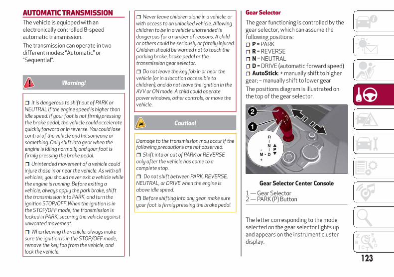
AUTOMATIC TRANSMISSIONThe vehicle is equipped with anelectronically controlled 8-speedautomatic transmission.
The transmission can operate in twodifferent modes: “Automatic” or“Sequential”.
Warning!
It is dangerous to shift out of PARK orNEUTRAL if the engine speed is higher thanidle speed. If your foot is not firmly pressingthe brake pedal, the vehicle could acceleratequickly forward or in reverse. You could losecontrol of the vehicle and hit someone orsomething. Only shift into gear when theengine is idling normally and your foot isfirmly pressing the brake pedal.
Unintended movement of a vehicle couldinjure those in or near the vehicle. As with allvehicles, you should never exit a vehicle whilethe engine is running. Before exiting avehicle, always apply the park brake, shiftthe transmission into PARK, and turn theignition STOP/OFF. When the ignition is inthe STOP/OFF mode, the transmission islocked in PARK, securing the vehicle againstunwanted movement.
When leaving the vehicle, always makesure the ignition is in the STOP/OFF mode,remove the key fob from the vehicle, andlock the vehicle.
Never leave children alone in a vehicle, orwith access to an unlocked vehicle. Allowingchildren to be in a vehicle unattended isdangerous for a number of reasons. A childor others could be seriously or fatally injured.Children should be warned not to touch theparking brake, brake pedal or thetransmission gear selector.
Do not leave the key fob in or near thevehicle (or in a location accessible tochildren), and do not leave the ignition in theAVV or ON mode. A child could operatepower windows, other controls, or move thevehicle.
Caution!
Damage to the transmission may occur if thefollowing precautions are not observed:
Shift into or out of PARK or REVERSEonly after the vehicle has come to acomplete stop.
Do not shift between PARK, REVERSE,NEUTRAL, or DRIVE when the engine isabove idle speed.
Before shifting into any gear, make sureyour foot is firmly pressing the brake pedal.
Gear SelectorThe gear functioning is controlled by thegear selector, which can assume thefollowing positions:
P = PARKR = REVERSEN = NEUTRALD = DRIVE (automatic forward speed)AutoStick: + manually shift to higher
gear; – manually shift to lower gear
The positions diagram is illustrated onthe top of the gear selector.
The letter corresponding to the modeselected on the gear selector lights upand appears on the instrument clusterdisplay.
Gear Selector Center Console
1 — Gear Selector2 — PARK (P) Button
123

To select a mode, move the gear selectorforward or rearward while pressing thebrake pedal. To engage REVERSE (R),press the brake pedal together with thegear selector button.
The gear selector is a joystick styleshifting mechanism which returns to thecenter position automatically. It can bepushed forward twice and rearwardtwice, based on the starting condition.
The PARK (P) mode can beenabled/disabled by pushing the PARK(P) button. PARK (P) mode isautomatically activated if the followingconditions are met simultaneously:
DRIVE (D) mode or REVERSE (R) modeis active
The vehicle’s speed is close to 0 mph(0 km/h)
The brake pedal is releasedThe driver’s seat belt is not fastenedThe driver’s door is open
To transition the vehicle into REVERSE(R) mode from DRIVE (D) mode, or intoDRIVE (D) mode from REVERSE (R)mode, it is necessary to move the gearselector by pushing the gear selectorbutton.
When using AutoStick, activate it bymoving the gear selector from DRIVE (D)to the left and then forward toward the -symbol or backward toward the + symboland the gear is changed.
To shift out of PARK (P), or to pass fromposition NEUTRAL (N) to position DRIVE(D) or REVERSE (R), the vehicle must bemoving at a low speed or stopped, andthe brake pedal must also be pressed.
Note:
DO NOT accelerate while shiftingfrom position PARK (P) or NEUTRAL (N)to another position.
After selecting a gear, wait a fewseconds before accelerating. Thisprecaution is particularly important withengine cold.
It is not possible to select NEUTRAL(N) mode from PARK (P) mode.
Transmission Operating ModesAutoStick
In the case of frequent shifting (e.g. forsport driving, when the vehicle is drivenwith a heavy load, on slopes, when towingheavy trailers), it is recommended to usethe Autostick (sequential shifting) modeto select and keep a lower fixed ratio.
In these conditions, the use of a lowergear improves vehicle performance andprevents overheating.
It is possible to shift from DRIVE (D)mode to sequential mode regardless ofvehicle speed.
Activation
Starting from DRIVE (D) mode, toactivate the sequential drive mode, movethe gear selector to the left (– and +indication of the trim). The gear engagedwill be shown on the display.
Shifting is made by moving the gearselector forwards, towards symbol – orbackwards, towards symbol +.
Steering Wheel Shift Paddles — IfEquipped
The gear can be manually shifted also byusing the paddles behind the steeringwheel, pull the right paddle (+) towardsthe steering wheel and release it toengage a higher gear, perform the sameoperation with the left paddle (-) toengage a lower gear.
Gear Selector
3 — Gear Selector Button
124
STA
RT
ING
AN
DO
PE
RAT
ING

Note:
If only one manual shift is necessary, theletter (D) will remain on the display withthe engaged gear next to it.
Deactivation
To deactivate the sequential drivingmode, bring the gear selector back inposition DRIVE (D) ("automatic" drivingmode).
Warning!
Do not downshift for additional enginebraking on a slippery surface. The drivewheels could lose their grip and the vehiclecould skid, causing a collision or personalinjury.
Note:To select the correct gear for
maximum deceleration (engine brake),just keep the gear paddle pulled (–): thetransmission goes to an operating modein which the vehicle can slow downeasily.
The vehicle will keep the gearselected by the driver until the safetyconditions allow it.
This means, for example, that thesystem will try to prevent the enginefrom switching off, automaticallydownshifting if the engine speed is toolow.
Automatic Transmission Limp HomeModeTransmission function is monitoredelectronically for abnormal conditions. Ifa condition is detected that could resultin transmission damage, TransmissionLimp Home Mode is activated.
In this condition, the transmission staysin fourth gear, regardless of the selectedgear. Positions PARK (P), REVERSE (R)and NEUTRAL (N) still work.
The symbol might light up in theinstrument cluster.
Temporary failure
In the event of a momentary problem, thetransmission can be reset to regain allforward gears by performing thefollowing steps:
1. Stop the vehicle.
2. Shift the transmission into PARK (P),if possible. If not, shift the transmissionto NEUTRAL (N).
3. Push and hold the ignition until theengine turns OFF.
4. Wait for about 10 seconds, thenrestart the engine.
5. Shift into the desired gear range. Ifthe problem is no longer detected, thetransmission will return to normaloperation.
Note:
Even if the transmission can be reset, werecommend that you visit yourauthorized dealer at your earliestpossible convenience. Your authorizeddealer has diagnostic equipment todetermine if the problem could reoccur. Ifthe transmission cannot be reset, serviceis required at your authorized dealer.
Steering Wheel Shift Paddles
125

ALFA DNA SELECTORAlfa DNA SystemThis vehicle is equipped with a Alfa DNAsystem selector (located on the centerconsole). There are up to four modes ofoperation to be selected according todriving style and road conditions:
d = Dynamic (sports driving mode)n = Natural (mode for driving in normal
conditions)a = Advanced Efficiency (ECO driving
mode for maximum fuel savings).= Adjusts the calibration of the
suspensions (if equipped).
On the instrument panel display, thedifferent modes are characterized bydifferent colors:
Natural - BlueDynamic - RedAdvanced Efficiency - Green
The different driving modes aregraphically different from the color ofthe frames and the contents only on the"performance" screens.
Driving Modes"Natural" Mode
Activation/Deactivation
It is activated by rotating the selector tothe letter "n"; the display will light up inblue.
To deactivate the Natural mode, movethe selector to another mode ("d" or "a").
"Dynamic" Mode
Activation/Deactivation
It is activated by rotating the selector tothe letter "d"; the display will light up inred.
To deactivate the Dynamic mode, movethe selector to "n", Natural mode.
"Advanced Efficiency" Mode
Activation/Deactivation
It is activated by rotating the selector tothe letter "a"; the display will light up ingreen.
To deactivate the Advanced Efficiencymode, move the selector to "n": Naturalmode.
Note:The next time that the engine is
started, the "Advanced Efficiency","Dynamic" and "Natural" mode selectedpreviously is retained. The system willreactivate in "Advanced Efficiency","Dynamic" or "Natural" mode, dependingon which mode was selected before theengine was stopped.
It is not possible to go directly from"Dynamic" mode to "AdvancedEfficiency" mode and vice versa. Youmust always activate the “Natural”mode first and then select the othermode.
Alfa DNA System Selector
Mode Display
126
STA
RT
ING
AN
DO
PE
RAT
ING

ALFA ACTIVE SUSPENSION(AAS) — IF EQUIPPEDThe vehicle's electronic suspensionsmanagement system is the result of asophisticated elaboration of the variousboard sensors, aimed at optimizing thevehicle's performance.
The system continuously monitors thedamping of the suspensions through theactuator installed on each shockabsorber. This way, the calibration of theshock absorbers can be adjusted to theconditions of the road surface and to thedynamic conditions of the vehicle,improving its comfort and road holding.
The driver can choose, even while driving,(only in "Dynamic” mode), between twotypes of suspension calibration: a moresporty or a more comfortable one.
By pushing the button, the systemprepares to work with a shock absorbercalibration which favours drivingcomfort.
In case of a system failure, the symboland a dedicated message will be
shown on the instrument panel display.
STOP/START SYSTEMThe Stop/Start system automaticallyshuts off the engine during a vehicle stopif the required conditions are met.Releasing the brake pedal or acceleratorpedal will automatically restart theengine.
The function was developed to increasevehicle efficiency by reducing fuelconsumption, gas emissions, and soundpollution.
Note:
When the Stop/Start system stops theengine, the power steering is alsodisabled.
Operating ModeStopping The Engine
With the vehicle at a standstill and brakepedal pressed, the engine switches off ifthe gear selector is in a position otherthan REVERSE (R).
The system does not operate when thegear selector is in REVERSE (R), in orderto make parking maneuvers easier.
In the event of stops uphill, engineswitching off is disabled to make the "HillStart Assist" function available (worksonly with running engine).
Alfa Active Suspension Button
127

Note:
The engine can only be automaticallystopped after having run at about 6 mph(10 km/h). After an automatic restart, thevehicle only needs to exceed a speed of0.3 mph (0.5 km/h) to stop the engine.
Engine stopping is signaled by thesymbol lighting up on the instrument
cluster display.
Restarting The Engine
To restart the engine, release the brakepedal.
With the brake pressed and thetransmission in automatic mode DRIVE(D), the engine will restart by shifting toREVERSE (R), to PARK (P) or to"AutoStick".
With brake pressed if the gear selector isin "AutoStick" mode, the engine willrestart by shifting to PARK (P) or bymoving the selector to + or -.
System Manual Activation/DeactivationTo manually activate/deactivate thesystem, push the button located in thecontrol panel on the left of the steeringwheel.
Light off: system activated.Light on: system deactivated.
SPEED LIMITERDescriptionThis feature allows the speed of thevehicle to be limited to speeds, which canbe set by the driver.
The maximum speed can be set with thevehicle stationary or in motion. Theminimum speed that can be set is 18 mph(30mk/h).
When this feature is active, the vehiclespeed depends on the pressing of theaccelerator pedal until the programmedspeed limit is reached (see "Speed LimitProgramming" paragraph).
ActivationThe feature can be activated/deactivated through the Information andEntertainment System.
Activating The Device
To access this feature on the main menu,select the following items in sequence:"Settings", "Safety", “Speed Limiter” and“ON”.
The activation of this feature is signaledby the displaying of the green symbolalong with the last speed set.
Stop/Start On/Off Button
128
STA
RT
ING
AN
DO
PE
RAT
ING

Speed Limit ProgrammingTo access the function, on the main menuselect the following items in sequence:"Settings", "Safety" and "Speed LimiterSet Speed".
By turning the Rotary Pad, the speedincreases by 5 mph (5 km/h), from aminimum of 18 mph (30 km/h) to amaximum of 112 mph (180 km/h).
DeactivationDeactivating The Device
To access this feature on the main menu,select the following items in sequence:"Settings", "Safety", "Speed Limiter" and"OFF".
Automatic Deactivation Of The Device
The device deactivates automatically inthe event of fault in the system. In thiscase, contact an authorized dealer.
SPEED CONTROL (CRUISECONTROL)Speed Control DescriptionThis is an electronically controlled drivingassistance feature that allows thedesired vehicle speed to be maintained,without having to press the acceleratorpedal. This feature can be used at a speedabove 25 mph (40 km/h) on longstretches of dry, straight roads with fewvariations (highways).
The speed control buttons are located onthe left side of the steering wheel.
Note:
To ensure correct operation, thespeed control is designed to deactivateif more than one function is operatedsimultaneously. In this case, the systemcan be reactivated by pushing the on/offbutton and setting the desiredspeed.
It is not recommended to use thisfeature in city traffic.
While driving downhill, the systemcould brake the vehicle to keep the setspeed the same.
Warning!
Speed Control can be dangerous where thesystem cannot maintain a constant speed.Your vehicle could go too fast for theconditions, and you could lose control andhave an accident. Do not use Speed Controlin heavy traffic or on roads that are winding,icy, snow-covered or slippery.
To ActivateTo activate the Speed Control System,push the on/off button located on the leftside of the steering wheel.
The activation of the system is signaledby the white warning light
illuminating in the instrument clusterdisplay.
Speed Control On/Off Button
129

The Speed Control function can remainactive at the same time as the SpeedLimiter System. If a speed limit below theone indicated in the set speed control isset, the speed control speed will belowered to that of the Speed Limiter.
Warning!
Leaving the Speed Control system on whennot in use is dangerous. You couldaccidentally set the system or cause it to gofaster than you want. You could lose controland have an accident. Always leave thesystem OFF when you are not using it.
Setting The Desired SpeedTo set a desired speed, proceed asfollows:
1. Turn the Speed Control on.
2. When the vehicle has reached thedesired speed, push the SET switch up ordown and release to activate. When theaccelerator is released, the vehicle willmaintain the selected speedautomatically.
If needed (when overtaking for instance),you can accelerate beyond the set speedby pressing the accelerator. When yourelease the pedal, the vehicle goes backto the previously set speed.
When traveling downhill with the systemactive, the vehicle speed may slightlyexceed the set one.
Note:
Before pushing the SET switch, thevehicle must be traveling at a constantspeed on a flat surface.
To Vary The Speed SettingIncreasing Speed
Once the Speed Control has beenactivated, the speed can be increased bypushing the SET switch upward.
By keeping the switch pushed, the setspeed will increase until the button isreleased. The new speed will then be set.
At every movement of the SET switch,the set speed will be adjusted.
Decreasing Speed
When the system is active, to reduce thespeed, push the SET switch downward.
By keeping the switch pushed, the setspeed will decrease until the button isreleased. The new speed will then be set.
At every movement of the SET switch,the set speed will be adjusted.
Note:
Moving the SET switch allows the driverto adjust the speed according to theselected unit of measurement set in theInformation and Entertainment System(see dedicated supplement).
Accelerating When Overtaking
Press the accelerator as you wouldnormally. When the pedal is released, thevehicle will return to the set speed.
Use Of The Feature On Hilly Routes
The vehicle can automatically downshiftto keep the set speed when driving onhilly routes.
On steep grades, the loss or gain in speedmay be considerable and is advisable todeactivate the Speed Control system.
Note:
The system keeps the speed set evenuphill and downhill. A slight variation inthe speed on slight elevations iscompletely normal.
To Resume The SpeedNote:
Before returning to the previously setspeed, you must accelerate to a speedclose to the set speed, then push andrelease the RES button.
130
STA
RT
ING
AN
DO
PE
RAT
ING

To DeactivateLightly pressing the brake pedaldeactivates the speed control withoutdeleting the set speed.
The speed control may also bedeactivated by applying the electric parkbrake or when the braking system isoperated (e.g. operation of the ESCsystem).
The set speed is deleted in the followingcases:
Pushing the on/off button twice
The ignition is cycled to the STOPposition
There is a malfunction with the SpeedControl.
ADAPTIVE CRUISE CONTROL(ACC) — IF EQUIPPEDSystem DescriptionAdaptive Cruise Control (ACC) is a driverassist system that combines the speedcontrol functions with maintaining thedistance from the vehicle ahead.
The system allows to set and hold thevehicle at the desired speed withoutneeding to press the accelerator. It alsoallows to set and hold a distance from thevehicle ahead (these settings are set bythe driver).
The Adaptive Cruise Control (ACC)system uses a radar sensor locatedbehind the front bumper and a cameralocated in the center/upper part of thewindshield, to detect the presence of avehicle close ahead.
This system enhances driving comfortwhile on the highway or out of town withlight traffic.
If the sensor does not detect a vehicleahead, the system will maintain a fixedset speed.
If the sensor detects a vehicle ahead, thesystem automatically intervenes bybraking (or accelerating) slightly in orderkeep the set distance while not exceedingthe original set speed, seeking to adapt tothe speed of the vehicle ahead.
Note:
Adaptive Cruise Control performance isnot guaranteed under the followingcircumstances, and it is recommended to
Front Bumper Radar Location
Windshield Camera Location
131

disable the system under the followingcircumstances:
Driving in fog, heavy rain, or snow.
Driving in heavy traffic orconstruction zones.
Driving on icy, snowy, slippery roads,roads with steep climbs and descents, orroads with numerous turns and bends.
Entering a turn lane.
Towing a trailer.
When circumstances do not allowsafe driving at a constant speed.
Warning!
Adaptive Cruise Control (ACC) is aconvenience system. It is not a substitute foractive driving involvement. It is always thedriver’s responsibility to be attentive ofroad, traffic, and weather conditions, vehiclespeed, distance to the vehicle ahead; and,most importantly, brake operation to ensuresafe operation of the vehicle under all roadconditions. Your complete attention isalways required while driving to maintainsafe control of your vehicle. Failure to followthese warnings can result in a collision anddeath or serious personal injury.
The ACC system:– Does not react to pedestrians, oncomingvehicles, and stationary objects (e.g., astopped vehicle in a traffic jam or adisabled vehicle).– Cannot take street, traffic, and weatherconditions into account, and may be limitedupon adverse sight distance conditions.– Does not always fully recognize complexdriving conditions, which can result inwrong or missing distance warnings.– Will bring the vehicle to a complete stopwhile following a target vehicle and holdthe vehicle for approximately 3 minutes inthe stop position. If the target vehicle doesnot start moving within 3 minutes theparking brake will be activated, and theACC system will be canceled.
You should switch off the ACC system:
When driving in fog, heavy rain, heavysnow, sleet, heavy traffic, and complexdriving situations (i.e., in highwayconstruction zones).
When entering a turn lane or highway offramp; when driving on roads that arewinding, icy, snow-covered, slippery, or havesteep uphill or downhill slopes.
When circumstances do not allow safedriving at a constant speed.
Activation/DeactivationThe system has four operating states:
Enabled (speed not set)
Activated (speed set)
Paused
Deactivated
Enabling / Activation
To enable the system, push and releasethe (on/off) button located on the leftside of the steering wheel.
When the system is enabled and ready tooperate, the display shows a whitevehicle icon above dashes in place of thespeed.
On/Off Button
132
STA
RT
ING
AN
DO
PE
RAT
ING

Setting a speed activates the system.The display shows the icon in green withthe set speed.
Warning!
Leaving the Adaptive Cruise Control (ACC)system on when not in use is dangerous. Youcould accidentally set the system or cause itto go faster than you want. You could losecontrol and have a collision. Always leavethe system off when you are not using it.
Pausing / Deactivating
With the system enabled (speed not set),push the (on/off) button to disable.
With the system active (speed set), pushthe (on/off) button to pause. Thedisplay will show the icon in white with
the speed in brackets. To then deactivatethe system, push the (on/off) buttonagain.
Setting The Desired SpeedThe speed can be set from a minimum of20 mph (30 km/h) to a maximum of110 mph (180 km/h).
When the vehicle reaches the desiredspeed, push the SET switch upward ordownward and release it to activate thesystem. When the accelerator is released,the vehicle will maintain the set speedautomatically.
While the accelerator pedal is pressed,the system will not be able to control thedistance between the vehicle and the oneahead. In this case, the speed will bedetermined only by the position of theaccelerator pedal.
The system will return to normaloperation as soon as the acceleratorpedal is released.
The system cannot be set:
When pressing the brake pedal.
When the brakes are overheated.
When the electric park brake has beenoperated.
When either PARK (P), REVERSE (R) orNEUTRAL (N) is engaged.
When the engine rpm is above amaximum threshold.
When the vehicle speed is not withinthe operational speed range.
When the ESC (or ABS or otherstability control systems) are operatingor have just operated.
When the ESC system is off.
When the Forward Collision Warningsystem (if equipped) is brakingautomatically.
In the event of system failure.
When the engine is OFF.
In case of obstruction of the radarsensor (in this case the bumper areawhere it is located must be cleaned).
If the system is set, the conditionsdescribed above also cause a
Enabled Icons
SET Switch
133
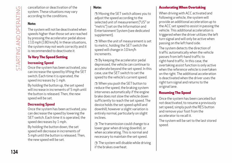
cancellation or deactivation of thesystem. These situations may varyaccording to the conditions.
Note:
The system will not be deactivated whenspeeds higher than those set are reachedby pressing the accelerator pedal above110 mph (180 km/h). In these situations,the system may not work correctly and itis recommended to deactivate it.
To Vary The Speed SettingIncreasing Speed
Once the system has been activated, youcan increase the speed by lifting the SETswitch. Each time it is operated, thespeed increases by 1 mph.
By holding the button up, the set speedwill increase in increments of 5 mph untilthe button is released. Then, the newspeed will be set.
Decreasing Speed
Once the system has been activated, youcan decrease the speed by lowering theSET switch. Each time it is operated, thespeed decreases by 1 mph.
By holding the button down, the setspeed will decrease in increments of5 mph until the button is released. Then,the new speed will be set.
Note:
Moving the SET switch allows you toadjust the speed according to theselected unit of measurement ("US" or"metric") set on the Information andEntertainment System (see dedicatedsupplement).
When the unit of measurement is setto metric, holding the SET switch thespeed will change in 10 km/hincrements.
By keeping the accelerator pedaldepressed, the vehicle can continue toaccelerate beyond the set speed. In thiscase, use the SET switch to set thespeed to the vehicle’s current speed.
When you push the SET button toreduce the speed, the braking systemintervenes automatically if the enginebrake does not slow the vehicle downsufficiently to reach the set speed. Thedevice holds the set speed uphill anddownhill; however a slight variation isentirely normal, particularly on slightinclines.
The transmission could change to alower gear when driving downhill, orwhen accelerating. This is normal andnecessary to maintain the set speed.
The system will disable while drivingif the brakes overheat.
Accelerating When OvertakingWhen driving with ACC activated andfollowing a vehicle, the system willprovide an additional acceleration up tothe ACC set speed to assist in passing thevehicle. This additional acceleration istriggered when the driver utilizes the leftturn signal and will only be active whenpassing on the left hand side.
The system detects the direction oftraffic automatically when the vehiclepasses from left-hand traffic toright-hand traffic. In this case, theovertaking assist function is only activewhen the reference vehicle is overtakenon the right. The additional accelerationis deactivated when the driver uses theright turn signal and returns to theoriginal lane.
Resuming The SpeedOnce the system has been canceled butnot deactivated, to resume a previouslyset speed, simply push the RES buttonand remove your foot from theaccelerator to recall it.
The system will be set to the last storedspeed.
134
STA
RT
ING
AN
DO
PE
RAT
ING

Before returning to the previously setspeed, bring the speed close to thatspeed, then push the RES button andrelease it.
Warning!
The Resume function should only be used iftraffic and road conditions permit.Resuming a set speed that is too high or toolow for prevailing traffic and road conditionscould cause the vehicle to accelerate ordecelerate too sharply for safe operation.Failure to follow these warnings can result ina collision and death or serious personalinjury.
Setting The Distance Between VehiclesThe distance between your vehicle andthe vehicle ahead may be set to one bar(short), two bars (medium), three bars(long), or four bars (maximum).
The distances from the vehicle ahead areproportional to speed.
The interval of time with relation to thevehicle ahead remains constant andvaries from one second (for the shortdistance one-bar setting) to two seconds(for the maximum distance four-barsetting).
The set distance is shown on the displayby a dedicated icon.
The setting is four (maximum) the firsttime the system is used. After thedistance has been modified by the driver,
the new distance will be stored also afterthe system is deactivated andreactivated.
To Decrease The Distance
Push and release the distance button todecrease the distance setting. Thedistance setting decreases by one bar(shorter) every time the button is pushed.
The set speed is held if there are novehicles ahead. Once the shortestdistance has been selected, the next pushof the button will set the maximumdistance.
If a slower vehicle is detected in the samelane, the vehicle icon on the displayilluminates from grey to white. Thesystem automatically adjusts thevehicle’s speed to keep the set distance,independently of the set speed.
RES (Resume) Button
Distance Icons
Distance Button
135
The vehicle holds the set distance until:
The vehicle ahead accelerates to aspeed higher than the set speed.
The vehicle ahead leaves the lane orthe detection field of the Adaptive CruiseControl system sensor.
The distance setting is changed.
The Adaptive Cruise Control system isdeactivated/paused.
Warning!
The maximum breaking applied by thesystem is limited. The driver may apply thebrakes in all cases if needed.
If the system predicts that the brakinglevel is insufficient to hold the set distance,either “BRAKE!” or a dedicated message isdisplayed to warn the driver of approachingthe vehicle ahead. An acoustic signal is alsoemitted. In this case, it is advised to brakeimmediately as necessary to hold a safedistance from the vehicle ahead.
The driver is responsible for ensuring thatthere are no pedestrians, other vehicles orobjectives along the direction of the vehicle.Failure to comply with these precautionsmay cause serious accidents and injuries.
The driver is fully responsible for holdinga safe distance from the vehicle aheadrespecting the highway code in force in therespective country.
“Stop And Go” FunctionThe “Stop and Go” feature allows you tomaintain a safe distance from the vehicleahead until the vehicle has completelystopped. It will also restart the vehicleautomatically if the vehicle ahead drivesaway within two seconds, otherwise it isnecessary to press the accelerator pedalor push the RES button to restart.
Warning!
When the ACC system is resumed, the drivermust ensure that there are no pedestrians,vehicles or objects in the path of the vehicle.Failure to follow these warnings can result ina collision and death or serious personalinjury.
DeactivationThe system is deactivated and the setspeed is canceled if:
The (on/off) button is pushed(when the system is on or paused).
The ignition is in STOP mode.
The system is canceled (the set speedand distance are stored):
When the system is paused (refer tothe “Activation / Deactivation” section).
When the conditions shown in the“Setting The Desired Speed” sectionoccur.
Limited Operation WarningIf the dedicated message is shown on thedisplay, a condition limiting the AdaptiveCruise Control operation may haveoccurred.
This could be due to an obstruction of thevehicle’s sensor or camera. It could alsobe due to a fault in the system. If anobstruction is detected, clean the area ofthe windshield opposite the interior rearview mirror, where the camera is located,as well as the area of the front bumperwhere the sensor is located. Then checkthat the message has disappeared.
When the conditions limiting the systemfunctions end, normal operation willresume.
Should the fault persist, contact yourauthorized dealer.
Precautions While DrivingThe system may not work correctly insome driving conditions (see below). Thedriver must control the vehicle at alltimes.
Towing A Trailer
Use of this system is not recommendedwhile towing a trailer.
136
STA
RT
ING
AN
DO
PE
RAT
ING

Vehicle Not Aligned
The system may not detect a vehicletraveling in the same lane, in the samedirection, but is not aligned. It also maynot detect a vehicle which is cutting infrom a side lane. Sufficient distance fromthe vehicles ahead may not beguaranteed in these cases.
The non-aligned vehicle can weave in andout of the driving lane causing the vehicleto brake or accelerate unexpectedly.
Steering And Curves
Driving on curves with the system setcould limit speed and acceleration toguarantee vehicle stability, even if novehicles are detected ahead.
When leaving the curve, the systemresets the previously set speed.
Note:
In cases of narrow curves, theperformance of the system could belimited. In this case, it is advisable todeactivate the system.
The system only limits the speedDURING a bend and not BEFORE it.
Using The System On Slopes
When driving on roads with a variableincline, the system may not detect thepresence of a vehicle in the lane. Systemperformance could be limited accordingto speed, load, traffic conditions andsteep slopes.
Lane Change
The system may not detect the presenceof a vehicle until it is fully in your lane.
In this case, sufficient distance from thevehicle which is changing lanes may not
be guaranteed. It is advisable to pay theutmost attention at all times and bealways ready to apply the brakes ifneeded.
Small Vehicles
Some narrow vehicles (e.g. bicycles andmotorcycles) traveling near the outeredges of the lane or which enter the lanefrom curb side are not detected until theyare fully in the lane.
Sufficient distance from the vehiclesahead may not be guaranteed in thesecases.
Steering And Curves Lane Change
Small Vehicles
137

Stationary Objects And Vehicles
The system cannot detect the presenceof stationary vehicles or objects. Forexample, the system will not operate ifthe vehicle ahead leaves the lane and avehicle ahead of that one is stationary inthat lane. Pay the utmost attention at alltimes and be always ready to apply thebrakes if needed.
Objects And Vehicles Moving InOpposite Or Crosswise Direction
The system cannot detect the presenceof objects or vehicles traveling inopposite or crosswise directions andconsequently will not activate.
General InformationThis vehicle has systems that operate onradio frequency that comply with Part15 of the Federal CommunicationsCommission (FCC) rules and withIndustry Canada Standards RSS-GEN/210/220/310.
Operation is subject to the following twoconditions:
1. The device may not cause harmfulinterference.
2. The device must accept anyinterference received, includinginterference that may cause undesiredoperation of the device.
Changes or modifications to any of thesesystems by other than an authorizedservice facility could void authorizationto use this equipment.
PARK SENSORS SYSTEMVehicles With Rear Parking SensorsOnlyThe parking sensors, located in the rearbumper, detect obstacles while thevehicle is in REVERSE. When an obstacleis detected, an acoustic alert will soundand visual indications will be displayed onthe instrument cluster.
System Activation/Deactivation
The system, when engaged, isautomatically activated by engaging theREVERSE gear, while it is deactivated byengaging another gear.
To turn the system off, push the ParkSensors System switch located to theleft of the headlight switch. The indicatorlight within the switch will illuminatewhen the system is turned off. Pushing
Objects And Vehicles Moving InOpposite Or Crosswise Direction
Rear Sensor Locations
138
STA
RT
ING
AN
DO
PE
RAT
ING

the switch a second time will turn thesystem back on, and the indicator lightwill turn off.
The indicator light within the ParkSensors System switch will also be on incase of system failure. If the switch ispushed with a system failure, theindicator light will flash forapproximately five seconds. The light willthen stay on constantly.
Note:
When the ignition is cycled to ON mode,the Park Sensors System keeps the laststate when the engine was stopped(activated or deactivated) in its memory.
System Activation/Deactivation
The system, when engaged, isautomatically activated by engaging theREVERSE gear. It is deactivated byengaging another gear.
Operation With A Trailer
The operation of the Park SensorsSystem is automatically deactivatedwhen a trailer’s electrical connector isplugged into the vehicle. The sensors areautomatically reactivated when theelectrical connector is removed.
Warning!
Before using the Park Sensors System, itis strongly recommended that the ball mountand hitch ball assembly is disconnected fromthe vehicle when the vehicle is not used fortowing. Failure to do so can result in injury ordamage to vehicles or obstacles because thehitch ball will be much closer to the obstaclethan the rear fascia when the loudspeakersounds the continuous tone. Also, thesensors could detect the ball mount andhitch ball assembly, depending on its sizeand shape, giving a false indication that anobstacle is behind the vehicle.
Drivers must be careful when backing upeven when using the Park Sensors System.Always check carefully behind your vehicle,look behind you, and be sure to check forpedestrians, animals, other vehicles,obstructions, and blind spots before backingup. You are responsible for safety and mustcontinue to pay attention to yoursurroundings. Failure to do so can result inserious injury or death.
Caution!
The Park Sensors System is only aparking aid and it is unable to recognizeevery obstacle, including small obstacles.Parking curbs might be temporarily detectedor not detected at all. Obstacles locatedabove or below the sensors will not bedetected when they are in close proximity.
The vehicle must be driven slowly whenusing the Park Sensors System in order to beable to stop in time when an obstacle isdetected. It is recommended that the driverlooks over his/her shoulder when using thePark Sensors System.
Vehicles With Front And Rear ParkingSensors — If EquippedThe parking sensors, located in the frontand rear bumpers, detect the presence ofany obstacles and warn the driverthrough an acoustic signal and visualindications on the instrument cluster.
Park Sensors System On/Off Switch
139
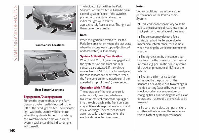
Engagement/Disengagement
To turn the system off, push the ParkSensors System switch located to theleft of the headlight switch. The indicatorlight within the switch will illuminatewhen the system is turned off. Pushingthe switch a second time will turn thesystem back on, and the indicator lightwill turn off.
The indicator light within the ParkSensors System switch will also be on incase of system failure. If the switch ispushed with a system failure, theindicator light will flash forapproximately five seconds. The light willthen stay on constantly.
Note:
When the ignition is cycled to ON, thePark Sensors system keeps the last statewhen the engine was stopped (activatedor deactivated) in its memory.
System Activation/Deactivation
When the REVERSE gear is engaged andthe system is on, the front and rearsensors are activated. If the vehiclemoves from REVERSE to a forward gear,the rear sensors are deactivated, whilethe front sensors remain active until thespeed of 9 mph (15 km/h) is exceeded.
Operation With A Trailer
The operation of the rear sensors isautomatically deactivated when atrailer’s electrical connector is pluggedinto the vehicle, while the front sensorsstay active and can provide acoustic andvisual warnings. The rear sensors areautomatically reactivated when theelectrical connector is removed.
Note:
Some conditions may influence theperformance of the Park SensorsSystem:
Reduced sensor sensitivity could bedue to the presence of ice, snow, mud, orthick paint on the surface of the sensor.
The sensors may detect a falseobstacle (echo interference) due tomechanical interference, for examplewhen washing the vehicle or in extremeweather.
The signals sent by the sensors canbe altered by the presence of ultrasonicsystems (e.g. pneumatic brake systemsof trucks or pneumatic drills) near thevehicle.
System performance can beinfluenced by the position of thesensors. For example, due to a change inthe ride setting (caused by wear to theshock absorbers or suspension), bychanging tires, overloading the vehicle oroperations that require the vehicle to belowered.
Be sure not to place bumper stickersor other adhesives over the sensors asthis will affect system performance.
Front Sensor Locations
Rear Sensor Locations
140
STA
RT
ING
AN
DO
PE
RAT
ING
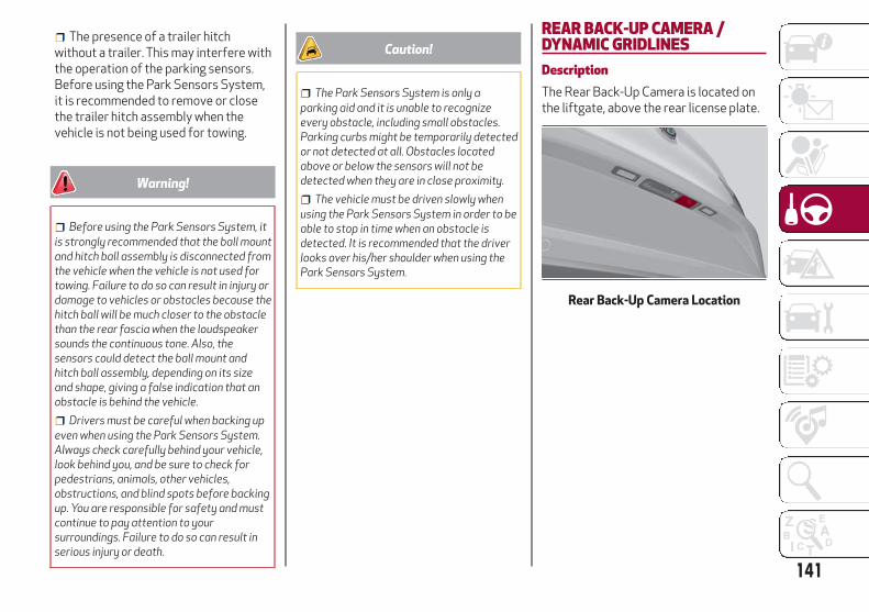
The presence of a trailer hitchwithout a trailer. This may interfere withthe operation of the parking sensors.Before using the Park Sensors System,it is recommended to remove or closethe trailer hitch assembly when thevehicle is not being used for towing.
Warning!
Before using the Park Sensors System, itis strongly recommended that the ball mountand hitch ball assembly is disconnected fromthe vehicle when the vehicle is not used fortowing. Failure to do so can result in injury ordamage to vehicles or obstacles because thehitch ball will be much closer to the obstaclethan the rear fascia when the loudspeakersounds the continuous tone. Also, thesensors could detect the ball mount andhitch ball assembly, depending on its sizeand shape, giving a false indication that anobstacle is behind the vehicle.
Drivers must be careful when backing upeven when using the Park Sensors System.Always check carefully behind your vehicle,look behind you, and be sure to check forpedestrians, animals, other vehicles,obstructions, and blind spots before backingup. You are responsible for safety and mustcontinue to pay attention to yoursurroundings. Failure to do so can result inserious injury or death.
Caution!
The Park Sensors System is only aparking aid and it is unable to recognizeevery obstacle, including small obstacles.Parking curbs might be temporarily detectedor not detected at all. Obstacles locatedabove or below the sensors will not bedetected when they are in close proximity.
The vehicle must be driven slowly whenusing the Park Sensors System in order to beable to stop in time when an obstacle isdetected. It is recommended that the driverlooks over his/her shoulder when using thePark Sensors System.
REAR BACK-UP CAMERA /DYNAMIC GRIDLINESDescriptionThe Rear Back-Up Camera is located onthe liftgate, above the rear license plate.
Rear Back-Up Camera Location
141

When the vehicle is in REVERSE, theInformation and Entertainment Systemdisplay will show the area behind thevehicle, as seen by the Rear Back-UpCamera, along with a warning message.
Rear Back-Up Camera Features
To activate the Rear Back-Up Camerafeatures, select “Settings” from the MainMenu of the Information andEntertainment System. Under “DriverAssistance”, Rear Back-Up Camerafeatures can be selected:
View
Camera Delay
Dynamic Grid Lines
Selecting “View” will activate the cameraview on the display.
Selecting “Camera Delay” will allow thecamera view to remain on the display
shortly after the vehicle is no longer inREVERSE, followed by the previouslyactive screen.
Selecting “Camera Guidelines” will activatethe display of the dynamic guidelines thatindicate the route of the vehicle.
Warning!
Drivers must be careful when backing upeven when using the Rear Back-Up Camera.Always check carefully behind your vehicle,and be sure to check for pedestrians,animals, other vehicles, obstructions, orblind spots before backing up. You areresponsible for the safety of yoursurroundings and must continue to payattention while backing up. Failure to do socan result in serious injury or death.
Caution!
To avoid vehicle damage, Rear Back-UpCamera should only be used as a parking aid.The Rear Back-Up Camera is unable to viewevery obstacle or object in your drive path.
To avoid vehicle damage, the vehicle mustbe driven slowly when using the Rear Back-UpCamera to be able to stop in time when anobstacle is seen. It is recommended that thedriver look frequently over his/her shoulderwhen using the Rear Back-Up Camera.
Symbols And Messages On The DisplayIndications On The Display
Through the Information andEntertainment System settings, byactivating the "Camera Guidelines"feature, guidelines can be seen on therear camera display. If activated, theguidelines are positioned on the image tohighlight the width of the vehicle and theexpected reverse path based on thesteering wheel position.
A central line indicates the center of thevehicle to assist in rear parkingmaneuvers or trailer hitch alignment. Thevarious colored areas indicate thedistance from the rear of the vehicle.
The table below shows the approximatedistances for each area:
AreaDistance From TheRear Of The Vehicle
Red0–11.8 inches
(0–30 cm)
Yellow11.8 inches to 3.3feet (30 cm–1 m)
Green3.3 feet or more
(1 m or more)
Rear Back-Up Camera Display
142
STA
RT
ING
AN
DO
PE
RAT
ING

Messages On The Display
If the liftgate is opened, the camera willnot detect any obstacle behind thevehicle. The display will show a dedicatedwarning message.
Make sure the liftgate is closed bypushing next to the lock until it clicks.
Important NotesIce, snow or mud on the surface of the
camera may reduce its sensitivity. It isimportant to keep the camera surfaceclean, and free from debris.
When parking, be aware of obstaclesthat may be above or below the camerarange.
LANE DEPARTURE WARNING(LDW) SYSTEMDescriptionThe Lane Departure Warning system usesa forward looking camera located on thewindshield to detect lane markings andmeasure vehicle position within the laneboundaries.
When one or both lane limits aredetected and the vehicle passes over onewithout an activated turn signal, thesystem emits a visual as well as anacoustic signal.
If the vehicle continues to go beyond theline of the lane without any interventionfrom the driver, the surpassed line willlight up on the display (left or right) tourge the driver to bring the vehicle backinto the limits of the lane.
Caution!
Do not tamper with nor operate on thecamera. Do not close the openings in theaesthetic cover located under the interiorrear view mirror. In the event of a failure ofthe camera, contact your authorized dealer.
The camera may have limited or absentoperation due to weather conditions such as:heavy rain, hail, thick fog, heavy snow,formation of ice layers on the windshield.
Camera operation may also becompromised by the presence of dust,condensation, dirt or ice on the windshield,by traffic conditions (e.g. vehicles that aredriving not aligned with yours, vehicle drivingin a transverse or opposite way on the samelane, bend with a small radius of curvature),by road surface conditions and by drivingconditions (e.g. off-road driving). Make surethe windshield is always clean. Use specificdetergents and clean cloths to avoidscratching the windshield. The cameraoperation may also be limited or absent insome driving, traffic and road surfaceconditions.
If the windshield must be replaced due toscratches, chipping or breakage, contactexclusively your authorized dealer. Do notreplace the windshield on your own. It isadvisable to replace the windshield if it isdamaged in the area of the camera.
143

System Activation/DeactivationThe system is activated/deactivated bypushing the button located on the end ofthe multifunction lever.
Note:
When the engine is started, the systemmaintains the operating mode that wasselected when it was turned OFF.
Activation Conditions
Once turned on, the system becomesactive only if the following conditions aremet:
The vehicle speed is above 37 mph(60 km/h).
The lane limit lines are visible at leaston one side.
There are suitable visibility conditions.
The road is straight or with wide radiusbends.
A suitable distance is kept from thevehicle in front.
The turn signal is not active.
REFUELING THE VEHICLERefueling The VehicleBefore refueling, make sure that the fueltype is correct.
Also, stop the engine before refueling.
Note:
An inefficient catalytic converter leads toharmful exhaust emissions, thuscontributing to air pollution.
Caution!
Never introduce leaded fuel to the tank, evenin small amounts in an emergency, as thiswould damage the catalytic converterbeyond repair.
Refueling ProcedureThe fuel filler door is unlocked when thecentral door locking system is released,while it is automatically locked when thecentral locking system is applied.
Opening The Fuel Filler Door
To refuel proceed as follows:
1. Open fuel filler door by pressing onthe point shown by the arrow.
Lane Departure Warning SystemActivation/Deactivation Button
144
STA
RT
ING
AN
DO
PE
RAT
ING

2. Remove the fuel filler cap.
3. Insert the fuel nozzle fully into thefiller pipe.
4. When the fuel nozzle “clicks” or shutsoff, before removing the nozzle, wait forat least 10 seconds in order for the fuelto flow inside the tank
5. Remove the fuel filler nozzle, tightenthe gas cap about ¼ turn until you hearone click. This is an indication that cap isproperly tightened.
The label indicates the fuel type(UNLEADED FUEL = gasoline).
Emergency Fuel Door Opening
In the event of an emergency the fuelfiller door can be opened by operatingfrom inside the trunk.
Proceed as follows:
1. Open the liftgate and locate theemergency fuel filler release cap placedon the side of the luggage compartment.
2. Open the cap, and pull the cord insideto unlock the fuel filler door.
3. Open the fuel filler door by pressingon it (see the previous instructions).
Warning!
Never have any smoking materials lit in ornear the vehicle when the fuel door is open orthe tank is being filled.
Never add fuel when the engine is running.This is in violation of most state and federalfire regulations and may cause the MIL toturn on.
A fire may result if gasoline is pumpedinto a portable container that is inside of avehicle. You could be burned. Always placegas containers on the ground while filling.
Note:
If the filler compartment is washed with apressure washer, keep it at a distance ofat least 8 inches (20 cm).
Fuel Door Fuel Door Label
145

TRAILER TOWING
Trailer Towing Weights (Maximum Trailer Weight Ratings)
Engine/Transmission Maximum GTW (Gross Trailer Wt.) Maximum Tongue Wt. (See Note)
2.0L Engine 3,000 lbs (1360 kg) 300 lbs (136 kg)
Refer to local laws for maximum trailer towing speeds.
NOTE: The trailer tongue weight must be considered as part of the combined weight of occupants and cargo, and should never exceed theweight referenced on the Tire and Loading Information placard.
146
STA
RT
ING
AN
DO
PE
RAT
ING
IN CASE OF EMERGENCY
Have a flat tire or a burnt-out bulb?
At times, a problem such as these mayinterfere with your driving experience.
The section on emergencies can help youto deal with critical situationsindependently.
In an emergency, we recommend that youcall the phone number found in theWarranty Book.
You may also consider contacting yournearest authorized dealer.
ROADSIDE ASSISTANCE . . . . . . .148HAZARD WARNING LIGHTS . . . . .148BULB REPLACEMENT . . . . . . . . .149FUSES . . . . . . . . . . . . . . . . . . .153JACKING AND TIRE CHANGING . . . .160TIRE SERVICE KIT — IF EQUIPPED .163JUMP STARTING . . . . . . . . . . . .167TOWING A DISABLED VEHICLE . . .169TOW EYES . . . . . . . . . . . . . . . .170ENHANCED ACCIDENT RESPONSESYSTEM (EARS) . . . . . . . . . . . . .172EVENT DATA RECORDER (EDR) . . .172
147
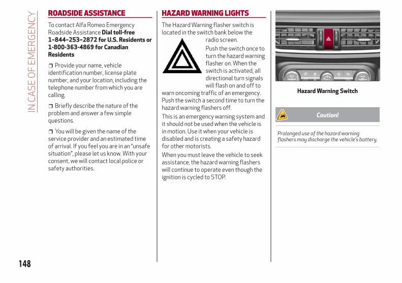
ROADSIDE ASSISTANCETo contact Alfa Romeo EmergencyRoadside Assistance Dial toll-free1–844–253–2872 for U.S. Residents or1-800-363-4869 for CanadianResidents
Provide your name, vehicleidentification number, license platenumber, and your location, including thetelephone number from which you arecalling.
Briefly describe the nature of theproblem and answer a few simplequestions.
You will be given the name of theservice provider and an estimated timeof arrival. If you feel you are in an “unsafesituation”, please let us know. With yourconsent, we will contact local police orsafety authorities.
HAZARD WARNING LIGHTSThe Hazard Warning flasher switch islocated in the switch bank below the
radio screen.
Push the switch once toturn the hazard warningflasher on. When theswitch is activated, alldirectional turn signalswill flash on and off to
warn oncoming traffic of an emergency.Push the switch a second time to turn thehazard warning flashers off.
This is an emergency warning system andit should not be used when the vehicle isin motion. Use it when your vehicle isdisabled and is creating a safety hazardfor other motorists.
When you must leave the vehicle to seekassistance, the hazard warning flasherswill continue to operate even though theignition is cycled to STOP.
Caution!
Prolonged use of the hazard warningflashers may discharge the vehicle’s battery.
Hazard Warning Switch
148
INC
AS
EO
FE
ME
RG
EN
CY

Emergency Braking
The hazard warning lights turn on andwarning lights and illuminate onthe instrument panel in case ofemergency braking and according to themode selected by the “Alfa DNA” selector.
When the "Alfa DNA" selector is inposition "n" or "a", the activationthreshold of the hazard warning lights ishigher. While in position "d", thesensitivity of the activation is lower thanthat in the "n" and "a" modes.
The hazard warning lights turn offautomatically when emergency brakingdeactivates. For further details about theemergency braking, see the "ActiveSafety Systems" section in the "Safety"chapter.
BULB REPLACEMENTGeneral Instructions
Before replacing a bulb, check thecontacts for oxidation.
Replace blown bulbs with others of thesame type and power.
After replacing a headlight bulb,always check its alignment.
When a light is not working, check thatthe corresponding fuse is intact beforechanging the bulb. For the location offuses, refer to “Fuses” in this chapter.
Note:
In some particular climate conditions,such as low temperature, humidity, orafter washing the vehicle, a thincondensation layer may form on theinternal surfaces of the front and rearheadlights. This condensation willdisappear after switching on theheadlights.
149

Types Of Bulbs
The vehicle may be equipped with the following bulbs
Glass Bulbs (Type A): They are press-fitted. Pull to extract.
Bayonet-Type Bulbs (Type B): To remove them from their holder, pressthe bulb and turn it counterclockwise, then extract it.
Tubular Bulbs (Type C): Release them from their contacts to remove.
Halogen Bulbs (Type D): To remove the bulb, turn the connector to theside and pull it out.
Halogen Bulbs (Type E): To remove the bulb, turn it counterclockwise.
Xenon Gas Discharge Bulb (Type F): to remove the bulb, contact anauthorized dealer.
150
INC
AS
EO
FE
ME
RG
EN
CY

Replacement Bulbs
Light bulbs Type Power
Front direction indicators (*) PY24W 24W
Rear Fog lights(*) H11 55 W
Main beam headlights, front side lights/daylight running lights (DRL) (*)
H15 55/15W
Dipped beam headlights (*) H7 55W
Main beam/dipped beam headlights (Xenon gas discharge) D3S 35W
Sun visor light 1.5CP 2.1W
Glove compartment light W5W 4W
Liftgate light W5W 5W
Puddle lights (under door panel) W5W 5W
(*) Only for basic version headlight with halogen main beam/dipped beam headlights
151

Replacing Exterior Bulbs
Warning!
Only replace bulbs when the engine is off.Also ensure that the engine is cold, toprevent the risk of burns.
Front Light Cluster With HalogenHeadlights
Main Beam Headlights
Proceed with the directions below tochange bulbs:
1. Operating inside the enginecompartment, locate the protectivecover.
2. Remove protective cover.
3. Turn the bulb/connector assemblycounterclockwise, and then slide it offthe headlight body.
4. Remove the bulb by sliding it off thebulb holder.
5. Install the new bulb, making sure it iscorrectly inserted in the bulb holder.
6. Insert the bulb/connector assembly inthe housing on the headlight body andturn it clockwise, making sure that it islocked correctly.
7. Install the protective cover.
Direction Indicators
Proceed with the directions below tochange bulbs:
1. Operating inside the enginecompartment, locate the protectivecover.
2. Remove protective cover.
Protective Cover Location
Protective Cover
Bulb/Connector
Protective Cover Location
152
INC
AS
EO
FE
ME
RG
EN
CY

3. Turn the bulb/connector assemblycounterclockwise, and then slide it offthe headlight body.
4. Remove the bulb by sliding it off thebulb holder.
5. Install the new bulb, making sure it iscorrectly inserted in the bulb holder.
6. Insert the bulb/connector assembly inthe housing on the headlight body andturn it clockwise, making sure that it islocked correctly.
7. Install the protective cover.
Fog Lights
To replace fog light bulbs, contact yourauthorized dealer.
Front Light Cluster With Main BeamXenon Gas Discharge Headlights
To replace the bulbs of the main beamheadlights, contact your authorizeddealer.
Caution!
Do not touch the new bulb with your fingers.Oil contamination will severely shorten bulblife. If the bulb comes in contact with any oilysurface, clean the bulb with rubbing alcohol.
FUSESIntroductionThe fuses protect electrical systemsagainst excessive current.
When a device does not work, you mustcheck the electrical circuit inside the fusefor a break/melt.
Also, please be aware that using poweroutlets for extended periods of time withthe engine off may result in vehiclebattery discharge.
Fuse Extracting Pliers
To replace a fuse, use the pliers hookedto the trunk fusebox cover.
Grab the pliers from the upper tabs,press the tabs together, and extract thepliers pulling upwards.
The pliers have two different ends, bothof which are specifically designed to
Protective Cover
Bulb/ConnectorFuse Box
153

remove the different types of fusespresent in the vehicle:
After use, return the pliers to their properposition by following the belowprocedures:
Grasp the pliers from the upper tabsand insert them into their housing.
Push downward on the pliers into theirhousing until they click into place.
Warning!
When replacing a blown fuse, always usean appropriate replacement fuse with thesame amp rating as the original fuse. Neverreplace a fuse with another fuse of higheramp rating. Never replace a blown fuse withmetal wires or any other material. Do notplace a fuse inside a circuit breaker cavity orvice versa. Failure to use proper fuses mayresult in serious personal injury, fire and/orproperty damage.
Before replacing a fuse, make sure thatthe ignition is off and that all the otherservices are switched off and/ordisengaged.
If the replaced fuse blows again, contactan authorized dealer.
If a general protection fuse for safetysystems (air bag system, braking system),power unit systems (engine system,transmission system) or steering systemblows, contact an authorized dealer.
Fuse LocationThe fuses, which can be replaced by theuser, are grouped in two boxes below thepassenger side foot board and inside theluggage compartment.
Control Unit Under Passenger SideFootboardTo access the fuses, proceed as follows:
1. Lift the upper end of the footboard onthe passenger side, pulling to release thetwo buttons.
2. Unscrew the two hooks, and removethe panel by pulling downward.
Fuse Extracting Pliers
1 — MINI fuse2 — J-CASE fuse
Release Buttons On Footboard
1 — Footboard
154
INC
AS
EO
FE
ME
RG
EN
CY

The fuses are freely accessible on thecontrol unit.
After replacing the fuse, make sure thatthe panel and footboard are correctlylocked back into place.
Luggage Compartment Fuse BoxTo access the fuses, proceed as follows:
1. Lift the luggage compartment cover.
2. Remove the control unit cover.
The fuses are freely accessible on thecontrol unit.
The number identifying the electricalcomponent corresponding to each fuse isshown on the cover.
After replacing a fuse, make sure thatyou have closed the cover correctly.
Release Hooks On Footboard
2 — Panel
Control Unit
155

Control Unit Under Passenger Side Footboard
Passenger Side Control Unit
156
INC
AS
EO
FE
ME
RG
EN
CY

FUNCTION FUSE AMPERAGE
Front power window (driver’s side) F33 25
Front power window (passenger side) F34 25
Supply for Information and Entertainment system, Climate Controlsystem, alarm, power door mirror folding, EOBD system, USB port
F36 15
Safe Lock device (driver side door unlock – if equipped), doorsunlock, central lock
F38 20
Windshield washer pump F43 20
Rear left power window F47 25
Rear right power window F48 25
Heater rear window coil F94 15
157

Luggage Compartment Fuse Box
Luggage Compartment Control Unit
158
INC
AS
EO
FE
ME
RG
EN
CY

FUNCTION FUSE AMPERE
Receiver module (TTM/TTEBM) F01 40
Hi-Fi system F08 30
I-Drive / USB Socket / AUX / USB Charger F21 10
KL15/a 12V Power socket in the luggage compartment F22 20
Trailer light control unit power supply (+30) F1 20
Trailer light control unit power supply (+30) F2 15
Trailer socket (only EMEA) (+30) F3 10
Tow bar (+15) F4 10
159
JACKING AND TIRE CHANGING
Warning!
Do not attempt to change a tire on theside of the vehicle close to moving traffic.Pull far enough off the road to avoid thedanger of being hit when operating the jackor changing the wheel.
Being under a jacked-up vehicle isdangerous. The vehicle could slip off the jackand fall on you. You could be crushed. Neverput any part of your body under a vehiclethat is on a jack. If you need to get under araised vehicle, take it to a service centerwhere it can be raised on a lift.
Never start or run the engine while thevehicle is on a jack.
The jack is designed to be used as a toolfor changing tires only. The jack should notbe used to lift the vehicle for servicepurposes. The vehicle should be jacked on afirm level surface only. Avoid ice or slipperyareas.
General InstructionsThis vehicle can be equipped with a TireService Kit. Refer to “Tire Service Kit” forfurther information.
As an alternative to the Tire Service Kit,the vehicle may be purchased with aninflatable spare tire. Refer to “ChangingProcedure” for further information.
Jack Information And UsagePrecautionsJack Information
The jack weighs 4.4 lb (2 kg).
The jack requires no adjustment.
The jack cannot be repaired, and in theevent of a fault it must be replaced byanother factory replacement.
No tool other than its extension levermay be fitted on the jack.
Jack Maintenance
Prevent any dirt from depositing onthe "worm screw".
Keep the "worm screw" lubricated.
Never modify the jack.
Conditions Of Non-Use Of The Jack
Temperatures below −40°F (−40°C).
On sandy or muddy ground
On uneven ground
On steep slopes in extreme weatherconditions.
In direct contact with the engine or forrepairs under the vehicle
On boats
Changing Procedure
1. Park the vehicle on a firm, levelsurface. Avoid ice or slippery areas.
Warning!
Do not attempt to change a tire on the sideof the vehicle close to moving traffic, pull farenough off the road to avoid being hit whenoperating the jack or changing the wheel.
2. Turn on the Hazard Warning flasher.
3. Apply the electric park brake.
4. Place the gear selector into PARK.
5. Cycle the ignition to STOP mode.
160
INC
AS
EO
FE
ME
RG
EN
CY

6. Block both the front and rear of thewheel diagonally opposite of the jackingposition. For example, if changing theright front tire, block the left rear wheel.
7. Open the liftgate and lift up the loadfloor using the handle.
8. Take the warning triangle and positionit at a suitable distance from the vehicleto warn oncoming vehicles.
9. Unscrew the locking plate and takeout the inflatable spare tire and the aircompressor.
10. Remove the damaged wheel byusing the wheel wrench to loosen thebolts by about one turn.
11. Position the jack under the vehicle,near the wheel to be changed, taking carenot to damage the plastic body panel.
12. Lift the extension lever on thewrench.
Wheels Blocked
Inflatable Spare Tire — If Equipped
1 — Locking Plate
Jacking Location
2 — Extension Lever3 — Wrench Head4 — Jack5 — Lifting Block
161
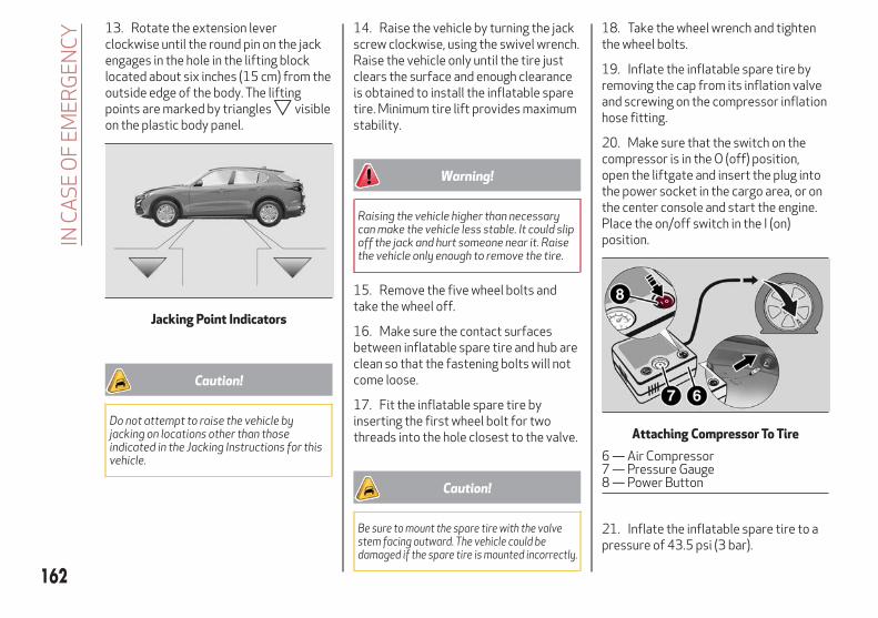
13. Rotate the extension leverclockwise until the round pin on the jackengages in the hole in the lifting blocklocated about six inches (15 cm) from theoutside edge of the body. The liftingpoints are marked by triangles visibleon the plastic body panel.
Caution!
Do not attempt to raise the vehicle byjacking on locations other than thoseindicated in the Jacking Instructions for thisvehicle.
14. Raise the vehicle by turning the jackscrew clockwise, using the swivel wrench.Raise the vehicle only until the tire justclears the surface and enough clearanceis obtained to install the inflatable sparetire. Minimum tire lift provides maximumstability.
Warning!
Raising the vehicle higher than necessarycan make the vehicle less stable. It could slipoff the jack and hurt someone near it. Raisethe vehicle only enough to remove the tire.
15. Remove the five wheel bolts andtake the wheel off.
16. Make sure the contact surfacesbetween inflatable spare tire and hub areclean so that the fastening bolts will notcome loose.
17. Fit the inflatable spare tire byinserting the first wheel bolt for twothreads into the hole closest to the valve.
Caution!
Be sure to mount the spare tire with the valvestem facing outward. The vehicle could bedamaged if the spare tire is mounted incorrectly.
18. Take the wheel wrench and tightenthe wheel bolts.
19. Inflate the inflatable spare tire byremoving the cap from its inflation valveand screwing on the compressor inflationhose fitting.
20. Make sure that the switch on thecompressor is in the O (off) position,open the liftgate and insert the plug intothe power socket in the cargo area, or onthe center console and start the engine.Place the on/off switch in the I (on)position.
21. Inflate the inflatable spare tire to apressure of 43.5 psi (3 bar).
Jacking Point Indicators
Attaching Compressor To Tire
6 — Air Compressor7 — Pressure Gauge8 — Power Button
162
INC
AS
EO
FE
ME
RG
EN
CY

Note:
If spare tire is over inflated, be sure tolower the psi in the tire to therecommended amount by using thedeflation button on the air compressor.
22. Operate the wheel wrench on thejack to lower the vehicle.
23. Remove the jack.
24. Use the wheel wrench to fullytighten the bolts, passing alternatelyfrom one bolt to the diagonally oppositeone.
Warning!
To avoid the risk of forcing the vehicle offthe jack, do not tighten the wheel nuts fullyuntil the vehicle has been lowered. Failure tofollow this warning may result in seriousinjury.
To obtain a more accurate reading, it isadvisable to check the pressure of theinflatable spare tire on the pressuregauge with the compressor off.
The compressor was designed forinflating the inflatable spare tire. Do notuse it for inflating mattresses, rafts, etc.
Note:
Do not stow the deflated tire in theinflatable spare tire location.
Have the full-sized tire repaired orreplaced, as soon as possible.
Warning!
A loose tire or jack thrown forward in acollision or hard stop could endanger theoccupants of the vehicle. Always stow thejack parts and the spare tire in the placesprovided. Have the deflated (flat) tirerepaired or replaced immediately.
TIRE SERVICE KIT — IFEQUIPPEDDescriptionIf a tire is punctured, you can make a firstemergency repair using the Tire ServiceKit located in the rear storage area underthe load platform.
1. Stop the vehicle in a position whereyou can repair the tire safely. You shouldbe as far as possible from the side of theroad, and in a position that is notdangerous for oncoming traffic. Turn onthe hazard warning flashers, remove thesafety triangle from the luggagecompartment, and place it at a suitabledistance from the vehicle to make otherdrivers aware of your presence.
2. Verify that the valve stem (on thewheel with the deflated tire) is in aposition that is near to the ground. Thiswill allow the tire repair kit hoses to reachthe valve stem and keep the tire servicekit flat on the ground.
3. Place the gear selector to PARK (P).
4. Apply the electric park brake and turnthe engine OFF.
163

To access the Tire Service Kit, open theliftgate and lift the load floor.
The Tire Service Kit consists of:
Sealant cartridge containing thesealing fluid
Filler Tube
Air compressor, complete withpressure gauge and connectors
Adhesive label with the writing "Max.50 mph (80 km/h)”, to be attached in aposition easily visible to the driver (eg. onthe dashboard) after repairing the tire
An instruction pamphlet for referencein prompt and correct use of the TireService Kit, which must be then given tothe personnel dealing with thesealant-treated tire
A pair of protective gloves
Some adaptors, for inflating differentelements
1 — Sealant Cartridge2 — Filling Hose3 — Adhesive Label4 — Air Compressor
Note:
The sealing fluid is effective withexternal temperatures of between-40°F (-40°C) and 122°F (50°C).
The sealing fluid has an expirationdate.
Inflation Procedure
Warning!
Do not attempt to seal a tire on the sideof the vehicle closest to traffic. Pull farenough off the road to avoid the danger ofbeing hit when using the Tire Service Kit.
Do not use Tire Service Kit or drive thevehicle under the following circumstances:
– If the puncture in the tire tread isapproximately 1/4 inch (6 mm) or larger.– If the tire has any sidewall damage.– If the tire has any damage from drivingwith extremely low tire pressure.– If the tire has any damage from drivingon a flat tire.– If the wheel has any damage.– If you are unsure of the condition of thetire or the wheel.
Keep Tire Service Kit away from openflames or heat sources.
A loose Tire Service Kit thrown forward ina collision or hard stop could endanger theoccupants of the vehicle. Always stow theTire Service Kit in the place provided. Failureto follow these warnings can result in injuriesthat are serious or fatal to you, yourpassengers, and others around you.
Load Floor
Tire Service Kit Components
164
INC
AS
EO
FE
ME
RG
EN
CY

Take care not to allow the contents ofTire Service Kit to come in contact with hair,eyes, or clothing. Tire Service Kit sealant isharmful if inhaled, swallowed, or absorbedthrough the skin. It causes skin, eye, andrespiratory irritation. Flush immediatelywith plenty of water if there is any contactwith eyes or skin. Change clothing as soon aspossible, if there is any contact with clothing.
Tire Service Kit Sealant solution containslatex. In case of an allergic reaction or rash,consult a physician immediately. Keep TireService Kit out of reach of children. Ifswallowed, rinse mouth immediately withplenty of water and drink plenty of water. Donot induce vomiting! Consult a physicianimmediately.
To use the Tire Service Kit, proceed asfollows:
1. Apply the electric park brake.
2. Connect the hose to the sealantcartridge containing the sealing liquid.Unscrew the tire valve cap, take out thefiller tube and tighten the fitting on thetire valve.
1 — Sealant Cartridge2 — Filler Hose4 — Air Compressor5 — Hose6 — Sealant Cartridge Connector
3. Make sure the power switch of thecompressor is in the off position (O).
4. Insert the plug into the power outlet inthe center console, then start the engine.
5. Start the compressor by placing thepower switch in the on position (I).
7 — Power Switch8 — Pressure Gauge
6. Inflate the tire to a pressure of atleast 32 psi (2.2 bar) Refer to “Tires” in“Servicing And Maintenance” for moreinformation. In order to obtain a moreprecise reading, check the pressure valueon pressure gauge with the compressoroff.
7. If the pressure is not at least 26 psi(1.8 bar) after 15 minutes, disengage thecompressor from the valve and poweroutlet. Then, move the vehicle forwardsapproximately five tire turns in order todistribute the sealing fluid inside the tireevenly, and then repeat the inflationoperation.
Attaching Filler Tube To Deflated Tire
Inserting Plug Into Outlet
Air Compressor
165

8. Drive the vehicle for about 5 miles(8 km), stop, engage the electric parkbrake, and recheck the tire pressure.
9. If the pressure is less than 19 psi(1.3 bar), DO NOT drive the vehicle, andsee your authorized dealer.
10. If a pressure value of at least 19 psi(1.3 bar) is detected, restore the correctpressure (with engine running andelectric park brake engaged), and driveimmediately with great care to yourauthorized dealer.
Warning!
Tire Service Kit is not a permanent flat tirerepair. Have the tire inspected and repairedor replaced after using Tire Service Kit. Donot exceed 50 mph (80 km/h) until the tire isrepaired or replaced. Failure to follow thiswarning can result in injuries that are seriousor fatal to you, your passengers, and othersaround you. Have the tire checked as soon aspossible at your authorized dealer.
11. Apply the adhesive label from thesealant bottle where it can be easily seenby the driver as a reminder that the tirehas been treated with a Tire Service Kit,as well as not to exceed the speedrestriction for the treated tire.
Warning!
Do not adhere the speed restriction stickerto the padded area on the steering wheel.Adhering the speed restriction sticker to thepadded area on the steering wheel isdangerous because the air bag may notoperate (deploy) normally resulting inserious injury. In addition, do not adhere thesticker to areas where warning lights or thespeedometer cannot be viewed.
Note:
Only use original sealant cartridges,which can be purchased at yourauthorized dealer.
Checking And Restoring Tire PressureThe compressor can also be used tocheck and, if necessary, restore the tirepressure.
Proceed as follows:
1. Make sure that power switch is in theO (off) position.
2. Connect the hose directly to the valveon the tire to be inflated.
3. Insert the plug into the socket in thepassenger compartment or in the cargoarea and start the engine.
4. Start the compressor by putting thepower switch to I (on). As soon as thecorrect pressure is reached, put thepower switch to O (off).
5 — Hose7 — Power Switch8 — Pressure Gauge9 — PSI/BAR Button
If the tire is over inflated, reduce thepressure by pushing the PSI/BAR buttonand releasing it when the correctpressure is reached.
Air Compressor And Components
166
INC
AS
EO
FE
ME
RG
EN
CY

JUMP STARTINGIf your vehicle has a discharged battery, itcan be jump started using a set of jumpercables and a battery in another vehicle, orby using a portable battery booster pack.Jump starting can be dangerous if doneimproperly, so please follow theprocedures in this section carefully.
Note:
When using a portable battery boosterpack, follow the manufacturer'soperating instructions and precautions.
Warning!
Failure to follow this jump-startingprocedure could result in personal injury orproperty damage due to battery explosion.
Caution!
Do not use a portable battery booster packor any other booster source with a systemvoltage greater than 12 Volts or damage tothe battery, starter motor, alternator orelectrical system may occur.
Remote Battery Connection PostsThe remote posts of the battery for jumpstarting can be found inside the enginecompartment. The battery itself islocated in the luggage compartment.
The negative terminal (-) is positionednext to the passenger side hood lock.
Warning!
Do not connect the jumper cable to thenegative (-) post of the discharged battery.The resulting electrical spark could causethe battery to explode and could result inserious injury. Only use the specific groundpoint, do not use any other exposed metalparts.
The positive post (+) can be accessed byremoving the cover, and opening theprotective flap.
To carry out the operation, you need tohave the correct cables to connect to thebattery of another vehicle or a portablebattery booster pack to the remote postsof the discharged battery. Usually, thesecables have terminals at the ends and areidentified by different sheath colors(red = positive, black = negative).
Remote Negative Post Location
Protective Flap
Remote Positive Post Location
167
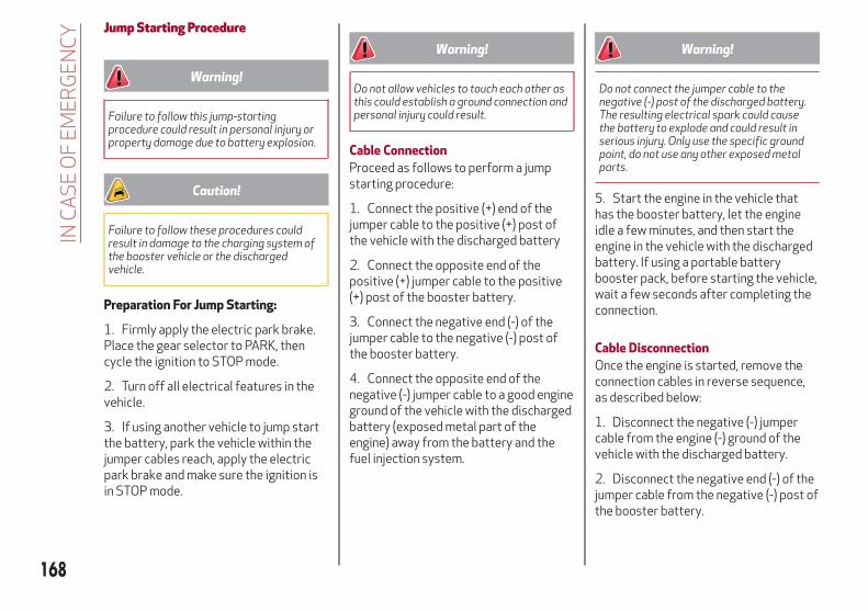
Jump Starting Procedure
Warning!
Failure to follow this jump-startingprocedure could result in personal injury orproperty damage due to battery explosion.
Caution!
Failure to follow these procedures couldresult in damage to the charging system ofthe booster vehicle or the dischargedvehicle.
Preparation For Jump Starting:
1. Firmly apply the electric park brake.Place the gear selector to PARK, thencycle the ignition to STOP mode.
2. Turn off all electrical features in thevehicle.
3. If using another vehicle to jump startthe battery, park the vehicle within thejumper cables reach, apply the electricpark brake and make sure the ignition isin STOP mode.
Warning!
Do not allow vehicles to touch each other asthis could establish a ground connection andpersonal injury could result.
Cable Connection
Proceed as follows to perform a jumpstarting procedure:
1. Connect the positive (+) end of thejumper cable to the positive (+) post ofthe vehicle with the discharged battery
2. Connect the opposite end of thepositive (+) jumper cable to the positive(+) post of the booster battery.
3. Connect the negative end (-) of thejumper cable to the negative (-) post ofthe booster battery.
4. Connect the opposite end of thenegative (-) jumper cable to a good engineground of the vehicle with the dischargedbattery (exposed metal part of theengine) away from the battery and thefuel injection system.
Warning!
Do not connect the jumper cable to thenegative (-) post of the discharged battery.The resulting electrical spark could causethe battery to explode and could result inserious injury. Only use the specific groundpoint, do not use any other exposed metalparts.
5. Start the engine in the vehicle thathas the booster battery, let the engineidle a few minutes, and then start theengine in the vehicle with the dischargedbattery. If using a portable batterybooster pack, before starting the vehicle,wait a few seconds after completing theconnection.
Cable Disconnection
Once the engine is started, remove theconnection cables in reverse sequence,as described below:
1. Disconnect the negative (-) jumpercable from the engine (-) ground of thevehicle with the discharged battery.
2. Disconnect the negative end (-) of thejumper cable from the negative (-) post ofthe booster battery.
168
INC
AS
EO
FE
ME
RG
EN
CY

3. Disconnect the opposite end of thepositive (+) jumper cable from thepositive (+) post of the booster battery.
4. Disconnect the positive (+) end of thejumper cable from the positive (+) post ofthe vehicle with the discharged battery.
If frequent jump-starting is required tostart your vehicle, you should have thebattery and charging system inspected atyour authorized dealer.
Caution!
Accessories plugged into the vehicle poweroutlets draw power from the vehicle’sbattery, even when not in use (i.e., cellularphones, etc.). Eventually, if plugged in longenough without engine operation, thevehicle’s battery will discharge sufficientlyto degrade battery life and/or prevent theengine from starting.
TOWING A DISABLED VEHICLEThis section describes procedures fortowing a disabled vehicle using acommercial towing service.
Caution!
The vehicle should be transported with allfour wheels OFF the ground on the flatbed ofa roadside assistance vehicle. Avoid towingwith only the front (or rear) wheels lifted.When towing with only the front (or rear)wheels lifted, in addition to damaging thebody, it could damage the transmission.
Do not use sling-type equipment whentowing. Vehicle damage may occur.
When securing the vehicle to a flatbedtruck, do not attach to front or rearsuspension components. Damage to yourvehicle may result from improper towing.
Ensure that the Electric Park Brake isreleased, and remain released, while beingtowed.
Damage from improper towing is notcovered under the New Vehicle LimitedWarranty.
Note:
If your vehicle is equipped with a Anti-LiftProtection system, you will need todisable the system prior to towing bypushing the button located on theoverhead console. Refer to “Anti-LiftProtection — If Equipped” in “Getting ToKnow Your Vehicle” for furtherinformation.
The operators of the assistance vehiclemust be informed with regard to thevehicle's minimum height from ground inorder to avoid contact between the endsof the bumpers with the equipment of thebreakdown truck.
169

The following image illustrates the frontand rear attachment corners of thevehicle, to be taken into considerationwhen loading the vehicle on thecommercial towing vehicle.
AWD Models
A 21.7°
B 18.3°
Four-Wheel Drive (AWD) ModelsIt is recommended to tow the vehiclewith all four wheels OFF the ground onthe flatbed of a commercial towingvehicle.
Caution!
DO NOT flat tow this vehicle. Damage tothe drivetrain will result.
DO NOT dolly tow this vehicle. Use of atowing dolly can cause significant damage toyour vehicle.Towing this vehicle in violation of the aboverequirements can cause severe transmissiondamage. Damage from improper towing isnot covered under the New Vehicle LimitedWarranty.
TOW EYESIf the vehicle has been in an accident orhas broken down, a tow eye is provided inthe tools container located inside theluggage compartment for vehicle towing.Towing is meant only for short distanceson a paved road surface.
Proceed as follows to use the tow eye:
1. Unhook the cap on the front grille orrear bumper (if equipped), pushing on theupper part.
Front And Rear Loading Angles
Front Tow Eye Cap
170
INC
AS
EO
FE
ME
RG
EN
CY
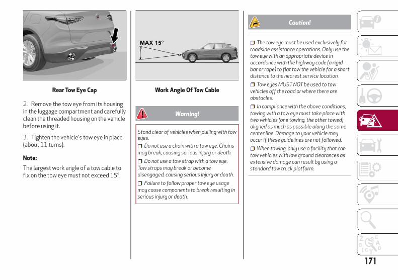
2. Remove the tow eye from its housingin the luggage compartment and carefullyclean the threaded housing on the vehiclebefore using it.
3. Tighten the vehicle's tow eye in place(about 11 turns).
Note:
The largest work angle of a tow cable tofix on the tow eye must not exceed 15°.
Warning!
Stand clear of vehicles when pulling with toweyes.
Do not use a chain with a tow eye. Chainsmay break, causing serious injury or death.
Do not use a tow strap with a tow eye.Tow straps may break or becomedisengaged, causing serious injury or death.
Failure to follow proper tow eye usagemay cause components to break resulting inserious injury or death.
Caution!
The tow eye must be used exclusively forroadside assistance operations. Only use thetow eye with an appropriate device inaccordance with the highway code (a rigidbar or rope) to flat tow the vehicle for a shortdistance to the nearest service location.
Tow eyes MUST NOT be used to towvehicles off the road or where there areobstacles.
In compliance with the above conditions,towing with a tow eye must take place withtwo vehicles (one towing, the other towed)aligned as much as possible along the samecenter line. Damage to your vehicle mayoccur if these guidelines are not followed.
When towing, only use a facility that cantow vehicles with low ground clearances asextensive damage can result by using astandard tow truck platform.
Rear Tow Eye Cap Work Angle Of Tow Cable
171

ENHANCED ACCIDENTRESPONSE SYSTEM (EARS)This vehicle is equipped with anEnhanced Accident Response System.
Please refer to “Occupant RestraintSystems” in “Safety” for furtherinformation on the Enhanced AccidentResponse System (EARS) function.
EVENT DATA RECORDER (EDR)This vehicle is equipped with an EventData Recorder (EDR). The main purposeof an EDR is to record data that willassist in understanding how a vehicle’ssystems performed under certain crashor near crash-like situations, such as anair bag deployment or hitting a roadobstacle.
Please refer to “Occupant RestraintSystems” in “Safety” for furtherinformation on the Event DataRecorder (EDR).
172
INC
AS
EO
FE
ME
RG
EN
CY

SERVICING AND MAINTENANCE
Correct servicing permits theperformance of the vehicle to bemaintained over time, as well as limitedrunning costs and safeguarding theefficiency of the safety systems.
This chapter explains how.
SCHEDULED SERVICING . . . . . . .174ENGINE COMPARTMENT . . . . . . .179BATTERY RECHARGING . . . . . . . .182DEALER SERVICE . . . . . . . . . . . .183RAISING THE VEHICLE . . . . . . . . .184TIRES . . . . . . . . . . . . . . . . . . .185DEPARTMENT OF TRANSPORTATIONUNIFORM TIRE QUALITY GRADES .202STORING THE VEHICLE . . . . . . . .203BODYWORK . . . . . . . . . . . . . . .203
173

SCHEDULED SERVICINGCorrect servicing is crucial forguaranteeing a long life for the vehicleunder the best conditions.
For this reason, Alfa Romeo has planneda series of checks and services for yourvehicle at fixed intervals based ondistance and time, as described in theScheduled Servicing Plan.
Before each service, it is alwaysnecessary to carefully follow theinstructions in the Scheduled ServicingPlan (e.g. periodically check level offluids, tire pressure, etc.).
Scheduled Servicing is offered by anauthorized dealer according to a set timeschedule. If, during each operation, inaddition to the ones scheduled, the needarises for further replacements orrepairs, these may be carried out with theowner’s explicit consent only.
Note:
Scheduled Servicing intervals arerequired by the manufacturer. Failure tohave them carried out may invalidate theNew Vehicle Limited Warranty.
You are advised to inform yourauthorized dealer of any small operatingirregularities without waiting for the nextservice.
Periodic ChecksEvery month or every 600 miles( 1,000 km) or before long trips checkand, if necessary, top off:
Engine coolant level.Brake fluid level (if insufficient, see
your authorized dealer as soon aspossible).
Windshield washer fluid level.Tire inflation pressure and condition.Operation of lighting system
(headlights, direction indicators, hazardwarning lights, etc.).
Operation of windshieldwashing/wiping system andpositioning/wear of wiper blades.
Every 2,000 miles ( 3,000 km), check andtop off if required:
Engine oil level.
Heavy Usage Of The VehicleIf the vehicle is used under one of thefollowing conditions:
Dusty roads.Short, repeated journeys less than
4 miles (7-8 km) at sub-zero outsidetemperatures.
Engine often idling or driving longdistances at low speeds or long periodsof inactivity.
In the event of a long period ofinactivity.
The following checks must be carried out
more often than indicated in theScheduled Servicing Plan:
Check cleanliness of hood and liftgatelocks, cleanliness and lubrication oflinkage.
Visually inspect conditions of: engine,transmission, pipes and hoses(exhaust/fuel system/brakes) and rubberelements (sleeves/bushes, etc.).
Check battery charge and battery fluidlevel (electrolyte).
Visually inspect conditions of theaccessory drive belts.
Check and, if necessary, change engineoil and replace oil filter.
Check and, if necessary, replace cabinair filter.
Check and, if necessary, replace aircleaner.
Severe Duty All Models
Change Engine Oil at 4,000 miles(6,500 km) if the vehicle is operated in adusty and off-road environment or isoperated predominately at idle or onlyvery low engine RPM’s. This type ofvehicle use is considered Severe Duty.
174
SE
RV
ICIN
GA
ND
MA
INT
EN
AN
CE

Maintenance Plan (2.0 T4 MAir Engine)
Thousands of miles 10
20
30
40
50
60
70
80
90
10
0
11
0
12
0
13
0
14
0
15
0
Years 1 2 3 4 5 6 7 8 9 10 11 12 13 14 15
Thousands of kilometers 16
32
48
64
80
96
11
2
12
8
14
4
16
0
17
6
19
2
20
8
22
4
24
0
Check battery charge status with theproper instrument
● ● ● ● ● ● ● ● ● ● ● ● ● ● ●
Check tire condition/wear and adjustpressure, if necessary. Check the tireservice kit recharge condition andexpire date
● ● ● ● ● ● ● ● ● ● ● ● ● ● ●
Check operation of lighting system(headlights, direction indicators,hazard warning lights, deck lid,passenger compartment, glovecompartment, instrument panelwarning lights, etc.)
● ● ● ● ● ● ● ● ● ● ● ● ● ● ●
Check and, if necessary, top up fluidlevels (1)
● ● ● ● ● ● ● ● ● ● ● ● ● ● ●
Check engine control systemoperation (via diagnostic tool) and, ifequipped, engine oil degradation (2)
● ● ● ● ● ● ● ● ● ● ● ● ● ● ●
(1) Top up using the fluids indicated in the “Fluids And Lubricants” section of the “Technical Specifications” chapter only after checking that thesystem is intact.
(2) If oil degradation ratio (data collectable from diagnostic device) is more than 80% (oil quality less than 20%) engine oil and filter replacement isrecommended.
175

Thousands of miles 10
20
30
40
50
60
70
80
90
10
0
11
0
12
0
13
0
14
0
15
0
Years 1 2 3 4 5 6 7 8 9 10 11 12 13 14 15
Thousands of kilometers 16
32
48
64
80
96
11
2
12
8
14
4
16
0
17
6
19
2
20
8
22
4
24
0
Visually inspect conditions of:exterior bodywork, underbodyprotection, pipes and hoses (exhaust,fuel system, brakes), rubber elements(sleeves, bushes, etc.)
● ● ● ● ● ● ●
Check position/wear of frontwindshield wiper blade
● ● ● ● ● ● ● ●
Check operation of the windshieldwiper/washer system and adjustnozzles, if necessary
● ● ● ● ● ● ● ●
Check cleanliness of hood andluggage compartment locks,cleanliness and lubrication of linkage
● ● ● ● ● ● ●
Visually inspect conditions and wearof front/rear disc brake pads andoperation of pad wear indicators
● ● ● ● ● ● ● ● ● ● ● ● ● ● ●
176
SE
RV
ICIN
GA
ND
MA
INT
EN
AN
CE
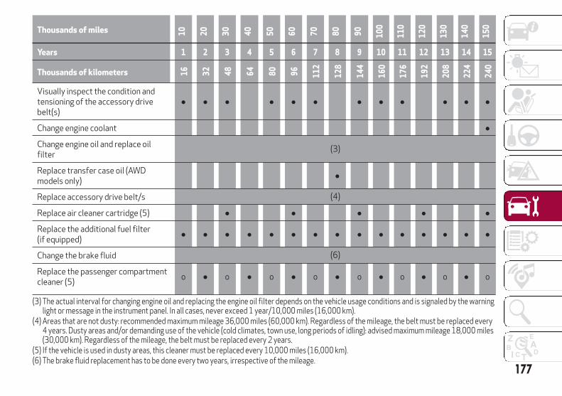
Thousands of miles 10
20
30
40
50
60
70
80
90
10
0
11
0
12
0
13
0
14
0
15
0
Years 1 2 3 4 5 6 7 8 9 10 11 12 13 14 15
Thousands of kilometers 16
32
48
64
80
96
11
2
12
8
14
4
16
0
17
6
19
2
20
8
22
4
24
0
Visually inspect the condition andtensioning of the accessory drivebelt(s)
● ● ● ● ● ● ● ● ● ● ● ●
Change engine coolant ●
Change engine oil and replace oilfilter
(3)
Replace transfer case oil (AWDmodels only)
●
Replace accessory drive belt/s (4)
Replace air cleaner cartridge (5) ● ● ● ● ●
Replace the additional fuel filter(if equipped)
● ● ● ● ● ● ● ● ● ● ● ● ● ● ●
Change the brake fluid (6)
Replace the passenger compartmentcleaner (5)
o ● o ● o ● o ● o ● o ● o ● o
(3) The actual interval for changing engine oil and replacing the engine oil filter depends on the vehicle usage conditions and is signaled by the warninglight or message in the instrument panel. In all cases, never exceed 1 year/10,000 miles (16,000 km).
(4) Areas that are not dusty: recommended maximum mileage 36,000 miles (60,000 km). Regardless of the mileage, the belt must be replaced every4 years. Dusty areas and/or demanding use of the vehicle (cold climates, town use, long periods of idling): advised maximum mileage 18,000 miles(30,000 km). Regardless of the mileage, the belt must be replaced every 2 years.
(5) If the vehicle is used in dusty areas, this cleaner must be replaced every 10,000 miles (16,000 km).(6) The brake fluid replacement has to be done every two years, irrespective of the mileage.
177

Thousands of miles 10
20
30
40
50
60
70
80
90
10
0
11
0
12
0
13
0
14
0
15
0
Years 1 2 3 4 5 6 7 8 9 10 11 12 13 14 15
Thousands of kilometers 16
32
48
64
80
96
11
2
12
8
14
4
16
0
17
6
19
2
20
8
22
4
24
0
Spark plug replacement * ● ● ● ● ●
*The spark plug change interval is mileage-based only. Yearly intervals do not apply.(o) Recommended operations
(●) Mandatory operations
Warning!
You can be badly injured working on or around a motor vehicle. Do only service work for which you have the knowledge and the right equipment.If you have any doubt about your ability to perform a service job, take your vehicle to a competent mechanic.
Failure to properly inspect and maintain your vehicle could result in a component malfunction and effect vehicle handling and performance.This could cause an accident.
178
SE
RV
ICIN
GA
ND
MA
INT
EN
AN
CE

ENGINE COMPARTMENTChecking LevelsVersion - 2.0 T4 MAir engine,
1 – Engine Oil Filler Cap 4 –Windshield/Headlights Washer Fluid Reservoir Cap2 – Engine Coolant Reservoir Cap 5 – Intercooler Coolant Reservoir Cap3 – Brake Fluid Reservoir Access Cover
179

Engine OilThe engine oil level can be seen on theinstrument cluster display every time theengine is started, or on the Informationand Entertainment system display byactivating on the main menu (MENUbutton) the following functions insequence: “Apps”; “My Car” and “OilLevel”.
Check on the display using the 6 notchesthat the oil level is between the MIN andMAX level: 1 notch MIN level, 6 notchesMAX level.
If the oil level is close to or below the MINmark, add oil gradually through the filler,(refer to “Top-up and oil level indicationupdate on display” in this section)considering that each notch shown on thedisplay corresponds to approximately8.8 fl oz (250 ml).
Caution!
Make sure not to add too much oil whentopping off the engine. Engine oil in excessmay damage the engine. Have the vehiclechecked. Never exceed the MAX level whentopping off engine oil.
Caution!
The oil level is not refreshed immediately onthe display after topping off. Consequently,wait for the oil level to be refreshed on thedisplay and follow the procedure below.
Note:
Always reinstall the oil cap and tighten toproper torque whenever it is removed toadd oil to engine. Never run the enginewith cap removed this could cause oil toleak from engine.
Top-Up And Oil Level Indication UpdateOn Display
If a engine oil top-off is needed, in orderto ensure the correct indication of the oillevel on the display, leave the vehicle onflat ground with the engine running forapproximately 5 minutes (temperaturehigher than 176°F (80°C)) and shut theengine off. Then, start the engine again,and idle it for about five minutes.
Note:
If you have added the specified amountof oil and the indicator is not reading“Full”, please contact you authorizeddealer.
Warning!
If the engine oil is being topped up, wait forthe engine to cool down before loosening thefiller cap, particularly for vehicles withaluminium cap (if equipped). WARNING: riskof burns!
Caution!
The oil level must never exceed the MAXmark.
If the MAX mark is exceeded MAX (lastnotch on the right turns red) after the fill-up,go to your authorized dealer as soon aspossible to have the oil in excess removed.
Do not add oil with specificationsdifferent from those of the oil already in theengine.
Used engine oil and oil filters containsubstances which are harmful to theenvironment. To change the oil and filters, weadvise you to contact your authorizeddealer.
180
SE
RV
ICIN
GA
ND
MA
INT
EN
AN
CE

Engine Coolant FluidIf the level is too low, unscrew the cap ofthe reservoir and add the fluid describedin the "Technical Specifications" chapter.
Washer Fluid For Windshield/HeadlightsThe windshield and headlights washerfluid reservoir (if equipped) has atelescopic filler.
If the level is too low, remove reservoircap and lift the filler. Then, add the fluiddescribed in the "TechnicalSpecifications" chapter.
Note:
The headlight washing system will notwork if the liquid level is low (situationindicated by the symbol on theinstrument cluster display). Thewindshield washer will keep working.
Brake FluidCheck that the fluid is at the maximumlevel. If the fluid level in the tank is low,contact your authorized dealer to havethe system checked.
Automatic Transmission ActivationSystem OilThe transmission control oil level shouldonly be checked at your authorizeddealer.
Useful Advice For Extending The LifeOf Your BatteryTo avoid draining your battery and makeit last longer, observe the followinginstructions:
When you park the vehicle, ensure thatthe doors and liftgate are closed properlyto prevent any lights from remaining oninside the passenger's compartment.
Do not keep accessories (e.g. radio,hazard warning lights, etc.) switched onfor a long time when the engine is notrunning.
Before performing any operation onthe electrical system, disconnect thenegative battery cable.
If you wish to install electricalaccessories after purchasing the vehiclethat require permanent electrical supply(e.g. alarm, etc.), or accessories whichinfluence the electrical supplyrequirements, contact your authorizeddealer, whose qualified staff will evaluatethe overall electrical consumption.
Caution!
If the charge level remains under 50% for along time, the battery may be damaged bysulphation, reducing its capacity andefficiency at start the vehicle. The battery isalso more prone to the risk of freezing (attemperatures as high as 14°F (-10°C).
Note:
After the battery is disconnected, thesteering must be initialized. The
warning light on the instrument panelswitches on to indicate this. To carry outthis procedure, simply turn the steeringwheel all the way from one end to theother, and then turn it back to the centralposition.
BatteryThe battery does not require theelectrolyte to be topped up with distilledwater. A periodic check carried out at anauthorized dealer, however, is necessaryto check efficiency.
Follow the battery manufacturer'sinstructions for maintenance.
181

BATTERY RECHARGINGImportant Notes
Warning!
Never charge or recharge a frozenbattery: it may explode because of thenitrogen trapped inside the ice crystals.
At all times while charging or rechargingthe battery, make sure that any sparks oropen flames are kept sufficiently far awayfrom the battery.
Note:
Before using the charging device,always make sure that it is appropriatefor the installed battery, with constantvoltage (below 14.8 V) and lowamperage (maximum 15 A).
Recharge the battery in a wellventilated environment.
Before using any devices to charge orto maintain the charge of the battery,carefully follow the instructionsprovided with the device in order toproperly and safely connect it to thevehicle battery.
You can recharge the battery withoutdisconnecting the wires of the vehicle'selectrical system.
To reach the battery, remove the loadplatform inside the liftgate.
Locate the battery access panel underthe load platform.
Remove the protective cover andconnect the positive cable terminal of thecharger (usually red) to the positiveterminal (+) of the battery.
Connect the negative terminal of thecharger (usually black) to nut next to thenegative terminal (-) of the battery.
The vehicle is equipped with an IBS(Intelligent Battery Sensor), which is ableto measure the charge and dischargevoltage and calculate the charge leveland the general condition of the battery.The sensor is placed next to the negativeterminal (-) of the battery.
For a correct charge/dischargeprocedure, the charge voltage must gothrough the IBS sensor.
1. Turn the charger on and follow theinstructions on the user's manual tocompletely recharge the battery.
Load Platform
Battery Access Panel
Battery
1 — Protective Cover2 — Negative Post (Nut)
182
SE
RV
ICIN
GA
ND
MA
INT
EN
AN
CE

2. When the battery is charged, turn thecharger off before disconnecting it fromthe battery.
3. Disconnect the black cable terminal ofthe battery charger and then the redcable terminal.
4. Refit the protective cover of thepositive terminal of the battery and theaccess cover to the batterycompartment.
Note:
If a "quick-type" battery charger is usedwith the battery fitted on the vehicle,before connecting it disconnect bothcables of the battery itself. Do not use a"quick-type" battery charger to providethe starting voltage.
DEALER SERVICEThe following pages contain instructionson the required maintenance from thetechnical personnel who designed thevehicle.
In addition to these specific maintenanceinstructions specified for routinescheduled servicing, there are othercomponents which may require periodicmaintenance or replacement over thevehicle’s life cycle.
Air Conditioning System MaintenanceTo ensure the best possible performance,the air conditioning system must bechecked and undergo maintenance at anauthorized dealer at the beginning of thesummer.
Windshield WiperRaising The Windshield Wiper Blades("Service Position" Function)
The "service position" function allows thedriver to replace the windshield wiperblades more easily. It is alsorecommended to activate this functionwhen it is snowing and to make it easierto remove any dirt deposits in the areawhere the blades are normallypositioned, when washing.
Activation Of The Function
To activate this function disable thewindshield wiper before cycling theignition to STOP.
This function can only be activated withintwo minutes of cycling the ignition toSTOP.
To activate this function, move the leverupwards for at least three seconds.
Function Deactivation
The function is deactivated if:
More than two minutes passes beforecycling the ignition to the STOP positionafter having raised the lever and puttingthe wipers into service position.
The ignition is cycled to the ON and thewindshield wiper control is used.
If, after using the function, the ignition isset back to ON with the blades in a
Windshield Wiper Stalk
183

position other than rest position (at thebase of the windshield), they will onlyreturn to rest position following acommand given using the stalk (stalkupwards, into unstable position) or whena speed of 3 mph (5 km/h) is exceeded.
Replacing The Windshield Wiper Blades
Proceed as follows:
1. Raise the wiper arm, push tab of theattachment spring and remove the bladefrom the arm.
2. Fit the new blade, inserting the tab inthe dedicated housing in the arm andchecking that it is locked.
3. Lower the wiper arm onto thewindshield.
Note:
Do not operate the windshield wiper withthe blades lifted from the windshield.
Front/Rear Windshield Washers
The window washer nozzles are fixed,and are located on the front windshieldwiper arms, the rear windshield wiperarm, and the rear spoiler. If there is no jetof fluid, first check that there is fluid inthe reservoir (see paragraph “EngineCompartment” in this chapter).
Then check that the nozzle holes are notclogged; use a needle to unblock them ifnecessary.
RAISING THE VEHICLEIf the vehicle requires lifting, visit anauthorized dealer which is equipped withshop jacks or jack arms.
The vehicle lifting points are marked onthe side skirts with the symbols.
Wiper Release Tab
Vehicle Lift Point Locations
184
SE
RV
ICIN
GA
ND
MA
INT
EN
AN
CE
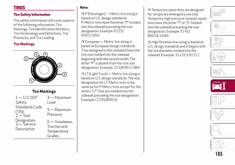
TIRESTire Safety InformationTire safety information will cover aspectsof the following information: TireMarkings, Tire Identification Numbers,Tire Terminology and Definitions, TirePressures, and Tire Loading.
Tire Markings
Note:
P (Passenger) — Metric tire sizing isbased on U.S. design standards.P-Metric tires have the letter “P” moldedinto the sidewall preceding the sizedesignation. Example: P215/65R15 95H.
European — Metric tire sizing isbased on European design standards.Tires designed to this standard have thetire size molded into the sidewallbeginning with the section width. Theletter "P" is absent from this tire sizedesignation. Example: 215/65R15 96H.
LT (Light Truck) — Metric tire sizing isbased on U.S. design standards. The sizedesignation for LT-Metric tires is thesame as for P-Metric tires except for theletters “LT” that are molded into thesidewall preceding the size designation.Example: LT235/85R16.
Temporary spare tires are designedfor temporary emergency use only.Temporary high pressure compact sparetires have the letter “T” or “S” moldedinto the sidewall preceding the sizedesignation. Example: T145/80D18 103M.
High flotation tire sizing is based onU.S. design standards and it begins withthe tire diameter molded into thesidewall. Example: 31x10.5 R15 LT.
Tire Markings
1 — U.S. DOTSafetyStandards Code(TIN)
4 — MaximumLoad
2 — SizeDesignation
5 — MaximumPressure
3 — ServiceDescription
6 — Treadwear,Traction andTemperatureGrades
185

Tire Sizing Chart
EXAMPLE:
Example Size Designation: P215/65R15XL 95H, 215/65R15 96H, LT235/85R16C, T145/80D18 103M, 31x10.5 R15 LT
P = Passenger car tire size based on U.S. design standards, or
"....blank...." = Passenger car tire based on European design standards, or
LT = Light truck tire based on U.S. design standards, or
T or S = Temporary spare tire or
31 = Overall diameter in inches (in)
215, 235, 145 = Section width in millimeters (mm)
65, 85, 80 = Aspect ratio in percent (%)
Ratio of section height to section width of tire, or
10.5 = Section width in inches (in)
R = Construction code
"R" means radial construction, or
"D" means diagonal or bias construction
15, 16, 18 = Rim diameter in inches (in)
186
SE
RV
ICIN
GA
ND
MA
INT
EN
AN
CE

EXAMPLE:
Service Description:
95 = Load Index
A numerical code associated with the maximum load a tire can carry
H = Speed Symbol
A symbol indicating the range of speeds at which a tire can carry a load corresponding to its load index under certain operating conditions
The maximum speed corresponding to the speed symbol should only be achieved under specified operating conditions (i.e., tire pressure, vehicleloading, road conditions, and posted speed limits)
Load Identification:Absence of the following load identification symbols on the sidewall of the tire indicates a Standard Load (SL) tire:
XL = Extra load (or reinforced) tire, or
LL = Light load tire or
C, D, E, F, G = Load range associated with the maximum load a tire can carry at a specified pressure
Maximum Load – Maximum load indicates the maximum load this tire is designed to carry
Maximum Pressure – Maximum pressure indicates the maximum permissible cold tire inflation pressure for this tire
187

Tire Identification Number (TIN)
The TIN may be found on one or both sides of the tire; however, the date code may only be on one side. Tires with white sidewalls willhave the full TIN, including the date code, located on the white sidewall side of the tire. Look for the TIN on the outboard side of blacksidewall tires as mounted on the vehicle. If the TIN is not found on the outboard side, then you will find it on the inboard side of thetire.
EXAMPLE:
DOT MA L9 ABCD 0301
DOT = Department of Transportation
This symbol certifies that the tire is in compliance with the U.S. Department of Transportation tire safety standards and is approved forhighway use
MA = Code representing the tire manufacturing location (two digits)
L9 = Code representing the tire size (two digits)
ABCD = Code used by the tire manufacturer (one to four digits)
03 = Number representing the week in which the tire was manufactured (two digits)
03 means the 3rd week
01 = Number representing the year in which the tire was manufactured (two digits)
01 means the year 2001
Prior to July 2000, tire manufacturers were only required to have one number to represent the year in which the tire was manufactured.Example: 031 could represent the 3rd week of 1981 or 1991
188
SE
RV
ICIN
GA
ND
MA
INT
EN
AN
CE

Tire Terminology And Definitions
Term Definition
B-PillarThe vehicle B-Pillar is the structural member of the body located behind thefront door.
Cold Tire Inflation Pressure
Cold tire inflation pressure is defined as the tire pressure after the vehicle has notbeen driven for at least three hours, or driven less than 1 mile (1.6 km) after sitting fora minimum of three hours. Inflation pressure is measured in units of PSI (pounds persquare inch) or kPa (kilopascals).
Maximum Inflation PressureThe maximum inflation pressure is the maximum permissible cold tire inflationpressure for this tire. The maximum inflation pressure is molded into the sidewall.
Recommended Cold Tire Inflation PressureVehicle manufacturer's recommended cold tire inflation pressure as shown on thetire placard.
Tire PlacardA label permanently attached to the vehicle describing the vehicle’s loading capacity,the original equipment tire sizes and the recommended cold tire inflation pressures.
189

Tire Loading And Tire Pressure
Note:
The proper cold tire inflation pressure islisted on the driver’s side B-Pillar or therear edge of the driver's side door.
Check the inflation pressure of each tire,including the spare tire (if equipped), atleast monthly and inflate to therecommended pressure for your vehicle.
Tire And Loading Information Placard
This placard tells you importantinformation about the:
1. Number of people that can be carriedin the vehicle.
2. Total weight your vehicle can carry.
3. Tire size designed for your vehicle.
4. Cold tire inflation pressures for thefront, rear, and spare tires.
Loading
The vehicle maximum load on the tiremust not exceed the load carryingcapacity of the tire on your vehicle. Youwill not exceed the tire's load carryingcapacity if you adhere to the loadingconditions, tire size, and cold tireinflation pressures specified on the Tireand Loading Information placard in“Vehicle Loading” in the “Starting AndOperating” section of this manual.
Note:
Under a maximum loaded vehiclecondition, gross axle weight ratings(GAWRs) for the front and rear axlesmust not be exceeded. For furtherinformation on GAWRs, vehicle loading,and trailer towing, refer to “VehicleLoading” in the “Starting And Operating”section of this manual.
To determine the maximum loadingconditions of your vehicle, locate thestatement “The combined weight ofoccupants and cargo should neverexceed XXX kg or XXX lbs” on the Tireand Loading Information placard. Thecombined weight of occupants,
Example Tire Placard Location (Door)
Example Tire Placard Location (B-Pillar)
Tire And Loading Information Placard
190
SE
RV
ICIN
GA
ND
MA
INT
EN
AN
CE

cargo/luggage and trailer tongue weight(if applicable) should never exceed theweight referenced here.
Steps For Determining Correct LoadLimit—
(1) Locate the statement “Thecombined weight of occupants andcargo should never exceed XXX kg orXXX lbs.” on your vehicle's placard.
(2) Determine the combined weightof the driver and passengers that willbe riding in your vehicle.
(3) Subtract the combined weight ofthe driver and passengers fromXXX kg or XXX lbs.
(4) The resulting figure equals theavailable amount of cargo andluggage load capacity. For example,if “XXX” amount equals 1400 lbs. andthere will be five 150 lb passengersin your vehicle, the amount ofavailable cargo and luggage loadcapacity is 650 lbs. (1400-750(5x150) = 650 lbs.)
(5) Determine the combined weightof luggage and cargo being loaded onthe vehicle. That weight may notsafely exceed the available cargo andluggage load capacity calculated inStep 4.
(6) If your vehicle will be towing atrailer, load from your trailer will betransferred to your vehicle. Consultthis manual to determine how thisreduces the available cargo andluggage load capacity of your vehicle.Metric Example For Load Limit
For example, if “XXX” amount equals635 kg and there will be five 68 kgpassengers in your vehicle, the amount ofavailable cargo and luggage load capacityis 295 kg (635-340 (5x68) = 295 kg) asshown in step 4.
Note:
If your vehicle will be towing a trailer,load from your trailer will be transferredto your vehicle. The following tableshows examples on how to calculatetotal load, cargo/luggage, and towingcapacities of your vehicle with varyingseating configurations and number andsize of occupants. This table is forillustration purposes only and may notbe accurate for the seating and loadcarry capacity of your vehicle.
For the following example, thecombined weight of occupants andcargo should never exceed 865 lbs(392 kg).
191
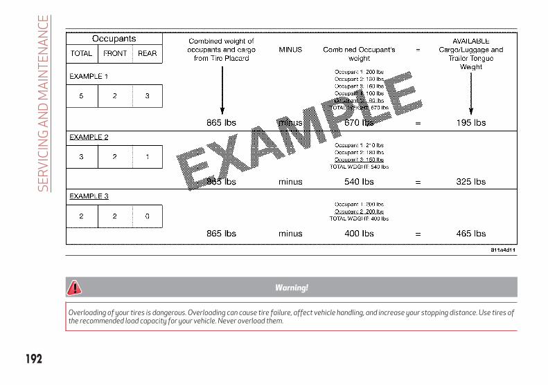
Warning!
Overloading of your tires is dangerous. Overloading can cause tire failure, affect vehicle handling, and increase your stopping distance. Use tires ofthe recommended load capacity for your vehicle. Never overload them.
192
SE
RV
ICIN
GA
ND
MA
INT
EN
AN
CE

Tires — General InformationTire Pressure
Proper tire inflation pressure is essentialto the safe and satisfactory operation ofyour vehicle. Four primary areas areaffected by improper tire pressure:
Safety and Vehicle Stability
Economy
Tread Wear
Ride Comfort
Safety
Warning!
Improperly inflated tires are dangerousand can cause collisions.
Underinflation increases tire flexing andcan result in overheating and tire failure.
Overinflation reduces a tire's ability tocushion shock. Objects on the road andchuckholes can cause damage that result intire failure.
Overinflated or underinflated tires canaffect vehicle handling and can fail suddenly,resulting in loss of vehicle control.
Unequal tire pressures can cause steeringproblems. You could lose control of yourvehicle.
Unequal tire pressures from one side ofthe vehicle to the other can cause the vehicleto drift to the right or left.
Always drive with each tire inflated to therecommended cold tire inflation pressure.
Both under-inflation and over-inflationaffect the stability of the vehicle and canproduce a feeling of sluggish response orover responsiveness in the steering.
Note:
Unequal tire pressures from side toside may cause erratic andunpredictable steering response.
Unequal tire pressure from side toside may cause the vehicle to drift left orright.
Fuel Economy
Underinflated tires will increase tirerolling resistance resulting in higher fuelconsumption.
Tread Wear
Improper cold tire inflation pressures cancause abnormal wear patterns andreduced tread life, resulting in the needfor earlier tire replacement.
Ride Comfort And Vehicle Stability
Proper tire inflation contributes to acomfortable ride. Over-inflationproduces a jarring and uncomfortableride.
Tire Inflation Pressures
The proper cold tire inflation pressure islisted on the driver's side B-Pillar or rearedge of the driver's side door.
At least once a month:
Check and adjust tire pressure with agood quality pocket-type pressure gauge.Do not make a visual judgement whendetermining proper inflation. Tires maylook properly inflated even when they areunder-inflated.
Inspect tires for signs of tire wear orvisible damage.
Caution!
After inspecting or adjusting the tirepressure, always reinstall the valve stemcap. This will prevent moisture and dirt fromentering the valve stem, which could damagethe valve stem.
Inflation pressures specified on theplacard are always “cold tire inflationpressure”. Cold tire inflation pressure isdefined as the tire pressure after thevehicle has not been driven for at leastthree hours, or driven less than 1 mile(1.6 km) after sitting for a minimum ofthree hours. The cold tire inflationpressure must not exceed the maximum
193

inflation pressure molded into the tiresidewall.
Check tire pressures more often ifsubject to a wide range of outdoortemperatures, as tire pressures vary withtemperature changes.
Tire pressures change by approximately1 psi (7 kPa) per 12°F (7°C) of airtemperature change. Keep this in mindwhen checking tire pressure inside agarage, especially in the Winter.
Example: If garage temperature = 68°F(20°C) and the outside temperature =32°F (0°C) then the cold tire inflationpressure should be increased by 3 psi(21 kPa), which equals 1 psi (7 kPa) forevery 12°F (7°C) for this outsidetemperature condition.
Tire pressure may increase from 2 to6 psi (13 to 40 kPa) during operation. DONOT reduce this normal pressure build upor your tire pressure will be too low.
Tire Pressures For High SpeedOperation
The manufacturer advocates driving atsafe speeds and within posted speedlimits. Where speed limits or conditionsare such that the vehicle can be driven athigh speeds, maintaining correct tireinflation pressure is very important.Increased tire pressure and reducedvehicle loading may be required for
high-speed vehicle operation. Refer toyour authorized tire dealer or originalequipment vehicle dealer forrecommended safe operating speeds,loading and cold tire inflation pressures.
Warning!
High speed driving with your vehicle undermaximum load is dangerous. The addedstrain on your tires could cause them to fail.You could have a serious collision. Do notdrive a vehicle loaded to the maximumcapacity at continuous speeds above75 mph (120 km/h).
Recommended Cold Tire InflationPressures
For vehicle speeds below 100 mph(160 km/h), recommended cold tireinflation pressures are listed on the TireAnd Loading Information Placard locatedon driver’s side B-Pillar or the rear edgeof the driver's side door.
When driving at speeds 100 mph(160 km/h) and above, increased tirepressures and reduced vehicle loadingare required for high-speed vehicleoperation.
For driving speeds above 100 mph(160 km/h) recommended cold tireinflation pressures are listed belowunder "High Speed Tire InflationPressure". Vehicle loading condition mustnot exceed 688 lbs. (312 kg) (driver +three passengers + 88 lbs. (40kg)luggage).
Warning!
High speed driving with your vehicle undermaximum load is dangerous. The addedstrain on your tires could cause them to fail.You could have a serious collision.
194
SE
RV
ICIN
GA
ND
MA
INT
EN
AN
CE

Tires Wheel
Recommended ColdTire Inflation
Pressure
High Speed TireInflation Pressure
Front Rear Front Rear
Original Equipment
235/60 R18 103V or103W
18x8J30 psi2.1 kPa
33 psi2.3 kPa
33 psi2.3 kPa
38 psi2.6 kPa
235/55 R19 101V or 105V 19x8J30 psi2.1 kPa
33 psi2.3 kPa
33 psi2.3 kPa
38 psi2.6 kPa
255/45 R20 101H 20x8.5J33 psi2.3 kPa
36 psi2.5 kPa
35 psi2.4 kPa
39 psi2.7 kPa
Snow Tires
235/60 R18 103V 18x8J30 psi2.1 kPa
33 psi2.3 kPa
33 psi2.3 kPa
38 psi2.6 kPa
235/55 R19 101V 19x8J30 psi2.1 kPa
33 psi2.3 kPa
33 psi2.3 kPa
38 psi2.6 kPa
255/45 R20 101V 20X8.5J33 psi2.3 kPa
36 psi2.5 kPa
35 psi2.4 kPa
39 psi2.7 kPa
Note:
Using tires of a different size, type, brand or design on the front and rear may adversely affect vehicle driveability. We recommendusing only tires approved by the manufacturer. The manufacturer cannot determine if unapproved tires are suitable for use andtherefore cannot guarantee vehicle safety in those conditions.
195

Radial Ply Tires
Warning!
Combining radial ply tires with other typesof tires on your vehicle will cause yourvehicle to handle poorly. The instabilitycould cause a collision. Always use radial plytires in sets of four. Never combine themwith other types of tires.
Tire Repair
If your tire becomes damaged, it may berepaired if it meets the following criteria:
The tire has not been driven on whenflat.
The damage is only on the treadsection of your tire (sidewall damage isnot repairable).
The puncture is no greater than a ¼ ofan inch (6 mm).
Consult an authorized tire dealer for tirerepairs and additional information.
Damaged Run Flat tires, or Run Flat tiresthat have experienced a loss of pressureshould be replaced immediately withanother Run Flat tire of identical size andservice description (Load Index andSpeed Symbol).
Run Flat Tires — If Equipped
Run Flat tires allow you the capability todrive 50 miles (80 km) at 50 mph(80 km/h) after a rapid loss of inflationpressure. This rapid loss of inflation isreferred to as the Run Flat mode. A RunFlat mode occurs when the tire inflationpressure is of/or below 14 psi (96 kPa).Once a Run Flat tire reaches the run flatmode it has limited driving capabilitiesand needs to be replaced immediately. ARun Flat tire is not repairable.
It is not recommended driving a vehicleloaded at full capacity or to tow a trailerwhile a tire is in the run flat mode.
See the tire pressure monitoring sectionfor more information.
Tire Spinning
When stuck in mud, sand, snow, or iceconditions, do not spin your vehicle'swheels above 30 mph (48 km/h) or forlonger than 30 seconds continuouslywithout stopping.
Warning!
Fast spinning tires can be dangerous. Forcesgenerated by excessive wheel speeds maycause tire damage or failure. A tire couldexplode and injure someone. Do not spinyour vehicle's wheels faster than 30 mph(48 km/h) for more than 30 secondscontinuously when you are stuck, and do notlet anyone near a spinning wheel, no matterwhat the speed.
Tread Wear Indicators
Tread wear indicators are in the originalequipment tires to help you indetermining when your tires should bereplaced.
Tire Tread
1 — Worn Tire2 — New Tire
196
SE
RV
ICIN
GA
ND
MA
INT
EN
AN
CE

These indicators are molded into thebottom of the tread grooves. They willappear as bands when the tread depthbecomes a 1/16 of an inch (1.6 mm).When the tread is worn to the tread wearindicators, the tire should be replaced.Refer to “Replacement Tires” in thissection for further information.
Life Of Tire
The service life of a tire is dependentupon varying factors including, but notlimited to:
Driving style.
Tire pressure - Improper cold tireinflation pressures can cause unevenwear patterns to develop across the tiretread. These abnormal wear patterns willreduce tread life, resulting in the need forearlier tire replacement.
Distance driven.
Performance tires, tires with a speedrating of V or higher, and Summer tirestypically have a reduced tread life.Rotation of these tires per the vehiclescheduled maintenance is highlyrecommended.
Warning!
Tires and the spare tire should be replacedafter six years, regardless of the remainingtread. Failure to follow this warning canresult in sudden tire failure. You could losecontrol and have a collision resulting inserious injury or death.
Keep dismounted tires in a cool, dry placewith as little exposure to light aspossible. Protect tires from contact withoil, grease, and gasoline.
Replacement Tires
The tires on your new vehicle provide abalance of many characteristics. Theyshould be inspected regularly for wearand correct cold tire inflation pressures.The manufacturer strongly recommendsthat you use tires equivalent to theoriginals in size, quality and performancewhen replacement is needed. Refer to theparagraph on “Tread Wear Indicators” inthis section. Refer to the Tire and LoadingInformation placard or the VehicleCertification Label for the sizedesignation of your tire. The Load Indexand Speed Symbol for your tire will befound on the original equipment tiresidewall.
See the Tire Sizing Chart example foundin the “Tire Safety Information” section ofthis manual for more information relatingto the Load Index and Speed Symbol of atire.
It is recommended to replace the twofront tires or two rear tires as a pair.Replacing just one tire can seriouslyaffect your vehicle’s handling. If you everreplace a wheel, make sure that thewheel’s specifications match those of theoriginal wheels.
It is recommended you contact yourauthorized tire dealer or originalequipment dealer with any questions youmay have on tire specifications orcapability. Failure to use equivalentreplacement tires may adversely affectthe safety, handling, and ride of yourvehicle.
197

Warning!
Do not use a tire, wheel size, load rating,or speed rating other than that specified foryour vehicle. Some combinations ofunapproved tires and wheels may changesuspension dimensions and performancecharacteristics, resulting in changes tosteering, handling, and braking of yourvehicle. This can cause unpredictablehandling and stress to steering andsuspension components. You could losecontrol and have a collision resulting inserious injury or death. Use only the tire andwheel sizes with load ratings approved foryour vehicle.
Never use a tire with a smaller load indexor capacity, other than what was originallyequipped on your vehicle. Using a tire with asmaller load index could result in tireoverloading and failure. You could losecontrol and have a collision.
Failure to equip your vehicle with tireshaving adequate speed capability can result insudden tire failure and loss of vehicle control.
Caution!
Replacing original tires with tires of adifferent size may result in falsespeedometer and odometer readings.
Spare Tires — If Equipped
Note:
For vehicles equipped with Tire ServiceKit instead of a spare tire, please refer to“Tire Service Kit” in “In Case OfEmergency” for further information.
Caution!
Because of the reduced ground clearance, donot take your vehicle through an automaticcar wash with a compact or limited usetemporary spare installed. Damage to thevehicle may result.
Spare Tire Matching Original EquippedTire And Wheel — If Equipped
Your vehicle may be equipped with aspare tire and wheel equivalent in lookand function to the original equipmenttire and wheel found on the front or rearaxle of your vehicle. This spare tire maybe used in the tire rotation for yourvehicle. If your vehicle has this option,refer to an authorized tire dealer for therecommended tire rotation pattern.
Compact Spare Tire — If Equipped
The compact spare is for temporaryemergency use only. You can identify ifyour vehicle is equipped with a compactspare by looking at the spare tire
description on the Tire and LoadingInformation Placard located on thedriver’s side door opening or on thesidewall of the tire. Compact spare tiredescriptions begin with the letter “T” or“S” preceding the size designation.Example: T145/80D18 103M.
T, S = Temporary Spare Tire
Since this tire has limited tread life, theoriginal equipment tire should berepaired (or replaced) and reinstalled onyour vehicle at the first opportunity.
Do not install a wheel cover or attempt tomount a conventional tire on the compactspare wheel, since the wheel is designedspecifically for the compact spare tire.Do not install more than one compactspare tire and wheel on the vehicle at anygiven time.
Warning!
Compact and collapsible spares are fortemporary emergency use only. With thesespares, do not drive more than 50 mph(80 km/h). Temporary use spares havelimited tread life. When the tread is worn tothe tread wear indicators, the temporaryuse spare tire needs to be replaced. Be sureto follow the warnings, which apply to yourspare. Failure to do so could result in sparetire failure and loss of vehicle control.
198
SE
RV
ICIN
GA
ND
MA
INT
EN
AN
CE

Full Size Spare — If Equipped
The full size spare is for temporaryemergency use only. This tire may looklike the originally equipped tire on thefront or rear axle of your vehicle, but it isnot. This spare tire may have limitedtread life. When the tread is worn to thetread wear indicators, the temporary usefull size spare tire needs to be replaced.Since it is not the same as your originalequipment tire, replace (or repair) theoriginal equipment tire and reinstall onthe vehicle at the first opportunity.
Limited Use Spare — If Equipped
The limited use spare tire is fortemporary emergency use only. This tireis identified by a label located on thelimited use spare wheel. This labelcontains the driving limitations for thisspare. This tire may look like the originalequipped tire on the front or rear axle ofyour vehicle, but it is not. Installation ofthis limited use spare tire affects vehiclehandling. Since it is not the same as youroriginal equipment tire, replace (orrepair) the original equipment tire andreinstall on the vehicle at the firstopportunity.
Warning!
Limited use spares are for emergency useonly. Installation of this limited use sparetire affects vehicle handling. With this tire,do not drive more than the speed listed onthe limited use spare wheel. Keep inflated tothe cold tire inflation pressures listed onyour Tire and Loading Information Placardlocated on the driver’s side B-Pillar or therear edge of the driver’s side door. Replace(or repair) the original equipment tire at thefirst opportunity and reinstall it on yourvehicle. Failure to do so could result in lossof vehicle control.
Wheel And Wheel Trim CareAll wheels and wheel trim, especiallyaluminum and chrome plated wheels,should be cleaned regularly using mild(neutral Ph) soap and water to maintaintheir luster and to prevent corrosion.Wash wheels with the same soap solutionrecommended for the body of thevehicle.
Your wheels are susceptible todeterioration caused by salt, sodiumchloride, magnesium chloride, calciumchloride, etc., and other road chemicalsused to melt ice or control dust on dirtroads. Use a soft cloth or sponge and mildsoap to wipe away promptly. Do not useharsh chemicals or a stiff brush. They can
damage the wheel’s protective coatingthat helps keep them from corroding andtarnishing.
Caution!
Avoid products or automatic car washes thatuse acidic solutions or strong alkalineadditives or harsh brushes. Manyaftermarket wheel cleaners and automaticcar washes may damage the wheel'sprotective finish. Such damage is notcovered by the New Vehicle LimitedWarranty. Only car wash soap, Mopar WheelCleaner or equivalent is recommended.
When cleaning extremely dirty wheelsincluding excessive brake dust, care mustbe taken in the selection of tire and wheelcleaning chemicals and equipment toprevent damage to the wheels. MoparWheel Treatment or Mopar ChromeCleaner or their equivalent isrecommended or select a non-abrasive,non-acidic cleaner for aluminum orchrome wheels.
199

Caution!
Do not use scouring pads, steel wool, abristle brush, metal polishes or oven cleaner.These products may damage the wheel'sprotective finish. Such damage is notcovered by the New Vehicle LimitedWarranty. Only car wash soap, Mopar WheelCleaner or equivalent is recommended.
Note:
If you intend parking or storing yourvehicle for an extended period aftercleaning the wheels with wheel cleaner,drive your vehicle and apply the brakes toremove the water droplets from thebrake components. This activity willremove the red rust on the brake rotorsand prevent vehicle vibration whenbraking.
Dark Vapor Chrome, Black SatinChrome, or Low Gloss Clear Coat Wheels
Caution!
If your vehicle is equipped with thesespecialty wheels, DO NOT USE wheelcleaners, abrasives, or polishing compounds.They will permanently damage this finishand such damage is not covered by the NewVehicle Limited Warranty. HAND WASHONLY USING MILD SOAP AND WATER WITHA SOFT CLOTH. Used on a regular basis; thisis all that is required to maintain this finish.
Tire TypesAll Season Tires — If Equipped
All Season tires provide traction for allseasons (Spring, Summer, Fall, andWinter). Traction levels may varybetween different all season tires. Allseason tires can be identified by the M+S,M&S, M/S or MS designation on the tiresidewall. Use all season tires only in setsof four; failure to do so may adverselyaffect the safety and handling of yourvehicle.
Summer Or Three Season Tires — IfEquipped
Summer tires provide traction in bothwet and dry conditions, and are notintended to be driven in snow or on ice. Ifyour vehicle is equipped with Summertires, be aware these tires are notdesigned for Winter or cold drivingconditions. Install Winter tires on yourvehicle when ambient temperatures areless than 40°F (5°C) or if roads arecovered with ice or snow. For moreinformation, contact an authorizeddealer.
Summer tires do not contain the allseason designation or mountain/snowflake symbol on the tire sidewall.Use Summer tires only in sets of four;failure to do so may adversely affect thesafety and handling of your vehicle.
Warning!
Do not use Summer tires in snow/iceconditions. You could lose vehicle control,resulting in severe injury or death. Drivingtoo fast for conditions also creates thepossibility of loss of vehicle control.
200
SE
RV
ICIN
GA
ND
MA
INT
EN
AN
CE

Snow Tires
Some areas of the country require theuse of snow tires during the Winter. Snowtires can be identified by a“mountain/snowflake” symbol on the tire
sidewall.
If you need snow tires,select tires equivalentin size and type to theoriginal equipmenttires. Use snow tiresonly in sets of four;
failure to do so may adversely affect thesafety and handling of your vehicle.
Snow tires generally have lower speedratings than what was originally equippedwith your vehicle and should not beoperated at sustained speeds over75 mph (120 km/h). For speeds above75 mph (120 km/h) refer to originalequipment or an authorized tire dealerfor recommended safe operating speeds,loading and cold tire inflation pressures.
While studded tires improveperformance on ice, skid and tractioncapability on wet or dry surfaces may bepoorer than that of non-studded tires.Some states prohibit studded tires;therefore, local laws should be checkedbefore using these tire types.
Snow ChainsIt is possible to fit 13 mm chains on allthe tires except for R20.
Use of traction devices require sufficienttire-to-body clearance. Follow theserecommendations to guard againstdamage.
Note:
Traction device must be of propersize for the tire, as recommended by thetraction device manufacturer.
Use on Rear Tires Only.
Check the tension of the snow chainsafter the first few metres have beendriven.
Using snow chains with tires withnon-original dimensions may damagethe vehicle.
Using different tires sizes or types(M+S, snow, etc.) between the front andrear axles may adversely affect vehicledriveability, with the risk of losingcontrol of the vehicle and resultingaccidents.
Caution!
To avoid damage to your vehicle or tires,observe the following precautions:
Because of restricted traction deviceclearance between tires and othersuspension components, it is important thatonly traction devices in good condition areused. Broken devices can cause seriousdamage. Stop the vehicle immediately ifnoise occurs that could indicate devicebreakage. Remove the damaged parts of thedevice before further use.
Install device as tightly as possible andthen retighten after driving about ½ mile(0.8 km).
Do not exceed 30 mph (48 km/h).
Drive cautiously and avoid severe turnsand large bumps, especially with a loadedvehicle.
Do not drive for a prolonged period on drypavement.
Observe the traction devicemanufacturer’s instructions on the methodof installation, operating speed, andconditions for use. Always use the suggestedoperating speed of the devicemanufacturer’s if it is less than 30 mph(48 km/h).
Do not use traction devices on a compactspare tire.
201

DEPARTMENT OFTRANSPORTATION UNIFORMTIRE QUALITY GRADESThe following tire grading categorieswere established by the NationalHighway Traffic SafetyAdministration. The specific graderating assigned by the tire'smanufacturer in each category isshown on the sidewall of the tires onyour vehicle.
All passenger vehicle tires mustconform to Federal safetyrequirements in addition to thesegrades.
Treadwear
The Treadwear grade is acomparative rating, based on thewear rate of the tire when testedunder controlled conditions on aspecified government test course.For example, a tire graded 150 wouldwear one and one-half times as wellon the government course as a tiregraded 100. The relativeperformance of tires depends uponthe actual conditions of their use,however, and may departsignificantly from the norm due tovariations in driving habits, service
practices, and differences in roadcharacteristics and climate.
Traction Grades
The Traction grades, from highest tolowest, are AA, A, B, and C. Thesegrades represent the tire's ability tostop on wet pavement, as measuredunder controlled conditions onspecified government test surfacesof asphalt and concrete. A tiremarked C may have poor tractionperformance.
Warning!
The traction grade assigned to thistire is based on straight-aheadbraking traction tests, and does notinclude acceleration, cornering,hydroplaning, or peak tractioncharacteristics.
Temperature Grades
The temperature grades are A (thehighest), B, and C, representing thetire's resistance to the generation ofheat and its ability to dissipate heat,when tested under controlledconditions on a specified indoor
laboratory test wheel. Sustained hightemperature can cause the materialof the tire to degenerate and reducetire life, and excessive temperaturecan lead to sudden tire failure. Thegrade C corresponds to a level ofperformance, which all passengervehicle tires must meet under theFederal Motor Vehicle SafetyStandard No. 109. Grades B and Arepresent higher levels ofperformance on the laboratory testwheel, than the minimum requiredby law.
Warning!
The temperature grade for this tireis established for a tire that isproperly inflated and notoverloaded. Excessive speed,under-inflation, or excessiveloading, either separately or incombination, can cause heatbuildup and possible tire failure.
202
SE
RV
ICIN
GA
ND
MA
INT
EN
AN
CE

STORING THE VEHICLEIf the vehicle is left inactive for longerthan a month, the following precautionsshould be observed:
Park the vehicle in an area that iscovered and dry, and well-ventilated ifpossible. Slightly open the windows.
Check that the electric park brake isnot activated.
Carry out the “manual liftgate openingdevice” procedure described in thisparagraph.
Disconnect the negative batteryterminal and check the battery charge.Repeat this check once every threemonths during storage.
If the battery is not disconnected fromthe electrical system, check its state ofcharge every thirty days.
Clean and protect the painted partsusing protective wax.
Clean and protect the shiny metalparts using special compounds availablecommercially.
Sprinkle talcum powder on thewindshield wiper rubber blades, and liftthem off the glass.
Cover the vehicle with a fabric orperforated plastic sheet, payingparticular care not to damage the paintedsurface by dragging any dust that mayhave accumulated on it. Do not usecompact plastic sheets, as they do not
allow humidity to evaporate from thesurface of the vehicle.
Inflate tires to +7.25 psi (+0.5 bar)above the standard prescribed pressureand check it periodically.
Do not drain the engine coolingsystem.
Any time the vehicle is left inactive fortwo weeks or more, operate the airconditioning system with engine idlingfor at least five minutes, setting externalair and with fan set to maximum speed.This operation will ensure appropriatelubrication for the system, thusminimizing the possibility of damage tothe compressor when the system isoperated again.
Note:
After cycling the ignition to STOP andhaving closed the driver side door, wait atleast one minute before disconnectingthe electrical supply from the battery.When reconnecting the electrical supplyto the battery, make sure that the ignitionis in the STOP position and the driver’sside door is closed.
BODYWORKPreserving The BodyworkPaint
Touch up abrasions and scratchesimmediately to prevent the formation ofrust.
Some parts of the vehicle may becovered with a matte paint which, inorder to be maintained intact, requiresspecial care: see the instructions in thewarning at the end of this paragraph.
To correctly wash the vehicle, followthese instructions:
If high pressure jets or cleaners areused to wash the vehicle, keep a distanceof at least 15 inches (40 cm) from thebodywork to avoid damage or alteration.Build up of water could cause damage tothe vehicle in the long term.
It is advisable to position the wipersvertically (Service Position) to facilitatethe removal of deposits of dirt from thearea where the blades normally rest; formore information see “Dealer Service” inthis chapter.
203

If washing the vehicle in a service thatmoves the vehicle, proceed with thefollowing directions:
Ensure that the vehicle is on a flatsurface
Disable the automatic engagement ofthe parking brake (refer to the “ElectricPark Brake” in “Starting And Operating”for further information).
With the vehicle stationary, the gear inNEUTRAL (N) and the brake pedaldepressed, push the START button.
Note:
The vehicle will remain in NEUTRAL (N)for 15 minutes before PARK (P) will beengaged automatically.
PARK (P) mode should not be activatedwhen entering a car wash which movesthe vehicle. Once correctly lined up in thecar wash, with the vehicle stopped andthe transmission in NEUTRAL (N), pushthe START button for at least threeseconds to turn off the engine.
204
SE
RV
ICIN
GA
ND
MA
INT
EN
AN
CE

TECHNICAL SPECIFICATIONS
Everything you may find useful forunderstanding how your vehicle is madeand works is contained in this chapterand illustrated with data, tables andgraphics. For the enthusiasts and thetechnician, but also just for those whowant to know every detail of theirvehicle.
IDENTIFICATION DATA . . . . . . . . .206ENGINE . . . . . . . . . . . . . . . . . .207TRANSMISSION . . . . . . . . . . . . .208BRAKES . . . . . . . . . . . . . . . . . .209SUSPENSION . . . . . . . . . . . . . .210STEERING . . . . . . . . . . . . . . . .211DIMENSIONS. . . . . . . . . . . . . . .212WEIGHTS . . . . . . . . . . . . . . . . .213FUEL REQUIREMENTS . . . . . . . .214FLUID CAPACITIES . . . . . . . . . . .215FLUIDS AND LUBRICANTS . . . . . .216PERFORMANCE . . . . . . . . . . . . .218
205

IDENTIFICATION DATAVEHICLE IDENTIFICATION NUMBERThe Vehicle Identification Number (VIN)is stamped on a plate on the front leftcorner of the dashboard trim, which canbe seen from outside the vehicle, throughthe windshield.
This number is also stamped on thechassis near the front left shockabsorber and can be seen by opening theengine compartment hood.
Vehicle Identification Number (VIN)PlateThe plates are located on the left side Apillar and contain the data about:
Chassis number (VIN).Vehicle type (USA and Canada only).Color code.Place of manufacturing of the vehicle
(USA and Mexico only).Vehicle manufacturing date.Maximum permitted weights.Permitted tire inflation pressure (USA
and Canada only).
Vehicle Identification Number
Vehicle Identification Number
206
TE
CH
NIC
AL
SP
EC
IFIC
ATIO
NS

ENGINE
2.0 T4 MAir engine 280 HP
Cycle Four
Number and position of cylinders 4 in line
Piston bore and stroke (mm) 84 / 90
Total displacement (cm³) 1995
Compression ratio 10:1
Maximum power (SAE) (HP) 280
Maximum power (kW) 209
Corresponding engine speed (rpm) 5200
Maximum torque (SAE) (ft-lb) 306
Maximum torque (Nm) 415
Corresponding engine speed (rpm) 3300 - 4400
Fuel87 Octane Minimum, 91 Recommended,
ethanol percentage is 0–15%.
207

TRANSMISSION
Version Transmission Traction
2.0 T4 MAir engine Eight forward gears plus reverse All-Wheel Drive
208
TE
CH
NIC
AL
SP
EC
IFIC
ATIO
NS

BRAKES
Version Front brakes Rear brakes Parking brake
2.0 T4 MAir engine Disc Disc Electric
Caution!
Water, ice and salt spread on the roads may deposit on the brake discs, reducing braking efficiency the first time the brakes are applied.
To obtain the maximum efficiency of the braking system, a bedding-in period of about 300 miles (500 km) is needed: during this period it isbetter to avoid sharp, repeated and prolonged braking.
209

SUSPENSION
Version Front Rear
2.0 T4 MAir engineIndependent wheel double-wishbone
suspensionIndependent wheel with multilink system
210
TE
CH
NIC
AL
SP
EC
IFIC
ATIO
NS

STEERING
Version Curb-to-curb turning circle Type
2.0 T4 MAir engine 38.55 ft (11.75 m)Rack and pinion with electric power
steering
211

DIMENSIONSDimensions are expressed in inches and refer to the vehicle equipped with its standard-supplied tires. Height is measured withvehicle unladen.
AFront
Overhang
BWheelbase
CRear
Overhang
DOverallLength
EOverallHeight
FFrontTrack
GRear Track
HOverall
Width (InclMirrors)
IOverall
Width (ExclMirrors)
33.9 inches(862 mm)
111 inches(2818 mm)
39.7 inches(1008 mm)
184.6 inches(4688 mm)
66 inches(1677 mm)
63.5 inches(1612 mm)
65 inches(1650 mm)
85.2 inches(2163 mm)
74.9 inches(1903 mm)
Small variations with respect to the reported values are possible depending on the dimensions of the rims.212
TE
CH
NIC
AL
SP
EC
IFIC
ATIO
NS

WEIGHTS
Weights (lbs) 2.0 T4 MAir engine
Unladen weight (with all fluids, fuel tank filled to 90% and withoutoptional equipment)
3992
Payload including the driver (*) 992
Maximum permitted loads (**) 242
– Front axle 2491
– Rear axle 2976
– Total 5247
Towable loads -
– Braked trailer 3000 lbs (1360 kg)
– Unbraked trailer 1000 lbs (454 kg)
Maximum load on roof 165 lbs (75 kg)
Maximum load on tow hitch (braked trailer) 300 lbs (136 kg)
(*) If special equipment is fitted (trailer towing equipment, etc.) the empty weight will increase and consequently the payload will decrease in relationto the maximum permitted loads.
(**) Loads not to be exceeded. The user is responsible for arranging goods in the luggage compartment and/or on the load platform within themaximum permitted loads.
213

FUEL REQUIREMENTSThis engine is designedto meet all emissionregulations, andprovide satisfactoryfuel economy andperformance whenusing high-quality
unleaded “Regular” gasoline having aposted octane number of 87 as specifiedby the (R+M)/2 method. For optimalperformance the use of 91 or higheroctane “Premium” gasoline isrecommended in these engines.
While operating on gasoline with therequired octane number, hearing a lightknocking sound from the engine is not acause for concern. However, if the engineis heard making a heavy knocking sound,see your authorized dealer immediately.Use of gasoline with a lower thanrecommended octane number can causeengine failure and may void or not becovered by the New Vehicle LimitedWarranty.
Poor quality gasoline can cause problemssuch as hard starting, stalling, andhesitations. If you experience thesesymptoms, try another brand of gasolinebefore considering service for thevehicle.
Materials Added To Fuel
Designated TOP TIERDetergent Gasolinecontains a higher levelof detergents tofurther aide inminimizing engine and
fuel system deposits. When available, theusage of Top Tier Detergent gasoline isrecommended. Visitwww.toptiergas.com for a list of TOPTIER Detergent Gasoline Retailers.
Indiscriminate use of fuel systemcleaning agents should be avoided. Manyof these materials intended for gum andvarnish removal may contain activesolvents or similar ingredients. These canharm fuel system gasket and diaphragmmaterials.
214
TE
CH
NIC
AL
SP
EC
IFIC
ATIO
NS

FLUID CAPACITIES
2.0 T4 MAir Engine
U.S. Metric
Fuel tank 16.9 Gallons 64 Liters
Fuel tank reserve 2.5 Gallons 9.6 Liters
Engine cooling system 2.3 Gallons 8.8 Liters
Intercooler cooling system 1.4 Gallons 5.25 Liters
Engine sump and filter 5.5 Quarts 5.2 Liters
Hydraulic brake circuit 0.9 Quarts 0.9 Liters
Windshield washer fluid reservoir 1.1 Gallons 4.1 Liters
Automatic transmission, 2.0 T4 MAir engine 9.8 Quarts 9.3 Liters
RDU 230-LSD differential 0.9 Quarts 0.9 Liters
RDU 210-eLSD differential (if equipped) 1.4 Quarts 1.3 Liters
RDU 210/215-LSD differential 1.1 Quarts 1.1 Liters
AWD System FAD transfer case 0.5 Quarts 0.5 Liters
AWD System TRANSFER CASE 0.7 Quarts 0.7 Liters
215
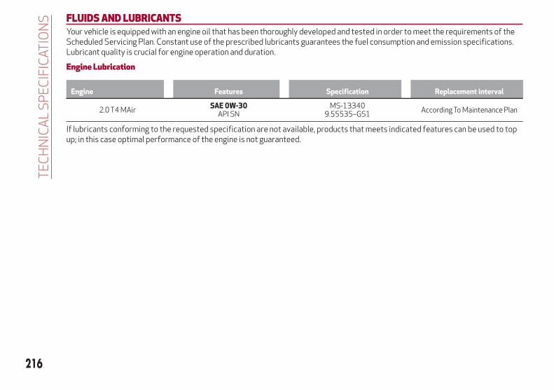
FLUIDS AND LUBRICANTSYour vehicle is equipped with an engine oil that has been thoroughly developed and tested in order to meet the requirements of theScheduled Servicing Plan. Constant use of the prescribed lubricants guarantees the fuel consumption and emission specifications.Lubricant quality is crucial for engine operation and duration.
Engine Lubrication
Engine Features Specification Replacement interval
2.0 T4 MAirSAE 0W-30
API SNMS-13340
9.55535–GS1According To Maintenance Plan
If lubricants conforming to the requested specification are not available, products that meets indicated features can be used to topup; in this case optimal performance of the engine is not guaranteed.
216
TE
CH
NIC
AL
SP
EC
IFIC
ATIO
NS
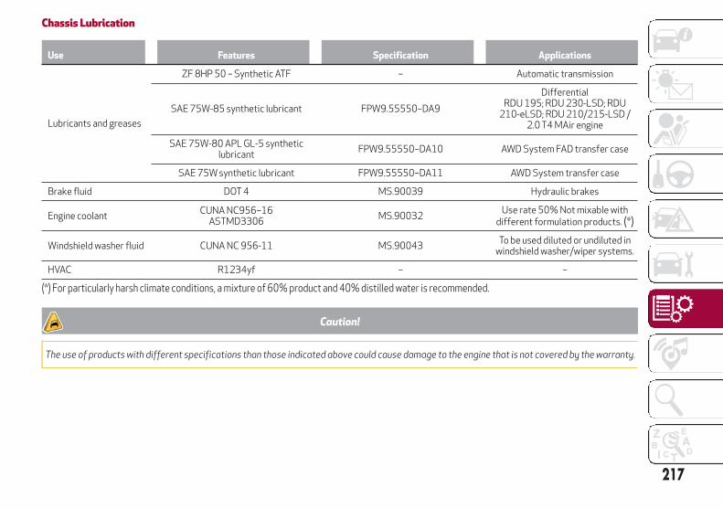
Chassis Lubrication
Use Features Specification Applications
Lubricants and greases
ZF 8HP 50 – Synthetic ATF – Automatic transmission
SAE 75W-85 synthetic lubricant FPW9.55550–DA9
DifferentialRDU 195; RDU 230-LSD; RDU
210-eLSD; RDU 210/215-LSD /2.0 T4 MAir engine
SAE 75W-80 APL GL-5 syntheticlubricant
FPW9.55550–DA10 AWD System FAD transfer case
SAE 75W synthetic lubricant FPW9.55550–DA11 AWD System transfer case
Brake fluid DOT 4 MS.90039 Hydraulic brakes
Engine coolantCUNA NC956–16
ASTMD3306MS.90032
Use rate 50% Not mixable withdifferent formulation products. (*)
Windshield washer fluid CUNA NC 956-11 MS.90043To be used diluted or undiluted in
windshield washer/wiper systems.
HVAC R1234yf – –
(*) For particularly harsh climate conditions, a mixture of 60% product and 40% distilled water is recommended.
Caution!
The use of products with different specifications than those indicated above could cause damage to the engine that is not covered by the warranty.
217

PERFORMANCETop performance after the initial period of vehicle usage.
Engine Top speed mph / (km/h)Acceleration from 0-60 mph /
(0-100 km/h) sec.
2.0 T4 MAir 280 HP AWD engine 144 / (232) 5.4
218
TE
CH
NIC
AL
SP
EC
IFIC
ATIO
NS

MULTIMEDIA
This chapter describes the mainfunctions of the Information andEntertainment system 6.5”, Informationand Entertainment System NAV 6.5”, andthe Information and EntertainmentSysytem 3D NAV 8.8” system that can beequipped in your vehicle.
CYBERSECURITY . . . . . . . . . . . .220ROAD SAFETY . . . . . . . . . . . . . .221RECEPTION CONDITIONS . . . . . . .221CARE AND MAINTENANCE . . . . . .221ANTITHEFT PROTECTION . . . . . . .222IMPORTANT NOTES. . . . . . . . . . .222CONTROLS . . . . . . . . . . . . . . . .222CONTROLS ON STEERING WHEEL . .227INTRODUCTION . . . . . . . . . . . . .229RADIO MODE . . . . . . . . . . . . . .229MEDIA MODE . . . . . . . . . . . . . .230USB/iPod/AUX SUPPORT . . . . . . .230PHONE MODE . . . . . . . . . . . . . .230NAVIGATION MODE — IFEQUIPPED . . . . . . . . . . . . . . . .231SETTINGS. . . . . . . . . . . . . . . . .232APPS . . . . . . . . . . . . . . . . . . . .234VOICE COMMANDS. . . . . . . . . . .236
219

CYBERSECURITYYour vehicle may be a connected vehicleand may be equipped with both wired andwireless networks. These networks allowyour vehicle to send and receiveinformation. This information allowssystems and features in your vehicle tofunction properly.
Your vehicle may be equipped withcertain security features to reduce therisk of unauthorized and unlawful accessto vehicle systems and wirelesscommunications. Vehicle softwaretechnology continues to evolve overtime, and FCA US LLC, working with itssuppliers, evaluates and takesappropriate steps as needed. Similar to acomputer or other devices, your vehiclemay require software updates toimprove the usability and performance ofyour systems, or to reduce the potentialrisk of unauthorized and unlawful accessto your vehicle systems.
The risk of unauthorized and unlawfulaccess to your vehicle systems may stillexist, even if the most recent version ofvehicle software is installed.
Warning!
It is not possible to know or to predict allof the possible outcomes if your vehicle’ssystems are breached. It may be possiblethat vehicle systems, including safetyrelated systems, could be impaired or a lossof vehicle control could occur that may resultin an accident involving serious injury ordeath.
ONLY insert media (e.g., USB or SD card)into your vehicle if it came from a trustedsource. Media of unknown origin couldpossibly contain malicious software, and ifinstalled in your vehicle, it may increase thepossibility for vehicle systems to bebreached.
As always, if you experience unusualvehicle behavior, take your vehicle to yournearest authorized dealer immediately.
Note:
FCA US LLC or your dealer maycontact you directly regarding softwareupdates.
To help further improve vehiclesecurity and minimize the potential riskof a security breach, vehicle ownersshould:
– Only connect and use trusted mediadevices (e.g. personal mobile phones orUSBs).
Privacy of any wireless and wiredcommunications cannot be assured. Thirdparties may unlawfully interceptinformation and private communicationswithout your consent.
220
MU
LTIM
ED
IA

ROAD SAFETYLearn how to use the various systemsand read the instructions carefully beforeoperating the system.
Warning!
ALWAYS drive safely with your hands on thewheel. You have full responsibility andassume all risks related to the use of thefeatures and applications in this vehicle.Only use these features and applicationswhen it is safe to do so. Failure to do so mayresult in an accident involving serious injuryor death.
RECEPTION CONDITIONSReception conditions change constantlywhile driving. There may be receptioninterference when near mountains, tallbuildings, or bridges, especially when youare far away from the broadcaster.
Note:
The volume may change when receivingtraffic information and news.
CARE AND MAINTENANCEObserve the following precautions toensure the system is fully operational:
Avoid hitting the display lens withpointed or hard objects that coulddamage its surface.
Clean with a damp cloth (microfibre ifpossible). If necessary, you can use adelicate mild soap and water solution,then dry with a soft, dry cloth. Do notapply pressure to the display lens whilecleaning.
Do not use alcohol, benzines and theirderivatives, ammonia, solvents or othercompounds to clean the display lens;prevent any liquid from entering the system:this could damage it beyond repair.
Caution!
Only clean the front panel and the displaywith a soft, clean, dry, anti-static cloth.Cleaning and polishing products maydamage the surface. Do not use alcohol orsimilar products to clean the panel or thedisplay.
Do not use the display as a base forsupports with suction pads or adhesives forexternal navigators or smartphones orsimilar devices.
221

ANTITHEFT PROTECTIONThe system is equipped with an antitheftprotection system based on theexchange of information with theelectronic control unit (Body Computer)on the vehicle.
This guarantees maximum safety andprevents the system from being used onother vehicles if it is stolen. If necessarycontact an authorized dealer.
IMPORTANT NOTESOnly look at the screen when it isnecessary and safe to do so. If you needto look at the screen for a long time, pullover to a safe place to avoid becomingdistracted while driving.
Immediately stop using the system in theevent of a fault, or you could damage thesystem. Contact an authorized dealer assoon as possible to have the systemrepaired.
CONTROLSCONTROLS ON CONSOLE
Controls
1 — ON/OFF Control And Volume Knob2 — OPTION Button3 — Rotary Pad4 — MENU Button
222
MU
LTIM
ED
IA

CONTROL SUMMARY TABLEON/OFF Control And Volume Knob
Action Function
LONG PRESS Turns the Information and Entertainment System on and off.
ROTATIONRotate clockwise to increase the volume.Rotate counterclockwise to decrease the volume.
SHORT PRESS
Turns the system on, if it is off.In Radio mode: Activates/deactivates the Mute function.In Media mode: Activates play/pause and activates/deactivates theMute function.
MOVE TO THE SIDE
In Radio mode:
Move to the right to seek to the next radio station.
Move to the left to seek to the previous radio station.In Media mode:
Move to the right to seek to the next track.
Move to the left to seek to the previous track.
223

OPTION Button
Pushing the "OPTION" button while within the modes “RADIO”, “MEDIA”, “PHONE”, or “NAVIGATION” will open the "Settings" screen ofthat particular mode. Press it again to go back to the previously selected mode.
Rotary Pad
Action Function
ROTATION
Within the Menus: scrolls the menu items.Within Point On Map, in Navigation mode (if equipped): Rotateclockwise to zoom in on the map. Rotate counterclockwise to zoom outon the map.
PUSH Within the Menus: confirms the selection.
BRIEF MOVEMENT TO THE RIGHTWithin the Menus: accesses the submenu of the selected function.Within Point On Map, in Navigation mode (if equipped): moves to theright on the map.
BRIEF MOVEMENT TO THE LEFTWithin the Menus: returns to the previous menu; ESC function.Within Point On Map, in Navigation mode (if equipped): moves to theleft on the map.
BRIEF UPWARD MOVEMENT
Within the Menus: enters the Multitasking menu and closes thepreselection bar if open.Within Point On Map, in Navigation mode (if equipped): moves upwardson the map.
BRIEF DOWNWARD MOVEMENT
Activates the radio preselection.Within the Menus: enters the preselection bar and closes theMultitasking menu if open.Within Point On Map, in Navigation mode (if equipped): movesdownwards on the map.
224
MU
LTIM
ED
IA

Touchpad Controls — If Equipped
The top of the Rotary Knob is a touchpaddevice, and can be used to operate someof the controls.
Function Action Where
Open And Close MultitaskingMenu
Scroll up
Anywhere (except where specified)
Open And Close the Preset Bar
Scroll down
Anywhere (except where specified)
Touchpad Controls
225

Function Action Where
Enter Letters, Symbols, AndNumbers
Writing
Data input screens
Zoom
Movement to open and close
Point On Map
Drag
Scroll
Point On Map
226
MU
LTIM
ED
IA
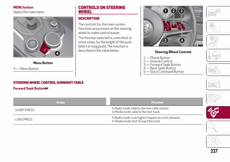
MENU button
Opens the main menu.CONTROLS ON STEERINGWHEELDESCRIPTIONThe controls for the main systemfunctions are present on the steeringwheel to make control easier.
The function selected is controlled, insome cases, by the length of the push(short or long push). The function isdescribed in the table below.
STEERING WHEEL CONTROL SUMMARY TABLEForward Seek Button
Action Function
SHORT PRESSIn Radio mode: selects the next radio station.In Media mode: selects the next track.
LONG PRESSIn Radio mode: scan higher frequencies until released.In Media mode: fast forward the track.
Menu Button
4 — Menu Button
Steering Wheel Controls
1 — Phone Button2 — Volume Control3 — Forward Seek Button4 — Back Seek Button5 — Voice Command Button
227

Back Seek Button
Action Function
SHORT PRESSIn Radio mode: selects the previous radio station.In Media mode: selects the previous track.
LONG PRESSIn Radio mode: scan lower frequencies until released.In Media mode: fast rewind.
Voice Command Button
Action Function
SHORT PRESS Activate voice commands.
LONG PRESS Immediately closes Voice Recognition.
Phone Button
Answers/ends call or shows the recent calls list.
Volume Control
Action Function
ROTATIONUpwards: increases volume.Downwards: decreases volume.
SHORT PRESSIn Radio mode: activates/deactivates the Mute function.In Media mode: activates play/pause and activates/deactivates theMute function.
228
MU
LTIM
ED
IA

INTRODUCTIONThe system can be managed using theRotary Pad.
Turn it to navigate the menus.
Push it to activate/confirm theselections.
Move it leftwards to go back to theprevious screen.
RADIO MODEAfter the desired radio station isselected, the following information isshown on the display.
1 — Control bar
Favorites
Next
Previous
Stations List
Search
Band
2 — Name of the radio station beingplayed and the favorite symbol if thestation is stored in the list
3 — Logo of the active frequency band
4 — Transmitted program type
5 — Current station frequency
6 — Preset number (if the current stationis stored)
Radio Mode
229

MEDIA MODENote:
Applications used on portable devicesmay be not compatible with theInformation and Entertainment System.
Track Selection (Browse)
With Media mode active, briefly pressthe Seek buttons to play theprevious/next track or keep the Seekbuttons pressed to fast rewind/forwardthe track.
USB/iPod/AUX SUPPORTThere might be up to three USB ports:one under the Climate Controls on theInstrument Panel, one in the centerconsole, and one (charge only) under theair vents on the back side of the centerconsole. The AUX socket is located insidethe center console.
Note:
After using a USB recharging socket, werecommend disconnecting the device(smartphone), by removing the cablefrom the vehicle socket first, never fromthe device. Cables left disconnected orconnected incorrectly could compromisecorrect recharging and/or the USBsocket condition.
PHONE MODEPhone mode can be activated from themain menu (MENU button) by turning andpressing the Rotary Pad.
The following control bar appears on thedisplay:
DialRecent callsFavoritesContactsText messagesEnd call
Media Mode
Phone Mode
230
MU
LTIM
ED
IA

With a call in progress, the controlchanges to:
DialRecent callsTransfer to deviceContactsMuteEnd call
Note:
The mobile phone audio is transmittedthrough the vehicle’s audio system. Thesystem automatically mutes the systemaudio when the PHONE function is used.
Pairing A Mobile Phone
Proceed as follows:Activate the Bluetooth function on the
devicePress the MENU button, select the
“SETTINGS” function by turning andpushing the Rotary Pad
Select “Infotainment”Select BluetoothSelect "Add device"Search for the Information and
Entertainment system on the Bluetoothaudio device (during the pairing stage ascreen is displayed showing the progressof the operation)
When requested by the audio device,enter the PIN code shown on the systemdisplay or confirm on the device the PINdisplayed
When the pairing procedure iscompleted successfully, a dedicatedscreen is displayed
The “Bluetooth” can be reached also bypressing the OPTION button in thePHONE or MEDIA functions. The lattercan be selected by turning and pressingthe Rotary Pad in the main menu (MENUbutton).
Making A Phone Call
Proceed as follows:Select the "Recent calls" iconSelect the “Contacts” iconSelect the “Dial” icon
NAVIGATION MODE — IFEQUIPPED
Note:
In the interest of safety and to reducedistractions while you are driving, youshould always plan a route before youstart driving.
To plan a route, do the following:Activate NAVIGATION mode by
selecting it on the main menu.Activate the “Set destination”
function.
To enter an address, select the item toadd (Country, City). On the circularkeypad, type the desired name, and thesystem automatically completes theword. The right of the display offers a listof options that apply to the enteredletters. You can now either complete theword, or go to the list of suggestions by
Navigation Mode
231

tapping the Rotary rightward, or bypointing to “OK”, and pressing theRotary Pad.
OrSelect an address from the “Recent
destinations” list.
OrSelect an address from the “Favorite
destinations” list.Once the desired destination has been
set, select "Start navigation".
With navigation started, select one of thefollowing options using the control bar onthe display:
Stop Navigation: this allows the userto stop navigation
Navigation Volume Adjustment: thisallows to set the volume of the messages
Edit Route: lets you refine your routechoice, offering a series of options
Route Preview: this is used to see apreview of the planned route
Zoom: this allows to zoom into/out ofthe map
Point On Map: this allows to moveinside the map
SETTINGSTo access the user-programmablefunctions, open the main menu bypressing the MENU button, then selectSETTINGS by turning and pressing theRotary Pad.
The following menu items can be foundwithin SETTINGS:
LightsUnits & LanguageClock & DateSafetyDriver AssistanceDoors & LocksClusterInfotainmentSystem
Lights
To access Lights settings, select it usingthe Rotary Pad. The following settingscan be modified when this mode isselected:
Headlight SensitivityHeadlight Off DelayCornering LightsFlash Lights with LockDaytime Running LightsGreeting LightsInterior Ambient LightsAutomatic High BeamRestore Settings
Units & Language
To access "Units & Language" settings,select it using the Rotary Pad. Thefollowing settings can be modified whenthis mode is selected:
UnitsLanguageRestore Settings
Clock & Date
To access "Clock & Date" settings, selectit using the Rotary Pad. The followingsettings can be modified when this modeis selected:
Sync with GPS TimeSet TimeTime FormatSet DateRestore Settings
Settings Menu
232
MU
LTIM
ED
IA

Safety
To access “Safety” settings, select itusing the Rotary Pad. The followingsettings can be modified when this modeis selected:
Speed Limiter
This feature activates/deactivates thewarning that indicates you haveexceeded the set speed.
Speed Limiter - Set Speed
This feature sets the desired speed limitvalue. By turning the Rotary Pad, thespeed increases by 5 mph (5 km/h), perrotation, from a minimum of 20 mph(30 km/h) to a maximum of 110 mph(180 km/h).
Forward Collision Warning — IfEquipped
This feature sets the type and sensitivityof the assistance features for theanti-collision system. The optionsavailable are:
– "Mode": used to set the followingoperating modes: Warning and Brake,Only Warning, or Disabled
– "Sensitivity": used to select desireddistance of the obstacle (near,medium, or far) that the assistancefeatures activate at.
Lane Departure Warning
This feature is used to select the"readiness" of the Lane Departuresystem to activate. The option availableis:
– "Sensitivity": used to select thetiming (early, or late) for when theassistance features activate.
Blind Spot Monitoring
Used to activate/deactivate the soundwarning that indicates that objects aredetected in the blind spot of the exteriorrear view mirrors.
Driver Assistance
To access “Driver assistance” settings,select it using the Rotary Pad. Thefollowing settings can be modified whenthis mode is selected:
ParkSense
This feature is used to select the type ofwarning provided by the ParkSensesystem.
The options available are:– “Mode”: the following options are
available in this function: “Sound”, thesystem notifies the driver of thepresence of an obstacle by means ofsound. This sound warning can beheard from the speakers in thevehicle. “Sound and Display”, thesystem notifies the driver of the
presence of an obstacle by means ofsound and visual signals on theinstrument panel display.
– "Parksense Volume": sets the volumeof the sound warnings provided bythe ParkSense system, the availableoptions are: "High, "Medium," or"Low".
Rear View Camera — If Equipped
This function can be used to carry out thefollowing adjustments:
– "View": lets you activate the videocamera on the display.
– "Camera Delay": allows you to delaythe camera from shutting offimmediately when the vehicle istaken out of REVERSE.
– "Camera Guidelines": allows you toactivate the dynamic guidelines thatappear on the display to indicate theroute of the vehicle.
Automatic Parking Brake
This function allows you toactivate/deactivate the automaticparking brake activation, when the engineis turned off.
Brake Service — If Equipped
This function activates a vehicle modethat allows brake system servicing.
233

Doors & Locks
To access “Doors & Locks” settings,select it using the Rotary Pad. Thefollowing settings can be modified whenthis mode is selected:
Door Lock in MotionUnlock All Doors on ExitPassive EntryDoor Unlock on EntryHorn with Remote StartSound Horn with LockRestore Settings
Cluster
To access “Cluster” settings, select itusing the Rotary Pad. The followingsettings can be modified when this modeis selected:
Warning Buzzer VolumeTrip BPhone RepeatRestore Settings
Infotainment
To access “Infotainment” settings, selectit using the Rotary Pad. The followingsettings can be modified when this modeis selected:
Screen OffSplitscreenAudioBluetoothRadioMediaPhoneNavigation (if equipped)Apps
System
To access “System” settings, select itusing the Rotary Pad. The followingsettings can be modified when this modeis selected:
Auto-On RadioSwitch-Off DelaySoftware UpdateMap UpdateClear Personal DataRestore Settings
APPSRadio Application Mode can be activatedfrom the main menu (MENU button) byturning and pressing the Rotary Pad.
The following information appears on thedisplay:
"My Car”: lets you see a series ofinformation linked to the vehicle status.
“Efficient Drive”: lets you see somedriving style parameters.
“User’s Manual”: lets you view and readthe vehicle's user manual.
Application Mode
234
MU
LTIM
ED
IA
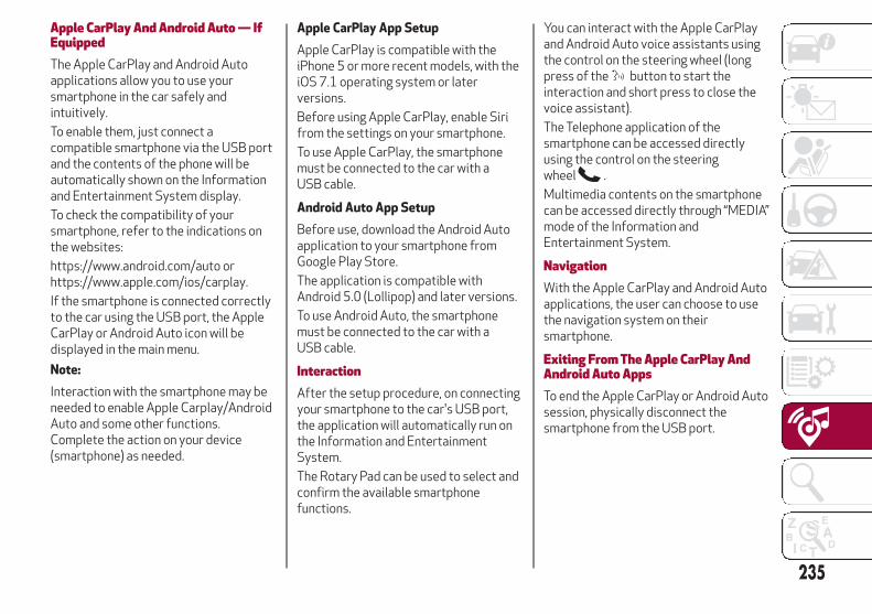
Apple CarPlay And Android Auto — IfEquippedThe Apple CarPlay and Android Autoapplications allow you to use yoursmartphone in the car safely andintuitively.
To enable them, just connect acompatible smartphone via the USB portand the contents of the phone will beautomatically shown on the Informationand Entertainment System display.
To check the compatibility of yoursmartphone, refer to the indications onthe websites:
https://www.android.com/auto orhttps://www.apple.com/ios/carplay.
If the smartphone is connected correctlyto the car using the USB port, the AppleCarPlay or Android Auto icon will bedisplayed in the main menu.
Note:
Interaction with the smartphone may beneeded to enable Apple Carplay/AndroidAuto and some other functions.Complete the action on your device(smartphone) as needed.
Apple CarPlay App Setup
Apple CarPlay is compatible with theiPhone 5 or more recent models, with theiOS 7.1 operating system or laterversions.
Before using Apple CarPlay, enable Sirifrom the settings on your smartphone.
To use Apple CarPlay, the smartphonemust be connected to the car with aUSB cable.
Android Auto App Setup
Before use, download the Android Autoapplication to your smartphone fromGoogle Play Store.
The application is compatible withAndroid 5.0 (Lollipop) and later versions.
To use Android Auto, the smartphonemust be connected to the car with aUSB cable.
InteractionAfter the setup procedure, on connectingyour smartphone to the car's USB port,the application will automatically run onthe Information and EntertainmentSystem.
The Rotary Pad can be used to select andconfirm the available smartphonefunctions.
You can interact with the Apple CarPlayand Android Auto voice assistants usingthe control on the steering wheel (longpress of the button to start theinteraction and short press to close thevoice assistant).
The Telephone application of thesmartphone can be accessed directlyusing the control on the steeringwheel .
Multimedia contents on the smartphonecan be accessed directly through “MEDIA”mode of the Information andEntertainment System.
NavigationWith the Apple CarPlay and Android Autoapplications, the user can choose to usethe navigation system on theirsmartphone.
Exiting From The Apple CarPlay AndAndroid Auto AppsTo end the Apple CarPlay or Android Autosession, physically disconnect thesmartphone from the USB port.
235

VOICE COMMANDSNote:
Voice commands are not available forlanguages not supported by the system.
To use the voice commands, press thebutton on the steering wheel and sayone of the commands below for thefunction you want to activate.
The available voice commands are listedbelow:
Radio Functions
The button can be used to activatethe following functions:
Tune In Station Xxx
Tune In Frequency Xxx
Add To Favorites
Show Available Stations
Show Favorite Stations
FM
AM
SiriusXM
Media Functions
The button can be used to activatethe following functions:
Display Album
Play Album
Display Artist
Play Artist
Display Composer
Play Composer
Display Genre
Play Genre
Display Playlist
Play Playlist
Play Song
Play All
Display All The Albums
Display All The Artists
Display All The Composers
Display All The Genres
Display All The Playlists
View All Songs
Activate Shuffle
Deactivate Shuffle
Pass To Aux
Pass To USB 1
Pass To USB 2
Pass To Bluetooth
Phone Functions
The button can be used to activatethe following functions:
Dial <XXX>
Call <XXX>
Redial
Show Contacts
Show All Calls
Show Missed Calls
Search
Navigation Functions — If Equipped
The button can be used to activatethe following functions:
Navigate To <XXXX>
Favorite
Set 2D Map
Set Detailed 3D Map
Set Overhead View
Route Preview
Start Navigation
Interrupt Navigation
Repeat Instructions
Show Map
Find The Nearest <Point Of Interest>
236
MU
LTIM
ED
IA
CUSTOMER ASSISTANCE
SUGGESTIONS FOR OBTAININGSERVICE FOR YOUR VEHICLE . . . .238IF YOU NEED ASSISTANCE . . . . . .238WARRANTY INFORMATION . . . . .239REPORTING SAFETY DEFECTS . . .240PUBLICATION ORDER FORMS . . . .240
237

SUGGESTIONS FOR OBTAININGSERVICE FOR YOUR VEHICLEPrepare For The AppointmentIf you are having warranty work done, besure to bring the right papers with you, aswell as your warranty folder. All work tobe performed may not be covered by thewarranty. Discuss additional charges withthe service manager. Keep a maintenancelog of your vehicle's service history, asthis can often provide a clue to thecurrent problem.
Prepare A ListMake a written list of your vehicle'sproblems or the specific work you wantdone. If you've had an accident or workdone that is not on your maintenance log,let the service advisor know.
Be Reasonable With RequestsIf you list a number of items and you musthave your vehicle by the end of the day,discuss the situation with the serviceadvisor and list the items in order ofpriority. At many authorized dealers, youmay obtain a rental vehicle at a minimaldaily charge. If you need a rental, it isadvisable to make these arrangementswhen you call for an appointment.
IF YOU NEED ASSISTANCEThe manufacturer and its authorizeddealer are vitally interested in yoursatisfaction. We want you to be happywith our products and services.
Warranty service must be done by anauthorized dealer. We stronglyrecommend that you take the vehicle toan authorized dealer. They know yourvehicle the best, and are most concernedthat you get prompt and high qualityservice. The manufacturer's authorizeddealer have the facilities, factory-trainedtechnicians, special tools, and the latestinformation to ensure the vehicle is fixedcorrectly and in a timely manner.
This is why you should always talk to anauthorized dealer service manager first.Most matters can be resolved with thisprocess.
If for some reason you are still notsatisfied, talk to the general manager orowner of the authorized dealer. Theywant to know if you need assistance.
If an authorized dealer is unable toresolve the concern, you may contact themanufacturer's customer center.
Any communication to themanufacturer's customer center shouldinclude the following information:
Owner's name and address
Owner's telephone number (home andoffice)
Authorized dealer name
Vehicle Identification Number (VIN)
Vehicle delivery date and mileage
Alfa Romeo Customer CenterP.O. Box 21–8004
Auburn Hills, MI 48321–8004
Phone: 1-844-Alfa-USA(1-844-253-2872)
Alfa Romeo Customer Center (Canada)P.O. Box 1621
Windsor, Ontario N9A 4H6
Phone: 1-800-465-2001 (English)Phone: 1-800-387-9983 (French)
Customer Assistance For The HearingOr Speech Impaired (TDD/TTY)To assist customers who have hearingdifficulties, the manufacturer hasinstalled special TDD(Telecommunication Devices for theDeaf) equipment at its customer center.Any hearing or speech impairedcustomer, who has access to a TDD or aconventional teletypewriter (TTY) in theUnited States, can communicate with themanufacturer by dialing1-800-380-2479.
238
CU
STO
ME
RA
SS
ISTA
NC
E

Canadian residents with hearingdifficulties that require assistance canuse the special needs relay serviceoffered by Bell Canada. For TTYteletypewriter users, dial 711 and forVoice callers, dial 1-800-855-0511 toconnect with a Bell Relay Serviceoperator.
Service ContractYou may have purchased a servicecontract for a vehicle to help protect youfrom the high cost of unexpected repairsafter the manufacturer's New VehicleLimited Warranty expires. Themanufacturer stands behind only themanufacturer's service contracts. If youpurchased a manufacturer's servicecontract, you will receive Plan Provisionsand an Owner Identification Card in themail within three weeks of the vehicledelivery date. If you have any questionsabout the service contract, call themanufacturer's Service ContractNational Customer Hotline at1-800-521-9922 (Canadian residents,call (800) 465-2001 English / (800)387-9983 French).
The manufacturer will not stand behindany service contract that is not themanufacturer's service contract. It is notresponsible for any service contractother than the manufacturer's servicecontract. If you purchased a service
contract that is not a manufacturer'sservice contract, and you require serviceafter the manufacturer's New VehicleLimited Warranty expires, please refer tothe contract documents, and contact theperson listed in those documents.
We appreciate that you have made amajor investment when you purchasedthe vehicle. An authorized dealer has alsomade a major investment in facilities,tools, and training to assure that you areabsolutely delighted with the ownershipexperience. You will be pleased with theirsincere efforts to resolve any warrantyissues or related concerns.
Warning!
Engine exhaust (internal combustionengines only), some of its constituents, andcertain vehicle components contain, or emit,chemicals known to the State of Californiato cause cancer and birth defects, or otherreproductive harm. In addition, certain fluidscontained in vehicles and certain products ofcomponent wear contain, or emit, chemicalsknown to the State of California to causecancer and birth defects, or otherreproductive harm.
WARRANTY INFORMATIONSee the Warranty Information Booklet,for the terms and provisions of FCA USLLC and FCA Canada Inc. warrantiesapplicable to this vehicle and market.
239

REPORTING SAFETY DEFECTSIn The 50 United States AndWashington, D.C.
If you believe that your vehicle has adefect that could cause a crash orcause injury or death, you shouldimmediately inform the NationalHighway Traffic SafetyAdministration (NHTSA) in additionto notifying FCA US LLC.
If NHTSA receives similarcomplaints, it may open aninvestigation, and if it finds that asafety defect exists in a group ofvehicles, it may order a recall andremedy campaign. However, NHTSAcannot become involved in individualproblems between you, yourauthorized dealer or FCA US LLC.
To contact NHTSA, you may call theVehicle Safety Hotline toll free at1-888-327-4236(TTY: 1-800-424-9153); or go tohttp://www.safercar.gov; or write to:Administrator, NHTSA, 1200 NewJersey Avenue, SE., West Building,Washington, D.C. 20590. You canalso obtain other information aboutmotor vehicle safety fromhttp://www.safercar.gov.
In Canada
If you believe that your vehicle has asafety defect, you should contact theCustomer Service Departmentimmediately. Canadian customerswho wish to report a safety defect tothe Canadian government shouldcontact Transport Canada, MotorVehicle Defect Investigations andRecalls at 1-800-333-0510 or go tohttp://www.tc.gc.ca/roadsafety/.
PUBLICATION ORDER FORMSReplacement English User Guide kits
may be purchased by visitingwww.techauthority.com or by calling1-800-890-4038 (U.S.) or1-800-387-1143 (Canada). Visa, MasterCard, American Express and Discoverorders are accepted.
240
CU
STO
ME
RA
SS
ISTA
NC
E

INDEXActive Safety Systems . . . . . . . . . .72
Adaptive Cruise Control. . . . . . . . .131
Adaptive Cruise Control (ACC)(Cruise Control) . . . . . . . . . . . .131
Additives, Fuel . . . . . . . . . . . . . .214
Air Bag . . . . . . . . . . . . . . . . . . . .94
Advance Front Air Bag . . . . . . . .94
Air Bag Operation . . . . . . . . . . .95
Air Bag Warning Light . . . . . . . . .92
Driver Knee Air Bag . . . . . . . . . .96
Enhanced Accident Response . . .172
Event Data Recorder (EDR) . . . . .172
Front Air Bag . . . . . . . . . . . . . .94
If A Deployment Occurs . . . . . . . .98
Knee Impact Bolsters . . . . . . . . .96
Maintaining Your Air BagSystem . . . . . . . . . . . . . . . . .102
Redundant Air Bag WarningLight . . . . . . . . . . . . . . . . . . .93
Side Air Bags . . . . . . . . . . . . . .96
Transporting Pets . . . . . . . . . .113
Air Bag Light . . . . . . . . . . . . .92,114
Air Bag Maintenance. . . . . . . . . . .102
Air Pressure, Tires . . . . . . . . . . . .193
Alarm (Security Alarm) . . . . . . . . . .12
Alfa Active Suspension (AAS) . . . . .127
Alfa DNA System . . . . . . . . . . . . .126
Anti-Lock Braking (ABS) System . . . .72
Antifreeze (Engine Coolant) . . . . . .215
Assistance Towing . . . . . . . . . . . .148
Automatic Dimming Mirror . . . . . . . .24
Automatic Headlights . . . . . . . . . . .26
Automatic Temperature Control(ATC) . . . . . . . . . . . . . . . . . . .31
Automatic Transmission . . . . . . . .123
Auxiliary Driving Systems . . . . . . . .76
B-Pillar Location . . . . . . . . . . . . .190
Battery . . . . . . . . . . . . . . . . . . .181
Battery Recharging . . . . . . . . . . .182
Belts, Seat . . . . . . . . . . . . . . . . .114
Blind Spot Monitoring . . . . . . . . . . .76
Bodywork (Cleaning AndMaintenance) . . . . . . . . . . . . .203
Brakes . . . . . . . . . . . . . . . . . . .209
Brake Fluid Level . . . . . . . . . . .181
Bulbs, Light . . . . . . . . . . . . . . . .115
Camera, Rear . . . . . . . . . . . . . . .141
Capacities, Fluid . . . . . . . . . . . . .215
Carbon Monoxide Warning . . . . . . .113
Changing A Flat Tire . . . . . . . . . . .184
Chart, Tire Sizing . . . . . . . . . . . . .186
Checking Levels . . . . . . . . . . . . .179
Checking Your Vehicle For Safety . . .113
Checks, Safety . . . . . . . . . . . . . .113
Child Restraint . . . . . . . . . . . . . .102
Child RestraintsBooster Seats . . . . . . . . . . . . .105
Child Restraints . . . . . . . . . . . .102
Child Seat Installation . . . . . . . .111
How To Stow An Unused ALR SeatBelt . . . . . . . . . . . . . . . . . . .109
Infants And Child Restraints . . . .104
LATCH Positions . . . . . . . . . . .106
Lower Anchors And Tethers ForChildren . . . . . . . . . . . . . . . .106
Older Children And ChildRestraints . . . . . . . . . . . . . . .104
Seating Positions . . . . . . . . . . .105
CleaningWheels . . . . . . . . . . . . . . . . .199
Climate Control. . . . . . . . . . . . . . .31
Close The Hood . . . . . . . . . . . . . . .36
Compact Spare Tire . . . . . . . . . . .198
Contract, Service . . . . . . . . . . . . .239
Controls . . . . . . . . . . . . . . . . . .222
Controls On Console . . . . . . . . .222
Summary Table . . . . . . . . .223,227
Controls On Steering Wheel . . . . . .227
Cooling SystemCoolant Capacity . . . . . . . . . . .215
Selection Of Coolant(Antifreeze) . . . . . . . . . . . . . .215
Cruise Control (Speed Control) . . . .131
Customer Assistance . . . . . . . . . .238

Daytime Running Lights. . . . . . . . . .26
Daytime Running Lights (DRL) . . . . . .26
Defroster, Windshield . . . . . . . . . .114
Dimensions . . . . . . . . . . . . . . . .212
Direction Indicators (Changing ABulb). . . . . . . . . . . . . . . . . . .152
Disabled Vehicle Towing . . . . . .148,169
Door LocksChild-Protection Door Lock —Rear Doors . . . . . . . . . . . . . . . .16
Power Door Locks . . . . . . . . . . .16
Doors. . . . . . . . . . . . . . . . . . . . .13
Drive Train Control (DTC) System . . . .72
Driving Modes . . . . . . . . . . . . . .126
Dynamic Steering Torque (DST)System . . . . . . . . . . . . . . . . . .74
Electric Park Brake. . . . . . . . . . . .120
Electric Remote Mirrors . . . . . . . . .24
Electric Steering Wheel Heating. . . . .24
Electronic Speed Control . . . . . . . .129
Electronic Speed Control (CruiseControl) . . . . . . . . . . . . . .129,131
Electronic Stability Control (ESC)System . . . . . . . . . . . . . . . . . .73
Emergency, In Case Of. . . . . . . . . .163
Hazard Warning Flasher . . . . . . .148
Jacking . . . . . . . . . . . . . . . . .184
Jump Starting . . . . . . . . . . . . .167
Towing . . . . . . . . . . .148,169,170
Engine . . . . . . . . . . . . . . . . . . .207
Engine Coolant Level . . . . . . . . .181
Exhaust Gas Caution . . . . . . . . .113
Fuel Requirements . . . . . . . . . .214
Jump Starting . . . . . . . . . . . . .167
Oil . . . . . . . . . . . . . . . . . . . .215
Oil Selection . . . . . . . . . . . . . .215
Engine Compartment . . . . . . . . . .179
Engine OilLevel Check . . . . . . . . . . . . . .180
Enhanced Accident ResponseFeature . . . . . . . . . . . . . . . . .172
Exhaust Gas Caution. . . . . . . . . . .113
Exhaust System . . . . . . . . . . . . .113
Exterior Lighting . . . . . . . . . . . .26,27
Exterior Lights . . . . . . . . . . . .26,115
FlashersHazard Warning . . . . . . . . . . . .148
Turn Signal . . . . . . . . . . . .28,115
Fluid Capacities. . . . . . . . . . . . . .215
Fluid Leaks . . . . . . . . . . . . . . . .115
Fluids And Lubricants . . . . . . . . . .216
Fog Lights (Changing A Bulb) . . . . . .153
Forward Collision Warning(System) . . . . . . . . . . . . . . . . .79
Front Light Cluster With HalogenHeadlights (Bulb Replacement). . .152
Front Light Cluster With MainBeam Xenon Gas DischargeHeadlights (Bulb Replacement). . .153
Front Seat Electric Heating . . . . . . .19
Front Seats (Power Adjustment) . . . .17
Front WipersWiper Operation . . . . . . . . . . . .29
FuelAdditives . . . . . . . . . . . . . . .214
Materials Added . . . . . . . . . . .214
Tank Capacity . . . . . . . . . . . . .215
Fuse Boxes . . . . . . . . . . . . . . . .154
Fuses (Replacement) . . . . . . . . . .153
Garage Door Opener (HomeLink) . . . .39
General Information . . . . . . . . .78,138
Hazard Warning Flasher . . . . . . . . .148
Hazard Warning LightsEmergency Braking . . . . . . . . . .149
Head Restraints . . . . . . . . . . . . . .21
Head Rests . . . . . . . . . . . . . . . . .21
HeadlightsSwitch . . . . . . . . . . . . . . . .26,27
High Beam Headlights . . . . . . . . . . .27
Automatic High BeamHeadlights . . . . . . . . . . . . . . . .28
IND
EX

Hill Decent Control (HDC) System. . . .75
Hill Start Assist (HSA) System. . . . . .74
Hood . . . . . . . . . . . . . . . . . . . . .36
Hood Release . . . . . . . . . . . . . . . .36
Identification Data . . . . . . . . . . . .206
Ignition . . . . . . . . . . . . . . . . . . . .11
Instrument Cluster . . . . . . . . . . . . .46
Instrument Cluster DisplayInstrument Cluster Display . . . . . .47
Reconfigurable InstrumentCluster Display . . . . . . . . . . . . .48
Instrument Panel FeaturesInstrument Panel Features . . . . . .46
Interior Lights. . . . . . . . . . . . . . . .28
Internal Equipment . . . . . . . . . . . .39
Jack Operation . . . . . . . . . . . . . .184
Jump Starting . . . . . . . . . . . .167,168
Key FobRemote Keyless Entry . . . . . . . . .10
Key, Replacement . . . . . . . . . . . . .10
Keyless Enter-N-GoPassive Entry . . . . . . . . . . . . . .14
Lane Change . . . . . . . . . . . . . . . .28
Lane Change And Turn Signals . . . . . .28
Lane Departure Warning System . . .143
LaneSense. . . . . . . . . . . . . . . . .143
Lap/Shoulder Belts . . . . . . . . . . . .88
Latches. . . . . . . . . . . . . . . . . . .115
Leaks, Fluid . . . . . . . . . . . . . . . .115
Life Of Tires . . . . . . . . . . . . . . . .197
Liftgate . . . . . . . . . . . . . . . . . . .37
Lifting The Vehicle . . . . . . . . . . . .184
Light Bulbs. . . . . . . . . . . . . . . . .115
Types Of Bulbs . . . . . . . . . . . .150
Light Switch. . . . . . . . . . . . . . . . .26
Lights. . . . . . . . . . . . . . . . . . . .115
Air Bag . . . . . . . . . . . . . . .92,114
Automatic Headlights . . . . . . . . .26
Courtesy/Reading . . . . . . . . . . .28
Daytime Running . . . . . . . . . . . .26
Exterior . . . . . . . . . . . . . . . .115
Hazard Warning Flasher . . . . . . .148
Headlight Switch . . . . . . . . . .26,27
Headlights . . . . . . . . . . . . .26,27
High Beam . . . . . . . . . . . . . . . .27
Instrument Cluster . . . . . . . .26,27
Map Reading . . . . . . . . . . . . . .28
Park . . . . . . . . . . . . . . . . . . .27
Reading . . . . . . . . . . . . . . . . .28
Turn Signal . . . . . . . . . . . .28,115
Loading VehicleTires . . . . . . . . . . . . . . . . . .190
LocksPower Door . . . . . . . . . . . . . . .13
Main Beam Headlights (Changing ABulb). . . . . . . . . . . . . . . . . . .152
Manual, Service . . . . . . . . . . . . . .240
Mirrors . . . . . . . . . . . . . . . . . . . .24
Automatic Dimming . . . . . . . . . .24
Electric Powered . . . . . . . . . . . .24
Electric Remote . . . . . . . . . . . .24
OBD System . . . . . . . . . . . . . . . .70
Occupant Restraints. . . . . . . . . . . .86
Oil, EngineCapacity . . . . . . . . . . . . . . . .215
Recommendation . . . . . . . . . .215
Viscosity . . . . . . . . . . . . . . . .215
Owner's Manual(Operator Manual) . . . . . . . . . .240
Paintwork (Cleaning AndMaintenance) . . . . . . . . . . . . .203
Panic Brake Assist (PBA) System . . . .74
Park Sensors System . . . . . . . . . .138
Performance (Top Speed) . . . . . . . .218
Pets . . . . . . . . . . . . . . . . . . . . .113
Placard, Tire And LoadingInformation . . . . . . . . . . . . . .190

PowerDoor Locks . . . . . . . . . . . . . . .13
Mirrors . . . . . . . . . . . . . . . . . .24
Seats . . . . . . . . . . . . . . . . . . .17
Sunroof . . . . . . . . . . . . . . . . .34
Power Sunroof . . . . . . . . . . . . . . .34
Pregnant Women And Seat Belts . . . .90
PretensionersSeat Belts . . . . . . . . . . . . . . . .91
Prolonged Vehicle Inactivity . . . . . .203
Radial Ply Tires . . . . . . . . . . . . . .196
Radio . . . . . . . . . . . . . . . . . . . .229
Radio FrequencyGeneral Information . . . . . .10,12,16
Rain Sensor . . . . . . . . . . . . . . . . .30
Rear Camera . . . . . . . . . . . . . . .141
Rear Cross Path . . . . . . . . . . . . . .76
Rear Seats. . . . . . . . . . . . . . . . . .20
Rear Window Wiper/Washer . . . . . . .30
Refueling Procedure . . . . . . . . . . .144
Refueling The Vehicle . . . . . . . . . .144
Reminder, Seat Belt . . . . . . . . . . . .87
Replacement Keys . . . . . . . . . . . . .10
Replacement Tires . . . . . . . . . . . .197
Replacing A Bulb . . . . . . . . . . . . .149
Replacing An External Bulb . . . . . . .152
Reporting Safety Defects . . . . . . .240
Restraint, Head . . . . . . . . . . . . . . .21
Restraints, Child . . . . . . . . . . . . .102
Rims And Tires . . . . . . . . . . . . . .185
Safety Checks Inside Vehicle . . . . . .114
Safety Checks Outside Vehicle. . . . .115
Safety Defects, Reporting . . . . . . .240
Safety Information, Tire. . . . . . . . .185
Safety Tips . . . . . . . . . . . . . . . .113
Safety, Exhaust Gas . . . . . . . . . . .113
Scheduled Servicing . . . . . . . . . . .174
Scheduled Servicing Program(2.0 T4 MAir Engine Versions) . . .175
Seat BeltAdjustable Upper Shoulder BeltAnchorage . . . . . . . . . . . . . . . .90
Energy Management Feature . . . .91
Lap/Shoulder Belt Untwisting . . . .89
Lap/Shoulder Belts . . . . . . . . . .88
Pregnant Women . . . . . . . . . . . .90
Seat Belt Pretensioner . . . . . . . .91
Seat Belt Reminder . . . . . . . . . .87
Seat Belt Reminder . . . . . . . . . . . .87
Seat Belts . . . . . . . . . . . . . . .87,114
Adjustable Shoulder Belt . . . . . . .90
Adjustable Upper ShoulderAnchorage . . . . . . . . . . . . . . . .90
Child Restraint . . . . . . . . . . . .102
Front Seat . . . . . . . . . . . . . .87,88
Inspection . . . . . . . . . . . . . . .114
Pregnant Women . . . . . . . . . . . .90
Pretensioners . . . . . . . . . . . . . .91
Rear Seat . . . . . . . . . . . . . . . .88
Untwisting Procedure . . . . . . . . .89
Seats . . . . . . . . . . . . . . . . . . . . .17
Head Restraints . . . . . . . . . . . .21
Height Adjustment . . . . . . . . . . .17
Power . . . . . . . . . . . . . . . . . .17
Tilting . . . . . . . . . . . . . . . . . .17
Sentry Key Replacement . . . . . . . . .10
Service Assistance . . . . . . . . . . . .238
Service Contract . . . . . . . . . . . . .239
Service Manuals . . . . . . . . . . . . .240
Servicing Procedures . . . . . . . . . .183
Shoulder Belts . . . . . . . . . . . . . . .88
Signals, Turn. . . . . . . . . . . . . .28,115
Snow Chains. . . . . . . . . . . . . . . .201
Snow Tires . . . . . . . . . . . . . . . . .201
Spare Tire . . . . . . . . . . . . . .198,199
Speed ControlAccel/Decel . . . . . . . . . . . . . .130
Cancel . . . . . . . . . . . . . . . . .131
Resume . . . . . . . . . . . . . . . .130
Set . . . . . . . . . . . . . . . . . . .130
Speed Control (Cruise Control) . . . .131
Speed Limiter . . . . . . . . . . . . . . .128
Starting The Engine . . . . . . . . . . .118
Steering . . . . . . . . . . . . . . . . . .211
Tilt Column . . . . . . . . . . . . . . .23
IND
EX

Wheel, Heated . . . . . . . . . . . . .24
Wheel, Tilt . . . . . . . . . . . . . . . .23
Steering Wheel . . . . . . . . . . . . . . .23
Stop/Start System. . . . . . . . . . . .127
Sun Roof . . . . . . . . . . . . . . . . . . .34
Supplemental Restraint System -Air Bag . . . . . . . . . . . . . . . . . .94
Suspension . . . . . . . . . . . . . . . .210
Symbols . . . . . . . . . . . . . . . . . . . .4
Telescoping Steering Column . . . . . .23
Tilt Steering Column . . . . . . . . . . . .23
Tire And Loading InformationPlacard . . . . . . . . . . . . . . . . .190
Tire Markings . . . . . . . . . . . . . . .185
Tire Safety Information . . . . . . . . .185
Tire Service Kit . . . . . . . . . . . . . .163
Tires . . . . . . . . . . .115,193,198,202
Aging (Life Of Tires) . . . . . . . . .197
Air Pressure . . . . . . . . . . . . . .193
Changing . . . . . . . . . . . . . . . .184
Compact Spare . . . . . . . . . . . .198
Flat Changing . . . . . . . . . . . . .163
General Information . . . . . .193,198
High Speed . . . . . . . . . . . . . .194
Inflation Pressures . . . . . . . . . .193
Jacking . . . . . . . . . . . . . . . . .184
Life Of Tires . . . . . . . . . . . . . .197
Load Capacity . . . . . . . . . . . . .190
Quality Grading . . . . . . . . . . . .202
Radial . . . . . . . . . . . . . . . . . .196
Replacement . . . . . . . . . . . . .197
Safety . . . . . . . . . . . . . .185,193
Sizes . . . . . . . . . . . . . . . . . .186
Snow Tires . . . . . . . . . . . . . . .201
Spare Tire . . . . . . . . . . . .198,199
Spinning . . . . . . . . . . . . . . . .196
Tread Wear Indicators . . . . . . . .196
Towing . . . . . . . . . . . . . . . . . . .146
Disabled Vehicle . . . . . . . . . . .169
Towing Eyes . . . . . . . . . . . . . . . .170
Towing The Vehicle . . . . . . . . . . . .170
TPMS (Tire Pressure MonitoringSystem). . . . . . . . . . . . . . . . . .83
Traction Control System (TCS). . . . . .73
Trailer Towing . . . . . . . . . . . . . . .146
Trailer And Tongue Weight . . . . .146
Trailer Towing Guide . . . . . . . . . . .146
Trailer Weight . . . . . . . . . . . . . . .146
Transmission . . . . . . . . . . . . . . .208
Transporting Pets . . . . . . . . . . . .113
Tread Wear Indicators . . . . . . . . . .196
Turn Signals . . . . . . . . . . . . . . . . .28
Uniform Tire Quality Grades . . . . . .202
Untwisting Procedure, Seat Belt . . . .89
Use Of The Owner’s Manual . . . . . . . .3
Vehicle Changes/Alterations . . . . . . .5
Vehicle Identification Number . . . . .206
Vehicle Loading . . . . . . . . . . . . . .190
Warning Flasher, Hazard . . . . . . . .148
Warranty Information . . . . . . . . . .239
Washer Fluid ForWindshield/Headlights. . . . . . . .181
Washers, Windshield. . . . . . . . . . . .29
Weights . . . . . . . . . . . . . . . . . .213
Wheel And Wheel Trim. . . . . . . . . .199
Wheel And Wheel Trim Care . . . . . .199
Wheels And Tires . . . . . . . . . . . . .185
Windshield Defroster . . . . . . . . . .114
Windshield Wiper . . . . . . . . . . . . .29
Replacing Blades . . . . . . . . . . .184
Windshield Wiper/WasherSmart Washing Function . . . . . . .29
Windshield Wipers . . . . . . . . . . . . .29
Wrecker Towing. . . . . . . . . . . . . .169


This guide has been prepared to help you get quickly acquainted with your new Alfa Romeo and to provide a convenient reference source for common questions. However, it is not a substitute for your Owner’s Manual.
For complete operational instructions, maintenance procedures and important safety messages, please consult your Owner’s Manual, Information and Entertainment System Manual found on the website on the back cover and other Warning Labels in your vehicle.
Not all features shown in this guide may apply to your vehicle. For additional information on accessories to help personalize your vehicle, visit alfaromeousa.com or your local Alfa Romeo dealer.
D R I V I N G A N D A L C O H O LDrunken driving is one of the most frequent causes of accidents. Your driving ability can be seriously impaired with blood alcohol levels far below the legal minimum. If you are drinking, don’t drive. Ride with a designated non-drinking driver, call a cab, a friend, or use public transportation.
W A R N I N G !Driving after drinking can lead to an accident. Your perceptions are less sharp, your reflexes are slower, and your judgment is impaired when you have been drinking. Never drink and then drive.
If you have any questions about your vehicle or need assistance, please call Alfa Romeo Customer Care at 1 844 253-2872 (U.S.) or 1 800 387-1143 (Canada).
I M P O R T A N T
Get warranty and other information online – you can review and print or download a copy of documents for your vehicle provided by FCA US LLC by visiting these links. For Owner’s Manual and Information and Entertainment System Manual, visit alfaromeousa.com/owners/owners-service-manual, and for the limited warranties, visit alfaromeousa.com/owners/warranty. Click on the applicable link and follow the instructions to select the applicable year, make and model for your vehicle.
This User Guide is intended to familiarize you with the important features of your vehicle. Your Owner’s Manual, Radio Manual and Warranty Booklet can be found by visiting the website on the back cover of your User Guide. We hope you find these resources useful. U.S. residents can purchase replacement kits by visiting www.techauthority.com and Canadian residents can purchase replacement kits by calling 1 800 387-1143.
The driver’s primary responsibility is the safe operation of the vehicle. Driving while distracted can result in loss of vehicle control, resulting in a collision and personal injury. FCA US LLC strongly recommends that the driver use extreme caution when using any device or feature that may take their attention off the road. Use of any electrical devices, such as cellular telephones, computers, portable radios, vehicle navigation or other devices, by the driver while the vehicle is moving is dangerous and could lead to a serious collision. Texting while driving is also dangerous and should never be done while the vehicle is moving. If you find yourself unable to devote your full attention to vehicle operation, pull off the road to a safe location and stop your vehicle. Some states or provinces prohibit the use of cellular telephones or texting while driving. It is always the driver’s responsibility to comply with all local laws.
2825671_18b_Alfa_Romeo_Stelvio_UG_070517.indd 2 7/5/17 5:14 PM

2 0 1 8 U S E R G U I D E
18
GU
-92
6-A
AA
LFA
RO
MEO
STE
LVIO
Seco
nd E
diti
onU
ser G
uide
©2017 FCA US LLC. All Rights Reserved. ALFA ROMEO is a registered trademark of FCA Group Marketing S.p.A., used with permission.
Get warranty and other information online – you can review and print or download a copy of documents for your vehicle provided by FCA US LLC by visiting these links. For Owner’s Manual and Information and Entertainment System Manual, visit alfaromeousa.com/owners/owners-service-manual, and for the Limited Warranties, visit alfaromeousa.com/owners/warranty. Click on the applicable link and follow the instructions to select the applicable year, make and model for your vehicle.
Whether it’s providing information about specific product features, taking a tour through your vehicle’s heritage, knowing what steps to take following an accident, or scheduling your next appointment, we know you’ll find the app an important extension of your Alfa Romeo vehicle. Simply download the app, select your make and model and enjoy the ride. To get this app, go directly to the App Store or Google Play and enter the search keyword “Alfa Romeo” (U.S. market only).
Download a FREE electronic copy of the most up-to-date documents by visiting these links:
Owner’s Manual and Media:www.alfaromeousa.com/owners/owners-service-manual (U.S. residents); www.owners.mopar.ca (Canadian residents).
Warranty Booklet:www.alfaromeousa.com/owners/warranty (U.S. residents); www.owners.mopar.ca (Canadian residents).
2825671_18b_Alfa_Romeo_Stelvio_UG_070517.indd 1 7/5/17 5:14 PM