Embed Size (px)
Citation preview


2018 Routine/Fracture Critical Member Inspection Report
Anna Hunt Marsh Bridge NH Route 119 over the Connecticut River
NHDOT Bridge No. 041/040 Hinsdale, NH
Prepared for
The Department of Transportation
July 2018
Prepared by

i
TABLE OF CONTENTS
LOCATION MAP ........................................................................................................... 1
DESCRIPTION OF BRIDGE .......................................................................................... 2
BRIDGE PLAN AND ELEVATION ................................................................................... 3
TYPICAL BRIDGE SECTION ......................................................................................... 4
IDENTIFICATION OF FRACTURE CRITICAL MEMBERS ................................................ 5
ROUTINE/FRACTURE CRITICAL MEMBER INSPECTION OVERVIEW ........................... 6 Introduction ..................................................................................................................... 6 Bridge Description ............................................................................................................ 6 Routine/Fracture Critical Member Inspection Methods ..................................................... 7
BRIDGE CONDITION ................................................................................................... 7 Critical Findings Summary ................................................................................................ 7 Item 58 Deck ................................................................................................................... 7 Item 59 Superstructure .................................................................................................... 8 Item 60 Substructure ..................................................................................................... 14
FRACTURE CRITICAL INSPECTION ...........................................................................15 Fracture Critical Members (FCM) and Fatigue Prone Detail Identification ....................... 15 Fracture Critical Member Inspection Procedures and Findings ....................................... 15 Identification of Fatigue Sensitive Details (FSD) ............................................................ 16
MAINTENANCE AND REPAIR RECOMMENDATIONS ..................................................21 APPENDIX A. Inspection Photos

LOCATION MAP
File Name:
DATE: Page 1
N/A NH Route 119 over the Connecticut River
Hinsdale, NH – Brattleboro, VT 7/18
1
Project Location Bridge No. 041/040
2
NH Route 119 over the Connecticut River Hinsdale, NH - Brattleboro, VT (NHDOT Bridge No. 041/040) 2018 Routine/Fracture Critical Member Inspection Report
DESCRIPTION OF BRIDGE Date of Construction: 1920, Rehabilitated in 1988
Original Design Loading: Trusses: H15; Deck, Stringers and Floorbeams: HS20
Bridge Type: Steel Through Truss – Camelback
Skew: None
Spans: 1
Width of Highway Bridge Deck:
20’-4 1/8” Between Face-of-Rails
Roadway Surface: Precast Concrete Deck Panels (Variable Thickness)
Sidewalk/Walkway/ Median:
Timber decking
Bridge Railing: Double Nested W-Beam Guardrail
Approach Railing: W-Beam Guardrail
Superstructure: Through truss comprised of riveted built-up upper chords, lower chords, vertical, and horizontal members; and diagonal members. The bridge deck is supported by rolled shape stringers. The stringers are supported by rolled shape floorbeams connected to the trusses at panel points.
Modifications to Original Superstructure:
The bridge deck was replaced in 2004 and the floor system (stringers and floorbeams) was replaced in their entirety in 1988. The bridge rail was replaced with double nested W-beam guardrail in 1988.
Utilities: Electric lines are attached to the truss sway bracing to provide power for street lights on the bridge.
Substructure: West (Vermont): Reinforced concrete cap founded on granite masonry.
East (New Hampshire): Reinforced concrete abutment.
Modifications to Original Substructure:
None

3
NH Route 119 over the Connecticut River Hinsdale, NH - Brattleboro, VT (NHDOT Bridge No. 041/040) 2018 Routine/Fracture Critical Member Inspection Report
BRIDGE PLAN AND ELEVATION Note: Plan and elevation taken from “State of New Hampshire Department of Transportation Plans of Proposed N.H. Project No. 10603 N.H. 119 Over Connecticut River (2 Bridges) Bridge Rehabilitation” plans dated February 17, 1987.

4
NH Route 119 over the Connecticut River Hinsdale, NH - Brattleboro, VT (NHDOT Bridge No. 041/040) 2018 Routine/Fracture Critical Member Inspection Report
TYPICAL BRIDGE SECTION Note: Typical section taken from “State of New Hampshire Department of Transportation Plans of Proposed N.H. Project No. 10603 N.H. 119 Over Connecticut River (2 Bridges) Bridge Rehabilitation” plans dated February 17, 1987.

5
NH Route 119 over the Connecticut River Hinsdale, NH - Brattleboro, VT (NHDOT Bridge No. 041/040) 2018 Routine/Fracture Critical Member Inspection Report
IDENTIFICATION OF FRACTURE CRITICAL MEMBERS

6
NH Route 119 over the Connecticut River Hinsdale, NH - Brattleboro, VT (NHDOT Bridge No. 041/040) 2018 Routine/Fracture Critical Member Inspection Report
ROUTINE/FRACTURE CRITICAL MEMBER INSPECTION OVERVIEW
Introduction Hoyle, Tanner and Associates, Inc. (Hoyle, Tanner) performed a routine/fracture critical member (FCM) inspection of the Anna Hunt Marsh Bridge (NHDOT Br. No. 041/040) carrying NH Route 119 over the Connecticut River between Hinsdale, NH and Brattleboro, VT for the New Hampshire Department of Transportation (NHDOT) from June 25 through June 27, 2018. The FCM inspection was performed for the following members:
• Floorbeams • Lower Chords
o L0-L1, L1-L2, L2-L3, L3-L4, L4-L5, L5-L6, L6-L7, L7-L8, L8-L9, o L9-L10, L10-L11, L11-L12, L12-L13, L13-L14, L14-L15, L15-L16
• Diagonals o U1-L2, U2-L3, U3-M4, M4-L5, L3-M4, M4-U5, U5-M6, M6-L7, o L5-M6, M6-U7, U7-M8, M8-L9, L7-M8, M8-U9, U9-M10, M10-L11, o L9-M10, M10-U11, U11-M12, M12-L13, L11-M12, M12-U13, o L13-U14, L14-U15
• Verticals o U1-L1, M4-L4, M6-L6, M8-L8, M10-L10, M12-L12, U15-L15
Bridge Description The Anna Hunt Marsh Bridge, constructed in 1920 and rehabilitated in 1988, carries NH Route 119 over the main channel of the Connecticut River from Hinsdale Island in Hinsdale, NH to Brattleboro, VT. The bridge is comprised of two (2) Camelback through steel trusses spaced at 23’-0” and has a span length of 330’-0”. Truss members consist of riveted built-up chords, verticals, diagonals and horizontals. The floor system consists of variable thickness precast concrete deck panels supported by eight (8) W18x40 end panel and W18x35 intermediate panel stringer lines and W27x102 floorbeams at interior panel points. The bridge deck supports a 20’-4 1/8” roadway. The bridge also supports a 5’-3” cantilevered sidewalk with a timber deck. The superstructure is supported by one (1) reinforced concrete cap founded on granite masonry (Vermont) and one (1) reinforced concrete abutment (New Hampshire). Truss panel points and floorbeams are numbered from west to east with the western most panel point designated as 0. Stringers are numbered from north to south. The first number designates the truss panel number while the second number designates the stringer number (i.e. panel number 3 stringer 5 is denoted as stringer 35).

7
NH Route 119 over the Connecticut River Hinsdale, NH - Brattleboro, VT (NHDOT Bridge No. 041/040) 2018 Routine/Fracture Critical Member Inspection Report
Routine/Fracture Critical Member Inspection Methods The stringers, floorbeams, lower chords, lower lateral bracing and lower panel point gusset plates were inspected using an Aqualift inspection vessel operated from the river. The truss members (diagonals, verticals and upper and mid gusset plates) and upper lateral and sway bracing systems above the bridge deck were inspected using a JLG 45’ articulating boom lift. One lane of alternating two-way traffic was maintained during the inspection of the truss members above the bridge deck.
BRIDGE CONDITION Critical Findings Summary There were no critical structural or hazard findings made during this inspection. However, Hoyle, Tanner recommends reducing the superstructure NBI rating from 5 fair to 4 poor due to the level of observed deterioration and section loss of the lower chord. Elements identified which require maintenance or repair are summarized in the Maintenance and Repair Recommendations section of this report. Item 58 Deck Item 58 Deck – Good Condition (NBI Condition Rating 7) 58.1 Deck: The bridge deck is considered to be in good condition. The following deficiencies were observed and are summarized below:
• Fine cracking on soffit. • Longitudinal cracking on deck surface. • Deck surface cracking and broken concrete at ends of precast panels. • Evidence of panel joint leakage.
Refer to Appendix A for representative condition photographs. 58.2 Wearing Surface: The epoxy overlay wearing surface has been worn off the majority of deck surface. Some wearing surface remains adjacent to the curb plates. Refer to Appendix A for representative condition photographs. 58.3 Bridge Rail: The bridge rail is considered to be in good condition. The W-beam bridge rail exhibits galvanized coating damage with light rusting, minor scrapes and minor impact damage throughout. Damage is more significant at the rail approach ends. The pedestrian rail is broken

8
NH Route 119 over the Connecticut River Hinsdale, NH - Brattleboro, VT (NHDOT Bridge No. 041/040) 2018 Routine/Fracture Critical Member Inspection Report
between truss members L9-M10 and M10-L10. Refer to Appendix A for representative condition photographs. Item 59 Superstructure Item 59 Superstructure – Poor Condition (NBI Condition Rating 4) Item 59.1 Stringers: The stringers are considered to be in satisfactory to poor condition. The following deficiencies were observed and are summarized below:
• Interior stringers exhibit paint system failure with light to moderate top and bottom flange rusting with some laminar corrosion.
• Exterior stringers exhibit paint system failure with varying degrees of light, moderate and heavy top and bottom flange rusting.
• Exterior stringers exhibit varying degrees of minor to advanced laminar corrosion and section loss.
• Exterior stringer S11 has bottom flange remaining thickness of 0.24” near floorbeam FB 1 connection.
• Exterior stringer S28 has top flange remaining thickness of 0.16” near midspan. • Exterior stringer S151 exhibit up to 100% bottom flange section loss at the floorbeam
FB14 end. • Exterior stringer S118 has bottom flange remaining thickness of 0.35” to 0.42” near
midspan. Refer to Appendix A for representative condition photographs. Item 59.2 Floorbeams: The floorbeams are considered to be in fair condition. The following deficiencies were observed and are summarized below:
• Paint system failure with top and bottom flange light to moderate rusting with scaling and laminar corrosion. o Some minor top flange section loss was observed at the ends.
• Scattered light to moderate web rusting with scaling. • Moderate to heavy rusting at floorbeam ends around connection angles with web
section loss ranging from 1/16” to 1/8” in depth. • Light to moderate web rusting at exterior stringer to floorbeam connections.
o FB14 exhibits up to 1/16” deep web pitting on each face. • Pack rust with prying and some section loss between floorbeam and lower lateral
bracing gusset plates. • Unfilled ¾” diameter holes in the top flange were observed.
Refer to Appendix A for representative condition photographs.

9
NH Route 119 over the Connecticut River Hinsdale, NH - Brattleboro, VT (NHDOT Bridge No. 041/040) 2018 Routine/Fracture Critical Member Inspection Report
Item 59.3 Truss Members: The lower chord angle legs and side plates general exhibit paint system failure with moderate to heavy rusting throughout. The lower chords also exhibit areas of light rusting. The lower chords are considered to be in poor condition based on the level of observed deterioration and section loss. The following deficiencies were observed and are summarized below:
• Significant pack rust with prying up to 1¼” thick is present between the angle horizontal legs throughout the lower chord.
• The lower chord tie plates exhibit advanced section loss of up to 100% and knife-edging throughout.
• The angle horizontal legs have significant laminar corrosion and exhibit up to 20% section loss throughout.
• Random areas of pitting up to 1/8” deep on the top of the angle horizontal legs throughout.
• South truss member L9-L10 exhibits heavy rusting with laminar corrosion and 1/16” to 1/8” of section loss at the splice.
• South truss member L13-L14 exhibits significant pack rust on the bottom of the bottom chord between the vertical leg of the angle and interior plate with approximately 25% section loss in the interior plate.
• South truss member L14-L15 angle vertical legs above the horizontal splice plate have up to 1/8” section loss for a length of 2’-6” horizontally and a height of 1¼” vertically.
• South truss member L14-L15 angle horizontal legs exhibit approximately ½” of leg width loss. This condition was also observed throughout.
• South truss member L15-L16 north element bottom angle horizontal leg has a remaining thickness of approximately 0.58”. o Member L15-L16 north angle exhibits heavy rusting with laminar corrosion and has
a remaining thickness of 0.40”. • Rivet head section loss of up to 90% was observed at isolated locations throughout. • Chord splice plates exhibit heavy rusting with laminar corrosion, section loss and rivet
head loss. o Pitting/section losses up to 1/8” deep was observed. o Horizontal splice plates exhibit heavy rusting and section loss. o North truss member L1-L2 top horizontal splice plate exhibits heavy rusting with
laminar corrosion and section loss as well as 50-90% rivet head section loss. o Horizontal splice plate rivet head losses of up to 100% were observed. North truss member L14-L15 splice exhibits rivet head loss of up to 100%.
• Chord splice angle horizontal legs exhibit heavy rusting with laminar corrosion. • Pack rust is present between the lower chord side and splice plates.

10
NH Route 119 over the Connecticut River Hinsdale, NH - Brattleboro, VT (NHDOT Bridge No. 041/040) 2018 Routine/Fracture Critical Member Inspection Report
The truss upper chords exhibit isolated locations of paint system failure on the interior and exterior surface. South truss members U7-U8 and U8-U9 have bent lacing bars near the U8 gusset plate. These members are considered to be in satisfactory condition. The truss diagonals are considered to be in satisfactory condition. The truss diagonals exhibit paint system failure with light to moderate surface rusting. The following deficiencies were observed and are summarized below:
• Pack rust between member angles varies from 3/8” to 1½” thick. • Diagonal members exhibit section loss varying from 1/16” to 5/16” deep at the
horizontal interface with the lower gusset plates throughout. • North truss member U1-L2 exhibits up to 10% rivet head loss at tie plates located in
spray zone. • South truss member U3-M4 exhibits approximately ½” of leg width loss immediately
below tie plate near U3 gusset plate and varying degrees of section loss at other locations with pack rust.
• North truss member U3-M4 exhibits approximately ½” of leg width loss immediately below tie plate near U3 gusset plate.
• South truss member U3-M4 has 1/16” pitting at the M4 gusset plate interface. • North truss member U3-M4 has pitting up to 1/8”, which is 1” in diameter, on the north
element north face of top angle at corner of M4 gusset plate and has ½” pitting, which is 1¼” in diameter, on the south element south face at corner of M4 gusset plate.
• South truss member U5-M6 has one empty rivet hole at the M6 gusset plate. The M6 gusset plate does not have the corresponding rivet hole.
• South truss member L13-M14 south element horizontal legs exhibit 1/16” section loss due to pack rust.
• Gouges, scrapes, abrasions and damage from impact were also observed, including the following specific locations: o South truss member U1-L2 north element bottom angle flange is bent up to ¾”
out-of-plane, for a length of 16”, located 7’-0” above top of deck. No cracks were observed.
o North truss member U1-L2 has several gouges up to 3/16” in depth. o North truss member U2-L3 south element top angle has a ¼” gouge at 8’-6” above
top of deck. o North truss L3-M4 has significant impact damage over one quarter of its length. o North truss member M4-U5 south element is rotated towards the center of the
bridge. Tie plates in this area are bent. o North truss member L5-M6 south element angle leg is bent ½” out-of-plane at 2’-6”
above the deck. o North truss member M6-L7 south element is bent 3’-0” out-of-plane and has an
angle leg bent 5/8” out-of-plane at 1’-0” above the bridge deck. o North truss member L7-M8 south angle leg has a 3/8” gouge located 4’-0” above
the bridge deck. Member is also slightly bent upwards at 8’-0” above the bridge deck.
o North truss members M8-L9 and M10-L11 south elements are twisted out of concentric alignment toward centerline of bridge.

11
NH Route 119 over the Connecticut River Hinsdale, NH - Brattleboro, VT (NHDOT Bridge No. 041/040) 2018 Routine/Fracture Critical Member Inspection Report
o North truss member M12-L13 south element is twisted in a direction toward and away from the bridge centerline.
o North truss member L13-U14 bottom angle leg is bent up to 1½” out-of-plane, for a length of 30”, located 2’-0” above top of deck.
The end diagonals are considered to be in satisfactory condition. The member exterior surfaces exhibit paint system failure with light to moderate surface rusting. The end diagonals also exhibit areas of minor impact damage. The end diagonal interior surfaces and lacing bars generally exhibit paint system failure with light to moderate surface rusting, laminar corrosion and section loss. Rivet heads exhibit up to 30% section loss. The truss vertical members are considered to be in satisfactory condition. These members exhibit paint system failure with light to moderate surface rusting. The following deficiencies were observed and are summarized below:
• Holes in members used to connect the original bridge rail are unfilled. • Some members exhibit pack rust between member angles. • South truss member U3-L3 exhibits pack rust with prying up to 5/16” thick between
member angle legs and M3 gusset plates. o Member also exhibits a 5” by 5” area with up to 100% section loss.
• North truss member U3-L3 exhibits pack rust with prying up to ½” thick between member angle legs and L3 gusset plates. o Member also exhibits 1½” by 1½” area of 100% north element west angle leg
section loss at deck level. • North truss member M6-L6 exhibits 1/8” section loss at the horizontal interface with
the L6 north gusset plate. • South truss member U7-L7 exhibits 1/8” section loss at the horizontal interface with
the L7 south gusset plate. o Member also exhibits pack rust with prying between member angle legs and M7
gusset plates. • North truss member L12-M12 has a 1/16” deep gouge measuring 1” in length at 4’-0”
above the bridge deck. • North truss member U13-L13 exhibits 1¼” by 1¼” area of 100% north element west
angle leg section loss below deck level. • North truss member U15-L15 has a 1/8” deep gouge measuring ½” in length at 3’-6”
above the bridge deck. Truss mid-height horizontal members are considered to be in good condition. No significant deficiencies were observed. However, the member exhibit paint system failure, minor surface rust and the beginning signs of pack rust between the built-up members. Refer to Appendix A for representative condition photographs.

12
NH Route 119 over the Connecticut River Hinsdale, NH - Brattleboro, VT (NHDOT Bridge No. 041/040) 2018 Routine/Fracture Critical Member Inspection Report
Item 59.4 Lateral and Sway Bracing: Upper Lateral Bracing: Upper lateral bracing members are considered to be in good condition. The upper lateral bracing exhibits areas of paint system failure with light to moderate surface rust and pack rust between components of built-up members. Lower Lateral Bracing: The lower lateral bracing exhibits moderate to heavy rusting with laminar corrosion and section loss. Some members are bowed due to their alignment with connection plates and pack rust with prying at the mid-panel connection plates. South truss L7 to north truss L6 member exhibits up to 100% section loss on angle horizontal legs. Lower lateral bracing members are considered to be in fair to poor condition. Portal Bracing: The portal bracing exhibits paint system failure with light rusting on members. Pack rust between bracing members and gusset plates is also present. The portal bracing also exhibits impact damage. These members are considered to be in satisfactory condition. Sway Bracing: The sway bracing bottom struts exhibit varying degrees of damage due to vehicular impact. The severity of damage ranges from scrapes of the paint, up to deformation of the steel members. There are areas of paint system failure with light surface rust and the pack rust between components of built-up members throughout. The sway bracing members are considered to be in satisfactory condition. Refer to Appendix A for representative condition photographs. Item 59.5 Connections and Plates The upper and mid-panel gusset plates exhibit paint system failure with light to moderate surface rusting and are considered to be satisfactory condition. Mid-panel gusset plates exhibit pack rust with prying between the gusset plate and member varying in thickness from ¼” to 5/8”. South truss M4 south gusset plate north face has pitting up to 1/16” deep measuring 1” high by 7” long. South truss M8 north gusset plate south face has pitting up to 1/32” deep between members M8-L9 and M8-M9. The north truss U13 north gusset plate has a ¾” long x 1/8” deep x 7/16” wide damaged area at the free edge between members U13-U14 and M13-U13. This damage likely occurred during the fabrication and erection process. The lower gusset plates are considered to be in fair to poor condition. The following deficiencies were observed and are summarized below:

13
NH Route 119 over the Connecticut River Hinsdale, NH - Brattleboro, VT (NHDOT Bridge No. 041/040) 2018 Routine/Fracture Critical Member Inspection Report
• Lower gusset plates exhibit paint system failure with moderate to heavy surface rusting with laminar corrosion and section loss.
• Random areas of pitting and section loss approximately ¼” in depth. • Laminar corrosion and section losses ranging from 1/8” to 5/16” at the lower lateral
bracing interface. • Laminar corrosion and section losses ranging from 1/16” to ¼” at the vertical and
diagonal member interfaces. • Pack rust with prying generally ranging from 3/8” to 7/8” thick between truss members
and gusset plates. o South truss L9 north gusset plate has 1” thick pack rust with prying at its interface
with lower chord member L8-L9. o South truss L11 north gusset plate has 1” thick pack rust with prying at its interface
with lower chord member L11-L12. o South truss L13 south gusset plate has 1” thick pack rust with prying at its interface
with diagonal member L13-U14. Plate also exhibits up to 50% section at free edge. • South truss L0 north gusset plate is knife-edged at the free edge below the lower chord.
o Gusset plate exhibits up to 80% rivet head loss sporadically throughout the connection.
• North truss L0 south gusset plate is knife-edged/holed at the free end to approximately 2” vertically.
• North truss L2 gusset plate exhibits up to 100% rivet head section loss throughout the connection.
• North truss L3 south gusset plate exhibits up to 50% section loss along the easterly vertical free edge.
• South truss L15 north gusset plate exhibits up to 1/8” along the easterly vertical free edge. Gusset plate also exhibits 1/8” pitting on the south face above the lower chord.
The lower lateral bracing system connection plates are considered to be in fair to poor condition. The bracing connection plates exhibit paint system failure with moderate to heavy rusting with laminar corrosion and section losses of up to 100%. Pack rust exists between the lower lateral bracing connection plates and the floorbeam bottom flanges. The stringer to floorbeam connection angles are considered to be in satisfactory condition. Exterior stringer connections exhibit paint system failure with varying degrees of light, moderate and heavy rusting and laminar corrosion. The floorbeam to truss connection angles exhibit paint system failure with light to moderate surface rusting and are considered to be satisfactory condition. Pack rust with prying was observed at the lower portion of the angles near the lateral bracing connection angles. Refer to Appendix A for representative condition photographs. Item 59.6 Cantilevered Sidewalk Support Members: The cantilevered sidewalk support members generally exhibit paint system failure with varying degrees of light to heavy rusting with laminar corrosion and section loss. The interior rolled channels in panels 1,3,7,10,12,13 and 14 exhibit advanced deterioration with up to 100%

14
NH Route 119 over the Connecticut River Hinsdale, NH - Brattleboro, VT (NHDOT Bridge No. 041/040) 2018 Routine/Fracture Critical Member Inspection Report
section loss of the member webs. The sidewalk built-up cantilevered support member at L15 is bent out-of-plane at its connection with the gusset plate. Refer to Appendix A for representative condition photographs. Item 59.7 Bearings: The bearings are considered to be in satisfactory to poor condition. The expansion and fixed shoes exhibit paint system failure with moderate to heavy rusting. There is heavy rusting with laminar corrosion at exterior of the pin and bearing saddle interface. The expansion bearing roller guides are not plumb. The north truss expansion bearing exterior rollers have rotated in the contraction direction beyond their limit and appear to be frozen based on the amount of surface rust and accumulated debris. The south truss expansion bearing exterior rollers have also rotated in the contraction direction but to a lesser degree and also appear to be frozen based on the amount of surface rust and accumulated debris. Refer to Appendix A for representative condition photographs. Item 60 Substructure Item 60 Substructure – Satisfactory Condition (NBI Condition Rating 6) Item 60.1 Abutments: The abutments are considered to be in satisfactory condition. Accessible areas were sounded with a hammer to identify areas of delaminated concrete. The following deficiencies were observed and are summarized below:
• The west abutment exhibits random areas of map cracking. • The west abutment has a 24” high by 7” wide area of delaminated concrete near the
south truss bearing. • The west abutment backwall adjacent to the restaurant foundation exhibits cracking,
efflorescence and exposed aggregate. • The east abutment has a full height stem crack adjacent to the north truss bearing. • The east abutment also has a large concrete spalls at the south truss bearing pedestal.
Refer to Appendix A for representative condition photographs.

15
NH Route 119 over the Connecticut River Hinsdale, NH - Brattleboro, VT (NHDOT Bridge No. 041/040) 2018 Routine/Fracture Critical Member Inspection Report
FRACTURE CRITICAL INSPECTION Fracture Critical Members (FCM) and Fatigue Prone Detail Identification
Type of FCM: Quantity Inspected:
Steel Riveted Truss Lower Chords 32
Steel Riveted Truss Diagonals 48
Steel Riveted Truss Verticals 14
Rolled Shape Floorbeams 15
Fracture Critical Member Inspection Procedures and Findings
1. Check all fasteners to determine if they are tight. Check for cracked or missing rivets and rivet heads.
Findings: Although rivet head and tie plate significant section loss was observed in numerous locations, all are functioning as intended.
2. Check each component to see that the loads are being evenly distributed between them
by attempting to vibrate the member by hand, and that tie plates are tight.
Findings: All individual components are operating as one.
3. Check carefully along the first row of rivets/bolts for cracking as the first row carries more load than succeeding rows. The first row is the row closest to the edge of the gusset plate and perpendicular to the axis of the member.
Findings: No cracks were observed.
4. Check for nicks, gouges and tears due to the impact from passing vehicular or marine
traffic. This type of damage can initiate future cracks.
Findings: North truss member U1-L2 has several gouges up to 3/16” in depth. North truss member U2-L3 south element top angle has a ¼” gouge at 8’-6” above top of deck. North truss member L7-M8 south angle leg has a 3/8” gouge located 4’-0” above the bridge deck. North truss member L12-M12 has a 1/16” deep gouge measuring 1” in length at 4’-0” above the bridge deck. North truss member U15-L15 has a 1/8” deep gouge measuring ½” in length at 3’-6” above the bridge deck. No cracking was observed at these locations.
5. Carefully observe any tack welding used either in construction or repair as this is a
potential source of cracks. Tack welds should be flagged to the attention of the bridge engineer in the report for future observation and consideration in stress rating.

16
NH Route 119 over the Connecticut River Hinsdale, NH - Brattleboro, VT (NHDOT Bridge No. 041/040) 2018 Routine/Fracture Critical Member Inspection Report
Findings: No tack welds were found.
6. If any misplaced holes or holes used for construction have been plug welded, check
carefully for fatigue cracks.
Findings: No holes filled with plug welds were found.
7. Check area around stringer-to-floorbeam connections for cracking in the web due to out of plane bending.
Findings: No cracks in the webs were found.
8. Check entire length of tension flanges and web for cracking which may have originated from corrosion, pitting, section loss, or defects in fabrication (i.e. nicks and gouges in the steel).
Findings: There is corrosion, pitting, and section loss on the truss chord, diagonal, and vertical tension elements; however, no cracks propagating from corrosion were found.
Identification of Fatigue Sensitive Details (FSD) FSD 21 – Base metal at net section of riveted and high strength bolted connections: All fracture critical members Quantity of FSD Types: 1

17
NH Route 119 over the Connecticut River Hinsdale, NH - Brattleboro, VT (NHDOT Bridge No. 041/040) 2018 Routine/Fracture Critical Member Inspection Report
IDENTIFICATION OF FATIGUE SENSITIVE DETAILS (FSD)
From AASHTO LRFD Bridge Design Specifications, 4th Edition, Table 6.6.1.2.3-1

18
NH Route 119 over the Connecticut River Hinsdale, NH - Brattleboro, VT (NHDOT Bridge No. 041/040) 2018 Routine/Fracture Critical Member Inspection Report
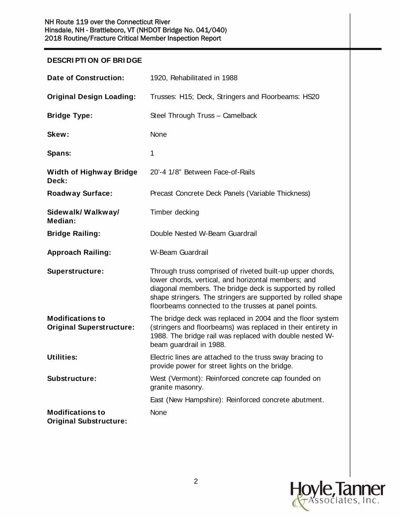
IDENTIFICATION OF FATIGUE SENSITIVE DETAILS (FSD)
From AASHTO LRFD Bridge Design Specifications, 4th Edition, Table 6.6.1.2.3-1
19
NH Route 119 over the Connecticut River Hinsdale, NH - Brattleboro, VT (NHDOT Bridge No. 041/040) 2018 Routine/Fracture Critical Member Inspection Report
IDENTIFICATION OF FATIGUE SENSITIVE DETAILS (FSD)
From AASHTO LRFD Bridge Design Specifications, 4th Edition, Table 6.6.1.2.3-1

20
NH Route 119 over the Connecticut River Hinsdale, NH - Brattleboro, VT (NHDOT Bridge No. 041/040) 2018 Routine/Fracture Critical Member Inspection Report
IDENTIFICATION OF FATIGUE SENSITIVE DETAILS (FSD)
From AASHTO LRFD Bridge Design Specifications, 4th Edition, Table 6.6.1.2.3-1

21
NH Route 119 over the Connecticut River Hinsdale, NH - Brattleboro, VT (NHDOT Bridge No. 041/040) 2018 Routine/Fracture Critical Member Inspection Report
MAINTENANCE AND REPAIR RECOMMENDATIONS Based on the inspection observations, the maintenance and repair recommendations are categorized as immediate, short-term, and long-term. Immediate (0 to 3 Months): Hoyle, Tanner recommends that accumulated debris be removed from the lower chords, floorbeams and lateral bracing gusset plates. Short-term (3 to 24 Months): None. Long-term (Beyond 24 Months): Hoyle, Tanner recommends consideration be given to replacing the bent and twisted diagonal members, lower chords, lower lateral bracing system and all exterior stringers as part of a future rehabilitation project due to the level of damage, pack rust, deterioration and section loss observed. Lower gusset plates should be evaluated for continued use in the rehabilitated structure.

APPENDIX A
Inspection Photos

SHEET 1 OF 26
BRIDGE INSPECTION PHOTOGRAPHS ANNA HUNT MARSH BRIDGE
ASS
ISTA
NT
TEA
M L
EAD
ER:
Ros
s S.
Woo
d, P
E FE
ATU
RE
CR
OSS
ED:
Conn
ectic
ut R
iver
PHOTO NO. 1
Location: Bridge deck
Description: Top of deck longitudinal cracking.
TEA
M L
EAD
ER:
Edw
ard
G. W
eing
artn
er, P
E FE
ATU
RE
CA
RR
IED
: N
H R
oute
119
PHOTO NO. 2
Location: Bridge deck
Description: Cracking and broken concrete at panel end.

SHEET 2 OF 26
BRIDGE INSPECTION PHOTOGRAPHS ANNA HUNT MARSH BRIDGE
ASS
ISTA
NT
TEA
M L
EAD
ER:
Ros
s S.
Woo
d, P
E FE
ATU
RE
CR
OSS
ED:
Conn
ectic
ut R
iver
PHOTO NO. 3
Location: W-beam bridge rail
Description: Typical condition.
TEA
M L
EAD
ER:
Edw
ard
G. W
eing
artn
er, P
E FE
ATU
RE
CA
RR
IED
: N
H R
oute
119
PHOTO NO. 4
Location: Interior stringer S151
Description: Bottom flange section loss.

SHEET 3 OF 26
BRIDGE INSPECTION PHOTOGRAPHS ANNA HUNT MARSH BRIDGE
ASS
ISTA
NT
TEA
M L
EAD
ER:
Ros
s S.
Woo
d, P
E FE
ATU
RE
CR
OSS
ED:
Conn
ectic
ut R
iver
PHOTO NO. 5
Location: North truss, L0 south gusset plate
Description: Up to 100% section loss with knife edge.
TEA
M L
EAD
ER:
Edw
ard
G. W
eing
artn
er, P
E FE
ATU
RE
CA
RR
IED
: N
H R
oute
119
PHOTO NO. 6
Location: North truss member L1-L2
Description: Horizontal splice with heavy laminar corrosion and section loss.

SHEET 4 OF 26
BRIDGE INSPECTION PHOTOGRAPHS ANNA HUNT MARSH BRIDGE
ASS
ISTA
NT
TEA
M L
EAD
ER:
Ros
s S.
Woo
d, P
E FE
ATU
RE
CR
OSS
ED:
Conn
ectic
ut R
iver
PHOTO NO. 7
Location: North truss member L1-L2 north element, north face
Description: Pitting around bolts.
TEA
M L
EAD
ER:
Edw
ard
G. W
eing
artn
er, P
E FE
ATU
RE
CA
RR
IED
: N
H R
oute
119
PHOTO NO. 8
Location: South truss member L2-L3, north element, south face
Description: Typical lower chord pack rust.

SHEET 5 OF 26
BRIDGE INSPECTION PHOTOGRAPHS ANNA HUNT MARSH BRIDGE
ASS
ISTA
NT
TEA
M L
EAD
ER:
Ros
s S.
Woo
d, P
E FE
ATU
RE
CR
OSS
ED:
Conn
ectic
ut R
iver
PHOTO NO. 9
Location: North truss
Description: 100% section loss in tie plate.
TEA
M L
EAD
ER:
Edw
ard
G. W
eing
artn
er, P
E FE
ATU
RE
CA
RR
IED
: N
H R
oute
119
PHOTO NO. 10
Location: North truss, L3 south gusset plate, south face
Description: Section loss around lower lateral bracing gusset plate.

SHEET 6 OF 26
BRIDGE INSPECTION PHOTOGRAPHS ANNA HUNT MARSH BRIDGE
ASS
ISTA
NT
TEA
M L
EAD
ER:
Ros
s S.
Woo
d, P
E FE
ATU
RE
CR
OSS
ED:
Conn
ectic
ut R
iver
PHOTO NO. 11
Location: North truss member L4-L5, north element, north face
Description: Typical lower chord condition.
TEA
M L
EAD
ER:
Edw
ard
G. W
eing
artn
er, P
E FE
ATU
RE
CA
RR
IED
: N
H R
oute
119
PHOTO NO. 12
Location: South truss member L1-L2
Description: Splice plate rivet head section loss.

SHEET 7 OF 26
BRIDGE INSPECTION PHOTOGRAPHS ANNA HUNT MARSH BRIDGE
ASS
ISTA
NT
TEA
M L
EAD
ER:
Ros
s S.
Woo
d, P
E FE
ATU
RE
CR
OSS
ED:
Conn
ectic
ut R
iver
PHOTO NO. 13
Location: South truss member L15-L16 north element, south face
Description: Heaving pack rust with loss of angle leg width.
TEA
M L
EAD
ER:
Edw
ard
G. W
eing
artn
er, P
E FE
ATU
RE
CA
RR
IED
: N
H R
oute
119
PHOTO NO. 14
Location: Floorbeam FB5
Description: Web laminar corrosion and section loss.

SHEET 8 OF 26
BRIDGE INSPECTION PHOTOGRAPHS ANNA HUNT MARSH BRIDGE
ASS
ISTA
NT
TEA
M L
EAD
ER:
Ros
s S.
Woo
d, P
E FE
ATU
RE
CR
OSS
ED:
Conn
ectic
ut R
iver
PHOTO NO. 15
Location: North truss, L14, FB 14 connection to South gusset plate Looking West
Description: Heavy rusting with laminar corrosion.
TEA
M L
EAD
ER:
Edw
ard
G. W
eing
artn
er, P
E FE
ATU
RE
CA
RR
IED
: N
H R
oute
119
PHOTO NO. 16
Location: North truss, L7 south gusset plate, south face
Description: Typical gusset plate condition, pitting and pack rust.

SHEET 9 OF 26
BRIDGE INSPECTION PHOTOGRAPHS ANNA HUNT MARSH BRIDGE
ASS
ISTA
NT
TEA
M L
EAD
ER:
Ros
s S.
Woo
d, P
E FE
ATU
RE
CR
OSS
ED:
Conn
ectic
ut R
iver
PHOTO NO. 17
Location: South truss, south gusset plate connection to member L14-U15
Description: Pack rust and pit.
TEA
M L
EAD
ER:
Edw
ard
G. W
eing
artn
er, P
E FE
ATU
RE
CA
RR
IED
: N
H R
oute
119
PHOTO NO. 18
Location: South truss member L13-L14
Description: North element pack rust and section loss.

SHEET 10 OF 26
BRIDGE INSPECTION PHOTOGRAPHS ANNA HUNT MARSH BRIDGE
ASS
ISTA
NT
TEA
M L
EAD
ER:
Ros
s S.
Woo
d, P
E FE
ATU
RE
CR
OSS
ED:
Conn
ectic
ut R
iver
PHOTO NO. 19
Location: South truss member U5-M6, north element, bottom angle
Description: Empty rivet hole near corner of M6 gusset plate.
TEA
M L
EAD
ER:
Edw
ard
G. W
eing
artn
er, P
E FE
ATU
RE
CA
RR
IED
: N
H R
oute
119
PHOTO NO. 20
Location: South truss member U3-M4, south angles
Description: Pack rust between angle legs above the tie plate.

SHEET 11 OF 26
BRIDGE INSPECTION PHOTOGRAPHS ANNA HUNT MARSH BRIDGE
ASS
ISTA
NT
TEA
M L
EAD
ER:
Ros
s S.
Woo
d, P
E FE
ATU
RE
CR
OSS
ED:
Conn
ectic
ut R
iver
PHOTO NO. 21
Location: South truss member U1-L2, north element, bottom angle
Description: 16" long deformation, angle bent up to 3/4" out of plane, 7' above top of deck.
TEA
M L
EAD
ER:
Edw
ard
G. W
eing
artn
er, P
E FE
ATU
RE
CA
RR
IED
: N
H R
oute
119
PHOTO NO. 22
Location: North truss member U1-L2, south element, top angle
Description: Series of gouges in top flange. 11” along the south, top angle leg, up to 3/16” deep.

SHEET 12 OF 26
BRIDGE INSPECTION PHOTOGRAPHS ANNA HUNT MARSH BRIDGE
ASS
ISTA
NT
TEA
M L
EAD
ER:
Ros
s S.
Woo
d, P
E FE
ATU
RE
CR
OSS
ED:
Conn
ectic
ut R
iver
PHOTO NO. 23
Location: North truss member U3-M4, north angles
Description: Up to 100% section loss of toes at the tie plate, 7" long up to 1/2" deep.
TEA
M L
EAD
ER:
Edw
ard
G. W
eing
artn
er, P
E FE
ATU
RE
CA
RR
IED
: N
H R
oute
119
PHOTO NO. 24
Location: North truss member U3-M4, south angle
Description: 1¼” diameter by ½” deep pit at heel of top angle.

SHEET 13 OF 26
BRIDGE INSPECTION PHOTOGRAPHS ANNA HUNT MARSH BRIDGE
ASS
ISTA
NT
TEA
M L
EAD
ER:
Ros
s S.
Woo
d, P
E FE
ATU
RE
CR
OSS
ED:
Conn
ectic
ut R
iver
PHOTO NO. 25
Location: North truss member U2-L3, south angle
Description: 1/4" gouge in top angle leg.
TEA
M L
EAD
ER:
Edw
ard
G. W
eing
artn
er, P
E FE
ATU
RE
CA
RR
IED
: N
H R
oute
119
PHOTO NO. 26
Location: North truss member L5-M6, south element
Description: Angle leg bent 1/2" out of plane, 30" above top of deck.

SHEET 14 OF 26
BRIDGE INSPECTION PHOTOGRAPHS ANNA HUNT MARSH BRIDGE
ASS
ISTA
NT
TEA
M L
EAD
ER:
Ros
s S.
Woo
d, P
E FE
ATU
RE
CR
OSS
ED:
Conn
ectic
ut R
iver
PHOTO NO. 27
Location: North truss member L5-M6, south element
Description: 1/4" gouge in top angle 3' length out of alignment, flange bent up to 5/8", 1' from top of deck.
TEA
M L
EAD
ER:
Edw
ard
G. W
eing
artn
er, P
E FE
ATU
RE
CA
RR
IED
: N
H R
oute
119
PHOTO NO. 28
Location: North truss member L7-L8
Description: Gouge in south angle leg, 4’ above top of deck, 3/8” diameter.

SHEET 15 OF 26
BRIDGE INSPECTION PHOTOGRAPHS ANNA HUNT MARSH BRIDGE
ASS
ISTA
NT
TEA
M L
EAD
ER:
Ros
s S.
Woo
d, P
E FE
ATU
RE
CR
OSS
ED:
Conn
ectic
ut R
iver
PHOTO NO. 29
Location: North truss
Description: Gouge in U13 north gusset plate between U13-U14 and M13-U13 members. ¾” long x 1/8” deep x 7/16” wide (full depth of plate).
TEA
M L
EAD
ER:
Edw
ard
G. W
eing
artn
er, P
E FE
ATU
RE
CA
RR
IED
: N
H R
oute
119
PHOTO NO. 30
Location: North truss member L3-M4
Description: Considerable impact damage along length, angle legs bent and member twisted out of plane.

SHEET 16 OF 26
BRIDGE INSPECTION PHOTOGRAPHS ANNA HUNT MARSH BRIDGE
ASS
ISTA
NT
TEA
M L
EAD
ER:
Ros
s S.
Woo
d, P
E FE
ATU
RE
CR
OSS
ED:
Conn
ectic
ut R
iver
PHOTO NO. 31
Location: North truss member L12-M12
Description: 1/16” deep gouge in angle leg, 1” long, 4’ above top of deck.
TEA
M L
EAD
ER:
Edw
ard
G. W
eing
artn
er, P
E FE
ATU
RE
CA
RR
IED
: N
H R
oute
119
PHOTO NO. 32
Location: North truss member L13-U14
Description: Bottom angle leg bent out of plane, 30” long, 1.5” max deformation, 2’ above top of deck.

SHEET 17 OF 26
BRIDGE INSPECTION PHOTOGRAPHS ANNA HUNT MARSH BRIDGE
ASS
ISTA
NT
TEA
M L
EAD
ER:
Ros
s S.
Woo
d, P
E FE
ATU
RE
CR
OSS
ED:
Conn
ectic
ut R
iver
PHOTO NO. 33
Location: North truss member L13-U14
Description: Bottom angle leg bent and pack rust between angle members.
TEA
M L
EAD
ER:
Edw
ard
G. W
eing
artn
er, P
E FE
ATU
RE
CA
RR
IED
: N
H R
oute
119
PHOTO NO. 34
Location: North truss member L15-U15
Description: 1/8” deep gouge in angle leg, ½” long, 3.5’ above top of deck.

SHEET 18 OF 26
BRIDGE INSPECTION PHOTOGRAPHS ANNA HUNT MARSH BRIDGE
ASS
ISTA
NT
TEA
M L
EAD
ER:
Ros
s S.
Woo
d, P
E FE
ATU
RE
CR
OSS
ED:
Conn
ectic
ut R
iver
PHOTO NO. 35
Location: North truss member U15-L16
Description: Member impact damage.
TEA
M L
EAD
ER:
Edw
ard
G. W
eing
artn
er, P
E FE
ATU
RE
CA
RR
IED
: N
H R
oute
119
PHOTO NO. 36
Location: End diagonal
Description: Typical condition.

SHEET 19 OF 26
BRIDGE INSPECTION PHOTOGRAPHS ANNA HUNT MARSH BRIDGE
ASS
ISTA
NT
TEA
M L
EAD
ER:
Ros
s S.
Woo
d, P
E FE
ATU
RE
CR
OSS
ED:
Conn
ectic
ut R
iver
PHOTO NO. 37
Location: South truss member U3-L3
Description: Section loss.
TEA
M L
EAD
ER:
Edw
ard
G. W
eing
artn
er, P
E FE
ATU
RE
CA
RR
IED
: N
H R
oute
119
PHOTO NO. 38
Location: North truss member U3-L3
Description: Section loss.

SHEET 20 OF 26
BRIDGE INSPECTION PHOTOGRAPHS ANNA HUNT MARSH BRIDGE
ASS
ISTA
NT
TEA
M L
EAD
ER:
Ros
s S.
Woo
d, P
E FE
ATU
RE
CR
OSS
ED:
Conn
ectic
ut R
iver
PHOTO NO. 39
Location: North truss member U13-L13
Description: Section loss.
TEA
M L
EAD
ER:
Edw
ard
G. W
eing
artn
er, P
E FE
ATU
RE
CA
RR
IED
: N
H R
oute
119
PHOTO NO. 40
Location: West Portal
Description: Impact damage.

SHEET 21 OF 26
BRIDGE INSPECTION PHOTOGRAPHS ANNA HUNT MARSH BRIDGE
ASS
ISTA
NT
TEA
M L
EAD
ER:
Ros
s S.
Woo
d, P
E FE
ATU
RE
CR
OSS
ED:
Conn
ectic
ut R
iver
PHOTO NO. 41
Location: East Portal
Description: Impact damage.
TEA
M L
EAD
ER:
Edw
ard
G. W
eing
artn
er, P
E FE
ATU
RE
CA
RR
IED
: N
H R
oute
119
PHOTO NO. 42
Location: Panel Point 2
Description: Impact damage.

SHEET 22 OF 26
BRIDGE INSPECTION PHOTOGRAPHS ANNA HUNT MARSH BRIDGE
ASS
ISTA
NT
TEA
M L
EAD
ER:
Ros
s S.
Woo
d, P
E FE
ATU
RE
CR
OSS
ED:
Conn
ectic
ut R
iver
PHOTO NO. 43
Location: Lower Lateral Bracing Gusset Plate @ L2
Description: Section loss.
TEA
M L
EAD
ER:
Edw
ard
G. W
eing
artn
er, P
E FE
ATU
RE
CA
RR
IED
: N
H R
oute
119
PHOTO NO. 44
Location: Sidewalk interior stringer
Description: Holed web.

SHEET 23 OF 26
BRIDGE INSPECTION PHOTOGRAPHS ANNA HUNT MARSH BRIDGE
ASS
ISTA
NT
TEA
M L
EAD
ER:
Ros
s S.
Woo
d, P
E FE
ATU
RE
CR
OSS
ED:
Conn
ectic
ut R
iver
PHOTO NO. 45
Location: Sidewalk support @ L15
Description: Bent out-of-plane.
TEA
M L
EAD
ER:
Edw
ard
G. W
eing
artn
er, P
E FE
ATU
RE
CA
RR
IED
: N
H R
oute
119
PHOTO NO. 46
Location: West abutment
Description: Delaminated area.

SHEET 24 OF 26
BRIDGE INSPECTION PHOTOGRAPHS ANNA HUNT MARSH BRIDGE
ASS
ISTA
NT
TEA
M L
EAD
ER:
Ros
s S.
Woo
d, P
E FE
ATU
RE
CR
OSS
ED:
Conn
ectic
ut R
iver
PHOTO NO. 47
Location: West abutment backwall
Description: Backwall spalling, cracking and efflorescence.
TEA
M L
EAD
ER:
Edw
ard
G. W
eing
artn
er, P
E FE
ATU
RE
CA
RR
IED
: N
H R
oute
119
PHOTO NO. 48
Location: East abutment
Description: Concrete spalling and deterioration.

SHEET 25 OF 26
BRIDGE INSPECTION PHOTOGRAPHS ANNA HUNT MARSH BRIDGE
ASS
ISTA
NT
TEA
M L
EAD
ER:
Ros
s S.
Woo
d, P
E FE
ATU
RE
CR
OSS
ED:
Conn
ectic
ut R
iver
PHOTO NO. 49
Location: East abutment
Description: Concrete spalling and deterioration.
TEA
M L
EAD
ER:
Edw
ard
G. W
eing
artn
er, P
E FE
ATU
RE
CA
RR
IED
: N
H R
oute
119
PHOTO NO. 50
Location: North truss expansion bearing
Description: Rotated exterior rollers and guides not plumb.

SHEET 26 OF 26
BRIDGE INSPECTION PHOTOGRAPHS ANNA HUNT MARSH BRIDGE
ASS
ISTA
NT
TEA
M L
EAD
ER:
Ros
s S.
Woo
d, P
E FE
ATU
RE
CR
OSS
ED:
Conn
ectic
ut R
iver
PHOTO NO. 51
Location: South truss expansion bearing
Description: Rotated exterior rollers and guides not plumb.
TEA
M L
EAD
ER:
Edw
ard
G. W
eing
artn
er, P
E FE
ATU
RE
CA
RR
IED
: N
H R
oute
119
PHOTO NO.
Location:
Description: