Embed Size (px)
Citation preview

Application Note Please read the Important Notice and Warnings at the end of this document V 1.1
www.infineon.com page 1 of 39 6/9/2020
AN2018-27
P U B L I C
How to Use iMOTION™ Script Language
About this document
Scope and purpose
This application note provides a guideline for using the iMOTIONTM script language on Motion Control Engine (MCE) platform with typical script examples covering the implementation of Low-Pass Filter (LPF), 2-level speed selection interface, motor target speed shaping based on DC bus voltage with brown-out protection, and
dynamic motor current limit customization.
Intended audience
This document is intended for customers who would like to understand how to use the iMOTIONTM script language to realize customization of system start-up behavior, specific speed profile definition, as well as
system specific fault handling definition.
Table of contents
About this document ....................................................................................................................... 1
Table of contents ............................................................................................................................ 1
1 Script Language Overview ....................................................................................................... 3 1.1 Introduction ............................................................................................................................................. 3
1.2 Script Development Workflow ................................................................................................................ 3
2 Script Application Examples .................................................................................................... 4
2.1 2-Level Speed Selection Interface .......................................................................................................... 4
2.1.1 Speed Selection Interface Requirement ........................................................................................... 4
2.1.2 Analog Input Pin for Speed Selection Interface ................................................................................ 4 2.1.3 Speed Selection State Machine ......................................................................................................... 5 2.1.4 Speed Selection Interface Script Implementation ........................................................................... 6 2.2 Low-Pass Filter for DC Bus Voltage ......................................................................................................... 8
2.2.1 DC Bus Voltage Ripple ........................................................................................................................ 8
2.2.2 DC Bus Voltage Sensing ..................................................................................................................... 9 2.2.3 LPF Design & Implementation ......................................................................................................... 10
2.2.4 LPF Test Results ............................................................................................................................... 12 2.3 Target Speed Shaping & Brown-out Protection ................................................................................... 13
2.3.1 Target Speed Requirements ............................................................................................................ 14 2.3.2 DC Bus Status State Machine ........................................................................................................... 15
2.3.3 Scaling for Target Speed Shaping Calculation................................................................................ 16 2.3.4 Target Speed Shaping & Brown-out Protection Script Implementation ....................................... 17 2.3.5 Target Speed Shaping Measurement Results ................................................................................. 21
2.4 Dynamic Motor Current Limit Customization ...................................................................................... 23 2.4.1 Motor Current Limit Requirement ................................................................................................... 23 2.4.2 Dynamic Motor Current Limit Algorithm Design & Implementation .............................................. 23 2.4.3 Dynamic Motor Current Limit Measurement Results ...................................................................... 30
3 Script Performance Evaluation ............................................................................................... 33
Application Note 2 of 39 V 1.1
6/9/2020
How to Use iMOTION™ Script Language
Table of Contents
P U B L I C
3.1 CPU Load Evaluation ............................................................................................................................. 33 3.2 Script Task Timing ................................................................................................................................. 34
3.2.1 Script Task Timing Setup ................................................................................................................. 34 3.2.2 Script Task Execution Time Evaluation ........................................................................................... 35
3.2.3 Script Task Execution Period Evaluation ........................................................................................ 36
4 Script Guidelines & Limitations ............................................................................................... 37
5 References ........................................................................................................................... 38
Revision history............................................................................................................................. 38
Application Note 3 of 39 V 1.1
6/9/2020
How to Use iMOTION™ Script Language
Script Language Overview
P U B L I C
1 Script Language Overview
1.1 Introduction
The latest software release of iMOTIONTM MCE includes a script engine, offering users the possibility to customize system level functionalities without affecting the motor and PFC control algorithm. The script engine is a light weight virtual machine that supports reading and writing all the motor control and PFC parameters
and variables, allowing users to take advantage of the analog and digital resources that are not used by motor
and / or PFC control, and is scalable for any functional extension in future. Typical script use cases include customization of system start-up behavior, specific speed profile definition and parameter configuration, as well as fault handling.
The CPU resource is prioritized for the execution of the motor and PFC control algorithms. The spare CPU resource is used for the execution of background tasks as well as the script engine which is used to drive the
execution of the script code. The priority of the execution of the script code is lower than that of the motor and PFC control algorithm execution, so that it won’t affect the performance of the control algorithms. It is highly recommended to check actual CPU load during the run time to ensure the CPU resource is allocated appropriately.
The script engine supports 2 independent tasks, namely, Task 0 and Task 1, running concurrently. The user script program runs repeatedly on a configurable interval within Task 0 or Task 1 loop. The shortest possible
execution period is 1 ms for Task 0, and 10 ms for Task 1.The execution period for each task can be configured to the multiples of 1 ms for Task 0 or 10 ms for Task 1 in the script code. Task 0 has higher priority
than Task 1.
iMOTIONTM script language is a type of interpreted language, for which its implementation compiles a script
program into pseudo code (bytecode) first, and then executes instructions directly by a virtual machine
running on MCE.
1.2 Script Development Workflow
The typical workflow of script program development starts from using MCEWizard [4] (or any other text editors)
to write script code and save as script input file with ‘.mcs’ suffix. MCEWizard is used to configure available Analog-to-Digital Converter (ADC) or General-Purpose-Input-Output (GPIO) pins if needed, and MCEWizard is
also used to compile the script code to generate a script object file with ‘.ldf’ suffix. The ldf file contains
information about the total number of script instructions for Task 0 and Task 1, as well as a list of global variables defined in the script code. Then MCEDesigner [3] is used to download the ldf file to the target MCE,
and it also supports monitoring the values of global variables used in the script program. More details about
the script language and its development can be found in [2].
Application Note 4 of 39 V 1.1
6/9/2020
How to Use iMOTION™ Script Language
Script Application Examples
P U B L I C
2 Script Application Examples
2.1 2-Level Speed Selection Interface
2.1.1 Speed Selection Interface Requirement
A multi-level speed selection interface to support different speed levels selected by users is commonly seen in motor control applications such as hair-dryers. This example detailizes the requirement and script implementation of a 2-level speed selection interface using one of the available ADC pins on IMC101T [1]
controller from iMOTIONTM MCE series.
Some hardware circuits were designed to translate the position of the speed selection mechanical switch into a
corresponding analog voltage level between 0 V and 5 V. Specifically, the voltage range from 0 V to 1 V was
defined as OFF state, the voltage range from 1 V to 2 V was defined as LOW SPEED state, and the voltage range from 2 V and above was defined as HIGH SPEED. In order to eliminate potential oscillation when the voltage level is in the vicinity of the boundaries of different speed states, a hysteresis of 0.2 V was introduced.
This application requires an analog voltage sensing interface to sample and translate the analog voltage to the
corresponding speed selection levels.
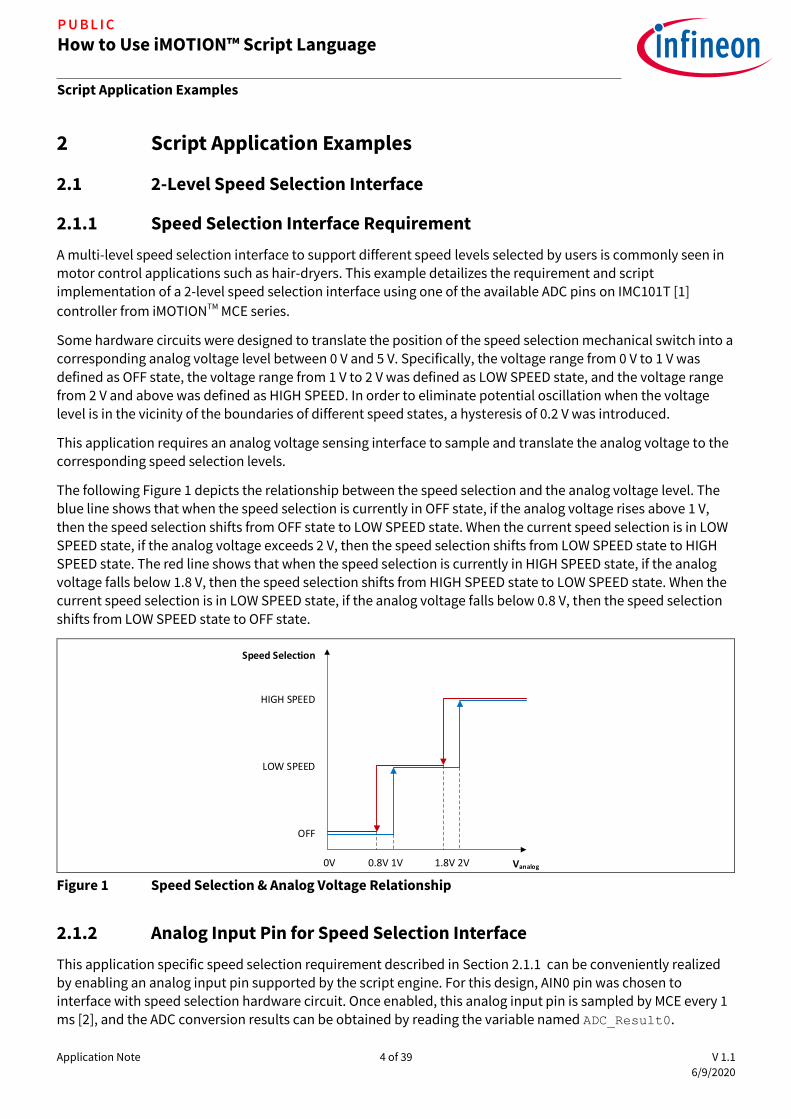
The following Figure 1 depicts the relationship between the speed selection and the analog voltage level. The blue line shows that when the speed selection is currently in OFF state, if the analog voltage rises above 1 V,
then the speed selection shifts from OFF state to LOW SPEED state. When the current speed selection is in LOW SPEED state, if the analog voltage exceeds 2 V, then the speed selection shifts from LOW SPEED state to HIGH
SPEED state. The red line shows that when the speed selection is currently in HIGH SPEED state, if the analog
voltage falls below 1.8 V, then the speed selection shifts from HIGH SPEED state to LOW SPEED state. When the
current speed selection is in LOW SPEED state, if the analog voltage falls below 0.8 V, then the speed selection
shifts from LOW SPEED state to OFF state.
0.8V 1V 1.8V 2V
OFF
LOW SPEED
HIGH SPEED
Speed Selection
0V Vanalog
Figure 1 Speed Selection & Analog Voltage Relationship
2.1.2 Analog Input Pin for Speed Selection Interface
This application specific speed selection requirement described in Section 2.1.1 can be conveniently realized by enabling an analog input pin supported by the script engine. For this design, AIN0 pin was chosen to interface with speed selection hardware circuit. Once enabled, this analog input pin is sampled by MCE every 1 ms [2], and the ADC conversion results can be obtained by reading the variable named ADC_Result0.

Application Note 5 of 39 V 1.1
6/9/2020
How to Use iMOTION™ Script Language
Script Application Examples
P U B L I C
Given that the resolution of the ADC is 12 bit, the calculation from the voltage at AIN0 pin to the ADC conversion
result follows this formula: ADC_Result0 = 𝐼𝑁𝑇(𝑉𝐴𝐼𝑁0 ∙212−1
𝑉𝑟𝑒𝑓+ 0.5) , where 𝑉𝑟𝑒𝑓 is the reference voltage for the
ADC. If we choose 𝑉𝑟𝑒𝑓 as 5 V, then those voltage thresholds associated with HIGH SPEED and LOW SPEED levels
can be calculated using the abovementioned formula as summarized in the following Table 1.
Table 1 Speed Selection Interface Voltage Thresholds
Variable Name Voltage Threshold ADC Conversion Result
VLSStart 1V 819 (ADC Counts)
VLSStop 0.8V 655 (ADC Counts)
VHSStart 2V 1638 (ADC Counts)
VHSStop 1.8V 1474 (ADC Counts)
2.1.3 Speed Selection State Machine
The speed selection logic can be abstracted using a finite state machine (FSM) model. An FSM can change from
one state to another in response to certain inputs. Figure 2 shows a state machine that was designed to
interpret the speed selection inputs. It uses a state variable named SpeedMode to represent 3 possible states, namely, Speed_Mode_OFF (SpeedMode = 0), Speed_Mode_LOW_SPEED (SpeedMode = 1), and Speed_Mode_HIGH_SPEED (SpeedMode = 2). Starting off in Speed_Mode_OFF state, the target speed is reset
to 0, and the motor is stopped. If VSP pin voltage is higher than VLSStart, then it shifts to
Speed_Mode_LOW_SPEED state. While it is in Speed_Mode_LOW_SPEED state, if VSP pin voltage is lower than
VLSStop, then it shifts to Speed_Mode_OFF; if VSP pin voltage is higher than VHSStart, then it shifts to Speed_Mode_HIGH_SPEED state. While it is in Speed_Mode_HIGH_SPEED state, if VSP pin voltage is lower than
VHSStop, then it shifts to Speed_Mode_LOW_SPEED state. While it is in Speed_Mode_HIGH_SPEED or
Speed_Mode_LOW_SPEED state, the target speed is set to the pre-defined HighSpeedValue or
LowSpeedValue corresponding to the specific speed selection levels, and the motor is started. The start / stop motor operation can be realized by setting or resetting the motor variable named Command. Thanks to the
accessibility of the motor parameters enabled by the script engine, Command parameter can be directly used in the script code without declaration.

Application Note 6 of 39 V 1.1
6/9/2020
How to Use iMOTION™ Script Language
Script Application Examples
P U B L I C
Speed_Mode_OFF
entry / do / Target Speed = 0;Stop motor;exit /
ADC_Result0 > VLSStart
Speed_Mode_LOW_SPEED
entry / do /TargetSpeed = LowSpeedValue;Start motor;exit /
ADC_Result0 > VHSStart
Speed_Mode_HIGH_SPEED
entry / do /TargetSpeed = HighSpeedValue;Start motor;exit /
ADC_Result0 < VHSStop
ADC_Result0 < VLSStop
Figure 2 Speed Selection State Machine
2.1.4 Speed Selection Interface Script Implementation
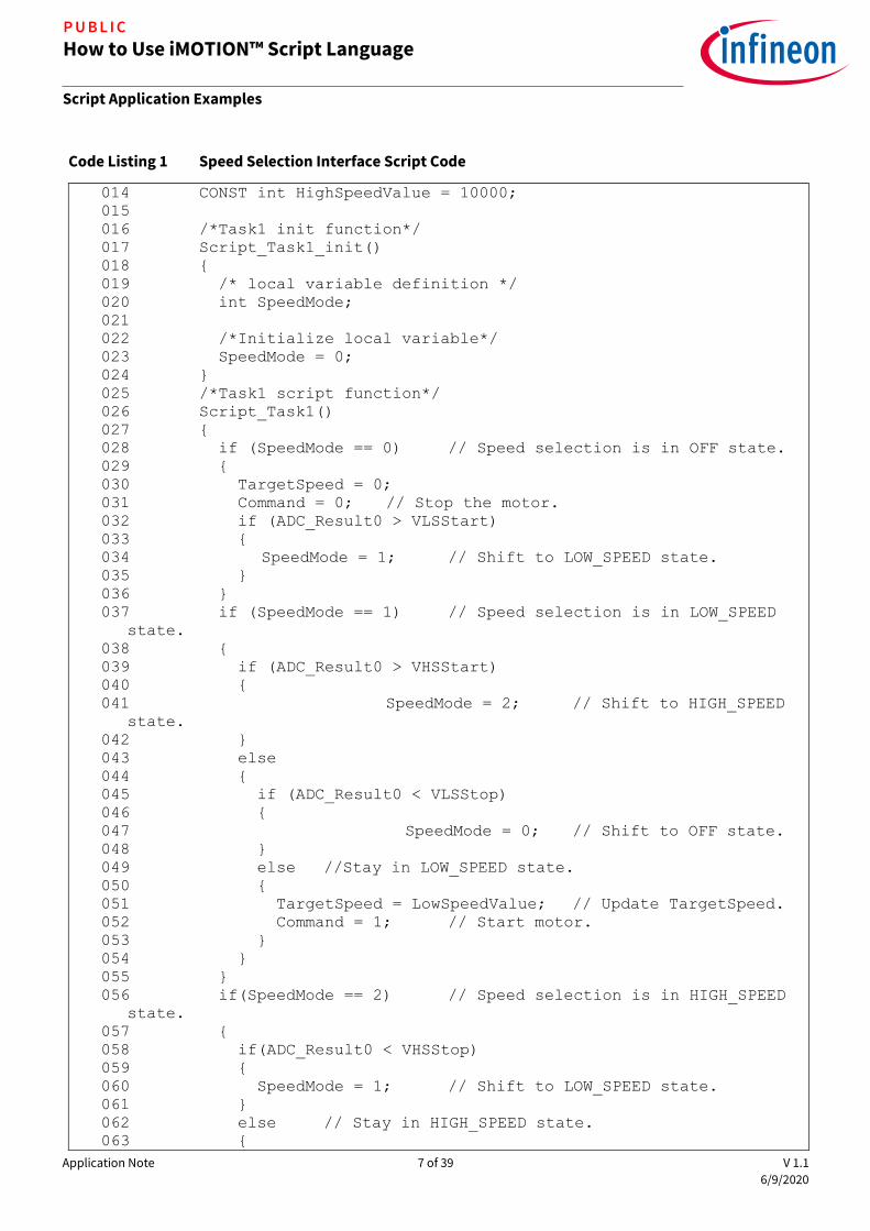
The following Code Listing 1 shows the source code for the 2-level speed selection interface application implemented in Task 1. Since the user speed selection switch position doesn’t change frequently, it is
recommended to set the loop execution period of Task 1 to be 50 ms. The following Code Listing 2 shows a portion of the compiled script object file where it shows at line 009 that the number of instructions for Task 1 is
17. So, the execution step for Task 1 should be set to greater than 17 to ensure that the entire loop of Task 1 is completed during each execution period. In this example, the execution period for Task 1
(SCRIPT_TASK1_EXECUTION_PERIOD) was set to 5, and the execution step for Task 1 (SCRIPT_TASK1_EXECUTION_STEP) was chosen to be 20 to meet the desired timing requirement.
This example can also be implemented in Task 0, in which case the execution period for Task 0
(SCRIPT_TASK0_EXECUTION_PERIOD) should be set to 50 to achieve the same execution period of 50 ms.
Code Listing 1 Speed Selection Interface Script Code
001 /************************************************************/
002 /*Script user version value, should be 255.255*/
003 #SET SCRIPT_USER_VERSION (1.00)
004 #SET SCRIPT_TASK1_EXECUTION_PERIOD (5)
005 /*Defines number of lines to be executed every 10mS in Task1*/
006 #SET SCRIPT_TASK1_EXECUTION_STEP (20)
007 /************************************************************/
008 /* constant definition */
009 CONST int VLSStart = 819; // 1V => 819 counts
010 CONST int VLSStop = 655; // 0.8V => 655 counts
011 CONST int VHSStart = 1638; // 2V => 1638 counts
012 CONST int VHSStop = 1474; // 1.8V => 1474 counts
013 CONST int LowSpeedValue = 5000;
Application Note 7 of 39 V 1.1
6/9/2020
How to Use iMOTION™ Script Language
Script Application Examples
P U B L I C
Code Listing 1 Speed Selection Interface Script Code
014 CONST int HighSpeedValue = 10000;
015
016 /*Task1 init function*/
017 Script_Task1_init()
018
019 /* local variable definition */
020 int SpeedMode;
021
022 /*Initialize local variable*/
023 SpeedMode = 0;
024
025 /*Task1 script function*/
026 Script_Task1()
027
028 if (SpeedMode == 0) // Speed selection is in OFF state.
029
030 TargetSpeed = 0;
031 Command = 0; // Stop the motor.
032 if (ADC_Result0 > VLSStart)
033
034 SpeedMode = 1; // Shift to LOW_SPEED state.
035
036
037 if (SpeedMode == 1) // Speed selection is in LOW_SPEED
state.
038
039 if (ADC_Result0 > VHSStart)
040
041 SpeedMode = 2; // Shift to HIGH_SPEED
state.
042
043 else
044
045 if (ADC_Result0 < VLSStop)
046
047 SpeedMode = 0; // Shift to OFF state.
048
049 else //Stay in LOW_SPEED state.
050
051 TargetSpeed = LowSpeedValue; // Update TargetSpeed.
052 Command = 1; // Start motor.
053
054
055
056 if(SpeedMode == 2) // Speed selection is in HIGH_SPEED
state.
057
058 if(ADC_Result0 < VHSStop)
059
060 SpeedMode = 1; // Shift to LOW_SPEED state.
061
062 else // Stay in HIGH_SPEED state.
063

Application Note 8 of 39 V 1.1
6/9/2020
How to Use iMOTION™ Script Language
Script Application Examples
P U B L I C
Code Listing 1 Speed Selection Interface Script Code
064 TargetSpeed = HighSpeedValue; // Update TargetSpeed.
065 Command = 1;
066
067
068
Code Listing 2 Portion of Compiled Script Object File for Speed Selection Interface Script Code
001 %-------------------------------------------------------------
002 % Script Object File
003 %-------------------------------------------------------------
004 % SCRIPT_USER_VERSION : 001.000
005 % DATE & TIME : 05.06.2020 15:55:15
006 % SIZE : 297 Bytes
007 % Total Number of Lines : 69
008 % Task0 - Number of Instructions : 0
009 % Task1 - Number of Instructions : 17
010 %-------------------------------------------------------------
2.2 Low-Pass Filter for DC Bus Voltage
2.2.1 DC Bus Voltage Ripple
Typically, the AC input front-end stage consists of a bridge rectifier followed by a bulky DC bus capacitor to
convert AC mains voltage to DC voltage whose amplitude tracks the peak of the AC input voltage. DC bus
voltage refers to the voltage across the DC bus capacitor. When the motor is running, DC bus voltage waveform
typically contains high frequency switching ripples as well as low frequency ripples due to bus capacitor charge and discharge operation at twice the mains frequency. Figure 3 is a screenshot of the AC portion of the actual DC bus voltage waveform with IMC101T controller driving a Permanent Magnet Synchronous Motor (PMSM)
running at a speed = 19400 RPM and Vin = 125 VAC / 50Hz. It could be seen that the amplitude of the DC bus
voltage ripples was around 9.84 V.

Application Note 9 of 39 V 1.1
6/9/2020
How to Use iMOTION™ Script Language
Script Application Examples
P U B L I C
Figure 3 DC Bus Voltage Waveform Screenshot
2.2.2 DC Bus Voltage Sensing
The valid input voltage for the ADC of MCE ranges from 0 V to 5 V thanks to the selection of 5 V as the ADC reference voltage (𝑉𝑟𝑒𝑓 = 5𝑉). Accordingly, the DC bus voltage is scaled down by a voltage divider composed of
R1 and R2 as shown in the following Figure 4 and then connected to VDC pin of MCE. With 𝑅1 = 2𝑀Ω and 𝑅2 =
13.3𝐾Ω, the DC Bus sensing gain 𝐺𝐷𝐶𝐵𝑢𝑠_𝑠𝑒𝑛𝑠𝑖𝑛𝑔 =𝑅2
𝑅1+𝑅2=
13.3𝐾Ω
2𝑀Ω+13.3𝐾Ω= 0.00661, and the maximum DC
voltage that the VDC pin can sense is up to 757 V.
Figure 4 DC Bus Voltage Sensing Interface Circuit Diagram
The DC bus voltage is being sampled by MCE every motor Pulse Width Modulation (PWM) cycle and is represented by the motor parameter VdcRaw whose unit is ADC count [2]. A typical motor PWM cycle value is 50
µs. VdcRaw goes through an internal digital LPF stage and the result is stored in VdcFilt [2].
Given that the resolution of the ADC is 12 bit, the conversion from DC bus voltage to ADC sampling result
follows this formula: 𝑉𝐷𝐶𝐵𝑢𝑠_𝐴𝐷𝐶 = 𝐼𝑁𝑇(𝑉𝐷𝐶𝐵𝑢𝑠 ∙ 𝐺𝐷𝐶𝐵𝑢𝑠_𝑠𝑒𝑛𝑠𝑖𝑛𝑔 ∙212−1
𝑉𝑟𝑒𝑓+ 0.5), where the 𝐼𝑁𝑇 operator means
taking the integer portion of a given number.
Thanks to the accessibility of the motor parameters enabled by the script engine, VdcRaw and VdcFilt parameters can be directly used in the script code without declaration. Figure 5 shows the VdcRaw and
VdcFilt waveforms under the same input / output conditions as in the case of Figure 3 using the tracing window of MCEDesigner [3]. With 9.84 V of DC bus voltage ripple amplitude, VdcRaw ripple amplitude should be 53 ADC counts following the abovementioned conversion formula. From Figure 5 it can be seen that the
amplitude of VdcRaw ripple was about 53 ADC counts. Comparing VdcFilt waveform with that of VdcRaw, it can be observed that although most of the high frequency ripples seen in VdcRaw was attenuated, VdcFilt
still presented a good amount of low frequency ripples whose amplitude was as high as 30 ADC counts.
In order to obtain an averaged value of DC bus voltage when the system is in steady state, there is a need to implement an additional stage of LPF in the script to attenuate the ripple of VdcFilt to no more than 1 ADC count.
CH3: DC Bus Voltage (AC coupling); Vpp_CH3: 9.84 V
R12M
R213.3K
DC Bus
GND
MCE Device
VDC
C1

Application Note 10 of 39 V 1.1
6/9/2020
How to Use iMOTION™ Script Language
Script Application Examples
P U B L I C
Ch1: VdcRaw; Ch2: VdcFilt; FPWM: 20kHz; Sample at PWM frequency divided by 2; Trigger Level: 920; Vin:
125VAC / 50Hz; Vpp_CH1: 53 ADC counts; Vpp_CH2: 30 ADC counts
Figure 5 VdcRaw & VdcFilt Waveform Screenshot
2.2.3 LPF Design & Implementation
Considering the limited resources supported by the script engine, a 1st order Infinite Impulse Response (IIR)
low-pass digital filter algorithm was chosen for this application. Its difference equation is shown as follows: (𝑛) = 𝛼 ∙ 𝑦(𝑛 − 1) + (1 − 𝛼) ∙ 𝑥(𝑛) , where 𝛼 is a constant between 0 and 1, 𝑥(𝑛) is the current input value, 𝑦(𝑛) is the current output value, and 𝑦(𝑛 − 1) is the last output value. This filter’s 𝑧 domain transfer function is
as follows: 𝐻𝐿𝑃𝐹(𝑧) =1−𝛼
1−𝛼∙𝑧−1 . Assuming that the sampling period is represented by 𝑇𝑠, and using 𝑧 = 𝑒𝑠∙𝑇𝑠 to
replace 𝑧, we could obtain the filter’s transfer function in 𝑠 domain: 𝐻𝐿𝑃𝐹(𝑠) =1−𝛼
1−𝛼∙𝑒−𝑠𝑇𝑠 .
The dominant portion of the VdcFilt ripples was the twice-of-mains-frequency component at 100 Hz or 120 Hz. According to Nyquist theorem, the sampling frequency needs to be at least higher than twice of the
frequency of interest to realize effective attenuation. Task 1 can support down to 10 ms execution period, which in this case is not enough. Task 0 was chosen to implement this LPF algorithm thanks to its support for down to 1 ms execution period. The higher the sampling frequency is, the higher the frequency of interest that can be attenuated goes. Accordingly, we chose the sampling period 𝑇𝑠 = 1 𝑚𝑠 so that the LPF would be
effective for the frequency ranging up to 500 Hz.
Taking 100Hz as the worst case example, attenuation of 1
30 corresponds to 20 ∙ 𝑙𝑜𝑔10 (
1
30) = −29.5𝑑𝐵. In order
to achieve at least −29.5𝑑𝐵 at 100 Hz, the desired 𝛼 needs to be 0.98 based on the calculation of the magnitude of 𝐻𝐿𝑃𝐹(𝑠). Unfortunately, the script engine only supports 32 bit signed integer type of variables [2],
so that the floating point number 0.98 has to be represented in fractional format. If we define 𝛼 =𝛼𝑁𝑈𝑀
𝛼𝐷𝐸𝑁, then
the LPF can be implemented by using the following pseudo code in Code Listing 3.
Code Listing 3 LPF Pseudo Code
011 Y1(n)=Y1(n-1)+(αDEN-αNUM)*(X(n)-Y(n-1));
012 Y(n)=Y1(n)/αDEN;
It is recommended to choose 𝛼𝐷𝐸𝑁 to be equal to the power of 2, so that the division operation can be realized efficiently by right shift operation. If we choose 𝛼𝐷𝐸𝑁 = 64, then the best integer value with minimum error for 𝛼𝑁𝑈𝑀 = 63, which results in an equivalent 𝛼 = 0.984 with an error of 0.5%. The division by 64 can be replaced by right shifting 6 bits. The following Code Listing 4 shows the script code implementation for the LPF.
Code Listing 4 LPF Script Code

Application Note 11 of 39 V 1.1
6/9/2020
How to Use iMOTION™ Script Language
Script Application Examples
P U B L I C
001 /**************************************************************/
002 /*Script execution time for Task0 in ms, maximum value 65535*/
003 #SET SCRIPT_TASK0_EXECUTION_PERIOD (1)
004 /*Defines number of lines to be executed every 1ms in Task0*/
005 #SET SCRIPT_TASK0_EXECUTION_STEP (2)
006 /**************************************************************/
007 /* Global variable definition */
008 int VDCBusLPF;
009 /**************************************************************/
010 /*Task0 init function*/
011 Script_Task0_init()
012
013 /*Initialize global variable*/
014 VDCBusLPF = 0;
015 /* local variable definition */
016 int VDCBusMultiplyDEN;
017 /*Initialize local variable*/
018 VDCBusMultiplyDEN = 0;
019
020
021 /*Task0 script function*/
022 Script_Task0()
023
024 // Vdcbus filtering
025 VDCBusMultiplyDEN = VDCBusMultiplyDEN + (VdcFilt -
VDCBusLPF);
026 VDCBusLPF = VDCBusMultiplyDEN >> 6;
As can be seen from the code, since there are 2 effective instructions (line 025 and 026) in the LPF implementation, the number of instructions to be executed every 1 ms by Task 0 needs to be set to 2 accordingly (line 005), so that Task 0 loop execution period becomes 1 ms. Thus, 1kHz sampling frequency for
VdcFilt is ensured. The effective number of instructions for each Task can be found out in the relevant script
object file with a suffix of ‘.ldf’.
With this implementation, the filter’s time constant 𝜏 = −𝑇𝑠
𝐿𝑛(𝛼)= −
1𝑚𝑠
𝐿𝑛(0.984)= 63𝑚𝑠; the cut-off frequency
𝑓𝑐 =1
2𝜋𝜏=
1
2𝜋∙63𝑚𝑠= 2.51𝐻𝑧; the gain at 100 Hz is -31.9 dB. Using MATLAB, the Bode plot and step response of
the implemented LPF were calculated and shown in the following Figure 6 and Figure 7.

Application Note 12 of 39 V 1.1
6/9/2020
How to Use iMOTION™ Script Language
Script Application Examples
P U B L I C
Figure 6 Calculated 1st Order IIR LPF Frequency Response
Figure 7 Calculated 1st Order IIR LPF Step Response
2.2.4 LPF Test Results
Figure 8 shows the waveforms of the filter input represented by VdcFilt and the filter output represented by VDCBusLPF_L (lower 16 bit of VDCBusLPF). It can be seen that the filtered result, VDCBusLPF_L, fluctuated by
no more than 1 ADC count. With the amplitude of VdcFilt being 30 ADC counts, the degree of attenuation
achieved was about -30 dB.
Figure 9 shows the measured step response of the implemented LPF, where Vin was increased from 70 VAC to
125 VAC. The initial value of VdcFilt was 500 ADC counts, and the steady state value of VdcFilt was 919 ADC
counts, resulting in a step change of 419 ADC counts. The time it took for VdcFilt to step up by 265 ADC counts (419 ∙ (1 − 𝑒−1) = 419 ∙ 0.6321 = 265) was 63.374 sample counts. Since the motor PWM cycle was 50 µs, and this tracing window screenshot was obtained with a sample rate that was equal to motor PWM frequency
divided by 20, the equivalent sample cycle was 1 ms. Accordingly, the measured time constant 𝜏𝑚𝑒𝑎𝑠𝑢𝑟𝑒𝑑 =63.374 𝑠𝑎𝑚𝑝𝑙𝑒 𝑐𝑜𝑢𝑛𝑡𝑠 ∙ 1𝑚𝑠 = 63.374𝑚𝑠. This result matches the theoretical value very well.

Application Note 13 of 39 V 1.1
6/9/2020
How to Use iMOTION™ Script Language
Script Application Examples
P U B L I C
Ch1: VdcFilt; Ch2: VDCBusLPF_L; FPWM: 20kHz; Sample at PWM frequency divided by 2; Trigger Level: 920;
Vin: 125VAC / 50Hz; Vpp_CH1 : 30 ADC counts; Vpp_CH2 : 1 ADC count
Figure 8 VdcFilt & VDCBusLPF_L Waveform Screenshot
Ch1: VdcFilt; Ch2: VDCBusLPF_L; FPWM: 20kHz; Sample at PWM frequency divided by 20; Trigger Level: 600;
Vin: step up from 70VAC to 125VAC; X: 63.374 sample counts; Y: 264.700 ADC counts
Figure 9 Measured 1st Order IIR LPF Step Response Screenshot
2.3 Target Speed Shaping & Brown-out Protection
In this example, it is shown that the motor target speed can be tailored as a function of DC bus voltage. Additionally, if the DC bus voltage brown-out occurs, then the motor is stopped. Since both of the requirements are based on DC bus voltage, these two functions are implemented together in this example.
Application Note 14 of 39 V 1.1
6/9/2020
How to Use iMOTION™ Script Language
Script Application Examples
P U B L I C
2.3.1 Target Speed Requirements
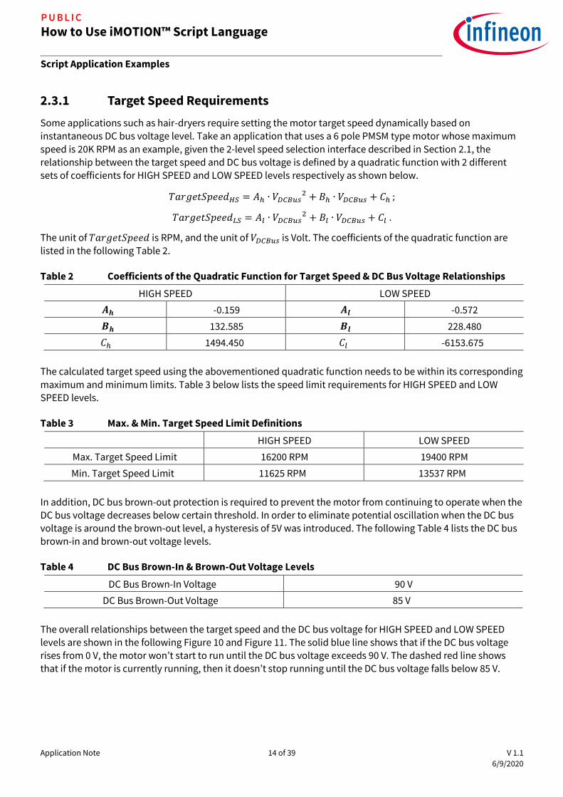
Some applications such as hair-dryers require setting the motor target speed dynamically based on instantaneous DC bus voltage level. Take an application that uses a 6 pole PMSM type motor whose maximum
speed is 20K RPM as an example, given the 2-level speed selection interface described in Section 2.1, the relationship between the target speed and DC bus voltage is defined by a quadratic function with 2 different
sets of coefficients for HIGH SPEED and LOW SPEED levels respectively as shown below.
𝑇𝑎𝑟𝑔𝑒𝑡𝑆𝑝𝑒𝑒𝑑𝐻𝑆 = 𝐴ℎ ∙ 𝑉𝐷𝐶𝐵𝑢𝑠2 + 𝐵ℎ ∙ 𝑉𝐷𝐶𝐵𝑢𝑠 + 𝐶ℎ ;
𝑇𝑎𝑟𝑔𝑒𝑡𝑆𝑝𝑒𝑒𝑑𝐿𝑆 = 𝐴𝑙 ∙ 𝑉𝐷𝐶𝐵𝑢𝑠2 + 𝐵𝑙 ∙ 𝑉𝐷𝐶𝐵𝑢𝑠 + 𝐶𝑙 .
The unit of 𝑇𝑎𝑟𝑔𝑒𝑡𝑆𝑝𝑒𝑒𝑑 is RPM, and the unit of 𝑉𝐷𝐶𝐵𝑢𝑠 is Volt. The coefficients of the quadratic function are
listed in the following Table 2.
Table 2 Coefficients of the Quadratic Function for Target Speed & DC Bus Voltage Relationships
HIGH SPEED LOW SPEED
𝑨𝒉 -0.159 𝑨𝒍 -0.572
𝑩𝒉 132.585 𝑩𝒍 228.480
𝐶ℎ 1494.450 𝐶𝑙 -6153.675
The calculated target speed using the abovementioned quadratic function needs to be within its corresponding
maximum and minimum limits. Table 3 below lists the speed limit requirements for HIGH SPEED and LOW SPEED levels.
Table 3 Max. & Min. Target Speed Limit Definitions
HIGH SPEED LOW SPEED
Max. Target Speed Limit 16200 RPM 19400 RPM
Min. Target Speed Limit 11625 RPM 13537 RPM
In addition, DC bus brown-out protection is required to prevent the motor from continuing to operate when the
DC bus voltage decreases below certain threshold. In order to eliminate potential oscillation when the DC bus voltage is around the brown-out level, a hysteresis of 5V was introduced. The following Table 4 lists the DC bus brown-in and brown-out voltage levels.
Table 4 DC Bus Brown-In & Brown-Out Voltage Levels
DC Bus Brown-In Voltage 90 V
DC Bus Brown-Out Voltage 85 V
The overall relationships between the target speed and the DC bus voltage for HIGH SPEED and LOW SPEED levels are shown in the following Figure 10 and Figure 11. The solid blue line shows that if the DC bus voltage rises from 0 V, the motor won’t start to run until the DC bus voltage exceeds 90 V. The dashed red line shows that if the motor is currently running, then it doesn’t stop running until the DC bus voltage falls below 85 V.

Application Note 15 of 39 V 1.1
6/9/2020
How to Use iMOTION™ Script Language
Script Application Examples
P U B L I C
Figure 10 Target Speed Shaping (LOW SPEED)
Figure 11 Target Speed Shaping (HIGH SPEED)
2.3.2 DC Bus Status State Machine
A dedicated state machine can be designed to keep track of DC Bus brown-in / brown-out status as shown in
the following Figure 12. The DC bus status state machine uses a state variable DCBusState to represent 2
possible states, namely, DC_Bus_State_Abnormal (DCBusState = 0), and DC_Bus_State_Normal (DCBusState = 1). The input signal to this state machine needs to be an averaged DC bus voltage ADC
conversion result to minimize potential oscillation. The LPF described in Section 2.2 can be used to generate the required input signal VDCBusLPF. Starting off in DC_Bus_State_Abnormal state, if VDCBusLPF is greater than the value of VDCBusBrownIn, then the DC bus status state machine shifts to DC_Bus_State_Normal state.
While it is in DC_Bus_State_Normal state, if VDCBusLPF becomes less than the value of VDCBusBrownOut, then the state machine shifts back to DC_Bus_State_Abnormal state.
-2000
0
2000
4000
6000
8000
10000
12000
14000
16000
18000
20000
0 20 40 60 80 100 120 140 160 180 200
Rev
olu
tio
n (
RP
M)
DC Bus Voltage (V)
Target Speed Shaping (LOW SPEED)
Desired Target Speed(Vdcbus rising)
Desired Target Speed(Vdcbus falling)
-2000
0
2000
4000
6000
8000
10000
12000
14000
16000
18000
20000
0 20 40 60 80 100 120 140 160 180 200
Rev
olu
tio
n (
RP
M)
DC Bus Voltage (V)
Target Speed Shaping (HIGH SPEED)
Desired Target Speed(Vdcbus rising)
Desired Target Speed(Vdcbus falling)

Application Note 16 of 39 V 1.1
6/9/2020
How to Use iMOTION™ Script Language
Script Application Examples
P U B L I C
Figure 12 DC Bus Status State Machine Diagram
The calculation of the value of VDCBusBrownIn and VDCBusBrownOut follows the conversion formula described in Section 2.2.2, and the voltage levels specified in Table 4. The results are shown in Table 5 below.
Table 5
DC Bus Brown-In Voltage 90 V VDCBusBrownIn 487 (ADC counts)
DC Bus Brown-Out Voltage 85 V VDCBusBrownOut 460 (ADC counts)
2.3.3 Scaling for Target Speed Shaping Calculation
Section 2.3.1 defined the relationship between 𝑇𝑎𝑟𝑔𝑒𝑡𝑆𝑝𝑒𝑒𝑑 and 𝑉𝐷𝐶𝐵𝑢𝑠 for different speed selection levels,
where the unit of 𝑇𝑎𝑟𝑔𝑒𝑡𝑆𝑝𝑒𝑒𝑑 was RPM, and the unit of 𝑉𝐷𝐶𝐵𝑢𝑠 was Volt. However, in MCE software, the target
speed is represented by a signed 16 bit integer, where 16383 corresponds to the motor’s maximum speed. For
this application, TargetSpeed = 16383 corresponds to the maximum motor speed of 20K RPM. The DC bus voltage in MCE software is presented by its corresponding ADC sampling result in ADC counts, following the
conversion formula described in Section 2.2.2. Thus, the formulas defined in Section 2.3.1 cannot be used
directly in script code. In order to obtain the correct calculation result of target speed in script code, those
scaling factors need to be taken into consideration as shown in the following formula.
𝑇𝑎𝑟𝑔𝑒𝑡𝑆𝑝𝑒𝑒𝑑𝑠𝑐𝑟𝑖𝑝𝑡 = [𝐴 ∙ (𝑉𝐷𝐶𝐵𝑢𝑠𝐴𝐷𝐶∙
𝑉𝑟𝑒𝑓
212−1∙
1
𝐺𝐷𝐶𝐵𝑢𝑠𝑠𝑒𝑛𝑠𝑖𝑛𝑔
)2 + 𝐵 ∙ (𝑉𝐷𝐶𝐵𝑢𝑠𝐴𝐷𝐶∙
𝑉𝑟𝑒𝑓
212−1∙
1
𝐺𝐷𝐶𝐵𝑢𝑠𝑠𝑒𝑛𝑠𝑖𝑛𝑔
) + 𝐶] ∙16383
𝑆𝑝𝑒𝑒𝑑𝑚𝑎𝑥 , where
𝑉𝑟𝑒𝑓 = 5𝑉, 𝐺𝐷𝐶𝐵𝑢𝑠_𝑠𝑒𝑛𝑠𝑖𝑛𝑔 = 0.00661 (described in Section 2.2.2), 𝑆𝑝𝑒𝑒𝑑𝑚𝑎𝑥 = 20000, 𝐴, 𝐵, and 𝐶 are the 3
coefficients in the original quadratic function that defines the relationship between the target speed and DC bus voltage for different speed selection levels.
If we define 𝑇𝑠𝑝𝑑_𝑓𝑎𝑐𝑡𝑜𝑟 =16383
𝑆𝑝𝑒𝑒𝑑𝑚𝑎𝑥= 0.819 , and 𝑉𝐷𝐶𝐵𝑢𝑠_𝑓𝑎𝑐𝑡𝑜𝑟 =
𝑉𝑟𝑒𝑓
212−1∙
1
𝐺𝐷𝐶𝐵𝑢𝑠𝑠𝑒𝑛𝑠𝑖𝑛𝑔
= 0.185 , then we can
obtain the following formula:
𝑇𝑎𝑟𝑔𝑒𝑡𝑆𝑝𝑒𝑒𝑑𝑠𝑐𝑟𝑖𝑝𝑡 = (𝐴 ∙ 𝑇𝑠𝑝𝑑_𝑓𝑎𝑐𝑡𝑜𝑟 ∙ 𝑉𝐷𝐶𝐵𝑢𝑠_𝑓𝑎𝑐𝑡𝑜𝑟2) ∙ 𝑉𝐷𝐶𝐵𝑢𝑠𝐴𝐷𝐶
2 + (𝐵 ∙ 𝑇𝑠𝑝𝑑_𝑓𝑎𝑐𝑡𝑜𝑟 ∙ 𝑉𝐷𝐶𝐵𝑢𝑠_𝑓𝑎𝑐𝑡𝑜𝑟) ∙ 𝑉𝐷𝐶𝐵𝑢𝑠𝐴𝐷𝐶+ (𝐶 ∙ 𝑇𝑠𝑝𝑑_𝑓𝑎𝑐𝑡𝑜𝑟) .
If we define 𝐴𝑠𝑐𝑟𝑖𝑝𝑡 = 𝐴 ∙ 𝑇𝑠𝑝𝑑_𝑓𝑎𝑐𝑡𝑜𝑟 ∙ 𝑉𝐷𝐶𝐵𝑢𝑠_𝑓𝑎𝑐𝑡𝑜𝑟2 , 𝐵𝑠𝑐𝑟𝑖𝑝𝑡 = 𝐵 ∙ 𝑇𝑠𝑝𝑑_𝑓𝑎𝑐𝑡𝑜𝑟 ∙ 𝑉𝐷𝐶𝐵𝑢𝑠_𝑓𝑎𝑐𝑡𝑜𝑟 , and 𝐶𝑠𝑐𝑟𝑖𝑝𝑡 = 𝐶 ∙
𝑇𝑠𝑝𝑑_𝑓𝑎𝑐𝑡𝑜𝑟 ∙ 𝑉𝐷𝐶𝐵𝑢𝑠_𝑓𝑎𝑐𝑡𝑜𝑟 , then the above formula can be simplified as follows.
𝑇𝑎𝑟𝑔𝑒𝑡𝑆𝑝𝑒𝑒𝑑𝑠𝑐𝑟𝑖𝑝𝑡 = 𝐴𝑠𝑐𝑟𝑖𝑝𝑡 ∙ 𝑉𝐷𝐶𝐵𝑢𝑠𝐴𝐷𝐶
2 + 𝐵𝑠𝑐𝑟𝑖𝑝𝑡 ∙ 𝑉𝐷𝐶𝐵𝑢𝑠𝐴𝐷𝐶+ 𝐶𝑠𝑐𝑟𝑖𝑝𝑡 .
Using this formula, the relevant coefficients with the inclusion of the scaling factors can be calculated for different speed selection levels as shown in the following Table 6.
VDCBusLPF < VDCBusBrownOut
DC_Bus_State_Abnormal
entry / do / DCBusState = 0;exit /
DC_Bus_State_Normal
entry / do / DCBusState = 1;exit /
VDCBusLPF > VDCBusBrownIn

Application Note 17 of 39 V 1.1
6/9/2020
How to Use iMOTION™ Script Language
Script Application Examples
P U B L I C
Table 6 Coefficients in Floating Point Format for the Quadratic Function for Target Speed & DC Bus Voltage Relationships with Scaling Factors
HIGH SPEED LOW SPEED
𝑨𝒉_𝒔𝒄𝒓𝒊𝒑𝒕 -0.004 𝑨𝒍_𝒔𝒄𝒓𝒊𝒑𝒕 -0.016
𝑩𝒉_𝒔𝒄𝒓𝒊𝒑𝒕 20.074 𝑩𝒍_𝒔𝒄𝒓𝒊𝒑𝒕 34.593
𝐶ℎ_𝑠𝑐𝑟𝑖𝑝𝑡 1224.179 𝐶𝑙_𝑠𝑐𝑟𝑖𝑝𝑡 -5040.783
The script engine only supports 32 bit signed integer type of variables [2], so these floating point numbers have to be represented in fractional format in the script code. For instance, if we choose a common denominator
DEN, then the target speed shaping calculation in script can be realized by using the following pseudo code in Code Listing 5.
Code Listing 5 Target Speed Shaping Calculation Pseudo Code
001 Speed_Value = A_NUM * VDCBus * VDCBus + B_NUM * VDCBus +
C_NUM;
002 TargetSpeed = Speed_Value / DEN;
Considering the accuracy requirement and overflow limit, we chose a common denominator of 65536 (Q15.16 format), with which the division operation can be replaced by efficient right shifting 16 bits. With that, the numerator value for each coefficient can be calculated accordingly as shown in the following Table 7.
Table 7 Coefficients in Q15.16 Format for the Quadratic Function for Target Speed & DC Bus
Voltage Relationships with Scaling Factors
𝑫𝒆𝒏𝒐𝒎𝒊𝒏𝒂𝒕𝒐𝒓 65536
HIGH SPEED LOW SPEED
𝑨𝒉_𝑵𝑼𝑴 -291 𝑨𝒍_𝑵𝑼𝑴 -1049
𝑩𝒉_𝑵𝑼𝑴 1315558 𝑩𝒍_𝑵𝑼𝑴 2267069
𝐶ℎ_𝑁𝑈𝑀 80227767 𝐶𝑙_𝑁𝑈𝑀 -330352746
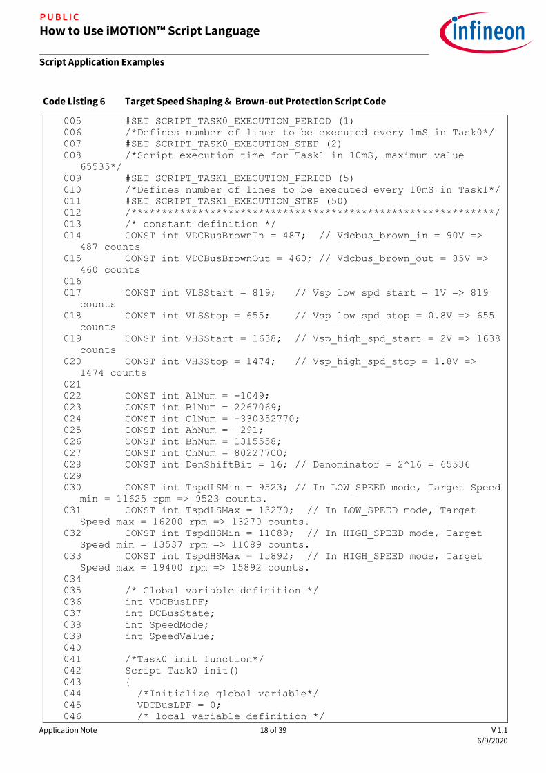
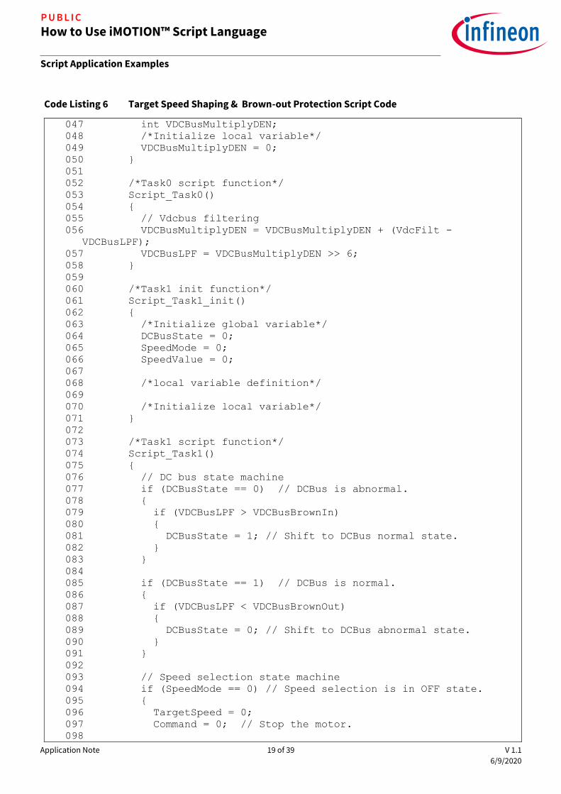
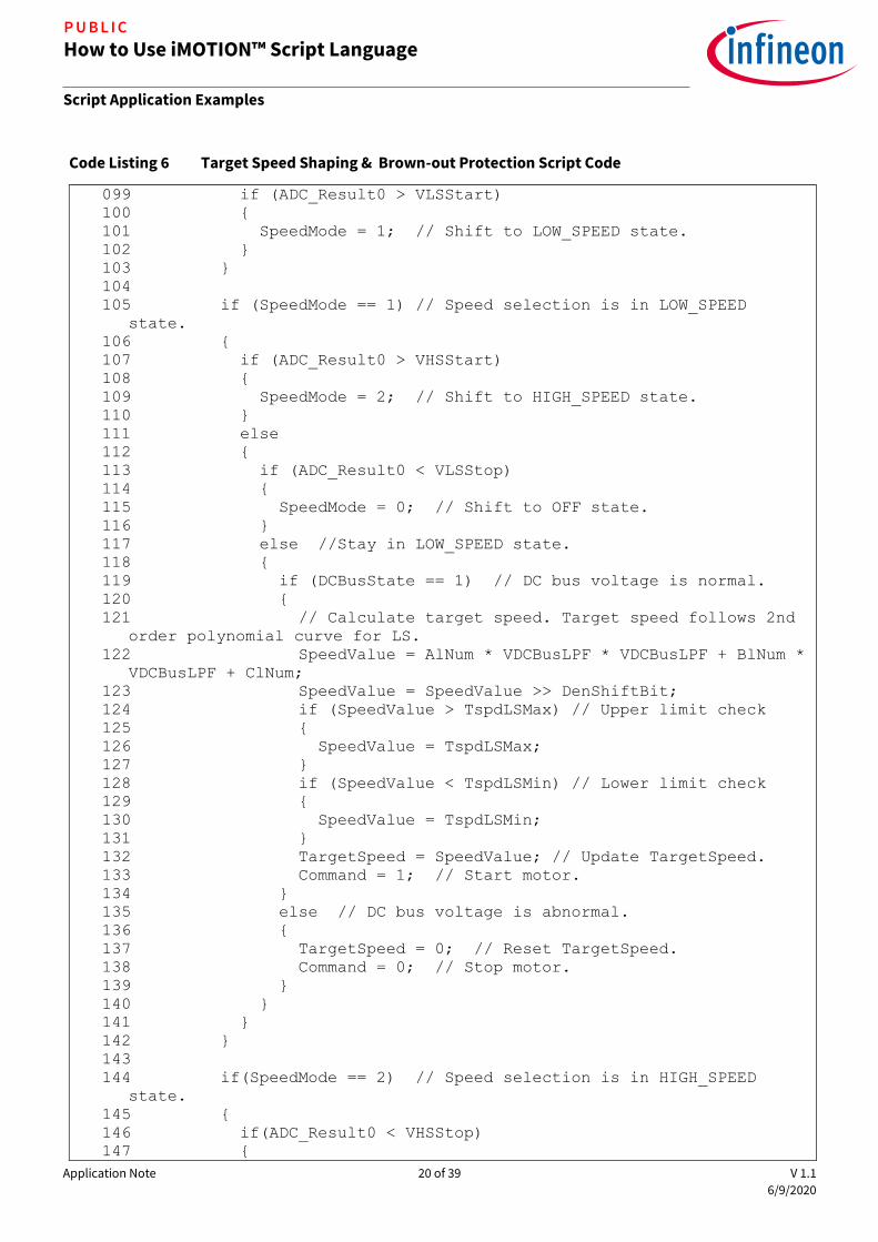
2.3.4 Target Speed Shaping & Brown-out Protection Script Implementation
The following Code Listing 6 shows the source code for the target speed shaping with brown-out protection application implemented in Task 1. Since the target speed doesn’t need to be updated too frequently, it is recommended to set the loop execution period of Task 1 to be 50 ms. The compiled script object file shows that
the number of instructions for Task 1 is 42. So, the execution step for Task 1 should be set to greater than 42 to ensure that the entire loop of Task 1 is completed during each execution period. In this example, the execution
period for Task 1 (SCRIPT_TASK1_EXECUTION_PERIOD) was set to 5, and the execution step for Task 1 (SCRIPT_TASK1_EXECUTION_STEP) was chosen to be 50 to meet the desired timing requirement.
This example can also be implemented in Task 0, in which case the execution period for Task 0 (SCRIPT_TASK0_EXECUTION_PERIOD) should be set to 50 to achieve the same execution period of 50 ms.
Code Listing 6 Target Speed Shaping & Brown-out Protection Script Code
001 /*************************************************************
*/
002 /*Script user version value, should be 255.255*/
003 #SET SCRIPT_USER_VERSION (1.00)
004 /*Script execution time for Task0 in mS, maximum value 65535*/
Application Note 18 of 39 V 1.1
6/9/2020
How to Use iMOTION™ Script Language
Script Application Examples
P U B L I C
Code Listing 6 Target Speed Shaping & Brown-out Protection Script Code
005 #SET SCRIPT_TASK0_EXECUTION_PERIOD (1)
006 /*Defines number of lines to be executed every 1mS in Task0*/
007 #SET SCRIPT_TASK0_EXECUTION_STEP (2)
008 /*Script execution time for Task1 in 10mS, maximum value
65535*/
009 #SET SCRIPT_TASK1_EXECUTION_PERIOD (5)
010 /*Defines number of lines to be executed every 10mS in Task1*/
011 #SET SCRIPT_TASK1_EXECUTION_STEP (50)
012 /************************************************************/
013 /* constant definition */
014 CONST int VDCBusBrownIn = 487; // Vdcbus_brown_in = 90V =>
487 counts
015 CONST int VDCBusBrownOut = 460; // Vdcbus_brown_out = 85V =>
460 counts
016
017 CONST int VLSStart = 819; // Vsp_low_spd_start = 1V => 819
counts
018 CONST int VLSStop = 655; // Vsp_low_spd_stop = 0.8V => 655
counts
019 CONST int VHSStart = 1638; // Vsp_high_spd_start = 2V => 1638
counts
020 CONST int VHSStop = 1474; // Vsp_high_spd_stop = 1.8V =>
1474 counts
021
022 CONST int AlNum = -1049;
023 CONST int BlNum = 2267069;
024 CONST int ClNum = -330352770;
025 CONST int AhNum = -291;
026 CONST int BhNum = 1315558;
027 CONST int ChNum = 80227700;
028 CONST int DenShiftBit = 16; // Denominator = 2^16 = 65536
029
030 CONST int TspdLSMin = 9523; // In LOW_SPEED mode, Target Speed
min = 11625 rpm => 9523 counts.
031 CONST int TspdLSMax = 13270; // In LOW_SPEED mode, Target
Speed max = 16200 rpm => 13270 counts.
032 CONST int TspdHSMin = 11089; // In HIGH_SPEED mode, Target
Speed min = 13537 rpm => 11089 counts.
033 CONST int TspdHSMax = 15892; // In HIGH_SPEED mode, Target
Speed max = 19400 rpm => 15892 counts.
034
035 /* Global variable definition */
036 int VDCBusLPF;
037 int DCBusState;
038 int SpeedMode;
039 int SpeedValue;
040
041 /*Task0 init function*/
042 Script_Task0_init()
043
044 /*Initialize global variable*/
045 VDCBusLPF = 0;
046 /* local variable definition */
Application Note 19 of 39 V 1.1
6/9/2020
How to Use iMOTION™ Script Language
Script Application Examples
P U B L I C
Code Listing 6 Target Speed Shaping & Brown-out Protection Script Code
047 int VDCBusMultiplyDEN;
048 /*Initialize local variable*/
049 VDCBusMultiplyDEN = 0;
050
051
052 /*Task0 script function*/
053 Script_Task0()
054
055 // Vdcbus filtering
056 VDCBusMultiplyDEN = VDCBusMultiplyDEN + (VdcFilt -
VDCBusLPF);
057 VDCBusLPF = VDCBusMultiplyDEN >> 6;
058
059
060 /*Task1 init function*/
061 Script_Task1_init()
062
063 /*Initialize global variable*/
064 DCBusState = 0;
065 SpeedMode = 0;
066 SpeedValue = 0;
067
068 /*local variable definition*/
069
070 /*Initialize local variable*/
071
072
073 /*Task1 script function*/
074 Script_Task1()
075
076 // DC bus state machine
077 if (DCBusState == 0) // DCBus is abnormal.
078
079 if (VDCBusLPF > VDCBusBrownIn)
080
081 DCBusState = 1; // Shift to DCBus normal state.
082
083
084
085 if (DCBusState == 1) // DCBus is normal.
086
087 if (VDCBusLPF < VDCBusBrownOut)
088
089 DCBusState = 0; // Shift to DCBus abnormal state.
090
091
092
093 // Speed selection state machine
094 if (SpeedMode == 0) // Speed selection is in OFF state.
095
096 TargetSpeed = 0;
097 Command = 0; // Stop the motor.
098
Application Note 20 of 39 V 1.1
6/9/2020
How to Use iMOTION™ Script Language
Script Application Examples
P U B L I C
Code Listing 6 Target Speed Shaping & Brown-out Protection Script Code
099 if (ADC_Result0 > VLSStart)
100
101 SpeedMode = 1; // Shift to LOW_SPEED state.
102
103
104
105 if (SpeedMode == 1) // Speed selection is in LOW_SPEED
state.
106
107 if (ADC_Result0 > VHSStart)
108
109 SpeedMode = 2; // Shift to HIGH_SPEED state.
110
111 else
112
113 if (ADC_Result0 < VLSStop)
114
115 SpeedMode = 0; // Shift to OFF state.
116
117 else //Stay in LOW_SPEED state.
118
119 if (DCBusState == 1) // DC bus voltage is normal.
120
121 // Calculate target speed. Target speed follows 2nd
order polynomial curve for LS.
122 SpeedValue = AlNum * VDCBusLPF * VDCBusLPF + BlNum *
VDCBusLPF + ClNum;
123 SpeedValue = SpeedValue >> DenShiftBit;
124 if (SpeedValue > TspdLSMax) // Upper limit check
125
126 SpeedValue = TspdLSMax;
127
128 if (SpeedValue < TspdLSMin) // Lower limit check
129
130 SpeedValue = TspdLSMin;
131
132 TargetSpeed = SpeedValue; // Update TargetSpeed.
133 Command = 1; // Start motor.
134
135 else // DC bus voltage is abnormal.
136
137 TargetSpeed = 0; // Reset TargetSpeed.
138 Command = 0; // Stop motor.
139
140
141
142
143
144 if(SpeedMode == 2) // Speed selection is in HIGH_SPEED
state.
145
146 if(ADC_Result0 < VHSStop)
147

Application Note 21 of 39 V 1.1
6/9/2020
How to Use iMOTION™ Script Language
Script Application Examples
P U B L I C
Code Listing 6 Target Speed Shaping & Brown-out Protection Script Code
148 SpeedMode = 1; // Shift to LOW_SPEED state.
149
150 else // Stay in HIGH_SPEED state.
151
152 if (DCBusState == 1) // DC bus voltage is normal.
153
154 // Target speed follows 2nd order polynomial curve for
HS.
155 SpeedValue = AhNum * VDCBusLPF * VDCBusLPF + BhNum *
VDCBusLPF + ChNum;
156 SpeedValue = SpeedValue >> DenShiftBit;
157 if (SpeedValue > TspdHSMax) // Upper limit check
158
159 SpeedValue = TspdHSMax;
160
161 if (SpeedValue < TspdHSMin) // Lower limit check
162
163 SpeedValue = TspdHSMin;
164
165 TargetSpeed = SpeedValue; // Update TargetSpeed.
166 Command = 1; // Start motor.
167
168 else // DC bus voltage is abnormal.
169
170 TargetSpeed = 0; // Reset TargetSpeed.
171 Command = 0; // Stop motor.
172
173
174
175
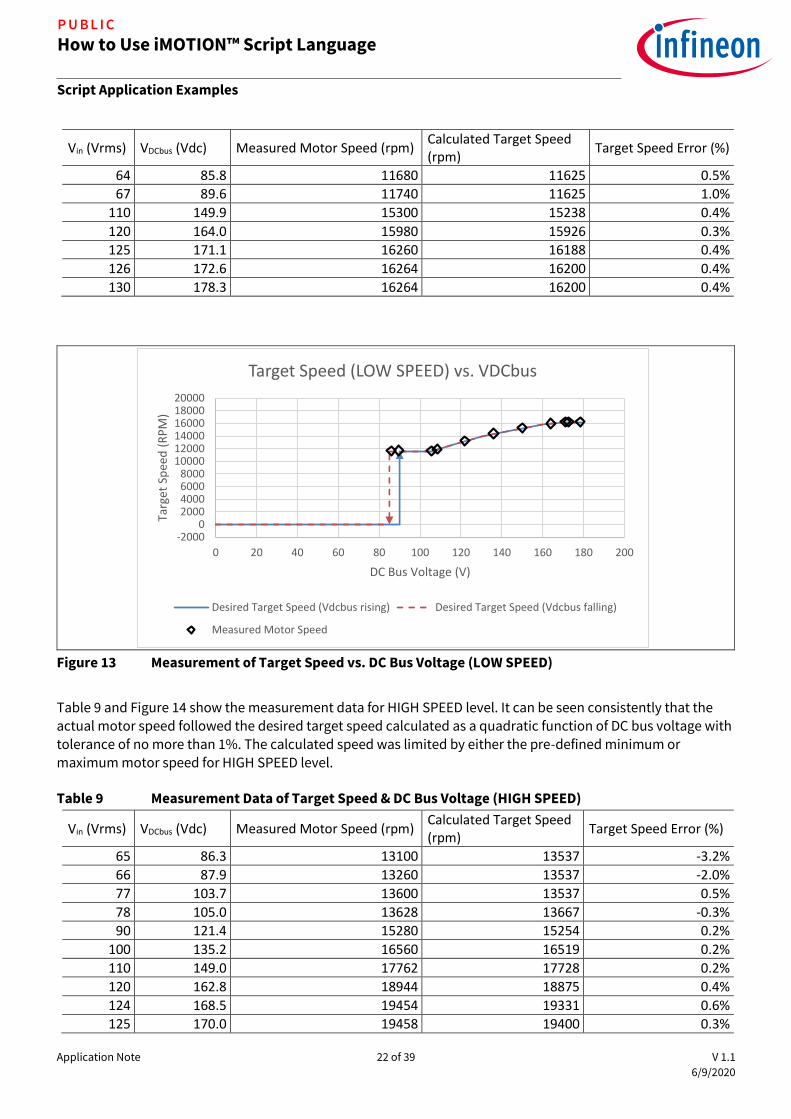
2.3.5 Target Speed Shaping Measurement Results
The actual motor speed was measured by calculating the frequency of the motor phase current waveforms while the input voltage was swept from 65 VAC to 130 VAC at different speed selection levels. The measurement
data for LOW SPEED level was shown in the following Table 8 and plotted against the desired target speed
shaping curves in Figure 13. As can be seen from the measurement data, the actual motor speed followed the desired target speed calculated as a quadratic function of DC bus voltage with tolerance of no more than 1%. The calculated speed was limited by either the pre-defined minimum or maximum motor speed for LOW SPEED
level.
Table 8 Measurement Data of Target Speed & DC Bus Voltage (LOW SPEED)
Vin (Vrms) VDCbus (Vdc) Measured Motor Speed (rpm) Calculated Target Speed (rpm)
Target Speed Error (%)
64 85.8 11680 11625 0.5%
67 89.6 11740 11625 1.0%
78 105.6 11680 11590 0.8%
80 108.4 11900 11890 0.1%
90 122.0 13216 13204 0.1%
100 135.9 14380 14329 0.4%
Application Note 22 of 39 V 1.1
6/9/2020
How to Use iMOTION™ Script Language
Script Application Examples
P U B L I C
Vin (Vrms) VDCbus (Vdc) Measured Motor Speed (rpm) Calculated Target Speed (rpm)
Target Speed Error (%)
64 85.8 11680 11625 0.5%
67 89.6 11740 11625 1.0%
110 149.9 15300 15238 0.4%
120 164.0 15980 15926 0.3%
125 171.1 16260 16188 0.4%
126 172.6 16264 16200 0.4%
130 178.3 16264 16200 0.4%
Figure 13 Measurement of Target Speed vs. DC Bus Voltage (LOW SPEED)
Table 9 and Figure 14 show the measurement data for HIGH SPEED level. It can be seen consistently that the actual motor speed followed the desired target speed calculated as a quadratic function of DC bus voltage with tolerance of no more than 1%. The calculated speed was limited by either the pre-defined minimum or
maximum motor speed for HIGH SPEED level.
Table 9 Measurement Data of Target Speed & DC Bus Voltage (HIGH SPEED)
Vin (Vrms) VDCbus (Vdc) Measured Motor Speed (rpm) Calculated Target Speed (rpm)
Target Speed Error (%)
65 86.3 13100 13537 -3.2%
66 87.9 13260 13537 -2.0%
77 103.7 13600 13537 0.5%
78 105.0 13628 13667 -0.3%
90 121.4 15280 15254 0.2%
100 135.2 16560 16519 0.2%
110 149.0 17762 17728 0.2%
120 162.8 18944 18875 0.4%
124 168.5 19454 19331 0.6%
125 170.0 19458 19400 0.3%
-20000
2000400060008000
100001200014000160001800020000
0 20 40 60 80 100 120 140 160 180 200
Targ
et S
pee
d (
RP
M)
DC Bus Voltage (V)
Target Speed (LOW SPEED) vs. VDCbus
Desired Target Speed (Vdcbus rising) Desired Target Speed (Vdcbus falling)
Measured Motor Speed

Application Note 23 of 39 V 1.1
6/9/2020
How to Use iMOTION™ Script Language
Script Application Examples
P U B L I C
Vin (Vrms) VDCbus (Vdc) Measured Motor Speed (rpm) Calculated Target Speed (rpm)
Target Speed Error (%)
65 86.3 13100 13537 -3.2%
66 87.9 13260 13537 -2.0%
130 177.2 19466 19400 0.3%
Figure 14 Measurements of Target Speed vs. DC Bus Voltage (HIGH SPEED)
2.4 Dynamic Motor Current Limit Customization
2.4.1 Motor Current Limit Requirement
By default, the motor current limit is set to 100% of its rated current. Some applications require implementing
customized motor current limit based on the speed selection input to enable tighter torque control. Besides,
during the motor speed ramp-up or ramp-down period, the motor current limit needs to be loosened up to its original setting (100% of the rated current) momentarily to allow for quicker response to speed change request.
When the motor is stopped, the motor current limit also needs to be restored to its original setting. The detailed motor current limit requirements are listed in the following Table 10.
Table 10 Motor Current Limit Requirements
Rated
Current
Speed Ramp-up
/ Ramp-down
Period
Speed Selection
= OFF
Speed Selection
= HIGH SPEED
Speed Selection
= LOW SPEED
Motor Current Limit 3 A 3 A 3 A 0.6 A 0.38 A
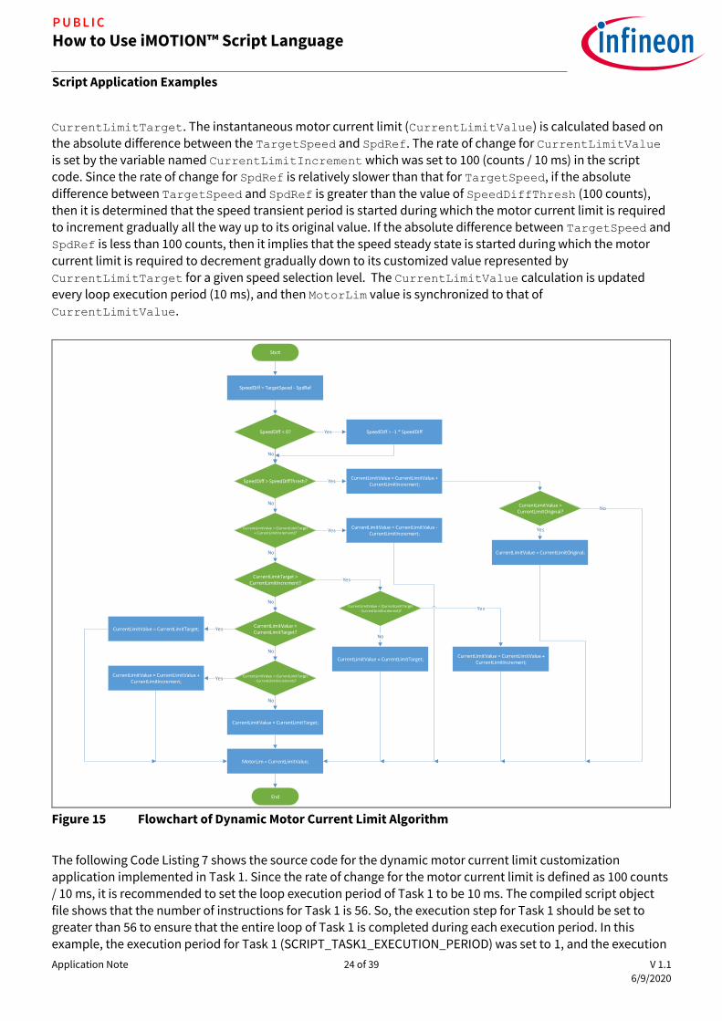
2.4.2 Dynamic Motor Current Limit Algorithm Design & Implementation
The following Figure 15 shows the detailed flowchart for dynamic motor current limit calculation algorithm. During the initialization, the original motor current limit value (MotorLim) is stored in a variable named
CurrentLimitOriginal. The customized motor current limit during steady state at a given speed selection level is updated by speed selection state machine and is maintained by the variable named
-20000
2000400060008000
100001200014000160001800020000
0 20 40 60 80 100 120 140 160 180 200
Targ
et S
pee
d (
RP
M)
DC Bus Voltage (V)
Target Speed (HIGH SPEED) vs. VDCbus
Desired Target Speed (Vdcbus rising) Desired Target Speed (Vdcbus falling)
Measured Motor Speed
Application Note 24 of 39 V 1.1
6/9/2020
How to Use iMOTION™ Script Language
Script Application Examples
P U B L I C
CurrentLimitTarget. The instantaneous motor current limit (CurrentLimitValue) is calculated based on the absolute difference between the TargetSpeed and SpdRef. The rate of change for CurrentLimitValue is set by the variable named CurrentLimitIncrement which was set to 100 (counts / 10 ms) in the script code. Since the rate of change for SpdRef is relatively slower than that for TargetSpeed, if the absolute
difference between TargetSpeed and SpdRef is greater than the value of SpeedDiffThresh (100 counts), then it is determined that the speed transient period is started during which the motor current limit is required to increment gradually all the way up to its original value. If the absolute difference between TargetSpeed and SpdRef is less than 100 counts, then it implies that the speed steady state is started during which the motor
current limit is required to decrement gradually down to its customized value represented by
CurrentLimitTarget for a given speed selection level. The CurrentLimitValue calculation is updated every loop execution period (10 ms), and then MotorLim value is synchronized to that of CurrentLimitValue.
Start
SpeedDiff = TargetSpeed - SpdRef
SpeedDiff < 0? Yes SpeedDiff = -1 * SpeedDiff
No
SpeedDiff > SpeedDiffThresh? YesCurrentLimitValue = CurrentLimitValue +
CurrentLimitIncrement;
CurrentLimitValue > CurrentLimitOriginal?
Yes
CurrentLimitValue = CurrentLimitOriginal;
No
CurrentLimitValue > (CurrentLimitTarget + CurrentLimitIncrement)? Yes
CurrentLimitValue = CurrentLimitValue - CurrentLimitIncrement;
No
CurrentLimitTarget > CurrentLimitIncrement?
Yes
CurrentLimitValue < (CurrentLimitTarget - CurrentLimitIncrement)? Yes
CurrentLimitValue = CurrentLimitValue + CurrentLimitIncrement;
No
CurrentLimitValue = CurrentLimitTarget;
No
CurrentLimitValue < CurrentLimitTarget?
YesCurrentLimitValue = CurrentLimitTarget;
No
CurrentLimitValue > (CurrentLimitTarget - CurrentLimitIncrement)?
No
CurrentLimitValue = CurrentLimitTarget;
YesCurrentLimitValue = CurrentLimitValue +
CurrentLimitIncrement;
No
MotorLim = CurrentLimitValue;
End
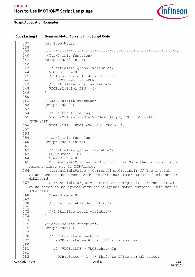
Figure 15 Flowchart of Dynamic Motor Current Limit Algorithm
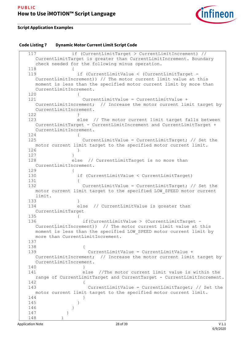
The following Code Listing 7 shows the source code for the dynamic motor current limit customization application implemented in Task 1. Since the rate of change for the motor current limit is defined as 100 counts
/ 10 ms, it is recommended to set the loop execution period of Task 1 to be 10 ms. The compiled script object
file shows that the number of instructions for Task 1 is 56. So, the execution step for Task 1 should be set to greater than 56 to ensure that the entire loop of Task 1 is completed during each execution period. In this example, the execution period for Task 1 (SCRIPT_TASK1_EXECUTION_PERIOD) was set to 1, and the execution

Application Note 25 of 39 V 1.1
6/9/2020
How to Use iMOTION™ Script Language
Script Application Examples
P U B L I C
step for Task 1 (SCRIPT_TASK1_EXECUTION_STEP) was chosen to be 60 to meet the desired timing requirement.
This example can also be implemented in Task 0, in which case the execution period for Task 0
(SCRIPT_TASK0_EXECUTION_PERIOD) should be set to 10 to achieve the same execution period of 10 ms.
Code Listing 7 Dynamic Motor Current Limit Script Code
001 /************************************************************/
002 /*Script user version value, should be 255.255*/
003 #SET SCRIPT_USER_VERSION (1.00)
004 /*Script execution time for Task0 in mS, maximum value 65535*/
005 #SET SCRIPT_TASK0_EXECUTION_PERIOD (1)
006 /*Defines number of lines to be executed every 1mS in Task0*/
007 #SET SCRIPT_TASK0_EXECUTION_STEP (2)
008 /*Script execution time for Task1 in 10mS, maximum value
65535*/
009 #SET SCRIPT_TASK1_EXECUTION_PERIOD (1)
010 /*Defines number of lines to be executed every 10mS in Task1*/
011 #SET SCRIPT_TASK1_EXECUTION_STEP (60)
012 /************************************************************/
013 /* constant definition */
014 CONST int VDCBusBrownIn = 487; // Vdcbus_brown_in = 90V =>
487 counts
015 CONST int VDCBusBrownOut = 460; // Vdcbus_brown_out = 85V =>
460 counts
016
017 CONST int SpeedDiffThresh = 100; // Set the speed difference
threshold to 100 counts.
018 CONST int CurrentLimitIncrement = 100; // Motor current limit
ramp rate = 100 counts / update interval (10 ms).
019 CONST int CurrentLimitLS = 519; // low speed motor current
limit = 0.38A => 519 counts
020 CONST int CurrentLimitHS = 819; // high speed motor current
limit = 0.6A => 819 counts
021
022 CONST int VLSStart = 819; // Vsp_low_spd_start = 1V => 819
counts
023 CONST int VLSStop = 655; // Vsp_low_spd_stop = 0.8V => 655
counts
024 CONST int VHSStart = 1638; // Vsp_high_spd_start = 2V => 1638
counts
025 CONST int VHSStop = 1474; // Vsp_high_spd_stop = 1.8V =>
1474 counts
026
027 CONST int LowSpeedValue = 5000;
028 CONST int HighSpeedValue = 10000;
029
030 /* Global variable definition */
031 int VDCBusLPF;
032 int DCBusState;
033 int SpeedDiff;
034 int CurrentLimitOriginal;
035 int CurrentLimitValue;
036 int CurrentLimitTarget;
Application Note 26 of 39 V 1.1
6/9/2020
How to Use iMOTION™ Script Language
Script Application Examples
P U B L I C
Code Listing 7 Dynamic Motor Current Limit Script Code
037 int SpeedMode;
038
039 /************************************************************/
040 /*Task0 init function*/
041 Script_Task0_init()
042
043 /*Initialize global variable*/
044 VDCBusLPF = 0;
045 /* local variable definition */
046 int VDCBusMultiplyDEN;
047 /*Initialize local variable*/
048 VDCBusMultiplyDEN = 0;
049
050
051 /*Task0 script function*/
052 Script_Task0()
053
054 // Vdcbus filtering
055 VDCBusMultiplyDEN = VDCBusMultiplyDEN + (VdcFilt -
VDCBusLPF);
056 VDCBusLPF = VDCBusMultiplyDEN >> 6;
057
058
059 /*Task1 init function*/
060 Script_Task1_init()
061
062 /*Initialize global variable*/
063 DCBusState = 0;
064 SpeedDiff = 0;
065 CurrentLimitOriginal = MotorLim; // Save the original motor
current limit set in MCEWizard.
066 CurrentLimitValue = CurrentLimitOriginal; // The initial
value needs to be synced with the original motor current limit set in
MCEWizard.
067 CurrentLimitTarget = CurrentLimitOriginal; // The initial
value needs to be synced with the original motor current limit set in
MCEWizard.
068 SpeedMode = 0;
069
070 /*local variable definition*/
071
072 /*Initialize local variable*/
073
074
075 /*Task1 script function*/
076 Script_Task1()
077
078 // DC bus state machine
079 if (DCBusState == 0) // DCBus is abnormal.
080
081 if (VDCBusLPF > VDCBusBrownIn)
082
083 DCBusState = 1; // Shift to DCBus normal state.

Application Note 27 of 39 V 1.1
6/9/2020
How to Use iMOTION™ Script Language
Script Application Examples
P U B L I C
Code Listing 7 Dynamic Motor Current Limit Script Code
084
085
086
087 if (DCBusState == 1) // DCBus is normal.
088
089 if (VDCBusLPF < VDCBusBrownOut)
090
091 DCBusState = 0; // Shift to DCBus abnormal state.
092
093
094 // Calculate the difference between the target speed and the
speed reference in preparation for motor current limit calculation.
095 SpeedDiff = TargetSpeed - SpdRef; // Find out the difference
between the speed reference and the target speed.
096 if(SpeedDiff < 0) // The target speed is lower than the
speed reference.
097
098 SpeedDiff = -1 * SpeedDiff; // Takes the absolute value of
SpeedDiff.
099
100 // Calculate motor current limit based on speed reference
and target speed.
101 if(SpeedDiff > SpeedDiffThresh) // The speed reference is
more than SpeedDiffThresh counts different from the target speed. We
need to increase the motor current limit to its original value
temperarily.
102
103 CurrentLimitValue = CurrentLimitValue +
CurrentLimitIncrement; // Increase the motor current limit by
CurrentLimitIncrement until it reaches CurrentLimOriginal.
104 if (CurrentLimitValue > CurrentLimitOriginal) // Upper
boundary check for CurrentLimitValue.
105
106 CurrentLimitValue = CurrentLimitOriginal;
107
108
109 else // The speed reference is no more than 100 counts
different from the target speed. We need to decrease the motor current
limit to CurrentLimitTarget.
110
111 if(CurrentLimitValue > (CurrentLimitTarget +
CurrentLimitIncrement)) // The motor current limit value at this
moment is greater than the specified motor current limit by more than
CurrentLimitIncrement.
112
113 CurrentLimitValue = CurrentLimitValue -
CurrentLimitIncrement; // Decrease the motor current limit target by
CurrentLimitIncrement.
114
115 else // The motor current limit target is no more than
the specified motor current limit by more than CurrentLimitIncrement.
116
Application Note 28 of 39 V 1.1
6/9/2020
How to Use iMOTION™ Script Language
Script Application Examples
P U B L I C
Code Listing 7 Dynamic Motor Current Limit Script Code
117 if (CurrentLimitTarget > CurrentLimitIncrement) //
CurrentLimitTarget is greater than CurrentLimitIncrement. Boundary
check needed for the following minus operation.
118
119 if (CurrentLimitValue < (CurrentLimitTarget -
CurrentLimitIncrement)) // The motor current limit value at this
moment is less than the specified motor current limit by more than
CurrentLimitIncrement.
120
121 CurrentLimitValue = CurrentLimitValue +
CurrentLimitIncrement; // Increase the motor current limit target by
CurrentLimitIncrement.
122
123 else // The motor current limit target falls between
CurrentLimitTarget - CurrentLimitIncrement and CurrentLimitTarget +
CurrentLimitIncrement.
124
125 CurrentLimitValue = CurrentLimitTarget; // Set the
motor current limit target to the specified motor current limit.
126
127
128 else // CurrentLimitTarget is no more than
CurrentLimitIncrement.
129
130 if (CurrentLimitValue < CurrentLimitTarget)
131
132 CurrentLimitValue = CurrentLimitTarget; // Set the
motor current limit target to the specified LOW_SPEED motor current
limit.
133
134 else // CurrentLimitValue is greater than
CurrentLimitTarget
135
136 if(CurrentLimitValue > (CurrentLimitTarget -
CurrentLimitIncrement)) // The motor current limit value at this
moment is less than the specified LOW_SPEED motor current limit by
more than CurrentLimitIncrement.
137
138
139 CurrentLimitValue = CurrentLimitValue +
CurrentLimitIncrement; // Increase the motor current limit target by
CurrentLimitIncrement.
140
141 else //The motor current limit value is within the
range of CurrentLimitTarget and CurrentTarget - CurrentLimitIncrement.
142
143 CurrentLimitValue = CurrentLimitTarget; // Set the
motor current limit target to the specified motor current limit.
144
145
146
147
148

Application Note 29 of 39 V 1.1
6/9/2020
How to Use iMOTION™ Script Language
Script Application Examples
P U B L I C
Code Listing 7 Dynamic Motor Current Limit Script Code
149 MotorLim = CurrentLimitValue; // Update MotorLim.
150
151 // Speed selection state machine
152 if (SpeedMode == 0) // Speed selection is in OFF state.
153
154 TargetSpeed = 0;
155 CurrentLimitTarget = CurrentLimitOriginal;
156 Command = 0; // Stop the motor.
157
158 if (ADC_Result0 > VLSStart)
159
160 SpeedMode = 1; // Shift to LOW_SPEED state.
161
162
163
164 if (SpeedMode == 1) // Speed selection is in LOW_SPEED
state.
165
166 if (ADC_Result0 > VHSStart)
167
168 SpeedMode = 2; // Shift to HIGH_SPEED state.
169
170 else
171
172 if (ADC_Result0 < VLSStop)
173
174 SpeedMode = 0; // Shift to OFF state.
175
176 else //Stay in LOW_SPEED state.
177
178 if (DCBusState == 1) // DC bus voltage is normal.
179
180 TargetSpeed = LowSpeedValue; // Update TargetSpeed.
181 CurrentLimitTarget = CurrentLimitLS;
182 Command = 1; // Start motor.
183
184 else // DC bus voltage is abnormal.
185
186 TargetSpeed = 0; // Reset TargetSpeed.
187 CurrentLimitTarget = CurrentLimitOriginal; // When
the target speed is zero, motor current limit is restored back to the
original limit.
188 Command = 0; // Stop motor.
189
190
191
192
193
194 if(SpeedMode == 2) // Speed selection is in HIGH_SPEED
state.
195
196 if(ADC_Result0 < VHSStop)
197

Application Note 30 of 39 V 1.1
6/9/2020
How to Use iMOTION™ Script Language
Script Application Examples
P U B L I C
Code Listing 7 Dynamic Motor Current Limit Script Code
198 SpeedMode = 1; // Shift to LOW_SPEED state.
199
200 else // Stay in HIGH_SPEED state.
201
202 if (DCBusState == 1) // DC bus voltage is normal.
203
204 // Target speed follows 2nd order polynomial curve for
HS.
205 TargetSpeed = HighSpeedValue; // Update TargetSpeed.
206 CurrentLimitTarget = CurrentLimitHS;
207 Command = 1; // Start motor.
208
209 else // DC bus voltage is abnormal.
210
211 TargetSpeed = 0; // Reset TargetSpeed.
212 CurrentLimitTarget = CurrentLimitOriginal; // When
the target speed is zero, motor current limit is restored back to the
original limit.
213 Command = 0; // Stop motor.
214
215
216
217
2.4.3 Dynamic Motor Current Limit Measurement Results
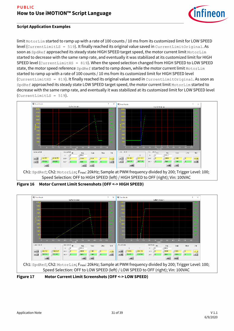
The following Figure 166 shows how the motor current limit was dynamically changed when the speed selection changed between OFF state and HIGH SPEED state. When the speed selection changed from OFF to
HIGH SPEED state, the motor started to spin with its current limit MotorLim set to its original value saved in
CurrentLimitOriginal. As the motor speed reference SpdRef approached its HIGH SPEED steady state target speed, the motor current limit MotorLim started to decrease with a rate of 100 counts / 10 ms. After
about 330 ms, it reached its customized limit for HIGH SPEED level (CurrentLimitHS = 819). When the speed selection changed from HIGH SPEED to OFF state, the motor speed reference SpdRef was instantly reset, while
the motor limit MotorLim started to ramp up with a rate of 100 counts / 10 ms, and stabilized at its original
value saved in CurrentLimitOriginal after about 330 ms.
The following Figure 17 shows how the motor current limit was dynamically changed when the speed selection
changed between OFF state and LOW SPEED state. When the speed selection changed from OFF to LOW SPEED
state, the motor started to spin with its current limit MotorLim set to its original value saved in CurrentLimitOriginal. As the motor speed reference SpdRef approached its LOW SPEED steady state target speed, the motor current limit MotorLim started to decrease with a rate of 100 counts / 10 ms. After
about 360 ms, it reached its customized limit for LOW SPEED level (CurrentLimitLS = 519). When the speed selection changed from LOW SPEED to OFF state, the motor speed reference SpdRef was instantly reset, while
the motor limit MotorLim started to ramp up with a rate of 100 counts / 10 ms, and stabilized at its original value saved in CurrentLimitOriginal after about 360 ms.
The following Figure 18 shows how the motor current limit was dynamically changed when the speed selection changed between LOW SPEED state and HIGH SPEED state. When the speed selection changed from LOW
SPEED to HIGH SPEED state, the motor speed reference SpdRef started to ramp up, while the motor current
Application Note 31 of 39 V 1.1
6/9/2020
How to Use iMOTION™ Script Language
Script Application Examples
P U B L I C
limit MotorLim started to ramp up with a rate of 100 counts / 10 ms from its customized limit for LOW SPEED level (CurrentLimitLS = 519). It finally reached its original value saved in CurrentLimitOriginal. As soon as SpdRef approached its steady state HIGH SPEED target speed, the motor current limit MotorLim started to decrease with the same ramp rate, and eventually it was stabilized at its customized limit for HIGH
SPEED level (CurrentLimitHS = 819). When the speed selection changed from HIGH SPEED to LOW SPEED state, the motor speed reference SpdRef started to ramp down, while the motor current limit MotorLim started to ramp up with a rate of 100 counts / 10 ms from its customized limit for HIGH SPEED level (CurrentLimitHS = 819). It finally reached its original value saved in CurrentLimitOriginal. As soon as
SpdRef approached its steady state LOW SPEED target speed, the motor current limit MotorLim started to
decrease with the same ramp rate, and eventually it was stabilized at its customized limit for LOW SPEED level (CurrentLimitLS = 519).
Ch1: SpdRef; Ch2: MotorLim; FPWM: 20kHz; Sample at PWM frequency divided by 200; Trigger Level: 100;
Speed Selection: OFF to HIGH SPEED (left) / HIGH SPEED to OFF (right); Vin: 100VAC
Figure 16 Motor Current Limit Screenshots (OFF <-> HIGH SPEED)
Ch1: SpdRef; Ch2: MotorLim; FPWM: 20kHz; Sample at PWM frequency divided by 200; Trigger Level: 100;
Speed Selection: OFF to LOW SPEED (left) / LOW SPEED to OFF (right); Vin: 100VAC
Figure 17 Motor Current Limit Screenshots (OFF <-> LOW SPEED)

Application Note 32 of 39 V 1.1
6/9/2020
How to Use iMOTION™ Script Language
Script Application Examples
P U B L I C
Ch1: SpdRef; Ch2: MotorLim; FPWM: 20kHz; Sample at PWM frequency divided by 200; Trigger Level: 12000;
Speed Selection: LOW SPEED to HIGH SPEED (left) / LOW SPEED to HIGH SPEED (right); Vin: 100VAC
Figure 18 Motor Current Limit Screenshots (LOW SPEED <-> HIGH SPEED)

Application Note 33 of 39 V 1.1
6/9/2020
How to Use iMOTION™ Script Language
Script Performance Evaluation
P U B L I C
3 Script Performance Evaluation
3.1 CPU Load Evaluation
The CPU resource is prioritized for the implementation of the motor and PFC control algorithm. The script engine is designed to take advantage of the spare CPU resource for the execution of the script program. The priority of the execution of the script program is lower than that of the motor and PFC control algorithm, so
that it won’t affect the performance of the control algorithm. However, CPU usage needs to be carefully
evaluated before enabling the script function.
The estimated CPU usage varies depending on the configuration of the motor or PFC PWM frequency as well as the safety functions. MCEWizard can be used to estimate the CPU usage. If the CPU usage estimation is higher
than 90% as shown in the left screenshot of the following Figure 19, then enabling script function is likely to overload the CPU. It is highly recommended to keep the CPU usage estimation to no more than 90% when the users intend to enable the script function.
Left: CPU Usage = 91%; Right: CPU Usage = 58%
Figure 19 CPU Usage Estimation Using MCEWizard
The execution of the script program, depending on the complexity of the code and the configuration of the execution period and the execution step for each task, would have an impact on the CPU loading. It is
recommended to evaluate the CPU load during run time with the script program enabled to ensure that the MCE is not overloaded.
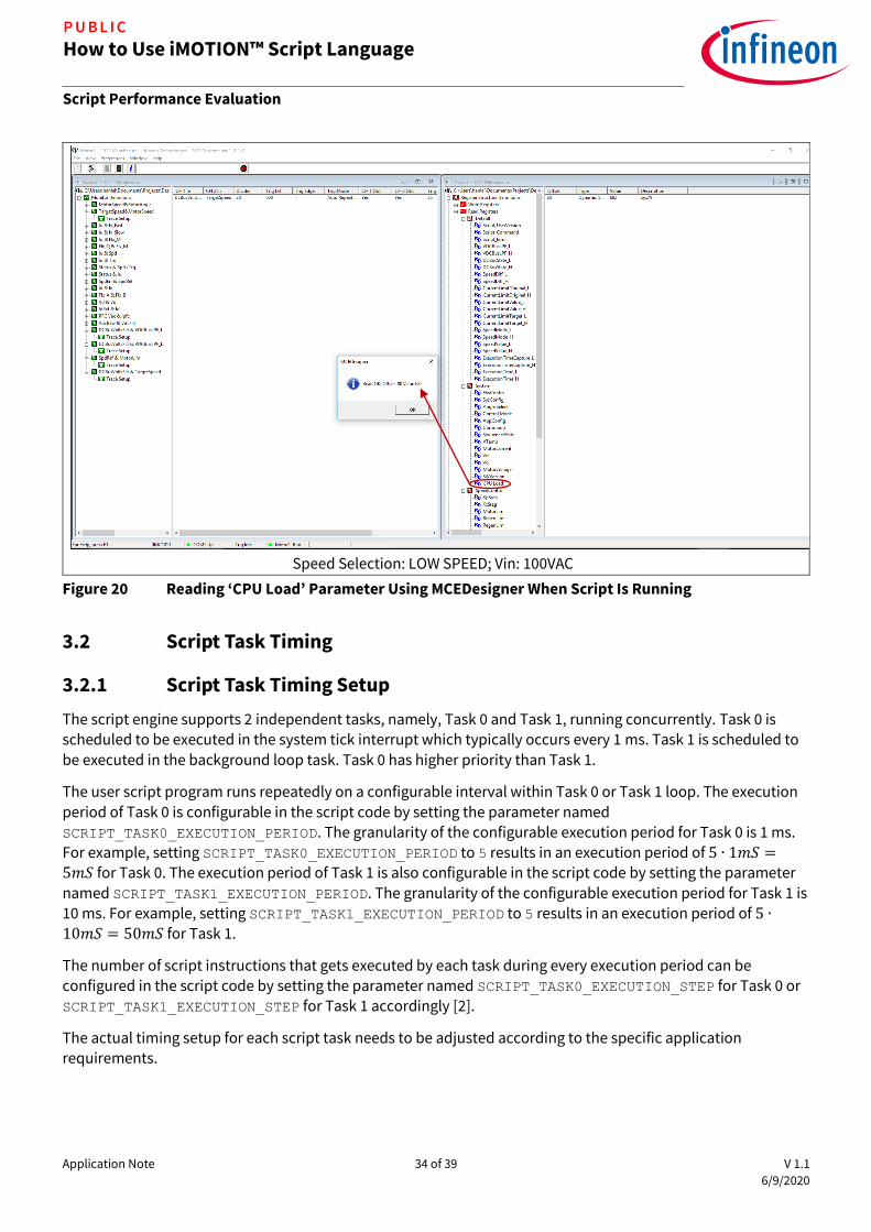
The CPU load status can be obtained by reading the system parameter ‘CPU Load’ [2] using MCEDesigner [3]. The CPU load is represented in 0.1% [2]. The following Figure 20 shows that CPU load was 68.2% with the script
described in Section 2.3 enabled while the motor was running with speed selection set to LOW SPEED level. The more complicated the script code becomes, the higher CPU load it would demand.
Application Note 34 of 39 V 1.1
6/9/2020
How to Use iMOTION™ Script Language
Script Performance Evaluation
P U B L I C
Speed Selection: LOW SPEED; Vin: 100VAC
Figure 20 Reading ‘CPU Load’ Parameter Using MCEDesigner When Script Is Running
3.2 Script Task Timing
3.2.1 Script Task Timing Setup
The script engine supports 2 independent tasks, namely, Task 0 and Task 1, running concurrently. Task 0 is scheduled to be executed in the system tick interrupt which typically occurs every 1 ms. Task 1 is scheduled to
be executed in the background loop task. Task 0 has higher priority than Task 1.
The user script program runs repeatedly on a configurable interval within Task 0 or Task 1 loop. The execution
period of Task 0 is configurable in the script code by setting the parameter named SCRIPT_TASK0_EXECUTION_PERIOD. The granularity of the configurable execution period for Task 0 is 1 ms.
For example, setting SCRIPT_TASK0_EXECUTION_PERIOD to 5 results in an execution period of 5 ∙ 1𝑚𝑆 =5𝑚𝑆 for Task 0. The execution period of Task 1 is also configurable in the script code by setting the parameter
named SCRIPT_TASK1_EXECUTION_PERIOD. The granularity of the configurable execution period for Task 1 is
10 ms. For example, setting SCRIPT_TASK1_EXECUTION_PERIOD to 5 results in an execution period of 5 ∙
10𝑚𝑆 = 50𝑚𝑆 for Task 1.
The number of script instructions that gets executed by each task during every execution period can be
configured in the script code by setting the parameter named SCRIPT_TASK0_EXECUTION_STEP for Task 0 or SCRIPT_TASK1_EXECUTION_STEP for Task 1 accordingly [2].
The actual timing setup for each script task needs to be adjusted according to the specific application requirements.
Application Note 35 of 39 V 1.1
6/9/2020
How to Use iMOTION™ Script Language
Script Performance Evaluation
P U B L I C
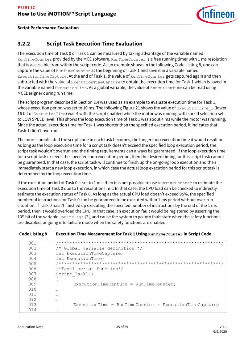
3.2.2 Script Task Execution Time Evaluation
The execution time of Task 0 or Task 1 can be measured by taking advantage of the variable named RunTimeCounter provided by the MCE software. RunTimeCounter is a free running timer with 1 ms resolution
that is accessible from within the script code. As an example shown in the following Code Listing 8, one can capture the value of RunTimeCounter at the beginning of Task 1 and save it in a variable named
ExecutionTimeCapture. At the end of Task 1, the value of RunTimeCounter gets captured again and then subtracted with the value of ExecutionTimeCapture to obtain the execution time for Task 1 which is saved in the variable named ExecutionTime. As a global variable, the value of ExecutionTime can be read using
MCEDesigner during run time.
The script program described in Section 2.4 was used as an example to evaluate execution time for Task 1,
whose execution period was set to 10 ms. The following Figure 21 shows the value of ExecutionTime_L (lower 16 bit of ExecutionTime) was 4 with the script enabled while the motor was running with speed selection set to LOW SPEED level. This shows the loop execution time of Task 1 was about 4 ms while the motor was running. Since the actual execution time for Task 1 was shorter than the specified execution period, it indicates that
Task 1 didn’t overrun.
The more complicated the script code in each task becomes, the longer loop execution time it would result in. As long as the loop execution time for a script task doesn’t exceed the specified loop execution period, the
script task wouldn’t overrun and the timing requirements can always be guaranteed. If the loop execution time for a script task exceeds the specified loop execution period, then the desired timing for this script task cannot
be guaranteed. In that case, the script task will continue to finish up the on-going loop execution and then
immediately start a new loop execution, in which case the actual loop execution period for this script task is determined by the loop execution time.
If the execution period of Task 0 is set to 1 ms, then it is not possible to use RunTimeCounter to estimate the execution time of Task 0 due to the resolution limit. In that case, the CPU load can be checked to indirectly
estimate the execution status of Task 0. As long as the actual CPU load doesn’t exceed 95%, the specified number of instructions for Task 0 can be guaranteed to be executed within 1 ms period without over-run
situation. If Task 0 hasn’t finished up executing the specified number of instructions by the end of the 1 ms
period, then it would overload the CPU. In that case, an execution fault would be registered by asserting the 10th bit of the variable FaultFlags [2], and cause the system to go into fault state when the safety functions are disabled, or going into failsafe mode when the safety functions are enabled.
Code Listing 8 Execution Time Measurement for Task 1 Using RunTimeCounter in Script Code
001 /************************************************************/
002 /* Global variable definition */
003 int ExecutionTimeCapture;
004 int ExecutionTime;
005 /************************************************************/
006 /*Task1 script function*/
007 Script_Task1()
008
009 ExecutionTimeCapture = RunTimeCounter;
010 …
011 …
012 …
013 ExecutionTime = RunTimeCounter - ExecutionTimeCapture;
014

Application Note 36 of 39 V 1.1
6/9/2020
How to Use iMOTION™ Script Language
Script Performance Evaluation
P U B L I C
Speed Selection: LOW SPEED; Vin: 100VAC
Figure 21 Reading ‘ExecutionTime_L’ Variable Used in Script Code Using MCEDesigner
3.2.3 Script Task Execution Period Evaluation
The variable RunTimeCounter can also be used to measure the loop execution period of Task 0 or Task 1. RunTimeCounter is a free running timer with 1 ms resolution that is accessible from within the script code.
The following Code Listing 9 shows an example of using RunTimeCounter to measure the loop execution period of Task 1.
Code Listing 9 Loop Execution Period Measurement for Task 1 Using RunTimeCounter in Script Code
001 /************************************************************/
002 /* Global variable definition */
003 int LoopExecutionPeriodCapture;
004 int LoopExecutionPeriod;
005 /************************************************************/
006 /*Task1 script function*/
007 Script_Task1()
008
009 LoopExecutionPeriod = RunTimeCounter –
LoopExecutionPeriodCapture;
010 LoopExecutionPeriodCapture = RunTimeCounter;
011 …
012 …
013 …
014

Application Note 37 of 39 V 1.1
6/9/2020
How to Use iMOTION™ Script Language
Script Guidelines & Limitations
P U B L I C
4 Script Guidelines & Limitations
The maximum number of global variables supported by the script engine is 30. The maximum number of
local variables for each task is 24. The intercommunication between Task 0 and Task 1 can be realized by using global variables. Only global variables are accessible from MCEDesigner or user UART interface. It is
recommended to define a variable as the global type if users intend to read its value during run time using MCEDesigner [3].
The maximum allowed script code size is 16kB. This is equivalent to approximately 1500 lines of script code.
The actual object code size is reported in the compiled script object file. An example is shown at line 008 and
line 009 in Code Listing 2.
The script engine only supports 32 bit signed integer type of variables, so that the floating point type of
variables or constants need to be converted to Q format for proper processing in the script code. An example of Q format conversion can be found in Section 2.3.3.
The script engine supports 2 independent tasks, namely, Task 0 and Task 1, running concurrently. The user
script program runs repeatedly on a configurable interval within Task 0 or Task 1 loop. The shortest possible execution period is 1 ms for Task 0, and 10 ms for Task 1.The execution period for each task can be configured to the multiples of 1 ms for Task 0 or 10 ms for Task 1 in the script code. Task 0 has higher priority than Task 1. The actual timing setup for each script task needs to be adjusted according to the specific
application requirements.
The analog input pins are sampled by MCE every 1 ms. According to Nyquist theorem, if the input analog
signal frequency is higher than 500 Hz, then it cannot be properly represented by the sampling method of MCE script engine. It is highly recommended that an analog LPF should be used to attenuate the input analog signal frequency that is higher than 500 Hz to minimize the aliasing effect.
The GPIO pins are sampled and updated by MCE every 1 ms. Any GPIO input changes that occur faster than 1
ms will not be properly captured by the sampling method of MCE script engine. Similarly, any GPIO output changes that happen faster than 1 ms cannot be realized by using the script program. The fastest possible
frequency generated by toggling an GPIO pin using script is 500 Hz.
It is recommended to change a specific GPIO pin value only once within the Task 0 or Task 1’s loop. If there are more than one instances of GPIO manipulation within Task 0 or Task 1’s loop, only the last operation would take effect due to the unique GPIO update mechanism in MCE software. For example, given that a
specific GPIO pin is originally reset to logic low level, if this GPIO pin is set to logic high level at the beginning
of Task 0, and then it gets reset at the end of Task 0, the actual GPIO will not toggle as expected. Instead, it will remain in reset state after the execution of Task 0 loop.
For those time critical functions, it is recommended to be implemented in Task 0, whose minimum execution period can be set to 1 ms. For those functions that are not time critical, either Task 0 or Task 1 can
be used. In that case, it is recommended to set the execution period of the script task to 50 ms typically.
Digital filter implementation using the script can be realized in Task 0 with sampling frequency up to 1 kHz
due to the minimum execution period limit of Task 0. As a result, signal frequency higher than 500 Hz cannot be properly sampled and processed.
The script language doesn’t support the implementation of infra-red communication.
The script language can support Programmable Logic Controller (PLC) as long as the minimum timing requirement is no less than 1 ms.
The script language doesn’t support the implementation of digital Hall Effect sensors.

Application Note 38 of 39 V 1.1
6/9/2020
How to Use iMOTION™ Script Language
References
P U B L I C
5 References
[1] iMOTIONTM IMC100 High Performance Motor Control IC Series Datasheet (REV 1.5).
[2] iMOTION™ Motor Control Engine Software Reference Manual (REV 1.3).
[3] MCEDesigner User Guide (REV 2.0.1.1).
[4] MCEWizard 2.0 User Guide (REV 2.0.1.1).
Revision history
Document
version
Date of release Description of changes
1.0 9/5/2018 Initial release.
1.1 6/5/2020 Analog input sampling rate and GPIO update rate are revised.
Example code in Section 2.1.4, 2.3.4, and 2.4.2 revised to use CONST
keyword to define constants.

Trademarks All referenced product or service names and trademarks are the property of their respective owners.
Edition 6/9/2020
AN2018-27
Published by
Infineon Technologies AG
81726 Munich, Germany
© 2020 Infineon Technologies AG.
All Rights Reserved.
Do you have a question about this
document?
Email: [email protected]
Document reference
IMPORTANT NOTICE The information contained in this application note is given as a hint for the implementation of the product only and shall in no event be regarded as a description or warranty of a certain functionality, condition or quality of the product. Before implementation of the product, the recipient of this application note must verify any function and other technical information given herein in the real application. Infineon Technologies hereby disclaims any and all warranties and liabilities of any kind (including without limitation warranties of non-infringement of intellectual property rights of any third party) with respect to any and all information given in this application note. The data contained in this document is exclusively intended for technically trained staff. It is the responsibility of customer’s technical departments to evaluate the suitability of the product for the intended application and the completeness of the product information given in this document with respect to such application.
For further information on the product, technology, delivery terms and conditions and prices please contact your nearest Infineon Technologies office (www.infineon.com).
WARNINGS Due to technical requirements products may contain dangerous substances. For information on the types in question please contact your nearest Infineon Technologies office. Except as otherwise explicitly approved by Infineon Technologies in a written document signed by authorized representatives of Infineon Technologies, Infineon Technologies’ products may not be used in any applications where a failure of the product or any consequences of the use thereof can reasonably be expected to result in personal injury.