Embed Size (px)
Citation preview

Dedicated PTZ Camera Professional2017/06
Version 4.5
SUNBA® PTZ CameraNetworkUser Guide V4.5
Series
Please go to http://guide.sunba.net to access the step by step YouTube video tutorials for Sunba IP PTZ camera setup.

- 01 -
FCC Warning (U.S.A)
MENU
The device has been tested in compliance with limits set by Part 15 of Federal Communication Commission (Class B). The operation of the device is thus limited by the following two conditions: 1) it is not permitted to cause harmful interference to any authorized radio communications, and 2) it must accept any interference it receives.
WARNING: Please test the camera locally by directly connecting to the default power adapter from the package before mounting it outside. Stay at least 24 hours to test both daytime and night vision IR LED.
1. Camera Connection
2. How to Power the Camera
3. Software Package
4. Camera Network Con�guration
5. Camera Management by Computer
6. Camera Management by Smartphone
7. Preset, Patrol & Pattern
8. The Full Preset List
9. Camera On-Screen-Display Menu
10. Camera Con�guration
11. Camera Infrared and Night Vision
12. Account Management
13. Motion Detection
14. FTP Communication
15. Reset the Camera
16. Cable Waterproof Measures
17. Warranty
02
04
05
06
09
11
14
15
16
18
21
23
24
24
26
27
27

- 02 -
Phase 1: Bench Test
What are you testing in this stage?
Non-PoE camera
PoE+ camera
1. Camera Connection
Note PTZ dome cameras have much higher power requirements than bullet cameras, especially for ones with higher zoom-in capacity. Therefore, how the unit is powered can be critical to its functionality. Please directly apply the DC12V adapter on the camera to make sure the unit itself is working, and try eliminating all cabling factors to set up the bench test.
A default adapter is prepared for you to rule out any problems of the cam--era. If the camera works properly under the DC power adapter but not with PoE, please check the PoE switch/injector you are using or replace an Ethernet cable.
How to Test LocallyIn short, in a bench test, do NOT use any power extension cable. Please connect the camera directly to the power adapter. Secondly, if the camera cannot be found by connecting to the router, please try connecting it to the Ethernet port on the computer.
ALWAYS test and setup locally before mounting outside!Ad
apte
r
DC12V
192.168.1.*
192.168.1.*
192.168.1.10

- 03 -
Why Test LocallyThe reason you should NOT extend the power cable during the bench test is because DC power drops quickly along the transmission. A bench test helps you rule out all problems caused by power supply. Underpower cau--ses problems such as 1) �ickering screen 2) unstable infrared (camera reboots repeatedly) and 3) spinning dome.
When powered up, the speed dome automatically begins a self-diagnostic process during which the camera will pan horizontally and vertically to make sure PTZ, lens and other parts of the camera are functional. Please contact our technical staff if a self-test does not happen on your unit. Ple--ase refrain from disassembling the unit before contacting us. Thanks for your cooperation.
Questions? Ask [email protected]
Built-in self-test
Connection Good Power Good Video and Control Good Tested Day and Night Guess we are ready to mount it outside.
Phase 2: Mounting Outdoor
Good, the camera is working correctly. Now I just need to pick the right extension cable and mount it outside!
≥30W100V~250V Data out
Data in
Router
POE+out
POE+802.3at
100~250ftPOE+
ELV (Extra-LowVoltageSystem)Wiring method:
Injector/Swith

- 04 -
100V~250V
Data in
Router
Non-PoE
ELE (Force Electricity)Wiring method:
≥18 wire gauge
DC 12V Power Adapter
2.How to power the cameraThere is an old saying that PTZ cameras are POWER-ful. So do NOT pull the old setup from your bullet and apply it directly to your new PTZ.
2.1 For Non-PoE Camera (if you extend the power):
The camera may not work properly if the power reaches the camera is be--low 12V due to resistance along the extended DC line (distance depend--ent). If that happens, please make your AC power source near the camera, and connect it with our default adapter you received from the package. For extension, you can select from AC power extension cable (no distance limit) or thick (≥18 AWG) DC power extension cable.
Risk Relevant1.Using 24VAC or higher voltage adapter (16V, 24V) will immediately dam--age the camera and void the warranty. 2.The camera will be exposed to high risks of motherboard damage and void the warranty if you use passive PoE injector/splitter.
AC110-220V in
802.3at ≥30W
RJ45 in
48V 0.5A DC out
PoE (cat5/5e/6)DC12V out
RJ45 outActive
PoE injector
Active PoE splitter
Active PoE Injector/Splitter are allowed if you use PoE to power non-PoE camera.

- 05 -
2.2 For PoE+ Camera :
PoE+ IEEE 802.3at standard is required. Note traditional PoE system( 802.3af standard) delivers up to 15.4W, which is unable to fully support the camera. Dome cameras, especially with 20 times zoom-in capacity, have higher power requirements than bullet cameras or �xed lens cameras.The PoE+ switch/injector need to meet two key features:
1. 802.3at. 2. Delivers at least 30w to the single port you are using.
Transmission distancePoE will also drop power along the Ethernet cable. If you are using a 300 ft long Ethernet cable, you may be at risk. Please try using the Ethernet cable less than 250 ft. The maximum travel distance also depends on the quality of the cable and the maximum power supplied by switch/injector.
NVR’s built-in PoE Some NVR has built-in PoE+ switch. However, this is mostly for devices fr--om the same manufacturer as the NVR (examples such as Dahua and Hik--vision). The built-in switch may work for few third party cameras but not all. We thus recommend getting a separate and dedicated PoE+ switch/injector.
Biggest issue when underpower In the daytime, even 802.3af (conventional PoE system) can provide enou--gh power to the camera. However, in the night time, if you are underpower, the following nightmare begins: low light environment detected -> infrared on -> not enough power -> reboot -> low light environment detected -> infrared on -> not enough power -> reboot …… (cycling)
3.Software Package1. Visit: http://www.sunba.net/en/download/2. Select one of the web-drives.3. Go to English-> Software and download the speci�c software you want.
For Setup Client Software Web Plugin (PC)
Re-development
Device Manager CMS VMS IEActive NetSDK

- 06 -
Router IP is usually the same value as the “gateway” (with few exceptions), which the camera’s IP will have to match.
Step 1: Understand the Goal of IP Con�gurationNo matter what IP Camera Management Software you intend to use later, the �rst step is to make sure your router, computer and the IP Camera are on the same subnet. Being on the same subnet means “the �rst three octets or segments in the IP address are the same.”
For example
4. Camera Network Con�gurationYou must �rst change the camera’s IP to match the IP of your router!
If your router is 10.0.0.1 and your camera is still 192.168.1.10 (default IP), you will NOT be able to access the camera by typing 192.168.1.10 in the web address without changing its IP �rst.
Welcome to our local network!
√ On the same subnet
10.0.0.1 10.0.0.188 10.0.0.15
You are not a member of our local network family!
X Not on the same subnet
I am notconnectingyou.
10.0.0.1
FIGHTING !IP address change
10.0.0.15192.168.1.10
192.168.1.1010.0.0.188×
√

- 07 -
Step 2: Know the Router IP/Gateway of Your Network
Method 1: Check Bottom of Your Router Sticker
ROUTER
CHECKTHIS
Model :Power : 12V 1ARouter IP : 192.168.10.1User ID : adminPassword: admin
Method 2: Check from your Computer.
Network
Router: 10.1.1.1
MAC :System Preference->Network
Check gateway.sunba.net for video PC:
In Start Menu of Windows, type “cmd.exe” and enter ipconfig as follows:
Press enter key and locate the “Default Gateway” from the list:
Command Prompt Command Prompt
Microsoft Windows(c)2015 Microsoft Corporation. All rights reseved.
C:\Users\Administrator>ipconfig
Ethernet adapter Network Bridge Connection-specific DNS suffix: Link-local iPv6 address: IPV4 address: Subnet Mask: Default Gateway: 10.0.0.1

- 08 -
Step 3: Download the IP Con�g Tool and Con�gure the IP address
PC : Please refer to Chapter 3. Software and download “Device Manager”under English-> Software. Then modify the IP address and Gateway acco--rding to what you found from Step 2.
DecviceManager
192.168.1.10 34567 10 . 0 . 0 . 15
10 . 0 . 0 . 1
255 . 255 . 255 . 0
Change to what you foundin step 2.
Gateway
IP Address
DeviceManager
Do NOT change TCP Port or HTTP Port to 554 or 8899, which will con�ict with the RTSP and ONVIF port of the camera and lock the device. No same value for two different ports.
192.168.1.10 192.168.1.10:34567 SunbaNot Available 192.168.1.10 192.168.1.10:34667 Sunba
IPPortSubmaskGatewayUserNamePassword
Defa...Not Available
Change gateway and IP correspondingly to match your network.
Double Click
10 . 0 . 0 .15
10 . 0 . 0 .1
34567
admin
255.255.255.0
OK
MAC: Please refer to Chapter 3. to download VMS for Mac under English-> Software.
The �rst 3 segments shouldmatch the new gateway .
Modify

- 09 -
Tricks:
1) Make sure the new IP you assigned to the camera is UNIQUE.Make sure only the �rst 3 segments of camera’s IP is the same as the gateway and your computer. 2)Do not change the camera’s ports until later. The camera’s default ports are ONVIF 8899, TCP 34567, HTTP 80 and RTSP 554. Those values must also be unique.
5.Camera Management by ComputerSunba’s free IP camera desktop enables you to con�gure advanced fea--tures of the camera such as accounts management, �rmware upgrade and access to the full feature of the device.
You can always download the web plugin seperately from Sunba websiteif it takes too long to download the plugin from popped window.
1) Enter the IP address of your camera.If you have changed the http port of the camera, you need to log in as IP: http port. 2) Install the web plugin following the request popped by the browser. Please make sure the browser is CLOSED during the installation. If you are unable to download the plugin, please go to download.sunba.net to download the plugin.3)You can change the language from the upper right corner. Changes onlytake effect after you successfully install the plugin, otherwise the text will show “??????” or disappear.
A. Internet Explorer (in Windows)

- 10 -
4)Enter username and password. The username is admin with no password by default. 5)Please change the admin password after log in to protect your privacy from Chapter 8. Do not forget your password. The password is very impor--tant if you want to reset your camera in Device Manager.6)Go to <stream menu> and connect with either main stream (better qua--lity, higher network requirements) or sub-stream(extra stream).
Note: our cameras currently do not support Windows 10 Edge Explorer.
B. CMS (in Windows) Download CMS from CD-ROM: English -> Software -> CMS Video Tutorial available from cms.sunba.net
Download CMS from CD-ROM: English -> Software -> VMS Video Tutorial available from mac.sunba.net
C. VMS for Windows & Mac
Make SUNBA
Also support Xmeye protocol
Blue Iris (in Windows)
Select the languagebefore login.
English

- 11 -
Security Spy (in Mac)
Other third party IP camera management toolsThere are many other IP camera management tools you can use. Above we attached the setting from the most popular software in Windows and Mac. Some software/NVR requires manually adding the camera through ONVIF port 8899. Note : In 3rd party software/NVR, due to the level of customization for ONVIF by diffrent surveillance manufacturers, only ptz, video and recording may work depending on speci�c ONVIF version.
6.Camera Mobile & Remote AccessTips: Go to Sunba website FAQ page and type keyword “mobile”to gain the setup page for popular smartphone app such as XMEye (JFeye), TinyCam Pro, IP Cam Viewer.
Type 1: P2P Function (simple setup)
Warning: P2P function may not work if you modify the default media port (34567) of the camera or the DNS of your camera is not on the same subnet as your router. Your NAT status by DeviceCon�g->Version needs to be “connected” before you are able to access your camera through P2P.
192. 168. 1. 10
admin
RTSP TCP (vidieo and audio)
ONVIF
Address:
Username:Password:
Pro�le:Format:
Fill in the boxeswith correspondingnetwork info ofyour camera
P2P cloud technology enables customers to remotely access, control and con�gure their cameras through internet even if you are thousands miles away.

- 12 -
Internet Explorer:Please go to xmeye.net and use “Device Login”. Enter the cloud ID of the camera and associated username and password.
Network Environment: WiFi, 3G/4G/LTE; Mobile System: Android, iOS Software Name: XMeye/JFeye (download from either Google Market or App store)If your mobile device is on the same subnet with your camera, you can use the "Search" button to locate the camera.
Find Your P2P Code by two methods:Note P2P Code = Cloud ID = Serial Number
987dc021338*****
CMS: VMS for PC:
Group:
Device Name:
Login Type:
Sunba
Default Group
CloudlD
adminUserName:
Vendor: SUNBA
Device Name
User Name
Vendor
Zone
Sunba
admin
South Lot
H264DVR
987dc021338*****
987dc021338*****

-13-
Please forward BOTH http port (80 by default) and TCP (media) port (34567 by default) and refer to the manual of your router for detailed steps of port forward in order to remotely access using a WAN IP. Other mobile apps such as Tiny Cam or IP Cam Viewer may require you to forward ONVIF and RTSP port as well.
Type 3: RTSPPlease use the following URL along with any 3rd RTSP service provider: “rtsp://IP:554/user=admin&password=&channel=1&stream=0.sdp?real_stream” where 0 = mainstream and 1 = substream For example with the default network setting:rtsp://192.168.1.10:554/user=admin&password=&channel=1&stream=0.sdp?real_stream
Type 4: VPN (Virtual Private Network) This is recommended for customers who have static IP address and advan--ced router functions.First, your router MUST support VPN.Then please refer to the corresponding manual of your router to establish a VPN for the local network where the camera is connected to.For example, the VPN was setup for the router at your home where the camera is installed. Please remember the username and password of the VPN. Then, at any remote location, you can always setup a new network using VPN to remotely access your camera at home.
Type 2: Port Forwarding
Please refer to portforward.sunba.net for more instructions.
Recommended : Choose "Local Login" tostore your device info locally.
Serial Number: P2P Code/IP/DomainUser name: Your camera’s user accountPassword : If your camera has a passwordPort: Please leave it in blank if you are uncertain. You should enter the TCP/Mediaport of the camera here.

- 14 -
PTZ Preset PositionSunba dome cameras can set preset PTZ positions for which cameras can memorize and travel directly by calling the preset. Preset positions are represented by numbers. You need to “add” a preset and then “call” it. You can always “delete” them later.
Special presets are preset numbers associated with advanced commands that cameras can follow to modify/enable settings such as changing infrar--ed mode, setting up camera auto scan boundaries etc. You can call the preset directly (no need to “add” a preset as they are pre-existed) accord--ing to The Full Preset List.Patrol The PTZ camera can travel from one preset to another by order. A patrol is usually named as a tour or a cruise. The total presets included in a patr--ol can be up to 10. To activate a patrol, �rst you will need to save corresponding presets you want to tour across. For example, preset 1-10 can be called by using special preset 88 (see The Full Preset List). PatternDifferent from patrol, which enables the camera to travel between different points, patterns are continuous sets of movement that Sunba cameras can perform in a record and replay fashion. Note: Patterns will not be activated unless Motion Detection and Video Blind are disabled.
When using 84 + Add Preset to set a pattern scan, you must use direction& zoom key to set the actions and click Iris+ key to end the pattern setup, prompt as follows:
Special Presets
Check Special Preset via specialpreset.sunba.net
Enter the number and hit “+” to set/add/save aEnter the number and hit “-” to delete a preset. Enter the number and hit “ ” to call a preset.
7.Presets, Patrol and Pattern Note: For other software please refer to the manual of the third party software.
Preset1
PresetNumber
CallPreset
SavePreset
DeletePreset
I R I S O P E N E X I T

- 15 -
Note: When pressing any direction key, the camera will stop the patrol, scan & pattern.
Special Preset0~50 Preset
XXX + Add Preset
XXX + CALL
95 + CALL
Conventional Position Preset
Set preset XXX.
Call preset XXX.
Open the On-Screen-Display menu of the camera
Shift to English OSD menu
Shift to Chinese OSD menu
Set the left boundary of frame scan for 507 series
Set the right boundary of frame scan for 507 series
Set the left boundary of frame scan for 601&805&405 series
Set the right boundary of frame scan for 601&805&405 series
Start pattern
Patrol from 1 to 10 preset
Start frame scan ( auto scan from left side to the right side)
47 + Add Preset
48 + Add Preset
81 + Add Preset
82 + Add Preset
82 + CALL
84 + CALL
88 + CALL
89 + CALL
90 + CALL
91 + CALL
81 + CALL
98+ CALL
93+ CALL
94 + CALL
100 + CALL
101+ CALL
102+ CALL
103 + CALL
120+ CALL
121+ CALL
83+ CALL
81+ CALL
92+ CALL
Patrol from 11 to 20 preset
Patrol from 21 to 30 preset
Patrol from 31 to 40 preset
360° interval scan for 507 series
360° continuous scan
Display preset information from upper left corner
Hide preset information from upper left corner
Manually turn IR on (half side on)
Manually turn IR off
Set the IR mode to auto (default)
Manually turn IR on (all side on)
Display the value of photoresister for 507 serises
Hide the value of photoresister for 507 serises
Clear all preset
Reset the PT position for 601&405 series
Reset the PTZ dome
84 + Add Preset
95+CALL followed by
93 + CALL
95+CALL followed by
94 + CALL
Set pattern followed by different action inputs;
con�rm by clicking “IRIS+” button
Function
8.The Full Preset List
preset1
preset2
preset3

- 16 -
9.Camera On-Screen-Display Menu
A.601 & 805 & 405 Series:
Please call preset 95 to open the OSD menu. Use the up and down key to browse and move the cursor, left key to go back to the previous menu, right key to select and con�rm.
B.507 & 604 Series:
MAIN MENU POWER UP NONE PARK ACT NONE PARK TIME 15FRAME SPEED 16DWELL TIME 6LED MODE AUTO LED ON 210LED OFF 185RESET EXIT
Check OSDlanguage.sunba.net to learn how to switch the dis--play language of the OSD main menu from Chinese to English.
How to activate and control the OSD?
MAIN MENU
IR SETTING PATTERNSPARK ACT NONE PARK TIME 25 S SET FRAME SCAN FRAME SPEED 8DWELL TIME 9 RESTORE DEFAULT EXIT
IR SETTING
IR MODE AUTOIR ON SENS 210IR OFF SENS 185BACK EXIT CURRENT LEVEL 33

- 17 -
IR MODE1.AUTO MODE: Turn on and off IR LED automatically according to the am--bient darkness of photoresister. If the value of the ambient environment (CURRENT LEVEL) is ≥ the IR ON SENS, then the LED will be turned on aut--omatically, vice versa. Larger CURRENT LEVEL is equivalent to darker environment.2.MANUAL mode: Turn on and off the IR LED manually. This can be accom--plished using special presets 100~103 as well. AUTO MODE is selected by default.IR ON SENSThe threshold for photoresister to turn on the IR LED, default is 210.IR OFF SENSThe threshold for photoresister to turn off the IR LED, default is 185.NOTE: The difference between the LED ON and LED OFF values must be at least 30 to avoid problems of IR LED blinking. Only half side of IR will be on for near view, please zoom in to enable the further view and the other side of the IR. Use preset 103+call to manually turn on both sides together.
PATTERNS
PARK ACT
PARK TIME
SET FRAME SCAN (405 & 601 & 805)
The waiting time (or idle time) before the camera executes its PARK ACTI--ON (see above). The default is 25 seconds.
Set the right and left position of frame scan. Submenu as follows:
IR IS OPEN EXIT
This option is also called the watch function or the defend function of a PTZ camera. The dome will automatically execute a corresponding preset action after a settled idle time (25 seconds is default) if no additional commands are sent from users.
This option has the same function as 84 + Add PRESET. To set up a pattern, you must use direction & zoom key to add actions and Iris+ key to end the setting. Each pattern scan can memorize no more than 31 actions.Note: If you open the video motion & video blind function the pattern scan will be disabled .
Use preset 120+call to check the CURRENT LEVEL for 507.

- 18 -
SET FRAME SCAN LEFT
LIMIT POSITION IRIS OPEN
CONTINUE
SET FRAME SCAN RIGHT
LIMIT POSITION IRIS OPEN
CONTINUE
FRAME SPEEDIt controls the speed when the dome does the 360° scan or frame scan.
DWELL TIMEIt represents the residence time the dome stops at each preset during the patrol/auto scan.
10. Camera Con�gurationHow to Access the Device Con�g:For IE: Click “DeviceCfg”For VMS: Choose Device Con�gFor CMS: Make a right click and select “Device Con�g” (PS: You must add the camera via H264DVR, not ONVIF)
This function enables the auto scan of the camera between a set left and right boundary. It can be set using PRESET 81+Add & PRESET 82+Add as well. When setting up the frame scan, direction keys are used to set the position of the boundary. Thus, please click the Iris+ key to con�rm your setting.

- 19 -
Record: Set camera recording plan and mode. The “manual” and “stop” selection allows you to manually turn on and off, and the “timing” allows you to set the schedule where recording takes place.
Video Motion: Enable motion detection alert formats (buzzer, email, recording, snapshot & FTP etc), region, and sensitivity. Set motion detection video recording time. Video Blind: Set an alarm when the vision of the camera is covered (usually by house breakers using clothes). Video Loss: Set an alarm when a video loss happens.Alarm Input: External connection linkage alarms such as infrared sensor etc (not built-in by camera, need additional support in quali�ed NVR). Alarm Output: Alarm output can be an externallights, siren, etc. (not built-in by camera, need additional support in quali--�ed NVR). Abnormal: Set an alarm for special events such as storage device access failure or IP con�ict with other devices.

- 20 -
General: Change system language and date. Encode: Change resolution, bit rate and other factors that affect video quality and connectivity. Enable/Disable audio. Network: Con�gure the camera's IP address, gateway, DNS etc.
NetService: Con�gure NTP, email alert, WiFi and other services.GUI Display: Customize camera name, time title and other display setting. Camera Parameter:Con�gure camera parameter such as exposure level, wide dynamic range, shutter speed, image direction (�ip, mirror) etc.
HDD Manage: Manage the storage device (TF card). Account: Add, delete and change account info (username/password) and their authority level. AutoMaintain: Set the automatic reboot plan and empty the cache of the camera. Default: Set the current camera con�guration info to the default. ImportExport: Import/Export the con�guration and log of the camera.

- 21 -
HDD Info: The information of the storage device (TF card). LOG: Access the events, alarm and activity record of camera. Version: Check the serial number of the camera, and the build date of the �rmware.
Reboot: Restart the camera. Upgrade: Upgrade the �rmware of the camera. You need to download the upgrade the �le (“bin” format) �rst.
11.Camera Infrared and Night VisionHow the IR LED works:When the IR-LED is on, the video will turn to black and white automa--tically. IR-LEDs will beam red lights at night. The IR-LED is set to the auto mode by default. Like auto lights, only half side of IR will be on for near view (low beam), please zoom in to enable the further view (high beam), which is the other side of the IR.
- 22 -
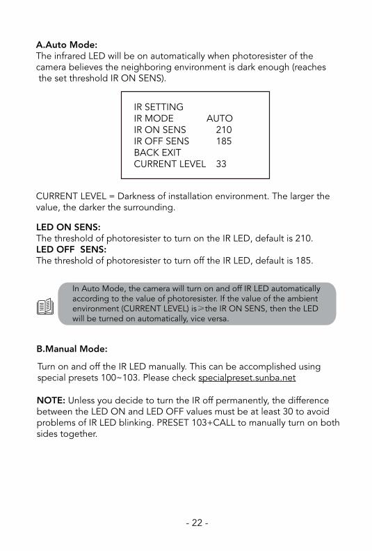
CURRENT LEVEL = Darkness of installation environment. The larger the value, the darker the surrounding.
Turn on and off the IR LED manually. This can be accomplished using special presets 100~103. Please check specialpreset.sunba.net
A.Auto Mode: The infrared LED will be on automatically when photoresister of the camera believes the neighboring environment is dark enough (reaches the set threshold IR ON SENS).
LED ON SENS:The threshold of photoresister to turn on the IR LED, default is 210.LED OFF SENS:The threshold of photoresister to turn off the IR LED, default is 185.
B.Manual Mode:
IR SETTINGIR MODE AUTOIR ON SENS 210IR OFF SENS 185BACK EXITCURRENT LEVEL 33
NOTE: Unless you decide to turn the IR off permanently, the difference between the LED ON and LED OFF values must be at least 30 to avoid problems of IR LED blinking. PRESET 103+CALL to manually turn on both sides together.
In Auto Mode, the camera will turn on and off IR LED automatically according to the value of photoresister. If the value of the ambient environment (CURRENT LEVEL) is≥the IR ON SENS, then the LED will be turned on automatically, vice versa.

- 23 -
12. Account Management Camera accounts can only be managed by its native clients. Third party software will not be able to modify any accounts information as it doesn’t have access to the camera’s private protocol.
Group and User Permission: ou can set a group that shares the same level of permission for camera control and view. For example, you can set several users to a “guest” group that has limited control over the camera.
Allow multiple access: Please remember to check the “sharable” or “reusable” option when adding a user if you wish to have the same user account accessed by multiple people.
CMS/IE:Device Con�g-> Account VMS:Device Con�g->Tool Manager->User Manager
To protect your account safety, please always remember to modify your default password!!
Default Camera Account Information:User name: adminPassword:
Modify your password here!
Modify your password here!

- 24 -
Alert Format Buzzer: Must have a siren connected with the alarm interface of the NVR to enable this option. Send Email: Enable this and enter your email information via Device Con�g->NetService (Network in VMS). You can also enable the snapshot option to activate email alert with snapshots.Write Log: A log will be popped on the screen every time an alert is received. FTP: See Chapter 14.
You can upload motion detection snapshots and videos to your FTP.
Step 1. Please remember to check the “Detect” option in the Snapshot Con�g or Record Con�g under Device Con�g.
Step 2: VMS: Device Con�g-> Network->FTPCMS/Browsers: Device Con�g->NetService->FTP
13. Motion Detection
14. FTP Communication
Enable motion detect
Modify the detection region
Edit the detection schedule

- 25-
Step 3. Enable the motion detection (in Video Detect or Video Motion). See Chapter 13. Then enable the FTP option.
Snapshots: You must also enable snapshot in Video Detect.
Videos: You must also enable record in Video Detect. And you must also have a storage media in order to upload the videos to FTP. Like many other network cameras, you will need to have a TF card (installed inside the camera’s built-in memory slot) or a NVR as a forwarding transfer station to your FTP. This is required because without storage media, the camera does not have enough RAM to hold large video �les before it establishes a connection with your FTP.
We would suggest that you control the Max File Length to ensure the stable upload of the �le.

- 26 -
15. Reset the CameraOption 1: Reset the camera parameter and con�guration (IE/VMS/CMS)Device Con�g → Default
Option 2: Reset camera network setting including ports and IP address.Device Manager → Reset Con�g
Option 3: Reset/modify camera network setting after lock-up (time out login error)Download the third party tool called ONVIF Device Manager
Option 4: Reset the password Ask [email protected] to provide the reset tool and the super password of the day.
Option 5: Telnet resetAsk [email protected] to schedule a remote TeamViewer session.

- 27 -
16. Cable Waterproof Measures
The camera itself is IP 66 Waterproof Rating. However, the cable connect--ors may still have exposures to water under different applications. It is always recommended for users to take precautions to protect the cable connectors of the camera. Below are 3 popular methods:
1. Certain models have waterproof ethernet kit shipped together with the camera. To apply the waterproof kit, you have to cut the crystal head, thread the ethernet cable through the waterproof kit, and then �nally use crimper tool to add the crystal head back to the cable.
2. Using electricial waterproof tape is one of the most popular ways of protecting connectors for water exposure.
3. Using waterproof connector protector together with some electrical waterproof tapes can be another option.
1 2
3
TAPE
TAPE

Warranty Statement
1.This product comes with a 2-year limited warranty in USA (1 year in other regions) and covering parts only. You must pay the labor fee for repair inside the warehouse. However, any parts replacements are always covered and we will be sending you videos & paper instructions on how to �x the unit. Please contact us �rst within the warranty period to make sure the condition of warranty is met.
2.Our warranty does not extend to any products that are physically damaged or are not under normal operating conditions as a result of misuse or improper installation on the user’s end.
Sunba's Return Policy
**Return WindowPlease return your product within 30 days of your receipt. That's the of�cial deadline the return request must be received. Exception applies for items in resellable conditions.
**RMAWe will provide a Returned Merchandise Authorization (RMA) Number for each item that satis�es the return request. Please put your RMA sheet inside the box for reference to expedite the refund process. All products must be returned within 14 days from the RMA issuing date.
**Complete Package RulePlease return the product with its original packaging, including manuals, brackets and toolkit that come with the unit for a full refund. According to Amazon's restocking fee policy, returns with incomplete/materially different package may enable sellers to charge a restocking fee up to 15% subject to the completeness of the package. Therefore, please make sure you keep the package in good condition in the period of valid return window to avoid any additional charge.
**RefundIf you didn't receive an automatic refund within 10 days of the receipt of your return, it is either the RMA was not attached to the package or the RMA was lost by the warehouse. In this case, please kindly provide us with your tracking number so that we can match the return package and the refund will be manually processed within 24 hours. Please watch your email noti�cations.
For any questions, don't hesitate to reach [email protected] SUNBA® Technology