Embed Size (px)
Citation preview
2017Computed Tomography
Radiologist’s Section
Radiologic Technologist’s Section
Qualified Medical Physicist’s Section
QUALITY CONTROL MANUAL
QUALITY CONTROL MANUAL
Radiologist’s Section
Radiologic Technologist’s Section
Qualified Medical Physicist’s Section
Chad Dillon, MSWilliam Breeden III, MS
Jessica Clements, MSDiana Cody, PhDDustin Gress, MS
Kalpana Kanal, PhDJames Kofler, PhD
Michael F. McNitt-Gray, PhDJames Norweck, MS
Doug Pfeiffer, MSThomas G. Ruckdeschel, MSKeith J. Strauss, MS, FACR
James Tomlinson, MS
Cynthia Davidson, ACR Staff MemberDina Hernandez, ACR Staff Member
© Copyright 2017, American College of Radiology. All rights reserved.
2017Computed Tomography
Contents
CT Quality Control Manual 3
ContentsPurpose and Scope 4
Radiologist’s section
Revisions 7
Introduction 8
Definition of Quality Assurance 10
Definition of Equipment Quality Control 11
Radiologist’s Responsibilities 12
Qualified Medical Physicist (QMP) Responsibilities 16
CT QC Technologist’s Responsibilities 18
Conclusion 20
References 21
Radiologic technologist’s section
Revisions 24
Introduction 25
Important Points 27
Technologist’s Daily CT Quality Control 32
Technologist’s Weekly Quality Control 39
Technologist’s Monthly Quality Control 43
References 49
Appendix 50
Qualified Medical Physicist’s section
Revisions 53
Introduction 54
Qualified Medical Physicist’s Annual Quality Control 56
References 84
Appendix 86
PuRPose and sCoPe
CT Quality Control Manual 4
This manual is designed to help guide facilities in establishing and maintaining an effective CT quality control program. All facilities must recognize the importance of a quality control program in producing diagnostic quality images at the lowest appropriate dose.
The tests in this manual are not intended to ensure that a scanner meets manufacturer’s specifications at the initial installation. Such testing is covered by acceptance testing and is beyond the scope of this document. Instead, this manual provides a minimum set of tests required to ensure that a scanner performs in a consistent manner and yields acceptable images.
If a scanner fails any of the tests specified within this manual, or if performance degradation is observed, the facility should further investigate to determine the cause of the failure or degradation, which may involve testing according to manufacturers’ procedures. If the scanner does not meet the manufacturers’ specifications, then the service engineer should be consulted to determine if a service visit is necessary.
Regardless of the quality of the image, if the diagnostic workstation is of poor quality, then a poor diagnostic result may occur. The ubiquity of workstations and the breadth of devices used for image interpretation add great complexity to establishing a quality control program for these devices. While photometric evaluation of workstations is vital, establishment of an appropriate quality control program for diagnostic workstations is beyond the scope of this document. Each facility should work with its workstation manufacturer(s) and its medical physicist to establish an appropriate and effective quality control program for the diagnostic workstations under their purview.
Purpose and scope
PuRPose and sCoPe
CT Quality Control Manual 5
Radiologist’s Section
2017Computed Tomography
Radiologist’s Section
QUALITY CONTROL MANUAL
Contents
CT Quality Control Manual 6
ContentsRevisions 7
Introduction 8
Definition of Quality Assurance 10
Definition of Equipment Quality Control 11
Radiologist’s Responsibilities 12
Qualified Medical Physicist (QMP) Responsibilities 16
CT QC Technologist’s Responsibilities 18
Conclusion 20
References 21
Revisions
CT Quality Control Manual 7
date Page(s) description of Revisions
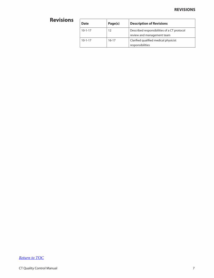
10-1-17 12 Described responsibilities of a CT protocol
review and management team
10-1-17 16-17 Clarified qualified medical physicist
responsibilities
Revisions
Return to TOC
intRoduCtion
CT Quality Control Manual 8
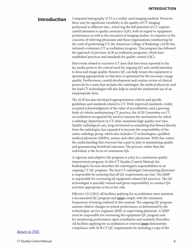
Computed tomography (CT) is a widely used imaging method. However, there may be significant variability in the quality of CT imaging performed at different sites. Achieving the full potential of CT requires careful attention to quality assurance (QA), both in regard to equipment performance as well as the execution of imaging studies. In response to the concerns of referring physicians and those organizations reimbursing for the costs of performing CT, the American College of Radiology (ACR) has initiated a voluntary CT accreditation program. This program has followed the approach of previous ACR accreditation programs, which have established practices and standards for quality control (QC).
Past events related to excessive CT dose that have been reported in the lay media point to the critical need for ongoing QC and careful attention to dose and image quality. Routine QC can help ensure the equipment is operating appropriately so that dose is optimized for the necessary image quality. Furthermore, careful development and routine review of clinical protocols by a team that includes the radiologist, the medical physicist, and the lead CT technologist will also help to avoid the inadvertent use of an inappropriate dose.
The ACR has also developed appropriateness criteria and specific guidelines and standards related to CT. With improved standards, widely accepted acknowledgment of the value of accreditation, and a growing body of criteria underpinning CT practice, the ACR Committee on CT Accreditation recognized the need to reassess the mechanisms by which a radiology department or CT clinic maintains high quality over time. Quality radiological care, long envisioned as something that flowed directly from the radiologist, has expanded to become the responsibility of the entire radiology group, which also includes CT technologists, qualified medical physicists (QMPs), nurses, and other physicians. With this comes the understanding that everyone has a part to play in maintaining quality and guaranteeing beneficial outcomes. The process, rather than the individual, is the focus of continuous QA.
A vigorous and adaptive QA program is a key to a continuous quality improvement program. In this CT Quality Control Manual, the Radiologist’s Section describes the radiologist’s responsibilities in an ongoing CT QC program. The lead CT radiologist (interpreting physician) is responsible for ensuring that all QA requirements are met. The QMP is responsible for overseeing all equipment-related QA practices. The QC technologist is specially trained and given responsibility to conduct QA activities appropriate to his or her role.
Effective 12/1/2012, all facilities applying for accreditation must maintain a documented QC program and must comply with the minimum frequencies of testing outlined in this manual. The ongoing QC program assesses relative changes in system performance as determined by the technologist, service engineer, QMP, or supervising physician. A QMP must be responsible for overseeing the equipment QC program and for monitoring performance upon installation and routinely thereafter. All facilities applying for accreditation or renewal must demonstrate compliance with ACR CT QC requirements by including a copy of the
introduction
Return to TOC
intRoduCtion
CT Quality Control Manual 9
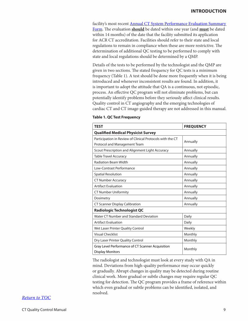
facility’s most recent Annual CT System Performance Evaluation Summary Form. The evaluation should be dated within one year (and must be dated within 14 months) of the date that the facility submitted its application for ACR CT accreditation. Facilities should refer to their state and local regulations to remain in compliance when these are more restrictive. The determination of additional QC testing to be performed to comply with state and local regulations should be determined by a QMP.
Details of the tests to be performed by the technologist and the QMP are given in two sections. The stated frequency for QC tests is a minimum frequency (Table 1). A test should be done more frequently when it is being introduced and whenever inconsistent results are found. In addition, it is important to adopt the attitude that QA is a continuous, not episodic, process. An effective QC program will not eliminate problems, but can potentially identify problems before they seriously affect clinical results. Quality control in CT angiography and the emerging technologies of cardiac CT and CT image-guided therapy are not addressed in this manual.
table 1. QC test Frequency
test FReQuenCY
Qualified Medical Physicist survey
Participation in Review of Clinical Protocols with the CT
Protocol and Management TeamAnnually
Scout Prescription and Alignment Light Accuracy Annually
Table Travel Accuracy Annually
Radiation Beam Width Annually
Low-Contrast Performance Annually
Spatial Resolution Annually
CT Number Accuracy Annually
Artifact Evaluation Annually
CT Number Uniformity Annually
Dosimetry Annually
CT Scanner Display Calibration Annually
Radiologic technologist QC
Water CT Number and Standard Deviation Daily
Artifact Evaluation Daily
Wet Laser Printer Quality Control Weekly
Visual Checklist Monthly
Dry Laser Printer Quality Control Monthly
Gray Level Performance of CT Scanner Acquisition
Display MonitorsMonthly
The radiologist and technologist must look at every study with QA in mind. Deviations from high-quality performance may occur quickly or gradually. Abrupt changes in quality may be detected during routine clinical work. More gradual or subtle changes may require regular QC testing for detection. The QC program provides a frame of reference within which even gradual or subtle problems can be identified, isolated, and resolved.
Return to TOC
deFinition oF QualitY assuRanCe
CT Quality Control Manual 10
A. Quality Assurance
Quality assurance is a comprehensive concept that comprises all of the oversight and management practices developed by the CT imaging team led by the supervising physician to ensure that:
1. Every imaging procedure is necessary and appropriate to the clinical objective;
2. The combination of acquisition parameters and procedures used for each exam is appropriate to address the clinical objective;
3. The images generated contain information critical to achieving the clinical objective;
4. The recorded information is correctly interpreted and made available in a timely fashion to the patient’s physician; and
5. The examination results in the lowest possible risk to the patient and is consistent with number 2 above in this section.
B. Quality Assurance Committee
The QA program includes many facets, including efficacy studies, continuing education, QC, preventive maintenance, and equipment calibration. An essential part of the QA program is the QA committee (QAC). This group is responsible for overseeing the QA program. The committee sets goals and direction, determines policies, and assesses the effectiveness of QA activities. The QAC should consist of the following:
1. One or more radiologists
2. A qualified medical physicist (QMP)
3. A supervisory, lead, or senior CT technologist
4. Other radiology department personnel who care for patients undergoing CT, including a nurse, desk attendant, medical secretary, or others
5. Personnel outside the radiology department, which includes medical and paramedical staff, such as referring physicians
definition of Quality assurance
Return to TOC
deFinition oF eQuiPMent QualitY ContRol
CT Quality Control Manual 11
A. Quality control
Quality Control is an integral part of quality assurance. Quality control is a series of distinct technical procedures that identifies defects or imperfections in a product such that the production process can be altered or corrected to eliminate these defects. Four steps are involved:
1. Acceptance testing to detect defects in equipment that is newly installed or has undergone major repair
2. Acceptance testing to establish baseline equipment performance
3. Routine QC for detection and diagnosis of changes in equipment performance before it become apparent in images
4. Follow-up measurements to verify that the causes of deterioration in equipment performance have been corrected
Acceptance testing should take place before a patient is scanned and after major repairs. Major repairs include replacement or repair of components such as an x-ray tube or detector assembly. The evaluation should be determined by the QMP based on the type of component that was replaced or repaired. All records should be accessible from a location near the CT scanner(s); decentralized access to records (e.g., web-based records) in a location near the CT scanner(s) may also be acceptable.
Specifics of the QC program for CT are provided by the ACR in this manual.
definition of equipment Quality
Control
Return to TOC
Radiologist’s ResPonsibilities
CT Quality Control Manual 12
A. The Supervising Radiologist
The Supervising Radiologist’s responsibilities relative to the optimization of patient dose in CT consist of the following:
1. Convene a CT Protocol Review and Management team that includes the supervising radiologist, the QMP, and the lead CT technologist to design and review all new or modified CT protocol settings to ensure that both image quality and radiation dose are appropriate. With the team:
2. Develop internal typical radiation dose metric (i.e., CTDIvol and DLP) ranges for any new CT protocol design.
3. Implement steps to ensure patient safety and to reduce future risk if an estimated dose value is inappropriately above the relevant threshold for any routine clinical exam.
4. Institute a review process for all protocols to ensure no unintended changes have been applied that may degrade image quality or unreasonably increase dose. The frequency of review must be consistent with federal, state and local laws and regulations. If there is no specific regulatory requirement, the frequency of protocol review should be no less than 24 months by the CT Protocol Review and Management team as this may be a time-consuming undertaking. This review should include all new protocols added since the last review. However, best practice would be to review a facility’s most frequent protocols at least annually.It is the responsibility of the QMP and the CT Protocol Review and Management team to review at least six protocol annually. See A. Review of Clinical Protocols.
5. Establish a policy stating that the CT dose estimate interface option is not to be disabled and that the dose information is displayed during the exam prescription phase.
B. Additional Responsibilities of Supervising Radiologist
The Supervising Radiologist, in collaboration with the QMP and administration (where appropriate), should develop appropriate elements of good practice in CT QC, which includes the following:
1. Provide technologists access to adequate training and continuing education in CT that includes a focus on patient safety.
2. Provide an orientation program for technologists based on a carefully established procedures manual.
3. Select a technologist as the primary QC technologist to perform the prescribed QC tests.
Radiologist’s Responsibilities
Return to TOC
Radiologist’s ResPonsibilities
CT Quality Control Manual 13
4. Provide the appropriate training, test equipment, and materials necessary for the technologist to perform the QC tests.
5. Arrange staffing and scheduling so that adequate time is available to carry out the QC tests and record and interpret the results.
6. Review or assign qualified staff to review the technologist’s test results at least every three months or more frequently if consistency has not yet been achieved.
7. Oversee or designate a qualified individual to oversee the safety program for employees, patients, and other individuals in the surrounding area.
C. All CT Radiologists (Interpreting Physicians)
Responsibilities of all CT radiologists (interpreting physicians) in CT QC consist of the following:
1. Ensure established protocols are followed.
2. Follow the facility procedures for corrective action when asked to interpret images of poor quality.
3. Participate in the facility’s practice improvement program.
4. Provide documentation of current qualifications to each CT facility where he or she practices, in accordance with ACR Accreditation and local rules.
D. Interpretive Quality Assurance
In addition, the radiologist needs to be involved in an ongoing QA program to assess the quality of CT interpretation. Such a program should include the following:
1. A double reading. in which two physicians interpret the same study
2. A process that allows a random selection of studies to be reviewed on a regularly scheduled basis
3. Exams and procedures representative of the actual clinical practice of each physician
4. Reviewer assessment of the agreement of the original report with subsequent review (or with surgical or pathological findings)
5. A classification of peer review findings with regard to level of quality concerns (One example is a four-point scoring scale.)
6. Policies and procedures for action on significant discrepant peer review findings for the purpose of achieving quality outcomes improvement
Return to TOC
Radiologist’s ResPonsibilities
CT Quality Control Manual 14
7. Summary statistics and comparisons generated for each physician by modality
8. Summary data for each facility/practice by modality
However, procedures for interpretive QA are not specifically addressed in this manual.
E. Radiologist’s Leadership Role in CT Quality Control
1. Radiologists performing CT must assume the primary responsibility for the quality of CT and for the implementation of an effective QA program at their site. The staff ’s commitment to high quality will often mirror that of the radiologist-in-charge. The individuals performing QC tests need to know that the radiologist understands the program and is interested in the results. The radiologist needs to review the test results and trends periodically and provide direction when problems are detected.
2. The QC tests outlined in this ACR Quality Control Manual are divided into a Qualified Medical Physicist’s and a Radiologic Technologist’s section. Relevant tests are described in detail in these two accompanying sections. The radiologist should ensure that these sections are available to the appropriate personnel and integrated into routine practice.
3. To ensure consistency in QC test performance, a single technologist should be selected for each CT system or group of systems. It is not desirable, for example, to rotate this assignment among a group of technologists. Such a practice would introduce variability extraneous to the items being tested into the test results. However, there should be a plan to provide backup to the QC technologist when he or she is not available.
4. An on-site QMP or one who is readily available, should administer each facility’s QC program, perform the tests designated as medical physicist QC tests, and oversee the work of the QC technologist(s). Where this is not feasible and during the QMP’s absence, the radiologist should oversee the QC program.
5. The radiologist is ultimately responsible for the quality of images produced under his or her direction and bears ultimate responsibility for both proper QC testing and QA procedures in CT.
F. CT Quality Assurance Procedures Manual
Working as a team, the radiologist, QC technologist, and QMP should develop and follow a CT QA procedures manual that is available to all members of the staff. The QC testing described in this ACR QC Manual should be a central part of the site’s QA procedures manual.
In addition, the site’s procedures manual(s) should contain the following:
1. Clearly assigned responsibilities and clearly developed procedures Return to TOC
Radiologist’s ResPonsibilities
CT Quality Control Manual 15
for QA/QC testing
2. Records of the most recent QC tests performed by the QC technologist and QMP
3. A description of the orientation program for operators of CT equipment, including its duration and content
4. Procedures for proper use and maintenance of equipment
5. CT protocols to be used, including pertinent information on radiation dose, positioning, and contrast agent administration that includes dose
6. Policies and procedures for dealing with pregnant or potentially pregnant patients and staff
7. Proper maintenance of records, including records of QC and QA testing, equipment service and maintenance, and QA meetings
8. Procedures for cleaning and disinfecting CT systems and ancillary equipment
The responsibilities of the QMP relate to equipment performance, including image quality and patient safety. A CT equipment performance review must take place at the time the equipment is installed and at least annually thereafter. The QMP should repeat appropriate tests after major repair or upgrade to the CT system, which includes a tube change. The QMP is also a key member of the CT Protocol Review and Management team that develops and reviews all new or modified CT protocol settings to ensure that both image quality and radiation dose are appropriate.
Specific tests for equipment performance review include:
1. Participation in Review of Clinical Protocols with the CT Protocol Review and Management Team
2. Scout Prescription and Alignment Light Accuracy
3. Table Travel Accuracy
4. Radiation Beam Width
5. Low-Contrast Performance
6. Spatial Resolution
7. CT Number Accuracy
8. Artifact Evaluation
9. CT Number Uniformity
10. Dosimetry
11. CT Scanner Display Calibration
Return to TOC
QualiFied MediCal PhYsiCist (QMP) ResPonsibilities
CT Quality Control Manual 16
A. Baseline Measurements and Action Limits
The QMP is responsible for performing baseline QC measurements. The QMP establishes performance criteria for the technologists’ QC program. This applies specifically to the determination of “action limits,” which are the thresholds of QC results that, if exceeded, require corrective action. Corrective action includes, but is not limited to, contacting appropriate service personnel to address equipment-related causes of QC failures.
During the annual review, the QMP also examines the records of the routine QC tests performed by the QC technologist(s). Following this review and the completion of the tests listed above, recommendations may be made regarding improvements in equipment performance or improvements in the QC process.
B. Purchase Specifications and Acceptance Testing
Many manufacturers sell CT systems with a large variety of features. Due to its complexity, a CT system’s quality under all scan conditions may be difficult to discern before purchase.
The quality of new equipment can be ensured through the use of purchase specifications. Purchase specifications also describe to manufacturers the type of equipment that is desired by the purchaser. Purchase specifications usually require manufacturers to provide detailed technical and performance specifications to the purchaser prior to the selection of equipment. These manufacturer-provided specifications then can be used to help determine the equipment to be purchased and, as a set of quantitative performance specifications, to be compared with measurements on the CT equipment during acceptance testing.
The purchase should be made contingent on satisfactory performance during acceptance testing. The purpose of acceptance testing is primarily to determine if the CT equipment performs according to the manufacturer’s specifications as stated in the documentation received from the manufacturer. Acceptance testing should be conducted by an experienced QMP. The manufacturer specified phantoms and test procedures must be used when comparing measured performance values to those specified by the manufacturer, which must be compliant with FDA and IEC standards. The description of acceptance testing procedures and limits is outside the scope of this document; however, testing performed during acceptance testing provides an opportunity to establish baseline values that will serve as the basis for comparison for ongoing QC testing.
The QC program described in this manual is intended to document consistency of performance after the unit has been accepted and put into service. Therefore, the QMP should consider using the results of these acceptance tests wherever possible as part of an initial set of baseline tests for the ongoing QC program. The QMP may also consider performing additional tests (that is, tests that are not determining whether the scanner meets the manufacturer’s specifications) but that can serve as the initial testing of a condition that will be evaluated at a later time; essentially performing the baseline test which will be used as a comparison for the
Qualified Medical Physicist (QMP)
Responsibilities
Return to TOC

QualiFied MediCal PhYsiCist (QMP) ResPonsibilities
CT Quality Control Manual 17
daily, weekly, quarterly, or annual tests described in this manual.
Once acceptance testing has been completed, there must be adequate applications training for the entire CT staff. Both the radiologist and the technologist need to fully understand how the automatic feature selection tools work, particularly with reference to Automatic Exposure Control (AEC) features, such as tube current modulation and automatic kV selection.
Return to TOC
Ct QC teChnologist’s ResPonsibilities
CT Quality Control Manual 18
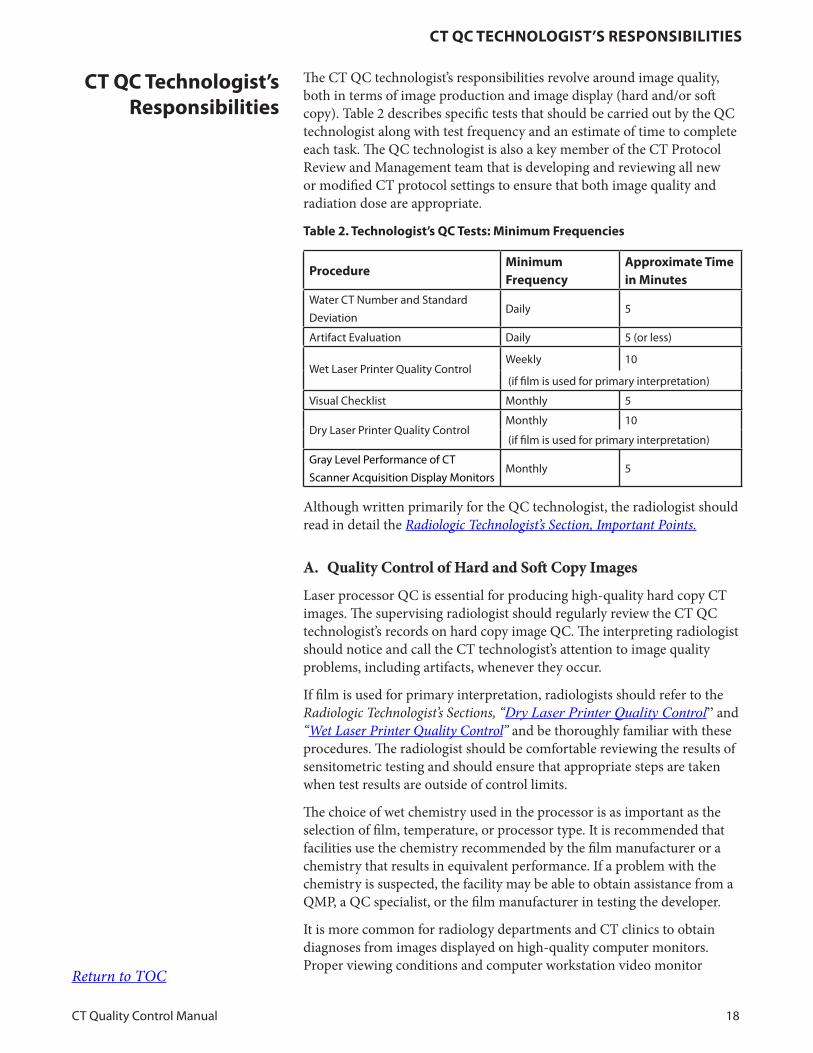
The CT QC technologist’s responsibilities revolve around image quality, both in terms of image production and image display (hard and/or soft copy). Table 2 describes specific tests that should be carried out by the QC technologist along with test frequency and an estimate of time to complete each task. The QC technologist is also a key member of the CT Protocol Review and Management team that is developing and reviewing all new or modified CT protocol settings to ensure that both image quality and radiation dose are appropriate.
table 2. technologist’s QC tests: Minimum Frequencies
ProcedureMinimum Frequency
approximate time in Minutes
Water CT Number and Standard
DeviationDaily 5
Artifact Evaluation Daily 5 (or less)
Wet Laser Printer Quality ControlWeekly 10
(if film is used for primary interpretation)
Visual Checklist Monthly 5
Dry Laser Printer Quality ControlMonthly 10
(if film is used for primary interpretation)
Gray Level Performance of CT
Scanner Acquisition Display MonitorsMonthly 5
Although written primarily for the QC technologist, the radiologist should read in detail the Radiologic Technologist’s Section, Important Points.
A. Quality Control of Hard and Soft Copy Images
Laser processor QC is essential for producing high-quality hard copy CT images. The supervising radiologist should regularly review the CT QC technologist’s records on hard copy image QC. The interpreting radiologist should notice and call the CT technologist’s attention to image quality problems, including artifacts, whenever they occur.
If film is used for primary interpretation, radiologists should refer to the Radiologic Technologist’s Sections, “Dry Laser Printer Quality Control” and “Wet Laser Printer Quality Control” and be thoroughly familiar with these procedures. The radiologist should be comfortable reviewing the results of sensitometric testing and should ensure that appropriate steps are taken when test results are outside of control limits.
The choice of wet chemistry used in the processor is as important as the selection of film, temperature, or processor type. It is recommended that facilities use the chemistry recommended by the film manufacturer or a chemistry that results in equivalent performance. If a problem with the chemistry is suspected, the facility may be able to obtain assistance from a QMP, a QC specialist, or the film manufacturer in testing the developer.
It is more common for radiology departments and CT clinics to obtain diagnoses from images displayed on high-quality computer monitors. Proper viewing conditions and computer workstation video monitor
Ct QC technologist’s Responsibilities
Return to TOC

Ct QC teChnologist’s ResPonsibilities
CT Quality Control Manual 19
performance are as essential in CT as in other areas of radiology. The radiologist should give particular attention to the information in the Qualified Medical Physicist’s Section, “CT Scanner Display Calibration”.
Return to TOC
ConClusion
CT Quality Control Manual 20
In addition to this technical QC program, the CT radiologist needs to be involved in an ongoing program to assess the quality of CT interpretation. Procedures for interpretive QA are not addressed in this manual but have been published in the radiological literature.
The public expects our profession to provide accurately interpreted CT images of the highest quality. Only a strong, consistent commitment to QA by all parties involved in performing CT will validate that trust.
Conclusion
Return to TOC
ReFeRenCes
CT Quality Control Manual 21
A. Downloadable from ACR Website (www.acr.org):
1. Computed Tomography Accreditation Program Requirements
2. ACR CT Accreditation Program Testing Instructions
3. ACR Technical Standard for Diagnostic Medical Physics Performance Monitoring of Computed Tomography (CT) Equipment [Res. 34 – 2012]
4. ACR Practice Parameter for Performing and Interpreting Diagnostic Computed Tomography (CT) [Res. 39 – 2017]
5. ACR-ASER-SCBT-MR-SPR Practice Parameter for the Performance of Pediatric Computed Tomography (CT) [Res. 3 – 2014]
6. ACR-SPR Practice Parameter for Imaging Pregnant or Potentially Pregnant Adolescents and Women With Ionizing Radiation [Res. 48 – 2013, Amended 2014 (Res. 39)]
7. ACR-AAPM Practice Parameter for Diagnostic Reference Levels and Achievable Doses in Medical X-Ray Imaging [Res. 53 – 2015]
8. The ACR and American Society of Neuroradiology Statement on CT Protocols and Radiation Dose
References
Return to TOC
ReFeRenCes
CT Quality Control Manual 22
Radiologic Technologist’s Section
2017Computed Tomography
Radiologic Technologist’s Section
QUALITY CONTROL MANUAL
Contents
CT Quality Control Manual 23
ContentsRevisions 24
Introduction 25
Important Points 27
Technologist’s Daily CT Quality Control 32
Technologist’s Weekly Quality Control 39
Technologist’s Monthly Quality Control 43
References 49
Appendix 50
Revisions
CT Quality Control Manual 24
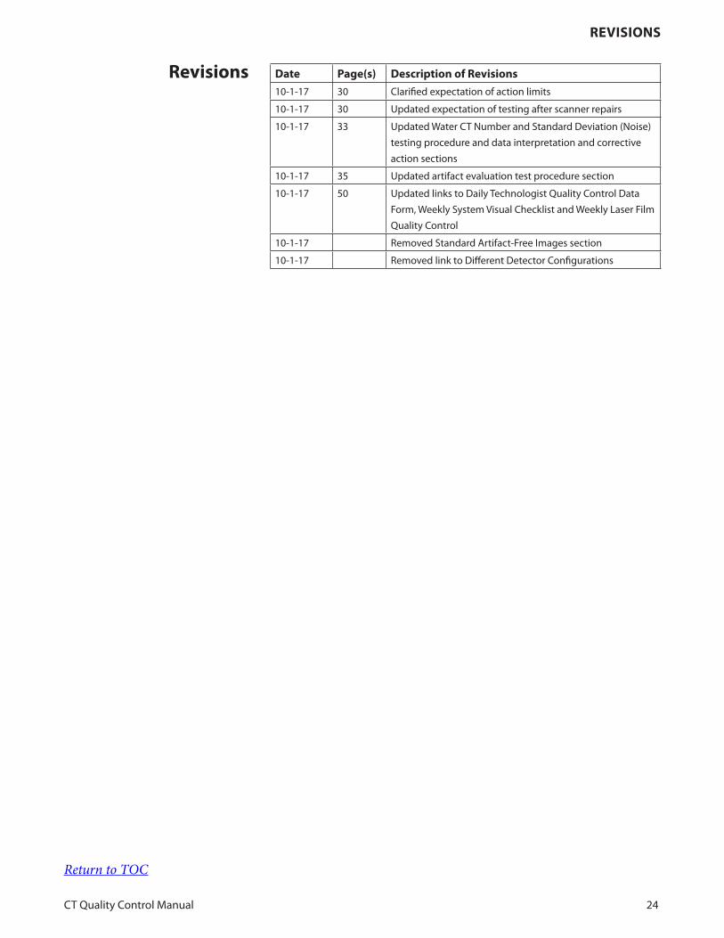
date Page(s) description of Revisions
10-1-17 30 Clarified expectation of action limits
10-1-17 30 Updated expectation of testing after scanner repairs
10-1-17 33 Updated Water CT Number and Standard Deviation (Noise)
testing procedure and data interpretation and corrective
action sections
10-1-17 35 Updated artifact evaluation test procedure section
10-1-17 50 Updated links to Daily Technologist Quality Control Data
Form, Weekly System Visual Checklist and Weekly Laser Film
Quality Control
10-1-17 Removed Standard Artifact-Free Images section
10-1-17 Removed link to Different Detector Configurations
Revisions
Return to TOC
intRoduCtion
CT Quality Control Manual 25
A well-designed, documented, and executed quality control (QC) program is essential to consistent production of high-quality CT images at reasonable radiation dose levels. The American College of Radiology (ACR) has developed this manual to assist radiologists, radiologic technologists, and qualified medical physicists (QMPs) in establishing and maintaining such QC programs. This is in accordance with the ACR’s educational and patient service missions, and is in response to growing requests from the diagnostic imaging community for guidance on CT QC.
Effective 12/1/2012, all facilities applying for accreditation must maintain a documented QC program and must comply with the minimum frequencies of testing outlined in this manual. The ongoing QC program assesses relative changes in system performance as determined by the technologist, service engineer, QMP, or supervising physician. A QMP must be responsible for overseeing the equipment QC program and for monitoring performance upon installation and routinely thereafter. All facilities applying for accreditation or renewal must demonstrate compliance with the ACR QC requirements by including a copy of the summary form from the most recent Annual CT System Performance Evaluation of each unit at the facility. The evaluation should be dated within one year (and must be dated within 14 months) of the date that the facility submitted its application for ACR CT accreditation. Facilities should refer to their state and local regulations to remain in compliance when these are more restrictive. The determination of additional QC testing to be performed to comply with state and local regulations should be determined by a QMP.
This section of the manual describes the CT technologist’s duties in the QC program. They can be carried out with a reasonable investment in time and equipment. The technologist’s responsibilities include regularly acquiring QC data, recording the data in QC records, and initiating appropriate corrective action as needed.
Each procedure description follows the same format:
• Objective
• Frequency
• Required equipment
• Procedure steps
• Data interpretation and corrective action guidelines
introduction
Return to TOC

intRoduCtion
CT Quality Control Manual 26
Table 1 under Important Points provides an overview of the technologist’s QC program. It lists the required procedures, how often each must be performed, and approximately how long each task should take. However, if state and/or local regulations require that the tests be performed more frequently, sites should comply with those regulations. The frequency with which these tests are required should be determined with the assistance of the QMP.
Return to TOC
iMPoRtant Points
CT Quality Control Manual 27
A. Teamwork
The CT technologist, QMP, and radiologist constitute a QC team. Each should be aware of the other’s responsibilities, especially as they relate to their own, and should assist one another in achieving the overall objectives of the QC program.
With respect to the technologist, the QMP has three important QC functions:
1. The QMP is responsible for ensuring the correct implementation and execution of the technologist’s QC procedures. Normally, this will entail some supervision and guidance from the QMP during implementation of the QC program. The QMP must conduct a review of the QC records maintained by the technologist on an annual basis, although a quarterly review is preferred.
2. The QMP also should help design the QC scan protocol technique to be used on each CT scanner. Using a preprogrammed set of imaging parameters for obtaining CT QC images provides more consistent and useful QC data. Sometimes this involves using a set of parameters specified by the scanner manufacturer.
3. The QMP is a resource to answer questions concerning image quality and patient dose to help identify and correct image quality problems or radiation dose issues.
With respect to the technologist, the radiologist has three important QC roles:
1. The radiologist reviews, with the technologist, image quality problems identified during interpretation of clinical images. This is often the first indication of a QC problem.
2. When image quality or radiation dose issues arise, the radiologist decides whether patient studies can continue or must be postponed pending corrective action.
3. The radiologist participates in the initial assessment of image quality at implementation of the QC program and regularly monitors QC results in the intervals between the annual QC data reviews.
B. Quality Control Testing Frequency
The technologist’s QC testing procedure frequencies given in Table 1 and in the rest of this manual are the minimum recommended frequencies.
important Points
Return to TOC
iMPoRtant Points
CT Quality Control Manual 28
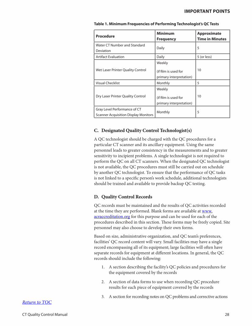
table 1. Minimum Frequencies of Performing technologist’s QC tests
ProcedureMinimum Frequency
approximate time in Minutes
Water CT Number and Standard
DeviationDaily 5
Artifact Evaluation Daily 5 (or less)
Wet Laser Printer Quality Control
Weekly
(if film is used for
primary interpretation)
10
Visual Checklist Monthly 5
Dry Laser Printer Quality Control
Weekly
(if film is used for
primary interpretation)
10
Gray Level Performance of CT
Scanner Acquisition Display MonitorsMonthly 5
C. Designated Quality Control Technologist(s)
A QC technologist should be charged with the QC procedures for a particular CT scanner and its ancillary equipment. Using the same personnel leads to greater consistency in the measurements and to greater sensitivity to incipient problems. A single technologist is not required to perform the QC on all CT scanners. When the designated QC technologist is not available, the QC procedures must still be carried out on schedule by another QC technologist. To ensure that the performance of QC tasks is not linked to a specific person’s work schedule, additional technologists should be trained and available to provide backup QC testing.
D. Quality Control Records
QC records must be maintained and the results of QC activities recorded at the time they are performed. Blank forms are available at www.acraccreditation.org for this purpose and can be used for each of the procedures described in this section. These forms may be freely copied. Site personnel may also choose to develop their own forms.
Based on size, administrative organization, and QC team’s preferences, facilities’ QC record content will vary. Small facilities may have a single record encompassing all of its equipment; large facilities will often have separate records for equipment at different locations. In general, the QC records should include the following:
1. A section describing the facility’s QC policies and procedures for the equipment covered by the records
2. A section of data forms to use when recording QC procedure results for each piece of equipment covered by the records
3. A section for recording notes on QC problems and corrective actionsReturn to TOC
iMPoRtant Points
CT Quality Control Manual 29
The QC records must be kept in a location that is accessible and known to all members of the QC team and the service engineer, so that they may refer to it when questions arise. The section for recording QC problems and corrective actions can facilitate communication between the service engineer and QC team members who often have different work schedules. QC records for an individual scanner should be kept for three years or in compliance with local regulations and accreditation mandates. QC images should be maintained for three months or until reviewed by the QMP.
E. QC Data Review
The QMP will review the QC data at least annually, although a quarterly review process is preferred. The purpose of the review is to make sure that no image quality problems have been inadvertently overlooked and to verify that the QC procedures are being performed on schedule with at least the minimum recommended frequency. This review should be part of a regular QA Committee meeting (Radiologist’s Section, B. The Quality Assurance Committee).
F. Alternative Phantoms
A water-filled, cylindrical phantom, which is typically provided by the scanner manufacturer at installation, should be used for the QC program. During long-term utilization, this phantom may experience some wear and tear. The site should have a backup plan for either a quick repair of the water phantom or an extra QC phantom, in the event the primary phantom is too damaged to be used effectively.
The ACR CT phantom may be used as an alternative to the water phantom.
G. Alternative Procedures
Test procedures in this document are considered the minimum set of acceptable tests. All of these tests should be completed unless the recommended procedures are ineffective on a particular scanner. In that instance, alternative QC tests should be developed or manufacturer’s testing procedures should be used. The QC technologist should not conduct alternative testing procedures until those procedures are reviewed and approved by a QMP. The QMP must document the necessary procedures, analysis methods, and action criteria for the alternative tests in the QC records (Radiologist’s Section, F. CT Quality Assurance Procedures Manual). The QMP must provide appropriate training for the QC technologist concerning alternative QC procedures.
Additional tests may be required if the system is used routinely for advanced clinical CT procedures. Such studies would include, but are not limited to, imaging to obtain reference data for stereotactic therapeutic procedures, imaging to be used for radiation treatment planning purposes, or advanced angiographic and blood perfusion methods using contrast agents.
Description of advanced CT QC tests is beyond the scope of this manual. Return to TOC
iMPoRtant Points
CT Quality Control Manual 30
The QMP is responsible for determining and setting up the methods and frequencies for these tests.
H. Action Limits
Performance criteria for the various QC measurements are specified in terms of action limits (also known as control limits), which define the range of acceptable values. Outside those values, corrective action is required. In some cases, the stability of the equipment and the consistency of the technologist’s measurements may result in measured values well within the action limits. In these cases, more restrictive action limits would increase sensitivity to potential developing problems. The QMP should review action criteria annually and ensure that they are adequately sensitive to detect CT equipment problems. Action limits should be based on the performance of an individual scanner. In addition, action limits should be re-evaluated whenever there are hardware changes or major service activities. Keep in mind that manufacturers might only initiate service if their standards (e.g. manufacturer specified testing procedures with specified phantom and action limits) are not met. It is important for the facility, the QMP, and the service engineer to maintain a close working relationship.
I. Scanner Repairs
QC testing should be completed after major repairs and ideally prior to the first clinical scan after the repair. However, if, this is not feasible, then the water phantom testing should be completed at a minimum, and complete testing may be postponed until the first feasible opportunity to complete it. Major repairs include replacement or repair of any of the following subsystem components: x-ray tube, generator, collimator assembly, or x-ray detectors. This is an opportunity to collect an up-to-date, standard set of artifact images for the CT unit.
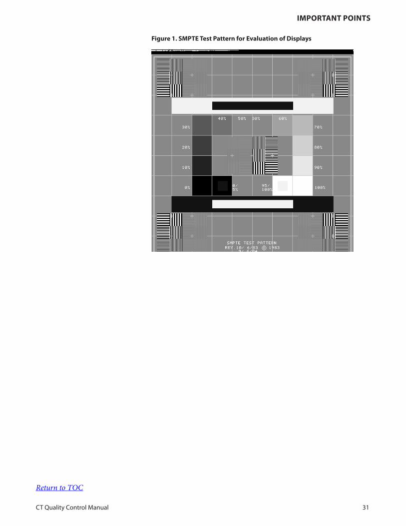
J. SMPTE Test Pattern
The SMPTE test pattern (Figure 1) created by the Society of Motion Picture and Television Engineers is widely used for evaluating display systems for medical diagnostic imaging. It should be available on all CT scanners.
The SMPTE pattern has several components designed to test the quality of the display. For the purposes of this procedure, we are concerned with only two of those components, which are indicated in Figure 1. The first component is a rectangular collection of square patches of different gray levels ranging from 0 to 100% in increments of 10%. The second component is a pair of square gray level patches, each with a smaller patch of slightly different gray level inside: one is a 0 patch with a 5% patch inside, and the other is a 100% patch with a 95% patch inside. These are referred to as the 0/5% patch and the 95/100% patch, respectively.
Return to TOC
iMPoRtant Points
CT Quality Control Manual 31
Figure 1. sMPte test Pattern for evaluation of displays
Return to TOC

teChnologist’s dailY Ct QualitY ContRol
CT Quality Control Manual 32
To ensure no patient images are potentially compromised, phantom image acquisition should be performed prior to the first clinical scan of the day (or the equivalent for scanners used around the clock). After images are acquired, the QC technologist should perform simple measurements to ensure that system performance is within the action limits prior to the first clinical scan of the day (or equivalent).
The daily QC procedure consists of two parts:
1. Water CT Number and Standard Deviation: Images of the water phantom are acquired in either the axial or helical scan modes (or both) using predetermined scan techniques. The specific quantitative values of mean and standard deviation of the images are recorded.
2. Analysis of Artifacts Contained Within Water Phantom Images: A set of QC phantom images are reviewed to identify image artifacts.
Automatic QC procedures may be used in place of these tests if the QMP has critically reviewed them and approved this substitution (in writing). It is not recommended that an automatic QC process be considered as a replacement for the artifact analysis portion of daily QC.
technologist’s daily Ct Quality Control
Return to TOC

teChnologist’s dailY Ct QualitY ContRol
CT Quality Control Manual 33
A. Water CT Number and Standard Deviation (Noise)
To ensure that the calibration of CT numbers relative to water remains within acceptable limits and that quantum noise and electronic system noise do not increase. Excessive image noise degrades low-contrast detectability and can be a symptom of other system problems.
Daily
The water phantom provided by the scanner manufacturer or the ACR CT phantom. Data can be recorded on the Data Form for Daily CT Equipment Quality Control (Appendix).
1. Warm up the scanner’s x-ray tube according to manufacturer recommendations.
2. Perform calibration scans (often called air-calibration scans) according to scanner manufacturer recommendations.
3. Place the QC phantom on the holder device provided. Center the phantom at the isocenter of the scanner using the laser alignment lights of the scanner and the alignment marks on the phantom surface.
4. Set up a scan of the QC phantom using the scanner’s daily QC scan parameter settings. It is strongly recommended that the QC scan protocols be preprogrammed for consistency. Usually, these scan protocols will follow the parameter settings recommended by the scanner manufacturer. Water mean and standard deviation values must be monitored in either the axial or helical scan mode and may be monitored in both modes; that is, the QMP should assist the QC technologist to establish (and ideally pre-program) the desired scan in one of these modes. If the QMP desires, then they can assist the QC technologist in establishing (and again, ideally pre-program) the desired scan for the other mode, which will typically be performed less frequently.
1. If a group of images were obtained on a multislice CT scanner, for example, then select an image from the central portion of the group to analyze. Place a region-of-interest (ROI) at the center of the image. If the size of this ROI is not specified by the scanner manufacturer, use an area around 400 mm2. Record the values reported for the water mean and standard deviation, which can be recorded on the data form.
2. Repeat Steps 1 and 2 for image(s) acquired in the second scan mode (if performed).
3. The QMP, after consulting the manufacturer’s specifications, should provide limit criteria for water mean and standard deviation. Typically, mean values for water fall within 0 +/- 3 HU; however, they must be within 0 ± 5 HU or as the manufacturer specifies. Limit criteria for the noise (standard deviation) values are primarily determined by the scan technique (radiation
obJeCtive
FReQuenCY
ReQuiRed eQuiPMent
test PRoCeduRe
data inteRPRetation and CoRReCtive aCtion
Return to TOC

teChnologist’s dailY Ct QualitY ContRol
CT Quality Control Manual 34
dose) used to acquire the images. If the QMP elects to use the manufacturer’s specified standard deviation as the limit criteria, the scan technique must be identical to the manufacturer’s recommendation (including reconstructed image thickness and reconstruction kernel or filter).
4. If the ACR CT phantom is used as the QC phantom, the water value should be 0 + 5 HU, but must be 0 + 7 HU. Note that the baseline value might be different on some scanners and should be established by the QMP. The QMP may establish limit criteria for noise (standard deviation) for either axial or helical modes (or both) after consulting manufacturer’s recommendations. Due to scanner and setup fluctuations, it may be advisable to perform a 10-day (or more) average of standard deviation data when establishing baselines.
5. If either the mean CT number or the noise (standard deviation) is not within the criteria established by the QMP, then the phantom, phantom positioning, phantom image used, ROI placement, and protocol used should be double checked. Additionally, air calibrations (if recommended by the manufacturer) should be run. The test should then be repeated. If the test is still failing, consult the QMP for guidance. The QMP should assist in determining whether or not service should be contacted, and, if necessary, if the service should be done prior to clinical imaging.
Return to TOC

teChnologist’s dailY Ct QualitY ContRol
CT Quality Control Manual 35
B. Artifact Evaluation
To identify and correct artifacts in images of a uniform test phantom before they become severe enough to be detected in patient images.
Daily
Either the water phantom provided by the scanner manufacturer or the ACR CT phantom is required. Data are recorded on the Data Form for Daily CT Equipment Quality Control (Appendix).
1. After the QC images in Section A are obtained, acquire additional images in axial mode for artifact analysis. Alternatively, the same images used for water CT number and noise could also be used. The acquisition parameters should be preprogrammed QC protocols designed in consultation with the QMP using the QC phantom. The reconstructed artifact images should: a) be the thinnest axial images possible on the scanner and b) span the z-axis of the detector array on the scanner. Meeting a and b may require more than one scan, particularly in axial mode. (Examples for several scanners are shown in Figures 2 and 3).
2. Good practices would also include the use of a larger uniform phantom on a weekly or monthly basis to identify artifacts outside of the water QC phantom region (Figure 3). Some manufacturers supply large uniform phantoms with scanners, which are excellent for artifact analysis. The 32-cm CT Dose Index (CTDI) phantom could also be used for this purpose. Examples of these artifacts are shown later in this section. Please also note that an alternative method involving air scans is described in the ACR CT Accreditation Program FAQ pages.
3. Visually assess the images acquired using an appropriate window width/level setting, such as a width of 100 HU and center of 0 HU. Look for rings in the image, which can be darker or lighter than the water portion. Rings can also occur at the very center of the phantom, which will appear as circular regions observed near the center of the phantom. (See Figure 2b). Also look for streaks, lines, etc., that should not be present in the image. This process can be accomplished by quickly cycling through all artifact images in a stack. After gaining some experience with this procedure, it will become a very quick task to review images for artifacts. Record findings on the data form.
Ring artifacts typically indicate detector or data channel imbalance. Corrective action may vary by manufacturer, so the operator’s manual and manufacturer’s recommendations should be followed. For some scanners, repeating the air-calibration procedure, if the manufacturer provides such user calibrations, (Step 2 of the Water CT Number and Standard Deviation test procedure) may smooth out these imbalances if the air-calibration process is set to correct only a subset of parameter combinations each time it is performed. If the ring artifacts are not corrected after performing several air-calibration procedures, or if these calibrations are not a user-
obJeCtive
FReQuenCY
ReQuiRed eQuiPMent
test PRoCeduRe
data inteRPRetation and CoRReCtive aCtion
Return to TOC
teChnologist’s dailY Ct QualitY ContRol
CT Quality Control Manual 36
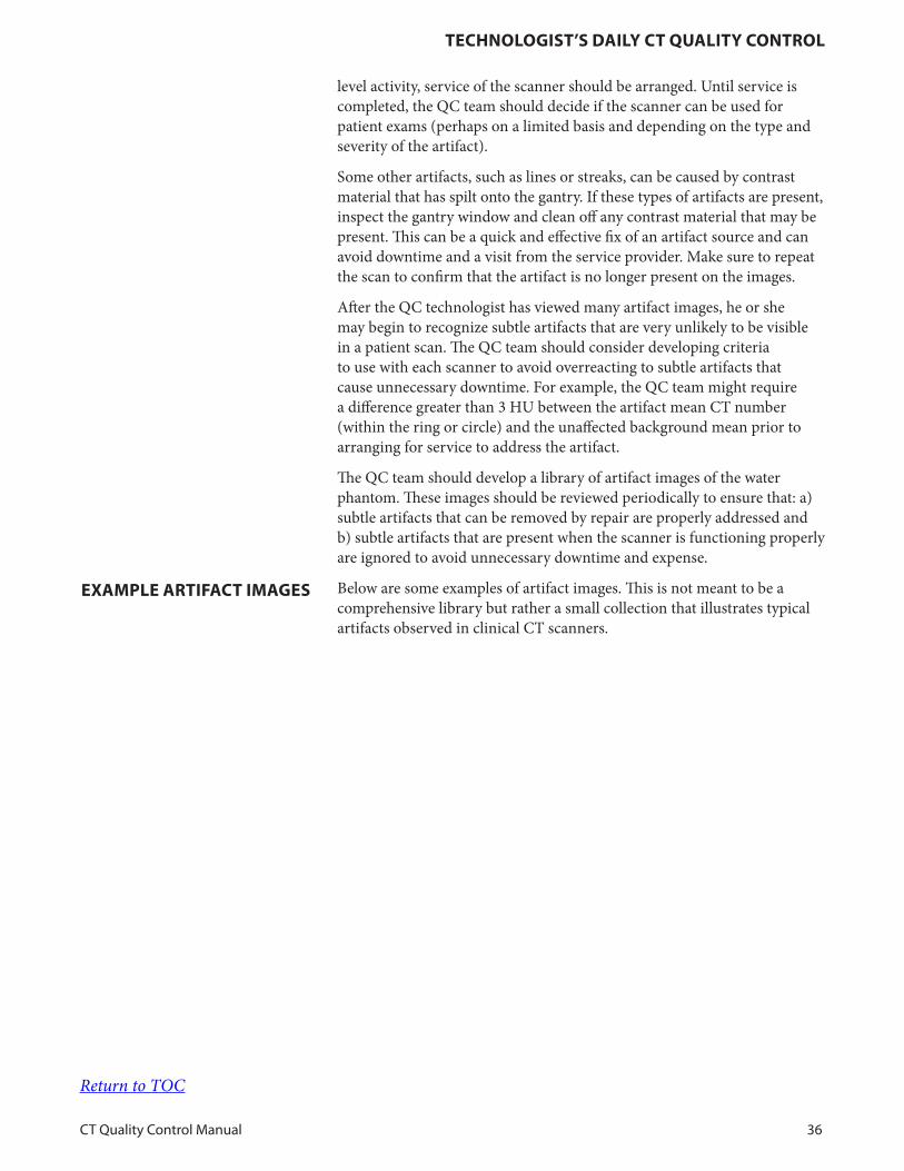
level activity, service of the scanner should be arranged. Until service is completed, the QC team should decide if the scanner can be used for patient exams (perhaps on a limited basis and depending on the type and severity of the artifact).
Some other artifacts, such as lines or streaks, can be caused by contrast material that has spilt onto the gantry. If these types of artifacts are present, inspect the gantry window and clean off any contrast material that may be present. This can be a quick and effective fix of an artifact source and can avoid downtime and a visit from the service provider. Make sure to repeat the scan to confirm that the artifact is no longer present on the images.
After the QC technologist has viewed many artifact images, he or she may begin to recognize subtle artifacts that are very unlikely to be visible in a patient scan. The QC team should consider developing criteria to use with each scanner to avoid overreacting to subtle artifacts that cause unnecessary downtime. For example, the QC team might require a difference greater than 3 HU between the artifact mean CT number (within the ring or circle) and the unaffected background mean prior to arranging for service to address the artifact.
The QC team should develop a library of artifact images of the water phantom. These images should be reviewed periodically to ensure that: a) subtle artifacts that can be removed by repair are properly addressed and b) subtle artifacts that are present when the scanner is functioning properly are ignored to avoid unnecessary downtime and expense.
Below are some examples of artifact images. This is not meant to be a comprehensive library but rather a small collection that illustrates typical artifacts observed in clinical CT scanners.
eXaMPle aRtiFaCt iMages
Return to TOC
teChnologist’s dailY Ct QualitY ContRol
CT Quality Control Manual 37
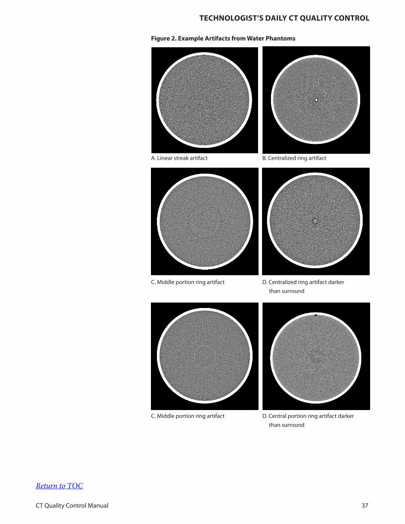
Figure 2. example artifacts from Water Phantoms
A Linear streak artifact B Centralized ring artifact
C Middle portion ring artifact D Centralized ring artifact darker
than surround
C Middle portion ring artifact D Central portion ring artifact darker
than surround
Return to TOC
teChnologist’s dailY Ct QualitY ContRol
CT Quality Control Manual 38
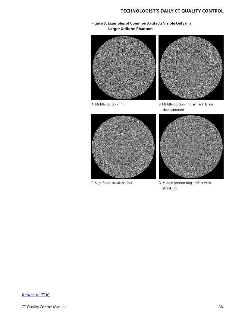
Figure 3. examples of Common artifacts visible only in a larger uniform Phantom
A Middle portion ring B Middle portion ring artifact darker
than surround
C Significant streak artifact D Middle portion ring artifact with
streaking
Return to TOC

teChnologist’s WeeklY QualitY ContRol
CT Quality Control Manual 39
The weekly QC procedures consist of one test:
1. Wet Laser Printer Quality Control
This testing is required to ensure that images printed on film appear the same as the images displayed on scanners’ display monitors.
technologist’s Weekly Quality Control
Return to TOC
teChnologist’s WeeklY QualitY ContRol
CT Quality Control Manual 40
A. Wet Laser Printer Quality Control
To ensure artifact-free images printed on film are produced with consistent gray levels that match the image appearance on the filming console.
This test must be performed weekly if film is used for primary interpretation. For printers used infrequently (e.g., backup printers), this test should be performed prior to clinical use. Additionally, the test should be completed at the initiation of the QC program and whenever a significant change is made in the film printing system (e.g., change of film type, chemicals, or processing conditions).
1. Calibrated Densitometer
2. Laser Film QC Chart
3. SMPTE Test Pattern
NOTE: If your current QC program is equivalent to the test described below, you may continue with your existing procedure.
1. Operating Levels
The QMP is responsible for establishing the correct operating levels for the laser film printer. This procedure will be carried out when the QC program is initiated and whenever a significant change is made in the film system. The QC technologist then compares films against the established operating levels. This is done weekly to ensure consistent film quality.
2. Wet Laser Film Quality Control
a. Display the SMPTE test pattern on the filming console. Set the display window width/level to the manufacturer-specified values for the SMPTE pattern. Do not set the window width/ level by eye; doing so invalidates this procedure.
b. Film the SMPTE pattern. Use a 6-on-1 format and capture the pattern into all six frames.
c. Using a film densitometer, measure the optical density of the 0, 10%, 40%, and 90% gray level patches of the SMPTE pattern in the upper left frame of the film.
d. Plot these optical densities in the appropriate places on the Laser Film QC Chart. Circle any points that fall outside the control limits. Optical density baseline values should already have been established and entered on the chart when the operating levels were set.
e. Put the film on a light box and inspect it for streaks, uneven densities, and other artifacts.
obJeCtive
FReQuenCY
ReQuiRed eQuiPMent
test PRoCeduRe
Return to TOC
teChnologist’s WeeklY QualitY ContRol
CT Quality Control Manual 41
If multiple modalities, such as CT or MRI, are connected to one laser film printer, similar initial setup and QC testing should be performed for each printer input.
Changes in laser film emulsion batches are common causes of variation beyond density control limits. To reduce the need to recalibrate the laser film printer, do not mix emulsion batches. Instead, use all of one emulsion number before using another batch.
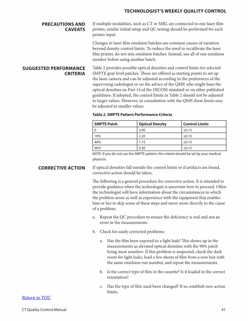
Table 2 provides possible optical densities and control limits for selected SMPTE gray level patches. These are offered as starting points to set up the laser camera and can be adjusted according to the preferences of the supervising radiologist or on the advice of the QMP, who might base the optical densities on Part 14 of the DICOM standard or on other published guidelines. If adopted, the control limits in Table 2 should not be adjusted to larger values. However, in consultation with the QMP, these limits may be adjusted to smaller values.
table 2. sMPte Pattern Performance Criteria
sMPte Patch optical density Control limits
0 3 00 ±0 15
10% 2 20 ±0 15
40% 1 15 ±0 15
90% 0 30 ±0 15
NOTE: If you do not use the SMPTE pattern, the criteria should be set by your medical
physicist
If optical densities fall outside the control limits or if artifacts are found, corrective action should be taken.
The following is a general procedure for corrective action. It is intended to provide guidance when the technologist is uncertain how to proceed. Often the technologist will have information about the circumstances in which the problem arose as well as experience with the equipment that enables him or her to skip some of these steps and move more directly to the cause of a problem:
a. Repeat the QC procedure to ensure the deficiency is real and not an error in the measurements.
b. Check for easily corrected problems:
a. Has the film been exposed to a light leak? This shows up in the measurements as elevated optical densities with the 90% patch being most sensitive. If this problem is suspected, check the dark room for light leaks, load a few sheets of film from a new box with the same emulsion run number, and repeat the measurements.
b. Is the correct type of film in the cassette? Is it loaded in the correct orientation?
c. Has the type of film used been changed? If so, establish new action limits.
PReCautions and Caveats
suggested PeRFoRManCe CRiteRia
CoRReCtive aCtion
Return to TOC
teChnologist’s WeeklY QualitY ContRol
CT Quality Control Manual 42
d. Are the processor rollers clean? Dirty rollers cause streaking and must be kept clean.
e. Is the water turned on? Is the water temperature correct? Are the replenishment rates of the developer and fixer correct? Correct temperatures and replenishment rates are specified in the film manufacturer’s published literature.
c. The QMP responsible for film QC should be informed and asked to assist with problem troubleshooting.
d. If the problem cannot be resolved quickly, consult with the supervising radiologist to decide whether filming can continue while waiting for the problem to be corrected.
Return to TOC
teChnologist’s MonthlY QualitY ContRol
CT Quality Control Manual 43
The monthly QC procedures consist of three parts:
A. Visual Checklist
This is required to ensure that all patient safety items associated with the CT scanner are in good working order.
B. Hard Copy Image Quality Control of Dry Laser Printers
This testing is required to ensure that images printed on film have the same appearance as the images displayed on scanners’ display monitors. These testing procedures and action levels are very similar to previous descriptions for Wet Laser Printers. The appropriate material is repeated for the convenience of the technologist.
C. Gray Level Performance of CT Scanner Acquisition Display Monitors
This testing is required to ensure that images on the CT scanner monitors display the entire range of gray shades produced by the CT scanner.
technologist’s Monthly Quality
Control
Return to TOC
teChnologist’s MonthlY QualitY ContRol
CT Quality Control Manual 44
A. Visual Checklist
To ensure the CT system’s patient bed transport, alignment and system indicator lights, intercom, the emergency cart, room safety lights, signage, and monitors are present, working properly, and are mechanically and electrically stable.
At a minimum, this test should be performed on a monthly basis.
Visual checklist (See Appendix) which may include, but is not limited to:
Gantry:
• Table height indicator functioning
• Table position indicator functioning
• Angulation indicator functioning
• Laser localization light functioning
• Acceptable smoothness of table motion
• X-ray on indicator functioning
Control Console:
• Exposure switch functioning
• Panel switches/lights/meters working
• X-ray on indicator functioning
• Warning labels present
• Intercom system functioning
Other:
• Postings present
• Service records maintained/accessible to the facility
Some of the items on the checklist may not be present on all systems, and some may be features for operator convenience. However, many of the items are essential for patient safety and high-quality diagnostic images. It may be necessary to add items to the list that are specific to particular equipment or procedures. These should be included on the checklist and in each evaluation.
Each of the items listed in the visual checklist should pass or receive a check mark. Items that do not pass the visual checklist should be replaced or corrected immediately if they are related to patient or worker safety; and should be replaced or corrected within 30 days otherwise. Items missing from the room should be replaced immediately. Malfunctioning equipment should be reported to the CT service engineer for repair or replacement as soon as possible.
obJeCtive
FReQuenCY
ReQuiRed eQuiPMent
PReCautions and Caveats
suggested PeRFoRManCe CRiteRia and CoRReCtive
aCtion
Return to TOC
teChnologist’s MonthlY QualitY ContRol
CT Quality Control Manual 45
B. Hard Copy Image Quality Control of Dry Laser Printers
NOTE: If your current QC program is equivalent to the test described below, you may continue with your existing procedure.
To ensure that all images printed on film are of diagnostic quality to be used for interpretation and that they are artifact-free, produced with consistent gray levels, and match the image appearance on the filming console.
This test must be performed monthly if film is used for primary interpretation. For printers used infrequently (e.g., backup printers), this test should be performed prior to clinical use. Additionally, this test is completed at the initiation of the QC program and whenever a significant change is made in the film printing system (e.g., change of film type or performance of the dry laser imager).
1. Calibrated Densitometer
2. Laser Film QC Chart
3. SMPTE Test Pattern or Equivalent
1. Operating Levels
The QMP is responsible for establishing the correct operating levels for the laser film printer. This procedure will be carried out when the QC program is initiated and whenever a significant change is made in the film system. The QC technologist then compares films against the established operating levels. This is done monthly to ensure consistent film quality.
2. Dry Laser Film Quality Control
a. Display the SMPTE test pattern on the filming console. Set the display window width/level to the manufacturer-specified values for the SMPTE pattern. Do not set the window width/level by eye; doing so invalidates this procedure.
b. Film the SMPTE pattern. Use a 6-on-1 format and capture the pattern into all 6 frames.
c. Using a film densitometer, measure the optical density of the 0, 10%, 40%, and 90% gray level patches of the SMPTE pattern in the upper left frame of the film.
d. Plot these optical densities in the appropriate places on the Laser Film QC Chart. Circle any points that fall outside the control limits. Optical density baseline values should already have been established and entered on the chart when the operating levels were set.
e. Put the film on a light box and inspect it for streaks, uneven densities, and other artifacts.
obJeCtive
FReQuenCY
ReQuiRed eQuiPMent
test PRoCeduRe
Return to TOC
teChnologist’s MonthlY QualitY ContRol
CT Quality Control Manual 46
If multiple modalities, such as CT or MRI, are connected to one laser film printer, similar initial setup and QC testing should be performed for each printer input.
Changes in laser film emulsion batches are common causes of variation beyond density control limits. To reduce the need to recalibrate the laser film printer, do not mix batches with different lot numbers. Instead, use all of one lot number before using another batch.
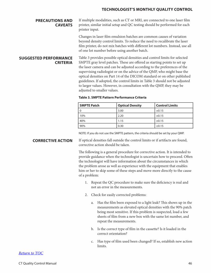
Table 3 provides possible optical densities and control limits for selected SMPTE gray level patches. These are offered as starting points to set up the laser camera and can be adjusted according to the preferences of the supervising radiologist or on the advice of the QMP, who might base the optical densities on Part 14 of the DICOM standard or on other published guidelines. If adopted, the control limits in Table 3 should not be adjusted to larger values. However, in consultation with the QMP, they may be adjusted to smaller values.
table 3. sMPte Pattern Performance Criteria
sMPte Patch optical density Control limits
0 3 00 ±0 15
10% 2 20 ±0 15
40% 1 15 ±0 15
90% 0 30 ±0 15
NOTE: If you do not use the SMPTE pattern, the criteria should be set by your QMP
If optical densities fall outside the control limits or if artifacts are found, corrective action should be taken.
The following is a general procedure for corrective action. It is intended to provide guidance when the technologist is uncertain how to proceed. Often the technologist will have information about the circumstances in which the problem arose as well as experience with the equipment that enables him or her to skip some of these steps and move more directly to the cause of a problem:
1. Repeat the QC procedure to make sure the deficiency is real and not an error in the measurements.
2. Check for easily corrected problems:
a. Has the film been exposed to a light leak? This shows up in the measurements as elevated optical densities with the 90% patch being most sensitive. If this problem is suspected, load a few sheets of film from a new box with the same lot number, and repeat the measurements.
b. Is the correct type of film in the cassette? Is it loaded in the correct orientation?
c. Has type of film used been changed? If so, establish new action limits.
PReCautions and Caveats
suggested PeRFoRManCe CRiteRia
CoRReCtive aCtion
Return to TOC
teChnologist’s MonthlY QualitY ContRol
CT Quality Control Manual 47
d. Is there dirt or debris in the cassette? This causes spots and marks on the film but does not affect optical densities.
e. Are the processor rollers clean? Dirty rollers cause streaking and must be kept clean.
3. The QMP responsible for film QC should be informed and asked to assist with problem troubleshooting.
4. If the problem cannot be resolved quickly, consult with the supervising radiologist to decide whether filming can continue while waiting for the problem to be corrected.
Return to TOC

teChnologist’s MonthlY QualitY ContRol
CT Quality Control Manual 48
C. Gray Level Performance of CT Scanner Acquisition Display Monitors
To ensure that images on the monitors of the CT scanner display the entire range of gray shades produced by the CT scanner.
This test must be performed monthly. Additionally, it is completed at the initiation of the QC program and whenever a significant change is made to the imager’s display monitors.
SMPTE Test Pattern or Equivalent
1. Display the test pattern on the imaging console. Set the display window width/level to the manufacturer-specified values for the SMPTE pattern. Do not set the window width/level by eye; doing so invalidates this procedure.
2. Examine the pattern to confirm that the gray level display on the imaging console is subjectively correct.
The visual impression should indicate an even progression of gray levels around the “ring” of gray level patches. Verify the following: a) the 5% patch can be distinguished in the 0/5% patch; b) the 95% patch can be distinguished in the 95/100% patch; and c) all the gray level steps around the ring of gray levels are distinct from adjacent steps (note that there are two adjacent squares that are both labelled as 50% which should appear to be equivalent). If these conditions are not met, do not adjust the display window width/level in an effort to correct the problem. Corrective action for the monitor is needed.
1. The monitor should be positioned so that there is no glare from room lighting.
2. As part of the preventative maintenance program of the CT scanner, the display monitors of the CT scanner should be checked at least annually.
1. Most often the problem is caused by incorrect adjustment of the monitor’s brightness and contrast. Excessive ambient lighting can cause the problem. Occasionally, components of the display may need recalibration, repair, or replacement.
2. Perform the manufacturer’s recommended procedure for monitor contrast and brightness adjustment. If there is any doubt about the correct procedure, or if the brightness and contrast controls are not accessible, have the QMP or service engineer make the adjustments.
obJeCtive
FReQuenCY
ReQuiRed eQuiPMent
test PRoCeduRe
PReCautions and Caveats
CoRReCtive aCtion
Return to TOC

ReFeRenCes
CT Quality Control Manual 49
1. Cody D. D., Stevens D. M., and Rong J., “CT quality control,” in Advances in Medical Physics – 2008, edited by Wolbarst A. B., Mossman K. L., and Hendee W. R. (Medical Physics, Madison, 2008), pp. 47–60.
2. DICOM Part 14: Grayscale Standard Display Function, National Electrical Manufacturers Association, Rosslyn, VA.
3. Gray JE, Lisk KG, Haddick DH, Members of the SMPTE Subcommittee on Recommended Practices for Medical Diagnostic Display Devices, et al: Test pattern for video displays and hard-copy cameras. Radiology 145:519–527, 1985
4. Gray JE, et al. Multiformat video and laser cameras: History, design considerations, acceptance testing, and quality control. Report of AAPM Diagnostic X-Ray Imaging Committee Task Group No. 1. Med Phys. 1993;20:427–438.
References
Return to TOC

aPPendiX
CT Quality Control Manual 50
Keeping orderly records of the QC tests is as important a task as carrying out the test procedures. If there is no record of the QC test results, or if the record is unintelligible, then they might as well not have been done. The following data sheets are formatted so that important information can appear in a compact, readable presentation. The data forms cover the following three areas of the CT equipment QC process:
A. Daily Technologist’s Quality Control
B. Weekly System Visual Checklist
C. Weekly Laser Film Quality Control
These data sheets should be stored in a safe place near the scanners for easy review. Copies of the QMP’s quarterly or annual QC report should be stored in the same location to facilitate data review and comparison.
All completed data forms should be reviewed and signed by the QMP at the quarterly or annual equipment review. At that time, suggestions for improvement of the CT equipment QC process should be considered.
appendix
Return to TOC
aPPendiX
CT Quality Control Manual 51
Qualified Medical Physicist’s Section
2017Computed Tomography
Qualified Medical Physicist’s Section
QUALITY CONTROL MANUAL

Contents
CT Quality Control Manual 52
ContentsRevisions 53
Introduction 54
Qualified Medical Physicist’s Annual Quality Control 56
References 84
Appendix 86
Revisions
CT Quality Control Manual 53
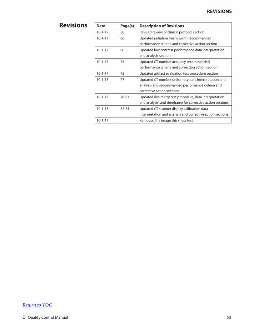
date Page(s) description of Revisions
10-1-17 58 Revised review of clinical protocol section
10-1-17 66 Updated radiation beam width recommended
performance criteria and corrective action section
10-1-17 68 Updated low contrast performance data interpretation
and analysis section
10-1-17 74 Updated CT number accuracy recommended
performance criteria and correction action section
10-1-17 75 Updated artifact evaluation test procedure section
10-1-17 77 Updated CT number uniformity data interpretation and
analysis and recommended performance criteria and
corrective action sections
10-1-17 78-81 Updated dosimetry test procedure, data interpretation
and analysis, and timeframe for corrective action sections
10-1-17 82-83 Updated CT scanner display calibration data
interpretation and analysis and corrective action sections
10-1-17 Removed the image thickness test
Revisions
Return to TOC
intRoduCtion
CT Quality Control Manual 54
The success of computed tomography (CT) imaging depends on the production of diagnostic quality images. To this end, the following tests should be performed annually by the qualified medical physicist (QMP). The tests are intended to ensure that the scanner is functioning as designed in all respects and to help ensure that the scanner is being utilized optimally.
Although equipment service engineers ensure the system is performing to within manufacturer’s specifications and technologists perform specified calibrations and QC, the QMP is uniquely qualified to perform certain tests and then analyze the data to determine which sets of specifications are relevant to a particular imaging problem. The QMP is able to bridge the gap between the technical aspects and clinical image quality of the system. The QMP testing allows the QMP to recognize equipment failures before they unacceptably degrade clinical images. The QMP can also perform tests to determine if imaging irregularities can be attributed to procedural or equipment errors. The QMP tests are also useful to help to understand the design strategy used in producing a particular CT scanner and recommend the equipment specifications most appropriate for a given practice.
Effective 12/1/2012, all facilities applying for accreditation must maintain a documented quality control (QC) program and must comply with the minimum frequencies of testing outlined in this manual. The ongoing QC program assesses relative changes in system performance as determined by the technologist, service engineer, QMP, or supervising physician. A QMP must be responsible for overseeing the equipment QC program and for monitoring performance upon installation and routinely thereafter. All facilities applying for accreditation or renewal must demonstrate compliance with the ACR QC requirements by including a copy of the Annual System Performance Evaluation Summary Form from the most recent Annual CT System Performance Evaluation for each unit at the facility. The evaluation should be dated within one year (and must be dated within 14 months) of the date that the facility submitted its application for ACR CT accreditation. Facilities should refer to their state and local regulations to remain in compliance when these are more restrictive. The determination of additional QC testing to be performed to comply with state and local regulations should be determined by a QMP.
It is the responsibility of the QMP conducting these tests to accurately convey test results in a written report, to make recommendations for corrective action according to the test results, and to review the results with the radiologists and technologists working on each scanner, when appropriate. Communicating test results and recommending corrective action are areas that should be given focused attention, as this is a vital interface between the technical assessment and the clinical practice. Corrective action should not be limited to repair of CT equipment by a qualified service engineer. It should also include recommendations concerning use of the CT scanner, protocol optimization, image processing, viewing conditions, and the QC program. The QMP should periodically review the results of the routine QC tests conducted by the technologist and make recommendations regarding these tests, if
introduction
Return to TOC
intRoduCtion
CT Quality Control Manual 55
appropriate. Furthermore, the QMP should participate in periodic reviews of the CT QC program as a whole in order to ensure that the program is meeting its objectives.
As previously stated, the QMP is responsible for helping to establish the continuous QC program for CT facilities. This program should include:
1. Water CT Number and Standard Deviation
2. Artifact Evaluation
3. Laser Printer Quality Control
4. Visual Checklist
The implementation of these tests should be determined by the QMP based on the specific needs of the facility and the scanner. The results of the QC program must be documented and reviewed annually by the QMP. These tests may be performed using the phantoms provided by the manufacturer, the ACR CT Accreditation Program (CTAP) Phantom, or another phantom deemed appropriate by the QMP. A QMP may determine that other tests, or more frequent testing, are required for any particular scanner.
Many CT manufacturers provide phantoms and software to automate performance of many of the tests listed below. Use of such programs is acceptable during the annual performance evaluations. However, at acceptance of the scanner, tests listed below should be performed independently of the software. Additionally, if it is to be used for the annual performance evaluation, the software must also be run at acceptance testing so that the results and conclusions can be verified. If the automated software was not tested by the QMP at acceptance testing, then it must be tested during the next annual QMP survey.
Many of the tests described below provide suggested acceptable limit criteria. These are provided as guidelines in the case that no other acceptable limit criteria exist; if the manufacturer has specified both testing conditions as well as acceptable limit criteria, the QMP may elect to use both those testing conditions and criteria as part of the QC program. In some cases, the manufacturer’s testing conditions (phantom, protocol) and specifications may take into account specific capabilities and functions of the scanner and therefore may be preferred.
Return to TOC
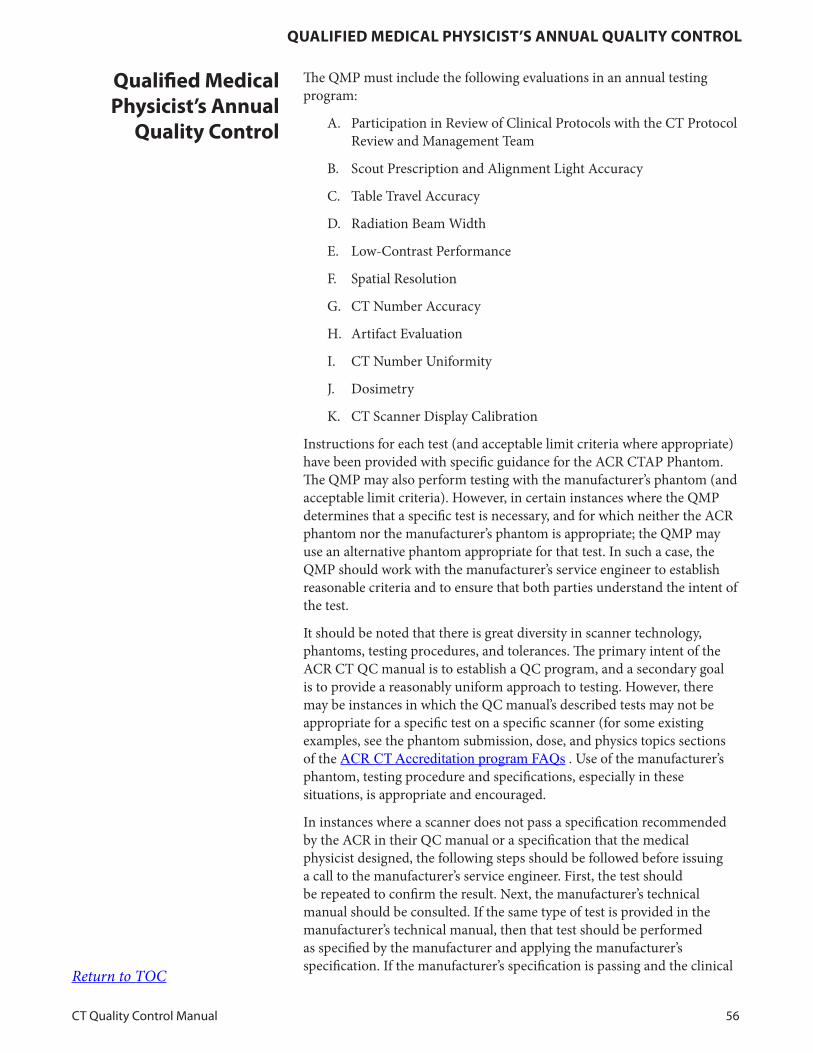
QualiFied MediCal PhYsiCist’s annual QualitY ContRol
CT Quality Control Manual 56
The QMP must include the following evaluations in an annual testing program:
A. Participation in Review of Clinical Protocols with the CT Protocol Review and Management Team
B. Scout Prescription and Alignment Light Accuracy
C. Table Travel Accuracy
D. Radiation Beam Width
E. Low-Contrast Performance
F. Spatial Resolution
G. CT Number Accuracy
H. Artifact Evaluation
I. CT Number Uniformity
J. Dosimetry
K. CT Scanner Display Calibration
Instructions for each test (and acceptable limit criteria where appropriate) have been provided with specific guidance for the ACR CTAP Phantom. The QMP may also perform testing with the manufacturer’s phantom (and acceptable limit criteria). However, in certain instances where the QMP determines that a specific test is necessary, and for which neither the ACR phantom nor the manufacturer’s phantom is appropriate; the QMP may use an alternative phantom appropriate for that test. In such a case, the QMP should work with the manufacturer’s service engineer to establish reasonable criteria and to ensure that both parties understand the intent of the test.
It should be noted that there is great diversity in scanner technology, phantoms, testing procedures, and tolerances. The primary intent of the ACR CT QC manual is to establish a QC program, and a secondary goal is to provide a reasonably uniform approach to testing. However, there may be instances in which the QC manual’s described tests may not be appropriate for a specific test on a specific scanner (for some existing examples, see the phantom submission, dose, and physics topics sections of the ACR CT Accreditation program FAQs . Use of the manufacturer’s phantom, testing procedure and specifications, especially in these situations, is appropriate and encouraged.
In instances where a scanner does not pass a specification recommended by the ACR in their QC manual or a specification that the medical physicist designed, the following steps should be followed before issuing a call to the manufacturer’s service engineer. First, the test should be repeated to confirm the result. Next, the manufacturer’s technical manual should be consulted. If the same type of test is provided in the manufacturer’s technical manual, then that test should be performed as specified by the manufacturer and applying the manufacturer’s specification. If the manufacturer’s specification is passing and the clinical
Qualified Medical Physicist’s annual
Quality Control
Return to TOC
QualiFied MediCal PhYsiCist’s annual QualitY ContRol
CT Quality Control Manual 57
images do not have a clinically significant image quality issue, corrective action is likely not needed. If the manufacturer-provided test result is outside the manufacturer’s specification, or there is believed to be a clinically significant degradation of image quality on the images used for diagnosis, service should be contacted.
Communication is key in these instances. The QMP should not just perform a test and inform the site that a service call is required; the QMP has a responsibility to provide clear communication regarding the following:
• The specific metric/issue under discussion
• The specific tests have been performed, including test objects
• The observed/measured results
• The specifications (e.g. manufacturer’s specifications) not being met
The site has the responsibility to ensure that effective and timely corrective action is performed and documented and that any comments or recommendations for quality improvement are addressed.
If the manufacturer does not provide specifications for a particular test, then the ACR or medical physicist’s test result should be benchmarked and monitored over time. Please note additional testing outside of the manufacturer specifications may not be supported by the manufacturer.
Return to TOC
QualiFied MediCal PhYsiCist’s annual QualitY ContRol
CT Quality Control Manual 58
A. Review of Clinical Protocols
1. To ensure that a selection of clinical protocols appropriately utilizes the scanner features, including kV, mAs, detector configuration, reconstructed scan width, pitch, reconstruction algorithm, and other features such as dose reduction options, including automatic exposure controls, iterative reconstruction techniques, etc.
2. To ensure that these protocols provide the diagnostic image quality required for the CT exam while minimizing radiation dose to the patient.
3. The review should be consistent with the AAPM Medical Physics Practice Guideline 1.a.: AAPM CT Protocol Management and Review Practice Guideline [4].
The frequency of review must be consistent with federal, state, and local laws and regulations. If there is no specific regulatory requirement, the frequency of protocol review for all protocols should be no less frequent than 24 months by the CT Protocol Review and Management team, as this may be a time-consuming undertaking. This review should include all new protocols added since the last review. However, the best practice would be to review a facility’s most frequently used protocols at least annually. It is the responsibility of the QMP and the CT Protocol Review and Management team to review annually at least the six protocols indicated in item 4 of the test procedure below.
None
1. A CT Protocol Review and Management Team, consisting at minimum of a radiologist, CT technologist, and QMP, must be responsible for development and review of all protocol parameter settings.
2. The CT Protocol Review and Management team develops and reviews all new or modified protocol settings for existing and new scanners to ensure that both image quality and radiation dose are appropriate.
3. The QMP need not be physically present at CT Protocol Review and Management Team meetings, but should be actively involved in the review process. While it may not be practical to have the QMP on-site for all discussions regarding protocol modification, their consult is critical to achieving good CT protocol performance. Phone, email, and perhaps text message conversations between visits are a reasonable compromise to ensure the radiologist, technologist, and QMP are able to discuss protocol modifications as necessary. The QMP protocol review need not be performed at the same time as any annual CT Physics testing, but should be performed with the frequency stated above.
4. For every facility there are protocols that are used frequently or could result in significant radiation doses. If a facility performs
obJeCtives
FReQuenCY
ReQuiRed eQuiPMent
test PRoCeduRe
Return to TOC
QualiFied MediCal PhYsiCist’s annual QualitY ContRol
CT Quality Control Manual 59
the following six clinical protocols, the CT Protocol Review and Management team must review these annually (or more frequently if required by state or local regulatory body). Facilities that do not perform all of the exams listed below must select additional protocols at their facility; either the most frequently performed or higher dose protocols, to total at least six for annual review. It is the responsibility of the QMP to review the six frequently used protocols annually. The six clinical protocols requiring annual review are:
f. Pediatric Head (1 year old) (if performed at the institution)
g. Pediatric Abdomen (5 year old; 40-50 lbs., or approx. 20 kg) (if performed at the institution)
h. Adult Head
i. Adult Abdomen (70 kg)
j. High Resolution Chest
k. Brain Perfusion (if performed at the institution)
5. Attention should be paid to acquisition and reconstruction parameters that should be influenced by the specific requirements of the diagnostic imaging task. These parameters include, but are not limited to, the following:
a. kV
b. mA (or mAs or effective mAs, depending on what each scanner uses)
c. Rotation time
d. Pitch
e. Detector configuration (or beam collimation)
f. Reconstructed image thickness and interval as well as any additional reformats such as coronal or sagittal plane
g. Reconstruction algorithm or kernels
h. Specific aspects of the acquisition that are demanded by the protocol, such as breath-hold time, which will be influenced by rotation time, collimation, pitch, etc. Similarly, contrast timing can also be affected by these parameters.
i. The facility should explicitly review the expected Volume Computed Tomography Dose Index (CTDIvol) values. For the limited set of protocols where reference values are available, the CTDIvol values should be compared to the reference values of the ACR CT Accreditation Program [2], AAPM CT Protocols [3], or other available reference values for the appropriate protocols.Return to TOC
QualiFied MediCal PhYsiCist’s annual QualitY ContRol
CT Quality Control Manual 60
NOTE: These reference values may be exceeded for individual patient scans (such as for very large patients, when the routine protocol is altered for a different clinical indication, or when the reference value only refers to a single pass in a multi-pass study).
6. Review the appropriate use of advanced dose reduction techniques if the use of such techniques is consistent with the goals of the exam. Depending on the capabilities of the scanner, consider use of the following if they are available:
a. Automatic exposure control (e.g., tube current modulation or kV selection) methods
b. Iterative reconstruction techniques
7. Review appropriate settings for patients of various sizes
a. Examples of this vary by manufacturer and include the Noise Index, Quality Reference mAs, Standard Deviation value, and other tube current modulation settings.
b. Special attention should be paid to how adjustments are made for pediatric patient groups.
8. Ensure that appropriate CTDI values result from these settings before patients are scanned with protocol. This can be done by reviewing prescan-reported values at the scanner interface or by scanning phantoms and reviewing postscan-reported values. It should be noted that console-predicted CTDIvol values given prior to CT localizer radiographs may not represent CTDIvol delivered during patient scan; some CT systems rely on patient data (i.e., localizer radiographs) for CTDIvol prediction.
9. After a new protocol is reviewed and pre-approved, the initial clinical scans should be reviewed, one case at a time, for:
a. Acceptable image quality for the diagnostic task required.
b. CTDI and/or DLP values should be checked and verified against expected values on patient images (or dose report) following initial scans.
c. Appropriate centering, especially for automatic exposure control (AEC) and pediatric patients.
If these criteria are met the protocol can be fully implemented.
NOTE: Manufacturer’s specifications may also be used.
Firm rules for clinical imaging are difficult to establish. The ACR has set several practice standards:
1. Reconstructed image thickness for standard Adult Head and standard Adult Abdomen should be ≤ 5 mm.
2. Appropriate rotation time for Pediatric Abdomen should be
data inteRPRetation and analYsis
Return to TOC
QualiFied MediCal PhYsiCist’s annual QualitY ContRol
CT Quality Control Manual 61
chosen to minimize motion and breath-hold.
Several other rules of thumb should be kept in mind, noting that there will be exceptions for specific protocols (e.g., helical head exams) and scanners. Please consult the manufacturer’s manual as well as protocols from the AAPM Alliance for Quality Computed Tomography for specific examples [3]:
1. The largest value of detector configuration or beam collimation (N × T, where N = the number of data channels used in a single axial scan, and T = the width of each data channel) available for the scan should be used whenever practical, as this improves dose efficiency. For example, 4 x 5 mm collimation is up to 30% more dose efficient than 2 x 5 mm collimation in axial mode with no image-quality penalty.
2. The facility may wish to be able to reconstruct both conventional thickness (e.g., 3 or 5 mm) as well as thinner images (e.g., 1 or 1.5 mm) under some circumstances (e.g., to obtain multiplanar reformats, etc.). In this case, the largest value of N × T that allows both to be accomplished should be used for a standard scan.
3. Lower kV settings should be considered for pediatric scans as well as those scans that use intravenous or oral contrast.
4. High-Resolution Chest (HRC) protocol should incorporate a sharp reconstruction kernel or filter. “Standard” reconstruction kernel or filter (or equivalent) is generally not appropriate.
5. HRC images should be axial, thin images separated by 10–20 mm. If HRC images are extracted from a helical chest scan, it must be verified that the chest scan is used appropriately for diagnosis.
6. Doses should be as low as necessary to accomplish the diagnostic task. For the two stated head protocols and the two stated abdomen protocols, the CTDIvol must not exceed ACR Pass/Fail levels and should not exceed ACR reference levels for the stated standard patient sizes (1-year-old head, 23 kg pediatric abdomen, adult head, 70 kg adult abdomen).
7. Develop relevant radiation dose thresholds during any new CT protocol design. This may include dose notification values (XR-25/XR-29), dose thresholds for the facility’s enterprise radiation dose monitoring systems, and/or other thresholds required to satisfy state and/or other accreditation body standards.
No changes should be made by the QMP without the knowledge and agreement of the radiologist and technologist responsible for protocol changes at the site. It is strongly recommended that the technologist responsible for protocol changes make the change. The QMP should provide assistance if necessary. Do not disable the CT dose estimate interface option; ensure that the dose information is displayed during the exam prescription phase.
PReCautions and Caveats
Return to TOC

QualiFied MediCal PhYsiCist’s annual QualitY ContRol
CT Quality Control Manual 62
The ACR standards must be met when applicable. Protocols should be designed to optimize dose and image quality. If an estimated dose value is above the relevant threshold for any routine clinical CT exam, investigate to determine if the dose was appropriate. If not, implement steps to ensure the appropriate dose will be used in the future.
Work related to adjustment(s) should begin as soon as a deficient protocol is identified.
ReCoMMended PeRFoRManCe CRiteRia
and CoRReCtive aCtion
tiMeFRaMe FoR CoRReCtive aCtion
Return to TOC
QualiFied MediCal PhYsiCist’s annual QualitY ContRol
CT Quality Control Manual 63
B. Scout Prescription and Alignment Light Accuracy
To verify that the incorporated alignment lights correctly indicate the scan position and that the scout image prescription correctly identifies the scan position.
Annually or after relevant service
A phantom that incorporates externally visible radiopaque fiducial markers or an image-center indication (ACR CTAP Phantom Module 1)
1. Using the alignment lights, carefully position the phantom to the radiopaque markers in all 3 orthogonal planes.
2. Zero the table location indication.
3. Scan the phantom in axial mode using a reconstructed scan width less than 2 mm or as thin as the scanner can produce in axial mode at the zero position. Use a technique appropriate to the phantom to allow accurate visualization of the fiducial markers; for most phantoms, the Adult Abdomen technique is adequate.
4. Scan the entire phantom in scout mode.
5. Magnify the image, if possible, and position a single slice at the location of the radiopaque fiducial markers.
6. Perform an axial scan using a reconstructed scan width less than 2 mm or as thin as the scanner can produce in axial mode.
NOTE: Manufacturer’s testing protocol and specifications may also be used.
1. Alignment Light Accuracy
a. View the image(s) collected in Step 3 above.
b. Verify that the visible radiopaque markers are visible in the reconstructed image.
• If multiple scans were performed, identify the image in which the markers are best visualized. The image position reported by the scanner is the axial misalignment.
2. Scout Prescription Accuracy
a. View the image(s) collected in Step 6 above.
b. Verify that the visible radiopaque markers are visible in the reconstructed image.
• If multiple scans were performed, identify the image in which the markers are best visualized. If the initial position was set to zero, then the image position reported by the scanner is the axial misalignment. Otherwise, the difference between the scout position and the axial scan position is the axial misalignment.
obJeCtive
FReQuenCY
ReQuiRed eQuiPMent
test PRoCeduRe
data inteRPRetation and analYsis
Return to TOC
QualiFied MediCal PhYsiCist’s annual QualitY ContRol
CT Quality Control Manual 64
It is beneficial to scan at 0.5 mm increments to 2 mm above and below the zero position. This will enable identification of the best-aligned image without having to rescan the phantom.
The location of scans positioned either with the alignment lights or with the scout prescription should be accurate to within 2 mm. If an error exceeding 2 mm is identified, service should be called.
NOTE: If the QMP elects to use the manufacturer’s specifications as the limit criteria, the scan technique must be identical to the manufacturer’s recommendation (including reconstructed image thickness and reconstruction kernel or filter).
Within 30 days
PReCautions and Caveats
ReCoMMended PeRFoRManCe CRiteRia
and CoRReCtive aCtion
tiMeFRaMe FoR CoRReCtive aCtion
Return to TOC
QualiFied MediCal PhYsiCist’s annual QualitY ContRol
CT Quality Control Manual 65
C. Table Travel Accuracy
To verify that the patient table translates as indicated.
Annually or after relevant service
A phantom with two sets of external fiducial markers of known separation (for example, ACR CTAP Phantom Modules 1 and 4)
1. If possible, add weight to the tabletop to simulate the weight of an average patient.
2. Using the alignment light, carefully position the phantom such that the first set of fiducial markers is in the axial plane.
3. Zero the table position indication.
4. Move the table to the second set of external fiducial markers.
5. Record the table position.
6. Translate the table to full extension and return to the first set of fiducial markers.
7. Record the new table position.
NOTE: Manufacturer’s testing protocol and specifications may also be used.
1. Compare the distance between the fiducial markers as determined by the table travel to the known distance.
2. Compare the first fiducial marker table position to the new position recorded after the table extension and return.
Some scanners have specific limitations on the extent of table travel, and under these limitations, the performance specifications are valid. Scanner-specific limitations must be noted.
The table translation accuracy and return to a fixed position should be accurate to within 2 mm.
If the table travel does not meet the above specifications, consult the manufacturer’s specifications that note the limitations related to valid travel. Then, ensure that the maximum travel has not been exceeded. The service engineer should then be contacted to make adjustments as necessary.
NOTE: If the QMP elects to use the manufacturer’s specifications as the limit criteria, the scan technique must be identical to the manufacturer’s recommendation (including reconstructed image thickness and reconstruction kernel or filter).
Within 30 days
obJeCtive
FReQuenCY
ReQuiRed eQuiPMent
test PRoCeduRe
data inteRPRetation and analYsis
PReCautions and Caveats
ReCoMMended PeRFoRManCe CRiteRia
and CoRReCtive aCtion
tiMeFRaMe FoR CoRReCtive aCtion
Return to TOC
QualiFied MediCal PhYsiCist’s annual QualitY ContRol
CT Quality Control Manual 66
D. Radiation Beam Width
To measure the radiation beam width and to assess its relationship to the nominal collimated beam width.
NOTE: It is expected that the measured radiation beam will be wider than the nominal collimated beam width. The purpose of this test is to evaluate the extent to which the radiation beam width is greater than the nominal collimated beam width.
Annually or after relevant service
1. External radiation detector (CR plate, self-developing film, OSL strip, electronic test tool)
2. Flat radiation attenuator (1/8-in thick lead or 15-cm thick acrylic)
• Number of Data Channels (N): the number of data channels used in a single axial scan.
• Z-axis Collimation (T): the width of each data channel along the z-axis. In multidetector row (multislice) CT scanners, several detector elements may be grouped together to form one data channel.
• Total Nominal Radiation Beam Width (N × T): The product of N × T is the total nominal collimated beam width.
1. Place the radiation attenuator on the table unless contraindicated by the test device being used.
2. Place the external radiation detector on the flat attenuator.
3. Adjust the table height so that the external radiation detector is at the isocenter. Each unique N × T product that is used clinically should be measured, adjusting table position as appropriate for the detector being used.
NOTE: Manufacturer’s specifications may also be used.
Using a method appropriate for the external radiation detector used, determine the actual radiation beam width for each unique N × T product (that is, a scanner may have beam widths of 1.25, 5, 10, 15, 20, and 40 mm, but multiple N × T permutations for achieving those beam widths; each beam width need only be tested once). For film, OSL, and CR-based measurements, determination should be made at the full width at half maximum (FWHM).
You may use the manufacturer’s specifications as the performance criteria. These specifications can usually be found in the manufacturer’s technical specifications documentation. If the radiation beam width is outside of manufacturer’s specifications using their specified procedure, service should be contacted for corrective action.
However, if these specifications are not readily available, then the measured radiation beam width should be accurate to within 3 mm or 30% of the
obJeCtive
FReQuenCY
ReQuiRed eQuiPMent
iMPoRtant deFinitions
test PRoCeduRe
data inteRPRetation and analYsis
ReCoMMended PeRFoRManCe CRiteRia
and CoRReCtive aCtion
Return to TOC
QualiFied MediCal PhYsiCist’s annual QualitY ContRol
CT Quality Control Manual 67
total nominal collimated beam width (N × T), whichever is greater. If the radiation beam width does not meet these criteria, an effort should be made to obtain the specifications from the manufacturer. If these are not able to be obtained, then service should be notified to evaluate the radiation beam width. The measured total collimation should never be less than the nominal total collimation.
NOTE: If the QMP elects to use the manufacturer’s specifications as the limit criteria, the scan technique must be identical to the manufacturer’s recommendation (including reconstructed image thickness and reconstruction kernel or filter).
Within 30 daysTIMEFRAME FOR CORRECTIVE ACTION
Return to TOC
QualiFied MediCal PhYsiCist’s annual QualitY ContRol
CT Quality Control Manual 68
E. Low-Contrast Performance
To verify that the low-contrast performance of clinical protocols is adequate for diagnosis.
Annually or after relevant service
A phantom that incorporates low-contrast targets of known contrast (Module 2 of the ACR CTAP Phantom)
NOTE: If the site does not possess the ACR CTAP Phantom for the physicist to perform annual low-contrast performance QC, then an alternative phantom may be used. The site should establish a correlation of performance between the on-site CT phantom and the ACR CTAP Phantom for each scanner so that it can be demonstrated that each scanner meets the ACR criteria for low-contrast performance. The ACR CTAP Phantom must be available to the site at the time of initial accreditation (to submit phantom images for review) and for reaccreditation every three years. The site should perform the low-contrast performance QC as described for the ACR CTAP Phantom and then, using its on-site phantom and the same protocols, establish low-contrast performance baseline values for ongoing QC monitoring.
1. Align the phantom.
2. Perform clinical scans covering the low-contrast section of the phantom. Any Auto mA feature must be disabled; use a mAs value appropriate for an average-sized patient. At a minimum, the scans performed should include the following:
a. Adult Head (average)
b. Pediatric Head (1 year old)
c. Adult Abdomen (70 kg)
d. Pediatric Abdomen (5 years old; 40–50 lb., approx. 20 kg)
NOTE: Manufacturer’s testing protocol and specifications may also be used. View each series and determine the image that provides the best low-contrast performance.
1. Place a Region of Interest (ROI ≈ 100 mm2) over the largest representative target (e.g., the 25-mm diameter target [see Figure 1]) and record the mean value.
2. Place an ROI adjacent to the target (i.e., in the background adjacent to the target [see Figure 4]) and record both the mean and the standard deviation.
3. Calculate the Contrast-Noise Ratio (CNR) as: CNR = (target mean – background mean) / (background std. dev.)
OBJECTIVE
FREQUENCYREQUIRED EQUIPMENT
test PRoCeduRe
data inteRPRetation and analYsis
Return to TOC
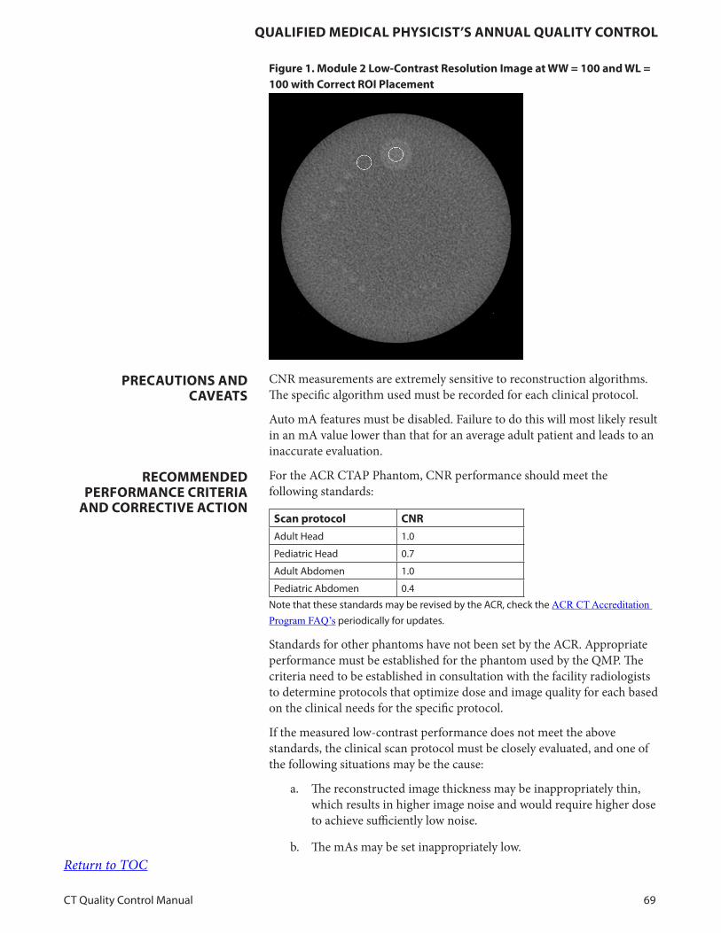
QualiFied MediCal PhYsiCist’s annual QualitY ContRol
CT Quality Control Manual 69
Figure 1. Module 2 low-Contrast Resolution image at WW = 100 and Wl = 100 with Correct Roi Placement
CNR measurements are extremely sensitive to reconstruction algorithms. The specific algorithm used must be recorded for each clinical protocol.
Auto mA features must be disabled. Failure to do this will most likely result in an mA value lower than that for an average adult patient and leads to an inaccurate evaluation.
For the ACR CTAP Phantom, CNR performance should meet the following standards:
scan protocol CnR
Adult Head 1 0
Pediatric Head 0 7
Adult Abdomen 1 0
Pediatric Abdomen 0 4
Note that these standards may be revised by the ACR, check the ACR CT Accreditation Program FAQ’s periodically for updates
Standards for other phantoms have not been set by the ACR. Appropriate performance must be established for the phantom used by the QMP. The criteria need to be established in consultation with the facility radiologists to determine protocols that optimize dose and image quality for each based on the clinical needs for the specific protocol.
If the measured low-contrast performance does not meet the above standards, the clinical scan protocol must be closely evaluated, and one of the following situations may be the cause:
a. The reconstructed image thickness may be inappropriately thin, which results in higher image noise and would require higher dose to achieve sufficiently low noise.
b. The mAs may be set inappropriately low.
PReCautions and Caveats
ReCoMMended PeRFoRManCe CRiteRia
and CoRReCtive aCtion
Return to TOC

QualiFied MediCal PhYsiCist’s annual QualitY ContRol
CT Quality Control Manual 70
c. The pitch may be too high for the clinical requirements, especially in those systems that set pitch and mAs independently.
NOTE: If the QMP elects to use the manufacturer’s specifications as the limit criteria, the scan technique must be identical to the manufacturer’s recommendation (including reconstructed image thickness and reconstruction kernel or filter).
As soon as feasible upon determination of suboptimal performance.tiMeFRaMe FoR CoRReCtive aCtion
Return to TOC
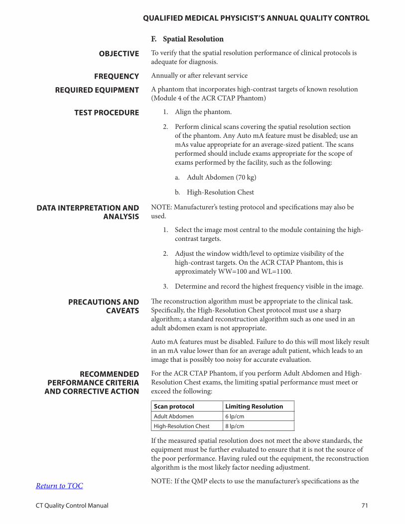
QualiFied MediCal PhYsiCist’s annual QualitY ContRol
CT Quality Control Manual 71
F. Spatial Resolution
To verify that the spatial resolution performance of clinical protocols is adequate for diagnosis.
Annually or after relevant service
A phantom that incorporates high-contrast targets of known resolution (Module 4 of the ACR CTAP Phantom)
1. Align the phantom.
2. Perform clinical scans covering the spatial resolution section of the phantom. Any Auto mA feature must be disabled; use an mAs value appropriate for an average-sized patient. The scans performed should include exams appropriate for the scope of exams performed by the facility, such as the following:
a. Adult Abdomen (70 kg)
b. High-Resolution Chest
NOTE: Manufacturer’s testing protocol and specifications may also be used.
1. Select the image most central to the module containing the high-contrast targets.
2. Adjust the window width/level to optimize visibility of the high-contrast targets. On the ACR CTAP Phantom, this is approximately WW=100 and WL=1100.
3. Determine and record the highest frequency visible in the image.
The reconstruction algorithm must be appropriate to the clinical task. Specifically, the High-Resolution Chest protocol must use a sharp algorithm; a standard reconstruction algorithm such as one used in an adult abdomen exam is not appropriate.
Auto mA features must be disabled. Failure to do this will most likely result in an mA value lower than for an average adult patient, which leads to an image that is possibly too noisy for accurate evaluation.
For the ACR CTAP Phantom, if you perform Adult Abdomen and High-Resolution Chest exams, the limiting spatial performance must meet or exceed the following:
scan protocol limiting Resolution
Adult Abdomen 6 lp/cm
High-Resolution Chest 8 lp/cm
If the measured spatial resolution does not meet the above standards, the equipment must be further evaluated to ensure that it is not the source of the poor performance. Having ruled out the equipment, the reconstruction algorithm is the most likely factor needing adjustment.
NOTE: If the QMP elects to use the manufacturer’s specifications as the
obJeCtive
FReQuenCY
ReQuiRed eQuiPMent
test PRoCeduRe
data inteRPRetation and analYsis
PReCautions and Caveats
ReCoMMended PeRFoRManCe CRiteRia
and CoRReCtive aCtion
Return to TOC

QualiFied MediCal PhYsiCist’s annual QualitY ContRol
CT Quality Control Manual 72
limit criteria, the scan technique must be identical to the manufacturer’s recommendation (including reconstructed image thickness and reconstruction kernel or filter).
Immediately upon determination of suboptimal performancetiMeFRaMe FoR CoRReCtive aCtion
Return to TOC
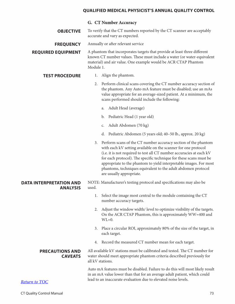
QualiFied MediCal PhYsiCist’s annual QualitY ContRol
CT Quality Control Manual 73
G. CT Number Accuracy
To verify that the CT numbers reported by the CT scanner are acceptably accurate and vary as expected.
Annually or after relevant service
A phantom that incorporates targets that provide at least three different known CT number values. These must include a water (or water-equivalent material) and air value. One example would be ACR CTAP Phantom Module 1.
1. Align the phantom.
2. Perform clinical scans covering the CT number accuracy section of the phantom. Any Auto mA feature must be disabled; use an mAs value appropriate for an average-sized patient. At a minimum, the scans performed should include the following:
a. Adult Head (average)
b. Pediatric Head (1 year old)
c. Adult Abdomen (70 kg)
d. Pediatric Abdomen (5 years old; 40–50 lb., approx. 20 kg)
3. Perform scans of the CT number accuracy section of the phantom with each kV setting available on the scanner for one protocol (i.e. it is not required to test all CT number accuracies at each kV for each protocol). The specific technique for these scans must be appropriate to the phantom to yield interpretable images. For most phantoms, techniques equivalent to the adult abdomen protocol are usually appropriate.
NOTE: Manufacturer’s testing protocol and specifications may also be used.
1. Select the image most central to the module containing the CT number accuracy targets.
2. Adjust the window width/ level to optimize visibility of the targets. On the ACR CTAP Phantom, this is approximately WW=400 and WL=0.
3. Place a circular ROI, approximately 80% of the size of the target, in each target.
4. Record the measured CT number mean for each target.
All available kV stations must be calibrated and tested. The CT number for water should meet appropriate phantom criteria described previously for all kV stations.
Auto mA features must be disabled. Failure to do this will most likely result in an mA value lower than that for an average adult patient, which could lead to an inaccurate evaluation due to elevated noise levels.
obJeCtive
FReQuenCY
ReQuiRed eQuiPMent
test PRoCeduRe
data inteRPRetation and analYsis
PReCautions and Caveats
Return to TOC
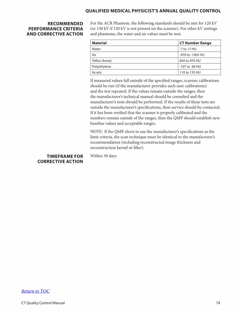
QualiFied MediCal PhYsiCist’s annual QualitY ContRol
CT Quality Control Manual 74
For the ACR Phantom, the following standards should be met for 120 kV (or 130 kV if 120 kV is not present on the scanner). For other kV settings and phantoms, the water and air values must be met.
Material Ct number Range
Water -7 to +7 HU
Air -970 to -1005 HU
Teflon (bone) 850 to 970 HU
Polyethylene -107 to -84 HU
Acrylic 110 to 135 HU
If measured values fall outside of the specified ranges, scanner calibrations should be run (if the manufacturer provides such user calibrations) and the test repeated. If the values remain outside the ranges, then the manufacturer’s technical manual should be consulted and the manufacturer’s tests should be performed. If the results of these tests are outside the manufacturer’s specifications, then service should be contacted. If it has been verified that the scanner is properly calibrated and the numbers remain outside of the ranges, then the QMP should establish new baseline values and acceptable ranges.
NOTE: If the QMP elects to use the manufacturer’s specifications as the limit criteria, the scan technique must be identical to the manufacturer’s recommendation (including reconstructed image thickness and reconstruction kernel or filter).
Within 30 days
ReCoMMended PeRFoRManCe CRiteRia
and CoRReCtive aCtion
tiMeFRaMe FoR CoRReCtive aCtion
Return to TOC
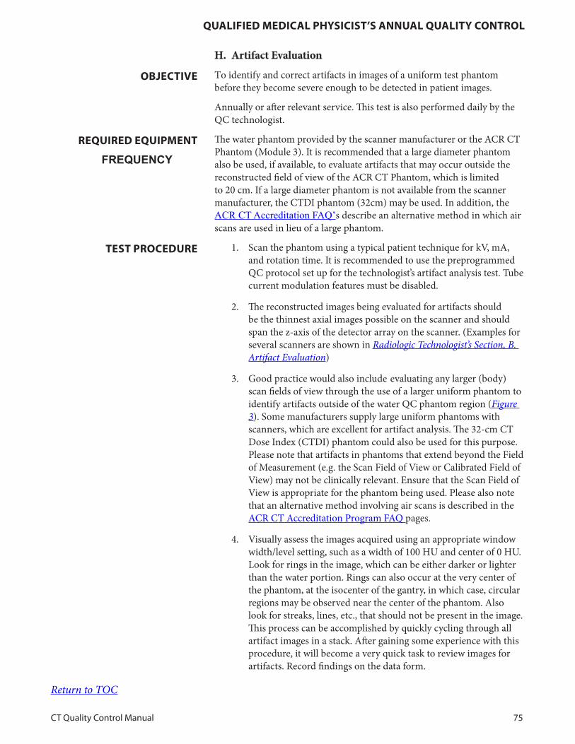
QualiFied MediCal PhYsiCist’s annual QualitY ContRol
CT Quality Control Manual 75
H. Artifact Evaluation
To identify and correct artifacts in images of a uniform test phantom before they become severe enough to be detected in patient images.
Annually or after relevant service. This test is also performed daily by the QC technologist.
The water phantom provided by the scanner manufacturer or the ACR CT Phantom (Module 3). It is recommended that a large diameter phantom also be used, if available, to evaluate artifacts that may occur outside the reconstructed field of view of the ACR CT Phantom, which is limited to 20 cm. If a large diameter phantom is not available from the scanner manufacturer, the CTDI phantom (32cm) may be used. In addition, the ACR CT Accreditation FAQ’s describe an alternative method in which air scans are used in lieu of a large phantom.
1. Scan the phantom using a typical patient technique for kV, mA, and rotation time. It is recommended to use the preprogrammed QC protocol set up for the technologist’s artifact analysis test. Tube current modulation features must be disabled.
2. The reconstructed images being evaluated for artifacts should be the thinnest axial images possible on the scanner and should span the z-axis of the detector array on the scanner. (Examples for several scanners are shown in Radiologic Technologist’s Section, B. Artifact Evaluation)
3. Good practice would also include evaluating any larger (body) scan fields of view through the use of a larger uniform phantom to identify artifacts outside of the water QC phantom region (Figure 3). Some manufacturers supply large uniform phantoms with scanners, which are excellent for artifact analysis. The 32-cm CT Dose Index (CTDI) phantom could also be used for this purpose. Please note that artifacts in phantoms that extend beyond the Field of Measurement (e.g. the Scan Field of View or Calibrated Field of View) may not be clinically relevant. Ensure that the Scan Field of View is appropriate for the phantom being used. Please also note that an alternative method involving air scans is described in the ACR CT Accreditation Program FAQ pages.
4. Visually assess the images acquired using an appropriate window width/level setting, such as a width of 100 HU and center of 0 HU. Look for rings in the image, which can be either darker or lighter than the water portion. Rings can also occur at the very center of the phantom, at the isocenter of the gantry, in which case, circular regions may be observed near the center of the phantom. Also look for streaks, lines, etc., that should not be present in the image. This process can be accomplished by quickly cycling through all artifact images in a stack. After gaining some experience with this procedure, it will become a very quick task to review images for artifacts. Record findings on the data form.
obJeCtive
FREQUENCYReQuiRed eQuiPMent
test PRoCeduRe
Return to TOC
QualiFied MediCal PhYsiCist’s annual QualitY ContRol
CT Quality Control Manual 76
NOTE: Manufacturer’s testing protocol and specifications may also be used.
1. Visually assess the acquired images. Cycle through all artifact images in a stack.
2. Adjust the window width/level to optimize visibility of the phantom material. On the ACR CTAP Phantom as well as the water phantom, this is approximately WW=100 and WL=0.
3. Inspect each image for evidence of artifacts, including streaks and rings, cupping, or capping.
Some scanners will demonstrate a noticeable bright ring just inside the phantom border. This is sometimes from the automatic corrections a scanner makes when a “routine head” scan protocol is performed and the scanner anticipates a skull will be present. This artifact may be excluded from consideration.
Tube current modulation features must be disabled. Failure to do this will most likely result in an mA value lower than for an average adult patient, which could lead to an inaccurate evaluation due to elevated noise levels.
Ring artifacts typically indicate detector or data channel imbalance. Repeating the air-calibration procedure, if the manufacturer provides such user calibrations (Radiologic Technologist A. Water CT Number and Standard Deviation, Step 2 of test procedure), may smooth out these imbalances if the air-calibration process is set to correct only a subset of parameter combinations each time it is performed. If the ring artifacts are not corrected after performing several air-calibration routines, or if such calibrations are not user-level activity, service of the scanner should be arranged. All artifacts observed in the images should be noted and reported. Any artifact that mimics pathology or that could obscure pathology must be reported immediately. A decision regarding the clinical significance of the artifact must be made in conjunction with the radiologist, including whether the scanner may continue to be used in a full or limited capacity. Artifacts that are subclinical should be corrected within 30 days or before they reach a level of clinical significance, whichever comes first.
The QC team should develop a history or file of standard artifact images of the water phantom. See Radiologic Technologist’s Section, B. Artifact Evaluation, for more details. These images should be reviewed periodically to ensure the subtle artifacts that can be removed by repair are properly addressed and that subtle artifacts present when the scanner is functioning properly are ignored to avoid unnecessary downtime and expense.
NOTE: If the QMP elects to use the manufacturer’s specifications as the limit criteria, the scan technique must be identical to the manufacturer’s recommendation (including phantom, scan protocol, reconstructed image thickness, and reconstruction kernel or filter).
Clinically severe artifacts must be addressed before the scanner is used. Subclinical artifacts may be carefully monitored, and service might be scheduled to avoid impacting the clinical exam schedule. Artifacts must be addressed within a maximum period of 30 days.
data inteRPRetation and analYsis
PReCautions and Caveats
ReCoMMended PeRFoRManCe CRiteRia
and CoRReCtive aCtion
tiMeFRaMe FoR CoRReCtive aCtion
Return to TOC
QualiFied MediCal PhYsiCist’s annual QualitY ContRol
CT Quality Control Manual 77
I. CT Number Uniformity
To identify and correct nonuniformities in the CT numbers in images of a uniform test phantom before they become severe enough to impact patient diagnosis.
Annually or after relevant service.
The water phantom provided by the scanner manufacturer or the ACR CT Phantom (Module 3).
1. Scan the phantom using a typical patient technique for kV, mA, and rotation time. Tube current modulation features must be disabled. It is recommended to use the preprogrammed QC protocol set up for the technologist’s artifact analysis test.
2. Reconstruct the images to a clinically relevant image thickness and reconstruction algorithm.
NOTE: Manufacturer’s testing protocol and specifications may also be used.
1. In the centrally located image, place an ROI with an area equal to approximately 1% of the phantom area at the center and at 3, 6, 9, and 12 o’clock positions around the periphery of the phantom, leaving approximately one ROI diameter between the outer edge of the ROI and phantom border.
2. Record the mean of all five ROIs.
3. Determine the difference between the mean value of each peripheral ROI and the central ROI.
Some scanners will demonstrate a noticeable bright ring just inside the phantom border. This is from the automatic corrections a scanner makes when it anticipates a skull will be present. This may be excluded from consideration by placing the peripheral ROIs at a full ROI diameter from the edge of the phantom.
Excessive noise can make interpretation difficult, so it is recommended that at relatively smooth reconstruction algorithm (such as used for brain or abdomen) be used.
The difference between the mean CT value of each peripheral ROI and the center ROI should not exceed 5 HU, and must not exceed 7 HU. If the difference exceeds the established criteria, then the test should be repeated to be certain that the failure is real and not an error in the procedure. If the error persists, the scanner should be recalibrated, and then the QC test repeated. If the results continue to remain outside of the control limits, then service should be contacted for corrective action within 30 days.
NOTE: If the QMP elects to use the manufacturer’s specifications as the limit criteria, the scan technique must be identical to the manufacturer’s recommendation (including reconstructed image thickness and reconstruction kernel or filter).
obJeCtive
FReQuenCY
ReQuiRed eQuiPMent
test PRoCeduRe
data inteRPRetation and analYsis
PReCautions and Caveats
ReCoMMended PeRFoRManCe CRiteRia
and CoRReCtive aCtion
Return to TOC
QualiFied MediCal PhYsiCist’s annual QualitY ContRol
CT Quality Control Manual 78
J. Dosimetry
To measure doses for verification of scanner performance and to allow for calculation of dosimetric quantities relevant to patient exam estimates.
Annually or after relevant service, including, but not limited to, x-ray tube replacement or alignment, collimator service, bowtie replacement, or alignment or generator service.
1. Calibrated electrometer and CTDI pencil ionization chamber (10- or 15-cm long)
2. Head CTDI phantom: 16-cm diameter
3. Body CTDI phantom: 32-cm diameter
• Z-axis Collimation (T): the width of the tomographic section along the z-axis imaged by one data channel. In multidetector row (multislice) CT scanners, several detector elements may be grouped together to form one data channel.
• Number of Data Channels (N): the number of tomographic sections imaged in a single axial scan.
• Total Nominal Radiation Beam Width (N × T): The product of N × T is the total nominal collimated beam width. Note that the actual beam width is likely to be wider than this (see Procedure E: Radiation Beam Width).
• Increment (I): the table increment per axial scan or the table increment per rotation of the x-ray tube in a helical scan.
• Pitch, P = I/(N × T)
1. Align the phantom (16 cm or 32 cm as appropriate for the scan protocol) such that the axis of the phantom is at the isocenter of the scanner and centered in all three planes.
a. For adult head protocols, position the 16-cm phantom in the head holder or as heads are scanned clinically.
b. For adult abdomen protocols, position the 32-cm phantom directly on the scan table.
c. For pediatric head protocols, position the 16-cm phantom directly on the scan table.
d. For pediatric abdomen protocols, position the 16- or 32-cm phantom directly on the scan table.
Note: For pediatric (40-50 pounds) abdomen protocols, some CT scanners report CTDIvol using the 16 cm phantom, while others use the 32 cm phantom. The physicist should select the phantom (16- or 32-cm) that is used by the scanner to report CTDIvol.
2. Connect the pencil chamber to the electrometer and insert the pencil chamber into the central hole in the phantom. Ensure that
obJeCtive
FReQuenCY
ReQuiRed eQuiPMent
iMPoRtant deFinitions
test PRoCeduRe
Return to TOC

QualiFied MediCal PhYsiCist’s annual QualitY ContRol
CT Quality Control Manual 79
all other holes (those at 3, 6, 9, and 12 o’clock positions) are filled with acrylic rods.
3. Clinical dose evaluation. At a minimum, the scans performed should include the following protocols:
a. Adult Routine Brain
b. Pediatric Routine Brain (1 year old)
c. Pediatric Routine Abdomen (5 years old; 40-50 lb., approx. 20 kg)
d. Adult Routine Abdomen (70 kg)
4. Using the appropriate protocol, prepare to acquire a single axial slice at the center of the phantom with no table increment. If the protocol is normally scanned helically, convert this to an axial scan while keeping the remaining technical parameters the same. In addition, see notes below about converting effective mAs or mAs/image to mA, time, and pitch.
All CTDI dose information must be acquired using axial scans.
In multislice CT, CTDI is a function of detector configuration. It is imperative that the detector configuration and total beam width used matches the site’s clinical protocol (N × T) as closely as possible.
If the N × T value used for dosimetry does not exactly match the clinical value, be sure to modify the table increment used in the calculation to yield the same pitch value as used clinically.
5. Measurements and Data Collection:
a. Record the CTDIvol reported by the scanner.
b. Position the phantom as described above.
c. Place the dosimeter probe in the central position.
d. Make one exposure in axial mode using the clinical N × T configuration. If this configuration is not accessible in axial mode, use the N × T configuration most closely matching the clinical value.
e. Record the exposure value reported by electrometer (usually in units of mR).
f. Repeat the scan two more times and record the exposure.
g. Repeat steps d–f above with the probe positioned at the 12 o’clock location.
h. Repeat steps a–g above for each clinical protocol to be tested.
6. If required by local regulation, hold constant kVp, rotation time, and N × T and then measure CTDI100 as mA is varied.
Return to TOC
QualiFied MediCal PhYsiCist’s annual QualitY ContRol
CT Quality Control Manual 80
NOTE: Manufacturer’s specifications may also be used.
Clinical dose estimation
Average the 3 measurements done for each chamber position for each protocol.
1. Calculate the values CTDI100, periphery and CTDI100, center as CTDI100 = (f*CF *E*L)/(N*T) where: f = conversion factor (from exposure to dose in air, use 8.7 mGy/R) (from air kerma to dose in air, use 1.0 mGy/mGy) CF = calibration or correction factor for electrometer E = average measured value (exposure or air kerma) L = active length of pencil ion chamber (typically 100 mm) N = actual number of data channels used during one axial acquisition T = width of each channel (Note that N × T = nominal radiation beam width)
2. Calculate CTDIw = ((1/3) CTDI100, center) + ((2/3) CTDI100, periphery)
3. Calculate CTDIvol = CTDIw((N × T)/ I) = CTDIw / pitch Where I = the table increment per rotation (table speed) of the clinical acquisition. If N and T do not match the clinical detector configuration, calculate the value of I that would yield the clinical pitch for use in the equation.
4. Compare the measured CTDIvol to the values reported by the scanner.
NOTE: It is imperative to verify the phantom used by the manufacturer for the CTDIvol values reported by the scanner. For all head scans (adult and pediatric) the 16-cm phantom is used. For most adult body scans, the 32-cm dosimetry phantom is used. For pediatric body scans performed on some scanners, the 32-cm dosimetry phantom is used in reporting CTDIvol, while others use the 16-cm dosimetry phantom for reporting. (Since the physicist should use the CTDI phantom (16 or 32 cm) that is used by the scanner to report CTDIvol, the measured CTDIvol value is directly comparable to the reported value.) Still, others base their choice of phantom on the patient size parameter selected. For example, “small” may use a 16-cm phantom, while “large” may use a 32-cm phantom. This variation is why it is important to verify which phantom is being used to report CTDI on the scanner for each protocol. Differences in phantoms can introduce errors of approximately a factor of 2 for scans made using the 16-cm dosimetry phantom versus those using the 32-cm phantom. Note that some scanners display phantom size next to the CTDIvol value or on the dose reporting page.
5. Compare the measured CTDIvol to the reference and Pass/Fail
data inteRPRetation and analYsis
Return to TOC
QualiFied MediCal PhYsiCist’s annual QualitY ContRol
CT Quality Control Manual 81
values of the ACR CT Accreditation Program.
For large values of N × T, approaching or greater than the length of the ionization chamber, significant portions of the scatter tails may not be measured. Therefore, it may be necessary to mathematically correct for them to more closely estimate actual CTDIvol.
See the Geleijns et al reference for a full discussion and recommendations for scanners with N × T greater than the length of the CTDI ionization chamber [18].
NOTE: Each manufacturer may use different terms to describe tube output for helical scans. These include:
1. mA, rotation time, and pitch (GE and Toshiba)
2. effective mAs (eff. mAs) = (mA × rotation time)/Pitch (Siemens)
3. mAs/image = (mA × rotation time)/Pitch (Philips)
For the latter two terms, the calculation to convert from effective mAs to mA is: mA = (effective mAs × Pitch) / rotation time or mA = (mAs/image × Pitch) / rotation time
Repeated measurements from year to year should not differ by more than 5% for identical protocols. All values measured in the scanner characterization section should be within 20% of the values reported by the scanner. Measured values not within 20% of the values reported by the scanner should be investigated to determine the cause. Measured values not within 20% of the values reported by the scanner, noting the caveats above, should be brought to the attention of the service engineer.
Measured CTDIvol values should not exceed the ACR CTAP Reference Values, and must not exceed the ACR CTAP Pass/Fail Values.
NOTE: If the QMP elects to use the manufacturer’s specifications as the limit criteria, the scan technique must be identical to the manufacturer’s recommendation (including reconstructed image thickness and reconstruction kernel or filter).
Measured values not within 20% of the values reported by the scanner should be investigated further. In some cases, or under certain scan conditions, the manufacturer’s specifications allow larger deviations between measured and displayed value (up to ± 30 or 40%). In these cases, the testing should be repeated under the manufacturer’s specified conditions and using the manufacturer’s specified tolerances. If these are exceeded, then service may be called.
For CTDIvol values exceeding ACR CTAP limits, efforts to reduce dose by modifying protocol settings should begin as soon as possible, in consultation with the technologist and the radiologist.
PReCautions and Caveats
ReCoMMended PeRFoRManCe CRiteRia
and CoRReCtive aCtion
tiMeFRaMe FoR CoRReCtive aCtion
Return to TOC
QualiFied MediCal PhYsiCist’s annual QualitY ContRol
CT Quality Control Manual 82
K. CT Scanner Display Calibration
To ensure that images on the CT scanner monitors display the entire range of gray shades produced by the CT scanner.
This test must be performed annually. Additionally, it must be completed at the initiation of the QC program and whenever a significant change is made to the scanner’s display monitors.
1. SMPTE Test Pattern (see Figure 1 in Radiologic Technologist’s Section) or equivalent
2. Calibrated photometer with adequate precision, accuracy, and calibration to effectively measure to 0.1 cd/m2 significance
1. Display the test pattern on the imaging console. Set the display window width/level to the manufacturer-specified values for the pattern. Do not set the window width/level by eye; doing so invalidates this procedure.
2. Examine the pattern to confirm that the gray level display on the imaging console is subjectively correct.
a. Review the line pair patterns in the center and at each of the corners.
b. Review each black-white transition.
c. Look for any evidence of “scalloping” (loss of bit depth) or geometric distortion.
3. Use the photometer to measure the maximum and minimum monitor brightness (0% and 100% steps).
4. Measure additional steps within the pattern to establish a response curve.
5. Measure the brightness near the center of the monitor and near all four corners (or all four sides, depending on the test pattern used).
6. In the scan room, displays used for interventional/biopsy procedures must provide good low-contrast visualization in typically bright room conditions. Consider repeating the above on all CT image acquisition displays.
NOTE: Manufacturer’s specifications may also be used.
Visual Analysis1. The visual impression should be an even progression of gray levels
around the ring of gray level patches. All gray level steps in the ring of gray levels must be visibly distinct from adjacent steps.
2. The 5% patch must be visible in the 0/5% patch; the 95% patch must be visible in the 95/100% patch.
3. If these conditions are not met, do not adjust the display window width/level in an effort to correct the problem. Corrective action for the monitor is needed.
obJeCtive
FReQuenCY
ReQuiRed eQuiPMent
test PRoCeduRe
data inteRPRetation and analYsis
Return to TOC
QualiFied MediCal PhYsiCist’s annual QualitY ContRol
CT Quality Control Manual 83
4. Ensure that the finest line pair pattern can be visualized in the center and at each of the four corners.
5. There must not be visible bleed-through in either direction of all black-white transitions. All high-contrast borders must be straight, not jagged.
6. There must not be scalloping of the gray scale. There must not be geometric distortion in the image.
Photometric Analysis1. The maximum brightness should be greater than or equal to 100
cd/m2, and the luminance ratio (LR’) should be greater than equal to 100.[9,TG-18]
2. The measured response curve data should be compared visually to the prior year’s result, verifying no significant change to the curve.
3. Calculate the nonuniformity of the display brightness using the equation
% difference = 200 × (Lmax – Lmin) / (Lmax + Lmin),
where Lmax and Lmin are the maximum and minimum measured luminance values of the five measurements made in step 5 above, respectively. The nonuniformity should not exceed 30% for CRTs and should be within ±15% for flat-panel displays.
1. The monitor should be positioned so that there is no glare from room lighting.
2. As part of the periodic maintenance program of the CT scanner, the CT scanner display monitors should be checked and recalibrated at least annually.
1. Most often the problem is caused by incorrect adjustment of the monitor’s brightness and contrast. Excessive ambient lighting can aggravate this problem. Occasionally, components of the display may need recalibration, repair, or replacement.
2. Perform the manufacturer’s recommended procedure for monitor contrast and brightness adjustment. If there is any doubt about the correct procedure or if the brightness and contrast controls are not accessible, have the QMP or service engineer make the adjustments.
3. If after corrective action is attempted and the monitor does not meet these specifications, additional action should be determined by the lead interpreting physician in consultation with a QMP. If the monitor is exclusively used for image acquisition and localization and not for clinical image interpretation, then it may be determined that it is acceptable to continue to use it based on this consultation.
PReCautions and Caveats
CORRECTIVE ACTION
Return to TOC
ReFeRenCes
CT Quality Control Manual 84
1. American College of Radiology. The ACR and American Society of Neuroradiology Statement on CT Protocols and Radiation Dose. Available at: http://gm.acr.org/SecondaryMainMenuCategories/NewsPublications/FeaturedCategories/CurrentACRNews/archive/ACRASNRStatementonCTProtocols.aspx. Accessed June 29, 2012.
2. American College of Radiology CT Accreditation Program, link: http://www.acraccreditation.org/Modalities/CT.
3. American Association of Physicists in Medicine. The Alliance for Quality Computed Tomography CT Protocols, link: http://www.aapm.org/pubs/CTProtocols/.
4. AAPM Medical Physics Practice Guideline 1.a: AAPM CT Protocol Management and Review Practice Guideline published in the Journal of Applied Clinical Medical Physics (JACMP). 2013;14(5) . [ISBN: 978-1-936366-27-9]; http://www.aapm.org/pubs/MPPG/documents/MPPG1a.pdf .
5. Cody D. D., Stevens D. M., and Rong J., “CT quality control,” in Advances in Medical Physics – 2008, edited by Wolbarst A. B., Mossman K. L., and Hendee W. R. (Medical Physics, Madison, 2008), pp. 47–60.
6. DICOM Part 14: Grayscale Standard Display Function, National Electrical Manufacturers Association, Rosslyn, VA.
7. Gray JE, Lisk KG, Haddick DH, Members of the SMPTE Subcommittee on Recommended Practices for Medical Diagnostic Display Devices, et al: Test pattern for video displays and hard-copy cameras. Radiology. 1985;145:519–527.
8. Gray JE, et al. Multiformat video and laser cameras: History, design considerations, acceptance testing, and quality control. Report of AAPM Diagnostic X-Ray Imaging Committee Task Group No. 1. Med Phys. 1993; 20:427–438.
9. American Association of Physicists in Medicine. On-Line Report No. 03: Assessment of Display Performance for Medical Imaging Systems. College Park, MD, AAPM; 2005.
10. American Association of Physicists in Medicine. AAPM Report 39: Specification and Acceptance Testing of Computed Tomography Scanners. New York, NY, AAPM; May 1993:17–18.
11. American Association of Physicists in Medicine. Quality Assurance for Computed-Tomography Simulators and the Computed Tomography-Simulation Process: Report of the AAPM Radiation Therapy Committee Task Group No. 66. AAPM; September 2003.
References
Return to TOC
ReFeRenCes
CT Quality Control Manual 85
12. American Association of Physicists in Medicine. Medical CT and Ultrasound: Current Technology and Applications: Proceedings of AAPM Summer School on Applications of CT and Ultrasound. AAPM; 1995.
13. Institute of Physics and Engineering in Medicine. IPEM Report 91: Recommended Standards for the Routine Performance Testing of Diagnostic X-Ray Imaging Systems. IPEM; 2005.
14. ImPACT group. Information Leaflet No. 1: CT Scanner Acceptance Testing, Version 1.02. ImPACT group; 2001.
15. McNitt-Gray MF. AAPM/RSNA physics tutorial for residents: topics in CT/ radiation dose in CT. RadioGraphics. November–December 2002;22(6):1541–53.
16. Mathieu KB, McNitt-Gray MF, Zhang D, Kim HJ, Cody DD. Precision of dosimetry-related measurements obtained on current multidetector computed tomography scanners. Med Phys. August 2010;37(8):4102–9.
17. NEMA XR 2502010, Computed Tomography Dose Check. Rosslyn, Va.: Medical Imaging & Technology Alliance (MITA)/National Electrical Manufacturers Association, 2010.
18. Geleijns J, Salvadó Artells M, de Bruin PW, Matter R, Muramatsu Y, McNitt-Gray MF. Computed tomography dose assessment for a 160-mm wide, 320 detector row, cone beam CT scanner. Physics in Medicine and Biology. 2009;54(10):3141-59.
Return to TOC

aPPendiX
CT Quality Control Manual 86
The Medical Physicist CT Survey Report may be used to record the data obtained during the annual medical physics survey.
A. Medical Physicist Annual System Performance Evaluation Summary Form
appendix
Return to TOC