Embed Size (px)
Citation preview

ALFOplus80Access Link Full Outdoor
User manual
MN.00288.E - 004

The information contained in this handbook is subject to change without notice.Property of Siae Microelettronica. All rights reserved according to the law and according to the internationalregulations. No part of this document may be reproduced or transmitted in any form or by any means,electronic or mechanical, without written permission from Siae Microelettronica S.p.A.Unless otherwise specified, reference to a Company, name, data and address produced on the screen dis-played is purely indicative aiming at illustrating the use of the product.MS-DOS®, MS Windows® are trademarks of Microsoft Corporation.HP®, HP OpenView NNM and HP–UX are Hewlett Packard Company registered trademarks.UNIX is a UNIX System Laboratories registered trademark.Oracle® is a Oracle Corporation registered trademark.Linux term is a trademark registered by Linus Torvalds, the original author of the Linux operating system.Linux is freely distributed according the GNU General Public License (GPL). Other products cited here in are constructor registered trademarks.

MN.00288.E - 004 1
Contents
Section 1.USER GUIDE 5
1 DECLARATION OF CONFORMITY ............................................................................... 5
2 FIRST AID FOR ELECTRICAL SHOCK AND SAFETY RULES .......................................... 62.1 FIRST AID FOR ELECTRICAL SHOCK..................................................................... 6
2.1.1 Artificial respiration .................................................................................. 62.1.2 Treatment of burns .................................................................................. 6
2.2 SAFETY RULES .................................................................................................. 72.3 CORRECT DISPOSAL OF THIS PRODUCT (WASTE ELECTRICAL & ELECTRONIC
EQUIPMENT) .................................................................................................... 9
3 PURPOSE AND STRUCTURE OF THE MANUAL............................................................103.1 PURPOSE OF THE MANUAL.................................................................................103.2 AUDIENCE BASIC KNOWLEDGE ..........................................................................103.3 STRUCTURE OF THE MANUAL .............................................................................10
Section 2.DESCRIPTIONS AND SPECIFICATION 13
4 ABBREVIATION LIST................................................................................................134.1 ABBREVIATION LIST .........................................................................................13
5 SYSTEM PRESENTATION ..........................................................................................155.1 GENERAL.........................................................................................................155.2 APPLICATIONS .................................................................................................15
5.2.1 Functionality ..........................................................................................165.3 PROGRAMMABILITY ..........................................................................................16
6 TECHNICAL SPECIFICATION ....................................................................................196.1 INTERNATIONAL STANDARD ..............................................................................196.2 MAIN CHARACTERISTICS...................................................................................19
6.2.1 Available frequency.................................................................................196.2.2 Transmitter characteristics .......................................................................20

2 MN.00288.E - 004
6.2.3 Receiver characteristics ...........................................................................216.3 LINE INTERFACE CHARACTERISTICS ...................................................................22
6.3.1 Ethernet optical interface characteristics ....................................................226.4 POWER SUPPLY AND CABLE ...............................................................................23
6.4.1 PoE injector ...........................................................................................246.4.1.1 PoE Injector functionality...........................................................246.4.1.2 Code Table ..............................................................................256.4.1.3 Electrical Characteristics............................................................256.4.1.4 Connectors..............................................................................256.4.1.5 Description of alarms ................................................................25
6.5 WAVEGUIDE FLANGE ........................................................................................266.6 MECHANICAL CHARACTERISTICS........................................................................266.7 SURGE AND LIGHTNING PROTECTION .................................................................266.8 ENVIRONMENTAL CONDITIONS ..........................................................................26
7 EQUIPMENT DESCRIPTION ......................................................................................277.1 GENERAL.........................................................................................................27
7.1.1 Block diagram ........................................................................................277.1.2 Baseband processor ................................................................................30
7.1.2.1 Firmware ................................................................................307.1.2.2 Web Lct ..................................................................................30
7.1.3 RF Transceiver unit .................................................................................307.1.4 Switch for Ethernet ports .........................................................................317.1.5 Synchronisation unit (SETS) .....................................................................327.1.6 Bandwidth & modulation ..........................................................................337.1.7 ATPC interaction .....................................................................................33
7.2 LOOPS ............................................................................................................347.3 RATE LIMITING AND INGRESS FILTER POLICING ..................................................35
7.3.1 Rate limiting ..........................................................................................357.4 ETHERNET PERFORMANCE MONITORING - RMON..................................................357.5 RMON COUNTERS.............................................................................................357.6 ADVANCED STATISTIC MONITORING FOR SERVICES AND PRIORITY COUNTERS .......36
7.6.1 Priority RMON.........................................................................................377.6.2 Service RMON ........................................................................................37
7.7 SYNCHRONISM.................................................................................................377.8 SOURCES OF SYNCHRONISM .............................................................................397.9 PROVIDE SYNCHRONISM TO EXTERNAL EQUIPMENT .............................................417.10 G.8264 SSM – SYNCHRONISATION STATUS MESSAGE...........................................41
7.10.1 SSM on Ethernet Interfaces......................................................................43
Section 3.INSTALLATION 45
8 INSTALLATION OF ALFOplus80................................................................................458.1 GENERAL INFORMATION TO BE READ BEFORE THE INSTALLATION..........................458.2 GENERAL.........................................................................................................468.3 ELECTRICAL WIRING.........................................................................................468.4 CONNECTIONS TO THE SUPPLY MAINS ................................................................468.5 GROUNDING CONNECTION ................................................................................47

MN.00288.E - 004 3
8.5.1 Mounting instruction of grounding cable KIT ICD00072F (Universal, No tools) .488.6 REQUIRED TOOLS FOR MOUNTING (NOT SUPPLIED) .............................................498.7 INSTALLATION PROCEDURE...............................................................................498.8 INSTALLATION ONTO THE POLE .........................................................................49
8.8.1 ODU......................................................................................................498.8.1.1 1+0 ODU with integrated antenna ..............................................49
8.9 ACCESSORIES FOR INSTALLATION .....................................................................568.9.1 Installation procedure of optical box ..........................................................57
8.10 USER CONNECTORS..........................................................................................638.10.1 Auxiliary connector .................................................................................638.10.2 RJ45 connector.......................................................................................658.10.3 Optical connector ....................................................................................758.10.4 Optical SFP mounting procedure ...............................................................788.10.5 Optical SFP unmounting procedure ............................................................78
Section 4.LINE-UP 85
9 LINE-UP OF ALFOplus80 ..........................................................................................859.1 GENERAL.........................................................................................................859.2 SWITCH ON .....................................................................................................859.3 ALARM LED CHECK ...........................................................................................869.4 CONNECTION PROCEDURE.................................................................................869.5 INITIALIZATION PROCEDURE .............................................................................909.6 OPTIMIZING ANTENNA ALIGNMENT WITH RX MEASUREMENT ................................959.7 ODU ACCESSING AND REMOTE MANAGEMENT......................................................979.8 COMMISSIONING MEASURES FOR ETHERNET TRAFFIC ..........................................98
9.8.1 Ethernet connection stability ....................................................................989.9 FIRMWARE UPDATE ..........................................................................................99
9.9.1 Scope....................................................................................................999.9.2 Procedure of firmware update...................................................................99
9.10 BACKUP FULL EQUIPMENT CONFIGURATION WITHOUT POSSIBILITY OF MODIFYING THE PARAMETERS...........................................................................................1019.10.1 Scope..................................................................................................1019.10.2 Backup/restore configuration using SCT ...................................................1019.10.3 Backup/restore configuration using WEBLCT .............................................102
Section 5.MAINTENANCE 105
10 ALFOplus80 ALARMS AND LOOPS...........................................................................10510.1 GENERAL.......................................................................................................10510.2 ALARMS ........................................................................................................105
10.2.1 Alarm indications ..................................................................................10510.2.2 SCT/WebLCT displayed alarms................................................................106

4 MN.00288.E - 004
11 ALFOplus80 MAINTENANCE AND TROUBLESHOOTING ...........................................10911.1 GENERAL.......................................................................................................10911.2 MAINTENANCE ...............................................................................................109
11.2.1 Periodical checks ..................................................................................10911.2.2 Corrective maintenance (troubleshooting) ................................................110
11.3 TROUBLESHOOTING .......................................................................................110
Section 6.PROGRAMMING AND SUPERVISION 111
12 PROGRAMMING AND SUPERVISION.......................................................................11112.1 GENERAL.......................................................................................................11112.2 SUPERVISION THROUGH ETHERNET..................................................................111
12.2.1 General ...............................................................................................11212.2.2 Configurability ......................................................................................11612.2.3 Address ...............................................................................................11612.2.4 Restore supervisioning access mode ........................................................116
Section 7.COMPOSITION 117
13 COMPOSITION OF OUTDOOR UNIT.........................................................................11713.1 GENERAL.......................................................................................................11713.2 ODU PART NUMBER ........................................................................................117
Section 8.LISTS AND SERVICES 119
14 LIST OF FIGURES ...................................................................................................119
15 LIST OF TABLES .....................................................................................................123
16 ASSISTANCE SERVICE............................................................................................125

MN.00288.E - 004 5
Section 1.USER GUIDE
1 DECLARATION OF CONFORMITY
SIAE MICROELETTRONICA Via Buonarroti, 21 - Cologno (MI) - Italy
DECLARESTHAT THE PRODUCTS
Digital Radio Relay System ALFOplus80(used as a stand-alone product or in conjunction with AGS-H Indoor unit)
comply with the essential requirements of article 3 of the R&TTE Directive (1999/05/EC)and therefore is marked:
The following standards have been applied:
EN 60950-1:2006 and EN 60950-22:2006“Safety of information technology equipment”
EN 301 489-4 v.1.4.1 (2009-5)“Electromagnetic compatibility and Radio spectrum Matters (ERM); ElectroMag-netic Compatibility (EMC) standard for radio equipment and services; Part 4: Specific conditions for fixedradio links and ancillary equipment and services”
ETSI EN 302 217-3 V1.3.1 (2009-7)“Fixed Radio Systems; Characteristics and requirements for point-to-point equipment and antennas; Part3: Equipment operating in frequency bands where both frequency coordinated or uncoordinated deploy-ment might be applied; Harmonized EN covering essential requirements of Article 3.2 of R&TTE Directive”
The equipment makes use of non-harmonized frequency bands. Following the requirementsof the R&TTE Directive (article 12) and the relevant decision of the EC, in term of classifica-tion of Radio Equipment and Telecommunications Terminal Equipment and associated iden-tifiers, the transmitting equipment shall carry the 'class 2' identifier:
Cologno Monzese, 26/11/2012 On behalf of SIAE MICROELETTRONICA Chairman and Executive Officer Alberto Mascetti

6 MN.00288.E - 004
2 FIRST AID FOR ELECTRICAL SHOCK AND SAFETY RULES
2.1 FIRST AID FOR ELECTRICAL SHOCK
Do not touch the bare hands until the circuit has been opened. pen the circuit by switching off the lineswitches. If that is not possible protect yourself with dry material and free the patient from the con-ductor.
2.1.1 Artificial respiration
It is important to start mouth resuscitation at once and to call a doctor immediately. suggested procedurefor mouth to mouth resuscitation method is described in the Tab.1.
2.1.2 Treatment of burns
This treatment should be used after the patient has regained consciousness. It can also be employed whileartificial respiration is being applied (in this case there should be at least two persons present).
Warning
• Do not attempt to remove clothing from burnt sections
• Apply dry gauze on the burns
• Do not apply ointments or other oily substances.

MN.00288.E - 004 7
Tab.1 - Artificial respiration
2.2 SAFETY RULES
When the equipment units are provided with the plate, shown in Fig.1, it means that they contain compo-nents electrostatic charge sensitive.
Step Description Figure
1
Lay the patient on his back with his arms parallel to the body. If the patient is laying on an inclined plane, make sure that his
stomach is slightly lower than his chest. Open the patients mouth and check that there is no foreign matter in mouth (den-
tures, chewing gum, etc.).
2
Kneel beside the patient level with his head. Put an hand under the patient’s head and one under his neck.
Lift the patient’s head and let it recline backwards as far as possible.
3
Shift the hand from the patient’s neck to his chin and his mouth, the index along his jawbone, and keep the other fingers
closed together.
While performing these operations take a good supply of oxy-gen by taking deep breaths with your mouth open
4
With your thumb between the patient’s chin and mouth keep his lips together and blow into his nasal cavities
5
While performing these operations observe if the patient’s chest rises. If not it is possible that his nose is blocked: in that case open the patient’s mouth as much as possible by pressing on his chin with your hand, place your lips around his mouth and blow into his oral cavity. Observe if the patient’s chest heaves. This second method can be used instead of the first even when the patient’s nose is not obstructed, provided his
nose is kept closed by pressing the nostrils together using the hand you were holding his head with. The patient’s head must
be kept sloping backwards as much as possible.
6
Start with ten rapid expirations, hence continue at a rate of twelve/fifteen expirations per minute. Go on like this until the patient has regained conscious–ness, or until a doctor has as-
certained his death.

8 MN.00288.E - 004
Fig.1 - Components electrostatic charge sensitive indication
In order to prevent the units from being damaged while handling, it is advisable to wear an elasticized band(Fig.2) around the wrist ground connected through coiled cord (Fig.3).
Fig.2 - Elasticized band
Fig.3 - Coiled cord
The units showing the label, shown in Fig.4, include laser diodes and the emitted power can be dangerousfor eyes; avoid exposure in the direction of optical signal emission.
Fig.4 - Laser indication

MN.00288.E - 004 9
2.3 CORRECT DISPOSAL OF THIS PRODUCT (WASTE ELECTRICAL & ELECTRONIC EQUIPMENT)
(Applicable in the European Union and other European countries with separate collection systems). Thismarking of Fig.5 shown on the product or its literature, indicates that it should not be disposed with otherhousehold wastes at the end of its working life. To prevent possible harm to the environment or humanhealth from uncontrolled waste disposal, please separate this from other types of wastes and recycle itresponsibly to promote the sustainable reuse of material resources. Household users should contact eitherthe retailer where they purchased this product, or their local government office, for details of where andhow they can take this item for environmentally safe recycling. Business users should contact their supplierand check the terms and conditions of the purchase contract. This product should not be mixed with othercommercial wastes for disposal.
Fig.5 - WEEE symbol - 2002/96/CE EN50419

10 MN.00288.E - 004
3 PURPOSE AND STRUCTURE OF THE MANUAL
3.1 PURPOSE OF THE MANUAL
The purpose of this manual consists in providing for the user information which permit to operate andmaintain the ALFOplus80 radio equipment.
Warning: This manual does not include information relevant to the SCT/WebLCT management programwindows and relevant application. They will provided by the program itself as help–on line.
3.2 AUDIENCE BASIC KNOWLEDGE
The following knowledge and skills are required to operate the equipment:
• a basic understanding of microwave transmission
• installation and maintenance experience on digital radio system
• a good knowledge of IP networks and routing policy.
3.3 STRUCTURE OF THE MANUAL
The manual is subdivided into sections each of them developing a specific topic entitling the section.
Each section consists of a set of chapters, enlarging the main subject master.
Section 1 – User Guide
It provides the information about the main safety rules and expounds the purpose and the structure of themanual.
Section 2 – Description and specifications
It describes a general overview of the typical applications and in particular of the whole radio equipment.
Section 3 – Installation
The mechanical installation procedures are herein set down as well as the user electrical connections.
The content of the tool kit (if supplied) is also listed.

MN.00288.E - 004 11
Section 4 – Line–Up
Line–up procedures are described as well as checks to be carried out for the equipment correct operation.The list of the instruments to be used and their characteristics are also set down.
Section 5 – Maintenance
The routine maintenance actions are described as well as fault location procedures in order to identify thefaulty unit and to re–establish the operation after its replacement with a spare one.
Section 6 – Programming and supervision
The ALFOplus80 radio is programmed and supervised using different software tools. Some of them are al-ready available, some other will be available in the future. This section lists the tools implemented andindicates if descriptions are already available.
Each description of software tools is supplied in a separated manual.
Section 7 – Composition
Position, part numbers of the components the equipment consist of, are shown in this section.
Section 8 – Indexes and services
Lists of figures, list of tables and assistance service are shown in this section.

12 MN.00288.E - 004

MN.00288.E - 004 13
Section 2.DESCRIPTIONS AND SPECIFICATION
4 ABBREVIATION LIST
4.1 ABBREVIATION LIST
What follows is a list of acronyms used in this handbook:
- ACM Adaptive Code Modulation
- AGC Automatic Gain Control
- ATPC Automatic Transmitted Power Control
- BBP Base Band Processor
- BER Bit Error Rate
- CBS Committed Burst Size
- CF Coupling Flag
- CIR Committed Information Rate
- CoS Class of Service
- CVID Customer VLAN Identifier
- DSCP Differentiated Serviced Code Point
- EBS Excess Burst Size
- EIR Excess Information Rate
- ELP Ethernet Line Protection
- EVC Ethernet Virtual Connection
- FPGA Field Programmable Gate-Array
- IP ToS Type of Service IP
- LACP Link Aggregation Control Protocol or Link Trunk
- LAN Local Area Network

14 MN.00288.E - 004
- LLF Link Loss Forwarding
- LNA Low Noise Amplifier
- MAC Media Access Control
- MDI Medium Dependent Interface
- MDX Medium Dependent Interface Crossover
- MEF Metro Ethernet Forum
- NE Network Element
- OAM Operation Administration and Maintenance
- ODU Outdoor Unit
- PLL Phase Locked Loop
- POE Power Over Ethernet
- PToS Priority Type of Service
- QAM Quadrature Amplitude Modulation
- RED Random Early Drop
- RF Radio Frequency
- RSSI Received Signal Strength Indicator
- RX Direction from antenna to user
- SCT Subnetwork Craft Terminal
- SNMP Simple Network Management Protocol
- SVID Service VLAN Identifier
- TX Direction from user to antenna
- UNI User Network Interface
- VCO Voltage Controlled Oscillator
- VID Virtual Lan Identifier
- VLAN Virtual LAN
- WEBLCT WEB Local Craft Terminal
- WRR Weighted Round Robin

MN.00288.E - 004 15
5 SYSTEM PRESENTATION
5.1 GENERAL
ALFOplus80 is a full-outdoor and full IP digital radio system for point-to-point applications, used for highcapacity Ethernet transport (1 Gbps). The frequency range is from 71 GHz up to 86 GHz with fixed modu-lation (4QAM).
There are two available versions for ALFOplus80: Gigabit Electrical (GE) and Gigabit Optical (GO). This doc-ument provides a general overview of ALFOplus80 (Access Link Full Outdoor) radio equipment.
The ODU ALFOplus80 combined with AGS-H can transport native TDM traffic (STM-1 and E1). See AGS-Hmanual (MN.00298.E) for more details.
5.2 APPLICATIONS
ALFOplus80 is the ideal solution in urban environments for all carrier-class applications in which the typicalrequirements are Ethernet connections:
• full IP radio, providing the foundation for a leading edge network
• fully integrable with 3G, 4G, LTE nodes and backhaul
• ideal for a fast and flexible evolution towards full IP network
• complementary solutions for fiber deploy
• last mile fiber extension for business customers
• ISP high capacity and performance, for LAN-to-LAN connections
• emergency wireless links
• zero footprint applications
ALFOplus80 doesn’t need any indoor unit; power supply can be directly by POE+ through the data cableor through a dedicated auxiliary port. It’s available 1+0 radio system configurable via software followingtwo versions of ALFOplus80:
• Electrical Gigabit Version
- LAN1 - 1x10/100/1000BaseT traffic and/or supervision port with clock, synchronism recoveryand PoE
- LAN2 - 1x10/100/1000BaseT supervision and/or traffic port with clock, synchronism recoveryand PoE
• Optical Gigabit Version
- LAN1 - 1x100/1000BaseX traffic and/or supervision port with clock and synchronism recovery
- LAN2 - 1x10/100/1000BaseT supervision and/or traffic port with clock, synchronism recoveryand PoE.
Depending on software configuration made for each port Lan1 and Lan2.

16 MN.00288.E - 004
5.2.1 Functionality
SIAE ALFOplus80 radio system presents the same functionalities of a “switch” (Layer 2).
ALFOplus80 radio system is able to forward Virtual LAN in transparent way or to manage incoming trafficfiltering it or tagging it or dividing it in different VLAN. Traffic Flow control and Traffic priority capabilitiescan be enabled or disabled via LAN software. ALFOplus80 Ethernet switch functionality:
• MAC switching, Learning and Ageing
• Jumbo Frame up to 10.5 kbytes
• IEEE 802.1Q VLAN/IEEE 802.1ad VLAN stacking QinQ and VLAN rewriting
• LLF (Link Loss Forwarding)
• IEEE 802.3x Flow control
• QoS management on 4 queue based on 802.1P/DSCP
• Queue Packet with Drop Policy: 8421WRR, Strict Priority, Strict3, Strict 3 and 2
• IEEE 802.1d STP (Spanning Tree Protocol)
• IEEE 802.1w RSTP (Rapid Spanning Tree Protocol)
• IEEE 802.1ag OAM/ITU-T y.1731 (Operation, Administration and Maintenance)
• IEEE 802.3af PoE - Power over Ethernet 1
• Advanced Statistics Monitoring Based VLAN and Priority
• Ethernet Performance Monitoring - RMon
5.3 PROGRAMMABILITY
ALFOplus80 radio system is managed by a microprocessor that makes it totally programmable via softwareto perform the following functions:
• radio link management
- capacity and modulation
- Link ID
- Tx frequency and power
- ATPC (Automatic Transmission Power Control)
• main management
- IP port configurable and supervisioning
- routing table
- remote element list
- alarm severity configuration (modify alarm)
- user manager (password, user, SNMP login)
• operation and maintenance
- permanent Tx Off
- Rx signal threshold alarm
- performance monitoring (G.828, Rx PWR, Tx PWR, Ethernet Statistic Rmon) with alarm thresh-old
1 With dispensation to maximum power.

MN.00288.E - 004 17
- S/N measure
- LAN summary, statistic basis on port, VLAN or Priority
- back-up/restore configuration
- software update
- report&logger maintenance (inventory, faul, commands)
- SNTP alignment
• manual operations (depends on timeout)
- Tx transmitter OFF
- force switch synch
- radio BER test
- baseband loop
- Ethernet port loop
• Ethernet switch management and functionalities
• synchronisation
More links can be managed by LAN access (see Section 6. PROGRAMMING AND SUPERVISION)

18 MN.00288.E - 004
Fig.6 - ALFOplus80 front/side view

MN.00288.E - 004 19
6 TECHNICAL SPECIFICATION
6.1 INTERNATIONAL STANDARD
The equipment complies with the following international standard:
• EN 301 489-4 for EMC
• ITU-R F.2006 and CEPT Recommendation T/R 05-07 for RF channel arrangement
• EN 302 217 for digital point to point fixed radio
• EN 300 132-2 Characteristics of power supply
• EN 300 019 Climatic Characteristics (Operation: class 3.2 for IDU and class 4.1 for ODU; storage:class 1.2; transport: class 2.3)
• EN 60950 for operator Safety
• IEEE 802.3 for Ethernet interfaces
• ITU-T G.8261 for timing and synchronization aspects in packet networks.
6.2 MAIN CHARACTERISTICS
The reported values are guaranteed if not specifically defined otherwise.
6.2.1 Available frequency
- Frequency band see Tab.2
Tab.2 - Frequency band
- Modulation scheme 4QAM
- Capacity see Tab.3
- RF filter range Wide Filter Option see Tab.4
- Transceiver tuning range see Tab.4
Frequency range (GHz)
Duplex spacing (GHz) Reference recommendation
71 - 86 10 ITU-R F.2006 - CEPT T/R 05-07

20 MN.00288.E - 004
Tab.3 - Net Radio Throughput in Mbit/s versus channel bandwidth for ALFO plus80 equipment
Tab.4 - Filter sub-bands for ALFOplus80
The frequency carrier limits are given in Tab.5.
Tab.5 - 71.0 - 86.0 GHz band - Go-return: 10 GHz frequency carrier limits
6.2.2 Transmitter characteristics
- Maximum transmit power see Tab.6
Tab.6 - Maximum transmit power
- Tx bandwidth see Tab.4
- Frequency agility following ITU-R/CEPT channel plans or at 125 MHz steps
- RF output attenuation up to 20dB (CH=1 GHz) or 17dB (CH=750 MHz)1dB step software adjustable
- Automatic Transmit Power Control (ATPC) range see Tab.7
- ATPC Attenuation step 1 dB
- Spurious emissions according to ETSI EN 301 390
Modulation typeChannel spacing (MHz)
750 1000
4QAM 1000 1000
Frequenccy range: 71.0 - 86.0 GHz - Go-return: 10 GHzITU-R F.2006 - CEPT T/R 05-07
Subband Lower Half Limits (GHz) Upper Half Limits (GHz) RF Filter Tuning Range(GHz)
1 71 - 86 81 - 86 5
Frequency range: 71.0 - 86.0 GHz - Go-return: 10 GHz - 5 GHzRF filter tuning range
Subband 1
Channel spacing (MHz)
Lower half of the band Higher half of the band
Lowest Frequency Carrier (GHz)
Highest Frequency Carrier (GHz)
Lowest Frequency Carrier (GHz)
Highest Frequency Carrier (GHz)
750 71.375 75.625 81.375 85.625
1000 71.500 75.500 81.500 85.500
Modulation Channel spacing (MHz) Nominal Output Power (dBm)
Nominal Power Tolerance
4QAM
750 15ETSI EN 302 217-2-2 ±3 dB
1000 18ETSI EN 302 217-3 ±3 dB

MN.00288.E - 004 21
- RF frequency stability ±6 ppm (including ageing)
- Muting attenuation 60 dB
Tab.7 - Automatic transmit power control (ATPC) range
6.2.3 Receiver characteristics
- Receiver bandwidth see Tab.4
- Noise figure 10 dB
- Equivalent Noise Bandwidth (MHz) 575 MHz
- Guaranteed receiver sensitivities 2 [dBm] see Tab.8
Tab.8 - Guaranteed receiver sensitivities
- Rx Spurious emissions according to ETSI EN 301 390
- AGC dynamic range from -23 dBm to threshold @ BER=10-6
- Accuracy of Rx level indication @ 25°C (PC reading) ±2 dB in the range -23 dBm ÷ threshold @BER=10-6
- Accuracy of Rx level indication over the whole temperature range (PC reading) ±3 dB in the range -50 dBm ÷ threshold @
BER=10-6
±4 dB in the range -49 dBm ÷ -23 dBm
- Residual BER (RBER) 10-12
- Link ID identifier RFOH: 1 to 255
- Loop facility Baseband loop, I/Q modem loop
- Spectral efficiency ETSI Class 2
- Max RSL Threshold see Tab.9
Tab.9 - Max RSL Threshold
Modulation Channel spacing (MHz)) ATPC Power range (dB)
4QAM750 17
1000 20
2 Typical receiver sensitivities are 2 dB lower
Channel spacing (MHz) 4QAM
750BER=10-6 -63.0
BER=10-10 -61.5
1000BER=10-6 -63.0
BER=10-10 -61.5
Max receive signal level Threshold (dBm)
Without degradation -25
With degradation up to BER 10-6 -23
Without permanent damage -10

22 MN.00288.E - 004
6.3 LINE INTERFACE CHARACTERISTICS
The line interfaces (LAN1, LAN2) are interposed by an Ethernet switch and a processing data unit for radioside (Port A).
All Ethernet ports can be “transmitters or sources” of the synchronism through Synchronous Ethernet.
- Ethernet connectors IEEE 802.3 10/100/1000BaseT RJ45IEEE 802.3 100/1000BaseX LC
- Ethernet switch functionality MAC Switching, Learning and AgeingJumbo frame up to 10 kbytesIEEE 802.3af PoE-Power Over Ethernet 3IEEE 802.1Q VLANIEEE 802.1ad QinQ-VLAN StackingLink Loss Forwarding (LLF)IEEE 802.3x Flow ControlIEEE 802.1p QoS/DSCPIEEE 802.1w RSTP-Rapid Spanning Tree Protocol ELP (Ethernet Line Protection)IEEE 802.1ag/ITU-T Y.1731 OAM-Operation, Administration andMaintenance G.8264 SyncE Quality Management (SSM)Advanced statistics monitoring based on VLAN and priorityEthernet performance monitoring-RMON
- Ethernet latency see Tab.10
Tab.10 - Guaranteed Ethernet Latency (ms) for ALFOplus80
- Guaranteed Ethernet throughput see Tab.11
Tab.11 - Guaranteed Ethernet Throughput (Mbit/s) for ALFOplus80
6.3.1 Ethernet optical interface characteristics
The optical interface can be specialized for the different applications by insertion of the proper transceiveron the unit.
3 Maximum power excluded.
Bandwidth (MHz) ModulationFrame size (byte)
64 128 256 512 1024 1518 10000
750 4QAM 0.0117 0.0127 0.0145 0.0186 0.0270 0.0350 T.B.D.
1000 4QAM 0.0117 0.0127 0.0145 0.0186 0.0270 0.0350 T.B.D.
Bandwidth (MHz) ModulationFrame size (byte)
64 128 256 512 1024 1518 10000
750 4QAM 1000 1000 1000 1000 1000 1000 1000
1000 4QAM 1000 1000 1000 1000 1000 1000 1000

MN.00288.E - 004 23
Tab.12 - Interface characteristics
6.4 POWER SUPPLY AND CABLE
ALFOplus80 unit is compatible with standard POE IEEE 802.3af (with exceeding maximum power). In caseof external PoE injector, verify that it has overcurrent protection. Power supply can be provided at the LAN(GE) or at an auxiliary separated connector at the same time. The maximum length of CAT5e cable (thatcarries data+PoE) is 100m.
- Operating voltage range 48Vdc ±15%
- Power consumption 4 see Tab.13
Tab.13 - Power consumption
In any case, for other different needs, a dedicated auxiliary port (5 pin connector) provides power supply48Volt (see Fig.57). For installation, please use rugged and waterproof cable.
Parameter
Gigabit 100 Mbit/s
Single Mode Multi Mode Multi Mode
9/125 µm 50/125 µm 62.5/125 µm 50/125 µm 62.5/125 µm
Operating Distance up to 10km up to 550m up to 2km
Optical Center Wavelength 1310 nm 850 nm 1310 nm
Optical Transmit Power -3 ÷ -9.5 dBm -2 ÷ -9.5 dBm -14 ÷ -22 dBm
Receive Sensitivity -19 dBm -17 dBm -29 dBm
Average Receive Power Max -3 dBm 0 dBm -14 dBm
Link Power Budget 9.5 dB 7.5 dB 7 dB
Compliance 1000BaseLX IEEE 802.3z
1000BaseSX IEEE 802.3z
1000BaseFX IEEE 802.3z or 100BaseFx IEEE 802.3z
Transceiver Type Pluggable
Connectors Type LC
4 Power consumption with negligible cable length.
Typical Power Consumption (W)
Guaranteed Power Consumption (W)
ALFOplus80 25.0 29.0

24 MN.00288.E - 004
6.4.1 PoE injector
Tab.14 - PoE injector supported
6.4.1.1 PoE Injector functionality
The equipment presented in this paragraph is a SIAE IDU that provides power to the ODU ALFOPLUS80through the LAN cable.
The SIAE Passive PoE Injector is a complete power management hot-swap with alarm indicators (over-current protection, excess-voltage and under-voltage lockout). The incoming Ethernet traffic from “DATA”connector (Input) is overlaid with power supply 48Volt into “DATA & Power” connector (Output). Below thedetails:
Fig.7 - C60507 (48VIN 2 ports PoE injector)
Fig.8 - C60506 (48VIN 4 ports PoE injector)
Code Description
S03653 AC/DC 60W PoE injector
S03654 DC/DC 75W PoE injector
MN.00288.E - 004 25
6.4.1.2 Code Table
6.4.1.3 Electrical Characteristics
6.4.1.4 Connectors
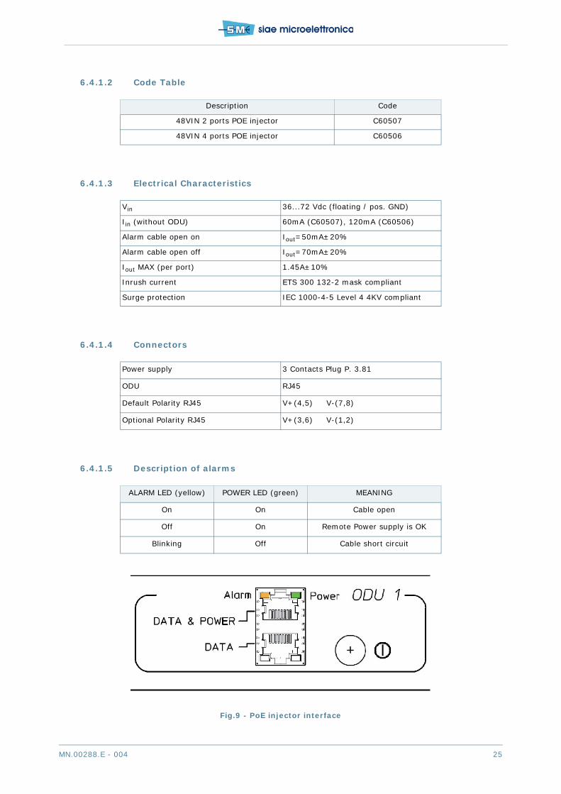
6.4.1.5 Description of alarms
Fig.9 - PoE injector interface
Description Code
48VIN 2 ports POE injector C60507
48VIN 4 ports POE injector C60506
Vin 36...72 Vdc (floating / pos. GND)
Iin (without ODU) 60mA (C60507), 120mA (C60506)
Alarm cable open on Iout=50mA±20%
Alarm cable open off Iout=70mA±20%
Iout MAX (per port) 1.45A±10%
Inrush current ETS 300 132-2 mask compliant
Surge protection IEC 1000-4-5 Level 4 4KV compliant
Power supply 3 Contacts Plug P. 3.81
ODU RJ45
Default Polarity RJ45 V+(4,5) V-(7,8)
Optional Polarity RJ45 V+(3,6) V-(1,2)
ALARM LED (yellow) POWER LED (green) MEANING
On On Cable open
Off On Remote Power supply is OK
Blinking Off Cable short circuit

26 MN.00288.E - 004
6.5 WAVEGUIDE FLANGE
- Radio WG flange type UBR740
6.6 MECHANICAL CHARACTERISTICS
Physical size of system components:
Tab.15 - Dimensions
Weight of system components:
- ALFOplus80 5 kg
6.7 SURGE AND LIGHTNING PROTECTION
- Protection Method Gas dischargers
- Gas dischargers Technical Characteristics
- DC spark-over voltage 150 V +/- 20%
- Nominal impulse discharge current (wave 8/20 s) 20 kA
- Single impulse discharge current (wave 8/20 s) 25 kA
- Operation and storage temperature -40°C +90°C
- Performances in accordance to EN 301 489
6.8 ENVIRONMENTAL CONDITIONS
- Operational temperature range for outdoor equipment -33°C ÷ +55°C
- Survival temperature range for outdoor equipment -40°C ÷ +70°C
- Operational humidity for outdoor equipment Weather proof according to IP65 environmental class.
- Outdoor equipment Thermal Resistance Thermal resistance 0.5°C/W.
- Solar heat gain Not exceeding 5°C
- Wind resistance < 150 Km/h (in operation)< 200 km/h (survival)
Width (mm) Height (mm) Depth (mm)
ALFOplus80 270 290 77.6

MN.00288.E - 004 27
7 EQUIPMENT DESCRIPTION
7.1 GENERAL
SIAE ALFOplus80 (Access Link Full Outdoor) is a microwave radio system for digital link in full outdoor me-chanics and full IP Ethernet. The Outdoor Unit can be easily installed and configured owing to its:
• reduced size
• easily orientable antenna
• broad operating temperature range
• high flexibility of line interfaces selection
• low consumption.
The first description given in the following first concerns the circuitry common to all the versions, then thatof the line interfaces will follow.
7.1.1 Block diagram
The ALFOplus80 consists of one PCB housed in a small size aluminium cabinet:
• BBP-GE (Baseband processor Gigabit electrical) and RF transceiver
or
• BBP-GO (Baseband processor Gigabit optical) and RF transceiver
The description that follows (see Fig.10 and Fig.11) details the block diagrams of electrical and optical ver-sion.

28 MN.00288.E - 004
Fig.10 - ALFOplus80 GE
Ge
LAN
2Sur
ge p
rote
ctio
n,m
agne
tics,
Po
E sp
litte
r
Mai
n D
C/D
C,
Aux
DC/D
C
SW
DFP
GA
Ge
LAN
1
PWM
AD
C
AD
C
AD
C
Mic
roco
ntro
ller
Aux
Pw
r Sup
ply
Filte
r
RAM
SSD
Vga
Vga
BBP8
0-G
E: b
ase
band
pro
cess
orSIP
: RF
tran
scei
ver
RAM
CO
NN
MII
Sur
ge p
rote
ctio
n,m
agne
tics,
Poe
split
ter
QSPI
GM
II
GM
II
2xSyn
cE
Filte
r
SIP
Tx
° C
Shap
ing
Filt
er
Shap
ing
Filt
er
Vcx
o ct
rl
SIP
Rx
Filte
r
Filte
r
Filte
rVga
Vga
Filte
r
I Q
PWM

MN.00288.E - 004 29
Fig.11 - ALFOplus80 GO
Go
LAN
1SFP
cage
Mai
n D
C/D
C,
Aux
DC/D
C
SW
DFP
GA
Ge
LAN
2
PWM
AD
C
AD
C
AD
C
Mic
roco
ntro
ller
Aux
Pw
r Sup
ply
Filte
r
RAM
SSD
Vga
Vga
BBP8
0-G
O:
base
ban
d pr
oces
sor
SIP
: RF
tran
scei
ver
RAM
CO
NN
MII
Sur
ge p
rote
ctio
n,m
agne
tics,
Poe
split
ter
QSPI
GM
II
GM
II
2xSyn
cE
Filte
r
SIP
Tx
° C
Shap
ing
Filt
er
Shap
ing
Filt
er
Vcx
o ct
rl
SIP
Rx
Filte
r
Filte
r
Filte
rVga
Vga
Filte
r
I Q
PWM
PHY
(SFP
100
0Bas
eX)

30 MN.00288.E - 004
7.1.2 Baseband processor
The baseband Processor (BBP) carries out the following operations:
• primary and secondary power supply
• line interfaces and protections
• baseband circuits and packets processing
• I and Q signals generation and sampling
• I, Q demodulator
• Rx baseband filtering
• Actuators and measurement points for RF unit
• FPGA debug connector
• FPGA
• Controller
BBP unit is different depending on the interface type (electrical or optical).
7.1.2.1 Firmware
Equipment software permits to control and manage all the equipment functionality and it is distributed ontwo hardware levels: main controller and ODU peripheral controllers.
Firmware can be updated through the Web Lct and it is stored in two different memory benches: one con-taining the running firmware and the other the stand-by firmware. This permits to download a new firm-ware release to the stand-by bench without cutting the traffic
Use “Bench Switch” to activate the bench in stand-by (SW restart will be performed).
There are 2 firmware versions for the ODU:
• ALFOplus80 “Stand alone”: radio full outdoor with transport of IP Ethernet traffic
• ALFOplus80 “split mount”: the ODU must be necessarily connected to the IDU AGS-H that it getsfull control of the ODU. The radio composed transports TDM (E1&STM1) and IP Ethernet traffic.
7.1.2.2 Web Lct
The Web Lct is a web interface software already present in the ALFOplus80, which requires Adobe FlashPlayer and allows the configuration and the management of the local radio, using LAN Port Management.When the remote one is configured properly, the whole link can be managed. WEB Lct runs on any browser(Internet Explorer or Firefox are recommended).
Web Lct console is a free software downloadable from the site www.siaemic.com after registration.
In order to transfer data it is necessary “Web LCT console” or “SCT” running.
7.1.3 RF Transceiver unit
RF Transceiver consists of the following functional blocks:
• power supply dedicated to microwave circuits
• Tx baseband filtering
• I, Q modulator
• frequency synthesizer

MN.00288.E - 004 31
• microwave transmitter and receiver
• IF devices on Rx side
7.1.4 Switch for Ethernet ports
Inside ALFOplus80 is present an Ethernet switch with 2 external ports line side (electrical 10/100/1000BaseT or optical 100/1000BaseFX), one internal radio port and one port towards controller (seeFig.12). Internal port is represented by the local radio stream where through native Ethernet transport isconnected with the remote equipment.
Fig.12 - ALFOplus80 block diagram
Switch function
ALFOplus80 can operate like a switch between two or more separated LANs with the following advantages:
• to connect two separate LANs
• to connect two LANs via radio within a complex digital network
• to keep separated the traffic into two LANs towards MAC filtering to get a total traffic greater thanthe traffic in a single LAN.
By default the routing works on basis Mac Address (Layer 2), but it can be enabled on basis VLAN ID, inWeb Lct - Ethernet switch (Enh) - Common Parameters.
The operation is the following: when a LAN port receives a MAC frame, on the basis of destination address,it decides which LAN to send it:
• if destination address is on originating LAN the frame is discarded
• if destination address is a known address (towards address learning procedure) and is present intolocal address table, the frame is sent only on destination LAN (MAC switching)
• otherwise the frame is sent to all ports with the same VLAN ID (flooding).
Take account the value of Max Packet Size [byte] when “802.1Q setting” is set as DISABLE or FALLBACKthe switch adds 4 Bytes for internal S-Tag. With 802.1Q setting in SECURE (that means that packet VIDmust be contained in Virtual LAN table list, otherwise the packet is discarded), no internal TAGS are added.
Ethernet Speed/Duplex function
With electrical interface, in Web Lct - Baseband - Lan, Speed/Duplex can be manually or automaticallyactivated as half Duplex or Full Duplex 10/100/1000Base-T, while with optical interface, Speed Duplex canbe set as Full Duplex 100/1000Base-X.
Ethernet packet switch
Port ARadio1+0
LAN1
LAN2
10/100BaseT1000BaseT
10/100/1000BaseT
Microcontroller

32 MN.00288.E - 004
Link Loss Forwarding
Link Loss Forwarding (LLF) is an alarm status of Ethernet interface. LLF can be enabled or disabled.
If LLF is enabled, any linkdown alarm will generate the alarm status of Ethernet interface blocking anytransmission to it. LLF can be enabled for each ports. With LLF enabled the equipment connected (routers,switches so on) can be notified that radio link is not available and can temporarily re-route the traffic.
MDI/MDIX cross-over
For each LAN interface, cross-over cable can be set in Web Lct - Baseband - Lan - Cable Crossover as:
• Auto - Lan recognizes automatically the connected cable type (Straight cable or Crossover cable)
• MDI (NIC) - Manual crossover wiring type T568A
• MDI-X (Switch) - Manual crossover wiring type T568B
With crossover cable it is necessary to use the same wiring format (MDI/MDI or MDI-x/MDI-x) on bothends. In case of straight cable is the opposite (MDI/MDI-x or MDI-x/MDI).
VLAN functionality
ALFOplus80 works with IEEE 802.1q and 802.1p tag. Tag is made up with:
• a fixed word of 2 bytes
• 3 bits for priority according with 802.1p
• 1 fixed bit
• 12 bits VLAN identifier (VLAN ID) according with 802.1q.
Switch cross-connections are based on Vlan Configuration Table where input and output ports or only out-put ports should be defined for any used VID. Vlan ID (VID) has a range from 1 to 4095.
Ethernet Flow Control (802.3x)
A network device asks its adjacent devices to send a pause frame because the input is faster it can process.The protocol used for this purpose is the flow control (802.3x).
Port Based Vlan
Port Based Vlan (or Lan per Port) allows to share the ethernet traffic (ingress or egress) in the interfaceSIAE switch.
7.1.5 Synchronisation unit (SETS)
Into ALFOplus80 a synchronisation circuit, SETS (Synchronous Equipment Timing Source), gets the syn-chronisation signal from the following different sources:
• LAN1
• LAN2
• radio
• Internal source
From the synchronization sources the reference clock is chosen on the base of alarm roots (Synch Loss,Synch Drift, Holdover, Freerunning), on the base of assigned priority, manual forcing and preferentialswitch (see Fig.13).

MN.00288.E - 004 33
The selected clock drives an oscillator through a PLL circuit. The oscillator will generate the required syn-chronisation for the frame generation. If no input signals are available the internal oscillator source is usedfor the local restart.
Fig.13 - Synchronisation block diagram
7.1.6 Bandwidth & modulation
ALFOplus80 radio family uses fixed Modulation (4QAM). It operates in an RF channel with the followingbandwidth:
• 750 MHz
• 1 GHz
7.1.7 ATPC interaction
The Automatic Transmission Power Control (ATPC) regulates the RF output power of the local transmitterdepending on the value of the RF level at the remote terminal. This value has to be preset from the localterminal as threshold high and low. The difference between the two thresholds must be equal or higherthan 3 dB.
As soon as the received level crosses the preset threshold level low due to the increase of the hop atten-uation, a microprocessor (µP), embedded in the ALFOplus80, at the receiver side of the remote terminalsends back to the local terminal a control to increase the transmitted power (see Fig.14).
TE LAN-1
Clock SelectorSynchronisation Source
TE LAN-2
T2 Radio
Internal Clock
PLLCircuit
Sync LossSync DriftStatus
T0 ReferenceClk
Alarms
Force SwitchPriority Control
Preferential Switch
Sel
ectio
n Lo
gica
l

34 MN.00288.E - 004
Fig.14 - ATPC diagram
7.2 LOOPS
To control the equipment correct operation a set of local and remote loops are made available. The com-mands are forwarded by the WEBLCT program. The available loop facilities are:
• Line loop (Ethernet port loop)
• Baseband loop
• I/Q loop
Fig.15 - Available loops
Thresh High
Thresh Low
Hop attenuation (dB)
ATPC range
PTx max.
PTx min.
Remote PRxdBm
Local PTxdBm
Hop attenuation (dB)
Tx
Rx
Rx
Tx
PTx actuation
Local Remote
PRx recording
Transmission
of PTx control
µP µPlevel
PTx control
ALFO Plus80
BBP-GE RADIO
I/Q Loop
BASEBANDLOOP
LINELOOP
PhysicalEthernet Port
Tx
Rx

MN.00288.E - 004 35
7.3 RATE LIMITING AND INGRESS FILTER POLICING
7.3.1 Rate limiting
In SIAE equipment it is possible to apply the Rate Limit, i.e. to limit the total rate passing through an in-terface. It is possible to apply the rate limiting from 64 kbit/s up to the maximum port speed (up to 1GE).
The values that can be inserted are pre-fixed from 64 kbit up to 10Mbit (64Kb, 128kb, 256kb, 512kb, 1Mb,2Mb, 3Mb, 4Mb, 5Mb, 6Mb, 7Mb, 8Mb and 9Mb), In the range from 10Mbit/s up to 1Gbit/s the limiting val-ues can be chosen by the user with a 10Mbit/s step. i.e. the minimum selectable granularity is 10Mb/s.
7.4 ETHERNET PERFORMANCE MONITORING - RMON
RMON (Remote Monitoring) is a standard whose function is providing a set of services of statistics count,monitoring and alarm report with reference to the activity of a LAN network.
SIAE equipment support RMONv1, first MIB, as defined in RFC2819. This MIB contains real-time LAN sta-tistics e.g. utilization, collisions and CRC errors. These counters are managed locally into the radio equip-ment and are defined independently for each port of the device (both LAN and Radio interfaces). SIAE NMSsystems collect periodically this data and store it into the network database.
More in details, the RMON implementation in SIAE Network Elements is classified into two groups:
• RMON – Statistics: These are the counters data collected in real time by the Network Equipment.These data are stored in the network equipment itself and, the NMS Statistics viewer can visualizethis data with the “Refresh” button.
• RMON - History: This is managed by the NMS through the collection of the counters data from theNetwork Equipment. After a periodical polling to the Network Element, the NMS collects all the dataand these data are seen as the RMON History.
In other words, the “RMON Statistics” are the data that are collected and stored in the Network Equipment,while the “RMON History” is an aggregation of the data collected from each network equipment and thedatabase is located in the NMS.
7.5 RMON COUNTERS
RMON statistics are composed by counters for each port of the device that are stored in the equipmentdeployed on field.
Into the equipment it can be chosen to store the values with a sampling period that can be defined betweentwo values: 1 min, 15 min, or both. For each sampling period the counters values are stored into the equip-ment. After a predefined period (polling period), all the RMON data stored by the equipment are get by theNMS. The polling period can be either less than 4 hours (if the sampling period is 1 min) or 1 day (in casethe sampling period is 15 min). The NMS aggregates the files received to create a bigger database withthe History of the Performance Monitoring samples.
Here below are described the RMON counters available for each device interface (both LAN and radioports):
• DropEvents: Total number of events (frames, or whole queue contents) in which packets weredropped by the interface due to lack of resources.

36 MN.00288.E - 004
• Octets RX: Total number of octets of data (including those in bad packets) received by the interface.
• Pkts RX: Total number of packets (including bad packets, broadcast packets, and multicast packets)received.
• BroadcastPkts RX: Total number of good packets received that were directed to the broadcast ad-dress.
• Multicast Pkts RX: Total number of good packets received that were directed to a multicast address.
• CRC Align Errors: Total number of packets received that had a length between 64 and the Max Pack-et Size configured on the equipment switch (in any case not exceeding 10240 bytes) with bad FrameCheck Sequence (FCS) and an integral number of octets (FCS Error) or a bad FCS with a non-inte-gral number of octets (Alignment Error).
• Undersize Pkts: Total number of packets received that were less than 64 octets long and were oth-erwise well formed.
• Oversize Pkts: The number of packets received during this sampling interval that were longer thanmaximum allowable length (excluding framing bits but including FCS octets) but were otherwisewell formed.
• Fragments: Total number of packets received that were less than 64 octets in length and had eithera bad Frame Check Sequence (FCS) with an integral number of octets (FCS Error) or a bad FCS witha nonintegral number of octets (Alignment Error).
• Jabbers: Total number of packets received that were longer than n (parameter Max Packet Size, itcan be set to 1522, 2048 bytes or 10240 Kbytes) octets, and had either a bad Frame Check Se-quence (FCS) with an integral number of octets (FCS Error) or a bad FCS with a nonintegral numberof octets (Alignment Error).
• Collisions: The best estimate of the total number of collisions on this EthLannet segment.
• Utilization Rx: The best estimate of the mean physical layer network utilization on this interface dur-ing this sampling interval, in hundredths of a percent. The percentage is always referred to a 1Gbit/s port speed. So, it represents the mean RX throughput measured on the port during the samplingperiod and it is expressed as a percentage of a port speed.
• Octets TX: Total number of octets of data (including those in bad packets) transmitted.
• Pkts TX: Total number of packets transmitted.
• BroadcastPkts TX: Total number of good packets transmitted that were directed to the broadcastaddress.
• Multicast Pkts TX: Total number of good packets transmitted that were directed to a multicast ad-dress.
• Utilization TX: The best estimate of the mean physical layer network utilization on this interface dur-ing this sampling interval, in hundredths of a percent. The percentage is always referred to a 1Gbit/s port speed. So, it represents the mean TX throughput measured on the port during the samplingperiod and it is expressed as a percentage of a port speed.
All the counters described above are part of the RMON statistics and it is not possible to collect only a sub-set of them. It is however possible to select on which equipment interface activate the RMON statistics (forexample, they can be enabled only on the radio interface). This allows reducing the total amount of PMdata, for example avoiding data collection from unused LAN interfaces. This can be done on all PayloadInterfaces (regardless if electrical or optical), the Radio interfaces are included as well.
7.6 ADVANCED STATISTIC MONITORING FOR SERVICES AND PRI-ORITY COUNTERS
In addition to the Ethernet Counters per Port with SIAE equipment it is possible to set on the Radio interfacethe RMON counters per Service (Vlan) or Priority (Queues). Differently from the previous RMON counters,the Service and Priority counters can be activated for the following variables.
• Octets TX: Total number of octets of data (including those in bad packets) transmitted.

MN.00288.E - 004 37
• Pkts TX: Total number of packets transmitted.
• Octets RX: Total number of octets of data (including those in bad packets) received by the interface.
• Pkts RX: Total number of packets (including bad packets, broadcast packets, and multicast packets)received.
• DropEvents: Total number of events (frames) in which packets were dropped by the interface dueto lack of resources.
The Service and Priority RMON can be activated and collected from NMS (Network Management System).The Service and Priority RMON are based on the Advanced Ethernet Counters present on the equipmentand configurable on site. This means that on site it is possible to activate the Advanced Ethernet Countersbut not the Service and Priority RMON.
In any case the NMS has higher priority in respect to the configuration inserted through Web LCT. Thismeans that the local operator can enable and read the active measure, but when the configuration of theseRMON is done through NMS, the local operator can only read the values of the Advanced Ethernet Counters.It is not possible to enable the RMON for Priority and, in the same equipment, the RMON per Vlan.
7.6.1 Priority RMON
The Priority RMON are based on the internal Queue of the equipment, not on the value of the Priority; thisimplies that:
• the maximum number of RMON (Priority) that can be enabled are limited to 8, i.e. the number ofthe queues available in SIAE equipment.
• if traffic with different priorities are listed in the same Queue, the Priority RMON will work with oneProbe on the Queue. I.e. the traffic in the same Queue is seen as “Same Priority Traffic” and thePriority RMON counts the frames belonging to the Queue
In other words, with Priority RMON there is a probe for each queue (8 queues in SIAE switch). Each probecounts the variables listed above (Octets TX, Pkts TX, Octets RX, Pkts RX and DropEvents).
These counters will be available only with the Minimum Polling Policy of 15 min.
7.6.2 Service RMON
The Service RMON counters allow the equipment to track the variables listed above depending on the Ser-vice (Vlan Tag). This type of RMON can be set only on the Radio interface.
Each equipment can be set to collect RMON up to 32 Services (Vlan Tag) and only on Customer Tag.
These counters will be available only with the Minimum Polling Policy of 15 min.
7.7 SYNCHRONISM
Network Synchronisation is a growing subject related to the network evolution from TDM to Ethernet pay-load.
In this chapter it will be described the different features supported by SIAE switch equipment for the syn-chronization transport. The decision of the correct source to enable and how to pass the synchronisationsignal to customer’s equipment depends on network situation which has to be evaluated case by case.

38 MN.00288.E - 004
Fig.16 - NodeB and BTS synch
The main concept is to transfer the synchronization signal throughout the network deployed. This impliesthat SIAE equipment will take the clock signal from the concentration points (POC) and transfer it towardsthe tail sites and distribute the synchronization signal to the external equipment such as NodeBs and BTS(see Fig.16).
Fig.17 - SETS circuit
Going into details, this means that each SIAE equipment (represented in Fig.17) will have, at least, one“Input” and one “Output” CK.
Input (CK IN) is/are the interface/s where the SIAE equipment get the Clock signal from, these could beanother SIAE equipment or external equipment.
Output (CK OUT) is/are the interface/s where the SIAE equipment provides the Clock Signal to, these couldbe another SIAE equipment or external equipment.
Internally to each SIAE equipment the SETS identify the input and output types of interfaces by the fol-lowing codes:
• TE: This code represents an Ethernet interface (LAN) used as input CK
• T0: Output interface. This code represents the Internal Clock
The purpose of the above list is to list the different acronyms used by the SETS that may be present in theconfiguration screens.
When the Synchronization is enabled in SIAE MW equipment, in the configuration screen, there are somefeatures to be used for maintenance or refined tuning of the clock propagation.
ETH
ALFOplus80 +
AGS-H
E1 TDMReference
Clock
SyncSync
Sync
Sync2G BTS
3G NodeBFull IP
Sync
ETH
E1 TDMEthernet/TDM
Network
Sync
ALFOplus80 +
AGS-H
SETSInputCK IN
OutputCK OUT

MN.00288.E - 004 39
Fig.18 - Synchronisation menu
Here below are listed the different configurations to be made:
• Status Control: this is a forced status for maintenance purposes of the SETS. It can be forced in
- “Free Running”: Independently from the synchronization signal received, the clock is locked ontothe internal clock.
- “Hold Over”: The SETS is locked into the internal clock which tries to preserve the frequencyreceived when the SETS was locked.
- “Locked”: in this case the SETS is locked to a source of synchronization.
• “Time” Settings: these are general setting for the synchronization
- “Hold Off Time”: Time (expressed in ms) during which the system keeps the evaluated frequen-cy of a synchronism source become invalid (not present or degraded). At the end of the HoldOff time, the invalid source will be rejected and the first input source having a valid signal willbe used.
- “WTR Time”: i.e. Wait-To-Restore, this is a wait time to avoid oscillations. Time (expressed inminutes) that has to pass before allowing the selected valid input source to be actually usedwithin the process for the selection of T0 synchronism.
• “LTI Set Time” and “LTI Reset Time”: are controls that avoid oscillations of Alarms. When one alarmraises up, it has to be active for at least the “LTI Set Time” and when it disappears it has to be offfor at least “LTI Reset Time”.
7.8 SOURCES OF SYNCHRONISM
SIAE equipment is able to select among different sources of synchronization. A priority has to be assignedto enable each source, with a value ranging from 1 to 9 included. The priority 1 corresponds to the maxi-mum value, while the priority 9 corresponds to the minimum value. The priority shall be used to select inwhich order the different synch sources must be used. In case the Priority is set as “Disabled” the corre-spondent interface is not used as a synchronization source.

40 MN.00288.E - 004
Fig.19 - Source of synchronisation
The selectable sources of synchronisation are listed below. For each source it is also listed in square brack-ets the correspondent acronym used by the SETS:
• Radio Interface: depending on the RF configuration it is possible to have 1 radio interfaces (1+0).
• GE Interface [TE]: to identify which LANs are the sources of synchronization they have to be chosenunder “TE LAN A” and “TE LAN B”. This implies that a maximum of 2 LAN interfaces can be set assource of synchronization. The AGS-H reference clock can be received on any one the 4 LAN inter-faces, independently from the fact they are electrical or optical. In order to receive the synchroni-zation signal (and regardless of the SSM status) the GE interface has to be set as “Slave”. Theconfiguration choices and other details are explained in “SSM on Ethernet Interfaces”.
• Internal Clock [T0]: with the Synchronization not enabled the equipment is locked into its internalclock
In case SSM is not enabled, the equipment switches from one source of synchronization to another follow-ing the priority scale, starting from the source set to priority 1 and scaling to the sources with higher valuesof priority (i.e. lower priority level). The synch source switch occurs when the present source suffers oneof the following events:
• The source of synchronization is not physically available
• The clock deviation is bigger than 4.6 ppm (maximum deviation that the internal clock can follow).
In other words, if the LAN1 is selected as first source (priority 1) of synchronization, and the LAN2 is se-lected as the second source (priority 2) of synchronization, the SIAE equipment will be synchronized onthe LAN1 until the cable will be physically unplugged or the LAN1 frequency and phase will be out of theirspecified ranges. Once one of these events occurs, the SIAE equipment will switch the source of synchro-nization to the second source listed. If the second source listed is unplugged or out of maximum range thenthe SIAE equipment will switch to the third source and so on.
In case no other synch sources are available the SIAE equipment will go on “Internal Source”, i.e. the in-ternal clock present in SIAE equipment. In this condition the internal clock will be kept in hold status, tryingto keep the last synchronization reference received. In these conditions, the internal clock of SIAE equip-ment has a reliability of 0.3 ppm over 24 h. When the SIAE equipment switches to internal clock, it prop-agates a quality of SEC – SDH Equipment Clock.

MN.00288.E - 004 41
7.9 PROVIDE SYNCHRONISM TO EXTERNAL EQUIPMENT
Once the SIAE equipment is synchronized, the clock signal has to be passed toward external equipment orother SIAE equipment. SIAE equipment can give the synchronization signal through different interfaces.
Fig.20 - Provide synchronism
The interfaces that are available to provide synchronization to other SIAE or external equipment are:
• Radio: this interface is passing the synchronism automatically to the remote equipment. No config-uration is needed.
• GE Interfaces: the TX CK of the all GE lines (i.e. LAN 1 and 2) is locked to the SETS. In this way,the CK can be passed through these connections to other equipment provided that they supportSynchronous Ethernet. The GE Interfaces when used in Electrical can provide the CK signal to otherequipment: in this case the equipment port role must be “Master”. Once the synchronization is en-abled in the SIAE equipment, automatically all the LAN interfaces are locked onto the SETS. Thisimplies that the synchronization signal is automatically provided onto all the LAN interfaces
The choices of the interface to pass the clock signal depend strictly on the external equipment. This meansthat in first place it is necessary to establish the possible sources of synchronization available on the ex-ternal equipment. Depending on the availability of these sources, SIAE equipment will be configured withthe correspondent interface to pass the clock signal.
7.10 G.8264 SSM – SYNCHRONISATION STATUS MESSAGE
The SSM is a protocol that transmits the quality of the synchronization message throughout the network(G.781).
In the synchronization network the transmission of the quality of the clock allows the network to be scal-able and to provide redundancy. In case of failure of SIAE equipment or cable, it is helpful to provide re-dundancy for clock propagation in order to avoid synchronization loops.
Synchronisation loops could happen after a failure when two equipment are synchronising each other onthe same physical connection. If this happens the equipment will not present any alarm on the synchroni-zation but will generate and propagate a not reliable clock.
The quality of the clocks that are propagated are:
• PRC: Primary reference Clock – Best quality clock reachable (Cesium Clock)

42 MN.00288.E - 004
• SSUT: Synchronization Supply Unit Transit (Rubidium Clock)
• SSUL: Synchronization Supply Unit Local
• SEC: SDH Equipment Clock ( Cristal Clock)
• DNU: Do not Use – This signal informs the receiver to do not use this clock
Here above are listed in order from the better quality clock (PRC – Primary Reference Clock) to the worsequality clock (DNU – Do Not Use). The better the quality is the more time can the SIAE equipment stay inholdover (Internal Clock) without a degradation of the payload. In other words, better is the quality, longercan remain reliable the clock in holdover cases.
The DNU quality is always propagated on the source on which the equipment is locked for synchronization.In this way the Loops of synchronization are easily avoided.
Unless the user forces the CK quality input/output, SIAE equipment reads the quality present in the inputinterfaces. This means that, unless there is some user’s modifications, SIAE equipment propagates thequality of the clock as it is. I.e. the output quality is the same as the input quality.
E.g.: If in the input interface (POC Site) there is a quality of SSUT of the CK signal, SIAE equipment willpass throughout the network this synchronization signal with a quality message of SSUT.
In case the SIAE equipment is in Holdover (internal clock) it changes the quality of the synchronization to“SEC” quality. With SSM enabled, SIAE equipment will choose the sources of the synchronization based onthe better quality received.
In general, the equipment selects the synch source with the following criteria:
• it chooses the sources with the highest quality
• if more than one source have the same quality, the one with the highest priority is selected (i.e. theones that have the smaller priority value, from 1 up to 9)
• in any case, if a DNU quality is received on the highest priority source, this latter is discarded andthe equipment selects an alternative source.
Example 1: if one SIAE equipment has the two following sources of synchronization, with the same priority:
a. LAN1 with quality SEC (Priority 1)
b. Radio with quality SSUT (Priority 1)
In case the sources have the same priority, the SIAE equipment will switch the source of synchronizationto the best quality, in this case (b) the Radio with SSUT quality.
Example 2: if one SIAE equipment has the two following sources of synchronization, with the different qual-ity and different priority:
a. LAN1 with quality SEC (Priority 1)
b. Radio with quality SSUT (Priority 2)
In case the sources have different priority and quality, the SIAE equipment will switch the source of syn-chronization with higher quality, in this case (b) the Radio with Priority 2 and quality SSUT. However, if aDNU quality would be received on Radio, the SIAE equipment will switch the synch source to LAN1 inter-face.
Example 3: if one SIAE equipment has the two following sources of synchronization, with the same quality:
a. LAN1 with quality SSUT (Priority 1)
b. Radio with quality SSUT (Priority 2)
In case the sources have equal quality, the SIAE equipment will switch the source of synchronization withhigher priority, in this case (a) the LAN1 with Priority 1 and quality SSUT. However, if a DNU quality wouldbe received on LAN1, the SIAE equipment will switch the synch source to Radio port.
The quality of the synchronism has to be enabled for each SIAE equipment and can be transported on thefollowing interfaces:
• On the Ethernet Interfaces through a standard protocol (according to ITU-T G.8264)
• Radio interface with Local/Remote Telemetry: Depending on the MW link configuration (1+0) theSSM messages are passed to the remote SIAE equipment in different ways.
- 1+0 Configuration: In this case there is one Local/Remote Telemetry passing the SSM messages

MN.00288.E - 004 43
Within this configuration table there are also some maintenance configurations such as:
• Forced Switch: this command allows the operator to force the SETS to lock to a predeterminedsource. This command is above all other configurations. This means that the SETS will be lockedonto this source even if the cable is unplugged
• Preferential switch: In case two sources have equal priority it is possible to set a Preferential Source.In any case the quality is the main parameter of choice, then when two sources have the same pri-ority, the preferential source is chosen.
In relation to the SSM, it is possible to:
• Visualize the quality of the clock signal received and transmitted (Rx Quality and Tx Quality)
• Overwrite the Quality received or transmitted (Ovw Rx Qlty and Ovw Tx Quality) and the choicesare:
- PRC: Primary reference Clock – Best quality clock reachable (Cesium Clock)
- SSUT: Synchronization Supply Unit Transit (Rubidium Clock)
- SSUL: Synchronization Supply Unit Local
- SEC: SDH Equipment Clock ( Cristal Clock)
- DNU: Do not Use – This signal informs the receiver to do not use this clock
The Overwrite of the Quality of the Clock is configurable by the user and simply forces in input or outputthe quality. This can be useful in case the SSM is not supported by external equipment or in case the 2MHz signal is used to pass the synchronization. Moreover, if the SIAE equipment is set with SSM enabled,its SETS will choose a source of synchronization that has the quality available.
7.10.1 SSM on Ethernet Interfaces
In order to propagate the clock signal through the Ethernet 1GE Electrical interface it is necessary to setcorrectly the master and slave option for each interface. It is possible to assign the roles (Master or Slave)statically (as set up for source LAN) or dynamically (according to Synch direction).
This because the Master interface transmits the clock to the Slave interface and in case the direction ofpropagation of the clock has to be changed (line failure, insufficient quality, etc..), the master and slaveassignment has to be re-negotiated with a consequent loss of traffic. This re-negotiation implies an inter-ruption of the traffic from 2.4 to 2.6 seconds.
SIAE equipment allows to set the role of the interfaces to “According to synch direction” (dynamic), theflow of the propagation of the clock signal is automatically changed depending on the transferring directionof the CK. If the role of the interfaces is set to “As set up for source LAN” (Static), the flow of the propa-gation of the clock signal is fixed (see Fig.21).
Fig.21 - LAN synchronisation method
The other configuration present in SIAE equipment that manage the role of the LAN interfaces (Master/Slave) is present in the main configuration of each LAN interface. Regardless if each LAN interface is setmanually as Master/Slave or with autonegotiation, the setting of dynamic or static in the SSM configurationis privileged.
In other words if the Master/Slave are set manually in the interface configuration and in the SSM is set“According to synch direction”, if needed, the role of the LAN changes according to synch directions.
When an electrical GE interface is in Master State (despite from the fact that it comes from a “static” or“dynamic” setting) every synchronization signal that is coming from this interface has automatically the

44 MN.00288.E - 004
quality of DNU. This does not occur for optical GE or FE interfaces (Electrical and Optical), where the “Mas-ter” and “Slave” roles are not foreseen and so the transmitting direction for the clock can be exchangedwithout any port role re-negotiation. All the Ethernet interfaces are locked on the SETS, regardless whichLAN interfaces are set as sources of synchronization. Nevertheless the “Overwrite RX Quality” and “Over-write TX Quality” can be applied only on the LAN interfaces used as sources of synchronization.

MN.00288.E - 004 45
Section 3.INSTALLATION
8 INSTALLATION OF ALFOPLUS80
8.1 GENERAL INFORMATION TO BE READ BEFORE THE INSTALLA-TION
The installation, maintenance or removal of antenna systems requires qualified, experienced personnel.
SIAE installation instructions have been written for such personnel. Antenna system should be inspectedonce a year by qualified personnel to verify proper installation, maintenance and condition of equipment.SIAE disclaims any liability or responsibility for the results of improper or unsafe installation practices.
ALFOplus80 equipment is a full-outdoor IP Ethernet radio link system operating in E-band frequency fortransport capacity up to 1000 Mbit/s, designed to establish LAN-LAN connections. For the details relatedto the actual used frequency band refer to the label on the equipment.
The system is provided with an integrated antenna.
This equipment makes use of non-harmonized frequency bands.
Class 2 radio equipment subject to Authorisation of use. The equipment can operate only at the fre-quencies authorised by the relevant National Authority.
The deployment and use of this equipment shall be made in agreement with the national regulationfor the Protection from Exposure to Electromagnetic Field.
The symbol indicates that, within the European Union, the product is subject to separate collec-tion at the product end-of-life. Do not dispose of these products as unsorted municipal waste. For moreinformation, please contact the relevant supplier for verifying the procedure of correct disposal.

46 MN.00288.E - 004
8.2 GENERAL
The ALFOplus80 radio system is made up of an outdoor unit, protected by a metallic shield. Compliance toelectromagnetic compatibility is guaranteed through the following precautionary measures:
• during the design phase
- use of protection circuits against electrical dischargers
- use of filters on the power supply input circuits against noise propagating on the power supplywires
• during the installation phase
- use of shielded cables
- use of ground connections.
The installation phases of the whole system are described in the following paraghaphs and it must be doneonly by service person suitably trained.
Warning: Remember that the whole radio link can work only if ODUs chosen for local and remote side haveequal sub-band and different Tx module (H and L).
8.3 ELECTRICAL WIRING
The electrical wiring must be done using appropriate cables thus assuring the equipment responds to theelectromagnetic compatibility standards.
The cable terminates to flying connectors which have to be connected to the corresponding connectors onthe equipment front.
Position and pin-out of the equipment connectors are available in this section.
8.4 CONNECTIONS TO THE SUPPLY MAINS
During the final installation, protect the ODU by a magneto-thermal switch (not supplied with the equip-ment), whose characteristics must comply with the laws in force in one’s country.
The disconnection from the supply mains is made disconnecting the auxiliary connector M12 5Pin from theODU or disconnecting the LAN PoE cable.
The typical magneto thermal switch has characteristics at least 48 Vdc @1.5A with overcurrent relay class“C” or “K” tripping curve.
Seal the auxiliary power connector when the radio is powered via PoE, in order to avoid the removal of thecover without tools.

MN.00288.E - 004 47
8.5 GROUNDING CONNECTION
Fig.22 and annexed legend show how to perform the grounding connections.
The ODU must be connected to ground with the available grounding bolt M08303 and eyelet terminalM06614, making reference to details of Fig.27.
Legend
1. Ethernet equipment chassis grounding point. The cross section area of the cable used must be 4sq. mm.
2. ODU grounding M6 bolt copper faston type. The cross section area of the cable used must be 16sq. mm
3. IDU–ODU interconnection cable
4. Grounding cable kit type cable copper or copper alloy to connect the shield of interconnection cable.
5. Battery grounding point of IDU to be connected to earth by means of a cable with a section area2.5 sq. mm. Length 10 m.
6. Grounding cords connected to a real earth internal of station. The cross section area of the cablemust be 16 sq. mm
7. Surge arrester (when needed)
Fig.22 - Grounding connection
Ethernetequipment
(IDU)
ODUunit
2
5(+) (-)
4
Localground
rackChassisground
Indoor
Stationground
6
1
4 37

48 MN.00288.E - 004
8.5.1 Mounting instruction of grounding cable KIT ICD00072F (Univer-sal, No tools)
Tab.16 - Mounting Instructions
Description
Remove the cable jacket by 30mm width approximate-ly. Take care not to damage the copper conductor. Cleanand dry the application area.
Remove the protective film from the butyle sealingpaste.Put the contact in position on the cable, by firmly press-ing on the cable jacket, checking the adherence of thebutyle sealing paste. The contact is firmly positioned onthe cable jacket.
Wrap the copper mesh around the contact and outerconductor (at least 4 revolutions). Block the mesh terminal under the contact tooth. Cut the exceeding mesh length.
Remove the self-agglomerating tape protective film.Carefully wrap tight the tape around contact and cable,following the suitable mean line.Tape adheres remaining in position and progressivelyself-agglomerates.
Connect the earthing cable.

MN.00288.E - 004 49
8.6 REQUIRED TOOLS FOR MOUNTING (NOT SUPPLIED)
• N.2 13mm torque wrench
• N.1 15 mm torque wrench
• N.1 17 mm torque wrench
• N.1 3 mm Allen wrench.
8.7 INSTALLATION PROCEDURE
Installation procedure proceeds according to the following steps:
• According to antenna polarization (vertical or horizontal), assemble the antenna and support brack-etWarning: these instructions are fully detailed in a separate manual “Antennas - Code: MN.00249.E”depending on the type of used antenna.
• Installation of the ODU
• Installation onto the pole of the supporting plate
• ODU grounding.
8.8 INSTALLATION ONTO THE POLE
8.8.1 ODU
Mounting kit 1+0 version
• Polarization kit V60334 (see Fig.24)
• M5 bolts
• Kit V60348 (see Fig.25)
• ODU with O-ring and devices for ground connection
8.8.1.1 1+0 ODU with integrated antenna
Install the antenna using the antenna installation guide (specific for each antenna) inside the antenna boxprovided by antenna producer.
After the antenna has been installed onto the pole, antenna back plate must be installed, see Fig.25.
• Tight the four M06614 screws on the antenna back plate, see Fig.25.
• Keep attention to the polarization of the antenna feeder depending on requested polarization. SeeFig.24 for twist disk polarization details; V (Vertical) or H (Horizontal) polarization will be chosen byantenna installation (see Fig.26)

50 MN.00288.E - 004
• It is recommended to apply seal and lubricant grease Dow Corning 4 (not supply) to the O-ring,protecting fingers with gloves, and insert in the proper track on the ODU flange
• Position the ODU in order to match the ODU holes into the hex spacers and fix the bolts M08210,see Fig.27
• ODU is ready to be connected to the grounding cable and LAN cable
• According toFig.27 and Fig.28 leave at least 250 mm straight LAN cable.
Fig.23 - ODU ALFOplus80

MN.00288.E - 004 51
Fig.24 - Polarization disk
M00
664
VER
TICAL
POLA
RIZ
ATI
ON
V60
334
HO
RIZ
ON
TAL
POLA
RIZ
ATI
ON
WRO
NG
MO
UN
TIN
G

52 MN.00288.E - 004
Fig.25 - Antenna back plate
Z21
084
M06
614
V60
348

MN.00288.E - 004 53
Fig.26 - Antenna flange
V60
334
M06
604

54 MN.00288.E - 004
Fig.27 - ODU installation
min
250
mm
M08303 M06614 M08210
(PARTS OF KIT V60334 )
GROUND CABLE

MN.00288.E - 004 55
Fig.28 - ODU mounted layout
min
250
mm

56 MN.00288.E - 004
8.9 ACCESSORIES FOR INSTALLATION
In the following a list of materials to be used during installation.
Tab.17 - Accessories for installation
SIAE code Descriptions View
U00921 a Fibre optical splitter distribution box for 1 ODU
U00922 a. b Junction box IP66, for fallen of optical cable to connect 2 ODU
J23599 Amphenol wrench connector
M03148 9x360 nylon ties cable
ICD00072F Universal kit cable grounding

MN.00288.E - 004 57
8.9.1 Installation procedure of optical box
Components
Fig.29 - Components
U00899 a. Optical box IP67150x250x46
a. The boxes do not foresee replacement seal.
b. If the second ODU connection takes place much later than the first one, it is possible that the closingof U00922 box doesn’t guarantee the seal tightness.
SIAE code Descriptions View

58 MN.00288.E - 004
Recommended tools (not included)
Fig.30 - Recommended tools (not included)

MN.00288.E - 004 59
Installation
1. Open the cover by special key and screw off the middle plate
Fig.31
2. Take off the adapter panel, put it back after installing adapters
Fig.32
3. Fix PLC splitter, connect splitter ribbon fibres with output pigtails that coated loose tube, fix the ar-ranged output pigtails with loose tube to tray. Lead output pigtail to the other side of the tray andinsert adaptor.

60 MN.00288.E - 004
Fig.33
4. Remove the input entry holder and tension member, put stripped fibre through rubber ring and fix;then guide the fibres in sleeve to splice with input of splitter.
Fig.34

MN.00288.E - 004 61
5. Fibre connection, coiling and storage, fixing, suitable for 2mm (or 3mm) pigtail and drop cable.
Fig.35
6. Check and lock the door

62 MN.00288.E - 004
Fig.36
7. Installation:
- pole mounted, make pole band pass through bracket’s hole, fix the bracket to the pole by fas-tening pole band’s bolts
- wall mounted, mark the target point on the bracket to target point by nail or bolt.
Fig.37 - On pole
Fig.38 - Wall mounted

MN.00288.E - 004 63
8.10 USER CONNECTORS
ALFOplus80 provides an auxiliary connector and 2 types of Amphenol connector, which guarantee Ethernetport compatibility for both version: Gigabit electrical and optical.
8.10.1 Auxiliary connector
The auxiliary 5 pin circulator connector has various functions and it is used when:
• the Power over Ethernet injector through the data Lan cable is not available or as additional powersupply source
• during the alignment of antenna (remember to enable received signal strength indicator inEquipment menu - General preset RSSI.It is recommended after the alignment to set RSSI as Disable not to overload CPU.
• In case of emergency, if ALFOplus80 IP address is unknown, connect it with serial console (F03594),as shown in Fig.57 using hyperterminal 115200 8, N, 1 and press Enter button to access in the login
The available auxiliary cables already assembled:
• F03594 cable for laboratory use only (see Fig.57)
• F03608 2xM12 5P pointing cable (remove it after commissioning pointing) (see Fig.58)
Tab.18 - Auxiliary power cable
SIAE code Descriptions View
P04185 Female 5 pin M12 shielded connector
M10154 Outdoor power supply cable2x0.75mmq for distance 100m
M10166 Outdoor power supply cable2x1.5mmq for distance 200m

64 MN.00288.E - 004
Assembly steps for M12 male/female connector and conductor
a= slide on parts
b= strip conductor, widen shield and lay around the shielding ring, cuf off projecting mesh. Slide coresthrough the housing. mount shielding ring, gasket and clamping cage. Tighten pressure screw to fix thecable. Screw down cores. Mount male/female part. Tighten pressure screw.
Fig.39 - Functional drawing
Fig.40 - Dimensioned drawing - M12 connector
Schematic diagram
Fig.41 - Cable connection side M12 (screw connection)
Fig.42 - Pin assignment M12 socket, 5-pos., A-coded, socket side view

MN.00288.E - 004 65
Tab.19 - Pinout M12 connector
8.10.2 RJ45 connector
The electrical RJ45 connection to ALFOplus80 is guaranteed only with coded connector; do not use otherconnectors, because the proper one is different than the RJ45 standard.
Part to be assembled (see Tab.20)
Tab.20 - Part to be assembled
Pinout Description
1 Vdc (-) = -48 Volts
2 Vdc (+) = 0 Volts
3 Rx_Console
4 Tx_Console& Vpointing (+)
5 GND_Console & Vpointing (-)
Shield Ground
SIAE code Description View
P20032 Amphenol kit RJ45 shielded full out-door connector
M02472 Data cable SF/UTP CAT5e for outdoor(AWG24) 100 Ohm
M05184 Indoor RJ45 boot protection black=6mm

66 MN.00288.E - 004
1000Base-T Gigabit Ethernet cables and connectors
Please be aware that modifying Ethernet cables improperly may cause loss of network connectivity. Pleasefollow colours of wiring.
Tab.21 - Wiring 1000Base-T
P03192 Indoor RJ45 unshielded plug
P20051 a Outdoor RJ45 shielded
a. Don’t use different RJ45.
Pin Assignment 1000Base-T
T568AColour wire
T568BColour wire
1 BI_DA+ WHT/GRN WHT/ORG
2 BI_DA- GRN ORG
3 BI_DB+ WHT/ORG WHT/GRN
4 BI_DC+ BLU BLU
5 BI_DC- WHT/BLU WHT/BLU
6 BI_DB- ORG GRN
7 BI_DD+ WHT/BRN WHT/BRN
8 BI_DD- BRN BRN
SIAE code Description View

MN.00288.E - 004 67
Fig.43 - Straight Ethernet cable
Fig.44 - RJ-45 Pinout
Fig.45 - Indoor RJ45 unshielded assembly
Straight cable EIA/TIA-568A
Straight cable EIA/TIA-568B

68 MN.00288.E - 004
LAN Cable connector - P20032 - Assembly procedure for RJ sealed connectors
Procedure to be used for terminating and assembling of Amphenol Connector Kit
Fig.46 - P20020 kit
Step 1
Feed CAT cable through boot and connector housing as shown below.
Warning: Care should be taken not to damage the rubber sealing gasket inside the rear of the connectorhousing.
Fig.47 - Boot connector

MN.00288.E - 004 69
Step 2
Terminate RJ-45 connector onto CAT cable
Warning: It is mandatory to verify with Ethernet tester (not supplied) the proper connectivity of both ends,in order to avoid autonegotiation problems (as for example 1Gbps fullduplex not reached)
Strip jacketing and shield as shown
Fold shield back onto jacketing. Wrap grain wireone and a half times around the shield. Trim ex-cess length from drain wire
Untwist pairs and arrange to desired order.Note: it is recommended to follow TIA-568 spec-ifications for wiring orientationTrim conductors at an angle and insert into theloading bar
Trim excess wire from holderInsert prepared cable into RJ-45 Plug
Bend strain relief to lay along cable
Crimp plug and strain relief

70 MN.00288.E - 004
Fig.48 - Assembled Amphenol
Fig.49 - Cable connector keys
KEY ODU CONNECTOR
ALIGN THE KEYS AND
PUSH

MN.00288.E - 004 71
Step 3
Insert terminated RJ-45 plug into connector housing.
While holding the connector body, pull cable through connector housing until RJ plus is near to the housing.Align the plug latch with the connector housing keyway.
Depress Plug latch and completely insert the RJ plug into the housing.
Fig.50 - Connector housing
Step 4
Attach and tighten sealing boot using a 19mm wrench.
Recommended tightening torque is 5.5 to 6.0 (in-lbs) or 0.62 to 0.68 (N-m)
Fig.51 - Connector tight

72 MN.00288.E - 004
Fig.52 - PO0032

MN.00288.E - 004 73
Fig.53 - Connector positions
Warning: Tighten all unused connectors with the appropriate cover, using the proper wrench J23599 (seeFig.54).
O K

74 MN.00288.E - 004
Fig.54 - Locking key for Amph. connector (J23599)

MN.00288.E - 004 75
Fig.55 - Assembled connectors
8.10.3 Optical connector
- Cable characteristics see Tab.22 and Fig.60, Fig.61, Fig.62
- Operating temperature range -40° C to +85°C
- Protection class IP67
P04185 (connector M12 female 5p shelded)
Outdoor LAN connector (LAN1-LAN2) P20032
Cable M10154 (Outdoor power supplycable 2x0.75mmq)
Tighten strongly LAN connectors with wrench J23599
to ensure the complete isola�on

76 MN.00288.E - 004
Tab.22 - List of Amphenol optical cable
Connector End/End Length (m) Type Mode SIAE Code
SFP LC/LC 100 Single Mode P20046
SFP LC/LC 50 Single Mode P20045
SFP LC/LC 25 Single Mode P20044
SFP LC/LC 2.5 Single Mode P20053
SFP LC/OPEN END 2.5 Single Mode P20043
SFP LC/SFP LC 2.5 Single Mode P20047
SFP LC/LC 100 Multi Mode P20037
SFP LC/LC 75 Multi Mode P20050
SFP LC/LC 50 Multi Mode P20036
SFP LC/LC 35 Multi Mode P20049
SFP LC/LC 25 Multi Mode P20035
SFP LC/LC 15 Multi Mode P20048
SFP LC/LC 2.5 Multi Mode P20052
SFP LC/OPEN END 2.5 Multi Mode P20034
SFP LC/SFP LC 2.5 Multi Mode P20038

MN.00288.E - 004 77
Fig.56 - IDU-ODU optical connection
Indo
or u
nit
Indo
or u
nitP200
52-J
UM
PER
LC/S
FP -L
C/LC
L=
2,5m
( m
ul�m
ode)
P200
53-J
UM
PER
LC/S
FP -L
C/LC
L=
2,5m
( si
ngle
mod
e)
U00
899
-U00
900
-U00
921
OPT
ICAL
BO
X
MU
LTI M
ODE
Siae
P/N
leng
thP2
0048
15 m
.P2
0035
25 m
.P2
0049
35 m
.P2
0036
50 m
.P2
0050
75 m
.P2
0037
100
m.
SIN
GLE
MO
DESi
ae P
/Nle
ngth
P200
5615
m.
P200
44
25 m
.P2
0057
35
m.
P200
45
50 m
.P2
0054
75
m.
P200
46
100
m.
P200
55
200
m.
F152
00-O
PT. J
UM
PER
SMLC
-LC
DU
P L=
15M
F152
01-O
PT. J
UM
PER
SMLC
-LC
DU
P L=
25M
F152
02-O
PT. J
UM
PER
SMLC
-LC
DU
P L=
50M
F152
03-O
PT. J
UM
PER
SMLC
-LC
DU
P L=
100M
F153
00-O
PT. J
UM
PER
MM
LC-L
C D
UP
L=15
MF1
5301
-OPT
. JU
MPE
R M
MLC
-LC
DU
P L=
25M
F153
02-O
PT. J
UM
PER
MM
LC-L
C D
UP
L=50
MF1
5303
-OPT
. JU
MPE
R M
MLC
-LC
DU
P L=
100M
M10
300
-OPT
ICAL
CAB
. 2 F
IBER
MM
50/1
25M
1030
1-O
PTIC
AL C
AB. 2
FIB
ER SM
9/12
5
AMPH
ENO
L O
PT. C
ABLE

78 MN.00288.E - 004
8.10.4 Optical SFP mounting procedure
Follow the instructions:
• plug the SFP module into LC embedded connectors until “Click” (see Fig.63 and Fig.64)
• pull lightly the SFP and check that it is locked to the connector (see Fig.65)
• insert plugged SFP on ALFOplus80 optical cage (see Fig.66)
• lock the connector by turning the nut with wrench J23599 (see Fig.67).
8.10.5 Optical SFP unmounting procedure
Follow the instructions:
• unlock the connector by untightening the nut with wrench J23599
• eject SFP module from ALFOplus80 Optical cage
• to unplug thr SFP from LC connector, push the locking by keeping a finger below the SFP module(see Fig.68).
Warning: Don’t insert the SFP module inside the housing of the ODU without the preliminary connectionbetween cable and the SFP as described in this paragraph.

MN.00288.E - 004 79
Fig.57 - F03594 cable for lab use only
WHI
TE/B
ROW
NW
HITE
/BRO
WN
4 BL
ACK
4 BL
ACK
2-1
2-1
2-2
2-2
2-4
2-4
2-3
2-3
FRO
MFR
OM
TOTOCO
URSE
COUR
SE
1-2
1-2
1-3
1-3
3-A1
3-A1
3-A3
3-A3
2-5
2-5
1-5
1-5
3-A2
3-A2
8 RE
D8
RED
ORA
NGE
ORA
NGE
COLO
URS
COLO
URS
WHI
TE/O
RANG
EW
HITE
/ORA
NGE
BLUE
BLUE
GREE
NGR
EEN
BRO
WN
BRO
WN
WHI
TE/B
LUE
WHI
TE/B
LUE
WHI
TE/G
REEN
WHI
TE/G
REEN
THER
MO
FIT
THER
MO
FIT
PIPE
PIPE
THER
MO
FIT
THER
MO
FIT
PIPE
PIPE
THER
MO
FIT
THER
MO
FIT
PIPE
PIPE
THER
MO
FIT
THER
MO
FIT
PIPE
PIPE
F035
94F0
3594
RED
RED
BLAC
KBL
ACK
8
3
6
2
1 4
7
V+V+V-V-
A1A1A2A2A3A3

80 MN.00288.E - 004
Fig.58 - F03608 cable for pointing (to remove after commission pointing)
see
N.B
.se
e N
.B.
F --
---
F --
---
WIR
ES C
ON
NEC
TIO
N W
IRES
CO
NN
ECTI
ON
SID
E EN
LARG
ED V
IEW
SID
E EN
LARG
ED V
IEW
WIR
ES C
ON
NEC
TIO
N W
IRES
CO
NN
ECTI
ON
SID
E EN
LARG
ED V
IEW
SID
E EN
LARG
ED V
IEW
5
4
3
2
1
51
4
32
RED
RED
BLAC
KBL
ACK
N.B
.2N
.B.2
N.B
.2N
.B.2
N.B
.1N
.B.1
N.B
.1 -
STR
IP T
HE
CABL
E RE
SPEC
TIN
G T
HE
DIM
ENSI
ON
SH
OW
IN
TH
E D
RAW
ING
N.B
.1 -
STR
IP T
HE
CABL
E RE
SPEC
TIN
G T
HE
DIM
ENSI
ON
SH
OW
IN
TH
E D
RAW
ING
N.B
.2 -
CAB
LE H
EAT
SHRI
NKA
BLE
N.B
.2 -
CAB
LE H
EAT
SHRI
NKA
BLE
WH
ITE/
BRO
WN
+ B
ROW
NW
HIT
E/BR
OW
N+
BRO
WN
WH
ITE/
ORA
NG
E +
ORA
NG
EW
HIT
E/O
RAN
GE
+ O
RAN
GE
WH
ITE/
BLU
EW
HIT
E/BL
UE
45
6
45
7
2
20,
6 m
m (
Blue
)0,
6 m
m (
Blue
)
06 m
m (
Gre
en)
06 m
m (
Gre
en)
*3 R
ED*3
RED
*2 B
LACK
*2 B
LACK
CF1-
4CF
1-4
CF1-
5CF
1-5 CO
URS
ECO
URS
E
TOTOPa
rtPa
rtRe
f.Re
f.FR
OM
FRO
MN
OTE
SN
OTE
S
BLU
EBL
UE
WH
ITE/
GRE
ENW
HIT
E/G
REEN
CM2-
1CM
2-1
CM2-
2CM
2-2
CM2-
3CM
2-3
CM2-
4CM
2-4
CF1-
1CF
1-1
CF1-
2CF
1-2
CF1-
3CF
1-3
CF1-
4CF
1-4
CF1-
5CF
1-5
CM2-
5CM
2-5
CM2
CM2
1
CF1
CF1
COU
RSE
COU
RSE
TOTOPa
rtPa
rtRe
f.Re
f.*1*1
FRO
MFR
OM
COLO
URS
COLO
URS
N.B
. - P
ART
MU
ST B
E LA
BELL
ED W
ITH
HO
T TI
GH
TEN
ING
RIN
G, D
ISPL
AYIN
G:
N.B
. - P
ART
MU
ST B
E LA
BELL
ED W
ITH
HO
T TI
GH
TEN
ING
RIN
G, D
ISPL
AYIN
G:
-
PAR
T N
UM
BER/
REVI
SIO
N;
-
PAR
T N
UM
BER/
REVI
SIO
N;
-
MAN
UFA
CTU
RER
ID (
REG
. MAR
K O
R IN
ITIA
L);
-
MAN
UFA
CTU
RER
ID (
REG
. MAR
K O
R IN
ITIA
L);
-
MAN
UFA
CTU
RIN
G D
ATE
(WEE
K/YE
AR);
-
MAN
UFA
CTU
RIN
G D
ATE
(WEE
K/YE
AR);
-
ELE
CTRI
CAL
TEST
PRO
VEN
("T
E" M
ARK)
.
- E
LECT
RICA
L TE
ST P
ROVE
N (
"TE"
MAR
K).
23
N.B
.1N
.B.1
6N
.B.2
N.B
.2
4
3535
4
6060
1530
1530
+20
+20
0 0 -
GET
VAL
UE F
ROM
LAS
T DI
GITS
OF
PART
DES
CRIP
TION
- G
ET V
ALUE
FRO
M L
AST
DIGI
TS O
F PA
RT D
ESCR
IPTI
ON

MN.00288.E - 004 81
Fig.59 - ALFOplus80 connectors
Fig.60 - SFP LC/LC
Fig.61 - SFP LC/OPEN END
Fig.62 - SFP LC/ SFP LC

82 MN.00288.E - 004
Fig.63 - LC connector
Fig.64 - SFP/LC connector locked
Fig.65 - SFP/LC connector check
Fig.66 - SFP into ALFOplus

MN.00288.E - 004 83
Fig.67 - Locked connection
Fig.68 - Unplug SFP

84 MN.00288.E - 004

MN.00288.E - 004 85
Section 4.LINE-UP
9 LINE-UP OF ALFOPLUS80
9.1 GENERAL
The line-up consists of the following steps:
• switch on equipment
• alarm leds check
• optimizing antenna orientation
• insertion into telecontrol and reachability of far-end terminal
• check of Ethernet connections
• quality evaluation with performance monitoring
Operations involving the use of SCT/WebLCT are roughly described here. For further details please referto software manual.
9.2 SWITCH ON
Checks to be performed before switching on the unit are:
• check external power supply voltage.
• antenna presence - check the connection between ODU output flange and antenna.
If everything is correct, switch on the ODU.

86 MN.00288.E - 004
9.3 ALARM LED CHECK
On the rear panel of ODU unit there is a transparent plastic window to see the status of an internal LEDdedicated to show unit alarms. Further information about ALFOplus80 alarms can be found onto the chap-ter “ALFOplus80 alarms and troubleshooting”.
9.4 CONNECTION PROCEDURE
Connection between PC and ALFOplus80 can only occur if IP Address of the PC and the radio belong to thesame subnet and it can be made directly or through a switch on the Lan2 radio connector.
Using Subnetwork Craft Terminal (SCT):
1. select Options, tab Connection
2. select Connect using Local Area Network (see Fig.69)
3. press OK and Connect.
Using WebLCT Console
1. Add the IP Address of radio in the address book (see Fig.73)
2. Press double click over IP Address to open the browser.
First connection using SCT (you know IP address)
1. with SCT or browser (internet explorer) type IP address stored previously (Factory Default are172.20.254.14/16 ODU L and 172.20.255.15/16 ODU H)
- Default User: SYSTEM
- Default Password: SIAEMICR
2. after connection it’s possible to modify IP address, etc.....
Rescue connection (you don’t know IP address)
1. Assign a static IP address (see Fig.70) to PC (the IP must belong to the rescue network)ALFOplus80 rescue IP address: 172.20.253.13ALFOplus80 rescue subnetwork mask: 255.255.0.0
2. Connect your PC directly to ALFOplus80 with a LAN direct-cable
3. By SCT, connect using Local Area Network, press Connect button, type equipment User/Passwordand press Rescue button (see Fig.71).
4. Follow the instructions of rescue login (see Fig.72)
5. In Rescue connection mode it is possible to set or recover values from Management Access.
Rescue connection using WLC (you don’t know IP address)
1. Assign a static IP Address (see Fig.70) to PC (the IP must belong to Rescue network)ALFOplus80 rescue IP Address: 172.20.253.13ALFOplus80 rescue subnetwork mask: 255.255.0.0

MN.00288.E - 004 87
2. Connect your PC directly to ALFOplus80 with a LAN cable
3. By WLC press the arrow down near the button connect and press “Rescue Connection” (see Fig.73)
4. Type equipment User/Password and follow the instructions of rescue login (see Fig.74)
5. In “Rescue connection” mode it is possible to set or recover the values for management access.
Rescue connection using “Command prompt” (you don’t know IP address)
1. Assign a static IP Address (see Fig.70) to PC (the IP must belong to the rescue network)ALFOplus80 rescue IP Address: 172.20.253.13ALFOplus80 rescue subnetwork mask: 255.255.0.0
2. Connect your PC directly to ALFOplus80 with a LAN cable
3. By command prompt, type “ping 172.20.253.13 -t” and press Enter
4. Restart hardware ALFOplus80
5. Wait till the ping reply, open Internet Explorer, type in the URL:172.20.253.13 and press F5 until the Login Menu appears
6. In Rescue connection mode it is possible to set or recover the values for management access.
Emergency connection (you don’t know the IP Address)
1. Connection between PC and ALFOplus80 with serial console cable (F03594) in auxiliary connector
2. Using Hyperterminal - Serial COM at 115200bps, 8bits, None parity, 1 stop bit, none flow controland press Enter button to access in the login
3. After login the radio IP Address will be shown
4. Type Config if you want to change the boot parameters (IP address, etc...)
Fig.69 - Connection option

88 MN.00288.E - 004
Fig.70 - IP address setting
Fig.71 - Login connection using SCT

MN.00288.E - 004 89
Fig.72 - Rescue login
Fig.73 - WebLCT console

90 MN.00288.E - 004
Fig.74 - Rescue connection using WLC
9.5 INITIALIZATION PROCEDURE
To activate a radio link it is necessary to program the ODU (local and remote side) in some basic itemslisted in the following:
• modulation & capacity
• Tx frequency & power
• port configuration
• agent IP address and equipment ID
• store routing table
• remote element list
• restart equipment
Bandwidth and Modulation setting
Into WebLCT at position:
• Equipment menu

MN.00288.E - 004 91
• Equipment - BW & MOD/LINK ID
• In Capacity and Modulation card, you can select Bandwidth&Modulation desired. Press Applyand Confirm.
Warning: Use the same parameters on remote unit.
Fig.75 - Bandwidth&Modulation, local link ID
Tx frequency setting
See Fig.76. Into WebLCT at position:
• Equipment menu
• Radio Branch
• Settings card: in this card you have to select Duplex frequency and Tx frequency; Rx frequencyvalue is shown in the top status bar and is set automatically. Press Apply and Confirm.
Local Tx frequency must be set as at remote Rx frequency. Please set the frequency according to yourlicense.
Warning: Remember that the whole radio link can work only if ODUs chosen for local and remote side haveequal sub-band and different Tx module (example of permissible pair ODU 1H and ODU 1L).
Tx power setting
See .Fig.76.Into WebLCT at position:
• Equipment menu
• Radio Branch
• Power card: in this card you have to set Tx power equal to radio planning value or if you do notknow it to maximum Tx power; in this card it is possible to enable automatic transmission powercontrol, but it’s important to set properly the ATPC thresholds: Rx Level Min, Rx Level Max. Seeparagraph 7.1.7 ATPC interaction for more details). Press Apply and Confirm.
Warning: Use the same parameters at remote ODU.

92 MN.00288.E - 004
Fig.76 - Frequency and power setting
Port configuration setting
See Fig.77.
Into WebLCT at position:
• Equipment menu
• Main - Port configuration
• In Ethernet card you can modify the IP address, netmask and supervisioning parameters. PressApply and Confirm. Press Store and Confirm.
Warning: For Remote Radio Management please change port settings in “Out of band” or “Drop node” or“In Band” on both sites (see Fig.77)

MN.00288.E - 004 93
Fig.77 - Port configuration
Agent IP address setting
See Fig.80.
Into WebLCT at position:
• Equipment menu
• Main - Equipment properties
In General Info card, change the equipment ID and agent IP address equal to Ethernet IP address.Press Apply and Confirm.
Fig.78 - Equipment properties

94 MN.00288.E - 004
Store routing table setting
See Fig.79.
Into WebLCT at position:
• Equipment menu
• Main - Store routing table
• Type the default gateway IP address and select LAN interface and/or add manually the routingcommand.
• Press Apply and Confirm. Press Save and Confirm.
Fig.79 - Store routing table
Remote element list setting
See Fig.80.
Into WebLCT at right position:
• Press the button to expand Remote Element List window
• Clear and Apply new list
• Add station, type “SIAE LINK” and press OK
• Select the station just created and add local element:
- IP address: type local radio IP agent address
- type of element: managed by SCTPress OK, Apply and Confirm.
• Add remote element:
- IP address: type remote radio IP agent address
- Type of element: Remote linkPress OK, Apply and Confirm.
Restart equipment
See Fig.80.
Into WebLCT at position:
• Equipment menu
• Main - Equipment properties
• Press the button Restart Equipment and Confirm.

MN.00288.E - 004 95
Fig.80 - Equipment properties
9.6 OPTIMIZING ANTENNA ALIGNMENT WITH RX MEASUREMENT
When the whole radio link is on, antenna alignment can be optimised. Antenna alignment optimization isperformed depending on the Rx signal power at local and remote equipment and evaluating both local andremote S/N value maximizing them. There are two possibilities to see the Rx signal power level:
• through WebLCT interface
• through a voltmeter connected to auxiliary connector on the ODU (F03608 cable - see Fig.58).
In order to get the Rx signal power level via software, connect the PC to ALFOplus80 (LAN2) and start thecommunication towards the ODU microcontroller with SCT/WebLCT supervisory program.
Into WebLCT is shown in the top status bar (Rx1A= -value dBm) see Fig.80:
If you’re using a voltmeter the Rx signal power level is available on the auxiliary connector of ODU, themeasurement can be performed with a proper cable (see Fig.58). Following this last procedure, the voltageyou’re reading with the voltmeter is proportional to Rx power level, refer to Tab.23.
Tab.23 - Voltage measured in auxiliary port
Received Signal (dBm) Signal Output (V) Error (dB)
-20 4.68 ±5
-30 3.51 ±5
-40 2.34 ±3
-50 1.17 ±3
-60 0 ±3
-70 -1.17 ±3

96 MN.00288.E - 004
Typical Rx signal power level -40 dBm. It is the most important item to optimise the antenna alignment,but in a situation of interference Rx level can be good, BER acceptable but S/N margin low. This meansthat when Rx fields will decrease then BER will increase fast. The situation can be easily shown with SCT/WebLCT software looking at Signal Quality level. Into WebLCT Software select:
• Equipment menu
• Maintenance
• S/N Meas. card (see Fig.81)
The S/N at nominal Rx level, read by WebLCT, must be 18dB@ 4QAM (typical S/N: 20-22dB) (see Fig.81).
Fig.81 - S/N measurement monitoring
Antenna aiming
Optimise antenna aiming towards remote side, operating on the “azimuth” nuts (1) and the “elevation”nuts (2) to maximize antenna strength signal (see Fig.82 and Fig.83).
- fine azimuth adjustment ± 7° (see Fig.83)
- fine elevation adjustment ± 30° (see Fig.82)
Fig.82 - Azimuth adjustment
-80 -2.34 ±3
-90 -3.51 ±5
-100 -4.68 ±5
Formula RSSI=Offset + (Signal/Output)/Slope
Slope (V/dB) 0.117
Offset (dBm) -60
1

MN.00288.E - 004 97
Fig.83 - Elevation adjustment
9.7 ODU ACCESSING AND REMOTE MANAGEMENT
Local ALFOplus80 ODU and its remote ODU can be accessed via LAN2 or LAN1 ports depending on super-visioning parameters, once the radio link has been initialized correctly (Local&Remote). In SCT the window(see Fig.84) shows the network element belonging to selected station. In the “login” column you can checkthe actual user profile of equipment (SYSTEM=Administrator; MONITOR=Read only) and which is the localradio (local) and remote radio (remote link). To change the user profile, select the network element andpress Login.
To connect in remote radio you can press double click on remote link element or select Remote Link -equipment - LCT interface.
In WebLCT software press Open Far End button to open and manage the remote radio window.
If the remote link is not visible, it means that the remote element list is missing in the local ODU (in SCT- Tools - Subnetwork Configuration Wizard).
Fig.84 - Remote accessing
2

98 MN.00288.E - 004
9.8 COMMISSIONING MEASURES FOR ETHERNET TRAFFIC
9.8.1 Ethernet connection stability
Settings
To verify the Ethernet performances set the equipment following Tab.24
Tab.24 - Ethernet connection stability
Local Terminal Remote terminal
LAN1 LAN2 PORT A LAN1 LAN2 PORT A
Lan
Set
ting
Rate Control Full Rate Full Rate Port Enable Full Rate Full Rate Port Enable
Flow Control Disable Disable Disable Disable Disable Disable
Master/Slave Master Master Master Master
M/S Autoneg. Disable Disable Disable Disable
MAC learning Disable Disable Disable Disable Disable Disable
Speed/Duplex Auto (1Gbit) Auto (100Mbit) Auto (1Gbit) Auto
(100Mbit)
Cable crossover Auto Auto Auto Auto
Vir
tual
Lan
(80
2.1Q
)
Port
Bas
ed V
LAN LAN1 / Disable Enable / Disable Enable
LAN2 Disable / Enable Disable / Enable
Port A Enable Enable / Enable Enable /
802.1q Manage-ment Fallback Disable Fallback Fallback Disable Fallback
Default Vid 101 102 111 101 102 111
Priority 802.1PPort default
0
Port default
7
Port default
0
Port default
7
Ethe
rnet
Sw
itch
Max Packet size 2048 byte
Mac address aging time 300 sec
QinQ ETH Type 9100
Priority
Radio to LanNative 802.1p
Priority
LAN to radioNative 802.1p

MN.00288.E - 004 99
After checking commissioning measures it is mandatory to fill “SIAE commissioning report” and send it toSIAE database, ready to be checked when necessary.
These reports are very important for SIAE and for the customer because they certify the conformity of SIAElink.
Only in case you don’t have this document, the full backup file .bku can be generate using SCT.
For any technical problem contact help-desk office:
• email: [email protected]
• tel. +39.02.27325452
9.9 FIRMWARE UPDATE
9.9.1 Scope
Scope of this paragraph is to provide a procedure that describes, step by step, how to perform the softwareupgrade of ALFOplus80 equipment.
Downloading time depends on connection used between PC and ALFOplus80.
Warning: In order to transfer data, “WebLCT Console” or “Subnetwork Craft Terminal” running is neces-sary.
9.9.2 Procedure of firmware update
Follow the steps below to perform the software upgrade of ALFOplus80 stand alone.
Boot download
1. Unzip files E82109 XXX.zip in a suitable directory of the PC used to performed the upgrade.
2. Connect to the equipment using the SCT or the WebLCT (login as “System”).
3. Open the Software Download window:
- using SCT select Version from menu Equipment Menu and press Download SW Setup
- using WebLCT select Software Info&Maint (see Fig.85) from Equipment Menu and pressUpgrade (see Fig.86)
4. Select the file E82109.dwl (boot firmware) from the directory boot_ e82109_xxyyzz
5. Select Only difference or not present/peripheral as download mode
6. Start the download and confirm by clicking on the window that pops-up.
7. At the end of the boot firmware download, the equipment Controller will automatically restart. Waitfor the restart to be completed.
System Version Download
1. Unzip files N20052-01 XXX.zip in a suitable directory of the PC used to performed the upgrade.
2. Connect to the equipment using the SCT or the WebLCT (login as “System”)

100 MN.00288.E - 004
3. Open the Software Download window:
- using SCT select Version from menu Equipment Menu and press Download SW Setup
- using WebLCT select Software Info&Maint (see Fig.85) from Equipment Menu and pressUpgrade (seeFig.86)
4. Select the file N20052.dwl (system version) from the directory bin
5. Select Forced as download mode
6. Start the download and confirm by clicking on the window that pops-up
7. At the end of the system version download, to activate the new system version a bench switch isrequired: click on Bench switch confirm by clicking on the window that pops-up.
Warning: The bench switch may be traffic affecting depending on the system version previously running.
WebLCT Download
1. Connect to the equipment using the WebLCT (login as “System”)
2. In Equipment menu - Software Info&Maint - WebLCT - Upload Manager press Browse andselect the file “Web_26_N96113_XXYYZZ”
3. Press the button Upload and Confirm
4. After the update it is recommended to clear temporary internet files, cookies and history of the usedbrowser.
Fig.85 - Software download procedure

MN.00288.E - 004 101
Fig.86 - Upgrade software
9.10 BACKUP FULL EQUIPMENT CONFIGURATION WITHOUT POSSI-BILITY OF MODIFYING THE PARAMETERS
9.10.1 Scope
This chapter describes the procedure to backup the full equipment configuration. This permits to recoverthe original equipment configuration in case of faulty CONTROLLER module replacement with spare.
Warning: In order to transfer data, “WebLCT console” or “Subnetwork Craft Terminal” running is necessary.
9.10.2 Backup/restore configuration using SCT
Backup configuration
Foreword: it is advisable to backup the configuration after the first installation. Proceed as follows:
1. Select Equipment Configuration Wizard from menu Tools; Equipment Configuration Wizardwindow will be displayed.
2. Select Upload and then Backup Full Equipment Configuration; Template Selection window willbe displayed.
3. Select the correct equipment template (in case of uncorrected choice the backup will be aborted).
4. Press OK and then select the equipment to be uploaded from Upload Configuration File window.
5. Press OK and then edit the file name from Save backup as window.
6. Press Save; Equipment Configuration Wizard: Complete Backup window will appear.The window shows dynamically the backup procedure. If everything is OK, at the end of the uploadwill appear the word done showing the procedure success.
7. Press OK to finish.

102 MN.00288.E - 004
Restore Configuration
Once the spare controller has been installed, or every time you need the primitive configuration, proceedas follows:
1. Select Equipment Configuration Wizard from menu Tools. Equipment Configuration Wizard win-dow will be displayed.
2. Select Download and than Restore Full Equipment Configuration from Equipment Configura-tion Wizard. Select Backup File window will be displayed.
3. Select the wanted backup file with extension .bku and then press Open. Download ConfigurationFile window will be displayed.
4. Select the equipment to download and then press OK; Equipment Configuration Wizard: Completerestore window will be displayed. This window shows dynamically the download operation. The worddone indicates that download has been successfully.
5. Press OK to finish.
Warning: In case of EOC alarm proceed to restart the equipment.
9.10.3 Backup/restore configuration using WEBLCT
Backup Configuration
Foreword: it is advisable to backup the configuration after the first installation. Proceed as follows:
1. select Backup/Restore Configuration in the Main menu
2. in the field Backup File name write the name of the configuration file you are going to upload in thePC, complete with the full path of its folder
3. push Backup. The status of the backup procedure is shown in the “Operation Status” field.
Restore Configuration
Once the spare Controller has been installed or every time the saved configuration is necessary, proceedas follow:
1. Select Backup/Restore Configuration in the Main menu
2. In the field Restore file name write the name of the configuration file you are going to download inthe ODU, complete with the full path of its folder
3. Push Restore. The status of the backup procedure is shown in the “operation Status” field. DuringRestore operation the equipment creates a backup configuration, you can come back to this config-uration at the end of the restore pushing Revert (see Fig.87)Warning: the file full backup, making use of SCT, isn’t compatible with WebLCT and vice versa.

MN.00288.E - 004 103
Fig.87 - Backup/Restore configuration

104 MN.00288.E - 004

MN.00288.E - 004 105
Section 5.MAINTENANCE
10 ALFOPLUS80 ALARMS AND LOOPS
10.1 GENERAL
A radio link generating alarm requires troubleshooting.
The troubleshooting of the ALFOplus80 can be organized on the basis of alarms.
Basic alarms come from LEDs on the equipment and all the active alarms can be observed through SCT/WebLCT.
In this document is present ALFOplus80 alarm list and a description of the loop facilities provided into theequipment.
10.2 ALARMS
Alarms can be pointed out through unit LEDs and/or through SCT/WebLCT software.
10.2.1 Alarm indications
There are two ways of processing the alarms:
• through LEDs
• through SCT/WebLCT
Alarm associated to ALFOplus80 can be classified in different groups. Names and composition of thesegroups as well as association between alarm classes and relay contact can be defined by the customer.

106 MN.00288.E - 004
Alarms are divided into 4 severity levels according to the effects that an alarm might cause to the regularoperation of the unit detecting it. Levels are prioritised as follows:
• Critical (red): out-of-service, hw failure, urgent alarm
• Major (orange): loss of signal, minimum residual functionality, urgent alarm
• minor (yellow): failure neither urgent, high residual functionality, not urgent alarm
• warning (light blue): indication or wrong configuration, not urgent alarm
• none (green): no alarm or masked alarm.
Critical and Major alarms indicate impossibility of executing a service, hence the faulty units needs to beserviced. Minor level represents the not urgent alarms which do not prejudice service continuity. Warninglevel indicates malfunctions that might be locally removed without having to replace the unit.
Alarm classification can be modified via SCT/WebLCT operator. A short description is given for each alarmin “Alarms” section with relevant class.
The visual indication is given by a LED, which can be green or orange or red. The information provided are:
• Red light:
- ON - An internal alarm is active. Connect the PC for troubleshooting
- Flashing - An external alarm is active
• Green light
- Flashing - No radio connection with far-end terminal
- ON - Radio connection with far-end terminal is active
• Orange light: during restart
During the power-up follows three status of display LED (see Tab.25)
Tab.25 - Bootstrap status display
10.2.2 SCT/WebLCT displayed alarms
All the alarms are displayed through SCT/WebLCT program running on a PC. Alarms are divided in groupsto refer to a particular functionality and are characterized by programmable severity.
Alarms, with group and a short description, are listed into Tab.26.
In the following you can find a class list and the item they describe:
• COMMON – Failure or status relevant to whole equipment
• ETH LAN - Failure on Ethernet traffic
• P.M. G.828 – Performance monitoring on signal quality
• P.M. Rx Power – Performance monitoring on received signal
• P.M. Tx Power – Performance monitoring on transmitted signal
• Plug-in module - Alarm on plug-in device
• RADIO - Alarm on Tx/Rx section of radio
• SETS - Synchronisation alarm or status
Led 1st step - boot strap 2nd step - Loading WebLCT
3rd step - Ready to management
Green OFF OFF OFF/BLINKING
Red OFF ON OFF/BLINKING
Orange ON OFF OFF

MN.00288.E - 004 107
• SNTP - Server lost (unavailable in this SW version)
• Unit - Hardware or software unit alarm
Tab.26 - Alarms
Class WebLCT name Description
COMMON
Equip Rmon Alarm Statistic counter Ethernet
Equip Manual Operation At least one manual operation on
OAM FmMEP Fail Alarm MEP not receiving
OAM FmMEP Configuration Mismatch Alarm MEP not configured properly
ETH LAN
Eth Lan Phy Lacp Protocol Down Link aggregation not working
Eth Lan Phy Master Slave Configura-tion Fault
Autonegotiation GBit Frame configuration failed
Eth Lan Phy Link Loss Forwarding Link loss in remote port
Eth Lan Phy Autonegotiation Autonegotiation failed
Eth Lan Phy Sync Synchronization not aligned
Eth Lan Phy Link Loss Loss of Ethernet signal
P.M. G.828
pm G828 - 24H SepAlarm
Quality measurements on radio signal re-ceived a
pm G828 - 15M SepAlarm
pm G828 - UAS Alarm
pm G828 - 24H Ses Alarm
pm G828 - 24H ES Alarm
pm G828 - 15M Ses Alarm
pm G828 - 15M ES Alarm
P.M. Rx Powerpm RxPwr - 24H Rlts Alarm Rx Power measurements on radio signal re-
ceived a.pm RxPwr - 15M Rlts Alarm
P.M. Tx Powerpm TxPwr - 24H Rlts Alarm Tx Power measurements on radio signal
transmitted a.pm TxPwr - 15M Rlts Alarm
Plug-in module
Plug-in Los Alarm Loss of signal on module
Plug-in Module Alarm SPF module is missing
Plug-in Module Mismatch Alarm Mismatch on module detected
Plug-in Status Change Status module changed

108 MN.00288.E - 004
RADIO
Radio Modulator Fail Alarm Failure on modulator
Radio Rx Quality Low Warning Received signal quality degraded
Radio Rx Quality Low Alarm Insufficient received signal quality
Radio Rx AGC Alarm Automatic Gain Controller
Radio Rt Vco Fail Voltage Controlled Oscillator failure
Radio Tx Power Alarm Transmitted power below the fixed threshold
Radio Rx Power Low Alarm Received power below the fixed threshold
Radio Rx Alarm Set Low received power on radio
Radio Configuration Mismatch BW&MOD Mismatch on radio link
Radio Equip Ber Sync Loss Alarm Bit error rate/Syncloss on received radio sig-nal
Radio Demodulator Fail Alarm Failure on Demodulator
Radio Equip Link Telemetry Fail Alarm Telemetry failed to radio link missing
Radio Equip Link ID Alarm Wrong Link ID received
SETS
Timing Sync Active Status Timing Sync is active
Timing Sync Drift Alarm Selected Synch bad quality
Timing Sync Los Alarm Selected Synch missing
Timing Generator Holdover Status Equipment in holdover status
Timing Generator Free Running Sta-tus Equipment in Free Running status
Timing Generator T0 Fail Alarm T0 synch missing
SNTP Sntp Client Unicast Server Lost Server connection unavailable
Unit
Unit SW Mismatch Alarm SW mismatch detected on the unit
Unit HW Mismatch Alarm HW mismatch detected on the unit
Unit Not Responding Alarm No response from the unit
Unit Missing Alarm Missing condition on the unit
Unit Fail Alarm Failure on the unit
a. Regarding periods of 15 minutes or 24 hours.

MN.00288.E - 004 109
11 ALFOPLUS80 MAINTENANCE AND TROUBLE-SHOOTING
11.1 GENERAL
In the following pages are listed all the procedures to follow for ALFOplus80 maintenance.
When corrective maintenance is necessary, a troubleshooting procedure helps the operator to identify thefailure unit to replace it with a spare one.
11.2 MAINTENANCE
Maintenance consists of two stages:
1. periodical checks to be carried out using SCT/WebLCT
2. corrective maintenance.
Periodical checks serve to detect correct radio performance without the presence of any alarm condition.
Corrective maintenance takes place as soon as one or more alarm conditions are in existence. Operationsequence to be carried out is shown in “Troubleshooting” paragraph.
11.2.1 Periodical checks
System routine maintenance consists in a series of routine checks aiming to verify correct operating modeof an alarm–free system.
These checks are made through SCT/WebLCT program, installed on a PC.
The items to be checked are:
• Tx power (i.e., attenuation value in dB vs. nominal value)
• Rx field (value measured must comply with that resulting from hop calculation)
• S/N (presence of possible interference)
• BER (values measured must comply with hop calculations)
How these operations are carried out is specified in “Line–up” section or, more widely, in ALFOplus80 soft-ware manual.

110 MN.00288.E - 004
11.2.2 Corrective maintenance (troubleshooting)
Corrective maintenance starts as soon as one or more alarm indication become active.
Corrective maintenance purpose is to locate the faulty unit and replace it with spare after having verifiedthat the cause of faulty is not external to the equipment.
Corrective maintenance does not include malfunction due to a wrong or incomplete configuration of thesystem or to failure due to alarm indication system itself or any other cause external to the system, i.e.:cabling damage, main voltage loss, antenna misalignment and propagation problems.
See paragraph 11.3 TROUBLESHOOTING for details.
11.3 TROUBLESHOOTING
Main purpose of troubleshooting is to identify the possible cause of alarm:
• Propagations of microwave
- interference (in a link radio turn off the Ptx module (local & remote)and monitoring the Prx dur-ing the day, active local Link ID)
- desalign of antenna (check positions and screws, maximize the voltage AUX connector presentin ODU)
- obstacle in the 1° Fresnel Zone (tree, tower building, etc....)
- using the “Performance Monitoring” Prx, Ptx BER measuring
- particular condition (heavy rain, stratification of different air temperature, flat surface)
• Radio hardware faulty
- alarms due of a wrong configurations or actual status of the radio
- faulty (using embedded radio BER test generator and loops, to check hardware failure)
• External event
- no constant 48 Volt power supply during the day/night
- very high temperature, humidity inside waveguide
- ODU operating range -33°C to +55°C; survival temperature range -40°C to +60°C
- ODU waterproof according to IP65 environmental class
The troubleshooting procedure is performed with:
• check value of Power Transmitter and Receiver
• reading Current Alarms and Alarm History labels and trying to figure out which part of the equip-ment is affected.
• disabled All Manual Operations
• verifying with radio BER test a hardware failure or S/N measure
• verifying the correct initialization of the Local and Remote Radio
• HW restart
• factory default
• firmware update
• replace with a spare part.

MN.00288.E - 004 111
Section 6.PROGRAMMING AND SUPERVISION
12 PROGRAMMING AND SUPERVISION
12.1 GENERAL
ALFOplus80 is programmed and supervised using SCT or WLC. This subject is fully described in the sepa-rated software manual (Web LCT ALFOplus80 - Software application for the management of ALFOplus80equipment).
Warning: Operating system compatibility for SCT and WLC are Windows XP or Windows7.
12.2 SUPERVISION THROUGH ETHERNET
The provided structure for Ethernet traffic defines the management facilities of "ALFOplus80" unit.

112 MN.00288.E - 004
Fig.88 - Traffic management of "ALFOplus80" unit
12.2.1 General
In general the management plane can be configured to be managed “in band”, that is transported withdata and differentiated on the base of VLan, or “out of band”, where a port is exclusively dedicated to themanagement. In particular, for management purposed, the LAN interfaces can be configured as follow:
• Disable - the management is not transported for that LAN
• Local Access Only - LAN is dedicated to the management and it allows to reach the local CPU only
• In Band - LAN is configured to transport both management and data: management is differentiatedby dedicated VLan
• Out Of Band (OOB) - LAN is dedicated to the management and the management forwarded overthe radio is maintained segregated from the data (in this application the segregation is virtuallyachieved via LAN)
• Drop Node - LAN is dedicated to the management and it is possible to access to both local CPU andthe rest of the network.
The combinations of management configuration for LAN1 and LAN2 are shown in the following.
Disable - Local Access Only (LAO)
LAN1: Disable LAN1 is for data only
LAN2: LAO LAN2 is local management only
LAN1
LAN2
Internal port
SWD Switcing Device
ControllerRate adapter
(fpga)
Mgt
Mac
Radio side

MN.00288.E - 004 113
Fig.89
• Management LAN2 Only - Untagged
• Reachability: From LAN2 only the local CPU is reachableLocal CPU is NOT reachable from the remote ODU
• Data LAN1 only - Tagged/Untagged
Disable - Out Of Band
LAN1: Disable LAN1 is for data only
LAN2: Out Of Band LAN2 is local management only, dedicated bandwidth for the management over the air
Fig.90
• Management LAN2 Only - Untaggeddedicated logical channel (bandwidth reserved over the radio link)
• Reachability: From LAN2: whole networkFrom Radio: whole network
• Data LAN1 only - Tagged/Untagged
InBand - Local Access Only
LAN1: In Band LAN1 is for data and management
LAN2: Local Access Only LAN2 is for local management only

114 MN.00288.E - 004
Fig.91
• Management LAN1 - TaggedLAN2 - Untagged
• Reachability: From LAN1: whole networkFrom LAN2: only local P onlyFrom remote (portA): whole network
• Data LAN1 only - Tagged/Untagged
In Band - Drop Node
LAN1: In Band LAN1 is for both data and management
LAN2: Drop Node LAN2 is for management only
Fig.92
• Management LAN1 - Tagged (InBandVlan)LAN2 - Untagged
• Reachability: From LAN1: whole networkFrom LAN2: whole networkFrom radio: whole network
• Data LAN1 only - Tagged and Untagged
In Band - In Band
LAN1: In Band LAN1 and LAN2 are both for both data and management
LAN2: In Band

MN.00288.E - 004 115
Fig.93
• Management LAN1 - Tagged (Tag=InBandVlan)LAN2 - Tagged (Tag=InBandVlan)
• Reachability: From LAN1: whole networkFrom LAN2: whole networkFrom radio: whole network
• Data LAN1 and LAN2
In Band - Disable
LAN1: In Band LAN1 is for data and management
LAN2: Disable LAN2 is for data only
Fig.94
• Management LAN1 only - Tagged (Tag=InBandVlan)
• Reachability: From LAN1: whole networkFrom radio: whole network
• Data LAN1 and LAN2

116 MN.00288.E - 004
12.2.2 Configurability
The management mode of equipment affects the Ethernet Channel and on the Switch configuration (RSTP,OAM, …). Therefore it is important to decide the optimal configuration of traffic Ethernet and management,to avoid blocking traffic conditions.
In Out od Band a dedicated service channel for management does not exist, but this is forwarded to radioside using “internal Vlan stacking” with priority 7, so that traffic IP with priority 7 (802.1p) could affect thespeed of management traffic.
The disabling of port A interface can cause outage of management and IP traffic.
12.2.3 Address
The unit uses a single IP address associated at the management port of controller and a single "defaultgateway".
12.2.4 Restore supervisioning access mode
The “RESTORE OF CPU ACCESS” command is available through serial port (F03594 cable) via Hypertermi-nal (115200bps,n,8,1):
• Login SYSTEM
• Password SIAEMICR
• Type string: lao
This string restores the factory default of port configuration:
• LAN1 disable
• LAN2 local access only

MN.00288.E - 004 117
Section 7.COMPOSITION
13 COMPOSITION OF OUTDOOR UNIT
13.1 GENERAL
There are several versions of ALFOplus80, each of them with different hardware characteristics, that if in-serted improperly in local and remote side, radio link doesn’t work.
Following statements:
• you must have 2 ODUs, the first working in the lower selected subband and the second one workingin the correspondent higher subband (e.g. 1L-1H, 2L-2H.... see Fig.95 and Fig.96)
Part number, hardware layout and equipment composition are subject to change without notice.
13.2 ODU PART NUMBER
Every version is identified by a specific part number (see Tab.27) shown on a label attached on ODU.
Other information such as power consumption, allowed configuration, feature key, system version, partnumber P/N and serial number S/N are also written.
P/N consists of six digits with the following meaning (see Tab.28).
Tab.27 - ODU part number
Digit Letter/number Meaning
1 G Functional assembly of units completed by a mechanical structure
2 B ALFOplus80 equipment
3 to 4 99 80 GHz (E-band)

118 MN.00288.E - 004
Tab.28 - ALFOplus80 versions
Fig.95 - Label attached on the ODU H
Fig.96 - Label attached on the ODU L
5 to 700 to 0102 to 0304 to 05
Gigabit electrical interface Gigabit electro/Optical interface
Gigabit optical
Code Description RF/Subband
GB 9900 ODU ALFOplus80 (LAN1 RJ45 LAN2 RJ45) 1L
GB 9901 ODU ALFOplus80 (LAN1 RJ45 LAN2 RJ45) 1H
GB 9902 ODU ALFOplus80 El. Opt. (LAN1 SPF LAN2 RJ45) 1L
GB 9903 ODU ALFOplus80 El. Opt. (LAN1 SPF LAN2 RJ45) 1H
GB 9904 ODU ALFOplus80 Opt. (LAN1 SPF LAN2 SPF) 1L
GB 9905 ODU ALFOplus80 Opt. (LAN1 SPF LAN2 SPF) 1H
Digit Letter/number Meaning

MN.00288.E - 004 119
Section 8.LISTS AND SERVICES
14 LIST OF FIGURES
Fig.1 - Components electrostatic charge sensitive indication................................................. 8
Fig.2 - Elasticized band ................................................................................................... 8
Fig.3 - Coiled cord .......................................................................................................... 8
Fig.4 - Laser indication.................................................................................................... 8
Fig.5 - WEEE symbol - 2002/96/CE EN50419 ..................................................................... 9
Fig.6 - ALFOplus80 front/side view .................................................................................. 18
Fig.7 - C60507 (48VIN 2 ports PoE injector) ...................................................................... 24
Fig.8 - C60506 (48VIN 4 ports PoE injector) ...................................................................... 24
Fig.9 - PoE injector interface........................................................................................... 25
Fig.10 - ALFOplus80 GE ................................................................................................. 28
Fig.11 - ALFOplus80 GO ................................................................................................. 29
Fig.12 - ALFOplus80 block diagram.................................................................................. 31
Fig.13 - Synchronisation block diagram ............................................................................ 33
Fig.14 - ATPC diagram ................................................................................................... 34
Fig.15 - Available loops .................................................................................................. 34
Fig.16 - NodeB and BTS synch ........................................................................................ 38
Fig.17 - SETS circuit ...................................................................................................... 38
Fig.18 - Synchronisation menu........................................................................................ 39
Fig.19 - Source of synchronisation................................................................................... 40
Fig.20 - Provide synchronism .......................................................................................... 41
Fig.21 - LAN synchronisation method ............................................................................... 43
Fig.22 - Grounding connection ........................................................................................ 47
Fig.23 - ODU ALFOplus80 ............................................................................................... 50
Fig.24 - Polarization disk ................................................................................................ 51

120 MN.00288.E - 004
Fig.25 - Antenna back plate ............................................................................................ 52
Fig.26 - Antenna flange.................................................................................................. 53
Fig.27 - ODU installation ................................................................................................ 54
Fig.28 - ODU mounted layout.......................................................................................... 55
Fig.29 - Components ..................................................................................................... 57
Fig.30 - Recommended tools (not included) ...................................................................... 58
Fig.31 .......................................................................................................................... 59
Fig.32 .......................................................................................................................... 59
Fig.33 .......................................................................................................................... 60
Fig.34 .......................................................................................................................... 60
Fig.35 .......................................................................................................................... 61
Fig.36 .......................................................................................................................... 62
Fig.37 - On pole ............................................................................................................ 62
Fig.38 - Wall mounted.................................................................................................... 62
Fig.39 - Functional drawing............................................................................................. 64
Fig.40 - Dimensioned drawing - M12 connector ................................................................. 64
Fig.41 - Cable connection side M12 (screw connection)....................................................... 64
Fig.42 - Pin assignment M12 socket, 5-pos., A-coded, socket side view ................................ 64
Fig.43 - Straight Ethernet cable....................................................................................... 67
Fig.44 - RJ-45 Pinout ..................................................................................................... 67
Fig.45 - Indoor RJ45 unshielded assembly ........................................................................ 67
Fig.46 - P20020 kit........................................................................................................ 68
Fig.47 - Boot connector.................................................................................................. 68
Fig.48 - Assembled Amphenol ......................................................................................... 70
Fig.49 - Cable connector keys ......................................................................................... 70
Fig.50 - Connector housing............................................................................................. 71
Fig.51 - Connector tight ................................................................................................. 71
Fig.52 - PO0032............................................................................................................ 72
Fig.53 - Connector positions ........................................................................................... 73
Fig.54 - Locking key for Amph. connector (J23599)............................................................ 74
Fig.55 - Assembled connectors........................................................................................ 75
Fig.56 - IDU-ODU optical connection ................................................................................ 77
Fig.57 - F03594 cable for lab use only.............................................................................. 79
Fig.58 - F03608 cable for pointing (to remove after commission pointing)............................. 80
Fig.59 - ALFOplus80 connectors ...................................................................................... 81
Fig.60 - SFP LC/LC ........................................................................................................ 81
Fig.61 - SFP LC/OPEN END ............................................................................................. 81
Fig.62 - SFP LC/ SFP LC ................................................................................................. 81
Fig.63 - LC connector..................................................................................................... 82
Fig.64 - SFP/LC connector locked .................................................................................... 82
Fig.65 - SFP/LC connector check ..................................................................................... 82
Fig.66 - SFP into ALFOplus.............................................................................................. 82
Fig.67 - Locked connection ............................................................................................. 83

MN.00288.E - 004 121
Fig.68 - Unplug SFP....................................................................................................... 83
Fig.69 - Connection option.............................................................................................. 87
Fig.70 - IP address setting.............................................................................................. 88
Fig.71 - Login connection using SCT................................................................................. 88
Fig.72 - Rescue login ..................................................................................................... 89
Fig.73 - WebLCT console ................................................................................................ 89
Fig.74 - Rescue connection using WLC ............................................................................. 90
Fig.75 - Bandwidth&Modulation, local link ID..................................................................... 91
Fig.76 - Frequency and power setting .............................................................................. 92
Fig.77 - Port configuration .............................................................................................. 93
Fig.78 - Equipment properties ......................................................................................... 93
Fig.79 - Store routing table............................................................................................. 94
Fig.80 - Equipment properties ......................................................................................... 95
Fig.81 - S/N measurement monitoring ............................................................................. 96
Fig.82 - Azimuth adjustment........................................................................................... 96
Fig.83 - Elevation adjustment ......................................................................................... 97
Fig.84 - Remote accessing.............................................................................................. 97
Fig.85 - Software download procedure ........................................................................... 100
Fig.86 - Upgrade software ............................................................................................ 101
Fig.87 - Backup/Restore configuration............................................................................ 103
Fig.88 - Traffic management of "ALFOplus80" unit ........................................................... 112
Fig.89 ........................................................................................................................ 113
Fig.90 ........................................................................................................................ 113
Fig.91 ........................................................................................................................ 114
Fig.92 ........................................................................................................................ 114
Fig.93 ........................................................................................................................ 115
Fig.94 ........................................................................................................................ 115
Fig.95 - Label attached on the ODU H ............................................................................ 118
Fig.96 - Label attached on the ODU L............................................................................. 118

122 MN.00288.E - 004

MN.00288.E - 004 123
15 LIST OF TABLES
Tab.1 - Artificial respiration .............................................................................................. 7
Tab.2 - Frequency band ..................................................................................................19
Tab.3 - Net Radio Throughput in Mbit/s versus channel bandwidth for ALFO plus80 equipment .20
Tab.4 - Filter sub-bands for ALFOplus80 ............................................................................20
Tab.5 - 71.0 - 86.0 GHz band - Go-return: 10 GHz frequency carrier limits ............................20
Tab.6 - Maximum transmit power .....................................................................................20
Tab.7 - Automatic transmit power control (ATPC) range ......................................................21
Tab.8 - Guaranteed receiver sensitivities ...........................................................................21
Tab.9 - Max RSL Threshold ..............................................................................................21
Tab.10 - Guaranteed Ethernet Latency (ms) for ALFOplus80 ................................................22
Tab.11 - Guaranteed Ethernet Throughput (Mbit/s) for ALFOplus80.......................................22
Tab.12 - Interface characteristics .....................................................................................23
Tab.13 - Power consumption............................................................................................23
Tab.14 - PoE injector supported .......................................................................................24
Tab.15 - Dimensions.......................................................................................................26
Tab.16 - Mounting Instructions ........................................................................................48
Tab.17 - Accessories for installation..................................................................................56
Tab.18 - Auxiliary power cable .........................................................................................63
Tab.19 - Pinout M12 connector.........................................................................................65
Tab.20 - Part to be assembled .........................................................................................65
Tab.21 - Wiring 1000Base-T ............................................................................................66
Tab.22 - List of Amphenol optical cable .............................................................................76
Tab.23 - Voltage measured in auxiliary port.......................................................................95
Tab.24 - Ethernet connection stability ...............................................................................98
Tab.25 - Bootstrap status display ...................................................................................106
Tab.26 - Alarms ...........................................................................................................107
Tab.27 - ODU part number ............................................................................................117
Tab.28 - ALFOplus80 versions........................................................................................118

124 MN.00288.E - 004

MN.00288.E - 004 125
16 ASSISTANCE SERVICE
For more information, refer to the section relevant to the technical support on the Internet site of the com-pany manufacturing the product.

126 MN.00288.E - 004