Embed Size (px)
Citation preview

© 2016 by the American Association of State Highway and Transportation Officials.All rights reserved. Duplication is a violation of applicable law.

ISBN: 978-1-56051-655-2 Pub Code: LRFDLTS-1-I1-OL
American Association of State Highway and Transportation Officials 444 North Capitol Street, NW, Suite 249
Washington, DC 20001 202-624-5800 phone/202-624-5806 fax
www.transportation.org
© 2016 by the American Association of State Highway and Transportation Officials. All rights reserved. Duplication is a violation of applicable law.
© 2016 by the American Association of State Highway and Transportation Officials.All rights reserved. Duplication is a violation of applicable law.
2017 INTERIM REVISIONS TO THE LRFD STRUCTURAL SUPPORTS INSTRUCTIONS AND INFORMATION FOR HIGHWAY SIGNS, LUMINAIRES, AND TRAFFIC SIGNALS
iii
2017 INTERIM REVISIONS INSTRUCTIONS AND INFORMATION
General AASHTO has issued interim revisions to the LRFD Structural Supports for Highway Signs, Luminaires, and
Traffic Signals, First Edition (2015). This packet contains the revised pages. They are designed to replace the corresponding pages in the book.
Affected Articles Underlined text indicates revisions that were approved in 2016 by the AASHTO Highways Subcommittee on Bridges
and Structures. Strikethrough text indicates any deletions that were likewise approved by the Subcommittee. A list of affected articles is included below.
All interim pages are displayed on a pink background to make the changes stand out when inserted in the first edition binder. They also have a page header displaying the section number affected and the interim publication year. Please note that these pages may also contain nontechnical (i.e., editorial) changes made by AASHTO publications staff; any changes of this type will not be marked in any way so as not to distract the reader from the technical changes.
2017 Changed Articles
SECTION 3: LOADS 3.8.7 C3.8.7
SECTION 5: STEEL DESIGN 5.3 5.12.1 C5.12.1
SECTION 10: SERVICEABILITY REQUIREMENTS 10.4.2.1 C10.4.2.1
SECTION 11: FATIGUE DESIGN 11.5.1 11.7.2 C11.9.3 C11.9.3.1
SECTION 12: BREAKAWAY SUPPORTS 12.1 C12.1
APPENDIX B: DESIGN AIDS B.2
© 2016 by the American Association of State Highway and Transportation Officials.All rights reserved. Duplication is a violation of applicable law.

2017 INTERIM REVISIONS TO THE LRFD STRUCTURAL SUPPORTS INSTRUCTIONS AND INFORMATION FOR HIGHWAY SIGNS, LUMINAIRES, AND TRAFFIC SIGNALS
iv
THIS PAGE LEFT BLANK INTENTIONALLY
© 2016 by the American Association of State Highway and Transportation Officials.All rights reserved. Duplication is a violation of applicable law.
2017 INTERIM REVISIONS TO THE LRFD STRUCTURAL SUPPORTS FOR HIGHWAY SIGNS, LUMINAIRES, AND TRAFFIC SIGNALS
SECTION 3: LOADS 3-17
3.8.6—Gust Effect Factor G C3.8.6
The gust effect factor, G, shall be taken as a minimum of 1.14.
G is the gust effect factor and it adjusts the effective velocity pressure for the dynamic interaction of the structure with the gust of the wind.
Information presented in ASCE/SEI 7-10 states that if the fundamental frequency of a structure is less than one Hz or if the ratio of the height to least horizontal dimension is greater than 4, the structure should be designed as a wind-sensitive structure. Thus, virtually all structures addressed by these Specifications should be classified as wind-sensitive structures based on the height to least horizontal dimension ratio. It is not appropriate to use a nonwind-sensitive gust effect factor, G, for the design of sign, luminaire, and traffic signal structures. Special procedures are presented in the commentary of ASCE/SEI 7 for the calculation of the gust effect factor for wind-sensitive structures. The ASCE/SEI 7 calculation procedure requires reasonable estimates of critical factors such as the damping ratio and fundamental frequency of the structure. These factors are site and structure dependent. Relatively small errors in the estimation of these factors result in significant variations in the calculated gust effect factor. Therefore, even though sign, luminaire, and traffic signal support structures are wind sensitive, the benefits of using the ASCE/SEI 7 gust effect factor calculation procedure do not outweigh the complexities introduced by its use.
If the designer wishes to perform a more rigorous gust effect analysis, the procedures presented in ASCE/SEI 7 may be used with permission of the Owner.
3.8.7—Drag Coefficients Cd C3.8.7
The wind drag coefficient, Cd, shall be determined from Table 3.8.7-1. Cv shall be taken as:
Cv = 0.8 for the Extreme Limit State Cv = 1.0 otherwise
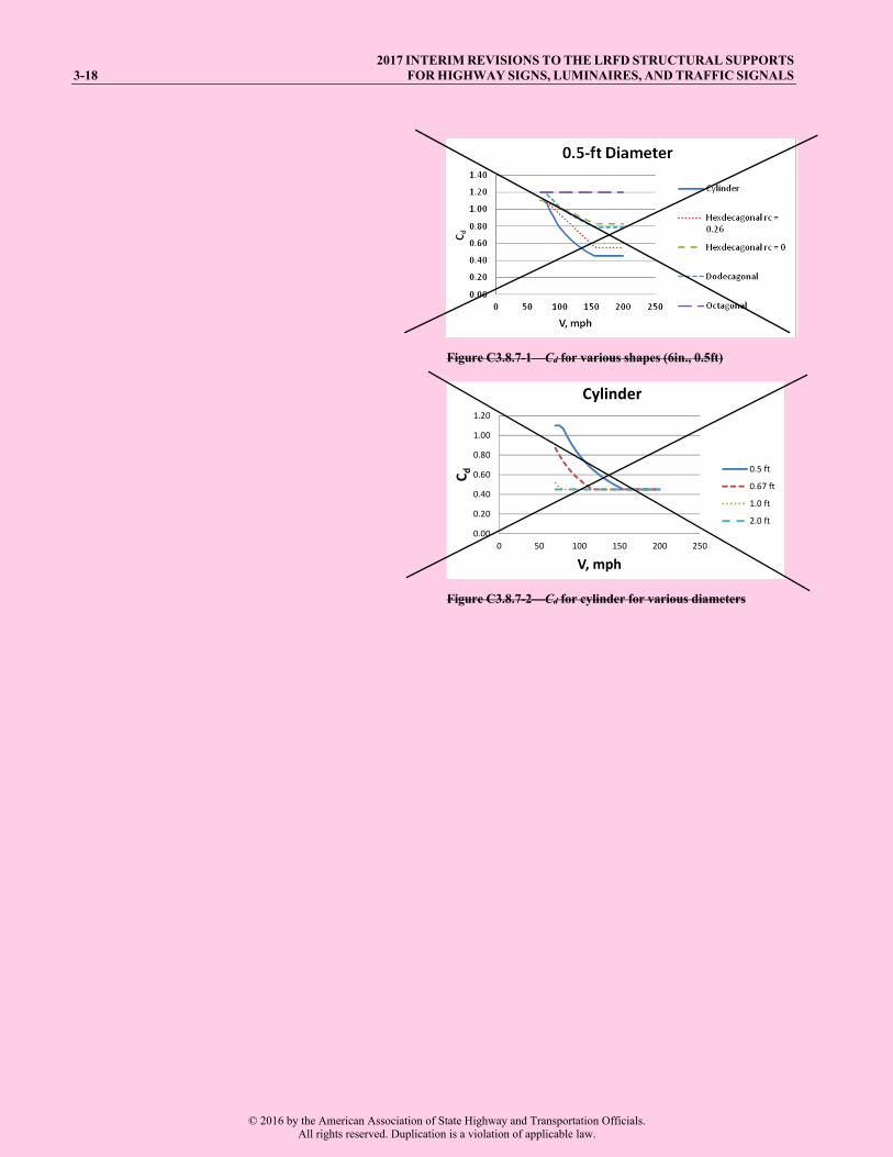
The wind drag coefficients in Table 3.8.7-1 were established based upon the work of several research projects as noted in the footnotes. Some coefficients are a strong function of Reynold’s number. The term CvVd is a simplified form of Reynolds using units convenient for LTS design. The algebraic form of these equations is somewhat different ; however, the behavior is similar as illustrated in Figure C3.8.7-1 and C3.8.7-1 and C3.8.7-2 where different shapes and equations are shown.
The typical extreme event wind speed is 105 mph or greater. Therefore, for diameters 8-in. or greater, the Cd is associated with the turbulent case, CvVd > 78 mph-ft, and the Cd is a constant (rightmost column of Table 3.8.7-1).
For smaller members, ASCE/SEI 07-10 wind speeds will tend to lower the Cd term compared to past practice. The Cv term at the extreme limit state adjusts the wind speed to correspond to past drag coefficients used for elements subject to wind.
For the fatigue limit state, the wind speeds are on the order of 10 mph and the CvVd will be low and the Cd will be the larger value in the leftmost column of Table 3.8.7-1. Between these extremes, the equations can the be used.
This observation simplifies the load application where speed varies with height, etc. The reliability calibration used these bounds in determining the load and resistance factors. See NCHRP 796 (Puckett et al, 2014).
© 2016 by the American Association of State Highway and Transportation Officials.All rights reserved. Duplication is a violation of applicable law.
2017 INTERIM REVISIONS TO THE LRFD STRUCTURAL SUPPORTS 3-18 FOR HIGHWAY SIGNS, LUMINAIRES, AND TRAFFIC SIGNALS
Figure C3.8.7-1—Cd for various shapes (6in., 0.5ft)
Figure C3.8.7-2—Cd for cylinder for various diameters
0.00
0.20
0.40
0.60
0.80
1.00
1.20
0 50 100 150 200 250
Cd
V, mph
Cylinder
0.5 ft
0.67 ft
1.0 ft
2.0 ft
© 2016 by the American Association of State Highway and Transportation Officials.All rights reserved. Duplication is a violation of applicable law.

2017 INTERIM REVISIONS TO THE LRFD STRUCTURAL SUPPORTS FOR HIGHWAY SIGNS, LUMINAIRES, AND TRAFFIC SIGNALS
SECTION 3: LOADS 3-19
Table 3.8.7-1—Wind Drag Coefficients, Cd P
a
Sign Panel Lsign/Wsign = 1.0
2.0 5.0 10.0 15.0
1.12 1.19 1.20 1.23 1.30
Traffic SignalsP
b 1.20 Luminaires (with generally rounded surfaces) 0.50 Luminaires (with rectangular flat side shapes) 1.20 Elliptical Member (D/do ≤ 2)
Broadside Facing Wind
1.7 1 2dDo o
D DCd d
Narrow Side Facing Wind
14
1 0.7 1ddo
DCd
Two Members or Trusses (one in front of other) (for widely separated trusses or trusses having small
solidity ratios see note c)
1.20 (cylindrical) 2.00 (flat)
Dynamic Message Signs (CMS)P
g 1.70 Attachments Drag coefficients for many attachments (cameras, luminaires,
traffic signals, etc.) are often available from the manufacturer, and are typically provided in terms of effective projected area (EPA), which is the drag coefficient times the projected area. If the EPA is not provided, the drag coefficient shall be taken as 1.0.
Continued on next page
© 2016 by the American Association of State Highway and Transportation Officials.All rights reserved. Duplication is a violation of applicable law.

2017 INTERIM REVISIONS TO THE LRFD STRUCTURAL SUPPORTS 3-20 FOR HIGHWAY SIGNS, LUMINAIRES, AND TRAFFIC SIGNALS
Table 3.8.7-1—Wind Drag Coefficients, Cd P
aP—Continued
Single Member or Truss Member CvVd ≤ 39 mph-ft 39 mph-ft CvVd 78 mph-ft
CvVd 78 mph-ft
Cylindrical 1.10 1.3(
129)vVdC
0.45
FlatP
d 1.70 1.70 1.70 Hexdecagonal: 16-Sides 0 rc 0.26
1.10 v1.37 1.08145 3
C6
cvc
Vd VdC rr
0.83 – 1.08rc
Hexdecagonal: 16-Sides rc 0.26P
e
1.10 78.20.55
71vC Vd
0.55
DodecagonalP
eP:
12-Sides 1.20
0.610.8
vVdC
0.79
OctagonalP
eP:
8-Sides 1.20 1.20 1.20
Square 2.0 – 6rs [for rs < 0.125]
1.25 [for rs 0.125]
DiamondP
f
1.70 [for d = 0.33 & 0.42]
1.90 [for d 0.50]
Notes:
a. Wind drag coefficients for members, sign panels, and other shapes not included in this table shall be established by windtunnel tests (over an appropriate range of Reynolds numbers), in which comparative tests are made on similar shapesincluded in this table. Values reported in peer-reviewed publications based upon wind tunnel tests are acceptable.Reynolds Number 9200 mph ftRe= V d
b. Wind loads on free-swinging traffic signals may be modified based on experimental data or other criteria as agreed by theOwner (e.g., Marchman, 1971).
c. Data show that the drag coefficients for a truss with a very small solidity ratio are merely the sum of the drags on theindividual members, which are essentially independent of one another. When two elements are placed in a line with thewind, the total drag depends on the spacing of the elements. If the spacing is zero or very small, the drag is the same as ona single element; however, if the spacing is infinite, the total force would be twice as much as on a single member. Whenconsidering pairs of trusses, the solidity ratio is of importance because the distance downstream in which shielding iseffective depends on the size of the individual members. The effect of shielding decreases with smaller spacing as thesolidity decreases. Further documentation may be found in Transactions (ASCE, 1961).
d. Flat members are those shapes that are essentially flat in elevation, including plates and angles.
e. Valid for members having a ratio of corner radius to distance between parallel faces equal to or greater than 0.125. Formultisided cross-sections with a large corner radius, a transition value for Cd can be taken as:
If rc ≤ rm, then Cd = Cdm
If rm < rc < rr, then Cd = Cdr + (Cdm – Cdr)[(rr – rc)/(rr – rm)]
If rc ≥ rr, then Cd = Cdr
© 2016 by the American Association of State Highway and Transportation Officials.All rights reserved. Duplication is a violation of applicable law.

2017 INTERIM REVISIONS TO THE LRFD STRUCTURAL SUPPORTS FOR HIGHWAY SIGNS, LUMINAIRES, AND TRAFFIC SIGNALS
SECTION 3: LOADS 3-21
where:
rc = ratio of corner radius (outside) to radius of inscribed circle,
Cdm = drag coefficient for multisided section,
Cdr = drag coefficient for round section,
rm = maximum ratio of corner radius to inscribed circle where the multisided section’s drag coefficient is unchanged (see figure and table below), and
rr = ratio of corner radius to radius of inscribed circle where multisided section is considered round (see figure and table below).
Shape rm rr 16-Sided, Hexdecagonal 0.26 0.63 12-Sided, Dodecagonal 0.50 0.75 8-Sided, Octagonal 0.75 1.00
f. The drag coefficient applies to the diamond’s maximum projected area measured perpendicular to the indicated directionof wind.
g. A value of 1.7 is suggested for Dynamic Message Signs (DMS) until research efforts can provide accurate dragcoefficients. This value may be used for both horizontal and vertical loads.
The validity of the drag coefficients (dimensionless) presented in Table 3.8.7-1 have been the subject of research (McDonald et al, 1995). Based on this work coupled with independent examinations of the information presented in Table 3.8.7-1, the drag coefficients were changed to account for 3-s gust wind speeds, except for square and diamond shapes.
Research concerning Cd values for dodecagonal shapes (12 sides) has been conducted at Iowa State University (James, 1971). The highest coefficients for the dodecagonal cylinder were measured for wind normal to a flat side. A circular cylinder was included in the testing program to allow a check on the test equipment, and boundary corrections were applied to the raw test data. All measured values for the dodecagonal cylinder with zero angle of incidence were higher than those measured for the circular cylinder. Lower shape coefficients might be justified for some velocities; however, this would require additional data for the
© 2016 by the American Association of State Highway and Transportation Officials.All rights reserved. Duplication is a violation of applicable law.

2017 INTERIM REVISIONS TO THE LRFD STRUCTURAL SUPPORTS 3-22 FOR HIGHWAY SIGNS, LUMINAIRES, AND TRAFFIC SIGNALS
dodecagons at lower Reynolds numbers and review of the factors specified for round cylinders.
The equation for the Cd value for an elliptical member with the narrow side facing the wind was empirically derived to fit wind tunnel test data.
The drag coefficients for hexadecagons (16 sided) include the effects that varying ratios of corner radius to cylinder radius have on the drag coefficient. The Cd values for CvVd greater than 78 mph-ft were selected from information from wind tunnel tests on a number of hexadecagons with different ratios of corner radius to radius of inscribed circle (James, 1985).
These minimum Cd values vary linearly from 0.83 for a ratio of zero, to a value of 0.55 for ratios equal to or over 0.26. For consistency between maximum Cd values for cylinders and hexadecagons, the maximum Cd value for hexadecagons was selected to be the maximum value given for a cylinder. For a given ratio, values of Cd for Vd values between 39 mph-ft and 78 mph-ft vary linearly from 1.10 for Vd equal to 39 mph-ft to the minimum value at Vd equal to 78 mph-ft. The wind force resulting from use of these Cd values represents the total static force acting on the member, which would be the vector sum of the actual drag force and lift or side force.
If traffic signals or signs on span-wire pole structures are restrained from swinging in the wind, the full wind load must be applied. When agreed on between Owner and Designer, reduced forces may be used for free-swinging traffic signals when substantiated by research (Marchman, 1971; Marchman and Harrison, 1971). Wind loads on signs that are not restrained from swinging in the wind may be reduced with the consent of the Owner. Wind tunnel test results (Marchman and Harrison, 1971) indicate instability problems with traffic signals with certain hood configurations when not restrained from swinging. These instability problems should be considered when designing span-wire support structures. Orientation varies according to tests, but a value of 1.20 was shown to be conservative over a wide range. Values of Cd for square tubing, with the wind direction perpendicular to the side of the tube, have been revised to reflect the influence from the ratio of the corner radius to depth of member (James and Vogel, 1996).
A transition in the values of Cd for multisided cross-sections (hexdecagonal, dodecagonal, and octagonal) that approach round was developed in NCHRP 494, Structural Supports for Highway Signs, Luminaires, and Traffic Signals (Fouad et al., 2003) and incorporated as note e to Table 3.8.7-1. The method uses a linear equation to interpolate between the drag coefficient for round poles, Cdr, and the drag coefficient for multisided poles, Cdm, with respect to the variable rc. If rc is unknown, the section can conservatively be treated as multisided using the lowest reasonable value of rc for the section.
When three members are used to form a triangular truss, the wind load shall be applied to all of the members. Even though all of the members are not in the same plane of reference, they may be seen in a normal elevation.
As provided in note b to Table 3.8.7-1, consideration may be given to modifying the forces applied to free-
© 2016 by the American Association of State Highway and Transportation Officials.All rights reserved. Duplication is a violation of applicable law.

2017 INTERIM REVISIONS TO THE LRFD STRUCTURAL SUPPORTS FOR HIGHWAY SIGNS, LUMINAIRES, AND TRAFFIC SIGNALS
SECTION 5: STEEL DESIGN
5.1—SCOPE C5.1
This Section specifies design provisions for steel structural supports. Fatigue-sensitive steel support structures are further addressed in Section 11. Additional design provisions not addressed in this Section shall be obtained from other references as noted.
Design provisions are provided for round and multi-sided tubular shapes, I-shaped sections, channels, plates, angles, and anchor bolts above the foundation. Anchorage requirements are specified in Section 15.
Laminated structures may be used when the fabrication process is such that adequate shear transfer between the lamina can be achieved. Their use is subject to the approval of the Owner.
5.2—DEFINITIONS
Anchor Bolt—A bolt, stud, or threaded rod used to transmit loads from the attachment into the concrete support or foundation. The end cast in concrete shall be provided with a positive anchorage device, such as forged head, nut, hooked end, or attachment to an anchor plate to resist forces on the anchor bolt.
Anchorage—The process of attaching a structural member or support to the concrete structure by means of an embedment, taking into consideration those factors that determine the load capacity of the anchorage system.
Attachment—The structural support external to the surfaces of the embedment that transmits loads to the embedment.
Compact Section—A section capable of developing the plastic moment capacity.
Ductile Anchor Connection—A connection whose resistance is controlled by the strength of the steel anchorage rather than the strength of the concrete.
Ductile Anchor Failure—A ductile failure occurs when the anchor bolts are sufficiently embedded so that failure occurs by yielding of the steel anchor bolts.
Embedment—The portion of a steel component embedded in the concrete used to transmit applied loads from the attachment to the concrete support or foundation.
Headed Anchor—A headed bolt, a headed stud, or a threaded rod with an end nut.
High-Mast Lighting Tower (HMLT)—Pole-type tower that provides lighting at heights greater than 55 ft.
Lateral-Torsional Buckling (LTB)— The buckling mode of a flexural member involving deflection normal to the plane of bending that occurs simultaneously with twist about the shear center of the cross section.
Local Flange Buckling (LFB)—Section instability due to buckling of flange or other local part of the cross section.
Multi-sided Tube—A section with generally round characteristics having eight or more sides.
Noncompact Section—A section in which the moment capacity is not permitted to exceed its yield moment.
Rectangular Tube—A square or rectangular section (four sides). Resistance checks differ from multi-sided tubes.
Retrofit Anchor Bolt—An anchor that is installed into hardened concrete.
Slender Section—A section in which the moment capacity is governed by buckling prior to reaching its yield moment.
5-1© 2016 by the American Association of State Highway and Transportation Officials.
All rights reserved. Duplication is a violation of applicable law.

2017 INTERIM REVISIONS TO THE LRFD STRUCTURAL SUPPORTS 5-2 FOR HIGHWAY SIGNS, LUMINAIRES, AND TRAFFIC SIGNALS
5.3—NOTATION
Ae = effective net area (in.2) (5.9.2) (5.9.3) AEFF = effective area summation (in.2) (5.10.2.3) Ag = gross area (in.2) (5.9.2) (5.9.3) (5.10.2.3) (5.11.2.1.1) (5.11.2.1.2) (5.12.1) An = net area (in.2) (5.9.3) Av = shear area (in.2) (5.11.2) (5.11.2.1.1) (5.11.2.1.2) (5.11.2.2) Aw = area of the web (in.2) (5.11.2.2) aw = ratio of two times the web area in compression due to application of major axis bending moment alone to the area
of the compression flange components (5.8.3.2.4) B = ratio (5.8.4.4) (5.12.1) B = moment magnification factor (5.12.1) Bx = moment magnification factor for second order effects (x axis) (5.12.1) (5.12.2) By = moment magnification factor for second order effects (y axis) (5.12.1) (5.12.2) b = element width (in.) (5.7.2) (C5.7.2) (5.7.3) (5.8.2) (5.8.3.1.2) (5.8.3.1.3) (5.10.2.3) (5.11.2.2) be = element effective width (in.) (5.10.2.3) bf = flange width of rolled beam (in.) (5.7.3) (C5.9.3) bl = longer leg width (in.) (5.10.2.4) bs = shorter leg width (in.) (5.10.2.4) Cb = moment gradient coefficient (5.8.3.1.3) (5.8.3.2.4) (5.8.7.2) Ct = the torsional constant (5.11.3) (C5.11.3) Cv = shear buckling coefficient (5.11.2.2) Cw = warping constant (in.6) (5.8.3.1.3) c = lateral-torsional buckling section coefficient (5.8.3.1.3) D = inside diameter of round cross-section (in.) (5.6.3) (5.6.6.1) (5.7.2) (C5.7.2) (5.8.2) (5.10.2.2) (5.11.2.1.1)
(5.11.3.1.1) D = outside diameter of round cross section (in.) (5.6.2) (C5.6.2) (5.6.3) (5.6.6.1) (5.7.2) (C5.7.2) (5.8.2) d = full nominal depth for stems of tees (in.) (5.7.3) (5.8.4.3) (5.8.4.4) (5.8.7.1) (5.8.7.2) (C5.9.3) (5.11.2.2) d = full nominal depth for webs of rolled or formed sections (in.) (5.7.3) (5.8.4.3) (5.8.4.4) (5.8.7.1) (5.8.7.2) (C5.9.3) E = modulus of elasticity of steel, 29,000 (ksi) (5.7.2) (5.7.3) (5.8.2) (5.8.3.1.3) (5.8.3.2.4) (5.8.4.3) (5.8.4.4) (5.8.7.1)
(5.8.7.2) (5.10.2.1) (5.10.2.2) (5.10.2.3) (5.11.2.1.1) (5.11.2.2) (5.11.3.1.1) (5.12.1) Fcr = critical buckling stress (ksi) (5.8.3.1.1) (5.8.3.2.4) (5.8.4.3) (5.8.7.2) (5.10.2.1) (5.10.2.3) Fe = Euler stress, calculated in the plane of bending (ksi) (5.10.2.1) FL = stress defined in Table 5.7.3-1 (ksi) (5.7.3) Fnt = torsional resistance (ksi) (5.11.3) (5.11.3.1.1) (5.11.3.1.2) (5.11.3.2) Fnv = nominal shear resistance (ksi) (5.11.2) (5.11.2.1.1) (5.11.2.1.2) (5.11.2.2) (5.11.3.2) Fu = specified minimum fracture stress (ksi) (5.9.2) Fy = specified minimum yield stress (ksi) (5.7.2) (5.7.3) (5.8.2) (5.8.3.1.1) (5.8.3.1.2) (5.8.3.1.3) (C5.8.3.1.3)
(5.8.3.2.1) (5.8.3.2.2) (5.8.3.2.3) (5.8.3.2.4) (5.8.4.2) (5.8.5.1) (5.8.5.2) (5.8.7.1) (5.8.7.2) (5.9.2) (5.10.2.1) (5.10.2.2) (5.11.2.1.1) (5.11.2.1.2) (5.11.2.2) (5.11.3.1.2)
f = buckling stress (ksi) (5.10.2.3) G = elastic shear modulus (ksi) (5.8.4.4) g = transverse center-to-center spacing (gauge) between lines of fasteners (in.) (5.9.3) H = height of backing ring at a groove-welded tube-to-transverse-plate connection (in.) (5.6.5) (C5.6.5) h = clear distance between the flanges for webs of rolled or built-up sections (in.) (5.7.3) (5.11.2.2) hc = twice the distance from center of gravity to inside face of compression flange (in.) (5.7.3) (5.8.3.2.4) ho = distance between flange centroids (in.) (5.8.3.1.3) (5.8.3.2.4) hp = twice the distance from plastic neutral axis to inside face of compression flange (in.) (5.7.3)
© 2016 by the American Association of State Highway and Transportation Officials.All rights reserved. Duplication is a violation of applicable law.

2017 INTERIM REVISIONS TO THE LRFD STRUCTURAL SUPPORTS FOR HIGHWAY SIGNS, LUMINAIRES, AND TRAFFIC SIGNALS
SECTION 5: STEEL DESIGN 5-33
5.11.3.1.2—Multi-Sided Tubular Members C.5.11.3.1.2
The nominal torsion stress capacity for multi-sided non-square and rectangular tubular shapes shall be:
0 .6nt yF F (5.11.3.1.2-1)
Previous editions of these specifications have shownthat multi-sided tubes will not buckle with width-to-thickness ratios limited to max.
5.11.3.2—I-Shapes; Channels; Tees; and Square and Rectangular, and Angle Shapes
For torsion on open I-shape, channel, tee, and angle sections, AISC Design Guide 9 (1997) may be used to develop an appropriate nominal torsional capacity.
For square and rectangular shapes
nt nvF F (5.11.3.2-1)
5.12—COMBINED FORCES C5.12
5.12.1—Combined Force Interaction Requirements Members subjected to combined bending, axial
compression or tension, shear, and torsion shall be proportioned to meet the following:
2
1.0u u u u
r r r r
P BM V TP M V T
(5.12.1-1)
If 0.20u
r
TT
torsional and shear effects can be ignored,
and when:
0.20u
r
PP
8 1.09
u u
r r
P BMP M
(5.12.1-2)
when 0.20u
r
PP
1.02
u u
r r
P BMP M (5.12.1-3)
For vertical luminaire supports, the term r
u
PP2
may be
approximated as 0.08.
For round and multi-sided tubular members,
2 2u ux uyM M M (5.12.1-4)
AISC (2011) design equations were incorporated for typical sign, luminaire, and signal supports. For members and limit states not addressed in these specifications, other resources should be considered such as AISC (2011) and LRFD Design.
For structural supports for signs, luminaires, and traffic signals, direct shear is typically small and therefore only torsional effects are checked to determine which interaction equation to use.
For vertical luminaire supports, the term r
u
PP is
relatively small where Pr is the buckling resistance of the entire pole subjected to the applied axial loads Pu. Poles are often tapered with multiple sections with different wall thicknesses; the axial loading typically consists of a concentrated luminaire load with a distributed dead load that is a function of the taper. Therefore, closed-form solutions are difficult. A rigorous numerical analysis to compute the buckling load may be employed and may be implemented in standard tools like a spreadsheet. The term
r
u
PP is the inverse of the buckling load factor (include
load and resistance factors). If a finite element analysis (frame elements) is employed that considers only the second-order geometry sway effects (P-), then the first term in Eq. 5.12.1-3 must be computed or approximated. If the finite element analysis considers both second-order sway effect and geometric axial “softening” effects of the stiffness matrix, then the
r
u
PP term may be discarded as it is implicitly
included in the analysis and will result in slightly higher bending moments. For simplicity, initial out-of-straightness, etc. does not need to be considered. Some
© 2016 by the American Association of State Highway and Transportation Officials.All rights reserved. Duplication is a violation of applicable law.

2017 INTERIM REVISIONS TO THE LRFD STRUCTURAL SUPPORTS 5-34 FOR HIGHWAY SIGNS, LUMINAIRES, AND TRAFFIC SIGNALS
and
2 2u ux uyV V V (5.12.1-5)
commercial analysis programs properly consider both effects, others do not.
For members with biaxial bending about geometric or
principal axes, the term u
r
BMM
may be expanded to:
uyuxx y
rx ry
MMB B
M M (5.12.1-6)
the greater of or uyu ux
r rx ry
VV VV V V
(5.12.1-7)
when member is in tension:
r t ntP P (5.12.1-8)
when member is in compression:
r c ncP P (5.12.1-9)
Moment Magnifier B:
For prismatic members:
Compression: 1
1 u
e
B PP
(5.12.1-10)
where:
2
2g
e
EAP
KLr
(5.12.1-11)
Tension:
1.0B (5.12.1-12)
For non-prismatic members, Tension:
1.0B (5.12.1-13)
Compression: B shall be computed according to Section 4.
This includes square and rectangular tubes and other nontubular shapes.
5.12.2—Bending of Square and Rectangular Tubes C5.12.2 Square and rectangular tubes shall meet the design
requirements of Article 5.12.1 for bending about the geometric axes. In addition, this section applies to tubes
NCHRP Report 494, Supports for Highway Signs, Luminaries, and Traffic Signals (Fouad et al., 2003) compared theoretical diagonal bending to experimental
© 2016 by the American Association of State Highway and Transportation Officials.All rights reserved. Duplication is a violation of applicable law.

2017 INTERIM REVISIONS TO THE LRFD STRUCTURAL SUPPORTS FOR HIGHWAY SIGNS, LUMINAIRES, AND TRAFFIC SIGNALS
SECTION 5: STEEL DESIGN 5-35
bent about a skewed (diagonal) axis. The following interaction equation shall be satisfied:
**
1y uyx ux
rx ry
B MB MM M
(5.12.2-1)
where for tubes with r
1.60, ,rx f px ry f pyM M M M
and, for tubes with r m ax
1.00, andrx f nx ry f nyM M M M
* *,ux uyM M = factored moments from skewed diagonal loading.
tests. The interaction increase in nominal strength is justified for tubes bent about the diagonal for sections with limited width–thickness ratios. Although the diagonal strength properties are significantly less than the primary axis properties, tests show additional strength compared with current strength predictions. For compact sections, the reserve strength is 33 percent higher for bending about a diagonal axis (Zx/Sx = 1.5) than about the principal axes (Zx/Sx = 1.13), where Zx and Sx are the plastic and elastic section moduli, respectively.
5.13—CABLES AND CONNECTIONS C5.13
The provisions of this Article apply to cables and their connections.
The factored tensile resistance, Rrt, shall be
rt rt nrR R (5.13-1)
where: rt is the resistance factor as specified in Article 5.5.3.2.
For horizontal supports (wire and connections) of span-wire pole structures, the resistance of the cable or connection is the nominal breaking strength of the cable or connection.
Typically manufacturers’ data may be used for the resistances.
5.14—WELDED CONNECTIONS C5.14
Welding design and fabrication shall be in accordance with the latest edition of the AWS Structural Welding Code—Steel (2010) and AWS Structural Welding Code—Reinforcing Steel (2011).
Fatigue considerations are provided in Section 11.
Hybrid laser arc welding (HLAW) is categorized in AWS D1.1 as “Other Welding Processes.” Process variables are to be agreed upon by the Fabricator and Owner. Fabrication guidance is provided in Division II.
5.15—BOLTED CONNECTIONS
Design of bolted connections shall be in accordance with the current LRFD Design.
Fatigue considerations are provided in Section 11.
5.16—ANCHOR BOLT CONNECTIONS C5.16
This Article provides the minimum requirements for design of steel anchor bolts used to transmit loads from attachments into concrete supports or foundations by means of tension, bearing, and shear. A minimum of
Figure C5.16-1 shows a typical steel-to-concrete double-nut connection. Figure C5.16-2 shows a typical single-nut connection. Installation considerations are provided in Division III.
© 2016 by the American Association of State Highway and Transportation Officials.All rights reserved. Duplication is a violation of applicable law.

2017 INTERIM REVISIONS TO THE LRFD STRUCTURAL SUPPORTS 5-36 FOR HIGHWAY SIGNS, LUMINAIRES, AND TRAFFIC SIGNALS
eight anchor bolts shall be used to connect high-mast lighting towers.
Figure C5.16-1—Typical Double-Nut Connection
Figure C5.16-2—Typical Single-Nut Connection
5.16.1—Anchor Bolt Types C5.16.1 Cast-in-place anchor bolts shall be used in new
construction.
The following requirements shall apply:
Anchor bolts may be headed through the use of apreformed bolt head or by other means, such as anut, flat washer, or plate;
Hooked anchor bolts with a yield strength notexceeding 55 ksi may be used; and
Deformed reinforcing bars may be used as anchorbolts.
The ring-shaped base plate of a high-level (pole-type) luminaire support has low bending stiffness. The number of anchor bolts and the geometry of the base plate determine the stiffness of the base plate. Research, both fatigue tests and analytical studies, indicates that using less than 12 bolts can result in a reduction in fatigue performance in some connections. The fatigue strength of the butt-welded connection detail with an external collar reinforcement shown in Detail 4.8 of Table 11-9.3.1-1 is less sensitive to the number of anchor bolts and as few as 8 bolts can be used with this detail. However, due to the field problems in properly tightening the anchor bolts, the use of 12 bolts is recommended to provide adequate anchorage stiffness when fatigue is controlling the design of the luminaire support connection.
Research (Jirsa et al., 1984) has shown that headed cast-in-place anchor bolts perform significantly better than hooked anchor bolts, regarding possible pull-out prior to development of full tensile strength. Caution should be exercised when using deformed reinforcing bars as anchor bolts, because no fatigue test data are available on threaded reinforcing bar. The ductility of deformed reinforcing bars, as measured by elongation, can be significantly less than most other anchor bolts.
Anchor bolts with hooks make it impossible to perform a proper ultrasound inspection.
© 2016 by the American Association of State Highway and Transportation Officials.All rights reserved. Duplication is a violation of applicable law.

2017 INTERIM REVISIONS TO THE LRFD STRUCTURAL SUPPORTS FOR HIGHWAY SIGNS, LUMINAIRES, AND TRAFFIC SIGNALS
10-1
SECTION 10:
SERVICEABILITY REQUIREMENTS
10.1—SCOPE
This Section provides serviceability requirements for support structures.
10.2—DEFINITIONS
Camber—The condition of the horizontal support being arched.
Quadri-Chord Truss—A horizontal member composed of four longitudinal chords connected by bracing.
Rake—To slant or incline from the vertical.
Tri-Chord Truss—A horizontal member composed of three longitudinal chords connected by bracing.
10.3—NOTATION
E = modulus of elasticity (ksi) (C10.5) H = height of vertical support (in.) (C10.5) I = moment of inertia of vertical support (in.4) (C10.5) L = distance between supports for an overhead bridge structure; distance from vertical support to free end for
horizontal cantilevered support (in.) (10.4.1) (C10.4.1) (10.4.3.1) (10.5) (C10.5) M = moment caused by dead loads applied to the vertical support at the connection of the horizontal support (lb-in.)
(C10.5) r = radius of gyration (in.) (10.4.3.1) u = prefabricated camber (slope) in the horizontal cantilevered arm (in./in.) (C10.5) DL = deflection at free end of horizontal support under dead load (in.) (C10.5) P = deflection at tip of vertical support under dead load from horizontal cantilevered support (in.) (C10.5) PDL = deflection at free end of horizontal support caused by slope at the tip of the vertical support (in.) (C10.5) TOTAL = total dead load deflection at free end of horizontal support (in.) (C10.5) = rotation at the top of the pole (radians) (C10.5)
C10.4
The deflection limits that are set by these Specifications are to serve two purposes. The first purpose is to provide an aesthetically pleasing structure under dead load conditions. The second purpose is to provide adequate structural stiffness that will result in acceptable performance under applied loads.
C10.4.1
10.4—DEFLECTION
Highway support structures of all materials should be designed to have adequate structural stiffness that will result in acceptable serviceability performance. Deflections for specific structure types shall be limited as provided in Articles 10.4.1 and 10.4.2. Permanent camber for specific structure types shall be provided per Article 10.5.
10.4.1—Overhead Bridge Supports for Signs and Traffic Signals
For overhead bridge monotube and truss structures supporting signs and traffic signals, the maximum vertical deflection of the horizontal support resulting from Service I load combination shall be limited to L/150, where L is the span length.
Research was sponsored by the Arizona Department of Transportation (Ehsani et al., 1984; Martin et al., 1985) to determine an appropriate deflection limitation for steel monotube bridge support structures. This research included field tests and analytical studies using computer modeling. The studies investigated the static and dynamic behavior of monotube bridge sign support structures and determined a dead load deflection limit that should be specified for
© 2016 by the American Association of State Highway and Transportation Officials.All rights reserved. Duplication is a violation of applicable law.

2017 INTERIM REVISIONS TO THE LRFD STRUCTURAL SUPPORTS 10-2 FOR HIGHWAY SIGNS, LUMINAIRES, AND TRAFFIC SIGNALS
monotube bridge structures. The 1989 Interim Specifications were revised to limit deflection to the span divided by 150 for dead and ice load applications based on this research.
A later study (Lundgren, 1989) indicated that because the deflection criterion was an aesthetic limitation, it could be increased to the span divided by 100; however, no additional work has been found to justify changing the deflection limit to a more liberal value. Although this study considered only steel members, the deflection limit has been generalized for other materials because aesthetics was the governing consideration.
Other types of overhead bridge sign supports (i.e., two-chord, tri-chord, and quadri-chord trusses) generally have higher stiffness than the monotube type. A dead load deflection limit of the span divided by 150 (i.e., L/150) may be adopted as a conservative limit for those types of overhead bridge sign and traffic signal support structures made with two-chord, tri-chord, or quadri-chord trusses.
10.4.2—Cantilevered Supports for Signs, Luminaires, and Traffic Signals
10.4.2.1—Vertical Supports C10.4.2.1
The horizontal deflection limits for vertical supports, such as street lighting poles, traffic signal structures, and sign structures, shall be as follows:
Under Service I load combination, the deflection at thetop of vertical supports with transverse load applicationsshall be limited to 2.5 percent of the structure height;and
Under Service I load combination, the slope at the top ofvertical supports with moment load applications shall belimited to 0.35 in./ft.
The dead load deflection and slope limitations were developed based on aesthetic considerations. The 2.5 percent deflection limit was developed for transverse load applications, such as strain pole applications, where a dead load caused by span-wire tension could cause unsightly deflection. The horizontal linear displacement at the top of the structure is measured in relation to a tangent to the centerline at the structure’s base. The slope limitation of 0.35 in./ft, which is equivalent to an angular rotation of 1 degree-40 minutes, was initially developed for street lighting poles with a single mast arm, where the mast arm applied a concentrated dead load moment that could also cause unsightly deflections. It is measured by the angular rotation of the centerline at the top of the structure in relation to the centerline at its base. The concentrated moment loads result from the effect of eccentric loads of single or unbalanced multiple horizontally mounted arm members and their appurtenances.
For luminaire support structures under Service I load combination (i.e., dead load and wind), deflection shall be limited to 15 10 percent of the structure height.
Deflections shall be computed by usual methods or equations for elastic deflections. For prestressed concrete members, the effects of cracking and reinforcement on member stiffness shall be considered.
The 15 10 percent deflection limitation for the Service I load combination constitutes a safeguard against the design of highly flexible structures. It is intended mainly for high-level lighting poles. The deflections are calculated with the unit load factors defined in Article 3.4, and second-order effects are normally considered in the analysis.
10.4.2.2—Horizontal Supports C10.4.2.2
Adequate stiffness shall be provided for the horizontal supports of cantilevered sign and traffic signal structures that will result in acceptable serviceability performance.
Galloping and truck gust-induced vibration deflections of cantilevered single-arm sign supports and traffic signal
No dead load deflection limit is prescribed for horizontal supports of cantilevered sign and traffic signal structures. Stiffness requirements are determined by the Designer. Structures are typically raked or the horizontal supports are cambered such that the dead load deflection at the end of the arm is above a horizontal reference. Camber requirements for
© 2016 by the American Association of State Highway and Transportation Officials.All rights reserved. Duplication is a violation of applicable law.

2017 INTERIM REVISIONS TO THE LRFD STRUCTURAL SUPPORTS FOR HIGHWAY SIGNS, LUMINAIRES, AND TRAFFIC SIGNALS
SECTION 11: FATIGUE DESIGN 11-3
F = fatigue resistance stress range (ksi) (11.5) (11.5.1) = indication of stress range in member (11.9.3.1) = load factor (11.5) (11.5.1) (11.9.3) = resistance factor (11.5) (11.5.1) (11.9.3)
11.4—APPLICABLE STRUCTURE TYPES C11.4
Design for fatigue shall be required for the following type structures:
a. overhead cantilevered sign structures,
b. overhead cantilevered traffic signal structures,
c. high-mast lighting towers (HMLT),
d. overhead noncantilevered sign structures, and
e. overhead noncantilevered traffic signal structures.
NCHRP Report 412 and NCHRP Web Only Document 176 are the basis for the fatigue design provisions for cantilevered structures. NCHRP Report 494 is the basis for the fatigue design provisions for non-cantilevered support structures. The fatigue design procedures outlined in this Section may be applicable to steel and aluminum structures in general. However, only specific types of structures are identified for fatigue design in this Article. Common lighting poles and roadside signs are not included because they are smaller structures and normally have not exhibited fatigue problems. An exception would be square lighting poles, as they are much more prone to fatigue than round or multi-sided cross-sections having eight or more sides. Caution should be exercised regarding the use of square lighting poles even when a fatigue design is performed. The provisions of this Section are not applicable for the design of span-wire (strain) poles.
11.5—DESIGN CRITERIA C11.5
Cantilevered and noncantilevered support structures shall be designed for fatigue to resist wind-induced stresses. Stress ranges on all components, openings, mechanical fasteners, and weld details shall be limited to satisfy:
f F (11.5-1)
where ∆f is the wind load induced stress range; ∆F is the fatigue resistance, is the load factor per the Fatigue I limit state defined in Table 3.4-1, and is the resistance factor equal to 1.0.
Fatigue design of the support structures may be conducted using the nominal stress-based classifications of typical connection details as provided in Article 11.9.1 and Table 11.9.3.1-1, or using the alternate local stress-based and/or experiment-based methodologies presented in Appendix C. Support structures shall be proportioned such that the wind-induced stress is below the constant amplitude fatigue threshold (CAFT) providing infinite life.
The remaining fatigue life of existing steel structures may be assessed based on a finite life. The finite life methodology shall only be used to evaluate the fatigue life of existing structures and shall not be used in the design of new structural elements.
Fatigue design of connection details in support structures may be as per nominal stress- or local stress-based and/or experiment-based methodologies. The nominal stress-based design approach using classification of typical connection details and their fatigue resistances as provided in Article 11.9.1 and Table 11.9.3.1-1 should suffice in most cases. However, if a connection detail is employed that has not been addressed in Table 11.9.3.1-1, an alternate local stress-based and/or experiment-based methodology as provided in Appendix C may be used for fatigue design. It is important that the stresses are calculated in agreement with the definition of stress used for a particular design methodology.
Accurate load spectra for defining fatigue loadings are generally not available. Assessment of stress fluctuations and the corresponding number of cycles for all wind-induced events (lifetime loading histogram) is difficult. With this uncertainty, the design of sign, high-level luminaire, and traffic signal supports for a finite fatigue life is unreliable. Therefore, an infinite life fatigue design approach is recommended.
The infinite life fatigue design approach should ensure that a structure performs satisfactorily for its design life to an acceptable level of reliability without significant fatigue damage. While some fatigue cracks may initiate at local stress concentrations, there should not be any time dependent propagation of these cracks. This is typically the case for structural supports where the wind-load cycles in 25 years or more are expected to exceed 100 million cycles, whereas typical weld details exhibit Constant Amplitude Fatigue
© 2016 by the American Association of State Highway and Transportation Officials.All rights reserved. Duplication is a violation of applicable law.

2017 INTERIM REVISIONS TO THE LRFD STRUCTURAL SUPPORTS 11-4 FOR HIGHWAY SIGNS, LUMINAIRES, AND TRAFFIC SIGNALS
Threshold (CAFT) at 10 to 20 million cycles. It may be noted that in the predecessor to these specifications, the CAFT was termed as Constant Amplitude Fatigue Limit (CAFL).
An accurate assessment of the lifetime wind induced stress range histogram is required for assessing finite life fatigue performance. Thus, designing new structures for finite fatigue life is impractical. Where an accurate assessment of the lifetime wind induced stress range histogram is available, a finite fatigue life may be considered for estimating remaining life of existing structures at the discretion of the Owner.
The equivalent static wind load effects as specified in Article 11.7 are to be considered for infinite life fatigue design. The wind effects for evaluating finite fatigue life should be obtained from analysis based on historical wind records, or directly from field measurements on the subject or similar structures situated in the same or similar wind environments, as approved by the Owner.
Due to significantly lower fatigue resistance compared to steel, remaining life assessment of aluminum structures is not advised.
11.5.1—Nominal Stress-Based Design C11.5.1
For nominal stress-based design, Equation 11.5-1 is rewritten as:
n nf F (11.5.1-1)
where:
(∆f )n = the wind-induced nominal stress range defined in Article 11.9.2,
(∆F)n = the nominal fatigue resistance as specified in Article 11.9.3 for the various detail classes identified in Article 11.9.1,
= the load factor per the Fatigue I limit state defined in Table 3.4-1, and
= the resistance factor equal to 1.0.
Fatigue-critical details may be designed such that the nominal stress ranges experienced by the details are less than the nominal fatigue resistance of respective detail classes. For fatigue design classification of typical support structure details, the applicable nominal stress ranges and their fatigue resistances are provided in Articles 11.9.1, 11.9.2, and 11.9.3.
11.6—FATIGUE IMPORTANCE FACTORS
A fatigue importance factor, IF, that accounts for the risk of hazard to traffic and damage to property shall be applied to the limit state wind-load effects specified in Article 11.7. Fatigue importance factors for traffic signal and sign support structures exposed to the three wind load effects are presented in Table 11.6-1. Fatigue importance categories for HMLTs are provided in Table 11.6-2.
C11.6
Fatigue importance factors are introduced into the Specifications to adjust the level of structural reliability of cantilevered and noncantilevered support structures. Fatigue importance factors should be determined by the Owner.
The importance categories and fatigue importance factors (rounded to the nearest 0.05) are results from NCHRP Reports 469 and 494. Two types of support structures are presented in Table 11.6-1. Structures classified as Category I present a high hazard in the event of failure and should be designed to resist rarely-occurring wind loading and vibration phenomena. It is recommended that all structures without effective mitigation devices on roadways with a speed limit in excess of 35 mph and average daily traffic (ADT) exceeding 10,000 or average daily truck traffic (ADTT) exceeding 1,000 should be classified as Category I
© 2016 by the American Association of State Highway and Transportation Officials.All rights reserved. Duplication is a violation of applicable law.

2017 INTERIM REVISIONS TO THE LRFD STRUCTURAL SUPPORTS FOR HIGHWAY SIGNS, LUMINAIRES, AND TRAFFIC SIGNALS
SECTION 11: FATIGUE DESIGN 11-9
11.7.1.2—Natural Wind Gust
Cantilevered and noncantilevered overhead sign and overhead traffic signal supports shall be designed to resist an equivalent static natural wind gust pressure range of:
PNW = 5.2CdIF (psf) (11.7.1.2-1)
where:
IF = fatigue importance factor
5.2 = pressure (psf)
Cd = the appropriate drag coefficient based on the yearly mean wind velocity of 11.2 mph specified in Section 3, “Loads,” for the considered element to which the pressure range is to be applied.
C11.7.1.2
Because of the inherent variability in the velocity and direction, natural wind gusts are the most basic wind phenomena that may induce vibrations in wind-loaded structures. The equivalent static natural wind gust pressure range specified for design was developed with data obtained from an analytical study of the response of cantilevered support structures subject to random gust loads (Kaczinski et al., 1998).
Because Vmean is relatively low, the largest values of Cd for the support may be used.
This parametric study was based on the 0.01 percent exceedance for a yearly mean wind velocity of 11.2 mph, which is a reasonable upper bound of yearly mean wind velocities for most locations in the country. There are locations, however, where the yearly mean wind velocity is larger than 11.2 mph. For installation sites with more detailed information regarding yearly mean wind speeds (particularly sites with higher wind speeds), the following equivalent static natural wind gust pressure range shall be used for design:
2mean5.2
11.2mph
NW d FV
P C I (psf) (C11.7.1.2-1)
If Eq. C11.7.1.2-1 is used in place of Eq. 11.7.1.2-1, Cd may be based on the location-specific yearly mean wind velocity Vmean. The natural wind gust pressure range shall be applied in the horizontal direction to the exposed area of all support structure members, signs, traffic signals, and/or miscellaneous attachments. Designs for natural wind gusts shall consider the application of wind gusts for any direction of wind. The design natural wind gust pressure range is based on a yearly mean wind speed of 11.2 mph. For locations with more detailed wind records, particularly sites with higher wind speeds, the natural wind gust pressure may be modified at the discretion of the Owner.
11.7.1.3—Truck-Induced Gust
Cantilevered and noncantilevered overhead sign support structures shall be designed to resist an equivalent static truck gust pressure range of
PTG = 18.8CdIF (psf) (11.7.1.3-1)
where
IF = fatigue importance factor 18.8 = pressure (psf) Cd = the drag coefficient based on the truck speed of 65
mph from Section 3 for the considered element to which the pressure range is to be applied.
If Eq. C11.7.1.3-1 is used in place of Eq. 11.7.1.3-1, Cd should be based on the considered truck speed VT. The pressure range shall be applied in the vertical direction to the horizontal support as well as the area of all signs, attachments, walkways, and/or lighting fixtures projected on a horizontal plane. This pressure range shall be applied along any 12-ft length to create the maximum stress range,
The largest natural wind gust loading for an arm or pole with a single arm is from a wind gust direction perpendicular to the arm. For a pole with multiple arms, such as two perpendicular arms, the critical direction for the natural wind gust is usually not normal to either arm. The design natural wind gust pressure range should be applied to the exposed surface areas seen in an elevation view orientated perpendicular to the assumed wind gust direction.
C11.7.1.3 The passage of trucks beneath support structures may
induce gust loads on the attachments mounted to the horizontal support of these structures. Although loads are applied in both horizontal and vertical directions, horizontal support vibrations caused by forces in the vertical direction are most critical. Therefore, truck gust pressures are applied only to the exposed horizontal surface of the attachment and horizontal support.
A pole with multiple horizontal cantilever arms may be designed for truck gust loads applied separately to each individual arm and need not consider truck gust loads applied simultaneously to multiple arms.
Recent vibration problems on sign structures with large projected areas in the horizontal plane, such as variable message sign (VMS) enclosures, have focused attention on vertical gust pressures created by the passage of trucks beneath the sign.
The design pressure calculated from Eq. 11.7.1.3-1 is based on a truck speed of 65 mph. For structures installed at locations where the posted speed limit is much less than 65
© 2016 by the American Association of State Highway and Transportation Officials.All rights reserved. Duplication is a violation of applicable law.

2017 INTERIM REVISIONS TO THE LRFD STRUCTURAL SUPPORTS 11-10 FOR HIGHWAY SIGNS, LUMINAIRES, AND TRAFFIC SIGNALS
excluding any portion of the structure not located directly above a traffic lane. The equivalent static truck pressure range may be reduced for locations where vehicle speeds are less than 65 mph.
The magnitude of applied pressure range may be varied depending on the height of the horizontal support and the attachments above the traffic lane. Full pressure shall be applied for heights up to and including 20 ft, and then the pressure may be linearly reduced for heights above 20 ft to a value of zero at 33 ft.
The truck-induced gust loading shall be excluded unless required by the Owner for the fatigue design of overhead traffic signal support structures.
mph, the design pressure may be recalculated based on this lower truck speed. The following equation may be used:
2
18.865mph
T
TG d FVP C I (psf) (C11.7.1.3-1)
where
VT = truck speed (mph).
The given truck-induced gust loading should be excludedunless required by the Owner for the fatigue design of overhead traffic signal structures. Many traffic signal structures are installed on roadways with negligible truck traffic. In addition, the typical response of traffic signal structures from truck-induced gusts is significantly overestimated by the design pressures prescribed in this article. This has been confirmed in a study (Albert et al., 2007) involving full-scale field tests where strains were monitored on cantilevered traffic signal structures. Over 400 truck events were recorded covering a variety of truck types and vehicle speeds; only 18 trucks produced even a detectable effect on the cantilevered traffic signal structures and the strains were very small relative to those associated with the design pressures in this Article.
11.7.2—High-Mast Lighting Towers Fatigue C11.7.2
High-mast lighting towers shall be designed for fatigue to resist the combined wind effect using the equivalent static pressure range of
PCW = PFLSCd (11.7.2-1)
where
PFLS = the fatigue-limit-state static pressure range presented in Table 11.7.2-1.
HMLTs are defined as being 55 ft or taller structures. Luminaires less than 55 ft tall do not need to be designed for fatigue.
For the structural element considered, Cd is the appropriate drag coefficient specified in Section 3 and shall be based on the yearly mean wind velocity, Vmean. The combined wind effect pressure range shall be applied in the horizontal direction to the exposed area of all high-mast lighting tower components. Designs for combined wind shall consider the application of wind from any direction.
The yearly mean wind velocity used in determiningPFLS shall be as given in Figure 11.7.2-1. For all islandsadjacent to the Alaska mainland and west coast Alaska mainland, use Ranges G and H C (>11 mph). For Alaskainlands, use Ranges E and F B (9-11 mph). For all Hawaiiislands use Range Ranges E and F B (9-11 mph).
Designers are cautioned of the effects of topography when considering location-specific mean wind velocity in their design. These effects can cause considerable variation
NCHRP Report 718 is the basis for fatigue loads identified in this section. Prior to 2012, these Specifications made no distinction between high-mast lighting towers and other signal or sign support structures. Failures resulting from wind-induced fatigue led to field testing, laboratory wind tunnel testing, and analytical studies to determine appropriate load models for the fatigue design of HMLTs.
The combined wind load specified for HMLTs was derived from the effects of the entire wind-load spectrum and therefore includes all ranges of wind speed. It is recocognized that the drag coefficient varies with wind speed.
The value of PFLS is intended to produce the same fatigue damage generated by the variable amplitude spectrum using a single equivalent constant amplitude load (PCW). PFLS was derived using constant values of Cd (using Section 3) and the values of PCW measured at each pole (NCHRP 718) to simplify the approach. Hence use of values other than those in Section 3 will result in erroneous estimates of PCW.
The in-service performance of HMLTs shorter than 55 ft appears to suggest that fatigue is not a critical limit state. Cracking has been primarily observed in HMLTs greater than 100 ft tall. The limit of 55 ft was selected somewhat arbitrarily to be well below the 100 ft height. However, although these specifications do not require HMLTs shorter than 55 ft to be designed for fatigue, fatigue resistance details should be selected and careful installation practices followed.
If the Engineer suspects that the HMLT will be subjected to high yearly mean wind speeds, the HMLT is placed in a location where local wind effects may be great (e.g., on a bluff), or previous performance of similar HMLTs
© 2016 by the American Association of State Highway and Transportation Officials.All rights reserved. Duplication is a violation of applicable law.

2017 INTERIM REVISIONS TO THE LRFD STRUCTURAL SUPPORTS FOR HIGHWAY SIGNS, LUMINAIRES, AND TRAFFIC SIGNALS
SECTION 11: FATIGUE DESIGN 11-11
in wind speed. For locations with more detailed wind records, the yearly mean wind velocity may be modified at the discretion of the Owner.
has been poor, consideration should be given to designing the structure for fatigue using the provisions contained herein.
For normal installations, the height shall be defined as the distance from the bottom of the base plate to the tip of the pole, not including the distance the lighting fixture may extend beyond the top.
The fatigue-limit-state static pressure range values listed in Table 11.7.2-1 account for fatigue importance factors and variation in mean wind speed. The combined wind pressure range includes the cumulative fatigue damage effects of vortex shedding.
Figure 11.7.2-1 serves as a broad guide for determining regional mean wind speed. Local conditions are known to vary and may not necessarily be represented by the map. NCHRP Reports 412 and 718 found the design method to be conservative in most cases; however, designers are encouraged to check local wind records and/or consider topographical effects in choosing a yearly mean wind speed for design if the local wind conditions are suspected to be more severe than suggested by Figure 11.7.2-1. It is not recommended to use design pressure ranges less than suggested by Figure 11.7.2-1.
Table 11.7.2-1—Fatigue-Limit-State Pressure Range for HMLT Design, PFLS
Fatigue Design Case Importance Category
I II Vmean ≤ 9 mph 6.5 psf 5.8 psf
9 mph < Vmean ≤ 11 mph 6.5 psf 6.5 psf Vmean > 11 mph 7.2 psf 7.2 psf
Figure 11.7.2-1 Yearly Mean Wind Speed, mph
No separate load is specified to account for vortex shedding since it is incorporated in the equivalent static combined wind pressure range, PCW used for fatigue design in Article 11.7.2.
High-mast lighting towers are highly susceptible to vibrations induced by vortex shedding, leading to the rapid accumulation of potentially damaging stress cycles that lead to fatigue failure. NCHRP Report 718 studied the response
© 2016 by the American Association of State Highway and Transportation Officials.All rights reserved. Duplication is a violation of applicable law.

2017 INTERIM REVISIONS TO THE LRFD STRUCTURAL SUPPORTS 11-12 FOR HIGHWAY SIGNS, LUMINAIRES, AND TRAFFIC SIGNALS
Where serviceability and maintenance requirements due to vortex shedding induced vibrations are an issue, devices such as strakes, shrouds, mechanical dampers, etc. may be used to mitigate the effect.
11.8—DEFLECTION
Galloping and truck gust-induced vertical deflections of cantilevered single-arm sign supports and traffic signal arms and non-cantilevered supports should not be excessive. Excessive deflections can prevent motorists from clearly seeing the attachments, and may cause concern about passing under the structures.
11.9—FATIGUE RESISTANCE
11.9.1—Detail Classification
All fatigue sensitive details in the connections and components in support structures shall be designed in accordance with their respective detail classifications. Detail classifications for typical components, mechanical fasteners, and welded details in support structures are tabulated in Table 11.9.3.1-1.
All connections shall be detailed as required in Article 5.6.
of these structures in the field and determined that the previous edition did not properly quantify vortex shedding. Rather than separate the effect of vortex shedding from all other wind phenomena, a loading spectrum was developed to encompass all possible wind load effects. The fatigue-limit-state static wind pressures listed in Table 11.7.2-1 represent this combined wind load effect.
Maintenance and serviceability issues resulting from vortex shedding may have a detrimental effect on the performance of HMLTs. Issues with anchor bolts loosening and rattling of the luminaire have been known to occur. Where fatigue-prone details exist which may shorten the life of HMLTs due to a lower fatigue resistance than initially considered, or in cases where the service life of an HMLT initially designed for a finite lifetime may wish to be extended, mitigation devices have proved reliable in reducing the number of damaging stress cycles. Information pertaining to the performance and sizing of strakes and shrouds on HMLTs is presented in NCHRP Report 718 and FHWA-WY-10/02F Report Reduction of Wind-Induced Vibrations in High-mast Light Poles (Ahearn and Puckett, 2010). Durability of the mitigation technique and the impacts on luminary lowering mechanisms should be considered.
C11.8
Because of the low levels of stiffness and damping inherent in cantilevered single mast arm sign and traffic signal support structures, even structures that are adequately designed to resist fatigue damage may experience excessive vertical deflections at the free end of the horizontal mast arm. The primary objective of this provision is to minimize the number of motorist complaints.
NCHRP Report 412 recommends that the total deflection at the free end of single-arm sign supports and all traffic signal arms be limited to 8 in. vertically, when the equivalent static design wind effect from galloping and truck-induced gusts are applied to the structure. NCHRP Report 494 recommends applying the 8 in. vertical limit to noncantilevered support structures. Double-member or truss-type cantilevered horizontal sign supports were not required to have vertical deflections checked because of their inherent stiffness. There are no provisions for a displacement limitation in the horizontal direction.
C11.9.1
Classification of components, mechanical fasteners, and welded details in typical support structures that are susceptible to fatigue cracking is provided in Table 11.9.3.1-1. The detail classes are consistent with the detail categories in the fatigue design provisions of the AASHTO LRFD Bridge Design Specifications (LRFD Design).
The details shown in Table 11.9.3.1-1 are developed based on a review of state departments of transportation standard drawings and manufacturers’ literature, and are grouped into six sections based on application. The list is not
© 2016 by the American Association of State Highway and Transportation Officials.All rights reserved. Duplication is a violation of applicable law.
2017 INTERIM REVISIONS TO THE LRFD STRUCTURAL SUPPORTS FOR HIGHWAY SIGNS, LUMINAIRES, AND TRAFFIC SIGNALS
SECTION 11: FATIGUE DESIGN 11-13
a complete set of all possible connection details; rather it is intended to include the most commonly used connection details in support structures. Any detail that is not listed in Table 11.9.3.1-1 may be classified based on alternate methodologies provided in Appendix C.
Appropriate details can improve the fatigue resistance of these structures, and can help in producing a cost-effective design by reducing the member size required for fatigue resistant details.
Stiffened and unstiffened tube-to-transverse plate connections, reinforced and unreinforced handholes, and anchor rods are the most fatigue critical details in the support structures. Most fatigue cracking in service and in laboratory tests under NCHRP Project 10-70 on full size specimens has occurred at these details. The details of specimens tested under NCHRP Project 10-70 are shown in Table C11.9.3.1-1.
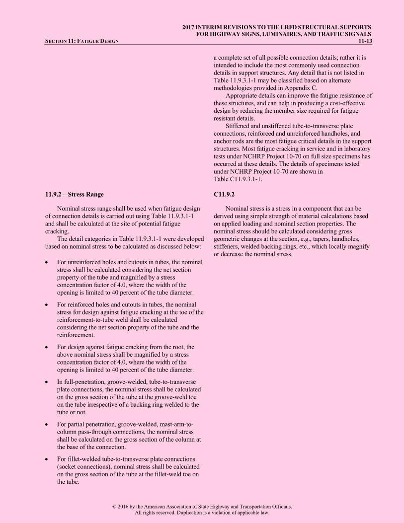
11.9.2—Stress Range C11.9.2
Nominal stress range shall be used when fatigue design of connection details is carried out using Table 11.9.3.1-1 and shall be calculated at the site of potential fatigue cracking.
The detail categories in Table 11.9.3.1-1 were developed based on nominal stress to be calculated as discussed below:
Nominal stress is a stress in a component that can be derived using simple strength of material calculations based on applied loading and nominal section properties. The nominal stress should be calculated considering gross geometric changes at the section, e.g., tapers, handholes, stiffeners, welded backing rings, etc., which locally magnify or decrease the nominal stress.
For unreinforced holes and cutouts in tubes, the nominalstress shall be calculated considering the net sectionproperty of the tube and magnified by a stressconcentration factor of 4.0, where the width of theopening is limited to 40 percent of the tube diameter.
For reinforced holes and cutouts in tubes, the nominalstress for design against fatigue cracking at the toe of thereinforcement-to-tube weld shall be calculatedconsidering the net section property of the tube and thereinforcement.
For design against fatigue cracking from the root, theabove nominal stress shall be magnified by a stressconcentration factor of 4.0, where the width of theopening is limited to 40 percent of the tube diameter.
In full-penetration, groove-welded, tube-to-transverseplate connections, the nominal stress shall be calculatedon the gross section of the tube at the groove-weld toeon the tube irrespective of a backing ring welded to thetube or not.
For partial penetration, groove-welded, mast-arm-to-column pass-through connections, the nominal stressshall be calculated on the gross section of the column atthe base of the connection.
For fillet-welded tube-to-transverse plate connections(socket connections), nominal stress shall be calculatedon the gross section of the tube at the fillet-weld toe onthe tube.
© 2016 by the American Association of State Highway and Transportation Officials.All rights reserved. Duplication is a violation of applicable law.

2017 INTERIM REVISIONS TO THE LRFD STRUCTURAL SUPPORTS 11-14 FOR HIGHWAY SIGNS, LUMINAIRES, AND TRAFFIC SIGNALS
In stiffened tube-to-transverse plate connections, thenominal stress at the termination of the stiffener shall becalculated based on the gross section of the tube at asection through the toe of the wrap-around-weld on thetube.
In stiffened tube-to-transverse plate connections, thenominal stress at the weld toe on the tube of the tube-to-transverse plate fillet-weld shall be calculated based onthe gross section of only the tube at the section.
In stiffened tube-to-transverse plate connections, thenominal stress at the stiffener-to-plate weld shall becalculated based on the gross section of the tube and thestiffeners at the section.
For computing nominal stress at the tube-to-transverse plate fillet-weld in a stiffened connection, only the gross section of the tube without the stiffeners should be considered. The fatigue resistance for these connections in Table 11.9.3.1-1 has been accordingly defined. The effect of the stiffeners is implicitly included in the computation of fatigue stress concentration factor in Eq. 11.9.3.1-4 in Table 11.9.3.1-2.
For computing nominal stress at the stiffener-to-transverse plate weld, the gross section including the tube and the stiffeners at the section should be considered.
11.9.3—Fatigue Resistance C11.9.3
Support structures shall be proportioned such that the wind load induced stress is below the CAFT providing infinite life. For infinite life, nominal fatigue resistance shall be taken as:
THnf F (11.9.3-1)
The remaining fatigue life of existing steel structures may be assessed based on a finite life. For finite life, nominal fatigue resistance shall be taken as:
13
nFAN
(11.9.3-2)
where
(∆F)n = the nominal fatigue resistance as specified in Table 11.9.3.1-1
(∆F)TH = the CAFT; A is the finite life constant N = the number of wind load induced stress cycles
expected during the life time of the structures.
The values of (∆F)TH and A for steel structure details are specified in Table 11.9.3.1-1. The values for are specified in Table 3.4-1, and the value for is 1.0.
Aluminum structures shall be designed to provide infinite life. The value of (∆F)TH of aluminum structure details shall be determined by dividing the respective threshold values of steel with 2.6.
Fatigue resistance of typical fatigue-sensitive connection details in support structures for finite and infinite life designs shall be determined from Table 11.9.3.1-1. The fatigue stress concentration factors as functions of connection geometry in tubular structures shall be determined as given in Article 11.9.3.1. The potential location of cracking in each detail is identified in the table. “Longitudinal” implies that the
When the wind load induced maximum stress range (determined as static load effects per Article 11.7) experienced by a component or a detail is less than the CAFT, the component or detail can be assumed to have a theoretically infinite fatigue life. Using Eq. 11.9.3-1 to establish (∆F)n in Eq. 11.5.1-1 should ensure infinite life performance.
In the finite life regime at stress ranges above the CAFT, the fatigue life is inversely proportional to the cube of the stress range. For example, if the stress range is reduced by a factor of 2, the fatigue life increases by a factor of 23 = 8 This result is reflected in Eq. 11.9.3-2. When assessing the finite life of an existing structure, the number of wind load induced stress cycles expected during the life time of the structure should be estimated from analysis based on historical wind records or directly by field measurements on similar structures, as decided by the owner.
The constant A and the constant amplitude fatigue threshold (∆F)TH for the detail classes specified in Table 11.9.3.1-1 are consistent with steel detail categories in LRFD Design. Figure C11.9.3-1 is a graphical representation of the nominal fatigue resistance for detail categories as per LRFD Design.
© 2016 by the American Association of State Highway and Transportation Officials.All rights reserved. Duplication is a violation of applicable law.

2017 INTERIM REVISIONS TO THE LRFD STRUCTURAL SUPPORTS FOR HIGHWAY SIGNS, LUMINAIRES, AND TRAFFIC SIGNALS
SECTION 11: FATIGUE DESIGN 11-15
direction of applied stress is parallel to the longitudinal axis of the detail, and “transverse” implies that the direction of applied stress is perpendicular to the longitudinal axis of the detail.
Figure C11.9.3-1—Stress Range vs. Number of Cycles
The fatigue resistance of support structures was established based on laboratory fatigue tests of full-scale cantilevered structures and substantiated by analytical studies. The resistance is based on elastic section analysis and nominal stresses on the cross-section. The resistance includes effects of residual stresses due to fabrication and anchor bolt pretension, which are not to be considered explicitly in the nominal stress computations.
Fatigue resistance of tube-to-transverse plate connections are classified in Table 11.9.3.1-1 in terms of separate fatigue stress concentration factors for finite and infinite life designs, which explicitly incorporate the effects of stress concentration due to the connection geometry and the weld toe notch. The effects of weld toe micro-discontinuities are implicitly considered in the experimental results for all connections. Research (Roy et al., 2011) shows that the infinite life fatigue resistance of connection details in support structures does not always correspond to their respective finite life detail categories in LRFD Design.
To assist designers, the details of full size support structure specimens that were tested in the laboratory under NCHRP Project 10-70 (Roy et al., 2011) are tabulated in Table C11.9.3.1-1 along with their fatigue resistance. Designers are encouraged to directly employ these details in service, wherever applicable, with nominal stress range calculated as per Article 11.9.2.
The fatigue resistance of handholes or cutouts is defined in terms of the magnified nominal stress as defined earlier.
Fatigue resistance of the fillet-welded T-, Y-, and K- tube-to-tube, angle-to-tube, and plate-to-tube connections was not established by laboratory testing. Fatigue resistance of these connections in Table 11.9.3.1-1 has been retained from the previous edition of the specification, which
© 2016 by the American Association of State Highway and Transportation Officials.All rights reserved. Duplication is a violation of applicable law.
2017 INTERIM REVISIONS TO THE LRFD STRUCTURAL SUPPORTS 11-16 FOR HIGHWAY SIGNS, LUMINAIRES, AND TRAFFIC SIGNALS
11.9.3.1—Stress Concentration Factors
For finite life evaluation of tubular connections, fatigue stress concentration factors in Table 11.9.3.1-1 shall be calculated as per equations given in Table 11.9.3.1-2.
For infinite life design of tubular connections, the fatigue stress concentration factor in Table 11.9.3.1-1 shall be calculated as:
1.76 1.83 4.76 0.22 FK
I T FK t K (11.9.3.1-1)
where KF is calculated from Table 11.9.3.1-2 for the respective details.
The parameters used in the expressions for stress concentration factors are:
DBC = diameter of circle through the fasteners in the transverse plate (for connections with two or more fastener circles, use the outer most circle diameter) (in.)
DOP = diameter of concentric opening in the transverse plate (in.)
DT = external diameter of a round tube or outer flat-to-flat distance of a multisided tube at top of transverse plate (in.)
hST = height of longitudinal attachment (stiffener) (in.) NB = number of fasteners in the transverse plate NS = number of sides
corresponds to the classification for cyclic punching shear stress in tubular members specified by the AWS Structural Welding Code D1.1—Steel based on research in the offshore industry on connections of thicker and larger diameter tubes. Stresses in tubular connections are strongly dependent on their geometric parameters and therefore, extrapolation of the fatigue design provisions from the AWS specification may not be consistent with the performance of the pass-through connections in service. Until further research can provide a better estimate of the fatigue resistance of these connections, they should be classified as indicated in Table 11.9.3.1-1.
Stool-type stiffened fillet-welded tube-to-transverse plate connections, similar to those in service in Iowa, were tested in the laboratory (Roy et al., 2011), but on thinner tubes (see Table C11.9.3.1-1). These stiffened connections employ a pair of rectangular vertical stiffeners welded to the tube wall and transverse plate and connected by a plate at the top. The top plate serves as an anchorage for the anchor rods, and is not welded to the tube. These connection details have performed extremely well in Iowa, where no cracking were observed during 40 years of service. In laboratory tests, however, these connections did not perform well. This detail may provide better fatigue performance in thicker and larger diameter tubes as was used for the structures in service. Until further research can provide a better estimate of the fatigue resistance of these stiffened connections, the fatigue performance of the welds terminating at the end of vertical stiffeners in the stool type stiffened tube-to-end plate connections should be classified as indicated in Table 11.9.3.1-1.
C11.9.3.1
Fatigue resistance of tubular connections in support structures depends on the relative stiffness of the components at a connection or the connection geometry. Geometric stresses arise from the need to maintain compatibility between the tubes and other components at the connections. This geometric stress concentration affects the fatigue resistance of the connections for both finite and infinite life performance. In addition, the resistance of the connections against any fatigue crack growth for infinite life is also affected by the local stress concentration related to local geometry of the weld. The effects of global and local geometric stress concentrations on the fatigue resistance of various connections in the support structures were determined experimentally and analytically under NCHRP Project 10-70 (Roy et al., 2011).
Traffic arm-to-pole connections often contain more than one bolt circle having two rows of 3 or 4 connecting bolts, as shown in the Figure C11.9.3.1-1. Table C11.9.3.1-1 provides the KF equation for the tube-to-transverse plate connections that contain the bolt circle variable, DBC. The bolt circle chosen influences the CAFT value. Finite element analysis shows that the internal bolts have little influence on the fatigue stresses in the tube. Therefore, the outer most bolt circle should be used in the KF equation from Table C11.9.3.1-1, which will result in the more conservative CAFT value.
© 2016 by the American Association of State Highway and Transportation Officials.All rights reserved. Duplication is a violation of applicable law.

2017 INTERIM REVISIONS TO THE LRFD STRUCTURAL SUPPORTS FOR HIGHWAY SIGNS, LUMINAIRES, AND TRAFFIC SIGNALS
SECTION 11: FATIGUE DESIGN 11-17 NST = number of longitudinal attachment (stiffener) tST = thickness of longitudinal attachment (stiffener)
plate (in.) tT = thickness of tube (in.) tTP = thickness of transverse plate (in.)
CBC = BC
T
D
D
COP = OP
T
D
D
Figure C11.9.3.1–1—Bolt Circle Example Equations for fatigue stress concentration factors were
determined based on parametric finite element analyses and were verified by test results. The ranges of the parameters describing the connection geometry in the studies covered the ranges determined from state departments of transportation’s drawings and manufacturer's literature. Fatigue resistance was determined based on the local stress-based methodology presented in Appendix C. Based on these results, the fatigue resistance of the tube-to-transverse plate connection details were classified in terms of separate fatigue stress concentration factors KF and KI for finite and infinite life regimes respectively. While the fatigue stress concentration factor for finite life design incorporates the effect of connection geometry, the fatigue stress concentration factor for infinite life design also includes the geometric effect of the weld toe notch.
Experimental and analytical studies demonstrated that the fatigue resistance of tube-to-transverse plate connections is a function of the relative flexibility of the tube and the transverse plate. Reducing the relative flexibility of the transverse plate can significantly increase the fatigue resistance of the connection. The relative flexibility of the transverse plate depends on:
1. the thickness of the transverse plate; 2. the opening in the transverse plate (in groove-welded
connections); 3. the number of fasteners; 4. the bolt circle ratio, defined as the ratio of the bolt circle
diameter to the tube diameter. In addition, the diameter and thickness of the tube
affects the relative stiffness. Reducing the opening size and/or increasing the plate thickness are the most cost-effective means of reducing the flexibility of the transverse plate and increasing the connection fatigue resistance.
Fatigue performance of a stiffened tube-to-transverse plate, fillet-welded connection is a function of:
1. the thickness of the transverse plate; 2. the thickness of the tube; 3. the stiffener shape and size (thickness, height, and
angle); and 4. the number of stiffeners (or stiffener spacing).
© 2016 by the American Association of State Highway and Transportation Officials.All rights reserved. Duplication is a violation of applicable law.
2017 INTERIM REVISIONS TO THE LRFD STRUCTURAL SUPPORTS 11-18 FOR HIGHWAY SIGNS, LUMINAIRES, AND TRAFFIC SIGNALS
Optimized, stiffened, tube-to-transverse plate, fillet-welded connections can provide a cost-effective solution in support structures employing larger diameter and thicker tubes.
For stiffened, fillet-welded, tube-to-transverse plate connections, the finite life fatigue stress concentration factor at the fillet-weld toe on the tube (Table 11.9.3.1-2) is obtained by modifying the finite life stress concentration factor for the fillet-welded tube-to-transverse plate connection detail.
Compared to a round tube of similar size, welded tube-to-transverse plate connections in multisided sections exhibit less fatigue resistance with decreasing roundness. The deviation in fatigue performance of multisided sections from round shapes depends on:
1. the outer flat-to-flat dimension of a multisided tube; 2. the thickness of the tube; 3. the number of sides in the multisided section; and 4. the internal bend radius.
The fatigue stress concentration factors for tube-to-
transverse plate connections in multisided cross sections should be obtained by multiplying Eq. 11.9.3.1-6 by the fatigue stress concentration factors of the respective details for round sections, except for the stiffener termination on the tube of a stiffened fillet-welded tube-to-transverse-plate connection. Parametric studies show that the fatigue stress concentration factor for finite life at the stiffener termination on the tube remains same for round and multisided sections irrespective of the number of sides and bend radius.
© 2016 by the American Association of State Highway and Transportation Officials.All rights reserved. Duplication is a violation of applicable law.

2017 INTERIM REVISIONS TO THE LRFD STRUCTURAL SUPPORTS FOR HIGHWAY SIGNS, LUMINAIRES, AND TRAFFIC SIGNALS
SECTION 11: FATIGUE DESIGN 11-21 Table 11.9.3.1-1—Fatigue Details of Cantilevered and Noncantilevered Support Structures (continued)
3.2 Reinforced holes and cutouts. At root of reinforcement-to-tube weld At toe of reinforcement-to-tube weld
120.0
22.0
16.0
7.0 (See note e)
In tube wall and hole reinforcement from root of reinforcement-to-tube weld. In tube wall and hole reinforcement from the toe of reinforcement-to-tube weld.
Reinforced handholes.
SECTION 1—GROOVE-WELDED CONNECTIONS 4.1 Tubes with continuous full- or partial penetration groove-welds parallel to the direction of the applied stress.
61.0 12.0 In the weld away from the weld termination.
Longitudinal seam welds.
4.2 Full-penetration groove-welded splices with welds ground to provide a smooth transition between members (with or without backing ring removed).
22.0
7.0 In weld through the throat or along the fusion boundary.
Column or mast-arm butt-splices.
4.3 Full-penetration groove-welded splices with weld reinforcement not removed (with or without backing ring removed).
11.0 4.5 In tube wall along weld toe.
Column or mast-arm butt-splices.
© 2016 by the American Association of State Highway and Transportation Officials.All rights reserved. Duplication is a violation of applicable law.

2017 INTERIM REVISIONS TO THE LRFD STRUCTURAL SUPPORTS 11-22 FOR HIGHWAY SIGNS, LUMINAIRES, AND TRAFFIC SIGNALS Table 11.9.3.1-1—Fatigue Details of Cantilevered and Noncantilevered Support Structures (continued)
4.4 Full-penetration groove-welded tube-to-transverse plate connections with backing ring attached to the plate with a full penetration weld, or with a continuous fillet-weld around interior face of backing ring, and the backing ring welded to the tube with a continuous fillet-weld at top face of backing ring.
KF ≤ 1.6: 11.0 1.6 < KF ≤ 2.3: 3.9
KI ≤ 3.0: 10.0 3.0< KI ≤ 4.0: 7.0 4.0< KI ≤ 6.5: 4.5
In tube wall along groove-weld toe or backing ring top weld toe.
Column-to-base plate connections. Mast-arm-to-flange-plate connections.
4.5 Full-penetration groove-welded tube-to-transverse plate connections with backing ring attached to the plate with a full penetration weld, or with a continuous fillet-weld around interior face of backing ring, and the backing ring not welded to the tube.
KF ≤ 1.6: 11.0 1.6 < KF ≤ 2.3: 3.9
KI ≤ 3.0: 10.0 3.0< KI ≤ 4.0: 7.0 4.0< KI ≤ 6.5: 4.5
In tube wall along groove-weld toe.
Column-to-base-plate connections. Mast-arm-to-flange-plate connections.
4.6 Full penetration groove-welded tube-to-transverse plate connections welded from both sides with back-gouging (without backing ring).
KF ≤ 1.6: 11.0 1.6< KF ≤ 2.3: 3.9
KI ≤ 3.0: 10.0 3.0< KI ≤ 4.0: 7.0 4.0< KI ≤ 6.5: 4.5
In tube wall along groove-weld toe.
Column-to-base-plate connections. Mast-arm-to-flange-plate connections.
4.7 Full-penetration groove-welded tube-to-transverse plate connections with the backing ring not attached to the plate, and the backing ring welded to the tube with a continuous fillet-weld at top face of backing ring.
KF≤ 1.6: 11.0 1.6< KF ≤ 2.3: 3.9
KI≤ 3.0: 10.0 3.0< KI ≤ 4.0: 7.0 4.0 < KI ≤ 6.5: 4.5
In tube wall along groove-weld toe or backing ring top weld toe.
Column-to-base-plate connections. Mast-arm-to-flange-plate connections.
© 2016 by the American Association of State Highway and Transportation Officials.All rights reserved. Duplication is a violation of applicable law.

2017 INTERIM REVISIONS TO THE LRFD STRUCTURAL SUPPORTS FOR HIGHWAY SIGNS, LUMINAIRES, AND TRAFFIC SIGNALS
SECTION 11: FATIGUE DESIGN 11-27
Table 11.9.3.1-1—Fatigue Details of Cantilevered and Noncantilevered Support Structures (continued)
Notes:
a. In a branching member with respect to the stress in the branching member: 1.2 ksiTHF ; when r/t ≤ 24 for the chord member
0.7
241.2THF rt
ksi ; when r/t > 24 for the chord member
In a chord member with respect to the stress in the chord member: (∆F)TH = 4.5 ksi.
b. In a branching member with respect to the stress in the branching member: (∆F)TH = 1.2 ksiIn main member with respect to the stress in the main member (column):
1.0 ksiTHF ; when r/t ≤ 24 for the chord member
0.7
241.0THFrt
ksi ; when r/t > 24 for the chord member
where: The nominal stress range in the main member equals (SR) main member = (SR) branching member (tb /tc) where tb is the wall thickness of the branching member, tc is the wall thickness of the main member (column), and is the ovalizing parameter for the main member equal to 0.67 for in-plane bending and equal to 1.5 for out-of-plane bending in the main member. (SR) branching member is the calculated nominal stress range in the branching member induced by fatigue design loads. (See Article C11.9.3.) The main member shall also be designed for (∆F)TH = 4.5 ksi using the elastic section of the main member and moment just below the connection of the branching member.
c. When t > 0.5 in., (∆F)TH shall be the lesser of 10.0 ksi or the following:
16
0.0055 0.7210.0 ksip
THp
Ht
Ft
where H is the effective weld throat in in., and tp is the attachment plate thickness, in. d. The diameter of coped holes shall be the greater of 1 in., twice the gusset plate thickness, or twice the tube thickness.e. Reinforced and unreinforced holes and cutouts shall be detailed as shown in Figures 5.6.6.1-1, 5.6.6.1-2, and 5.6.6.1-3.f. The standard fillet-welded gusseted box or ring-stiffened box connections in Article 5.6.7 shall be used for infinite life.g. Threshold values are tabulated for steel details. Threshold values of aluminum details shall be obtained by dividing the
respective threshold values with 2.6.
© 2016 by the American Association of State Highway and Transportation Officials.All rights reserved. Duplication is a violation of applicable law.
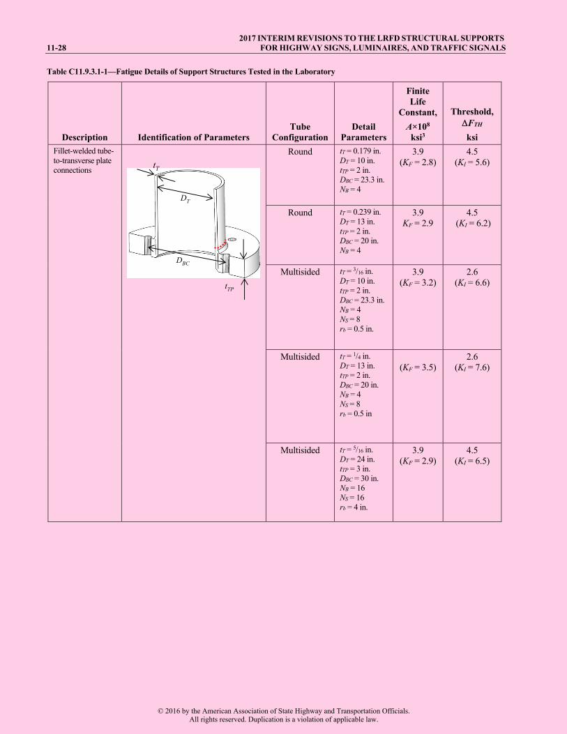
2017 INTERIM REVISIONS TO THE LRFD STRUCTURAL SUPPORTS 11-28 FOR HIGHWAY SIGNS, LUMINAIRES, AND TRAFFIC SIGNALS Table C11.9.3.1-1—Fatigue Details of Support Structures Tested in the Laboratory
Description Identification of Parameters Tube
Configuration Detail
Parameters
Finite Life
Constant, A×108
ksi3
Threshold, FTH
ksi Fillet-welded tube-to-transverse plate connections
tT
tTP
DT
DBC
Round tT = 0.179 in. DT = 10 in. tTP = 2 in. DBC = 23.3 in. NB = 4
3.9 (KF = 2.8)
4.5 (KI = 5.6)
Round tT = 0.239 in. DT = 13 in. tTP = 2 in. DBC = 20 in. NB = 4
3.9 KF = 2.9
4.5 (KI = 6.2)
Multisided tT = 3/16 in. DT = 10 in. tTP = 2 in. DBC = 23.3 in. NB = 4 NS = 8 rb = 0.5 in.
3.9 (KF = 3.2)
2.6 (KI = 6.6)
Multisided tT = 1/4 in. DT = 13 in. tTP = 2 in. DBC = 20 in. NB = 4 NS = 8 rb = 0.5 in
(KF = 3.5)
2.6 (KI = 7.6)
Multisided tT = 5/16 in. DT = 24 in. tTP = 3 in. DBC = 30 in. NB = 16 NS = 16 rb = 4 in.
3.9 (KF = 2.9)
4.5 (KI = 6.5)
© 2016 by the American Association of State Highway and Transportation Officials.All rights reserved. Duplication is a violation of applicable law.

2017 INTERIM REVISIONS TO THE LRFD STRUCTURAL SUPPORTS FOR HIGHWAY SIGNS, LUMINAIRES, AND TRAFFIC SIGNALS
SECTION 11: FATIGUE DESIGN 11-31
Table 11.9.3.1-2—Fatigue Stress Concentration Factors, KF
Section Type Detail Location
Fatigue Stress Concentration Factor for Finite Life, KF
Section Type
Roun
d
Fillet-welded tube-to-transverse plate connections
Fillet-weld toe on tube wall
1.2
0.03 2.5
2.2 4.6 15 2 10
1
F T T
BC TP
K t D
C t
Valid for: 0.179 in. ≤ tT ≤ 0.5 in.; 8 in. ≤ DT ≤ 50 in.; 1.5 in. ≤ tTP ≤ 4 in.; 1.25 ≤ CBC ≤ 2.5
(11.9.3.1–2)
Groove-welded tube-to-transverse plate connections
Groove-weld toe on tube wall
0.02
20.7
1.35 16 15 1 5
14 3
F T T
BCTP
OP
K t D
Ct
C
Valid for: 0.179 in. ≤ tT ≤ 0.625 in.; 8 in. ≤ DT ≤ 50 in.; 1.5 in. ≤ tTP ≤ 4 in.; 1.25 ≤ CBC ≤ 2.5; 0.3 ≤ COP ≤ 0.9
(11.9.3.1–3)
Fillet-welded tube-to-transverse plate connections stiffened by longitudinal attachments
Weld toe on tube wall at the end of attachment
0.4 0.8
0.7 1.20.3 0.4 0.9ST TF
T ST
t DKt N
Valid for: 0.25 in. ≤ tST ≤ 0.75 in.; 8 ≤ NST; 0.25 in. ≤ tT ≤ 0.625 in.; 24 in. ≤ DT ≤ 50 in.
(11.9.3.1–4)
Fillet-welded tube-to-transverse plate connections stiffened by longitudinal attachments
Fillet-weld toe on tube wall
0.15
1.5 0.50.13 6.5130 1 1
7
as per Eq. 11.9.3.1-2
T
F STST ST
F
DK hN t
K
Valid for: 12 in. ≤ hST ≤ 42 in.; 0.25 in. ≤ tST ≤ 0.75 in.; 8 ≤ NST ; 24 in. ≤ DT ≤ 50 in.
(11.9.3.1–5)
Mul
tisid
ed As above As above Multiply respective KF above by:
21 T b SD r N Valid for: 8 in. ≤ DT ≤ 50 in.; 1 in. ≤ rb ≤ 4 in.; 8 ≤ NS ≤ 16
(11.9.3.1–6)
© 2016 by the American Association of State Highway and Transportation Officials.All rights reserved. Duplication is a violation of applicable law.

2017 INTERIM REVISIONS TO THE LRFD STRUCTURAL SUPPORTS 11-32 FOR HIGHWAY SIGNS, LUMINAIRES, AND TRAFFIC SIGNALS
11.10—REFERENCES
AASHTO. 2002. Standard Specifications for Highway Bridges, 17th Edition. American Association of State Highway and Transportation Officials, Washington, DC.
AASHTO. 2013. Standard Specifications for Structural Supports for Highway Signs, Luminaires, and Traffic Signals, Sixth Edition. American Association of State Highway and Transportation Officials, Washington, DC.
Ahearn, E. B., and J. A. Puckett. 2010. Reduction of Wind-Induced Vibrations in High-Mast Light Poles, Report No. FHWA-WY-10/02F, University of Wyoming, Laramie, WY.
Albert M. N., L. Manuel, K. H. Frank, and S. L. Wood. 2007. Field Testing of Cantilevered Traffic Signal Structures under Truck-Induced Gust Loads, Report No. FHWA/TX-07/4586-2. Center for Transportation Research, Texas Department of Transportation, Austin, TX.
Amir, G., and A. Whittaker. 2000. “Fatigue-Life Evaluation of Steel Post Structures II: Experimentation,” Journal of Structural Engineering. American Society of Civil Engineers, New York, NY. Vol. 126, No. 3, Vol. 2 (March 2000), pp. 331–340.
ASTM. 2012. “Standard Specification for Structural Bolts, Steel, Heat Treated, 120/105 ksi Minimum Tensile Strength,” A325-12, Annual Book of ASTM Standards. American Society for Testing Materials, West Conshohocken, PA.
ASTM. 2014. “Standard Specification for Structural Bolts, Alloy Steel, Heat Treated, 150 ksi Minimum Tensile Strength,” A490-14a, Annual Book of ASTM Standards. American Society for Testing Materials, West Conshohocken, PA.
AWS. 2010, Structural Welding Code- Steel, D1.1/D1.1M. American Welding Society, Miami, FL
Connor, R. J., S. H. Collicott, A. M. DeSchepper, R. J. Sherman, and J. A. Ocampo. 2012. Development of Fatigue Loading and Design Methodology for High-Mast Lighting Towers, NCHRP Report 718. Transportation Research Board, National Research Council, Washington, DC.
Cook, R. A., D. Bloomquist, A. M. Agosta, and K. F. Taylor. 1996. Wind Load Data for Variable Message Signs, Report No. FL/DOT/RMC/0728-9488. University of Florida, Gainesville, FL. Report prepared for Florida Department of Transportation.
Creamer, B. M., K. G. Frank, and R. E. Klingner. 1979. Fatigue Loading of Cantilever Sign Structures from Truck Wind Gusts, Report No. FHWA/TX-79/10+209-1F. Center for Transportation Research, Texas State Department of Highways and Public Transportation, Austin, TX.
Dexter, R. J., and K. W. Johns. 1998. Fatigue-Related Wind Loads on Highway Support Structures: Advanced Technology for Large Structural Systems, Report No. 98-03. Lehigh University, Bethlehem, PA.
Dexter, R., and M. Ricker. 2002. Fatigue-Resistant Design of Cantilevered Signal, Sign, and Light Supports, NCHRP Report 469. Transportation Research Board, National Research Council, Washington, DC.
Fisher, J. W., A. Nussbaumer, P. B. Keating, and B. T. Yen. 1993. Resistance of Welded Details Under Variable Amplitude Long-Life Fatigue Loading, NCHRP Report 354. Transportation Research Board, National Research Council, Washington, DC.
Florea M. J., L. Manuel, K. H. Frank, and S. L. Wood. 2007. Field Tests and Analytical Studies of the Dynamic Behavior and the Onset of Galloping in Traffic Signal Structures, Report No. FHWA/TX-07/4586-1. Center for Transportation Research, Texas Department of Transportation, Austin, TX.
Fouad, F. H., J. S Davison, N. Delatte , E. A. Calvert , S. E. Chen, E. Nunez, and R. Abdalla, 2003. “Structural Supports for Highway Signs, Luminaires, and Traffic Signals,” NCHRP Report 494. Transportation Research Board, National Research Council, Washington, DC.
Kaczinski, M. R., R. J. Dexter, and J. P. Van Dien. 1998. Fatigue Resistant Design of Cantilevered Signal, Sign and Light Supports, NCHRP Report 412. Transportation Research Board, National Research Council, Washington, DC.
Koenigs, M. T., T. A. Botros, D. Freytag, and K. H. Frank. 2003. Fatigue Strength of Signal Mast Arm Connections, Report No. FHWA/TX-04/4178-2. Center for Transportation Research, Texas Department of Transportation, Austin, TX.
© 2016 by the American Association of State Highway and Transportation Officials.All rights reserved. Duplication is a violation of applicable law.

2017 INTERIM REVISIONS TO THE LRFD STRUCTURAL SUPPORTS FOR HIGHWAY SIGNS, LUMINAIRES, AND TRAFFIC SIGNALS
12-1
SECTION 12:
BREAKAWAY SUPPORTS
12.1—SCOPE C12.1
Breakaway supports shall be provided based on the guidelines for use and location, as specified in Section 2. Breakaway supports shall be designed to yield, fracture, or separate when struck, thereby minimizing injury to the occupants and damage to the vehicle.
This Section addresses the structural, breakaway, and durability requirements for structures required to yield, fracture, or separate when struck by an errant vehicle. Structure types addressed include roadside sign, luminaire, call box, and pole top mounted traffic signal supports.
The term "breakaway support" refers to all types of sign, luminaire, call box, and pole top mounted traffic signal supports that are safely displaced under vehicle impact. Breakaway requirements of mailboxes and utility poles may be found in the Roadside Design Guide.
Breakaway devices shall meet the requirements hereinand of the Manual for Assessing Safety Hardware (MASH)(2009). Additional guidelines for breakaway devices may befound in the Roadside Design Guide (2011) the currentestablished crash testing standards.
The Manual for Assessing Safety Hardware (MASH) (2009) is an update to and supersedes NCHRP Report 350, Recommended Procedures for the Safety Performance Evaluation of Highway Features, for the purposes of evaluating new safety hardware devices. MASH does not supersede any guidelines for the design of roadside safety hardware, which are contained within the AASHTO Roadside Design Guide. An implementation plan for MASH that was adopted jointly by AASHTO and FHWA states that all highway safety hardware accepted prior to the adoption of MASH – using criteria contained in NCHRP Report 350 – may remain in place and may continue to be manufactured and installed. In addition, highway safety hardware accepted using NCHRP Report 350 criteria is not required to be retested using MASH criteria. However, new highway safety hardware not previously evaluate must utilize MASH for testing and evaluation.
12.2—DEFINITIONS
Breakaway—A design feature that allows a sign, luminaire, call box, or pole top mounted traffic signal support to yield, fracture, or separate near ground level on impact.
Call Box—Telephone device placed on a short post to allow emergency calls by stranded motorists.
Manufacturer—Company that makes a finished component.
Hinge—The weakened section of a support post designed to allow the post to rotate when impacted by a vehicle.
12.3—DESIGN OF BREAKAWAY SUPPORTS C12.3
Breakaway supports shall be designed to meet both the structural and the dynamic performance requirements of Articles 12.4 and 12.5, respectively.
As requested by the Owner, certification of both breakaway and structural adequacy shall be provided by the Manufacturer. Design calculations or test data of production samples to support certification shall be provided, if requested by the Owner. The data shall indicate a constant ability to produce a device that will meet both breakaway and structural requirements.
The Manufacturer is responsible for breakaway testing and for submitting test reports to FHWA for review and approval. Manufacturers of luminaire poles with associated breakaway base components will commonly provide copies of the FHWA testing approval to the Owners. This approval, however, does not include any consideration of the structural adequacy of the component. Structural adequacy should be demonstrated to the Owner by the Manufacturer. In general,
© 2016 by the American Association of State Highway and Transportation Officials.All rights reserved. Duplication is a violation of applicable law.

2017 INTERIM REVISIONS TO THE LRFD STRUCTURAL SUPPORTS 12-2 FOR HIGHWAY SIGNS, LUMINAIRES, AND TRAFFIC SIGNALS
any breakaway support component should provide the same or greater structural strength than the support post or pole using the breakaway device.
12.4—STRUCTURAL PERFORMANCE C12.4
Breakaway supports shall be designed to carry the loads, as provided in Section 3, using the appropriate resistances for the material used, as stipulated in these Specifications.
Where the structural adequacy of the breakaway support or components associated with the breakaway feature is in question, load tests shall be performed. The load tests shall be performed and evaluated based on the following criteria:
Typically, static load tests are conducted to verify the structural capacity of the breakaway support. The structure is required to withstand the design loads with appropriate safety. Further, because of the nature of the breakaway devices, additional tests such as fatigue and corrosion may be required by the Owner. In such cases, the Owner and Manufacturer should agree on the specific test requirements.
Breakaway supports shall be tested to determine their ultimate strengths. The loading arrangement and structure configuration shall be selected to maximize the deflection and stresses in the critical regions of the structure or breakaway component. More than one test load arrangement shall be used should a single arrangement not demonstrate the ultimate strength of the breakaway support. The breakaway support shall be tested in a manner that closely models field support conditions.
In general, breakaway devices should be tested to determine if they provide bending strengths compatible with the posts or poles they support. The structural support, including the breakaway device, may be tested for bending, shear, torsion, tension, or compression, to demonstrate the load-carrying capacity. For testing, a length of pole or post suitable for application of the test load may be attached to the breakaway device. The pole or post test length should model the actual structure as to thicknesses, attachment bolts, and so forth. The distance from the breakaway device to the application point of the test load should be at least five times the maximum major bending dimension of the pole or post. Additonally, the upper hinge mechanisms on certain large breakaway sign supports should be subjected to the structural performance considerations.
The test load shall not be less than the Extreme I limit state with load factors provided in Table 3.4-1.
Three samples for each test load arrangement shall be tested to determine the ultimate load that the breakaway support assembly is capable of supporting in the weakest direction.
If one of the ultimate loads differs from the mean by more than ten percent, three additional samples shall be tested. Average of the lowest three ultimate loads out of the six test to determine the ultimate load.
12.5—BREAKAWAY DYNAMIC PERFORMANCE
Breakaway supports shall meet the impact test evaluation criteria of Article 12.5.1, Article 12.5.2, or both. Additional provisions of Article 12.5.3 shall be considered.
12.5.1—Impact Test Evaluation Criteria
Criteria for testing, documentation, and evaluation of breakaway supports shall be performed in accordance with the guidelines of MASH (2009).
© 2016 by the American Association of State Highway and Transportation Officials.All rights reserved. Duplication is a violation of applicable law.

2017 INTERIM REVISIONS TO THE LRFD STRUCTURAL SUPPORTS FOR HIGHWAY SIGNS, LUMINAIRES, AND TRAFFIC SIGNALS
B-1
APPENDIX B:
DESIGN AIDS
B.1—NOTATION
A = area (B.2) (B.3) (in.2) C = cross-sectional constant (B.2) (B.4) Ct = torsional constant (B.3) (in.3) da = diameter at free end (B.5) (in.) db = diameter at fixed end (B.5) (in.) E = modulus of elasticity (B.4) (B.5) (ksi) fb = bending stress (ksi) (B.3) fvb = shear stress due to transverse loads (B.3) (ksi) fvt = shear stress due to torsion (B.3) (ksi) fx = stress due to bending about the x-axis (B.3) (ksi) fy = stress due to bending about the y-axis (B.3) (ksi) I = moment of inertia (in.4) (B.2) Ia = moment of inertia of cross-section at free end of beam (B.5) (in.4) Kp = shape factor (B.2) kt = stress concentration factor (B.3) L = length of the beam (B.4) (B.5) (in.) M = applied moment (B.4) (B.5) (kip-in.) Mz = torsional moment (B.3) (kip-in.) n = ratio of the inside-corner radius to wall thickness (B.3)P = horizontal load applied at free end of beam (B.5) (kip) R = radius measured to the mid-thickness of the wall (B.2) (B.3) (in.) RA = radius measured to mid-thickness of wall at free end (B.4) (in.) RB = radius measured to mid-thickness of wall at fixed end (B.4) (in.) S = section modulus (B.2) (B.3) (in.3) t = wall thickness (B.2) (B.3) (B.4) (in.) Vs = applied shear (B.3) (kip) W = load (B.4) (kip) w = load per unit length (B.4) (B.5) (kip/in.) θmax = maximum slope at free end of beam (rad) (B.4) (B.5) (radians) Z = plastic section modulus (B.2) (in.3) ymax = maximum horizontal deflection at free end of beam (B.4) (B.5) (in.)
© 2016 by the American Association of State Highway and Transportation Officials.All rights reserved. Duplication is a violation of applicable law.

2017 INTERIM REVISIONS TO THE LRFD STRUCTURAL SUPPORTS B-2 FOR HIGHWAY SIGNS, LUMINAIRES, AND TRAFFIC SIGNALS
B.2—SECTIONAL PROPERTIES FOR TUBULAR SHAPES
Table B.2-1 provides approximate equations to compute sectional properties of tubular shapes.
Table B.2-1—Estimated Sectional Properties for Common Tubular Shapes
Property Round Tube Hexdecagonal Tube
Dodecagonal Tube Octagonal Tube Square Tube
Square Tube (Axis on Diagonal)
Moment of inertia, I 3.14R3t 3.22R3t 3.29R3t 3.50R3t 5.33R3t 5.33R3t Section modulus, S 3.14R2t 3.22R2t 3.29R2t 3.50R2t 5.33R2t 3.77R2t Area, A 6.28Rt 6.37Rt 6.43Rt 6.63Rt 8.00Rt 8.00Rt Shape factor, Kp = Z/S 1.27 1.27 1.26 1.24 1.12 — Radius of gyration, R 0.707R 0.711R 0.715R 0.727R 0.816R 0.816R Cross-sectional constant, C 3.14 3.22 3.29 3.50 5.33 — Pictorial representation
Notations:
C = cross-sectional constant used in Table B.4-1
R = radius measured to the mid-thickness of the wall
t = wall thickness
Z = plastic section modulus
© 2016 by the American Association of State Highway and Transportation Officials.All rights reserved. Duplication is a violation of applicable law.