Embed Size (px)
Citation preview

2015 PHYSICS Higher Level
1 Leaving Certifi cate Physics – Higher Level Solutions
SECTION A
1.
tap
pressure gaugeair pump
oil reservoir
gas volume
TIP: The labelled diagram should include a method of measuring the volume of gas, as well as the applied pressure. There
may be diff erent equipment setups in each laboratory setting, but as long as gas volume and associated pressure are
measured, enough information is available to plot an inverse proportion graph and verify Boyle’s Law with a straight-line slope.
The student should make the following measurements:
Volume of gas (taken from sealed container)
Associated pressure for each volume reading (taken from pressure gauge attached)
Method
1. Set up apparatus, as shown in diagram, by connecting the air pump to the Boyle’s Law apparatus.
2. Make sure the gas volume is at atmospheric pressure at the beginning by opening and closing the tap.
3. Pump air into the apparatus until the pressure gauge reaches its maximum safe oil pressure.
4. Wait a few minutes for the oil level to stabilise.
5. Take the pressure reading from the gauge and corresponding gas volume reading from the tube.
6. Gradually open the tap to release some of the air and close again.
7. Repeat steps 4–6 at least fi ve more times and record the results until atmospheric pressure is reached again.
8. Plot a graph of P against 1/V on graph paper, drawing a best fi t line through your points. (4 3 3)
TIP: It is important to clearly label your diagram with the equipment you are going to describe later. It is not essential to have
identical equipment to everyone else. You need only reference the correct apparatus you are using. The clearer and more
labelled your diagram is, the easier it is to describe your method referring to it.
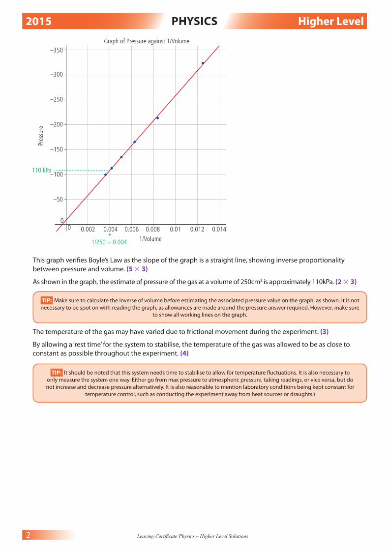
1/V 0.0125 0.00833 0.00625 0.005 0.00417 0.00357
V ( cm 3 ) 80 120 160 200 240 280
P (kPa) 324 214 165 135 112 100
2015 PHYSICS Higher Level
2 Leaving Certifi cate Physics – Higher Level Solutions
00
0.002
–50
–100110 kPa
1/250 = 0.004
–150
Pres
sure
–200
–250
–300
–350Graph of Pressure against 1/Volume
0.004 0.006 0.008 0.01 0.012 0.014
1/Volume
This graph verifi es Boyle’s Law as the slope of the graph is a straight line, showing inverse proportionality
between pressure and volume. (5 3 3)
As shown in the graph, the estimate of pressure of the gas at a volume of 250cm3 is approximately 110kPa. (2 3 3)
TIP: Make sure to calculate the inverse of volume before estimating the associated pressure value on the graph, as shown. It is not
necessary to be spot on with reading the graph, as allowances are made around the pressure answer required. However, make sure
to show all working lines on the graph.
The temperature of the gas may have varied due to frictional movement during the experiment. (3)
By allowing a ‘rest time’ for the system to stabilise, the temperature of the gas was allowed to be as close to
constant as possible throughout the experiment. (4)
TIP: It should be noted that this system needs time to stabilise to allow for temperature fl uctuations. It is also necessary to
only measure the system one way. Either go from max pressure to atmospheric pressure, taking readings, or vice versa, but do
not increase and decrease pressure alternatively. It is also reasonable to mention laboratory conditions being kept constant for
temperature control, such as conducting the experiment away from heat sources or draughts.)

2015 PHYSICS Higher Level
3 Leaving Certifi cate Physics – Higher Level Solutions
2.
insulationdigitalthermometer
calorimeter of water lid steam
trap
delivery tube stopper
flask of water
hot plate
insulatedtube
(3 3 3)
TIP: Make sure to clearly label the diagram initially so as to make future descriptions easy to reference.
Possible assumptions made about the polystyrene cup could be:
• The material had negligible heat capacity and did not need to be factored into the calculations.
• The cup had an insulating lid as part of it.
• It is a perfect insulator. (2 3 2)
mc∆θ (water) = ml (steam to water) + mc∆θ (water that was previously steam)
(83.4 × 10 −3 )(4180)(19) = (2.6 × 10 −3 )(l ) + (2.6 × 1 0 −3 )(4180)(70)
6623.628 = 0.0026l + 760.76
6623.628 − 760.76 = 0.0026l
5862.868 = 0.0026l
5862.868
________ 0.0026
= l
2.255 × 10 6 J. kg −1 = l (4 3 2, 3 3 2, 2, 2)
TIP: It should be noted in the above calculation that the mass of water was gained by subtracting the mass of
the cup from the combined mass of cup and water. The mass of the steam added was also gained by getting
the diff erence between the mass of cup + water and the mass of cup + water + steam. All masses must be used
in kg form. The temperature diff erence for water was from 30 degrees to 11 degrees, whereas the temperature
diff erence for the steam was from 100 degrees to 30 degrees fi nal.
The steam was dried so as to ensure that only latent change occurred when the steam was added. If the steam
was wet, there would have been less latent change occurring than presumed from the mass of material added.
The water in the cup was pre-cooled to minimise temperature errors. If the water was pre-cooled, it would take
energy from the environment until reaching room temperature equilibrium. However, when the water was
heated above room temperature, it would emit energy into the environment until reaching room temperature.
By pre-cooling the water, energy gains at the start would reasonably cancel energy losses at the end of the
experiment. (6 + 3)
2015 PHYSICS Higher Level
4 Leaving Certifi cate Physics – Higher Level Solutions
3.
laser
screenzero order
diffraction grating 1 m
1st order2nd order
3rd order
Or:
slit
monochromaticlight
collimator vernier scale
turntable
telescope
eyepiece
basegrating
(3 × 3)
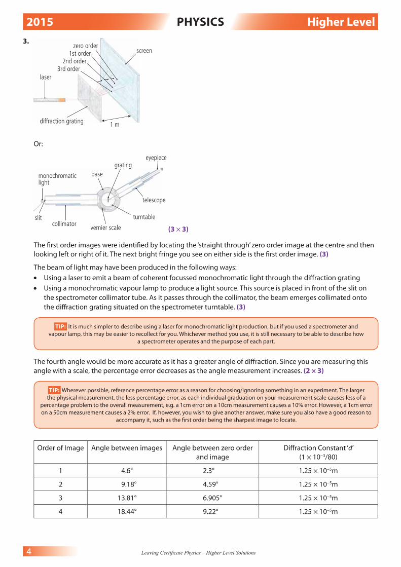
The fi rst order images were identifi ed by locating the ‘straight through’ zero order image at the centre and then
looking left or right of it. The next bright fringe you see on either side is the fi rst order image. (3)
The beam of light may have been produced in the following ways:
• Using a laser to emit a beam of coherent focussed monochromatic light through the diff raction grating
• Using a monochromatic vapour lamp to produce a light source. This source is placed in front of the slit on
the spectrometer collimator tube. As it passes through the collimator, the beam emerges collimated onto
the diff raction grating situated on the spectrometer turntable. (3)
TIP: It is much simpler to describe using a laser for monochromatic light production, but if you used a spectrometer and
vapour lamp, this may be easier to recollect for you. Whichever method you use, it is still necessary to be able to describe how
a spectrometer operates and the purpose of each part.
The fourth angle would be more accurate as it has a greater angle of diff raction. Since you are measuring this
angle with a scale, the percentage error decreases as the angle measurement increases. (2 × 3)
TIP: Wherever possible, reference percentage error as a reason for choosing/ignoring something in an experiment. The larger
the physical measurement, the less percentage error, as each individual graduation on your measurement scale causes less of a
percentage problem to the overall measurement, e.g. a 1cm error on a 10cm measurement causes a 10% error. However, a 1cm error
on a 50cm measurement causes a 2% error. If, however, you wish to give another answer, make sure you also have a good reason to
accompany it, such as the fi rst order being the sharpest image to locate.
Order of Image Angle between images Angle between zero order
and image
Diff raction Constant ‘d’
(1 × 10 −3 /80)
1 4.6° 2.3° 1.25 × 10 −5 m
2 9.18° 4.59° 1.25 × 10 −5 m
3 13.81° 6.905° 1.25 × 10 −5 m
4 18.44° 9.22° 1.25 × 10 −5 m
2015 PHYSICS Higher Level
5 Leaving Certifi cate Physics – Higher Level Solutions
Calculation of Wavelength:
Order 1:
nλ = dSin θ
(1)λ = (1.25 × 10 −5 )Sin 2.3°
λ = 5.0165 × 10 −7 m = 501.65nm
Order 2:
nλ = dSin θ
(2)λ = (1.25 × 10 −5 )Sin 4.59°
(2)λ = 1.003 × 10 −6
λ = (1.003 × 10 −6 )
____________ 2
λ = 5.0016 × 10 −7 m = 500.16nm
Order 3:
nλ = dSin θ
(3)λ = (1.25 × 10 −5 )Sin 6.905°
(3)λ = 1.5028 × 10 −6
λ = (1.5028 × 10 −6 )
_____________ 3
λ = 5.0093 × 10 −7 m = 500.93nm
Order 4:
nλ = dSin θ
(4)λ = (1.25 × 10 −5 )Sin 9.22°
(4)λ = 2.0028 × 10 −6
λ = (2.0028 × 10 −6 )
_____________ 4
λ = 5.0071 × 10 −7 m = 500.71nm
Average Wavelength = (501.65nm + 500.16nm + 500.93nm + 500.71nm)
_________________________________________ 4
= 500.86nm (3, 6, 3, 3)
TIP: Make sure to divide the angle in two before using in the formula as the angle given was between orders. Also,
individually calculate wavelength for all four orders given, and then average the wavelengths to gain a fi nal result.
By increasing the number of lines per mm, you are essentially narrowing the gaps for the light to travel through.
This has the eff ect of increasing the angle of diff raction and thereby lowering % error but also reducing the
number of possible orders available by causing the images to appear further away from zero order. (4)

2015 PHYSICS Higher Level
6 Leaving Certifi cate Physics – Higher Level Solutions
4.
0 10
0
20 30 40 50
Temperature/°C
60 70 80 90 100 110
–1
–2
–3
Resis
tanc
e/Ω –4
–5
Melting ice = 0°C= intersection withy axis = 5.5Ω
–6
(0, 5.5)
(105, 9)
–7
–8
–9
Graph of Resistance against Temperature
(i) Rate of change = slope = ( y
2 − y
1 ) _______
( x 2 − x
1 ) =
(9) − (5.5) _________
(105) − (0) =
3.5 ____
105 =
1 ___
30 = 0.033Ω/°C
TIP: By continuing your graph and gaining a best fi t line, you can take arbitrary points for slope calculation. Since slope in
this case is the change in y relative to x, this equates to an answer of ohms per degree Celsius.
(ii) Resistance in melting ice, as seen in the graph at 0°C = 5.5Ω (3, 5, 3 & 3 × 3)
1. Set up the circuit as shown, making sure the ammeter is in series and the voltmeter is in parallel.
2. Use the variable resistor to apply a voltage close to 0V to the bulb.
3. Record the voltage across and current through the bulb for this setting.
4. Keep increasing the voltage to 5V in 0.5V increments, recording I and V for each setting (use the variable
resistor to vary the voltage applied).
5. Place all values in a table and plot a graph of I against V. (6, 2 × 2, 2 × 3)
ammeter
voltmeter
potentialdivider
d.c. powersupply
filamentbulb

2015 PHYSICS Higher Level
7 Leaving Certifi cate Physics – Higher Level Solutions
According to Ohm’s law, current is proportional to voltage in an ohmic metallic conductor. However, since
resistance is proportional to temperature in a metallic conductor, as a metallic conductor gets hotter, its
resistance changes. This can be seen in a fi lament bulb, which heats up as current fl ows through it. The fi rst
part of the curve is like the graph shape shown in the fi rst part of the question, but as the material heats up,
more electrons are released and impede current fl ow by colliding with each other. This increases resistance
and current tends to drop off as shown. (2 3 2)
TIP: Since the question specifi cally asks you to use the previous fi ndings, it is important to mention in your answer the
conclusion gained from the fi rst graph.
SECTION B
5. (8 × 7)
(a)
41m.s–1 Cos 30°
30°
41m.s–1
41Cos 30° = 35.507m. s −1
s = ut + 1
__ 2
a t 2
s = (35.507 m.s −1 )(3s) + 1
__ 2
(0)(3s ) 2
s = 106.52m
(b) Any particle undergoing simple harmonic motion is one that is moving with periodic motion where the
acceleration is always directed towards the equilibrium point and proportional to the displacement from
that point.
(c) n = 1 _____
Sin C
1
__ n = Sin C
Sin −1 1
__ n = C
Sin −1 1
___ 3.2
= C
18.21° = C
(d) f ′= fc
____ c − u
f ′= (512)(340)
__________ (340) − (28)
f ′ = 174080
_______ 312
f ′ = 557.95Hz
(e) 1.36kWm −2 = 1360J per second for every m 2
Area: 106m × 68m = 7208m 2
Time: 90 minutes = 90 × 60s = 5400s
Total energy incident: 1360J × 5400s × 7208m 2 = 5.2936 × 10 10 J
TIP: There is no acceleration in the horizontal direction as gravity will only
act in the vertical. Therefore, work out the horizontal component of 41m. s −1
and use this in the formula for displacement.
2015 PHYSICS Higher Level
8 Leaving Certifi cate Physics – Higher Level Solutions
(f ) C = Q
__ V
C = εA
___ d
∴ Q
__ V
= εA
___ d
→ Q = εAV
____ d
ε = Permittivity of the dielectric
A = Common area of overlap
V = Potential Diff erence
D = Distance between plates
Q = Charge
(g) One ampere is the constant current when you have two straight infi nitely long parallel conductors a metre
apart in a vacuum with negligible cross section and a force produced between them of 2 × 10 −7 Nm −1
(h) The live contains the fuse and is coloured brown or red.
(i) 14
7 N+
4 2 He →
17 8
O + 1 1 H
(j) Quark composition of proton: uud (up up down)
Quark composition of anti-neutron: ____
udd (anti-up anti-down anti-down)
Or
Input 1 Output
1 0
0 1 NOT
output1
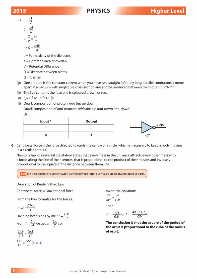
6. Centripetal force is the force directed towards the centre of a circle, which is necessary to keep a body moving
in a circular path. (3)
Newton’s law of universal gravitation states that every mass in the universe attracts every other mass with
a force, along the line of their centres, that is proportional to the product of their masses and inversely
proportional to the square of the distance between them. (6)
TIP: It is also possible to state Newton’s law in formula form, but make sure to give notation of parts.
Derivation of Kepler’s Third Law
Centripetal force = Gravitational force
From the two formulae for the forces:
mrω 2 = GMm
_____ r 2
Dividing both sides by mr: ω 2 = GM
___ r 3
From T = 2π
___ ω we get ω = 2π
___ T
, so:
( 2π ___
T )
2
= GM
___ r 3
4π 2
___ T 2
= GM
___ r 3
(5 3 3)
Invert the equation:
T 2
___ 4π 2
= r 3
___ GM
Then:
T 2 = 4π 2 r 3
_____ GM
or T 2 = 4π 2 (r + h) 3
_________ GM
The conclusion is that the square of the period of
the orbit is proportional to the cube of the radius
of orbit.

2015 PHYSICS Higher Level
9 Leaving Certifi cate Physics – Higher Level Solutions
(i) T = 12 hours = 12 × 60 × 60s = 43200s
T 2 = 4π 2 (r + h) 3
_________ GM
(43200) 2 = 4π 2 (6371 × 10 3 + h) 3
____________________ (6.7 × 10 −11 )(5.97 × 10 24 )
(43200) 2 (6.7 × 10 −11 )(5.97 × 10 24 )
___________________________ 4π 2
= (6371 × 10 3 + h) 3
(7.46477 × 10 23 )
______________ 4π 2
= (6371 × 10 3 + h) 3
1.8909 × 10 22 = (6371 × 10 3 + h) 3
3 √____________
1.8909 × 10 22 = 6371 × 10 3 + h
2.66411089 × 10 7 = 6371 × 10 3 + h
2.66411089 × 10 7 − 6371 × 10 3 = h
2.0270 × 10 7 m = h
20270km = h (above surface of Earth) (4 3 3)
(ii) F = (mv 2 )
_____ r = GMm
_____ r 2
→ v 2 = GM
___ r ( cancel m
__ r )
v = √____
GM
___ r
v = (6.7 × 10 −11 )(5.97 × 10 24 )
______________________ (6371 × 10 3 + 20270 × 10 3 )
v = √___________
1.5014 × 10 7
v = 3.875 × 10 3 m.s −1 (2 3 3)
TIP: By equating centripetal force mentioned earlier and gravitational force, we can isolate velocity and substitute in the
values given in the question and those calculated in part (i).
(iii) Time taken to travel from GPS satellite to Earth surface receiver = distance/speed
Time = 20270 × 10 3 m
____________ 3 ×10 8 m.s −1
= 6.7567 × 10 −2 s (2 3 3)
Only those satell ites that stay above the same point of the Earth at all times are geostationary. In order
for this to happen, they must be on the equatorial plane, have a period of 24 hours and move in the same
direction as the Earth. This satellite has a period of 12 hours and as such is not geostationary. (4)
The next lowest frequency EM radiation to radio waves is microwaves. (4)

2015 PHYSICS Higher Level
10 Leaving Certifi cate Physics – Higher Level Solutions
7.
tungsten targetoil coolantcirculatesanode
cathodeX-rays produced when high speed electrons hit the metal target
X-ray window
lowvoltage
heated filamentemits electrons bythermionic emission
electrons accelerated by high voltage
EHT (~50–90 kV)
To produce an X-ray:
• the cathode is heated by low voltage (approximately 6V)
• electrons are emitted by thermionic emission
• extra high potential diff erence (voltage) between the cathode and anode (positive plate) attracts and
accelerates electrons towards the anode (approximately 50Kv–90kV)
• tungsten is placed on the anode and forms the target. The tungsten is backed by an oil coolant to prevent
melting and overheating
• when the electrons strike the target, their kinetic energy is converted
• high-energy electrons can produce approximately 1 per cent X-rays and 99 per cent heat
• the cathode and target anode are all contained within an evacuated lead-lined chamber to prevent
unwanted X-ray leakage. The chamber has an X-ray window which can be adjusted to allow for focusing of
the X-ray beam. (2 3 4, 2 3 3)
(i) Energy gained at start (potential energy EP) = Energy gained at end (kinetic energy E
K)
EP = eV
EK =
1 __
2 mv2
(50 × 10 3 V)(1.6 × 10 −19 C) = 1
__ 2
(9.1 × 10 −31 kg)v 2
8 × 10 −15 J = 4.55 × 10 −31 v 2
8 × 10 −15
__________ 4.55 × 10 −31
= v 2
√____________
1.7582 × 10 16 = v 2
√____________
1.7582 × 10 16 = v
1.326 × 10 8 m.s −1 = v (3 3 3)
TIP: By allowing the potential energy of electron volts = the kinetic energy of the electron at the end of its transit, a value
for velocity can be found.
(ii) E = hf
E = (50 × 10 3 V)(1.6 × 10⁻¹⁹C) = 8 × 10⁻¹⁵J
8 × 10⁻¹⁵J = hf
8 × 10 −15
________ h
= f
8 × 10 −15
_________ 6.6 × 10 −34
= f
1.2121 × 10 19 Hz
2015 PHYSICS Higher Level
11 Leaving Certifi cate Physics – Higher Level Solutions
c = f λ
3 × 10 8 = (1.2121 × 10 19 )λ
3 × 10 8
___________ 1.2121 × 10 19
= λ
2.475 × 10 −11 m = λ (3 3 3)
The photoelectric eff ect is the emission of electrons from the surface of a metal when EM radiation
of a suitable frequency is incident on it. (2 3 3)
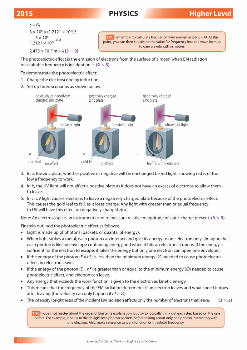
To demonstrate the photoelectric eff ect:
1. Charge the electroscope by induction.
2. Set up three scenarios as shown below.
a b c
no effect no effect leaf falls immediatelygold leaf gold leaf
ultraviolet lightultraviolet lightred laser light
positively or negativelycharged zinc plate
negatively chargedzinc plate
positively chargedzinc plate
3. In a, the zinc plate, whether positive or negative will be unchanged be red light, showing red is of too
low a frequency to work.
4. In b, the UV light will not aff ect a positive plate as it does not have an excess of electrons to allow them
to leave.
5. In c, UV light causes electrons to leave a negatively charged plate because of the photoelectric eff ect.
This causes the gold leaf to fall, as it loses charge. Any light with greater than or equal frequency
to UV will have this eff ect on negatively charged zinc.
Note: An electroscope is an instrument used to measure relative magnitude of static charge present. (3 3 3)
Einstein outlined the photoelectric eff ect as follows:
• Light is made up of photons (packets, or quanta, of energy).
• When light strikes a metal, each photon can interact and give its energy to one electron only. (Imagine that
each photon is like an envelope containing energy and when it hits an electron, it opens. If the energy is
suffi cient for the electron to escape, it takes the energy but only one electron can open one envelope.)
• If the energy of the photon (E = hf ) is less than the minimum energy (∅) needed to cause photoelectric
eff ect, no electron leaves.
• If the energy of the photon (E = hf ) is greater than or equal to the minimum energy (∅) needed to cause
photoelectric eff ect, and electron can leave.
• Any energy that exceeds the work function is given to the electron as kinetic energy.
• This means that the frequency of the EM radiation determines if an electron leaves and what speed it does
after leaving (the velocity can only happen if hf ≥ ∅).
• The intensity (brightness) of the incident EM radiation aff ects only the number of electrons that leave. (3 3 3)
TIP: It does not matter about the order of Einstein’s explanation, but try to logically think out each step based on the one
before. For example, it helps to divide light into photon packets before talking about only one photon interacting with
one electron. Also, make reference to work function or threshold frequency.
TIP: Remember to calculate frequency from energy, as per E = hf. At this
point, you can then substitute the value for frequency into the wave formula
to gain wavelength in metres.

2015 PHYSICS Higher Level
12 Leaving Certifi cate Physics – Higher Level Solutions
8. Electric fi eld strength is the force per unit charge. The electric fi eld strength at any point in an electric fi eld is the
force a 1C charge would experience at that point. It is measured in N.C−1 (2 3 3)
aUncharged electroscope
cap insulation
metal rod
earthed boxwith glass window
gold leaf
(3 3 3)
In order to charge an electroscope by induction, do the following:
1. Bring a positively charged rod near an uncharged electroscope.
2. The gold leaf will diverge as the rod approaches.
3. Touch the cap of the electroscope as the rod is held in place. The leaf will fall again.
4. Remove your fi nger from the cap of the electroscope.
5. Remove the rod from near the electroscope and the leaf will diverge again.
6. The electroscope is now negatively charged by induction. (3 3 3, 2)
TIP: As the positively charged rod approaches, the electrons move towards the cap attracted to it. At the same time, there are now
too many positives at the leaf, and it diverges repulsively. When you touch the cap, the extra electrons needed to neutralise the leaf
come from the ground through you into the electroscope. This causes the leaf to fall. As you remove your fi nger, the path to ground
is lost and as such, when the rod is removed, there are now too many electrons in the electroscope, and the leaf diverges with
negative charge. If you wished to charge it positively by induction, you would start with a negatively charged rod.
Point discharge can occur when a large accumulation of charge is at a point. This causes a high electric fi eld
in the region around the point, which in turn can cause the attraction/repulsion of ions to or from the point.
(3 3 3)
Demo:
1. Set up Van de Graaff generator with pointed rod attached and earth rod held at a distance.
2. Wait until the generator is charged suffi ciently.
3. Bring the earth rod slowly towards the point of the generator.
4. You will hear the noise of the electric wind as ions begin to transfer between the point and earth rod.

2015 PHYSICS Higher Level
13 Leaving Certifi cate Physics – Higher Level Solutions
5. When the rod is close enough, an arc of electricity will jump to the earth rod in a ‘point discharge’.
6. This is a similar eff ect to the way a lightning rod brings charge to the ground (earth) from a charged
lightning strike. (3 3 3)
TIP: In describing a phenomenon such as point discharge, even if you have not actually demonstrated it in the laboratory before,
you are free to describe it in any context you feel best illustrates the idea, such as a recently extinguished candle held near the
charged point.
F = ( 1 ____
4π ε 0 ) (
Q 1 Q
2 ____
d 2 )
E = F
__ Q
∴ E =
( 1 _____
(4π ε 0 ) (
Q 1 Q
2 ____
d 2 ) ___________
Q
E = ( 1 ____
4π ε 0 ) (
Q 1 ___
d 2 )
E = ( 1 ____________
4π(8.9 × 10 −12 ) ) ( 3.8 × 10 −6
__________________ ( 20 × 10 −2 + 4 × 10 −2 ) 2
)
E = (8.9413 × 10 9 )(6.5972 × 10 −5 )
E = 5.8988 × 10 5 N.C −1 (3, 6, 3)
TIP: Remember to halve the diameter of the dome and add the distance away to this fi gure. Also, make sure to convert all
distances to metres and all charges to coulombs.
9. Stationary waves are waves of the same frequency and amplitude that constructively and destructively interfere
to produce a wave pattern in a confi ned space. (3)
Stationary waves are produced as the result of a collision between two waves of equal amplitude and frequency,
confi ned and refl ected between two boundaries. (2 3 3)
Resonance is the transfer of energy between two bodies with the same natural frequency. (2 3 3)
To demonstrate resonance of sound (Barton’s pendulum)
X
AB
CD
E
l l
1. Set up equipment as seen above, with pendulums of various lengths.
2. Attach a mass X of the same length string (l ) as one of the pendulums.
3. When you swing the mass, the pendulum of similar length l (in this case pendulum C) will begin to swing
as well. This demonstrates the resonance caused by the natural frequency applied from the swinging mass.
(3 3 3)
The two other factors upon which the frequency of a stretched string depends are: i) length, ii) mass per unit
length. (2 3 3)
2015 PHYSICS Higher Level
14 Leaving Certifi cate Physics – Higher Level Solutions
The eff ect of increasing tension from 36N to 81N is to increase the fundamental frequency of the string by
a factor of √____
2.25 , provided all other factors remain constant. This is gained by dividing 81 by 36. The fi nal
calculated factor increase in frequency is therefore 1.5. (2 3 3)
TIP: The tension in this case changed by 45N. As long as length and mass per unit length remain constant, frequency
is proportional to √__
T . √____
2.25 = 1.5.
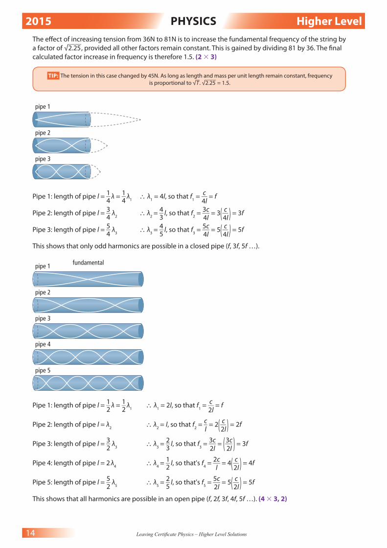
pipe 1
pipe 2
pipe 3
Pipe 1: length of pipe l = 1
__ 4
λ = 1
__ 4
λ 1 ∴ λ
1 = 4l, so that f
1 =
c __
4l = f
Pipe 2: length of pipe l = 3
__ 4
λ 2 ∴ λ
2 =
4 __
3 l, so that f
2 =
3c __
4l = 3 ( c __
4l ) = 3f
Pipe 3: length of pipe l = 5
__ 4
λ 3 ∴ λ
3 =
4 __
5 l, so that f
3 =
5c __
4l = 5 ( c __
4l ) = 5f
This shows that only odd harmonics are possible in a closed pipe (f, 3f, 5f …).
pipe 1
pipe 2
pipe 3
pipe 4
pipe 5
fundamental
Pipe 1: length of pipe l = 1
__ 2
λ = 1
__ 2
λ1 ∴ λ
1 = 2l, so that f
1 =
c __
2l = f
Pipe 2: length of pipe l = λ 2 ∴ λ
2 = l, so that f
2 =
c _
l = 2 ( c __
2l ) = 2f
Pipe 3: length of pipe l = 3
__ 2
λ 3 ∴ λ
3 =
2 __
3 l, so that f
3 =
3c __
2l = ( 3c
__ 2l
) = 3f
Pipe 4: length of pipe l = 2 λ 4 ∴ λ
4 =
1 __
2 l, so that's f
4 =
2c __
l = 4 ( c __
2l ) = 4f
Pipe 5: length of pipe l = 5
__ 2
λ 5 ∴ λ
5 =
2 __
5 l, so that's f
5 =
5c __
2l = 5 ( c __
2l ) = 5f
This shows that all harmonics are possible in an open pipe (f, 2f, 3f, 4f, 5f …). (4 3 3, 2)
2015 PHYSICS Higher Level
15 Leaving Certifi cate Physics – Higher Level Solutions
c = f λ
At fundamental frequency, 1
__ 2
the wavelength is present with antinodes at both ends. Therefore, if 587Hz is f,
2(length of pipe) = λ
∴c = f(2l)
c
_ f = 2l
340
____ 587
= 2l
0.5792 = 2l
0.5792
______ 2
= l
0.2896m = l (2 3 3)
10. (a) Neutrinos will principally be aff ected by weak nuclear force. (3)
TIP: Since neutrinos are leptons and do not experience the strong nuclear force, they should experience the other three
forces: EM, weak nuclear & gravitational, but since they have no charge, EM does not aff ect them.
Choose any two leptons from the following:
Muon, tau, electron neutrino, muon neutrino, tau neutrino, anti-particles of each of these, positron. (2 3 3)
Quarks are subject to the strong nuclear force. (3)
Pauli postulated the existence of the neutrino to explain the defi ciency in mass-energy/momentum
conservation calculated from beta decay, according to Einstein’s E = mc2 equation (2 3 2)
0 1 n →
1 1 H +
0 −1 e + ϑ (10)
1.67492728 × 10 −27 kg − (1.67262171 × 10 −27 kg + 9.1093826 × 10 −31 kg) = Loss in mass
1.395 × 10 −31 kg = Loss in mass
E = mc 2
E = (1.395 × 10 −31 kg) (2.99792458 × 10 8 ) 2
E = 1.2534 × 10 −13 J
No. of eV = 1.2534 × 10 −13 J
________________ 1.60217653 × 10 −19
= 782331.08eV = 0.78MeV (4 3 3)
TIP: Make sure you calculate the diff erence in mass in kilograms before using E = mc 2 . Once you have an answer in joules, you
need only divide by the charge on 1 electron to gain it in eV. If the values for masses or charges are not in a question, refer to
your maths tables. Note the neutrino is of almost negligible mass, thereby showing the problem in identifying it historically.
Cloud chambers show the observable tracks of ionised particles. However, since a neutrino has no charge,
is of very small mass and interacts very weakly with matter, it is much more diffi cult to observe. (6)
F = qvB
F = mv 2
____ r
∴ qvB = mv 2
____ r
qB = mv
___ r
r = mv
___ qB
r = (9.1 × 10 −31 )(1.45 × 10 8 )
____________________ (1.6 × 10 −19 )(90 × 10 −3 )

2015 PHYSICS Higher Level
16 Leaving Certifi cate Physics – Higher Level Solutions
r = (1.3195 × 10 −22 )
_____________ (1.44 × 10 −20 )
r = 9.163 × 10 −3 m (3 3 3)
A neutrino would travel in a straight line as only charged particles travel with circular motion in a uniform
magnetic fi eld. (3)
(b) To demonstrate force on a current-carrying conductor:
1. Place a conducting wire between two magnetic poles,
as shown in a.
2. Pass a current through this wire. You will notice the wire
move down as per Fleming’s left-hand rule.
3. Check this yourself with the rule, noting in which direction
the current is fl owing.
4. Now, reverse the current and switch the circuit on b.
5. Again, according to Fleming’s left-hand rule, the wire should
react to a force pushing it upwards; now the current is going
the other way.
Note that current is taken as conventional positive-to-negative
direction for this rule. (3 3 3)
A current-carrying conductor in a magnetic fi eld can also be
used to produce a loudspeaker. If a coil of wire is wound around a
cardboard tube and placed within a uniform magnetic fi eld, it can
be made to move proportionally based on applied current.
It works in the following way (see below):
• The tube is connected to a rigid speaker cone.
• When current fl ows through the coil from the amplifi er, it
creates a magnetic fi eld in the coil. This causes the coil and
tube to move forward and back along the central magnet.
• This varying frequency of movement is transmitted as a matching
frequency of sound through the rigid cone.
• Therefore, the frequency of input current aff ects the frequency of output sound.
magnets
basket
voicecoil
rigidspeakercone
signal fromamplifier
flexible suspensionring
a b
field ofpermanentmagnet (B)
I directionof motion
(4 3 3)
The principal energy conversion in a d.c. motor is electrical to kinetic energy (3)
(i) Commutator: A commutator changes the direction of the current in the coil and hence changes the
direction of the force in every half revolution. This results in the coil turning continuously. (2 3 3)
(ii) Carbon brushes: The carbon brushes maintain contact between the current source and split ring
commutator, allowing for continuous contact throughout 360° rotation. (3)
F = BIl
F = (5.5T)(1.2A)(8 × 10 −2 m)(500 turns) = 264N
wire moves downward wirecarryingcurrenta
wire moves upwards
wirecarryingcurrentb

2015 PHYSICS Higher Level
17 Leaving Certifi cate Physics – Higher Level Solutions
Torque = Fd
T = (264N)(8 × 10 −2 m) = 21.12Nm (3 3 3)
TIP: Given that the coil has 500 turns, we need to multiply the force by this factor. In terms of torque, we can calculate
this by multiplying the force applied on one side of the coil by the perpendicular distance between them.
Total resistance required through galvanometer:
V = IR
(5V) = (10 × 10 −3 A)(R)
5
___ 10
× 10 −3 = R
500Ω = R
If total resistance required is 500Ω, resistance of new resistor inserted in series = (500 – 90)Ω
∴ R new
= 410Ω
This 410Ω resistor is placed in series (‘multiplier’) with the galvanometer. The multiplier will draw the
same current as the galvanometer but will take the majority of the voltage, th ereby protecting it. By
knowing the fraction of voltage passing through the galvanometer, we can calculate the full voltage in
the circuit. (2, 4 3 3)
11. (8 3 7)
(a) One Tesla is the magnetic fl ux density when a 1m conductor carrying a 1A current, at a right angle to the
magnetic fi eld, experiences a 1N force.
(b)
+Voltage
Time
–Voltage
peak voltage +325.2 V
rms 230 V d.c. equivalent
0.01 s 0.02 s
peak voltage –325.2 V
1 cycle every 1/50 second (50 Hz)
(c) Electromagnetic induction occurs when a changing magnetic fi eld induces an emf, which, in turn,
produces a current.
(d) A transformer is a device used to change the value of an alternating voltage. However, it will not work
with d.c. due to the constant supply of voltage and current. Transformers are based on EM induction and
require a changing magnetic fi eld, not present in d.c. throughout its cycle.
(e) According to Joule’s law, the heat produced is proportional to the square of the current. If voltage is low,
current is high, from P = VI. This creates a huge heating energy loss in electricity transmission. By ‘stepping
up’ the voltage with a transformer, voltage increases, current decreases and the electricity transfer is more
effi cient.
(f ) V a.c.
= V RMS
× √__
2
V
a.c. ___
√__
2 = V
RMS
321
____ √
__ 2 = V
RMS
(g) 226.98V = V RMS
According to Joule’s law, there is a heating eff ect proportional to the square of the current. But in order to
correctly compare a.c., we need to average the a.c. level to an equivalent d.c. level. These equivalent levels
are root mean square (RMS) and allow us to correctly equate heating eff ects between a.c. and d.c.
TIP: You do not have to place actual voltage fi gures here, but it is a
good idea to have a reasonable knowledge of domestic voltage levels
with peak and rms equivalences.

2015 PHYSICS Higher Level
18 Leaving Certifi cate Physics – Higher Level Solutions
(h) Choose one from the following advantages:
Cheaper to run
Cleaner emissions
Quieter for noise pollution purposes
Choose one from the following disadvantages:
More expensive to initially buy
They still use electricity gained by fossil fuels and alternative means
Less noise from the car can cause a greater pedestrian risk
The batteries are expensive to replace and cause large pollution when dumped/recycled
12. (a) Newton’s second law of motion states that the rate of change of a body’s momentum is proportional
to the net force applied and will act in the direction of the force. (2 3 3)
The main energy conversion for the skier is the conversion of gravitational potential energy at the top
of the ski slope to kinetic energy at the base of the slope. (2 3 2)
Let potential energy at top (EP) = kinetic energy at base (E
K)
E P = E
K
mgh = 1
__ 2
m v 2
gh = 1
__ 2
v 2 (cancel m)
2gh = v 2 (multiply by 2)
√____
2gh = v
√_________
2(9.8)(90) = v
√_____
1764 = v
42m.s −1 = v (6, 3)
Time to stop (t) = 0.8s
Initial velocity (u) = 42 m.s −1
Final velocity (v) = 0 m.s −1
v = u + at
(0) = (42) + a(0.8)
−42 = 0.8a
−42
____ 0.8
= a
−52.5m.s −2 = a
F = ma
F = (71kg)(−52.5m.s −2 )
F = −3727.5N (2 3 3)
TIP: Always keep the start of a question in mind when looking for clues. Newton’s second law is a special case of F = ma
and therefore will most likely feature in the question later. By allowing potential and kinetic energy equal (since friction
is ignored), you can calculate velocity. By then stating what you have and looking for acceleration, you can use F = ma
to calculate the stopping force. The minus does not change the magnitude but just shows it is a retarding force from
negative acceleration.
The snow drift exerts an equal but opposite force on the skier, as stated in Newton’s third law. Therefore,
if the fi rst force is −3727.5N, the other force exerted on her is +3727.5N (3)
TIP: The signs do not matter as to which force gets which sign, but they will always be opposite in an equal but
opposite reaction.

2015 PHYSICS Higher Level
19 Leaving Certifi cate Physics – Higher Level Solutions
(b) Normal
Normal
Incident rayRefracted ray
qi
qi qrqr
(2 3 3)
uv2F F 2FF
(3 3 3)
f 1 = 0.2m f
2 = 0.08m
(Converging lens is positive power) P 1 =
1 __
f 1 =
1 _____
0.2m = +5m −1
(Diverging lens is negative power) P 1 =
1 __
f 1 = −
1 ______
0.08m = −12.5m −1
(Total Power = P 1 + P
2 ) P
Total = +5m −1 − 12m −1 = −7.5m −1 (Diverging) (3 3 3)
TIP: Make sure you state all focal length in metres and have power in m −1 . Also, clearly apply signs to converging or
diverging lenses for combined power calculations.
Long-sightedness (hyperopia) is corrected with a converging lens. (4)
(c) Thermometric property is a physical property that changes measurably and repeatedly with temperature.
(2 3 3)
Emf (electromotive force) is the voltage generated by the electrical source for the entire circuit, that is the
work done moving unit charges. (3)
The SI unit of temperature is Kelvin. The advantage of this unit is that it has its lowest possible
measurement as 0 Kelvin (absolute zero), and therefore any temperature measurement is a positive
number ranging from zero upwards. It also has the same incremental size as Celsius for conversion
purposes. (2 3 3)
The emf of a thermocouple
A thermocouple consists of two diff erent metals joined at two junctions. It allows us to link emf to
temperature (see diagram at top of page 20).
• One junction is maintained at a fi xed temperature lower than what is to be measured (this is the
relatively ‘cold’ junction – usually melting ice).
• The other junction then measures the temperature (this is the relatively ‘hot’ junction).

2015 PHYSICS Higher Level
20 Leaving Certifi cate Physics – Higher Level Solutions
When temperature diff erences are maintained in a thermocouple, an emf exists and can be measured
with a sensitive voltmeter (such as a millivoltmeter). The amount of emf generated is proportional to the
temperature diff erence between the two junctions.
constantan
millivoltmeter
iron
cold junction
mV
constantan
hot junction
beaker of ice water (3 3 3)
Choose one from the following:
A thermocouple is more sensitive to temperature changes.
A thermocouple is more durable.
A thermocouple has a greater temperature range.
A thermocouple can be installed into equipment and read digitally. (4)
(d) Radioactivity is the emission of one or more types of radiation (alpha, beta or gamma), caused by the
spontaneous disintegration of an unstable nuclei. Energy is emitted from overactive elements, wanting
to get rid of energy. (2 3 3)
Choose any one type of radiation detector:
Geiger-Müller tube: This consists of a container with a thin
mica window at one end, through which radiation can pass.
Inside the container is low pressure argon gas, a cylindrical
cathode and anode rod. When ionising radiation enters the
tube, molecules of the gas are ionised by radiation or further
collision. This creates positively charged ions and electrons (ion
pairs). The strong electric fi eld created by the tube’s electrodes
accelerates the positive ions to the cathode and electrons to
the anode. This causes current to fl ow and is converted into
‘counts’ or ‘pulses’ by an external amplifi er and counter.
Solid state detector: A semiconductor p-n diode is used here. Radiation hits the depletion layer, which
creates electron-hole pairs. This allows current to fl ow through the junction. The current is converted to
counts by an external amplifi er and counter.
holes
electrons
(6, 4, 3)
cathode micawindow
ionising radiation
anodeatom
electron ion
counter
R
500 V
2015 PHYSICS Higher Level
21 Leaving Certifi cate Physics – Higher Level Solutions
T 1
__ 2
= 144 minutes = (144)(60s) = 8640s
N = 4.5 × 10 15 Atoms
1 Day = (24)(60)(60s) = 86400s
No. of half-lives in 1 day = 86400s
_______ 8640s
= 10 half-lives
∴ Fraction of sample remaining after 10 half-lives = 1
___ 2 10
= 1 _____
1024
∴ No. of atoms remaining in Radon − 210 = (4.5 × 10 15 ) ( 1 _____
1024 ) = 4.395 × 10 12 Atoms (3 × 3)
TIP: Make sure you con vert half-life to seconds. It is also a quick way to determine fraction remaining by using 1
__ 2 n
as a calculation, with ‘n’ as no. of half-lives.


![7. Static Electricity and Capacitance - The Physics Teacher Physics/Revision/Long... · 3 Static electricity: higher level questions 2011 Question 9 (b) [Higher Level] (i) Draw a](https://img.dokumen.tips/doc/110x75/5f3568dfb8baec16bb74bb8a/7-static-electricity-and-capacitance-the-physics-physicsrevisionlong-3.jpg)