Embed Size (px)
Citation preview
2015 Academic Challenge
ENGINEERING GRAPHICS TEST – REGIONAL
– This Test Consists of 40 Questions –
Engineering Graphics Test Production Team
Ryan Brown, Illinois State University – Author/Team Leader
Mark Laingen, Illinois State University – Reviewer
Kathryn Torrey, WYSE – Coordinator of Test Production
GENERAL DIRECTIONS
Please read the following instructions carefully. This is a timed test; any instructions from the test
supervisor should be followed promptly.
The test supervisor will give instructions for filling in any necessary information on the answer sheet.
Most Academic Challenge sites will ask you to indicate your answer to each question by marking an
oval that corresponds to the correct answer for that question. One oval should be marked to answer each
question. Multiple ovals will automatically be graded as an incorrect answer.
If you wish to change an answer, erase your first mark completely before marking your new choice.
You are advised to use your time effectively and to work as rapidly as you can without losing accuracy.
Do not waste your time on questions that seem too difficult for you. Go on to the other questions, and
then come back to the difficult ones later if time remains.
*** Time: 40 Minutes ***
DO NOT OPEN TEST BOOKLET UNTIL YOU ARE TOLD TO DO SO!
©2015 Worldwide Youth in Science and Engineering
“WYSE”, “Worldwide Youth in Science and Engineering” and the “WYSE Design” are service marks of and
this work is Copyright ©2015 by the Board of Trustees of the University of Illinois at Urbana – Champaign.
All rights reserved

Engineering Graphics - 1
2015 Regional
WYSE – Academic Challenge Engineering Graphics Test (Regional) - 2015
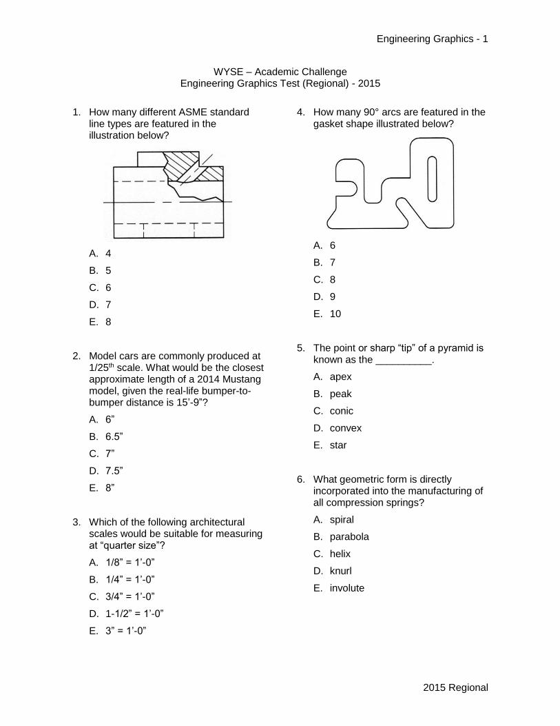
1. How many different ASME standard line types are featured in the illustration below?
A. 4
B. 5
C. 6
D. 7
E. 8
2. Model cars are commonly produced at 1/25th scale. What would be the closest approximate length of a 2014 Mustang model, given the real-life bumper-to-bumper distance is 15’-9”?
A. 6”
B. 6.5”
C. 7”
D. 7.5”
E. 8”
3. Which of the following architectural scales would be suitable for measuring at “quarter size”?
A. 1/8” = 1’-0”
B. 1/4” = 1’-0”
C. 3/4” = 1’-0”
D. 1-1/2” = 1’-0”
E. 3” = 1’-0”
4. How many 90° arcs are featured in the gasket shape illustrated below?
A. 6
B. 7
C. 8
D. 9
E. 10
5. The point or sharp “tip” of a pyramid is known as the __________.
A. apex
B. peak
C. conic
D. convex
E. star
6. What geometric form is directly incorporated into the manufacturing of all compression springs?
A. spiral
B. parabola
C. helix
D. knurl
E. involute
Engineering Graphics - 2
2015 Regional
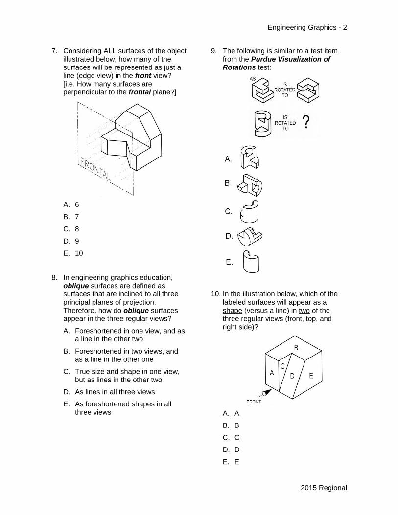
7. Considering ALL surfaces of the object illustrated below, how many of the surfaces will be represented as just a line (edge view) in the front view? [i.e. How many surfaces are perpendicular to the frontal plane?]
A. 6
B. 7
C. 8
D. 9
E. 10
8. In engineering graphics education, oblique surfaces are defined as surfaces that are inclined to all three principal planes of projection. Therefore, how do oblique surfaces appear in the three regular views?
A. Foreshortened in one view, and as a line in the other two
B. Foreshortened in two views, and as a line in the other one
C. True size and shape in one view, but as lines in the other two
D. As lines in all three views
E. As foreshortened shapes in all three views
9. The following is similar to a test item from the Purdue Visualization of Rotations test:
10. In the illustration below, which of the
labeled surfaces will appear as a shape (versus a line) in two of the three regular views (front, top, and right side)?
A. A
B. B
C. C
D. D
E. E
Engineering Graphics - 3
2015 Regional
11. Identify the TRUE statement about circles appearing as ellipses in pictorial drawings.
A. Isometric ellipses can be created using a four-center/four-arc “approximate” method
B. Isometric ellipse templates also create proper and exact ellipses for two-point perspective drawings
C. Oblique drawings won’t ever have ellipses because the front surface is parallel with the drawing plane
D. One-point perspective pictorial drawings won’t ever have ellipses because the front surface is parallel with the drawing plane
E. Circular features cannot be projected as ellipses in trimetric pictorials.
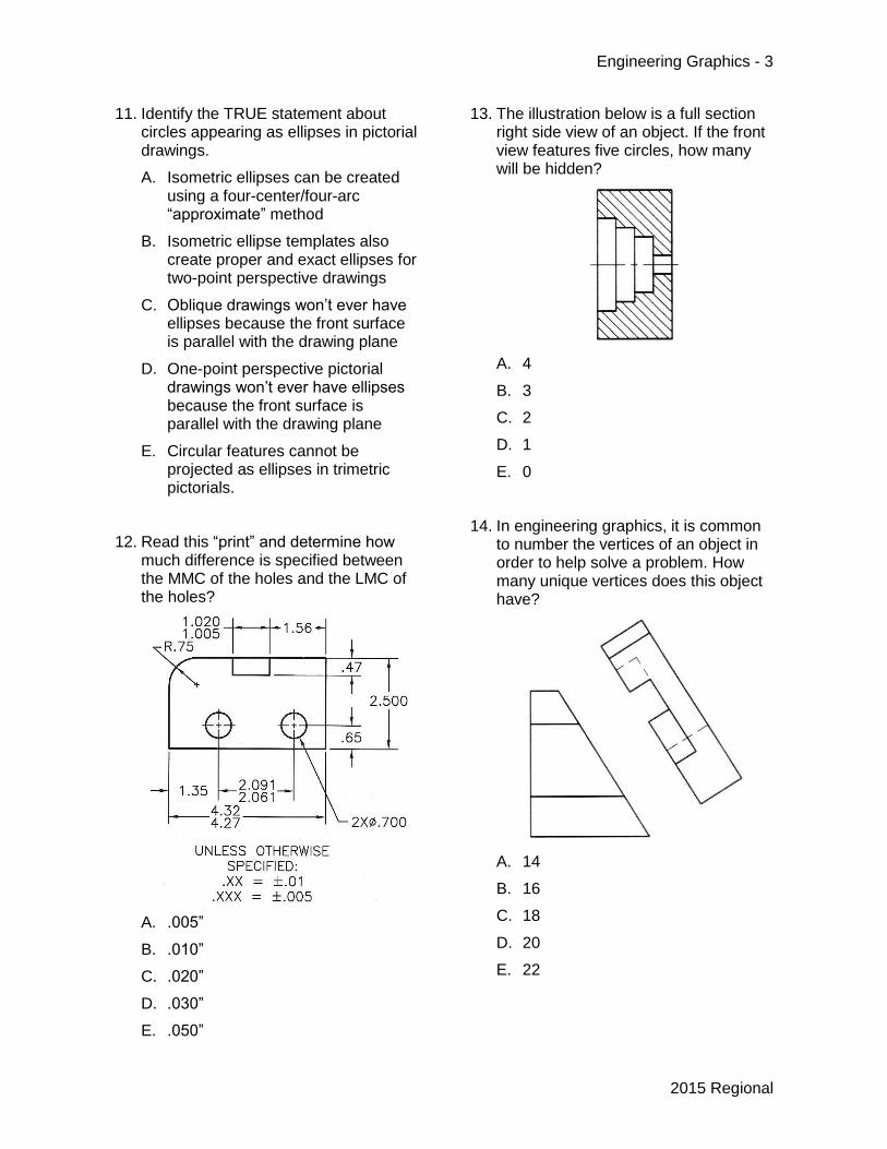
12. Read this “print” and determine how much difference is specified between the MMC of the holes and the LMC of the holes?
A. .005”
B. .010”
C. .020”
D. .030”
E. .050”
13. The illustration below is a full section right side view of an object. If the front view features five circles, how many will be hidden?
A. 4
B. 3
C. 2
D. 1
E. 0
14. In engineering graphics, it is common to number the vertices of an object in order to help solve a problem. How many unique vertices does this object have?
A. 14
B. 16
C. 18
D. 20
E. 22
Engineering Graphics - 4
2015 Regional
15. Some solid modeling programs require you to constrain a __________ fully before the creation of a solid feature can be created.
A. primitive
B. thread
C. axis
D. fillet
E. profile
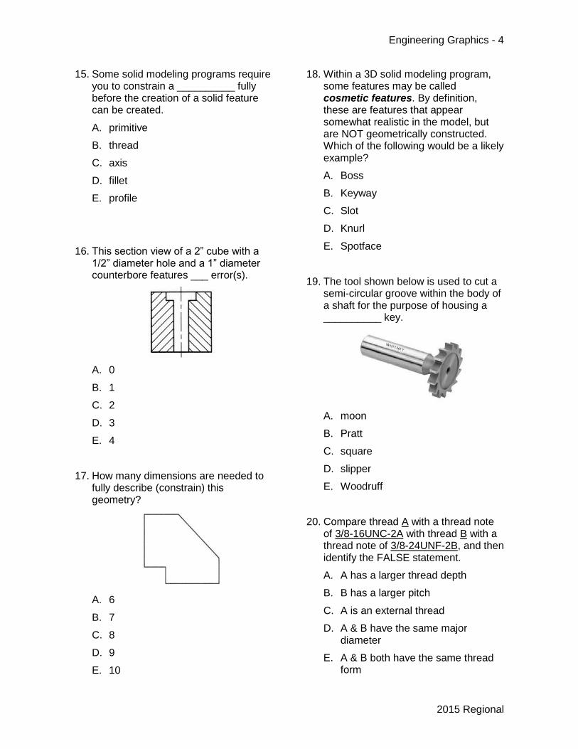
16. This section view of a 2” cube with a 1/2” diameter hole and a 1” diameter counterbore features ___ error(s).
A. 0
B. 1
C. 2
D. 3
E. 4
17. How many dimensions are needed to fully describe (constrain) this geometry?
A. 6
B. 7
C. 8
D. 9
E. 10
18. Within a 3D solid modeling program, some features may be called cosmetic features. By definition, these are features that appear somewhat realistic in the model, but are NOT geometrically constructed. Which of the following would be a likely example?
A. Boss
B. Keyway
C. Slot
D. Knurl
E. Spotface
19. The tool shown below is used to cut a semi-circular groove within the body of a shaft for the purpose of housing a __________ key.
A. moon
B. Pratt
C. square
D. slipper
E. Woodruff
20. Compare thread A with a thread note of 3/8-16UNC-2A with thread B with a thread note of 3/8-24UNF-2B, and then identify the FALSE statement.
A. A has a larger thread depth
B. B has a larger pitch
C. A is an external thread
D. A & B have the same major diameter
E. A & B both have the same thread form
Engineering Graphics - 5
2015 Regional
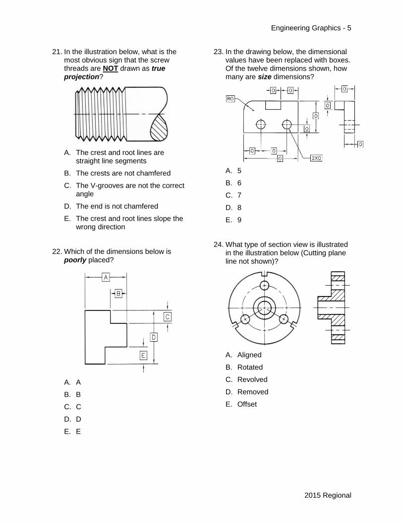
21. In the illustration below, what is the most obvious sign that the screw threads are NOT drawn as true projection?
A. The crest and root lines are straight line segments
B. The crests are not chamfered
C. The V-grooves are not the correct angle
D. The end is not chamfered
E. The crest and root lines slope the wrong direction
22. Which of the dimensions below is poorly placed?
A. A
B. B
C. C
D. D
E. E
23. In the drawing below, the dimensional values have been replaced with boxes. Of the twelve dimensions shown, how many are size dimensions?
A. 5
B. 6
C. 7
D. 8
E. 9
24. What type of section view is illustrated in the illustration below (Cutting plane line not shown)?
A. Aligned
B. Rotated
C. Revolved
D. Removed
E. Offset
Engineering Graphics - 6
2015 Regional
Engineering Graphics - 7
2015 Regional
Engineering Graphics - 8
2015 Regional
Engineering Graphics - 9
2015 Regional