Embed Size (px)
Citation preview

2014 Charles Pankow Foundation Annual
Architectural Engineering Student Competition
A Senior Project
presented to
the Faculty of the Architectural Engineering
California Polytechnic State University, San Luis Obispo
In Partial Fulfillment
of the Requirements for the Degree
Bachelor of Science
by
Jeffrey Hine, Joaquin Bermudez, Jason Serda
March, 2014
© 2014 Jeff Hine, Joaquin Bermudez, Jason Serda

STRUCTURALTEAM 13-2014
FEBRUARY 17, 2014

II
4Team 13-2014
I) Structural Narrative a) Project Goals............................................................................... b) Structural Criteria ........................................................................ c) Materials...................................................................................... d) Lateral System 1.0 Design Rationale........................................................ 2.0 Rocking Steel Braced Frame..................................... 3.0 Blume Report No. 174 Design Procedure................. 4.0 Concrete Moment Frame........................................... e) Gravity Systems 1.0 Design Rationale....................................................... 2.0 Interior Steel Framing................................................ 3.0 Exterior Concrete Framing........................................ f) Substructure 1.0 Design Rationale..................................................... g) Foundation 1.0 Design Rationale...................................................... h) Special Considerations 1.0 Cladding System...................................................... 2.0 Fog Catchers............................................................ i) Conclusion..................................................................................
II) Supporting Documentation a)References................................................................................. b)Codes, Standards, & Software................................................... c)Design Loads and Parameters 1.0 Dead Loads................................................................... 2.0 Live Loads..................................................................... d)Rocking Braced Frame Calculations Nomenclature...................................................................... 3.1 Base Shear & Overturn Moment.................................. 3.2 Allocation of Lateral Force Resistance......................... 3.3 Check Uplift Ratios & Drift........................................... 3.4 Size Brace Frame Members........................................ e)Moment Frame Calculations 1.0 Loads........................................................................... 2.0 Risa Output.................................................................. 3.0 SP Column Output.................................................. ..... f)Gravity System Calculations.......................................................
Table of contents
123
4577
888
10
11
121213
1415
1617
1820202528
29303031

1Team 13-2014
I
For the 2014 ASCE Charles Pankow Foundation Annual Architectural Engineering Student Design Competition, the structural design team had the goal of creating an innovative structural system that is well integrated with other building systems and supports the overall project goals of high performance. We wanted to find a system that worked best for this building and every discipline involved. There were a few directions we could have taken for the structural design. One approach was to focus on the performance of the building in terms of energy consumption and resources used in its construction. SOM’s use of concrete allowed the building to be seen as high performance as the concrete complements the mechanical and architectural system. Concrete can be used as a finished surface and its thermal mass reduces the demand on the heating and ventilation systems. The use of concrete also employs local labor for the production of the materials and for construction. The other was to strive towards high performance by optimizing the seismic response. The proper system would minimize the damage to itself and also nonstructural elements. The carbon footprint would then be less in the sense that less time and money are spent in repairs after a significant seismic event. Thus the building could be operable again with minimal repairs and waste.
a) Project Goals
2Team 13-2014
I
Building code: San Francisco Building code, 2013 edition Seismic: Seismic Site Class = D Risk Category = II Ie = 1.0 Ss = 1.5 S1 = 0.498 Fa = 1.0 Fv = 1.5 SMs = 1.5 SM1 = 0.748 SDS = 1 SD1 = 0.498 Seismic Design Category = D Soils Engineer: Treadwell & Rollo Soils Report No.: 730466502 Soils Report Date: 28 June 2012 Soils Bearing: Dead & Live = 10,000 psf Other:
The term ‘high-performance building’ means a building that integrates and optimizes on a life cycle basis all major high performance attributes, including energy conservation, environment, safety, security, durability, accessibility, cost-benefit, productivity, sustainability, functionality, and operational considerations.
A building with building drift limited to approximately half of what is currently allowed by the building code.
The owner would prefer that the design limit the amount of damage and repair to the building by a design earthquake event.
b) Structural Cr i ter ia

3Team 13-2014
I
c) Mater ia ls
Concrete Slab: fc’=5000 psi LWC (115 PCF)
Concrete Walls & Columns: fc’= 5000 psi NWC (150 PCF)
Steel Framing: ASTM A992
Post Tensioned Strands: 0.6” ASTM A416
Steel Plate Fuse: ASTM A992
Reinforcing Steel: ASTM A615 Gr60
Mat Foundation: fc’=5000 psi NWC (150 PCF)

4Team 13-2014
I
The competition guidelines specify a “minimum business downtime after a major earthquake”. We quickly came to understand what the causes are for this downtime. They include damage to the structural systems and also nonstructural systems.
As seen on Figure 1.0, the force demand reduces as elements yield. It takes time and money to replace these elements but another issue is that there is often residual displacement that can harm the nonstructural elements. Downtime can include the time and money spent to repair cladding and even mechanical systems.
Our structural design team then set a goal to learn about systems that allow for near immediate occupancy performance. This brought our structural design team to ask, can this be achieved with conventional structural systems?
Conventionally, specific elements in the lateral system yield as a means of energy dissipation. Consider a concrete shear wall. When designed correctly, the flexural reinforcement yields and the failure mode is ductile. Under cyclic loading, however, the concrete cracks and spalls. The shear wall is no longer adequate for another seismic event. Steel can be more easily repaired. Consider a buckling restrained braced frame. Proper connection design allows for ductile failure also. Even if there is minimal damage to the non structural elements of the building, repairs to gusset plates are both costly and time consuming.
Our structural team then looked into self-centering lateral systems. As seen in Figure 1.1, the pinched plot demonstrates that there is little to no residual displacement. This means that the energy dissipation is allocated to smaller elements that do not
Fig. 1.0: Typical hysteresis curve
Fig. 1.1: Self centering system hysteresis curve
d) Lateral System
1.0 Design Rationale

5Team 13-2014
I
compromise the entire lateral system. Not only can these elements be faster to replace, but also the self-centering motion allows for the gravity system to center back on itself.
After learning about advantages of self centering-systems, we chose the system that peaked our interest the most. The fundamental approach of a rocking braced frame is to have a rigid braced frame that is allowed to rock back and forth on its supports. Our frame configuration features steel plates between in plane pairs of rigid frames.
There are also post tensioned strands that help with the self-centering motion. The steel elements act as fuses such that the rigid frame can remain elastic during the seismic event. Both the post tensioned cables and steel fuses are designed to be easily replaceable. The building can be considered high performance since damage, repair costs, and repair time due to an earthquake are all minimized using structural elements that already exist today.
Our design for 350 Mission features rocking braced frames with post tensioned strands and butterfly fuses. They were placed in the interior to maximize the available floor space. The frames are in groups of six, with three pairs fastened to one another such that the frames rotate with the same lateral force. The steel fuses are found on the outside of the three pairs for constructability, see Figure 2.0 Our resources had not considered the use of rocking braced frames for high rises. We made it goal to push the limits of the system and weight its advantages and disadvantages.
During the development of the design of the rocking braced frames, our team examined ways to reduce sizes by optimizing the design. Significant floor space was going to be needed for not only the frames but also the independent gravity system. Two approaches were taken to decrease the frame member sizes and reduce the impact of the structure.
The building was already implementing concrete beams and columns for vertical loads at the perimeter. The first solution was to take advantage of perimeter concrete beams and columns. Rather than neglecting the rigidity of frames, the approach was to have them resist approximately 20% of the lateral load in each direction as exterior moment frames. The relatively small demands allowed us to conclude that the moment frames would remain elastic while the rocking frame system would behave inelastically.
d)Lateral System
1.0 Design Rationale
2.0 Rocking Steel Braced Frame

6Team 13-2014
I
Design of the perimeter concrete moment frames included further collaboration with the rest of the team. Since the concrete frames would be exposed, our team decided to use white concrete. White concrete reduced the need for painted finishes on the building’s exterior while helping to prevent heat island effects.
The second step toward reducing the member sizes of the rocking frames was to change their placement within the core. The initial design included placing the frames on the perimeter of the core area. It was concluded that a rigid body response was more possible by increasing the width of the frames, the axial demand was subsequently reduced and so was the required steel section size. Increasing the bay size involved working with the architects to incorporate our frames with their design of the core area. Our team came up with an elegant solution of allowing entrance to the core interior through the frames themselves. The diagonal members were changed to a chevron configuration to allow passage. The walk way was rotated 8 degrees through the core to satisfy both the structural and architectural design. The frames were able to fit in the core and the architects used the rotated walkway to lead people from the front corner of the building to the back, see Figure 2.0.
The proposed design includes two seismic joints separating the gravity system and the lateral system within the core. The first seismic joint is located between the rocking brace frames and the gravity system outside of the core. The second seismic joint is located between the rocking brace frames and the gravity system within the core. Keeping the gravity and lateral system separate served two purposes. The gravity system would not be damaged when an earthquake would induce rocking in the system. In addition, the gravity system did not need to be designed for resisting a MCE. The rocking motion could be achieved only with the lateral load transfer from the floor system, so special connections were designed to transfer inertial floor loads and also to allow the rotation of the rigid frame.
Fig 2.0: Brace configuration diagram
d)Lateral System
2.0 Rocking Steel Braced Frame

7Team 13-2014
I
Given the modernity of the system, time was invested in learning about the behavior of self-centering systems and the design process of our system in particular. Our design is based on procedures described in Blume Report No 174. It recommends the following process:
3.1 Base shear and overturning moment calculation.
3.2 Allocation of lateral force resistance between the fuses and post tensioned cables. 3.2.1 Design of cables and fuses. 3.2.2 Equivalent pushover curve points. 3.2.3 Single degree of freedom parameters.
3.3 Check uplift ratios and drift associated with the fuse and cable design.
3.4 Size braced frame members. One of the primary assumptions associated with this design procedure is that the frames remain elastic while the inelastic behavior of both steel plates and post tension cables dissipate energy during seismic motion. It is assumed that the frame is rigid enough to be considered first mode dominant. Our team followed the parameters and assumptions used within the Blume report.
We knew there had to be deformation compatibility with the exterior and interior lateral force resisting systems. With approximately 20% of the lateral loads, we investigated two layouts of moments frames, a 2 bay and a 4 bay configurations along the perimeter. After consulting with the architects, we selected the 4 bay frames so that we could reduce the column size, maximizing the perimeter view. After choosing initial column and beam from gravity loads, analysis with SP Column showed us that we needed to make the column size bigger. After calculating and setting the column sizes, we tested multiple beam sizes in Risa2D to analyze the drift of the moment frame system. Risa2D only takes into account linear elastic behavior, so we used 50 percent of gross moment of inertia in the analysis. SP column was also useful in designing the flexural reinforcement of the moment frame beams. Analysis with software allowed us to conclude that the lateral drift would not be enough for inelastic response during an MCE.
d)Lateral System
3.0 Blume Report 174 Design Procedure
4.0 Concrete Moment Frame

8Team 13-2014
I
The gravity system is separated into two components for the lateral load flow to the interior rocking braced frames. There was also a distinction between the materials used in these two areas in consideration with the constructability of the structure.
The core area, enclosed by the rocking frame system, consists of conventional steel framing with corrugated steel decking. Floor to floor height was not an issue here for the architects and the beam depth would be reasonable, as the span of the beams would be much less than if they were to span the floor system outside of the core area. The use of steel columns and beams reduces need for concrete construction on both sides of the rocking frame system.
Outside of the rocking frame perimeter are steel columns. It was concluded that the lateral load transfer would be easier if the materials were the same.
Beyond the steel columns surrounding the core, the floor system is a post tensioned two way lightweight concrete slab. SOM also used two way post tensioned slab. Our team very much agreed with advantages of the floor system. As confirmed by the architects and mechanical engineers of the team, using the two post tensioned slab allows for larger floor heights and reduces the need for columns at mid span. Coordinating with the mechanical engineer to use the 12 inch concrete slabs that gave them enough room within the story height to run their heating and cooling system and still give the architects plenty of ceiling height. Comparing the concrete slab to a steel beams with metal and concrete slab we were able to reduce the floor thickness from approximately 41 inches to about 12 inches. If we had chosen steel framing, the mechanical system would only require a few inches and the rest of the 29 inch space would not be utilized, see Figure 3.0. With the concrete slab, every inch is utilized and the rest of the height is cut out.
For the exterior gravity system our team determined that concrete columns would work best with the concrete floor system. The use of concrete columns was useful in later calculations when the were used as part of the perimeter moment frame system.
e)Gravi ty system
1.0 Design Rationale
3.0 Exterior Concrete Framing
2.0 Interior Steel Framing

9Team 13-2014
I
e)Gravi ty system
3.0 Exertior Concrete Framing
Fig 3.0: Floor framing depths

10Team 13-2014
I
The approach to the substructure design was to resolve the overturn moment of the rocking frames and also the loads from the gravity system with minimal changes to the SOM design. Given the time for the competition, our team didnt see the need to redesign the use of space below ground but rather modify it to meet our design loads.
There are no seismic joints below grade separating the core with the rest of the exterior. There is a continuous lightweight post tensioned concrete slab spanning the subfloors.
The rocking brace frames are supported by steel plates anchored to the concrete at the first floor the transfer the lateral loads into the diaphragm at street level. The reinforced concrete slab is designed to act as a collector to transfer the lateral loads at the base where the rocking frames occur.
Overturning forces induced by the lateral system are transmitted to the foundation through a 7’ thick concrete wall below grade. The gravity columns above grade are supported by pilasters around the concrete wall. The concrete moment frames supported by a 4’x4’ concrete pilasters around a 30” concrete wall below grade around the perimeter of the building. Basement walls are waterproofed and designed to account for equivalent fluid weights below the waterline in accordance with the geotechnical report.
f ) Substructure
1.0 Design Rationale

11Team 13-2014
I
The foundation of the building is designed to resist gravity and lateral loads consistent with recommendations contained in the geotechnical report by Treadwell and Rollo. The geotechnical report describes the subsurface conditions as heterogeneous fill over marine deposits underlain by dense to very dense sand (Colma Sand), stiff clay (Old Bay Clay) and Franciscan Complex bedrock. The geotechnical report recommends a mat foundation bearing on very dense Colma Sand. The Colma Sand starts approximately 46 to 50 feet below grade. The upper layers have a potential for liquefaction during an earthquake. Groundwater has the potential to occur as high as 3 feet below grade. The geotechnical report recommends a mat foundation to be placed at a minimum of 50 feet below grade to bear on the Colma Sand. According to the geotechnical report, differential compaction, seismic settlement and lateral spreading will not be an issue. To accommodate the overturn forces induced by the lateral system, our team designed to load path to go straight into the foundation through concrete walls below grade. Due to the large loads into the soil, a large bearing area is needed to meet the allowable bearing pressure. A 10 feet thick deep mat foundation was chosen to distribute the load over the entire building footprint. Basement walls needed to be waterproofed and designed to account for equivalent fluid weights below the waterline. Site shoring is required to accommodate a 60 foot deep excavation. The shoring needed to minimize the inflow of groundwater, reduce potential ground movement, and protect the integrity of existing buildings and utilities.
The geotechnical report suggests using either soldier pile tremie concrete, mixed in place soil/cement walls/ diaphragm walls or secant pile walls. Soil nailing is not a viable option due to the presence of ground-water and loose to medium dense sand. Sheet piles are not recommended since they would be very difficult to drive through the fill and could liquefy the loose and medium dense sand. Soldier-pile and lagging system would not be rigid enough to prevent potential ground movement.
Below grade our team chose to use concrete walls as the gravity system. The rocking brace frames start above grade, therefore they would not be in the core below grade. It made it easier for constructability below grade to use concrete walls with the concrete slabs. The concrete walls were also a logical choice to handle the high loads that accumulated from the entire building.
g) Foundat ion
1.0 Design Rationale

12Team 13-2014
I
After talking as a group we decided to go with a glass cladding with a double facade on the East and West faces of the building. Since these two faces of the building receives the most sunlight the double facade will have internal controllable louvers to manage the sunlight. We can do this because the moment frame provides enough room in between the columns to use this otherwise wasted space. Within the lobby we had to take in account such a long span of 53’ so we coordinated with the architect to joint the glass cladding so that it can accommodate the necessary drift.
Fog catchers are an innovative idea that our design team utilized in the building. Our team worked through many different designs and placements of the fog catchers in order to achieve a design that worked with every discipline. The Fog catchers are anchored 2 inches into the the concrete slab and columns. Placing the fog catchers in the corners along with keeping the slab enabled the area to be used as outdoor space. This designed maintained the square footage of the building, did not affect the lateral system and maximized the fog catchers.
h)Special Considerat ions
1.0 Cladding System
2.0 Fog Catchers

13Team 13-2014
I
The key to choosing a lateral system was considering not only strength and ductility, but also residual displacement. By establishing this criteria to the design, we achieve high performance with respect to a seismic event by minimizing the repairs to structural and nonstructural elements required after a major earthquake. Our team recognizes the extra cost of construction to meet the seismic criteria. However, the extra money spent on the steel conctruction will bring siginficant savings in the event of an earthquake.
We would like to address that our efforts have provided a preliminary design as a whole. Collaboration with the other disciplines has allowed the major design issues to surface. From here, the design process would include finite element modeling and testing of the fuse elements, verification of the rigid body response of the dual braced frames, further investigation into the constructability of independent lateral and gravity systems for high rises, and a nonlinear time history analysis on the lateral force resisting system as a whole.
i ) Conclusion

II
14Team 13-2014
(1)American Concrete Institute (ACI). “Building Code Requirements for Structural Concrete and Commentary.” ACI Standard 318-11. (2011).
(2)American Institute of Steel Construction (AISC). Steel Construction Manual. Fourteenth Edition. (2011).
(3)American Society of Civil Engineers (ASCE). “Minimum Design Loads for Buildings and Other Structures”. ASCE/SEI Standard 7-10. (2010).
(4)Christopoulos, Constantin, Andre Filiatrault, and Vitelmo V. Bertero. Principles of Passive Supplemental Damping and Seismic Isolation. Pavia, Italy: IUSS (2006).
(5)Ma, Xiang, Helmut Krawinkler, and Gregory G. Deierlein. Seismic Design and Behavior of Self-Centering Braced Frame with Controlled Rocking and Energy Dissipating Fuses. The John A Blume Earthquake Engineering Center, Stanford University. (2011).
(6)Mar, David. Tipping Mar principal. Interview. February 2014.
(7)Naaman, Antoine E. Prestressed Concrete Analysis and Design: Fundamentals. Ann Arbor, MI: Techno 3000, (2012).
(8)Schokker, Andrea J. The Sustainable Concrete Guide: Applications. Farmington Hills, MI: U.S. Green Concrete Council, (2012).
(9)Schokker, Andrea J. The Sustainable Concrete Guide: Strategies and Examples. Farmington Hills, MI: U.S. Green Concrete Council, (2010).
a)References

II
15Team 13-2014
American Concrete Institute (ACI). “Building Code Requirements for Structural Concrete and Commentary.” ACI Standard 318-11. (2011).
American Institute of Steel Construction (AISC). Steel Construction Manual. Fourteenth Edition. (2011).
American Society of Civil Engineers (ASCE). “Minimum Design Loads for Buildings and Other Structures”. ASCE/SEI Standard 7-10. (2010).
International Code Council (ICC). International Building Code. International Code Council, Falls Church, VA. (2011). “Autodesk Revit 2014.” Autodesk. (2014).
“Etabs Nonlinear Version 9.7.3.” Computers and Structure, Inc.(2011).
“Risa-2D Version 11.0.0.” Risa technologies. (2012).
“SP Column v4.81.” Structurepoint. (2014).
b)Codes, Standards, & Software

II
16Team 13-2014
1.1 Roof dead loads Light Gage Steel Framing Lightweight Concrete Slab Suspended Ceiling MEP MISC Total Roof Load = (136’)(134’)(0.127ksf) = 2,314k
1.2Typical floor dead loads Partitions Cladding Lightweight Concrete Slab Suspended Ceiling NWC Moment Frame Beam NWC Moment Frame Column MEP MISC 1.3 Core floor dead loads Partitions NWC Fill on Steel Deck Suspended Ceiling Steel Framing Column Fireproofing MEP MISC Total Floor Load = [(136’)(134’) - (46.6’)(56.6‘)](0.151ksf) + (46.6’)(56.6’)(0.08p4ksf)= 2,575k
Inertial dead loads of steel braced frames included in the total floor weight Total Floor Load = 2,575k + 725k
= 3,300k
5.0115.0
1.03.03.0
127.0 psf
15.08.0
115.01.06.0
10.03.03.0
151.0 psf
15.045.41.05.0
10.02.03.03.0
84.4 psf
c )Design Loads & Parameters
1.0 Dead loads

II
17Team 13-2014
Roof 35psf Office areas 50psf Restrooms 100psf Lobby corridors 100psf Typical floor corridors 80psf
c)Design Loads & Parameters
2.0 Live Loads
II
18Team 13-2014
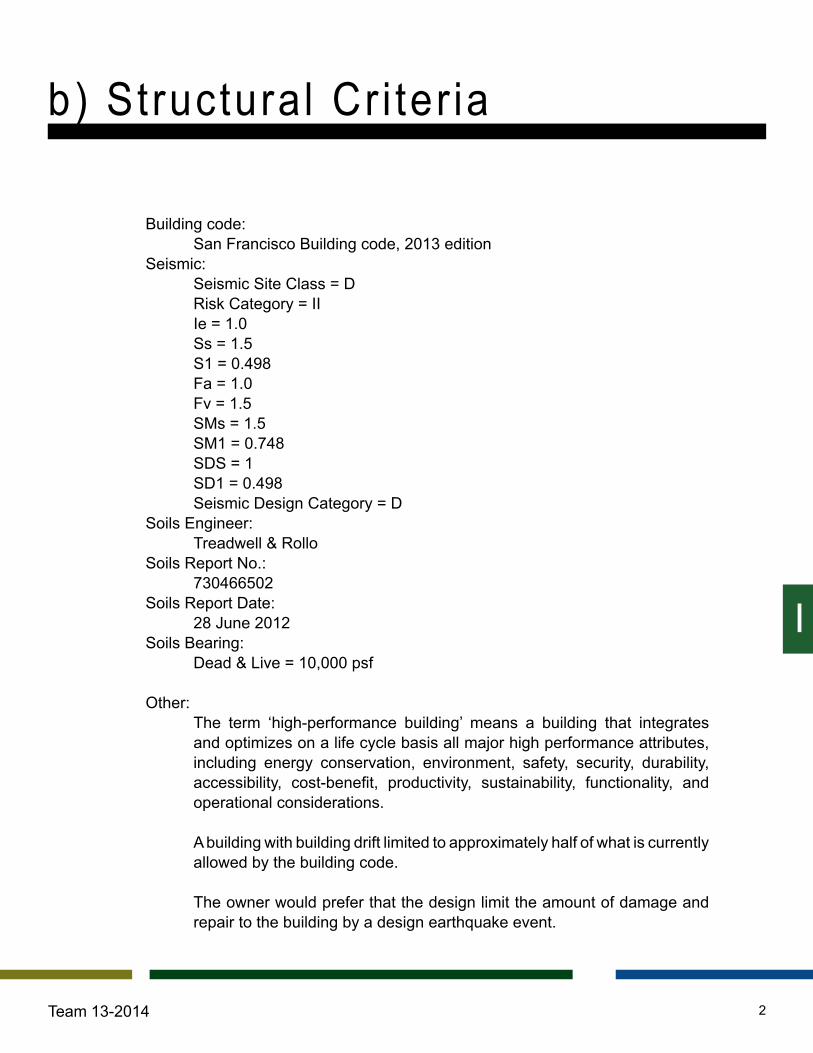
Nomenclature Units
A: Width of single braced frame. ft
As: Area of post tension strand bundle. in2
b: Geometric property of the steel fuses, [reference image]. in
c: Geometric property of the steel fuses, [reference image]. in
Dfuse: Distance between fuse elements and rocking end. ft
DPT: Distance between post tension strand and rocking end. ft
EPT: Post tension strand modulus of elasticity. ksi
FPTO: Post tension strand bundle force required to resist overturning. k
FfuseP: Steel fuse force required to resist overturning. k
fu: Ultimate stress of post tensioned strands. ksi
fy: Yield stress of post tensioned strands. ksi
He: Single degree of freedom height. ft
hi: Height at level i. ft K1: Elastic lateral system stiffness. k/in
K2: Pseudo-elastic lateral system stiffness, after fuses yield. k/in
K3: Inelastic system stiffness, after post tension cables yield. k/in
Ke: Single degree of freedom stiffness. k/in
Keff: Effective lateral system stiffness. k in/rad
KPT: Elastic stiffness of post tension strand bundle. k/in
KV: Elastic stiffness of steel fuses. k/in
d)Rocking Braced Frame Calculations

II
19Team 13-2014
KV2: Inelastic stiffness of steel fuses. k/in Ks: Secant lateral stiffness. k in/rad
L: Geometric property of the steel fuses, [reference image]. in
LPT: Length of post tension strand bundle. ft
Me: Single degree of freedom mass. k mi: Mass at level i. k
Mm: Overturn moment associated with θm and yielding of cables. k in
Movt max: Overturn moment associated with θe and MCE k in
Te: Single degree of freedom period. sec
Mupi: Initial overturn moment, no uplift yet. k in
My: Overturn moment associated with θy and yielding of fuses. k in
N: Number of post tensioned strands.
nf: Number of braced frames per direction.
nL: Geometric properties of the steel fuses, [reference image]. in
PD: Dead load on uplifted end of frame. k sc: self centering capability of the frame
β: Fuse post yielding stiffness ratio.
η0: Prestress ratio.
λ: Effective stiffness ratio.
φ: Resistance factor, LRFD design.
θm: Uplift ratio that yields post tension cable.
d)Rocking Braced Frame Calculations

II
20Team 13-2014
Per the Blume report No. 174, the initial step was to calculate the lateral force demand based on the Equivalent Lateral Force Procedure, ASCE 7-10 12.8.1. The design spectral acceleration values provided in the geotechnical report were used to solve for approximate period, ASCE 7-10 Table 12.8-2. Preliminary elastic base shear was calculated with an R of 8, as the link beam in an eccentric braced frame is analogous to the fuse elements within the dual frames.
Ta = 0.02(H)0.75 Cs max ≤ Cs = SDS/(R/I) ≤ Cs max V = Cs W
Base shear is then distributed along the height of the building, ASCE 7-10 12.8.3. Statics is used to solve for an equivalent overturn moment caused by the lateral story loads. To solve for the moment demand per frame, this overturn moment is divided by the number individual frame per direction. Given the symmetry of our design, we assumed the same number of frames in each direction. This number was increased to reduce the demand to each frame. The resulting overturn moment is then reduced by 20% to account for the strength of the concrete moment frames along the exterior. The 20% contribution was later verified with the design of the concrete members.
3.2.1 Design of cables and fuses. We then designed the energy dissipation systems for each individual frame. See Figure 4.0. The overturn moment is resisted by both fuse and strand systems, as the gravity system is independent of the lateral system for the configuration we chose. This division of systems reduces damage to the lateral system and therefore does not need to be designed for a MCE.
Ta = 1.73 secCs = Cs max = 0.03595V = 3,088.19 k
d)Rocking Braced Frame Calculations
3.1 Base Shear & Overturn Moment
3.2 Allocation of Lateral Force Resistance

II
21Team 13-2014
The force required from the post tensioned strands to resist the overturning moment is calculated with self centering in mind. The self centering capability of the the system is influenced by the width of the frame and also the dead load that would help bring the uplifted end back down. Since our lateral system is independent of the gravity system, SC was only slightly increased from 1.5 to 2.0 in anticipation that the self weight of the frames could help with the overturn moment. The minimum force from the post tensioned strand was used, the intention was to rely less on the strands and more on the fuse elements to resist overturning.
FPTO ≥ sc/(1+sc)*MOVT/φ(DPT) - PDA/DPT A minimum prestressed ratio then is established. Notice that rigid body dynamics plays a role in reducing the minimum prestress ratio. The post tensioned cables are design to yield at θm. Setting θm to zero would result in the greatest pretension force in the cables. The number of cables needed is then selected based on the prestress ratio, a large ratio means that less are needed. Post tension strand length, and yield rotation were changed such that the system could be constructed more easily. In consideration of the limited floor space, it was clear that reducing the number strands needed would reduce the diameter of the anchor at the ends of the strands.
η0 ≤ fy/fu -(EPT (DPT) θm)/(fu LPT) N ≥ FPTO/(η0 fu As )
FPTO = 2,373k ≥ 2,373k
η0 = 0.566 ≤ 0.5664N = 72 ≥ 71.52
Fig. 4.0: Idealized rocking braced frame system
d)Rocking Braced Frame Calculations
3.2 Allocation of Lateral Force Resistance

II
22Team 13-2014
Just as the post tension strands, the fuse is designed to help resist the overturn moment. Its strength is dependant on the geometry and way it is constructed. Dimensions in FfuseP are found in Figure 5.0. Changing the value of nL later proved to be the best way of increasing the stiffness of the lateral system as a whole.
FfuseP ≥ 1/(1+sc)*MOVT/φ(Dfuse) FfuseP = (4 nL b2 t σy)/(9 L)
3.2.2 Equivalent push-over curve points The following equations were used to approximate what the system pushover curve would be like, see Figure 6.0 through Figure 6.2. The structural team decided not to develop a pushover curve due to the complexity of modeling the fuses and strands. β was a value that the design team decided not to change. Extensive testing of our proposed steel fuse would be needed for a better approximation of β.
KPT = (N EPT As)/LPT KV = 1/(1+2.8(C/L)) 0.47 nL Et (b/L)3 KV2 = βKV Mupi = (FPTO)DPT K1 = KPT (Dfuse)2+KV (DPT)
2 My = (FfuseP)Dfuse+(FPTO )DPT K2 = KPT (Dfuse)2+βKV (DPT)
2 Mm =(FfuseM)Dfuse+(FPTY )DPT K3 = βKV (DPT)2
FfuseP ≥ 1,187 kFfuseP = 3,913 k
Fig. 5.0: Butterfly fuse geometry
d)Rocking Braced Frames Calculations
3.2 Allocation of Lateral Force Resistance
KPT = 700 k/inKV = 37,826 k/inβ ≈ 0.04, KV2 = 1,513 k/inMupi= 477,064 k inK1= 1.56 x 10⁹ k/inMy =1,263,586 k/inK2 = 89,414,975 k/in
K3 = 61,128,939 k/in

II
23Team 13-2014
Fig. 6.0: Butterfly fuse ideal push over curve
d)Rocking Braced Frame Calculations
3.2 Allocation of Lateral Force Resistance

II
24Team 13-2014
3.2.3 Single degree of freedom parameters Since only the first mode of motion is considered, an equivalent single degree of freedom is developed to analyze the drift associated with a MCE. As seen in the next section, the solving for the single degree of freedom system iterations with changes in the energy dissipation elements and estimated uplift ratios.
He = (Σmi (hi )2)/(Σmi hi ) He = 261 ft
Me = (Σmi hi)/((He/nf) ) Me = 4,748 k
Fig. 6.1: Post tenioned strand ideal push over curve
d)Rocking Braced Frame Calculations
3.2 Allocation of Lateral Force Resistance
II
25Team 13-2014
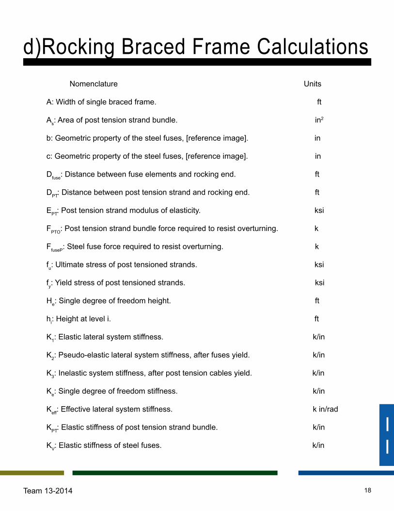
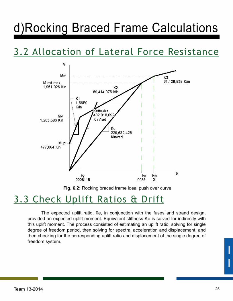
The expected uplift ratio, θe, in conjunction with the fuses and strand design, provided an expected uplift moment. Equivalent stiffness Ke is solved for indirectly with this uplift moment. The process consisted of estimating an uplift ratio, solving for single degree of freedom period, then solving for spectral acceleration and displacement, and then checking for the corresponding uplift ratio and displacement of the single degree of freedom system.
Fig. 6.2: Rocking braced frame ideal push over curve
d)Rocking Braced Frame Calculations
3.2 Allocation of Lateral Force Resistance
3.3 Check Uplift Ratios & Drift

II
26Team 13-2014
The following equations better explain the iterative process.
θy = My/K1 θy = 0.000818 Estimate a θe θe = 0.0085 Movt max = My+K2(θe-θy) Movt max = 1,951,026 k in Ks = (Movt max)/θe Ks = 229,532,425 k in/rad Keff = λKs Keff = 482,018,092 k in/rad Ke = Keff/He
2 Ke = 49.26 k Te = 2π√(Me/Ke ) Te = 3.14 sec MCE spectral acceleration is found with Te SA = 0.26g SD = (Ke/Me)SA SD = 25 in θe = SD/He θe = 0.008
λ was slightly increase from 1.8 to 2.0 in anticipation that there would be higher mode responses. There were subsequent iterations to reduce SD and or have the θe match up better. The single degree of freedom stiffness, mass, and height allowed for an estimation in spectral displacement that we less than the code specified limit.
∆max = 0.01 hsx ∆max = 46 in, see Table 7.0 25 in < 46 in SD < ∆max
We then considered the moment frame. The design process for the rocking system was based on a single degree of freedom approximation. Our goal was to have the concrete moment frame remain elastic during a MCE. As diaphragms displace laterally during the event, the forces in the moment frame increase. Limiting the drift in the moment frame proved to be critical in its ability to remain elastic. Designing the concrete members to remain elastic while the drift reached SD was not conservative enough. We then decided to design the concrete moment frame for a greater lateral drift.
25 * 1.4 = 35 in
We considered 1.4 as out factor of safety, in anticipation that the rocking braced frame system would displace more than the calculated SD value.
d)Rocking Braced Frame Calculations
3.3 Check Uplift Ratios & Drift

II
27Team 13-2014
d)Rocking Braced Frame Calculations
3.3 Check Uplift Ratios & Drift
Table 7.0: Allowable drift, sum of story drifts

II
28Team 13-2014
With satisfactory spectral displacements and uplift ratios, the final step was to design the members that would make up the braced frames. The overturn moment was turned back into a triangular load distribution with a force to the frame at each level. The initial frame design featured widths that would enclose the proposed core space. Smaller frame widths led to increased member demands. Increasing the with size not only reduced the member demand but allowed for the structure to further integrate with the architectural planning. The frame width was increased to a centerline to centerline length of 16.75’ to allow people to walk through. The brace configuration was then changed from x patterns to inverted chevrons. Frame members were designed with the lateral loads derived from the estimated overturn moment. This last step differed from the process suggested in the Blume report because it gave us more reasonable frame member demands.
d)Rocking Braced Frame Calculations
3.4 Size Braced Frame Members

II
29Team 13-2014
Starting off the moment frame design, we calculated the tributary area of the concrete columns and applied the factored dead and live loads to get the cross sectional area needed. Using the lobby column that spans 54 feet to design reinforcement:
Tributary Area Columns ATrib. column = (20’)(27.25' )= 545ft2
Dead loads Roof = 127psf(545ft2 )= 69215lb = 69.215k Floor = 161psf(545ft2 )= 87745lb = 87.745k
Live loads Roof = 35psf(545ft2 )= 19075lb = 19.075k Floor = 80psf(545ft2 )= 43600lb = 43.6k
Self Weight Column weight = ((48''*48'')/(144''/ft))(150pcf)(54ft)= 129600lb = 129.6k
Total loads Dead load = 24levels(87.745k)+69.215k = 2177.5k Live load = 24Levels(43.6k)+19.075k = 1065.48k
Factord loads Factored axial load = 1.2(2177.5+129.6) + 1.6(1065.48) = 4473.29k
Area Required Cross sectional area req'd Pu/2 = 4473.29/2 = 2236.64in2
48'' x 48'' = 2304in^2 ≥ 2236.64in2 Use: 48’’ x48’’ column.
Now having a preliminary column size we matched the drift of the rocking brace frame in Risa2D and found what beam size we needed. We did this so that that the two systems are compatible. Taking these sizes of columns and beams and 50 percent Igross in Risa2D, the Maximum moments, shears and axial loads are generated and used to calculate the reinforcement in the concrete members.
e)Moment Frame Calculat ions
1.0 Loads
II
30Team 13-2014
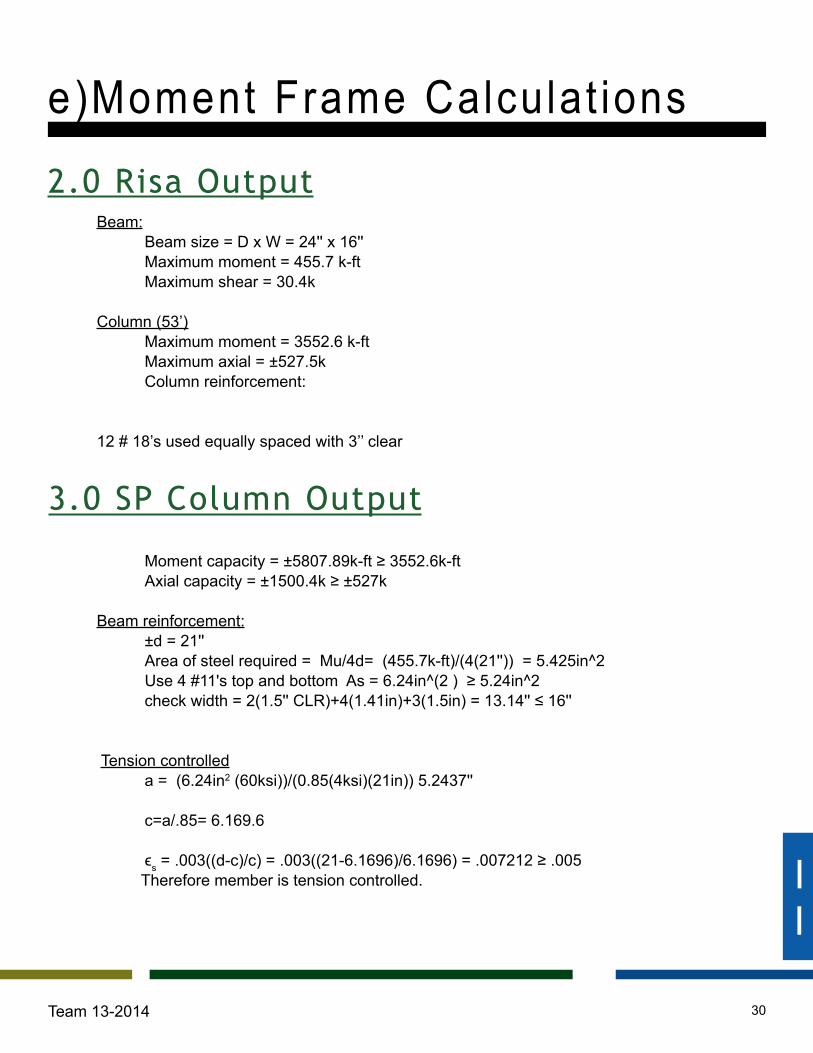
Beam: Beam size = D x W = 24'' x 16'' Maximum moment = 455.7 k-ft Maximum shear = 30.4k
Column (53’) Maximum moment = 3552.6 k-ft Maximum axial = ±527.5k Column reinforcement:
12 # 18’s used equally spaced with 3’’ clear
Moment capacity = ±5807.89k-ft ≥ 3552.6k-ft Axial capacity = ±1500.4k ≥ ±527k
Beam reinforcement: ±d = 21'' Area of steel required = Mu/4d= (455.7k-ft)/(4(21'')) = 5.425in^2 Use 4 #11's top and bottom As = 6.24in^(2 ) ≥ 5.24in^2 check width = 2(1.5'' CLR)+4(1.41in)+3(1.5in) = 13.14'' ≤ 16''
Tension controlled a = (6.24in2 (60ksi))/(0.85(4ksi)(21in)) 5.2437'' c=a/.85= 6.169.6
ϵs = .003((d-c)/c) = .003((21-6.1696)/6.1696) = .007212 ≥ .005 Therefore member is tension controlled.
e)Moment Frame Calculat ions
2.0 Risa Output
3.0 SP Column Output
II
31Team 13-2014
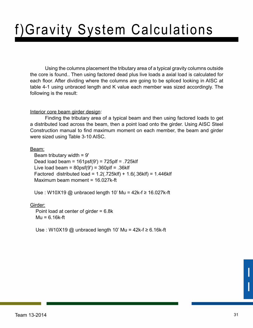
Using the columns placement the tributary area of a typical gravity columns outside the core is found.. Then using factored dead plus live loads a axial load is calculated for each floor. After dividing where the columns are going to be spliced looking in AISC at table 4-1 using unbraced length and K value each member was sized accordingly. The following is the result:
Interior core beam girder design: Finding the tributary area of a typical beam and then using factored loads to get a distributed load across the beam, then a point load onto the girder. Using AISC Steel Construction manual to find maximum moment on each member, the beam and girder were sized using Table 3-10 AISC. Beam: Beam tributary width = 9' Dead load beam = 161psf(9') = 725plf = .725klf Live load beam = 80psf(9') = 360plf = .36klf Factored distributed load = 1.2(.725klf) + 1.6(.36klf) = 1.446klf Maximum beam moment = 16.027k-ft
Use : W10X19 @ unbraced length 10’ Mu = 42k-f ≥ 16.027k-ft Girder: Point load at center of girder = 6.8k Mu = 6.16k-ft Use : W10X19 @ unbraced length 10’ Mu = 42k-f ≥ 6.16k-ft
f )Gravi ty System Calculat ions

ASCE CHARLES PANKOW FOUNDATIONANNUAL AEI STUDENT COMPETITION
350 MISSION ST, SAN FRANCISCOTEAM 13-2014
S 1.03D STRUCTURE PERSPECTIVE
INTERIOR GRAVITY
COLUMNS
STEEL ROCKING
BRACED FRAMES
EXTERIOR SPECIAL
CONCRETE MOMENT FRAME
POST TESNIONED
TWO WAY LWC SLAB
COMPLETE STRUCTURAL
SYSTEM

A F J
9
8
5
2
1
D G
6
4
3
7
----
33' -
0"
8' -
8"1'
- 0" 23
' - 4
"23
' - 4
"1' -
0"8'
- 8"
33' -
0"
12" SLOPEDCONCRETE SLAB
4'X4' CONCRETE PILASTERTYP
24"X26" OUTERCONCRETE PILASTERTYP24"X26" CONCRETE
COLUMN TYP
7' CONCRETEBEARING WALL
36"X30 INNER CONCRETEPILASTER TYP
30" CONCRETERETAINING WALL
132'
- 0"
35' - 0" 30' - 0" 30' - 0" 35' - 0"
130' - 0"2
S 2.0
1ST FL0' - 0"
LEVEL B1-13' - 9"
LEVEL B2-27' - 6"
LEVEL B3-41' - 3"
LEVEL B4-55' - 0"
31 7 9
SEE ARCH PLANFOR SLOPE
9' -
1"9'
- 1"
7' -
0 1/
2"
10' MAT FOUNDATION
132' - 0"
ASCE CHARLES PANKOW FOUNDATIONANNUAL AEI STUDENT COMPETITION
350 MISSION ST, SAN FRANCISCOTEAM 13-2014
S 2.0SUB GRADE FRAMING PLAN
1/8" = 1'-0"1 LEVEL B1
1/8" = 1'-0"2 SUBSTRUCTURE ELEVATION

A B F I J
9
8
5
2
1
D G
6
4
C H
3
7
33' -
0"
8' -
8"
1' -
0"23' -
4"
23' -
4"
1' -
0"8'
- 8"
33' -
0"
30' - 10"
3' - 2" 1' - 0"30' - 0" 30' - 0"
1' - 0" 1' - 6"
32' - 6"
W10X19
W10X19
W10X19
W10X19
W10X19
W10X19
W10
X19
W10X19
W14
X48
W10
X19
W10
X19
W10
X19
W10
X19
W10
X19
W10X19
W10X19
W10
X19
4'x4' CONC.COLUMNTYP.
RBFRBF
RBFRBF
RBF
RBF
RBF
RBF
GRAVITY COLUMNOUTSIDE OF CORESEE SCHEDULE
GRAVITY COLUMNINSIDE OF CORESEE SCHEDULE
12" POST TENSIONEDTWO WAY SLAB
DECKING LWC5-1/4", 20 GAGEPHOS/PAINTED
W10
X19
W10X19
SEISMIC JOINTAROUND RBF SYSTEMS
W10
X19
W10X19
W10X19 W10X19
132'
- 0"
130' - 0"
6' - 6"
13' - 7"
10' -
7 1
/2"
A B F I J
9
8
5
2
1
D G
6
4
C H
3
7
W10X19
W10X19
W10X19
W10X19
W10X19
W10X19
W10
X19
W10X19
W10
X19
W10
X19
W10
X19
W10
X19
W10
X19
W10
X19
W10X19
W10
X19
132'
- 0"
130' - 0"
RBFRBF
RBFRBF
RBF
RBF
RBF
RBF
GRAVITY COLUMNOUTSIDE OF CORESEE SCHEDULE
GRAVITY COLUMNINSIDE OF CORESEE SCHEDULE
4'x4' CONC.COLUMNTYP.
12" POST TENSIONEDTWO WAY SLAB
W10
X19
W10X19
SEISMIC JOINTSAROUND RBF SYSTEMS
W10
X19
W10X19
W10X19 W10X19
W10X19
DECKING LWC5-1/4", 20 GAGEPHOS/PAINTED
33' -
0"
8' -
8"
1' -
0"23' -
4"
23' -
4"
1' -
0"
8' -
8"33
' - 0
"
11' - 5 1/4"
11' -
6"
6' - 1 1/8" 16' - 11 1/2"
20' -
0"
10' -
11
5/8"
ASCE CHARLES PANKOW FOUNDATIONANNUAL AEI STUDENT COMPETITION
350 MISSION ST, SAN FRANCISCOTEAM 13-2014
S 2.1LOBBY FRAMING PLANS
1/8" = 1'-0"1 LEVEL 2
1/8" = 1'-0"2 LEVEL 3

A B F I J
9
8
5
2
1
D G
6
4
C H
3
7
1.S 3.0
W10X19
W10X19
W10X19
W10X19
W10X19
W10X19
W10X19
W10
X19
W10X19
W10
X19
W10
X19
W10
X19
W10
X19
W10
X19
W10
X19
W10X19
W10
X19
W10
X19
W10
X19
W10X19
W10X19
12" POST TENSIONEDTWO WAY SLAB
GRAVITY COLUMNOUTSIDE OF CORESEE SCHEDULE
GRAVITY COLUMNINSIDE OF CORESEE SCHEDULE
RBFRBF
RBFRBF
RBF
RBF
RBF
RBF
4'x4' CONC.COLUMNTYP.
SEISMIC JOINTAROUND RBF SYSTEMS
W14X48 W14X48
W14X48
DECKING LWC5-1/4", 20 GAGEPHOS/PAINTED
33' -
0"
8' -
8"
1' -
0"23' -
4"
23' -
4" 1' -
0"
8' -
8"33
' - 0
"
132'
- 0"
130' - 0"30' - 10"
3' - 2"1' - 0" 30' - 0" 30' - 0" 1' - 0"
1' - 6"32' - 6"
STEEL GRAVITY COLUMN SCHEDULE
LEVELMARK
ROOF
28TH FL
27TH FL
26TH FL
25TH FL
24TH FL
23TH FL
22ND FL
21ST FL
20TH FL
19TH FL
18TH FL
17TH FL
16TH FL
15TH FL
14TH FL
12TH FL
11TH FL
10TH FL
9TH FL
8TH FL
7TH FL
6TH FL
5TH FL
4TH FL
3RD FL
2ND FL
1ST FL
13TH FL
TYP. COL
W14x99
W14x90
W14x68
W14x48
INTERIOR CORE EXTERIOR CORE
W14x132
W14x145
W14x176
W14x193
W14x211
W14x223
W14x223
W14x257
W14x257
W14x257
W14x99
W14x90
W14x68
W14x48
W14x109
W14x145
W14x159
W14x176
W14x193
W14x211
W14x211
W14x233
W14x233
W14x233
ASCE CHARLES PANKOW FOUNDATIONANNUAL AEI STUDENT COMPETITION
350 MISSION ST, SAN FRANCISCOTEAM 13-2014
S 2.2TYPICAL FRAMING PLAN
1/8" = 1'-0"1 7TH FL
1" = 1'-0"2 GRAVITY COLUMN SCHEDULE
C D E F G H I
3
4
5
6
7
RBFRBF
RBF
RBF
RBF
RBF
GRAVITY COLUMNOUTSIDE OF CORESEE SCHEDULE
GRAVITY COLUMNINSIDE OF CORESEE SCHEDULE
1' -
0"23
' - 4
"23
' - 4
"1'
- 0"
1' - 6" 1' - 0" 30' - 0" 30' - 0" 1' - 0" 1' - 6"
SEISMIC JOINTAROUND RBF SYSTEMS
DECKING LWC5-1/4", 20 GAGEPHOS/PAINTED
48' -
8"
62' - 0"
RBFRBF
W10x19
W10x19
W10x19
W10x19
W10x19
W10x19
W10x19
W10x19
W10x19W10x19
W10x19
W10x19
W10
x19
W10
x19
W10
x19
W10
x19
W10
x19
W10
x19
W10
x19
W10
x19
W10
x19
W10
x19
ASCE CHARLES PANKOW FOUNDATIONANNUAL AEI STUDENT COMPETITION
350 MISSION ST, SAN FRANCISCOTEAM 13-2014
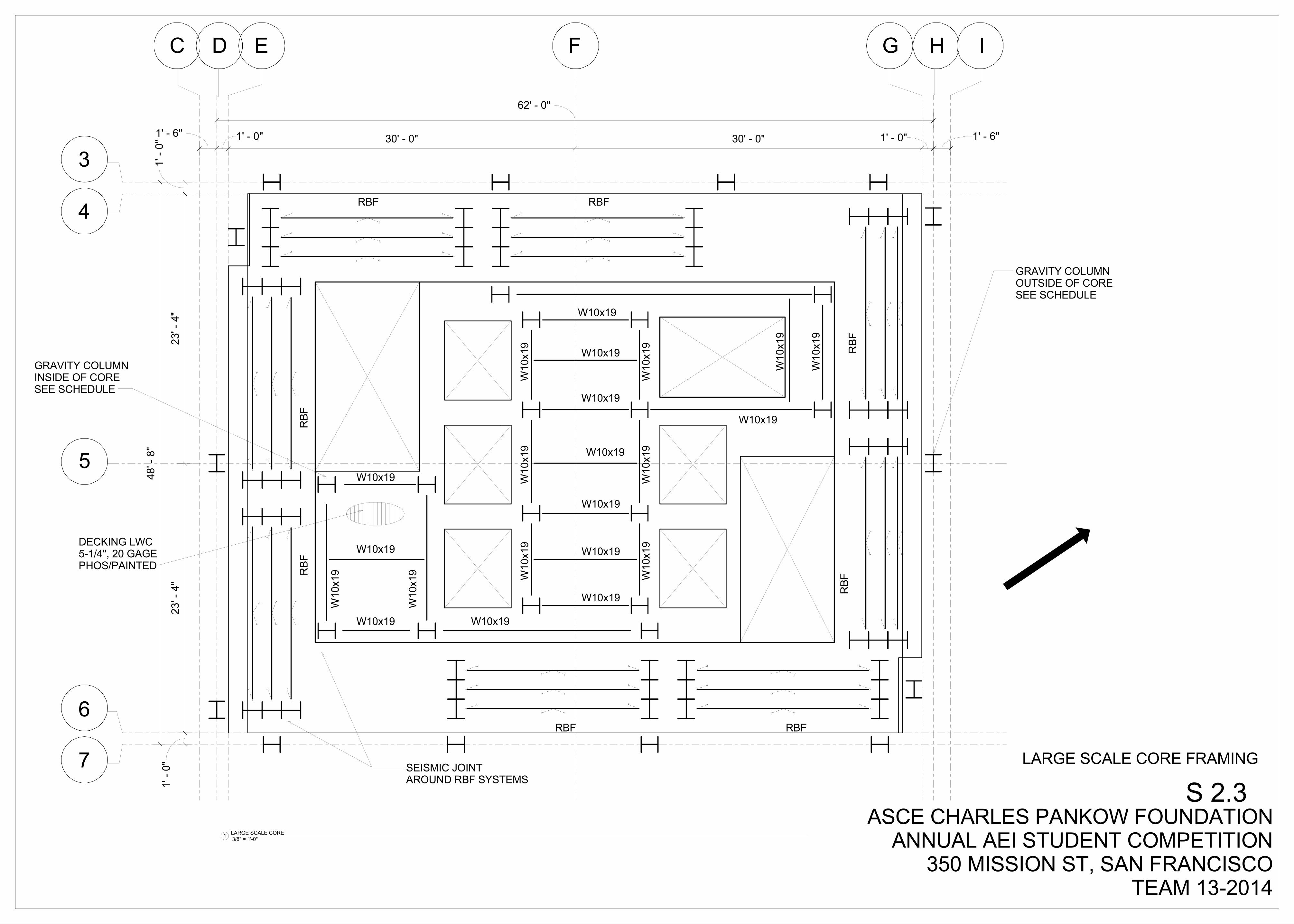
S 2.3LARGE SCALE CORE FRAMING
3/8" = 1'-0"1 LARGE SCALE CORE
1ST FL0' - 0"
5TH FL53' - 0"
6TH FL66' - 9"
7TH FL80' - 6"
8TH FL94' - 3"
9TH FL108' - 0"
10TH FL121' - 9"
11TH FL135' - 6"
12TH FL149' - 3"
13TH FL163' - 0"
14TH FL176' - 9"
15TH FL190' - 6"
W14
X74 W
14X74
W14X74W
14X7
4W
14X7
4 W14X74
W14X82 W14X82
W14
X74 W
14X74
W14X82
W14
X74 W
14X74
W14X82
W14X74
W14X82 W14X82
W14
X74 W
14X74
W14X74W
14X7
4W
14X7
4
W14X82
W14X74
W14X82
W14
X74 W
14X74
W14X82
W14X74W
14X7
4
W14X82
W14
X74 W
14X74
W14X74
W14X82
W14
X74 W
14X74
W14X82
W14
X74 W
14X74
W14
X74 W
14X74
W14X82 W14X82
W14
X74 W
14X74
W14X82
W14X74W
14X7
4
W14X82
W14X74W
14X7
4
W14X82
W14
X74 W
14X74 W14
X74 W
14X74
W14
X74 W
14X74
W14
X74 W
14X74
W14
X74 W
14X74
W14
X74 W
14X74
W14
X74 W
14X74 W14
X74 W
14X74
W14
X74 W
14X74
W14
X74 W
14X74
W14
X74 W
14X74
W14X82
W14
X74
W14X82
W14X82W14X82
W14X82
W14X82
W14X82
W14X82
W14
X74 W
14X74
W14X82
W14X82
W14X82
W14
X74
POST TENSIONEDSTRANDS
TYP BUTTERFLY FUSEBOTTOM 2' ABOVE FLOOR
2' -
0"
S 4.03
S 4.05
S 4.04
S 4.01
2ND FL24' - 0"
3RD FL42' - 0"
3RD FL.42' - 0"
16' - 9"TYP
15TH FL190' - 6"
16TH FL204' - 3"
17TH FL218' - 0"
18TH FL231' - 9"
19TH FL245' - 6"
20TH FL259' - 3"
21ST FL273' - 0"
22ND FL286' - 9"
23RD FL300' - 6"
24TH FL314' - 3"
25TH FL328' - 0"
26TH FL341' - 9"
27TH FL355' - 6"
28TH FL369' - 3"
ROOF383' - 0"
W14X53
W14X48W
14X4
8
W14X48W
14X4
8
W14X53
W14X48W
14X4
8
W14X53
W14X48W
14X4
8
W14X53
W14
X48 W
14X48
W14X53
W14
X48 W
14X48
W14
X48 W
14X48 W14
X48 W
14X48
W14
X48
W14X53
W14X48 W
14X4
8 W14X48W
14X4
8
W14X53
W14X48W
14X4
8
W14X53W14X53
W14X48W
14X4
8W
14X6
1 W14X61
W14X53
W14
X61
W14X53
W14X61
W14X61W
14X6
1
W14X61W14X61
W14X61W
14X6
1
W14X61
W14X61W
14X6
1
W14
X61 W
14X61
W14X61
W14X53
W14X53
W14
X74 W
14X74
W14X82
W14X74W
14X7
4
W14X61
W14
X61 W
14X61
W14X61
W14X61W
14X6
1
W14X61
W14
X61 W
14X61
W14X61
W14
X61 W
14X61
W14X61W14X61
W14X61W
14X6
1
W14X61
W14
X61 W
14X61
W14X61
W14X61W
14X6
1W
14X6
1 W14X61
W14X61
W14X61
W14X74W
14X7
4
W14X82
W14
X74 W
14X74
W14X53
STEEL ROCKING BRACE FRAMECOLUMN SCHEDULE
LEVELMARK
ROOF
28TH FL
27TH FL
26TH FL
25TH FL
24TH FL
23TH FL
22ND FL
21ST FL
20TH FL
19TH FL
18TH FL
17TH FL
16TH FL
15TH FL
14TH FL
12TH FL
11TH FL
10TH FL
9TH FL
8TH FL
7TH FL
6TH FL
5TH FL
4TH FL
3RD FL
2ND FL
1ST FL
13TH FL
TYP. COL
W14x550
W14x257
W14x257
W14x82
W14x82
W14x257
W14x550
W14x550
W14x550
W14x550
W14x550
W14x550
W14x550
W14x550
W14x550
2'' PLATES T & B
2'' PLATES T & B
2'' PLATES T & B2'' PLATES T & B
2'' PLATES T & B
2'' PLATES T & B
ASCE CHARLES PANKOW FOUNDATIONANNUAL AEI STUDENT COMPETITION
350 MISSION ST, SAN FRANCISCOTEAM 13-2014
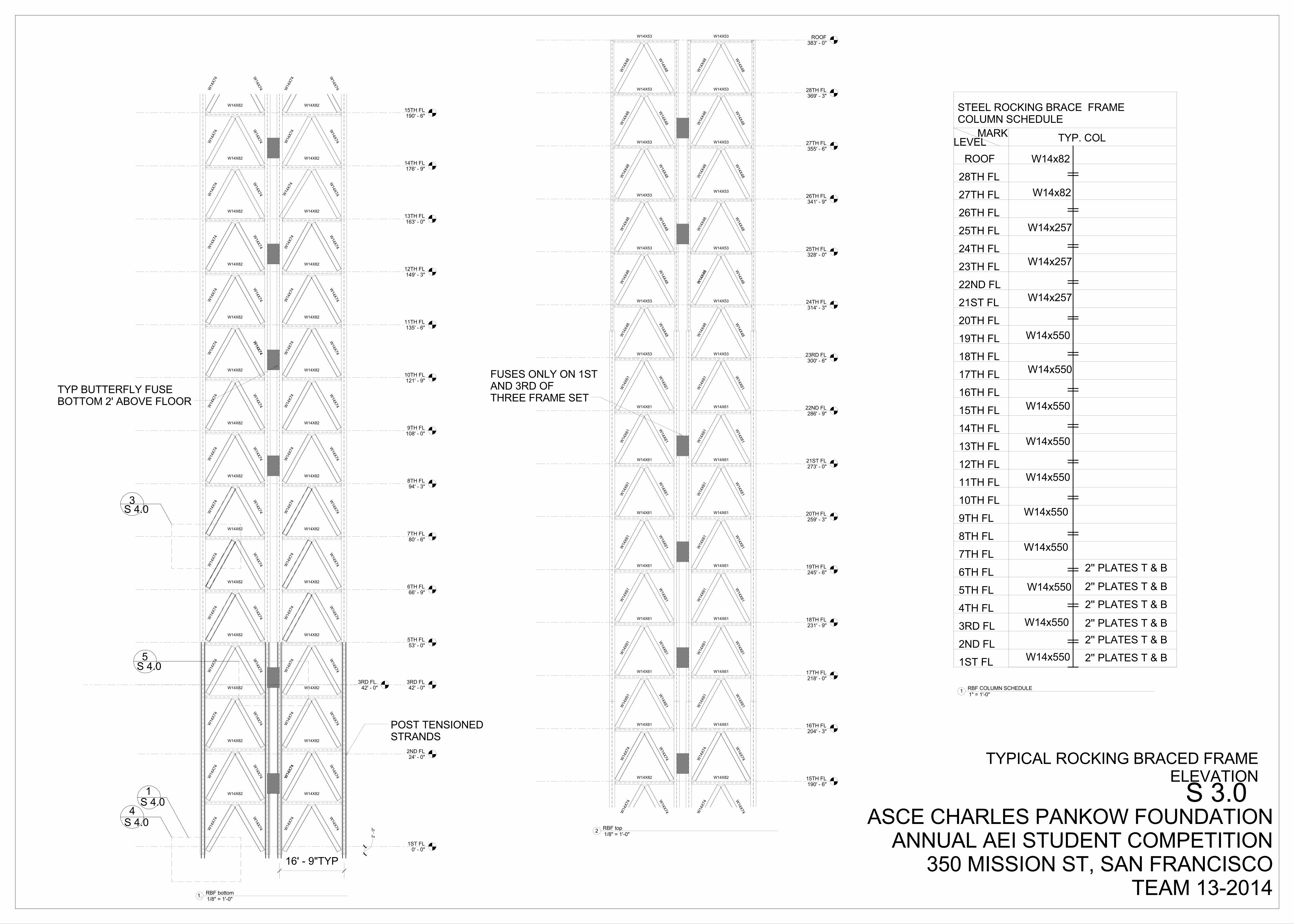
S 3.0TYPICAL ROCKING BRACED FRAME
ELEVATION
1/8" = 1'-0"1. RBF bottom
1/8" = 1'-0"2 RBF top
1" = 1'-0"1 RBF COLUMN SCHEDULE
FUSES ONLY ON 1STAND 3RD OFTHREE FRAME SET

1ST FL0' - 0"
5TH FL53' - 0"
A B F I J
6TH FL66' - 9"
7TH FL80' - 6"
8TH FL94' - 3"
9TH FL108' - 0"
10TH FL121' - 9"
11TH FL135' - 6"
12TH FL149' - 3"
13TH FL163' - 0"
14TH FL176' - 9"
15TH FL190' - 6"
16TH FL204' - 3"
17TH FL218' - 0"
18TH FL231' - 9"
19TH FL245' - 6"
20TH FL259' - 3"
21ST FL273' - 0"
22ND FL286' - 9"
23RD FL300' - 6"
24TH FL314' - 3"
25TH FL328' - 0"
26TH FL341' - 9"
27TH FL355' - 6"
28TH FL369' - 3"
ROOF383' - 0"
D GC H
LEVEL B1-13' - 9"
4S.7
3RD FL.42' - 0"
2ND FL.24' - 0"
1' - 4"
2' -
0"
1 1/2" 1 1/2"
4 # 10 TOP & BOTTOM
1' -
9"
EQ EQ EQ
#4 @ 12'' O.C.
12 # 18's
3"
CLR3"
0" EQ EQ EQ
5' - 0"
5' -
0"
#4 STIRRUPS 8'' O.C.
#4 STIRRUPS 6'' O.C.
ASCE CHARLES PANKOW FOUNDATIONANNUAL AEI STUDENT COMPETITION
350 MISSION ST, SAN FRANCISCOTEAM 13-2014
S 3.1MOMENT FRAME ELEVATION, DETAILS
1/16" = 1'-0"1 MOMENT FRAM ELEVATION
5" = 1'-0"2 MOMENT FRAME RENDER_1
3" = 1'-0"3 BEAM CROSS SECTION
3/4" = 1'-0"4 BEAM COLUMN JOINT
GRAVITY COLUMNSEE SCHEDULE
ROCKING BRACEDFRAME COLUMNSEE SCHEDULE
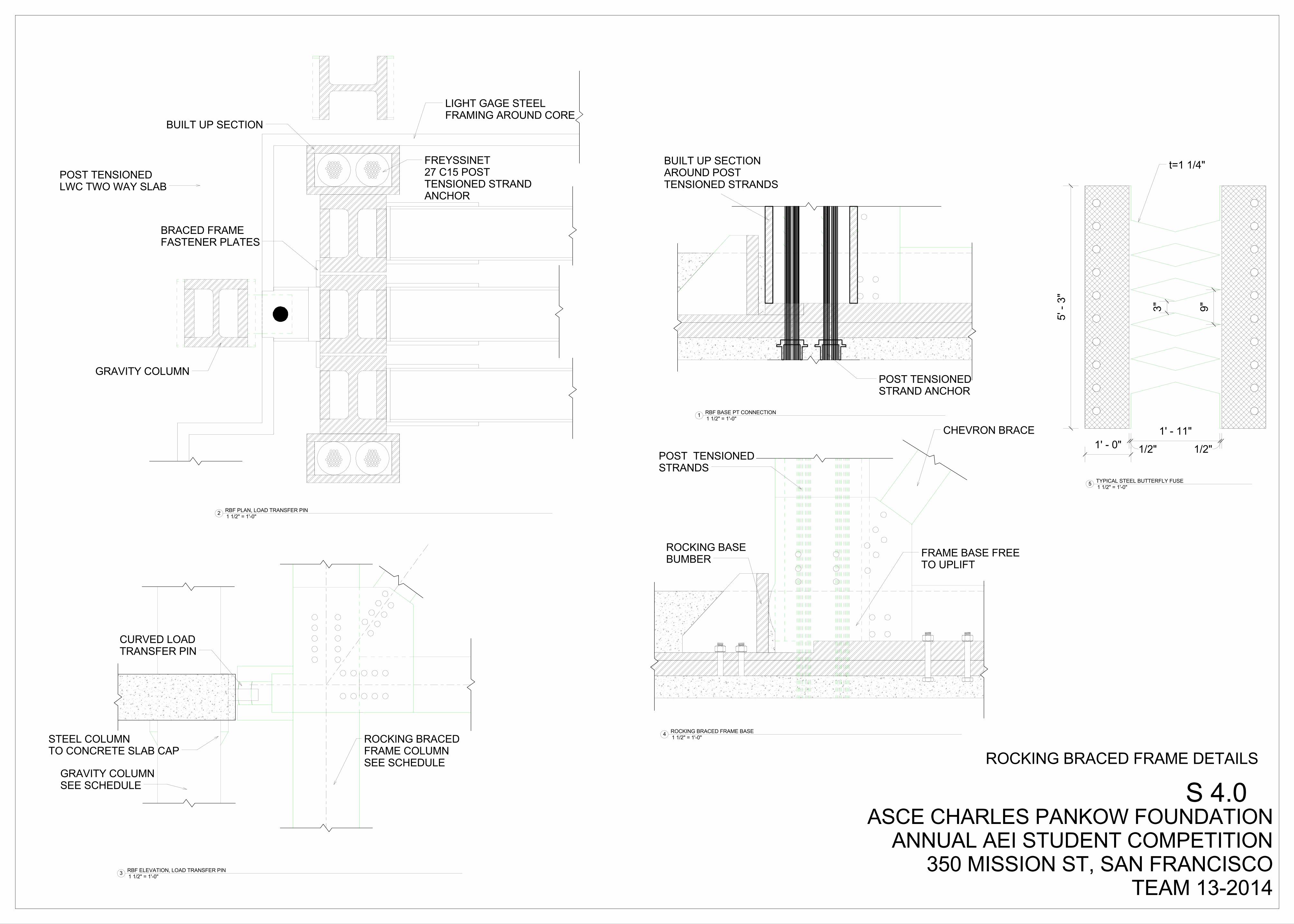
CURVED LOADTRANSFER PIN
STEEL COLUMNTO CONCRETE SLAB CAP
POST TENSIONEDSTRAND ANCHOR
BUILT UP SECTIONAROUND POSTTENSIONED STRANDS
FREYSSINET27 C15 POSTTENSIONED STRANDANCHOR
BUILT UP SECTION
POST TENSIONEDLWC TWO WAY SLAB
GRAVITY COLUMN
BRACED FRAMEFASTENER PLATES
LIGHT GAGE STEELFRAMING AROUND CORE
POST TENSIONEDSTRANDS
CHEVRON BRACE
ROCKING BASEBUMBER FRAME BASE FREE
TO UPLIFT
3" 9"
1/2"
1' - 11"
1/2"
5' -
3"
1' - 0"
ASCE CHARLES PANKOW FOUNDATIONANNUAL AEI STUDENT COMPETITION
350 MISSION ST, SAN FRANCISCOTEAM 13-2014
S 4.0ROCKING BRACED FRAME DETAILS
1 1/2" = 1'-0"3 RBF ELEVATION, LOAD TRANSFER PIN
1 1/2" = 1'-0"1 RBF BASE PT CONNECTION
1 1/2" = 1'-0"2 RBF PLAN, LOAD TRANSFER PIN
1 1/2" = 1'-0"4 ROCKING BRACED FRAME BASE
1 1/2" = 1'-0"5 TYPICAL STEEL BUTTERFLY FUSE
t=1 1/4"

ASCE CHARLES PANKOW FOUNDATIONANNUAL AEI STUDENT COMPETITION
350 MISSION ST, SAN FRANCISCOTEAM 13-2014
S 5.0BUILDING RENDERING

2014 Charles Pankow Foundation Annual Architectural Engineering Student Competition
A Senior Project
presented to
the Faculty of the Architectural Engineering
California Polytechnic State University, San Luis Obispo
In Partial Fulfillment
of the Requirements for the Degree
Bachelor of Science
by
Jeffrey Hine, Joaquin Bermudez, Jason Serda
March, 2014
© 2014 Jeff Hine, Joaquin Bermudez, Jason Serda

2014 ASCE Charles Pankow FoundationAnnual AEI Student Competition350 Mission St., San Francisco
Submission categories: Structural Systems Mechanical Systems Construction Methods
DesignIntegrationTEAM 13-2014
FEBRUARY 17, 2014

TABLE OF CONTENTS
1Team #13-2014
1.0 Executive Summary.........................................................................1
2.0 Integration Design Goals...............................................................2
3.0 Building Design Criteria..................................................................3
4.0 Design Team Collaboration...........................................................4
4.1 Technology..........................................................................................5
5.0 Structural Integration......................................................................7
6.0 Mechanical Integration....................................................................8
7.0 Construction Methods.....................................................................9
8.0 Facade Integration...........................................................................10 9.0 Water Harvesting...............................................................................11
10.0 Lobby Design....................................................................................13
Appendix A: References.......................................................................15
Appendix B: Virtual Models.................................................................
Appendix C: Daylighting......................................................................16
Appendix E: Leed....................................................................................17
1Team #13-2014
1.0 EXECUTIVE SUMMARY The challenge set forth by AEI was met not by individual research for solutions, but the sharing of the research results and conflicts between various approaches. Our team has learned that integration is responsive. There is no immediate solution and it requires a collaborative group to work together in search for solutions through the process of trial and error. This process is crucial to composing a well integrated high-performance structure. The 2014 AEI student design competition defined this term as:
“... a building that integrates and optimizes on a lifecycle basis all major high performance attributes, including energy conservation, environment, safety, security, durability, accessibility, cost-benefit, productivity, sustainability, functionality, and operational considerations.”
More specifically, our building was to address the following issues:
1. Construction, design issues and life cycle cost concepts related to a high performance building that addresses the desire of the owner to have a building that strives to meet a near net zero energy, emissions, water and waste goal.
2. The engineering challenges involved in the design of a high rise building using the existing project building information as a baseline project.
3. The owner would prefer that the design limit the amount of damage and repair to the building by a design earthquake event. Mechanical and electrical systems should allow for a near immediate occupancy after a design earthquake event.
4. The design of typical office spaces which enhance the employees experience through the
The process resulted in various solutions which were then evaluated across the different disciplines. Having a team of multiple disciplines and allowing for the exchange of ideas to occur during a period of several times a week helped expose the flaws of our designs and further our understanding of an integrated design approach. The collaboration resulted in a greater understand of the reprocutions of our issolated design decisions.
2Team #13-2014
2.0 Integrated Design Goals We wanted to design a building that seamlessly integrated building systems with the architectural design of the building, and in doing so, enhance the human experience inside and outside of the building. We believe that in order to design a building that is holisitically integrated, it must go further than simply integrating technical systems to meet the status quo; the building must also respond to its users, to its locale, and to the environment as a whole. Building design integration serves many benefits, one of which includes the elimination of waste; wasted time, wasted money, wasted resources, etc. Waste associated with bad design has been a hot topic in the fields of architecture and environmental control systems because of an evergrowing consciousness of the impact that it has on the envionment. As future professionals in the construction field, it is our job to do all we can to improve upon current procedures and redesign norms in order to create buildings that respond properly to their environments in attempts to advocate for a more utopian world. By working closely with a cross-disciplinary team, we believe we were able to design a building and a construction method that eliminates some of this waste. The first step to thoughtfully designing a building is to make sure that the building is going to be safe to inhabit after it is constructed. This is a very obvious goal, but in a seismically sensitive area such as San Francisco it is not easy to achieve. However, by incorporating structural engineers into the design team and referring to them heavily in every design decision that was made, we were able to design around a structural system enhances the life cycle of the building by reducing the damage to nonstructural systems during a seismic event. The implementation of a self centering lateral force resisting system could potentially save millions of dollars throughout the life of the building in repairs and downtime for the repairs. Another goal was to integrate the building with the site that it is located on. We designed the building to open up to the street, allowing it to become a place for meeting friends and having a good time. We want the building to add to the aesthetic of the neighborhood and to help create a sense of community in the business-oriented area.
Perhaps the most important aspect of integrated design is to make sure the building is a delightful space for humans to occupy, and that it becomes a delightful space without being a burden on the environment. In order to guide us towards this goal we decided to aim for LEED Platinum status for our design. That being said, the design team also realized that LEED certification does not mean that a building is entirely place responsive, buildings can rack up massive amount of LEED points and not even be properly oriented towards the sun, so we took the LEED goal with a grain of salt and strived to create a great design without lustfully pursuing a glass plaque. Two major global issues which we wanted to address with our design are global warming and water scarcity. We see these issues as particularly crucial at this point in time, and they will most likely become driving forces in all of our designs throughout our professional careers, so we saw this project as a great opportunity to address some global problems with local solutions. In order to guide us towards this goal we decided to aim for LEED Platinum status for our design. That being said, the design team also realized that LEED certification does not mean that a building is entirely place responsive, buildings can rack up massive amount of LEED points and not even be properly oriented towards the sun, so we took the LEED goal with a grain of salt and strived to create a great design without lustfully pursuing a glass plaque. Two major global issues which we wanted to address with our design are global warming and water scarcity. We see these issues as particularly crucial at this point in time, and they will most likely become driving forces in all of our designs throughout our professional careers, so we saw this project as a great opportunity to address some global problems with local solutions.
3Team #13-2014
3.0 Bui ld ing Design Cri ter ia
The challenge put forth by AEI for this competition was:
a. to improve the quality, efficiency and value of large buildings by advancing innovations in structural components and systems that can be codified.
b. to improve the performance of building design and construction teams by advancing integration, collaboration, communication, and efficiency through innovative new tools and technologies, and by advancing new means and methods for project team practices.
The first step for our design team was to align our personal goals for the project with those of the AEI’s. Next, we added to that set of goals by deciding upon certain innovations in construction and design that we thought would not simply meet the baseline requirements for the project, but possibly exceed them.
350 Mission is situated two blocks from the future Transbay Transit Center, making the site a new node of activity in which the public can gather. This future adjacency is important because it creates a link to, and allows for a dialogue with, this larger context. The way which we attempted to connect our design to this larger context was through the expansion of the programmatic spaces in the lobby. The added program is additional restaurants and cafes which create more places of interest in the lobbies. The additional floor space in the lobby also allowed for the implementation of outdoor terraces which connects the individual to the outdoors. This connection to the outdoors and to nature was a goal because of the decline of green spaces in urban contexts. This focus on function and how it relates to the human experience became a compelling force behind the design.
The goal of connecting to the environment placed a lot of importance on the development of a well integrated and fully responsive environmental controls design. The original project as presented by SOM is forecasted to achieve LEED Platinum. With the introduction of Architecture 2030, the building industry is pushing for all new commercial buildings to reach a significant level of climate responsiveness and in the case of certain building types, net zero energy. For this particular project, the goal was to improve the existing design’s integration of systems while introducing a public lobby open to the public. In order to achieve this goal, we relied heavily on our our integrated design team and each member’s expertise in their field of study. Our main challenge was to take all of the information from all the different disciplines and turn it into a building in the given amount of time for the competition. This meant that the design team had to meet frequently, both at scheduled weekly meetings, and impromptu weekend meetings. In order to make sure the original design goals of the building set forth by the team were considered by each team member throughout the design process we all had to constantly communicate new ideas and challenges. This type of group interaction led us to ask critical questions across the different fields of expertise to ensure that all of the individual systems were working well together.
4Team #13-2014
4.0 Design Team Col laborat ion4.1 Technology:
Doodle.comThe first technology that we used to collaborate as a group was doodle.com. This website allowed us to input each person in the group to input their class schedule and then generates times that works for everyone to meet. This is how our weekly group meeting times were set up.
Team DropBoxWithin Dropbox we made different folders so that each member of the team can access updates information. We decided that anytime each person or discipline had new information we would upload in these folders. The folders consisted of the following: Contact info for everyone in the group, individual discipline, links to project information, rendering, narratives and Revit files. Have dropbox with these files made it easy to keep track of everyones updated files and information. Having everyones email and phone number assured that we could get in contact with individuals in our group.
Google DocsThe google drive allowed us to start our narrative documents and let each person work on them individually. This website allowed each person access to real time changes of word based documents. This saved the group time and allowed us to work together even when we physically could not be at the same location.
RevitRevit was the main program used for the structural engineers and architects. This program was were the buildings dimensions and structural elements locations were placed. Have the architect and engineer using the same base program for their models allowed the trading of information easy and efficient. Other disciplines had access to these Revit files on dropbox and allowed them to pull any dimension or location of elements from the building. Also using the same base program allowed the architects and engineers to change information to eaches model quickly.
Trace PaperSheets of trace paper along with sketch books and other drawing tools became a very useful tool when collaborating. It helped group members better visualize the ideas that were brought to the table. It also allowed for easy layering of systems on the stop rather than having to wait on someone to produce digital files. Having physical tools cut down our brainstorming and evaluating time.
EmailingThroughout this project the team as a whole was constantly emailing. Each disciplines used emailing mostly to stay in contact with their advisors. Asking them questions or setting up times to meet.
AutoDesk360This website was an option through revit were you could have our model rendered through the cloud . This was brought to the team from the architects and allowed the team to access all the rendering done by both the architects and the structural engineers.

5Team #13-2014
4.0 Design Team Col laborat ion
4.1 Technology: School ComputersAt our weekly meetings, the team met up on campus at a computer lab to discuss and work on the project. These school computer allowed us to save information on to a school drive so that anytime we were on campus we could access the information that we saved.Because there computer labs had many computer the team could work on their individual portions of the project but still be in the same room for any questions or further collaboration.
InDesignDuring the formatting portion towards the end of the project the team used Indesign to put together each narrative. By using the same program each discipline could have the same format for their documentation.
4.2 Intrapersonal: Over the summer and beginning of the school year each person went to their respective departments and said they were interested in the A.E.I. competition. from there, each discipline came up with a team and selected an advisor for the discipline. Once each discipline had an advisor, the advisor and students got in contact with the other disciplines across the university to get a global team together comprised of all of the disciplines. The first step after our team was in place was coming up with the team goals for the project and laying how we were going to accomplish those goals by February 17th. Our team set up a survey to come up with a time that every member on the team could get together once a week to start laying out the design. Early on the team came up with calendar laying out how to spend the next few months to finish the project. The calendar would be updated and more defined as it got closer to the submittal date. After laying out a calendar and working with everyone’s schedules, the team came up with a weekly meeting time and place that worked best for everyone. The team met on campus in the architectural engineering labs after class. In addition to the weekly team meetings, each discipline met with their advisors on a weekly basis to catch them up to speed with the rest of the team along with work through any design obstacles.
As the project went along and the design process really picked up questions came up between disciplines that could not wait until the next weekly meeting. When this happened, the team members would meet up in the on campus labs to work through the design. Each discipline’s labs were a short walk from each other.
In terms of the group itself, there was no hierarchy in power. Each discipline had an equal say in the discussions and decisions. Within in discipline there was not a designated leader. This allowed people to speak freely and made it where each discipline had an influence on the design. Our team did not miss out of people’s good ideas due to this. Even though there was not any designated leaders on the team, people still took initiative to make sure the team was on track to meet the team goals. If something needed to be done, our team figured out who could accomplish the task. Throughout the design process our team discussed all of the positives and negatives for each discipline before making a final decision. If a decision could not be made right away, each discipline would work through multiple solutions before meeting back up again.

6Team #13-2014
4.0 Design Team Col laborat ion
4.2 Intrapersonal:
In addition to the weekly meetings with each disciplines advisor, intermediate meetings throughout the week and weekends were made to work through design problems that came about. If the mechanical engineers had a question pertaining to structures, the structural engineers on the team could sit down with their advisor and relay the information to the mechanical engineers.
As our team transitioned out of the research portion and the design process was in full swing, our design team would all work together in the same computer lab on campus when at all possible. This provided instant feedback and really allowed integration in our team to occur.
• In a city famous for its fog, the fog catcher was a great idea for our building. However, problems immediately arose about how and where they could be implemented. Mechanical systems needed to be constructed to store any water collected, and architects needed to create physical space for them on the building. Constant deliberation allowed both teams to settle on a unique and viable design.
• The decision to move the mechanical room to the North face of the building was a collaborative team decision made during one of our scheduled weekly meetings. The team decided that the reduction in office space per floor was necessary for the seismic stability of the building. Additionally, the mechanical room location offered several benefits to the HVAC system’s efficiency.
• Minimizing floor to floor height was inspected as a method to reduce costs for the building. The structural choice to incorporate thick concrete slabs for the floor construction allowed the mechanical team to fully utilizing an underfloor air distribution system, providing for maximum floor to floor height savings. Provided below are detailed explanations of the design process and results of many cross disciplinary integrations included in the design of 350 Mission Street.

7Team #13-2014
5.0 Structural Integrat ion From the very first day on the project, the structural engineers made their goal very clear, design a building with high seismic performance. This was soon after defined as a building that would sustain minimal damage to both the structural and nonstructural elements in an effort to save time and money in repairs after a seismic event.
We first took a look at integrating the structure of the building with an innovative lateral force resisting system called rocking braced frames (RBFs). Instead of having critical structural members fail, the braces would rock and energy dissipation is allocated to smaller elements designed to be quickly and affordably replaced. While this is not new to the ductile design of steel structures, the self centering capability of the system reduces the damage caused by residual displacement . The move to use this innovative system was a huge step in the right direction for our team. We are all very familiar with San Francisco, and we all know the havoc that a high magnitude earthquake can wreak on the city. This is a great example of site responsive architecture, because a system like this
only makes sense in a city where large earthquakes are perpetually imminent. The structural engineers proposed this lateral system, but the implementation of the RBFs had implications for the entire design team. Since this structural system is still in its infancy for high rises, there were not any precedents that we could study to get a good idea of how the system works in a tall building. Due to this uncertainty, there was a lot of back and forth between the structural engineers, the architects, and the mechanical engineers. The first obstacle was estimating how much space would be required for the lateral and gravity systems. As more preliminary calculations developed, the team came to realize that more space was going to be needed for the braces in order for the system to reach its idealized rocking motion response. After several different braced frame layouts, we found a combination of the structural systems that worked well with the rest of the design. Finalizing the framing system involved much collaboration between the amount of space desired by the mechanical engineers and architects, the constructability as seen from the construction manager, and the system performance as seen from the structural engineers. Thankfully, due to the nature of the design team, this workflow was very efficient and we were able to prototype these layout relatively quickly. It was this back and forth dialogue which ultimately became the cornerstone of our design delivery process.

8Team #13-2014
6.0 Mechanical Integrat ion When designing mechanical systems, there are many opportunities to further our two mains goals of reducing energy use and increasing human comfort. The mechanical system is a crucial component of any ecologically designed building, especially in a high-rise where an efficient mechanical system is absolutely necessary due to the high occupancy and heat gain due to high internal loads. Because of the importance of the mechanical design, a lot of the buildings program was tailored to accept the mechanical system that the mechanical engineers believed would best fit our energy and human
comfort goals.
We looked at what our heating and cooling needs would be and how we could give the highest degree of comfort and control to the user of the space.The option we chose was an underfloor air distribution HVAC system, that has moveable floor panels to
allow for customization of the air distribution system. With this in-floor system, users are able to change the location and airflow of their own personal HVAC air diffuser, giving them full control over the room’s comfort and allowing them to rearrange the room to best suit their needs. This arrangement creates a very high level of perceived comfort by the occupants, as opposed to a traditional overhead system which has the diffusers in fixed ceiling locations and only allows thermal comfort changes through a thermostat. Collaboration was very important when selecting this system, because it plays a huge role in human comfort in the space. On the office floors, we wanted to make the occupants comfortable both thermally and spatially. What this translates to is making sure the room stays at a comfortable temperature and humidity level, and providing the room with a comfortable, spacious, 10’-0” ceiling height. This became a big project for the entire team because, in a high-rise, it is desirable to have as many occupied floors as possible, because the more floors you have, the more rentable space you have, the more money you can make. Not surprisingly, it becomes hard to balance the maximizing the number of floors in a building, providing a sufficient HVAC system, creating a comfortable space for the occupant, and making sure the structural system is sound. Over the course of the project, there was a constant dialogue between the Mechanical engineers, architects, and structural engineers, about what the floor to floor height of the floor slabs needed to be in order to fit the mechanical systems and maintain a comfortable 10’ ceiling height. By using a post-tensioned concrete slab at each floor, we were able to minimize the depth of the slab to 1’-0”. This flat slab also maximized the efficiency of our HVAC systems air return, which utilizes a, slim, 0’-6” return plenum space just above the ceiling. Had we used a steel beam construction type, the floor and HVAC system together would have been significantly deeper and we would not have been able to achieve a 10’-0” floor to ceiling height, with the number of floors we have. Furthermore, since our HVAC system does not use large metal ducts like a traditional system does, the HVAC system is less prone to failure in the event of an earthquake, which ties it back to our main structural design goal of creating a building which if rapidly occupiable, with minimum damage and cost, after an earthquake.

9Team #13-2014
6.0 Mechanical Integrat ion
7.0 Construction Methods
Another notable systems integration we achieved was the placement of the air handling unit for the HVAC system. Traditionally this unit is placed in the core of the building, but due to the large lateral bracing in the core, we did not have an excessive amount of room in the core to place such a unit. Additionally, placing the unit in the core would mean a large overhead duct would have to be run across the ceiling to proved the air handler with intake and exhaust ports. Our solution was to move the mechanical room to the edge of the building on every floor. By doing this the air handler is nestled in right in between the restrooms, where the process noise produced by the unit is not an issue. Also, by moving the mechanical room to the periphery of the building, we were able to use less ducting and the air handler no longer needs as much energy to intake and exhaust air. This move to the edge of the building completely eliminates the need for overhead ducting in the system lowering the risk of damage in the event of an earthquake, and uses less fan energysince the air handler does not need to push and pull the air through overhead ducts and waste energy.
CBI has chosen the Design-Build method as the best Delivery Method for the 350 Mission St. High Rise. Design-Build allows CBI to integrate the Design and Construction process into a more efficient and cohesive team. A typical project selection may include Design-Bid-Build. This project delivery method leads to an abudance of RFI’s and Change Orders effecting the client in a negatively. Using the Design-Build Method will allow risks associated with the 350 Mission Street to become clear. Design and Constructability become a single entity and work together to complete the project in a timely fashion, while designing to budget. One such example of Design and Construction integration concerns the use of Steel for the interior core of the project. Construction of Steel has the advantage of being erected quicker then any other material, and steel was therefore integrated into the project.
The health and well being of the communities we build in is one of our highest priorities. After a detailed site and construction analysis the three major impacts to the community excluding the traffic control, which was explained in our Traffic Plan, are noise impacts, hazardous debris and material from the site, Dust from Excavation Process, and Damage to Existing Buildings. We want to be as invisible as much during the construction process of 350 Mission St.
The base cost estimate was broken into 19 different sections. Starting with Foundation and ending with the Gerenal Requirements. A major line item that needs to be highlighted includes the Superstructure at $18,980,000. The cost includes Structural Steel, exterior Reinforced Columns and Deck. The cost reflects the design to resist lagre amounts of ground force created by earthquakes. Another item includes Interior Construction and Interior Finishes totaling $13,808,589. Costs include the metal framing of walls and glass partitions to increase a feeling of open space and light in the building. Lastly, I would like to highlight Plumbing at $9,437,778; Electrical at $8,208,818; and HVAC at $13,864,061. The building will contain a raised flooring with an large plenum space to transfer cooling and heating loads. The raised flooring gives us an advantage in work rate and reducting in cost. Installing on the floor is faster then installing in the ceiling. The General Requirements at $1,967,655 has been fully broken out for owner review. The General Requirements are based largely on time, and if the project progresses at quicker rates then the cost will be reduced. Lastly, GC conditions are 3% of the $96,738,225 Subtotal and Preconstruction will be at 10.50%.

10Team #13-2014
8.0 Facade Integrat ion In order to add to the comfort of the building occupants, we employed the use of a double facade for the glazing of the building. A double facade uses multiple curtain walls to create an air gap in between the interior space and the exterior environment. The air gap creates a buffer zone which helps control the indoor air quality of the building. This buffer zone allows the interior of the building to remain comfortable while the exterior is very uncomfortable. Double facades also give the occupant more control over ventilation of the space. In most tall buildings, windows are not operable because the exterior air temperature is too extreme. With a double facade, semi-conditioned air from the buffer zone can be drawn into the space, providing fresh air on demand. This will create a delightful space for the occupants of the building because humans like to have control over their environment, and providing something as simple as a window can promote comfort and happiness for the occupants. Capture between the two curtain walls of the double facade is a louver system which can be controlled via a computer operating system. By adjusting these louvers, full control of the daylighting and partial control of thermal comfort in the building can be achieved. The adjustable nature of the louvers will allow for one side of the building to open up for daylighting, while the opposite side of the building could close to reject solar gain and prevent overheating. when properly functioning, a double
facade can reduce the energy load on a building by passively controlling the building lighting and thermal needs. We were able to use the space between the concrete moment frame columns for this double facade to use to use the space most effectively. When constructing the facade on the lobby level the consideration of the lateral displacement from the rocking of the lateral system, the facade system would be designed with adequate clearance in the panel joints. The cladding system flexibility and lateral system rigidity would be designed to ensure that the minimal amount of damage would occur during a seismic event.

11Team #13-2014
9.0 Water Harvest ingIntegrated into the mechanical system is a grey water collection system. This system harvests water used in sinks and showers, to be reused to irrigate the plants around and inside the building. In response to San Francisco’s unique climate, we added a special type of grey water harvester to the building, fog catchers. these fog catchers are located on each corner of the building, acting as water harvesters, shading devices, and a unique facade finish. The catchers were placed on the corners in order to maximize the views from the office spaces, and to make sure there is an
ample amount of air moving through them, because in order to work properly the fog catchers need to have fog blowing through them. These fog catchers are a forward thinking strategy for collecting
water that is unique to our site and is necessary because of the growing scarcity of water. The collectors feed into a trough that drains the water into a water tank located in the basement, the collectors will also serve to collect a fair amount of rainwater when it is raining because the infrastructure for catching fog works well for catching rain as well. The 2013-14 drought has showed us that we can’t rely on the rain in San Francisco like we can rely on the fog, the fog catchers are a great local solution to the global problem of water scarcity. It was important for our design team to make sure the nets of the fog catchers became an integral part of the buildings facade, and did not simply look like something that the
design team decided to tack on to the side of the building at the last second to try to get some LEED points. We truly believe that the fog catchers have great promise for capturing useable amounts of water in the foggy San Francisco climate. Furthermore, allowing the fog catchers to become an aesthetic feature of the building, we were able to save money by leaving much of the buildings facade unfinished, knowing that the fog catchers would be covering the unfinished portions and demanding the viewer’s full attention. The Fog Catchers also work to filter harsh sunlight, creating a pleasant space on the
exterior balconies. The fog catcher’s ability to filter sunlight lead us to multiple studies in which the fog catchers were attached to the facade such that they would shade the majority of the buildings glazing. We looked at several different methods of attaching fog catchers to the building. Initially we figure the best way to go about it would be to attach the fog catchers where we could maximize the square footage of the nets.

12Team #13-2014
9.0 Water Harvest ingIn order to maximize square footage we placed the nets on the north,south, east, and west elevations, covering 100% of the glazing. This was an interesting design study for our team. The benefits of this approach was the large square footage, and the nice filtering of southern light, which decreased solar gain. However, We realized that this was an impractical approach to integrating fog catchers, because it impeded views in all directions, and decreased the light levels in the space. The final design for the fog catcher integration was conceived after the teams mechanical engineers further researched fog catchers and discovered that in order to be effective, the nets need to have a constant wind blowing over them. Without doing any computational fluid dynamic studies, we assumed that the most likely place for constant windflow on the high rise building is at the corners of the building. This is due the the high and low pressure zones in the windward and leeward sides of a cubic mass. By placing the nets at the corners of the building, we will be able to capture the water out of the fog as it is blown around the corners of
the building.

13Team #13-2014
10.0 Lobby Design It was important to us to keep the lobby very open to the street corner, in order to welcome in passer-by and create a bustling community at the base of our building. It was also important to keep the lobby of the building open because San Francisco has enacted a public ordinance that requires all designers to allocate a sum of money equivalent to 2% of the total building cost towards the art enrichment of the proposed building. To realize this allocation, we took a similar route to that which S.O.M. took, we opened up the lobby floor to invite the community in and then integrated a large L.E.D. display screen which will display artwork created by local artists. In order to further involve the community, the L.E.D. wall will be accessible to the community via a web-based app which will allow artists to upload an image of their art work along with their name, to be displayed on a loop throughout a given week. Working closely with the structural engineers, we were able to eliminate cross bracing on the perimeter of the lobby, which allowed us to have a very transparent street level facade. With this transparency, people passing by are free to look into the building and be intrigued by the large L.E.D. wall which will show images of local artists work and become a screen for public viewings of movies. The Screen was originally designed by S.O.M. and we decided to keep it in the design because of the sense of community we could create by having a space that people love to share with each other. We added to retail spaces on the ground floor, and a cafe, where people can grab a coffee on their way into work, and a drink on their way home from work. The design of the lobby called for some of the most intensive collaboration on the part of the architects and structural engineers. Aside from our weekly meetings, several more meetings were arranged each week, along with frequent emails, calls, and text messages until we were finally able to realize our initial design goal. We initially designed the lobby to be a very tall space due to the vernacular of the site; anyone that takes a stroll past our site will tell you that all of the buildings around 350 Mission are incredibly tall, and since the buildings are so tall, it is hard to create an open feeling on the ground level unless you make that opening very tall as well. In order to achieve the height that we wanted we met with the structural engineers frequently, they were concerned that the building would not have the proper stiffness due to the non-uniformity of the structural system. The first recommendation by the structural engineers was to add beams at 14’-0”, 28’-0” and 42’-0” inside the lobby height, this was a great structural solution, but for our design it was not going to be acceptable. After numerous late nights running calculations, our structural engineers presented us with various options for the structural design, all of which would change the aesthetic of the building remarkably. One option was to go with a floor slab design which utilized two different slab designs which alternated at every floor, this design emphasized the verticality of the building and brought a lot of attention to the fog catchers on the corners of the building, but in order for this design to work we would have to have 3 large beams inside the lobby height, which makes the lobby seem less open to the public. Another option, which is the option we pursued, was to keep the lobby beam-free, by keeping the slabs for the upper stories uniform. At this point we considered what our design intent was and decided that having alternating floor slabs was not crucial to our design, and in fact this ultimatum opened our eyes to an obvious problem with the alternating slabs; having them made it so only every other floor had an outdoor balcony space, where as you can see in our final design, every floor has a balcony. We decided that creating a lobby space that could become a great community hub was more important for the design, and we also believe that the building will have a strong vertical expression due to the fog catchers running up the height of the building, forming a strong vertical gesture.

14Team #13-2014
Appendix A: References
2009 ASHRAE Fundamentals Handbook. Atlanta, VA. ASHRAE, 2009. Print.
ASHRAE. “HVAC Maintenance Cost Database.” ASHRAE Owning and Operating Cost Database. ashrae.org. 2014. Web. 14 Feb 2014.
Christopoulos, Constantin, Andre Filiatrault, and Vitelmo V. Bertero. Principles of Passive Supplemental Damping and Seismic Isolation. Pavia, Italy: IUSS 2006. Print.
Cereceda, P. et al. FogQuestCollection Manual. BC, Canada. 2005. Print.
Fernandez, Daniel, et al. “Measurements of Fog Water Deposition on the California Central Coast.” Scientific Research. June 16,2012. Web.
Fessehaye, Mussie, et al. “Fog water collection for community use.” Renewable and Sustainable Energy Reviews. September 17, 2013. Web.
Jacobson, Brad, et al. “Plug Load Reduction: The Next Big Hurdle for Net Zero Energy Building Design.” institutebe.com. Summer 2010. February 13, 2014.
Schokker, Andrea J. The Sustainable Concrete Guide: Strategies and Examples. Farmington Hills, MI: U.S. Green Concrete Council, 2010. Print
UFAD Guide: Design, Construction and Operation of Underfloor Air Distribution Systems. Atlanta, GA. ASHRAE, 2013. Print.

15Team #13-2014
-The integration of 350 Mission included the consideration of daylighting in order to achieve a more environmentally conscious design. The ways in which daylighting was addressed was through the use of light wall finishes, the installation of transom windows on the walls of offices around the perimeter of the building, and double facade windows with operable louvers in order to have control over light shading. The louvers in the double facade of the building were specified to be the material white pine in order to also aid in light diffusion when open to the sun angles. The transom windows around the perimeter allow for light to enter the deeper spaces of the office floors without compromising the privacy of the typical law and finance floors. These floors require private offices so it was important to find a way in which both privacy and daylighting could be achieved. Light colored wall finishes and floor to ceiling glass curtain walls allow light to travel deeper into the space through diffusion.
Appendix B: Virtual Models-pictures that we havent used that show the process of what we could have doneAppendix D: Lobby stuff. -excess pictures, reasoning behind choice,
Appendix C: Daylighting

16Team #13-2014
Appendix E: LEED
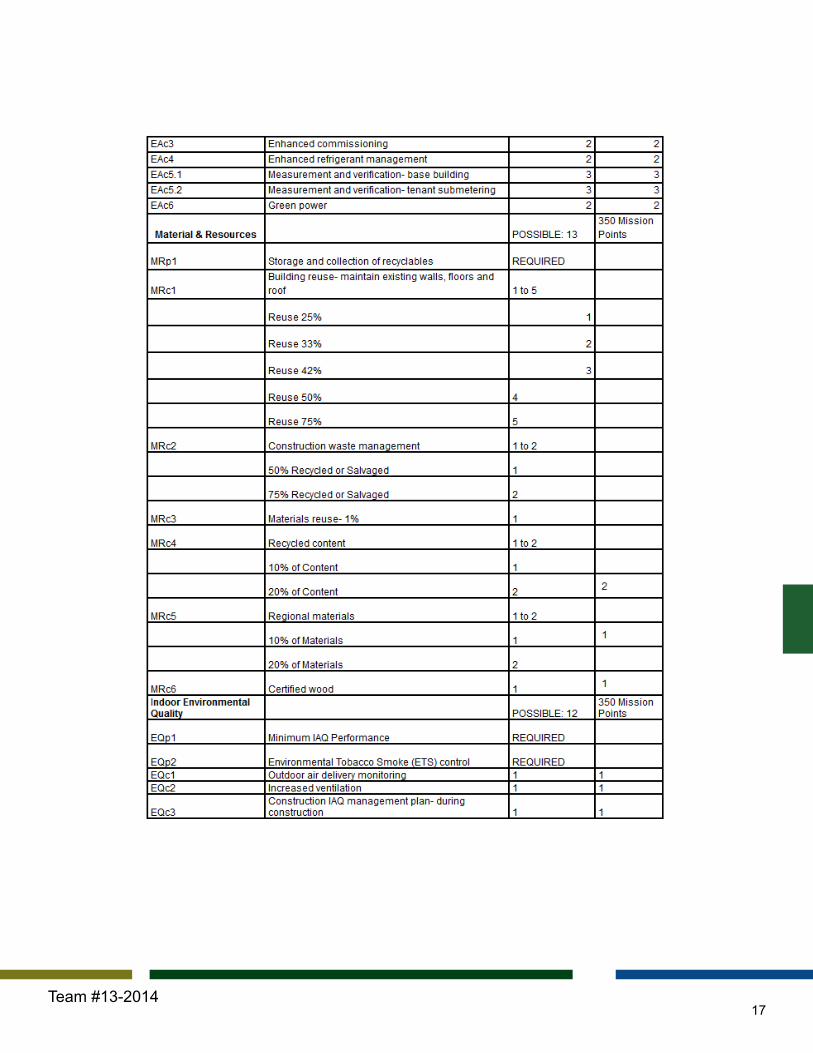
17Team #13-2014

18Team #13-2014

UP
AB
FI
J
98521
DG
64
CH
3 7
1.S
3.0
W10
X19
W10
X19
W10
X19
W10
X19
W10
X19
W10
X19
W10
X19
W10X19
W10
X19
W10X19 W10X19
W10X19 W10X19W10X19
W10X19
W10
X19
W10X19
W10X19W10X19
W10
X19
W10
X19
12" P
OST
TEN
SIO
NED
TWO
WAY
SLA
B
GR
AVIT
Y C
OLU
MN
OU
TSID
E O
F C
OR
ESE
E SC
HED
ULE
GR
AVIT
Y C
OLU
MN
INSI
DE
OF
CO
RE
SEE
SCH
EDU
LE
RBF
RBF
RBF
RBF
RBFRBF
RBF RBF
4'x4
' CO
NC
.C
OLU
MN
TYP.
SEIS
MIC
JO
INT
ARO
UN
D R
BF S
YSTE
MS
W14
X48
W14
X48
W14
X48
DEC
KIN
G L
WC
5-1/
4", 2
0 G
AGE
PHO
S/PA
INTE
D
33' - 0"8' - 8"
1' - 0"
23' - 4"23' - 4"
1' - 0"
8' - 8"33' - 0"
132' - 0"
130'
- 0"
30' -
10"
3' -
2"1'
- 0"
30' -
0"
30' -
0"
1' -
0"1'
- 6"
32' -
6"
33' - 0"8' - 8"1' - 0"23' - 4"23' - 4"1' - 0"8' - 8"33' - 0"
AB
FI
J
98521
DG
64
CH
3 7
ASC
E C
HAR
LES
PAN
KOW
FO
UN
DAT
ION
ANN
UAL
AEI
STU
DEN
T C
OM
PETI
TIO
N35
0 M
ISSI
ON
ST,
SAN
FR
ANC
ISC
OTE
AM 1
3-20
14
A 1.
0TY
PIC
AL F
LOO
R P
LAN
, LAW
1/8
" = 1
'-0"
1TY
PIC
AL F
LOO
R P
LAN
, LAW
1/8
" = 1
'-0"
2TY
PIC
AL F
RAM
ING
PLA
N

AB
FI
J
98521
DG
64
CH
3 7
1.S
3.0
W10
X19
W10
X19
W10
X19
W10
X19
W10
X19
W10
X19
W10
X19
W10X19
W10
X19
W10X19 W10X19
W10X19 W10X19W10X19
W10X19
W10
X19
W10X19
W10X19W10X19
W10
X19
W10
X19
12" P
OST
TEN
SIO
NED
TWO
WAY
SLA
B
GR
AVIT
Y C
OLU
MN
OU
TSID
E O
F C
OR
ESE
E SC
HED
ULE
GR
AVIT
Y C
OLU
MN
INSI
DE
OF
CO
RE
SEE
SCH
EDU
LE
RBF
RBF
RBF
RBF
RBFRBF
RBF RBF
4'x4
' CO
NC
.C
OLU
MN
TYP.
SEIS
MIC
JO
INT
ARO
UN
D R
BF S
YSTE
MS
W14
X48
W14
X48
W14
X48
DEC
KIN
G L
WC
5-1/
4", 2
0 G
AGE
PHO
S/PA
INTE
D
33' - 0"8' - 8"
1' - 0"
23' - 4"23' - 4"
1' - 0"
8' - 8"33' - 0"
132' - 0"
130'
- 0"
30' -
10"
3' -
2"1'
- 0"
30' -
0"
30' -
0"
1' -
0"1'
- 6"
32' -
6"
33' - 0"8' - 8"1' - 0"23' - 4"23' - 4"1' - 0"8' - 8"33' - 0"
AB
FI
J
98521
DG
64
CH
3 7
DN
UP
ASC
E C
HAR
LES
PAN
KOW
FO
UN
DAT
ION
ANN
UAL
AEI
STU
DEN
T C
OM
PETI
TIO
N35
0 M
ISSI
ON
ST,
SAN
FR
ANC
ISC
OTE
AM 1
3-20
14
A 1.
1TY
PIC
AL F
LOO
R P
LAN
, FIN
ANC
E 1
/8" =
1'-0
"1
TYPI
CAL
FR
AMIN
G P
LAN
.
1/8
" = 1
'-0"
3TY
PIC
AL F
LOO
R P
LAN
, FIN
ANC
E

AB
FI
J
98521
DG
64
CH
3 7
1.S
3.0
W10
X19
W10
X19
W10
X19
W10
X19
W10
X19
W10
X19
W10
X19
W10X19
W10
X19
W10X19 W10X19
W10X19 W10X19W10X19
W10X19
W10
X19
W10X19
W10X19W10X19
W10
X19
W10
X19
12" P
OST
TEN
SIO
NED
TWO
WAY
SLA
B
GR
AVIT
Y C
OLU
MN
OU
TSID
E O
F C
OR
ESE
E SC
HED
ULE
GR
AVIT
Y C
OLU
MN
INSI
DE
OF
CO
RE
SEE
SCH
EDU
LE
RBF
RBF
RBF
RBF
RBFRBF
RBF RBF
4'x4
' CO
NC
.C
OLU
MN
TYP.
SEIS
MIC
JO
INT
ARO
UN
D R
BF S
YSTE
MS
W14
X48
W14
X48
W14
X48
DEC
KIN
G L
WC
5-1/
4", 2
0 G
AGE
PHO
S/PA
INTE
D
132' - 0"
130'
- 0"
30' -
10"
3' -
2"1'
- 0"
30' -
0"
30' -
0"
1' -
0"1'
- 6"
32' -
6"
33' - 0"8' - 8"1' - 0"
23' - 4"23' - 4"1' - 0"
8' - 8"33' - 0"
DN
UP
AB
FI
J
98521
DG
64
CH
3 7
ASC
E C
HAR
LES
PAN
KOW
FO
UN
DAT
ION
ANN
UAL
AEI
STU
DEN
T C
OM
PETI
TIO
N35
0 M
ISSI
ON
ST,
SAN
FR
ANC
ISC
OTE
AM 1
3-20
14
A 1.
2TY
PIC
AL F
LOO
R P
LAN
, TEC
H
1/8
" = 1
'-0"
1.T
YPIC
AL F
RAM
ING
PLA
N.
1/8
" = 1
'-0"
2TY
PIC
AL F
LOO
R P
LAN
, TEC
H

DN
DN
UP
UP
UP
AB
FI
J
98521
DG
64
CH
3 7
AB
FI
J
98521
DG
64
CH
3 7
1.S
3.0
30' -
10"
3' -
2"1'
- 0"
30' -
0"
30' -
0"
1' -
0"1'
- 6"
32' -
6"
130'
- 0"
33' - 0"8' - 8"1' - 0"
23' - 4"23' - 4"1' - 0"
8' - 8"33' - 0"132' - 0"
ASC
E C
HAR
LES
PAN
KOW
FO
UN
DAT
ION
ANN
UAL
AEI
STU
DEN
T C
OM
PETI
TIO
N35
0 M
ISSI
ON
ST,
SAN
FR
ANC
ISC
OTE
AM 1
3-20
14
A 1.
3LO
BBY
PLAN
, 2N
D F
LOO
R
1/8
" = 1
'-0"
1LO
BBY
PLAN
, 2N
D F
LOO
R
1/8
" = 1
'-0"
35T
H F
L

Abo
ve: V
iew
of t
ypic
al c
ubic
le s
pace
insi
de th
e fin
anci
al o
ffice
floo
rs
Rig
ht: E
xter
ior s
hot o
f bui
ldin
g in
con
text
Imag
e U
RL:
http
://w
ww
.fran
ktop
10.c
om/s
kysc
rape
rs/3
5340
/ 10:
05pm
_10
:04
pm 2
/17/
14
Bel
ow: V
iew
into
ele
vato
r lob
by s
how
ing
how
the
stru
ctur
e an
d ci
rcul
atio
n w
as re
solv
ed
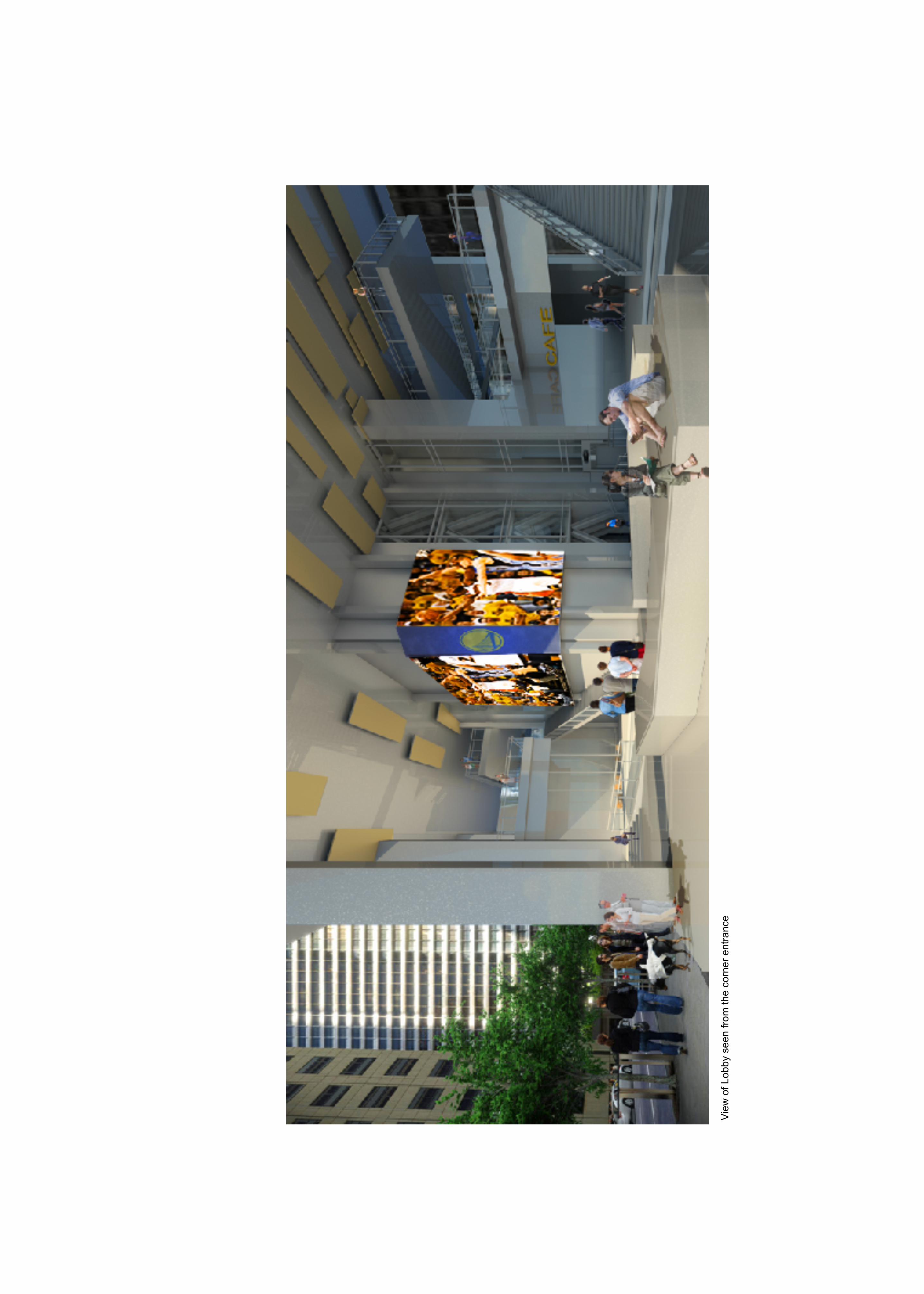
View
of L
obby
see
n fro
m th
e co
rner
ent
ranc
e