Embed Size (px)
DESCRIPTION
Valving & Isolation Philosophy
Citation preview

SU TU TRANG FULL FIELD DEVELOPMENT – PHASE 1
DETAILED ENGINEERING AND PROCUREMENT ENGINEERING SUPPORT SERVICES
VALVING & ISOLATION PHILOSOPHY Doc. No.: 2014-4800-1H-0003
Rev: E
Page No.: 2 of 19
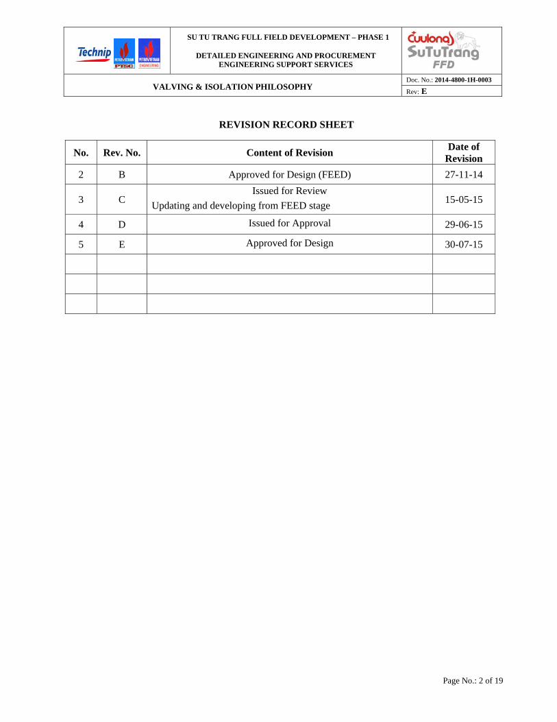
REVISION RECORD SHEET
No. Rev. No. Content of Revision Date of
Revision
2 B Approved for Design (FEED) 27-11-14
3 C Issued for Review
Updating and developing from FEED stage 15-05-15
4 D Issued for Approval 29-06-15
5 E Approved for Design 30-07-15
SU TU TRANG FULL FIELD DEVELOPMENT – PHASE 1
DETAILED ENGINEERING AND PROCUREMENT ENGINEERING SUPPORT SERVICES
VALVING & ISOLATION PHILOSOPHY Doc. No.: 2014-4800-1H-0003
Rev: E
Page No.: 3 of 19
TABLE OF CONTENTS
1.0 INTRODUCTION 5
1.1 DESCRIPTION OF FACILITIES 5
1.2 DOCUMENT PURPOSE 5
1.3 ABBREVIATION AND DEFINITION 6
2.0 GENERAL OBJECTIVES 6
3.0 DEFINITIONS 7
3.1 SEVERE SERVICE 7
3.2 NON-SEVERE SERVICE 7
3.3 CRITICAL SERVICE 7
3.4 NON-CRITICAL SERVICE 7
3.5 POSITION ISOLATION 7
3.6 GENERAL ISOLATION 7
3.7 HIGH PRESSURE 7
3.8 LOW PRESSURE 7
3.9 DOUBLE BLOCK AND BLEED 8
3.10 DOUBLE BLOCK WITHOUT BLEED 8
3.11 SINGLE BLOCK AND BLEED 8
3.12 SINGLE BLOCK 8
3.13 INTERLOCKED OPEN / CLOSED 8
3.14 LOCKED OPEN / CLOSED 9
3.15 CAR SEAL OPEN / CLOSED 9
3.16 SHUTDOWN VALVE (SDV) 9
3.17 LIVE FACILITY 9
3.18 CONFINED SPACE 9
3.19 TRAIN 9
3.20 BLOWNDOWN VALVE 9
3.21 SOUR SERVICE 9
3.22 SWEET SERVICE 9
3.23 ABBREVIATION 10
4.0 SYSTEM ISOLATION AND VALVING REQUIREMENTS 10
4.1 GENERAL GUIDELINES 10
4.2 MAINTENANCE ISOLATION 15
SU TU TRANG FULL FIELD DEVELOPMENT – PHASE 1
DETAILED ENGINEERING AND PROCUREMENT ENGINEERING SUPPORT SERVICES
VALVING & ISOLATION PHILOSOPHY Doc. No.: 2014-4800-1H-0003
Rev: E
Page No.: 4 of 19
4.3 CONFINE SPACE ENTRY 15
4.4 EQUIPMENT 15
4.5 VALVES 16
4.6 PACKAGE EQUIPMENT 17
4.7 INSTRUMENT ISOLATION 18
4.8 DRAIN AND VENT 18
4.9 POWERED EQUIPMENT ISOLATION 19
SU TU TRANG FULL FIELD DEVELOPMENT – PHASE 1
DETAILED ENGINEERING AND PROCUREMENT ENGINEERING SUPPORT SERVICES
VALVING & ISOLATION PHILOSOPHY Doc. No.: 2014-4800-1H-0003
Rev: E
Page No.: 5 of 19
1.0 INTRODUCTION
1.1 DESCRIPTION OF FACILITIES
The Su Tu Trang (White Lion) field is located at the South end of Block 15-1 (approximately 20km’s South of STV) in approximately 56 meters of water. The Block 15-1 contract area is located in the Cuu Long Basin offshore southern Vietnam, 180 kilometres southeast of Ho Chi Minh City. The development of Su Tu Trang started in September 2012 with the Long term Production Testing Phase (LTPTP). It consists of a remote, unmanned wellhead platform (WHP-C) that produces to and is controlled from the Su Tu Vang CPP. The platform has the capability of handling up to 4 high pressure gas wells. Present production is 6,000 BPD of condensate and 50 MMSCFD of gas and all the STT produced fluids are exported for processing to the Su Tu Vang CPP via a multiphase 12” pipeline.
Production of the Su Tu Trang Field is now bottlenecked by the CPP process capacities, and most significantly by the gas export pipeline to shore and the gas sales demand in South Vietnam.
The purpose of the Phase 1 of Su Tu Trang Full Field Development is to face these restrictions by allowing the increase of the condensate production while keeping the gas export flow rate steady. It will also provide more reservoir information to support STT Full Field Development Phase 2 that will significantly increase gas production/export.
The Project consists of the installation of a reinjection platform (ST-PIP) bridge-linked to the existing WHP-C, the drilling of two new wells on ST-PIP and the conversion from producers into injectors of two existing wells on WHP-C. The outcome of the project will be a continuous production rate of 150 MMSCFD, a reinjection rate of 100 MMSCFD, an export rate of 50 MMSCFD to Bach Ho via CPP (no change), and an incremental condensate production of 13,000 BPD.
ST-PIP will be bridge-linked to a separated living quarters platform designed for 20 pax during Phase 1, but extendable to 60 pax at a later stage. In addition to accommodation, ST-LQ will be equipped with most of the utilities for ST-PIP. It is also designed to be bridge-linked to a separated Central Gas Facility Platform (CGF) in the future (Phase 2).
1.2 DOCUMENT PURPOSE
This philosophy describes the provisions to be made for isolation of process equipment or sections of plant to permit safe operation and to provide access for maintenance and inspection while allowing continued safe operation where required. A basis for valve arrangements around control valves, relief valves, shutdown valves, blowdown valves, etc. is included.
Isolation is to be accomplished by the use of block valves and / or the insertion of spectacle blinds or spades, or the removal of spool pieces and the installation of blind flanges. The location of the isolation to enable maintenance and inspection is dependent upon the extent of shutdown, hazardous nature of the contained fluids, and the pressure rating of the piping system in question.
It is recognized that there may be individual instances where for safety reasons or significant engineering technicalities the philosophy detailed in this document cannot be achieved. In these

SU TU TRANG FULL FIELD DEVELOPMENT – PHASE 1
DETAILED ENGINEERING AND PROCUREMENT ENGINEERING SUPPORT SERVICES
VALVING & ISOLATION PHILOSOPHY Doc. No.: 2014-4800-1H-0003
Rev: E
Page No.: 6 of 19
cases a review will be carried out jointly by the relevant engineering group and Operations to establish a safe and justifiable alternative. Selection of valves or other isolation devices to accommodate any deviations from this basis of design shall only be made from types currently in similar service with a known performance and maintenance history.
Fully auditable documentation supporting any agreed changes shall be available and retained for future reference as part of the project files.
1.3 ABBREVIATION AND DEFINITION
1.3.1 Definition
Definitions used in this document are described below:
COMPANY
[CPY]
CUU LONG JOINT OPERATING COMPANY. [CLJOC]
EPCI CONTRACTOR
[CTR]
PTSC MECHANICAL & CONSTRUCTION CO., LTD.
[PTSC M&C]
DETAILED ENGINEERING INTEGRATED TEAM
[DE]
TECHNIP VIETNAM CO., LTD. [TPVN]
PTSC MECHANICAL & CONSTRUCTION CO., LTD. [PTSC M&C]
PETROVIETNAM ENGINEERING COMPANY. [PVE]
VENDOR Party responsible for manufacturing and/or packaging of equipment.
SUB-VENDOR Other entity employed by VENDOR to perform work and/or supply equipment.
1.3.2 Abbreviation
ST-PIP : Reinjection platform ST-LQ : Living quarter platform STT : Su Tu Trang
2.0 GENERAL OBJECTIVES
The methods of isolation required and precautions taken will be defined by the frequency and
level of risk that the work to be done on a system will involve. Where hazards are identified as
capable of causing injury to personnel or damage to plant, total and secure isolation from the risk
shall be achieved.This document describes the valving and isolation philosophy to be adapted for
the design of Su Tu Trang Complex. The objectives of this philosophy are:
To define safe isolation methods, draining, purging and venting provision for on-line plant
containing process (oil, gas, condensate, produce water and hazardous chemical), utility
liquid and gases, hence operation, maintenance and inspection can take place with minimum
plant shut down.
SU TU TRANG FULL FIELD DEVELOPMENT – PHASE 1
DETAILED ENGINEERING AND PROCUREMENT ENGINEERING SUPPORT SERVICES
VALVING & ISOLATION PHILOSOPHY Doc. No.: 2014-4800-1H-0003
Rev: E
Page No.: 7 of 19
To ensure necessary facilities are incorporated in the design.
To minimize cost impact whilst maintaining safety objectives.
3.0 DEFINITIONS
3.1 SEVERE SERVICE
All systems containing produced hydrocarbons
All systems containing hydrogen sulfide gas and Mercury
All systems at ASME 900# flange rating or above
Heating Medium
Hazardous liquids used above atmospheric pressure or with a flash point below 60ºC
(140ºF)
3.2 NON-SEVERE SERVICE
All systems not classified as severe service.
3.3 CRITICAL SERVICE
A process system (normally gas/liquid production), considered critical to maintain facility
production rates.
3.4 NON-CRITICAL SERVICE
All systems not classified as critical service.
3.5 POSITION ISOLATION
A physical barrier, where no leakage can be tolerated for safety or contamination reasons.
Positive isolation is provided by spectacle blinds, spades or removable spools that allow for the
installation of blind flanges.
3.6 GENERAL ISOLATION
Isolation for a specific work activity where the requirements are less critical than needed to
ensure Positive Isolation. Typically in non-hazardous and low pressure hazardous services.
3.7 HIGH PRESSURE
Service where the system pressure class rating is ANSI Class 300 or above.
3.8 LOW PRESSURE
Service where the system pressure class rating is ANSI Class 150 or below.

SU TU TRANG FULL FIELD DEVELOPMENT – PHASE 1
DETAILED ENGINEERING AND PROCUREMENT ENGINEERING SUPPORT SERVICES
VALVING & ISOLATION PHILOSOPHY Doc. No.: 2014-4800-1H-0003
Rev: E
Page No.: 8 of 19
3.9 DOUBLE BLOCK AND BLEED
An isolation system providing two seals against fluid flow and incorporating an intermediate
venting facility to monitor performance of the first seal and prevent pressure build up on the
second seal.
Double Block and Bleed can be provided by one of the following methods:
By two separate block valves with a vent valve on the interconnecting pipework.
By modular or mono-flange double block and bleed valve assemblies.
By valve types which by nature provide two mechanically activated seats with a cavity bleed
(such as expanding slab, through conduit gate valve with body cavity vent). Such valves
require the provision of a body cavity relief valve which should be incorporated into the vent
assembly. Such valves also have a preferred orientation with regard to sealing direction if
the need to equalize across the valve to open it is to be avoided.
By special ball valves with dual seats and a body cavity vent.
Notes:
Use of a Shutdown Valve (fail closed) as the second valve in a DBB configuration is
acceptable provided that the SDV controls are deactivated.
Use of widely separated process block valves is acceptable provided the trapped volume
between the two block valves is less than 1.5m3.
3.10 DOUBLE BLOCK WITHOUT BLEED
An isolating system providing two seals against fluid flow using two independent valves. This is
generally used for vents and drains, etc. but exceptionally also used with a downstream vent to
provide for installation of positive isolation for equipment maintenance.
3.11 SINGLE BLOCK AND BLEED
A single valve with a bleed valve located on the downstream side so that leakage can be tested
prior to breaking a flange.
3.12 SINGLE BLOCK
Single valves are used to provide system isolation in non-severe service and to divert flows in
operating systems.
3.13 INTERLOCKED OPEN / CLOSED
An interlocking system where valves are always secured in the open or closed position to provide
safe operating conditions. Proper valve sequencing must be ensured by an interlocking system.

SU TU TRANG FULL FIELD DEVELOPMENT – PHASE 1
DETAILED ENGINEERING AND PROCUREMENT ENGINEERING SUPPORT SERVICES
VALVING & ISOLATION PHILOSOPHY Doc. No.: 2014-4800-1H-0003
Rev: E
Page No.: 9 of 19
3.14 LOCKED OPEN / CLOSED
A system where valves shall be secured in the Open or Closed position by keyed locks to provide
safe operational isolation.
3.15 CAR SEAL OPEN / CLOSED
A system where valves shall be always secured in the Open or Close position by car seals to
provide temporary operational isolation.
3.16 SHUTDOWN VALVE (SDV)
A block valve that is actuated through the SIS System. This valve is tested regularly and is not
used for any form of process control. The valve is fail closed.
3.17 LIVE FACILITY
Anytime the facility is processing produced fluids the facility is considered “live”. The facility is
considered “dead” only when the facility is isolated from producing pipelines or wells and the
facility has been completely blown down and drained of hydrocarbon liquids.
3.18 CONFINED SPACE
An area or vessel that normally contains a fluid or gas under pressure and that may have a limited
entry or exit provision (e.g. manway) and that may require entry for inspection or periodic
service.
3.19 TRAIN
A train is defined as comprising one or more pieces of equipment which are similar in function
and capacity and operate in parallel with another similar grouping, such that each grouping can
operate independently of one another (e.g. Lift Gas Compression)
3.20 BLOWNDOWN VALVE
A block valve that is actuated through the ESD System. This system is tested regularly as per
applicable safety regulation. It is not use for process control.
3.21 SOUR SERVICE
All severe service system containing more than 10 ppm Hydrogen Sulphide (H2S).
3.22 SWEET SERVICE
All severe service systems containing less than 10 ppm Hydrogen Sulphide (H2S).
SU TU TRANG FULL FIELD DEVELOPMENT – PHASE 1
DETAILED ENGINEERING AND PROCUREMENT ENGINEERING SUPPORT SERVICES
VALVING & ISOLATION PHILOSOPHY Doc. No.: 2014-4800-1H-0003
Rev: E
Page No.: 10 of 19
3.23 ABBREVIATION
DB Double Block
DBB Double Block and Bleed
IDBB Integral Double Block and Bleed
SBB Single Block and Bleed
SB Single Block
ILO Interlocked Open
ILC Interlocked Closed
LO Locked Open
LC Locked Closed
CSO Car Seal Open
CSC Car Seal Closed
NO Normally Open
NC Normally Closed
SDV Shutdown Valve
BDV Blowdown Valve
PSV Pressure Safety Valve (Relief Valve)
RO Restriction Orifice
FB Full Bore
RB Reduced Bore
VOC Volatile Organic Compound
4.0 SYSTEM ISOLATION AND VALVING REQUIREMENTS
4.1 GENERAL GUIDELINES
Isolation of sections of plant or equipment will be generally divided into two types:
4.1.1 Positive Isolation
Where an absolute guarantee of segregation (i.e. no leakage) is required between the isolated
section and the surrounding plant. Positive isolation is typically provided by non-valve methods,
such as spectacle blinds, spades, or removable spools that allow for installation of blind flange.

SU TU TRANG FULL FIELD DEVELOPMENT – PHASE 1
DETAILED ENGINEERING AND PROCUREMENT ENGINEERING SUPPORT SERVICES
VALVING & ISOLATION PHILOSOPHY Doc. No.: 2014-4800-1H-0003
Rev: E
Page No.: 11 of 19
The following table 4.1 provides general guideline on the application for positive isolation.
TABLE 4.1 : POSITIVE ISOLATION METHOD
Isolation Type / Application
Method
Positive Isolation
Used where no leakage can be tolerated, e.g.;
All confined space entries
To prevent cross contamination of
utilities with process
To isolate a process train from other
hazardous process / utilities for the
purpose of overhaul / inspection
Hot Work
For process fluids above ignition
temperature
Positive Isolation can be achieved by any of
the following:
Removable Spool & Blind Flange
Spade and Spacer
Spectacle Blind
The use of process isolation valves is NOT
acceptable for positive isolation.
Table 4.2 and 4.3 provide the general limits of use for blinds, spacers and removable spools for
the different piping sizes and classifications.
TABLE 4.2 : LIMITS OF USE OF BLINDS, SPACERS AND SPOOLS – CARBON STEEL PIPING
Line Size (Inch NB)
150# (RF)
300# (RF)
600# (RF)
900# (RTJ)
1500# (RTJ)
2500# (RTJ)
API 10000#(RTJ)
¾”
SPECTACLE BLIND
1” 1½” 2” 3” 4” 6” 8” 10”
REMOVABLE SPOOL
& BLIND FLANGE
12”
14” SPACER & SPADE
Over 14”

SU TU TRANG FULL FIELD DEVELOPMENT – PHASE 1
DETAILED ENGINEERING AND PROCUREMENT ENGINEERING SUPPORT SERVICES
VALVING & ISOLATION PHILOSOPHY Doc. No.: 2014-4800-1H-0003
Rev: E
Page No.: 12 of 19
TABLE 4.3 : LIMITS OF USE OF BLINDS, SPACERS AND SPOOLS – NON-CARBON STEEL PIPING
Line Size (Inch NB)
150# (RF)
300# (RF)
600# (RF)
900# (RTJ)
API 10000# (RTJ)
¾” 1”
1½” 2”
SPECTACLE BLIND
3” 4” 6” 8” 10” 12” REMOVABLE SPOOL 14” SPACER & SPADE & BLIND FLANGE
Over 14”
In general the above selections are based upon use of a spade and spacer when the weight of a
spectacle blind exceeds 50 kg.
The following options exist for achieving Positive Isolation:
1) Spade Only
Spreading the flange and inserting a spade blind – limited to small bore piping only.
2) Spectacle Blind
Combined spacer and blind system used where weight is less than 50 kg.
3) Spacer and Spade Blind
Installation of a spacer of the same thickness as the fully rated spade blind. The spacer facilitates
the installation of the spade blind when required (via use of jacking screw)
4) Removable Spools and Blind Flange
These are normally used when:
Piping is too large to enable a flange to be sprung and a spade installed, but when a
permanent spacer is not justified
Insufficient flexibility exists to enable the use of a spectacle blind / spacer and spade.
SU TU TRANG FULL FIELD DEVELOPMENT – PHASE 1
DETAILED ENGINEERING AND PROCUREMENT ENGINEERING SUPPORT SERVICES
VALVING & ISOLATION PHILOSOPHY Doc. No.: 2014-4800-1H-0003
Rev: E
Page No.: 13 of 19
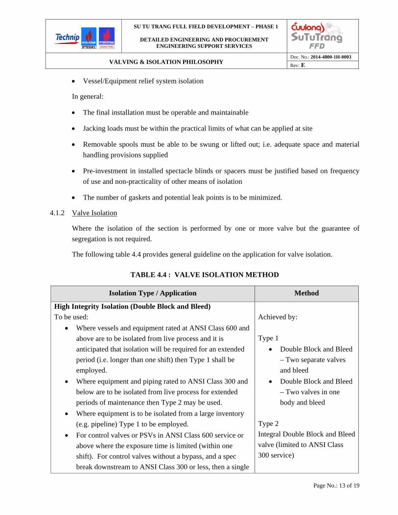
Vessel/Equipment relief system isolation
In general:
The final installation must be operable and maintainable
Jacking loads must be within the practical limits of what can be applied at site
Removable spools must be able to be swung or lifted out; i.e. adequate space and material
handling provisions supplied
Pre-investment in installed spectacle blinds or spacers must be justified based on frequency
of use and non-practicality of other means of isolation
The number of gaskets and potential leak points is to be minimized.
4.1.2 Valve Isolation
Where the isolation of the section is performed by one or more valve but the guarantee of
segregation is not required.
The following table 4.4 provides general guideline on the application for valve isolation.
TABLE 4.4 : VALVE ISOLATION METHOD
Isolation Type / Application Method
High Integrity Isolation (Double Block and Bleed)
To be used:
Where vessels and equipment rated at ANSI Class 600 and
above are to be isolated from live process and it is
anticipated that isolation will be required for an extended
period (i.e. longer than one shift) then Type 1 shall be
employed.
Where equipment and piping rated to ANSI Class 300 and
below are to be isolated from live process for extended
periods of maintenance then Type 2 may be used.
Where equipment is to be isolated from a large inventory
(e.g. pipeline) Type 1 to be employed.
For control valves or PSVs in ANSI Class 600 service or
above where the exposure time is limited (within one
shift). For control valves without a bypass, and a spec
break downstream to ANSI Class 300 or less, then a single
Achieved by:
Type 1
Double Block and Bleed
– Two separate valves
and bleed
Double Block and Bleed
– Two valves in one
body and bleed
Type 2
Integral Double Block and Bleed
valve (limited to ANSI Class
300 service)
SU TU TRANG FULL FIELD DEVELOPMENT – PHASE 1
DETAILED ENGINEERING AND PROCUREMENT ENGINEERING SUPPORT SERVICES
VALVING & ISOLATION PHILOSOPHY Doc. No.: 2014-4800-1H-0003
Rev: E
Page No.: 14 of 19
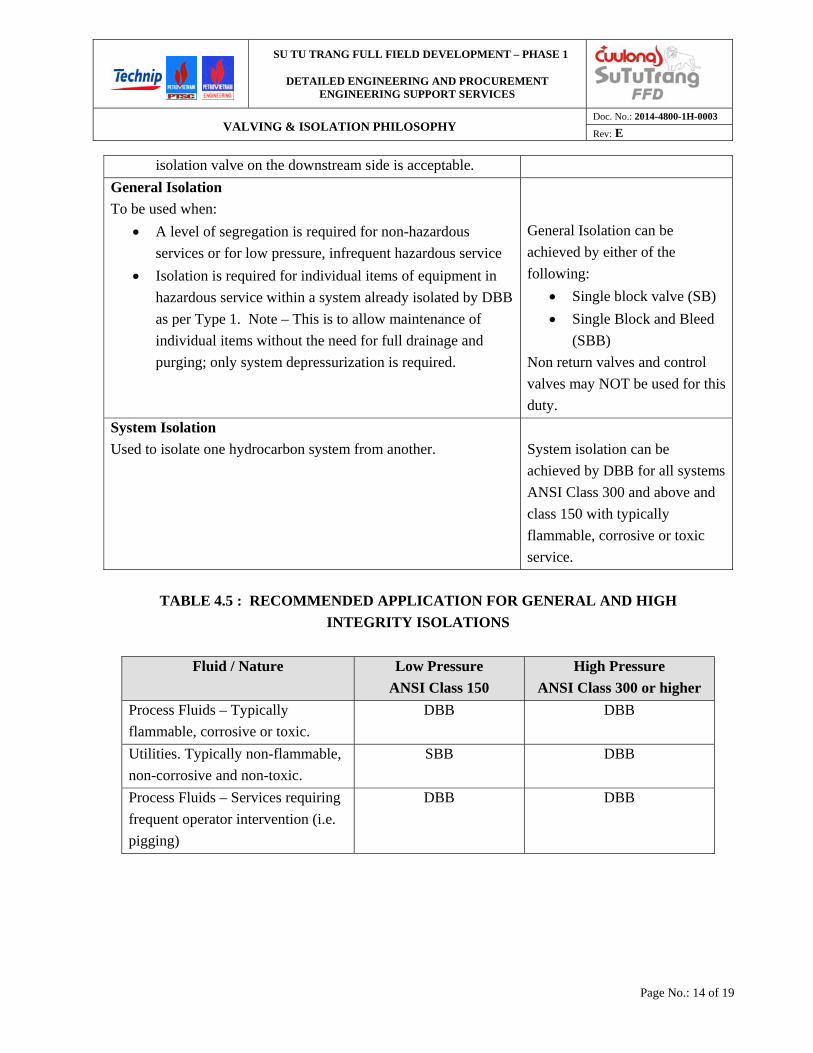
isolation valve on the downstream side is acceptable.
General Isolation
To be used when:
A level of segregation is required for non-hazardous
services or for low pressure, infrequent hazardous service
Isolation is required for individual items of equipment in
hazardous service within a system already isolated by DBB
as per Type 1. Note – This is to allow maintenance of
individual items without the need for full drainage and
purging; only system depressurization is required.
General Isolation can be
achieved by either of the
following:
Single block valve (SB)
Single Block and Bleed
(SBB)
Non return valves and control
valves may NOT be used for this
duty.
System Isolation
Used to isolate one hydrocarbon system from another.
System isolation can be
achieved by DBB for all systems
ANSI Class 300 and above and
class 150 with typically
flammable, corrosive or toxic
service.
TABLE 4.5 : RECOMMENDED APPLICATION FOR GENERAL AND HIGH
INTEGRITY ISOLATIONS
Fluid / Nature Low Pressure
ANSI Class 150
High Pressure
ANSI Class 300 or higher
Process Fluids – Typically
flammable, corrosive or toxic.
DBB DBB
Utilities. Typically non-flammable,
non-corrosive and non-toxic.
SBB DBB
Process Fluids – Services requiring
frequent operator intervention (i.e.
pigging)
DBB DBB

SU TU TRANG FULL FIELD DEVELOPMENT – PHASE 1
DETAILED ENGINEERING AND PROCUREMENT ENGINEERING SUPPORT SERVICES
VALVING & ISOLATION PHILOSOPHY Doc. No.: 2014-4800-1H-0003
Rev: E
Page No.: 15 of 19
4.2 MAINTENANCE ISOLATION
4.2.1 Process Train Isolation
Dedicated isolation valves need not be provided for unspared equipment within a train except:
Where the equipment can be bypassed and the process allowed continuing in operation
To reduce system size to a reasonable value with respect to inventory vented (loss of
product and / or environmental considerations) and with respect to gas freeing and purging
requirements.
Equipment spared within the train must be provided with isolation at the inlet and outlet in
accordance with Table 4.1.
4.2.2 Flow line Isolation
Production flow lines shall be provided with DBB to allow isolation of individual flow lines and
wells. This is to allow access to choke valves or tie-ins of additional lines without the
requirement for shutting down and depressurizing the main manifold.
4.3 CONFINE SPACE ENTRY
An area or equipment normally containing a fluid that may have limited entry and exit provision
to allow entry for inspection and periodic service shall be provided with isolation as described
below:
Valve isolation as per Table 4.4
Positive isolation as per Table 4.1
Drain isolation as per section 4.8
PSV isolation as per section 4.5.2.
If entry is required to a vessel, a pump or compressor is dismantled, while the facilities is
live, the isolation valve should be provided to enable the blinds to be installed or spool pieces
removed.
4.4 EQUIPMENT
Equipment that is not within a train but which is spared and sufficiently critical to operations for
maintenance of services of this equipment while the facilities is live may be required, shall have
provision for positive isolation. (Including DBB if required by the service).
Equipment not intent to be disconnected of taken out of services while the facility is live does not
require isolation. However, isolation may still be provided to facilitate operation and
maintenance, and to minimize purging volumes and duration and reduce maintenance intervals.

SU TU TRANG FULL FIELD DEVELOPMENT – PHASE 1
DETAILED ENGINEERING AND PROCUREMENT ENGINEERING SUPPORT SERVICES
VALVING & ISOLATION PHILOSOPHY Doc. No.: 2014-4800-1H-0003
Rev: E
Page No.: 16 of 19
4.5 VALVES
4.5.1 Control Valves
Control valves shall be provided with inlet and outlet isolation valves. Requirements for single
block or double block are to be determined based on the guidelines provided in Table 4.4 and
Table 4.5 in conjunction with evaluation of service criticality.
Critical service is defined as that where facility production would stop if the valve failed or were
taken out of service. This also applies to control valves where two separate, parallel valves have
been provided to ensure availability. The spare valve or the one not specifically in service must
have provisions for adequate isolation for maintenance purposes.
Isolation valves shall be full line size and reducers, if required to match control valve size, shall
be located inside the block valves. Reducer spool pieces should be large enough to handle
increasing to the next larger control valve body size without modifications to the control valve
station isolation valves.
Control valve manifolds shall be provided with drain valves to allow venting / draining after
isolation, the number of valves shall be decided on a case by case basis depending on the failure
position and location of the control valves.
Check valves provided for prevention of backflow shall be provided downstream of the control
valve manifold and bypass connection to allow for maintenance and inspection. Bypass operation
is to be controlled by procedure and continuously attended.
Where a control valve capacity sets a downstream relief valve sizing basis, then the control valve
bypass valve, if provided, shall be Car Seal Closed and its operation controlled by procedure.
4.5.2 Relief Valves (PSVs)
Where relief valves are spared, the inlet isolation shall be provided such that the spares are
Interlocked together. This is to ensure controlled changeover and following of the correct
sequencing and can be achieved by either special inlet valve manifolds which automatically place
one valve in service when the other is isolated or by locking (and reliance upon procedure)
individual inlet block valves into position.
All relief valves discharging into a closed system shall be fully isolatable with each PSV having a
dedicated outlet isolation valve. Outlet block valves, including those for spare service, shall be
locked open.
All relief valves of size greater than 1.5” x 2” shall be equipped with inlet and outlet bleed rings
to allow testing in place. Relief valves of size 1.5” x 2” and smaller shall be equipped with bleed
valves within the isolation valves to allow testing in place.
SU TU TRANG FULL FIELD DEVELOPMENT – PHASE 1
DETAILED ENGINEERING AND PROCUREMENT ENGINEERING SUPPORT SERVICES
VALVING & ISOLATION PHILOSOPHY Doc. No.: 2014-4800-1H-0003
Rev: E
Page No.: 17 of 19
Testing in place provisions for relief valves located within packaged, but isolatable equipment
trains, will necessitate the installation of PSV inlet isolation valves and bleeds as noted above.
4.5.3 Shutdown Valves
High integrity valves will be used in key areas for shutdown valves. These valves will isolate
various portion of the process. Unless special circumstances exist, no isolation valves are
required for individual SDVs as the process system in question will be depressured prior to
maintenance of an SDV.
SDVs on vessel liquid outlets should be located as near to the vessel outlet flange as practical.
The need for pressurization bypasses shall be determined by the start up procedure and
philosophy. The size of a bypass shall be based upon the volume of the system to be pressurized
and the initial pressure differential across the valve. All SDVs with start-up bypass shall have a
differential pressure permissive to prevent the SDV from opening under high differential
pressure. All transmitter tapping points used for differential pressure permissives shall be local
to the valve (within 3 meters).
Manual pressurization valves should be Locked Closed when not in use. These valves should be
globe valves capable of throttling across large pressure differentials.
4.5.4 Blowdown Valves
All blowdown valves shall have upstream and downstream isolation valves so that they may be
isolated from both the process and the relief system. These valves shall be Locked Open.
Where needed, a Restriction Orifice (RO) may be provided on the downstream side of the BDV.
The RO shall be sized such that in high pressure systems the pressure drop occurs across the
orifice rather than the BDV itself.
RO’s shall be located within the BDV station isolation valves.
Inlet BDV isolation valves may be reduced port. Isolation valves downstream of the BDV and
RO assembly shall be full port.
4.6 PACKAGE EQUIPMENT
Package equipment connected to the process and utility systems will be provided with flange,
isolation valves and if necessary, blinding facilities at the skid limits.
Yard valves provided within the compression package shall only be used for isolation of the
associated package equipment and controlled / actuated from its local control panel. These yard
valves shall not be used the main SDV for process system isolation (i.e. not connected to the PSD
system).

SU TU TRANG FULL FIELD DEVELOPMENT – PHASE 1
DETAILED ENGINEERING AND PROCUREMENT ENGINEERING SUPPORT SERVICES
VALVING & ISOLATION PHILOSOPHY Doc. No.: 2014-4800-1H-0003
Rev: E
Page No.: 18 of 19
4.7 INSTRUMENT ISOLATION
4.7.1 Level Instrumentation
For 150#
Level instrumentation on all vessels shall be provided with single ball valve assembly as the
process isolation.
For 300# and above
Level instrumentation on all vessels shall be provided with integral double block and bleed
assembly as the process isolation.
4.7.2 Pressure Instrumentation
For 150#
Pressure instrumentation shall be provided with an integral single block and bleed, single ball
valve for piping class ‘A8’ assembly as the process isolation.
For 300# and above
Pressure instrumentation shall be provided with an integral double block and bleed assembly as
the process isolation.
4.7.3 Small Bore Pipework
Small bore pipework (e.g. level bridles) of size 40 mm and below can be isolated using general
isolation (SB) except for high pressure systems class 600 or more where DBB shall be used. This
can be reviewed on a case by case basis based on normal operating conditions.
4.8 DRAIN AND VENT
4.8.1 Vessel Vents
Manual maintenance vent connections, routed to the flare, shall be provided as required and as
indicated by the P&IDs. The vent connections shall comprise a globe valve (process side)
followed by an isolation valve.
Minimum size for vent connections to closed relief systems is 2”.
4.8.2 Vessel Drains
Vessel Drainage in Hazardous Areas
Vessels in hydrocarbon service shall be provided with a drain connection to the Closed Drain
Header. The drain connection may be either directly off the vessel or on the liquid outlet piping
assuming that it is at a low point and adequate natural drainage is provided.
Closed Drain System connections shall consist of a globe valve (process side) followed by an
isolation valve. A Restriction Orifice may be provided to limit gas blow by throughput.
SU TU TRANG FULL FIELD DEVELOPMENT – PHASE 1
DETAILED ENGINEERING AND PROCUREMENT ENGINEERING SUPPORT SERVICES
VALVING & ISOLATION PHILOSOPHY Doc. No.: 2014-4800-1H-0003
Rev: E
Page No.: 19 of 19
Ball valve only connections to the Closed Drain System may be considered for low pressure,
non-flashing service subject to COMPANY approval.
Vessel Drainage in Non-Hazardous Areas
Vessels in non-hazardous areas will be provided with a single drain valve. The drained fluids
will be routed to the Non-Hazardous Open Drain System via tundish or deck drain.
4.9 POWERED EQUIPMENT ISOLATION
Powered equipment isolations can be segregated by driver type. Specifically:
Electrically Driven
Pneumatically Driven or Hydraulically Driven
Engine or Turbine Driven
4.9.1 Electric Drives
Electrically power equipment shall be capable of being properly isolated under the Cuulong
Electrical Isolation Procedures and Permit to Work System.
4.9.2 Pneumatic or Hydraulic Drives
Hydraulic or pneumatic powered equipment shall be capable of being isolated by lockable
isolation valves and breaking of the motive source and return lines. Any reservoirs in the supply
side shall have lockable vents and / or drains.
4.9.3 Engine or Turbine Drives
Engine or turbine driven equipment shall be isolated by locking off the fuel supply to the engine
and the isolation of all starting systems. If the driver is part of a package then the package shall
include a master lockable isolation device to prevent any start up sequence from being initiated.