Embed Size (px)
Citation preview
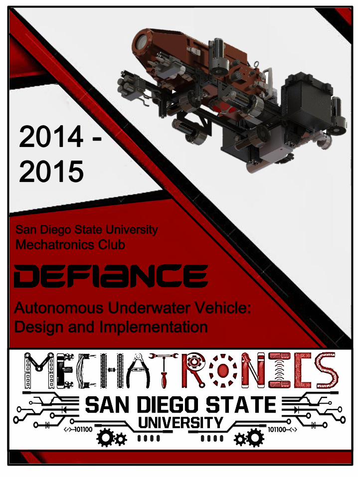
2014 -
2015
Autonomous Underwater Vehicle:
Design and Implementation
San Diego State University
Mechatronics Club

Abstract - Mechatronics is a student-runorganization at San Diego State University thatdesigns and builds unmanned vehicle systems androbotics. The club is comprised of 3 differentdepartments: Robosub, RoboAir, and Mechatronics101. The club has designed an AutonomousUnderwater Vehicle (AUV), or RoboSub, tocompete in the 18th Annual RoboSub competitionhosted by the Association for Unmanned VehicleSystems International (AUVSI) Foundation andOffice of Naval Research (ONR). The competition isheld in San Diego at the SPAWAR SSC’s PacificTRANSDEC pool in July and consists of navigatinga brightly colored underwater obstacle courseinvolving image processing tasks, maneuveringexercises, path following, torpedo launching,marker dropping, object manipulation, andacoustic recognition.
I. IntroductionThe Mechatronics Club’s main objective is todesign, program, and build a reliable and effectiveAutonomous Underwater Vehicle (AUV) that willcompete in the AUVSI and ONR’s InternationalRoboSub Competition for many years to come.Ideally, the RoboSub will accomplish every taskthroughout the obstacle course and inspire futureSDSU students to continue our work by improvingupon the vehicle design. The competition is held inthe team’s hometown of San Diego at the SPAWARSSC’s Pacific TRANSDEC pool during July. In orderto create a reliable and effective AUV, the taskswere split and the team was divided into foursubgroups; Mechanical, Electrical, Software, andBusiness team. With a lot of hard work and
determination, the Mechatronics Club successfullydesigned and built our second AutonomousUnderwater Vehicle.
II. Design OverviewThis year, the vehicle was completely redesignedcompared to last year’s vehicle. After gainingenough experience from the previous year, wewere able to incorporate a lot of features thatfixed problems we encountered previously. Withall the insight, we were able to effectively build aflexible and modular sub to compete in this year’scompetition. The sub, as shown in Figure 1,features a modular hull that allows access tocertain sections depending on what the teamneeds to get to such as electrical components,cameras, main computers, etc. The vehicleincludes two cameras, torpedo launchers,dropping mechanism, and an external frame thatallows versatility with the placement ofcomponents.
Figure 1: Defiance - 2015 Vehicle
The design features eight thrusters providingpropulsion in the forward, reverse, up, down, left,right, clockwise, counterclockwise, yaw, pitch, androll. It is powered by two lithium-ion cell batteriesplaced in parallel and features a collection ofinertial, visual, and pressure sensors that enablesuccessful navigation through the obstacle course.A new sensor we were able to incorporate this year
Team Members: Austin Owens, Maryann Ibrahim, Josh Pritts, Rodrigo Leon - Alvarez,Drew Smith, Jacob Marlay, David Barnes, Matthew Wnuk, Ryan Mohedano, JeffreyMiller, Joseph Clements, Petar Tasev, Felipe Jared Guerrero Moreno, Kevin Phelan,Erick Campas, Daniel Stec, Adrian Hui, James Walker, Andrew Orellano, Que Nguyen,Jeremy Bates, Marques Jackson, and Karah Hui
1

is a Doppler Velocity Log which will be able topinpoint the sub’s position and velocity whileit’s in the water. The design incorporates a fullycustom and modular electronics package and awatertight sectional hull. The main computerfeatures an Intel i7 Quad-Core processor for thenew software graphical interface that isresponsible for image processing and objectdetection, serial communication, missionplanning, navigation, and manual control.
III. Mechanical SystemsThe mechanical team is heavily involved inapplying mechanics of materials, heat transfer,fluid mechanics, materials science, solidmodeling, drafting and also common industrypractices such as product data management andplanning around vendor turn-around times.From a mechanical standpoint, almost everyaspect of this year’s vehicle has beentransformed completely. Defiance features a farmore compact and streamlined form factor. Themain chassis changed from a large bulkyenclosure to a series of individual hull sectionsfor a more modular approach. Our outer frameis far more compact and weighs much less asopposed to last year's vehicle. Its new designallows for up to 13 different components to bemounted to it simultaneously. The Inner Frame,lighter and easier to attach, allows for moremounting real estate for all the interior
sensitive equipment.
A. FrameThe external frame structure, as shown in Figure2, is anodized 80/20 Adjustable AluminumExtrusion which provides modularity andflexibility for relocating the sub’s componentssuch as the thrusters and weapons systems. Theframe is designed to be neutrally buoyant in thewater. Each component mount is strategicallyplaced along the extrusion to allow even weightdistribution.
Figure 2: 80/20 Frame Structure
The components are screwed directly into themounts and are designed with flexibility in
mind. The modularity of the outer frame alsogives us the ability to manipulate where thevehicle’s center of gravity will be. This designallows us to find the best configuration andadjust if needed.
B. Main Hull and Inner FrameThe main hull features custom designed andmachined subsections that piece together toform the main chassis. Each section of the hullhas an integrated latching system which allowsfor individual sections of the chassis to beremoved. This allows for easy access to criticalinternal areas of the sub that require constantmaintenance and adjustments such as sensors,circuit boards, etc. The front half of the vehiclehouses the on-board cameras and the mainprocessing computer. At the center rests theDoppler velocity log, pressure transducers aswell as the main bulkheads through which allinternal systems connect to the exteriorhardware. Sitting on top of the central hub rests
the sensor module which houses three attitudeheading referencing systems (AHRS) as well asthe kill and reset switches.
The rear portion of the submarine houses allpower management boards. All thesecomponents mount to the internal frame, asseen in Figure 3, which is split into two lightweight Aluminum 6061 plates. If the need to getmore hands on arises, these plates are alsodesigned to slide out of the submarine with ease 2

so that the software and electrical teammembers can get up close and personal withthe internal hardware.
Figure 3: Inner Frame
C. Heat TransferThe new design switched materials from plasticto 6061 aluminum allowing Defiance to takeadvantage of the temperature differences itwill be exposed to. Running the length of thesubmarine is a series of channels machineddirectly into the chassis itself, these are meantto act as heat sinks. They strategically runparallel to the flow of water in order to induceaccelerated heat transfer through an increasein surface area. Defiance’s slow travel speedmeans the flow will remain laminar through out
the length of the channels meaning moreeffective heat transfer.
D. Weapons SystemsThe weapons system consists of twopneumatically launched torpedoes, shown inFigure 4, two pneumatically actuated claws, anda servo driven payload dropping mechanism.Actuators are activated by sending electricalimpulses to servo motors and solenoid coils onthe pneumatic valves of the respectiveactuator.The pneumatics system is composed of a high-pressure CO2 tank, pressure regulator, solenoidvalves, pneumatic cylinders, and plastic tubing.As a result, the pneumatic valves open up andtrigger a cylinder to expand or contract. Thechange in length of the cylinders influence theactions of a respective weapon system.
For example, when launching a torpedo, an electrical impulse is sent to the corresponding valve, opening it, thus extending the piston
attached to the torpedo at high speed. The amount of force placed on the torpedo at that instant, propels it through the water.
Figure 4: Torpedo Weapons System
The same concept can be applied to the claws;the claws would either open or close dependingon which pneumatic solenoid valve wastriggered. There are two valves controlling bothof the claws, one for open, one for closeposition. The speed of these actuators isadjusted through variable flow regulators,which limit the amount of air passing into thepistons.
The dropping mechanism utilizes a differentmode of triggering. In this case, a servo rotatesa feeder containing steel ball bearings.
D. ThrustersPropulsion is provided by eight brushed-DCmotor, high performance, SeaBotix BTD150thrusters. The thrusters are mounted on theexternal frame and are oriented to provide sixdegrees of freedom. The sub is able to movefreely in the forward, reverse, up, down, left,right, clockwise, counterclockwise, and roll leftand right. The external frame also provides theability to relocate the thrusters in order toimprove movement in the water.
IV. Electrical SystemsThe electrical systems consist of powerdistribution and electronics. When compared to 3

our last year’s vehicle Endeavor, Defiancefeatures two additional brushed-DC thrusters,increased power system reliability, reducedelectronics form factor, and improved wiremanagement. There are nine custommanufactured printed circuit boards (PCBs)that were designed, sent in for fabrication, andpopulated with components.
A. Power DistributionThe power sources for Defiance are twoStarkPower Lithium Iron Phosphate 24V 10AHbatteries that range from 21V to 30V with amaximum output current of 15A. A Mini-BoxM4-ATX, 250W, 6V to 30V wide input intelligentautomotive DC-DC power supply was used topower the main computer. There are two Mini-Box DC-DC USB Converters that are used tosupply the 6V and 24V power planes on thebackplane.
B. ElectronicsA fully custom and modular electronics packagewas created for Defiance. The electronicspackage consists of a passive backplane for usewith 8 daughter cards that utilize PIC24microcontrollers for communication andsignaling.The modular design allowed the electrical teamto divide the electronics design, verification,and testing (DVT) into manageable modules to
thereby give all team members an opportunityto gain hands-on experience with printed circuitboard (PCB) design and embedded systemsprogramming.
C. Backplane and IntegrationThe backplane, as shown in Figure 5, improvedwire management and enabled a modularelectronic design. Power and signal traces wererouted within the 4 layers of the backplane. Forserial communication within the backplane,UART signals must be logic level adjusted to
RS-232 to prevent thruster noise fromcorrupting communication waveforms. Servervoltage regulator module (VRM) PCB-PCBconnectors were used to interconnect daughtercards to the backplane. Molex Mini-Fitconnectors were used for wiring harnessesassociated with DC-DC converters. On-ShoreTechnology (OST) terminal blocks facilitatedphasing out Molex Mini-Fit Jr. Connectors,
which were prone to severing wires just behindcrimps due to normal wear and tear associatedwith vehicle maintenance and vibrations duringoperation. For ease of installation, pigtail wiresattached to SEACON bulkhead connectors areinserted into the terminal blocks, thuseliminating the crimps that damage the wires.
Figure 5: Custom PCB Backplane
D. Power Management and UndervoltageDetection (PMUD)The Power Management and UndervoltageDetection (PMUD) board, shown in Figure 6,delivers power to the backplane from the twoparallel batteries. PMUD monitors and routes
battery power to the DC-DC converters,thrusters, and weapons. PMUD utilizes twoLinear Technology LTC2946 Power Monitors forprecise battery voltage and currentmeasurements, which are communicated to themain computer and logged on a 2GB microSDcard for engineering analysis. PMUD containstwo 15A fuses for circuit protection.Additionally, PMUD contains kill switch circuitrycomprised of two mechanical relays in series(one software controlled and the otherhardware controlled) to physically disconnect 4

power from thrusters and weapons and notfrom the DC-DC converters.
Figure 6: PMUD Board
E. Thruster Control Board (TCB)The Thruster Control Board (TCB), shown inFigure 7, drives four SeaBotix BTD150 BrushedDC thrusters. As a result, there are two TCBsonboard Defiance to accommodate 8 thrusters.During normal operation, each TCB receivespower from the 6V plane and deliversunregulated battery power to four H-bridgecircuits to drive the thrusters. The H-bridgecircuitry is comprised of an Allegro A3941 FullBridge Driver IC and four N-channel MOSFETs.
Figure 7: Thruster Control Board
TCB monitors current consumption in the eachthruster with Allegro ACS712 Hall Effect CurrentSensors, which is then communicated to themain computer and logged on a 2GB microSDcard for engineering analysis. For safetypurposes, when the kill switch is engaged theunregulated battery power is physicallydisconnected from both TCBs by PMUD toprevent thruster operation.
F. Weapons Control Board (WCB)The Weapons Control Board (WCB), shown inFigure 8, powers and controls launching twotorpedoes, dropping two ball bearings, andoperating two grabbers. The WCB features re-usable control outputs that can be used withnumerous actuators. Since weapons are a newaddition, this functionality was deemednecessary by project management to facilitate
prototyping of several different weaponssystems designs.
Figure 8: Weapons Control Board
The WCB has LED indicators for safety duringprototyping and development. The WCB has a12V buck converter with a large capacitor bankfor actuators requiring large pulsed current.For safety purposes, when the kill switch isengaged the unregulated battery power isphysically disconnected from 12V buckconverter by PMUD to prevent actuatoroperation, but only after the capacitor bankdischarges.
G. Communications Board (COM)
The USB to RS-232 communications board(COM), as seen in Figure 9, is a custom serialcommunications hub that fits the modulardaughter card form factor. The COM facilitatescommunication between the main computerand potentially 7 daughter cards connected tothe backplane. Serial communication signalsare interpreted by FTDI chips and logic leveladjusted by Texas Instruments MAX-232Eintegrated circuits (IC). The COM boardfeatures transmit and receive LEDs to aiddebugging. Two USB Type-B connectors were 5

used for cable support to reduce strain on thePCB dielectric material.
Figure 9: Communications Board
H. Sensor Interface Board (SIB)The Sensor Interface Board (SIB), shown inFigure 10, features triple redundant sensorsand filtering for internal temperature, internalpressure, and external pressure. Internaltemperature sensor data is logged forengineering analysis. Internal pressuretransducers are used for leak detection.External pressure transducers measure depth ofthe vehicle.
Figure 10: Sensor Interface Board
I. Hydrophones and Direction Rendering Analysis System (HYDRAS)The Hydrophones and Direction RenderingAnalysis System (HYDRAS) board, shown inFigure 11, makes use of a square array of fourhydrophone acoustic sensors to locateunderwater pingers. HYDRAS features three 7-segment displays to show desired frequency,heading angle, and ascent angle. pinger signalsinduced in each hydrophone pass through anAnalog Devices AD8010 Operational Amplifier,a Linear Technology LTC1068 band pass filter(BPF), and a resistive network before beingsampled by a PIC24 microcontroller. The decoypinger signal is removed by the BPF, so HYDRAScan iterate complex algorithms to determinethe direction to the target pinger.
Figure 11: HYDRAS Board
J. Doppler Velocity Log Communications Board (DVL COM)The Doppler Velocity Log Communicationsboard (DVL COM), shown in Figure 12, is acustom serial communications hub that fits theform factor of the Doppler Velocity Log (DVL).See the Communications Board section formore information on design and operation.
Figure 12: DVL COM Board
V. Sensors
The sensors onboard Defiance are capable ofobserving the sub’s environment and therelative position of the vehicle. The sensorsconsist of two cameras, three Sparton GEDC-60Attitude Heading Reference Systems (AHRS),three pressure transducers, a Teledyne RDIExplorer Doppler Velocity Log, and threeSparton PHOD-1 Hydrophones.
A. CamerasThe sub utilizes two cameras for imageprocessing, object detection, and navigation.The DFK 23UV024 and DFK 23U274, shown inFigure 13, are USB 3.0 Color Industrial camerasmanufactured by the Imaging Source. Eachcamera is located in the frontal hull section ofthe vehicle. One camera is used for forwardvision and the other is used for downwardvision. The forward facing camera utilizes a 6

a wide angle lens and is responsible for imageprocessing and object detection of the courseobstacles, as well as navigation. The downwardfacing camera is responsible for tracking thedepth and the course path and detecting the
obstacles at the bottom of the pool.
Figure 13: DFK 23U274 Camera
B. Attitude Heading Reference System (AHRS)The Sparton GEDC-60 AHRS, as shown in Figure14, measures spatial orientation. The SpartonAHRS features a Kalman filter that providesaccurate heading by eliminatingelectromagnetic interference from yaw, pitch,and roll solutions. It includes a 3-Axismeasurement in the X, Y, and Z direction andfeatures yaw, pitch, and roll all at low powerconsumption which is ideal for our vehicle. Weare using three AHRS for triple redundancy in
order to get the most accurate readings.
Figure 14: Sparton Attitude Heading Reference System
C. Pressure TransducersIn order to measure the depth of the vehiclerelative to the bottom of the TRANSDEC pool,three pressure transducers were incorporateinto the vehicle. The MEAS 15psi PressureTransducer, as shown in Figure 15, monitors the
depth and is capable of operating up to 15psi.We are also using triple redundancy with thepressure transducers in order to get the mostaccurate readings for depth. When the sub issubmerged underwater, the water presser is
measure by the transducer which then interactswith the Sensor Interface Board (SIB) toaccurately estimate the depth and thenmaintain a constant depth.
Figure 15: MEAS 15psi Pressure Transducer
D. Doppler Velocity Log (DVL)The Teledyne RDI Explorer Doppler Velocity Log(DVL), shown in Figure 16, provides precisevelocity and altitude updates that are helpfulwhen performing underwater tasks. Withvelocity, we are then able to integrate andcalculate the position of the vehicle which willallow us to map out the pool and createwaypoints where the obstacles are located in
order to successfully navigate through thecourse.
Figure 16: Teledyne RDI Explorer Doppler Velocity Log
E. HydrophonesThere are four Sparton Navigation andExploration PHOD-1 Hydrophones, as shown inFigure 17, that were used for Defiance. Threeare required and one hydrophone serves as aspare. 67

Figure 17: Sparton PHOD-1 Hydrophone
The Hydrophones are supplied 20V from thebackplane and require 10mA for operation.They are usable for frequencies between 10Hzand 50KHz. These are necessary for one of theobstacles where the vehicle has to find thepinger that is emitting a certain frequency andrise to the surface above it.
VI. Software SystemAll of the vehicle’s high level functionality,including completing the obstacle tasks, imageprocessing and object detection, serialcommunication, mission planning, 3D modelingand animation, and navigation is accomplishedthrough the vehicle’s software system. Thisyear, a brand new customizable graphical userinterface (GUI), was programmed andimplemented that incorporates all of the highlevel functionality. It is built upon a Windows 7Professional PC and is primarily written in thePython programming language; other features
in the software system utilize the Cprogramming language.
A. Main ComputerThe software system uses an ASUS mini-ITXmotherboard equipped with an Intel i7-4790kQuad-Core Processor, 8GB of Memory, and a256GB SSD. The computer’s small form factor,as shown in Figure 18, is efficient for spacemanagement in the main hull and the fastprocessor allows for seamless execution of thesoftware GUI.
Figure 18: Sub’s main computer – ASUS mini-ITX
B. Software Graphic User InterfaceThis year we developed a brand new graphicaluser interface (GUI) that is user friendly andwill allow team members to: create userprofiles, customize graphic gauges, selectparameters for image processing and missionplanning, manually control the vehicle,communicate with our embedded systems, anddisplay a 3D model of the vehicle in itsenvironment. The GUI, as shown in Figure 19,displays gauges of the vehicle’s status whichincludes its yaw, pitch, and roll, depth, positionand velocity, voltage and current levels, dutycycle percentages of the motors,alerts/warnings, and internal temperature fordetecting leaks.
Figure 19: Software GUI
This graphical user interface will allow futureteams of Mechatronics to easily monitor andcontrol all aspects of the vehicle.
C. Image ProcessingImage processing throughout the obstaclecourse is accomplished with the GUI usingOpenCV and the Python programminglanguage. OpenCV is an Open Source ComputerVision Library developed by Intel that features 8

many image processing algorithms for filteringimages and object detection. Utilizing OpenCVwith Python, the team was able to develop ourown algorithms for detecting objects thatcontain a specific Hue, Saturation, and Value(HSV), as well as a certain number of contours.For a user to track an object through the GUI,
they must click and drag the mouse to create arectangle to establish a region of interest (ROI).The Image Processing tab has sliders that willthen immediately snap into place for the HSVparameters. The user has the option tomanually change the HSV parameters to get amore accurate track on the object.
D. Mission PlanningBy having predefined blocks of code written foreach one of the missions, we can choose whichmissions we want to execute from a list, whatorder the vehicle executes them in, and haveusers enter in various parameters for eachmission, as shown in Figure 20.
Figure 20: Mission Planning
Users can save the mission lists they create to their own user profile so that the list may be imported later on.
E. Embedded Device CommunicationFor easy debugging, the software teamincorporated a communications tab, as shownin Figure 21, that allows us to automatically seewhich boards are connected to the PC and sendvarious commands to the embedded devicesthat a user can select from a list. Because thecommunications tab includes a script wherecommands can be entered and executed, the
script can also serve as a general access point tocode in python.
Figure 21: Communications Tab
F. Control and NavigationTo accurately control and navigate the subunderwater, the DVL, Pressure Transducers,and AHRS’s are used synergistically to create aclosed loop control system. PID controllers areused to prevent overshoot as well as keepingthe vehicle on track if it gets knocked offcourse. Transformation matrices are used tocapture the location and orientation (pose) ofthe vehicle and allows us to use linear algebraicalgorithms to have full control over the vehiclein 3D space.The user can push a button in the GUI that putsthe vehicle into manual control mode, as shownin Figure 22, where the user can operate thevehicle with a joystick controller. The joystickcontroller has two modes; one mode allows theuser to freely maneuver the vehicle, the othermode locks the vehicle’s orientation in placebut still allows it to translate along all axes. It’s
possible to lock the vehicle’s orientations byusing the AHRS’s as a closed loop controlsystem. By applying the right PID controllers,the vehicle will find its way back on course asfast as possible without overshoot. The GUI alsohas graphic gauges that represent the desiredand actual orientations and translations of thevehicle.
Figure 22: Manual Control Tab 9

G. Console LogIn order to see various sensor readings orgeneral data in the GUI, there is a console tab,as shown in Figure 23, that allows users toselect what data they are interested indisplaying in live time to the GUI console. Thesoftware does this by redirecting the standard
output from print statements and sends themto the GUI console instead. Users can choose toexport the data to a file that can be read byexcel for further analysis.
Figure 23: Console Tab
H. Graphic Interface CustomizationThe GUI is very customizable and members canmake their own user profile and personalize itto how they prefer, as seen in Figure 24. Thesoftware remembers various things about theuser’s actions including the missions and imageprocessing values they have selected, theposition, color, and number of gauges theydisplay during their sessions, and the lastmember that was using the program. Uponrestarting the software, it can restore all of the
user’s previous settings.
Figure 24: Graphics Settings Tab
AcknowledgementsMechatronics would like to thank all theindividuals and companies that have supportedus over the year on our RoboSub Project. Wedepend immensely on the support from ourcorporate sponsors for the necessary funding,hardware, materials, and equipment to be
competitive in this competition. We would liketo thank:Platinum Sponsors: Cymer, Leidos, Hewlett-Packard, San Diego State UniversitySilver Sponsors: General Atomics AeronauticalBronze Sponsors: Teledyne RDI, ThinkTankPhoto, Harvest, Teledyne SeaBotix, SEACON,Northrup Grumman, Teledyne Benthos,MicroChip, Industrial Metal Supply,MathWorks, Wrike, and Sparton.
10