Embed Size (px)
Citation preview

RAILWAYS Tramway
Jarosław Zwolski, PhD CE

Many big cities are nowadays performing on the verge of their transportation systems functioning ability. The media and decision-makers very often try to solve this issue by building a new bypass or a parking place. Meanwhile in the world it has been proved that building new roads never keeps up with the number of passenger cars. A rational public transport introduction/maintaining is considered as the only effective method.
More and more surface city transportation means (running on the street level) are coming back: tramway, trolley–bus because they penetrate the city much easier than an underground and are much cheaper and less troublesome for citizens.
In many agglomerations the bi-system means as tramway-railway or tramway-underground are working efficiently.

How many units of city space does one person takes travelling with different transportation means?
source: I. Gisterek

DEFINITION: A rail vehicle serving as a city transportation means, running on a surface railroad embedded in street pavement, separate or independent.

1832 – the first horse tramway, Nowy York.
1855 – horse tramway in Paris (the first in Europe).
To 1892 – in all important European capitals tramways are operating.
1873 – rope tramway in San Francisco, then in Edinburgh.
1875 – in France, Switzerland and US Ludwik Mękarski constructs tramways propelled by compressed air.
70’ of XIX c. – first steam tramways.
To 1894 – steam tramways arise in big European cities.
At the turn of XIX i XX c. – trials of combustion and gas engine application for trams propelling (Daimler).
1879 – the first electric tramway by Werner Siemens, Berlin.
Up to end of XIX c. – testing of various electrical propelling systems.
Beginning of XX c. – development of electric tramway (even in small towns).
From 20’ to 70’ – disappearance of trams networks from many big cities and almost all small towns due to increasing passenger cars share in transportation.
After 1974 – renewed development of tram networks after the petrol crisis.
After 1985 – modern low-floor tram stock.

1866 – the first tramway in Warsaw.
1873 – the first tramway line in Gdansk.
1877 – the first tramway line in Wroclaw.
1879 – the first tramway line in Szczecin.
1880 – the first tramway line in Poznan.
1882 – the first tramway line in Krakow.
1883 – electric tramway in Wroclaw.
1884 – the first tramway line in Sopot.
Up to WW II there were 31 cities with tramway lines.

source: Wojcieszak J., Dzieje komunikacji tramwajowej na świecie, Technika Transportu Szynowego, nr 1, 1996.
Names of the cities currently served by trams are underlined.
Horse tramway Diesel tramway Electric tramway
Horse tramway Steam tramway Gas propelled tramway Diesel tramway Electric tramway

After WW II most tram systems in the US and in West Europe (Germany, Austria, Denmark, UK, France, Sweden, Spain, Italia) were closed.
Some of polish cities also removed tramways (Bielsko-Biała, Inowrocław, Jelenia Góra, Legnica, Olsztyn, Słupsk i Wałbrzych).
Main reasons for tramways disappearance: 1. Better availability of passenger cars. 2. Common claim that a long and slow tram blocks the traffic and takes too much
space. 3. Other common claim that trams are anachronism and obsolete. 4. Monopoly action of General Motors (US), buying out tramway companies and
replacing with buses. 5. Central decision of PZPR to eliminate tram lines in small towns and to limit the
range of tram services in cities (Poland).

After WW I in many cities the infrastructure was modernized (the track gauge was changed from 1000 mm to 1435 mm, electrification).
After WW II the rolling stock was also exchanged with a more modern one, based on the idea of American PCC.
Original PCC After Presidents' Conference Committee
Tatra T1 (CR) (1952-1958)
Konstal 13N (PL) (1959-1969)

Kraków
Warszawa Poznań Wrocław
Gdańsk Łódź
Katowice
Bydgoszcz
Elbląg Gorzów Wlkp. Grudziądz Szczecin Toruń

Low-floor tram stock on the whole length (and also the platform) with easy access for older, disabled and blind people.
The gauge: 1435 mm for easier joining of tram and railway tracks if required.
Sparing of energy, energy recuperation at breaking.
Easy access to on-line information at stops and in the wagons.
Location of stops coincide with other means of transportation for easier transfer (transfer nodes, P+R).
Soundproofing of limitation of mechanical vibrations generated by the rolling stock and the trackway.
Tracks dedicated for tramway, excluded from road traffic, alternatively shared with bus.
Self-inductive traffic light systems on crossroads preferring passage of the tram.
Automatic following location and punctuality of trams.
Main trends in the design of trams and tramway lines:

Tramway lines can be designed independently from streets which enables fluent operation and avoids traffic jams with road traffic.
The lane taken by a tram is narrower than the one taken by a bus. Thanks to bogies enabling taking turns driving the tram on curves is easy and safe (the danger of running onto vehicles on the next lanes or onto pedestrians on the pavement is minimal).
The tramway is a long-lived and durable vehicle which keeps the maintenance costs at a reasonable level.
A tramway in most cases is more cost effective than a bus. Having less rolling resistance it can take advantage from coasting and during breaking it can take the energy back to the traction network (recuperation), the energy consumption per 1 passenger is less,
Joining wagons in trains enables the limitation of employment costs.

A tramway practically doesn’t emit any pollution which is very important for a cities ecological balance.
A tramway with wagons joined in trains has a bigger carrying capacity than a bus (over 200 passengers).
A tramway doesn’t suffer so much from unfavourable weather conditions (glazed frost, precipitation) thanks to driving on rails and to devices assisting in starting and breaking (i.a. the rail brake and sanding).
Work of electric engines is much more silent than combustion motors which makes interiors of trams more silent and comfortable.
An electric engine easier bears overloading and is easier to construct which makes the maintenance costs lower and the out-of-service time shorter than in the case of a bus engine.
Alternating current engines often and often used in modern trams contribute to good parameters of starting especially on a dry surface of rails.

A tramway is a very safe vehicle thanks to the so called „driver's safety device” and emergency brakes available for passengers.
A tramway has a shorter stopping distance than a train thus the stops can be located closer to each other.
A tramway is able to speed up to 70 km/h which speed fits to city conditions.
A tramway network requires infrastructure (tracks, overhead lines, stops) but it is cheaper than the infrastructure for a railway or an underground.
The rolling stock construction enables easy passing of tight curves (min. R=25 m), which makes penetration of the city easier even in a narrow street in the old town.
A tramway is easier available for the disabled or older people than an underground or a train (low-floor rolling stock, easy access to the platform from ground level).
They can use overhead wire set to be shared with trolleybuses (a three wire system).

Overhead lines and rail power supply require costly infrastructure but its efficiency is much higher than (also costly) separate lanes for buses.
The price of a new tram is quite high but depreciation is designed for a longer period than for a bus.
In case of blocking a track, failure, derailment or accident with a tram the following units on the line are also blocked.
The organization of a bypass route during track works on a poorly developed track network is difficult and can require an introduction of a temporary bus service. This disadvantage can be eliminated by the introduction of a bi-directional rolling stock.
Building and maintenance of a tram line network has economic sense where a suitably intense and condensed passenger flow exists.

Tram passing is related with a noise which can be decreased or eliminated by appropriate track and rolling stock maintenance and by the application of technologies for noise&vibration mitigation/damping (elastic pads between the trackway and the ground formation).
Tram tracks can be hazardous for cyclists, as bikes, particularly those with narrow tyres, may get their wheels caught in the track grooves. It is possible to close the grooves of the tracks on critical sections by rubber profiles that are pressed down by the wheelflanges of the passing tram but that cannot be lowered by the weight of a cyclist. If not well-maintained, however, these lose their effectiveness over time.
Trams can cause speed reduction for other transport modes (buses, cars) when stops in the middle of the road do not have pedestrian refuges, as in such configurations other traffic cannot pass whilst passengers alight or board the tram.

separated – designed for the running of rail rolling stock only,
shared – designed for common use of road and rail traffic.
Taking into account function 2 kinds of trackway can be distinguished:
Examples of separated trackway asphalt
concrete grassy
ballasted

asphalt paved with stone asphalt&concrete
separated – designed for the running of rail rolling stock only,
shared – designed for common use of road and rail traffic.
Taking into account function 2 kinds of trackway can be distinguished:
Examples of shared trackway

Another type of pavement + 3 cm of difference in height
Another type of pavement+curb
Additional elements in the pavement
Marks painted

Another pavement color
Special pavement
Marks painted
A pole in the entrance

Separate roadway Tram-bus lane
Special pavement A barrier in the entrance

Historic or residential buildings nearby, bridges or tunnels
Example of ballasted tramway track with a vibro-insulation layer (a mat)
bber under ballast mat (3 cm) Concrete B10 (25 cm) or gravel layer with Eo ≥ 80 MN/m2ound with Eo ≥ 45 MN/m2
bber under ballast mat (3 cm) Concrete B10 (25 cm) or gravel layer with Eo ≥ 80 MN/m2ound with Eo ≥ 45 MN/m2
bber under ballast mat (3 cm) Concrete B10 (25 cm) or gravel layer with Eo ≥ 80 MN/m2ound with Eo ≥ 45 MN/m2
S49 rail Cork elastomer (0.7 – 0.8 cm) SB-3 fastening type Precast concrete sleeper Ballast layer (30 – 40 cm) Geotextile (0.2 cm) Rubber under ballast mat (3 cm) Concrete B10 (25 cm) or gravel layer with Eo ≥ 80 MN/m2
Ground with Eo ≥ 45 MN/m2
Concrete kerb Concrete B10 (15 cm) Ground
Concrete
Drainage

Often a Vignoles’s rail (e.g. S49) without the groove is used to limit noise produced mostly by the web.
The most commonly a spring rail fastening is applied (Skl, Nabla, Pandroll, SB3) – it ensures a constant close tight between the rail and the sleeper which doesn’t need maintenance (screwing).
The pads under the rail – the best are made of cork elastomer, rubber or polyurethane but not polypropylene (doesn’t protect sleepers against microcracking).
Sleepers – the best are concrete, adapted to spring rail fastenings (they emit nearly the same amount of noise as wooden sleepers but are much more durable).
Ballast – should contain grains of size 30/60 mm, from rock with tensile strength 100 MPa, the ballast layer should be laid on a formation or subbalast layer which is well compacted (E > 50 MPa). Ballast should be separated from the surrounding ground by a retaining wall and should be properly dewatered.
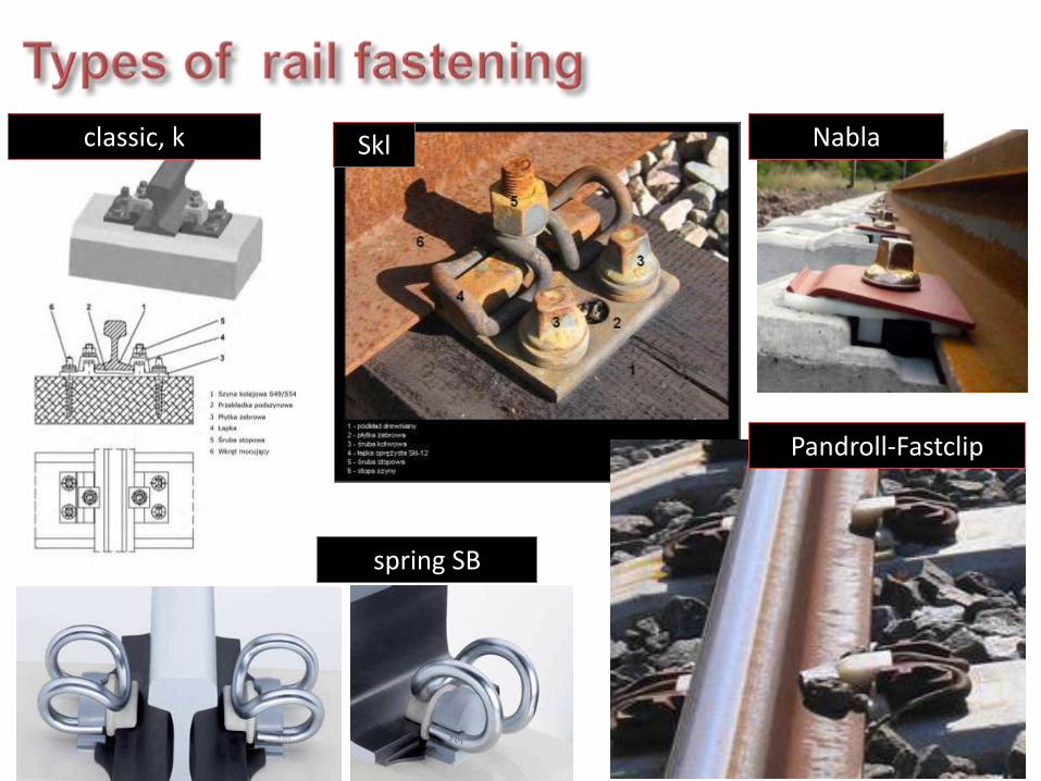
Skl classic, k Nabla
Pandroll-Fastclip
spring SB

An example of embedded tramway track on a concrete substructure with continuous elastic support of rails. Rails are separated from the pavement by rubber tape and the track is separated from the road by a kerb.
Concrete substructure Rubber profiles
Insulation tape
Asphalt pavement
Bitumic grout
Concrete substructure
Bitumic grout
Joints filling
Stone cube

An example of embedded (and shared) tramway track on a concrete substructure with continuous elastic support of rails and with continuous fastening by a resin with permanent elasticity.
LEGEND (in the order of assembling):
1. Concrete substructure 2. Grooved rail 180 S type 5. Levelling layer (epoxy concrete, 1-6 cm) 6. Elastic vibro-insulation layer (polyurethane resin, 1-1.5 cm) 7. Precast concrete elements (L=50 cm) glued by a latex glue 8. Concrete B20 (side support) 9. Road pavement (stone cube, asphaltic, precast concrete slab etc.) 10. Permanently elastic grout (polyurethane resin)

Main task of the concrete substructure is to delimit the unequal settlement of the track.
The substructure can be constructed as a slab on the whole width of the track or as two stripes under rails. Both types can be constructed in situ or with precast elements.
Filling between rails to the level 20 mm below the rail head (grassy or paved for ambulance cars passage) is favourable regarding noise.
The pavement should be waterproof (filling made of resin with permanent elasticity or made of modified bitumen or rubber profiles).
Low noise&vibration emission is ensured by the use of an idea called „flying slab” – the slab is constructed on a rubber mat layer.

A stop without a platform (kerbside stop)
A stop with a platform (centre platform stop)

Kraków – an easy access stop phot.: Ireneusz Hyra

Kraków – an easy access stop phot.: Ireneusz Hyra

Kassel – an easy access stop http://cs.wikipedia.org/wiki/Zast%C3%A1vka_v%C3%ADde%C5%88sk%C3%A9ho_typu

Praga – a kerb access tram stop http://cs.wikipedia.org/wiki/Zast%C3%A1vkov%C3%BD_mys

Brno – a kerbside stop with a safety island blocking the traffic source: Stranky o mestske hromadne doprave

Grenoble – a stop in the slow traffic zone phot.: Jacek Wesołowski

Bazylea – a stop with platforms in railway station layout source: Technika Transportu Szynowego 7-8/2002

The Reagan Roundabout, Wrocław - a stop with platforms in railway
station layout

Taking into account the height of floor the level the rolling stock can be divided into standard and low-floor stock. For the proper function of such trams the platforms should also have the compatible height. Low-floor stock is favourable due to:
source: J. Makuch
It makes travelling easier for all passengers, especially for the disabled or the elderly,
It increases the system capability due to shortening the time needed to get on and to get off,
It decreases the number of accidents when geting on and off and it creates a good look of tram in the mind of passengers and creates an interest in public transport.

If you made a mistake it looks like: The tram stop at Szewska Street (Wrocław) the platform is to low and the gangplank for the disabled is hanging over it. (similar mistake was made in design of the stop at Reagan Roundabout) phot.: Tomasz Sielicki
At the end of the platform a ramp is designed to make the levels difference easier to pass.

This part of the presentation has been prepared on the base of the webpage of Jacek Wesołowski:
http://historia.arch.p.lodz.pl/jw37/urbtr/trsh-bordeaux.html
As well as on the base of other webpages:
http://infotram.pl/text.php?id=18195
http://fr.wikipedia.org/wiki/Tramway_de_Bordeaux
http://www.railfaneurope.net/pix_frameset.html

• Bordeaux in the past had a broad tram network of 38 lines and over 200 km of tracks. In 1947 Jacques Chaban-Delmas became the mayor of the city, which represented a strong automotive lobby. It caused quite fast closing of even well maintained lines. Liquidation was finished in 1958.

• The false politics caused the city in 70’ to already start suffering from traffic jams and gradually loose its transportation capability.
• Chaban, still didn’t take into account the return of trams to the city. His strategy for solving the transportation issue assumed building a fully automated underground (VAL).
• The proposal of VAL fell through due to geological conditions (sand very difficult for underground building technology).
• Only the change of major in 1995 to Alain Juppé enabled the change of strategy in the public transportation improvement. The new major commissioned a new study of transportation development, which suggested the need of the tram system reconstruction.
• Bordeaux counts nowadays over 200 000 citizens but with the nearby towns it makes an agglomeration of 600 000. Due to too weak a flow of passengers the idea of building an underground was pointless but a tram network could serve the city on a few main routes. The implementation of such a system was decided.

Od samego początku budowano jednocześnie trzy linie, z czego
linia A biegnie w relacji wschód - zachód, natomiast linie B i C - w
relacji północ - południe. Wszystkie trzy linie spotykają się w centrum miasta, co umożliwia
dokonanie przesiadki.
Pierwszy odcinek linii A uruchomiono
21.12.2003 roku, linii C - 24.04.2004, a linii
B - 15.05.2004.
Ostatecznie system będzie miał 43,3 km tras i 84 przystanki.

• Unfortunately the negative ghost of the previous major was still present in the government. One of the arguments against trams was the overhead lines which destroys the historic look of the old city. Due to this accusation a new powering system was developed by means of the third rail built in the pavement (APS). Due to high costs this solution was applied only in the old city (total lenght 11 kms).
• The rest of the network is powered by the traditional overhead lines.

• The third rail is powered during the tram passage only and on a short section of the track under the tram. The powering rail is located in the middle of the track and it is divided into 8 m electrically insulated sections.
• Every tram is equipped in 2 sliders to collect current and next to them an antenna is located which transmits information on the actual location of the tram. On the base of this data consecutive sections of the track under the tram are powered.
• It is the first tramway system with such powering technology since the closing of Washington tramways in 1962.

• Place de Stalingrad, the track during construction – the point of change from overhead line to the third rail powering system.

• 1. Receiver of current switch on/off signal, sent by the passing tram. 2. The switch (in the rectangular box). 3. Insulated section of the powering rail and the lighting beam between the tracks

• Place Pey-Berland – the crossing isn’t powered

• Turnover in Cours d'Alsace et Lorraine

• Cours d'Alsace et Lorraine - design of the tram stop; the lighting beams are located in a denser grid on the length of the platform

• Standard edge of the platform
watch the platform!

• Cours d'Alsace et Lorraine - „the furniture” of the crossing zone; the signalling is induced by the passing tram

• Place des Quinconces

• Tramway infrastructure seen from the cathedral tower

• Rue Vital Carles – probably the most narrow street with a tramway track

• Pont de Pierre - tramway of line A

• Rue Bonnier in the administration centre of 70’ – traffic engineers probably never expected that the precious space will be given back for tramway

• Mérignac-Centre – the terminus of line A

• Pessac-Centre – the terminus of line B


