Embed Size (px)
Citation preview

2012 Update Emiss ion Reduct ion Strateg i es Findings Report for
the New York/New Jersey Harbor Navigat ion Pro je c t
May 2013
U.S. A rmy Corps of Engineers, New York District In support of the Harbor Deepening Project

2012 EMISSION REDUCTION STRATEGIES FINDINGS REPORT FOR THE New York/New Jersey Harbor Deepening Projec t
TABLE OF CONTENTS
EXECUTIVE SUMMARY .......................................................................................................... ES-1 1.0 INTRODUCTION .................................................................................................................... 1 2.0 OBJECTIVE ............................................................................................................................ 2 3.0 BACKGROUND ON DIESEL ENGINE EMISSIONS .................................................................. 3
3.1. HDP Emission Source Types ........................................................................................ 3 3.2. Pollutants of Concern .................................................................................................... 6
4.0 EMISSION CONTROL TECHNOLOGIES AND STRATEGIES FOR PRIMARY SOURCES .......... 10
4.1. Vessel or Equipment Re-Powering .............................................................................. 10 4.1.1. Regulatory Requirements for New and Existing Heavy Duty Diesel Engines ............................... 10 4.1.2 Benefits of Engine Replacement ...................................................................................................... 11 4.1.3 Examples of Repowering Programs ................................................................................................ 12
4.2. Equipment or Vessel Replacement ............................................................................. 13 4.3. Diesel Emission Retrofit Technologies ....................................................................... 14
4.3.1 Diesel Oxidation Catalysts ........................................................................................................... 16 4.3.2. Diesel Particulate Filters .............................................................................................................. 18 4.3.3. Selective Catalytic Reduction ......................................................................................................... 24 4.3.4. Certified Remanufacture Retrofit Kits ........................................................................................... 27 4.3.5. Issues Associated with Implementing Diesel Retrofit Technologies .................................................. 29
4.4. Internal Engine Modifications/Advanced Engine Designs ....................................... 29 4.5 Hybridization and Electrification ................................................................................. 32
4.5.1. Hybridization .............................................................................................................................. 32 4.5.2. Electrification ............................................................................................................................... 35
4.6. Fuel Based Technologies ............................................................................................. 35 4.6. Technology Combinations and Other Equipment Alternatives ................................. 40 4.7. Summary ...................................................................................................................... 40
5.0 OTHER POTENTIAL EMISSION REDUCTION OPPORTUNITIES .......................................... 41
5.1 Vessel Speed Reduction (VSR) ..................................................................................... 41 5.2 Fuel Switch .................................................................................................................... 42 5.3 Shore Power .................................................................................................................. 42 5.4 Engine Modification ..................................................................................................... 43 5.5 Summary ....................................................................................................................... 44
6.0 EMERGING DIESEL TECHNOLOGIES ................................................................................. 45
6.1 Emerging Technologies for New Engines and As Retrofits ........................................ 45 6.2 Summary ....................................................................................................................... 55
7. 0 POTENTIAL FUNDING OPPORTUNITIES FOR DEMONSTRATION PROJECTS .................... 56 8.0 REFERENCES ...................................................................................................................... 59

2012 EMISSION REDUCTION STRATEGIES FINDINGS REPORT FOR THE New York/New Jersey Harbor Deepening Projec t
US Army Corps of Engineers – N Y District 3 May 2013
LIST OF TABLES
Table ES.1: Diesel Emission Control Strategies and Technologies ..................................................... ES-2 Table ES.2: Diesel Emission Control Strategies and Technologies by Major Source Category ..... ES-2 Table ES.3: Verified Systems for NonRoad Engines ............................................................................. ES-3 Table 3.1: Equipment Types, Average horsepower and Common Duty Cycles ...................................... 4 Table 4.1: EPA Low-Sulfur Fuel Standards Phase-in Schedule for Non-Road Engines ..................... 15 Table 4.2: Verified DPF Systems for Nonroad Engines ........................................................................... 21
LIST OF FIGURES:
Figure 3.1: Hopper Dredge ............................................................................................................................... 4 Figure 3.2: Cutter Dredge .................................................................................................................................. 5 Figure 3.3: Clamshell Dredge ............................................................................................................................ 5 Figure 3.4: Excavator ......................................................................................................................................... 6 Figure 3.5: Pushboat ........................................................................................................................................... 6 Figure 3.6: Emissions from internal combustion engines with changing fuel/air ratios ......................... 7 Figure 3.7: Counties in the New York-New Jersey-Connecticut Region Designated in Nonattainment
for Ozone by the EPA ................................................................................................................................ 8 Figure 3.8: Counties in the New York-New Jersey-Connecticut Region Designated in
Nonattainment for PM2.5 by the EPA .................................................................................................... 9 Figure 4.1: Diesel oxidation catalyst – cutaway ........................................................................................... 16 Figure 4.2: Passive diesel particulate concept and cutaway ....................................................................... 18 Figure 4.3: SCR system and process diagram .............................................................................................. 26 Figure 4.4: Charge air cooling process .......................................................................................................... 31 Figure 4.5: Layout of the Foss Tugboat Hybrid System Components .................................................... 32 Figure 4.6: The Campbell Foss, retrofit with hybrid drive ............................................................................ 33 Figure 4.7: Basic locomotive hybrid system principles (from GE) .......................................................... 34 Figure 4.8: The hydrogen powered ferry Alsterwasser in Hamburg ........................................................... 38 Figure 6.1: NoNOx Emulsion Combustion Unit (ECU) .......................................................................... 46 Figure 6.2: Humid Air Motor (HAM) system overview ............................................................................ 47 Figure 6.3: Wärtsilä's "WetPac" intake air humidification system ............................................................ 48 Figure 6.4: Example of a closed-loop wet scrubber system ...................................................................... 49 Figure 6.5: German company Couple Systems’ EGCS dry scrubber being fit to a large ship ............ 49
2012 EMISSION REDUCTION STRATEGIES FINDINGS REPORT FOR THE New York/New Jersey Harbor Deepening Projec t
US Army Corps of Engineers – N Y District 4 May 2013
ACRONYM LIST
ºC degrees Celsius ºF degrees Fahrenheit AC after-cooled ADEC advanced diesel emission control BNSF Burlington Northern and Santa Fe Btu British thermal unit CA California CAA Clean Air Act CAAA 1990 Clean Air Act Amendments CAAP Clean Air Action Plan CARB California Air Resources Board CDPF catalyzed diesel particulate filter CFR Code of Federal Regulations CNG compressed natural gas CO carbon monoxide CO2 carbon dioxide CSCR compact selective catalytic reduction CSOC conditional Statement of Conformity DECS diesel emission control system DER discrete emission reduction DOC diesel oxidation catalyst DOE U.S. Department of Energy DPF diesel particulate filter DPM diesel particulate matter DPT diesel particulate trap DWI direct water injection EC electronic control ECT emission control technology EGR exhaust gas recirculation EGRT exhaust gas recirculation technology ERC emission reduction credit ETV environmental technology verification EU European Union EUI electronic unit injector FBC fuel borne catalysts FIP Federal Implementation Plan FTP Federal Test Procedure GDI gasoline direct injection GHG greenhouse gases g/bhp-hr grams per brake horsepower-hour g/kW-hr grams per kilowatt-hour HAM humid air motor HAMP Harbor Air Management Plan HC hydrocarbon HDP Harbor Deepening Project HEUI hydraulic electronic unit injector

2012 EMISSION REDUCTION STRATEGIES FINDINGS REPORT FOR THE New York/New Jersey Harbor Deepening Projec t
US Army Corps of Engineers – N Y District 5 May 2013
ACRONYM LIST (CONT’D) HFO heavy fuel oil hp horsepower hp-hr horsepower-hour hrs hours IMO International Maritime Organization ISO International Standards Organization kg kilogram kW kilowatt l/hr liters per hour LNG liquefied natural gas MARPOL 73/78 International Convention for the Prevention of Pollution from
Ships, 1973, as modified by the Protocol of 1978 relating thereto (MARPOL 73/78)
MAN MAN B&W Company MDO marine diesel oil MECA Manufacturers of Emission Controls Association MMBtu million British thermal units MOU memorandum of understanding MVERP marine vessel engine replacement program MTA Metropolitan Transit Authority N2 nitrogen N2O nitrous oxide NA naturally aspirated NAAQS national ambient air quality standards NEDC Northeast Diesel Collaborative NESCAUM Northeast States for Coordinated Air Use Management NGO nongovernmental organization NH3 ammonia NJAC New Jersey Administrative Code NJDEP New Jersey Department of Environmental Protection NJDOTOMR New Jersey Department of Transportation Office of Maritime
Resources NMHC non-methane hydrocarbon NO nitric oxide NO2 nitrogen dioxide NOX oxides of nitrogen NYCDOT New York City Department of Transportation NYCRR New York Conservation Rules and Regulations NYSDEC New York State Department of Environmental Conservation NYSERDA New York State Energy Research & Development Authority OEM original equipment manufacturer OGVs ocean-going vessels OTAQ Office of Transportation Air Quality OTC Ozone Transport Commission OTR ozone transport region PAH poly-aromatic hydrocarbons

2012 EMISSION REDUCTION STRATEGIES FINDINGS REPORT FOR THE New York/New Jersey Harbor Deepening Projec t
US Army Corps of Engineers – N Y District 6 May 2013
ACRONYM LIST (CONT’D) PANYNJ Port Authority of New York & New Jersey PHL Pacific Harbor Line PM particulate matter PM2.5 PM less than 2.5 microns in diameter PM10 PM less than 10 microns in diameter ppm parts per million psi pounds per square inch RAT regional air team RTG rubber tired gantry TCEQ Texas Commission on Environmental Quality TDC top-dead-center SCR selective catalytic reduction SIP State Implementation Plan SO2 sulfur dioxide SOC Statement of Conformity SOF soluble organic fraction SOX sulfur oxides TC turbocharged THC total hydrocarbon TPM total particulate matter TX Texas ULEV ultra low emissions vehicle ULSD ultra low sulfur diesel UP Union Pacific U.S. United States USACE United States Army Corps of Engineers USSG United States Coast Guard US EPA United States Environmental Protection Agency VDRP voluntary diesel retrofit program VOC volatile organic compound VSR vessel speed reduction VTS vessel traffic system WETA Water Emergency Transportation Authority

2012 EMISSION REDUCTION STRATEGIES FINDINGS REPORT FOR THE New York/New Jersey Harbor Deepening Projec t
US Army Corps of Engineers – N Y District ES-1 May 2013
EXECUTIVE SUMMARY This report is the 2012 annual update to the Emissions Reduction Strategies Findings Report for the New York/New Jersey Harbor Deepening Project (HDP). The United States Army Corps of Engineers (USACE) and Port Authority of New York and New Jersey (PANYNJ) are committed to identify, evaluate and implement potential diesel emission reduction strategies as contingency measures to offset the air quality impacts of the HDP. This update is based on an evaluation of the latest status of nonroad and marine diesel technologies and strategies applicable to HDP sources. Following a process that began around the beginning of the HDP, EPA established new regulations that have led to substantial reductions in air emissions from new marine and nonroad diesel engines. With the phase-in of most of these regulations complete as of 2012, gradual turnover of the heavy duty diesel fleets will lead to substantially improved air quality over the next several decades. For the existing fleet, when federal regulations do not apply, other options are available to reduce air emissions. These options often borrow from technological improvements that have come from research done in preparation for new regulations and adapted for legacy engines. In recent years, new technologies focus on maximizing engine or operational efficiency with technologies that will reduce both fuel consumption and air emissions. Drawing from the state of the art and evolving policy, this report evaluates emission reduction opportunities from 3 different angles.
1. Emissions control technologies and strategies for primary sources (nonroad equipment, harbor vessels, and rail locomotives) such as equipment/vessel repowering and replacement, and verified diesel retrofit technologies. The majority of these technologies and strategies has already been proven and are currently being used in operational settings. But the complexity and specialty nature of the technologies means that applicability of any given system or technology must be evaluated on a case-by-case basis;
2. Potential emission reduction opportunities from non-project sources (i.e., ocean-going vessels) such as vessel speed reduction, use of lower sulfur fuel, shore power, and slide valves. These additional strategies offer the opportunity for achieving significant emission reductions that could potentially be used for offsetting project emissions. However, implementation of these strategies is complex since it requires development of mechanisms for tracking and quantifying emission reductions as well as interaction with agencies for verification; and
3. Emerging control technologies that are being evaluated and developed and offer the potential for future reductions. These include evolution and improvement of existing technologies, new technologies that are currently in a prototype phase, and proven technologies that are being adapted or repurposed for the heavy-duty diesel market
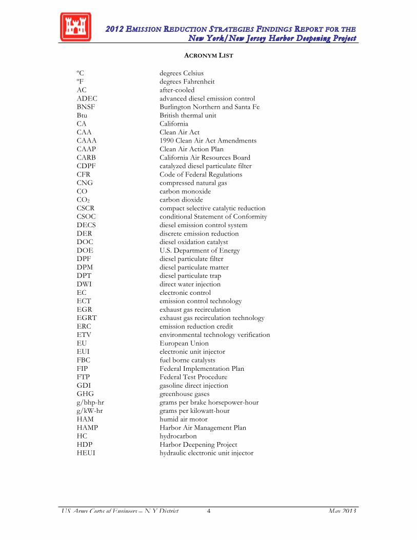
All of the technologies and strategies considered in this report are compiled into three summary tables for quick reference and overview. Table ES.1 presents the estimated emissions benefits for proven diesel emission control technologies and strategies, other potential emission reduction strategies, and emerging technologies. Table ES.2 presents these strategies and technologies for the four major source categories: harbor vessels, nonroad equipment, rail locomotives, and ocean-going vessels. Table ES.3 provides a current list of diesel retrofit technologies verified by CARB or U.S. EPA.

2012 EMISSION REDUCTION STRATEGIES FINDINGS REPORT FOR THE New York/New Jersey Harbor Deepening Projec t
US Army Corps of Engineers – N Y District 2 May 2013
Table ES.1: Diesel Emission Control Strategies and Technologies
Table ES.2: Diesel Emission Control Strategies and Technologies by Major Source Category
2012 EMISSION REDUCTION STRATEGIES FINDINGS REPORT FOR THE New York/New Jersey Harbor Deepening Projec t
US Army Corps of Engineers – N Y District 3 May 2013
Table ES.3: Verified Systems for NonRoad Engines

2012 EMISSION REDUCTION STRATEGIES FINDINGS REPORT FOR THE New York/New Jersey Harbor Deepening Projec t
US Army Corps of Engineers – N Y District 1 July 2013
1.0 INTRODUCTION This report is an update of a Findings Report produced for the United States Army Corps of Engineers (USACE) and Port Authority of New York and New Jersey (PANYNJ) in 2002 and updated annually in 2006, 2007, 2008, 2009, 2010, and 2011. The report examines potential diesel engine emission control strategies and technologies. This update is focused on contingency emission reduction strategies related to dredging for the 50-foot deepening project, also known as the Harbor Deepening Project (HDP), within seven channels of the New York/New Jersey Harbor. The conditional Statement of Conformity (cSOC) 2002 issued by USACE includes provisions for updating information to the Regional Air Team (RAT). Member agencies in addition to USACE and PANYNJ include the New Jersey Department of Environmental Protection (NJDEP), the New York State Department of Environmental Conservation (NYSDEC), the United States Environmental Protection Agency (USEPA) Region 2, the New York City Department of Transportation (NYCDOT), and the New Jersey Department of Transportation Office of Maritime Resources (NJDOTOMR). As part of the Harbor Air Management Plan (HAMP)1, USACE committed to provide updates to the Findings Report in order to provide additional innovative and cost effective emission control strategies that could be used as contingencies to the agreed upon strategies adopted under Scenario #7, the selected mitigation alternative for the HDP. The regulatory driver is the federal requirement of General Conformity (40 CFR§93.158), which is triggered by USACE funding of the HDP, as described in the New York and New Jersey Harbor Navigation Feasibility Study (December 1999). This report identifies potential emission reduction strategies to help ensure that any increase in emissions would not adversely impact the State Implementation Plans (SIPs)2 for either New York or New Jersey. As part of the cSOC, the USACE committed to update the evaluation of technological solutions and to assess new technologies for reducing diesel emissions during the course of the HDP.
1 Harbor Air Management Plan, New York District, United States Army Corps of Engineers, March 2004. 2 A State Implementation Plan is a set of projections and commitments that describe how the state will attain
air quality standards.

2012 EMISSION REDUCTION STRATEGIES FINDINGS REPORT FOR THE New York/New Jersey Harbor Deepening Projec t
US Army Corps of Engineers – N Y District 2 May 2013
2.0 OBJECTIVE The primary objective of this report is to provide updated information on emissions control strategies that could be included as contingency measures in the HAMP for HDP sources. The HAMP is the agreed upon approach to meet General Conformity requirements for the HDP and per the cSOC, an updated review and examination of emission reduction strategies is provided in this report. The secondary objective of this report is to provide a useful reference document for identifying potential emission reduction technologies and strategies that could be applicable to other projects with similar requirements to reduce or offset emissions. An evaluation of the following emission reduction strategies and technologies has been undertaken and presented in Sections 4 to 6 of this report. Also, potential funding opportunities for demonstration and implementation of emission reduction strategies are presented in Section 7 of the report.
Emission Control Technologies and Strategies for Primary Sources (see Section 4): A. Re-powering B. Equipment or Vessel Replacement C. Diesel Retrofit Technologies D. Engine Modifications and Advanced Engine Designs E. Hybrid and Electric Systems F. Fuel-Based Strategies (incl. LNG)
Other Potential Emission Reduction Opportunities (see Section 5): A. Operational Control (Vessel Speed Reduction) B. Fuel Switch C. Electrification (Shore Power) D. Engine Modifications (Slide Valves, LNG/duel fuel retrofit
Emerging Technologies (see Section 6)) A. Retrofit and Hybrid Technologies B. Alternative Propulsion
Potential funding opportunities for demonstration and implementation projects (see Section 7). The information presented in this report is current as of November 2012. New information pertaining to the technologies and strategies described herein is likely to become available as these technologies are further developed and implemented in various domestic and international projects.

2012 EMISSION REDUCTION STRATEGIES FINDINGS REPORT FOR THE New York/New Jersey Harbor Deepening Projec t
US Army Corps of Engineers – N Y District 3 May 2013
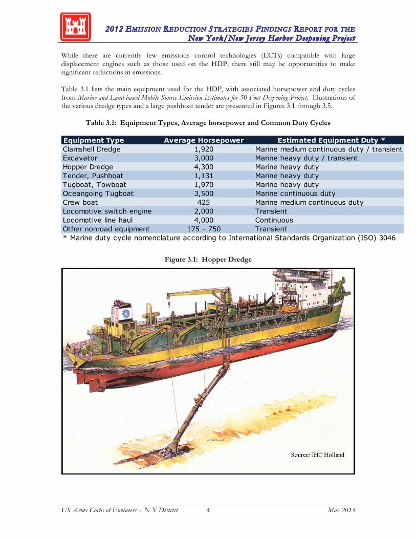
3.0 BACKGROUND ON DIESEL ENGINE EMISSIONS Emission control technologies are generally designed for specific source types and target reductions of specific pollutants. This section presents the HDP main sources of emissions and the pollutants of concern. 3.1. HDP Emission Source Types The major emission source types associated with the HDP are nonroad mobile sources with large and medium-sized diesel engines that are on either marine or land-based equipment, such as dredges, towboats, push boats, crew boats, excavators, locomotives and nonroad trucks. Unlike stationary industrial diesel engines, which mainly operate under constant loads to generate electricity, these nonroad engines have varying load profiles during their normal duty cycles. While duty cycles for some marine engines can be considered 'continuous', most of the duty cycles are 'transient'. This means that the load applied to the engines is not constant or steady throughout normal operations. The equipment operating load characteristics have important ramifications for the effectiveness of emission control technologies due to the varying exhaust gas temperatures and flow rates that occur under various load conditions. Emission estimates prepared for the HDP3 indicate that dredges and towboats are responsible for the majority of the projected HDP emissions. While hopper dredges are usually self-propelled, push boats move cutter and clamshell dredges to their working positions. Thus, emission estimates are based upon the type of dredge and associated equipment. Propulsion engines on the push boats and the hopper dredges are mainly Category 1 and 2 marine engines or land-based engines (adapted for use on marine vessels) greater than 750 horsepower (hp). Engines for the dredging and excavating equipment are usually large land-based nonroad engines greater than 500 hp. While this currently presents limitations for emission control technologies due to engine size, recently initiated demonstrations of diesel engine emission control systems in land-based nonroad equipment may provide future emission control opportunities for higher horsepower engines used in marine applications. In addition, emission control systems available for stationary sources may have application to land-based engines adapted for use in a marine environment.
3 Marine and Land-based Mobile Source Emission Estimates for 50 Foot Deepening Project. Port Authority of New York and New Jersey, 2002.
2012 EMISSION REDUCTION STRATEGIES FINDINGS REPORT FOR THE New York/New Jersey Harbor Deepening Projec t
US Army Corps of Engineers – N Y District 4 May 2013
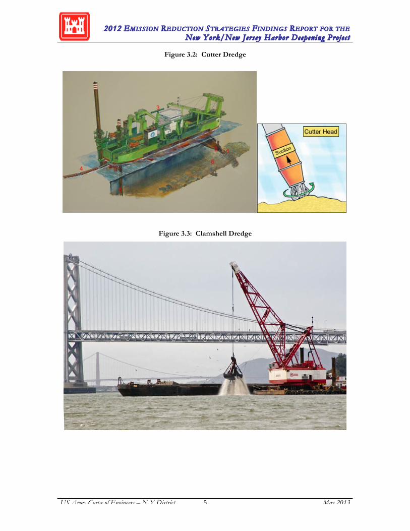
While there are currently few emissions control technologies (ECTs) compatible with large displacement engines such as those used on the HDP, there still may be opportunities to make significant reductions in emissions. Table 3.1 lists the main equipment used for the HDP, with associated horsepower and duty cycles from Marine and Land-based Mobile Source Emission Estimates for 50 Foot Deepening Project. Illustrations of the various dredge types and a large pushboat tender are presented in Figures 3.1 through 3.5.
Table 3.1: Equipment Types, Average horsepower and Common Duty Cycles
Figure 3.1: Hopper Dredge
Equipment Type Average Horsepower Estimated Equipment Duty *Clamshell Dredge 1,920 Marine medium continuous duty / transientExcavator 3,000 Marine heavy duty / transientHopper Dredge 4,300 Marine heavy dutyTender, Pushboat 1,131 Marine heavy dutyTugboat, Towboat 1,970 Marine heavy dutyOceangoing Tugboat 3,500 Marine continuous dutyCrew boat 425 Marine medium continuous dutyLocomotive switch engine 2,000 TransientLocomotive line haul 4,000 ContinuousOther nonroad equipment 175 - 750 Transient* Marine duty cycle nomenclature according to International Standards Organization (ISO) 3046
2012 EMISSION REDUCTION STRATEGIES FINDINGS REPORT FOR THE New York/New Jersey Harbor Deepening Projec t
US Army Corps of Engineers – N Y District 5 May 2013
Figure 3.2: Cutter Dredge
Figure 3.3: Clamshell Dredge

2012 EMISSION REDUCTION STRATEGIES FINDINGS REPORT FOR THE New York/New Jersey Harbor Deepening Projec t
US Army Corps of Engineers – N Y District 6 May 2013
Figure 3.4: Excavator
Figure 3.5: Pushboat
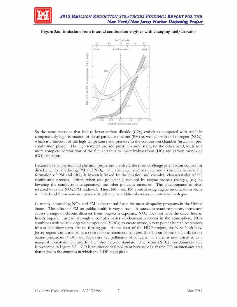
3.2. Pollutants of Concern Diesel engines are the most energy efficient internal combustion engines. This and other key characteristics such as reliability, longevity, and power make them the most common choice for heavy-duty applications. Diesel engines fundamentally differ from gas engines in how they ignite the fuel. Diesel fuel has a higher fuel density, meaning it can generate more energy per unit volume than gasoline. That also makes the fuel more viscous, requiring “compression ignition” (CI) to combust it in an engine instead of “spark ignition” (SI) as found in gasoline engines. This difference in ignition is fundamental to both the power profile of the engines and their emission profiles. Because diesel only needs a certain high level of pressure to ignite, it can be combusted in an environment that has more oxygen than is chemically needed for complete combustion of the hydrocarbons in the fuel. This is referred to as a “lean burning” engine. It uses less fuel and therefore produces less CO2 per unit energy compared to a gasoline engine that requires a “rich” fuel mixture. Lean versus rich burning has implications for many other air emissions, as shown in Figure 3.6.
2012 EMISSION REDUCTION STRATEGIES FINDINGS REPORT FOR THE New York/New Jersey Harbor Deepening Projec t
US Army Corps of Engineers – N Y District 7 May 2013
Figure 3.6: Emissions from internal combustion engines with changing fuel/air ratios
So the same reactions that lead to lower carbon dioxide (CO2) emissions compared with result in comparatively high formation of diesel particulate matter (PM) as well as oxides of nitrogen (NOX), which is a function of the high temperature and pressure in the combustion chamber (usually in pre-combustion phase). The high temperature and pressure combustion, on the other hand, leads to a more complete combustion of the fuel and thus to lower hydrocarbon (HC) and carbon monoxide (CO) emissions. Because of the physical and chemical properties involved, the main challenge of emission control for diesel engines is reducing PM and NOX. The challenge becomes even more complex because the formation of PM and NOX is inversely linked by the physical and chemical characteristics of the combustion process. Often, when one pollutant is reduced by engine process changes, (e.g. by lowering the combustion temperature) the other pollutant increases. This phenomenon is often referred to as the NOX/PM trade-off. Thus, NOX and PM control using engine modifications alone is limited and future emission standards will require additional emission control technologies. Currently, controlling NOx and PM is the central focus for most air quality programs in the United States. The effect of PM on public health is very direct – it causes to acute respiratory stress and causes a range of chronic illnesses from long-term exposure. NOx does not have the direct human health impact. Instead, through a complex series of chemical reactions in the atmosphere, NOx combines with volatile organic compounds (VOCs) to create ozone, a very potent human respiratory irritant and short-term climate forcing gas. At the start of the HDP project, the New York-New Jersey region was classified as a severe ozone nonattainment area (for 1-hour ozone standard), so the ozone precursors (VOCs and NOX) are key pollutants of concern. The area is now classified as a marginal non-attainment area for the 8-hour ozone standard. The ozone (NOx) nonattainment area is presented in Figure 3.7. CO is another critical pollutant because of a shared CO maintenance area that includes the counties in which the HDP takes place.

2012 EMISSION REDUCTION STRATEGIES FINDINGS REPORT FOR THE New York/New Jersey Harbor Deepening Projec t
US Army Corps of Engineers – N Y District 8 May 2013
Figure 3.7: Counties in the New York-New Jersey-Connecticut Region Designated in Nonattainment for Ozone by the EPA
2012 EMISSION REDUCTION STRATEGIES FINDINGS REPORT FOR THE New York/New Jersey Harbor Deepening Projec t
US Army Corps of Engineers – N Y District 9 May 2013
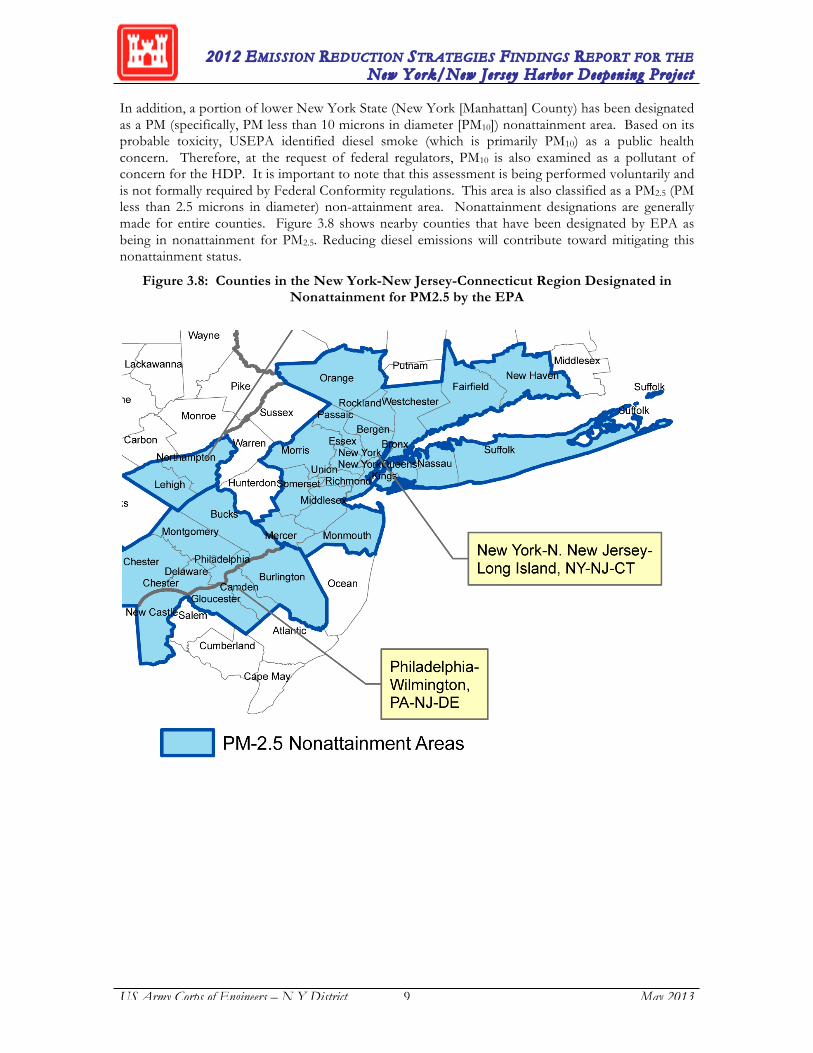
In addition, a portion of lower New York State (New York [Manhattan] County) has been designated as a PM (specifically, PM less than 10 microns in diameter [PM10]) nonattainment area. Based on its probable toxicity, USEPA identified diesel smoke (which is primarily PM10) as a public health concern. Therefore, at the request of federal regulators, PM10 is also examined as a pollutant of concern for the HDP. It is important to note that this assessment is being performed voluntarily and is not formally required by Federal Conformity regulations. This area is also classified as a PM2.5 (PM less than 2.5 microns in diameter) non-attainment area. Nonattainment designations are generally made for entire counties. Figure 3.8 shows nearby counties that have been designated by EPA as being in nonattainment for PM2.5. Reducing diesel emissions will contribute toward mitigating this nonattainment status.
Figure 3.8: Counties in the New York-New Jersey-Connecticut Region Designated in Nonattainment for PM2.5 by the EPA
2012 EMISSION REDUCTION STRATEGIES FINDINGS REPORT FOR THE New York/New Jersey Harbor Deepening Projec t
US Army Corps of Engineers – N Y District 10 May 2013
4.0 EMISSION CONTROL TECHNOLOGIES AND STRATEGIES FOR PRIMARY SOURCES In this section, the following five categories of diesel emissions reduction technologies and strategies are evaluated:
1) Equipment or vessel re-powering, 2) Equipment or vessel replacement; 3) Diesel retrofit technologies; 4) Engine modifications and advanced designs; 5) Hybridization and electrification; and 6) Fuel-based technologies
4.1. Vessel or Equipment Re-Powering Most heavy-duty equipment is designed to last for several decades of intense operation. Designing for this kind of longevity implies that any major systems will be periodically serviced or replaced. This is especially mid-sized vessels and locomotives that can have a service life of 30 years or more. Engines on any heavy-duty equipment are routinely rebuilt at major maintenance intervals: 5-10 years depending on the service intensity and type of equipment. Rebuilding an engine retains the main body of the engine while replacing all internal components that experience wear. Rebuilding will return the engine to “as new” performance, but will not improve fuel economy or emissions beyond original specifications. Re-powering refers to the replacement of the entire engine and many of the peripheral components. Re-powering is less common because it has much higher costs compared to the rebuild with relatively minor performance improvements that will only be realized for the remaining life of the equipment. It becomes a viable option when the remaining life of the equipment is long and the incremental improvements to emissions are high. In addition to direct costs and benefits, opportunity costs and logistical issues can be equally important considerations as described in the following overview of the repower process for harbor craft. For a typical harbor craft re-powering, the process would begin with proper planning in terms of selection of the appropriate replacement engine meeting the operational needs, obtaining approval from agencies or U.S. Coast Guard (if applicable), purchase and shipment to the facility conducting the replacement procedure, and scheduling dry dock time with a local boat repair/building facility. Propulsion engines replacements, on average, require about two to three weeks per engine which in many cases, involve cutting a hole in the deck or side of the vessel to remove and replace the engine. Since new engines are typically smaller and lighter than the old engines, fitting the engine into the space occupied by the old engine would generally not be an issue. However, it may be necessary to replace the gears and the propeller shaft to accommodate the new engine. Auxiliary engine replacement on harbor craft can be less complicated than main engine replacements. Auxiliary engines are generally more ancillary to the vessel, and therefore, the replacement is less complex and may be done without going into dry dock. Re-powering other nonroad equipment engines with cleaner engines will generally be more straightforward because the engines are more accessible. 4.1.1. Regulatory Requirements for New and Existing Heavy Duty Diesel Engines EPA emission regulations for the broad range of diesel engines follow a complex schedule of implementation times and pollutant limits. For the on-road sector, rollout of new engine requirements is complete as of 2010. For the non-road sector which includes a broader variety of engines and applications, the roll-out of requirements will last through the 2015 model year for most non-road applications and through the 2016 model year for marine applications with an “interim” Tier 4 standard in place between 2014 and 2016.

2012 EMISSION REDUCTION STRATEGIES FINDINGS REPORT FOR THE New York/New Jersey Harbor Deepening Projec t
US Army Corps of Engineers – N Y District 11 May 2013
Study and development of these regulations has been in progress since the early 90’s with periodic updates and improvements. For marine engines, in 2008, EPA finalized the latest regulation establishing new emission standards for new “Category 1 & 2” diesel engines rated over 50 horsepower (hp) used in most harbor craft. The new Tier 3 engine standards phase in started in 2009. The more stringent Tier 4 engine standards (which effectively require use of high-efficiency catalytic after-treatment technologies) would phase in beginning in 2014 and apply only to commercial marine diesel engines greater than 800 hp. The regulation also includes requirements for remanufacturing commercial marine diesel engines greater than 800 hp. In California, CARB adopted a regulation in 2007 that will reduce diesel particulate matter (DPM) and NOx emissions from new and in-use commercial harbor crafts operating in Regulated California Waters (i.e., internal waters, ports, and coastal waters within 24 nm of California coastline). Under CARB’s definition, commercial harbor craft include tugboats, towboats, ferries, excursion vessels, workboats, crew boats, fishing vessels, barges and dredges. This regulation4 requires stringent emission limits from auxiliary and propulsion engines installed in commercial harbor craft. All in-use, newly purchased, or replacement engines must meet EPA’s most stringent emission standards per a compliance schedule set by the CARB for in-use engines and from new engines at the time of purchase. In addition, the propulsion engines on all new ferries, with the capacity of more than 75 passengers, acquired after January 1, 2009, will be required to install control technology that represents the best available control technology in addition to an engine that meets the Tier 2 or Tier 3 U.S. EPA marine engine standards, as applicable, in effect at the time of vessel acquisition. The in-use emission limits only apply to ferries, excursion vessels, tugboats and tow boats. The compliance schedule for in-use engine replacement began in 2009, but in February of 2010, CARB issued a regulatory advisory5 delaying the regulation’s key NOx and PM requirements pending further notice. This delay corresponds to a delay in authorization from the EPA to enforce the rule. In general, the delay is an effort to mitigate continuing effects of a slow economy on industries that would be affected by the rule. For areas outside of CA, the effect of this delay will be to delay development and deployment of after-treatment technologies that can be applied to existing engines. 4.1.2 Benefits of Engine Replacement Replacing (re-powering) Tier 0 and Tier 1 harbor vessel engines with currently available Tier 3 or emerging Tier 4 engines will result in substantial emissions improvements. Heavy-duty marine diesel engines currently being manufactured are significantly cleaner than those built just a short time ago and can provide significant PM and NOx benefits compared to an older engine. For instance, replacing a Tier 0 propulsion or auxiliary marine engine with a Tier 3 engine will achieve approximately 70 to 80 percent reduction in PM and 50 to 70 percent reduction in NOx emissions while replacing a Tier 1 engine with a Tier 3 engine will achieve about the same level of PM reductions and 40 to 45 percent NOx reductions.6 Tier 4 engines, which will be required on all new engines as of 2014, reduce NOx by 95% and PM by 90% compared to Tier 3 engines. Tier 4 engines achieve this by adding high-efficiency particle filters and selective catalytic reduction, but the complexity of these additional systems makes application beyond OEM unlikely in the near future.
4 http://www.arb.ca.gov/regact/2010/chc10/appa.pdf 5 http://www.arb.ca.gov/enf/advs/advs414.pdf 6 http://www.epa.gov/otaq/marine.htm
2012 EMISSION REDUCTION STRATEGIES FINDINGS REPORT FOR THE New York/New Jersey Harbor Deepening Projec t
US Army Corps of Engineers – N Y District 12 May 2013
4.1.3 Examples of Repowering Programs Repowering harbor vessels including crew boats, towboats, and push boats is a technically feasible and cost-effective control strategy. The PANYNJ has incorporated this strategy, specifically engine replacements, as part of their tug re-power efforts which have included several tugboats re-powered with cleaner, more efficient engines. Candidate vessels were required to spend greater than 90% of their operational time in the non-attainment area, and were considered, therefore, as prime candidates for re-powering. The PANYNJ has implemented several rounds of tugboat engine re-powers since the original S-KVK-5 tugboat re-power project (TERP) initiated in 2002. Due to the success of the previous programs, the first Marine Vessel Engine Replacement Program (MVERP) was funded and managed by the PANYNJ in 2006 and the second MVERP program (MVERP2) was initiated in 2008. As of 2012, 23 total vessels (including tugboats, ferries, dinner cruise vessels, etc.) operating in the HDP area have been repowered. Also in 2012, the New Jersey Clean Cities Coalition, a program of the US Department of Energy, received $900,000 from the EPA to replace 21 engines with Tier 2 compliant engines on 8 marine vessels. In California, over 400 harbor craft propulsion and auxiliary engines have already been replaced with cleaner, newer engines under the Carl Moyer Program or other funding programs. In 2011, North Carolina Department of Environment and Natural Resources expanded their Mobile source Emissions Reduction Grants7 to include repowering of marine vessels. In 2011, 4 vessels successfully applied for grants under the program including 3 fishing vessels and a recreational dive vessel. Responding to a 2009 EPA grant program as part of the National Clean Diesel Funding Assistance Program (NCDFAP), the Northeast States for Coordinated Air Use Management (NESCAUM) teamed with 9 owners of 13 marine vessels and successfully applied for funding to replace 35 existing engines with Tier 3 compliant engines. The Great Lakes Steamship Repower Incentive Program Compared to past years that emphasized exhaust retrofits and clean fuels, marine vessel repower projects have become more common grant recipients at that national scale. Following are examples of projects funded by NCDFAP in 2012:
• The Heart of Illinois Environmental Protection Agency received EPA funds to repower 6 tug boats operating along the Illinois and Mississippi rivers.
• Southeast Missouri Regional Planning Commission received $500, 000 from EPA to repower a push boat operating on the Mississippi River.
• The Maine Department of Environmental Protection received $250,000 of EPA funds to replace four engines on two vessels.
• Oregon’s Department of Environmental Quality (DEQ) received $500,000 from EPA to repower a river channel dredge.
• The Houston-Galveston Area Council received $991,000 to repower 3 marine vessels with Tier II compliant engines.
• In Washington State, the Makah and Tulalip Tribes respectively received $750,000 and $576,000 to repower 9 and 11 marine vessels.
7 http://daq.state.nc.us/motor/ms_grants/

2012 EMISSION REDUCTION STRATEGIES FINDINGS REPORT FOR THE New York/New Jersey Harbor Deepening Projec t
US Army Corps of Engineers – N Y District 13 May 2013
4.2. Equipment or Vessel Replacement Replacement of older higher-emitting nonroad equipment (e.g., construction equipment), rail locomotives and harbor vessels with newer and cleaner models provides an additional opportunity for achieving significant emission benefits. However, the replacement costs are generally higher than engine repowers and retrofits and therefore, the feasibility of replacing existing units has to be evaluated on a case-by-case basis. Under the EPA’s existing regulation for diesel-powered nonroad equipment, the emissions standards for new engines have progressively become more stringent. The majority of new nonroad equipment is already equipped with cleaner engines meeting EPA’s Tier 3 nonroad engine standards (i.e., up to 750 hp engine). Beginning in 2011 (depending on engine size and model year), the more stringent Tier 4 engine standards will be phased achieving over 90% reductions in PM and NOx compared to uncontrolled Tier 0 engines. In March 2008, EPA adopted new Tier 3 and Tier 4 standards for new locomotives as well as standards for remanufactured locomotives. The new Tier 3 emission standards will achieve 50 percent reduction in PM beyond the Tier 2 standard and will become effective in 2012 for switcher and line-haul locomotives. The longer term Tier 4 emission standards which are based on the application of high efficiency catalytic after-treatment technologies for NOx and PM will become effective in 2015 and will achieve about 75% percent reduction in NOx and 85% reduction in PM compared to Tier 2 standards. In addition, the regulation also establishes emission standards for remanufactured Tier 0, 1, and 2 locomotives, which would achieve 50 to 60 percent reduction in PM and 0 to 20 percent reductions in NOx. Therefore, replacing existing older equipment with newer equipment will result in substantial emission benefits. For instance, replacement of older nonroad diesel equipment (equipped with an uncontrolled Tier 0 engine) with Tier 3 equipment, which is currently available for most engine sizes, will achieve an approximately 70% to 80% PM and NOx reductions. Also, replacing Tier 1 equipment with Tier 3 equipment will achieve about 60% PM and NOx reductions.8 Similarly, replacing Tier 0 diesel locomotives with Tier 2 locomotives (line haul and switcher) will achieve approximately 65% PM and 40% NOx reductions.9 For switcher locomotives, Tier 3-plus engines with installed DPF10 have recently become available and are capable of achieving over 90% PM and about 70-80% NOx reductions from older switcher engines (i.e., Tier 0 or Tier 1 switcher engines) in addition to providing 35-70% in fuel savings.11 12 Pacific Harbor Line (PHL), which conducts switching operations at the Ports of Los Angeles and Long Beach plans to convert 16 of its switching locomotives with the switcher locomotives equipped with Tier 3 plus engines. In addition, Union Pacific (UP) as well as Burlington Northern and Santa Fe (BNSF) Railroads have acquired multi-engine genset switchers equipped with USEPA certified Tier 3 non-road engines (providing 700 to 2,100 hp) for their switching operations at West coast ports, focusing in the Los Angeles/Long Beach area. CSX installed gensets on three switchers operating at Port Newark and Port Elizabeth and Norfolk Southern will be installing gensets on 2 additional switchers operating at the same locations.
8 http://www.epa.gov/nonroad-diesel/regulations.htm 9 http://www.epa.gov/otaq/locomotives.htm 10 http://www.latimes.com/business/la-fi-clean-railroad-20110929,0,4697883.story 11 National Railway Equipment Company’s presentation published by NE diesel collaborative at provided
emission factors for Gensets. The PM and NOx percent reductions are based on the comparison of these emission factors with EPA’s Tier 0 (14.0 g/bhp-hr NOx and 0.72 g/bhp-hr PM) and Tier 1 (11.0 g/bhp-hr NOx and 0.54 g/bhp-hr PM) emission standards for switcher locomotives.
12 http://www.nationalrailway.com/nviro.asp

2012 EMISSION REDUCTION STRATEGIES FINDINGS REPORT FOR THE New York/New Jersey Harbor Deepening Projec t
US Army Corps of Engineers – N Y District 14 May 2013
4.3. Diesel Emission Retrofit Technologies Diesel emission retrofit technologies refer to modification to an existing engine or addition of a control device to an existing engine to reduce emissions, such as by using an exhaust retrofit kit, or engine upgrade kit. For the purposes of this report, 'retrofit' is defined as an emission control system that has been developed as a separate technology from the base engine offered by the original equipment manufacturer (OEM). In most cases, these technologies are installed on “in-use” engines, usually when re-powering existing equipment. However, some of the emission control technologies may only be feasible with engines specifically designed for their use, and not as a retrofit. Such technologies are presented in this section to provide a more complete picture of emission control possibilities. In order to utilize diesel retrofit technologies for the HDP (or other projects), the vendor’s claims of emission reductions must be proven to ensure that actual emission reductions are achieved. The primary method of claiming emission reductions in a SIP is by using USEPA or California Air Resources Board (CARB) verified technology. USEPA and CARB established a reciprocal verification agreement that coordinates testing so data generated may satisfy the requirements of both programs. This expedites the verification and introduction of innovative emission reduction technologies. Verification within the nonroad engine category is complicated considering the different engines and the various operational profiles (or duty cycles) for those engines when used in different nonroad applications. For example, some diesel retrofit technologies depend on a particular exhaust temperature range for their emission reduction effectiveness. As such, transferring technologies from one type of nonroad equipment to another with a different temperature range/profile may not have the same emission reduction benefit.
Therefore, the RAT has agreed that non-verified diesel retrofit technologies which are proposed to be used as emissions reduction strategies or contingency measures, or are proposed by dredge contractors, must be verified either through the Environmental Technology Verification (ETV) or CARB verification programs, or by the RAT for specific HDP use. In addition, the RAT must concur that the verified application of the ECT’s is sufficiently similar to the specific application for the HDP. Information regarding the test protocols and procedures for USEPA and CARB verification programs can be reviewed at the following websites:
http://epa.gov/cleandiesel/verification/
http://www.arb.ca.gov/diesel/verdev/home/background.htm Diesel retrofit technologies can be categorized into two main groups: (1) alterations made to the diesel engine combustion process and (2) post-combustion devices, which clean the exhaust stream (add-on exhaust gas after-treatment devices). Engine modifications are somewhat limited for existing engines but a number of diesel retrofit (after-treatment) technologies have been developed which fall into one of the categories listed and discussed below.
Diesel Oxidation Catalysts (DOC) Diesel Particulate Filters (DPF) Selective Catalytic Reduction (SCR) Certified Remanufacture Kits (commercial marine engines)
2012 EMISSION REDUCTION STRATEGIES FINDINGS REPORT FOR THE New York/New Jersey Harbor Deepening Projec t
US Army Corps of Engineers – N Y District 15 May 2013
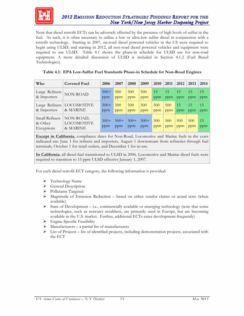
Note that diesel retrofit ECTs can be adversely affected by the presence of high levels of sulfur in the fuel. As such, it is often necessary to utilize a low or ultra-low sulfur diesel in conjunction with a retrofit technology. Starting in 2007, on-road diesel powered vehicles in the US were required to begin using ULSD, and starting in 2012, all non-road diesel powered vehicles and equipment were required to use ULSD. Table 4.1 shows the phase-in schedule for ULSD use for non-road equipment. A more detailed discussion of ULSD is included in Section 4.1.2 (Fuel Based Technologies).
Table 4.1: EPA Low-Sulfur Fuel Standards Phase-in Schedule for Non-Road Engines
Who Covered Fuel 2006 2007 2008 2009 2010 2011 2012 2013 2014
Large Refiners & Importers NON-ROAD 500+
ppm 500 ppm
500 ppm
500 ppm
15 ppm
15 ppm
15 ppm
15 ppm
15 ppm
Large Refiners & Importers
LOCOMOTIVE & MARINE
500+ ppm
500 ppm
500 ppm
500 ppm
500 ppm
500 ppm
15 ppm
15 ppm
15 ppm
Small Refiners & Other Exceptions
NON-ROAD, LOCOMOTIVE & MARINE
500+ ppm
500+ ppm
500+ ppm
500+ ppm
500 ppm
500 ppm
500 ppm
500 ppm
15 ppm
Except in California, compliance dates for Non-Road, Locomotive and Marine fuels in the years indicated are: June 1 for refiners and importers, August 1 downstream from refineries through fuel terminals, October 1 for retail outlets, and December 1 for in-use.
In California, all diesel fuel transitioned to ULSD in 2006. Locomotive and Marine diesel fuels were required to transition to 15 ppm ULSD effective January 1, 2007.
For each diesel retrofit ECT category, the following information is provided:
Technology Name General Description Pollutants Targeted Magnitude of Emission Reduction – based on either vendor claims or actual tests (when
available) State of Development – i.e., commercially available or emerging technology (note that some
technologies, such as seawater scrubbers, are primarily used in Europe, but are becoming available in the U.S. market. Further, additional ECTs enter development frequently)
Engine Specific Feasibility Manufacturers – a partial list of manufacturers List of Projects – list of identified projects, including demonstration projects, associated with
the ECT

2012 EMISSION REDUCTION STRATEGIES FINDINGS REPORT FOR THE New York/New Jersey Harbor Deepening Projec t
US Army Corps of Engineers – N Y District 16 May 2013
4.3.1 Diesel Oxidation Catalysts Technology Name: Diese l Oxidat ion Cata ly s t (DOC)
Figure 4.1: Diesel oxidation catalyst – cutaway
General Description: DOCs (Figure 4.1) consist of a porous, active catalyst layer applied to a high geometric surface area, honeycomb-like structure called a substrate or catalyst support. The catalyst layer contains a small, well-dispersed amount of precious metals such as platinum and palladium. The catalyst synergizes oxidation of CO, gaseous hydrocarbons (including VOCs), and liquid hydrocarbon particles, while reducing smoke and the characteristic diesel exhaust odor. Its ability to reduce diesel PM depends on the composition of the PM exhaust component, because DOCs oxidize only the soluble organic fraction (SOF) of the diesel PM. Typical exhaust gas temperature with effective oxidation processes range between 150 degrees Celsius (ºC) - 450ºC (300 degrees Fahrenheit [ºF] - 840ºF). DOCs are usually a direct muffler replacement and are a relatively easy retrofit application. Pollutants Targeted: PM, CO, HC Magnitude of Emission Reduction: DOCs equipped on an engine fueled with low sulfur diesel fuel with sulfur levels at or below 0.05% (500 ppm) sulfur have achieved PM reductions of 20-55%.13 Since the PM reduction is essentially a function of the oxidation of the SOF of the particles, the performance of DOCs depends on the composition of the engine's particulate emissions. Some engines emit PM with SOF up to 50%, allowing the higher emission reduction percentages. The PM emission reduction may be offset by the formation of sulfate particles, due to the oxidation of the fuel sulfur. Thus a low sulfur fuel, although not a technological prerequisite for DOCs, is beneficial for effective PM control. DOCs achieve 60-90% HC reduction (including those HC species considered toxic14) and 60-90% CO reduction.15 They further eliminate the characteristic odor of diesel engine exhaust. Note that the use of ultra-low sulfur fuel (15 ppm maximum) will optimize emission reduction of all pollutants by allowing a highly active precious metal formulation for the catalyst. Such a formulation can achieve HC and CO reductions greater than 90%.
13 http://www.dieselforum.org/files/dmfile/Retrofitting-America-s-Diesel-Engines-11-2006.pdf 14 DOC showed a 54 to 68% reduction of polyaromatic hydrocarbons (PAH), some of which are considered
carcinogenic. 15 http://www.dieselforum.org/files/dmfile/Retrofitting-America-s-Diesel-Engines-11-2006.pdf

2012 EMISSION REDUCTION STRATEGIES FINDINGS REPORT FOR THE New York/New Jersey Harbor Deepening Projec t
US Army Corps of Engineers – N Y District 17 May 2013
State of Development: CARB has verified the Donaldson DCM diesel oxidation catalyst mufflers with 6000 series catalyst formulations plus closed loop crankcase with Donaldson Spiracle closed crankcase filtration system with California diesel or lower sulfur fuels. For nonroad port applications, this system may be installed in some four-stroke, turbocharged diesel engines ranging from 150 to 600 hp such as yard tractors, large lift trucks, top picks, side picks, and gantry cranes ranging from 150 to 500 hp. The Donaldson 6000 plus Spiracle system is verified to reduce diesel PM emissions by an average of at least 25%. This verified system is applicable to certain 1996 to 2003 model year engine families. CARB has also verified the AZ Purimuffler DOC when used with PuriNOx fuel water emulsion system. For the most current approved engine families and applications, check CARB’s website below:
http://www.arb.ca.gov/diesel/verdev/vt/cvt.htm Engine Specific Feasibility: Most of the experiences with DOCs have occurred on land-side nonroad and on-road equipment with engines smaller than 500 horsepower. Technically, there are no limitations in terms of size and duty cycle for applying DOCs to diesel engines, although space considerations might prohibit the installation of DOCs on large construction equipment and marine vessels. As a rule of thumb, the DOC volume should approximately equal the engine's displacement volume and gas space velocities should be below 150,000 l/hr.16 Manufacturers: Catalytic Exhaust Products, Engelhard, Johnson Matthey, Nett Technologies, Engine Control Systems, CleanAIR Systems, Inc., Donaldson Company, Inc., DCL International Inc., Lubrizol Engine Control Systems, Environmental Solutions Worldwide, Inc. , Fleet Guard Emissions Solutions List of Projects: Since passage of Tier 4 engine requirements that effectively mandate Level 3 controls on new equipment, fewer level one technologies such as DOCs are being retrofitted onto older engines. Many grant programs that still seek to retrofit older equipment are also favoring the more broadly available level 2 and level 3 control technologies. The following are examples of projects that employed DOC technologies in early adoption.
At the Port of Long Beach, over 282 DOCs are installed in cargo handling equipment including yard tractors, forklifts, RTG cranes, side handlers and top handlers.17
At the Port of Los Angeles, over 302 pieces of cargo handling equipment (i.e., yard tractors, top handlers, side handlers, rubber-tired gantry (RTG) cranes and forklifts) are equipped with DOCs.18
On the nonroad side, nearly 250,000 DOCs have been installed predominantly in the mining and materials handling industry on equipment such as excavators, loaders, dozers, and nonroad trucks.
The City of Houston (TX) included a diesel oxidation catalyst in their demonstration program on lower horsepower engines (12 hp to 80 hp) powering equipment such as mowers and small excavators.
16 Space velocity is an important measure for determining the size of a catalyst. It describes the volume of gas
flow divided by the volume of the catalyst per unit time. A low space velocity, achievable with big sized catalysts, means a long reaction time of the exhaust gas with the catalyst substrate. The space constraints in mobile source applications often require a catalyst to function with high space velocity, meaning short reaction time. Space velocity in catalysts ranges between 3,000 and 300,000 liters per hour (l/hr).
17 Port of Long Beach Air Emissions Inventory – 2010, http://www.polb.com/environment/air/emissions.asp 18 Port of Los Angeles Inventory of Air Emissions – 2010,
http://www.portoflosangeles.org/environment/studies_reports.asp

2012 EMISSION REDUCTION STRATEGIES FINDINGS REPORT FOR THE New York/New Jersey Harbor Deepening Projec t
US Army Corps of Engineers – N Y District 18 May 2013
The USEPA’s Clean Construction Program, Central Artery/Tunnel Project (The Big Dig) in Boston, MA is the first major project where the use of DOCs on construction equipment was successfully implemented. More than 100 pieces of equipment including excavators, front end loaders, dump trucks, cranes that range from 50-300 hp, lifts, bulldozers, generators and compressors were retrofitted with DOCs. This program was completed in 2007 and contractors did not report any major operational or maintenance problems due to DOC retrofits.
Under USEPA’s Clean Construction Program, administrators overseeing the I-95 New Haven Harbor Crossing Improvement Program in Southern Connecticut opted for DOCs on all diesel powered equipment with a rating of 60 hp or above and used on site for more than 30 days as one of the major construction equipment emissions reduction strategies. At the time, all contractors have opted to install DOCs on 100 pieces of their nonroad construction equipment including cranes, sweepers, rollers, excavators, and man lifts.
Under USEPA’s Clean Construction Program, based on the success of The Big Dig and I-95 New Haven Harbor Crossing Improvement Project, administrators overseeing Dan Ryan Expressway Road Construction Project in Chicago, required DOCs as one of the main emissions control technologies for the 290 pieces of construction equipment.
4.3.2. Diesel Particulate Filters Technology Name: Diese l Par t i cu la t e Fi l t e r (DPF), Cata lyzed Diese l Par t i cu la t e Fi l t e r (CDPF), and Diese l Par t i cu la t e Trap (DPT)
Figure 4.2: Passive diesel particulate concept and cutaway
DPFs (Figure 4.2) from several manufacturers applicable to on-road as well as nonroad engines have been verified either by USEPA and CARB. See the USEPA and CARB Internet sites at:
http://epa.gov/cleandiesel/verification/verif-list.htm
http://www.arb.ca.gov/diesel/verdev/vt/cvt.htm General Description: A DPF is a stainless steel canister that contains ceramic monoliths, fiber wound cartridges, and silica carbide or paper filters. The use of 15 ppm sulfur fuel is required for DPFs. The DPF forces the exhaust stream through a porous media and traps the particles on the intake side of the filter. The purpose of the particulate filter is to allow sufficient time for the oxidation of the trapped particles. DPFs function very much like DOCs, except that particle oxidation requires more time and higher temperatures than the oxidation of HC and CO, so particles need to be trapped in the filter medium to allow oxidation.

2012 EMISSION REDUCTION STRATEGIES FINDINGS REPORT FOR THE New York/New Jersey Harbor Deepening Projec t
US Army Corps of Engineers – N Y District 19 May 2013
Sufficient oxidation and, therefore, removal of particles during regular duty cycles is critical for operating DPFs and determines the feasibility of DPF applications. Over time, particles emitted from a diesel engine can fill up and plug a reasonably sized filter. With filling and plugging of the filter medium, the backpressure of the system increases over time and eventually reaches values above those specified by the engine manufacturer. This situation might lead to the failure of engines to start up, or potentially damage the engine’s pistons or turbocharger. Therefore, design and operational parameters that influence the regeneration capability of a DPF are critical to this technology. The trapped particles are usually oxidized during hot duty cycle operations in order to regenerate the filter. A complete oxidation of particles happens at temperatures above 600ºC (1,100ºF). Many diesel exhaust gases do not or only partially reach those required temperatures for complete oxidation. Different technical measures exist to improve filter regeneration. The possible measures are as follows: i) lowering the minimum required exhaust gas temperature, ii) externally increasing the exhaust gas temperature19 and iii) improving the oxidation capacity of the exhaust gas. DPF technology is grouped into passive and active DPFs, catalyzed and non-catalyzed DPFs and disposable DPFs. Filter regeneration can be:
Passive (based on existing exhaust heat), supported by catalytic coating of the filter
medium/or added liquid catalyst. Active, supplying additional energy to the catalyst (additional fuel injection, exhaust heat
recuperation, or electric heating element). The passive filter systems are only feasible on engines with duty cycles that produce high enough exhaust gas temperatures. Catalytic coatings reduce the required minimum exhaust gas temperature by inducing oxidation. Effective regeneration rates with catalyzed filters can be obtained at temperatures between 300ºC - 400ºC (570ºF - 750ºF). Fuel borne catalysts rely on the same principles but the catalyst is added to either the fuel or into the exhaust stream through dispensing unit.
Passive DPFs usually replace the existing muffler by providing noise reduction in addition to particle control. They are, therefore, relatively easy to install as a retrofit application. Actively regenerated, high-efficiency filter systems can be applied to a much larger range of applications. Because of added complexity needed to expand the range, they are generally more expensive than passive DPFs. Some of the active technology options are burners (some operate while the engine is running, others while the engine is turned off), injection of diesel fuel into the exhaust stream for oxidation across a DOC upstream of the DPF, or electrical heaters.
The most commonly applied method of active regeneration is to introduce a temporary change in engine mode operation or an oxidation catalyst to facilitate an increase in exhaust temperature. Engine mode strategies include:
Air-intake throttling: Throttling the air intake to one or more of the engine cylinders can
increase the exhaust temperature and facilitate filter regeneration. Post top-dead-center (TDC) fuel injection: Injecting small amounts of fuel in the
cylinders of a diesel engine after pistons have reached TDC introduces a small amount of unburned fuel in the engine’s exhaust gases. This unburned fuel can then be oxidized over an oxidation catalyst upstream of the filter or oxidized over a catalyzed particulate filter to combust accumulated particulate matter.
19 “Externally” means by means of energy sources other than the engine combustion heat, e.g., electrical.

2012 EMISSION REDUCTION STRATEGIES FINDINGS REPORT FOR THE New York/New Jersey Harbor Deepening Projec t
US Army Corps of Engineers – N Y District 20 May 2013
Post injection of diesel fuel in the exhaust upstream of an oxidation catalyst and/or catalyzed particulate filter: This regeneration method serves to generate heat used to combust accumulated particulates by oxidizing fuel across a catalyst present on the filter or on an oxidation catalyst upstream of the filter.
The above techniques can be used in combination with a catalyzed or uncatalyzed DPF. In special applications where sufficient exhaust temperatures cannot be reached using the above techniques it may be necessary to use external means such as on-board fuel burners or electrical resistive heaters to heat the filter element and oxidize the soot. These can be used with catalyzed or uncatalyzed filter elements. In some cases regeneration can be accomplished while the vehicle is in operation, whereas in other cases the engine must be turned off for regeneration to proceed. In some situations, installation of a filter system on a vehicle may cause a very slight fuel economy penalty. This fuel penalty is due to the backpressure of the filter system. As noted above, some filter regeneration methods involve the use of fuel burners and to the extent those methods are used, there is the potential for an additional fuel economy penalty. Many filter systems, however, have been optimized to minimize, or nearly eliminate, any noticeable fuel economy penalty. The experience with U.S. 2007 heavy-duty filter technology has been consistent with manufacturer’s projections of a 1% or less fuel penalty associated with filter operation. Active DPFs require electronic control units and components for active regeneration. Their installation is, therefore, more labor and cost intensive than that of passive systems. However, active systems oftentimes offer more flexibility in placement on a vehicle or equipment and thus have proven their viability for retrofit applications. Disposable filter systems also have been used to reduce emissions. The disposal filter is sized to collect enough PM for one or two working shifts of operation while remaining within the engine manufacturer’s back-pressure specification; it is then removed for proper disposal. Despite filter regeneration during regular operations, all non-disposable DPFs must be cleaned regularly according to the maintenance schedule of the manufacturer. Cleaning removes the inert soot and ash content and will differ for each application and duty cycle. Manufacturers have also developed DPF systems that combine DPF technology with NOX reduction technologies such as Lean NOx catalyst and EGR. Examples of combination DPFs that CARB has verified are ESW Clean Tech’s (formerly Cleaire) Lean NOX catalyst DPF and Johnson Matthey EGRT which reduce PM as well as NOX emissions. For more information, refer to the following Internet sites:
http://eswgroup.com/ http://ect.jmcatalysts.com/
Pollutants Targeted: PM, CO, HC and NOX when DPF technology is combined with NOX reduction technologies such as catalysts or exhaust gas recirculation (EGR). Magnitude of Emission Reduction: Particulate reductions of 80% to 99% can be achieved with DPF technology. However, the particulate reduction is highly dependent on the fuel sulfur content. DPFs that are designed for ultra-low sulfur fuel also reduce HC and CO more effectively (potential for 50% to 90%).20,21 20 MECA (2009): Case Studies of Construction Equipment Diesel Retrofit Projects. Manufacturers of Emission
Controls Association, July 2009

2012 EMISSION REDUCTION STRATEGIES FINDINGS REPORT FOR THE New York/New Jersey Harbor Deepening Projec t
US Army Corps of Engineers – N Y District 21 May 2013
Product Name Technology Agency Date NOx PM MY Engine TypeCaterpillar/CleanAIR Systems DPF USEPA Jun-2005 N/A 89% 1996-2005 non-roadCDTi Purifilter EGR DPF DPF USEPA Nov-2012 N/A 90% 2002-2010 on-roadCleaire Horizon DPF CARB Jun-2011 N/A 85% 2006 or older on-roadCleaire Lonestar Lean NOx Catalyst & DPF CARB Jun-2011 40% 85% 1996-2009 off-roadCleaire Longmile-S DPF CARB Dec-2012 N/A 85% 1993-2010 on-roadCleaire Longview(reformulated) Lean NOx Catalyst & DPF CARB Jun-2011 25% 85% 1993-2006 on-roadCleaire Phoenix DPF CARB Jun-2011 N/A 85% 1996-2010 off-roadCleaire Vista DPF CARB Nov-2012 N/A 85% 1993-2010 on-roadDCL International Inc. DPF CARB Jul-2011 N/A 85% 1996-2011 off-roadDCL International Inc. ROADWARRIOR. DPF CARB Jul-2012 N/A 85% 1994-2004 on-roadDiesel Emission Technologies UltraTrap DPF CARB Jul-2012 N/A 85% 1994-2006 on-roadDinex DiSiC DPF CARB May-2009 N/A 85% 1994-2005 TRUsDonaldson LNF DPF CARB Jun-2012 N/A 85% 1993-2006 on-roadDonaldson LXF DPF CARB Nov-2012 N/A 85% 2002-2006 on-roadDonaldson SEF DPF CARB Nov-2012 N/A 85% 1991-2006 on-roadEngine Control System Combifilter DPF CARB Mar-2010 N/A 85% 2007 or older off-roadEngine Control System Purifilter (High Load) DPF CARB Jan-2012 N/A 85% 1993-2006 on-roadEngine Control System Purifilter L (Low Load) DPF CARB Jan-2004 N/A 85% 1994-2004 on-roadEngine Control Systems Purifilter Plus DPF USEPA Apr-2011 N/A 90% 1994-2006 on-roadEngine Control Systems Purifilter Plus M DPF CARB/USEPA May-2012 N/A 85% 1993-2010 on-roadESW Canada ThermaCat DPF CARB Sep-2010 N/A 85% 1996-2010 off-roadESW Technologies ThermaCat™ DPF CARB Nov-2012 N/A 85% 1996-2010 off-roadESW Technologies ThermaCat™ e DPF CARB Jul-2012 N/A 85% 1994-2009 on-roadHUG Filtersystems Mobiclean R DPF CARB Aug-2012 N/A 85% 1991-2006 on-roadHUSS Umwelttechnik FS-MK Off-Road DPF CARB Sep-2012 N/A 85% 2011 or older off-roadHUSS Umwelttechnik FS-MK On-Road DPF CARB Sep-2012 N/A 85% 2006 or older on-roadHUSS Umwelttechnik FS-NK TRU DPF CARB Aug-2011 N/A 85% 1998 and newer TRUsImpco Ecotrans CLEARSKY DPF CARB Mar-2012 N/A 85% 2005-2012 APUsJohnson Matthey AdvCCRT DPF CARB Oct-2012 N/A 85% 2002-2006 on-roadJohnson Matthey CRT3 DPF USEPA Dec-2008 N/A 90% 1994-2006 on-roadJohnson Matthey CRTreformulated DPF CARB Sep-2012 N/A 85% 1994-2006 on-roadJohnson Matthey EGRT DPF CARB Oct-2005 N/A 85% 1998-2002 on-roadProventia EHDPF DPF CARB Mar-2012 N/A 85% 2007-2012 APUsRYPOS DPF/ULETRU Hybrid DPF CARB Aug-2001 N/A 85% 2003 and newer TRUsRypos, Inc. ADPF* DPF CARB Aug-2011 N/A 50% 1996-2008 MarineSK Energy Co. Econix DPF -A DPF CARB Dec-2009 N/A 85% 1994-2006 on-roadImpco Ecotrans Clear Sky DPF DPF CARB Mar-2012 N/A 85% 2005-2012 APUsThermo King eDPF DPF CARB Aug-2012 N/A 85% 2006-2012 APUs* Rypos ADPF system is the only CARB verified DPF system for marine harbor craft engines** TRU: Transport Refrigeration Unit; APU: Auxilliary Power Unit
Verification Reduction
State of Development: Particulate traps are widely commercially available both as retrofit technologies and on new equipment. Beginning with the 2007 model year, all heavy-duty highway diesel engines sold in the U.S. were equipped with high efficiency diesel particulate filters as part of USEPA’s 2007-2010 highway diesel engine emission program. For Nonroad engines, DPFs will be required on all equipment by 2014 or sooner depending on the engine size and configuration. The engine settings, the type of control and the fuel determine the engine-out particle load. Fuel with nonroad sulfur levels leads to a higher particle loading of the exhaust and thus a faster buildup of particles in the filter compared to using ultra-low sulfur diesel. As of 2012, this effect is ameliorated with the universal requirement for use of ULSD (see Table 4.1). Regardless of fuel, however, older and, in particular, mechanically controlled engines have higher PM emissions due to the inability to optimize fuel and air ratios during load changes. Peaks of smoke (unburned fuel) during load changes can emit significant amounts of PM in a short amount of time. Currently available DPFs can all be used with ULSD, but in general, DPFs are more likely to be feasible with lower PM loading regardless of the cause. Diesel particulate filters are becoming increasingly available for nonroad applications. Verified DPF systems for all vehicles and equipment are presented in Table 4.2:
Table 4.2: Verified DPF Systems for Nonroad Engines
21 MECA (2007): Emission Control Technologies for Diesel-Powered Vehicles. Manufacturers of Emission
Controls Association, December 2007
2012 EMISSION REDUCTION STRATEGIES FINDINGS REPORT FOR THE New York/New Jersey Harbor Deepening Projec t
US Army Corps of Engineers – N Y District 22 May 2013
Note that CARB’s verification process identifies the specific engine families that are approved for installation of verified retrofit technologies. Verification of these products is also subject to the terms and conditions specified in the CARB’s executive order and the verification letter. For instance, verified DPF systems are required to be used in conjunction with ultra low sulfur fuels (i.e., 15 ppm or less). For the latest list of verified systems and approved engine families as well as CARB’s executive orders and verification letters (specifying terms and conditions for verified systems), refer to CARB’s web site:
http://www.arb.ca.gov/diesel/verdev/vt/cvt.htm The California Air Resources Board in conjunction with the SCAQMD and the Mobile Source Air Pollution Reduction Review Committee (MSRC) implemented the Off-Road Diesel Retrofit Showcase Program to demonstrate the viability of diesel emission control devices in a variety of off-road engines and to obtain new emission control systems that will be verified by the CARB. This project provides an opportunity for manufacturers of diesel emission control technologies to participate with fleet owners in retrofitting off-road engines with a diesel emission control device to reduce PM or PM and NOX. This program is open to manufacturers who have previously received verification from the USEPA’s Voluntary Retrofit Program, CARB’s Verification Procedure. Verification may be from a previous on-road or off-road verification. Within the original program, “Showcase I” there were two different technologies that could be implemented to minimize diesel emissions. These included passive and active engine retrofit technologies, depending on the temperature profile of the vehicle. 18 fleet owners were involved in the program: 5 public fleets and 13 private fleets, which account for a total of 184 vehicles. In total, 16 emission control manufacturers contributed to the original showcase project: 11 active diesel particulate filters and 18 passive diesel particulate filters. Showcase II announced February, 2011 had slightly lower participation with 12 private fleets, 1 public fleet, and 88 pieces of equipment represented. Showcase III, announced in June, 2012 that they will build the program further. Refer to the following link for the latest updates:
http://www.arb.ca.gov/diesel/showcase/showcase.htm
Engine Specific Feasibility: The temperature of the exhaust stream, and thus the question of feasibility for DPFs, depends largely on the engine's speed and duty cycle. Diesel engines operating with transient loads, varying speeds, and multiple stops, or oversized engines barely reaching exhaust gas temperatures above 250ºC (480ºF) are not well suited for DPF technology. The more heavily loaded, faster running, and more continuously operating engines result in higher exhaust gas temperatures. Under such conditions, diesel exhaust can reach temperatures of up to 700ºC (1300ºF). Several other parameters also have the potential to reduce the required exhaust gas temperature due to a lower particle load per volume of exhaust. Those parameters are lower engine-out PM emissions and lower fuel sulfur level. Modern (i.e., electronically controlled) diesel engines with an optimized fuel/air ratio and enhanced combustion chamber design are generally more suitable for DPF technology than older mechanically controlled engines. Some of the equipment that will be used for constructing the HDP that operates on continuous duty cycles is equipped with or could be re-powered with engines that are potentially suitable for DPFs. For example, some of the marine applications (i.e., long-haul tow- and push boats) and the line haul locomotive engines could be powered with diesel electric power units which provide lower engine-out PM emissions, higher exhaust gas temperatures, and more continuous operations. The installation of DPFs on those pieces of equipment also may be feasible when powered with modern (electronically controlled) diesel direct propulsion engines, in particular when operated with low or ultra-low sulfur diesel. Other construction and nonroad equipment needs to be tested for feasibility of DPFs on a case-by-case basis.
2012 EMISSION REDUCTION STRATEGIES FINDINGS REPORT FOR THE New York/New Jersey Harbor Deepening Projec t
US Army Corps of Engineers – N Y District 23 May 2013
It is important to note that, while some newer engines might be feasible for DPFs, some older engines under the same duty cycle might not, due to the higher engine-out particle emissions. Furthermore, ULSD should be used in conjunction with DPFs to ensure that the catalyst is not prematurely “poisoned” by higher sulfur fuels. ULSD is required for nonroad equipment and required for marine and locomotive applications as of August, 2012. Therefore, the feasibility of DPFs depends on the overall project strategy, including equipment and engine replacements in combination with fuel related measures and after treatment technologies. Lastly, DPFs are large, and lack of available space may prohibit some applications. Depending on the engine-out PM levels, the DPFs should be sized approximately 1.5 to 4 times the volume of the engine's displacement. Manufacturers: Caterpillar/CleanAIR Systems, ESW Clean Tech, DCL International, Dinex DiSiC, Donaldson, Engine Control Systems, GTE Industries, HUSS Umwelttechnik, Johnson Mattey, MIRATECH Corporation, Nett Technologies, Rypos Inc., SK Energy, and Sud-Chemie, Inc. List of Projects:
In Sweden, over 2,500 buses have been equipped with passive DPFs. DPFs have been retrofitted on heavy-duty vehicles in Great Britain, Germany, Finland,
Denmark, and France. The installation of DPFs for tunnel construction equipment is mandatory in Germany,
Switzerland and Austria. Approximately 35,000 DPFs have been installed on all varieties of construction equipment used on large construction projects in Switzerland and in confined places in Germany.
In the U.S., diesel filter retrofit programs are underway in New York City with plans to retrofit 4,500 buses with DPFs.
For the WTC Diesel Emissions Reduction Project, in order to investigate diesel emission reduction from nonroad construction equipment at the World Trade Center, the Port Authority of New York and New Jersey initiated a project to investigate the use of DPF for two Caterpillar 966G wheel loaders. Caterpillar, Inc. installed the DPF into the wheel loader exhaust system with a complete retrofit replacement kit that is a direct replacement for the original muffler and the wheel loaders were operated with ULSD fuel. Emission tests indicated PM reductions to be over 97% with DPF and ULSD.
For the Croton Water Treatment Plant project in New York, which began in 2005 and is continuing, over 25 pieces of construction equipment including loaders, excavators, dozers, drill rigs, and off-road trucks were retrofitted with DPFs. The filters were from four different retrofit manufacturers and included actively and passively regenerated models. Based on the emission test results, PM reductions greater than 95% was achieved.
For the New South Ferry Terminal Project, which was completed in 2008, about 100 pieces of equipment were retrofitted with DPFs.
At the Ports of Los Angeles and Long Beach, over 80 pieces of cargo handling equipment, mainly yard tractors, are equipped with DPFs.
At the South Airfield Improvement Project at Los Angeles International Airport (LAX), diesel construction equipment used in runway reconstruction were retrofitted with the Engine Control Systems (ECS) Purifilter passively regenerated DPFs.
2012 EMISSION REDUCTION STRATEGIES FINDINGS REPORT FOR THE New York/New Jersey Harbor Deepening Projec t
US Army Corps of Engineers – N Y District 24 May 2013
4.3.3. Selective Catalytic Reduction Technology name: Sele c t i v e Cata ly t i c Reduc t ion (SCR) SCR has been used to control NOX emissions from stationary sources such as power plants for over 20 years. More recently, it has been applied to select mobile sources including cars, trucks, marine vessels, and locomotives. Applying SCR to diesel-powered vehicles provides simultaneous reductions of NOX, PM, and HC emissions. EPA’s 2010 stringent NOx regulations forced most on-road heavy-duty vehicle manufacturers to incorporate SCR systems. Many engine manufacturers are also offering SCR systems on new highway heavy-duty engines sold in Europe to comply with the European Union’s Euro IV or Euro V heavy-duty engine emission requirements. More than 100,000 new, SCR-equipped trucks are operating in Europe using a urea-based reductant. SCR systems have also been installed on marine vessels, locomotives and other nonroad diesel engines. Significant numbers of marine vessels have been equipped with SCR, including auto ferries, transport ships, cruise ships, and military vessels. The marine engines range from approximately 1,250 hp to almost 10,000 hp, with installations in operation since the early to mid-1990s. SCR offers a high level of NOX conversion with high durability. Open loop SCR systems can reduce NOX emissions from 75% to 90%.22 Closed loop systems on stationary engines have achieved NOX reductions greater than 95%. Engine manufacturers in the U.S. use combined DPF+SCR system to comply with EPA’s heavy-duty highway emission standards since 2010. Similar technologies are being used to meet the 2012-2014 nonroad emission standards. Modern SCR system designs combine highly controlled reductant injection systems, flow mixing devices for effective distribution of the reductant across the available catalyst cross-section, durable SCR catalyst formulations, and ammonia slip “clean-up catalysts” that are capable of achieving and maintaining high NOX conversion efficiencies with extremely low levels of exhaust outlet ammonia concentrations. As shown in
22 MECA (2007): Emission Control Technologies for Diesel-Powered Vehicles. Manufacturers of Emission
Controls Association, December 2007

2012 EMISSION REDUCTION STRATEGIES FINDINGS REPORT FOR THE New York/New Jersey Harbor Deepening Projec t
US Army Corps of Engineers – N Y District 25 May 2013
Figure 4.3, SCR system uses a metallic or ceramic wash-coated catalyzed substrate, or a homogeneously extruded catalyst, and a chemical reductant to convert nitrogen oxides to molecular nitrogen and oxygen. In mobile source applications, an aqueous urea solution, commonly called “Diesel Exhaust Fluid” (DEF), is the preferred reductant. In open loop systems, the reductant is added at a rate calculated by a NOX estimation algorithm that estimates the amount of NOX present in the exhaust stream. The algorithm relates NOX emissions to engine parameters such as engine revolutions per minute (rpm), exhaust temperature, backpressure and load. As exhaust and reductant pass over the SCR catalyst, chemical reactions occur that reduce NOX emissions. In closed loop systems, a sensor that directly measures the NOx concentration in the exhaust is used to determine how much reductant to inject. SCR catalysts formulations based on vanadia-titania and base metal-containing zeolites have been commercialized for both stationary and mobile source applications. The maximum NOX conversion window for SCR catalysts is a function of exhaust gas composition, in particular the nitrogen dioxide (NO2) to nitrogen oxide (NO) ratio.

2012 EMISSION REDUCTION STRATEGIES FINDINGS REPORT FOR THE New York/New Jersey Harbor Deepening Projec t
US Army Corps of Engineers – N Y District 26 May 2013
Figure 4.3: SCR system and process diagram23
In addition to NOX, SCR systems can reduce HC emissions up to 80% and PM emissions 20% to 30%. They also reduce the characteristic odor produced by a diesel engine and diesel smoke. Like all catalyst-based emission control technologies, SCR performance is enhanced by the use of low sulfur fuel. Combinations of DPFs and SCR generally require the use of ULSD to achieve the highest combined reductions of both PM and NOX. The PANYNJ and the NYCDOT have installed and are now operating a SCR on the Alice Austen Staten Island Ferry. The Alice Austen ferry vessel was selected for this demonstration project because it is a “relatively” small vessel within the fleet and is equipped with the Caterpillar 3516A four-stroke main engines. The NYCDOT installed SCR technology on the John Noble Austen ferry in 2012. In the past, SCR has been successfully installed on several hundred of these specific engines in both marine and power generation applications. This type of testing of SCR on vessels dates back nearly ten years. West Virginia University and M.J. Bradley & Associates conducted the emissions test program on the Alice Austen during April 2005 and issued a report summarizing these emission results in August 2006. The emission testing observed on the ferry showed an overall trip reduction of NOX ranging from 68.6% to 81.2% using the installed SCR system. NOX reductions during ferry cruise modes with urea injection operational typically exceeded 94%. The DOC was shown to reduce CO production by 80% to 95%. A final report24 has been published entitled “Staten Island Ferry Alice Austen Vessel SCR Demonstration Project” detailing the specification of the SCR system and emission reductions under various modes of ferry operations. 23 http://www.superiorlubricants.com/terracair/selective-catalytic-reduction-scr-technology.png
24 “Staten Island Ferry Alice Austen Vessel SCR Demonstration Project – Final Report”, August 2006, prepared by M.J. Bradley & Associates for The Port Authority of New York and New Jersey and New York Department of Transportation; P.A. Agreement No. 426-03 - 024

2012 EMISSION REDUCTION STRATEGIES FINDINGS REPORT FOR THE New York/New Jersey Harbor Deepening Projec t
US Army Corps of Engineers – N Y District 27 May 2013
Another example of a successful vessel installations is from the Water Emergency Transportation Authority (WETA) which now operates four passenger ferries (Gemini, Pisces, Scorpio, and Taurus) in San Francisco Bay equipped with compact SCR systems on their main propulsion engines (1,410 hp).25 To mitigate the environmental impact of new ferry services, the WETA specification required cruise emissions from the new boats to be 85% below Tier 2 levels. Testing showed the actual emissions to be 96% below Tier 2, and within Tier 4 emission limits. NOX was reduced by 97% and PM by about 60% compared to engine-out emissions. Also, compact SCR systems have been retrofitted to the main engines and generator engines in two passenger ferries operating between San Francisco and Alcatraz Island under an agreement with the National Park Service. The first vessel, Alcatraz Flyer, returned to service in February 2008. The second Alcatraz Clipper, re-entered service in September 2008. Both vessels are still operating today. The Alcatraz Clipper was further retrofit with Hornblower Hybrid systems in 2011 to improve fuel efficiency and further reduce overall emissions. The Alcatraz ferries are equipped with two 625 hp main engines each.26 In response to CARB’s Statewide Portable Equipment Registration Program, at least one dredge unit in California had been retrofitted with SCR system (e.g., system manufactured by Kaparta of Switzerland on Manson Construction Company’s 10,000 hp cutterhead dredge H.R. Morris). However, according to Manson Construction, the SCR system was removed since the company that built and installed the unit was no longer in business. 4.3.4. Certified Remanufacture Retrofit Kits Technology name: Cert i f i ed Remanufac ture Retro f i t Ki t s In March 2008, USEPA adopted a new regulation for commercial marine diesel engines below 30 liters per cylinder displacement. These include marine propulsion engines used on vessels from recreational and small fishing boats to towboats, tugboats and Great Lake freighters, and marine auxiliary engines ranging from small generator sets to large generator sets on ocean-going vessels (OGVs). The final rule establishes Tier 3 emissions standards for newly-built engines that will phase in beginning in 2009 and Tier 4 standards for newly-built commercial marine diesel engines above 600 kW, based on the application of high-efficiency catalytic after-treatment technology, to be phased in beginning in 2014. In addition, the final rule includes the first-ever national emission standards for existing marine diesel engines, larger than 600 kW when they are remanufactured to take effect as soon as certified systems are available, as early as 2008. The certified kits are required to achieve a minimum of 25% reduction in PM emissions. As a result of USEPA’s rule, certified remanufacture kits are available or becoming available for commercial marine engines (covered under the rule) which are capable of achieving PM and NOX reductions. As of December, 2012, four currently available retrofit kits can be used to upgrade engines to Tier 2 or Tier 3 emission levels27. Several additional marine engine upgrade kits are currently on EPA’s list of emerging technologies awaiting verification. The emission benefits associated with these upgrades are expected to be about 25% for PM and up to 50% for NOX.28
25 http://www.watertransit.org/ 26 http://www.efee.com/scr.html 27 http://www.arb.ca.gov/ports/marinevess/harborcraft/documents/alttech.pdf 28 http://epa.gov/cleandiesel/verification/emerg-list.htm

2012 EMISSION REDUCTION STRATEGIES FINDINGS REPORT FOR THE New York/New Jersey Harbor Deepening Projec t
US Army Corps of Engineers – N Y District 28 May 2013
Further Reading “Case Studies of the Use of Exhaust Emission Controls on locomotives and large marine
diesel engines”, dated September 2009, by the Manufacturers of Emission Controls Association.
http://www.meca.org/page.ww?name=Publications§ion=Resources
The “Diesel Technology Forum” website hosts a thorough discussion of numerous topics
related to clean diesel technologies including the topic of retrofitting:
http://www.dieselforum.org/retrofit
“Case Studies of Construction Equipment Diesel Retrofit Projects”, dated July 2009, by the Manufacturers of Emission Controls Association.
http://www.meca.org/page.ww?name=Publications§ion=Resources
The case studies presented in the above report focus on projects that have either been completed, or have received funding for retrofitting diesel-powered construction equipment with emission control technologies.
“Retrofitting America’s Diesel Engines – A Guide to Cleaner Air Through Cleaner Diesel”, dated November 2006, by Diesel Technology Forum gives a comprehensive overview of various ongoing and planned projects related to reducing emissions from in-use on- and nonroad engines.
http://www.dieselforum.org/files/dmfile/Retrofitting-America-s-Diesel-Engines-11-2006.pdf
The above site also summarizes several successful diesel emissions reduction programs employed by various state and local public and private agencies in the field of on- and nonroad equipment operations including construction and marine. The summaries include the background on the program/project, details of emissions reduction strategies, and emissions reduction achieved (where available). It is also recommended that RAT members refer to the following websites to obtain up-to-date information on various demonstration programs that are ongoing to reduce emissions such as PM, NOX, HC and CO.
http://www.northeastdiesel.org/ http://westcoastcollaborative.org/

2012 EMISSION REDUCTION STRATEGIES FINDINGS REPORT FOR THE New York/New Jersey Harbor Deepening Projec t
US Army Corps of Engineers – N Y District 29 May 2013
4.3.5. Issues Associated with Implementing Diesel Retrofit Technologies When implementing a diesel retrofit technology onto a diesel engine for the first time, it is important to address and plan for the following issues:
Operability: The equipment that is considered as a candidate to operate with a retrofit
control technology is required to perform certain tasks. An operability test should be conducted prior to actual emission testing and deployment within a part or all of a fleet to determine if the equipment will operate at a satisfactory level with the control technology.
Verification Protocol. If the retrofit control technology has been verified by the USEPA or CARB, then that default emission reduction value can be taken without any further testing. However, this does not rule out future testing requirements (e.g., durability testing may be required to demonstrate that the assigned reduction continues to be achieved). If the USEPA or CARB has not verified the control technology, it may be possible to utilize the technology, with close coordination with USEPA’s Office of Transportation and Air Quality (OTAQ). Emission reductions could be determined using accepted test protocols and methodologies. However, there is the potential for the pre-ETV work to be superseded if a USEPA protocol is developed that has significantly different conclusions.
Emission Deterioration Testing. Either as verification or as part of manufacturer’s 25% and 75% useful life tests, emission deterioration testing may be required. Logistics and cost can be significant, so prior planning is essential.
4.4. Internal Engine Modifications/Advanced Engine Designs Emission reductions can also be achieved by optimizing the combustion process. Diesel engines usually operate in a lean (oxygen rich) environment. The excess oxygen favors complete combustion (oxidation) of fuel droplets. However, it also oxidizes other fuel and inlet air components, resulting in the generation of NOX, SOX and other compounds. Measures may be taken to reduce the oxidizing activity in the combustion chamber to control the NOX and SOX formation. However, the particle emissions and soot will increase due to less complete combustion (the NOX/PM trade-off). Optimized precision of fuel injection, however, has enabled the simultaneous reduction of practically all pollutants.
Some alteration to existing engines may be a suitable emission control measure in certain circumstances or in combination with other post combustion measures that compensate for adverse effects. The engine modifications and advanced engine design features described in this section provide an overview of available engines controls. The technologies are not always applicable as engine retrofits. The purpose of this section is to raise awareness of advanced engine technologies that will be relevant when planning and designing replacement programs.
Engine modifications and advanced engine designs are responsible for adhering to on-road and nonroad emission standards since they were introduced in the 1980s and 90s. Engine and vehicle manufacturers already have utilized emission reduction potentials.
Elec t ron i c Engine Contro l : The use of electronic engine control is now standard practice for on-road and light-duty engines and continues to gain ground for the nonroad market, including the marine engine market. Electronic control is a powerful tool to reduce emissions on problematic operational cycles, such as cold start, load response, transient conditions, etc. Common engine control systems regulate the quantity and timing of fuel, air and other parameters. Electronically controlled engines are usually better suited to implement emission control technologies because of the lower engine-out emissions and the controlled engine settings.

2012 EMISSION REDUCTION STRATEGIES FINDINGS REPORT FOR THE New York/New Jersey Harbor Deepening Projec t
US Army Corps of Engineers – N Y District 30 May 2013
A transition to electronically controlled engines usually can be accomplished when replacing or re-powering a piece of equipment. In j e c t ion Time Retardat ion : The delay of the injection timing is a basic NOX control measure. The optimization of diesel engines' fuel consumption in the 1970’s encouraged the use of early fuel injection methods. Early fuel injection favored premixed combustion, high pressure and high temperatures and had a positive effect on fuel efficiency and particle formation while having an adverse effect on NOX emissions. Retarded injection has led to reduced combustion efficiency at lower combustion temperatures. Under these conditions, PM, HC and smoke will increase and a small fuel penalty will be observed. For this reason, time retardation alone is not possible on certified existing engines because it would negatively impact the PM emissions. On marine engines built prior to the year 2000, time retardation is an option because it would not violate any certification rule. Furthermore, when combining time retardation, with for example a DOC (diesel oxidation catalyst), the increase in PM, HC and smoke may be offset and it may be possible to achieve an overall emission reduction. Two combinations of time retardation with a DOC and a DPF for Cummins engines achieved certification under CARB's Risk Reduction Program. The combinations are applicable to 1994 - 1998 Cummins M 11 engines29 and are certified for a 25% NOX reduction. The certified PM reduction is 25% and 85% using DOC and DPF respectively. The use of ULSD is a prerequisite, but this is not a problem now because ULSD is now mandated for on-road and non-road diesel engines in the U.S. There are also examples where ceramic coating was combined with timing retarding. The ceramic coating tends to suppress smoke and particulate formation, and use of this technology should offset the detrimental effect of the timing retardation. Nonroad kits are available under the USEPA's urban bus program while availability for marine engines is uncertain. It is unlikely that more combination solutions will be certified involving time retardation because it is mainly a strategy that applies to legacy mechanically controlled engines. High Pressure Injection: High-pressure injection improves fuel vaporization and combustion. It ensures that fuel penetrates the entire combustion chamber before igniting. With older engines the pressure drops with lower loads and leads to higher PM and smoke emissions at low-load and various load operations. Thus, high-pressure systems lower PM and smoke emissions, but may increase NOX emissions. Most engine manufacturers offer diesel engines with high-pressure fuel injections. Together with optimized combustion chamber designs and electronic engine controls, engines are able to meet current emission standards by achieving beneficial fuel consumption rates. Available high-pressure systems are electronically controlled injector pumps, electronic unit injector (EUI) systems, hydraulic electronic unit injector (HEUI) systems and common rail systems. HEUI and common rail systems allow engine pressure independent from engine load and speed and therefore result in an optimized combustion pressure over the entire duty cycle. Common rail and HEUI systems also have entered the marine engine market and engines are offered as 'smokeless' engines. Also, all systems allow some pilot fuel injections that reduce NOX emissions. While some camshaft modifications and nozzle changes might be available as retrofits, modern high-pressure injection systems are likely available only for specific current engine models. However, high-pressure injection should be considered when re-powering pieces of equipment. 29 Cummins M11 engines (~330 and 450 hp) may be found on some construction equipment.
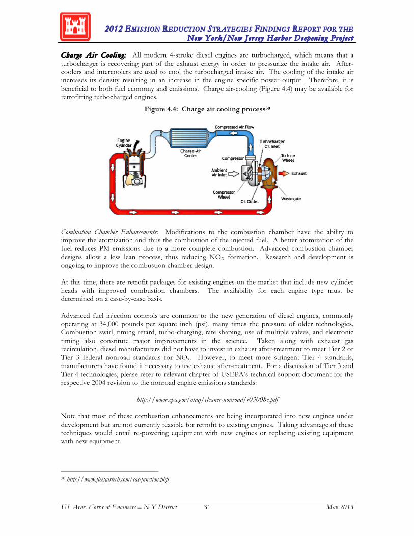
2012 EMISSION REDUCTION STRATEGIES FINDINGS REPORT FOR THE New York/New Jersey Harbor Deepening Projec t
US Army Corps of Engineers – N Y District 31 May 2013
Charge Air Coo l ing : All modern 4-stroke diesel engines are turbocharged, which means that a turbocharger is recovering part of the exhaust energy in order to pressurize the intake air. After-coolers and intercoolers are used to cool the turbocharged intake air. The cooling of the intake air increases its density resulting in an increase in the engine specific power output. Therefore, it is beneficial to both fuel economy and emissions. Charge air-cooling (Figure 4.4) may be available for retrofitting turbocharged engines.
Figure 4.4: Charge air cooling process30
Combustion Chamber Enhancements: Modifications to the combustion chamber have the ability to improve the atomization and thus the combustion of the injected fuel. A better atomization of the fuel reduces PM emissions due to a more complete combustion. Advanced combustion chamber designs allow a less lean process, thus reducing NOX formation. Research and development is ongoing to improve the combustion chamber design. At this time, there are retrofit packages for existing engines on the market that include new cylinder heads with improved combustion chambers. The availability for each engine type must be determined on a case-by-case basis.
Advanced fuel injection controls are common to the new generation of diesel engines, commonly operating at 34,000 pounds per square inch (psi), many times the pressure of older technologies. Combustion swirl, timing retard, turbo-charging, rate shaping, use of multiple valves, and electronic timing also constitute major improvements in the science. Taken along with exhaust gas recirculation, diesel manufacturers did not have to invest in exhaust after-treatment to meet Tier 2 or Tier 3 federal nonroad standards for NOx. However, to meet more stringent Tier 4 standards, manufacturers have found it necessary to use exhaust after-treatment. For a discussion of Tier 3 and Tier 4 technologies, please refer to relevant chapter of USEPA’s technical support document for the respective 2004 revision to the nonroad engine emissions standards:
http://www.epa.gov/otaq/cleaner-nonroad/r03008e.pdf
Note that most of these combustion enhancements are being incorporated into new engines under development but are not currently feasible for retrofit to existing engines. Taking advantage of these techniques would entail re-powering equipment with new engines or replacing existing equipment with new equipment.
30 http://www.fleetairtech.com/cac-function.php
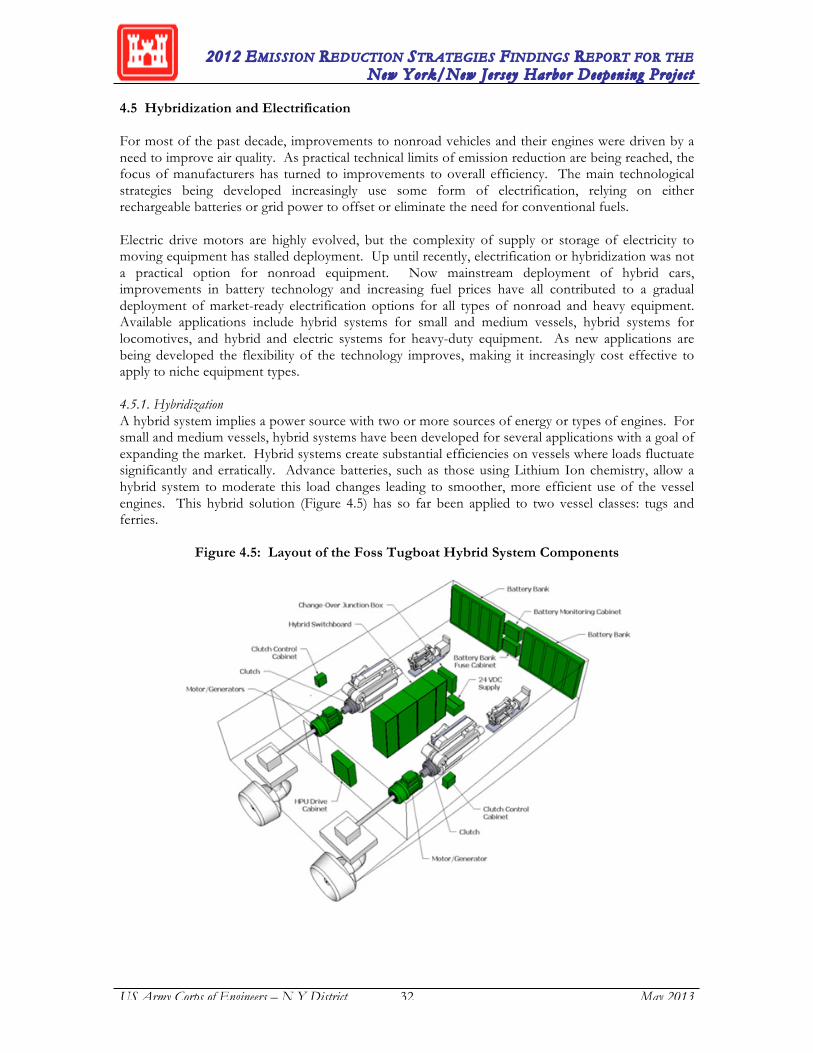
2012 EMISSION REDUCTION STRATEGIES FINDINGS REPORT FOR THE New York/New Jersey Harbor Deepening Projec t
US Army Corps of Engineers – N Y District 32 May 2013
4.5 Hybridization and Electrification For most of the past decade, improvements to nonroad vehicles and their engines were driven by a need to improve air quality. As practical technical limits of emission reduction are being reached, the focus of manufacturers has turned to improvements to overall efficiency. The main technological strategies being developed increasingly use some form of electrification, relying on either rechargeable batteries or grid power to offset or eliminate the need for conventional fuels. Electric drive motors are highly evolved, but the complexity of supply or storage of electricity to moving equipment has stalled deployment. Up until recently, electrification or hybridization was not a practical option for nonroad equipment. Now mainstream deployment of hybrid cars, improvements in battery technology and increasing fuel prices have all contributed to a gradual deployment of market-ready electrification options for all types of nonroad and heavy equipment. Available applications include hybrid systems for small and medium vessels, hybrid systems for locomotives, and hybrid and electric systems for heavy-duty equipment. As new applications are being developed the flexibility of the technology improves, making it increasingly cost effective to apply to niche equipment types. 4.5.1. Hybridization A hybrid system implies a power source with two or more sources of energy or types of engines. For small and medium vessels, hybrid systems have been developed for several applications with a goal of expanding the market. Hybrid systems create substantial efficiencies on vessels where loads fluctuate significantly and erratically. Advance batteries, such as those using Lithium Ion chemistry, allow a hybrid system to moderate this load changes leading to smoother, more efficient use of the vessel engines. This hybrid solution (Figure 4.5) has so far been applied to two vessel classes: tugs and ferries.
Figure 4.5: Layout of the Foss Tugboat Hybrid System Components

2012 EMISSION REDUCTION STRATEGIES FINDINGS REPORT FOR THE New York/New Jersey Harbor Deepening Projec t
US Army Corps of Engineers – N Y District 33 May 2013
The first ever demonstration of a hybrid tugboat was conducted by Foss Maritime Company, in partnership with the Port of Los Angeles, the Port of Long Beach, and South Coast Air Quality Management District (SCAQMD). The Green Assist Hybrid Tug, the Carolyn Dorothy, was unveiled in January 2009 for operation at the Ports of Los Angeles and Long Beach. Results of a research study31 sponsored by California Air Resources Board and carried out by Foss Maritime Company indicated that hybrid technology reduced PM by 73%, NOx by 51% and fuel consumption by 25%. In 2010 Foss received a grant from CARB to expand their hybrid technology to existing vessels. This led to the retrofit of a second tugboat, the Campbell Foss (Figure 4.6), also destined for the Ports of Los Angeles and Long Beach and deployed in January, 2012.
Figure 4.6: The Campbe l l Foss , retrofit with hybrid drive
Other vessel operations around the US and in Europe are using hybrid systems to improve efficiency. The passenger ferry “Alcatraz Clipper” mentioned previously was retrofit with Hornblower Hybrid systems in 2011 to improve fuel efficiency and further reduce overall emissions. In Scotland, the government invested £20 million to fund development of two RO-RO ferries that would operate near the Port of Glasgow. The second of these two ferries was launched in May, 2013.32 Unlike the vessels described previously, power output on locomotives varies slowly making the types of hybridization that moderates engine loads less beneficial. Instead, it is the potential to regain some of the massive amount of braking power that makes hybrid technology appealing. Locomotives have long used diesel-electric engines to generate the types of traction power required to move a mile-long assembly of rail cars, but they lacked the ability to use the electric component of that to capture power during braking. Adding batteries to the system allows braking energy to be stored long enough to make available for traction when the train starts to accelerate again. This type of system was originally conceived for trains as early as 1911, but the first prototype was not deployed until 1986 in Czechoslovakia where it ran successfully for 10 years. More recent
31 http://www.arb.ca.gov/ports/marinevess/harborcraft/documents/hybridreport1010.pdf 32 http://www.cmassets.co.uk/en/news-articles/second-hybrid-ferry-launches-on-the-clyde.html
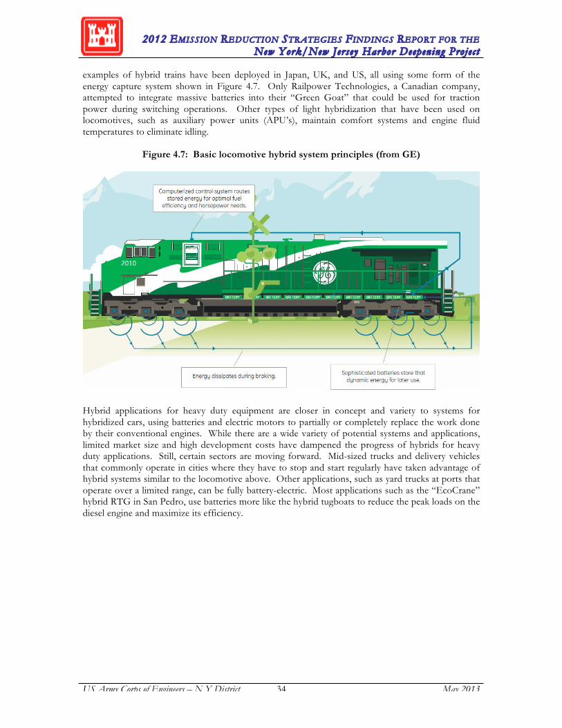
2012 EMISSION REDUCTION STRATEGIES FINDINGS REPORT FOR THE New York/New Jersey Harbor Deepening Projec t
US Army Corps of Engineers – N Y District 34 May 2013
examples of hybrid trains have been deployed in Japan, UK, and US, all using some form of the energy capture system shown in Figure 4.7. Only Railpower Technologies, a Canadian company, attempted to integrate massive batteries into their “Green Goat” that could be used for traction power during switching operations. Other types of light hybridization that have been used on locomotives, such as auxiliary power units (APU’s), maintain comfort systems and engine fluid temperatures to eliminate idling.
Figure 4.7: Basic locomotive hybrid system principles (from GE)
Hybrid applications for heavy duty equipment are closer in concept and variety to systems for hybridized cars, using batteries and electric motors to partially or completely replace the work done by their conventional engines. While there are a wide variety of potential systems and applications, limited market size and high development costs have dampened the progress of hybrids for heavy duty applications. Still, certain sectors are moving forward. Mid-sized trucks and delivery vehicles that commonly operate in cities where they have to stop and start regularly have taken advantage of hybrid systems similar to the locomotive above. Other applications, such as yard trucks at ports that operate over a limited range, can be fully battery-electric. Most applications such as the “EcoCrane” hybrid RTG in San Pedro, use batteries more like the hybrid tugboats to reduce the peak loads on the diesel engine and maximize its efficiency.

2012 EMISSION REDUCTION STRATEGIES FINDINGS REPORT FOR THE New York/New Jersey Harbor Deepening Projec t
US Army Corps of Engineers – N Y District 35 May 2013
4.5.2. Electrification When a vehicle is operated entirely with electricity stored on board or supplied through a connection to an electricity source, it is considered an electric vehicle. For most applications, electric motive and accessory power is desirable and feasible but is inherently limited as replacement to conventional power sources. The need to either maintain a tether to an electricity supply or store sufficient energy onboard limits electric applications to stationary, small, or short-range operations. Historically, it was only large stationary equipment such as terminal cranes that were cost effective to electrify. Now, with increasing fuel prices over the last 10 years and technology improvements, small passenger vehicles have become a reasonable and available option. Fuel price and technology also drive developments in heavy duty applications, but many times there are additional trade-offs that enter in. Since 2008, many ports in the world have been testing full-electric rubber-tired gantry (RTG) cranes that operate using either bus bars or cable reels to connect them to the grid. RTG’s are a good application for electrification because they perform similar tasks repeatedly over a limited range. The trade-off for electrification is that the additional infrastructure requirements place limits on the future flexibility of terminal operations. Likewise with battery electric yard trucks which are slowly being deployed in Southern California, the need to charge regularly and have charging stations conveniently located on the terminal requires a commitment both to the equipment and to certain operational limits. So far, battery electric yard trucks and electric RTG’s are only demonstrated and available fully electric vehicle options in the goods movement industry, but increasing fuel prices and improving battery technologies will increase the range and size of candidate equipment. With respect to the replacement of existing diesel-powered dredges with electric or hybrid models, the PANYNJ evaluated the use of an electric dredge for the Port Jersey contract and found that it was not a viable option at this time in terms of cost-effectiveness and general applicability throughout the project area. Subsequently, for the S-KVK-1 contract, the dredging contractor pursued the option of getting a substation sited for the contract for use of an electric dredge, however the costs were prohibitive. However, there are other potential electrification opportunities for HDP sources that need to be further evaluated. Recently, a seventeen-month channel-deepening project at the Port of Long Beach was completed where the majority of the dredge work was done by using electric dredges.33 In addition, shore-based electrical power can potentially be used by assist tugs at designated staging areas to eliminate unnecessary idling emissions associated with diesel powered engines while the vessels are waiting to be deployed for their next assignments. 4.6. Fuel Based Technologies Fuel-based emission reduction measures utilize beneficial effects from changes in the fuel sulfur levels, alternative diesel formulations, and additives to diesel fuel without a required change to the power plant or exhaust system. ULSD belongs to the first group (changes in fuel sulfur level). Some formulations with low aromatic content are commercially available as well (e.g., Arco ECD). Lower sulfur diesel levels result in lower PM emissions. More importantly, ULSD facilitates the operation of some of the previously described retrofit technologies and in some cases is required for their use. The currently available alternative diesel formulations that offer emission reductions are either a) emulsions of diesel and water that are mixed just prior to combustion, or b) alternative fuels, such as blends of petroleum diesel with some percentage of a bio-fuel like biodiesel or ethanol that are mixed by the supplier. Fuel-based catalysts belong to a third group of fuel-based technologies.
33 http://www.polb.com/news/displaynews.asp?NewsID=919
2012 EMISSION REDUCTION STRATEGIES FINDINGS REPORT FOR THE New York/New Jersey Harbor Deepening Projec t
US Army Corps of Engineers – N Y District 36 May 2013
ULTRA LOW SULFUR DIESEL FUEL (ULSD) ULSD, as the name implies, is diesel fuel that is manufactured with substantially reduced sulfur levels. It is produced with sulfur capped at 15 ppm by weight under EPA rules applicable to on-road and non-road diesel fuel. Tests have been also made with ULSD that has lower aromatic levels as well. The cost of refining this low-aromatic fuel, however, is significantly higher than standard ultra-low sulfur diesel. To accommodate the low and high volatility types of ULSD, he ASTM standard (D975) that specifies ULSD fuel properties for use in engine design has two definitions: Grade No. 2-D S15 (regular ULSD) and Grade No. 1-D S15 (a higher volatility fuel with a lower gelling temperature than regular ULSD). Current Federal regulations require use of ULSD for all on-road and non-road vehicles, and, as of 2012, for nonroad engines, locomotives, and marine applications. The transition to these fuels was critical for allowing nonroad engines to fully take advantage of catalyst technology to comply with future USEPA Tier 4 emission regulations for non-road, marine and locomotive diesel engines. The emissions benefits of low- and ultra-low-sulfur diesel use alone are not substantial. For example, when formulated with higher cetane and lower aromatics, low sulfur (500 ppm) diesel may achieve a 5-10% NOX emission reduction. PM emission reductions of 13% have been reported when switching from 370 ppm to 60 ppm fuel. The USEPA allowed CARB specified fuels with lower aromatic content as part of diesel fuel specifications in their SIP and claimed a 7% NOX reduction. DIESEL EMULSIONS Diesel emulsions, such as those developed by Lubrizol and TotalFinaElf are a combination of standard diesel fuel, water, and an additive package. Lubrizol withdrew their PuriNOx technology from the North American market in 2006, leaving the TotalFinaElf product, Aquazole, the only available form of diesel emulsion fuel. The components of emulsified fuel (diesel fuel, water, and additive) are mixed to produce a stable, finished fuel. The diesel emulsion leads to lower combustion temperatures thereby reducing the NOX formation. The water droplets, surrounded by diesel fuel, also promote a cloud-like atomization of the mixture during fuel injection, which improves combustion and hence minimizes the NOX/PM trade-off. Thus, the diesel emulsions are able to reduce NOX and PM emissions. Due to addition of the water into the diesel fuel, the energy density of the fuel is lowered which results into less engine power and fuel economy, as well as increases in CO2 emissions. TotalFinaElf’s fuel additive formulation, Aquazole was verified in August 2002 by CARB for nonroad equipment use, with emission reductions of 25% HC, 60% for PM, and 16% for NOX. Aquazole is not registered for on-road applications. No demonstration projects have been identified at this time using Aquazole with nonroad equipment, although its similarity to PuriNOx might indicate that successful PuriNOx applications could also use Aquazole. ALTERNATIVE FUELS Engines may also be re-powered such that an alternative fuel rather than conventional diesel is used to power the equipment. Standard alternative fuels such as compressed natural gas (CNG), liquefied natural gas (LNG), hydrogen-based CNG mixtures (Hythane™), propane, ethanol, methanol and bio-diesel may offer decreased NOX, VOC, PM and/or CO emissions. The major drawback associated with the use of alternative fuels is a fuel efficiency penalty, since diesel fuel offers the most energy (British thermal unit [Btu] value) in terms of mass (gallon equivalents).
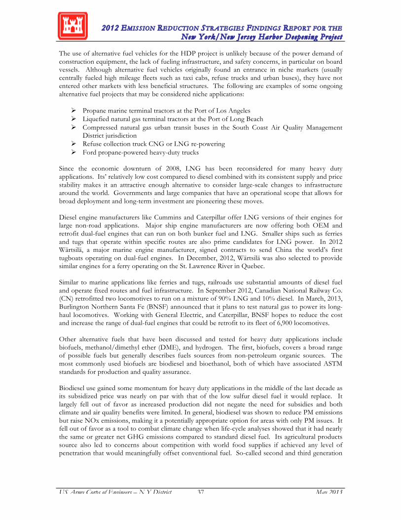
2012 EMISSION REDUCTION STRATEGIES FINDINGS REPORT FOR THE New York/New Jersey Harbor Deepening Projec t
US Army Corps of Engineers – N Y District 37 May 2013
The use of alternative fuel vehicles for the HDP project is unlikely because of the power demand of construction equipment, the lack of fueling infrastructure, and safety concerns, in particular on board vessels. Although alternative fuel vehicles originally found an entrance in niche markets (usually centrally fueled high mileage fleets such as taxi cabs, refuse trucks and urban buses), they have not entered other markets with less beneficial structures. The following are examples of some ongoing alternative fuel projects that may be considered niche applications:
Propane marine terminal tractors at the Port of Los Angeles Liquefied natural gas terminal tractors at the Port of Long Beach Compressed natural gas urban transit buses in the South Coast Air Quality Management
District jurisdiction Refuse collection truck CNG or LNG re-powering Ford propane-powered heavy-duty trucks
Since the economic downturn of 2008, LNG has been reconsidered for many heavy duty applications. Its’ relatively low cost compared to diesel combined with its consistent supply and price stability makes it an attractive enough alternative to consider large-scale changes to infrastructure around the world. Governments and large companies that have an operational scope that allows for broad deployment and long-term investment are pioneering these moves. Diesel engine manufacturers like Cummins and Caterpillar offer LNG versions of their engines for large non-road applications. Major ship engine manufacturers are now offering both OEM and retrofit dual-fuel engines that can run on both bunker fuel and LNG. Smaller ships such as ferries and tugs that operate within specific routes are also prime candidates for LNG power. In 2012 Wärtsilä, a major marine engine manufacturer, signed contracts to send China the world’s first tugboats operating on dual-fuel engines. In December, 2012, Wärtsilä was also selected to provide similar engines for a ferry operating on the St. Lawrence River in Quebec. Similar to marine applications like ferries and tugs, railroads use substantial amounts of diesel fuel and operate fixed routes and fuel infrastructure. In September 2012, Canadian National Railway Co. (CN) retrofitted two locomotives to run on a mixture of 90% LNG and 10% diesel. In March, 2013, Burlington Northern Santa Fe (BNSF) announced that it plans to test natural gas to power its long-haul locomotives. Working with General Electric, and Caterpillar, BNSF hopes to reduce the cost and increase the range of dual-fuel engines that could be retrofit to its fleet of 6,900 locomotives. Other alternative fuels that have been discussed and tested for heavy duty applications include biofuels, methanol/dimethyl ether (DME), and hydrogen. The first, biofuels, covers a broad range of possible fuels but generally describes fuels sources from non-petroleum organic sources. The most commonly used biofuels are biodiesel and bioethanol, both of which have associated ASTM standards for production and quality assurance. Biodiesel use gained some momentum for heavy duty applications in the middle of the last decade as its subsidized price was nearly on par with that of the low sulfur diesel fuel it would replace. It largely fell out of favor as increased production did not negate the need for subsidies and both climate and air quality benefits were limited. In general, biodiesel was shown to reduce PM emissions but raise NOx emissions, making it a potentially appropriate option for areas with only PM issues. It fell out of favor as a tool to combat climate change when life-cycle analyses showed that it had nearly the same or greater net GHG emissions compared to standard diesel fuel. Its agricultural products source also led to concerns about competition with world food supplies if achieved any level of penetration that would meaningfully offset conventional fuel. So-called second and third generation
2012 EMISSION REDUCTION STRATEGIES FINDINGS REPORT FOR THE New York/New Jersey Harbor Deepening Projec t
US Army Corps of Engineers – N Y District 38 May 2013
biofuels potentially address the lifecycle and sustainability issues by using waste products or algae as feedstock respectively.
A more recent development has been the consideration of a methanol-DME mix to power vessels and other large equipment. Because of its low production cost and relatively clean emissions, its use has been growing quickly as a land-based fuel in Scandinavia, China, and Korea and is being considered for marine applications for vessels operating within ECA zones. Methanol itself is not necessarily a good choice because of its low fuel density, corrosivity, and low lubricity. It can however be catalyzed to DME either prior to bunkering or onboard to make it a much more appropriate choice for use with dual-fuel marine engines. Despite a range of handling and supply issues that will need to be managed, Methanol/DME is seen as a viable contender with LNG. Hydrogen is a third potential fuel, but much more controversial. In addition to bunkering and handling issues for vessels, hydrogen generation is very energy intensive. Its allure as a fuel for any application is unquestionable. With zero direct emissions and the ability to drive efficient electric drive propulsion systems, prototype applications have been deployed regularly over the last decade. Most waterborne applications have been some small private and commercial vessels including recreational boats and ferries. A recent application in 2009 with a 100 passenger Zemships project Alsterwasser out of Hamburg, Germany (Figure 4.8) has been one of the largest applications of a hydrogen fueled vessel to date and is still in operation. Use hydrogen requires fuel cells to convert the fuel into electricity. Mature fuel cell technology has been available for decades with many new technologies still in development. While many stationary and mobile applications have been implemented, commercial fuel cell production has yet to become profitable34.
Figure 4.8: The hydrogen powered ferry Alsterwasser in Hamburg
34 http://www.greentechmedia.com/articles/read/Year-End-Reflections-on-Fuel-Cells-2010

2012 EMISSION REDUCTION STRATEGIES FINDINGS REPORT FOR THE New York/New Jersey Harbor Deepening Projec t
US Army Corps of Engineers – N Y District 39 May 2013
FUEL BORNE CATALYST Microemulsion is a process in which water is emulsified into fuel droplets shortly before combustion in the engine by utilizing a special ‘mixing’ device. It has potential to reduce NOX by 20% with no fuel consumption penalty. Microemulsion is more stable than emulsions produced with distillate fuel and a fuel borne catalyst additive is needed for the microemulsion. Fuel borne catalysts (FBCs) have the same purpose as that of the catalytic coating on filter substrates of DPFs and DOCs. Their physio-chemical function is to lower the soot ignition temperature to below 400°C (750°F). FBCs form small oxides that adsorb to the particles and react as a catalyst directly to the particle. This process provides a better contact between the catalyst and the particles, thus allowing regeneration of the filter system at somewhat lower temperatures than comparable catalyzed particulate filters. Unfortunately, the oxides of the additive are small particles that increase the backpressure of the system. Furthermore, since the additives usually contain heavy metals, the filter system also needs to be able to trap the additive oxides. Based on some health and biological concerns, FBCs require USEPA registration to be legally sold for on-road use. Nonroad uses do not require FBC registration in the U.S., except for underground mining. In Switzerland, FBCs are only allowed if they are dosed in an on-board dosing system, to avoid accidentally fueling a non-filter-equipped vehicle, which would create heavy metal emissions. FBCs offer an interesting alternative for nonroad applications; however, some problems remain to be solved before this technology is utilized. The application of FBCs has caused, in some instances, increased wear of fuel and injection systems. This is particularly true for copper-based FBCs and to a lesser extent for iron/strontium-based FBCs. In the latter case, the deterioration of the filter medium itself has been reported. Cerium-based FBCs and platinum, platinum/cerium combinations have shown the least effect on engine wear. Additionally, cerium is beneficial for its inertness and non-toxic character. Probably the most notable FBC system is the Peugeot Citroen PSA developed passenger diesel engine with common rail injection, DOC, DPF and fuel-based catalyst. It became commercially available in 2000 and meets the 2005 EU emission standards (compares to current California Ultra Low Emission Vehicle [ULEV] standards with slightly higher NOX allowance) for light duty vehicles. The Peugeot system uses a cerium based FBC. Several fuel-based particulate filter systems for controlling diesel particulate emissions in tunnel construction projects passed approval by the Swiss environmental agency in 1999. Some conditions, including an on-board dosing system, are placed on the approved systems to avoid secondary emissions of heavy metals. Commerc ia l l y Avai lab l e Sys t ems : The currently commercially available FBCs are:
Iron-based FBC, "Satacen" by Octel; Iron/strontium-based FBC, "Octimax 4800", by Octel; Cerium-based FBC, "Eolys" by Rhodia; Platinum and platinum-cerium based FBC, "Platinum Plus" by Clean Diesel Technology.
2012 EMISSION REDUCTION STRATEGIES FINDINGS REPORT FOR THE New York/New Jersey Harbor Deepening Projec t
US Army Corps of Engineers – N Y District 40 May 2013
4.6. Technology Combinations and Other Equipment Alternatives Other potential emission reduction options include combinations of technologies described above, as well as equipment alternatives. Also, it should be noted that, although some of the described technologies may not be feasible for retrofit applications, they may become feasible when used in combination with engine and equipment replacements. Considering the combined emission reduction potential, engine and equipment replacements in conjunction with the implementation of emission control technologies might be technically effective and cost efficient. A more detailed discussion of engine replacements (re-powering) and equipment replacements were discussed previously in this report (see Section 4.2). COMBINED EMISSION CONTROL SYSTEMS New systems that combine catalysts, filters, air enhancement technologies, thermal management technologies, and/or engine adjustments and components are emerging as retrofit options. As described for certain diesel retrofit technologies, some catalysts are offered on the market in combinations. For example, there are SCR units only and SCR units in combination with pre- and post-DOC on the market. Extengine Transport Systems ADEC employs a combination of SCR and DOC and is verified by CARB to achieve 80% NOx and 25% PM reductions in 1991 to 1995 model year off-road Cummins 5.9-liter diesel engines from 150 to 200 horsepower, which are used in rubber-tired excavators, dozers, and loaders. Other catalyst configurations also may include oxidation or reduction units/sections. For verified combination systems, refer to USEPA and CARB websites:
http://epa.gov/cleandiesel/verification/verif-list.htm http://www.arb.ca.gov/diesel/verdev/vt/cvt.htm
4.7. Summary The emission reduction technologies and strategies presented in this section, many of which are proven and verified, have the potential to achieve significant emission reductions from existing sources. However, a case-by-case evaluation of these strategies is warranted to ensure feasibility, applicability, and cost-effectiveness. Thus far, engine re-powering has been the most successful emission reduction strategy implemented under the HAMP but other strategies will continue to be reviewed and monitored for potential contingency measures. Any non-verified technology will have to meet testing/demonstration requirements detailed by the RAT for each specific application. Use of any of these options as contingency measures will also need to be reviewed and approved by the RAT prior to implementation. In considering retrofit technologies, it is important to consider that there will become a point at which traditional diesel exhaust retrofits rapidly begin to decline in utility. These types of technologies provide the best cost-benefit ratio for old equipment with very high emissions. These types of high emitting equipment are now naturally phasing out of fleets near the end of their useful life. The application of retrofit technologies to newer equipment that already have some type of regulatory-drive emissions controls is less likely to be cost effective compared to other options. It is only in areas that have the most significant air quality issues that it may be reasonable to replace or retrofit equipment that was state of the art only 3-5 years prior.

2012 EMISSION REDUCTION STRATEGIES FINDINGS REPORT FOR THE New York/New Jersey Harbor Deepening Projec t
US Army Corps of Engineers – N Y District 41 May 2013
5.0 OTHER POTENTIAL EMISSION REDUCTION OPPORTUNITIES In addition to the emission reduction technologies and strategies for HDP sources described in Section 4, there are other potential emission reduction opportunities, which could result in additional emissions benefits from non-HDP region sources. This section describes several proven strategies for ocean-going vessels for reducing emissions including: vessel speed reduction (VSR), switching to lower sulfur fuel, shore power for vessels at-berth, and main engine modifications (i.e., slide valves). However, implementation of these strategies is more complex compared to emission control technologies and strategies (described in previous section) affecting project sources. In addition to requiring specific mechanisms for implementation and tracking, these strategies would also require close coordination and interaction with regulatory agencies to verify emission benefits. 5.1 Vessel Speed Reduction (VSR) Vessel speed reduction for ocean-going vessels during transit is an effective strategy in reducing main engines’ fuel consumption and thereby emissions. Under this voluntary program, vessels are requested to slow down (e.g., 12 knots) as they approach or depart the ports. As ships slow down, the load on their main engines decreases considerably compared to the engine load when transiting at higher speeds, leading to a decrease in the total energy required to propel the ship through the water. This energy reduction in turn reduces emissions for this segment of the transit. Since the load on the main engines affects power demand and fuel consumption, this strategy significantly reduces all pollutants including DPM, NOx, SOx, and GHG emissions. In an ongoing effort to improve air quality in the region, the Port Authority of New York and New Jersey’s Board of Commissioners has authorized incentives to shipping lines and terminal operators in the Port of New York and New Jersey to operate in a more environmentally friendly manner. Specifically, the Ocean-going Vessels Low Sulfur Fuel Program35 encourages the use of low-sulfur fuel by providing financial incentives to operators of ocean vessels for up to 50 percent of the cost differential between high-sulfur fuel and low-sulfur fuel. Participating vessel operators are absorbing the remaining 50 percent of the cost differential. Vessels in this program are also required to participate in a vessel speed reduction program. Beginning in 2010, the VSR program requires ships to travel at an average speed of 10 knots or less during arrivals and departures within the 20 nautical mile Participation Zone. Beginning in 2013, vessels calling the Port of New York and New Jersey are also eligible to participate in the Clean Vessel Incentive (CVI) program that builds on Environmental Ship Index (ESI) methodologies to award points to ships that have lower than normal emissions. Since 2001, the Port of Los Angeles (POLA) and the Port of Long Beach (POLB) have administered a voluntary VSR program for OGVs to reduce their speeds during arrivals and departures to/from the San Pedro Bay ports. Starting in 2008, POLA and POLB subsequently revised their VSR program to extend the distance at which ship speeds are reduced to 12 knots from 20 nm to 40 nm seaward from Point Fermin. For all of 2011, POLA reported 20 nm compliance rate of 92% and 40 nm compliance rate of 70%36. For all of 2012, POLB reported at 20 nm compliance rate of 96% and 40 nm compliance rate of 83.5%.37
35 http://www.panynj.gov/about/low-sulfur-fuel.html 36 http://www.portoflosangeles.org/environment/ogv.asp 37 http://www.polb.com/environment/air/vessels/default.asp
2012 EMISSION REDUCTION STRATEGIES FINDINGS REPORT FOR THE New York/New Jersey Harbor Deepening Projec t
US Army Corps of Engineers – N Y District 42 May 2013
Following this trend in mitigation strategies, the Port of San Diego in 2009 started its own VSR program. As a large cruise port, it needed to set standards that would differentiate between cruise and regular vessels. As such, within 20 nm, Cruise ships are required to slow to 15 knots while all other ships are required to slow to 12 knots. 5.2 Fuel Switch Ocean-going vessels generally use heavy fuel oil (HFO) in their main propulsion engines and auxiliary engines and boilers. Often referred to as residual fuel or bunker fuel, HFO is a very viscous fuel that must be heated to allow for flow through piping and for combustion in auxiliary engines. Because of the high content of sulfur, ash, and nitrogen containing compounds, combustion of residual fuel results in significantly higher levels of emissions of PM and SOx compared to marine distillate fuels. Marine distillate fuels include marine gas oil (MGO) and marine diesel oil (MDO) and are similar to the diesel fuel used by landside sources. Switching from residual fuel (with an average 2.7% sulfur content) to marine distillate fuel (with an average 0.1 to 0.5% sulfur content) will result in significant reductions of PM and SOx emissions and small reduction in NOx emissions. Specifically, the use of marine distillate fuel with an average 0.5% sulfur content will achieve 75% reduction in PM, 81% reduction in SOx, and 6% reduction in NOx emissions. Similarly, using a 0.1% sulfur marine distillate fuel will achieve 83% reduction in PM, 96% reduction in SOx, and 6% reduction in NOx emissions. The use of low-sulfur marine fuel for OGVs is now required by international law. In March 2009, the United States and Canada submitted a joint proposal to the IMO (International Maritime Organization) for the designation of an Emission Control Area (ECA) for implementation of the stringent international emission controls. In March 2010, the IMO officially designated waters within 200 miles of North American coasts as an ECA. This means that in 2012, fuel used by all vessels operating in this area could not exceed 1.0 percent sulfur (10,000 ppm). In 2015 this will be further require ships to use fuel with less than 0.1 percent sulfur (1,000 ppm). In California, CARB has adopted low sulfur fuel requirements for marine main engines, auxiliary engines and auxiliary boilers in two phases. Starting in July of 2009, the Phase I required the use of marine gas oil (MGO) with sulfur content less than 1.5% by weight or marine diesel oil (MDO) with a sulfur content of equal to, or less than 0.5% by weight followed by second part of Phase I, starting on August 1, 2012, required the use of marine gas oil (MGO) with sulfur content less than 1.0% by weight, with MDO remaining the same. Phase II, effective January 1, 2014, requires the use of MGO or MDO with a sulfur content of equal to or less than 0.1 %. This will put into effect California’s regulation one year earlier than the requirement of the ECA. 5.3 Shore Power Ocean-going vessels operate their diesel-powered auxiliary engines (while docked at a berth or “hotelling”) in order to provide power for lighting, ventilation, pumps, communication, and other onboard equipment. Depending on the duration of “hotelling” time, auxiliary engines could generate significant amounts of emissions, particularly NOx, PM, and SOx. Alternatively, the auxiliary engines could be turned off and the necessary power could be supplied from the on-shore power supplies. The process of shutting off engines and connecting to power on shore is sometimes referred to as “shore power” or “cold-ironing.” Shore power provides an opportunity to reduce emissions from ships during hotelling operations.
2012 EMISSION REDUCTION STRATEGIES FINDINGS REPORT FOR THE New York/New Jersey Harbor Deepening Projec t
US Army Corps of Engineers – N Y District 43 May 2013
Grid-supplied shore power is technologically feasible and is already being used for passenger ships, container ships, bulk ships and oil tankers at several U.S. ports. For example, shore power is currently used at two container terminals at the Port of Los Angeles and a tanker terminal at the Port of Long Beach. In order to implement shore power as an emission reduction measure, modifications would be required to both terminals and ships to utilize grid-based shore power. Terminals may have different shore-power designs to accommodate ships with different voltage and power loads. While most vessels are configured for 440-480 volts, larger container ships and passenger ships are configured for 6.6 kilovolts (kV) and the newer vessels are configured for 11 kV. Therefore, since all ships don’t have the same voltage requirements, a transformer can be used to increase or decrease the voltage to a ship. The transformer may be provided at the berth or be onboard the visiting ships. In addition, existing ships will also have to be retrofitted with shore power capabilities while some of the new builds already have these capabilities. CARB has adopted a regulation to reduce emissions from diesel auxiliary engines on OGV while at-berth for container, cruise and refrigerated cargo vessels. The regulation requires that auxiliary diesel engines on OGV to be shut down (i.e., use shore-power) for specified percentages of fleet’s visits and also the fleet’s at-berth auxiliary engine power generation to be reduced by the same percentages. As an alternative, vessel operators may employ any combination of clean emissions control technologies to achieve equivalent reductions. Specifically, by 2014, vessel operators relying on shore power are required to shut down their auxiliary engines at-berth for 50 percent of the fleet’s vessel visits and also reduce their onboard auxiliary engine power generation by 50 percent. The specified percentages will increase to 70 percent in 2017 and 80 percent in 2020. For vessel operators choosing the emission reduction equivalency alternative, the regulation requires a 10% reduction in OGV hotelling emissions starting in 2010 increasing in stringency to an 80% reduction by 2020. While CARB’s regulation requires the use of shore power or other equivalent technologies for compliance, this technology can be implemented in other states as an additional opportunity for reducing emissions from OGVs auxiliary engines during hotelling operations and generating emission credits. 5.4 Engine Modification Modification of engines through advanced designs and other engine technologies for optimizing fuel combustion in OGVs offers another opportunity for achieving emissions reductions. MAN B&W Diesel announced the introduction of slide valves as standard in their new engines in 2002 offering significant savings by lowering fuel consumption and the resulting emissions. The slide valves are fuel injection valves that are designed to optimize the fuel injection and fuel spray pattern leading into more optimized fuel combustion. Measurements on an engine equipped with new slide valves installed by Swedish Wallenius Lines on one of their vessels, Don Juan, confirmed a 30% reduction in NOx emissions (from 19 g/kWh to 13.4 g/kWh) without any fuel penalty38 39. The PM emissions benefits of approximately 25% have also been reported during emissions testing of engines using slide valves40. The slide valves are also available as retrofits in Category 3 (large ship propulsion ) MAN engines.
38 MAN B&W Press Release, dated 20 August 2002 39 http://www.walleniuslines.com/Environment/Results-and-Statistics/ 40 MAN Presentations: 1) Clean Ships: Advanced Technology for Clean Air – San Diego - Feb 2007; 2) MARAD- Ship Energies Technology Workshop – April 2004

2012 EMISSION REDUCTION STRATEGIES FINDINGS REPORT FOR THE New York/New Jersey Harbor Deepening Projec t
US Army Corps of Engineers – N Y District 44 May 2013
5.5 Summary The emission reduction strategies discussed in this section offer additional opportunities for generating emissions reductions from non-project sources. However, the feasibility of these strategies will have to be specifically evaluated in relation to HDP or other projects. Successful implementation of these strategies would require development of specific mechanisms for tracking and quantifying emission benefits and close coordination with agencies.
2012 EMISSION REDUCTION STRATEGIES FINDINGS REPORT FOR THE New York/New Jersey Harbor Deepening Projec t
US Army Corps of Engineers – N Y District 45 May 2013
6.0 EMERGING DIESEL TECHNOLOGIES This section presents a number of emerging diesel retrofit technologies which are currently under development or are recently available on the market. 6.1 Emerging Technologies for New Engines and As Retrofits The following technologies are listed generally according to their states of development. Currently, some of these technologies may be available only in conjunction with new engines and require engine swap (re-power) or equipment replacement. Some of the technologies are recent to the market or are under test operations and only limited data is available (e. g., Humid Air Motor [HAM], sulfur oxides [SOX] Scrubber). Other technologies were developed for selected applications but have not become commercially available on a widespread basis (e.g., electronic supercharger) or for retrofitting existing engines (e.g., exhaust gas recirculation). The last group of technologies includes two varieties of NOX catalysts that are currently being tested. While some of these options may be readily available and in use today, they are considered “emerging” for the sake of this report because none have been certified or verified by the USEPA as to their effectiveness.
Technology Name: Direc t Water In j e c t ion (DWI) General Description: A combined injection valve for both fuel and water injection is the key element of the DWI system. The injection is controlled electronically. DWI system emission reduction effect is related to the lowering of the combustion temperature and the better vaporization of the injected fuel. This is similar to the effects that can be observed with water-fuel emulsions (see section 4.1.2 below). Pollutant Targeted: NOX Magnitude of Emission Reduction: NOX emission reductions up to 50% with water/fuel ratio of 0.5 are reported.41,42 In comparison to water-fuel emulsions, higher percentages of water are possible with DWI systems. However, care should be taken since the trade-off between NOX and PM may increase the PM emissions with higher water content percentages. State of Development: DWI systems are used in all sizes of diesel engines to change combustion characteristics or improve cooling. It is less commonly used specifically as a means to control emissions in most applications. The technology has been also developed for medium speed 4-stroke marine diesel engines and is now commercially available from one manufacturer. At least 10 vessels, mostly ferryboats in the Baltic Sea region, operate now with DWI. Those ferryboats are equipped with Wärtsilä engines of the 32 and 46 series and achieve certified NOX levels of 4 to 6 g/kW-hr when using marine diesel oil (MDO) and 5 to 7 g/kW-hr when using heavy fuel oil (HFO). Availability for new smaller vessels, such as tugboats, would need to be investigated because current applications are all on engines with more than 3,000 kW. The ability to retrofit existing engines with DWI is limited and may be possible only for certain engines where manufacturers have employed DWI.
41 IVL (2006): Experiences from Use of Some Techniques to Reduce Emissions from Ships, Prepared for the Swedish Maritime Administration and the Region Vastra Gotaland. August 2006 42 Wartsilla (2008): Developments and Perspectives of Marine Engines, Presentation by Paolo Tremuli, November 6, 2008

2012 EMISSION REDUCTION STRATEGIES FINDINGS REPORT FOR THE New York/New Jersey Harbor Deepening Projec t
US Army Corps of Engineers – N Y District 46 May 2013
Also, the San Pedro Bay Ports, in cooperation with the USEPA, CARB, and several local Air Quality Management Districts, have sponsored the demonstration of the Water-in-Fuel Emulsification (WiFE) technology on the container ship APL Singapore. The fuel-water emulsion technology is provided by Sea to Sky Pollution Solutions, Inc. A fuel homogenizer was installed in the APL Singapore’s engine room to produce the emulsification. The unit injects water into the bunker fuel used by the vessel’s main engine and continually agitates the mixture to keep oil and water from separating. Emission measurements were conducted on the main engine during a voyage from San Pedro Bay to Dutch Harbor at different engine loads and varying percentages of water added. At 50% engine load, NOX emissions were reduced by up to 34% based on 48% water addition, respectively. The influence of water on carbon monoxide and particulate emission is unclear but not considered significant. Low sulfur fuels below 1.5% are required Another manufacturer, NoNOx in the Bahamas, manufactures and sells what they describe as an emulsion combustion unit (ECU) shown in Figure 6.1 below. Their technology is primarily marketed for its fuel efficiency benefits, but introduction of water to the combustion cycle will also reduce PM and NOx. Nonox claims to see 25-50% reduction in NOx, 60-90% reduction in PM, and 5-15% reduction in CO2. They have installed their ECU systems as retrofits on a wide variety of diesel equipment from stationary generators to large ocean going vessels including Wallenius Wilhelmsen;s M/V Tortugas and M/V Taiko vessels. The units are specified to be scalable from 25-2000 gallons per hour fuel flow rates.
Figure 6.1: NoNOx Emulsion Combustion Unit (ECU)
Engine Specific Feasibility: DWI has applicability for a wide range of diesel engines. DWI can be incorporated in new engine designs together with high-pressure fuel injection and fuel nozzle improvements or, in the case of NoNox, can be retrofit to many different types of systems. Technology Name: Scavenging Air Moistening (SAM)/Humid Air Motor (HAM) General Description: The scavenging air moistening (SAM), for large two-stroke engines, and humid air motor (HAM), for four-stroke engines, both feed humidified air into the combustion chamber. Currently, both MAN and Wärtsilä offer this technology for their engines. The principle is based on the characteristic that NOX formation increases with higher pressure and temperature. As with water-diesel emulsions and with DWI, SAM/HAM lower the combustion pressure and temperature by adding water vapor to the combustion air43. The amount of water that can be added to the inlet air is limited by the water vapor saturation point. Therefore, a higher mass
43 The heat capacity, e.g. the amount of energy that is necessary to heat a unit of air, is much higher with water vapor containing air than with dry air.

2012 EMISSION REDUCTION STRATEGIES FINDINGS REPORT FOR THE New York/New Jersey Harbor Deepening Projec t
US Army Corps of Engineers – N Y District 47 May 2013
of water can be vaporized if the inlet air is pre-heated before the humidification tower, because the water saturation capacity increases with increased temperature. These systems can be operated with seawater, because the moisture is introduced to the engine as a vapor, so the salt content of seawater is not an impediment to its use. Water separators prevent liquid water from entering the combustion chamber. The benefit of SAM/HAM is also that it is unaffected by fuel type. Pollutant Targeted: NOX Magnitude of Emission Reduction: A NOX reduction of 35% to 85% is possible in direct relation with the amount of water vapor fed into the combustion chamber.44 Thus, higher emission reduction can be achieved with heated water and air used for humidification. A major benefit of SAM/HAM technology (Figure 6.2) is efficient NOX reduction at low and transient load conditions. The tradeoff is that hydrocarbon (HC) and particulate matter (PM) are increased due to cooler combustion temperatures, and there is ~3% penalty in fuel consumption.
Figure 6.2: Humid Air Motor (HAM) system overview
State of Development: HAM technology has shown successful NOX reductions in laboratory tests. Laboratory units that operated with seawater did not show the presence of any water in the lube oil or any effects of corrosion. Viking Line’s MS Mariella is the first passenger ferry in the world to have HAM technology installed on all its four medium speed main engines (5,750 kW). The ferry operating between Helsinki and Stockholm has accumulated over 27,000 hours (hrs) of successful operation achieving about 80% to 85% reduction in NOx emissions.45 Man B&W Diesel (MAN) has reported NOX reductions from 2-stroke engines of about 35% using their HAM technology called Scavenging Air Moisturizing (SAM) based on laboratory tests.46 A full-scale test of the SAM system has also been conducted on a vessel in service (Wallenius-Wilhelmsen Lines’ M/V Mignon).47 These
44 IVL (2006): Experiences from Use of Some Techniques to Reduce Emissions from Ships, Prepared for the Swedish Maritime Administration and the Region Vastra Gotaland. August 2006 45 http://www.vikingline.fi/about/environment.asp 46 http://www.mandieselturbo-greentechnology.com/category_000510.html 47 MAN Diesel, “Exhaust Gas Emission Control Today and Tomorrow, Application on MAN B&W Two-Stroke Marine Diesel Engines ” August 2008, http://www.manbw.com/article_009187.html

2012 EMISSION REDUCTION STRATEGIES FINDINGS REPORT FOR THE New York/New Jersey Harbor Deepening Projec t
US Army Corps of Engineers – N Y District 48 May 2013
tests include the injection of freshwater at the end of the humidification tower in order to minimize the risk of corrosion.
The major marine engine manufacturer Wärtsilä also offers Wetpac humidification technology (Figure 6.3), a variation of HAM Technology that introduces pressurized water to the engine air intake after the turbo charger. With potential NOx reduction up to 40% these systems have been installed on at least 17 ships in Wallenius’ fleet.
Figure 6.3: Wärtsilä's "WetPac" intake air humidification system
Engine Specific Feasibility: SAM/HAM technology is designed primarily for marine engines, but has theoretical applicability to other diesel powered systems. Additional testing and development is needed to determine its applicability for different size engines and duty cycles. Technology Name: SOX Scrubber General Description: The Exhaust gas scrubbers have been developed and deployed over the last ten years in the marine market primarily to offer an alternative to costly fuel switching in ECAs as mandated originally by IMO regulation 14.4(b) of MARPOL Annex VI which limits SOx emissions to 6.0 g/kWh. While other alternatives are legally allowed under the regulation, including using low S fuel, removing SOx from HFO exhaust using a scrubber system is proven to be more cost effective for certain applications. Scrubber systems have numerous types and configurations, but in general they are either in the form of either a “wet” scrubber which can be either a closed or open-loop system, or a “dry” scrubber. All scrubbers will create some form of waste products from their cleaning process while discharging cleaned exhaust to the ambient air. In some cases, waste products can be further processed and discharged overboard, while others will require use of shore reception facilities to collect and handle scrubber waste. The wet versions of scrubbers all combine exhaust gases with some form of treatment fluid with the help of various physical structures or conditions to promote optimal interaction. The key idea of the scrubbing phase is to remove all water-soluble constituents from exhaust along with some of the suspended, insoluble particles. After the initial scrubbing, however, the interaction of the scrubbing fluid with the exhaust creates an acidic solution which must be neutralized later in a process that can include several additional treatments and processes. In addition to adding chemicals to neutralize the

2012 EMISSION REDUCTION STRATEGIES FINDINGS REPORT FOR THE New York/New Jersey Harbor Deepening Projec t
US Army Corps of Engineers – N Y District 49 May 2013
acidic solution, the wash water in an open loop system will be further processed to separate solid particles where some heavy metals, organic compounds and other contaminants creating sludge that will be contained on the ship for later disposal at port. Finally the treated wash water in an open loop system will be cooled before being discharged. A closed-looped system will be very similar to an open loop system, but an additional fresh water tank permits a process that produces much lower discharge and enables periods of operation with no discharge at all. Closed loop systems are generally prescribed for vessels traveling in areas that have sensitive marine environments where even treated wash water may cause damage to the ecosystem. Figure 6.4 illustrates these general components and processes.
Figure 6.4: Example of a closed-loop wet scrubber system48
Dry scrubbers that work in conjunction with an absorber made of slaked lime (Ca(OH)2) granulated pellets. Exhaust from engine is passed through the absorber that can remove up to 99% of SOx. Dry scrubbers can work in conjunction with SCR if there is no lowering of exhaust gas temperature. A SCR system located downstream to the scrubber can effectively treat NOx emissions.49 Dry scrubbers systems tend to be larger than wet scrubbers in order to ensure contact with dry scrubbing materials without adding substantial back pressure, but they also do not require additional tankage for wash water. Figure 6.5 shows a dry scrubber system being installed by MAN PrimeServ in Hamburg.
Figure 6.5: German company Couple Systems’ EGCS dry scrubber being fit to a large ship
48 http://www.shippipedia.com/scrubber/ 49http://mandieselturbo.com/1015107/Press/Press-Releases/Trade-Press-Releases/Marine-Power/Medium-Speed/New,-Dry-
Scrubber-Technology-Proven-in-Field-Conditions.html

2012 EMISSION REDUCTION STRATEGIES FINDINGS REPORT FOR THE New York/New Jersey Harbor Deepening Projec t
US Army Corps of Engineers – N Y District 50 May 2013
Pollutants Targeted: SOX, PM Magnitude of Emission Reduction: The sulfur oxides (SOx) removal efficiency is estimated to be up to 99%. This results in a PM reduction of up to 75%, depending on the sulfate content of the PM emissions.50 There is also a small NOX reduction due to the solubility of NO2. This may reduce the overall NOX by 5% - 10%. State of Development: Following years of prototypes and in-use testing, some scrubbers are considered market-ready and are in increasing demand from ships faced with operating in ECAs in the US and Europe. Initial testing and prototypes such as those described below, preliminarily indicated the viability and utility of scrubber systems in real-life operations but have not satisfied all concerns. On the other hand, a large book of orders in 2013 with manufacturers such as Alfa Laval51 indicates that industry acceptance and fleet penetration is growing steadily. A number of other companies are still in prototype phase but now have trouble finding installation partners because they will not guarantee the performance of their systems. In the US, cruise ships are the most strongly class of ships affected by the ECA rules because they travel almost exclusively within ECA zones. In advance of the rules coming into effect, Holland
50http://www.hamworthy.com/Products-Systems/Hamworthy-Marine/Emissions-Reduction/SOx-Scrubber-Systems/ 51 http://www.alfalaval.com/about-us/pressroom/articles/Pages/wins-marine-environmental-order-SEK-170-million.aspx

2012 EMISSION REDUCTION STRATEGIES FINDINGS REPORT FOR THE New York/New Jersey Harbor Deepening Projec t
US Army Corps of Engineers – N Y District 51 May 2013
America conducted a feasibility study of a new seawater scrubbing technology on the ms Zaandam cruise ship (operating between Hawaii, Alaska, and along the West Coast) to reduce emissions from seagoing vessels.52 The advanced seawater scrubber technology was expected to almost eliminate SOx emissions, significantly reduce PM, and partially reduce NOx emissions. The projected reductions were 98% for SOx, 50% to 80% for PM and about 10% for NOx. Actual reduction levels varied depending on operating conditions and other factors. USEPA provided $300,000 to fund this project with The Holland America Line, Puget Sound Clean Air Agency, Environment Canada, and the British Columbia Clean Air Research Fund provided a combined total of $700,000 in leveraged funds. Completed in 2010, the final report from this project can be found at:
http://cleantech.cnss.no/wp-content/uploads/2011/06/2010-Holland-America-Line-Sea-water-scrubber-technology-demonstration-project-on-the-MS-Zaandam.pdf
In Canada, MAN has conducted laboratory tests and implemented a successful field test of a SOx scrubber retrofit on a Stena line ferry 'Leif Ericson.' With 20MW power installed from 4 engines, this ferry operates regularly between Sydney, Nova Scotia (Canada) and Port-aux-Basques, Newfoundland (Canada). For this trial, MAN tested the SOX scrubber together with EGR for large 2-stroke engines. Further development includes the cooperation between MAN Copenhagen (Denmark) and DME Charlottetown, Canada. In Europe, Stena is one of the largest private ferry operators in Europe with a significant number of vessels that will be operating fully within the Baltic SECA. In a push to investigate all possible options for achieving required emissions reductions, Stena lines tested both wet and dry scrubbing systems on two of its vessels in 2011. After an investment of €8 million per ship and a net operating cost of €600 thousand over the course of a year, Stena found overall costs to be 15% less than low sulfur fuel for wet scrubbers but found a slightly negative return in the case of the dry scrubbers. Overall Stena concluded that the trials were successful and that both wet and dry scrubbers could be a viable option, but they are actively investigating alternatives that would bring costs down even lower. Technology Name: Elec t ron i c Super charger General Description: The electronic supercharger replaces the exhaust gas turbine of a turbocharger with an electric motor, providing an initial boost and sufficient oxygen to the combustion chamber in order to avoid what is known as “turbo lag.” Turbo lag describes a phenomenon whereby fuel that accumulates in the combustion chamber during low load or idling conditions ignites incompletely when shifting to full load because the turbocharger cannot provide pressure and oxygen to the combustion chamber in a timely fashion. The incomplete combustion leads to short time periods of high emissions of HC, CO, PM and smoke. The turbo lag phenomenon is particularly significant in transient duty cycle operations. An additional benefit of the electronic supercharger is the reduced wear of engine and oil, and the improved initial torque of the equipment.
52 http://www.westcoastcollaborative.org/grants/wa-holland-america-scrubber.htm

2012 EMISSION REDUCTION STRATEGIES FINDINGS REPORT FOR THE New York/New Jersey Harbor Deepening Projec t
US Army Corps of Engineers – N Y District 52 May 2013
Pollutant Targeted: PM Magnitude of Emission Reduction: PM emission reductions have been demonstrated with the electronic supercharger. PM emission reductions of 50% have been demonstrated when this technology is used in combination with DOC. State of Development: Over two hundred units have been installed on urban buses in the U.S. The technology is also being used on heavy-duty diesel applications worldwide, including Canada, Brazil, England, and Germany. However, the technology is currently limited to certain engine models, which are rarely found on HDP equipment. Technology Name: Exhaust Gas Rec i r cu la t ion (EGR) General Description: EGR is commonly used by engine manufacturers in new engines achieve NOx reductions. As an emerging retrofit strategy the use of EGR is more limited due to the extent of engine modifications required. EGR involves recirculating a portion of the engine’s exhaust back to the charger inlet (or intake manifold in the case of naturally aspirated engines). In most systems, an intercooler lowers the temperature of the recirculated gases. The EGR technology has been proven to be an effective NOX control strategy, for two reasons: 1) the EGR dilutes the intake air with inert gas, thus lowering the oxygen content of the combustion air, and, 2) the recirculated air has a higher heat absorbing capacity due to a higher CO2 concentration than ambient air, thus reducing the combustion temperature which leads to lower NOX formation. However, some drawbacks, including fuel penalty and an increase of PM, HC and CO emissions, make additional control measures necessary. Future EGR applications will likely be combined with advanced fuel injection systems, electronic engine controls, and after treatment technologies such as DOC and DPF. These factors make the retrofit of existing engines with EGR is problematic and, in some instances, infeasible. Pollutant Targeted: NOX Magnitude of Emission Reduction: EGR has been one of the technologies used by engine manufacturers to meet the 2004 and 2007 on-road emission standards as well as the Tier 3 nonroad engine emission standards. EGR is one of the most promising emission control technologies being considered by marine engine manufacturers. MAN Diesel has tested EGR with a scrubber and water treatment on a test engine achieving a 70% reduction in NOx emissions.53 Emission measurements have also indicated about 20-25% reduction in PM emissions due to the scrubbing system while HC and CO are nearly unaffected. MAN expects to demonstrate its first shipboard system next year. A City of Houston (TX) demonstration project using EGR in combination with a DPF and ULSD (30 ppm sulfur) on 275 to 350-hp equipment achieved 75-80% NOX and PM emission reductions (Environment Canada 2001). State of Development: Durability problems and increased wear of engine, fuel, and exhaust systems and increased PM emissions are major concerns with EGR and make it unlikely that EGR will become available as a retrofit technology. Until recently, use of 500ppm diesel limited the deployment of EGR to nonroad applications because high fuel sulfur content posed additional problems of contaminating the EGR system and engine components. Contaminants of recirculated air are carbonaceous materials, sulfuric acid, particles, and water. The formation of sulfuric acid
53 MAN Diesel, “Exhaust Gas Emission Control Today and Tomorrow, Application on MAN B&W Two-Stroke Marine Diesel Engines ” August 2008, http://www.mandieselturbo.com/files/news/filesof9187/5510-0060-01ppr_low.pdf

2012 EMISSION REDUCTION STRATEGIES FINDINGS REPORT FOR THE New York/New Jersey Harbor Deepening Projec t
US Army Corps of Engineers – N Y District 53 May 2013
increases with increased fuel sulfur levels and will be much less of a problem now that ULSD is universally required. Water condensation increases with many cooled EGR systems that otherwise offer better NOX control. All of these contaminants could lead to corrosion and wear of fuel pumps, piping, and engine components. As a result the re-circulated air stream at least would need to be cleaned prior to the introduction into the engine. A combination of EGR with after-treatment devices, most likely diesel particulate filters, may be applied in order to remove some contaminants and to compensate for the NOX/PM trade-off. In April 2005, CARB verified the Johnson Matthey Exhaust Gas Recirculation Technology (EGRT) for some Cummins, Detroit Diesel, and International engines used in on-road applications. The EGRT uses an exhaust gas recirculation system and a diesel particulate filter to achieve an 85 percent reduction in particulate matter emissions and 40% reduction in oxides of nitrogen. Also, in April 2007, CARB conditionally verified the EGR Technologies LLC/CleanAIR Systems diesel emission control system (DECS) as a Level 3 diesel emission control strategy (i.e., >85% PM reduction) for use with stationary prime and emergency standby generator sets and pumps with a maximum rated power of 600 hp and emitting 0.4 grams per brake horsepower-hour (g/bhp-hr) PM or less. The system is comprised of an exhaust gas recirculation unit and a CleanAIR PERMIT™ DPF. The DPF is a passive regeneration unit using a cordierite wall-flow filter with a platinum catalyst. The PERMIT™ also includes a backpressure monitoring system. The EGR/CleanAIR DECS achieves emission reductions of at least 85% for PM and 50% for NOX. Note, however, that EGR is most commonly applied to new on- and nonroad machines, including marine engines, because original engine manufacturers can optimize material components and engine controls to minimize the negative effect of EGR. It is likely that an engine manufacturer would void the engine warranty if EGR were installed as retrofit. John Deere has announced that it will use cooled EGR engines with exhaust filters consisting of a diesel oxidation catalyst/diesel particulate filter in its construction equipment to meet the 2011 Interim Tier 4 emissions standards. Engine Specific Feasibility: EGR is part of the portfolio of options explored and/or utilized by engine manufacturers to adhere to the new on-road and nonroad engine standards. List of Projects:
EGR is used by original engine manufacturers for certain on-road vehicles, primarily to meet the 2004 and 2007 on-highway emission standards.
Approximately 400 bus engines in Europe have been retrofitted with EGR. Currently, several demonstration projects on waste haulers and buses are underway in the
U.S. MAN is testing EGR on large 2-stroke marine engines.
Technology Name: NOX Adsorbers and Lean NOX Cata ly s t General Description: NOX adsorber technology is a relatively new catalyst technology for removing NOX in a lean (i.e., oxygen-rich) exhaust environment for both diesel and gasoline lean-burn direct-injection engines. Nitric oxide is catalytically oxidized to NO2 and stored in an adjacent chemical trapping site as nitrate. In a reduction step a small amount of fuel releases the stored NO2 and, in presence of rhodium and other precious metals, converts it to nitrogen (N2).
2012 EMISSION REDUCTION STRATEGIES FINDINGS REPORT FOR THE New York/New Jersey Harbor Deepening Projec t
US Army Corps of Engineers – N Y District 54 May 2013
Development and optimization of NOX adsorber systems is continuing for diesel engines. Adsorber systems have demonstrated NOX conversion efficiencies ranging from 50% to in excess of 90% depending on the operating temperatures and system responsiveness, as well as diesel fuel sulfur content. An important consideration in designing a NOX adsorber emission control system is the effect on fuel economy. NOX adsorbers may experience a fuel economy penalty as a result of the fuel necessary to generate a rich exhaust environment during regeneration of the catalyst. There is potential to overcome this associated penalty by utilizing system engineering and taking advantage of all components. For instance, an approach to minimize the fuel economy penalty associated with the NOX regeneration step may be to calibrate the engine for maximum fuel economy at points on the engine map where the NOX adsorber is performing at its peak conversion efficiency. Although such a calibration results in higher engine-out NOX emissions, with the NOX adsorber functioning at its peak conversion efficiency, NOX emissions could still be kept low.
NOX adsorber technology made significant progress as manufacturers were trying to meet new EPA emission requirements. The first commercialized application of the technology was on a medium duty pick-up truck to meet USEPA’s 2010 on-highway emission standards. Several additional vehicle manufacturers announced plans to commercialize LNT catalysts on diesel passenger vehicles prior to 2010, but most of these systems were abandoned in favor of SCR systems. NOX adsorber technology is also being applied to gasoline vehicles powered by gasoline direct injection (GDI) engines. Several OEM vehicle manufacturers have commercially introduced NOx adsorber catalysts on some of their models powered by lean-burn gasoline engines in both Europe and Japan. While the application of NOX adsorber technology to diesel engines offers different challenges than gasoline applications, the experience being gained in gasoline applications is an important compliment to NOX adsorber technology developments for diesel engines. The U.S. Department of Energy’s “Advanced Petroleum Based Fuel-Diesel Emission Control Program” included vehicle demonstrations of NOX adsorber catalyst technologies that achieved NOX emission reductions in excess of 90% for light-duty and medium-duty diesel-powered vehicles. Lean NOX catalysts function by injecting HC into the exhaust stream to promote the reduction of NOX. The associated fuel penalty is about 3%, similar to that of the NOX adsorber technology. Low temperature and high temperature lean NOX catalyst with different precious metal configurations are used. Both have a narrow temperature window and may be implemented in combination. Due to a risk of HC slip, the reduction efficiency of lean NOX catalysts is currently limited. Pollutant Targeted: NOX Magnitude of Emission Reduction: NOX adsorbers and lean NOX catalysts are reported to reduce NOX by 50% - 70% on small engines in laboratory tests. Potentials may be much higher, perhaps as high as 90% NOX reduction, if the technology is optimized in conjunction with other filter technologies.54
54 MECA (2007): Emission Control Technologies for Diesel-Powered Vehicles. Manufacturers of Emission Controls Association, December

2012 EMISSION REDUCTION STRATEGIES FINDINGS REPORT FOR THE New York/New Jersey Harbor Deepening Projec t
US Army Corps of Engineers – N Y District 55 May 2013
State of Development: In December 2009, CARB conditionally verified the Cleaire Lonestar diesel retrofit system for certain 1996 through 2009 model year diesel engines in rubber-tired off-road vehicles. The Lonestar reduces emissions of diesel particulate matter by at least 85% and is designated as a Level 3 plus system. The Lonestar also reduces emissions of NOx by 40%. The primary components of the Lonestar include a catalyzed silicon carbide wall-flow filter and a lean NOx catalyst. CARB has also verified the Cleaire Longview lean NOx catalyst system for specific 1993 through 2006 model year diesel engines used in on-road applications operating on ULSD fuel or biodiesel. The system employs a diesel particulate filter to achieve at least 85% reduction of PM and a lean NOX catalyst to achieve a 25% reduction of NOX.
http://www.arb.ca.gov/diesel/verdev/vt/cvt.htm Both NOX adsorbers and lean NOX catalysts are extremely sulfur sensitive and were not feasible with nonroad fuel sulfur levels prior to the switch to ULSD. Engine Specific Feasibility: One verified system incorporating the lean NOx catalyst has been approved for certain 1996 to 2009 model year nonroad engines. List of Projects: None. In addition, under the EPA’s Clean Diesel Campaign Emerging Technologies Program, a number of emerging technologies for nonroad and marine engines are going through verification process for emissions performance or were funded through EPA grants for demonstration purposes (see Section 7). Examples of these emerging technologies include: combined after-treatment systems designed to reduce PM, SOx, and NOx emissions from ships at-berth, marine engine upgrade kits, SCR for locomotives, hybrid RTGs, DOCs for marine engines, and seawater PM scrubbing.55
6.2 Summary As emerging technologies are further developed and verified, they could provide additional alternatives for achieving emissions reductions in the future for HDP and other sources.
55 EPA’s Emerging Technologies List, http://epa.gov/cleandiesel/verification/emerg-list.htm
2012 EMISSION REDUCTION STRATEGIES FINDINGS REPORT FOR THE New York/New Jersey Harbor Deepening Projec t
US Army Corps of Engineers – N Y District 56 May 2013
7. 0 POTENTIAL FUNDING OPPORTUNITIES FOR DEMONSTRATION PROJECTS Several potential funding and guidance resources from USEPA, states, and private sectors have become available to evaluate the effectiveness of new emerging technologies to reduce emissions from diesel fueled mobile equipment. As described earlier in this document, many of the NOx control technologies are either available only for on-road vehicles or are still being developed for application to nonroad sources. USEPA Diesel Retrofit Grants: National Clean Diesel Campaign Under US EPA’s Clean Diesel Campaign, efforts to reduce diesel emissions from new and existing engines are encouraged through both regulatory and voluntary efforts. Voluntary control measures include retrofitting existing engines with cleaner technologies, use of cleaner fuels, engine replacements, reduced idling, or other pollution control measures that can be applied. Activities eligible for funding included the use of verified pollution control technologies or innovative uses of verified pollution control technologies in nonroad diesel vehicles and equipment in public, tribal or privately owned fleets. Diesel engine/vehicle/equipment replacements or the application of cleaner fuels were also eligible. Begun in 2005 as part of the Energy Policy Act, USEPA’s National Clean Diesel Campaign provided funding for clean diesel activities through USEPA Appropriations for five years through 2011. In 2011, President Obama signed an extension of the Diesel Emissions Reduction Act (DERA) that authorized $100 million a year in funding over fiscal years 2012 through 2016 with actual amounts depending on appropriations in a given year. The actual amount is usually around 50% of the authorized amount, though $300 million in special funds were made available during the stimulus of 2009. In FY 2012, $30 million was appropriated for DERA grants and $15 million is budgeted for 201356. Funding opportunities included the following: The National Clean Diesel Funding Assistance Program provides funding to reduce emissions from existing diesel engines through a variety of strategies, including but not limited to: add-on emission control retrofit technologies; idle reduction technologies; cleaner fuel use; engine repowers; engine upgrades; and/or vehicle or equipment replacement; and the creation of innovative finance programs to fund diesel emissions reduction projects. Under this grant program, funding is restricted to the use of USEPA and CARB verified and certified diesel emission reduction technologies. Marine engines and nonroad engines used in construction and cargo handling qualify under this program. Port authorities are among eligible applicants. Examples of verified technologies are DOCs, DPFs, and engine upgrades. Under this program, EPA awarded approximately $156 million in Recovery Act funding to promote diesel emission reduction strategies utilizing EPA or California Air Resource Board (CARB) verified and certified technologies. For a list of awarded projects, refer to the following link:
http://www.epa.gov/cleandiesel/projects-national.htm
56 http://www.epa.gov/planandbudget/annualplan/fy2013.html

2012 EMISSION REDUCTION STRATEGIES FINDINGS REPORT FOR THE New York/New Jersey Harbor Deepening Projec t
US Army Corps of Engineers – N Y District 57 May 2013
The Clean Diesel Emerging Technologies Program is an opportunity to advance new, cutting edge technologies that reduce diesel emissions from existing fleets. Under this program, USEPA provides funding assistance to eligible entities for the deployment of diesel emission reduction technologies that have not yet been verified or certified by USEPA or CARB. To qualify as an emerging technology, the manufacturer of the technology must be in the initial stages of the verification process with USEPA or CARB and listed on USEPA‘s Emerging Technology List. There are two components of the Emerging Technology Program. The first component focuses on the technology manufacturer and their efforts to seek placement of their technology on the EPA’s Emerging Technologies List. The second component is the grant competition, through which an eligible entity applies for funds to purchase an emerging technology listed on the Emerging Technologies List. Under this program, EPA has awarded approximately $20 million in funding assistance to eligible entities to deploy diesel emission reduction technologies that are not yet verified or certified by the EPA or the California Air Resources Board (CARB). For a list of awarded projects, refer to the following link:
http://www.epa.gov/cleandiesel/projects-emerge.htm
USEPA's State Grant Program allocates funds to participating states to implement grant and loan programs for clean diesel projects. To support states in the development of clean diesel programs, USEPA has developed a toolkit for state and local governments. Funding for states under this program totaled approximately $15 million each year from 2008 to 2010, 12.6 million in 2011, and $7.7 million in 2012.57 USEPA allocates funding to the states through a formula outlined in the Energy Policy Act of 2005. According to the Act, each state will receive one of two amounts, contingent on the provision of matching funds provided by the state. Two-thirds of the funds from the state program are provided to the participating states as base funding. The remaining third is awarded to states that provide matching funds. A match is not required for this program, but if a state matches the entire base amount dollar for dollar with cash or in-kind services, they will be awarded an additional amount equal to half of their base funding. The match must be spent on eligible and allowable costs and is subject to the match provisions in the assistance agreement. Other federal funds cannot be used as a match. Any unclaimed funds will revert to the National Clean Diesel Funding Assistance Program. The SmartWay Clean Diesel Finance Program uses cooperative agreements to establish innovative finance programs for buyers of eligible diesel vehicles and equipment. Innovative finance projects include those where the loan recipient receives a unique financial incentive (i.e., greater than regular market rates or conditions) for the purchase of eligible vehicles or equipment. Particular emphasis is on establishing low cost loan programs for the retrofit of used pre-2007 highway vehicles and new or used pieces of nonroad equipment with US EPA or CARB verified emission control technologies. Available tools and resources from USEPA include Tips for a Successful Diesel Retrofit Project and the Diesel Emissions Quantifier (Quantifier) is an interactive tool to help state/local governments, fleet owners/operators, school districts, municipalities, contractors, port authorities, and others to estimate emission reductions and cost effectiveness for clean diesel projects. For a list of awarded projects, refer to the following link:
http://www.epa.gov/cleandiesel/projects/
57 http://www.epa.gov/cleandiesel/prgstate-alloc.htm

2012 EMISSION REDUCTION STRATEGIES FINDINGS REPORT FOR THE New York/New Jersey Harbor Deepening Projec t
US Army Corps of Engineers – N Y District 58 May 2013
For more detailed information on the USEPA’s funding programs, refer to:
http://www.epa.gov/otaq/diesel/grantfund.htm#ncdc Northeast Diesel Collaborative (NEDC) To build on the success of the Northeast region’s diesel retrofit programs, NESCAUM, USEPA and the Northeast States have initiated the NEDC. By working together, NEDC aims to educate the public, lawmakers, and public and private fleet operators about the importance of and strategies for reducing diesel emissions; link and expand the scope of existing programs; create new partnerships, programs, regulations, and agreements to reduce emissions; demonstrate new technologies and expanding the use of proven technologies; and improve data on emission and fleet inventories as well as exposure and health effects.
http://www.northeastdiesel.org/ EPA’s Multi-Media Sector Strategies Program The Sector Strategies Program under The Office of Policy, Economics, and Innovation, the primary policy arm of USEPA, supports collaborative ways to promote the use of environmental management systems and helps in addressing the regulatory hurdles that can hinder performance improvements. This unit manages the Ports Sector Program58, which focuses on promoting and assisting operations of port and waterfront terminals such as piers, docks, and buildings.
http://epa.gov/otaq/diesel/grantfund.htm
New York State Energy Research and Development Authority (NYSERDA) Opportunities NYSERDA59 provides funds to support innovative ways and technologies that have the potential to solve New York state energy and environmental problems. Examples of NYSERDA’s programs are:
Development of truck stop electrification so that extended idling can be eliminated which saves fuel and reduces emissions;
Purchase of hybrid electric vehicles by Fedex; Private ferry emission reduction by utilizing currently available technologies; and Development of a mechanical arm that can be used during loading and unloading of
passengers. Non-road Best Available Technology (BAT) for construction applications
http://www.nyserda.org/funding/default.asp
58 http://www.epa.gov/sectors/sectorinfo/sectorprofiles/ports.html 59 http://www.nyserda.org

2012 EMISSION REDUCTION STRATEGIES FINDINGS REPORT FOR THE New York/New Jersey Harbor Deepening Projec t
US Army Corps of Engineers – N Y District 59 May 2013
8.0 REFERENCES Diesel Technology Forum (2006): Retrofitting America’s Diesel Engines – A Guide to Cleaner Air
Through Cleaner Diesel, November 2006
Emissions Advantage, LLC (2005): Diesel Retrofit Technology and Program Experience, Final Draft July 2005, prepared for the U.S. Environmental Protection Agency Certification and Compliance Division, July 29, 2005.
Engelhard Corporation (2002): Engelhard receives patent on exhaust gas recirculation system for diesel engines, press release, 11 March 2002.
Environment Canada (2001): City of Houston Diesel Field Demonstration Project, ERMD Report # 01-36, 2001.
Henningsen, S. (1998): Air Pollution from Large Two-Stroke Diesel Engines and Technologies to Control it. In: Sher, Eran (1998), Handbook of Air Pollution from Internal Combustion Engines; Academic Press, N.Y.
IVL (2006): Experiences from Use of Some Techniques to Reduce Emissions from Ships, Prepared for the Swedish Maritime Administration and the Region Vastra Gotaland. August 2006Jensen, F.E. (2002): Viable SCR for Two-Stroke Engines - the Navion Dania Experience. Presentation held at the Maritime Conference "Thermal Waste Treatment and Air Pollution from Ships", 19-21 June 2002, Lübeck, Germany. Proceedings edited by Eule & Partner.
Koebel, M.; Elsener, M.; Madia, G. (2001): Recent Advances in the Development of Urea-SCR for Automotive Applications. Society of Automotive Engineers, 2001-01-3625.
MAN Diesel (2008): Exhaust Gas Emission Control Today and Tomorrow, Application on MAN B&W Two-Stroke Marine Diesel Engines, August 2008
Majewski, W.A. (2002): Selective Catalytic Reduction. DieselNet Technology Guide: Diesel Catalysts, Ecopoint Inc. Revision May 2002.
MECA (continuously updated, status summer 2009): Clean Air Facts: Emission Control Retrofit for Existing Diesel Engines. Manufacturers of Emission Controls Association.
MECA (2000a): Catalyst-Based DPFs and NOX Adsorbers: A Summary of the Technologies and the Effects of Fuel Sulfur. 14 August 2000. Manufacturers of Emission Controls Association.
MECA (2000b): Emission Control Retrofit of Diesel-Fueled Vehicles. March 2000. Manufacturers of Emission Controls Association.
MECA (2000c): Independent Cost Survey for Emission Control Retrofit Technologies: Report of Agreed-Upon Procedures. 9 November 2000. Mark L Gollub. Manufacturers of Emission Controls Association.
MECA (2002): Retrofitting Emission Controls on Diesel Powered Vehicles. Manufacturer of Emission Controls Association, March 2002.
MECA (2004): Written Statement of the Manufacturers of Emission Controls Association on the U.S. Environmental Protection Agency’s Control of Emissions of Air Pollution from New Locomotive Engines and New Marine Compression-Ignition Engines Less Than 30 Liters Per Cylinder Advanced Notice of Proposed Rulemaking, Manufacturer of Emission Controls Association, August 2004.
MECA (2006): Retrofitting Emission Controls on Diesel-Powered Vehicles. Manufacturers of Emission Controls Association, April 2006.

2012 EMISSION REDUCTION STRATEGIES FINDINGS REPORT FOR THE New York/New Jersey Harbor Deepening Projec t
US Army Corps of Engineers – N Y District 60 May 2013
MECA (2006): Case Studies of the Use of Exhaust Emission Controls on Locomotives and Large Marine Diesel Engines, Manufacturers of Emission Controls Association, October 2006.
MECA (2007): Emission Control Technologies for Diesel-Powered Vehicles. Manufacturers of Emission Controls Association, December 2007
MECA (2009): Case Studies of Construction Equipment Diesel Retrofit Projects. Manufacturers of Emission Controls Association, July 2009
MECA (2009): Case Studies of the Use of Exhaust Emission Controls on Locomotives and large Marine Diesel Engines, September 2009
MECA (2009): Retrofitting Emission Controls for Diesel-Powered Vehicles, October 2009
NYSERDA (2006): NYC Private Ferry Fleet Emissions Reduction Technology Study and Demonstration, Final Report 06-15, September 2006
NESCAUM (1999): Heavy-Duty Diesel Emission Reduction Project; Retrofit/Rebuild Component. March 1999. Prepared by Northeast States for Coordinated Air Use Management (NESCAUM) for the U.S. Environmental Protection Agency. EPA420-R-99-014, June 1999.
PANYNJ and NYDOT (2006): Staten Island Ferry Alice Austen Vessel SCR Demonstration Project – Final Report, August 2006, prepared by M.J. Bradley & Associates; P.A. Agreement No. 426-03 – 024
Schenk, C.; McDonald, J.; Laroo, C. (2001): High Efficiency NOX and PM Exhaust Emission Control for Heavy-Duty On-Highway Diesel Engines - Part Two. SAE Technical Paper 2001-01-3619, prepared by the US EPA Office of Transportation and Air Quality.
Starcrest Consulting Group (2002): Marine and Land-based Mobile Source Emission Estimates for 50 Foot Deepening Project. Prepared for the Port Authority of New York and New Jersey, under contract of Killam Associates.
Starcrest Consulting Group (2011): Port of Los Angeles Air Emissions Inventory. Prepared for the Port of Los Angeles, 2010
Starcrest Consulting Group (2011): Port of Long Beach Air Emissions Inventory, Prepared for the Port of Long Beach, 2010
Swedish NGO Secretariat on Acid Rain, European Environmental Bureau, European Federation for Transport and Environment (2002): Air pollution from Ships - could advantageously be reduced.
US Army Corps of Engineers, New York District Harbor Air Management Plan, March 2004
U.S. Department of Energy (DOE) (2000): Diesel Emission Control - Sulfur Effects (DECSE) Program. Phase I Interim Data Report No. 4: DPFs - Final Report, January 2000.
US EPA (2001): Nonroad Diesel Emission Standards. Staff Technical Paper, EPA420-R-01-052. October 2001. United States Environmental Protection Agency, Office of Air and Radiation.
US EPA (2003): Summary and Analysis of Comments: Control of Emissions from Marine Compression-Ignition Engines at or Above 30 Liters per Cylinder, EPA420-R-03-003. January 2003. United States Environmental Protection Agency, Office of Air and Radiation.
US EPA (2006): Diesel Retrofit Technology: An Analysis of the Cost Effectiveness of Reducing Particulate Matter Emissions from Heavy-Duty Diesel Engines Through Retrofits, EPA420-S-06-002. March 2006. United States Environmental Protection Agency, Office of Transportation and Air Quality.
2012 EMISSION REDUCTION STRATEGIES FINDINGS REPORT FOR THE New York/New Jersey Harbor Deepening Projec t
US Army Corps of Engineers – N Y District 61 May 2013
US EPA (2007): Diesel Retrofit Technology: An Analysis of the Cost Effectiveness of Reducing Particulate Matter and Nitrogen Oxides Emissions from Heavy-Duty Nonroad Diesel Engines Through Retrofits, EPA420-R-07-005. May 2007. United States Environmental Protection Agency, Office of Transportation and Air Quality.
Wartsilla (2008): Developments and Perspectives of Marine Engines, Presentation by Paolo Tremuli, November 6, 2008
Repowering: NE Diesel collaborative: http://www.northeastdiesel.org/marine-repower-guide.html FHWA MPE benefits and calculations http://www.fhwa.dot.gov/ENVIRONMENT/air_quality/conformity/research/mpe_benefits/mpe06.cfm