Embed Size (px)
Citation preview
24700 MAPLEHURST CLINTON TOWNSHIP, MICHIGAN 48036-1336 (586) 307-3700 FAX (586) 307-3997
Dist: File copy, job folder Control No. 409-134-03 11/26/07 Page 1 of 1
NISSAN SERVICE MANUAL CLIENT REVIEW COPY
Model year/vehicle: 2013 NV200 (X11M)
FOR RERELEASES ONLY WD:
All sections present
All change list items addressed
Initials/date
Sections(s) or set: Body Builder’s Guide (BBG)
Diagnostic:
All sections present
All change list items addressed
Reviewer: NMEX
Date to review: 7/13/12
Mechanical:
All sections present
All change list items addressed
Date due back to TG: 7/30/12 JT (for Tweddle Group internal use only): 1097846 Copy made
Notes to Reviewer:
Attention Reviewers: 1) There are specific questions and information requests marked within this review copy.
Also, there are areas marked “TBD” where specifications are needed. 2) Your responses are appreciated by the due date above. Thank you very much.
The attached copy has been forwarded to you for review. Please update the procedures and graphics clearly to reflect any technical changes or corrections to the information shown. Please include all information required to support any engineering changes. In order to meet our publication deadlines, it is imperative that this review copy is returned on or before the due date. If you have additional comments, please write them in the space below:
Notes from Reviewer:
REVIEWER: When complete, please sign and date below.

Draft C
opy 7
/13/20
122013NV200
CARGO
VAN
BODYBUILDER’S
GUIDE
NISSAN Commercial Vehicles
SHIFT_the way you move

Draft C
opy 7
/13/20
12FOREWORD
This manual contains body builder’s information for the 2013
NISSAN NV200 Cargo Van.
In order to assure your safety and the efficient functioning of
the vehicle, this guide should be read thoroughly.
All information in this guide is based on the latest product
information at the time of publication. The right is reserved to
make changes in specifications and methods at any time
without notice.
IMPORTANT SAFETY NOTICE
The proper performance of procedures is essential for both the
safety of the technician and the efficient functioning of the
vehicle. The methods in this Body Builder’s Guide are described
in such a manner that they may be performed safely and
accurately. Methods vary with the procedures used, the skills of
the technician and the tools and parts available. Accordingly,
anyone using procedures, tools or parts which are not
specifically recommended by NISSAN must first be completely
satisfied that neither personal safety nor the vehicle’s safety will
be jeopardized by the method selected.
Edition: November 2012
Revision: July 2012 (Draft)
Publication Number: BG3E-1M20U0
[BBG_FOREWORD_NV200]
BBG-2
Draft C
opy 7
/13/20
12CONTENTS
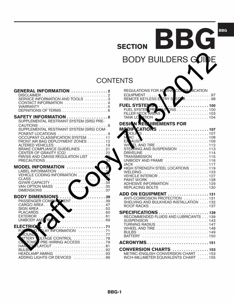
GENERAL INFORMATION . . . . . . . . . . . . . . . . 2DISCLAIMER . . . . . . . . . . . . . . . . . . . . . . . . . . . . . 2SERVICE INFORMATION AND TOOLS . . . . . . . . . . 3CONTACT INFORMATION . . . . . . . . . . . . . . . . . . . 4WARRANTY . . . . . . . . . . . . . . . . . . . . . . . . . . . . . 5DEFINITIONS OF TERMS . . . . . . . . . . . . . . . . . . . . 6
SAFETY INFORMATION . . . . . . . . . . . . . . . . . . 8SUPPLEMENTAL RESTRAINT SYSTEM (SRS) PRE-CAUTIONS . . . . . . . . . . . . . . . . . . . . . . . . . . . . . . 8SUPPLEMENTAL RESTRAINT SYSTEM (SRS) COM-PONENT LOCATIONS . . . . . . . . . . . . . . . . . . . . . . 9OCCUPANT CLASSIFICATION SYSTEM . . . . . . . . 11FRONT AIR BAG DEPLOYMENT ZONES . . . . . . . . 12ALTERED VEHICLES . . . . . . . . . . . . . . . . . . . . . . 19BRAKE COMPLIANCE GUIDELINES . . . . . . . . . . . 21CENTER OF GRAVITY (CG) . . . . . . . . . . . . . . . . . 22FMVSS AND CMVSS REGULATION LIST . . . . . . . 29PRECAUTIONS . . . . . . . . . . . . . . . . . . . . . . . . . . 30
MODEL INFORMATION . . . . . . . . . . . . . . . . . 31LABEL INFORMATION . . . . . . . . . . . . . . . . . . . . . 31VEHICLE CODING INFORMATION . . . . . . . . . . . . 32CLASS . . . . . . . . . . . . . . . . . . . . . . . . . . . . . . . . 33GVWR CAPACITY . . . . . . . . . . . . . . . . . . . . . . . . 34VAN OPTION MASS . . . . . . . . . . . . . . . . . . . . . . 35DIMENSIONS . . . . . . . . . . . . . . . . . . . . . . . . . . . 37
BODY DIMENSIONS . . . . . . . . . . . . . . . . . . . . 39PASSENGER COMPARTMENT . . . . . . . . . . . . . . . 39CARGO AREA . . . . . . . . . . . . . . . . . . . . . . . . . . . 47SIGN AREA . . . . . . . . . . . . . . . . . . . . . . . . . . . . . 52PLACARDS . . . . . . . . . . . . . . . . . . . . . . . . . . . . . 60EXTERIOR . . . . . . . . . . . . . . . . . . . . . . . . . . . . . 61UNIBODY AND FRAME . . . . . . . . . . . . . . . . . . . . 69
ELECTRICAL . . . . . . . . . . . . . . . . . . . . . . . . . . . 71FUSE AND RELAY INFORMATION . . . . . . . . . . . . 71GROUNDS . . . . . . . . . . . . . . . . . . . . . . . . . . . . . 77BATTERY VOLTAGE CONTROL . . . . . . . . . . . . . . 78CUSTOMER PRE-WIRING ACCESS . . . . . . . . . . . 79HARNESS LAYOUT . . . . . . . . . . . . . . . . . . . . . . . 81BULBS . . . . . . . . . . . . . . . . . . . . . . . . . . . . . . . . 92HEADLAMP AIMING . . . . . . . . . . . . . . . . . . . . . . 93ADDING LIGHTS OR DEVICES . . . . . . . . . . . . . . 96
REGULATIONS FOR ADDING COMMUNICATIONEQUIPMENT . . . . . . . . . . . . . . . . . . . . . . . . . . . . 97REMOTE KEYLESS ENTRY SYSTEM . . . . . . . . . . . 98
FUEL SYSTEMS . . . . . . . . . . . . . . . . . . . . . . . 100FUEL SYSTEM PRECAUTIONS . . . . . . . . . . . . . . 100FILLER NECK AREAS . . . . . . . . . . . . . . . . . . . . . 103TANK LOCATION . . . . . . . . . . . . . . . . . . . . . . . . 104
DESIGN REQUIREMENTS FORMODIFICATIONS . . . . . . . . . . . . . . . . . . . . . . 107
COOLING . . . . . . . . . . . . . . . . . . . . . . . . . . . . . 107HVAC . . . . . . . . . . . . . . . . . . . . . . . . . . . . . . . . 108EXHAUST . . . . . . . . . . . . . . . . . . . . . . . . . . . . . 109WHEEL AND TIRE . . . . . . . . . . . . . . . . . . . . . . . 112STEERING AND SUSPENSION . . . . . . . . . . . . . 113DRIVELINE . . . . . . . . . . . . . . . . . . . . . . . . . . . . 114TRANSMISSION . . . . . . . . . . . . . . . . . . . . . . . . 115UNIBODY AND FRAME . . . . . . . . . . . . . . . . . . . 116JACK . . . . . . . . . . . . . . . . . . . . . . . . . . . . . . . . 117HIGH STRENGTH STEEL LOCATIONS . . . . . . . . 119WELDING . . . . . . . . . . . . . . . . . . . . . . . . . . . . . 123VEHICLE INTERIOR . . . . . . . . . . . . . . . . . . . . . . 127PAINT WORK . . . . . . . . . . . . . . . . . . . . . . . . . . 128ADHESIVE INFORMATION . . . . . . . . . . . . . . . . . 129REPLACING BOLTS . . . . . . . . . . . . . . . . . . . . . 130
ADD ON EQUIPMENT . . . . . . . . . . . . . . . . . . 131ANTI-CORROSION PROTECTION . . . . . . . . . . . 131SHELVING AND BULKHEAD INSTALLATION . . . . 132ROOF RACKS . . . . . . . . . . . . . . . . . . . . . . . . . . 137
SPECIFICATIONS . . . . . . . . . . . . . . . . . . . . . . 139RECOMMENDED FLUIDS AND LUBRICANTS . . . 139SUSPENSION . . . . . . . . . . . . . . . . . . . . . . . . . . 143TURNING RADIUS . . . . . . . . . . . . . . . . . . . . . . . 147WHEEL AND TIRE . . . . . . . . . . . . . . . . . . . . . . . 148BULBS . . . . . . . . . . . . . . . . . . . . . . . . . . . . . . . 149BATTERY . . . . . . . . . . . . . . . . . . . . . . . . . . . . . 150
ACRONYMS . . . . . . . . . . . . . . . . . . . . . . . . . . . 151
CONVERSION CHARTS . . . . . . . . . . . . . . . . 153METRIC-ENGLISH CONVERSION CHART . . . . . 153INCH-MILLIMETER EQUIVALENTS CHART . . . . . 155
BBG-1
SECTION BBGBODY BUILDERS GUIDE
BBG

Draft C
opy 7
/13/20
12GENERAL INFORMATIONDISCLAIMER
Important Regulatory Information
Emission standards and motor vehicle safety standards for new vehicles and equipment have been establishedby the United States and Canadian Governments under the provisions of the Clean Air Act, the Noise ControlAct, and the National Traffic and Motor Vehicle Safety Act in the U.S., and the Canadian Motor Vehicle Safety Actin Canada. These Acts govern NISSAN as the original equipment manufacturer of the NISSAN NV200 CargoVans. They also govern dealers, body builders, and all others who manufacture and market new motor vehiclesand equipment. Part 568 of the Title 49 Code of Federal Regulations (CFR) describes requirements forintermediate manufacturers, final-stage manufacturers, and manufacturers who assume legal responsibility for avehicle. This Body Builder’s Guide (Guide) partially fulfills NISSAN’s obligations as the original equipmentmanufacturer. Additionally, this guide identifies regulatory requirements to assist intermediate and final stagemanufacturers to determine their obligations to conform with these standards.
Compliance labels affixed to NISSAN NV200 Cargo Vans provide the status of initial compliance at the date ofmanufacture by NISSAN. Subsequent modifications made to this vehicle may affect the final certification of theengine, vehicle or equipment. The body builder, conversion company, or dealer has the responsibility to certifythat the altered vehicle and equipment complies or continues to comply with all applicable motor vehicle safetystandards and emissions regulations. The body builder, conversion company, or dealer is responsible for makingsure the modifications or installed equipment does not affect the safety of the vehicle, which may result in acollision, serious personal injury or death.
NISSAN does not assume the responsibility as the final stage manufacturer for modified or altered vehicles.NISSAN is not responsible for the final certification, product liability claims, or warranty claims, resulting from anycomponent, assembly, or system being altered by the body builder, conversion company, dealer or vehiclepurchaser. NISSAN is not responsible for modifications which cause the vehicle to become noncompliant withany of the motor vehicle safety standards, emissions regulations, or modifications that cause the vehicle to be orbecome defective or unsafe.
Disclaimer
All information, specifications and illustrations in this manual are those in effect at the time of printing. NISSANreserves the right to change specifications or design without notice and without obligation.
The body builder, conversion company, aftermarket equipment manufacturer, second stage manufacturer, upfitter,dealer and the vehicle purchaser are responsible to abide by the regulations issued by the National HighwayTraffic Safety Administration (NHTSA), the Occupational Safety and Health Act (OSHA), state, local, orprovincial government laws. These regulations and laws may require the installation of additional equipment forthe intended vehicle uses.
© 2012 NISSAN NORTH AMERICA, INC. All rights reserved. No part of this Body Builder’s Guide may bereproduced or stored in a retrieval system, or transmitted in any form, or by any means, electronic, mechanical,photocopying, recording or otherwise, without the prior written permission of NISSAN North America, Inc.
DISCLAIMER[GENERAL INFORMATION]
BBG-2

Draft C
opy 7
/13/20
12SERVICE INFORMATION AND TOOLS
For service information, refer to http://www.nissan-techinfo.com.
For special service tools, refer to http://www.nissantechmate.com.
SERVICE INFORMATION AND TOOLS[GENERAL INFORMATION]
BBG-3
BBG

Draft C
opy 7
/13/20
12CONTACT INFORMATION
General
NISSAN Commercial and Fleet Aftermarket Engineering (248) 488-4862.
CONTACT INFORMATION[GENERAL INFORMATION]
BBG-4

Draft C
opy 7
/13/20
12WARRANTY
Emissions Control System Warranty
For NISSAN warranty information, refer to the Warranty Information Booklet in the Owner’s Manual package.
WARRANTY[GENERAL INFORMATION]
BBG-5
BBG

Draft C
opy 7
/13/20
12DEFINITIONS OF TERMS
The following definitions are from Title 49, Code of Federal Regulations, Parts 567.3, 568.3 and 571.3 wherenoted. Canadian definitions are from Canada Motor Vehicle Safety Regulations, Section 2(1), and are in italics.NISSAN definitions are for the purpose of this publication only. Some terms are followed by an abbreviation thatis used throughout this publication.
USA
Brake Switch — Brake switch signal is applied to the ECM through the stop lamp switch when the brake pedalis depressed. This signal is used mainly to decrease the engine speed while driving the vehicle.
Completed Vehicle — A vehicle that requires no further manufacturing operations to perform its intendedfunction, other than the addition of readily attachable components, such as mirrors or tire and rim assemblies, orminor finishing operations such as painting. (49CFR568.3)
Curb Weight — Is the weight of a motor vehicle with standard equipment; maximum capacity of engine fuel, oil,and coolant; and if so equipped, air conditioning and additional weight optional engine. (49CFR571.3)
Engine Control Module (ECM) — The ECM consists of a microcomputer and connectors for signal input andoutput and for the power supply, and also controls the engine.
Gross Combination Weight Rating (GCWR) — The value specified by the manufacturer as the loaded weightof a combination vehicle. (49CFR571.3)
Gross Vehicle Weight Rating (GVWR) — The value specified by the manufacturer as the loaded weight of asingle vehicle. (49CFR571.3)
HO2 Heated Oxygen Sensor — The sensor after the three-way catalyst (manifold) that monitors the oxygenlevel in the exhaust gas on each bank.
Lamps, Reflective Devices, and Associated Equipment — A lamp that is mounted on a multipurposepassenger vehicle, truck, or bus for the purpose of providing illumination to load or unload cargo.
Seating system— Any seating position that can be adjusted to conform to different configurations.
SgRP — The theoretical hip point used by manufacturers when designing a vehicle. More specifically, itdescribes the relative position of the seated dummy’s hip point when the seat is set in the rearmost andlowermost seating position. Also known as the “R-point” (reference point).
Throttle Position Sensor (TPS) — The electric throttle control actuator that consists of the throttle controlmotor, throttle position sensor, etc. The throttle position sensor responds to the throttle valve movement.
Truck — A motor vehicle with motive power, except a trailer, designed primarily for the transportation of propertyor special purpose equipment. (49CFR571.3)
Unloaded Vehicle Weight (UVW) — The weight of a vehicle with maximum capacity of all fluids necessary foroperation of the vehicle, but without cargo, occupants, or accessories that are ordinarily removed from the vehiclewhen it is not in use. (49CFR571.3)
Vehicle Speed Sensor (VSS) — ECM receives vehicle speed signals from two different paths via CANcommunication line: One is from the ABS actuator and electric unit (control unit) via the combination unit, and theother is from the TCM.
Canada
Brake Switch — Brake switch signal that is applied to the ECM through the stoplamp switch when the brakepedal is depressed. This signal is used mainly to decrease the engine speed when driving the vehicle.
Completed Vehicle — A vehicle that needs no further manufacturing operations to perform its intendedfunction, other than the addition of readily attachable components, such as minor finishing operations such aspainting.
DEFINITIONS OF TERMS[GENERAL INFORMATION]
BBG-6

Draft C
opy 7
/13/20
12Curb Weight — Is the weight of a vehicle with standard equipment and carrying its maximum capacity of fuel,oil, and coolant and includes the weight of any air conditioning equipment on the vehicle and the amount bywhich the weight of any optional engine with which the vehicle is equipped exceeds the weight of the standardengine.
Engine Control Module (ECM) — The ECM consists of a microcomputer and connectors for signal input andoutput and for the power supple. The ECM also controls the engine.
Gross Combination Weight Rating — The value specified by the manufacturer as the loaded weight of acombination vehicle. (49CFR571.3).
Gross Vehicle Weight Rating or (GVWR( — The value specified by the vehicle manufacturer as the loadedweight of a single vehicle.
H02 Heated Oxygen Sensor — The sensor after the three-way catalyst (manifold) that monitors the oxygenlevel in the exhaust gas on each bank.
Lamps, Reflective Devices, and Associated Equipment — A lamp that is mounted on a multipurposepassenger vehicle, truck, or bus for the purpose of providing illumination to load or unload cargo or passenger.
Seating System — Any seating position that can be adjusted to conform to different configurations.
SgRP — The theoretical hip point used by manufacturers when designing a vehicle. More specifically, itdescribes the relative position of the seated dummy’s hip point when the seat is set in the rearmost andlowermost seating position. Also known as the “R-point” (reference point).
Throttle Position Sensor (TPS) — The electric throttle control actuator consisting of the throttle control motor,throttle position sensor, etc. The throttle position sensor responds to the throttle valve movement.
Truck — A motor vehicle designed primarily for the transportation of property or special-purpose equipment, butdoes not include a competition vehicle, a crawler-mounted vehicle, a three-wheeled vehicle, a trailer, a workvehicle, a vehicle imported temporarily for special purposes, a vehicle designed for operation exclusively off-roador a low-speed vehicle.
Unloaded Vehicle Weight — The weight of a vehicle equipped with the containers for the fluids necessary forthe operation of the vehicle filled to their maximum capacity, but without cargo or occupants.
Vehicle Speed Sensor (VSS) — The speed signal sent to the ECM from the sensor. The ECM receives vehiclespeed signals from two different paths via the CAN communication line. One signal is from the ABS actuator andelectric unit (control unit) via the combination unit, and the other signal is sent from the TCM.
DEFINITIONS OF TERMS[GENERAL INFORMATION]
BBG-7
BBG
Draft C
opy 7
/13/20
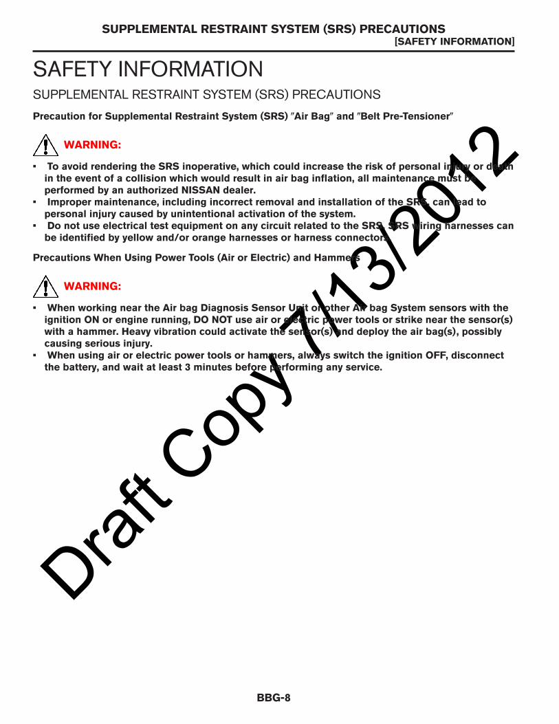
12SAFETY INFORMATIONSUPPLEMENTAL RESTRAINT SYSTEM (SRS) PRECAUTIONS
Precaution for Supplemental Restraint System (SRS) (Air Bag( and (Belt Pre-Tensioner(
WARNING:
• To avoid rendering the SRS inoperative, which could increase the risk of personal injury or deathin the event of a collision which would result in air bag inflation, all maintenance must beperformed by an authorized NISSAN dealer.
• Improper maintenance, including incorrect removal and installation of the SRS, can lead topersonal injury caused by unintentional activation of the system.
• Do not use electrical test equipment on any circuit related to the SRS. SRS wiring harnesses canbe identified by yellow and/or orange harnesses or harness connectors.
Precautions When Using Power Tools (Air or Electric) and Hammers
WARNING:
• When working near the Air bag Diagnosis Sensor Unit or other Air bag System sensors with theignition ON or engine running, DO NOT use air or electric power tools or strike near the sensor(s)with a hammer. Heavy vibration could activate the sensor(s) and deploy the air bag(s), possiblycausing serious injury.
• When using air or electric power tools or hammers, always switch the ignition OFF, disconnectthe battery, and wait at least 3 minutes before performing any service.
SUPPLEMENTAL RESTRAINT SYSTEM (SRS) PRECAUTIONS[SAFETY INFORMATION]
BBG-8

Draft C
opy 7
/13/20
12SUPPLEMENTAL RESTRAINT SYSTEM (SRS) COMPONENT LOCATIONS
012
3
4
56
7 8RPM 1000
20
40
60
20
40
60
80100 120
MPH
km/h 140
160
180
80
120
PS100
7
p
ODO
miles 1/2
1
0
9
6
1
2
5
7
8
3
10
4
AAZIA0152ZZ
SUPPLEMENTAL RESTRAINT SYSTEM (SRS) COMPONENT LOCATIONS[SAFETY INFORMATION]
BBG-9
BBG
Draft C
opy 7
/13/20
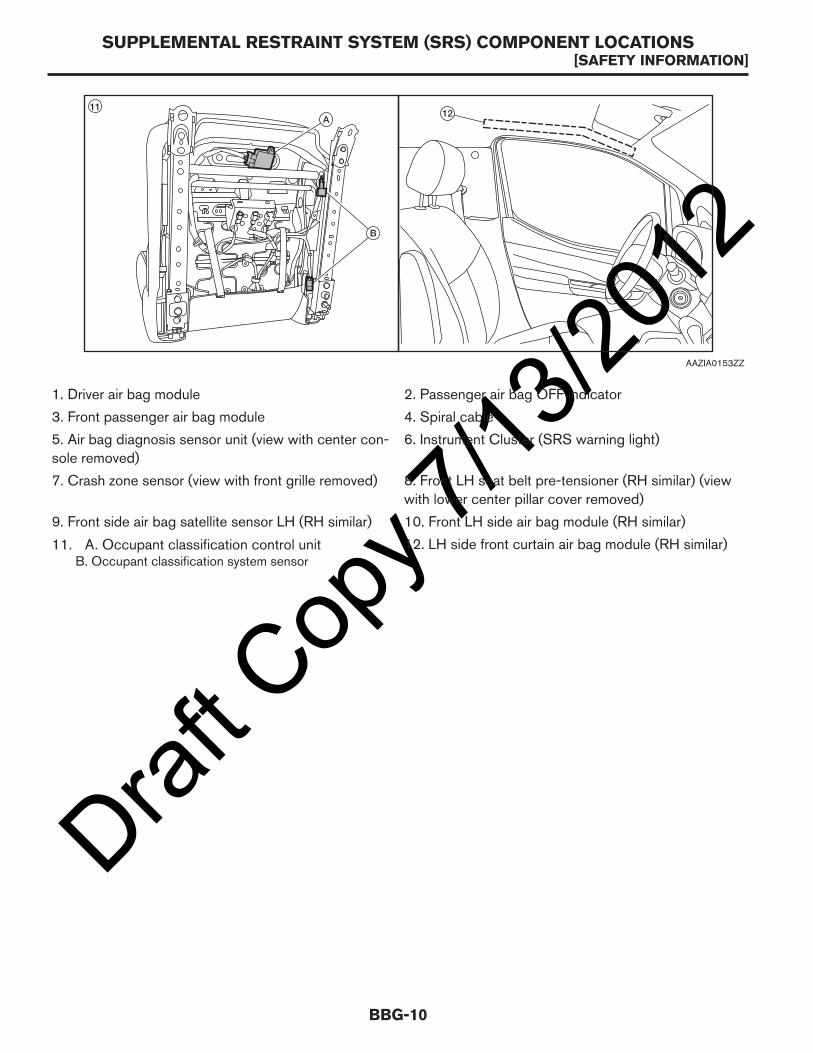
121. Driver air bag module 2. Passenger air bag OFF indicator
3. Front passenger air bag module 4. Spiral cable
5. Air bag diagnosis sensor unit (view with center con-sole removed)
6. Instrument Cluster (SRS warning light)
7. Crash zone sensor (view with front grille removed) 8. Front LH seat belt pre-tensioner (RH similar) (viewwith lower center pillar cover removed)
9. Front side air bag satellite sensor LH (RH similar) 10. Front LH side air bag module (RH similar)
11. A. Occupant classification control unitB. Occupant classification system sensor
12. LH side front curtain air bag module (RH similar)
1211
A
B
AAZIA0153ZZ
SUPPLEMENTAL RESTRAINT SYSTEM (SRS) COMPONENT LOCATIONS[SAFETY INFORMATION]
BBG-10

Draft C
opy 7
/13/20
12OCCUPANT CLASSIFICATION SYSTEM
WARNING:
After removal and installation of the front passenger seat, a zero point reset function must beperformed by a Nissan dealer using a special tool. If zero point reset is not performed, theoccupant classification system may not operate normally which may increase the risk of seriousinjury in a collision.
WARNING:
Do not disturb or modify the front passenger seat wiring. Failure to follow this instruction maycause incorrect operation of the occupant classification system and front passenger air bagor system failure and may increase the risk of serious injury in a collision.
The front passenger seat is equipped with seat weight sensors as part of the supplemental restraints occupantclassification system. The occupant classification sensors (weight sensors) are on the seat cushion frame underthe front passenger seat and are designed to detect an occupant and objects on the seat. The front passengerair bag status lamp is illuminated when the system is disabled. For occupant classification system and frontpassenger air bag operation, refer to the Owner’s Manual. For repair of the front passenger seat, occupantclassification system, air bags or if an air bag warning lamp is illuminated, refer to a Nissan dealer. For seatmounting and fastener torque specifications, refer to Seat Mounting Holes.
OCCUPANT CLASSIFICATION SYSTEM[SAFETY INFORMATION]
BBG-11
BBG

Draft C
opy 7
/13/20
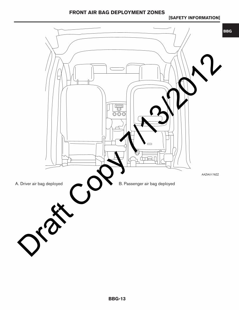
12FRONT AIR BAG DEPLOYMENT ZONES
NOTE:
Do not add accessory items that, when installed, will interfere with the installed position of the air bag or the
zones of the deploying air bags.
A. Driver air bag deployment zone B. Passenger air bag deployment zone
4060
6080
100 120
MPH
km/h 140160180
80100
120
AAZIA0177ZZ
FRONT AIR BAG DEPLOYMENT ZONES[SAFETY INFORMATION]
BBG-12

FRONT AIR BAG DEPLOYMENT ZONES
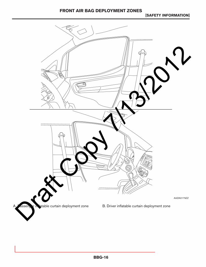
NOTE:
Do not add accessory items that, when installed, will interfere with the installed position of the air bag or the
zones of the deploying air bags.
AAZIA0190GB
A. Driver air bag deployment zone B. Passenger air bag deployment zone
FRONT AIR BAG DEPLOYMENT ZONES[SAFETY INFORMATION]
BBG-11
BBG
Draft C
opy 7
/13/20
12
A. Driver air bag deployed B. Passenger air bag deployed
AAZIA0178ZZ
FRONT AIR BAG DEPLOYMENT ZONES[SAFETY INFORMATION]
BBG-13
BBG

AAZIA0194GB
A. Driver air bag deployed B. Passenger air bag deployed
FRONT AIR BAG DEPLOYMENT ZONES[SAFETY INFORMATION]
BBG-12

Draft C
opy 7
/13/20
12
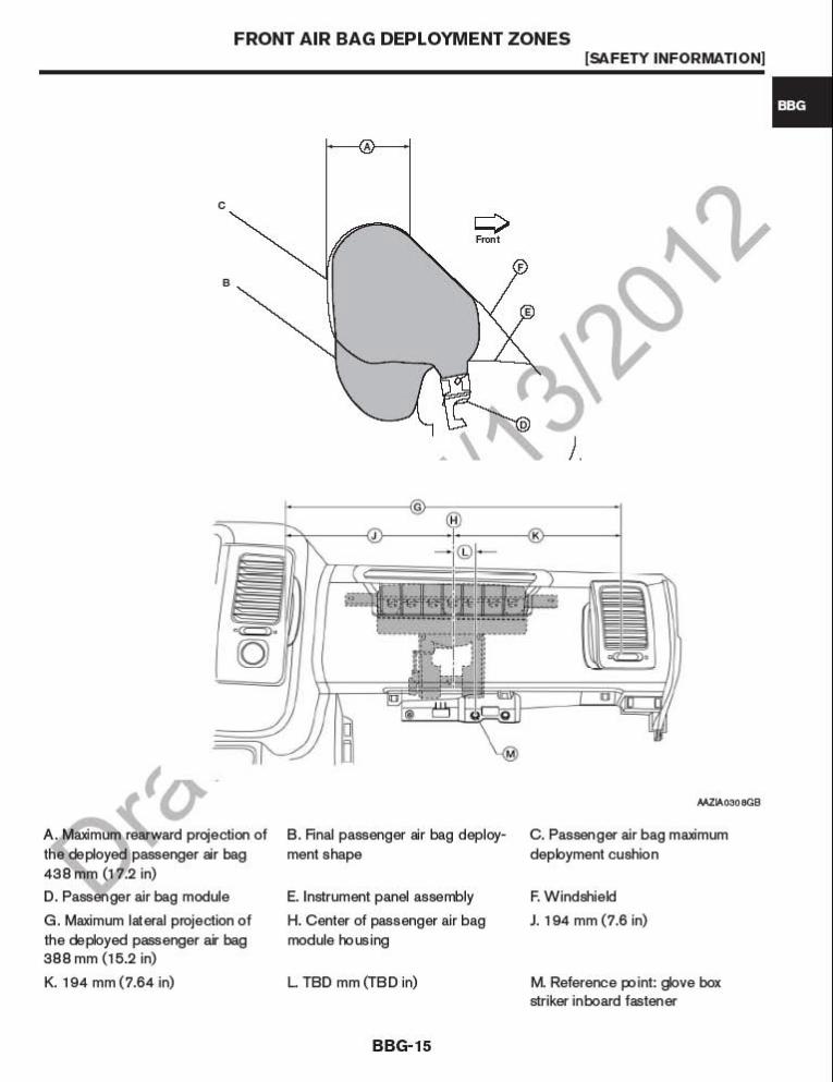
A. Maximum rearward projection ofthe deployed driver air bag TBDmm (TBD in)
B. Steering wheel C. Driver air bag housing
D. Final driver air bag deploymentshape
E. Driver air bag maximum deploy-ment cushion
F. TBD mm (TBD in)
G. Center of the driver air bag mod-ule housing
H. Maximum lateral projection of thedeployed driver air bag TBD mm(TBD in)
J. TBD mm (TBD in)
40
6080
100120140
160180
200
3
45
6 7 8
20
40
60 80
100
120
A
E
D
B
C
AAZIA0182ZZ
FRONT AIR BAG DEPLOYMENT ZONES[SAFETY INFORMATION]
BBG-14

AAZIA0060ZZ
A. Maximum rearward projection ofthe deployed driver air bag 600 mm(23.6 in)
B. Steering wheel C. Driver air bag housing
D. Final driver air bag deploymentshape
E. Driver air bag maximum deploy-ment cushion
F. 300 mm (11.81 in)
G. Center of the driver air bag mod-ule housing
H. Maximum lateral projection ofthe deployed driver air bag 600 mm(23.6 in)
J. 300 mm (11.81 in)
FRONT AIR BAG DEPLOYMENT ZONES[SAFETY INFORMATION]
BBG-13
BBG
Draft C
opy 7
/13/20
12
A. Passenger inflatable curtain deployment zone B. Driver inflatable curtain deployment zone
AAZIA0179ZZ
FRONT AIR BAG DEPLOYMENT ZONES[SAFETY INFORMATION]
BBG-16

AAZIA0191GB
A. Passenger inflatable curtain deployment zone B. Driver inflatable curtain deployment zone
FRONT AIR BAG DEPLOYMENT ZONES[SAFETY INFORMATION]
BBG-15
BBG
Draft C
opy 7
/13/20
12
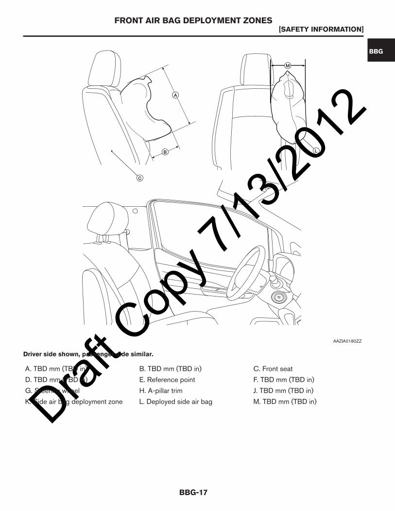
A. TBD mm (TBD in) B. TBD mm (TBD in) C. Front seat
D. TBD mm (TBD in) E. Reference point F. TBD mm (TBD in)
G. Steering wheel H. A-pillar trim J. TBD mm (TBD in)
K. Side air bag deployment zone L. Deployed side air bag M. TBD mm (TBD in)
C
L
A
B
M
AAZIA0180ZZ
Driver side shown, passenger side similar.
FRONT AIR BAG DEPLOYMENT ZONES[SAFETY INFORMATION]
BBG-17
BBG

AAZIA0055ZZ
Driver side shown, passenger side similar.
A. 440 mm (17.3 in) B. 380 mm (14.96 in) C. Front seatD. 600 mm (23.6 in) E. Reference point F. 800 mm (31.5 in)G. Steering wheel H. A-pillar trim J. 170 mm (6.7 in)K. Side air bag deployment zone L. Deployed side air bag M. 210 mm (8.3 in)
FRONT AIR BAG DEPLOYMENT ZONES[SAFETY INFORMATION]
BBG-16

Draft C
opy 7
/13/20
12
A. TBD mm (TBD in) B. TBD mm (TBD in) C. Deployed inflatable curtain
D. Inflatable curtain deploymentzone
E. Reference point F. Front seat
G. Steering wheel H. A-pillar trim J. Center of deployment zone
J - J
A
B
AAZIA0181ZZ
Driver side shown, passenger side similar.
FRONT AIR BAG DEPLOYMENT ZONES[SAFETY INFORMATION]
BBG-18

AAZIA0061ZZ
Driver side shown, passenger side similar.
A. 540 mm (21.3 in) B. 230 mm (9.1 in) C. Deployed inflatable curtainD. Inflatable curtain deploymentzone
E. Reference point F. Front seat
G. Steering wheel H. A-pillar trim J. Center of deployment zone
FRONT AIR BAG DEPLOYMENT ZONES[SAFETY INFORMATION]
BBG-17
BBG
Draft C
opy 7
/13/20
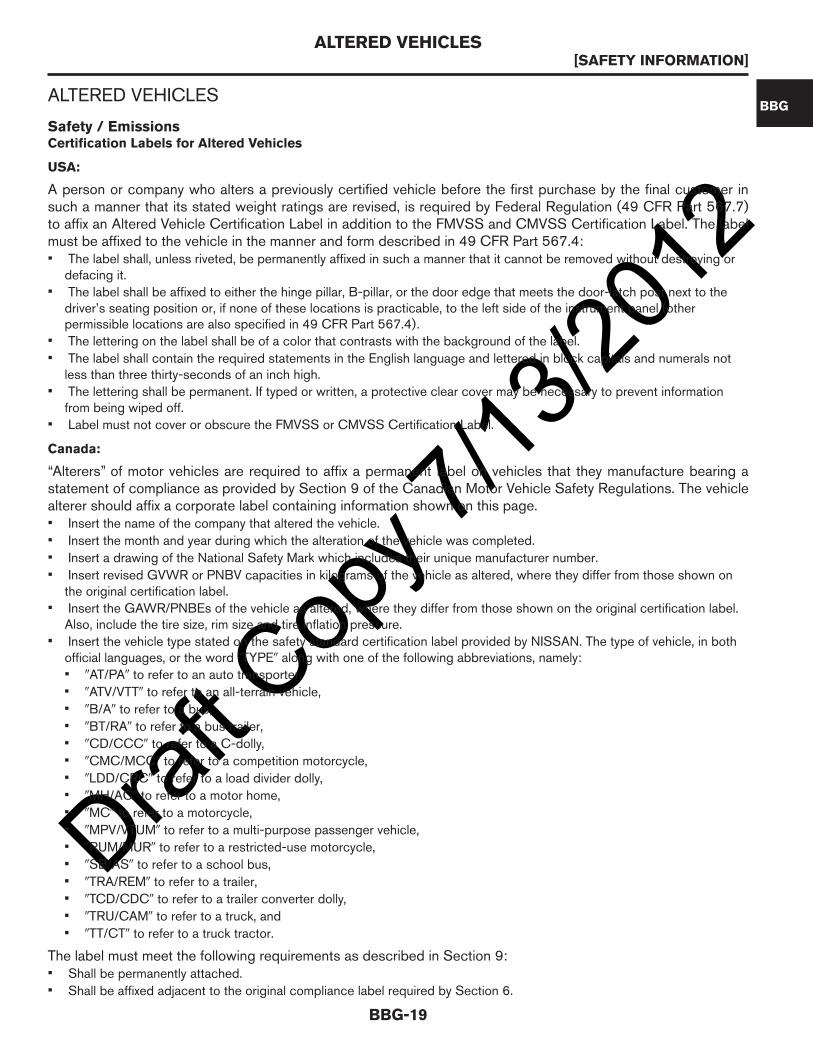
12ALTERED VEHICLES
Safety / EmissionsCertification Labels for Altered Vehicles
USA:
A person or company who alters a previously certified vehicle before the first purchase by the final customer insuch a manner that its stated weight ratings are revised, is required by Federal Regulation (49 CFR Part 567.7)to affix an Altered Vehicle Certification Label in addition to the FMVSS and CMVSS Certification Label. The labelmust be affixed to the vehicle in the manner and form described in 49 CFR Part 567.4:• The label shall, unless riveted, be permanently affixed in such a manner that it cannot be removed without destroying or
defacing it.• The label shall be affixed to either the hinge pillar, B-pillar, or the door edge that meets the door-latch post next to the
driver’s seating position or, if none of these locations is practicable, to the left side of the instrument panel (otherpermissible locations are also specified in 49 CFR Part 567.4).
• The lettering on the label shall be of a color that contrasts with the background of the label.
• The label shall contain the required statements in the English language and lettered in block capitals and numerals notless than three thirty-seconds of an inch high.
• The lettering shall be permanent. If typed or written, a protective clear cover may be necessary to prevent informationfrom being wiped off.
• Label must not cover or obscure the FMVSS or CMVSS Certification Label.
Canada:
“Alterers” of motor vehicles are required to affix a permanent label on vehicles that they manufacture bearing astatement of compliance as provided by Section 9 of the Canadian Motor Vehicle Safety Regulations. The vehiclealterer should affix a corporate label containing information shown on this page.• Insert the name of the company that altered the vehicle.
• Insert the month and year during which the alteration of the vehicle was completed.
• Insert a drawing of the National Safety Mark which includes their unique manufacturer number.
• Insert revised GVWR or PNBV capacities in kilograms of the vehicle as altered, where they differ from those shown onthe original certification label.
• Insert the GAWR/PNBEs of the vehicle as altered, where they differ from those shown on the original certification label.Also, include the tire size, rim size and tire inflation pressure.
• Insert the vehicle type stated on the safety standard certification label provided by NISSAN. The type of vehicle, in bothofficial languages, or the word 9TYPE9 along with one of the following abbreviations, namely:• 9AT/PA9 to refer to an auto transporter,
• 9ATV/VTT9 to refer to an all-terrain vehicle,
• 9B/A9 to refer to a bus,
• 9BT/RA9 to refer to a bus trailer,
• 9CD/CCC9 to refer to a C-dolly,
• 9CMC/MCC9 to refer to a competition motorcycle,
• 9LDD/CRC9 to refer to a load divider dolly,
• 9MH/AC9 to refer to a motor home,
• 9MC9 to refer to a motorcycle,
• 9MPV/VTUM9 to refer to a multi-purpose passenger vehicle,
• 9RUM/MUR9 to refer to a restricted-use motorcycle,
• 9SB/AS9 to refer to a school bus,
• 9TRA/REM9 to refer to a trailer,
• 9TCD/CDC9 to refer to a trailer converter dolly,
• 9TRU/CAM9 to refer to a truck, and
• 9TT/CT9 to refer to a truck tractor.
The label must meet the following requirements as described in Section 9:• Shall be permanently attached.
• Shall be affixed adjacent to the original compliance label required by Section 6.
ALTERED VEHICLES[SAFETY INFORMATION]
BBG-19
BBG

Draft C
opy 7
/13/20
12• The lettering of the label shall be clear, indelible, indented, or embossed, or of a color that contrasts with the background
color of the label, and in block capitals and numerals not less than 2.0 mm (0.1 in) high.• The label shall be permanently affixed to the same surface as that to which the FMVSS or CMVSS label is affixed.
ALTERED VEHICLES[SAFETY INFORMATION]
BBG-20

Draft C
opy 7
/13/20
12BRAKE COMPLIANCE GUIDELINES
Brake Compliance Guidelines (FMVSS and CMVSS 105)
The calculations and abbreviated definitions necessary for the Center of Gravity (CG) measurements areincluded in this manual.
Any changes to the vehicle must still comply with FMVSS and CMVSS 105 allowing for the following provisions:• No alterations, modifications or replacements are made to the following systems:
• parking brake
• anti-lock brakes
• engine vacuum
• steering
• wheels or tires
• brakes
• indicator lamps and wiring
• brake system reservoir labeling
• suspension ride height or spring rate
• engine belt drive
• The vehicle is re-balanced by the addition of an equivalent weight if components are permanently removed.
• The applicable GAWRs and GVWR weights are not exceeded.
• The applicable center of gravity limitations are met using the calculation methods in Center of Gravity (CG) section.
BRAKE COMPLIANCE GUIDELINES[SAFETY INFORMATION]
BBG-21
BBG

Draft C
opy 7
/13/20
12CENTER OF GRAVITY (CG)
Introduction
List of Terms
Term Definition
CGh
Horizontal distance from the center line of the front wheels to the center of gravity of the com-pleted vehicle mm (in).
CGhl
Horizontal distance from the center line of the front wheels to the center of gravity of the cargomm (in). If CGhl is not known, it may be estimated as the distance from the center line of the frontwheels to the horizontal midpoint of the cargo area.
CGhb
Horizontal distance from the center line of the front wheels to the center of gravity of SUB and/orpermanently attached equipment mm (in).
CGhp
Horizontal distance from the center line of the front wheels to the center of gravity of the passen-ger load mm (in). By design is 1,169 mm (46.02 in).
CGv Vertical distance from the ground to the center of gravity of the completed vehicle mm (in).
CGvb
Vertical distance from the ground to the center of gravity of the SUB and/or permanently attachedequipment mm (in).
CGvc Vertical distance from the ground to the center of gravity of the chassis (including cab) mm (in).
CGvl Vertical distance from the ground to the center of gravity of the cargo mm (in).
CGvp Vertical distance from the ground to the center of gravity of the passenger load mm (in).
GVW Actual Gross Vehicle Weight (pounds). GVW = Wb + Wc + Wl + P
GVWR Gross Vehicle Weight Rating of the vehicle kg (lbs).
P Passenger load 136 kg (300 lbs).
Pf Passenger front load distribution kg (lbs). Pf = P – Pr
Pr Passenger rear load distribution kg (lbs). Pr =PCGhp
WB
CGvl
Wf Wc WrlWrb Wb
WlWrc
GVWR
CGvb
CGv
CGvc
CGvp
CGhp
CGh
CGhl
CGhb
WB
P
CG OF CARGO
CG OF CHASSIS
CG OF COMPLETED VEHICLE
CG OF SUB
SUB
AAZIA0312GB
CENTER OF GRAVITY (CG)[SAFETY INFORMATION]
BBG-22

Draft C
opy 7
/13/20
12Term Definition
SUBA Second Unit Body consists of the body structure and/or all the cargo carrying, work performingand/or load bearing components and/or equipment installed by a subsequent stage manufactureron an incomplete vehicle, so that the incomplete vehicle becomes a completed vehicle.
Wb Weight of the SUB and/or permanently attached added equipment kg (lbs).
WB Vehicle wheelbase mm (in).
Wrb Weight at the rear wheels of the SUB and/or permanently attached added equipment kg (lbs).
Wc Weight of the vehicle (chassis and cab) (fuel tank full) kg (lbs), including options weight.
Wl Weight of the cargo kg (lbs).
Wrc
Weight at the rear wheels of the vehicle (chassis and cab) (fuel tank full) kg (lbs), includingoptions weight.
Wf Weight at front wheels.
Wrl Weight at the cargo on the rear wheels kg (lbs). Wrl =WlCGhl
WB
This information is being used to assist upfitters in determining the vehicle center of gravity (horizontal andvertical distances). This has been prepared for the use of knowledgeable test engineers. It is not a how-todocument for people without technical training.
Recommended Procedure
Setup
The following vehicle conditions should be verified prior to the measurement:• Vehicle Mass: Unloaded Vehicle Condition — Full fluids, spare tire, jack and tire tool.
• Vehicle Posture: Unloaded Vehicle Condition — Adjust fender opening height to the design value.
• Tire: Production parts shall be used. Tire pressure should be set to the specified pressure on the Tire Placard (locatednear the front LH door striker) once the vehicle has cooled.
• Steering Wheel: Set to center of stroke with wheels pointing forward.
• Seats: Adjust to reference position:
• Longitudinal slide: Center of slide• Seat Lifter: Lowermost• Back angle: Set to normal driving condition or as close to 23° as possible.
• Window Glass: Fully closed.
• Other Parts: Production parts shall be used.
• Road Surface to be used: Flat load cell.
• Measurement Needed: Wheelbase, height of wheel centers from ground, lifting heights, axle load.
• Shift Position: Neutral. For safety, apply the parking brake.
Measurement Methods
1. The vehicle should be at its unladen vehicle condition, with full fluids and equipped with spare tire, jack and tools.
2. Measure the wheelbase of the vehicle (ℓ) on the left-hand and right-hand sides of the vehicle and use theaverage value for the calculations. Measure the height of the 4 wheel centers from the ground to get hf and hr.
3. Replace the shock absorbers with turnbuckles or solid link to avoid suspension travel.
4. Increase the tire air pressure to the maximum recommended level specified in tire placard or Owner’s Manual.
5. Once the vehicle is on the scale, set the parking brake to prevent vehicle from rolling.
6. Measure the rear wheel load (WR) in a horizontal position.
7. Raise the front of the vehicle with a hoist. Lift height should be at 0.5 m (1.6 ft) to start, with additional lift heightsused to improve accuracy. (i.e., 0.5 m (1.6 ft) + a, 0.5 m (1.6 ft) + B).
8. Measure the rear wheel load (WR) with raised vehicle.
CENTER OF GRAVITY (CG)[SAFETY INFORMATION]
BBG-23
BBG

Draft C
opy 7
/13/20
129. Change the lift height and measure the load on the rear wheel to find the relationship between lift and load. Measure
two times for each lift height.
10. Follow the same procedure from (7) to (9) by raising the rear wheels.
Analysis Method
1. Plot the relation between the lift height (E) and the load on rear wheels (WR) for raising the front wheels and therelation between the lift (E) and the load on the front wheels (WF) for raising the rear wheels. Draw a regression linefor both cases with front or rear wheels raised.
2. Obtain the shifted load (D WF) for the lift (E) according to the graph. D WR and DWF with E = 0.5 m (1.6 ft.) shall berepresentative value.
3. Calculate the CG height by using the following equations:
Results
The center of gravity height (H) obtained is theoretically the same for both cases with the front or rear wheelsraised. The accuracy of the results should be verified by performing several tests and averaging the results.
hf hr
e
SCALE
LIFT
AAZIA0313GB
AAZIA0282GB
CENTER OF GRAVITY (CG)[SAFETY INFORMATION]
BBG-24

Draft C
opy 7
/13/20
12Unloaded Vehicle Weight (UVW) Vertical Center of Gravity
WB WbWf Wrb
CARGO AREA
CG AREA TO INSTALL
ARC MAX 134 kg
SCALESCALE
AAZIA0314GB
CENTER OF GRAVITY (CG)[SAFETY INFORMATION]
BBG-25
BBG

Draft C
opy 7
/13/20
12UVW Resource Chart
If ARC CGhb is located greater than or equal to 2,400 mm (94.49 in), then:
Model Wheelbasemm (in)
Engine MaxGVWRkg (lbs)
MaxPayloadkg (lbs)
*1
ARCWeightkg (lbs)
*2
MaxCargokg (lbs)
*3
Max GAWRkg (lbs)
Base Curb Weightkg (lbs)
Front Rear Front Rear Total
S2,925(115.2)
2.0 L2,140(4,718)
681.1(1,501.5)
134 (295)Refer to“Max C”
1,040(2,293)
1,150(2,535)
894.9(1,973)
564(1,243)
1,458.9(3,216)
SV2,925(115.2)
2.0 L2,140(4,718)
671.9(1,481.9)
134 (295)1,040(2,293)
1,150(2,535)
896.6(1,977)
571.4(1,260)
1,468(3,236)
*1: Load rating representing maximum allowable weight of people, cargo and body equipment and is reduced by optional equipment weight.
*2: ARC aftermarket equipment Accessory Reserve Capacity for models with standard equipment.
*3: When an ARC is installed, the Max Cargo capacity must be considered, in order to keep good performance with mechanical limits.
The CG hb can be approximated using the following formula:CGhb =
Wrb x WB
Wb
The Max C can be approximated using the following formula:Max C =
(FRGAWR – Wf – Pf) x WB
WB – CGhb
After calculating Max C, GVW can be confirmed using the followingformula:
GVW = Wc + Wb + Max C + PIf GVW is greater than GVWR, then Max C must be reduced .
CENTER
OFGRAVITY
(CG)
[SAFETYIN
FORMATIO
N]
BBG-26
Draft C
opy 7
/13/20
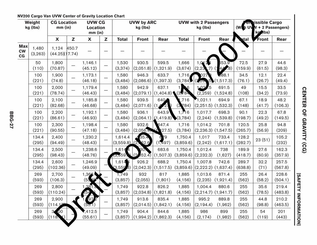
12NV200 Cargo Van UVW Center of Gravity Location Chart
Weightkg (lbs)
CG Locationmm (in)
UVW CGLocationmm (in)
UVW by ARCkg (lbs)
UVW with 2 Passengerskg (lbs)
Permissible Cargo(With UVW + 2 Passengers)
kg (lbs)
X Z X Z Total Front Rear Total Front Rear Total Front Rear
MaxCWCG
1,480(3,263)
1,124(44.25)
450.7(17.74)
— — — — — — — — — — —
50(110)
1,800(70.87)
—1,146.1(45.12)
—1,530(3,374)
930.5(2,051.8)
599.5(1,321.9)
1,666(3,674)
1,012.1(2,231.7)
653.9(1,441.8)
72.5(159.9)
27.9(61.5)
44.6(98.3)
100(221)
1,900(74.8)
—1,173.1(46.18)
—1,580(3,484)
946.3(2,086.6)
633.7(1,397.3)
1,716(3,784)
1,027.9(2,266.5)
688.1(1,517.3)
34.5(76.1)
12.1(26.7)
22.4(49.4)
100(221)
2,000(78.74)
—1,179.4(46.43)
—1,580(3,484)
942.9(2,079.1)
637.1(1,404.8)
1,716(3,784)
1,024.5(2,259)
691.5(1,524.8)
49(108)
15.5(34.2)
33.5(73.9)
100(221)
2,100(82.68)
—1,185.8(46.68)
—1,580(3,484)
939.5(2,071.6)
640.5(1,412.3)
1,716(3,784)
1,021.1(2,251.5)
694.9(1,532.3)
67.1(148)
18.9(41.7)
48.2(106.3)
100(221)
2,200(86.61)
—1,192.1(46.93)
—1,580(3,484)
936.1(2,064.1)
643.9(1,419.8)
1,716(3,784)
1,017.7(2,244)
698.3(1,539.8)
90.1(198.7)
22.3(49.2)
67.8(149.5)
100(221)
2,300(90.55)
—1,198.4(47.18)
—1,580(3,484)
932.6(2,056.4)
647.4(1,427.5)
1,716(3,784)
1,014.2(2,236.3)
701.8(1,547.5)
120.5(265.7)
25.8(56.9)
94.8(209)
134.4(295)
2,400(94.49)
—1,230.2(48.43)
—1,614.4(3,559.8)
935.4(2,062.6)
679(1,497)
1,750.4(3,859.6)
1,017(2,242)
733.4(1,617.1)
128.2(282.7)
23 (51)105.2(232)
134.4(295)
2,500(98.43)
—1,238.6(48.76)
—1,614.4(3,559.8)
930.8(2,052.4)
683.6(1,507.3)
1,750.4(3,859.6)
1,012.4(2,232.3)
738(1,627)
189.9(418.7)
27.6(60.9)
162.3(357.9)
134.4(295)
2,600(102.36)
—1,246.9(49.09)
—1,614.4(3,559.8)
926.2(2,042.3)
688.2(1,517.5)
1,750.4(3,859.6)
1,007.8(2,222.2)
742.6(1,637.4)
289.7(638.8)
32.2(71)
257.5(567.8)
269(593)
2,700(106.3)
—1,366.4(53.8)
—1,749(3,857)
932(2,055)
817(1,801)
1,885(4,156)
1,013.6(2,235)
871.4(1,921.4)
255(562)
26.4(58.2)
228.6(504.1)
269(593)
2,800(110.24)
—1,381.8(54.4)
—1,749(3,857)
922.8(2,034.8)
826.2(1,821.8)
1,885(4,156)
1,004.4(2,214.7)
880.6(1,941.7)
255(562)
35.6(78.5)
219.4(483.8)
269(593)
2,900(114.17)
—1,397.2(55.1)
—1,749(3,857)
913.6(2,014.5)
835.4(1,842.1)
1,885(4,156)
995.2(2,194.4)
889.8(1,962)
255(562)
44.8(98.8)
210.2(463.5)
269(593)
3,000(118.11)
—1,412.5(55.61)
—1,749(3,857)
904.4(1,994.2)
844.6(1,862.3)
1,885(4,156)
986(2,174)
899(1,982)
255(562)
54(119)
201(443)
CENTER
OFGRAVITY
(CG)
[SAFETYIN
FORMATIO
N]
BBG-27

Draft C
opy 7
/13/20
12
F/CMVSS 126 Electronic Stability Control Systems and F/CMVSS 135 Light Vehicle Brake Systems
For Body Builder’s use and applicable to F/CMVSS 126 (1) and 135 (2), the vertical vehicle center of gravitylocation can be approximated by following the formula below:
The Vertical Center of Gravity of completed vehicle at Unloaded Vehicle Weight + 136 kg (300 lbs) PassengerLoad CGv (Equation 1 and 2 above) must not exceed 846 mm (33 in), when measured from the ground.
(1)CGCG CG
=++
(2)CGCG CG CG
=+ +
+ +
AAZIA0183ZZ
CENTER OF GRAVITY (CG)[SAFETY INFORMATION]
BBG-28

Draft C
opy 7
/13/20
12FMVSS AND CMVSS REGULATION LIST
Standards
For FMVSS standards, refer to the following website:
http://www.nhtsa.gov/staticfiles/rulemaking/pdf/FMVSS-QuickRefGuide-HS811439.pdf
For CMVSS standards, refer to the following website:
http://www.tc.gc.ca/eng/acts-regulations/regulations-crc-c1038.htm
FMVSS AND CMVSS REGULATION LIST[SAFETY INFORMATION]
BBG-29
BBG

Draft C
opy 7
/13/20
12PRECAUTIONS
Precautions For Electrical CAN (Controller Area Network) System• Do not modify the CAN system.• For additional information and identification of CAN system, refer to the Service Manual or contact NISSAN
Commercial and Fleet Aftermarket Engineering (248) 488–4862.
PRECAUTIONS[SAFETY INFORMATION]
BBG-30
Draft C
opy 7
/13/20
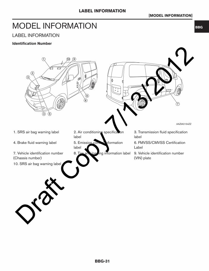
12MODEL INFORMATIONLABEL INFORMATION
Identification Number
1. SRS air bag warning label 2. Air conditioning specificationlabel
3. Transmission fluid specificationlabel
4. Brake fluid warning label 5. Emission control informationlabel
6. FMVSS/CMVSS CertificationLabel
7. Vehicle identification number(Chassis number)
8. Tire and loading information label 9. Vehicle identification number(VIN) plate
10. SRS air bag warning label
1 910
2
3
4 5
6
8
7
AAZIA0154ZZ
LABEL INFORMATION[MODEL INFORMATION]
BBG-31
BBG

Draft C
opy 7
/13/20
12VEHICLE CODING INFORMATION
Vehicle IdentificationVehicle Identification Number Arrangement
Position Character Qualifier Definition
1
3N6 Manufacturer3N6: Mexico producedNISSAN Truck
2
3
4 C Engine type C: MR20DE
5M0 Vehicle line M0: Model Code M20
6
7 K Body type K: Cargo Van
8 NGross vehicle weight rat-ing
N: 2 Seating Capacity,2WD, Class C + Driverand Passenger 3-PointManual Belts, Frontal AirBags, Side Air Bags andCurtain Side Air Bags
9 * Check digit
(0 to 9 or X) The code forthe check digit is deter-mined by a mathematicalcomputation.
10 D Model year D: 2013
11 K Manufacturing plantK: CIVAC (Cuernavaca,Mexico)
12
XXXXXX Vehicle serial number Chassis number
13
14
15
16
17
VEHICLE CODING INFORMATION[MODEL INFORMATION]
BBG-32

Draft C
opy 7
/13/20
12CLASS
Model Variation
Prefix and suffix designations:
Position Character Qualifier Definition
1 Y Body type Y: Cargo Van
2DR Engine DR: MR20DE (2.0L)
3
4 A Axle A: 2WD
5 L Drive L: LH
6 D GradeD: S
G: SV
7 V Transmission V: CVT
8
M20 Model M20: NV2009
10
11 E Intake E: EGI
12 U ZoneN: Canada
U: Federal
13 A Equipment A: Std. Equipment
14
XXXXX Option Codes Option Codes
15
16
17
18
Body Engine Transmission Destination Grade Equipment Model
Cargo VanMR20DE(2.0L)
CVT
Federal
SV NV200YDRALGV-
EUA
S NV200YDRALDV-
EUA
Canada
SV NV200YDRALGV-
ENA
S NV200YDRALDV-
ENA
CLASS[MODEL INFORMATION]
BBG-33
BBG

Draft C
opy 7
/13/20
12GVWR CAPACITY
Gross Vehicle Weight Rating (GVWR) is the weight specified by NISSAN as the maximum allowable weight forthe loaded vehicle.
The GVW must not exceed the Gross Vehicle Weight Rating (GVWR) shown on the FMVSS/CMVSSCertification Label. The GVW equals the combined weight of the unloaded vehicle, passengers, luggage and anyother optional equipment. In addition, front or rear GAW must not exceed the Gross Axle Weight Rating (GAWR)shown on the FMVSS/CMVSS Certification Label.
GVWR CAPACITY[MODEL INFORMATION]
BBG-34
Draft C
opy 7
/13/20
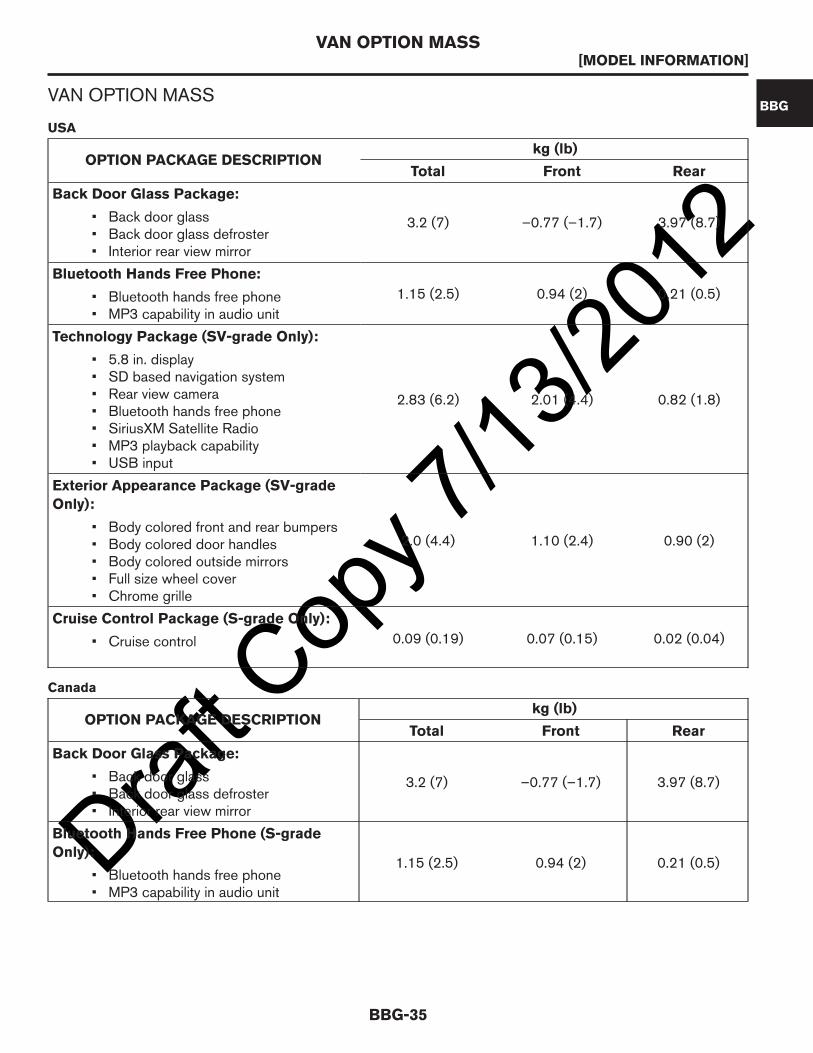
12VAN OPTION MASS
USA
OPTION PACKAGE DESCRIPTIONkg (lb)
Total Front Rear
Back Door Glass Package:
3.2 (7) –0.77 (–1.7) 3.97 (8.7)• Back door glass• Back door glass defroster• Interior rear view mirror
Bluetooth Hands Free Phone:
1.15 (2.5) 0.94 (2) 0.21 (0.5)• Bluetooth hands free phone• MP3 capability in audio unit
Technology Package (SV-grade Only):
2.83 (6.2) 2.01 (4.4) 0.82 (1.8)
• 5.8 in. display• SD based navigation system• Rear view camera• Bluetooth hands free phone• SiriusXM Satellite Radio• MP3 playback capability• USB input
Exterior Appearance Package (SV-grade
Only):
2.0 (4.4) 1.10 (2.4) 0.90 (2)• Body colored front and rear bumpers• Body colored door handles• Body colored outside mirrors• Full size wheel cover• Chrome grille
Cruise Control Package (S-grade Only):
0.09 (0.19) 0.07 (0.15) 0.02 (0.04)• Cruise control
Canada
OPTION PACKAGE DESCRIPTIONkg (lb)
Total Front Rear
Back Door Glass Package:
3.2 (7) –0.77 (–1.7) 3.97 (8.7)• Back door glass• Back door glass defroster• Interior rear view mirror
Bluetooth Hands Free Phone (S-grade
Only):1.15 (2.5) 0.94 (2) 0.21 (0.5)
• Bluetooth hands free phone• MP3 capability in audio unit
VAN OPTION MASS[MODEL INFORMATION]
BBG-35
BBG
Draft C
opy 7
/13/20
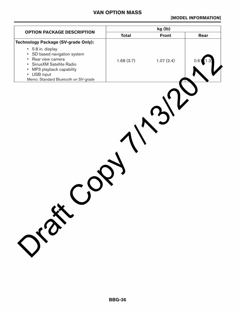
12OPTION PACKAGE DESCRIPTION
kg (lb)
Total Front Rear
Technology Package (SV-grade Only):
1.68 (3.7) 1.07 (2.4) 0.61 (1.3)
• 5.8 in. display• SD based navigation system• Rear view camera• SiriusXM Satellite Radio• MP3 playback capability• USB inputMemo: Standard Bluetooth on SV-grade
VAN OPTION MASS[MODEL INFORMATION]
BBG-36
Draft C
opy 7
/13/20
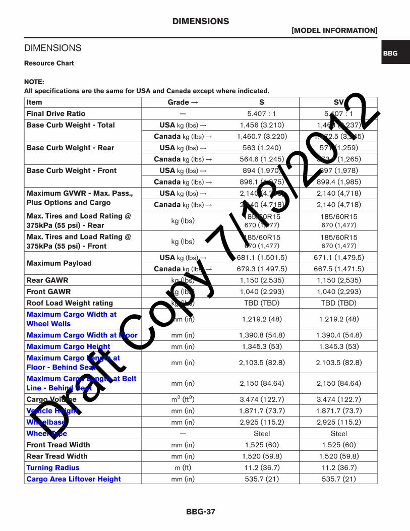
12DIMENSIONS
Resource Chart
NOTE:
All specifications are the same for USA and Canada except where indicated.
Item Grade → S SV
Final Drive Ratio — 5.407 : 1 5.407 : 1
Base Curb Weight - Total USA kg (lbs) → 1,456 (3,210) 1,468 (3,237)
Canada kg (lbs) → 1,460.7 (3,220) 1,472.5 (3,245)
Base Curb Weight - Rear USA kg (lbs) → 563 (1,240) 571 (1,259)
Canada kg (lbs) → 564.6 (1,245) 573.1 (1,265)
Base Curb Weight - Front USA kg (lbs) → 894 (1,970) 897 (1,978)
Canada kg (lbs) → 896.1 (1,975) 899.4 (1,985)
Maximum GVWR - Max. Pass.,
Plus Options and Cargo
USA kg (lbs) → 2,140 (4,718) 2,140 (4,718)
Canada kg (lbs) → 2,140 (4,718) 2,140 (4,718)
Max. Tires and Load Rating @
375kPa (55 psi) - Rearkg (lbs)
185/60R15670 (1,477)
185/60R15670 (1,477)
Max. Tires and Load Rating @
375kPa (55 psi) - Frontkg (lbs)
185/60R15670 (1,477)
185/60R15670 (1,477)
Maximum PayloadUSA kg (lbs) → 681.1 (1,501.5) 671.1 (1,479.5)
Canada kg (lbs) → 679.3 (1,497.5) 667.5 (1,471.5)
Rear GAWR kg (lbs) 1,150 (2,535) 1,150 (2,535)
Front GAWR kg (lbs) 1,040 (2,293) 1,040 (2,293)
Roof Load Weight rating kg (lbs) TBD (TBD) TBD (TBD)
Maximum Cargo Width at
Wheel Wellsmm (in) 1,219.2 (48) 1,219.2 (48)
Maximum Cargo Width at Floor mm (in) 1,390.8 (54.8) 1,390.4 (54.8)
Maximum Cargo Height mm (in) 1,345.3 (53) 1,345.3 (53)
Maximum Cargo Length at
Floor - Behind Seatmm (in) 2,103.5 (82.8) 2,103.5 (82.8)
Maximum Cargo Length at Belt
Line - Behind Seatmm (in) 2,150 (84.64) 2,150 (84.64)
Cargo Volume m3 (ft3) 3.474 (122.7) 3.474 (122.7)
Vehicle Height mm (in) 1,871.7 (73.7) 1,871.7 (73.7)
Wheelbase mm (in) 2,925 (115.2) 2,925 (115.2)
Wheel Type — Steel Steel
Front Tread Width mm (in) 1,525 (60) 1,525 (60)
Rear Tread Width mm (in) 1,520 (59.8) 1,520 (59.8)
Turning Radius m (ft) 11.2 (36.7) 11.2 (36.7)
Cargo Area Liftover Height mm (in) 535.7 (21) 535.7 (21)
DIMENSIONS[MODEL INFORMATION]
BBG-37
BBG

Draft C
opy 7
/13/20
12Item Grade → S SV
Slide Door Opening Width -
Maximum Clearance, Without
Door
Without Door Sealand Interior Trim
mm (in) → 818 (32.2) 818 (32.2)
With Door Seal andInterior Trim
mm (in) → 818 (32.2) 818 (32.2)
Slide Door Opening Width -
Maximum Clearance, With
Door
Without Door Sealand Interior Trim
mm (in) → 689 (27.1) 689 (27.1)
With Door Seal andInterior Trim
mm (in) → 686 (27) 686 (27)
Slide Door Opening Height -
Maximum Clearance
Without Door Sealand Interior Trim
mm (in) → 1,211 (47.6) 1,211 (47.6)
With Door Seal andInterior Trim
mm (in) → 1,204 (47.4) 1,204 (47.4)
Vehicle Length mm (in) 4,732.5 (186.3) 4,732.5 (186.3)
Front Overhang mm (in) 968.2 (38.1) 968.2 (38.1)
Rear Overhang mm (in) 839.3 (33) 839.3 (33)
Rear Door Opening Height -
Maximum Clearancemm (in) 1,238 (48.75) 1,238 (48.75)
Rear Door Opening Width -
Maximum Clearancemm (in) 1,267 (49.9) 1,267 (49.9)
Vehicle Width - Without Mirrors mm (in) 1,729.5 (68.1) 1,729.5 (68.1)
Vehicle Width - With Mirrors mm (in) 2,010 (79.1) 2,010 (79.1)
Vehicle Width - With Mirrors
Foldedmm (in) 1,817 (71.5) 1,817 (71.5)
Ground Clearance - With
Vehicle Parkedmm (in)
Front/Rear - 164(6.5)
Front/Rear - 211 (8.3)
Ground Clearance - With
Vehicle Runningmm (in)
Front/Rear - 140(5.5)
Front/Rear - 165 (6.5)
Step-in Height - Front mm (in) 376.8 (14.8) 376.8 (14.8)
Step-in Height - Slide Door mm (in) 487.1 (19.2) 487.1 (19.2)
Step-in Height - Rear mm (in) 535.7 (21.1) 535.7 (21.1)
DIMENSIONS[MODEL INFORMATION]
BBG-38

Draft C
opy 7
/13/20
12BODY DIMENSIONSPASSENGER COMPARTMENT
Front Center Console Removal and Installation
CAUTION:
Before removing the center console, turn the ignition switch OFF.Removal
1. Disconnect the center console harness connector (1) located under floor trim (2) near the front edge of thedriver seat.
2. Open the center console lid and remove storage tray (for access). Using a suitable tool (A), remove thefour bolts located inside the console.
3. Remove the two bolts located in the front storage tray.4. Remove center console as an assembly from the floor.
CAUTION:
Always use an assistant to steady the front center console assembly during removal from vehicleinterior.
Installation
Installation is in the reverse order of removal.
Dimensions
AAZIA0279GB
PASSENGER COMPARTMENT[BODY DIMENSIONS]
BBG-39
BBG

Draft C
opy 7
/13/20
12
A. 191.42 mm (7.5 in) B. 30.71 mm (1.2 in) C. 130 mm (5.1 in)
D. 532.2 mm (21.0 in)
Seat Mounting Holes
Front Seat Mounting Hole Dimensions
Front Center Console Mounting Holes
Front
A
CBB
D
AAZIA0290GB
PASSENGER COMPARTMENT[BODY DIMENSIONS]
BBG-40
Draft C
opy 7
/13/20
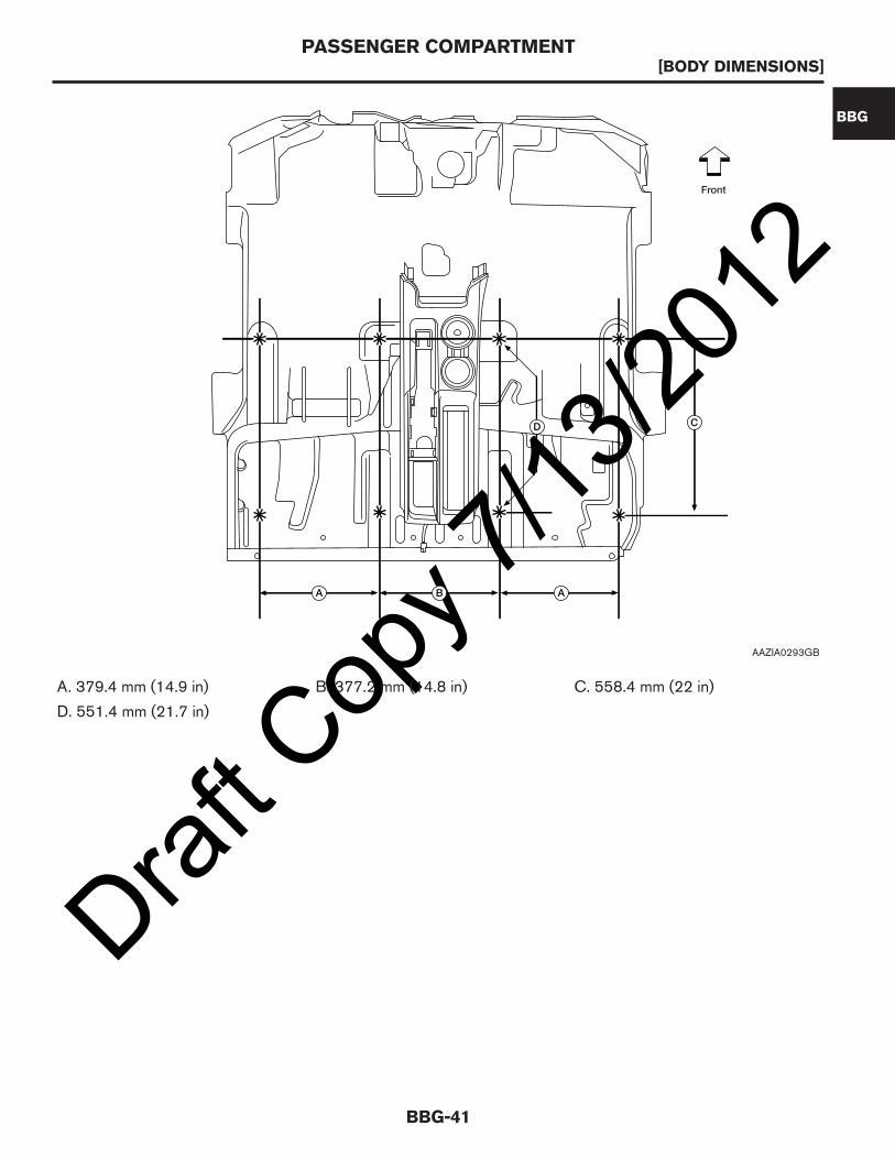
12
A. 379.4 mm (14.9 in) B. 377.2 mm (14.8 in) C. 558.4 mm (22 in)
D. 551.4 mm (21.7 in)
Front
D C
A AB
AAZIA0293GB
PASSENGER COMPARTMENT[BODY DIMENSIONS]
BBG-41
BBG

Draft C
opy 7
/13/20
12WARNING:
After removal and installation of the front passenger seat, a zero point reset function must beperformed by a Nissan dealer using a special tool. If zero point reset is not performed, theoccupant classification system may not operate normally which may increase the risk of seriousinjury in a collision.
WARNING:
Do not disturb or modify the front passenger seat wiring. Failure to follow this instruction maycause incorrect operation of the occupant classification system and front passenger air bagor system failure and may increase the risk of serious injury in a collision.
NOTE:
For complete removal and installation procedure of the front seats, refer to the SE section in theservice manual. Basic seat installation uses the following sequence:1. Before removing or installing the front seats, turn ignition switch OFF, disconnect both battery terminals
and wait at least 3 minutes.2. Place the seat in the vehicle on the mounting stud with the locator pin correctly seated. Make sure there
are no foreign objects under the seat, seat belts, pinched wires or carpeting between the seat mountingfeet and floor.
3. Fully connect the seat electrical connectors and make sure the inboard and outboard seat tracks arepositioned evenly and locked in place.
4. Install the front outboard seat bolt and hand tighten only.5. Install the front inboard seat bolt and tighten to 40 Nm (30 ft-lb).6. Tighten the front outboard seat bolt to 40 Nm (30 ft-lb).7. Move the seat forward and install the rear inboard seat bolt. Make sure both seat tracks are locked in place
and tighten to 40 Nm (30 ft-lb).8. Install the rear outboard seat nut. Tighten to 40 Nm (30 ft-lb) and install the cap.9. Connect the battery.
10. For front passenger seat, the zero point reset function must be performed by a Nissan dealer.
PASSENGER COMPARTMENT[BODY DIMENSIONS]
BBG-42

Draft C
opy 7
/13/20
12
1. Inboard center of hole 2. Outboard center of hole
X: 874.1 mm (34.4 in) X: 874.1 mm (34.4 in)
Y: 188.6 mm (7.4 in) Y: 568 mm (22.4 in)
Z: 265.6 mm (10.5 in) Z: 265.6 mm (10.5 in)
RH Front Seat Front Mounting Hole Location
1
2
AAZIA0147ZZ
PASSENGER COMPARTMENT[BODY DIMENSIONS]
BBG-43
BBG
Draft C
opy 7
/13/20
12
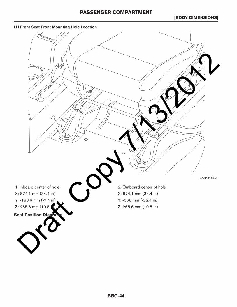
1. Inboard center of hole 2. Outboard center of hole
X: 874.1 mm (34.4 in) X: 874.1 mm (34.4 in)
Y: -188.6 mm (-7.4 in) Y: -568 mm (-22.4 in)
Z: 265.6 mm (10.5 in) Z: 265.6 mm (10.5 in)
Seat Position Diagrams
LH Front Seat Front Mounting Hole Location
1
2
AAZIA0146ZZ
PASSENGER COMPARTMENT[BODY DIMENSIONS]
BBG-44

Draft C
opy 7
/13/20
12
NOTE:
Seat is in full down and back position.
A. 1,429 mm (56.3 in) B. 403 mm (15.9 in) C. 464 mm (18.3 in)
D. 365 mm (14.4 in)
SgRP Front Seat Dimension
SgRP SgRP
X=0
D D
SgRP
Y=0
A
B
C
AAZIA0148ZZ
PASSENGER COMPARTMENT[BODY DIMENSIONS]
BBG-45
BBG

Draft C
opy 7
/13/20
12
NOTE:
The X, Y, Z values are measured from the front seat front bolt holes.
NOTE:
The X, Y, Z values are measured from the front seat front bolt holes.
LH Manual Track
X = 1,043.2 mm Y = -365 mm Z = 625.9 mm X = 1,283.2 mm
Y = -365 mm Z = 625.9 mm
21
13.5
X=1,214.9 mm Y= -365 mm Z= 625.9 mm
X=1,043.2 mm Y= -365 mm Z= 625.9 mm
X=1,283.2 mm Y= -365 mm Z= 625.9 mm
X = 465.6 mm Z = 281.4 mm
H-POINT LOCUS TRAVEL
HEEL GAP 344.5 mm
HEEL POINT
H-POINT FULL DOWN NEUTRAL
H-POINT FULL DOWN FULL FORWARD
0 SEAT SLIDE ANGLE
TORSO ANGLE
Rearmost H-pt
H-POINT FULL REAR FULL DOWN
CUSH ANGLE
AAZIA0294GB
RH Manual Track
X= 1,214.9 mm Y= 365 mm Z= 653.9 mm
X= 1,024.9 mm Y= 365 mm Z= 653.9 mm
X= 1,264.9 mm Y= 365 mm Z= 653.9 mm
372.5 mm
X = 465.6 mm Z = 281.4 mm
X = 1,024.9 mm Y = 365 mm Z = 653.9 mm X = 1,264.9 mm
Y = 365 mm Z = 653.9mm
21
13.5
H-POINT LOCUS TRAVEL
HEEL GAP
HEEL POINT
H-POINT FULL DOWN NEUTRAL
H-POINT FULL DOWN FULL FORWARD
0 SEAT SLIDE ANGLE
TORSO ANGLE
CUSH ANGLE
Rearmost H-pt
H-POINT FULL REAR FULL DOWN
AAZIA0295GB
PASSENGER COMPARTMENT[BODY DIMENSIONS]
BBG-46

Draft C
opy 7
/13/20
12CARGO AREA
Interior Dimensions
A. Length at beltline with seatposition:• rear-most: 1,910 mm (75.2 in)• center: 2,006 mm (78.97 in)• front-most: 2,150 mm (84.64 in)
B. Maximum length at floor:2,103.5 mm (82.8 in)
C. Maximum cargo height:1,345 mm (53 in)
D. Height at rear wheel center:1,319.3 mm (51.9 in)
E. Maximum width at floor:1,390.4 mm (54.8 in)
F. Width at floor between wheelwells:1,219.4 mm (48 in)
G. Maximum height at rear cargoentrance with striker:1,200 mm (47.24 in)
H. Maximum width at center ofwindow:1,511.9 mm (59.5 in)
Wheel Well Clearance
Overall
H
E
F
G
C D
A
B
AAZIA0149ZZ
CARGO AREA[BODY DIMENSIONS]
BBG-47
BBG

Draft C
opy 7
/13/20
12
NOTE:
View from inside of vehicle.
A. Seat position:• rear-most: 856 mm (33.7 in)• center: 952 mm (37.5 in)• front-most: 1,096 mm (43.15 in)
B. 296 mm (11.65 in)
NOTE:
View from inside of vehicle.
Cutaway Side View — RH
A
B
AAZIA0175ZZ
Cutaway Side View — LH
A
B
AAZIA0150ZZ
CARGO AREA[BODY DIMENSIONS]
BBG-48

Draft C
opy 7
/13/20
12A. Seat position:• rear-most: 856 mm (33.7 in)• center: 952 mm (37.5 in)• front-most: 1,096 mm (43.15 in)
B. 296 mm (11.65 in)
A. 1,263 mm (49.7 in) B. 1,220.49 mm (48 in) C. 725 mm (28.5 in)
D. 271 mm (10.6 in) E. 747 mm (29.4 in) F. 271 mm (10.6 in)
Cutaway Wheel Well and Rear Views
LH RH
A
B
C
D
E
F
Rear
Front Front
AAZIA0296GB
CARGO AREA[BODY DIMENSIONS]
BBG-49
BBG

Draft C
opy 7
/13/20
12
A. 584 mm (22.9 in) B. 1,297 mm (51 in) C. 1,425 mm (56.1 in)
D-Ring Tie-Downs (If Equipped)
Cutaway Overhead View
A
B
C
Front
AAZIA0297GB
CARGO AREA[BODY DIMENSIONS]
BBG-50
Draft C
opy 7
/13/20
12
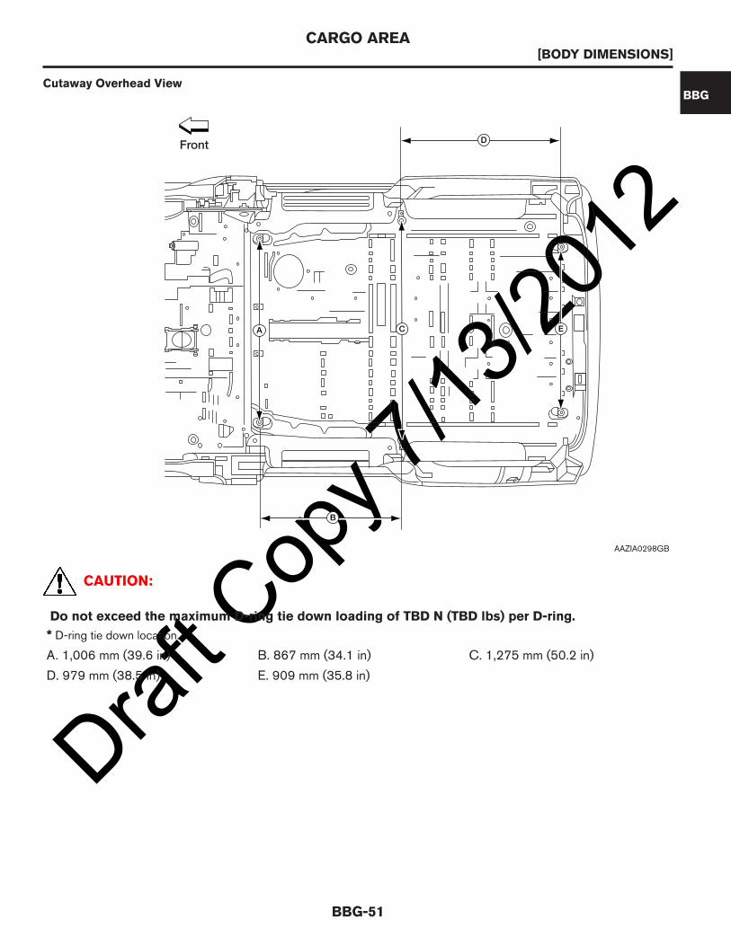
CAUTION:
Do not exceed the maximum D-ring tie down loading of TBD N (TBD lbs) per D-ring.
* D-ring tie down location.
A. 1,006 mm (39.6 in) B. 867 mm (34.1 in) C. 1,275 mm (50.2 in)
D. 979 mm (38.5 in) E. 909 mm (35.8 in)
Cutaway Overhead View
D
ECA
B
Front
AAZIA0298GB
CARGO AREA[BODY DIMENSIONS]
BBG-51
BBG

Draft C
opy 7
/13/20
12SIGN AREA
A. 915 mm (36 in) B. 817 mm (32.2 in) C. 394 mm (15.5 in)
D. 725 mm (28.5 in) E. 777 mm (30.6 in) F. 434 mm (17.1 in)
G. 288 mm (11.3 in) H. 62 mm (2.4 in) J. 723 mm (28.5 in)
K. 114 mm (4.5 in) L. 1,107 mm (43.6 in) M. 695 mm (27.4 in)
N. 200 mm (7.6 in) P. 208 mm (8.2 in)
RH Exterior Dimensions
D
E
A
B
J
M
L
C
K
H
G
N
P
F
AAZIA0151ZZ
SIGN AREA[BODY DIMENSIONS]
BBG-52

Draft C
opy 7
/13/20
12
A. 627 mm (24.7 in) B. 795 mm (31.3 in) C. 934 mm (36.8 in)
D. 1,014 mm (39.9 in) E. 1,394 mm (54.9 in) F. 1,517 mm (59.7 in)
G. 200 mm (7.9 in) H. 315 mm (12.4 in) J. 378 mm (14.9 in)
K. 750 mm (29.5 in) L. 1,302 mm (51.3 in) M. 2,626 mm (103.4 in)
N. 262 mm (10.3 in) P. 757 mm (29.8 in) Q. 253 mm (10 in)
LH Exterior Dimensions
M N
P
L
F
E
DC
BA
K
JHG
Q
AAZIA0165ZZ
SIGN AREA[BODY DIMENSIONS]
BBG-53
BBG

Draft C
opy 7
/13/20
12
A. 1,430 mm (56.3 in) B. 932 mm (36.7 in) C. 853 mm (33.6 in)
D. 1,002 mm (39.4 in)
RH Slide Door Exterior Dimensions
A
B
D
C
AAZIA0166ZZ
SIGN AREA[BODY DIMENSIONS]
BBG-54

Draft C
opy 7
/13/20
12
A. 1,430 mm (56.3 in) B. 932 mm (36.7 in) C. 853 mm (33.6 in)
D. 1,002 mm (39.4 in)
LH Slide Door Exterior Dimensions
A
B
D
C
AAZIA0176ZZ
SIGN AREA[BODY DIMENSIONS]
BBG-55
BBG

Draft C
opy 7
/13/20
12
A. 280 mm (11 in) B. 273 mm (10.75 in) C. 813 mm (32 in)
D. 95 mm (3.7 in) E. 625 mm (24.6 in) F. 94 mm (3.7 in)
Hood Surface Exterior Dimensions
B
C
EF
D
A
AAZIA0167ZZ
SIGN AREA[BODY DIMENSIONS]
BBG-56
Draft C
opy 7
/13/20
12
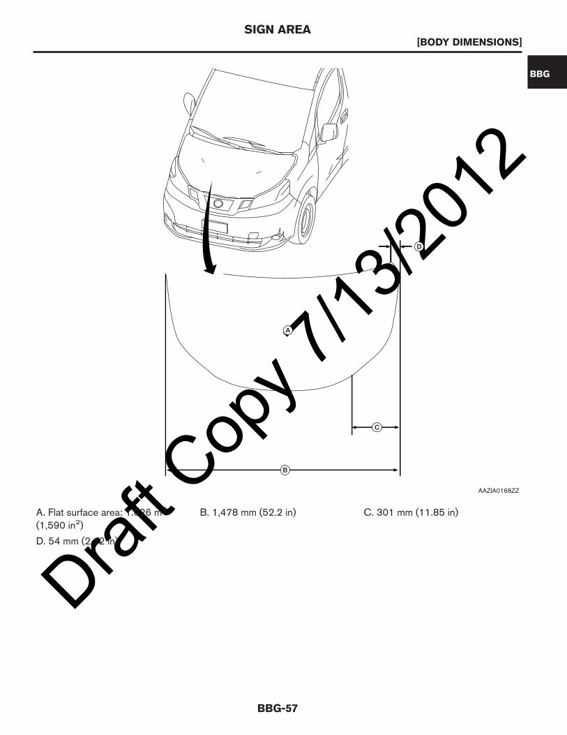
A. Flat surface area: 1.026 m2
(1,590 in2)B. 1,478 mm (52.2 in) C. 301 mm (11.85 in)
D. 54 mm (2.12 in)
A
C
D
B
AAZIA0168ZZ
SIGN AREA[BODY DIMENSIONS]
BBG-57
BBG

Draft C
opy 7
/13/20
12
A. 48 mm (1.9 in) B. 74 mm (2.9 in) C. 571 mm (22.5 in)
D. 798 mm (31.42 in) E. 99 mm (3.9 in) F. 62 mm (2.4 in)
G. 37 mm (1.45 in) H. 41 mm (1.61 in) J. 63 mm (2.45 in)
K. 636 mm (25 in) L. 30 mm (1.2 in) M. 253 mm (9.96 in)
N. 640 mm (25.2 in) P. 81 mm (3.19 in) Q. 128 mm (5.03 in)
R. 32 mm (1.26 in) S. 213 mm (8.4 in)
Back Door Sign Area
F
GH
E
P
L
J
Q
M
S
D
K
C
N
A
R
B
AAZIA0169ZZ
SIGN AREA[BODY DIMENSIONS]
BBG-58

Draft C
opy 7
/13/20
12
A. 121 mm (4.76 in) B. 430 mm (16.9 in) C. 473 mm (18.6 in)
D. 495 mm (19.5 in) E. 447 mm (17.6 in) F. 755 mm (29.7 in)
G. 787 mm (30.9)
Back Door Window Opening Sign Area
A
B
C
D
F
G
E B
AAZIA0170ZZ
SIGN AREA[BODY DIMENSIONS]
BBG-59
BBG

Draft C
opy 7
/13/20
12PLACARDS
To find information and regulations about the placards, refer to the following website:
http://www.fmcsa.dot.gov
PLACARDS[BODY DIMENSIONS]
BBG-60
Draft C
opy 7
/13/20
12EXTERIOR
Front Door Opening Measurements
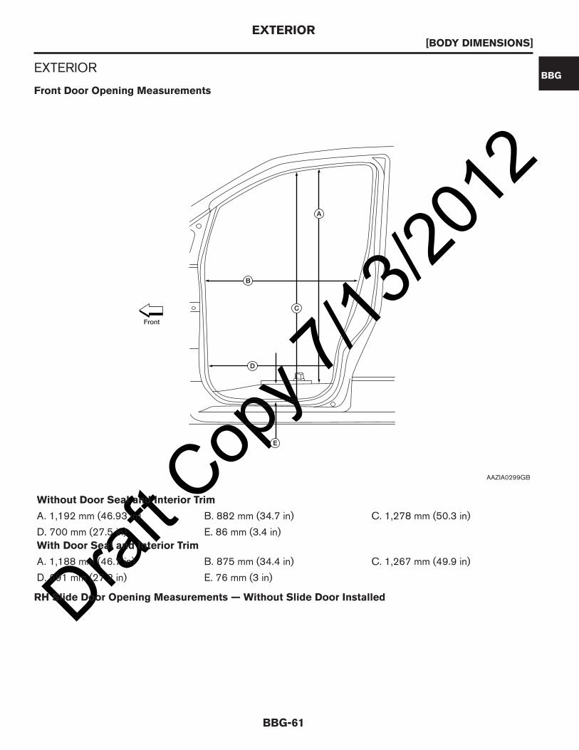
Without Door Seal and Interior Trim
A. 1,192 mm (46.93 in) B. 882 mm (34.7 in) C. 1,278 mm (50.3 in)
D. 700 mm (27.5 in) E. 86 mm (3.4 in)
With Door Seal and Interior Trim
A. 1,188 mm (46.7 in) B. 875 mm (34.4 in) C. 1,267 mm (49.9 in)
D. 691 mm (27.2 in) E. 76 mm (3 in)
RH Slide Door Opening Measurements — Without Slide Door Installed
B
C
A
D
E
Front
AAZIA0299GB
EXTERIOR[BODY DIMENSIONS]
BBG-61
BBG

Draft C
opy 7
/13/20
12
Without Door Seal and Interior Trim
A. 818 mm (32.2 in) B. 737 mm (39 in) C. 1,211 mm (47.6 in)
D. 1,185 mm (46.6 in) E. 27 mm (1.06 in) F. 1,206 mm (47.5 in)
With Door Seal and Interior Trim
A. 811 mm (31.9 in) B. 730 mm (28.7 in) C. 1,204 mm (47.4 in)
D. 1,164 mm (45.8 in) E. 35 mm (1.37 in) F. 1,199 mm (47.2 in)
LH Slide Door Opening Measurements — Without Slide Door Installed
C D F
B
E
A
Front
AAZIA0300GB
EXTERIOR[BODY DIMENSIONS]
BBG-62
Draft C
opy 7
/13/20
12
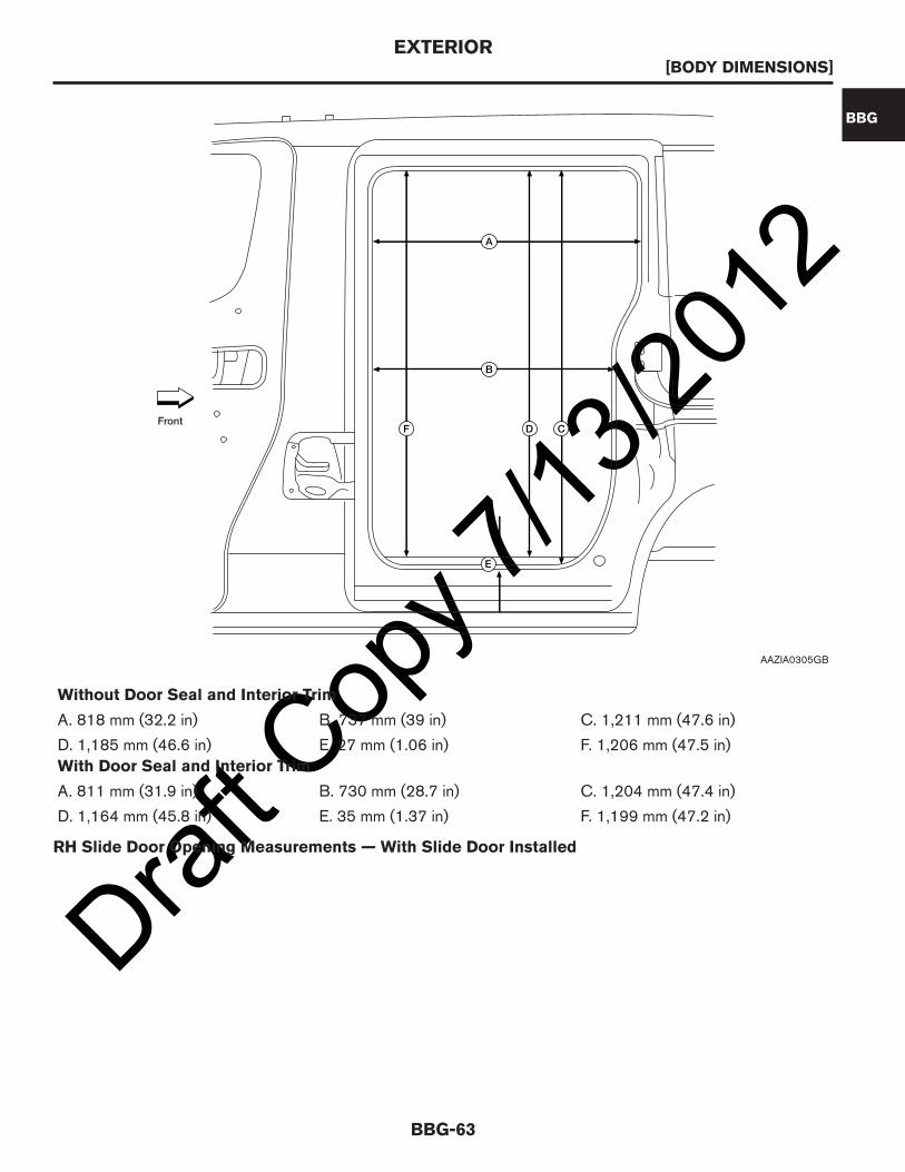
Without Door Seal and Interior Trim
A. 818 mm (32.2 in) B. 737 mm (39 in) C. 1,211 mm (47.6 in)
D. 1,185 mm (46.6 in) E. 27 mm (1.06 in) F. 1,206 mm (47.5 in)
With Door Seal and Interior Trim
A. 811 mm (31.9 in) B. 730 mm (28.7 in) C. 1,204 mm (47.4 in)
D. 1,164 mm (45.8 in) E. 35 mm (1.37 in) F. 1,199 mm (47.2 in)
RH Slide Door Opening Measurements — With Slide Door Installed
Front CDF
B
E
A
AAZIA0305GB
EXTERIOR[BODY DIMENSIONS]
BBG-63
BBG

Draft C
opy 7
/13/20
12
Without Door Seal and Interior Trim
A. 679 mm (26.7 in) B. 1,185 mm (46.6 in) C. 670 mm (2.63 in)
D. 689 mm (27.1 in) E. 27 mm (1.06 in)
With Door Seal and Interior Trim
A. 675 mm (26.57 in) B. 1,164 mm (45.8 in) C. 667 mm (26.2 in)
D. 686 mm (27 in) E. 35 mm (1.37 in)
LH Slide Door Opening Measurements — With Slide Door Installed
A
C
B
D
E
Front
AAZIA0301GB
EXTERIOR[BODY DIMENSIONS]
BBG-64

Draft C
opy 7
/13/20
12
Without Door Seal and Interior Trim
A. 679 mm (26.7 in) B. 1,185 mm (46.6 in) C. 670 mm (2.63 in)
D. 689 mm (27.1 in) E. 27 mm (1.06 in)
With Door Seal and Interior Trim
A. 675 mm (26.57 in) B. 1,164 mm (45.8 in) C. 667 mm (26.2 in)
D. 686 mm (27 in) E. 35 mm (1.37 in)
Back Door Opening Measurements
A
C
B
D
E
Front
AAZIA0304GB
EXTERIOR[BODY DIMENSIONS]
BBG-65
BBG

Draft C
opy 7
/13/20
12
A. 252 mm (9.92 in) B. 1,238 mm (48.75 in) C. 1,197 mm (47.1 in)
D. 1,267 mm (49.9 in) E. 1,286 mm (50.63 in)
Doors and Mirrors DimensionsOverhead View
B A
C
D
E
AAZIA0171ZZ
EXTERIOR[BODY DIMENSIONS]
BBG-66
Draft C
opy 7
/13/20
12
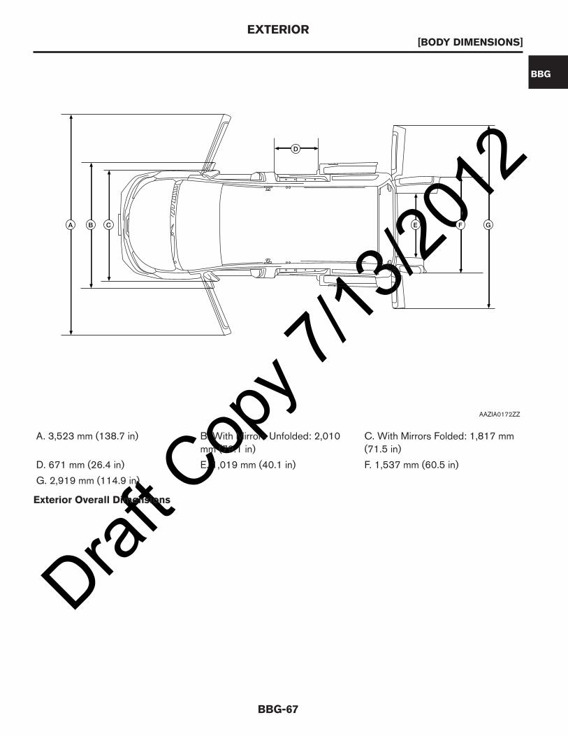
A. 3,523 mm (138.7 in) B. With Mirrors Unfolded: 2,010mm (79.1 in)
C. With Mirrors Folded: 1,817 mm(71.5 in)
D. 671 mm (26.4 in) E. 1,019 mm (40.1 in) F. 1,537 mm (60.5 in)
G. 2,919 mm (114.9 in)
Exterior Overall Dimensions
D
CBA GFE
AAZIA0172ZZ
EXTERIOR[BODY DIMENSIONS]
BBG-67
BBG

Draft C
opy 7
/13/20
12
A. 4,732.5 mm (186.3 in) B. 2,925 mm (115.2 in) C. 968.2 mm (38.1 in)
D. 839.3 mm (33 in) E. 535.7 mm (21 in) F. 1,226.7 mm (48.3 in)
G. 1,871.7 mm (73.7 in) H. 1,729.5 mm (68.1 in) J. 1,525 mm (60 in)
K. 1,520 mm (59.8 in) L. 996.6 mm (39.2 in) M. 1,710 mm (67.32 in)
FG
E
M
B
A
C D
L
K
J
H
AAZIA0173ZZ
EXTERIOR[BODY DIMENSIONS]
BBG-68

Draft C
opy 7
/13/20
12UNIBODY AND FRAME
Crossmember and Body Mount Dimensions
A. 4,311.65 mm (169.75 in) B. 520 mm (20.5 in) C. 508.05 mm (20 in)
D. 376.94 mm (14.84 in) E. 68.14 mm (2.68 in) F. 343.87 mm (13.5 in)
G. 472.97 mm (18.6 in) H. 844.21 mm (33.23 in) J. 329.36 mm (12.9 in)
K. 909.28 mm (35.8 in) L. 383.22 mm (15.08 in) M. 220.22 mm (8.67 in)
N. 272.91 mm (10.75 in) P. 326.32 mm (12.85 in) Q. 339.07 mm (13.35 in)
R. 442.02 mm (17.4 in) S. 220.01 mm (8.66 in) T. 305.8 mm (12 in)
U. 268.69 mm (10.6 in)
A
D C
F G H KJ
U T
E
Z=0 Y=0
X=0
B R Q P N M LS
Front
AAZIA0302GB
UNIBODY AND FRAME[BODY DIMENSIONS]
BBG-69
BBG

Draft C
opy 7
/13/20
12
A. 1,009 mm (39.7 in) B. 1,134 mm (44.6 in) C. 1,250 mm (49.2 in)
D. 1,225 mm (48.2 in) E. 1,331 mm (52.4 in) F. 1,275.4 mm (50.2 in)
G. 1,428 mm (56.2 in) H. 70.22 mm (2.7 in) J. 69.74 mm (2.74 in)
K. 71.46 mm (2.8 in) L. 96.96 mm (3.8 in) M. 91.31 mm (3.6 in)
A B C D E F G
H
J K L M
Front
AAZIA0303GB
UNIBODY AND FRAME[BODY DIMENSIONS]
BBG-70

Draft C
opy 7
/13/20
12ELECTRICALFUSE AND RELAY INFORMATION
Fuses and Relays — Engine Compartment
CAUTION:
This information is reference only. To avoid damage, modification of the vehicle’s electricalsystems is not recommended. For pre-wiring access points, refer to Customer Pre-Wiring Access.
Item Fuse/relay color Fuse ratingPower supplycondition
Fuse/relay name
1 Yellow 20A BatteryRear windowdefogger
2 — — — Not used
3 Yellow 20A Battery ECM relay
4 — — — Not used
5 Green 30A Battery Front wiper
F1 20ARR DEFF2F3 20AEGIF4F5 30AFR WIPERF6 10APOS LAMPSF7F8F9 10AA/C CLUTCHF10 15AFR FOG LAMPF11 10AH/LAMP HI RHF12 10AH/LAMP HI LHF13 15AH/LAMP LO LHF14 15AH/LAMP LO RHF15 10AA/T ECU IGNF16 10AREV LAMP IGNF17 10AABS ECU IGNF18F19F20 15AFUEL PUMPF21 15AIGN COILF22 15AINJECTOR IGNF23F24 15AETC
1 3
56
78
910
1112
1314
1819
2021
22 2423
426
15
2527
28
16
17
2
AAZIA0160ZZ
FUSE AND RELAY INFORMATION[ELECTRICAL]
BBG-71
BBG
Draft C
opy 7
/13/20
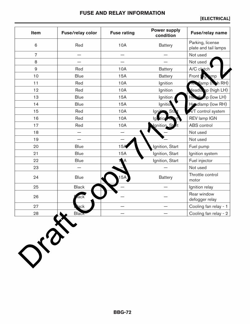
12Item Fuse/relay color Fuse rating
Power supplycondition
Fuse/relay name
6 Red 10A BatteryParking, licenseplate and tail lamps
7 — — — Not used
8 — — — Not used
9 Red 10A Battery A/C clutch
10 Blue 15A Battery Front fog lamp
11 Red 10A Ignition Headlamp (high RH)
12 Red 10A Ignition Headlamp (high LH)
13 Blue 15A Ignition Headlamp (low LH)
14 Blue 15A Ignition Headlamp (low RH)
15 Red 10A Ignition, Start A/T control system
16 Red 10A Ignition, Start REV lamp IGN
17 Red 10A Ignition, Start ABS control
18 — — — Not used
19 — — — Not used
20 Blue 15A Ignition, Start Fuel pump
21 Blue 15A Ignition, Start Ignition system
22 Blue 15A Ignition, Start Fuel injector
23 — — — Not used
24 Blue 15A BatteryThrottle controlmotor
25 Black — — Ignition relay
26 Black — —Rear windowdefogger relay
27 Black — — Cooling fan relay - 1
28 Black — — Cooling fan relay - 2
FUSE AND RELAY INFORMATION[ELECTRICAL]
BBG-72
Draft C
opy 7
/13/20
12
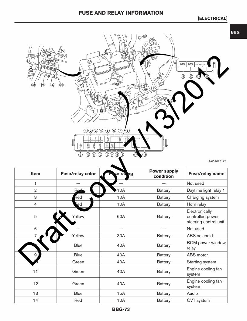
Item Fuse/relay color Fuse ratingPower supplycondition
Fuse/relay name
1 — — — Not used
2 Red 10A Battery Daytime light relay 1
3 Red 10A Battery Charging system
4 Red 10A Battery Horn relay
5 Yellow 60A BatteryElectronicallycontrolled powersteering control unit
6 — — — Not used
7 Yellow 30A Battery ABS solenoid
8 Blue 40A BatteryBCM power windowrelay
9 Blue 40A Battery ABS motor
10 Green 40A Battery Starting system
11 Green 40A BatteryEngine cooling fansystem
12 Green 40A BatteryEngine cooling fansystem
13 Blue 15A Battery Audio
14 Red 10A Battery CVT system
F/L
40
A
AB
S
F/L
40
A
IGN
SW
F/L
40
A
RA
D F
AN
F/L
40
A
RA
D F
AN
15
A
10
A
A/T
E
CU
F/L
40
A
P/W
DW
B
CM
F/L
30
A
AB
S
F/L
60
A
EP
S
10
A
15
A
10
A
RAD HI RAD LO
27
26
19 20 21 22
87654321
9 10 11 12 13 14 15 16 17 18
252423
AU
DIO
HO
RN
ALT
DT
RL
HO
RN
DTRL DTRL FAN FAN
AAZIA0161ZZ
FUSE AND RELAY INFORMATION[ELECTRICAL]
BBG-73
BBG
Draft C
opy 7
/13/20
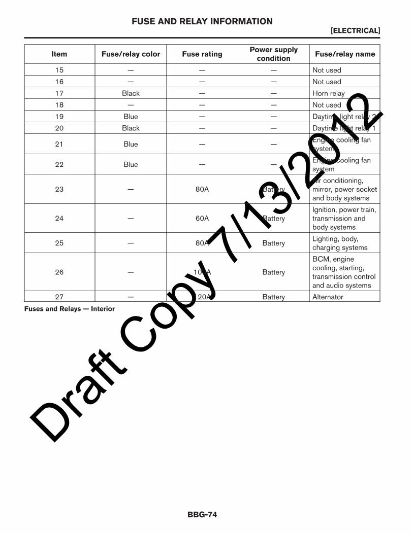
12Item Fuse/relay color Fuse rating
Power supplycondition
Fuse/relay name
15 — — — Not used
16 — — — Not used
17 Black — — Horn relay
18 — — — Not used
19 Blue — — Daytime light relay 2
20 Black — — Daytime light relay 1
21 Blue — —Engine cooling fansystem
22 Blue — —Engine cooling fansystem
23 — 80A BatteryAir conditioning,mirror, power socketand body systems
24 — 60A BatteryIgnition, power train,transmission andbody systems
25 — 80A BatteryLighting, body,charging systems
26 — 100A Battery
BCM, enginecooling, starting,transmission controland audio systems
27 — 120A Battery Alternator
Fuses and Relays — Interior
FUSE AND RELAY INFORMATION[ELECTRICAL]
BBG-74

Draft C
opy 7
/13/20
12
Item Fuse/Relay Color Fuse RatingPower SupplyCondition
Fuse/Relay Name
1 Blue 15A IgnitionAir conditioningsystem
2 Blue 15A IgnitionAir conditioningsystem
3 Red 10A IgnitionAir conditioningsystem
4 Yellow 20A Accessory, IgnitionFront 12V powersocket
5 Yellow 20A Accessory, IgnitionRear 12V powersocket
6 — — — Not used
7 — — — Not used
8 — — — Not used
9 — — — Not used
10 Red 10A B+Meter, key switch,CONSULT
11 Red 10A B+ Stop lamp system
12 — — — Not used
13 Red 10A B+ BCM
1010
15
10
10
1010
15
10
20
20
15A
10A
10A
10A
10A
10A
10A
WASHER
MOTOR
AUDIO
/ MIRROR
HEATER
MIRROR
1. U
SE
S
PE
CIF
IE
D F
US
ES
O
NL
Y
2. C
ON
TA
CT
A
D
EA
LE
R F
OR
S
YS
TE
MS
N
OT
L
IS
TE
D.
20A
20A
FR POWER
OUTLET
RR POWER
OUTLET
ELEC IG
AIR BAG
METER
10A
ELEC
PARTS1
10A
10A
STOP
LAMP
ELEC
PARTS2
C:1 2 3 4 5/01 3LMOA
15A
10A
BLOWER
BLOWER
AIR COND
UP
21
7
14 13 12
1
2
3
4
5
6
20
19
18
17
16
15
10
11
8 9
22
AAZIA0162ZZ
FUSE AND RELAY INFORMATION[ELECTRICAL]
BBG-75
BBG

Draft C
opy 7
/13/20
12Item Fuse/Relay Color Fuse Rating
Power SupplyCondition
Fuse/Relay Name
14 — — — Not used
15 Red 10A Ignition Ignition system
16 Red 10A Ignition Air bag system
17 Red 10A Ignition
Meter, Bluetooth®control unit, ITmaster, stop lamp,EPS, CONSULTsystem
18 Red 10A IgnitionWiper and washersystem switch
19 Red 10A Accessory, Ignition
BCM, Bluetooth®control unit, audio,mirror andtelematics system
20 Red 10A Accessory, Ignition Heater mirror
21 Blue — Ignition Blower relay
22 Blue — Accessory Accessory relay
FUSE AND RELAY INFORMATION[ELECTRICAL]
BBG-76

Draft C
opy 7
/13/20
12GROUNDS
Grounds
CAUTION:
• Do not ground accessories directly to the battery negative terminal. Doing so may interfere withthe voltage control system and cause poor or inoperative battery charging.
• Install electrical accessories using suitable body ground connections or ground to the engineblock area. Refer to BATTERY VOLTAGE CONTROL in this section.
It is the responsibility of the vehicle upfitter to install any grounds necessary for equipment from aftermarket orsecond stage equipment manufacturers. NISSAN factory grounds should not be altered.
GROUNDS[ELECTRICAL]
BBG-77
BBG

Draft C
opy 7
/13/20
12BATTERY VOLTAGE CONTROL
CAUTION:
• Do not ground accessories directly to the battery negative terminal. Doing so may interfere withthe voltage control system and cause poor or inoperative battery charging.
• Install electrical accessories using suitable body ground connections or ground to the engineblock area.
• Use electrical accessories with the engine running to avoid discharging the vehicle battery.
Adding electrical devices puts more load on the electrical system and the battery. The engine control module(ECM) monitors battery voltage. If battery voltage drops below 12 volts, engine RPM is increased up to 900 RPM(maximum for idle condition when the engine is at normal operating temperature). RPM will decrease as batteryvoltage increases. Engine RPM changes are gradually ramped up and down by ECM control.
For battery specifications, refer to Battery in the Specifications section.
BATTERY VOLTAGE CONTROL[ELECTRICAL]
BBG-78

Draft C
opy 7
/13/20
12CUSTOMER PRE-WIRING ACCESS
CUSTOMER PRE-WIRING ACCESS[ELECTRICAL]
BBG-79
BBG
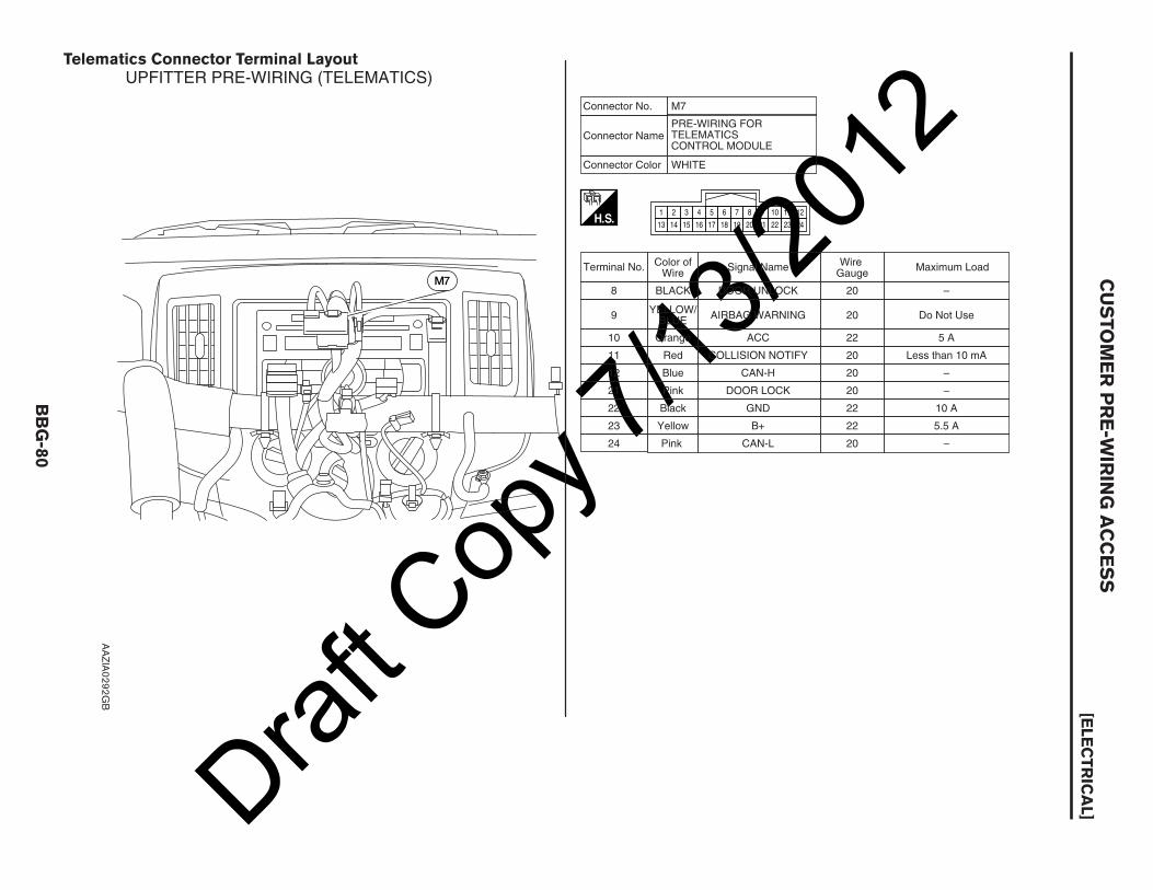
Draft C
opy 7
/13/20
12Telematics Connector Terminal Layout
M7
H.S.
8 BLACK DOOR UNLOCK
9YELLOW/
BLUEAIRBAG WARNING
10 Orange ACC
11 Red COLLISION NOTIFY
12 Blue CAN-H
20
20
22
20
20
–
Do Not Use
5 A
Less than 10 mA
–
21 Pink DOOR LOCK 20 –
22 Black GND 22 10 A
23 Yellow B+ 22 5.5 A
24 Pink CAN-L 20 –
1
13
32 4
1514 16
109
2221
11 12
23 24
5
17
76 8
1918 20
Connector No.
Connector NamePRE-WIRING FOR TELEMATICS CONTROL MODULE
Connector Color WHITE
Signal NameTerminal No. Color of Wire
Wire Gauge
Maximum Load
UPFITTER PRE-WIRING (TELEMATICS)
M7
AAZIA0292GB
CUSTOMER
PRE-W
IRIN
GACCESS
[ELECTRIC
AL]
BBG-80

Draft C
opy 7
/13/20
12HARNESS LAYOUT
Harness Outline
Main Harness
AAZIA0164ZZ
HARNESS LAYOUT[ELECTRICAL]
BBG-81
BBG

Draft C
opy 7
/13/20
12
Engine Room Harness
AAZIA0121ZZ
HARNESS LAYOUT[ELECTRICAL]
BBG-82

Draft C
opy 7
/13/20
12
Engine Room Harness (Passenger Compartment)
AAZIA0118ZZ
HARNESS LAYOUT[ELECTRICAL]
BBG-83
BBG

Draft C
opy 7
/13/20
12
Engine Control Harness
AAZIA0117ZZ
HARNESS LAYOUT[ELECTRICAL]
BBG-84

Draft C
opy 7
/13/20
12
Body Harness
AAZIA0116ZZ
HARNESS LAYOUT[ELECTRICAL]
BBG-85
BBG

Draft C
opy 7
/13/20
12
Room Lamp Harness
AAZIA0115ZZ
HARNESS LAYOUT[ELECTRICAL]
BBG-86

Draft C
opy 7
/13/20
12
Front Door LH Harness
AAZIA0122ZZ
HARNESS LAYOUT[ELECTRICAL]
BBG-87
BBG
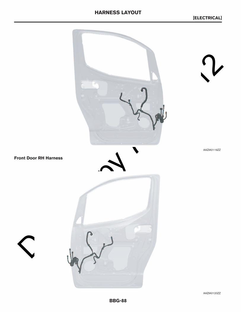
Draft C
opy 7
/13/20
12
Front Door RH Harness
AAZIA0119ZZ
AAZIA0120ZZ
HARNESS LAYOUT[ELECTRICAL]
BBG-88

Draft C
opy 7
/13/20
12Sliding Door (LH) Harness
Sliding Door (RH) Harness
AAZIA0125ZZ
HARNESS LAYOUT[ELECTRICAL]
BBG-89
BBG

Draft C
opy 7
/13/20
12
Back Door RH Harness (With Window Glass)
AAZIA0126ZZ
AAZIA0123ZZ
HARNESS LAYOUT[ELECTRICAL]
BBG-90
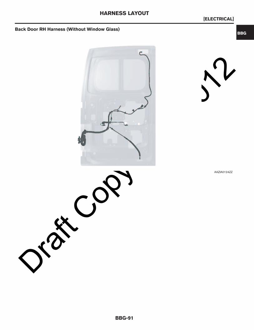
Draft C
opy 7
/13/20
12Back Door RH Harness (Without Window Glass)
AAZIA0124ZZ
HARNESS LAYOUT[ELECTRICAL]
BBG-91
BBG
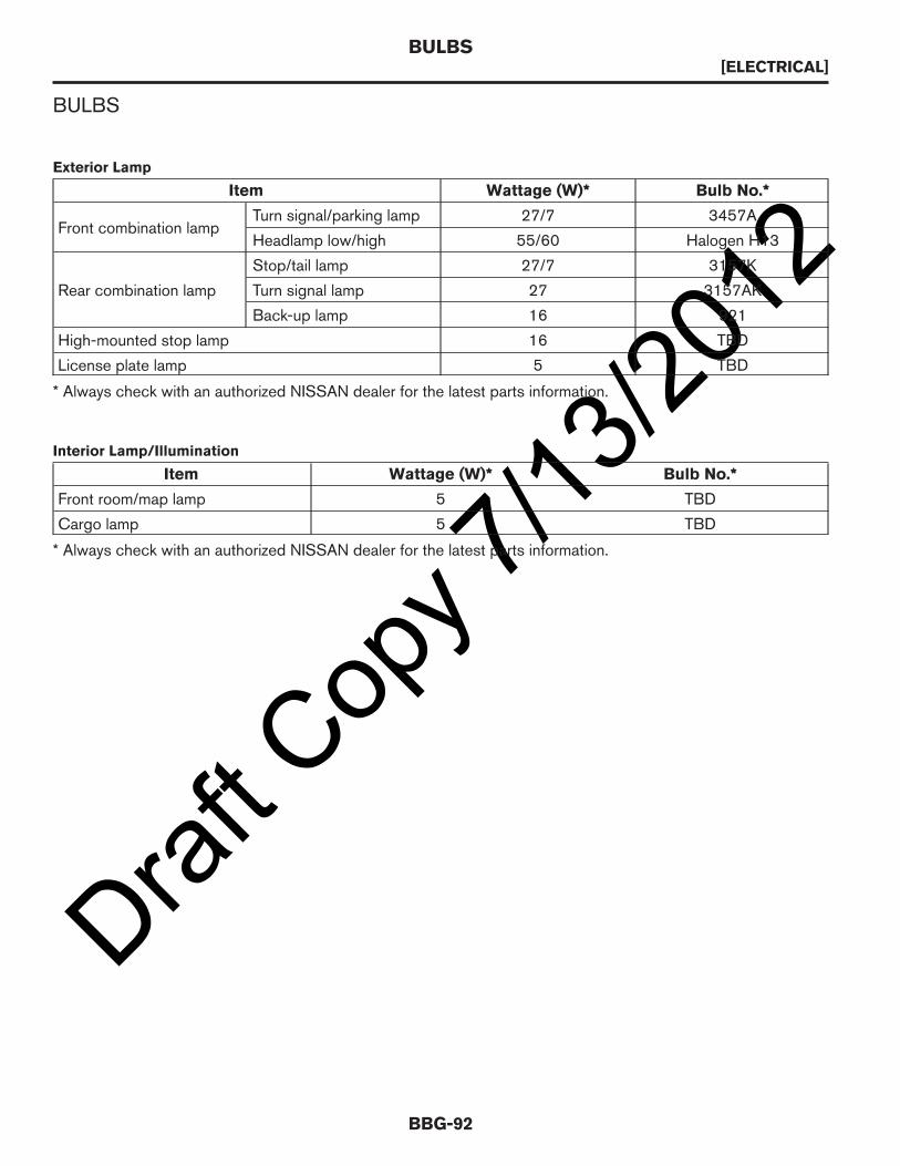
Draft C
opy 7
/13/20
12BULBS
Exterior Lamp
Item Wattage (W)* Bulb No.*
Front combination lampTurn signal/parking lamp 27/7 3457A
Headlamp low/high 55/60 Halogen H13
Rear combination lamp
Stop/tail lamp 27/7 3157K
Turn signal lamp 27 3157AK
Back-up lamp 16 921
High-mounted stop lamp 16 TBD
License plate lamp 5 TBD
* Always check with an authorized NISSAN dealer for the latest parts information.
Interior Lamp/Illumination
Item Wattage (W)* Bulb No.*
Front room/map lamp 5 TBD
Cargo lamp 5 TBD
* Always check with an authorized NISSAN dealer for the latest parts information.
BULBS[ELECTRICAL]
BBG-92

Draft C
opy 7
/13/20
12HEADLAMP AIMING
Inspection
NOTE:
The aftermarket equipment manufacturer, second stage manufacturer, and upfitter are responsible for
maintaining or restoring the headlamp adjustment after modifications to the vehicle are complete. The
upfitter is responsible for maintaining compliance with the Federal or Canadian Motor Vehicle Safety
Standards.
Preparation Before Adjusting
Before performing aiming adjustment, check the following:• Modifications are complete and the vehicle is unladen.• Adjust the tire pressure to the specification.• Place the vehicle on a level surface.• Fill vehicle with fuel, engine coolant, and engine oil.• Remove cargo to maintain an unloaded vehicle condition.• Confirm the spare tire, jack, and tools are present and properly stowed.• Place a driver or equivalent weight of 68.5 kg (150 lbs) on the driver seat.• By hand, bounce the front and rear of the vehicle to settle the suspension and eliminate any static load.• Place the front tires in the straight ahead position.• Carefully wipe off any dirt from the headlamp lens.
CAUTION:
Never use organic solvent (thinner, gasoline, etc.).
NOTE:
• For headlamp aiming details, refer to the regulations in your own area.• Perform headlamp aiming if the vehicle front body has been repaired and/or the front combination lamp has
been removed or replaced.• By regulation, no means for horizontal adjustment is provided. Horizontal aim will only be serviced by
combination lamp replacement.Aiming Adjustment Screw
• Rotate the headlamp (UP/DOWN) adjustment screw to raise or lower the headlamp vertical beam pattern,using a suitable tool.
CAUTION:
A
AAZIA0128ZZ
A. Headlamp (UP/DOWN) adjustment screw
HEADLAMP AIMING[ELECTRICAL]
BBG-93
BBG
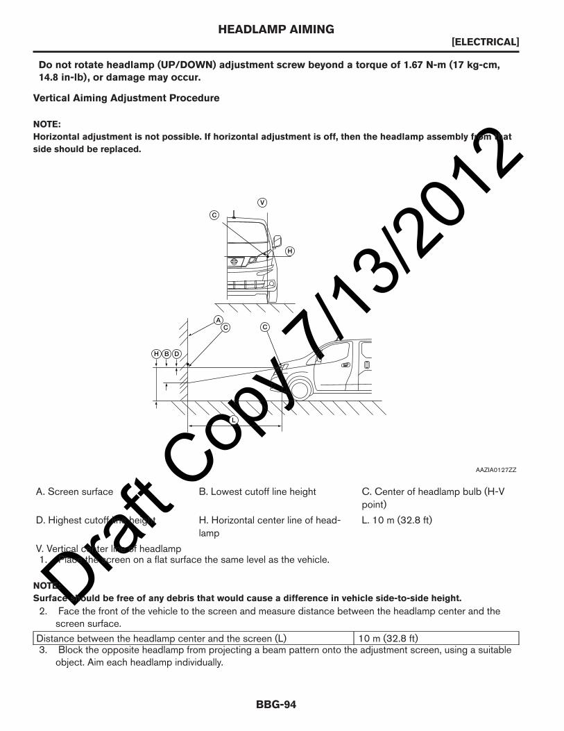
Draft C
opy 7
/13/20
12Do not rotate headlamp (UP/DOWN) adjustment screw beyond a torque of 1.67 N-m (17 kg-cm,14.8 in-lb), or damage may occur.
Vertical Aiming Adjustment Procedure
NOTE:
Horizontal adjustment is not possible. If horizontal adjustment is off, then the headlamp assembly from that
side should be replaced.
A. Screen surface B. Lowest cutoff line height C. Center of headlamp bulb (H-Vpoint)
D. Highest cutoff line height H. Horizontal center line of head-lamp
L. 10 m (32.8 ft)
V. Vertical center line of headlamp1. Place the screen on a flat surface the same level as the vehicle.
NOTE:
Surface should be free of any debris that would cause a difference in vehicle side-to-side height.
2. Face the front of the vehicle to the screen and measure distance between the headlamp center and thescreen surface.
Distance between the headlamp center and the screen (L) 10 m (32.8 ft)3. Block the opposite headlamp from projecting a beam pattern onto the adjustment screen, using a suitable
object. Aim each headlamp individually.
ACC
C
V
H
H B D
L
AAZIA0127ZZ
HEADLAMP AIMING[ELECTRICAL]
BBG-94

Draft C
opy 7
/13/20
12CAUTION:
Never cover the lens surface with tape or plastic, etc. The lens is made of resin.4. Start the engine. Turn the headlamps on.5. Determine the preferred vertical aim range dimensions, using the illustration and table.
Headlamp Center Heightmm (in)
Highest Cutoffmm (in)
Lowest Cutoffmm (in)
700 - 800 (27.56 - 31.49) 4.0 (0.157) 30.0 (1.18)
801 (31.54) 17.0 (0.669) 44.0 (1.73)6. Measure the projected beam within the aim evaluation segment on the screen.7. Adjust the beam pattern of each headlamp until the aim evaluation segment (the area relative to both the
highest and lowest cutoff line height) is positioned within the vertical aim range dimensions shown on theaiming chart.
HEADLAMP AIMING[ELECTRICAL]
BBG-95
BBG

Draft C
opy 7
/13/20
12ADDING LIGHTS OR DEVICES
Added Lights or Accessories Controlled By Added Switches
This section describes the connection points for added electrical accessories when these accessories are to becontrolled by added switches not a part of the NISSAN released vehicle. The added switches and wiring musthave sufficient electrical capacity for the accessory load and must be protected by appropriate fuses or circuitbreakers. Also, added current draw must not cause total loads to exceed capabilities of the base vehicle wiring.
Electrical Wiring — Adding Lights or Electrical Devices
CAUTION:
Improper electrical tie-ins may affect vehicle operation (i.e., engine, transmission). After allelectrical or vehicle modifications, confirm that no Diagnostic Trouble Codes (DTCs) are presentand all systems operate normally. Road test the vehicle to verify that no DTCs are present. If DTCsare generated, perform the appropriate diagnostic procedures and repairs. Vehicle operation(engine/transmission) may be affected if DTCs are not serviced.
Although there are many points in the electrical system to connect additional circuits, certain connection pointsare recommended for reliability and convenience. This section defines the recommended connection points.Alternative connections or wiring practices are not recommended as certain modifications may result in othercircuits becoming nonfunctional.
Disconnect the battery negative (ground) cable prior to any vehicle modification. Upon completion of body orequipment installation, all wiring should be checked for proper routing, etc. to preclude electrical shorts uponreconnecting the battery negative cable.
Connect only to the upfitter connections identified in the 9customer pre-wiring access9 section of this manual.Connecting to any component or wires other than those identified may adversely affect other systems and theiroperation.
Radio Frequency Interference (RFI)
During modifications to the vehicle, manufacturers, service technicians, owners and users should take thenecessary precautions to maintain the RFI integrity of components. (Both the United States and Canada have RFIregulations in effect.) Precautionary procedures and components listed below are examples and do notnecessarily represent a complete list.1. All components required to suppress RFI emissions, which are removed during service, repair, or
modification to the vehicle, must be reinstalled in the manner in which they were installed by NISSAN.2. Do not modify or change any RF device in a manner not expressly approved by NISSAN.3. Shields on ignition components must remain installed.4. Replacement of ignition components which are not OEM is not recommended by NISSAN.5. Electrical grounds on all components must be retained.6. Metallic components installed on the body or chassis must be grounded to the chassis.7. Electrical circuits added to the vehicle should not be installed near the ignition components.8. Only “static conductive” accessory drive belts should be used.9. Drive belts should be of the OEM type or equivalent that will not build up a static electrical charge.
10. Additional measures may be needed to adequately suppress RFI emissions.
ADDING LIGHTS OR DEVICES[ELECTRICAL]
BBG-96

Draft C
opy 7
/13/20
12REGULATIONS FOR ADDING COMMUNICATION EQUIPMENT
FCC Regulations
The FCC rules and regulations are compiled in Title 47 of the Code of Federal Regulations (CFR). They areinitially published in the Federal Register. After October 1 of each year, the GPO compiles all the changes,additions, and deletions to the FCC rules and publishes an updated CFR. Refer to the FCC website for the mostup-to-date information. The rules are provided in text version and in portable document format (PDF) and canbe viewed using the Adobe Acrobat Reader. The FCC does not maintain a database of its rules nor does it printor stock copies of the rules and regulations. To order a copy of Title 47 of the Code of Federal Regulations visit:
http://www.fcc.gov/encyclopedia/rules-regulations-title-47
FCC Notice:
For USA:
These devices must comply with Part 15 of the FCC Rules. Operation is subject to the following two conditions:1. The device may not cause harmful interference.2. The device must accept any interference received, including interference that may cause undesired
operation.
NOTE:
Changes or modifications not expressly approved by the party responsible for compliance could void the
user’s authority to operate the equipment.
For Canada:
These devices must comply with RSS-210 of Industry Canada. Operation is subject to the following twoconditions:1. The device may not cause interference.2. The device must accept any interference, including interference that may cause undesired operation of the
device.
REGULATIONS FOR ADDING COMMUNICATION EQUIPMENT[ELECTRICAL]
BBG-97
BBG

Draft C
opy 7
/13/20
12REMOTE KEYLESS ENTRY SYSTEM
Component Parts Location
1. Remote keyless entry receiver (view with glove boxremoved)
2. Body Control Module (BCM) (view with instrumentcluster and steering wheel removed)
3. Intelligent Power Distribution Module Engine Room(IPDM E/R)
4. Horn (view with front grille removed)
5. Front door switch LH 6. Sliding door switch LH
4
12
3
56
7 89
AAZIA0155ZZ
REMOTE KEYLESS ENTRY SYSTEM[ELECTRICAL]
BBG-98

Draft C
opy 7
/13/20
127. Back door switch 8. Sliding door switch RH
9. Front door switch RH
System Diagram
System Description
• When the keyfob is operated, the signal from the keyfob is sent to the remote keyless entry receiver. Theremote keyless entry receiver receives the signal and sends it to the BCM. The BCM only locks/unlocksthe doors if the ID number matches. (Remote control entry functions)
• Using the keyfob, the transmitter sends radio waves to the remote keyless entry receiver, which than sends thereceived waves to the BCM. Only if the ID number matches does the BCM lock/unlock the doors. (Remotecontrol function)
• Unless the key is inserted into the ignition key cylinder or one of the doors is opened within 1 minute after theUNLOCK switch on the keyfob is pressed, all the doors are automatically locked. (Auto lock function)
• When a door is locked or unlocked, the vehicle hazard lamps flash and the horn sounds to verify operation.(Active check function)
• When the key is in the ignition key cylinder (when the key switch is ON) and one of the doors is open, the doorlock function does not work even when the door lock is operated with the keyfob.
• Keyfob ID set up is available.• If a keyfob is lost, a new keyfob can be set up. A maximum of 5 IDs can be set up simultaneously.
Keyfob ID Setup
BCM
IPDM E/R
Key switchKey switch signal
KeyfobKey ID
signal
Door switch signalEach door switch
Horn
CAN�
communication
Headlamps
Hazard lamps
Interior lamps
Door lock actuator signal
Key ID
signal
Remote keyless
entry receiver
Interior lamp signal
Hazard lamp signal
Headlamps signal
Each door
lock actuator
AAZIA0286GB
REMOTE KEYLESS ENTRY SYSTEM[ELECTRICAL]
BBG-99
BBG

Draft C
opy 7
/13/20
12
FUEL SYSTEMSFUEL SYSTEM PRECAUTIONS
General
Modifications in the fuel system are not recommended, either in the circuit or the components.
AAZIA0273GB
FUEL SYSTEM PRECAUTIONS[FUEL SYSTEMS]
BBG-100

Draft C
opy 7
/13/20
12WARNING:
When replacing fuel line parts, be sure to observe the following:• Put a “CAUTION: FLAMMABLE” sign in the workshop.• Be sure to work in a well-ventilated area and furnish workshop with a CO2 fire extinguisher.• Do not smoke while servicing fuel system. Keep open flames and sparks away from the
work area.
CAUTION:
• Before removing fuel line parts, carry out the following procedures:• Put drained fuel in an explosion-proof container and put the lid on securely. Keep the
container in safe area.• Release fuel pressure from the fuel lines. Refer to the Fuel Pressure Release Procedure in this
section.• Disconnect the battery negative terminal.
• Always replace O-rings and clamps with new ones.• Do not kink or twist hoses when they are being installed.• After connecting the fuel tube quick connectors, make sure the quick connectors are secure.
Ensure that the connector and resin tube do not contact any adjacent parts.• After installing tubes, make sure there is no fuel leakage at
connections in the following steps:• Apply fuel pressure to fuel lines by turning ignition switch
ON (with engine stopped). Then check for fuel leaks atconnections.
• Start the engine and rev it up and check for fuel leaks atconnections.
• Use only a Genuine NISSAN fuel filler cap as a replacement.If an incorrect fuel filler cap is used, the MIL may come on.
• For servicing Evaporative Emission System parts, refer to theEC section in the service manual.
• For servicing On Board Refueling Vapor Recovery (ORVR)parts, refer to the EC section in the service manual.
Fuel Pressure Release Procedure
FUEL SYSTEM PRECAUTIONS[FUEL SYSTEMS]
BBG-101
BBG
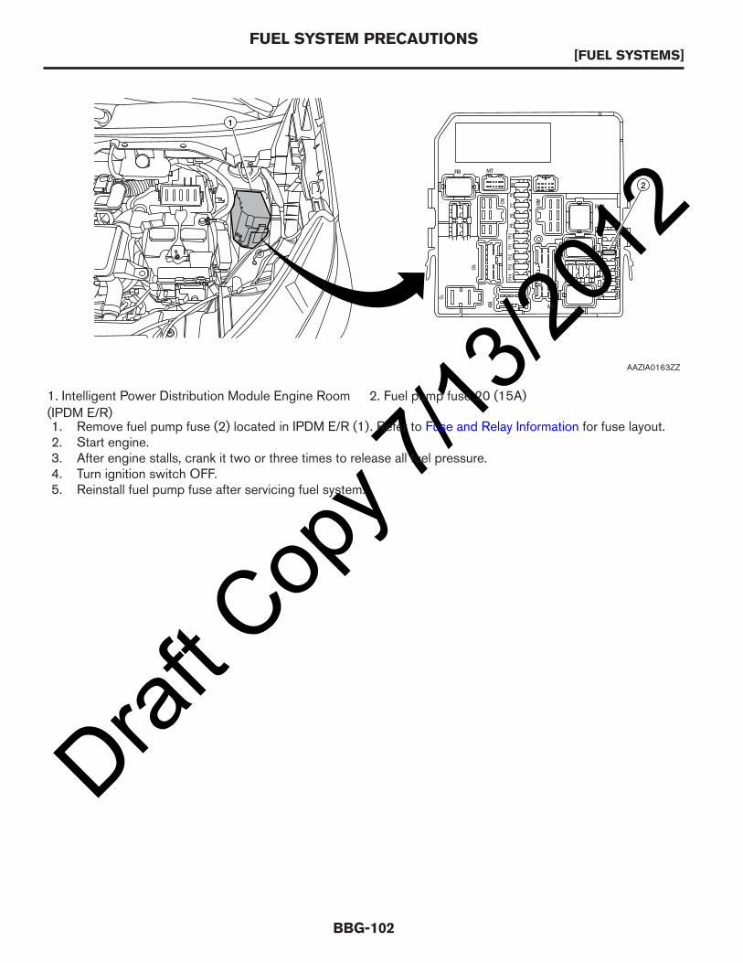
Draft C
opy 7
/13/20
12
1. Intelligent Power Distribution Module Engine Room(IPDM E/R)
2. Fuel pump fuse 20 (15A)
1. Remove fuel pump fuse (2) located in IPDM E/R (1). Refer to Fuse and Relay Information for fuse layout.2. Start engine.3. After engine stalls, crank it two or three times to release all fuel pressure.4. Turn ignition switch OFF.5. Reinstall fuel pump fuse after servicing fuel system.
1
2
R18
MTR8
MNR20
MMCM
CN
F14
F13
F12
F11
F10
F9F8
F7F6
F5
CL
AN
AAZIA0163ZZ
FUEL SYSTEM PRECAUTIONS[FUEL SYSTEMS]
BBG-102

Draft C
opy 7
/13/20
12FILLER NECK AREAS
Chassis
1. B pillar rear edge A. 191 mm (7.52 in) B. 149 mm (5.87 in)
C. 212.5 mm (8.37 in) D. 430 mm (16.93 in)
Fuel Filler Pipe and EVAP Canister Location
1. EVAP canister assembly 2. Fuel tank protector 3. Fuel tank
4. Front tank strap 5. Clamp 6. Fuel filler hose
7. Rear tank strap 8. EVAP vent tube
1 B
C
D
A
Front
AAZIA0309GB
12
8
3457 6 Front
AAZIA0310GB
FILLER NECK AREAS[FUEL SYSTEMS]
BBG-103
BBG

Draft C
opy 7
/13/20
12TANK LOCATION
Tank Mounting
1. Fuel tank 2. Rear tank strap 3. Front tank strap
4. EVAP canister assembly A. Fuel tank strap bolts
Drilling Precaution Area
CAUTION:
Use special care when drilling through the floor in the areas shown because the fuel tank, fuelpump, fuel filler hose, EVAP canister assembly, and EVAP hoses are located just below the floorand could be damaged.
A
1
3
4
2
Front
AAZIA0311GB
TANK LOCATION[FUEL SYSTEMS]
BBG-104
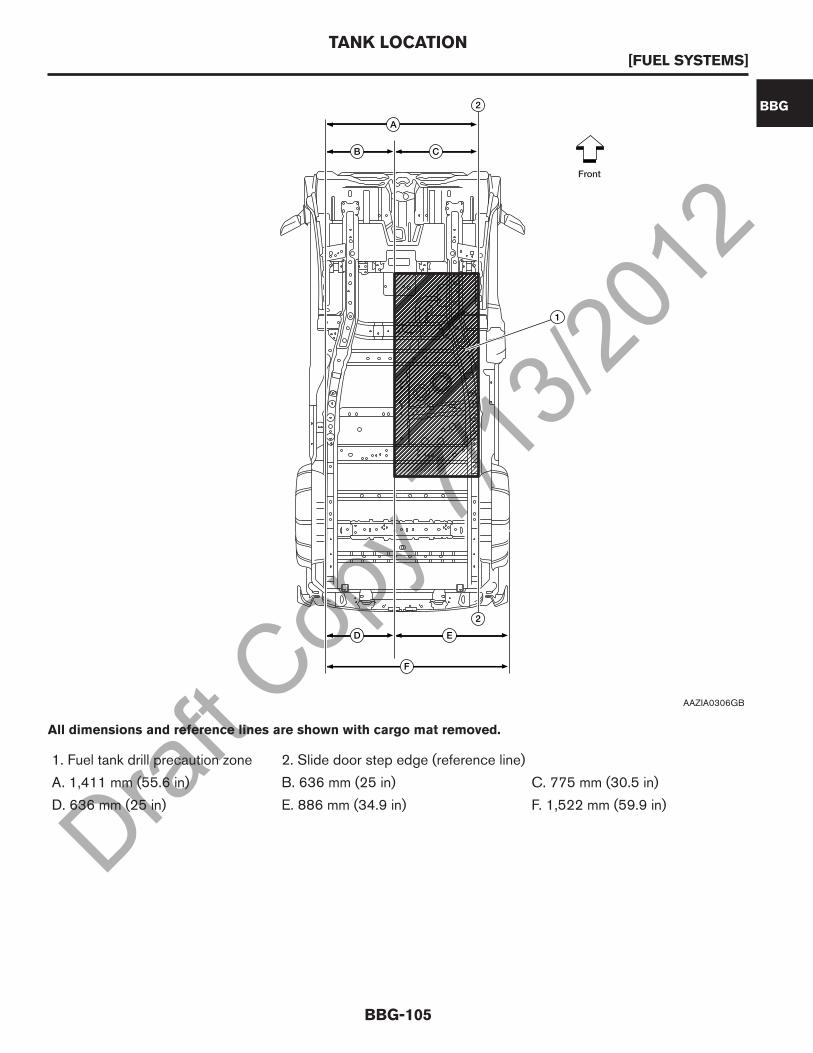
Draft C
opy 7
/13/20
12
1. Fuel tank drill precaution zone 2. Slide door step edge (reference line)
A. 1,411 mm (55.6 in) B. 636 mm (25 in) C. 775 mm (30.5 in)
D. 636 mm (25 in) E. 886 mm (34.9 in) F. 1,522 mm (59.9 in)
����������2
2
1
A
B C
F
D E
Front
AAZIA0306GB
All dimensions and reference lines are shown with cargo mat removed.
TANK LOCATION[FUEL SYSTEMS]
BBG-105
BBG
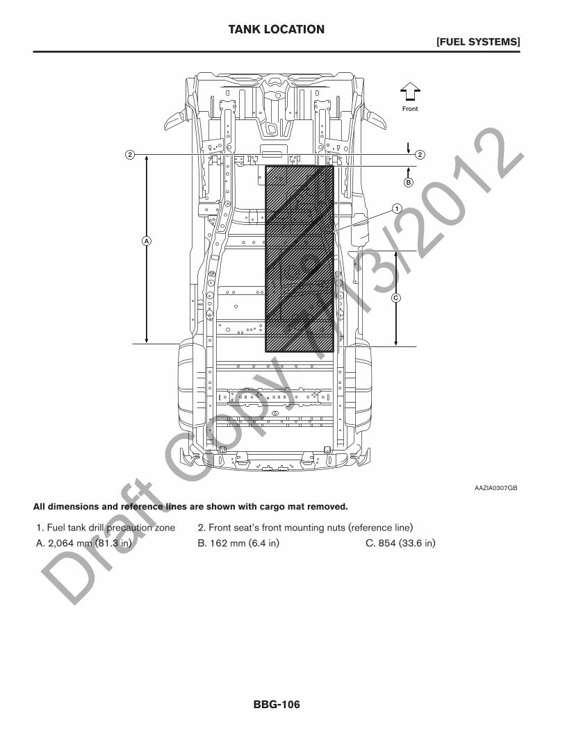
Draft C
opy 7
/13/20
12
1. Fuel tank drill precaution zone 2. Front seat’s front mounting nuts (reference line)
A. 2,064 mm (81.3 in) B. 162 mm (6.4 in) C. 854 (33.6 in)
����������A
2 2
1
B
C
Front
AAZIA0307GB
All dimensions and reference lines are shown with cargo mat removed.
TANK LOCATION[FUEL SYSTEMS]
BBG-106

Draft C
opy 7
/13/20
12DESIGN REQUIREMENTS FOR MODIFICATIONSCOOLING
Engine Cooling System
CAUTION:
No modification to the engine cooling system (radiator, radiator shroud, cooling fans, liquidcooling circuit, etc.) is allowed. Sufficient air passage to the radiator must be maintained,therefore, do not block the air passage through the radiator grille to the radiator with publicityplates, posters, trim or other decorative elements. Reduced air flow can cause overheatingand could lead to component damage.
COOLING[DESIGN REQUIREMENTS FOR MODIFICATIONS]
BBG-107
BBG

Draft C
opy 7
/13/20
12HVAC
Changes To The HVAC System
Changes to the HVAC system are not recommended. For liquid connection information, service data andspecifications, refer to the service manual.
HVAC System Component Locations
MANUAL AIR CONDITIONING SYSTEM
0
12
A/C
3
4
A
1
A
AAZIA0156ZZ
1. Front air control (shown with optional rear window defroster button).
HVAC[DESIGN REQUIREMENTS FOR MODIFICATIONS]
BBG-108

Draft C
opy 7
/13/20
12EXHAUST
Exhaust System
Changes to the exhaust system are not recommended.
6
8
11
4
A
9 A
7 A
A
3
12
A
48.5 N·m (4.9 kg-m, 36 ft-lb)
48.5 N·m (4.9 kg-m, 36 ft-lb)
58.0 N·m (5.9 kg-m, 43 ft-lb)
12 50 N·m (5.1 kg-m, 37 ft-lb)
48.5A N·m (4.9 kg-m, 36 ft-lb)
5
10
AAZIA0138ZZ
EXHAUST[DESIGN REQUIREMENTS FOR MODIFICATIONS]
BBG-109
BBG
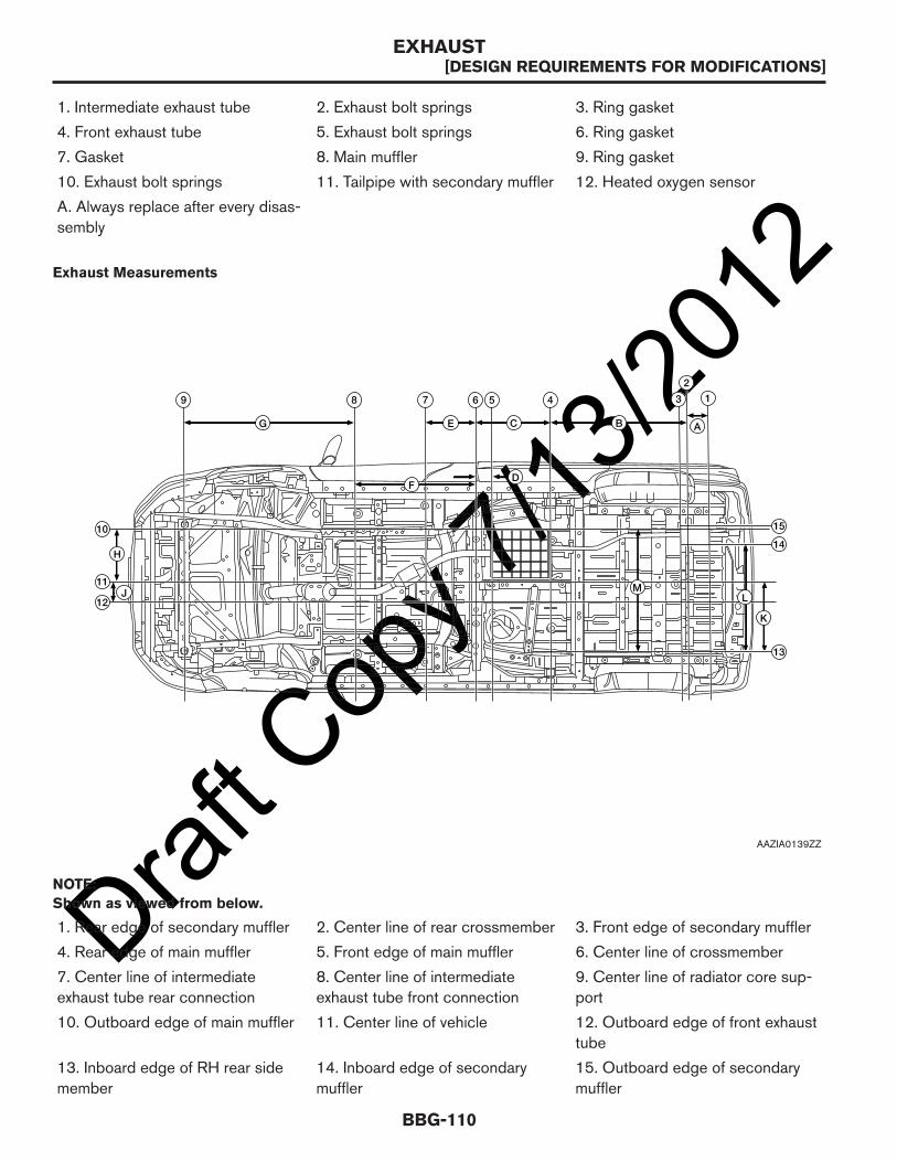
Draft C
opy 7
/13/20
121. Intermediate exhaust tube 2. Exhaust bolt springs 3. Ring gasket
4. Front exhaust tube 5. Exhaust bolt springs 6. Ring gasket
7. Gasket 8. Main muffler 9. Ring gasket
10. Exhaust bolt springs 11. Tailpipe with secondary muffler 12. Heated oxygen sensor
A. Always replace after every disas-sembly
NOTE:
Shown as viewed from below.
1. Rear edge of secondary muffler 2. Center line of rear crossmember 3. Front edge of secondary muffler
4. Rear edge of main muffler 5. Front edge of main muffler 6. Center line of crossmember
7. Center line of intermediateexhaust tube rear connection
8. Center line of intermediateexhaust tube front connection
9. Center line of radiator core sup-port
10. Outboard edge of main muffler 11. Center line of vehicle 12. Outboard edge of front exhausttube
13. Inboard edge of RH rear sidemember
14. Inboard edge of secondarymuffler
15. Outboard edge of secondarymuffler
Exhaust Measurements
9 8 7 6 5 4
G
F
E A
D
C B
K
H
J
15
14
13
12
11
10
M
3 1
2
L
AAZIA0139ZZ
EXHAUST[DESIGN REQUIREMENTS FOR MODIFICATIONS]
BBG-110
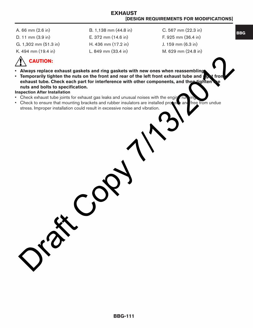
Draft C
opy 7
/13/20
12A. 66 mm (2.6 in) B. 1,138 mm (44.8 in) C. 567 mm (22.3 in)
D. 11 mm (3.9 in) E. 372 mm (14.6 in) F. 925 mm (36.4 in)
G. 1,302 mm (51.3 in) H. 436 mm (17.2 in) J. 159 mm (6.3 in)
K. 494 mm (19.4 in) L. 849 mm (33.4 in) M. 629 mm (24.8 in)
CAUTION:
• Always replace exhaust gaskets and ring gaskets with new ones when reassembling.• Temporarily tighten the nuts on the front and rear of the left front exhaust tube and right front
exhaust tube. Check each part for interference with other components, and then tighten thenuts and bolts to specification.
Inspection After Installation
• Check exhaust tube joints for exhaust gas leaks and unusual noises with the engine running.• Check to ensure that mounting brackets and rubber insulators are installed properly and free from undue
stress. Improper installation could result in excessive noise and vibration.
EXHAUST[DESIGN REQUIREMENTS FOR MODIFICATIONS]
BBG-111
BBG

Draft C
opy 7
/13/20
12WHEEL AND TIRE
General
The replacement of the tires with those other than the ones indicated by NISSAN is not recommended. Usingtires of different make, size, type or characteristics on the same axle is not allowed. Using non-recommendedtires could affect the performance of the Vehicle Dynamic Control (VDC) or other vehicle components.
WHEEL AND TIRE[DESIGN REQUIREMENTS FOR MODIFICATIONS]
BBG-112

Draft C
opy 7
/13/20
12STEERING AND SUSPENSION
Vehicle Handling Information
WARNING:
• Changes made to the vehicle that significantly affect the ride height may cause vehicle controlproblems during sharp turns or sudden steering maneuvers. Any maneuvers of this type couldresult in an accident. The steering gear, intermediate shaft, coupling shaft, linkage, column, andsteering wheel should not be altered or relocated. Steering linkage travel should not berestricted.
CAUTION:
• Because the heat from welding on or near the suspension or steering components may damageor weaken the components, it is not authorized.
• Welding equipment should not be grounded to any of the suspension components.• Any new components attached to the steering column or its components must not interfere with
the steering column performance during either normal operation or crash situations.• New components and/or the vehicle load must not exceed the front and rear GAWRs or the
GVWR.
NOTE:
The aftermarket equipment manufacturer, second stage manufacturer, and upfitter are responsiblefor maintaining or restoring the front wheel alignment after modifications to the vehicle arecomplete. The straight ahead orientation of the steering wheel must be maintained whenre-adjusting the front wheel alignment. Changes to the vehicle center of gravity will affecthandling. The upfitter is responsible for maintaining compliance with the Federal or Canada MotorVehicle Safety Standards in regards to the center of gravity and vehicle handling characteristics.Please observe the following:
STEERING AND SUSPENSION[DESIGN REQUIREMENTS FOR MODIFICATIONS]
BBG-113
BBG

Draft C
opy 7
/13/20
12DRIVELINE
CAUTION:
Any deviation from NISSAN specifications may adversely affect powertrain operation, includingengine, transmission, or component reliability. The aftermarket equipment manufacturer, secondstage manufacturer, and upfitter are responsible for maintaining the specifications after thecompletion of any modifications.
DRIVELINE[DESIGN REQUIREMENTS FOR MODIFICATIONS]
BBG-114

Draft C
opy 7
/13/20
12TRANSMISSION
CAUTION:
• The engine and transmission position relative to the shift linkage must not be altered.• The transmission vent must not be altered, pinched, collapsed, restricted or relocated.• The spacing for tool access for transmission adjustments or removal must be maintained.• Transmission oil cooler lines should not be kinked, bent, or restricted. All oil cooler lines must be
properly retained with adequate clips.• The shift cable, external transmission shift lever, and shift cable bracket must not be altered.• Transmission identification tags must not be removed or destroyed.• All transmission wire harness routing, locating clips, heat shielding, and clearance to the exhaust
must be maintained as installed by the factory.
TRANSMISSION[DESIGN REQUIREMENTS FOR MODIFICATIONS]
BBG-115
BBG

Draft C
opy 7
/13/20
12UNIBODY AND FRAME
WARNING:
Failure to follow the recommendations below may weaken the vehicle structure, which couldresult in death or serious injury.• Do not modify or alter the front crush horns. Modifications or alterations could adversely affect
the vehicle in a crash.
The vehicle structure is a unibody design with high strength steel support areas. High strength steel locations arenot intended for modification. Refer to HIGH STRENGTH STEEL LOCATIONS in this section.
UNIBODY AND FRAME[DESIGN REQUIREMENTS FOR MODIFICATIONS]
BBG-116

Draft C
opy 7
/13/20
12JACK
Jacking and Lifting PointsJack Storage
NOTE:
Jack and tools are stored under front passenger seat.
Garage Jack Points
1 2
3
5
4
AAZIA0157ZZ
JACK[DESIGN REQUIREMENTS FOR MODIFICATIONS]
BBG-117
BBG

Draft C
opy 7
/13/20
122 Pole Lift Points
AAZIA0158ZZ
AAZIA0159ZZ
JACK[DESIGN REQUIREMENTS FOR MODIFICATIONS]
BBG-118

Draft C
opy 7
/13/20
12HIGH STRENGTH STEEL LOCATIONS
Precaution in Repairing High Strength Steel (HSS)
WARNING:
• While working, suitable work clothes, a work cap and safety shoes must be worn. To preventburns, a long sleeve shirt and trousers must also be worn and must not be taken off under anycircumstance.
• Before starting repair work, be sure to disconnect the negative terminal of the battery.• Pay attention to ventilation and health of the operators.• Paint and sealants may generate poisonous gases when heated by fire.
WARNING:
Do not heat, bend, or cut high strength steel or the structural integrity of the vehicle may becompromised.
High Strength Steel Locations
The grey shading in the following illustrations indicate body areas with high strength steel (HSS).
Front
AAZIA0129ZZ
HIGH STRENGTH STEEL LOCATIONS[DESIGN REQUIREMENTS FOR MODIFICATIONS]
BBG-119
BBG
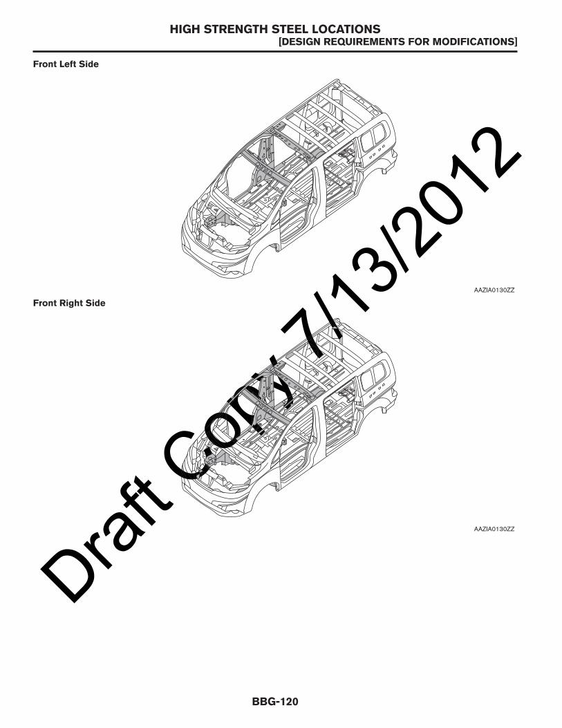
Draft C
opy 7
/13/20
12
Front Left Side
AAZIA0130ZZ
Front Right Side
AAZIA0130ZZ
HIGH STRENGTH STEEL LOCATIONS[DESIGN REQUIREMENTS FOR MODIFICATIONS]
BBG-120

Draft C
opy 7
/13/20
12
Right Side
AAZIA0132ZZ
Left Side
AAZIA0133ZZ
HIGH STRENGTH STEEL LOCATIONS[DESIGN REQUIREMENTS FOR MODIFICATIONS]
BBG-121
BBG

Draft C
opy 7
/13/20
12
Rear Left Side
AAZIA0134ZZ
Rear Right Side
AAZIA0135ZZ
HIGH STRENGTH STEEL LOCATIONS[DESIGN REQUIREMENTS FOR MODIFICATIONS]
BBG-122

Draft C
opy 7
/13/20
12
WELDING
HSS is used for body panels in order to reduce vehicle weight. Accordingly, precautions in repairing automotivebodies made of HSS are described below:
HSS Used in NISSAN Vehicles
Tensile strength Major applicable parts
440 - 780 MPa
• Front inner pillar upper• Front pillar hinge brace• Outer front pillar reinforcement• Other reinforcements
Rear
AAZIA0136ZZ
Floor
AAZIA0137ZZ
WELDING[DESIGN REQUIREMENTS FOR MODIFICATIONS]
BBG-123
BBG

Draft C
opy 7
/13/20
12Tensile strength Major applicable parts
980 - 1310 MPa• Outer sill reinforcement• Main back pillar
Read the following precautions when repairing HSS:1. Additional points to consider:
• The repair of reinforcements (such as side members) by heating is not recommended since it mayweaken the component. When heating is unavoidable, do notheat HSS parts above 550° C (1,022° F). Verify heatingtemperature with a thermometer (Crayon-type and other similartype thermometers are appropriate).
• When straightening body panels, use caution in pulling any HSS panel. Because HSS is very strong,pulling may cause deformation in adjacent portions of the body.In this case, increase the number of measuring points andcarefully pull the HSS panel.
• When cutting HSS panels, avoid gas (torch) cutting if possible. Instead, use a saw to avoid weakeningsurrounding areas due to heat. If gas (torch) cutting isunavoidable, allow a minimum margin of 50 mm (1.97 in).
• When welding HSS panels, use spot welding whenever possible in order to minimize weakeningsurrounding areas due to heat.
• If spot welding is impossible, use MIG welding. Do not use gas (torch) welding because it is inferior in
PIIA0115E
PIIA0116E
AAZIA0240GB
WELDING[DESIGN REQUIREMENTS FOR MODIFICATIONS]
BBG-124

Draft C
opy 7
/13/20
12welding strength.
• The spot weld on HSS panels is harder than that of an ordinary steel panel. Therefore, when cutting spotwelds on a HSS panel, use a low speed high torque drill (1,000to 1,200 rpm) to increase drill bit durability and facilitate theoperation.
• SP150 HSS panels with a tensile strength of 785 to 981 N/mm2 (80 to 100 kg/mm2, 114 to 142 lb/sqin), used as reinforcement in the door guard beams, is too strong to repair. When these HSS parts aredamaged, the outer panels also sustain substantial damage; therefore, the assembly parts must bereplaced.
2. Precautions in spot welding HSS:This work should be performed under standard working conditions.Always note the following when spot welding HSS:• The electrode tip diameter must be sized properly according to
the metal thickness.
• The panel surfaces must fit flush to each other, leaving no gaps.
AAZIA0241GB
PIIA0145E
PIIA0146E
WELDING[DESIGN REQUIREMENTS FOR MODIFICATIONS]
BBG-125
BBG
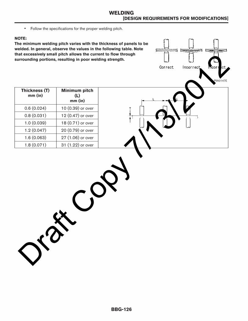
Draft C
opy 7
/13/20
12• Follow the specifications for the proper welding pitch.
NOTE:
The minimum welding pitch varies with the thickness of panels to be
welded. In general, observe the values in the following table. Note
that excessively small pitch allows the current to flow through
surrounding portions, resulting in poor welding strength.
Thickness (T)mm (in)
Minimum pitch(L)
mm (in)
0.6 (0.024) 10 (0.39) or over
0.8 (0.031) 12 (0.47) or over
1.0 (0.039) 18 (0.71) or over
1.2 (0.047) 20 (0.79) or over
1.6 (0.063) 27 (1.06) or over
1.8 (0.071) 31 (1.22) or over
PIIA0147E
WELDING[DESIGN REQUIREMENTS FOR MODIFICATIONS]
BBG-126

Draft C
opy 7
/13/20
12VEHICLE INTERIOR
Modifications in the Vehicle InteriorGeneral
The modifications should not affect the operation of the control units (pedals, switches, rods, etc.) located in thearea affected by the modification.
After any modification to the body that affect the acoustic and thermal insulation, the new and/or modifiedinsulation must meet or exceed the original specifications.
The ergonomic access to the controls for the driver must not be prevented by the installation of newcomponents.
Any modifications made by the aftermarket equipment manufacturer, second stage manufacturer, and upfittermust be properly sealed to protect against corrosion.
The aftermarket equipment manufacturer, second stage manufacturer, and upfitter must ensure that anymodifications that have been made to the cabin still meet the legal requirements regarding the interior andexterior characteristics.
No new holes should be drilled to allow for attaching any new components to the roof of the cabin.Modifications in the Roof of the Cabin
When attaching equipment to the roof, make sure that the added weight does not exceed the maximum roof loadlimit.
All components that pass through the external sheet metal (for electric cables, telephone aerials, etc.) must beproperly sealed. Only NISSAN approved products should be used.
Changes to the center of gravity should not exceed the maximum authorized height.
VEHICLE INTERIOR[DESIGN REQUIREMENTS FOR MODIFICATIONS]
BBG-127
BBG

Draft C
opy 7
/13/20
12PAINT WORK
The aftermarket equipment manufacturer, second stage manufacturer, and upfitter are responsible for repairingany damage to the paint incurred while modifying the vehicle.
Only NISSAN specified paint should be used for these repairs. Refer to the BRM section in the Service Manualfor information about the paint.
Component
Color code B23 K23 QM1 KH3 NAC
Description DK Blue Silver White Black Red
Type M M S S S
Clear coat n n n n n
Outside mirrorS Black (no paint) G01–1 G01–1 G01–1 G01–1 G01–1
SV Body color B23 K23 QM1 KH3 NAC
BumpersS Black (no paint) G01–1 G01–1 G01–1 G01–1 G01–1
SV Body color* B23 K23 QM1 KH3 NAC
Outside handlesS Black TBD TBD TBD TBD TBD
SV Body color* B23 K23 QM1 KH3 NAC
Radiator grille
S SilverSilver paint
Silverpaint
Silver paint Silver paintSilverpaint
SV Chromium plate* Cr2P Cr2P Cr2P Cr2P Cr2PM: Metallic; S-Solid; n: Non-primerless Clear Coat; *: Option
PAINT WORK[DESIGN REQUIREMENTS FOR MODIFICATIONS]
BBG-128

Draft C
opy 7
/13/20
12ADHESIVE INFORMATION
MSDS Information
Contact the product supplier for the latest MSDS (Material Safety Data Sheet) information.
Product Name Code/Number Supplier/Emergency Phone Numbers
Sunnex (adhesive for body) SH-310Sunstar Inc.www.sunstarea.com937-746-8575
Terostat (mastic adhesives)
06-1273 HMHenkel Corporationwww.henkel.comUSA 1-248-583-9300Chemtrec emergency 1-800-424-9300
SA-461
SA-462
SA-463
Mastic adhesive PCC-13A
EFTEC North America, L.L.C.www.eftec.com24 hour emergency 1-888-853-1758Emergency transport 1-800-424-9300
Stiffener for outer panel PE7000NITTO Denkowww.nitto.com816-6452-2101
Betaseal adhesive (Directglassing)
57302
Dow Chemical Co.www.dow.com24 hour emergency 1-989-636-4400Customer Information 1-800-258-2436
ADHESIVE INFORMATION[DESIGN REQUIREMENTS FOR MODIFICATIONS]
BBG-129
BBG
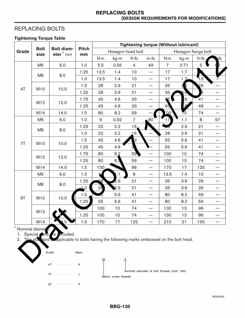
Draft C
opy 7
/13/20
12REPLACING BOLTS
Tightening Torque Table
GradeBolt
size
Bolt diam-
eter * mmPitch
mm
Tightening torque (Without lubricant)
Hexagon head bolt Hexagon flange bolt
N·m kg-m ft-lb in-lb N·m kg-m ft-lb in-lb
4T
M6 6.0 1.0 5.5 0.56 4 49 7 0.71 5 62
M8 8.01.25 13.5 1.4 10 — 17 1.7 13 —
1.0 13.5 1.4 10 — 17 1.7 13 —
M10 10.01.5 28 2.9 21 — 35 3.6 26 —
1.25 28 2.9 21 — 35 3.6 26 —
M12 12.01.75 45 4.6 33 — 55 5.6 41 —
1.25 45 4.6 33 — 65 6.6 48 —
M14 14.0 1.5 80 8.2 59 — 100 10 74 —
7T
M6 6.0 1.0 9 0.92 7 80 11 1.1 8 97
M8 8.01.25 22 2.2 16 — 28 2.9 21 —
1.0 22 2.2 16 — 28 2.9 21 —
M10 10.01.5 45 4.6 33 — 55 5.6 41 —
1.25 45 4.6 33 — 55 5.6 41 —
M12 12.01.75 80 8.2 59 — 100 10 74 —
1.25 80 8.2 59 — 100 10 74 —
M14 14.0 1.5 130 13 96 — 170 17 125 —
9T
M6 6.0 1.0 11 1.1 8 — 13.5 1.4 10 —
M8 8.01.25 28 2.9 21 — 35 3.6 26 —
1.0 28 2.9 21 — 35 3.6 26 —
M10 10.01.5 55 5.6 41 — 80 8.2 59 —
1.25 55 5.6 41 — 80 8.2 59 —
M12 12.01.75 100 10 74 — 130 13 96 —
1.25 100 10 74 — 130 13 96 —
M14 14.0 1.5 170 17 125 — 210 21 155 —* Nominal diameter1. Special parts are excluded.2. This standard is applicable to bolts having the following marks embossed on the bolt head.
MGI044A
REPLACING BOLTS[DESIGN REQUIREMENTS FOR MODIFICATIONS]
BBG-130

Draft C
opy 7
/13/20
12ADD ON EQUIPMENTANTI-CORROSION PROTECTION
CAUTION:
Failure to refinish bare metal will result in corrosion.
The basic steps to refinish bare metal are as follows:1. Prep the metal surface(s) as follows:
A. Remove burrs from the edges with a file or sandpaper.B. Thoroughly clean the metal with solvent and allow to completely dry.C. Apply self-etching primer to all bare metal.D. Allow primer to properly dry.
2. Apply base coat paint and allow to properly dry.3. Apply clear coat and allow to properly dry.4. Apply Nissan Bitumen Wax (part number 999MP-9G001P) available at a Nissan dealer.
ANTI-CORROSION PROTECTION[ADD ON EQUIPMENT]
BBG-131
BBG

Draft C
opy 7
/13/20
12SHELVING AND BULKHEAD INSTALLATION
Bulkhead
The bulkhead should be attached to the NISSAN supplied weld nuts in the roof crossmember and the floor. Nonew attachment points should be added. Loading should be distributed evenly utilizing as many mounting pointsas possible.
* Weld nut locations for bulkhead installation; All bolts are M8 x 1.25
1. Mounting point loading not to exceed TBD kg (TBD lbs) per point. Total loading across these 4 mountingpoints not to exceed TBD kg (TBD lbs).
2. Mounting point loading not to exceed TBD kg (TBD lbs) per point.
3. Mounting point loading not to exceed TBD kg (TBD lbs) per point. Total loading across these 4 mountingpoints not to exceed TBD kg (TBD lbs).
A. 165 mm (6.5 in) B. 140 mm (5.5 in) C. 376.21 mm (14.8 in)
D. 253.58 mm (10.0 in) E. 1,103.67 mm (43.5 in) F. 1,104.07 mm (43.5 in)
G. 219.63 mm (8.65 in) H. 224.06 mm (8.8 in)
Front
1
2
3
C D C
2
E
G H G
A
F E
B A
AAZIA0140ZZ
SHELVING AND BULKHEAD INSTALLATION[ADD ON EQUIPMENT]
BBG-132
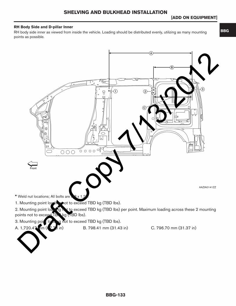
Draft C
opy 7
/13/20
12
* Weld nut locations; All bolts are M8 x 1.25.
1. Mounting point loading not to exceed TBD kg (TBD lbs).
2. Mounting point loading not to exceed TBD kg (TBD lbs) per point. Maximum loading across these 2 mountingpoints not to exceed TBD kg (TBD lbs).
3. Mounting point loading not to exceed TBD kg (TBD lbs).
A. 1,720.47 mm (67.73 in) B. 798.41 mm (31.43 in) C. 796.70 mm (31.37 in)
RH Body Side and D-pillar Inner
RH body side inner as viewed from inside the vehicle. Loading should be distributed evenly, utilizing as many mountingpoints as possible.
1 23
B
A
C
Front
AAZIA0141ZZ
SHELVING AND BULKHEAD INSTALLATION[ADD ON EQUIPMENT]
BBG-133
BBG

Draft C
opy 7
/13/20
12
* Weld nut locations; All bolts are M8 x 1.25
1. Mounting point loading not to exceed TBD kg (TBD lbs).
2. Mounting point loading not to exceed TBD kg (TBD lbs) per point. Total loading across these 2 mountingpoints not to exceed TBD kg (TBD lbs).
3. Mounting point loading not to exceed TBD kg (TBD lbs).
A. 1,720.47 mm (67.73 in) B. 798.41 mm (31.43 in) C. 796.70 mm (31.37 in)Floor
The shelves bolt to the same location on the floor as the D-rings (if equipped). Loading should be distributedevenly utilizing as many mounting points as possible.
LH Body Side and D-pillar Inner
LH body side inner as viewed from inside the vehicle. Loading should be distributed evenly, utilizing as many mounting pointsas possible.
A
B
C
1 32
Front
AAZIA0142ZZ
SHELVING AND BULKHEAD INSTALLATION[ADD ON EQUIPMENT]
BBG-134

Draft C
opy 7
/13/20
12
* Bolt locations for shelving installation; All bolts are M8 x 1.25
1. Mounting point loading not to exceed TBD kg (TBD lbs).
A. 817 mm (32.2 in) B. 845 mm (33.3 in) C. 1,007 mm (39.6 in)
D. 845 mm (33.3 in) E. 817 mm (32.2 in) F. 1,139 mm (44.8 in)Interior Roof Bow Mounting Points
Loading should be distributed evenly, utilizing as many mounting points as possible.
B A
D
C F
E
Front
AAZIA0288GB
SHELVING AND BULKHEAD INSTALLATION[ADD ON EQUIPMENT]
BBG-135
BBG

Draft C
opy 7
/13/20
12
* Weld nut locations; All bolts are M8 x 1.25
1. Bulkhead roof bow 2. Windshield header 3. Roof bow
A. 100 mm (3.9 in) B. 418 mm (16.5 in)
12
3
B
A
Front
AAZIA0289GB
SHELVING AND BULKHEAD INSTALLATION[ADD ON EQUIPMENT]
BBG-136

Draft C
opy 7
/13/20
12ROOF RACKS
WARNING:
• Drive extra carefully when the vehicle is loaded at or near the cargo carrying capacity, especiallyif the significant portion of that load is carried on the roof rack.
• Heavy loading of the roof rack has the potential to affect the vehicle stability and handlingduring sudden or abnormal handling maneuvers.
• Roof rack load should be evenly distributed.• Do not exceed maximum roof rack load weight capacity.• Properly secure all cargo with ropes or straps to help prevent it from sliding or shifting. In a
sudden stop or collision, unsecured cargo could cause personal injury.
CAUTION:
Use care when placing or removing items from the roof rack. If you cannot comfortably lift theitems onto the roof rack from the ground, use a ladder or stool. Always distribute the cargo evenlyon the roof rack. Do not exceed the maximum roof rack load or maximum load per mountingbracket.
The satellite radio antenna (if equipped) is located on the roof. Do not cover the module; it may affect thereception of the device.
The factory installed weld nuts are the only NISSAN approved attachment points for the installation of a roof rack.Use bolts for attaching the roof racks to the brackets.
ROOF RACKS[ADD ON EQUIPMENT]
BBG-137
BBG

Draft C
opy 7
/13/20
12
*: Weld nut locations; All bolts are M8 x 1.25
A. 1,004.95 mm (36.56 in) B. 632.01 mm (24.88 in) C. 1,117.98 mm (44.01 in)
D. 1,108.78 mm (43.65 in) E. 1,126.66 mm (44.36 in)
A
EDC
B Front
AAZIA0291GB
ROOF RACKS[ADD ON EQUIPMENT]
BBG-138

Draft C
opy 7
/13/20
12SPECIFICATIONSRECOMMENDED FLUIDS AND LUBRICANTS
NOTE:
Refer to Service Manual for detailed service procedures.
Description
Capacity (Approximate)Recommended Fluids/
LubricantsMetricUS mea-
sure
Imperial
measure
Fuel 55 liters14½ gal-
lons12⅛ gal-
lons
Unleaded gasoline with anoctane rating of at least 87AKI (RON 91) *1
Engine oilDrain and refill
With oil filterchange
4.3 liters 4½ quarts 3¾ quarts Engine oil with APICertification Mark *2Viscosity SAE 5W-30Without oil filter
change4.0 liters 4¼ quarts 3½ quarts
Cooling system(With reservoir atMAX level)
7.6 liters 8 quarts 6¾ quartsPre-diluted Genuine NISSANLong Life Antifreeze/Coolant(blue) or equivalent *3
Continuously variable transmission(CVT) fluid
TBD litersTBDquarts
TBDquarts
Genuine NISSAN CVT FluidNS-3 *4
Brake fluid — — —
Genuine NISSAN SuperHeavy Duty Brake Fluid *5 or
equivalent, DOT 3 (US FMVSS
No. 116)
Multi-purpose grease — — —NLGI No.2 (lithium soapbase)
Windshield washer fluid 4.5 liters 1¼ gallons 1 gallonGenuine NISSAN WindshieldWasher Concentrate Cleaner& Antifreeze or equivalent
Air conditioning system refrigerant450 ±50grams
0.99pounds
(±0.11 lb)
0.99pounds
(±0.11 lb)HFC-134a (R-134a) *6
Air conditioning system oil150 ±20milliliters
5.1 ±0.7ounces
5.1 ±0.7ounces
A/C System Oil Type S (DH-PS) *6
*1: For further details, refer to Precaution for Fuel.
*2: For further details, refer to Engine Oil Recommendation.
*3: For further details, refer to Engine Coolant Recommendation.
*4: Use only Genuine NISSAN CVT Fluid NS-3. Using transmission fluid other than Genuine NISSANCVT Fluid NS-3 will damage the CVT, which is not covered by the NISSAN new vehicle limitedwarranty.
*5: Available in mainland U.S.A. through a NISSAN dealer.
*6: For further details, see “Air conditioner specification label” on the underside of the hood.
RECOMMENDED FLUIDS AND LUBRICANTS[SPECIFICATIONS]
BBG-139
BBG

Draft C
opy 7
/13/20
12
Precaution for Fuel (Unleaded Regular Gasoline Recommended)
Use unleaded regular gasoline with an octane rating of at least 87 AKI (Anti-Knock Index) number (Researchoctane number 91).
RECOMMENDED FLUIDS AND LUBRICANTS[SPECIFICATIONS]
BBG-140

Draft C
opy 7
/13/20
12CAUTION:
Do not use leaded gasoline. Using leaded gasoline will damage the three-way catalyst. Do not useE-85 fuel (85% fuel ethanol, 15% unleaded gasoline) unless the vehicle is specifically designedfor E-85 fuel (i.e., Flexible Fuel Vehicle — FFV Models). Using a fuel other than that specifiedcould adversely affect the emission control devices and systems, and could also affect thewarranty coverage validity.
Engine Oil Recommendation
NISSAN recommends the use of an energy conserving oil in order to improve fuel economy. Select only engineoils that meet the American Petroleum Institute (API) certification and International Lubricant Standardization andApproval Committee (ILSAC) certification and SAE viscosity standard. These oils have the API certificationmark on the front of the container. Oils which do not have the specified quality label should not be used as theycould cause engine damage.
Engine Coolant Recommendation
The engine cooling system is filled at the factory with a pre-diluted mixture of 50% Genuine NISSAN Long LifeAntifreeze/Coolant (blue) and 50% water to provide year round antifreeze and coolant protection. The antifreezesolution contains rust and corrosion inhibitors. Additional cooling system additives are not necessary.
WARNING:
• Never remove the radiator or coolant reservoir cap when the engine is hot. Wait until the engineand radiator cool down. Serious burns could be caused by high pressure fluid escaping from theradiator.
• The radiator is equipped with a pressure type radiator cap. To prevent engine damage, use only aGenuine NISSAN radiator cap.
CAUTION:
• When adding or replacing coolant, be sure to use only Genuine NISSAN Long Life Antifreeze/Coolant (blue) or equivalent. Genuine NISSAN Long Life Antifreeze/Coolant (blue) is pre-diluted to provide antifreeze protection to -34° F (-37° C). If additional freeze protection isneeded due to weather where the vehicle is operated, add Genuine NISSAN long life Antifreeze/Coolant (blue) concentrate following the directions on the container. If an equivalent coolantother than Genuine NISSAN Long Life Antifreeze/Coolant (blue) is used, follow the coolantmanufacturer’s instructions to maintain minimum antifreeze protection to -34° F (-37° C). The useof other types of coolant solutions other than Genuine NISSAN Long Life Antifreeze/Coolant
JSPIA0006ZZ
1. API certification mark 2. API service symbol
RECOMMENDED FLUIDS AND LUBRICANTS[SPECIFICATIONS]
BBG-141
BBG

Draft C
opy 7
/13/20
12(blue) or equivalent may damage the engine cooling system.
• Mixing any other type of coolant other than Genuine NISSAN Long Life Antifreeze/Coolant(blue), including Genuine NISSAN Long Life Antifreeze/Coolant (green), or the use of non-distilled water will reduce the life expectancy of the factory filled coolant.
RECOMMENDED FLUIDS AND LUBRICANTS[SPECIFICATIONS]
BBG-142

Draft C
opy 7
/13/20
12SUSPENSION
General Specification (Front)
Suspension typeFront: independent strut
Rear: multi-leaf with solid axle
Shock absorber typeFront: twin tube strut
Rear: twin tube
Stabilizer Front solid stabilizer bar (standard equipment)
Front Wheel Alignment (Unladen*1)
Camber *2Degree minute (decimal degree) LH
Minimum -1° 05’ (-1.08°)
Nominal -0° 20’ (-0.33°)
Maximum 0° 25’ (0.42°)
RH
Minimum -1° 05’ (-1.08°)
Nominal -0° 20’ (-0.33°)
Maximum 0° 25’ (0.42°)
Caster *3Degree minute (decimal degree)
Nominal 4° 10’ (4.17°)
Kingpin offsetDegree minute (decimal degree) LH
Minimum 12° 40’ (12.67°)
Nominal 11° 55’ (11.92°)
Maximum 11° 10’ (11.17°)
RH
Minimum 12° 40’ (12.67°)
Nominal 11° 55’ (11.92°)
Maximum 11° 10’ (11.17°)
SUSPENSION[SPECIFICATIONS]
BBG-143
BBG
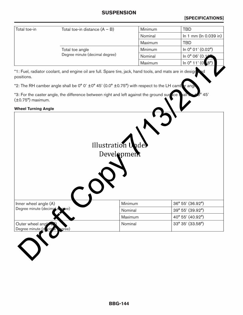
Draft C
opy 7
/13/20
12Total toe-in Total toe-in distance (A – B) Minimum TBD
Nominal In 1 mm (In 0.039 in)
Maximum TBD
Total toe angleDegree minute (decimal degree)
Minimum In 0° 01’ (0.02°)
Nominal In 0° 06’ (0.10°)
Maximum In 0° 11’ (0.18°)
*1: Fuel, radiator coolant, and engine oil are full. Spare tire, jack, hand tools, and mats are in designatedpositions.
*2: The RH camber angle shall be 0° 0’ ±0° 45’ (0.0° ±0.75°) with respect to the LH camber angle.
*3: For the caster angle, the difference between right and left against the ground surface shall be ±0° 45’(±0.75°) maximum.
Wheel Turning Angle
Inner wheel angle (A)Degree minute (decimal degree)
Minimum 36° 55’ (36.92°)
Nominal 39° 55’ (39.92°)
Maximum 40° 55’ (40.92°)
Outer wheel angle (B)Degree minute (decimal degree)
Nominal 33° 35’ (33.58°)
SUSPENSION[SPECIFICATIONS]
BBG-144

Draft C
opy 7
/13/20
12
Rear Wheel Alignment (Unladen*)
Camber*Degree minute (decimal degree)
Minimum -2° 0’ (-2.0°)
Nominal -1° 30’ (-1.5°)
Maximum -1° 0’ (-1.0°)
Total toe-in Total toe-in distance (A– B)
Minimum Out 2 mm (0.079 in)
Nominal In 3 mm (0.118 in)
Maximum In 8 mm (0.315 in)
Total toe-in angleDegree minute (decimaldegree)
Minimum Out 0° 46’ (0.77°)
Nominal In 0° 16’ (0.27°)
Maximum In 0° 46’ (0.77°)
*: Fuel, radiator coolant, and engine oil are full. Spare tire, jack, hand tools, and mats are in designated positions.
General Specification (Rear)
Suspension type Rigid axle with semi-elliptic leaf spring
Shock absorber type Double-acting hydraulic
Wheelarch Height at Offline Curb Weight (Unladen*1)
Tire Size 185/60R15
SUSPENSION[SPECIFICATIONS]
BBG-145
BBG

Draft C
opy 7
/13/20
12Front wheelarch height (Hf) 700 mm (27.6 in)
Rear wheelarch height (Hr) 737 mm (29.0 in)
*1: Fuel, radiator coolant and engine oil full. Spare tire, jack, hand tools and mats in designated positions.
Wheelarch Height at Maximum Payload Weight*1
Tire Size 185/60R15
Front wheelarch height (Hf) 682 mm (26.9 in)
Rear wheelarch height (Hr) 683 mm (26.9 in)
*1: Fuel, radiator coolant and engine oil full. Spare tire, jack, hand tools and mats in designated positions.
SUSPENSION[SPECIFICATIONS]
BBG-146

Draft C
opy 7
/13/20
12TURNING RADIUS
Curb-to-Curb
AAZIA0062ZZ
A. 11.2 m (36.7 ft)
TURNING RADIUS[SPECIFICATIONS]
BBG-147
BBG

Draft C
opy 7
/13/20
12WHEEL AND TIRE
Wheels and Tires
Grade Road wheel Tire Size Spare tire size
S15X5.5JJ Steel 185/60R15 185/60R15
SV
Wheel Dimensions
Diameter 15 in
Width 168 mm (6.61 in)
Offset 45 mm (1.77 in)
Bolt pattern 5 x 114.3 mm
Center bore 66 + 0.1 mm / -0.00 mm
Lug nut thread pitch TBD
Brake caliper clearance TBD
WHEEL AND TIRE[SPECIFICATIONS]
BBG-148

Draft C
opy 7
/13/20
12BULBS
Exterior Lamp
Item Wattage (W)* Bulb No.*
Front combination lampTurn signal/parking lamp 27/7 3457A
Headlamp low/high 55/60 Halogen H13
Rear combination lamp
Stop/tail lamp 27/7 3157K
Turn signal lamp 27 3157AK
Back-up lamp 16 921
High-mounted stop lamp 16 TBD
License plate lamp 5 TBD
* Always check with an authorized NISSAN dealer for the latest parts information.
Interior Lamp/Illumination
Item Wattage (W)* Bulb No.*
Front room/map lamp 5 TBD
Cargo lamp 5 TBD
* Always check with an authorized NISSAN dealer for the latest parts information.
BULBS[SPECIFICATIONS]
BBG-149
BBG

Draft C
opy 7
/13/20
12BATTERY
Application → Standard
Type* GR21R
Capacity (20 HR) minimum V-AH 49
Cold Cranking Current A[For reference value at -18°C (0°F)]
470
* Always check with an authorized NISSAN dealer for the latest parts information.
BATTERY[SPECIFICATIONS]
BBG-150
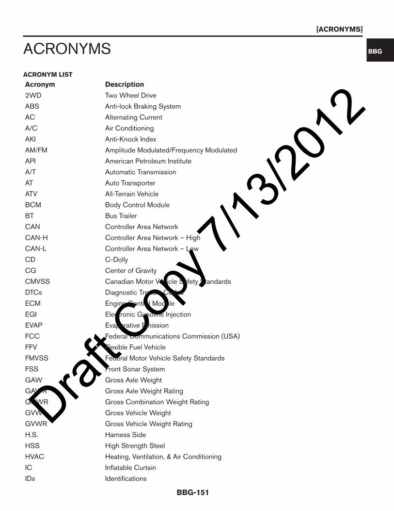
Draft C
opy 7
/13/20
12ACRONYMS
ACRONYM LIST
Acronym Description
2WD Two Wheel Drive
ABS Anti-lock Braking System
AC Alternating Current
A/C Air Conditioning
AKI Anti-Knock Index
AM/FM Amplitude Modulated/Frequency Modulated
API American Petroleum Institute
A/T Automatic Transmission
AT Auto Transporter
ATV All-Terrain Vehicle
BCM Body Control Module
BT Bus Trailer
CAN Controller Area Network
CAN-H Controller Area Network – High
CAN-L Controller Area Network – Low
CD C-Dolly
CG Center of Gravity
CMVSS Canadian Motor Vehicle Safety Standards
DTCs Diagnostic Trouble Codes
ECM Engine Control Module
EGI Electronic Gasoline Injection
EVAP Evaporative Emission
FCC Federal Communications Commission (USA)
FFV Flexible Fuel Vehicle
FMVSS Federal Motor Vehicle Safety Standards
FSS Front Sonar System
GAW Gross Axle Weight
GAWR Gross Axle Weight Rating
GCWR Gross Combination Weight Rating
GVW Gross Vehicle Weight
GVWR Gross Vehicle Weight Rating
H.S. Harness Side
HSS High Strength Steel
HVAC Heating, Ventilation, & Air Conditioning
IC Inflatable Curtain
IDs Identifications
[ACRONYMS]
BBG-151
BBG

Draft C
opy 7
/13/20
12Acronym Description
ILSAC International Lubricant Standardization and Approval Committee
IPDM E/R Intelligent Power Distribution Module Engine Room
LDD Load Divider Dolly
MH Motor Home
MIL Malfunction Indicator Light
MPV Multi-purpose Passenger Vehicle
MSDS Material Safety Data Sheet
NHTSA National Highway Traffic Safety Administration
NNA NISSAN North America
OEM Original Equipment Manufacturer
ORVR On-Board Refueling Vapor Recovery
OSHA Occupational Safety and Health Act
PSF Power Steering Fluid
RF Radio Frequency
RFI Radio Frequency Interference
RKE Remote Keyless Entry
RPM Revolutions Per Minute
SAE Society of Automotive Engineers
SB School Bus
SgRP Seating Reference Point
SRS Supplemental Restraint System
SUB Second Unit Body
TCD Trailer Converter Dolly
TCM Transmission Control Module
TPS Throttle Position Sensor
TRA Trailer
TRU Truck
TT Truck Tractor
USB Universal Serial Bus
UVW Unloaded Vehicle Weight
VDC Vehicle Dynamic Control
VIN Vehicle Identification Number
VSS Vehicle Speed Sensor
[ACRONYMS]
BBG-152
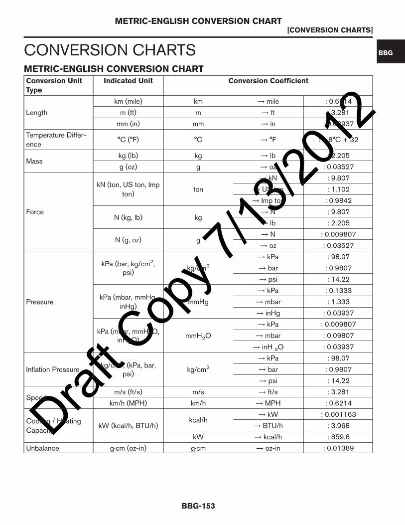
Draft C
opy 7
/13/20
12CONVERSION CHARTSMETRIC-ENGLISH CONVERSION CHARTConversion Unit
Type
Indicated Unit Conversion Coefficient
Length
km (mile) km → mile : 0.6214
m (ft) m → ft : 3.281
mm (in) mm → in : 0.03937
Temperature Differ-ence
°C (°F) °C → °F : 1.8°C + 32
Masskg (lb) kg → lb : 2.205
g (oz) g → oz : 0.03527
Force
kN (ton, US ton, Impton)
ton
→ kN : 9.807
→ US ton : 1.102
→ Imp ton : 0.9842
N (kg, lb) kg→ N : 9.807
→ lb : 2.205
N (g, oz) g→ N : 0.009807
→ oz : 0.03527
Pressure
kPa (bar, kg/cm2,psi)
kg/cm2
→ kPa : 98.07
→ bar : 0.9807
→ psi : 14.22
kPa (mbar, mmHg,inHg)
mmHg
→ kPa : 0.1333
→ mbar : 1.333
→ inHg : 0.03937
kPa (mbar, mmH2O,inH2O)
mmH2O
→ kPa : 0.009807
→ mbar : 0.09807
→ inH 2O : 0.03937
Inflation Pressurekg/cm2, (kPa, bar,
psi)kg/cm2
→ kPa : 98.07
→ bar : 0.9807
→ psi : 14.22
Speedm/s (ft/s) m/s → ft/s : 3.281
km/h (MPH) km/h → MPH : 0.6214
Cooling / HeatingCapacity
kW (kcal/h, BTU/h)kcal/h
→ kW : 0.001163
→ BTU/h : 3.968
kW → kcal/h : 859.8
Unbalance g·cm (oz-in) g·cm → oz-in : 0.01389
METRIC-ENGLISH CONVERSION CHART[CONVERSION CHARTS]
BBG-153
BBG

Draft C
opy 7
/13/20
12Conversion Unit
Type
Indicated Unit Conversion Coefficient
Torque
N·m (kg-m, ft-lb,in-lb)
kg-m
→ N·m : 9.807
→ ft-lb : 7.233
→ in-lb : 86.80
N·m (kg-cm, in-lb) kg-cm→ N·m : 0.09807
→ in-lb : 0.8680
Volume
<Fluid> ℓ (US gal,Imp gal)
ℓ
→ US gal : 0.2642
→ Imp gal : 0.2200
ℓ (US qt, Imp qt)→ US qt : 1.057
→ Imp qt : 0.8801
ℓ (US pt, Imp pt)→ US pt : 2.114
→ Imp pt : 1.760
<Fluid> ml (US floz, Imp fl oz)
ml→ US fl oz : 0.03381
→ Imp fl oz : 0.03520
<Displacement>cm
3
/(cu in)cm3
→ cu in : 0.06102
Spring Constant N/mm (kg/mm, lb/in) kg/mm→ N/mm : 9.807
→ lb/in : 56.00
METRIC-ENGLISH CONVERSION CHART[CONVERSION CHARTS]
BBG-154

Draft C
opy 7
/13/20
12INCH-MILLIMETER EQUIVALENTS CHART
Fraction
inches
Decimal
inches
Metric
mm
Fraction
inches
Decimal
inches
Metric
mm
1/64 0.015625 0.39688 33/64 0.51625 13.09687
1/32 0.03125 0.79375 17/32 0.53125 13.49375
3/64 0.046875 1.19062 35/64 0.546875 13.89062
1/16 0.0625 1.58750 9/16 0.5625 14.28750
5/64 0.078125 1.98437 37/64 0.578125 14.68437
3/32 0.09375 2.38125 19/32 0.59375 15.08125
7/64 0.109375 2.77812 39/64 0.609375 15.47812
1/8 0.125 3.1750 5/8 0.625 15.87500
9/64 0.140625 3.57187 41/64 0.640625 16.27187
5/32 0.15625 3.96875 21/32 0.65625 16.66875
11/64 0.171875 4.36562 43/64 0.671875 17.06562
3/16 0.1875 4.76250 11/16 0.6875 17.46250
13/64 0.203125 5.15937 45/64 0.703125 17.85937
7/32 0.21875 5.55625 23/32 0.71875 18.25625
15/64 0.234375 5.95312 47/64 0.734375 18.65312
1/4 0.250 6.35000 3/4 0.750 19.05000
17/64 0.265625 6.74687 49/64 0.765625 19.44687
9/32 0.28125 7.14375 25/32 0.78125 19.84375
19/64 0.296875 7.54062 51/64 0.796875 20.24062
5/16 0.3125 7.93750 13/16 0.8125 20.63750
21/64 0.328125 8.33437 53/64 0.828125 21.03437
11/32 0.34375 8.73125 27/32 0.84375 21.43125
23/64 0.359375 9.12812 55/64 0.859375 21.82812
3/8 0.375 9.52500 7/8 0.875 22.22500
25/64 0.390625 9.92187 57/64 0.890625 22.62187
13/32 0.40625 10.31875 29/32 0.90625 23.01875
27/64 0.421875 10.71562 59/64 0.921875 23.41562
7/16 0.4375 11.11250 15/16 0.9375 23.81250
29/64 0.453125 11.50937 61/64 0.953125 24.20937
15/32 0.46875 11.90625 31/32 0.96875 24.60625
31/64 0.484375 12.30312 63/64 0.984375 25.00312
1/2 0.500 12.70000 1 1.00 25.40000
INCH-MILLIMETER EQUIVALENTS CHART[CONVERSION CHARTS]
BBG-155
BBG

Draft C
opy 7
/13/20
12
INCH-MILLIMETER EQUIVALENTS CHART[CONVERSION CHARTS]
BBG-156