Embed Size (px)
Citation preview
Int. J. Thin Film Sci. Tec. 2 No. 3, 195-205 (2013) 195
@ 2013 NSP
Natural Sciences Publishing Cor.
International Journal of Thin Films Science and Technology
© 2012 NSP
http://dx.doi.org/10/12785/ijtfst/020305
Electrochemical Studies on the Cathodic Electrodeposition of n-type
semiconductor CdS thin film from Thiosulfate Acidic Aqueous
Solution
M Akif Shikhan Aliyev1 and Mahmoud El-rouby*
2,3
1 Institute of chemical problems, National Academy of sciences of Azerbaijan, AZ 1143 Baku, Azerbaijan 2 Chemistry Department, Faculty of Science, Sohag University, 82524 Shag, Egypt
E-mail: [email protected]
Received: 6 Jul. 2013, Revised: 11 Jul. 2013; Accepted: 11 Aug. 2013
Published online: 1 Sep. 2013
Abstract: The cathodic electrodeposition of CdS from aqueous solutions of Cd2+ and S2O32− at 40 °C, has been achieved using a
combination of cyclic voltammetric and potentiostatic techniques. The voltammetric responses of the investigated thiosulfate, Cd2+
both individually as well as with each other are achieved and hence the optimum conditions for the electrodeposition of CdS were
determined. Interesting data was obtained and discussed in this work. The mechanism of the electrode reactions for the investigated
substance have been evaluated and proposed. X-ray diffraction investigations demonstrate that the electrodeposited CdS is
hexagonal polycrystalline in nature. Furthermore, the electrodeposited CdS is of n-type semiconductor was investigated by Mott-
Schottky test and from it, donor concentration (ND) is also determined.
Keywords: CdS, Cathodic Electroredeposition, Aqueous Acidic Media, hexagonal crystal, Mott-Schottky test
1. Introduction
II-VI semiconductors such as CdS is used as buffer layers in Cu(In,Ga)(S) (CIGS) photovoltaic
devices. CdS n-type semiconductor is with a band gap of 2.42 eV at room temperature. Thus, CdS thin
films have been used widely as window layers in solar cells with an absorber layer of CdTe, Cu2S2 or
CuInSe2. Therefore it is still under consideration of the researchers till now. So far, CdS thin films have
been deposited by various methods, e.g. vapor deposition, spray pyrolysis, chemical bath deposition, and
electrochemical deposition. Electrochemical deposition is an attractive method for preparation of thin
films in commercial quantities because it uses relatively cheap equipment, enables the deposition in large
area and easy control of growth parameters through applied potential, current, pH and temperature of the
bath. Many works have been reported for studying the mechanism of an electrochemical deposition of
CdS from aqueous [1-6].
Cadmium sulfide has been formed from the anodization of the metal in alkaline sulfide solution [7] and in
buffered sulfide solution [8, 9]. It has been deposited cathodically from a solution containing cadmium
and thiosulfate ions [1, 10]. CdS has also been deposited on ITO-coated glass potentiostatically [11].
196 Akif Aliyev, Mahmoud El-rouby: Electrochemical Studies...
Where an aqueous solution of 0.2M CdCl2.2H2O and 0.01M Na2S2O3 adjusted to a pH in the range of 2–3
using HCl was used with a bath temperature of 90 ºC.
The aim of the present work is to study the optimal conditions for simple and fast cathodic
electrodeposition method for obtaining of n-type hexagonal crystal structure of CdS. Also determination
of ND of CdS from the Mott-Schotky test.
2. Materials And Methods
2.1. Apparatus
Electrochemical experiments were carried out using an Ivium Sat potentiostat /galvanostat at controlled
thermostated desired temperature. A conventional three-electrode cell was used. The cell has a slot for
purging the nitrogen gas and a magnet for mixing the solutions; hence the cell is set on a stirrer. A
silver/sliver chloride (Ag/AgCl/KCl(sat.)) and platinum sheet were used as reference and auxiliary,
respectively. Platinum wire (0.25 cm2) and Nickel sheet (0.5 cm
2) were used as working electrodes. The
working electrode was cleaned with a solution contains 1:1 concentrated H2SO4 and H2O2 followed by
acetone and rinsed with deionized water before performing the experiment.
The pH value of the solution was adjusted to the desired value with H2SO4 by a digital calibrated pH-
meter.
2.2. Reagents
Cadmium sulfate 3CdSO4.8H2O, Sodium thiosulfate Na2S2O3.5H2O, Thiourea (NH2)2CS and sulfuric acid
H2SO4 are of analytical grade from Merck, and BDH were used without further purification. All solutions
were prepared freshly with deionized water.
3. Results and Discussion
3.1. Cyclic voltammetric behavior
Cyclic voltammetry was used to determine the electrode potential mechanism for the electrodeposition of
CdS and to determine the peak location of CdS electroreduction.
Cyclic voltammetry of S2O32-
At first Na2S2O3 solution was investigated to get information relating to its cathodic reaction as in Fig. 1.
It shows the cyclic voltammogram of 0.005 M Na2S2O3 solution containing sulfuric acid at pH = 2.5,
room temperature and scan rate = 0.05 V s-1
. In the voltammogram the cathodic peak was observed
around – 0.66 V. It has a similar behavior, irreversible, that was obtained in other literatures. But in the
later, the reduction peak was observed around -0.8 V on Ti electrode [12]. This difference may be
attributed to the difference of hydrogen over potential and the electrocatalytic activity between Ti and Pt.

Akif Aliyev, Mahmoud El-rouby: Electrochemical Studies... 197
-1.2 -1.0 -0.8 -0.6 -0.4 -0.2 0.0 0.2 0.4
-1.0
-0.8
-0.6
-0.4
-0.2
0.0
0.2
Cu
rren
t d
ensi
ty (
J) ,
mA
cm
-2
Potential (E), V vs. Ag/AgCl/KCl sat.
Figure 1: Cyclic Voltammogram of 0.005-M Na2S2O3 at 0.05 V s-1, at pH = 2.5 on Pt- electrode at at 22 oC at pH = 3 and t =22 oC.
nnF
RTEE pp
7.47857.12/
The number of electrons that consumed in this electrochemical reduction reaction can be determined to
know the mechanism of the reaction by the following equation [13];
mV (1)
In addition, the peak separations confirm that there is a totally irreversible two electron transfer process at
the main cathodic peak on the working electrode according to the previous relation.
Cyclic voltammetry of Cd2+
Fig. 2. shows the cyclic voltammogram of 0.01 M Cd2+
solution containing sulfuric acid at pH = 2.5, at
22 oC and at scan rate = 0.05 V s
-1. In the voltammogram the cathodic peak was observed around – 0.85
V.
-1.6 -1.4 -1.2 -1.0 -0.8 -0.6 -0.4 -0.2 0.0 0.2 0.4
-3
-2
-1
0
1
2
3
4
Cu
rren
t d
ensi
ty (
J) ,
mA
cm
-2
Potential (E), V vs. Ag/AgCl/KCl sat.
Figure 2: Cyclic Voltammogram of 0.01-M Cd2+ at 0.05 V s-1, at pH = 2.5 on Pt- electrode at 22 oC at pH = 3 and t =22 oC.
198 Akif Aliyev, Mahmoud El-rouby: Electrochemical Studies...
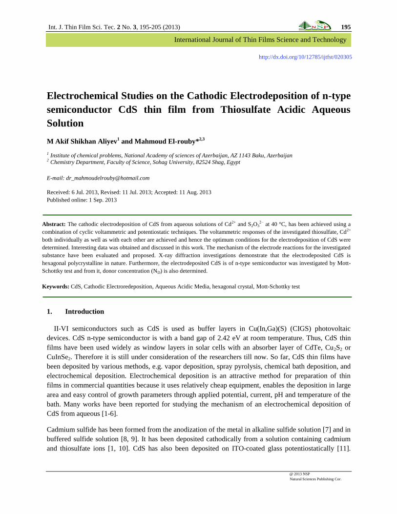
While the oxidation peak appeared at a potential of -0.53 V, the redox process is considered to be
quasi- reversible with two electrons transfer. It seems that the peaks are commonly associated with
reduction process of the Cd (II) to Cd(0), as confirmed by other researches [14,15].
Figure 3 : Cyclic Voltammogram of 0.01-M Cd2+ + 0.1 S2O32- without TU (a) and with TU (b) at 0.02 V s-1, at pH = 2.5 on
Pt- electrode at 40 oC at pH = 3 and t =22 oC.
-1.2 -0.9 -0.6 -0.3 0.0 0.3
-3
-2
-1
0
1
2
3 (a) without TU
(b) with TU
Cur
rent
den
sity
(J) ,
mA
cm
-2
Potential (E), V vs. Ag/AgCl/KCl sat.
b
a
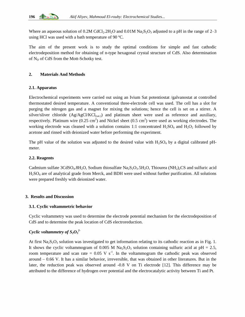
Figure 4: Cyclic Voltammogram of 0.01-M Cd2+ + 0.1 S2O32- + (NH2)2CS at 0.02 V s-1, at pH = 2.5 on Pt-
electrode at (1) at 22 oC and (2) 40
oC at pH = 3 and t =22
oC.
Pt- electrode at (1) at 22 oC and (2) 40 oC at pH = 3 and t =22 oC.
-1.6 -1.4 -1.2 -1.0 -0.8 -0.6 -0.4 -0.2 0.0
-9
-6
-3
0
3III/
II/
IV III
Cu
rren
t d
en
sity
(J
) ,
mA
cm
-2
Potential (E), V vs. Ag/AgCl/KCl sat.
(1) 22 oC
(2) 40 oC
III
Akif Aliyev, Mahmoud El-rouby: Electrochemical Studies... 199
-1.4 -1.2 -1.0 -0.8 -0.6 -0.4 -0.2 0.0 0.2 0.4
-3
-2
-1
0
1
2
3
4
5
6
7
Cu
rren
t d
en
sity
(J
) ,
mA
cm
-2
Potential (E), V vs. Ag/AgCl/KCl sat.
(1) 0.010 M Cd2+
(2) 0.015 M Cd2+
(3) 0.020 M Cd2+
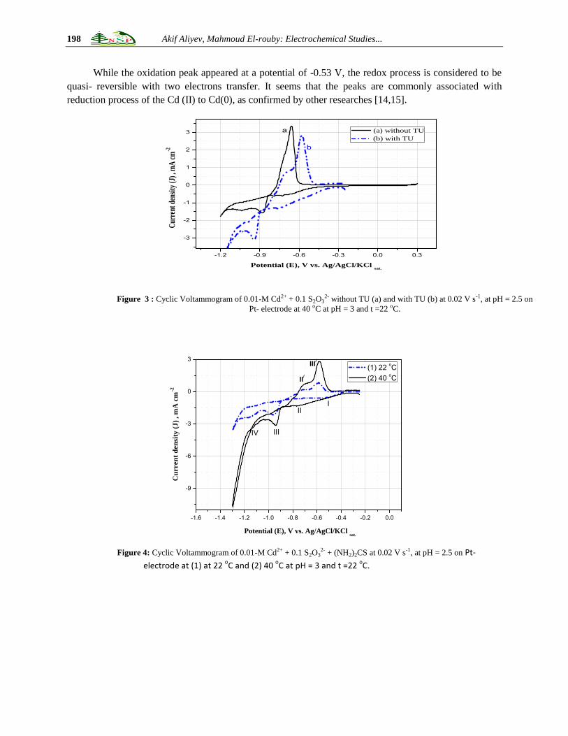
Figure 5: Cyclic Voltammogram of M Cd2+ + 0.1 S2O32- at (1) 0.01 M Cd2+, (2) 0.015 M Cd2+, (3) 0.02 M Cd2+ at 0.02 V s-1, at pH = 2.5
on Pt- electrode at 40 oC at pH = 3 and t =22 oC.
-1.4 -1.2 -1.0 -0.8 -0.6 -0.4 -0.2 0.0
-12
-9
-6
-3
0
3
6
Cu
rren
t d
en
sity
(J
) ,
mA
cm
-2
Potential (E), V vs. Ag/AgCl/KCl sat.
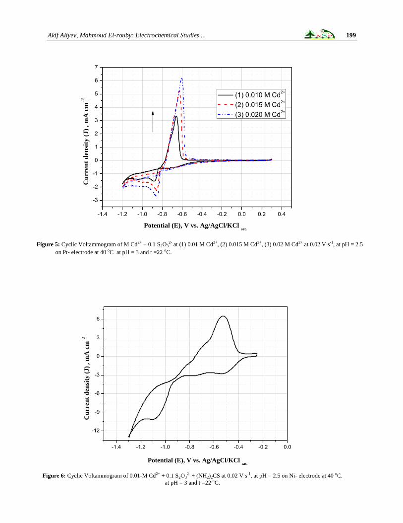
Figure 6: Cyclic Voltammogram of 0.01-M Cd2+ + 0.1 S2O32- + (NH2)2CS at 0.02 V s-1, at pH = 2.5 on Ni- electrode at 40 oC.
at pH = 3 and t =22 oC.

200 Akif Aliyev, Mahmoud El-rouby: Electrochemical Studies...
Cyclic voltammetry of Cd2+
+ S2O32-
Thiourea effect
Fig. 3 shows the cyclic voltammograms of a Pt electrode in 0.01 M Cd2+
+ 0.1 M S2O32-
without and with
0. 1 M thiourea (TU) at 40 oC. The addition of TU gave a little hinder effect on the cathodic peak
potential (shifted to more negative potential) of Cd2+
/Cd while a significant increase in the cathodic peak
current density was observed.
In aqueous solutions, there are mainly two ways for the additives to affect the deposits during the
electroplating. One is carried through making a complex with the metal ions and the other by the
adsorption on the electrode surface and/or the electrodeposits. So, there are change in the cathodic current
density and in the location of the cathodic peaks potential [16,17].
Temperature effect
It is found in this work, the optimum condition for the electrodeposition of CdS (confirmed by XRD
analysis below) as described in Fig. 4(2). Figure 4 shows the cyclic voltammograms of a Pt electrode in
0.01 M Cd2+
+ 0.1 M S2O32-
+ 0. 1 M thiourea (TU) at room temperature (22 oC) and at 40
oC. The
increase of temperature increases the cathodic peak current density of the electrodeposition process.
The first cathodic peak (I) (~ -0.55 V) is attributed to the electroreduction of the colloidal sulfur which
dissociated from thiosulfate at these conditions. While The electroreduction cathodic peak potential of
sulfur is observed at ~ -0.65 V in Fig. 1., this difference due to the difference in temperature and
concentrations in the two experiments and the presence of thiourea. The second cathodic peak potential
(II) (~ - 0.75 V) is attributed to the electrodeposition of CdS (confirmed by XRD);
S (colloidal) + 2e- → S
2- (adsorbed at the electrode surface) …………… (first peak, I)
S2-
(adsorbed) + Cd2+
= CdS (adsorbed at the electrode surface)………. (second peak, II)
At the third cathodic peak potential, III, (~ - 0.93 V) free unreacted Cd2+
ions are discharged into Cd(0).
But the electroreduction peak potential of Cd2+
is observed at ~ -0.87 V as in Fig. 2. This deference is due
to the presence of thiourea which makes a complex with Cd2+
ion that hinders the electroreduction
process and also the difference in the temperature of each experiment. Also it can be confirmed by
addition of Cd2+
as shown in Fig. 5.
Fig. 5. shows the cyclic voltammetry of Pt electrode in a solution of M Cd2+
+ 0.1 M S2O32-
at pH = 2.5
and temperature of 40 oC. It is observed that, by increasing the concentration of Cd
2+ ions the third peak
increases. This emphasizes that the third peak is attributed to the electroreduction of Cd2+
ions into Cd(0).
The fourth cathodic peak, IV, (~ -1.15 V) is attributed to the electroreduction decomposition of the
electrodeposited CdS on the electrode surface resulting Cd(0) and S2-
;
CdS + 2e- = Cd + S
2-
Fig. 6. shows the cyclic voltammetry of Ni electrode in a solution of 0.01M Cd2+
+ 0.1 M S2O32-
at pH =
2.5 and temperature of 40 oC. This behavior looks like the behavior on Pt electrode. So Ni can be used as
a substrate for the electrodeposition of CdS. Moreover, because of Ni is more available and cheaper than
Akif Aliyev, Mahmoud El-rouby: Electrochemical Studies... 201
Pt, so it can be introduced as a substrate for the analysis such as XRD,….etc of the electrodeposited CdS
on its surface.
From the previous data of cyclic voltammetric measurements, the optimum conditions for the
electrodeposition of CdS thin film are; by using a solution of a composition 0.1 M S2O32-
+ 0.01 M Cd2+
+
0.1 M thiourae (TU) at pH = 2.5, t = 40 oC and the electrodeposition potential is in between the range -
0.75 > E > -0.85 for a certain time.
3.2. XRD analysis
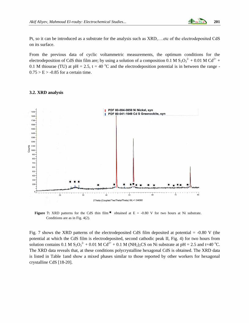
Fig. 7 shows the XRD patterns of the electrodeposited CdS film deposited at potential = -0.80 V (the
potential at which the CdS film is electrodeposited, second cathodic peak II, Fig. 4) for two hours from
solution contains 0.1 M S2O32-
+ 0.01 M Cd2+
+ 0.1 M (NH2)2CS on Ni substrate at pH = 2.5 and t=40 oC.
The XRD data reveals that, at these conditions polycrystalline hexagonal CdS is obtained. The XRD data
is listed in Table 1and show a mixed phases similar to those reported by other workers for hexagonal
crystalline CdS [18-20].
Figure 7: XRD patterns for the CdS thin film obtained at E = -0.80 V for two hours at Ni substrate.
Conditions are as in Fig. 4(2).

202 Akif Aliyev, Mahmoud El-rouby: Electrochemical Studies...
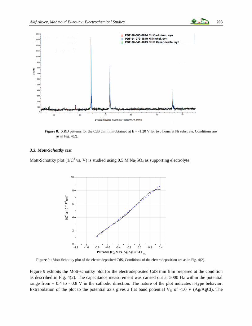
From XRD data, it is illustrated that when the deposition potential is fixed at potential of -0.80 V (second
cathodic peak II, Fig. 4 ), the CdS is only deposited on the electrode surface, but when the deposition
potential is fixed at -1.2 (fourth cathodic peak IV) CdS and Cd(0) are electrodeposited as shown in Fig. 8.
Fig. 8 shows the XRD patterns of the electrodeposited CdS film deposited at potential = -1.2 V for two
hours from solution contains 0.1 M S2O32-
+ 0.01 M Cd2+
+ 0.1 M (NH2)2CS on Ni substrate at pH = 2.5
and t=40 oC.
2ɵ d(oA) I hkl
24.81 3.59 63 100
26.51 3.36 94 002
28.18 3.16 105 101
36.62 2.45 30 102
43.68 2.07 50 110
47.84 1.90 51 103
50.88 1.79 10 200
51.83 1.76 30 112
52.80 1.73 16 201
54.58 1.68 5 004
58.28 1.58 3 202
60.84 1.52 3 104
66.77 1.40 14 203
69.26 1.36 5 210
70.86 1.33 7 211
72.40 1.30 4 114
75.48 1.26 8 105
Table 1: Experimental XRD data related to CdS films as in Fig. 6.
Akif Aliyev, Mahmoud El-rouby: Electrochemical Studies... 203
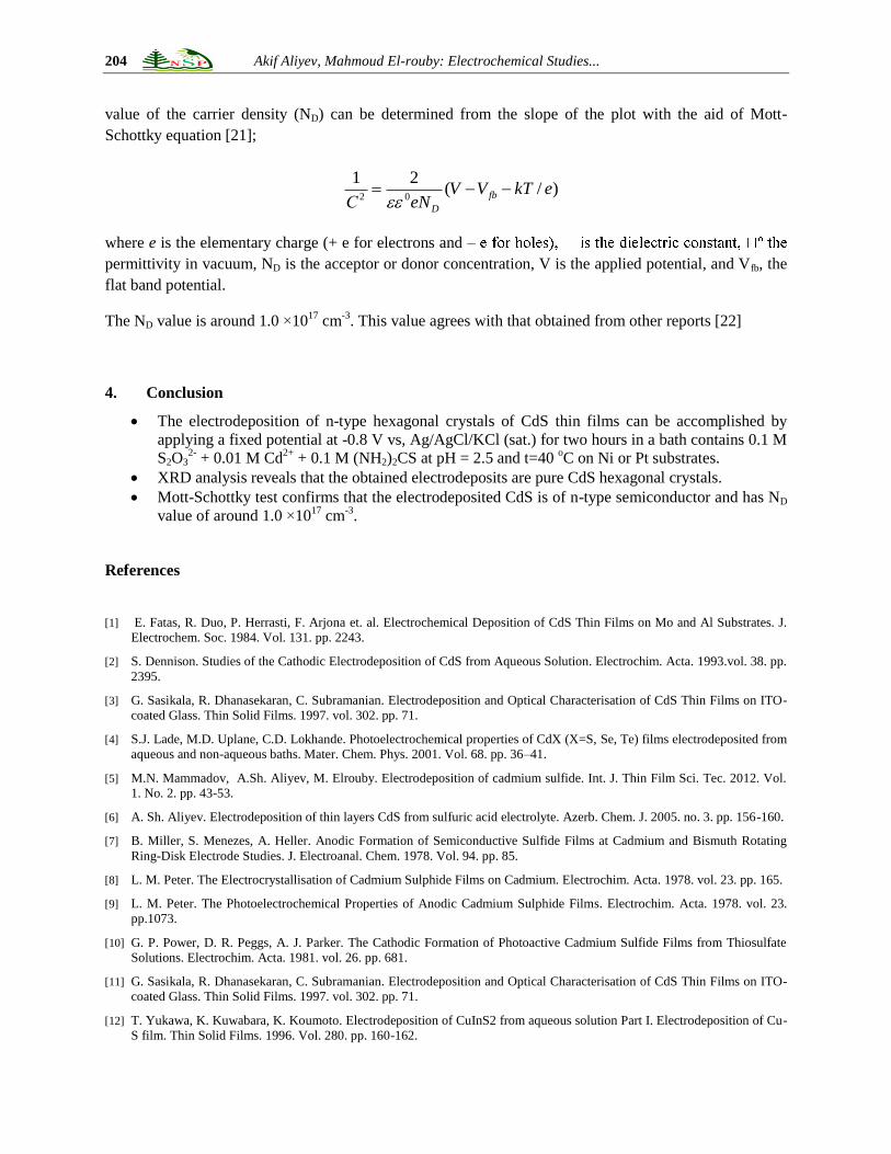
Figure 9 : Mott-Schottky plot of the electrodeposited CdS, Conditions of the electrodeposition are as in Fig. 4(2).
-1.2 -1.0 -0.8 -0.6 -0.4 -0.2 0.0 0.2 0.4
0
2
4
6
8
10
Potential (E), V vs. Ag/AgCl/KCl sat.
1/C
2 x
10
10 F
-2cm
4
3.3. Mott-Schottky test
Mott-Schottky plot (1/C2 vs. V) is studied using 0.5 M Na2SO4 as supporting electrolyte.
Figure 9 exhibits the Mott-schottky plot for the electrodeposited CdS thin film prepared at the condition
as described in Fig. 4(2). The capacitance measurement was carried out at 5000 Hz within the potential
range from + 0.4 to - 0.8 V in the cathodic direction. The nature of the plot indicates n-type behavior.
Extrapolation of the plot to the potential axis gives a flat band potential Vfb of -1.0 V (Ag/AgCl). The
Figure 8: XRD patterns for the CdS thin film obtained at E = -1.20 V for two hours at Ni substrate. Conditions are
as in Fig. 4(2).
204 Akif Aliyev, Mahmoud El-rouby: Electrochemical Studies...
value of the carrier density (ND) can be determined from the slope of the plot with the aid of Mott-
Schottky equation [21];
where e is the elementary charge (+ e for electrons and –
permittivity in vacuum, ND is the acceptor or donor concentration, V is the applied potential, and Vfb, the
flat band potential.
The ND value is around 1.0 ×10¹⁷
cm-3
. This value agrees with that obtained from other reports [22]
4. Conclusion
The electrodeposition of n-type hexagonal crystals of CdS thin films can be accomplished by
applying a fixed potential at -0.8 V vs, Ag/AgCl/KCl (sat.) for two hours in a bath contains 0.1 M
S2O32-
+ 0.01 M Cd2+
+ 0.1 M (NH2)2CS at pH = 2.5 and t=40 oC on Ni or Pt substrates.
XRD analysis reveals that the obtained electrodeposits are pure CdS hexagonal crystals.
Mott-Schottky test confirms that the electrodeposited CdS is of n-type semiconductor and has ND
value of around 1.0 ×10¹⁷
cm-3
.
References
[1] E. Fatas, R. Duo, P. Herrasti, F. Arjona et. al. Electrochemical Deposition of CdS Thin Films on Mo and Al Substrates. J.
Electrochem. Soc. 1984. Vol. 131. pp. 2243.
[2] S. Dennison. Studies of the Cathodic Electrodeposition of CdS from Aqueous Solution. Electrochim. Acta. 1993.vol. 38. pp.
2395.
[3] G. Sasikala, R. Dhanasekaran, C. Subramanian. Electrodeposition and Optical Characterisation of CdS Thin Films on ITO-
coated Glass. Thin Solid Films. 1997. vol. 302. pp. 71.
[4] S.J. Lade, M.D. Uplane, C.D. Lokhande. Photoelectrochemical properties of CdX (X=S, Se, Te) films electrodeposited from
aqueous and non-aqueous baths. Mater. Chem. Phys. 2001. Vol. 68. pp. 36–41.
[5] M.N. Mammadov, A.Sh. Aliyev, M. Elrouby. Electrodeposition of cadmium sulfide. Int. J. Thin Film Sci. Tec. 2012. Vol.
1. No. 2. pp. 43-53.
[6] A. Sh. Aliyev. Electrodeposition of thin layers CdS from sulfuric acid electrolyte. Azerb. Chem. J. 2005. no. 3. pp. 156-160.
[7] B. Miller, S. Menezes, A. Heller. Anodic Formation of Semiconductive Sulfide Films at Cadmium and Bismuth Rotating
Ring-Disk Electrode Studies. J. Electroanal. Chem. 1978. Vol. 94. pp. 85.
[8] L. M. Peter. The Electrocrystallisation of Cadmium Sulphide Films on Cadmium. Electrochim. Acta. 1978. vol. 23. pp. 165.
[9] L. M. Peter. The Photoelectrochemical Properties of Anodic Cadmium Sulphide Films. Electrochim. Acta. 1978. vol. 23.
pp.1073.
[10] G. P. Power, D. R. Peggs, A. J. Parker. The Cathodic Formation of Photoactive Cadmium Sulfide Films from Thiosulfate
Solutions. Electrochim. Acta. 1981. vol. 26. pp. 681.
[11] G. Sasikala, R. Dhanasekaran, C. Subramanian. Electrodeposition and Optical Characterisation of CdS Thin Films on ITO-
coated Glass. Thin Solid Films. 1997. vol. 302. pp. 71.
[12] T. Yukawa, K. Kuwabara, K. Koumoto. Electrodeposition of CuInS2 from aqueous solution Part I. Electrodeposition of Cu-
S film. Thin Solid Films. 1996. Vol. 280. pp. 160-162.
)/(21
02ekTVV
eNСfb
D
Akif Aliyev, Mahmoud El-rouby: Electrochemical Studies... 205
[13] A.J. Bard, L.R. Faulkner. Electrochemical methods: fundamentals and applications. 2001. Wiley, New York.
[14] A. Dolati, A. Afshar, H. Ghasemi. A kinetic study on the electrodeposition of cadmium with the presence of organic agents
in sulfate solutions, Mater. Chem. Phys. 2005. Vol. 94. pp. 23–28.
[15] T.S.N. Sankara Narayanan. Influence of quaternary ammonium ions the electrodeposition of cadmium. Met. Finish. 1999.
Vol. 97. pp. 94.
[16] G.T. Rogers, M.J. Ware. The Incorporation of Sulfur in Electrodeposited Nickel, Using Thiourea as a Brightener and
Leveler, J. Electrochem. Soc. 1960. Vol.107. pp. 677.
[17] H. Yang, X. Guo, N. Birbilis, G. Wu, W. Ding. Tailoring nickel coatings via electrodeposition from a eutectic-based ionic
liquid doped with nicotinic acid. Appl. Surf. Sci. 2011. vol. 257. pp. 9094.
[18] H. Uda, S. Ikegami, H. Sonomura. Structural and Electrical Properties of Chemical-Solution-Deposited CdS Films for Solar
Cells, Jpn. J. Appl. Phys. 1990. Vol. 29. pp. 30.
[19] D. Bhattacharya, M.J. Carter. Effect of substrate on the structural and optical properties of chemical-bath-deposited CdS
films. Thin Solid Films. 1996. vol. 288. pp. 176.
[20] N. Razik. Use of a standard reference material for precise lattice parameter determination of materials of hexagonal crystal
structure. J. Mater. Sci. Lett. 1987. Vol.6. pp. 1443.
[21] S.R. Morrison. Electrochemistry at Semiconductor and Oxidized Metal Electrodes. 1980. Chap. 5, Plenum Press, New York.
[22] Y. Ramprakas, V. Subramanian, R. Krishnakumar, A. S. Lakshmanan, V. K. Venkatesan, photoelectrochemical study of
screen-printed cadmium sulphide electrodes. J. Power Sources. 1988. vol. 24. pp. 4.