Embed Size (px)
Citation preview

Distributed by
LG ElectronicsAE Company, Commercial Air Conditioning20 Yeouido-dong, Yeongdeungpo-gu, Yeouido P.O.Box 335 Seoul, 150-721, Korea.
Phone : +82-2-3777-5248
www.lg.com www.lgeaircon.com
Copyright © 2012 LG Electronics. All rights reserved.
2012LG COMMERCIAL AIR CONDITIONERS

GHGReduction
GREENOVATIONReducing greenhouse gas emissions, enhancing green growth with suppliers, developing new green businesses.
LG Electronics’ vision is to grow into
a leading environmentally conscious
company by working to protect the global
environment and creating products with
environmentally friendly features.
Green Vision
Green Goals
Our green management activities include
greenhouse gas reduction across the
entire production process, enhancing
green and shared growth with suppliers,
and developing green businesses to
secure new growth opportunities.
Green Management
Eco Strategy Team
Green Product Expert Committee
Green MarketingCouncil
Eco-Design CommitteeChairman : CTO
Members : Head of Research Center (Executives)
LG Electronics has established a low-
carbon green management system to
provide low carbon value to customers
through voluntary greenhouse gas (GHG)
reduction. Throughout its activities, LGE
is creating value for customers and
stakeholders, and protecting the natural
environment.
Major decisions in green management
at LGE are made by the Eco-Design
Committee; comprised of the heads of
laboratories under the CTO, and supported
by the Green Product Expert Committee,
consisting of members working on R&D
and management of green products, and
the Green Marketing Council, in which
division marketing managers set-up green
marketing strategies.
Green Strategy
Low-Carbon Factories
Low-Carbon Products
Low-Carbon Value Chain
Low-Carbon Culture
HVAC
HVAC
Summer (Cooling)
Cooled air
Surface 30 C
Underground 15+/-5 C
Cool the air thanks to Multi V Waterand a “heat exchanger” in the ground
Heat transferfrom the ground
Heated air
Surface -10 C
Underground 15+/-5 C
Winter (Heating)Heat the air thanks to Multi V Waterand a “heat exchanger” in the ground
Multi V Water
Heat Exchanger
Heat transfer to the ground
We’re in the business of creating comfort for any season of the year through Heating, Ventilation and Air-Conditioning solutions.
LGE provides a total HVAC system with optimized heating, ventilation and air-conditioning solutions carefully adapted to the unique
conditions of each site during the building’s construction or renovation. The company is also engaging in the development of green
buildings through its line of products using renewable energy. For example, our Multi V Water uses geothermal energy, which is
known as a constant source of heating and cooling that maintains a temperature of 15±5C regardless of the surface temperature.
Secure future green growth drivers in energy, water treatment and environmental businesses
HVAC Business

LGE’s heating and air conditioning products are continually being developed with energy savings, reduction
of hazardous substances, and impact on the environment in mind. In particular, we have made great strides
in the use of renewable energies through our cutting edge systems.
Energy-saving, High-efficiency Inverter Compressor and Motion
Sensor
This super energy-saving inverter compressor technology saves up
to 72% of electricity by automatically controlling the unit according to
the indoor temperature and a motion sensor.
High-efficiency Central Air Conditioning System
Using eco design for every part of the product has improved the
High-performance, High-efficiency Inverter Heat Pump
Air Conditioner These compact outdoor units feature enhanced heating and
cooling technology, low-noise indoor unit technology and a highly
effectiveness in comparison to constant-speed air conditioners.
Geothermal Air Conditioner and Heater
Using reusable geothermal energy to reduce greenhouse gas
compressor in the outdoor unit.
Hybrid solar air conditioner
function as well as a 15% solar powered cooling function, a “Human
GREEN HEATING AND AIR CONDITIONING
(Inverter and solar technology) - Korea
Prize-Winning Technologies
Awards & Certifications
Green Product Evaluation System
Green Technologies
Green R&D Investment
LGE established an environmental accounting guideline in
2009 for green R&D investment. LGE invested KRW 808
billion for green R&D in 2010. The majority of the investment
The Eco Index
The Eco-Index is LGE’s own rating system for managing
eco design level of products in terms of their eco-consciousness
(Green 1-Star, 2-Star and 3-Star). The Green Index measures three
areas of product footprints such as Climate impact, Chemicals
used and Materials used. We will continue increasing the number of
products to reach the higher Eco-Index.
Evaluating the Carbon Footprint of the Product Process
Since 2002, LGE has been conducting Life Cycle Assessment
(LCA) to evaluate the entire process’ carbon emission and to fully
utilize LCA to develop low carbon products. In 2011, LGE plans to
establish an infrastructure that will enable LGE to perform LCA on
greenhouse gas emission from the entire product process.
LGE has been conducting R&D to reduce the environmental
products, replacing hazardous substances in products, improving
product design to facilitate recycling, and establishing an
infrastructure to enable the development of green products and
technologies.
GREENER PRODUCTSLGE’s Green Product Strategy aims at minimizing the environmental load in every stage of the product
lifecycle and improving energy, resources and humanity – through production of highly energy-efficient
products, reduction of raw material usage, and improvement of living environments for everyone.
Green Product Strategy
Phase out the use of certain
hazardous materials
Decrease noise and vibrations
Reduce CO2 emissions throughout product lifecycle
Reduce stand-by power consumption
Use recyclable materials
Reduce product weight/volume
HazardousSubstancesManagement
HomeEnvironment
CO2 EmissionsReduction
Energy EfficiencyEnhancement
RecyclabilityImprovement
ResourceReduction
Res
ou
rces Hum
an
GreenProduct
Energy
Energy Resources HumanityEnergy-Focusing on two key areas: improving energy efficiency and reducing greenhouse gas emissions from the manufacturing process.
Resources-committed to strategies of lowering resource usage in products and improving product recyclability.
Humanity-Providing green value to customers

LG Electronics products display their energy credentials on the standardized energy label, a transparent and easy to compare tool. An
arrow indicates which energy class your product belongs in on a scale from A to G. The higher the class, the less energy-hungry your
product is at delivering heating or cooling. The label will also give you an estimate of the product’s annual energy consumption in kW.
Energy Label
For single ducts below 12 kW the
same information is displayed, with
some adjustments: Single ducts
indicate the hourly energy consumption
in kW whereas double ducts indicate
the yearly annual consumption in kW.
Finally, performances of single and
double ducts in heating and/or cooling
mode are still subject to nominal
calculations, not seasonal.
For split air conditioners below 12 kW
that provide both heating and cooling,
the energy label will indicate two energy
classes-one for heating and one for
cooling. Also displayed are capacity in
kW, annual energy consumption and
the seasonal performance ratio for
heating and cooling.
Current energy label will remain
until 2012.
EER>3.20
3.20 EER>3.00
3.00 EER>2.80
2.80 EER>2.60
2.60 EER>2.40
2.40 EER>2.20
2.20 EER
A
B
C
D
E
F
G
COP>3.60
3.60 COP>3.40
3.40 COP>3.20
3.20 COP>2.80
2.80 COP>2.60
2.60 COP>2.40
2.40 COP
OUR AIR-CONDITIONERS MAKE THE MOST
OF THE ENERGY THEY ARE USING
With different cooling and heating needs throughout the year,
LGE’s products are designed for optimal performance according
to each season and geographical area. The Seasonal Energy
illustrate best how each product will operate in heating and/
or cooling mode depending on where you live and on the basis
auxiliary modes of operation of the product, where energy use is
still necessary.
Calculations are simulated under different combinations of
indoor and outdoor average temperatures over all seasons
corresponding to one out the three Europe climate zones. LG
products improve the indoor environment and save energy in a
LG Electronics is involved in a cross-industry evaluation whereby
the performance of the outdoor units of VRF systems is
voluntarily measured and rated. Committed to producing energy
since its start. The standard, coordinated by Eurovent, will allow
and cooling mode and allow side-by-side comparison with
competing products. In the end, the user can make the most
informed choice when purchasing an LG Electronics product,
from both an environmental and a pricing point of view.
LG Electronics has improved its products’ design so that they
consume less energy while satisfying all your cooling and
heating needs.
Less is More
European regulations on energy-related products (ErP) require
The 20/20/20 by 2020 policy aims to ensure 20% less primary
energy consumption and 20% less greenhouse gas emissions,
while the share of renewable energies increases by 20% by 2020.
LG Electronics air conditioners integrate these expectations and
contribute their fair share in global climate protection.
The rule of 20
LG Electronics deploys products with environmentally-friendly
features both in heating and cooling modes that go beyond
the minimum requirements set by European legislation. With a
rating of close to 4, LG Electronics products make the most of
the energy they are using. No energy is wasted, while we help
you decrease your energy bills - all year long.
Going beyond - ErP
LG Electronics supplies equipment that is being noticed for its
design and performance and not for its noise. The sound power
indoor and outdoor units, in conformity with limit values that are
set by European Regulations.
LG Electronics is actually doing its best for reducing noise levels
of its equipment. We bring to our customers products that emit
30 % less noise than required by European law.
The Sound of Silence
EUEco design
LGElectronics
0 10 20 30 40 50 60 70 80
Comparison of noise levels
Several rating
temperature
Includes energy
consumption in
auxiliary modes
No longer
operations
at full load
For cooling 1 region
to calculate SEER
For heating 3 regions
to calculate SCOP*
Reference
design conditions
supplied by Reg
To reflect performance
over entire season
Thermostat off
Stand by mode
Off mode
Crankcase heater
Integrates
operations at
partial load
*SCOP : available from 2013

Ceiling Cassette
Ceiling Concealed Duct Type
Ceiling & Floor / Ceiling Suspended Type
Console Type
Synchro Operation
Dimensions
18
28
36
46
50
58
76
86
Outdoor Unit
Indoor Unit
Single Split
Multi Split

H-Inverter 3Phase
H-Inverter Standard Inverter
3Phase Standard Inverter
2.5
3.5
5.0
6.0
7.1
8.0
10.0
12.5
14.0
15.0
UU18WH UE1
UU12WH UE1
UU24WH U41
UU36WH U31 UU37WH U31
UU43WH U31
UU49WH U31
UU42WH U31
UU48WH U31
UU12W ULD
UU09W ULD
UU18W UE2
UU24W U42
UU36W UO2
UU42W U32
UU48W U32
UU60W U32
UU30W U42
UU37W UO2
UU49W U32
UU43W U32
UU61W U32
UU21WH U41
LG Commercial Air Conditioners2012 Single split Model Line-up
Ceiling Cassette TypeCeiling Concealed
Duct TypeCeiling and Floor ype Console Type*
H-Inverter Standard Inverter H-Inverter Standard Inverter H-Inverter Standard Inverter Standard Inverter
2.5
3.5
5.0
6.0
7.1
8.0
10.0
12.5
14.0
15.0
UT12H NP1
UT18H NP1
UT21H NN1
UT24H NN1
UT36H NM1
UT42H NM1
UT48H NM1
CT12 NR2
CT09 NR2
CT18 NQ2
CT24 NP2
UT30 NP2
UT36 NN2
UT42 NM2
UT48 NM2
UT60 NM2
NH2NG1
NG1
NG1
NR1
NR1
NR1
NH2
NG2
NG2
NR2
NR2
NR2
UV12H NJ1
UV18H NJ1
UV21H NK1
UV24H NK1
UV36H NL1
UV42H NL1
UV48H NL1
CV12 NE2
CV09 NE2
CV18 NJ2
CV24 NJ2
UV30 NJ2
UV36 NK2
UV42 NL2
UV48 NL2
UV60 NL2
CQ12 NA0
CQ09 NA0
CQ18 NA0

Step-up Inverter by the PFC & the Sine Wave Control Technology
(PFC : Power Factor Correction)compared to conventional.
*V : Input voltage *I : Input electric current
Rectangle wave Sine wavePartial switching Full range Sine wave switching
DC 280V DC 380V(Boost up)
V VI
I
PFC(Power Factor Correction) Control in Power Input
Powerful, Quick & PI controlWith PI control logic, the set temperature is achieved quicker and also the air conditioning efficiency is improved by 30%. It provides not only quick but also powerful air conditioning operation.
*PI: Proportional-Integral
Inverter Technology
Reduced Sound Level
With the advancement of Inverter technology, it comes to be more silent, economical and powerful air conditioning systems. The LG air conditioner is manufactured based on the PFC and the sine wave technology. It makes possible to down noise level, be better efficiency, minimize compressor vibration and wider operation range.
The operating voltage is increased from DC 280V to DC 380 V. This means that at high load conditions, there will be less energy consumption while at low load conditions the energy consumption.
With sinusoidal wave function of the voltage, the sine wave makes the function more soft and efficient.
Grilled shape changed
Axial Fan
The new grilled shape design of the outdoor unit helps to outlet airflow improvement so it increases heat exchange efficiency and reduces noise levels.
The new axial fan shape has a thickening front edge and smooth rear edge, it provides high efficiency with low noise and a wide fan wing width. High Air flow rate and increasing fan operation efficiency are also improved.
*Except SCAC 2.5kW, 3.5kW ODU
Grilled shape changed
INVERTER
Temp
30%
Quick & powerful
performance
Conventional
Leading edge thickening
Saw tooth trailing edge
Reverse hubTrailing edge
moguul
Narrow hub bladebl d
To be To beAs is
Type 1 Type 2
As is
-23 7 15 35 40
temperature
Heating rangeHeating range
Cooling rangeCooling rangeCooling range
Heating range
Current polnt for Cooling
Current polnt for Heating
Design based on SEER
Powerful BLDC Compressor
BLDC Fan Technology
SEER stands for Seasonal Energy Efficiency Ratio. This is a new measurement of air conditioning energy efficiency. It is conducted in various environmental conditions. The whole tested range of temperatures for heating and cooling reflect real life environments. On the hand, current measurement EER is tested specific temperature. Thus different result comes out depending on models. And we could say normally SEER of H inverter is better than standard's.
*Distributed winding : H Inveter
*Concentrated winding : Standard Inverter (Except 2.5, 3.5kW)
technology controls the speed of the motor and the compressor simultaneously.
components. Ultimately, with the help of such advanced technology, Inverter air conditioners are less prone to breakdown, cheaper to run and the outdoor compressor is generally quieter than conventional air conditioners. LG revolutionary Inverter technology boasts powerful silent performance while minimizing energy consumption by as much as up to 60%.
200
40
60
80
100
20
0
600400 800 1000
Motor Speed(RPM)
Effi
cie
ncy(
%)
DC MotorDC Motor
AC MotorAC Motor increase
increase
Approx
nncncreareaseseeincrease
AppApppproxroxAAAAApprox
Optimize Vibration, Noise
High Reliability5
Minimized Oil circulation
High Efficiency Motor
Optimize Compression Eff.
1
3
saving in operating mode up to 35% at full speed compared with AC motor.
Its compressor thus has improved efficiency compared with the AC inverter and it is optimized for SEER
Distributed winding Concentrated winding

Weekly Program
Outdoor Dry Contact
Heating Capacity in Low Temperature
You can set the daily desired temperature and automatic on/off functiun for a week. Weekly reservation keeps operating until it is cancelled by the user.
We are able to connect “Dry Contact” and outdoor unit for turning on and off a product when leaving office, after school or emergency situations usefully.
Available for *H Inverter : 10kW ~14kW, 3phase only.*Standard Inverter : 10kW~15kW, both 1phase and 3phase.
Keeping the same heating capacity in low
compressor and sub cooling effect of the larger condenser. it represents 32% higher capacity compared with the competitor.
7.1kW : UU24WH + UT24H10kW : UU36WH + UT36H10kW : UU42WH + UT42H14kW : UU48WH + UT48H
* Indoor unit is turned on at the desired temperature, the TEMP up/down buttons can be used to set the desired present or preset temperature.
(Temperature selection range is 18ºC~30ºC)* When desired temperature is not setted, it is turned on automatically with the
desired temperature of the previous operation
7.36
10.0810.08
12.7412.74
14.2614.26
5.677.897.89
9.739.7310.0810.08
Norm
al H
eati
ng C
apacit
y
(kW
, at
-10
°C
) CompetitorLG
Grade
15
13
11
09
07
05
7.1kW 10kW 12.5kW 14kW
17
19
OFF
Ordinary switch is connected
to each product
ALL OFF
Using dry contact, all switches are
connected to all products
Night Silent Operation
Wide Louver Technology
Easy Service
Night Silent Operation can reduce noise level at night
To maximize touched area of fin and air, to reduce heat exchange loss.
Easy and efficient installation of outdoor unit will provide the best solution for small offices and shops.
- 4 Way piping is possible
(Front, Rear, Right, Down)
- Excellent exterior
- Fitted hand grips for easy
transportation and installation
- Remove 3 pieces of screw for SVC
- Front panel removal system
UU12WH
UU18WH
UU21WH
UU24WH
UU36WH
UU42WH
UU48WH
UU37WH
UU43WH
UU49WH
48
47
47
47
51
51
51
51
51
51
45
39
44
44
47
47
47
47
47
47
Day time (Cooling)
Night Silent
Mode
Hea
t ex
chan
ge
rate
(%)
Corrugate fin Wide louver fin
100
123
128128%128%
123%123%
100100 100100
HHCC HHCC
4 way1 way
1. Inner SVC valve 2. Convenient moving handle 3. Compact Design & Ez SVC
Ez SVC
3 pieces of screw
Day time Night Silent
UU36WH
UU42WH
UU48WH
UU37WH
UU43WH
UU49WH
UU21WH
UU24WH*UU12WH
UU36WH
UU42WH
UU48WH
UU37WH
UU43WH
UU49WH
UU21WH
UU24WH*UU12WH
Nois
e L
eve
l [d
B(A
)] Day time
Night Silent
5148
444747
45
5148
444747
45
* Standard Inverter model has also night silent operation function except 2.5, 3.5kW
Standard Inverter
*Cooling mode*
*Heating mode*
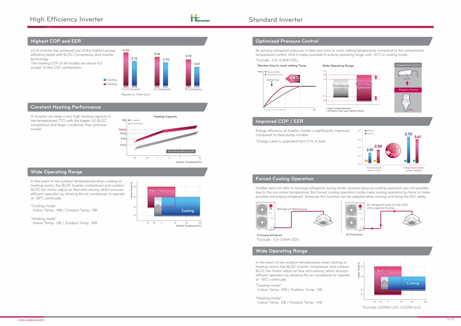
Optimized Pressure Control
Wide Operating Range
temperature control. And it makes possible to extend operating range until -15ºC in cooling mode.
*Exclude : 2.5~3.5kW ODU
In the event of low outdoor temperatures when cooling or
efficient operation by allowing the air conditioner to operate at -18°C continually.
*Exclude UU09W.ULD, UU12W.ULD
Improved COP / EER
Energy efficiency of Inverter model is significantly improved compared to Heat pump models.
*Energy Label is upgraded form D to A level
2.00
2.50
3.00
3.50
4.00
(CT24 + UU24W)
Standard Inverter Model
(UT24 + UU24)
Heat Pump Model
3.61
2.882.81
3.70Cooling
Heating
%%55%5%%2255%%222255%2222 %%%%%225%
Immmprprp oovveddeddp oo er vImprovedbybyyby
PPPPOOCOCOC PPCC PCOP
D D
Indoor
Tem
p(˚
C)
-18 -15 0 18 35 48
10
23
30
12
CoolingCooling
HeatingHeating
Low AmbientControl
Low AmbientControl
AS-IS
NEW
Temperature Control
Pressure Control
Tim
Temp
Setting Temp
Temperature Control
eduuccctttiioonnneeedReeed ooooeeR ii44%Reduction
※ Based on 18K (Heating)
Shorten time to reach setting Temp.
Pressure Control
- Yearly Cooling Operation
- OA Room, Cook room, Machine Room..
˚C
-15
-10
48
43
Continuousoperation
ContinuousoperationContinuous
operationContinuousoperation
Wide Operating Range
Forced Cooling Operation
Installer were not able to recharge refrigerant during winter seasons because cooling operation was not possible
possible recharging refrigerant. Moreover this function can be adapted when moving and fixing the IDU safely.
*Exclude : 2.5~3.5kW ODU
1) Charging Refrigerant
Refrigerant Recharging
All refrigerant goes to only ODU when pipeline moving
2) Pump Down
High Efficiency Inverter
Highest COP and EER
Constant Heating Performance
Wide Operating Range
LG H-Inverter has achieved one of the highest energy
technology. The heating COP of all models are above 4.0 except 13.4kw CST combination
H-Inverter can keep a very high heating capacity in
compressor and larger condenser than previous model.
In the event of low outdoor temperatures when cooling or
efficient operation by allowing the air conditioner to operate at -18°C continually.
*Cooling mode*
*Heating mode*
*Based on 10kw Duct
LG H-Inverter A Company B Company
4.46
3.72
4.16
3.704.12
3.61
Cooling
Heating
Inverter
-15 -10 -7 0 7 16
Outdoor Temperature(ºC)
(%)
Heating Capacity
100%
90%
79%
55%
Conventional
H-Inverter
Excluding defrost cycle
Indoor
Tem
p(˚
C)
-18 -10 0 18 35 48
Outdoor Temperature(ºC)
12
23
30
16
CoolingCooling
HeatingHeating
Low AmbientControl
Low AmbientControl
1:20º
6:70º5:60º:60º
4:50º5
4:50º3:40º
4:53:40º
2:30º
LG Cassette
Conventional
Ceilin
g C
asse
tteC
eilin
g C
onceale
d D
uct
Ceilin
g &
Flo
or /
Ceilin
g S
usp
ended
Conso
le
Syn
chro
Opera
tion
Flo
or S
tandin
g
Multi S
plit
WiderWider
567mm80mm
487mm487mm
Low-Low Low Medium High Power
Wind-amount mode
110%100%90%70% 130%
Airflow Variable range
BLDC MotorBLDC Motor
AC MotorAC Motor
Variable range of wind of the interior fan motor
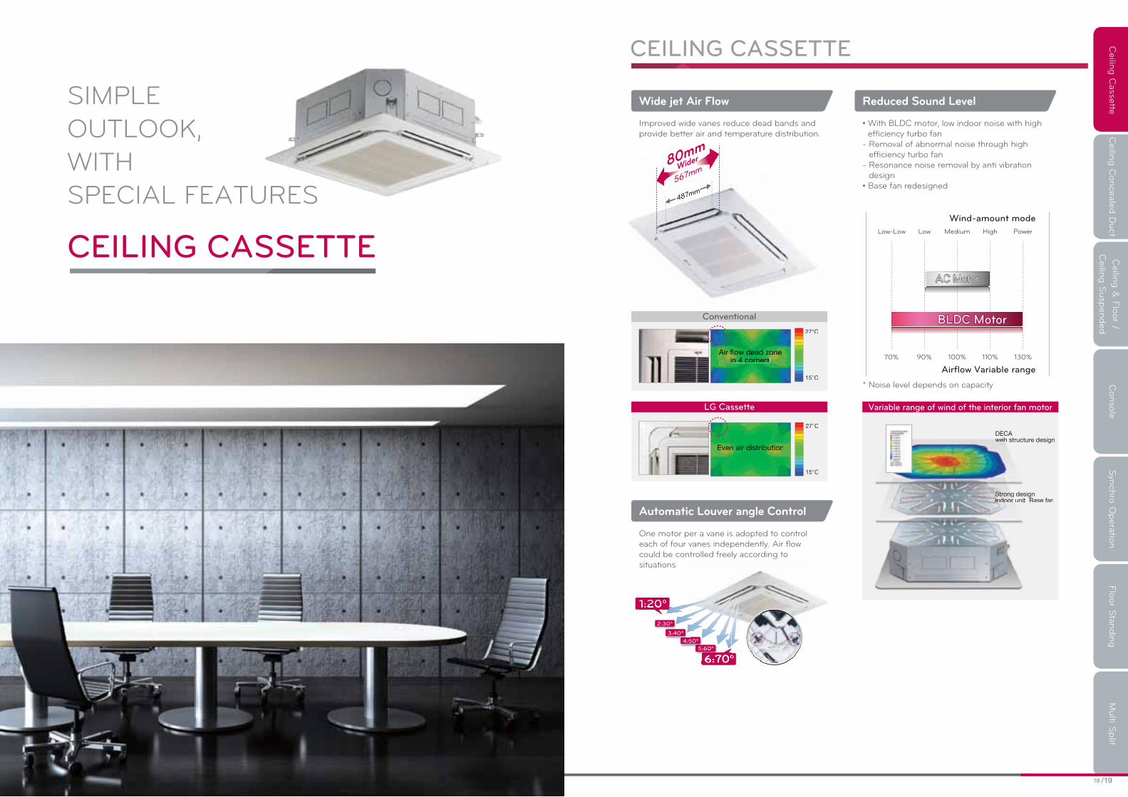
Wide jet Air Flow Reduced Sound Level
Automatic Louver angle Control
Improved wide vanes reduce dead bands and provide better air and temperature distribution. efficiency turbo fan
- Removal of abnormal noise through high efficiency turbo fan
- Resonance noise removal by anti vibration design
* Noise level depends on capacity
One motor per a vane is adopted to control each of four vanes independently. Air flow could be controlled freely according to situations
CEILING CASSETTE
SIMPLE
OUTLOOK,
WITH
SPECIAL FEATURES
CEILING CASSETTE

Ceilin
g C
asse
tteC
eilin
g C
onceale
d D
uct
Ceilin
g &
Flo
or /
Ceilin
g S
usp
ended
Conso
le
Syn
chro
Opera
tion
Dim
ensio
ns
Multi S
plit
Design to Reduce the Ceiling Stains
Auto Elevation Grille ( Accessory : PTEGM0)
One Touch Panel
The new outlet design can reduce ceiling contamination from air current flowing along the ceiling.
Easy filter cleaning with elevation grille
- Installed inside main body- Auto horizontal level- 4 points support- Memory for user’s level- Max 4.5m length
The simple push-up panel design easily connects to the panel with the body enabling the installer to use his two hands freely.
Existing type
Ceiling pollutions prevention type
CeilingProduct
Lover Ceiling
Pollutions
Lover
Product Ceiling
Drain leakage
check
Hanger adjust
Refrigant
Piping check
Hanger adjust
Attachable/detachable
corner design
Hanger adjust Drain leakage check
CEILING CASSETTE
4.2m
All vane operation
Individual vane operation
Individual vane angle control
Air flow rate control
Indirect air flowDirect air flow
Independent Vane Operation High Ceiling Mode
Detachable Corner Panel
Vane angle control satisfies both users who like direct wind or indirect wind and also reduces cold air draft.
High ceiling mode with phase-control algorithm is possible to apply as high as 4.2m from the floor.This setting offers a reduction of drought.
The attachable and detachable corner design makes it easy to adjust the hanger during installation and to check leakage in the drain connection pipe.

Ceilin
g C
asse
tteC
eilin
g C
onceale
d D
uct
Ceilin
g &
Flo
or /
Ceilin
g S
usp
ended
Conso
le
Syn
chro
Opera
tion
Dim
ensio
ns
Multi S
plit
UU36WH
UU42WH
UU48WH
PQRCVSL0QW (White)
Inverter
Specifications
Indoor Unit Model Name UT36H NM1 UT42H NM1 UT48H NM1
Capacity
Cooling
Min kW 4.5 5.0 5.5
Nom kW 10.0 12.5 13.4
Max kW 13.0 14.9 16.0
Heating
Min kW 4.9 5.5 6.4
Nom kW 11.2 14.0 15.5
Max kW 14.0 16.8 17.9
Power Input Cooling/Heating Nom kW 2.6 /2.5 3.7/3.4 4.2/4.1
Power Input (only IDU) Nom kW 0.1 0.1 0.1
Running Current (Set) Cooling/Heating Nom A 11.5/11.3 16.8/15.0 18.7/18.0
Power Supply Ø/V/Hz 1 / 220~240 / 50 1 / 220~240 / 50 1 / 220~240 / 50
EER W/W 3.85 3.42 3.23
COP W/W 4.46 4.11 3.81
SEER
Energy Label Cooling/Heating A/A A/A A/A
Annual Energy Consumption Cooling kWh 1,300 1,830 2,075
Air Flow Rate
Low m3/min 20.2 21.5 22.8
Medium m3/min 26.1 26.7 27.4
High m3/min 32.0 32.0 32.0
Sound Pressure
Low 42 42 42
Medium 45 45 45
High 47 47 47
Sound Power Cooling
Dehumidification Rate l/h 2.7 3.6 3.6
Dimmension W*H*D mm 840x288x840 840x288x840 840x288x840
Net weight kg 28.0 28.0 28.0
Piping connection
Liquid mm(inch) Ø9.52(3/8) Ø9.52(3/8) Ø9.52(3/8)
Gas mm(inch) Ø15.88(5/8) Ø15.88(5/8) Ø15.88(5/8)
Drain O.D./I.D. mm 32/25 32/25 32/25
Decoration Panel
Model PT-UMC PT-UMC PT-UMC
Color morning Fog morning Fog morning Fog
Dimensions HxDxW mm 950*25*950 950*25*950 950*25*950
Weight kg 5.0 5.0 5.0
Outdoor Unit Model Name UU36WH U31 UU42WH U31 UU48WH U31
Compressor Type Twin Rotary Twin Rotary Twin Rotary
Airflow Rate m3/min 110 110 110
Sound PressureCooling 51 51 51
Heating 53 53 53
Sound Power Cooling
Dimmensions WxHxD mm 950 x 1,380 x 330 950 x 1,380 x 330 950 x 1,380 x 330
Net weight kg 103 103 103
RefrigerantType R410A R410A R410A
Charge g 3,600 3,600 3,600
Additional Refrigerant charge g/m 40 40 40
Operation Range (Outdoor)Cooling Min~Max -10 ~ 48 -10 ~ 48 -10 ~ 48
Heating Min~Max -18 ~ 18 -18 ~ 18 -18 ~ 18
Power Supply Ø/V/Hz 1 / 220~240 / 50 1 / 220~240 / 50 1 / 220~240 / 50
Power Supply Cable Nxmm² 3 x 5.0 3 x 5.0 3 x 5.0
Transmission cable Nxmm² 4 x 0.75 4 x 0.75 4 x 0.75
A 40 40 40
Piping Length totalMin m 5 5 5
Max m 75 75 75
Piping elevation difference IDU-ODU Max m 30 30 30
Piping connectionLiquid mm(inch) Ø9.52(3/8) Ø9.52(3/8) Ø9.52(3/8)
Gas mm(inch) Ø15.88(5/8) Ø15.88(5/8) Ø15.88(5/8)
UU21WH
UU24WHUU12WH
PQRCVSL0QW (White)
Inverter
UU18WH
Specifications
Indoor Unit Model Name UT12H NP1 UT18H NP1 UT21H NN1 UT24H NN1
Capacity
Cooling
Min kW 1.4 2.0 2.8 2.8
Nom kW 3.5 5.0 6.0 7.0
Max kW 4.2 5.5 8.0 8.4
Heating
Min kW 1.6 2.2 3.2 3.2
Nom kW 4.2 5.5 7.0 8.0
Max kW 5.0 6.05 9.0 9.4
Power Input Cooling/Heating Nom kW 1.0/1.0 1.4/1.4 1.5/1.7 1.9/1.9
Power Input (only IDU) Nom kW 0.05 0.05 0.07 0.07
Running Current (Set) Cooling/Heating Nom A 4.4/4.6 6.0/6.7 7.6/7.7 9.5/9
Power Supply Ø/V/Hz 1 / 220~240 / 50 1 / 220~240 / 50 1 / 220~240 / 50 1 / 220~240 / 50
EER W/W 3.54 3.7 3.92 3.65
COP W/W 4.04 4.07 4.22 4.15
SEER
Energy Label Cooling/Heating A/A A/A A/A A/A
Annual Energy Consumption Cooling kWh 495 675 765 960
Air Flow Rate
Low m3/min 10.0 13.0 16.0 16.0
Medium m3/min 12.0 15.0 18.0 18.0
High m3/min 13.0 17.0 21.0 21.0
Sound Pressure
Low 31 34 36 36
Medium 33 37 38 38
High 35 39 40 40
Sound Power Cooling
Dehumidification Rate l/h 1.3 2.1 2.7 2.7
Dimmension W*H*D mm 840x204x840 840x204x840 840x246x840 840x246x840
Net weight kg 21.0 21.0 23.5 23.5
Piping connection
Liquid mm(inch) Ø6.35(1/4) Ø6.35(1/4) Ø9.52(3/8) Ø9.52(3/8)
Gas mm(inch) Ø9.52(3/8) Ø12.7(1/2) Ø15.88(5/8) Ø15.88(5/8)
Drain O.D./I.D. mm 32/25 32/25 32/25 32/25
Decoration Panel
Model PT-UMC PT-UMC PT-UMC PT-UMC
Color morning Fog morning Fog morning Fog morning Fog
Dimensions HxDxW mm 950*25*950 950*25*950 950*25*950 950*25*950
Weight kg 5.0 5.0 5.0 5.0
Outdoor Unit Model Name UU12WH UE1 UU18WH UE1 UU21WH U41 UU24WH U41
Compressor Type Twin Rotary Twin Rotary Twin Rotary Twin Rotary
Airflow Rate m3/min 50 58 58 58
Sound PressureCooling 48 47 47 47
Heating 48 50 50 50
Sound Power Cooling
Dimmensions WxHxD mm 870x655x320 870x808x320 950x834x330 950x834x330
Net weight kg 46 58 63 63
RefrigerantType R410A R410A R410A R410A
Charge g 1,250 2,000 2,200 2,200
Additional Refrigerant charge g/m 20 20 40 40
Operation Range (Outdoor)Cooling Min~Max -10 ~ 48 -10 ~ 48 -10 ~ 48 -10 ~ 48
Heating Min~Max -18 ~ 18 -18 ~ 18 -18 ~ 18 -18 ~ 18
Power Supply Ø/V/Hz 1 / 220~240 / 50 1 / 220~240 / 50 1 / 220~240 / 50 1 / 220~240 / 50
Power Supply Cable Nxmm² 3 x 2.5 3 x 2.5 3 x 2.5 3 x 2.5
Transmission cable Nxmm² 4 x 0.75 4 x 0.75 4 x 0.75 4 x 0.75
A 15 20 25 25
Piping Length totalMin m 5 5 5 5
Max m 30 50 50 50
Piping elevation difference IDU-ODU Max m 20 30 30 30
Piping connectionLiquid mm(inch) Ø6.35(1/4) Ø6.35(1/4) Ø9.52(3/8) Ø9.52(3/8)
Gas mm(inch) Ø9.52(3/8) Ø12.7(1/2) Ø15.88(5/8) Ø15.88(5/8)

Ceilin
g C
asse
tteC
eilin
g C
onceale
d D
uct
Ceilin
g &
Flo
or /
Ceilin
g S
usp
ended
Conso
le
Syn
chro
Opera
tion
Dim
ensio
ns
Multi S
plit
UU09W
UU12W UU18W
Specifications
Standard Inverter
Indoor Unit Model Name CT09 NR2 CT12 NR2 CT18 NQ2
Capacity
Cooling
Min kW 1.0 1.4 2.0
Nom kW 2.5 3.4 4.7
Max kW 2.8 3.7 5.5
Heating
Min kW 1.2 1.6 2.2
Nom kW 3.0 4.0 5.5
Max kW 3.3 4.4 6.1
Power Input Cooling/Heating Nom kW 0.8/0.8 1.1/1.1 1.6/1.5
Power Input (only IDU) Nom kW 0.03 0.03 0.03
Running Current (Set) Cooling/Heating Nom A 3.3/3.5 4.6/4.8 6.8/6.6
Power Supply Ø/V/Hz 1 / 220~240 / 50 1 / 220~240 / 50 1 / 220~240 / 50
EER W/W 3.33 3.21 3.27
COP W/W 3.70 3.64 3.61
SEER
Energy Label Cooling/Heating A/A A/A A/A
Annual Energy Consumption Cooling kWh 375 530 780
Air Flow Rate
Low m3/min 6.0 7.0 11.0
Medium m3/min 7.0 8.0 12.0
High m3/min 8.5 9.5 13.0
Sound Pressure
Low 30 32 36
Medium 33 35 39
High 36 38 41
Sound Power Cooling
Dehumidification Rate l/h 1.4 1.7 2.4
Dimmension W*H*D mm 570*214*570 570*214*570 570*256*570
Net weight kg 14.0 14.0 15.0
Piping connection
Liquid mm(inch) Ø6.35(1/4) Ø6.35(1/4) Ø6.35(1/4)
Gas mm(inch) Ø9.52(3/8) Ø9.52(3/8) Ø12.7(1/2)
Drain O.D./I.D. mm 32/25 32/25 32/25
Decoration Panel
Model PT-UQC PT-UQC PT-UQC
Color morning Fog morning Fog morning Fog
Dimensions HxDxW mm 700*30*700 700*30*700 700*30*700
Weight kg 3.0 3.0 3.0
Outdoor Unit Model Name UU09W ULD UU12W ULD UU18W UE2
Compressor Type Rotary Rotary Twin Rotary
Airflow Rate m3/min 50 50 50
Sound PressureCooling 47 47 48
Heating 48 48 48
Sound Power Cooling 62
Dimmensions WxHxD mm 770x540x245 770x540x245 870x655x320
Net weight kg 32 32 48
RefrigerantType R410A R410A R410A
Charge g 1,000 1,000 1,400
Additional Refrigerant charge g/m 20 20 20
Operation Range (Outdoor)Cooling Min~Max -10 ~ 46 -10 ~ 46 -15~48
Heating Min~Max -18~18 -18~18 -18~18
Power Supply Ø/V/Hz 1 / 220~240 / 50 1 / 220~240 / 50 1 / 220~240 / 50
Power Supply Cable Nxmm² 3 x 2.5 3 x 2.5 3 x 2.5
Transmission cable Nxmm² 4 x 0.75 4 x 0.75 4 x 0.75
A 15 15 20
Piping Length totalMin m 5 5 5
Max m 15 15 40
Piping elevation difference IDU-ODU Max m 10 10 30
Piping connectionLiquid mm(inch) Ø6.35(1/4) Ø6.35(1/4) Ø6.35(1/4)
Gas mm(inch) Ø9.52(3/8) Ø9.52(3/8) Ø12.7(1/2)
PQRCVSL0QW (White)
UU37WH UU43WHUU49WH
Inverter
Specifications
Outdoor Unit Model Name UU37WH U31 UU43WH U31 UU49WH U31
Compressor Type Twin Rotary Twin Rotary Twin Rotary
Airflow Rate m3/min 110 110 110
Sound PressureCooling 51 51 51
Heating 53 53 53
Sound Power Cooling
Dimmensions WxHxD mm 950 x 1,380 x 330 950 x 1,380 x 330 950 x 1,380 x 330
Net weight kg 103 103 103
RefrigerantType R410A R410A R410A
Charge g 3600 3600 3600
Additional Refrigerant charge g/m 40 40 40
Operation Range (Outdoor)Cooling Min~Max -10 ~ 48 -10 ~ 48 -10 ~ 48
Heating Min~Max -18 ~ 18 -18 ~ 18 -18 ~ 18
Power Supply Ø/V/Hz 3 / 380~415 / 50 3 / 380~415 / 50 3 / 380~415 / 50
Power Supply Cable Nxmm² 5 x 2.5 5 x 2.5 5 x 2.5
Transmission cable Nxmm² 4 x 0.75 4 x 0.75 4 x 0.75
A 20 25 25
Piping Length totalMin m 5 5 5
Max m 75 75 75
Piping elevation difference IDU-ODU Max m 30 30 30
Piping connectionLiquid mm(inch) Ø9.52(3/8) Ø9.52(3/8) Ø9.52(3/8)
Gas mm(inch) Ø15.88(5/8) Ø15.88(5/8) Ø15.88(5/8)
Indoor Unit Model Name UT36H NM1 UT42H NM1 UT48H NM1
Capacity
Cooling
Min kW 4.5 5.0 5.5
Nom kW 10.0 12.5 13.4
Max kW 13.0 14.9 16.0
Heating
Min kW 4.9 5.5 6.4
Nom kW 11.2 14.0 15.5
Max kW 14.0 16.8 17.9
Power Input Cooling/Heating Nom kW 2.6/2.5 3.7/3.4 4.2/4.1
Power Input (only IDU) Nom kW 0.1 0.1 0.1
Running Current (Set) Cooling/Heating Nom A 4.2/4.1 6.0/5.7 6.7/6.5
Power Supply Ø/V/Hz 1 / 220~240 / 50 1 / 220~240 / 50 1 / 220~240 / 50
EER W/W 3.85 3.42 3.23
COP W/W 4.46 4.11 3.81
SEER
Energy Label Cooling/Heating A/A A/A A/A
Annual Energy Consumption Cooling kWh 1,300 1,830 2,075
Air Flow Rate
Low m3/min 20.2 21.5 22.8
Medium m3/min 26.1 26.7 27.4
High m3/min 32 32 32
Sound Pressure
Low 42 42 42
Medium 45 45 45
High 47 47 47
Sound Power Cooling
Dehumidification Rate l/h 2.7 3.6 3.6
Dimmension W*H*D mm 840x288x840 840x288x840 840x288x840
Net weight kg 28.0 28.0 28.0
Piping connection
Liquid mm(inch) Ø9.52(3/8) Ø9.52(3/8) Ø9.52(3/8)
Gas mm(inch) Ø15.88(5/8) Ø15.88(5/8) Ø15.88(5/8)
Drain O.D./I.D. mm 32/25 32/25 32/25
Decoration Panel
Model PT-UMC PT-UMC PT-UMC
Color morning Fog morning Fog morning Fog
Dimensions HxDxW mm 950*25*950 950*25*950 950*25*950
Weight kg 5.0 5.0 5.0
PQRCVSL0QW (White)

Ceilin
g C
asse
tteC
eilin
g C
onceale
d D
uct
Ceilin
g &
Flo
or /
Ceilin
g S
usp
ended
Conso
le
Syn
chro
Opera
tion
Dim
ensio
ns
Multi S
plit
Standard Inverter
Specifications
Indoor Unit Model Name UT36 NN2 UT42 NM2 UT48 NM2 UT60 NM2
Capacity
Cooling
Min kW 4.0 5.0 5.5 5.9
Nom kW 10.0 12.5 13.9 14.6
Max kW 11.0 13.8 15.7 16.3
Heating
Min kW 4.4 5.0 6.4 6.8
Nom kW 11.0 14.0 15.4 16.9
Max kW 12.1 15.4 17.6 18.7
Power Input Cooling/Heating Nom kW 2.9/3.1 3.9/3.9 4.6/4.5 5.4/5.5
Power Input (only IDU) Nom kW 0.07 0.12 0.12 0.12
Running Current (Set) Cooling/Heating Nom A 12.7/13.6 16.9/16.9 20.1/19.7 23.5/23.9
Power Supply Ø/V/Hz
EER W/W 3.41 3.21 3.01 2.70
COP W/W 3.51 3.61 3.41 3.07
SEER
Energy Label Cooling/Heating A/B A/A B/B D/D
Annual Energy Consumption Cooling kWh 1,465 1,945 2,310 2,700
Air Flow Rate
Low m3/min 19.0 26.0 30.0 30.0
Medium m3/min 22.0 28.0 32.0 32.0
High m3/min 24.0 30.0 34.0 34.0
Sound Pressure
Low 37 40 43 43
Medium 40 44 47 47
High 43 46 49 49
Sound Power Cooling
Dehumidification Rate l/h 2.7 3.6 4.4 5.5
Dimmension W*H*D mm 840*246*840 840*288*840 840*288*840 840*288*840
Net weight kg 23.5 26.0 26.0 26.0
Piping connection
Liquid mm(inch) Ø9.52(3/8) Ø9.52(3/8) Ø9.52(3/8) Ø9.52(3/8)
Gas mm(inch) Ø15.88(5/8) Ø15.88(5/8) Ø15.88(5/8) Ø15.88(5/8)
Drain O.D./I.D. mm 32/25 32/25 32/25 32/25
Decoration Panel
Model PT-UMC PT-UMC PT-UMC PT-UMC
Color morning Fog morning Fog morning Fog morning Fog
Dimensions HxDxW mm 950*25*950 950*25*950 950*25*950 950*25*950
Weight kg 5.0 5.0 5.0 5.0
Outdoor Unit Model Name UU37W U02 UU43W U32 UU49W U32 UU61W U32
Compressor Type Twin Rotary Twin Rotary Twin Rotary Twin Rotary
Airflow Rate m3/min 90 110 110 110
Sound PressureCooling 54 51 51 51
Heating 55 53 53 53
Sound Power Cooling 68 70 70 70
Dimmensions WxHxD mm 950x1,170x330 950x1,380x330 950x1,380x330 950x1,380x330
Net weight kg 80 103 103 103
RefrigerantType R410A R410A R410A R410A
Charge g 2,800 3,600 3,600 3,600
Additional Refrigerant charge g/m 40 40 40 40
Operation Range (Outdoor)Cooling Min~Max -15~48 -15~48 -15~48 -15~48
Heating Min~Max -18~18 -18~18 -18~18 -18~18
Power Supply Ø/V/Hz 3 / 380~415 / 50 3 / 380~415 / 50 3 / 380~415 / 50 3 / 380~415 / 50
Power Supply Cable Nxmm² 3 x 2.5 3 x 2.5 3 x 2.5 3 x 2.5
Transmission cable Nxmm² 4 x 0.75 4 x 0.75 4 x 0.75 4 x 0.75
A 20 25 25 25
Piping Length totalMin m 5 5 5 5
Max m 50 75 75 75
Piping elevation difference IDU-ODU Max m 30 30 30 30
Piping connectionLiquid mm(inch) Ø9.52(3/8) Ø9.52(3/8) Ø9.52(3/8) Ø9.52(3/8)
Gas mm(inch) Ø9.52(3/8) Ø15.88(5/8) Ø15.88(5/8) Ø15.88(5/8)
PQRCVSL0QW (White)
Standard Inverter
Specifications
Indoor Unit Model Name CT24 NP2 UT30 NP2 UT36 NN2 UT42 NM2 UT48 NM2 UT60 NM2
Capacity
Cooling
Min kW 2.8 3.2 4.0 5.0 5.5 5.9
Nom kW 7.1 8.0 10.0 12.5 13.9 14.6
Max kW 7.8 8.8 11.0 13.8 15.7 16.3
Heating
Min kW 3.2 3.6 4.4 5.0 6.4 6.8
Nom kW 8.0 9.0 11.0 14.0 15.5 16.9
Max kW 8.8 9.9 12.1 15.4 17.6 18.7
Power Input Cooling/Heating Nom kW 1.9/2.2 2.5/2.7 2.9/3.1 3.9/3.9 4.6/4.5 5.4/5.5
Power Input (only IDU) Nom kW 0.05 0.07 0.07 0.12 0.12 0.12
Running Current (Set) Cooling/Heating Nom A 8.4 /9.6 10.8 /11.8 12.7/13.6 16.9/16.9 20.1/19.7 23.5/23.9
Power Supply Ø/V/Hz 1 / 220~240 / 50 1 / 220~240 / 50 1 / 220~240 / 50 1 / 220~240 / 50 1 / 220~240 / 50 1 / 220~240 / 50
EER W/W 3.70 3.21 3.41 3.21 3.01 2.70
COP W/W 3.61 3.31 3.51 3.61 3.41 3.07
SEER
Energy Label Cooling/Heating A/A A/C A/B A/A B/B D/D
Annual Energy Consumption Cooling kWh 960 1,245 1,465 1,945 2,310 2,700
Air Flow Rate
Low m3/min 13.0 15.0 19.0 26.0 30.0 30.0
Medium m3/min 15.0 17.0 22.0 28.0 32.0 32.0
High m3/min 17.0 19.0 24.0 30.0 34.0 34.0
Sound Pressure
Low 34 37 37 40 43 43
Medium 37 40 40 44 47 47
High 39 43 43 46 49 49
Sound Power Cooling
Dehumidification Rate l/h 2.1 2.5 2.7 3.6 4.4 5.5
Dimmension W*H*D mm 840*204*840 840*204*840 840*246*840 840*288*840 840*288*840 840*288*840
Net weight kg 21.0 21.0 23.5 26.0 26.0 26.0
Piping connection
Liquid mm(inch) Ø9.52(3/8) Ø9.52(3/8) Ø9.52(3/8) Ø9.52(3/8) Ø9.52(3/8) Ø9.52(3/8)
Gas mm(inch) Ø15.88(5/8) Ø15.88(5/8) Ø15.88(5/8) Ø15.88(5/8) Ø15.88(5/8) Ø15.88(5/8)
Drain O.D./I.D. mm 32/25 32/25 32/25 32/25 32/25 32/25
Decoration Panel
Model PT-UMC PT-UMC PT-UMC PT-UMC PT-UMC PT-UMC
Color morning Fog morning Fog morning Fog morning Fog morning Fog morning Fog
Dimensions HxDxW mm 950*25*950 950*25*950 950*25*950 950*25*950 950*25*950 950*25*950
Weight kg 5.0 5.0 5.0 5.0 5.0 5.0
Outdoor Unit Model Name UU24W U42 UU30W U42 UU36W U02 UU42W U32 UU48W U32 UU60W U32
Compressor Type Twin Rotary Twin Rotary Twin Rotary Twin Rotary Twin Rotary Twin Rotary
Airflow Rate m3/min 58 58 90 110 110 110
Sound PressureCooling 47 47 54 51 51 51
Heating 50 50 55 53 53 53
Sound Power Cooling 65 66 68 70 70 70
Dimmensions WxHxD mm 950x834x330 950x834x330 950x1,170x330 950x1,380x330 950x1,380x330 950x1,380x330
Net weight kg 61 61 75 103 103 103
RefrigerantType R410A R410A R410A R410A R410A R410A
Charge g 2,000 2,000 2,800 3,600 3,600 3,600
Additional Refrigerant charge g/m 40 40 40 40 40 40
Operation Range (Outdoor)Cooling Min~Max -15~48 -15~48 -15~48 -15~48 -15~48 -15~48
Heating Min~Max -18~18 -18~18 -18~18 -18~18 -18~18 -18~18
Power Supply Ø/V/Hz 1 / 220~240 / 50 1 / 220~240 / 50 1 / 220~240 / 50 1 / 220~240 / 50 1 / 220~240 / 50 1 / 220~240 / 50
Power Supply Cable Nxmm² 3 x 2.5 3 x 2.5 3 x 2.5 3 x 3.5 3 x 3.5 3 x 3.5
Transmission cable Nxmm² 4 x 0.75 4 x 0.75 4 x 0.75 4 x 0.75 4 x 0.75 4 x 0.75
A 30 30 30 40 40 40
Piping Length totalMin m 5 5 5 5 5 5
Max m 50 50 50 75 75 75
Piping elevation difference IDU-ODU Max m 30 30 30 30 30 30
Piping connectionLiquid mm(inch) Ø9.52(3/8) Ø9.52(3/8) Ø9.52(3/8) Ø9.52(3/8) Ø9.52(3/8) Ø9.52(3/8)
Gas mm(inch) Ø15.88(5/8) Ø15.88(5/8) Ø15.88(5/8) Ø15.88(5/8) Ø15.88(5/8) Ø15.88(5/8)
PQRCVSL0QW (White)

Ceilin
g C
asse
tteC
eilin
g C
onceale
d D
uct
Ceilin
g &
Flo
or /
Ceilin
g S
usp
ended
Conso
le
Syn
chro
Opera
tion
Dim
ensio
ns
Multi S
plit
* H-Inverter : High head drain pump is included in indoor unit
Natural Interior
Linear E.S.P. Control
High Head Drain Pump
Dignified and elegant interior to hide product inside ceiling.
Air volume and sound maintained as design regardless of duct resistance so, you can
Auxiliary drain pump automatically drains water. A standard drain-head height is possible, up to 700mm creating the ideal solution for perfect water drainage.
Ceiling Concealed
Duct
LCD wired remote controller
Two Thermistor Control
There may be a significant difference between the temperature taken at the installed product and indoor temperature. Two thermistor control provides an option to control temperature by referring any of the two temperatures. With helping of the slide switch at the back of the LCD wired remote controller, selection of the desired thermistor for controlling the unit can be done. One thermistor is in the Indoor unit and the other one is inside the LCD wired remote.
Maximum 9 rooms operation
Due to installation of spiral duct (Embedding or flexible type) and stream chamber, it's possible to operate for several rooms simultaneously.
CEILING CONCEALED DUCT
CeilingEmission Induction
IDUExternal Static Pressure (E.S.P)
H
M
L
HM
L
Air
volu
me
CLEAN INTERIOR
KEEPING
HEALTHY AIR FLOW
CEILING CONCEALED DUCT
Inverter
Specifications
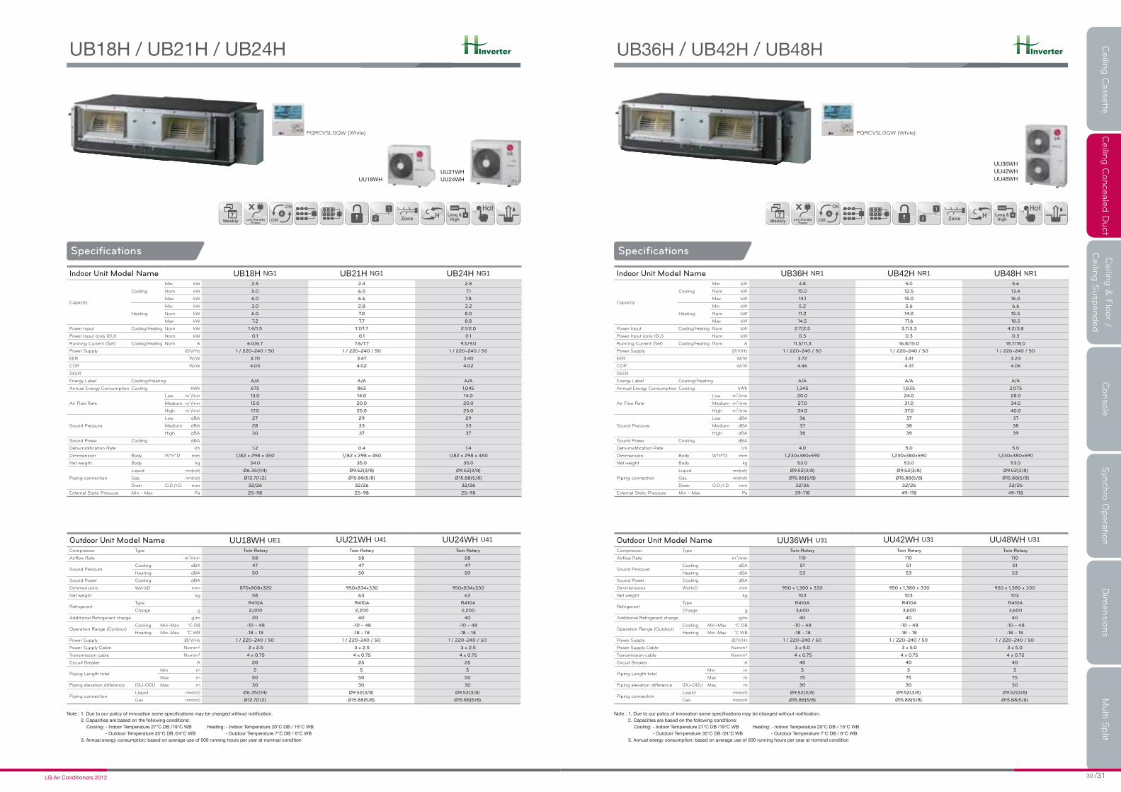
Indoor Unit Model Name UB18H NG1 UB21H NG1 UB24H NG1
Capacity
Cooling
Min kW 2.5 2.4 2.8
Nom kW 5.0 6.0 7.1
Max kW 6.0 6.6 7.8
Heating
Min kW 3.0 2.8 3.2
Nom kW 6.0 7.0 8.0
Max kW 7.2 7.7 8.8
Power Input Cooling/Heating Nom kW 1.4/1.5 1.7/1.7 2.1/2.0
Power Input (only IDU) Nom kW 0.1 0.1 0.1
Running Current (Set) Cooling/Heating Nom A 6.0/6.7 7.6/7.7 9.5/9.0
Power Supply Ø/V/Hz 1 / 220~240 / 50 1 / 220~240 / 50 1 / 220~240 / 50
EER W/W 3.70 3.47 3.40
COP W/W 4.03 4.02 4.02
SEER
Energy Label Cooling/Heating A/A A/A A/A
Annual Energy Consumption Cooling kWh 675 865 1,045
Air Flow Rate
Low m3/min 13.0 14.0 14.0
Medium m3/min 15.0 20.0 20.0
High m3/min 17.0 25.0 25.0
Sound Pressure
Low 27 29 29
Medium 28 33 33
High 30 37 37
Sound Power Cooling
Dehumidification Rate l/h 1.2 0.4 1.4
Dimmension W*H*D mm 1,182 x 298 x 450 1,182 x 298 x 450 1,182 x 298 x 450
Net weight kg 34.0 35.0 35.0
Piping connection
Liquid mm(inch) Ø6.35(1/4) Ø9.52(3/8) Ø9.52(3/8)
Gas mm(inch) Ø12.7(1/2) Ø15.88(5/8) Ø15.88(5/8)
Drain O.D./I.D. mm 32/26 32/26 32/26
External Static Pressure Min ~ Max Pa 25~98 25~98 25~98
Outdoor Unit Model Name UU18WH UE1 UU21WH U41 UU24WH U41
Compressor Type Twin Rotary Twin Rotary Twin Rotary
Airflow Rate m3/min 58 58 58
Sound PressureCooling 47 47 47
Heating 50 50 50
Sound Power Cooling
Dimmensions WxHxD mm 870x808x320 950x834x330 950x834x330
Net weight kg 58 63 63
RefrigerantType R410A R410A R410A
Charge g 2,000 2,200 2,200
Additional Refrigerant charge g/m 20 40 40
Operation Range (Outdoor)Cooling Min~Max -10 ~ 48 -10 ~ 48 -10 ~ 48
Heating Min~Max -18 ~ 18 -18 ~ 18 -18 ~ 18
Power Supply Ø/V/Hz 1 / 220~240 / 50 1 / 220~240 / 50 1 / 220~240 / 50
Power Supply Cable Nxmm² 3 x 2.5 3 x 2.5 3 x 2.5
Transmission cable Nxmm² 4 x 0.75 4 x 0.75 4 x 0.75
A 20 25 25
Piping Length totalMin m 5 5 5
Max m 50 50 50
Piping elevation difference IDU-ODU Max m 30 30 30
Piping connectionLiquid mm(inch) Ø6.35(1/4) Ø9.52(3/8) Ø9.52(3/8)
Gas mm(inch) Ø12.7(1/2) Ø15.88(5/8) Ø15.88(5/8)
PQRCVSL0QW (White)
Ceilin
g C
asse
tteC
eilin
g C
onceale
d D
uct
Ceilin
g &
Flo
or /
Ceilin
g S
usp
ended
Conso
le
Syn
chro
Opera
tion
Dim
ensio
ns
Multi S
plit
Inverter
Specifications
Indoor Unit Model Name UB36H NR1 UB42H NR1 UB48H NR1
Capacity
Cooling
Min kW 4.8 5.0 5.6
Nom kW 10.0 12.5 13.4
Max kW 14.1 15.0 16.0
Heating
Min kW 5.2 5.6 6.6
Nom kW 11.2 14.0 15.5
Max kW 14.5 17.6 18.5
Power Input Cooling/Heating Nom kW 2.7/2.5 3.7/3.3 4.2/3.8
Power Input (only IDU) Nom kW 0.3 0.3 0.3
Running Current (Set) Cooling/Heating Nom A 11.5/11.3 16.8/15.0 18.7/18.0
Power Supply Ø/V/Hz 1 / 220~240 / 50 1 / 220~240 / 50 1 / 220~240 / 50
EER W/W 3.72 3.41 3.23
COP W/W 4.46 4.31 4.06
SEER
Energy Label Cooling/Heating A/A A/A A/A
Annual Energy Consumption Cooling kWh 1,345 1,835 2,075
Air Flow Rate
Low m3/min 20.0 24.0 28.0
Medium m3/min 27.0 31.0 34.0
High m3/min 34.0 37.0 40.0
Sound Pressure
Low dBA 36 37 37
Medium dBA 37 38 38
High dBA 38 39 39
Sound Power Cooling dBA
Dehumidification Rate l/h 4.0 5.0 5.0
Dimmension Body W*H*D mm 1,230x380x590 1,230x380x590 1,230x380x590
Net weight Body kg 53.0 53.0 53.0
Piping connection
Liquid mm(inch) Ø9.52(3/8) Ø9.52(3/8) Ø9.52(3/8)
Gas mm(inch) Ø15.88(5/8) Ø15.88(5/8) Ø15.88(5/8)
Drain O.D./I.D. mm 32/26 32/26 32/26
External Static Pressure Min ~ Max Pa 39~118 49~118 49~118
Outdoor Unit Model Name UU36WH U31 UU42WH U31 UU48WH U31
Compressor Type Twin Rotary Twin Rotary Twin Rotary
Airflow Rate m3/min 110 110 110
Sound PressureCooling dBA 51 51 51
Heating dBA 53 53 53
Sound Power Cooling dBA
Dimmensions WxHxD mm 950 x 1,380 x 330 950 x 1,380 x 330 950 x 1,380 x 330
Net weight kg 103 103 103
RefrigerantType R410A R410A R410A
Charge g 3,600 3,600 3,600
Additional Refrigerant charge g/m 40 40 40
Operation Range (Outdoor)Cooling Min~Max °C DB -10 ~ 48 -10 ~ 48 -10 ~ 48
Heating Min~Max °C WB -18 ~ 18 -18 ~ 18 -18 ~ 18
Power Supply Ø/V/Hz 1 / 220~240 / 50 1 / 220~240 / 50 1 / 220~240 / 50
Power Supply Cable Nxmm² 3 x 5.0 3 x 5.0 3 x 5.0
Transmission cable Nxmm² 4 x 0.75 4 x 0.75 4 x 0.75
Circuit Breaker A 40 40 40
Piping Length totalMin m 5 5 5
Max m 75 75 75
Piping elevation difference IDU-ODU Max m 30 30 30
Piping connectionLiquid mm(inch) Ø9.52(3/8) Ø9.52(3/8) Ø9.52(3/8)
Gas mm(inch) Ø15.88(5/8) Ø15.88(5/8) Ø15.88(5/8)
PQRCVSL0QW (White)

Inverter
Specifications
Indoor Unit Model Name UB36H NR1 UB42H NR1 UB48H NR1
Capacity
Cooling
Min kW 4.8 5.0 5.6
Nom kW 10.0 12.5 13.4
Max kW 14.1 15.0 16.0
Heating
Min kW 5.2 5.6 6.6
Nom kW 11.2 14.0 15.5
Max kW 14.5 17.6 18.5
Power Input Cooling/Heating Nom kW 2.7/2.5 3.7/3.3 4.2/3.8
Power Input (only IDU) Nom kW 0.3 0.3 0.3
Running Current (Set) Cooling/Heating Nom A 11.5/11.3 16.8/15.0 18.7/18.0
Power Supply Ø/V/Hz 1 / 220~240 / 50 1 / 220~240 / 50 1 / 220~240 / 50
EER W/W 3.72 3.41 3.23
COP W/W 4.46 4.31 4.06
SEER
Energy Label Cooling/Heating A/A A/A A/A
Annual Energy Consumption Cooling kWh 1,345 1,835 2,075
Air Flow Rate
Low m3/min 20.0 24.0 28.0
Medium m3/min 27.0 31.0 34.0
High m3/min 34.0 37.0 40.0
Sound Pressure
Low dBA 36 37 37
Medium dBA 37 38 38
High dBA 38 39 39
Sound Power Cooling dBA
Dehumidification Rate l/h 4.0 5.0 5.0
Dimmension Body W*H*D mm 1,230x380x590 1,230x380x590 1,230x380x590
Net weight Body kg 53.0 53.0 53.0
Piping connection
Liquid mm(inch) Ø9.52(3/8) Ø9.52(3/8) Ø9.52(3/8)
Gas mm(inch) Ø15.88(5/8) Ø15.88(5/8) Ø15.88(5/8)
Drain O.D./I.D. mm 32/26 32/26 32/26
External Static Pressure Min ~ Max Pa 39~118 49~118 49~118
Outdoor Unit Model Name UU37WH U31 UU43WH U31 UU49WH U31
Compressor Type Twin Rotary Twin Rotary Twin Rotary
Airflow Rate m3/min 110 110 110
Sound PressureCooling dBA 51 51 51
Heating dBA 53 53 53
Sound Power Cooling dBA
Dimmensions WxHxD mm 950 x 1,380 x 330 950 x 1,380 x 330 950 x 1,380 x 330
Net weight kg 103 103 103
RefrigerantType R410A R410A R410A
Charge g 3,600 3,600 3,600
Additional Refrigerant charge g/m 40 40 40
Operation Range (Outdoor)Cooling Min~Max °C DB -10 ~ 48 -10 ~ 48 -10 ~ 48
Heating Min~Max °C WB -18 ~ 18 -18 ~ 18 -18 ~ 18
Power Supply Ø/V/Hz 3 / 380~415 / 50 3 / 380~415 / 50 3 / 380~415 / 50
Power Supply Cable Nxmm² 5 x 2.5 5 x 2.5 5 x 2.5
Transmission cable Nxmm² 4 x 0.75 4 x 0.75 4 x 0.75
Circuit Breaker A 20 25 25
Piping Length totalMin m 5 5 5
Max m 75 75 75
Piping elevation difference IDU-ODU Max m 30 30 30
Piping connectionLiquid mm(inch) Ø9.52(3/8) Ø9.52(3/8) Ø9.52(3/8)
Gas mm(inch) Ø15.88(5/8) Ø15.88(5/8) Ø15.88(5/8)
PQRCVSL0QW (White)
Ceilin
g C
asse
tteC
eilin
g C
onceale
d D
uct
Ceilin
g &
Flo
or /
Ceilin
g S
usp
ended
Conso
le
Syn
chro
Opera
tion
Dim
ensio
ns
Multi S
plit
Specifications
Standard Inverter
Indoor Unit Model Name CB18 NH2 CB24 NH2 UB30 NG2
Capacity
Cooling
Min kW 2.0 2.8 3.2
Nom kW 5.0 7.1 8.0
Max kW 5.4 7.8 8.8
Heating
Min kW 2.4 3.2 3.6
Nom kW 6.0 8.0 9.0
Max kW 6.6 8.8 9.9
Power Input Cooling/Heating Nom kW 1.5/1.7 2.4/2.5 2.3/2.5
Power Input (only IDU) Nom kW 0.9 0.9 1.3
Running Current (Set) Cooling/Heating Nom A 6.7/7.2 10.3/10.8 9.9/10.8
Power Supply Ø/V/Hz 1 / 220~240 / 50 1 / 220~240 / 50 1 / 220~240 / 50
EER W/W 3.21 3.01 3.51
COP W/W 3.61 3.21 3.61
SEER
Energy Label Cooling/Heating A/A B/C A/A
Annual Energy Consumption Cooling kWh 770 1,180 1,140
Air Flow Rate
Low m3/min 13.0 14.0 20.0
Medium m3/min 14.5 16.5 23.0
High m3/min 16.5 18.0 26.5
Sound Pressure
Low dBA 32 34 35
Medium dBA 34 36 38
High dBA 36 38 40
Sound Power Cooling dBA
Dehumidification Rate l/h 2.0 2.5 3.3
Dimmension Body W*H*D mm 880*260*450 880*260*450 1,180*298*450
Net weight Body kg 35.0 35.0 38.0
Piping connection
Liquid mm(inch) Ø6.35(1/4) Ø9.52(3/8) Ø9.52(3/8)
Gas mm(inch) Ø12.7(1/2) Ø15.88(5/8) Ø15.88(5/8)
Drain O.D./I.D. mm 32/25 32/25 32/25
External Static Pressure Min ~ Max Pa 25 ~ 80 25 ~ 40 ~ 80 40 ~ 50 ~ 100
Outdoor Unit Model Name UU18W UE2 UU24W U42 UU30W U42
Compressor Type Twin Rotary Twin Rotary Twin Rotary
Airflow Rate m3/min 50 58 58
Sound PressureCooling dBA 48 47 47
Heating dBA 48 50 50
Sound Power Cooling dBA 62 65 66
Dimmensions WxHxD mm 870x655x320 950x834x330 950x834x330
Net weight kg 48 61 61
RefrigerantType R410A R410A R410A
Charge g 1,400 2,000 2,000
Additional Refrigerant charge g/m 20 40 40
Operation Range (Outdoor)Cooling Min~Max °C DB -15~48 -15~48 -15~48
Heating Min~Max °C WB -18~18 -18~18 -18~18
Power Supply Ø/V/Hz 1 / 220~240 / 50 1 / 220~240 / 50 1 / 220~240 / 50
Power Supply Cable Nxmm² 3 x 2.5 3 x 2.5 3 x 2.5
Transmission cable Nxmm² 4 x 0.75 4 x 0.75 4 x 0.75
Circuit Breaker A 20 30 30
Piping Length totalMin m 5 5 5
Max m 40 50 50
Piping elevation difference IDU-ODU Max m 30 30 30
Piping connectionLiquid mm(inch) Ø6.35(1/4) Ø9.52(3/8) Ø9.52(3/8)
Gas mm(inch) Ø12.7(1/2) Ø15.88(5/8) Ø15.88(5/8)
PQRCVSL0QW (White)

Standard Inverter
Specifications
Indoor Unit Model Name UB36 NG2 UB42 NR2 UB48 NR2 UB60 NR2
Capacity
Cooling
Min kW 4.0 5.0 5.6 5.9
Nom kW 10.0 12.5 14.0 14.8
Max kW 11.0 13.8 15.4 16.3
Heating
Min kW 4.5 5.6 6.6 6.8
Nom kW 11.2 14 16.4 16.8
Max kW 12.3 15.4 18.2 18.7
Power Input Cooling/Heating Nom kW 3.5/3.5 4.2/3.7 4.7/4.5 5.3/4.6
Power Input (only IDU) Nom kW 1.4 3.7 3.7 3.7
Running Current (Set) Cooling/Heating Nom A 15.3/15.2 18.0/16.2 20.2/19.7 22.8/19.9
Power Supply Ø/V/Hz
EER W/W 2.85 3.01 3.01 2.81
COP W/W 3.21 3.75 3.61 3.67
SEER
Energy Label Cooling/Heating C/C B/A B/A C/A
Annual Energy Consumption Cooling kWh 1,755 2,075 2,325 2,630
Air Flow Rate
Low m3/min 26.0 32.0 30.0 40.0
Medium m3/min 29.0 36.0 35.0 45.0
High m3/min 32.0 38.0 40.0 50.0
Sound Pressure
Low dBA 36 38 40 42
Medium dBA 39 40 42 44
High dBA 42 42 44 46
Sound Power Cooling dBA
Dehumidification Rate l/h 4.0 5.0 6.0 6.5
Dimmension Body W*H*D mm 1,180*298*450 1,230*380*590 1,230*380*590 1,230*380*590
Net weight Body kg 38.0 60.0 60.0 62.0
Piping connection
Liquid mm(inch) Ø9.52(3/8) Ø9.52(3/8) Ø9.52(3/8) Ø9.52(3/8)
Gas mm(inch) Ø15.88(5/8) Ø15.88(5/8) Ø15.88(5/8) Ø15.88(5/8)
Drain O.D./I.D. mm 32/25 32/25 32/25 32/25
External Static Pressure Min ~ Max Pa 40 ~ 50 ~ 100 60 ~ 100 60 ~ 100 60 ~ 100
Outdoor Unit Model Name UU36W U02 UU42W U32 UU48W U32 UU60W U32
Compressor Type Twin Rotary Twin Rotary Twin Rotary Twin Rotary
Airflow Rate m3/min 90 110 110 110
Sound PressureCooling dBA 54 51 51 51
Heating dBA 55 53 53 53
Sound Power Cooling dBA 68 70 70 70
Dimmensions WxHxD mm 950x1,170x330 950x1,380x330 950x1,380x330 950x1,380x330
Net weight kg 75 103 103 103
RefrigerantType R410A R410A R410A R410A
Charge g 2,800 3,600 3,600 3,600
Additional Refrigerant charge g/m 40 40 40 40
Operation Range (Outdoor)Cooling Min~Max °C DB -15~48 -15~48 -15~48 -15~48
Heating Min~Max °C WB -18~18 -18~18 -18~18 -18~18
Power Supply Ø/V/Hz 1 / 220~240 / 50 1 / 220~240 / 50 1 / 220~240 / 50 1 / 220~240 / 50
Power Supply Cable Nxmm² 3 x 2.5 3 x 3.5 3 x 3.5 3 x 3.5
Transmission cable Nxmm² 4 x 0.75 4 x 0.75 4 x 0.75 4 x 0.75
Circuit Breaker A 30 40 40 40
Piping Length totalMin m 5 5 5 5
Max m 50 75 75 75
Piping elevation difference IDU-ODU Max m 30 30 30 30
Piping connectionLiquid mm(inch) Ø9.52(3/8) Ø9.52(3/8) Ø9.52(3/8) Ø9.52(3/8)
Gas mm(inch) Ø15.88(5/8) Ø15.88(5/8) Ø15.88(5/8) Ø15.88(5/8)
PQRCVSL0QW (White)
UU37W
UU43WUU49W UU61W
Ceilin
g C
asse
tteC
eilin
g C
onceale
d D
uct
Ceilin
g &
Flo
or /
Ceilin
g S
usp
ended
Conso
le
Syn
chro
Opera
tion
Dim
ensio
ns
Multi S
plit
Standard Inverter
Specifications
Indoor Unit Model Name UB36 NG2 UB42 NR2 UB48 NR2 UB60 NR2
Capacity
Cooling
Min kW 4.0 5.0 5.6 5.9
Nom kW 10.0 12.5 14.0 14.8
Max kW 11.0 13.8 15.4 16.3
Heating
Min kW 4.5 5.6 6.6 6.8
Nom kW 11.2 14.0 16.4 16.8
Max kW 12.3 15.4 18.2 18.7
Power Input Cooling/Heating Nom kW 3.5/3.5 4.2/3.7 4.7/4.5 5.3/4.6
Power Input (only IDU) Nom kW 1.4 3.7 3.7 3.7
Running Current (Set) Cooling/Heating Nom A 15.3/15.2 18.0/16.2 20.2/19.7 22.9/19.9
Power Supply Ø/V/Hz
EER W/W 2.85 3.01 3.01 2.81
COP W/W 3.21 3.75 3.61 3.67
SEER
Energy Label Cooling/Heating C/C B/A B/A C/A
Annual Energy Consumption Cooling kWh 1,755 2,075 2,325 2,630
Air Flow Rate
Low m3/min 26.0 32.0 30.0 40.0
Medium m3/min 29.0 36.0 35.0 45.0
High m3/min 32.0 38.0 40.0 50.0
Sound Pressure
Low dBA 36 38 40 42
Medium dBA 39 40 42 44
High dBA 42 42 44 46
Sound Power Cooling dBA
Dehumidification Rate l/h 4.0 5.0 6.0 6.5
Dimmension Body W*H*D mm 1,180*298*450 1,230*380*590 1,230*380*590 1,230*380*590
Net weight Body kg 38.0 60.0 60.0 62.0
Piping connection
Liquid mm(inch) Ø9.52(3/8) Ø9.52(3/8) Ø9.52(3/8) Ø9.52(3/8)
Gas mm(inch) Ø15.88(5/8) Ø15.88(5/8) Ø15.88(5/8) Ø15.88(5/8)
Drain O.D./I.D. mm 32/25 32/25 32/25 32/25
External Static Pressure Min ~ Max Pa 40 ~ 50 ~ 100 60 ~ 100 60 ~ 100 60 ~ 100
Outdoor Unit Model Name UU37W U02 UU43W U32 UU49W U32 UU61W U32
Compressor Type Twin Rotary Twin Rotary Twin Rotary Twin Rotary
Airflow Rate m3/min 90 110 110 110
Sound PressureCooling dBA 54 51 51 51
Heating dBA 55 53 53 53
Sound Power Cooling dBA 68 70 70 70
Dimmensions WxHxD mm 950x1,170x330 950x1,380x330 950x1,380x330 950x1,380x330
Net weight kg 80 103 103 103
RefrigerantType R410A R410A R410A R410A
Charge g 2,800 3,600 3,600 3,600
Additional Refrigerant charge g/m 40 40 40 40
Operation Range (Outdoor)Cooling Min~Max °C DB -15~48 -15~48 -15~48 -15~48
Heating Min~Max °C WB -18~18 -18~18 -18~18 -18~18
Power Supply Ø/V/Hz 3 / 380~415 / 50 3 / 380~415 / 50 3 / 380~415 / 50 3 / 380~415 / 50
Power Supply Cable Nxmm² 3 x 2.5 3 x 2.5 3 x 2.5 3 x 2.5
Transmission cable Nxmm² 4 x 0.75 4 x 0.75 4 x 0.75 4 x 0.75
Circuit Breaker A 20 25 25 25
Piping Length totalMin m 5 5 5 5
Max m 50 75 75 75
Piping elevation difference IDU-ODU Max m 30 30 30 30
Piping connectionLiquid mm(inch) Ø9.52(3/8) Ø9.52(3/8) Ø9.52(3/8) Ø9.52(3/8)
Gas mm(inch) Ø9.52(3/8) Ø15.88(5/8) Ø15.88(5/8) Ø15.88(5/8)
PQRCVSL0QW (White)

COMFORT
SPACE,
WITH
EASY OPERATION
FLOOR & CEILING SUSPENDED
Ceilin
g C
asse
tteC
eilin
g C
onceale
d D
uct
Ceilin
g &
Flo
or /
Ceilin
g S
usp
ended
Conso
le
Syn
chro
Opera
tion
Dim
ensio
ns
Multi S
plit
FLOOR & CEILING SUSPENDED
*Floor is only for standard inverter 2.5, 3.5kW
Flexible Installation
The ceiling and floor model can be installed either ceiling or floor. So you can save the space when you install this units on your shop or office.
Airflow Direction Control
Horizontal Airflow Direction Control. Adjust the horizontal airflow direction by manually moving the horizontal airflow direction louver by hand.
Vertical Airflow Direction ControlThe airflow direction can be adjusted as desired by using the remote controller.
Ez-Remote Controller
User friendly & modern design and easy usage-Comfortable to grab- Sliding type- Bigger size button- Highlighted some buttons with different colors- Easy to recognize functions withgraphics
Vertical
Horizontal
FLOOR & CEILING SUSPENDED
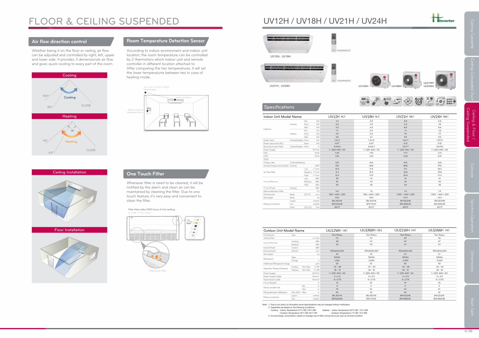
Air flow direction control
Whether being it on the floor or ceiling, air flow can be adjusted and controlled by right, left, upper and lower side. It provides 3 dimensionals air flow and gives quick cooling to every part of the room.
Room Temperature Detection Sensor
According to indoor environment and indoor unit location, the room temperature can be controlled by 2 thermistors which indoor unit and remote controller in different location attached to. After comparing the two temperatures, it will set the lower temperaturre between two in case ofheating mode.
One Touch Filter
Whenever filter is need to be cleaned, it will be notified by the alarm and clean air can be maintained by cleaning the filter. Due to one touch feature, it's very easy and convenient to clean the filter.
FilterChange Alarm
One touch Filter
Filter Alarm after 2400 hours of Unit working※ model: VJ,VK,VL chassis
Indoor Unit Sensor
Remote Controller
TemperaturTT e Sensor
Indoor Unit + Remote Controller
Sensor Analysis
135
CLOSE
Heating
63º
93º
CLOSE
Cooling
80º
100º
Cooling
Ceiling Installation
Heating
Floor Installation
Inverter
UV12H, UV18H
UV21H , UV24H
Ceilin
g C
asse
tteC
eilin
g C
onceale
d D
uct
Ceilin
g &
Flo
or /
Ceilin
g S
usp
ended
Conso
le
Syn
chro
Opera
tion
Dim
ensio
ns
Multi S
plit
Indoor Unit Model Name UV12H NJ1 UV18H NJ1 UV21H NK1 UV24H NK1
Capacity
Cooling
Min kW 1.4 2.0 2.8 2.8
Nom kW 3.5 5.0 6.0 7.0
Max kW 4.2 5.5 8.0 8.4
Heating
Min kW 1.6 2.2 3.1 3.2
Nom kW 4.0 5.4 7.0 7.7
Max kW 4.8 6.1 9.0 9.2
Power Input Cooling/Heating Nom kW 1.0/1.1 1.3/1.5 1.6/1.7 1.9/1.9
Power Input (only IDU) Nom kW 0.07 0.07 0.12 0.12
Running Current (Set) Cooling/Heating Nom A 4.4/4.6 6.0/6.7 7.6/7.7 9.5/9.0
Power Supply Ø/V/Hz 1 / 220~240 / 50 1 / 220~240 / 50 1 / 220~240 / 50 1 / 220~240 / 50
EER W/W 3.40 3.81 3.75 3.61
COP W/W 3.81 3.61 4.22 4.01
SEER
Energy Label Cooling/Heating A/A A/A A/A A/A
Annual Energy Consumption Cooling kWh 515 655 800 970
Air Flow Rate
Low m3/min 10.4 11.9 17.2 18.2
Medium m3/min 11.4 12.9 18.8 19.8
High m3/min 12.4 13.9 20.4 21.4
Sound Pressure
Low dBA 39 41 41 41
Medium dBA 40 43 42 44
High dBA 42 45 44 45
Sound Power Cooling dBA
Dehumidification Rate l/h 0.6 1.6 1.9 1.9
Dimmension Body W*H*D mm 950 × 650 × 220 950 × 650 × 220 1,350 × 650 × 220 1,350 × 650 × 220
Net weight Body kg 24.6 24.6 35.0 35.0
Piping connection
Liquid mm(inch) Ø6.35(1/4) Ø6.35(1/4) Ø9.52(3/8) Ø9.52(3/8)
Gas mm(inch) Ø9.52(3/8) Ø12.7(1/2) Ø15.88(5/8) Ø15.88(5/8)
Drain O.D./I.D. mm 20/17 20/17 20/17 20/17
Specifications
Outdoor Unit Model Name UU12WH UE1 UU18WH UE1 UU21WH U41 UU24WH U41
Compressor Type Twin Rotary Twin Rotary Twin Rotary Twin Rotary
Airflow Rate m3/min 50 58 58 58
Sound PressureCooling dBA 48 47 47 47
Heating dBA 48 50 50 50
Sound Power Cooling dBA
Dimmensions WxHxD mm 870x655x320 870x808x320 950x834x330 950x834x330
Net weight kg 46 58 63 63
RefrigerantType R410A R410A R410A R410A
Charge g 1,250 2,000 2,200 2,200
Additional Refrigerant charge g/m 20 20 40 40
Operation Range (Outdoor)Cooling Min~Max °C DB -10 ~ 48 -10 ~ 48 -10 ~ 48 -10 ~ 48
Heating Min~Max °C WB -18 ~ 18 -18 ~ 18 -18 ~ 18 -18 ~ 18
Power Supply Ø/V/Hz 1 / 220~240 / 50 1 / 220~240 / 50 1 / 220~240 / 50 1 / 220~240 / 50
Power Supply Cable Nxmm² 3 x 2.5 3 x 2.5 3 x 2.5 3 x 2.5
Transmission cable Nxmm² 4 x 0.75 4 x 0.75 4 x 0.75 4 x 0.75
Circuit Breaker A 15 20 25 25
Piping Length totalMin m 5 5 5 5
Max m 30 50 50 50
Piping elevation difference IDU-ODU Max m 20 30 30 30
Piping connectionLiquid mm(inch) Ø6.35(1/4) Ø6.35(1/4) Ø9.52(3/8) Ø9.52(3/8)
Gas mm(inch) Ø9.52(3/8) Ø12.7(1/2) Ø15.88(5/8) Ø15.88(5/8)
PQWRHDF
PQWRHDF

Inverter
Indoor Unit Model Name UV36H NL1 UV42H NL1 UV48H NL1
Capacity
Cooling
Min kW 4.3 5.0 5.4
Nom kW 10.0 12.5 13.3
Max kW 12.4 14.9 16.1
Heating
Min kW 4.2 5.4 6.2
Nom kW 10.5 13.6 15.0
Max kW 13.7 16.3 17.8
Power Input Cooling/Heating Nom kW 2.8/2.6 3.9/3.6 4.4/4.2
Power Input (only IDU) Nom kW 0.2 0.2 0.2
Running Current (Set) Cooling/Heating Nom A 11.5/11.3 16.8/15.0 18.7/18.0
Power Supply Ø/V/Hz 1 / 220~240 / 50 1 / 220~240 / 50 1 / 220~240 / 50
EER W/W 3.61 3.21 3.01
COP W/W 4.01 3.81 3.61
SEER
Energy Label Cooling/Heating A/A A/A B/A
Annual Energy Consumption Cooling kWh 1315 1945 2210
Air Flow Rate
Low m3/min 25 27 28
Medium m3/min 27 28 30
High m3/min 29 30 32
Sound Pressure
Low dBA 43 44 45
Medium dBA 44 46 47
High dBA 46 47 48
Sound Power Cooling dBA
Dehumidification Rate l/h 2.9 4.8 5.1
Dimmension Body W*H*D mm 1750 × 650 × 220 1750 × 650 × 220 1750 × 650 × 220
Net weight Body kg 45 45 45
Piping connection
Liquid mm(inch) Ø9.52(3/8) Ø9.52(3/8) Ø9.52(3/8)
Gas mm(inch) Ø15.88(5/8) Ø15.88(5/8) Ø15.88(5/8)
Drain O.D./I.D. mm 20/17 20/17 20/17
Specifications
Outdoor Unit Model Name UU36WH U31 UU42WH U31 UU48WH U31
Compressor Type Twin Rotary Twin Rotary Twin Rotary
Airflow Rate m3/min 110 110 110
Sound PressureCooling dBA 51 51 51
Heating dBA 53 53 53
Sound Power Cooling dBA
Dimmensions WxHxD mm 950 x 1,380 x 330 950 x 1,380 x 330 950 x 1,380 x 330
Net weight kg 103 103 103
RefrigerantType R410A R410A R410A
Charge g 3,600 3,600 3.600
Additional Refrigerant charge g/m 40 40 40
Operation Range (Outdoor)Cooling Min~Max °C DB -10 ~ 48 -10 ~ 48 -10 ~ 48
Heating Min~Max °C WB -18 ~ 18 -18 ~ 18 -18 ~ 18
Power Supply Ø/V/Hz 1 / 220~240 / 50 1 / 220~240 / 50 1 / 220~240 / 50
Power Supply Cable Nxmm² 3 x 5.0 3 x 5.0 3 x 5.0
Transmission cable Nxmm² 4 x 0.75 4 x 0.75 4 x 0.75
Circuit Breaker A 40 40 40
Piping Length totalMin m 5 5 5
Max m 75 75 75
Piping elevation difference IDU-ODU Max m 30 30 30
Piping connectionLiquid mm(inch) Ø9.52(3/8) Ø9.52(3/8) Ø9.52(3/8)
Gas mm(inch) Ø15.88(5/8) Ø15.88(5/8) Ø15.88(5/8)
PQWRHDF
Ceilin
g C
asse
tteC
eilin
g C
onceale
d D
uct
Ceilin
g &
Flo
or /
Ceilin
g S
usp
ended
Conso
le
Syn
chro
Opera
tion
Dim
ensio
ns
Multi S
plit
Inverter
Indoor Unit Model Name UV36H NL1 UV42H NL1 UV48H NL1
Capacity
Cooling
Min kW 4.3 5.0 5.4
Nom kW 10.0 12.5 13.3
Max kW 12.4 14.9 16.1
Heating
Min kW 4.2 5.4 6.2
Nom kW 10.5 13.6 15.0
Max kW 13.7 16.3 17.8
Power Input Cooling/Heating Nom kW 2.8/2.6 3.9/3.6 4.4/4.2
Power Input (only IDU) Nom kW 0.2 0.2 0.2
Running Current (Set) Cooling/Heating Nom A 11.5/11.3 16.8/15.0 18.7/18.0
Power Supply Ø/V/Hz 1 / 220~240 / 50 1 / 220~240 / 50 1 / 220~240 / 50
EER W/W 3.61 3.21 3.01
COP W/W 4.01 3.81 3.61
SEER
Energy Label Cooling/Heating A/A A/A B/A
Annual Energy Consumption Cooling kWh 1,315 1,945 2,210
Air Flow Rate
Low m3/min 25.2 26.6 28.0
Medium m3/min 26.9 28.3 29.7
High m3/min 28.6 30.0 31.5
Sound Pressure
Low dBA 43 44 45
Medium dBA 44 46 47
High dBA 46 47 48
Sound Power Cooling dBA
Dehumidification Rate l/h 2.9 4.8 5.1
Dimmension Body W*H*D mm 1,750 × 650 × 220 1,750 × 650 × 220 1,750 × 650 × 220
Net weight Body kg 45 45 45
Piping connection
Liquid mm(inch) Ø9.52(3/8) Ø9.52(3/8) Ø9.52(3/8)
Gas mm(inch) Ø15.88(5/8) Ø15.88(5/8) Ø15.88(5/8)
Drain O.D./I.D. mm 20/17 20/17 20/17
Specifications
Outdoor Unit Model Name UU37WH U31 UU43WH U31 UU49WH U31
Compressor Type Twin Rotary Twin Rotary Twin Rotary
Airflow Rate m3/min 110 110 110
Sound PressureCooling dBA 51 51 51
Heating dBA 53 53 53
Sound Power Cooling dBA
Dimmensions WxHxD mm 950 x 1,380 x 330 950 x 1,380 x 330 950 x 1,380 x 330
Net weight kg 103 103 103
RefrigerantType R410A R410A R410A
Charge g 3,600 3,600 3,600
Additional Refrigerant charge g/m 40 40 40
Operation Range (Outdoor)Cooling Min~Max °C DB -10 ~ 48 -10 ~ 48 -10 ~ 48
Heating Min~Max °C WB -18 ~ 18 -18 ~ 18 -18 ~ 18
Power Supply Ø/V/Hz 3 / 380~415 / 50 3 / 380~415 / 50 3 / 380~415 / 50
Power Supply Cable Nxmm² 5 x 2.5 5 x 2.5 5 x 2.5
Transmission cable Nxmm² 4 x 0.75 4 x 0.75 4 x 0.75
Circuit Breaker A 20 25 25
Piping Length totalMin m 5 5 5
Max m 75 75 75
Piping elevation difference IDU-ODU Max m 30 30 30
Piping connectionLiquid mm(inch) Ø9.52(3/8) Ø9.52(3/8) Ø9.52(3/8)
Gas mm(inch) Ø15.88(5/8) Ø15.88(5/8) Ø15.88(5/8)
PQWRHDF

Standard Inverter
Specifications
Indoor Unit Model Name CV09 NE2 CV12 NE2
Capacity
Cooling
Min kW 1.0 1.3
Nom kW 2.5 3.3
Max kW 2.8 3.6
Heating
Min kW 1.2 1.5
Nom kW 3.0 3.8
Max kW 3.3 4.2
Power Input Cooling/Heating Nom kW 0.8/0.8 1.1/1.2
Power Input (only IDU) Nom kW 0.02 0.02
Running Current (Set) Cooling/Heating Nom A 3.3/3.6 4.7/5.1
Power Supply Ø/V/Hz 1 / 220~240 / 50 1 / 220~240 / 50
EER W/W 3.33 3.03
COP W/W 3.61 3.22
SEER
Energy Label Cooling/Heating A/A B/C
Annual Energy Consumption Cooling kWh 375 545
Air Flow Rate
Low m3/min 6.2 6.6
Medium m3/min 6.9 7.6
High m3/min 7.6 9.2
Sound Pressure
Low dBA 32 31
Medium dBA 35 36
High dBA 38 40
Sound Power Cooling dBA
Dehumidification Rate l/h 1.2 1.2
Dimmension Body W*H*D mm 900*200*490 900*200*490
Net weight Body kg 13.7 13.7
Piping connection
Liquid mm(inch) Ø6.35(1/4) Ø6.35(1/4)
Gas mm(inch) Ø9.52(3/8) Ø9.52(3/8)
Drain O.D./I.D. mm 32/25 32/25
Outdoor Unit Model Name UU09W ULD UU12W ULD
Compressor Type Rotary Rotary
Airflow Rate m3/min 50 50
Sound PressureCooling dBA 47 47
Heating dBA 48 48
Sound Power Cooling dBA
Dimmensions WxHxD mm 770x540x245 770x540x245
Net weight kg 32 32
RefrigerantType R410A R410A
Charge g 1,000 1,000
Additional Refrigerant charge g/m 20 20
Operation Range (Outdoor)Cooling Min~Max °C DB -10~46 -10~46
Heating Min~Max °C WB -18~18 -18~18
Power Supply Ø/V/Hz 1 / 220~240 / 50 1 / 220~240 / 50
Power Supply Cable Nxmm² 3 x 2.5 3 x 2.5
Transmission cable Nxmm² 4 x 0.75 4 x 0.75
Circuit Breaker A 15 15
Piping Length totalMin m 5 5
Max m 15 15
Piping elevation difference IDU-ODU Max m 10 10
Piping connectionLiquid mm(inch) Ø6.35(1/4) Ø6.35(1/4)
Gas mm(inch) Ø9.52(3/8) Ø9.52(3/8)
PQWRHDF
Ceilin
g C
asse
tteC
eilin
g C
onceale
d D
uct
Ceilin
g &
Flo
or /
Ceilin
g S
usp
ended
Conso
le
Syn
chro
Opera
tion
Dim
ensio
ns
Multi S
plit
Standard Inverter
Specifications
Indoor Unit Model Name CV18 NJ2 CV24 NJ2 UV30 NJ2
Capacity
Cooling
Min kW 1.9 2.8 3.0
Nom kW 4.8 7.0 7.6
Max kW 5.3 7.7 8.4
Heating
Min kW 2.0 3.1 3.4
Nom kW 5.1 7.6 8.2
Max kW 5.6 8.5 9.2
Power Input Cooling/Heating Nom kW 1.5/1.5 2.2/2.4 2.5/2.7
Power Input (only IDU) Nom kW 0.07 0.07 0.07
Running Current (Set) Cooling/Heating Nom A 6.8/6.8 9.5/10.3 11.0/11.8
Power Supply Ø/V/Hz 1 / 220~240 / 50 1 / 220~240 / 50 1 / 220~240 / 50
EER W/W 3.22 3.21 3.01
COP W/W 3.42 3.21 3.01
SEER
Energy Label Cooling/Heating A/B A/C B/D
Annual Energy Consumption Cooling kWh 745 1,090 1,260
Air Flow Rate
Low m3/min 10.4 11.9 11.9
Medium m3/min 11.4 12.9 12.9
High m3/min 12.4 13.9 13.9
Sound Pressure
Low dBA 39 41 41
Medium dBA 40 43 43
High dBA 42 44 44
Sound Power Cooling dBA
Dehumidification Rate l/h 1.6 1.9 1.9
Dimmension Body W*H*D mm 950*650*220 950*650*220 950*650*220
Net weight Body kg 24.6 24.6 24.6
Piping connection
Liquid mm(inch) Ø6.35(1/4) Ø9.52(3/8) Ø9.52(3/8)
Gas mm(inch) Ø12.7(1/2) Ø15.88(5/8) Ø15.88(5/8)
Drain O.D./I.D. mm 32/25 32/25 32/25
Outdoor Unit Model Name UU18W UE2 UU24W U42 UU30W U42
Compressor Type Twin Rotary Twin Rotary Twin Rotary
Airflow Rate m3/min 50 58 58
Sound PressureCooling dBA 48 47 47
Heating dBA 48 50 50
Sound Power Cooling dBA 62 65 66
Dimmensions WxHxD mm 870x655x320 950x834x330 950x834x330
Net weight kg 48 61 61
RefrigerantType R410A R410A R410A
Charge g 1,400 2,000 2,000
Additional Refrigerant charge g/m 20 40 40
Operation Range (Outdoor)Cooling Min~Max °C DB -15~48 -15~48 -15~48
Heating Min~Max °C WB -18~18 -18~18 -18~18
Power Supply Ø/V/Hz 1 / 220~240 / 50 1 / 220~240 / 50 1 / 220~240 / 50
Power Supply Cable Nxmm² 3 x 2.5 3 x 2.5 3 x 2.5
Transmission cable Nxmm² 4 x 0.75 4 x 0.75 4 x 0.75
Circuit Breaker A 20 30 30
Piping Length totalMin m 5 5 5
Max m 40 50 50
Piping elevation difference IDU-ODU Max m 30 30 30
Piping connectionLiquid mm(inch) Ø6.35(1/4) Ø9.52(3/8) Ø9.52(3/8)
Gas mm(inch) Ø12.7(1/2) Ø15.88(5/8) Ø15.88(5/8)
PQWRHDF
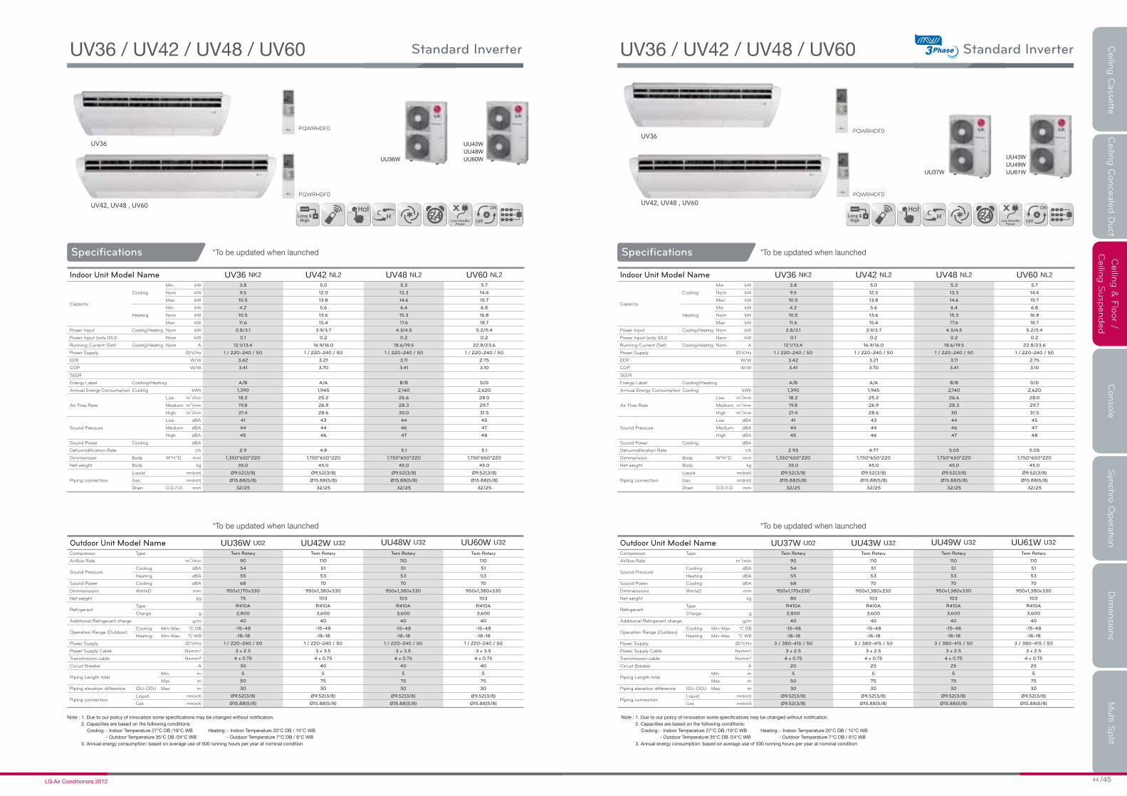
UV36
UV42, UV48 , UV60
Standard Inverter
Specifications
Indoor Unit Model Name UV36 NK2 UV42 NL2 UV48 NL2 UV60 NL2
Capacity
Cooling
Min kW 3.8 5.0 5.3 5.7
Nom kW 9.5 12.5 13.3 14.4
Max kW 10.5 13.8 14.6 15.7
Heating
Min kW 4.2 5.6 6.4 6.8
Nom kW 10.5 13.6 15.3 16.8
Max kW 11.6 15.4 17.6 18.7
Power Input Cooling/Heating Nom kW 2.8/3.1 3.9/3.7 4.3/4.5 5.2/5.4
Power Input (only IDU) Nom kW 0.1 0.2 0.2 0.2
Running Current (Set) Cooling/Heating Nom A 12.1/13.4 16.9/16.0 18.6/19.5 22.8/23.6
Power Supply Ø/V/Hz 1 / 220~240 / 50 1 / 220~240 / 50 1 / 220~240 / 50 1 / 220~240 / 50
EER W/W 3.42 3.21 3.11 2.75
COP W/W 3.41 3.70 3.41 3.10
SEER
Energy Label Cooling/Heating A/B A/A B/B D/D
Annual Energy Consumption Cooling kWh 1,390 1,945 2,140 2,620
Air Flow Rate
Low m3/min 18.2 25.2 26.6 28.0
Medium m3/min 19.8 26.9 28.3 29.7
High m3/min 21.4 28.6 30.0 31.5
Sound Pressure
Low dBA 41 43 44 45
Medium dBA 44 44 46 47
High dBA 45 46 47 48
Sound Power Cooling dBA
Dehumidification Rate l/h 2.9 4.8 5.1 5.1
Dimmension Body W*H*D mm 1,350*650*220 1,750*650*220 1,750*650*220 1,750*650*220
Net weight Body kg 35.0 45.0 45.0 45.0
Piping connection
Liquid mm(inch) Ø9.52(3/8) Ø9.52(3/8) Ø9.52(3/8) Ø9.52(3/8)
Gas mm(inch) Ø15.88(5/8) Ø15.88(5/8) Ø15.88(5/8) Ø15.88(5/8)
Drain O.D./I.D. mm 32/25 32/25 32/25 32/25
Outdoor Unit Model Name UU36W U02 UU42W U32 UU48W U32 UU60W U32
Compressor Type Twin Rotary Twin Rotary Twin Rotary Twin Rotary
Airflow Rate m3/min 90 110 110 110
Sound PressureCooling dBA 54 51 51 51
Heating dBA 55 53 53 53
Sound Power Cooling dBA 68 70 70 70
Dimmensions WxHxD mm 950x1,170x330 950x1,380x330 950x1,380x330 950x1,380x330
Net weight kg 75 103 103 103
RefrigerantType R410A R410A R410A R410A
Charge g 2,800 3,600 3,600 3,600
Additional Refrigerant charge g/m 40 40 40 40
Operation Range (Outdoor)Cooling Min~Max °C DB -15~48 -15~48 -15~48 -15~48
Heating Min~Max °C WB -18~18 -18~18 -18~18 -18~18
Power Supply Ø/V/Hz 1 / 220~240 / 50 1 / 220~240 / 50 1 / 220~240 / 50 1 / 220~240 / 50
Power Supply Cable Nxmm² 3 x 2.5 3 x 3.5 3 x 3.5 3 x 3.5
Transmission cable Nxmm² 4 x 0.75 4 x 0.75 4 x 0.75 4 x 0.75
Circuit Breaker A 30 40 40 40
Piping Length totalMin m 5 5 5 5
Max m 50 75 75 75
Piping elevation difference IDU-ODU Max m 30 30 30 30
Piping connectionLiquid mm(inch) Ø9.52(3/8) Ø9.52(3/8) Ø9.52(3/8) Ø9.52(3/8)
Gas mm(inch) Ø15.88(5/8) Ø15.88(5/8) Ø15.88(5/8) Ø15.88(5/8)
PQWRHDF
PQWRHDF
Ceilin
g C
asse
tteC
eilin
g C
onceale
d D
uct
Ceilin
g &
Flo
or /
Ceilin
g S
usp
ended
Conso
le
Syn
chro
Opera
tion
Dim
ensio
ns
Multi S
plit
UV36
UV42, UV48 , UV60
Standard Inverter
Specifications
Indoor Unit Model Name UV36 NK2 UV42 NL2 UV48 NL2 UV60 NL2
Capacity
Cooling
Min kW 3.8 5.0 5.3 5.7
Nom kW 9.5 12.5 13.3 14.4
Max kW 10.5 13.8 14.6 15.7
Heating
Min kW 4.2 5.6 6.4 6.8
Nom kW 10.5 13.6 15.3 16.8
Max kW 11.6 15.4 17.6 18.7
Power Input Cooling/Heating Nom kW 2.8/3.1 3.9/3.7 4.3/4.5 5.2/5.4
Power Input (only IDU) Nom kW 0.1 0.2 0.2 0.2
Running Current (Set) Cooling/Heating Nom A 12.1/13.4 16.9/16.0 18.6/19.5 22.8/23.6
Power Supply Ø/V/Hz 1 / 220~240 / 50 1 / 220~240 / 50 1 / 220~240 / 50 1 / 220~240 / 50
EER W/W 3.42 3.21 3.11 2.75
COP W/W 3.41 3.70 3.41 3.10
SEER
Energy Label Cooling/Heating A/B A/A B/B D/D
Annual Energy Consumption Cooling kWh 1,390 1,945 2,140 2,620
Air Flow Rate
Low m3/min 18.2 25.2 26.6 28.0
Medium m3/min 19.8 26.9 28.3 29.7
High m3/min 21.4 28.6 30 31.5
Sound Pressure
Low dBA 41 43 44 45
Medium dBA 44 44 46 47
High dBA 45 46 47 48
Sound Power Cooling dBA
Dehumidification Rate l/h 2.93 4.77 5.05 5.05
Dimmension Body W*H*D mm 1,350*650*220 1,750*650*220 1,750*650*220 1,750*650*220
Net weight Body kg 35.0 45.0 45.0 45.0
Piping connection
Liquid mm(inch) Ø9.52(3/8) Ø9.52(3/8) Ø9.52(3/8) Ø9.52(3/8)
Gas mm(inch) Ø15.88(5/8) Ø15.88(5/8) Ø15.88(5/8) Ø15.88(5/8)
Drain O.D./I.D. mm 32/25 32/25 32/25 32/25
Outdoor Unit Model Name UU37W U02 UU43W U32 UU49W U32 UU61W U32
Compressor Type Twin Rotary Twin Rotary Twin Rotary Twin Rotary
Airflow Rate m3/min 90 110 110 110
Sound PressureCooling dBA 54 51 51 51
Heating dBA 55 53 53 53
Sound Power Cooling dBA 68 70 70 70
Dimmensions WxHxD mm 950x1,170x330 950x1,380x330 950x1,380x330 950x1,380x330
Net weight kg 80 103 103 103
RefrigerantType R410A R410A R410A R410A
Charge g 2,800 3,600 3,600 3,600
Additional Refrigerant charge g/m 40 40 40 40
Operation Range (Outdoor)Cooling Min~Max °C DB -15~48 -15~48 -15~48 -15~48
Heating Min~Max °C WB -18~18 -18~18 -18~18 -18~18
Power Supply Ø/V/Hz 3 / 380~415 / 50 3 / 380~415 / 50 3 / 380~415 / 50 3 / 380~415 / 50
Power Supply Cable Nxmm² 3 x 2.5 3 x 2.5 3 x 2.5 3 x 2.5
Transmission cable Nxmm² 4 x 0.75 4 x 0.75 4 x 0.75 4 x 0.75
Circuit Breaker A 20 25 25 25
Piping Length totalMin m 5 5 5 5
Max m 50 75 75 75
Piping elevation difference IDU-ODU Max m 30 30 30 30
Piping connectionLiquid mm(inch) Ø9.52(3/8) Ø9.52(3/8) Ø9.52(3/8) Ø9.52(3/8)
Gas mm(inch) Ø9.52(3/8) Ø15.88(5/8) Ø15.88(5/8) Ø15.88(5/8)
PQWRHDF
PQWRHDF

NICE DESIGN,
PROVIDING
COMPORT AIR FLOW
CONSOLE
Ceilin
g C
asse
tteC
eilin
g C
onceale
d D
uct
Ceilin
g &
Flo
or /
Ceilin
g S
usp
ended
Conso
le
Syn
chro
Opera
tion
Dim
ensio
ns
Multi S
plit
Vane angle could be controlled in few directions air flow to adjust.
Cooling
Heating (Nomal) Heating (Floor Heating Mode)
Company A
12 minutes 30 seconds
50 minutes 9 minutes 30 seconds
8 minutes 40 seconds
Electric Heater LG
(Test Condition :Target Temp 23°C, Indoor Room:13°C~ , Outdoor Room:7°C)
27°C
15°C
Vertical
Lead Time for Heating
(13°C 21°C)
LGFloor Heating Mode
Horizontal
5 STEP
1 STEP
2 STEP
3 STEP
4 STEP
Comfort Air Flow
For cooling, the vane is adjusted upwards to let the cold air travel up. As for heating, the vane sends the heated air downwards to balance room temperature specially for floor.
Console air conditioners can operate faster to provider more powerful performance. The results is to attain the desired temperature much faster in floor heating mode than conventional air conditioners.
Healthy Air (3 stage air filter system)
1st Advanced pre filter :The antibacterial pre-filter primarily reduces large dust, mould and quilt dust.
2nd Allergy Filter :Filter consists of enzyme that breaks down allergen, apatite, and organic/inorganic binder that attaches the enzyme to the filter. When the air passes the filter, allergen clings to the filter and like tiny pairs of scissors the enzymes cut allergen's protein to deactivate the allergen.
3rd Plasma Ion Generator :The sterilized ion generating system, Ion Generator, emits around 1.2 million ions, and catches hazardous substances floating in the air, therefore proactively looking for and catching germs.
CONSOLE
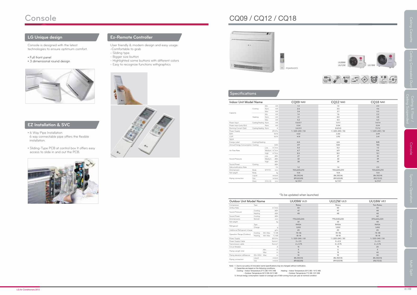
Console
LG Unique design
EZ Installation & SVC
Ez-Remote Controller
Console is designed with the latest technologies to ensure optimum comfort.
6 way connectable pipe offers the flexible installation.
access to slide in and out the PCB.
User friendly & modern design and easy usage.-Comfortable to grab- Sliding type- Bigger size button- Highlighted some buttons with different colors- Easy to recognize functions withgraphics
Ceilin
g C
asse
tteC
eilin
g C
onceale
d D
uct
Ceilin
g &
Flo
or /
Ceilin
g S
usp
ended
Conso
le
Syn
chro
Opera
tion
Dim
ensio
ns
Multi S
plit
Specifications
Indoor Unit Model Name CQ09 NA0 CQ12 NA0 CQ18 NA0
Capacity
Cooling
Min kW 1.3 1.4 2.0
Nom kW 2.6 3.5 4.6
Max kW 3.4 3.7 5.5
Heating
Min kW 1.4 1.6 2.2
Nom kW 3.1 4.0 4.8
Max kW 4.2 4.4 6.0
Power Input Cooling/Heating Nom kW 0.6/0.7 1.1/1.1 1.4/1.4
Power Input (only IDU) Nom kW 0.04 0.04 0.04
Running Current (Set) Cooling/Heating Nom A 3.4/3.9 5.0/5.0 7.1/7.2
Power Supply Ø/V/Hz 1 / 220~240 / 50 1 / 220~240 / 50 1 / 220~240 / 50
EER W/W 4.02 3.30 3.09
COP W/W 4.19 3.70 3.41
SEER
Energy Label Cooling/Heating A/A A/A B/B
Annual Energy Consumption Cooling kWh 317 530 745
Air Flow Rate
Low m3/min 5.0 5.2 7.2
Medium m3/min 6.7 6.9 8.6
High m3/min 8.5 8.0 10.1
Sound Pressure
Low dBA 27 27 35
Medium dBA 32 32 39
High dBA 38 39 44
Sound Power Cooling dBA
Dehumidification Rate l/h 1.2 1.4 2.0
Dimmension Body W*H*D mm 700x600x210 700x600x210 700x600x210
Net weight Body kg 13.8 13.8 13.8
Piping connection
Liquid mm(inch) Ø6.35(1/4) Ø6.35(1/4) Ø6.35(1/4)
Gas mm(inch) Ø9.52(3/8) Ø9.52(3/8) Ø12.7(1/2)
Drain O.D./I.D. mm 16.7/9.7 16.7/9.7 16.7/9.7
Outdoor Unit Model Name UU09W ULD UU12W ULD UU18W UE2
Compressor Type Rotary Rotary Twin Rotary
Airflow Rate m3/min 50 50 50
Sound PressureCooling dBA 47 47 48
Heating dBA 48 48 48
Sound Power Cooling dBA 62
Dimmensions WxHxD mm 770x540x245 770x540x245 870x655x320
Net weight kg 32 32 48
RefrigerantType R410A R410A R410A
Charge g 1,000 1,000 1,400
Additional Refrigerant charge g/m 20 20 20
Operation Range (Outdoor)Cooling Min~Max °C DB -10~46 -10~46 -15~48
Heating Min~Max °C WB -18~18 -18~18 -18~18
Power Supply Ø/V/Hz 1 / 220~240 / 50 1 / 220~240 / 50 1 / 220~240 / 50
Power Supply Cable Nxmm² 3 x 2.5 3 x 2.5 3 x 2.5
Transmission cable Nxmm² 4 x 0.75 4 x 0.75 4 x 0.75
Circuit Breaker A 15 15 20
Piping Length totalMin m 5 5 5
Max m 15 15 40
Piping elevation difference IDU-ODU Max m 10 10 30
Piping connectionLiquid mm(inch) Ø6.35(1/4) Ø6.35(1/4) Ø6.35(1/4)
Gas mm(inch) Ø9.52(3/8) Ø9.52(3/8) Ø12.7(1/2)
PQWRHDF

It offers very useful solution for economic customer because it uses 2,3
or 4 indoor units with one outdoor unit. Each indoor units are running as
one cycle with same mode(cooling or heating). It helps same air
distribution all arround the middle or larger room(office or open places)
even in irregualr shaped spaces.
EFFICIENT
SOLUTION
FOR
LARGE AREA
SYNCHRO OPERATION
Ceilin
g C
asse
tteC
eilin
g C
onceale
d D
uct
Ceilin
g &
Flo
or /
Ceilin
g S
usp
ended
Conso
le
Syn
chro
Opera
tion
Dim
ensio
ns
Multi S
plit
2 branchPMUB11A PMUB111A PMUB1111A
3 branch 4 branch
Synchro
SYNCHRO OPERATION

Specifications
Inverter
Outdoor Unit Model Name UU36WH U31 UU42WH U31 UU48WH U31
Nominal Capacity
(Min~Rated~Max)
Cooling kW
"Synchro application
(simultaneous operation).
Refer to combination table."
"Synchro application
(simultaneous operation).
Refer to combination table."
"Synchro application
(simultaneous operation).
Refer to combination table. "
Heating Btu/h
Norminal Input
(Min~Rated~Max)
Cooling kW
Heating kW
Running Current Cooling/Heating A
Power supply Ø/V/Hz 1 / 220-240 / 50 1 / 220-240 / 50 1 / 220-240 / 50
Dimensions WxHxD mm 950x1,380x330 950x1,380x330 950x1,380x330
Net Weight Outdoor kg 103 103 103
Refrigerant Charge* g 3,600 3,600 3,600
Air flow rate m3/min 110 110 110
Noise Level Cooling/Heating dB(A)±3 51 /53 51 / 53 51 / 53
SVC ValveLiquid mm(inch) Ø9.52(3/8) Ø9.52(3/8) Ø9.52(3/8)
Gas mm(inch) Ø15.88(5/8) Ø15.88(5/8) Ø15.88(5/8)
Max. Interunit
Piping Length
Total Piping(Main+Total Branch) m 80 80 80
Main Piping m 45 45 45
Total Branch Piping m 40 40 40
Each Branch Piping m 15 15 15
Max. Installation
Height Difference
Indoor Unit~Outdoor Unit m 30 30 30
Indoor Unit~Indoor Unit m 1 1 1
Indoor Unit Model NameUT12H/UT18H/UT21H/UT24H N*1 / UV12H/UV18H/UV21H/UV24H N*1
UB18H/UB21H/UB24H N*1
Nominal Capacity
(Min~Rating~Max)
CoolingkW
Synchro application(simultaneous operation).
Refer to each indoor unit specification
Bellow functions are not available for Synchro Operation
- Group Control, Zone Control, Dry Contact and Auto Changeover
Btu/h
HeatingkW
Btu/h
Nominal Input
(Min~Rating~Max)
Cooling kW
Heating kW
EER kW/kW
COP kW/kW
Operational Temperature
Range(Outdoor)
Cooling °CDB -10 ~ 48
Heating °CWB -18 ~ 18
Ceilin
g C
asse
tteC
eilin
g C
onceale
d D
uct
Ceilin
g &
Flo
or /
Ceilin
g S
usp
ended
Conso
le
Syn
chro
Opera
tion
Dim
ensio
ns
Multi S
plit
Specifications
Inverter
Outdoor Unit Model Name UU37WH U31 UU43WH U31 UU49WH U31
Nominal Capacity
(Min~Rated~Max)
Cooling kW
"Synchro application
(simultaneous operation).
Refer to combination table. "
"Synchro application
(simultaneous operation).
Refer to combination table."
"Synchro application
(simultaneous operation).
Refer to combination table."
Heating Btu/h
Norminal Input
(Min~Rated~Max)
Cooling kW
Heating kW
Running Current Cooling/Heating A
Power supply Ø/V/Hz 3 / 380~415 / 50 3 / 380~415 / 50 3 / 380~415 / 50
Dimensions WxHxD mm 950x1,380x330 950x1,380x330 950x1,380x330
Net Weight Outdoor kg 103 103 103
Refrigerant Charge* g 3,600 3,600 3,600
Air flow rate m3/min 110 110 110
Noise Level Cooling/Heating dB(A)±3 51 / 53 51 / 53 51 / 53
SVC ValveLiquid mm(inch) Ø9.52(3/8) Ø9.52(3/8) Ø9.52(3/8)
Gas mm(inch) Ø15.88(5/8) Ø15.88(5/8) Ø15.88(5/8)
Max. Interunit
Piping Length
Total Piping(Main+Total Branch) m 80 80 80
Main Piping m 45 45 45
Total Branch Piping m 40 40 40
Each Branch Piping m 15 15 15
Max. Installation
Height Difference
Indoor Unit~Outdoor Unit m 30 30 30
Indoor Unit~Indoor Unit m 1 1 1
Indoor Unit Model NameUT12H/UT18H/UT21H/UT24H N*1 / UV12H/UV18H/UV21H/UV24H N*1
UB18H/UB21H/UB24H N*1
Nominal Capacity
(Min~Rating~Max)
CoolingkW
Synchro application(simultaneous operation).
Refer to each indoor unit specification
Bellow functions are not available for Synchro Operation
- Group Control, Zone Control, Dry Contact and Auto Changeover
Btu/h
HeatingkW
Btu/h
Nominal Input
(Min~Rating~Max)
Cooling kW
Heating kW
EER kW/kW
COP kW/kW
Operational Temperature
Range(Outdoor)
Cooling °CDB -10 ~ 48
Heating °CWB -18 ~ 18

Specifications
Standard Inverter
Indoor Unit Model NameCT12/CT18/CT24/UT30 N*2
CV18/CV24/UV30/CB18/CB24/UB30 N*2
Nominal Capacity
(Min~Rating~Max)
CoolingkW
Synchro application(simultaneous operation).
Refer to each indoor unit specification
Bellow functions are not available for Synchro Operation
- Group Control, Zone Control, Dry Contact and Auto Changeover
Btu/h
HeatingkW
Btu/h
Nominal Input
(Min~Rating~Max)
Cooling kW
Heating kW
EER kW/kW
COP kW/kW
Operational Temperature
Range(Outdoor)
Cooling °CDB -15 ~ 48
Heating °CWB -18 ~ 18
Outdoor Unit Model Name UU42W U32 UU48W U32 UU60W U32
Nominal Capacity
(Min~Rated~Max)
Cooling kW
"Synchro application
(simultaneous operation).
Refer to combination table."
"Synchro application
(simultaneous operation).
Refer to combination table."
"Synchro application
(simultaneous operation).
Refer to combination table."
Heating Btu/h
Norminal Input
(Min~Rated~Max)
Cooling kW
Heating kW
Running Current Cooling/Heating A
Power supply Ø/V/Hz 1 / 220~240 / 50 1 / 220~240 / 50 1 / 220~240 / 50
Dimensions WxHxD mm 950×1,380×330 950×1,380×330 950×1,380×330
Net Weight Outdoor kg 103 103 103
Refrigerant Charge* g 3,600 3,600 3,600
Air flow rate m3/min 110 110 110
Noise Level Cooling/Heating dB(A)±3 51/53 51/53 51/53
SVC ValveLiquid mm(inch) Ø9.52 (3/8) Ø9.52 (3/8) Ø9.52 (3/8)
Gas mm(inch) Ø15.88 (5/8) Ø15.88 (5/8) Ø15.88 (5/8)
Max. Interunit
Piping Length
Total Piping(Main+Total Branch) m 80 80 80
Main Piping m 40 40 40
Total Branch Piping m 40 40 40
Each Branch Piping m 10 10 10
Max. Installation
Height Difference
Indoor Unit~Outdoor Unit m 30 30 30
Indoor Unit~Indoor Unit m 1 1 1
Ceilin
g C
asse
tteC
eilin
g C
onceale
d D
uct
Ceilin
g &
Flo
or /
Ceilin
g S
usp
ended
Conso
le
Syn
chro
Opera
tion
Dim
ensio
ns
Multi S
plit
Standard Inverter
Specifications
Indoor Unit Model NameCT12/CT18/CT24/UT30 N*2
CV18/CV24/UV30/CB18/CB24/UB30 N*2
Nominal Capacity
(Min~Rating~Max)
CoolingkW
Synchro application(simultaneous operation).
Refer to each indoor unit specification
Bellow functions are not available for Synchro Operation
- Group Control, Zone Control, Dry Contact and Auto Changeover
Btu/h
HeatingkW
Btu/h
Nominal Input
(Min~Rating~Max)
Cooling kW
Heating kW
EER kW/kW
COP kW/kW
Operational Temperature
Range(Outdoor)
Cooling °CDB -15 ~ 48
Heating °CWB -18 ~ 18
Outdoor Unit Model Name UU43W U32 UU49W U32 UU61W U32
Nominal Capacity
(Min~Rated~Max)
Cooling kW
"Synchro application
(simultaneous operation).
Refer to combination table."
"Synchro application
(simultaneous operation).
Refer to combination table."
"Synchro application
(simultaneous operation).
Refer to combination table."
Heating Btu/h
Norminal Input
(Min~Rated~Max)
Cooling kW
` kW
Running Current Cooling/Heating A
Power supply Ø/V/Hz 3 / 380~415 / 50 3 / 380~415 / 50 3 / 380~415 / 50
Dimensions WxHxD mm 950×1,380×330 950×1,380×330 950×1,380×330
Net Weight Outdoor kg 103 103 103
Refrigerant Charge* g 3,600 3,600 3,600
Air flow rate m3/min 110 110 110
Noise Level Cooling/Heating dB(A)±3 51/53 51/53 51/53
SVC ValveLiquid mm(inch) Ø9.52 (3/8) Ø9.52 (3/8) Ø9.52 (3/8)
Gas mm(inch) Ø15.88 (5/8) Ø15.88 (5/8) Ø15.88 (5/8)
Max. Interunit
Piping Length
Total Piping(Main+Total Branch) m 80 80 80
Main Piping m 40 40 40
Total Branch Piping m 40 40 40
Each Branch Piping m 10 10 10
Max. Installation
Height Difference
Indoor Unit~Outdoor Unit m 30 30 30
Indoor Unit~Indoor Unit m 1 1 1

Combination Table
UU36WH U31
UU37WH U31
UU42WH U31
UU43WH U31
UU48WH U31
UU49WH U31UU42W U32UU43W U32
UU48W U32UU49W U32
UU60W U32UU61W U32
AppliedAccessories
OUTDOORUNITS
For Synchro operation
* Use only wired remote controller, not wireless remote controller.
Choose the right remote controller with the remote controller table.
0S0.
* Has to be purchased separately
Possible combination of indor units
Installation scene
Cassette Duct Ceiling & Floor Cassette Duct Ceiling & Floor Cassette Duct Ceiling & Floor
Duo Trio Quartet
ODU
BD
ODU
Capacity (kW)
Cooling Heating
10.0 11.2
12.5 14.0
13.4 15.5
12.5 14.0
14.0 16.0
15.0 17.0
UT18H NP1 *2
UT18H NP1 *2
UT21H NN1 *2
UT21H NN1 *2
UT24H NN1 *2
UT24H NN1 *2
UB18H NG1 *2
UB18H NG1 *2
UB21H NG1 *2
UB21H NG1 *2
UB24H NG1 *2
UB24H NG1 *2
UV18H NJ1 *2
UV18H NJ1 *2
UV21H NK1 *2
UV21H NK1 *2
UV24H NK1 *2
UV24H NK1 *2
UT12H NP1 *3
UT12H NP1 *3
UT18H NP1 *3
UT18H NP1 *3
UT18H NP1 *3
UT18H NP1 *3
-
-
UB18H NG1 *3
UB18H NG1 *3
UB18H NG1 *3
UB18H NG1 *3
-
-
UV18H NJ1 *3
UV18H NJ1 *3
UV18H NI1 *3
UV18H NI1 *3
-
-
UT12H NP1 *4
UT12H NP1 *4
UT12H NP1 *4
UT12H NP1 *4
CT24 NP2 *2
CT24 NP2 *2
UT30 NP2 *2
CB24 NH2 *2
CB24 NH2 *2
UB30 NG2 *2
CV24 NJ2 *2
CV24 NJ2 *2
UV30 NJ2*2
CT18 NQ2 *3
CT18 NQ2 *3
CT18 NQ2 *3
CB18 NH2 *3
CB18 NH2 *3
CB18 NH2 *3
CV18 NJ2 *3
CV18 NJ2 *3
CV18 NJ2 *3
CT12 NR2 *4
CT12 NR2 *4
CT12 NR2 *4
-
-
-
-
-
-
-
-
-
-
-
-
* * *
PMUB11A
PQCSZ250S0
PMUB111A PMUB1111ABD unit
Wired remotecontroller*
AC EZ**
BD BD
IDU IDU IDU IDU IDU IDU IDU IDU IDU
ODU
IDU : INDOOR UNITODU : OUTDOOR UNITBD : BRANCH DISTRIBUTOR UNITREMO :WIRED REMOTE CONTROLLER
REMO REMO REMO
Plz refer to PDB or Installation manual
Additional Refrigerant Charge
Branch Pipe
Model Outdoor
PMUB11A
PMUB111A
PMUB1111A
Indoor
2 units
3 units
4 units
Indoor Capacity Ratio(%)
50:50 (1:1)
33:33:33 (1:1:1)
25:25:25:25 (1:1:1:1)
Combination Table
Type of Indoor Unit Remote controller needed
H-Inverter
Cassette PQRCVSL0 (Black) or PQRCVSL0QW (White)
Duct PQRCVSL0 (Black) or PQRCVSL0QW (White)
Ceiling & Floor PQRCVSL0 (Black)* or PQRCVSL0QW (White)*
Standard Inverter
Cassette PQRCVSL0 (Black) or PQRCVSL0QW (White)
Duct PQRCVSL0 (Black) or PQRCVSL0QW (White)
Ceiling & Floor PQRCVSL0 (Black)* or PQRCVSL0QW (White)*
Ceilin
g C
asse
tteC
eilin
g C
onceale
d D
uct
Ceilin
g &
Flo
or /
Ceilin
g S
usp
ended
Conso
le
Syn
chro
Opera
tion
Dim
ensio
ns
Multi S
plit

No. Part Name1 Decoration panel (PT-UQC)
2 Air suction grille
3 Air discharge grille
4 Gas pipe connection
5 Liquid pipe connection
6 Drain pipe connection
7 Power supply connection
8 Fresh air connection (Ø70)
No. Part Name1 Decoration panel (PT-UQC)
2 Air suction grille
3 Air discharge grille
4 Gas pipe connection
5 Liquid pipe connection
6 Drain pipe connection
7 Power supply connection
8 Fresh air connection (Ø70)
(Unit:mm)
(Unit:mm)
DIMENSIONS _ CEILING CASSETTE Ceilin
g C
asse
tteC
eilin
g C
onceale
d D
uct
Ceilin
g &
Flo
or /
Ceilin
g S
usp
ended
Conso
le
Syn
chro
Opera
tion
Dim
ensio
ns
Multi S
plit
No. Part Name1 Decoration panel (PT-UMC)
2 Air suction grille
3 Air discharge grille
4 Gas pipe connection
5 Liquid pipe connection
6 Drain pipe connection
7 Power supply connection
8 Fresh air connection (Ø70)
(Unit:mm)
(Unit:mm)
No. Part Name1 Decoration panel (PT-UMC)
2 Air suction grille
3 Air discharge grille
4 Gas pipe connection
5 Liquid pipe connection
6 Drain pipe connection
7 Power supply connection
8 Fresh air connection (Ø70)

140
2970
260
87750
30 47
355
450
219
932
133
355
450
114
224
60
R37.5
47
24
49
21
882
158
260
65
108
64 243 212 243 119
75
115745
2017
5
32
5
1
4
6
119
428
106
127
122
5010
0
16510
048
3182
101
(Unit:mm)
No. Part Name1 Liquid pipe connection
2
3
4
5
6
DIMENSIONS _ CEILING CASSETTE
(Unit:mm)
No. Part Name1 Decoration panel (PT-UMC)
2 Air suction grille
3 Air discharge grille
4 Gas pipe connection
5 Liquid pipe connection
6 Drain pipe connection
7 Power supply connection
8 Fresh air connection (Ø70)
DIMENSIONS _ CEILING CONCEALED DUCT
Ceilin
g C
asse
tteC
eilin
g C
onceale
d D
uct
Ceilin
g &
Flo
or /
Ceilin
g S
usp
ended
Conso
le
Syn
chro
Opera
tion
Dim
ensio
ns
Multi S
plit
261
122
140
31
5010
0
87830
75
355
87
1,230
45
0
23
49
1081,182
158
113
298 18
6
232 342342 232 232
1151,043
2022
0
32
5
1
4
6
152
224
60
ø100
219
29
136
565
16510
048
82101
2970
(Unit:mm)
(Unit:mm)
No. Part Name1 Liquid pipe connection
2
3
4
5
6
No. Part Name1 Air suction flange
2
3
4
5
6
DIMENSIONS _ CEILING CONCEALED DUCT

Name1234
5
6
7
8
9
10
11
Liquid pipe
Gas pipe
Suction gille
Discharge grille
Suspension bracket
Right side drain hose hole
Left side drain hose hole
Wiring connection
Piping connection
Right side drain pipe connection
Left side drain pipe connection
ø6.35 Flare connectionø12.7 Flare connection
Number Descripition
Slit holeSlit hole
Slit holeSlit hole
(Unit:mm)
(Unit:mm)
No. Part Name1 Front air discharge grille
2
3
4
5
DIMENSIONS _ FLOOR & CEILING SUSPENDED C
eilin
g C
asse
tteC
eilin
g C
onceale
d D
uct
Ceilin
g &
Flo
or /
Ceilin
g S
usp
ended
Conso
le
Syn
chro
Opera
tion
Dim
ensio
ns
Multi S
plit
(Unit:mm)
No. Part Name1 Front air discharge grille
2
3

No. Part Name1 Front air discharge grille
2
3
(Unit:mm)
No. Part Name1 Front air discharge grille
2
3
DIMENSIONS _ CONSOLE
(Unit:mm)
DIMENSIONS _ FLOOR & CEILING SUSPENDED C
eilin
g C
asse
tteC
eilin
g C
onceale
d D
uct
Ceilin
g &
Flo
or /
Ceilin
g S
usp
ended
Conso
le
Syn
chro
Opera
tion
Dim
ensio
ns
Multi S
plit
(Unit:mm)
No. Part Name1 Air discharge grille
2
3
4
5
DIMENSIONS _ UNIVERSAL OUTDOOR
(Unit:mm)
No. Part Name1 Air discharge grille
2
3
4
5
6

Supporter
490
4
(Unit:mm)
(Unit:mm)
No. Part Name1 Air discharge grille
2
3
4
No. Part Name1 Air discharge grille
2
3
4
5
6
DIMENSIONS _ UNIVERSAL OUTDOOR Ceilin
g C
asse
tteC
eilin
g C
onceale
d D
uct
Ceilin
g &
Flo
or /
Ceilin
g S
usp
ended
Conso
le
Syn
chro
Opera
tion
Dim
ensio
ns
Multi S
plit
(Unit:mm)
No. Part Name1 Air discharge grille
2
3
4
5
6
6
(Unit:mm)
No. Part Name1 Air discharge grille
2
3
4
5
6

Multi PipingMax.
Indoor units
Phase Combination Sample
4.1 2 1ø
4.7 2 1ø
5.3 3 1ø
6.2 3 1ø
7.0 4 1ø
7.9 4 1ø
8.8 5 1ø
11.7 5 1ø
DB Box TypeMax.
Indoor units
Phase Combination Sample
9.7 6 3ø
11.7 7 1ø
13.5 7 3ø
15.5 81ø3ø
16.7 91ø3ø
Wide RangeLG Multi systems provide various indoor units and outdoor units up to 16.7kW. More than
2,000 types of combinations are available using 15 outdoor units and 41 indoor units
LG Commercial Air Conditioners2012 MULTI Model Line-up
Wall Mounted TypeCeiling Cassette
Type
Ceiling Concealed
Duct TypeConsole
Ceiling &
Floor Type
5/1.5
7/2.1
9/2.6
12/3.5
18/5.3
24/7.0
Free Combination with Various Indoor TypesART COOL Mirror Note : *indicates color of panel_Mirror(R),Silver(V), White(W)ART COOL Panel Note : *indicates color of panel_Silver(V) Red(E) Gold(G) White Silver(H),Gallery(1)
Deluxe Standard
Standard
Standard
Standard
Standard
Standard
Deluxe
Deluxe
Deluxe
Deluxe
Ceilin
g C
asse
tteC
eilin
g C
onceale
d D
uct
Ceilin
g &
Flo
or /
Ceilin
g S
usp
ended
Conso
le
Syn
chro
Opera
tion
Dim
ensio
ns
Multi S
plit
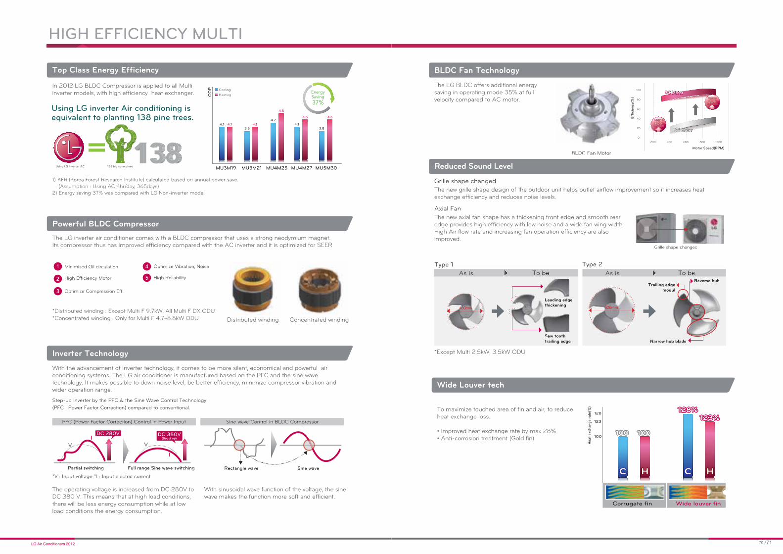
HIGH EFFICIENCY MULTI
1) KFRI(Korea Forest Research Institute) calculated based on annual power save.
(Assumption : Using AC 4hr/day, 365days)
2) Energy saving 37% was compared with LG Non-inverter model
Using LG Inverter AC 138 big cone pines
=MU3M19 MU3M21 MU4M25 MU4M27 MU5M30
CO
P
4.14.1
Cooling
Heating
4.6
4.1
4.6
4.13.8 3.8
4.8
4.2
Using LG inverter Air conditioning is equivalent to planting 138 pine trees.
EnergySaving37%
Top Class Energy Efficiency
In 2012 LG BLDC Compressor is applied to all Multi inverter models, with high efficiency heat exchanger.
Powerful BLDC CompressorThe LG inverter air conditioner comes with a BLDC compressor that uses a strong neodymium magnet. Its compressor thus has improved efficiency compared with the AC inverter and it is optimized for SEER
*Distributed winding : Except Multi F 9.7kW, All Multi F DX ODU
*Concentrated winding : Only for Multi F 4.7~8.8kW ODU
Optimize Vibration, Noise
High Reliability
4
5
Minimized Oil circulation
High Efficiency Motor
Optimize Compression Eff.
1
2
3
Step-up Inverter by the PFC & the Sine Wave Control Technology
(PFC : Power Factor Correction) compared to conventional.
*V : Input voltage *I : Input electric current
Rectangle wave Sine wave
Sine wave Control in BLDC Compressor
Partial switching Full range Sine wave switching
DC 280V DC 380V(Boost up)
V VI
I
PFC (Power Factor Correction) Control in Power Input
Inverter Technology
With the advancement of Inverter technology, it comes to be more silent, economical and powerful air conditioning systems. The LG air conditioner is manufactured based on the PFC and the sine wave technology. It makes possible to down noise level, be better efficiency, minimize compressor vibration and wider operation range.
The operating voltage is increased from DC 280V to DC 380 V. This means that at high load conditions, there will be less energy consumption while at low load conditions the energy consumption.
With sinusoidal wave function of the voltage, the sine wave makes the function more soft and efficient.
Distributed winding Concentrated winding
To maximize touched area of fin and air, to reduce heat exchange loss.
Wide Louver tech
BLDC Fan Technology
200
40
60
80
100
20
0
600400 800 1000
Motor Speed(RPM)
Effi
cie
ncy(
%)
DC MotorDC Motor
AC MotorAC Motor increase
increase
Approx
nncncreareaseseeincrease
AppApppproxroxAAAAApprox
BLDC Fan Motor
Reduced Sound Level
Leading edge thickening
Saw tooth trailing edge
Reverse hubTrailing edge
mogul
Narrow hub blade
As is
Type 1 Type 2
As is
Hea
t ex
chan
ge
rate
(%)
Corrugate fin Wide louver fin
100
123
128128%128%
123%123%
100100 100100
HHCC HHCC

Low static duct
High static duct
Restaurant BuildingHouse
Deluxe
Console
Standard
The Variety of Various Combination
For Reference Sites
1.5 kW
Available from 1.5kW
1.5 kW
Don't you worry aboutconsumption for using
Big capacity in Small space?
41 Indoor Units
More than
2000types
Wide Operating Range
HIGH EFFICIENCY MULTI
15 Outdoor Units15 Outdoor Units 41 Indoor Units
*Cooling mode*
*Heating mode*
Indoor
Tem
p(D
B˚C
)
-18 -10 0 18 35 48
Outdoor Temperature(ºC)
12
23
30
16
CoolingCooling
HeatingHeating
Low AmbientControl
Low AmbientControl
Day time Night Silent
MU3M21
MU4M25
MU4M27
MU5M30MU3M19
MU2M15
MU2M17
MU3M21
MU4M25
MU4M27
MU5M30MU3M19MU2M15
MU2M17
Nois
e L
eve
l [d
B(A
)] Day time
Night Silent
5150
45 4649
44
5150
45 4649
44
Optimized Pressure Control
Indoor Capacity Combination
160%Max
AS-IS
NEW
Temperature Control
Pressure Control
Tim
Temp
Setting Temp
Temperature Control
eduuccctttiioonnneeedReeed ooooeeR ii44%Reduction
※ Based on 18K (Heating)
Pressure Control
Outdoor Load
Outl
et
Tem
p
Outdoor Load
Outdoor Load
Outl
et
Tem
p
Outl
et
Tem
p
Skew Fan Technology
Night Quiet Operation
49
49
44
44
Night Silent
Mode
Cooling Heating
167%Max
163%Max
Fan rotates
Skew FanConventional Fan
Fan rotatesStabilizer Stabilizer

Total
Piping Length(m)
Piping Length(m)
Long & High Elevation Piping
Command
Sensor reading
LG MV
Available to link with home network
Air Conditioner
Home ServerInternet
Digital Door Lock Emergency Switch Motion Detect Sensor
Living Room Light Kitchen TV Door Phone
Remote Switch
For Less 10 Floors
A
L1
C
HIGH EFFICIENCY MULTI
B
C
L1
L2
L3ON
Wiring Error Check
ON
Tool downsizing / Tool compact
Before Target
0.53
5.24
99900000%%%%%%%%%999990000%%%%%%%9 %%%%9990%
W
Time
Setting Current
Cut-off
Peak
Energy Saving
Lower Standby Power TechnologyPeak Current Control
PCBNotification

Forced Cooling Operation
Easy Service
and installation
Ez SVC
3 pieces of screw
HIGH EFFICIENCY MULTI
Cassette
Duct
Console
Mode LockCompatible Indoor units
Refrigerant Recharging
1) Charging Refrigerant
All refrigerant goes to only ODU when pipeline moving
2) Pump Down
OUTDOOR UNIT
Ceilin
g C
asse
tteC
eilin
g C
onceale
d D
uct
Conso
le
Dim
ensio
ns

Specifications
Multi Outdoor Unit MU2M15 UL2 MU2M17 UL2
Twin Rotary Twin Rotary
Cooling
Min 0.9 1.0
Nom 4.1 4.7
Max 4.7 5.1
Heating
Min 0.7 0.9
Nom 4.7 5.3
Max 5.3 5.7
Cooling
Min 0.1 0.1
Nom 1.0 1.3
Max 1.3 1.8
Heating
Min 0.1 0.2
Nom 1.1 1.3
Max 1.3 1.7
Running Current
Cooling
Min 1.5 1.5
Nom 4.5 5.9
Max 8.8 8.8
Heating
Min 1.8 1.8
Nom 5.3 6.6
Max 8.8 8.8
15 15
EER 4.00 3.70
4.30 4.00
SEER 6.50 6.30
A/A A/A
Cooling 539 641
m 28.2 28.2
49 49
Cooling 58 58
Dimension mm 770*545*288 770*545*288
Net weight 40 40
RefrigerantR410A R410A
Charge g 1300 1300
20 20
Cooling -10 ~ 48 -10 ~ 48
Heating -18 ~ 18 -18 ~ 18
1 / 220~240 / 50 1 / 220~240 / 50
N x mm² 3 × 2.5 3 × 2.5
N x mm² 4 × 0.75 4 × 0.75
m 30 30
Max m 20 20
Max m 15 15
Max m 7.5 7.5
mm Ø6.35 Ø6.35
inch Ø1/4 Ø1/4
mm Ø9.52 Ø9.52
inch Ø3/8 Ø3/8
Ceilin
g C
asse
tteC
eilin
g C
onceale
d D
uct
Conso
le
Dim
ensio
ns
Specifications
Multi Outdoor Unit MU3M19 UE2 MU3M21 UE2
Twin Rotary Twin Rotary
Cooling
Min 1.4 1.3
Nom 5.3 6.2
Max 6.3 7.3
Heating
Min 1.4 1.1
Nom 6.3 7.0
Max 7.3 7.8
Cooling
Min 0.1 0.1
Nom 1.3 1.6
Max 2.5 2.9
Heating
Min 0.2 0.2
Nom 1.5 1.7
Max 2.5 3.0
Running Current
Cooling
Min 0.7 1.2
Nom 6.0 6.6
Max 11.0 12.7
Heating
Min 1.4 1.7
Nom 7.0 7.4
Max 11.0 12.8
20 20
EER 4.10 3.80
4.10 4.10
SEER 6.80 6.30
A/A A/A
Cooling 680 870
m 50 50
50 51
Cooling 62 62
Dimension mm 870*655*320 870*655*320
Net weight 45 46
RefrigerantR410A R410A
Charge g 1700 1800
20 20
Cooling -10 ~ 48 -10 ~ 48
Heating -18 ~ 18 -18 ~ 18
1 / 220~240 / 50 1 / 220~240 / 50
N x mm² 3 × 2.5 3 × 2.5
N x mm² 4 × 0.75 4 × 0.75
m 50 50
Max m 25 25
Max m 15 15
Max m 7.5 7.5
mm Ø6.35 Ø6.35
inch Ø1/4 Ø1/4
mm Ø9.52 Ø9.52
inch Ø3/8 Ø3/8
Notes: 1. Capacities are based on the following conditions: Cooling: - Indoor Temperature 27°C (80.6°F) DB / 19°C (66.2°F) WB - Outdoor Temperature 35°C (95°F) DB / 24°C (75.2°F) WB Heating: - Indoor Temperature 20°C (68°F) DB / 15°C (59°F) WB - Outdoor Temperature 7°C (44.6°F) DB / 6°C (42.8°F) WB Piping Length - Interconnecting Piping Length 7.5m - Level Difference of Zero. 2. * : See page "Combination Table". 3. Due to our policy of innovation some specifications may be changed without notification. 4. Minimum combination capacity rate should be more than 40%.
Notes: 1. Capacities are based on the following conditions: Cooling: - Indoor Temperature 27°C (80.6°F) DB / 19°C (66.2°F) WB - Outdoor Temperature 35°C (95°F) DB / 24°C (75.2°F) WB Heating: - Indoor Temperature 20°C (68°F) DB / 15°C (59°F) WB - Outdoor Temperature 7°C (44.6°F) DB / 6°C (42.8°F) WB Piping Length - Interconnecting Piping Length 7.5m - Level Difference of Zero. 2. * : See page "Combination Table". 3. Due to our policy of innovation some specifications may be changed without notification. 4. Minimum combination capacity rate should be more than 40%.

950
165 165620
39
0
33
08
09
83
4
Specifications
Multi Outdoor Unit MU4M25 U42 MU4M27 U42 MU5M30 U42 Twin Rotary Twin Rotary Twin Rotary
Cooling
Min 1.9 1.9 1.9
Nom 7.0 7.9 8.8
Max 8.5 9.5 10.6
Heating
Min 2.2 2.2 2.2
Nom 8.4 9.1 10.1
Max 9.4 10.6 12.1
Cooling
Min 0.7 0.7 0.7
Nom 1.7 1.9 2.3
Max 3.1 3.1 3.2
Heating
Min 0.9 0.9 0.9
Nom 1.8 2.0 2.2
Max 3.1 3.7 3.9
Running Current
Cooling
Min 3.1 3.1 3.1
Nom 7.1 8.4 10.1
Max 13.4 13.5 13.7
Heating
Min 3.8 3.8 3.8
Nom 7.7 8.8 9.6
Max 16.0 16.0 16.8
25 25 25
EER 4.20 4.10 3.80
4.80 4.60 4.60
SEER 6.80 7.00 7.40
A/A A/A A/A
Cooling 1100 1220 1320
m 60 60 60
51 51 51
Cooling 62 62 62
Dimension mm 950*834*330 950*834*330 950*834*330
Net weight 66 66 67
RefrigerantR410A R410A R410A
Charge g 3200 3200 3200
20 20 20
Cooling -10 ~ 48 -10 ~ 48 -10 ~ 48
Heating -18 ~ 18 -18 ~ 18 -18 ~ 18
1 / 220~240 / 50 1 / 220~240 / 50 1 / 220~240 / 50
N x mm² 3 × 2.5 3 × 2.5 3 × 2.5
N x mm² 4 × 0.75 4 × 0.75 4 × 0.75
m 70 70 75
Max m 25 25 25
Max m 15 15 15
Max m 7.5 7.5 7.5
mm Ø6.35 Ø6.35 Ø6.35
inch Ø1/4 Ø1/4 Ø1/4
mm Ø9.52 Ø9.52 Ø9.52
inch Ø3/8 Ø3/8 Ø3/8
Ceilin
g C
asse
tteC
eilin
g C
onceale
d D
uct
Conso
le
Dim
ensio
ns
370
1135
1165
308
565
273
520
900
550
370
395
15
175
50*4
=20
014
8
50
50
Specifications
Multi Outdoor Unit MU5M40 UH0
Twin-Rotary
Cooling
Min 2.8
Nom 11.7
Max 13.5
Heating
Min 3.2
Nom 13.5
Max 15.0
Cooling
Min 1.1
Nom 3.6
Max 4.7
Heating
Min 1.4
Nom 3.7
Max 4.8
Running Current
Cooling
Min 6.2
Nom 16.0
Max 20.0
Heating
Min 6.9
Nom 16.4
Max 20.5
30
EER 3.22
3.70
SEER
A/A
Cooling
m 106
58
Cooling
Dimension mm 900 x 1,165 x 370
Net weight 95
Refrigerant R410A
Charge g 4,000
20
Cooling -10 ~ 46
Heating -18 ~ 18
1 / 220~240 / 50
N x mm² 3 x 3.5 (Including Earth)
N x mm² 4 x 0.75 (Including Earth)
m 85
Max m 25
Max m 15
Max m 7.5
mm Ø6.35 x 5EA
inch Ø1/4 x 5EA
mm Ø9.52 x 5EA
inch Ø3/8 x 5EA
Notes: 1. Capacities are based on the following conditions: Cooling: - Indoor Temperature 27°C (80.6°F) DB / 19°C (66.2°F) WB - Outdoor Temperature 35°C (95°F) DB / 24°C (75.2°F) WB Heating: - Indoor Temperature 20°C (68°F) DB / 15°C (59°F) WB - Outdoor Temperature 7°C (44.6°F) DB / 6°C (42.8°F) WB Piping Length - Interconnecting Piping Length 7.5m - Level Difference of Zero. 2. * : See page "Combination Table". 3. Due to our policy of innovation some specifications may be changed without notification. 4. Minimum combination capacity rate should be more than 40%.
Notes: 1. Capacities are based on the following conditions: Cooling: - Indoor Temperature 27°C (80.6°F) DB / 19°C (66.2°F) WB - Outdoor Temperature 35°C (95°F) DB / 24°C (75.2°F) WB Heating: - Indoor Temperature 20°C (68°F) DB / 15°C (59°F) WB - Outdoor Temperature 7°C (44.6°F) DB / 6°C (42.8°F) WB Piping Length - Interconnecting Piping Length 7.5m - Level Difference of Zero. 2. * : See page "Combination Table". 3. Due to our policy of innovation some specifications may be changed without notification. 4. Minimum combination capacity rate should be more than 40%.

65
370
1135
1165
308
565
273
520
8012
4
900
550
370
395
15
175
Specifications
Multi Outdoor Unit FM40AH UH5
Twin-Rotary
Cooling
Min 2.8
Nom 11.7
Max 13.5
Heating
Min 3.2
Nom 13.5
Max 15.0
Cooling
Min 1.1
Nom 3.6
Max 4.7
Heating
Min 1.4
Nom 3.7
Max 4.8
Running Current
Cooling
Min 6.2
Nom 16.0
Max 20.0
Heating
Min 6.9
Nom 16.4
Max 20.5
30
EER 3.22
3.70
SEER
A/A
Cooling
m 106
58
Cooling
Dimension mm 900 x 1,165 x 370
Net weight 95
Refrigerant R410A
Charge g 4,000
20
Cooling -10 ~ 46
Heating -18 ~ 18
1 / 220~240 / 50
N x mm² 3 x 3.5(Including Earth)
N x mm² 4 x 1.25(Including Earth)
N x mm² 4 x 0.75(Including Earth)
100
m 50
m 50
m 15
Max m 30
Max m 15
mm Ø9.52
inch Ø3/8
mm Ø19.05
inch Ø3/4
m
Ceilin
g C
asse
tteC
eilin
g C
onceale
d D
uct
Conso
le
Dim
ensio
ns
390
39
0
36
0
33
0
138
0
620 165165
950
135
6
Specifications
Multi Outdoor Unit FM48AH U33 FM56AH U33
Twin-Rotary Twin-Rotary
Cooling
Min 3.3 4.0
Nom 15.5 16.7
Max 17.0 18.5
Heating
Min 3.7 4.5
Nom 16.4 17.9
Max 17.3 18.8
Cooling
Min 0.8 1.0
Nom 4.7 5.0
Max 5.4 5.7
Heating
Min 1.3 1.3
Nom 4.4 4.6
Max 5.6 5.7
Running Current
Cooling
Min 3.9 4.6
Nom 21.1 21.7
Max 23.2 24.0
Heating
Min 6.9 7.4
Nom 22.6 22.4
Max 25.0 26.0
40 40
EER 3.30 3.37
3.70 3.87
SEER
A/A A/A
Cooling
m 120 120
55 56
Cooling
Dimension mm 950 x 1,380 x 330 950 x 1,380 x 330
Net weight 108 108
Refrigerant R410A R410A
Charge g 4800 4800
20 20
Cooling -10 ~ 46 -10 ~ 46
Heating -18 ~ 18 -18 ~ 18
1 / 220~240 / 50 1 / 220~240 / 50
N x mm² 3 x 4.0(Including Earth) 3 x 4.0(Including Earth)
N x mm² 4 x 1.25(Including Earth) 4 x 1.25(Including Earth)
N x mm² 4 x 0.75(Including Earth) 4 x 0.75(Including Earth)
m 135 145
m 55 55
m 80 90
m 30 15
Max m 30 30
Max m 15 15
mm Ø9.52 Ø9.52
inch Ø3/8 Ø3/8
mm Ø19.05 Ø19.05
inch Ø3/4 Ø3/4
Notes: 1. Capacities are based on the following conditions: Cooling: - Indoor Temperature 27°C (80.6°F) DB / 19°C (66.2°F) WB - Outdoor Temperature 35°C (95°F) DB / 24°C (75.2°F) WB Heating: - Indoor Temperature 20°C (68°F) DB / 15°C (59°F) WB - Outdoor Temperature 7°C (44.6°F) DB / 6°C (42.8°F) WB Piping Length - Main piping 5m, Branch piping 5m - Level Difference of Zero. 2. * : See page "Combination Table" 3. Due to our policy of innovation some specifications may be changed without notification. 4. Minimum combination capacity rate should be more than 40%.
Notes: 1. Capacities are based on the following conditions: Cooling: - Indoor Temperature 27°C (80.6°F) DB / 19°C (66.2°F) WB - Outdoor Temperature 35°C (95°F) DB / 24°C (75.2°F) WB Heating: - Indoor Temperature 20°C (68°F) DB / 15°C (59°F) WB - Outdoor Temperature 7°C (44.6°F) DB / 6°C (42.8°F) WB Piping Length - Main piping 5m, Branch piping 5m - Level Difference of Zero. 2. * : See page "Combination Table" 3. Due to our policy of innovation some specifications may be changed without notification. 4. Minimum combination capacity rate should be more than 40%.

Specifications
Multi Outdoor Unit FM37AH UE0
Twin rotary
Cooling
Min 6.3
Nom 9.7
Max 10.8
Heating
Min 6.7
Nom 11.1
Max 12.3
Cooling
Min 1.8
Nom 3.0
Max 3.5
Heating
Min 1.8
Nom 3.1
Max 3.5
Running Current
Cooling
Min 3.4
Nom 5.4
Max 6.0
Heating
Min 3.5
Nom 5.4
Max 6.1
20
EER 3.22
3.64
SEER
A/A
Cooling
m 64
51
Cooling
Dimension mm 870 x 1,060 x 320
Net weight 80
Refrigerant R410A
Charge g 2,800
25
Cooling -10 ~ 46
Heating -18 ~ 18
1 / 220~240 / 50
N x mm² 5 x 2.5
N x mm² 4 x 1.25 (Including Earth)
N x mm² 4 x 0.75 (Including Earth)
m 100
m 40
m 60
m 20
Max m 30
Max m 15
mm Ø6.35
inch Ø1/4
mm Ø15.88
inch Ø5/8
Ceilin
g C
asse
tteC
eilin
g C
onceale
d D
uct
Conso
le
Dim
ensio
ns
390
138
0
620 165165
950
135
6
39
0
36
0
33
0
Specifications
Multi Outdoor Unit FM41AH U33 FM49AH U33 FM57AH U33
Twin-Rotary Twin-Rotary Twin-Rotary
Cooling
Min 2.8 3.3 4.0
Nom 13.5 15.5 16.7
Max 14.1 17.0 18.5
Heating
Min 3.2 3.7 4.5
Nom 14.1 16.4 17.9
Max 15.2 17.3 18.8
Cooling
Min 0.8 0.9 1.0
Nom 4.0 4.6 4.9
Max 4.9 5.4 5.7
Heating
Min 0.9 1.1 1.5
Nom 3.9 4.5 4.6
Max 5.1 5.2 5.7
Running Current
Cooling
Min 1.5 1.8 2.3
Nom 7.2 8.0 8.1
Max 8.1 8.4 9.1
Heating
Min 1.7 2.1 2.5
Nom 7.5 7.5 8.0
Max 8.0 8.3 8.7
20 20 20
EER 3.38 3.37 3.40
3.62 3.69 3.93
SEER
A/A A/A A/A
Cooling
m 120 120 120
55 55 56
Cooling
Dimension mm 950 x 1,380 x 330 950 x 1,380 x 330 950 x 1,380 x 330
Net weight 108 108 108
Refrigerant R410A R410A R410A
Charge g 4,800 4,800 4,800
20 20 20
Cooling -10 ~ 46 -10 ~ 46 -10 ~ 46
Heating -18 ~ 18 -18 ~ 18 -18 ~ 18
1 / 220~240 / 50 1 / 220~240 / 50 1 / 220~240 / 50
N x mm² 5 x 2.5(including earth) 5 x 2.5(including earth) 5 x 2.5(including earth)
N x mm² 4 x 1.25(including earth) 4 x 1.25(including earth) 4 x 1.25(including earth)
N x mm² 4 x 0.75(including earth) 4 x 0.75(including earth) 4 x 0.75(including earth)
m 125 135 145
m 55 55 55
m 70 80 90
m 15 15 15
Max m 30 30 30
Max m 15 15 15
mm Ø9.52 Ø9.52 Ø9.52
inch Ø3/8 Ø3/8 Ø3/8
mm Ø19.05 Ø19.05 Ø19.05
inch Ø3/4 Ø3/4 Ø3/4
Notes: 1. Capacities are based on the following conditions: Cooling: - Indoor Temperature 27°C (80.6°F) DB / 19°C (66.2°F) WB - Outdoor Temperature 35°C (95°F) DB / 24°C (75.2°F) WB Heating: - Indoor Temperature 20°C (68°F) DB / 15°C (59°F) WB - Outdoor Temperature 7°C (44.6°F) DB / 6°C (42.8°F) WB Piping Length - Main piping 5m, Branch piping 5m - Level Difference of Zero. 2. * : See page "Combination Table" 3. Due to our policy of innovation some specifications may be changed without notification. 4. Minimum combination capacity rate should be more than 40%.
Notes: 1. Capacities are based on the following conditions: Cooling: - Indoor Temperature 27°C (80.6°F) DB / 19°C (66.2°F) WB - Outdoor Temperature 35°C (95°F) DB / 24°C (75.2°F) WB Heating: - Indoor Temperature 20°C (68°F) DB / 15°C (59°F) WB - Outdoor Temperature 7°C (44.6°F) DB / 6°C (42.8°F) WB Piping Length - Main piping 5m, Branch piping 5m - Level Difference of Zero. 2. * : See page "Combination Table" 3. Due to our policy of innovation some specifications may be changed without notification. 4. Minimum combination capacity rate should be more than 40%.

INDOOR UNIT
Ceilin
g C
asse
tteC
eilin
g C
onceale
d D
uct
Conso
le
Dim
ensio
ns
MULTI SPLIT_ WALL MOUNTED TYPE
1
2
3
that is discharged from household materials
cause migraine and chronic fatigue
31 2
Deodorizing_Triple Filter
Filter Apatite
(Ca10(PO4)6(OH)2)
Organic/Inorganic Binder
Enzyme
Step 1 Step 2
Step 3Clean Air
Step 4Inactivated Allergen
Bio Allergen
LG 4-way protection system
Filtering_Virus & Allergy Safe Filter Eliminating_Plasma Filter
Auto Cleaning
The auto clean function dries the wet heat
cleaning.

Various Indoor Units
much easier.
Sample
MULTI SPLIT_ WALL MOUNTED TYPE
Quick & Easy installation Photo Changeable
Standard
Deluxe
Ceilin
g C
asse
tteC
eilin
g C
onceale
d D
uct
Conso
le
Dim
ensio
ns
Specifications
Multi Indoor Unit MS07AQ NB0 MS09AQ NB0 MS12AQ NB0 MS18AQ NC0 MS24AQ NC0
Nom 2.1/2.3 2.6/2.9 3.5/3.9 5.3/5.8 6.7/7.5
Running Current 0.1 0.2 0.2 0.3 0.3
1 / 220~240 / 50 1 / 220~240 / 50 1 / 220~240 / 50 1 / 220~240 / 50 1 / 220~240 / 50
Low m 4.6 6.0 8.5 8.2 10.2
Medium m 5.0 6.5 9.0 10.0 12.5
High m 5.6 7.0 9.5 12.0 14.2
Low 25 27 31 28 36
Medium 28 30 36 33 39
High 31 33 39 37 42
Cooling
Dehumidification Rate 0.9 1.1 1.2 1.9 2.6
Dimension mm 895*289*210 895*289*210 895*289*210 1030*325*250 1030*325*250
Net weight 11 11 11 17 17
mm Ø6.35 Ø6.35 Ø6.35 Ø6.35 Ø6.35
inch Ø1/4 Ø1/4 Ø1/4 Ø1/4 Ø1/4
mm Ø9.52 Ø9.52 Ø9.52 Ø12.7 Ø12.7
inch Ø3/8 Ø3/8 Ø 3/8 Ø1/2 Ø1/2
Multi Indoor Unit MS05SQ NW0 MS07SQ NW0 MS09SQ NB0 MS12SQ NB0 MS18SQ NC0 MS24SQ NC0
Nom 1.5/1.6 2.1/2.3 2.6/2.9 3.5/3.9 5.3/5.8 6.7/7.5
Running Current 0.1 0.1 0.2 0.2 0.3 0.3
1 / 220~240 / 50 1 / 220~240 / 50 1 / 220~240 / 50 1 / 220~240 / 50 1 / 220~240 / 50 1 / 220~240 / 50
Low m 4.6 4.6 6.0 8.5 8.2 10.2
Medium m 5.0 5.0 6.5 9.0 10.0 12.5
High m 5.6 5.6 7.0 9.5 12.0 14.2
Low 26 26 27 31 28 36
Medium 29 29 30 36 33 39
High 32 32 33 39 37 42
Cooling
Dehumidification Rate 0.9 0.9 1.1 1.2 1.9 2.6
Dimension mm 756*265*184 756*265*184 895*289*215 895*289*215 1030*325*250 1030*325*250
Net weight 8.4 8.4 11 11 17 17
mm Ø6.35 Ø6.35 Ø6.35 Ø6.35 Ø6.35 Ø6.35
inch Ø1/4 Ø1/4 Ø1/4 Ø1/4 Ø1/4 Ø1/4
mm Ø9.52 Ø9.52 Ø9.52 Ø9.52 Ø12.7 Ø12.7
inch Ø3/8 Ø3/8 Ø3/8 Ø3/8 Ø1/2 Ø1/2
Multi Indoor Unit MS07AW* NB0 MS09AW* NB0 MS12AW* NB0 MS18AW* NC0 MS24AW* NC0 Nom 2.1/2.3 2.6/2.9 3.5/3.9 5.3/5.8 6.7/7.5
Running Current 0.1 0.2 0.2 0.3 0.3
1 / 220~240 / 50 1 / 220~240 / 50 1 / 220~240 / 50 1 / 220~240 / 50 1 / 220~240 / 50
Low m 4.6 6.0 8.5 8.2 10.2
Medium m 5.0 6.5 9.0 10.0 12.5
High m 5.6 7.0 9.5 12.0 14.2
Low 25 27 31 28 36
Medium 28 30 36 33 39
High 31 33 39 37 42
Cooling
Dehumidification Rate 0.9 1.1 1.2 1.9 2.6
Dimension mm 895*289*205 895*289*205 895*289*205 1030*325*245 1030*325*245
Net weight 10 10 10 15.5 15.5
mm Ø6.35 Ø6.35 Ø6.35 Ø6.35 Ø6.35
inch Ø1/4 Ø1/4 Ø1/4 Ø1/4 Ø1/4
mm Ø9.52 Ø9.52 Ø9.52 Ø12.7 Ø12.7
inch Ø3/8 Ø3/8 Ø3/8 Ø1/2 Ø1/2
Multi Indoor Unit MA09AH1 NF1 MA12AH1 NF1 MA09AH* NF1 MA12AH* NF1
Nom 2.6/2.9 3.5/3.9 2.6/2.9 3.5/3.9
Running Current 0.1 0.1 0.1 0.1
1 / 220~240 / 50 1 / 220~240 / 50 1 / 220~240 / 50 1 / 220~240 / 50
Low m 4.4 5.6 4.4 5.6
Medium m 5.9 7.3 5.9 7.3
High m 7.7 8.9 7.7 8.9
Low 27 32 27 32
Medium 32 38 32 38
High 38 44 38 44
Cooling
Dehumidification Rate 1.2 1.4 1.2 1.4
Dimension mm 600 x 600 x 145 600 x 600 x 145 600 x 600 x 145 600 x 600 x 145
Net weight 15.0 15.0 15.0 15.0
mm Ø6.4 Ø6.4 Ø6.4 Ø6.4
inch Ø1/4 Ø1/4 Ø1/4 Ø1/4
mm Ø9.5 Ø9.5 Ø9.5 Ø9.5
inch Ø3/8 Ø3/8 Ø3/8 Ø3/8

1:20º
6:70º5:60º:60º
4:50º5
4:50º3:40º
4:53:40º
2:30º
New Cassette
4.5m
Conventional
3.5m
Direct air flow
Various Indoor Units
MULTI SPLIT_ CEILING CASSETTE TYPE
Wide jet Air Flow
Independent Vane Operation
Automatic Louver angle Control
Detachable Corner Panels
One Touch Panel
Auto Elevation Grille( Accessory : PTEGM0)
direct wind or indirect wind and also reduces cold air draft.
current according to situations.
WiderWider
567mm80mm
487mm487mm
Hanger adjust Drain leakage check
Ceilin
g C
asse
tteC
eilin
g C
onceale
d D
uct
Conso
le
Dim
ensio
ns
Specifications
Multi Indoor Unit _ 1way MT09AH NU1 MT11AH NU1
Nom 2.6/2.9 3.5/3.9
Running Current 0.2 0.2
1 / 220~240 / 50 1 / 220~240 / 50
Low m 6.8 7.0
Medium m 7.3 7.4
High m 7.5 8.1
Low 32 33
Medium 34 36
High 36 37
Cooling
Dehumidification Rate 1.1 1.2
Dimension mm 860*132*450 860*132*450
Net weight 13.5 13.5
mm Ø6.35 Ø6.35
inch Ø1/4 Ø1/4
mm Ø9.52 Ø9.52
inch Ø3/8 Ø3/8
Model PT-UUC1 PT-UUC1
Color Morning Fog Morning Fog
Dimensions mm 1100*500*34 1100*500*34
4.4 4.4
Multi Indoor Unit _ 4way MT06AH NR0 MT08AH NR0
Nom 1.5/1.6 2.1/2.3
Running Current 0.4 0.4
1 / 220~240 / 50 1 / 220~240 / 50
Low m 5.0 5.0
Medium m 6.0 6.0
High m 7.5 7.5
Low 24 24
Medium 27 27
High 31 31
Cooling
Dehumidification Rate 0.8 1.0
Dimension mm 570 x 214 x 570 570 x 214 x 570
Net weight 14 14
mm Ø6.35 Ø6.35
inch Ø1/4 Ø1/4
mm Ø9.52 Ø9.52
inch Ø3/8 Ø3/8
Model PT-UQC PT-UQC
Color Morning Fog Morning Fog
Dimensions mm 700 x 22 x 700 700 x 22 x 700
3 3
Multi Indoor Unit _ 4way CT09 NR2 CT12 NR2 CT18 NQ2 CT24 NP2
Nom 2.5/3.0 3.4/4.0 4.7/5.5 7.1/8.0
Running Current 0.4 0.4 0.4 0.6
1 / 220~240 / 50 1 / 220~240 / 50 1 / 220~240 / 50 1 / 220~240 / 50
Low m 6.0 7.0 11.0 13.0
Medium m 7.0 8.0 12.0 15.0
High m 8.5 9.5 13.0 17.0
Low 30 32 36 34
Medium 33 35 39 37
High 36 38 41 39
Cooling
Dehumidification Rate 1.4 1.7 2.4 2.1
Dimension mm 570 x 214 x 570 570 x 214 x 570 570 x 256 x 570 840 x 204 x 840
Net weight 14 14 15 21
mm Ø6.35 Ø6.35 Ø6.35 Ø9.52
inch Ø1/4 Ø1/4 Ø1/4 Ø3/8
mm Ø9.52 Ø9.52 Ø12.7 Ø15.88
inch Ø3/8 Ø3/8 Ø1/2 Ø5/8
Model PT-UQC PT-UQC PT-UQC PT-UMC
Color Morning Fog Morning Fog Morning Fog Morning Fog
Dimensions mm 700 x 22 x 700 700 x 22 x 700 700 x 22 x 700 950 x 25 x 950
3 3 3 5

MULTI SPLIT_ CEILING CONCEALED DUCT TYPE
inside ceiling.
Ceiling Concealed
Duct
LCD wired remote controller
Two Thermistor Control
Two Thermistor Control
wired remote controller, selection of the desired
one is in the LCD wired remote.
Natural Interior
Linear E.S.P. Control
Maximum 9 rooms operation
CeilingEmission Induction
IDU
*E.S.P is easily controlled by remote controller*More detailed information, please refer to the PDB.
External Static Pressure (E.S.P)
H
M
L
HM
L
Air
volu
me
Ceilin
g C
asse
tteC
eilin
g C
onceale
d D
uct
Conso
le
Dim
ensio
ns
Various Indoor Units
Specifications
Multi Indoor Unit _ Slim Duct MB09AHL N12 MB12AHL N12 MB18AHL N22 MB24AHL N22
Nom 2.6/2.9 3.5/3.9 5.3/5.8 7.0/7.4
Running Current 1.0 1.0 1.6 1.6
1 / 220~240 / 50 1 / 220~240 / 50 1 / 220~240 / 50 1 / 220~240 / 50
Low m 6.5 7.5 11.5 13.5
Medium m 7.5 8.5 13.5 15.0
High m 8.5 9.5 15.0 17.0
Low 25 26 29 32
Medium 26 31 31 34
High 31 33 34 36
Cooling
Dehumidification Rate 1 1.2 2 2.5
Dimension mm 820 x 190 x 575 820 x 190 x 575 1,100 x 190 x 575 1,100 x 190 x 575
Net weight 20.5 20.5 26.5 27.0
mm Ø6.35 Ø6.35 Ø6.35 Ø6.35
inch Ø1/4 Ø1/4 Ø1/4 Ø1/4
mm Ø9.52 Ø9.52 Ø12.70 Ø12.70
inch Ø3/8 Ø3/8 Ø1/2 Ø1/2
4 4 4 4
Multi Indoor Unit _ High Static CB18 NH2 CB24 NH2
Nom 5.0/6.0 7.1/8.0
Running Current 1.6 1.6
1 / 220~240 / 50 1 / 220~240 / 50
Low m 13.0 14.0
Medium m 14.5 16.5
High m 16.5 18.0
Low 32 34
Medium 34 36
High 36 38
Cooling
Dehumidification Rate 2.0 2.5
Dimension mm 880 x 260 x 450 880 x 260 x 450
Net weight 35.0 35.0
mm Ø6.35 Ø9.52
inch Ø1/4 Ø3/8
mm Ø12.7 Ø15.9
inch Ø1/2 Ø5/8
8 8

Various Indoor Units
MULTI SPLIT_ CEILING & FLOOR TYPE
Airflow Direction Control
hand.
Flexible Installation
Specifications
High Efficiency BLDC Motor
Multi Indoor Unit_Ceiling & Floor CV09 NE2 CV12 NE2 CV18 NJ2 CV24 NJ2
Nom 2.5/3.0 3.3/3.8 4.8/5.1 7.0/7.6
Running Current 0.4 0.4 0.4 0.6
1 / 220~240 / 50 1 / 220~240 / 50 1 / 220~240 / 50 1 / 220~240 / 50
Low m 6.2 6.6 10.4 11.9
Medium m 6.9 7.6 11.4 12.9
High m 7.6 9.2 12.4 13.9
Low 32 31 39 41
Medium 35 36 40 43
High 38 40 42 44
Cooling
Dehumidification Rate 1.2 1.2 1.6 1.9
Dimension mm 900 x 200 x 490 900 x 200 x 490 950 x 650 x 220 950 x 650 x 220
Net weight 13.7 13.7 24.6 24.6
mm Ø6.35 Ø6.35 Ø6.35 Ø9.52
inch Ø1/4 Ø1/4 Ø1/4 Ø3/8
mm Ø9.52 Ø9.52 Ø12.70 Ø15.88
inch Ø3/8 Ø3/8 Ø1/2 Ø5/8
Vertical
Horizontal
NewBefore
Pow
er c
onsu
mpti
on
%%40440444400%%%%%%40%
Ceilin
g C
asse
tteC
eilin
g C
onceale
d D
uct
Conso
le
Dim
ensio
ns
germs.
Various Indoor Units
CONSOLE TYPE
Healthy Air (3 stage air filter system)Comfort Air Flow
Specifications
Multi Indoor Unit_Console CQ09 NA0 CQ12 NA0 CQ18 NA0
Nom 2.6/3.1 3.5/4.0 4.6/4.8
Running Current 0.6 0.6 0.6
1 / 220~240 / 50 1 / 220~240 / 50 1 / 220~240 / 50
Low m 5.0 5.2 7.2
Medium m 6.7 6.9 8.6
High m 8.5 9.0 10.1
Low 27 27 35
Medium 32 32 39
High 38 39 44
Cooling
Dehumidification Rate 1.2 1.4 2.0
Dimension mm 700 x 600 x 210 700 x 600 x 210 700 x 600 x 210
Net weight 13.8 13.8 13.8
mm Ø6.35 Ø6.35 Ø6.35
inch Ø1/4 Ø1/4 Ø1/4
mm Ø9.52 Ø9.52 Ø12.7
inch Ø3/8 Ø3/8 Ø1/2
Company A
12 minutes 30 seconds
50 minutes 9 minutes 30 seconds
8 minutes 40 seconds
Electric Heater LG
(Test Condition :Target Temp 23°C, Indoor Room:13°C~ , Outdoor Room:7°C)
27°C
15°C
Vertical
Lead Time for Heating
(13°C 21°C)
LGFloor Heating Mode
Horizontal
55dB
50dB40dB
22dB 20dB
office conversation library LG empty studio

Distributor Box
Features
Model
1~25k/7k/9k/12k/18k/24k
1, 50, 220~24010
0.05302×143×252(11.9×5.6×9.9)
4.8/10.6Ø9.52(3/8)Ø19.05(3/4)
Ø6.35(1/4)×2EAØ9.52(3/8)×2EA
481
1~35k/7k/9k/12k/18k/24k
1, 50, 220~24010
0.05302×143×252(11.9×5.6×9.9)
4.9/10.8Ø9.52(3/8)Ø19.05(3/4)
Ø6.35(1/4)×3EAØ9.52(3/8)×3EA
481
1~45k/7k/9k/12k/18k/24k
1, 50, 220~24010
0.05302×143×252(11.9×5.6×9.9)
5/11Ø9.52(3/8)Ø19.05(3/4)
Ø6.35(1/4)×4EAØ9.52(3/8)×4EA
481
ACCESSORY_ Ceilin
g C
asse
tteC
eilin
g C
onceale
d D
uct
Conso
le
Dim
ensio
ns
Y Branch and Branch Kit
Features
2 units
2 units
3 units
Only 3ø, 36k Btu/h
1ø, 3ø
1ø, 3ø
Ø15.88 Ø15.88
Ø15.88
Ø19.05 Ø19.05
Ø19.05
Ø9.52 Ø9.52
Ø9.52
Ø6.35 Ø6.35
Ø6.35
No. of BD unitsModel Name

COMBINATION TABLE _
Ceilin
g C
asse
tteC
eilin
g C
onceale
d D
uct
Conso
le
Dim
ensio
ns
Note :
1. Cooling Capacity is based on : indoor temp. 27°C DB, 19°C WB; outdoor temp. 35°C DB 2. Heating Capacity is based on : indoor temp. 20°C DB; outdoor temp. 7°C DB, 6°C WB
3 .The total ability of connected a indoor unit is up to 24 k Btu/h 4. At least two indoor units should be connected.
Note :
1. Cooling Capacity is based on : indoor temp. 27°C DB, 19°C WB; outdoor temp. 35°C DB 2. Heating Capacity is based on : indoor temp. 20°C DB; outdoor temp. 7°C DB, 6°C WB
3 .The total ability of connected a indoor unit is up to 24 k Btu/h 4. At least two indoor units should be connected.
Note :
1. Cooling Capacity is based on : indoor temp. 27°C DB, 19°C WB; outdoor temp. 35°C DB 2. Heating Capacity is based on : indoor temp. 20°C DB; outdoor temp. 7°C DB, 6°C WB
3 .The total ability of connected a indoor unit is up to 24 k Btu/h 4. At least two indoor units should be connected.
Note :
1. Cooling Capacity is based on : indoor temp. 27°C DB, 19°C WB; outdoor temp. 35°C DB 2. Heating Capacity is based on : indoor temp. 20°C DB; outdoor temp. 7°C DB, 6°C WB
3 .The total ability of connected a indoor unit is up to 24 k Btu/h 4. At least two indoor units should be connected.

Ceiling
Cassette
COMBINATION TABLE _
Ceilin
g C
asse
tteC
eilin
g C
onceale
d D
uct
Conso
le
Dim
ensio
ns
Note :
1. Cooling Capacity is based on : indoor temp. 27°C DB, 19°C WB; outdoor temp. 35°C DB
2. Heating Capacity is based on : indoor temp. 20°C DB; outdoor temp. 7°C DB, 6°C WB
3. The total ability of connected a indoor unit is up to 30 k Btu/h
4. At least two indoor units should be connected.
Note :
1. Cooling Capacity is based on : indoor temp. 27°C DB, 19°C WB; outdoor temp. 35°C DB
2. Heating Capacity is based on : indoor temp. 20°C DB; outdoor temp. 7°C DB, 6°C WB
3. The total ability of connected a indoor unit is up to 30 k Btu/h
4. At least two indoor units should be connected.

COMBINATION TABLE _
Ceilin
g C
asse
tteC
eilin
g C
onceale
d D
uct
Conso
le
Dim
ensio
ns
Note :
1. Cooling Capacity is based on : indoor temp. 27°C DB, 19°C WB; outdoor temp. 35°C DB
2. Heating Capacity is based on : indoor temp. 20°C DB; outdoor temp. 7°C DB, 6°C WB
3. The total ability of connected a indoor unit is up to 33 k Btu/h
4. At least two indoor units should be connected.
Note :
1. Cooling Capacity is based on : indoor temp. 27°C DB, 19°C WB; outdoor temp. 35°C DB
2. Heating Capacity is based on : indoor temp. 20°C DB; outdoor temp. 7°C DB, 6°C WB
3. The total ability of connected a indoor unit is up to 33 k Btu/h
4. At least two indoor units should be connected.

COMBINATION TABLE _
Ceilin
g C
asse
tteC
eilin
g C
onceale
d D
uct
Conso
le
Dim
ensio
ns
Note :
1. Cooling Capacity is based on : indoor temp. 27°C DB, 19°C WB; outdoor temp. 35°C DB
2. Heating Capacity is based on : indoor temp. 20°C DB; outdoor temp. 7°C DB, 6°C WB
3. The total ability of connected a indoor unit is up to 39 k Btu/h
4. At least two indoor units should be connected.
Note :
1. Cooling Capacity is based on : indoor temp. 27°C DB, 19°C WB; outdoor temp. 35°C DB
2. Heating Capacity is based on : indoor temp. 20°C DB; outdoor temp. 7°C DB, 6°C WB
3. The total ability of connected a indoor unit is up to 39 k Btu/h
4. At least two indoor units should be connected.

COMBINATION TABLE _
Ceilin
g C
asse
tteC
eilin
g C
onceale
d D
uct
Ceilin
g &
Flo
or /
Ceilin
g S
usp
ended
Conso
le
Syn
chro
Opera
tion
Dim
ensio
ns
Multi S
plit
Note :
1. Cooling Capacity is based on : indoor temp. 27°C DB, 19°C WB; outdoor temp. 35°C DB
2. Heating Capacity is based on : indoor temp. 20°C DB; outdoor temp. 7°C DB, 6°C WB
3. The total ability of connected a indoor unit is up to 41 k Btu/h
4. At least two indoor units should be connected.

COMBINATION TABLE _
Ceilin
g C
asse
tteC
eilin
g C
onceale
d D
uct
Ceilin
g &
Flo
or /
Ceilin
g S
usp
ended
Conso
le
Syn
chro
Opera
tion
Dim
ensio
ns
Multi S
plit
Note :
1. Cooling Capacity is based on : indoor temp. 27°C DB, 19°C WB; outdoor temp. 35°C DB / 2. Heating Capacity is based on : indoor temp. 20°C DB; outdoor temp. 7°C DB, 6°C WB
3. The total ability of connected a indoor unit is up to 48 k Btu/h / 4. At least two indoor units should be connected.

COMBINATION TABLE _
Ceilin
g C
asse
tteC
eilin
g C
onceale
d D
uct
Ceilin
g &
Flo
or /
Ceilin
g S
usp
ended
Conso
le
Syn
chro
Opera
tion
Dim
ensio
ns
Multi S
plit
Combination Table_
Note :
1. Cooling Capacity is based on : indoor temp. 27°C DB, 19°C WB; outdoor temp. 35°C DB / 2. Heating Capacity is based on : indoor temp. 20°C DB; outdoor temp. 7°C DB, 6°C WB
3. The total ability of connected a indoor unit is up to 48 k Btu/h / 4. At least two indoor units should be connected.

COMBINATION TABLE _
Ceilin
g C
asse
tteC
eilin
g C
onceale
d D
uct
Ceilin
g &
Flo
or /
Ceilin
g S
usp
ended
Conso
le
Syn
chro
Opera
tion
Dim
ensio
ns
Multi S
plit
Note :
1.Cooling Capacity is based on : indoor temp. 27°C DB, 19°C WB; outdoor temp. 35°C DB
2.Heating Capacity is based on : indoor temp. 20°C DB; outdoor temp. 7°C DB, 6°C WB
3.The rated capacities above show the rise in the total indoor unit capacity when operating frequency is constant.
Values for changes in capacity are fixed after accounting for variations in operating frequency and should be used as reference values.
4.Total capacity index of indoor unit should be within 16~52 k Btu/h (40%~130%)
5.At least two indoor units should be connected.
Note :
1.Cooling Capacity is based on : indoor temp. 27°C DB, 19°C WB; outdoor temp. 35°C DB
2.Heating Capacity is based on : indoor temp. 20°C DB; outdoor temp. 7°C DB, 6°C WB
3.The rated capacities above show the rise in the total indoor unit capacity when operating frequency is constant.
Values for changes in capacity are fixed after accounting for variations in operating frequency and should be used as reference values.
4.Total capacity index of indoor unit should be within 19~62 k Btu/h (40%~130%)
5.At least two indoor units should be connected.

COMBINATION TABLE _
Ceilin
g C
asse
tteC
eilin
g C
onceale
d D
uct
Ceilin
g &
Flo
or /
Ceilin
g S
usp
ended
Conso
le
Syn
chro
Opera
tion
Dim
ensio
ns
Multi S
plit
Note :
1.Cooling Capacity is based on : indoor temp. 27°C DB, 19°C WB; outdoor temp. 35°C DB
2.Heating Capacity is based on : indoor temp. 20°C DB; outdoor temp. 7°C DB, 6°C WB
3.The rated capacities above show the rise in the total indoor unit capacity when operating frequency is constant.
Values for changes in capacity are fixed after accounting for variations in operating frequency and should be used as reference values.
4.Total capacity index of indoor unit should be within 23~73 k Btu/h (40%~130%)
5.At least two indoor units should be connected.
Note :
1.Cooling Capacity is based on : indoor temp. 27°C DB, 19°C WB; outdoor temp. 35°C DB
2.Heating Capacity is based on : indoor temp. 20°C DB; outdoor temp. 7°C DB, 6°C WB
3.The rated capacities above show the rise in the total indoor unit capacity when operating frequency is constant.
Values for changes in capacity are fixed after accounting for variations in operating frequency and should be used as reference values.
4.Total capacity index of indoor unit should be within 16~46 k Btu/h (40%~130%)
5.At least two indoor units should be connected.

COMBINATION TABLE _
Ceilin
g C
asse
tteC
eilin
g C
onceale
d D
uct
Ceilin
g &
Flo
or /
Ceilin
g S
usp
ended
Conso
le
Syn
chro
Opera
tion
Dim
ensio
ns
Multi S
plit
Note :
1.Cooling Capacity is based on : indoor temp. 27°C DB, 19°C WB; outdoor temp. 35°C DB
2.Heating Capacity is based on : indoor temp. 20°C DB; outdoor temp. 7°C DB, 6°C WB
3.The rated capacities above show the rise in the total indoor unit capacity when operating frequency is constant.
Values for changes in capacity are fixed after accounting for variations in operating frequency and should be used as reference values.
4.Total capacity index of indoor unit should be within 16~54 k Btu/h (40%~130%)
5.At least two indoor units should be connected. Note :
1.Cooling Capacity is based on : indoor temp. 27°C DB, 19°CWB; outdoor temp. 35°C DB
2.Heating Capacity is based on : indoor temp. 20°C DB; outdoor temp. 7°C DB, 6°C WB
3.The rated capacities above show the rise in the total indoor unit capacity when operating frequency is constant.
Values for changes in capacity are fixed after accounting for variations in operating frequency and should be used as reference values.
4.Total capacity index of indoor unit should be within 19~62 k Btu/h (40%~130%)
5.At least two indoor units should be connected.
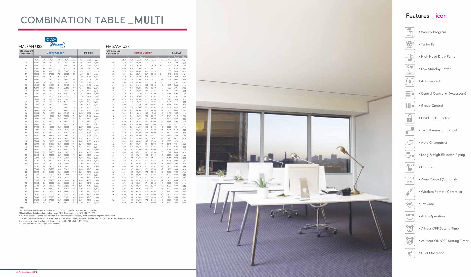
Min Rating Max Min Min Rating MaxRating Max
COMBINATION TABLE _
Note :
1.Cooling Capacity is based on : indoor temp. 27°C DB, 19°C WB; outdoor temp. 35°C DB
2.Heating Capacity is based on : indoor temp. 20°C DB; outdoor temp. 7°C DB, 6°C WB
3.The rated capacities above show the rise in the total indoor unit capacity when operating frequency is constant.
Values for changes in capacity are fixed after accounting for variations in operating frequency and should be used as reference values.
4.Total capacity index of indoor unit should be within 23~73 k Btu/h (40%~130%)
5.At least two indoor units should be connected.

Distributed by
LG ElectronicsAE Company, Commercial Air Conditioning20 Yeouido-dong, Yeongdeungpo-gu, Yeouido P.O.Box 335 Seoul, 150-721, Korea.
Phone : +82-2-3777-7934 Fax : +82-2-3777-3099
www.lg.com www.lgeaircon.com
Copyright © 2012 LG Electronics. All rights reserved.
LG Electronics Търговско предстaвителство1784 София, бул. „Цариградско шосе” 115Г • Бизнес сграда „Мегапарк”Тел. 02/ 817 3434 Факс: 02/817 3415
http://www.lge.bg http://bg.lgeaircon.com
За целите на непрекъснатото развитие на продуктите, LG си запазва правото да променя техническите характеристики без предварително известие.


![Energy Efficient HVAC System with Distributed Sensing and ... · of the HVAC energy usage is wasted [27]. This paper presents our implementation experience of BubbleZERO, an energy](https://img.dokumen.tips/doc/110x75/5f11ed783a08350e884f8c43/energy-eficient-hvac-system-with-distributed-sensing-and-of-the-hvac-energy.jpg)