Embed Size (px)
Citation preview

Dave BensonHUNTAIR President
• IntelIntel– HVAC Design Engineer
Operations Maintenance Manager– Operations Maintenance Manager– Site Engineer
L tti S i d t• Lattice Semiconductor– Director of Facilities
• Pace– VP Head of CleanPak Division
• HUNTAIR

HUNTAIR CleanPak
Temtrol
Governair
CESVenmar
Mammoth
Ventrol
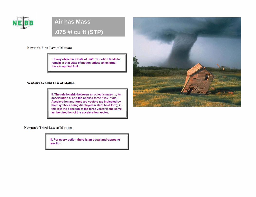
Air has Mass
.075 #/ cu ft (STP)
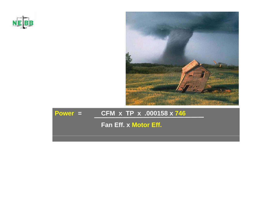
P CFM TP 000158 746Power = CFM x TP x .000158 x 746
Fan Eff. x Motor Eff.

Ratings vs. Application• Fans rated by or in• Fans rated by or in
accordance with AMCA• How fans are rated and how
fans are applied typically are significantly different
• Focus on System• Focus on System performance vs component performance.
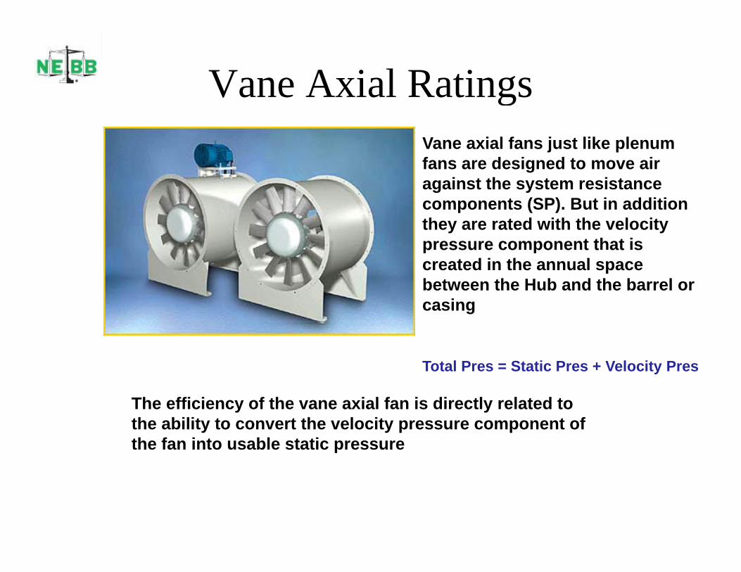
Vane Axial RatingsgVane axial fans just like plenum fans are designed to move air
i t th t i tagainst the system resistance components (SP). But in addition they are rated with the velocity pressure component that is p essu e co po e t t at screated in the annual space between the Hub and the barrel or casing
Total Pres = Static Pres + Velocity Pres
The efficiency of the vane axial fan is directly related to the ability to convert the velocity pressure component of the fan into usable static pressure.
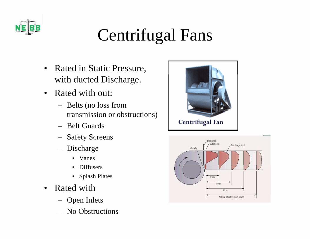
Centrifugal Fansg
• Rated in Static Pressure, with ducted Discharge.
• Rated with out:Belts (no loss from– Belts (no loss from transmission or obstructions)
– Belt GuardsS f S– Safety Screens
– Discharge• Vanes
iff• Diffusers• Splash Plates
• Rated with– Open Inlets– No Obstructions
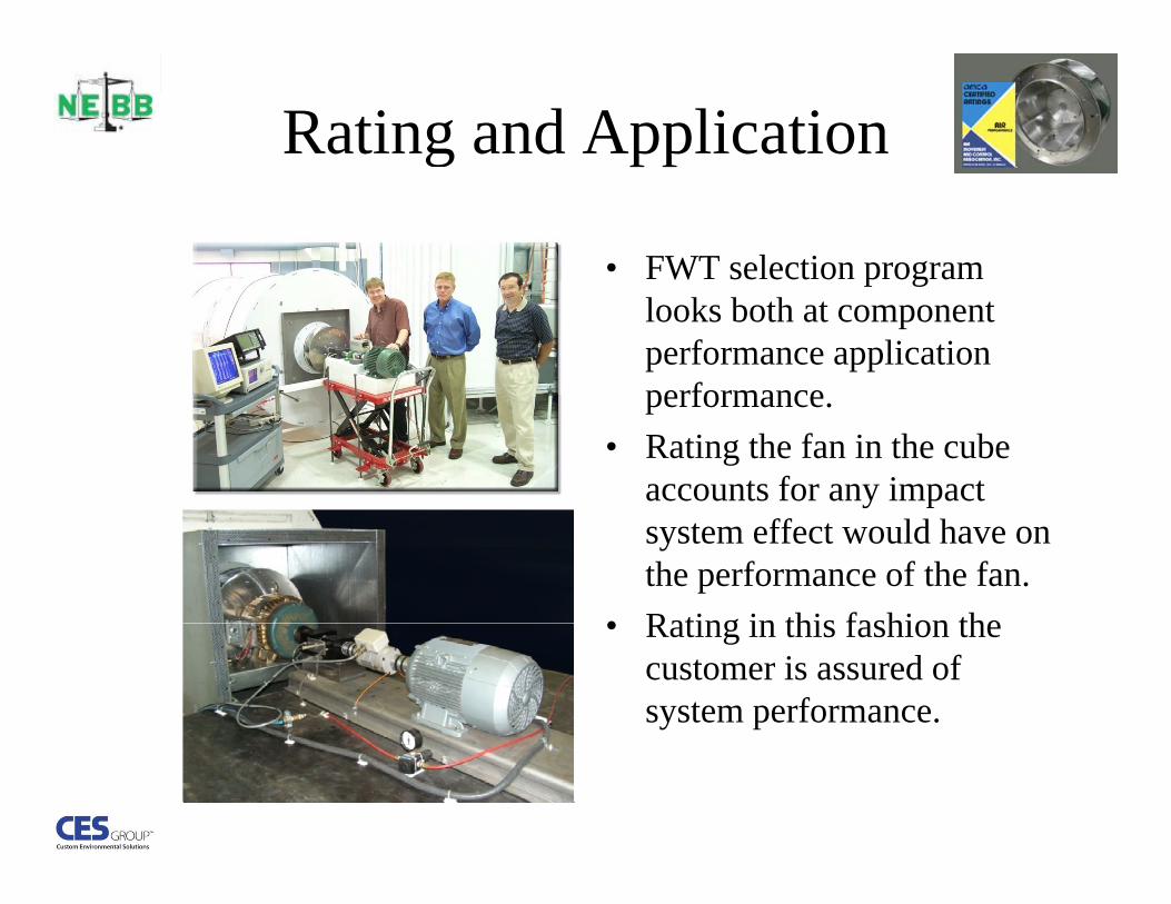
Rating and Applicationg
• FWT selection program p glooks both at component performance application performanceperformance.
• Rating the fan in the cube accounts for any impact system effect would have on the performance of the fan.
• Rating in this fashion the• Rating in this fashion the customer is assured of system performance.

AMCA defines system effect as “a pressure loss which i th ff t f f i l t t i ti tl t frecognizes the effect of fan inlet restrictions, outlet fan
restrictions, or other conditions influencing fan performance when installed in the system”.
F f t t t l th t t t f d idFan manufacturers go to great lengths to test fans and provide reliable air performance data in their literature. These fans are tested under very specific conditions as specified on the performance pages. Statements such as, “performance shown for model xxx with p g , pinlet and outlet ducts” indicate how the fan was tested. An installation where elbows, transitions, dampers, and other disruptions to airflow are located before and after the fan create a condition different from the manufacturers test methods Therefore a performance loss orthe manufacturers test methods. Therefore, a performance loss or system effect is created.
System effect is very difficult to quantify and correct. Frequently the only means to correct the resulting poor performance is to increaseonly means to correct the resulting poor performance is to increase the fan speed.
The Black hole of the air handling industry is SYSTEM EFFECT Difficult to measure except forSYSTEM EFFECT. Difficult to measure except for the money spent in energy to offset the effect.

System Effects on the Roof
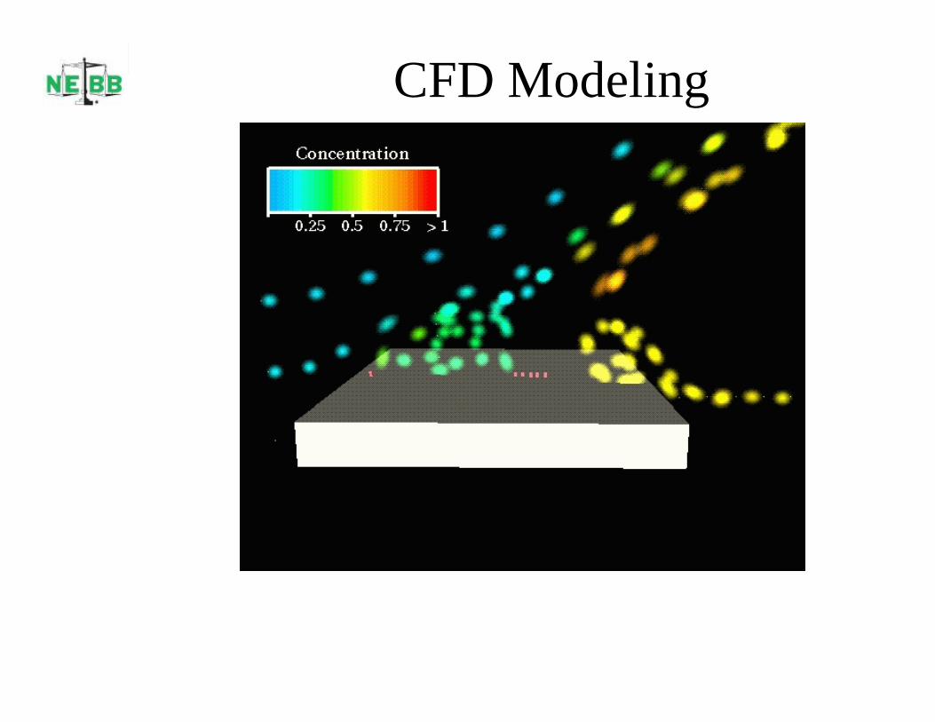
CFD Modeling
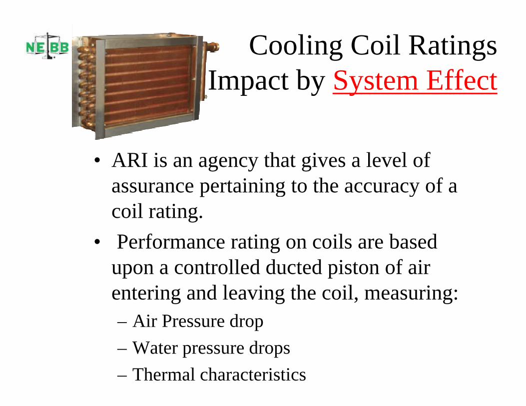
Cooling Coil RatingsI t b S t Eff tImpact by System Effect
• ARI is an agency that gives a level of assurance pertaining to the accuracy of a coil rating.
• Performance rating on coils are based upon a controlled ducted piston of air entering and leaving the coil, measuring:– Air Pressure drop– Water pressure drops– Thermal characteristics

Sound AttenuationI t d b S t Eff tImpacted by System Effect
As pictured in this IAC lab rendering the sound attenuation properties as well as pressure drop is based upon a very controlled piston ofcontrolled piston of air entering and leaving the tested device.
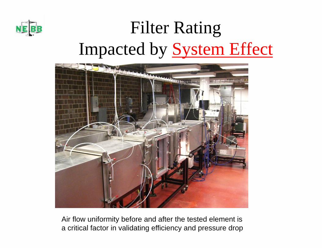
Filter RatingI t d b S t Eff tImpacted by System Effect
Air flow uniformity before and after the tested element is a critical factor in validating efficiency and pressure drop
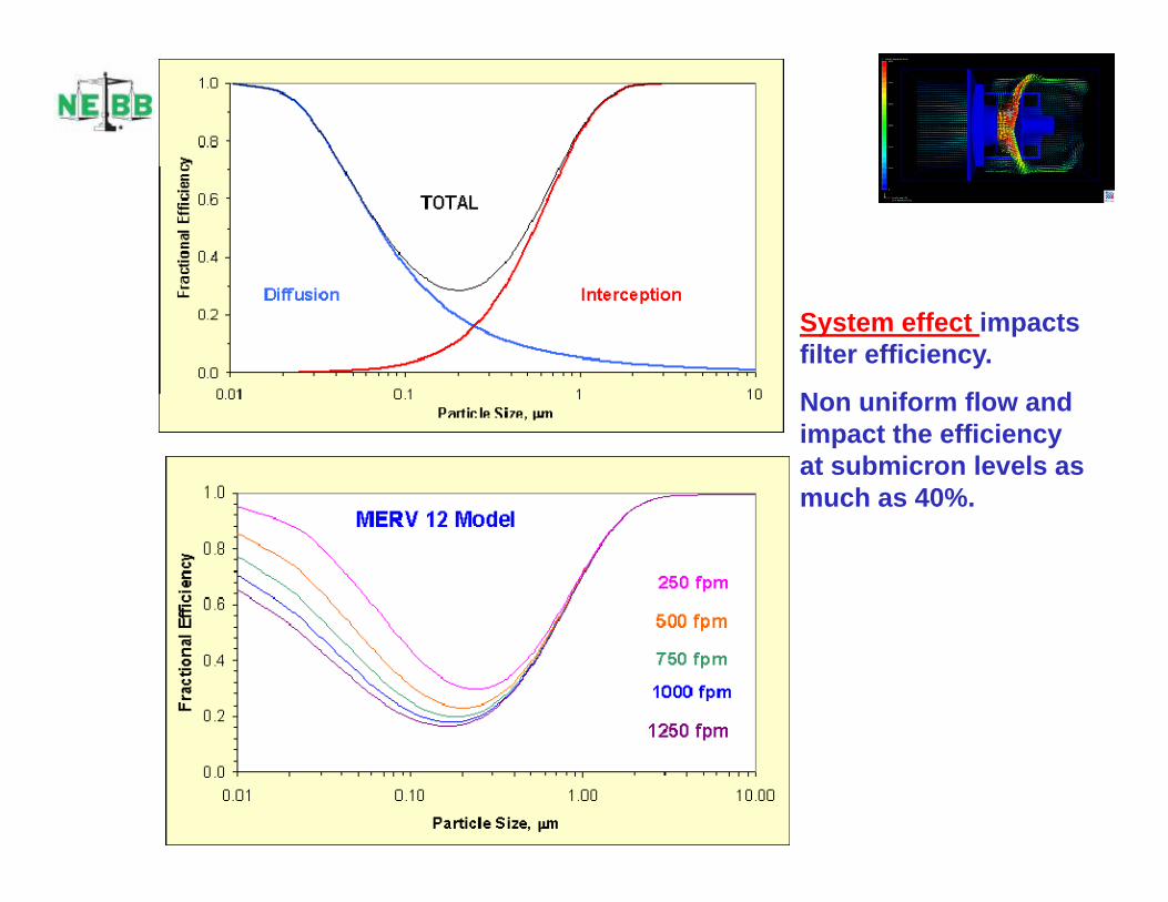
System effect impacts filter efficiency.
N if fl dNon uniform flow and impact the efficiency at submicron levels as much as 40%.

Chemical Vapor FiltrationI t d b S t Eff tImpacted by System Effect
System effect impacts filter efficiency.
Non uniform flow and impact the adsorption efficiency up to 100%

System effect impacts Ultra Violet SterilizationSterilization efficiency.
Non uniform flow and impact the efficiency impact the efficiency up to 100%

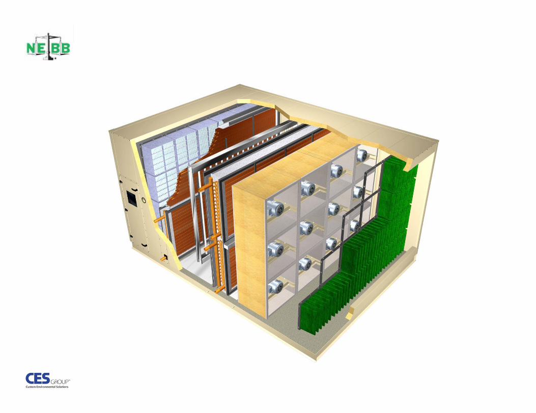
Redundant Fans – It’s impact to S t Eff tSystem Effect
Design for reliability – Plan for failure
480 Pound Wheel
2,800 Pound Motor

Conventional Fan SelectionSelection
CFM SP Selection RPM BHP Speed Ratio Min Motor Selected MotorCFM SP Selection RPM BHP Speed Ratio Min Motor Selected Motor60,000 7.25 54 In Plenum Fan 1090 107 0.932 114.85 125 Hp 1170 RPM
36,000 4.15 54 In. Plenum Fan 748 35.4 0.623 56.79 125 Hp 1170 RPM
Conventional fans require a connected load of 250 HP, driving all aspects of the electrical system inclusive of
•Switchgear
•Wire
•Breakers
•VFD’s Motor Loading is iti l icritical in
evaluation of motor efficiency
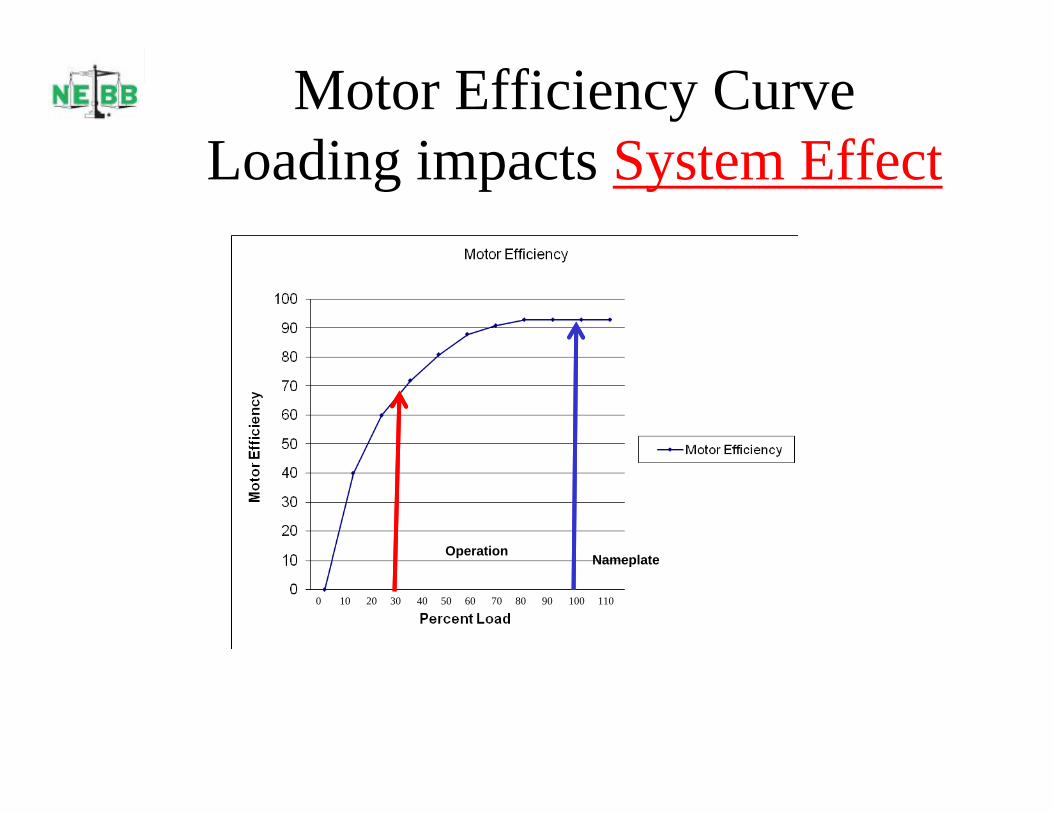
Motor Efficiency CurveL di i t S t Eff tLoading impacts System Effect
NameplateOperation
0 10 20 30 40 50 60 70 80 90 100 110
Nameplate

Motor Efficiency y
•Motors are Not 100% efficient
•Motor Efficiencies vary with input V/Hz
•Motor Efficiencies vary with load
oFans rarely operate at 100% CFM
oFans Rarely operate at 100% SP
0 10 20 30 40 50 60 70 80 90 100 110
Efficiency curve at 60 HZ
Efficiency curve w/ VFD

The NEBB Difference
NEBB exists to help architects engineers building owners and contractorsNEBB exists to help architects, engineers, building owners, and contractorsproduce great buildings with HVAC systems that perform in ways they havebeen visualized and designed. Each discipline is anchored by a NEBBProcedural Standards that provides guidelines for work to be performed. NEBBhas also created technical manuals training materials and seminars tohas also created technical manuals, training materials, and seminars toenhance and support each discipline. NEBB certified firms that meet certaincriteria, ensuring strict conformance to its high standards and procedures

CFD and Fan Evolution
• Plenum fans have been• Plenum fans have been widely used for approx 30 years– Versatile– Compact
S d– Sound– Relatively low FAN
efficiency
B li
• Analytical engineering changes the way we think and designBaseline
Velocity1400 RPM1621 CFM
think and design

2,000 CFM to 200,000 CFM

Vertical Fan Configurationg
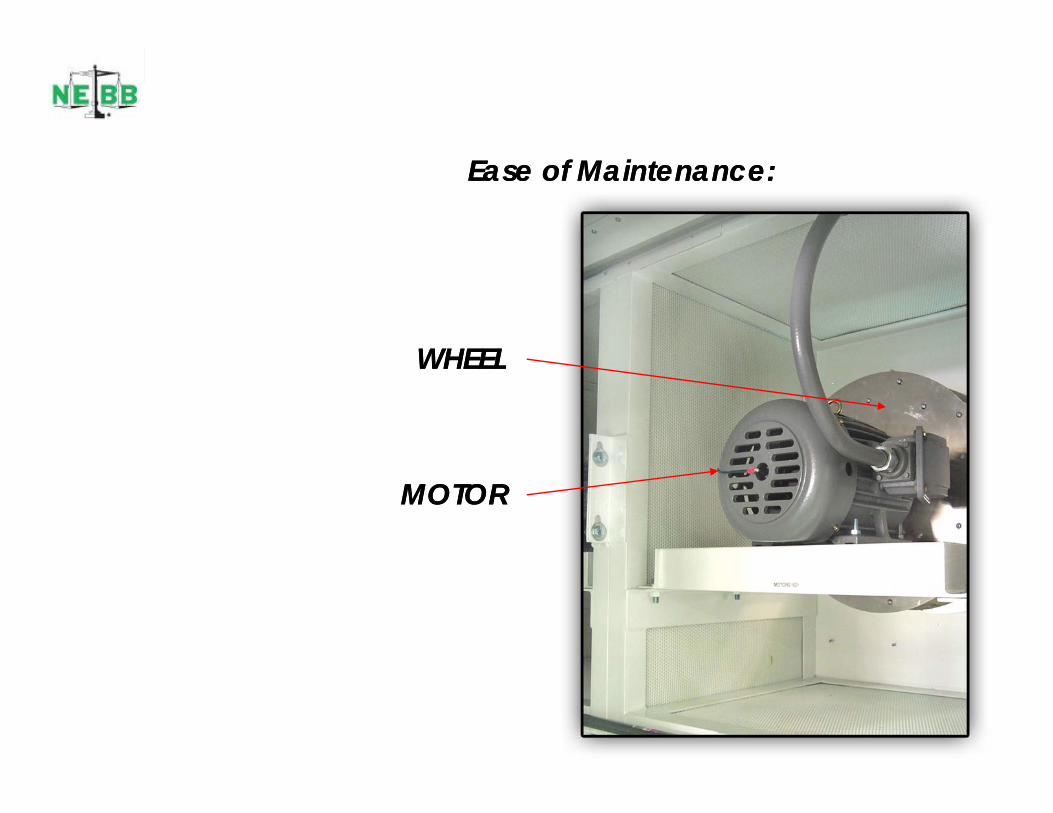
Ease of Maintenance:Ease of Maintenance:
WHEELWHEELWHEELWHEEL
MOTORMOTOR

Ease of maintenance:Ease of maintenance:
Remove 4 Bolts(2 this side, 2 other side)
Inlet View ShownInlet View ShownOptional Front Load Fan CartridgeOptional Front Load Fan Cartridge

Ease of maintenance:Ease of maintenance:
In the previous slide, the twin 125 HP motors were in units that were stacked in a well in the center of a roof opening. To remove a motor from the roof a crane with a boom that could extend into the building 200 feet would be required.
With FWT th f / t ld bWith FWT the fan / motors could be removed by two technicians from the unit and off the roof.

Greater Flexibility in Unit Dimensions: Greater Flexibility in Unit Dimensions:
• Greater Flexibility in Unit Dimensions –
Fan Wall Technology offers greater flexibility in unitsizing. Designers are able to incorporate lower profile
9’
Approximate 25k CFM
units where height restrictions are involved.
34”
34”
9
9’
34”
27’
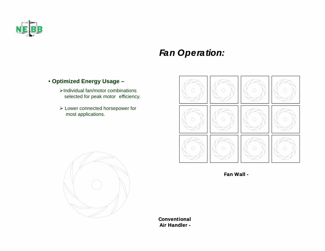
Fan Operation:Fan Operation:
• Optimized Energy Usage –Individual fan/motor combinations
selected for peak motor efficiency.
Lower connected horsepower for Lower connected horsepower for most applications.
F W llF W llFan Wall Fan Wall --
ConventionalConventionalAir Handler Air Handler --
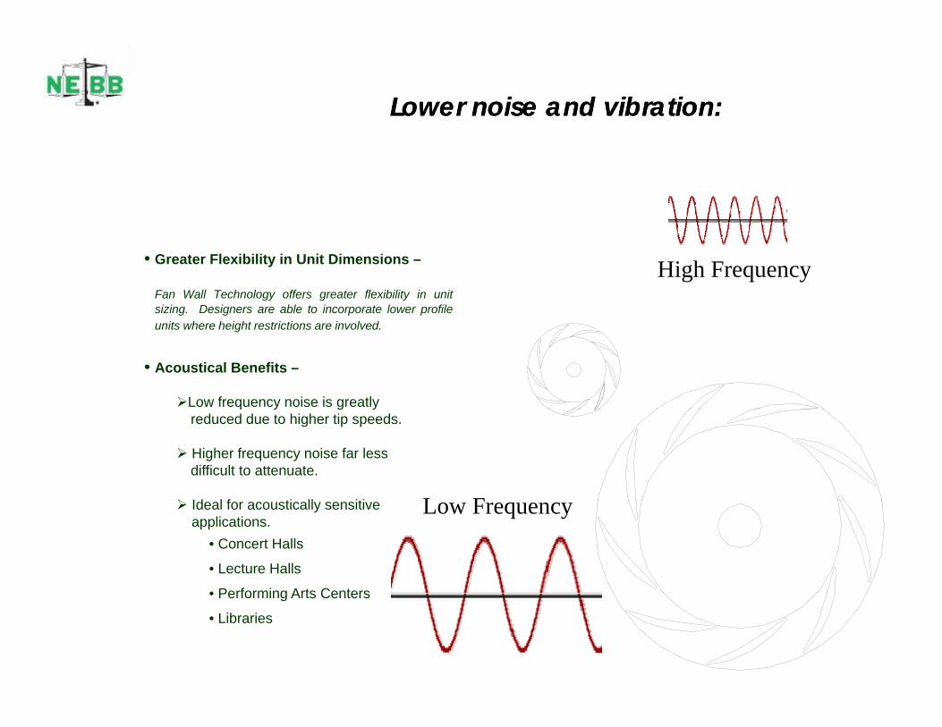
Lower noise and vibration: Lower noise and vibration:
• Greater Flexibility in Unit Dimensions –
Fan Wall Technology offers greater flexibility in unitsizing. Designers are able to incorporate lower profile
High Frequency
units where height restrictions are involved.
• Acoustical Benefits –
Low frequency noise is greatlyy g yreduced due to higher tip speeds.
Higher frequency noise far lessdifficult to attenuate.
Id l f ti ll iti L F Ideal for acoustically sensitive applications.
• Concert Halls
• Lecture Halls
• Performing Arts Centers
Low Frequency
• Performing Arts Centers
• Libraries

Sound you hear – Power you avoid
Savings you recognize
Coplanar Silencer AdvantageCoplanar Silencer Advantage
120
Fan wall Comparison 54,000 CFM 3.7" TSP-27-17 -14 -12 -9 -11 -10 -5
60
80
100
wer
Lev
el
20
40
60
Soun
d Po
w
01 2 3 4 5 6 7 8
Octave Band
Fanwall with Coplanar Fanwall Conventional fanselectionFanwall with Coplanar Fanwall Conventional fan selection

Residual Unbalance
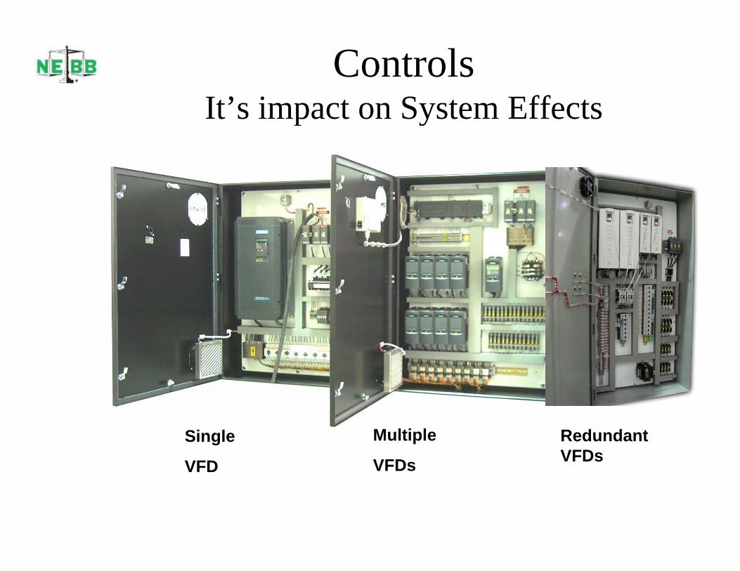
Controls It’s impact on System EffectsIt s impact on System Effects
Single
VFD
Multiple
VFDs
Redundant VFDsVFD VFDs

Dampers and Louvers• Dampers and louvers are an
important component in the i h dli i d t Thair handling industry. There
performance is carefully rated by manufacturers in component not system application.
• This manufacture’s damper• This manufacture s damper was AMCA rated as a component with careful attention in the foot note that it was tested per AMCA with ducted inlet and outlet
• System effect significantly impacts these ratings

Motor SpeedMotor Speed
•• Motor speed = Required Fan Speed 50 Hz Motor speed = Required Fan Speed 50 Hz –– 60Hz not part of the 60Hz not part of the selection criteria except when under speed is utilized.selection criteria except when under speed is utilized. Motor Torque
Motor Heat
Motor FLA
FWT fans are selected based upon ffi i f M t d F d iefficiency of Motor and Fan design.
Base Speed = Frequency x 120# of Motor Poles
Example –• US base speed using across the line power (60 HZ)
for a 4 pole motor is 1800• European base speed for exact same motor using (50
Shown with Coplanar Silencer Option
p p g (HZ) for a 4 pole motor is 1500.

Looking for SavingsThe adjacent unit is typical of many retrofits we see. For clarity the access doors are not shown, but the components andcomponents and configuration are representative of a Hospital application.
In this configuration there areIn this configuration there are many locations of inefficiencies.
•Inlet velocity and crowding
Splash Plate•Splash Plate
•Coil performance and uniformity
•Bearings and bearing barsg g
•Sheaves, Drives, and Belts
•Belt guard

Retrofit Opport nitiesRetrofit Opportunities

Retrofit - Kaiser
• Initial Motivation – FailureInitial Motivation Failure• Subsequent Motivation
E– Energy– Serviceability– Redundancy
• Result– 40% reduction of power

Sutter Hospital FWT Goal
• To replace the existing Vane Axial system with FWT while the system is in operation.
• Provide N+2 redundancyy• Provide 100% design flow (currently at 80%)• Reduce power consumption by 10%• Reduce power consumption by 10%• Actual performance – 43% reduction in
d t ti l i tconsumed power at same operational point
Maxim Retrofit
• Existing Semiconductor manufacturing facilityExisting Semiconductor manufacturing facility• 24 hour operation – 25 year old equipment
M i i• Motivation– Energy savings– Redundancy– Eliminate vibration– Reduce maintenance
• Result – 55% reduction in consumed powerp