Embed Size (px)
Citation preview

FEDERATION INTERNATIONALE DE L' AUTOMOBILE
Appendix to the 2011 FIA Formula One Technical Regulations
The purpose of this Appendix is to provide information about the practices and procedures in use by the FIA when carrying out checks under the regulations. It is for information only and does not form part of the regulations themselves. In general, any changes deemed necessary by the FIA Technical Department will come into force 90 days after publication, or sooner in consultation with the Formula One Technical Working Group.
Index Page Article Concerning
2 6.1.1 Approved FT5 fuel bladder materials
3 6.1.4 Approved FT5 fuel bladder manufacturers
4 6.6.3 Fuel sampling hose
5 7.5 Water system pressure relief valve
6 8.10 Medical Warning Light
7 9.9.5 KERS status light
8‐12 10.3.6 Wheel tether test procedure
13 14.1.2 Approved extinguishants
14 14.1.3 Extinguishant quantities
15 14.1.5 Extinguishant pressures
16‐17 14.5 Rear light specification
18 14.6.1 Approved headrest materials
19 14.6.5 Approved headrest installation system
20 14.6.7 Approved leg padding material
21‐23 14.8.4 Extractable seat specifications
24‐25 15.1.2 Test specification for and definition of metallic materials
26 15.4.1 Positions of chassis transponders
27‐28 15.4.7 Main anti‐intrusion panels
29‐30 15.4.8 Front anti‐intrusion panels
31‐32 16.1.1 Impact test specification
33 16.1.2 Parts to be fitted to the crash structure for impact tests
34 16.2 Frontal impact test 2
35‐38 16.4 Specification of the side impactor
39‐40 18.6.1 Side intrusion test procedure
41 19.8.1 Formula One fuel sampling procedure
42 Track side fuel conformity procedure
43‐47 20.2 Camera housing weights and dimensions
48‐49 20.4 Timing transponder fitting instructions
50‐66 Drawings
1 of 66

Article 6.1.1 The following are the only materials approved by the FIA for use in the manufacture of fuel bladders to FIA/FT5‐1999 specification : Manufacturer AERO TEC LABORATORIES Materials ATL‐818‐D ATL‐818‐D (Issue 2003) Manufacturer PREMIER FUEL SYSTEMS Material Kevlar F228 Manufacturer PRONAL Material 39387/02396
2 of 66

Article 6.1.4 The list of manufacturers approved to produce fuel bladders to the FIA/FT5‐1999 specification are : Aero Tec Laboratories Spear Road Industrial Park Ramsey NJ 07446 USA Tel + 1 201 825 1400 Fax + 1 201 825 1962 40 Clarke Road Mount Farm Industrial Estate Bletchley Milton Keynes MK1 1LG United Kingdom Tel + 44 1908 270590 Fax + 44 1908 270591 FPT Industries The Airport Portsmouth Hants PO3 5PE United Kingdom Tel Fax Premier Fuel Systems Limited Willow Road Trent Lane Industrial Estate Castle Donington Derby DE7 2NP United Kingdom Tel + 44 1332 850515 Fax + 44 1332 850749 Pronal Rue du Trieu du Quesnoy ZI de Roubaix‐Est 59115 Leers France Tel + 33 3 20 99 75 00 Fax + 33 3 20 99 75 20
3 of 66

Article 6.6.3 The fuel sampling hose comprises a tube approximately 2000mm long x 4.6 mm internal diameter with a “‐2” female snap fit connector at one end and a valve at the other end attached to a 200 mm long piece of stainless steel tubing of 4.6 mm internal diameter.
4 of 66

Article 7.5 Details of the FIA approved water pressure relief valve are as follows : Manufacturer : Circle Seal Controls, Inc. Model Number : 532A‐2MP‐3.75 Bar g Seal Material : Viton Temperature Range : ‐20 ºF to 400 ºF Supplier: TAMO LIMITED Crown Business Centre 195 Horton Road West Drayton Middlesex UB7 8HB Tel + 44 (0)1895 859700 Fax + 44 (0)1895 859888 Contact : Jim Pearce
5 of 66
Article 8.10 Details of the FIA approved Medical Warning Light are as follows :
6 of 66
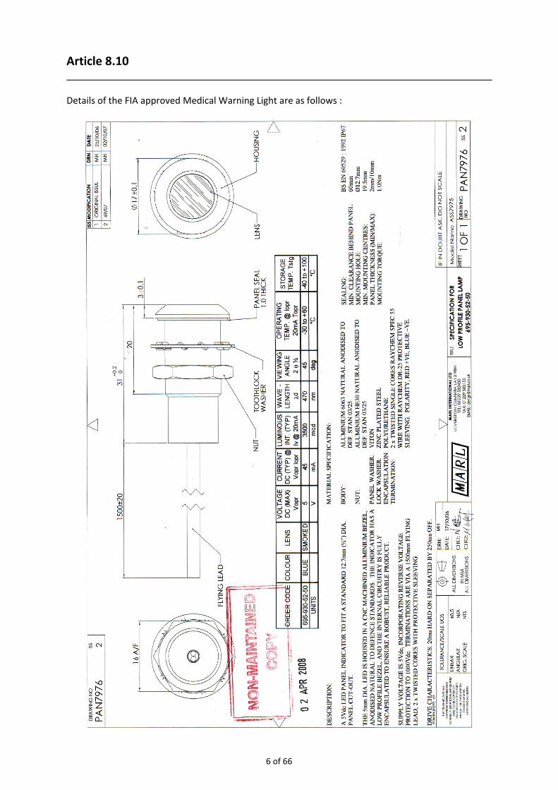
Article 9.9.5 The light shown below may be used for KERS status warning :
7 of 66
Article 10.3.6 Wheel tethers will be tested using the following test procedure :
FIA TEST SPECIFICATION 03/07
FOR
FORMULA ONE WHEEL RESTRAINT CABLES 1. SCOPE
Wheel restraint systems are important to improve protection to the drivers and the personnel
(spectators and officials) within the proximity of the race event. It has been shown that during an
accident a wheel may be ejected at velocities in excess of 150km/h (42m/s) relative to the car, which
corresponds to a linear kinetic energy of 17kJ for a 20kg wheel assembly.
This specification provides test methods, criteria and limits to assess the performance of wheel
restraint systems to ensure that the potential for wheel ejection is reduced.
During early development work, an advanced wheel restraint system was considered in two parts; an
energy absorbing unit and a connecting tether. However, the latest research has demonstrated that
an integrated tether can absorb the required energy without the need for a separate energy
absorbing unit. And, therefore, an integrated tether is the preferred solution. Other designs may be
acceptable, but the geometry and function must be approved by the FIA before submitting for
certification.
A definition of the key components is provided below.
2. DEFINITIONS
2.1 Wheel Assembly
Those parts, likely to include the wheel, tyre, upright, brake calliper and brake disk, that are considered to be a single projectile during a wheel ejection event. 2.2 Wheel Restraint Cable (Tether)
Flexible load carrying element that connects the wheel assembly to the main structure of the car and
that provides the required strength and energy absorbing capability.
2.3 Energy Absorber
The energy absorbing capability of the tether. A separate energy absorbing element may be permitted but must be approved by the FIA before submitting for certification.
8 of 66

2.4 Tether End Fitting
Feature at each end of the tether to facilitate attachment to the car and the wheel assembly. The
tether end fitting may include a bobbin if this represents the in‐car conditions.
The in‐board‐tether‐end‐fitting connects to the car chassis
The out‐board‐tether‐end‐fitting connects to the wheel assembly
2.5 Tether Attachment
Attachment between the tether end fitting and the main structure of the car that achieves the
strength and geometrical requirements defined by the Technical Regulations.
2.6 Tether Sliding Surface
Rigid structure that represents the local structure of the car over which the tether must slide if the
wheel is ejected in any direction normal to the axis of rotation of the rear wheels.
3. PERFORMANCE ASSESSMENT
3.1 Wheel Restraint Cable Test
The performance of the wheel restraint system shall be measured in accordance with the dynamic
tests defined in Appendix A.
3.1.1. One Wheel Restraint Cable (per wheel assembly)
During the tensile tests and tether sliding surface tests, the following performance shall be achieved
by all test samples;
The energy absorption shall not be less than 6kJ over the first 250mm of displacement.
The peak force shall not exceed 70kN (CFC 1000) over the first 250mm of displacement.
3.1.2. Two Wheel Restraint Cables (per wheel assembly)
During the tensile tests and tether sliding surface tests, the following performance shall be achieved
by all test samples;
The energy absorption shall not be less than 3kJ over the first 250mm of displacement.
The peak force shall not exceed 70kN (CFC 1000) over the first 250mm of displacement.
APPENDIX A: WHEEL RESTRAINT CABLE TEST PROCEDURE
A1. Apparatus
An appropriate test apparatus is shown in Figures A1 and A2.
The aim of the test is to dynamically load the tether in a tensile direction, in order to determine the
strength, elongation and energy absorbing characteristics. The tests shall be conducted using a
dynamic sled apparatus based on the Formula One frontal impact test. The mass of the sled shall be
780kg ± 7.8kg.
9 of 66

Two tether attachments shall be provided; one fitted to the sled and one fitted to a ground anchor
within a close proximity to the sled. The position of the sled tether attachment point relative to the
CoG of the sled shall be chosen to prevent excessive torque loadings to the sled. The position of the
ground anchor tether attachment point shall achieve the tether angle requirements defined in A1.1
and A1.2. The tether attachments shall reproduce the in‐car fixing method as defined by the
Technical Regulations. The tether manufacturer may provide a bobbin arrangement if this represents
the in‐car fixing method.
During the test, the entire kinetic energy of the sled shall be directed into the tether end fittings to
load the tether in tension. The tether shall move with the sled during the pre‐impact phase with the
in‐board tether end fitting engaged with the sled tether attachment. At the point of impact, the out‐
board tether end fitting shall engage with the ground anchor tether attachment. As the tether is
loaded the sled will be decelerated. The motion of the sled shall be otherwise unrestrained until the
displacement of the sled has exceeded 500mm from the point of impact. After this time, the sled
may be arrested using crush tubes or any other appropriate device.
Two loading configurations are prescribed
A1.1 Tensile Test (0o)
During the tensile test, the tether shall be loaded between two points only; the sled attachment
point and the ground anchor attachment point. At the point of impact, the angle between the major
axis of the tether and the axis of the sled shall not exceed 20o.
A1.2 Tether Sliding Surface Test (90o)
During the tether sliding surface test, the tether shall be loaded at three points; the sled attachment
point, the tether sliding surface and the ground anchor attachment point. The tether sliding surface
shall be a solid steel cylinder with a diameter of 25mm and a length of at least 100mm. The major
axis shall be perpendicular to the axis of the tether. At the impact point, the distance between the in‐
board end of the tether and the centre of the Tether Sliding Surface shall be 115mm ± 15mm. The
apparatus shall be configured such that the tether is flexed through 90o ± 5o around the tether sliding
surface. At the point of impact, the angle between the out‐board section of the tether and the axis of
the sled shall not exceed 20o.
A2. Test Samples
The test samples shall include the tether and the tether end fittings. The test samples shall have a
length of 600mm ± 15mm measured between the centres of the tether end fittings.
A3. Environmental Conditioning
The FIA may require that polymeric tethers are conditioned before testing as follows;
Temperature: 100oC for 24 hours
Moisture: Immersed in water 25oC for 48 hours
Ultra‐violet: 250mm from 125V xenon‐filled quartz lamp for 48hours
A4. Instrumentation
The apparatus shall be fitted with a single axis load cell to measure the force exerted at the out‐
board tether end fitting along the direction of the tether. The sensitive axis of the load cell must be
aligned with the axis of the tether ± 5o at the point of impact. It is understood that during the impact
event, the angle of the tether will change as the tether extends. However, the sensitive axis of the
load cell shall be fixed at the point of impact position.
10 of 66

A method of measuring the velocity of the sled immediately before the point of impact shall be
provided. The sled shall be fitted with an accelerometer to measure the fore‐aft acceleration during
the impact event.
All instrumentation shall conform to SAE J211 (latest revision) with a channel frequency class (CFC) of
1000. The sampling frequency shall be at least 20,000Hz.
A5. Test Procedures
Test A5.1. Wheel Restraint Tensile Test
The test samples shall be fitted to the sled with the in accordance with the tensile test configuration
as described in A1. The impact velocity shall be at least 14m/s. The tests shall be conducted on two
test samples and the results shall be reported as defined in A6.
Test A5.2. Wheel Restraint Tether Sliding Surface Test
The test samples shall be fitted to the sled with the in accordance with the tether sliding surface test
configuration as described in A1. The impact velocity shall be at least 14m/s. The tests shall be
conducted on two test samples and the results shall be reported as defined in A6.
A6. Results
The results shall include:
(a) Length of test sample (mm)
(b) Diameter (or x‐sectional area) of test sample (mm or mm2)
(c) Mass of test sample (g) including end fittings
(d) Actual impact velocity (m/s)
(e) Acceleration‐time history of the sled CFC60 (g, ms)
(f) Velocity1‐time history of the sled (m/s, ms)
(g) Force‐time history for tether showing peak force CFC1000 (N, ms)
(h) Force‐displacement2 history for tether CFC1000 (N, mm)
(i) Energy3 absorbed over first 250mm
1. The velocity shall be calculated by single integration of acceleration 2. The displacement shall be calculated by double integration of acceleration 3. The energy shall be calculated by integration of force with respect to displacement
11 of 66

Figure A1. Test apparatus for 0o (tensile) tests on wheel restraint cables
Figure A2. Test apparatus for 90o (tether sliding surface) tests on wheel restraint cables
12 of 66

Article 14.1.2 The following extinguishants are approved for use in Formula One cars : Company Product SPA Design SPA Lite Chubb Fire Spray Lance OMP Ecolife Total Walther Microdrop Arc 3x6 Hi Tech AFFF Safety Devices AFFF Kingdragon Hydral AFFF Werner GmbH Wema AFFF Lifeline Zero 2000 Sparco Eco‐Sir AP Sport Exteco Taifun Safetydrive III BRB/QUELL 3M Light Water FEV AFFF FX G‐TEC Mistec AFFF
13 of 66

Article 14.1.3 The following volumes (in litres) of extinguishant are required : : SPA Lite ‐ Zero 2000 ‐ Spray Lance ‐ Eco‐Sir ‐ Ecolife – FEV AFFF ‐ Safety Devices : HiTech ‐ Mistec
FEVFX G‐TEC
Wema AFFF
Exteco Safetydrive 3
Arc 3x6 3M L. Water
Hydral AFFF
Cockpit
1.65 n/a 4.7 2 4.8 5 same 4.7 2.20
Engine
3.30 n/a 4.7 4 engine +cockpit
5 same 4.7 3.30
With reference to the above Article, the following quantities (in kg) of extinguishant are required : Cockpit
1.12 1.7 4 1.15 4 4 same 4 1.75
Engine
2.25 Engine +cockpit
4 2.3 engine +cockpit
4 same 4 3.0
14 of 66

Article 14.1.5 Depending upon the product, extinguishers should be pressurised as follows : Product Fill Pressure Temperature limits SPA Lite 7.0 bar ‐15°C / +60°C * Zero 2000 12.0 bar ‐5°C / + 45°C * Spray Lance 10.0 bar ‐11°C / +55°C * Wema AFFF A1, B1 14.0 bar ‐15°C / +60°C Wema AFFF A2, B2 14.0 bar +4°C / +60°C Eco‐Sir 12.0 bar +20°C / Ecolife 12.0 bar ‐20°C / Exteco 12.0 bar ‐20°C / +100°C Safetydrive III 15.0 bar 0°C / +50°C Arc 3x6 16.0 bar +4°C / +60°C (without antifreeze) ‐20°C / +60°C (with antifreeze) 3M Light Water 10.3 bar +4°C / +60°C Hi Tech 12.0 bar ‐6°C / +60°C FEV AFFF 9.0 bar ‐5°C / +60°C ‐10°C / +60°C FEV G‐TEC n/a Safety Devices 9.0 bar ‐5°C / +60°C ‐10°C / +60°C Mistec 12.0 bar ‐6°C / +60°C Hydral AFFF 14.0 bar ‐15°C / +60°C * Special options available
15 of 66

Article 14.5
16 of 66

17 of 66

Article 14.6.1 The following materials are the only ones approved for head protection : For ambient temperatures above 30ºC (Type A) ‘Confor’ CF45 (Blue) For ambient temperatures between 15ºC and 30ºC (Type B) ‘Confor’ CF42 (Pink) For ambient temperatures below 15ºC (Type C) ‘Sunmate’ medium soft grade (Light blue) Type A and B foams are available from :
E.A.R. Specialty Composites Corporation 7911 Zionsville Road Indianapolis IN 46268 ‐ USA Tel + 1 317 692 1111 Fax + 1 317 692 0618 or Dowty Energy Control Products Unit C The Beaver Centre Ashburton Industrial Estate Ross on Wye Herefordshire HR9 7BW United Kingdom Tel + 44 1989 565 636 Fax + 44 1989 565 410 Type C foam is available from :
Dynamic Systems Inc 235 Sunlight Drive Leicester NC 28748 USA Tel + 1 828 683 3523 Fax + 1 828 683 3511 E Mail [email protected]
18 of 66

Article 14.6.5 The head protection must be secured to the car in the following way : Two horizontal pegs behind the driver’s head and one pin on each of the forward extremities, the latter must be clearly indicated and easily removable without the use of tools.
19 of 66

Article 14.6.7 The following material is the only one approved for leg protection : For all ambient temperatures (Type B) : Confor CF42 (Pink) Type B foam is available from :
E.A.R. Specialty Composites Corporation 7911 Zionsville Road Indianapolis IN 46268 ‐ USA Tel + 1 317 692 1111 Fax + 1 317 692 0618 or Dowty Energy Control Products Unit C The Beaver Centre Ashburton Industrial Estate Ross on Wye Herefordshire HR9 7BW United Kingdom Tel + 44 1989 565 636 Fax + 44 1989 565 410
20 of 66

Article 14.8.4 Details of the tool, belt receptacles and head stabilisation may be found in the specification below.
RECOMMENDED SPECIFICATION FOR EXTRACTABLE SEATS IN SINGLE SEATER AND SPORTS CARS
Version 3 01‐10‐2005
In order that an injured driver may be immobilised and removed from the car in his seat under medical supervision following an accident, cars shall be fitted with a seat constructed according to the following principles. 1. The seat shall be in the form of a shell in non‐metallic fibre composite material, suitable if necessary for receiving a liner formed to the driver, which should be positively located. The seat shall provide him with good lateral support at the hips and shall extend from coccyx to shoulder level (unless there is an integrated headrest as mentioned in 3). 2. The shape and fit of the seat in the cockpit will be such that: ‐ no head restraint worn by the driver may be less 25mm from any structural part of the car when he is seated in his normal driving position; ‐ removable shoulder supports can be fitted on either side if necessary. 3. Normally the seat shall be designed with a slot in the back to accept a head stabilising board which is issued to all extrication crews in the FIA Extrication Bag. The dimensions of this slot are given in Figures 1 and 2.
Figure 1. Receptacle for removable head board Figure 2. Removable head board
21 of 66

An alternative model, used in some existing formula cars, has an integral head support which extends upwards, with a minimum width of 90mm, as far as a horizontal tangent to the top of the driver's head. 4. The seat must be removable without the need to cut any of the seat belts or remove the harness buckle. The shoulder and lap belts must fall away over the seat edges as it is withdrawn and the crotch straps must pass freely through the seat bottom hole or holes, which must be located in front of the driver's crotch. Any seat liner must have the same holes as the seat shell, identical and perfectly aligned with them in order to prevent the harness straps being trapped. However, if the lap straps have to pass through holes in the seat, it is necessary to fit the car with a harness having the buckle attached to a shoulder belt, given that the buckle will not pass between the driver's body and the side of the seat. 5. The seat shall be located in the chassis such that it is firmly fixed horizontally. It is important that the seat shall not be displaced or fractured by lateral or longitudinal accelerations. To achieve this it is recommended to eliminate any voids between seat and chassis. If it is mechanically secured, this must be done with no more than two bolts. If bolts are used they must: ‐ be clearly indicated and easily accessible to rescue crews; ‐ be fitted vertically; ‐ be removable with a 4mm Allen key, issued to all extrication crews in the FIA Extrication Bag. 6. The seat must be equipped with the following straps and anchorages (see figures 3 and 4) for immobilising the driver and lifting the seat, with the help of the contents of the FIA Bag (see bag contents in Appendix).
Figure 3. Disposition of strap receptacles Figure 4. Detail of lower straps ‐ 2 shoulder straps, diagonally crossed from right side of thorax to top left corner (red strap) and from left side of thorax to top right corner (blue strap), attached with plastic adjuster buckles. The female buckle receptacles at the shoulders are mounted on webbing loops in the corresponding colours, on to which 2 of the black lifting straps from the FIA Bag will also be clipped.
22 of 66

‐ 1 buckle receptacle* on each side of the seat at hip level, to receive one of the orange immobilising straps from the FIA Bag ‐ 1 buckle receptacle* on each side at the bottom end of the seat, to receive the other orange immobilising strap from the FIA Bag and mounted on orange webbing loops onto which the other 2 black lifting straps from the FIA Bag will also be clipped. *See buckle references in Appendix. The straps shall be:
‐ in 50mm wide seat belt webbing;
‐ preferably in the colour corresponding to their function;
‐ permanently exposed at the edges of the seat so as to be immediately visible and accessible to the extrication teams. The liner shall be trimmed accordingly.
7. The FIA training DVD showing the seat in action, as well as any further information, is available on request from the FIA, Geneva.
APPENDIX ‐ CONTENTS OF THE "FIA EXTRICATION BAG" One bag with FIA logo One tool ‐ 4mm Allen key One headboard in carbon fibre with Velcro on both sides 4 cushions to place between head and headboard as necessary 2 red straps with Velcro for immobilising the head at forehead and chin 2 orange straps with plastic male buckles*, adjustable, for immobilising at hips and thigh 1 black strap with Velcro for tying hands together 1 blue strap with Velcro for tying feet together 4 black straps with snap hooks for lifting the seat out * BUCKLE: maker and references: Butonia (London) Ltd. E‐mail: bltd@butonia‐group.com Tel: +44 (020)7249 5141 Fax: +44 (020)7249 8859 Part n°: 960406‐BA‐50 Description: ACW CSR2 2" BLACK BUCKLES
23 of 66

Article 15.1.2 The definition of metallic materials and test procedure are detailed below.
DEFINITION OF METALLIC MATERIALS A metallic material will be defined as a material that is made‐up of metallic elements, whether that material is a pure metal, alloy of several metals or an inter‐metallic. In the case of a composite this is designated a metallic material when the matrix or reinforcement, whatever phase proportion, is composed of metallic elements. Metallic elements are those designated by the periodic table, shaded yellow below.
PERIODIC TABLE OF THE ELEMENTS
Non‐metallic materials will include pure and impure compounds such as oxides, nitrides, silicides etc, and material with organic matrices such as carbon and Kevlar reinforced composites.
24 of 66

FIA TEST PROCEDURE 03/03
SPECIFIC MODULUS OF METALLIC MATERIALS 1) All materials over 35GPa/gm/cm3, and with a metallic content greater than 60% by mass, must
be submitted for testing at the National Physical Laboratory, Teddington, UK.
2) All tests will be carried out at 20‐25ºC and by using test procedure ASTM E 111 as a basis for analysis.
3) Ten test samples of each material type must be supplied.
4) Flat specimens FTSB, FTSD or FTSE must be supplied. Drawings of the specimens are attached to this test procedure.
5) Data will normally be analysed using the tangent and secant moduli to calculate Young’s modulus.
6) The tests will not normally be carried out to failure, only the early (linear) part of the stress‐strain curve will be measured.
7) The modulus measurements will normally be made only from the first loading cycle unless there are problems in obtaining a linear part to the curve. In this case some pre‐loading or repeat load cycling will be carried out.
8) Archimedes Principle will be used to assess the density of the samples.
9) The report for each materials type will normally include all relevant information, the stress‐strain curves, Young’s modulus values, density measurements and calculated specific modulus.
Specific modulus results will be quoted to the nearest 0.1GPa/gm/cm3. Any material found to be above 40GPa/gm/cm3 (including total uncertainty) will be deemed not to comply with Article 15.1.2 of the 2003 F1 Technical Regulations.
10) If a dispute arises the car component(s) in question will undergo quantitative chemical analysis according to UKAS standards. The National Physical Laboratory will compare the component chemical analysis to that of the specimens previously submitted for specific modulus testing to ensure they are manufactured from the same material.
May 2003
25 of 66

Article 15.4.1 Position of chassis transponders required by the above Article :
One transponder on the upper surface of the survival cell within a 150mm radius of the centre of the line A‐A.
One transponder in each side of the cockpit rim anywhere between 300‐850mm forward of the rear edge of the cockpit entry template.
26 of 66

Article 15.4.7 The additional side anti‐intrusion panel lay‐up details may be found below.
Specification for 2008 Secondary Side Intrusion Panel
FINAL VERSION 1.0
General
The panel shall be constructed from Torayca T1000G and Toyobo High Modulus Zylon (PBO) fibres, impregnated with a toughened, elevated cure temperature, epoxy resin system. If different resins are used for the T1000G and Zylon reinforced plies, they must be co‐curable. The construction of the panel shall be quasi isotropic and shall avoid darts, joins or gaps in any ply, apart from those required to cover complex geometry, cut outs for wiring and side impact structures. Rebates shall be permitted in the outer four Zylon plies only, for the attachment of external bodywork. Any joins required in each ±45 degree ply, to cater for a finite material roll width, shall overlap by at least 10mm and be staggered through the laminate, to avoid super‐imposing. The panel must be cured to the manufacturer’s recommended cure cycle. The panel will be bonded to the chassis over the entire surface area with the prescribed film or paste adhesive. Zylon HM – 300gsm
Minimum average weight [285]gsm, 6K fibres per tow, in a 2 X 2 twill weave style, impregnated with an epoxy resin. T1000G – 280gsm
Minimum average weight [269]gsm, 12K fibres per tow, 2 X 2 twill weave or 5 harness satin weave, impregnated with an epoxy resin. Matrix System
MTM49‐3 or Cycom 2020 epoxy resin. Alternatively, it is permissible to replace the approved resin system with the primary matrix system used for the homologated side intrusion panel. Adhesive (to chassis)
Film adhesive 150gsm 3M AF163‐2 or paste adhesive 3M 9323 B/A Stacking Sequence (0 degree represents longitudinal axis of the chassis)
Outer surface
1 ply T1000G (0/90)
16 plies Zylon (±45, 0/90)8 or (±45, 0/90, 0/90, ±45)4
1 ply T1000G (0/90)
Inner surface
27 of 66
Thickness
The minimum thickness of the cured panel, excluding the adhesive, shall be [6.2]mm. Area Weight
The minimum area weight of the cured panel, excluding the adhesive, shall be [8700]gsm. Voids
The panel shall be essentially void free. Examples of Compliant Materials
1. Supplied by Cytec
Zylon HM‐300gsm/2x2 twill with Cycom2020 epoxy resin (NOM 42% by weight)
T1000G‐12K 280gsm/2x2twill or 5 harness weave with Cycom2020 epoxy resin (NOM 42% by weight)
2. Supplied by ACG
Zylon HM‐300gsm/2x2 twill with MTM49‐3 epoxy resin (NOM 43% by weight)
T1000G‐12K 280gsm/2x2twill or 5 harness weave with MTM49‐3 epoxy resin (NOM 40% by weight)
Andrew Mellor 4 September 2006
28 of 66

Article 15.4.8 The additional front anti‐intrusion panel lay‐up details may be found below.
Specification for 2011 Forward Side Intrusion Panel
FINAL VERSION 1.0
General
The panel shall be constructed from Torayca T1000G and Toyobo High Modulus Zylon (PBO) fibres, impregnated with a toughened, elevated cure temperature, epoxy resin system. If different resins are used for the T1000G and Zylon reinforced plies, they must be co‐curable. The construction of the panel shall be quasi isotropic and shall avoid darts, joins or gaps in any ply, apart from those required to cover complex geometry, cut outs for wiring and side impact structures. Rebates shall be permitted in the outer three Zylon plies only, for the attachment of external bodywork. Any joins required in each ±45 degree ply, to cater for a finite material roll width, shall overlap by at least 10mm and be staggered through the laminate, to avoid super‐imposing. The panel must be cured to the manufacturer’s recommended cure cycle. The panel will be bonded to the chassis over the entire surface area with the prescribed film or paste adhesive. Zylon HM – 300gsm
Minimum average weight [285]gsm, 6K fibres per tow, in a 2 X 2 twill weave style, impregnated with an epoxy resin. T1000G – 280gsm
Minimum average weight [269]gsm, 12K fibres per tow, 2 X 2 twill weave or 5 harness satin weave, impregnated with an epoxy resin. Matrix System
MTM49‐3 or Cycom 2020 epoxy resin. Alternatively, it is permissible to replace the approved resin system with the primary matrix system used for the homologated side intrusion panel. Adhesive (to chassis)
Film adhesive 150gsm 3M AF163‐2 or paste adhesive 3M 9323 B/A Stacking Sequence (0 degree represents longitudinal axis of the chassis)
Outer surface
1 ply T1000G (0/90)
7 plies Zylon (±45, 0/90, ±45, 0/90, ±45, 0/90, ±45)
1 ply T1000G (0/90)
Inner surface
29 of 66

Thickness
The minimum thickness of the cured panel, excluding the adhesive, shall be [3.0]mm. Area Weight
The minimum area weight of the cured panel, excluding the adhesive, shall be [8700]gsm. Voids
The panel shall be essentially void free. Examples of Compliant Materials
1. Supplied by Cytec
Zylon HM‐300gsm/2x2 twill with Cycom2020 epoxy resin (NOM 42% by weight)
T1000G‐12K 280gsm/2x2twill or 5 harness weave with Cycom2020 epoxy resin (NOM 42% by weight)
2. Supplied by ACG
Zylon HM‐300gsm/2x2 twill with MTM49‐3 epoxy resin (NOM 43% by weight)
T1000G‐12K 280gsm/2x2twill or 5 harness weave with MTM49‐3 epoxy resin (NOM 40% by weight)
Andrew Mellor 4 January 2011
30 of 66

Article 16.1.1 The test procedure is detailed below.
TYPE AND RANGE OF CHASSIS AND STEERING COLUMN TRANSDUCERS
Single axis transducers
2000g overload capacity (+/‐ 1000g). Low working range 200g (high linearity (2 % or better) of the accelerometer within the range of 0 – 200g)
DUMMY SUGGESTION Hybrid III (size: 50% male)
TYPE AND RANGE OF DUMMY TRANSDUCER Three axis transducer
2000g overload capacity (+/‐ 1000g). Low working range 200g (high linearity (2 % or better) of the accelerometer within the range of 0 ‐ 200g)
TYPE OF SIDE IMPACT TRANSDUCER TNC F1 Impact TR001.issue 1
FILTER FOR TRANSDUCER DATA Front and rear test (peak deceleration) CFC 60
Front test (average deceleration) unfiltered
Dummy chest CFC 180
Side (peak force) CFC 60
Side (average deceleration) unfiltered
Steering column (peak deceleration) CFC 600
All filters specified SAE J211
SAMPLING RATE 20 kHz each test
TIME ZERO (T0) T0 will be defined by electronic contact
VELOCITY AT T0 Velocity at T0 will be measured immediately before impact
VELOCITY CALCULATION Single integration of unfiltered deceleration data
DISPLACEMENT CALCULATION Displacement will be established by double integration of unfiltered deceleration data
FRONTAL IMPACT TEST :
DATA PROCESSING PROCEDURE
Peak deceleration over the first 150mm of deformation
Peak deceleration using deceleration data filtered to CFC60
Time for 150mm will be determined as the first instant that displacement exceeds 150mm
Peak deceleration over the first 60kJ energy absorption
Peak deceleration using deceleration data filtered to CFC60
Energy will be established by numerical integration (unfiltered deceleration x mass) x displacement
Time for 60kJ will be determined as first instant that the energy exceeds 60kJ
Average deceleration of the trolley
Average deceleration from T0 to V0 using unfiltered deceleration data
V0 will be determined as first instant that velocity is less than 0m/s
31 of 66

Peak deceleration in the chest of the dummy
Deceleration data filtered to CFC180
SIDE IMPACT TEST :
DATA PROCESSING PROCEDURE
Average deceleration
Average deceleration from T0 to V0 using unfiltered deceleration data
V0 will be determined as first instant that velocity is less than 0m/s
Force applied to any one of the four impactor segments
Force data filtered to CFC60
Energy absorbed by each of the four impactor segments
Energy will be established by numerical integration of force x displacement from T0 to V0
Force data per segment will be established using the sum of unfiltered data from four load cells
V0 will be determined as first instant that velocity is less than 0m/s
REAR IMPACT TEST :
DATA PROCESSING PROCEDURE
Peak deceleration over the first 225mm
Peak deceleration using deceleration data filtered to CFC60
Time for 225mm will be determined as first instant that displacement exceeds 225mm Maximum deceleration for cumulative 15ms
Cumulative period will be established by using deceleration data filtered to CFC60
STEERING COLUMN TEST :
DATA PROCESSING PROCEDURE
Maximum deceleration for cumulative 3ms
Cumulative period will be established by using deceleration data filtered to CFC600
32 of 66

Parts to be fitted to the crash structure for impact tests Frontal impact test :
- front impact structure including properly attached front wing hangers ;
- a fully representative 500mm wide front wing section. If there is provision within the front wing to carry ballast the lightest version must be tested ;
- ventilation scoops ;
- any kind of externally fitted winglets including a dummy camera ;
- any kind of externally fitted brackets ;
- any part or component which is forward the front end of the survival cell such as the steering rack, hydraulic lines for the power steering, brake fluid containers etc., even if these fall outside the deformation zone.
Rear impact test
- rear impact structure including inserts for the attachment of components ;
- a fully representative 500mm wide lower rear wing section ;
- fully machined gearbox (the part number and weight must be supplied at the test) ;
- differential (real or dummy) ;
- any structural shrouds ;
- rear light (SLC dummy rear light possible) ;
- any brackets situated behind the rear wheel centre line ;
- any rear suspension members which are fitted to the structure behind the rear wheel centre line ;
- jack hook (if fitted).
Side impact test
- impact structures including any brackets ;
- all components such as electronic boxes which fall within the area of the impactor, allowing for the tolerances permitted by Article 16.3 and the 1mm between the impactor tiles, this area is 407mm x 551mm (its centre lying 300mm above the reference plane and 500mm forward of the rear edge of the cockpit opening template).
33 of 66

Article 16.2 With reference to the above Article, the test procedure is detailed below.
TYPE AND RANGE OF FRONTAL IMPACT LOADCELL WALL TRANSDUCERS
FTSS FIA load cell system :
Array of 20 single axis 600kN load cells, each 125mm x 125mm, arranged 4 wide x 5 high.
FILTER FOR TRANSDUCER DATA Front test (peak force) CFC60
34 of 66

Article 16.3 Details of the impactor which must be used during the side impact test are as follows :
Unit C3, Acre Business Park Acre Road, Reading Berkshire RG2 0SA Telephone : 01189 314107
Facsimile: 01189 314971
F1 2001 Impact Load measuring plate
TNC F1 Impact TR001 issue 1(8/5/00) Description: The Impact load measuring plate will be manufactured in such a way that 4 off Impact faces (Tiles) of 200 mm x 250 mm x 38 mm will be mounted via the load cells to a single back plate
manufactured from 38 mm thick Aluminium 600 mm 501 mm.
MOUNTING HOLES FOR BACK PLATETO BE AGREED ON
600.0FRONT VIEW OF IMPACT PLATE
+/- 2MM
SPACE BETWEEN EACH TILE
250.0
200.0
+/-0
.1
1.0+/-0.1
1.0
501.0
A
A
+/-
2MM
(Drawing 1153a) Each Impact Tile will be mounted on a 4 off Load Cell system which will comprise of 2 Off Double Shear Beam style Load Cells designed in such a way that each end of the beam is wired as an independent Load Cell. (See attached out line drg. and spec for TNC 850s).
35 of 66

Each Load cell will be manufactured so that an over load stop will be provided at approx. 200% of rated load. Therefore no load cell will suffer damage if loaded up to 400% of rated load
Outline drawing TNC 850s 100 kN
100 kN NOMINAL LOAD200 kN OVERLOAD STOP
4 M20 MOUNTING HOLES FOR M20 CAPSCREWS
100 kN NOMINAL LOAD200 kN OVERLOAD STOP
IP68 PG7 CABLE GLANDFOR 6 CORE SCREENED CABLE
(Drawing 1153) Each load cell will be individually calibrated up to 200% of rated load, and the outputs rationalised to 1.5 mV/V +/‐0.25%. Load cell mounting: The plate will be designed and manufactured in such a way that all fixing bolts will be accessed via the back plate, thus leaving the font Tile faces clear of holes.
VIEW A,A
All MOUNTING BOLTS FIXEDVIA BACK PLATE
36 of 66

Impact plate Technical Details:
Nominal Tile loading 4100 KN=400KN. Obtainable measuring accuracy of each Tile:< 0.25% Nominal load
Total Load per Tile up to overload 4 200KN= 800KN. Static Calibration Certification traceable to NAMAS will be provided for each Impact Tile. Single Lifting Eye for assembly will be provided. Maximum overall weight estimated at: 91 Kg. (Including all fixing bolts) 150 KN Rated Load Cells can be provided at no extra cost as an option. Materials used: Load cell : 174/PH precipitation hardened. Impact plates: HS 30 TF. Fixing bolts: High Tensile steel BZP. Cable: 6 core poly insulated overall screen braid 5.5 dia.
TNC 850s
Technical Data Standard load ranges kN 100, 150
Full Load output mV/V 1.5 +/‐0.25%
Excitation voltage (recommended) dc or ac V 10 ‐ 15
Excitation voltage (maximum) dc or ac V 18
Safe service load % 400 Safe side load % 150 Combined error (non‐linearity & hysteresis) % <+/‐ 0.08
Repeatability % <+/‐ 0.05 Output at zero load % <+/‐ 1.0% Input resistance ohms 350 +20/ ‐0 Output resistance ohms 350 +/‐2 Creep after 30 minutes (20 deg C) % <+/‐ 0.02 Operational temperature range deg C ‐20 to +80 Compensated temperature range deg C ‐10 to +40 Temperature coefficient of zero %/C <+/‐0.0017 Temperature coefficient of span %/C <+/‐0.0010 Environmental protection IP65
37 of 66

Cable length standard m 5 Insulation G ohms >2 at
50V.dc
NOTE: All percentages related to Full Rated Load Electrical LC1 LC2 Connections Red + input Green + output White + output Blue ‐ input Yellow – output Black – output Screen not connected to load cell
All Dimensions in mm.
Outline drawing TNC 850s 100,150kN
50.0
240.0200.040.0
62.0
4 M20 MOUNTING HOLES FOR M20 CAPSCREWS
IP68 PG7 CABLE GLANDFOR 6 CORE SCREENED CABLE
38 of 66

Article 18.6.1 Side intrusion panels will be tested using the following test procedure :
FEDERATION INTERNATIONALE DE L' AUTOMOBILE
SIDE INTRUSION TEST PROCEDURE 02/05 1. SCOPE
This document defines the test methodology and performance specification for Formula One Survival
Cell Penetration Resistance. The penetration resistance is evaluated by testing flat samples which are
constructed with the same lay‐up configuration as the survival cell. The test method aims to
represent the conditions by which the survival cell structure is loaded during a side impact.
2. DEFINITIONS
2.1 Test sample
Flat panel with lay‐up configuration corresponding to the side wall of the survival cell. The size of the
test sample is 550mm x 550mm with a rigid 25mm border. The sample will be supplied with 28
mounting holes, of diameter 9.0mm, which are equally spaced around the perimeter of the sample,
and positioned 15mm from the edge.
2.2 Rigid nosecone
A conical impactor which represents the loading conditions of a Formula One deformable nosecone
during a side impact accident. The rigid nosecone is a truncated cone with an enclosed angle of 25o ±
1o, a length of at least 200mm, and a 138mm ± 1mm diameter flat face which has a radius of 10mm
(± 1mm).
3. PERFORMANCE ASSESSMENT
The performance of the survival cell panel shall be tested by the method described in 4) below The
results shall be presented to the FIA in accordance with 5) below.
The maximum load shall exceed 250kN and the energy absorption shall exceed 6,000J.
4. TEST PROCEDURE AND INSTRUMENTATION
4.1 Apparatus
A rigid frame shall be provided to which the four sides of the test specimen may be clamped in order
to simulate in‐vehicle boundary conditions whilst preventing any spurious damage to the test
specimen. The frame shall support the perimeter of the sample with an overlap of 25mm, thus
providing an unsupported central area of 500mm x 500mm.
39 of 66

The inside lower edge of the frame may have a 5mm radius. The sample should be placed with the
side which represents the outer skin of the survival cell uppermost and be fastened by a clamping
plate and 28 M8 screws which have been tightened to a torque of 20Nm.
The sample will be tested using the rigid nosecone described in 2.2 above.
A method of forcing the nosecone through the test sample at a rate of 2mm ± 1mm per second to a
maximum load of 300 kN shall be provided.
4.2 Specification of test samples
The lay‐up configuration of the test sample shall correspond to the side wall of the survival cell. The test sample shall be flat and measure 550mm x 550mm, and the thickness shall correspond to the thickness of the survival cell. A rigid border of width 25mm shall be provided, in order to fasten the test sample to the test apparatus, thus providing a central test area of 500mm x 500mm.
4.3 Instrumentation
The apparatus shall provide a means for measuring the applied load and the displacement of the
nosecone. The instrumentation shall conform to the requirements of the NAMAS Accreditation
Standard and the NAMAS regulations (or equivalent). The load and displacement shall be
continuously measured at a sampling frequency of 10Hz.
4.4 Test Procedure
The test sample shall be fastened to the rigid frame and positioned on the compression testing
machine. The rigid nosecone shall be positioned on the centre of the panel and a load shall be
applied, to force the nosecone through the panel, until the displacement of the nosecone has
exceeded 150mm. The applied load and the deflection shall be continuously measured during the
test. The ambient temperature shall be 25oC (+/‐5oC).
5. RESULTS
The results shall be presented on A4 size paper and shall include:
(a) Chassis reference number
(b) Thickness of test sample
(c) Graphical trace to show load (kN) versus displacement (mm)
(d) Graphical trace to show energy 1 (J) versus displacement (mm)
(e) Maximum load 2 (kN)
(f) Energy absorbed 3 (J)
1. The energy shall be calculated by single integration of the load with respect to displacement with
an interval no greater than 1mm.
2. The maximum load over the first 100mm of displacement.
3. The energy absorbed over the first 100mm of displacement.
40 of 66

Article 19.8.1 Fuel samples will be taken and handled in the following way : At any time during an Event a fuel sample can be taken from a car, a fuel drum or from a fuel rig by the FIA. A representative of the team should be present during sampling.
SAMPLING
When sampling from a car or a fuel rig the fuel is sampled with the fuel sampling hose mentioned in Article 6.6.3 of the 2009 FIA Formula One Technical Regulations. This comprises a tube approximately 2000 mm long x 4.6 mm internal diameter with a “‐2” female snap fit connector at one end and a valve at the other end attached to ca. 200 mm of 4.6 mm internal diameter stainless steel tubing. Fuel drums are sampled by siphoning using approximately 1500 mm of rubber fuel piping.
Before sampling the sampling hose is flushed with the fuel to be sampled using a volume of fuel approximately equal to three times the volume of the hose. The fuel is then sampled sequentially into three tinplate cans. Therefore at least one litre of fuel has to be on board a car at any time during the Event. The tinplate cans should be filled to at least 85 % of their total volume with fuel. During the sampling the fuel temperature may be measured. A fire extinguisher should be present.
LABELLING
After sampling all three cans are labelled and sealed with a numbered seal. On the label the following is recorded: the Event, date, team, car number, seal number, team representative including signature and FIA delegate including signature. SAMPLES
One sample remains with the team, two samples remain with the FIA. One of these two FIA samples is used for the “Track‐side” analysis. The other is kept refrigerated and used in the case of a dispute.
41 of 66

TRACK SIDE FUEL CONFORMITY PROCEDURES
Initial comparisons are carried out by careful manual inspection of peak height ratios in the GC traces of the sample and that of the approved reference fuel. The fuel traces are also overlaid and compared using facilities available in an appropriate software package. If an apparent discrepancy is observed, computer generated peak areas are compared with those obtained on the reference fuel (using the same integration parameters). To avoid any effects due to evaporation, comparisons will be made with the change in peak area of similar sized peaks either side of (and, if possible, close to) the peak in question. For example, if the peaks either side of the peak in questions have each increased in relative area by 5% and the peak in question has increased by 15%, it will be considered that the relevant increase in area on the peak in question is 10%. Only increases in the relative areas of individual peaks will be examined. No action will normally be considered necessary unless the relevant increase in peak area is greater than 12%. This value is considerably greater than the established repeatability for peak area measurements on the FIA instrument in the mobile laboratory (3 x relative standard deviation is usually less than 5%). Increases greater than 12% will be highlighted in the report I from the fuel analyst to the technical delegate. For compounds present at concentrations below 0.80%, the peak area criteria is replaced by an absolute maximum change of 0.10% peak area. Action may also be considered necessary if a peak is detected in a fuel sample that was absent in the corresponding reference fuel and its peak area represents more than 0.10% of the summed peak areas of the fuel.
42 of 66
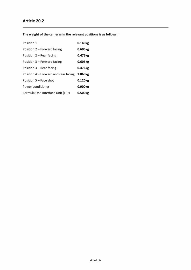
Article 20.2 The weight of the cameras in the relevant positions is as follows : Position 1 0.140kg
Position 2 – Forward facing 0.605kg
Position 2 – Rear facing 0.476kg
Position 3 – Forward facing 0.605kg
Position 3 – Rear facing 0.476kg
Position 4 – Forward and rear facing 1.860kg
Position 5 – Face shot 0.120kg
Power conditioner 0.900kg
Formula One Interface Unit (FIU) 0.500kg
43 of 66

44 of 66

45 of 66

46 of 66

47 of 66

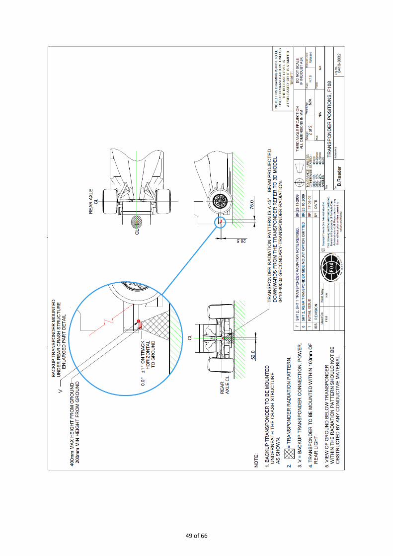
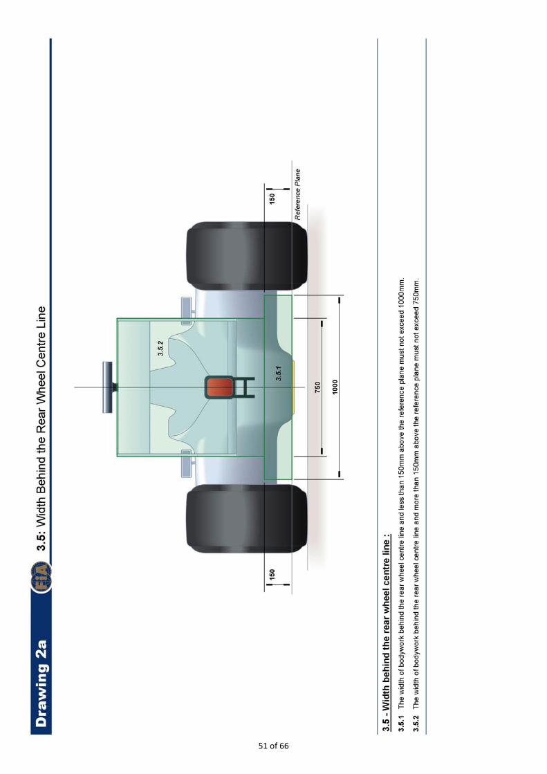
Article 20.4 The timing transponders must be fitted in accordance with the instructions given in the following drawings :
48 of 66
49 of 66

50 of 66
51 of 66

52 of 66

53 of 66

54 of 66

55 of 66

56 of 66

57 of 66
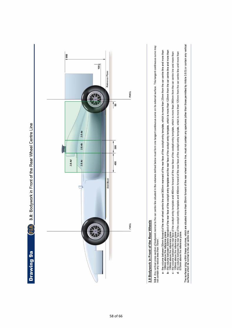
58 of 66

59 of 66

60 of 66

61 of 66

62 of 66

63 of 66
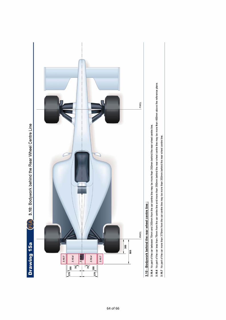
64 of 66

65 of 66

66 of 66