Embed Size (px)
Citation preview

Applied Photovoltaics LAB MANUAL
2010
Author: Todd Kaiser Montana State University
July 2009 So
lar
Ce
ll L
AB
MA
NU
AL
This manual was designed for use with the Montana Microfabrication Facility at Montana State University. The intention of the manual is to provide lab users and MSU students with a complete description of the methods used to fabricate Solar Cells on 4‐inch silicon substrates.
Special Thanks to: Brian Peterson Phil Himmer

SUPPLIERS University of Minnesota Nano Fabrication Center (NFC): Photomasks www.nfc.unm.edu Virginia Semiconductor: Silicon Substrates www.virginiasemi.com EL‐CAT Inc.: Silicon Substrates www.el‐cat.com JT Baker: Chemical Supplies www.mallbaker.com/default.asp Technical Glass Products Inc: Quartz‐ware www.technicalglass.com Kurt J Lesker Company: Evaporation Filaments www.lesker.com MSU Chem‐store: Labware/Chemical Supplies www.chemistry.montana.edu/chemstores Sigma‐Aldrich: Chemical Supplies www.sigmaaldrich.com SPI Supplies: Wafer Tweezers http://www.2spi.com/spihome.html Gases Plus: Pressurized Gas Tanks www.gasesplus.com (406)388‐9109

The suggested high temperature process steps for use in Solar Cell EE 408 lab are listed here.
P+ diffusion 950°C 50 min
wet oxidation 1000°C 90 min
N+ diffusion 825°C 50 min
dry oxidation 1000°C 80 min

How to use this manual…
11‐Lab Overview
The manual is broken up into laboratory segments containing multiple sections: Goals, Equipment, Parameters, Methods and Results. Each lab a set of process goals is presented to the user along with a list of equipment and the methods used to achieve those goals. The parameters segment is devoted to process dependent parameters specific to the fabrication methods used that week. The parameters are color coded to correspond to a specific process method. The methods section describes the processes used within that lab to achieve the desired goals. The methods are numbered to correspond to a process goal. The result section is left blank for users to record the results of that lab’s processes.
Introduction & P+ Rear Diffusion (Cobleigh) Lab 1
Thermal Oxidation (Mask for Si Etch) (Cobleigh) Lab 2
Photolithography, Oxide Etch, Silicon Etch (EPS) Lab 3
Oxide Etch & N+ Front Diffusion (Cobleigh) Lab 4
Thermal Oxidation (AR coating) (Cobleigh) Lab 5
Photolithography & Vias Oxide Etch (Front) (EPS) Lab 6
Cleaning & Aluminum Evaporation (Front) (Cobleigh) Lab 7
Photolithography & Aluminum Contact Etch (Front) (EPS) Lab 8
Cleaning & Aluminum Evaporation (Back) (Cobleigh) Lab 9
Characterization (Cobleigh) Lab 10
Dicing & Characterization (Cobleigh) Lab 11

Introduction & P+ Rear Diffusion Lab 1
Boron Diffusion Parameters (Back Contact) Boron Source Temperature (°C) Time (minutes) N2 Flow
BORONPLUS GS‐139 950 50 7
EQUIPMENT: • Wafer Scribe • Boron Diffusion Furnace • BORONPLUS GS139 Boron Sources
GOALS: 1. Familiarize students with the cleanroom
layout, equipment, safety and procedure. 2. Present an overview of the solar cell
fabrication process and various processing techniques (i.e. photolithography, etching, etc)
3. ID individual wafers 4. P+ Diffusion
PARAMETERS

Methods: 1. Clean Room Etiquette The lab employs many hazardous chemicals and processes. The safety of the lab students and users is the number one priority when participating in the lab. Follow all gowning and safety procedures outlined by the lab TA. To maintain the integrity of the wafers and the equipment, adhere to the process descriptions and details provided by the lab TA. The most common reason a wafer will not make it to the end of the fabrication sequence, is poor handling. The wafer should be handled with the wafer‐ tweezers and with great attention. Limit the handling of the wafer with gloved hands to the edges and only during necessary circumstances. Never touch the wafer with a bare hand and never touch the center of the wafer, even with gloved hands.
When processing in the cleanroom, sources of contamination are another factor which may inhibit the success of the fabrication. Therefore, do not talk next to the wafers, keep the lid to the wafer box closed and lastly, do not hastily move about the clean room and do not get in a hurry to finish a process. When a lab student gets in a hurry it creates a situation with a greater likely hood of breaking a wafer or damaging a piece of equipment.
Follow proper gowning procedure and remember the clothing you where is to protect your wafer from you not to protect you from dangerous chemicals.
Lab 1

M2.
comtecsteandthesholab
cleaproeveano
3.
canfor 100polto a
typUsiheawitmenegindvoltshoFigu
Methods:Process O
These mbination ofhniques. Theps including d patterning. e right (Figurould take rou devoted to t
Documean room. Rocedures and ery detail whomalies.
Wafer ChaSemicon
n easily be orspecific appl0mm in diamlished, single‐a resistivity of
A simplepe or N‐type sng a Digital Mat the positivth the soldereasure “mV.”gative(groundicates a posittage is negaould be accurure 2 Figure show
: verview: Solar Cells f thin film ae sequence ioxidation, An overview e 1). The fabughly ten labstesting. ent everythinecord all many deviatio
hich may hel
aracterizatnductor substrdered throulications. Theeter, 525±25 ‐crystal siliconf 1‐10 Ω‐cm. e test to detesilicon is knowMulti Meter (e probe of thring iron. Ma” Place bothd) to the wtive voltage tative the subate up to a rewing determinat
are fabricand bulk silis a simple seetching, diffof the sequebrication pors to complete
ng seen andmeasureable ons. It is impop explain de
tion and IDtrates, referregh retailers ae wafers usedµm thick, <1n, doped with ermine if thewn as the “H(DMM) and ahe DMM for ske sure the h probe tipswafer surfacehe substrate bstrate is P‐esistivity of 10tion of silicon su
cated using con processiet of repeatiusion, cleanince is shownrtion of the le, with the fin
d done in tquantities aortant to recovice failures
D: ed to as wafeand customizd for the lab a00>, single‐sih boron (P‐typ
e substrate isHot Probe Tesa soldering iroseveral minutDMM is set s, positive ae. If the DMis N‐type, if t‐type. This te000 Ω‐cm. ubstrate type.
a ing ing ing to lab nal
the and ord or
ers, zed are ide pe)
P‐st.” on, tes to
and MM the est
Figure 1
Overview of thee fabrication seq
quence.
Lab 1

Methods: 3. Wafer Characterization and ID: Continued…
To keep track of individual wafers, a scribe can be used to mark the back of the wafer with an identification mark, typically a number or letter (Figure 3).
Proceed by firmly pressing the tip of the scribe against the surface of the wafer and with as few strokes as possible ‘scribe’ a section number and wafer number. Scribing should be done as close to the edge as possible to limit the effect on fabricated devices.
4. Boron Diffusion: (Check Parameters section for details) The goal of the boron diffusion is to create highly doped P‐type silicon that will improve the contact between the silicon and the metal on the back of the cell. To diffuse P‐type (Boron) material, ramp the Lindberg Blue Boron Diffusion Furnace to 600°C and set the nitrogen flow. Remove the quartz boat with the solid, white, BORONPLUS GS‐139 sources already in place. Load the silicon wafers next to the sources with the back side facing a source (Figure 4). Insert the quartz boat to the center of the furnace and ramp the furnace to the desired temperature (Figure 5). When the desired temperature is reached start the timer. After the allotted time, ramp the furnace down to 600°C (or 0°C if finished with furnace), pull the quartz boat and remove the wafers and set them aside to cool. When the temperature drops below 400°C the nitrogen can be turned off. Figure 5 Inserting the boat into the Boron Diffusion Furnace.
Lab 1 Figure 3 Scribing the surface of a wafer using a steel‐tipped scribe.
Figure 4 An illustration of how the wafers are loaded into the quartz boat next to the diffusion sources.

Wafer Number: _______________________________________________________________________________________________________________________________________________________________________________________________________________________________________________________________________________________________________________________________________________________________________________________ ___________________________________________________________________________________________________________________________________________________________________________________________________________________________________________________________________________________________________________________________________________________________________________________________________________________________________________________________________________________________________________________________________________________________________________________________________________________________________________________________________________________________________ NOTES/CHANGES: __________________________________________________________________________________________________________________________________________________________________________________________________________________________________________________________________________________________________________________________________________________________________________________________________________________________________________________________________ ____________________________________________________________________________________________________________________________________________________________________________________________________________________________________________________________________________________________________________________________________________________________________________________________________________________________________________________________________________________________________________________________________________________________________________________________________________________________________________________________________________________________________________________________________________________________________________________________________________________________________________________________________________________________________________________________________
RESULTS: Lab 1

Thermal Oxidation Lab 2 EQUIPMENT:
• 6:1 BOE
• Teflon Dish
• JANDEL 4‐point Probe Station
• MODULAB Oxidation Furnace
GOALS: 1. Strip the Borosilicate Glass 2. Measure Sheet Resistivity 3. Oxidation for Silicon Etch Mask
PARAMETERS:
SiO2 Etch Parameters* BOE concentration SiO2 Etch Rate (Ǻ/min) Approx. Etch Time (minutes) Etch Mask
6:1 900 5* none Oxidation Parameters
Temperature (°C) Time (minutes) Type (wet or dry) N2/O2 Flow Bubbler Setting 1000 90 Wet 7/9 40

Methods: 1. Etching the SiO2: (Check Parameters section for details) There is a layer of borosilicate glass on the surface of the wafer that needs to be removed before the wafers can go into the oxidation furnace. This step should be carried out with extreme care. Begin by pouring enough 6:1 BOE into a Teflon or plastic dish. Submerge the wafer in the 6:1 BOE for the appropriate amount of time or until the exposed SiO2 is completely removed. Rinse in DI water and dry with the nitrogen gun. 2. Sheet Resistivity Measurements:
The back of the wafer now has a higher conducting layer on the surface. To characterize the doping the sheet resistivity is measured. Use the JANDEL 4‐point probe (Figure 6) to measure the sheet resistivity of the diffusion. Start by raising the probe arm, uncapping the tip and placing the wafer on the stage. Align the probes over the rear of the wafer opposite of the flat, then lower the arm to make contact with the wafer. Set the current to 1uA (press ‘1’ and ‘uA’) Press ‘FWD’ The unit is now passing a current through the sample. It should be giving a positive voltage reading. If the voltage reading is less than a millivolt, increase the current by an order of magnitude until you get a voltage reading of greater than one millivolt. Record the value. Press ‘REV’ The unit is now passing a current through the sample in the reverse direction. It should be giving a negative voltage reading about the same magnitude as the FWD measurement. Record the value.
Figure 6 The four‐point probe used to measure sheet resistivity
Lab 2 Increase the current by another order of
magnitude but do not exceed 100 mA, the voltage should also increase by an order of magnitude. Record the value Press ‘FWD’ Record the value for the new forward current, it should be an order of magnitude
larger than the previously recorded value. Press ‘Ω/’. Record this sheet resistivity measurement. Figure 7 The sheet resistivity measurement is taken by pressing the
‘Ω/‘ button.
3. Oxidation: Growing SiO2 (Check Parameters section for details)
The goal of the first oxidation run is to grow enough silicon dioxide (SiO2) roughly a 0.5µm thick film. This will be used to protect the silicon where silicon is not to be etched.
To oxidize, insert the wafers into the MODULAB oxidation furnace using the quartz rod and quartz boat (see Figure 7). There should be two dummy wafers, one at the front of the boat and another at the rear, to maintain uniformity across the boat. Ramp the furnace to 600°C before the removing the quartz boat and loading the wafers. Prior to the temperature reaching 400°C, turn on the nitrogen to purge the furnace. Also, set the potentiometer on the bubbler if performing a wet oxidation (which we are). Once the wafers are loaded and in place at the center of the furnace, ramp the furnace to the desired temperature. When the desired temperature is reached start the timer, stop the nitrogen flow and turn on the oxygen. After the allotted time, ramp the furnace down to 600°C, pull the boat, remove the wafers, and set them aside to cool. When finished, turn the furnace to 0°C and turn off the nitrogen when the temperature drops below 400°C.

RESULTS: Lab 2
Rear Sheet Resistivity & Calculated SiO2 Thickness (Ǻ):_____________________________________________________________________________________________________________________________________________________________________________________________________________________________________________________________________________________________________________________________________________________________________________________________________________________________________________________________________________________________________________________________________________________________________________________________________________________________________________________________________________________________________________________________________________________________________________________________________________________________________________________________________________________________________________________________________________________________________________________________________________________________________________________________________________________________________________________________________________________________________ NOTES/CHANGES: ___________________________________________________________________________________________________________________________________________________________________________________________________________________________________________________________________________________________________________________________________________________________________________________________________________________________________________________________________________________________________________________________________________________________________________________________________________________________________________________________________________________________________________________________________________________________________________________________________________________________________________________________________________________________________________________________________________________________________________________________________________________________________________________________________________________________________________________________________________________________________________________________________________________________________________________________________________________________________________________________

Photolithography, Oxide & Silicon Etch Lab 3 EQUIPMENT & Materials:
• Nanospec
• Brewer spin‐coater and hot plate
• Shipley 1813 Positive Photoresist
• ABM Contact Mask Aligner
• MF 319 Developer
• 6:1 BOE
• TMAH
PARAMETERS:
Hard‐bake Parameters (back)
Hard‐bake Program Temperature (°C) Time (minutes) #2 115 2
Spin‐coat & Soft‐bake Parameters (front) Spin
Program Speed (RPM)
Time (seconds)
Ramp (RPM/s)
Dispense Type
(automatic or manual)
Soft‐bake Program
Temperature (°C)
Time (minutes)
#9 5250 30 20000 Manual (static)
#9 115 1
Exposure & Development Parameters (MASK #1) Mask Orientation (writing toward or away from
user)
Wafer Orientation (flat to the left or the
right)
UV Intensity Channel B (mW/cm2)
UV Dose (J/cm2)
Exposure Time (seconds)
Development Time (seconds)
Toward Left 30 ~135 4.5 60 Hard‐bake Parameters
Hard‐bake Program Temperature (°C) Time (seconds) #9 115 60
SiO2 Etch Parameters* for 8,000‐8,500Ǻ thick SiO2 layer BOE concentration SiO2 Etch Rate (Ǻ/min) Approx. Etch Time (minutes) Etch Mask
6:1 900 15* Shipley 1813 Photoresist Bulk Silicon Etch Parameters *for multiple wafer etch setup
Etchant Bath Temperature* (°C)
(100) Etch Rate (micron/minute)
Approximate Etch Time (min)
Etch Mask
25% TMAH 75 1 120 SiO2
GOALS: 1. Measure the thickness of the SiO2 with
the ellipsometer 2. Photolithography (PV Mask 1 Si Etch) 3. Etch SiO2 4. Solvent Clean 5. Etch Silicon

Methods: 1. Measuring the SiO2 thickness:
Measure the thickness of the silicon dioxide at several different points on the wafer using the ellipsometer. For reference, the ellipsometer prompts for measuring SiO2 thickness estimate and index they are:
Thickness 5000 Å Index 1.46
Figure 8 The oxide thickness is measured using the ellipsometer. It measures the light intensity as a function of polarization reflected off the surfaces on the wafer
2. Photolithography with Mask 1 (Si Etch): Spin‐coating & Soft‐baking (Check Parameters section for details) The goal of the photolithography step is to transfer patterns from the mask set to the wafer surface. Photoresist, which is a UV sensitive chemical, is patterned by selectively exposing certain regions with ultraviolet light. Photoresist is also chemically resistant to the SiO2 etchant, hydrofluoric acid (also referred to as BOE); therefore it is used to mask, or block, select portions of the SiO2 from being etched. The first patterns transferred to the wafer are the inverted pyramid texture, which reduces the reflection loss from the surface.
Begin by using the BREWER spin‐coater to spin a thin film (~1um) of SHIPLEY 1813 photoresist onto the backside (rough) of the wafer. Next, transfer the wafer
1
4 5 2
3
Lab 3 to the adjacent hotplate and soft‐bake to remove solvents and harden the resist. A good coating of photoresist will be barely visible to the naked eye and have a minimal number of streaks or blotches. If there are a large number of defects, solvent clean, dehydrate, and try re‐spinning more photoresist.
Now repeat the process on the topside (smooth) of the wafer, spin on the photoresist and soft‐ bake to remove solvent and harden the photoresist.
3. Photolithography with Mask #1 (Si Etch): Exposure & Development (Check Parameters section for details)
Proceed by patterning the photoresist with Mask #1. Start by centering the chuck inside the mask holder then load the mask onto the ABM contact‐aligner mask stage.
Turn the mask‐vac on and raise the mask stage. Carefully, load the wafer onto the substrate chuck and orient it such that the <110> plane (wafer flat) is to the bottom and running straight left and right. The wafer should be centered in the chuck. Turn on the substrate‐vac to lock the wafer in place and lower the chuck to avoid hitting the contact mask. Next, lower the mask stage and raise the substrate chuck up to meet the mask, while holding the chuck tilt release button, fringe lines will become visible as the wafer and mask come into contact. Align the mask to the wafer using the markers on the sides of the wafer (no alignment for the first photolithography step). Turn on the contact‐vac to remove any air gap between mask and wafer. You should be able to see interference fringes in the etch windows. Adjust the exposure time and channel setting then expose. Remove the wafer by turning off the contact‐vac, lowering the substrate chuck, raising the mask frame, and turning off the substrate‐vac. Transfer the wafer to a dish of MF319 developer (a faint outline of the features can be seen at this point), submerge the wafer in MF319 and gently swirl for 30‐60 seconds until the exposed resist is completely dissolved. If done correctly there should be no photoresist left in the exposed regions. If there is, resubmerge the wafer in the MF319 developer for additional time.

Methods: 4. Hard‐baking: (Check Parameters section for details) Hard‐baking is the final step in the photolithography sequence, but to emphasize its importance it gets its own heading. The goal of the hard‐bake is to remove any remaining solvents and/or water from the resist. It has been observed, that without hard‐baking, the photoresist exhibits adhesion problems and frequently delaminates from the surface during etching. Hard‐baking is very similar to soft‐baking and follows the same procedure. Load a wafer onto a hotplate for a set time at the appropriate temperature.
5. Etching the SiO2: (Check Parameters section for details) The goal of the SiO2 etch is to remove the silicon dioxide from the exposed regions in the photoresist. Silicon dioxide is etched with BOE (Buffered Oxide Etch) which is a combination of hydrofluoric acid and buffering chemicals to stabilize the reaction. BOE is highly selective to silicon dioxide so the photoresist will not be etched.
This step should be carried out by the lab TA for safety reasons. Begin by loading the wafers into a Teflon cassette with equal spacing between wafers. Using the handle, submerge the cassette in 6:1 BOE for the appropriate amount of time or until the exposed SiO2 is completely removed. To determine if the SiO2 is completely removed, check the regions for color (see Figure 9) and hydrophobicity. When the etch is complete, remove the cassette and rinse the wafers in a DI water rinse sink. Pull the cassette from the rinse sink and dry individual wafers with the nitrogen gun.
6. Solvent Clean: REPEAT: To remove photoresist with a solvent clean begin by placing an evaporating dish on the solvent bench to catch solvent waste. Rinse the wafer with acetone using the squirt bottle, follow with isopropyl and methanol (Figure 10). The acetone will remove the photoresist and the isopropyl and methanol with remove any acetone residue. Rinse the wafers in DI water and dry with a nitrogen gun.
Lab 3 7. Bulk Silicon Etch in TMAH: (Check Parameters section for details) The goal of the bulk silicon etch is to create the inverted pyramids for reducing the reflection off the solar cell. Be sure that that the TMAH bath has reached the set temperature. Place the wafers in the cassette and completely submerge the wafers in the bath. Start the timer. The etchant attacks the surface plane of the silicon crystal (100) but etches the angled planes (111) much slower. The results are inverted pyramids etched into the surface of the wafer where the silicon is not protected by the oxide mask layer. The etch is complete when the diagonals of the corners meet in the center. Figure 9 Wafers that have oxide will have a characteristic color depending on the thickness of the oxide.
Figure 10 Use a three solvent clean to remove the photoresist from the wafer.

RESULTS: Lab 3
SiO2 Thickness (Å): _____________________________________________________________________________________________________________________________________________________________________________________________________________________________________________________________________________________________________________________________________________________________________________________________________________________________________________________________________________________________________________________________________________________________________________________________________________________________________________________________________________________________________________________________________________________________________________________________________________________________________________________________________________________________________________________________________________________________________________________________________________________________________________________________________________________________________________________________________________________________________ NOTES/CHANGES: ___________________________________________________________________________________________________________________________________________________________________________________________________________________________________________________________________________________________________________________________________________________________________________________________________________________________________________________________________________________________________________________________________________________________________________________________________________________________________________________________________________________________________________________________________________________________________________________________________________________________________________________________________________________________________________________________________________________________________________________________________________________________________________________________________________________________________________________________________________________________________________________________________________________________________________________________________________________________________________________________

N+ Front Diffusion Lab 4
EQUIPMENT: • Optical Microscope • Digital Camera • 6:1 BOE • Teflon cassette • Phosphorous Diffusion Furnace • PHOSPLUS TP‐250 Phosphorous Sources
PARAMETERS:
GOALS: 1. Take pictures using the microscope and
digital camera. 2. Strip the SiO2 3. Phosphorus Diffusion
SiO2 Etch Parameters* for 8,000‐8,500Ǻ thick SiO2 layer BOE concentration SiO2 Etch Rate (Ǻ/min) Approx. Etch Time (minutes) Etch Mask
6:1 900 15* none Phosphorous Diffusion Parameters ( N+)
Phosphorous Source Temperature (°C) Time (minutes) N2 Flow PHOSPLUS TP‐250 900 50 7

Methods: 1. Taking Pictures:
With the silicon etch completed, the wafers now have observable features. From this point, one goal of the lab is to document the fabrication progress by taking pictures of the surface of the wafer as it moves through the sequence. Begin by using the optical microscope and digital camera to take a picture of the textured front of the wafer.
2. Stripping the SiO2 : (Check Parameters section for details)
Prepare the wafer surface for the next diffusion by completely removing all the SiO2.
REPEAT: This step should be carried out by the lab TA for safety reasons. Begin by loading the wafers into a Teflon cassette with equal spacing between wafers. Figure 11 Wafers being stripped of SiO2 in a 6:1 BOE solution.
Figure 12 Wafers being stripped of SiO2 in a 6:1 BOE solution.
Lab 4 Using the handle, submerge the cassette in 6:1 BOE for the appropriate amount of time or until the exposed SiO2 is completely removed (Figure 11). To determine if the SiO2 is completely removed, check the regions for color (see Figure 9) and hydrophobicity. When the etch is complete, remove the cassette and rinse the wafers in a DI water rinse sink (Figure 12). Pull the cassette from the rinse sink and dry individual wafers with the nitrogen gun.
3. Phosphorous Diffusion: (Check Parameters section for details) The goal of the phosphorous diffusion is to create highly doped N‐type silicon to create the pn junction of the solar cell. To diffuse N‐type (Phosphorous) material, ramp the MODULAB Phosphorous Diffusion Furnace to 600°C and set the nitrogen flow. Remove the quartz boat with the solid, white, PHOSPLUS TP‐250 sources already in place. Load the silicon wafers next to the sources with the patterned side facing a source. Insert the quartz boat to the center of the furnace and ramp the furnace to the desired temperature. When the desired temperature is reached start the timer. After the allotted time, ramp the furnace down to 600°C (or 0°C if finished with furnace), pull the quartz boat and remove the wafers and set them aside to cool. When the temperature drops below 400°C the nitrogen can be turned off. Figure 13 Placing the boat tray on the front of the Phosphorus Diffusion Furnace .

Sheet Resistance (Ω/) & Resistivity (Ω‐cm):_____________________________________________________________________________________________________________________________________________________________________________________________________________________________________________________________________________________________________________________________________________________________________________________________________________________________________________________________________________________________________________________________________________________________________________________________________________________________________________________________________________________________________________________________________________________________________________________________________________________________________________________________________________________________________________________________________________________________________________________________________________________________________________________________________________________________________________________________________________________________________ NOTES/CHANGES: ___________________________________________________________________________________________________________________________________________________________________________________________________________________________________________________________________________________________________________________________________________________________________________________________________________________________________________________________________________________________________________________________________________________________________________________________________________________________________________________________________________________________________________________________________________________________________________________________________________________________________________________________________________________________________________________________________________________________________________________________________________________________________________________________________________________________________________________________________________________________________________________________________________________________________________________________________________________________________________________________
RESULTS: Lab 4

Antireflection Oxidation Lab 5
EQUIPMENT: • 6:1 BOE
• Teflon Dish
• JANDEL 4‐point Probe Station
• MODULAB Oxidation Furnace
PARAMETERS:
Oxidation Parameters Temperature (°C) Time (minutes) Type (wet or dry) N2/O2 Flow Bubbler Setting
1000 90 Dry 7/9 off
GOALS: 1. Strip the phosphosilicate glass (PSG) 2. Measure Sheet Resistivity 3. Dry Oxidation

M1. (Ch surtheshopouSubamrem
2.
condop4‐pdifftip ovelowSetTheshoreaordgreThethevoltmeanothemavalof m
Pre
moresRemto t
Methods:Etching thheck Parame
There isrface of the we wafers can ould be carruring enoughbmerge the wount of timemoved. Sheet Resi
REPEAT:nducting layeping the sheepoint probe tfusion. Start and placing ter the rear ower the probt the current e unit is now ould be givingading is less thder of magniteater than one unit is now e reverse dirtage reading easurement. Rother order oe voltage shgnitude. Recue for the nemagnitude la
ess ‘Ω/’. Rec
The theove farther iistivity each measure the the initial me
: he SiO2: eters sections a layer of pwafer that nego into the oried out with 6:1 BOE inwafer in the 6e or until the
istivity MeT: The front ofer on the suet resistivity isto measure tby raising thethe wafer onof the wafere arm to mato 1uA (prespassing a cug a positive vohan a millivoltude until yoe millivolt. Rpassing a curection. It shabout the sa
Record the vaof magnitude hould also cord the valuew forward cuarger than the
cord this shee
rmal processinto the subtime the wsheet resistivasurement.
n for detailsphosphosilicaeeds to be roxidation furh extreme cnto a Teflon 6:1 BOE for texposed SiO
easuremenf the wafer nourface. To chs measured. Uthe sheet ree probe arm,n the stage. Ar opposite ofake contact wss ‘1’ and ‘uArrent througholtage readint, increase thou get a voltecord the varrent throughhould be givame magnitualue. Increasebut do not eincrease byue Press ‘FWurrent, it shoe previously r
et resistivity m
ing will causebstrate changafers go intovity of the bac
s) te glass on temoved befornace. This stcare. Begin or plastic disthe appropriaO2 is complet
nts: ow has a highharacterize tUse the JANDesistivity of t, uncapping tAlign the probf the flat, thwith the wafA’) Press ‘FWh the sampleg. If the voltahe current by tage reading lue. Press ‘REh the sampleving a negatude as the FWe the current exceed 100 m an order
WD’ Record tuld be an ordrecorded valu
measuremen
e the dopantsging the sheo the furnacck and compa
the ore tep by sh. ate ely
her the DEL the the bes hen fer. WD’ . It age an of EV’ e in ive WD by
mA, of
the der ue.
t.
s to eet es. are
3. Dry(Check
antirefapproxdiffers with dr
oxidatiThere sthe boacross removto the to purquartz furnacetempenitrogetime, rwith futhem aFigure 1
y Oxidatiok ParameterThe goal o
flective coatiximately 130from the prry O2. REPEAT: T
ion furnace ushould be twat and anoththe boat. Raing the quarttemperaturerge the furnaboat to the e to the desrature is reen flow and tramp the furnurnace), pull taside to cool.4 After oxidatio
on: Growinrs section foof this oxidatng. The oxid0Å thick. Threvious run, t
o oxidize, iusing the quawo dummy waer at the reaamp the furntz boat and l reaching 400ace. Load thecenter of thired temperaeached startturn on the onace down tothe boat, rem
n the wafer will
g SiO2 or details) tion run is tde thicknesshe method othe oxide wi
insert the wartz rod and qafers, one at r, to maintainace to 600°Coading the w0°C, turn on te wafers ande furnace anature. When t the timerxygen. After o 600°C (or 0°move the waf
appear blue .
Lab 5
o grow the s should be of oxidation ll be grown
wafers into quartz boat. the front of n uniformity C before the wafers. Prior the nitrogen d insert the nd ramp the the desired , stop the the allotted °C if finished fers, and set

M Bullarg
Frocon
Masks:
k etch of silge squares to
ont silicon diontacts.
icon (very smo appear solid
oxide etch to
mall squares d).
expose the s
that cause t
silicon for me
the
etal
The mewordin
etal etch creang on the surf
ates the electface.
rical contacts
Lab 5
s and

SiO2 Thickness (Å): _____________________________________________________________________________________________________________________________________________________________________________________________________________________________________________________________________________________________________________________________________________________________________________________________________________________________________________________________________________________________________________________________________________________________________________________________________________________________________________________________________________________________________________________________________________________________________________________________________________________________________________________________________________________________________________________________________________________________________________________________________________________________________________________________________________________________________________________________________________________________________ NOTES/CHANGES: ___________________________________________________________________________________________________________________________________________________________________________________________________________________________________________________________________________________________________________________________________________________________________________________________________________________________________________________________________________________________________________________________________________________________________________________________________________________________________________________________________________________________________________________________________________________________________________________________________________________________________________________________________________________________________________________________________________________________________________________________________________________________________________________________________________________________________________________________________________________________________________________________________________________________________________________________________________________________________________________________
RESULTS: Lab 5

Photolithography & Vias Oxide Etch Lab 6
EQUIPMENT: • Ellipsometer
• BREWER Spin‐coater & Hotplate
• SHIPLEY 1813 Positive Photoresist
• ABM Contact Mask Aligner
• MF 319 Developer
• 6:1 BOE
• Teflon Cassette
PARAMETERS:
Spin‐coat & Soft‐bake Parameters Spin
Program Speed (RPM)
Time (seconds)
Ramp (RPM/s)
Dispense Type
(automatic or manual)
Soft‐bake Program
Temperature (°C)
Time (minutes)
#9 5250 30 20000 Manual (static)
#9 115 1
Exposure & Development Parameters (MASK #4) Mask Orientation (writing toward or away from
user)
Wafer Orientation (flat to the left or the
right)
UV Intensity Channel B (mW/cm2)
UV Dose (J/cm2)
Exposure Time (seconds)
Development Time (seconds)
Toward Left 30 ~135 4.5 30‐60 Hard‐bake Parameters
Hard‐bake Program Temperature (°C) Time (minutes) #9 115 1
Exposure & Development Parameters (MASK #2) Mask Orientation (writing toward or away from
user)
Wafer Orientation (flat to the left or the
right)
UV Intensity Channel B (mW/cm2)
UV Dose (J/cm2)
Exposure Time (seconds)
Development Time (seconds)
Toward Left 30 ~135 4.5 30‐60 Hard‐bake Parameters
Hard‐bake Program Temperature (°C) Time (minutes) #9 115 1
SiO2 Etch Parameters* for 4,200‐4,500Ǻ thick SiO2 layer BOE concentration SiO2 Etch Rate (Ǻ/min) Approx. Etch Time (minutes) Etch Mask
6:1 900 5* Shipley 1813 Photoresist
GOALS: 1. Measure the thickness of the SiO2 layer
with the ellipsometer 2. Photolithography (PV Mask 4 Backside
Contacts) 3. Hardbake 4. Photolithography (PV Mask 2 SiO2 Etch) 5. Hardbake 6. Oxide Etch

Methods: 1. Measuring the SiO2 thickness:
REPEAT: Measure the thickness of the silicon dioxide at several different points on the wafer using the ellipsometer. For reference, the ellipsometer prompts for measuring SiO2 thickness estimate and index they are:
Thickness 5000 Å Index 1.46
2. Photolithography with Mask #4 (Backside Contacts): Spin‐coating & Soft‐baking (Check Parameters section for details) The fourth mask contains the features of the backside contact via etch. The vias are holes in the SiO2 which allow the aluminum pads to contact the diffused silicon surface.
REPEAT: Begin by using the BREWER spin‐coater to spin a thin film of SHIPLEY 1813 photoresist onto the backside of the wafer. Next, transfer the wafer to the adjacent hotplate and soft‐bake to remove solvents and harden the resist. A good coating of photoresist will be barely visible to the naked eye and have a minimal number of streaks or blotches (see Figure 7). If there are a large number of defects, solvent clean, dehydrate, and try re‐spinning the photoresist a second time.
Figure 15 Student pouring photoresist on wafer .
1
4 5 2
3
Lab 6 3. Photolithography with Mask #4 (Backside Contacts): Exposure & Development (Check Parameters section for details)
Proceed by patterning the photoresist with Mask #4.
REPEAT: Load the mask onto the ABM contact‐aligner mask stage. Turn the mask‐vac on and raise the mask stage. Carefully, load the wafer onto the substrate chuck backside up and orient it such that the <110> plane (wafer flat) is to the left and running straight up and down. Turn on the substrate‐vac to lock the wafer in place and lower the chuck to avoid hitting the contact mask. Next, lower the mask stage and raise the substrate chuck up to meet the mask, fringe lines will become visible as the wafer and mask come into contact. Align the mask to the wafer using the markers on the sides of the wafer. Turn on the contact‐vac to remove any air gap between mask and wafer. Adjust the exposure time and channel setting then expose. Remove the wafer by turning off the contact‐vac, lowering the substrate chuck, raising the mask frame, and turning off the substrate‐vac. Transfer the wafer to a dish of MF319 developer (a faint outline of the features can be seen at this point), submerge the wafer in MF319 and gently swirl for 30‐60 seconds until the exposed resist is completely dissolved. If done correctly there should be no photoresist left in the diffusion contact regions (see Figure 8). If there is, resubmerge the wafer in the MF319 developer for additional time. If unsuccessful, use a solvent clean to strip the photoresist, dehydrate and re‐spin again. When finished, pour the used MF319 into the MF319 waste container located under the solvent bench next to the photoresist.

Methods: 4. Hard‐baking: (Check Parameters section for details) REPEAT: It has been observed, that without hard‐baking, the photoresist exhibits adhesion problems and frequently delaminates from the surface during etching. Hard‐baking is very similar to soft‐baking and follows the same procedure. Load a wafer onto a hotplate for a set time at the appropriate temperature.
5. Photolithography with Mask #2 (SiO2 Etch): Spin‐coating & Soft‐baking (Check Parameters section for details) The PV Mask #2 contains the features of the front side oxide contact etch. The oxide is removed which allows the aluminum fingers to contact the diffused silicon surface. REPEAT: Begin by using the BREWER spin‐coater to spin a thin film of SHIPLEY 1813 photoresist onto the topside of the wafer. Next, transfer the wafer to the adjacent hotplate and soft‐bake to remove solvents and harden the resist. A good coating of photoresist will be barely visible to the naked eye and have a minimal number of streaks or blotches (see Figure 7). If there are a large number of defects, solvent clean, dehydrate, and try re‐spinning more photoresist.
6. Photolithography with Mask #2 (SiO2 Etch): Exposure & Development (Check Parameters section for details)
Proceed by patterning the photoresist with Mask #2. REPEAT: Load the mask onto the ABM contact‐aligner mask stage. Turn the mask‐vac on and raise the mask stage. Carefully, load the wafer onto the substrate chuck top surface up and orient it such that the <110> plane (wafer flat) is to the left and running straight up and down. Turn on the substrate‐vac to lock the wafer in place and lower the chuck to avoid hitting the contact mask.
Lab 6 Next, lower the mask stage and raise the
substrate chuck up to meet the mask, fringe lines will become visible as the wafer and mask come into contact. Align the mask to the wafer using the markers on the sides of the wafer. Turn on the contact‐vac to remove any air gap between mask and wafer. Adjust the exposure time and channel setting then expose. Remove the wafer by turning off the contact‐vac, lowering the substrate chuck, raising the mask frame, and turning off the substrate‐vac. Transfer the wafer to a dish of MF319 developer (a faint outline of the features can be seen at this point), submerge the wafer in MF319 and gently swirl for 30‐60 seconds until the exposed resist is completely dissolved. If done correctly there should be no photoresist left in the diffusion contact regions (see Figure 8). If there is, resubmerge the wafer in the MF319 developer for additional time. If unsuccessful, use a solvent clean to strip the photoresist, dehydrate and re‐spin again. When finished, pour the used MF319 into the MF319 waste container located under the solvent bench next to the photoresist.
7. Etching the SiO2: (Check Parameters section for details)
REPEAT: This step should be carried out by the lab TA for safety reasons. Begin by loading the wafers into a Teflon cassette with equal spacing between wafers. Using the handle, submerge the cassette in 6:1 BOE for the appropriate amount of time or until the exposed SiO2 is completely removed. To determine if the SiO2 is completely removed, check the regions for color (see Figure 9) and hydrophobicity. When the etch is complete, remove the cassette and rinse the wafers in a bucket of DI water. Pull the cassette and place in the rinse sink then run the rinse cycle dry the wafers with the nitrogen gun when completed

SiO2 Thickness (Å): _____________________________________________________________________________________________________________________________________________________________________________________________________________________________________________________________________________________________________________________________________________________________________________________________________________________________________________________________________________________________________________________________________________________________________________________________________________________________________________________________________________________________________________________________________________________________________________________________________________________________________________________________________________________________________________________________________________________________________________________________________________________________________________________________________________________________________________________________________________________________________ NOTES/CHANGES: ___________________________________________________________________________________________________________________________________________________________________________________________________________________________________________________________________________________________________________________________________________________________________________________________________________________________________________________________________________________________________________________________________________________________________________________________________________________________________________________________________________________________________________________________________________________________________________________________________________________________________________________________________________________________________________________________________________________________________________________________________________________________________________________________________________________________________________________________________________________________________________________________________________________________________________________________________________________________________________________________

Cleaning & Al Evaporation (Front) Lab 7
PARAMETERS:
Aluminum Deposit Parameters* for 3000‐4000Ǻ thick Aluminum layer Al Foil Area (cm2) Al Foil Thickness (µ) Filament to Wafer Distance (cm) Power Level
30 40 13.5 40%
GOALS: 1. Take pictures using the microscope and
digital camera 2. Solvent Clean 3. Aluminum PVD 4. Measure Sheet Resistivity
EQUIPMENT: • Optical Microscope • CANON Digital Camera • Acetone, Methanol, Isopropyl • MODULAB Physical Vapor Deposition
System • JANDEL 4‐point Probe Station

Methods: 1. Taking Pictures:
Use the Optical Microscope and Digital Camera to take pictures of the vias and contact regions
2. Solvent Clean: REPEAT: To remove the photoresist a solvent
clean is performed. Begin by placing an evaporating dish on the solvent bench to catch solvent waste. Rinse the wafer with acetone using the squirt bottle, and follow with isopropyl and methanol. Rinse the wafers in DI water and dry with a nitrogen gun. When finished pour the solvent waste into the Solvent Waste Container.
3. Aluminum PVD: The goal of the aluminum evaporation is to create a thin film of aluminum on the topside of the wafer. The aluminum will be patterned with Mask #5 to create electrical contact pads for characterizing the finished devices. The evaporation is accomplished with the MODULAB PVD system. See the MODULAB PVD operations manual for more information. Approximately 40‐50 cm2
of aluminum should be evaporated. This will provide roughly 0.5‐0.7µm of aluminum on the wafer surface. Figure 16 Hanging the Wafers in the Evaporator.
Lab 7 4. Sheet Resistivity Measurements:
The aluminum layer on the wafer creates a higher conducting layer on the surface. To characterize the aluminum layer the sheet resistivity is measured. Use the JANDEL 4‐point probe (Figure 6) to measure the sheet resistivity of the aluminum. Start by raising the probe arm, uncapping the tip and placing the wafer on the stage. Align the probes over the rear of the wafer opposite of the flat, then lower the probe arm to make contact with the wafer. Set the current to 1uA (press ‘1’ and ‘uA’) Press ‘FWD’ The unit is now passing a current through the sample. It should be giving a positive voltage reading. If the voltage reading is less than a millivolt, increase the current by an order of magnitude until you get a voltage reading of greater than one millivolt. Record the value. Press ‘REV’ The unit is now passing a current through the sample in the reverse direction. It should be giving a negative voltage reading about the same magnitude as the FWD measurement. Record the value. Increase the current by another order of magnitude but do not exceed 100 mA, the voltage should also increase by an order of magnitude. Record the value Press ‘FWD’ Record the value for the new forward current, it should be an order of magnitude
larger than the previously recorded value. Press ‘Ω/’. This is the sheet resistivity measurement.

Front Aluminum Sheet Resistance (Ω/):__________________________________________________________________________________________________________________________________________________________________________________________________________________________________________________________________________________________________________________________________________________________________________________________________________________________________________________________________________________________________________________________________________________________________________________________________________________________________________________________________________________________________________________________________________________________________________________________________________________________________________________________________________________________________________________________________________________________________________________________________________________________________________________________________________________________ NOTES/CHANGES: ___________________________________________________________________________________________________________________________________________________________________________________________________________________________________________________________________________________________________________________________________________________________________________________________________________________________________________________________________________________________________________________________________________________________________________________________________________________________________________________________________________________________________________________________________________________________________________________________________________________________________________________________________________________________________________________________________________________________________________________________________________________________________________________________________________________________________________________________________________________________________________________________________________________________________________________________________________________________________________________________ ___________________________________________________________________________
RESULTS: Lab 7

Ph
PA
P
Ma(wo
GO1. 2. 3. 4.
hotoli
ARAMET
Spin Program
#9
ask Orientatiowriting towardor away from
user) Away
Hardba
Etchant PAE
OALS: PhotolithoHardbakeAluminumMeasure
ithogr
TERS:
Speed (RPM)
5250
on d
WaOrientatto the le
rigLe
ake Program #2
App
ography (Pe m Etch Aluminum
raphy
Time
(seconds)
30
Exposurafer tion (flat eft or the ht) eft
Aluminum Etprox. Etch Rat
350
V Mask #3
m thickness
y & Al
Spin‐coat & SRamp (RPM/s)
20000
re & DevelopUV IntensityChannel B (mW/cm2)
30 Hard‐b
Tem
tch Parametete (Å /min)
3 Metal 1)
s
l Cont
Soft‐bake ParDispenType
(automatmanuaManu(static
pment Paramy UV
(J/
~bake Paramet
mperature (°C)115
ers* for 0.5‐1uApprox. Et15* (Roo
EQU• B• SH• A• M• PA• W
• A
tact E
rameters nse e tic or al)
SoftProg
al c)
#
meters (MASKV Dose /cm2)
~135 ters
)
um thick alumintch Time (minom Temperat
UIPMENTREWER spHIPLEY 181BM Conta
MF 319 devAN Etch
Wafer Glass
MBIOS Pro
tch
tbake gram
Te
#2
K #3) Exposure Tim
(seconds)
4.5
T
num layer nutes) ure) S
T: in‐coater a13 positivect Mask Alveloper
sware
ofilometer
L
mperature (°C)
115
me )
DevTime
ime (minutes2
Etch Mhipley 1813 P
and hotplae photoresigner
Lab 8
Time (minutes)
2
velopment e (seconds)
30‐60
s)
Mask Photoresist
ate ist

Methods: 1. Photolithography with Mask #3 (Metal 1): Spin‐coating & Soft‐baking (Check Parameters section for details) The third mask contains the features for the top side metal contacts.
REPEAT: Begin by using the BREWER spin‐coater to spin a thin film of SHIPLEY 1813 photoresist onto the topside of the wafer. Next, transfer the wafer to the adjacent hotplate and soft‐bake to remove solvents and harden the resist. A good coating of photoresist will be barely visible to the naked eye and have a minimal number of streaks or blotches (see Figure 7). If there are a large number of defects, solvent clean, dehydrate, and try re‐spinning more photoresist.
Figure 17 A student using the ABM mask aligner to align Mask #3.
Lab 8 2. Photolithography with Mask #3 (Metal 1): Exposure & Development (Check Parameters section for details)
Proceed by patterning the photoresist with Mask #3.
REPEAT: Load the mask onto the ABM contact‐aligner mask stage. Turn the mask‐vac on and raise the mask stage. Carefully, load the wafer onto the substrate chuck and orient it such that the <110> plane (wafer flat) is to the left and running straight up and down. Turn on the substrate‐vac to lock the wafer in place and lower the chuck to avoid hitting the contact mask. Next, lower the mask stage and raise the substrate chuck up to meet the mask, fringe lines will become visible as the wafer and mask come into contact. Align the mask to the wafer using the markers on the sides of the wafer. Turn on the contact‐vac to remove any air gap between mask and wafer. Adjust the exposure time and channel setting then expose. Remove the wafer by turning off the contact‐vac, lowering the substrate chuck, raising the mask frame, and turning off the substrate‐vac. Transfer the wafer to a dish of MF319 developer (a faint outline of the features can be seen at this point), submerge the wafer in MF319 and gently swirl for 30‐60 seconds until the exposed resist is completely dissolved. If done correctly there should be no photoresist left in the diffusion contact regions (see Figure 8). If there is, resubmerge the wafer in the MF319 developer for additional time. If unsuccessful, use a solvent clean to strip the photoresist, dehydrate and re‐spin again. When finished, pour the used MF319 into the MF319 waste container located under the solvent bench next to the photoresist.
2. Hard‐baking: (Check Parameters section for details) REPEAT: It has been observed, that without hard‐baking, the photoresist exhibits adhesion problems and frequently delaminates from the surface during etching. Hard‐baking is very similar to soft‐baking and follows the same procedure. Load a wafer onto a hotplate for a set time at the appropriate temperature.

Methods: 3. Etching Aluminum: (Check Parameters section for details) The exposed aluminum is removed in PAE (Phosphoric Acid Etch) one wafer at a time. The PAE contains three acids: phosphoric, acetic, and nitric. It etches aluminum at approximately 350Å/min and is highly selective to aluminum compared to photoresist.
Begin by pouring a small amount of PAE into a pyrex or Teflon evaporating dish. Submerge a wafer and gently swirl until the exposed aluminum has been etched. A visible etch front will move across the wafer as the aluminum is removed (see Figure 17). The etch will take between 10‐15 minutes to complete at room temperature. The etch rate increases with temperature. The evaporating dish can be placed on a hot plate and heated to 70⁰C to increase the etch rate. The complete etch will then only take several minutes.
Figure 17 Aluminum being etched in PAE. Note the etch front moving from left to right. This is a result of a varying thickness in the aluminum created during the evaporation.
3. Solvent Clean: REPEAT: To remove the photoresist a solvent
clean is performed. Begin by placing an evaporating dish on the solvent bench to catch solvent waste. Rinse the wafer with acetone using the squirt bottle, and follow with isopropyl and methanol. Rinse the wafers in DI water and dry with a nitrogen gun. When finished pour the solvent waste into the Solvent Waste Container.
Lab 8 4. Aluminum Thickness Measurements: Measure the thickness of the patterned aluminum film with the AMBIOS Stylus Profilometer, Figure 18. Begin by loading a wafer onto the stage. Using the XP2 software move the stage and wafer beneath the stylus. Adjust the stylus height and stage position over a patterned feature. Scan the feature with an appropriate scan length, speed, and force. Consult the AMBIOS operations manual for more details. The results should resemble the following figure, Figure 19. Figure 18 The Stylus Profilometer is used to measure steps in thin films.
Figure 19 Profilometer data of an aluminum pad. The data reveals the thickness of the aluminum film.

Aluminum Thickness (Å): _____________________________________________________________________________________________________________________________________________________________________________________________________________________________________________________________________________________________________________________________________________________________________________________________________________________________________________________________________________________________________________________________________________________________________________________________________________________________________________________________________________________________________________________________________________________________________________________________________________________________________________________________________________________________________________________________________________________________________________________________________________________________________________________________________________________________________________________________________________________________________ NOTES/CHANGES: ___________________________________________________________________________________________________________________________________________________________________________________________________________________________________________________________________________________________________________________________________________________________________________________________________________________________________________________________________________________________________________________________________________________________________________________________________________________________________________________________________________________________________________________________________________________________________________________________________________________________________________________________________________________________________________________________________________________________________________________________________________________________________________________________________________________________________________________________________________________________________________________________________________________________________________________________________________________________________________________________
RESULTS: Lab 8

Cleaning & Al Evaporation (Back) Lab 9
PARAMETERS:
Aluminum Deposit Parameters* for 3000‐4000Ǻ thick Aluminum layer Al Foil Area (cm2) Al Foil Thickness (µ) Filament to Wafer Distance (cm) Power Level
30 40 13.5 40% Annealing Parameters
Programmable Hot Plate Temperature (°C) Time (minutes) Manually Set Temperature 400 60
EQUIPMENT: • Acetone, Methanol, Isopropyl • MODULAB Physical Vapor Deposition
System • JANDEL 4‐point Probe Station • Programmable Hot‐Plate
GOALS: 1. Solvent Clean 2. Aluminum PVD 3. Measure Sheet Resistivity 4. Anneal the wafer to improve the
electrical contact between the metal and semiconductor

Methods: 1. Solvent Clean:
REPEAT: To remove the photoresist a solvent clean is performed. Begin by placing an evaporating dish on the solvent bench to catch solvent waste. Rinse the wafer with acetone using the squirt bottle, and follow with isopropyl and methanol. Rinse the wafers in DI water and dry with a nitrogen gun. When finished pour the solvent waste into the Solvent Waste Container.
2. Aluminum PVD: The goal of this aluminum evaporation is to create a thin film of aluminum on the backside of the wafer. The aluminum will not be patterned. The evaporation is accomplished with the MODULAB PVD system. See the MODULAB PVD operations manual for more information.
Approximately 40‐50 cm2 of aluminum should be
evaporated. This will provide roughly 0.5‐0.7µm of aluminum on the wafer surface. If sufficient coverage is not obtained the wafers can be rotated in the holder and a second coat of aluminum can be evaporated over the first coating.
3. Sheet Resistivity Measurements: The aluminum layer on the wafer creates a higher conducting layer on the surface. To characterize the aluminum layer the sheet resistivity is measured. Use the JANDEL 4‐point probe (Figure 6) to measure the sheet resistivity of the aluminum. Start by raising the probe arm, uncapping the tip and placing the wafer on the stage. Align the probes over the rear of the wafer opposite the flat, then lower the probe arm to make contact with the wafer. Set the current to 1uA (press ‘1’ and ‘uA’) Press ‘FWD’ The unit is now passing a current through the sample. It should be giving a positive voltage reading. If the voltage reading is less than a millivolt, increase the current by an order of magnitude until you get a voltage reading of greater than one millivolt. Record the value. Press ‘REV’ The unit is now passing a current through the sample in the reverse direction. It should be giving a negative voltage reading about the same magnitude as the FWD measurement. Record the value.
Lab 9 Increase the current by another order of
magnitude but do not exceed 100 mA, the voltage should also increase by an order of magnitude. Record the value Press ‘FWD’ Record the value for the new forward current, it should be an order of magnitude
larger than the previously recorded value. Press ‘Ω/’. This is the sheet resistivity measurement.
4. Annealing: (Check Parameters section for details)
Typically there is a poor connection between the aluminum and the silicon. This contact can be improved by the inter‐diffusion of the aluminum and silicon during the annealing of the wafer. The annealing is done by placing the wafer on a hot plate and heating the wafer. First make sure the hot plate has a clean aluminum foil covering the heating surface. This is to ensure you do not contaminate the surface of your wafer. Set the temperature to 400⁰C and place your wafer on the hot plate. Once the plate temperature has reached 390⁰C begin the timer. Remove the wafer once the annealing time has been reached and place it on a stainless steel table to cool before packaging your solar cell to remove from the clean room. Figure 20 Annealing the solar cell wafer on a hot plate.

Rear Aluminum Sheet Resistance (Ω/):_____________________________________________________________________________________________________________________________________________________________________________________________________________________________________________________________________________________________________________________________________________________________________________________________________________________________________________________________________________________________________________________________________________________________________________________________________________________________________________________________________________________________________________________________________________________________________________________________________________________________________________________________________________________________________________________________________________________________________________________________________________________________________________________________________________________________________________________________________________________________________ NOTES/CHANGES: ___________________________________________________________________________________________________________________________________________________________________________________________________________________________________________________________________________________________________________________________________________________________________________________________________________________________________________________________________________________________________________________________________________________________________________________________________________________________________________________________________________________________________________________________________________________________________________________________________________________________________________________________________________________________________________________________________________________________________________________________________________________________________________________________________________________________________________________________________________________________________________________________________________________________________________________________________________________________________________________________
RESULTS: Lab 9

Characterization Lab 10
PARAMETERS:
Figure 22 Test set up with flood light as source.
EQUIPMENT: • Flood Light • Contact station • Digital Multi Meter (2) • Decade Resistor Box
GOALS: 1. Measure the open circuit voltage 2. Measure the short circuit current 3. Create current – voltage plots for
each of your four solar cells.

Methods: 1. Open Circuit Voltage 2. Short Circuit Current
The two measurements that gives an indication of the performance of the solar cell are the Open Circuit Voltage (Voc) and the Short Circuit Current (Isc). Both are measured by placing a Digital Multimeter (DMM) across the contacts of the solar cell.
Place your wafer in the test bed be sure that contact is made to one solar cell front pads and the rear aluminum of the wafer. Connect the front side contact to the common terminal of the DDM and the rear contact to the Voltage terminal. Illuminate the solar cell and set the DDM to measure DC voltage. Record the Open Circuit Voltage (Figure 20). Move the Rear contact to the Current Terminal and set the DDM to measure DC current. Record the Short Circuit Current. Figure 20 Set up to measure the Open Circuit Voltage and the Short Circuit Current of the solar cell.
Lab 10 2. Current Voltage Data:
Place your wafer in the test bed. Be sure that contacts are made to one solar cell front pads and the rear aluminum of the wafer. Connect the front side contact to the common terminal of the DMM and the rear contact to the Voltage terminal, turn the knob such that the DMM is acting as a voltmeter (VDC). Connect a second DMM Current terminal to the Voltage terminal of the first DMM and the common terminal to a decade resistor box and turn the knob on the DMM to measure DC current (ADC). Connect the other terminal of the decade resistor box to the common terminal of the first DMM that is acting as a voltmeter. The set up should be ready to measure the voltage and current output of the solar cell as the load resistance is varied as shown in Figure 23.
Figure 23 Schematic of the Voltage – Current Measurement System
Illuminate the solar cell with the flood light and record the voltage and current readings as the load resistance is varied. Fill out the following results sheet for each of your four solar cells. Record your wafer marking, the fabrication dates, which solar cell you are testing (top left, top right, bottom left, or bottom right) the date you tested your solar cell, the final sheet resistivities and the thermal processing times and temperatures in the places provided. You will be turning in a copy of these sheets for each of your solar cells. They will be used to monitor the process results with the possibility of improving the process in future offerings of the class.

Lab 10
Methods: At short circuit, the solar cell produces electric
current but not voltage. At open circuit, the solar cell produces voltage but no current. Electric power is defined as the product of the current and the voltage. Somewhere between these points where zero power is produced a maximum power operating point exists.
Place the data in a spreadsheet or graphing program with one column recording the voltage another column recording the current and a third column that records the product of the voltage and the current, which is the power generated. Plot the IV curve with the current on the vertical or y‐axis and voltage on the horizontal or x‐axis. Plot the power in the vertical axis (use the right axis or plot a second graph) and the voltage on the horizontal axis. Find the maximum power on the curve and find the corrsponding voltage and current. This is the maximum power your solar cell can produce under this illumination condition.
Repeat these two plots for each of your solar cells. Be sure to discuss the differences in the four solar cells and their corresponding IV curves and power plots in your final lab report.
Calculate the fill factor, FF = Pmax/(IscVoc). For a good cell this should be 0.7 or greater. It is a measure of how “square” the IV characterization curve is.

RESULTS: Lab 10
Wafer: Fab Dates:
Device: Top Left Top Right Bot Left
Bot Right Test Date:
Isc: Voc:
R (Ohms) I (mA) V (mV)
Isc= 0
0 1
10 100 ∞ 0 Voc=
P+ Diffussion P+ Sheet Resistivity
Time: Temperature:
N+ Diffussion N+ Sheet Resistivity
Time: Temperature
Mask Oxidation (Wet) Front Al Sheet Resistivity Time: Temperature:
AR Oxidation (Dry) Back Al Sheet Resistivity
Time: Temperature:
Lights Off Forward Resistance Reverse Resistance
Lights On Forward Resistance Reverse Resistance

Dicing and Testing Lab 11
PARAMETERS:
EQUIPMENT: • Metal Scribe • Flood Light • Contact station • Digital Multi Meter (2) • Decade Resistor Box
GOALS: 1. Cleave the Wafer into Individual Solar
Cells 2. Characterize Individual Solar Cells

M1. Theelebe pla It isepfigu Figu
PlastratippThetheuniscrisep
Methods:Cleaving We wafer has ctrically isolaseparated bnes.
s easier to parate the foure.
ure
ace the wafaight edge aped scribe ane wafer will we scribed maform pressuibe line. Coparated.
: Wafers: four individu
ated from eacby cleaving t
make the foour cells by c
er on a smlong the crysnd firmly scriwant to crackrk will be a ure, the wafontinue until
ual solar celch other. Thehe wafer alo
our edge cleacleaving betw
mooth surfacestal plane. Tibe along thek along its crweakened aer should cr the four s
ls that are ne solar cells cong the crys
aves first, thween them. S
e and placeake a diamoe straight edgystal plane aarea. With firack along tsolar cells a
not can stal
hen See
e a ond ge. and rm the are
2. ChThe foGeneraCompawhen Explain
3. SerFind thneed tthem iof the cells? Scurrenlab rep
4. ParConnecthe curit compand nSumma
haracterizaur solar cellsate the I‐V cuare the resuthe solar celn any discrepa
ries Connehree solar ceto use somen series. Meamodule. HoShade one oft and voltageport.
rallel Connct the well mrrent and voltpare to the innote the imarize your res
ation: s should nowurve for eachults to the plls were in cancies in the
ected: ells that are we of your labasure the curw does it cof the cells ande. Summarize
nected: atched solar tage output ondividual cellspact to thesults in your f
w be characteh of the solarprevious meontact with final lab repo
well matchedb partners) arrent and volompare to thd note the imyour results
cells in parallof the modules? Shade onee current anfinal lab repor
Lab 11
erized again. r cells again. easurements each other. ort
d ( you may and connect tage output e individual
mpact to the in your final
lel. Measure e. How does e of the cells nd voltage. rt.

RESULTS: Lab 11
Wafer: Fab Dates:
Device: Top Left Top Right Bot Left
Bot Right Test Date:
Isc: Voc:
R (Ohms) I (mA) V (mV)
Isc= 0
0 1
10 100 ∞ 0 Voc=
P+ Diffussion P+ Sheet Resistivity
Time: Temperature:
N+ Diffussion N+ Sheet Resistivity
Time: Temperature
Mask Oxidation (Wet) Front Al Sheet Resistivity Time: Temperature:
AR Oxidation (Dry) Back Al Sheet Resistivity
Time: Temperature:
Lights Off Forward Resistance Reverse Resistance
Lights On Forward Resistance Reverse Resistance
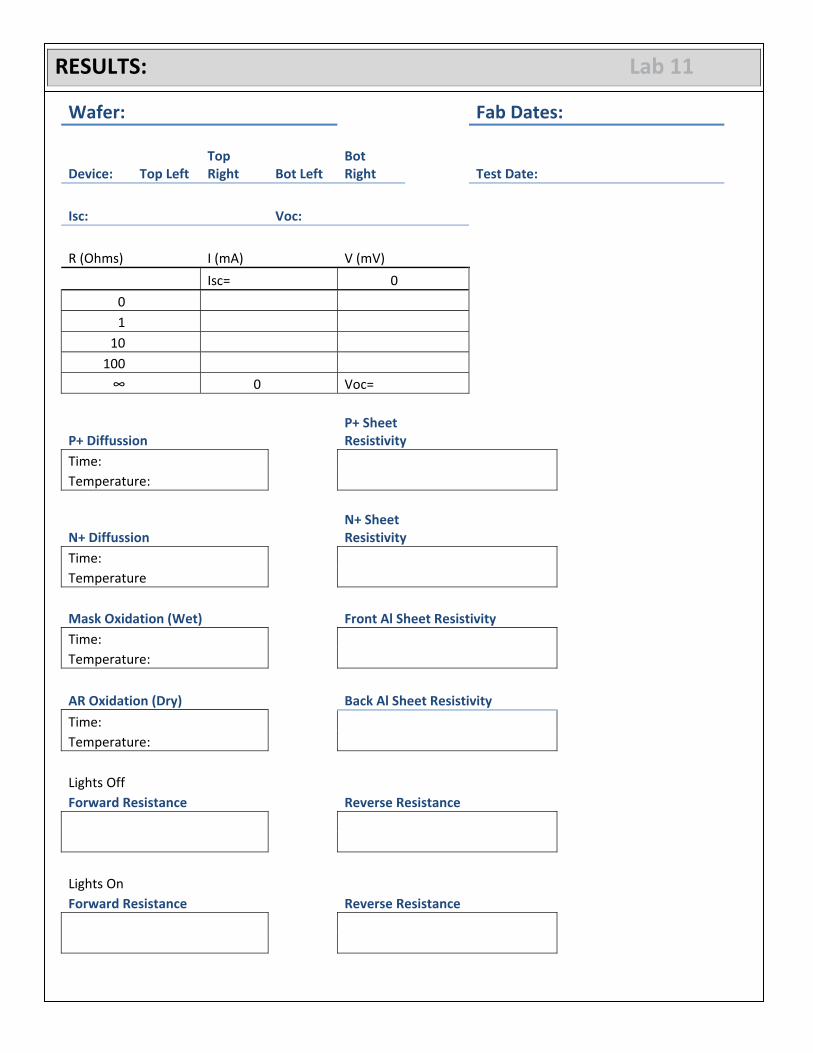
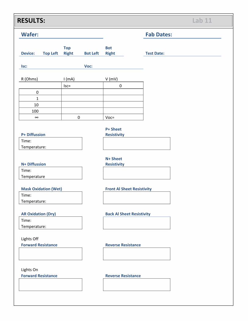

W
Wafer LThe follo
Layouowing image
ut is of the wafe
Top Left
BottomLeft
er layout. Eac
m
ch wafer conttains 4 device
TopRig
BottRigh
es as well as a
p ght
tomht
test structur
re.