Embed Size (px)
Citation preview

Proposal ASCE-002_-2012-11-29-Hooper – 2010 Edition of ASCE 7:
Minimum Design Loads for Building and Other Structures, Supplement No.1 ______________________________________________________________________________
SCOPE: Adopt Supplement No. 1 of ASCE 7-10, thereby modifying the following sections
of the 2014 NEHRP Provisions: 12.2.5.5, 12.3.3.3, 12.3.4.2, 12.8.2.1, 13.2.5, 13.5,
13.6, 14.1, 14.2.2, 14.5.2, 15.4, 15.3.3, 15.7.6, 16.1.4, 21.2, and Ch. 23. This
proposal includes only code language.
______________________________________________________________________________
PROPOSAL FOR CHANGE: 1
2
The attached content is the entirety of Supplement No. 1 of ASCE 7-10 that was sent out for 3
public comment. The proposed change is to adopt the modifications that Supplement No. 1 4
makes to ASCE 7-10, which has already been adopted as the basis for the 2014 Edition of the 5
NEHRP Recommended Seismic Provisions. 6
7
REASON FOR PROPOSAL: 8
9
The 2014 NEHRP Provisions will use ASCE 7-10 as the base document, making modifications 10
to that text as necessary. This proposal would adopt the changes specified in Supplement No. 1 11
to ASCE 7-10, providing the most up-to-date version of the Provisions’ base document. Any 12
changes to Supplement No. 1 from the public comment process will be adopted at a later time. 13
PLEASE NOTE that the original ASCE 7 proposals that comprise Supplement No. 1 have been 14
included as a reference document for this ballot. The reference document contains a “reason for 15
proposal” for each of the proposed changes in Supplement No. 1. 16

ATTACHMENT: Supplement 1 Changes 1
2
Chapter 12 3
4
12.2.5.5 Special Moment Frames in Structures Assigned to Seismic Design Categories D through F. 5
For structures assigned to Seismic Design Categories D, E, or F, awhere a special moment frame is required by 6
Table 12.2-1 due to the structural system limitations, the frame shall be continuous to the base. 7
A special moment frame that is used but not required by Table 12.2-1, shall notis permitted to be discontinued above 8
the base and supported by a more rigid system with a lower response modification coefficient, R., unless provided 9
that the requirements of Sections 12.23.3.12 and 12.3.3.4 are met. Where a special moment frame is required by 10
Table 12.1-1, the frame shall be continuous to the foundation. 11
12.3.3.3 Elements Supporting Discontinuous Walls or Frames 12
Columns, beams, trusses, or slabs Structural elements supporting discontinuous walls or frames of structures having 13
horizontal irregularity Type 4 of Table 12.3-1 or vertical irregularity Type 4 of Table 12.3-2 shall be designed to 14
resist the seismic load effects including overstrength factor of Section 2.4.3. The connections of such discontinuous 15
elements walls or frames to the supporting members shall be adequate to transmit the forces for which the 16
discontinuous elements walls or frames were required to be designed. 17
Revise Table 12.3-2 Vertical Structural Irregularities 18
4. In-Plane Discontinuity in Vertical Lateral-Force-Resisting Element
Irregularity: In-plane discontinuity in vertical lateral force-resisting
elements irregularity is defined to exist where there is an in-plane offset of
a vertical seismic force-resisting element resulting in overturning demands
on a supporting beam, column, truss, or slab structural elements.
12.3.3.3
12.3.3.4
Table 12.6-1
B, C, D, E, and
F
D, E, and F
D, E, and F
19
12.3.4.2 Redundancy Factor, ρ, for Seismic Design Categories D through F. 20
For structures assigned to Seismic Design Category D, E, or F, and having Extreme Torsional Irregularity as defined 21
in Table 12.3-1, Type 1b, ρ shall equal 1.3. For other structures assigned to Seismic Design Category D, and for 22
structures assigned to Seismic Design Categories E or F, ρ shall equal 1.3 unless one of the following two conditions 23
is met, whereby ρ is permitted to be taken as 1.0. A reduction in the value of rho from 1.3 is not permitted for 24
structures assigned to Seismic Design Category D that have an extreme torsional irregularity (Type 1b). Seismic 25
Design Categories E and F are not also specified because extreme torsional irregularities are prohibited (see Section 26
12.3.3.1). 27
Revise Table 12.3-1 as follows: 28
1b. Extreme Torsional Irregularity is defined to exist where the maximum story drift,
computed including accidental torsion, at one end of the structure transverse to an axis is more than 1.4 times the average of the story drifts at the two ends of the
structure. Extreme torsional irregularity requirements in the reference sections
apply only to structures in which the diaphragms are rigid or semirigid.
12.3.3.1
12.3.3.4 12.7.3
12.8.4.3
12.12.1 Table 12.6-1
Section 16.2.2
Section 12.3.4.2
E and F
D B, C and D
C and D
C and D D
B, C and D
D
29

12.8.2.1 Approximate Fundamental Period 1
The approximate fundamental period, Ta, for masonry or concrete shear wall structures not exceeding 120 feet in 2
height is permitted to be determined from Eq. 12.8-9 as follows: 3
4
n
w
a hC
T0019.0
(12.8-9) 5
6
where Cw is calculated from Eq. 12.8-10 as follows: 7
8
Cw =100
AB
hn
hi
æ
èç
ö
ø÷
i=1
x
å2
Ai
1+ 0.83hiDi
æ
èç
ö
ø÷
2é
ë
êê
ù
û
úú
9
10
(12.8-10) 11
12
where 13
14
AB = area of the structure, in ft2 15
Ai =web area of shear wall i, in ft2 16
Di =Length of shear wall i, ft 17
hi = height of wall i, in ft 18
x =number of shear walls in the building effective in resisting lateral forces in the direction under 19
consideration 20
Cw =100
AB
Ai
1+ 0.83hnDi
æ
èç
ö
ø÷
2é
ë
êê
ù
û
úú
i=1
x
å

Chapter 13 1
2
13.2.5 Testing Alternative for Seismic Capacity Determination 3
As an alternative to the analytical requirements……………..equal or exceed the seismic demands 4
determined in accordance with Section 13.3.1 and 13.3.2. For the testing alternative, the maximum seismic demand 5
determined in accordance with Equation 13.3-2 is not required to exceed 3.2IpWp. 6
13.5 ARCHITECTURAL COMPONENTS 7
Revise Table 13.5-1 to add overstrength coefficients and convert all existing values from decimal to fractional form 8
for consistency with Table 12.2-1 (not shown in with strike-out and underline text for clarity). 9
10
TABLE 13.5-1 COEFFICIENTS FOR ARCHITECTURAL COMPONENTS
Architectural Component apa Rp Ω0
c
Interior Nonstructural Walls and Partitionsb
Plain (unreinforced) masonry walls 1 1 ½ 1 ½
All other walls and partitions 1 2 ½ 2 ½
Cantilever Elements (Unbraced or braced to structural frame below its center of mass)
Parapets and cantilever interior nonstructural walls 2 ½ 2 ½ 2 ½
Chimneys where laterally braced or supported by the structural frame 2 ½ 2 ½ 2 ½
Cantilever Elements (Braced to structural frame above its center of mass)
Parapets 1 2 ½ 2 ½
Chimneys 1 2 ½ 2 ½
Exterior Nonstructural Wallsb 1
b 2 ½ 2 ½
Exterior Nonstructural Wall Elements and Connectionsb
Wall Element 1 2 ½ 2 ½
Body of wall panel connections 1 2 ½ 2 ½
Fasteners of the connecting system 1 ¼ 1 1 ½
Veneer
Limited deformability elements and attachments 1 2 ½ 2 ½
Low deformability elements and attachments 1 1 ½ 1 ½
Penthouses (except where framed by an extension of the building frame) 2 ½ 3 ½ 2 ½
Ceilings
All 1 2 ½ 2 ½
Cabinets
Permanent floor-supported storage cabinets over 6 feet (1829 mm) tall, including contents
Permanent floor-supported library shelving, book stacks and bookshelves over 6 feet (1829
mm) tall, including contents
1
1
2 ½
1
2 ½
1 ½
Laboratory equipment 1 2 ½ 2 ½
Access Floors
Special access floors (designed in accordance with Section 13.5.7.2) 1 2 ½ 2 ½
All other 1 1 ½ 1 ½
Appendages and Ornamentations 2 ½ 2 ½ 2 ½
Signs and Billboards 2 ½ 3 2 ½
Other Rigid Components
High deformability elements and attachments 1 3 ½ 2 ½

TABLE 13.5-1 COEFFICIENTS FOR ARCHITECTURAL COMPONENTS
Architectural Component apa Rp Ω0
c
Limited deformability elements and attachments 1 2 ½ 2 ½
Low deformability materials and attachments 1 1 ½ 1 ½
Other Flexible Components
High deformability elements and attachments 2 ½ 3 ½ 2 ½
Limited deformability elements and attachments 2 ½ 2 ½ 2 ½
Low deformability materials and attachments 2 ½ 1 ½ 1 ½
Egress stairways not part of the building structure 1 2 ½ 2 ½ a
A lower value for ap shall not be used unless justified by detailed dynamic analysis. The value for ap shall not be less
than 1. 1.00. The value of ap = 1 is for rigid components and rigidly attached components. The value of ap = 2.5 2 ½ is
for flexible components and flexibly attached components. b
Where flexible diaphragms provide lateral support for concrete or masonry walls and partitions, the design forces for
anchorage to the diaphragm shall be as specified in Section 12.11.2. c
Overstrength as required for anchorage to concrete. See Section 12.4.3 for inclusion of overstrength factor in seismic
load effect.
13.6 MECHANICAL AND ELECTRICAL COMPONENTS 1
Revise Table 13.6-1 to add overstrength coefficients and convert all existing values from decimal to fractional form 2
for consistency with Table 12.2-1 (not shown in with strike-out and underline text for clarity). 3
4
TABLE 13.6-1 SEISMIC COEFFICIENTS FOR MECHANICAL AND ELECTRICAL COMPONENTS
MECHANICAL AND ELECTRICAL COMPONENTS apa Rp
b Ω0
c
Air-side HVAC, fans, air handlers, air conditioning units, cabinet heaters, air distribution boxes,
and other mechanical components constructed of sheet metal framing.
2 ½ 6 2 ½
Wet-side HVAC, boilers, furnaces, atmospheric tanks and bins, chillers, water heaters, heat
exchangers, evaporators, air separators, manufacturing or process equipment, and other
mechanical components constructed of high-deformability materials.
1 2 ½ 2 ½
Engines, turbines, pumps, compressors, and pressure vessels not supported on skirts and not
within the scope of Chapter 15.
1 2 ½ 2 ½
Skirt-supported pressure vessels not within the scope of Chapter 15. 2 ½ 2 ½ 2 ½
Elevator and escalator components. 1 2 ½ 2 ½
Generators, batteries, inverters, motors, transformers, and other electrical components
constructed of high deformability materials.
1 2 ½ 2 ½
Motor control centers, panel boards, switch gear, instrumentation cabinets, and other
components constructed of sheet metal framing.
2 ½ 6 2 ½
Communication equipment, computers, instrumentation, and controls. 1 2 ½ 2 ½
Roof-mounted stacks, cooling and electrical towers laterally braced below their center of mass. 2 ½ 3 2 ½
Roof-mounted stacks, cooling and electrical towers laterally braced above their center of mass. 1 2 ½ 2 ½
Lighting fixtures. 1 1 ½ 1 ½
Other mechanical or electrical components. 1 1 ½ 1 ½
VIBRATION ISOLATED COMPONENTS AND SYSTEMSb
Components and systems isolated using neoprene elements and neoprene isolated floors with
built-in or separate elastomeric snubbing devices or resilient perimeter stops.
2 ½ 2 ½ 2 ½
Spring isolated components and systems and vibration isolated floors closely restrained using 2 ½ 2 2 ½

TABLE 13.6-1 SEISMIC COEFFICIENTS FOR MECHANICAL AND ELECTRICAL COMPONENTS
MECHANICAL AND ELECTRICAL COMPONENTS apa Rp
b Ω0
c
built-in or separate elastomeric snubbing devices or resilient perimeter stops.
Internally isolated components and systems. 2 ½ 2 2 ½
Suspended vibration isolated equipment including in-line duct devices and suspended internally
isolated components.
2 ½ 2 ½ 2 ½
DISTRIBUTION SYSTEMS
Piping in accordance with ASME B31, including in-line components with joints made by
welding or brazing.
2 ½ 12 2 ½
Piping in accordance with ASME B31, including in-line components, constructed of high or
limited deformability materials, with joints made by threading, bonding, compression couplings,
or grooved couplings.
2 ½ 6 2 ½
Piping and tubing not in accordance with ASME B31, including in-line components,
constructed of high-deformability materials, with joints made by welding or brazing.
2 ½ 9 2 ½
Piping and tubing not in accordance with ASME B31, including in-line components,
constructed of high- or limited-deformability materials, with joints made by threading, bonding,
compression couplings, or grooved couplings.
2 ½ 4 ½ 2 ½
Piping and tubing constructed of low-deformability materials, such as cast iron, glass, and
nonductile plastics.
2 ½ 3 2 ½
Ductwork, including in-line components, constructed of high-deformability materials, with
joints made by welding or brazing.
2 ½ 9 2 ½
Ductwork, including in-line components, constructed of high- or limited-deformability
materials with joints made by means other than welding or brazing.
2 ½ 6 2 ½
Ductwork, including in-line components, constructed of low-deformability materials, such as
cast iron, glass, and nonductile plastics.
2 ½ 3 2 ½
Electrical conduit and cable trays 2 ½ 6 2 ½
Bus ducts 1 2 ½ 2 ½
Plumbing 1 2 ½ 2 ½
Manufacturing or process conveyors (nonpersonnel). 2 ½ 3 2 ½ a
A lower value for ap is permitted where justified by detailed dynamic analyses. The value for ap shall not be
less than 11.0. The value of ap equal to 11.0 is for rigid components and rigidly attached components. The
value of ap equal to 2 ½ 2.5 is for flexible components and flexibly attached components. b
Components mounted on vibration isolators shall have a bumper restraint or snubber in each horizontal
direction. The design force shall be taken as 2Fp if the nominal clearance (air gap) between the equipment
support frame and restraint is greater than 0.25 in. If the nominal clearance specified on the construction
documents is not greater than 0.25 in., the design force is permitted to be taken as Fp. c
Overstrength as required for anchorage to concrete. See Section 12.4.3 for inclusion of overstrength factor in
seismic load effect.
Chapter 14 1
2
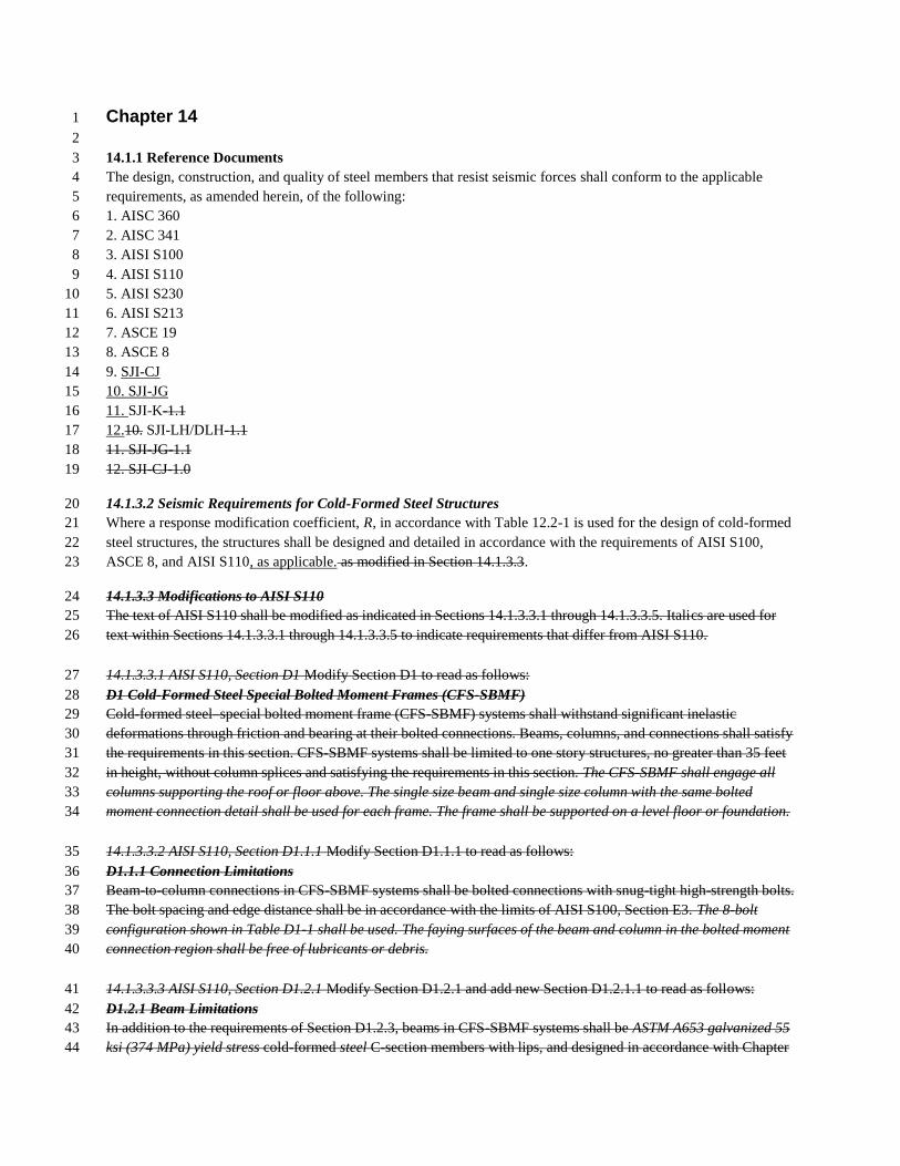
14.1.1 Reference Documents 3
The design, construction, and quality of steel members that resist seismic forces shall conform to the applicable 4
requirements, as amended herein, of the following: 5
1. AISC 360 6
2. AISC 341 7
3. AISI S100 8
4. AISI S110 9
5. AISI S230 10
6. AISI S213 11
7. ASCE 19 12
8. ASCE 8 13
9. SJI-CJ 14
10. SJI-JG 15
11. SJI-K-1.1 16
12.10. SJI-LH/DLH-1.1 17
11. SJI-JG-1.1 18
12. SJI-CJ-1.0 19
14.1.3.2 Seismic Requirements for Cold-Formed Steel Structures 20
Where a response modification coefficient, R, in accordance with Table 12.2-1 is used for the design of cold-formed 21
steel structures, the structures shall be designed and detailed in accordance with the requirements of AISI S100, 22
ASCE 8, and AISI S110, as applicable. as modified in Section 14.1.3.3. 23
14.1.3.3 Modifications to AISI S110 24
The text of AISI S110 shall be modified as indicated in Sections 14.1.3.3.1 through 14.1.3.3.5. Italics are used for 25
text within Sections 14.1.3.3.1 through 14.1.3.3.5 to indicate requirements that differ from AISI S110. 26
14.1.3.3.1 AISI S110, Section D1 Modify Section D1 to read as follows: 27
D1 Cold-Formed Steel Special Bolted Moment Frames (CFS-SBMF) 28
Cold-formed steel–special bolted moment frame (CFS-SBMF) systems shall withstand significant inelastic 29
deformations through friction and bearing at their bolted connections. Beams, columns, and connections shall satisfy 30
the requirements in this section. CFS-SBMF systems shall be limited to one story structures, no greater than 35 feet 31
in height, without column splices and satisfying the requirements in this section. The CFS-SBMF shall engage all 32
columns supporting the roof or floor above. The single size beam and single size column with the same bolted 33
moment connection detail shall be used for each frame. The frame shall be supported on a level floor or foundation. 34
14.1.3.3.2 AISI S110, Section D1.1.1 Modify Section D1.1.1 to read as follows: 35
D1.1.1 Connection Limitations 36
Beam-to-column connections in CFS-SBMF systems shall be bolted connections with snug-tight high-strength bolts. 37
The bolt spacing and edge distance shall be in accordance with the limits of AISI S100, Section E3. The 8-bolt 38
configuration shown in Table D1-1 shall be used. The faying surfaces of the beam and column in the bolted moment 39
connection region shall be free of lubricants or debris. 40
14.1.3.3.3 AISI S110, Section D1.2.1 Modify Section D1.2.1 and add new Section D1.2.1.1 to read as follows: 41
D1.2.1 Beam Limitations 42
In addition to the requirements of Section D1.2.3, beams in CFS-SBMF systems shall be ASTM A653 galvanized 55 43
ksi (374 MPa) yield stress cold-formed steel C-section members with lips, and designed in accordance with Chapter 44

C of AISI S100. The beams shall have a minimum design thickness of 0.105 in. (2.67 mm). The beam depth shall be 1
not less than 12 in. (305 mm) or greater than 20 in. (508 mm). The flat depth-to-thickness ratio of the web shall not 2
exceed 6.18 E / Fy . 3
D1.2.1.1 Single-Channel Beam Limitations 4
When single-channel beams are used, torsional effects shall be accounted for in the design. 5
14.1.3.3.4 AISI S110, Section D1.2.2 Modify Section D1.2.2 to read as follows: 6
D1.2.2 Column Limitations 7
In addition to the requirements of D1.2.3, columns in CFS-SBMF systems shall be ASTM A500 Grade B cold-8
formed steel hollow structural section (HSS) members painted with a standard industrial finished surface, and 9
designed in accordance with Chapter C of AISI S100. The column depth shall be not less than 8 in. (203 mm) or 10
greater than 12 in. (305 mm). The fl at depth-to-thickness ratio shall not exceed 1.40 E / Fy . 11
14.1.3.3.5 AISI S110, Section D1.3 Delete text in Section D1.3 to read as follows: 12
D1.3 Design Story Drift 13
Where the applicable building code does not contain design coefficients for CSF-SBMF systems, the provisions of 14
Appendix 1 shall apply. For structures having a period less than TS, as defined in the applicable building code, 15
alternate methods of computing shall be permitted, provided such alternate methods are acceptable to the authority 16
having jurisdiction. 17
14.1.6 Steel Cables 18
The design strength of steel cables shall be determined by the requirements of ASCE 19 except as modified by this 19
chapter. ASCE 19, Section 3.1.2(d), shall be modified by substituting 1.5(T4) where T4 is the net tension in cable 20
due to dead load, prestress, live load, and seismic load. A load factor of 1.1 shall be applied to the prestress force to 21
be added to the load combination of Section 3.1.2 of ASCE 19. The design strength of steel cables serving as main 22
structural load carrying members shall be determined by the requirements of ASCE/SEI 19. 23
14.2.2 Modifications to ACI 318. 24
The text of ACI 318 shall be modified as indicated in Sections 14.2.2.1 through 14.2.2.914.2.2.8. Italics are used for 25
text within Sections 14.2.2.1 through 14.2.2.914.2.2.8 to indicate requirements that differ from ACI 318. 26
14.2.2.1 Definitions. 27
Add the following definitions to Section 2.2. 28
DETAILED PLAIN CONCRETE STRUCTURAL WALL: A wall complying with the requirements of Chapter 29
22. 30
ORDINARY PRECAST STRUCTURAL WALL: A precast wall complying with the requirements of Chapters 31
1 through 18. 32
WALL PIER: A wall segment with a horizontal length-to-thickness ratio of at least 2.5, but not exceeding 6, 33
whose clear height is at least two times its horizontal length. 34
14.2.2.2 ACI 318, Section 7.10. 35
Modify Section 7.10 by revising Section 7.10.5.67 to read as follows: 36
7.10.5.67 – Where anchor bolts are placed in the top of columns or pedestals, the bolts shall be enclosed by lateral 37
reinforcement that also surrounds at least four vertical bars of the column or pedestal. The lateral reinforcement 38
shall be distributed within 5 in. of the top of the column or pedestal, and shall consist of at least two No.4 or three 39

No.3 bars. In structures assigned to Seismic Design Categories C, D, E or F, the ties shall have a hook on each free 1
end that complies with 7.1.4. 2
14.2.2.3 Scope. 3
Modify Section 21.1.1.3 to read as follows: 4
21.1.1.3 All members shall satisfy requirements of Chapters 1 to 19 and 22. Structures assigned to SDC B, C, D, E, 5
or F also shall satisfy 21.1.1.4 through 21.1.1.8, as applicable, except as modified by the requirements of Chapters 6
14 and 15 ASCE 7-10. 7
14.2.2.4 Intermediate Precast Structural Walls: 8
Modify Section 21.4 by renumbering Sections 21.4.3 and 21.4.4 to Sections 21.4.45 and 21.4.6, respectively and 9
adding new Sections 21.4.3, 21.4.5 and 21.4.6, to read as follows: 10
21.4.3 Connections that are designed to yield shall be capable of maintaining 80 percent of their design strength at 11
the deformation induced by design displacement, or shall use type 2 mechanical splices. 12
21.4.4 Elements of the connection that are not designed to yield shall develop at least 1.5 Sy. 13
21.4.5 In structures assigned to SDC D, E, or F, wall piers shall be designed in accordance with 21.9 or 21.13. 14
21.4.5 Wall piers in structures assigned to SDC D, E, or F shall comply with Section 14.2.2.4 of this 15
standard. 16
21.4.6 Wall piers not designed as part of a moment frame in SDC C shall have transverse reinforcement designed to 17
resist the shear forces determined from Section 21.3.3. Spacing of transverse reinforcement shall not exceed 8 in. 18
Transverse reinforcement shall be extended beyond the pier clear height for at least 12 in. 19
Exceptions: The preceding requirement need not apply in the following situations: 20
1. Wall piers that satisfy Section 21.13. 21
2. Wall piers along a wall line within a story where other shear wall segments provide lateral support to the wall 22
piers and such segments have a total stiffness of at least six times the sum of the stiffnesses of all the wall piers. 23
24
Wall segments with a horizontal length-to-thickness ratio less than 2.5 shall be designed as columns. 25
14.2.2.5 Wall Piers and Wall Segments. 26
Modify Section 21.9 by adding a new Section 21.9.10 to read as follows: 27
21.9.10 Wall Piers and Wall Segments. 28
21.9.10.1 Wall piers not designed as a part of a special moment-resisting frame shall have transverse reinforcement 29
designed to satisfy the requirements in Section 21.9.10.2. 30
Exceptions: 31
1. Wall piers that satisfy Section 21.13. 32
2. Wall piers along a wall line within a story where other shear wall segments provide lateral support to the wall 33
piers, and such segments have a total stiffness of at least six times the sum of the in-plane stiffnesses of all the 34
wall piers. 35
21.9.10.2 Transverse reinforcement with seismic hooks at both ends shall be designed to resist the shear forces 36
determined from Section 21.6.5.1. Spacing of transverse reinforcement shall not exceed 6 in. (152 mm). Transverse 37
reinforcement shall be extended beyond the pier clear height for at least 12 in. (304 mm). 38

21.9.10.3 Wall segments with a horizontal length-to-thickness ratio less than 2.5 shall be designed as columns 1
14.2.2.65 Special Precast Structural Walls. 2
Modify Section 21.10.2 to read as follows: 3
21.10.2 Special structural walls constructed using precast concrete shall satisfy all the requirements of Section 21.9 4
in addition to Section 21.4 as modified by Section 14.2.2 of ASCE 7-10. 5
14.2.2.76 Foundations. 6
Modify Section 21.12.1.1 to read as follows: 7
21.12.1.1 Foundations resisting earthquake-induced forces or transferring earthquake-induced forces between 8
structure and ground in structures assigned to SDC D, E, or F shall comply with requirements of Section 21.12 and 9
other applicable code provisions unless modified by Sections 12.1.5, 12.13 or 14.2 of ASCE 7. 10
14.2.2.87 Detailed Plain Concrete Shear Walls. 11
Modify Section 22.6 by adding a new Section 22.6.7 to read: 12
22.6.7 Detailed Plain Concrete Shear Walls. 13
22.6.7.1 - Detailed plain concrete shear walls are walls conforming to the requirements for ordinary plain concrete 14
shear walls and Section 22.6.7.2 15
22.6.7.2 - Reinforcement shall be provided as follows: 16
a. Vertical reinforcement of at least 0.20 in.2 (129 mm
2) in cross-sectional area shall be provided continuously 17
from support to support at each corner, at each side of each opening, and at the ends of walls. The 18
continuous vertical bar required beside an opening is permitted to substitute for the No. 5 bar required by 19
Section 22.6.6.5. 20
b. Horizontal reinforcement at least 0.20 in.2 (129 mm
2) in cross-sectional area shall be provided: 21
1. Continuously at structurally connected roof and floor levels and at the top of walls. 22
2. At the bottom of load-bearing walls or in the top of foundations where doweled to the wall. 23
3. At a maximum spacing of 120 in. (3,048 mm). 24
Reinforcement at the top and bottom of openings, where used in determining the maximum spacing specified in 25
Item 3 in the preceding text, shall be continuous in the wall. 26
14.2.2.9 Strength Requirements for Anchors: 27
Modify Section D.4 by adding a new exception at the end of Section D.4.2.2 to read as follows: 28
EXCEPTION: If Nb is determined using Eq. D-7, the concrete breakout strength of Section D.4.2 shall be 29
considered satisfied by the design procedure of Sections D.5.2 and D.6.2 without the need for testing regardless 30
of anchor bolt diameter and tensile embedment. 31
14.5.2 Framing 32
All wood columns and posts shall be framed to provide Full end bearing. Alternatively, column and post 33
end connections shall be designed to resist the full compressive loads neglecting all end-bearing capacity. Continuity 34
of wall top plates or provision for transfer of induced axial load forces shall be provided. Where offsets occur in the 35
wall line, portions of the shear wall on each side of the offset shall be considered as separate shear walls unless 36
provisions for force transfer around the offset are provided. 37
Chapter 15 1
2
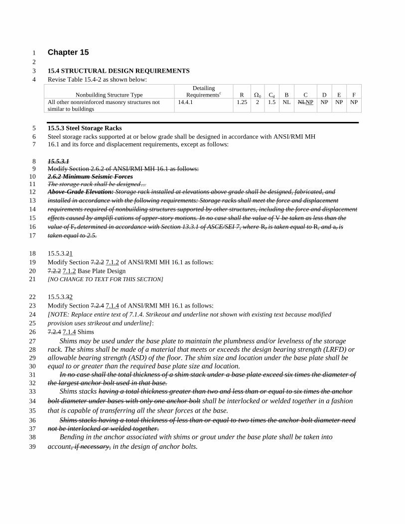
15.4 STRUCTURAL DESIGN REQUIREMENTS 3
Revise Table 15.4-2 as shown below: 4
Nonbuilding Structure Type
Detailing
Requirementsc R 0 Cd B C D E F
All other nonreinforced masonry structures not
similar to buildings
14.4.1 1.25 2 1.5 NL NLNP NP NP NP
15.5.3 Steel Storage Racks 5
Steel storage racks supported at or below grade shall be designed in accordance with ANSI/RMI MH 6
16.1 and its force and displacement requirements, except as follows: 7
15.5.3.1 8 Modify Section 2.6.2 of ANSI/RMI MH 16.1 as follows: 9
2.6.2 Minimum Seismic Forces 10 The storage rack shall be designed… 11
Above-Grade Elevation: Storage rack installed at elevations above grade shall be designed, fabricated, and 12
installed in accordance with the following requirements: Storage racks shall meet the force and displacement 13
requirements required of nonbuilding structures supported by other structures, including the force and displacement 14
effects caused by amplifi cations of upper-story motions. In no case shall the value of V be taken as less than the 15
value of Fp determined in accordance with Section 13.3.1 of ASCE/SEI 7, where Rp is taken equal to R, and ap is 16
taken equal to 2.5. 17
15.5.3.21 18
Modify Section 7.2.2 7.1.2 of ANSI/RMI MH 16.1 as follows: 19
7.2.2 7.1.2 Base Plate Design 20
[NO CHANGE TO TEXT FOR THIS SECTION] 21
15.5.3.32 22
Modify Section 7.2.4 7.1.4 of ANSI/RMI MH 16.1 as follows: 23
[NOTE: Replace entire text of 7.1.4. Strikeout and underline not shown with existing text because modified 24
provision uses strikeout and underline]: 25
7.2.4 7.1.4 Shims 26
Shims may be used under the base plate to maintain the plumbness and/or levelness of the storage 27
rack. The shims shall be made of a material that meets or exceeds the design bearing strength (LRFD) or 28
allowable bearing strength (ASD) of the floor. The shim size and location under the base plate shall be 29
equal to or greater than the required base plate size and location. 30
In no case shall the total thickness of a shim stack under a base plate exceed six times the diameter of 31
the largest anchor bolt used in that base. 32
Shims stacks having a total thickness greater than two and less than or equal to six times the anchor 33
bolt diameter under bases with only one anchor bolt shall be interlocked or welded together in a fashion 34
that is capable of transferring all the shear forces at the base. 35
Shims stacks having a total thickness of less than or equal to two times the anchor bolt diameter need 36
not be interlocked or welded together. 37
Bending in the anchor associated with shims or grout under the base plate shall be taken into 38
account, if necessary, in the design of anchor bolts. 39

15.7.6 Ground-Supported Storage Tanks for Liquids 1
Revise Equation 15.7-10: 2
3
For Tc ≤ TL: 4
5
(15.7-10) 6

Chapter 16 1
2
16.1.4 Response Parameters 3
For each ground motion analyzed, the individual response parameters shall be multiplied by the following scalar 4
quantities: 5 6
a. Force response parameters shall be multiplied by Ie/R, where I
e is the importance factor determined in 7
accordance with Section 11.5.1 and R is the Response Modification Coefficient selected in accordance 8
with Section 12.2.1. 9
b. Drift quantities shall be multiplied by Cd/R, where C
d is the deflection amplification factor specified in 10
Table 12.2-1. 11
12
For each ground motion i, where i is the designation assigned to each ground motion, the maximum value of the 13
base shear, Vi, member forces, QEi, and story drifts, i, at each story scaled as indicated in the preceding text and 14
story drifts, i, at each story as defined in Section 12.8.6 shall be determined. Story drifts at each story shall be 15
determined at the locations defined in Section 12.8.6. Where the maximum scaled base shear predicted by the 16
analysis, Vi, is less than 85 percent of the value of V determined using the minimum value of Cs set forth in Eq. 12.8-17
5 or when located where S1 is equal to or greater than 0.6g, the minimum value of Cs set forth in Eq. 12.8-6, the 18
scaled member forces, QEi, shall be additionally multiplied by V / Vi where V is the minimum base shear that has 19
been determined using the minimum value of Cs set forth in Eq. 12.8-5, or when located where S1 is equal to or 20
greater than 0.6g, the minimum value of Cs set forth in Eq. 12.8-6. Where the maximum scaled base shear predicted 21
by the analysis, Vi, is less than 0.85CsW, where Cs is from Eq. 12.8-6, drifts shall be multiplied by 0.85 Cs W / Vi. 22
16.1.4.1 Additional Scaling of Forces 23
Where the maximum scaled base shear predicted by the analysis, Vi, is less than 85 percent of the calculated base 24
shear, V, using the equivalent lateral force procedure, the scaled member forces, QEi, shall be additionally multiplied 25
by 0.85V/Vi., 26
27
Where V = the equivalent lateral force procedure base shear, calculated in accordance with Section 12.8. 28
16.1.4.2 Additional Scaling of Drifts 29
Where the maximum scaled base shear predicted by the analysis, Vi, is less than 0.85CsW, where Cs is determined in 30
accordance with Section 12.8.1.1, the scaled story drifts, i, shall be additionally multiplied by 0.85CsW/Vi. 31
32

Chapter 21 1
2
21.2 RISK-TARGETED MAXIMUM CONSIDERED EARTHQUAKE (MCER) GROUND MOTION 3
HAZARD ANALYSIS 4
The requirements of Section 21.2 shall be satisfied where a ground motion hazard analysis is performed or required 5
by Section 11.4.7. The ground motion hazard analysis shall account for the regional tectonic setting, geology, and 6
seismicity, the expected recurrence rates and maximum magnitudes of earthquakes on known faults and source 7
zones, the characteristics of ground motion attenuation, near source effects, if any, on ground motions, and the 8
effects of subsurface site conditions on ground motions. The characteristics of subsurface site conditions shall be 9
considered either using attenuation relations that represent regional and local geology or in accordance with Section 10
21.1. The analysis shall incorporate current seismic interpretations, including uncertainties for models and parameter 11
values for seismic sources and ground motions. If the spectral response accelerations predicted by the attenuation 12
relations do not represent the maximum response in the horizontal plane, then the response spectral accelerations 13
computed from the hazard analysis shall be scaled by factors to increase the motions to the maximum response. If 14
the attenuation relations predict the geometric mean or similar metric of the two horizontal components, then the 15
scale factors shall be: 1.1 for periods less than or equal to 0.2 sec; 1.3 for a period of 1.0 sec., and, 1.5 for periods 16
greater than or equal to 5.0 sec., unless it can be shown that other scale factors more closely represent the maximum 17
response, in the horizontal plane, to the geometric mean of the horizontal components. Scale factors between these 18
periods shall be obtained by linear interpolation. The analysis shall be documented in a report. 19

Chapter 23 1
2
ACI 318 3
Sections 13.4.2.1, 13.4.4, 13.5.7.2, 14.2.2, 14.2.2.1, 14.2.2.2, 14.2.2.3, 14.2.2.4, 14.2.2.5, 14.2.2.6, 14.2.2.7, 4
14.2.2.8, 14.2.2.9, 14.2.3, 14.2.3.1.1, 14.2.3.2.1, 14.2.3.2.2, 14.2.3.2.3, 14.2.3.2.5, 14.2.3.2.6, 14.3.1, 14.4.4.2.2, 5
14.4.5.2, 15.4.9.1, 15.6.2, 15.7.5, 15.7.11.7. 6
Building Code Requirements for Structural Concrete and Commentary (2008)(2011) 7
ACI 530/ASCE 5/TMS 402 8
Sections 13.4.2.2, 14.4.1, 14.4.2, 14.4.3, 14.4.3.1, 14.4.4.1, 14.4.4.2.2, 14.4.5, 14.4.5.1, 14.4.5.3, 14.4.5.4, 9
14.4.5.5, 14.4.5.6, 14.4.6, 14.4.6.1, 14.4.6.2.2, 14.4.7, 14.4.7.1, 14.4.7.2, 14.4.7.3, 14.4.7.4, 14.4.7.5, 14.4.7.6, 10
14.4.8, 14.4.8.1, 15.4.9.2 11
Building Code Requirements for Masonry Structures,20082011 12
ACI 530.1/ASCE 6/TMS 602 13
Sections 14.4.1, 14.4.2, 14.4.7, 14.4.7.1 14
Specification for Masonry Structures, 20082011 15
AF&PA 16
American Forest and Paper Association 17
1111 19th
Street NW, Suite 800 18
Washington, DC 20036 19
AWC 20
American Wood Council 21
803 Sycolin Road, Suite 201 22
Leesburg, VA 20175 23
AF&PA AWC NDS 24
Section 12.4.3.3, 12.14.2.2.2.3, 12.14.3.2.3, 14.5.1 25
National Design Specification for Wood Construction, Including Supplements, 26
AF&PA NDS-05, 2005 AWC NDS-12, 2012 27
AF&PA AWC SDPWS 28
Section 12.14.6.2, 12.14.7.2, 14.5.1, 14.5.3, 14.5.3.1 29
AF&PA Special Design Provisions for Wind and Seismic, AWC SDPWS-08, 2008 (previously AF&PA SDPWS-30
08) 31
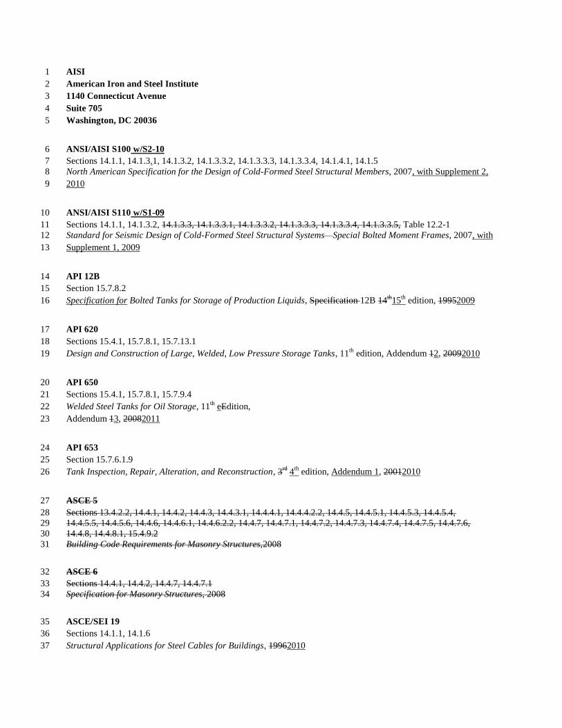
AISI 1
American Iron and Steel Institute 2
1140 Connecticut Avenue 3
Suite 705 4
Washington, DC 20036 5
ANSI/AISI S100 w/S2-10 6
Sections 14.1.1, 14.1.3.1, 14.1.3.2, 14.1.3.3.2, 14.1.3.3.3, 14.1.3.3.4, 14.1.4.1, 14.1.5 7
North American Specification for the Design of Cold-Formed Steel Structural Members, 2007, with Supplement 2, 8
2010 9
ANSI/AISI S110 w/S1-09 10
Sections 14.1.1, 14.1.3.2, 14.1.3.3, 14.1.3.3.1, 14.1.3.3.2, 14.1.3.3.3, 14.1.3.3.4, 14.1.3.3.5, Table 12.2-1 11
Standard for Seismic Design of Cold-Formed Steel Structural Systems—Special Bolted Moment Frames, 2007, with 12
Supplement 1, 2009 13
API 12B 14
Section 15.7.8.2 15
Specification for Bolted Tanks for Storage of Production Liquids, Specification 12B 14th
15th
edition, 19952009 16
API 620 17
Sections 15.4.1, 15.7.8.1, 15.7.13.1 18
Design and Construction of Large, Welded, Low Pressure Storage Tanks, 11th
edition, Addendum 12, 20092010 19
API 650 20
Sections 15.4.1, 15.7.8.1, 15.7.9.4 21
Welded Steel Tanks for Oil Storage, 11th
eEdition, 22
Addendum 13, 20082011 23
API 653 24
Section 15.7.6.1.9 25
Tank Inspection, Repair, Alteration, and Reconstruction, 3rd
4th
edition, Addendum 1, 20012010 26
ASCE 5 27
Sections 13.4.2.2, 14.4.1, 14.4.2, 14.4.3, 14.4.3.1, 14.4.4.1, 14.4.4.2.2, 14.4.5, 14.4.5.1, 14.4.5.3, 14.4.5.4, 28
14.4.5.5, 14.4.5.6, 14.4.6, 14.4.6.1, 14.4.6.2.2, 14.4.7, 14.4.7.1, 14.4.7.2, 14.4.7.3, 14.4.7.4, 14.4.7.5, 14.4.7.6, 29
14.4.8, 14.4.8.1, 15.4.9.2 30
Building Code Requirements for Masonry Structures,2008 31
ASCE 6 32
Sections 14.4.1, 14.4.2, 14.4.7, 14.4.7.1 33
Specification for Masonry Structures, 2008 34
ASCE/SEI 19 35
Sections 14.1.1, 14.1.6 36
Structural Applications for Steel Cables for Buildings, 19962010 37

ASME 1
American Society of Mechanical Engineers 2
Three Park Avenue 3
New York, NY 10016-5900 4
ASME A17.1 5
Sections 13.6.10, 13.6.10.3 6
Safety Code for Elevators and Escalators, 2004 2007 7
ASME B31 (consists of the following listed standards) 8
Sections 13.6.5.1, 13.6.8.1, 16.8.4, Table 13.6-1 9
Power Piping, ASME B31.1, 2001 2010 10
Process Piping, ASME B31.3, 2002 2010 11
Liquid Pipeline Transportation Systems for Liquid Hydrocarbons and Other Liquids, Liquid Petroleum Gas, 12
Anhydrous Ammonia, and Alcohols, ASME B31.4, 2002 2009 13
Refrigeration Piping and Heat Transfer Components, ASME B31.5, 2001 2010 14
Gas Transmission and Distribution Piping Systems, ASME B31.8, 1999 2010 15
Building Services Piping, ASME B31.9, 1996 2008 16
Slurry Transportation Piping Systems, ASME B31.11, 2002 17
Hydrogen Piping and Pipelines, ASME B31.12, 2008 18
Standard for the Seismic Design and Retrofit of Above-Ground Piping Systems, ASME B31Ea-2010 19
ASME BPVC-01 (consists of the following listed standards) 20
Sections 13.6.9, 13.6.11, 15.7.11.2, 15.7.11.6, 15.7.12.2 21
Boiler and Pressure Vessel Code, 2004 excluding Section III, Nuclear Components, and Section XI, In-Service 22
Inspection of Nuclear Components 23
Rules for Construction of Power Boilers, BPVC-I 2010 24
Rules for Construction of Heating Boilers, BPVC-IV 2010 25
Rules for Construction of Pressure Vessels, BPVC-VIII Division 1 2010 26
Rules for Construction of Pressure Vessels, BPVC-VIII Division 2 Alternative Rules 2010 27
Rules for Construction of Pressure Vessels, BPVC-VIII Division 3 Alternative Rules for Construction of High 28
Pressure Vessels 2010 29
AWWA D103 30
Sections 15.4.1, 15.7.7.2, 15.7.9.5 31
Factory-Coated Bolted Steel Tanks for Water Storage, 32
19972009 33
NFPA 59A 34
Section 15.4.8 35
Standard for the Production, Storage, and Handling of Liquefied natural Gas (LNG), 36
20062009 37

ICC 1
International Code Council 2
5203 Leesburg Pike 3
Suite 600 4
Falls Church, VA 22041 5
500 New Jersey Ave. NW 6
6th Floor 7
Washington, DC 20001 8
* IRC 9
Section 11.1.2 10
20122003 International Residential Code, 20122003 11
RMI 12
Rack Manufacturers Institute 13
8720 Red Oak Boulevard 14
Suite 201 15
Charlotte, NC 28217SJI 16
ANSI/MH 16.1 17
Section 15.5.3 18
Specification for the Design, Testing, and Utilization of Industrial Steel Storage Racks, 2008 2011 19
SJI 20
Steel Joist Institute 21
1173 B London Links Drive 22
Forest, VA 24551 23
ANSI/SJI-CJ-2010 24
Section 14.1.1 25
Standard Specification for Composite Steel Joists, CJ-series, 2010 26
ANSI/SJI-JG-2010 27
Section 14.1.1 28
Standard Specification for Joist Girders, 2010 29
ANSI/SJI-K-1.1--2010 30
Section 14.1.1 31
Standard Specifications for Open Web Steel Joists, 32
K-Series, 20052010 33
ANSI/SJI-LH/DLH-1.1-2010 34
Section 14.1.1 35
Standard Specifications for Longspan Steel Joists, LH-Series and Deep Longspan Steel Joists, DLH-Series, 36
20102005 37

ANSI/SJI-JG-1.1 1
Section 14.1.1 2
Standard Specifications for Joist Girders, 2005 3
ANSI/SJI-CJ-1.0 4
Section 14.1.1 5
Standard Specifications for Composite Steel Joists, 6
2006 7
TMS 402 8
Sections 13.4.2.2, 14.4.1, 14.4.2, 14.4.3, 14.4.3.1, 9
14.4.4.1, 14.4.4.2.2, 14.4.5, 14.4.5.1, 14.4.5.3, 14.4.5.4, 14.4.5.5, 14.4.5.6, 14.4.6, 14.4.6.1, 14.4.6.2.2, 14.4.7, 10
14.4.7.1, 14.4.7.2, 14.4.7.3, 14.4.7.4, 14.4.7.5, 14.4.7.6, 14.4.8, 14.4.8.1, 15.4.9.2 11
Building Code Requirements for Masonry Structures,2008 12
TMS 602 13
Sections 14.4.1, 14.4.2, 14.4.7, 14.4.7.1 14
Specification for Masonry Structures, 2008 15