Embed Size (px)
Citation preview

2010 Cadillac CTS/CTS-V Owner Manual M
Keys, Doors and Windows . . . 1-1Keys and Locks . . . . . . . . . . . . . . . 1-2Doors . . . . . . . . . . . . . . . . . . . . . . . . 1-17Vehicle Security. . . . . . . . . . . . . . 1-23Exterior Mirrors . . . . . . . . . . . . . . . 1-26Interior Mirrors . . . . . . . . . . . . . . . . 1-27Windows . . . . . . . . . . . . . . . . . . . . . 1-28Roof . . . . . . . . . . . . . . . . . . . . . . . . . . 1-31
Seats and Restraints . . . . . . . . . 2-1Head Restraints . . . . . . . . . . . . . . . 2-2Front Seats . . . . . . . . . . . . . . . . . . . . 2-3Rear Seats . . . . . . . . . . . . . . . . . . . 2-10Safety Belts . . . . . . . . . . . . . . . . . . 2-11Airbag System . . . . . . . . . . . . . . . . 2-27Child Restraints . . . . . . . . . . . . . . 2-43
Storage . . . . . . . . . . . . . . . . . . . . . . . 3-1Storage Compartments . . . . . . . . 3-1Additional Storage Features . . . 3-2Roof Rack System . . . . . . . . . . . . . 3-6
Instruments and Controls . . . . 4-1Instrument Panel Overview. . . . 4-4Controls . . . . . . . . . . . . . . . . . . . . . . . 4-6Warning Lights, Gages, andIndicators . . . . . . . . . . . . . . . . . . . 4-14
Information Displays . . . . . . . . . . 4-31Vehicle Messages . . . . . . . . . . . . 4-36Vehicle Personalization . . . . . . . 4-51OnStar® System . . . . . . . . . . . . . . 4-59Universal Remote System . . . . 4-61
Lighting . . . . . . . . . . . . . . . . . . . . . . . 5-1Exterior Lighting . . . . . . . . . . . . . . . 5-1Interior Lighting . . . . . . . . . . . . . . . . 5-5Lighting Features . . . . . . . . . . . . . . 5-6
Infotainment System . . . . . . . . . 6-1Introduction . . . . . . . . . . . . . . . . . . . . 6-1Radio . . . . . . . . . . . . . . . . . . . . . . . . . . 6-9Audio Players . . . . . . . . . . . . . . . . 6-16Phone . . . . . . . . . . . . . . . . . . . . . . . . 6-37
Climate Controls . . . . . . . . . . . . . 7-1Climate Control Systems . . . . . . 7-1Air Vents . . . . . . . . . . . . . . . . . . . . . . . 7-6Maintenance . . . . . . . . . . . . . . . . . . . 7-6
Driving and Operating . . . . . . . . 8-1Driving Information . . . . . . . . . . . . . 8-2Starting and Operating . . . . . . . 8-17Engine Exhaust . . . . . . . . . . . . . . 8-25Automatic Transmission . . . . . . 8-26Manual Transmission . . . . . . . . . 8-30Drive Systems . . . . . . . . . . . . . . . . 8-32Brakes . . . . . . . . . . . . . . . . . . . . . . . 8-33Ride Control Systems . . . . . . . . 8-37Cruise Control . . . . . . . . . . . . . . . . 8-41Object Detection Systems . . . . 8-44Fuel . . . . . . . . . . . . . . . . . . . . . . . . . . 8-49Towing . . . . . . . . . . . . . . . . . . . . . . . 8-54Conversions and Add-Ons . . . 8-60

2010 Cadillac CTS/CTS-V Owner Manual M
Vehicle Care . . . . . . . . . . . . . . . . . . 9-1General Information . . . . . . . . . . . . 9-2Vehicle Checks . . . . . . . . . . . . . . . . 9-4Headlamp Aiming . . . . . . . . . . . . 9-34Bulb Replacement . . . . . . . . . . . . 9-37Electrical System . . . . . . . . . . . . . 9-40Wheels and Tires . . . . . . . . . . . . . 9-58Jump Starting . . . . . . . . . . . . . . . 9-103Towing . . . . . . . . . . . . . . . . . . . . . . 9-108Appearance Care . . . . . . . . . . . 9-110
Service and Maintenance . . . 10-1General Information . . . . . . . . . . 10-1Scheduled Maintenance . . . . . . 10-3Recommended Fluids,Lubricants, and Parts . . . . . . . 10-7
Maintenance Records . . . . . . . 10-11
Technical Data . . . . . . . . . . . . . . . 11-1Vehicle Identification . . . . . . . . . . 11-1Vehicle Data . . . . . . . . . . . . . . . . . . 11-2
Customer Information . . . . . . . 12-1Customer Information . . . . . . . . 12-1Reporting Safety Defects . . . . 12-13Vehicle Data Recordingand Privacy. . . . . . . . . . . . . . . 12-15
Index . . . . . . . . . . . . . . . . . . . . . i-1

Introduction iii
GENERAL MOTORS, GM, the GMEmblem, CADILLAC, the CADILLACCrest and Wreath, and the nameCTS/CTS-V are registeredtrademarks of General Motors.
This manual describes features thatmay or may not be on your specificvehicle either because they areoptions that you did not purchase ordue to changes subsequent to theprinting of this owner manual.Please refer to the purchasedocumentation relating to yourspecific vehicle to confirm each ofthe features found on your vehicle.For vehicles first sold in Canada,substitute the name “GeneralMotors of Canada Limited” forCadillac Motor Car Divisionwherever it appears in this manual.
Music recognition technology andrelated data are provided byGracenote®. Gracenote is theindustry standard in musicrecognition technology andrelated content delivery.For more information, visitwww.gracenote.com.
DTS and DTS Digital surroundare registered trademarks ofDigital Theater systems, Inc.
Dolby® is manufactured underlicense from Dolby® Laboratories.Dolby®, MLP Lossless, and thedouble-D symbol are trademarksof Dolby® Laboratories.
This manual describes features thatmay or may not be on your specificvehicle either because they areoptions that you did not purchase ordue to changes subsequent to theprinting of this owner manual.Please refer to the purchasedocumentation relating to yourspecific vehicle to confirm each ofthe features found on your vehicle.For vehicles first sold in Canada,substitute the name “GeneralMotors of Canada Limited” forCadillac Motor Car Divisionwherever it appears in this manual.
Litho in U.S.A.Part No. 25834994 B Second Printing ©2009 General Motors. All Rights Reserved.

iv Introduction
Canadian Vehicle Owners
Propriétaires Canadiens
A French language copy of thismanual can be obtained from yourdealer/retailer or from:
On peut obtenir un exemplaire dece guide en français auprès duconcessionnaire ou à l'adressesuivante:
Helm, IncorporatedP.O. Box 07130Detroit, MI 48207
1-800-551-4123Numéro de poste 6438 de languefrançaisewww.helminc.com
Using this ManualTo quickly locate information aboutthe vehicle use the Index in theback of the manual. It is analphabetical list of what is in themanual and the page number whereit can be found.
Danger, Warnings, andCautionsWarning messages found on vehiclelabels and in this manual describehazards and what to do to avoid orreduce them.
Danger indicates a hazard with ahigh level of risk which will result inserious injury or death.
Warning or Caution indicates ahazard that could result in injury ordeath.
{ WARNING
These mean there is somethingthat could hurt you or otherpeople.
Notice: This means there issomething that could result inproperty or vehicle damage.This would not be covered bythe vehicle's warranty.
A circle with a slash through it isa safety symbol which means“Do Not,” “Do not do this” or “Do notlet this happen.”
SymbolsThe vehicle has components andlabels that use symbols instead oftext. Symbols are shown along withthe text describing the operation orinformation relating to a specificcomponent, control, message, gage,or indicator.
M : This symbol is shown whenyou need to see your owner manualfor additional instructions orinformation.
* : This symbol is shown whenyou need to see a service manualfor additional instructions orinformation.

Introduction v
Vehicle Symbol Chart
Here are some additional symbolsthat may be found on the vehicleand what they mean. For moreinformation on the symbol, refer tothe index.
9 : Airbag Readiness Light
# : Air Conditioning
! : Antilock Brake System (ABS)
g : Audio Steering Wheel Controlsor OnStar®
$ : Brake System Warning Light
" : Charging System
I : Cruise Control
B : Engine Coolant Temperature
O : Exterior Lamps
# : Fog Lamps
. : Fuel Gage
+ : Fuses
i : Headlamp High/Low-BeamChanger
j : LATCH System ChildRestraints
* : Malfunction Indicator Lamp
: : Oil Pressure
} : Power
/ : Remote Vehicle Start
> : Safety Belt Reminders
7 : Tire Pressure Monitor
d : Traction Control
M : Windshield Washer Fluid

vi Introduction
2 NOTES

Keys, Doors and Windows 1-1
Keys, Doors andWindows
Keys and LocksKeys . . . . . . . . . . . . . . . . . . . . . . . . . . 1-2Remote Keyless Entry (RKE)System . . . . . . . . . . . . . . . . . . . . . . 1-4
Remote Keyless Entry (RKE)System Operation(Key Access) . . . . . . . . . . . . . . . . 1-5
Remote Keyless Entry (RKE)System Operation(Keyless Access) . . . . . . . . . . . . 1-7
Remote Vehicle Start . . . . . . . . 1-12Door Locks . . . . . . . . . . . . . . . . . . 1-14Central Door UnlockingSystem . . . . . . . . . . . . . . . . . . . . . 1-15
Power Door Locks . . . . . . . . . . . 1-15Delayed Locking . . . . . . . . . . . . . 1-15Automatic Door Locks . . . . . . . 1-15Lockout Protection . . . . . . . . . . . 1-16Safety Locks . . . . . . . . . . . . . . . . . 1-16
DoorsTrunk (Sedan) . . . . . . . . . . . . . . . 1-17Liftgate (Wagon) . . . . . . . . . . . . . 1-19
Vehicle SecurityVehicle Security . . . . . . . . . . . . . . 1-23Anti-Theft Alarm System . . . . . 1-23Immobilizer . . . . . . . . . . . . . . . . . . 1-24Immobilizer Operation(Key Access) . . . . . . . . . . . . . . 1-24
Immobilizer Operation(Keyless Access) . . . . . . . . . . . 1-25
Exterior MirrorsConvex Mirrors . . . . . . . . . . . . . . 1-26Power Mirrors . . . . . . . . . . . . . . . . 1-27Folding Mirrors . . . . . . . . . . . . . . . 1-27Heated Mirrors . . . . . . . . . . . . . . . 1-27
Interior MirrorsAutomatic Dimming RearviewMirror . . . . . . . . . . . . . . . . . . . . . . . 1-27
WindowsWindows . . . . . . . . . . . . . . . . . . . . . 1-28Power Windows . . . . . . . . . . . . . 1-28Sun Visors . . . . . . . . . . . . . . . . . . . 1-31
RoofSunroof . . . . . . . . . . . . . . . . . . . . . . 1-31

1-2 Keys, Doors and Windows
Keys and Locks
Keys
{ WARNING
Leaving children in a vehicle withthe ignition key is dangerous formany reasons, children or otherscould be badly injured or evenkilled. They could operate thepower windows or other controlsor even make the vehicle move.The windows will function with thekeys in the ignition and childrencould be seriously injured or killedif caught in the path of a closingwindow. Do not leave the keys ina vehicle with children.
{ WARNING
Leaving children in a vehicle withthe keyless access transmitter isdangerous for many reasons,children or others could be badlyinjured or even killed. They couldoperate the power windows orother controls or even make thevehicle move. The windows willfunction with the keyless accesstransmitter in the vehicle and theycould be seriously injured or killedif caught in the path of a closingwindow. Do not leave the keylessaccess transmitter in a vehiclewith children.

Keys, Doors and Windows 1-3
One of the following keys comeswith the vehicle.
This key is used for the driver door,ignition, and glove box.
This key, located inside the keylessaccess transmitter, is used for thedriver door, glove box, and rear seatpass-through door. See “Rear SeatPass-Through Door” under Trunk(Sedan) on page 1‑17 for moreinformation.
This type of transmitter has a thinbutton (A) near the bottom ofthe keyless access transmitter.To remove the key, press (A) andpull the key out. Never pull the keyout without pressing the button.

1-4 Keys, Doors and Windows
Notice: If the transmitter does nothave a button near the base, donot pull on the chrome base ofthe transmitter. This type oftransmitter does not have a keyinside. Pulling on the base of thistransmitter could damage it.
This vehicle may have the KeylessAccess System. See IgnitionPositions (Key Access) onpage 8‑18 or Ignition Positions(Keyless Access) on page 8‑19 forinformation on starting the vehicle.
See your dealer/retailer if a new keyis needed.
Notice: If you ever lock your keysin the vehicle, you may have todamage the vehicle to get in.Be sure you have spare keys.
Contact Roadside Service if youare locked out of the vehicle.See Roadside Service onpage 12‑6.
Remote Keyless Entry(RKE) SystemSee Radio Frequency Statement onpage 12‑16 for informationregarding Part 15 of the FederalCommunications Commission (FCC)Rules and RSS-210/211 of Industryand Science Canada.
Changes or modifications to thissystem by other than an authorizedservice facility could voidauthorization to use this equipment.
If there is a decrease in the RKEoperating range:. Check the distance. The
transmitter may be too far fromthe vehicle.
. Check the location. Othervehicles or objects may beblocking the signal.
. Check the transmitter's battery.See “Battery Replacement” laterin this section.
. If the transmitter is still notworking correctly, see yourdealer/retailer or a qualifiedtechnician for service.

Keys, Doors and Windows 1-5
Remote Keyless Entry(RKE) System Operation(Key Access)The Remote Keyless Entry (RKE)transmitter functions work up to20 m (65 feet) away from thevehicle.
There are other conditions that canaffect the performance of thetransmitter. See Remote KeylessEntry (RKE) System on page 1‑4.
Do not pull on the chrome base ofthe transmitter.
Q (Lock): Press to lock all thedoors.
If enabled through the DriverInformation Center (DIC), theparking lamps may flash once toindicate locking has occurred.The horn may chirp when Q ispressed again within five seconds.See Vehicle Personalization onpage 4‑51 for additionalinformation.
K (Unlock): Press to unlock thedriver door. If K is pressed againwithin five seconds, all remainingdoors unlock. The interior lampscome on and stay on for 20 secondsor until the ignition is turned on.
If enabled through the DIC, theparking lamps flash twice to indicateunlocking has occurred. See VehiclePersonalization on page 4‑51.
V /& (Remote Trunk/LiftgateRelease): Press and hold forabout one second to unlock thetrunk/liftgate. The automatictransmission must be in P (Park) orthe manual transmission must be inNeutral with the parking brake set.
L (Vehicle Locator/PanicAlarm): Press and release tolocate the vehicle. The turn signallamps flash and the horn soundsthree times.
Press and holdL for more thantwo seconds to activate the panicalarm. The turn signal lampsflash and the horn sounds for30 seconds. The alarm turns offwhen the ignition is moved toSTART orL is pressed again.The ignition must be in LOCK/OFFfor the panic alarm to work.

1-6 Keys, Doors and Windows
The vehicle comes with twotransmitters. Each transmitterwill have a number on top of it,“1” or “2”. These numberscorrespond to the driver of thevehicle. For example, the memoryseat position for driver 1 will berecalled when using the transmitterlabeled “1”, if enabled through theDIC. See “Memory Seat” underPower Seat Adjustment onpage 2‑4 and VehiclePersonalization on page 4‑51for more information.
Programming Transmittersto the Vehicle
Only RKE transmitters programmedto the vehicle will work. If atransmitter is lost or stolen, areplacement can be purchasedand programmed through yourdealer/retailer. When thereplacement transmitter isprogrammed to the vehicle, allremaining transmitters must also
be programmed. Any lost or stolentransmitters no longer work once thenew transmitter is programmed.Each vehicle can have up to eighttransmitters programmed to it.See “Relearn Remote Key” underDriver Information Center (DIC) onpage 4‑31.
Battery Replacement
Replace the battery if the ReplaceBattery In Remote Key messagedisplays in the DIC. See “ReplaceBattery In Remote Key” under Keyand Lock Messages on page 4‑42for additional information.
Notice: When replacing thebattery, do not touch any of thecircuitry on the transmitter.Static from your body coulddamage the transmitter.
To replace the battery:
1. Separate the transmitter with aflat, thin object inserted intothe notch, located above themetal base.
2. Remove the old battery. Do notuse a metal object.
3. Insert the new battery, positiveside facing up. Replace with aCR2032 or equivalent battery.
4. Snap the transmitter backtogether.

Keys, Doors and Windows 1-7
Remote Keyless Entry(RKE) System Operation(Keyless Access)The Keyless Access Systemtransmitter functions will work up to60 m (195 feet) away from thevehicle.
The Keyless Access System letsyou lock and unlock the doors andaccess the trunk without removingthe remote transmitter from yourpocket, purse, briefcase, etc.The keyless access transmitter mustbe within 1 m (3 feet) of the door ortrunk being opened.
Keyless Unlocking
With the keyless access transmitterwithin 1 m (3 feet), approach thefront door and pull the handle tounlock and open the door. If thetransmitter is recognized, the doorwill unlock and open.
To access the rear doors first, pullthe rear door handle once to unlockall doors and a second time to openthe door.
Entering any door other than thedriver door will always cause all ofthe doors to unlock. This is notcustomizable.
To customize which doors unlockwhen the driver's door is opened,see “Keyless Unlock” under VehiclePersonalization on page 4‑51.
Keyless Locking
The doors lock after severalseconds if all doors are closed andat least one keyless accesstransmitter has been removed fromthe interior of the vehicle. It does notmatter how far away that onetransmitter is from the vehicle.
To customize whether the doorsautomatically lock when you exit thevehicle, see “Keyless Locking”under Vehicle Personalization onpage 4‑51.
Keyless Trunk Opening
Press the trunk release buttonlocated on the trunk lid above thelicense plate to open the trunk if thekeyless access transmitter is withinrange.
There are other conditions whichcan affect the performance of thetransmitter. See Remote KeylessEntry (RKE) System on page 1‑4.

1-8 Keys, Doors and Windows
With Remote Start Shown,Without Similar
Q (Lock): Press once to lock thedoors. The turn signal indicatorsflash. When Q is pressed twice, theturn signal indicators flash twice,and the horn sounds once toconfirm locking.
To program the vehicle so the turnsignal indicators do not flash andthe horn does not sound whenpressing Q on the keyless accesstransmitter, see “Remote DoorLock Feedback” under VehiclePersonalization on page 4‑51.
K (Unlock): Press once to unlockonly the driver door. The turn signalindicators flash twice.
Press K twice within five secondsto unlock all the doors. The interiorlamps may come on.
To program the vehicle so the turnsignal indicators do not flash andthe fog lamps and reverse lampsremain on steady for about20 seconds when the keylessaccess transmitter is used to unlockthe vehicle, see “Remote DoorUnlock Feedback” under VehiclePersonalization on page 4‑51.
For vehicles with the memoryfeature, press K on the keylessaccess transmitter to program andrecall the memory settings. See“Memory Seat” under Power SeatAdjustment on page 2‑4 for moreinformation.
/ (Remote Start): Press tooperate the remote start feature.See Remote Vehicle Start onpage 1‑12 for additionalinformation.
V /& (Remote Trunk/LiftgateRelease): Press and hold forabout one second to unlock thetrunk/liftgate. The automatictransmission must be in P (Park) orthe manual transmission must be inNeutral with the parking brake set.
L (Vehicle Locator/PanicAlarm): Press and release tolocate the vehicle. The horn soundsthree times and the turn signallamps flash three times.
Press and holdL forthree seconds to sound thepanic alarm. The horn soundsand the turn signal lamps flashfor 30 seconds. Press andreleaseL again to stopthe alarm.

Keys, Doors and Windows 1-9
The vehicle comes with twotransmitters. Each transmitter willhave a number on top of it,“1” or “2”. These numberscorrespond to the driver of thevehicle. For example, the memoryseat position for driver 1 will berecalled when using the transmitterlabeled “1”, if enabled through theDIC. See “Memory Seat” underPower Seat Adjustment onpage 2‑4 and VehiclePersonalization on page 4‑51 formore information.
Programming Transmittersto the Vehicle
Only keyless access transmittersprogrammed to the vehicle will work.If a transmitter is lost or stolen, areplacement can be purchasedand programmed through yourdealer/retailer. The vehicle can bereprogrammed so that lost orstolen transmitters no longer work.Each vehicle can have up tofour transmitters matched to it.
Programming with a RecognizedTransmitter
A new transmitter can beprogrammed to the vehicle whenthere is one recognized transmitter.For vehicles sold in Canada, tworecognized transmitters are requiredto program a new transmitter.
1. The vehicle must be off.
2. Place the recognizedtransmitter(s) in the cupholder.Have the new transmitteravailable with you.
3. Insert the vehicle key into thekey lock cylinder located on theoutside of the driver door.
4. Turn the key to the unlockposition five times withinfive seconds.
5. The Driver Information Center(DIC) displays Ready To LearnElectronic Key #2, 3 or 4.
6. Place the new transmitter intothe transmitter pocket with thebuttons facing the front of thevehicle. The transmitter pocketis inside the center consolestorage area located betweenthe driver and front passengerseats.
7. A beep sounds once thetransmitter is programmed.The DIC displays Ready ToLearn Electronic Key #3 or 4,or Maximum # Electronic KeysLearned.

1-10 Keys, Doors and Windows
8. Press the ignition control knob toexit programming mode.
9. Remove the transmitter fromthe transmitter pocket andpress K on the keyless accesstransmitter two times.
10. To program additionaltransmitters, repeat Steps 6through 9.
Programming without aRecognized Transmitter
United States owners are permittedto program a new transmitter totheir vehicle when a recognizedtransmitter is not available. TheCanadian immobilizer standardrequires that Canadian ownerssee their dealer/retailer forprogramming new transmitterswhen two recognized transmittersare not available.
The procedure requires three,ten minute cycles to complete thematching process.
1. The vehicle must be off.
2. Place the new transmitter intothe transmitter pocket with thebuttons facing the front of thevehicle. The transmitter pocketis inside the center consolestorage area located betweenthe driver and front passengerseats.
3. Insert the vehicle key into thekey lock cylinder located on thedriver door.
4. Turn the key to the unlockposition five times withinfive seconds.
5. The DIC displays Press StartControl To Learn Keys.
6. Press the ignition switch in.
7. The DIC reads Learn DelayActive Wait XX Min and countsdown to zero.
8. The DIC displays Press StartControl To Learn Keys again.
9. Press the ignition switch inagain.
10. Repeat Steps 7, 8 and 9.
11. The DIC reads Learn DelayActive Wait XX Min and countsdown to zero.
12. A beep sounds and theDIC reads Ready To LearnElectronic Key # X. Allpreviously known transmitterprogramming has been erased.

Keys, Doors and Windows 1-11
13. A beep sounds onceprogramming is complete.The DIC displays ReadyTo Learn Electronic Key # 2.
To program additionaltransmitters, insert eachtransmitter in the pocket untila beep is heard and theDIC advances to the nextelectronic key number. Up tofour transmitters can beprogrammed. The DIC displaysMaximum # Electronic KeysLearned and exits theprogramming mode.
Press the ignition control knobto complete the process.
14. Press the ignition control knobif programming is complete.
15. Press K on each newlyprogrammed transmitter tocomplete the process.
Starting the Vehicle with a LowTransmitter Battery
Replace the battery if the ReplaceBattery In Remote Key messagedisplays in the DIC. See “ReplaceBattery In Remote Key” under Keyand Lock Messages on page 4‑42for additional information.
If the transmitter battery is weak, theDIC may display Electronic Key NotDetected when you try to start thevehicle. To start the vehicle, placethe transmitter in the center consolestorage area transmitter pocket withthe buttons facing to the front of thevehicle. Then, with the vehicle inP (Park) or N (Neutral), press thebrake pedal and the ignition controlknob. See Starting the Engine onpage 8‑20, for additionalinformation about the vehicle'selectronic keyless ignition with pushstart. Replace the transmitter batteryas soon as possible.
Battery Replacement
Notice: When replacing thebattery, do not touch any of thecircuitry on the transmitter.Static from your body coulddamage the transmitter.
1. Separate the transmitter with aflat, thin object inserted into theslot on the side or back of thetransmitter.
2. Remove the old battery. Do notuse a metal object.

1-12 Keys, Doors and Windows
3. Insert the new battery, positiveside facing down. Replace with aCR2032 or equivalent battery.
4. Snap the transmitter backtogether.
Remote Vehicle StartThis vehicle may have a remotestarting feature that allows you tostart the engine from outside thevehicle.
/ (Remote Vehicle Start):This button will be on the RKEtransmitter if you have remote start.
The automatic climate control willbegin to heat or cool your vehicleduring remote start depending onthe temperature inside and outsideof the vehicle. The windshielddefroster and/or rear windowdefogger turn on if it is cold outside.If the vehicle has heated seats,they may also be turned on duringremote start to warm up the seat incold weather. Normal operation ofthe climate control system returns
after the ignition is turned toON/RUN. See Dual AutomaticClimate Control System onpage 7‑1 .
Laws in some local communitiesmay restrict the use of remotestarters. For example, some lawsmay require a person using remotestart to have the vehicle in viewwhen doing so. Check localregulations for any requirements onremote starting of vehicles.
If your vehicle is low on fuel,do not use the remote start feature.The vehicle may run out of fuel.
If your vehicle has the remote startfeature, the RKE transmitterfunctions will have an increasedrange of operation. However, therange may be less while the vehicleis running.
There are other conditions whichcan affect the performance of thetransmitter, see Remote KeylessEntry (RKE) System on page 1‑4for additional information.
Starting the Engine UsingRemote Start
To start the engine using the remotestart feature:
1. Aim the transmitter at the vehicleand press Q on the transmitter.
2. Press and hold/ for at leastfour seconds or until thevehicle's turn signal lamps flash.The parking lamps will turn onand remain on as long as theengine is running. The vehicle'sdoors will be locked.
3. After entering the vehicle duringa remote start, press the brakepedal and turn the ignition toON/RUN to drive the vehicle.
After a remote start, the enginewill automatically shut off after10 minutes unless a timeextension has been done or theignition has been turned toON/RUN.

Keys, Doors and Windows 1-13
Extending Engine Run Time
To extend the engine run time by10 minutes, repeat Steps 1 and 2while the engine is still running.The engine run time can only beextended if it is the first remote startsince the vehicle has been driven.Remote start can be extendedone time.
If the remote start procedure is usedagain before the first 10 minutetime frame has ended, the first10 minutes will immediately expireand the second 10 minute timeframe will start.
For example, if the lock button andthen the remote start buttons arepressed again after the vehicle hasbeen running for five minutes,10 minutes are added, allowingthe engine to run for a total of15 minutes.
A maximum of two remote starts orremote start attempts are allowedbetween ignition cycles.
After the vehicle's engine has beenstarted two times using the remotestart button, the ignition must beturned on and then back off beforethe remote start procedure can beused again.
Shutting the Engine Off After aRemote Start
To manually shut off the engineafter a remote start, do any of thefollowing:
. Press/ until the parking lampsturn off.
. Turn on the hazard warningflashers.
. Turn the ignition switch on andthen off.
Conditions in Which Remote StartWill Not Work
The remote vehicle start feature willnot operate if any of the followingoccur:. The ignition is in any position
other than LOCK/OFF.. A keyless access transmitter is
inside the vehicle.. The vehicle's hood is not closed.. The hazard warning flashers
are on.. There is an emission control
system malfunction.. The engine coolant temperature
is too high.. The oil pressure is low.. Two remote vehicle starts
have already been used.The maximum number of remotestarts or remote start attemptsbetween ignition cycles with thekey is two.

1-14 Keys, Doors and Windows
Door Locks
{ WARNING
Unlocked doors can bedangerous.
. Passengers, especiallychildren, can easily open thedoors and fall out of a movingvehicle. When a door islocked, the handle will notopen it. The chance of beingthrown out of the vehicle ina crash is increased if thedoors are not locked. So, allpassengers should wearsafety belts properly and thedoors should be lockedwhenever the vehicle isdriven.
(Continued)
WARNING (Continued)
. Young children who get intounlocked vehicles may beunable to get out. A child canbe overcome by extreme heatand can suffer permanentinjuries or even death fromheat stroke. Always lock thevehicle whenever leaving it.
. Outsiders can easily enterthrough an unlocked doorwhen you slow down or stopyour vehicle. Locking yourdoors can help prevent thisfrom happening.
There are several ways to lock andunlock the vehicle.
From the outside, use the key,or press the lock or unlock button onthe Remote Keyless Entry (RKE)transmitter. See Remote KeylessEntry (RKE) System Operation(Key Access) on page 1‑5 or
Remote Keyless Entry (RKE)System Operation (Keyless Access)on page 1‑7 for more information.
On vehicles with the RemoteKeyless Access system, the doorunlocks by pulling the door handlewhen you have the transmitter withyou. See Remote Keyless Entry(RKE) System Operation (KeyAccess) on page 1‑5 or RemoteKeyless Entry (RKE) SystemOperation (Keyless Access) onpage 1‑7 for more information.
If the windows are down and thedoors are locked, do not reach in tomanually unlock the vehiclebecause you will set off the alarm.
From the inside, press the powerdoor lock switch located on the frontdoor. See Power Door Locks onpage 1‑15.
Push down or pull up on the manuallock knob, located at the top of thedoor near the window, for the reardoors.
Keys, Doors and Windows 1-15
Central Door UnlockingSystemThe vehicle has a central doorunlocking feature. When unlockingthe driver door, the other doors canbe unlocked by holding the keyin the turned position for afew seconds or by quickly turningthe key twice in the lock cylinder.
Power Door LocksOn vehicles with power door locks,the switches are located on the frontdoors.
" (Unlock): Press to unlock thedoors.
Q (Lock): Remove the key fromthe ignition and press to lock thedoors.
Delayed LockingWith this feature, you can delay theactual locking of the doors.
When the power door lock switch ispressed when the key is not in theignition and the driver door isopened, a chime will sound threetimes indicating that delayed lockingis active.
When all the doors are closed, thedoors will lock automatically afterfive seconds. If a door is reopenedbefore five seconds have elapsed,the five second timer will reset itselfonce all the doors are closed again.
You can press the door lock switchagain or the lock button on the RKEtransmitter to override this featureand lock the doors immediately.
Automatic Door LocksIf the vehicle has an automatictransmission, the vehicle isprogrammed so that the doors willlock automatically when all doorsare closed, the ignition is on, and
the shift lever is moved out ofP (Park). The doors willautomatically unlock when thevehicle is stopped and the shiftlever is moved into P (Park).
If the vehicle has a manualtransmission, the vehicle isprogrammed so that the doors willlock automatically after the vehiclespeed reaches 8 km (5 mph). Thedoors will automatically unlock whenthe ignition is turned off and the keyis removed from the ignition.
If someone needs to exit the vehicleonce the doors are locked, havethat person use the manual lever orpower door lock switch. When thedoor is closed again, it will not lockautomatically. Use the manual leveror the power door lock switch to lockthe door.
The power door locks can beprogrammed through promptsdisplayed on the Driver InformationCenter (DIC). For more informationon programming, see VehiclePersonalization on page 4‑51.

1-16 Keys, Doors and Windows
Lockout ProtectionIf the power door lock switch ispressed when the key is in theignition and a door is open, all thedoors will lock and only the driverdoor will unlock. If the doors areclosed, they can be locked by usingthe Remote Keyless Entry (RKE)transmitter. Be sure to remove thekey from the ignition when lockingthe vehicle.
This feature can be overridden bypressing the lock button on the RKEtransmitter or by pressing the powerlock switch a second time.
On vehicles with a Keyless AccessSystem, the system can beprogrammed to alert you whenall the doors are closed and atransmitter has been left insideof the vehicle. See VehiclePersonalization on page 4‑51 formore information.
Safety LocksThe vehicle has rear door securitylocks. These prevent passengersfrom opening the rear doors fromthe inside.
Lock Label shown
The rear door security locks arelocated on the inside edge of eachrear door. The rear doors must beopen to access them. The labelshowing lock and unlock positions islocated near the lock.
To set the locks:
1. Insert the key into the securitylock slot and turn it so the slot isin the horizontal position.
2. Close the door.
When you want to open a rear doorwhen the security lock is on:
1. Unlock the door using theRemote Keyless Entry (RKE) orKeyless Access Systemtransmitter, if the vehicle hasone, the power door lock switch,or the rear door manual lock.
2. Open the door from the outside.
To cancel the rear doorsecurity lock:
1. Unlock the door and open it fromthe outside.
2. Insert the key into the securitylock slot and turn it so the slot isin the vertical position.

Keys, Doors and Windows 1-17
Doors
Trunk (Sedan)
{ WARNING
Exhaust gases can enter thevehicle if it is driven with theliftgate, trunk/hatch open, or withany objects that pass through theseal between the body and thetrunk/hatch or liftgate. Engineexhaust contains CarbonMonoxide (CO) which cannot beseen or smelled. It can causeunconsciousness and even death.
If the vehicle must be driven withthe liftgate, or trunk/hatch open:
. Close all of the windows.
. Fully open the air outlets onor under the instrumentpanel.
(Continued)
WARNING (Continued)
. Adjust the Climate Controlsystem to a setting thatbrings in only outside air andset the fan speed to thehighest setting. See ClimateControl System in the Index.
. If the vehicle is equipped witha power liftgate, disable thepower liftgate function.
For more information aboutcarbon monoxide, see EngineExhaust on page 8‑25.
Trunk Lock Release
The remote trunk release button islocated on the lower portion of thedriver door.
To use the remote trunk release, theshift lever must be in P (Park) orN (Neutral) for a vehicle with anautomatic transmission. The shiftlever must be in N (Neutral), with theparking brake set for a vehicle witha manual transmission.

1-18 Keys, Doors and Windows
Press the button to open the trunk.You can also press the button withthe trunk symbol on the RemoteKeyless Entry (RKE) transmitter toopen the trunk.
With the Keyless Access System,when you have the transmitter, thetrunk can be opened by the trunkrelease button located on the rear ofthe trunk above the license plate.The vehicle must be in P (Park) andthe valet mode turned off.
If the vehicle is locked, the keylessaccess transmitter must be within3 feet (1 meter) of the trunk openingfor it to be recognized and allow thetrunk to open.
If the vehicle is ever without power,the trunk area can still be accessedby using one of the followingprocedures.
On vehicles with a rear seatpass-through door:
1. Fold the rear armrest down andopen the pass-through door.See “Rear-Seat Pass Through”following for more information.
2. Reach upward through theopening to locate the emergencytrunk release handle. See“Emergency Trunk ReleaseHandle” for more information.
3. Pull forward on the trunk releasehandle to open the trunk lid.
On vehicles with a split foldingrear seat:
1. Fold down the rear seatback.See Rear Seats on page 2‑10for more information.
2. Reach upward through theopening to locate the trunkrelease handle.
3. Pull forward on the trunk releasehandle to open the trunk lid.
Close the trunk by pulling on thehandle. Do not use the handle as atie-down.
Rear-Seat Pass Through
If the vehicle has the rear seat-passthrough door, the trunk can beaccessed through the rear seat.This is useful when transportinglong items.
To open the door, pull down the rearseat armrest. Then pull the lever allthe way down to release the door.
To close the door, push it up andback into place. Then try to openthe door without pulling up on thelever to make sure it is locked intoplace.

Keys, Doors and Windows 1-19
Emergency Trunk ReleaseHandle (Sedan Only)
Notice: Do not use theemergency trunk release handleas a tie-down or anchor pointwhen securing items in the trunkas it could damage the handle.The emergency trunk releasehandle is only intended to aid aperson trapped in a latched trunk,enabling them to open the trunkfrom the inside.
There is a glow-in-the-darkemergency trunk release handlelocated on the back wall of thetrunk. This handle will glow followingexposure to light. Pull the releasehandle toward the front of thevehicle to open the trunk from theinside.
Liftgate (Wagon)
Power Liftgate Operation
{ WARNING
Exhaust gases can enter thevehicle if it is driven with theliftgate, trunk/hatch open, or withany objects that pass through theseal between the body and thetrunk/hatch or liftgate. Engineexhaust contains CarbonMonoxide (CO) which cannot beseen or smelled. It can causeunconsciousness and even death.
(Continued)
WARNING (Continued)
If the vehicle must be driven withthe liftgate, or trunk/hatch open:
. Close all of the windows.
. Fully open the air outlets onor under the instrumentpanel.
. Adjust the Climate Controlsystem to a setting thatbrings in only outside air andset the fan speed to thehighest setting. See ClimateControl System in the Index.
. If the vehicle is equipped witha power liftgate, disable thepower liftgate function.
For more information aboutcarbon monoxide, see EngineExhaust on page 8‑25.

1-20 Keys, Doors and Windows
The switch is located on the driver’sdoor. The vehicle must be inP (Park) to use the power feature.The taillamps flash when the powerliftgate moves.
{ WARNING
You or others could be injured ifcaught in the path of the powerliftgate. Make sure there is no onein the way of the liftgate as it isopening and closing.
Notice: If you open the liftgatewithout checking for overheadobstructions such as a garagedoor, you could damage theliftgate or the liftgate glass.Always check to make sure thearea above and behind the liftgateis clear before opening it.
The power liftgate has three modesof operation. Mode selection iscontrolled by the interior modeswitch located on the driver door.
Choose the power liftgate mode byturning the dial on the switch untilthe indicator lines up with thedesired position.
The three modes are:
MAX: The liftgate power opens tothe full open height.
3/4: The liftgate power opens to areduced open height that can be setby the vehicle operator in a range ofapproximately ¾ open to full open.
Use this setting to prevent theliftgate from opening into overheadobstructions such as a garage dooror roof mounted cargo during poweroperation. The liftgate can still beopened fully manually.
OFF: The liftgate only operatesmanually in this position.
Manual operation of a liftgate thatalso has power operation requiresmore effort than with a standardmanual liftgate.
In either the MAX or the ¾ mode,the liftgate can be power openedand closed by:. Press and hold the power liftgate
button& on the RemoteKeyless Entry (RKE) transmitteruntil the liftgate starts moving.See Remote Keyless Entry(RKE) System Operation(Key Access) on page 1‑5 orRemote Keyless Entry (RKE)System Operation (KeylessAccess) on page 1‑7.

Keys, Doors and Windows 1-21
. Press the power liftgate buttonon the center of the modeswitch, located on thedriver’s door.
. Press the touchpad switch onthe liftgate outside handle toopen the liftgate.
. Press and release the powerliftgate button on the liftgateadjacent to the latch to closethe liftgate.
Pressing any button that operatesthe power liftgate, or the touchpadswitch while the liftgate is moving,stops it. Pressing the button or RKEswitch again reverses the direction.There is a minimum that the powerliftgate must already be open for thesystem to hold it open. If movementis stopped below that minimum theliftgate closes.
Do not force the liftgate open orclosed during a power cycle.
The power liftgate may betemporarily disabled under extremetemperatures or low batteryconditions. If this occurs, the liftgatecan still be operated manually.
If you shift the transmission out ofP (Park) while the power function isin progress, the liftgate powerfunction will continue to completion.If you shift the transmission out ofP (Park) and accelerate before thepower liftgate latch is closed, theliftgate may reverse to the openposition. Cargo could fall out of the
vehicle. Always make sure thepower liftgate is closed and latchedbefore you drive away.
If the liftgate is powered open andthe liftgate support struts have lostpressure, the turn signals will flashand a chime will sound. The liftgatewill stay open temporarily, and thenslowly close. See your dealer/retailer for service before using theliftgate.
Obstacle Detection Features
If the liftgate encounters an obstacleduring a power open or close cycle,a warning chime will sound and theliftgate will automatically reversedirection to the full closed or openposition. After removing theobstruction, the power liftgateoperation can be used again.If the liftgate encounters multipleobstacles on the same power cycle,the power function will deactivate.After removing the obstructions, theliftgate will resume normal poweroperation.

1-22 Keys, Doors and Windows
The vehicle has pinch sensorslocated on the side edges of theliftgate. If an object is caughtbetween the liftgate and the bodyand presses against this sensor, theliftgate will reverse direction andopen fully. The liftgate will remainopen until it is activated again orclosed manually.
Setting the Power LiftgateIntermediate Mode
To change the liftgate stop position:
1. Turn the liftgate switch to eitherthe MAX, or the ¾ mode positionand power open the liftgate.
2. Stop the liftgate movement atthe desired height by pressingany button that operates thepower lift gate, or the touchpadswitch. Manually adjust theliftgate position if required.
3. Press and hold the button on theliftgate adjacent to the latch untilthe turn signals flash and a beepsounds to indicate that the newsetting is recorded.
When power opened with the¾ mode selected, the liftgatestops at the new set position.
If an audible and visual response isnot received when setting theintermediate stop position, theliftgate height is below the ¾ openheight minimum, approximately5 feet at the edge of the liftgate.
Manual Operation of PowerLiftgate
To change the liftgate to manualoperation, turn the mode switchto OFF.
With the power liftgate disabledand all of the doors unlocked, theliftgate can be manually openedand closed. Note: Manual efforts of
a vehicle equipped with a powerliftgate will be higher than astandard non-power liftgate.
To open the liftgate, press thetouchpad on the handle on theoutside of the liftgate, and lift thegate open. To close the liftgate, usethe pull cup to lower the liftgate andclose. With the power liftgatedisabled the liftgate electric latch willstill power latch once contact ismade with the striker. Always closethe liftgate before driving.
If the RKE button is pressed whilepower operation is disabled, the turnsignals will flash, and the liftgate willnot move.
The liftgate has an electric latch.If the battery is disconnected or haslow voltage, the liftgate will notopen. The liftgate will resumeoperation when the battery isreconnected and charged.

Keys, Doors and Windows 1-23
Vehicle SecurityVehicle theft is big business,especially in some cities. Thisvehicle has theft-deterrent features,however, they do not make itimpossible to steal.
Anti-Theft Alarm SystemThis vehicle has an anti-theft alarmsystem.
The security light, located in theinstrument panel cluster, comes onwhen the system is arming.
Arming the System
To arm the system,
1. Open the door.
2. Lock the door with thetransmitter. The security lightshould come on and stay on.
3. Close all doors. The securitylight should go off after about30 seconds. The alarm is notarmed until the security lightgoes off.
If a locked door or trunk is openedwithout using the key in the driver'sdoor key cylinder or the transmitter,a ten second pre-alarm will occur.The horn will chirp and the lights willflash. If the key is not placed in theignition and turned to START or thedoor is not unlocked by pressing theunlock button on the transmitterduring the ten second pre-alarm,the alarm will go off. Your vehicle'sheadlamps will flash and the hornwill sound for about 30 seconds,then will turn off to save the batterypower.
The theft-deterrent system will notactivate if the doors are locked withthe vehicle's key or the manual doorlock. It activates only if the powerdoor lock switch is used while thedoor is open or with the transmitter.You should also remember that youcan start your vehicle with thecorrect ignition key if the alarm hasbeen set off.
To avoid setting off the alarm byaccident:. Lock the vehicle with the door
key after the doors are closed.. Always unlock a door with the
transmitter. Unlocking a door anyother way will set off the alarm.
If you set off the alarm by accident,turn off the alarm by pressing theunlock button on the transmitter.The alarm will not stop if you try tounlock a door any other way.

1-24 Keys, Doors and Windows
How to Detect a TamperCondition
If K is pressed and the hornsounds, an attempted break-in hasoccurred while the system wasarmed.
If the alarm has been activated, theTheft Attempted message willappear on the DIC. See Key andLock Messages on page 4‑42 foradditional information.
ImmobilizerSee Radio Frequency Statement onpage 12‑16 for informationregarding Part 15 of the FederalCommunications Commission (FCC)Rules and RSS-210/211 of Industryand Science Canada.
Immobilizer Operation(Key Access)This vehicle has a passivetheft-deterrent system.
The system does not have to bemanually armed or disarmed.
The vehicle is automaticallyimmobilized when the key isremoved from the ignition.
The system is automaticallydisarmed when the vehicle isstarted with the correct key. The keyuses a transponder that matches animmobilizer control unit in thevehicle and automatically disarmsthe system. Only the correct keystarts the vehicle. The vehicle maynot start if the key is damaged.
The security light, located in theinstrument panel cluster, comes onif there is a problem with arming ordisarming the theft-deterrentsystem.
When trying to start the vehicle, thesecurity light comes on briefly whenthe ignition is turned on.
If the engine does not start and thesecurity light stays on there is aproblem with the system. Turn theignition off and try again.
If the engine still does not start, andthe key appears to be undamaged,try another ignition key.
If the engine still does not start andthe light continues to stay on tryanother key.

Keys, Doors and Windows 1-25
If the engine still does not start withthe other key, the vehicle needsservice. If the vehicle does start, thefirst key may be damaged. See yourdealer/retailer who can service thetheft-deterrent system and have anew key made.
It is possible for the theft-deterrentsystem decoder to learn thetransponder value of a new orreplacement key. Up to 10 keys canbe programmed for the vehicle.The following procedure is forprogramming additional keys only.
To program a new key do thefollowing:
1. Verify that the new key has 1stamped on it.
2. Insert the current driver's key inthe ignition and start the engine.If the engine will not start seeyour dealer/retailer for service.
3. After the engine has started,turn the key to LOCK/OFF, andremove the key.
4. Insert the key to be programmedand turn it to ON/RUN withinfive seconds of the ignition beingturned to LOCK/OFF in Step 3.
5. The security light will turn offonce the key has beenprogrammed. It may not beapparent that the security lightwent on due to how quickly thekey is programmed.
6. Repeat the Steps 1 through 4if additional keys are to beprogrammed.
Do not leave the key or device thatdisarms or deactivates the theftdeterrent system in the vehicle.
Immobilizer Operation(Keyless Access)This vehicle has a passivetheft-deterrent system.
The system does not have to bemanually armed or disarmed.
The vehicle is automaticallyimmobilized when the ignitioncontrol knob is turned to LOCK/OFF.
The immobilization system isdisarmed when the ignition controlknob is pushed in and a validtransmitter is found in the vehicle.
The security light, located in theinstrument panel cluster, comes onif there is a problem with arming ordisarming the theft-deterrentsystem.

1-26 Keys, Doors and Windows
The system has one or morekeyless access transmitters that arematched to an immobilizer controlunit in your vehicle. Only a correctlymatched keyless access transmitterwill start the vehicle. If the keylessaccess transmitter is ever damaged,you may not be able to start yourvehicle.
When trying to start the vehicle, thesecurity light comes on briefly whenthe ignition is turned on.
If the engine does not start and thesecurity light stays on there is aproblem with the system. Turn theignition control knob off and tryagain.
If the ignition control knob does notrotate, and the keyless accesstransmitter appears to beundamaged, try another keylessaccess transmitter. Or, you may tryplacing the transmitter in thetransmitter pocket located in thecenter console. See “Electronic KeyNot Detected” under Key and LockMessages on page 4‑42.
If the ignition control knob still doesnot rotate with the other transmitter,your vehicle needs service. If theignition control knob does rotate,the first transmitter may be faulty.See your dealer/retailer who canservice the theft-deterrent systemand have a new keyless accesstransmitter programmed to thevehicle.
It is possible for the immobilizersystem to learn new or replacementkeyless access transmitters. Up to4 keyless access transmitters canbe programmed for the vehicle.To program additional transmitters,see “Matching transmitter(s) to YourVehicle” for Keyless Access underRemote Keyless Entry (RKE)System Operation (Key Access) onpage 1‑5 or Remote Keyless Entry(RKE) System Operation (KeylessAccess) on page 1‑7.
Do not leave the key or device thatdisarms or deactivates the theftdeterrent system in the vehicle.
Exterior Mirrors
Convex Mirrors
{ CAUTION
A convex mirror can make things,like other vehicles, look fartheraway than they really are. If youcut too sharply into the right lane,you could hit a vehicle on theright. Check the inside mirror orglance over your shoulder beforechanging lanes.
The passenger side mirror is convexshaped. A convex mirror's surface iscurved so more can be seen fromthe driver seat.

Keys, Doors and Windows 1-27
Power Mirrors
Controls for the outside powermirrors are located on thedriver door.
To adjust each mirrors:
1. Press} or| to select thedriver or passenger side mirror.
2. Press one of the four arrowslocated on the control pad tomove the mirror to the desireddirection.
3. Adjust each outside mirror sothat a little of the vehicle and thearea behind it can be seen.
4. Press either} or| again todeselect the mirror.
Folding Mirrors
Manual
Vehicles with manual fold mirrorsare folded inward toward the vehicleto prevent damage when goingthrough an automatic car wash.Push the mirror outward, to return itto the original position.
Heated Mirrors= (Rear Window Defogger):Press to heat the mirrors.
See “Rear Window Defogger”under Climate Control for moreinformation.
Interior Mirrors
Automatic DimmingRearview MirrorThe vehicle has an automaticdimming inside rearview mirror withOnStar® controls, located at thebottom of the mirror. See yourdealer/retailer for more informationon the system and how to subscribeto OnStar. See OnStar System formore information about the servicesOnStar provides.
O (On/Off): Press to turn thedimming feature on or off.
If the vehicle has a rear visioncamera (RVC). See Rear VisionCamera (RVC) on page 8‑46 formore information.

1-28 Keys, Doors and Windows
Automatic Dimming MirrorOperation
Automatic dimming reduces theglare of headlamps from behindyou. The dimming feature comes onand the indicator light illuminateseach time the vehicle is started.
Cleaning the Mirror
Do not spray glass cleaner directlyon the mirror. Use a soft toweldampened with water.
Windows
{ WARNING
Leaving children, helpless adults,or pets in a vehicle with thewindows closed is dangerous.They can be overcome bythe extreme heat and sufferpermanent injuries or even deathfrom heat stroke. Never leave achild, a helpless adult, or a petalone in a vehicle, especially withthe windows closed in warm orhot weather.
Power Windows
{ WARNING
Leaving children in a vehicle withthe keys is dangerous for manyreasons, children or others couldbe badly injured or even killed.They could operate the powerwindows or other controls oreven make the vehicle move.The windows will function andthey could be seriously injured or
(Continued)

Keys, Doors and Windows 1-29
WARNING (Continued)
killed if caught in the path of aclosing window. Do not leavekeys in a vehicle with children.
When there are children in therear seat use the window lockoutbutton to prevent unintentionaloperation of the windows.
Driver Side Shown
The power window switches arelocated on the driver door.
In addition, each door has a switchfor its own window. The front powerwindow switch operates with twopositions for both up and downmovement and the rear powerwindow switch operates with oneposition for up and two positions fordown movement. Press the switchto the first position to lower thewindow to the desired level. Pull theswitch up to raise the window.
The vehicle has RetainedAccessory Power (RAP) that allowsyou to use the power windows oncethe ignition has been turned off.For more information, see RetainedAccessory Power (RAP) onpage 8‑19.
Express-Down/Up Windows
Windows with the express featureallow the windows to be raised andlowered all the way without holdingthe switch.
Press or pull the switch fully andrelease it to activate the expressfeature.
The express mode can be canceledat any time by briefly pressing orpulling the switch.
Express Window Anti-PinchFeature
If any object is in the path of thewindow when the express-up isactive, the window will stop at theobstruction and auto-reverse to apreset factory position. Weatherconditions such as severe icingmay also cause the window toauto-reverse. The window will returnto normal operation once theobstruction or condition is removed.

1-30 Keys, Doors and Windows
Express Window Anti-PinchOverride
{ WARNING
If express override is activated,the window will not reverseautomatically. You or others couldbe injured and the window couldbe damaged. Before you useexpress override, make sure thatall people and obstructions areclear of the window path.
In an emergency, the anti-pinchfeature can be overridden in asupervised mode. Hold the windowswitch all the way up to the secondposition. The window will rise for aslong as the switch is held. Once theswitch is released, the expressmode is re-activated.
In this mode, the window can stillclose on an object in its path. Usecare when using the override mode.
Programming the PowerWindows
If the battery on the vehicle hasbeen recharged, disconnected,or is not working, you will need toreprogram each front power windowfor the express-up feature to work.Before reprogramming, replace orrecharge the vehicle's battery.
To program each front window,follow these steps:
1. With the ignition in ACC/ACCESSORY, ON/RUN,or when Retained AccessoryPower (RAP) is active, closeall doors.
2. Press and hold the powerwindow switch until the windowis fully open.
3. Pull the power window switch upuntil the window is fully closed.
4. Continue holding the switch upfor approximately two secondsafter the window is completelyclosed.
The window is now reprogrammed.Repeat the process for the otherwindows.
Window Lockout
o (Window Lockout): The rearwindow lockout button is located onthe driver door near the windowswitches.
Press the right side of the button todisable the rear window controls.The light on the button willilluminate, indicating the feature is inuse. The rear windows still can beraised or lowered using the driverwindow switches when the lockoutfeature is active.
To restore power to the rearwindows, press the button again.The light on the button will go out.

Keys, Doors and Windows 1-31
Sun VisorsSwing down the visor to block outglare. It can also be detached fromthe center mount and moved tothe side to block glare from thatdirection.
The driver visor may also havebuttons for a built-in garage dooropener. See Universal RemoteSystem on page 4‑61 for moreinformation.
Lighted Visor Vanity Mirror
Pull the visor down and lift the coverto access the mirror. A light comeson when the cover is lifted and goesout when it is closed.
Roof
SunroofIf the vehicle has a power sunroof itwill only operate when the ignition isturned on, or in ACC/ACCESSORY,or when Retained Accessory Power(RAP) is active. See RetainedAccessory Power (RAP) onpage 8‑19.
The sunroof switches are located onthe overhead console.
The driver side switch operates thesunshade.
Press and hold the rear of theswitch to open the sunshade.Press and hold the front of theswitch to close the sunshade.
Express-Open: To open thesunshade, fully press and releasethe rear of the driver side switch.The sunshade will automaticallyopen. To stop the sunshadepartway, press the switch asecond time.
Express-Close: To close thesunshade, fully press and releasethe front of the driver side switch.The sunshade will automaticallyclose. To stop the sunshadepartway, press the switch asecond time.
The sunshade will openautomatically with the sunroof,but can also be opened manually.

1-32 Keys, Doors and Windows
The passenger side switch operatesthe sunroof.
Express-Open: To open thesunroof, fully press and release therear of the passenger side switch.The sunroof will automatically open.To stop the sunroof partway, pressthe switch a second time.
Express-Close: To close thesunroof, fully press and release thefront of the driver's side switch.The sunroof will automatically close.To stop the sunroof partway, pressthe switch a second time.
Comfort Stop Feature: Thesunroof has a comfort stop featurewhich stops the sunroof fromopening to the full-open position.From the comfort stop position,press the rear of the passenger sideswitch a second time to open thesunroof to the full-open position.
Vent Feature: Press and hold thefront of the passenger side switch tovent the sunroof. The sunshade willautomatically open approximatelyfifteen inches. Press and hold therear of the passenger side switch toclose the sunroof vent.
Anti-Pinch Feature
If an object is in the path of thesunroof/sunshade when it isclosing, the anti-pinch feature willdetect the object and stop thesunroof/sunshade from closingat the point of the obstruction.The sunroof/sunshade will thenreturn to the full-open position.To close the sunroof/sunshade,see “Express-Close” earlier in thissection.

Seats and Restraints 2-1
Seats andRestraints
Head RestraintsHead Restraints . . . . . . . . . . . . . . . 2-2Active Head Restraints . . . . . . . . 2-3
Front SeatsSeat Adjustment . . . . . . . . . . . . . . 2-3Power Seat Adjustment . . . . . . . 2-4Lumbar Adjustment . . . . . . . . . . . 2-6Thigh Support Adjustment . . . . 2-7Reclining Seatbacks . . . . . . . . . . 2-7Heated and Ventilated FrontSeats . . . . . . . . . . . . . . . . . . . . . . . . 2-9
Rear SeatsRear Seats . . . . . . . . . . . . . . . . . . 2-10
Safety BeltsSafety Belts . . . . . . . . . . . . . . . . . . 2-11How to Wear Safety BeltsProperly . . . . . . . . . . . . . . . . . . . . 2-15
Lap-Shoulder Belt . . . . . . . . . . . 2-20Safety Belt Use DuringPregnancy . . . . . . . . . . . . . . . . . . 2-25
Safety Belt Extender . . . . . . . . . 2-25Safety System Check . . . . . . . . 2-25Safety Belt Care . . . . . . . . . . . . . 2-26Replacing Safety Belt SystemParts After a Crash . . . . . . . . . 2-26
Airbag SystemAirbag System . . . . . . . . . . . . . . . 2-27Where Are the Airbags? . . . . . 2-29When Should an AirbagInflate? . . . . . . . . . . . . . . . . . . . . . 2-31
What Makes an AirbagInflate? . . . . . . . . . . . . . . . . . . . . . 2-32
How Does an AirbagRestrain? . . . . . . . . . . . . . . . . . . . 2-33
What Will You See After anAirbag Inflates? . . . . . . . . . . . . 2-33
Passenger SensingSystem . . . . . . . . . . . . . . . . . . . . . 2-35
Servicing the Airbag-EquippedVehicle . . . . . . . . . . . . . . . . . . . . . 2-40
Adding Equipment to theAirbag-Equipped Vehicle . . . 2-40
Airbag System Check . . . . . . . . 2-42Replacing Airbag SystemParts After a Crash . . . . . . . . . 2-42
Child RestraintsOlder Children . . . . . . . . . . . . . . . 2-43Infants and YoungChildren . . . . . . . . . . . . . . . . . . . . 2-45
Child Restraint Systems . . . . . 2-47Where to Put the Restraint . . . 2-49Lower Anchors and Tethersfor Children (LATCHSystem) . . . . . . . . . . . . . . . . . . . . 2-51
Replacing LATCH SystemParts After a Crash . . . . . . . . . 2-57
Securing Child Restraints(Rear Seat) . . . . . . . . . . . . . . . . . 2-57
Securing Child Restraints(Front Passenger Seat) . . . . 2-59

2-2 Seats and Restraints
Head RestraintsThe vehicle's front seats haveadjustable head restraints in theoutboard seating positions.
The vehicle's rear seats have headrestraints in the outboard seatingpositions, but they are notadjustable.
{ WARNING
With head restraints that are notinstalled and adjusted properly,there is a greater chance thatoccupants will suffer a neck/spinal injury in a crash. Do notdrive until the head restraints forall occupants are installed andadjusted properly.
Adjust the head restraint so that thetop of the restraint is at the sameheight as the top of the occupant'shead. This position reduces thechance of a neck injury in a crash.
Pull the head restraint up to raise it.To lower the head restraint, pressthe button, located on the top of theseatback, and push therestraint down.
Push down on the head restraintafter the button is released to makesure that it is locked in place.
The vehicle's head restraints are notdesigned to be removed.

Seats and Restraints 2-3
Active Head Restraints
Active Head Restraint System
The vehicle has an active headrestraint system in the front seatingpositions. These automatically tiltforward to reduce the risk of neckinjury if the vehicle is hit frombehind.
Front Seats
Seat Adjustment
{ WARNING
You can lose control of thevehicle if you try to adjust amanual driver's seat while thevehicle is moving. The suddenmovement could startle andconfuse you, or make you push apedal when you do not want to.Adjust the driver's seat only whenthe vehicle is not moving.
To move a manual seat forward orrearward:
1. Lift the bar to unlock the seat.
2. Slide the seat to the desiredposition and release the bar.
Try to move the seat with your bodyto be sure the seat is locked inplace.

2-4 Seats and Restraints
Power Seat Adjustment
Power Seats
On vehicles with power seats, thecontrols are located on the outboardside of the seats.
. Move the seat forward orrearward by sliding thehorizontal control forward orrearward.
. Raise or lower the front part ofthe seat cushion by moving thefront of the horizontal control upor down.
. Raise or lower the rear part ofthe seat cushion by moving therear of the horizontal control upor down.
. Raise or lower the entire seat bymoving the entire horizontalcontrol up or down.
The vertical control is used forreclining the seatback. See “PowerReclining Seatbacks” underReclining Seatbacks on page 2‑7for more information.
Memory Seat, Mirrors andSteering Wheel
On vehicles with the memorypackage the controls are located onthe driver door. This feature is usedto program and recall memorysettings for the driver seat, outsidemirror, and the steering wheelposition if the vehicle has the powertilt wheel and telescopic steeringfeature.
1: Saves the seating position fordriver 1.
2: Saves the seating position fordriver 2.
S : Recalls the easy exit position.
To save your positions in memory:
1. Adjust the driver seat, seatbackrecliner and lumbar, both outsidemirrors, and the steering wheelto a comfortable position.
2. Press and hold button 1 until twobeeps sound through the driverside front speaker to let youknow that the position has beenstored.
3. Repeat the procedure for asecond driver using button 2.
To recall memory positions, thevehicle must be in P (Park) for anautomatic transmission or theparking brake applied for amanual transmission. Press andrelease either button 1 or button 2.

Seats and Restraints 2-5
A single beep will sound. The seat,outside mirrors, and steering wheelwill move to the position previouslystored for the identified driver.
If the Remote Keyless Entry (RKE)transmitter is used to enter thevehicle and the remote recallmemory feature is on, automaticseat and mirror movement occur.
On vehicles with the KeylessAccess System, automaticadjustment occurs when thedriver door is opened.
To stop recall movement of thememory feature at any time, pressone of the power seat controls,memory buttons, power tilt wheelcontrol, or power mirror buttons.
If something has blocked the driverseat or the steering column whilerecalling a memory position, therecall may stop. Remove theobstruction, then press theappropriate control for the area thatis not recalling for two seconds.Try recalling the memory positionagain by pressing the appropriatememory button. If the memoryposition is still not recalling, seeyour dealer/retailer for service.
Easy Exit Recall
S : With the vehicle in P (Park) foran automatic transmission or theparking brake applied for a manualtransmission, press the exit buttonto recall the exit position.
If the easy exit seat feature is onin the DIC, automatic seat andpower telescopic steering columnmovement occurs when the key isremoved from the ignition.
On vehicles with the KeylessAccess System, automaticadjustment occurs when the ignitionis turned to OFF and the driver dooris opened.
A single beep sounds. The driverseat moves back, and if the vehiclehas the power tilt wheel andtelescopic steering feature, it movesup and forward.
See “EASY EXIT RECALL” underVehicle Personalization onpage 4‑51 for more information.
For more programming information,see Vehicle Personalization onpage 4‑51.

2-6 Seats and Restraints
Lumbar Adjustment
The vehicle may have this feature.The driver and passenger seatbacklumbar support can be adjusted bymoving the control located on theoutboard side of the seat cushions.
To increase or decrease support,hold the control forward or rearward.Adjust the seat as needed.
A. Seat Cushion BolsterAdjustment Switch
B. Lumbar Support Control Switch
C. Seatback Bolster AdjustmentSwitch
Power Lumbar
On vehicles with this feature:. Press and hold the top of the
control (B) to increase support tothe top of the seatback anddecrease support to the bottomof the lumbar.
. Press and hold the bottom of thecontrol to decrease support tothe top of the seatback andincrease support to the bottomof the seatback.
. Press and hold the front or rearof the control to increase ordecrease support to the entireseatback.
Side Bolster
On vehicles with this feature:. Press the top or bottom of
control (A) to increase ordecrease support in seatcushion bolsters.
. Press the top or bottom of thecontrol (C) to increase ordecrease support in theseatback bolsters.

Seats and Restraints 2-7
Thigh SupportAdjustment
On vehicles with this feature,adjust the manual leg extension byreaching under it, in the pocketedarea. Press the release buttonand pull or push to lengthen orshorten it. Release the button tolock it in place.
Reclining Seatbacks
Manual Reclining Seatbacks
{ WARNING
You can lose control of thevehicle if you try to adjust amanual driver's seat while thevehicle is moving. The suddenmovement could startle andconfuse you, or make you push apedal when you do not want to.Adjust the driver's seat only whenthe vehicle is not moving.
{ WARNING
If either seatback is not locked, itcould move forward in a suddenstop or crash. That could causeinjury to the person sitting there.Always push and pull on theseatbacks to be sure they arelocked.
If the front passenger seat has amanual reclining seatback, the leverused to operate it is located on theoutboard side of the seat.
To recline the seatback:
1. Lift the recline lever.
2. Move the seatback to thedesired position, then releasethe lever to lock the seatback inplace.
3. Push and pull on the seatback tomake sure it is locked.

2-8 Seats and Restraints
To return the seatback to an uprightposition:
1. Lift the lever fully withoutapplying pressure to theseatback and the seatback willreturn to the upright position.
2. Push and pull on the seatback tomake sure it is locked.
Power Reclining Seatbacks
If the seats have power recliningseatbacks, use the vertical powerseat control located on the outboardside of each seat.
. To recline the seatback, pressthe control toward the rear ofthe vehicle.
. To raise the seatback, press thecontrol toward the front of thevehicle.
{ WARNING
Sitting in a reclined position whenyour vehicle is in motion can bedangerous. Even if you buckle up,your safety belts cannot do theirjob when you are reclinedlike this.
The shoulder belt cannot do itsjob. In a crash, you could go intoit, receiving neck or other injuries.
The lap belt cannot do its jobeither. In a crash the belt could goup over your abdomen. The beltforces would be there, not at yourpelvic bones. This could causeserious internal injuries.
For proper protection when thevehicle is in motion, have theseatback upright. Then sit wellback in the seat and wear yoursafety belt properly.

Seats and Restraints 2-9
Do not have a seatback reclined ifthe vehicle is moving.
Heated and VentilatedFront Seats
{ WARNING
If you cannot feel temperaturechange or pain to the skin, theseat heater may cause burnseven at low temperatures.To reduce the risk of burns,people with such a conditionshould use care when using theseat heater, especially for longperiods of time. Do not placeanything on the seat thatinsulates against heat, such asa blanket, cushion, cover orsimilar item. This may causethe seat heater to overheat.An overheated seat heater maycause a burn or may damagethe seat.
On vehicles with this feature, thebuttons are located on the climatecontrol panel.
z (Heated Seat and Seatback):Press to heat the seat andseatback.
{ (Ventilated Seat): Press toventilate the seat.
A light bar in the climate controldisplay shows the setting; high,medium, or low.
Press either button to start thatfeature at the highest setting.Each press of the button, decreasesthe setting.
To turn the feature off, press thebutton until the light turns off.
The heated or ventilated seats shutoff when the vehicle is turned off.

2-10 Seats and Restraints
Rear SeatsNotice: Folding a rear seat withthe safety belts still fastened maycause damage to the seat or thesafety belts. Always unbuckle thesafety belts and return them totheir normal stowed positionbefore folding a rear seat.
The vehicle may have a split foldingrear seat.
Sedan
To lower one or both of the rearseatbacks:
1. Pull forward on the tab, locatedon the outboard side of theseatback, to unlock theseatback.
2. Fold the seatback down.This allows access to the trunk.
See Trunk (Sedan) on page 1‑17for more information.
Wagon
To lower one or both of the rearseatbacks:
1. Pull on the lever, located onthe top outboard side of theseatback, to unlock theseatback.
2. Fold the seatback down.

Seats and Restraints 2-11
To return a seatback to the uprightposition:
{ WARNING
If either seatback is not locked, itcould move forward in a suddenstop or crash. That could causeinjury to the person sitting there.Always push and pull on theseatbacks to be sure they arelocked.
1. Lift the seatback up and push itback into place.
2. Make sure the seatback islocked into place by pushing andpulling on it.
3. Repeat Steps 1 and 3 for theother seatback.
When the seatback is not in use, itshould be kept in the upright, lockedposition.
Safety BeltsThis section of the manualdescribes how to use safety beltsproperly. It also describes somethings not to do with safety belts.
{ WARNING
Do not let anyone ride where asafety belt cannot be wornproperly. In a crash, if you or yourpassenger(s) are not wearingsafety belts, the injuries can bemuch worse. You can hit thingsinside the vehicle harder or beejected from the vehicle. You andyour passenger(s) can beseriously injured or killed. In thesame crash, you might not be,if you are buckled up. Alwaysfasten your safety belt, and checkthat your passenger(s) arerestrained properly too.
{ WARNING
It is extremely dangerous to ridein a cargo area, inside or outsideof a vehicle. In a collision, peopleriding in these areas are morelikely to be seriously injured orkilled. Do not allow people to ridein any area of your vehicle that isnot equipped with seats andsafety belts. Be sure everyone inyour vehicle is in a seat and usinga safety belt properly.
This vehicle has indicators as areminder to buckle the safety belts.See Safety Belt Reminders onpage 4‑21 for additionalinformation.

2-12 Seats and Restraints
In most states and in all Canadianprovinces, the law requires wearingsafety belts. Here is why:
You never know if you will be in acrash. If you do have a crash,you do not know if it will be aserious one.
A few crashes are mild, and somecrashes can be so serious that evenbuckled up, a person would notsurvive. But most crashes are inbetween. In many of them, peoplewho buckle up can survive andsometimes walk away. Withoutsafety belts they could have beenbadly hurt or killed.
After more than 40 years of safetybelts in vehicles, the facts are clear.In most crashes buckling up doesmatter ... a lot!
Why Safety Belts Work
When you ride in or on anything,you go as fast as it goes.
Take the simplest vehicle. Supposeit is just a seat on wheels.
Put someone on it.

Seats and Restraints 2-13
Get it up to speed. Then stop thevehicle. The rider does not stop.
The person keeps going untilstopped by something. In a realvehicle, it could be the windshield...
or the instrument panel...

2-14 Seats and Restraints
or the safety belts!
With safety belts, you slow downas the vehicle does. You get moretime to stop. You stop over moredistance, and your strongest bonestake the forces. That is why safetybelts make such good sense.
Questions and Answers AboutSafety Belts
Q: Will I be trapped in the vehicleafter a crash if I am wearing asafety belt?
A: You could be — whether you arewearing a safety belt or not. Butyour chance of being consciousduring and after an accident, soyou can unbuckle and get out, ismuch greater if you are belted.And you can unbuckle a safetybelt, even if you areupside down.
Q: If my vehicle has airbags,why should I have to wearsafety belts?
A: Airbags are supplementalsystems only; so they work withsafety belts — not instead ofthem. Whether or not an airbagis provided, all occupants stillhave to buckle up to get themost protection. That is true notonly in frontal collisions, butespecially in side and othercollisions.
Q: If I am a good driver, andI never drive far fromhome, why should I wearsafety belts?
A: You may be an excellent driver,but if you are in a crash — evenone that is not your fault — youand your passenger(s) can behurt. Being a good driver doesnot protect you from thingsbeyond your control, such asbad drivers.
Most accidents occur within40 km (25miles) of home.And the greatest number ofserious injuries and deathsoccur at speeds of less than65 km/h (40 mph).
Safety belts are for everyone.

Seats and Restraints 2-15
How to Wear Safety BeltsProperlyThis section is only for people ofadult size.
Be aware that there are specialthings to know about safety beltsand children. And there are differentrules for smaller children andinfants. If a child will be riding in thevehicle, see Older Children onpage 2‑43 or Infants and YoungChildren on page 2‑45. Followthose rules for everyone'sprotection.
It is very important for all occupantsto buckle up. Statistics show thatunbelted people are hurt more oftenin crashes than those who arewearing safety belts.
Occupants who are not buckled upcan be thrown out of the vehicle ina crash. And they can strike othersin the vehicle who are wearingsafety belts.
First, before you or yourpassenger(s) wear a safety belt,there is important information youshould know.
Sit up straight and always keepyour feet on the floor in front of you.The lap part of the belt should beworn low and snug on the hips,just touching the thighs. In a crash,this applies force to the strongpelvic bones and you would be lesslikely to slide under the lap belt.
If you slid under it, the belt wouldapply force on your abdomen.This could cause serious or evenfatal injuries. The shoulder beltshould go over the shoulder andacross the chest. These parts of thebody are best able to take beltrestraining forces.
The shoulder belt locks if there is asudden stop or crash.

2-16 Seats and Restraints
Q: What is wrong with this?
A: The shoulder belt is too loose.It will not give as muchprotection this way.
{ WARNING
You can be seriously hurt if yourshoulder belt is too loose. In acrash, you would move forwardtoo much, which could increaseinjury. The shoulder belt should fitsnugly against your body.
Q: What is wrong with this?
A: The lap belt is too loose.It will not give nearly as muchprotection this way.

Seats and Restraints 2-17
{ WARNING
You can be seriously hurt if yourlap belt is too loose. In a crash,you could slide under the lapbelt and apply force on yourabdomen. This could causeserious or even fatal injuries.The lap belt should be wornlow and snug on the hips,just touching the thighs.
Q: What is wrong with this?
A: The belt is buckled in the wrongbuckle.
{ WARNING
You can be seriously injured ifyour belt is buckled in the wrongplace like this. In a crash, the beltwould go up over your abdomen.The belt forces would be there,not on the pelvic bones. Thiscould cause serious internalinjuries. Always buckle your beltinto the buckle nearest you.

2-18 Seats and Restraints
Q: What is wrong with this?
A: The belt is over an armrest.
{ WARNING
You can be seriously injured ifyour belt goes over an armrestlike this. The belt would be muchtoo high. In a crash, you can slideunder the belt. The belt forcewould then be applied on theabdomen, not on the pelvicbones, and that could causeserious or fatal injuries. Be surethe belt goes under the armrests.
Q: What is wrong with this?
A: The shoulder belt is worn underthe arm. It should be worn overthe shoulder at all times.

Seats and Restraints 2-19
{ WARNING
You can be seriously injured ifyou wear the shoulder belt underyour arm. In a crash, your bodywould move too far forward,which would increase the chanceof head and neck injury. Also, thebelt would apply too much forceto the ribs, which are not asstrong as shoulder bones.You could also severely injureinternal organs like your liver orspleen. The shoulder belt shouldgo over the shoulder and acrossthe chest.
Q: What is wrong with this?
A: The belt is behind the body.
{ WARNING
You can be seriously injured bynot wearing the lap-shoulder beltproperly. In a crash, you wouldnot be restrained by the shoulderbelt. Your body could movetoo far forward increasing thechance of head and neck injury.You might also slide under thelap belt. The belt force would thenbe applied right on the abdomen.That could cause serious or fatalinjuries. The shoulder belt shouldgo over the shoulder and acrossthe chest.

2-20 Seats and Restraints
Q: What is wrong with this?
A: The belt is twisted acrossthe body.
{ WARNING
You can be seriously injured by atwisted belt. In a crash, you wouldnot have the full width of the beltto spread impact forces. If a beltis twisted, make it straight so itcan work properly, or ask yourdealer/retailer to fix it.
Lap-Shoulder BeltAll seating positions in the vehiclehave a lap-shoulder belt.
The following instructions explainhow to wear a lap-shoulder beltproperly.
1. Adjust the seat, if the seat isadjustable, so you can sit upstraight. To see how, see “Seats”in the Index.
2. Pick up the latch plate and pullthe belt across you. Do not let itget twisted.
The lap-shoulder belt may lock ifyou pull the belt across you veryquickly. If this happens, let thebelt go back slightly to unlock it.Then pull the belt across youmore slowly.
If the shoulder portion of apassenger belt is pulled out allthe way, the child restraintlocking feature may be engaged.If this happens, let the belt goback all the way and start again.

Seats and Restraints 2-21
3. Push the latch plate into thebuckle until it clicks.
Pull up on the latch plate tomake sure it is secure. If the beltis not long enough, see SafetyBelt Extender on page 2‑25.
Position the release button onthe buckle so that the safety beltcould be quickly unbuckled ifnecessary.
4. If equipped with a shoulder beltheight adjuster, move it to theheight that is right for you.See “Shoulder Belt HeightAdjustment” later in this sectionfor use and important safetyinformation.
5. To make the lap part tight,pull up on the shoulder belt.
It may be necessary to pullstitching on the safety beltthrough the latch plate to fullytighten the lap belt on smalleroccupants.
To unlatch the belt, push the buttonon the buckle. The belt shouldreturn to its stowed position.
Before a door is closed, be sure thesafety belt is out of the way. If adoor is slammed against a safetybelt, damage can occur to both thesafety belt and the vehicle.

2-22 Seats and Restraints
Shoulder Belt Height Adjuster
The vehicle has a shoulder beltheight adjuster for the driver andright front passenger seatingpositions.
Adjust the height so that theshoulder portion of the belt iscentered on the shoulder. The beltshould be away from the face andneck, but not falling off the shoulder.Improper shoulder belt heightadjustment could reduce theeffectiveness of the safety belt ina crash.
Push down on the release button (A)and move the height adjuster to thedesired position. The adjuster canbe moved up by pushing up on theshoulder belt guide.
After the height adjuster is set to thedesired position, try to move it downwithout pressing the release buttonto make sure it has locked intoposition.
Safety Belt Pretensioners
This vehicle has safety beltpretensioners for front outboardoccupants. Although the safety beltpretensioners cannot be seen, theyare part of the safety belt assembly.They can help tighten the safetybelts during the early stages of amoderate to severe frontal ornear frontal crash if the thresholdconditions for pretensioneractivation are met. And, if thevehicle has side impact airbags,safety belt pretensioners can helptighten the safety belts in a side orrear crash.
Pretensioners work only once. If thepretensioners activate in a crash,They will need to be replaced, andprobably other new parts for thevehicle's safety belt system.See Replacing Safety Belt SystemParts After a Crash on page 2‑26.

Seats and Restraints 2-23
Rear Safety Belt ComfortGuides
This vehicle may have rear shoulderbelt comfort guides. If not, theyare available through yourdealer/retailer. The guides mayprovide added safety belt comfortfor older children who haveoutgrown booster seats and forsome adults. When installed andproperly adjusted, the comfort guidepositions the shoulder belt awayfrom the neck and head.
Here is how to install a comfortguide to the safety belt:
1. Pull the elastic cord out frombetween the edge of theseatback and the interior bodyto remove the guide from itsstorage clip.
2. Place the guide over the beltand insert the two edges of thebelt into the slots of the guide.

2-24 Seats and Restraints
3. Be sure that the belt is nottwisted and it lies flat. Theelastic cord must be under thebelt and the guide on top.
{ WARNING
A safety belt that is not properlyworn may not provide theprotection needed in a crash.The person wearing the belt couldbe seriously injured. The shoulderbelt should go over the shoulderand across the chest. These partsof the body are best able to takebelt restraining forces.
4. Buckle, position, and releasethe safety belt as describedpreviously in this section.Make sure that the shoulder beltcrosses the shoulder.
To remove and store the comfortguide, squeeze the belt edgestogether so that the safety belt canbe removed from the guide. Pull theguide upward to expose its storageclip, and then slide the guide ontothe clip. Turn the guide and clipinward and slide them in betweenthe seatback and the interior body,leaving only the loop of the elasticcord exposed.

Seats and Restraints 2-25
Safety Belt Use DuringPregnancySafety belts work for everyone,including pregnant women. Like alloccupants, they are more likely tobe seriously injured if they do notwear safety belts.
A pregnant woman should wear alap-shoulder belt, and the lapportion should be worn as low aspossible, below the rounding,throughout the pregnancy.
The best way to protect the fetus isto protect the mother. When a safetybelt is worn properly, it is more likelythat the fetus will not be hurt in acrash. For pregnant women, as foranyone, the key to making safetybelts effective is wearing themproperly.
Safety Belt ExtenderIf the vehicle's safety belt will fastenaround you, you should use it.
But if a safety belt is not longenough, your dealer/retailer willorder you an extender. When yougo in to order it, take the heaviestcoat you will wear, so the extenderwill be long enough for you. To helpavoid personal injury, do not letsomeone else use it, and use it onlyfor the seat it is made to fit. Theextender has been designed foradults. Never use it for securingchild seats. To wear it, attach it tothe regular safety belt. For moreinformation, see the instructionsheet that comes with the extender.
Safety System CheckNow and then, check that the safetybelt reminder light, safety belts,buckles, latch plates, retractors andanchorages are working properly.Look for any other loose ordamaged safety belt system partsthat might keep a safety belt systemfrom doing its job. See your dealer/retailer to have it repaired. Torn orfrayed safety belts may not protectyou in a crash. They can rip apartunder impact forces. If a belt is tornor frayed, get a new one right away.
Make sure the safety belt reminderlight is working. See Safety BeltReminders on page 4‑21 for moreinformation.
Keep safety belts clean and dry.See Safety Belt Care onpage 2‑26.

2-26 Seats and Restraints
Safety Belt CareKeep belts clean and dry.
{ WARNING
Do not bleach or dye safety belts.It may severely weaken them.In a crash, they might not be ableto provide adequate protection.Clean safety belts only with mildsoap and lukewarm water.
Replacing Safety BeltSystem Parts After aCrash
{ WARNING
A crash can damage the safetybelt system in the vehicle.A damaged safety belt systemmay not properly protect theperson using it, resulting inserious injury or even death in acrash. To help make sure thesafety belt systems are workingproperly after a crash, have theminspected and any necessaryreplacements made as soon aspossible.
After a minor crash, replacement ofsafety belts may not be necessary.But the safety belt assemblies thatwere used during any crash mayhave been stressed or damaged.See your dealer/retailer to have thesafety belt assemblies inspected orreplaced.
New parts and repairs may benecessary even if the safety beltsystem was not being used at thetime of the crash.
Have the safety belt pretensionerschecked if the vehicle has been in acrash, or if the airbag readiness lightstays on after you start the vehicleor while you are driving. See AirbagReadiness Light on page 4‑21.

Seats and Restraints 2-27
Airbag SystemThe vehicle has the followingairbags:. A frontal airbag for the driver.. A frontal airbag for the right front
passenger.. A seat-mounted side impact
airbag for the driver.. A seat-mounted side impact
airbag for the right frontpassenger.
. A roof-rail airbag for the driverand the passenger seateddirectly behind the driver.
. A roof-rail airbag for the rightfront passenger and thepassenger seated directlybehind the right front passenger.
All of the airbags in the vehicle willhave the word AIRBAG embossedin the trim or on an attached labelnear the deployment opening.
For frontal airbags, the wordAIRBAG will appear on the middlepart of the steering wheel for thedriver and on the instrument panelfor the right front passenger.
With seat-mounted side impactairbags, the word AIRBAG willappear on the side of the seatbackclosest to the door.
With roof-rail airbags, the wordAIRBAG will appear along theheadliner or trim.
Airbags are designed to supplementthe protection provided by safetybelts. Even though today's airbagsare also designed to help reducethe risk of injury from the force of aninflating bag, all airbags must inflatevery quickly to do their job.
Here are the most important thingsto know about the airbag system:
{ WARNING
You can be severely injured orkilled in a crash if you are notwearing your safety belt— even ifyou have airbags. Airbags aredesigned to work with safetybelts, but do not replace them.Also, airbags are not designed todeploy in every crash. In somecrashes safety belts are your onlyrestraint. See When Should anAirbag Inflate? on page 2‑31.
Wearing your safety belt during acrash helps reduce your chanceof hitting things inside the vehicleor being ejected from it. Airbagsare “supplemental restraints” tothe safety belts. Everyone in yourvehicle should wear a safety beltproperly—whether or not there isan airbag for that person.

2-28 Seats and Restraints
{ WARNING
Airbags inflate with great force,faster than the blink of an eye.Anyone who is up against, or veryclose to, any airbag when itinflates can be seriously injuredor killed. Do not sit unnecessarilyclose to the airbag, as you wouldbe if you were sitting on the edgeof your seat or leaning forward.Safety belts help keep you inposition before and during acrash. Always wear your safetybelt, even with airbags. The drivershould sit as far back as possiblewhile still maintaining control ofthe vehicle.
Occupants should not lean on orsleep against the door or sidewindows in seating positions withseat-mounted side impact airbagsand/or roof-rail airbags.
{ WARNING
Children who are up against,or very close to, any airbagwhen it inflates can be seriouslyinjured or killed. Airbags pluslap-shoulder belts offer protectionfor adults and older children, butnot for young children and infants.Neither the vehicle's safety beltsystem nor its airbag system isdesigned for them. Youngchildren and infants need theprotection that a child restraintsystem can provide. Alwayssecure children properly inyour vehicle. To read how, seeOlder Children on page 2‑43 orInfants and Young Children onpage 2‑45.
There is an airbag readiness lighton the instrument panel cluster,which shows the airbag symbol.The system checks the airbagelectrical system for malfunctions.The light tells you if there is anelectrical problem. See AirbagReadiness Light on page 4‑21for more information.

Seats and Restraints 2-29
Where Are the Airbags?
The driver's frontal airbag is in themiddle of the steering wheel.
The right front passenger frontalairbag is in the instrument panel onthe passenger side.
Driver Side shown, PassengerSide similar
The seat-mounted side impactairbags for the driver and right frontpassenger are in the side of theseatbacks closest to the door.

2-30 Seats and Restraints
Driver Side shown,Passenger Side similar
The roof-rail airbags for the driver,right front passenger, and secondrow outboard passengers are in theceiling above the side windows.
{ WARNING
If something is between anoccupant and an airbag, theairbag might not inflate properlyor it might force the object intothat person causing severe injuryor even death. The path of aninflating airbag must be keptclear. Do not put anythingbetween an occupant and anairbag, and do not attach or putanything on the steering wheelhub or on or near any otherairbag covering.
(Continued)
WARNING (Continued)
Do not use seat accessories thatblock the inflation path of aseat-mounted side impact airbag.
Never secure anything to the roofof a vehicle with roof-rail airbagsby routing a rope or tie downthrough any door or windowopening. If you do, the path of aninflating roof-rail airbag will beblocked.

Seats and Restraints 2-31
When Should an AirbagInflate?Frontal airbags are designed toinflate in moderate to severefrontal or near-frontal crashes tohelp reduce the potential for severeinjuries mainly to the driver's or rightfront passenger's head and chest.However, they are only designedto inflate if the impact exceeds apredetermined deploymentthreshold. Deployment thresholdsare used to predict how severe acrash is likely to be in time for theairbags to inflate and help restrainthe occupants.
Whether your frontal airbags willor should deploy is not based onhow fast your vehicle is traveling.It depends largely on what you hit,the direction of the impact, and howquickly your vehicle slows down.
Frontal airbags may inflate atdifferent crash speeds.For example:. If the vehicle hits a stationary
object, the airbags could inflateat a different crash speed than ifthe vehicle hits a moving object.
. If the vehicle hits an object thatdeforms, the airbags couldinflate at a different crash speedthan if the vehicle hits an objectthat does not deform.
. If the vehicle hits a narrow object(like a pole), the airbags couldinflate at a different crash speedthan if the vehicle hits a wideobject (like a wall).
. If the vehicle goes into an objectat an angle, the airbags couldinflate at a different crash speedthan if the vehicle goes straightinto the object.
Thresholds can also vary withspecific vehicle design.
Frontal airbags are not intended toinflate during vehicle rollovers, rearimpacts, or in many side impacts.
In addition, the vehicle hasdual-stage frontal airbags.Dual-stage airbags adjust therestraint according to crash severity.Your vehicle has electronic frontalsensors, which help the sensingsystem distinguish between amoderate frontal impact and a moresevere frontal impact. For moderatefrontal impacts, dual-stage airbagsinflate at a level less than fulldeployment. For more severe frontalimpacts, full deployment occurs.
The vehicle has seat-mountedside impact and roof-rail airbags.See Airbag System on page 2‑27.

2-32 Seats and Restraints
Seat-mounted side impact androof-rail airbags are intended toinflate in moderate to severe sidecrashes. In addition, these roof-railairbags are intended to inflateduring a rollover or in a severefrontal impact. Seat-mounted sideimpact and roof-rail airbags willinflate if the crash severity is abovethe system's designed thresholdlevel. The threshold level can varywith specific vehicle design.
Roof-rail airbags are notintended to inflate in rear impacts.A seat-mounted side impact airbagis intended to deploy on the sideof the vehicle that is struck. Bothroof-rail airbags will deploy wheneither side of the vehicle is struck orif the sensing system predicts thatthe vehicle is about to roll over, or ina severe frontal impact.
In any particular crash, no onecan say whether an airbag shouldhave inflated simply because of thedamage to a vehicle or becauseof what the repair costs were.For frontal airbags, inflation isdetermined by what the vehicle hits,the angle of the impact, and howquickly the vehicle slows down.For seat-mounted side impact androof-rail airbags, deployment isdetermined by the location andseverity of the side impact.
In a rollover event, roof-rail airbagdeployment is determined by thedirection of the roll.
What Makes an AirbagInflate?In a deployment event, the sensingsystem sends an electrical signaltriggering a release of gas from theinflator. Gas from the inflator fills theairbag causing the bag to break outof the cover and deploy. The inflator,the airbag, and related hardware areall part of the airbag module.
Frontal airbag modules are locatedinside the steering wheel andinstrument panel. For vehicles withseat-mounted side impact airbags,there are airbag modules in the sideof the front seatbacks closest to thedoor. For vehicles with roof-railairbags, there are airbag modules inthe ceiling of the vehicle, near theside windows that have occupantseating positions.

Seats and Restraints 2-33
How Does an AirbagRestrain?In moderate to severe frontal ornear frontal collisions, even beltedoccupants can contact the steeringwheel or the instrument panel.In moderate to severe sidecollisions, even belted occupantscan contact the inside of thevehicle.
Airbags supplement the protectionprovided by safety belts. Frontalairbags distribute the force of theimpact more evenly over theoccupant's upper body, stoppingthe occupant more gradually.Seat-mounted side impact androof-rail airbags distribute the forceof the impact more evenly over theoccupant's upper body.
Rollover capable roof-rail airbagsare designed to help contain thehead and chest of occupants in theoutboard seating positions in thefirst and second rows. The rollovercapable roof-rail airbags aredesigned to help reduce the risk offull or partial ejection in rolloverevents, although no system canprevent all such ejections.
But airbags would not help in manytypes of collisions, primarilybecause the occupant's motion isnot toward those airbags. See WhenShould an Airbag Inflate? onpage 2‑31 for more information.
Airbags should never be regardedas anything more than a supplementto safety belts.
What Will You See Afteran Airbag Inflates?After the frontal airbags andseat-mounted side impact airbagsinflate, they quickly deflate, soquickly that some people may noteven realize an airbag inflated.Roof-rail airbags may still be at leastpartially inflated for some time afterthey deploy. Some components ofthe airbag module may be hot forseveral minutes. For location of theairbag modules, see What Makesan Airbag Inflate? on page 2‑32.

2-34 Seats and Restraints
The parts of the airbag that comeinto contact with you may be warm,but not too hot to touch. There maybe some smoke and dust comingfrom the vents in the deflatedairbags. Airbag inflation does notprevent the driver from seeing out ofthe windshield or being able to steerthe vehicle, nor does it preventpeople from leaving the vehicle.
{ WARNING
When an airbag inflates, theremay be dust in the air. This dustcould cause breathing problemsfor people with a history ofasthma or other breathing trouble.To avoid this, everyone in thevehicle should get out as soon asit is safe to do so. If you havebreathing problems but cannot
(Continued)
WARNING (Continued)
get out of the vehicle after anairbag inflates, then get fresh airby opening a window or a door.If you experience breathingproblems following an airbagdeployment, you should seekmedical attention.
The vehicle has a feature that mayautomatically unlock the doors, turnthe interior lamps on, and turn thehazard warning flashers on whenthe airbags inflate. You can lock thedoors, turn the interior lamps off,and turn the hazard warningflashers off by using the controls forthose features.
In many crashes severe enough toinflate the airbag, windshields arebroken by vehicle deformation.Additional windshield breakagemay also occur from the right frontpassenger airbag.. Airbags are designed to inflate
only once. After an airbaginflates, you will need somenew parts for the airbag system.If you do not get them, theairbag system will not be thereto help protect you in anothercrash. A new system will includeairbag modules and possiblyother parts. The service manualfor your vehicle covers the needto replace other parts.

Seats and Restraints 2-35
. The vehicle has a crash sensingand diagnostic module whichrecords information after acrash. See Vehicle DataRecording and Privacy onpage 12‑15 and Event DataRecorders on page 12‑15.
. Let only qualified technicianswork on the airbag systems.Improper service can mean thatan airbag system will not workproperly. See your dealer/retailerfor service.
Passenger SensingSystemThe vehicle has a passengersensing system for the right frontpassenger position. The passengerairbag status indicator will be visibleon the instrument panel when thevehicle is started.
United States
Canada
The words ON and OFF, or thesymbol for on and off, will be visibleduring the system check. If thevehicle has remote start, and it isbeing used to start the vehicle froma distance, you may not see thesystem check. When the systemcheck is complete, either the wordON or OFF, or the symbol for on oroff, will be visible. See PassengerAirbag Status Indicator onpage 4‑22.
The passenger sensing systemturns off the right front passengerfrontal airbag under certainconditions. The driver airbag,seat-mounted side impact airbagsand the roof-rail airbags are notaffected by the passenger sensingsystem.

2-36 Seats and Restraints
The passenger sensing systemworks with sensors that are part ofthe right front passenger seat.The sensors are designed to detectthe presence of a properly-seatedoccupant and determine if the rightfront passenger frontal airbagshould be enabled (may inflate)or not.
According to accident statistics,children are safer when properlysecured in a rear seat in the correctchild restraint for their weightand size.
We recommend that children besecured in a rear seat, including:an infant or a child riding in arear-facing child restraint; a childriding in a forward-facing child seat;an older child riding in a boosterseat; and children, who are largeenough, using safety belts.
A label on the sun visor says,“Never put a rear-facing child seat inthe front.” This is because the risk tothe rear-facing child is so great,if the airbag deploys.
{ WARNING
A child in a rear-facing childrestraint can be seriouslyinjured or killed if the right frontpassenger airbag inflates.This is because the back of therear-facing child restraint wouldbe very close to the inflatingairbag. A child in a forward-facingchild restraint can be seriouslyinjured or killed if the right frontpassenger airbag inflates and thepassenger seat is in a forwardposition.
(Continued)
WARNING (Continued)
Even if the passenger sensingsystem has turned off the rightfront passenger frontal airbag, nosystem is fail-safe. No one canguarantee that an airbag will notdeploy under some unusualcircumstance, even though theairbag is turned off.
Secure rear-facing childrestraints in a rear seat, even ifthe airbag is off. If you secure aforward-facing child restraint inthe right front seat, always movethe front passenger seat as farback as it will go. It is better tosecure the child restraint in arear seat.

Seats and Restraints 2-37
The passenger sensing system isdesigned to turn off the right frontpassenger airbag if:. The right front passenger seat is
unoccupied.. The system determines an infant
is present in a child restraint.. A right front passenger takes
his/her weight off of the seat fora period of time.
. Or, if there is a critical problemwith the airbag system or thepassenger sensing system.
When the passenger sensingsystem has turned off the right frontpassenger frontal airbag, the offindicator will light and stay lit toremind you that the airbag is off.See Passenger Airbag StatusIndicator on page 4‑22.
The passenger sensing system isdesigned to turn on (may inflate) theright front passenger frontal airbaganytime the system senses that aperson of adult size is sittingproperly in the right frontpassenger seat.
When the passenger sensingsystem has allowed the airbag to beenabled, the on indicator will lightand stay lit to remind you that theairbag is active.
For some children, includingchildren in child restraints, and forvery small adults, the passengersensing system may or may notturn off the right front passengerfrontal airbag, depending uponthe person’s seating posture andbody build. Everyone in the vehiclewho has outgrown child restraintsshould wear a safety beltproperly — whether or not there isan airbag for that person.
{ WARNING
If the airbag readiness light evercomes on and stays on, it meansthat something may be wrongwith the airbag system. To helpavoid injury to yourself or others,have the vehicle serviced rightaway. See Airbag ReadinessLight on page 4‑21 for moreinformation, including importantsafety information.

2-38 Seats and Restraints
If the On Indicator is Lit for aChild Restraint
If a child restraint has been installedand the on indicator is lit:
1. Turn the vehicle off.
2. Remove the child restraint fromthe vehicle.
3. Remove any additional itemsfrom the seat such as blankets,cushions, seat covers, seatheaters, or seat massagers.
4. Reinstall the child restraintfollowing the directionsprovided by the child restraintmanufacturer and refer toSecuring Child Restraints(Rear Seat) on page 2‑57 orSecuring Child Restraints(Front Passenger Seat) onpage 2‑59.
5. If, after reinstalling the childrestraint and restarting thevehicle, the on indicator is still lit,turn the vehicle off. Then slightlyrecline the vehicle seatbackand adjust the seat cushion,if adjustable, to make sure thatthe vehicle seatback is notpushing the child restraint intothe seat cushion.
Also make sure the childrestraint is not trapped underthe vehicle head restraint.If this happens, adjust the headrestraint. See Head Restraintson page 2‑2 .
6. Restart the vehicle.
The passenger sensing systemmay or may not turn off theairbag for a child in a childrestraint depending upon thechild's seating posture and bodybuild. It is better to secure thechild restraint in a rear seat.
If the Off Indicator is Lit for anAdult-Size Occupant
If a person of adult-size is sittingin the right front passenger seat,but the off indicator is lit, it couldbe because that person is notsitting properly in the seat.

Seats and Restraints 2-39
If this happens, use the followingsteps to allow the system to detectthat person and enable the rightfront passenger frontal airbag:
1. Turn the vehicle off.
2. Remove any additional materialfrom the seat, such as blankets,cushions, seat covers, seatheaters, or seat massagers.
3. Place the seatback in the fullyupright position.
4. Have the person sit upright inthe seat, centered on the seatcushion, with legs comfortablyextended.
5. Restart the vehicle and have theperson remain in this position fortwo to three minutes after the onindicator is lit.
Additional Factors AffectingSystem Operation
Safety belts help keep thepassenger in position on the seatduring vehicle maneuvers andbraking, which helps the passengersensing system maintain thepassenger airbag status.See “Safety Belts” and “ChildRestraints” in the Index foradditional information about theimportance of proper restraint use.
A thick layer of additional material,such as a blanket or cushion,or aftermarket equipment such asseat covers, seat heaters, and seatmassagers can affect how wellthe passenger sensing systemoperates. We recommend thatyou not use seat covers or otheraftermarket equipment except whenapproved by GM for your specificvehicle. See Adding Equipment tothe Airbag-Equipped Vehicle onpage 2‑40 for more informationabout modifications that can affecthow the system operates.
A wet seat can affect theperformance of the passengersensing system. Here is how:. The passenger sensing system
may turn off the passengerairbag when liquid is soaked intothe seat. If this happens, the offindicator will be lit, and theairbag readiness light on theinstrument panel will also be lit.
. Liquid pooled on the seat thathas not soaked in may make itmore likely that the passengersensing system will enable(turn on) the passenger airbagwhile a child restraint or childoccupant is on the seat. If thepassenger airbag is turned on,the on indicator will be lit.
If the passenger seat gets wet, drythe seat immediately. If the airbagreadiness light is lit, do not install achild restraint or allow anyone tooccupy the seat. See AirbagReadiness Light on page 4‑21for important safety information.

2-40 Seats and Restraints
The on indicator may be lit if anobject, such as a briefcase,handbag, grocery bag, laptop orother electronic device, is put onan unoccupied seat. If this is notdesired remove the object fromthe seat.
{ WARNING
Stowing of articles under thepassenger seat or between thepassenger seat cushion andseatback may interfere with theproper operation of the passengersensing system.
Servicing theAirbag-Equipped VehicleAirbags affect how the vehicleshould be serviced. There areparts of the airbag system inseveral places around the vehicle.
Your dealer/retailer and the servicemanual have information aboutservicing the vehicle and theairbag system. To purchase aservice manual, see ServicePublications Ordering Information onpage 12‑12.
{ WARNING
For up to 10 seconds after theignition is turned off and thebattery is disconnected, an airbagcan still inflate during improperservice. You can be injured if youare close to an airbag when itinflates. Avoid yellow connectors.They are probably part of theairbag system. Be sure to followproper service procedures, andmake sure the person performingwork for you is qualified to do so.
Adding Equipment to theAirbag-Equipped VehicleQ: Is there anything I might add
to or change about the vehiclethat could keep the airbagsfrom working properly?
A: Yes. If you add things thatchange the vehicle's frame,bumper system, height, front endor side sheet metal, they maykeep the airbag system fromworking properly. Changing ormoving any parts of the frontseats, safety belts, the airbagsensing and diagnostic module,steering wheel, instrumentpanel, roof-rail airbag modules,ceiling headliner or pillar garnishtrim, overhead console, frontsensors, side impact sensors,rollover sensor module, or airbagwiring can affect the operation ofthe airbag system.

Seats and Restraints 2-41
In addition, the vehicle has apassenger sensing system forthe right front passengerposition, which includes sensorsthat are part of the passengerseat. The passenger sensingsystem may not operate properlyif the original seat trim isreplaced with non-GM covers,upholstery or trim, or with GMcovers, upholstery or trimdesigned for a different vehicle.Any object, such as anaftermarket seat heater or acomfort enhancing pad ordevice, installed under or on topof the seat fabric, could alsointerfere with the operation ofthe passenger sensing system.
This could either prevent properdeployment of the passengerairbag(s) or prevent thepassenger sensing systemfrom properly turning off thepassenger airbag(s). SeePassenger Sensing System onpage 2‑35.
If you have questions,call Customer Assistance.The phone numbers andaddresses for CustomerAssistance are in Step Twoof the Customer SatisfactionProcedure in this manual.See Customer SatisfactionProcedure on page 12‑1.
If the vehicle has rolloverroof-rail airbags, see DifferentSize Tires and Wheels onpage 9‑77 for additionalimportant information.
Q: Because I have a disability,I have to get my vehiclemodified. How can I find outwhether this will affect myairbag system?
A: If you have questions,call Customer Assistance.The phone numbers andaddresses for CustomerAssistance are in Step Twoof the Customer SatisfactionProcedure in this manual.See Customer SatisfactionProcedure on page 12‑1.
In addition, your dealer/retailer andthe service manual have informationabout the location of the airbagsensors, sensing and diagnosticmodule and airbag wiring.

2-42 Seats and Restraints
Airbag System CheckThe airbag system does not needregularly scheduled maintenanceor replacement. Make sure theairbag readiness light is working.See Airbag Readiness Light onpage 4‑21 for more information.
Notice: If an airbag covering isdamaged, opened, or broken, theairbag may not work properly.Do not open or break the airbagcoverings. If there are anyopened or broken airbag covers,have the airbag covering and/orairbag module replaced. For thelocation of the airbag modules,see What Makes an AirbagInflate? on page 2‑32. See yourdealer/retailer for service.
Replacing Airbag SystemParts After a Crash
{ WARNING
A crash can damage theairbag systems in your vehicle.A damaged airbag system maynot work properly and maynot protect you and yourpassenger(s) in a crash, resultingin serious injury or even death.To help make sure your airbagsystems are working properlyafter a crash, have theminspected and any necessaryreplacements made as soon aspossible.
If an airbag inflates, you will needto replace airbag system parts.See your dealer/retailer for service.
If the airbag readiness light stays onafter the vehicle is started or comeson when you are driving, the airbagsystem may not work properly.Have the vehicle serviced rightaway. See Airbag Readiness Lighton page 4‑21 for more information.

Seats and Restraints 2-43
Child Restraints
Older Children
Older children who have outgrownbooster seats should wear thevehicle's safety belts.
The manufacturer's instructionsthat come with the booster seat,state the weight and heightlimitations for that booster.
Use a booster seat with alap-shoulder belt until the childpasses the below fit test:. Sit all the way back on the seat.
Do the knees bend at the seatedge? If yes, continue. If no,return to the booster seat.
. Buckle the lap-shoulder belt.Does the shoulder belt rest onthe shoulder? If yes, continue.If no, try using the rear safetybelt comfort guide. See “RearSafety Belt Comfort Guides”under Lap-Shoulder Belt onpage 2‑20 for more information.If the shoulder belt still does notrest on the shoulder, then returnto the booster seat.
. Does the lap belt fit low andsnug on the hips, touching thethighs? If yes, continue. If no,return to the booster seat.
. Can proper safety belt fit bemaintained for the length ofthe trip? If yes, continue. If no,return to the booster seat.
Q: What is the proper way towear safety belts?
A: An older child should wear alap-shoulder belt and get theadditional restraint a shoulderbelt can provide. The shoulderbelt should not cross the face orneck. The lap belt should fitsnugly below the hips, justtouching the top of the thighs.This applies belt force to thechild's pelvic bones in a crash.It should never be worn over theabdomen, which could causesevere or even fatal internalinjuries in a crash.
Also see “Rear Safety Belt ComfortGuides” under Lap-Shoulder Belt onpage 2‑20.

2-44 Seats and Restraints
According to accident statistics,children and infants are safer whenproperly restrained in a childrestraint system or infant restraintsystem secured in a rear seatingposition.
In a crash, children who are notbuckled up can strike other peoplewho are buckled up, or can bethrown out of the vehicle. Olderchildren need to use safety beltsproperly.
{ WARNING
Never do this.
Never allow two children to wearthe same safety belt. The safetybelt can not properly spread theimpact forces. In a crash, the twochildren can be crushed togetherand seriously injured. A safetybelt must be used by only oneperson at a time.
{ WARNING
Never do this.
Never allow a child to wear thesafety belt with the shoulder beltbehind their back. A child can beseriously injured by not wearingthe lap-shoulder belt properly.In a crash, the child would not berestrained by the shoulder belt.
(Continued)
WARNING (Continued)
The child could move too farforward increasing the chance ofhead and neck injury. The childmight also slide under the lapbelt. The belt force would then beapplied right on the abdomen.That could cause serious or fatalinjuries. The shoulder belt shouldgo over the shoulder and acrossthe chest.

Seats and Restraints 2-45
Infants and YoungChildrenEveryone in a vehicle needsprotection! This includes infants andall other children. Neither thedistance traveled nor the age andsize of the traveler changes theneed, for everyone, to use safetyrestraints. In fact, the law in everystate in the United States and inevery Canadian province sayschildren up to some age must berestrained while in a vehicle.
{ WARNING
Children can be seriously injuredor strangled if a shoulder belt iswrapped around their neck andthe safety belt continues totighten. Never leave childrenunattended in a vehicle and neverallow children to play with thesafety belts.
Airbags plus lap-shoulder belts offerprotection for adults and olderchildren, but not for young childrenand infants. Neither the vehicle'ssafety belt system nor its airbagsystem is designed for them. Everytime infants and young children ridein vehicles, they should have theprotection provided by appropriatechild restraints.
Children who are not restrainedproperly can strike other people,or can be thrown out of the vehicle.
{ WARNING
Never do this.
Never hold an infant or a childwhile riding in a vehicle. Due tocrash forces, an infant or a childwill become so heavy it is notpossible to hold it during a crash.
(Continued)
WARNING (Continued)
For example, in a crash at only40 km/h (25 mph), a 5.5 kg (12 lb)infant will suddenly become a110 kg (240 lb) force on a person'sarms. An infant should besecured in an appropriaterestraint.

2-46 Seats and Restraints
{ WARNING
Never do this.
Children who are up against,or very close to, any airbag whenit inflates can be seriously injuredor killed. Never put a rear-facingchild restraint in the right frontseat. Secure a rear-facing childrestraint in a rear seat. It is alsobetter to secure a forward-facingchild restraint in a rear seat. If youmust secure a forward-facingchild restraint in the right frontseat, always move the frontpassenger seat as far back as itwill go.
Q: What are the different types ofadd-on child restraints?
A: Add-on child restraints, whichare purchased by the vehicle'sowner, are available in four basictypes. Selection of a particularrestraint should take intoconsideration not only the child'sweight, height, and age but alsowhether or not the restraint willbe compatible with the motorvehicle in which it will be used.
For most basic types of childrestraints, there are manydifferent models available. Whenpurchasing a child restraint, besure it is designed to be used ina motor vehicle. If it is, therestraint will have a label sayingthat it meets federal motorvehicle safety standards.
The restraint manufacturer'sinstructions that come with therestraint state the weight andheight limitations for a particularchild restraint. In addition, thereare many kinds of restraintsavailable for children withspecial needs.

Seats and Restraints 2-47
{ WARNING
To reduce the risk of neck andhead injury during a crash, infantsneed complete support. This isbecause an infant's neck is notfully developed and its headweighs so much compared withthe rest of its body. In a crash, aninfant in a rear-facing childrestraint settles into the restraint,so the crash forces can bedistributed across the strongestpart of an infant's body, the backand shoulders. Infants shouldalways be secured in rear-facingchild restraints.
{ WARNING
A young child's hip bones are stillso small that the vehicle's regularsafety belt may not remain low onthe hip bones, as it should.Instead, it may settle up aroundthe child's abdomen. In a crash,the belt would apply force on abody area that is unprotected byany bony structure. This alonecould cause serious or fatalinjuries. To reduce the risk ofserious or fatal injuries during acrash, young children shouldalways be secured in appropriatechild restraints.
Child Restraint Systems
(A) Rear-Facing Infant Seat
A rear-facing infant seat (A)provides restraint with the seatingsurface against the back of theinfant.
The harness system holds the infantin place and, in a crash, acts tokeep the infant positioned in therestraint.

2-48 Seats and Restraints
(B) Forward-Facing Child Seat
A forward-facing child seat (B)provides restraint for the child'sbody with the harness.
(C) Booster Seats
A booster seat (C) is a child restraintdesigned to improve the fit of thevehicle's safety belt system.A booster seat can also help a childto see out the window.
Securing an Add-On ChildRestraint in the Vehicle
{ WARNING
A child can be seriously injuredor killed in a crash if the childrestraint is not properly secured inthe vehicle. Secure the childrestraint properly in the vehicleusing the vehicle's safety belt orLATCH system, following theinstructions that came with thatchild restraint and the instructionsin this manual.
To help reduce the chance of injury,the child restraint must be securedin the vehicle. Child restraintsystems must be secured in vehicleseats by lap belts or the lap beltportion of a lap-shoulder belt, or by

Seats and Restraints 2-49
the LATCH system. See LowerAnchors and Tethers for Children(LATCH System) on page 2‑51 formore information. Children can beendangered in a crash if the childrestraint is not properly secured inthe vehicle.
When securing an add-on childrestraint, refer to the instructionsthat come with the restraint whichmay be on the restraint itself or in abooklet, or both, and to this manual.The child restraint instructions areimportant, so if they are notavailable, obtain a replacementcopy from the manufacturer.
Keep in mind that an unsecuredchild restraint can move around in acollision or sudden stop and injurepeople in the vehicle. Be sure toproperly secure any child restraintin the vehicle — even when no childis in it.
Securing the Child Within theChild Restraint
{ WARNING
A child can be seriously injured orkilled in a crash if the child is notproperly secured in the childrestraint. Secure the childproperly following the instructionsthat came with that child restraint.
Where to Put theRestraintAccording to accident statistics,children and infants are safer whenproperly restrained in a childrestraint system or infant restraintsystem secured in a rear seatingposition.
We recommend that children andchild restraints be secured in a rearseat, including: an infant or a childriding in a rear-facing child restraint;a child riding in a forward-facingchild seat; an older child riding in abooster seat; and children, who arelarge enough, using safety belts.

2-50 Seats and Restraints
A label on the sun visor says,“Never put a rear-facing childrestraint in the front.” This isbecause the risk to the rear-facingchild is so great, if the airbagdeploys.
{ WARNING
A child in a rear-facing childrestraint can be seriouslyinjured or killed if the right frontpassenger airbag inflates.This is because the back of therear-facing child restraint wouldbe very close to the inflatingairbag. A child in a forward-facingchild restraint can be seriouslyinjured or killed if the right frontpassenger airbag inflates and thepassenger seat is in a forwardposition.
(Continued)
WARNING (Continued)
Even if the passenger sensingsystem has turned off the rightfront passenger frontal airbag, nosystem is fail-safe. No one canguarantee that an airbag will notdeploy under some unusualcircumstance, even though it isturned off.
Secure rear-facing childrestraints in a rear seat, evenif the airbag is off. If you securea forward-facing child restraint inthe right front seat, always movethe front passenger seat as farback as it will go. It is better tosecure the child restraint in arear seat.
See Passenger Sensing Systemon page 2‑35 for additionalinformation.
When securing a child restraint in arear seating position, study theinstructions that came with thechild restraint to make sure it iscompatible with this vehicle.
Wherever a child restraint isinstalled, be sure to secure thechild restraint properly.
Keep in mind that an unsecuredchild restraint can move around in acollision or sudden stop and injurepeople in the vehicle. Be sure toproperly secure any child restraintin the vehicle — even when no childis in it.

Seats and Restraints 2-51
Lower Anchors andTethers for Children(LATCH System)The LATCH system holds a childrestraint during driving or in a crash.This system is designed to makeinstallation of a child restraint easier.The LATCH system uses anchors inthe vehicle and attachments on thechild restraint that are made for usewith the LATCH system.
Make sure that a LATCH-compatiblechild restraint is properly installedusing the anchors, or use thevehicle's safety belts to secure therestraint, following the instructionsthat came with that restraint, andalso the instructions in this manual.
When installing a child restraint witha top tether, you must also useeither the lower anchors or thesafety belts to properly secure thechild restraint. A child restraint mustnever be installed using only the toptether and anchor.
In order to use the LATCH systemin your vehicle, you need a childrestraint that has LATCHattachments. The child restraintmanufacturer will provide you withinstructions on how to use thechild restraint and its attachments.The following explains how toattach a child restraint with theseattachments in your vehicle.
Not all vehicle seating positions orchild restraints have lower anchorsand attachments or top tetheranchors and attachments.
Lower Anchors
Lower anchors (A) are metal barsbuilt into the vehicle. There aretwo lower anchors for eachLATCH seating position that willaccommodate a child restraint withlower attachments (B).

2-52 Seats and Restraints
Top Tether Anchor
A top tether (A, C) anchors the topof the child restraint to the vehicle.A top tether anchor is built intothe vehicle. The top tetherattachment (B) on the child restraintconnects to the top tether anchor inthe vehicle in order to reduce theforward movement and rotation ofthe child restraint during driving orin a crash.
Your child restraint may havea single tether (A) or a dualtether (C). Either will have asingle attachment (B) to securethe top tether to the anchor.
Some child restraints with toptethers are designed for use withor without the top tether beingattached. Others require the toptether always to be attached.In Canada, the law requires thatforward-facing child restraints havea top tether, and that the tether beattached. Be sure to read andfollow the instructions for yourchild restraint.
If the child restraint does not have atop tether, one can be obtained, inkit form, for many child restraints.Ask the child restraint manufacturerwhether or not a kit is available.
Lower Anchor and Top TetherAnchor Locations
Rear Seat
i (Top Tether Anchor): Seatingpositions with top tether anchors.
j (Lower Anchor): Seatingpositions with two lower anchors.

Seats and Restraints 2-53
To assist you in locating the loweranchors, each seating position withlower anchors has two labels, nearthe crease between the seatbackand the seat cushion. For a wagonthe lower anchors are beneathzippers, located near the labels.Open the zippers to access thelower anchors.
To assist you in locating the toptether anchors, the top tether anchorsymbol is located on the cover.
Sedan
Wagon
The top tether anchors for a sedanare located under the tether covers,on the rear seatback filler panel.For the wagon, the outboard toptether anchors are located under thetether covers behind the rearseatback. The wagon's center toptether anchor is under the tethercover, located on the vehicle floor,behind the rear seatback. Be sure touse an anchor located on the sameside of the vehicle as the seatingposition where the child restraint willbe placed.
Do not secure a child restraint in aposition without a top tether anchorif a national or local law requiresthat the top tether be attached, or ifthe instructions that come with thechild restraint say that the top tethermust be attached.
Accident statistics show thatchildren are safer if they arerestrained in the rear rather thanthe front seat. See Where to Putthe Restraint on page 2‑49 foradditional information.

2-54 Seats and Restraints
Securing a Child RestraintDesigned for the LATCHSystem
{ WARNING
If a LATCH-type child restraint isnot attached to anchors, the childrestraint will not be able to protectthe child correctly. In a crash, thechild could be seriously injured orkilled. Install a LATCH-type childrestraint properly using theanchors, or use the vehicle'ssafety belts to secure therestraint, following the instructionsthat came with the child restraintand the instructions in thismanual.
{ WARNING
Do not attach more than one childrestraint to a single anchor.Attaching more than one childrestraint to a single anchor couldcause the anchor or attachmentto come loose or even breakduring a crash. A child or otherscould be injured. To reduce therisk of serious or fatal injuriesduring a crash, attach only onechild restraint per anchor.
{ WARNING
Children can be seriously injuredor strangled if a shoulder belt iswrapped around their neck andthe safety belt continues totighten. Buckle any unused safety
(Continued)
WARNING (Continued)
belts behind the child restraint sochildren cannot reach them. Pullthe shoulder belt all the way outof the retractor to set the lock,if your vehicle has one, after thechild restraint has been installed.
Notice: Do not let the LATCHattachments rub against thevehicle’s safety belts. This maydamage these parts. If necessary,move buckled safety belts toavoid rubbing the LATCHattachments.
Do not fold the empty rear seatwith a safety belt buckled. Thiscould damage the safety belt orthe seat. Unbuckle and return thesafety belt to its stowed position,before folding the seat.

Seats and Restraints 2-55
1. Attach and tighten the lowerattachments to the loweranchors. If the child restraintdoes not have lowerattachments or the desiredseating position does not havelower anchors, secure the childrestraint with the top tether andthe safety belts. Refer to yourchild restraint manufacturerinstructions and the instructionsin this manual.
1.1. Find the lower anchors forthe desired seatingposition.
1.2. Put the child restraint onthe seat.
1.3. Attach and tighten the lowerattachments on the childrestraint to the loweranchors.
2. If the child restraint manufacturerrecommends that the top tetherbe attached, attach and tightenthe top tether to the top tetheranchor, if equipped. Refer to thechild restraint instructions andthe following steps:
2.1. Find the top tether anchor.
2.2. Press the ribbed area of thecover to open the cover andexpose the anchor.
2.3. If you have an adjustablehead restraint, raise thehead restraint.
2.4. Route, attach and tightenthe top tether according toyour child restraintinstructions and thefollowing instructions:
If the position you are usingdoes not have a headrestor head restraint and youare using a single tether,route the tether over theseatback.

2-56 Seats and Restraints
If the position you are usingdoes not have a headrestor head restraint and youare using a dual tether,route the tether over theseatback.
If the position you are usinghas a fixed headrest orhead restraint and you areusing a dual tether, routethe tether around theheadrest or head restraint.
If the position you are usinghas a fixed headrest orhead restraint and you areusing a single tether, routethe tether over the headrestor head restraint.
3. Push and pull the child restraintin different directions to be sureit is secure.

Seats and Restraints 2-57
Replacing LATCH SystemParts After a Crash
{ WARNING
A crash can damage the LATCHsystem in the vehicle. A damagedLATCH system may not properlysecure the child restraint,resulting in serious injury or evendeath in a crash. To help makesure the LATCH system isworking properly after a crash,see your dealer/retailer to havethe system inspected and anynecessary replacements made assoon as possible.
If the vehicle has the LATCH systemand it was being used during acrash, new LATCH system partsmay be needed.
New parts and repairs may benecessary even if the LATCHsystem was not being used at thetime of the crash.
Securing Child Restraints(Rear Seat)When securing a child restraint in arear seating position, study theinstructions that came with thechild restraint to make sure it iscompatible with this vehicle.
If the child restraint has the LATCHsystem, see Lower Anchors andTethers for Children (LATCHSystem) on page 2‑51 for how andwhere to install your child restraintusing LATCH. If a child restraint issecured in the vehicle using asafety belt and it uses a top tether,see Lower Anchors and Tethers forChildren (LATCH System) onpage 2‑51 for top tether anchorlocations.
Do not secure a child restraint in aposition without a top tether anchorif a national or local law requiresthat the top tether be anchored, or ifthe instructions that come with thechild restraint say that the top strapmust be anchored.

2-58 Seats and Restraints
If the child restraint does not havethe LATCH system, you will beusing the safety belt to secure thechild restraint in this position.Be sure to follow the instructionsthat came with the child restraint.Secure the child in the child restraintwhen and as the instructions say.
If more than one child restraintneeds to be installed in the rearseat, be sure to read Where to Putthe Restraint on page 2‑49.
1. Put the child restraint onthe seat.
2. Pick up the latch plate, and runthe lap and shoulder portions ofthe vehicle's safety belt throughor around the restraint. The childrestraint instructions will showyou how.
3. Push the latch plate into thebuckle until it clicks.
Position the release button onthe buckle so that the safety beltcould be quickly unbuckled ifnecessary.
4. Pull the rest of the shoulder beltall the way out of the retractor toset the lock.

Seats and Restraints 2-59
5. To tighten the belt, push downon the child restraint, pull theshoulder portion of the belt totighten the lap portion of the belt,and feed the shoulder belt backinto the retractor. When installinga forward-facing child restraint,it may be helpful to use yourknee to push down on the childrestraint as you tighten the belt.
6. If the child restraint has a toptether, follow the child restraintmanufacturer's instructionsregarding the use of the toptether. See Lower Anchors andTethers for Children (LATCHSystem) on page 2‑51 for moreinformation.
7. Push and pull the child restraintin different directions to be sureit is secure.
To remove the child restraint,unbuckle the vehicle safety belt andlet it return to the stowed position.If the top tether is attached to a toptether anchor, disconnect it.
Securing Child Restraints(Front Passenger Seat)This vehicle has airbags. A rearseat is a safer place to secure aforward-facing child restraint.See Where to Put the Restraint onpage 2‑49
In addition, the vehicle has apassenger sensing system which isdesigned to turn off the frontpassenger frontal airbag undercertain conditions. See PassengerSensing System on page 2‑35 andPassenger Airbag Status Indicatoron page 4‑22 for more information,including important safetyinformation.

2-60 Seats and Restraints
A label on the sun visor says,“Never put a rear-facing child seat inthe front.” This is because the risk tothe rear-facing child is so great,if the airbag deploys.
{ WARNING
A child in a rear-facing childrestraint can be seriously injuredor killed if the front passengerairbag inflates. This is becausethe back of the rear-facing childrestraint would be very close tothe inflating airbag. A child in aforward-facing child restraint canbe seriously injured or killed if thefront passenger airbag inflatesand the passenger seat is in aforward position.
(Continued)
WARNING (Continued)
Even if the passenger sensingsystem has turned off the frontpassenger frontal airbag, nosystem is fail-safe. No one canguarantee that an airbag will notdeploy under some unusualcircumstance, even though it isturned off.
Secure rear-facing child restraintsin a rear seat, even if theairbag is off. If you secure aforward-facing child restraint inthe front seat, always move thefront passenger seat as far backas it will go. It is better to securethe child restraint in a rear seat.
See Passenger Sensing Systemon page 2‑35 for additionalinformation.
If the child restraint has the LATCHsystem, see Lower Anchors andTethers for Children (LATCHSystem) on page 2‑51 for how andwhere to install the child restraintusing LATCH. If a child restraint issecured using a safety belt and ituses a top tether, see LowerAnchors and Tethers for Children(LATCH System) on page 2‑51 fortop tether anchor locations.
Do not secure a child seat in aposition without a top tether anchorif a national or local law requiresthat the top tether be anchored, or ifthe instructions that come with thechild restraint say that the top strapmust be anchored.
In Canada, the law requires thatforward-facing child restraints havea top tether, and that the tether beattached.

Seats and Restraints 2-61
You will be using the lap-shoulderbelt to secure the child restraint inthis position. Follow the instructionsthat came with the child restraint.
1. Move the seat as far back as itwill go before securing theforward-facing child restraint.
When the passenger sensingsystem has turned off the frontpassenger frontal airbag, the offindicator on the passengerairbag status indicator shouldlight and stay lit when thevehicle is started. SeePassenger Airbag StatusIndicator on page 4‑22.
2. Put the child restraint onthe seat.
3. Pick up the latch plate, and runthe lap and shoulder portions ofthe vehicle's safety belt throughor around the restraint. The childrestraint instructions will showyou how.
4. Push the latch plate into thebuckle until it clicks.
Position the release button onthe buckle, so that the safetybelt could be quickly unbuckledif necessary.
5. Pull the rest of the shoulder beltall the way out of the retractor toset the lock.

2-62 Seats and Restraints
6. To tighten the belt, push downon the child restraint, pull theshoulder portion of the belt totighten the lap portion of the beltand feed the shoulder belt backinto the retractor. When installinga forward-facing child restraint,it may be helpful to use yourknee to push down on the childrestraint as you tighten the belt.
7. Push and pull the child restraintin different directions to be sureit is secure.
If the airbag is off, the off indicatorin the passenger airbag statusindicator will come on and stay onwhen the vehicle is started.
If a child restraint has been installedand the on indicator is lit, see“If the On Indicator is Lit for a ChildRestraint” under Passenger SensingSystem on page 2‑35 for moreinformation.
To remove the child restraint,unbuckle the vehicle safety belt andlet it return to the stowed position.

Storage 3-1
Storage
Storage CompartmentsInstrument Panel Storage . . . . 3-1Glove Box . . . . . . . . . . . . . . . . . . . . 3-1Cupholders . . . . . . . . . . . . . . . . . . . 3-1Center Console Storage . . . . . . 3-1
Additional Storage FeaturesCargo Cover . . . . . . . . . . . . . . . . . . 3-2Cargo Management System(Wagon Only) . . . . . . . . . . . . . . . . 3-3
Cargo Net (Wagon) . . . . . . . . . . . 3-4Convenience Net (Sedan) . . . . . 3-6
Roof Rack SystemRoof Rack System (Wagon) . . . 3-6
StorageCompartments
Instrument Panel StorageYour vehicle has a storage arealocated below the climate controlsystems. To access, push on thecover.
Glove BoxTo open, press the button. Use thekey to lock and unlock. The glovebox has a shelf that can be removedby pulling it out.
CupholdersThe vehicle has cupholders locatedin front of the center console.Push down on the cover to open.There are also cupholders in therear center armrest. Pull the armrestdown to use.
Center Console StorageYour vehicle has a center consolewith an upper and lower storagearea. To access the upper storagearea, lift the driver side lever on thefront of the console and lift thecover. To access the lower storagearea, lift the passenger side lever onthe center console. There is anadditional storage area behind thecenter console. To access, push thecover.

3-2 Storage
Additional StorageFeatures
Cargo CoverThe cargo cover can be used tocover items in the cargo area ofthe vehicle.
To install the cargo cover:
1. Hold the cartridge so that thepull out shade faces backwards.
2. Align the cartridge over thepin (B) on both sides. Press thecartridge down and turn itslightly forward until it clicks.
3. Make sure the cartridge isproperly installed by pulling itslightly up, it should be firmlyfitted.
4. Grasp the handle and unroll thecover. Latch the posts into thesockets on the inside of thevehicle to secure it.
To remove the cargo cover, do thefollowing:
1. Release the cover from the latchposts and carefully roll itback up.
2. Pull the handle (A) back andremove it from the pin (B) on thetrim panel. Repeat this on theother side.

Storage 3-3
{ WARNING
An improperly stored cargo covercould be thrown about the vehicleduring a collision or suddenmaneuver. Someone could beinjured. If the cover is removed,always store it in the properstorage location. When it isreplaced, always be sure that it issecurely reattached.
Cargo ManagementSystem (Wagon Only)
Press on the bottom of load floorhandle assembly to lift the top onthe handle. Pull up on the handle toopen the cargo managementsystem.
The cover can be opened totwo positions to allow accessto the storage area.
Some items may be stored in thecargo area when the cover isclosed.

3-4 Storage
D-Ring Sliders
There are four D-Ring sliders thatmove along rails on both sides ofthe cargo management area.These can be used as tie-downswhen storing cargo.
Installing D-Ring Sliders
To install the D-Ring slider (A),insert it into the channel (B) locatedin the middle of each rail.
The loop of the D-Ring slider mustbe facing inward towards thestorage area and the ring must be inthe up position for proper usage.
Push the button to move the D-Ringslider either towards the front or therear of the vehicle. The rings can belocked into various positions alongthe rail.
Cargo Net (Wagon)
{ WARNING
Do not stack items higher thanthe upper end of the cargo net orhang anything from the net. Avoiditems that have sharp edges orthat apply excessive force to thenet. If items are not properlystored, damage to the net couldoccur and items can be thrownabout the vehicle. You or othercould be injured. Always storeitems behind the net.
For vehicles equipped with a cargonet, it can be used to store lightloads, keeping them from fallingover or being thrown into the cabinduring heavy braking.
The net should not be overloaded orused to store heavy loads.

Storage 3-5
1. There are four installationopenings in the roof, two locatedin front of and two behind therear seats.
Insert the top corners of thecargo net into the large openingin the roof and secure by slidingthem into the small opening.
2. There are four tether positionsfor the lower hook straps. In thefront position, the seat backsshould be down for the net toproperly hold items.
3. Mount the cargo net to the rearseat tethers located on the frontof the bottom cushions.
4. The net can also be mounted tothe tethers on the back of therear seats when the seats areupright.

3-6 Storage
5. Pull on the straps to tightenthe net.
Put light loads behind the net tokeep them from falling over orbeing thrown into the cabinduring heavy braking. The netshould not be overloaded orused to store heavy loads.
Convenience Net (Sedan)Your vehicle may have aconvenience net in the rear of thevehicle. Put small loads behind thenet. It can also be positioned into anenvelope style to hold smaller items.The net is not for heavier loads.Store items as far forward asyou can.
Roof Rack System
Roof Rack System(Wagon)
{ WARNING
If something is carried ontop of the vehicle that islonger or wider than the roofrack — like paneling, plywood,or a mattress — the wind cancatch it while the vehicle is beingdriven. The item being carriedcould be violently torn off, andthis could cause a collision, anddamage the vehicle. Never carrysomething longer or wider thanthe roof rack on top of the vehicleunless using a GM Certifiedaccessory carrier.

Storage 3-7
For vehicles with a roof rack, therack can be used to load items.For roof racks that do not havecrossrails included, GM Certifiedcrossrails can be purchased as anaccessory. See your dealer/retailerfor additional information.
Notice: Loading cargo on theroof rack that weighs more than75 kg (165 lbs) or hangs over therear or sides of the vehicle maydamage the vehicle. Load cargoso that it rests evenly betweenthe crossrails, making sure tofasten cargo securely.
To prevent damage or loss of cargowhen driving, check to make surecrossrails and cargo are securelyfastened. Loading cargo on the roofrack will make the vehicle’s centerof gravity higher. Avoid high speeds,sudden starts, sharp turns, suddenbraking or abrupt maneuvers,otherwise it may result in loss ofcontrol. If driving for a long distance,on rough roads, or at high speeds,occasionally stop the vehicle tomake sure the cargo remains inits place.
Do not exceed the maximum vehiclecapacity when loading the vehicle.For more information on vehiclecapacity and loading, see VehicleLoad Limits on page 8‑12.
Installation of Crossrails
A. Crossrails
B. Crossrail End
C. Siderail Cover
1. Siderail covers (C) must beremoved for installing thecrossrails (A).
2. To remove siderail covers, startat the back of the vehicle andpull straight up.

3-8 Storage
3. Store the siderail covers in aplace where it can be laid flat.Do not stack any items on top ofthe cover.
4. Identify front and rear crossrailby the size of the crossrailsupport.
5. The front crossrail support (A) issmaller than the rear crossrailsupport (B).
6. The crossrail supports arelabeled with an arrow that needsto point toward the front of thevehicle. When the lever on thecrossrail support is in the downposition a pin (A) will be visibleon the bottom of the assembly.To install the crossrail support,move the lever into the forwardupper position. The pin (A)should no longer be visible.
7. Locate the forward or rearwardmost cut-out (A) in the siderailchannel.
8. Insert both crossrail ends intothe cut-outs, making sure thearrows on the crossrail ends arepointed towards the front of thevehicle.

Storage 3-9
9. Levers must still be in theforward up position. For frontcrossbar, slide the crossrailassembly (A) forward until thecrossrail end is past the channelcut-out area (B). For rearcrossbar, slide the crossrailassembly (A) rearward until theentire crossrail support is infirst position to the rear of thechannel cut-out area (B).
10. Move the levers on bothcrossrail supports to the downposition. Slide the crossrailassembly back and forth untilthe crossrail pin engages.
11. Push back and forth again tomake sure the pins haveengaged into the slots.
Make sure both crossrails arelocked into the same holeposition on each side of thevehicle.
Removing the Crossrails
1. Start with either crossrailassembly, slide both levers intothe upper most position, movingthe lever from the rear to thefront of the vehicle.
2. Slide the crossrail assembly untilit is in the cut-out area or thesiderail channel.
3. Remove the crossrail from thevehicle.
4. Repeat steps 1–3 for the othercrossrail assembly.
5. Reinstall the siderail coversmaking sure they are fullyseated in the siderail channel.

3-10 Storage
2 NOTES

Instruments and Controls 4-1
Instruments andControls
Instrument Panel OverviewInstrument Panel Overview . . . . 4-4
ControlsSteering Wheel Adjustment . . . 4-6Steering Wheel Controls . . . . . . 4-7Horn . . . . . . . . . . . . . . . . . . . . . . . . . . 4-7Windshield Wiper/Washer . . . . . 4-8Rear Window Wiper/Washer . . . . . . . . . . . . . . . . . . . . . . 4-9
Headlamp Washer . . . . . . . . . . . 4-10Compass . . . . . . . . . . . . . . . . . . . . 4-11Clock . . . . . . . . . . . . . . . . . . . . . . . . 4-12Power Outlets . . . . . . . . . . . . . . . 4-12Cigarette Lighter . . . . . . . . . . . . . 4-13Ashtrays . . . . . . . . . . . . . . . . . . . . . 4-14
Warning Lights, Gages, andIndicatorsWarning Lights, Gages, andIndicators . . . . . . . . . . . . . . . . . . 4-14
Instrument Cluster . . . . . . . . . . . 4-15Speedometer . . . . . . . . . . . . . . . . 4-17Odometer . . . . . . . . . . . . . . . . . . . . 4-17Trip Odometer . . . . . . . . . . . . . . . 4-17Tachometer . . . . . . . . . . . . . . . . . . 4-17Fuel Gage . . . . . . . . . . . . . . . . . . . 4-17Boost Gage . . . . . . . . . . . . . . . . . . 4-18Engine Speed Limiter . . . . . . . . 4-19Engine Oil Pressure Gage . . . 4-19Engine CoolantTemperature Gage . . . . . . . . . 4-20
Safety Belt Reminders . . . . . . . 4-21Airbag Readiness Light . . . . . . 4-21Passenger Airbag StatusIndicator . . . . . . . . . . . . . . . . . . . . 4-22
Charging System Light . . . . . . 4-23
MalfunctionIndicator Lamp . . . . . . . . . . . . . 4-23
Brake System WarningLight . . . . . . . . . . . . . . . . . . . . . . . 4-26
Antilock Brake System (ABS)Warning Light . . . . . . . . . . . . . . 4-27
Up-Shift Light . . . . . . . . . . . . . . . . 4-28Traction Control System(TCS)/StabiliTrak® Light . . . . 4-28
Engine Coolant TemperatureWarning Light . . . . . . . . . . . . . . 4-29
Tire Pressure Light . . . . . . . . . . 4-29Engine Oil Pressure Light . . . . 4-30Security Light . . . . . . . . . . . . . . . . 4-30High-Beam on Light . . . . . . . . . 4-30Fog Lamp Light . . . . . . . . . . . . . . 4-31Lamps on Reminder . . . . . . . . . 4-31Cruise Control Light . . . . . . . . . 4-31
Information DisplaysDriver InformationCenter (DIC) . . . . . . . . . . . . . . . 4-31

4-2 Instruments and Controls
Vehicle MessagesVehicle Messages . . . . . . . . . . . 4-36Battery Voltage and ChargingMessages . . . . . . . . . . . . . . . . . . 4-37
Brake System Messages . . . . 4-38Compass Messages . . . . . . . . . 4-39Cruise Control Messages . . . . 4-39Door Ajar Messages . . . . . . . . . 4-39Engine Cooling SystemMessages . . . . . . . . . . . . . . . . . . 4-40
Engine Oil Messages . . . . . . . . 4-40Engine Power Messages . . . . 4-41Fuel System Messages . . . . . . 4-42
Key and Lock Messages . . . . . 4-42Lamp Messages . . . . . . . . . . . . . 4-44Object Detection SystemMessages . . . . . . . . . . . . . . . . . . 4-45
Ride Control SystemMessages . . . . . . . . . . . . . . . . . . 4-45
Airbag System Messages . . . . 4-48Anti-Theft Alarm SystemMessages . . . . . . . . . . . . . . . . . . 4-48
Service Vehicle Messages . . . 4-48Tire Messages . . . . . . . . . . . . . . . 4-48Transmission Messages . . . . . 4-49Vehicle Speed Messages . . . . 4-50Washer Fluid Messages . . . . . 4-50
Vehicle PersonalizationVehicle Personalization . . . . . . 4-51
OnStar® SystemOnStar® System . . . . . . . . . . . . . 4-59
Universal Remote SystemUniversal Remote System . . . 4-61Universal Remote SystemProgramming . . . . . . . . . . . . . . . 4-61
Universal Remote SystemOperation . . . . . . . . . . . . . . . . . . 4-65

Instruments and Controls 4-3
2 NOTES

4-4 Instruments and Controls
Instrument Panel Overview
CTS Shown, CTS-V Similar

Instruments and Controls 4-5
A. Air Vents on page 7‑6.
B. Driver Information Center (DIC)on page 4‑31.
C. Instrument Panel IlluminationControl on page 5‑5.
D. Turn and Lane-Change Signalson page 5‑4 .
E. Instrument Cluster onpage 4‑15.
F. Windshield Wiper/Washer onpage 4‑8 . Rear WindowWiper/Washer on page 4‑9(If Equipped).
G. Navigation Button (If Equipped).See Navigation System Manual.
H. Traction Control System (TCS)on page 8‑37. Magnetic RideControl on page 8‑40 (CTS-VModel Only).
I. Clock on page 4‑12.
J. Passenger Sensing System onpage 2‑35.
K. Hazard Warning Flashers onpage 5‑4 .
L. Navigation Display BrightnessControl (If Equipped). SeeNavigation System Manual.
M. AM-FM Radio on page 6‑9(Base Audio System) orNavigation/Radio System(If Equipped). See NavigationSystem Manual.
N. Parking Brake (Manual) onpage 8‑34 or Parking Brake(Electric) on page 8‑35.
O. Hood on page 9‑5.
P. Cruise Control on page 8‑41.Traction Control System (TCS)Disable Button (CTS-V ModelOnly). See Traction ControlSystem (TCS) on page 8‑37.
Q. Tap Shift Controls (CTS-V ModelOnly). See AutomaticTransmission on page 8‑26.
R. Steering Wheel Adjustment onpage 4‑6 .
S. Horn on page 4‑7.
T. Steering Wheel Controls onpage 4‑7 .
U. Heated and Ventilated FrontSeats on page 2‑9.
V. Dual Automatic Climate ControlSystem on page 7‑1.
W. Parking Brake (Manual) onpage 8‑34 or Parking Brake(Electric) on page 8‑35.
X. Shift Lever. See AutomaticTransmission on page 8‑26 orManual Transmission onpage 8‑30.
Y. Instrument Panel Storage onpage 3‑1 . Power Outlets onpage 4‑12.
Z. Glove Box on page 3‑1 .

4-6 Instruments and Controls
Controls
Steering WheelAdjustmentA tilt and telescope wheel lets thesteering wheel be adjusted.
Do not adjust the steering wheelwhile driving.
The tilt and telescope lever is on theleft side of the steering column.
To tilt and telescope the steeringwheel, pull the lever down. Thenmove the steering wheel up or downor backward or forward into acomfortable position. Pull the leverup to lock the steering wheel inplace.
Power Tilt Wheel
For vehicles with this feature, thepower tilt wheel control is on the leftside of the steering column.
To operate the power tilt feature,push the control up or down to tiltthe steering wheel up or down.
Push the control forward orrearward to move the steering wheeltoward the front or rear of thevehicle.

Instruments and Controls 4-7
Steering Wheel Controls
Some audio steering wheel controlscould differ depending on thevehicle's options. Controls that canbe adjusted at the steering wheelmay include:
SRCE (Source): Press to switchbetween the radio AM, FM,XM (if equipped), CD, HDD(if equipped), auxiliary input jack,DVD (if equipped), and USB(if equipped).
y /cz (Previous/Next): Pressto go to the previous or next radiostation stored as a favorite, or theprevious or next track of a CD.
Press to interact with the Bluetooth®
system. See Bluetooth onpage 6‑37 for more information.
+ e − e (Volume): Press toincrease or to decrease the volume.
b g (Mute/Speech Recognition/Push to Talk): Press and releaseto silence the vehicle speakers only.The audio of the wireless and wiredheadphones, if the vehicle hasthese features, does not mute.Press and release b g again, toturn the sound on.. For vehicles with a navigation
system, press and hold g fortwo seconds to initiate speechrecognition. See “SpeechRecognition” in the NavigationSystem manual for moreinformation.
. For vehicles without a navigationsystem, press and hold g fortwo seconds to interact withOnStar® or Bluetooth. See theOnStar® System on page 4‑59,or Bluetooth on page 6‑37 formore information about thesefeatures.
. For vehicles with a navigationsystem, OnStar, or Bluetooth,press and hold g fortwo seconds and say “handsfree” to interact with OnStar orBluetooth. See the OnStar®
System on page 4‑59,or Bluetooth on page 6‑37 formore information about thesefeatures.
HornPress near the horn symbols orpress on the steering wheel pad tosound the horn.

4-8 Instruments and Controls
Windshield Wiper/Washer
Sedan Model shown
Wagon Model shown
The windshield wiper lever is on theright side of the steering column.
Move the windshield wiper lever toselect the wiper speed.
7 (Mist): Single wipe, brieflymove the lever down and release.Several wipes, hold the lever down.
T (Off): Turns the wipers off.
& (Adjustable Interval Wipes):For a delayed wiping cycle. Turn theadjustable interval wiper band to setthe frequency of wipes.
6 (Adjustable Interval WiperBand): Turn the band up for morefrequent wipes or down for lessfrequent wipes.
1 : Slow wipes.
2 : Fast wipes.
If the windshield wipers are in usefor about six seconds while you aredriving, the exterior lamps come onautomatically if the exterior lampcontrol is in AUTO. See “WiperActivated Headlamps” for moreinformation.
Clear snow and ice from the wiperblades before using them. If frozento the windshield, carefully loosen orthaw them. Damaged wiper bladesshould be replaced. For moreinformation, see Wiper BladeReplacement on page 9‑33.
Heavy snow or ice can overload thewiper motor. A circuit breaker willstop the motor until it cools down.
Wiper Arm Assembly Protection
When using an automatic car wash,move the windshield wiper lever tothe OFF position. This disables thewindshield wipes and/or rear wipers,if equipped.
The wiper operations return tonormal when the transmission is nolonger in N (Neutral) or the vehiclespeed has increased.

Instruments and Controls 4-9
Windshield Washer
{ WARNING
In freezing weather, do not useyour washer until the windshieldis warmed. Otherwise the washerfluid can form ice on thewindshield, blocking your vision.
Sedan Model
K (Washer Fluid): Press thebutton with this symbol, on the endof the windshield washer lever, towash the windshield. The washerfluid sprays onto the windshield andthe wipers run for a few cycles toclear the windshield. Press andholdK for more wash cycles.
Wagon Model
Pull the lever toward you to spraywasher fluid on the windshield.The spray continues until the leveris released. The wipers will run afew times.
Washer Fluid Low Add Fluiddisplays on the Driver InformationCenter (DIC) when the washer fluidis low. See Driver InformationCenter (DIC) on page 4‑31.
See Washer Fluid on page 9‑25 forinformation on filling the windshieldwasher fluid reservoir.
If the headlamps are on while thewindshield is being washed, theheadlamp washers, if the vehiclehas them, will also turn on. See“Headlamp Washer” following formore information.
Wiper Activated Headlamps
This feature activates theheadlamps and parking lamps afterthe windshield wipers have been inuse for about six seconds. For thisfeature to work, the exterior lampcontrol must be in AUTO.
The wiper-activated headlampsimmediately turn off, when theignition is turned to LOCK/OFF orthe windshield wiper control isturned off.
Rear WindowWiper/WasherFor vehicles with a rear windowwiper/washer, the controls are onthe end of the windshield wiperlever.
Press the upper or lower portion ofthe button to control the rear wiperand rear wiper delay.
The system turns off when thebutton is returned to the middleposition.

4-10 Instruments and Controls
Z (Rear Wiper Delay Short):Sets a five second delay betweenwipes.
5 (Rear Wiper Delay Long): Setsa ten second delay between wipes.
= (Rear Washer): Push thewindshield wiper lever forward tospray washer fluid on the rearwindow. The lever returns to itsstarting position when released.
The windshield washer reservoir isused for the windshield and the rearwindow. Check the fluid level in thereservoir if either washer is notworking. See Washer Fluid onpage 9‑25.
{ WARNING
In freezing weather, do not useyour washer until the windshieldis warmed. Otherwise the washerfluid can form ice on thewindshield, blocking your vision.
Headlamp WasherFor vehicles with headlamp washersthey clear debris from the headlamplenses.
The headlamp washers are beneaththe headlamps.
Press the washer button at the endof the windshield wiper lever, towash the headlamps. Both theheadlamps and the windshield willbe washed. After the first wash, theheadlamps will not be washed untilthe fifth press of the windshieldwasher button.
The headlamps must be on to bewashed. If the headlamps are off,only the windshield will be washedwhen the washer button is pressed.If the washer fluid is low, theheadlamp washers will not work.
See Windshield Wiper/Washer onpage 4‑8 for more information.

Instruments and Controls 4-11
CompassThe vehicle may have a compass inthe Driver Information Center (DIC).
Compass Zone
The zone is set to zone eight. If youdo not live in zone eight or drive outof the area, the variance needs tobe changed to the appropriate zone.
To adjust for compass variance, usethe following procedure:
Compass Variance (Zone)Procedure
1. Do not set the compass zonewhen the vehicle is moving. Onan automatic transmissionvehicle, only set it when thevehicle is in P (Park). On amanual transmission vehicle,only set it when the vehicle isstopped.
Press the vehicle informationbutton until Press To ChangeCompass Zone displays.
2. Find the vehicle's currentlocation and variance zonenumber on the map.
Zones 1 through 15 areavailable.
3. Press the set/reset button toscroll through and select theappropriate variance zone.
4. Press the trip/fuel button untilthe vehicle heading, forexample, N for North, isdisplayed in the DIC.
5. Calibrate the compass. See“Compass CalibrationProcedure” following.
Compass Calibration
The compass can be manuallycalibrated. Only calibrate thecompass in a magnetically cleanand safe location, such as an openparking lot, where driving thevehicle in circles is not a danger.It is suggested to calibrate awayfrom tall buildings, utility wires,manhole covers, or other industrialstructures, if possible.
If CAL appears in the DIC display,the compass should be calibrated.
If the DIC display does not show aheading, for example, N for North,or the heading does not changeafter making turns, there may be astrong magnetic field interfering withthe compass. Interference may becaused by a magnetic antennamount, magnetic note pad holder,or any other magnetic item. Turn offthe vehicle, move the magneticitem, then turn on the vehicle andcalibrate the compass.

4-12 Instruments and Controls
To calibrate the compass, use thefollowing procedure:
Compass Calibration Procedure
1. Before calibrating the compass,check that the compass is set tothe correct variance zone. See“Compass Variance (Zone)Procedure” earlier in thissection.
Do not operate any switchessuch as window, sunroof,climate controls, seats, etc.during the calibration procedure.
2. Press the vehicle informationbutton until Press To CalibrateCompass displays.
3. Press the set/reset button tostart the compass calibration.
4. The DIC will display CalibratingDrive In Circles. Drive thevehicle in tight circles at lessthan 8 km/h (5 mph) to completethe calibration. The DIC willdisplay Calibration Complete fora few seconds when thecalibration is complete. The DICdisplay will then return to PressTo Calibrate Compass.
ClockThe analog clock is located on theinstrument panel above the radio.The clock is not connected with anyother vehicle system and runs byitself. To adjust the clock:
1. Locate the adjustment buttonsdirectly below the clock face.
2. Push and hold the rightadjustment button to move theclock hands forward or the leftadjustment button to make theclock hands go backward.
Holding either button down willcause the clock to advancefaster. Release the button beforethe desired time is reached.
3. Push and release either buttonto adjust the time by one minuteincrements until the desired timeis reached.
Power OutletsAccessory power outlets can beused to connect auxiliary electricalequipment, such as a cellulartelephone.
There are three accessory poweroutlets. There is an outlet located inthe front storage area below theclimate control system, one insidethe center console storage bin, andone on the rear of the centerconsole.
For CTS Wagon model only, there isan additional accessory poweroutlet located near the rearcargo net.

Instruments and Controls 4-13
To use an outlet, remove theprotective cap. When not in use,always cover the outlet with theprotective cap. The accessorypower outlet is operational at alltimes.
Notice: If electrical devices areleft plugged into a power outlet,the battery may drain causing thevehicle not to start or damage tothe battery. This would not becovered by the vehicle warranty.Always unplug all electricaldevices when turning off thevehicle.
Certain electrical accessories maynot be compatible with theaccessory power outlet and couldresult in blown vehicle or adapterfuses. If you experience a problemsee your dealer/retailer foradditional information on accessorypower outlets.
Notice: Adding any electricalequipment to the vehicle candamage it or keep othercomponents from working asthey should. The repairs wouldnot be covered by the vehiclewarranty. Do not use equipmentexceeding maximum amperagerating of 20 amperes. Check withyour dealer/retailer before addingelectrical equipment.
Notice: Improper use of thepower outlet can cause damagenot covered by the vehiclewarranty. Do not hang any type ofaccessory or accessory bracketfrom the plug because the poweroutlets are designed foraccessory power plugs only.
Cigarette LighterThe vehicle may have a cigarettelighter. To use the lighter, push it inall the way and let go. When it isready, it will pop back out by itself.
Notice: Holding a cigarette lighterin while it is heating does not letthe lighter back away from theheating element when it is hot.Damage from overheating canoccur to the lighter or heatingelement, or a fuse could beblown. Do not hold a cigarettelighter in while it is heating.

4-14 Instruments and Controls
AshtraysThe vehicle may have tworemovable ashtrays. One ashtraycan be placed into the instrumentpanel storage compartment and theother into the center console rearcompartment.
To empty the ashtrays, hold on tothe edges of the bin and pull straightout. To reinstall, push the tray backinto place.
Notice: If papers, pins, or otherflammable items are put in theashtray, hot cigarettes or othersmoking materials could ignitethem and possibly damage thevehicle. Never put flammableitems in the ashtray.
Warning Lights,Gages, and IndicatorsWarning lights come on when therecould be a problem with a vehiclefunction. Some warning lights comeon briefly when the engine is startedto indicate they are working.
Gages can indicate when therecould be a problem with a vehiclefunction. Often gages and warninglights work together to indicate aproblem with the vehicle.
When one of the warning lightscomes on and stays on whiledriving, or when one of the gagesshows there may be a problem,check the section that explains whatto do. Follow this manual's advice.Waiting to do repairs can be costlyand even dangerous.

Instruments and Controls 4-15
Instrument Cluster
United States Automatic Transmission Cluster Shown, Canada and Manual Similar

4-16 Instruments and Controls
United States V-Series Automatic Transmission Cluster Shown, Canada and Manual Similar

Instruments and Controls 4-17
SpeedometerThe speedometer shows thevehicle's speed in both kilometersper hour (km/h) and miles perhour (mph).
OdometerThe odometer shows how far thevehicle has been driven, in eitherkilometers or miles.
If this vehicle has to have a newodometer installed, the new onemay read the correct mileage. Thisis because the vehicle computerhas stored the mileage in memory.
Trip OdometerThe trip odometer can record thenumber of miles or kilometerstraveled for up to two trips.
The trip odometer is part of theDriver Information Center (DIC),for more information see DriverInformation Center (DIC) onpage 4‑31.
For vehicles that have thenavigation system, see yourNavigation System manual formore information.
TachometerThe tachometer displays the enginespeed in revolutions perminute (rpm).
Notice: If the engine is operatedwith the tachometer in the shadedwarning area, the vehicle couldbe damaged, and the damageswould not be covered by thevehicle warranty. Do not operatethe engine with the tachometer inthe shaded warning area.
The CTS-V tachometer has tracerlights that follow the movement ofthe tachometer indicator. The tracerlights also flash when it is time toup-shift to avoid the engine speedlimit. See Automatic Transmissionon page 8‑26 or ManualTransmission on page 8‑30 formore information.
Fuel Gage
When the ignition is on, the fuelgage tells you about how much fuelyou have left in your tank.
An arrow on the fuel gage indicatesthe side of the vehicle the fuel dooris on.
When the indicator nears empty, thelow fuel light comes on. There is stilla little fuel left in the vehicle, but thefuel tank should be filled soon.

4-18 Instruments and Controls
The Fuel Level Low messageappears in the Driver InformationCenter (DIC) and a single chimesounds. See Fuel SystemMessages on page 4‑42 for moreinformation.
Here are four things that someowners ask about. None of theseshow a problem with your fuel gage:. At the service station, the fuel
pump shuts off before the gagereads full.
. It takes a little more or less fuelto fill up than the gage indicated.For example, the gage may haveindicated the tank was half full,but it actually took a little moreor less than half the tank'scapacity to fill the tank.
. The gage moves a little whileturning a corner or speeding up.
. The gage takes a few secondsto stabilize after the ignition isturned on, and will go back toempty when the ignition isturned off.
Boost Gage
United States
Canada
For the CTS-V, this gage is locatedin the instrument panel cluster.
This gage indicates positivemanifold pressure which is theinduction air pressure level in theintake manifold before it enters thecombustion chamber. This gagereads zero under light throttle beforeboost is generated.
This gage automatically resets tozero every time the engine isstarted.

Instruments and Controls 4-19
Engine Speed LimiterThis feature prevents the enginespeed from reaching an unsafelevel. If the level is too high, thethrottle closes or limits the fuelsupply until the engine speedreturns to a safe level. Throttleoperation and fuel supply returns tonormal when engine speed islowered.
For the CTS-V, the tachometertracer lights flashes prior to reachingengine speed limit. The tracer lightsalso flash on automatic transmissionvehicles while in the DSC or TapShift modes.
Engine Oil Pressure Gage
United States
Canada
For vehicles with an engine oilpressure gage. It shows the engineoil pressure in psi (pounds persquare inch) when the engine isrunning. Canadian vehicles indicatepressure in kPa (kilopascals).
Oil pressure may vary with enginespeed, outside temperature and oilviscosity, but if readings are outsidethe normal operating range, the oilpressure light will come on. SeeEngine Oil Pressure Light onpage 4‑30 for more information.

4-20 Instruments and Controls
A reading outside the normaloperating range may be caused bya dangerously low oil level or someother problem causing low oilpressure. Oil should be checked assoon as possible. See Oil PressureLow Stop Engine under DriverInformation Center (DIC) onpage 4‑31 and Engine Oil onpage 9‑10.
{ WARNING
Do not keep driving if the oilpressure is low. The engine canbecome so hot that it catches fire.Someone could be burned. Checkthe oil as soon as possible andhave the vehicle serviced.
Notice: Lack of proper engine oilmaintenance can damage theengine. The repairs would not becovered by the vehicle warranty.Always follow the maintenanceschedule in this manual forchanging engine oil.
Engine CoolantTemperature Gage
United States
Canada
This gage shows the engine coolanttemperature. If the engine coolantoverheats the engine coolanttemperature warning light will comeon. See Engine CoolantTemperature Warning Light onpage 4‑29 and Engine Overheatingon page 9‑23 for more information.

Instruments and Controls 4-21
Safety Belt Reminders
Driver Safety Belt ReminderLight
There is a driver safety beltreminder light on the instrumentpanel cluster.
When the engine is started this lightand a chime come on and stay onfor several seconds to reminddrivers to fasten their safety belts.The light also begins to flash.
This cycle repeats if the driverremains unbuckled and the vehicleis moving.
If the driver safety belt is alreadybuckled, neither the light nor chimecome on.
Passenger Safety BeltReminder Light
When the engine is started this lightand the chime comes on and stayson for several seconds to remindthe passenger to fasten their safetybelt. The light also begins to flash.
This cycle repeats if the passengerremains unbuckled and the vehicleis moving.
If the passenger safety belt isbuckled, neither the chime nor thelight comes on.
The front passenger safety beltwarning light and chime may turn onif an object is put on the seat suchas a briefcase, handbag, grocerybag, laptop or other electronicdevice. To turn off the warning lightand or chime, remove the objectfrom the seat or buckle thesafety belt.
Airbag Readiness LightThis light shows if there is anelectrical problem. The systemcheck includes the airbag sensor,the pretensioners, the airbagmodules, the wiring and the crashsensing and diagnostic module. Formore information on the airbagsystem, see Airbag System onpage 2‑27.

4-22 Instruments and Controls
The airbag readiness light comes onand stays on for several secondswhen the vehicle is started. Thenthe light goes out.
{ WARNING
If the airbag readiness light stayson after the vehicle is started orcomes on while driving, it meansthe airbag system might not beworking properly. The airbags inthe vehicle might not inflate in acrash, or they could even inflatewithout a crash. To help avoidinjury, have the vehicle servicedright away.
Passenger Airbag StatusIndicatorThe vehicle has the passengersensing system. See PassengerSensing System on page 2‑35 forimportant safety information. Theinstrument panel has a passengerairbag status indicator.
United States
Canada
When the vehicle is started, thepassenger airbag status indicatorwill light the words ON and OFF,or the symbols for on and off, forseveral seconds as a system check.If the vehicle has remote start, and itis being used to start the vehiclefrom a distance, you may not seethe system check. Then, afterseveral more seconds, the statusindicator will light either ON or OFF,or either the on or off symbol, to letyou know the status of the right frontpassenger frontal airbag.
If the word ON or the on symbol islit on the passenger airbag statusindicator, it means that the rightfront passenger frontal airbag isenabled (may inflate).
If the word OFF or the off symbol islit on the passenger airbag statusindicator, it means that thepassenger sensing system hasturned off the right front passengerfrontal airbag.

Instruments and Controls 4-23
If, after several seconds, both statusindicator lights remain on, or if thereare no lights at all, there may be aproblem with the lights or thepassenger sensing system. Seeyour dealer/retailer for service.
{ WARNING
If the airbag readiness light evercomes on and stays on, it meansthat something may be wrongwith the airbag system. To helpavoid injury to yourself or others,have the vehicle serviced rightaway. See Airbag ReadinessLight on page 4‑21 for moreinformation, including importantsafety information.
Charging System Light
The charging system light comes onbriefly when the ignition is turned onbut the engine is not running, as acheck to show the light is working.It should go out when the engine isstarted.
If the light stays on, or comes onwhile driving, there may be aproblem with the electrical chargingsystem. Have it checked by yourdealer/retailer. Driving while thislight is on could drain the battery.
When this light comes on, the DriverInformation Center (DIC) alsodisplays a message.
See Battery Voltage and ChargingMessages on page 4‑37.
If a short distance must be drivenwith the light on, be sure to turn offall accessories, such as the radioand air conditioner.
MalfunctionIndicator LampA computer system called OBD II(On-Board Diagnostics-SecondGeneration) monitors operation ofthe fuel, ignition, and emissioncontrol systems. It ensures thatemissions are at acceptable levelsfor the life of the vehicle, helping toproduce a cleaner environment.
This light comes on when theignition is on, but the engine is notrunning, as a check to show it isworking. If it does not, have thevehicle serviced by your dealer/retailer.

4-24 Instruments and Controls
If the check engine light comes onand stays on, while the engine isrunning, this indicates that there isan OBD II problem and service isrequired.
Malfunctions often are indicated bythe system before any problem isapparent. Being aware of the lightcan prevent more serious damageto the vehicle. This system assiststhe service technician in correctlydiagnosing any malfunction.
Notice: If the vehicle iscontinually driven with this lighton, after a while, the emissioncontrols might not work as well,the vehicle's fuel economy mightnot be as good, and the enginemight not run as smoothly. Thiscould lead to costly repairs thatmight not be covered by thevehicle warranty.
Notice: Modifications made to theengine, transmission, exhaust,intake, or fuel system of thevehicle or the replacement of theoriginal tires with other thanthose of the same TirePerformance Criteria (TPC) canaffect the vehicle's emissioncontrols and can cause this lightto come on. Modifications tothese systems could lead tocostly repairs not covered by thevehicle warranty. This could alsoresult in a failure to pass arequired Emission Inspection/Maintenance test. SeeAccessories and Modificationson page 9‑3.
This light comes on during amalfunction in one of two ways:
Light Flashing: A misfire conditionhas been detected. A misfireincreases vehicle emissions andcould damage the emission controlsystem on the vehicle. Diagnosisand service might be required.
The following can prevent moreserious damage to the vehicle:. Reduce vehicle speed.. Avoid hard accelerations.. Avoid steep uphill grades.. If towing a trailer, reduce the
amount of cargo being hauled assoon as it is possible.
If the light continues to flash, whenit is safe to do so, stop the vehicle.Find a safe place to park thevehicle. Turn the vehicle off, wait atleast 10 seconds, and restart theengine. If the light is still flashing,follow the previous steps and seeyour dealer/retailer for service assoon as possible.
Light On Steady: An emissioncontrol system malfunction hasbeen detected on the vehicle.Diagnosis and service might berequired.

Instruments and Controls 4-25
An emission system malfunctionmight be corrected.. Make sure the fuel cap is fully
installed. See Filling the Tank onpage 8‑52. The diagnosticsystem can determine if thefuel cap has been left off orimproperly installed. A loose ormissing fuel cap allows fuel toevaporate into the atmosphere.A few driving trips with the capproperly installed should turn thelight off.
. If the vehicle has been driventhrough a deep puddle of water,the vehicle's electrical systemmight be wet. The condition isusually corrected when theelectrical system dries out. Afew driving trips should turn thelight off.
. Make sure to fuel the vehiclewith quality fuel. Poor fuel qualitycauses the engine not to run asefficiently as designed and maycause: stalling after start-up,stalling when the vehicle ischanged into gear, misfiring,hesitation on acceleration,or stumbling on acceleration.These conditions might go awayonce the engine is warmed up.
If one or more of theseconditions occurs, change thefuel brand used. It will require atleast one full tank of the properfuel to turn the light off.
See Gasoline Specifications onpage 8‑50.
If none of the above have madethe light turn off, your dealer/retailercan check the vehicle. Thedealer/retailer has the proper testequipment and diagnostic tools tofix any mechanical or electricalproblems that might havedeveloped.
Emissions Inspection andMaintenance Programs
Some state/provincial and localgovernments have or might beginprograms to inspect the emissioncontrol equipment on the vehicle.Failure to pass this inspection couldprevent getting a vehicleregistration.
Here are some things to know tohelp the vehicle pass an inspection:. The vehicle will not pass this
inspection if the check enginelight is on with the enginerunning, or if the ignition isplaced in ON/RUN and the lightis not on.

4-26 Instruments and Controls
. The vehicle will not pass thisinspection if the OBD II(on-board diagnostic) systemdetermines that critical emissioncontrol systems have not beencompletely diagnosed by thesystem. The vehicle would beconsidered not ready forinspection. This can happen ifthe battery has recently beenreplaced or if the battery has rundown. The diagnostic system isdesigned to evaluate criticalemission control systems duringnormal driving. This can takeseveral days of routine driving.If this has been done and thevehicle still does not pass theinspection for lack of OBD IIsystem readiness, yourdealer/retailer can preparethe vehicle for inspection.
Brake SystemWarning LightThis vehicle's hydraulic brakesystem is divided into two parts.If one part is not working, the otherpart can still work and stop thevehicle. For good braking both partsneed to be working well.
If the warning light comes on, thereis a brake problem. Have the brakesystem inspected right away.
United States Canada
This light should come on brieflywhen the ignition is placed inON/RUN. If it does not come onthen, have it fixed so it will be readyto warn if there is a problem.
When the ignition is on, the brakesystem warning light will also comeon when the parking brake is set.
The light will flash or stay on if theparking brake is not fully released.
If the light stays on after the parkingbrake is fully released there is abase brake problem.
{ CAUTION
The brake system might not beworking properly if the brakesystem warning light is on.Driving with the brake systemwarning light on can lead to acrash. If the light is still on afterthe vehicle has been pulled offthe road and carefully stopped,have the vehicle towed forservice.

Instruments and Controls 4-27
For vehicles with the Electric ParkBrake (EPB), this red brake warninglight comes on when the park brakeis applied. If the light continuesflashing after the park brake isreleased, or while driving, there is aproblem with the Electric ParkingBrake system.
If the light does not come on,or remains flashing, see youdealer/retailer.
For vehicles with the Electric ParkBrake (EPB), this park brake statuslight should come on briefly whenignition is placed in ON/RUN. If it
does not come on then, have it fixedso it will be ready to warn if there isa problem.
If this park brake light comes onthere is a problem with a system onthe vehicle that is causing the parkbrake system to work at a reducedlevel. The vehicle can still be driven,but should be taken to a dealer/retailer
See Brake Assist (Except CTS-V)on page 8‑37 for more information.
Antilock Brake System(ABS) Warning Light
For vehicles with the Antilock BrakeSystem (ABS), this light comes onbriefly when the engine is started.
If the light does not come on, have itfixed so it will be ready to warn ifthere is a problem.
If the ABS light stays on, turn theignition off. If the light comes onwhile driving, stop as soon as itis safely possible and turn theignition off. A chime may also soundwhen the light comes on steady.

4-28 Instruments and Controls
Then start the engine again to resetthe system. If the ABS light stayson, or comes on again while driving,the vehicle needs service. If theregular brake system warning lightis not on, the vehicle still hasbrakes, but not antilock brakes.If the regular brake system warninglight is also on, the vehicle does nothave antilock brakes and there is aproblem with the regular brakes.See Brake System Warning Lighton page 4‑26.
For vehicles with a DriverInformation Center (DIC), see DriverInformation Center (DIC) onpage 4‑31 for all brake related DICmessages.
Up-Shift Light
The vehicle may have an up-shiftlight, it shows when to shift to thenext higher gear for best fueleconomy.
See Manual Transmission onpage 8‑30 for more information.
For the CTS-V, the tracer lightsfunction as a performance up-shiftlight.
These tracers flash to indicate whento shift to the next higher gear toavoid the engine speed limit. SeeAutomatic Transmission onpage 8‑26 or Manual Transmissionon page 8‑30 for more information.
Traction Control System(TCS)/StabiliTrak® Light
The Traction Control System(TCS)/StabiliTrak warning lightshould come on briefly when theengine is started.
If it does not, have the vehicleserviced by your dealer/retailer.If the system is working normally theindicator light then goes off.
If the light comes on or stays onwhile driving, there may be aproblem with the TCS/StabiliTrakand the vehicle may need service.When this warning light is on, thesystem does not limit wheel spin.Adjust driving accordingly.

Instruments and Controls 4-29
See Traction Control System (TCS)on page 8‑37 and StabiliTrakSystem on page 8‑38 for moreinformation.
Engine CoolantTemperature WarningLight
The engine coolant temperaturewarning light comes on briefly whenthe engine is started.
If it does not, have the vehicleserviced by your dealer/retailer.If the system is working normally theindicator light then goes off.
If the light comes on and stays onwhile driving, the vehicle may havea problem with the cooling system.
Stop the vehicle and turn off theengine to avoid damage to theengine. A warning chime soundswhen this light is on.
See Engine Overheating onpage 9‑23 for more information.
Tire Pressure Light
For vehicles with a tire pressuremonitoring system, this light comeson briefly when the engine isstarted. It provides informationabout tire pressures and the TirePressure Monitoring System.
When the Light is On Steady
This indicates that one or more ofthe tires are significantlyunderinflated.
A tire pressure message in theDriver Information Center (DIC), canaccompany the light. See TireMessages on page 4‑48 for moreinformation. Stop as soon aspossible, and inflate the tires to thepressure value shown on the tireloading information label. See TirePressure on page 9‑66 for moreinformation.
When the Light Flashes First andThen is On Steady
This indicates that there may be aproblem with the Tire PressureMonitor System. The light flashesfor about a minute and stays onsteady for the remainder of theignition cycle. This sequencerepeats with every ignition cycle.See Tire Pressure MonitorOperation on page 9‑69 for moreinformation.

4-30 Instruments and Controls
Engine Oil Pressure Light
{ WARNING
Do not keep driving if the oilpressure is low. The engine canbecome so hot that it catches fire.Someone could be burned. Checkthe oil as soon as possible andhave the vehicle serviced.
Notice: Lack of proper engine oilmaintenance can damage theengine. The repairs would not becovered by the vehicle warranty.Always follow the maintenanceschedule in this manual forchanging engine oil.
The oil pressure light should comeon briefly as the engine is started.If it does not come on have thevehicle serviced by your dealer/retailer.
If the light comes on and stays on, itmeans that oil is not flowing throughthe engine properly. The vehiclecould be low on oil and might havesome other system problem. Seeyour dealer/retailer.
Security Light
This light flashes when the securitysystem is activated.
For more information, see VehicleSecurity on page 1‑23.
High-Beam on Light
The high-beam on light comes onwhen the high-beam headlamps arein use.
See Headlamp High/Low-BeamChanger on page 5‑2 for moreinformation.

Instruments and Controls 4-31
Fog Lamp Light
The fog lamp light comes on whenthe fog lamps are in use.
The light goes out when the foglamps are turned off. See FogLamps on page 5‑5 for moreinformation.
Lamps on Reminder
This light comes on when thetaillamps are on.
Cruise Control Light
This light comes on whenever thecruise control is set.
The light goes out when the cruisecontrol is turned off. See CruiseControl on page 8‑41 for moreinformation.
Information Displays
Driver InformationCenter (DIC)The Driver Information Center (DIC)gives you the status of many of yourvehicle's systems. The DIC is alsoused to display warning/statusmessages. All messages appear inthe DIC display located at thebottom of the instrument panelcluster. The DIC buttons are locatedon the instrument panel, next to thesteering wheel.
The DIC comes on when the ignitionis on. After a short delay, the DICdisplays the information that waslast displayed before the enginewas turned off.
The top line of the DIC displayshows the DIC information. Thebottom line of the DIC displayshows the compass. The compassdisplays in the trip/fuel menus andin some vehicle information menus.

4-32 Instruments and Controls
If a problem is detected, a warningmessage appears on the display.Take any message that appears onthe display seriously and rememberthat clearing the message onlymakes the message disappear, anddoes not correct the problem.
DIC Operation and Displays
The Driver Information Center (DIC)has different displays which can beaccessed by pressing the DICbuttons located on the instrumentpanel, next to the steering wheel.
3 (Trip/Fuel): Press this buttonto scroll through the trip and fueldisplays. See “Trip/Fuel DisplayMenu Items” following for moreinformation on these displays.
T (Vehicle Information): Pressthis button to scroll through thevehicle information displays. See“Vehicle Information Display MenuItems” following for more informationon these displays.
U (Customization): Press thisbutton to scroll through each of thecustomization features. See VehiclePersonalization on page 4‑51 formore information on thecustomization features.
V (Set/Reset): Press this button toreset certain DIC features and toacknowledge DIC warningmessages and clear them from theDIC display.
yz (Menu Up/Down): Press thisbutton to scroll up and down themenu items.
Trip/Fuel Display Menu Items
3 (Trip/Fuel): The followingdisplay menu items can bedisplayed by pressing the trip/fuelbutton:
Odometer
This display shows the distance thevehicle has been driven in eithermiles (mi) or kilometers (km).
Trip A or Trip B
These displays show the currentdistance traveled since the lastreset for each trip odometer in eithermiles (mi) or kilometers (km). Bothodometers can be used at the sametime. Each trip odometer can bereset to zero separately by pressingand holding the set/reset button fora few seconds while the desired tripodometer is displayed.

Instruments and Controls 4-33
Fuel Range
This display shows the approximatenumber of remaining miles (mi) orkilometers (km) you can drivewithout refilling the fuel tank. Thisestimate is based on the currentdriving conditions and changes ifthe driving conditions change. Forexample, if you are driving in trafficand making frequent stops, thedisplay may read one number, but ifyou enter the freeway, the numbermay change even though you stillhave the same amount of fuel in thefuel tank. This is because differentdriving conditions produce differentfuel economies. Generally, freewaydriving produces better fueleconomy than city driving.
Once the range drops below about30 miles (48 km) remaining, thedisplay shows Low Range.
If the vehicle is low on fuel, the FuelLevel Low message displays. See“Fuel Level Low” under Fuel SystemMessages on page 4‑42 for moreinformation.
AVG (Average) Economy
This display shows the approximateaverage miles per gallon (mpg) orliters per 100 kilometers (L/100 km).This number is calculated based onthe number of mpg (L/100 km)recorded since the last time thisdisplay was reset. To reset thisdisplay to zero, press the set/resetbutton.
Timer
This display can be used like astopwatch. You can record the timeit takes to travel from one point toanother. To access the timer, pressthe trip/fuel button until Timer00:00:00 displays.
To turn on the timer, press theset/reset button until the timerstarts.
To turn off the timer, press theset/reset button again. The timerstops and displays the end timingvalue.
To reset the timer to zero, press andhold the set/reset button after thetimer has been stopped.
Inst (Instantaneous) Economy
This display shows the current fueleconomy in either miles pergallon (mpg) or liters per100 kilometers (L/100 km). Thisnumber reflects only the fueleconomy that the vehicle has rightnow and changes frequently asdriving conditions change. Unlikeaverage economy, this displaycannot be reset.
AVG (Average) Speed
This display shows the averagespeed of the vehicle in either milesper hour (mph) or kilometers perhour (km/h). This average iscalculated based on the variousvehicle speeds recorded since thelast reset of this display. To resetthis display to zero, press theset/reset button.

4-34 Instruments and Controls
Speedometer
This display shows a digitalspeedometer in the DIC. The speeddisplays in either miles perhour (mph) or kilometers perhour (km/h). To change the unitsfrom English to metric, see “Units”later in this section.
Blank Display
This display shows no information.
Vehicle Information DisplayMenu Items
T (Vehicle Information): Thefollowing display menu items can bedisplayed by pressing the vehicleinformation button:
Oil Life Remaining
If the vehicle has this display, itshows the estimated oil liferemaining. If you see 99% Oil LifeRemaining on the display, thatmeans that 99% of the current oillife remains.
When the oil life is depleted, theChange Engine Oil Soon messageappears on the display. You shouldchange the oil as soon as possible.In addition to the engine oil lifesystem monitoring the oil life,additional maintenance isrecommended in the MaintenanceSchedule in this manual. SeeScheduled Maintenance onpage 10‑3 and Engine Oil onpage 9‑10.
The Oil Life must be reset aftereach oil change. It does not resetitself. Avoid accidental resetting ofthe Oil Life system. It cannot bereset accurately until the next oilchange. To reset the engine oil lifesystem, See Engine Oil Life Systemon page 9‑12. The display shows100% when the system is reset.
Units
This display allows you to selectbetween English or Metric units ofmeasurement. Once in this display,press the set/reset button to selectbetween English or Metric units.
Parking Assist
If the vehicle has the UltrasonicRear Parking Assist (URPA) system,this display allows the system to beturned on or off. Once in thisdisplay, press the set/reset button toselect between On or Off. TheURPA system automatically turnsback on after each vehicle start.When the URPA system is turnedoff and the vehicle is shifted out ofP (Park), the DIC displays theParking Assist Off message as areminder that the system has beenturned off. See Object DetectionSystem Messages on page 4‑45and Ultrasonic Parking Assist onpage 8‑44 for more information.
Tire Pressure
The pressure for each tire canbe viewed in the DIC. The tirepressure is shown in eitherpounds per square inch (psi) orkilopascals (kPa). Press the vehicleinformation button until the DICdisplays Front Tire PSI (kPa) Left ##Right ##. Press the vehicle

Instruments and Controls 4-35
information button again until theDIC displays Rear Tire PSI (kPa)Left ## Right ##.
If a low tire pressure condition isdetected by the system whiledriving, a message advising you toadd air to a specific tire appears inthe display. See Tire Pressure onpage 9‑66 and Tire Messages onpage 4‑48 for more information.
Battery Voltage
This display shows the currentbattery voltage. The vehicle'scharging system regulates voltagebased on the state of the battery.The battery voltage may fluctuatewhen viewing this information on theDIC. This is normal.
If there is a problem with the batterycharging system, the chargingsystem light illuminates and/or theDIC displays a message. SeeCharging System Light onpage 4‑23, Battery Voltage andCharging Messages on page 4‑37and Battery Load Management onpage 5‑6 for more information.
Calibrate Compass
The vehicle may have this feature.The compass can be manuallycalibrated. To calibrate the compassthrough the DIC, see “DICCompass” later in this section.
Change Compass Zone
The vehicle may have this feature.To change the compass zonethrough the DIC, see “DICCompass” later in this section.
Relearn Remote Key
If the vehicle has the RemoteKeyless Entry (RKE) system, thisdisplay allows you to match thetransmitter to the vehicle. Thisprocedure will erase all previouslylearned transmitters. Therefore, theymust be relearned as additionaltransmitters.
If the vehicle has the keylessaccess system, see the KeylessAccess information for RemoteKeyless Entry (RKE) SystemOperation (Key Access) onpage 1‑5 or Remote Keyless Entry
(RKE) System Operation (KeylessAccess) on page 1‑7 forinstructions on matching a keylessaccess transmitter to the vehicle.
To match an RKE transmitter to thevehicle:
1. Press the vehicle informationbutton until Press To RelearnRemote Key displays.
2. Press the set/reset button untilRemote Key Learning Active isdisplayed.
3. Press and hold the lock andunlock buttons on the firsttransmitter at the same time forabout 15 seconds.
On vehicles with memory recallseats, the first transmitterlearned will match driver 1 andthe second will match driver 2.
A chime sounds indicating thatthe transmitter is matched.

4-36 Instruments and Controls
4. To learn additional transmittersat this time, repeat Step 3.
Each vehicle can have amaximum of eight learnedtransmitters.
5. To exit the programming mode,you must cycle the key toLOCK/OFF.
Trans (Transmission) Temp(Temperature) (CTS-V Only)
This display shows the transmissionfluid temperature in either degreesFahrenheit (°F) or degreesCelsius (°C).
Oil Pressure (CTS-V Only)
This display shows the oil pressurein either pounds per squareinch (psi) or kilopascals (kPa).
Lateral Acceleration (CTS-V Only)
Lateral acceleration is a measure ofhow hard you are taking a corner.For example, when you are turningright you will feel your body push tothe left. This force is measured in a"g". This gage will display from0.0 g to 2.0 g.
Blank Display
This display shows no information.
DIC Compass
The vehicle may have a compass inthe Driver Information Center (DIC).See Compass on page 4‑11 forinformation.
Vehicle MessagesMessages are displayed on the DICto notify the driver that the status ofthe vehicle has changed and thatsome action may be needed by thedriver to correct the condition.Multiple messages may appear oneafter another.
Some messages may not requireimmediate action, but you canpress V (Set/Reset) toacknowledge that you received themessages and to clear them fromthe display.
Some messages cannot be clearedfrom the DIC display because theyare more urgent. These messagesrequire action before they can becleared. You should take anymessages that appear on thedisplay seriously and remember thatclearing the messages will onlymake the messages disappear, notcorrect the problem.

Instruments and Controls 4-37
The following are the possiblemessages that can be displayedand some information about them.
Battery Voltage andCharging Messages
Battery Saver Active
This message displays when thesystem detects that the batteryvoltage is dropping below expectedlevels. The battery saver systemstarts reducing certain features ofthe vehicle that you may be able tonotice. At the point that the featuresare disabled, this message isdisplayed. It means that the vehicleis trying to save the charge in thebattery.
Turn off all unnecessaryaccessories to allow the battery torecharge.
The normal battery voltage range is11.5 to 15.5 volts. You can monitorbattery voltage on the DIC by
pressing the vehicle informationbutton until Battery Voltage isdisplayed.
Battery Volts Low
This message displays when theelectrical system is charging lessthan 10 volts or the battery hasbeen drained.
If this message appearsimmediately after starting theengine, it is possible that thegenerator can still recharge thebattery. The battery should rechargewhile driving, but may take a fewhours to do so. Consider using anauxiliary charger to boost thebattery after returning home or to afinal destination. Make sure youfollow the manufacturer'sinstructions.
If this message appears whiledriving or after starting the vehicleand stays on, have it checkedimmediately to determine the causeof this problem.
To help the generator recharge thebattery quickly, you can reduce theload on the electrical system byturning off the accessories.
The normal battery voltage range is11.5 to 15.5 volts. You can monitorbattery voltage on the DIC bypressing the vehicle informationbutton until Battery Voltage isdisplayed.
Service Battery ChargingSystem
This message displays when thereis a problem with the generator andbattery charging systems. Drivingwith this problem could drain thebattery. Turn off all unnecessaryaccessories. Stop and turn off thevehicle as soon as it is safe to doso. Have the electrical systemchecked by your dealer/retailer.Under certain conditions, thecharging system light may also turnon in the instrument panel cluster.See Charging System Light onpage 4‑23 for more information.

4-38 Instruments and Controls
Brake System Messages
Park Brake Released
For vehicles with the ElectricParking Brake, this messagedisplays when the parking brakehas been released from the setposition. See the Electric ParkingBrake information under ParkingBrake (Manual) on page 8‑34 orParking Brake (Electric) onpage 8‑35 for more information.
Park Brake Set
For vehicles with the ElectricParking Brake, this messagedisplays when the parking brakehas been applied to the set position.See the Electric Parking Brakeinformation under Parking Brake(Manual) on page 8‑34 or ParkingBrake (Electric) on page 8‑35 formore information.
Press Brake To Start Engine(Automatic Transmission Only)
If the vehicle has the keylessaccess system, this messagedisplays if you try to start the enginewithout having the brake pressed.The brake needs to be pressedwhen starting the engine. SeeIgnition Positions (Key Access) onpage 8‑18 or Ignition Positions(Keyless Access) on page 8‑19 formore information.
Release Park Brake Switch
For vehicles with the ElectricParking Brake, this messagedisplays if the Park Brake switch ispulled while the vehicle is moving.See the Electric Parking Brakeinformation under Parking Brake(Manual) on page 8‑34 or ParkingBrake (Electric) on page 8‑35 formore information.
Service Brake Assist
This message displays if there is aproblem with the brake system. Thebrake system warning light and theantilock brake system (ABS)warning light may also display onthe instrument panel cluster. SeeBrake System Warning Light onpage 4‑26 and Antilock BrakeSystem (ABS) Warning Light onpage 4‑27 for more information.Stop as soon as possible and turnoff the vehicle. Restart the vehicleand check for the message on theDIC display. If the message displaysimmediately or again after you begindriving, the brake system needsservice. See your dealer/retailer assoon as possible. See AntilockBrake System (ABS) on page 8‑33for more information.
Service Brake System
This message displays, while theignition is on, when the brake fluidlevel is low. The brake systemwarning light on the instrumentpanel cluster also comes on. See

Instruments and Controls 4-39
Brake System Warning Light onpage 4‑26 for more information.This message may also bedisplayed for other brake systemproblems. Have the brake systemserviced by your dealer/retailer assoon as possible.
Service Park Brake
For vehicles with the ElectricParking Brake, this messagedisplays if a problem is detectedwith the electric parking brakesystem. See your dealer/retailer forservice.
Step On Brake To ReleasePark Brake
For vehicles with the ElectricParking Brake, this messagedisplays if you try to release thepark brake system without firstpressing the brake pedal. See theElectric Parking Brake informationunder Parking Brake (Manual) onpage 8‑34 or Parking Brake(Electric) on page 8‑35 for moreinformation.
Compass Messages
Calibrating Drive In Circles
This message displays whencalibrating the compass. Drive thevehicle in circles at less than 5 mph(8 km/h) to complete the calibration.See “DIC Compass” under DriverInformation Center (DIC) onpage 4‑31 for more information.
Calibration Complete
This message displays when thecompass calibration is complete.See “DIC Compass” under DriverInformation Center (DIC) onpage 4‑31 for more information.
Cruise Control Messages
Cruise Set To XXXMPH (km/h)
This message displays wheneverthe cruise control is set. See CruiseControl on page 8‑41 for moreinformation.
Door Ajar Messages
Driver Door Open
This message displays when thedriver door is not closed completely.Close the door completely.
Hood Open
This message displays when thehood is not closed completely. Makesure that the hood is closedcompletely.
Left Rear Door Open
This message displays when thedriver side rear door is not closedcompletely. Make sure that the dooris closed completely.
Passenger Door Open
This message displays when thepassenger side front door is notclosed completely. Make sure thatthe door is closed completely.

4-40 Instruments and Controls
Rear Access Open (Wagon)
This message displays when theliftgate is not closed completely.Make sure that the liftgate is closedcompletely.
Right Rear Door Open
This message displays when thepassenger side rear door is notclosed completely. Make sure thatthe door is closed completely.
Trunk Open (Sedan)
This message displays when thetrunk is not closed completely. Makesure that the trunk is closedcompletely.
Engine Cooling SystemMessages
Engine Hot A/C (AirConditioning) Off
This message displays when theengine coolant becomes hotter thanthe normal operating temperature.
See Engine Coolant TemperatureGage on page 4‑20. To avoidadded strain on a hot engine, the airconditioning compressorautomatically turns off. When thecoolant temperature returns tonormal, the air conditioningcompressor turns back on. You cancontinue to drive the vehicle.
If this message continues to appear,have the system repaired by yourdealer/retailer as soon as possibleto avoid damage to the engine.
Engine Overheated Idle Engine
Notice: If you drive your vehiclewhile the engine is overheating,severe engine damage mayoccur. If an overheat warningappears on the instrument panelcluster and/or DIC, stop thevehicle as soon as possible. Donot increase the engine speedabove normal idling speed. SeeEngine Overheating on page 9‑23for more information.
This message displays when theengine coolant temperature is toohot. Stop and allow the vehicle toidle until it cools down. If themessage does not clear in a fewminutes or if the overheat light stayson, shut the vehicle off and have itserviced before driving again. SeeEngine Coolant TemperatureWarning Light on page 4‑29.
See Overheated Engine ProtectionOperating Mode on page 9‑24 forinformation on driving to a safeplace in an emergency.
Engine Oil Messages
Change Engine Oil Soon
When this message displays, itmeans that service is required forthe vehicle. See your dealer/retailer.See Scheduled Maintenance onpage 10‑3 and Engine Oil onpage 9‑10 for more information.

Instruments and Controls 4-41
When you reset the Change EngineOil Soon message by clearing itfrom the display, you still must resetthe engine oil life system separately.For more information on resettingthe engine oil life system, seeEngine Oil Life System onpage 9‑12.
Engine Oil Low Add Oil
If the vehicle has an oil level sensor,this message displays if the oil levelin the vehicle is low. Check the oillevel and correct it as necessary.You may need to let the vehicle coolor warm up and cycle the ignition tobe sure this message clears.
This message clears itself after10 seconds, until the next ignitioncycle. See Engine Oil on page 9‑10for additional information.
Oil Pressure Low Stop Engine
Notice: If you drive your vehiclewhile the engine oil pressure islow, severe engine damage mayoccur. If a low oil pressurewarning appears on theinstrument panel cluster and/orDIC, stop the vehicle as soon aspossible. Do not drive the vehicleuntil the cause of the low oilpressure is corrected. See EngineOil on page 9‑10 for moreinformation.
This message displays when thevehicle's engine oil pressure is low.The oil pressure light may alsoappear on the instrument panelcluster. See Engine Oil PressureLight on page 4‑30. See Engine Oilon page 9‑10 for more information.
Stop the vehicle immediately, asengine damage can result fromdriving a vehicle with low oilpressure. Have the vehicle servicedby your dealer/retailer as soon aspossible when this message isdisplayed.
Engine Power Messages
Engine Power Is Reduced
This message displays when theengine power is being reduced toprotect the engine from damage.There could be several malfunctionsthat might cause this message.Reduced engine power can affectthe vehicle's ability to accelerate.If this message is on, but there is noreduction in performance, proceedto your destination. Theperformance may be reduced thenext time the vehicle is driven. Thevehicle may be driven at a reducedspeed while this message is on, butacceleration and speed may bereduced. Anytime this messagestays on, the vehicle should betaken to your dealer/retailer forservice as soon as possible.

4-42 Instruments and Controls
Fuel System Messages
Fuel Level Low
This message displays when thevehicle is low on fuel. Refill the fueltank as soon as possible. A chimemay sound when this messagedisplays. See Filling the Tank onpage 8‑52.
Tighten Gas Cap
This message displays when thefuel cap has not been fullytightened. Recheck the fuel cap toensure that it is on and tightenedproperly.
Key and Lock Messages
Accessory Mode Active
If the vehicle has the keylessaccess system, this messagedisplays when the accessory modeis active. See Ignition Positions (KeyAccess) on page 8‑18 or IgnitionPositions (Keyless Access) onpage 8‑19 for more information.
Electronic Key Already Known
If the vehicle has the keylessaccess system, this messagedisplays if you try to match atransmitter that has already beenlearned. See the Keyless Accessinformation for Remote KeylessEntry (RKE) System Operation (KeyAccess) on page 1‑5 or RemoteKeyless Entry (RKE) SystemOperation (Keyless Access) onpage 1‑7 for more information.
Electronic Key Not Detected
If the vehicle has the keylessaccess system, this messagedisplays if the vehicle does notdetect the presence of a transmitterwhen you have attempted to startthe vehicle or a vehicle door hasjust closed. The following conditionsmay cause this message to appear:. Driver-added equipment plugged
into the accessory power outleton the center console is causinginterference. Examples of these
devices are cell phones and cellphone chargers, two-way radios,power inverters, or similar items.Try moving the keyless accesstransmitter away from thesedevices when starting thevehicle. In addition, PDA devicesand remote garage and gateopeners may also generateElectromagnetic Interference(EMI) that may interfere with thekeyless access transmitter. Donot carry the keyless accesstransmitter in the same pocket orbag as these devices.
. The vehicle is experiencingElectromagnetic Interference(EMI). Some locations, such asairports, automatic toll booths,and some gas stations have EMIfields which may interfere withthe keyless access transmitter.

Instruments and Controls 4-43
If moving the transmitter todifferent locations within thevehicle does not help, place thetransmitter in the center consoletransmitter pocket with thebuttons facing the front of thevehicle and then start thevehicle.
. The vehicle's battery voltage islow. The battery voltage must beabove 10 volts for the keylessaccess transmitter to bedetected properly.
Electronic Key Not DetectedRestart Allowed
If the vehicle has the keylessaccess system, this messagedisplays when the keyless accesstransmitter is not detected inside thevehicle while you are trying to turnthe ignition off. The vehicle may benear a strong radio antenna signalcausing the keyless access systemto be jammed. If you have thekeyless access transmitter with you,get out of the vehicle and lock thedoors. If you do not have thekeyless access transmitter with you,you will be able to start the vehicleagain within five minutes, or until thevehicle's content theft deterrentsystem is armed. See Starting theEngine on page 8‑20 for moreinformation.
Learn Delay Active WaitXXMin (Minutes)
If the vehicle has the keylessaccess system, this messagedisplays when matching newtransmitters to the vehicle. See theKeyless Access information forRemote Keyless Entry (RKE)System Operation (Key Access) onpage 1‑5 or Remote Keyless Entry(RKE) System Operation (KeylessAccess) on page 1‑7 for moreinformation.
Maximum # Electronic KeysLearned
If the vehicle has the keylessaccess system, this messagedisplays when the maximumnumber of transmitters have beenlearned. See the Keyless Accessinformation for Remote KeylessEntry (RKE) System Operation (KeyAccess) on page 1‑5 or RemoteKeyless Entry (RKE) SystemOperation (Keyless Access) onpage 1‑7 for more information.

4-44 Instruments and Controls
Press Start Control ToLearn Keys
If the vehicle has the keylessaccess system, this messagedisplays when matching newtransmitters to the vehicle. See theKeyless Access information forRemote Keyless Entry (RKE)System Operation (Key Access) onpage 1‑5 or Remote Keyless Entry(RKE) System Operation (KeylessAccess) on page 1‑7 for moreinformation.
Ready To LearnElectronic Key # X
If the vehicle has the keylessaccess system, this messagedisplays while matching newtransmitters to the vehicle. See theKeyless Access information forRemote Keyless Entry (RKE)System Operation (Key Access) onpage 1‑5 or Remote Keyless Entry(RKE) System Operation (KeylessAccess) on page 1‑7 for moreinformation.
Remote Key Learning Active
If the vehicle has the RemoteKeyless Entry (RKE) system, thismessage displays while matchingnew transmitters to the vehicle. See“Matching Transmitter(s) to YourVehicle” under the Key Accessinformation for Remote KeylessEntry (RKE) System Operation (KeyAccess) on page 1‑5 or RemoteKeyless Entry (RKE) SystemOperation (Keyless Access) onpage 1‑7 and Driver InformationCenter (DIC) on page 4‑31 formore information.
Replace Battery In Remote Key
This message displays when thebattery in the Remote Keyless Entry(RKE) or keyless access transmitterneeds to be replaced. To replacethe battery, see “BatteryReplacement” under RemoteKeyless Entry (RKE) SystemOperation (Key Access) onpage 1‑5 or Remote Keyless Entry(RKE) System Operation (KeylessAccess) on page 1‑7.
Rotate Control To Off Position
If the vehicle has the keylessaccess system, this messagedisplays when the ignition is inACC/ACCESSORY and the shiftlever has just been moved toP (Park). The message displays asa reminder to turn the ignition off. Toavoid draining the battery, makesure the ignition is turned off beforeleaving the vehicle.
Service Keyless Start System
If the vehicle has the keylessaccess system, this messagedisplays when there is a problemwith this feature. See your dealer/retailer.
Lamp Messages
AFL (Adaptive ForwardLighting) Lamps Need Service
This message displays when theAdaptive Forward Lighting (AFL)system is disabled and needsservice. See your dealer/retailer.

Instruments and Controls 4-45
See Adaptive Forward Lighting(AFL) on page 5‑4 for moreinformation.
Automatic Light Control Off
This message displays when theautomatic headlamps are turned off.
Automatic Light Control On
This message displays when theautomatic headlamps are turned on.
Turn Signal On
This message displays as areminder to turn off the turn signal ifyou drive the vehicle for more thanabout 1.6 km (1 mile) with a turnsignal on. A multiple chime soundswhen this message displays.
Object Detection SystemMessages
Parking Assist Off
If the vehicle has the UltrasonicRear Parking Assist (URPA) system,after the vehicle has been started,this message displays to remind thedriver that the URPA system hasbeen turned off. Press the set/resetbutton to acknowledge this messageand clear it from the DIC display. Toturn the URPA system back on, see“Parking Assist” under DriverInformation Center (DIC) onpage 4‑31. See Ultrasonic ParkingAssist on page 8‑44 for moreinformation.
Service Parking Assist
If the vehicle has the UltrasonicRear Parking Assist (URPA) system,this message displays if there is aproblem with the URPA system. SeeUltrasonic Parking Assist onpage 8‑44 for more information.See your dealer/retailer for service.
Ride Control SystemMessages
All Wheel Drive Off
If the vehicle has the All-WheelDrive (AWD) system, this messagedisplays when there is a temporarycondition making the AWD systemunavailable. The vehicle will run in2WD. This could be caused by:. Loss of wheel or vehicle speed. AWD system overheat. Certain vehicle electrical
conditions
This message turns off when theabove conditions are no longerpresent and by resetting thewarning message.
To reset the warning message, turnthe ignition off and then back onagain after 30 seconds. If themessage stays on, see your dealer/retailer right away. See All-WheelDrive on page 8‑32 for moreinformation.

4-46 Instruments and Controls
Service All Wheel Drive
This message displays if a problemoccurs with the All-Wheel Drive(AWD) system. The vehicle will runin 2WD. This could be caused by:. An electronics problem. An AWD system oil overheat. Worn out or overheated clutch
plates. Various electrical issues
If this message appears, stop assoon as possible and turn off theignition for 30 seconds. Restart thevehicle and check for the messageon the DIC display. If the messageis still displayed or appears againwhen you begin driving, the systemneeds service. See your dealer/retailer right away.
Service Power Steering
This message displays if a problemis detected with the speed variableassist steering system. When thismessage is displayed, you may
notice that the effort required tosteer the vehicle increases or feelsheavier, but you will still be able tosteer the vehicle. See Steering onpage 8‑5 .
Service Stabilitrak
This message displays if there hasbeen a problem detected with theStabiliTrak® system. The TCS/StabiliTrak warning light on theinstrument panel cluster alsocomes on.
If this message comes on while youare driving, pull off the road as soonas possible and stop carefully. Tryresetting the system by turning theignition off then back on. If thismessage still stays on or comesback on again while you are driving,the vehicle needs service. Have theStabiliTrak system inspected byyour dealer/retailer as soon aspossible. See StabiliTrak System onpage 8‑38 for more information.
Service Suspension System
This message displays when thereis a problem with the Magnetic RideControl system. See Magnetic RideControl on page 8‑40 for moreinformation. Have the vehicleserviced by your dealer/retailer.
Service Traction Control
This message displays when thereis a problem with the TractionControl System (TCS). The TCS/StabiliTrak warning light on theinstrument panel cluster also comeson. When this message displays,the system will not limit wheel spin.Adjust your driving accordingly. Seeyour dealer/retailer for service. SeeTraction Control System (TCS) onpage 8‑37 for more information.
Stabilitrak Competitive Mode
This message displays when theCompetitive Driving mode isselected. When in this mode, theTraction Control System (TCS) willnot be operating and the TCS/StabiliTrak warning light will turn on.

Instruments and Controls 4-47
Adjust your driving accordingly. See“Competitive Driving Mode” underTraction Control System (TCS) onpage 8‑37 for more information.
Stabilitrak Not Ready
This message may display after firstdriving the vehicle and exceeding30 km/h (19 mph) for 30 seconds.The TCS/StabiliTrak warning lighton the instrument panel cluster alsocomes on. The StabiliTrak system isnot functional until the message hasturned off. See StabiliTrak Systemon page 8‑38 for more information.
Stabilitrak Off
This message displays when youturn off StabiliTrak, or when thestability control has beenautomatically disabled. The TCS/StabiliTrak warning light on theinstrument panel cluster alsocomes on.
To realize the full benefits of thestability enhancement system, youshould normally leave StabiliTrak
on. To turn the StabiliTrak systemon or off, see StabiliTrak System onpage 8‑38.
There are several conditions thatcan cause this message to appear.. One condition is overheating,
which could occur if StabiliTrakactivates continuously for anextended period of time.
. The message also displays if thebrake system warning light is on.See Brake System WarningLight on page 4‑26.
. The message could display if thestability system takes longerthan usual to complete itsdiagnostic checks due to drivingconditions.
. The message displays if anengine or vehicle relatedproblem has been detected andthe vehicle needs service. Seeyour dealer/retailer.
The message turns off as soon asthe conditions that caused themessage to be displayed are nolonger present.
Suspension Mode Sport(CTS-V Only)
This message will be displayedwhen sport mode is selected usingthe Magnetic Ride Control button inthe center of the instrument panel.See Magnetic Ride Control onpage 8‑40 for more information.
Suspension Mode Tour(CTS-V Only)
This message will be displayedwhen touring mode is selectedusing the Magnetic Ride Controlbutton in the center of theinstrument panel. See MagneticRide Control on page 8‑40 for moreinformation.

4-48 Instruments and Controls
Airbag System Messages
Service Air Bag
This message displays when thereis a problem with the airbag system.Have the vehicle serviced by yourdealer/retailer immediately. SeeAirbag Readiness Light onpage 4‑21 for more information.
Anti-Theft Alarm SystemMessages
Service Theft Deterrent System
This message displays when thereis a problem with the theft-deterrentsystem programmed in the key.A fault has been detected in thesystem which means that thesystem is disabled and it is notprotecting the vehicle. The vehicleusually restarts; however, you maywant to take the vehicle to yourdealer/retailer before turning off theengine. See Immobilizer Operation(Key Access) on page 1‑24 or
Immobilizer Operation (KeylessAccess) on page 1‑25 for moreinformation.
Start Aborted By TheftDeterrent
This message displays if there is acommunication problem betweenthe keyless access system and thevehicle. The vehicle cannot bestarted when this message displays.See your dealer/retailer for service.
Theft Attempted
This message displays if thetheft-deterrent system has detecteda break-in attempt while you wereaway from the vehicle. SeeAnti-Theft Alarm System onpage 1‑23 for more information.
Service Vehicle Messages
Service A/C System
This message displays when theelectronic sensors that control theair conditioning and heatingsystems are no longer working.
Have the climate control systemserviced by your dealer/retailer ifyou notice a drop in heating and airconditioning efficiency.
Service Vehicle Soon
This message displays when anon-emissions related malfunctionoccurs. Have the vehicle servicedby your dealer/retailer as soon aspossible.
Tire Messages
Service Tire Monitor System
This message displays if a part onthe Tire Pressure Monitor System(TPMS) is not working properly. Thetire pressure light also flashes andthen remains on during the sameignition cycle. See Tire PressureLight on page 4‑29. Severalconditions may cause this messageto appear. See Tire PressureMonitor Operation on page 9‑69 formore information. If the warning

Instruments and Controls 4-49
comes on and stays on, there maybe a problem with the TPMS. Seeyour dealer/retailer.
Tire Learning Active
This message displays when theTire Pressure Monitor System(TPMS) is re-learning the tirepositions on the vehicle. The tirepositions must be re-learned afterrotating the tires or after replacing atire or sensor. See Tire Rotation onpage 9‑73, Tire Pressure MonitorSystem on page 9‑68, and TirePressure on page 9‑66 for moreinformation.
Tire Low Add Air To Tire
On vehicles with the Tire PressureMonitor System (TPMS), thismessage displays when thepressure in one or more of thevehicle’s tires is low. This messagealso displays LEFT FRONT, RIGHTFRONT, LEFT REAR, or RIGHTREAR to indicate the location of thelow tire.
The low tire pressure warning lightwill also come on. See TirePressure Light on page 4‑29.
If a tire pressure message appearson the DIC, stop as soon as youcan. Inflate the tires by adding airuntil the tire pressure is equal to thevalues shown on the Tire LoadingInformation label. See Tires onpage 9‑58, Vehicle Load Limits onpage 8‑12, and Tire Pressure onpage 9‑66.
If the vehicle does not have a sparetire, the message will display “UseInflator Kit in Trunk”. Use the inflatorkit to inflate the tires to the correctpressure. See Tire Sealant andCompressor Kit on page 9‑84 formore information.
More than one tire pressuremessage can be received at a time.To read the other messages, pressthe set/reset button.
The DIC display also shows the tirepressure values. See DriverInformation Center (DIC) onpage 4‑31.
Transmission Messages
Differential Hot, Reduce Speed(CTS-V Only)
This message displays and a chimesounds if the differential fluidtemperature exceeds 150°C(300°F). Driving aggressively or athigh speeds can cause thedifferential fluid temperature to behigher than normal. If this messageappears, you may continue to driveat a slower speed. If you have beenoperating the vehicle under normaldriving conditions, the vehicle mayneed service. See your dealer/retailer for an inspection.
To acknowledge the message,press V . The message reappearsand a chime sounds everytwo minutes until this conditionchanges. If you do not clear themessage, it will remain on until thecondition changes.

4-50 Instruments and Controls
Service Transmission
This message displays when thereis a problem with the vehicle'stransmission. Have the vehicleserviced by your dealer/retailer.
Shift To Park (AutomaticTransmission Only)
If the vehicle has the keylessaccess system, this messagedisplays if the vehicle is not inP (Park) while the engine is beingturned off. The vehicle will be inACC/ACCESSORY. Once the shiftlever is moved to P (Park), theignition needs to be turned off. If theignition is not turned off, the vehiclewill remain in ACC/ACCESSORY.To avoid draining the battery, turnthe ignition to off before leaving thevehicle.
Sport Mode
This message displays when thevehicle is in sport mode. Thetransmission gear position will alsobe displayed when DSC is in use.See “Driver Shift Control (DSC)”under Automatic Transmission onpage 8‑26 for more information.
Transmission Hot Idle Engine
This message displays when thetransmission fluid in the vehicle istoo hot. Stop the vehicle and allow itto idle until the transmission coolsdown or until this message isremoved.
Vehicle Speed Messages
Ice Possible Drive With Care
This message displays when theoutside temperature is cold enoughto create icy road conditions. Adjustyour driving accordingly.
Speed Limited ToXXXMPH (km/h)
This message displays when thevehicle speed is limited to 80 mph(128 km/h) because the vehicledetects a problem in the speedvariable assist steering, magneticride control, or automatic levelingcontrol systems. Have the vehicleserviced by your dealer/retailer.
Washer Fluid Messages
Washer Fluid Low Add Fluid
This message displays when thevehicle is low on windshield washerfluid. Refill the windshield washerfluid reservoir as soon as possible.See Washer Fluid on page 9‑25 formore information.

Instruments and Controls 4-51
VehiclePersonalizationVehicle customization allows certainfeatures to be programmed for onepreferred setting.
Only the customization optionsavailable will be displayed onthe DIC.
The default settings were presetwhen the vehicle left the factory, butmay have been changed.
The customization preferences areautomatically recalled.
To change customizationpreferences, use the followingprocedure.
Entering the FeatureSettings Menu
1. Turn the ignition on.
To avoid excessive drain on thebattery, it is recommended thatthe headlamps are turned off.
2. Press the customizationbutton to enter the featuresettings menu.
Feature Settings Menu Items
The following are customizationfeatures that allow you to programsettings to the vehicle:
Display In English
This feature will only display if alanguage other than English hasbeen set. This feature allows forchanging the language of the DICmessages back to English.
Press the customization button untilthe Press V To Display In Englishscreen appears on the DIC display.Press the set/reset button once toselect English as the language inwhich all DIC messages will appear.
Display Language
This feature allows you to select thelanguage in which the DICmessages will appear.
Press the customization button untilthe Display Language screenappears on the DIC display. Pressthe set/reset button once to accessthe settings for this feature. Thenpress the menu up/down button toscroll through the following settings:
English (default): All messageswill appear in English.
Deutsch: All messages will appearin German.
Italiano: All messages will appearin Italian.
Francais: All messages will appearin French.
Espanol: All messages will appearin Spanish.
Portugese: All messages willappear in Portugese.
Arabic: All messages will appear inArabic.
Chinese: All messages will appearin Chinese.
Japanese: All messages willappear in Japanese.
4-52 Instruments and Controls
No Change: No change will bemade to this feature. The currentsetting will remain.
To select a setting, press theset/reset button while the desiredsetting is displayed on the DIC.
Auto Door Lock
This feature allows you to selectwhen the vehicle's doors willautomatically lock. See AutomaticDoor Locks on page 1‑15 for moreinformation.
Press the customization button untilAuto Door Lock appears on the DICdisplay. Press the set/reset buttononce to access the settings for thisfeature. Then press the menuup/down button to scroll throughthe following settings:
Shift Out Of Park (default onAutomatic Transmission)(Automatic Transmission Only):The vehicle's doors automaticallylock when the doors are closed andthe vehicle is shifted out of P (Park).
At Vehicle Speed (default onManual Transmission): Thevehicle's doors automatically lockwhen the vehicle speed is above5 mph (8 km/h) for three seconds.
No Change: No change will bemade to this feature. The currentsetting will remain.
To select a setting, press theset/reset button while the desiredsetting is displayed on the DIC.
Auto Door Unlock
This feature allows you to selectwhether or not the door(s) willautomatically unlock. It also allowsyou to select which doors and whenthey will automatically unlock. SeeAutomatic Door Locks onpage 1‑15 for more information.
Press the customization button untilAuto Door Unlock appears on theDIC display. Press the set/resetbutton once to access the settingsfor this feature. Then press themenu up/down button to scrollthrough the following settings:
Off: None of the doors willautomatically unlock.
Driver Only At Off: Only thedriver's door will unlock when theignition is turned off.
All At Off (default on ManualTransmission): All of the doors willunlock when the ignition isturned off.
All In Park (default on AutomaticTransmission) (AutomaticTransmission Only): All of thedoors will unlock when the vehicle isshifted into P (Park).
No Change: No change will bemade to this feature. The currentsetting will remain.

Instruments and Controls 4-53
To select a setting, press theset/reset button while the desiredsetting is displayed on the DIC.
Remote Door Lock Feedback
This feature allows you to select thetype of feedback you will receivewhen locking the vehicle with theRemote Keyless Entry (RKE) orkeyless access transmitter, or whenthe vehicle is automatically lockedusing the Keyless Locking feature.You will not receive feedback whenlocking the vehicle with thetransmitter if the doors are open.See Remote Keyless Entry (RKE)System Operation (Key Access) onpage 1‑5 or Remote Keyless Entry(RKE) System Operation (KeylessAccess) on page 1‑7 or “KeylessLocking” later in this section formore information.
Press the customization button untilRemote Door Lock appears on theDIC display. Press the set/resetbutton once to access the settingsfor this feature. Then press themenu up/down button to scrollthrough the following settings:
Off: There will be no feedbackwhen you press the lock button onthe transmitter.
Lights Only: The exterior lampswill flash when you press the lockbutton on the transmitter.
Horn Only: The horn will sound onthe second press of the lock buttonon the transmitter.
Horn & Lights (default): Theexterior lamps will flash when youpress the lock button on thetransmitter, and the horn will soundwhen the lock button is pressedagain within five seconds of theprevious command.
No Change: No change will bemade to this feature. The currentsetting will remain.
To select a setting, press the set/reset button while the desiredsetting is displayed on the DIC.
Remote Door Unlock Feedback
This feature allows you to select thetype of feedback you will receivewhen unlocking the vehicle with theRemote Keyless Entry (RKE) orkeyless access transmitter, or whenthe vehicle is automaticallyunlocked using the Keyless Unlockfeature. You will not receivefeedback when unlocking thevehicle with the transmitter if thedoors are open. See RemoteKeyless Entry (RKE) SystemOperation (Key Access) onpage 1‑5 or Remote Keyless Entry(RKE) System Operation (KeylessAccess) on page 1‑7 or “KeylessUnlock” later in this section for moreinformation.

4-54 Instruments and Controls
Press the customization button untilRemote Door Unlock appears onthe DIC display. Press the set/resetbutton once to access the settingsfor this feature. Then press themenu up/down button to scrollthrough the following settings:
Lights Off: The exterior lamps willnot flash when you press the unlockbutton on the transmitter.
Lights On (default): The exteriorlamps will flash when you press theunlock button on the transmitter.
No Change: No change will bemade to this feature. The currentsetting will remain.
To select a setting, press theset/reset button while the desiredsetting is displayed on the DIC.
Exit Lighting
This feature allows you to select theamount of time you want theexterior lamps to remain on when itis dark enough outside. Thishappens after the key is turned fromON/RUN to LOCK/OFF.
Press the customization button untilExit Lighting appears on the DICdisplay. Press the set/reset buttononce to access the settings for thisfeature. Then press the menu up/down button to scroll through thefollowing settings:
Off: The exterior lamps will notturn on.
10 Seconds (default): The exteriorlamps will stay on for 10 seconds.
30 Seconds: The exterior lampswill stay on for 30 seconds.
2Minutes: The exterior lamps willstay on for two minutes.
No Change: No change will bemade to this feature. The currentsetting will remain.
To select a setting, press theset/reset button while the desiredsetting is displayed on the DIC.
Approach Lighting
This feature allows you to selectwhether or not to have the exteriorlights turn on briefly during low light
periods after unlocking the vehicleusing the Remote Keyless Entry(RKE) or keyless access transmitter.
Press the customization button untilApproach Lighting appears on theDIC display. Press the set/resetbutton once to access the settingsfor this feature. Then press themenu up/down button to scrollthrough the following settings:
Off: The exterior lights will not turnon when you unlock the vehicle withthe transmitter.
On (default): If it is dark enoughoutside, the exterior lights will turnon briefly when you unlock thevehicle with the transmitter.
The lights will remain on for20 seconds or until the lock buttonon the transmitter is pressed, or thevehicle is no longer off. See RemoteKeyless Entry (RKE) SystemOperation (Key Access) onpage 1‑5 or Remote Keyless Entry(RKE) System Operation (KeylessAccess) on page 1‑7 for moreinformation.

Instruments and Controls 4-55
No Change: No change will bemade to this feature. The currentsetting will remain.
To select a setting, press theset/reset button while the desiredsetting is displayed on the DIC.
Factory Settings
This feature allows you to set all ofthe customization features back totheir factory default settings.
Press the customization button untilFactory Settings appears on theDIC display. Press the set/resetbutton once to access the settingsfor this feature. Then press themenu up/down button to scrollthrough the following settings:
Restore All (default): Thecustomization features will be set totheir factory default settings.
No Change: The customizationfeatures will not be set to theirfactory default settings.
To select a setting, press the set/reset button while the desiredsetting is displayed on the DIC.
Keyless Locking
If the vehicle has the keylessaccess system, this feature allowsyou to select whether the doorsautomatically lock during normalvehicle exit. When the ignition isturned off and all doors becomeclosed, the vehicle will determinehow many keyless accesstransmitters remain in the vehicleinterior. If at least one keylessaccess transmitter has beenremoved from the interior of thevehicle, the doors will lock afterseveral seconds.
For example, if there are twokeyless access transmitters in thevehicle and one is removed, theother will be locked in. The keylessaccess transmitter locked in thevehicle can still be used to start thevehicle or unlock the doors,
if needed. A person approaching theoutside of the locked vehicle withoutan authorized keyless accesstransmitter, however, will not be ableto open the door, even with atransmitter in the vehicle. See theKeyless Access information forRemote Keyless Entry (RKE)System Operation (Key Access) onpage 1‑5 or Remote Keyless Entry(RKE) System Operation (KeylessAccess) on page 1‑7 for moreinformation.
You may temporarily disable thekeyless locking feature by pressingthe door unlock switch forthree seconds on an open door.Keyless locking will then remaindisabled until a door lock switch ispressed or until the power modetransitions from the off power mode.
To select whether the horn soundsor the lights flash when the vehicleis locked, see “Remote Door Lock”earlier in this section.

4-56 Instruments and Controls
Press the customization button untilKeyless Locking appears on theDIC display. Press the set/resetbutton once to access the settingsfor this feature. Then press themenu up/down button to scrollthrough the following settings:
Off (default): The keyless lockingfeature will be disabled.
On: The keyless locking feature willbe enabled.
The doors will automatically lockseveral seconds after you turn theignition off, remove a keylessaccess transmitter from the interiorof the vehicle, and close all of thedoors.
No Change: No change will bemade to this feature. The currentsetting will remain.
To select a setting, press theset/reset button while the desiredsetting is displayed on the DIC.
Keyless Unlock
If the vehicle has the keylessaccess system, this feature allowsyou to select which doors willautomatically unlock when youapproach the vehicle with thekeyless access transmitter andopen the driver's door. See theKeyless Access information forRemote Keyless Entry (RKE)System Operation (Key Access) onpage 1‑5 or Remote Keyless Entry(RKE) System Operation (KeylessAccess) on page 1‑7 for moreinformation.
To select whether the lights flashwhen the vehicle is unlocked, see“Remote Door Unlock” earlier in thissection.
Press the customization button untilKeyless Unlock appears on the DICdisplay. Press the set/reset buttononce to access the settings for this
feature. Then press the menuup/down button to scroll through thefollowing settings:
Entry Door Only: Only the driver'sdoor will automatically unlock whenyou approach the vehicle with thekeyless access transmitter andopen the driver's door.
All Doors (default): All doors willautomatically unlock when youapproach the vehicle with thekeyless access transmitter andopen the driver's door.
No Change: No change will bemade to this feature. The currentsetting will remain.
To select a setting, press theset/reset button while the desiredsetting is displayed on the DIC.
Chime Volume
This feature allows you to select thevolume level of the chime.

Instruments and Controls 4-57
Press the customization button untilChime Volume appears on the DICdisplay. Press the set/reset buttononce to access the settings for thisfeature. Then press the menu up/down button to scroll through thefollowing settings:
Normal: The chime volume will beset to a normal level.
Loud: The chime volume will beset to a loud level.
No Change: No change will bemade to this feature. The currentsetting will remain.
There is no default for chimevolume. The volume will stay at thelast known setting.
To select a setting, press the set/reset button while the desiredsetting is displayed on the DIC.
Easy Exit Recall
If the vehicle has this feature, itallows you to select your preferencefor the automatic easy exit seatfeature and the remote memory
feature. See the “Memory Seat”information under Power SeatAdjustment on page 2‑4 for moreinformation.
Press the customization button untilEasy Exit Recall appears on theDIC display. Press the set/resetbutton once to access the settingsfor this feature. Then press themenu up/down button to scrollthrough the following settings:
Automatic Off (default): Noautomatic seat exit recall or remotememory recall will occur. The easyexit seat recall will only occur afterpressing the easy exit seat button.The automatic memory recall willonly occur after pressing thememory buttons.
Automatic On (Keyless Access):If the features are enabled thoughthe Easy Exit Setup menu, thedriver's seat will move back, and ifthe vehicle has the power tilt wheeland telescopic steering feature, thepower steering column will move upand forward when the vehicle is
parked and the driver door isopened, or after pressing the easyexit seat button.
The automatic easy exit seatmovement will only occur one timeafter the driver door is opened. Alsothe driver's seat, outside mirrors andsteering wheel will automaticallymove to the stored driving positionwhen the unlock button on thekeyless access transmitter ispressed or when the driver door isopened. The steering column willalso move on vehicles with thepower tilt and telescopic steeringfeature.
Automatic On (Key Access): Ifthe features are enabled though theEasy Exit Setup menu, the driver'sseat will move back, and if thevehicle has the power tilt wheel andtelescopic steering feature, thepower steering column will move upand forward when the key isremoved from the ignition or afterpressing the easy exit seat button.

4-58 Instruments and Controls
The automatic easy exit seatmovement will only occur one timeafter the key is removed from theignition. If the automatic movementhas already occurred, and you putthe key back in the ignition andremove it again, the seat andsteering column will stay in theoriginal exit position, unless amemory recall took place prior toremoving the key again.
Also, the driver's seat, outsidemirrors and steering wheel willautomatically move to the storeddriving position when the unlockbutton on the Remote Keyless Entry(RKE) transmitter is pressed. Thesteering column will also move onvehicles with the power tilt andtelescopic steering feature.
No Change: No change will bemade to this feature. The currentsetting will remain.
To select a setting, press the set/reset button while the desiredsetting is displayed on the DIC.
Easy Exit Setup
If the vehicle has this feature, itallows you to select which areas willrecall with the automatic easy exitseat feature. The remote memoryrecall feature is unaffected by thisselection. It also allows you to turnoff the automatic easy exit feature.See the “Memory Seat” informationunder Power Seat Adjustment onpage 2‑4 and “Easy Exit Recall”earlier for more information.
Press the customization button untilEasy Exit Setup appears on the DICdisplay. Press the set/reset buttononce to access the settings for thisfeature. Then press the menu up/down button to scroll through thefollowing settings:
Off: No automatic seat exit willrecall.
Tilt/Telescope: The steering wheeltilt and steering column telescopefeatures will recall.
All (default): The driver's seat andthe steering wheel tilt and steeringcolumn telescope features willrecall, if the vehicle has this option.
No Change: No change will bemade to this feature. The currentsetting will remain.
To select a setting, press the set/reset button while the desiredsetting is displayed on the DIC.
Exiting the FeatureSettings Menu
The feature settings menu will beexited when any of the followingoccurs:. The vehicle is no longer in
ON/RUN.. The trip/fuel or vehicle
information DIC buttons arepressed.
. The end of the feature settingsmenu is reached and exited.
. A 40 second time period haselapsed with no selection made.

Instruments and Controls 4-59
OnStar® System
OnStar® uses several innovativetechnologies and live advisors toprovide a wide range of safety,security, navigation, diagnostics,and calling services.
Automatic Crash Response
In a crash, built in sensors canautomatically alert an OnStaradvisor who is immediatelyconnected to the vehicle to see ifyou need help.
How OnStar Service Works
Q : This blue button connects youto a specially trained OnStar advisorto verify your account informationand to answer questions.
] : Push this red emergencybutton to get priority help fromspecially trained OnStar emergencyadvisors.
X : Push this button for hands-free,voice-activated calling and to givevoice commands for turn-by-turnnavigation.
Crisis Assist, Stolen VehicleAssistance, Vehicle Diagnostics,Remote Door Unlock, RoadsideAssistance, Turn-by-Turn Navigationand Hands-Free Calling areavailable on most vehicles. Not allOnStar services are available on allvehicles. For more information seethe OnStar Owner's Guide or visitwww.onstar.com (U.S.) orwww.onstar.ca (Canada), contactOnStar at 1-888-4-ONSTAR(1‐888‐466‐7827) orTTY 1‐877‐248‐2080, or pressQ tospeak with an OnStar advisor24 hours a day, 7 days a week.
For a full description of OnStarservices and system limitations, seethe OnStar Owner's Guide in theglove box.
OnStar service is subject to theOnStar terms and conditionsincluded in the OnStar SubscriberInformation.
OnStar service cannot work unlessthe vehicle is in a place whereOnStar has an agreement with awireless service provider for servicein that area. OnStar service alsocannot work unless the vehicle is ina place where the wireless serviceprovider OnStar has hired for thatarea has coverage, networkcapacity and reception when theservice is needed, and technologythat is compatible with the OnStarservice. Not all services areavailable everywhere, particularly inremote or enclosed areas, or at alltimes.

4-60 Instruments and Controls
The OnStar system can record andtransmit vehicle information. Thisinformation is automatically sent toan OnStar call center whenQ is
pressed,] is pressed, or if theairbags or ACR system deploy. Thisinformation usually includes thevehicle's GPS location and, in theevent of a crash, additionalinformation regarding the crash thatthe vehicle was involved in (e.g. thedirection from which the vehicle washit). When the virtual advisor featureof OnStar hands-free calling isused, the vehicle also sends OnStarthe vehicle's GPS location so theycan provide services where it islocated.
Location information about thevehicle is only available if the GPSsatellite signals are unobstructedand available.
The vehicle must have a workingelectrical system, includingadequate battery power, for theOnStar equipment to operate. Thereare other problems OnStar cannotcontrol that may prevent OnStarfrom providing OnStar service atany particular time or place. Someexamples are damage to importantparts of the vehicle in a crash, hills,tall buildings, tunnels, weather orwireless phone network congestion.
OnStar Steering WheelControls
This vehicle may have a Talk/Mutebutton that can be used to interactwith OnStar hands-free calling. SeeSteering Wheel Controls onpage 4‑7 for more information.
On some vehicles, the mute buttoncan be used to dial numbers intovoice mail systems, or to dial phoneextensions. See the OnStar Owner'sGuide for more information.
Your Responsibility
Increase the volume of the radio ifthe OnStar advisor cannot be heard.
If the light next to the OnStarbuttons is red, the system may notbe functioning properly. PressQand request a vehicle diagnostic.If the light appears clear (no light isappearing), your OnStarsubscription has expired and allservices have been deactivated.PressQ to confirm that the OnStarequipment is active.

Instruments and Controls 4-61
Universal RemoteSystemSee Radio Frequency Statement onpage 12‑16 for informationregarding Part 15 of the FederalCommunications Commission (FCC)Rules and RSS-210/211 of Industryand Science Canada.
Universal Remote SystemProgramming
This system provides a way toreplace up to three remote controltransmitters used to activatedevices such as garage dooropeners, security systems, andhome automation devices.
Do not use the Universal HomeRemote with any garage dooropener that does not have the stopand reverse feature. This includesany garage door opener modelmanufactured before April 1, 1982.
Read the instructions completelybefore attempting to program theUniversal Home Remote. Becauseof the steps involved, it may behelpful to have another personavailable to assist you withprogramming the Universal HomeRemote.
Keep the original hand-heldtransmitter for use in other vehiclesas well as for future Universal HomeRemote programming. It is alsorecommended that upon the sale ofthe vehicle, the programmedUniversal Home Remote buttonsshould be erased for securitypurposes. See “Erasing UniversalHome Remote Buttons” later in thissection.
When programming a garage door,park outside of the garage. Parkdirectly in line with and facing thegarage door opener motor-head orgate motor-head. Be sure thatpeople and objects are clear of thegarage door or gate that is beingprogrammed.
It is recommended that a newbattery be installed in yourhand-held transmitter for quickerand more accurate transmission ofthe radio-frequency signal.

4-62 Instruments and Controls
Programming the UniversalHome Remote System
For questions or help programmingthe Universal Home RemoteSystem, call 1‐800‐355‐3515 or goto www.homelink.com.
Programming a garage door openerinvolves time-sensitive actions, soread the entire procedure beforestarting. Otherwise, the device willtime out and the procedure will haveto be repeated.
To program up to three devices:
1. From inside the vehicle, pressand hold down the two outsidebuttons at the same time,releasing only when theUniversal Home Remoteindicator light begins to flash,after 20 seconds. This step willerase the factory settings or allpreviously programmed buttons.
Do not hold down the buttons forlonger than 30 seconds and donot repeat this step to programthe remaining two UniversalHome Remote buttons.
2. Hold the end of your hand-heldtransmitter about 3 to 8 cm(1 to 3 inches) away from theUniversal Home Remote buttonswhile keeping the indicatorlight in view. The hand-heldtransmitter was supplied by themanufacturer of your garagedoor opener receiver (motorhead unit).

Instruments and Controls 4-63
3. At the same time, press andhold both the Universal HomeRemote button to be used tocontrol the garage door and thehand-held transmitter button. Donot release the Universal HomeRemote button or the hand-heldtransmitter button until Step 4has been completed.
Some entry gates and garagedoor openers may requiresubstitution of Step 3 with theprocedure noted in “GateOperator and CanadianProgramming” later in thissection.
4. The indicator light on theUniversal Home Remote willflash slowly at first and thenrapidly after Universal HomeRemote successfully receivesthe frequency signal from thehand-held transmitter. Releaseboth buttons.
5. Press and hold the newly-trainedUniversal Home Remote buttonand observe the indicator light.. If the indicator light stays
on continuously, theprogramming is completeand the garage door shouldmove when the UniversalHome Remote button ispressed and released.There is no need tocontinue programmingSteps 6 through 8.
. If the Universal HomeRemote indicator lightblinks rapidly fortwo seconds and thenturns to a constant light,continue with theprogramming Steps 6through 8.
It may be helpful to haveanother person assist withthe remaining steps.

4-64 Instruments and Controls
6. After Steps 1 through 5 havebeen completed, locate insidethe garage the garage dooropener receiver (motor-headunit). Locate the “Learn” or“Smart” button. The name andcolor of the button may vary bymanufacturer.
7. Firmly press and release the“Learn” or “Smart” button. Afteryou press this button, you willhave 30 seconds to completeStep 8.
8. Immediately return to thevehicle. Firmly press and holdthe Universal Home Remotebutton, selected in Step 3 tocontrol the garage door, fortwo seconds, and then releaseit. If the garage door does notmove, press and hold the samebutton a second time fortwo seconds, and then releaseit. Again, if the door does notmove, press and hold the samebutton a third time fortwo seconds, and then release.
The Universal Home Remoteshould now activate thegarage door.
To program the remaining twoUniversal Home Remote buttons,begin with Step 2 of “Programmingthe Universal Home RemoteSystem.” Do not repeat Step 1,as this will erase all previousprogramming from the UniversalHome Remote buttons.

Instruments and Controls 4-65
Gate Operator and CanadianProgramming
If you have questions or needhelp programming the UniversalHome Remote System, call1-800-355-3515 or go towww.homelink.com.
Canadian radio-frequency lawsrequire transmitter signals to timeout or quit after several seconds oftransmission. This may not be longenough for Universal Home Remoteto pick up the signal duringprogramming. Similarly, some U.S.gate operators are manufactured totime out in the same manner.
If you live in Canada, or you arehaving difficulty programming a gateoperator or garage door opener byusing the “Programming UniversalHome Remote” procedures,regardless of where you live,replace Step 3 under “ProgrammingUniversal Home Remote” with thefollowing:
Continue to press and hold theUniversal Home Remote buttonwhile you press and release everytwo seconds (cycle) the hand-heldtransmitter button until thefrequency signal has beensuccessfully accepted by theUniversal Home Remote. TheUniversal Home Remote indicatorlight will flash slowly at first and thenrapidly. Proceed with Step 4 under“Programming Universal HomeRemote” to complete the trainingprocedure.
Universal Remote SystemOperation
Using Universal Remote
Press and hold the appropriateUniversal Remote button for at leasthalf of a second. The indicator lightwill come on while the signal isbeing transmitted.

4-66 Instruments and Controls
Erasing Universal RemoteButtons
All programmed buttons should beerased when the vehicle is sold orthe lease ends.
To erase all programmed buttons onthe Universal Remote device:
1. Press and hold down the twooutside buttons until theindicator light begins to flash,after 20 seconds.
2. Release both buttons.
Reprogramming a SingleUniversal Remote Button
To reprogram any of the threeUniversal Remote buttons, repeatthe programming instructions earlierin this section, beginning withStep 2.
For help or information on theUniversal Home Remote System,call the customer assistance phonenumber under Customer AssistanceOffices on page 12‑3.

Lighting 5-1
Lighting
Exterior LightingExterior Lamp Controls . . . . . . . . 5-1Exterior Lamps OffReminder . . . . . . . . . . . . . . . . . . . . 5-2
Headlamp High/Low-BeamChanger . . . . . . . . . . . . . . . . . . . . . 5-2
Flash-to-Pass . . . . . . . . . . . . . . . . . 5-2Daytime RunningLamps (DRL) . . . . . . . . . . . . . . . . 5-3
Adaptive ForwardLighting (AFL) . . . . . . . . . . . . . . . 5-4
Hazard Warning Flashers . . . . . 5-4Turn and Lane-ChangeSignals . . . . . . . . . . . . . . . . . . . . . . 5-4
Fog Lamps . . . . . . . . . . . . . . . . . . . . 5-5
Interior LightingInstrument Panel IlluminationControl . . . . . . . . . . . . . . . . . . . . . . 5-5
Reading Lamps . . . . . . . . . . . . . . . 5-5
Lighting FeaturesEntry Lighting . . . . . . . . . . . . . . . . . 5-6Parade Dimming . . . . . . . . . . . . . . 5-6Battery Load Management . . . . 5-6Battery Power Protection . . . . . . 5-7Exterior Lighting BatterySaver . . . . . . . . . . . . . . . . . . . . . . . . 5-7
Exterior Lighting
Exterior Lamp ControlsThe exterior lamp control islocated towards the end of theturn signal/lane change lever.
O (Exterior Lamp Control): Turnthe band with this symbol on it tooperate the exterior lamps.
The exterior lamp control hasfour positions:
O (Off): Turns off all lamps, exceptthe Daytime Running Lamps (DRL).
AUTO (Automatic): Turns theheadlamps on and off automatically,depending upon how much light isavailable outside of the vehicle.

5-2 Lighting
; (Parking Lamps): Turns on theparking lamps together with thefollowing:. Sidemarker Lamps. Taillamps. License Plate Lamps. Instrument Panel Lights
5 (Headlamps): Turns on theheadlamps, together with thepreviously listed lamps and lights.
Exterior Lamps OffReminderA warning chime will sound if theexterior lamp control is left on ineither the headlamp or parking lampposition and the driver's door isopened with the ignition off.
Headlamp High/Low-Beam ChangerPush the turn signal/lane changelever away from you to turn the highbeams on. Pull the lever towardsyou and then release it to return tolow beams.
If the vehicle is turned off while thehigh beams are on, they will comeon the next time the vehicle isstarted.
This indicator light turns on in theinstrument panel cluster when thehigh beam headlamps are on.
Flash-to-PassThis feature allows the high-beamheadlamps to be used to signal thedriver in front of you that you wantto pass.
Pull and hold the turn signal/lanechange lever toward you to use thisfeature. When this is done thefollowing will occur:. If the headlamps are off,
in low-beam or in DaytimeRunning Lamps (DRL) mode,the high-beam headlamps willturn on. They will stay on aslong as the lever is held there.Release the lever to turnthem off.
. If the headlamps are already inhigh-beam mode, they willremain on high-beam.

Lighting 5-3
Daytime RunningLamps (DRL)Daytime Running Lamps (DRL) canmake it easier for others to see thefront of your vehicle during the day.Fully functional daytime runninglamps are required on all vehiclesfirst sold in Canada.
The DRL system will make eitherthe reduced intensity low-beamheadlamps or dedicated DRL'scome on when the followingconditions are met:. It is still daylight and the ignition
is in ON/RUN or START.. The exterior lamp control is in off
or AUTO and the headlampsare off.
. The automatic transmission isnot in P (Park).
When DRL's are on, only thereduced intensity low-beamheadlamps or dedicated DRL's willbe on. The other exterior lamps andthe instrument panel cluster will notbe on.
When the exterior lamp control is inAUTO and it is dark enough outside,the DRL turns off and the low-beamheadlamps will turn on. When it isbright enough outside, the low-beamheadlamps will go off, and the DRLwill turn back on. If the vehicle isstarted in a dark garage, theautomatic headlamp system comeson immediately. Once the vehicleleaves the garage, it takes aboutone minute for the automaticheadlamp system to change toDRL if it is light outside. During thatdelay, the instrument panel clustermay not be as bright as usual.
Make sure the instrument panelbrightness lever is in the full brightposition. See Instrument PanelIllumination Control on page 5‑5.
Turning the exterior lamp control tooff or to the low-beam headlampposition will turn off the DRL. If theparking lamps or the fog lamps wereturned on instead, the DRL will stillturn off.
This will work regardless of gearposition and whether or not theparking brake is set.

5-4 Lighting
Adaptive ForwardLighting (AFL)The Adaptive Forward LightingSystem (AFL) pivots the headlampshorizontally to provide greater roadillumination while turning. To enableAFL, set the exterior lamp switch onthe multifunction lever to the AUTOposition. Moving the switch out ofthe AUTO position will deactivatethe system. AFL will operate whenthe vehicle speed is greater than2 mph (3 km/h). AFL will notoperate when the transmission is inR (Reverse). AFL is not immediatelyoperable after starting the vehicle;driving a short distance is requiredto calibrate the AFL. See ExteriorLamp Controls on page 5‑1.
Hazard Warning Flashers| Hazard Warning Flasher:Press this button located on theinstrument panel near the audiosystem, to make the front and rearturn signal lamps flash on and off.This warns others that you arehaving trouble. Press again to turnthe flashers off.
Turn and Lane-ChangeSignals
An arrow on the instrument panelcluster flashes in the direction of theturn or lane change.
Move the lever all the way up ordown to signal a turn.
Raise or lower the lever until thearrow starts to flash to signal a lanechange. Hold it briefly until the lanechange is complete. The arrow willautomatically flash three times.
The lever returns to its startingposition when it is released.
If after signaling a turn or lanechange the arrow flashes rapidly ordoes not come on, a signal bulbmay be burned out.
Have the bulbs replaced. If the bulbis not burned out, check the fuse.See Fuses and Circuit Breakers onpage 9‑41.
Turn Signal On Chime
If the turn signal is left on for about1.6 km (1 mile), a warning chime willsound and the TURN SIGNAL ONmessage will appear on the DriverInformation Center (DIC) display.See “Turn Signal On” under DriverInformation Center (DIC) onpage 4‑31 for more information.

Lighting 5-5
Fog LampsUse the fog lamps for better visionin foggy or misty conditions. The foglamp control is located on the turnsignal/multifunction lever.
# (Fog Lamps): Turn the fog lampband on the lever up to # andrelease it, to turn the fog lamps onor off. The band will return to itsoriginal position.
The parking lamps must be on forthe fog lamps to work.
If the high-beam headlamps areturned on, the fog lamps will alsoturn off. They will turn back on againwhen you change back to low-beamheadlamps.
Some localities have laws thatrequire the headlamps to be onalong with the fog lamps.
Interior Lighting
Instrument PanelIllumination ControlThe instrument panel brightnessknob is located on the instrumentpanel to the left of the steeringcolumn.
D (Instrument PanelBrightness): Turn the knobclockwise or counterclockwise tobrighten or dim the lights. Turn theknob completely clockwise to turnon the interior lamps.
Reading LampsThe reading lamps are located onthe overhead console. These lampscome on automatically when anydoor is opened.
For manual operation, press thebutton next to each lamp to turn iton or off.
If the reading lamps are left on, theyautomatically shut off 10 minutesafter the ignition has beenturned off.

5-6 Lighting
Lighting Features
Entry LightingThe entry lighting system turns onthe reading and dome lamps andthe backlighting to the exterior lampcontrol, when a door is opened orif the transmitter unlock buttonis pressed. If activated by thetransmitter, the lighting stays on forabout 25 seconds. The entry lightingsystem uses the light sensor on theinstrument panel; so it must be darkoutside in order for the lamps toturn on. The lamps turn off about25 seconds after the last door isclosed. They dim then turn off if theignition key is turned to ON/RUN.They immediately turn off if thepower locks are used.
Parade DimmingThis feature does not let theinstrument panel backlight dimduring daylight hours while thekey is in the ignition and theheadlamps are on. Parade dimmingautomatically works with the lightsensor, located on top of thedashboard. If it is dark enoughoutside and the parking lamps areon, the backlight on the instrumentpanel can be adjusted by turningthe instrument panel brightnessknob clockwise or counterclockwiseto brighten or dim the lighting.See Instrument Panel IlluminationControl on page 5‑5.
Battery LoadManagementThe vehicle has Electric PowerManagement (EPM) that estimatesthe battery's temperature and stateof charge. It then adjusts the voltagefor best performance and extendedlife of the battery.
When the battery's state of chargeis low, the voltage is raised slightlyto quickly bring the charge back up.When the state of charge is high,the voltage is lowered slightly toprevent overcharging. If the vehiclehas a voltmeter gage or a voltagedisplay on the Driver InformationCenter (DIC), you may see thevoltage move up or down. This isnormal. If there is a problem, analert will be displayed.
The battery can be discharged atidle if the electrical loads are veryhigh. This is true for all vehicles.

Lighting 5-7
This is because the generator(alternator) may not be spinning fastenough at idle to produce all thepower that is needed for very highelectrical loads.
A high electrical load occurs whenseveral of the following are on, suchas: headlamps, high beams, foglamps, rear window defogger,climate control fan at high speed,heated seats, engine cooling fans,trailer loads, and loads plugged intoaccessory power outlets.
EPM works to prevent excessivedischarge of the battery. It does thisby balancing the generator's outputand the vehicle's electrical needs.It can increase engine idle speed togenerate more power, wheneverneeded. It can temporarily reducethe power demands of someaccessories.
Normally, these actions occur insteps or levels, without beingnoticeable. In rare cases at thehighest levels of corrective action,this action may be noticeable to thedriver. If so, a Driver InformationCenter (DIC) message might bedisplayed, such as BATTERYSAVER ACTIVE, BATTERYVOLTAGE LOW, or LOW BATTERY.If one of these messages displays,it is recommended that the driverreduce the electrical loads as muchas possible. See Driver InformationCenter (DIC) on page 4‑31.
Battery Power ProtectionThis feature helps to prevent batterydrain if accessory lamps are left on.If accessory lamps such as thevanity mirror, cargo, reading,console, or glove box are left on,
they automatically time-out afterabout 20 minutes. To reset thebattery protection, all of theabove lamps must be turned offor the ignition must be in theACC/ACCESSORY position.
Exterior Lighting BatterySaverThe exterior lamps turn off about10 minutes after the ignition isturned to LOCK/OFF, if the parkinglamps or headlamps have been lefton. This protects against drainingthe battery. The battery saverdoes not work if the headlamps areturned on after the ignition is turnedto LOCK/OFF.
To keep the lamps on for more than10 minutes, turn the lamps back onwith the exterior lamp control.

5-8 Lighting
2 NOTES

Infotainment System 6-1
InfotainmentSystem
IntroductionIntroduction . . . . . . . . . . . . . . . . . . . 6-1Theft-Deterrent Feature . . . . . . . 6-2Operation . . . . . . . . . . . . . . . . . . . . . 6-2
RadioAM-FM Radio . . . . . . . . . . . . . . . . . 6-9Satellite Radio . . . . . . . . . . . . . . . 6-11Radio Reception . . . . . . . . . . . . . 6-15Diversity Antenna System . . . 6-15
Audio PlayersCD Player . . . . . . . . . . . . . . . . . . . 6-16CD/DVD Player . . . . . . . . . . . . . . 6-19MP3 . . . . . . . . . . . . . . . . . . . . . . . . . 6-23Hard Drive Device (HDD) . . . . 6-27Auxiliary Devices . . . . . . . . . . . . 6-35
PhoneBluetooth . . . . . . . . . . . . . . . . . . . . 6-37
IntroductionRead the following pages tobecome familiar with the audiosystem's features.
{ WARNING
Taking your eyes off the roadfor extended periods could causea crash resulting in injury ordeath to you or others. Do notgive extended attention toentertainment tasks while driving.
This system provides access tomany audio and non audio listings.
To minimize taking your eyes off theroad while driving, do the followingwhile the vehicle is parked:. Become familiar with the
operation and controls of theaudio system.
. Set up the tone, speakeradjustments, and preset radiostations.
For more information, see DefensiveDriving on page 8‑3.
Notice: Contact your dealer/retailer before adding anyequipment.
Adding audio or communicationequipment could interfere withthe operation of the vehicle'sengine, radio, or other systems,and could damage them. Followfederal rules covering mobileradio and telephone equipment.
The vehicle has RetainedAccessory Power (RAP). With RAP,the audio system can be playedeven after the ignition is turned off.See Retained Accessory Power(RAP) on page 8‑19 for moreinformation.

6-2 Infotainment System
Navigation/Radio System
For vehicles with a navigation radiosystem, see the separate NavigationSystem manual.
Theft-Deterrent FeatureTHEFTLOCK® is designed todiscourage theft of the vehicle'sradio by learning a portion of theVehicle Identification Number (VIN).The radio does not operate if it isstolen or moved to a differentvehicle.
Operation
Full View of Radio with CD shown, Radio with Six-Disc CD similar

Infotainment System 6-3
Partial View of Radio with DVD Audio, Hard Drive Device (HDD),and USB
The vehicle may have one of theseradios as its audio system.
If the vehicle does not have one ofthese radio systems, it may have anavigation radio system. See theNavigation System manual for moreinformation on the navigation audiosystem.
Turning the System On or Off
VOLP (Volume/Power): Press toturn the system on and off.
Volume Control
VOLP (Volume/Power): Turnclockwise or counterclockwise toincrease or decrease the volume.
Setting the Tone(Bass/Midrange/Treble)
BASS/MID/TREB (Bass, Midrange,or Treble): To adjust bass,midrange, or treble:
1. Press the TUNE/TONE knobuntil the tone control tabsdisplay.
2. Continue pressing the TUNE/TONE knob, or press the softkeyunder the desired tab to highlightthe desired tone setting.
3. To increase the highlightedsetting, do one of the following:. Turn the TUNE/TONE knob
clockwise.
. Press the\ FWD button.
. Press the¨ SEEK button.

6-4 Infotainment System
4. To decrease the highlightedsetting, do one of the following:. Turn the TUNE/TONE knob
counterclockwise.
. Press thes REV button.
. Press the© SEEK button.
To quickly adjust bass, midrange,or treble to the middle position,press the softkey under the BASS,MID, or TREB tab for more thantwo seconds. A beep may soundand the level adjusts to the middleposition.
To quickly adjust all tone andspeaker controls to the middleposition, press the TUNE/TONEknob for more than two seconds.
Adjusting the Speakers(Balance/Fade)
BAL/FADE (Balance/Fade): Toadjust balance or fade:
1. Press the TUNE/TONE knobuntil the speaker control tabsdisplay.
2. Continue pressing the TUNE/TONE knob, or press the softkeyunder the desired tab to highlightthe desired tone setting.
3. To increase the highlightedsetting, do one of the following:. Turn the TUNE/TONE knob
clockwise.
. Press the\ FWD button.
. Press the¨ SEEK button.
4. To decrease the highlightedsetting, do one of the following:. Turn the TUNE/TONE knob
counterclockwise.
. Press thes REV button.
. Press the© SEEK button.
To quickly adjust balance or fade tothe middle position, press thepushbutton positioned under theBAL or FADE label for more thantwo seconds. A beep may soundand the level adjusts to the middleposition.
To quickly adjust all speaker andtone controls to the middle position,press the TUNE/TONE knob formore than two seconds.
Digital SignalProcessing (DSP)
If the radio has this feature, it haseither a Bose® sound system or aBose® 5.1 Cabin Surround® soundsystem. DSP is used to provide achoice of different listeningexperiences.
To choose a DSP setting:
1. Press the TUNE/TONE knob todisplay the tone/speaker, andDSP labels.
2. Press the pushbutton locatedunder the DSP label.
3. Press the Back button to exit thedisplay. To return to the originaldisplay, repeatedly press theBack button or wait for thedisplay to time out.

Infotainment System 6-5
The DSP settings available are:. Normal: Select for normal mode,
this provides the best soundquality for all seating positions.
. Driver: Select to adjust theaudio for the driver to receivethe best possible sound quality.
. Rear: Select to adjust the audiofor the rear seat passengers toreceive the best possible soundquality.
. Centerpoint®: Select toenable Bose® Centerpoint®.Centerpoint® produces afull vehicle surround soundlistening experience from CD,non-5.1 surround sound DVD-A,MP3/WMA, AUX (auxiliary)input, or XM digital audio sourceand will deliver five independentaudio channels fromconventional two channelstereo recording.
This feature is not available inAM/FM radio mode.
If the vehicle is equipped withthe Bose® 5.1 Cabin Surround®
sound system, the radiocan support the playback of5.1 Surround Sound DVD-Adiscs or DTS 5.1 SurroundSound CD discs. When a5.1 Surround Sound formatteddisc is playing, DSP optionsavailable are:
‐ 5.1 Surround + Normal: Bestfor all seating positions.
‐ 5.1 Surround + Rear: Best forthe rear seating position.
System Settings
CONFIG: Press to adjust thenumber of favorites pages, autovolume, XM (if equipped), and HDD(if available) settings. The FAV,AUTO VOL, XM (if equipped), HDD(if available), and Back tabs display.Press the softkey located under theBack tab to go back to the previousdisplay.
Configuring the Number ofFavorite Pages
The number of favorites pages canbe setup using the CONFIG button.To setup the number of favoritespages:
1. Press the CONFIG button todisplay the radio setup menu.
2. Press the softkey located belowthe FAV tab.
3. Select the desired number offavorites pages by pressing thesoftkey located below thedisplayed page numbers.
4. Press the FAV button, or let themenu time out, to return to theoriginal main radio screenshowing the radio stationfrequency tabs and to beginthe process of programmingfavorites for the chosen numberof pages.

6-6 Infotainment System
Speed CompensatedVolume (SCV)
A Radio with SCV automaticallyadjusts the sound to compensate forroad and wind noise as the vehiclespeeds up or slows down, so thatthe volume is consistent whiledriving. To activate SCV:
1. Set the radio volume to thedesired level.
2. Press the CONFIG button todisplay the radio setup menu.
3. Press the softkey under theAUTO VOL tab on the radiodisplay.
4. Press the softkey under thedesired Speed CompensatedVolume setting (OFF, Low, Med,or High) to select the level ofradio volume compensation.The display times out afterapproximately 10 seconds. Eachhigher setting allows for moreradio volume compensation atfaster vehicle speeds.
Noise Compensation Technology
If the vehicle has the Radio withDVD Audio, HDD, and USB, ithas Bose AudioPilot® noisecompensation technology.
When turned on, AudioPilot®
continuously adjusts the audiosystem equalization, to compensatefor background noise.
To activate AudioPilot®:
1. Press the CONFIG button todisplay the radio setup menu.
2. Press the pushbutton under theAUTO VOL label on the radiodisplay.
3. Press either the On or Off labellocated under the AUTO VOLdisplay to turn this feature on oroff. The display times out afterapproximately 10 seconds.
This feature is most effective atlower radio volume settings wherebackground noise can affect howthe music being played through thevehicle's audio system is heard. Athigher volume settings, where the
music is much louder than thebackground noise, there may belittle or no adjustments byAudioPilot®. For additionalinformation on AudioPilot®, visitwww.bose.com/audiopilot.
Radio Message
Locked: Displays when theTHEFTLOCK® system has lockedup the infotainment system. Takethe vehicle to your dealer/retailer forservice.
If any error occurs repeatedly orif an error cannot be corrected,contact your dealer/retailer.
Other Information
The radio with DVD Audio, HDD,and USB utilizes Gracenote®
technology to provide Song, Artist,Album, and Genre information formany CD audio discs and iscapable of playing DVD-A and DTSencoded discs, (DTS and DTSDigital Surround are registeredtrademarks of Digital TheaterSystems, Inc.).

Infotainment System 6-7
Dolby and the double-D symbol aretrademarks of Dolby Laboratories.Manufactured under license fromDolby Laboratories.
Gracenote® Database
Gracenote Music RecognitionService, Music recognitiontechnology, and related data areprovided by Gracenote®. Gracenoteis the industry standard in musicrecognition technology and relatedcontent delivery. For moreinformation, visitwww.gracenote.com.
CD and music-related datafrom Gracenote, Inc., copyright ©2000-2007 Gracenote. GracenoteSoftware, copyright © 2000-2007Gracenote. This product andservice may practice one or moreof the following U.S. Patents:#5,987,525; #6,061,680;#6,154,773, #6,161,132,#6,230,192, #6,230,207,#6,240,459, #6,330,593, andother patents issued or pending.
Some services supplied underlicense from Open Globe, Inc. forU.S. Patent: #6,304,523.
Gracenote and CDDB are registeredtrademarks of Gracenote. TheGracenote logo and logotype, andthe “Powered by Gracenote” logoare trademarks of Gracenote.
If you require more informationregarding the use of the GracenoteService, visit: www.gracenote.com/corporate.
For the data provided byGracenote® Music RecognitionService, the content is notnecessarily guaranteed 100%.
Regarding the use of GracenoteMusic Recognition Service. Whenthis product is used, it is necessaryto agree to the following articles.
This application or device containssoftware from Gracenote, Inc. ofEmeryville, California (“Gracenote”).
The software from Gracenote (the“Gracenote Software”) enablesthis application to perform disc
and/or file identification and obtainmusic-related information, includingname, artist, track, and titleinformation (“Gracenote Data”)from online servers or embeddeddatabases (collectively, “GracenoteServers”) and to perform otherfunctions.
You may use Gracenote Data onlyby means of the intended End-Userfunctions of this application ordevice. You agree that you will useGracenote Data, the GracenoteSoftware, and GracenoteServers for your own personalnon-commercial use only. You agreenot to assign, copy, transfer ortransmit the Gracenote Software orany Gracenote Data to any thirdparty.
YOU AGREE NOT TO USE OREXPLOIT GRACENOTE DATA,THE GRACENOTE SOFTWARE,OR GRACENOTE SERVERS,EXCEPT AS EXPRESSLYPERMITTED HEREIN.

6-8 Infotainment System
You agree that your non-exclusivelicense to use the Gracenote Data,the Gracenote Software, andGracenote Servers will terminate ifyou violate these restrictions. If yourlicense terminates, you agree tocease any and all use of theGracenote Data, the GracenoteSoftware, and Gracenote Servers.
Gracenote reserves all rights inGracenote Data, the GracenoteSoftware, and the GracenoteServers, including all ownershiprights.
Under no circumstances willGracenote become liable for anypayment to you for any informationthat you provide. You agree thatGracenote, Inc. may enforce itsrights under this Agreement againstyou directly in its own name.
The Gracenote service uses aunique identifier to track queries forstatistical purposes.
The purpose of a randomlyassigned numeric identifier is toallow the Gracenote service tocount queries without knowinganything about who you are. Formore information, see the web pagefor the Gracenote Privacy Policy forthe Gracenote service.
The Gracenote Software and eachitem of Gracenote Data are licensedto you “AS IS.” Gracenote makes norepresentations or warranties,express or implied, regarding theaccuracy of any Gracenote Datafrom in the Gracenote Servers.
Gracenote reserves the right todelete data from the GracenoteServers or to change datacategories for any cause thatGracenote deems sufficient.
No warranty is made that theGracenote Software or GracenoteServers are error-free or thatfunctioning of Gracenote Softwareor Gracenote Servers will beuninterrupted.
Gracenote is not obligated toprovide you with new enhanced oradditional data types or categoriesthat Gracenote may provide in thefuture and is free to discontinue itsservices at any time.
GRACENOTE DISCLAIMS ALLWARRANTIES EXPRESS ORIMPLIED, INCLUDING, BUTNOT LIMITED TO, IMPLIEDWARRANTIES OFMERCHANTABILITY, FITNESSFOR A PARTICULAR PURPOSE,TITLE, AND NON-INFRINGEMENT.GRACENOTE DOES NOTWARRANT THE RESULTS THATWILL BE OBTAINED BY YOURUSE OF THE GRACENOTESOFTWARE OR ANYGRACENOTE SERVER.IN NO CASE WILL GRACENOTEBE LIABLE FOR ANYCONSEQUENTIAL ORINCIDENTAL DAMAGES ORFOR ANY LOST PROFITS ORLOST REVENUES.

Infotainment System 6-9
Radio
AM-FM Radio
Control Buttons
The buttons used to control theradio are:
FM/AM: Press to choose betweenFM and AM.
m : Press to choose the XM™ band(if equipped).
TUNE: Turn to search for stations.
MENU/SELECT: Turn clockwise orcounterclockwise to scroll throughthe station list. Press the MENU/SELECT knob to select the desiredstation.
INFO: Press to display additionalinformation that may be available forthe current song. When informationis not available, No Informationdisplays.
¨ SEEK/© SEEK: Press to goto the previous or to the next radiostation and stay there.
The radio only tunes into stationswith a strong signal that are in theselected band.
FAV: Press to open thefavorites list.
Softkeys: Press to select presetstations.
Radio Data System (RDS)
The audio system has a RadioData System (RDS) feature. RDSis available for use only on FMstations that broadcast RDSinformation. This system relies uponreceiving specific information fromthese stations and only works whenthe information is available. Whilethe radio is tuned to an FM-RDSstation, the station name or callletters display. In rare cases, a radiostation can broadcast incorrectinformation that causes the radiofeatures to work improperly. If thishappens, contact the radio station.
Selecting a Station
Seek Tuning
If the radio station is not known:
Briefly press¨ SEEK or© SEEK.The radio automatically searches forthe next receivable station. If theradio does not find a station, itswitches automatically to a moresensitive search level. If it still doesnot find a station, the frequency thatwas last active begins to play.
If the radio station is known:
Press and hold¨ SEEK or© SEEK until the desired stationon the pop-up frequency display isalmost reached, then release thebutton.
Manual Tuning
Turn the TUNE knob to select thefrequency on the pop-up display.

6-10 Infotainment System
Storing a Radio Station as aFavorite
Drivers are encouraged to set uptheir radio station favorites while thevehicle is stopped. Tune to favoritestations using the presets, favoritesbutton, and steering wheel controls,if the vehicle has this feature.
FAV (Favorites): A maximum of36 stations can be programmed asfavorites using the six softkeysbelow the radio station frequencytabs on the display and by usingthe radio favorites page button(FAV button). Press the FAV buttonto go through up to six pages offavorites, each having six favoritestations available per page. Eachpage of favorites can contain anycombination of AM, FM, or XMstations.
To store a station as a favorite,perform the following steps:
1. Tune to the desired radio station.
2. Press the FAV button to displaythe page where the station is tobe stored.
3. Press and hold one of thesix softkeys until a beep sounds.When that softkey is pressedand released, the radio recallsthe station that was set.
4. Repeat the steps for each radiostation to be stored as a favorite.
The number of favorites pages canbe setup using the CONFIG button.To setup the number of favoritespages, perform the following steps:
1. Press the CONFIG button todisplay the radio setup menu.
2. Press the softkey located belowthe FAV label.
3. Select the desired number offavorites pages by pressing thesoftkey located below thedisplayed page numbers.
4. Press the FAV button, or let themenu time out, to return to theoriginal main radio screenshowing the radio stationfrequency labels and to beginthe process of programmingfavorites for the chosen numberof pages.
Time-shifting — Pause andRewind Live FM/AM
The Radio with DVD Audio, HDD,and USB has the ability to rewind60 minutes of FM/AM and XM(if equipped) content. While listeningto the radio, the content from thecurrent station is always beingbuffered to the HDD.
Pressr / j (play/pause) To pausethe radio. The radio display willshow the Time Shift buffer statusbar. The status bar shows theamount of content that is stored inthe buffer and the current pausepoint.

Infotainment System 6-11
To resume playback fromthe current pause point,pressr / j again. The radio willno longer be playing “live” radio.Instead, time shifted content isbeing played from the buffer. Whenthe radio is playing time shiftedcontent from the buffer, a bufferstatus bar shows below the stationnumber on the left side of screen.
Press and hold the REV or FWDbuttons to rewind or fast forwardthrough the time shift buffer. HoldFWD until the end of the currentlyrecorded buffer to resume “live”radio playback. With “live” radioplaying, the radio display will nolonger show the buffer bar belowthe station number.
On AM/FM, press the REV or FWDbutton multiple times to rewind orfast forward. Each press will rewindor fast forward 30 seconds ofcontent. On XM, press the REV orFWD button multiple time to jump tothe previous or next song orcommercial.
When the radio station ischanged, the buffer is cleared andautomatically restarted for thecurrent station. You cannot rewindto content from a previously tunedstation.
Time shifting of AM/FM or XM is notavailable while recording or whileother sources of playback areselected.
Pausing AM/FM or XM™(if equipped) with the VehicleTurned Off
If AM/FM or XM is paused when thevehicle is turned off, the radio willcontinue to buffer the current radiostation for up to one hour. If thevehicle is turned back on withinone hour, the radio will automaticallyresume playback from the pausepoint.
Satellite RadioVehicles with an XM™ SatelliteRadio tuner and a valid XM SatelliteRadio subscription can receive XMprogramming.
XM Satellite Radio Service
XM is a satellite radio service that isbased in the 48 contiguous UnitedStates and 10 Canadian provinces.XM Satellite Radio has a widevariety of programming andcommercial-free music,coast-to-coast, and in digital-qualitysound. A service fee is requiredto receive the XM service. Formore information, contact XMat www.xmradio.com or call1-800-929-2100 in the U.S. andwww.xmradio.ca or call1-877-438-9677 in Canada.

6-12 Infotainment System
Control Buttons
The buttons used to control theradio are:
m : Press to choose the XM™ band(if equipped).
TUNE: Turn to search for stations.
MENU/SELECT: Turn clockwise orcounterclockwise to scroll throughthe category list. Press the MENU/SELECT knob to select the desiredcategory.
INFO: Press to display additionalinformation that may be available forthe current song. When informationis not available, No Informationdisplays.
¨ SEEK/© SEEK: Press to goto the previous or to the next radiostation.
FAV: Press to open thefavorites list.
Softkeys: Press to select presetstations.
XM Categories
XM stations are organized incategories.
Removing or Adding Categories
1. Press the CONFIG button.
2. Press the softkey below theXM tab.
3. Turn the TUNE/TONE knob orthe MENU/SELECT knob toscroll through the availablecategories.
4. Press any softkey below theRemove or Add tab to add orremove the displayed category.
5. Press any softkey below theRestore All tab to restore allremoved categories.
Selecting an XM Station
Seek Tuning
Press¨ SEEK or© SEEK to goto the next or previous station.
Selecting a Station by Station List
The infotainment system can list allXM stations.
To select a station from thestation list:
1. Turn the TUNE/TONE knob andhighlight the desired station.
2. Press the TUNE/TONE knob toselect the station.
Selecting a Station by Category
The infotainment system can list XMstations by genre.
To select a station from thecategory list:
1. Turn the MENU/SELECT knoband highlight the desired genre,then press the MENU/SELECTknob to select the genre.
2. Turn the MENU/SELECT knoband highlight the desired station,then press the MENU/SELECTknob to select the station.

Infotainment System 6-13
m : Press to switch to XM mode.Turn the TUNE/TONE knob toselect from a list of available XMstations. Turn the TUNE/TONEknob until the desired station ishighlighted. Press the TUNE/TONEknob to select the highlightedstation. The highlighted station willalso automatically be selected if theTUNE/TONE is released and nolonger turned.
Storing an XM Station as aFavorite
Drivers are encouraged to set uptheir radio station favorites while thevehicle is stopped. Tune to favoritestations using the presets, favoritesbutton, and steering wheel controls,if the vehicle has this feature.
FAV (Favorites): A maximum of36 stations can be programmed asfavorites using the six softkeysbelow the radio station frequencytabs on the display and by usingthe radio favorites page button(FAV button). Press the FAV buttonto go through up to six pages of
favorites, each having six favoritestations available per page. Eachpage of favorites can contain anycombination of AM, FM, or XMstations.
To store a station as a favorite,perform the following steps:
1. Tune to the desired radio station.
2. Press the FAV button to displaythe page where the station is tobe stored.
3. Press and hold one of thesix softkeys until a beep sounds.When that softkey is pressedand released, the radio recallsthe station that was set.
4. Repeat the steps for each radiostation to be stored as a favorite.
The number of favorites pages canbe setup using the CONFIG button.To setup the number of favoritespages, perform the following steps:
1. Press the CONFIG button todisplay the radio setup menu.
2. Press the softkey located belowthe FAV label.
3. Select the desired number offavorites pages by pressing thesoftkey located below thedisplayed page numbers.
4. Press the FAV button, or let themenu time out, to return to theoriginal main radio screenshowing the radio stationfrequency labels and to beginthe process of programmingfavorites for the chosen numberof pages.

6-14 Infotainment System
XM Messages
XL (Explicit LanguageChannels): These channels, orany others, can be blocked at acustomer's request, by calling1-800-852-XMXM (9696).
XM Updating: The encryption codein the receiver is being updated, andno action is required. This processshould take no longer than30 seconds.
No XM Signal: The system isfunctioning correctly, but the vehicleis in a location that is blocking theXM™ signal. When the vehicle ismoved into an open area, the signalshould return.
Loading XM: The audio system isacquiring and processing audio andtext data. No action is needed. Thismessage should disappear shortly.
Channel Off Air: This channel isnot currently in service. Tune in toanother channel.
Channel Unauth: This channel isblocked or cannot be received withyour XM Subscription package.
Channel Unavail: This previouslyassigned channel is no longerassigned. Tune to another station.If this station was one of thepresets, choose another station forthat preset button.
No Artist Info: No artistinformation is available at this timeon this channel. The system isworking properly.
No Title Info: No song titleinformation is available at this timeon this channel. The system isworking properly.
No CAT Info: No categoryinformation is available at this timeon this channel. The system isworking properly.
No Information: No text orinformational messages areavailable at this time on thischannel. The system is workingproperly.
CAT Not Found: There are nochannels available for the selectedcategory. The system is workingproperly.
XM Theftlocked: The XM receiverin the vehicle could have previouslybeen in another vehicle. For securitypurposes, XM receivers cannot beswapped between vehicles. If thismessage is received after havingthe vehicle serviced, check withyour dealer/retailer.
XM Radio ID: If tuned to channel 0,this message alternates with theXM™ Radio 8 digit radio ID label.This label is needed to activate theservice.
Unknown: If this message isreceived when tuned to channel 0,there could be a receiver fault.Consult with your dealer/retailer.
Check XM Receivr: If thismessage does not clear within ashort period of time, the receivercould have a fault. Consult with yourdealer/retailer.

Infotainment System 6-15
XM Not Available: If this messagedoes not clear within a short periodof time, the receiver could have afault. Consult with your dealer/retailer.
Radio ReceptionFrequency interference and staticcan occur during normal radioreception if items such as cell phonechargers, vehicle convenienceaccessories, and external electronicdevices are plugged into theaccessory power outlet. If there isinterference or static, unplug theitem from the accessory poweroutlet.
FM
FM signals only reach about 16 to65 km (10 to 40 miles). Although theradio has a built-in electronic circuitthat automatically works to reduceinterference, some static can occur,especially around tall buildings orhills, causing the sound to fade inand out.
AM
The range for most AM stations isgreater than for FM, especially atnight. The longer range can causestation frequencies to interferewith each other. For better radioreception, most AM radio stationsboost the power levels during theday, and then reduce these levelsduring the night. Static can alsooccur when things like storms andpower lines interfere with radioreception. When this happens, tryreducing the treble on the radio.
XM™ Satellite Radio Service
XM Satellite Radio Service givesdigital radio reception fromcoast-to-coast in the 48 contiguousUnited States, and in Canada. Justas with FM, tall buildings or hills caninterfere with satellite radio signals,causing the sound to fade in andout. In addition, traveling or standingunder heavy foliage, bridges,garages, or tunnels may cause lossof the XM signal for a period of time.
Cellular Phone Usage
Cellular phone usage may causeinterference with the vehicle's radio.This interference may occur whenmaking or receiving phone calls,charging the phone's battery,or simply having the phone on. Thisinterference can cause an increasedlevel of static while listening to theradio. If static is received whilelistening to the radio, unplug thecellular phone and turn it off.
Diversity Antenna SystemThe multi-band antenna is locatedon the roof of the vehicle. Theantenna is used for the AM/FMradio, OnStar, the XM SatelliteRadio Service System, and GPS; ifthe vehicle has these features.Keep the antenna clear ofobstructions for clear reception.If the vehicle has a sunroof, theperformance of the AM/FM radio,OnStar, XM system, and GPS maybe affected if the sunroof is open.

6-16 Infotainment System
Audio Players
CD PlayerThe Infotainment system's CDplayer can play audio CDs andMP3 CDs.
CDs that are 8 cm (3 in.) in diameterwill not work in the CD player.
Care of CDs
If playing a CD, the sound qualitycan be reduced due to disc quality,the method of recording, thequality of the music that has beenrecorded, and the way the dischas been handled. Handle discscarefully. Store CDs in their originalcases or other protective cases andaway from direct sunlight and dust.The CD player scans the bottomsurface of the disc. If the surface ofa disc is damaged, such as cracked,broken, or scratched, the disc maynot play properly or not at all. Donot touch the bottom side of a discwhile handling it; this could damage
the surface. Pick up discs bygrasping the outer edges or theedge of the hole and the outer edge.
If the surface of a disc is soiled,take a soft, lint free cloth or dampena clean, soft cloth in a mild, neutraldetergent solution mixed with water,and clean it. Make sure the wipingprocess starts from the center tothe edge.
Care of the CD Player
Do not add labels to a disc, it couldget caught in the CD player. If alabel is needed, label the top of therecorded disc with a marking pen.
The use of disc lens cleaners fordiscs is not advised, due to the riskof contaminating the lens of the discoptics with lubricants internal to theCD player mechanism.
Notice: If a label is added to aCD, or more than one CD isinserted into the slot at a time,or an attempt is made to playscratched or damaged CDs, theCD player could be damaged.
While using the CD player, useonly CDs in good conditionwithout any label, load one CD ata time, and keep the CD playerand the loading slot free offoreign materials, liquids, anddebris.
Control Buttons
The buttons used to control the CDplayer are:
CD: Press to play a CD whenlistening to the radio. The disc and/or track number displays when a CDis in the player.
© SEEK¨ : Press to selecttracks.
TUNE/TONE: Turn and then pressto select tracks.
MENU/SELECT: Turn and thenpress to select.
s REV (Fast Reverse): Pressand hold to reverse playback quicklywithin a track.

Infotainment System 6-17
\ FWD (Fast Forward): Pressand hold to advance playbackquickly within a track.
^ (Load) : Press to load CDs intothe Six-Disc CD player.
Z (Eject): Press to eject the disc.
For the Six-Disc CD player, pressand hold for two seconds to eject alldiscs.
Inserting a CD (Single DiscPlayer)
With the printed side facing up,insert a CD into the audio CD slotuntil it is drawn in. The CD tracknumber and a Shuffle label displaysand begins playback.
If the ignition or radio is turned offwhile a CD in the player, it stays inthe player. When the ignition orradio is turned on, the CD startsplaying where it stopped, if it wasthe last selected audio source.
Inserting a CD (Six-Disc CDPlayer)
^ (Load) : Press to load CDs intothe CD player. This CD player holdsup to six CDs.
To insert one CD:
1. Press and release the loadbutton.
2. Wait for the message to insertthe disc.
3. Load a CD. Insert the CDpartway into the slot, label sideup. The player pulls the CD in.A Shuffle label and the DISCicon displays.
4. Press the pushbutton locatedbelow the Shuffle label to playthe tracks of a current disc inrandom order. Press thepushbutton again to turn Shuffleoff. Shuffle Off displays.
5. The CD resumes normalplayback.
To insert multiple CDs:
1. Press and hold this button forfive seconds. A beep soundsand Load All Discs displays.
2. Follow the displayed instructionon when to insert the discs. TheCD player takes up to six CDs.
3. Press the Load button again tocancel loading more CDs.
If the ignition or radio is turned offwhile a CD in the player, it stays inthe player. When the ignition orradio is turned on, the CD startsplaying where it stopped, if it wasthe last selected audio source.
When a CD is inserted, the discnumber displays on the upper rightside of the screen and the tracknumber displays at the left andcenter of the screen. The Shuffleand Disc labels appear below. Pressthe pushbuttons located under theDisc label to change to another disc.

6-18 Infotainment System
The CD begins playback of the firsttrack on the selected disc. As eachnew track starts to play the tracknumber displays in the left andcenter of the screen.
Playing a CD
Selecting a CD Track
Tracks can be selected using theseek buttons, TUNE/TONE knob,or the MENU/SELECT knob.
To use the seek buttons:
Press the© SEEK button to go tothe start of the current track, if morethan five seconds have played.Press the¨ SEEK button to go to
the next track. If© SEEK or¨SEEK is held, or pressed multipletimes, the player continues movingbackward or forward through thetracks on the CD.
To use the TUNE/TONE knob or theMENU SELECT knob:
Turn the TUNE/TONE knob or theMENU/SELECT knob to highlightthe desired track then press theTUNE/TONE knob or MENU/SELECT knob to select the track.
Fast Forward and Rewind
s REV (Fast Reverse): Pressand hold to reverse playback quicklywithin a track. Sound is heard at areduced volume and the elapsedtime of the track displays. Releaseto resume playing the track.
\ FWD (Fast Forward): Pressand hold to advance playbackquickly within a track. Sound isheard at a reduced volume and theelapsed time of the track displays.Release to resume playing thetrack.
Playing Tracks in Random Order
Press the softkey under the Shuffletab to play the tracks of a CD inrandom order. Press again to turnShuffle off. Shuffle Off displays.
For vehicles with a Radio withSix-Disc CD player, the shufflefeature only works on the disc thatis currently playing.
Playing an MP3/WMA Disc
CD players with the MP3 feature arecapable of playing an MP3/WMACD-R or CD-RW disc, see MP3 onpage 6‑23 for more information.
Disc Messages
DISC ERROR: If this messagedisplays and/or the disc ejects, itcould be for one of the followingreasons:. The radio system does not
support the playlist format, thecompressed audio format, or thedata file format.
. It is very hot. When thetemperature returns to normal,the disc should play.

Infotainment System 6-19
. The road is very rough. Whenthe road becomes smoother, thedisc should play.
. The disc is dirty, scratched, wet,or upside down.
. The air is very humid. If so, waitabout an hour and try again.
. There could have been aproblem while burning the disc.
. The label could be caught in theCD/DVD-A player.
If the disc is not playing correctly, forany other reason, try a knowngood disc.
If any error occurs repeatedly or ifan error cannot be corrected,contact your dealer/retailer. If theradio displays an error message,write it down and provide it to yourdealer/retailer when reporting theproblem.
CD/DVD PlayerThe Infotainment system's CD/DVDplayer can play audio discs andMP3 discs.
Discs that are 8 cm (3 in.) indiameter will not work in the CD/DVD player.
The CD/DVD player does notsupport the playback of DVD videodiscs. If DVD video disc is insertedinto the player, the radio displays“Read Error Please Check Disc”and ejects the disc.
Care of CDs and DVDs
If playing a CD/DVD, the soundquality can be reduced due to discquality, the method of recording, thequality of the music that has beenrecorded, and the way the dischas been handled. Handle discscarefully. Store CDs and DVDsin their original cases or otherprotective cases and awayfrom direct sunlight and dust.
The CD/DVD player scans thebottom surface of the disc. If thesurface of a disc is damaged, suchas cracked, broken, or scratched,the disc may not play properly or notat all. Do not touch the bottom sideof a disc while handling it; this coulddamage the surface. Pick up discsby grasping the outer edges or theedge of the hole and the outer edge.
If the surface of a disc is soiled,take a soft, lint free cloth or dampena clean, soft cloth in a mild, neutraldetergent solution mixed with water,and clean it. Make sure the wipingprocess starts from the center tothe edge.
Care of the CD/DVD Player
Do not add labels to a disc, it couldget caught in the CD/DVD player.If a label is needed, label the topof the recorded disc with amarking pen.

6-20 Infotainment System
The use of disc lens cleaners fordiscs is not advised, due to the riskof contaminating the lens of the discoptics with lubricants internal to theCD/DVD player mechanism.
Notice: If a label is added to aCD, or more than one CD isinserted into the slot at a time,or an attempt is made to playscratched or damaged CDs, theCD player could be damaged.While using the CD player, useonly CDs in good conditionwithout any label, load one CD ata time, and keep the CD playerand the loading slot free offoreign materials, liquids, anddebris.
Control Buttons
The buttons used to control theCD/DVD player are:
CD/AUX (CD/Auxiliary): Press toswitch between CD/DVD, auxiliaryinput, and USB devices.
© SEEK¨ : Press to selecttracks.
TUNE/TONE: Turn and then pressto select tracks.
MENU/SELECT: Turn and thenpress to select.
s REV (Fast Reverse): Press toreverse playback quickly within atrack. Sound is heard at a reducedvolume. Press once to changeplayback to a speed of 2X. Eachsuccessive press changes playbackto a speed of 4X, 10X, or 21X.Pressr / j to resume normalplayback. The elapsed time of thetrack displays.
While recording a disc to HDD, thefast reverse does not function.
\ FWD (Fast Forward): Press toadvance playback quickly within atrack. Sound is heard at a reducedvolume. Press once to changeplayback to a speed of 2X. Eachsuccessive press changes playbackto a speed of 4X, 10X, or 21X.Pressr / j to resume normalplayback. The elapsed time of thetrack displays.
While recording a disc to HDD, thefast forward does not function.
Z (Eject): Press to eject the disc.
Inserting a Disc
With the printed side facing up,insert a disc into the audio CD/DVDslot until it is drawn in. The disctrack number and a Shuffle labeldisplays and begins playback.
If the ignition or radio is turned offwhile a disc in the player, it stays inthe player. When the ignition orradio is turned on, the disc startsplaying where it stopped, if it wasthe last selected audio source.
Playing a CD
Selecting a CD Track
Tracks can be selected using theseek buttons, TUNE/TONE knob,or the MENU/SELECT knob.
To use the seek buttons:
Press the© SEEK button to go tothe start of the current track, if morethan five seconds have played.

Infotainment System 6-21
Press the¨ SEEK button to go to
the next track. If© SEEK or¨SEEK is held, or pressed multipletimes, the player continues movingbackward or forward through thetracks on the CD.
To use the TUNE/TONE knob:
Turn the TUNE/TONE knob tohighlight the desired track thenpress the TUNE/TONE knob toselect the track.
To use the MENU/SELECT knob:
Turn the MENU/SELECT knob tohighlight the desired track thenpress the MENU/SELECT knob toselect the track.
Fast Forward and Rewind
s REV (Fast Reverse): Pressand hold to reverse playback quicklywithin a track. Sound is heard at areduced volume and the elapsedtime of the track displays. Releaseto resume playing the track.
\ FWD (Fast Forward): Pressand hold to advance playbackquickly within a track. Sound isheard at a reduced volume and theelapsed time of the track displays.Release to resume playing thetrack.
Playing Tracks in Random Order
Press the softkey under the Shuffletab to play the tracks of a CD inrandom order. Press again to turnShuffle off. Shuffle Off displays.
Playing a DVD-A (Audio) Disc
The radio with DVD Audio, HDD,and USB is capable of playing DVDaudio discs in the Bose® 5.1 Cabinsurround sound system.
Insert the DVD audio disc into theCD/DVD player. DVD AUDIOdisplays and playback begins. TheGroup and track number displaysduring playback.
Selecting a DVD-A Track
Tracks can be selected using theseek buttons, TUNE/TONE knob,or the MENU/SELECT knob.
To use the seek buttons:
Press© SEEK button to go to thestart of the current track, if morethan five seconds have played.Press the¨ SEEK button to go to
the next track. If the© SEEK or¨ SEEK button is held, or pressedmultiple times, the player continuesmoving backward or forwardthrough the tracks within the currentgroup.
To use the TUNE/TONE knob:
Turn the TUNE/TONE knob todisplay a list of all tracks in allgroups on the DVD audio disc andto highlight tracks. Stop turning theTUNE/TONE knob or press theTUNE/TONE knob to start playbackof the highlighted track.

6-22 Infotainment System
To use the MENU/SELECT knob:
Press the softkey under the Menutab to display a list of all Groups. Tochange Groups, turn the MENU/SELECT knob to highlight thedesired Group. Press the MENU/SELECT knob to select it. Playbackbegins from track 1 of thehighlighted Group.
Fast Forward and Rewind
s REV (Fast Reverse): Press toreverse playback quickly within atrack. Sound is heard at a reducedvolume. Press once to changeplayback to a speed of 2X. Eachsuccessive press changes playbackto a speed of 4X, 10X, or 21X.Pressr / j to resume normalplayback. The elapsed time of thetrack displays.
While recording a disc to HDD, thefast reverse does not function.
\ FWD (Fast Forward): Press toadvance playback quickly within atrack. Sound is heard at a reducedvolume. Press once to changeplayback to a speed of 2X. Eachsuccessive press changes playbackto a speed of 4X, 10X, or 21X.Pressr / j to resume normalplayback. The elapsed time of thetrack displays.
While recording a disc to HDD, thefast forward does not function.
Playing Tracks in Random Order
Press the softkey under the Shuffletab to begin random playback of allsongs in the current Group. Pressagain to turn off random playback.
Stopping DVD Audio Playback
Press the softkey under thec tabto stop playback of the DVD audiodisc. “DVD PreStop” displays.Press ther / j button to resumeplayback from where it wasstopped.
Press the softkey under thec tabagain while in DVDPreStop,“DVDStop” displays. Pressther / j button while in DVDStopto begin playback from thebeginning of the DVD audio disc.
Press ther / j button during DVDaudio playback to pause or resumeplayback.
Selecting DVD Audio Streams
Each DVD audio Group may containaudio content that is encoded in oneor two formats. For example, aparticular Group may have both a5.1 surround audio stream and a2.0 stereo audio stream available.
Press the softkey located under theAudio label to display the currentaudio stream playing. “AudioStream 1” or “Audio Stream 2” brieflydisplays. Press the softkey locatedunder the Audio label again totoggle between Audio Stream 1 orAudio Stream 2 (if available).

Infotainment System 6-23
Check the DSP settings todetermine if a 5.1 surround soundAudio Stream is playing. SeeOperation on page 6‑2 for moreinformation. Press the DSP tabto see if the 5.1 + Normal or5.1 + Rear settings are availablefor selection. If these settings areavailable, Audio Stream 1 is playing.
Playing an MP3/WMA Disc
CD/DVD players with the MP3feature are capable of playing anMP3/WMA on DVD+/-R, CD-R,or CD-RW discs. For moreinformation, see MP3 on page 6‑23for more information.
Disc Messages
DISC ERROR: If this messagedisplays and/or the disc ejects, itcould be for one of the followingreasons:. The radio system does not
support the playlist format, thecompressed audio format, or thedata file format.
. It is very hot. When thetemperature returns to normal,the disc should play.
. The road is very rough. Whenthe road becomes smoother, thedisc should play.
. The disc is dirty, scratched, wet,or upside down.
. The air is very humid. If so, waitabout an hour and try again.
. There could have been aproblem while burning the disc.
. The label could be caught in theCD/DVD player.
If the disc is not playing correctly,for any other reason, try a knowngood disc.
If any error occurs repeatedly orif an error cannot be corrected,contact your dealer/retailer. If theradio displays an error message,write it down and provide it to yourdealer/retailer when reporting theproblem.
MP3
MP3/WMA Format
The Single CD and the Six-Disc CDRadio will play MP3/WMA files thatwere recorded on a CD-R orCD-RW disc. The HDD Radio andcan also play MP3/WMA filesrecorded on DVD +/− R discs orstored on a USB storage device.Some USB storage devices may notbe supported.
The files can be recorded with thefollowing fixed bit rates: 32 kbps,40 kbps, 56 kbps, 64 kbps, 80 kbps,96 kbps, 112 kbps, 128 kbps,160 kbps, 192 kbps, 224 kbps,256 kbps, and 320 kbps or avariable bit rate. Song title, artistname, and album can display whenfiles are recorded using ID3 tagsversion 1 and 2.

6-24 Infotainment System
Creating an MP3/WMA Disc
When creating a MP3/WMA disc:. Make sure the MP3/WMA files
are recorded on a CD-R orCD-RW disc.
. Do not mix standard audio andMP3/WMA files on one disc.
. Make sure the CD does nothave more than a maximum of50 folders and playlists, and255 files to read and play.
. Create a folder structure thatmakes it easy to find songswhile driving. Organize songs byalbums using one folder for eachalbum. Each folder or albumshould contain 18 songs or less.
. Avoid subfolders. The systemcan support up to 8 subfoldersdeep, keep the total number offolders to a minimum to reducethe complexity and confusionduring playback.
. Create playlists that have a .m3uor .wpl extension, other fileextensions may not work.
. Minimize the length of the file,folder or playlist names. Longfile, folder, or playlist names,or a combination of a largenumber of files and folders,or playlists can cause the playerto be unable to play up to themaximum number of files,folders, playlists, or sessions.
. Finalize the audio disc beforeburning it. Adding music to anexisting disc can cause the discnot to function.
Playlists can be selected by usingthe previous and next folderbuttons, the SEEK arrows,\ FWD, ors REV buttons. AnMP3/WMA CD-R or CD-RW thatwas recorded using no file folderscan also be played. If a CD-R orCD-RW contains more than themaximum of 50 folders andplaylists, and 255 files, the playerlets you access and navigate up tothe maximum, but all items over themaximum are not accessible.
The HDD Radio can support morethan 255 files on an MP3/WMA disc.
The HDD Radio does not supportplaylists on a disc or USB storagedevice.
Root Directory
The root directory of the CD-R orCD-RW is treated as a folder. If theroot directory has compressed audiofiles, the directory displays asF1 DISC. All files contained directlyunder the root directory areaccessed prior to any root directoryfolders. Playlists (Px) are alwaysaccessed after root folders or files.
The HDD Radio displays the rootdirectory of an MP3/WMA disc asF1 MP3 and the root directory of aUSB storage device as F1 USB.

Infotainment System 6-25
Empty Directory or Folder
If a root directory or a folder existssomewhere in the file structure thatcontains only folders/subfoldersand no compressed files directlybeneath them, the player advancesto the next folder in the file structurethat contains compressed audiofiles.
No Folder
When the CD contains onlycompressed files, the files arelocated under the root folder. Thenext and previous folder functionsdo not display on a CD that wasrecorded without folders or playlists.The radio displays F1 DISC for theroot directory.
When the CD contains only playlistsand compressed audio files, but nofolders, all files are located underthe root folder. The folder downand the folder up buttons searchplaylists (Px) first and then goes tothe root folder. The radio displaysF1 DISC for the root directory.
Order of Play
Tracks recorded to the CD-R orCD-RW play in the following order:. Play begins from the first track in
the first folder and continuessequentially through all tracks ineach folder. When the last trackof the last folder has played,play continues from the firsttrack of the first playlist.
‐ Playlists can be changed bypressing the next and previousfolder button.
. Play begins from the first track inthe first playlist and continuessequentially through all tracks ineach playlist. When the lasttrack of the last playlist hasplayed, play continues from thefirst track of the first folder.
When play enters a new folder, thedisplay does not automatically showthe new folder name unless thefolder mode has been chosen asthe default display. The new trackname displays.
File System and Naming
The song name displays the songname that is contained in theID3 tag. If the song name is not inthe ID3 tag, the radio displays thefile name without the extension.
Track names longer than32 characters are shortened. Partsof words on the last page of textand the extension of the file name isnot displayed.
The HDD Radio will display filenames with the extension.
Preprogrammed Playlists
Preprogrammed playlists thatwere created using WinAmp™,MusicMatch™, or Real Jukebox™software can be accessed, howeverthey cannot be edited using theradio. These playlists are specialfolders containing compressedaudio song files. Playlists must havea file extension of PLS or M3U.

6-26 Infotainment System
Playlists can be selected using theprevious and next folder buttons.Tracks can be changed by pressingthe seek buttons or turning the tuneknob. Songs are playedsequentially; press thes REV or\ FWD to reverse or advancethrough the playing song.
The HDD Radio does not supportpreprogrammed playlists. To createa playlist on the HDD radio fromsongs recorded to the HDD, seeHard Drive Device (HDD) onpage 6‑27.
Playing an MP3/WMA From aDisc or a USB Storage Device
Selecting an MP3 Track
Tracks can be selected using theseek buttons, the TUNE/TONEknob, or the softkeys below thefolder tabs on the infotainmentdisplay.
To use the seek buttons:
Press the© SEEK button to go tothe start of the current track, if morethan five seconds have played.Press the¨ SEEK button to go
to the next track. If© SEEK or¨ SEEK is held, or pressedmultiple times, the player continuesmoving backward or forwardthrough the tracks on the disc.
To use the TUNE/TONE knob:
Turn the TUNE/TONE knob tohighlight the desired track thenpress the TUNE/TONE knob toselect the track.
To use the softkeys below thefolder tabs:
S Folder (Previous Folder): Pressthe softkey under the Folder tab togo to the first track in the previousfolder.
Folder T (Next Folder): Press thesoftkey under the Folder tab to go tothe first track in the next folder.
Fast Forward and Rewind
s REV (Fast Reverse): Pressand hold to reverse playback quicklywithin a track. Sound is heard at areduced volume and the elapsedtime of the track displays. Releaseto resume playing the track.
\ FWD (Fast Forward): Pressand hold to advance playbackquickly within a track. Sound isheard at a reduced volume and theelapsed time of the track displays.Release to resume playing thetrack.

Infotainment System 6-27
Searching for MP3 Tracks
Tracks can be searched for by usingthe menu system.
To use the menu system:
1. Press the MENU/SELECT knobto display the MP3 Menu.
2. Turn the MENU/SELECT knob tohighlight an option from the MP3Menu. The available options are:. Playlists*. Tracks. Folders. Artists. Albums. Song Titles. AudioBook
3. Press the MENU/SELECT knobto select the desired option.
*The HDD Radio does not supportpreprogrammed playlists. To createa playlist on the HDD radio from
songs recorded to the HDD, seeHard Drive Device (HDD) onpage 6‑27.
Quick Jump
To scroll up or down the list ofArtists, Albums, or Song Titles,press and hold the softkey locatedunder the FWD or REV tab.
To jump to the beginning, middle,or last section of the list:. Press the first softkey located
under the display to go to thebeginning section of the list.
. Press the second softkeylocated under the display to goto the middle section of the list.
. Press the third softkey locatedunder the display to go to thelast section of the list.
Playing Tracks in Random Order
Press the softkey under the Shuffletab to play the tracks of the currentfolder in random order. Press againto turn Shuffle off. Shuffle Offdisplays.
Hard Drive Device (HDD)To use the HDD, tracks must berecorded from a CD, DVD, or USBdevice first.
Recording From Audio Discs
REC (Record): Press to startrecording tracks from the disc whileit is playing. The radio has theoption to record the current trackplaying or all tracks from the CD.Press the softkey under the desiredrecord option.
The last radio station that was onbegins playing and a status barappears on the top of the displaywhen the recording process starts.The status bar disappears when theprocess has ended. The recordedsongs are now available.

6-28 Infotainment System
Copy Protected CD(s)
Make sure the disc is notcopy-protected. The radio doesnot copy a copy-protected CD tothe HDD.
Deleting a Recorded Song orCategory
DEL (Delete): Press the DELbutton to delete the track that iscurrently playing or select a trackfrom one of the song lists.
To Delete an entire category, selecta category and press DEL.
Stopping the Recording
While recording from the audio CD,press the REC button to display thestop recording option. Press thesoftkey under this option to confirmthe selection.
Ejecting a CD or Turning Off TheVehicle While Recording
If the CD is ejected or the vehicleis turned off before the recordingprocess has completed, tracks thathave been completely recorded arestored to the HDD. Incompletetracks are discarded.
Re-recording Audio CDs
If a CD has already been recorded,the radio system will not recordthe contents again. If a partiallyrecorded CD is selected forrecording, only those songs whichare not already on the HDD will berecorded.
Audio CD Song, Artist, Album andGenre Information
Radios with HDD, contain aGracenote® Database that theradio uses to determine the song,artist, album and genre information.
The Gracenote® Database allowsthe radio to record an audio CD tothe HDD and store the contentusing song, artist, album and genreinformation.
Newly released audio CDs as wellas some less common audio CDsmay not be found in the Gracenote®
Database stored on the HDD.If these audio CDs contain CD-text,the radio will use the CD-textinformation when recording thecontent to the HDD. If an audio CDis not found in the Gracenote®
Database and it does not haveCD-text information, the radio willrecord the audio CD with all song,artist, album and genre names as“NO INFO”.

Infotainment System 6-29
Songs recorded with “NO INFO” tothe HDD will be hard to sort,identify, and select. To make HDDnavigation easier, CDs with “NOINFO” can first be converted to MP3format with Tag information on ahome computer and then recordedto the HDD from an MP3 disc orUSB device.
Occasionally, the radio may findmore than one match in Gracenote®
Database for an audio CD that hasbeen recorded. If this happens, theradio will display “Multi-Hit” for thename information when the songsare selected from the HDD. With a“Muli-Hit” song playing, press thebutton below the EDIT tab to bringup the list of multiple names foundin the Gracenote® Database. Usethe Menu/Select knob to highlightand select the correct name for the“Multi-Hit” recorded CD.
The Gracenote® Database storedon the HDD can be updated so thatit includes name information formore recently released audio CDs.See your dealer/retailer for moreinformation on Gracenote®
Database updates for the HDDradio.
Recording From MP3/WMADiscs or USB
REC (Record): Press to startrecording tracks from a MP3/WMAdisc or a USB device (excludingiPod), while it is playing. The radiohas the option to record the currenttrack playing or all tracks from theCD. Press the softkey under thedesired record option.
The last radio station that was onbegins playing and a status barappears on the top of the displaywhen the recording process starts.The status bar disappears when theprocess has ended. The recordedsongs are now available.
AAC and OGG Vorbis file types arenot fully supported. These file typesmay or may not play and may beshown without Tag information.Without Tag information available,these file types may be identifiedonly by file name.
AudioBooks from audible.com canalso be transferred to the HDDusing the record function. SeeAudioBooks later in this section formore information.

6-30 Infotainment System
USB Host Support
The USB connector uses the USBstandards, 1.1 and 2.0.
USB Supported Devices. USB Flash Drives. Portable USB Hard Drives
Playing From the Hard DriveDevice
HDD (Hard Drive Device): Pressthe HDD button to start playingtracks from the HDD. HDD displaysand playback resumes from where itwas last stopped.
HDD Playback Mode
The infotainment system displays the current HDD playback mode. Thetable below shows the display mode options and what happens as the modeis displayed:
Mode When Displayed
ShuffleSystem is randomly playing back all HDDcontent.
ArtistSystem is playing back content by a selectedArtist in alphabetical order.
AlbumSystem is playing back content from a selectedalbum in track order.
Genre System is playing back content in a selectedGenre in alphabetical order.
Song System is playing back all songs in alphabeticalorder.
Playlist System is playing back all songs from theselected playlist in the order they were added.
AudioBook System is playing back AudioBook content.

Infotainment System 6-31
HDD Menu
1. Press the MENU/SELECT knobto display the HDD Menu.
2. Turn the MENU/SELECT knob tohighlight an option from the HDDMenu. The available options are:. Shuffle Songs. Playlist. Artists. Albums. Song Titles. Genres. Recently Saved. AudioBook
3. Press the MENU/SELECT knobto select the desired option.
Quick Jump
To scroll up or down the list ofArtists, Albums, or Song Titles,press and hold the softkey underthe FWD or REV tab.
To jump to the beginning, middle,or last section of the list:. Press the first softkey located
under the display to go to thebeginning section of the list.
. Press the second softkeylocated under the display to goto the middle section of the list.
. Press the third softkey locatedunder the display to go to thelast section of the list.
Shuffle Songs
Select this option from the HDDMenu to randomly play back HDDcontent.
Playlist
Select this option from the HDDMenu to display all six favoritePlaylists, then select one of the sixplaylist to display a list of songs thathave been added to that favoriteplaylist. Select a song from the listto begin playback of that song andto put the HDD into the Playlistmode. See “Saving HDD Favorites”later in this section for moreinformation.

6-32 Infotainment System
HDD Categories
The HDD category mode can beused to select a song by a particularartist, album, or genre for playback.As an example, the HDD Menudisplays a layout such as:
Artists (5)
Albums (6)
Song Titles (77)
Genres (3)
The radio system displays thenumber of available items in eachindividual category as shown on thesample display. For example, thesample display shows there iscontent on the hard drive fromfive individual artists.
Select the HDD Menu category todisplay the available items in eachindividual category, then select anitem from one of these submenus todisplay a list of songs related to thatmenu item. Select a song to beginplayback of that song and to put theHDD in the playback mode.
Recently Saved
Select this option from the HDDMenu to display the last 50 songsadded since the vehicle waslast turned on. The songs arecategorized into songs recordedfrom CDs or USB devices.
Audiblebook
The radio is able to play backAudioBook content downloadedfrom www.audible.com. This contentcan be transferred into the HDD byeither burning it to a CD or copyingit to a USB storage device and thenrecording it to the HDD.
The audible.com® playback requiresactivation of the vehicle as a playerfor downloaded content. The radiosystem activates the audible.com®
system when information is foundon either a CD inserted into theCD/DVD player or if a USB storagedevice is connected. The VehicleIdentification Number (VIN) numberis a required in order to activate thevehicle.

Infotainment System 6-33
Saving HDD Favorites
Press the FAV button to changebetween favorite modes during HDDplayback. The following favoritemodes are supported:. Playlists. Artists. Albums. Genres
Favorites can be saved by pressing and holding the softkey under thefavorites selection. Store favorites according to the following table:
FavoritesDisplay Mode
Action on Press-and-Hold
Playlist Adds currently playing track to the playlistselected.
ArtistSaves the artist associated with the currentlyplaying track in the indicated favorites position.
AlbumSaves the album associated with the currentlyplaying track in the indicated favorites position.
GenreSaves the genre associated with the currentlyplaying track in the indicated favorites position.
Configuring HDD Favorites
Press the CONFIG button to displaythe radio configuration options.Press the softkey under the HDDtab to display the available favoritemodes. Press the softkey under thefavorite tab to set the availablefavorite modes. Available favoritemodes are highlighted.
Time-shifting — Pause andRewind Live FM/AM and XM™(if equipped)
The Radio with DVD Audio, HDD,and USB has the ability to rewind60 minutes of FM/AM and XM(if equipped) content. While listeningto the radio, the content from thecurrent station is always beingbuffered to the HDD.

6-34 Infotainment System
Pressr / j (play/pause) To pausethe radio. The radio display willshow the Time Shift buffer statusbar. The status bar shows theamount of content that is stored inthe buffer and the current pausepoint.
To resume playback from thecurrent pause point, pressr / jagain. The radio will no longer beplaying “live” radio. Instead, timeshifted content is being played fromthe buffer. When the radio is playingtime shifted content from the buffer,a buffer status bar shows below thestation number on the left side ofscreen.
Press and hold the REV or FWDbuttons to rewind or fast forwardthrough the time shift buffer. HoldFWD until the end of the currentlyrecorded buffer to resume “live”radio playback. With “live” radioplaying, the radio display will nolonger show the buffer bar belowthe station number.
On AM/FM, press the REV or FWDbutton multiple times to rewind orfast forward. Each press will rewindor fast forward 30 seconds ofcontent. On XM, press the REV orFWD button multiple time to jump tothe previous or next song orcommercial.
When the radio station is changed,the buffer is cleared andautomatically restarted for thecurrent station. You cannot rewindto content from a previously tunedstation.
Time shifting of AM/FM or XM is notavailable while recording or whileother sources of playback areselected.
Pausing AM/FM or XM™(if equipped) with the VehicleTurned Off
If AM/FM or XM is paused when thevehicle is turned off, the radio willcontinue to buffer the current radiostation for up to one hour. If thevehicle is turned back on withinone hour, the radio will automaticallyresume playback from the pausepoint.

Infotainment System 6-35
Auxiliary DevicesThe 3.5mm (1/8 in.) input jack andthe USB port (if equipped), locatedin the center console bin, allowsportable devices to connect to thevehicle. This is not an audio output;do not plug headphones into theauxiliary input jack.
Set up auxiliary devices while thevehicle is stopped. See DefensiveDriving on page 8‑3 for moreinformation on driver distraction.
When a device is first connectedto the 3.5mm (1/8 in.) input jackor the USB port (if equipped) theinfotainment system automaticallyswitches to that device. If anauxiliary device has already beenconnected, press the AUX or CD/AUX button.
3.5mm Jack
Connect a 3.5mm (1/8 in.) cable tothe auxiliary input jack to use aportable audio player.
Playback of an audio device that isconnected to the 3.5mm jack canonly be controlled using the controlson the device.
VOL/O (Volume/Power): Turnclockwise or counterclockwise toincrease or decrease the volume ofthe portable player. Use the portabledevice to make additional volumeadjustments.
CD or CD/AUX (CD/Auxiliary):Press to play a CD when a portableaudio device is playing. Press againto start playing audio from theconnected portable audio player.If a portable audio player is notconnected, “No Aux Device”displays.
USB Port
The USB connector uses the USBstandards, 1.1 and 2.0.
USB Supported Devices. USB Flash Drives. Portable USB Hard Drives. Fifth generation or later iPod*. First, Second, or Third
generation iPod nano*. iPod classic*
*For proper operation, make surethe iPod has the latest firmwarefrom Apple®. The iPod firmware canbe updated using the latest iTunesapplication. See www.apple.com/itunes.
Connecting a USB Storage Device
Connect the USB storage device tothe USB port located in the centerconsole. Some USB devices maynot be supported.
Playing an MP3/WMA From a USBStorage Device
See MP3 on page 6‑23 for moreinformation.

6-36 Infotainment System
Connecting an iPod
To connect the iPod, connect oneend of the special iPod connectioncable to the iPod’s dock connector.Connect the other end to both theUSB port and the auxiliary input jacklocated in the center console. TheUSB port and the auxiliary input jackare located in the center consolebin. If the vehicle is on and the USBconnection works, a GM logo mayappear on the iPod. The iPod'smusic information will be shown onthe radio’s display and the musicbegins playing through the vehiclesaudio system.
The iPod's battery charges while itis connected to the vehicle and ifthe ignition is turned to ACC/ACCESSORY or ON/RUN. It canalso be left connected to the vehicleafter the vehicle is turned off. Withthe vehicle turned off, the iPod willautomatically be powered off andwill not charge or draw power fromthe vehicle's battery.
A standard iPod USB cable, likethe one that came with the iPod,cannot be used to connect an iPodto the vehicle. The special iPodconnection cable that cameequipped with the vehicle or thatwas made available from yourdealer/retailer must be used tocommand and control an iPod.
Use a standard 3.5 mm (1/8 in.)stereo cable to connect an olderiPod model that is not supported,or if the special iPod connectioncable is missing. Command andcontrol of the iPod using theinfotainment control buttons andknobs is not supported when onlya 3.5 mm (1/8 in.) stereo cableis used.
Commanding and Controllingan iPod
An iPod™ can be controlled byusing the radio buttons and knobs;the song information shows on theinfotainment system's display.
To connect and control the iPodusing the radio controls, use thespecial iPod connection cable thatcame as standard equipment withthe vehicle as part of the USBoption. The special iPod connectioncable can also be purchased ormade available, from your dealer/retailer. See your dealer/retailer formore information.
Use the Menu/Select knob to bringup the iPod Menu and select Songs,Artists, Albums, Playlists and Audiobooks to play from the iPod.
Disconnecting an iPod
To properly dismount the iPod USBdevice before disconnecting fromthe vehicle, press the softkey underthe EJECT tab on the infotainmentdisplay screen during iPodplayback.

Infotainment System 6-37
Phone
BluetoothVehicles with a Bluetooth systemcan use a Bluetooth capable cellphone with a Hands Free Profile tomake and receive phone calls.The system can be used while theignition is in ON/RUN or ACC/ACCESSORY position. The rangeof the Bluetooth system can be upto 30 ft. (9.1 m). Not all phonessupport all functions, and not allphones are guaranteed to work withthe in-vehicle Bluetooth system.See www.gm.com/bluetooth formore information on compatiblephones.
Voice Recognition
The Bluetooth system uses voicerecognition to interpret voicecommands to dial phone numbersand name tags.
Noise: Keep interior noise levels toa minimum. The system may notrecognize voice commands if thereis too much background noise.
When to Speak: A short tonesounds after the system respondsindicating when it is waiting for avoice command. Wait until the toneand then speak.
How to Speak: Speak clearly in acalm and natural voice.
Audio System
When using the in-vehicle Bluetoothsystem, sound comes throughthe vehicle's front audio systemspeakers and over-rides the audiosystem. Use the audio systemvolume knob, during a call, tochange the volume level. Theadjusted volume level remains inmemory for later calls. To preventmissed calls, a minimum volumelevel is used if the volume is turneddown too low.
Bluetooth Controls
Use the buttons located on thesteering wheel to operate thein-vehicle Bluetooth system.See Steering Wheel Controls onpage 4‑7 for more information.
b g (Push To Talk) : Press toanswer incoming calls, to confirmsystem information, and to startspeech recognition.
cª (Phone On Hook): Pressto end a call, reject a call, or tocancel an operation.
Pairing
A Bluetooth enabled cell phonemust be paired to the in-vehicleBluetooth system first and thenconnected to the vehicle before itcan be used. See the cell phonemanufacturers user guide forBluetooth functions before pairingthe cell phone. If a Bluetooth phoneis not connected, calls will be madeusing OnStar® Hands-Free Calling,if available. Refer to the OnStarowner's guide for more information.

6-38 Infotainment System
Pairing Information:. Up to five cell phones can be
paired to the in-vehicle Bluetoothsystem.
. The pairing process is disabledwhen the vehicle is moving.
. The in-vehicle Bluetooth systemautomatically links with the firstavailable paired cell phone in theorder the phone was paired.
. Only one paired cell phone canbe connected to the in-vehicleBluetooth system at a time.
. Pairing should only need to becompleted once, unless changesto the pairing information havebeen made or the phone isdeleted.
To link to a different paired phone,see Linking to a Different Phonelater in this section.
Pairing a Phone
1. Press and hold b g fortwo seconds:. For vehicles without a
navigation system, thesystem responds with“Ready” followed by a tone.
. For vehicles with anavigation system, thesystem responds with atone. After the tone say“Hands Free”. The systemresponds with “Ready”followed by a tone.
2. Say “Bluetooth”. The systemresponds with “Bluetooth ready”followed by a tone.
3. Say “Pair”. The system respondswith instructions and a four digitPIN number. The PIN numberwill be used in Step 4.
4. Start the Pairing process on thecell phone that will be paired tothe vehicle. Reference the cellphone manufacturers user guidefor information on this process.
Locate the device named“General Motors” in the list onthe cellular phone and follow theinstructions on the cell phone toenter the four digit PIN numberthat was provided in Step 3.
5. The system prompts for a namefor the phone. Use a name thatbest describes the phone. Thisname will be used to indicatewhich phone is connected. Thesystem then confirms the nameprovided.
6. The system responds with“<Phone name> has beensuccessfully paired” after thepairing process is complete.
7. Repeat Steps 1 through 7 foradditional phones to be paired.

Infotainment System 6-39
Listing All Paired and ConnectedPhones
1. Press and hold b g fortwo seconds:. For vehicles without a
navigation system, thesystem responds with“Ready” followed by a tone.
. For vehicles with anavigation system, thesystem responds with atone. After the tone say“Hands Free”. The systemresponds with “Ready”followed by a tone.
2. Say “Bluetooth”. The systemresponds with “Bluetooth ready”followed by a tone.
3. Say “List”. The system lists allthe paired Bluetooth devices.If a phone is connected to thevehicle, the system will say “Isconnected” after the connectedphone.
Deleting a Paired Phone
1. Press and hold b g fortwo seconds:. For vehicles without a
navigation system, thesystem responds with“Ready” followed by a tone.
. For vehicles with anavigation system, thesystem responds with atone. After the tone say“Hands Free”. The systemresponds with “Ready”followed by a tone.
2. Say “Bluetooth”. The systemresponds with “Bluetooth ready”followed by a tone.
3. Say “Delete”. The system askswhich phone to delete followedby a tone.
4. Say the name of the phone tobe deleted. If the phone nameis unknown, use the “List”command for a list of all pairedphones. The system responds
with “Would you like to delete<phone name>? Yes or No”followed by a tone
5. Say “Yes” to delete the phone.The system responds with “OK,deleting <phone name>”.
Linking to a Different Phone
1. Press and hold b g fortwo seconds:. For vehicles without a
navigation system, thesystem responds with“Ready” followed by a tone.
. For vehicles with anavigation system, thesystem responds with atone. After the tone say“Hands Free”. The systemresponds with “Ready”followed by a tone.
2. Say “Bluetooth”. The systemresponds with “Bluetooth ready”followed by a tone.

6-40 Infotainment System
3. Say “Change phone”. Thesystem responds with “Pleasewait while I search for otherphones”.. If another phone is found,
the response will be“<Phone name> is nowconnected”.
. If another phone is notfound, the original phoneremains connected.
Storing Name Tags
The system can store up to thirtyphone numbers as name tags thatare shared between the Bluetoothand OnStar systems.
The system uses the followingcommands to store and retrievephone numbers:. Store. Digit Store. Directory
Using the Store Command
The store command allows a phonenumber to be stored withoutentering the digits individually.
1. Press and hold b g fortwo seconds:. For vehicles without a
navigation system, thesystem responds with“Ready” followed by a tone.
. For vehicles with anavigation system, thesystem responds with atone. After the tone say“Hands Free”. The systemresponds with “Ready”followed by a tone.
2. Say “Store”. The systemresponds with “Store, numberplease” followed by a tone.
3. Say the complete phone numberto be stored at once with nopauses.. If the system recognizes
the number it responds with“OK, Storing” and repeatsthe phone number.
. If the system is unsure itrecognizes the phonenumber, it responds with“Store” and repeats thenumber followed by “Pleasesay yes or no”. If thenumber is correct, say“Yes”. If the number is notcorrect, say “No”. Thesystem will ask for thenumber to be re-entered.
4. After the system stores thephone number, it responds with“Please say the name tag”followed by a tone.

Infotainment System 6-41
5. Say a name tag for the phonenumber. The name tag isrecorded and the systemresponds with “About to store<name tag>. Does thatsound OK?”.. If the name tag does not
sound correct, say “No” andrepeat Step 5.
. If the name tag soundscorrect, say “Yes” and thename tag is stored. Afterthe number is stored thesystem returns to themain menu.
Using the Digit Store Command
The digit store command allows aphone number to be stored byentering the digits individually.
1. Press and hold b g fortwo seconds:. For vehicles without a
navigation system, thesystem responds with“Ready” followed by a tone.
. For vehicles with anavigation system, thesystem responds with atone. After the tone say“Hands Free”. The systemresponds with “Ready”followed by a tone.
2. Say “Digit Store”. The systemresponds with “Please say thefirst digit to store” followed bya tone.
3. Say the first digit to be stored.The system will repeat back thedigit it heard followed by a tone.Continue entering digits until thenumber to be stored is complete.. If an unwanted number is
recognized by the system,say “Clear” at any time toclear the last number.
. To hear all of the numbersrecognized by the system,say “Verify” at any time andthe system will repeat them.
4. After the complete number hasbeen entered, say “Store”. Thesystem responds with “Pleasesay the name tag” followed bya tone.
5. Say a name tag for the phonenumber. The name tag isrecorded and the systemresponds with “About to store<name tag>. Does thatsound OK?”.. If the name tag does not
sound correct, say “No” andrepeat Step 5.
. If the name tag soundscorrect, say “Yes” and thename tag is stored. Afterthe number is stored thesystem returns to themain menu.

6-42 Infotainment System
Using the Directory Command
The directory command lists all ofthe name tags stored by the system.To use the directory command:
1. Press and hold b g fortwo seconds:. For vehicles without a
navigation system, thesystem responds with“Ready” followed by a tone.
. For vehicles with anavigation system, thesystem responds with atone. After the tone say“Hands Free”. The systemresponds with “Ready”followed by a tone.
2. Say “Directory”. The systemresponds with “Directory” andthen plays back all of the storedname tags. When the list iscomplete, the system returns tothe main menu.
Deleting Name Tags
The system uses the followingcommands to delete name tags:. Delete. Delete all name tags
Using the Delete Command
The delete command allows specificname tags to be deleted.
To use the delete command:
1. Press and hold b g fortwo seconds:. For vehicles without a
navigation system, thesystem responds with“Ready” followed by a tone.
. For vehicles with anavigation system, thesystem responds with atone. After the tone say“Hands Free”. The systemresponds with “Ready”followed by a tone.
2. Say “Delete”. The systemresponds with “Delete, pleasesay the name tag” followed bya tone.
3. Say the name tag to be deleted.The system responds with“Would you like to delete, <nametag>? Please say yes or no”.. If the name tag is correct,
say “Yes” to delete thename tag. The systemresponds with “OK, deleting<name tag>, returning tothe main menu.”
. If the name tag is incorrect,say “No”. The systemresponds with “No. OK, let'stry again, please say thename tag.”

Infotainment System 6-43
Using the Delete All Name TagsCommand
The delete all name tags commanddeletes all stored phone book nametags and route name tags forOnStar (if present).
To use the delete all name tagscommand:
1. Press and hold b g fortwo seconds:. For vehicles without a
navigation system, thesystem responds with“Ready” followed by a tone.
. For vehicles with anavigation system, thesystem responds with atone. After the tone say“Hands Free”. The systemresponds with “Ready”followed by a tone.
2. Say “Delete all name tags”. Thesystem responds with “You areabout to delete all name tagsstored in your phone directoryand your route destinationdirectory. Are you sure you wantto do this? Please say yesor no.”. Say “Yes” to delete all
name tags.. Say “No” to cancel the
function and return to themain menu.
Making a Call
Calls can be made using thefollowing commands:. Dial. Digit Dial. Call. Re-dial
Using the Dial Command
1. Press and hold b g fortwo seconds:. For vehicles without a
navigation system, thesystem responds with“Ready” followed by a tone.
. For vehicles with anavigation system, thesystem responds with atone. After the tone say“Hands Free”. The systemresponds with “Ready”followed by a tone.
2. Say “Dial”. The system respondswith “Dial using <phone name>.“Number please” followed bya tone.

6-44 Infotainment System
3. Say the entire number withoutpausing.. If the system recognizes
the number, it respondswith “OK, Dialing” and dialsthe number.
. If the system does notrecognize the number, itconfirms the numbersfollowed by a tone. If thenumber is correct, say“Yes”. The system respondswith “OK, Dialing” and dialsthe number. If the numberis not correct, say “No”.The system will ask for thenumber to be re-entered.
Using the Digit Dial Command
1. Press and hold b g fortwo seconds:. For vehicles without a
navigation system, thesystem responds with“Ready” followed by a tone.
. For vehicles with anavigation system, thesystem responds with atone. After the tone say“Hands Free”. The systemresponds with “Ready”followed by a tone.
2. Say “Digit Dial”. The systemresponds with “Digit dial using<phone name>, please say thefirst digit to dial” followed bya tone.
3. Say the digit to be dialed one ata time. Following each digit, thesystem will repeat back the digitit heard followed by a tone.
4. Continue entering digits until thenumber to be dialed is complete.After the whole number hasbeen entered, say “Dial”. Thesystem responds with “OK,Dialing” and dials the number.. If an unwanted number is
recognized by the system,say “Clear” at any time toclear the last number.
. To hear all of the numbersrecognized by the system,say “Verify” at any time andthe system will repeat them.
Using the Call Command
1. Press and hold b g fortwo seconds:. For vehicles without a
navigation system, thesystem responds with“Ready” followed by a tone.
. For vehicles with anavigation system, thesystem responds with atone. After the tone say“Hands Free”. The systemresponds with “Ready”followed by a tone.
2. Say “Call”. The system respondswith “Call using <phone name>.Please say the name tag”followed by a tone.

Infotainment System 6-45
3. Say the name tag of the personto call.. If the system clearly
recognizes the name tag itresponds with “OK, calling,<name tag>” and dials thenumber.
. If the system is unsure itrecognizes the right nametag, it confirms the nametag followed by a tone.If the name tag is correct,say “Yes”. The systemresponds with “OK, calling,<name tag>” and dials thenumber. If the name tag isnot correct, say “No”. Thesystem will ask for thename tag to be re-entered.
Once connected, the person calledwill be heard through the audiospeakers.
Using the Re-dial Command
1. Press and hold b g fortwo seconds:. For vehicles without a
navigation system, thesystem responds with“Ready” followed by a tone.
. For vehicles with anavigation system, thesystem responds with atone. After the tone say“Hands Free”. The systemresponds with “Ready”followed by a tone.
2. After the tone, say “Re-dial”. Thesystem responds with “Re-dialusing <phone name>” and dialsthe last number called from theconnected Bluetooth phone.
Once connected, the person calledwill be heard through the audiospeakers.
Receiving a Call
When an incoming call is received,the audio system mutes and a ringtone is heard in the vehicle.
. Press b g and begin speakingto answer the call.
. Presscª to ignore a call.
Call Waiting
Call waiting must be supported onthe Bluetooth phone and enabled bythe wireless service carrier to work.
. Press b g to answer anincoming call when another callis active. The original call isplaced on hold.
. Press b g again to return to theoriginal call.
. To ignore the incoming call,continue with the original callwith no action.
. Presscª to disconnect thecurrent call and switch to the callon hold.

6-46 Infotainment System
Three-Way Calling
Three-Way Calling must besupported on the Bluetooth phoneand enabled by the wireless servicecarrier to work.
1. While on a call press b g . Thesystem responds with “Ready”followed by a tone.
2. Say “Three-way call”. Thesystem responds with“Three-way call, please saydial or call”.
3. Use the dial or call command todial the number of the third partyto be called.
4. Once the call is connected,press b g to link all the callerstogether.
Ending a Call
Presscª to end a call.
Muting a Call
During a call, all sounds from insidethe vehicle can be muted so that theperson on the other end of the callcannot hear them.
To Mute a call
1. Press b g . The systemresponds with “Ready” followedby a tone.
2. Say “Mute Call”. The systemresponds with “Call muted”.
To Cancel Mute
1. Press b g . The systemresponds with “Ready” followedby a tone.
2. After the tone, say “Mute Call”.The system responds with“Resuming call”.
Transferring a Call
Audio can be transferred betweenthe in-vehicle Bluetooth system andthe cell phone.
To Transfer Audio to the CellPhone
During a call with the audio in thevehicle:
1. Press b g . The systemresponds with “Ready” followedby a tone.
2. Say “Transfer Call.” The systemresponds with “Transferring call”and the audio will switch fromthe vehicle to the cell phone.

Infotainment System 6-47
To Transfer Audio to the In-VehicleBluetooth System
The cellular phone must be pairedand connected with the Bluetoothsystem before a call can betransferred. The connection processcan take up to two minutes after theignition is turned to the ON/RUN orACC/ACCESSORY position.
1. During a call with the audioon the cell phone, press andhold b g for two seconds:
. For vehicles without anavigation system, the calltransfers to the Bluetoothsystem.
. For vehicles with anavigation system, thesystem responds with atone. After the tone say“Hands Free”. The call thentransfers to the Bluetoothsystem.
Voice Pass-Thru
Voice Pass-Thru allows access tothe voice recognition commands onthe cell phone. See the cell phonemanufacturers user guide to see ifthe cell phone supports this feature.This feature can be used to verballyaccess contacts stored in the cellphone.
1. Press and hold b g fortwo seconds:. For vehicles without a
navigation system, thesystem responds with“Ready” followed by a tone.
. For vehicles with anavigation system, thesystem responds with atone. After the tone say“Hands Free”. The systemresponds with “Ready”followed by a tone.
2. Say “Bluetooth”. The systemresponds with “Bluetooth ready”followed by a tone.
3. Say “Voice”. The systemresponds with “OK, accessing<phone name>”.. The cell phone's normal
prompt messages will gothrough its cycle accordingto the phone's operatinginstructions.
Dual Tone Multi-Frequency(DTMF) Tones
The in-vehicle Bluetooth system cansend numbers and numbers storedas name tags during a call. This isused when calling a menu drivenphone system. Account numberscan be programmed into thephonebook for retrieval during menudriven calls.
Sending a number during a call
1. Press b g . The systemresponds with “Ready” followedby a tone.
2. Say “Dial”. The system respondswith “Say a number to sendtones” followed by a tone.

6-48 Infotainment System
3. Say the number to send.. If the system clearly
recognizes the number itresponds with “OK, SendingNumber” and the dial tonesare sent and the callcontinues.
. If the system is not sure itrecognized the numberproperly, it responds “DialNumber, Please say yes orno?” followed by a tone.If the number is correct, say“Yes”. The system respondswith “OK, Sending Number”and the dial tones are sentand the call continues.
Sending a Stored Name TagDuring a Call
1. Press b g . The systemresponds with “Ready” followedby a tone.
2. Say “Send name tag.” Thesystem responds with “Say aname tag to send tones”followed by a tone.
3. Say the name tag to send.. If the system clearly
recognizes the name tag itresponds with “OK, Sending<name tag>” and the dialtones are sent and the callcontinues.
. If the system is not sure itrecognized the name tagproperly, it responds “Dial<name tag>, Please sayyes or no?” followed by atone. If the name tag iscorrect, say “Yes”. Thesystem responds with “OK,Sending <name tag>” andthe dial tones are sent andthe call continues.
Clearing the System
Unless information is deleted out ofthe in-vehicle Bluetooth system, itwill be retained indefinitely. Thisincludes all saved name tags in thephonebook and phone pairinginformation. For information on howto delete this information, see theabove sections on Deleting a PairedPhone and Deleting Name Tags.
Other Information
The Bluetooth® word mark andlogos are owned by the Bluetooth®
SIG, Inc. and any use of such marksby General Motors is under license.Other trademarks and trade namesare those of their respective owners.
See Radio Frequency Statement onpage 12‑16 for FCC information.

Climate Controls 7-1
Climate Controls
Climate Control SystemsDual Automatic Climate ControlSystem . . . . . . . . . . . . . . . . . . . . . . 7-1
Air VentsAir Vents . . . . . . . . . . . . . . . . . . . . . . 7-6
MaintenancePassenger Compartment AirFilter . . . . . . . . . . . . . . . . . . . . . . . . . 7-6
Climate Control Systems
Dual Automatic Climate Control SystemThe heating, cooling, and ventilation for the vehicle can be controlled withthis system.
A. Display
B. Fan Control
C. Power
D. AUTO
E. PASS (Passenger ClimateControl)
F. Defrost
G. Air Delivery Mode Control
H. Temperature Control andHeated Seat
I. Air Conditioning
J. Recirculation
K. Outside Air
L. Rear Window Defogger

7-2 Climate Controls
Automatic Operation
AUTO (Automatic): The systemautomatically controls fan speed, airdelivery, and air conditioning inorder to heat or cool the vehicle tothe desired temperature. When theindicator light is on, the system is infull automatic operation. If the airdelivery mode or fan setting ismanually adjusted, the autoindicator turns off and displays willshow the selected settings.
1. Press the AUTO button.
2. Adjust the temperature to acomfortable setting between21°C (70°F) and 27°C (80°F).
Choosing the coldest or warmesttemperature setting will notcause the system to heat or coolany faster.
To avoid blowing cold air in coldweather, the system delaysturning on the fan until warm airis available. The system startsout blowing air at the floor, butcan automatically change modes
as the vehicle warms up tomaintain the chosen temperaturesetting. The length of timeneeded for warm up depends onthe outside temperature and thelength of time that has elapsedsince the vehicle was last driven.
3. Wait for the system to regulate.This may take from 10 to30 minutes. Then adjust thetemperature, if necessary.
English can be changed to metricunits through the Driver InformationCenter (DIC). See DriverInformation Center (DIC) onpage 4‑31.
Q /R (Temperature Control):The temperature can be adjustedseparately for the driver and thepassenger. Press to increase ordecrease the automatic temperaturesettings.
PASS (Passenger ClimateControl): Press to set a differenttemperature for the passenger.
Then adjust the passengertemperature buttons to acomfortable setting.
Pressing the PASS button againautomatically sets the passenger'stemperature to the driver's setting.
Turning the passenger'stemperature display off does notshut the passenger's climate controlsystem off.
Manual Operation
O (Power): Press to turn theclimate control system on or off.When the climate control system isturned off the air inlet defaults tooutside air.
D C (Fan Control): Press thebuttons to increase or decrease thefan speed. Pressing either buttoncancels automatic fan control. PressAUTO to return to automaticoperation. The blower may reduceduring an Onstar® session to limitbackground noise.

Climate Controls 7-3
If the airflow seems low when thefan speed is at the highest setting,the passenger compartment air filtermight need to be replaced. For moreinformation, see PassengerCompartment Air Filter onpage 7‑6 and ScheduledMaintenance on page 10‑3.
H G (Air Delivery Mode Control):Press the buttons to change thedirection of the airflow. The currentmode appears in the display screen.Changing the mode cancels theautomatic air delivery. Press AUTOto return to automatic operation.
The outboard air outlets alwaysreceive some airflow in every mode,except defrost.
To change the current mode, selectone of the following:
Y (Vent): Air is directed to theinstrument panel outlets.
\ (Bi-Level): Air is dividedbetween the instrument paneloutlets and the floor outlets. In
automatic operation, cooler air isdirected to the upper outlets andwarmer air to the floor outlets.
[ (Floor): Air is directed to thefloor outlets, with some air directedto the windshield and outboardoutlets.
- (Defog): This mode clears thewindows of fog or moisture. Air isdirected to the windshield, floor andside window outlets. When thismode is selected, the system turnsoff recirculation and runs theair-conditioning compressor unlessthe outside temperature is at orbelow freezing. If recirculation isselected while in defog mode, it iscancelled after 10 minutes.
0 (Defrost): This mode clears thewindshield of fog or frost morequickly. Air is directed to thewindshield, with some air directed tothe side windows. In this mode, thesystem automatically turns offrecirculation and runs the
air-conditioning compressor, unlessthe outside temperature is at orbelow freezing.
This mode can also cause the fanspeed and air temperature toincrease.
# (Air Conditioning): Press toturn the air conditioning system onor off and override the automaticsystem. When in AUTO, the airconditioning compressor comes onautomatically, as needed.
The air conditioning systemremoves moisture from the air, sowater might drip under the vehiclewhile idling or after turning off theengine. This is normal.
M (Recirculation): Press to turnon recirculation. An indicator lightcomes on. Air is recirculated insidethe vehicle. It helps to quickly coolthe air inside the vehicle or preventoutside air and odors from entering.Press the auto button to have thesystem select the best air deliverymode for the temperature setting.

7-4 Climate Controls
Recirculation is not available in thedefrost mode and automaticallyturns off 10 minutes after defog isselected. This helps to limit windowfogging in the vehicle.
Using recirculation for long periodsof time could cause the air insidethe vehicle to become too dry orstuffy. To prevent this fromhappening, after the air in thevehicle has cooled, select outsideair or press the auto button.
F (Outside Air): Press to turnon the outside air. An indicator lightturns on. The outside air mode pullsfresh air from outside the vehicle.Outside air is always selected indefrost mode to prevent fogging.
Rear Window Defogger
The rear window defogger uses awarming grid to remove fog or frostfrom the rear window. It only workswhen the ignition is in ON/RUN.
= (Rear Window Defogger):Press to turn the rear windowdefogger on or off.
The rear window defogger stays onfor about 15 minutes, before turningoff if the vehicle is moving at aslower speed. At higher speeds, therear window defogger may stay oncontinuously. With each additionalpress, the defogger runs for about10 minutes. The defogger can alsobe turned off by turning off theengine.
The heated outside rearview mirrorsturn on when the rear windowdefogger button is on and helps toclear fog or frost from the surface ofthe mirror. See Heated Mirrors onpage 1‑27.
Notice: Do not try to clear frostor other material from the insideof the front windshield and rearwindow with a razor blade oranything else that is sharp. Thismay damage the rear windowdefogger grid and affect yourradio's ability to pick up stationsclearly. The repairs wouldn't becovered by your warranty.
z /{ (Heated and VentilatedSeats): Press to heat or ventilatethe seat. See Heated and VentilatedFront Seats on page 2‑9.
Remote Start Climate ControlOperation: For vehicles withremote vehicle start, the climatecontrol system automatically heatsand cools the vehicle based on thetemperature inside and outside ofthe vehicle. The climate controldisplays will be blank. See RemoteVehicle Start on page 1‑12.
In cold weather the windshielddefroster and/or rear windowdefogger automatically turn on.If the vehicle has heated seats, theywill also turn on.
When the ignition is turned to ON/RUN, the climate control systemreturns to the settings used beforethe vehicle was last turned off. Theheated seats will turn off,if equipped.

Climate Controls 7-5
Sensors
The solar sensor located on theinstrument panel, near thewindshield, monitors the solar heat.
The interior temperature sensorlocated on the instrument panel tothe right of the steering wheel,measures the temperature of the airinside the vehicle.
The climate control system uses theinformation from these sensors toadjust the fan speed and the airdelivery, in order to maintain theselected temperature. The systemmay also supply cooler air to theside of the vehicle facing the sun.The recirculation mode will also beactivated, as necessary.
Do not cover the sensors or theautomatic climate control system willnot work properly.
Air Quality Sensor
For vehicles with an air qualitysensor, the climate control systemadjusts to limit some exhaust fumesfrom being pulled inside yourvehicle.
Press the AUTO button on theclimate control to activate the airquality sensor. The recirculationindicator light comes on when poorquality air is detected. The airquality sensor will not maintainrecirculation for an extended periodto prevent the air inside the vehiclefrom becoming too dry or stuffy.

7-6 Climate Controls
Under certain conditions, the airquality sensor will not activaterecirculation, such as during coldweather or with odors, like skunk. Tolimit odors manually, pressM untilthe condition has passed.
The air quality sensor system doesnot protect against carbon monoxide(CO), which you cannot see orsmell. See Engine Exhaust onpage 8‑25.
Air VentsUse the air outlets located in thecenter and on the side of theinstrument panel to direct theairflow. Use the thumbwheels nearthe air outlets to open or close offthe airflow.
Operation Tips. Clear away any ice, snow,
or leaves from air inlets at thebase of the windshield that couldblock the flow of air into thevehicle.
. Keep the path under the frontseats clear of objects to helpcirculate the air inside of thevehicle more effectively.
. Use of non-GM approved hooddeflectors can adversely affectthe performance of the system.Check with your dealer/retailerbefore adding equipment to theoutside of the vehicle.
Maintenance
Passenger CompartmentAir FilterThe passenger compartment airfilter traps most of the dust andpollen from the air entering thevehicle. The filter will need to bechanged periodically. SeeScheduled Maintenance onpage 10‑3.
Using the climate control systemwithout the passenger air filterinstalled could let water or otherdebris enter the system. This couldcause a water leak or noises. Makesure a new air filter is installed afterremoving the old one.
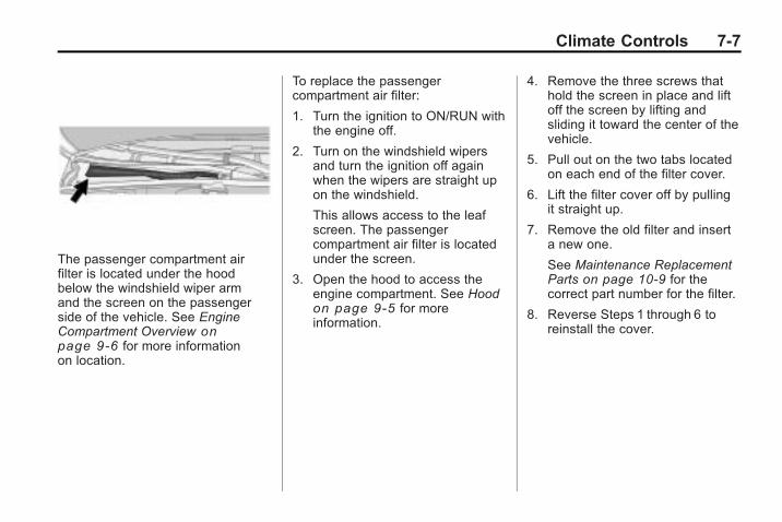
Climate Controls 7-7
The passenger compartment airfilter is located under the hoodbelow the windshield wiper armand the screen on the passengerside of the vehicle. See EngineCompartment Overview onpage 9‑6 for more informationon location.
To replace the passengercompartment air filter:
1. Turn the ignition to ON/RUN withthe engine off.
2. Turn on the windshield wipersand turn the ignition off againwhen the wipers are straight upon the windshield.
This allows access to the leafscreen. The passengercompartment air filter is locatedunder the screen.
3. Open the hood to access theengine compartment. See Hoodon page 9‑5 for moreinformation.
4. Remove the three screws thathold the screen in place and liftoff the screen by lifting andsliding it toward the center of thevehicle.
5. Pull out on the two tabs locatedon each end of the filter cover.
6. Lift the filter cover off by pullingit straight up.
7. Remove the old filter and inserta new one.
See Maintenance ReplacementParts on page 10‑9 for thecorrect part number for the filter.
8. Reverse Steps 1 through 6 toreinstall the cover.

7-8 Climate Controls
2 NOTES
Driving and Operating 8-1
Driving andOperating
Driving InformationDriving for Better FuelEconomy . . . . . . . . . . . . . . . . . . . . 8-2
Defensive Driving . . . . . . . . . . . . . 8-3Drunk Driving . . . . . . . . . . . . . . . . . 8-3Control of a Vehicle . . . . . . . . . . . 8-4Braking . . . . . . . . . . . . . . . . . . . . . . . 8-4Steering . . . . . . . . . . . . . . . . . . . . . . . 8-5Off-Road Recovery . . . . . . . . . . . . 8-6Loss of Control . . . . . . . . . . . . . . . . 8-7Competitive Driving . . . . . . . . . . . 8-8Driving on Wet Roads . . . . . . . . . 8-8Highway Hypnosis . . . . . . . . . . . . 8-9Hill and Mountain Roads . . . . . . 8-9Winter Driving . . . . . . . . . . . . . . . 8-10If the Vehicle is Stuck . . . . . . . . 8-12Vehicle Load Limits . . . . . . . . . . 8-12
Starting and OperatingNew Vehicle Break-In . . . . . . . . 8-17Ignition Positions(Key Access) . . . . . . . . . . . . . . . 8-18
Ignition Positions(Keyless Access) . . . . . . . . . . . 8-19
Retained AccessoryPower (RAP) . . . . . . . . . . . . . . . 8-19
Starting the Engine . . . . . . . . . . 8-20Engine Coolant Heater . . . . . . . 8-22Shifting Into Park . . . . . . . . . . . . 8-22Shifting Out of Park . . . . . . . . . . 8-23Parking (ManualTransmission) . . . . . . . . . . . . . . 8-24
Parking Over ThingsThat Burn . . . . . . . . . . . . . . . . . . 8-24
Engine ExhaustEngine Exhaust . . . . . . . . . . . . . . 8-25Running the Vehicle WhileParked . . . . . . . . . . . . . . . . . . . . . 8-25
Automatic TransmissionAutomatic Transmission . . . . . 8-26Manual Mode . . . . . . . . . . . . . . . . 8-28
Manual TransmissionManual Transmission . . . . . . . . 8-30
Drive SystemsAll-Wheel Drive . . . . . . . . . . . . . . 8-32
BrakesAntilock BrakeSystem (ABS) . . . . . . . . . . . . . . 8-33
Parking Brake (Manual) . . . . . . 8-34Parking Brake (Electric) . . . . . . 8-35Brake Assist(Except CTS-V) . . . . . . . . . . . . 8-37
Ride Control SystemsTraction ControlSystem (TCS) . . . . . . . . . . . . . . 8-37
StabiliTrak System . . . . . . . . . . . 8-38Competitive Driving Mode . . . 8-40Magnetic Ride Control . . . . . . . 8-40Limited-Slip Rear Axle . . . . . . . 8-41
Cruise ControlCruise Control . . . . . . . . . . . . . . . 8-41
Object Detection SystemsUltrasonic Parking Assist . . . . 8-44Rear VisionCamera (RVC) . . . . . . . . . . . . . 8-46

8-2 Driving and Operating
FuelFuel . . . . . . . . . . . . . . . . . . . . . . . . . 8-49Recommended Fuel . . . . . . . . . 8-49Gasoline Specifications . . . . . . 8-50California FuelRequirements . . . . . . . . . . . . . . 8-50
Fuels in Foreign Countries . . . 8-50Fuel Additives . . . . . . . . . . . . . . . 8-50Filling the Tank . . . . . . . . . . . . . . 8-52Filling a Portable FuelContainer . . . . . . . . . . . . . . . . . . . 8-53
TowingGeneral TowingInformation . . . . . . . . . . . . . . . . . 8-54
Driving Characteristics andTowing Tips . . . . . . . . . . . . . . . . 8-54
Trailer Towing(Except CTS-V) . . . . . . . . . . . . 8-58
Trailer Towing (CTS-V) . . . . . . 8-59Towing Equipment . . . . . . . . . . . 8-59
Conversions and Add-OnsAdd-On ElectricalEquipment . . . . . . . . . . . . . . . . . 8-60
Driving Information
Driving for Better FuelEconomyDriving habits can affect fuelmileage. Here are some driving tipsto get the best fuel economypossible.. Avoid fast starts and accelerate
smoothly.. Brake gradually and avoid
abrupt stops.. Avoid idling the engine for long
periods of time.. When road and weather
conditions are appropriate, usecruise control, if equipped.
. Always follow posted speedlimits or drive more slowly whenconditions require.
. Keep vehicle tires properlyinflated.
. Combine several trips into asingle trip.
. Replace the vehicle's tires withthe same TPC Spec numbermolded into the tire's sidewallnear the size.
. Follow recommended scheduledmaintenance.

Driving and Operating 8-3
Defensive DrivingDefensive driving means “alwaysexpect the unexpected.” The firststep in driving defensively is to wearyour safety belt, see Safety Belts onpage 2‑11.
{ WARNING
Assume that other road users(pedestrians, bicyclists, and otherdrivers) are going to be carelessand make mistakes. Anticipatewhat they might do and be ready.In addition:
. Allow enough followingdistance between you andthe driver in front of you.
. Focus on the task of driving.
Driver distraction can causecollisions resulting in injury orpossible death. These simpledefensive driving techniquescould save your life.
Drunk Driving
{ WARNING
Drinking and then driving is verydangerous. Your reflexes,perceptions, attentiveness, andjudgment can be affected by evena small amount of alcohol. Youcan have a serious — or evenfatal — collision if you drive afterdrinking. Do not drink and drive orride with a driver who has beendrinking. Ride home in a cab; or ifyou are with a group, designate adriver who will not drink.
Death and injury associated withdrinking and driving is a globaltragedy.
Alcohol affects four things thatanyone needs to drive a vehicle:judgment, muscular coordination,vision, and attentiveness.
Police records show that almost40 percent of all motorvehicle-related deaths involvealcohol. In most cases, thesedeaths are the result of someonewho was drinking and driving.In recent years, more than17,000 annual motor vehicle-relateddeaths have been associated withthe use of alcohol, with about250,000 people injured.
For persons under 21, it is againstthe law in every U.S. state to drinkalcohol. There are good medical,psychological, and developmentalreasons for these laws.
The obvious way to eliminate theleading highway safety problem isfor people never to drink alcoholand then drive.
Medical research shows thatalcohol in a person's system canmake crash injuries worse,especially injuries to the brain,

8-4 Driving and Operating
spinal cord, or heart. This meansthat when anyone who has beendrinking — driver or passenger — isin a crash, that person's chance ofbeing killed or permanently disabledis higher than if the person had notbeen drinking.
Control of a VehicleThe following three systems helpto control the vehicle whiledriving — brakes, steering, andaccelerator. At times, as whendriving on snow or ice, it is easy toask more of those control systemsthan the tires and road can provide.Meaning, you can lose control of thevehicle. See Traction ControlSystem (TCS) on page 8‑37.
Adding non-dealer/non-retaileraccessories can affect vehicleperformance. See Accessories andModifications on page 9‑3.
BrakingSee Brake System Warning Lighton page 4‑26.
Braking action involves perceptiontime and reaction time. Deciding topush the brake pedal is perceptiontime. Actually doing it isreaction time.
Average reaction time is aboutthree-fourths of a second. But that isonly an average. It might be lesswith one driver and as long as twoor three seconds or more withanother. Age, physical condition,alertness, coordination, andeyesight all play a part. So doalcohol, drugs, and frustration. Buteven in three-fourths of a second,a vehicle moving at 100 km/h(60 mph) travels 20 m (66 ft).That could be a lot of distance inan emergency, so keeping enoughspace between the vehicle andothers is important.
And, of course, actual stoppingdistances vary greatly with thesurface of the road, whether it ispavement or gravel; the condition ofthe road, whether it is wet, dry,or icy; tire tread; the condition of thebrakes; the weight of the vehicle;and the amount of brake forceapplied.
Avoid needless heavy braking.Some people drive inspurts — heavy accelerationfollowed by heavy braking — ratherthan keeping pace with traffic. Thisis a mistake. The brakes might nothave time to cool between hardstops. The brakes will wear outmuch faster with a lot of heavybraking. Keeping pace with thetraffic and allowing realistic followingdistances eliminates a lot ofunnecessary braking. That meansbetter braking and longer brake life.

Driving and Operating 8-5
If the engine ever stops while thevehicle is being driven, brakenormally but do not pump thebrakes. If the brakes are pumped,the pedal could get harder to pushdown. If the engine stops, there willstill be some power brake assist butit will be used when the brake isapplied. Once the power assist isused up, it can take longer to stopand the brake pedal will be harderto push.
Adding non-dealer/non-retaileraccessories can affect vehicleperformance. See Accessories andModifications on page 9‑3.
Steering
Power Steering
If power steering assist is lostbecause the engine stops or thepower steering system is notfunctioning, the vehicle can besteered but it will take more effort.
Speed Variable Assist Steering
The vehicle has a steering systemthat varies the amount of effortrequired to steer the vehicle inrelation to the speed of the vehicle.
The amount of steering effortrequired is less at slower speedsto make the vehicle moremaneuverable and easier to park.At faster speeds, the steering effortincreases to provide a sport-like feelto the steering. This providesmaximum control and stability.
If the vehicle seems harder to steerthan normal when parking or drivingslowly, there may be a problem withthe system. You will still have powersteering, but steering will be stifferthan normal at slow speeds. Seeyour dealer/retailer for service.
Steering Tips
It is important to take curves at areasonable speed.
Traction in a curve depends on thecondition of the tires and the roadsurface, the angle at which thecurve is banked, and vehicle speed.While in a curve, speed is theone factor that can be controlled.
If there is a need to reduce speed,do it before entering the curve, whilethe front wheels are straight.
Try to adjust the speed so you candrive through the curve. Maintain areasonable, steady speed. Wait toaccelerate until out of the curve, andthen accelerate gently into thestraightaway.

8-6 Driving and Operating
Steering in Emergencies
There are times when steering canbe more effective than braking. Forexample, you come over a hill andfind a truck stopped in your lane,or a car suddenly pulls out fromnowhere, or a child darts out frombetween parked cars and stops rightin front of you. These problems canbe avoided by braking— if you canstop in time. But sometimes youcannot stop in time because there isno room. That is the time forevasive action— steering aroundthe problem.
The vehicle can perform very well inemergencies like these. First applythe brakes. See Braking onpage 8‑4 . It is better to remove asmuch speed as possible from acollision. Then steer around theproblem, to the left or rightdepending on the space available.
An emergency like this requiresclose attention and a quick decision.If holding the steering wheel at therecommended 9 and 3 o'clockpositions, it can be turned a full180 degrees very quickly withoutremoving either hand. But you haveto act fast, steer quickly, and just asquickly straighten the wheel onceyou have avoided the object.
The fact that such emergencysituations are always possible is agood reason to practice defensivedriving at all times and wear safetybelts properly.
Off-Road RecoveryThe vehicle's right wheels can dropoff the edge of a road onto theshoulder while driving.
If the level of the shoulder is onlyslightly below the pavement,recovery should be fairly easy. Easeoff the accelerator and then, if thereis nothing in the way, steer so thatthe vehicle straddles the edge of thepavement. Turn the steering wheel8 to 13 cm (3 to 5 inches), aboutone-eighth turn, until the right front
Driving and Operating 8-7
tire contacts the pavement edge.Then turn the steering wheel to gostraight down the roadway.
Loss of ControlLet us review what driving expertssay about what happens when thethree control systems— brakes,steering, and acceleration— do nothave enough friction where the tiresmeet the road to do what the driverhas asked.
In any emergency, do not give up.Keep trying to steer and constantlyseek an escape route or area ofless danger.
Skidding
In a skid, a driver can lose control ofthe vehicle. Defensive drivers avoidmost skids by taking reasonablecare suited to existing conditions,and by not overdriving thoseconditions. But skids are alwayspossible.
The three types of skids correspondto the vehicle's three controlsystems. In the braking skid, thewheels are not rolling. In thesteering or cornering skid, too muchspeed or steering in a curve causestires to slip and lose cornering force.And in the acceleration skid, toomuch throttle causes the drivingwheels to spin.
If the vehicle starts to slide, easeyour foot off the accelerator pedaland quickly steer the way you wantthe vehicle to go. If you startsteering quickly enough, the vehiclemay straighten out. Always be readyfor a second skid if it occurs.
Of course, traction is reduced whenwater, snow, ice, gravel, or othermaterial is on the road. For safety,slow down and adjust your driving tothese conditions. It is important toslow down on slippery surfacesbecause stopping distance is longerand vehicle control more limited.
While driving on a surface withreduced traction, try your best toavoid sudden steering, acceleration,or braking, including reducingvehicle speed by shifting to a lowergear. Any sudden changes couldcause the tires to slide. You mightnot realize the surface is slipperyuntil the vehicle is skidding. Learn torecognize warning clues— such asenough water, ice, or packed snowon the road to make a mirroredsurface— and slow down when youhave any doubt.
Remember: Antilock brakes helpavoid only the braking skid.

8-8 Driving and Operating
Competitive DrivingCompetitive driving may affect thevehicle warranty. See the warrantybook before using the vehicle forcompetitive driving.
Notice: If you use your vehiclefor competitive driving, theengine may use more oil than itwould with normal use. Low oillevels can damage the engine. Besure to check the oil level oftenduring competitive driving andkeep the level at or near theupper mark that shows the properoperating range on the engine oildipstick. For information on howto add oil, see Engine Oil onpage 9‑10.
CTS-V Only: For competitivedriving, it is recommended that thebrake fluid be replaced with a highperformance brake fluid that hasa dry boiling point greater than279°C (534°F). After conversion to
the high performance brake fluid,follow the brake fluid servicerecommendations outlined by thefluid manufacturer. Do not usesilicone or DOT‐5 brake fluids.
Driving on Wet RoadsRain and wet roads can reducevehicle traction and affect yourability to stop and accelerate.Always drive slower in these typesof driving conditions and avoiddriving through large puddles anddeep-standing or flowing water.
{ WARNING
Wet brakes can cause crashes.They might not work as well in aquick stop and could causepulling to one side. You couldlose control of the vehicle.
(Continued)
WARNING (Continued)
After driving through a largepuddle of water or a car/vehiclewash, lightly apply the brakepedal until the brakes worknormally.
Flowing or rushing water createsstrong forces. Driving throughflowing water could cause yourvehicle to be carried away. If thishappens, you and other vehicleoccupants could drown. Do notignore police warnings and bevery cautious about trying to drivethrough flowing water.

Driving and Operating 8-9
Hydroplaning
Hydroplaning is dangerous. Watercan build up under your vehicle'stires so they actually ride on thewater. This can happen if the road iswet enough and you are going fastenough. When your vehicle ishydroplaning, it has little or nocontact with the road.
There is no hard and fast rule abouthydroplaning. The best advice is toslow down when the road is wet.
Other Rainy Weather Tips
Besides slowing down, other wetweather driving tips include:. Allow extra following distance.. Pass with caution.. Keep windshield wiping
equipment in good shape.
. Keep the windshield washerfluid reservoir filled.
. Have good tires with propertread depth. See Tires onpage 9‑58.
. Turn off cruise control.
Highway HypnosisAlways be alert and pay attention toyour surroundings while driving.If you become tired or sleepy, find asafe place to park your vehicleand rest.
Other driving tips include:. Keep the vehicle well ventilated.. Keep interior temperature cool.. Keep your eyes moving — scan
the road ahead and to the sides.. Check the rearview mirror and
vehicle instruments often.
Hill and Mountain RoadsDriving on steep hills or throughmountains is different than drivingon flat or rolling terrain. Tips fordriving in these conditions include:. Keep the vehicle serviced and in
good shape.. Check all fluid levels and brakes,
tires, cooling system, andtransmission.
. Going down steep or long hills,shift to a lower gear.
{ WARNING
If you do not shift down, thebrakes could get so hot that theywould not work well. You wouldthen have poor braking or evennone going down a hill. You couldcrash. Shift down to let the engineassist the brakes on a steepdownhill slope.

8-10 Driving and Operating
{ WARNING
Coasting downhill in N (Neutral)or with the ignition off isdangerous. The brakes will haveto do all the work of slowing downand they could get so hot thatthey would not work well. Youwould then have poor braking oreven none going down a hill.You could crash. Always have theengine running and the vehicle ingear when going downhill.
. Stay in your own lane. Do notswing wide or cut across thecenter of the road. Drive atspeeds that let you stay in yourown lane.
. Top of hills: Bealert — something could be inyour lane (stalled car, accident).
. Pay attention to special roadsigns (falling rocks area, windingroads, long grades, passing orno-passing zones) and takeappropriate action.
Winter Driving
Driving on Snow or Ice
Drive carefully when there is snowor ice between the tires and theroad, creating less traction or grip.Wet ice can occur at about 0°C(32°F) when freezing rain begins tofall, resulting in even less traction.Avoid driving on wet ice or infreezing rain until roads can betreated with salt or sand.
Drive with caution, whatever thecondition. Accelerate gently sotraction is not lost. Accelerating tooquickly causes the wheels to spinand makes the surface under thetires slick, so there is even lesstraction.
Try not to break the fragile traction.If you accelerate too fast, the drivewheels will spin and polish thesurface under the tires even more.
The Antilock Brake System (ABS)on page 8‑33 improves vehiclestability during hard stops onslippery roads, but apply the brakessooner than when on dry pavement.
Allow greater following distance onany slippery road and watch forslippery spots. Icy patches canoccur on otherwise clear roads inshaded areas. The surface of acurve or an overpass can remain icywhen the surrounding roads areclear. Avoid sudden steeringmaneuvers and braking whileon ice.
Turn off cruise control, if equipped,on slippery surfaces.

Driving and Operating 8-11
Blizzard Conditions
Being stuck in snow can be aserious situation. Stay with thevehicle unless there is help nearby.If possible, use the RoadsideService on page 12‑6. To get helpand keep everyone in thevehicle safe:. Turn on the hazard warning
flashers.. Tie a red cloth to an outside
mirror.
{ WARNING
Snow can trap engine exhaustunder the vehicle. This maycause exhaust gases to getinside. Engine exhaust containscarbon monoxide (CO) whichcannot be seen or smelled. It cancause unconsciousness and evendeath.
(Continued)
WARNING (Continued)
If the vehicle is stuck in the snow:. Clear away snow from aroundthe base of your vehicle,especially any that is blockingthe exhaust pipe.
. Check again from time totime to be sure snow doesnot collect there.
. Open a window about 5 cm(two inches) on the side ofthe vehicle that is away fromthe wind to bring in fresh air.
. Fully open the air outlets onor under the instrumentpanel.
. Adjust the Climate Controlsystem to a setting thatcirculates the air inside thevehicle and set the fan speedto the highest setting. SeeClimate Control System in theIndex.
(Continued)
WARNING (Continued)
For more information aboutcarbon monoxide, see EngineExhaust on page 8‑25.
Snow can trap exhaust gasesunder your vehicle. This cancause deadly CO (carbonmonoxide) gas to get inside. COcould overcome you and kill you.You cannot see it or smell it, soyou might not know it is in yourvehicle. Clear away snow fromaround the base of your vehicle,especially any that is blocking theexhaust.
Run the engine for short periodsonly as needed to keep warm, butbe careful.
To save fuel, run the engine for onlyshort periods as needed to warmthe vehicle and then shut theengine off and close the windowmost of the way to save heat.

8-12 Driving and Operating
Repeat this until help arrives butonly when you feel reallyuncomfortable from the cold. Movingabout to keep warm also helps.
If it takes some time for help toarrive, now and then when you runthe engine, push the acceleratorpedal slightly so the engine runsfaster than the idle speed. Thiskeeps the battery charged to restartthe vehicle and to signal for helpwith the headlamps. Do this as littleas possible to save fuel.
If the Vehicle is StuckSlowly and cautiously spin thewheels to free the vehicle whenstuck in sand, mud, ice, or snow.
If stuck too severely for the tractionsystem to free the vehicle, turn thetraction system off and use therocking method.
{ WARNING
If the vehicle's tires spin at highspeed, they can explode, and youor others could be injured. Thevehicle can overheat, causing anengine compartment fire or otherdamage. Spin the wheels as littleas possible and avoid goingabove 55 km/h (35 mph) asshown on the speedometer.
For information about using tirechains on the vehicle, see TireChains on page 9‑81.
Rocking the Vehicle to Getit Out
Turn the steering wheel left andright to clear the area around thefront wheels. Turn off any tractionsystem. Shift back and forthbetween R (Reverse) and a forwardgear, or with a manual transmission,between 1 (First) or 2 (Second) andR (Reverse), spinning the wheels as
little as possible. To preventtransmission wear, wait until thewheels stop spinning before shiftinggears. Release the acceleratorpedal while shifting, and presslightly on the accelerator pedalwhen the transmission is in gear.Slowly spinning the wheels in theforward and reverse directionscauses a rocking motion that couldfree the vehicle. If that does not getthe vehicle out after a few tries, itmight need to be towed out. If thevehicle does need to be towed out,see Towing the Vehicle onpage 9‑108.
Vehicle Load LimitsIt is very important to know howmuch weight the vehicle cancarry. This weight is called thevehicle capacity weight andincludes the weight of alloccupants, cargo and allnonfactory-installed options.

Driving and Operating 8-13
Two labels on the vehicle showhow much weight it mayproperly carry, the Tire andLoading Information label andthe Certification label.
{ WARNING
Do not load the vehicle anyheavier than the GrossVehicle Weight Rating(GVWR), or either themaximum front or rear GrossAxle Weight Rating (GAWR).If you do, parts on the vehiclecan break, and it can changethe way the vehicle handles.These could cause you to losecontrol and crash. Also,overloading can shorten thelife of the vehicle.
Tire and Loading InformationLabel
Label Example
A vehicle specific Tire andLoading Information label isattached to the vehicle's centerpillar (B-pillar). With the driver'sdoor open, you will find the labelattached near the door lockpost. The Tire and LoadingInformation label shows the
number of occupant seatingpositions (A), and the maximumvehicle capacity weight (B) inkilograms and pounds.
The Tire and LoadingInformation label also showsthe tire size of the originalequipment tires (C) and therecommended cold tire inflationpressures (D). For moreinformation on tires and inflationsee Tires on page 9‑58 and TirePressure on page 9‑66 .
There is also important loadinginformation on the Certificationlabel. It tells you the GrossVehicle Weight Rating (GVWR)and the Gross Axle WeightRating (GAWR) for the front andrear axle. See “CertificationLabel” later in this section.

8-14 Driving and Operating
Steps for Determining CorrectLoad Limit
1. Locate the statement“The combined weight ofoccupants and cargo shouldnever exceed XXX kg orXXX lbs” on your vehicle'splacard.
2. Determine the combinedweight of the driver andpassengers that will be ridingin your vehicle.
3. Subtract the combinedweight of the driver andpassengers from XXX kg orXXX lbs.
4. The resulting figure equalsthe available amount of cargoand luggage load capacity.For example, if the “XXX”amount equals 1400 lbs andthere will be five 150 lbpassengers in your vehicle,
the amount of available cargoand luggage load capacityis 650 lbs (1400 − 750(5 x 150) = 650 lbs).
5. Determine the combinedweight of luggage and cargobeing loaded on the vehicle.That weight may not safelyexceed the available cargoand luggage load capacitycalculated in Step 4.
6. If your vehicle will be towinga trailer, the load from yourtrailer will be transferred toyour vehicle. Consult thismanual to determine how thisreduces the available cargoand luggage load capacity ofyour vehicle.
See Trailer Towing (ExceptCTS-V) on page 8‑58 or TrailerTowing (CTS-V) on page 8‑59 forimportant information on towinga trailer, towing safety rules andtrailering tips.
Example 1
A. Vehicle Capacity Weight forExample 1 = 453 kg(1,000 lbs).
B. Subtract Occupant Weight @68 kg (150 lbs) × 2 = 136 kg(300 lbs).
C. Available Occupant andCargo Weight = 317 kg(700 lbs).

Driving and Operating 8-15
Example 2
A. Vehicle Capacity Weight forExample 2 = 453 kg(1,000 lbs).
B. Subtract Occupant Weight @68 kg (150 lbs) × 5 = 340 kg(750 lbs).
C. Available Cargo Weight =113 kg (250 lbs).
Example 3
A. Vehicle Capacity Weight forExample 3 = 453 kg(1,000 lbs).
B. Subtract Occupant Weight @91 kg (200 lbs) × 5 = 453 kg(1,000 lbs).
C. Available Cargo Weight =0 kg (0 lbs).
Refer to the vehicle's Tire andLoading Information label forspecific information about thevehicle's capacity weight and
seating positions. The combinedweight of the driver, passengers,and cargo should never exceedthe vehicle's capacity weight.
Certification Label
Label Example
A vehicle specific Certificationlabel is attached to either thedriver's door edge or the lowercenter pillar on the driver's sideof the vehicle. The label tellsthe gross weight capacity ofthe vehicle, called the GrossVehicle Weight Rating (GVWR).

8-16 Driving and Operating
The GVWR includes the weightof the vehicle, all occupants,fuel, and cargo. Never exceedthe GVWR for the vehicle, or theGross Axle Weight Rating(GAWR) for either the front orrear axle.
If the vehicle is carrying a heavyload, it should be spread out.See “Steps for DeterminingCorrect Load Limit” earlier in thissection.
{ WARNING
Do not load the vehicle anyheavier than the GrossVehicle Weight Rating(GVWR), or either themaximum front or rear GrossAxle Weight Rating (GAWR).If you do, parts on the vehiclecan break, and it can changethe way the vehicle handles.
(Continued)
WARNING (Continued)
These could cause you to losecontrol and crash. Also,overloading can shorten thelife of the vehicle.
{ WARNING
Things you put inside thevehicle can strike and injurepeople in a sudden stop orturn, or in a crash.
. Put things in the cargoarea of the vehicle. In thecargo area, put them asfar forward as you can.Try to spread the weightevenly.
(Continued)
WARNING (Continued)
. Never stack heavierthings, like suitcases,inside the vehicle so thatsome of them are abovethe tops of the seats.
. Do not leave anunsecured child restraintin the vehicle.
. When you carry somethinginside the vehicle, secureit whenever you can.
. Do not leave a seat foldeddown unless you need to.

Driving and Operating 8-17
Starting andOperating
New Vehicle Break-InFollow these recommendedguidelines during the first2 414 km/1,500 miles of drivingthis vehicle. Parts have a break-inperiod and performance will bebetter in the long run.
For the first 2 414 km/1,500 miles:. Avoid full throttle starts and
abrupt stops.. Do not exceed 4,000
engine rpm.. Avoid driving at any one
constant speed, fast or slow.
. Avoid downshifting to brake orslow the vehicle when theengine speed will exceed4000 RPM.
. Do not let the engine labor.Never lug the engine in highgear at low speeds. With amanual transmission, shift to thenext lower gear. This ruleapplies at all times, not justduring the break-in period.
. Do not participate in trackevents, sport driving schools,or similar activities during thisbreak–in period.
. Check engine oil with everyrefueling and add if necessary.Oil and fuel consumption may behigher than normal during thefirst 2 414 km/1,500 miles.
. To break in new tires, drive atmoderate speeds and avoid hardcornering for the first 322 km/200 miles. New tires do not havemaximum traction and may tendto slip.
. New brake linings also need abreak–in period. Avoid makinghard stops during the first322 km/200 miles. This isrecommended every time brakelinings are replaced.

8-18 Driving and Operating
Ignition Positions(Key Access)
The key can be turned to fourdifferent positions.
To shift out of P (Park), the ignitionmust be in the ON/RUN or ACC/ACCESSORY and the brake pedalmust be applied.
Notice: Using a tool to force thekey from its cylinder could causedamage or break the key. Use thecorrect key and turn the key onlywith your hand. Make sure thekey is all the way in. If it is andyou have a manual transmissionvehicle, turn the steering wheelleft and right while you turn thekey hard. If none of this works,then the vehicle needs service.
A (LOCK/OFF): This is the onlyposition in which the key can beinserted or removed. This positionlocks the ignition and shifter onautomatic transmission vehicles,and the ignition and steering wheelon manual transmission vehicles.
B (ACC/ACCESSORY): Thisposition lets you use things like theradio and the windshield wiperswhen the engine is off. This positionallows you to turn off the engine.
C (ON/RUN): This position is fordriving. It is the position the ignitionswitch returns to after the enginestarts, and the key is released.
To shift the transmission out ofP (Park), the ignition key has to bein ACC/ACCESSORY or ON/RUN.
The battery could be drained if thekey is left in the ACC/ACCESSORYor ON/RUN position with the engineoff. The vehicle might not start if thebattery is allowed to drain for anextended period of time.
D (START): This position starts theengine. When the engine starts,release the key. The ignition switchreturns to ON/RUN for driving.
A warning tone will sound when thedriver door is opened, the ignition isin ACC/ACCESSORY or LOCK/OFFand the key is in the ignition.

Driving and Operating 8-19
Ignition Positions(Keyless Access)You can turn the ignition controlknob to four different positions.
To shift out of P (Park), ignition mustbe in the ON/RUN or ACC/ACCESSORY and the regular brakepedal must be applied.
Using a tool to force the ignitioncontrol knob from its cylinder coulddamage it.
Make sure the keyless accesstransmitter is inside the vehiclewhen trying to turn the ignitioncontrol knob.
A (LOCK/OFF): The ignition controlknob cannot be removed from thevehicle. The keyless accesstransmitter must be inside thevehicle to start the engine. Thisposition locks the ignition and shifteron automatic transmission vehicles,and the ignition and steering wheelon manual transmission vehicles.
B (ACC/ACCESSORY): Thisposition allows you to use thingslike the radio and the windshieldwipers when the engine is off. Thisposition will allow you to turn off theengine.
C (ON/RUN): This position is fordriving. It is the position the ignitionswitch returns to after the enginestarts, and the control knob isreleased.
If you need to shift the transmissionout of P (Park), the ignition controlknob has to be in ACC/ACCESSORY or ON/RUN.
The battery could be drainedif you leave the key in the ACC/ACCESSORY or ON/RUN positionwith the engine off. You may not beable to start your vehicle if thebattery is allowed to drain for anextended period of time.
D (START): This position starts theengine.
Retained AccessoryPower (RAP)These vehicle accessories can beused for up to 10 minutes after theengine is turned off:. Audio System. Power Windows. Sunroof (if equipped)
Power to the audio system willwork up to 10 minutes or untilthe driver door is opened.

8-20 Driving and Operating
Power to the windows or sunroofwill work up to 10 minutes or untilany door is opened. For anadditional 10 minutes of operation,close all the doors and turn the keyto ON/RUN and then back toLOCK/OFF.
Starting the EnginePlace the transmission in theproper gear.
If the vehicle has the keylessaccess system, the keyless accesstransmitter must be authenticated inorder for the ignition control knob toturn. The transmitter can beauthenticated either by putting yourfoot on the brake pedal or bypushing the ignition control knob in.
Automatic Transmission
Move the shift lever to P (Park) orN (Neutral). The engine will not startin any other position. To restart theengine when the vehicle is alreadymoving, use N (Neutral) only.
If the vehicle has the keylessaccess system, your foot must beon the brake pedal to start theengine. To rotate the ignition controlknob, put your foot on the brakepedal and turn the ignition controlknob to the START position. If theignition control knob does not turn,try pushing the knob in and turningagain. When the engine beginscranking, let go of the ignitioncontrol knob, it will return to the ON/RUN position.
If the transmitter is not in the vehicleor something is interfering with thetransmitter, the Driver InformationCenter (DIC) will display ElectronicKey Not Detected. See DriverInformation Center (DIC) onpage 4‑31 for more information.
If the battery in the keyless accesstransmitter needs replacing, the DICdisplays Replace Battery In RemoteKey. The vehicle can still be driven.
See “Battery Replacement” underRemote Keyless Entry (RKE)System Operation (Key Access) onpage 1‑5 or Remote Keyless Entry(RKE) System Operation (KeylessAccess) on page 1‑7 for moreinformation.
Notice: Do not try to shift toP (Park) if the vehicle is moving.If you do, you could damage thetransmission. Shift to P (Park)only when the vehicle is stopped.
Manual Transmission
The shift lever should be in neutralposition and the parking brakeengaged. Hold the clutch pedaldown to the floor and start theengine. The vehicle will not start ifthe clutch pedal is not all theway down.

Driving and Operating 8-21
Starting Procedure
1. With your foot off the acceleratorpedal, turn the ignition key toSTART. If the vehicle has thekeyless access system, push theignition control knob in androtate the knob to the STARTposition. When the engine starts,let go of the ignition. The idlespeed will go down as yourengine gets warm. Do not racethe engine immediately afterstarting it. Operate the engineand transmission gently to allowthe oil to warm up and lubricateall moving parts.
The vehicle has aComputer-Controlled CrankingSystem. This feature assists instarting the engine and protectscomponents. If the ignition key isturned to the START position,and then released when theengine begins cranking, theengine will continue cranking fora few seconds or until thevehicle starts. If the engine doesnot start and the key is held in
START for many seconds,cranking will be stopped after15 seconds to prevent crankingmotor damage. To prevent geardamage, this system alsoprevents cranking if the engineis already running. Enginecranking can be stopped byturning the ignition switch toACC/ACCESSORY orLOCK/OFF.
Notice: Cranking the engine forlong periods of time, by returningthe key to the START positionimmediately after cranking hasended, can overheat and damagethe cranking motor, and drain thebattery. Wait at least 15 secondsbetween each try, to let thecranking motor cool down.
2. If the engine does not start after5‐10 seconds, especially in verycold weather (below 0°F or−18°C), it could be flooded withtoo much gasoline. Try pushingthe accelerator pedal all the wayto the floor and holding it thereas you hold the key in START
for up to a maximum of15 seconds. Wait at least15 seconds between each try, toallow the cranking motor to cooldown. When the engine starts,let go of the key and accelerator.If the vehicle starts briefly butthen stops again, do the samething. This clears the extragasoline from the engine. Do notrace the engine immediatelyafter starting it. Operate theengine and transmission gentlyuntil the oil warms up andlubricates all moving parts.
Notice: The engine is designed towork with the electronics in thevehicle. If you add electrical partsor accessories, you could changethe way the engine operates.Before adding electricalequipment, check with yourdealer/retailer. If you do not, theengine might not performproperly. Any resulting damagewould not be covered by thevehicle warranty.

8-22 Driving and Operating
Engine Coolant HeaterVehicles with the engine coolantheater can use this option incold weather conditions at orbelow −18°C (0°F) for easierstarting and better fuel economyduring engine warm-up. Plug in thecoolant heater at least four hoursbefore starting your vehicle.An internal thermostat in theplug-end of the cord may existwhich will prevent engine coolantheater operation at temperaturesabove −18°C (0°F).
To Use the Engine CoolantHeater
1. Turn off the engine.
2. Open the hood and unwrap theelectrical cord. The cord islocated near the driver side struttower.
Remove the plastic cap toaccess the plug.
3. Plug it into a normal, grounded110-volt AC outlet.
{ WARNING
Plugging the cord into anungrounded outlet could cause anelectrical shock. Also, the wrongkind of extension cord couldoverheat and cause a fire. Youcould be seriously injured. Plugthe cord into a properly groundedthree-prong 110-volt AC outlet.If the cord will not reach, use aheavy-duty three-prong extensioncord rated for at least 15 amps.
4. Before starting the engine, besure to unplug and store thecord as it was before to keep itaway from moving engine parts.If you do not, it could bedamaged.
Contact your dealer/retailer forinformation on how long to use theheater in your particular area.
Shifting Into Park
{ WARNING
It can be dangerous to get out ofthe vehicle if the shift lever is notfully in P (Park) with the parkingbrake firmly set. The vehicle canroll. If you have left the enginerunning, the vehicle can movesuddenly. You or others could beinjured. To be sure the vehicle willnot move, even when you are onfairly level ground, use the stepsthat follow. If you are pulling atrailer, see Driving Characteristicsand Towing Tips on page 8‑54.
Use this procedure to shift intoP (Park):
1. Hold the brake pedal down andset the parking brake.
See Parking Brake (Manual) onpage 8‑34 or Parking Brake(Electric) on page 8‑35 for moreinformation.

Driving and Operating 8-23
2. Move the shift lever into P (Park)by holding in the button on theshift lever and pushing the leverall the way toward the front ofthe vehicle.
3. Turn the ignition key toLOCK/OFF.
4. For vehicles with key access,remove the key and take it withyou. If you can leave the vehiclewith the ignition key in yourhand, the vehicle is in P (Park).Vehicles with the keyless accesssystem, take the keyless accesstransmitter with you.
Leaving the Vehicle Withthe Engine Running(Automatic Transmission)
{ WARNING
It can be dangerous to leave thevehicle with the engine running.The vehicle could move suddenlyif the shift lever is not fully in
(Continued)
WARNING (Continued)
P (Park) with the parking brakefirmly set. And, if you leave thevehicle with the engine running, itcould overheat and even catchfire. You or others could beinjured. Do not leave the vehiclewith the engine running.
If you have to leave the vehicle withthe engine running, the vehicle mustbe in P (Park) and the parking brakeset. After shifting into P (Park), try tomove the shift lever out without firstpushing the button on the shift lever.
If you can, the shift lever was notfully locked into P (Park).
Torque Lock(Automatic Transmission)
Torque lock is when the weightof the vehicle puts too muchforce on the parking pawl in thetransmission. This happens when
parking on a hill and shifting thetransmission into P (Park) is notdone properly and then it is difficultto shift out of P (Park). To preventtorque lock, set the parking brakeand then shift into P (Park). To findout how, see "Shifting Into P (Park)"listed previously.
If torque lock does occur, yourvehicle may need to be pusheduphill by another vehicle to relievethe parking pawl pressure, so youcan shift out of P (Park).
Shifting Out of ParkThis vehicle is equipped with anelectronic shift lock release system.The shift lock release isdesigned to:. Prevent ignition key removal
unless the shift lever is inP (Park) with the shift leverbutton fully released, for vehicleswith key access.

8-24 Driving and Operating
. Prevent movement of the shiftlever out of P (Park), unless theignition is in ON/RUN or ACC/ACCESSORY and the brakepedal is applied.
The shift lock release is alwaysfunctional except in the case of anuncharged or low voltage (less than9 volt) battery.
If the vehicle has an unchargedbattery or a battery with low voltage,try charging or jump starting thebattery. See Jump Starting onpage 9‑103 for more information.
To shift out of P (Park) use thefollowing:
1. Apply the brake pedal.
2. Then press the shift lever button.
3. Move the shift lever to thedesired position.
If you still are unable to shift out ofP (Park):
1. Fully release the shift leverbutton.
2. While holding down the brakepedal, press the shift leverbutton again.
3. Move the shift lever to thedesired position.
If you still cannot move the shiftlever from P (Park), consult yourdealer/retailer or a professionaltowing service.
Parking (ManualTransmission)Before you get out of the vehicle,place the shift lever in R (Reverse)and firmly apply the parking brake.
For vehicles with the key accessignition, turn the ignition key toOFF/LOCK, and remove the key.See Ignition Positions (Key Access)
on page 8‑18 or Ignition Positions(Keyless Access) on page 8‑19 formore information.
For vehicles with the keylessaccess ignition, turn the ignition toLOCK/OFF and remove the keylessaccess transmitter.
If you are towing a trailer, seeTrailer Towing (Except CTS-V) onpage 8‑58 or Trailer Towing(CTS-V) on page 8‑59.
Parking Over ThingsThat Burn
{ WARNING
Things that can burn could touchhot exhaust parts under thevehicle and ignite. Do not parkover papers, leaves, dry grass,or other things that can burn.

Driving and Operating 8-25
Engine Exhaust
{ WARNING
Engine exhaust contains CarbonMonoxide (CO) which cannot beseen or smelled. Exposure to COcan cause unconsciousness andeven death.
Exhaust may enter the vehicle if:. The vehicle idles in areaswith poor ventilation (parkinggarages, tunnels, deep snowthat may block underbodyairflow or tail pipes).
. The exhaust smells orsounds strange or different.
. The exhaust system leaksdue to corrosion or damage.
. The vehicle’s exhaust systemhas been modified, damagedor improperly repaired.
(Continued)
WARNING (Continued)
. There are holes or openingsin the vehicle body fromdamage or after-marketmodifications that are notcompletely sealed.
If unusual fumes are detected orif it is suspected that exhaust iscoming into the vehicle:
. Drive it only with the windowscompletely down.
. Have the vehicle repairedimmediately.
Never park the vehicle with theengine running in an enclosedarea such as a garage or abuilding that has no fresh airventilation.
Running the VehicleWhile ParkedIt is better not to park with theengine running. But if you ever haveto, here are some things to know.
{ WARNING
Idling a vehicle in an enclosedarea with poor ventilation isdangerous. Engine exhaust mayenter the vehicle. Engine exhaustcontains Carbon Monoxide (CO)which cannot be seen or smelled.It can cause unconsciousnessand even death. Never run theengine in an enclosed area thathas no fresh air ventilation. Formore information, see EngineExhaust on page 8‑25.

8-26 Driving and Operating
{ WARNING
It can be dangerous to get out ofthe vehicle if the automatictransmission shift lever is not fullyin P (Park) with the parking brakefirmly set. The vehicle can roll.Do not leave the vehicle when theengine is running unless youhave to. If you have left theengine running, the vehicle canmove suddenly. You or otherscould be injured. To be sure thevehicle will not move, even whenyou are on fairly level ground,always set the parking brake andmove the shift lever to P (Park).
Follow the proper steps to be surethe vehicle will not move. SeeShifting Into Park on page 8‑22.
If parking on a hill and pulling atrailer, see Driving Characteristicsand Towing Tips on page 8‑54.
AutomaticTransmissionThe shift lever is located on thecenter console between the frontseats.
There are several different positionsfor the shift lever.
P (Park): This position locks therear wheels. It is the best position touse when you start the enginebecause the vehicle cannot moveeasily.
{ WARNING
It is dangerous to get out of thevehicle if the shift lever is not fullyin P (Park) with the parking brakefirmly set. The vehicle can roll.
Do not leave the vehicle when theengine is running unless youhave to. If you have left theengine running, the vehicle canmove suddenly. You or otherscould be injured. To be sure thevehicle will not move, even whenyou are on fairly level ground,always set the parking brake andmove the shift lever to P (Park).See Shifting Into Park onpage 8‑22. If you are pulling atrailer, see Driving Characteristicsand Towing Tips on page 8‑54.
Make sure the shift lever is fully inP (Park) before starting the engine.The vehicle has an automatictransmission shift lock controlsystem. You must fully apply theregular brakes first and then press

Driving and Operating 8-27
the shift lever button before you canshift from P (Park) when the ignitionkey is in ON/RUN. If you cannotshift out of P (Park), ease pressureon the shift lever and push the shiftlever all the way into P (Park) asyou maintain brake application.Then press the shift lever buttonand move the shift lever intoanother gear. See Shifting Out ofPark on page 8‑23.
Notice: Shifting to R (Reverse)while the vehicle is movingforward could damage thetransmission. The repairs wouldnot be covered by the vehiclewarranty. Shift to R (Reverse) onlyafter the vehicle is stopped.
R (Reverse): Use this gear toback up.
At low vehicle speeds, R (Reverse)can be used to rock the vehicleback and forth to get out of snow,ice, or sand without damaging yourtransmission. See If the Vehicle isStuck on page 8‑12 for additionalinformation.
N (Neutral): In this position, theengine does not connect with thewheels. To restart when the vehicleis already moving, use N (Neutral)only. You can also use N (Neutral)when the vehicle is being towed.
{ WARNING
Shifting into a drive gear while theengine is running at high speed isdangerous. Unless your foot isfirmly on the brake pedal, thevehicle could move very rapidly.You could lose control and hitpeople or objects. Do not shiftinto a drive gear while the engineis running at high speed.
Notice: Shifting out of P (Park) orN (Neutral) with the enginerunning at high speed maydamage the transmission. Therepairs would not be covered bythe vehicle warranty. Be sure theengine is not running at highspeed when shifting the vehicle.
D (Drive): This position is fornormal driving. It provides the bestfuel economy. If you need morepower for passing, and you are:. Going less than 55 km/h
(35 mph), push the acceleratorpedal about halfway down.
. Going about 55 km/h (35 mph) ormore, push the accelerator allthe way down.
The transmission will shift downto a lower gear and have morepower.
Downshifting the transmission inslippery road conditions could resultin skidding, see Skidding underLoss of Control on page 8‑7
While in D (Drive), the CTS-Vvehicle's first forward gearautomatic shift after starting thevehicle will be from 1 (First).Afterwards, the CTS-V vehicles willalways start in 2 (Second) gear.While in M (Manual Mode), forincreased performance, the vehiclewill start in 1 (First) gear.

8-28 Driving and Operating
M (Manual Mode): This positionallows the driver to select the rangeof gears appropriate for currentdriving conditions. See Driver ShiftControl (DSC) later in this section.
Notice: Spinning the tires orholding the vehicle in one placeon a hill using only theaccelerator pedal may damagethe transmission. If you arestuck, do not spin the tires.When stopping on a hill, use thebrakes to hold the vehicle inplace.
Manual Mode
Driver Shift Control (DSC) orTap Shift
Notice: If you drive the vehicle athigh RPMs without upshiftingwhile using Driver Shift Control(DSC), you could damage thevehicle. Always upshift whennecessary while using DSC.
Driver Shift Control (DSC) allowsyou to shift an automatictransmission similar to a manualtransmission.
DSC can be enabled through theshift lever or the Tap Shift controls,located on the back of the steeringwheel (if equipped).
To use the DSC feature using theshift lever:
1. Move the shift lever to theright from D (Drive) toM (Manual Mode).
Once in M (Manual Mode)position, if you do not move theshift lever forward or rearward,the vehicle will be in sport mode.When you are in sport modethe vehicle will still shiftautomatically. The transmissionmay remain in a gear longerthan it would in the normaldriving mode based on braking,throttle input, and vehicle lateralacceleration.
SPORT MODE will be displayedin the DIC momentarily.The vehicle will remain in sportmode if the shift lever is notmoved. Sport mode will shiftautomatically but remain in agear longer then it would innormal driving mode based onbraking and acceleration.
2. To go from sport mode to DSC,move the shift lever forward toupshift or rearward to downshift.
3. When in DSC, you can exit backinto sport mode by continuouslyholding the shifter in theupshift (forward) position forapproximately one second.

Driving and Operating 8-29
To use the DSC feature withthe steering wheel paddles(if equipped):
1. Move the shift lever to theright from D (Drive) toM (Manual Mode).
2. The paddles are on the back ofthe steering wheel. Tap the leftpaddle to downshift, and theright paddle to upshift.
3. When in DSC, you can exit backinto sport mode by continuouslyholding the upshift paddle (righthand side) for approximatelyone second.
The tachometer display on theinstrument panel cluster will showwhich gear the vehicle is in. Thenumber indicates the requestedgear range when moving the shiftlever forward or rearward. SeeTachometer on page 4‑17 for moreinformation on the odometer.
CTS-V vehicles use tracer lightsaround the outside of thetachometer as a performanceup-shift light. These tracers flash toindicate when to shift to the nexthigher gear to avoid the enginespeed limit. See Tachometer onpage 4‑17 for more information.
While using the DSC feature, thevehicle will have firmer, quickershifting. You can use this for sportdriving or when climbing ordescending hills, to stay in gearlonger, or to down shift for morepower or engine braking.
The transmission will only allow youto shift into gears appropriate forthe vehicle speed and engineRevolutions Per Minute (RPM). Thetransmission will not automaticallyshift to the next lower gear if theengine RPM is too high, nor to thenext higher gear when the maximumengine RPM is reached.

8-30 Driving and Operating
If shifting is prevented for anyreason, the currently selected gearwill flash multiple times, indicatingthat the transmission has notshifted gears.
While in the DSC mode, the CTSautomatic transmission willautomatically downshift when thevehicle comes to a stop. This willallow for more power duringacceleration.
The CTS-V automatic transmissionwill not automatically downshifton hard acceleration when inDSC mode.
When accelerating the vehiclefrom a stop in snowy and icyconditions, you may want to shiftinto second gear. A higher gearallows the vehicle to gain moretraction on slippery surfaces.
Manual TransmissionIf the vehicle has a manualtransmission, the shift lever islocated on the center consolebetween the front seats. Thefollowing explains how to operatethe manual transmission.
CTS
CTS-V
1 (First): Press the clutch pedaland shift into 1 (First). Then slowlylet up on the clutch pedal as youpress the accelerator pedal.
Shift into 1 (First) when you aregoing less than 40 km/h (25 mph).For CTS-V, shift into 1 (First) whenyou are going less than 64 km/h(40 mph ). If you come to acomplete stop and it is hard to shiftinto 1 (First), put the shift lever inNeutral and let up on the clutch.Press the clutch pedal back down.Then shift into 1 (First).

Driving and Operating 8-31
2 (Second): Press the clutch pedalas you let up on the acceleratorpedal and shift into 2 (Second).Then, slowly let up on the clutchpedal as you press the acceleratorpedal.
3 (Third), 4 (Fourth), 5 (Fifth) and6 (Sixth): Shift into 3 (Third),4 (Fourth), 5 (Fifth) and 6 (Sixth) thesame way you do for 2 (Second).Slowly let up on the clutch pedal asyou press the accelerator pedal.
To stop, let up on the acceleratorpedal and press the brake pedal.Just before the vehicle stops, pressthe clutch pedal and the brakepedal, and shift to Neutral.
Neutral: Use this position whenyou start or idle your engine. Yourshift lever is in Neutral when it iscentered in the shift pattern, not inany gear.
R (Reverse): To back up, pressdown the clutch pedal, completelystop the vehicle, and shift intoR (Reverse). Let up on the clutchpedal slowly while pressing theaccelerator pedal.
The CTS-V transmission preventsyou from easily shifting intoR (Reverse) using normal shiftingforce while the vehicle is moving atmore than 5 km/h (3 mph), or whenthe ignition is in LOCK/OFF.
Shift Speeds (ManualTransmission)
{ WARNING
If you skip a gear when youdownshift, you could lose controlof the vehicle. You could injureyourself or others. Do not shiftdown more than one gear at atime when you downshift.
Notice: If you skip more than onegear when you downshift, or ifyou race the engine when yourelease the clutch pedal whiledownshifting, you could damagethe engine, clutch, driveshaft orthe transmission. Do not skipgears or race the engine whendownshifting.
If the vehicle speed drops below32 km/h (20 mph), or if the engine isnot running smoothly, you shoulddownshift to the next lower gear.You may have to downshift two ormore gears to keep the enginerunning smoothly or for goodperformance.

8-32 Driving and Operating
Up-Shift Light
CTS vehicles with a manualtransmission have an up-shift lighton the instrument panel. This lightshows when to shift to the nexthigher gear for the best fueleconomy.
When this light comes on, you canshift to the next higher gear ifweather, road, and traffic conditionsallow. For the best fuel economy,accelerate slowly and shift when thelight comes on.
While you accelerate, it is normalfor the light to go on and off if youquickly change the position of theaccelerator. Ignore the light whenyou downshift.
CTS-V vehicles use tracer lightsaround the outside of thetachometer as a performanceup-shift light. These tracers flash toindicate when to shift to the nexthigher gear to avoid the enginespeed limit. See Tachometer onpage 4‑17 for more information.
Skip Shift (CTS-V)
Under light acceleration, thetransmission will only allow you toshift from 1 (First) to 4 (Fourth).Shifts from 1 (First) to 2 (Second) or3 (Third) are not allowed. This helpsimprove fuel mileage.
Under harder acceleration, SkipShift is disabled, and the driver hasall gears available.
Drive Systems
All-Wheel DriveWith this feature, engine power isalways sent to all four wheels. It isfully automatic, and adjusts itself asneeded for road conditions.
When using a compact spare tire onan AWD vehicle, the systemautomatically detects the compactspare and disables AWD. To restoreAWD operation and preventexcessive wear on system, replacethe compact spare with a full-sizetire as soon as possible. SeeCompact Spare Tire on page 9‑102for more information.

Driving and Operating 8-33
Brakes
Antilock BrakeSystem (ABS)This vehicle has the Antilock BrakeSystem (ABS), an advancedelectronic braking system that helpsprevent a braking skid.
When the engine is started and thevehicle begins to drive away, ABSchecks itself. A momentary motor orclicking noise might be heard whilethis test is going on, and it mighteven be noticed that the brakepedal moves a little. This is normal.
If there is a problem with ABS, thiswarning light stays on. See AntilockBrake System (ABS) Warning Lighton page 4‑27.
If driving safely on a wet road and itbecomes necessary to slam on thebrakes and continue braking toavoid a sudden obstacle, acomputer senses that the wheelsare slowing down. If one of thewheels is about to stop rolling, thecomputer will separately work thebrakes at each wheel.
ABS can change the brake pressureto each wheel, as required, fasterthan any driver could. This can helpthe driver steer around the obstaclewhile braking hard.
As the brakes are applied, thecomputer keeps receiving updateson wheel speed and controlsbraking pressure accordingly.
Remember: ABS does not changethe time needed to get a foot up tothe brake pedal or always decreasestopping distance. If you get tooclose to the vehicle in front of you,
there will not be enough time toapply the brakes if that vehiclesuddenly slows or stops. Alwaysleave enough room up ahead tostop, even with ABS.
Using ABS
Do not pump the brakes. Just holdthe brake pedal down firmly and letABS work. The ABS pump or motormight be heard operating, and thebrake pedal might be felt to pulsate,but this is normal.
Braking in Emergencies
ABS allows the driver to steer andbrake at the same time. In manyemergencies, steering can helpmore than even the very bestbraking.

8-34 Driving and Operating
Parking Brake (Manual)
The parking brake pedal is locatedon the lower portion of theinstrument panel to the left of thesteering wheel.
To set the parking brake, hold thebrake pedal down, then push theparking brake pedal down.
If the ignition is on, the brakesystem warning light on theinstrument panel cluster shouldcome on. If it does not, you need tohave the vehicle serviced. SeeBrake System Warning Light onpage 4‑26 for more information.
To release the parking brake, pullthe release lever located to the leftof the steering wheel on theinstrument panel.
Notice: Driving with the parkingbrake on can overheat the brakesystem and cause prematurewear or damage to brake systemparts. Make sure that the parkingbrake is fully released and thebrake warning light is off beforedriving.
A warning chime will sound if theparking brake is set, the ignition ison, and the vehicle begins to move.To stop the chime, fully release theparking brake.
If you are towing a trailer andparking on a hill, see Trailer Towing(Except CTS-V) on page 8‑58 orTrailer Towing (CTS-V) onpage 8‑59 for more information.

Driving and Operating 8-35
Parking Brake (Electric)
{ WARNING
On vehicles with a manualtransmission, releasing the clutchand pressing the accelerator willrelease the Electric ParkingBrake. If the vehicle is not in agear, the vehicle could move, andyou or others could be injured.Make sure the vehicle is in a gearbefore attempting to drive away.To avoid unexpected vehiclemovement, do not partiallyrelease the clutch or press theaccelerator pedal until you areready to release the parkingbrake and drive away.
Vehicles with the electric parkingbrake (EPB) have a switch in thecenter console.
The EPB takes the place of themanual parking brake system, thefoot pedal and release handle. TheEPB can always be activated, evenif the ignition is OFF. To avoiddraining the battery, do not operatethe EPB too often without theengine running.
The system has two warning lightsand five Driver Information Center(DIC) messages. See Brake SystemWarning Light on page 4‑26 andDriver Information Center (DIC) onpage 4‑31 for more information. Incase of insufficient electrical power,the EPB cannot be applied orreleased.
EPB Apply
The EPB can be applied any timethe vehicle is stopped. The EPB isapplied by momentarily lifting up onthe EPB switch. Once fully applied,the BRAKE light will be on, and theDIC message “Park Brake Set” willbe displayed. While the brake isbeing applied, the status light willflash until full apply is reached.If the light does not come on,or remains flashing, you need tohave the vehicle serviced. Do notdrive the vehicle if the BRAKE lightis flashing. See your dealer/retailer.See Brake System Warning Lighton page 4‑26 for more information.

8-36 Driving and Operating
If the EPB is applied while thevehicle is in motion, a chime willsound, and the DIC message“Release Park Brake Switch” will bedisplayed. The vehicle willdecelerate as long as the switch isheld in the up position. Releasingthe EPB switch during thedeceleration will release the parkingbrake. If the switch is held in the upposition until the vehicle comes to astop, the EPB will remain applied.
If the BRAKE light is on, either theEPB is applied, or there is a failurein the hydraulic brake system.
If this light is flashing continuously,the EPB is only partially applied orreleased, or there is a problem withthe EPB. The DIC message“Service Park Brake” will bedisplayed. If this light is flashingcontinuously, release the EPB, andattempt to apply it again. If this lightcontinues to flash, do not drive thevehicle. See your dealer/retailer.
If the yellow light is on, the EPB hasdetected an error in another systemand is operating with reducedfunctionality. To apply the EPB whenthis light is on, lift up on the EPBswitch and hold it in the up position.Full application of the parking brakeby the EPB system may take alonger period of time than normalwhen this light is on. Continue tohold the switch until the BRAKElight remains on. If the yellow light ison, see your dealer/retailer.
If the EPB fails to apply, the rearwheels should be blocked toprevent vehicle movement.
EPB Release
To release the EPB, turn the ignitionswitch to the ON/RUN position,apply and hold the brake pedal,and push down momentarily on theEPB switch. If you attempt torelease the EPB without the brakepedal applied, a chime will sound,and the DIC message “Step OnBrake to Release Park Brake” will
be displayed. The EPB is releasedwhen the BRAKE light is off and theDIC message “Park BrakeReleased” is displayed.
If the yellow light is on, the EPB hasdetected an error in another systemand is operating with reducedfunctionality. To release the EPBwhen this light is on, push down onthe EPB switch and hold it in thedown position. EPB release maytake a longer period of time thannormal when this light is on.Continue to hold the switch until theBRAKE light is off. If the yellow lightis on, see your dealer/retailer.
Notice: Driving with the parkingbrake on can overheat the brakesystem and cause prematurewear or damage to brake systemparts. Make sure that the parkingbrake is fully released and the redbrake warning light is off beforedriving.

Driving and Operating 8-37
Automatic EPB Release
The EPB will automatically release ifthe vehicle is running, placed intogear and an attempt is made todrive away. Avoid rapid accelerationwhen the EPB is applied, topreserve park brake lining life.
The EPB can also be used toprevent roll back for vehicles with amanual transmission taking off on ahill. In a situation where no roll backis desired, an applied EPB will allowboth feet to be used for the clutchand accelerator pedals inpreparation for starting the vehiclemoving in the intended direction.
In this situation, perform the normalclutch and/or accelerator actionsrequired to begin moving thevehicle. There is no need to pushthe switch to release the EPB.
If you are towing a trailer andparking on a hill, see Trailer Towing(Except CTS-V) on page 8‑58 orTrailer Towing (CTS-V) onpage 8‑59 for more information.
Brake Assist(Except CTS-V)This vehicle has a brake assistfeature designed to assist the driverin stopping or decreasing vehiclespeed in emergency drivingconditions. This feature uses thestability system hydraulic brakecontrol module to supplement thepower brake system underconditions where the driver hasquickly and forcefully applied thebrake pedal in an attempt to quicklystop or slow down the vehicle. Thestability system hydraulic brakecontrol module increases brakepressure at each corner of thevehicle until the ABS activates.Minor brake pedal pulsations orpedal movement during this timeis normal and the driver shouldcontinue to apply the brake pedalas the driving situation dictates.The brake assist feature willautomatically disengage whenthe brake pedal is released orbrake pedal pressure is quicklydecreased.
Ride Control Systems
Traction ControlSystem (TCS)The vehicle has a Traction ControlSystem (TCS) that limits wheelspin. This is especially useful inslippery road conditions. On arear-wheel-drive vehicle, the systemoperates if it senses that one orboth of the rear wheels are spinningor beginning to lose traction. On anAll-Wheel-Drive (AWD) vehicle, thesystem will operate if it senses thatany of the wheels are spinning orbeginning to lose traction. When thishappens, the system brakes thespinning wheel(s) and/or reducesengine power to limit wheel spin.
The system may be heard or feltwhile it is working, but this isnormal.

8-38 Driving and Operating
The TCS/StabiliTrak warning lightflashes when the traction controlsystem is limiting wheel spin.
The TCS/StabiliTrak warning lightcomes on if there is a problemwith the traction control system.When the TCS/StabiliTrak warninglight is on, the system will not limitwheel spin. Adjust your drivingaccordingly. See Traction ControlSystem (TCS)/StabiliTrak® Light onpage 4‑28 for more information.
TCS automatically comes onwhenever the vehicle is started.To limit wheel spin, especially inslippery road conditions, the systemshould always be left on, but it maybe necessary to turn the system offif the vehicle is stuck in sand, mud
or snow and rocking the vehicle isrequired. See If the Vehicle is Stuckon page 8‑12 for more information.See Winter Driving on page 8‑10for information on using TCS whendriving in snowy or icy conditions.
The TCS/StabiliTrak button islocated on the instrumentpanel (CTS) or the steeringwheel (CTS-V).
Press and release the TCS/StabiliTrak button and the tractioncontrol system will turn off and theTCS/StabiliTrak warning light willcome on. Press the button againto turn the system back on. Forinformation on turning StabiliTrakoff and on, see StabiliTrak Systemfollowing.
Adding non-dealer/non-retaileraccessories can affect yourvehicle's performance. SeeAccessories and Modifications onpage 9‑3 for more information.
StabiliTrak SystemThe vehicle has an electronicstability control system calledStabiliTrak. It is an advancedcomputer controlled system thatassists with directional control of thevehicle in difficult driving conditions.
StabiliTrak activates when thesystem senses a discrepancybetween the intended path and thedirection the vehicle is actuallytraveling. StabiliTrak selectivelyapplies braking pressure at any oneof the vehicle's brakes to help steerthe vehicle in the direction whichyou are steering.

Driving and Operating 8-39
When the system activates, theTraction Control System (TCS)/StabiliTrak warning light flashes onthe instrument panel. A noise maybe heard or a vibration may be feltin the brake pedal. This is normal.Continue to steer the vehicle in theintended direction.
If there is a problem detectedwith StabiliTrak, SERVICESTABILITRAK displays on theDriver Information Center (DIC) andthe TCS/StabiliTrak warning lightcomes on the instrument panelcluster. When this message and
warning light displays, the system isnot operational. Driving should beadjusted accordingly. See DriverInformation Center (DIC) onpage 4‑31 and Messages andTraction Control System (TCS)/StabiliTrak® Light on page 4‑28 formore information.
The TCS/StabiliTrak button islocated on the instrumentpanel (CTS) or the steeringwheel (CTS-V).
StabiliTrak comes on automaticallywhenever the vehicle is started.The system should be left on to helpassist with directional control of thevehicle. If StabiliTrak needs to beturned off, press and hold theTCS/StabiliTrak button until theTCS/StabiliTrak warning light comeson and STABILITRAK OFF comeson the DIC. More steering effort isrequired when the system isturned off.
If cruise control is being used whenthe StabiliTrak activates, the cruisecontrol will automatically disengage.When road conditions allow,reengage the cruise control.See Cruise Control on page 8‑41for more information.

8-40 Driving and Operating
Competitive Driving Mode
Competitive Driving Mode
To select this optional handlingmode, press the TCS/StabiliTrakbutton quickly two times andSTABILITRAK COMPETITIVEMODE displays in the DriverInformation Center (DIC). While inthe StabiliTrak Competitive Mode,the TCS/StabiliTrak warning lightcomes on, TCS does not limit wheelspin, and more effort is required toturn the steering wheel. Adjust yourdriving accordingly.
Press the TCS/StabiliTrak buttonagain, or turn the ignition toACC/ACCESSORY and restart thevehicle, to turn TCS back on andturn the TCS/StabiliTrak warninglight off.
Notice: When traction control isturned off, or Competitive DrivingMode is active, it is possible tolose traction. If you attempt toshift with the drive wheelsspinning with a loss of traction, itis possible to cause damage tothe transmission. Do not attemptto shift when the drive wheels donot have traction. Damage causedby misuse of the vehicle is notcovered. See the warranty bookfor additional information.
Magnetic Ride ControlWith this feature on the CTS-V, theMagnetic Ride Control systemadjusts the ride of the vehicle toTouring or Sport modes. MagneticRide Control monitors thesuspension system to determine theproper system response.
TOUR: Use for normal city andhighway driving. This settingprovides a smooth, soft ride.
SPORT: Use where road conditionsor personal preference demandmore control. This setting providesmore “feel”, or response to roadconditions.
The setting can be changed at anytime. Based on road conditions,steering wheel angle and thevehicle speed, the systemautomatically adjusts to provide thebest handling while providing asmooth ride. The Touring and Sportmodes will feel similar on a smoothroad. Select a new setting wheneverdriving conditions change.

Driving and Operating 8-41
The Driver Information Center (DIC)briefly displays SUSPENSIONMODE TOURING or SUSPENSIONMODE SPORT on vehicle startup orwhen a new mode is selected.
Press and release this button,located in the center of theinstrument panel, to change modes.
Limited-Slip Rear AxleVehicles with a limited-slip rear axlecan give more traction on snow,mud, ice, sand or gravel. Whentraction is low, this feature allowsthe drive wheel with the mosttraction to move the vehicle.
Cruise Control
{ WARNING
Cruise control can be dangerouswhere you cannot drive safely ata steady speed. So, do not usethe cruise control on windingroads or in heavy traffic.
Cruise control can be dangerouson slippery roads. On such roads,fast changes in tire traction cancause excessive wheel slip, andyou could lose control. Do not usecruise control on slippery roads.
With cruise control, a speed ofabout 40 km/h (25 mph) or morecan be maintained without keeping
your foot on the accelerator. Cruisecontrol does not work at speedsbelow about 40 km/h (25 mph).
When the brakes are applied, thecruise control turns off.
If the vehicle has the Stabilitrak®
system and begins to limit wheelspin while you are using cruisecontrol, the cruise control willautomatically disengage. SeeStabiliTrak System on page 8‑38.When road conditions allow you tosafely use it again, the cruisecontrol can be turned back on.

8-42 Driving and Operating
CTS Shown, CTS-V Similar
The cruise control buttons arelocated on the left side of thesteering wheel.
I (On/Off): Press to turn thesystem on or off. The indicator lighton the button turns on when cruisecontrol is on.
+ RES (Resume/Accelerate):Press to make the vehicleaccelerate or resume to a previouslyset speed.
SET − (Set/Coast): Press to setthe speed or make the vehicledecelerate.
[ (Cancel): Press to cancel cruisecontrol without erasing the setspeed from memory.
Setting Cruise Control
Cruise control will not work if theparking brake is set, or if the mastercylinder brake fluid level is low.
The cruise control light on theinstrument panel cluster comes onafter the cruise control has been setto the desired speed.
{ WARNING
If you leave your cruise control onwhen you are not using cruise,you might hit a button and go intocruise when you do not want to.
(Continued)
WARNING (Continued)
You could be startled and evenlose control. Keep the cruisecontrol switch off until you want touse cruise control.
1. Press theI button.
2. Get up to the desired speed.
3. Press the SET− button locatedon the steering wheel andrelease it.
4. Take your foot off theaccelerator.
Resuming a Set Speed
Suppose the cruise control is set ata desired speed and then the brakeis applied. This shuts off the cruisecontrol. But it does not need to bereset.
Once the vehicle is driving at about40 km/h (25 mph) or more, press the+RES button on the steering wheel.

Driving and Operating 8-43
The vehicle goes back to thepreviously set speed and staysthere.
Increasing Speed While UsingCruise Control
To increase the cruise speed whileusing cruise control:. Press and hold the +RES button
on the steering wheel until thedesired speed is reached, thenrelease it.
. To increase vehicle speed insmall increments, press the+RES button. Each time this isdone, the vehicle goes about1.6 km/h (1 mph) faster.
Reducing Speed While UsingCruise Control
To reduce the vehicle's speed whileusing cruise control:. Press and hold the SET– button
on the steering wheel until thedesired speed is reached, thenrelease it.
. To slow down in very smallamounts, press the SET– buttonon the steering wheel briefly.Each time this is done, thevehicle goes about 1.6 km/h(1 mph) slower.
Passing Another Vehicle WhileUsing Cruise Control
Use the accelerator pedal toincrease the vehicle's speed. Whenyou take your foot off the pedal, thevehicle slows down to the previouslyset cruise speed.
Using Cruise Control on Hills
How well the cruise control workson hills depends upon the vehicle'sspeed, load, and the steepness ofthe hills. When going up steep hills,you might have to step on theaccelerator pedal to maintain thevehicle's speed. When goingdownhill, you might have to brake orshift to a lower gear to keep thevehicle's speed down. When thebrakes are applied the cruise controlturns off.
Ending Cruise Control
There are four ways to end cruisecontrol:. Step lightly on the brake pedal
(manual and automatictransmissions).
. Press the clutch pedal to thefloor (manual transmissions).
. Press [ on the steering wheel.
. PressI on the steering wheel.
Erasing Speed Memory
The cruise control set speedmemory is erased when the cruisecontrol or the ignition is turned off.

8-44 Driving and Operating
Object DetectionSystems
Ultrasonic Parking AssistFor vehicles with the UltrasonicRear Parking Assist (URPA) system,it assists the driver with parkingand avoiding objects while inR (Reverse). URPA operates atspeeds less than 8 km/h (5 mph),and the sensors on the rear bumperdetect objects up to 2.4m (8 ft.)behind the vehicle, and at least25.4 cm (10 in.) off the ground.
{ WARNING
The Ultrasonic Rear ParkingAssist (URPA) system does notreplace driver vision. It cannotdetect:
. Objects that are below thebumper, underneath thevehicle, or if they are tooclose or far from the vehicle
. Children, pedestrians,bicyclists, or pets.
If you do not use proper carebefore and while backing; vehicledamage, injury, or death couldoccur. Even with URPA, alwayscheck behind the vehicle beforebacking up. While backing, besure to look for objects and checkthe vehicle's mirrors.
The display uses three color-codedlights to provide distance andsystem information and is locatedabove the rear window. It can beseen by looking over your rightshoulder.

Driving and Operating 8-45
How the System Works
URPA comes on automatically andthe display briefly illuminates toindicate the system is workingwhen the shift lever is moved intoR (Reverse).
If the vehicle is traveling faster then8 km/h (5 mph) in reverse, the redlight on the rear display flashes.
Objects must be at least 25.4 cm(10 in.) off the ground and belowtrunk level, and within 2.4m (8 ft.)from the rear bumper to bedetected. The distance may be lessduring warmer or humid weather.
A single beep sounds the first timean object is detected between1.0 m (40 in.) and 2.4m (8 ft.) away.Beeping occurs continuously whenthe vehicle is 0.6 m (23 in.) or closerto an object.
The following describes how the URPA display lights appear as the vehiclegets closer to a detected object:
Description Metric English
amber light 2.4 m 8 ft.
amber/amber lights 1.0 m 40 in.
amber/amber/red lights andcontinuous beeping for
five seconds0.6 m 23 in.
amber/amber/red lights flashingand continuous beeping for
five seconds0.3 m 1 ft.
The system can be disabled throughthe Driver Information Center (DIC).See “Park Assist” under VehiclePersonalization on page 4‑51 formore information.

8-46 Driving and Operating
When the System Does NotSeem to Work Properly
If the URPA system will not activatedue to a temporary condition, themessage PARK ASSIST OFF will bedisplayed on the DIC and a red lightwill be shown on the rear URPAdisplay when the shift lever ismoved into R (Reverse). Thisoccurs under the followingconditions:. The driver disables the system.. The ultrasonic sensors are not
clean. Keep the vehicle's rearbumper free of mud, dirt, snow,ice and slush. For cleaninginstructions, see Exterior Careon page 9‑110.
. A trailer was attached to thevehicle, or a bicycle or an objectwas hanging out of the trunkduring the last drive cycle, thered light may illuminate in therear display. Once the attachedobject is removed, URPA willreturn to normal operation.
. A tow bar is attached to thevehicle.
. The vehicle's bumper isdamaged. Take the vehicle toyour dealer/retailer to repair thesystem.
. Other conditions may affectsystem performance, such asvibrations from a jackhammer orthe compression of air brakes ona very large truck.
If the system is still disabled afterdriving forward at least 25 km/h(15 mph), take the vehicle to yourdealer/retailer.
Rear VisionCamera (RVC)The vehicle may have a Rear VisionCamera system. Read this entiresection before using it.
The rear vision camera system isdesigned to help the driver whenbacking up by displaying a view ofthe area behind the vehicle.
{ WARNING
The Rear Vision Camera (RVC)system does not replace drivervision. RVC does not:
. Detect objects that areoutside the camera's field ofview, below the bumper,or underneath the vehicle.
. Detect children, pedestrians,bicyclists, or pets.
Do not back the vehicle by onlylooking at the RVC screen, or usethe screen during longer, higher
(Continued)

Driving and Operating 8-47
WARNING (Continued)
speed backing maneuvers orwhere there could be cross-traffic.Your judged distances using thescreen will differ from actualdistances.
So if you do not use proper carebefore backing up, you could hita vehicle, child, pedestrian,bicyclist, or pet, resulting invehicle damage, injury, or death.Even though the vehicle has theRVC system, always checkcarefully before backing up bychecking behind and around thevehicle.
Vehicles Without a NavigationSystem
When the key is in the ON/RUNposition and the driver shifts thevehicle into R (Reverse), the videoimage automatically appears on theinside rear view mirror. Once thedriver shifts out of R (Reverse),
the video image automaticallydisappears from the inside rearview mirror.
Vehicles With a NavigationSystem
When the driver shifts the vehicleinto R (Reverse), the video imageautomatically appears on thenavigation screen. Once the drivershifts out of R (Reverse), thenavigation screen will go back to thelast screen that had been displayed,after a delay.
The delay that is received aftershifting out of R (Reverse) isapproximately 5 seconds. The delaycan be cancelled by performing oneof the following:. Shifting in to P (Park).. Reach a vehicle speed of
8 km/h (5 mph).
There may be a message on therear vision camera screen thatstates “Check Surroundings forSafety”.
Rear Vision Camera ErrorMessages
Service Rear Vision CameraSystem: This message can displaywhen the system is not receivinginformation it requires from othervehicle systems.
If any other problem occurs or if aproblem persists, see your dealer/retailer.
Rear Vision Camera Location
The camera is located above thelicense plate.

8-48 Driving and Operating
The area displayed by the camera islimited and does not display objectsthat are close to either corner orunder the bumper. The areadisplayed can vary depending onvehicle orientation or roadconditions. The distance of theimage that appears on the screendiffers from the actual distance.
The following illustration shows thefield of view that the cameraprovides.
A. View displayed by the camera.
B. Corner of the rear bumper.
When the System Does NotSeem To Work Properly
The rear vision camera systemmight not work properly or display aclear image if:. It is dark.. The sun or the beam of
headlights is shining directly intothe camera lens.
. Ice, snow, mud, or anything elsebuilds up on the camera lens.Clean the lens, rinse it withwater, and wipe it with a softcloth.
. The back of the vehicle is in anaccident, the position andmounting angle of the cameracan change or the camera canbe affected. Be sure to have thecamera and its position andmounting angle checked at yourdealer/retailer.
. There are extreme temperaturechanges.

Driving and Operating 8-49
FuelUse of the recommended fuel is animportant part of the propermaintenance of this vehicle. To helpkeep the engine clean and maintainoptimum vehicle performance, werecommend the use of gasolineadvertised as TOP TIER DetergentGasoline.
Look for the TOP TIER label on thefuel pump to ensure gasoline meetsenhanced detergency standardsdeveloped by auto companies. A listof marketers providing TOP TIERDetergent Gasoline can be found atwww.toptiergas.com.
The 8th digit of the VehicleIdentification Number (VIN) showsthe code letter or number thatidentifies the vehicle's engine.
The VIN is at the top left of theinstrument panel. See VehicleIdentification Number (VIN) onpage 11‑1.
Recommended FuelIf the vehicle has a V6 engine, useregular unleaded gasoline with aposted octane rating of 87 or higher.If the octane rating is less than 87,an audible knocking noise,commonly referred to as sparkknock, might be heard when driving.If this occurs, use a gasoline ratedat 87 octane or higher as soon aspossible. If heavy knocking is heardwhen using gasoline rated at87 octane or higher, the engineneeds service.
If the vehicle has the 6.2L V8 engine(VIN Code P), use premiumunleaded gasoline with a postedoctane rating of 91 or higher. Forbest performance, use premiumunleaded gasoline with a postedoctane rating of 93. In anemergency, you can use regular

8-50 Driving and Operating
unleaded gasoline with an octanerating of 87 or higher. If 87 octanefuel is used, do not perform anyaggressive driving maneuvers suchas wide open throttle applications.You might also hear audible sparkknock during acceleration. Refill thetank with premium fuel as soon aspossible to avoid damaging theengine. If heavy knocking is heardwhen using gasoline rated at 91octane or higher, the engine needsservice.
Gasoline SpecificationsAt a minimum, gasoline shouldmeet ASTM specification D 4814in the United States or CAN/CGSB‐3.5 or 3.511 in Canada.Some gasolines contain anoctane-enhancing additive calledmethylcyclopentadienyl manganesetricarbonyl (MMT). We recommendagainst the use of gasolinescontaining MMT. See Fuel Additiveson page 8‑50 for additionalinformation.
California FuelRequirementsIf the vehicle is certified to meetCalifornia Emissions Standards, it isdesigned to operate on fuels thatmeet California specifications.See the underhood emission controllabel. If this fuel is not available instates adopting California emissionsstandards, the vehicle will operatesatisfactorily on fuels meetingfederal specifications, but emissioncontrol system performance mightbe affected. The malfunctionindicator lamp could turn on and thevehicle might fail a smog-check test.See Malfunction Indicator Lamp onpage 4‑23. If this occurs, return toyour authorized dealer/retailer fordiagnosis. If it is determined that thecondition is caused by the type offuel used, repairs might not becovered by the vehicle warranty.
Fuels in ForeignCountriesIf you plan on driving in anothercountry outside the United States orCanada, the proper fuel might behard to find. Never use leadedgasoline or any other fuel notrecommended in the previous texton fuel. Costly repairs caused byuse of improper fuel would not becovered by the vehicle warranty.
To check the fuel availability, ask anauto club, or contact a major oilcompany that does business in thecountry where you will be driving.
Fuel AdditivesTo provide cleaner air, all gasolinesin the United States are nowrequired to contain additives thathelp prevent engine and fuel systemdeposits from forming, allowing theemission control system to workproperly. In most cases, nothingshould have to be added to the fuel.

Driving and Operating 8-51
However, some gasolines containonly the minimum amount ofadditive required to meet U.S.Environmental Protection Agencyregulations. To help keep fuelinjectors and intake valves clean,or if the vehicle experiencesproblems due to dirty injectors orvalves, look for gasoline that isadvertised as TOP TIER DetergentGasoline. Look for the TOP TIERlabel on the fuel pump to ensuregasoline meets enhanceddetergency standards developedby the auto companies. A list ofmarketers providing TOP TIERDetergent Gasoline can be found atwww.toptiergas.com.
For customers who do not use TOPTIER Detergent Gasoline regularly,one bottle of GM Fuel SystemTreatment PLUS, added to the fueltank at every engine oil change,can help clean deposits from fuelinjectors and intake valves. GM FuelSystem Treatment PLUS is the only
gasoline additive recommended byGeneral Motors. It is available atyour dealer/retailer.
Gasolines containing oxygenates,such as ethers and ethanol, andreformulated gasolines might beavailable in your area. Werecommend that you use thesegasolines, if they comply with thespecifications described earlier.However, E85 (85% ethanol) andother fuels containing more than10% ethanol must not be used invehicles that were not designed forthose fuels.
Notice: This vehicle was notdesigned for fuel that containsmethanol. Do not use fuelcontaining methanol. It cancorrode metal parts in the fuelsystem and also damage plasticand rubber parts. That damagewould not be covered under thevehicle warranty.
Some gasolines that arenot reformulated for lowemissions can contain anoctane-enhancing additive calledmethylcyclopentadienyl manganesetricarbonyl (MMT); ask the attendantwhere you buy gasoline whether thefuel contains MMT. We recommendagainst the use of such gasolines.Fuels containing MMT can reducethe life of spark plugs and theperformance of the emission controlsystem could be affected. Themalfunction indicator lamp mightturn on. If this occurs, return to yourdealer/retailer for service.

8-52 Driving and Operating
Filling the Tank
{ WARNING
Fuel vapor burns violently and afuel fire can cause bad injuries.To help avoid injuries to you andothers, read and follow all theinstructions on the fuel pumpisland. Turn off the engine whenrefueling. Do not smoke near fuelor when refueling the vehicle.Do not use cellular phones.Keep sparks, flames, andsmoking materials away from fuel.Do not leave the fuel pumpunattended when refueling thevehicle. This is against the law insome places. Do not re-enter thevehicle while pumping fuel. Keepchildren away from the fuel pump;never let children pump fuel.
The tethered fuel cap is locatedbehind a hinged fuel door on thepassenger side of the vehicle.
To open the fuel door, push therearward center edge in and releaseand it will open.
To remove the fuel cap, turn itslowly counterclockwise.
While refueling, hang the tetheredfuel cap from the hook on thefuel door.
When reinstalling the cap, turn itclockwise until it clicks once,otherwise the Malfunction Indicator
Lamp could turn on. SeeMalfunction Indicator Lamp onpage 4‑23.
{ WARNING
Fuel can spray out on you if youopen the fuel cap too quickly.If you spill fuel and thensomething ignites it, you could bebadly burned. This spray canhappen if the tank is nearly full,and is more likely in hot weather.Open the fuel cap slowly andwait for any hiss noise to stop.Then unscrew the cap all the way.
Be careful not to spill fuel. Do nottop off or overfill the tank and wait afew seconds after you have finishedpumping before removing thenozzle. Clean fuel from paintedsurfaces as soon as possible.See Exterior Care on page 9‑110.
When replacing the fuel cap, turnit clockwise until it clicks once.Make sure the cap is fully installed.

Driving and Operating 8-53
The diagnostic system candetermine if the fuel cap has beenleft off or improperly installed. Thiswould allow fuel to evaporate intothe atmosphere. See MalfunctionIndicator Lamp on page 4‑23.
{ WARNING
If a fire starts while you arerefueling, do not remove thenozzle. Shut off the flow of fuel byshutting off the pump or bynotifying the station attendant.Leave the area immediately.
Notice: If a new fuel cap isneeded, be sure to get the righttype of cap from your dealer/retailer. The wrong type fuel capmight not fit properly, mightcause the malfunction indicatorlamp to light, and could damagethe fuel tank and emissionssystem. See Malfunction IndicatorLamp on page 4‑23.
Filling a Portable FuelContainer
{ WARNING
Never fill a portable fuel containerwhile it is in the vehicle. Staticelectricity discharge from thecontainer can ignite the fuelvapor. You can be badly burnedand the vehicle damaged if thisoccurs. To help avoid injury to youand others:
. Dispense fuel only intoapproved containers.
. Do not fill a container while itis inside a vehicle, in avehicle's trunk, pickup bed,or on any surface other thanthe ground.
(Continued)
WARNING (Continued)
. Bring the fill nozzle in contactwith the inside of the fillopening before operating thenozzle. Contact should bemaintained until the filling iscomplete.
. Do not smoke whilepumping fuel.
. Do not use a cellular phonewhile pumping fuel.

8-54 Driving and Operating
Towing
General TowingInformationOnly use towing equipment that hasbeen designed for the vehicle.Contact your dealer/retailer ortrailering retailer for assistance withpreparing the vehicle for towing atrailer.
See the following trailer towinginformation in this section:. For information on driving while
towing a trailer, see “DrivingCharacteristics andTowing Tips”.
. For maximum vehicle and trailerweights, see “Trailer Towing”.
. For information on equipment totow a trailer, see “TowingEquipment”.
For information on towing a disabledvehicle, see Towing the Vehicle onpage 9‑108. For information ontowing the vehicle behind another
vehicle — such as a motorhome,see Recreational Vehicle Towing onpage 9‑108.
Driving Characteristicsand Towing Tips
{ WARNING
The driver can lose control whenpulling a trailer if the correctequipment is not used or thevehicle is not driven properly.For example, if the trailer is tooheavy, the brakes may not workwell— or even at all. The driverand passengers could beseriously injured. The vehicle mayalso be damaged; the resultingrepairs would not be covered bythe vehicle warranty. Pull a traileronly if all the steps in this sectionhave been followed. Ask yourdealer/retailer for advice andinformation about towing a trailerwith the vehicle.
The vehicle can tow a trailer if it isequipped with the proper trailertowing equipment. To identify thetrailering capacity of the vehicle, seeTrailer Towing (Except CTS-V) onpage 8‑58 or Trailer Towing(CTS-V) on page 8‑59. Traileringchanges handling, acceleration,braking, durability and fueleconomy. With the added weight,the engine, transmission, wheelassemblies and tires are forced towork harder and under greaterloads. The trailer also adds windresistance, increasing the pullingrequirements. For safe trailering,correctly use the proper traileringequipment.
The following information hasimportant trailering tips and rulesfor your safety and that of yourpassengers. Read this sectioncarefully before pulling a trailer.

Driving and Operating 8-55
Pulling A Trailer
Here are some important points:. There are many laws, including
speed limit restrictions that applyto trailering. Check for legalrequirements with state orprovincial police.
. Do not tow a trailer at all duringthe first 1 600 km (1,000 miles)the new vehicle is driven. Theengine, axle or other parts couldbe damaged.
. During the first 800 km(500 miles) that a trailer istowed, do not drive over 80 km/h(50 mph) and do not make startsat full throttle. This reduces wearon the vehicle.
. Vehicles with automatictransmissions can tow in D(Drive) but M (Manual Mode) isrecommended. See ManualMode on page 8‑28 for moreinformation. Use a lower gear ifthe transmission shifts too often.For vehicles with a manualtransmission, it is better not touse the highest gear.
. Use the cruise control whentowing.
. Obey speed limit restrictions.Do not drive faster than themaximum posted speed fortrailers, or no more than 90 km/h(55 mph), to reduce wear on thevehicle.
Driving with a Trailer
Towing a trailer requires experience.Get familiar with handling andbraking with the added trailerweight. The vehicle is now longerand not as responsive as thevehicle is by itself.
Check all trailer hitch parts andattachments, safety chains,electrical connectors, lamps, tiresand mirror adjustments. If the trailerhas electric brakes, start the vehicleand trailer moving and then applythe trailer brake controller by handto be sure the brakes are working.
During the trip, check regularly to besure that the load is secure, and thelamps and trailer brakes are workingproperly.
Towing with a Stability ControlSystem
When towing, the sound of thestability control system might beheard. The system is reacting to thevehicle movement caused by thetrailer, which mainly occurs duringcornering. This is normal whentowing heavier trailers.

8-56 Driving and Operating
Following Distance
Stay at least twice as far behind thevehicle ahead as you would whendriving the vehicle without a trailer.This can help to avoid situationsthat require heavy braking andsudden turns.
Passing
More passing distance is neededwhen towing a trailer. Because therig is longer, it is necessary to gomuch farther beyond the passedvehicle before returning to the lane.
Backing Up
Hold the bottom of the steeringwheel with one hand. Then, to movethe trailer to the left, move that handto the left. To move the trailer to theright, move your hand to the right.Always back up slowly and,if possible, have someoneguide you.
Making Turns
Notice: Making very sharp turnswhile trailering could cause thetrailer to come in contact with thevehicle. The vehicle could bedamaged. Avoid making verysharp turns while trailering.
When turning with a trailer, makewider turns than normal. Do this sothe trailer won't strike softshoulders, curbs, road signs, treesor other objects. Avoid jerky orsudden maneuvers. Signal well inadvance.
Turn Signals When Towing aTrailer
The arrows on the instrument panelflash whenever signaling a turn orlane change. Properly hooked up,the trailer lamps also flash, tellingother drivers the vehicle is turning,changing lanes or stopping.
When towing a trailer, the arrows onthe instrument panel flash for turnseven if the bulbs on the trailer areburned out. For this reason you maythink other drivers are seeing thesignal when they are not. It isimportant to check occasionally tobe sure the trailer bulbs are stillworking.
Driving On Grades
Reduce speed and shift to a lowergear before starting down a longor steep downgrade. If thetransmission is not shifted down, thebrakes might have to be used somuch that they would get hot and nolonger work well.
Vehicles with an automatictransmission can tow in D (Drive).Shift the transmission to a lowergear if the transmission shifts toooften under heavy loads and/or hillyconditions. For vehicles with amanual transmission, it is better notto use the highest gear.
Driving and Operating 8-57
When towing at high altitude onsteep uphill grades, consider thefollowing: Engine coolant will boil ata lower temperature than at normalaltitudes. If the engine is turned offimmediately after towing at highaltitude on steep uphill grades, thevehicle may show signs similar toengine overheating. To avoid this,let the engine run while parked,preferably on level ground, with theautomatic transmission in P (Park)for a few minutes before turning theengine off. For vehicles with manualtransmissions, let the engine runwhile parked, preferably on levelground, with the transmission out ofgear and the parking brake applied,for a few minutes before turning theengine off. If the overheat warningcomes on, see Engine Overheatingon page 9‑23.
Parking on Hills
{ WARNING
Parking the vehicle on a hill withthe trailer attached can bedangerous. If something goeswrong, the rig could start to move.People can be injured, and boththe vehicle and the trailer can bedamaged. When possible, alwayspark the rig on a flat surface.
If parking the rig on a hill:
1. Press the brake pedal, but donot shift into P (Park) yet forvehicles with an automatictransmission, or into gear forvehicles with a manualtransmission. Turn the wheelsinto the curb if facing downhill orinto traffic if facing uphill.
2. Have someone place chocksunder the trailer wheels.
3. When the wheel chocks are inplace, release the brake pedaluntil the chocks absorb the load.
4. Reapply the brake pedal. Thenapply the parking brake and shiftinto P (Park) for vehicles with anautomatic transmission or intogear for vehicles with a manualtransmission.
5. Release the brake pedal.
Leaving After Parking on a Hill
1. Apply and hold the brake pedalwhile you:. Start the engine,. Shift into a gear, and. Release the parking brake.
2. Let up on the brake pedal.
3. Drive slowly until the trailer isclear of the chocks.
4. Stop and have someone pick upand store the chocks.

8-58 Driving and Operating
Maintenance When TrailerTowing
The vehicle needs service moreoften when pulling a trailer. See thismanual's Maintenance Schedule orIndex for more information. Thingsthat are especially important intrailer operation are automatictransmission fluid, engine oil, axlelubricant, belts, cooling system andbrake system. It is a good idea toinspect these before and duringthe trip.
Check periodically to see that allhitch nuts and bolts are tight.
Engine Cooling When TrailerTowing
The cooling system may temporarilyoverheat during severe operatingconditions. See Engine Overheatingon page 9‑23.
Trailer Towing(Except CTS-V)Before pulling a trailer, there arethree important considerations thathave to do with weight:. The weight of the trailer.. The weight of the trailer tongue.. The total weight on the vehicle's
tires.
Weight of the Trailer
How heavy can a trailer safely be?
It should never weigh more than450 kg (1,000 lbs). But even thatcan be too heavy.
Speed, altitude, road grades,outside temperature, specialequipment, and the amount oftongue weight the vehicle can carrymust be considered. See “Weight ofthe Trailer Tongue” later in thissection for more information.
Maximum trailer weight is calculatedassuming only the driver is in thetow vehicle and it has all therequired trailering equipment.The weight of additional optionalequipment, passengers and cargo inthe tow vehicle must be subtractedfrom the maximum trailer weight.
Ask your dealer/retailer for ourtrailering information or advice,or write us at our CustomerAssistance Offices. See CustomerAssistance Offices on page 12‑3for more information.
Weight of the Trailer Tongue
The tongue load (A) of any trailer isan important weight to measurebecause it affects the total grossweight of the vehicle. The GrossVehicle Weight (GVW) includes thecurb weight of the vehicle, anycargo carried in it, and the peoplewho will be riding in the vehicle.If there are a lot of options,equipment, passengers or cargo in

Driving and Operating 8-59
the vehicle, it will reduce the tongueweight the vehicle can carry, whichwill also reduce the trailer weight thevehicle can tow. If towing a trailer,the tongue load must be added tothe GVW because the vehicle willbe carrying that weight, too. SeeVehicle Load Limits on page 8‑12for more information about thevehicle's maximum load capacity.
For a weight-carrying hitch, thetrailer tongue (A) should weigh 10 to15 percent of the total loaded trailerweight (B).
After loading the trailer, weigh thetrailer and then the tongue,separately, to see if the weights areproper. If they are not, adjustmentsmight be made by moving someitems around in the trailer.
Total Weight on the Vehicle'sTires
Inflate the vehicle's tires to theupper limit for cold tires. Thesenumbers can be found on theCertification label or see VehicleLoad Limits on page 8‑12. Do notgo over the GVW limit for thevehicle, or the GAWR, including theweight of the trailer tongue.
Trailer Towing (CTS-V)The vehicle is neither designed norintended to tow a trailer.
Towing Equipment
Hitches
Use the correct hitch equipment.See your dealer/retailer or a hitchdealer for assistance.. The rear bumper on the vehicle
is not intended for hitches. Donot attach rental hitches or otherbumper-type hitches to it. Useonly a frame-mounted hitch thatdoes not attach to the bumper.
. Will any holes be made in thebody of the vehicle when thetrailer hitch is installed? If thereare, seal the holes when thehitch is removed. If the holes arenot sealed, dirt, water, anddeadly carbon monoxide (CO)from the exhaust can get into thevehicle. See Engine Exhaust onpage 8‑25.

8-60 Driving and Operating
Safety Chains
Always attach chains between thevehicle and the trailer. Cross thesafety chains under the tongue ofthe trailer to help prevent the tonguefrom contacting the road if itbecomes separated from the hitch.Leave enough slack so the rig canturn. Never allow safety chains todrag on the ground.
Trailer Brakes
Does the trailer have its ownbrakes? Be sure to read and followthe instructions for the trailer brakesso they are installed, adjusted andmaintained properly.
Because the vehicle has antilockbrakes, do not tap into the vehicle'sbrake system. If this is done, bothbrake systems will not work well,or at all.
Conversions andAdd-Ons
Add-On ElectricalEquipmentNotice: Do not add anythingelectrical to the vehicle unlessyou check with your dealer/retailer first. Some electricalequipment can damage thevehicle and the damage wouldnot be covered by the vehicle'swarranty. Some add-on electricalequipment can keep othercomponents from working asthey should.
Add-on equipment can drain thevehicle battery, even if the vehicle isnot operating.
The vehicle has an airbag system.Before attempting to add anythingelectrical to the vehicle, seeServicing the Airbag-EquippedVehicle on page 2‑40 and AddingEquipment to the Airbag-EquippedVehicle on page 2‑40.

Vehicle Care 9-1
Vehicle Care
General InformationGeneral Information . . . . . . . . . . . 9-2California Proposition65 Warning . . . . . . . . . . . . . . . . . . 9-3
California Perchlorate MaterialsRequirements . . . . . . . . . . . . . . . 9-3
Accessories andModifications . . . . . . . . . . . . . . . . 9-3
Vehicle ChecksDoing Your OwnService Work . . . . . . . . . . . . . . . . 9-4
Hood . . . . . . . . . . . . . . . . . . . . . . . . . . 9-5Engine CompartmentOverview . . . . . . . . . . . . . . . . . . . . 9-6
Engine Cover . . . . . . . . . . . . . . . . . 9-9Engine Oil . . . . . . . . . . . . . . . . . . . 9-10Engine Oil Life System . . . . . . 9-12Automatic TransmissionFluid . . . . . . . . . . . . . . . . . . . . . . . 9-13
Manual TransmissionFluid . . . . . . . . . . . . . . . . . . . . . . . 9-14
Hydraulic Clutch . . . . . . . . . . . . . 9-14Engine Air Cleaner/Filter . . . . . 9-15Cooling System . . . . . . . . . . . . . . 9-18Engine Coolant . . . . . . . . . . . . . . 9-18Engine Overheating . . . . . . . . . 9-23Overheated Engine ProtectionOperating Mode . . . . . . . . . . . . 9-24
Power Steering Fluid . . . . . . . . 9-25Washer Fluid . . . . . . . . . . . . . . . . 9-25Brakes . . . . . . . . . . . . . . . . . . . . . . . 9-26Brake Fluid . . . . . . . . . . . . . . . . . . 9-27Battery . . . . . . . . . . . . . . . . . . . . . . . 9-29All-Wheel Drive . . . . . . . . . . . . . . 9-30Rear Axle . . . . . . . . . . . . . . . . . . . . 9-30Starter Switch Check . . . . . . . . 9-31Automatic Transmission ShiftLock Control SystemCheck . . . . . . . . . . . . . . . . . . . . . . 9-32
Ignition Transmission LockCheck . . . . . . . . . . . . . . . . . . . . . . 9-32
Park Brake and P (Park)Mechanism Check . . . . . . . . . 9-32
Wiper Blade Replacement . . . 9-33
Headlamp AimingHeadlamp Aiming . . . . . . . . . . . . 9-34
Bulb ReplacementBulb Replacement . . . . . . . . . . . 9-37Halogen Bulbs . . . . . . . . . . . . . . . 9-37High Intensity Discharge (HID)Lighting . . . . . . . . . . . . . . . . . . . . 9-37
Fog Lamps . . . . . . . . . . . . . . . . . . 9-37License Plate Lamp(Sedan) . . . . . . . . . . . . . . . . . . . . 9-38
License Plate Lamp(Wagon) . . . . . . . . . . . . . . . . . . . . 9-39
Replacement Bulbs . . . . . . . . . . 9-39
Electrical SystemElectrical SystemOverload . . . . . . . . . . . . . . . . . . . 9-40
Fuses and CircuitBreakers . . . . . . . . . . . . . . . . . . . 9-41
Engine Compartment FuseBlock (CTS) . . . . . . . . . . . . . . . . 9-41
Engine Compartment FuseBlock (CTS-V) . . . . . . . . . . . . . . 9-45
Engine Compartment FuseBlock (CTS Wagon) . . . . . . . . 9-48
Rear Compartment FuseBlock (CTS) . . . . . . . . . . . . . . . . 9-51
Rear Compartment FuseBlock (CTS-V) . . . . . . . . . . . . . . 9-53
Rear Compartment FuseBlock (CTS Wagon) . . . . . . . . 9-55

9-2 Vehicle Care
Wheels and TiresTires . . . . . . . . . . . . . . . . . . . . . . . . . 9-58Winter Tires . . . . . . . . . . . . . . . . . . 9-59Low-Profile Tires . . . . . . . . . . . . . 9-59Tire Sidewall Labeling . . . . . . . 9-60Tire Designations . . . . . . . . . . . . 9-62Tire Terminology andDefinitions . . . . . . . . . . . . . . . . . . 9-63
Tire Pressure . . . . . . . . . . . . . . . . 9-66Tire Pressure for High-SpeedOperation . . . . . . . . . . . . . . . . . . 9-67
Tire Pressure MonitorSystem . . . . . . . . . . . . . . . . . . . . . 9-68
Tire Pressure MonitorOperation . . . . . . . . . . . . . . . . . . 9-69
Tire Inspection . . . . . . . . . . . . . . . 9-73Tire Rotation . . . . . . . . . . . . . . . . . 9-73When It Is Time for NewTires . . . . . . . . . . . . . . . . . . . . . . . 9-74
Buying New Tires . . . . . . . . . . . . 9-75Different Size Tires andWheels . . . . . . . . . . . . . . . . . . . . . 9-77
Uniform Tire QualityGrading . . . . . . . . . . . . . . . . . . . . 9-78
Wheel Alignment and TireBalance . . . . . . . . . . . . . . . . . . . . 9-79
Wheel Replacement . . . . . . . . . 9-80Tire Chains . . . . . . . . . . . . . . . . . . 9-81If a Tire Goes Flat . . . . . . . . . . . 9-81Tire Sealant andCompressor Kit . . . . . . . . . . . . . 9-84
Storing the Tire Sealant andCompressor Kit (Sedan) . . . . 9-92
Storing the Tire Sealant andCompressor Kit (Wagon) . . . 9-93
Tire Changing . . . . . . . . . . . . . . . 9-94Compact Spare Tire . . . . . . . . 9-102
Jump StartingJump Starting . . . . . . . . . . . . . . 9-103
TowingTowing the Vehicle . . . . . . . . . 9-108Recreational VehicleTowing . . . . . . . . . . . . . . . . . . . . 9-108
Appearance CareExterior Care . . . . . . . . . . . . . . . 9-110Interior Care . . . . . . . . . . . . . . . . 9-114
General InformationFor service and parts needs, visityour dealer/retailer. You will receivegenuine GM parts and GM-trainedand supported service people.
Genuine GM parts have one ofthese marks:

Vehicle Care 9-3
California Proposition65 WarningMost motor vehicles, including thisone, contain and/or emit chemicalsknown to the State of California tocause cancer and birth defects orother reproductive harm. Engineexhaust, many parts and systems,many fluids, and some componentwear by-products contain and/oremit these chemicals.
California PerchlorateMaterials RequirementsCertain types of automotiveapplications, such as airbaginitiators, seat belt pretensioners,and lithium batteries contained inremote keyless transmitters, maycontain perchlorate materials.Special handling may be necessary.For additional information, seewww.dtsc.ca.gov/hazardouswaste/perchlorate.
Accessories andModificationsAdding non-dealer/non-retaileraccessories to the vehicle can affectvehicle performance and safety,including such things as airbags,braking, stability, ride and handling,emissions systems, aerodynamics,durability, and electronic systemslike antilock brakes, traction control,and stability control. Some of theseaccessories could even causemalfunction or damage not coveredby the vehicle warranty.
Damage to vehicle componentsresulting from the installation or useof non-GM certified parts, includingcontrol module modifications, is notcovered under the terms of thevehicle warranty and may affectremaining warranty coverage foraffected parts.
GM Accessories are designed tocomplement and function with othersystems on the vehicle. Your GMdealer/retailer can accessorizethe vehicle using genuine GMAccessories. When you go to yourGM dealer/retailer and ask for GMAccessories, you will know thatGM-trained and supported servicetechnicians will perform the workusing genuine GM Accessories.
Also, see Adding Equipment to theAirbag-Equipped Vehicle onpage 2‑40.

9-4 Vehicle Care
Vehicle Checks
Doing Your OwnService Work
{ WARNING
You can be injured and thevehicle could be damaged if youtry to do service work on a vehiclewithout knowing enough about it.
. Be sure you have sufficientknowledge, experience,the proper replacementparts, and tools beforeattempting any vehiclemaintenance task.
(Continued)
WARNING (Continued)
. Be sure to use the propernuts, bolts, and otherfasteners. English and metricfasteners can be easilyconfused. If the wrongfasteners are used, partscan later break or fall off.You could be hurt.
If doing some of your own servicework, use the proper servicemanual. It tells you much moreabout how to service the vehicle
than this manual can. To order theproper service manual, see ServicePublications Ordering Information onpage 12‑12.
This vehicle has an airbag system.Before attempting to do your ownservice work, see Airbag SystemCheck on page 2‑42.
Keep a record with all parts receiptsand list the mileage and the dateof any service work performed.See Maintenance Records onpage 10‑11.

Vehicle Care 9-5
HoodTo open the hood:
1. Pull the hood release lever withthis symbol on it. It is locatedinside the vehicle on the lowerleft side of the instrument panel.
2. Then go to the front of thevehicle and find the secondaryhood release lever. The lever islocated under the front edge ofthe grille near the center. Pushthe release lever up and raisethe hood.
Before closing the hood, be sureall the filler caps are on properly.Then pull the hood down andclose it firmly.

9-6 Vehicle Care
Engine Compartment Overview
CTS 3.6 L V6 Engine shown, 3.0 L V6 Engine similar

Vehicle Care 9-7
A. Windshield Washer FluidReservoir. See Washer Fluid onpage 9‑25.
B. Engine Compartment FuseBlock (CTS) on page 9‑41 orEngine Compartment FuseBlock (CTS-V) on page 9‑45 orEngine Compartment FuseBlock (CTS Wagon) onpage 9‑48.
C. Remote Positive (+) Terminal.See Jump Starting onpage 9‑103.
D. Remote Negative (−) Terminal.See Jump Starting onpage 9‑103.
E. Passenger Compartment AirFilter. See PassengerCompartment Air Filter onpage 7‑6 .
F. Engine Cooling Fan. SeeCooling System on page 9‑18.
G. Power Steering Fluid Reservoir(Under Engine Cover). SeePower Steering Fluid onpage 9‑25.
H. Engine Oil Fill Cap. See EngineOil on page 9‑10.
I. Engine Oil Dipstick (Out ofView). See Engine Oil onpage 9‑10.
J. Hydraulic Clutch Reservoir(If Equipped) (Not Shown).See Hydraulic Clutch onpage 9‑14.
K. Brake Master Cylinder Reservoir(Out of View). See Brakes onpage 9‑26.
L. Engine Coolant Surge Tank andPressure Cap. See EngineCoolant on page 9‑18.
M. Engine Air Cleaner/Filter onpage 9‑15.

9-8 Vehicle Care
CTS-V 6.2 L V8 Engine

Vehicle Care 9-9
A. Windshield Washer FluidReservoir. See Washer Fluid onpage 9‑25.
B. Engine Compartment FuseBlock (CTS) on page 9‑41 orEngine Compartment FuseBlock (CTS-V) on page 9‑45 orEngine Compartment FuseBlock (CTS Wagon) onpage 9‑48.
C. Remote Positive (+) Terminal.See Jump Starting onpage 9‑103.
D. Remote Negative (−) Terminal.See Jump Starting onpage 9‑103.
E. Engine Oil Fill Cap (Out ofView). See Engine Oil onpage 9‑10.
F. Engine Oil Dipstick. See EngineOil on page 9‑10.
G. Passenger CompartmentAir Filter. See PassengerCompartment Air Filter onpage 7‑6 .
H. Intercooler System PressureCap. See Cooling System onpage 9‑18.
I. Engine Cooling Fans. SeeCooling System on page 9‑18.
J. Hydraulic Clutch Reservoir(If Equipped) (Not Shown).See Hydraulic Clutch onpage 9‑14.
K. Brake Master CylinderReservoir. See Brakes onpage 9‑26.
L. Engine Coolant Surge Tank andPressure Cap. See EngineCoolant on page 9‑18.
M. Power Steering Fluid Reservoir(Under Engine Cover). SeePower Steering Fluid onpage 9‑25.
N. Engine Air Cleaner/Filter onpage 9‑15.
Engine Cover
Engine Cover (CTS)
To remove:
1. Remove the oil fill cap (A).
2. Raise the right front corner ofengine cover (B) to release fromthe ball stud.
3. Pull the engine cover (B) forwardto slide the rear tabs (C) out fromunder the retainers.

9-10 Vehicle Care
4. Lift and remove the enginecover.
5. Reverse Steps 1 through 4 toreinstall engine cover.
Engine Cover (CTS-V)
To remove:
The engine cover consists oftwo pieces. Only the larger frontpiece needs to be removed toaccess the engine oil and powersteering fill caps.
1. Raise the front of enginecover (A) to release from theball studs (B).
2. Pull the engine cover forwarduntil clear of the smaller piece.
3. Lift and remove the enginecover.
4. Reverse Steps 1 through 3 toreinstall engine cover.
Engine Oil
Checking Engine Oil
It is a good idea to check the engineoil level at each fuel fill. In order toget an accurate reading, the oilmust be warm and the vehicle mustbe on level ground.
The engine oil dipstick handleis a yellow loop. See EngineCompartment Overview onpage 9‑6 for the location of theengine oil dipstick.
1. Turn off the engine and give theoil several minutes to drain backinto the oil pan. If this is notdone, the oil dipstick might notshow the actual level.
2. Pull out the dipstick and clean itwith a paper towel or cloth,then push it back in all the way.Remove it again, keeping the tipdown, and check the level.
When to Add Engine Oil
If the oil is below the cross-hatchedarea at the tip of the dipstick,add at least one liter/quart of therecommended oil. This sectionexplains what kind of oil to use.For engine oil crankcase capacity,see Capacities and Specificationson page 11‑2.

Vehicle Care 9-11
Notice: Do not add too much oil.If the engine has so much oil thatthe oil level gets above thecross-hatched area that showsthe proper operating range, theengine could be damaged.
See Engine Compartment Overviewon page 9‑6 for the location of theengine oil fill cap.
Add enough oil to put the levelsomewhere in the proper operatingrange. Push the dipstick all the wayback in when through.
What Kind of Engine Oil to Use
Look for three things:. GM4718M
This vehicle's engine requires aspecial oil meeting GM StandardGM4718M. Oils meeting thisstandard may be identified assynthetic. However, not allsynthetic oils will meet this GMstandard. Use only an oil thatmeets GM Standard GM4718M.
Notice: Using oils that do nothave the GM4718M Standarddesignation can cause enginedamage not covered by thevehicle warranty.. SAE 5W-30
SAE 5W-30 is best for thevehicle. These numbers onan oil container show itsviscosity, or thickness. Do notuse other viscosity oils such asSAE 20W-50.
. American Petroleum Institute(API) starburst symbol
Oils meeting these requirementsshould have the starburstsymbol on the container. Thissymbol indicates that the oil hasbeen certified by the AmericanPetroleum Institute (API).
This vehicle's engine was filled atthe factory with a Mobil 1® syntheticoil meeting all requirements for thisvehicle.

9-12 Vehicle Care
Substitute Engine Oil: When addingoil to maintain engine oil level, oilmeeting GM Standard GM4718Mmight not be available. You can addsubstitute oil designated SAE 5W-30with the starburst symbol at alltemperatures. Substitute oil notmeeting GM Standard GM4718Mshould not be used for an oilchange.
Engine Oil Additives / EngineOil Flushes
Do not add anything to the oil.The recommended oils with thestarburst symbol that meet GMstandards are all that is needed forgood performance and engineprotection.
Engine oil system flushes are notrecommended and could causeengine damage not covered by thevehicle warranty.
Engine Oil Life System
When to Change Engine Oil
This vehicle has a computer systemthat indicates when to change theengine oil and filter. This is basedon engine revolutions and enginetemperature, and not on mileage.Based on driving conditions, themileage at which an oil change isindicated can vary considerably.For the oil life system to workproperly, the system must be resetevery time the oil is changed.
When the system has calculatedthat oil life has been diminished,it indicates that an oil change isnecessary. A “Change EngineOil Soon” message comes on.See Engine Oil Messages onpage 4‑40. Change the oil assoon as possible within the next1 000 km (600miles). It is possible
that, if driving under the bestconditions, the oil life system mightnot indicate that an oil change isnecessary for over a year. However,the engine oil and filter must bechanged at least once a year and atthis time the system must be reset.Your dealer/retailer has trainedservice people who will perform thiswork using genuine parts and resetthe system. It is also important tocheck the oil regularly and keep it atthe proper level.
If the system is ever resetaccidentally, the oil must bechanged at 5 000 km (3,000 miles)since the last oil change.Remember to reset the oil lifesystem whenever the oil is changed.

Vehicle Care 9-13
How to Reset the Engine OilLife System
Reset the system whenever theengine oil is changed so that thesystem can calculate the nextengine oil change. To reset thesystem:
1. Turn the ignition to ON/RUN withthe engine off.
2. Fully press and release theaccelerator pedal three timeswithin five seconds.
If the “Change Engine Oil Soon”message is not on, the system isreset.
The system is reset when the“Change Engine Oil Soon” messageis off.
What to Do with Used Oil
Used engine oil contains elementsthat can be unhealthy for your skinand could even cause cancer. Donot let used oil stay on your skin.Clean your skin and nails with soapand water, or a good hand cleaner.Wash or properly dispose of clothingor rags. See the manufacturer'swarnings about the use anddisposal of oil products.
Used oil can be a threat to theenvironment. If you change yourown oil, be sure to drain all the oilfrom the filter before disposal. Neverdispose of oil by putting it in thetrash, pouring it on the ground, intosewers, or into streams or bodies ofwater. Recycle it by taking it to aplace that collects used oil.
Automatic TransmissionFluid
How to Check AutomaticTransmission Fluid
It is not necessary to check thetransmission fluid level.A transmission fluid leak is theonly reason for fluid loss. If a leakoccurs, take the vehicle to thedealer/retailer service departmentand have it repaired as soon aspossible.
There is a special procedure forchecking and changing thetransmission fluid. Because thisprocedure is difficult, it should bedone at the dealer/retailer servicedepartment. Contact your dealer/retailer for additional information orthe procedure can be found in theservice manual. To purchase aservice manual, see ServicePublications Ordering Information onpage 12‑12.

9-14 Vehicle Care
Change the fluid and filter at theintervals listed in ScheduledMaintenance on page 10‑3, andbe sure to use the fluid listed inRecommended Fluids andLubricants on page 10‑7.
Manual TransmissionFluidIt is not necessary to check themanual transmission fluid level.A transmission fluid leak is the onlyreason for fluid loss. If a leakoccurs, take the vehicle to a dealer/retailer for service. Have it repairedas soon as possible. You may alsohave the fluid level checked by yourdealer/retailer when the oil ischanged. See Recommended Fluidsand Lubricants on page 10‑7 forthe proper fluid to use.
Hydraulic ClutchIt is not necessary to regularlycheck clutch fluid unless yoususpect there is a leak in thesystem. Adding fluid will not correcta leak. A fluid loss in this systemcould indicate a problem. Have thesystem inspected and repaired.
When to Check and Whatto Use
The hydraulic clutch fluid reservoircap has this symbol on it. SeeEngine Compartment Overview onpage 9‑6 for reservoir location.
Refer to the MaintenanceSchedule for the proper fluid to use.See Recommended Fluids andLubricants on page 10‑7. The fluidrequires changing every two years.See Scheduled Maintenance onpage 10‑3.
How to Check and Add Fluid
Visually check the clutch fluidreservoir to make sure the fluid levelis at the MIN (minimum) line on theside of the reservoir. The hydraulicclutch fluid system should be closedand sealed.
Do not remove the cap to checkthe fluid level or to top-off the fluidlevel. Remove the cap only whennecessary to add the proper fluiduntil the level reaches the MIN line.

Vehicle Care 9-15
Engine Air Cleaner/FilterThe engine air cleaner/filter is in theengine compartment on the driverside of the vehicle, near the front.See Engine Compartment Overviewon page 9‑6 for more informationon location.
When to Inspect the EngineAir Cleaner/Filter
Inspect the air cleaner/filter at theMaintenance II intervals and replaceit at the first oil change after each80 000 km (50,000 mile) interval.See Scheduled Maintenance onpage 10‑3 for more information.If you are driving in dusty/dirtyconditions, inspect the filter at eachengine oil change.
How to Inspect the EngineAir Cleaner/Filter
To inspect the air cleaner/filter,remove the filter from the vehicleand lightly shake the filter to releaseloose dust and dirt. If the filterremains caked with dirt, a new filteris required.
To inspect or replace the engineair cleaner/filter:
1. Turn the ignition off.
2. Remove the side cover bypulling up on the front of thecover.
3. Disconnect the electricalconnector from the air box.
4. Loosen the screw on the clampholding the air outlet duct inplace. Do not remove the clamp.Move the duct aside.
5. Remove the hose from the aircleaner housing mounting arm.Move the hose aside.

9-16 Vehicle Care
6. Remove the three air cleanerhousing cover screws.
7. Move the air cleaner housingcover and remove the coverfrom the air cleaner housing.
8. Remove the air cleaner filterfrom the air cleaner housing.

Vehicle Care 9-17
How to Reinstall Engine AirCleaner/Filter
1. Install the air cleaner into the aircleaner housing. The outer aircleaner filter seal must be fittedproperly in the air cleanerhousing.
2. Align the air cleaner housingcover tabs to the air cleanerhousing.
3. Install the air cleaner housingcover.
4. Install the air cleaner housingcover screws.
5. Install the hose to the air cleanerhousing mounting arm. The hosemust be routed correctly.
6. Install the air cleaner outlet ductto the air cleaner housing.
7. Tighten the air cleaner outletduct screw clamp.
8. Attach the electrical connector tothe air box.
9. Reinstall the side cover.
{ WARNING
Operating the engine with the aircleaner/filter off can cause you orothers to be burned. The aircleaner not only cleans the air; ithelps to stop flames if the enginebackfires. Use caution whenworking on the engine and do notdrive with the air cleaner/filter off.
Notice: If the air cleaner/filter isoff, dirt can easily get into theengine, which could damage it.Always have the air cleaner/filterin place when you are driving.

9-18 Vehicle Care
Cooling SystemThe cooling system allows theengine to maintain the correctworking temperature.
When you decide it is safe to lift thehood, here is what you will see:
A. Electric Engine Cooling Fan(s)(Out of View)
B. Coolant Surge Tank andPressure Cap
{ WARNING
An electric engine cooling fanunder the hood can start up evenwhen the engine is not runningand can cause injury. Keephands, clothing, and tools awayfrom any underhood electric fan.
{ WARNING
Heater and radiator hoses, andother engine parts, can be veryhot. Do not touch them. If you do,you can be burned.
Do not run the engine if there is aleak. If you run the engine, itcould lose all coolant. That couldcause an engine fire, and youcould be burned. Get any leakfixed before you drive the vehicle.
Notice: Using coolant otherthan DEX-COOL® can causepremature engine, heater core,or radiator corrosion. In addition,the engine coolant could requirechanging sooner, at 50 000 km(30,000miles) or 24months,whichever occurs first. Anyrepairs would not be covered bythe vehicle warranty. Always useDEX-COOL® (silicate-free) coolantin the vehicle.
Engine CoolantThe cooling system in the vehiclefor all engines and the intercooleris filled with DEX-COOL®. Thiscoolant is designed to remain in thevehicle for five years or 240 000 km(150,000 miles), whichever occursfirst.
The following explains the coolingsystem and how to check and addcoolant when it is low. If there is aproblem with engine overheating,see Engine Overheating onpage 9‑23.

Vehicle Care 9-19
What to Use
{ WARNING
Adding only plain water tothe cooling system can bedangerous. Plain water, or someother liquid such as alcohol, canboil before the proper coolantmixture will. The vehicle's coolantwarning system is set for theproper coolant mixture. With plainwater or the wrong mixture, theengine could get too hot but youwould not get the overheatwarning. The engine could catchfire and you or others could beburned. Use a 50/50 mixture ofclean, drinkable water andDEX-COOL® coolant.
Use a 50/50 mixture of clean,drinkable water and DEX-COOL®
coolant. If using this mixture,nothing else needs to be added.This mixture:. Gives freezing protection down
to −37°C (−34°F), outsidetemperature.
. Gives boiling protection up to129°C (265°F), enginetemperature.
. Protects against rust andcorrosion.
. Will not damage aluminum parts.
. Helps keep the proper enginetemperature.
Notice: If an improper coolantmixture is used, the engine couldoverheat and be badly damaged.The repair cost would not becovered by the vehicle warranty.Too much water in the mixturecan freeze and crack the engine,radiator, heater core, and otherparts.
Checking Coolant
The vehicle must be on a levelsurface when checking the coolantlevel.
The engine coolant reservoir islocated in the engine compartmenton the driver side of the vehicle.See Engine Compartment Overviewon page 9‑6 .
Check to see if coolant is visible inthe surge tank. If the coolant insidethe surge tank is boiling, do not doanything else until it cools down.If coolant is visible but the coolantlevel is not at or above the FULLCOLD mark, add a 50/50 mixtureof clean, drinkable water andDEX-COOL® coolant at the coolantsurge tank, but be sure the coolingsystem is cool before this is done.See Engine Coolant on page 9‑18for more information.

9-20 Vehicle Care
If the engine is warm or hot, thecoolant level should be at or abovethe FROID/FULL COLD line on theside of the coolant surge tank. If theengine is cold, the coolant levelshould be near the FROID/FULLCOLD line on the side of the coolantsurge tank. If it is not, there couldbe a leak in the cooling system.
How to Add Coolant to theSurge Tank
{ WARNING
You can be burned if you spillcoolant on hot engine parts.Coolant contains ethylene glycoland it will burn if the engine partsare hot enough. Do not spillcoolant on a hot engine.
Notice: This vehicle has aspecific coolant fill procedure.Failure to follow this procedurecould cause the engine tooverheat and be severelydamaged.
{ WARNING
An electric engine cooling fanunder the hood can start up evenwhen the engine is not runningand can cause injury. Keephands, clothing, and tools awayfrom any underhood electric fan.
{ WARNING
Steam and scalding liquids from ahot cooling system can blow outand burn you badly. They areunder pressure, and if you turnthe surge tank pressurecap— even a little— they cancome out at high speed. Neverturn the cap when the coolingsystem, including the surge tankpressure cap, is hot. Wait for thecooling system and surge tankpressure cap to cool if you everhave to turn the pressure cap.
If coolant is needed, add the properDEX-COOL® coolant mixture at thecoolant surge tank.
If no coolant is visible in the surgetank, add coolant as follows:
1. Remove the coolant surge tankpressure cap when the coolingsystem, including the coolantsurge tank pressure cap andupper radiator hose, is no longerhot. Turn the pressure capslowly counterclockwise aboutone-quarter turn and then stop.
If you hear a hiss, wait for that tostop. A hiss means there is stillsome pressure left.

Vehicle Care 9-21
2. Then keep turning the pressurecap slowly and remove it.
3. Fill the coolant surge tank withthe proper mixture, to slightlyabove the FROID/FULL COLDline on the side of the coolantsurge tank.
4. With the coolant surge tankpressure cap off, start theengine and let it run until youcan feel the upper radiator hosegetting hot. The upper radiatorhose is the top hose coming outof the radiator, on the passengerside of the vehicle. Watch out forthe engine cooling fans.
By this time, the coolant levelinside the coolant surge tankmay be lower. If the level islower, add more of the propermixture to the coolant surge tankuntil the level reaches theFROID/FULL COLD line on theside of the coolant surge tank.
5. Then replace the pressure cap.Be sure the pressure cap ishand-tight and fully seated.
Notice: If the pressure cap is nottightly installed, coolant loss andpossible engine damage mayoccur. Be sure the cap is properlyand tightly secured.
Recheck the coolant level in thebottle next time you use yourvehicle to insure the system is fullwhen cold. See Engine Coolant onpage 9‑18.

9-22 Vehicle Care
Checking Coolant in theIntercooler System (CTS-V)
The vehicle must be on a levelsurface when checking the coolantlevel.
The super charged engineintercooler coolant fill neck islocated in the engine compartmenton the passenger side of thevehicle. See Engine CompartmentOverview on page 9‑6.
On the coolant fill neck, there isa cold fill region between thetwo horizontal lines shown.
Check to see if coolant is visible inthe coolant fill neck. If the coolantis not visible or below the cold fillregion in the fill neck, add a50/50 mixture of clean, drinkablewater and DEX-COOL® coolant atthe coolant fill bottle, but be sure thecooling system is cool before thisis done.
Adding Coolant to theIntercooler SystemCoolant (CTS-V)
1. Remove the intercooler systempressure cap when theintercooler system hoses are nolonger hot. Turn the pressurecap slowly counterclockwiseabout one-quarter of a turn.If you hear a hiss, wait for that tostop. This allows any pressurestill left to be vented.
2. Then keep turning the pressurecap slowly and remove it.
3. Add the proper DEX-COOL®
coolant mixture to the fill neckuntil the coolant is within thecold fill region.
With the intercooler systempressure cap off, start theengine and let it run for a coupleof minutes. Then turn the engineoff. By this time, the coolantlevel inside the fill neck may belower. If the level drops wherecoolant is no longer within thecold fill region of the fill neckwith the engine off, add more ofthe DEX-COOL® coolant mixtureto the fill neck until the level isagain visible in the cold fillregion.
4. Then replace the pressure cap.Be sure the pressure cap ishand-tight and fully seated.

Vehicle Care 9-23
Notice: If the pressure cap is nottightly installed, coolant loss andpossible engine damage mayoccur. Be sure the cap is properlyand tightly secured.
If the coolant is not at the properlevel when the system cools downagain, see your dealer/retailer.
Engine OverheatingThe vehicle has several indicatorsto warn of engine overheating.
There are two engine hot messagesthat may be displayed in the DriverInformation Center (DIC). See DriverInformation Center (DIC) onpage 4‑31 for more information.
You may decide not to lift the hoodwhen this warning appears, butinstead get service help right away.See Roadside Service onpage 12‑6.
If you do decide to lift the hood ,make sure the vehicle is parked ona level surface.
Then check to see if the enginecooling fans are running. If theengine is overheating, the fan(s)should be running. If they are not,do not continue to run the engineand have the vehicle serviced.
Notice: Engine damage fromrunning the engine withoutcoolant is not covered by thewarranty.
Notice: If the engine catches firebecause of being driven with nocoolant, your vehicle can bebadly damaged. The costlyrepairs would not be covered bythe vehicle warranty.
If Steam Is Coming From TheEngine Compartment
{ WARNING
Steam from an overheated enginecan burn you badly, even if youjust open the hood. Stay awayfrom the engine if you see or hearsteam coming from it. Just turn itoff and get everyone away fromthe vehicle until it cools down.Wait until there is no sign ofsteam or coolant before you openthe hood.
If you keep driving when yourengine is overheated, the liquidsin it can catch fire. You or otherscould be badly burned. Stop yourengine if it overheats, and get outof the vehicle until the engineis cool.

9-24 Vehicle Care
If No Steam Is Coming FromThe Engine Compartment
If an engine overheat warning isdisplayed but no steam can be seenor heard, the problem may not betoo serious. Sometimes the enginecan get a little too hot when thevehicle:. Climbs a long hill on a hot day.. Stops after high-speed driving.. Idles for long periods in traffic.. Tows a trailer.
If the overheat warning is displayedwith no sign of steam:
1. Turn the air conditioning off.
2. Turn the heater on to the highesttemperature and to the highestfan speed. Open the windows asnecessary.
3. In heavy traffic, let the engineidle in N (Neutral) while stopped.If it is safe to do so, pull offthe road, shift to P (Park) orN (Neutral) and let theengine idle.
If the temperature overheat gageis no longer in the overheat zone oran overheat warning no longerdisplays, the vehicle can be driven.Continue to drive the vehicle slowfor about 10 minutes. Keep a safevehicle distance from the car in frontof you. If the warning does not comeback on, continue to drive normally.
If the warning continues, pull over,stop, and park the vehicleright away.
If there is no sign of steam, idle theengine for three minutes whileparked. If the warning is stilldisplayed, turn off the engine until itcools down. Also, see “OverheatedEngine Protection Operating Mode”next in this section.
Overheated EngineProtectionOperating ModeThis operating mode allows yourvehicle to be driven to a safe placein an emergency. Should a hotengine condition exist, an overheatprotection mode which alternatesfiring groups of cylinders helpsprevent engine damage. In thismode, there is a loss in powerand engine performance. Drivingextended miles (km) and/or towing atrailer in the overheat protectionmode should be avoided.

Vehicle Care 9-25
Power Steering Fluid
See Engine Compartment Overviewon page 9‑6 for the location of thepower steering fluid reservoir.
When to Check Power SteeringFluid
It is not necessary to regularlycheck power steering fluid unlessyou suspect there is a leak in thesystem or you hear an unusualnoise. A fluid loss in this systemcould indicate a problem. Have thesystem inspected and repaired.
How to Check Power SteeringFluid
To check the power steering fluid:
1. Turn the key off and let theengine compartment cool down.
2. Wipe the cap and the top of thereservoir clean.
3. Unscrew the cap and wipe thedipstick with a clean rag.
4. Replace the cap and completelytighten it.
5. Remove the cap again and lookat the fluid level on the dipstick.
The level should be between theHOT and COLD marks. If necessary,add only enough fluid to bring thelevel up to the mark.
What to Use
To determine what kind of fluid touse, see Recommended Fluidsand Lubricants on page 10‑7.Always use the proper fluid.
Washer Fluid
What to Use
When adding windshield washerfluid to the vehicle, be sure to readthe manufacturer's instructionsbefore use. If you will be operatingyour vehicle in an area where thetemperature may fall below freezing,use a fluid that has sufficientprotection against freezing.

9-26 Vehicle Care
Adding Washer Fluid
The Washer Fluid Low Add Fluidmessage will appear on the DriverInformation Center (DIC) when thefluid level is low. See DriverInformation Center (DIC) onpage 4‑31 for more information.
Open the cap with the washersymbol on it. Add washer fluiduntil the tank is full. See EngineCompartment Overview onpage 9‑6 for reservoir location.
Notice:. When using concentratedwasher fluid, follow themanufacturer's instructionsfor adding water.
. Do not mix water withready-to-use washer fluid.Water can cause the solutionto freeze and damage thewasher fluid tank and otherparts of the washer system.Also, water does not clean aswell as washer fluid.
. Fill the washer fluid tankonly three-quarters fullwhen it is very cold. Thisallows for fluid expansion iffreezing occurs, which coulddamage the tank if it iscompletely full.
. Do not use engine coolant(antifreeze) in the windshieldwasher. It can damage thevehicle's windshield washersystem and paint.
BrakesThis vehicle has disc brakes.Disc brake pads have built-in wearindicators that make a high-pitchedwarning sound when the brake padsare worn and new pads are needed.The sound can come and go or beheard all the time the vehicle ismoving, except when applying thebrake pedal firmly.
{ WARNING
The brake wear warning soundmeans that soon the brakes willnot work well. That could lead toan accident. When the brakewear warning sound is heard,have the vehicle serviced.
Notice: Continuing to drive withworn-out brake pads could resultin costly brake repair.

Vehicle Care 9-27
Some driving conditions or climatescan cause a brake squeal when thebrakes are first applied or lightlyapplied. This does not meansomething is wrong with the brakes.
Properly torqued wheel nuts arenecessary to help prevent brakepulsation. When tires are rotated,inspect brake pads for wear andevenly tighten wheel nuts in theproper sequence to torquespecifications in Capacities andSpecifications on page 11‑2.
Brake linings should always bereplaced as complete axle sets.
Brake Pedal Travel
See your dealer/retailer if the brakepedal does not return to normalheight, or if there is a rapid increasein pedal travel. This could be asign that brake service might berequired.
Brake Adjustment
Every time the brakes are applied,with or without the vehicle moving,the brakes adjust for wear.
Replacing Brake System Parts
The braking system on a vehicle iscomplex. Its many parts have to beof top quality and work well togetherif the vehicle is to have really goodbraking. The vehicle was designedand tested with top-quality brakeparts. When parts of the brakingsystem are replaced, be sure to getnew, approved replacement parts.If this is not done, the brakes mightnot work properly. For example,installing disc brake pads that arewrong for the vehicle, can changethe balance between the front andrear brakes — for the worse. Thebraking performance expected canchange in many other ways if thewrong replacement brake parts areinstalled.
Brake Fluid
The brake master cylinder reservoiris filled with DOT 3 brake fluid asindicated on the reservoir cap.See Engine Compartment Overviewon page 9‑6 for the location of thereservoir.
There are only two reasons why thebrake fluid level in the reservoirmight go down:. The brake fluid level goes down
because of normal brake liningwear. When new linings areinstalled, the fluid level goesback up.

9-28 Vehicle Care
. A fluid leak in the brakehydraulic system can also causea low fluid level. Have the brakehydraulic system fixed, since aleak means that sooner or laterthe brakes will not work well.
Do not top off the brake fluid.Adding fluid does not correct a leak.If fluid is added when the linings areworn, there will be too much fluidwhen new brake linings areinstalled. Add or remove brake fluid,as necessary, only when work isdone on the brake hydraulic system.
{ WARNING
If too much brake fluid is added, itcan spill on the engine and burn,if the engine is hot enough. Youor others could be burned, andthe vehicle could be damaged.Add brake fluid only when workis done on the brake hydraulicsystem.
When the brake fluid falls to a lowlevel, the brake warning light comeson. See Brake System WarningLight on page 4‑26.
What to Add
Use only new DOT 3 brake fluidfrom a sealed container. SeeRecommended Fluids andLubricants on page 10‑7.
Always clean the brake fluidreservoir cap and the area aroundthe cap before removing it. Thishelps keep dirt from entering thereservoir.
{ WARNING
With the wrong kind of fluid inthe brake hydraulic system, thebrakes might not work well. Thiscould cause a crash. Always usethe proper brake fluid.
Notice:. Using the wrong fluidcan badly damage brakehydraulic system parts.For example, just a fewdrops of mineral-based oil,such as engine oil, in thebrake hydraulic system candamage brake hydraulicsystem parts so badly thatthey will have to be replaced.Do not let someone put inthe wrong kind of fluid.
. If brake fluid is spilledon the vehicle's paintedsurfaces, the paint finish canbe damaged. Be careful notto spill brake fluid on thevehicle. If you do, wash it offimmediately.

Vehicle Care 9-29
BatteryThe battery is in the trunk, behindthe trim panel, on the passengerside of the vehicle. Refer to thereplacement number shown on theoriginal battery label when a newbattery is needed.
{ DANGER
Battery posts, terminals, andrelated accessories contain leadand lead compounds, chemicalsknown to the State of California tocause cancer and reproductiveharm. Wash hands after handling.
After a power loss, such asdisconnecting the battery orremoving the maxi fuses in thepower distribution fuse block, thefollowing steps must be performedto calibrate the electronic throttlecontrol. If this is not done, theengine will not run properly.
1. Turn the ignition to ON/RUN.Do not start the engine.
2. Leave the ignition in ON/RUN forat least three minutes so that theelectronic throttle control willcycle and re-learn its homeposition.
3. Turn the ignition to LOCK/OFF.
4. Start and run the engine for atleast 30 seconds.
Vehicle Storage
{ WARNING
Batteries have acid that can burnyou and gas that can explode.You can be badly hurt if you arenot careful. See Jump Starting onpage 9‑103 for tips on workingaround a battery withoutgetting hurt.
Infrequent Usage: Remove theblack, negative (−) cable from thebattery to keep the battery fromrunning down.
Extended Storage: Remove theblack, negative (−) cable from thebattery or use a battery tricklecharger.

9-30 Vehicle Care
All-Wheel DriveIf your vehicle is equipped withall-wheel-drive, this is an additionalsystem that needs lubrication.
Transfer Case
When to Check Lubricant
It is not necessary to regularlycheck the transfer case fluid unlessyou suspect there is a leak or youhear an unusual noise. A fluid losscould indicate a problem. Have itinspected and repaired.
How to Check Lubricant
A. Drain Plug
B. Fill Plug
To get an accurate reading, thevehicle should be on a levelsurface.
If the level is below the bottom ofthe filler plug hole, located on thetransfer case, you'll need to add
some lubricant. Add enoughlubricant to raise the level to thebottom of the filler plug hole.Use care not to overtightenthe plug.
What to Use
Refer to the Maintenance Scheduleto determine what kind of lubricantto use. See Recommended Fluidsand Lubricants on page 10‑7.
Rear Axle
When to Check Lubricant
It is not necessary to regularlycheck rear axle fluid unless yoususpect there is a leak or youhear an unusual noise. A fluid losscould indicate a problem. Have itinspected and repaired.

Vehicle Care 9-31
How to Check Lubricant
To get an accurate reading, thevehicle should be on a levelsurface.
If the level is below the bottom ofthe filler plug hole, located on therear axle, you'll need to add somelubricant. Add enough lubricant toraise the level to the bottom of thefiller plug hole.
What to Use
Refer to the Maintenance Scheduleto determine what kind of lubricantto use. See Recommended Fluidsand Lubricants on page 10‑7.
Starter Switch Check
{ WARNING
When you are doing thisinspection, the vehicle couldmove suddenly. If the vehiclemoves, you or others could beinjured.
1. Before starting this check, besure there is enough roomaround the vehicle.
2. Firmly apply both the parkingbrake and the regular brake.See Parking Brake (Manual) onpage 8‑34 or Parking Brake(Electric) on page 8‑35.
Do not use the acceleratorpedal, and be ready to turn offthe engine immediately if itstarts.
3. For automatic transmissionvehicles, try to start the enginein each gear. The vehicleshould start only in P (Park) orN (Neutral). If the vehicle startsin any other position, contactyour dealer/retailer for service.
For manual transmissionvehicles, put the shift lever inNeutral, push the clutch pedaldown halfway, and try to startthe engine. The vehicle shouldstart only when the clutch pedalis pushed down all the way tothe floor. If the vehicle startswhen the clutch pedal is notpushed all the way down,contact your dealer/retailer forservice.

9-32 Vehicle Care
Automatic TransmissionShift Lock ControlSystem Check
{ WARNING
When you are doing thisinspection, the vehicle couldmove suddenly. If the vehiclemoves, you or others could beinjured.
1. Before starting this check, besure there is enough roomaround the vehicle. It should beparked on a level surface.
2. Firmly apply the parking brake.See Parking Brake (Manual) onpage 8‑34 or Parking Brake(Electric) on page 8‑35.
Be ready to apply the regularbrake immediately if the vehiclebegins to move.
3. With the engine off, turn theignition to ON/RUN, but do notstart the engine. Withoutapplying the regular brake, try tomove the shift lever out ofP (Park) with normal effort. If theshift lever moves out of P (Park),contact your dealer/retailer forservice.
Ignition TransmissionLock CheckWhile parked, and with the parkingbrake set, try to turn the ignition toLOCK/OFF in each shift leverposition.. The ignition should turn to
LOCK/OFF only when the shiftlever is in P (Park).
. With the key access ignitionsystem, the ignition key shouldcome out only in LOCK/OFF.
See Ignition Positions (KeyAccess) on page 8‑18 orIgnition Positions (KeylessAccess) on page 8‑19.
Contact your dealer/retailer ifservice is required.
Park Brake and P (Park)Mechanism Check
{ WARNING
When you are doing this check,the vehicle could begin to move.You or others could be injuredand property could be damaged.Make sure there is room in frontof the vehicle in case it begins toroll. Be ready to apply the regularbrake at once should the vehiclebegin to move.

Vehicle Care 9-33
Park on a fairly steep hill, with thevehicle facing downhill. Keepingyour foot on the regular brake,set the parking brake.. To check the parking brake's
holding ability: With the enginerunning and the transmission inN (Neutral), slowly remove footpressure from the regular brakepedal. Do this until the vehicle isheld by the parking brake only.
. To check the P (Park)mechanism's holding ability:With the engine running, shift toP (Park). Then release theparking brake followed by theregular brake.
Contact your dealer/retailer ifservice is required.
Wiper Blade ReplacementWindshield wiper blades should beinspected for wear or cracking.See Scheduled Maintenance onpage 10‑3.
It is a good idea to clean or replacethe wiper blade assembly on aregular basis or when worn. Forproper windshield wiper bladelength and type, see MaintenanceReplacement Parts on page 10‑9.
To replace the wiper bladeassembly:
1. Turn the ignition to ON/RUN withthe engine off.
2. Turn on the windshield wipersand turn them off again whenthe wipers are in the out-wipeposition. The driver side bladewill be straight up and down onthe windshield.
3. Pull the windshield wiperassembly away from thewindshield.
4. Lift up the wiper bladeassembly cap.
5. Pull the wiper blade assemblydown far enough to release itfrom the J-hooked end of thewiper arm. Slide the assemblyaway from the arm.
Allowing the wiper blade armto touch the windshield whenno wiper blade is installedcould damage the windshield.Any damage that occurs wouldnot be covered by your warranty.Do not allow the wiper blade armto touch the windshield.

9-34 Vehicle Care
6. Replace the blade with anew one.
7. Reinstall the wiper bladeassembly by sliding it over thewiper arm to engage theJ-hooked end. Pull up on theassembly to lock it into place.
8. Repeat the steps for the otherwiper.
Headlamp AimingThe vehicle has a visual opticalheadlamp aiming system. The aimhas been preset at the factory andshould need no further adjustment.
However, if the vehicle is damagedin a crash, the headlamp aim maybe affected and adjustment may benecessary.
If oncoming vehicles flash their highbeams at you, this may also meanthe vertical aim needs to beadjusted.
It is recommended that the vehicleis taken to your dealer/retailer forservice if the headlamps need to bere-aimed. It is possible however, tore-aim the headlamps as described.
The vehicle should:. Be placed so the headlamps
are 7.6 m (25 ft) from a lightcolored wall.
. Have all four tires on a levelsurface which is level all the wayto the wall.
. Be placed so it is perpendicularto the wall.
. Not have any snow, ice, or mudon it.
. Be fully assembled and all otherwork stopped while headlampaiming is being performed.
. Normally loaded with a fulltank of fuel and one person or75 kg (160 lbs) sitting on thedriver seat.
. Have all tires properly inflated.
. If your vehicle has a spare tire,ensure the spare tire is in itsoriginal location in the vehicle.
Headlamp aiming is done with thevehicle's low-beam headlamps.The high-beam headlamps will becorrectly aimed if the low-beamheadlamps are aimed properly.
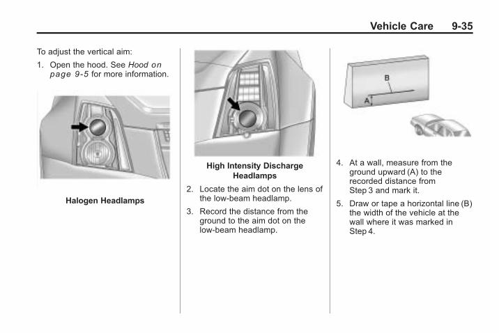
Vehicle Care 9-35
To adjust the vertical aim:
1. Open the hood. See Hood onpage 9‑5 for more information.
Halogen Headlamps
High Intensity DischargeHeadlamps
2. Locate the aim dot on the lens ofthe low-beam headlamp.
3. Record the distance from theground to the aim dot on thelow-beam headlamp.
4. At a wall, measure from theground upward (A) to therecorded distance fromStep 3 and mark it.
5. Draw or tape a horizontal line (B)the width of the vehicle at thewall where it was marked inStep 4.

9-36 Vehicle Care
Notice: Do not cover a headlampto improve beam cut-off whenaiming. Covering a headlamp maycause excessive heat build-upwhich may cause damage to theheadlamp.
6. Turn on the low-beamheadlamps and place a piece ofcardboard or equivalent in frontof the headlamp not beingaimed. This should allow onlythe beam of light from theheadlamp being aimed to beseen on the flat surface.
Driver Side Shown
7. Locate the vertical headlampaiming screws, which are underthe hood near each headlampassembly. They are covered bya rubber caps.
The adjustment screw can beturned with a 6 mm hex driver.
8. Turn the vertical aiming screwuntil the headlamp beam isaimed to the horizontaltape line. Turn it clockwise orcounterclockwise to raise orlower the angle of the beam.
The top edge of the cut-offshould be positioned at thebottom edge of the horizontaltape line.
9. Make sure that the light from theheadlamp is positioned at thebottom edge of the horizontaltape line. The lamp on theleft (A) shows the correctheadlamp aim. The lamp on theright (B) shows the incorrectheadlamp aim.
10. Repeat Steps 7 through 9 forthe opposite headlamp.

Vehicle Care 9-37
Bulb ReplacementFor the proper type of replacementbulbs, see Replacement Bulbs onpage 9‑39.
For any bulb changing procedurenot listed in this section, contactyour dealer/retailer.
Halogen Bulbs
{ WARNING
Halogen bulbs have pressurizedgas inside and can burst if youdrop or scratch the bulb. You orothers could be injured. Be sureto read and follow the instructionson the bulb package.
High Intensity Discharge(HID) Lighting
{ WARNING
The low beam high intensitydischarge lighting systemoperates at a very high voltage.If you try to service any of thesystem components, you could beseriously injured. Have yourdealer/retailer or a qualifiedtechnician service them.
The up-level vehicle has HIDheadlamps. The park lamp functionis also a function of the HIDheadlamp. After an HID headlampbulb has been replaced, the beammight be a slightly different shadethan it was originally. This is normal.
Fog Lamps
To replace fog lamp bulb:
1. Pull out the push-pins located onthe underside of the protectionshield to remove the shield.
2. Reach up behind the frontbumper area from under thevehicle to access the lamphousing.
3. Remove the electrical connectorfrom the bulb by lifting the twoplastic clips.

9-38 Vehicle Care
4. Remove the bulb socket fromthe lamp housing by turning thebulb socket one-quarter turncounterclockwise.
5. Pull the old bulb from the lamphousing keeping the bulbstraight as you pull it out.
6. Install a new bulb.
7. Reinstall the electrical connectorby pushing in the two plasticclips.
8. Push the bulb socket into thelamp housing and turn thesocket one-quarter turnclockwise.
License Plate Lamp(Sedan)To replace one of these bulbs:
1. Push tab to remove the licenseplate lamp.
2. Turn the license plate lampassembly down to remove it.
3. Turn the socketcounterclockwise andremove it.
4. Pull the bulb straight out toremove it.
5. Push the new bulb straight intothe socket.
6. Reverse Steps 1 through 3 toreinstall the license plate lampassembly.

Vehicle Care 9-39
License Plate Lamp(Wagon)To replace one of these bulbs:
1. Open the liftgate. See Liftgate(Wagon) on page 1‑19 for moreinformation.
Passenger side shown,driver side similar
2. Push the left end of the lampassembly towards the right.
3. Turn the lamp assembly down toremove from liftgate.
A. Bulb Socket
B. Bulb
C. Lamp Assembly
4. Turn the bulb socket (A)counterclockwise to removefrom lamp assembly (C).
5. Pull the bulb (B) straight out ofthe bulb socket.
6. Push the replacement bulbstraight into the bulb socket andturn the bulb socket clockwise toinstall into lamp assembly.
7. Turn the lamp assembly intothe liftgate engaging the clipside first.
8. Push on the lamp side oppositethe clip until the lamp assemblysnaps into place.
Replacement Bulbs
Exterior LampBulb
Number
Fog Lamp(Up Level Only)
H11LL
License Plate Lamp W5WLL
For replacement bulbs not listedhere, contact your dealer/retailer.

9-40 Vehicle Care
Electrical System
Electrical SystemOverloadThe vehicle has fuses and circuitbreakers to protect against anelectrical system overload.
When the current electrical load istoo heavy, the circuit breaker opensand closes, protecting the circuituntil the current load returns tonormal or the problem is fixed.This greatly reduces the chance ofcircuit overload and fire caused byelectrical problems.
Fuses and circuit breakers protectthe following in the vehicle:. Headlamp Wiring. Windshield Wiper Motor. Power Windows and other
Power Accessories
Headlamp Wiring
An electrical overload may causethe lamps to go on and off, or insome cases to remain off. Have theheadlamp wiring checked rightaway if the lamps go on and off orremain off.
Windshield Wipers
If the wiper motor overheats due toheavy snow or ice, the windshieldwipers will stop until the motor coolsand will then restart.
Although the circuit is protectedfrom electrical overload, overloaddue to heavy snow or ice, maycause wiper linkage damage.Always clear ice and heavy snowfrom the windshield before using thewindshield wipers.
If the overload is caused by anelectrical problem and not snow orice, be sure to get it fixed.

Vehicle Care 9-41
Fuses and CircuitBreakersThe wiring circuits in the vehicle areprotected from short circuits by acombination of fuses and circuitbreakers. This greatly reduces thechance of damage caused byelectrical problems.
To check a fuse, look at thesilver-colored band inside the fuse.If the band is broken or melted,replace the fuse. Be sure to replacea bad fuse with a new one of theidentical size and rating.
Fuses of the same amperage canbe temporarily borrowed fromanother fuse location, if a fuse goesout. Replace the fuse as soon asyou can.
To identify and check fuses, circuitbreakers, and relays, see EngineCompartment Fuse Block (CTS) onpage 9‑41 or Engine CompartmentFuse Block (CTS-V) on page 9‑45or Engine Compartment Fuse Block(CTS Wagon) on page 9‑48 andRear Compartment Fuse Block(CTS) on page 9‑51 or RearCompartment Fuse Block (CTS-V)on page 9‑53 or RearCompartment Fuse Block (CTSWagon) on page 9‑55.
Engine CompartmentFuse Block (CTS)The underhood fuse block is locatedon the passenger side of the enginecompartment.
Lift the fuse block cover to accessthe fuses.
Notice: Spilling liquid on anyelectrical components on thevehicle may damage it. Alwayskeep the covers on any electricalcomponent.

9-42 Vehicle Care
Mini-Fuses Usage
A/C CLTCHAir ConditioningClutch
ABSAntilock BrakingSystem (ABS)
AFSAdaptive ForwardLighting System
Mini-Fuses Usage
AIRBAGIGN
Airbag Switch
AQS/ISRVM/REAR
CAMERA
Air Quality Sensor/Inside Rear ViewMirror/Rear ViewCamera
AWD All-Wheel Drive
Mini-Fuses Usage
BCM 1 Body ControlModule 1
BCM 2Body ControlModule 2
BCM 3Body ControlModule 3
BCM 4Body ControlModule 4
BCM 5Body ControlModule 5
BCM 6,BCM 7
Body ControlModule 6 and 7
DISPLY Display
DRL/LTLO BEAM
Daytime RunningLamps/LeftLow-BeamHeadlamp
DRL RTRight DaytimeRunningLamp (DRL)

Vehicle Care 9-43
Mini-Fuses Usage
DRL/WSWDaytime RunningLamps/WindshieldWasher Pump
ECMEngine ControlModule (ECM)
ECM/TCM IGN
ECM, TransmissionControlModule (TCM),Instrument PanelCluster (IPC),PASS-Key III+Module
EMIS 1 Emission 1
EMIS 2 Emission 2
EVENCOILS Even Coils
FRT FOG Front Fog Lamps
HDLPWASH
Not Used
HORN Horn
Mini-Fuses Usage
LO BEAMDRL LEFT
Low-BeamDaytime RunningLamps (Left)
LTHI BEAM
Left High-BeamHeadlamp
LTLO BEAM
Left Low-BeamHeadlamp
LTR Cigarette Lighter
MISC IGN Ignition
NAV MTR Navigation Motor
ODD COILS Odd Coils
PED PRO Not Used
PWRMODING
PassKey Module,Body ControlModule
RTHI BEAM
Right High-BeamHeadlamp
RTLO BEAM
Right Low-BeamHeadlamp
RTLO BEAM
Right Low-BeamHeadlamp
Mini-Fuses Usage
SPARE Spare
SPARE Spare
STR/WHL/CNTRL
Steering WheelIllumination
TCM BATTTransmissionControl ModuleBattery
TOSS/BRKVAC RLY
Transmission OutputSpeed Sensor/BrakeVacuum Relay
WPR Windshield Wiper
SPARE Spare
J-CaseFuses
Usage
ABS MTR ABS Motor
BLWR Blower
BRKVAC PUMP
BrakeVacuum Pump
EPB Not Used

9-44 Vehicle Care
J-CaseFuses
Usage
FAN 1 Cooling Fan 1
FAN 2 Cooling Fan 2
REARDEFOG Rear Defogger
STRTR Starter
SPARE Spare
WSW/HTR Not Used
Relays Usage
A/CCMPRSR
Air ConditioningCompressor Clutch
DRL(W/O HID)LO BEAM(HID)
Daytime RunningLamps (without HighIntensity Discharge),Low-BeamHeadlamps (HighIntensity Discharge)
Relays Usage
FAN S/P Cooling FanSeries/Parallel
FAN 1 Cooling Fan 1
FAN 2 Cooling Fan 2
FOG LAMP Fog Lamps
HDLPWASH
Not Used
HI BEAMHigh-BeamHeadlamp
HORN Horn
IGN 1 Ignition 1
LO BEAM(W/O HID)LT DRL(HID)
Low-Beam (withoutHigh IntensityDischarge), LeftDaytime RunningLamp (High IntensityDischarge)
Relays Usage
PWR/TRN Powertrain
REARDEFOG
Rear Defogger
RTDRL (HID)
Right DaytimeRunning Lamp(High IntensityDischarge)
SPARE Spare
STRTR Starter
WPR Windshield Wiper
WPR HIWindshield WiperHigh Speed
WSWWindshieldWasher Pump

Vehicle Care 9-45
Engine CompartmentFuse Block (CTS-V)The underhood fuse block is locatedon the passenger side of the enginecompartment.
Lift the fuse block cover to accessthe fuses.
Notice: Spilling liquid on anyelectrical components on thevehicle may damage it. Alwayskeep the covers on any electricalcomponent.
Mini-Fuses Usage
A/C CLTCHAir ConditioningClutch
ABSAntilock BrakingSystem (ABS)
AFSAdaptive ForwardLighting System
Mini-Fuses Usage
AIRBAGIGN
Airbag Switch
AQS/ISRVM/REAR
CAMERA
Air Quality Sensor/Inside Rear ViewMirror/Rear ViewCamera
BCM 1Body ControlModule 1

9-46 Vehicle Care
Mini-Fuses Usage
BCM 2 Body ControlModule 2
BCM 3Body ControlModule 3
BCM 4Body ControlModule 4
BCM 5Body ControlModule 5
BCM 6,BCM 7
Body ControlModule 6 and 7
DISPLY Display
DRL LT Left DaytimeRunning Lamps
DRL RTRight DaytimeRunningLamp (DRL)
DRL/WSWDaytime RunningLamps/WindshieldWasher Pump
ECMEngine ControlModule (ECM)
Mini-Fuses Usage
ECM/TCM IGN
ECM, TransmissionControlModule (TCM),Instrument PanelCluster (IPC),PASS-Key III+Module
EMIS 1 Emission 1
EMIS 2 Emission 2
EVENCOILS
Even Coils
FRT FOG Front Fog Lamps
HDLPWASH
Headlamp Washer
HORN Horn
INTCLR Intercooler Pump
LTHI BEAM
Left High-BeamHeadlamp
LTLO BEAM
Left Low-BeamHeadlamp
LTR Cigarette Lighter
Mini-Fuses Usage
MISC IGN Ignition
NAV MTR Navigation Motor
ODD COILS Odd Coils
PED PRO Not Used
PWRMODING
PassKey Module,Body ControlModule
RTHI BEAM
Right High-BeamHeadlamp
RTLO BEAM
Right Low-BeamHeadlamp
SPARE Spare
STR/WHL/CNTRL
Steering WheelIllumination
S/ROOF Sunroof
TCM BATTTransmissionControl ModuleBattery
WPR Windshield Wiper

Vehicle Care 9-47
J-CaseFuses
Usage
ABS MTR ABS Motor
BLWR Blower
EPB Electric Park Brake
FAN 1 Cooling Fan 1
FAN 2 Cooling Fan 2
MRTDMR Ride/Suspension Control
REARDEFOG
Rear Defogger
STRTR Starter
SPARE Spare
WSW/HTR Not Used
Relays Usage
A/CCMPRSR
Air ConditioningCompressor Clutch
FAN S/PCooling FanSeries/Parallel
Relays Usage
FAN 1 Cooling Fan 1
FAN 2 Cooling Fan 2
FOG LAMP Fog Lamps
HDLPWASH Headlamp Washer
HI BEAMHigh-BeamHeadlamp
HORN Horn
IGN 1 Ignition 1
INTCLR Intercooler Pump
LT DRLLeft DaytimeRunning Lamps
LO BEAM Low Beam
PWR/TRN Powertrain
REARDEFOG Rear Defogger
RT DRLRight DaytimeRunning Lamp
Relays Usage
SPARE Spare
STRTR Starter
WPR Windshield Wiper
WPR HIWindshield WiperHigh Speed
WSWDaytime RunningLamps/WindshieldWasher Pump

9-48 Vehicle Care
Engine CompartmentFuse Block (CTS Wagon)The underhood fuse block is locatedon the passenger side of the enginecompartment.
Lift the fuse block cover to accessthe fuses.
Notice: Spilling liquid on anyelectrical components on thevehicle may damage it. Alwayskeep the covers on any electricalcomponent.
Mini-Fuses Usage
A/C CLTCHAir ConditioningClutch
ABSAntilock BrakingSystem (ABS)
AFSAdaptive ForwardLighting System
Mini-Fuses Usage
AIRBAGIGN
Airbag Switch
AQS/ISRVM/REAR
CAMERA
Air Quality Sensor/Inside Rear ViewMirror/Rear ViewCamera

Vehicle Care 9-49
Mini-Fuses Usage
AWD All-Wheel Drive
BCM 1Body ControlModule 1
BCM 2Body ControlModule 2
BCM 3Body ControlModule 3
BCM 4Body ControlModule 4
BCM 5Body ControlModule 5
BCM 6,BCM 7
Body ControlModule 6 and 7
DISPLY Display
DRL RTRight DaytimeRunningLamp (DRL)
Mini-Fuses Usage
DRL/LTLO BEAM
Daytime RunningLamps/LeftLow-BeamHeadlamp
DRL/WSWDaytime RunningLamps/WindshieldWasher Pump
ECMEngine ControlModule (ECM)
ECM/TCM IGN
ECM, TransmissionControlModule (TCM),Instrument PanelCluster (IPC),PASS-Key III+Module
EMIS 1 Emission 1
EMIS 2 Emission 2
EVENCOILS Even Coils
Mini-Fuses Usage
FRT FOG Front Fog Lamps
HDLPWASH
Headlamp Washer
HORN Horn
LO BEAMDRL LEFT
Low-BeamDaytime RunningLamps (Left)
LTHI BEAM
Left High-BeamHeadlamp
LTLO BEAM
Left Low-BeamHeadlamp
LTR Cigarette Lighter
MISC IGN Ignition
NAV MTR Navigation Motor
ODD COILS Odd Coils
PED PRO Not Used

9-50 Vehicle Care
Mini-Fuses Usage
PWRMODING
PassKey Module,Body ControlModule
PWROUTLET
Console AuxiliaryPower Outlet
RTHI BEAM
Right High-BeamHeadlamp
RTLO BEAM
Right Low-BeamHeadlamp
RTLO BEAM
Right Low-BeamHeadlamp
SPARE Spare
STR/WHL/CNTRL
Steering WheelIllumination
TCM BATTTransmissionControl ModuleBattery
TOSS/BRKVAC RLY
Transmission OutputSpeed Sensor/BrakeVacuum Relay
WPR Windshield Wiper
J-CaseFuses
Usage
ABS MTR ABS Motor
BLWR Blower
BRKVAC PUMP
BrakeVacuum Pump
EPB Electric Park Brake
FAN 1 Cooling Fan 1
FAN 2 Cooling Fan 2
REARDEFOG
Rear Defogger
SPARE Spare
STRTR Starter
TRLR Trailer Towing
WSW/HTR Not Used
Relays Usage
A/CCMPRSR
Air ConditioningCompressor Clutch
DRL(W/O HID)LO BEAM(HID)
Daytime RunningLamps (without HighIntensity Discharge),Low-BeamHeadlamps (HighIntensity Discharge)
FAN S/PCooling FanSeries/Parallel
FAN 1 Cooling Fan 1
FAN 2 Cooling Fan 2
FOG LAMP Fog Lamps
HDLPWASH
Headlamp Washer
HI BEAMHigh-BeamHeadlamp
HORN Horn
IGN 1 Ignition 1

Vehicle Care 9-51
Relays Usage
LO BEAM(W/O HID)LT DRL(HID)
Low-Beam (withoutHigh IntensityDischarge), LeftDaytime RunningLamp (High IntensityDischarge)
PWR/TRN Powertrain
REARDEFOG Rear Defogger
RTDRL (HID)
Right DaytimeRunning Lamp (HighIntensity Discharge)
SPARE Spare
STRTR Starter
WPR Windshield Wiper
WPR HIWindshield WiperHigh Speed
Rear Compartment Fuse Block (CTS)The rear compartment fuse block is located on top of the battery, on the rightside of the trunk. The battery access door must be removed to access thefuse block.
Relays Usage
FUEL/DR/RELSE
Not Used
LCK Lock
Relays Usage
LT/POS/LP Left Position Lamp
MRKR/LP Not Used

9-52 Vehicle Care
Relays Usage
REAR/FOG Not Used
RT/POS/LP Not Used
STOP/LP Not Used
TRUNK/RELSE Trunk Release
UNLCK Unlock
Mini-Fuses Usage
AIRBAG Airbag System
AMP Amplifier
AUX/OUTLET
Auxiliary PowerOutlet
CNSTR/VENT
Canister Vent
DR/LCK Door Lock
ECMEngine ControlModule (ECM)
Mini-Fuses Usage
EE SEAT Not Used
FUEL/PUMP
Fuel Pump
LT/POS/LP Left Position Lamp
MSMMemory SeatModule
ONSTAR OnStar® System
PDMPassenger DoorModule
RDO Audio System
RDO/SPKR Audio Speakers
REAR/FOG Not Used
RKE/PASS-KEY/
MDL
Remote KeylessEntry System,Pass-Key TheftDeterrent FeatureModule
Mini-Fuses Usage
RT/POS/LP Not Used
RT/POS/LP Right Position Lamp
RVC/SNSRRegulated VoltageControl Sensor
S/ROOF Sunroof
STOP/LP Not Used
THEFT/UGDO
Theft DeterrentSystem, UniversalHome RemoteSystem
TRLR/POS/LP
Not Used
TRUNK/RELSE
Trunk Release

Vehicle Care 9-53
CircuitBreakers
Usage
DRV/PWR/SEAT
Left FrontPower Seat
LT/REAR/WNDW
Left Rear Window
PWR CLMNPower SteeringColumn
PWR/WNDW
Power Window
PASS/PWR/SEAT
Right FrontPower Seat
REAR/WNDW
Right Rear Window
Rear Compartment Fuse Block (CTS-V)The rear compartment fuse block is located on top of the battery, on the rightside of the trunk. The battery access door must be removed to access thefuse block.
Relays Usage
FUEL/DR/RELSE
Not Used
LCK Lock
Relays Usage
LT/POS/LP Left Position Lamp
MRKR/LP Not Used

9-54 Vehicle Care
Relays Usage
REAR/FOG Not Used
RT/POS/LP Not Used
STOP/LP Not Used
TRUNK/RELSE Trunk Release
UNLCK Unlock
Mini-Fuses Usage
AIRBAG Airbag System
AMP Amplifier
AUX/OUTLET
Auxiliary PowerOutlet
CNSTR/VENT
Canister Vent
DR/LCK Door Lock
ECMEngine ControlModule (ECM)
Mini-Fuses Usage
EE SEAT Not Used
FUEL/PUMP
Fuel Pump
LT/POS/LP Left Position Lamp
MSMMemory SeatModule
ONSTAR OnStar® System
PDMPassenger DoorModule
RDO Audio System
RDO/SPKR Audio Speakers
REAR/DIFF/PUMP
Rear DifferentialCooling Pump
REAR/FOG Not Used
Mini-Fuses Usage
RKE/PASS-KEY/
MDL
Remote KeylessEntry System,Pass-Key TheftDeterrent FeatureModule
RT/POS/LP Right Position Lamp
RT/POS/LP Not Used
RVC/SNSRRegulated VoltageControl Sensor
SPARE Spare
STOP/LP Not Used
THEFT/UGDO
Theft DeterrentSystem, UniversalHome RemoteSystem
TRUNK/RELSE
Trunk Release

Vehicle Care 9-55
CircuitBreakers
Usage
DRV/PWR/SEAT
Left FrontPower Seat
LT/REAR/WNDW
Left Rear Window
PASS/PWR/SEAT
Right FrontPower Seat
PWR CLMNPower SteeringColumn
PWR/WNDW
Power Window
REAR/WNDW
Right Rear Window
Rear Compartment Fuse Block (CTS Wagon)The rear compartment fuse block is located on the passenger side of thevehicle, behind the trim panel in the rear compartment.
Relays Usage
FUEL/DR/RELSE
Not Used
LCK Lock
Relays Usage
LT/POS/LP Left Position Lamp
MRKR/LP Not Used

9-56 Vehicle Care
Relays Usage
REAR/FOG Not Used
RT/POS/LP Not Used
STOP/LP Not Used
TRUNK/RELSE Trunk Release
UNLCK Unlock
Mini-Fuses Usage
AIRBAG Airbag System
AMP Amplifier
Mini-Fuses Usage
AUX/OUTLET
Auxiliary PowerOutlet
CNSTR/VENT
Canister Vent
DR/LCK Door Lock
ECMEngine ControlModule (ECM)
FUEL/PUMP Fuel Pump
LT/POS/LP Left Position Lamp
Mini-Fuses Usage
MSM Memory SeatModule
ONSTAR OnStar® System
PDMPassenger DoorModule
RDO Audio System
RDO/SPKR Audio Speakers
REAR/FOG Not Used
REAR/WSW
Rear WindshieldWiper/Washer

Vehicle Care 9-57
Mini-Fuses Usage
RKE/PASS-KEY/
MDL
Remote KeylessEntry System,Pass-Key TheftDeterrent FeatureModule
RT/POS/LP Not Used
RT/POS/LP Right Position Lamp
RVC/SNSRRegulated VoltageControl Sensor
S/ROOF Sunroof
Mini-Fuses Usage
STOP/LP Not Used
THEFT/UGDO
Theft DeterrentSystem, UniversalHome RemoteSystem
TRLR/POS/LP
Trailer Turn PositionLamps
WASH/PUMP
WindshieldWasher Pump
CircuitBreakers
Usage
DRV/PWR/SEAT
Left FrontPower Seat
LT/REAR/WNDW
Left Rear Window
PASS/PWR/SEAT
Right FrontPower Seat
PWR CLMNPower SteeringColumn
PWR/WNDW
Power Window
REAR/WNDW
Right Rear Window

9-58 Vehicle Care
Wheels and Tires
TiresYour new vehicle comes withhigh-quality tires made by aleading tire manufacturer. If youever have questions about yourtire warranty and where toobtain service, see your vehicleWarranty booklet for details.For additional information referto the tire manufacturer.
{ WARNING
Poorly maintained and improperlyused tires are dangerous.
. Overloading your tires cancause overheating as a resultof too much flexing. Youcould have an air-out and aserious accident. See VehicleLoad Limits on page 8‑12.
. Underinflated tires pose thesame danger as overloadedtires. The resulting accidentcould cause serious injury.Check all tires frequently tomaintain the recommendedpressure. Tire pressureshould be checked when yourtires are cold. See TirePressure on page 9‑66.
(Continued)
WARNING (Continued)
. Overinflated tires are morelikely to be cut, puncturedor broken by a suddenimpact — such as when youhit a pothole. Keep tires atthe recommended pressure.
. Worn, old tires can causeaccidents. If your tread isbadly worn, or if your tireshave been damaged,replace them.
See Tire Pressure for High-SpeedOperation on page 9‑67 forinflation pressure adjustment forhigh speed driving.

Vehicle Care 9-59
Winter TiresIf you expect to drive on snow or icecovered roads often, you may wantto get winter tires for your vehicle.All season tires provide good overallperformance on most surfaces butthey may not offer the traction youwould like or the same level ofperformance as winter tires onsnow or ice covered roads.
Winter tires, in general, aredesigned for increased tractionon snow and ice covered roads.With winter tires, there may bedecreased dry road traction,increased road noise, and shortertread life. After switching to wintertires, be alert for changes in vehiclehandling and braking.
See your dealer/retailer for detailsregarding winter tire availability andproper tire selection. Also, seeBuying New Tires on page 9‑75.
If you choose to use winter tires:. Use tires of the same brand and
tread type on all four wheelpositions.
. Use only radial ply tires of thesame size, load range, andspeed rating as the originalequipment tires.
Winter tires with the same speedrating as your original equipmenttires may not be available for H, V,W, Y, and ZR speed rated tires.If you choose winter tires with alower speed rating, never exceedthe tire's maximum speed capability.
Low-Profile TiresIf your vehicle has 235/50ZR18,P235/50R18, 255/40ZR19 or285/35ZR19 size tires, they areclassified as low-profile tires.These tires are designed forvery responsive driving on wet
or dry pavement. You may alsonotice more road noise withlow-profile performance tires andthat they tend to wear faster.
Notice: If the vehicle haslow-profile tires, they are moresusceptible to damage fromroad hazards or curb impactthan standard profile tires.Tire and/or wheel assemblydamage can occur whencoming into contact withroad hazards like, potholes,or sharp edged objects,or when sliding into a curb.The vehicle warranty does notcover this type of damage.Keep tires set to the correctinflation pressure and, whenpossible avoid contact withcurbs, potholes, and otherroad hazards.

9-60 Vehicle Care
Summer Performance Tires
Many General Motors highperformance models comefactory-equipped with tires thatare optimized for maximum dryand wet road performance whilestill retaining satisfactory treadlife, excellent durability, and lownoise levels. In severe winterclimates where snowfall may besignificant, these tires may befound to provide less traction.
Tire Sidewall LabelingUseful information about a tire ismolded into its sidewall. Theexamples below show a typicalpassenger vehicle tire and acompact spare tire sidewall.
Passenger (P-Metric) Tire Example
(A) Tire Size: The tire size is acombination of letters andnumbers used to define aparticular tire's width, height,aspect ratio, construction type,and service description. See the“Tire Size” illustration later in thissection for more detail.
(B) TPC Spec (TirePerformance CriteriaSpecification): Originalequipment tires designed toGM's specific tire performancecriteria have a TPC specificationcode molded onto the sidewall.GM's TPC specifications meetor exceed all federal safetyguidelines.
(C) DOT (Department ofTransportation): TheDepartment of Transportation(DOT) code indicates that thetire is in compliance withthe U.S. Department ofTransportation Motor VehicleSafety Standards.
(D) Tire Identification Number(TIN): The letters and numbersfollowing the DOT (Departmentof Transportation) code is theTire Identification Number (TIN).

Vehicle Care 9-61
The TIN shows themanufacturer and plant code,tire size, and date the tire wasmanufactured. The TIN ismolded onto both sides of thetire, although only one side mayhave the date of manufacture.
(E) Tire Ply Material: The typeof cord and number of plies inthe sidewall and under the tread.
(F) Uniform Tire QualityGrading (UTQG): Tiremanufacturers are required tograde tires based on threeperformance factors: treadwear,traction, and temperatureresistance. For more informationsee Uniform Tire QualityGrading on page 9‑78 .
(G) Maximum Cold InflationLoad Limit: Maximum loadthat can be carried and themaximum pressure needed tosupport that load.
Compact Spare Tire Example
(A) Tire Ply Material: The typeof cord and number of plies inthe sidewall and under the tread.
(B) Temporary Use Only:The compact spare tire ortemporary use tire has a treadlife of approximately 5 000 km(3,000 miles) and should not bedriven at speeds over 105 km/h(65 mph). The compact sparetire is for emergency use whena regular road tire has lost air
and gone flat. If your vehiclehas a compact spare tire,see Compact Spare Tire onpage 9‑102 and If a Tire GoesFlat on page 9‑81 .
(C) Tire Identification Number(TIN): The letters and numbersfollowing the DOT (Departmentof Transportation) code isthe Tire Identification Number(TIN). The TIN shows themanufacturer and plant code,tire size, and date the tire wasmanufactured. The TIN ismolded onto both sides of thetire, although only one side mayhave the date of manufacture.
(D) Maximum Cold InflationLoad Limit: Maximum loadthat can be carried and themaximum pressure needed tosupport that load.

9-62 Vehicle Care
(E) Tire Inflation: Thetemporary use tire or compactspare tire should be inflated to420 kPa (60 psi). For moreinformation on tire pressure andinflation see Tire Pressure onpage 9‑66 .
(F) Tire Size: A combination ofletters and numbers define atire's width, height, aspect ratio,construction type, and servicedescription. The letter T as thefirst character in the tire sizemeans the tire is for temporaryuse only.
(G) TPC Spec (TirePerformance CriteriaSpecification): Originalequipment tires designed toGM's specific tire performancecriteria have a TPC specificationcode molded onto the sidewall.GM's TPC specifications meetor exceed all federal safetyguidelines.
Tire Designations
Tire Size
The following illustration showsan example of a typicalpassenger vehicle tire size.
(A) Passenger (P-Metric) Tire:The United States version of ametric tire sizing system. Theletter P as the first character inthe tire size means a passengervehicle tire engineered tostandards set by the U.S. Tireand Rim Association.
(B) Tire Width: The three-digitnumber indicates the tire sectionwidth in millimeters fromsidewall to sidewall.
(C) Aspect Ratio: A two-digitnumber that indicates the tireheight-to-width measurements.For example, if the tire sizeaspect ratio is 60, as shown initem C of the illustration, it wouldmean that the tire's sidewall is60 percent as high as it is wide.
(D) Construction Code:A letter code is used to indicatethe type of ply construction inthe tire. The letter R meansradial ply construction; theletter D means diagonal orbias ply construction; and theletter B means belted-bias plyconstruction.

Vehicle Care 9-63
(E) Rim Diameter: Diameter ofthe wheel in inches.
(F) Service Description: Thesecharacters represent the loadindex and speed rating of thetire. The load index representsthe load carry capacity a tire iscertified to carry. The speedrating is the maximum speed atire is certified to carry a load.
Tire Terminology andDefinitionsAir Pressure: The amount ofair inside the tire pressingoutward on each square inchof the tire. Air pressure isexpressed in psi (pounds persquare inch) or kPa (kilopascal).
Accessory Weight: Thismeans the combined weightof optional accessories.Some examples of optionalaccessories are, automatic
transmission, power steering,power brakes, power windows,power seats, and airconditioning.
Aspect Ratio: The relationshipof a tire's height to its width.
Belt: A rubber coated layer ofcords that is located betweenthe plies and the tread. Cordsmay be made from steel or otherreinforcing materials.
Bead: The tire bead containssteel wires wrapped by steelcords that hold the tire ontothe rim.
Bias Ply Tire: A pneumatic tirein which the plies are laid atalternate angles less than90 degrees to the centerline ofthe tread.
Cold Tire Pressure: Theamount of air pressure in a tire,measured in psi (pounds persquare inch) or kPa (kilopascal)
before a tire has built up heatfrom driving. See Tire Pressureon page 9‑66 .
Curb Weight: The weight of amotor vehicle with standard andoptional equipment including themaximum capacity of fuel, oil,and coolant, but withoutpassengers and cargo.
DOT Markings: A code moldedinto the sidewall of a tiresignifying that the tire is incompliance with the U.S.Department of Transportation(DOT) motor vehicle safetystandards. The DOT codeincludes the Tire IdentificationNumber (TIN), an alphanumericdesignator which can alsoidentify the tire manufacturer,production plant, brand, anddate of production.
GVWR: Gross Vehicle WeightRating. See Vehicle Load Limitson page 8‑12 .

9-64 Vehicle Care
GAWR FRT: Gross AxleWeight Rating for the front axle.See Vehicle Load Limits onpage 8‑12 .
GAWR RR: Gross AxleWeight Rating for the rear axle.See Vehicle Load Limits onpage 8‑12 .
Intended Outboard Sidewall:The side of an asymmetrical tire,that must always face outwardwhen mounted on a vehicle.
Kilopascal (kPa): The metricunit for air pressure.
Light Truck (LT-Metric) Tire:A tire used on light duty trucksand some multipurposepassenger vehicles.
Load Index: An assignednumber ranging from 1 to 279that corresponds to the loadcarrying capacity of a tire.
Maximum Inflation Pressure:The maximum air pressure towhich a cold tire can be inflated.The maximum air pressure ismolded onto the sidewall.
Maximum Load Rating: Theload rating for a tire at themaximum permissible inflationpressure for that tire.
Maximum Loaded VehicleWeight: The sum of curbweight, accessory weight,vehicle capacity weight, andproduction options weight.
Normal Occupant Weight:The number of occupants avehicle is designed to seatmultiplied by 68 kg (150 lbs).See Vehicle Load Limits onpage 8‑12 .
Occupant Distribution:Designated seating positions.
Outward Facing Sidewall:The side of an asymmetrical tirethat has a particular side thatfaces outward when mounted ona vehicle. The side of the tirethat contains a whitewall,bears white lettering, or bearsmanufacturer, brand, and/ormodel name molding that ishigher or deeper than the samemoldings on the other sidewallof the tire.
Passenger (P-Metric) Tire:A tire used on passenger carsand some light duty trucks andmultipurpose vehicles.
Recommended InflationPressure: Vehiclemanufacturer's recommendedtire inflation pressure as shownon the tire placard. See TirePressure on page 9‑66 andVehicle Load Limits onpage 8‑12 .

Vehicle Care 9-65
Radial Ply Tire: A pneumatictire in which the ply cords thatextend to the beads are laid at90 degrees to the centerline ofthe tread.
Rim: A metal support for a tireand upon which the tire beadsare seated.
Sidewall: The portion of a tirebetween the tread and the bead.
Speed Rating: Analphanumeric code assigned toa tire indicating the maximumspeed at which a tire canoperate.
Traction: The friction betweenthe tire and the road surface.The amount of grip provided.
Tread: The portion of a tirethat comes into contact withthe road.
Treadwear Indicators: Narrowbands, sometimes called wearbars, that show across thetread of a tire when only 1.6 mm(1/16 inch) of tread remains.See When It Is Time for NewTires on page 9‑74 .
UTQGS (Uniform Tire QualityGrading Standards): A tireinformation system thatprovides consumers withratings for a tire's traction,temperature, and treadwear.Ratings are determined bytire manufacturers usinggovernment testing procedures.The ratings are molded into thesidewall of the tire. See UniformTire Quality Grading onpage 9‑78 .
Vehicle Capacity Weight:The number of designatedseating positions multiplied by68 kg (150 lbs) plus the ratedcargo load. See Vehicle LoadLimits on page 8‑12 .
Vehicle Maximum Load on theTire: Load on an individual tiredue to curb weight, accessoryweight, occupant weight, andcargo weight.
Vehicle Placard: A labelpermanently attached to avehicle showing the vehicle'scapacity weight and theoriginal equipment tire sizeand recommended inflationpressure. See “Tire and LoadingInformation Label” under VehicleLoad Limits on page 8‑12 .

9-66 Vehicle Care
Tire PressureTires need the correct amount ofair pressure to operateeffectively.
Notice: Do not let anyone tellyou that under-inflation orover-inflation is all right. It isnot. If your tires do not haveenough air (under-inflation),you can get the following:. Too much flexing. Too much heat. Tire overloading. Premature orirregular wear
. Poor handling
. Reduced fuel economy
If your tires have too much air(over-inflation), you can getthe following:. Unusual wear. Poor handling. Rough ride. Needless damage fromroad hazards
A vehicle specific Tire andLoading Information label isattached to your vehicle. Thislabel shows your vehicle'soriginal equipment tires and thecorrect inflation pressures foryour tires when they are cold.The recommended cold tireinflation pressure, shown on thelabel, is the minimum amount ofair pressure needed to supportyour vehicle's maximum loadcarrying capacity.
For additional informationregarding how much weightyour vehicle can carry, and anexample of the Tire and LoadingInformation label, see VehicleLoad Limits on page 8‑12 .How you load your vehicleaffects vehicle handling and ridecomfort. Never load your vehiclewith more weight than it wasdesigned to carry.
When to Check
Check your tires once a monthor more. Do not forget to checkthe compact spare tire, if thevehicle has one. The compactspare should be at 60 psi(420 kPa). For additionalinformation regarding thecompact spare tire, seeCompact Spare Tire onpage 9‑102 .

Vehicle Care 9-67
How to Check
Use a good quality pocket-typegage to check tire pressure.You cannot tell if your tires areproperly inflated simply bylooking at them. Radial tires maylook properly inflated even whenthey are under-inflated. Checkthe tire's inflation pressure whenthe tires are cold. Cold meansyour vehicle has been sitting forat least three hours or driven nomore than 1.6 km (1 mile).
Remove the valve cap from thetire valve stem. Press the tiregage firmly onto the valve to geta pressure measurement. If thecold tire inflation pressurematches the recommendedpressure on the Tire andLoading Information label, nofurther adjustment is necessary.If the inflation pressure is low,add air until you reach therecommended amount.
If you overfill the tire, release airby pushing on the metal stem inthe center of the tire valve.Re-check the tire pressure withthe tire gage.
Be sure to put the valve capsback on the valve stems. Theyhelp prevent leaks by keepingout dirt and moisture.
Tire Pressure forHigh-Speed Operation
{ WARNING
Driving at high speeds, 160 km/h(100mph) or higher, puts anadditional strain on tires.Sustained high-speed drivingcauses excessive heat build upand can cause sudden tire failure.You could have a crash and youor others could be killed. Somehigh-speed rated tires require
(Continued)
WARNING (Continued)
inflation pressure adjustment forhigh speed operation. Whenspeed limits and road conditionsare such that a vehicle can bedriven at high speeds, make surethe tires are rated for high speedoperation, in excellent condition,and set to the correct cold tireinflation pressure for thevehicle load.
If your vehicle has 235/50ZR18,255/40ZR19 or 285/35ZR19 sizetires, they will require inflationpressure adjustment whendriving your vehicle at speedsof 160 km/h (100 mph) or higher.Set the cold inflation pressure tothe maximum inflation pressureshown on the tire sidewall,or 300 kPa (44 psi), whichever islower. See the example following.

9-68 Vehicle Care
When you end this high-speeddriving, return the tires to the coldtire inflation pressure shown on theTire and Loading Information label.See Vehicle Load Limits onpage 8‑12 and Tire Pressure onpage 9‑66.
Example:
You will find the maximum load andinflation pressure molded on thetire's sidewall, in small letters,near the rim flange. It will readsomething like this: Maximum load690 kg (1521 lbs) 300 kPa (44 psi)Max. Press.
For this example, you would set theinflation pressure for high-speeddriving at 44 psi (300 kPa).
Tire Pressure MonitorSystemThe Tire Pressure Monitor System(TPMS) uses radio and sensortechnology to check tire pressurelevels. The TPMS sensors monitorthe air pressure in your vehicle'stires and transmit tire pressurereadings to a receiver located inthe vehicle.
Each tire, including the spare(if provided), should be checkedmonthly when cold and inflated tothe inflation pressure recommendedby the vehicle manufacturer on thevehicle placard or tire inflationpressure label. (If your vehicle hastires of a different size than the sizeindicated on the vehicle placard ortire inflation pressure label, youshould determine the proper tireinflation pressure for those tires.)
As an added safety feature, yourvehicle has been equipped with atire pressure monitoring system(TPMS) that illuminates a low tirepressure telltale when one or moreof your tires is significantlyunder-inflated.
Accordingly, when the low tirepressure telltale illuminates, youshould stop and check your tires assoon as possible, and inflate themto the proper pressure. Driving on asignificantly under-inflated tirecauses the tire to overheat and canlead to tire failure. Under-inflationalso reduces fuel efficiency and tiretread life, and may affect thevehicle's handling and stoppingability.

Vehicle Care 9-69
Please note that the TPMS isnot a substitute for proper tiremaintenance, and it is the driver'sresponsibility to maintain correct tirepressure, even if under-inflation hasnot reached the level to triggerillumination of the TPMS low tirepressure telltale.
Your vehicle has also beenequipped with a TPMS malfunctionindicator to indicate when thesystem is not operating properly.The TPMS malfunction indicator iscombined with the low tire pressuretelltale. When the system detects amalfunction, the telltale will flash forapproximately one minute and thenremain continuously illuminated.This sequence will continue uponsubsequent vehicle start-ups aslong as the malfunction exists.
When the malfunction indicator isilluminated, the system may not beable to detect or signal low tirepressure as intended. TPMS
malfunctions may occur for a varietyof reasons, including the installationof replacement or alternate tires orwheels on the vehicle that preventthe TPMS from functioning properly.Always check the TPMS malfunctiontelltale after replacing one or moretires or wheels on your vehicle toensure that the replacement oralternate tires and wheels allow theTPMS to continue to functionproperly.
See Tire Pressure MonitorOperation on page 9‑69 foradditional information.
Federal CommunicationsCommission (FCC) andIndustry and Science Canada
See Radio Frequency Statement onpage 12‑16 for informationregarding Part 15 of the FederalCommunications Commission (FCC)Rules and RSS-210/211 of Industryand Science Canada.
Tire Pressure MonitorOperationThis vehicle may have a TirePressure Monitor System (TPMS).The TPMS is designed to warn thedriver when a low tire pressurecondition exists. TPMS sensors aremounted onto each tire and wheelassembly, excluding the spare tireand wheel assembly, if the vehiclehas one. The TPMS sensorsmonitor the air pressure in thevehicle's tires and transmits the tirepressure readings to a receiverlocated in the vehicle.
Using the Driver Information Center(DIC), the driver can also check tirepressure levels using the DIC. Foradditional information and detailsabout the DIC operation anddisplays see Driver InformationCenter (DIC) on page 4‑31 andTire Messages on page 4‑48.

9-70 Vehicle Care
When a low tire pressure conditionis detected, the TPMS illuminatesthe low tire pressure warning lightlocated on the instrument panelcluster.
A DIC warning message to checkthe pressure in a specific tire is alsoshown on the DIC display screen.The low tire pressure warning lightand the DIC warning message comeat each ignition cycle until the tiresare inflated to the correct inflationpressure.
The low tire pressure warning lightmay come on in cool weatherwhen the vehicle is first started, andthen turn off as you start to drive.
This could be an early indicator thatthe air pressure in the tire(s) aregetting low and need to be inflatedto the proper pressure.
The Tire and Loading Informationlabel, attached to your vehicle,shows the size of your vehicle'soriginal equipment tires and thecorrect inflation pressure for thetires when they are cold. SeeVehicle Load Limits on page 8‑12,for an example of the Tire andLoading Information label and itslocation on your vehicle. Also seeTire Pressure on page 9‑66.
Your vehicle's TPMS can warn youabout a low tire pressure conditionbut it does not replace normal tiremaintenance. See Tire Inspectionon page 9‑73, Tire Rotation onpage 9‑73 and Tires on page 9‑58.
Notice: Using non-approved tiresealants could damage the TirePressure Monitor System (TPMS)sensors. TPMS sensor damagecaused by using an incorrect tiresealant is not covered by thevehicle warranty. Always usethe GM approved tire sealantavailable through your dealer/retailer.
Factory-installed Tire Inflator Kitsuse a GM approved liquid tiresealant. Using non-approved tiresealants could damage the TPMSsensors. See Tire Sealant andCompressor Kit on page 9‑84 forinformation regarding the inflator kitmaterials and instructions.

Vehicle Care 9-71
TPMS Malfunction Light andMessage
The TPMS will not function properlyif one or more of the TPMS sensorsare missing or inoperable. When thesystem detects a malfunction, thelow tire warning light flashes forabout one minute and then stays onfor the remainder of the ignitioncycle. A DIC warning message isalso displayed. The low tire warninglight and DIC warning messagecome on at each ignition cycle untilthe problem is corrected. Some ofthe conditions that can cause themalfunction light and DIC messageto come on are:. One of the road tires has been
replaced with the spare tire,if the vehicle has one. The sparetire does not have a TPMSsensor. The DIC messageshould go off once you re-installthe road tire containing theTPMS sensor.
. The TPMS sensor matchingprocess was not done or notcompleted successfully afterrotating the vehicle's tires.The DIC message should go offafter successfully completingthe sensor matching process.See “TPMS Sensor MatchingProcess” later in this section.
. One or more TPMS sensors aremissing or damaged. The DICmessage and the TPMSmalfunction light should go offwhen the TPMS sensors areinstalled and the sensormatching process is performedsuccessfully. See your dealer/retailer for service.
. Replacement tires or wheels donot match your vehicle's originalequipment tires or wheels.Tires and wheels other thanthose recommended for yourvehicle could prevent the TPMSfrom functioning properly. SeeBuying New Tires on page 9‑75.
. Operating electronic devices orbeing near facilities using radiowave frequencies similar to theTPMS could cause the TPMSsensors to malfunction.
If the TPMS is not functioning itcannot detect or signal a low tirecondition. See your dealer/retailerfor service if the TPMS malfunctionlight and DIC message comes onand stays on.
TPMS Sensor MatchingProcess
Each TPMS sensor has a uniqueidentification code. Any time youreplace one or more of the TPMSsensors or rotate your vehicle'stires, the identification codes needto be matched to the new tire/wheelposition. The sensors are matchedto the tire/wheel positions in thefollowing order: driver side front tire,passenger side front tire, passengerside rear tire, and driver side reartire using a TPMS diagnostic tool.See your dealer/retailer for service.

9-72 Vehicle Care
The TPMS sensors can also bematched to each tire/wheel positionby increasing or decreasing thetire's air pressure. If increasing thetire's air pressure, do not exceedthe maximum inflation pressureindicated on the tire's sidewall.To decrease the tire's air-pressureuse the pointed end of the valvecap, a pencil-style air pressuregage, or a key.
You have two minutes to match thefirst tire/wheel position, andfive minutes overall, to match allfour tire/wheel positions. If it takeslonger than two minutes, to matchthe first tire and wheel, or more thanfive minutes to match all four tireand wheel positions, the matchingprocess stops and you need tostart over.
The TPMS matching process isoutlined below:
1. Set the parking brake.
2. Turn the ignition switch toON/RUN with the engine off.
3. Press the Remote Keyless Entry(RKE) transmitter's lock andunlock buttons at the same timefor approximately five seconds.The horn sounds twice to signalthe receiver is in relearn modeand Tire Learning Activemessage displays on the DICscreen.
4. Start with the driver sidefront tire.
5. Remove the valve cap from thevalve stem. Activate the TPMSsensor by increasing ordecreasing the tire's air pressurefor 10 seconds, or until a hornchirp sounds. The horn chirp,which can take up to 30 secondsto sound, confirms that the
TPMS sensor identification codehas been matched to this tireposition.
6. Proceed to the passenger sidefront tire, and repeat theprocedure in Step 5.
7. Proceed to the passenger siderear tire, and repeat theprocedure in Step 5.
8. Proceed to the driver side reartire, and repeat the procedurein Step 5.
9. After hearing the confirming hornchirp, for the driver side rear tire,the horn sounds two more timesto signal the tire learning modeis no longer active. Turn theignition switch to LOCK/OFF.
10. Set all four tires to therecommended air pressurelevel as indicated on the tireand loading information label.
11. Put the valve caps back on thevalve stems.

Vehicle Care 9-73
Tire InspectionWe recommend that youregularly inspect your vehicle'stires, including the spare tire,if the vehicle has one, for signsof wear or damage. See When ItIs Time for New Tires onpage 9‑74 for more information.
Tire RotationTire rotation is notrecommended if the vehicle has255/40R19 size tires on the frontwheels and 285/35R19 size tireson the rear wheels.
Different tire sizes should not berotated front to rear. Each tireand wheel should only be usedin its original front or rearposition.
Tire rotation is recommended ifthe vehicle has the same sizetires on all four wheel positions.These tires should be rotatedevery 5,000 to 8,000 miles(8 000 to 13 000 km). SeeScheduled Maintenance onpage 10‑3 .
The purpose of a regular tirerotation is to achieve a uniformwear for all tires on the vehicle.This will ensure that the vehiclecontinues to perform most like itdid when the tires were new.
Any time you notice unusualwear, rotate the tires as soon aspossible and check wheelalignment. Also check fordamaged tires or wheels. SeeWhen It Is Time for New Tireson page 9‑74 and WheelReplacement on page 9‑80 .
Use the rotation pattern shownhere when rotating tires of thesame size installed on all fourwheel positions.

9-74 Vehicle Care
After the tires have beenrotated, adjust the front and rearinflation pressures as shown onthe Tire and Loading Informationlabel. See Tire Pressure onpage 9‑66 and Vehicle LoadLimits on page 8‑12 .
Reset the Tire Pressure MonitorSystem. See Tire PressureMonitor Operation on page 9‑69 .
Make certain that all wheelnuts are properly tightened.See “Wheel Nut Torque” underCapacities and Specifications onpage 11‑2 .
{ WARNING
Rust or dirt on a wheel, or on theparts to which it is fastened, canmake wheel nuts become looseafter time. The wheel could comeoff and cause an accident. Whenchanging a wheel, remove anyrust or dirt from places where thewheel attaches to the vehicle.In an emergency, use a cloth or apaper towel to do this; but be sureto use a scraper or wire brushlater, if needed, to get all the rustor dirt off. See If a Tire Goes Flaton page 9‑81.
When It Is Time for NewTiresVarious factors, such asmaintenance, temperatures, drivingspeeds, vehicle loading, and roadconditions influence when you neednew tires.
One way to tell when it is time fornew tires is to check the treadwearindicators, which appear when thetires have only 1.6 mm (1/16 inch) orless of tread remaining.

Vehicle Care 9-75
The vehicle needs new tires if anyof the following statements are true:. You can see the indicators at
three or more places aroundthe tire.
. You can see cord or fabricshowing through the tire'srubber.
. The tread or sidewall is cracked,cut, or snagged deep enough toshow cord or fabric.
. The tire has a bump, bulge,or split.
. The tire has a puncture, cut,or other damage that cannot berepaired well because of the sizeor location of the damage.
The rubber in tires degrades overtime. This is also true for the sparetire, if the vehicle has one, evenif it is not being used. Multipleconditions affect how fast this agingtakes place, including temperatures,loading conditions, and inflationpressure maintenance. With propercare and maintenance tires typicallywear out before they degrade due toage. If you are unsure about theneed to replace the tires as they getolder, consult the tire manufacturerfor more information.
Buying New TiresGM has developed and matchedspecific tires for your vehicle.The original equipment tiresinstalled on your vehicle, when itwas new, were designed to meetGeneral Motors Tire PerformanceCriteria Specification (TPC Spec)system rating. If you needreplacement tires, GM stronglyrecommends that you get tires withthe same TPC Spec rating. Thisway, your vehicle will continue tohave tires that are designed to givethe same performance and vehiclesafety, during normal use, as theoriginal tires.

9-76 Vehicle Care
GM's exclusive TPC Spec systemconsiders over a dozen criticalspecifications that impact theoverall performance of yourvehicle, including brake systemperformance, ride and handling,traction control, and tire pressuremonitoring performance. GM's TPCSpec number is molded onto thetire's sidewall near the tire size.If the tires have an all-season treaddesign, the TPC Spec number willbe followed by an MS for mud andsnow. See Tire Sidewall Labeling onpage 9‑60, for additionalinformation.
GM recommends replacing tires insets of four. This is because uniformtread depth on all tires will helpkeep your vehicle performing mostlike it did when the tires were new.Replacing less than a full set of tirescan affect the braking and handlingperformance of your vehicle. SeeTire Inspection on page 9‑73 andTire Rotation on page 9‑73.
Winter tires with the same speedrating as your original equipmenttires may not be available for H, V,W, Y and ZR speed rated tires.If you choose snow tires with alower speed rating, never exceedthe tire's maximum speed capability.
{ WARNING
Mixing tires could cause you tolose control while driving. If youmix tires of different sizes (otherthan those originally installed onyour vehicle), brands, or types(radial and bias-belted tires), thevehicle may not handle properly,and you could have a crash.Using tires of different sizes(other than those originallyinstalled on your vehicle), brandsor types, may also cause damageto your vehicle. Be sure to usethe correct size, brand, and typetires on all four wheels.

Vehicle Care 9-77
{ WARNING
If you use bias-ply tires on thevehicle, the wheel rim flangescould develop cracks aftermany miles of driving. A tireand/or wheel could failsuddenly, causing a crash.Use only radial-ply tires withthe wheels on the vehicle.
If you must replace your vehicle'stires with those that do not have aTPC Spec number, make sure theyare the same size, load range,speed rating, and construction type(radial and bias-belted tires) as yourvehicle's original tires.
Vehicles that have a tire pressuremonitoring system could give aninaccurate low-pressure warning ifnon-TPC Spec rated tires areinstalled on it. Non-TPC Spec ratedtires may give a low-pressurewarning that is higher or lower thanthe proper warning level you wouldget with TPC Spec rated tires. SeeTire Pressure Monitor Operation onpage 9‑69.
Your vehicle's original equipmenttires are listed on the Tire andLoading Information label. SeeVehicle Load Limits on page 8‑12,for more information about the Tireand Loading Information label andits location on your vehicle.
Different Size Tires andWheelsIf you add wheels or tires that are adifferent size than your originalequipment wheels and tires, thiscould affect the way your vehicleperforms, including its braking, rideand handling characteristics,stability, and resistance to rollover.Additionally, if your vehicle haselectronic systems such as anti-lockbrakes, traction control, andelectronic stability control, theperformance of these systems canbe affected.
See Buying New Tires onpage 9‑75 and Accessories andModifications on page 9‑3 foradditional information.

9-78 Vehicle Care
Uniform Tire QualityGradingQuality grades can be foundwhere applicable on the tiresidewall between tread shoulderand maximum section width.For example:
Treadwear 200 Traction AATemperature A
The following information relatesto the system developed by theUnited States National HighwayTraffic Safety Administration(NHTSA), which grades tiresby treadwear, traction, andtemperature performance.This applies only to vehiclessold in the United States.
The grades are molded on thesidewalls of most passenger cartires. The Uniform Tire QualityGrading (UTQG) systemdoes not apply to deep tread,winter-type snow tires,space-saver, or temporary usespare tires, tires with nominalrim diameters of 25 to 30 cm(10 to 12 inches), or to somelimited-production tires.
While the tires available onGeneral Motors passenger carsand light trucks may vary withrespect to these grades, theymust also conform to federalsafety requirements andadditional General Motors TirePerformance Criteria (TPC)standards.
Treadwear
The treadwear grade is acomparative rating based on thewear rate of the tire when testedunder controlled conditions on aspecified government testcourse. For example, a tiregraded 150 would wear one anda half (1.5) times as well on thegovernment course as a tiregraded 100. The relativeperformance of tires dependsupon the actual conditions oftheir use, however, and maydepart significantly from thenorm due to variations indriving habits, service practices,and differences in roadcharacteristics and climate.

Vehicle Care 9-79
Traction – AA, A, B, C
The traction grades, fromhighest to lowest, are AA, A, B,and C. Those grades representthe tire's ability to stop on wetpavement as measured undercontrolled conditions onspecified government testsurfaces of asphalt andconcrete. A tire marked C mayhave poor traction performance.
Temperature – A, B, C
The temperature grades areA (the highest), B, and C,representing the tire's resistanceto the generation of heat andits ability to dissipate heatwhen tested under controlledconditions on a specified indoorlaboratory test wheel. Sustainedhigh temperature can cause the
material of the tire to degenerateand reduce tire life, andexcessive temperature canlead to sudden tire failure.The grade C corresponds to alevel of performance which allpassenger car tires must meetunder the Federal Motor VehicleSafety Standard No. 109.Grades B and A representhigher levels of performance onthe laboratory test wheel thanthe minimum required by law.It should be noted that thetemperature grade for this tire isestablished for a tire that isproperly inflated and notoverloaded. Excessive speed,underinflation, or excessiveloading, either separately or incombination, can cause heatbuildup and possible tire failure.
Wheel Alignment and TireBalanceThe tires and wheels on yourvehicle were aligned and balancedcarefully at the factory to give youthe longest tire life and best overallperformance. Adjustments to wheelalignment and tire balancing will notbe necessary on a regular basis.However, if you notice unusual tirewear or your vehicle pulling to oneside or the other, the alignmentmight need to be checked. If younotice your vehicle vibrating whendriving on a smooth road, the tiresand wheels might need to berebalanced. See your dealer/retailerfor proper diagnosis.
CTS-V models should only useadhesive wheel weights to balancethe tires and wheels.

9-80 Vehicle Care
Wheel ReplacementReplace any wheel that is bent,cracked, or badly rusted orcorroded. If wheel nuts keep comingloose, the wheel, wheel bolts, andwheel nuts should be replaced.If the wheel leaks air, replace it(except some aluminum wheels,which can sometimes be repaired).See your dealer/retailer if any ofthese conditions exist.
Your dealer/retailer will know thekind of wheel you need.
Each new wheel should have thesame load-carrying capacity,diameter, width, offset, and bemounted the same way as the one itreplaces.
If you need to replace any of thewheels, wheel bolts, wheel nuts,or Tire Pressure Monitor System(TPMS) sensors, replace them onlywith new GM original equipmentparts. This way, you will be sure tohave the right wheel, wheel bolts,wheel nuts, and TPMS sensors forthe vehicle.
{ WARNING
Using the wrong replacementwheels, wheel bolts, or wheelnuts on your vehicle can bedangerous. It could affect thebraking and handling of yourvehicle, make your tires lose airand make you lose control. Youcould have a collision in whichyou or others could be injured.Always use the correct wheel,wheel bolts, and wheel nuts forreplacement.
Notice: The wrong wheel canalso cause problems with bearinglife, brake cooling, speedometeror odometer calibration,headlamp aim, bumper height,vehicle ground clearance, and tireor tire chain clearance to thebody and chassis.
See If a Tire Goes Flat onpage 9‑81 for more information.
Used Replacement Wheels
{ WARNING
Putting a used wheel on thevehicle is dangerous. You cannotknow how it has been used orhow far it has been driven.It could fail suddenly and cause acrash. If you have to replace awheel, use a new GM originalequipment wheel.

Vehicle Care 9-81
Tire Chains
{ WARNING
Do not use tire chains. There isnot enough clearance. Tire chainsused on a vehicle without theproper amount of clearance cancause damage to the brakes,suspension, or other vehicleparts. The area damaged by thetire chains could cause you tolose control of the vehicle andyou or others may be injured in acrash. Use another type of
(Continued)
WARNING (Continued)
traction device only if itsmanufacturer recommends it foruse on the vehicle and tire sizecombination and road conditions.Follow that manufacturer'sinstructions. To help avoiddamage to the vehicle, driveslowly, re-adjust or remove thedevice if it is contacting thevehicle, and do not spin thewheels. If you do find tractiondevices that will fit, install them onthe rear tires.
If a Tire Goes FlatIt is unusual for a tire to blowoutwhile you are driving, especially ifyou maintain your vehicle's tiresproperly. If air goes out of a tire, it ismuch more likely to leak out slowly.But if you should ever have ablowout, here are a few tips aboutwhat to expect and what to do:
If a front tire fails, the flat tirecreates a drag that pulls the vehicletoward that side. Take your foot offthe accelerator pedal and grip thesteering wheel firmly. Steer tomaintain lane position, and thengently brake to a stop well out of thetraffic lane.

9-82 Vehicle Care
A rear blowout, particularly on acurve, acts much like a skid andmay require the same correctionyou would use in a skid. In any rearblowout remove your foot from theaccelerator pedal. Get the vehicleunder control by steering the wayyou want the vehicle to go. It maybe very bumpy and noisy, but youcan still steer. Gently brake to astop, well off the road if possible.
{ WARNING
Lifting a vehicle and gettingunder it to do maintenance orrepairs is dangerous without theappropriate safety equipment andtraining. If a jack is provided with
(Continued)
WARNING (Continued)
the vehicle, it is designed only forchanging a flat tire. If it is used foranything else, you or others couldbe badly injured or killed if thevehicle slips off the jack. If a jackis provided with the vehicle, onlyuse it for changing a flat tire.
If a tire goes flat, avoid further tireand wheel damage by driving slowlyto a level place. Turn on the hazardwarning flashers. See HazardWarning Flashers on page 5‑4.
{ WARNING
Changing a tire can bedangerous. The vehicle can slipoff the jack and roll over or fall onyou or other people. You and theycould be badly injured or evenkilled. Find a level place tochange your tire. To help preventthe vehicle from moving:
1. Set the parking brake firmly.
2. Put an automatictransmission shift lever inP (Park), or shift a manualtransmission to 1 (First) orR (Reverse).
(Continued)

Vehicle Care 9-83
WARNING (Continued)
3. Turn off the engine and donot restart while the vehicleis raised.
4. Do not allow passengers toremain in the vehicle.
To be certain the vehicle will notmove, put blocks at the front andrear of the tire farthest away fromthe one being changed. Thatwould be the tire on the otherside, at the opposite end of thevehicle.
This vehicle may come with a jackand spare tire or a tire sealant andcompressor kit. To use the jackingequipment to change a spare tiresafely, follow the instructions below.Then see Tire Changing onpage 9‑94. To use the tire sealantand compressor kit, see TireSealant and Compressor Kit onpage 9‑84.
When the vehicle has a flat tire (B),use the following example as aguide to assist you in the placementof wheel blocks (A).
A. Wheel Block
B. Flat Tire
The following information explainshow to repair or change a tire.

9-84 Vehicle Care
Tire Sealant andCompressor Kit
{ WARNING
Idling a vehicle in an enclosedarea with poor ventilation isdangerous. Engine exhaust mayenter the vehicle. Engine exhaustcontains Carbon Monoxide (CO)which cannot be seen or smelled.It can cause unconsciousnessand even death. Never run theengine in an enclosed area thathas no fresh air ventilation. Formore information, see EngineExhaust on page 8‑25.
{ WARNING
Over-inflating a tire could causethe tire to rupture and you orothers could be injured. Be sureto read and follow the tire sealantand compressor kit instructionsand inflate the tire to itsrecommended pressure. Do notexceed the recommendedpressure.
{ WARNING
Storing the tire sealant andcompressor kit or otherequipment in the passengercompartment of the vehicle couldcause injury. In a sudden stop orcollision, loose equipment couldstrike someone. Store the tiresealant and compressor kit in itsoriginal location.
If this vehicle has a tire sealant andcompressor kit, there may not be aspare tire, tire changing equipment,and on some vehicles there may notbe a place to store a tire.
The tire sealant and compressorcan be used to temporarily sealpunctures up to 6 mm (¼ inch) inthe tread area of the tire. It canalso be used to inflate an underinflated tire.
If the tire has been separated fromthe wheel, has damaged sidewalls,or has a large puncture, the tire istoo severely damaged for the tiresealant and compressor kit to beeffective. See Roadside Service onpage 12‑6.
Read and follow all of the tiresealant and compressor kitinstructions.

Vehicle Care 9-85
This vehicle may have one ofthe following tire sealant andcompressor kits. The kit includes:
A. Selector Switch (Sealant/Air orAir Only)
B. On/Off Button
C. Pressure Gage
D. Pressure Deflation Button(If equipped)
E. Tire Sealant Canister
F. Sealant/Air Hose (Clear)
G. Air Only Hose (Black)
H. Power Plug
Tire Sealant
Read and follow the safe handlinginstructions on the label adhered tothe sealant canister.
Check the tire sealant expirationdate on the sealant canister.The sealant canister should bereplaced before its expiration date.Replacement sealant canisters areavailable at your local dealer/retailer. See “Removal andInstallation of the Sealant Canister”following.
There is only enough sealant to sealone tire. After usage, the sealantcanister and sealant/air hoseassembly must be replaced. See“Removal and Installation of theSealant Canister” following.

9-86 Vehicle Care
Using the Tire Sealant andCompressor Kit to TemporarilySeal and Inflate aPunctured Tire
Follow the directions closely forcorrect sealant usage.
When using the tire sealant andcompressor kit during coldtemperatures, warm the kit in aheated environment for 5 minutes.This will help to inflate the tirefaster.

Vehicle Care 9-87
Always do a safety check first.See If a Tire Goes Flat onpage 9‑81. Do not remove anyobjects that have penetratedthe tire.
1. Remove the tire sealant andcompressor kit from its storagelocation. See Storing the TireSealant and Compressor Kit(Sedan) on page 9‑92 orStoring the Tire Sealant andCompressor Kit (Wagon) onpage 9‑93.
2. Unwrap the sealant/air hose (F)and the power plug (H).
3. Place the kit on the ground.
Make sure the tire valve stem ispositioned close to the groundso the hose will reach it.
4. Remove the valve stem capfrom the flat tire by turning itcounterclockwise.
5. Attach the sealant/air hose (F)onto the tire valve stem. Turn itclockwise until it is tight.
6. Plug the power plug (H) into theaccessory power outlet in thevehicle. Unplug all items fromother accessory power outlets.See Power Outlets onpage 4‑12.
If the vehicle has an accessorypower outlet, do not use thecigarette lighter.
If the vehicle only has a cigarettelighter, use the cigarette lighter.
Do not pinch the power plugcord in the door or window.
7. Start the vehicle. The vehiclemust be running while using theair compressor.
8. Turn the selector switch (A)counterclockwise to theSealant + Air position.
9. Press the on/off (B) button toturn the tire sealant andcompressor kit on.
The compressor will injectsealant and air into the tire.
The pressure gage (C) willinitially show a high pressurewhile the compressor pushes thesealant into the tire. Once thesealant is completely dispersedinto the tire, the pressure willquickly drop and start to riseagain as the tire inflates withair only.

9-88 Vehicle Care
10. Inflate the tire to therecommended inflationpressure using the pressuregage (C). The recommendedinflation pressure can be foundon the Tire and LoadingInformation label. See TirePressure on page 9‑66.
The pressure gage (C) mayread higher than the actual tirepressure while the compressoris on. Turn the compressor offto get an accurate pressurereading. The compressor maybe turned on/off until thecorrect pressure is reached.
Notice: If the recommendedpressure cannot be reached afterapproximately 25 minutes, thevehicle should not be drivenfarther. The tire is too severelydamaged and the tire sealant andcompressor kit cannot inflate thetire. Remove the power plug fromthe accessory power outlet andunscrew the inflating hose fromthe tire valve. See RoadsideService on page 12‑6.
11. Press the on/off button (B) toturn the tire sealant andcompressor kit off.
The tire is not sealed andwill continue to leak airuntil the vehicle is driven andthe sealant is distributed inthe tire, therefore, Steps 12through 18 must be doneimmediately after Step 11.
Be careful while handling thetire sealant and compressor kitas it could be warm afterusage.
12. Unplug the power plug (H) fromthe accessory power outlet inthe vehicle.
13. Turn the sealant/air hose (F)counterclockwise to remove itfrom the tire valve stem.
14. Replace the tire valvestem cap.
15. Replace the sealant/airhose (F), and the powerplug (H) back in their originallocation.

Vehicle Care 9-89
16. If the flat tire was able to inflateto the recommended inflationpressure, remove themaximum speed label from thesealant canister (E) and placeit in a highly visible location.
The label is a reminder not toexceed 90 km/h (55 mph) untilthe damaged tire is repaired orreplaced.
17. Return the equipment to itsoriginal storage location in thevehicle.
18. Immediately drive the vehicle8 km (5 miles) to distribute thesealant in the tire.
19. Stop at a safe location andcheck the tire pressure.Refer to Steps 1 through 11under “Using the Tire Sealantand Compressor Kit withoutSealant to Inflate a Tire(Not Punctured).”
If the tire pressure has fallenmore than 68 kPa (10 psi)below the recommendedinflation pressure, stop drivingthe vehicle. The tire is tooseverely damaged and the tiresealant cannot seal the tire.See Roadside Service onpage 12‑6.
If the tire pressure has notdropped more than 68 kPa(10 psi) from the recommendedinflation pressure, inflate thetire to the recommendedinflation pressure.
20. Wipe off any sealant from thewheel, tire, and vehicle.
21. Dispose of the used sealantcanister (E) and sealant/airhose (F) assembly at a localdealer/retailer or in accordancewith local state codes andpractices.
22. Replace it with a new canisteravailable from your dealer/retailer.
23. After temporarily sealing a tireusing the tire sealant andcompressor kit, take thevehicle to an authorizeddealer/retailer within a 161 km(100 miles) of driving to havethe tire repaired or replaced.

9-90 Vehicle Care
Using the Tire Sealant andCompressor Kit withoutSealant to Inflate a Tire(Not Punctured)
To use the air compressor to inflatea tire with air only and not sealant:
Always do a safety check first. SeeIf a Tire Goes Flat on page 9‑81.
1. Remove the tire sealant andcompressor kit from its storagelocation. See Storing the TireSealant and Compressor Kit(Sedan) on page 9‑92 orStoring the Tire Sealant andCompressor Kit (Wagon) onpage 9‑93.
2. Unwrap the air only hose (G)and the power plug (H).

Vehicle Care 9-91
3. Place the kit on the ground.
Make sure the tire valve stem ispositioned close to the groundso the hose will reach it.
4. Remove the tire valve stem capfrom the flat tire by turning itcounterclockwise.
5. Attach the air only hose (G) ontothe tire valve stem by turning itclockwise until it is tight.
6. Plug the power plug (H) into theaccessory power outlet in thevehicle. Unplug all items fromother accessory power outlets.See Power Outlets onpage 4‑12.
If the vehicle has an accessorypower outlet, do not use thecigarette lighter.
If the vehicle only has a cigarettelighter, use the cigarette lighter.
Do not pinch the power plugcord in the door or window.
7. Start the vehicle. The vehiclemust be running while using theair compressor.
8. Turn the selector switch (A)clockwise to the Air Onlyposition.
9. Press the on/off (B) button toturn the compressor on.
The compressor will inflate thetire with air only.
10. Inflate the tire to therecommended inflationpressure using the pressuregage (C). The recommendedinflation pressure can be foundon the Tire and LoadingInformation label. See TirePressure on page 9‑66.
The pressure gage (C) mayread higher than the actual tirepressure while the compressoris on. Turn the compressor offto get an accurate reading.The compressor may be turnedon/off until the correct pressureis reached.
If you inflate the tire higherthan the recommendedpressure you can adjust theexcess pressure by pressingthe pressure deflationbutton (D), if equipped, until theproper pressure reading isreached. This option is onlyfunctional when using the aironly hose (G).
11. Press the on/off button (B) toturn the tire sealant andcompressor kit off.
Be careful while handling thetire sealant and compressor kitas it could be warm afterusage.
12. Unplug the power plug (H) fromthe accessory power outlet inthe vehicle.
13. Disconnect the air onlyhose (G) from the tirevalve stem, by turning itcounterclockwise, and replacethe tire valve stem cap.

9-92 Vehicle Care
14. Replace the air only hose (G)and the power plug (H) andcord back in its originallocation.
15. Place the equipment in theoriginal storage location in thevehicle.
The tire sealant and compressor kithas an accessory adapter located ina compartment on the bottom of itshousing that may be used to inflateair mattresses, balls, etc.
Removal and Installation of theSealant Canister
To remove the sealant canister:
1. Unwrap the sealant hose.
2. Press the canister releasebutton.
3. Pull up and remove the canister.
4. Replace with a new canisterwhich is available from yourdealer/retailer.
5. Push the new canister intoplace.
Storing the Tire Sealantand Compressor Kit(Sedan)The tire sealant and compressor kitis located in the trunk.
Tire Sealant and Compressor Kitwithout Pressure Deflation Button
A. Tire Sealant and Compressor Kit
B. Foam Container
C. Wing Nut
1. Open the trunk. See Trunk(Sedan) on page 1‑17.
2. Locate the tire sealant andcompressor kit (A) in the centerof the cargo area.
3. Remove the wing nut (C) thatholds the tire sealant andcompressor kit (A) in place.

Vehicle Care 9-93
4. Remove the tire sealant andcompressor kit (A) from the foamcontainer (B).
Tire Sealant and Compressor Kitwith Pressure Deflation Button
1. Open the trunk. See Trunk(Sedan) on page 1‑17.
2. Remove the retainer that holdsthe tire sealant and compressorkit in place.
3. Remove the tire sealant andcompressor kit from the foamcontainer.
To store the tire sealant andcompressor kit, reverse thesteps.
Storing the Tire Sealantand Compressor Kit(Wagon)The tire sealant and compressor kitis located in the rear of the vehicle.
A. Tire Sealant and Compressor Kit
B. Foam Container
C. Subwoofer (Optional)
1. Open the liftgate. See Liftgate(Wagon) on page 1‑19.
2. Pull up on the tire sealant andcompressor kit (A) to remove itfrom the foam container (B).
It is not necessary to remove thesubwoofer (C) to access the tiresealant and compressor kit,however, if you want to remove itsee Tire Changing onpage 9‑94 for instructions.
To store the tire sealant andcompressor kit, reverse the steps.

9-94 Vehicle Care
Tire Changing
Removing the Spare Tire andTools (Sedan)
Sedan
A. Wing Nut
B. Spare Tire
C. Jack
D. Wheel Wrench
E. Extension
F. Strap
To access the spare tire and jackingequipment:
1. Remove the spare tire cover.
2. Remove the stow rod cap bypulling it straight up off ofthe rod.
3. Turn the wing nut (A) on thecompact spare tire (B)counterclockwise to remove.
4. Remove the spare tire and placeit next to the flat tire.
5. The tools you will be using nextinclude the jack (C), wheelwrench (D), and extension (E).
Removing the Spare Tire andTools (Wagon)

Vehicle Care 9-95
A. Wing Nut
B. Spare Tire
C. Jack
D. Subwoofer
E. Wheel Wrench
F. Extension
G. Cable
To access the spare tire and jackingequipment:
1. Remove the spare tire cover.
2. Remove the subwoofer (D),if the vehicle has one.
To remove the subwoofer:
2.1. Turn the nut (A)counterclockwise toremove.
2.2. Disconnect theconnector wire.
2.3. Pull the subwoofer (D) up toremove it from the stow rod.
3. Remove the spare tire (B) andplace it next to the flat tire.
4. Remove the jack (C), wheelwrench (E), and extension (F).
To remove the jack:
1. Remove the retainer nut (A).
2. Remove the jack stowagebracket (B).
3. Slide the jack (C) forward toremove it from the floor storagebracket.

9-96 Vehicle Care
Removing the Flat Tire andInstalling the Spare Tire
1. Do a safety check beforeproceeding. See If a Tire GoesFlat on page 9‑81 for moreinformation.
2. Loosen the wheel nuts, but donot remove them yet, using thewheel wrench. Turn the handleabout 180 degrees, then returnthe handle back to the startingposition. This avoids taking thewrench off the lug nut foreach turn.
3. Find the jacking location usingthe diagram above andcorresponding V-shaped locatingnotches located in the plasticmolding.
4. Insert the hooked end of theextension handle through thejack and the flat end through thewheel wrench.
{ WARNING
Getting under a vehicle when it isjacked up is dangerous. If thevehicle slips off the jack, youcould be badly injured or killed.Never get under a vehicle when itis supported only by a jack.

Vehicle Care 9-97
{ WARNING
Lifting a vehicle and gettingunder it to do maintenance orrepairs is dangerous without theappropriate safety equipment andtraining. If a jack is provided withthe vehicle, it is designed only forchanging a flat tire. If it is used foranything else, you or others couldbe badly injured or killed if thevehicle slips off the jack. If a jackis provided with the vehicle, onlyuse it for changing a flat tire.
{ WARNING
Raising your vehicle with thejack improperly positioned candamage the vehicle and evenmake the vehicle fall. To helpavoid personal injury and vehicledamage, be sure to fit the jack lifthead into the proper locationbefore raising the vehicle.
Notice: If you position the jackunder the rocker molding andattempt to raise the vehicle, youcould break the molding and/orcause other damage to yourvehicle. Always position the jackso that when the jack head israised, it will fit firmly in the notchlocated inboard from the rockermolding.
5. Turn the wheel wrenchcounterclockwise to lower thejack lift head until the jack fitsunder the vehicle.
6. Raise the jack by turning thewheel wrench clockwise until theslots in the jack head fit into themetal flange located behind theV-shaped locating notches onthe plastic molding as shown.
7. Put the compact spare tirenear you.
8. Raise the vehicle by turning thewheel wrench clockwise. Raisethe vehicle far enough off theground for the compact sparetire to fit under the vehicle.

9-98 Vehicle Care
9. Remove all the wheel nuts andthe flat tire.
{ WARNING
Rust or dirt on a wheel, or on theparts to which it is fastened, canmake wheel nuts become looseafter time. The wheel could comeoff and cause an accident. When
(Continued)
WARNING (Continued)
changing a wheel, remove anyrust or dirt from places where thewheel attaches to the vehicle. Inan emergency, use a cloth or apaper towel to do this; but be sureto use a scraper or wire brushlater, if needed, to get all the rustor dirt off. See If a Tire Goes Flaton page 9‑81.
{ WARNING
Never use oil or grease on boltsor nuts because the nuts mightcome loose. The vehicle's wheelcould fall off, causing a crash.
10. Remove any rust or dirt fromthe wheel bolts, mountingsurfaces, and spare wheel.
11. Install the spare tire.
12. Put the wheel nuts back onwith the rounded end of thenuts toward the wheel.

Vehicle Care 9-99
13. Tighten each wheel nut byturning it clockwise with yourhand until the wheel is heldagainst the hub.
14. Lower the vehicle byturning the wheel wrenchcounterclockwise. Lower thejack completely.
{ WARNING
Wheel nuts that are improperly orincorrectly tightened can causethe wheels to become loose orcome off. The wheel nuts shouldbe tightened with a torque wrenchto the proper torque specificationafter replacing. Follow the torquespecification supplied by theaftermarket manufacturer whenusing accessory locking wheelnuts. See Capacities andSpecifications on page 11‑2 fororiginal equipment wheel nuttorque specifications.
Notice: Improperly tightenedwheel nuts can lead to brakepulsation and rotor damage.To avoid expensive brake repairs,evenly tighten the wheel nuts inthe proper sequence and to theproper torque specification.See Capacities and Specificationson page 11‑2 for the wheel nuttorque specification.
15. Tighten the wheel nuts firmlyin a crisscross sequence asshown.
Storing a Flat or Spare Tireand Tools
{ WARNING
Storing a jack, a tire, or otherequipment in the passengercompartment of the vehicle couldcause injury. In a sudden stop orcollision, loose equipment couldstrike someone. Store all these inthe proper place.
Storing the Flat Tire with a FlatLoad Floor (Sedan)
1. Put back all tools as they werestored in the rear storagecompartment and put thecompartment cover back on.
2. Put the flat tire in the tire storagebag, if there is one.
3. Place the tire, lying flat, in therear storage compartment.

9-100 Vehicle Care
4. Route the loop end of thestrap (C) through one of thecargo tie-downs (A) located inthe rear of the vehicle.
5. Route the hook (B) through theloop (C).
6. Pull the strap to tighten it aroundthe cargo tie-down (A).
7. Route the hook end of the strapthrough the wheel.
8. Attach the hook to the cargotie-down in the rear of thevehicle.
9. Slide the buckle to tighten thecargo tie-down strap.
Use the following diagram as aguide for storing the compact sparetire in the trunk.
Storing the Flat Tire with a FlatLoad Floor (Wagon)
1. Return all tools as they werestored in the rear storagecompartment and put thecompartment cover on.
2. Put the flat tire in the tire storagebag, if there is one.
3. Place the tire, lying flat, in therear storage compartment.
4. Route one of the hooks (A), atthe end of the cable provided,through the liftgate striker (B).

Vehicle Care 9-101
5. Slide both D-rings (E) on eachside of the vehicle as farrearward as they will go.
6. Route one hook (A) under thewheel spoke (C) and place thehook into the slot in the cargorail on the driver side of thevehicle.
7. Slide the D-ring (E) on that sideforward to engage the hook.
8. Route the other hook under thewheel spoke (D) and place thehook into the slot in the cargorail on the passenger side of thevehicle.
9. Slide the D-ring (E) on that sideforward to engage the hook.
Compact Spare Tire and Tools(Sedan)
Use the following diagram as aguide for storing the compact sparetire and tools in the trunk:
A. Wing Nut
B. Compact Spare Tire orFlat Tire (valve stem down)
C. Jack
D. Wheel Wrench
E. Extension
F. Strap
Reverse the instructions forremoving the spare tire and tools tostore the compact spare tire.

9-102 Vehicle Care
Compact Spare Tire and Tools(Wagon)
Use the following diagram as aguide for storing the compactspare tire and tools in the rearcompartment area:
A. Wing Nut
B. Spare Tire
C. Jack
D. Subwoofer
E. Wheel Wrench
F. Extension
G. Strap
Reverse the instructions forremoving the spare tire and tools tostore the compact spare tire.
Compact Spare Tire
{ WARNING
Driving with more than onecompact spare tire at a time couldresult in loss of braking andhandling. This could lead to acrash and you or others could beinjured. Use only one compactspare tire at a time.
If your vehicle is equipped with acompact spare tire it was fullyinflated when the vehicle was new, itcan lose air after a time. Check theinflation pressure regularly. It shouldbe 60 psi (420 kPa).
After installing the compact spareon the vehicle, stop as soon aspossible and make sure the sparetire is correctly inflated. Thecompact spare is made to performwell at speeds up to 65 mph(105 km/h) for distances up to3,000 miles (5 000 km), so you canfinish your trip and have the full-sizetire repaired or replaced at your

Vehicle Care 9-103
convenience. Of course, it is best toreplace the spare with a full-size tireas soon as possible. The spare tirewill last longer and be in goodshape in case it is needed again.
Notice: When the compact spareis installed, do not take thevehicle through an automatic carwash with guide rails. Thecompact spare can get caught onthe rails which can damage thetire, wheel and other parts of thevehicle.
Do not use the compact spare onother vehicles.
And do not mix the compact sparetire or wheel with other wheels ortires. They will not fit. Keep thespare tire and its wheel together.
Notice: Tire chains will not fit thecompact spare. Using them candamage the vehicle and candamage the chains too. Do notuse tire chains on the compactspare.
Jump StartingIf the vehicle battery has run down,you may want to use anothervehicle and some jumper cables tostart your vehicle. Be sure to usethe following steps to do it safely.
{ WARNING
Batteries can hurt you. They canbe dangerous because:
. They contain acid that canburn you.
. They contain gas that canexplode or ignite.
. They contain enoughelectricity to burn you.
If you do not follow these stepsexactly, some or all of thesethings can hurt you.
Notice: Ignoring these stepscould result in costly damage tothe vehicle that would not becovered by the warranty.
Trying to start the vehicle bypushing or pulling it will notwork, and it could damage thevehicle.
1. Check the other vehicle. It musthave a 12-volt battery with anegative ground system.
Notice: If the other vehicle'ssystem is not a 12-volt systemwith a negative ground, bothvehicles can be damaged. Onlyuse vehicles with 12-volt systemswith negative grounds to jumpstart your vehicle.

9-104 Vehicle Care
2. Get the vehicles close enoughso the jumper cables can reach,but be sure the vehicles are nottouching each other. If they are,it could cause a groundconnection you do not want.You would not be able to startyour vehicle and the badgrounding could damage theelectrical systems.
To avoid the possibility of thevehicles rolling, set the parkingbrake firmly on both vehiclesinvolved in the jump startprocedure. Put an automatictransmission in P (Park) or amanual transmission in Neutralbefore setting the parking brake.
Notice: If you leave the radio orother accessories on during thejump starting procedure, theycould be damaged. The repairswould not be covered by thewarranty. Always turn off theradio and other accessorieswhen jump starting the vehicle.
3. Turn off the ignition on bothvehicles. Unplug unnecessaryaccessories plugged into thecigarette lighter or the accessorypower outlets. Turn off the radioand all lamps that are notneeded. This will avoid sparksand help save both batteries.And it could save the radio!
4. Open the hoods and locate thepositive (+) and negative (−)terminal locations or the remotepositive (+) and remotenegative (−) terminals of theother vehicle. Then locate theremote positive (+) location onyour vehicle. See EngineCompartment Overview onpage 9‑6 for more informationon locations the terminals.
Your vehicle has a remotenegative (−) ground location, asshown in the illustration. It islocated on the rear passengerside of the vehicle . See EngineCompartment Overview onpage 9‑6 . You should alwaysuse this remote ground location,instead of the terminal on thebattery.

Vehicle Care 9-105
Notice: If you connect a negativecable to the Engine ControlModule (ECM), ECM mountingbracket, or any cables that attachto the ECM bracket, you maydamage the ECM. Always attachthe negative cable to yourvehicle's remote negative groundlocation, instead of the ECM, ECMbracket, or any cables attached tothe ECM bracket.
{ WARNING
An electric fan can start up evenwhen the engine is not runningand can injure you. Keep hands,clothing and tools away from anyunderhood electric fan.
{ WARNING
Using an open flame near abattery can cause battery gas toexplode. People have been hurtdoing this, and some have beenblinded. Use a flashlight if youneed more light.
Be sure the battery has enoughwater. You do not need to addwater to the battery installed inyour new vehicle. But if a batteryhas filler caps, be sure the rightamount of fluid is there. If it is low,add water to take care of thatfirst. If you do not, explosive gascould be present.
Battery fluid contains acid thatcan burn you. Do not get it onyou. If you accidentally get it inyour eyes or on your skin, flushthe place with water and getmedical help immediately.
{ WARNING
Fans or other moving engineparts can injure you badly. Keepyour hands away from movingparts once the engine is running.
5. Check that the jumper cablesdo not have loose or missinginsulation. If they do, you couldget a shock. The vehicles couldbe damaged too.
Before you connect the cables,here are some basic things youshould know. Positive (+) will goto positive (+) or to a remotepositive (+) terminal if the vehiclehas one. Negative (−) will go to aheavy, unpainted metal enginepart or to a remote negative (−)terminal if the vehicle has one.

9-106 Vehicle Care
Do not connect positive (+) tonegative (−) or you will get ashort that would damage thebattery and maybe other partstoo. And do not connect thenegative (−) cable to thenegative (−) terminal on the deadbattery because this can causesparks.
6. Connect the red positive (+)cable to the positive (+) terminalof the dead battery. Use aremote positive (+) terminal if thevehicle has one.
7. Do not let the other end touchmetal. Connect it to thepositive (+) terminal of thegood battery. Use a remotepositive (+) terminal if the vehiclehas one.
8. Now connect the blacknegative (−) cable to thenegative terminal of the goodbattery. Use a remotenegative (−) terminal if thevehicle has one.
Do not let the other end touchanything until the next step. Theother end of the negative (−)cable does not go to the deadbattery. It goes to a heavy,unpainted metal engine part orto a remote negative (−) terminalon the vehicle with the deadbattery.
9. Connect the other end of thenegative (−) cable at least18 inches (45 cm) away from thedead battery, but not nearengine parts that move. Theelectrical connection is just asgood there, and the chance ofsparks getting back to thebattery is much less.
Use a remote negative (−)terminal if the vehicle has one.Your vehicle's remotenegative (−) ground location isfor this purpose.
10. Now start the vehicle with thegood battery and run theengine for a while.
11. Try to start the vehicle that hadthe dead battery. If it will notstart after a few tries, itprobably needs service.

Vehicle Care 9-107
Notice: If the jumper cables areconnected or removed in thewrong order, electrical shortingmay occur and damage thevehicle. The repairs would not becovered by the vehicle warranty.Always connect and remove thejumper cables in the correctorder, making sure that thecables do not touch each other orother metal.
Jumper Cable Removal
A. Heavy, Unpainted Metal EnginePart or Remote Negative (−)Terminal
B. Good Battery or RemotePositive (+) and RemoteNegative (−) Terminals
C. Dead Battery or RemotePositive (+) Terminal
To disconnect the jumper cablesfrom both vehicles, do the following:
1. Disconnect the blacknegative (−) cable from thevehicle that had the deadbattery.
2. Disconnect the blacknegative (−) cable from thevehicle with the good battery.
3. Disconnect the red positive (+)cable from the vehicle with thegood battery.
4. Disconnect the red positive (+)cable from the other vehicle.

9-108 Vehicle Care
Towing
Towing the VehicleConsult your dealer/retailer or aprofessional towing service if thedisabled vehicle needs to be towed.See Roadside Service onpage 12‑6.
To tow the vehicle behind anothervehicle for recreational purposes(such as behind a motorhome),see Recreational Vehicle Towingfollowing.
Recreational VehicleTowingRecreational vehicle towing meanstowing the vehicle behind anothervehicle – such as behind amotorhome. The two most commontypes of recreational vehicle towingare known as dinghy towing anddolly towing. Dingy towing is towingthe vehicle with all four wheels onthe ground. Dolly towing is towing
the vehicle with two wheels on theground and two wheels up on adevice known as a dolly.
Here are some important things toconsider before recreational vehicletowing:. What is the towing capacity
of the towing vehicle?Be sure to read the towvehicle manufacturer'srecommendations.
. What is the distance that will betravelled? Some vehicles haverestrictions on how far and howlong they can tow.
. Is the proper towing equipmentgoing to be used? See yourdealer/retailer or traileringprofessional for additionaladvice and equipmentrecommendations.
. Is the vehicle ready to betowed? Just as preparing thevehicle for a long trip, make surethe vehicle is prepared to betowed.
Dinghy Towing

Vehicle Care 9-109
Notice: If the vehicle istowed with all four wheelson the ground, the drivetraincomponents could be damaged.The repairs would not be coveredby the vehicle warranty. Do nottow the vehicle with all fourwheels on the ground.
The vehicle was not designed to betowed with all four wheels on theground. If a rear-wheel-drive vehiclemust be towed, a dolly or a trailershould be used. If an all-wheel-drivevehicle must be towed, a trailershould be used. See “Dolly Towing”following for more information.
Dolly Towing(Rear-Wheel-Drive Vehicles)
Use the following procedure to dollytow a rear-wheel-drive vehicle fromthe rear:
1. Attach the dolly to the towvehicle following the dollymanufacturer's instructions.
2. Put the rear wheels on the dolly.
3. Firmly set the parking brake.See Parking Brake (Manual) onpage 8‑34 or Parking Brake(Electric) on page 8‑35.
4. Put the vehicle in P (Park) foran automatic transmissionor in 1 (First) for a manualtransmission.
5. Securely attach the vehiclebeing towed to the dolly.
6. Clamp the steering wheel in astraight-ahead position with aclamping device designed fortowing.
7. Turn the ignition to LOCK/OFF.

9-110 Vehicle Care
Dolly Towing(All-Wheel-Drive Vehicles)
Notice: Towing an all-wheel-drivevehicle with all four wheels on theground, or even with only two ofits wheels on the ground, willdamage drivetrain components.Do not tow an all-wheel-drivevehicle with any of its wheels onthe ground.
All-wheel-drive vehicles can only betowed with all four wheels on atrailer.
Appearance Care
Exterior Care
Cleaning ExteriorLamps/Lenses
Use only lukewarm or cold water, asoft cloth and a car washing soap toclean exterior lamps and lenses.Follow instructions under “Washingthe Vehicle” later in this section.
Finish Care
Occasional waxing or mild polishingof the vehicle by hand may benecessary to remove residue fromthe paint finish. Approved cleaningproducts can be obtained from yourdealer/retailer.
If the vehicle has a basecoat/clearcoat paint finish, the clearcoatgives more depth and gloss to thecolored basecoat. Always usewaxes and polishes that arenon-abrasive and made for abasecoat/clearcoat paint finish.

Vehicle Care 9-111
Notice: Machine compoundingor aggressive polishing on abasecoat/clearcoat paint finishmay damage it. Use onlynon-abrasive waxes andpolishes that are made for abasecoat/clearcoat paint finishon the vehicle.
Foreign materials such as calciumchloride and other salts, ice meltingagents, road oil and tar, tree sap,bird droppings, chemicals fromindustrial chimneys, etc., candamage the vehicle's finish if theyremain on painted surfaces. Washthe vehicle as soon as possible.If necessary, use non-abrasivecleaners that are marked safe forpainted surfaces to remove foreignmatter.
Exterior painted surfaces aresubject to aging, weather andchemical fallout that can take theirtoll over a period of years. To keepthe paint finish looking new, keepthe vehicle garaged or coveredwhenever possible.
Protecting Exterior Bright MetalParts
Bright metal parts should becleaned regularly to keep theirluster. Wash with water or usechrome polish on chrome orstainless steel trim, if necessary.
Use special care with aluminumtrim. To avoid damaging protectivetrim, never use auto or chromepolish, steam or caustic soap toclean aluminum. A coating ofwax, rubbed to high polish, isrecommended for all bright metalparts.
Washing the Vehicle
To preserve the vehicle's finish,keep it clean by washing it often.
Do not wash the vehicle indirect sunlight and use a carwashing soap.
Notice: Certain cleaners containchemicals that can damage theemblems or nameplates on thevehicle. Check the cleaningproduct label. If it states that itshould not be used on plasticparts, do not use it on the vehicleor damage may occur and itwould not be covered by thewarranty.
Do not use cleaning agents that arepetroleum based or that containacid or abrasives, as they candamage the paint, metal or plasticon the vehicle. Approved cleaningproducts can be obtained fromyour dealer/retailer. Follow allmanufacturer directions regardingcorrect product usage, necessarysafety precautions and appropriatedisposal of any vehicle careproduct.

9-112 Vehicle Care
Rinse the vehicle well, beforewashing and after to remove allcleaning agents completely. If theyare allowed to dry on the surface,they could stain.
Dry the finish with a soft, cleanchamois or an all-cotton towel toavoid surface scratches and waterspotting.
High pressure car washes couldcause water to enter the vehicle.Avoid using high pressure washescloser than 30 cm (12 inches) to thesurface of the vehicle. Use of powerwashers exceeding 8,274 kPa(1,200 psi) can result in damage orremoval of paint and decals.
Notice: Conveyor systems onsome automatic car washes coulddamage the vehicle. There maynot be enough clearance for theundercarriage. Check with the carwash manager before using theautomatic car wash.
Weatherstrips
Silicone grease on weatherstrips willmake them last longer, seal better,and not stick or squeak. Applysilicone grease with a clean cloth.During very cold, damp weatherfrequent application may berequired. See Recommended Fluidsand Lubricants on page 10‑7.
Wheels and Trim—Aluminumor Chrome
The vehicle may have eitheraluminum or chrome-plated wheels.
Keep the wheels clean using a softclean cloth with mild soap andwater. Rinse with clean water. Afterrinsing thoroughly, dry with a softclean towel. A wax may then beapplied.
Notice: Chrome wheels and otherchrome trim may be damaged ifthe vehicle is not washed afterdriving on roads that have beensprayed with magnesium, calciumor sodium chloride. Thesechlorides are used on roads forconditions such as ice and dust.Always wash the vehicle'schrome with soap and waterafter exposure.
Notice: Using strong soaps,chemicals, abrasive polishes,cleaners, brushes, or cleanersthat contain acid on aluminum orchrome-plated wheels, coulddamage the surface of thewheel(s). The repairs would notbe covered by the vehiclewarranty. Use only approvedcleaners on aluminum orchrome-plated wheels.

Vehicle Care 9-113
The surface of these wheels issimilar to the painted surface of thevehicle. Do not use strong soaps,chemicals, abrasive polishes,abrasive cleaners, cleaners withacid, or abrasive cleaning brusheson them because the surface couldbe damaged. Do not use chromepolish on aluminum wheels.
Notice: Using chrome polish onaluminum wheels could damagethe wheels. The repairs wouldnot be covered by the vehiclewarranty. Use chrome polish onchrome wheels only.
Use chrome polish only onchrome-plated wheels, but avoidany painted surface of the wheel,and buff off immediately afterapplication.
Notice: Driving the vehiclethrough an automatic car washthat has silicone carbide tirecleaning brushes, could damagethe aluminum or chrome-platedwheels. The repairs would not becovered by the vehicle warranty.
Never drive a vehicle that hasaluminum or chrome-platedwheels through an automatic carwash that uses silicone carbidetire cleaning brushes.
Windshield and Wiper Blades
Clean the outside of the windshieldwith glass cleaner.
Clean the rubber blades using a lintfree cloth or paper towel soakedwith windshield washer fluid or amild detergent. Wash the windshieldthoroughly when cleaning theblades. Bugs, road grime, sap, anda buildup of vehicle wash/waxtreatments may cause wiperstreaking. Replace the wiper bladesif they are worn or damaged.
Wipers can be damaged by:. Extreme dusty conditions. Sand and salt. Heat and sun. Snow and ice, without proper
removal
Tires
Use a stiff brush with tire cleaner toclean the tires.
Notice: Using petroleum-basedtire dressing products on thevehicle may damage the paintfinish and/or tires. When applyinga tire dressing, always wipe offany overspray from all paintedsurfaces on the vehicle.
Sheet Metal Damage
If the vehicle is damaged andrequires sheet metal repair orreplacement, make sure the bodyrepair shop applies anti-corrosionmaterial to parts repaired orreplaced to restore corrosionprotection.
Original manufacturer replacementparts will provide the corrosionprotection while maintaining thevehicle warranty.

9-114 Vehicle Care
Finish Damage
Any stone chips, fractures or deepscratches in the finish should berepaired right away. Bare metal willcorrode quickly and may developinto major repair expense.
Minor chips and scratches can berepaired with touch-up materialsavailable from your dealer/retailer.Larger areas of finish damage canbe corrected in your dealer's/retailer's body and paint shop.
Underbody Maintenance
Chemicals used for ice and snowremoval and dust control can collecton the underbody. If these are notremoved, corrosion and rust candevelop on the underbody partssuch as fuel lines, frame, floor pan,and exhaust system even thoughthey have corrosion protection.
At least every spring, flush thesematerials from the underbody withplain water. Clean any areas wheremud and debris can collect. Dirtpacked in close areas of the frameshould be loosened before beingflushed. Your dealer/retailer or anunderbody car washing system cando this.
Chemical Paint Spotting
Some weather and atmosphericconditions can create a chemicalfallout. Airborne pollutants can fallupon and attack painted surfaces onthe vehicle. This damage can taketwo forms: blotchy, ring-shapeddiscolorations, and small, irregulardark spots etched into the paintsurface.
Interior CareThe vehicle's interior will continue tolook its best if it is cleaned often.Dust and dirt can accumulate on theupholstery and cause damage tothe carpet, fabric, leather, andplastic surfaces. Stains should beremoved quickly as extreme heatcould cause them to set rapidly.
Lighter colored interiors mayrequire more frequent cleaning.Newspapers and garments that cantransfer color to home furnishingscan also transfer color to thevehicle's interior.
Remove dust from small buttonsand knobs with a small brush withsoft bristles.

Vehicle Care 9-115
Your dealer/retailer has products forcleaning the vehicle's interior. Whencleaning the vehicle's interior, onlyuse cleaners specifically designedfor the surfaces that are beingcleaned. Permanent damage canresult from using cleaners onsurfaces for which they were notintended. Apply the cleaner directlyto the cleaning cloth to preventover-spray. Remove any accidentalover-spray from other surfacesimmediately.
Notice: Using abrasive cleanerswhen cleaning glass surfaces onthe vehicle, could scratch theglass and/or cause damage to therear window defogger. Whencleaning the glass on the vehicle,use only a soft cloth and glasscleaner.
Cleaners can contain solvents thatcan become concentrated in thevehicle's interior. Before usingcleaners, read and adhere to allsafety instructions on the label.While cleaning the vehicle's interior,maintain adequate ventilation byopening the vehicle's doors andwindows.
Do not clean the interior using thefollowing cleaners or techniques:. Never use a knife or any other
sharp object to remove a soilfrom any interior surface.
. Never use a stiff brush. It cancause damage to the vehicle'sinterior surfaces.
. Never apply heavy pressure orrub aggressively with a cleaningcloth. Use of heavy pressure candamage the interior and doesnot improve the effectiveness ofsoil removal.
. Use only mild, neutral-pH soaps.Avoid laundry detergents ordishwashing soaps withdegreasers. Using too muchsoap will leave a residue thatleaves streaks and attracts dirt.For liquid cleaners, about20 drops per 3.78 L (1 gal) ofwater is a good guide.
. Do not heavily saturate theupholstery while cleaning.
. Damage to the vehicle's interiormay result from the use of manyorganic solvents such as naptha,alcohol, etc.

9-116 Vehicle Care
Fabric/Carpet
Use a vacuum cleaner with a softbrush attachment to remove dustand loose dirt. A canister vacuumwith a beater bar in the nozzle mayonly be used on floor carpet andcarpeted floor mats. For soils,always try to remove them first withplain water or club soda. Beforecleaning, gently remove as much ofthe soil as possible using one of thefollowing techniques:. For liquids: gently blot the
remaining soil with a papertowel. Allow the soil to absorbinto the paper towel until nomore can be removed.
. For solid dry soils: remove asmuch as possible and thenvacuum.
To clean:
1. Saturate a lint-free, clean whitecloth with water or club soda.
2. Remove excess moisture.
3. Start on the outside edge of thesoil and gently rub toward thecenter. Continue cleaning, usinga clean area of the cloth eachtime it becomes soiled.
4. Continue to gently rub thesoiled area.
5. If the soil is not completelyremoved, use a mild soapsolution and repeat the cleaningprocess with plain water.
If any of the soil remains, acommercial fabric cleaner or spotlifter may be necessary. Test a smallhidden area for colorfastness beforeusing a commercial upholsterycleaner or spot lifter. If the locallycleaned area gives any impressionthat a ring formation may result,clean the entire surface.
A paper towel can be used to blotexcess moisture from the fabric orcarpet after the cleaning process.
Leather
To remove dust, a soft clothdampened with water can be used.If a more thorough cleaning isnecessary, a soft cloth dampenedwith a mild soap solution can beused. Allow the leather to drynaturally. Do not use heat, steam,or spot lifters or spot removers,or shoe polish on leather.Many commercial leather cleanersand coatings that are sold topreserve and protect leathermay permanently change theappearance and feel of the leatherand are not recommended. Do notuse silicone or wax-based products,or those containing organic solventsto clean the vehicle's interiorbecause they can alter theappearance by increasing thegloss in a non-uniform manner.

Vehicle Care 9-117
Instrument Panel, Vinyl, andOther Plastic Surfaces
To remove dust, a soft clothdampened with water can be used.If a more thorough cleaning isnecessary, a clean soft clothdampened with a mild soap solutioncan be used to gently remove dustand dirt. Never use spot lifters orremovers on plastic surfaces.Many commercial cleaners andcoatings that are sold to preserveand protect soft plastic surfacesmay permanently change theappearance and feel of the interiorand are not recommended. Do notuse silicone or wax-based products,or those containing organic solventsto clean the vehicle's interiorbecause they can alter theappearance by increasing thegloss in a non-uniform manner.
Some commercial products mayincrease gloss on the instrumentpanel. The increase in gloss maycause annoying reflections in thewindshield and even make it difficultto see through the windshield undercertain conditions.
Care of Safety Belts
Keep belts clean and dry.
{ WARNING
Do not bleach or dye safety belts.It may severely weaken them. Ina crash, they might not be able toprovide adequate protection.Clean safety belts only with mildsoap and lukewarm water.

9-118 Vehicle Care
2 NOTES

Service and Maintenance 10-1
Service andMaintenance
General InformationGeneral Information . . . . . . . . . . 10-1
Scheduled MaintenanceScheduled Maintenance . . . . . 10-3
Recommended Fluids,Lubricants, and PartsRecommended Fluids andLubricants . . . . . . . . . . . . . . . . . . 10-7
Maintenance ReplacementParts . . . . . . . . . . . . . . . . . . . . . . . 10-9
Maintenance RecordsMaintenance Records . . . . . . 10-11
General InformationNotice: Maintenance intervals,checks, inspections,recommended fluids, andlubricants are necessary to keepthis vehicle in good workingcondition. Damage caused byfailure to follow scheduledmaintenance might not becovered by the vehicle warranty.
Proper vehicle maintenance helps tokeep the vehicle in good workingcondition, improves fuel economy,and reduces vehicle emissions forbetter air quality.
Because of all the different wayspeople use vehicles, maintenanceneeds vary. The vehicle might needmore frequent checks and services.
Please read the information underScheduled Maintenance. To keepthe vehicle in good condition,see your dealer/retailer.
The maintenance schedule is forvehicles that:. Carry passengers and cargo
within recommended limits onthe Tire and Loading Informationlabel. See Vehicle Load Limitson page 8‑12.
. Are driven on reasonable roadsurfaces within legal drivinglimits.
. Use the recommended fuel.See Recommended Fuel onpage 8‑49.

10-2 Service and Maintenance
{ WARNING
Performing maintenance work canbe dangerous. Some jobs cancause serious injury. Performmaintenance work only if youhave the required know-howand the proper tools andequipment. If in doubt, see yourdealer/retailer to have a qualifiedtechnician do the work. SeeDoing Your Own Service Work onpage 9‑4 .
At your General Motors dealer/retailer, you can be certain that youwill receive the highest level ofservice available. Your dealer/retailer has specially trainedservice technicians, uses genuineGM replacement parts, as well as,up to date tools and equipment toensure fast and accuratediagnostics.
The proper replacement parts,fluids, and lubricants to use arelisted in Recommended Fluids andLubricants on page 10‑7 andMaintenance Replacement Parts onpage 10‑9. We recommend theuse of genuine parts from yourdealer/retailer.
Rotation of New Tires
Tire rotation is not recommended ifthe vehicle has different size tireson the front and rear wheels. If tirerotation is recommended for thevehicle, to maintain ride, handling,and performance of the vehicle,it is important that the first rotationservice for new tires be performedwhen they have 8 000 to 13 000 km(5,000 to 8,000 miles). See TireRotation on page 9‑73.

Service and Maintenance 10-3
ScheduledMaintenanceWhen the Change Engine OilSoon Message Displays
Change engine oil and filter.See Engine Oil on page 9‑10.An Emission Control Service.
When the “Change Engine OilSoon” message displays, service isrequired for the vehicle as soon aspossible, within the next 1 000 km/600 miles. If driving under the bestconditions, the engine oil life systemmight not indicate the need forvehicle service for more than a year.The engine oil and filter must bechanged at least once a year andthe oil life system must be reset.Your dealer/retailer has trainedservice technicians who will performthis work and reset the system.
If the engine oil life system is resetaccidentally, service the vehiclewithin 5 000 km/3,000 miles sincethe last service. Reset the oil lifesystem whenever the oil is changed.See Engine Oil Life System onpage 9‑12.
Every Engine Oil Change. Change engine oil and filter.
See Engine Oil on page 9‑10.An Emission Control Service.
. Engine coolant level check.See Engine Coolant onpage 9‑18.
. Engine cooling systeminspection. Visual inspection ofhoses, pipes, fittings, andclamps and replacement,if needed.
. Windshield washer fluid levelcheck. See Washer Fluid onpage 9‑25.
. Windshield wiper bladeinspection for wear, cracking,or contamination and windshieldand wiper blade cleaning,if contaminated. See ExteriorCare on page 9‑110. Worn ordamaged wiper bladereplacement. See Wiper BladeReplacement on page 9‑33.
. Tire inflation check. See TirePressure on page 9‑66.
. Tire wear inspection. See TireInspection on page 9‑73.
. If tire rotation is recommendedfor the vehicle, rotate tires.See Tire Rotation on page 9‑73.
. Fluids visual leak check(or every 12 months, whicheveroccurs first). A leak in anysystem must be repaired andthe fluid level checked.
. Engine air cleaner filterinspection. See Engine AirCleaner/Filter on page 9‑15.

10-4 Service and Maintenance
. Brake system inspection(or every 12 months, whicheveroccurs first).
. Steering and suspensioninspection. Visual inspection fordamaged, loose, or missingparts or signs of wear.
. Body hinges and latches, keylock cylinders, folding seathardware, and sunroof(if equipped) lubrication. SeeRecommended Fluids andLubricants on page 10‑7.More frequent lubrication maybe required when vehicle isexposed to a corrosiveenvironment. Applying siliconegrease on weatherstrips with aclean cloth makes them lastlonger, seal better, and not stickor squeak.
. Restraint system componentcheck. See Safety SystemCheck on page 2‑25.
Additional Required Services
At Each Fuel Stop. Engine oil level check. See
Engine Oil on page 9‑10.. Engine coolant level check.
See Engine Coolant onpage 9‑18.
. Windshield washer fluid levelcheck. See Washer Fluid onpage 9‑25.
Once a Month. Tire inflation check. See Tire
Pressure on page 9‑66.. Tire wear inspection. See Tire
Inspection on page 9‑73.
Once a Year. See Starter Switch Check on
page 9‑31.. See Automatic Transmission
Shift Lock Control SystemCheck on page 9‑32.
. See Ignition Transmission LockCheck on page 9‑32.
. See Park Brake and P (Park)Mechanism Check onpage 9‑32.
. Exhaust system and nearby heatshields inspection for loose ordamaged components.
. Accelerator pedal check fordamage, high effort, or binding.Replace if needed.
. If the vehicle has a Tire Sealantand Compressor Kit, check thesealant expiration date printedon the instruction label of thekit. See Tire Sealant andCompressor Kit on page 9‑84.

Service and Maintenance 10-5
First Engine Oil Change AfterEvery 40 000 km/25,000Miles. Fuel system inspection for
damage or leaks.. Passenger compartment air
filter replacement (or every12 months, whichever occursfirst). More frequent replacementmay be required if vehicle isdriven regularly under dustyconditions.
. CTS-V only: 6‐speed manualtransmission fluid change(severe service) for vehiclesmainly driven in heavy city trafficin hot weather, in hilly ormountainous terrain, whenfrequently towing a trailer,or used for taxi, police,or delivery service.
. CTS-V only: Clutch hydraulicsystem drain, flush, and refill.
. CTS-V only: Brake hydraulicsystem drain, flush, and refill(severe service only) for vehiclesused for high performanceoperation.
First Engine Oil Change AfterEvery 80 000 km/50,000Miles. Engine air cleaner filter
replacement. See Engine AirCleaner/Filter on page 9‑15.
. Automatic transmission fluidchange (severe service) forvehicles mainly driven inheavy city traffic in hot weather,in hilly or mountainous terrain,when frequently towing atrailer, or used for taxi,police, or delivery service.See Automatic TransmissionFluid on page 9‑13.
. CTS-V only: 6‐speed manualtransmission fluid change(normal service).
. All-wheel-drive vehicles only:Transfer case fluid change(severe service) for vehiclesmainly driven in heavy citytraffic in hot weather, in hilly ormountainous terrain, whenfrequently towing a trailer,or used for taxi, police,or delivery service. During anymaintenance, if a power washeris used to clean mud and dirtfrom the underbody, care shouldbe taken to not directly spraythe transfer case output seals.High pressure water canovercome the seals andcontaminate the transfer casefluid. Contaminated fluid willdecrease the life of the transfercase and should be replaced.

10-6 Service and Maintenance
. CTS-V only: Rear axle fluidchange (severe service only) forvehicles mainly driven in hilly ormountainous terrain, whenfrequently towing a trailer, usedfor high speed or competitivedriving, or used for taxi, police,or delivery service. See RearAxle on page 9‑30.
First Engine Oil Change AfterEvery 160 000 km/100,000Miles. Automatic transmission fluid
change (normal service).See Automatic TransmissionFluid on page 9‑13.
. All-wheel-drive vehicles only:Transfer case fluid change(normal service). During anymaintenance, if a power washeris used to clean mud and dirtfrom the underbody, care shouldbe taken to not directly spraythe transfer case output seals.
High pressure water canovercome the seals andcontaminate the transfer casefluid. Contaminated fluid willdecrease the life of the transfercase and should be replaced.
. Spark plug replacement.An Emission Control Service.
. CTS-V only: Supercharger drivebelt inspection for fraying,excessive cracks, or obviousdamage and replacement,if needed.
First Engine Oil Change AfterEvery 240 000 km/150,000Miles. Engine cooling system drain,
flush, and refill, cooling systemand cap pressure check, andcleaning of outside of radiatorand air conditioning condenser(or every 5 years, whicheveroccurs first). See CoolingSystem on page 9‑18. AnEmission Control Service.
. 6.2L supercharged V8 engineonly: Intercooler system drain,flush, and refill, cooling systemand cap pressure check, andcleaning of outside of radiatorand air conditioning condenser(or every 5 years, whicheveroccurs first). See CoolingSystem on page 9‑18.An Emission Control Service.
. Engine accessory drive beltinspection for fraying, excessivecracks, or obvious damageand replacement, if needed.An Emission Control Service.

Service and Maintenance 10-7
Recommended Fluids, Lubricants, and Parts
Recommended Fluids and Lubricants
Usage Fluid/Lubricant
Engine Oil
The engine requires a special engine oil meeting GM Standard GM4718M.Oils meeting this standard can be identified with the American PetroleumInstitute (API) Certified for Gasoline Engines starburst symbol. However,not all synthetic API oils with the starburst symbol will meet this GMstandard. Look for and use only an oil that meets GM Standard GM4718M.For the proper viscosity, see Engine Oil on page 9‑10.
Engine Coolant 50/50 mixture of clean, drinkable water and use only DEX-COOL® Coolant.See Engine Coolant on page 9‑18.
Hydraulic Brake SystemDOT 3 Hydraulic Brake Fluid (GM Part No. U.S. 88862806,in Canada 88862807).
Windshield Washer Optikleen® Washer Solvent.
Hydraulic Power Steering SystemGM Power Steering Fluid (GM Part No. U.S. 89021184,in Canada 89021186).
Hydraulic Clutch SystemDOT 4 Hydraulic Clutch Fluid (GM Part No. U.S. 88958860,in Canada 88901244).
Manual Transmission (CTS)SAE 75W-90 GL5 Gear Oil (GM Part No. U.S. 88862475,in Canada 88862476).
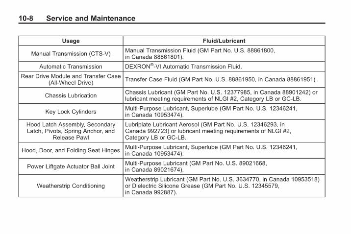
10-8 Service and Maintenance
Usage Fluid/Lubricant
Manual Transmission (CTS-V) Manual Transmission Fluid (GM Part No. U.S. 88861800,in Canada 88861801).
Automatic Transmission DEXRON®-VI Automatic Transmission Fluid.
Rear Drive Module and Transfer Case(All-Wheel Drive) Transfer Case Fluid (GM Part No. U.S. 88861950, in Canada 88861951).
Chassis LubricationChassis Lubricant (GM Part No. U.S. 12377985, in Canada 88901242) orlubricant meeting requirements of NLGI #2, Category LB or GC-LB.
Key Lock CylindersMulti-Purpose Lubricant, Superlube (GM Part No. U.S. 12346241,in Canada 10953474).
Hood Latch Assembly, SecondaryLatch, Pivots, Spring Anchor, and
Release Pawl
Lubriplate Lubricant Aerosol (GM Part No. U.S. 12346293, inCanada 992723) or lubricant meeting requirements of NLGI #2,Category LB or GC-LB.
Hood, Door, and Folding Seat HingesMulti-Purpose Lubricant, Superlube (GM Part No. U.S. 12346241,in Canada 10953474).
Power Liftgate Actuator Ball JointMulti-Purpose Lubricant (GM Part No. U.S. 89021668,in Canada 89021674).
Weatherstrip ConditioningWeatherstrip Lubricant (GM Part No. U.S. 3634770, in Canada 10953518)or Dielectric Silicone Grease (GM Part No. U.S. 12345579,in Canada 992887).

Service and Maintenance 10-9
Maintenance Replacement PartsReplacement parts identified below by name, part number, or specification can be obtained from your retailer.
Part GM Part Number ACDelco Part Number
Engine Air Cleaner/Filter
3.0L V6 Engine 15875795 A3096C
3.6L V6 Engine 15875795 A3096C
6.2L V8 Engine 25898499 A3105C
Engine Oil Filter
3.0L V6 Engine 25177917 PF2129
3.6L V6 Engine 25177917 PF2129
6.2L V8 Engine 89017524 PF48
Passenger Compartment Air Filter Element 19130403 CF133
Spark Plugs
3.0L V6 Engine 12622561 41–109
3.6L V6 Engine 12597464 41-990
6.2L V8 Engine 12571165 41-104

10-10 Service and Maintenance
Part GM Part Number ACDelco Part Number
Wiper Blades — Except CTS-V
Driver Side – 56.5 cm (22 in) 15890062 —
Passenger Side – 53.3 cm (21 in) 15890064 —
Wiper Blades — CTS-V
Driver Side – 56.5 cm (22 in) 20791461 —
Passenger Side – 53.3 cm (21 in) 20791462 —

Service and Maintenance 10-11
Maintenance RecordsAfter the scheduled services are performed, record the date, odometer reading, who performed the service, and thetype of services performed in the boxes provided. Retain all maintenance receipts.
Maintenance Record
DateOdometerReading
Serviced By Maintenance Stamp Services Performed

10-12 Service and Maintenance
Maintenance Record (cont'd)
Date OdometerReading
Serviced By Maintenance Stamp Services Performed

Service and Maintenance 10-13
Maintenance Record (cont'd)
Date OdometerReading
Serviced By Maintenance Stamp Services Performed

10-14 Service and Maintenance
Maintenance Record (cont'd)
Date OdometerReading
Serviced By Maintenance Stamp Services Performed

Technical Data 11-1
Technical Data
Vehicle IdentificationVehicle IdentificationNumber (VIN) . . . . . . . . . . . . . . 11-1
Service Parts IdentificationLabel . . . . . . . . . . . . . . . . . . . . . . . 11-1
Vehicle DataCapacities andSpecifications . . . . . . . . . . . . . . 11-2
Engine Drive Belt Routing . . . . 11-4
Vehicle Identification
Vehicle IdentificationNumber (VIN)
This legal identifier is in the frontcorner of the instrument panel, onthe left side of the vehicle. It can beseen through the windshield fromoutside. The VIN also appears onthe Vehicle Certification and ServiceParts labels and certificates of titleand registration.
Engine Identification
The eighth character in the VINis the engine code. This codeidentifies the vehicle's engine,specifications, and replacementparts. See “Engine Specifications”under Capacities and Specificationson page 11‑2 for the vehicle'sengine code.
Service PartsIdentification LabelThis label, on the spare tire cover,has the following information:. Vehicle Identification
Number (VIN). Model designation. Paint information. Production options and special
equipment
Do not remove this label from thevehicle.

11-2 Technical Data
Vehicle Data
Capacities and SpecificationsThe following approximate capacities are given in metric and English conversions. See Recommended Fluids andLubricants on page 10‑7 for more information.
ApplicationCapacities
Metric English
Air Conditioning Refrigerant R134a
For the air conditioning system refrigerant chargeamount, see the refrigerant caution label locatedunder the hood. See your dealer/retailer for more
information.
Cooling System — Engine
3.0LV6 Engine 10.3 L 10.9 qt
3.6LV6 Engine 10.3 L 10.9 qt
6.2LV8 Engine 11.8 L 12.5 qt
Cooling System — Intercooler, 6.2LV8 Engine 2.3 L 2.4 qt
Engine Oil with Filter
3.0LV6 Engine 5.7 L 6.0 qt
3.6LV6 Engine 5.7 L 6.0 qt
6.2LV8 Engine 5.7 L 6.0 qt

Technical Data 11-3
ApplicationCapacities
Metric English
Fuel Tank 68.1 L 18.0 gal
Transfer Case — AWD 1.0 L 1.1 qt
Transmission Fluid (Pan Removal and Filter Replacement)
3.0LV6 Engine, 6-Speed Automatic 6.3 L 6.7 qt
3.6LV6 Engine, 6-Speed Automatic 6.3 L 6.7 qt
6.2LV8 Engine, 6-Speed Automatic 6.3 L 6.7 qt
3.0L, 3.6LV6 Engines, 6-Speed Manual 1.8 L 1.9 qt
6.2LV8 Engine, 6-Speed Manual 3.8 L 4.0 qt
Wheel Nut Torque 190Y 140 lb ft
All capacities are approximate. When adding, be sure to fill to the approximate level, as recommended in thismanual. Recheck fluid level after filling.

11-4 Technical Data
Engine Specifications
Engine VIN Code Transmission Spark Plug Gap
3.0LV6 Engine GAutomaticManual
1.1 mm (0.043 in)
3.6LV6 Engine VAutomaticManual 1.1 mm (0.043 in)
6.2LV8 Engine PAutomaticManual
1.0 mm (0.040 in)
Engine Drive Belt Routing
CTS 3.0L V6 Engine
CTS 3.6L V6 Engine CTS-V 6.2L V8 Engine

Customer Information 12-1
CustomerInformation
Customer InformationCustomer SatisfactionProcedure . . . . . . . . . . . . . . . . . . 12-1
Customer AssistanceOffices . . . . . . . . . . . . . . . . . . . . . 12-3
Customer Assistance for TextTelephone (TTY) Users . . . . . 12-4
Online Owner Center . . . . . . . . 12-4GM Mobility ReimbursementProgram . . . . . . . . . . . . . . . . . . . . 12-5
Roadside Service . . . . . . . . . . . . 12-6Scheduling ServiceAppointments . . . . . . . . . . . . . . 12-8
Courtesy TransportationProgram . . . . . . . . . . . . . . . . . . . . 12-8
Collision Damage Repair . . . 12-10Service PublicationsOrdering Information . . . . . . 12-12
Reporting Safety DefectsReporting Safety Defects tothe United StatesGovernment . . . . . . . . . . . . . . . 12-13
Reporting Safety Defects tothe CanadianGovernment . . . . . . . . . . . . . . . 12-14
Reporting Safety Defects toGeneral Motors . . . . . . . . . . . 12-14
Vehicle Data Recording andPrivacyVehicle Data Recording andPrivacy . . . . . . . . . . . . . . . . . . . . 12-15
Event Data Recorders . . . . . . 12-15OnStar® . . . . . . . . . . . . . . . . . . . . 12-16Navigation System . . . . . . . . . 12-16Radio FrequencyIdentification (RFID) . . . . . . . 12-16
Radio FrequencyStatement . . . . . . . . . . . . . . . . . 12-16
Customer Information
Customer SatisfactionProcedureYour satisfaction and goodwill areimportant to your dealer and toCadillac. Normally, any concernswith the sales transaction or theoperation of the vehicle will beresolved by the dealer's sales orservice departments. Sometimes,however, despite the best intentionsof all concerned, misunderstandingscan occur. If your concern has notbeen resolved to your satisfaction,the following steps should be taken:
STEP ONE: Discuss your concernwith a member of dealershipmanagement. Normally, concernscan be quickly resolved at that level.If the matter has already beenreviewed with the sales, service orparts manager, contact the owner ofthe dealership or the generalmanager.

12-2 Customer Information
STEP TWO: If after contacting amember of dealership management,it appears your concern cannot beresolved by the dealership withoutfurther help, in the United States,call the Cadillac CustomerAssistance Center, 24 hours a day,at 1-800-458-8006. In Canada, callthe Canadian Cadillac CustomerCommunication Centre at1-888-446-2000.
We encourage you to call thetoll-free number in order to give yourinquiry prompt attention. Have thefollowing information available togive the Customer AssistanceRepresentative:. Vehicle Identification Number
(VIN). This is available from thevehicle registration or title, or theplate at the top left of theinstrument panel and visiblethrough the windshield.
. Dealership name and location.
. Vehicle delivery date andpresent mileage.
When contacting Cadillac,remember that your concern willlikely be resolved at a dealer'sfacility. That is why we suggestfollowing Step One first.
STEP THREE (U.S. Owners): BothGeneral Motors and your dealer arecommitted to making sure you arecompletely satisfied with your newvehicle. However, if you continue toremain unsatisfied after followingthe procedure outlined in Steps Oneand Two, you can file with the BetterBusiness Bureau (BBB) Auto LineProgram to enforce your rights.
The BBB Auto Line Program is anout of court program administeredby the Council of Better BusinessBureaus to settle automotivedisputes regarding vehicle repairs orthe interpretation of the New VehicleLimited Warranty. Although you maybe required to resort to this informaldispute resolution program prior tofiling a court action, use of theprogram is free of charge and yourcase will generally be heard within40 days. If you do not agree with the
decision given in your case, youmay reject it and proceed with anyother venue for relief availableto you.
You may contact the BBB AutoLine Program using the toll-freetelephone number or write them atthe following address:
BBB Auto Line ProgramCouncil of Better BusinessBureaus, Inc.4200 Wilson BoulevardSuite 800Arlington, VA 22203-1838
Telephone: 1-800-955-5100dr.bbb.org/goauto
This program is available in all50 states and the District ofColumbia. Eligibility is limited byvehicle age, mileage and otherfactors. General Motors reservesthe right to change eligibilitylimitations and/or discontinue itsparticipation in this program.

Customer Information 12-3
STEP THREE (Canadian Owners):
General Motors Participation inthe Mediation/Arbitration Program
In the event that you do not feelyour concerns have been addressedafter the following the procedureoutlined in Steps One and Two.General Motors of Canada Limitedwants you to be aware of itsparticipation in a no-chargemediation/Arbitration program.General Motors of Canada Limitedhas committed to binding arbitrationof owner disputes involvingfactory-related vehicle serviceclaims. The program provides forthe review of the facts involved byan impartial third party arbiter, andmay include an informal hearingbefore the arbiter. The program isdesigned so that the entire disputesettlement process, from the timeyou file your complaint to the finaldecision, should be completed inapproximately 70 days. We believe
our impartial program offersadvantages over courts in mostjurisdictions because it is informal,quick, and free of charge.
For further information concerningeligibility in the Canadian MotorVehicle Arbitration Plan (CAMVAP),call toll-free 1-800-207-0685, orcall the General Motors CustomerCommunication Centre,1-800-263-3777 (English),1-800-263-7854 (French), or write tothe Mediation/Arbitration Program atthe following address:
Mediation/Arbitration Programc/o Customer CommunicationCentreGeneral Motors of Canada LimitedMail Code: CA1–163–0051908 Colonel Sam DriveOshawa, Ontario L1H 8P7
Your inquiry should be accompaniedby the Vehicle IdentificationNumber (VIN).
Customer AssistanceOfficesCadillac encourages customersto call the toll-free number forassistance. However, if a customerwishes to write or e-mail Cadillac,the letter should be addressed to:
United States — CustomerAssistance
Cadillac Customer AssistanceCenterCadillac Motor Car DivisionP.O. Box 33169Detroit, MI 48232-5169www.Cadillac.com
1-800-458-80061-800-833-2622 (For TextTelephone devices (TTYs))Roadside Assistance:1-800-882-1112

12-4 Customer Information
From Puerto Rico:
1-800-496-9992 (English)1-800-496-9993 (Spanish)
From U.S. Virgin Islands:
1-800-496-9994
Canada — CustomerAssistance
General Motors of Canada LimitedCanadian Cadillac CustomerCommunication Centre,CA1-163-0051908 Colonel Sam DriveOshawa, Ontario L1H 8P7www.gmcanada.com
1-888-446-20001-800-263-3830 (For TextTelephone devices (TTYs))Roadside Assistance:1-800-882-1112
Overseas — CustomerAssistance
Please contact the local GeneralMotors Business Unit.
Mexico, Central America andCaribbean Islands/Countries(Except Puerto Rico and U.S.Virgin Islands) — CustomerAssistance
General Motors de Mexico,S. de R.L. de C.V.Customer Assistance CenterPaseo de la Reforma # 2740Col. Lomas de BezaresC.P. 11910, Mexico, D.F.
01-800-508-0000Long Distance: 011-52-53 29 0 800
Customer Assistance forText Telephone (TTY)UsersTo assist customers who are deaf,hard of hearing, or speech-impairedand who use Text Telephones(TTYs), Cadillac has TTY equipmentavailable at its Customer AssistanceCenter. Any TTY user cancommunicate with Cadillac by
dialing: 1-800-833-CMCC (2622).(TTY users in Canada can dial1-800-263-3830.)
Online Owner Center
Online Owner Center (U.S.) —www.gmownercenter.com/cadillac
Information and servicescustomized for your specificvehicle — all in one convenientplace.. Digital owner manual, warranty
information, and more. Online service and maintenance
records. Find Cadillac dealers for service
nationwide. Exclusive privileges and offers. Recall notices for your specific
vehicle. OnStar® and GM Cardmember
Services Earnings summaries

Customer Information 12-5
Other Helpful Links:
Cadillac — www.cadillac.com
Cadillac Merchandise —www.cadillaccollection.com
Help Center — www.cadillac.com/helpcenter. FAQ. Contact Us
My GM Canada(Canada) — www.gm.ca
My GM Canada is apassword-protected section ofwww.gm.ca where you can saveinformation on GM vehicles, getpersonalized offers, and use handytools and forms with greater ease.
Here are a few of the valuable toolsand services you will haveaccess to:. My Showroom: Find and save
information on vehicles andcurrent offers in your area.
. My Dealers/Retailers: Savedetails such as address andphone number for each of yourpreferred GM dealers/retailers.
. My Driveway: Access quick linksto parts and service estimates,check trade-in values,or schedule a serviceappointment by adding thevehicles you own to yourdriveway profile.
. My Preferences: Manage yourprofile and use tools and formswith greater ease.
To sign up, visit the My GM Canadasection within www.gm.ca.
GM MobilityReimbursement Program
This program, available to qualifiedapplicants for cost reimbursementof eligible aftermarket adaptiveequipment required for yourvehicle, such as hand controls ora wheelchair/scooter lift for thevehicle.
For more information on the limitedoffer visit gmmobility.com or call theGM Mobility Assistance Center at1-800-323-9935. Text telephone(TTY) users, call 1-800-833-9935.
General Motors of Canada alsohas a Mobility Program. Call1-800-GM-DRIVE (463-7483)for details. TTY users call1-800-263-3830.

12-6 Customer Information
Roadside ServiceIn the United States or Canada, call1-800-882-1112.
Text Telephone (TTY), U.S. only,call 1-888-889-2438.
Service is available 24 hours a day,365 days a year.
Calling for Assistance
When calling Roadside Assistance,have the following informationready:. Your name, home address, and
home telephone number. Telephone number of your
location. Location of the vehicle. Model, year, color, and license
plate number of the vehicle. Odometer reading, Vehicle
Identification Number (VIN), anddelivery date of the vehicle
. Description of the problem
Coverage
Services are provided up to 5 years/100,000 miles (160 000 km),whichever comes first.
In the U.S., anyone driving thevehicle is covered. In Canada, aperson driving the vehicle withoutpermission from the owner is notcovered.
Roadside Assistance is not a part ofthe New Vehicle Limited Warranty.Cadillac and General Motors ofCanada Limited reserve the right tomake any changes or discontinuethe Roadside Assistance program atany time without notification.
Cadillac and General Motors ofCanada Limited reserve the right tolimit services or payment to anowner or driver if they decide theclaims are made too often, or thesame type of claim is made manytimes.
Cadillac Owner Privileges™. Emergency Fuel Delivery:
Delivery of enough fuel for thevehicle to get to the nearestservice station.
. Lock-Out Service: Service isprovided to unlock the vehicle ifyou are locked out. A remoteunlock may be available if youhave OnStar®. For securityreasons, the driver must presentidentification before this serviceis given.
. Emergency Tow From a PublicRoad or Highway: Tow to thenearest Cadillac dealer forwarranty service, or if the vehiclewas in a crash and cannot bedriven. Assistance is also givenwhen the vehicle is stuck in thesand, mud, or snow.
. Flat Tire Change: Service isprovided to change a flat tirewith spare tire. The spare tire,if equipped, must be in goodcondition and properly inflated.

Customer Information 12-7
It is your responsibility for therepair or replacement of thetire if it is not covered by thewarranty.
. Battery Jump Start: Service isprovided to jump start a deadbattery.
. Trip Routing Service: Detailedmaps of North America areprovided when requested eitherwith the most direct route or themost scenic route. Additionaltravel information is alsoavailable. Allow three weeksfor delivery.
. Trip Interruption Benefits andAssistance: If your trip isinterrupted due to a warrantyfailure, incidental expenses maybe reimbursed during the 5 year/100,000 miles (160 000 km)Powertrain warranty period.Items considered are hotel,meals, and rental car.
Cadillac Technician RoadsideService (U.S. only)
Cadillac's exceptional RoadsideService is more than an auto club ortowing service. It provides everyCadillac owner in the United Stateswith the advantage of contactinga Cadillac advisor and, whereavailable, a Cadillac trained dealertechnician who can provide on-siteservice.
A dealer technician will travel toyour location within a 30 mileradius of a participating Cadillacdealership. If beyond this radius, wewill arrange to have your car towedto the nearest Cadillac dealership.Each technician travels with aspecially equipped service vehiclecomplete with the necessaryCadillac parts and tools requiredto handle most roadside repairs.
Services Not Included inRoadside Assistance. Impound towing caused by
violation of any laws.. Legal fines.. Mounting, dismounting or
changing of snow tires, chains,or other traction devices.
. Towing or services for vehiclesdriven on a non-public road orhighway.
Services Specific to CanadianPurchased Vehicles. Fuel delivery: Reimbursement
is approximately $5 Canadian.Diesel fuel delivery may berestricted. Propane and otherfuels are not provided throughthis service.
. Lock-Out Service: Vehicleregistration is required.
. Trip Routing Service: Limit ofsix requests per year.

12-8 Customer Information
. Trip Interruption Benefits andAssistance: Pre-authorization,original detailed receipts, and acopy of the repair orders arerequired. Once authorization hasbeen received, the RoadsideAssistance advisor will help youmake arrangements and explainhow to receive payment.
. Alternative Service: Ifassistance cannot be providedright away, the RoadsideAssistance advisor may giveyou permission to get localemergency road service. You willreceive payment, up to $100,after sending the originalreceipt to Roadside Assistance.Mechanical failures may becovered, however any cost forparts and labor for repairs notcovered by the warranty are theowner responsibility.
Scheduling ServiceAppointmentsWhen your vehicle requireswarranty service, contact yourdealer/retailer and request anappointment. By scheduling aservice appointment and advisingyour service consultant of yourtransportation needs, your dealer/retailer can help minimize yourinconvenience.
If your vehicle cannot be scheduledinto the service departmentimmediately, keep driving it until itcan be scheduled for service,unless, of course, the problem issafety-related. If it is, please callyour dealership/retailer, let themknow this, and ask for instructions.
If the dealer/retailer requests you tobring the vehicle for service, you areurged to do so as early in the workday as possible to allow for thesame day repair.
Courtesy TransportationProgramTo enhance your ownershipexperience, we and our participatingdealers are proud to offer CourtesyTransportation, a customer supportprogram for vehicles with the NewVehicle Limited Warranty (BaseWarranty Coverage period inCanada) and extended powertrain,and hybrid specific warranty in boththe U.S. and Canada.
Several courtesy transportationoptions are available to assist inreducing your inconvenience whenwarranty repairs are required.
Courtesy Transportation is not apart of the New Vehicle LimitedWarranty. A separate bookletentitled “Warranty and OwnerAssistance Information” furnishedwith each new vehicle providesdetailed warranty coverageinformation.

Customer Information 12-9
Transportation Options
Warranty service can generally becompleted while you wait. However,if you are unable to wait, GM helpsto minimize your inconvenience byproviding several transportationoptions. Depending on thecircumstances, your dealer canoffer you one of the following:
Shuttle Service
Shuttle service is the preferredmeans of offering CourtesyTransportation. Dealers may provideyou with shuttle service to get youto your destination with minimalinterruption of your daily schedule.This includes one-way or round tripshuttle service within reasonabletime and distance parameters of thedealer's area.
Public Transportation or FuelReimbursement
If your vehicle requires overnightwarranty repairs, and publictransportation is used instead of thedealer's shuttle service, the expensemust be supported by originalreceipts and can only be up to themaximum amount allowed by GMfor shuttle service. In addition, forU.S. customers, should you arrangetransportation through a friend orrelative, limited reimbursement forreasonable fuel expenses may beavailable. Claim amounts shouldreflect actual costs and besupported by original receipts.See your dealer for informationregarding the allowance amountsfor reimbursement of fuel or othertransportation costs.
Courtesy Rental Vehicle
Your dealer may arrange to provideyou with a courtesy rental vehicle orreimburse you for a rental vehiclethat you obtain if your vehicle iskept for an overnight warrantyrepair. Rental reimbursement willbe limited and must be supportedby original receipts. This requiresthat you sign and complete arental agreement and meet state/provincial, local, and rentalvehicle provider requirements.Requirements vary and may includeminimum age requirements,insurance coverage, credit card,etc. You are responsible for fuelusage charges and may also beresponsible for taxes, levies, usagefees, excessive mileage, or rentalusage beyond the completion of therepair.
It may not be possible to provide alike-vehicle as a courtesy rental.

12-10 Customer Information
Additional ProgramInformation
All program options, such as shuttleservice, may not be available atevery dealer. Please contact yourdealer for specific informationabout availability. All CourtesyTransportation arrangements will beadministered by appropriate dealerpersonnel.
General Motors reserves the rightto unilaterally modify, change ordiscontinue Courtesy Transportationat any time and to resolve allquestions of claim eligibilitypursuant to the terms andconditions described herein at itssole discretion.
Collision Damage RepairIf your vehicle is involved in acollision and it is damaged, havethe damage repaired by a qualifiedtechnician using the properequipment and quality replacementparts. Poorly performed collisionrepairs diminish your vehicle'sresale value, and safetyperformance can be compromisedin subsequent collisions.
Collision Parts
Genuine GM Collision parts are newparts made with the same materialsand construction methods as theparts with which your vehiclewas originally built. Genuine GMCollision parts are your best choiceto ensure that your vehicle'sdesigned appearance, durability,and safety are preserved. The useof Genuine GM parts can helpmaintain your GM New VehicleWarranty.
Recycled original equipment partsmay also be used for repair. Theseparts are typically removed fromvehicles that were total losses inprior crashes. In most cases, theparts being recycled are fromundamaged sections of the vehicle.A recycled original equipment GMpart, may be an acceptable choiceto maintain your vehicle's originallydesigned appearance and safetyperformance, however, the history ofthese parts is not known. Such partsare not covered by your GM NewVehicle Limited Warranty, and anyrelated failures are not covered bythat warranty.
Aftermarket collision parts are alsoavailable. These are made bycompanies other than GM andmay not have been tested for yourvehicle. As a result, these partsmay fit poorly, exhibit prematuredurability/corrosion problems,and may not perform properlyin subsequent collisions.

Customer Information 12-11
Aftermarket parts are not coveredby your GM New Vehicle LimitedWarranty, and any vehicle failurerelated to such parts are notcovered by that warranty.
Repair Facility
We recommend that you choose acollision repair facility that meetsyour needs before you ever needcollision repairs. Your dealer/retailermay have a collision repair centerwith GM-trained technicians andstate of the art equipment, or beable to recommend a collision repaircenter that has GM-trainedtechnicians and comparableequipment.
Insuring Your Vehicle
Protect your investment in your GMvehicle with comprehensive andcollision insurance coverage. Thereare significant differences in thequality of coverage afforded byvarious insurance policy terms.
Many insurance policies providereduced protection to your GMvehicle by limiting compensationfor damage repairs by usingaftermarket collision parts. Someinsurance companies will notspecify aftermarket collision parts.When purchasing insurance, werecommend that you assure yourvehicle will be repaired with GMoriginal equipment collision parts.If such insurance coverage isnot available from your currentinsurance carrier, consider switchingto another insurance carrier.
If your vehicle is leased, the leasingcompany may require you to haveinsurance that assures repairs withGenuine GM Original EquipmentManufacturer (OEM) parts orGenuine Manufacturer replacementparts. Read your lease carefully, asyou may be charged at the end ofyour lease for poor quality repairs.
If a Crash Occurs
If there has been an injury, callemergency services for help. Do notleave the scene of a crash until allmatters have been taken care of.Move the vehicle only if its positionputs you in danger, or you areinstructed to move it by a policeofficer.
Give only the necessary informationto police and other parties involvedin the crash.
For emergency towing seeRoadside Service on page 12‑6.
Gather the following information:. Driver's name, address, phone
number. Driver's license number. Owner's name, address, phone
number. Vehicle license plate. Vehicle make, model and
model year

12-12 Customer Information
. Vehicle IdentificationNumber (VIN)
. Insurance company and policynumber
. General description of thedamage to the other vehicle
Choose a reputable repair facilitythat uses quality replacement parts.See “Collision Parts” earlier in thissection.
If the airbag has inflated, see WhatWill You See After an AirbagInflates? on page 2‑33.
Managing the Vehicle DamageRepair Process
In the event that your vehiclerequires damage repairs, GMrecommends that you take anactive role in its repair. If you havea pre-determined repair facility ofchoice, take your vehicle there,or have it towed there. Specify tothe facility that any requiredreplacement collision parts beoriginal equipment parts, eithernew Genuine GM parts or recycled
original GM parts. Remember,recycled parts will not be covered byyour GM vehicle warranty.
Insurance pays the bill for the repair,but you must live with the repair.Depending on your policy limits,your insurance company mayinitially value the repair usingaftermarket parts. Discuss this withyour repair professional, and insiston Genuine GM parts. Remember ifyour vehicle is leased you may beobligated to have the vehiclerepaired with Genuine GM parts,even if your insurance coveragedoes not pay the full cost.
If another party's insurancecompany is paying for the repairs,you are not obligated to accept arepair valuation based on thatinsurance company's collision policyrepair limits, as you have nocontractual limits with that company.In such cases, you can have controlof the repair and parts choices aslong as cost stays within reasonablelimits.
Service PublicationsOrdering Information
Service Manuals
Service Manuals have the diagnosisand repair information on engines,transmission, axle, suspension,brakes, electrical, steering,body, etc.
Service Bulletins
Service Bulletins give additionaltechnical service informationneeded to knowledgeably serviceGeneral Motors cars and trucks.Each bulletin contains instructionsto assist in the diagnosis andservice of your vehicle.
Owner Information
Owner publications are writtenspecifically for owners and intendedto provide basic operationalinformation about the vehicle.The owner manual includes theMaintenance Schedule for allmodels.

Customer Information 12-13
In-Portfolio: Includes a Portfolio,Owner Manual, and WarrantyBooklet.
RETAIL SELL PRICE:$35.00 (U.S.) plus processing fee
Without Portfolio: OwnerManual only.
RETAIL SELL PRICE:$25.00 (U.S.) plus processing fee
Current and Past Model OrderForms
Technical Service Bulletins andManuals are available for currentand past model GM vehicles. Torequest an order form, specify yearand model name of the vehicle.
ORDER TOLL FREE:1-800-551-4123 Monday-Friday8:00 AM - 6:00 PM Eastern Time
For Credit Card Orders Only(VISA-MasterCard-Discover), visitHelm, Inc. on the World Wide Webat: helminc.com
Or you can write to:
Helm, IncorporatedP.O. Box 07130Detroit, MI 48207
Prices are subject to changewithout notice and without incurringobligation. Allow ample time fordelivery.
Note to Canadian Customers: Alllisted prices are quoted in U.S.funds. Canadian residents are tomake checks payable in U.S. funds.
Reporting SafetyDefects
Reporting Safety Defectsto the United StatesGovernmentIf you believe that your vehiclehas a defect which could causea crash or could cause injury ordeath, you should immediatelyinform the National HighwayTraffic Safety Administration(NHTSA) in addition to notifyingGeneral Motors.
If NHTSA receives similarcomplaints, it may open aninvestigation, and if it finds thata safety defect exists in a groupof vehicles, it may order arecall and remedy campaign.

12-14 Customer Information
However, NHTSA cannotbecome involved in individualproblems between you, yourdealer, or General Motors.
To contact NHTSA, you may callthe Vehicle Safety Hotlinetoll-free at 1-888-327-4236(TTY: 1-800-424-9153); go tohttp://www.safecar.gov; orwrite to:
Administrator, NHTSA1200 New Jersey Avenue, S.E.Washington D.C. 20590
You can also obtain otherinformation about motorvehicle safety fromhttp://www.safecar.gov.
Reporting Safety Defectsto the CanadianGovernmentIf you live in Canada, and youbelieve that your vehicle has asafety defect, notify TransportCanada immediately, in addition tonotifying General Motors ofCanada Limited. Call them at1-800-333-0510 or write to:
Transport CanadaRoad Safety Branch2780 Sheffield RoadOttawa, Ontario K1B 3V9
Reporting Safety Defectsto General MotorsIn addition to notifying NHTSA (orTransport Canada) in a situation likethis, please notify General Motors.
Call 1-800-458-8006, or write:
Cadillac Customer AssistanceCenterCadillac Motor Car DivisionP.O. Box 33169Detroit, MI 48232-5169
In Canada, call 1‐888‐446‐2000,or write:
Canadian Cadillac CustomerCommunication Centre,CA1-163-005General Motors of Canada Limited1908 Colonel Sam DriveOshawa, Ontario L1H 8P7

Customer Information 12-15
Vehicle DataRecording andPrivacyYour GM vehicle has a number ofsophisticated computers that recordinformation about the vehicle’sperformance and how it is driven.For example, your vehicle usescomputer modules to monitor andcontrol engine and transmissionperformance, to monitor theconditions for airbag deploymentand deploy airbags in a crash and,if so equipped, to provide antilockbraking to help the driver control thevehicle. These modules may storedata to help your dealer/retailertechnician service your vehicle.Some modules may also store dataabout how you operate the vehicle,such as rate of fuel consumption oraverage speed. These modules mayalso retain the owner’s personalpreferences, such as radio pre-sets,seat positions, and temperaturesettings.
Event Data RecordersThis vehicle has an Event DataRecorder (EDR). The main purposeof an EDR is to record, in certaincrash or near crash-like situations,such as an airbag deployment orhitting a road obstacle, data that willassist in understanding how avehicle's systems performed. TheEDR is designed to record datarelated to vehicle dynamics andsafety systems for a short period oftime, typically 30 seconds or less.The EDR in this vehicle is designedto record such data as:. How various systems in your
vehicle were operating. Whether or not the driver and
passenger safety belts werebuckled/fastened
. How far, if at all, the driver waspressing the accelerator and/orbrake pedal
. How fast the vehicle wastraveling
This data can help provide a betterunderstanding of the circumstancesin which crashes and injuries occur.
Important: EDR data is recordedby your vehicle only if a non-trivialcrash situation occurs; no data isrecorded by the EDR under normaldriving conditions and no personaldata (e.g., name, gender, age,and crash location) is recorded.However, other parties, such aslaw enforcement, could combinethe EDR data with the type ofpersonally identifying data routinelyacquired during a crashinvestigation.
To read data recorded by an EDR,special equipment is required, andaccess to the vehicle or the EDR isneeded. In addition to the vehiclemanufacturer, other parties, such aslaw enforcement, that have thespecial equipment, can read theinformation if they have access tothe vehicle or the EDR.

12-16 Customer Information
GM will not access this data orshare it with others except: with theconsent of the vehicle owner or,if the vehicle is leased, with theconsent of the lessee; in responseto an official request of police orsimilar government office; as part ofGM's defense of litigation throughthe discovery process; or, asrequired by law. Data that GMcollects or receives may also beused for GM research needs or maybe made available to others forresearch purposes, where a need isshown and the data is not tied to aspecific vehicle or vehicle owner.
OnStar®
If your vehicle has OnStar and yousubscribe to the OnStar services,please refer to the OnStar Termsand Conditions for information ondata collection and use. See alsoOnStar® System on page 4‑59 inthis manual for more information.
Navigation SystemIf your vehicle has a navigationsystem, use of the system mayresult in the storage of destinations,addresses, telephone numbers, andother trip information. Refer to thenavigation system operating manualfor information on stored data andfor deletion instructions.
Radio FrequencyIdentification (RFID)RFID technology is used in somevehicles for functions such as tirepressure monitoring and ignitionsystem security, as well as inconnection with conveniencessuch as key fobs for remote doorlocking/unlocking and starting, andin-vehicle transmitters for garagedoor openers. RFID technology inGM vehicles does not use or recordpersonal information or link with anyother GM system containingpersonal information.
Radio FrequencyStatementThis vehicle has systems thatoperate on a radio frequency thatcomply with Part 15 of the FederalCommunications Commission (FCC)Rules and with RSS-210/211 ofIndustry and Science Canada.
Operation is subject to the followingtwo conditions:
1. The device may not causeinterference.
2. The device must accept anyinterference received, includinginterference that may causeundesired operation of thedevice.
Changes or modifications to any ofthese systems by other than anauthorized service facility could voidauthorization to use this equipment.

INDEX i-1
AAccessories andModifications . . . . . . . . . . . . . . . . . . 9-3
Accessory Power . . . . . . . . . . . . . . 8-19Adaptive ForwardLighting (AFL) . . . . . . . . . . . . . . . . . 5-4
Add-On ElectricalEquipment . . . . . . . . . . . . . . . . . . . 8-60
Adding Equipment to theAirbag-Equipped Vehicle . . . . . 2-40
AdjustmentSThigh Support . . . . . . . . . . . . . . . . . 2-7
AdjustmentsLumbar, Front Seats . . . . . . . . . . . 2-6
Air Cleaner/Filter, Engine . . . . . . 9-15Air Filter, PassengerCompartment . . . . . . . . . . . . . . . . . 7-6
Air Vents . . . . . . . . . . . . . . . . . . . . . . . 7-6Airbag SystemCheck . . . . . . . . . . . . . . . . . . . . . . . .2-42How Does an AirbagRestrain? . . . . . . . . . . . . . . . . . . .2-33
Airbag System (cont.)Passenger SensingSystem . . . . . . . . . . . . . . . . . . . . . .2-35
What Makes an AirbagInflate? . . . . . . . . . . . . . . . . . . . . . .2-32
What Will You See Afteran Airbag Inflates? . . . . . . . . . .2-33
When Should an AirbagInflate? . . . . . . . . . . . . . . . . . . . . . .2-31
Where Are the Airbags? . . . . . .2-29AirbagsAdding Equipment to theVehicle . . . . . . . . . . . . . . . . . . . . . .2-40
Passenger Status Indicator . . .4-22Readiness Light . . . . . . . . . . . . . .4-21Servicing Airbag-EquippedVehicles . . . . . . . . . . . . . . . . . . . . .2-40
System Check . . . . . . . . . . . . . . . .2-27Alarm SystemAnti-Theft . . . . . . . . . . . . . . . . . . . . .1-23
All-Wheel Drive . . . . . . . . . . 8-32, 9-30AM-FM Radio . . . . . . . . . . . . . . . . . . . 6-9Anti-TheftAlarm System . . . . . . . . . . . . . . . .1-23Alarm System Messages . . . . .4-48
Antilock BrakeSystem (ABS) . . . . . . . . . . . . . . . . 8-33Warning Light . . . . . . . . . . . . . . . . .4-27
Appearance CareExterior . . . . . . . . . . . . . . . . . . . . . .9-110Interior . . . . . . . . . . . . . . . . . . . . . . .9-114
Ashtrays . . . . . . . . . . . . . . . . . . . . . . . 4-14Audio Players . . . . . . . . . . . . . . . . . 6-16CD . . . . . . . . . . . . . . . . . . . . . . . . . . .6-16MP3 . . . . . . . . . . . . . . . . . . . . . . . . . .6-23
Audio SystemDiversity Antenna System . . . .6-15Hard Drive Device (HDD) . . . . .6-27Radio Reception . . . . . . . . . . . . . .6-15Theft-Deterrent Feature . . . . . . . . 6-2
AutomaticDoor Locks . . . . . . . . . . . . . . . . . . .1-15
Automatic Transmission . . . . . . . 8-26Fluid . . . . . . . . . . . . . . . . . . . . . . . . . .9-13Manual Mode . . . . . . . . . . . . . . . . .8-28Shiftlock Control SystemCheck . . . . . . . . . . . . . . . . . . . . . . .9-32
Auxiliary Devices . . . . . . . . . . . . . . 6-35Axle, Rear . . . . . . . . . . . . . . . . . . . . . 9-30

i-2 INDEX
BBattery . . . . . . . . . . . . . . . . . . . . . . . . 9-29Exterior Lighting BatterySaver . . . . . . . . . . . . . . . . . . . . . . . . 5-7
Jump Starting . . . . . . . . . . . . . . . 9-103Load Management . . . . . . . . . . . . . 5-6Power Protection . . . . . . . . . . . . . . 5-7Voltage and ChargingMessages . . . . . . . . . . . . . . . . . . .4-37
Blade Replacement, Wiper . . . . 9-33Bluetooth . . . . . . . . . . . . . . . . . . . . . . 6-37Boost Gage . . . . . . . . . . . . . . . . . . . . 4-18Brakes . . . . . . . . . . . . . . . . . . . . . . . . . 9-26Antilock . . . . . . . . . . . . . . . . . . . . . . .8-33Assist . . . . . . . . . . . . . . . . . . . . . . . . .8-37Fluid . . . . . . . . . . . . . . . . . . . . . . . . . .9-27Parking . . . . . . . . . . . . . . . . .8-34, 8-35System Messages . . . . . . . . . . . .4-38
Braking . . . . . . . . . . . . . . . . . . . . . . . . . 8-4Break-In, New Vehicle . . . . . . . . . 8-17Bulb Replacement . . . . . . . . . . . . . 9-39Fog Lamps . . . . . . . . . . . . . . 5-5, 9-37Halogen Bulbs . . . . . . . . . . . . . . . .9-37Headlamp Aiming . . . . . . . . . . . . .9-34
Bulb Replacement (cont.)Headlamps . . . . . . . . . . . . . . . . . . .9-37High Intensity Discharge(HID) Lighting . . . . . . . . . . . . . . .9-37
License Plate Lamps . . .9-38, 9-39Buying New Tires . . . . . . . . . . . . . . 9-75
CCalibration . . . . . . . . . . . . . . . . . . . . . 4-11CaliforniaFuel Requirements . . . . . . . . . . .8-50Perchlorate MaterialsRequirements . . . . . . . . . . . . . . . . 9-3
Warning . . . . . . . . . . . . . . . . . . . . . . . 9-3Camera, Rear Vision . . . . . . . . . . 8-46Canadian Vehicle Owners . . . . . . . . ivCapacities andSpecifications . . . . . . . . . . . . . . . . 11-2
Carbon MonoxideEngine Exhaust . . . . . . . . . . . . . . .8-25Liftgate . . . . . . . . . . . . . . . . . . . . . . .1-19Trunk . . . . . . . . . . . . . . . . . . . . . . . . .1-17Winter Driving . . . . . . . . . . . . . . . .8-10
CargoCover . . . . . . . . . . . . . . . . . . . . . . . . . . 3-2Management System . . . . . . . . . . 3-3
Cargo Net . . . . . . . . . . . . . . . . . . . . . . 3-4Cautions, Danger, andWarnings . . . . . . . . . . . . . . . . . . . . . . . . iv
CDDVD Player . . . . . . . . . . . . . . . . . . .6-19
CD Player . . . . . . . . . . . . . . . . . . . . . 6-16Center Console Storage . . . . . . . . 3-1Central Door Unlock System . . . 1-15Chains, Tire . . . . . . . . . . . . . . . . . . . 9-81Charging System Light . . . . . . . . 4-23CheckEngine Lamp . . . . . . . . . . . . . . . . .4-23Ignition Transmission Lock . . .9-32
Child RestraintsInfants and YoungChildren . . . . . . . . . . . . . . . . . . . . .2-45
Lower Anchors andTethers for Children . . . . . . . . .2-51
Older Children . . . . . . . . . . . . . . . .2-43Securing . . . . . . . . . . . . . . . .2-57, 2-59Systems . . . . . . . . . . . . . . . . . . . . . .2-47Where to Put the Restraint . . .2-49
Cigarette Lighter . . . . . . . . . . . . . . . 4-13Circuit Breakers . . . . . . . . . . . . . . . 9-41

INDEX i-3
CleaningExterior Care . . . . . . . . . . . . . . . .9-110Interior Care . . . . . . . . . . . . . . . . .9-114
Climate Control SystemsDual Automatic . . . . . . . . . . . . . . . . 7-1
Clock . . . . . . . . . . . . . . . . . . . . . . . . . . 4-12Cluster, IP . . . . . . . . . . . . . . . . . . . . . 4-15Clutch, Hydraulic . . . . . . . . . . . . . . 9-14Collision Damage Repair . . . . . 12-10Compact Spare Tire . . . . . . . . . . 9-102Compass . . . . . . . . . . . . . . . . . . . . . . 4-11Compass Messages . . . . . . . . . . . 4-39Competitive Driving . . . . . . . . . . . . . 8-8Competitive Driving Mode . . . . . 8-40Compressor Kit, TireSealant . . . . . . . . . . . . . . . . . . . . . . . 9-84
Control of a Vehicle . . . . . . . . . . . . . 8-4Convenience Net . . . . . . . . . . . . . . . 3-6Convex Mirrors . . . . . . . . . . . . . . . . 1-26CoolantEngine . . . . . . . . . . . . . . . . . . . . . . . .9-18Engine Temperature Gage . . . .4-20Engine TemperatureWarning Light . . . . . . . . . . . . . . .4-29
Cooling System . . . . . . . . . . . . . . . . 9-18Engine Messages . . . . . . . . . . . .4-40
Courtesy TransportationProgram . . . . . . . . . . . . . . . . . . . . . . 12-8
CoversCargo . . . . . . . . . . . . . . . . . . . . . . . . . . 3-2Engine . . . . . . . . . . . . . . . . . . . . . . . . . 9-9
Cruise Control . . . . . . . . . . . . . . . . . 8-41Light . . . . . . . . . . . . . . . . . . . . . . . . . .4-31Messages . . . . . . . . . . . . . . . . . . . .4-39
Cupholders . . . . . . . . . . . . . . . . . . . . . 3-1Customer Assistance . . . . . . . . . . 12-4Offices . . . . . . . . . . . . . . . . . . . . . . . .12-3Text Telephone (TTY)Users . . . . . . . . . . . . . . . . . . . . . . .12-4
Customer InformationService PublicationsOrdering Information . . . . . . 12-12
Customer SatisfactionProcedure . . . . . . . . . . . . . . . . . . . . 12-1
DDamage Repair, Collision . . . . . 12-10Danger, Warnings, andCautions . . . . . . . . . . . . . . . . . . . . . . . . iv
Data Recorders, Event . . . . . . . 12-15Daytime RunningLamps (DRL) . . . . . . . . . . . . . . . . . . 5-3
Defensive Driving . . . . . . . . . . . . . . . 8-3Delayed Locking . . . . . . . . . . . . . . . 1-15Devices, Auxiliary . . . . . . . . . . . . . 6-35DoorAjar Messages . . . . . . . . . . . . . . .4-39Central Door UnlockingSystem . . . . . . . . . . . . . . . . . . . . . .1-15
Delayed Locking . . . . . . . . . . . . . .1-15Locks . . . . . . . . . . . . . . . . . . . . . . . . .1-14Power Locks . . . . . . . . . . . . . . . . . .1-15
Drive SystemsAll-Wheel Drive . . . . . . . . .8-32, 9-30
Driver InformationCenter (DIC) . . . . . . . . . . . . . . . . . 4-31
DrivingBetter Fuel Economy . . . . . . . . . . 8-2Characteristics andTowing Tips . . . . . . . . . . . . . . . . .8-54
Competitive . . . . . . . . . . . . . . 8-8, 8-40Defensive . . . . . . . . . . . . . . . . . . . . . . 8-3Drunk . . . . . . . . . . . . . . . . . . . . . . . . . . 8-3Highway Hypnosis . . . . . . . . . . . . . 8-9Hill and Mountain Roads . . . . . . . 8-9If the Vehicle is Stuck . . . . . . . . .8-12Loss of Control . . . . . . . . . . . . . . . . 8-7

i-4 INDEX
Driving (cont.)Off-Road Recovery . . . . . . . . . . . . 8-6Vehicle Load Limits . . . . . . . . . . .8-12Winter . . . . . . . . . . . . . . . . . . . . . . . .8-10
Dual Automatic ClimateControl System . . . . . . . . . . . . . . . . 7-1
DVD/CD Player . . . . . . . . . . . . . . . . 6-19
EElectrical Equipment,Add-On . . . . . . . . . . . . . . . . . . . . . . 8-60
Electrical SystemEngineCompartmentFuse Block . . . . . . 9-41, 9-45, 9-48
Fuses and CircuitBreakers . . . . . . . . . . . . . . . . . . . .9-41
Overload . . . . . . . . . . . . . . . . . . . . .9-40RearCompartmentFuse Block . . . . . . 9-51, 9-53, 9-55
EngineAir Cleaner/Filter . . . . . . . . . . . . .9-15Check and Service EngineSoon Lamp . . . . . . . . . . . . . . . . . .4-23
Compartment Overview . . . . . . . . 9-6
Engine (cont.)Coolant . . . . . . . . . . . . . . . . . . . . . . .9-18Coolant Heater . . . . . . . . . . . . . . .8-22Coolant Temperature Gage . . .4-20Coolant TemperatureWarning Light . . . . . . . . . . . . . . .4-29
Cooling System . . . . . . . . . . . . . . .9-18Cooling System Messages . . .4-40Cover . . . . . . . . . . . . . . . . . . . . . . . . . . 9-9Drive Belt Routing . . . . . . . . . . . . 11-4Exhaust . . . . . . . . . . . . . . . . . . . . . .8-25Oil Pressure Gage . . . . . . . . . . . .4-19Overheated ProtectionOperating Mode . . . . . . . . . . . . .9-24
Overheating . . . . . . . . . . . . . . . . . .9-23Power Messages . . . . . . . . . . . . .4-41Pressure Light . . . . . . . . . . . . . . . .4-30Running While Parked . . . . . . . .8-25Speed Limiter . . . . . . . . . . . . . . . . .4-19Starting . . . . . . . . . . . . . . . . . . . . . . .8-20
Engine OilLife System . . . . . . . . . . . . . . . . . . .9-12Messages . . . . . . . . . . . . . . . . . . . .4-40
Entry Lighting . . . . . . . . . . . . . . . . . . . 5-6Equipment, Towing . . . . . . . . . . . . 8-59
Event Data Recorders . . . . . . . . 12-15Extender, Safety Belt . . . . . . . . . . 2-25Exterior Lamp Controls . . . . . . . . . 5-1Exterior Lamps Off Reminder . . . 5-2Exterior Lighting BatterySaver . . . . . . . . . . . . . . . . . . . . . . . . . 5-7
FFilterEngine Air Cleaner . . . . . . . . . . .9-15
Flash-to-Pass . . . . . . . . . . . . . . . . . . . 5-2Flashers, Hazard Warning . . . . . . 5-4Flat Tire . . . . . . . . . . . . . . . . . . . . . . . 9-81Flat Tire, Changing . . . . . . . . . . . . 9-94FluidAutomatic Transmission . . . . . .9-13Brakes . . . . . . . . . . . . . . . . . . . . . . . .9-27Power Steering . . . . . . . . . . . . . . .9-25Washer . . . . . . . . . . . . . . . . . . . . . . .9-25
Fog LampsBulb Replacement . . . . . . . 5-5, 9-37Light . . . . . . . . . . . . . . . . . . . . . . . . . .4-31
Folding Mirrors . . . . . . . . . . . . . . . . 1-27

INDEX i-5
Front SeatsAdjustment . . . . . . . . . . . . . . . . . . . . 2-3Heated and Ventilated . . . . . . . . . 2-9
Fuel . . . . . . . . . . . . . . . . . . . . . . . . . . . 8-49Additives . . . . . . . . . . . . . . . . . . . . .8-50Economy Driving . . . . . . . . . . . . . . 8-2Filling a Portable FuelContainer . . . . . . . . . . . . . . . . . . .8-53
Filling the Tank . . . . . . . . . . . . . . .8-52Fuels in Foreign Countries . . . .8-50Gage . . . . . . . . . . . . . . . . . . . . . . . . .4-17Gasoline Specifications . . . . . . .8-50Recommended . . . . . . . . . . . . . . .8-49Requirements, California . . . . .8-50System Messages . . . . . . . . . . . .4-42
FusesEngineCompartmentFuse Block . . . . . . 9-41, 9-45, 9-48
Fuses and CircuitBreakers . . . . . . . . . . . . . . . . . . . .9-41
RearCompartmentFuse Block . . . . . . 9-51, 9-53, 9-55
GGagesBoost . . . . . . . . . . . . . . . . . . . . . . . . .4-18Engine CoolantTemperature . . . . . . . . . . . . . . . .4-20
Engine Oil Pressure . . . . . . . . . .4-19Fuel . . . . . . . . . . . . . . . . . . . . . . . . . .4-17Odometer . . . . . . . . . . . . . . . . . . . . .4-17Speedometer . . . . . . . . . . . . . . . . .4-17Tachometer . . . . . . . . . . . . . . . . . . .4-17Trip Odometer . . . . . . . . . . . . . . . .4-17Warning Lights andIndicators . . . . . . . . . . . . . . . . . . .4-14
Garage Door Opener . . . . . . . . . . 4-61Programming . . . . . . . . . . . . . . . . .4-61
GasolineSpecifications . . . . . . . . . . . . . . . . .8-50
General InformationService and Maintenance . . . . .10-1Towing . . . . . . . . . . . . . . . . . . . . . . . .8-54Vehicle Care . . . . . . . . . . . . . . . . . . . 9-2
Glove Box . . . . . . . . . . . . . . . . . . . . . . 3-1GM Mobility ReimbursementProgram . . . . . . . . . . . . . . . . . . . . . . 12-5
HHalogen Bulbs . . . . . . . . . . . . . . . . . 9-37Hard Drive Device (HDD) . . . . . . 6-27Hazard Warning Flashers . . . . . . . 5-4Head Restraints . . . . . . . . . . . . . . . . 2-2Active . . . . . . . . . . . . . . . . . . . . . . . . . 2-3
HeadlampsAdaptive ForwardLighting (AFL) . . . . . . . . . . . . . . . . 5-4
Aiming . . . . . . . . . . . . . . . . . . . . . . . .9-34Bulb Replacement . . . . . . . . . . . .9-37Daytime RunningLamps (DRL) . . . . . . . . . . . . . . . . . 5-3
Flash-to-Pass . . . . . . . . . . . . . . . . . . 5-2High Intensity Discharge(HID) Lighting . . . . . . . . . . . . . . .9-37
High-Beam On Light . . . . . . . . . .4-30High/Low Beam Changer . . . . . . 5-2Lamps On Reminder . . . . . . . . .4-31Washer . . . . . . . . . . . . . . . . . . . . . . .4-10
Heated and VentilatedFront Seats . . . . . . . . . . . . . . . . . . . 2-9
Heated Mirrors . . . . . . . . . . . . . . . . . 1-27

i-6 INDEX
HeaterEngine Coolant . . . . . . . . . . . . . . .8-22
High-Beam On Light . . . . . . . . . . . 4-30High-Speed Operation . . . . . . . . . 9-67Highway Hypnosis . . . . . . . . . . . . . . 8-9Hill and Mountain Roads . . . . . . . . 8-9Hood . . . . . . . . . . . . . . . . . . . . . . . . . . . 9-5Horn . . . . . . . . . . . . . . . . . . . . . . . . . . . . 4-7How to Wear Safety BeltsProperly . . . . . . . . . . . . . . . . . . . . . . 2-15
Hydraulic Clutch . . . . . . . . . . . . . . . 9-14
IIgnition Positions . . . . . . . . 8-18, 8-19Ignition TransmissionLock Check . . . . . . . . . . . . . . . . . . 9-32
Illumination Control . . . . . . . . . . . . . 5-5Immobilizer . . . . . . . . . . . . . . . . . . . . 1-24Infants and Young Children,Restraints . . . . . . . . . . . . . . . . . . . . 2-45
Instrument Cluster . . . . . . . . . . . . . 4-15Instrument Panel . . . . . . . . . . . . . . . 5-5Storage Area . . . . . . . . . . . . . . . . . . 3-1
Introduction . . . . . . . . . . . . . . . . . . .iii, 6-1
JJump Starting . . . . . . . . . . . . . . . . . 9-103
KKey and Lock Messages . . . . . . . 4-42Keyless EntryRemote (RKE) System . . . 1-5, 1-7
Keyless Entry System . . . . . . . . . . 1-4Keys . . . . . . . . . . . . . . . . . . . . . . . . . . . . 1-2
LLabeling, Tire Sidewall . . . . . . . . . 9-60Lamp Messages . . . . . . . . . . . . . . . 4-44LampsDaytime Running (DRL) . . . . . . . 5-3Exterior Controls . . . . . . . . . . . . . . . 5-1Exterior Lamps OffReminder . . . . . . . . . . . . . . . . . . . . 5-2
Exterior Lighting BatterySaver . . . . . . . . . . . . . . . . . . . . . . . . 5-7
License Plate . . . . . . . . . . .9-38, 9-39Malfunction Indicator . . . . . . . . .4-23On Reminder . . . . . . . . . . . . . . . . .4-31Reading . . . . . . . . . . . . . . . . . . . . . . . 5-5
Lap-Shoulder Belt . . . . . . . . . . . . . 2-20LATCH SystemReplacing Parts After aCrash . . . . . . . . . . . . . . . . . . . . . . .2-57
Latch, Lower Anchors andTethers for Children . . . . . . . . . . 2-51
LiftgateCarbon Monoxide . . . . . . . . . . . . .1-19
Lighter, Cigarette . . . . . . . . . . . . . . 4-13LightingAdaptive Forward . . . . . . . . . . . . . . 5-4Entry . . . . . . . . . . . . . . . . . . . . . . . . . . 5-6Parade Dimming . . . . . . . . . . . . . . . 5-6
LightsAirbag Readiness . . . . . . . . . . . . .4-21Antilock Brake System(ABS) Warning . . . . . . . . . . . . . .4-27
Charging System . . . . . . . . . . . . .4-23Cruise Control . . . . . . . . . . . . . . . .4-31Engine CoolantTemperature Warning . . . . . . .4-29
Engine Oil Pressure . . . . . . . . . .4-30Flash-to-Pass . . . . . . . . . . . . . . . . . . 5-2Fog Lamps . . . . . . . . . . . . . . . . . . .4-31High-Beam On . . . . . . . . . . . . . . . .4-30High/Low Beam Changer . . . . . . 5-2

INDEX i-7
Lights (cont.)Safety Belt Reminders . . . . . . . .4-21Security . . . . . . . . . . . . . . . . . . . . . .4-30Tire Pressure . . . . . . . . . . . . . . . . .4-29Traction Control System(TCS)/StabiliTrak® . . . . . . . . . .4-28
Up-Shift . . . . . . . . . . . . . . . . . . . . . .4-28Limited-Slip Rear Axle . . . . . . . . . 8-41LocksAutomatic Door . . . . . . . . . . . . . . .1-15Central Door UnlockingSystem . . . . . . . . . . . . . . . . . . . . . .1-15
Delayed Locking . . . . . . . . . . . . . .1-15Door . . . . . . . . . . . . . . . . . . . . . . . . . .1-14Lockout Protection . . . . . . . . . . . .1-16Power Door . . . . . . . . . . . . . . . . . . .1-15Safety . . . . . . . . . . . . . . . . . . . . . . . .1-16
Loss of Control . . . . . . . . . . . . . . . . . 8-7Low-Profile Tires . . . . . . . . . . . . . . . 9-59Lower Anchors andTethers for Children(LATCH SYSTEM) . . . . . . . . . . . 2-51
Lumbar Adjustment . . . . . . . . . . . . . 2-6Front Seats . . . . . . . . . . . . . . . . . . . . 2-6
MMagnetic Ride Control . . . . . . . . . 8-40MaintenanceRecords . . . . . . . . . . . . . . . . . . . . .10-11
Maintenance ScheduleRecommended Fluids andLubricants . . . . . . . . . . . . . . . . . . .10-7
Scheduled Maintenance . . . . . .10-3Malfunction Indicator Lamp . . . . 4-23Manual Mode . . . . . . . . . . . . . . . . . . 8-28Manual Transmission . . . . . . . . . . 8-30Fluid . . . . . . . . . . . . . . . . . . . . . . . . . .9-14
MessagesAirbag System . . . . . . . . . . . . . . . .4-48Anti-Theft Alarm System . . . . . .4-48Battery Voltage andCharging . . . . . . . . . . . . . . . . . . . .4-37
Brake System . . . . . . . . . . . . . . . .4-38Compass . . . . . . . . . . . . . . . . . . . . .4-39Door Ajar . . . . . . . . . . . . . . . . . . . . .4-39Engine Cooling System . . . . . . .4-40Engine Oil . . . . . . . . . . . . . . . . . . . .4-40Engine Power . . . . . . . . . . . . . . . .4-41
Messages (cont.)Fuel System . . . . . . . . . . . . . . . . . .4-42Key and Lock . . . . . . . . . . . . . . . . .4-42Lamp . . . . . . . . . . . . . . . . . . . . . . . . .4-44Object Detection System . . . . .4-45Ride Control System . . . . . . . . . .4-45Service Vehicle . . . . . . . . . . . . . . .4-48Tire . . . . . . . . . . . . . . . . . . . . . . . . . . .4-48Transmission . . . . . . . . . . . . . . . . .4-49Vehicle . . . . . . . . . . . . . . . . . . . . . . .4-36Vehicle Speed . . . . . . . . . . . . . . . .4-50Washer Fluid . . . . . . . . . . . . . . . . .4-50
MirrorsAutomatic DimmingRearview . . . . . . . . . . . . . . . . . . . .1-27
Convex . . . . . . . . . . . . . . . . . . . . . . .1-26Folding . . . . . . . . . . . . . . . . . . . . . . .1-27Heated . . . . . . . . . . . . . . . . . . . . . . .1-27Power . . . . . . . . . . . . . . . . . . . . . . . .1-27
Monitor System, TirePressure . . . . . . . . . . . . . . . . . . . . . 9-68
MP3 . . . . . . . . . . . . . . . . . . . . . . . . . . . 6-23

i-8 INDEX
NNavigation SystemVehicle Data Recordingand Privacy . . . . . . . . . . . . . . . 12-16
NetCargo . . . . . . . . . . . . . . . . . . . . . . . . . . 3-4
Net, Convenience . . . . . . . . . . . . . . 3-6New Vehicle Break-In . . . . . . . . . . 8-17
OObject Detection SystemMessages . . . . . . . . . . . . . . . . . . . . 4-45
Odometer . . . . . . . . . . . . . . . . . . . . . . 4-17Trip . . . . . . . . . . . . . . . . . . . . . . . . . . .4-17
Off-RoadRecovery . . . . . . . . . . . . . . . . . . . . . . 8-6
OilEngine . . . . . . . . . . . . . . . . . . . . . . . .9-10Engine Oil Life System . . . . . . .9-12Engine Oil Pressure Gage . . . .4-19Messages . . . . . . . . . . . . . . . . . . . .4-40Pressure Light . . . . . . . . . . . . . . . .4-30
Older Children, Restraints . . . . . 2-43
Online Owner Center . . . . . . . . . . 12-4OnStar® System . . . . . . . . . . . . . . . 4-59Operation, InfotainmentSystem . . . . . . . . . . . . . . . . . . . . . . . . 6-2
OutletsPower . . . . . . . . . . . . . . . . . . . . . . . .4-12
Overheated EngineProtection Operating Mode . . . 9-24
Overheating, Engine . . . . . . . . . . . 9-23
PParade Dimming . . . . . . . . . . . . . . . . 5-6ParkShifting Into . . . . . . . . . . . . . . . . . . .8-22Shifting Out of . . . . . . . . . . . . . . . .8-23
Parking . . . . . . . . . . . . . . . . . . . . . . . . 8-24Assist, Ultrasonic . . . . . . . . . . . . .8-44Brake . . . . . . . . . . . . . . . . . . .8-34, 8-35Brake and P (Park)Mechanism Check . . . . . . . . . .9-32
Over Things That Burn . . . . . . .8-24Passenger Airbag StatusIndicator . . . . . . . . . . . . . . . . . . . . . 4-22
Passenger CompartmentAir Filter . . . . . . . . . . . . . . . . . . . . . . . 7-6
Passenger Sensing System . . . 2-35Perchlorate MaterialsRequirements, California . . . . . . 9-3
PhoneBluetooth . . . . . . . . . . . . . . . . . . . . .6-37
PowerDoor Locks . . . . . . . . . . . . . . . . . . .1-15Mirrors . . . . . . . . . . . . . . . . . . . . . . . .1-27Protection, Battery . . . . . . . . . . . . . 5-7Retained Accessory (RAP) . . .8-19Seat Adjustment . . . . . . . . . . . . . . . 2-4Steering Fluid . . . . . . . . . . . . . . . . .9-25Windows . . . . . . . . . . . . . . . . . . . . .1-28
Power Outlets . . . . . . . . . . . . . . . . . 4-12Pregnancy,Using Safety Belts . . . . . . . . . . . 2-25
PrivacyRadio FrequencyIdentification (RFID) . . . . . . 12-16
ProgramCourtesy Transportation . . . . . .12-8
Proposition 65 Warning,California . . . . . . . . . . . . . . . . . . . . . . 9-3

INDEX i-9
RRadio FrequencyIdentification (RFID) . . . . . . . . 12-16Statement . . . . . . . . . . . . . . . . . . 12-16
RadiosAM-FM Radio . . . . . . . . . . . . . . . . . . 6-9CD/DVD Player . . . . . . . . . . . . . . .6-19Reception . . . . . . . . . . . . . . . . . . . .6-15Satellite . . . . . . . . . . . . . . . . . . . . . . . 6-11
Reading Lamps . . . . . . . . . . . . . . . . . 5-5Rear Axle . . . . . . . . . . . . . . . . . . . . . . 9-30Limited-Slip . . . . . . . . . . . . . . . . . . .8-41
Rear Seats . . . . . . . . . . . . . . . . . . . . 2-10Rear Vision Camera (RVC) . . . . 8-46Rear Window Washer/Wiper . . . . 4-9Rearview MirrorsAutomatic Dimming . . . . . . . . . . .1-27
Reclining Seatbacks . . . . . . . . . . . . 2-7Recommended Fluids andLubricants . . . . . . . . . . . . . . . . . . . . 10-7
Recommended Fuel . . . . . . . . . . . 8-49RecordsMaintenance . . . . . . . . . . . . . . . . .10-11
Recreational VehicleTowing . . . . . . . . . . . . . . . . . . . . . . 9-108
Reimbursement Program,GM Mobility . . . . . . . . . . . . . . . . . . 12-5
Remote KeylessEntry (RKE)System . . . . . . . . . . . . . . . 1-4, 1-5, 1-7
Remote Vehicle Start . . . . . . . . . . 1-12Replacement Bulbs . . . . . . . . . . . . 9-39Replacement PartsAirbags . . . . . . . . . . . . . . . . . . . . . . .2-42Maintenance . . . . . . . . . . . . . . . . . .10-9
Replacing Airbag System . . . . . . 2-42Replacing LATCH SystemParts After a Crash . . . . . . . . . . . 2-57
Replacing Safety BeltSystem Parts After aCrash . . . . . . . . . . . . . . . . . . . . . . . . 2-26
Reporting Safety DefectsCanadian Government . . . . . . 12-14General Motors . . . . . . . . . . . . . 12-14U.S. Government . . . . . . . . . . . 12-13
Retained AccessoryPower (RAP) . . . . . . . . . . . . . . . . . 8-19
Ride Control SystemsLimited Slip Rear Axle . . . . . . . .8-41Magnetic . . . . . . . . . . . . . . . . . . . . .8-40Messages . . . . . . . . . . . . . . . . . . . .4-45
Roadside Service . . . . . . . . . . . . . . 12-6RoofSunroof . . . . . . . . . . . . . . . . . . . . . . .1-31
Roof Rack System . . . . . . . . . . . . . . 3-6Rotation, Tires . . . . . . . . . . . . . . . . . 9-73Routing, Engine Drive Belt . . . . . 11-4Running the Vehicle WhileParked . . . . . . . . . . . . . . . . . . . . . . . 8-25
SSafety Belts . . . . . . . . . . . . . . . . . . . 2-11Care . . . . . . . . . . . . . . . . . . . . . . . . . .2-26Extender . . . . . . . . . . . . . . . . . . . . . .2-25How to Wear Safety BeltsProperly . . . . . . . . . . . . . . . . . . . . .2-15
Lap-Shoulder Belt . . . . . . . . . . . .2-20Reminders . . . . . . . . . . . . . . . . . . . .4-21Replacing After a Crash . . . . . .2-26Use During Pregnancy . . . . . . . .2-25
Safety Defects ReportingCanadian Government . . . . . . 12-14General Motors . . . . . . . . . . . . . 12-14U.S. Government . . . . . . . . . . . 12-13
Safety Locks . . . . . . . . . . . . . . . . . . . 1-16

i-10 INDEX
Safety System Check . . . . . . . . . . 2-25Satellite Radio . . . . . . . . . . . . . . . . . 6-11Scheduled Maintenance . . . . . . . 10-3Scheduling Appointments . . . . . . 12-8Sealant Kit, Tire . . . . . . . . . . . . . . . 9-84SeatsAdjustment, Front . . . . . . . . . . . . . . 2-3Head Restraints . . . . . . . . . . . . . . . 2-2Heated and Ventilated Front . . . 2-9Lumbar Adjustment, Front . . . . . 2-6Power Adjustment, Front . . . . . . 2-4Rear . . . . . . . . . . . . . . . . . . . . . . . . . .2-10Reclining Seatbacks . . . . . . . . . . . 2-7
Securing ChildRestraints . . . . . . . . . . . . . . 2-57, 2-59
SecurityLight . . . . . . . . . . . . . . . . . . . . . . . . . .4-30Vehicle . . . . . . . . . . . . . . . . . . . . . . .1-23
ServiceAccessories andModifications . . . . . . . . . . . . . . . . . 9-3
Doing Your Own Work . . . . . . . . . 9-4Engine Soon Lamp . . . . . . . . . . .4-23Maintenance Records . . . . . . .10-11
Service (cont.)Maintenance, GeneralInformation . . . . . . . . . . . . . . . . .10-1
Parts Identification Label . . . . . 11-1Publications OrderingInformation . . . . . . . . . . . . . . . 12-12
Scheduling Appointments . . . . .12-8Vehicle Messages . . . . . . . . . . . .4-48
Servicing theAirbag-Equipped Vehicle . . . . . 2-40
ShiftingInto Park . . . . . . . . . . . . . . . . . . . . . .8-22Out of Park . . . . . . . . . . . . . . . . . . .8-23
Signals, Turn andLane-Change . . . . . . . . . . . . . . . . . 5-4
Spare TireCompact . . . . . . . . . . . . . . . . . . . . 9-102
Specifications andCapacities . . . . . . . . . . . . . . . . . . . . 11-2
Speed Limiter, Engine . . . . . . . . . 4-19Speedometer . . . . . . . . . . . . . . . . . . 4-17StabiliTrak System . . . . . . . . . . . . . 8-38Start Vehicle, Remote . . . . . . . . . 1-12Starter Switch Check . . . . . . . . . . 9-31Starting the Engine . . . . . . . . . . . . 8-20
Steering . . . . . . . . . . . . . . . . . . . . . . . . 8-5Fluid, Power . . . . . . . . . . . . . . . . . .9-25Wheel Adjustment . . . . . . . . . . . . . 4-6Wheel Controls . . . . . . . . . . . . . . . . 4-7
Storage AreasCargo Cover . . . . . . . . . . . . . . . . . . . 3-2Cargo Management System . . . 3-3Center Console . . . . . . . . . . . . . . . . 3-1Convenience Net . . . . . . . . . . . . . . 3-6Glove Box . . . . . . . . . . . . . . . . . . . . . 3-1Instrument Panel . . . . . . . . . . . . . . 3-1Roof Rack System . . . . . . . . . . . . . 3-6
Storing the TireSealant andCompressor Kit . . . . . . . . 9-92, 9-93
Stuck Vehicle . . . . . . . . . . . . . . . . . . 8-12Sun Visors . . . . . . . . . . . . . . . . . . . . . 1-31Sunroof . . . . . . . . . . . . . . . . . . . . . . . . 1-31Symbols . . . . . . . . . . . . . . . . . . . . . . . . . . ivSystemRoof Rack . . . . . . . . . . . . . . . . . . . . . 3-6
System CheckAutomatic TransmissionShiftlock Control . . . . . . . . . . . .9-32

INDEX i-11
TTachometer . . . . . . . . . . . . . . . . . . . . 4-17Text Telephone (TTY) Users . . . 12-4Theft-DeterrentSystems . . . . . . . . . . . . . . . 1-24, 1-25Immobilizer . . . . . . . . . . . . . . . . . . .1-24
Thigh Support Adjustment . . . . . . 2-7Time . . . . . . . . . . . . . . . . . . . . . . . . . . . 4-12TiresBuying New Tires . . . . . . . . . . . . .9-75Chains . . . . . . . . . . . . . . . . . . . . . . . .9-81Changing . . . . . . . . . . . . . . . . . . . . .9-94Compact Spare . . . . . . . . . . . . . 9-102Designations . . . . . . . . . . . . . . . . .9-62Different Size . . . . . . . . . . . . . . . . .9-77If a Tire Goes Flat . . . . . . . . . . . .9-81Inflation Monitor System . . . . . .9-69Inspection . . . . . . . . . . . . . . . . . . . .9-73Low Profile . . . . . . . . . . . . . . . . . . .9-59Messages . . . . . . . . . . . . . . . . . . . .4-48Pressure . . . . . . . . . . . . . . . . . . . . . .9-67Pressure Light . . . . . . . . . . . . . . . .4-29Pressure Monitor System . . . . .9-68
Tires (cont.)Rotation . . . . . . . . . . . . . . . . . . . . . .9-73Sealant andCompressor Kit . . . . . . . . . . . . .9-84
Sealant andCompressor Kit,Storing . . . . . . . . . . . . . . . .9-92, 9-93
Sidewall Labeling . . . . . . . . . . . . .9-60Terminology andDefinitions . . . . . . . . . . . . . . . . . . .9-63
Uniform Tire QualityGrading . . . . . . . . . . . . . . . . . . . . .9-78
Wheel Alignment andTire Balance . . . . . . . . . . . . . . . .9-79
Wheel Replacement . . . . . . . . . .9-80When It Is Time forNew Tires . . . . . . . . . . . . . . . . . . .9-74
Winter . . . . . . . . . . . . . . . . . . . . . . . .9-59TowingDriving Characteristics . . . . . . . .8-54Equipment . . . . . . . . . . . . . . . . . . . .8-59General Information . . . . . . . . . .8-54Recreational Vehicle . . . . . . . . 9-108
Towing (cont.)Trailer . . . . . . . . . . . . . . . . . .8-58, 8-59Vehicle . . . . . . . . . . . . . . . . . . . . . 9-108
TractionControl System (TCS) . . . . . . . .8-37Control System (TCS)/StabiliTrak® Light . . . . . . . . . . . .4-28
Limited-Slip Rear Axle . . . . . . . .8-41Trailer Towing . . . . . . . . . . . 8-58, 8-59TransmissionAutomatic . . . . . . . . . . . . . . . . . . . . .8-26Fluid, Automatic . . . . . . . . . . . . . .9-13Fluid, Manual . . . . . . . . . . . . . . . . .9-14Messages . . . . . . . . . . . . . . . . . . . .4-49
Transportation Program,Courtesy . . . . . . . . . . . . . . . . . . . . . 12-8
Trip Odometer . . . . . . . . . . . . . . . . . 4-17Trunk . . . . . . . . . . . . . . . . . . . . . . . . . . 1-17Turn and Lane-ChangeSignals . . . . . . . . . . . . . . . . . . . . . . . . 5-4

i-12 INDEX
UUltrasonic Parking Assist . . . . . . 8-44Uniform Tire QualityGrading . . . . . . . . . . . . . . . . . . . . . . 9-78
Universal Remote System . . . . . 4-61Operation . . . . . . . . . . . . . . . . . . . . .4-65Programming . . . . . . . . . . . . . . . . .4-61
Up-Shift Light . . . . . . . . . . . . . . . . . . 4-28Using this Manual . . . . . . . . . . . . . . . . iv
VVehicleCanadian Owners . . . . . . . . . . . . . . .ivControl . . . . . . . . . . . . . . . . . . . . . . . . 8-4Load Limits . . . . . . . . . . . . . . . . . . .8-12Messages . . . . . . . . . . . . . . . . . . . .4-36Personalization . . . . . . . . . . . . . . .4-51Remote Start . . . . . . . . . . . . . . . . .1-12Security . . . . . . . . . . . . . . . . . . . . . .1-23Speed Messages . . . . . . . . . . . . .4-50Towing . . . . . . . . . . . . . . . . . . . . . . 9-108
Vehicle CareStoring the TireSealant andCompressor Kit . . . . . . .9-92, 9-93
Tire Pressure . . . . . . . . . . . . . . . . .9-66Vehicle IdentificationNumber (VIN) . . . . . . . . . . . . . . . . . 11-1Service PartsIdentification Label . . . . . . . . . 11-1
Ventilation, Air . . . . . . . . . . . . . . . . . . 7-6Visors . . . . . . . . . . . . . . . . . . . . . . . . . 1-31
WWarning Lights, Gages, andIndicators . . . . . . . . . . . . . . . . . . . . 4-14
Warnings . . . . . . . . . . . . . . . . . . . . . . . . . ivCautions and Danger . . . . . . . . . . . .ivHazard Flashers . . . . . . . . . . . . . . . 5-4
Washer Fluid . . . . . . . . . . . . . . . . . . 9-25Washer Fluid Messages . . . . . . . 4-50Washer, Headlamps . . . . . . . . . . . 4-10
WheelsAlignment and TireBalance . . . . . . . . . . . . . . . . . . . . .9-79
Different Size . . . . . . . . . . . . . . . . .9-77Replacement . . . . . . . . . . . . . . . . .9-80
When It Is Time forNew Tires . . . . . . . . . . . . . . . . . . . 9-74
Where to Put the ChildRestraint . . . . . . . . . . . . . . . . . . . . . 2-49
Windows . . . . . . . . . . . . . . . . . . . . . . 1-28Power . . . . . . . . . . . . . . . . . . . . . . . .1-28
WindshieldWiper/Washer . . . . . . . . . . . . . . . . . 4-8
Winter Driving . . . . . . . . . . . . . . . . . 8-10Winter Tires . . . . . . . . . . . . . . . . . . . 9-59Wiper Blade Replacement . . . . . 9-33WipersRear Washer . . . . . . . . . . . . . . . . . . 4-9