Embed Size (px)
Citation preview

8/20/2019 2010-07_UrbanHydraulicDesign.pdf
http://slidepdf.com/reader/full/2010-07urbanhydraulicdesignpdf 1/37
Urban Hydraulic Design
Presented By Audra Poehls

8/20/2019 2010-07_UrbanHydraulicDesign.pdf
http://slidepdf.com/reader/full/2010-07urbanhydraulicdesignpdf 2/37
What will we cover?
Hydraulic Design Basics
Hydrologic Analysis
Hydraulic Analysis
Gutterflow
Hydraulic Grade Line

8/20/2019 2010-07_UrbanHydraulicDesign.pdf
http://slidepdf.com/reader/full/2010-07urbanhydraulicdesignpdf 3/37
HYDRAULIC DESIGN BASICS

8/20/2019 2010-07_UrbanHydraulicDesign.pdf
http://slidepdf.com/reader/full/2010-07urbanhydraulicdesignpdf 4/37
Hydraulic Design Standards
Complete a HydraulicReview/Report
What can be used for HydraulicDesign NDDOT Design Manual Section V Code of Federal Regulations
U.S. DOT Federal Highway Administration Hydraulic Engineering
Circular No. 22 Urban Drainage Designmanual
Classify the Highway to determinethe design flood frequencey
Analyze the Water Surface Profile

8/20/2019 2010-07_UrbanHydraulicDesign.pdf
http://slidepdf.com/reader/full/2010-07urbanhydraulicdesignpdf 5/37
Why do we design storm drainage systems?
“The objective of highway storm drainage design isto provide for safe passage of vehicles during thedesign storm event. The drainage system is
designed to collect stormwater runoff from theroadway surface and right-of-way, and discharge itto an adequate receiving body without causingadverse on- or 0ff-site impacts.”
-HEC 22

8/20/2019 2010-07_UrbanHydraulicDesign.pdf
http://slidepdf.com/reader/full/2010-07urbanhydraulicdesignpdf 6/37
What is Hydrology
According to Dictionary.com Hydrology is thescience dealing with the occurrence, circulation,distribution, and properties of the waters of the
earth and it’s atmosphere Hydrology in the NDDOT’s application is better
defined as estimating f lood magnitudes as theresult of precipitation

8/20/2019 2010-07_UrbanHydraulicDesign.pdf
http://slidepdf.com/reader/full/2010-07urbanhydraulicdesignpdf 7/37
What does Hydrologic mean?
According to FHWA’s HEC 22 Urban DrainageDesign Manual Hydrologic is defined as:
Losses of rainfall that do not contribute to direct
runoff. These losses abstraction include waterretained in surface depressions, water intercepted by vegetation, evaporation, and infiltration.

8/20/2019 2010-07_UrbanHydraulicDesign.pdf
http://slidepdf.com/reader/full/2010-07urbanhydraulicdesignpdf 8/37
Hydrologic Vs. Hydraulic
Hydrologic deals with rainfall while Hydraulicdeals with flow of water in pipes

8/20/2019 2010-07_UrbanHydraulicDesign.pdf
http://slidepdf.com/reader/full/2010-07urbanhydraulicdesignpdf 9/37
HYDROLOGIC ANALYSIS

8/20/2019 2010-07_UrbanHydraulicDesign.pdf
http://slidepdf.com/reader/full/2010-07urbanhydraulicdesignpdf 10/37
Hydrologic Analysis
Analysis Considerations
Approved Methods
Rational Method
Step 1 Step 2

8/20/2019 2010-07_UrbanHydraulicDesign.pdf
http://slidepdf.com/reader/full/2010-07urbanhydraulicdesignpdf 11/37
Hydrologic Analysis
Analysis Considerations
Drainage Basin Characteristics
Size
Slope Land use
Soil Type
Surface Infiltration/cover
Storage

8/20/2019 2010-07_UrbanHydraulicDesign.pdf
http://slidepdf.com/reader/full/2010-07urbanhydraulicdesignpdf 12/37
Hydrologic Analysis
Analysis Considerations
Storage potential
Overbank
Reservoirs Channels
Ditches
Etc.

8/20/2019 2010-07_UrbanHydraulicDesign.pdf
http://slidepdf.com/reader/full/2010-07urbanhydraulicdesignpdf 13/37
Hydrologic Analysis
Analysis Considerations Type of Precipitation
Rain
Snow
Hail Combination of the
above

8/20/2019 2010-07_UrbanHydraulicDesign.pdf
http://slidepdf.com/reader/full/2010-07urbanhydraulicdesignpdf 14/37
Hydrologic Analysis
Analysis considerations
Flood plain characteristics
Rainfall amount and storm distribution
Ground cover Type of soil
Prior moisture condition
Watershed development
Terrain

8/20/2019 2010-07_UrbanHydraulicDesign.pdf
http://slidepdf.com/reader/full/2010-07urbanhydraulicdesignpdf 15/37
Hydrologic Analysis
There are many different approved methods
For urban drainage areas the method most generallyused by NDDOT is the Rational Method
More detail to come
Other accepted methods for Hydrologic design
FHWA method
“Hydrology Manual for North Dakota” published by theNatural Resources Conservation Service
Suitable hydrograph methods may be used for routingcalculations to decrease peak flows, after the peak flow hasbeen determined

8/20/2019 2010-07_UrbanHydraulicDesign.pdf
http://slidepdf.com/reader/full/2010-07urbanhydraulicdesignpdf 16/37
Rational Method
Step 1 – Determine Contributing Drainage Area
Look at contour maps
Consider structures and manmade changes
Use your common sense and best engineering judgment

8/20/2019 2010-07_UrbanHydraulicDesign.pdf
http://slidepdf.com/reader/full/2010-07urbanhydraulicdesignpdf 17/37
Rational Method
Step 2 – Compute Runoff Urban Design uses the rational
method Q=CIA
Q = maximum design rate ofrunoff, cfs
C = runoff coefficient representinga ratio of runoff to rainfall See Design Manual Appendix V-03 A
I = Average rainfall intensity for aduration equal to the time ofconcentrations for a selected returnperiod, in/he See Design Manual Appendix V-03 C
A = drainage area tributary to the
design location, acres

8/20/2019 2010-07_UrbanHydraulicDesign.pdf
http://slidepdf.com/reader/full/2010-07urbanhydraulicdesignpdf 18/37 Appendix V-03 A

8/20/2019 2010-07_UrbanHydraulicDesign.pdf
http://slidepdf.com/reader/full/2010-07urbanhydraulicdesignpdf 19/37
Appendix V-03 C

8/20/2019 2010-07_UrbanHydraulicDesign.pdf
http://slidepdf.com/reader/full/2010-07urbanhydraulicdesignpdf 20/37
Rational Method
Step 2- Compute Runoff (continued)
Rational method
The rational method is used to estimate peak discharges
Must use good engineering judgment

8/20/2019 2010-07_UrbanHydraulicDesign.pdf
http://slidepdf.com/reader/full/2010-07urbanhydraulicdesignpdf 21/37
Rational Method
Step 2 – Compute Runoff (continued) Time of Concentration
Flow Type Overland
Shallow Concentrated Land Cover
Paved (OL)
Dense Grass (OL)
Short Grass (OL)
Grassed (SC) Unpaved (SC)
Paved (SC)

8/20/2019 2010-07_UrbanHydraulicDesign.pdf
http://slidepdf.com/reader/full/2010-07urbanhydraulicdesignpdf 22/37
Rational Method
Step 2 – Compute Runoff (continued)
Time of Concentration
n or k
n- Manning’s Roughness Coefficient for Overland Sheet Flow Table 3-2 HEC 22
k – Intercept Coefficients for Velocity vs. Slope Relationship

8/20/2019 2010-07_UrbanHydraulicDesign.pdf
http://slidepdf.com/reader/full/2010-07urbanhydraulicdesignpdf 23/37

8/20/2019 2010-07_UrbanHydraulicDesign.pdf
http://slidepdf.com/reader/full/2010-07urbanhydraulicdesignpdf 24/37
Rational Method
Step 2 – Compute Runoff (continued) Time of concentration
I – The rainfall intensity determined from NDDOT graphsin Appendix V-03 C pages 1 through 15.
The graphs are for 15 major cities in North Dakota

8/20/2019 2010-07_UrbanHydraulicDesign.pdf
http://slidepdf.com/reader/full/2010-07urbanhydraulicdesignpdf 25/37
Rational Method
Step 2 – Compute Runoff (continued) Time of concentration
After imputing other basic information with the assistanceof Microsoft Excel you can do some iteration to determine
the time of concentration

8/20/2019 2010-07_UrbanHydraulicDesign.pdf
http://slidepdf.com/reader/full/2010-07urbanhydraulicdesignpdf 26/37
HYDRAULIC METHOD

8/20/2019 2010-07_UrbanHydraulicDesign.pdf
http://slidepdf.com/reader/full/2010-07urbanhydraulicdesignpdf 27/37
Hydraulic Methods
Using Time of Concentration and the rest of theinformation equated through the rational methodand begin to compute the flow of water in the inlet
and pipes. This portion is determined by examining the
elevations of inlets, the slopes and parts full foreach pipe section as well as the pipe sizing to
determine the most efficient and cost effectivedesign options

8/20/2019 2010-07_UrbanHydraulicDesign.pdf
http://slidepdf.com/reader/full/2010-07urbanhydraulicdesignpdf 28/37
GUTTER FLOW

8/20/2019 2010-07_UrbanHydraulicDesign.pdf
http://slidepdf.com/reader/full/2010-07urbanhydraulicdesignpdf 29/37
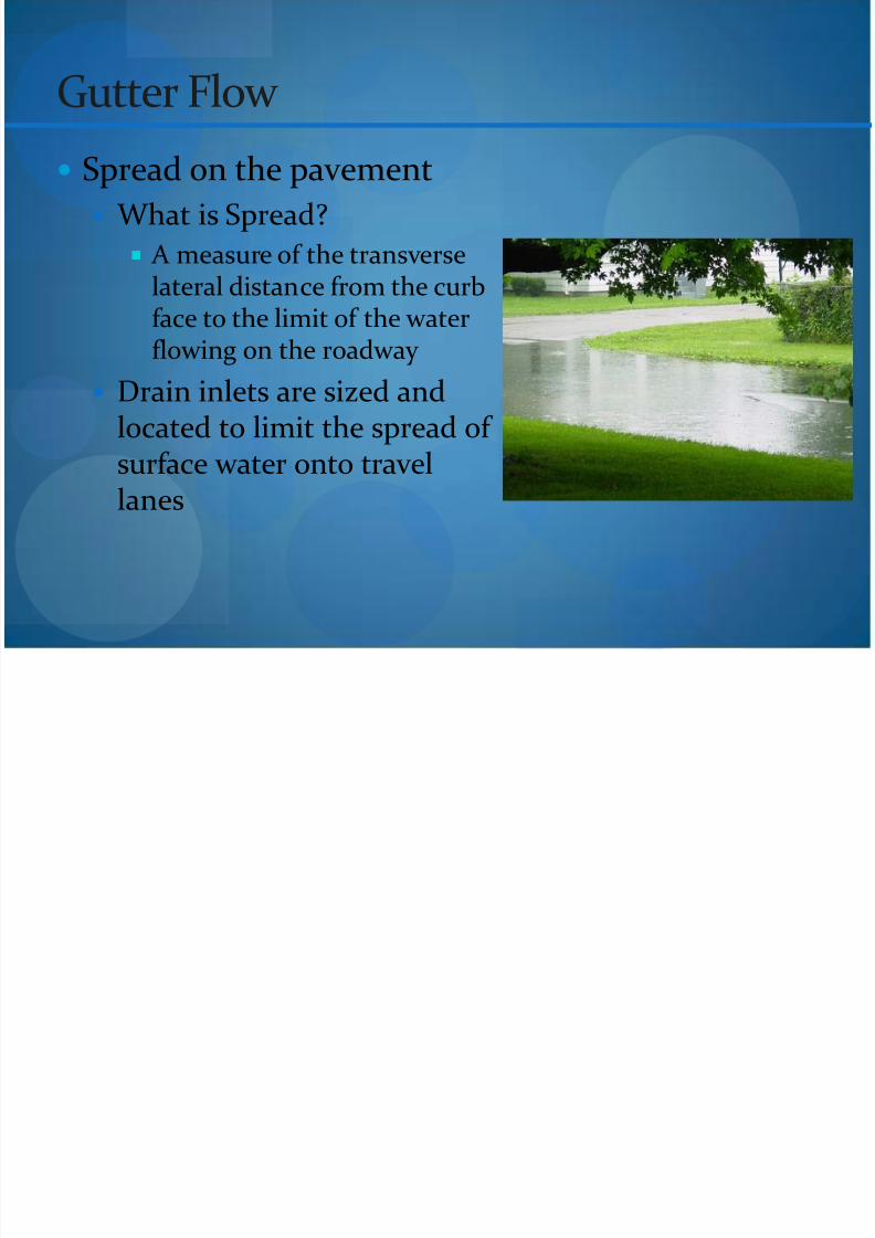
Gutter Flow
Gutter Flow is unique in the fact that you must usehydrologic as well as hydraulic methods ofanalyzing
Spread on Pavement Gutter Velocity/Slope

8/20/2019 2010-07_UrbanHydraulicDesign.pdf
http://slidepdf.com/reader/full/2010-07urbanhydraulicdesignpdf 30/37
Gutter Flow
Interception If an inlet is on grade you
must determine how muchof the flow it will intercept
Another analysis that youmight need to do isdetermine how much of theflow you want to intercept atthe specific inlet and thendepending on yoursurrounding constraintsadjust your inlet to meet the
desired intercept

8/20/2019 2010-07_UrbanHydraulicDesign.pdf
http://slidepdf.com/reader/full/2010-07urbanhydraulicdesignpdf 31/37
Gutter Flow
Flow into the inlet The easiest way to determine how water will f low, at
what rate, and how much is by using the hydrologicmethods that were previously discussed specificallythe rational method
8/20/2019 2010-07_UrbanHydraulicDesign.pdf
http://slidepdf.com/reader/full/2010-07urbanhydraulicdesignpdf 32/37

8/20/2019 2010-07_UrbanHydraulicDesign.pdf
http://slidepdf.com/reader/full/2010-07urbanhydraulicdesignpdf 33/37
Gutter Flow
Gutter Velocity/Slope Gutter Velocity is directly related to determining the
flow time in a gutter which is essential to urbandrainage design.
To determine gutter flow and velocity Manningsequations is used.

8/20/2019 2010-07_UrbanHydraulicDesign.pdf
http://slidepdf.com/reader/full/2010-07urbanhydraulicdesignpdf 34/37
HYDRAULIC GRADE LINE

8/20/2019 2010-07_UrbanHydraulicDesign.pdf
http://slidepdf.com/reader/full/2010-07urbanhydraulicdesignpdf 35/37
Hydraulic Grade Line
Up to this point of Hydraulic Design you haveanalyzed the movement of the water before andonce it gets to the pipe.
Now the level of the water within the pipe itselfmust be analyzed.

8/20/2019 2010-07_UrbanHydraulicDesign.pdf
http://slidepdf.com/reader/full/2010-07urbanhydraulicdesignpdf 36/37
Hydraulic Grade Line
What is Hydraulic Grade Line? According to HEC 22 hydraulic Grade Line is:
A line coinciding with the level of flowing water at anypoint along an open channel.
For purposes of storm drain design Hydraulic Grade Line isused to determine the acceptability of a proposed stormdrainage system by establishing the elevation to which
water will rise when the system is operation under design
conditions

8/20/2019 2010-07_UrbanHydraulicDesign.pdf
http://slidepdf.com/reader/full/2010-07urbanhydraulicdesignpdf 37/37


![(2010) · 2010. 8. 3. · Detailaruanne[30.07.2010 13:07]: Riigikogu liige: Aivar Riisalu, Kululiigid: kõik € € jaanuar (2010) veebruar (2010) märts (2010) aprill (2010) mai](https://img.dokumen.tips/doc/110x75/6106a7003ec91d28267f3cc7/2010-2010-8-3-detailaruanne30072010-1307-riigikogu-liige-aivar-riisalu.jpg)