Embed Size (px)
Citation preview
P. 1
2017 MATE International ROV Competition
(HONG KONG) - Technical Documentation
Company Name: Kwok Tak Seng Inc.
Team Name: KTSCSS Dolphin
School: Kwok Tak Seng Catholic Secondary School
City: Hong Kong, China
Team Adviser: Mr. Lee Siu Fung Mr. Hon Sze Ping Steven
Our team photo
(From Left) Chan On Shan, Chan Sze Ting, Leung Yuet Ming, Ngan Wai Sing,
Wong King Ho, Ng Kai Hei, Lee Kin Yuen Cyrus

P. 2
Abstract
Upon the request of the Port of Long Beach for proposals of a remotely-operated vehicle and
crew that can operate in confined and often precarious conditions of the port and waterfront, we
carefully design our ROV for the proposal.
The mission consists of four major categories which are Commerce, Entertainment, Health and
Safety. Our ROV is capable of tackling a variety of tasks including installation of Hyperloop
Construction, replacement of the fountain (Light and Water Show Maintenance), determination
of contaminated sediments (Environmental Cleanup), and locating and measuring the distance of
cargo containers (Risk Mitigation).
It is controlled by a PS4 game pad. All equipment is assisted by a well-designed electrical
communication system and has been tested under water. Our ROV is equipped with:
1) Six powerful brushless thrusters, for forward-backward, left-right turn movements,
left-right shift adjustments and sink-rise motion,
2) Multiple cameras were made to give driver various view simultaneously for identifying
and determination,
3) A pair of pliers (pay load) pneumatic system for grabbing and transporting objects firmly
likes pins, rods, U-bolt , power cable and etc.,
4) A rotational arm for turning of the valve,
5) A sucker for collecting a sediment sample (agar) from the contaminated area, and
6) LED lights which simulate the detection and the activation of RFID for identification of
the high-risk cargo containers.
This report lists the development process and the design details of our ROV, including the
safety, troubleshooting techniques; further improvement, reflection, as well as the project budget.
(247 words)

P. 3
Table of Contents
Abstract ................................................................................................................................................ 2
Table of Contents ................................................................................................................................. 3
I. Project Costing ..................................................................................................................... 4
II. System Integration Diagram ................................................................................................ 5
III. Design Rationale .................................................................................................................. 6
A. Framework and Buoyancy ........................................................................................... 7
B. Vehicle System ............................................................................................................ 8
1. Thrusters ............................................................................................................. 8
2. Electronic speed control (ESC) ........................................................................... 9
3. H-bridge ............................................................................................................ 10
4. Control Algorithm ............................................................................................. 11
5. Gamepad (USB Shield on Arduino) ................................................................. 12
C. Pay load - the pliers ................................................................................................... 13
D. Software ..................................................................................................................... 15
E. Camera ........................................................................................................................ 16
F. U-shaped Aluminum Rotational Arm ......................................................................... 16
G. Sucker ......................................................................................................................... 17
H. Waterproof .................................................................................................................. 17
IV. Build Vs buy, New Vs Used .............................................................................................. 18
V. Safety ................................................................................................................................. 19
VI. Challenges and Trouble Shooting Techniques ................................................................... 20
VII. Further improvement.......................................................................................................... 21
VIII. Reflection ........................................................................................................................... 22
IX. Company Social Responsibility ......................................................................................... 22
X. Project Management: ......................................................................................................... 23
XI. Reference ........................................................................................................................... 24
XII. Acknowledgement ............................................................................................................. 24

P. 4
I. Project Costing

P. 5
Reason of reusing items There are lots of items that we reuse, like motors, the controller, and the Adriano mega board. One of the most important concerns of reusing these items is to reduce the budget. Our budget is highly limited this year. Everything of our ROV has to be well-designed to fit our budgets. In facts, we reduce 40% of spence this year. In addition, the budget is not only points we concern to reuse items but also the reliability of the components, the efficiency of making new components and whether the components still fit our new design. For example, the motor for rotating arm still fits our new design of the pliers and it still working well. Therefore we design to reuse it. And also for the Arduino mega board is reused for the same reason. All reused items are tested to ensure it can still function properly.
II. System Integration Diagram
Figure 1 SID
P. 6
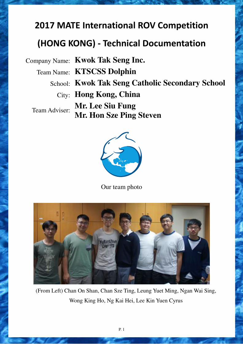
III. Design Rationale
Most of the components of our ROV are newly designed and constructed. They consist of an
external framework made by an aluminum strip as the ROV’s main body, a cylindrical camera
chamber, six water proofed thrusters as the vehicle system, a pneumatic payload (a pair of pliers), a
rotational arm and a sucker for collecting a sediment sample (agar) from the contaminated area. The
major concern of the design rationale is that the movement of ROV under water is too slow which
affected by two factors. The first one is the water resistance. The other is the power of the thrusters.
However, the above two factors are constant in the competition. 12V power and water resistance in
a swimming pool are environmental factors which cannot be changed or enhanced. As a result, the
efficiency of thrusters and the streamline design of the ROV are the two important design rationales
to encounter the affections.
To build a highly efficient ROV underwater is our major objective, as we have only 15 minutes
to complete all the tasks. From our experience in the previous years, using brushless motors is much
more efficient than brushed motors. The efficiency and speed is greatly increased. As a result, two
brushed motors responsible for vertical movement of the ROV are replaced by brushless thrusters.
The cylindrical chamber is a streamline design to reduce the water resistance affections. The
cylindrical chamber also provides a high up thrust force under water to provide a buoyant ROV.
For off-shore controlling, the control box is too bulky. To make it smaller with full functional
buttons, an PS4 game pad with two multi-directional controls and 8 buttons are adopted for
controlling all components of the ROV.
Figure 2 Font view of the ROV
Figure 2 Side view of ROV
Figure 3 Top view of ROV

P. 7
A. Framework and Buoyancy
The frame of our ROV consists of one water-proofed acrylic cylindrical chamber and some
acrylic boards and aluminum strips. The acrylic cylindrical chamber is water-proofed by adding two
O-rings and petroleum jelly between the surfaces of the acrylic plates. All components will be
affixed with acrylic boards into the main body of the ROV. The ROV frame is specifically designed
to acquire the following advantages.
First of all, the size of the ROV body frame is reduced to fix the requirement of the
specification. Each of the cameras is sealed with epoxy and enclosed in an acrylic cylindrical tube.
They are highly mobilized to fix any parts of the ROV. The tools can be attached to the exterior
frame body more easily when compared to attaching the tools onto the curved surface of the acrylic
cylinder. In addition, it is easier for us to attach and remove different tools to the ROV.
Last year, out camera and all electronic components were put together to minimize the size of
the ROV. According to the evaluation of the previous year, the view camera was blurred by the
water vapor contained in the air of the chamber. In this year, we redesigned the arrangement and the
connection of camera chamber by separating it from the main body.
The main electronic components of our ROV are placed in the waterproofed chamber. This
makes it easier to perform maintenance. The accessories, such as the pliers, are clutched to the main
ROV body. This reduces the size of our ROV significantly in order to score 20 bonus points from
the requirements which limited the size within 48 cm diameter.
In order to reduce the fluid resistance of water, we designed our ROV in a streamline shape and a small size. The center of gravity (CG)of the whole vehicle is on the middle of the vehicle, with the center of buoyancy (CB) above CG.
Figure 4 Waterproofed cylindrical chamber for storing all electronics
Moreover, since the waterproofed chamber stored the
accessories like the Arduino AT mega board, the ESC and all electronic components, it is covered
by tight screws with O-rings so that water cannot easily get inside the box. As the acrylic cylinder is

P. 8
also enclosed by two acrylic plates and two strong O-rings, water cannot easily get into the cylinder.
But we are still worried that water may slowly leak into the cylinder. As for the cable connection
holes in and out of the box, we sealed them with AB Proxy agent to make them water- proofed.
Both the waterproofed chamber provides a large up thrust force under water to provide
buoyancy of the ROV to encounter the weight of the ROV. The diameter and the length of the
acrylic cylindrical chamber have been measured carefully for providing a suitable up thrust to
encounter the total weight or the ROV.
Besides, it is easier for us to attach tools including pay load to the frame body.
B. Vehicle System
1. Thrusters The vehicle system of our ROV consists of six thrusters. The four
T200 blue robotics thrusters are used to control the movement of the
ROV in all directions including forward, backward, left-right turn and
left-right shift movement. Another two blue robotics motors T200
thrusters are used to control the float and sink of the ROV.
Figure 5 T200 Thruster
In past years, the float and sink of the propulsion system was composed of four 1100GPH bilge
pumps. It was rather reluctant to perform well and time consuming for the ROV to move to a desire
depth. In order to improve the efficiency of the vehicle system, we decided to replace them with
brushless motors which provide a more powerful propelling force to drive the movement of the
ROV. By replacing bilge pumps with brushless motors, the mobilization efficiency had been
improved greatly. In 2015, we used two Video ray thrusters for controlling the float and sink of the
ROV. In 2016, we found that the two Video ray thrusters were too large in height for our design. As
a result, we replaced them with two shorter Blue robotics T200 thrusters.
We used only two Video ray thrusters on the two
side chambers to control forward, backward, left turn and
right turn and two Blue robotics T200 thrusters to control
the float and sink of the ROV.
This year, in order to equip both the payload and the
rotational arm on the ROV, we needed to further reduce the length of the thruster. As a result, the
Figure 6 Design of the ROV in 2016

P. 9
two video ray thrusters have also been replaced by Blue robotics T200 thrusters which are smaller
in size. Moreover, our team would also like to build the ROV so that it can move in all directions
(Omni-directional movement) by attaching four thrusters arranged in four corners. Fig 4.9 shows
the design of the arrangement of the four thrusters. All four thrusters can generate both forward and
backward movement. By applying different combinations of thrusters, different resultant force will
be provided to drive the ROV to the desired location.
Figure 7 Illustration of forward movement
Figure 8 Thrusters positions of ROV
Finally, the performance of the thrusters is better than we expected. High speed movement and
all directional movements of our ROV can give us an advantage in moving and searching
throughout the competition. Through observations, each single direction of movement is governed
by four thrusters together. By comparing our previous design, two thrusters control the movement
in two directions only. Now, we have four thrusters controlling all 360 degrees of movement.
In conclusion, by using six blue robotics motors T200 thrusters, we can control the ROV much
more efficiently by moving the ROV in all directions, including up and down.
2. Electronic speed control (ESC)
By using brushless motors, an ESC must be used to drive it. An ESC is an electronic circuit
used to vary the speed, direction, and possibly used as a dynamic brake for an electric motor. ESCs
are used on electrically powered radio controlled models, and often used for brushless motors which
require electronically-generated three phase electric power.
P. 10
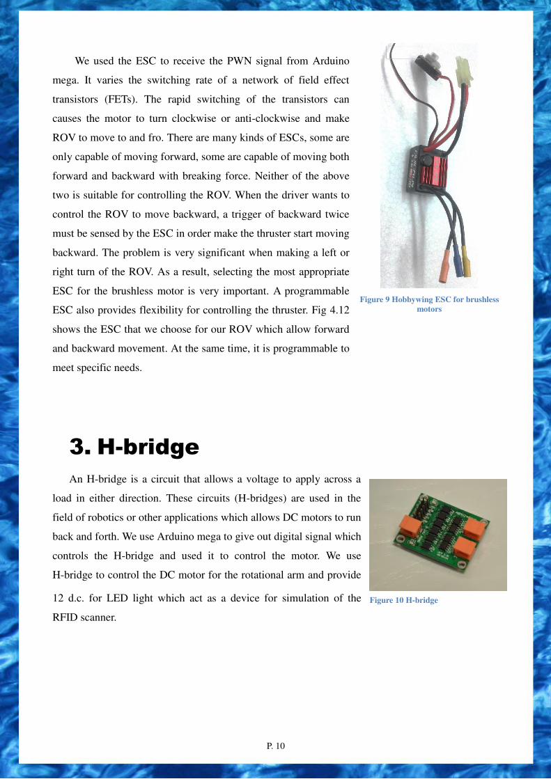
We used the ESC to receive the PWN signal from Arduino
mega. It varies the switching rate of a network of field effect
transistors (FETs). The rapid switching of the transistors can
causes the motor to turn clockwise or anti-clockwise and make
ROV to move to and fro. There are many kinds of ESCs, some are
only capable of moving forward, some are capable of moving both
forward and backward with breaking force. Neither of the above
two is suitable for controlling the ROV. When the driver wants to
control the ROV to move backward, a trigger of backward twice
must be sensed by the ESC in order make the thruster start moving
backward. The problem is very significant when making a left or
right turn of the ROV. As a result, selecting the most appropriate
ESC for the brushless motor is very important. A programmable
ESC also provides flexibility for controlling the thruster. Fig 4.12
shows the ESC that we choose for our ROV which allow forward
and backward movement. At the same time, it is programmable to
meet specific needs.
Figure 9 Hobbywing ESC for brushless motors
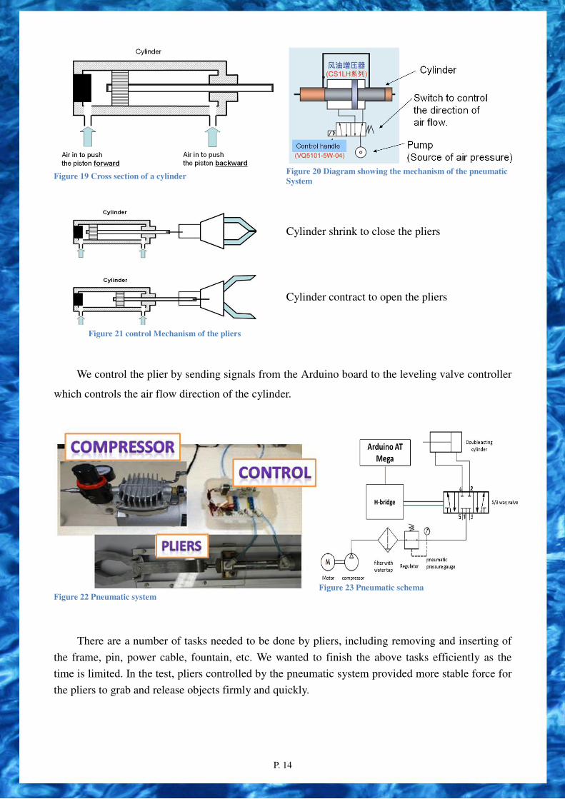
3. H-bridge
An H-bridge is a circuit that allows a voltage to apply across a
load in either direction. These circuits (H-bridges) are used in the
field of robotics or other applications which allows DC motors to run
back and forth. We use Arduino mega to give out digital signal which
controls the H-bridge and used it to control the motor. We use
H-bridge to control the DC motor for the rotational arm and provide
12 d.c. for LED light which act as a device for simulation of the
RFID scanner.
Figure 10 H-bridge

P. 11
4. Control Algorithm
We used the Arduino board to control our ROV. The ROV is controlled via the program made
for the communication between two Arduino boards, which consists of two electronic boards
Arduino Leonardo for off shore control and Arduino mega for onshore control of the all motors.
The USB shield is connected to the Arduino Leonardo. The program in the electronic board
Arduino Leonardo can convert the analogue signals of the input from the USB shield to digital
signals. When the pilot inputs analogue signals via the PS4 game pad into the offshore Arduino
control board, the program converts them into digital signals, which is then sent to the offshore
Arduino mega board in the ROV through the data transmission wires.
The Arduino mega board inside the body of the ROV then converts the digital signals sent
from the Arduino Leonardo board to control the H-bridges, the ESC, and other parts of the ROV,
where the Arduino Leonardo board establishes a communication path with Arduino mega inside the
ROV. Therefore, different parts of the ROV can be controlled via this communication algorithm.
Arduino Leonardo is a microcontroller board based on the ATmega32u4. It has 20 digital
input/output pins, a 16 MHz crystal oscillator, a micro USB connection, a power jack, an ICSP
header, and a reset button. It contains everything needed to support the microcontroller. The
Arduino mega microcontroller board can be simply powered by a 7-12V power supply to get
started. Because of the simple, open source, low cost properties of Arduino, we adopted it as the
communicator and it can process all of the commands instructed by the signal from the Arduino
Leonardo microcontroller board, which is controlled by the Arduino compatible USB compatible
devices.
The Arduino Leonardo microcontroller provides serial communication, which is available on
digital pins 0 and 1. Arduino Leonardo is used to receive both analog and digital signal from the
joystick and the buttons respectively. It (Arduino Leonardo) acts as a translator which translates the
analogue signal of the Arduino compatible joystick shield into different digital signals, which is
then sent to the Arduino mega microcontroller board inside the ROV by using the Serial library of
Arduino and the serial communication ports of Arduino boards.
Figure 11 Arduino Mega
Figure 12 Arduino Leonardo

P. 12
Arduino Mega is a microcontroller board based on the ATmega1280. It has 54 digital
input/output pins, 16 analog inputs, 4 UARTs, a 16 MHz crystal oscillator, a USB connection, a
power jack, an ICSP header, and a reset button. It contains everything needed to support the
microcontroller. It can easily be started by connecting it to a computer with a USB cable, but we
decided to use the 12V power supply as the power source of the Arduino mega is located inside the
ROV. The Arduino Mega act as a control unit of our ROV. It is used to receive the digital signal
sent from Arduino Leonardo.
Figure 13 RS485
Figure 14 testing RS485 over 30m
A 5-character message packet is made for each communication between control side and
underwater ROV. When the ROV is under the water and receives the message packet, it will decode
and interpret the data by the program in the Arduino mega and then a series of commands will be
executed according to signals received. Afterward, the ROV will behave according to the signals.
5. Gamepad (USB Shield on
Arduino)
The Arduino USB shield consists of a USB port to connect the gamepad. This joystick is used
to control the propulsion system of the ROV and other component such as the rotatable camera and
the pliers. Different actions can be performed by simply pressing two buttons at once or moving the
joystick.
Figure 15 Arduino USB shield, Arduino Leonardo
Figure 16 the PS4 gamepad

P. 13
C. Pay load - the pliers
Our pliers are designed and constructed for picking up objects and grabbing tools for the ROV.
In the past, we have made the pliers with plastic or metal pliers. The opening and closing of the
pliers was controlled by either electronic or pneumatic means. Different options have different pros
and cons. If an electronic device is used, the speed of opening and closing is slow due to applying a
high gear ratio for grabbing the object tightly. In order to make the pliers response quickly, a
pneumatic system is adopted for our pay load tool. As a result, the pliers made by metal are more
appropriate in terms of strength and durability.
A. Pliers:
The head of the pliers is made of aluminum which is lightweight. The shape is designed to
grab tightly objects under water. The pliers is controlled by pneumatics which uses air pressure to
push a cylinder to move forward and backward such that it can adjust the pliers to grab and release
objects. The pliers can be controlled remotely by pumping and releasing the air in the cylinder
through a long wire on land to change its air pressure. The pliers can open widely or close tightly.
The object can be picked up and dropped down underwater smoothly by the pliers.
Figure 17 Top view of the plier
Figure 18 Widely opened plier
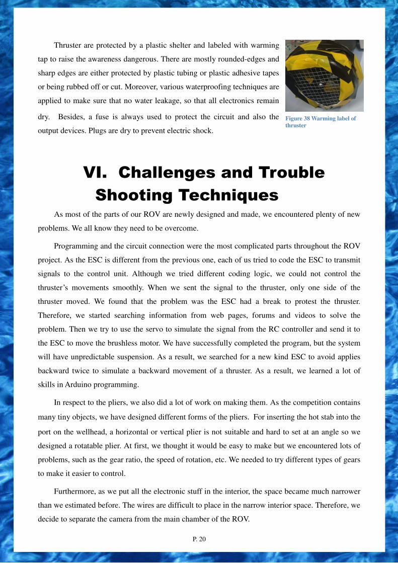
B. Pneumatics System:
The pneumatic system works based on the change in air pressure inside different parts of the
cylinder. When the pump blows air into the rear part of the cylinder, the air pressure at the rear part
increases. As the air pressure becomes stronger than that at the front, the tube inside the cylinder
separating the front and the rear part is forced to move forward. The tubing is then extended out of
the cylinder and the arm is opened. The principle is the same when making the arm close but the
pump has to push air into the front of the cylinder to force the tube to move backward.
P. 14
Figure 19 Cross section of a cylinder
Figure 20 Diagram showing the mechanism of the pneumatic System
Figure 21 control Mechanism of the pliers
Cylinder shrink to close the pliers
Cylinder contract to open the pliers
We control the plier by sending signals from the Arduino board to the leveling valve controller
which controls the air flow direction of the cylinder.
Figure 22 Pneumatic system Figure 23 Pneumatic schema
There are a number of tasks needed to be done by pliers, including removing and inserting of
the frame, pin, power cable, fountain, etc. We wanted to finish the above tasks efficiently as the
time is limited. In the test, pliers controlled by the pneumatic system provided more stable force for
the pliers to grab and release objects firmly and quickly.

P. 15
D. Software Arduino version 1.61
We used Arduino 1.6.1 to write
commands to the Arduino board, which
communicates with the board and control the
motor by the joystick. Its code is mostly based on
the C language, which make us easy to correct
and use. It also provides a wide range of standard
library, which helps us do our programming job
more easily.
Figure 24 Sample code
The program logic to control the action of the ROV is based on sending and receiving a packet
of commands. The control program will send a series of the commands as a packet over time to the
ROV. Upon receiving the packet, the ROV will interpret and execute the commands accordingly.
The following flowchart helps in describing the logic.
Figure 25 Program Control logic

P. 16
E. Camera We put 4 cameras around the ROV for the missions. There are multiple cameras is used and
positioned in various parts of the ROV in order to provide different views for the driver to
accomplish different tasks.
We decided to fixed camera with size of 2*2cm.Since it is small, it benefit in position the
camera. Previous generation of KWOK TAK SENG INC. employed IP camera and web camera, yet
the latency of the digital system (IP camera system) increased the operational difficulty. According
to Hill et al. , latency can be reduced to less than 60ms in a pure analogue system, and is less than
50% of the latency in a digital system (640X480 with 80% quality).To minimize the latency, analog
cameras are applied in the vision system this year.
Figure 26 Camera
Figure 27 Camera sealed by E-proxy
F. U-shaped Aluminum Rotational Arm A self-made U-shaped aluminum rotational arm was built in order to turn the valve wheel
handle. Since a large force will be needed to turn and close the valve, a powerful motor is needed to
give maximum torque. We adopted a much higher gear ratio motor with the attachment of the
U-shaped aluminum manipulator to turn and close the value. The rotating speed of the motor is 5
rotations per minute.
Figure 28 Camera U-shaped aluminum manipulator with high power motor
Figure 29 Camera Position of rotational arm located at the rear part of the pay load

P. 17
G. Sucker In order to collect the sediment sample from the contaminated area which is simulated by agar,
a sucker tool was made for sucking up the agar. The sucker is made by using a metallic cylinder
with a hole on the top. The top of the hole is attached with a funnel head. There is a metallic ball
trapped inside the funnel head which can freely move under water. The mechanism is that when the
sucker penetrates into the agar, the metallic ball will be sucked at the end of the funnel and a
negative pressure will be created for holding the metallic ball firmly on the opening and the agar
inside the tube will be sucked firmly as well. Hence, the agar will be sucked and stored inside the
tube. After collecting the agar on the water surface, we just need to shake the ball to release the
negative pressure, and then the agar will come out. It had been tested with the agar we made.
Figure 30 sucker
Figure 31 Mechanism of the sucker
H. Waterproof KWOK TAK SENG INC. electronic system is housed in Poly methyl m Polyethylene
ethacrylate (acrylic) tube. Both ends of the tube were sealed by high density polyethene cover.
Acrylic was selected instead of polycarbonate because acrylic has the highest transparency to light
(92%) in all type of plastic. Also, the price of acrylic is lower than polycarbonate. Acrylic does
not contain any harmful chemical bisphenol-A (BPA) like polycarbonate. BPA could affect
regulation of sexual hormones to human as well as the growth and reproduction of marine life. As
safety and public health awareness is the highest priority for Kwok Tak Seng Inc., material with
hazardous chemical is prohibited in the whole design of KWOK TAK SENG INC..
KWOK TAK SENG INC. have
tested different brands of epoxy to
select the epoxy that acquire strength
and toughness for KWOK TAK
SENG INC.. Epoxy B was selected, as
it provides balance between strength
and toughness along with a reasonable
price for our large demand.
Figure 32 Plot for transverse stress against strain among 3 different epoxy

P. 18
We use 4-pin waterproof plugs to hold all the wires we need and use tether to twist the wires
into one single tube and waterproof the wires.
The waterproof plug is the device utilizing blades which, when inserted into a waterproof
connector body, establish the connection between the conductors of the attached flexible cord and
conductors connected to the waterproof connector body, having waterproof performance of IP65
(International Protection Code).
They are useful for us since there are many wires we need to use for different aspects as they
may twist together and tie each other up. We used a lot of time to fix this problem.
Figure 33 Waterproofed plug (cross section)
Figure 34 Waterproofed plug
IV. Build Vs buy, New Vs Used In discussing the “build or buy” issue, the principle of our team is that we build as much as
possible. To purchase a complete tool from the market would cost much more and provide less fun,
even though it is time saved. We deeply believe that through the process of designing and building,
we can learn more about the mechanisms of the product, appreciate more about the product in the
market and most importantly, we can evaluate the ready-made market product. After the evaluation
of both the ready-made product and our skills of craftsmanship, we made our decision.
The following items are too expensive to purchase from market.
Figure 35 ROV body
Figure 36 Pay load (Pliers)
Figure 37 Water proofed camera
Here are tables in capered in the commercial product and self-made tool of the ROV. KWOK TAK
SENG INC. found that the commercial product are general expensive than homemade. The design
of commercial product requires further modification before adapt to KTSCSS Dolphin. Therefore
our company decided to self-made Plier and camera for KTSCSS Dolphin.

P. 19
Pay load (Pliers)
Ready-made product Self-made
Cost($) $ 2350 $370
Time use(days) About 10 About 20
Modification difficulties High Low
Maintainability Low High
Water proofed camera
Ready-made product Self-made
Cost($) $287 $80
Time use(days) About 10 About 5
Modification difficulties High Low
Maintainability Low High
As for the thrusters and ESC, it is too difficult for high school students to build them. The
self-made thruster performance was under our expectation the thrust power is not large enough.
Also the developing cost was higher than we brought a commercial product. As a result, we are
going to purchase these two items.
After series of research in the commercial product from the market, KWOK TAK SENG INC.
found that Blue-motor T200 have a high efficiency of power and most suitable to our use in
KTSCSS dolphin.
V. Safety Safety is the most important consideration during construction of the ROV, including
protecting the environment and people. When we work, we will follow our safety checklist to
minimize the possibility of accidents (cuts or bruises, electrical shocks, defective chemicals)
happening in order to protect the members. Besides our members' safety, we consider the
environment too. We have tried to build an eco-friendly ROV to protect the surrounding
environment, including the undersea creatures or sea structures, as the mission aims at conserving
the environment, so our materials are, in part, reused when possible.
We make sure our shoes are tied, toes protected and our clothes tidy, as well as safety glasses
being worn. Wires should be placed neatly and not twisted up to prevent stumbling, and tethers
added to them if possible. Tools such as scroll saws, drill beds, heat guns, etc., should be switched
off while not in use. Soldering irons and glue guns should be unplugged after use as well.
Masks and gloves are always worn when handling hazardous chemicals, like epoxy and chloroform. The process of filling epoxy was done in a good ventilation workplace and 70% Alcohol was used to clean the workplace after chemical pouring.
P. 20
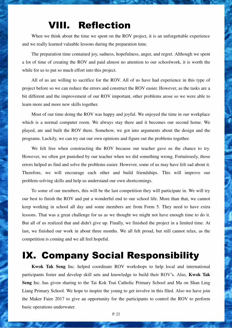
Thruster are protected by a plastic shelter and labeled with warming
tap to raise the awareness dangerous. There are mostly rounded-edges and
sharp edges are either protected by plastic tubing or plastic adhesive tapes
or being rubbed off or cut. Moreover, various waterproofing techniques are
applied to make sure that no water leakage, so that all electronics remain
dry. Besides, a fuse is always used to protect the circuit and also the
output devices. Plugs are dry to prevent electric shock.
VI. Challenges and Trouble
Shooting Techniques As most of the parts of our ROV are newly designed and made, we encountered plenty of new
problems. We all know they need to be overcome.
Programming and the circuit connection were the most complicated parts throughout the ROV
project. As the ESC is different from the previous one, each of us tried to code the ESC to transmit
signals to the control unit. Although we tried different coding logic, we could not control the
thruster’s movements smoothly. When we sent the signal to the thruster, only one side of the
thruster moved. We found that the problem was the ESC had a break to protest the thruster.
Therefore, we started searching information from web pages, forums and videos to solve the
problem. Then we try to use the servo to simulate the signal from the RC controller and send it to
the ESC to move the brushless motor. We have successfully completed the program, but the system
will have unpredictable suspension. As a result, we searched for a new kind ESC to avoid applies
backward twice to simulate a backward movement of a thruster. As a result, we learned a lot of
skills in Arduino programming.
In respect to the pliers, we also did a lot of work on making them. As the competition contains
many tiny objects, we have designed different forms of the pliers. For inserting the hot stab into the
port on the wellhead, a horizontal or vertical plier is not suitable and hard to set at an angle so we
designed a rotatable plier. At first, we thought it would be easy to make but we encountered lots of
problems, such as the gear ratio, the speed of rotation, etc. We needed to try different types of gears
to make it easier to control.
Furthermore, as we put all the electronic stuff in the interior, the space became much narrower
than we estimated before. The wires are difficult to place in the narrow interior space. Therefore, we
decide to separate the camera from the main chamber of the ROV.
Figure 38 Warming label of thruster

P. 21
We learned a lesson in waterproofing and had the experience of programming the Arduino. We
found that different electronic parts in the ROV need different types of programs. During this year
we have learned some advanced programming of Arduino. For example, we have learned how to
write a program to control a servo motor. As we didn’t have enough programing experience in the
past, we needed to do a lot of research to find out how to program the Arduino. We have learned
how to sort the data and basic data analyzing skills. We also used a CPP program to send the signal
to the Arduino board. We also learned how to use the most suitable type of Arduino board. Owing to
the various types of signal wires, chipsets and shield, especially the 25 - pin signal cable, soldering
the wires is not an easy task. Lack of spare time of the servo motor also slowed our progress. Our
programmer had to do more work at school in order to reduce the time spent on the project.
We need to plan different posts for different people. From this experience, we have learnt more
about the intensity of division of labor and also how to communicate and help each other within our
team. Lack of communication will not help us finish our work.
We also learned how to plan to put the board in our ROV. It was difficult to plan the design of
our ROV as the board has many wires, characteristics and uses.
VII. Further improvement In creating a new ROV by original and authentic materials to accomplish every task stated in
missions, we have done a lot research and interviews from past students to acquire more knowledge
about building an ROV. We adopted their advice to use high efficient thrusters with the appropriate
ESC. For further improvement, we plan to modularize each component with water-proofed
electronic plugs. Which benefit in maintained and replacing of failure parts.
The circuit board had already been redesigned to suit different electronic devices. It is
suggested that more general boards can be built to suit any other components. The circuit board
design should be designed by computer software and printed by a professional circuit board
company instead of using cables to build the circuit.
In addition, the frame could be streamlined. The streamlined shape has smooth and regular
surface without corners, and can reduce the turbulence during moving, hence reduce the water
resistance and increase the speed.
P. 22
VIII. Reflection When we think about the time we spent on the ROV project, it is an unforgettable experience
and we really learned valuable lessons during the preparation time.
The preparation time contained joy, sadness, hopefulness, anger, and regret. Although we spent
a lot of time of creating the ROV and paid almost no attention to our schoolwork, it is worth the
while for us to put so much effort into this project.
All of us are willing to sacrifice for the ROV. All of us have had experience in this type of
project before so we can reduce the errors and construct the ROV easier. However, as the tasks are a
bit different and the improvement of our ROV important, other problems arose so we were able to
learn more and more new skills together.
Most of our time doing the ROV was happy and joyful. We enjoyed the time in our workplace
which is a normal computer room. We always stay there and it becomes our second home. We
played, ate and built the ROV there. Somehow, we got into arguments about the design and the
programs. Luckily, we can try out our own opinions and figure out the problems together.
We felt free when constructing the ROV because our teacher gave us the chance to try.
However, we often got punished by our teacher when we did something wrong. Fortuitously, those
errors helped us find and solve the problems easier. However, some of us may have felt sad about it.
Therefore, we will encourage each other and build friendships. This will improve our
problem-solving skills and help us understand our own shortcomings.
To some of our members, this will be the last competition they will participate in. We will try
our best to finish the ROV and put a wonderful end to our school life. More than that, we cannot
keep working in school all day and some members are from Form 5. They need to have extra
lessons. That was a great challenge for us as we thought we might not have enough time to do it.
But all of us realized that and didn't give up. Finally, we finished the project in a limited time. At
last, we finished our work in about three months. We all felt proud, but still cannot relax, as the
competition is coming and we all feel hopeful.
IX. Company Social Responsibility Kwok Tak Seng Inc. helped coordinate ROV workshops to help local and international
participants foster and develop skill sets and knowledge to build their ROV’s. Also, Kwok Tak
Seng Inc. has given sharing to the Tai Kok Tsui Catholic Primary School and Ma on Shan Ling
Liang Primary School. We hope to inspire the young to get involve in this filed. Also we have join
the Maker Faire 2017 to give an opportunity for the participants to control the ROV to perform
basic operations underwater.

P. 23
Figure 39 Cooperation of teams in making ROV
Figure 40 Making of ROV
X. Project Management:
Figure 41 Gantt Chart
To complete the development of KWOK TAK SENG INC. on time, a Gantt chart is used for
scheduling generic resources as well as for project management. The CEO of KWOK TAK SENG
INC. delegates responsibility for the heads of each departmental unit at each workday, who in turn
lead their corresponding employees in building tasks and deliverables required by MATE before
reviewing and updating the chart. Deadlines are encouraged to meet where on unreached goals,
employees worked between workdays and those who done their tasks on time nicely and skillfully
could be motivated to take parts in other interesting duty to help them develop their interest and
practical skills.

P. 24
XI. Reference
1. ROV Competition, Marine Advanced Technology Education,
http://www.marinetech.org/rov-competition
2. "Special issue on video surveillance",
IEEE Trans. Circuits Syst. Video Technol., vol. 17, no. 8, pp. 1093-1093, 2007.
3. Underwater Robotics Science, Design & Fabrication
by Steven W. Moore, Harry Bohm, Vickie Jensen
4. http://www.videoray.com/homepage/thrusters-3.html
5. http://arduino.cc/en/Main/arduinoBoardLeonardo
6. http://www.svseeker.com
7. http://cs.stanford.edu/group/manips/projects/redsearobotics.html
XII. Acknowledgement KWOK TAK SENG INC. would like to express their deepest gratitude to the following sponsors: Kwok Tak Seng Catholic Secondary School for the funding and support, Department of Electrical Engineering, PolyU– for providing mentor tour; MATE Center – for organizing the international competition, providing a platform for the growth of the entire community, and being the origins of the competition; The Institution of Engineering and Technology, Hong Kong – for organizing the Hong Kong/Asia Regional of the MATE International ROV Competition.

P. 25
Appendix I - Budget Category Estimation (US$)
Administration 125
High power Thruster 975
ROV main body 170
Camera 37.5
Electronics 125
Cable 80
Others 200
1712.5
Appendix II - Safety Checklist


![Akzo Nobel NV v Competition Commission [2013] CAT 13 · PDF fileAKZO NOBEL N.V. Applicant - v - COMPETITION COMMISSION ... Mr Mario Siragusa and Mr Paul Gilbert ... acquisition by](https://img.dokumen.tips/doc/110x75/5a90222c7f8b9a085a8e15c2/akzo-nobel-nv-v-competition-commission-2013-cat-13-akzo-nobel-nv-applicant.jpg)


![SemiconductorDevicePhysics_4pt3 [Sze]](https://img.dokumen.tips/doc/110x75/553d7f8c550346792d8b4699/semiconductordevicephysics4pt3-sze.jpg)