Embed Size (px)
Citation preview

TABLE OF CONTENTS
Table of Contents............................................................................................................................ 1
List of Figures ................................................................................................................................. 5 67-1A Use of Integral End Bents............................................................................................. 5 67-1B Suggested Integral End Bent Details (Beams Attached Directly To Piling, Method A)
......................................................................................................................................... 5 67-1C Suggested Integral End Bent Details (Beams Attached to Concrete Cap, Method B) . 5 67-1C(1) Suggested Semi-Integral End Bent Details, Method 1............................................. 5 67-1C(2) Suggested Semi-Integral End Bent Details, Method 2............................................. 5 67-1C(3) Joint Membrane Detail ............................................................................................. 5 67-1D Pavement Ledge Detail................................................................................................. 5 67-1E Pavement Ledge Detail ................................................................................................. 5 67-1F Non-Integral End Bent (Deck with Expansion Joint) ................................................... 5 67-1G Non-Integral End Bent (Deck without Expansion Joint).............................................. 5 67-1H Typical Wingwall Details ............................................................................................. 5 67-2A(1) Flared-Wing Lengths and Elevations, Square Structure.......................................... 5 67-2A(2) Flared-Wing Lengths and Elevations, Structure Skewed to Right .......................... 5 67-2A(3) Flared-Wing Lengths and Elevations, Structure Skewed to Left............................. 5 67-2B Flared-Wing Lengths and Elevations Example ............................................................ 5 67-2C(1) Flared-Wing Corner Dimensions, Square Structure ................................................ 5 67-2C(2) Flared-Wing Corner Dimensions, Structure Skewed to Right................................. 5 67-2C(3) Flared-Wing Corner Dimensions, Structure Skewed to Left ................................... 5 67-2D Typical Abutment Details............................................................................................. 5 67-3A Extended Pile Bent ....................................................................................................... 5 67-3B Wall Pier on Single Row of Piles ................................................................................. 5 67-3C Hammerhead Pier.......................................................................................................... 5 67-3D Geometrics for Frame Bent with Solid Stub Wall........................................................ 5 67-3E Geometrics for Frame Bent with Individual Crashwalls............................................... 5 67-3E(1) Step Cap.................................................................................................................... 5 67-3F Suggested Reinforcing Details for Wall or Hammerhead Pier In Seismic Zone 1 ....... 5 67-4A Summary of Expansion Bearing Capabilities............................................................... 5 67-4B Strains in a Steel Reinforced Elastomeric Bearing ....................................................... 5 67-4C Elastomeric Bearing Pad or Assembly Types, Properties, and Allowable Values for
AASHTO I-Beams .......................................................................................................... 5 67-4D Elastomeric Bearing Pad or Assembly Types, Properties, and Allowable Values for
Box Beams ...................................................................................................................... 5 67-4E Elastomeric Bearing Pad or Assembly Types, Properties, and Allowable Values for
Indiana Bulb-Tee Members............................................................................................. 5 67-4F Elastomeric Bearing Pad or Assembly Types, Properties, and Allowable Values for
Structural-Steel Members................................................................................................ 5
2009
67-4G Nominal Shear Resistance of Anchor Bolts and Pintles............................................... 5 67-4G(1) Minimum Connections for Fixed Steel Shoes ......................................................... 5 67-4H Fixed Shoe Assembly ................................................................................................... 6 67-4I Elastomeric Bearing Assembly ...................................................................................... 6 67-4J Elastomeric Bearing Assembly...................................................................................... 6 67-4K Elastomeric Bearing Assembly with Bottom Plate ...................................................... 6 67-4L PTFE Elastomeric Bearing Assembly........................................................................... 6 67-5A Typical Bridge Section (Concrete I-Beam Example)................................................... 6 67-5B Fillet Dimensions for Concrete Beam........................................................................... 6 67-5C Seat Elevations for Concrete I-Beam Example ............................................................ 6 67-5D Typical Bridge Section (Built-Up Plate Girder Example)............................................ 6 67-5E Seat Elevations (Steel Beam or Plate Girder) ............................................................... 6 67-5F Fillet Dimensions for Steel Beam ................................................................................. 6 67-5G Seat Elevations for Steel Beam or Plate Girder Example............................................. 6
Chapter Sixty-seven........................................................................................................................ 7
67-1.0 SPILL-THROUGH END BENT........................................................................................ 7 67-1.01 Integral End Bent........................................................................................................ 7
67-1.01(01) General............................................................................................................7 67-1.01(02) Usage for a New Structure.............................................................................7 67-1.01(03) Usage for an Existing Structure ......................................................................8 67-1.01(04) General Design Criteria ..................................................................................8 67-1.01(05) Superstructure and Interior Substructure Design Criteria...............................9 67-1.01(06) Design Requirements [Rev. July 2008] ..........................................................9 67-1.01(07) Plan Details ...................................................................................................10
67-1.02 Non-Integral End Bent.............................................................................................. 11 67-1.02(01) Usage.............................................................................................................11 67-1.02(02) Mudwall ........................................................................................................11 67-1.02(03) Epoxy-Coated Reinforcing Steel ..................................................................11 67-1.02(04) Connection to Reinforced-Concrete Bridge Approach.................................11 67-1.02(05) Beam and Mudwall Slots ..............................................................................11 67-1.02(06) Design Requirements ....................................................................................12
67-1.03 Pile Spacings and Loads ........................................................................................... 12 67-1.03(01) General Design Criteria ................................................................................12 67-1.03(02) Live-Load Distribution .................................................................................13 67-1.03(03) Integral End Bent ..........................................................................................13 67-1.03(04) Non-Integral End Bent..................................................................................14
67-1.04 Wingwalls................................................................................................................. 14 67-1.05 Drainage.................................................................................................................... 15 67-1.06 Joints......................................................................................................................... 15
67-1.06(01) Construction Joint .........................................................................................15 67-1.06(02) Longitudinal Open Joint ...............................................................................15
67-1.07 Concrete.................................................................................................................... 16
2009
67-1.08 Semi-Integral End Bents [Added Jan. 2009] ............................................................ 16
67-2.0 CANTILEVER ABUTMENT AND WINGWALLS....................................................... 16 67-2.01 Usage ........................................................................................................................ 16 67-2.02 Loads ........................................................................................................................ 16 67-2.03 General Design Criteria ............................................................................................ 17 67-2.04 Drainage.................................................................................................................... 18 67-2.05 Construction Joints ................................................................................................... 19 67-2.06 Details....................................................................................................................... 19
67-3.0 INTERIOR SUPPORTS................................................................................................... 19 67-3.01 Types ........................................................................................................................ 19
67-3.01(01) Extended-Pile or Drilled-Shaft Bent.............................................................19 67-3.01(02) Stem-Type Pier .............................................................................................20 67-3.01(03) Frame Bent....................................................................................................20
67-3.02 Usage ........................................................................................................................ 20 67-3.03 General Design Considerations ................................................................................ 21 67-3.04 Specific Design Criteria............................................................................................ 23
67-3.04(01) Extended-Pile Bent .......................................................................................23 67-3.04(02) Hammerhead Pier..........................................................................................23 67-3.04(03) Frame Bent....................................................................................................24
67-3.05 Compression ............................................................................................................. 24
67-4.0 BEARINGS ...................................................................................................................... 25 67-4.01 General...................................................................................................................... 25 67-4.02 Fixed Steel Bearings................................................................................................. 28 67-4.03 Elastomeric Bearing Pads and Steel-Reinforced Elastomeric Bearings................... 28
67-4.03(01) Elastomer ......................................................................................................29 67-4.03(02) Steel-Reinforced Elastomeric Bearing Pads .................................................29 67-4.03(03) Elastomeric Bearing Pads .............................................................................30
67-4.04 Standardized Elastomeric Bearing Pads and Assemblies [Rev. Dec. 2008] ............ 31 67-4.04(01) Standard Pad and Assembly Types [Rev. Dec. 2008] ..................................31 67-4.04(02) Design Parameters [Rev. Dec. 2008]............................................................32 67-4.04(03) Determining Standard Bearing-Device Type [Rev. Dec. 2008] ...................32
67-4.05 Nonstandardized Elastomeric Bearing Device [Rev. Dec. 2008] ............................ 34 67-4.05(01) Load Capacity [Rev. Dec. 2008]...................................................................35 67-4.05(02) Expansion-Length Limit [Rev. Dec. 2008]...................................................36 67-4.05(03) Slope Limitations [Rev. Dec. 2008] .............................................................37
67-4.06 Seismic Design ......................................................................................................... 39 67-4.06(01) Application....................................................................................................39 67-4.06(02) Zone 1 Criteria ..............................................................................................39 67-4.06(03) Connections for Fixed Steel Shoes ...............................................................40 67-4.06(04) Connections for Pot Bearings .......................................................................40 67-4.06(05) Connections for Elastomeric Bearings and PTFE/Elastomeric Bearings .....40
2009

67-4.06(06) Shear Keys at Semi-Fixed Prestressed I-Beam and Adjacent Box Beam Bearings .......................................................................................................................41
67-4.06(07) Seismic Isolation Bearings............................................................................42 67-4.07 Bearing-Assembly Details........................................................................................ 42
67-5.0 BRIDGE-SEAT ELEVATIONS ...................................................................................... 42 67-5.01 General...................................................................................................................... 42 67-5.02 Examples .................................................................................................................. 43
2009
LIST OF FIGURES Figure Title 67-1A Use of Integral End Bents 67-1B Suggested Integral End Bent Details (Beams Attached Directly To Piling, Method A) 67-1C Suggested Integral End Bent Details (Beams Attached to Concrete Cap, Method B) 67-1C(1) Suggested Semi-Integral End Bent Details, Method 1 67-1C(2) Suggested Semi-Integral End Bent Details, Method 2 67-1C(3) Joint Membrane Detail 67-1D Pavement Ledge Detail 67-1E Pavement Ledge Detail 67-1F Non-Integral End Bent (Deck with Expansion Joint) 67-1G Non-Integral End Bent (Deck without Expansion Joint) 67-1H Typical Wingwall Details 67-2A(1) Flared-Wing Lengths and Elevations, Square Structure 67-2A(2) Flared-Wing Lengths and Elevations, Structure Skewed to Right 67-2A(3) Flared-Wing Lengths and Elevations, Structure Skewed to Left 67-2B Flared-Wing Lengths and Elevations Example 67-2C(1) Flared-Wing Corner Dimensions, Square Structure 67-2C(2) Flared-Wing Corner Dimensions, Structure Skewed to Right 67-2C(3) Flared-Wing Corner Dimensions, Structure Skewed to Left 67-2D Typical Abutment Details 67-3A Extended Pile Bent 67-3B Wall Pier on Single Row of Piles 67-3C Hammerhead Pier 67-3D Geometrics for Frame Bent with Solid Stub Wall 67-3E Geometrics for Frame Bent with Individual Crashwalls 67-3E(1) Step Cap 67-3F Suggested Reinforcing Details for Wall or Hammerhead Pier In Seismic Zone 1 67-4A Summary of Expansion Bearing Capabilities 67-4B Strains in a Steel Reinforced Elastomeric Bearing 67-4C Elastomeric Bearing Pad or Assembly Types, Properties, and Allowable Values for AASHTO I-Beams 67-4D Elastomeric Bearing Pad or Assembly Types, Properties, and Allowable Values for Box Beams 67-4E Elastomeric Bearing Pad or Assembly Types, Properties, and Allowable Values for Indiana Bulb-Tee Members 67-4F Elastomeric Bearing Pad or Assembly Types, Properties, and Allowable Values for Structural-Steel Members 67-4G Nominal Shear Resistance of Anchor Bolts and Pintles 67-4G(1) Minimum Connections for Fixed Steel Shoes
2009

67-4H Fixed Shoe Assembly 67-4I Elastomeric Bearing Assembly 67-4J Elastomeric Bearing Assembly 67-4K Elastomeric Bearing Assembly with Bottom Plate 67-4L PTFE Elastomeric Bearing Assembly 67-5A Typical Bridge Section (Concrete I-Beam Example) 67-5B Fillet Dimensions for Concrete Beam 67-5C Seat Elevations for Concrete I-Beam Example 67-5D Typical Bridge Section (Built-Up Plate Girder Example) 67-5E Seat Elevations (Steel Beam or Plate Girder) 67-5F Fillet Dimensions for Steel Beam 67-5G Seat Elevations for Steel Beam or Plate Girder Example
2009
CHAPTER SIXTY-SEVEN
BENTS, PIERS, AND ABUTMENTS
References shown following section titles are to the AASHTO LRFD Bridge Design Specifications. LRFD Bridge Design Specifications Section 11 discusses the design requirements of bents, piers, and abutments. This Chapter describes supplementary information on the design of these structural components. See Section 59-2.0 for more information on substructure types and their selection. 67-1.0 SPILL-THROUGH END BENT Spill-through end bents are the most common form of bridge end support treatment presently used. A spill-through end bent may be designed as one of two types: integral end bent (without joint between substructure and superstructure), or non-integral end bent (with joint). These are discussed in this Section. See Section 59-2.0 for more information on spill-through end bents. 67-1.01 Integral End Bent 67-1.01(01) General Traditionally, bridges have been designed with expansion joints or other structural releases that allow the superstructure to expand and contract relatively freely with changing temperatures and other geometric effects. Integral end bents eliminate expansion joints in the bridge deck, which reduce both the initial construction costs and subsequent maintenance costs. The use of integral end bents is very effective in accommodating the horizontal seismic forces of Seismic Performance Zone 1 or 2. Minimum support-length requirements need not be investigated for an integral-end-bent bridge. 67-1.01(02) Usage for a New Structure Integral end bents should be used for a new structure in accordance with the geometric limitations provided in Figure 67-1A.
2009

67-1.01(03) Usage for an Existing Structure For an existing bridge without integral end bents, the design criteria shown in Figure 67-1A should be used when evaluating the conversion to an integral-end-bent structure. For additional information, see Section 72-3.04. 67-1.01(04) General Design Criteria The following requirements must be satisfied. 1. Backfill. Each integral end bent for a beam or girder type superstructure should be
backfilled with coarse aggregate, under the pay item, aggregate for end bent backfill. Each reinforced concrete slab bridge end bent should be backfilled with flowable backfill material. The INDOT Standard Drawings provide backfill details for both concrete slab and beam or girder type structures.
The total estimated quantity of flowable backfill or aggregate for end bent backfill should be shown on the Layout Sheet.
2. Bridge Approach. A reinforced-concrete bridge approach, anchored to the end bent with
epoxy coated #5 bars spaced at 1’-0” centers, should be used at each integral end bent regardless of the traffic volume. The bars should extend out of the pavement ledge as shown in Figures 67-1B and 67-1C. Two layers of polyethylene sheeting should be placed between the reinforced-concrete bridge approach and the subgrade. A rigid reinforced-concrete bridge approach is necessary to prevent compaction of the backfill behind the end bent.
3. Bridge-Approach Joint. A 2-ft wide terminal joint or pavement relief joint should be
used at the roadway end of the reinforced-concrete bridge approach if a portion of the adjacent pavement section is concrete. A joint is not required if the entire adjacent pavement section is asphalt.
4. Wingwall Configuration. Wingwalls should extend parallel to the centerline of roadway.
This configuration reduces the loads imposed upon the bridge structure due to passive earth pressure from the end bent backfill.
5. Wingwall Connection. The connection between the wingwall and the end bent cap
should be treated as described below. The wingwall should not extend more than 10 ft behind the rear face of the cap. If longer extensions are necessary, force effects in the
2009

connection between the wingwall and cap, and in the wingwall itself, should be investigated, and adequate reinforcing steel should be provided.
6. Interior Diaphragms for Steel Structure. Where steel beams or girders are used, an
interior diaphragm should be placed within 10 ft of the end support to provide beam stability prior to and during the deck pour.
67-1.01(05) Superstructure and Interior Substructure Design Criteria Although each end of the superstructure is monolithically attached to an integral end bent, the rotation permitted by the piles is sufficiently high, and the attendant end moment sufficiently low, to justify the assumption of a pinned-end condition for design. The following design assumptions should be considered. 1. Ends. The ends of the superstructure are free to rotate and translate longitudinally. 2. Passive Earth Pressure. The restraining effect of passive earth pressure behind the end
bents should be neglected when considering superstructure longitudinal force distribution to the interior piers.
3. Interior Pile Bents. All longitudinal forces from the superstructure are to be disregarded
when designing an interior pile bent or a thin-wall pier on a single row of piles. 4. Shears and Moments. Force effects in the cap beam may be determined on the basis of a
linear distribution of vertical pile reactions. For minimum reinforcement, the cap should be treated as a structural beam.
67-1.01(06) Design Requirements [Rev. July 2008] An integral end bent may be constructed using either of the following methods. 1. Method A. The superstructure beams are placed on and attached directly to the end-bent
piling. The entire end bent is then poured at the same time as the superstructure deck. This is the preferred method.
2. Method B. The superstructure beams are set in place and anchored to the previously cast-
in-place end-bent cap. The concrete above the previously cast-in-place cap should be poured at the same time as the superstructure deck.
2009

Optional construction joints may be placed in the end bent cap to facilitate construction. The optional joint below the bottom of beam may be used regardless of bridge length. The optional construction joint at the pavement-ledge elevation shown in Figures 67-1B and 67-1C allows the contractor to pour the reinforced-concrete bridge approach with the bridge deck. Regardless of the method used, the end bent should be in accordance with the following: 1. Width. The width should not be less than 2.5 ft. 2. Cap Embedment. The embedment of piles into the cap should be 2 ft. The embedded
portion should not be wrapped with polystyrene. 3. Beam Attachment. The beams should be physically attached to the piling if using
Method A, or to the cast-in-place cap if using Method B. 4. Beam Extension. The beams should extend at least 1.67 ft into the bent, as measured
along the centerline of the beam. 5. Concrete Cover. Concrete cover beyond the farthest most edge of the beam at the rear
face of the bent should be at least 4 in. This minimum cover should also apply to the pavement ledge area. The top flanges of steel beams and prestressed I-beams may be coped to meet this requirement. Where the 4-in. minimum cover cannot be maintained within a 2.5-ft cap, the cap should be widened.
6. Stiffener Plates. Steel beams or girders should have 5/8-in. stiffener plates welded to
both sides of their webs and to the flanges over the supports to anchor the beams into the concrete. A minimum of three holes should be provided through the webs of steel beams or girders. Two holes should be provided through prestressed I-beam webs near the front face of the bent, to allow #6 bars to be inserted to further anchor the beam to the cap. Box beams should have two threaded inserts placed in each side face for anchorage of #7 threaded bars.
7. Reinforcement. The minimum size of stirrups should be #6 spaced at a maximum of 1’-
0”. Longitudinal cap reinforcing should be #7 at 1’-0” maximum spacing along both faces of the bent. All reinforcing steel should be epoxy coated.
8. Corner Bars. Corner bars should extend from the rear face of the cap into the top of the
deck at not more than 1’-0” spacing as shown in Figures 67-1B and 67-1C. 67-1.01(07) Plan Details
2009

Section 62-3.0 includes suggested details for integral end bents with a reinforced concrete slab bridge. Figures 67-1B and 67-1C show suggested details for integral end bents with a structural-members bridge. Other reinforcing and connection details should be considered and used where they are structurally sound and afford a definite advantage if compared to those shown in the Figures. 67-1.02 Non-Integral End Bent 67-1.02(01) Usage A non-integral end bent should be used where an integral end bent is not appropriate. It should be backfilled with coarse aggregate material, under the pay item, aggregate for end bent backfill. The INDOT Standard Drawings show backfill details for beam or girder type structures. 67-1.02(02) Mudwall A mudwall should be 1 ft wide with minimum vertical reinforcing steel of #4 at 1”-0”. For a mudwall greater than 5 ft height, or for a mudwall with large joint forces, the designer should investigate the mudwall reinforcement. 67-1.02(03) Epoxy-Coated Reinforcing Steel For an end bent with a bridge-deck expansion joint located between the end of the deck and the face of the mudwall, all reinforcing steel in the end bent should be epoxy coated. This includes all cap, mudwall, and, if present, wingwall reinforcing. 67-1.02(04) Connection to Reinforced-Concrete Bridge Approach The reinforced-concrete bridge approach should be connected to the adjacent mudwall with epoxy-coated #5 bars spaced at 1’-0” centers. The bars should extend out of the pavement ledge as shown in Figure 67-1D. For details of the connection of a reinforced-concrete bridge approach carried over the top of a mudwall, see Figure 67-1E. 67-1.02(05) Beam and Mudwall Slots Beam slots (concrete channels) may be formed into the top of the end bent cap to provide lateral restraint for beams which do not have side restraint provided by the bearings or other means.
2009

The vertical face of the slot should extend a minimum of 2 in. above the bottom of beam or bearing plate. A height of 6 in. will often suffice. If a concrete deck is carried over the top of a mudwall, channel slots may be provided in the top of the mudwall to provide lateral restraint for the superstructure. The latter technique is used for a bridge rehabilitation project, and may be used for a new bridge that exceeds the skew limits, but not the length limits, for integral end bents. Figure 67-1F provides a schematic diagram of beam slots at a non-integral end bent with a deck expansion joint. Figure 67-1G provides a schematic diagram of mudwall slots at a jointless, non-integral end bent. 67-1.02(06) Design Requirements Figure 67-1F provides suggested details for a pile cap with minimum cap thickness for a jointed, non-integral end bent. Figure 67-1G provides suggested details for a pile cap with minimum cap thickness for a jointless, non-integral end bent. 67-1.03 Pile Spacings and Loads 67-1.03(01) General Design Criteria The following criteria apply to piling for an integral or non-integral end bent. 1. Pile Spacing. Pile spacing should not exceed 10 ft. If the cap is properly analyzed and
designed as a continuous beam, this restriction need not apply. If practical, one pile may be placed beneath each girder. To reduce force effects for a large beam spacing, consideration may be given to twin piles under the beam, spaced at not less than 2.5 ft. See Chapter Sixty-six for minimum pile spacing. For an integral end bent within the limits defined in Figure 67-1A, or for a non-integral end bent, the piles are considered to be free ended and capable of resisting only horizontal and vertical forces.
2. Number. The number of piles per support should not be less than four. Three piles per
support may be used for a local-public-agency structure if the agency has documented its approval of a three-beam or -girder superstructure.
3. Cap Overhang. The minimum cap overhang should be 1.5 ft. 4. Pile Overload. If an individual pile is overloaded due to the maximum beam or girder
loads, the overload amount may be considered equally distributed to the two adjacent piles provided that this distribution of overloads does not cause either of the adjacent
2009
piles to exceed its allowable bearing capacity. This distribution of overload will be permitted only if the allowable bearing value for the pile is based upon the capacity of the soils and not on the structural strength of the pile, and if the pile cap has enough beam strength to distribute the overload to the adjacent piles.
67-1.03(02) Live-Load Distribution The wheel loads located out in the span should be distributed to the substructure in accordance with the live-load distribution factors shown in LRFD Specifications Article 4.6.2.2.2. For wheels located over the support, a simple-span transverse distribution should be used. 67-1.03(03) Integral End Bent The following criteria apply specifically to piles and loads at an integral end bent. 1. Loads and Forces. Only vertical loads may be considered when designing end-bent
piling for a structure which satisfies the requirements provided in Figure 67-1A. Force effects in the end-bent piles due to temperature, shrinkage, creep, and horizontal earth pressures may be neglected.
An alternative analysis must be used if the criteria in Figure 67-1A are not met. The following steps should be considered in this analysis.
a. The point of zero movement should be established by considering the elastic
resistance of all substructure elements and bearing devices. b. The effects of creep, shrinkage, and temperature should be considered. c. Movement at any point on the superstructure should be taken as being
proportional to its distance to the point of zero movement. d. Lateral curvature of the superstructure may be neglected if it satisfies LRFD
Bridge Design Specifications Article 4.6.1.2. e. Vertical force effects in the end-bent piles should be distributed linearly with load
eccentricities properly accounted for. f. Lateral soil resistance should be considered in establishing force effects and
buckling resistance of piles. Force effects should be combined in accordance with LRFD Specifications Article 3.4.1.
2. Pile Type. Only steel H-piles or steel-encased concrete piles should be used with an
integral end bent. Steel H-pile webs should be placed perpendicular to the centerline of the structure to minimize flexural forces in the piling. All end bent piling should be driven vertically. Only one row of piling is permitted.
2009

3. Hard Soils. Where an existing cohesive earth stratum, with a standard penetration
resistance, N, exceeding 35 blows per foot, is located within the 10-ft interval below the bottom of the cap, the pile should be placed in an oversized predrilled hole before driving. The predrilled hole should extend 8 ft below the bottom of the cap. The minimum diameter of the oversized hole should be 4 in. greater than the maximum cross-sectional dimension of the pile. The hole should be backfilled with uncrushed coarse aggregate size No. 12 following the pile-driving operation.
67-1.03(04) Non-Integral End Bent The following criteria apply to piles at a non-integral end bent. 1. Pile Spacing. The minimum pile spacing is 2.5 ft parallel to the centerline of the bent.
For a structure with deep girders, two rows of piles with a staggered pile spacing should be considered.
2. Batter. Up to one-half of the piles may be battered to increase the overturning stability of
the structure. 3. Overturning. If the pile spacing is less than 10 ft and one-half of the piles are battered, no
investigation is needed for overturning. If less than one-half of the piles are battered or if pile spacing is 10 ft or greater, the stability due to overturning pressures should be investigated.
67-1.04 Wingwalls With respect to a spill-through end bent, the following applies to wingwalls. 1. Usage. Each steel or prestressed-concrete beam bridge requires wingwalls. A
reinforced-concrete slab bridge usually does not require wingwalls. 2. Dimensions. Wingwalls should be of sufficient length and depth to prevent the roadway
embankment from encroaching onto the stream channel or clear opening. The slope of the fill should not be steeper than 2:1 (H:V). Wingwall lengths can be established on this basis. See Figure 67-1H for suggested wingwall dimensioning details. The minimum thickness of a wingwall used with a spill-through end bent should be 1 ft.
2009
3. Pile Support. If wingwalls for a non-integral end bent have a total length of more than 15 ft, pile support should be investigated. Pile-supported wings should not be used with an integral end bent.
4. Design. Each non-pile-supported wingwall should be designed as a horizontal
cantilevered wall. Because the wingwalls are rigidly attached to the remainder of the bent, the bent is restrained from deflecting except laterally as a unit. Due to the lack of the usual retaining-structure rotation, the active soil pressure condition cannot develop, and the design soil pressure must be increased to a value between the active and at-rest condition. Therefore, the horizontal earth pressure to be used in design should be equal to 150 percent of the value determined assuming an active-soil condition. Live-load surcharge should be added to soil loads in accordance with LRFD Bridge Design Specifications Article 3.11.6.2.
67-1.05 Drainage See the INDOT Standard Drawings for details of drainage-pipes placement behind an end bent. 67-1.06 Joints 67-1.06(01) Construction Joint The following applies to a construction joint at a spill-through end bent. 1. Type. Use construction joint type A for each horizontal construction joint. See the
INDOT Standard Drawings. 2. Integral. See Figures 67-1B and 67-1C for construction-joint use at an integral end bent. 3. Non-Integral. See Figures 67-1F and 67-1G for construction-joint use at a non-integral
end bent. A construction joint cannot be placed higher than the pavement ledge. 67-1.06(02) Longitudinal Open Joint If the bridge deck includes a longitudinal open joint, also place an expansion joint in the end bent. Also, place flashing behind the joint in the end bent. See the INDOT Standard Drawings.
2009

67-1.07 Concrete 1. Integral End Bent. Concrete should be Class C. 2. Non-Integral End Bent. Concrete should be Class A, unless the concrete is detailed to be
poured with the deck. If so, the class of concrete should be the same as that of the deck. 3. Wingwalls. For a non-integral end bent, the concrete should be Class A unless otherwise
designated. For an integral end bent, the concrete should be Class C. 67-1.08 Semi-Integral End Bents [Added Jan. 2009] Semi-integral end bents should be considered for each bridge for which integral end bents are not practical or feasible. For a skew angle of greater than 30 deg, or an expansion length of 250 ft or longer, twisting or racking of the bridge should be investigated. Figure 67-1C(1) shows details for Method 1, Figure 67-1C(2) shows details for Method 2, and Figure 67-1C(3) shows details for the joint-protection sheeting. All applicable information shown in the figures should be shown on the plans. 67-2.0 CANTILEVER ABUTMENT AND WINGWALLS See Section 59-2.0 for more information on the selection and design of abutments. 67-2.01 Usage For soil conditions or bridge geometric dimensions not suitable for a spill-through end bent or mechanically-stabilized earth abutment, an abutment with wingwalls of the cantilever type should be used. Such a cantilever structural unit should be founded on a spread footing, drilled shafts, or a driven-pile footing with a minimum of two rows of piles. The front row of piles may be battered a maximum of 1:4 (H:V) to provide additional horizontal resistance. 67-2.02 Loads An abutment stem should be designed for the imposed gravitational loads, weight of stem, and horizontal loads. The static earth pressure should be determined in accordance with LRFD Bridge Design Specifications Article 3.11. Passive earth pressure should not be assumed to be generated by the prism of earth in front of the wall.
2009

67-2.03 General Design Criteria The following apply. 1. Integral Abutment. An integral abutment should be analyzed as part of a rigid frame for
a bridge of 50 ft or longer. For a shorter bridge, the abutment may be analyzed as if it is pinned at the top.
2. Expansion Joints. Vertical expansion joints should be considered for an abutment whose
width exceeds 100 ft. 3. Abutment-Wingwall Junction. The junction of the abutment wall and wingwall is a
critical design element, requiring the considerations as follows.
a. If the abutment wall and wingwall are designed using active earth pressure, the two elements should be separated by a 1/2-in. filled expansion joint to permit the expected deformations. If the abutment is designed using at-rest earth pressure, no expansion joint between the wingwall and abutment wall is required.
b. If the wingwall is tied to the abutment wall (no joint), all horizontal steel
reinforcement should be developed into both elements such that full moment resistance can be obtained.
4. Stem Batter. A vertical stem, with no batter, should be used. Where a batter is used, it
should be between 1:10 to 1:15 (H:V). 5. Concrete. For the abutment and wingwalls, use Class A concrete for all components
above the footings. Use Class B concrete in the footings. 6. Keyways. Keyways should be used in vertical expansion and construction joints. See the
INDOT Standard Drawings for details. 7. Backfill. The abutment and wingwalls should be backfilled with structure backfill. The
neat-line limits and the estimated quantity of structure backfill should be shown on the Layout Sheet.
8. Reinforcing Steel. If an expansion joint is located directly over the abutment cap, all
reinforcement in the abutment wall should be epoxy coated. 9. Toe. The fill on the toe of footing should be ignored.
2009
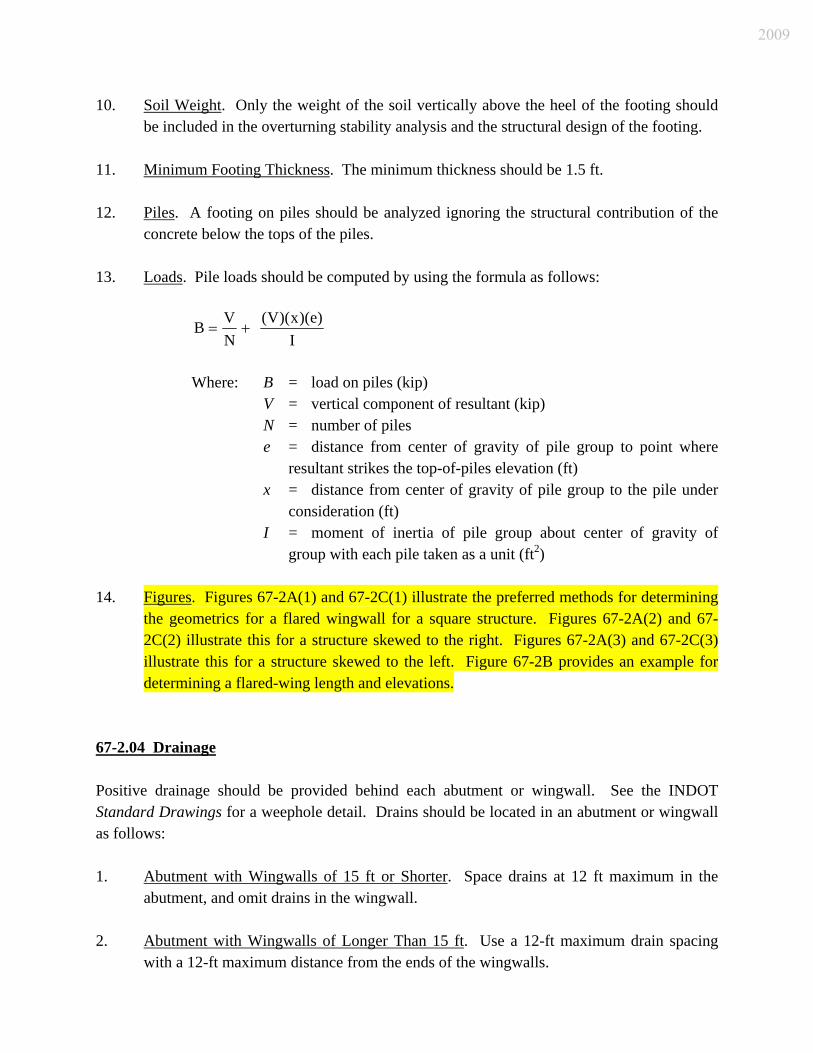
10. Soil Weight. Only the weight of the soil vertically above the heel of the footing should
be included in the overturning stability analysis and the structural design of the footing. 11. Minimum Footing Thickness. The minimum thickness should be 1.5 ft. 12. Piles. A footing on piles should be analyzed ignoring the structural contribution of the
concrete below the tops of the piles. 13. Loads. Pile loads should be computed by using the formula as follows:
I
)e)(x)(V(NVB +=
Where: B = load on piles (kip) V = vertical component of resultant (kip) N = number of piles e = distance from center of gravity of pile group to point where
resultant strikes the top-of-piles elevation (ft) x = distance from center of gravity of pile group to the pile under
consideration (ft) I = moment of inertia of pile group about center of gravity of
group with each pile taken as a unit (ft2) 14. Figures. Figures 67-2A(1) and 67-2C(1) illustrate the preferred methods for determining
the geometrics for a flared wingwall for a square structure. Figures 67-2A(2) and 67-2C(2) illustrate this for a structure skewed to the right. Figures 67-2A(3) and 67-2C(3) illustrate this for a structure skewed to the left. Figure 67-2B provides an example for determining a flared-wing length and elevations.
67-2.04 Drainage Positive drainage should be provided behind each abutment or wingwall. See the INDOT Standard Drawings for a weephole detail. Drains should be located in an abutment or wingwall as follows: 1. Abutment with Wingwalls of 15 ft or Shorter. Space drains at 12 ft maximum in the
abutment, and omit drains in the wingwall. 2. Abutment with Wingwalls of Longer Than 15 ft. Use a 12-ft maximum drain spacing
with a 12-ft maximum distance from the ends of the wingwalls.
2009

3. Location of Drain Outlet. Locate the outlet 1 ft above the low-water elevation or the
proposed ground-line elevation. 67-2.05 Construction Joints Use construction joint type A for all horizontal construction joints in both the abutment and wingwalls. See the INDOT Standard Drawings. Vertical construction joints should be placed as follows. 1. Abutment. Place preferably at 30 ft center to center, with a maximum of 40 ft. 2. Wingwall of 20 ft or Longer. Place at 20 ft center to center and cut one batter face only. 3. Wingwall Shorter than 20 ft. Place in the abutment section so that the combined length
of wingwall and abutment between joints is approximately 20 ft. 4. Either the Wingwall or the Abutment. Place not less than 1.5 ft from the intersection of
batter faces at the top of the footing. Joints should not be placed under bridge bearing areas. The horizontal reinforcing steel should continue through the construction joint. Vertical bars should be placed at a minimum of 3 in. from the centerline of joint. 67-2.06 Details Figure 67-2D provides suggested typical abutment details. 67-3.0 INTERIOR SUPPORTS 67-3.01 Types Three basic types of interior supports are used, which are discussed below. Also, see Sections 59-2.0 and 66-3.04 for more information. 67-3.01(01) Extended-Pile or Drilled-Shaft Bent
2009
Under certain conditions, the economy of a substructure can be enhanced by extending a deep foundation, such as a single row of driven piles or drilled shafts above ground level to the superstructure. An extended-pile bent may be of the integral type or the non-integral type. See Figure 67-3A. 67-3.01(02) Stem-Type Pier The types of stem piers are as follows: 1. Single-Wall. This is a relatively thin wall set on a single row of piles, a spread footing,
or a pile cap with multiple rows of piles. The single-wall is most suitable if its structural height is less than 20 ft, or the superstructure length is less than 25 ft parallel to the pier centerline. See Figure 67-3B for a wall pier on a single row of piles.
2. Hammerhead. For a larger structural height or pier width, a hammerhead pier, either with
a rectangular or rounded stem, is often more suitable. Figure 67-3C illustrates the typical design of a hammerhead pier.
67-3.01(03) Frame Bent A concrete frame bent may be used to support a variety of superstructures. The columns of the bent may be either circular or rectangular in cross section. The columns may be directly supported by the footing or by a partial-height wall. Figures 67-3D and 67-3E illustrate the typical designs of a frame bent. If the columns rest directly on the footing, the footing should be designed as a two-way slab. Construction joints may be required in the cap if the concrete shrinkage moments introduced into the columns becomes excessive. 67-3.02 Usage The selection of the interior-support type should be based on the feature passing beneath the bridge, as follows. 1. Major Water Crossing. A hammerhead, wall, or single round column-type pier supported
by a deep foundation or a spread footing on rock is preferred. Multiple round columns may be used, but they may require a solid wall between columns to avoid the collection of debris. This decision must be coordinated with the Production Management Division’s Hydraulics Team. A single-wall pier may be a more suitable alternative.
2009

2. Meandering River. For a meandering river or stream, or where the high flow is at a different skew than the low flow, the most desirable pier type is normally a single, circular pier column.
3. Highway Grade Separation. A thin-wall or frame bent with multiple columns should be
used. The aesthetics of the pier should be considered. Special surface treatments using form liners or other means should be investigated, especially for a wall pier.
67-3.03 General Design Considerations The following design criteria apply to an interior support, where applicable. 1. Pier in Waterway. A stem-type pier should have a solid wall to an elevation of 1 ft above
the Q100 high-water level. Depending on aesthetics and economics, the remainder of the wall may be either solid or multiple columns. The dimensions of the wall may be reduced by providing cantilevers to form a hammerhead pier.
2. Railroad Crossing. The design should be in accordance with AREMA requirements if the
pier is within 25 ft of the present-track or a future-track centerline. If the pier is located within 50 ft of the centerline of a railroad track, it should be designed for the collision force, if applicable, as described in LRFD Bridge Design Specifications, Article 3.6.5.2.
3. Cap Reinforcement. Multiple layers of negative-moment reinforcement are permitted to
minimize cap dimensions. 4. Column Reinforcement. Vertical column bars should extend a minimum of 20 bar
diameters into the cap beam and the required development length into the spread footing or pile cap. The area of steel reinforcement provided across the interface between the base of the column or pier stem and the top of footing should not be less than 0.5% of the gross area of column or stem as described in LRFD Bridge Design Specifications, Article 5.13.3.8. According to LRFD Article 5.10.11.4.2, the minimum reinforcement ratio, both horizontally and vertically in a pier, should not be less than 0.0025. The vertical reinforcement ratio should not be less than the horizontal reinforcement ratio. The reinforcement spacing, either horizontally or vertically, should not exceed 1’-6”.
5. Size. Columns are rectangular, square, or round, with a minimum diameter or thickness
of 2 in. Diameter increments should be in multiples of 6 in. A solid pier wall should have a minimum thickness of 2 ft, and may be widened at the top to accommodate the bridge seat.
2009

6. Cap Extension. The width of the cap should project beyond the sides of the columns. The added width of the cap should be a minimum of 1½ in. on the outside the columns. This width will reduce the reinforcement interference between the column and cap. The cap should have cantilevered ends to balance positive and negative moments in the cap.
7. Step Cap. Where one end of the cap is on a considerably different elevation than the
other, the difference should be accommodated by increasing the column heights as shown in Figure 67-3E(1). The bottom of the cap should be sloped at the same rate as the cross slope of the top of the bridge deck. The top of the cap should be stepped to provide level bearing surfaces.
8. Construction Joints. Use construction joint type A for all horizontal construction joints.
See the INDOT Standard Drawings. However, at the base of the pier stem, a keyway construction joint should be used.
9. Reinforcement Clearance. The reinforcement clearances should be checked to ensure
that there is adequate space for the proper placement of the concrete during construction. 10. Backfill. An interior bent or pier at the base of a slopewall should be backfilled with
structure backfill as shown on the INDOT Standard Drawings. For an interior bent or pier adjacent to a railroad, the area should be backfilled with structure backfill to a point 18 in. outside the neat lines of the footing. Show the neat line limits and estimate the quantity on the Layout Sheet for each bent or pier location. Do not provide structure backfill as backfill material around a pier that is located in a stream.
11. Epoxy-Coated Steel Under Expansion Joint. All reinforcing steel in concrete above the
footing for an interior pier where an expansion joint is located directly over the cap should be epoxy coated. This includes the stem, cantilevers, and cap. This applies only to a substructure which supports the ends of two superstructure units with an expansion joint located directly over the cap.
12. Concrete. Use Class A concrete above the footings, and use Class B concrete in footings. 13. Reinforcing-Steel Splicing. If a pier stem is less than 10 ft in height, do not splice the
steel extending out of the footing. For small columns with a high percentage of vertical steel and for columns in Seismic Zone 2, mechanical connectors should be used for splicing the vertical steel.
14. Compression Reinforcement. Compression steel tends to buckle once the concrete cover
is gone or where the concrete around the steel is weakened by compression. The criteria in LRFD Specifications Articles 5.7.4.6, 5.10.6, or 5.10.11, for ties or spirals should be used. See Figure 67-3F for suggested hammerhead and wall-type pier reinforcing in
2009

columns with no plastic hinging capability. Ties may be #3 bars for longitudinal bars up to size #10.
67-3.04 Specific Design Criteria This Section describes design criteria which apply to each specific type of interior support. 67-3.04(01) Extended-Pile Bent The following applies to the design of an extended-pile bent. 1. Limitations. This type of support has very little resistance to longitudinal forces and
should not be used unless such forces are resisted by other substructure units such as integral end bents or abutments. This support should also not be used if the stream carries large debris, heavy ice flow, or large vessels. If steel H-piles are used for support, they should be encased in concrete. The concrete encasement should be extended to 2 ft below the flow-line elevation. Encasement details are provided on the INDOT Standard Drawings. Scour should be considered in establishing design pile lengths and for the structural design of the piles.
2. Cap Beam. Extended piles always need a cap beam for structural soundness, which may
be an integral part of the superstructure. Extended drilled shafts should be arranged to support, for example, widely-spaced beams without the presence of a cap beam if sufficient space is provided at the top for mandatory jacking operations.
3. Loads. Girders may be fixed or semi-fixed at an extended pile bent. Because the piles
are relatively flexible compared to the end bents or abutments, the force effects induced in the piles by lateral displacement is small. Where practical, one pile should be placed beneath each girder. The vertical load carried by the piles should be the girder reaction and the appropriate portion of the pile cap dead load. Assuming the bent acts as a rigid frame in a direction parallel to the bent, force effects due to lateral displacement and lateral loads may be uniformly distributed among the extended piles.
4. Cap Design. The minimum reinforcement should be #5 bars at 1’-0” spacing on all faces,
and should be in accordance with LRFD Bridge Design Specifications Article 5.7.3.3. The cap should be designed as a continuous beam.
67-3.04(02) Hammerhead Pier
2009

The following applies to the design of a hammerhead pier. 1. Cofferdam. If a cofferdam is anticipated to be required, the hammerhead portion of the
pier must be above the average low-water level of the stream. 2. Bottom Elevation. The bottom of the hammerhead portion should be a minimum of 6 ft
above the finished ground line at a stream crossing to help prevent debris accumulation. 3. Effective-Length Factor. The LRFD Bridge Design Specifications Article 4.6.2.5
commentary table provides criteria for the effective length factor, K. For beams on rockers or slide bearings, use K = 2.1. For an expansion pier with beams on a single row of neoprene pads, use K = 1.5. For prestressed-concrete beams on semi-fixed bearings on a fixed pier, use K = 1.2. Use K = 1.0 for the strong or transverse direction.
4. Pier Wall. This should be designed as columns for biaxial bending. 67-3.04(03) Frame Bent The following applies to the design of a frame bent. 1. Column Fixity. The columns founded on a spread or multiple-piles footing should be
assumed to be fixed at the bottom. 2. Cantilevered Cap. The moments used for the cap design should be calculated at the face
of the support for a square or rectangular column, or at the theoretical face of a circular column.
3. Effective-Length Factor. Use the same K factors as described for a hammerhead pier in
Section 67-3.04(02) in the weak (longitudinal) direction. Use K = 1.0 for the strong (transverse) direction.
4. Structural Design. If the number of columns is kept to a minimum, and the components
are reasonably small, frame analysis is both appropriate and safe for a frame bent. 67-3.05 Compression Reinforced-concrete piers, pier columns, and piles are referred to as compression members although their design is normally controlled by flexure. Tall, slender columns or pier shafts are relatively rare due to topography. The use of the moment magnification approach in the LRFD
2009

Specifications is most often warranted. For exceptionally tall or slender columns or shafts, a refined analysis, as outlined in LRFD Specifications Article 5.7.4.1, should be performed. For a bridge in Seismic Zone 1 and 2, a reduced effective area may be used if the cross section is larger than that required to resist the applied loading. The minimum percentage of total longitudinal reinforcement of the reduced effective area should be the greater of 1% or the value obtained from LRFD Specifications Equation 5.7.4.2-3. Both the reduced effective area and the gross area must be capable of resisting all applicable load combinations shown in LRFD Specifications Table 3.4.1-1. 67-4.0 BEARINGS 67-4.01 General Bearings ensure the functionality of a bridge by allowing translation and rotation to occur while supporting the vertical loads. However, the designer should first consider the use of integral abutments and possibly integral piers prior to deciding upon the use of bearings to support the structure. The following will apply. 1. Movement. Movement should be considered. Movement includes both translations and
rotations. The sources of movement include bridge skew and horizontal-curvature effects, initial camber or curvature, construction loads, misalignment or construction tolerances, settlement of supports, thermal effects, creep, shrinkage, or traffic loading. Bearing pads on a skewed structure should be oriented parallel to the principal rotation axis. Where insufficient seat width exists, the bearing pads may be oriented normal to the support.
2. Effect of Bridge Skew and Horizontal Curvature. A skewed bridge moves both
longitudinally and transversely. The transverse movement becomes significant on a bridge with a skew angle greater than 20 deg that has bearings not oriented parallel to the movement of the structure.
A curved bridge moves both radially and tangentially. These complex movements are predominant in a curved bridge with a small radius and with an expansion length of longer than 200 ft.
3. Effect of Camber and Construction Procedures. The initial camber of bridge girders and
out- of-level support surfaces induces bearing rotation. Initial camber may cause a larger initial rotation on the bearing, but this rotation may grow smaller as the construction of the bridge progresses. Rotation due to camber and the initial construction tolerances is sometimes the largest component of the total bearing rotation. Both the initial rotation
2009
and its short duration should be considered. If the bearing is installed level at an intermediate state of construction, deflections and rotations due to the weight of the deck slab and construction equipment must be added to the effects of live load and temperature. Construction loads and movements due to tolerances should be included. The direction of loads, movements, and rotations must also be considered, because it is inappropriate to simply add the absolute magnitudes of these design requirements. Rational design requires consideration of the worst possible combination of conditions without designing for unrealistic or impossible combinations or conditions. It may be economical to install the bearing with an initial offset, or to adjust the position of the bearing after construction has started, to minimize the adverse effect of these temporary initial conditions. Combinations of load and movement that are not possible should not be considered.
4. Thermal Effects. Thermal translation, Δo, is estimated as follows:
Δo = αLΔT where L is the expansion length, α is the coefficient of thermal expansion of 6.0 x 10⁻⁶ / °F for normal-density concrete, or 6.5 x 10⁻⁶ / °F for steel, and ΔT is the change in the average bridge temperature from the installation temperature. A change in the average bridge temperature causes a thermal translation. A change in the temperature gradient induces bending and deflections. The design temperature changes are specified in the AASHTO LRFD Specifications. Maximum and minimum bridge temperatures are defined depending upon whether the location is viewed as a cold or moderate climate. Indiana is considered a cold climate. See LRFD Table 3.12.2.1-1 for temperature range values. The designer should assume an installation temperature of 60°F. The change in average bridge temperature, ΔT, between the installation temperature and the design extreme temperatures is used to compute the positive and negative movements. A given temperature change causes thermal movement in all directions. This means that a short, wide bridge may experience greater transverse movement than longitudinal movement.
5. Loads and Restraint. Restraint forces occur when any part of a movement is prevented.
Forces due to direct loads include the dead load of the bridge and loads due to traffic, earthquakes, water, or wind. Temporary loads due to construction equipment and staging also occur. The majority of the direct design loads are reactions of the bridge superstructure on the bearing, so they can be estimated from the structural analysis. The applicable AASHTO LRFD load combinations must be considered.
6. Serviceability, Maintenance, and Protection Requirements. Bearings under deck joints
collect large amounts of dirt and moisture which promotes problems of corrosion and deterioration. As a result, such bearings should be designed and installed to have the
2009

maximum possible protection against the environment and to allow easy access for inspection.
The service demands on bridge bearings are very severe and result in a service life that is typically shorter than that of other bridge elements. Therefore, allowances for bearing replacement should be part of the design process. Lifting locations should be provided to facilitate removal and re-installation of bearings without damaging the structure. No additional hardware is should be necessary for this purpose. The primary requirements are to allow space suitable for lifting jacks based on the original design and to employ details that permit quick removal and replacement of the bearing.
7. Clear Distance. The minimum clear distance between the bottom shoe of a steel bearing
and the edge of the bearing seat or cap should be 3 in. For an elastomeric pad resting directly on the concrete bridge seat, the minimum edge distance should be 6 in. under a deck expansion joint, or 3 in. with 4 in. desirable for all other locations. Seismic support lengths should also be checked.
8. Bearing Selection. Bearing selection is influenced by factors such as loads, geometry,
maintenance, available clearance, displacement, rotation, deflection, availability, policy, designer preference, construction tolerances, or cost.
Vertical displacements are prevented, rotations are allowed to occur as freely as possible, and horizontal displacements may be either accommodated or prevented. The loads should be distributed among the bearings in accordance with the superstructure analysis.
Unless conditions dictate otherwise, conventional steel-reinforced elastomeric bearings should be used for a girder bridge. Where the practical limits of an elastomeric bearing pad are exceeded, the designer should consider using flat polytetrafluorethylene (PTFE) slider plates in conjunction with a steel-reinforced elastomeric bearing. See Figure 67-4A for a general summary of expansion-bearing capabilities. The values shown in the table are for guidance only.
The final step in the selection process consists of completing a design of the bearing in accordance with the LRFD Specifications. The resulting design will provide the geometry and other pertinent specifications for the bearing.
For a structure widening, bearing types should not be mismatched. Yielding type bearings, such as elastomeric, should not be used in conjunction with steel rockers or other non-yielding type bearings.
A steel-beam bridge without integral end bents must have at least one fixed bearing line. Due to the presence of the interior-diaphragm keyway, semi-fixed interior supports are
2009
allowed for a precast-concrete bridge. If integral end bents in accordance with the empirical design limits are used, interior fixed bearings are not required.
9. Anchor Plates and Anchor Bolts. Anchor plates should only be used to attach the bottom
steel shoe of an expansion bearing to the concrete beam seat. Anchor bolts should be used to connect fixed steel bearings to the concrete beam seat.
67-4.02 Fixed Steel Bearings The top shoe of a steel bearing should be at least as wide as the beam flange, but not more than 2 in. wider. The maximum reaction is shown for each shoe type in the INDOT Standard Drawings. An independent design is required if the design reaction is greater than the maximum reaction shown or if the beam or girder flange width is not in accordance with the Standard Drawings. If the flexibility of tall, slender piers is sufficient to absorb the horizontal movement at the bearings due to temperature change without developing undue force in the superstructure, the bearings, one pier, or two or more piers may be fixed to distribute the longitudinal force among the piers. 67-4.03 Elastomeric Bearing Pads and Steel-Reinforced Elastomeric Bearings Elastomers are used in both elastomeric bearing pads and steel-reinforced elastomeric bearings. The behavior of both pads and bearings is influenced by the shape factor, S, as follows:
elgButoFreePerimeterofArea
AreaPlanS =
Elastomeric bearing pads and steel-reinforced elastomeric bearings have fundamentally different behaviors and, therefore, they are discussed separately. It is desirable to orient elastomeric pads and bearings so that the long side is parallel to the principal axis of rotation, because this facilitates the accommodation of rotation. Holes should not be placed in an elastomeric bearing pad due to increased stress concentrations around the hole. These increased stresses can cause tearing of the elastomer during an extreme event, such as an earthquake. If holes are placed in a steel-reinforced bearing, the steel-reinforcement thickness should be increased in accordance with LRFD Article 14.7.5.3.7. Elastomeric bearing pads and steel-reinforced elastomeric bearings have many desirable attributes. They are usually a low-cost option, and they require minimal maintenance. Further,
2009

these components are relatively forgiving if subjected to loads, movements, or rotations that are slightly larger than those considered in their design. This is not to encourage underdesign of elastomeric pads or bearings, but it is to indicate that an extreme event, which has a low probability of occurrence, will have far less serious consequences with these elastomeric components than with other bearing systems. 67-4.03(01) Elastomer Both natural rubber and neoprene are used in the construction of bridge bearings. The differences between the two are usually not very significant. Neoprene has greater resistance than natural rubber to ozone and a wide range of chemicals, so it is more suitable for some harsh chemical environments. However, natural rubber generally stiffens less than neoprene at low temperatures. All elastomers are visco-elastic, nonlinear materials, and therefore, their properties vary with strain level, rate of loading, and temperature. Bearing manufacturers evaluate the materials on the basis of Shore A Durometer hardness, but this parameter is not a good indicator of the shear modulus, G. A Shore A Durometer hardness of 55 ± 5 should be used. This leads to shear modulus values in the range of 0.110 ksi to 0.170 ksi at 73°F. The least favorable value should be used for design. The shear stiffness of the bearing is its most important property because it affects the forces transmitted between the superstructure and substructure. Elastomers are flexible under shear and uniaxial deformation, but they are very stiff against volume changes. This feature makes possible the design of a bearing that is stiff in compression but flexible in shear. Elastomers stiffen at low temperatures. The low-temperature stiffening effect is very sensitive to the elastomer compound. The increase in shear resistance can be controlled by selection of an elastomer compound that is appropriate for the climatic conditions. The minimum low-temperature elastomer should be Grade 3, unless otherwise specified. The elastomer grade should be shown in the contract documents. 67-4.03(02) Steel-Reinforced Elastomeric Bearing Pads Steel-reinforced elastomeric bearings are often categorized with elastomeric bearing pads, but the steel reinforcement makes their behavior quite different. Steel-reinforced elastomeric bearings have uniformly-spaced layers of steel and elastomer. The bearing accommodates translation and rotation by deformation of the elastomer. The elastomer is flexible under shear stress but stiff against volumetric changes. Under uniaxial compression, the flexible elastomer would shorten significantly and sustain large increases in its plan dimension, but the stiff steel
2009
layers restrain this lateral expansion. This restraint induces a bulging pattern as shown in Figure 67-4B and provides a large increase in stiffness under compressive load. This permits a steel reinforced elastomeric bearing to support relatively large compressive loads while accommodating large translations and rotations. The design of a steel-reinforced elastomeric bearing pad requires an appropriate balance of compressive, shear, and rotational stiffnesses. The shape factor affects the compressive and rotation stiffness, but it has no impact on the translational stiffness or deformation capacity. A bearing pad must be designed to control the stress in the steel reinforcement and the strain in the elastomer. This is done by controlling the elastomer layer thickness and the shape factor of the bearing. Fatigue, stability, delamination, yield, rupture of the steel reinforcement, stiffness of the elastomer, and geometric constraints must be satisfied. Large rotations and translations require thicker bearings. Translations and rotations may occur about the longitudinal or transverse axis of a steel-reinforced elastomeric bearing. A steel-reinforced elastomeric bearing becomes large if it is designed for a load greater than about 675 kip. Uniform heating and curing during vulcanization of such a large mass of elastomer becomes difficult, as elastomers are poor heat conductors. Manufacturing constraints thus impose a practical upper limit on the size of most steel-reinforced elastomeric bearings. If the design load exceeds 675 kip, the designer should check with the manufacturer for availability. 67-4.03(03) Elastomeric Bearing Pads Elastomeric bearing pads include plain elastomeric pads (PEP), cotton-duck reinforced pads (CDP), and layered fiberglass-reinforced bearing pads (FGP). The designer must prepare a unique special provision if these pads are to be used. There is considerable variation between pad types. Elastomeric bearing pads can support modest gravity loads, but they can only accommodate limited rotation or translation. Hence, they are best suited for a bridge with small expansion lengths or a specialty situation. A plain elastomeric pad relies on friction at its top and bottom surfaces to restrain bulging due to the Poisson effect. Friction is unreliable, and local slip results in a larger elastomer strain than that which occurs in a reinforced elastomeric pad or bearing. The increased elastomer strain limits the load capacity of the PEP. The PEP must be relatively thin if it is to carry the maximum allowable compressive load. A maximum friction coefficient of 0.20 should be used for the design of an elastomeric pad that is in contact with clean concrete or steel surfaces. If the shear force is greater than 0.20 of the simultaneously occurring compressive force, the bearing should be secured against horizontal movement. If the designer is checking the maximum
2009

seismic forces that can be transferred to the substructure through the pad, a friction coefficient of 0.40 should be used. A cotton-duck reinforced pad has very thin elastomer layers (less than 1/64 in.). It is stiff and strong in compression so it has much larger compressive load capacities than a PEP, but it has very little rotational or translational capacity. A CDP is sometimes used with a PTFE slider to accommodate horizontal translation. The behavior of an elastomeric pad reinforced with discrete layers of fiberglass (FGP) is closer to that of a steel reinforced elastomeric bearing than to that of other elastomeric bearing pads. The fiberglass, however, is weaker, more flexible, and bonds less well to the elastomer than does the steel reinforcement. Sudden failure occurs if the reinforcement ruptures. These factors limit the compressive load capacity of the fiberglass-reinforced bearing pad. An FGP pad accommodates larger gravity loads than a PEP of identical geometry, but its load capacity may be smaller than that achieved with a CDP. An FGP can accommodate modest translations and rotations. The use of an FGP or PEP elastomeric pad is restricted to lighter bearing loads, on the order of 160 kip or less. A CDP may support somewhat larger loads than an FGP or PEP, on the order of 260 kip or less, but has no significant translation or rotational capabilities. Translations of 0.75 in. and rotations of 1 deg or less are possible with an FGP or a PEP bearing. Due to the limited use of PEP, FGP, and CDP bearing pads, no design example is provided herein. See the LRFD Specifications Article 14.7.6 for design requirements. 67-4.04 Standardized Elastomeric Bearing Pads and Assemblies [Rev. Dec. 2008] Standardized elastomeric bearing pads and assemblies have been developed for use with AASHTO prestressed-concrete I-beams, Indiana prestressed-concrete bulb-tee beams, prestressed-concrete spread and adjacent box beams, and structural-steel members. They have been designed based on AASHTO LRFD Bridge Design Specifications Section 14.7.6, Design Method A. 67-4.04(01) Standard Pad and Assembly Types [Rev. Dec. 2008] 1. AASHTO Prestressed-Concrete I-Beam. Elastomeric bearing pads are designated as type
1, 2, 3, or 4 for this type of member. The details are shown on the INDOT Standard Drawings.
2009

2. Prestressed-Concrete Box Beam. Elastomeric bearing pads are designated as type 5, 6, or 7, and shape A or B, for this type of member. For a spread box beam, shape A or B may be used. For an adjacent interior box beam, shape A should be used. For the outside edge under an adjacent exterior box beam, shape B should be used. The details are shown on the INDOT Standard Drawings.
3. Prestressed-Concrete Bulb-Tee Beam. Elastomeric bearing pads are designated as type
T, and shape 1, 2, 3, or 4, for this type of member. The details are shown on the INDOT Standard Drawings.
4. Steel Beam or Girder. Elastomeric bearing assemblies are designated as type S, with
bearing-area designation 1, 2, 3, 4, 5, 6, or 7, and effective-elastomer-thickness designation a or b, for this type of member. The details and designations are shown on the INDOT Standard Drawings.
The locations of elastomeric-bearing devices should be shown on the plans with their type and shape designations. However, they are not separate pay items. 67-4.04(02) Design Parameters [Rev. Dec. 2008] The design of bearing devices is governed by the basic parameters as follows: 1. dead-load plus live-load reaction (impact not included); 2. expansion length, or distance from fixed support to expansion support; and 3. grade percentage due to nonparallel surfaces, considering dead-load rotation, profile
grade of member, and camber of member. 67-4.04(03) Determining Standard Bearing-Device Type [Rev. Dec. 2008] The procedure for determining the applicable standard elastomeric bearing device is the same for each structural-member type. 1. Step 1: Determine the Required Bearing Device Type. Determine the dead-load plus
live-load reaction, and calculate the maximum expansion length for the bridge at the support for which the device is located. Then enter Figure 67-4C, 67-4D, 67-4E, or 67-4F, Elastomeric Bearing Pad or Assembly Types, Properties, and Allowable Values, for the appropriate structural-member type, with the reaction and maximum expansion length. The required bearing-device size is that which corresponds to the reaction and
2009

expansion-length values shown in the figure which are less than or equal to those determined. If the reaction or expansion length is greater than the figure’s value, use the next larger device size. If the reaction or expansion length is greater than the maximum value shown on the figure, the pad must be designed as described in Section VII below.
2. Step 2: Check Compressive Stress due to Total Load Associated with Rotational
Deflection. The rotational deflection, θS, is the sum of the total service-load rotation due to imposed loads about the transverse axis, θX, or about the longitudinal axis, θZ, initial lack of parallelism due to grade, θG, and the rotation due to uncertainties, θU.
The rotation of the beam due to imposed loads, θX or θZ , should be the value, in radians, determined in the dead-load-plus-live-load analysis from the beam design about the transverse x-axis or about the longitudinal z-axis.
The total service-load rotation due to lack of parallelism, θG, in radians, should be determined from Equation 67-4.1 as follows:
⎟⎟⎠
⎞⎜⎜⎝
⎛ −=
eG L
ElEl 2.1.arctanθ [Equation 67-4.1]
Where: El. 1 = Bridge seat elevation of one support, ft El. 2 = Bridge seat elevation of adjacent support, ft Le = Span length between the two centerlines of bearings
along the bridge seat, ft
The rotation due to uncertainties, θU, should be taken as 0.005 rad (AASHTO LRFD Specifications Article 14.4.2.1) in any direction unless an approved quality control plan justifies a smaller value.
The values of θS,X or θS,Z can be obtained from the equations as follows:
θS,X = θX + θG+ θU (Equation 67-4.2)
θS,Z = θZ + θG+ θU (Equation 67-4.3)
The value of θS,X or θS,Z should be incorporated into the appropriate equation below to determine the service-load compressive stress due to total load, σS.
⎟⎟⎠
⎞⎜⎜⎝
⎛⎟⎟⎠
⎞⎜⎜⎝
⎛=
nhLGS XS
riS
,2
5.0θ
σ [AASHTO LRFD Equation 14.7.6.3.5d-1]
2009
⎟⎟⎠
⎞⎜⎜⎝
⎛⎟⎟⎠
⎞⎜⎜⎝
⎛=
nhWGS ZS
riS
,2
5.0θ
σ [AASHTO LRFD Equation 14.7.6.3.5d-2]
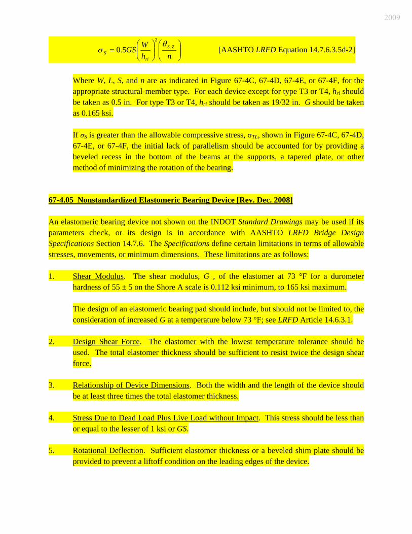
Where W, L, S, and n are as indicated in Figure 67-4C, 67-4D, 67-4E, or 67-4F, for the appropriate structural-member type. For each device except for type T3 or T4, hri should be taken as 0.5 in. For type T3 or T4, hri should be taken as 19/32 in. G should be taken as 0.165 ksi.
If σS is greater than the allowable compressive stress, σTL, shown in Figure 67-4C, 67-4D, 67-4E, or 67-4F, the initial lack of parallelism should be accounted for by providing a beveled recess in the bottom of the beams at the supports, a tapered plate, or other method of minimizing the rotation of the bearing.
67-4.05 Nonstandardized Elastomeric Bearing Device [Rev. Dec. 2008] An elastomeric bearing device not shown on the INDOT Standard Drawings may be used if its parameters check, or its design is in accordance with AASHTO LRFD Bridge Design Specifications Section 14.7.6. The Specifications define certain limitations in terms of allowable stresses, movements, or minimum dimensions. These limitations are as follows: 1. Shear Modulus. The shear modulus, G , of the elastomer at 73 °F for a durometer
hardness of 55 ± 5 on the Shore A scale is 0.112 ksi minimum, to 165 ksi maximum.
The design of an elastomeric bearing pad should include, but should not be limited to, the consideration of increased G at a temperature below 73 °F; see LRFD Article 14.6.3.1.
2. Design Shear Force. The elastomer with the lowest temperature tolerance should be
used. The total elastomer thickness should be sufficient to resist twice the design shear force.
3. Relationship of Device Dimensions. Both the width and the length of the device should
be at least three times the total elastomer thickness. 4. Stress Due to Dead Load Plus Live Load without Impact. This stress should be less than
or equal to the lesser of 1 ksi or GS. 5. Rotational Deflection. Sufficient elastomer thickness or a beveled shim plate should be
provided to prevent a liftoff condition on the leading edges of the device.
2009

6. Anchorage. The pad or assembly should be secured against seismic or other extreme-event resistant anchorage to defy the horizontal movement in excess of that accommodated by shear in the pad, unless it is intended to act as a fuse as required by AASHTO LRFD 14.7.6.3.8. The calculations are performed in the strength-limit state. The load modifiers for ductility (LRFD 1.3.3), redundancy (LRFD 1.3.4), and importance (LRFD 1.3. 5) must be accounted for.
The design is based on AASHTO LRFD Bridge Design Specifications, 4th Edition, including all interims, Article 14.7.6, Method A. Each pad or assembly is sized according to the load capacities and expansion lengths which it will accommodate. 67-4.05(01) Load Capacity [Rev. Dec. 2008] To calculate the maximum load capacity of a nonstandard-sized bearing pad, use the allowable-stress limitation indicated in LRFD Equation 14.7.6.3.2-2, as follows: GSS 0.1≤σ Where σS = allowable stress, psi G = shear modulus of elastomer at 73 ºF (psi) S = shape factor of the thickest elastomer layer To determine G, use the Standard Shore A Durometer Hardness Level of 55 ± 5. From LRFD Table 14.7.6.2-1, for hardness 50, the Gmin range is 95 to 130. Take the average of these to get Gmin = 112.5 psi. From LRFD Table 14.7.6.2-1, for hardness 60, the Gmax range is 130 to 200. Take the average of these to get Gmax = 165 psi. The shape factor can be determined from LRFD Equation 14.7.5.1-1, as follows:
( )WLhLW
ri +=
2S
Where L = pad length parallel to the longitudinal bridge axis W = pad width parallel to the transverse bridge axis hri = thickness of an internal elastomer layer
* * * * * * * *
2009

Example 67-4.1 Load Capacity: Check load capacity for a concrete-members-structure pad with W = 26 in. and L = 23 in. For calculation of allowable stress, use the least-favorable value of G. The least-favorable value is Gmin, or 112.5 psi. The internal-elastomer thickness, hri, is 5/8 in., or 0.625 in.
Therefore, ( )( )( )( )2623625.02
2623+
=S = 9.76.
So, ( )( ) == 76.95.1120.1Sσ 1098 psi, or 1.098 ksi. The maximum dead load plus live load reaction, Qmax (kip), which can be supported by the pad is the allowable stress times the area of the pad, as shown in the formula as follows: ( )( )( ) === 2623098.1max LWQ Sσ 657 kip.
* * * * * * * * 67-4.05(02) Expansion-Length Limit [Rev. Dec. 2008] The elastomer should be designed to resist 2 times the maximum shear deformation as specified in LRFD Equation 14.7.6.3.4-1, as follows: Srth Δ≥ 2 Where hrt = total elastomer thickness less that of metallic bonded shims ΔS = shear deformation. The shear deformation can be calculated from the equation as follows: TLeTUS Δ=Δ αγ Where γTU = load factor for temperature effects ά = coefficient of thermal expansion Le = maximum expansion length ΔT = temperature range. For γTU see LRFD Table 3.4.1-1. Use Limit State at Service I and the higher of the two values shown, or 1.20. The value of ά for concrete should be taken as 0.000006 in./in./ ºF.
2009
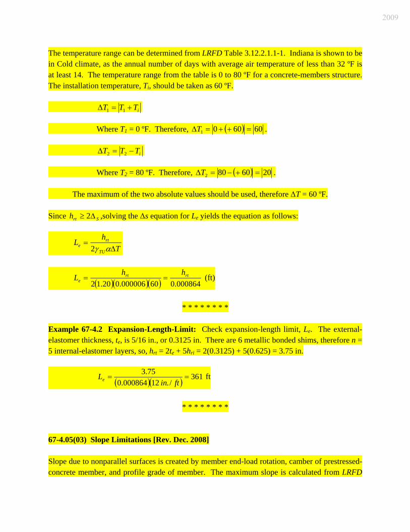
The temperature range can be determined from LRFD Table 3.12.2.1.1-1. Indiana is shown to be in Cold climate, as the annual number of days with average air temperature of less than 32 ºF is at least 14. The temperature range from the table is 0 to 80 ºF for a concrete-members structure. The installation temperature, Ti, should be taken as 60 ºF. iTTT += 11Δ Where T1 = 0 ºF. Therefore, ( ) 606001 =++=ΔT . iTTT −= 22Δ Where T2 = 80 ºF. Therefore, ( ) 2060802 =+−=ΔT . The maximum of the two absolute values should be used, therefore ΔT = 60 ºF. Since ,solving the Δs equation for LSrth Δ≥ 2 e yields the equation as follows:
T
hL
TU
rte Δ=
αγ2
( )( )( ) 000864.060000006.020.12rtrt
ehh
L == (ft)
* * * * * * * *
Example 67-4.2 Expansion-Length-Limit: Check expansion-length limit, Le. The external-elastomer thickness, te, is 5/16 in., or 0.3125 in. There are 6 metallic bonded shims, therefore n = 5 internal-elastomer layers, so, hrt = 2te + 5hri = 2(0.3125) + 5(0.625) = 3.75 in.
( )( ) 361/.12000864.0
75.3==
ftinLe ft
* * * * * * * *
67-4.05(03) Slope Limitations [Rev. Dec. 2008] Slope due to nonparallel surfaces is created by member end-load rotation, camber of prestressed-concrete member, and profile grade of member. The maximum slope is calculated from LRFD
2009

Articles 14.4.2 and 14.7.6.3.5d. The compressive stress for a PEP pad should be calculated from the equations as follows:
2
,5.0 ⎟⎟⎠
⎞⎜⎜⎝
⎛≥
rtXSS h
LGSθσ [LRFD Eqn. 14.7.6.3.5b-1]
2
,5.0 ⎟⎟⎠
⎞⎜⎜⎝
⎛≥
rtZSS h
WGSθσ [LRFD Eqn. 14.7.6.3.5b-2]
Where σS = allowable stress (ksi) G = Gmax of 0.165 ksi S = Shape factor of thickest elastomer layer of bearing pad L = Length of bearing pad parallel to longitudinal bridge axis W = Width of bearing pad in transverse direction hrt = total thickness of all elastomer layers θS,X = service-load rotation due to total load about transverse axis θS,Z = service-load rotation due to total load about longitudinal axis From the above equations the following can be derived. Service-load rotation due to total load about the transverse axis, θS,X (rad), can be determined by solving Equation 14.7.6.3.5b-1 for θS,X as follows:
2
2
, 5.0 GSLhrtS
XSσ
θ ≤
Service-load rotation due to total load about the longitudinal axis, θS,Z (rad), can be determined by solving Equation 14.7.6.3.5b-2 for θS,Z as follows:
2
2
, 5.0 GSWhrtS
ZSσ
θ ≤
* * * * * * * *
Example 67-4.3 Slope-Limitations: Check service-load rotation. From the Load-Capacity Example above, σS = 1.098 ksi, G = 0.165 ksi, and S = 9.76.
( )( )( )( )( )
0010.02376.9165.05.0
625.0098.12
2
, =≤XSθ rad
( )( )( )( )( )
0008.02676.9165.05.0
625.0098.12
2
, =≤ZSθ rad
2009

* * * * * * * * 67-4.06 Seismic Design 67-4.06(01) Application The counties in Seismic Performance Zone 2 are Gibson, Posey, and Vanderburgh. All other counties are in Seismic Performance Zone 1. Each bridge therein should be designed in accordance with the criteria applicable to Zone 1. See Section 60-3.06 for more information. 67-4.06(02) Zone 1 Criteria The LRFD Specifications criteria for Zone 1 are as follows: 1. Minimum Support Length. Adequate support length is the most significant contributor to
satisfactory performance of a bridge during a seismic event. The support length required by LFRD Specifications Article 4.7.4.4 should be provided at the expansion ends of the structure unless longitudinal restrainers are provided.
2. Minimum Bearing-Force Demands. The connection of the superstructure to the
substructure should be designed to resist a horizontal seismic force equal to 0.20 times (the dead load + 0.5 live load) reaction force in the restrained directions. See Article 3.10.9.2. No additional adjustment factors, loadings, or friction forces should be applied to increase or decrease this minimum horizontal seismic force. The force should not be considered in the substructure design.
To preclude the need for restraining devices in Zone 1, expansion bearings should resist the minimum horizontal seismic force in the transverse direction only. The minimum longitudinal seismic force resulting at an expansion bearing should be applied at the nearest fixed bearing. Fixed bearings, such as steel shoes, should be attached to the pier cap with anchor bolts. Some examples of acceptable means of restraint at semi-fixed or expansion bearings in Zone 1 include concrete shear keys between prestressed beams, beams resting in concrete channels, or steel side retainers bolted to the cap. In designing the bearing connections for a Zone 2 bridge, the actual calculated seismic design forces, as adjusted by LRFD Specifications Article 3.10.7, for Zone 2, should be used. The longitudinal seismic forces at expansion bearings in Zone 2 may be resisted either by using seismic restraining devices (positive horizontal linkage), or they may be transferred to the bearing connections at the nearest fixed pier. Positive linkage should be provided by means of
2009
ties, cables, dampers, or other equivalent mechanisms. Friction should not be considered a positive linkage. See LRFD Specifications Article 3.10.9.6 to determine if hold-down devices are required. 67-4.06(03) Connections for Fixed Steel Shoes The connection between a fixed steel shoe and the pier cap should be made with anchor bolts. The ultimate shear resistance in the anchor bolts, pintles, and high-strength bolts in the top shoe should be verified that it is adequate to resist the calculated seismic forces of Seismic Zone 1 or 2. See LRFD Specifications Article 6.13.2.7 and Figure 67-4G for determining the nominal shear resistance of anchor bolts and pintles. The minimum connections should be as shown in Figure 67-4G(1). Masonry anchor bolts should extend into the concrete a minimum of 1’-3”. Anchor bolts used in Seismic Zone 2 should be in accordance with LRFD Specifications Article 14.8.3. Anchor bolts should be located beyond the limits of the bottom beam flange and interior diaphragm to ensure adequate clearance for anchor bolt installations and impact wrenches. The grade of structural steel used for the anchor bolts or pintles should be shown on the plans. Where the pintles cannot be designed to accommodate the minimum seismic force of Zone 1, a hooded top shoe (see Figure 67-4H) should be provided. A hooded top shoe may also be an acceptable seismic restrainer for a Zone 2 design. If seismic forces are extremely large, a restraining device will be required instead of the hooded shoe. 67-4.06(04) Connections for Pot Bearings Fixed pot bearings should be in accordance with the connection requirements for fixed steel shoes. The top bearing plate and lower masonry plate should be bolted to the beam flange and the pier cap respectively. Where welds are required between plates in the pot bearing, they should be made continuous around the perimeter of the smaller plate. 67-4.06(05) Connections for Elastomeric Bearings and PTFE/Elastomeric Bearings Elastomeric bearings and PTFE/elastomeric bearings should be provided with adequate seismic-resistant anchorage to resist the transverse horizontal forces in excess of those accommodated by shear in the bearing. The restraint may be provided by one of the methods as follows:
2009

1. steel side retainers with anchor bolts; 2. concrete shear keys placed in the top of the pier cap, or channel slots formed into the top
of the cap or mudwall at the end bent (see Section 67-4.06(06); or 3. concrete channels formed in the top of the end bent cap or expansion pier cap. Steel side retainers and the anchor bolts should be designed to resist the minimum transverse seismic force for the zone in which the bridge is located. The number of side retainers should be as required to resist the seismic forces and should be placed symmetrically with respect to the cross section of the bridge. Side retainers will often be required on each side of the girder flange of each beam line. The strength of the beams and diaphragms should be sufficient to transmit the seismic forces from the superstructure to the bearings. A minimum of one 1-in. diameter anchor bolt should be provided for each side retainer. Concrete channels formed around each beam in the top of the end bent cap or expansion pier cap represent an acceptable alternative to steel side retainers. The top of the top shoe should be set a minimum of 2 in. below the top of the concrete channel. If no top shoe is present, the bottom of the beam should be placed 2 in. below the top of the channel. The minimum depth of the channel should be 6 in. The horizontal clearance from the side of the top shoe or edge of the beam to the side wall of the channel should be 0.5 in. or less. Integral end bents are an effective way of accommodating the horizontal seismic forces of Zone 1 or 2. An integrally-designed end bent will inherently resist the transverse seismic forces. Minimum support length requirements need not be checked for this type of substructure. 67-4.06(06) Shear Keys at Semi-Fixed Prestressed I-Beam and Adjacent Box Beam Bearings Unreinforced shear keys should be provided between the beams at all semi-fixed supports. The shear keys rest in 1-ft width by 3-ft length by 3-in. depth recessed keyways, the edges of which are also unreinforced. Although the shear keys are not structurally designed, they are expected to adequately resist the horizontal seismic forces anticipated for either Zone 1 or 2. To ensure that the shear keys will function as intended, keyways should be provided between each beam line at each semi-fixed support, and an expanded polystyrene sheet, not exceeding 1/2 in. in thickness, should be provided in the bottom of the keyway resulting in a minimum of 2 1/2 in. of shear key extending into the keyway. Seismic restraint for an adjacent-box-beams bridge should be provided with retaining blocks at the ends of the pier caps and end bent caps. The blocks should be designed as reinforced shear keys and should be in accordance with LRFD Specifications Article 5.8.4.
2009
67-4.06(07) Seismic Isolation Bearings The use of seismic isolation bearings should be considered for a long-span steel bridge in Zone 2. The savings in substructure rehabilitation cost, resulting from an isolation-bearing design, roughly offsets the substantial cost of the isolation bearings. The use of seismic isolation bearings should be based on performing a cost analysis comparing other alternatives, such as pot bearings or elastomeric bearings with suitable retainers or longitudinal restraining devices. The use of seismic isolation bearings in a Zone 1 structure does not appear to be cost effective. The minimum-bearing-support length requirements of the AASHTO LRFD Bridge Design Specifications for seismic design should be satisfied at the expansion ends of a bridge with seismic isolation bearings. The minimum-bearing-force demands should be assumed to be the actual calculated seismic forces of a Zone 2 isolation design. Seismic isolation bearings significantly reduce the seismic forces on the substructure, possibly to the point where a non-seismic loading may control the pier design. This, however, does not relieve the designer of the need to provide pile anchorage, confinement steel in plastic hinge regions, and proper location of lap splices in designing a Zone 2 structure. The design of seismic isolation bearings should be in accordance with the AASHTO Guide Specifications for Seismic Isolation Design. The LRFD Bridge Design Specifications requires that each bearing system be tested under both static and cyclic loading prior to acceptance. The designer should prepare a unique special provision which includes the testing requirements. 67-4.07 Bearing-Assembly Details The following figures provide suggested details for acceptable connections for bearing assemblies. 1. Fixed-Shoe Assembly. See Figure 67-4H. 2. Elastomeric Bearing Assembly. See Figures 67-4I, 67-4J, and 67-4K. 3. PTFE/Elastomeric Bearing Assembly. See Figure 67-4L. The suggested details may be revised as necessary for each project. Also, see the INDOT Standard Drawings for more bearing details. 67-5.0 BRIDGE-SEAT ELEVATIONS 67-5.01 General
2009
In establishing bridge-seat elevations at both end and interior supports, the following should be considered: 1. bridge deck depth; 2.* 3/4-in. fillet. Ssee Section 61-4.02(02) for steel beams or girders, or Section 61-4.02(03)
for concrete beams; 3.** residual beam camber, or difference between design camber and dead load deflection of
slab. At the interior supports, use the larger value from the adjacent spans; 4.** vertical curve effect: (+) for sag vertical curve, (-) for crest vertical curve; 5. beam depth; 6.** beam notch; and 7. bearing thickness, including shims. * The fillet distance is measured from bottom of deck to top of beam. This distance
is included to allow for variation in beam camber. ** Precast-concrete beams only. The accuracy for establishing bridge-seat elevations should be to the nearest 0.001 ft. 67-5.02 Examples The following figures and examples provide information for determining bridge-seat elevations. Figure 67-5A Typical Bridge Section (Concrete I-Beam Example) Figure 67-5B Fillet Dimensions for Concrete I-Beams Figure 67-5C Seat Elevations for Concrete I-Beam Example Figure 67-5D Typical Bridge Section (Built-Up Plate Girder Example) Figure 67-5E Seat Elevations (Steel Beam or Plate Girder) Figure 67-5F Fillet Dimensions for Steel Beams Figure 67-5G Seat Elevations for Steel Beam or Plate Girder Example
2009

Structure Type
Highway AlignmentAcross Bridge Maximum Skew
Maximum Bridge Length
Maximum to Zero Point
Reinforced Concrete Slab
No Restrictions No Restrictions 500 ft * 250 ft *
Structural Steel
Tangent Only ** 30 deg *** 500 ft * 250 ft *
Prestressed Concrete
No Restrictions 30 deg *** 500 ft * 250 ft *
Notes: * The maximum length indicated may be increased, subject to approval by the Structural
Services Office manager, if a rational analysis of induced pile loads indicates that the piles are not overloaded. Two rational analysis methods are described in the Iowa Department of Transportation report, Pile Design and Tests for Integral Abutment Bridges. See Section 67-1.03(03) for an alternative analysis in lieu of the above criteria.
** The horizontal alignment may be curved as long as curved beams are not used. *** A skew of greater than 30 deg but equal to or less than 45 deg will be permitted if the
maximum bridge length does not exceed 250 ft, or if the maximum to zero point does not exceed 125 ft.
USE OF INTEGRAL END BENTS
Figure 67-1A
2009

2009
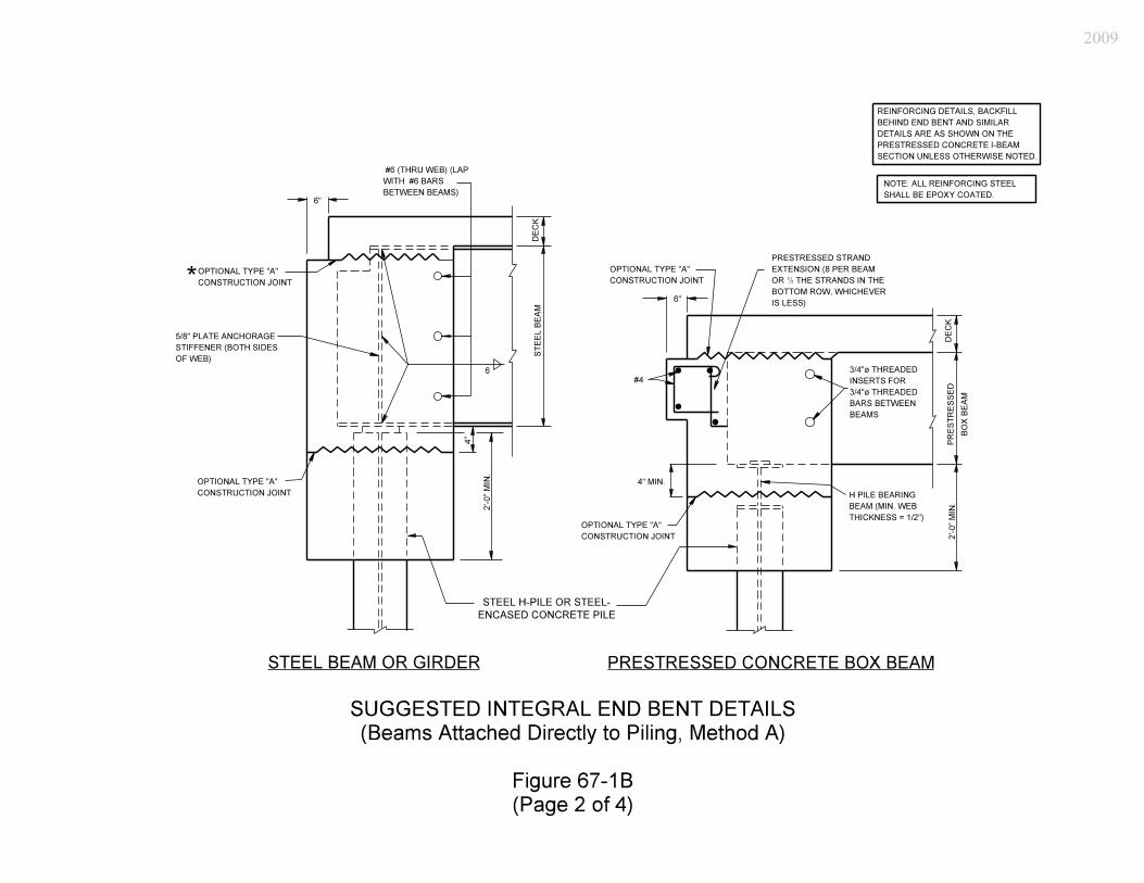
2009

2009

2009

2009
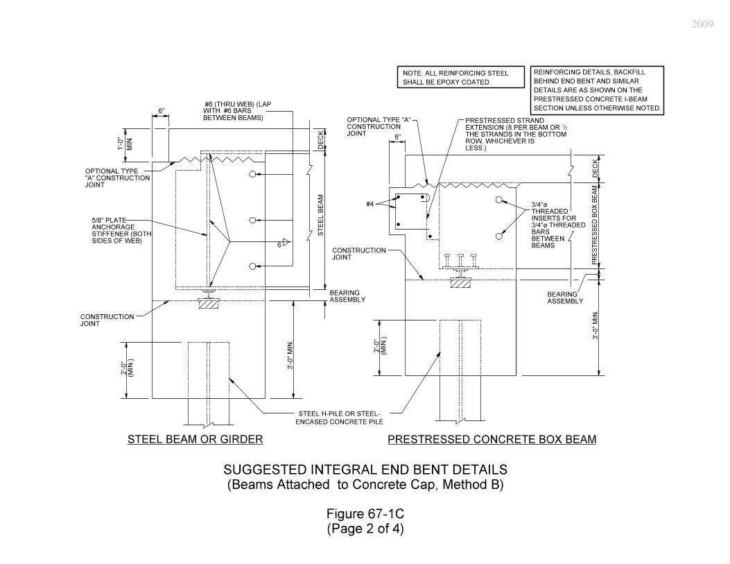
2009

2009

2009
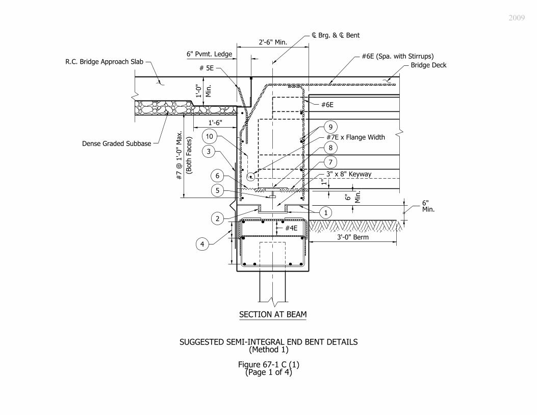
2009

2009

2009

2009

2009

2009
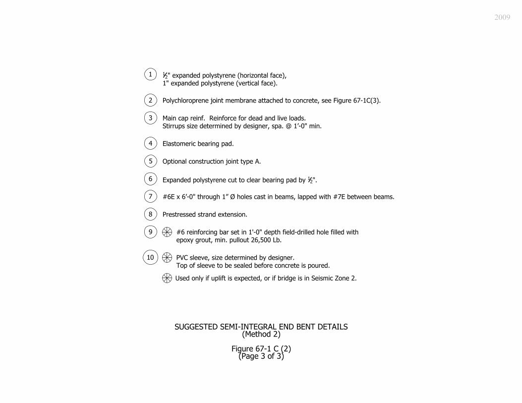
2009
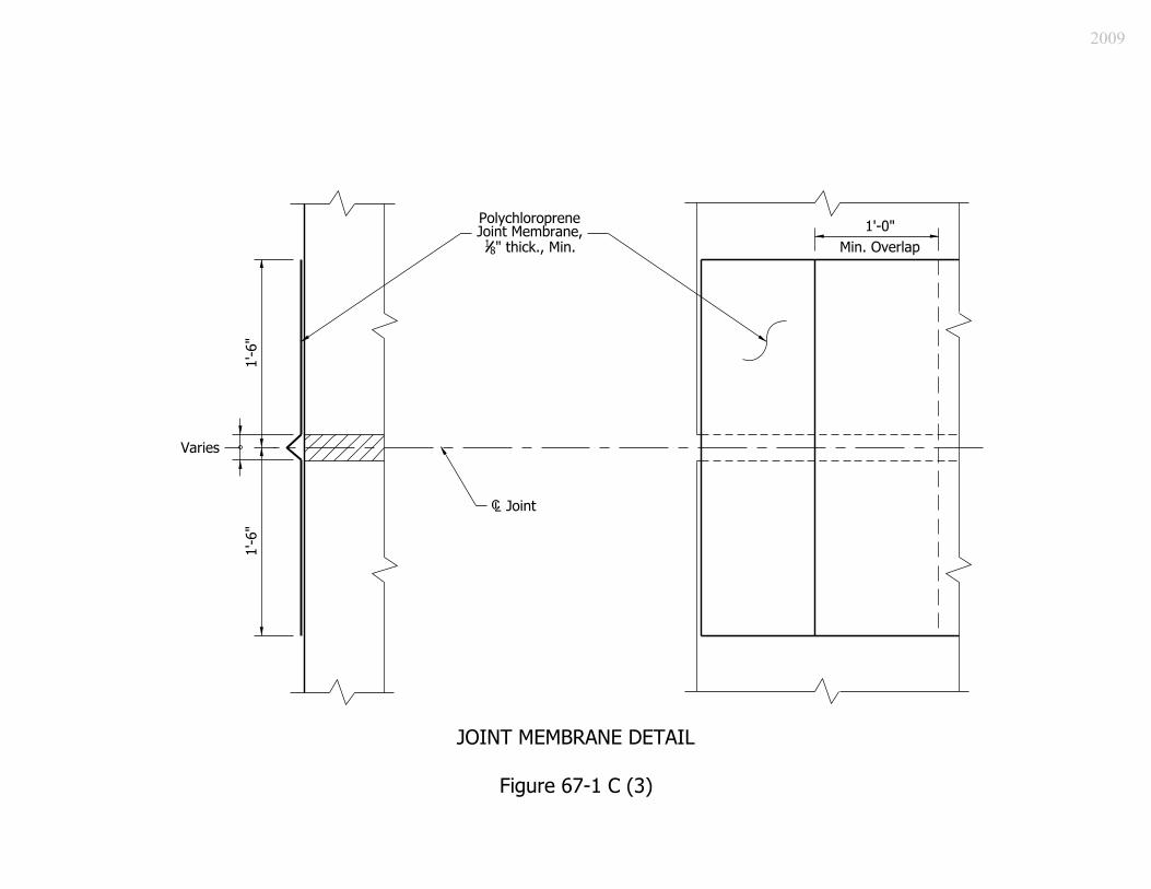
2009

2009
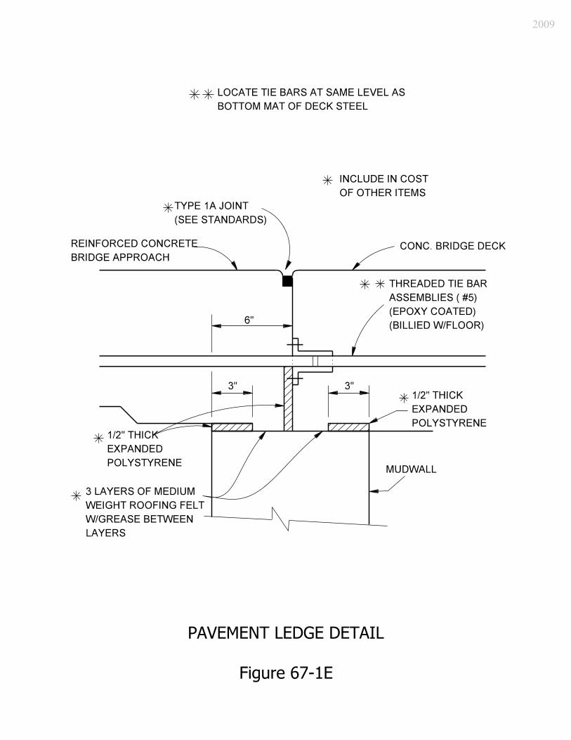
2009

2009

2009

2009

2009

2009

2009

2009

2009
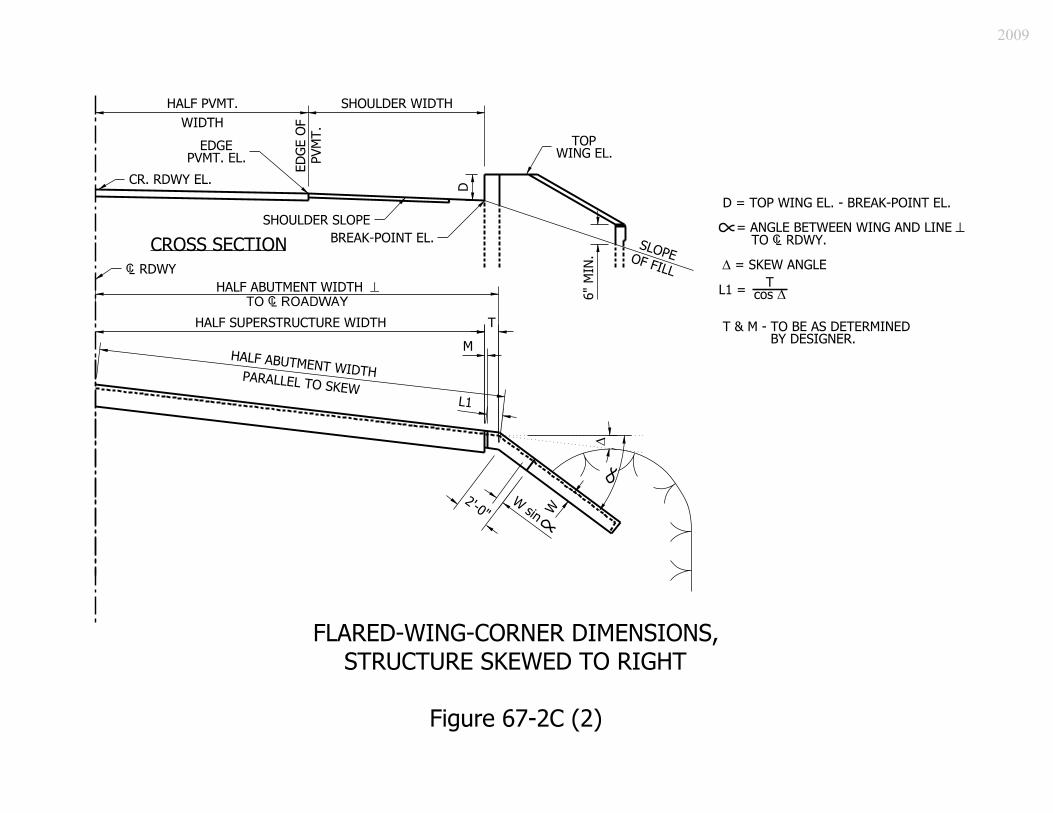
2009

2009

2009

2009
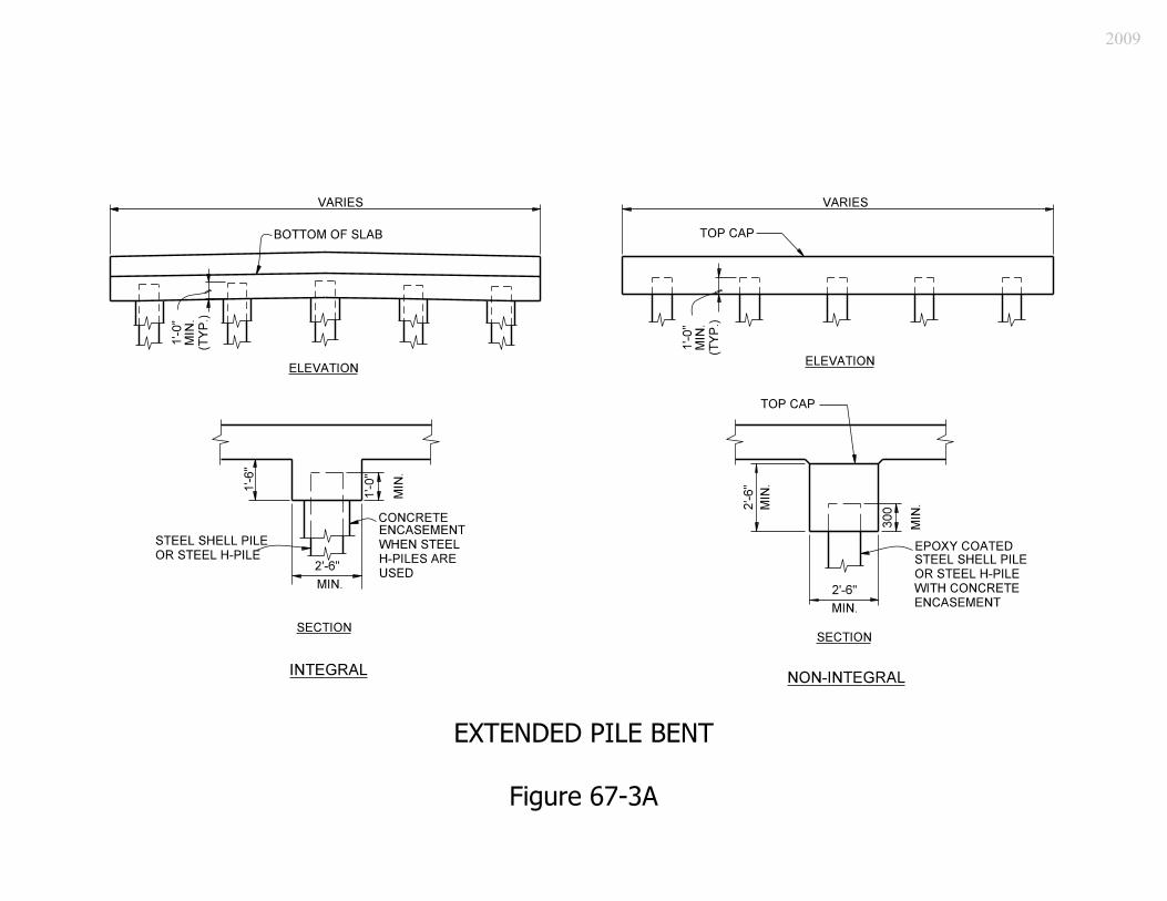
2009
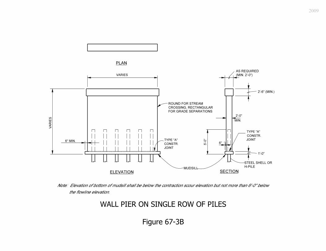
2009

2009

2009
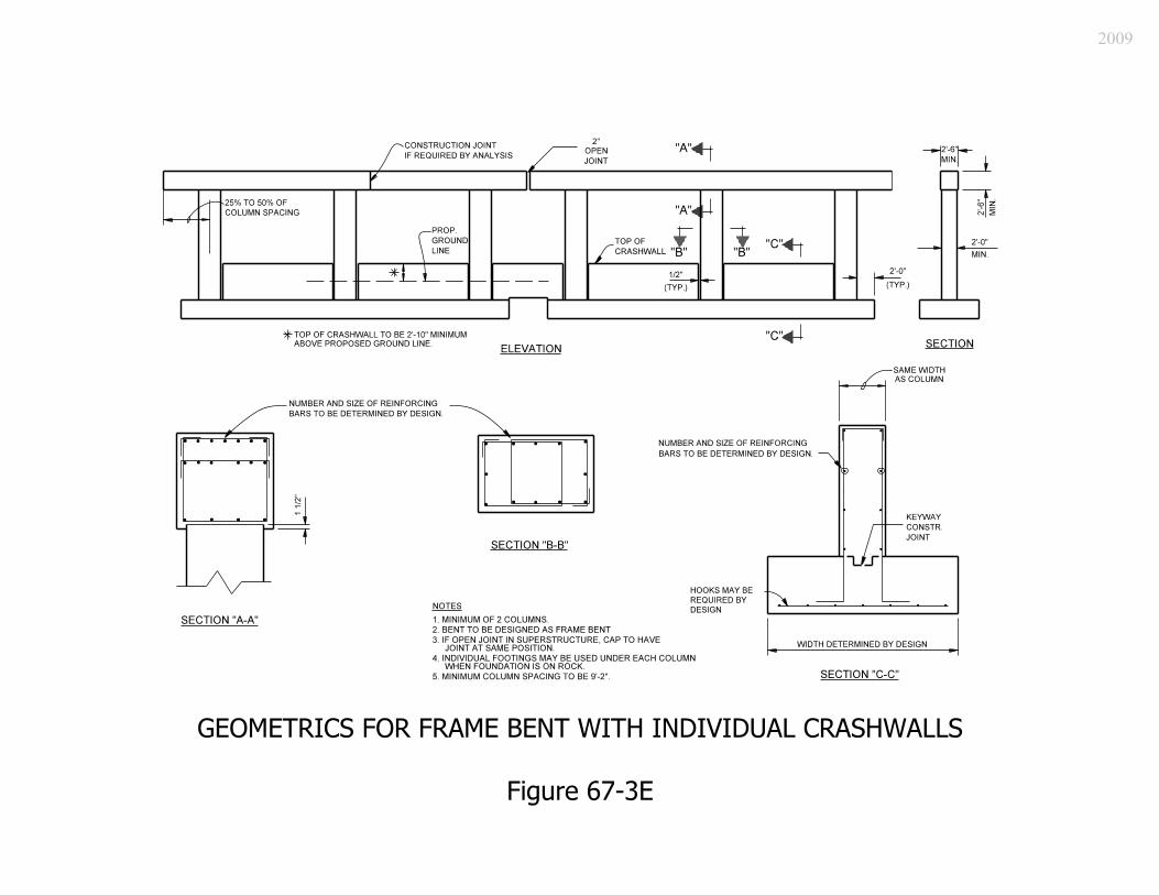
2009

2009

2009
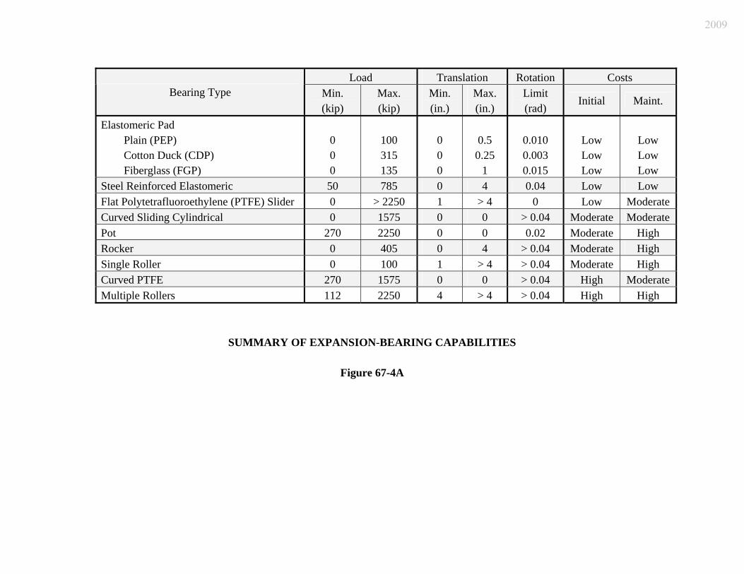
Load Translation Rotation Costs Bearing Type Min.
(kip) Max. (kip)
Min. (in.)
Max. (in.)
Limit (rad)
Initial Maint.
Elastomeric Pad Plain (PEP) Cotton Duck (CDP) Fiberglass (FGP)
0 0 0
100 315 135
0 0 0
0.5 0.25
1
0.010 0.003 0.015
Low Low Low
Low Low Low
Steel Reinforced Elastomeric 50 785 0 4 0.04 Low Low Flat Polytetrafluoroethylene (PTFE) Slider 0 > 2250 1 > 4 0 Low Moderate Curved Sliding Cylindrical 0 1575 0 0 > 0.04 Moderate Moderate Pot 270 2250 0 0 0.02 Moderate High Rocker 0 405 0 4 > 0.04 Moderate High Single Roller 0 100 1 > 4 > 0.04 Moderate High Curved PTFE 270 1575 0 0 > 0.04 High Moderate Multiple Rollers 112 2250 4 > 4 > 0.04 High High
SUMMARY OF EXPANSION-BEARING CAPABILITIES
Figure 67-4A
2009
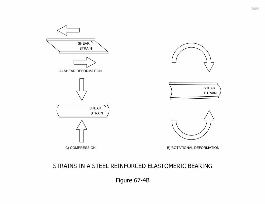
2009

Maximum DL + LL Reaction,
(kip)
Maximum Expansion
Length, (ft)
Bearing- Pad
Type
W (in.)
L (in.)
Area (in.2)
Shape Factor,
S
hrt
(in.)
Number of Internal
Elastomeric Layers, n
Allowable Compressive
Stress, σTL (psi)
99 199 1 14 10.5 147 6.00 2.0625 3 675
114 247 2 14 11.5 161 6.31 2.5625 4 710
152 247 3 18 11 198 6.83 2.5625 4 768
259 295 4 24 12 288 8.00 3.0625 5 900
ELASTOMERIC BEARING PAD TYPES, PROPERTIES, AND ALLOWABLE VALUES FOR AASHTO I-BEAMS
Figure 67-4C
2009

Maximum DL + LL Reaction,
(kip)
Maximum Expansion
Length, (ft)
Bearing- Pad
Type
W (in.)
L (in.)
Area (in.2)
Shape Factor,
S
hrt
(in.)
Number of Internal
Elastomeric Layers, n
Allowable Compressive
Stress, σTL (psi)
200 247 5A 22 11 242 7.33 2.5625 4 825
97 247 5B 12 12 144 6.00 2.5625 4 675
170 247 6A 22 10 220 6.88 2.5625 4 773
85 247 6B 12 11 132 5.74 2.5625 4 646
142 253 7A 22 9 198 6.39 2.0625 3 719
74 199 7B 12 10 120 5.45 2.0625 3 614
ELASTOMERIC BEARING PAD TYPES, PROPERTIES, AND ALLOWABLE VALUES FOR BOX BEAMS
Figure 67-4D
2009

Maximum DL + LL Reaction,
(kip)
Maximum Expansion
Length, (ft)
Bearing- Pad
Type
W (in.)
L (in.)
Area (in.2)
Shape Factor,
S
hrt
(in.)
Number of Internal
ElastomericLayers, n
Allowable Compressive
Stress, σTL (psi)
245 295 T1 23 12 276 7.89 3.0625 5 887
315 344 T2 23 14 322 8.70 3.5625 6 979
262 461 T3 23 17 391 8.23 4.7812 7 926
458 518 T4 24 19 456 8.93 5.3750 8 1005
ELASTOMERIC BEARING PAD TYPES, PROPERTIES, AND ALLOWABLE VALUES FOR INDIANA BULB-TEE MEMBERS
Figure 67-4E
2009

Maximum DL + LL Reaction,
(kip)
Maximum Expansion
Length, (ft)
Bearing- Assembly
Type
W (in.)
L (in.)
Area (in.2)
Shape Factor,
S
hrt
(in.)
Number of Internal
Elastomeric Layers, n
Allowable Compressive
Stress, σTL (psi)
46 93 S1-a 11 8 88 4.63 1.5625 2 521
46 122 S1-b 11 8 88 4.63 2.0625 3 521
62 93 S2-a 12 9 108 5.14 1.5625 2 579
62 122 S2-b 12 9 108 5.14 2.0625 3 579
83 122 S3-a 13 10 130 5.65 2.0625 3 636
83 152 S3-b 13 10 130 5.65 2.5625 4 636
118 152 S4-a 15 11 165 6.35 2.5625 4 714
118 182 S4-b 15 11 165 6.35 3.0625 5 714
148 152 S5-a 16 12 192 6.86 2.5625 4 771
148 182 S5-b 16 12 192 6.86 3.0626 5 771
230 182 S6-a 20 13 260 7.88 3.0625 5 886
230 211 S6-b 20 13 260 7.88 3.5625 6 886
289 211 S7-a 20 15 300 8.57 3.5625 6 964
289 241 S7-b 20 15 300 8.57 4.0625 7 964
ELASTOMERIC BEARING ASSEMBLY TYPES, PROPERTIES, AND ALLOWABLE VALUES FOR STRUCTURAL-STEEL MEMBERS
Figure 67-4F
2009

Nominal Shear Resistance, Rn, (kip) * Anchor Bolts, threads
included ** Threads excluded,
or pintles included ** Grade of Steel
Minimum Tensile
Strength, FU, (ksi) 1 in. 1 1/8 in. 1 3/8 in. 1 in. 1 1/8 in. 1 3/8 in.
A307 60 17.9 22.7 33.9 17.9 22.7 33.9
120 35.8 n/a n/a 45.2 n/a n/a A325 High Strength 105 n/a 39.7 59.2 n/a 50.1 74.8
* One shear plane is assumed. Multiply resistance value by number of shear planes. ** Value should be multiplied by 0.80 for a connection longer than 50 in.
NOMINAL SHEAR RESISTANCE OF ANCHOR BOLTS AND PINTLES
Figure 67-4G
2009

No. of Anchor Bolts
Diameter(in)
Span Length Range (ft)
4 1 20 ≤ Span < 100 4 1 1/8 100 ≤ Span < 1504 1 3/8 Span ≥ 150
MINIMUM CONNECTIONS FOR FIXED STEEL SHOES
Figure 67-4G(1)
2009

2009
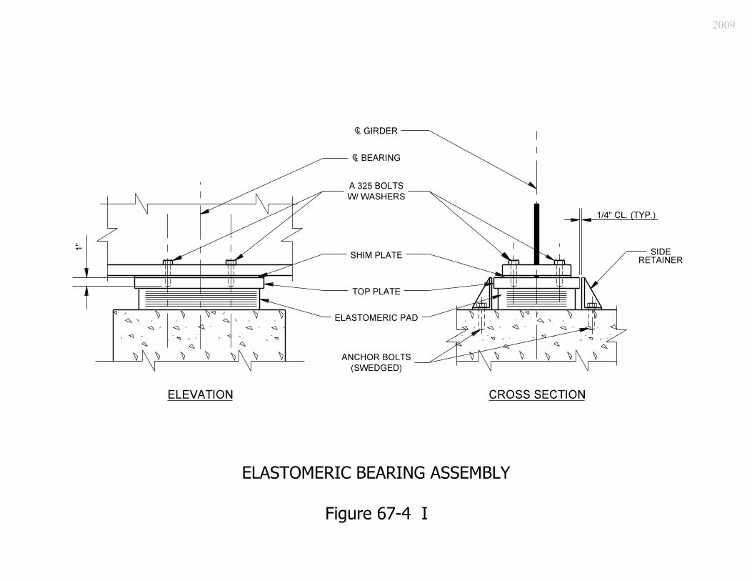
2009

2009
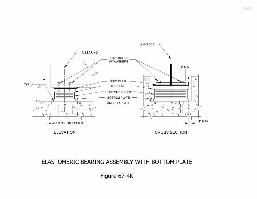
2009

2009

2009
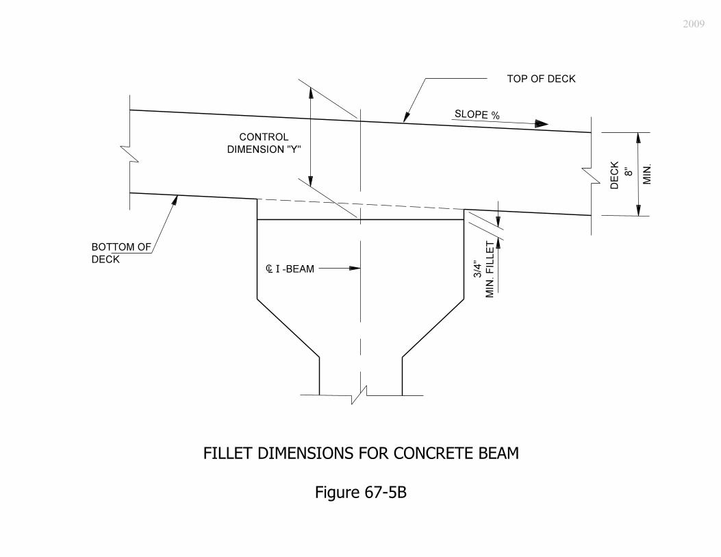
2009
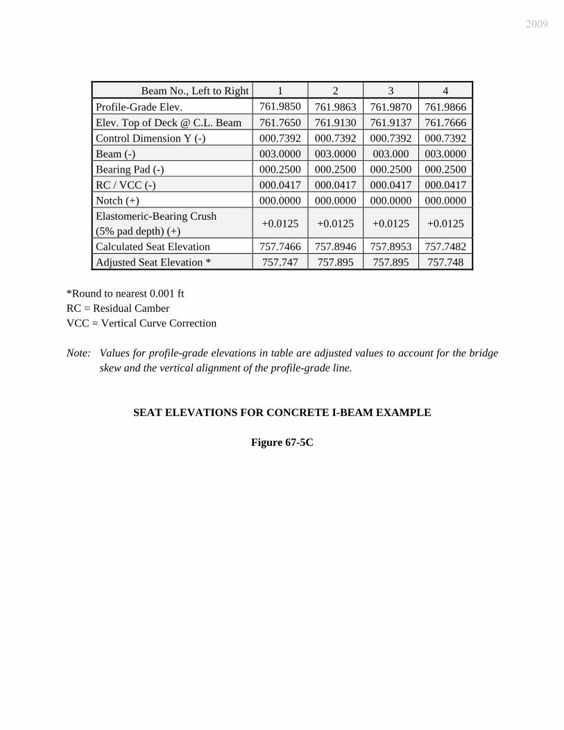
Beam No., Left to Right 1 2 3 4
Profile-Grade Elev. 761.9850 761.9863 761.9870 761.9866 Elev. Top of Deck @ C.L. Beam 761.7650 761.9130 761.9137 761.7666 Control Dimension Y (-) 000.7392 000.7392 000.7392 000.7392 Beam (-) 003.0000 003.0000 003.000 003.0000 Bearing Pad (-) 000.2500 000.2500 000.2500 000.2500 RC / VCC (-) 000.0417 000.0417 000.0417 000.0417 Notch (+) 000.0000 000.0000 000.0000 000.0000 Elastomeric-Bearing Crush (5% pad depth) (+)
+0.0125 +0.0125 +0.0125 +0.0125
Calculated Seat Elevation 757.7466 757.8946 757.8953 757.7482 Adjusted Seat Elevation * 757.747 757.895 757.895 757.748
*Round to nearest 0.001 ft RC = Residual Camber VCC = Vertical Curve Correction Note: Values for profile-grade elevations in table are adjusted values to account for the bridge
skew and the vertical alignment of the profile-grade line.
SEAT ELEVATIONS FOR CONCRETE I-BEAM EXAMPLE
Figure 67-5C
2009

2009

2009
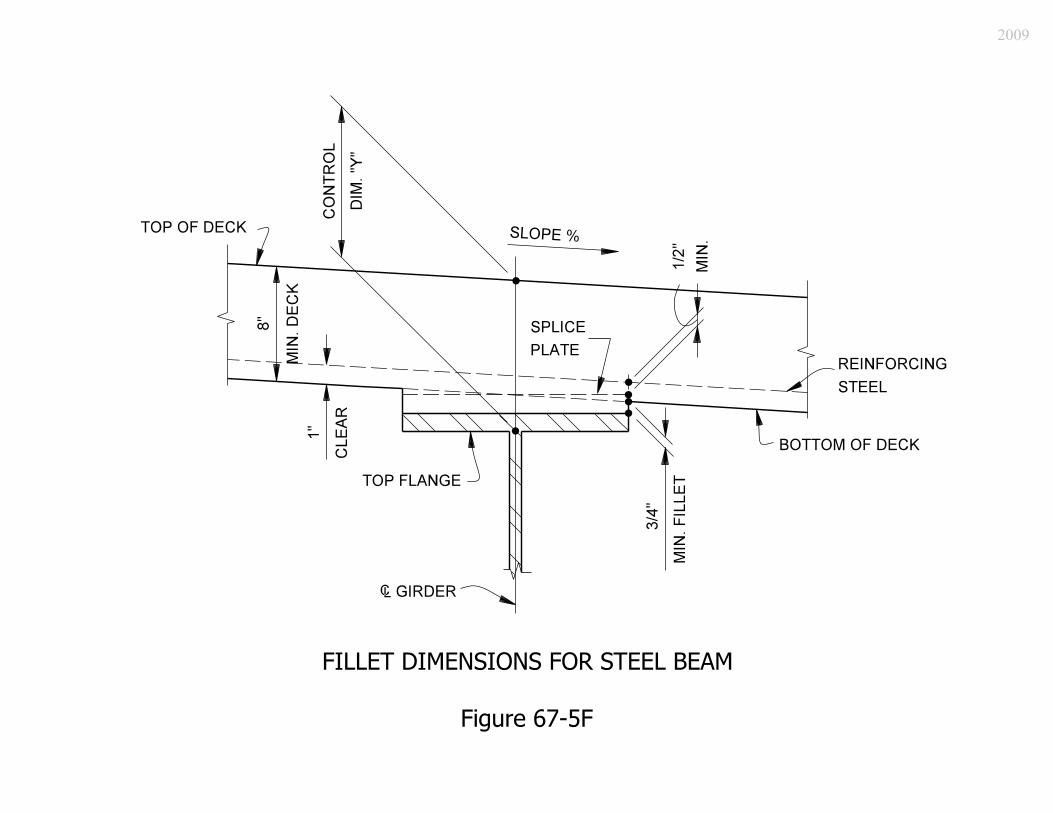
2009

Beam No., Left to Right 1 2 3 4
Profile-Grade Elev. 749.9002 749.9592 750.0182 750.0773Elev. Top of Deck @ C.L. Beam 749.5469 749.8192 749.8782 749.7240Control Dimension Y (-) 000.8675 000.8675 000.8675 000.8675Beam Web (-) 004.0000 004.0000 004.0000 004.0000Bottom Flange Plate (-) 000.1250 000.1250 000.1250 000.1250Shim above Top Shoe (-) 000.0417 000.0417 000.0417 000.0417Bearing Thickness (-) 000.3958 000.3958 000.3958 000.3958Elastomeric-Bearing Crush (5% pad depth) (+) -0- -0- -0- -0- Calculated Seat Elevation 744.1169 744.3892 744.4482 744.2940Additional Shim above Top Shoe (-) 0 0 000.059 0 Adjusted Seat Elevation 744.117 744.389 744.389 744.294
Note: Values for profile-grade elevations in table are adjusted values to account for the bridge
skew and the vertical alignment of the profile-grade line.
SEAT ELEVATIONS FOR STEEL-BEAM OR PLATE-GIRDER EXAMPLE
Figure 67-5G
2009