Embed Size (px)
Citation preview

Seats and Restraint Systems ........................... 1-1Front Seats ............................................... 1-2Rear Seats .............................................. 1-12Safety Belts ............................................. 1-14Child Restraints ....................................... 1-35Airbag System ......................................... 1-69Restraint System Check ............................ 1-88
Features and Controls ..................................... 2-1Keys ........................................................ 2-3Doors and Locks ...................................... 2-10Windows ................................................. 2-15Theft-Deterrent Systems ............................ 2-18Starting and Operating Your Vehicle ........... 2-22Mirrors .................................................... 2-56Object Detection Systems .......................... 2-64OnStar® System ...................................... 2-67Universal Home Remote System ................ 2-71Storage Areas ......................................... 2-78Sunroof .................................................. 2-82
Instrument Panel ............................................. 3-1Instrument Panel Overview .......................... 3-4Climate Controls ...................................... 3-25Warning Lights, Gages, and Indicators ........ 3-36Driver Information Center (DIC) .................. 3-56Audio System(s) ....................................... 3-84
Driving Your Vehicle ....................................... 4-1Your Driving, the Road, and Your Vehicle ..... 4-2Towing ................................................... 4-50
Service and Appearance Care .......................... 5-1Service ..................................................... 5-4Fuel ......................................................... 5-6Checking Things Under the Hood ............... 5-12Rear Axle ............................................... 5-52Four-Wheel Drive ..................................... 5-54Front Axle ............................................... 5-56Noise Control System ............................... 5-57Headlamp Aiming ..................................... 5-58Bulb Replacement .................................... 5-61Windshield Wiper Blade Replacement ......... 5-67Tires ...................................................... 5-68Appearance Care ................................... 5-114Vehicle Identification ............................... 5-124Electrical System .................................... 5-125Capacities and Specifications ................... 5-133
Maintenance Schedule ..................................... 6-1Maintenance Schedule ................................ 6-2
Customer Assistance Information .................... 7-1Customer Assistance and Information ........... 7-2Reporting Safety Defects ........................... 7-14Vehicle Data Recording and Privacy ........... 7-16
Index ................................................................ 1
2008 Chevrolet Silverado Owner Manual M

GENERAL MOTORS, GM, the GM Emblem,CHEVROLET, the CHEVROLET Emblem, and thenames SILVERADO and Z71 are registered trademarksof General Motors Corporation.
This manual includes the latest information at the time itwas printed. GM reserves the right to make changesafter that time without further notice. For vehiclesfirst sold in Canada, substitute the name “GeneralMotors of Canada Limited” for Chevrolet Motor Divisionwherever it appears in this manual.
This manual describes features that may or may not beon your specific vehicle.
Keep this manual in the vehicle for quick reference.
Canadian OwnersA French language copy of this manual can be obtainedfrom your dealer/retailer or from:
Helm, IncorporatedP.O. Box 07130Detroit, MI 48207
1-800-551-4123www.helminc.com
Propriétaires CanadiensOn peut obtenir un exemplaire de ce guide en françaisauprès de concessionnaire ou à l’adresse suivante:
Helm IncorporatedP.O. Box 07130Detroit, MI 48207
1-800-551-4123www.helminc.com
Litho in U.S.A.Part No. 15854803 B Second Printing ©2007 General Motors Corporation. All Rights Reserved.
ii

Using this ManualRead the owner manual from beginning to end to learnabout the vehicle’s features and controls. Picturesand words work together to explain things.
If the vehicle has the DURAMAX® Diesel engine, referto the DURAMAX® Diesel supplement for additionaland specific information on this engine.
IndexTo quickly locate information about the vehicle use theIndex in the back of the manual. It is an alphabeticallist of what is in the manual and the page number whereit can be found.
Safety Warnings and SymbolsThere are a number of safety cautions in this book. Abox with the word CAUTION is used to tell about thingsthat could hurt you or others if you were to ignore thewarning.
{CAUTION:
These mean there is something that could hurtyou or other people.
Cautions tell what the hazard is and what to do to avoidor reduce the hazard. Read these cautions.
A circle with a slashthrough it is a safetysymbol which means “DoNot,” “Do Not do this”or “Do Not let this happen.”
iii

Vehicle Damage WarningsNotices are also used in this manual.
Notice: These mean there is something that coulddamage your vehicle.
A notice tells about something that can damage thevehicle. Many times, this damage would not be coveredby the vehicle’s warranty, and it could be costly. Thenotice tells what to do to help avoid the damage.
When you read other manuals, you might see CAUTIONand NOTICE warnings in different colors or in differentwords.
There are also warning labels on the vehicle which usethe same words, CAUTION or NOTICE.
Vehicle SymbolsThe vehicle has components and labels that usesymbols instead of text. Symbols are shown along withthe text describing the operation or informationrelating to a specific component, control, message,gage, or indicator.
iv

Front Seats ......................................................1-2Manual Seats ................................................1-2Power Seats ..................................................1-3Manual Lumbar ..............................................1-4Power Lumbar ...............................................1-4Heated Seats .................................................1-5Memory Seat, Mirrors, and Pedals ....................1-6Reclining Seatbacks ........................................1-8Head Restraints ............................................1-11Seatback Latches .........................................1-12Center Seat .................................................1-12
Rear Seats .....................................................1-12Rear Seat Operation (Full Bench) ...................1-12Rear Seat Operation (Split Bench) ..................1-13
Safety Belts ...................................................1-14Safety Belts: They Are for Everyone ................1-14How to Wear Safety Belts Properly .................1-19Lap-Shoulder Belt .........................................1-28Safety Belt Use During Pregnancy ..................1-33Lap Belt (Crew and Extended Cab) .................1-34Safety Belt Extender .....................................1-35
Child Restraints .............................................1-35Older Children ..............................................1-35Infants and Young Children ............................1-39Child Restraint Systems .................................1-42Where to Put the Restraint .............................1-44
Lower Anchors and Tethers for Children(LATCH) ..................................................1-45
Securing a Child Restraint in a Rear SeatPosition ...................................................1-54
Securing a Child Restraint in the CenterFront Seat Position ....................................1-57
Securing a Child Restraint in the Right FrontSeat Position (With Airbag Off Switch) ..........1-57
Securing a Child Restraint in the Right Front SeatPosition (With Passenger Sensing System) .....1-62
Securing a Child Restraint in the Right FrontSeat Position (Heavy Duty Crew Cab Only) ......1-66
Airbag System ...............................................1-69Where Are the Airbags? ................................1-72When Should an Airbag Inflate? .....................1-74What Makes an Airbag Inflate? .......................1-75How Does an Airbag Restrain? .......................1-76What Will You See After an Airbag Inflates? .....1-76Airbag Off Switch ..........................................1-78Passenger Sensing System ............................1-81Servicing Your Airbag-Equipped Vehicle ...........1-86Adding Equipment to Your Airbag-Equipped
Vehicle ....................................................1-86Restraint System Check ..................................1-88
Checking the Restraint Systems ......................1-88Replacing Restraint System Parts After a Crash ...1-89
Section 1 Seats and Restraint Systems
1-1

Front Seats
Manual Seats
{CAUTION:
You can lose control of the vehicle if you try toadjust a manual driver’s seat while the vehicleis moving. The sudden movement could startleand confuse you, or make you push a pedalwhen you do not want to. Adjust the driver’sseat only when the vehicle is not moving.
To move a manual seat forward or rearward:
1. Lift the bar to unlockthe seat.
2. Slide the seat to thedesired position andrelease the bar.
Try to move the seat with your body to be sure the seatis locked in place.
1-2
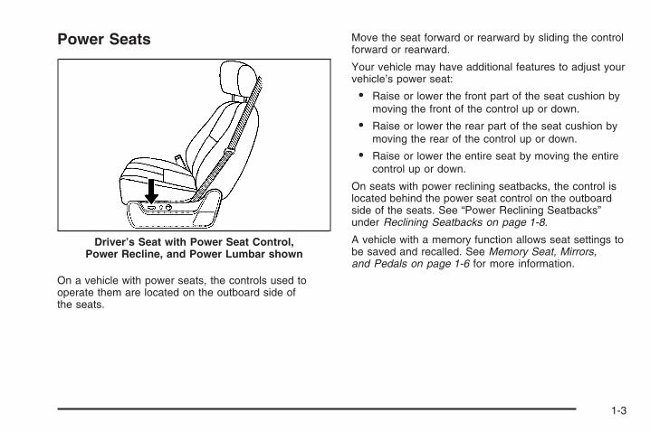
Power Seats
On a vehicle with power seats, the controls used tooperate them are located on the outboard side ofthe seats.
Move the seat forward or rearward by sliding the controlforward or rearward.
Your vehicle may have additional features to adjust yourvehicle’s power seat:
• Raise or lower the front part of the seat cushion bymoving the front of the control up or down.
• Raise or lower the rear part of the seat cushion bymoving the rear of the control up or down.
• Raise or lower the entire seat by moving the entirecontrol up or down.
On seats with power reclining seatbacks, the control islocated behind the power seat control on the outboardside of the seats. See “Power Reclining Seatbacks”under Reclining Seatbacks on page 1-8.
A vehicle with a memory function allows seat settings tobe saved and recalled. See Memory Seat, Mirrors,and Pedals on page 1-6 for more information.
Driver’s Seat with Power Seat Control,Power Recline, and Power Lumbar shown
1-3

Manual Lumbar
On vehicles with this feature the control is located onthe outboard side of the seat.
Increase or decrease lumbar support by turning theknob forward or rearward.
Power Lumbar
On vehicles with power lumbar, the controls used tooperate this feature are located on the outboard side ofthe seats.
• To increase lumbar support, press and hold thefront of the control.
• To decrease lumbar support, press and hold therear of the control.
1-4
The vehicle may have additional features to adjust thepower lumbar:
• To raise the height of the lumbar support, pressand hold the top of the control.
• To lower the height of the lumbar support, pressand hold the bottom of the control.
Release the control when the lower seatback reachesthe desired level of lumbar support.
Vehicles with a memory function allow seat settings tobe saved and recalled. See Memory Seat, Mirrors,and Pedals on page 1-6 for more information.
Heated SeatsOn vehicles with heated front seats, the controls arelocated on the driver’s and passenger’s doors.
I (Heated Seatback): Press to turn on the heatedseatback.
J (Heated Seat and Seatback): Press to turn on theheated seat and seatback.
The light on the button will come on to indicate that thefeature is working. Press the button to cycle through thetemperature settings of high, medium, and low and to turnthe heat to the seat off. Indicator lights will show the levelof heat selected: three for high, two for medium, and onefor low.
The heated seats will be canceled ten seconds after theignition is turned off. To use the heated seat featureafter restarting your vehicle, press the heated seator seatback button again.
1-5

Memory Seat, Mirrors, and PedalsYour vehicle may have the memory package.
The controls for thisfeature are located on thedriver’s door panel, and areused to program and recallmemory settings for thedriver’s seat, outsidemirrors, and the adjustablethrottle and brake pedal.
To save your positions in memory, do the following:
1. Adjust the driver’s seat, including the seatbackrecliner and lumbar, both outside mirrors, andthe throttle and brake pedals to a comfortableposition.See Outside Power Mirrors on page 2-61 andAdjustable Throttle and Brake Pedal on page 2-26for more information.Not all mirrors will have the ability to save andrecall their positions.Not all adjustable throttles and brake pedals willhave the ability to save and recall their positions.
2. Press and hold button 1 until two beeps are heardindicating that the position has been stored.
A second seating, mirror, and throttle and brake pedalposition can be programmed by repeating the abovesteps and pressing button 2.
1-6
To recall the memory positions, the vehicle must be inPARK (P). Press and release either button 1 or button 2corresponding to the desired driving position. The seat,outside mirrors, and adjustable throttle and brake pedalswill move to the position previously stored. You will hear asingle beep.
If you use the remote keyless entry transmitter to enteryour vehicle and the remote recall memory feature is on,automatic seat, adjustable mirror, and adjustable pedalmovements will occur. See “MEMORY SEAT RECALL”under DIC Vehicle Customization (With DIC Buttons) onpage 3-76 for more information.
To stop recall movement of the memory function at anytime, press one of the power seat controls, memorybuttons, power mirror buttons, or adjustable pedalswitch.
If something has blocked the driver’s seat and/or theadjustable pedals while recalling a memory position,the driver’s seat and/or the adjustable pedals recall maystop working. If this happens, remove the obstructionand press the appropriate control for the area that is notresponding for two seconds. Try recalling the memoryposition again by pressing the appropriate memorybutton. If the memory position is still not recalling,see your dealer for service.
Easy Exit SeatThe control for this feature is located on the driver’sdoor panel between buttons 1 and 2.
With the vehicle in PARK (P), the driver’s seat exitposition can be recalled by pressing the exit button.You will hear a single beep, and the driver’s seatwill move back.
If the easy exit seat feature is programmed in the DriverInformation Center (DIC), automatic seat movement willoccur when the key is removed from the ignition. See“EASY EXIT SEAT” under DIC Vehicle Customization(With DIC Buttons) on page 3-76 for more information.
The memory seat and easy exit features can also beprogrammed using the DIC.
For programming information, see DIC VehicleCustomization (With DIC Buttons) on page 3-76.
1-7

Reclining Seatbacks
{CAUTION:
You can lose control of the vehicle if you try toadjust a manual driver’s seat while the vehicleis moving. The sudden movement could startleand confuse you, or make you push a pedalwhen you do not want to. Adjust the driver’sseat only when the vehicle is not moving.
{CAUTION:
If the seatback is not locked, it could moveforward in a sudden stop or crash. That couldcause injury to the person sitting there. Alwayspush and pull on the seatback to be sure it islocked.
1-8

{CAUTION:
Sitting in a reclined position when your vehicleis in motion can be dangerous. Even if youbuckle up, your safety belts cannot do theirjob when you are reclined like this.
The shoulder belt cannot do its job. In a crash,you could go into it, receiving neck or otherinjuries.
The lap belt cannot do its job either. In a crashthe belt could go up over your abdomen. Thebelt forces would be there, not at your pelvicbones. This could cause serious internalinjuries.
For proper protection when the vehicle is inmotion, have the seatback upright. Then sitwell back in the seat and wear your safety beltproperly.
Manual Reclining SeatbacksOn seats with manual reclining seatbacks, the leverused to operate them is located on the outboard side ofthe seat(s).
To recline the seatback:
1. Lift the recline lever.
2. Move the seatback to the desired position, thenrelease the lever to lock the seatback in place.
3. Push and pull on the seatback to make sure it islocked.
1-9

To return the seatback to an upright position, do thefollowing:
1. Lift the lever fully without applying pressure to theseatback and the seatback will return to the uprightposition.
2. Push and pull on the seatback to make sure it islocked.
Power Reclining Seatbacks
If the seats have power reclining seatbacks, the controlused to recline them is located on the outboard sideof the seat behind the power seat control.
• To recline the seatback, tilt the top of the controlrearward.
• To bring the seatback forward, tilt the top of thecontrol forward.
Do not have a seatback reclined if your vehicle ismoving.
1-10
Head Restraints
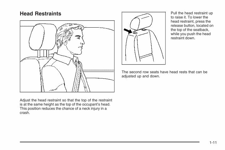
Adjust the head restraint so that the top of the restraintis at the same height as the top of the occupant’s head.This position reduces the chance of a neck injury in acrash.
Pull the head restraint upto raise it. To lower thehead restraint, press therelease button, located onthe top of the seatback,while you push the headrestraint down.
The second row seats have head rests that can beadjusted up and down.
1-11

Seatback LatchesThe front seatbacks tilt forward to allow access to therear of the cab.To tilt the seatback forward, lift the lever located on theoutboard side of the seat cushion.
{CAUTION:
If the seatback is not locked, it could moveforward in a sudden stop or crash. That couldcause injury to the person sitting there. Alwayspush and pull on the seatback to be sure it islocked.
To return the seatback to the upright position, push theseatback rearward until it latches. After returning theseatback to its upright position, push and pull onthe seatback to make sure it is locked.
Center SeatYour vehicle may have a front center seat. The seatbackdoubles as an armrest and cupholder/storage area forthe driver and passenger when the center seat isnot used. Do not use it as a seating position when theseatback is folded down.
Rear SeatsRear Seat Operation (Full Bench)Folding the Rear SeatTo fold the seat up, do the following:
Notice: Folding a rear seat with the safety beltsstill fastened may cause damage to the seat or thesafety belts. Always unbuckle the safety beltsand return them to their normal stowed positionbefore folding a rear seat.
1. Pull up on the front ofthe seat cushion whilepulling down on therelease strap, locatedunder the seat cushion.
2. Pull the seat cushion up until it latches with theseatback.
3. After latching the seat cushion up, pull forward on itto make sure it is locked.
1-12

To fold the seat down, do the following:
1. Push the seat cushion rearward while pulling therelease strap, located under the seat cushion.Pull the seat cushion down until it latches.
2. After latching the seat cushion, pull up on it tomake sure it is locked.
Rear Seat Operation (Split Bench)
Folding Rear SeatOn a vehicle with a second row 60/40 split seat eitherside of the rear seat may be folded for added cargospace.
Notice: Folding a rear seat with the safety beltsstill fastened may cause damage to the seat orthe safety belts. Always unbuckle the safety beltsand return them to their normal stowed positionbefore folding a rear seat.
Make sure that nothing is on the seat.
To fold the seat, slowly pull the seat cushion up.
To return the seat to the normal seating position, slowlypull the seat cushion down.
{CAUTION:
A safety belt that is improperly routed, notproperly attached, or twisted will not providethe protection needed in a crash. The personwearing the belt could be seriously injured.After raising the rear seatback, always checkto be sure that the safety belts are properlyrouted and attached, and are not twisted.
1-13

Safety Belts
Safety Belts: They Are for EveryoneThis part of the manual tells you how to use safetybelts properly. It also tells you some things you shouldnot do with safety belts.
{CAUTION:
Do not let anyone ride where he or she cannotwear a safety belt properly. If you are in a crashand you are not wearing a safety belt, yourinjuries can be much worse. You can hit thingsinside the vehicle harder or be ejected from itand be seriously injured or killed. In the samecrash, you might not be, if you are buckled up.Always fasten your safety belt, and check thatyour passenger(s) are restrained properly too.
{CAUTION:
People riding on the tailgate (if equipped) caneasily lose their balance and fall even whenthe vehicle is operated at low speeds. Fallingfrom a moving vehicle may result in seriousinjuries or death.
{CAUTION:
It is extremely dangerous to ride in a cargoarea, inside or outside of a vehicle. In acollision, people riding in these areas are morelikely to be seriously injured or killed. Do notallow people to ride in any area of your vehiclethat is not equipped with seats and safety belts.Be sure everyone in your vehicle is in a seat andusing a safety belt properly.
Your vehicle has indicators as a reminder to buckle yoursafety belts. See Safety Belt Reminders on page 3-39.
1-14

In most states and in all Canadian provinces, the lawrequires wearing safety belts. Here is why:
You never know if you will be in a crash. If you do havea crash, you do not know if it will be a serious one.
A few crashes are mild, and some crashes can beso serious that even buckled up, a person would notsurvive. But most crashes are in between. In manyof them, people who buckle up can survive andsometimes walk away. Without belts they couldhave been badly hurt or killed.
After more than 40 years of safety belts in vehicles,the facts are clear. In most crashes buckling up doesmatter... a lot!
Why Safety Belts WorkWhen you ride in or on anything, you go as fast asit goes.
Take the simplest vehicle. Suppose it is just a seat onwheels.
1-15

Put someone on it. Get it up to speed. Then stop the vehicle. The riderdoes not stop.
1-16
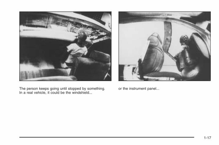
The person keeps going until stopped by something.In a real vehicle, it could be the windshield...
or the instrument panel...
1-17

or the safety belts!
With safety belts, you slow down as the vehicle does.You get more time to stop. You stop over more distance,and your strongest bones take the forces. That is whysafety belts make such good sense.
Questions and Answers AboutSafety Belts
Q: Will I be trapped in the vehicle after a crash if Iam wearing a safety belt?
A: You could be — whether you are wearing a safetybelt or not. But your chance of being consciousduring and after an accident, so you can unbuckleand get out, is much greater if you are belted.And you can unbuckle a safety belt, even if youare upside down.
Q: If my vehicle has airbags, why should I have towear safety belts?
A: Airbags are supplemental systems only; so theywork with safety belts — not instead of them.Whether or not an airbag is provided, all occupantsstill have to buckle up to get the most protection.That is true not only in frontal collisions, butespecially in side and other collisions.
1-18

Q: If I am a good driver, and I never drive far fromhome, why should I wear safety belts?
A: You may be an excellent driver, but if you are in acrash — even one that is not your fault — you andyour passenger(s) can be hurt. Being a good driverdoes not protect you from things beyond yourcontrol, such as bad drivers.
Most accidents occur within 25 miles (40 km) ofhome. And the greatest number of serious injuriesand deaths occur at speeds of less than 40 mph(65 km/h).
Safety belts are for everyone.
How to Wear Safety Belts ProperlyThis section is only for people of adult size.
Be aware that there are special things to know aboutsafety belts and children. And there are differentrules for smaller children and babies. If a child will beriding in your vehicle, see Older Children on page 1-35or Infants and Young Children on page 1-39. Followthose rules for everyone’s protection.
It is very important for all occupants to buckle up.Statistics show that unbelted people are hurt more oftenin crashes than those who are wearing safety belts.
Occupants who are not buckled up can be thrown out ofthe vehicle in a crash. And they can strike others inthe vehicle who are wearing safety belts.
First, before you or your passenger(s) wear a safetybelt, there is important information you should know.
1-19

Sit up straight and always keep your feet on the floor infront of you. The lap part of the belt should be worn lowand snug on the hips, just touching the thighs. In a crash,this applies force to the strong pelvic bones and youwould be less likely to slide under the lap belt. If you slidunder it, the belt would apply force on your abdomen.This could cause serious or even fatal injuries. Theshoulder belt should go over the shoulder and across thechest. These parts of the body are best able to take beltrestraining forces.
The shoulder belt locks if there is a sudden stop orcrash.
1-20

Q: What is wrong with this?
A: The shoulder belt is too loose. It will not give asmuch protection this way.
{CAUTION:
You can be seriously hurt if your shoulderbelt is too loose. In a crash, you would moveforward too much, which could increase injury.The shoulder belt should fit snugly againstyour body.
1-21

Q: What is wrong with this?
A: The lap belt is too loose. It will not give nearly asmuch protection this way.
{CAUTION:
You can be seriously hurt if your lap belt is tooloose. In a crash, you could slide under the lapbelt and apply force on your abdomen. Thiscould cause serious or even fatal injuries. Thelap belt should be worn low and snug on thehips, just touching the thighs.
1-22

Q: What is wrong with this?
A: The belt is buckled in the wrong place.
{CAUTION:
You can be seriously injured if your belt isbuckled in the wrong place like this. In a crash,the belt would go up over your abdomen. Thebelt forces would be there, not on the pelvicbones. This could cause serious internalinjuries. Always buckle your belt into thebuckle nearest you.
1-23

Q: What is wrong with this?
A: The belt is over an armrest.
{CAUTION:
You can be seriously injured if your belt goesover an armrest like this. The belt would bemuch too high. In a crash, you can slide underthe belt. The belt force would then be appliedon the abdomen, not on the pelvic bones, andthat could cause serious or fatal injuries.Be sure the belt goes under the armrests.
1-24
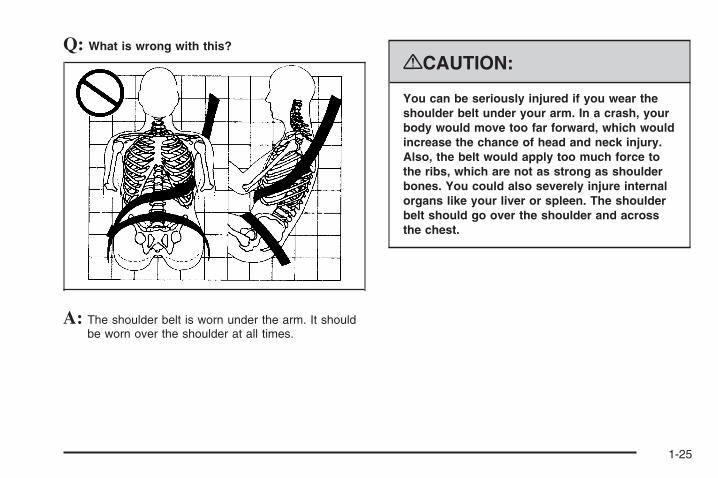
Q: What is wrong with this?
A: The shoulder belt is worn under the arm. It shouldbe worn over the shoulder at all times.
{CAUTION:
You can be seriously injured if you wear theshoulder belt under your arm. In a crash, yourbody would move too far forward, which wouldincrease the chance of head and neck injury.Also, the belt would apply too much force tothe ribs, which are not as strong as shoulderbones. You could also severely injure internalorgans like your liver or spleen. The shoulderbelt should go over the shoulder and acrossthe chest.
1-25

Q: What is wrong with this?
A: The belt is behind the body.
{CAUTION:
You can be seriously injured by not wearingthe lap-shoulder belt properly. In a crash, youwould not be restrained by the shoulder belt.Your body could move too far forwardincreasing the chance of head and neck injury.You might also slide under the lap belt. Thebelt force would then be applied right on theabdomen. That could cause serious or fatalinjuries. The shoulder belt should go over theshoulder and across the chest.
1-26

Q: What is wrong with this?
A: The belt is twisted across the body.
{CAUTION:
You can be seriously injured by a twisted belt.In a crash, you would not have the full width ofthe belt to spread impact forces. If a belt istwisted, make it straight so it can workproperly, or ask your dealer/retailer to fix it.
1-27

Lap-Shoulder BeltAll seating positions in your vehicle have a lap-shoulderbelt except for the center front passenger position(if equipped) if your vehicle is a crew or extendedcab, which has a lap belt. See Lap Belt (Crew andExtended Cab) on page 1-34 for more information.
Here is how to wear a lap-shoulder belt properly.
1. Adjust the seat, if the seat is adjustable, so you cansit up straight. To see how, see “Seats” in the Index.
2. Pick up the latch plate and pull the belt across you.Do not let it get twisted.The lap-shoulder belt may lock if you pull the beltacross you very quickly. If this happens, let thebelt go back slightly to unlock it. Then pull the beltacross you more slowly.If you ever pull the shoulder portion of a passengerbelt out all the way, you may engage the childrestraint locking feature. If this happens, just letthe belt go back all the way and start again.Engaging the child restraint locking featuremay affect the passenger sensing system.See Passenger Sensing System on page 1-81.
3. Push the latch plate into the buckle until it clicks.Pull up on the latch plate to make sure it is secure.If the belt is not long enough, see Safety BeltExtender on page 1-35.Make sure the release button on the buckle ispositioned so you would be able to unbuckle thesafety belt quickly if necessary.
4. If equipped with a shoulder belt height adjuster,move it to the height that is right for you. Impropershoulder belt height adjustment could reducethe effectiveness of the safety belt in a crash.See “Shoulder Belt Height Adjustment” later inthis section.
1-28

5. To make the lap part tight, pull up on theshoulder belt.It may be necessary to pull stitching on the safetybelt through the latch plate to fully tighten thelap belt on smaller occupants.
To unlatch the belt, just push the button on the buckle.
Before you close a door, be sure the belt is out ofthe way. If you slam the door on it, you can damageboth the belt and your vehicle.
1-29

Shoulder Belt Height AdjusterYour vehicle has a shoulder belt height adjuster for thedriver and right front passenger.
Adjust the height so that the shoulder portion of thebelt is centered on your shoulder. The belt shouldbe away from your face and neck, but not falling offyour shoulder. Improper shoulder belt height adjustmentcould reduce the effectiveness of the safety belt in acrash.
To move the adjusterdown for the regular andcrew cabs, squeeze thebuttons (A) on the sides ofthe height adjuster andmove the height adjusterto the desired position.
On the extended cabs,push down on the releasebutton (A) and movethe height adjuster tothe desired position.
You can move the adjuster up just by pushing up on theshoulder belt guide.
After you move the adjuster to where you want it, try tomove it down, without squeezing the buttons for theregular and crew cabs, or without pushing the releasebutton for extended cabs, to make sure it has locked intoposition.
Regular and Crew Cab
Extended Cab
1-30

Safety Belt PretensionersYour vehicle has safety belt pretensioners for frontoutboard occupants. Although you cannot see them,they are part of the safety belt assembly. They can helptighten the safety belts during the early stages of amoderate to severe frontal, near frontal, or rear crash ifthe threshold conditions for pretensioner activation aremet. And, if your vehicle has side impact airbags, safetybelt pretensioners can help tighten the safety belts in aside crash or a rollover event.
Pretensioners work only once. If they activate in acrash, you will need to get new ones, and probably othernew parts for your safety belt system. See ReplacingRestraint System Parts After a Crash on page 1-89.
Rear Safety Belt Comfort GuidesRear shoulder belt comfort guides may provide addedsafety belt comfort for older children who have outgrownbooster seats and for some adults. When installed ona shoulder belt, the comfort guide positions the beltaway from the neck and head.
There is one guide for each outboard passengerposition in the rear seat. Here is how to install acomfort guide to the shoulder belt:
1. Remove the guide from its storage clip on theinterior body.
2. Place the guide over the belt and insert thetwo edges of the belt into the slots of the guide.
1-31
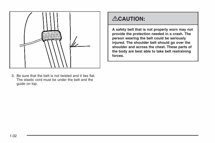
3. Be sure that the belt is not twisted and it lies flat.The elastic cord must be under the belt and theguide on top.
{CAUTION:
A safety belt that is not properly worn may notprovide the protection needed in a crash. Theperson wearing the belt could be seriouslyinjured. The shoulder belt should go over theshoulder and across the chest. These parts ofthe body are best able to take belt restrainingforces.
1-32
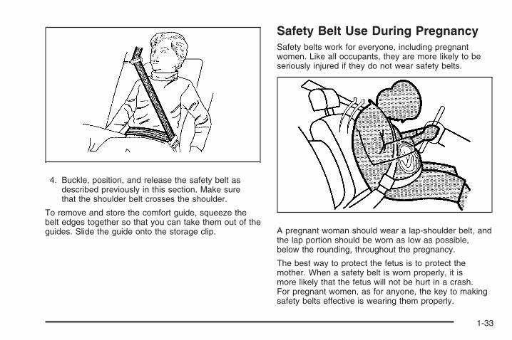
4. Buckle, position, and release the safety belt asdescribed previously in this section. Make surethat the shoulder belt crosses the shoulder.
To remove and store the comfort guide, squeeze thebelt edges together so that you can take them out of theguides. Slide the guide onto the storage clip.
Safety Belt Use During PregnancySafety belts work for everyone, including pregnantwomen. Like all occupants, they are more likely to beseriously injured if they do not wear safety belts.
A pregnant woman should wear a lap-shoulder belt, andthe lap portion should be worn as low as possible,below the rounding, throughout the pregnancy.
The best way to protect the fetus is to protect themother. When a safety belt is worn properly, it ismore likely that the fetus will not be hurt in a crash.For pregnant women, as for anyone, the key to makingsafety belts effective is wearing them properly.
1-33

Lap Belt (Crew and Extended Cab)This part is only for the lap belt. To learn how to wear alap-shoulder belt, see Lap-Shoulder Belt on page 1-28.
You vehicle may have a center seating position.When you sit in the center front seating position, youhave a lap safety belt, which has no retractor.
To make the belt longer, tilt the latch plate and pull italong the belt.
To make the belt shorter, pull its free end as shownuntil the belt is snug.
Buckle, position, and release it the same way as thelap part of a lap-shoulder belt. If the belt is not longenough, see Safety Belt Extender on page 1-35.
Make sure the release button on the buckle is positionedso you would be able to unbuckle the safety beltquickly if necessary.
1-34
Safety Belt ExtenderIf the safety belt will fasten around you, you shoulduse it.
But if a safety belt is not long enough, your dealer/retailer will order you an extender. When you go in toorder it, take the heaviest coat you will wear, so theextender will be long enough for you. To help avoidpersonal injury, do not let someone else use it, and use itonly for the seat it is made to fit. The extender has beendesigned for adults. Never use it for securing child seats.To wear it, attach it to the regular safety belt. For moreinformation, see the instruction sheet that comes with theextender.
Child Restraints
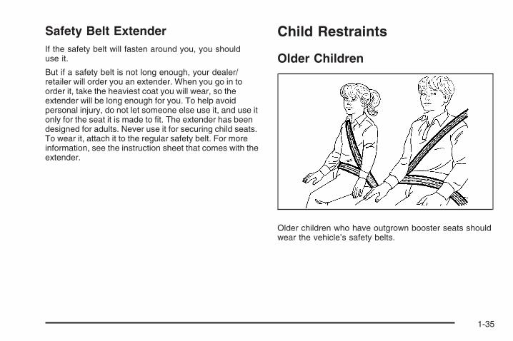
Older Children
Older children who have outgrown booster seats shouldwear the vehicle’s safety belts.
1-35
The manufacturer’s instructions that come with thebooster seat state the weight and height limitations forthat booster. Use a booster seat with a lap-shoulder beltuntil the child passes the below fit test:
• Sit all the way back on the seat. Do the knees bendat the seat edge? If yes, continue. If no, return tothe booster seat.
• Buckle the lap-shoulder belt. Does the shoulder beltrest on the shoulder? If yes, continue. If no, tryusing the rear safety belt comfort guide. See “RearSafety Belt Comfort Guides” under Lap-ShoulderBelt on page 1-28 for more information. If theshoulder belt still does not rest on the shoulder,then return to the booster seat.
• Does the lap belt fit low and snug on the hips,touching the thighs? If yes, continue. If no, returnto the booster seat.
• Can proper safety belt fit be maintained for thelength of the trip? If yes, continue. If no, returnto the booster seat.
Q: What is the proper way to wear safety belts?
A: An older child should wear a lap-shoulder beltand get the additional restraint a shoulder belt canprovide. The shoulder belt should not cross the faceor neck. The lap belt should fit snugly below the hips,just touching the top of the thighs. This applies beltforce to the child’s pelvic bones in a crash. It shouldnever be worn over the abdomen, which could causesevere or even fatal internal injuries in a crash.
Also see “Rear Safety Belt Comfort Guides” underLap-Shoulder Belt on page 1-28.
According to accident statistics, children and infantsare safer when properly restrained in the rear seatingpositions than in the front seating positions.
In a crash, children who are not buckled up can strikeother people who are buckled up, or can be thrownout of the vehicle. Older children need to use safetybelts properly.
1-36

{CAUTION:
Never do this.
Here two children are wearing the same belt.The belt cannot properly spread the impactforces. In a crash, the two children can becrushed together and seriously injured. A beltmust be used by only one person at a time.
1-37

{CAUTION:
Never do this.
Here a child is sitting in a seat that has alap-shoulder belt, but the shoulder part isbehind the child. In a crash, the child wouldnot be restrained by the shoulder belt. Thechild might slide under the lap belt. The beltforce would then be applied right on theabdomen. That could cause serious or fatalinjuries. The child could also move too farforward increasing the chance of head andneck injury. The shoulder belt should go overthe shoulder and across the chest.
1-38

Infants and Young ChildrenEveryone in a vehicle needs protection! This includesinfants and all other children. Neither the distancetraveled nor the age and size of the traveler changesthe need, for everyone, to use safety restraints. In fact,the law in every state in the United States and in everyCanadian province says children up to some age mustbe restrained while in a vehicle.
{CAUTION:
Children can be seriously injured or strangledif a shoulder belt is wrapped around their neckand the safety belt continues to tighten. Neverleave children unattended in a vehicle and neverallow children to play with the safety belts.
Every time infants and young children ride in vehicles,they should have the protection provided by appropriaterestraints. Children who are not restrained properly canstrike other people, or can be thrown out of the vehicle.In addition, young children should not use the vehicle’sadult safety belts alone; they need to use a child restraint.
{CAUTION:
People should never hold an infant in theirarms while riding in a vehicle. An infant doesnot weigh much — until a crash. During acrash an infant will become so heavy it is notpossible to hold it. For example, in a crash atonly 25 mph (40 km/h), a 12 lb (5.5 kg) infantwill suddenly become a 240 lb (110 kg) forceon a person’s arms. An infant should besecured in an appropriate restraint.
1-39

{CAUTION:
Children who are up against, or very close to,any airbag when it inflates can be seriouslyinjured or killed. Airbags plus lap-shoulderbelts offer protection for adults and olderchildren, but not for young children andinfants. Neither the vehicle’s safety belt systemnor its airbag system is designed for them.Young children and infants need the protectionthat a child restraint system can provide.
Q: What are the different types of add-on childrestraints?
A: Add-on child restraints, which are purchased by thevehicle’s owner, are available in four basic types.Selection of a particular restraint should take intoconsideration not only the child’s weight, height,and age but also whether or not the restraint willbe compatible with the motor vehicle in which it willbe used.
1-40

For most basic types of child restraints, there aremany different models available. When purchasinga child restraint, be sure it is designed to beused in a motor vehicle. If it is, the restraint willhave a label saying that it meets federal motorvehicle safety standards.
The restraint manufacturer’s instructions thatcome with the restraint state the weight and heightlimitations for a particular child restraint. In addition,there are many kinds of restraints available forchildren with special needs.
{CAUTION:
Newborn infants need complete support,including support for the head and neck. This isnecessary because a newborn infant’s neck isweak and its head weighs so much comparedwith the rest of its body. In a crash, an infantin a rear-facing seat settles into the restraint,so the crash forces can be distributed acrossthe strongest part of an infant’s body, the backand shoulders. Infants should always besecured in appropriate infant restraints.
{CAUTION:
The body structure of a young child is quiteunlike that of an adult or older child, for whomthe safety belts are designed. A young child’ship bones are still so small that the vehicle’sregular safety belt may not remain low on thehip bones, as it should. Instead, it may settleup around the child’s abdomen. In a crash, thebelt would apply force on a body area that isunprotected by any bony structure. This alonecould cause serious or fatal injuries. Youngchildren should always be secured inappropriate child restraints.
1-41
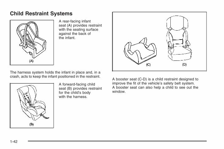
Child Restraint SystemsA rear-facing infantseat (A) provides restraintwith the seating surfaceagainst the back ofthe infant.
The harness system holds the infant in place and, in acrash, acts to keep the infant positioned in the restraint.
A forward-facing childseat (B) provides restraintfor the child’s bodywith the harness.
A booster seat (C-D) is a child restraint designed toimprove the fit of the vehicle’s safety belt system.A booster seat can also help a child to see out thewindow.
1-42
Securing an Add-On Child Restraint inthe Vehicle
{CAUTION:
A child can be seriously injured or killed in acrash if the child restraint is not properlysecured in the vehicle. Make sure the childrestraint is properly installed in the vehicleusing the vehicle’s safety belt or LATCHsystem, following the instructions that camewith that restraint, and also the instructionsin this manual.
To help reduce the chance of injury, the child restraintmust be secured in the vehicle. Child restraint systemsmust be secured in vehicle seats by lap belts or thelap belt portion of a lap-shoulder belt, or by the LATCHsystem. See Lower Anchors and Tethers for Children(LATCH) on page 1-45 for more information. A childcan be endangered in a crash if the child restraint isnot properly secured in the vehicle.
When securing an add-on child restraint, refer to theinstructions that come with the restraint which may be onthe restraint itself or in a booklet, or both, and to thismanual. The child restraint instructions are important,so if they are not available, obtain a replacementcopy from the manufacturer.
Keep in mind that an unsecured child restraint canmove around in a collision or sudden stop and injurepeople in the vehicle. Be sure to properly secureany child restraint in your vehicle — even when nochild is in it.
Securing the Child Within the ChildRestraint
{CAUTION:
A child can be seriously injured or killed ina crash if the child is not properly secured inthe child restraint. Because there are differentsystems, it is important to refer to theinstructions that come with the restraint. Makesure the child is properly secured, following theinstructions that came with that restraint.
1-43

Where to Put the RestraintAccident statistics show that children are safer if theyare restrained in the rear rather than the front seat.
We recommend that children and child restraints besecured in a rear seat, including: an infant or a childriding in a rear-facing child restraint; a child riding in aforward-facing child seat; an older child riding in a boosterseat; and children, who are large enough, using safetybelts.
A label on the sun visor says, “Never put a rear-facingchild seat in the front.” This is because the risk tothe rear-facing child is so great, if the airbag deploys.
{CAUTION:
A child in a rear-facing child restraint can beseriously injured or killed if the right frontpassenger’s airbag inflates. This is becausethe back of the rear-facing child restraintwould be very close to the inflating airbag.
Even it the passenger sensing system or theairbag off switch has turned off the right frontpassenger’s frontal airbag, no system isfail-safe. No one can guarantee that anairbag will not deploy under some unusualcircumstance, even though it is turned off.Rear-facing child restraints should be securedin a rear seat, even if the airbag is off.
If you secure a forward-facing child restraintin the right front seat, always move the frontpassenger seat as far back as it will go. It isbetter to secure the child restraint in a rear seat.
1-44

{CAUTION:
A child in a child restraint in the center frontseat can be badly injured or killed by thefrontal airbags if they inflate. Never secure achild restraint in the center front seat. It isalways better to secure a child restraint in arear seat.
Do not use child restraints in the center front seatposition.
When securing a child restraint in a rear seatingposition, study the instructions that came with your childrestraint to make sure it is compatible with this vehicle.
If the vehicle does not have a rear seat that willaccommodate a rear-facing child restraint, a rear-facingchild restraint should not be installed in the vehicle,even if the airbag is off.
Wherever you install a child restraint, be sure to securethe child restraint properly.
Keep in mind that an unsecured child restraint canmove around in a collision or sudden stop and injurepeople in the vehicle. Be sure to properly secureany child restraint in your vehicle — even when nochild is in it.
Lower Anchors and Tethers forChildren (LATCH)The LATCH system holds a child restraint during drivingor in a crash. This system is designed to make installationof a child restraint easier. The LATCH system usesanchors in the vehicle and attachments on the childrestraint that are made for use with the LATCH system.
Make sure that a LATCH-compatible child restraintis properly installed using the anchors, or use thevehicle’s safety belts to secure the restraint, followingthe instructions that came with that restraint, and alsothe instructions in this manual. When installing a childrestraint with a top tether, you must also use either thelower anchors or the safety belts to properly secure thechild restraint. A child restraint must never be installedusing only the top tether and anchor.
In order to use the LATCH system in your vehicle,you need a child restraint that has LATCH attachments.The child restraint manufacturer will provide you withinstructions on how to use the child restraint and itsattachments. The following explains how to attach achild restraint with these attachments in your vehicle.
Not all vehicle seating positions or child restraints havelower anchors and attachments or top tether anchorsand attachments.
1-45
Lower Anchors
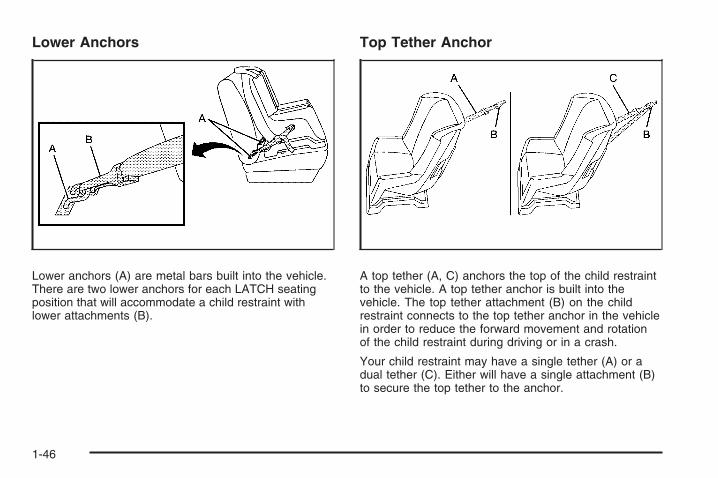
Lower anchors (A) are metal bars built into the vehicle.There are two lower anchors for each LATCH seatingposition that will accommodate a child restraint withlower attachments (B).
Top Tether Anchor
A top tether (A, C) anchors the top of the child restraintto the vehicle. A top tether anchor is built into thevehicle. The top tether attachment (B) on the childrestraint connects to the top tether anchor in the vehiclein order to reduce the forward movement and rotationof the child restraint during driving or in a crash.
Your child restraint may have a single tether (A) or adual tether (C). Either will have a single attachment (B)to secure the top tether to the anchor.
1-46

Some child restraints that have a top tether aredesigned for use with or without the top tether beingattached. Others require the top tether always to beattached. In Canada, the law requires that forward-facingchild restraints have a top tether, and that the tether beattached. Be sure to read and follow the instructions foryour child restraint.
If the child restraint does not have a top tether, one canbe obtained, in kit form, for many child restraints. Askthe child restraint manufacturer whether or not a kitis available.
Lower Anchor and Top Tether AnchorLocations
i (Top Tether Anchor):Seating positions with toptether anchors.
Do not install a child restraint in the center front seatposition. See Securing a Child Restraint in the CenterFront Seat Position on page 1-57 for more information.
RegularCab — Two-Passenger
Front Seat
RegularCab — Three-Passenger
Front Seat
1-47
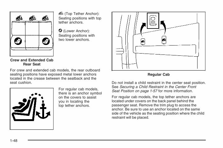
i (Top Tether Anchor):Seating positions with toptether anchors.
j (Lower Anchor):Seating positions withtwo lower anchors.
For crew and extended cab models, the rear outboardseating positions have exposed metal lower anchorslocated in the crease between the seatback and theseat cushion.
For regular cab models,there is an anchor symbolon the covers to assistyou in locating thetop tether anchors.
Do not install a child restraint in the center seat position.See Securing a Child Restraint in the Center FrontSeat Position on page 1-57 for more information.
For regular cab models, the top tether anchors arelocated under covers on the back panel behind thepassenger seat. Remove the trim plug to access theanchor. Be sure to use an anchor located on the sameside of the vehicle as the seating position where the childrestraint will be placed.
Crew and Extended CabRear Seat
Regular Cab
1-48
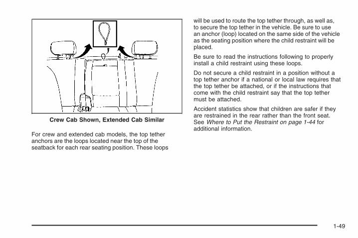
For crew and extended cab models, the top tetheranchors are the loops located near the top of theseatback for each rear seating position. These loops
will be used to route the top tether through, as well as,to secure the top tether in the vehicle. Be sure to usean anchor (loop) located on the same side of the vehicleas the seating position where the child restraint will beplaced.
Be sure to read the instructions following to properlyinstall a child restraint using these loops.
Do not secure a child restraint in a position without atop tether anchor if a national or local law requires thatthe top tether be attached, or if the instructions thatcome with the child restraint say that the top tethermust be attached.
Accident statistics show that children are safer if theyare restrained in the rear rather than the front seat.See Where to Put the Restraint on page 1-44 foradditional information.
Crew Cab Shown, Extended Cab Similar
1-49

Securing a Child Restraint Designed forthe LATCH System
{CAUTION:
If a LATCH-type child restraint is not attachedto anchors, the restraint will not be able toprotect the child correctly. In a crash, the childcould be seriously injured or killed. Make surethat a LATCH-type child restraint is properlyinstalled using the anchors, or use thevehicle’s safety belts to secure the restraint,following the instructions that came with thatrestraint, and also the instructions in thismanual.
{CAUTION:
Each lower anchor and top tether anchor inthe vehicle is designed to hold only one childrestraint, except the center top tether anchor increw and extended cab models. Attaching morethan one child restraint to a single anchor couldcause the anchor or attachment to come looseor even break during a crash. A child or otherscould be injured if this happens. To help preventinjury to people and damage to your vehicle,attach only one child restraint per anchor.
1-50
{CAUTION:
Children can be seriously injured or strangledif a shoulder belt is wrapped around their neckand the safety belt continues to tighten.Secure any unused safety belts behind thechild restraint so children cannot reach them.Pull the shoulder belt all the way out of theretractor to set the lock, if your vehicle hasone, after the child restraint has been installed.Be sure to follow the instructions of the childrestraint manufacturer.
Notice: Contact between the child restraint LATCHattachment parts and the vehicle’s safety beltassembly may cause damage to these parts. Makesure when securing unused safety belts behindthe child restraint that there is no contact betweenthe child restraint LATCH attachment parts andthe vehicle’s safety belt assembly.
Folding an empty rear seat with the safety beltssecured may cause damage to the safety belt orthe seat. When removing the child restraint, alwaysremember to return the safety belts to their normal,stowed position before folding the rear seat.
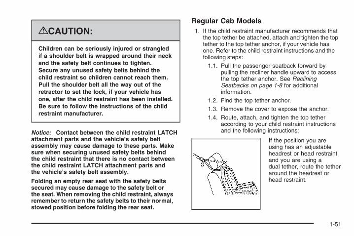
Regular Cab Models1. If the child restraint manufacturer recommends that
the top tether be attached, attach and tighten the toptether to the top tether anchor, if your vehicle hasone. Refer to the child restraint instructions and thefollowing steps:
1.1. Pull the passenger seatback forward bypulling the recliner handle upward to accessthe top tether anchor. See RecliningSeatbacks on page 1-8 for additionalinformation.
1.2. Find the top tether anchor.1.3. Remove the cover to expose the anchor.1.4. Route, attach, and tighten the top tether
according to your child restraint instructionsand the following instructions:
If the position you areusing has an adjustableheadrest or head restraintand you are using adual tether, route the tetheraround the headrest orhead restraint.
1-51

If the position you are usinghas an adjustable headrestor head restraint and youare using a single tether,raise the headrest or headrestraint and route thetether under the headrestor head restraint and inbetween the headrest orhead restraint posts.
2. See Securing a Child Restraint in the Right FrontSeat Position (With Airbag Off Switch) on page 1-57or Securing a Child Restraint in the Right FrontSeat Position (With Passenger Sensing System)on page 1-62 or Securing a Child Restraint inthe Right Front Seat Position (Heavy Duty CrewCab Only) on page 1-66 for instructions on installingthe child restraint using the safety belts.
3. Push and pull the child restraint in differentdirections to be sure it is secure.
Crew and Extended Cab Models1. Attach and tighten the lower attachments to the
lower anchors. If the child restraint does not havelower attachments or the desired seating positiondoes not have lower anchors, secure the childrestraint with the top tether and the safety belts.Refer to your child restraint manufacturerinstructions and the instructions in this manual.
1.1. Find the lower anchors for the desiredseating position.
1.2. Put the child restraint on the seat.1.3. Attach and tighten the lower attachments on
the child restraint to the lower anchors.
2. If the child restraint manufacturer recommends thatthe top tether be attached, attach and tighten the toptether to the top tether anchor (loop), if your vehiclehas one. Refer to the child restraint instructions andthe following steps:
1-52
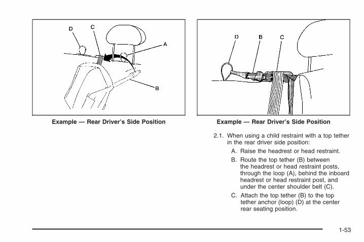
2.1. When using a child restraint with a top tetherin the rear driver side position:
A. Raise the headrest or head restraint.B. Route the top tether (B) between
the headrest or head restraint posts,through the loop (A), behind the inboardheadrest or head restraint post, andunder the center shoulder belt (C).
C. Attach the top tether (B) to the toptether anchor (loop) (D) at the centerrear seating position.
Example — Rear Driver’s Side Position Example — Rear Driver’s Side Position
1-53

2.2. When using a child restraint with a top tetherin the rear center position:
D. Route the top tether (B) through thecenter loop (D), and behind the inboardpassenger side headrest or headrestraint post.
E. Attach the top tether (B) to the toptether anchor (loop) at the rearpassenger side seating position.
2.3. When using a child restraint with a top tetherin the rear passenger position:
F. Raise the headrest or head restraint.G. Route the top tether (B) between the
headrest or head restraint posts, throughthe loop on the passenger side andbehind the inboard headrest or headrestraint post.
H. Attach the top tether (B) to the toptether anchor (loop) (D) at the centerrear seating position.
2.4. Tighten the top tether when and as the childrestraint manufacturer’s instructions say.When the top tether is tightened, the anchor(loop) may bend. This is normal and willnot damage the vehicle.
3. Push and pull the child restraint in differentdirections to be sure it is secure.
Securing a Child Restraint in aRear Seat PositionWhen securing a child restraint in a rear seatingposition, study the instructions that came with your childrestraint to make sure it is compatible with this vehicle.
If your child restraint has the LATCH system, see LowerAnchors and Tethers for Children (LATCH) on page 1-45for how and where to install your child restraint usingLATCH. If you secure a child restraint using a safety beltand it uses a top tether, see Lower Anchors and Tethersfor Children (LATCH) on page 1-45 for top tether anchorlocations.
Do not secure a child restraint in a position without atop tether anchor if a national or local law requires thatthe top tether be anchored, or if the instructions thatcome with the child restraint say that the top strapmust be anchored.
In Canada, the law requires that forward-facing childrestraints have a top tether, and that the tether beattached.
If your child restraint does not have the LATCH system,you will be using the safety belt to secure the childrestraint in this position. Be sure to follow the instructionsthat came with the child restraint. Secure the child in thechild restraint when and as the instructions say.
1-54

If you need to install more than one child restraint in therear seat, be sure to read Where to Put the Restrainton page 1-44.
1. Put the child restraint on the seat.
2. Pick up the latch plate, and run the lap and shoulderportions of the vehicle’s safety belt through oraround the restraint. The child restraint instructionswill show you how.
3. Push the latch plate into the buckle until it clicks.Make sure the release button is positioned so youwould be able to unbuckle the safety belt quicklyif necessary.
4. Pull the rest of the shoulder belt all the way out ofthe retractor to set the lock.
1-55

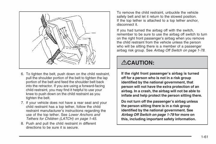
5. To tighten the belt, push down on the child restraint,pull the shoulder portion of the belt to tighten the lapportion of the belt, and feed the shoulder belt backinto the retractor. If you are using a forward-facingchild restraint, you may find it helpful to use yourknee to push down on the child restraint as youtighten the belt.
6. If your child restraint has a top tether, follow thechild restraint manufacturer’s instructions regardingthe use of the top tether. See Lower Anchorsand Tethers for Children (LATCH) on page 1-45for more information.
7. Push and pull the child restraint in differentdirections to be sure it is secure.
To remove the child restraint, unbuckle the vehiclesafety belt and let it return to the stowed position.If the top tether is attached to a top tether anchor,disconnect it.
1-56

Securing a Child Restraint in theCenter Front Seat Position
{CAUTION:
A child in a child restraint in the center frontseat can be badly injured or killed by thefrontal airbags if they inflate. Never secure achild restraint in the center front seat. It isalways better to secure a child restraint in arear seat.
Do not use child restraints in the center front seatposition.
Securing a Child Restraint inthe Right Front Seat Position(With Airbag Off Switch)Your vehicle has airbags. A rear seat is a safer place tosecure a forward-facing child restraint. See Where toPut the Restraint on page 1-44.
There may be a switch in the glove box that you canuse to turn off the right front passenger frontal airbag.See Airbag Off Switch on page 1-78 for more onthis, including important safety information.
1-57

A label on the sun visor says, “Never put a rear-facingchild seat in the front.” This is because the risk tothe rear-facing child is so great, if the airbag deploys.
{CAUTION:
A child in a rear-facing child restraint can beseriously injured or killed if the right frontpassenger’s airbag inflates. This is becausethe back of the rear-facing child restraintwould be very close to the inflating airbag.
Even if the airbag off switch has turned offthe right front passenger’s frontal airbag, nosystem is fail-safe. No one can guarantee thatan airbag will not deploy under some unusualcircumstance, even though it is turned off.Rear-facing child restraints should be securedin a rear seat, even if the airbag is off.
If you secure a forward-facing child restraintin the right front seat, always move the frontpassenger seat as far back as it will go. It isbetter to secure the child restraint in a rear seat.
{CAUTION:
If the airbag readiness light ever comes onwhen you have turned off the airbag, it meansthat something may be wrong with the airbagsystem. The right front passenger’s airbagcould inflate even though the switch is off.If this ever happens, do not let anyone whomthe national government has identified as amember of a passenger airbag risk group sitin the right front passenger’s position (forexample, do not secure a rear-facing childrestraint in the right front passenger’s seat)until you have your vehicle serviced. See AirbagOff Switch on page 1-78 and Airbag ReadinessLight on page 3-40 for more on this, includingimportant safety information.
If the vehicle does not have a rear seat that willaccommodate a rear-facing child restraint, a rear-facingchild restraint should not be installed in the vehicle,even if the airbag is off.
1-58

If your child restraint has the LATCH system, see LowerAnchors and Tethers for Children (LATCH) on page 1-45for how and where to install your child restraint usingLATCH. If you secure a child restraint using a safety beltand it uses a top tether, see Lower Anchors and Tethersfor Children (LATCH) on page 1-45 for top tether anchorlocations.
Do not secure a child restraint in a position without atop tether anchor if a national or local law requires thatthe top tether be anchored, or if the instructions thatcome with the child restraint say that the top strap mustbe anchored.
In Canada, the law requires that forward-facing childrestraints have a top tether, and that the tether beattached.
You will be using the lap-shoulder belt to secure thechild restraint in this position. Follow the instructions thatcame with the child restraint.
1. Move the seat as far back as it will go beforesecuring the forward-facing child restraint.If you have no other choice but to install arear-facing child restraint in this seat, make surethe airbag is off once the child restraint has beeninstalled.When the airbag off switch has turned off the rightfront passenger frontal airbag, the off indicatorin the airbag off light should light and stay lit whenyou start the vehicle. See Airbag Off Light onpage 3-41.
2. Put the child restraint on the seat.
3. Pick up the latch plate, and run the lap and shoulderportions of the vehicle’s safety belt through oraround the restraint. The child restraint instructionswill show you how.
1-59

4. Push the latch plate into the buckle until it clicks.Make sure the release button is positioned so youwould be able to unbuckle the safety belt quicklyif necessary.
5. Pull the rest of the shoulder belt all the way out ofthe retractor to set the lock.
1-60
6. To tighten the belt, push down on the child restraint,pull the shoulder portion of the belt to tighten the lapportion of the belt and feed the shoulder belt backinto the retractor. If you are using a forward-facingchild restraint, you may find it helpful to use yourknee to push down on the child restraint as youtighten the belt.
7. If your vehicle does not have a rear seat and yourchild restraint has a top tether, follow the childrestraint manufacturer’s instructions regarding theuse of the top tether. See Lower Anchors andTethers for Children (LATCH) on page 1-45.
8. Push and pull the child restraint in differentdirections to be sure it is secure.
To remove the child restraint, unbuckle the vehiclesafety belt and let it return to the stowed position.If the top tether is attached to a top tether anchor,disconnect it.
If you had turned the airbag off with the switch,remember to be sure to use the airbag off switch to turnon the right front passenger’s airbag when you removethe child restraint from the vehicle unless the personwho will be sitting there is a member of a passengerairbag risk group. See Airbag Off Switch on page 1-78.
{CAUTION:
If the right front passenger’s airbag is turnedoff for a person who is not in a risk groupidentified by the national government, thatperson will not have the extra protection of anairbag. In a crash, the airbag will not be able toinflate and help protect the person sitting there.
Do not turn off the passenger’s airbag unlessthe person sitting there is in a risk groupidentified by the national government. SeeAirbag Off Switch on page 1-78 for more onthis, including important safety information.
1-61

Securing a Child Restraint inthe Right Front Seat Position(With Passenger Sensing System)Your vehicle has airbags. A rear seat is a safer place tosecure a forward-facing child restraint. See Where toPut the Restraint on page 1-44.In addition, your vehicle may have a passenger sensingsystem which is designed to turn off the right frontpassenger’s frontal airbag under certain conditions. SeePassenger Sensing System on page 1-81 and PassengerAirbag Status Indicator on page 3-43 for more informationon this, including important safety information.A label on your sun visor says, “Never put a rear-facingchild seat in the front.” This is because the risk to therear-facing child is so great, if the airbag deploys.
{CAUTION:
A child in a rear-facing child restraint can beseriously injured or killed if the right frontpassenger’s airbag inflates. This is becausethe back of the rear-facing child restraintwould be very close to the inflating airbag.
CAUTION: (Continued)
CAUTION: (Continued)
Even if the passenger sensing system hasturned off the right front passenger’s frontalairbag, no system is fail-safe. No one canguarantee that an airbag will not deploy undersome unusual circumstance, even though it isturned off. Rear-facing child restraints shouldbe secured in a rear seat, even if the airbagis off.
If you secure a forward-facing child restraintin the right front seat, always move the frontpassenger seat as far back as it will go. It isbetter to secure the child restraint in a rear seat.
See Passenger Sensing System on page 1-81for additional information.
If your vehicle does not have a rear seat that willaccommodate a rear-facing child restraint, werecommend that rear-facing child restraints not betransported in your vehicle, even if the airbag is off.
1-62

If your child restraint has the LATCH system, see LowerAnchors and Tethers for Children (LATCH) on page 1-45for how to install your child restraint using LATCH. If yousecure a child restraint using a safety belt and it uses atop tether, see Lower Anchors and Tethers for Children(LATCH) on page 1-45 for top tether anchor locations.
Do not secure a child seat in a position without a toptether anchor if a national or local law requires that thetop tether be anchored, or if the instructions that comewith the child restraint say that the top strap must beanchored.
In Canada, the law requires that forward-facing childrestraints have a top tether, and that the tether beattached.
You will be using the lap-shoulder belt to secure thechild restraint in this position. Follow the instructions thatcame with the child restraint.
1. Move the seat as far back as it will go beforesecuring the forward-facing child restraint.When the passenger sensing system has turnedoff the right front passenger’s frontal airbag, the offindicator in the passenger airbag status indicatorshould light and stay lit when you start the vehicle.See Passenger Airbag Status Indicator onpage 3-43.
2. Put the child restraint on the seat.
3. Pick up the latch plate, and run the lap andshoulder portions of the vehicle’s safety belt throughor around the restraint. The child restraintinstructions will show you how.
4. Push the latch plate into the buckle until it clicks.Make sure the release button is positioned so youwould be able to unbuckle the safety belt quicklyif necessary.
1-63

5. Pull the rest of the shoulder belt all the way out ofthe retractor to set the lock.
6. To tighten the belt, push down on the child restraint,pull the shoulder portion of the belt to tighten the lapportion of the belt and feed the shoulder belt backinto the retractor. If you are using a forward-facingchild restraint, you may find it helpful to use yourknee to push down on the child restraint as youtighten the belt.
1-64

7. If your child restraint manufacturer recommendsusing a top tether and the position you are usinghas a top tether anchor, attach and tighten thetop tether to the top tether anchor. Refer tothe instructions that came with the child restraintand to Lower Anchors and Tethers for Children(LATCH) on page 1-45.
8. Push and pull the child restraint in differentdirections to be sure it is secure.
If the airbag is off, the off indicator in the passengerairbag status indicator will come on and stay on whenthe vehicle is started.
If a child restraint has been installed and the onindicator is lit, turn the vehicle off. Remove the childrestraint from the vehicle and reinstall the child restraint.
If, after reinstalling the child restraint and restartingthe vehicle, the on indicator is still lit, check to makesure that the vehicle’s seatback is not pressing the childrestraint into the seat cushion. If this happens, slightlyrecline the vehicle’s seatback and adjust the seatcushion if possible. Also make sure the child restraintis not trapped under the vehicle head restraint.If this happens, adjust the head restraint.
Remove any additional material from the seat suchas blankets, cushions, seat covers, seat heaters orseat massagers before reinstalling or securing thechild restraint.
If the on indicator is still lit, secure the child in thechild restraint in a rear seat position in the vehicleand check with your dealer/retailer. If no rear seat isavailable, do not install a child restraint in this vehicleand check with your dealer/retailer.
To remove the child restraint, unbuckle the vehicle’ssafety belt and let it go back all the way. If the top tetheris attached to a top tether anchor, disconnect it.
1-65

Securing a Child Restraint inthe Right Front Seat Position(Heavy Duty Crew Cab Only)Your vehicle has airbags. A rear seat is a safer place tosecure a forward-facing child restraint. See Where toPut the Restraint on page 1-44.
A label on the sun visor says, “Never put a rear-facingchild seat in the front.” This is because the risk tothe rear-facing child is so great, if the airbag deploys.
Never put a rear-facing child restraint in the rightfront passenger seat. Here is why:
{CAUTION:
A child in a rear-facing child restraint can beseriously injured or killed if the right frontpassenger’s airbag inflates. This is becausethe back of the rear-facing child restraintwould be very close to the inflating airbag.Always secure a rear-facing child restraintin a rear seat.
If the vehicle does not have a rear seat that willaccommodate a rear-facing child restraint, a rear-facingchild restraint should not be installed in the vehicle,even if the airbag is off.
If your child restraint has the LATCH system, see LowerAnchors and Tethers for Children (LATCH) on page 1-45for how and where to install your child restraint usingLATCH. If you secure a child restraint using a safety beltand it uses a top tether, see Lower Anchors and Tethersfor Children (LATCH) on page 1-45 for top tether anchorlocations.
Do not secure a child seat in a position without a toptether anchor if a national or local law requires thatthe top tether be anchored, or if the instructionsthat come with the child restraint say that the topstrap must be anchored.
In Canada, the law requires that forward-facing childrestraints have a top tether, and that the tether beattached.
1-66

You will be using the lap-shoulder belt to secure thechild restraint in this position. Follow the instructions thatcame with the child restraint.
1. Move the seat as far back as it will go beforesecuring the forward-facing child restraint.
2. Put the child restraint on the seat.
3. Pick up the latch plate, and run the lap andshoulder portions of the vehicle’s safety beltthrough or around the restraint. The child restraintinstructions will show you how.
4. Push the latch plate into the buckle until it clicks.Make sure the release button is positioned so youwould be able to unbuckle the safety belt quicklyif necessary.
1-67

5. Pull the rest of the shoulder belt all the way out ofthe retractor to set the lock.
6. To tighten the belt, push down on the child restraint,pull the shoulder portion of the belt to tighten the lapportion of the belt and feed the shoulder belt backinto the retractor. If you are using a forward-facingchild restraint, you may find it helpful to use yourknee to push down on the child restraint as youtighten the belt.
1-68

7. If your child restraint has a top tether, follow thechild restraint manufacturer’s instructions regardingthe use of the top tether. See Lower Anchorsand Tethers for Children (LATCH) on page 1-45for more information.
8. Push and pull the child restraint in differentdirections to be sure it is secure.
To remove the child restraint, unbuckle the vehiclesafety belt and let it return to the stowed position. If thetop tether is attached to a top tether anchor, disconnect it.
Airbag SystemYour vehicle has the following airbags:
• A frontal airbag for the driver.
• A frontal airbag for the right front passenger.
Your vehicle may have the following airbags:
• A roof-rail airbag for the driver and the passengerseated directly behind the driver.
• A roof-rail airbag for the right front passenger andthe person seated directly behind the right frontpassenger.
All of the airbags in your vehicle will have the wordAIRBAG embossed in the trim or on an attached labelnear the deployment opening.
For frontal airbags, the word AIRBAG will appear onthe middle part of the steering wheel for the driver andon the instrument panel for the right front passenger.
With roof-rail airbags, the word AIRBAG will appearalong the headliner or trim.
Airbags are designed to supplement the protectionprovided by safety belts. Even though today’s airbagsare also designed to help reduce the risk of injuryfrom the force of an inflating bag, all airbags mustinflate very quickly to do their job.
1-69

Here are the most important things to know about theairbag system:
{CAUTION:
You can be severely injured or killed in a crashif you are not wearing your safety belt — evenif you have airbags. Wearing your safety beltduring a crash helps reduce your chance ofhitting things inside the vehicle or beingejected from it. Airbags are “supplementalrestraints” to the safety belts. All airbags aredesigned to work with safety belts, but do notreplace them.
{CAUTION:
Frontal airbags are designed to deploy inmoderate to severe frontal and near frontalcrashes. They are not designed to inflate inrollover, rear crashes, or in many side crashes.
If your vehicle has rollover capable roof-railairbags, they are designed to inflate inmoderate to severe crashes where somethinghits the side of your vehicle, during a vehiclerollover, or in a severe frontal impact. They arenot designed to inflate in rear crashes.
Everyone in your vehicle should wear a safetybelt properly — whether or not there is anairbag for that person.
1-70

{CAUTION:
Airbags inflate with great force, faster thanthe blink of an eye. Anyone who is up against,or very close to, any airbag when it inflatescan be seriously injured or killed. Do not situnnecessarily close to the airbag, as you wouldbe if you were sitting on the edge of your seat orleaning forward. Safety belts help keep you inposition before and during a crash. Always wearyour safety belt, even with airbags. The drivershould sit as far back as possible while stillmaintaining control of the vehicle.
Occupants should not lean on or sleep againstthe door or side windows in seating positionswith roof-rail airbags.
{CAUTION:
Airbags plus lap-shoulder belts offer thebest protection for adults, but not for youngchildren and infants. Neither the vehicle’ssafety belt system nor its airbag system isdesigned for them. Young children and infantsneed the protection that a child restraintsystem can provide. Always secure childrenproperly in your vehicle. To read how, seeOlder Children on page 1-35 or Infants andYoung Children on page 1-39.
There is an airbagreadiness light on theinstrument panel cluster,which shows the airbagsymbol.
The system checks the airbag electrical system formalfunctions. The light tells you if there is an electricalproblem. See Airbag Readiness Light on page 3-40for more information.
1-71

Where Are the Airbags?
The driver’s airbag is in the middle of the steeringwheel.
The right front passenger’s airbag is in the instrumentpanel on the passenger’s side.
1-72
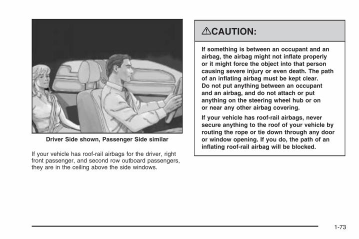
If your vehicle has roof-rail airbags for the driver, rightfront passenger, and second row outboard passengers,they are in the ceiling above the side windows.
{CAUTION:
If something is between an occupant and anairbag, the airbag might not inflate properlyor it might force the object into that personcausing severe injury or even death. The pathof an inflating airbag must be kept clear.Do not put anything between an occupantand an airbag, and do not attach or putanything on the steering wheel hub or onor near any other airbag covering.
If your vehicle has roof-rail airbags, neversecure anything to the roof of your vehicle byrouting the rope or tie down through any dooror window opening. If you do, the path of aninflating roof-rail airbag will be blocked.
Driver Side shown, Passenger Side similar
1-73

When Should an Airbag Inflate?Frontal airbags are designed to inflate in moderate tosevere frontal or near-frontal crashes to help reduce thepotential for severe injuries mainly to the driver’s or rightfront passenger’s head and chest. However, they are onlydesigned to inflate if the impact exceeds a predetermineddeployment threshold. Deployment thresholds are usedto predict how severe a crash is likely to be in time for theairbags to inflate and help restrain the occupants.
Whether your frontal airbags will or should deploy is notbased on how fast your vehicle is traveling. It dependslargely on what you hit, the direction of the impact,and how quickly your vehicle slows down.
Frontal airbags may inflate at different crash speeds.For example:
• If the vehicle hits a stationary object, the airbagscould inflate at a different crash speed than if thevehicle hits a moving object.
• If the vehicle hits an object that deforms, theairbags could inflate at a different crash speed thanif the vehicle hits an object that does not deform.
• If the vehicle hits a narrow object (like a pole), theairbags could inflate at a different crash speedthan if the vehicle hits a wide object (like a wall).
• If the vehicle goes into an object at an angle, theairbags could inflate at a different crash speedthan if the vehicle goes straight into the object.
Thresholds can also vary with specific vehicle design.
Frontal airbags are not intended to inflate during vehiclerollovers, rear impacts, or in many side impacts.
If the GVWR (Gross Vehicle Weight Rating) of yourvehicle is 8,500 lb (3 855 kg) or above, your vehiclehas single stage airbags. If the GVWR is below 8,500 lb(3 855 kg) then your vehicle has dual stage airbags. Youcan find the GVWR on the certification label on the rearedge of the driver’s door. See Loading Your Vehicle onpage 4-36 for more information.
In addition, your vehicle may have dual-stage frontalairbags. Dual-stage airbags adjust the restraint accordingto crash severity. Your vehicle has electronic frontalsensors, which help the sensing system distinguishbetween a moderate frontal impact and a more severefrontal impact. For moderate frontal impacts, dual-stageairbags inflate at a level less than full deployment. Formore severe frontal impacts, full deployment occurs.
1-74

Vehicles with dual stage airbags also have seat positionsensors which enables the sensing system to monitorthe position of the driver’s seat. The seat position sensorprovides information that is used to determine if theairbags should deploy at a reduced level or at fulldeployment.
Your vehicle may or may not have roof-rail airbags.See Airbag System on page 1-69. Roof-rail airbags areintended to inflate in moderate to severe side crashes.In addition, these roof-rail airbags are intended to inflateduring a rollover or in a severe frontal impact. Roof-railairbags will inflate if the crash severity is above thesystem’s designed threshold level. The threshold levelcan vary with specific vehicle design.
Roof-rail airbags are not intended to inflate in rearimpacts. Both roof-rail airbags will deploy when eitherside of the vehicle is struck, or if the sensing systempredicts that the vehicle is about to roll over, or ina severe frontal impact.
In any particular crash, no one can say whether anairbag should have inflated simply because of thedamage to a vehicle or because of what the repair costswere. For frontal airbags, inflation is determined by whatthe vehicle hits, the angle of the impact, and how quicklythe vehicle slows down. For roof-rail airbags, deploymentis determined by the location and severity of the sideimpact. In a rollover event, roof-rail airbag deploymentis determined by the direction of the roll.
What Makes an Airbag Inflate?In a deployment event, the sensing system sends anelectrical signal triggering a release of gas from theinflator. Gas from the inflator fills the airbag causing thebag to break out of the cover and deploy. The inflator,the airbag, and related hardware are all part of the airbagmodule.
Frontal airbag modules are located inside the steeringwheel and instrument panel. For vehicles with roof-railairbags, there are airbag modules in the ceiling of thevehicle, near the side windows that have occupantseating positions.
1-75

How Does an Airbag Restrain?In moderate to severe frontal or near frontal collisions,even belted occupants can contact the steering wheelor the instrument panel. In moderate to severe sidecollisions, even belted occupants can contact theinside of the vehicle.
Airbags supplement the protection provided by safetybelts. Frontal airbags distribute the force of the impactmore evenly over the occupant’s upper body, stoppingthe occupant more gradually. Roof-rail airbags distributethe force of the impact more evenly over the occupant’supper body.
Rollover capable roof-rail airbags are designed tohelp contain the head and chest of occupants in theoutboard seating positions in the first and second rows.The rollover capable roof-rail airbags are designed tohelp reduce the risk of full or partial ejection in rolloverevents, although no system can prevent all suchejections.
But airbags would not help in many types of collisions,primarily because the occupant’s motion is not towardthose airbags. See When Should an Airbag Inflate? onpage 1-74 for more information.
Airbags should never be regarded as anything morethan a supplement to safety belts.
What Will You See After anAirbag Inflates?After the frontal airbags inflate, they quickly deflate,so quickly that some people may not even realize anairbag inflated. Roof-rail airbags may still be at leastpartially inflated for some time after they deploy. Somecomponents of the airbag module may be hot for severalminutes. For location of the airbag modules, see WhatMakes an Airbag Inflate? on page 1-75.
The parts of the airbag that come into contact with youmay be warm, but not too hot to touch. There may besome smoke and dust coming from the vents in thedeflated airbags. Airbag inflation does not prevent thedriver from seeing out of the windshield or being able tosteer the vehicle, nor does it prevent people from leavingthe vehicle.
1-76

{CAUTION:
When an airbag inflates, there may be dustin the air. This dust could cause breathingproblems for people with a history of asthma orother breathing trouble. To avoid this, everyonein the vehicle should get out as soon as it issafe to do so. If you have breathing problemsbut cannot get out of the vehicle after an airbaginflates, then get fresh air by opening a windowor a door. If you experience breathing problemsfollowing an airbag deployment, you shouldseek medical attention.
Your vehicle has a feature that may automaticallyunlock the doors, turn the interior lamps on, and turnthe hazard warning flashers on when the airbags inflate.You can lock the doors, turn the interior lamps off,and turn the hazard warning flashers off by usingthe controls for those features.
In many crashes severe enough to inflate the airbag,windshields are broken by vehicle deformation. Additionalwindshield breakage may also occur from the right frontpassenger airbag.
• Airbags are designed to inflate only once. After anairbag inflates, you will need some new parts for theairbag system. If you do not get them, the airbagsystem will not be there to help protect you in anothercrash. A new system will include airbag modules andpossibly other parts. The service manual for yourvehicle covers the need to replace other parts.
• Your vehicle has a crash sensing and diagnosticmodule which records information after a crash.See Vehicle Data Recording and Privacy onpage 7-16 and Event Data Recorders on page 7-17.
• Let only qualified technicians work on the airbagsystems. Improper service can mean that an airbagsystem will not work properly. See your dealer/retailer for service.
1-77
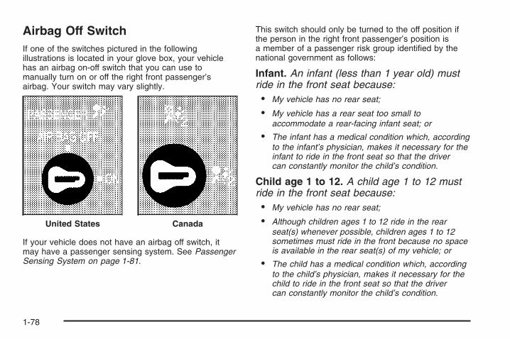
Airbag Off SwitchIf one of the switches pictured in the followingillustrations is located in your glove box, your vehiclehas an airbag on-off switch that you can use tomanually turn on or off the right front passenger’sairbag. Your switch may vary slightly.
If your vehicle does not have an airbag off switch, itmay have a passenger sensing system. See PassengerSensing System on page 1-81.
This switch should only be turned to the off position ifthe person in the right front passenger’s position isa member of a passenger risk group identified by thenational government as follows:
Infant. An infant (less than 1 year old) mustride in the front seat because:• My vehicle has no rear seat;
• My vehicle has a rear seat too small toaccommodate a rear-facing infant seat; or
• The infant has a medical condition which, accordingto the infant’s physician, makes it necessary for theinfant to ride in the front seat so that the drivercan constantly monitor the child’s condition.
Child age 1 to 12. A child age 1 to 12 mustride in the front seat because:• My vehicle has no rear seat;
• Although children ages 1 to 12 ride in the rearseat(s) whenever possible, children ages 1 to 12sometimes must ride in the front because no spaceis available in the rear seat(s) of my vehicle; or
• The child has a medical condition which, accordingto the child’s physician, makes it necessary for thechild to ride in the front seat so that the drivercan constantly monitor the child’s condition.
United States Canada
1-78

Medical Condition. A passenger has amedical condition which, according to his orher physician:• Causes the passenger airbag to pose a special risk
for the passenger; and
• Makes the potential harm from the passengerairbag in a crash greater than the potentialharm from turning off the airbag and allowing thepassenger, even if belted, to hit the dashboardor windshield in a crash.
{CAUTION:
If the right front passenger’s airbag is turnedoff for a person who is not in a risk groupidentified by the national government, thatperson will not have the extra protection of anairbag. In a crash, the airbag will not be able toinflate and help protect the person sitting there.Do not turn off the passenger’s airbag unlessthe person sitting there is in a risk group.
To turn off the right front passenger’s airbag, insert yourignition key into the switch, push in, and move theswitch to the off position.
The word OFF or the off symbol will come on in thepassenger airbag status indicator located in the overheadconsole to let you know that the right front passenger’sairbag is off, after the system check is completed. Theairbag off light will come on and stay on to let you knowthat the right front passenger’s airbag is off. See AirbagOff Light on page 3-41.
United States Canada
1-79
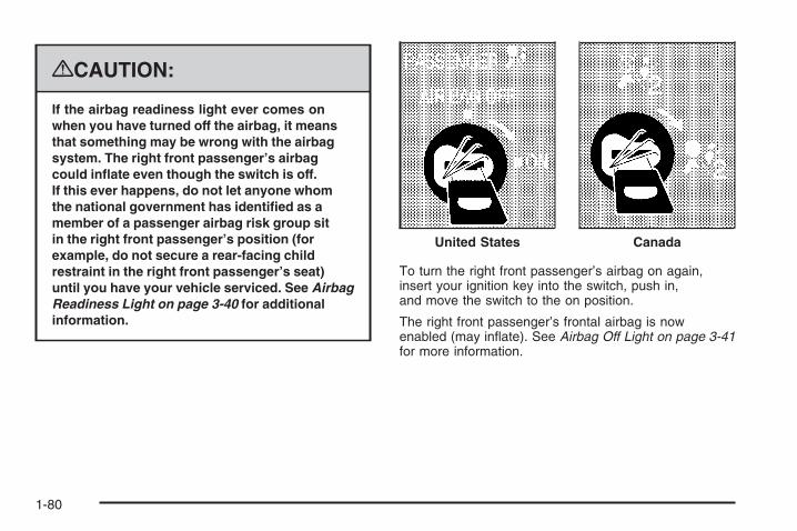
{CAUTION:
If the airbag readiness light ever comes onwhen you have turned off the airbag, it meansthat something may be wrong with the airbagsystem. The right front passenger’s airbagcould inflate even though the switch is off.If this ever happens, do not let anyone whomthe national government has identified as amember of a passenger airbag risk group sitin the right front passenger’s position (forexample, do not secure a rear-facing childrestraint in the right front passenger’s seat)until you have your vehicle serviced. See AirbagReadiness Light on page 3-40 for additionalinformation.
To turn the right front passenger’s airbag on again,insert your ignition key into the switch, push in,and move the switch to the on position.
The right front passenger’s frontal airbag is nowenabled (may inflate). See Airbag Off Light on page 3-41for more information.
United States Canada
1-80

Passenger Sensing SystemIf your vehicle has one of the indicators pictured in thefollowing illustrations, then your vehicle has a passengersensing system for the right front passenger’s position,unless there is an airbag off switch located in the glovebox. If there is an airbag off switch, your vehicle does nothave a passenger sensing system. See Airbag Off Switchon page 1-78 for more information.
The passenger airbag status indicator will be visible onthe overhead console when you start your vehicle.
The words ON and OFF, or the symbol for on and off,will be visible during the system check. When the systemcheck is complete, either the word ON or the word OFF,or the symbol for on or the symbol for off, will be visible.See Passenger Airbag Status Indicator on page 3-43.
The passenger sensing system will turn off the rightfront passenger’s frontal airbag under certain conditions.The driver’s airbags are not part of the passengersensing system.
The passenger sensing system works with sensors thatare part of the right front passenger’s seat and safetybelt. The sensors are designed to detect the presenceof a properly-seated occupant and determine if theright front passenger’s frontal airbag should be enabled(may inflate) or not.
Accident statistics show that children are safer if theyare restrained in the rear rather than the front seat.
We recommend that children be secured in a rear seat,including: an infant or a child riding in a rear-facingchild restraint; a child riding in a forward-facing childseat; an older child riding in a booster seat; and children,who are large enough, using safety belts.
United States Canada
1-81

A label on your sun visor says, “Never put a rear-facingchild seat in the front.” This is because the risk to therear-facing child is so great, if the airbag deploys.
{CAUTION:
A child in a rear-facing child restraint can beseriously injured or killed if the right frontpassenger’s airbag inflates. This is becausethe back of the rear-facing child restraintwould be very close to the inflating airbag.
Even if the passenger sensing system hasturned off the right front passenger’s frontalairbag, no system is fail-safe. No one canguarantee that an airbag will not deploy undersome unusual circumstance, even though it isturned off. Rear-facing child restraints shouldbe secured in a rear seat, even if the airbagis off.
If you secure a forward-facing child restraint inthe right front seat, always move the frontpassenger seat as far back as it will go. It isbetter to secure the child restraint in a rear seat.
If your vehicle does not have a rear seat that willaccommodate a rear-facing child restraint, werecommend that rear-facing child restraints not betransported in your vehicle, even if the airbag is off.
The passenger sensing system is designed to turn offthe right front passenger’s frontal airbag if:
• The right front passenger seat is unoccupied.
• The system determines that an infant is present ina rear-facing infant seat.
• The system determines that a small child is presentin a child restraint.
• The system determines that a small child is presentin a booster seat.
• A right front passenger takes his/her weight off ofthe seat for a period of time.
• The right front passenger seat is occupied by asmaller person, such as a child who has outgrownchild restraints.
• Or, if there is a critical problem with the airbagsystem or the passenger sensing system.
When the passenger sensing system has turned off theright front passenger’s frontal airbag, the off indicatorwill light and stay lit to remind you that the airbag is off.See Passenger Airbag Status Indicator on page 3-43.
1-82
If a child restraint has been installed and the onindicator is lit, turn the vehicle off. Remove the childrestraint from the vehicle and reinstall the child restraintfollowing the child restraint manufacturer’s directionsand refer to Securing a Child Restraint in the Right FrontSeat Position (With Airbag Off Switch) on page 1-57or Securing a Child Restraint in the Right Front SeatPosition (With Passenger Sensing System) on page 1-62or Securing a Child Restraint in the Right Front SeatPosition (Heavy Duty Crew Cab Only) on page 1-66.
If, after reinstalling the child restraint and restarting thevehicle, the on indicator is still lit, check to make sure thatthe vehicle’s seatback is not pressing the child restraintinto the seat cushion. If this happens, slightly reclinethe vehicle’s seatback and adjust the seat cushion ifpossible. Also make sure the child restraint is not trappedunder the vehicle head restraint. If this happens, adjustthe head restraint. See Head Restraints on page 1-11.
Remove any additional material from the seat such asblankets, cushions, seat covers, seat heaters, or seatmassagers before reinstalling or securing the childrestraint.
If the on indicator is still lit, secure the child in the childrestraint in a rear seat position in the vehicle, andcheck with your dealer/retailer. If no rear seat isavailable, do not install a child restraint in this vehicle,and check with your dealer/retailer.
The passenger sensing system is designed to enable(may inflate) the right front passenger’s frontal airbaganytime the system senses that a person of adult size issitting properly in the right front passenger’s seat. Whenthe passenger sensing system has allowed the airbag tobe enabled, the on indicator will light and stay lit to remindyou that the airbag is active.
For some children who have outgrown child restraintsand for very small adults, the passenger sensing systemmay or may not turn off the right front passenger’s frontalairbag, depending upon the person’s seating postureand body build. Everyone in your vehicle who hasoutgrown child restraints should wear a safety beltproperly — whether or not there is an airbag for thatperson.
1-83

If a person of adult-size is sitting in the right frontpassenger’s seat, but the off indicator is lit, it could bebecause that person is not sitting properly in the seat.If this happens, turn the vehicle off, remove anyadditional material from the seat, such as blankets,cushions, seat covers, seat heaters or seat massagersand ask the person to place the seatback in the fullyupright position, then sit upright in the seat, centeredon the seat cushion, with the person’s legs comfortablyextended. Restart the vehicle and have the personremain in this position for two to three minutes. Thiswill allow the system to detect that person andthen enable the right front passenger’s frontal airbag.
Safety belts help keep the passenger in position on theseat during vehicle maneuvers and braking, which helpsthe passenger sensing system maintain the passengerairbag status. See “Safety Belts” and “Child Restraints” inthe Index for additional information about the importanceof proper restraint use.
1-84

If you ever pull the shoulder portion of the belt outall the way, you will engage the child restraint lockingfeature. This may unintentionally cause the passengersensing system to turn the airbag(s) off for some adultsize occupants. If this happens, just let the belt go backall the way and start again.
{CAUTION:
If the airbag readiness light in the instrumentpanel cluster ever comes on and stays on,it means that something may be wrong withthe airbag system. If this ever happens, havethe vehicle serviced promptly, because anadult-size person sitting in the right frontpassenger’s seat may not have the protectionof the airbag(s). See Airbag Readiness Lighton page 3-40 for more on this, includingimportant safety information.
A thick layer of additional material, such as a blanket orcushion, or aftermarket equipment such as seat covers,seat heaters, and seat massagers can affect how well thepassenger sensing system operates. We recommendthat you not use seat covers or other aftermarketequipment other than any that GM has approved foryour specific vehicle. See Adding Equipment to YourAirbag-Equipped Vehicle on page 1-86 for moreinformation about modifications that can affect howthe system operates.
{CAUTION:
Stowing of articles under the passenger’sseat or between the passenger’s seat cushionand seatback may interfere with the properoperation of the passenger sensing system.
1-85

Servicing Your Airbag-EquippedVehicleAirbags affect how your vehicle should be serviced.There are parts of the airbag system in several placesaround your vehicle. Your dealer/retailer and the servicemanual have information about servicing your vehicleand the airbag system. To purchase a service manual,see Service Publications Ordering Information onpage 7-15.
{CAUTION:
For up to 10 seconds after the ignition isturned off and the battery is disconnected,an airbag can still inflate during improperservice. You can be injured if you are closeto an airbag when it inflates. Avoid yellowconnectors. They are probably part of theairbag system. Be sure to follow properservice procedures, and make sure the personperforming work for you is qualified to do so.
Adding Equipment to YourAirbag-Equipped Vehicle
Q: Is there anything I might add to or changeabout the vehicle that could keep the airbagsfrom working properly?
A: Yes. If you add things that change your vehicle’sframe, bumper system, height, front end or sidesheet metal, they may keep the airbag system fromworking properly. Changing or moving any partsof the front seats, safety belts, the airbag sensingand diagnostic module, steering wheel, instrumentpanel, roof-rail airbag modules, ceiling headlineror pillar garnish trim, overhead console, frontsensors, rollover sensor module, or airbag wiringcan affect the operation of the airbag system.
1-86

In addition, your vehicle may have a passengersensing system for the right front passenger’sposition, which includes sensors that are part of thepassenger’s seat. The passenger sensing systemmay not operate properly if the original seat trim isreplaced with non-GM covers, upholstery or trim, orwith GM covers, upholstery or trim designed for adifferent vehicle. Any object, such as an aftermarketseat heater or a comfort enhancing pad or device,installed under or on top of the seat fabric, could alsointerfere with the operation of the passenger sensingsystem. This could either prevent proper deploymentof the passenger airbag(s) or prevent the passengersensing system from properly turning off thepassenger airbag(s). See Passenger SensingSystem on page 1-81.
If you have any questions about this, you shouldcontact Customer Assistance before you modifyyour vehicle. The phone numbers and addressesfor Customer Assistance are in Step Two ofthe Customer Satisfaction Procedure in this manual.See Customer Satisfaction Procedure on page 7-2.
If your vehicle has rollover roof-rail airbags, seeDifferent Size Tires and Wheels on page 5-88for additional important information.
Q: What if I added a snow plow? Will it keep theairbags from working properly?
A: We have designed our airbag systems to workproperly under a wide range of conditions, includingsnow plowing with vehicles that have the optionalSnow Plow Prep Package (RPO VYU). But donot change or defeat the snow plow’s “trippingmechanism.” If you do, it can damage your snowplow and your vehicle, and it may cause an airbaginflation.
Q: Because I have a disability, I have to get myvehicle modified. How can I find out whetherthis will affect my airbag system?
A: If you have questions, call Customer Assistance.The phone numbers and addresses for CustomerAssistance are in Step Two of the CustomerSatisfaction Procedure in this manual. SeeCustomer Satisfaction Procedure on page 7-2.
In addition, your dealer/retailer and the service manualhave information about the location of the airbagsensors, sensing and diagnostic module and airbagwiring.
1-87

Restraint System Check
Checking the Restraint Systems
Safety BeltsNow and then, make sure the safety belt reminder lightand all your belts, buckles, latch plates, retractorsand anchorages are working properly.
Look for any other loose or damaged safety belt systemparts. If you see anything that might keep a safety beltsystem from doing its job, have it repaired. Torn or frayedsafety belts may not protect you in a crash. They can ripapart under impact forces. If a belt is torn or frayed, get anew one right away.
Make sure the safety belt reminder light is working.See Safety Belt Reminders on page 3-39 for moreinformation.
Keep safety belts clean and dry. See Care of SafetyBelts on page 5-117.
AirbagsThe airbag system does not need regularly scheduledmaintenance or replacement. Make sure the airbagreadiness light is working. See Airbag Readiness Lighton page 3-40 for more information.
Notice: If an airbag covering is damaged, opened,or broken, the airbag may not work properly.Do not open or break the airbag coverings. If thereare any opened or broken airbag covers, havethe airbag covering and/or airbag module replaced.For the location of the airbag modules, see WhatMakes an Airbag Inflate? on page 1-75. See yourdealer/retailer for service.
1-88

Replacing Restraint System PartsAfter a Crash
{CAUTION:
A crash can damage the restraint systemsin your vehicle. A damaged restraint systemmay not properly protect the person using it,resulting in serious injury or even death ina crash. To help make sure your restraintsystems are working properly after a crash,have them inspected and any necessaryreplacements made as soon as possible.
If you have had a crash, do you need new belts orLATCH system (if equipped) parts?
After a very minor crash, nothing may be necessary.But the belt assemblies that were used during anycrash may have been stressed or damaged. See yourdealer/retailer to have your safety belt assembliesinspected or replaced.
If your vehicle has the LATCH system and it was beingused during a crash, you may need new LATCHsystem parts.
New parts and repairs may be necessary even if thebelt or LATCH system (if equipped), was not being usedat the time of the crash.
If an airbag inflates, you will need to replace airbagsystem parts. See the part on the airbag system earlierin this section.
Have your safety belt pretensioners checked if yourvehicle has been in a crash, if your airbag readinesslight stays on after you start your vehicle, or while youare driving. See Airbag Readiness Light on page 3-40.
1-89

✍ NOTES
1-90

Keys ...............................................................2-3Remote Keyless Entry (RKE) System ................2-4Remote Keyless Entry (RKE) System
Operation ...................................................2-5Remote Vehicle Start ......................................2-7
Doors and Locks ............................................2-10Door Locks ..................................................2-10Power Door Locks ........................................2-10Delayed Locking ...........................................2-11Programmable Automatic Door Locks ..............2-11Rear Door Security Locks ..............................2-11Lockout Protection ........................................2-12Rear Doors ..................................................2-12Tailgate .......................................................2-13
Windows ........................................................2-15Manual Windows ..........................................2-15Power Windows ............................................2-16Power Sliding Rear Window ...........................2-17Sun Visors ...................................................2-18
Theft-Deterrent Systems ..................................2-18Content Theft-Deterrent .................................2-18PASS-Key® III+ Electronic Immobilizer .............2-20PASS-Key® III+ Electronic Immobilizer
Operation .................................................2-20
Starting and Operating Your Vehicle ................2-22New Vehicle Break-In ....................................2-22Ignition Positions ..........................................2-22Retained Accessory Power (RAP) ...................2-24Starting the Engine .......................................2-24Fast Idle System ..........................................2-25Adjustable Throttle and Brake Pedal ................2-26Engine Coolant Heater ..................................2-27Active Fuel Management™ .............................2-28Automatic Transmission Operation ...................2-28Tow/Haul Mode ............................................2-34Four-Wheel Drive ..........................................2-36Parking Brake ..............................................2-50Shifting Into Park ..........................................2-51Shifting Out of Park ......................................2-53Parking Over Things That Burn .......................2-53Engine Exhaust ............................................2-54Running the Vehicle While Parked ..................2-54
Mirrors ...........................................................2-56Manual Rearview Mirror .................................2-56Automatic Dimming Rearview Mirror
with OnStar®, Compass and TemperatureDisplay ....................................................2-56
Automatic Dimming Rearview Mirror withCompass and Temperature Display ..............2-58
Section 2 Features and Controls
2-1

Outside Manual Mirrors ..................................2-59Outside Towing Mirrors ..................................2-60Outside Power Mirrors ...................................2-61Outside Power Foldaway Mirrors .....................2-62
Object Detection Systems ...............................2-64Ultrasonic Rear Parking Assist (URPA) ............2-64
OnStar® System .............................................2-67Universal Home Remote System ......................2-71
Universal Home Remote System Operation(With Three Round LED) ............................2-71
Storage Areas ................................................2-78Glove Box ...................................................2-78Cupholders ..................................................2-78Instrument Panel Storage ...............................2-78Center Console Storage .................................2-79Luggage Carrier ...........................................2-79Rear Seat Armrest ........................................2-80Cargo Management System ...........................2-80
Sunroof .........................................................2-82
Section 2 Features and Controls
2-2

Keys
{CAUTION:
Leaving children in a vehicle with the ignitionkey is dangerous for many reasons, childrenor others could be badly injured or even killed.They could operate the power windows orother controls or even make the vehicle move.The windows will function with the keys in theignition and they could be seriously injuredor killed if caught in the path of a closingwindow. Do not leave the keys in a vehiclewith children.
The key can be used for the ignition and all door locks.
The key has a bar-coded key tag that the dealer/retaileror qualified locksmith can use to make new keys.Store this information in a safe place, not in your vehicle.
2-3

See your dealer/retailer if a replacement key oradditional key is needed.
Notice: If you ever lock your keys in your vehicle,you may have to damage the vehicle to get in.Be sure you have spare keys.
If you are locked out of your vehicle, call the RoadsideAssistance Center. See Roadside Assistance Programon page 7-7.
Remote Keyless Entry (RKE)SystemIf this vehicle has the Remote Keyless Entry (RKE)system, it operates on a radio frequency subjectto Federal Communications Commission (FCC)Rules and with Industry Canada.
This device complies with Part 15 of the FCC Rules.Operation is subject to the following two conditions:
1. This device may not cause interference.
2. This device must accept any interference received,including interference that may cause undesiredoperation of the device.
This device complies with RSS-210 of Industry Canada.Operation is subject to the following two conditions:
1. This device may not cause interference.
2. This device must accept any interference received,including interference that may cause undesiredoperation of the device.
Changes or modifications to this system by other thanan authorized service facility could void authorization touse this equipment.
If there is a decrease in the RKE operating range,try this:
• Check the distance. The transmitter may be toofar from the vehicle. Stand closer during rainyor snowy weather.
• Check the location. Other vehicles or objects maybe blocking the signal. Take a few steps to theleft or right, hold the transmitter higher, andtry again.
• Check the transmitter’s battery. See “BatteryReplacement” later in this section.
• If the transmitter is still not working correctly, seeyour dealer/retailer or a qualified technician forservice.
2-4
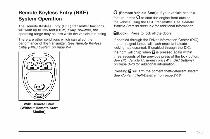
Remote Keyless Entry (RKE)System OperationThe Remote Keyless Entry (RKE) transmitter functionswill work up to 195 feet (60 m) away, however, theoperating range may be less while the vehicle is running.
There are other conditions which can affect theperformance of the transmitter. See Remote KeylessEntry (RKE) System on page 2-4.
/ (Remote Vehicle Start): If your vehicle has thisfeature, press / to start the engine from outsidethe vehicle using the RKE transmitter. See RemoteVehicle Start on page 2-7 for additional information.
Q (Lock): Press to lock all the doors.
If enabled through the Driver Information Center (DIC),the turn signal lamps will flash once to indicatelocking has occurred. If enabled through the DIC,the horn will chirp when Q is pressed again withinthree seconds of the previous press of the lock button.See DIC Vehicle Customization (With DIC Buttons)on page 3-76 for additional information.
Pressing Q will arm the content theft-deterrent system.See Content Theft-Deterrent on page 2-18.
With Remote Start(Without Remote Start
Similar)
2-5
" (Unlock): Press to unlock the driver’s door. If " ispressed again within three seconds, all remaining doorswill unlock.
If it is dark enough outside, your interior lamps willcome on and stay on for 20 seconds or until the ignitionis turned on. If enabled through the DIC, the turn signallamps will flash twice to indicate unlocking has occurred.See DIC Vehicle Customization (With DIC Buttons)on page 3-76. If enabled through the DIC, the exteriorlights will turn on briefly if it is dark enough outside.See “APPROACH LIGHTING” under DIC VehicleCustomization (With DIC Buttons) on page 3-76.
Pressing " on the RKE transmitter will disarm the contenttheft-deterrent system. See Content Theft-Deterrent onpage 2-18.
L (Vehicle Locator/Panic Alarm): Press and releaseto locate your vehicle. The turn signal lamps will flashand the horn will sound three times.
Press and hold L for more than two seconds toactivate the panic alarm. The turn signal lamps will flashand the horn will sound repeatedly for 30 seconds.The alarm will turn off when the ignition is movedto ON/RUN or L is pressed again. The ignitionmust be in LOCK/OFF for the panic alarm to work.
Matching Transmitter(s) to YourVehicleEach RKE transmitter is coded to prevent anothertransmitter from unlocking your vehicle. If a transmitter islost or stolen, a replacement can be purchased throughyour dealer/retailer. All transmitters need to be re-codedto match the new transmitter. The lost transmitter will nolonger work after the new transmitters are re-coded.The vehicle can have a maximum of eight transmittersmatched to it. See “Relearn Remote Key” under DICOperation and Displays (With DIC Buttons) on page 3-57or DIC Operation and Displays (Without DIC Buttons)on page 3-63 for instructions on how to match RKEtransmitters to your vehicle.
Battery ReplacementReplace the battery if the REPLACE BATTERYIN REMOTE KEY message displays in the DIC.See “REPLACE BATTERY IN REMOTE KEY” underDIC Warnings and Messages on page 3-66 for additionalinformation.
Notice: When replacing the battery, do not to touchany of the circuitry on the transmitter. Static fromyour body could damage the transmitter.
2-6
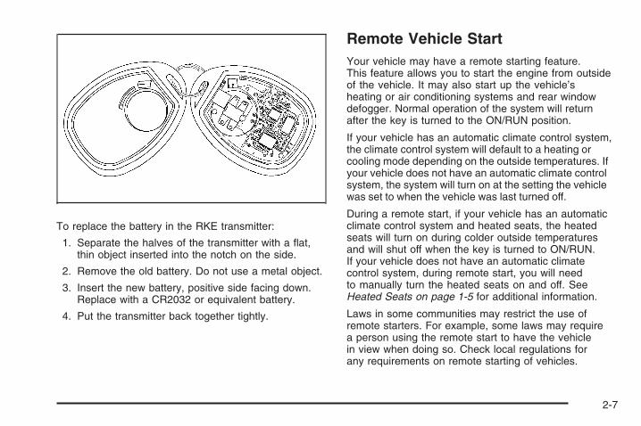
To replace the battery in the RKE transmitter:
1. Separate the halves of the transmitter with a flat,thin object inserted into the notch on the side.
2. Remove the old battery. Do not use a metal object.
3. Insert the new battery, positive side facing down.Replace with a CR2032 or equivalent battery.
4. Put the transmitter back together tightly.
Remote Vehicle StartYour vehicle may have a remote starting feature.This feature allows you to start the engine from outsideof the vehicle. It may also start up the vehicle’sheating or air conditioning systems and rear windowdefogger. Normal operation of the system will returnafter the key is turned to the ON/RUN position.
If your vehicle has an automatic climate control system,the climate control system will default to a heating orcooling mode depending on the outside temperatures. Ifyour vehicle does not have an automatic climate controlsystem, the system will turn on at the setting the vehiclewas set to when the vehicle was last turned off.
During a remote start, if your vehicle has an automaticclimate control system and heated seats, the heatedseats will turn on during colder outside temperaturesand will shut off when the key is turned to ON/RUN.If your vehicle does not have an automatic climatecontrol system, during remote start, you will needto manually turn the heated seats on and off. SeeHeated Seats on page 1-5 for additional information.
Laws in some communities may restrict the use ofremote starters. For example, some laws may requirea person using the remote start to have the vehiclein view when doing so. Check local regulations forany requirements on remote starting of vehicles.
2-7

Do not use the remote start feature if your vehicle is lowon fuel. Your vehicle may run out of fuel.
If your vehicle has the remote start feature, the RKEtransmitter functions will have an increased rangeof operation. However, the range may be less whilethe vehicle is running.
There are other conditions which can affect theperformance of the transmitter, see Remote KeylessEntry (RKE) System on page 2-4 for additionalinformation.
/ (Remote Start): This button will be on the RKEtransmitter if you have remote start.
To start the vehicle using the remote start feature:
1. Aim the transmitter at the vehicle.
2. Press and release the transmitter’s lock button.The vehicle’s doors will lock. Immediately press andhold the transmitter’s remote start button until theturn signal lights flash. If you cannot see the vehicle’slights, press and hold the remote start button fortwo to four seconds. Pressing the remote startbutton again after the vehicle has started willturn the engine off.When the vehicle starts, the parking lamps will turnon and remain on while the vehicle is running.
If the vehicle is left running it will automatically shutoff after 10 minutes unless a time extension hasbeen done.
3. If it is the first remote start since the vehicle hasbeen driven, repeat these steps, while the engineis still running, to extend the engine running timeby 10 minutes. Remote start can be extendedone time.
After entering the vehicle during a remote start, insertand turn the key to RUN to drive the vehicle.
To manually shut off a remote start, do any of thefollowing:
• Aim the RKE transmitter at the vehicle and pressthe remote start button until the parking lampsturn off.
• Turn on the hazard warning flashers.
• Turn the ignition switch on and then off.
The vehicle can be remote started two separate timesbetween driving sequences. The engine will run for10 minutes after each remote start.
Or, you can extend the engine run time by another10 minutes within the first 10 minute remote start timeframe, and before the engine stops.
2-8

For example, if the lock button and then the remotestart buttons are pressed again after the vehiclehas been running for five minutes, 10 minutes areadded, allowing the engine to run for 15 minutes.
The additional ten minutes are considered a secondremote vehicle start.
Once two remote starts, or a single remote start withone time extension has been done, the vehicle must bestarted with the key.
After the key is removed from the ignition, the vehiclecan be remote started again.
The vehicle cannot be remote started if the key isin the ignition, the hood is not closed, or if there isan emission control system malfunction and thecheck engine light comes on.
Also, the engine will turn off during a remote vehiclestart if the coolant temperature gets too high or if theoil pressure gets low.
Vehicles that have the remote vehicle start feature areshipped from the factory with the remote vehicle startsystem enabled. The system may be enabled or disabledthrough the DIC. See “REMOTE START” under DICVehicle Customization (With DIC Buttons) on page 3-76for additional information. If your vehicle does not haveDIC buttons, see your dealer/retailer to enable or disablethe remote vehicle start system.
Remote Start ReadyIf your vehicle does not have the remote vehicle startfeature, it may have the remote start ready feature.This feature allows your dealer/retailer to add themanufacturer’s remote vehicle start feature.
See your dealer/retailer if you would like to add themanufacturer’s remote vehicle start feature to yourvehicle.
2-9

Doors and Locks
Door Locks
{CAUTION:
Unlocked doors can be dangerous.• Passengers, especially children, can easily
open the doors and fall out of a movingvehicle. When a door is locked, the handlewill not open it. You increase the chanceof being thrown out of the vehicle in acrash if the doors are not locked. So, wearsafety belts properly and lock the doorswhenever you drive.
• Young children who get into unlockedvehicles may be unable to get out. A childcan be overcome by extreme heat and cansuffer permanent injuries or even deathfrom heat stroke. Always lock your vehiclewhenever you leave it.
• Outsiders can easily enter through anunlocked door when you slow down orstop your vehicle. Locking your doorscan help prevent this from happening.
There are several ways to lock and unlock your vehicle.
From the outside, use the Remote Keyless Entry (RKE)transmitter or the key in the driver’s door.
From the inside, use the power door locks or manualdoor locks. To lock or unlock the door with the manuallocks, push down or pull up on the manual lock knob.
Power Door LocksThe power door lock switches are located on the frontdoors.
K (Unlock): Press to unlock the doors.
Q (Lock): Remove the key from the ignition and pressto lock the doors.
2-10

Delayed LockingWhen locking the doors with the power lock switch orthe Remote Keyless Entry (RKE) transmitter and a dooris open, the doors will lock five seconds after the lastdoor is closed. You will hear three chimes to signal thatthe delayed locking feature is in use.
Pressing the power lock switch twice or the lock buttonon the RKE transmitter twice will override the delayedlocking feature and immediately lock all the doors.
This feature will not operate if the key is in the ignition.
You can program this feature using the DriverInformation Center (DIC). See DELAY DOOR LOCKunder DIC Vehicle Customization (With DIC Buttons)on page 3-76.
Programmable Automatic DoorLocksVehicles with an automatic lock/unlock feature enableyou to program the vehicle’s power door locks. You canprogram this feature through the Driver InformationCenter (DIC). See DIC Vehicle Customization (With DICButtons) on page 3-76 for more information on DICprogramming.
Rear Door Security LocksYour vehicle has rear door security locks. Theseprevent passengers from opening the rear doors fromthe inside.
The rear door securitylocks are located on theinside edge of eachrear door.
The rear doors must be open to access them.The label showing lock and unlock positions is locatednear the lock.
To set the locks, do the following:
1. Insert the key into the security lock slot and turn itso the slot is in the horizontal position.
2. Close the door.
2-11

When you want to open a rear door when the securitylock is on, do the following:
1. Unlock the door by lifting the rear door manual lock,using the power door lock switch, or the RemoteKeyless Entry (RKE) transmitter, if the vehiclehas one.
2. Open the door from the outside.
To cancel the rear door security lock, do the following:
1. Unlock the door and open it from the outside.
2. Insert the key into the security lock slot and turn itso the slot is in the vertical position.
Lockout ProtectionThis feature protects you from locking the key in thevehicle when the key is in the ignition and a front dooris open.
If the driver’s side power door lock switch is pressedwhen the driver’s door is open and the key is in theignition, all of the doors will lock and then the driver’sdoor will unlock.
If the passenger’s side power door lock switch ispressed when the front passenger’s door is open andthe key is in the ignition, all of the doors will lockand then the front passenger’s door will unlock.
Rear Doors
Extended CabYour vehicle may have a rear access door(s) that allowseasier access to the rear area of the extended cab.
To open a rear accessdoor from the outside,first open the front door.Then, use the handlelocated on the front edgeof the rear access doorto open it.
You must fully close a rear access door before you canclose the front door.
2-12

To open a rear accessdoor from the inside, thefront door must be openedfirst. Then, use the handlelocated on the inside of therear access door to open.
Crew CabsIf your vehicle is a crew cab, you can open your doorsfrom the inside or outside. Your vehicle may alsohave a feature which prevents children from opening therear doors. See Rear Door Security Locks on page 2-11for more information.
Tailgate
{CAUTION:
It is extremely dangerous to ride on thetailgate, even when the vehicle is operated atlow speeds. People riding on the tailgate caneasily lose their balance and fall in responseto vehicle maneuvers. Falling from a movingvehicle may result in serious injuries or death.Do not allow people to ride on the tailgate.Be sure everyone in your vehicle is in a seatand using a safety belt properly.
On vehicles with a lock on the tailgate, use the key tolock or unlock the tailgate.
Open the tailgate by lifting up on its handle while pullingthe tailgate toward you.
To shut the tailgate, firmly push it upward until itlatches.
After you put the tailgate back up, pull it back towardsyou to be sure it latches securely.
2-13
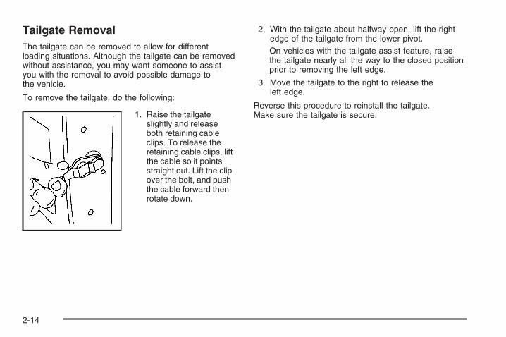
Tailgate RemovalThe tailgate can be removed to allow for differentloading situations. Although the tailgate can be removedwithout assistance, you may want someone to assistyou with the removal to avoid possible damage tothe vehicle.
To remove the tailgate, do the following:
1. Raise the tailgateslightly and releaseboth retaining cableclips. To release theretaining cable clips, liftthe cable so it pointsstraight out. Lift the clipover the bolt, and pushthe cable forward thenrotate down.
2. With the tailgate about halfway open, lift the rightedge of the tailgate from the lower pivot.On vehicles with the tailgate assist feature, raisethe tailgate nearly all the way to the closed positionprior to removing the left edge.
3. Move the tailgate to the right to release theleft edge.
Reverse this procedure to reinstall the tailgate.Make sure the tailgate is secure.
2-14

Windows
{CAUTION:
Leaving children, helpless adults, or pets in avehicle with the windows closed is dangerous.They can be overcome by the extreme heatand suffer permanent injuries or even deathfrom heat stroke. Never leave a child, ahelpless adult, or a pet alone in a vehicle,especially with the windows closed in warmor hot weather.
Manual WindowsTurn the hand crank on each door to manually raise orlower the manual windows.
2-15

Power Windows
{CAUTION:
Leaving children in a vehicle with the keys isdangerous for many reasons, children orothers could be badly injured or even killed.They could operate the power windows orother controls or even make the vehicle move.The windows will function and they could beseriously injured or killed if caught in the pathof a closing window. Do not leave keys in avehicle with children.
When there are children in the rear seatuse the window lockout button to preventunintentional operation of the windows.
If your vehicle has power windows, the controls arelocated on each of the side doors in the front and rearfor crew cab and extended cab models.
The driver’s door has a switch for the passenger’s andrear windows as well. Your power windows will workwhen the ignition has been turned to ACCESSORY orRUN or when Retained Accessory Power (RAP) isactive. See Retained Accessory Power (RAP) onpage 2-24.
Press the switch down to lower the window, and pull upthe front of the switch to raise the window.
Crew Cab shown
2-16
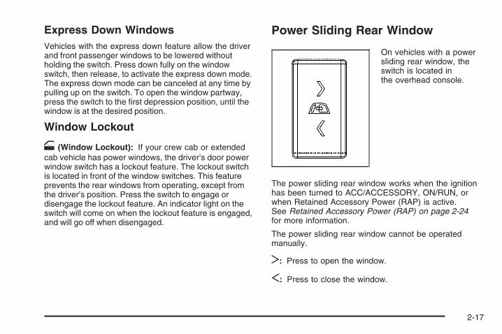
Express Down WindowsVehicles with the express down feature allow the driverand front passenger windows to be lowered withoutholding the switch. Press down fully on the windowswitch, then release, to activate the express down mode.The express down mode can be canceled at any time bypulling up on the switch. To open the window partway,press the switch to the first depression position, until thewindow is at the desired position.
Window Lockout
o (Window Lockout): If your crew cab or extendedcab vehicle has power windows, the driver’s door powerwindow switch has a lockout feature. The lockout switchis located in front of the window switches. This featureprevents the rear windows from operating, except fromthe driver’s position. Press the switch to engage ordisengage the lockout feature. An indicator light on theswitch will come on when the lockout feature is engaged,and will go off when disengaged.
Power Sliding Rear Window
On vehicles with a powersliding rear window, theswitch is located inthe overhead console.
The power sliding rear window works when the ignitionhas been turned to ACC/ACCESSORY, ON/RUN, orwhen Retained Accessory Power (RAP) is active.See Retained Accessory Power (RAP) on page 2-24for more information.
The power sliding rear window cannot be operatedmanually.
T: Press to open the window.
S: Press to close the window.
2-17

Sun VisorsPull the sun visor down to block glare. Swing the sunvisor to the side to cover the side window.
The passenger’s side sun visor may have a vanitymirror.
Theft-Deterrent SystemsVehicle theft is big business, especially in some cities.This vehicle has theft-deterrent features, however,they do not make it impossible to steal.
Content Theft-DeterrentYour vehicle may have a content theft-deterrent alarmsystem.
This is the security light.
To arm the theft-deterrent system:
1. Open the door.
2. Lock the door with the Remote Keyless Entry (RKE)transmitter. The security light should come on andflash.If the delayed locking feature is active, the alarmwill not be activated until all doors are closedand the security light goes off.
3. Close all doors. The security light will stop flashingand go off after approximately 30 seconds. Thecontent theft deterrent alarm is not armed until thesecurity light goes off.
If a locked door is opened without using the RKEtransmitter, a ten second pre-alarm will occur. The hornwill chirp and the lights will flash. If the key is not placedin the ignition and turned to START or the door is notunlocked by pressing the unlock button on the RKEtransmitter during the ten second pre-alarm, the alarmwill go off. Your vehicle’s headlamps will flash and thehorn will sound for about two minutes, then will turn offto save the battery power.
2-18
The theft-deterrent system will not activate if the doorsare locked with the vehicle’s key or the manual door lock.It activates only if you use the power door lock switch withthe door open or the RKE transmitter. You should alsoremember that you can start your vehicle with the correctignition key if the alarm has been set off.
To avoid setting off the alarm by accident:
• If you do not want to activate the theft-deterrentsystem, the vehicle should be locked with thedoor key after the doors are closed.
• Always unlock a door with the RKE transmitter.Unlocking a door any other way will set off the alarmif the system has been armed.
If you set off the alarm by accident, press unlock onthe RKE transmitter or place the key in the ignition andturn it to START to turn it off.
Testing the AlarmTo test the alarm:
1. From inside the vehicle, lower the driver’s windowand open the driver’s door.
2. Activate the system by locking the doors with theRKE transmitter.
3. Get out of the vehicle, close the door and wait forthe security light to go out.
4. Then reach in through the window, unlock the doorwith the manual door lock and open the door.This should set off the alarm.
If the alarm does not sound when it should but theheadlamps flash, check to see if the horn works.The horn fuse may be blown. To replace the fuse,see Fuses and Circuit Breakers on page 5-125.
If the alarm does not sound or the headlamps do notflash, see your dealer/retailer for service.
2-19

PASS-Key® III+ ElectronicImmobilizerThe PASS-Key III+ system operates on a radiofrequency subject to Federal CommunicationsCommission (FCC) Rules and with Industry Canada.
This device complies with Part 15 of the FCC Rules.Operation is subject to the following two conditions:
1. This device may not cause harmful interference.
2. This device must accept any interference received,including interference that may cause undesiredoperation.
This device complies with RSS-210 of Industry Canada.Operation is subject to the following two conditions:
1. This device may not cause interference.
2. This device must accept any interference received,including interference that may cause undesiredoperation of the device.
Changes or modifications to this system by other thanan authorized service facility could void authorization touse this equipment.
PASS-Key III+ uses a radio frequency transponder inthe key that matches a decoder in the vehicle.
PASS-Key® III+ ElectronicImmobilizer OperationYour vehicle has PASS-Key® III+ (PersonalizedAutomotive Security System) theft-deterrent system.PASS-Key® III+ is a passive theft-deterrent system.
The system is automatically armed when the keyis removed from the ignition.
The system is automatically disarmed when the key isturned to ON/RUN, ACC/ACCESSORY or STARTfrom the LOCK/OFF position.
You do not have to manually arm or disarm the system.
The security light will come on if there is a problemwith arming or disarming the theft-deterrent system.
When the PASS-Key® III+ system senses that someoneis using the wrong key, it prevents the vehicle fromstarting. Anyone using a trial-and-error method to startthe vehicle will be discouraged because of the highnumber of electrical key codes.
If the engine does not start and the security light onthe instrument panel cluster comes on when trying tostart the vehicle, there may be a problem with yourtheft-deterrent system. Turn the ignition off and try again.
2-20
If the engine still does not start, and the key appears tobe undamaged, try another ignition key. At this time, youmay also want to check the fuse, see Fuses and CircuitBreakers on page 5-125. If the engine still does not startwith the other key, your vehicle needs service. If yourvehicle does start, the first key may be faulty. See yourdealer/retailer who can service the PASS-Key® III+ tohave a new key made. In an emergency, contactRoadside Assistance.
It is possible for the PASS-Key® III+ decoder to learnthe transponder value of a new or replacement key.Up to 10 keys may be programmed for the vehicle.The following procedure is for programming additionalkeys only. If all the currently programmed keys arelost or do not operate, you must see your dealer/retaileror a locksmith who can service PASS-Key® III+ tohave keys made and programmed to the system.
See your dealer/retailer or a locksmith who can servicePASS-Key® III+ to get a new key blank that is cutexactly as the ignition key that operates the system.
To program the new additional key:
1. Verify that the new key has a 1 stamped on it.
2. Insert the original, already programmed, key in theignition and start the engine. If the engine will notstart, see your dealer/retailer for service.
3. After the engine has started, turn the key toLOCK/OFF, and remove the key.
4. Insert the new key to be programmed and turn it tothe ON/RUN position within five seconds of turningthe ignition to the LOCK/OFF position in Step 3.The security light will turn off once the key has beenprogrammed.
5. Repeat Steps 1 through 4 if additional keys are tobe programmed.
If you lose or damage your PASS-Key® III+ key, seeyour dealer/retailer or a locksmith who can servicePASS-Key® III+ to have a new key made.
Do not leave the key or device that disarms ordeactivates the theft deterrent system in the vehicle.
2-21

Starting and OperatingYour Vehicle
New Vehicle Break-InNotice: Your vehicle does not need an elaboratebreak-in. But it will perform better in the long run ifyou follow these guidelines:
• Keep your speed at 55 mph (88 km/h) or less forthe first 500 miles (805 km).
• Do not drive at any one constant speed, fast orslow, for the first 500 miles (805 km). Do notmake full-throttle starts. Avoid downshiftingto brake or slow the vehicle.
• Avoid making hard stops for the first 200 miles(322 km) or so. During this time the new brakelinings are not yet broken in. Hard stops withnew linings can mean premature wear and earlierreplacement. Follow this breaking-in guidelineevery time you get new brake linings.
• Do not tow a trailer during break-in. See Towinga Trailer on page 4-55 for the trailer towingcapabilities of your vehicle and moreinformation.
Following break-in, engine speed and load can begradually increased.
Ignition PositionsUse the key to turn theignition switch to fourdifferent positions.
In order to shift out of PARK (P), ignition must be in theON/RUN or ACC/ACCESSORY and the regular brakepedal must be applied.
A (LOCK/OFF): This position locks the ignition andtransmission. It is a theft-deterrent feature. The keycan only be removed when the ignition is turned toLOCK/OFF.Notice: Using a tool to force the key from theignition switch could cause damage or break thekey. Use the correct key and turn the key only withyour hand. Make sure the key is all the way in.If it is, turn the steering wheel left and right whileyou turn the key hard. If none of this works,then your vehicle needs service.
2-22
B (ACC/ACCESSORY): This position lets things likethe radio and the windshield wipers operate whilethe engine is off.
Lengthy operation of features such as the radio in theACC/ACCESSORY ignition position and the ON/RUNposition may drain the battery and prevent your vehiclefrom starting. Do not operate your vehicle in the ACC/ACCESSORY ignition position for a long period of time.
C (ON/RUN): This is the position for driving. It is theposition the ignition switch returns to after the enginestarts, and the key is released.
The battery could be drained if you leave the key in theACC/ACCESSORY or ON/RUN position with the engineoff. You may not be able to start your vehicle if the batteryis allowed to drain for an extended period of time.
D (START): This position starts the engine.
Key In the IgnitionNever leave your vehicle with the keys inside, as it is aneasy target for joy riders or thieves. If you leave the key inthe ignition and park your vehicle, a chime will sound,when you open the driver’s door. Always remember toremove your key from the ignition and take it with you.This will lock your ignition and transmission. Also, alwaysremember to lock the doors.
The battery could be drained if you leave the key in theignition while your vehicle is parked. You may not beable to start your vehicle after it has been parked for anextended period of time.
2-23

Retained Accessory Power (RAP)The following vehicle accessories can be used for up to10 minutes after the engine is turned off:
• Audio System
• Power Windows
• OnStar® System (if equipped)
• Sunroof (if equipped)
These features work when the key is in ON/RUN orACC/ACCESSORY. Once the key is turned fromON/RUN to LOCK/OFF, the windows and sunroofcontinue to work up to 10 minutes until any dooris opened. The radio continues to work for up to10 minutes or until the driver’s door is opened.
Starting the EngineIf your vehicle has the DURAMAX® Diesel engine, seethe DURAMAX® Diesel manual for more information.
To place the transmission in the proper gear:
Move your shift lever to PARK (P) or NEUTRAL (N).Your engine will not start in any other position -- this isa safety feature. To restart when you are alreadymoving, use NEUTRAL (N) only.
Starting Procedure1. With your foot off the accelerator pedal, turn the
ignition key to START. When the engine starts,let go of the key. The idle speed will go down asyour engine gets warm. Do not race the engineimmediately after starting it. Operate the engineand transmission gently to allow the oil to warmup and lubricate all moving parts.Your vehicle has a Computer-Controlled CrankingSystem. This feature assists in starting the engineand protects components. If the ignition key is turnedto the START position, and then released when theengine begins cranking, the engine will continuecranking for a few seconds or until the vehicle starts.If the engine does not start and the key is held inSTART for many seconds, cranking will be stoppedafter 15 seconds to prevent cranking motor damage.To prevent gear damage, this system also preventscranking if the engine is already running. Enginecranking can be stopped by turning the ignitionswitch to the ACC/ACCESSORY or LOCK/OFFposition.
Notice: Cranking the engine for long periods oftime, by returning the key to the START positionimmediately after cranking has ended, can overheatand damage the cranking motor, and drain thebattery. Wait at least 15 seconds between each try,to let the cranking motor cool down.
2-24

2. If the engine does not start after 5-10 seconds,especially in very cold weather (below 0°F or −18°C),it could be flooded with too much gasoline. Trypushing the accelerator pedal all the way to the floorand holding it there as you hold the key in STARTfor up to a maximum of 15 seconds. Wait at least15 seconds between each try, to allow the crankingmotor to cool down. When the engine starts, let go ofthe key and accelerator. If the vehicle starts brieflybut then stops again, do the same thing. This clearsthe extra gasoline from the engine. Do not race theengine immediately after starting it. Operate theengine and transmission gently until the oil warmsup and lubricates all moving parts.
Notice: The engine is designed to work with theelectronics in your vehicle. If you add electricalparts or accessories, you could change the way theengine operates. Before adding electrical equipment,check with your dealer/retailer. If you do not, yourengine might not perform properly. Any resultingdamage would not be covered by your vehicle’swarranty.
Fast Idle System
Fast Idle System with Switch
If your vehicle has thisfeature it is availableonly with cruise control.The manual fast idle switchis operated using thecruise control buttonslocated on the left handside of the steering wheel.
This system can be used to increase your engine idlespeed whenever the following conditions are met:
• The park brake is set.
• The brake pedal is not pressed.
• The vehicle must not be moving and the acceleratormust not be pressed.
2-25
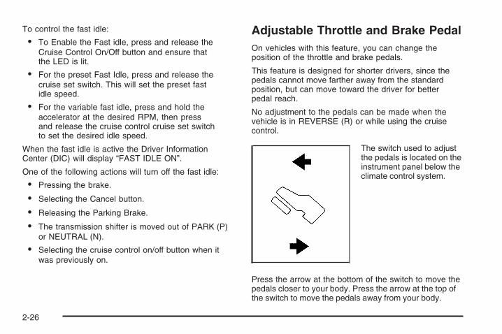
To control the fast idle:
• To Enable the Fast idle, press and release theCruise Control On/Off button and ensure thatthe LED is lit.
• For the preset Fast Idle, press and release thecruise set switch. This will set the preset fastidle speed.
• For the variable fast idle, press and hold theaccelerator at the desired RPM, then pressand release the cruise control cruise set switchto set the desired idle speed.
When the fast idle is active the Driver InformationCenter (DIC) will display “FAST IDLE ON”.
One of the following actions will turn off the fast idle:
• Pressing the brake.
• Selecting the Cancel button.
• Releasing the Parking Brake.
• The transmission shifter is moved out of PARK (P)or NEUTRAL (N).
• Selecting the cruise control on/off button when itwas previously on.
Adjustable Throttle and Brake PedalOn vehicles with this feature, you can change theposition of the throttle and brake pedals.
This feature is designed for shorter drivers, since thepedals cannot move farther away from the standardposition, but can move toward the driver for betterpedal reach.
No adjustment to the pedals can be made when thevehicle is in REVERSE (R) or while using the cruisecontrol.
The switch used to adjustthe pedals is located on theinstrument panel below theclimate control system.
Press the arrow at the bottom of the switch to move thepedals closer to your body. Press the arrow at the top ofthe switch to move the pedals away from your body.
2-26

Before you start driving, fully press the brake pedal toconfirm the adjustment is right for you. While driving,make only small adjustments.
Your vehicle may have a memory function which letspedal settings be saved and recalled. See Memory Seat,Mirrors, and Pedals on page 1-6 for more information.
Engine Coolant HeaterThe engine coolant heater, if available, can help in coldweather conditions at or below 0°F (−18°C) for easierstarting and better fuel economy during engine warm-up.Plug in the coolant heater at least four hours beforestarting your vehicle. An internal thermostat in theplug-end of the cord may exist which will preventengine coolant heater operation at temperaturesabove 0°F (−18°C).
If your vehicle has the DURAMAX® Diesel engine, seethe DURAMAX® Diesel manual for more information.
To Use the Engine Coolant Heater1. Turn off the engine.
2. Open the hood and unwrap the electrical cord.The cord is located on the driver’s side of theengine compartment, near the power steeringfluid reservoir.
3. Plug the cord into a normal, grounded 110-voltAC outlet.
{CAUTION:
Plugging the cord into an ungrounded outletcould cause an electrical shock. Also, thewrong kind of extension cord could overheatand cause a fire. You could be seriously injured.Plug the cord into a properly groundedthree-prong 110-volt AC outlet. If the cordwill not reach, use a heavy-duty three-prongextension cord rated for at least 15 amps.
4. Before starting the engine, be sure to unplug andstore the cord as it was before to keep it awayfrom moving engine parts. If you do not, it couldbe damaged.
2-27

How long should you keep the coolant heater pluggedin? The answer depends on the outside temperature, thekind of oil you have, and some other things. Instead oftrying to list everything here, we ask that you contact yourdealer/retailer in the area where you will be parking yourvehicle. The dealer/retailer can give you the best advicefor that particular area.
Active Fuel Management™Your vehicle’s V8 engine may have Active FuelManagement™. This system allows the engine tooperate on either all or half of its cylinders, dependingon the driving conditions.
When less power is required, such as cruising at aconstant vehicle speed, the system will operate in thehalf cylinder mode, allowing your vehicle to achievebetter fuel economy. When greater power demands arerequired, such as accelerating from a stop, passing,or merging onto a freeway, the system will maintainfull-cylinder operation.
If your vehicle has an Active Fuel Management™indicator, see DIC Operation and Displays (With DICButtons) on page 3-57 or DIC Operation and Displays(Without DIC Buttons) on page 3-63 for more informationon using this display.
Automatic Transmission OperationIf your vehicle is has an automatic transmission,it has an electronic shift position indicator within theinstrument panel cluster. This display comes on whenthe ignition key is turned to the ON/RUN position.
There are several differentpositions for the shift lever.
Hydra-Matic® 4-SpeedAutomatic Transmission
2-28

See “Range Selection Mode” later in this section.
PARK (P): This position locks your rear wheels. It is thebest position to use when you start the engine becauseyour vehicle cannot move easily. When parked on a hill,especially when the vehicle has a heavy load, you mightnotice an increase in the effort to shift out of Park. SeeTorque Lock (Automatic Transmission) under ShiftingInto Park on page 2-51 for more information.
{CAUTION:
It is dangerous to get out of your vehicle if theshift lever is not fully in PARK (P) with theparking brake firmly set. Your vehicle can roll.
CAUTION: (Continued)
CAUTION: (Continued)
Do not leave your vehicle when the engine isrunning unless you have to. If you have left theengine running, the vehicle can move suddenly.You or others could be injured. To be sure yourvehicle will not move, even when you are onfairly level ground, always set your parkingbrake and move the shift lever to PARK (P).See Shifting Into Park on page 2-51. If youare pulling a trailer, see Towing a Trailer onpage 4-55.
{CAUTION:
If you have Four-Wheel Drive, your vehiclewill be free to roll — even if your shift leveris in PARK (P) — if your transfer case is inNEUTRAL. So, be sure the transfer case is in adrive gear, Two-Wheel Drive High or Four-WheelDrive High or Four-Wheel Drive Low — not inNEUTRAL. See Shifting Into Park on page 2-51.
Allison Transmission® or Hydra-Matic® 6-SpeedAutomatic Transmission
2-29

REVERSE (R): Use this gear to back up.
Notice: Shifting to REVERSE (R) while your vehicleis moving forward could damage the transmission.The repairs would not be covered by your warranty.Shift to REVERSE (R) only after your vehicle isstopped.
To rock your vehicle back and forth to get out of snow,ice, or sand without damaging your transmission, see IfYour Vehicle is Stuck in Sand, Mud, Ice, or Snow onpage 4-34.
NEUTRAL (N): In this position, your engine does notconnect with the wheels. To restart when you arealready moving, use NEUTRAL (N) only. Also, useNEUTRAL (N) when your vehicle is being towed.
{CAUTION:
Shifting into a drive gear while the engine isrunning at high speed is dangerous. Unlessyour foot is firmly on the brake pedal, yourvehicle could move very rapidly. You couldlose control and hit people or objects. Do notshift into a drive gear while your engine isrunning at high speed.
Notice: Shifting out of PARK (P) or NEUTRAL (N)with the engine running at high speed may damagethe transmission. The repairs would not becovered by your warranty. Be sure the engine is notrunning at high speed when shifting your vehicle.
DRIVE (D): This position is for normal driving.It provides the best fuel economy for your vehicle.If you need more power for passing, and you are:
• Going less than about 35 mph (55 km/h), push youraccelerator pedal about halfway down.
• Going about 35 mph (55 km/h) or more, push theaccelerator all the way down.
By doing this, the vehicle shifts down to the nextgear and has more power.
DRIVE (D) can be used when towing a trailer, carrying aheavy load, driving on steep hills, or for off-road driving.You might want to shift the transmission to a lower gearselection if the transmission shifts too often.
Downshifting the transmission in slippery road conditionscould result in skidding. See Skidding under Loss ofControl on page 4-11.
2-30

Your vehicle has a shift stabilization feature that adjuststhe transmission shifting to the current driving conditionsin order to reduce rapid upshifts and downshifts. This shiftstabilization feature is designed to determine, beforemaking an upshift, if the engine is able to maintain vehiclespeed by analyzing things such as vehicle speed, throttleposition, and vehicle load. If the shift stabilization featuredetermines that a current vehicle speed cannot bemaintained, the transmission does not upshift and insteadholds the current gear. In some cases, this could appearto be a delayed shift, however the transmission isoperating normally.
Your vehicle’s transmission uses adaptive shift controls.Adaptive shift controls continually compares key shiftparameters to pre-programmed ideal shifts stored in thetransmissions computer. The transmission constantlymakes adjustments to improve vehicle performanceaccording to how the vehicle is being used, such as witha heavy load or when temperature changes. During thisadaptive shift control process, shifting might feel differentas the transmission determines the best settings.
When temperatures are very cold, the AllisonTransmission® and Hydra-Matic® 6-Speed transmission’sgear shifting could be delayed providing more stableshifts until the engine warms up. Shifts could be morenoticeable with a cold transmission. This difference inshifting is normal.
MANUAL MODE (M): This position, is available onvehicles with the Allison Transmission® or Hydra-Matic®
6-Speed transmission. It lets drivers select the rangeof gears appropriate for current driving conditions.If your vehicle has this feature, see Range SelectMode (Allison Transmission® or Hydra-Matic®
6-Speed transmission) later in this section.
THIRD (3): This position is also used for normal driving.It reduces vehicle speed more than DRIVE (D) withoutusing the brakes. You might choose THIRD (3)instead of DRIVE (D) when driving on hilly, windingroads, when towing a trailer, so there is less shiftingbetween gears and when going down a steep hill.
SECOND (2): This position reduces vehicle speed evenmore than THIRD (3) without using your brakes. You canuse SECOND (2) on hills. It can help control your speedas you go down steep mountain roads, but then youwould also want to use the brakes off and on.
If you manually select SECOND (2) in an automatictransmission, the transmission will start in second gear.You can use this feature for reducing the speed of therear wheels when you are trying to start your vehiclefrom a stop on slippery road surfaces.
2-31

FIRST (1): For the Hydra-Matic® 4-Speed transmissionthis position reduces vehicle speed even more thanSECOND (2) without using the brakes. You can use it onvery steep hills, or in deep snow or mud. If the shift leveris put in FIRST (1) while the vehicle is moving forward,the transmission does not shift into first gear until thevehicle is going slowly enough.
For an Allison Transmission® or Hydra-Matic® 6-Speedtransmission, this position reduces vehicle speedwithout using your brakes. You can use it formajor/severe downgrades and off-road driving wherethe vehicle would otherwise accelerate due to steepnessof grade. When you shift to FIRST (1) it provides thelowest gear appropriate to your current road speed andcontinues to downshift as the vehicle slows, eventuallydownshifting to FIRST (1) gear.
Notice: Spinning the tires or holding the vehiclein one place on a hill using only the acceleratorpedal may damage the transmission. The repair willnot be covered by your warranty. If you are stuck,do not spin the tires. When stopping on a hill,use the brakes to hold the vehicle in place.
Range Selection Mode (Allison® orHydra-Matic® 6-Speed Transmission)
Your vehicle may have a Range Selection Mode.The Range Selection Mode helps control the vehicle’stransmission and vehicle speed while driving down hill ortowing a trailer by letting you select a desired range ofgears.
2-32
To use this feature, do the following:
1. Move the shift lever to the MANUAL MODE (M).
2. Press the plus/minus buttons, located on thesteering column shift lever, to select the desiredrange of gears for your current driving conditions.
When MANUAL MODE (M) is selected a numberdisplays next to the M, indicating the current gear.
This number is the highest gear that can be used.However, your vehicle can automatically shift to lowergears as it adjusts to driving conditions. This meansthat all gears below that number are available. WhenFIFTH (5) is selected, FIRST (1) through FIFTH (5)gears are automatically shifted by the vehicle, butSIXTH (6) cannot be used until the plus/minus buttonlocated on the steering column lever is used to changeto the gear.
Grade Braking is not available when the RangeSelection Mode is active. See Tow/Haul Mode onpage 2-34
While using the Range Selection mode feature, cruisecontrol and the Tow/Haul mode can be used.
Notice: Spinning the tires or holding the vehiclein one place on a hill using only the acceleratorpedal may damage the transmission. The repair willnot be covered by your warranty. If you are stuck,do not spin the tires. When stopping on a hill,use the brakes to hold the vehicle in place.
Low Traction ModeIf your vehicle has the Allison Transmission®, or theHydra-Matic® 6-Speed Automatic Transmission, it has aLow Traction Mode that assist in vehicle accelerationwhen road conditions are slippery, such as with ice orsnow. While the vehicle is at a stop, select the secondgear range using the Range Selection system. This willlimit torque to the wheels after it detects wheel slip,preventing the tires from spinning.
2-33

Tow/Haul Mode If your vehicle has an automatic transmission, ithas a tow/haul mode. If your vehicle has an Allisonor Hydra-Matic® 6-speed automatic transmission see“Tow/Haul Mode (Allison or Hydra-Matic® 6-SpeedAutomatic Transmission®) following. The tow/haulmode adjusts the transmission shift pattern to reduceshift cycling, providing increased performance, vehiclecontrol, and transmission cooling when towing or haulingheavy loads.
The selector button is located on the end of the shiftlever. Turn the tow/haul on and off by pressing thebutton. When the tow/haul is on, a light on theinstrument panel cluster will come on.
See Tow/Haul Mode Light on page 3-54 for moreinformation.
Also see Tow Haul Mode under Towing a Trailer onpage 4-55 for more information.
2-34

Tow/Haul Mode (Allison Transmission®
or Hydra-Matic® 6-Speed AutomaticTransmission)
If your vehicle has an Allison or Hydra-Matic® 6-speedautomatic transmission®, it has a tow/haul mode.The tow/haul mode adjusts the transmission shift patternto reduce shift cycling, providing increased performance,vehicle control, and transmission cooling when towingor hauling heavy loads.
Turn the tow/haul mode on and off by pressing thebutton, located on the end of the shift lever. When thetow/haul is on, a light on the instrument panel cluster willcome on.
See Tow/Haul Mode Light on page 3-54 for moreinformation.
Also see “Tow Haul Mode” under Towing a Trailer onpage 4-55 for more information.
2-35

Grade Braking (Allison Transmission®
or Hydra-Matic® 6-Speed AutomaticTransmission)The Grade Braking shift modes can be activated bypressing the button on the end of the shift control lever.While in Range Selection Mode, Grade Braking isdeactivated allowing the driver to select a desiredrange of gears.
Grade Braking is only active while the Tow/Haul Mode isselected and you are not in the Range Selection Mode.See “Tow/Haul Mode listed previously and AutomaticTransmission Operation on page 2-28 for moreinformation on the Range Selection Mode. Grade Brakingassists in maintaining desired vehicle speeds whendriving on downhill grades by automatically implementinga shift schedule that utilizes the engine and transmissionto slow the vehicle. This reduces wear on the brakingsystem and increases control of the vehicle. GradeBraking monitors vehicle speed, acceleration, enginetorque and brake pedal usage. Using this information,it detects when the truck is on a downhill grade and thedriver desires to slow the vehicle by pressing the brake.See the diesel supplement for information on CruiseGrade Braking.
Also see Towing a Trailer on page 4-55 for moreinformation.
Four-Wheel DriveIf your vehicle has Four-Wheel Drive, you can send theengine’s driving power to all four wheels for extra traction.To get the most satisfaction out of Four-Wheel Drive, youmust be familiar with its operation. Read the part thatfollows before using Four-Wheel Drive. See theappropriate text for the transfer case in your vehicle.
Notice: Driving on clean, dry pavement inFour-Wheel-Drive High or Four-Wheel-Drive Low foran extended period of time may cause prematurewear on your vehicle’s powertrain. Do not drive onclean, dry pavement in Four-Wheel-Drive High orFour-Wheel-Drive Low for extended periods of time.
While driving on clean dry pavement and during tightturns, you may experience vibration in the steeringsystem.
Front AxleThe front axle engages and disengages automaticallywhen you shift the transfer case. Some delay forthe axle to engage or disengage is normal.
2-36

Manual Transfer Case
The transfer case shift lever is on the floor to the rightof the driver. Use this lever to shift into and out ofFour-Wheel Drive.
A Four-Wheel Driveindicator light comeson when you shift intofour-wheel drive and thefront axle engages. SeeFour-Wheel-Drive Lighton page 3-54.
Some delay between shifting and when the indicatorlight comes on is normal.
Recommended Transfer Case Settings
Driving ConditionsTransfer Case Settings
2m 4m 4n N
Normal YES
Severe YES
Extreme YES
Vehicle in Tow* YES
*See Recreational Vehicle Towing on page 4-50Towing Your Vehicle on page 4-50
Notice: Driving on clean, dry pavement infour-wheel drive for an extended period of time cancause premature wear on your vehicle’s powertrain.Do not drive on clean, dry pavement in Four-WheelDrive for extended periods of time.
2-37

4 n(Four-Wheel-Drive Low): This setting alsoengages the front axle and delivers extra torque.You may never need Four-Wheel-Drive Low. It sendsmaximum power to all four wheels. You might chooseFour-Wheel-Drive Low if you are driving off-road in deepsand, deep mud, deep snow, and while climbing ordescending steep hills. When operating in Four-WheelLow, the gear ratio provides additional torque whencompared to Four-Wheel-Drive High. The transmissiongear shift feel is exaggerated.
A parking brake symbolis located next to the N(NEUTRAL) symbol as areminder to set the parkingbrake before shifting thetransfer case in Neutral.
{CAUTION:
Shifting the transfer case to NEUTRALcan cause your vehicle to roll even if thetransmission is in PARK (P). You or someoneelse could be seriously injured. Be sure to setthe parking brake before placing the transfercase in NEUTRAL. See Parking Brake onpage 2-50.
N (NEUTRAL): Shift to this setting only when yourvehicle needs to be towed. See Recreational VehicleTowing on page 4-50 or Towing Your Vehicle onpage 4-50.
2 m(Two-Wheel-Drive High): This setting is usedfor driving in most street and highway situations.The front axle is not engaged in two-wheel drive.This setting also provides the best fuel economy.
4 m(Four-Wheel-Drive High): Use this setting whenyou need extra traction, such as on snowy or icy roads orin most off-road situations. This setting also engages thefront axle to help drive your vehicle. This is the bestsetting to use when plowing snow.
2-38
You can shift from Two-Wheel-Drive High toFour-Wheel-Drive High or Four-Wheel-Drive High toTwo-Wheel-Drive High while the vehicle is moving. Inextremely cold weather, it may be necessary to stop orslow the vehicle to shift into Four-Wheel-Drive High.
When Using the Manual Transfer Case• Shifting should be made using quick motions.
Shifting slowly may make it more difficult to shift.
• You may notice that it is harder to shift when thevehicle is cold. After the vehicle warms up theshifting will return to normal.
• While in Four-Wheel High or Four-Wheel-Drive Lowyou may experience reduced fuel economy.
• Avoid driving in Four-Wheel Drive on clean, drypavement. It may cause your tires to wear faster,and make the transfer case harder to shift and runnoisier.
• If the transfer case shifter is in the NEUTRALposition and you have difficulty reaching theselected transfer case mode, with the enginerunning, shift the transmission momentarily todrive and then back to NEUTRAL. This will realignthe gear teeth in the transfer case and allowyou to complete the shift.
Shifting from Two-Wheel-Drive High toFour-Wheel-Drive High• Shifts between Two-Wheel-Drive High and
Four-Wheel-Drive High can be made at anyvehicle speed.
• Shift the transfer case lever in one continuousmotion into either the Four-Wheel-Drive Highor Two-Wheel-Drive High position.
• In extremely cold weather, it may be necessary toslow or stop the vehicle to shift into Four-wheel-DriveHigh until your vehicle has warmed up.
• While in Four-Wheel-Drive High, your vehicle can bedriven at any posted legal speed limit.
2-39
Shifting In or Out of Four-Wheel-Drive Low
Notice: Shifting the transfer case intoFour-Wheel-Drive Low while moving at speedsfaster than 3 mph (5 km/h) may cause prematurewear to the transfer case, and may cause the gearsto grind. To avoid causing premature wear, andgrinding the gears, do not shift the transfer case intoFour-Wheel-Drive Low while the vehicle is movingfaster than 3 mph (5 km/h).
Shifting into Four-Wheel-Drive Low should be done, ifpossible, with the vehicle at a slight roll, 3 mph (5 km/h)or less.
• Shift the transmission into NEUTRAL (N).
{CAUTION:
Shifting the transfer case to NEUTRALcan cause your vehicle to roll even if thetransmission is in PARK (P). You or someoneelse could be seriously injured. Be sure to setthe parking brake before placing the transfercase in NEUTRAL. See Parking Brake onpage 2-50.
• Shifting into Four-Wheel-Drive Low with the vehicleat a stop may be more difficult. You may be unable tocomplete the shift to Four-Wheel-Drive Low, and willend up in NEUTRAL. This is normal, and is a functionof the gear teeth aligning in your transfer case. Whenthis happens, make sure the engine is on, shift yourtransmission momentarily to drive and back toNEUTRAL, and then complete the shift.
• Shift the transfer case shift lever in one continuousmotion into the Four-Wheel-Drive Low position.
• When Four-Wheel-Drive Low do not drive faster than45 mph. This will reduce wear and extend the life ofyour transfer case.
2-40

Shifting In or Out of NEUTRAL
1. With the vehicle running and the engine at an idleset the parking brake.
2. Place the transmission into NEUTRAL (N).
Shift the transfer case in one continuous motion into orout of the NEUTRAL position.
Electronic Transfer CaseThe transfer case knobis located next to thesteering column.
Use the dial to shift into and out of four-wheel drive.
Recommended Transfer Case Settings
Driving ConditionsTransfer Case Settings
2m 4m 4n N
Normal YES
Severe YES
Extreme YES
Vehicle in Tow* YES
*See Recreational Vehicle Towing on page 4-50Towing Your Vehicle on page 4-50
You can choose among four driving settings:
Indicator lights in the dial show which setting you are in.The indicator lights will come on briefly when you turn onthe ignition and one will stay on. If the lights do not comeon, you should take your vehicle to your dealer forservice. An indicator light flashes while shifting thetransfer case and remains illuminated when the shift iscomplete. If for some reason the transfer case cannotmake a requested shift, it will return to the last chosensetting.
2 m(Two-Wheel-Drive High): This setting is usedfor driving in most street and highway situations.The front axle is not engaged in Two-Wheel Drive.This setting also provides the best fuel economy.
2-41

4 m(Four-Wheel-Drive High): Use theFour-Wheel-Drive High position when extra traction isneeded, such as on snowy or icy roads or in most off-roadsituations. This setting also engages the front axle to helpdrive your vehicle. This is the best setting to use whenplowing snow.
4 n(Four-Wheel-Drive Low): This setting alsoengages the front axle and delivers extra torque. Youmay never need this setting. It sends maximum powerto all four wheels. You might choose Four-Wheel-DriveLow while driving off-road in deep sand, deep mud, deepsnow, and while climbing or descending steep hills.StabiliTrak® will not engage in this mode.
{CAUTION:
Shifting the transfer case to NEUTRALcan cause your vehicle to roll even if thetransmission is in PARK (P). You or someoneelse could be seriously injured. Be sure to setthe parking brake before placing the transfercase in NEUTRAL. See Parking Brake onpage 2-50.
N (NEUTRAL): Shift the vehicle’s transfer caseto NEUTRAL only when towing your vehicle. SeeRecreational Vehicle Towing on page 4-50 or TowingYour Vehicle on page 4-50 for more information.
If the SERVICE 4–Wheel Drive message stays on, youshould take your vehicle to your dealer for service.See “Service 4–Wheel Drive message” under DICWarnings and Messages on page 3-66.
Shifting Into Two-Wheel-Drive HighTurn the knob to the Two-Wheel-Drive High position.This can be done at any speed, except when shiftingfrom Four-Wheel-Drive Low. See Shifting Out ofFour-Wheel-Drive Low for more information.
2-42

Shifting Into Four-Wheel Drive LowWhen Four-Wheel-Drive Low is engaged, vehicle speedshould be kept below 45 mph. Extended high-speedoperation in Four-Wheel-Drive Low may damageor shorten the life of the drivetrain.
To shift to the Four-Wheel-Drive Low position, theignition must be in RUN and the vehicle must be stoppedor moving less than 3 mph (5 km/h) with the transmissionin NEUTRAL (N). The preferred method for shifting intoFour-Wheel-Drive Low is to have your vehicle moving1 to 2 mph (1.6 to 3.2 km/h). Turn the knob to theFour-Wheel-Drive Low position. You must wait for theFour-Wheel-Drive Low indicator light to stop flashing andremain on before shifting your transmission in gear.
Notice: Shifting the transmission into gear beforethe requested mode indicator light has stoppedflashing could damage the transfer case. To helpavoid damaging your vehicle, always wait for themode indicator lights to stop flashing before shiftingthe transmission into gear.
It is typical for your vehicle to exhibit significantengagement noise and bump when shifting betweenFour-Wheel-Drive Low and Four-Wheel-Drive Highranges or from NEUTRAL with the engine running.
If the knob is turned to the Four-Wheel-Drive Lowposition when your vehicle is in gear and/or moving,the Four-Wheel-Drive Low indicator light will flash for30 seconds and not complete the shift unless yourvehicle is moving less than 3 mph (5 km/h) and thetransmission is in NEUTRAL (N). After 30 seconds thetransfer case will shift to Four-Wheel-Drive High mode.
2-43
Shifting Out of Four-Wheel-Drive LowTo shift from Four-Wheel-Drive Low toFour-Wheel-Drive High, or Two-Wheel-Drive High,your vehicle must be stopped or moving less than 3 mph(5 km/h) with the transmission in NEUTRAL (N) and theignition in ON/RUN. The preferred method for shiftingout of Four-Wheel-Drive Low is to have your vehiclemoving 1 to 2 mph (1.6 to 3.2 km/h). Turn the knob tothe Four-Wheel-Drive High, or Two-Wheel-Drive Highposition. You must wait for the Four-Wheel-Drive High,or Two-Wheel-Drive High indicator light to stop flashingand remain on before shifting the transmission into gear.
Notice: Shifting the transmission into gear beforethe requested mode indicator light has stoppedflashing could damage the transfer case. To helpavoid damaging your vehicle, always wait for themode indicator lights to stop flashing before shiftingthe transmission into gear.It is typical for your vehicle to exhibit significantengagement noise and bump when shifting betweenFour-Wheel-Drive Low and Four-Wheel-Drive Highranges or from NEUTRAL with the engine running.If the knob is turned to the Four-Wheel-Drive High, orTwo-Wheel-Drive High switch position when your vehicleis in gear and/or moving, the Four-Wheel-Drive High,or Two-Wheel-Drive High indicator light will flash for30 seconds but will not complete the shift unless yourvehicle is moving less than 3 mph (5 km/h) and thetransmission is in NEUTRAL (N).
Shifting into NEUTRALTo shift the transfer case to NEUTRAL do the following:
1. Make sure the vehicle is parked so that it willnot roll.
2. Set the parking brake and press and hold theregular brake pedal. See Parking Brake onpage 2-50 for more information.
3. Start the vehicle or turn the ignition to ON/RUN.4. Shift the transmission to NEUTRAL (N).5. Shift the transfer case to Two-Wheel-Drive High.6. Turn the transfer case dial clockwise to NEUTRAL
till it stops and hold it for 10 seconds. Then slowlyrelease the dial to the four low position. TheNEUTRAL light will come on when the transfercase shift to NEUTRAL is complete.
7. If the engine is running, verify that the transfer caseis in NEUTRAL (N) by shifting the transmission toREVERSE (R) for one second, then shift thetransmission to DRIVE (D) for one second.
8. Turn the ignition to ACC/ACCESSORY, which willturn the engine off.
9. Place the transmission shift lever in PARK (P).10. Release the parking brake prior to moving
the vehicle.11. Turn the ignition to LOCK/OFF.
2-44

Shifting Out of NEUTRALTo shift out of NEUTRAL do the following:
1. Set the parking brake and apply the regularbrake pedal.
2. Shift the transmission to NEUTRAL (N) and turn theignition to RUN with the engine off.
3. Turn the transfer case dial to Two-Wheel-Drive High.After the transfer case has shifted out of NEUTRALthe NEUTRAL light will go out.
4. Release the parking brake prior to moving thevehicle.
Notice: Shifting the transmission into gearbefore the requested mode indicator light hasstopped flashing could damage the transfer case.To help avoid damaging your vehicle, alwayswait for the mode indicator lights to stop flashingbefore shifting the transmission into gear.
5. Start the engine and shift the transmission to thedesired position.
Excessively shifting the transfer case into or out of thedifferent modes may cause the transfer case to enter theshift protection mode. This will protect the transfer casefrom possible damage and will only allow the transfercase to respond to one shift per 10 seconds. The transfercase may stay in this mode for up to three minutes.
Automatic Transfer CaseThe transfer case knobis located next to thesteering column.
For information on StabiliTrak®, see StabiliTrak®
System on page 4-6.
Use the dial to shift into and out of Four-Wheel Drive.
You can choose among five driving settings:
Indicator lights in the dial show which setting you are in.The indicator lights will come on briefly when you turn onthe ignition and one will stay on. If the lights do not comeon, you should take your vehicle to your dealer forservice. An indicator light will flash while shifting thetransfer case. It will remain illuminated when the shift iscomplete. If for some reason the transfer case cannotmake a requested shift, it will return to the last chosensetting.
2 m(Two-Wheel-Drive High): This setting is used
2-45

for driving in most street and highway situations. Thefront axle is not engaged in Two-Wheel Drive.This setting also provides the best fuel economy.
AUTO (Automatic Four-Wheel Drive): This setting isideal for use when road surface traction conditions arevariable. When driving your vehicle in AUTO, the frontaxle is engaged, but the vehicle’s power is sent only tothe front and rear wheels automatically based on drivingconditions. Driving in this mode results in slightly lowerfuel economy than Two-Wheel-Drive High.
4 m(Four-Wheel-Drive High): Use theFour-Wheel-Drive High position when extra traction isneeded, such as on snowy or icy roads or in most off-roadsituations. This setting also engages the front axle to helpdrive your vehicle. This is the best setting to use whenplowing snow.
4 n(Four-Wheel-Drive Low): This setting alsoengages the front axle and delivers extra torque.You may never need this setting. It sends maximumpower to all four wheels. You might chooseFour-Wheel-Drive Low if you are driving off-road indeep sand, deep mud, deep snow, and while climbingor descending steep hills. StabiliTrak® will not engagein this mode. See StabiliTrak® System on page 4-6 formore information.
{CAUTION:
Shifting the transfer case to NEUTRALcan cause your vehicle to roll even if thetransmission is in PARK (P). You or someoneelse could be seriously injured. Be sure to setthe parking brake before placing the transfercase in NEUTRAL. See Parking Brake onpage 2-50.
N (NEUTRAL): Shift the vehicle’s transfer caseto NEUTRAL only when towing your vehicle. SeeRecreational Vehicle Towing on page 4-50 or TowingYour Vehicle on page 4-50 for more information.
If the SERVICE 4–Wheel Drive message stays on, youshould take your vehicle to your dealer for service.See “Service 4–Wheel Drive message” under DICWarnings and Messages on page 3-66.
2-46
Shifting Into Four-Wheel-Drive High orAUTO (Automatic Four-Wheel Drive)Turn the knob to the Four-Wheel-Drive High or AUTOposition. This can be done at any speed, except whenshifting from Four-Wheel-Drive Low, and the indicatorlight will flash while shifting. It will remain on when theshift is completed.
Shifting Into Two-Wheel-Drive HighTurn the knob to the Two-Wheel-Drive High position.This can be done at any speed, except when shiftingfrom Four-Wheel-Drive Low.
Shifting Into Four-Wheel-Drive LowWhen Four-Wheel-Drive Low is engaged, vehicle speedshould be kept below 45 mph. Extended high-speedoperation in Four-Wheel-Drive Low may damageor shorten the life of the drivetrain.
To shift to the Four-Wheel-Drive Low position, theignition must be in RUN and the vehicle must be stoppedor moving less than 3 mph (5 km/h) with the transmissionin NEUTRAL (N). The preferred method for shifting into
Four-Wheel-Drive Low is to have your vehicle moving1 to 2 mph (1.6 to 3.2 km/h). Turn the knob to theFour-Wheel-Drive Low position. You must wait for theFour-Wheel-Drive Low indicator light to stop flashingand remain on before shifting your transmission in gear.
Notice: Shifting the transmission into gearbefore the requested mode indicator light hasstopped flashing could damage the transfer case.To help avoid damaging your vehicle, alwayswait for the mode indicator lights to stop flashingbefore shifting the transmission into gear.
It is typical for your vehicle to exhibit significantengagement noise and bump when shifting betweenFour-Wheel-Drive Low and Four-Wheel-Drive Highranges or from NEUTRAL with the engine running.
If the knob is turned to the Four-Wheel-Drive Lowposition when your vehicle is in gear and/or moving,the Four-Wheel-Drive Low indicator light will flash for30 seconds and not complete the shift unless yourvehicle is moving less than 3 mph (5 km/h) and thetransmission is in NEUTRAL (N). After 30 seconds thetransfer case will shift to Four-Wheel-Drive High mode.
2-47
Shifting Out of Four-Wheel-Drive LowTo shift from Four-Wheel-Drive Low toFour-Wheel-Drive High, AUTO or Two-Wheel-Drive High,your vehicle must be stopped or moving less than 3 mph(5 km/h) with the transmission in NEUTRAL (N) and theignition in RUN. The preferred method for shifting out ofFour-Wheel-Drive Low is to have your vehicle moving1 to 2 mph (1.6 to 3.2 km/h). Turn the knob to theFour-Wheel-Drive High, AUTO or Two-Wheel-Drive Highposition. You must wait for the Four-Wheel-Drive High,AUTO or Two-Wheel-Drive High indicator light to stopflashing and remain on before shifting your transmissioninto gear.
Notice: Shifting the transmission into gearbefore the requested mode indicator light hasstopped flashing could damage the transfer case.To help avoid damaging your vehicle, alwayswait for the mode indicator lights to stop flashingbefore shifting the transmission into gear.
It is typical for your vehicle to exhibit significantengagement noise and bump when shifting betweenFour-Wheel-Drive Low and Four-Wheel-Drive Highranges or from NEUTRAL with the engine running.
If the knob is turned to the Four-Wheel-Drive High,AUTO, or Two-Wheel-Drive High switch positionwhen your vehicle is in gear and/or moving, theFour-Wheel-Drive High, AUTO or Two-Wheel-DriveHigh indicator light will flash for 30 seconds but willnot complete the shift unless your vehicle is movingless than 3 mph (5 km/h) and the transmission isin NEUTRAL (N).
2-48

Shifting into NEUTRALTo shift the transfer case to NEUTRAL do the following:
1. Make sure the vehicle is parked so that it will not roll.
2. Set the parking brake and apply the regular brakepedal. See Parking Brake on page 2-50 for moreinformation.
3. Start the vehicle or turn the ignition to ON/RUN.
4. Put the transmission in NEUTRAL (N).
5. Shift the transfer case to Two-Wheel Drive High.
6. Turn the transfer case dial clockwise to NEUTRALtill it stops and hold it for 10 seconds. Then slowlyrelease the dial to the four low position. TheNEUTRAL light will come on when the transfercase shift to NEUTRAL is complete.
7. If the engine is running, make sure that the transfercase is in NEUTRAL (N) by shifting the transmissionto REVERSE (R) for one second, then shift thetransmission to DRIVE (D) for one second.
8. Turn the ignition to ACC/ACCESSORY, which willturn the engine off.
9. Place the transmission shift lever in PARK (P).
10. Release the parking brake prior to movingthe vehicle.
11. Turn the ignition to LOCK/OFF.
Shifting Out of NEUTRALTo shift out of NEUTRAL do the following:
1. Set the parking brake and apply the regularbrake pedal.
2. Shift the transmission to NEUTRAL (N) and turn theignition to RUN with the engine off.
3. Turn the transfer case dial to Two-Wheel-DriveHigh, Four-Wheel-Drive High, AUTO.After the transfer case has shifted out of NEUTRALthe NEUTRAL light will go out.
4. Release the parking brake prior to moving thevehicle.
Notice: Shifting the transmission into gearbefore the requested mode indicator light hasstopped flashing could damage the transfer case.To help avoid damaging your vehicle, alwayswait for the mode indicator lights to stop flashingbefore shifting the transmission into gear.
5. Start the engine and shift the transmission to thedesired position.
2-49

Parking BrakeTo set the parking brake, hold the regular brake pedaldown with your right foot. Push down the parkingbrake pedal with your left foot.
A chime sounds and the warning light flashes when theparking brake is applied and the vehicle is moving atleast 5 mph (8 km/h).
To release the parking brake, hold the regular brakepedal down. Then pull the bottom edge of the lever,with the parking brake symbol and located abovethe parking brake pedal.
If the ignition is on when the parking brake is released,the brake system warning light goes off.
Notice: Driving with the parking brake on canoverheat the brake system and cause prematurewear or damage to brake system parts. Make surethat the parking brake is fully released and the brakewarning light is off before driving.
If you are towing a trailer and are parking on any hill,see Towing a Trailer on page 4-55.
2-50
Shifting Into Park
{CAUTION:
It can be dangerous to get out of your vehicleif the shift lever is not fully in PARK (P) withthe parking brake firmly set. Your vehicle canroll. If you have left the engine running, thevehicle can move suddenly. You or otherscould be injured. To be sure your vehicle willnot move, even when you are on fairly levelground, use the steps that follow. Withfour-wheel drive, if your transfer case is inNEUTRAL, your vehicle will be free to roll,even if your shift lever is in PARK (P).
CAUTION: (Continued)
CAUTION: (Continued)
So, be sure the transfer case is in a drivegear — not in NEUTRAL. If you are pulling atrailer, see Towing a Trailer on page 4-55.
1. Hold the brake pedal down with your right foot andset the parking brake.See Parking Brake on page 2-50 for moreinformation.
2. Move the shift lever into the PARK (P) position bypulling the shift lever toward you and moving it upas far as it will go.
3. Be sure the transfer case is in a drive gear — notin NEUTRAL (N).
4. Turn the ignition key to LOCK/OFF.
5. Remove the key and take it with you. If you canleave your vehicle with the ignition key in yourhand, your vehicle is in PARK (P).
2-51

Leaving Your Vehicle With the EngineRunning
{CAUTION:
It can be dangerous to leave your vehicle withthe engine running. Your vehicle could movesuddenly if the shift lever is not fully in PARK(P) with the parking brake firmly set.
If you have four-wheel drive and your transfercase is in NEUTRAL, your vehicle will be freeto roll, even if your shift lever is in PARK (P).So be sure the transfer case is in a drivegear — not in NEUTRAL.
And, if you leave the vehicle with the enginerunning, it could overheat and even catch fire.You or others could be injured. Do not leaveyour vehicle with the engine running unlessyou have to.
If you have to leave your vehicle with the enginerunning, be sure your vehicle is in PARK (P) and theparking brake is firmly set before you leave it. After youmove the shift lever into PARK (P), hold the regularbrake pedal down. Then, see if you can move theshift lever away from PARK (P) without first pullingit toward you. If you can, it means that the shift leverwas not fully locked into PARK (P).
Torque LockIf you are parking on a hill and you do not shift yourtransmission into PARK (P) properly, the weight of thevehicle may put too much force on the parking pawlin the transmission. You may find it difficult to pull theshift lever out of PARK (P). This is called torque lock.To prevent torque lock, set the parking brake andthen shift into PARK (P) properly before you leavethe driver’s seat. To find out how, see Shifting IntoPark on page 2-51.
When you are ready to drive, move the shift lever out ofPARK (P) before you release the parking brake.
If torque lock does occur, you may need to have anothervehicle push yours a little uphill to take some of thepressure from the parking pawl in the transmission, thenyou will be able to pull the shift lever out of PARK (P).
2-52
Shifting Out of ParkThis vehicle is equipped with an electronic shift lockrelease system. The shift lock release is designed to:
• Prevent ignition key removal unless the shiftlever is in PARK (P) with the shift lever buttonfully released, and
• Prevent movement of the shift lever out ofPARK (P), unless the ignition is in ON/RUNor ACC/ACCESSORY and the regular brakepedal is applied.
The shift lock release is always functional except in thecase of an uncharged or low voltage (less than 9 volt)battery.
If your vehicle has an uncharged battery or a batterywith low voltage, try charging or jump starting thebattery. See Jump Starting on page 5-47 for moreinformation.
To shift out of PARK (P) use the following:
1. Apply the brake pedal.
2. Move the shift lever to the desired position.
If you still are unable to shift out of PARK (P):
1. Ease the pressure on the shift lever.
2. While holding down the brake pedal, press the shiftlever all the way into PARK (P).
3. Move the shift lever to the desired position.
If you are still having a problem shifting, then have yourvehicle serviced soon.
Parking Over Things That Burn
{CAUTION:
Things that can burn could touch hot exhaustparts under your vehicle and ignite. Do notpark over papers, leaves, dry grass, or otherthings that can burn.
2-53
Engine Exhaust
{CAUTION:
Engine exhaust can kill. It contains the gascarbon monoxide (CO), which you cannot see orsmell. It can cause unconsciousness and death.
You might have exhaust coming in if:• The exhaust system sounds strange or
different.• Your vehicle gets rusty underneath.• Your vehicle was damaged in a collision.• Your vehicle was damaged when driving
over high points on the road or over roaddebris.
• Repairs were not done correctly.• Your vehicle or the exhaust system has
been modified improperly.
If you ever suspect exhaust is coming into yourvehicle:
• Drive it only with all the windows down toblow out any CO.
• Have your vehicle fixed immediately.
Running the Vehicle While ParkedIt is better not to park with the engine running. But if youever have to, here are some things to know.
{CAUTION:
Idling the engine with the climate controlsystem off could allow dangerous exhaust intoyour vehicle. See the earlier caution underEngine Exhaust on page 2-54.
Also, idling in a closed-in place can let deadlycarbon monoxide (CO) into your vehicle even ifthe climate control fan is at the highest setting.One place this can happen is a garage.Exhaust — with CO — can come in easily.NEVER park in a garage with the enginerunning.
Also see “If You Are Caught in a Blizzard”under Winter Driving on page 4-31.
2-54

{CAUTION:
It can be dangerous to get out of your vehicleif the shift lever is not fully in PARK (P) withthe parking brake firmly set. Your vehicle canroll. Do not leave your vehicle when the engineis running unless you have to. If you have leftthe engine running, the vehicle can movesuddenly. You or others could be injured.To be sure your vehicle will not move, evenwhen you are on fairly level ground, alwaysset the parking brake and move the shift leverto PARK (P).
{CAUTION:
Four-wheel drive vehicles with the transfercase in NEUTRAL will allow the vehicle to roll,even if the shift lever is in PARK (P). So, besure the transfer case is in a drive gear — notin NEUTRAL. Always set the parking brake.
Follow the proper steps to be sure your vehicle will notmove. See Shifting Into Park on page 2-51.
If you are pulling a trailer, see Towing a Trailer onpage 4-55.
2-55

Mirrors
Manual Rearview MirrorAdjust the mirror to see clearly behind your vehicle.Hold the mirror in the center to move it up or down andside to side. Adjust the mirror to avoid glare from thelamps behind you. Push the tab forward for daytimeuse and pull it for nighttime use.
Automatic Dimming Rearview Mirrorwith OnStar®, Compass andTemperature DisplayYour vehicle may have this feature. When on, theautomatic dimming mirror dims to the proper level tominimize glare from lights behind you after dark.
The mirror has a dual display in the upper right cornerof the mirror face that shows the compass readingand the outside temperature.
Control buttons for the OnStar® system are at the bottomof the mirror. See OnStar® System on page 2-67 for moreinformation about the services OnStar® provides.
P (On/Off): This is the on/off button.
Temperature and Compass DisplayPress the on/off button, located to the far left, briefly toturn the compass/temperature display on or off.
If the display reads CAL, the compass needs to becalibrated. For more information, see “CompassCalibration” following.
To adjust between Fahrenheit and Celsius:
1. Press and hold the on/off button for approximatelyfour seconds until either a flashing F or C appears.
2. Press the button again to change the display to thedesired unit of measurement. After approximatelyfour seconds of inactivity, the new unit will be lockedin and the compass/temperature display will return.
If an abnormal temperature reading is displayed foran extended period of time, see your dealer/retailer.Under certain circumstances, a delay in updatingthe temperature is normal.
Automatic Dimming Mirror OperationThe automatic dimming mirror comes on each timethe ignition is turned to start. To turn the automaticdimming feature off or back on, press the on/off button.The indicator light on the mirror is lit when theautomatic dimming feature is on.
2-56
Compass CalibrationThe compass may need calibration if one of thefollowing occurs:
• After approximately five seconds, the display doesnot show a compass heading, N for North, forexample, there may be a strong magnetic fieldinterfering with the compass. Such interference maybe caused by a magnetic antenna mount, magneticnote pad holder, or a similar magnetic item.
• The compass does not display the correct headingand the compass zone variance is set correctly.
In order to calibrate, CAL must be displayed in themirror compass windows. If CAL is not displayed,push the on/off button for approximately 12 secondsor until CAL is displayed.
The compass can be calibrated by driving the vehiclein circles at 5 mph (8 km/h) or less until the displayreads a direction.
Compass VarianceThe mirror is set in zone eight upon leaving the factory.It will be necessary to adjust the compass to compensatefor compass variance if the vehicle is outside of zoneeight. Under certain circumstances, as during a longdistance cross-country trip, it will be necessary toadjust for compass variance. Compass variance isthe difference between earth’s magnetic north andtrue geographic north. If not adjusted to account forcompass variance, the compass could give falsereadings.
2-57

To adjust for compass variance:
1. Find your current location and variance zonenumber on the following zone map.
2. Press and hold the on/off button until a Z and azone number appears in the display. The compassis now in zone mode.
3. Keep pressing the on/off button until the desiredzone number appears in the display. Release thebutton. After approximately four seconds ofinactivity, the new zone number will be locked inand the compass/temperature display will return.
Cleaning the MirrorWhen cleaning the mirror, use a paper towel or similarmaterial dampened with glass cleaner. Do not sprayglass cleaner directly on the mirror as that may causethe liquid cleaner to enter the mirror housing.
Automatic Dimming Rearview Mirrorwith Compass and TemperatureDisplayYour vehicle may have this mirror. When on, anautomatic dimming mirror will dim to the proper level tominimize glare from lights behind you after dark.
The mirror also includes a dual display in the upperright corner of the mirror with the compass reading andthe outside temperature.
Yb: Briefly press this button to turn the display onor off.
2-58

Temperature DisplayThe temperature can be displayed by pressingthe compass/temperature button. Pressing thecompass/temperature button once briefly, will toggle thedisplay reading on and off. To alternate the temperaturereading between Fahrenheit and Celsius, press andhold the compass/temperature button for approximatelythree seconds until the display blinks F and C. Afterapproximately five seconds of inactivity, the displaywill stop blinking and display the last selection made.
If an abnormal temperature reading is displayedfor an extended period of time, see your dealer.Under certain circumstances, a delay in updatingthe temperature is normal.
Automatic Dimming Mirror Operation
OOn/Off: Press this button to turn the automaticdimming feature on or off. The indicator light to the leftof the button will turn on to indicate when the featureis on. Once the mirror is turned off, it will remain off untilit is turned back on, or until the vehicle is restarted.
Compass OperationPress the compass/temperature button once briefly toturn the display on or off.
Compass CalibrationSee “Compass Calibration” under AutomaticDimming Rearview Mirror with OnStar®, Compass andTemperature Display on page 2-56 for more information.
Compass VarianceSee “Compass Variance” under AutomaticDimming Rearview Mirror with OnStar®, Compass andTemperature Display on page 2-56 for more information.
Cleaning the MirrorUse a paper towel or similar material dampened withglass cleaner. Do not spray glass cleaner directly onthe mirror as that may cause the liquid cleaner to enterthe mirror housing.
Outside Manual MirrorsAdjust the outside mirrors to see the side of the vehicleand have a clear view of objects behind you.
Manually fold the mirrors inward to prevent damagewhen going through an automatic car wash. To fold, pushthe mirror toward the vehicle. Push the mirror outward, toreturn to its original position.
Using hood-mounted air deflectors and add-on convexmirror attachments could decrease mirror performance.
2-59

Outside Towing Mirrors
If the vehicle has trailer towing type mirrors, they can beadjusted so you can have a clear view of the objectsbehind you. Manually pull out the mirror head to extendit for better visibility when towing a trailer.
These mirrors can be manually folded forward orrearward. The lower portion of the mirror is convex.A convex mirror’s surface is curved to see more fromthe driver seat. The convex mirror can be adjustedmanually to the driver’s preferred position for bettervision.
The vehicle may have outside heated mirrors whichhelp clear them of condensation, snow, and ice.
< (Rear Window Defogger): Press to turn theheated mirrors on or off. Only the upper glass of themirror is heated. The lower convex part of the mirroris not heated. Depending on the vehicle’s features,see “Rear Window Defogger” under, Climate ControlSystem (With Air Conditioning ) on page 3-25 or ClimateControl System (Heater Only) on page 3-28 or DualAutomatic Climate Control System on page 3-29for more information.
The mirror may also have a turn signal arrow thatflashes in the direction of the turn or lane change.
2-60

Outside Power MirrorsIf your vehicle is equippedwith outside power mirrors,the controls are locatedon the driver’s doorarmrest.
• Press (A) to select the driver’s side mirror. Thenpress the arrows located on the four-way controlpad to adjust the mirror. Press (A) again to deselectthe mirror.
• Press (B) to select the passenger’s side mirror.Then press the arrows located on the four-waycontrol pad to adjust the mirror. Press (B) againto deselect the mirror.
This mirror has the following features.
Manual FoldingThe mirrors can be manually folded inward to preventdamage when going through an automatic car wash.To fold, push the mirror toward the vehicle. To returnthe mirror to its original position, push outward. Be sureto return both mirrors to their original unfolded positionbefore driving.
Heated MirrorsThe button to turn the heated mirrors on or off is locatedon the climate control panel. Press this button to warmthe driver’s and passenger’s outside rearview mirrors tohelp clear them of ice, snow, and condensation.
See “Rear Window Defogger” under Dual AutomaticClimate Control System on page 3-29 for moreinformation.
2-61

Convex MirrorThe passenger’s side mirror may have convex glass.A convex mirror’s surface is curved so more canbe seen from the driver’s seat.
{CAUTION:
A convex mirror can make things (like othervehicles) look farther away than they really are.If you cut too sharply into the right lane, youcould hit a vehicle on your right. Check yourinside mirror or glance over your shoulderbefore changing lanes.
Outside Power Foldaway MirrorsIf your vehicle is equippedwith outside powerfoldaway mirrors, thecontrols are located onthe driver’s door armrest.
• Press (A) to select the driver’s side mirror. Thenpress the arrows located on the four-way control padto adjust the mirror. Press (A) again to deselect themirror.
• Press (B) to select the passenger’s side mirror.Then press the arrows located on the four-waycontrol pad to adjust the mirror. Press (B) again todeselect the mirror.
• Press (C) to fold the mirrors out to the drivingposition.
• Press (D) to fold the mirrors in to the folded position.
2-62

If the mirrors are accidentally folded/unfolded manually,they may shake or flutter at normal driving speedsand may not stay in the unfolded position. If thishappens, you will need to reset the mirrors. See“Resetting the Power Foldaway Mirrors” next.
Resetting the Power Foldaway MirrorsYou will need to reset the power foldaway mirrors if thefollowing occurs:
• The mirrors are accidentally obstructed whilefolding.
• They are accidentally manually folded/unfolded.
• The mirrors will not stay in the unfolded position.
• The mirrors shake and flutter at normal drivingspeeds.
To reset the power foldaway mirrors, fold and unfoldthem one time using the mirror controls. This will resetthem to their normal position.
This mirror has the following features.
Automatic DimmingThe driver’s outside mirror will adjust for the glare ofthe headlamps behind you. See Automatic DimmingRearview Mirror with OnStar®, Compass andTemperature Display on page 2-56.
Park Tilt MirrorsIf your vehicle has the memory package, the outsidemirrors are able to perform the park tilt function. Thisfeature may be useful in allowing the driver to view thecurb when parallel parking. This feature will cause thepassenger’s and/or driver’s mirror to tilt to a preselectedposition when the vehicle is in REVERSE (R).
The passenger’s and/or driver’s mirror will return toits original position when the vehicle is shifted outof REVERSE (R), or the ignition is turned off or toOFF/LOCK.
This feature can be turned on or off through theDriver Information Center (DIC). See DIC VehicleCustomization (With DIC Buttons) on page 3-76.
Heated MirrorsThe button to turn the heated mirrors on or off is locatedon the climate control panel. Press this button to warmthe driver’s and passenger’s outside rearview mirrorsto help clear them of ice, snow, and condensation.
See “Rear Window Defogger” under Dual AutomaticClimate Control System on page 3-29 for moreinformation.
2-63

Convex Mirror
{CAUTION:
A convex mirror can make things (like othervehicles) look farther away than they really are.If you cut too sharply into the right lane, youcould hit a vehicle on your right. Check yourinside mirror or glance over your shoulderbefore changing lanes.
The passenger’s side mirror may have convex glass.A convex mirror’s surface is curved so more canbe seen from the driver’s seat.
Your vehicle may also have a turn signal indicator onthe mirror. An arrow on the mirror will flash in thedirection of the turn or lane change.
Object Detection Systems
Ultrasonic Rear ParkingAssist (URPA)For vehicles with the Ultrasonic Rear Parking Assist(URPA) system, it operates at speeds less than 5 mph(8 km/h), and assists the driver with parking and avoidingobjects while in R (Reverse). The sensors on the rearbumper are used to detect the distance to an object up to8 feet (2.5 m) behind the vehicle, and at least 10 inches(25.4 cm) off the ground.
2-64

{CAUTION:
The Ultrasonic Rear Parking Assist (URPA)system does not replace driver vision.It cannot detect:
• objects that are below the bumper,underneath the vehicle, or if theyare too close or far from the vehicle
• children, pedestrians, bicyclists, or pets.
If you do not use proper care before and whilebacking; vehicle damage, injury, or deathcould occur. Even with URPA, always checkbehind your vehicle before backing up. Whilebacking, be sure to look for objects and checkyour vehicle’s mirrors.
The display is located nearthe passenger side rearwindow and can be seenby looking over your rightshoulder.
URPA uses three color-coded lights to provide distanceand system information.
How the System WorksURPA comes on automatically when the shift leveris moved into R (Reverse). The rear display brieflyilluminates to indicate the system is working.
URPA operates only at speeds less than 5 mph(8 km/h). If the vehicle is above this speed,the red light on the rear display will flash.
2-65

To be detected, objects must be at least 10 inches(25.4 cm) off the ground and below tailgate level.Objects must also be within 8 feet (2.5 m) from therear bumper. This distance may be less during warmeror humid weather.
A single beep will sound the first time an object isdetected between 20 inches (0.5 m) and 8 feet (2.5 m)away. Beeping will occur for a short time when thevehicle is closer than 1 foot (0.3 m) from the object.
The following describes what will occur with the URPAdisplay as the vehicle gets closer to a detected object:
Description English Metricamber light 8 ft 2.5 m
amber/amber lights 40 in 1.0 mamber/amber/red lights 23 in 0.6 mamber/amber/red lightsflashing and beep for
three seconds1 ft 0.3 m
The system can bedisabled by pressing therear park aid disable buttonlocated next to the radio.
The indicator light will come on and PARKING ASSISTOFF displays on the Driver Information Center (DIC)to indicate that URPA is off, see DIC Warningsand Messages on page 3-66 for information aboutclearing the message.
Notice: If you use URPA while the tailgate islowered, it may not detect an object behind yourvehicle, and you might back into the object anddamage your vehicle. Always verify the tailgate isclosed when using URPA or turn off URPA whendriving with the tailgate lowered.
2-66

When the System Does Not Seem toWork ProperlyIf the URPA system will not activate due to a temporarycondition, the message PARKING ASSIST OFF will bedisplayed on the DIC and a red light will be shown on therear URPA display when the shift lever is moved intoR (Reverse). This occurs under the following conditions:• The driver disables the system.• The parking brake pedal is depressed.• The ultrasonic sensors are not clean. Keep the
vehicle’s rear bumper free of mud, dirt, snow, ice andslush. For cleaning instructions, see Washing YourVehicle on page 5-118.
• A trailer was attached to the vehicle, or a bicycle oran object was hanging out of the tailgate during thelast drive cycle, the red light may illuminate in therear display. Once the attached object is removed,URPA will return to normal operation.
• A tow bar is attached to the vehicle.• The vehicle’s bumper is damaged. Take the vehicle
to your dealer/retailer to repair the system.• Other conditions may affect system performance,
such as vibrations from a jackhammer or thecompression of air brakes on a very large truck.
If the system is still disabled, after driving forward atleast 15 mph (25 km/h), take the vehicle to yourdealer/retailer.
OnStar® System
OnStar uses several innovative technologies and liveadvisors to provide you with a wide range of safety,security, information, and convenience services. If yourairbags deploy, the system is designed to make anautomatic call to OnStar Emergency advisors who canrequest emergency services be sent to your location.If you lock your keys in the vehicle, call OnStar at1-888-4-ONSTAR and they can send a signal to unlockyour doors. If you need roadside assistance, pressthe OnStar button and they can contact RoadsideService for you.
OnStar service is provided to you subject to theOnStar Terms and Conditions. You may cancel yourOnStar service at any time by contacting OnStar.
2-67

A complete OnStar Owner’s Guide and the OnStarTerms and Conditions are included in the vehicle’sOnStar Subscriber glove box literature. For moreinformation, visit onstar.com or onstar.ca, contactOnStar at 1-888-4-ONSTAR (1-888-466-7827) or TTY1-877-248-2080, or press the OnStar button to speakwith an OnStar advisor 24 hours a day, 7 days a week.
Not all OnStar features are available on all vehicles.To check if your vehicle is equipped to provide theservices described below, or for a full description ofOnStar services and system limitations, see the OnStarOwner’s Guide in your glove box or visit onstar.com.
OnStar ServicesFor new vehicles with OnStar, the Safe & Sound Plan,or the Directions & Connections Plan is included forone year from the date of purchase. You can extend thisplan beyond the first year, or upgrade to the Directions& Connections Plan. For more information, pressthe OnStar button to speak with an advisor. SomeOnStar services (such as Remote Door Unlock or StolenVehicle Location Assistance) may not be availableuntil you register with OnStar.
Available Services with Safe & Sound Plan• Automatic Notification of Airbag Deployment
• Advanced Automatic Crash Notification (AACN)(If equipped)
• Link to Emergency Services
• Roadside Assistance
• Stolen Vehicle Location Assistance
• AccidentAssist
• Remote Door Unlock/Vehicle Alert
• OnStar Vehicle Diagnostics
• GM Goodwrench On Demand Diagnostics
• OnStar Hands-Free Calling with30 complimentary minutes
• OnStar Virtual Advisor (U.S. Only)
2-68

Available Services included withDirections & Connections Plan• All Safe and Sound Plan Services
• Driving Directions - Advisor delivered or OnStarTurn-by-Turn Navigation (If equipped)
• RideAssist
• Information and Convenience Services
OnStar Hands-Free CallingOnStar Hands-Free Calling allows eligible OnStarsubscribers to make and receive calls using voicecommands. Hands-Free Calling is fully integratedinto the vehicle, and can be used with OnStar Pre-PaidMinute Packages. Hands-Free Calling may also be linkedto a Verizon Wireless service plan in the U.S. or a BellMobility service plan in Canada, depending on eligibility.To find out more, refer to the OnStar Owner’s Guidein the vehicle’s glove box, visit www.onstar.com orwww.onstar.ca, or speak with an OnStar advisor bypressing the OnStar button or calling 1-888-4-ONSTAR(1-888-466-7827).
OnStar Virtual AdvisorOnStar Virtual Advisor is a feature of OnStarHands-Free Calling that uses your minutes to accesslocation-based weather, local traffic reports, and stockquotes. By pressing the phone button and giving a fewsimple voice commands, you can browse through thevarious topics. See the OnStar Owner’s Guide for moreinformation (Only available in the continental U.S.).
OnStar Steering Wheel ControlsYour vehicle may have a Talk/Mute button that canbe used to interact with OnStar Hands-Free Calling.See Audio Steering Wheel Controls on page 3-132for more information.
On some vehicles, you may have to hold the buttonfor a few seconds and give the command “ONSTAR”to activate the OnStar Hands-Free Calling.
On some vehicles, the mute button can be used todial numbers into voicemail systems, or to dial phoneextensions. See the OnStar Owner’s Guide formore information.
2-69

How OnStar Service WorksYour vehicle’s OnStar system has the capabilityof recording and transmitting vehicle information.This information is automatically sent to an OnStarCall Center at the time of an OnStar button press,Emergency button press or if your airbags or AACNsystem deploys. The vehicle information usually includesyour GPS location and, in the event of a crash, additionalinformation regarding the accident that your vehicle hasbeen involved in (e.g. the direction from which yourvehicle was hit). When you use the Virtual Advisor featureof OnStar Hands-Free Calling, your vehicle also sendsOnStar your GPS location so that we can provide youwith location-based services.
OnStar service cannot work unless your vehicle is in aplace where OnStar has an agreement with a wirelessservice provider for service in that area. OnStar servicealso cannot work unless you are in a place where thewireless service provider OnStar has hired for that areahas coverage, network capacity and reception when theservice is needed, and technology that is compatiblewith the OnStar service. Not all services are availableeverywhere, particularly in remote or enclosed areas,or at all times.
Location information about your vehicle is only availableif the GPS satellite signals are unobstructed andavailable.
Your vehicle must have a working electrical system(including adequate battery power) for the OnStarequipment to operate. There are other problems OnStarcannot control that may prevent OnStar from providingOnStar service to you at any particular time or place.Some examples are damage to important parts of yourvehicle in an accident, hills, tall buildings, tunnels,weather or wireless phone network congestion.
Your ResponsibilityIncrease the radio volume if you cannot hear the OnStaradvisor. If the light next to the OnStar buttons is red,this means that your system is not functioning properlyand should be checked by your dealer/retailer. If thelight appears clear (no light is appearing), your OnStarsubscription has expired. You can always press theOnStar button to confirm that your OnStar equipmentis active.
2-70
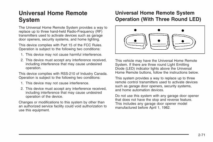
Universal Home RemoteSystemThe Universal Home Remote System provides a way toreplace up to three hand-held Radio-Frequency (RF)transmitters used to activate devices such as garagedoor openers, security systems, and home lighting.
This device complies with Part 15 of the FCC Rules.Operation is subject to the following two conditions:
1. This device may not cause harmful interference.
2. This device must accept any interference received,including interference that may cause undesiredoperation.
This device complies with RSS-210 of Industry Canada.Operation is subject to the following two conditions:
1. This device may not cause interference.
2. This device must accept any interference received,including interference that may cause undesiredoperation of the device.
Changes or modifications to this system by other thanan authorized service facility could void authorization touse this equipment.
Universal Home Remote SystemOperation (With Three Round LED)
This vehicle may have the Universal Home RemoteSystem. If there are three round Light EmittingDiode (LED) indicator lights above the UniversalHome Remote buttons, follow the instructions below.
This system provides a way to replace up to threeremote control transmitters used to activate devicessuch as garage door openers, security systems,and home automation devices.
Do not use this system with any garage door openerthat does not have the stop and reverse feature.This includes any garage door opener modelmanufactured before April 1, 1982.
2-71

Read the instructions completely before attempting toprogram the transmitter. Because of the steps involved,it may be helpful to have another person assist withprogramming the transmitter.
Be sure to keep the original remote controltransmitter for use in other vehicles, as well as,for future programming. Only the original remotecontrol transmitter is needed for Fixed Codeprogramming. The programmed buttons should beerased when the vehicle is sold or the lease ends.See “Erasing Universal Home Remote Buttons”later in this section.
Park the vehicle outside of the garage whenprogramming a garage door. Be sure that peopleand objects are clear of the garage door or gatethat is being programmed.
Programming Universal HomeRemote — Rolling CodeFor questions or help programming the UniversalHome Remote System, call 1-866-572-2728 or go towww.learcar2u.com.
Most garage door openers sold after 1996 are RollingCode units.
Programming a garage door opener involvestime-sensitive actions, so read the entire procedurebefore starting. Otherwise, the device will time outand the procedure will have to be repeated.
To program up to three devices:
1. From inside the vehicle, press the two outsidebuttons at the same time for one to two seconds,and immediately release them.
2-72

2. Locate in the garage, the garage door openerreceiver (motor-head unit). Locate the “Learn” or“Smart” button. It can usually be found where thehanging antenna wire is attached to the motor-headunit and may be a colored button. Press this button.After pressing this button, complete the followingsteps in less than 30 seconds.
3. Immediately return to the vehicle. Press and holdthe Universal Home Remote button that will be usedto control the garage door until the garage doormoves. The indicator light, above the selectedbutton, should slowly blink. This button mayneed to be held for up to 20 seconds.
4. Immediately, within one second, release the buttonwhen the garage door moves. The indicator lightwill blink rapidly until programming is complete.
5. Press and release the same button again.The garage door should move, confirmingthat programming is successful and complete.
To program another Rolling Code device such asan additional garage door opener, a security device,or home automation device, repeat Steps 1 through 5,choosing a different function button in Step 3 thanwhat was used for the garage door opener.
If these instructions do not work, the garage dooropener is probably a Fixed Code unit. Follow theProgramming instructions that follow for a Fixed Codegarage door opener.
2-73

Programming Universal HomeRemote — Fixed CodeFor questions or help programming the UniversalHome Remote System, call 1-866-572-2728 or goto www.learcar2u.com.
Most garage door openers sold before 1996 are FixedCode units.
Programming a garage door opener involvestime-sensitive actions, so read the entire procedurebefore starting. Otherwise, the device will time outand the procedure will have to be repeated.
To program up to three devices:
1. To verify that the garage door opener is a FixedCode unit, remove the battery cover on the handheld transmitter supplied by the manufacturer of thegarage door opener motor. If there are a row of dipswitches similar to the graphic above, the garagedoor opener is a Fixed Code unit. If you do notsee a row of dip switches, return to the previoussection for Programming Universal HomeRemote – Rolling Code.Your hand held transmitter can have betweeneight to 12 dip switches depending on the brandof transmitter.
2-74

The garage door opener receiver (motor head unit)could also have a row of dip switches that can beused when programming the Universal HomeRemote. If the total number of switches on the motorhead and hand held transmitter are different, or if thedip switch settings are different, use the dip switchsettings on the motor head unit to program theUniversal Home Remote. The motor head dip switchsettings can also be used when the original handheld transmitter is not available.
The panel of switches might not appear exactly asthey do in the examples above, but they shouldbe similar.The switch positions on the hand-held transmittercould be labeled, as follows:
• A switch in the up position could be labeledas “Up,” “+,” or “On.”
• A switch in the down position could be labeledas “Down,” “−,” or “Off.”
• A switch in the middle position could be labeledas “Middle,” “0,” or “Neutral.”
Example of Eight Dip Switches with Two Positions
Example of Eight Dip Switches with Three Positions
2-75

2. Write down the eight to 12 switch settings from leftto right as follows:
• When a switch is in the up position, write “Left.”
• When a switch is in the down position, write“Right.”
• If a switch is set between the up and downposition, write “Middle.”The switch settings written down in Step 2 nowbecome the button strokes to be entered into theUniversal Home Remote in Step 4. Be sure toenter the switch settings written down in Step 2,in order from left to right, into the Universal HomeRemote, when completing Step 4.
3. From inside your vehicle, first firmly press all threebuttons at the same time for about three seconds.Release the buttons to put the Universal HomeRemote into programming mode.
4. The indicator lights will blink slowly. Enter eachswitch setting from Step 2 into your vehicle’sUniversal Home Remote. You will have two andone-half minutes to complete Step 4. Now pressone button on the Universal Home Remote for eachswitch setting as follows:
• If you wrote “Left,” press the left button in thevehicle.
• If you wrote “Right,” press the right button in thevehicle.
• If you wrote “Middle,” press the middle button inthe vehicle.
2-76

5. After entering all of the switch positions, again,firmly press and release all three buttons at thesame time. The indicator lights will turn on.
6. Press and hold the button that will be used tocontrol the garage door until the garage doormoves. The indicator light above the selectedbutton should slowly blink. This button mayneed to be held for up to 55 seconds.
7. Immediately release the button when the garagedoor moves. The indicator light will blink rapidlyuntil programming is complete.
8. Press and release the same button again.The garage door should move, confirmingthat programming is successful and complete.
To program another Fixed Code device such as anadditional garage door opener, a security device,or home automation device, repeat Steps 1-8, choosinga different button in Step 6 than what was used forthe garage door opener.
Using Universal Home RemotePress and hold the appropriate button for at least halfof a second. The indicator light will come on whilethe signal is being transmitted.
Reprogramming Universal HomeRemote ButtonsAny of the three buttons can be reprogrammed byrepeating the instructions.
Erasing Universal Home RemoteButtonsThe programmed buttons should be erased when thevehicle is sold or the lease ends.
To erase either Rolling Code or Fixed Code on theUniversal Home Remote device:
1. Press and hold the two outside buttons at thesame time for approximately 20 seconds, untilthe indicator lights, located directly above thebuttons, begin to blink rapidly.
2. Once the indicator lights begin to blink, release bothbuttons. The codes from all buttons will be erased.
For help or information on the Universal Home RemoteSystem, call the customer assistance phone numberunder Customer Assistance Offices on page 7-5.
2-77

Storage Areas
Glove BoxTo open the glove box, lift up on the lever.
CupholdersYour vehicle may have cupholders located on andbehind the center console and in the rear seat armrest.Pull the loop down on the rear seat armrest to accessthe cupholders.
Pull downward on the lid to use the cupholders behindthe center console.
Instrument Panel StorageYour vehicle may have an instrument panel storagearea. It is located above the glove box.
To open, press and hold the driver’s side of the handlein and pull out on the exposed portion of the handle.
2-78

Center Console StorageYour vehicle may have an upper and lower centerconsole storage area with cupholders.
To access the upper storage area, pull lever (A) up.To access the lower storage area, raise the upperstorage bin, then pull lever (B) up. Use the key tolock and unlock the lower storage area.
Luggage CarrierThe vehicle may have a luggage carrier that can beused to load things on top of the vehicle.
The luggage carrier has siderails attached to the roof.It may also have crossrails which can be movedback and forth to help secure cargo. Tie the loadto the siderails or siderail supports.
Notice: Loading cargo on the luggage carrier thatweighs more than 200 lbs (91 kg) or hangs overthe rear or sides of the vehicle may damage yourvehicle. Load cargo so that it rests on the slatsas far forward as possible and against the side rails,making sure to fasten it securely.
Do not exceed the maximum vehicle capacity whenloading your vehicle. For more information on vehiclecapacity and loading, see Loading Your Vehicle onpage 4-36.
To prevent damage or loss of cargo while you aredriving, check to make sure the luggage and cargo arestill securely fastened.
2-79

Be sure the cargo is properly loaded.
• If small heavy objects are placed on the roof, cut apiece of 3/8 inch plywood to fit inside the crossrailsand siderails to spread the load. Tie the plywoodto the siderail supports.
• Tie the load to the crossrails or the siderailsupports. Use the crossrails only to keep the loadfrom sliding. To move a crossrail, lift the releaselever, on both sides of the rail, up to loosen it. Slidethe crossrail to the desired position balancing theforce side to side. Press the release lever on bothsides of the rail, down to tighten it. Try to slide thecrossrail back and forth slightly to be sure it is tight.
• If you need to carry long items, move the crossrailsas far apart as they will go. Tie the load to thecrossrails and the siderails or siderail supports. Alsotie the load to the bumpers. Do not tie the load sotightly that the crossrails or siderails are damaged.
• After moving a crossrail, be sure it is securely lockedinto the siderail.
Your vehicle has a Center High-MountedStoplamp (CHMSL) located above the rear glass.
If items are loaded on the roof of the vehicle, careshould be taken not to block or damage the CHMSL unit.
Rear Seat ArmrestYour vehicle may have a rear seat armrest that containstwo cupholders. To access the cupholders, pull thearmrest down from the rear seatback.
Cargo Management SystemYour vehicle may have a cargo management system.It is located in the bed of the truck. The system containsthree rails located on the front and sides of the bed.
The system will include four adjustable cargo tie-downs.The tie-downs can be placed on the upper and lowerslides of the rail.
2-80

To adjust a tie-down, pull the locator pin out andmove the tie-down to another location making surethe locator pin lines up with a locator hole on the rail.The tie-down pin may not be installed correctly if the pindoes not line up, turn it over and reinstall. The tie-downwill not move when the pin is installed completely.The maximum load for each rail is 500 lbs (227 kg).
The rails are notched at each end which allows thetie-downs to be removed and placed on anotherrail. To remove, pull the locator pin out and slide thetie-down to the end of the rail and pull back.
To remove or install cargo tie-downs at the front of thebed, slide the corner cap towards the center of thebed to expose the rail notches. To remove the cornercap, pull either edge away from the rail.
To remove the system, loosen the toggle bolts on eachrail until they can be removed from the bed of thetruck. To replace the system, place the toggle bolts andrails into their original locations and tighten them to atorque setting of 12.5 ft-lbs (17 Y).
If the system is removed to install a bed liner, makesure there is no bed liner material in the installationpoints.
Notice: If you tie down cargo using the horizontalslots on the top of the pickup box, you may damagethe box. Using the horizontal slots on the top of thepickup box for tie-down locations may cause damageto the pickup box and would not be covered by yourwarranty. Only use the tie-down loops if you do nothave the cargo management system.
2-81

SunroofIf your vehicle has a power sliding sunroof, the ignitionneeds to be turned to RUN, or the Retained AccessoryPower (RAP) must be activated to open or closethe sunroof. When RAP is active, the sunroof will workfor 10 minutes after the ignition is turned off, or untilthe driver’s door is opened. See Retained AccessoryPower (RAP) on page 2-24 for more information.
Extended CabIf your vehicle is anextended-cab, the sunroofswitch is located on theheadliner above therearview mirror.
Vent: From the closed position, press and hold the rearof the switch to vent the sunroof. To close the sunroof,press and hold the front of the switch.
Open: From the vent position, the sunroof can be fullyopened either manually or by using the express-openfeature. To open manually, press the rear of the switchto the first depression and hold until the sunroofhas reached the desired position. To open usingexpress-open, press the rear of the switch fully andrelease. The sunroof will move to the full open position.To stop the sunroof partway, press the switch asecond time.
Close: From the vent, or open position, press and holdthe front of the switch to close the sunroof.
The sunroof also has a roller sunshade that can beused to block the rays of the sun. The roller sunshadecan be manually operated with the sunroof in an openor closed position. To open the sunshade, pressand unlatch it, and roll it back. To close, pull itforward and latch it into the closed position.
When the sunroof is opened, an air deflector willautomatically raise. The air deflector will retract whenthe sunroof is closed.
2-82

Crew CabIf your vehicle is a crewcab, there are two sunroofswitches located in theoverhead console abovethe rearview mirror.
Vent: From the closed position, press the rear of thepassenger’s side switch to vent the sunroof. To close thesunroof, press and hold the front of the passenger’sside switch.
Manual-Open/Manual-Close: To open the sunroofpress and hold the rear of the driver’s side switch untilthe sunroof reaches the desired position. To closethe sunroof, press and hold the front of the driver’s sideswitch until the sunroof reaches the desired position.
When the sunroof is opened, an air deflector willautomatically raise. The air deflector will retract whenthe sunroof is closed.
Express-Open/Express-Close: To express-open thesunroof, fully press and release the rear of the driver’sside switch. The sunroof will open automatically. To stopthe sunroof partway, press the switch a second time.To express-close the sunroof, fully press and release thefront of the driver’s side switch. The sunroof will closeautomatically. To stop the sunroof partway, press theswitch a second time.
The sunroof also has a sunshade which you can pullforward to block sun rays. The sunshade must be openedand closed manually.
Anti-Pinch Feature (Crew Cab Only): If an object is inthe path of the sunroof while it is closing, the anti-pinchfeature will detect the object and stop the sunroof fromclosing at the point of the obstruction. The sunroof willthen open halfway, and the air deflector will raise.To close the sunroof once it has re-opened, refer to theExpress-Close or Manual-Close functions describedpreviously. If the sunroof is in the vent position, and thereis an object in the path of the sunroof when it closing,the anti-pinch feature will detect the object and stopthe sunroof. To close the sunroof once it has stopped,refer to the Vent functions described previously.
2-83

✍ NOTES
2-84
Instrument Panel Overview ...............................3-4Instrument Panel Overview
(Base/Uplevel version) .................................3-4Instrument Panel Overview (Premium version) ....3-6Hazard Warning Flashers ................................3-8Other Warning Devices ...................................3-8Horn .............................................................3-8Tilt Wheel .....................................................3-8Turn Signal/Multifunction Lever .........................3-9Turn and Lane-Change Signals .......................3-10Headlamp High/Low-Beam Changer .................3-10Flash-to-Pass ...............................................3-11Windshield Wipers ........................................3-11Rainsense™ II Wipers ...................................3-12Windshield Washer .......................................3-12Cruise Control ..............................................3-13Exterior Lamps .............................................3-17Headlamps on Reminder ................................3-18Daytime Running Lamps (DRL) .......................3-18Automatic Headlamp System ..........................3-19Puddle Lamps ..............................................3-20Fog Lamps ..................................................3-20Auxiliary Roof Mounted Lamp .........................3-20Instrument Panel Brightness ...........................3-21Dome Lamps ...............................................3-21Dome Lamp Override ....................................3-21Entry Lighting ...............................................3-21
Exit Lighting .................................................3-21Reading Lamps ............................................3-22Cargo Lamp .................................................3-22Electric Power Management ...........................3-22Battery Run-Down Protection ..........................3-23Accessory Power Outlet(s) .............................3-23Ashtray(s) and Cigarette Lighter ......................3-24
Climate Controls ............................................3-25Climate Control System
(With Air Conditioning ) ..............................3-25Climate Control System (Heater Only) ..............3-28Dual Automatic Climate Control System ...........3-29Outlet Adjustment .........................................3-35
Warning Lights, Gages, and Indicators ............3-36Instrument Panel Cluster ................................3-37Speedometer and Odometer ...........................3-38Trip Odometer ..............................................3-38Tachometer .................................................3-38Safety Belt Reminders ...................................3-39Airbag Readiness Light ..................................3-40Airbag Off Light ............................................3-41Passenger Airbag Status Indicator ...................3-43Charging System Light ..................................3-45Voltmeter Gage ............................................3-45Brake System Warning Light ..........................3-46Anti-lock Brake System (ABS) Warning Light ....3-47
Section 3 Instrument Panel
3-1

StabiliTrak® Indicator Light .............................3-48Engine Coolant Temperature Gage ..................3-48Tire Pressure Light .......................................3-49Malfunction Indicator Lamp .............................3-49Oil Pressure Gage ........................................3-52Oil Pressure Light .........................................3-53Security Light ...............................................3-53Fog Lamp Light ............................................3-53Cruise Control Light ......................................3-54Highbeam On Light .......................................3-54Four-Wheel-Drive Light ..................................3-54Tow/Haul Mode Light ....................................3-54Fuel Gage ...................................................3-55Low Fuel Warning Light .................................3-56
Driver Information Center (DIC) .......................3-56DIC Operation and Displays
(With DIC Buttons) ....................................3-57DIC Operation and Displays
(Without DIC Buttons) ................................3-63
DIC Warnings and Messages .........................3-66DIC Vehicle Customization (With DIC Buttons) ...3-76
Audio System(s) .............................................3-84Setting the Clock ..........................................3-86Radio(s) ......................................................3-88Using an MP3 (Radio with CD or
Six-Disc CD Player) .................................3-108Using an MP3 (Radio with CD and
DVD Player) ...........................................3-114XM Radio Messages ...................................3-119Navigation/Radio System ..............................3-120Rear Seat Entertainment (RSE) System .........3-121Rear Seat Audio (RSA) ................................3-130Theft-Deterrent Feature ................................3-132Audio Steering Wheel Controls ......................3-132Radio Reception .........................................3-133Fixed Mast Antenna ....................................3-134XM™ Satellite Radio Antenna System ............3-134
Section 3 Instrument Panel
3-2

✍ NOTES
3-3

Instrument Panel OverviewInstrument Panel Overview (Base/Uplevel version)
The main components of the instrument panel are the following:
A. Air Outlets. See Outlet Adjustment onpage 3-35.
B. Turn Signal/Multifunction Lever. See TurnSignal/Multifunction Lever on page 3-9.
3-4

C. Driver Information Center (DIC) Buttons. See DriverInformation Center (DIC) on page 3-56.
D. Hazard Warning Flasher Button. See HazardWarning Flashers on page 3-8.
E. Instrument Panel Cluster. See Instrument PanelCluster on page 3-37.
F. Shift Lever. See Automatic Transmission Operation onpage 2-28. Tow/Haul Selector Button (If Equipped).See Tow/Haul Mode on page 2-34. Range SelectionMode (Allison Transmission and Hydra-Matic®
6-Speed Button (If Equipped). See AutomaticTransmission Operation on page 2-28.
G. Audio System. See Audio System(s) on page 3-84.H. Instrument Panel Storage Area. See Instrument
Panel Storage on page 2-78.I. Integrated Trailer Brake Controller (If Equipped).
See Towing a Trailer on page 4-55.J. Exterior Lamp Controls. See Exterior Lamps on
page 3-17.K. Hood Release. See Hood Release on page 5-13.L. Parking Brake. See Parking Brake on page 2-50.M. Dome Lamp Override Button. See Dome Lamp
Override on page 3-21. Dome Lamp Knob.See Dome Lamps on page 3-21. Fog Lamp Button(If Equipped). See Fog Lamps on page 3-20.
N. Cruise Control Buttons. See Cruise Control onpage 3-13.
O. Tilt Wheel Lever. See Tilt Wheel on page 3-8.P. Horn. See Horn on page 3-8.Q. Audio Steering Wheel Controls (If Equipped).
See Audio Steering Wheel Controls on page 3-132.R. Automatic Transfer Case Control (If Equipped).
See Four-Wheel Drive on page 2-36.S. Ashtray (If Equipped). See Ashtray(s) and Cigarette
Lighter on page 3-24.T. StabiliTrak® Button (If Equipped). See StabiliTrak®
System on page 4-6. Ultrasonic Rear Park AssistDisable Button (If Equipped). See UltrasonicRear Parking Assist (URPA) on page 2-64. PedalAdjust Button (If Equipped). See Adjustable Throttleand Brake Pedal on page 2-26. Heated WindshieldWasher Fluid Button (If Equipped). WindshieldWasher on page 3-12.
U. Accessory Power Outlet. See Accessory PowerOutlet(s) on page 3-23.
V. Climate Control System. See Climate Control System(With Air Conditioning ) on page 3-25 or ClimateControl System (Heater Only) on page 3-28 and DualAutomatic Climate Control System on page 3-29.
W. Power Take Off (PTO) Control (If Equipped).See Power Take Off (PTO) in the Duramax DieselSupplement Index.
X. Passenger Airbag Off Control (If Equipped).See Airbag Off Switch on page 1-78.
Y. Glove Box. See Glove Box on page 2-78.
3-5

Instrument Panel Overview (Premium version)
A. Air Outlets. See Outlet Adjustment on page 3-35.B. Turn Signal/Multifunction Lever. See Turn
Signal/Multifunction Lever on page 3-9.
C. Instrument Panel Cluster. See Instrument PanelCluster on page 3-37.
D. Hazard Warning Flasher Button. See HazardWarning Flashers on page 3-8.
3-6

E. Shift Lever. See Automatic Transmission Operationon page 2-28.
F. Tow/Haul Selector Button (If Equipped).See Tow/Haul Mode on page 2-34.
G. Driver Information Center (DIC) Controls. See DriverInformation Center (DIC) on page 3-56.
H. Audio System. See Audio System(s) on page 3-84.I. Exterior Lamps Control. See Exterior Lamps on
page 3-17.J. Integrated Trailer Brake Controller (If Equipped).
See Towing a Trailer on page 4-55.K. Dome Lamp Override Button. See Dome Lamp
Override on page 3-21. Dome Lamp Knob.See Dome Lamps on page 3-21.
L. Automatic Transfer Case Control. (If Equipped).See Four-Wheel Drive on page 2-36.
M. Hood Release. See Hood Release on page 5-13.N. Parking Brake. See Parking Brake on page 2-50.O. Cruise Control Buttons. See Cruise Control on
page 3-13.P. Tilt Wheel Lever. See Tilt Wheel on page 3-8.Q. Horn. See Horn on page 3-8.
R. Audio Steering Wheel Controls. See Audio SteeringWheel Controls on page 3-132.
S. Climate Controls. See Climate Control System(With Air Conditioning ) on page 3-25 or ClimateControl System (Heater Only) on page 3-28 orDual Automatic Climate Controls (If Equipped).See Dual Automatic Climate Control Systemon page 3-29.
T. Accessory Power Outlets. See Accessory PowerOutlet(s) on page 3-23. Cigarette Lighter(If Equipped). See Ashtray(s) and Cigarette Lighteron page 3-24.
U. StabiliTrak® Button (If Equipped). See StabiliTrak®
System on page 4-6. Pedal Adjust Button(If Equipped). See Adjustable Throttle and BrakePedal on page 2-26. Rear Park Assist Disable Button(If Equipped). See Ultrasonic Rear Parking Assist(URPA) on page 2-64. Heated Windshield WasherFluid Button (If Equipped). See Windshield Washeron page 3-12.
V. Passenger Airbag Off Control (If Equipped).See Airbag Off Switch on page 1-78.
W. Glove Box. See Glove Box on page 2-78.
3-7

Hazard Warning FlashersThe hazard warning flashers warn others. They also letthe police and other emergency vehicles know youhave a problem.
The hazard warning flasherbutton is located on top ofthe steering column.
Press the button to make the front and rear turn signallamps flash on and off. Press the button again toturn the flashers off.
The hazard warning flashers work no matter whatignition position the key is in, and even if the key is notin the ignition.
When the hazard warning flashers are on, your vehicle’sturn signals will not work.
Other Warning DevicesIf you carry reflective triangles, you can set them up atthe side of the road about 300 feet (100 m) behindyour vehicle.
HornTo sound the horn, press the horn symbols located onthe steering wheel.
Tilt WheelThe tilt wheel lets you adjust the steering wheel beforeyou drive. Raise it to the highest level to give yourlegs more room when exiting or entering the vehicle.
3-8
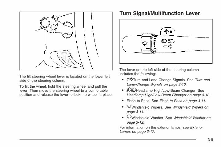
The tilt steering wheel lever is located on the lower leftside of the steering column.
To tilt the wheel, hold the steering wheel and pull thelever. Then move the steering wheel to a comfortableposition and release the lever to lock the wheel in place.
Turn Signal/Multifunction Lever
The lever on the left side of the steering columnincludes the following:
• GTurn and Lane Change Signals. See Turn andLane-Change Signals on page 3-10.
• 53Headlamp High/Low-Beam Changer. SeeHeadlamp High/Low-Beam Changer on page 3-10.
• Flash-to-Pass. See Flash-to-Pass on page 3-11.
• NWindshield Wipers. See Windshield Wipers onpage 3-11.
• LWindshield Washer. See Windshield Washer onpage 3-12.
For information on the exterior lamps, see ExteriorLamps on page 3-17.
3-9

Turn and Lane-Change SignalsThe turn signal has two upward (for right) and twodownward (for left) positions. These positions allow youto signal a turn or a lane change.
To signal a turn, move the lever all the way up ordown. When the turn is finished, the lever will returnautomatically.
To signal a lane change, raise or lower the lever forless than one second until the arrow starts to flash.This will cause the turn signals to automatically flashthree times. It will flash six times if tow-haul modeis active. Holding the turn signal lever for more thanone second will cause the turn signals to flash until yourelease the lever. The lever will return by itself whenit is released.
An arrow on the instrumentpanel cluster will flash inthe direction of theturn or lane change.
As you signal a turn or a lane change, if the arrows flashmore quickly than normal, a signal bulb may be burnedout and other drivers will not see your turn signal.
If a bulb is burned out, replace it to help avoid anaccident. If the arrows do not go on at all when yousignal a turn, check for burned-out bulbs and a blownfuse. See Fuses and Circuit Breakers on page 5-125.
Turn Signal On ChimeIf your turn signal is left on for more than 3/4 of a mile(1.2 km), a chime will sound at each flash of theturn signal and the message TURN SIGNAL ON willalso appear in the Driver Information Control (DIC).To turn the chime and message off, move the turn signallever to the off position.
Headlamp High/Low-Beam Changer53 (Headlamp High/Low Beam Changer):To change the headlamps from low to high beam, pushthe lever toward the instrument panel. To return tolow-beam headlamps, pull the multifunction lever towardyou. Then release it.
When the high beams areon, this indicator light onthe instrument panelcluster will also be on.
3-10

Flash-to-PassThis feature lets you use your high-beam headlamps tosignal a driver in front of you that you want to pass.It works even if your headlamps are in the automaticposition.
To use it, pull the turn signal lever toward you, thenrelease it.
If your headlamps are in the automatic position or onlow beam, your high-beam headlamps will turn on.They will stay on as long as you hold the lever towardyou. The high-beam indicator on the instrumentpanel cluster will come on. Release the lever to returnto normal operation.
Windshield WipersClear ice and snow from the wiper blades before usingthem. If they are frozen to the windshield, gentlyloosen or thaw them. Damaged wiper blades may notclear the windshield well, making it harder to seeand drive safely. If the blades do become damaged,install new blades or blade inserts. For more information,see Windshield Wiper Blade Replacement on page 5-67.
Heavy snow or ice can overload the wiper motor.A circuit breaker will stop the motor until it cools down.Clear away snow or ice to prevent an overload.
Turn the band with the wiper symbol to control thewindshield wipers.
8(Mist): Turn the band to mist for a single wipingcycle. Hold it there until the wipers start. Then letgo. The wipers stop after one wipe. Hold the band onmist longer, for more wipe cycles.
9(Off): To stop the wipers, move the band to off.
6 (Delay): Turn the band to adjust the delay time.The delay between wiping cycles becomes shorter asthe band is moved to the top of the lever. This canbe very useful in light rain or snow.
6 (Low Speed): Turn the band away from you tothe first solid band past the delay settings, for steadywiping at low speed.
? (High Speed): Turn the band further, to thesecond solid band past the delay settings, forhigh-speed wiping.
3-11

Rainsense™ II WipersIf your vehicle has Rainsense™ II windshield wipers,the moisture sensor is located next to the insiderearview mirror and is mounted on the windshield. Whenactive, these sensors are able to detect moisture onthe windshield and automatically turn on the wipers.
To turn on the Rainsense™ feature, the wipers must beset to one of the five delay settings on the multifunctionlever. Each of the five settings adjusts the sensitivityof the rainsensor.
Since different drivers have different setting preferences,it is recommended that the mid-range setting (position 3)be used initially. For more wipes, select the highersettings; for fewer wipes, select the lower settings locatedcloser to the off position on the multifunction lever.
The rainsensor will automatically control the frequency ofthe wipes from the off setting to the high speed settingaccording to the weather conditions. The wipers can beleft in a rainsense mode even when it is not raining.
When Rainsense™ is active, the headlamps will turn onautomatically if the exterior lamp control is in theAUTO position and the wipers are active.
Notice: Going through an automatic car wash withthe wipers on can damage them. Turn the wipersoff when going through an automatic car wash.
Windshield Washer
{CAUTION:
In freezing weather, do not use your washeruntil the windshield is warmed. Otherwise thewasher fluid can form ice on the windshield,blocking your vision.
L (Washer Fluid): Push the paddle marked with thewindshield washer symbol at the top of the multifunctionlever, to spray washer fluid on the windshield. The wipersclear the window and then either stop or return to thepreset speed.
3-12
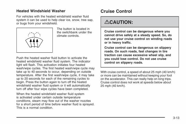
Heated Windshield WasherFor vehicles with the heated windshield washer fluidsystem it can be used to help clear ice, snow, tree sap,or bugs from your windshield.
The button is located inthe switchbank under theclimate controls.
Push the heated washer fluid button to activate theheated windshield washer fluid system. The indicatorlight will flash. This activation initiates four heatedwash/wipe cycles. The first heated wash/wipe cycle maytake up to 40 seconds to occur, depending on outsidetemperature. After the first wash/wipe cycle, it may takeup to 20 seconds for each of the remaining cycles tobegin. Press the button again to turn off the heatedwindshield washer fluid system or it will automaticallyturn off after four wipe cycles have been completed.
When the heated windshield washer fluid systemis activated under certain outside temperatureconditions, steam may flow out of the washer nozzlesfor a short period of time before washer fluid is sprayed.This is a normal condition.
Cruise Control
{CAUTION:
Cruise control can be dangerous where youcannot drive safely at a steady speed. So, donot use your cruise control on winding roadsor in heavy traffic.
Cruise control can be dangerous on slipperyroads. On such roads, fast changes in tiretraction can cause excessive wheel slip, andyou could lose control. Do not use cruisecontrol on slippery roads.
With cruise control, a speed of about 25 mph (40 km/h)or more can be maintained without keeping your footon the accelerator. This can really help on long trips.Cruise control does not work at speeds below about25 mph (40 km/h).
3-13
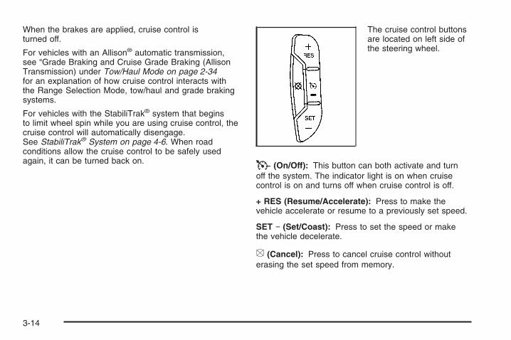
When the brakes are applied, cruise control isturned off.
For vehicles with an Allison® automatic transmission,see “Grade Braking and Cruise Grade Braking (AllisonTransmission) under Tow/Haul Mode on page 2-34for an explanation of how cruise control interacts withthe Range Selection Mode, tow/haul and grade brakingsystems.
For vehicles with the StabiliTrak® system that beginsto limit wheel spin while you are using cruise control, thecruise control will automatically disengage.See StabiliTrak® System on page 4-6. When roadconditions allow the cruise control to be safely usedagain, it can be turned back on.
The cruise control buttonsare located on left side ofthe steering wheel.
T (On/Off): This button can both activate and turnoff the system. The indicator light is on when cruisecontrol is on and turns off when cruise control is off.
+ RES (Resume/Accelerate): Press to make thevehicle accelerate or resume to a previously set speed.
SET − (Set/Coast): Press to set the speed or makethe vehicle decelerate.
[ (Cancel): Press to cancel cruise control withouterasing the set speed from memory.
3-14

Setting Cruise ControlCruise control will not work if the parking brake is set, orif the master cylinder brake fluid level is low.
The cruise control light on the instrument panel clusterwill come on after the cruise control has been set tothe desired speed.
{CAUTION:
If you leave your cruise control on when youare not using cruise, you might hit a buttonand go into cruise when you do not want to.You could be startled and even lose control.Keep the cruise control switch off until youwant to use cruise control.
1. Press the cruise control On/Off button.
2. Get up to the desired speed.
3. Press the SET− button located on the steeringwheel and release it.
4. Take your foot off the accelerator.
Resuming a Set SpeedIf the brakes are applied while the cruise control is set,the cruise control is disengaged. But it does notneed to be reset.
Once the vehicle speed reaches about 25 mph(40 km/h) or more, press the +RES button on thesteering wheel. The vehicle will go back to theprevious set speed and stay there.
Increasing Speed While Using CruiseControlTo increase the cruise speed while using cruise control:
• Press and hold the +RES button on the steeringwheel until the desired speed is reached, thenrelease it.
• To increase vehicle speed in small increments,press the +RES button. Each time this is done,the vehicle goes about 1 mph (1.6 km/h) faster.
3-15

Reducing Speed While Using CruiseControlTo reduce the vehicle speed while using cruise control:
• Press and hold the SET– button on the steeringwheel until the desired lower speed is reached,then release it.
• To slow down in very small amounts, press theSET– button on the steering wheel briefly.Each time this is done, the vehicle goes about1 mph (1.6 km/h) slower.
Passing Another Vehicle While UsingCruise ControlUse the accelerator pedal to increase the vehicle speed.When you take your foot off the pedal, the vehicle willslow down to the previous set cruise speed.
Using Cruise Control on HillsHow well the cruise control will work on hills dependsupon the vehicle speed, load, and the steepness of thehills. While going up steep hills, you might have to step onthe accelerator pedal to maintain the vehicle’s speed.While going downhill, you might have to brake or shift to alower gear to keep the vehicle’s speed down. When thebrakes are applied the cruise control turns off.
Ending Cruise ControlThere are three ways to end cruise control:
• Step lightly on the brake pedal.
• Press the cancel button on the steering wheel.
• Press the On/Off button on the steering wheel.
Erasing Speed MemoryThe cruise control set speed memory is erased, whenthe cruise control or the ignition is turned off.
3-16

Exterior LampsThe exterior lampscontrol is located on theinstrument panel to the leftof the steering wheel.
It controls the following systems:
• Headlamps
• Taillamps
• Parking Lamps
• License Plate Lamps
• Instrument Panel Lights
The exterior lamps control has four positions:
O(Off): Turn the control to this position to turn off theautomatic headlamps and daytime running lamps (DRL).Turn the headlamp control to the off position again toturn the automatic headlamps or DRL back on.
For vehicles first sold in Canada, the off position willonly work when the vehicle is shifted into PARK (P).
AUTO (Automatic): Turn the control to this positionto automatically turn on the headlamps at normalbrightness, together with the following:
• Parking Lamps
• Instrument Panel Lights
• Taillamps
• License Plate Lamps
When the vehicle is turned off and the headlamps arein AUTO, the headlamps may automatically remainon for a set time. The time of the delay can be changedusing the DIC. See Driver Information Center (DIC)on page 3-56.
; (Parking Lamps): Turn the control to this positionto turn on the parking lamps together with thefollowing:
• Instrument Panel Lights
• Taillamps
• License Plate Lamps
3-17

2 (Headlamps): Turn the control to this position toturn on the headlamps together with the following:
• Parking Lamps
• Instrument Panel Lights
• Taillamps
• License Plate Lamps
When the headlamps are turned on while the vehicle ison, the headlamps turn off automatically 10 minutesafter the ignition is turned off. When the headlamps areturned on while the vehicle is off, the headlamps willstay on for 10 minutes before automatically turning off toprevent the battery from being drained. Turn theheadlamp control to off and then back to the headlampon position to make the headlamps stay on for anadditional 10 minutes.
Push the turn signal/multifunction lever toward theinstrument panel to change the headlamps from lowbeam to high beam.
Headlamps on ReminderA reminder chime will sound when the headlamps orparking lamps are manually turned on and your ignitionis off and a door is open. To disable the chime, turnthe light off.
Daytime Running Lamps (DRL)Daytime Running Lamps (DRL) can make it easier forothers to see the front of your vehicle during the day.DRL can be helpful in many different driving conditions,but they can be especially helpful in the short periodsafter dawn and before sunset. Fully functional daytimerunning lamps are required on all vehicles first soldin Canada.
The DRL system will come on when the followingconditions are met:
• The ignition is on.
• The exterior lamps control is in AUTO.
• The transmission is not in PARK (P).
• The light sensor determines it is daytime.
When the DRL are on, only the DRL lamps will be on.The taillamps, sidemarker, and other lamps will notbe on. The instrument panel will not be lit up either.
When it begins to get dark, the automatic headlampsystem will switch from DRL to the headlamps.
To turn off the DRL lamps, turn the exterior lampscontrol to the OFF position and then release. Forvehicles first sold in Canada, the transmission must bein the PARK (P) position, before the DRL lamps canbe turned off.
3-18

Automatic Headlamp SystemWhen it is dark enough outside, the automatic headlampsystem will turn on the headlamps at the normalbrightness, along with the taillamps, sidemarker, parkinglamps, and the instrument panel lights. The radio lightswill also be dim.
To turn off the automatic headlamp system, turn theexterior lamps switch to the off position and then releaseit. For vehicles first sold in Canada, the transmissionmust be in the PARK (P) position, before the automaticheadlamp system can be turned off.
The vehicle has a light sensor located on the top of theinstrument panel in the defroster grille that regulateswhen the automatic headlamps turn on. Be sure it is notcovered, or the headlamps will come on wheneverthe ignition is on.
The system may also turn on the headlamps whendriving through a parking garage, heavy overcastweather, or a tunnel. This is normal.
There is a delay in the transition between thedaytime and nighttime operation of the DaytimeRunning Lamps (DRL) and the automatic headlampsystems so that driving under bridges or brightoverhead street lights does not affect the system.
The DRL and automatic headlamp system will only beaffected when the light sensor detects a change inlighting lasting longer than the delay.
If the vehicle is started in a dark garage, the automaticheadlamp system will come on immediately. Once thevehicle leaves the garage, it takes approximatelyone minute for the automatic headlamp system tochange to DRL if it is bright enough outside. During thatdelay, the instrument panel cluster may not be asbright as usual. Make sure the instrument panelbrightness control is in the full bright position.See Instrument Panel Brightness on page 3-21.
To idle the vehicle with the automatic headlamp systemoff, turn the control to the off position.
The headlamps will also stay on after you exit thevehicle. This feature can be programmed using theDriver Information Center (DIC). See DIC VehicleCustomization (With DIC Buttons) on page 3-76.
The regular headlamp system can be turned onwhen needed.
3-19
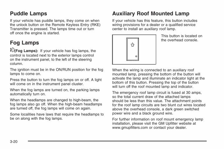
Puddle LampsIf your vehicle has puddle lamps, they come on whenthe unlock button on the Remote Keyless Entry (RKE)Transmitter is pressed. The lamps time out or turnoff once the engine is started.
Fog Lamps-(Fog Lamps): If your vehicle has fog lamps, thecontrol is located next to the exterior lamps controlon the instrument panel, to the left of the steeringcolumn.
The ignition must be in the ON/RUN position for the foglamps to come on.
Press the button to turn the fog lamps on or off. A lightwill come on in the instrument panel cluster.
When the fog lamps are turned on, the parking lampsautomatically turn on.
When the headlamps are changed to high-beam, thefog lamps also go off. When the high-beam headlampsare turned off, the fog lamps will come on again.
Some localities have laws that require the headlamps tobe on along with the fog lamps.
Auxiliary Roof Mounted LampIf your vehicle has this feature, this button includeswiring provisions for a dealer or a qualified servicecenter to install an auxiliary roof lamp.
This button is located onthe overhead console.
When the wiring is connected to an auxiliary roofmounted lamp, pressing the bottom of the button willactivate the lamp and illuminate an indicator light at thebottom of this button. Pressing the top of the buttonwill turn off the roof mounted lamp and indicator.
The emergency roof lamp circuit is fused at 30 amps,so the total current draw of the attached lampsshould be less than this value. The attachment pointsfor the roof lamp circuits are two blunt cut wires locatedabove the overhead console, a dark green switchedpower wire and a black ground wire.
For further information on roof mount emergency lampinstallation, please visit the GM Upfitter website atwww.gmupfitters.com or contact your dealer.
3-20

If your vehicle has this button, your vehicle may havethe snow plow prep package. For further information seeAdding a Snow Plow or Similar Equipment onpage 4-43.
Instrument Panel BrightnessD (Instrument Panel Brightness): This featurecontrols the brightness of the instrument panel lightsand is located next to the exterior lamp control.
Push the knob to extend out and then it can be turned.
Turn the knob clockwise or counterclockwise tobrighten or dim the instrument panel lights. Turning theknob to the farthest clockwise position turns on thedome lamps.
Dome LampsThe dome lamps come on when any door is opened.They turn off after all the doors are closed.
The dome lamps can also be turned on by turning theinstrument panel brightness knob, located next tothe exterior lamps control, clockwise to the farthestposition. In this position, the dome lamps remainon whether a door is opened or closed.
Dome Lamp OverrideThe dome lamp override button is located next to theexterior lamps control.
k (Dome Off): Press the button in and the domelamps remain off when a door is opened. Pressthe button again to return it to the extended position sothat the dome lamps come on when a door is opened.
Entry LightingYour vehicle has an illuminated entry feature.
When the doors are opened, the dome lamps will comeon if the dome override button is in the extendedposition. If the dome override button is pressed in,the lamps will not come on.
Exit LightingThe interior lamps come on when the key is removedfrom the ignition. They turn off automatically in20 seconds. The lights do not come on if the domeoverride button is pressed in.
3-21

Reading LampsIf your vehicle has reading lamps they are located onthe overhead console.
To turn on the reading lamps, press the buttonlocated next to each lamp. To turn them off, press thebutton again.
Your vehicle may also have reading lamps in otherlocations. To turn the lamps on or off, press the buttonlocated next to the lamp.
If your vehicle has a DVD Rear Seat Entertainment(RSE) system, press the lamp lenses to turn the lampson or off.
The lamps are fixed and cannot be adjusted.
Cargo LampThe cargo lamps come on by turning the instrumentpanel brightness control knob to the farthest clockwiseposition. This knob is located on the instrumentpanel and also turns on the dome lamps.
The cargo lamp can be used if more light is neededin the cargo area of the vehicle or in the top-boxstorage units.
Electric Power ManagementThe vehicle has Electric Power Management (EPM) thatestimates the battery’s temperature and state ofcharge. It then adjusts the voltage for best performanceand extended life of the battery.
When the battery’s state of charge is low, the voltage israised slightly to quickly put the charge back in. Whenthe state of charge is high, the voltage is lowered slightlyto prevent overcharging. If the vehicle has a voltmetergage or a voltage display on the Driver InformationCenter (DIC), you may see the voltage move upor down. This is normal. If there is a problem, an alertwill be displayed.
The battery can be discharged at idle if the electricalloads are very high. This is true for all vehicles.This is because the generator (alternator) may not bespinning fast enough at idle to produce all the power thatis needed for very high electrical loads.
A high electrical load occurs when several of thefollowing loads are on: headlamps, high beams, foglamps, rear window defogger, climate control fan athigh speed, heated seats, engine cooling fans, trailerloads, and loads plugged into accessory power outlets.
3-22

EPM works to prevent excessive discharge of thebattery. It does this by balancing the generator’s outputand the vehicle’s electrical needs. It can increaseengine idle speed to generate more power, wheneverneeded. It can temporarily reduce the power demands ofsome accessories.
Normally, these actions occur in steps or levels, withoutbeing noticeable. In rare cases at the highest levelsof corrective action, this action may be noticeable tothe driver. If so, a Driver Information Center (DIC)message might be displayed, such as Battery SaverActive or Service Battery Charging System. If thismessage is displayed, it is recommended that thedriver reduce the electrical loads as much as possible.See DIC Warnings and Messages on page 3-66.
Battery Run-Down ProtectionThis feature shuts off the dome and reading lamps,if they are left on for more than 10 minutes afterthe ignition is turned off. The cargo lamp shuts offafter 20 minutes. This prevents the battery fromrunning down.
Accessory Power Outlet(s)Accessory power outlets can be used to connectauxiliary electrical equipment, such as a cellulartelephone or CB radio.
The vehicle may have two accessory power outletslocated below the climate control system, or may haveone accessory power outlet and one cigarette lighter.The cigarette lighter is designed to fit only in thereceptacle closest to the driver.
There may be another accessory power outlet in therear cargo area. If the vehicle has a floor console, thereis an accessory power outlet inside the storage binand one on the rear of the floor console.
To use an accessory power outlet, remove the protectivecap. When not in use, always cover the accessorypower outlet with the protective cap.
Notice: Leaving electrical equipment plugged in foran extended period of time while the vehicle is offwill drain the battery. Power is always suppliedto the outlets. Always unplug electrical equipmentwhen not in use and do not plug in equipmentthat exceeds the maximum 20 ampere rating.
3-23

Certain power accessory plugs may not be compatibleto the accessory power outlet and could result inblown vehicle or adapter fuses. If you experience aproblem, see your dealer/retailer for additionalinformation on the accessory power plugs.
The accessory power outlets are powered, even whenthe ignition is in LOCK/OFF. Continuing to usepower outlets while the ignition is in LOCK/OFF maycause the vehicle’s battery to run down.
Notice: Adding any electrical equipment to thevehicle can damage it or keep other componentsfrom working as they should. The repairs would notbe covered by the vehicle warranty. Do not useequipment exceeding maximum amperage rating of20 amperes. Check with your dealer/retailer beforeadding electrical equipment.
When adding electrical equipment, be sure to followthe proper installation instructions included withthe equipment.
Notice: Improper use of the power outlet can causedamage not covered by your warranty. Do nothang any type of accessory or accessory bracketfrom the plug because the power outlets aredesigned for accessory power plugs only.
Ashtray(s) and Cigarette LighterYour vehicle may have a front ashtray located near thecenter of the instrument panel. Pull on the door toopen it. The ashtray may have a cigarette lighter.
Notice: If papers, pins, or other flammable itemsare put in the ashtray, hot cigarettes or othersmoking materials could ignite them and possiblydamage your vehicle. Never put flammable items inthe ashtray.
To remove the ashtray, open the door and pull theashtray bin toward you. To replace the ashtray, insertthe ashtray bin inside the ashtray door and press downuntil it engages. To use the cigarette lighter, push itin all the way, and let go. When it is ready for use, thelighter pops back out.
Notice: Holding a cigarette lighter in while it isheating does not let the lighter back away from theheating element when it is hot. Damage fromoverheating can occur to the lighter or heatingelement, or a fuse could be blown. Do not hold acigarette lighter in while it is heating.
3-24
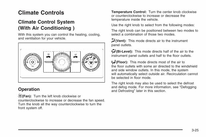
Climate Controls
Climate Control System(With Air Conditioning )With this system you can control the heating, cooling,and ventilation for your vehicle.
Operation9(Fan): Turn the left knob clockwise orcounterclockwise to increase or decrease the fan speed.Turn the knob all the way counterclockwise to turn thefront system off.
Temperature Control: Turn the center knob clockwiseor counterclockwise to increase or decrease thetemperature inside the vehicle.
Use the right knob to select from the following modes:
The right knob can be positioned between two modes toselect a combination of those two modes.
H (Vent): This mode directs air to the instrumentpanel outlets.
) (Bi-Level): This mode directs half of the air to theinstrument panel outlets and half to the floor outlets.
6 (Floor): This mode directs most of the air tothe floor outlets with some air directed to the windshieldand side window outlets. In this mode, the systemwill automatically select outside air. Recirculation cannotbe selected in floor mode.
The right knob may also be used to select the defrostand defog mode. For more information, see “Defoggingand Defrosting” later in this section.
3-25

: (Outside Air): Press this button to turn the outsideair mode on. When the button is pressed, an indicatorlight will come on. When this mode is on, outside air willcirculate throughout the vehicle. The outside air modecan be used with all modes, but it cannot be usedwith the recirculation mode.
?(Recirculation): Press this button to turn therecirculation mode on. When the button is pressed, anindicator light will come on.
This mode keeps outside air from entering the vehicle.It can be used to reduce outside air and preventodors from entering the vehicle. Recirculation may alsohelp cool the air inside the vehicle more quickly oncethe temperature inside the vehicle is less than theoutside temperature.
The recirculation mode cannot be used with floor, defogor defrost modes. If recirculation is selected with oneof these modes, the indicator light will flash three timesand then turn off. While in recirculation mode thewindows may fog when the weather is cold and damp.To clear the fog, select either the defog or defrostmode and increase the fan speed.
The recirculation mode can be turned off by pressingthe outside air button, or by turning off the ignition.
#(Air Conditioning): Press this button to turn the airconditioning system on or off. When this button ispressed, an indicator light on the button will come on tolet you know the air conditioning is activated. The airconditioning can be selected in any mode as long as thefan switch is on.
The air conditioning system removes moisture from theair, so you may sometimes notice a small amount ofwater dripping underneath your vehicle while idlingor after turning off the engine. This is normal.
3-26

Defogging and DefrostingFog or frost on the inside of windows is a result of highhumidity (moisture) condensing on the cool windowglass. This can be minimized if the climate controlsystem is used properly. To avoid fogging windows onrainy and humid days at temperatures above freezing,run the air conditioning compressor. It is best toavoid the use of the recirculation mode, except whenmaximum A/C performance is needed or for short timesto avoid exterior odors.
Turn the right knob to select the defog or defrost mode.
- (Defog): This mode clears the windows of fog ormoisture and warm the passengers. The air is directedto the windshield, floor outlets, and side windowvents.
0 (Defrost): This mode removes fog or frost from thewindshield more quickly. A portion of the air is directedto the windshield and the side window vents, with someair directed to the floor vents. The system willautomatically force outside air into the vehicle.
The recirculation mode cannot be selected in the defogor defrost mode. When either mode is selected, thesystem runs the air conditioning compressor, unless theoutside temperature is close to freezing. Do not drivethe vehicle until all the windows are clear.
Rear Window DefoggerIf your vehicle has a rear window defogger it uses awarming grid to remove fog from the rear window.
The rear window defogger will only work whenthe ignition is in RUN.
< (Rear): Press this button to turn the rear windowdefogger on or off. An indicator light on the buttonwill come on to let you know that the rear windowdefogger is activated.
The rear window defogger will only work when theignition is in RUN. The rear window defogger will stayon for approximately 10 minutes after the button ispressed, unless the ignition is turned to ACC or LOCK.The defogger can also be turned off by pressing thebutton again or by turning off the engine.
Notice: Do not use anything sharp on the insideof the rear window. If you do, you could cut ordamage the warming grid, and the repairs would notbe covered by the vehicle warranty. Do not attacha temporary vehicle license, tape, a decal oranything similar to the defogger grid.
3-27

Climate Control System(Heater Only)With this system you can control the heating andventilation for your vehicle.
Operation9(Fan): Turn the left knob clockwise orcounterclockwise to increase or decrease the fan speed.Turn the knob all the way counterclockwise to turn thefront system off.
Temperature Control: Turn the center knob clockwiseor counterclockwise to increase or decrease thetemperature inside the vehicle.
Use the right knob to select from the following modes:
The right knob can be positioned between two modesto select a combination of those two modes.
H (Vent): This mode directs air to the instrumentpanel outlets.
) (Bi-Level): This mode directs half of the air to theinstrument panel outlets and to the floor outlets.
6 (Floor): This mode directs most of the air to thefloor outlets with some air directed to the windshield,side window outlets, and second row floor outlets.In this mode, the system will automatically selectoutside air.
3-28

Defogging and DefrostingFog or frost on the inside of windows is a result of highhumidity (moisture) condensing on the cool windowglass. This can be minimized if the climate controlsystem is used properly.
Turn the right knob to select the defog or defrost mode.
- (Defog): This mode clears the windows of fog ormoisture and warm the passengers. The air is directedto the windshield, floor outlets, and side window vents.
0 (Defrost): This mode removes fog or frost from thewindshield more quickly. A portion of the air is directedto the windshield and the side window vents, withsome air directed to the floor vents. The system willautomatically force outside air into the vehicle.
Do not drive the vehicle until all the windows are clear.
Dual Automatic ClimateControl SystemThe heating, cooling, and ventilation in the vehicle canbe controlled with this system. The vehicle also hasa flow-through ventilation system described later in thissection.
Different climate control settings can be selected for thedriver and passengers.
3-29

Driver and Passenger Side TemperatureControlsThe driver and passenger side temperature buttonsare used to adjust the temperature of the air comingthrough the system on the driver or passenger’s side ofthe vehicle. The temperature can be adjusted even ifthe system is turned off. This is possible since outsideair always flows through the system as the vehicleis moving forward unless it is set to recirculation mode.See “Recirculation” later in this section.
Press the + or − buttons to increase or decrease thecabin temperature. The driver side or passengerside temperature display shows the temperature settingdecreasing or increasing.
The passenger’s temperature setting can be set tomatch the driver’s temperature setting by pressing thePASS button and turning off the PASS indicator.When the passenger’s temperature setting is setdifferent than the driver’s setting, the indicator on thePASS button illuminates and both the driver’s side andpassenger’s side temperature displays are shown.
Automatic Operation
AUTO (Automatic): When automatic operation isactive the system controls the inside temperature,the air delivery, and the fan speed.
Use the steps below to place the entire system inautomatic mode:
1. Press the AUTO button.When AUTO is selected, the display changes toshow the current temperature(s) and AUTO is lit onthe display. The current air delivery mode andfan speed are also displayed for about 5 seconds.When AUTO is selected, the air conditioningoperation and air inlet are automatically controlled.The air conditioning compressor may run whenthe outside temperature is above freezing. The airinlet will normally be set to outside air. If it is hotoutside, the air inlet may automatically switch to therecirculate mode to help quickly cool down theair inside the vehicle. The light on the button comeson in recirculation.
3-30

2. Set the driver’s and passenger’s temperature.To find your comfort setting, start with a 74°F (23°C)temperature setting and allow about 20 minutesfor the system to regulate. Use the driver’s orpassenger’s temperature buttons to adjust thetemperature setting as necessary. If you choose thetemperature setting of 60°F (15°C), the systemremains at the maximum cooling setting. If youchoose the temperature setting of 90°F (32°C),the system remains at the maximum heat setting.Choosing either maximum setting will not cause thevehicle to heat or cool any faster.
Be careful not to cover the solar sensor located onthe top of the instrument panel near the windshield.This sensor regulates air temperature based onsun load. For more information on the solar sensor,see “Sensors” later in this section.
To avoid blowing cold air in cold weather, the systemdelays turning the fan on until warm air is available.The length of delay depends on the engine coolanttemperature. Pressing the fan switch overrides this delayand changes the fan to a selected speed.
O(On/Off): Press this button to turn off the climatecontrol system. Outside air still enters the vehicle, andis directed to the floor. This direction can be changed bypressing the mode button. Recirculation can beselected once you have selected vent or bi-level mode.The temperature can also be adjusted using eithertemperature button. If the air delivery mode ortemperature settings are adjusted with the system off,the display illuminates briefly to show the settingsand then returns to off. Press the on/off button or the updown arrows on the fan switch, the defrost button,AUTO button, or the air conditioning button to turn thesystem on when it is off.
3-31

Manual OperationThe air delivery mode or fan speed can be manuallyadjusted.
DC (Fan): These buttons let you manually adjust thefan speed. Press D to increase fan speed and C todecrease fan speed.
Pressing either fan button while the system is off turnsthe system on. Pressing either fan button while inautomatic control places the fan under manual control.The fan setting remains displayed and the AUTOlight turns off. The air delivery mode remains underautomatic control.
HG (Mode): Press H and G to manually change thedirection of the airflow in the vehicle. Repeatedly presseither button until the desired mode appears on thedisplay. Pressing either mode button while the system isoff changes the air delivery mode without turning thesystem on. Pressing either mode button while inautomatic control places the mode under manual control.
The air delivery mode setting is displayed and theAUTO light turns off. The fan remains under automaticcontrol.
H(Vent): Air is directed to the instrument panel outlets.
)(Bi-Level): Air is directed partly to the instrumentpanel outlets and to the floor outlets. A little air isdirected towards the windshield and side window outlets.Cooler air is directed to the upper outlets and warmerair to the floor outlets.
6(Floor): Air is directed to the floor outlets, withsome to the windshield, side window outlets, andsecond row floor outlets. In this mode, the system willautomatically select outside air.
-(Defog): See “Defogging and Defrosting” later inthis section.
@(Recirculation): Press this button to turn therecirculation mode on. When the button is pressed, anindicator light comes on.
This mode keeps outside air from entering the vehicle.It can be used to reduce outside air and preventodors from entering the vehicle. Recirculation may alsohelp cool the air inside the vehicle more quickly oncethe temperature inside the vehicle is less than theoutside temperature.
3-32
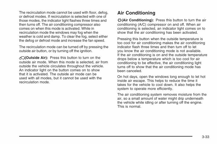
The recirculation mode cannot be used with floor, defog,or defrost modes. If recirculation is selected with one ofthose modes, the indicator light flashes three times andthen turns off. The air conditioning compressor alsocomes on when this mode is activated. While inrecirculation mode the windows may fog when theweather is cold and damp. To clear the fog, select eitherthe defog or defrost mode and increase the fan speed.
The recirculation mode can be turned off by pressing theoutside air button, or by turning off the ignition.
;(Outside Air): Press this button to turn on theoutside air mode. When this mode is selected, air fromoutside the vehicle circulates throughout the vehicle.An indicator light on the button comes on to showthat it is activated. The outside air mode can beused with all modes, but it cannot be used with therecirculation mode.
Air Conditioning#(Air Conditioning): Press this button to turn the airconditioning (A/C) compressor on and off. When airconditioning is selected, an indicator light comes on toshow that the air conditioning has been activated.
Pressing this button when the outside temperature istoo cool for air conditioning makes the air conditioningindicator flash three times and then turn off to letyou know the air conditioning mode is not available.If the air conditioning is on and the outside temperaturedrops below a temperature which is too cool for airconditioning to be effective, the air conditioning lightturns off to show that the air conditioning mode hasbeen canceled.
On hot days, open the windows long enough to let hotinside air escape. This helps to reduce the time ittakes for the vehicle to cool down. It also helps thesystem to operate more efficiently.
The air conditioning system removes moisture from theair, so a small amount of water might drip underneaththe vehicle while idling or after turning off the engine.This is normal.
3-33
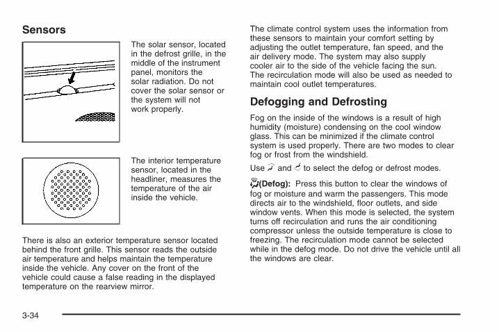
SensorsThe solar sensor, locatedin the defrost grille, in themiddle of the instrumentpanel, monitors thesolar radiation. Do notcover the solar sensor orthe system will notwork properly.
The interior temperaturesensor, located in theheadliner, measures thetemperature of the airinside the vehicle.
There is also an exterior temperature sensor locatedbehind the front grille. This sensor reads the outsideair temperature and helps maintain the temperatureinside the vehicle. Any cover on the front of thevehicle could cause a false reading in the displayedtemperature on the rearview mirror.
The climate control system uses the information fromthese sensors to maintain your comfort setting byadjusting the outlet temperature, fan speed, and theair delivery mode. The system may also supplycooler air to the side of the vehicle facing the sun.The recirculation mode will also be used as needed tomaintain cool outlet temperatures.
Defogging and DefrostingFog on the inside of the windows is a result of highhumidity (moisture) condensing on the cool windowglass. This can be minimized if the climate controlsystem is used properly. There are two modes to clearfog or frost from the windshield.
Use H and G to select the defog or defrost modes.
-(Defog): Press this button to clear the windows offog or moisture and warm the passengers. This modedirects air to the windshield, floor outlets, and sidewindow vents. When this mode is selected, the systemturns off recirculation and runs the air conditioningcompressor unless the outside temperature is close tofreezing. The recirculation mode cannot be selectedwhile in the defog mode. Do not drive the vehicle until allthe windows are clear.
3-34
0(Defrost): Press this button to remove fog or frostfrom the windshield more quickly. This mode directsa portion of the air to the windshield and side windowvents and some to the floor vents. In this mode, thesystem will automatically force outside air into yourvehicle. The recirculation mode cannot be selected whilein the defrost mode. The air conditioning compressorwill run automatically in this setting, unless the outsidetemperature is close to freezing. Do not drive thevehicle until all the windows are clear.
Rear Window DefoggerThe rear window defogger uses a warming grid toremove fog from the rear window.
<(Rear Window Defogger): If your vehicle has thisfeature, press this button to turn the defogger on oroff. It automatically turns off several minutes after it hasbeen activated. The defogger can also be turned offby turning the engine off. Do not drive the vehicle untilall the windows are clear.
Notice: Do not use a razor blade or sharp objectto clear the inside rear window. Do not adhereanything to the defogger grid lines in the rear glass.These actions may damage the rear defogger.Repairs would not be covered by your warranty.
Heated Mirrors: If your vehicle has heated outsiderearview mirrors, the mirrors will heat to help clear fogor frost from the surface of the mirror when the rearwindow defog button is pressed. See Outside PowerMirrors on page 2-61.
Outlet AdjustmentUse the air outlets located in the center and on the sideof the instrument panel to direct the airflow. Use thethumbwheels near the air outlets to open or close offthe airflow.
Operation Tips• Clear away any ice, snow, or leaves from air inlets
at the base of the windshield that could block theflow of air into the vehicle.
• Keep the path under the front seats clear of objectsto help circulate the air inside of the vehicle moreeffectively.
• Use of non-GM approved hood deflectors canadversely affect the performance of the system.Check with your dealer/retailer before addingequipment to the outside of your vehicle.
3-35
Warning Lights, Gages, andIndicatorsThis part describes the warning lights and gages onyour vehicle. The pictures help to locate them.
Warning lights and gages can signal that something iswrong before it becomes serious enough to causean expensive repair or replacement. Paying attention tothe warning lights and gages could also save you orothers from injury.
Warning lights come on when there may be or is aproblem with one of your vehicle’s functions. As thedetails show on the next few pages, some warning lightscome on briefly when you start the engine just to let youknow they are working. If you are familiar with thissection, you should not be alarmed when this happens.
Gages can indicate when there may be or is a problemwith one of your vehicle’s functions. Often gages andwarning lights work together to let you know when thereis a problem with your vehicle.
When one of the warning lights comes on and stays onas you are driving, or when one of the gages showsthere may be a problem, check the section that tells youwhat to do about it. Please follow this manual’sadvice. Waiting to do repairs can be costly and evendangerous. So please get to know your vehicle’swarning lights and gages. They can be a big help.
Your vehicle also has a Driver Information Center (DIC)that works along with warning lights and gages.See DIC Warnings and Messages on page 3-66 formore information.
3-36

Instrument Panel Cluster
Your instrument cluster is designed to let you know at a glance how your vehicle is running. You will know how fastyou are going, about how much fuel you have and many other things you will need to know to drive safely andeconomically. If your vehicle has the DURAMAX® Diesel engine, see the DURAMAX® Diesel manual for moreinformation.
United States Light Duty Premium version shown. Canada, Uplevel, Base, Heavy Duty Clusters similar.
3-37

Speedometer and OdometerYour speedometer lets you see your speed in bothmiles per hour (mph) and kilometers per hour (km/h).Your odometer shows how far your vehicle hasbeen driven, in either miles (used in the United States)or kilometers (used in Canada).
Engine Hour Meter DisplayThe Driver Information Center (DIC) can also displaythe number of hours the engine has run. To display theengine hours, turn the ignition off, press and hold thereset button for at least four seconds. The hour meterwill be displayed for up to 30 seconds, or until theignition is turned on. See DIC Operation and Displays(With DIC Buttons) on page 3-57 or DIC Operationand Displays (Without DIC Buttons) on page 3-63 formore information.
Trip OdometerThe trip odometer can tell you how far your vehiclehas been driven since you last set the trip odometerto zero.
Press the reset button, located on the instrument panelcluster next to the voltmeter, to toggle between thetrip odometer and the regular odometer. Holding thereset button for approximately one second whilethe trip odometer is displayed will reset it.
To display the odometer reading with the ignition off,press the reset button.
See DIC Operation and Displays (With DIC Buttons)on page 3-57 or DIC Operation and Displays (WithoutDIC Buttons) on page 3-63 for more information.
TachometerYour tachometer displays the engine speed inrevolutions per minute (rpm). See “Grade Braking(Allison Transmission®)” under Tow/Haul Mode onpage 2-34 for more information.
3-38

Safety Belt Reminders
Safety Belt Reminder LightWhen the engine is started, a chime will sound forseveral seconds to remind people to buckle their safetybelts. The driver safety belt light will also come onand stay on for several seconds, then it will flash forseveral more. You should buckle your seat belt.
This chime and light willbe repeated if the driverremains unbuckled and thevehicle is in motion.
If the driver’s belt is buckled, neither the chime nor thelight will come on.
Passenger Safety Belt Reminder LightFor vehicles with Passenger Safety Belt ReminderLights, several seconds after the engine is started, achime will sound for several seconds to remind the frontpassenger to buckle their safety belt. This would onlyoccur if the passenger airbag is enabled. See PassengerSensing System on page 1-81 for more information.The passenger safety belt light will also come onand stay on for several seconds, then it will flash forseveral more.
This chime and light arerepeated if the passengerremains unbuckled andthe vehicle is in motion.
If the passenger’s safety belt is buckled, neither thechime nor the light will come on.
3-39

Airbag Readiness LightThere is an airbag readiness light on the instrumentpanel cluster, which shows the airbag symbol.The system checks the airbag’s electrical system formalfunctions. The light tells you if there is an electricalproblem. The system check includes the airbagsensor, the pretensioners, the airbag modules, thewiring and the crash sensing and diagnostic module.For more information on the airbag system, see AirbagSystem on page 1-69.
This light will come onwhen you start yourvehicle, and it will flash fora few seconds. The lightshould go out and thesystem is ready.
If the airbag readiness light stays on after you start thevehicle or comes on when you are driving, yourairbag system may not work properly. Have your vehicleserviced right away.
{CAUTION:
If the airbag readiness light stays on after youstart your vehicle, it means the airbag systemmay not be working properly. The airbags inyour vehicle may not inflate in a crash, or theycould even inflate without a crash. To helpavoid injury to yourself or others, have yourvehicle serviced right away.
The airbag readiness light should flash for a few secondswhen you start the engine. If the light does not come onthen, have it fixed immediately. If there is a problem withthe airbag system, an airbag Driver Information Center(DIC) message may also come on. See DIC Warningsand Messages on page 3-66 for more information.
3-40

Airbag Off LightIf your vehicle has an airbag on-off switch, it also hasa passenger airbag status indicator located in theoverhead console.
When you start your vehicle, the passenger airbagstatus indicator will light ON and OFF, or the symbol foron and off, will light for several seconds as a systemcheck. Then, after several more seconds, the statusindicator ON or OFF, or either the on or off symbol,will light to let you know the status of the right frontpassenger’s frontal airbag.
When you turn the right front passenger’s airbag off,this light will come on and stay on to remind you that theairbag has been turned off. This light will go off whenyou turn the airbag back on again. See Airbag OffSwitch on page 1-78 for more on this, includingimportant safety information.
United States Canada
United States Canada
3-41
When you manually turn the right front passenger’sairbag off using the airbag on-off switch in the glove box,the indicator light OFF or the off symbol will come onand stay on to remind you that the airbag has beenturned off. This light will go off when you turn the airbagon. See Airbag Off Switch on page 1-78 for more onthis, including important safety information.
{CAUTION:
If the right front passenger’s airbag is turned offfor a person who is not in a risk group identifiedby the national government, that person will nothave the extra protection of an airbag. In acrash, the airbag will not be able to inflate andhelp protect the person sitting there.
Do not turn off the passenger’s airbag unlessthe person sitting there is in a risk groupidentified by the national government.See Airbag Off Switch on page 1-78 for more onthis, including important safety information.
{CAUTION:
If the airbag readiness light ever comes onwhen you have turned off the airbag, it meansthat something may be wrong with the airbagsystem. The right front passenger’s airbagcould inflate even though the switch is off.If this ever happens, do not let anyone whomthe national government has identified as amember of a passenger airbag risk groupsit in the right front passenger’s position(for example, do not secure a rear-facing childrestraint in the right front passenger’s seat)until you have your vehicle serviced. See AirbagOff Switch on page 1-78 and Airbag ReadinessLight on page 3-40 for more on this, includingimportant safety information.
If the word ON or the on symbol is lit, it means thatthe right front passenger’s frontal airbag is enabled(may inflate). See Airbag Off Switch on page 1-78 formore on this, including important safety information.If, after several seconds, both status indicator lightsremain on, or if there are no lights at all, there may bea problem with the lights or the airbag on-off switch.See your dealer/retailer for service.
3-42

Passenger Airbag Status IndicatorIf your vehicle has the passenger sensing system, youroverhead console will have a passenger airbag statusindicator.
When you start the vehicle, the passenger airbag statusindicator will light ON and OFF, or the symbol for onand off, for several seconds as a system check. Then,after several more seconds, the status indicator willlight either ON or OFF, or either the on or off symbol tolet you know the status of the right front passenger’sfrontal airbag.
If the word ON or the on symbol is lit on the passengerairbag status indicator, it means that the right frontpassenger’s frontal airbag is enabled (may inflate).
{CAUTION:
If the on indicator comes on when you have arear-facing child restraint installed in the rightfront passenger’s seat, it means that thepassenger sensing system has not turned offthe passenger’s frontal airbag. A child in arear-facing child restraint can be seriouslyinjured or killed if the right front passenger’sairbag inflates. This is because the back of therear-facing child restraint would be very closeto the inflating airbag. Do not use a rear-facingchild restraint in the right front passenger’sseat if the airbag is turned on.
United States Canada
3-43
{CAUTION:
Even though the passenger sensing system isdesigned to turn off the right front passenger’sfrontal airbag if the system detects a rear-facingchild restraint, no system is fail-safe, and noone can guarantee that an airbag will not deployunder some unusual circumstance, eventhough it is turned off. We recommend thatrear-facing child restraints be secured in therear seat, even if the airbag is off.
If the word OFF or the off symbol is lit on the airbagstatus indicator, it means that the passenger sensingsystem has turned off the right front passenger’s frontalairbag. See Passenger Sensing System on page 1-81for more on this, including important safety information.
If, after several seconds, both status indicator lightsremain on, or if there are no lights at all, there may bea problem with the lights or the passenger sensingsystem. See your dealer/retailer for service.
{CAUTION:
If the airbag readiness light in the instrumentpanel cluster ever comes on and stays on,it means that something may be wrong withthe airbag system. If this ever happens,have the vehicle serviced promptly, becausean adult-size person sitting in the right frontpassenger’s seat may not have the protection ofthe airbag(s). See Airbag Readiness Light onpage 3-40 for more on this, including importantsafety information.
3-44
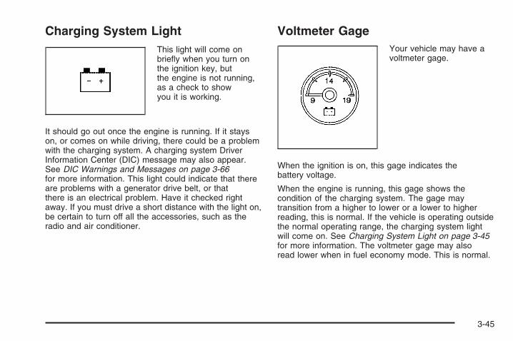
Charging System LightThis light will come onbriefly when you turn onthe ignition key, butthe engine is not running,as a check to showyou it is working.
It should go out once the engine is running. If it stayson, or comes on while driving, there could be a problemwith the charging system. A charging system DriverInformation Center (DIC) message may also appear.See DIC Warnings and Messages on page 3-66for more information. This light could indicate that thereare problems with a generator drive belt, or thatthere is an electrical problem. Have it checked rightaway. If you must drive a short distance with the light on,be certain to turn off all the accessories, such as theradio and air conditioner.
Voltmeter GageYour vehicle may have avoltmeter gage.
When the ignition is on, this gage indicates thebattery voltage.
When the engine is running, this gage shows thecondition of the charging system. The gage maytransition from a higher to lower or a lower to higherreading, this is normal. If the vehicle is operating outsidethe normal operating range, the charging system lightwill come on. See Charging System Light on page 3-45for more information. The voltmeter gage may alsoread lower when in fuel economy mode. This is normal.
3-45

Readings outside the normal operating range may alsooccur when a large number of electrical accessoriesare operating in the vehicle and the engine is left idlingfor an extended period. This condition is normalsince the charging system is not able to provide fullpower at engine idle. As engine speeds are increased,this condition should correct itself as higher enginespeeds allow the charging system to create maximumpower.
You can only drive for a short time with the readingsoutside the normal operating range. If you mustdrive, turn off all unnecessary accessories.
Readings outside the normal operating range indicatea possible problem in the electrical system.Have the vehicle serviced as soon as possible.
Brake System Warning LightWith the ignition on, the brake system warning light willcome on when you set the parking brake. If you try todrive with the parking brake engaged, a chime will soundwhen the vehicle speed is greater than 5 mph (8 km/h).
Your vehicle’s hydraulic brake system is divided into twoparts. If one part is not working, the other part canstill work and stop you. For good braking, though, youneed both parts working well.
If the warning light comes on and a chime sounds therecould be a brake problem. Have your brake systeminspected right away.
This light may also come on due to low brake fluid.See Brakes on page 5-43 for more information.
United States Canada
3-46

This light should come on briefly when you turn theignition key to RUN. If it does not come on then, have itfixed so it will be ready to warn you if there is a problem.
{CAUTION:
Your brake system may not be working properlyif the brake system warning light is on. Drivingwith the brake system warning light on can leadto an accident. If the light is still on after youhave pulled off the road and stopped carefully,have the vehicle towed for service.
If the light comes on while you are driving, pull off theroad and stop carefully. You may notice that the pedal isharder to push or may go closer to the floor. It may takelonger to stop. If the light is still on, have the vehicletowed for service. See Towing Your Vehicle onpage 4-50.
Anti-lock Brake System (ABS)Warning Light
For vehicles with theAntilock Brake System(ABS), this light comes onbriefly when the engineis started.
That is normal. If the light does not come on then, have itfixed so it will be ready to warn you if there is a problem.
If the ABS light stays on, turn the ignition off. If the lightcomes on when you are driving, stop as soon as it issafely possible and turn the ignition off. Then start theengine again to reset the system. If the ABS light stillstays on, or comes on again while you are driving, yourvehicle needs service. If the regular brake systemwarning light is not on, your vehicle still has brakes, butnot antilock brakes. If the regular brake system warninglight is also on, your vehicle does not have antilockbrakes and there is a problem with the regular brakes.See Brake System Warning Light on page 3-46.
For vehicles with a Driver Information Center (DIC),see DIC Warnings and Messages on page 3-66 for allbrake related DIC messages.
3-47

StabiliTrak® Indicator LightIf equipped, this warninglight should come onbriefly when the engineis started.
If the warning light does not come on then, have it fixedso it will be ready to warn you if there is a problem. If itstays on, or comes on when you are driving, there maybe a problem with your StabiliTrak® system and yourvehicle may need service. When this warning light is on,the system is off and will not limit wheel spin. Adjust yourdriving accordingly.
This light will also flash when the StabiliTrak® systemis active.
If the StabiliTrak® system warning light comes on andstays on for an extended period of time when the systemis turned on, your vehicle needs service. See StabiliTrak®
System on page 4-6 for more information.
Engine Coolant Temperature Gage
This gage shows the engine coolant temperature.
It also provides an indicator of how hard your vehicle isworking. During a majority of the operation, the gage willread 210°F (100°C) or less. If you are pulling a load orgoing up hills, it is normal for the temperature to fluctuateand go over the 235°F (113°C) mark. However, if thegage reaches the 260°F (125°C) mark, it indicates thatthe cooling system is working beyond its capacity.
See Engine Overheating on page 5-32.
United States Canada
3-48

Tire Pressure LightThis light comes on brieflywhen the engine is started.
This light will also come on when one or more of yourtires are significantly underinflated.
A tire pressure message in the Driver InformationCenter (DIC), may accompany the light. See DICWarnings and Messages on page 3-66 for moreinformation.
Stop and check your tires as soon as it is safe todo so. If underinflated, inflate to the proper pressure.See Tires on page 5-68 for more information.
If a problem is detected with the Tire Pressure MonitorSystem, this light will flash for approximately60 seconds and then stay on solid for the remainder ofthe ignition cycle. See Tire Pressure Monitor Systemon page 5-78 for more information.
Malfunction Indicator Lamp
Check Engine LightA computer system called OBD II (On-BoardDiagnostics-Second Generation) monitors operation ofthe fuel, ignition, and emission control systems. It makessure that emissions are at acceptable levels for the life ofthe vehicle, helping to produce a cleaner environment.
The check engine lightcomes on to indicatethat there is an OBD IIproblem and serviceis required.
Malfunctions often are indicated by the system beforeany problem is apparent. This can prevent more seriousdamage to your vehicle. This system is also designedto assist your service technician in correctly diagnosingany malfunction.
Notice: If you keep driving your vehicle with thislight on, after a while, the emission controlsmight not work as well, your vehicle’s fuel economymight not be as good, and the engine might notrun as smoothly. This could lead to costly repairsthat might not be covered by your warranty.
3-49

Notice: Modifications made to the engine,transmission, exhaust, intake, or fuel system ofyour vehicle or the replacement of the original tireswith other than those of the same Tire PerformanceCriteria (TPC) can affect your vehicle’s emissioncontrols and can cause this light to come on.Modifications to these systems could lead to costlyrepairs not covered by your warranty. This couldalso result in a failure to pass a required EmissionInspection/Maintenance test. See Accessoriesand Modifications on page 5-4.
This light comes on, as a check to show it is working,when the ignition is turned ON/RUN but the engine is notrunning. If the light does not come on, have it repaired.This light also comes on during a malfunction inone of two ways:
• Light Flashing — A misfire condition has beendetected. A misfire increases vehicle emissionsand could damage the emission control system onyour vehicle. Diagnosis and service might berequired.
• Light On Steady — An emission control systemmalfunction has been detected on your vehicle.Diagnosis and service might be required.
If the Light is FlashingThe following can prevent more serious damage toyour vehicle:• Reduce vehicle speed.• Avoid hard accelerations.• Avoid steep uphill grades.• If you are towing a trailer, reduce the amount of
cargo being hauled as soon as it is possible.
If the light stops flashing and remains on steady,see “If the Light Is On Steady” following.
If the light continues to flash, when it is safe to do so,stop the vehicle. Find a safe place to park the vehicle.Turn the ignition off, wait at least 10 seconds, and restartthe engine. If the light remains on steady, see “If theLight Is On Steady” following. If the light is still flashing,follow the previous steps and see your dealer/retailerfor service as soon as possible.
If the Light Is On SteadyYou might be able to correct the emission systemmalfunction by considering the following:
Did you recently put fuel into your vehicle?
If so, reinstall the fuel cap, making sure to fullyinstall the cap. See Filling the Tank on page 5-10.The diagnostic system can determine if the fuelcap has been left off or improperly installed.
3-50
A loose or missing fuel cap allows fuel to evaporateinto the atmosphere. A few driving trips with thecap properly installed should turn the light off.
Did you just drive through a deep puddle of water?
If so, your vehicle’s electrical system might be wet.The condition is usually corrected when the electricalsystem dries out. A few driving trips should turn thelight off.
Have you recently changed brands of fuel?
If so, be sure to fuel your vehicle with quality fuel.See Gasoline Octane on page 5-6. Poor fuel qualitycauses the engine not to run as efficiently asdesigned. You might notice this as stalling afterstart-up, stalling when you put the vehicle into gear,misfiring, hesitation on acceleration, or stumblingon acceleration — these conditions might go awayonce the engine is warmed up. This will be detectedby the system and cause the light to turn on.
If you experience one or more of these conditions,change the fuel brand you use. It will require at leastone full tank of the proper fuel to turn the light off.
If none of the above steps have made the light turn off,your dealer/retailer can check the vehicle. Yourdealer/retailer has the proper test equipment anddiagnostic tools to fix any mechanical or electricalproblems that might have developed.
Emissions Inspection andMaintenance ProgramsSome state/provincial and local governments have ormight begin programs to inspect the emission controlequipment on your vehicle. Failure to pass thisinspection could prevent you from getting a vehicleregistration.
Here are some things you need to know to help yourvehicle pass an inspection:
Your vehicle will not pass this inspection if the checkengine light is on or not working properly.
Your vehicle will not pass this inspection if the OBD(on-board diagnostic) system determines that criticalemission control systems have not been completelydiagnosed by the system. The vehicle would beconsidered not ready for inspection. This can happenif you have recently replaced the battery or if the batteryhas run down. The diagnostic system is designed toevaluate critical emission control systems during normaldriving. This can take several days of routine driving.If you have done this and your vehicle still does not passthe inspection for lack of OBD system readiness, yourdealer/retailer can prepare the vehicle for inspection.
3-51
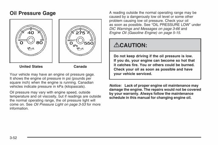
Oil Pressure Gage
Your vehicle may have an engine oil pressure gage.It shows the engine oil pressure in psi (pounds persquare inch) when the engine is running. Canadianvehicles indicate pressure in kPa (kilopascals).
Oil pressure may vary with engine speed, outsidetemperature and oil viscosity, but if readings are outsidethe normal operating range, the oil pressure light willcome on. See Oil Pressure Light on page 3-53 for moreinformation.
A reading outside the normal operating range may becaused by a dangerously low oil level or some otherproblem causing low oil pressure. Check your oilas soon as possible. See “OIL PRESSURE LOW” underDIC Warnings and Messages on page 3-66 andEngine Oil (Gasoline Engine) on page 5-15.
{CAUTION:
Do not keep driving if the oil pressure is low.If you do, your engine can become so hot thatit catches fire. You or others could be burned.Check your oil as soon as possible and haveyour vehicle serviced.
Notice: Lack of proper engine oil maintenance maydamage the engine. The repairs would not be coveredby your warranty. Always follow the maintenanceschedule in this manual for changing engine oil.
United States Canada
3-52

Oil Pressure Light
{CAUTION:
Do not keep driving if the oil pressure is low.If you do, your engine can become so hot thatit catches fire. You or others could be burned.Check your oil as soon as possible and haveyour vehicle serviced.
Notice: Lack of proper engine oil maintenance maydamage the engine. The repairs would not be coveredby your warranty. Always follow the maintenanceschedule in this manual for changing engine oil.
This light will come onbriefly when you start yourengine as a check to besure it works. If it does not,have your vehicle serviced.
If the light comes on and stays on, it means that oil is notflowing through your engine properly. You could be lowon oil and you might have some other system problem.
Security LightFor information regardingthis light and the vehicle’ssecurity system, seeContent Theft-Deterrent onpage 2-18.
Fog Lamp LightThe fog lamp light willcome on when the foglamps are in use.
The light will go out when the fog lamps are turned off.See Fog Lamps on page 3-20 for more information.
3-53

Cruise Control LightThis light comes onwhenever you set thecruise control.
The light goes out when the cruise control is turned off.See Cruise Control on page 3-13 for more information.
Highbeam On LightThis light comes on whenthe high-beam headlampsare in use.
See Headlamp High/Low-Beam Changer on page 3-10for more information.
Four-Wheel-Drive LightThe four-wheel-drive lightcomes on when you shift amanual transfer caseinto four-wheel drive andthe front axle engages.
Some delay between the shifting and the light comingon is normal.
See Four-Wheel Drive on page 2-36 for more information.
Tow/Haul Mode LightThis light comes on whenthe Tow/Haul mode hasbeen activated.
For more information, see Tow/Haul Mode on page 2-34.
3-54

Fuel Gage
When the ignition is on, the fuel gage tells you abouthow much fuel you have left in your tank.
The gage will first indicate empty before you are out offuel, and you should get more fuel as soon as possible.
When the fuel tank is low the FUEL LEVEL LOWmessage will appear. See DIC Warnings and Messageson page 3-66 for more information.
Here are some situations you may experience with yourfuel gage. None of these indicate a problem with thefuel gage.
• At the gas station, the fuel pump shuts off beforethe gage reads full.
• It takes a little more or less fuel to fill up than thefuel gage indicated. For example, the gage mayhave indicated the tank was half full, but it actuallytook a little more or less than half the tank’scapacity to fill the tank.
• The gage goes back to empty when you turn offthe ignition.
If you have a diesel engine, see “Fuel Gage” in theDiesel Engine Supplement.
United States Canada
3-55
Low Fuel Warning LightThis light, under the fuelgage, will come on brieflywhen you are startingthe engine.
This light and a chime will come on when the fuel tank islow on fuel. There will also be a “FUEL LEVEL LOW”message on the Driver Information Center, see DICWarnings and Messages on page 3-66 for moreinformation. When you add fuel this light and messageshould go off. If it does not, have your vehicle serviced.
Driver Information Center (DIC)Your vehicle has a Driver Information Center (DIC).
The DIC displays information about your vehicle.It also displays warning messages if a system problemis detected.
All messages will appear in the DIC display locatedbelow the tachometer in the instrument panel cluster.
The DIC comes on when the ignition is on. After a shortdelay, the DIC will display the information that waslast displayed before the engine was turned off.
If your vehicle has DIC buttons, see “DIC Operation andDisplays (With DIC Buttons)” later in this section andDIC Vehicle Customization (With DIC Buttons) onpage 3-76 for the displays available.
If your vehicle does not have DIC buttons, see “DICOperation and Displays (Without DIC Buttons)” later inthis section for the displays available.
3-56

DIC Operation and Displays(With DIC Buttons)If your vehicle has DIC buttons, the information belowexplains the operation of this system.
The DIC has different displays which can be accessedby pressing the DIC buttons located on the instrumentpanel, next to the steering wheel.
The DIC displays trip, fuel, and vehicle systeminformation, and warning messages if a system problemis detected.
The DIC also allows some features to be customized.See DIC Vehicle Customization (With DIC Buttons)on page 3-76 for more information.
If your vehicle has DIC buttons, you can also usethe trip odometer reset stem to view some of theDIC displays. See “DIC Operation and Displays(Without DIC Buttons)” later in this section.
DIC ButtonsThe buttons are thetrip/fuel, vehicleinformation, customization,and set/reset buttons.The button functionsare detailed in thefollowing pages.
3 (Trip/Fuel): Press this button to display theodometer, trip odometer, fuel range, average economy,fuel used, timer, and transmission temperature.Some vehicles also display instantaneous economyand an Active Fuel Management™ indicator.
3-57

T (Vehicle Information): Press this button to displaythe oil life, units, tire pressure readings for vehicleswith the Tire Pressure Monitor System (TPMS), trailerbrake gain and output information for vehicles withthe Integrated Trailer Brake Control (ITBC) system,engine hours, and Remote Keyless Entry (RKE)transmitter programming.
U (Customization): Press this button to customize thefeature settings on your vehicle. See DIC VehicleCustomization (With DIC Buttons) on page 3-76 for moreinformation.
V (Set/Reset): Press this button to set or reset certainfunctions and to turn off or acknowledge messageson the DIC.
Trip/Fuel Menu Items
3 (Trip/Fuel): Press this button to scroll throughthe following menu items:
OdometerPress the trip/fuel button until ODOMETER displays.This display shows the distance the vehicle hasbeen driven in either miles (mi) or kilometers (km).Pressing the trip odometer reset stem will also displaythe odometer.
To switch between English and metric measurements,see “Units” later in this section.
Trip OdometerPress the trip/fuel button until TRIP displays. Thisdisplay shows the current distance traveled in eithermiles (mi) or kilometers (km) since the last reset for thetrip odometer. Pressing the trip odometer reset stemwill also display the trip odometer.
The trip odometer can be reset to zero by pressing theset/reset button while the trip odometer is displayed.You can also reset the trip odometer while it is displayedby pressing and holding the trip odometer reset stem.
3-58

The trip odometer has a feature called the retro-activereset. This can be used to set the trip odometer tothe number of miles (kilometers) driven since the ignitionwas last turned on. This can be used if the tripodometer is not reset at the beginning of the trip.
To use the retro-active reset feature, press and holdthe set/reset button for at least four seconds. The tripodometer will display the number of miles (mi) orkilometers (km) driven since the ignition was lastturned on and the vehicle was moving. Once the vehiclebegins moving, the trip odometer will accumulatemileage. For example, if the vehicle was driven5 miles (8 km) before it is started again, and then theretro-active reset feature is activated, the display willshow 5 miles (8 km). As the vehicle begins moving,the display will then increase to 5.1 miles (8.2 km),5.2 miles (8.4 km), etc.
Fuel RangePress the trip/fuel button until FUEL RANGE displays.This display shows the approximate number ofremaining miles (mi) or kilometers (km) the vehiclecan be driven without refueling. The display will showLOW if the fuel level is low.
The fuel range estimate is based on an average ofthe vehicle’s fuel economy over recent driving historyand the amount of fuel remaining in the fuel tank.
This estimate will change if driving conditions change.For example, if driving in traffic and making frequentstops, this display may read one number, but ifthe vehicle is driven on a freeway, the number maychange even though the same amount of fuel is in thefuel tank. This is because different driving conditionsproduce different fuel economies. Generally, freewaydriving produces better fuel economy than city driving.Fuel range cannot be reset.
Average EconomyPress the trip/fuel button until AVG ECONOMY displays.This display shows the approximate average milesper gallon (mpg) or liters per 100 kilometers (L/100 km).This number is calculated based on the number ofmpg (L/100 km) recorded since the last time this menuitem was reset. To reset AVG ECONOMY, pressand hold the set/reset button.
Fuel UsedPress the trip/fuel button until FUEL USED displays.This display shows the number of gallons (gal) orliters (L) of fuel used since the last reset of this menuitem. To reset the fuel used information, press and holdthe set/reset button while FUEL USED is displayed.
3-59

TimerPress the trip/fuel button until TIMER displays.This display can be used as a timer.
To start the timer, press the set/reset button whileTIMER is displayed. The display will show the amountof time that has passed since the timer was lastreset, not including time the ignition is off. Time willcontinue to be counted as long as the ignition ison, even if another display is being shown on the DIC.The timer will record up to 99 hours, 59 minutesand 59 seconds (99:59:59) after which the display willreturn to zero.
To stop the timer, press the set/reset button briefly whileTIMER is displayed.
To reset the timer to zero, press and hold the set/resetbutton while TIMER is displayed.
Transmission TemperaturePress the trip/fuel button until TRANS TEMP displays.This display shows the temperature of the automatictransmission fluid in either degrees Fahrenheit (°F) ordegrees Celsius (°C).
Instantaneous Economy and ActiveFuel Management™ IndicatorIf your vehicle has this display, press the trip/fuelbutton until INST ECONOMY V8 MODE displays.This display shows the current fuel economy at aparticular moment and will change frequently as drivingconditions change. This display shows the instantaneousfuel economy in miles per gallon (mpg) or liters per100 kilometers (L/100 km). Unlike average economy,this screen cannot be reset.
An Active Fuel Management™ indicator will display onthe right side of the DIC, while INST ECONOMYdisplays on the left side. Active Fuel Management™allows the engine to operate on either four or eightcylinders, depending on your driving demands. WhenActive Fuel Management™ is active, V4 MODE willdisplay on the DIC. When Active Fuel Management™is inactive, V8 MODE will display. See Active FuelManagement™ on page 2-28 for more information.
Blank DisplayThis display shows no information.
3-60

Vehicle Information Menu ItemsT (Vehicle Information): Press this button to scrollthrough the following menu items:
Oil LifePress the vehicle information button until OIL LIFEREMAINING displays. This display shows an estimateof the oil’s remaining useful life. If you see 99% OIL LIFEREMAINING on the display, that means 99% of thecurrent oil life remains. The engine oil life systemwill alert you to change the oil on a schedule consistentwith your driving conditions.
When the remaining oil life is low, the CHANGEENGINE OIL SOON message will appear on the display.See “CHANGE ENGINE OIL SOON” under DICWarnings and Messages on page 3-66. You shouldchange the oil as soon as you can. See EngineOil (Gasoline Engine) on page 5-15. In addition to theengine oil life system monitoring the oil life, additionalmaintenance is recommended in the MaintenanceSchedule in this manual. See Scheduled Maintenance(Gasoline Engine) on page 6-4 for more information.
Remember, you must reset the OIL LIFE displayyourself after each oil change. It will not reset itself.Also, be careful not to reset the OIL LIFE displayaccidentally at any time other than when the oil has justbeen changed. It cannot be reset accurately until thenext oil change. To reset the engine oil life system,see Engine Oil Life System on page 5-18.
UnitsPress the vehicle information button until UNITSdisplays. This display allows you to select betweenEnglish or Metric units of measurement. Once in thisdisplay, press the set/reset button to select betweenENGLISH or METRIC units. All of the vehicle informationwill then be displayed in the unit of measurementselected.
Tire PressureIf your vehicle has the Tire Pressure Monitor System(TPMS), the pressure for each tire can be viewed in theDIC. The tire pressure will be shown in either poundsper square inch (psi) or kilopascals (kPa). Press thevehicle information button until the DIC displays FRONTTIRES PSI (kPa) LEFT ## RIGHT ##. Press thevehicle information button again until the DIC displaysREAR TIRES PSI (kPa) LEFT ## RIGHT ##.
If a low or high tire pressure condition is detected bythe system while driving, a message advising youto check the pressure in a specific tire will appear in thedisplay. See Inflation - Tire Pressure on page 5-76and DIC Warnings and Messages on page 3-66 formore information.
If the tire pressure display shows dashes instead of avalue, there may be a problem with your vehicle. If thisconsistently occurs, see your dealer/retailer for service.
3-61

Trailer Gain and OutputOn vehicles with the Integrated Trailer Brake Control(ITBC) system, the trailer brake display appears inthe DIC. Press the vehicle information button untilTRAILER GAIN and OUTPUT display.
TRAILER GAIN shows the trailer gain setting. Thissetting can be adjusted from 0.0 to 10.0 with either atrailer connected or disconnected. To adjust this setting,see “Integrated Trailer Brake Control System” underTowing a Trailer on page 4-55 for more information.
OUTPUT shows the power output to the trailer anytimea trailer with electric brakes is connected. Output isdisplayed in 0 to 10 bars. Dashes may appear inthe OUTPUT display. See “Integrated Trailer BrakeControl System” under Towing a Trailer on page 4-55for more information.
Engine HoursPress the vehicle information button until ENGINEHOURS displays. This display shows the total numberof hours the engine has run.
Relearn Remote KeyThis display allows you to match Remote Keyless Entry(RKE) transmitters to your vehicle. To match an RKEtransmitter to your vehicle:1. Press the vehicle information button until
PRESS V TO RELEARN REMOTE KEY displays.
2. Press the set/reset button until REMOTE KEYLEARNING ACTIVE is displayed.
3. Press and hold the lock and unlock buttons on the firsttransmitter at the same time for about 15 seconds.On vehicles with memory recall seats, the firsttransmitter learned will match driver 1 andthe second will match driver 2.A chime will sound indicating that the transmitteris matched.
4. To match additional transmitters at this time,repeat Step 3.Each vehicle can have a maximum ofeight transmitters matched to it.
5. To exit the programming mode, you must cycle thekey to LOCK/OFF.
Blank DisplayThis display shows no information.
3-62

DIC Operation and Displays(Without DIC Buttons)If your vehicle does not have DIC buttons, theinformation below explains the operation of this system.
The DIC has different displays which can be accessed bypressing the trip odometer reset stem located on theinstrument panel cluster. Pressing the trip odometer resetstem will also turn off, or acknowledge, DIC messages.
The DIC displays trip and vehicle system information,and warning messages if a system problem is detected.
If your vehicle does not have DIC buttons, you canuse the trip odometer reset stem to view the followingdisplays: odometer, engine hours, trip odometer,transmission temperature, trailer brake gain and outputinformation for vehicles with the Integrated TrailerBrake Control (ITBC) system, oil life, Tire PressureMonitor System (TPMS) programming for vehicles withthe TPMS, Remote Keyless Entry (RKE) transmitterprogramming, and display language.
If your vehicle has DIC buttons, you can use the tripodometer reset stem to view the following displays:odometer, engine hours, trip odometer, and displaylanguage.
Trip Odometer Reset Stem Menu Items
OdometerPress the trip odometer reset stem until ODOMETERdisplays. This display shows the distance the vehiclehas been driven in either miles (mi) or kilometers (km).
Engine HoursTo display the ENGINE HOURS, place the ignition inLOCK/OFF or ACC/ACCESSORY, then press and holdthe trip odometer reset stem for four seconds whileviewing the ODOMETER. This display shows the totalnumber of hours the engine has run.
Trip OdometerPress the trip odometer reset stem until TRIP displays.This display shows the current distance traveled ineither miles (mi) or kilometers (km) since the last resetfor the trip odometer.
The trip odometer can be reset to zero by pressing andholding the trip odometer reset stem while the tripodometer is displayed.
The trip odometer has a feature called the retro-activereset. This can be used to set the trip odometer tothe number of miles (kilometers) driven since theignition was last turned on. This can be used if thetrip odometer is not reset at the beginning of the trip.
3-63

To use the retro-active reset feature, press and hold thetrip odometer reset stem for at least four seconds.The trip odometer will display the number of miles (mi)or kilometers (km) driven since the ignition was lastturned on and the vehicle was moving. Once the vehiclebegins moving, the trip odometer will accumulatemileage. For example, if the vehicle was driven5 miles (8 km) before it is started again, and then theretro-active reset feature is activated, the displaywill show 5 miles (8 km). As the vehicle begins moving,the display will then increase to 5.1 miles (8.2 km),5.2 miles (8.4 km), etc.
Transmission TemperaturePress the trip odometer reset stem until TRANS TEMPdisplays. This display shows the temperature of theautomatic transmission fluid in either degreesFahrenheit (°F) or degrees Celsius (°C).
Trailer Gain and OutputOn vehicles with the Integrated Trailer Brake Control(ITBC) system, the trailer brake display appears in theDIC. Press the trip odometer reset stem until TRAILERGAIN and OUTPUT display.
TRAILER GAIN shows the trailer gain setting. Thissetting can be adjusted from 0.0 to 10.0 with either atrailer connected or disconnected. To adjust this setting,see “Integrated Trailer Brake Control System” underTowing a Trailer on page 4-55 for more information.
OUTPUT shows the power output to the trailer anytimea trailer with electric brakes is connected. Output isdisplayed in 0 to 10 bars. Dashes may appear inthe OUTPUT display. See “Integrated Trailer BrakeControl System” under Towing a Trailer on page 4-55for more information.
Oil LifeTo access this display, the vehicle must be in PARK (P).Press the trip odometer reset stem until OIL LIFEREMAINING displays. This display shows an estimateof the oil’s remaining useful life. If you see 99% OIL LIFEREMAINING on the display, that means 99% of thecurrent oil life remains. The engine oil life systemwill alert you to change the oil on a schedule consistentwith your driving conditions.
When the remaining oil life is low, the CHANGEENGINE OIL SOON message will appear on thedisplay. See “CHANGE ENGINE OIL SOON” underDIC Warnings and Messages on page 3-66.
3-64

You should change the oil as soon as you can.See Engine Oil (Gasoline Engine) on page 5-15.In addition to the engine oil life system monitoringthe oil life, additional maintenance is recommendedin the Maintenance Schedule in this manual.See Scheduled Maintenance (Gasoline Engine) onpage 6-4 for more information.
Remember, you must reset the OIL LIFE displayyourself after each oil change. It will not reset itself.Also, be careful not to reset the OIL LIFE displayaccidentally at any time other than when the oil has justbeen changed. It cannot be reset accurately until thenext oil change. To reset the engine oil life system,see Engine Oil Life System on page 5-18.
Relearn Tire PositionsYour vehicle may have this display. To access thisdisplay, the vehicle must be in PARK (P). If your vehiclehas the Tire Pressure Monitor System (TPMS), afterrotating the tires or after replacing a tire or sensor,the system must re-learn the tire positions. To re-learnthe tire positions, see Tire Pressure Monitor Systemon page 5-78. See Tire Inspection and Rotationon page 5-83 and DIC Warnings and Messages onpage 3-66 for more information.
Relearn Remote KeyTo access this display, the vehicle must be in PARK (P).This display allows you to match Remote KeylessEntry (RKE) transmitters to your vehicle. To match anRKE transmitter to your vehicle:
1. Press the trip odometer reset stem until RELEARNREMOTE KEY displays.
2. Press and hold the trip odometer reset stem forthree seconds.The message REMOTE KEY LEARNING ACTIVEwill display.
3. Press and hold the lock and unlock buttons onthe first transmitter at the same time for about15 seconds.On vehicles with memory recall seats, the firsttransmitter learned will match driver 1 andthe second will match driver 2.A chime will sound indicating that the transmitteris matched.
4. To match additional transmitters at this time,repeat Step 3.Each vehicle can have a maximum ofeight transmitters matched to it.
5. To exit the programming mode, you must cyclethe key to LOCK/OFF.
3-65

LanguageThis display allows you to select the language in whichthe DIC messages will appear. To select a language:
1. Press the trip odometer reset stem untilODOMETER displays.
2. While in the ODOMETER display, press and holdthe trip odometer reset stem for three seconds untilthe currently set language displays.
3. Continue to press and hold the trip odometer resetstem to scroll through all of the available languages.The available languages are ENGLISH (default),FRANCAIS (French), ESPANOL (Spanish), andNO CHANGE.
4. Once the desired language is displayed, releasethe trip odometer reset stem to set your choice.
DIC Warnings and MessagesMessages are displayed on the DIC to notify the driverthat the status of the vehicle has changed and thatsome action may be needed by the driver to correct thecondition. Multiple messages may appear one afteranother.
Some messages may not require immediate action, butyou can press any of the DIC buttons on the instrumentpanel or the trip odometer reset stem on the instrumentpanel cluster to acknowledge that you received themessages and to clear them from the display.
Some messages cannot be cleared from the DICdisplay because they are more urgent. These messagesrequire action before they can be cleared. You shouldtake any messages that appear on the display seriouslyand remember that clearing the messages will onlymake the messages disappear, not correct the problem.
The following are the possible messages that can bedisplayed and some information about them.
If your vehicle has the DURAMAX® Diesel engine, seethe DURAMAX® Diesel manual for more information.
3-66

CHANGE ENGINE OIL SOONThis message displays when the engine oil needs to bechanged. When you change the engine oil, be sureto reset the CHANGE ENGINE OIL SOON message.See Engine Oil Life System on page 5-18 for informationon how to reset the message. See Engine Oil (GasolineEngine) on page 5-15 and Scheduled Maintenance(Gasoline Engine) on page 6-4 for more information.
CHECK TIRE PRESSUREIf your vehicle has the Tire Pressure Monitor System(TPMS), this message displays when the pressure in oneor more of the vehicle’s tires needs to be checked. Thismessage also displays LEFT FRONT, RIGHT FRONT,LEFT REAR, or RIGHT REAR to indicate which tireneeds to be checked. You can receive more than one tirepressure message at a time. To read the other messagesthat may have been sent at the same time, press theset/reset button or the trip odometer reset stem. If a tirepressure message appears on the DIC, stop as soon asyou can. Have the tire pressures checked and set tothose shown on the Tire Loading Information label.See Tires on page 5-68, Loading Your Vehicle onpage 4-36, and Inflation - Tire Pressure on page 5-76.The DIC also shows the tire pressure values. See “DICOperation and Displays (With DIC Buttons)” earlier in thissection. If the tire pressure is low, the low tire pressurewarning light comes on. See Tire Pressure Light onpage 3-49.
CHECK TRAILER WIRINGOn vehicles with the Integrated Trailer Brake Control(ITBC) system, this message may display and a chimemay sound when one of the following conditions exists:
• A trailer with electric brakes becomes disconnectedfrom the vehicle.
− If the disconnect occurs while the vehicle isstopped, this message clears itself after ashort time.
− If the disconnect occurs while the vehicle ismoving, this message stays on until theignition is turned off.
• There is a short in the wiring to the electrictrailer brakes.
When this message displays, power is no longeravailable to the trailer brakes.
As soon as it is safe to do so, carefully pull your vehicleover to the side of the road and turn the ignition off.Check the wiring connection to the trailer and turn theignition back on. This message clears if the trailer isreconnected. This message also clears if youacknowledge it. If this message still displays,either your vehicle or the trailer needs service.See your dealer/retailer.
See “Integrated Trailer Brake Control System” underTowing a Trailer on page 4-55 for more information.
3-67
DRIVER DOOR OPENThis message displays and a chime sounds if the driverdoor is not fully closed and the vehicle is in a drivegear. Stop and turn off the vehicle, check the door forobstructions, and close the door again. Check tosee if the message still appears on the DIC.
ENGINE HOT A/C (Air Conditioning)TURNED OFFThis message displays when the engine coolantbecomes hotter than the normal operating temperature.See Engine Coolant Temperature Gage on page 3-48.To avoid added strain on a hot engine, the airconditioning compressor automatically turns off.When the coolant temperature returns to normal,the air conditioning compressor turns back on.You can continue to drive your vehicle.
If this message continues to appear, have the systemrepaired by your dealer/retailer as soon as possibleto avoid damage to the engine.
ENGINE OVERHEATED IDLE ENGINENotice: If you drive your vehicle while the engine isoverheating, severe engine damage may occur.If an overheat warning appears on the instrumentpanel cluster and/or DIC, stop the vehicle as soon aspossible. See Engine Overheating on page 5-32for more information.
This message displays when the engine coolanttemperature is too hot. Stop and allow the vehicle toidle until it cools down. See Engine CoolantTemperature Gage on page 3-48.
See Overheated Engine Protection Operating Mode(V8 Engines Only) on page 5-34 for informationon driving to a safe place in an emergency.
ENGINE OVERHEATED STOP ENGINENotice: If you drive your vehicle while the engineis overheating, severe engine damage may occur.If an overheat warning appears on the instrumentpanel cluster and/or DIC, stop the vehicle as soon aspossible. See Engine Overheating on page 5-32for more information.
3-68

This message displays and a chime sounds if theengine cooling system reaches unsafe temperatures foroperation. Stop and turn off the vehicle as soon as itis safe to do so to avoid severe damage. This messageclears when the engine has cooled to a safe operatingtemperature.
ENGINE POWER IS REDUCEDThis message displays and a chime sounds when thecooling system temperature gets too hot and the enginefurther enters the engine coolant protection mode.See Engine Overheating on page 5-32 for furtherinformation.
This message also displays when the vehicle’s enginepower is reduced. Reduced engine power can affect thevehicle’s ability to accelerate. If this message is on,but there is no reduction in performance, proceedto your destination. The performance may be reducedthe next time the vehicle is driven. The vehicle maybe driven at a reduced speed while this message is on,but acceleration and speed may be reduced. Anytimethis message stays on, the vehicle should be takento your dealer/retailer for service as soon as possible.
FAST IDLE ONIf your vehicle has this feature, this message displayswhen the fast idle feature is on. See Fast Idle Systemon page 2-25 for more information.
FUEL LEVEL LOWThis message displays and a chime sounds if the fuellevel is low. Refuel as soon as possible. See Fuel Gageon page 3-55 and Fuel on page 5-6 for more information.
HOOD OPENThis message displays and a chime sounds if the hood isnot fully closed. Stop and turn off the vehicle, check thehood for obstructions, and close the hood again. Check tosee if the message still appears on the DIC.
LEFT REAR DOOR OPEN (Crew Cab)This message displays and a chime sounds if the driverside rear door is not fully closed and the vehicle is ina drive gear. Stop and turn off the vehicle, checkthe door for obstructions, and close the door again.Check to see if the message still appears on the DIC.
3-69
OIL PRESSURE LOW STOP ENGINENotice: If you drive your vehicle while the engineoil pressure is low, severe engine damage mayoccur. If a low oil pressure warning appears on theDriver Information Center (DIC), stop the vehicleas soon as possible. Do not drive the vehicle untilthe cause of the low oil pressure is corrected.See Engine Oil (Gasoline Engine) on page 5-15 formore information.
This message displays if low oil pressure levels occur.Stop the vehicle as soon as safely possible and donot operate it until the cause of the low oil pressure hasbeen corrected. Check the oil as soon as possibleand have your vehicle serviced by your dealer/retailer.See Engine Oil (Gasoline Engine) on page 5-15.
PARK ASSIST OFFIf your vehicle has the Ultrasonic Rear Parking Assist(URPA) system, after the vehicle has been started, thismessage displays to remind the driver that the URPAsystem has been turned off. Press the set/resetbutton or the trip odometer reset stem to acknowledgethis message and clear it from the DIC display.To turn the URPA system back on, see UltrasonicRear Parking Assist (URPA) on page 2-64.
PASSENGER DOOR OPENThis message displays and a chime sounds if thepassenger door is not fully closed and the vehicle isin a drive gear. Stop and turn off the vehicle, check thedoor for obstructions, and close the door again.Check to see if the message still appears on the DIC.
REMOTE KEY LEARNING ACTIVEThis message displays while you are matching a RemoteKeyless Entry (RKE) transmitter to your vehicle. See“Matching Transmitter(s) to Your Vehicle” under RemoteKeyless Entry (RKE) System Operation on page 2-5 andDIC Operation and Displays (With DIC Buttons) onpage 3-57 or DIC Operation and Displays (Without DICButtons) on page 3-63 for more information.
REPLACE BATTERY IN REMOTE KEYThis message displays if a Remote Keyless Entry (RKE)transmitter battery is low. The battery needs to bereplaced in the transmitter. See “Battery Replacement”under Remote Keyless Entry (RKE) System Operationon page 2-5.
3-70

RIGHT REAR DOOR OPEN (Crew Cab)This message displays and a chime sounds if thepassenger side rear door is not fully closed and thevehicle is in a drive gear. Stop and turn off the vehicle,check the door for obstructions, and close the dooragain. Check to see if the message still appears onthe DIC.
SERVICE 4 WHEEL DRIVEThis message displays if a problem occurs with thefour-wheel-drive system. If this message appears, stopas soon as possible and turn off the vehicle. Restartthe vehicle and check for the message on the DICdisplay. If the message is still displayed or appearsagain when you begin driving, the four-wheel-drivesystem needs service. See your dealer/retailer.
SERVICE AIR BAGThis message displays if there is a problem with theairbag system. Have your dealer/retailer inspectthe system for problems. See Airbag Readiness Lighton page 3-40 and Airbag System on page 1-69 formore information.
SERVICE BATTERY CHARGINGSYSTEMOn some vehicles, this message displays if there is aproblem with the battery charging system. Under certainconditions, the charging system light may also turnon in the instrument panel cluster. See Charging SystemLight on page 3-45. Driving with this problem coulddrain the battery. Turn off all unnecessary accessories.Have the electrical system checked as soon as possible.See your dealer/retailer.
SERVICE BRAKE SYSTEMThis message displays along with the brake systemwarning light if there is a problem with the brake system.See Brake System Warning Light on page 3-46. If thismessage appears, stop as soon as possible and turn offthe vehicle. Restart the vehicle and check for themessage on the DIC display. If the message is stilldisplayed or appears again when you begin driving,the brake system needs service as soon as possible.See your dealer/retailer.
3-71

SERVICE BRAKES SOONThis message displays if there is a problem with thebrake system. If this message appears, stop as soon aspossible and turn off the vehicle. Restart the vehicleand check for the message on the DIC display.If the message is still displayed or appears again whenyou begin driving, the brake system needs service.See your dealer/retailer.
SERVICE PARK ASSISTIf your vehicle has the Ultrasonic Rear Parking Assist(URPA) system, this message displays if there is aproblem with the URPA system. Do not use this systemto help you park. See Ultrasonic Rear Parking Assist(URPA) on page 2-64 for more information. See yourdealer/retailer for service.
SERVICE STABILITRAKIf your vehicle has StabiliTrak® and this messagedisplays, it means there may be a problem with theStabiliTrak® system. If you see this message, try toreset the system. Stop; turn off the engine for at least15 seconds; then start the engine again. If this messagestill comes on, it means there is a problem. You shouldsee your dealer/retailer for service. The vehicle is safeto drive, however, you do not have the benefit ofStabiliTrak®, so reduce your speed and drive accordingly.
SERVICE THEFT DETERRENT SYSTEMThis message displays when there is a problem withthe theft-deterrent system. The vehicle may or may notrestart so you may want to take the vehicle to yourdealer/retailer before turning off the engine. SeePASS-Key® III+ Electronic Immobilizer Operation onpage 2-20 for more information.
SERVICE TIRE MONITOR SYSTEMIf your vehicle has the Tire Pressure Monitor System(TPMS), this message displays if a part on the system isnot working properly. The tire pressure light also flashesand then remains on during the same ignition cycle.See Tire Pressure Light on page 3-49. Several conditionsmay cause this message to appear. See Tire PressureMonitor Operation on page 5-79 for more information.If the warning comes on and stays on, there may be aproblem with the TPMS. See your dealer/retailer.
SERVICE TRACTION CONTROLIf your vehicle has StabiliTrak®, this message displayswhen there is a problem with the Traction ControlSystem (TCS). When this message displays, the systemwill not limit wheel spin. Adjust your driving accordingly.See your dealer/retailer for service. See StabiliTrak®
System on page 4-6 for more information.
3-72
SERVICE TRAILER BRAKE SYSTEMOn vehicles with the Integrated Trailer Brake Control(ITBC) system, this message displays and a chimesounds when there is a problem with the ITBC system.
When this message displays, power is no longeravailable to the trailer brakes.
As soon as it is safe to do so, carefully pull your vehicleover to the side of the road and turn the ignition off.Check the wiring connection to the trailer and turnthe ignition back on. If this message still displays,either your vehicle or the trailer needs service.See your dealer/retailer.
See “Integrated Trailer Brake Control System” underTowing a Trailer on page 4-55 for more information.
STABILITRAK OFFIf your vehicle has StabiliTrak®, this message displayswhen you turn off StabiliTrak®, or when the stabilitycontrol has been automatically disabled. To limitwheel spin and realize the full benefits of the stabilityenhancement system, you should normally leaveStabiliTrak® on. However, you should turn StabiliTrak®
off if your vehicle gets stuck in sand, mud, ice, orsnow and you want to rock your vehicle to attempt tofree it, or if you are driving in extreme off-road conditions
and require more wheel spin. See If Your Vehicle isStuck in Sand, Mud, Ice, or Snow on page 4-34.To turn the StabiliTrak® system on or off, seeStabiliTrak® System on page 4-6.
There are several conditions that can cause thismessage to appear.
• One condition is overheating, which could occur ifStabiliTrak® activates continuously for an extendedperiod of time.
• The message also displays if the brake systemwarning light is on. See Brake System WarningLight on page 3-46.
• The message could display if the stability systemtakes longer than usual to complete its diagnosticchecks due to driving conditions.
• The message displays if an engine or vehiclerelated problem has been detected and the vehicleneeds service. See your dealer/retailer.
• The message also displays if the vehicle is shiftedinto 4LO.
The message turns off as soon as the conditions thatcaused the message to be displayed are no longerpresent.
3-73

TIGHTEN GAS CAPThis message may display along with the check enginelight on the instrument panel cluster if the vehicle’sfuel cap is not tightened properly. See MalfunctionIndicator Lamp on page 3-49. Reinstall the fuel cap fully.See Filling the Tank on page 5-10. The diagnosticsystem can determine if the fuel cap has been left off orimproperly installed. A loose or missing fuel cap allowsfuel to evaporate into the atmosphere. A few driving tripswith the cap properly installed should turn this lightand message off.
TIRE LEARNING ACTIVEIf your vehicle has the Tire Pressure Monitor System(TPMS), this message displays when the systemis re-learning the tire positions on your vehicle.See “DIC Operation and Displays (Without DIC Buttons)”earlier in this section for more information. The tirepositions must be re-learned after rotating the tires orafter replacing a tire or sensor. See Tire Inspection andRotation on page 5-83, Tire Pressure Monitor Systemon page 5-78, and Inflation - Tire Pressure on page 5-76for more information.
TRACTION CONTROL OFFIf your vehicle has StabiliTrak®, this message displayswhen the Traction Control System (TCS) is turnedoff. Adjust your driving accordingly. See StabiliTrak®
System on page 4-6 for more information.
TRAILER CONNECTEDOn vehicles with the Integrated Trailer Brake Control(ITBC) system, this message displays briefly whena trailer with electric brakes is first connected tothe vehicle.
This message clears itself after several seconds.This message also clears if you acknowledge it.After this message clears, the TRAILER GAIN/OUTPUTdisplay appears in the DIC.
See “TRAILER GAIN/OUTPUT” under DIC Operationand Displays (With DIC Buttons) on page 3-57 orDIC Operation and Displays (Without DIC Buttons)on page 3-63 and “Integrated Trailer Brake ControlSystem” under Towing a Trailer on page 4-55 formore information.
3-74

TRANSMISSION HOT IDLE ENGINE
Notice: If you drive your vehicle while thetransmission fluid is overheating and thetransmission temperature warning is displayed onthe instrument panel cluster and/or DIC, youcan damage the transmission. This could lead tocostly repairs that would not be covered byyour warranty. Do not drive your vehicle withoverheated transmission fluid or while thetransmission temperature warning is displayed.
This message displays along with a continuous chime ifthe transmission fluid in the vehicle gets hot. Drivingwith the transmission fluid temperature high can causedamage to the vehicle. Stop the vehicle and let itidle to allow the transmission to cool. This messageclears and the chime stops when the fluid temperaturereaches a safe level.
TURN SIGNAL ONThis message displays and a chime sounds if a turnsignal is left on for 3/4 of a mile (1.2 km). Move the turnsignal/multifunction lever to the off position.
WASHER FLUID LOW ADD FLUIDThis message displays when the windshield washerfluid is low. Fill the windshield washer fluid reservoir assoon as possible. See Engine Compartment Overviewon page 5-14 for the location of the windshieldwasher fluid reservoir. Also, see Windshield WasherFluid on page 5-42 for more information.
3-75
DIC Vehicle Customization(With DIC Buttons)Your vehicle may have customization capabilities thatallow you to program certain features to one preferredsetting. Customization features can only be programmedto one setting on the vehicle and cannot be programmedto a preferred setting for two different drivers.
All of the customization options may not be availableon your vehicle. Only the options available will bedisplayed on the DIC.
The default settings for the customization features wereset when your vehicle left the factory, but may havebeen changed from their default state since then.
The customization preferences are automaticallyrecalled.
To change customization preferences, use the followingprocedure.
Entering the Feature Settings Menu1. Turn the ignition on and place the vehicle in
PARK (P).To avoid excessive drain on the battery, it isrecommended that the headlamps are turned off.
2. Press the customization button to scroll through theavailable customizable options.
Feature Settings Menu ItemsThe following are customization features that allow youto program settings to the vehicle:
DISPLAY IN ENGLISHThis feature will only display if a language other thanEnglish has been set. This feature allows you to changethe language in which the DIC messages appear toEnglish.
Press the customization button until the PRESS V TODISPLAY IN ENGLISH screen appears on the DICdisplay. Press the set/reset button once to display allDIC messages in English.
3-76

DISPLAY LANGUAGEThis feature allows you to select the language in whichthe DIC messages will appear.
Press the customization button until the DISPLAYLANGUAGE screen appears on the DIC display.Press the set/reset button once to access the settingsfor this feature. Then press the customization buttonto scroll through the following settings:
ENGLISH (default): All messages will appear inEnglish.
FRANCAIS: All messages will appear in French.
ESPANOL: All messages will appear in Spanish.
NO CHANGE: No change will be made to this feature.The current setting will remain.
To select a setting, press the set/reset button while thedesired setting is displayed on the DIC.
You can also change the language by pressing the tripodometer reset stem. See “Language” under DICOperation and Displays (Without DIC Buttons) earlier inthis section for more information.
AUTO DOOR LOCKThis feature allows you to select when the vehicle’sdoors will automatically lock. See ProgrammableAutomatic Door Locks on page 2-11 for moreinformation.
Press the customization button until AUTO DOORLOCK appears on the DIC display. Press the set/resetbutton once to access the settings for this feature.Then press the customization button to scroll throughthe following settings:
SHIFT OUT OF PARK (default): The doors willautomatically lock when the vehicle is shifted out ofPARK (P).
AT VEHICLE SPEED: The doors will automatically lockwhen the vehicle speed is above 8 mph (13 km/h) forthree seconds.
NO CHANGE: No change will be made to this feature.The current setting will remain.
To select a setting, press the set/reset button while thedesired setting is displayed on the DIC.
3-77

AUTO DOOR UNLOCKThis feature allows you to select whether or not to turnoff the automatic door unlocking feature. It alsoallows you to select which doors and when the doorswill automatically unlock. See Programmable AutomaticDoor Locks on page 2-11 for more information.
Press the customization button until AUTO DOORUNLOCK appears on the DIC display. Press theset/reset button once to access the settings for thisfeature. Then press the customization button to scrollthrough the following settings:
OFF: None of the doors will automatically unlock.
DRIVER AT KEY OUT: Only the driver’s door willunlock when the key is taken out of the ignition.
DRIVER IN PARK: Only the driver’s door will unlockwhen the vehicle is shifted into PARK (P).
ALL AT KEY OUT: All of the doors will unlock whenthe key is taken out of the ignition.
ALL IN PARK (default): All of the doors will unlockwhen the vehicle is shifted into PARK (P).
NO CHANGE: No change will be made to this feature.The current setting will remain.
To select a setting, press the set/reset button while thedesired setting is displayed on the DIC.
REMOTE DOOR LOCKThis feature allows you to select the type of feedbackyou will receive when locking the vehicle with theRemote Keyless Entry (RKE) transmitter. You will notreceive feedback when locking the vehicle with the RKEtransmitter if the doors are open. See Remote KeylessEntry (RKE) System Operation on page 2-5 for moreinformation.Press the customization button until REMOTE DOORLOCK appears on the DIC display. Press the set/resetbutton once to access the settings for this feature.Then press the customization button to scroll throughthe following settings:
OFF: There will be no feedback when you press thelock button on the RKE transmitter.
LIGHTS ONLY: The exterior lamps will flash when youpress the lock button on the RKE transmitter.
HORN ONLY: The horn will sound on the second pressof the lock button on the RKE transmitter.
HORN & LIGHTS (default): The exterior lamps will flashwhen you press the lock button on the RKE transmitter,and the horn will sound when the lock button is pressedagain within five seconds of the previous command.
NO CHANGE: No change will be made to this feature.The current setting will remain.
To select a setting, press the set/reset button while thedesired setting is displayed on the DIC.
3-78
REMOTE DOOR UNLOCKThis feature allows you to select the type of feedbackyou will receive when unlocking the vehicle withthe Remote Keyless Entry (RKE) transmitter. You willnot receive feedback when unlocking the vehiclewith the RKE transmitter if the doors are open.See Remote Keyless Entry (RKE) System Operationon page 2-5 for more information.
Press the customization button until REMOTE DOORUNLOCK appears on the DIC display. Press theset/reset button once to access the settings for thisfeature. Then press the customization button to scrollthrough the following settings:
LIGHTS OFF: The exterior lamps will not flash whenyou press the unlock button on the RKE transmitter.
LIGHTS ON (default): The exterior lamps will flashwhen you press the unlock button on the RKEtransmitter.
NO CHANGE: No change will be made to this feature.The current setting will remain.
To select a setting, press the set/reset button while thedesired setting is displayed on the DIC.
DELAY DOOR LOCKOn vehicles with a crew cab, this feature allows you toselect whether or not the locking of the vehicle’sdoors will be delayed. When locking the doors withthe power door lock switch and a door is open,this feature will delay locking the doors until five secondsafter the last door is closed. You will hear three chimesto signal that the delayed locking feature is in use.The key must be out of the ignition for this feature towork. You can temporarily override delayed lockingby pressing the power door lock switch twice or thelock button on the RKE transmitter twice. See DelayedLocking on page 2-11 for more information.
Press the customization button until DELAY DOORLOCK appears on the DIC display. Press the set/resetbutton once to access the settings for this feature.Then press the customization button to scroll throughthe following settings:
OFF: There will be no delayed locking of thevehicle’s doors.
ON (default): The doors will not lock until five secondsafter the last door is closed.
NO CHANGE: No change will be made to this feature.The current setting will remain.
To select a setting, press the set/reset button while thedesired setting is displayed on the DIC.
3-79

EXIT LIGHTINGThis feature allows you to select the amount of time youwant the exterior lamps to remain on when it is darkenough outside. This happens after the key is turnedfrom ON/RUN to LOCK/OFF.
Press the customization button until EXIT LIGHTINGappears on the DIC display. Press the set/reset buttononce to access the settings for this feature. Then pressthe customization button to scroll through the followingsettings:
OFF: The exterior lamps will not turn on.
30 SECONDS (default): The exterior lamps will stay onfor 30 seconds.
1 MINUTE: The exterior lamps will stay on forone minute.
2 MINUTES: The exterior lamps will stay on fortwo minutes.
NO CHANGE: No change will be made to this feature.The current setting will remain.
To select a setting, press the set/reset button while thedesired setting is displayed on the DIC.
APPROACH LIGHTINGThis feature allows you to select whether or not to havethe exterior lights turn on briefly during low light periodsafter unlocking the vehicle using the Remote KeylessEntry (RKE) transmitter.
Press the customization button until APPROACHLIGHTING appears on the DIC display. Press theset/reset button once to access the settings forthis feature. Then press the customization button toscroll through the following settings:
OFF: The exterior lights will not turn on when youunlock the vehicle with the RKE transmitter.
ON (default): If it is dark enough outside, the exteriorlights will turn on briefly when you unlock the vehiclewith the RKE transmitter.
The lights will remain on for 20 seconds or until thelock button on the RKE transmitter is pressed, or thevehicle is no longer off. See Remote Keyless Entry (RKE)System Operation on page 2-5 for more information.
NO CHANGE: No change will be made to this feature.The current setting will remain.
To select a setting, press the set/reset button while thedesired setting is displayed on the DIC.
3-80

CHIME VOLUMEThis feature allows you to select the volume level ofthe chime.
Press the customization button until CHIME VOLUMEappears on the DIC display. Press the set/resetbutton once to access the settings for this feature.Then press the customization button to scroll throughthe following settings:
NORMAL: The chime volume will be set to anormal level.
LOUD: The chime volume will be set to a loud level.
NO CHANGE: No change will be made to this feature.The current setting will remain.
There is no default for chime volume. The volume willstay at the last known setting.
To select a setting, press the set/reset button while thedesired setting is displayed on the DIC.
PARK TILT MIRRORSIf your vehicle has this feature, it allows you to selectwhether or not the outside mirror(s) will automatically tiltdown when the vehicle is shifted into REVERSE (R).See Outside Power Foldaway Mirrors on page 2-62for more information.
Press the customization button until PARK TILTMIRRORS appears on the DIC display. Press theset/reset button once to access the settings forthis feature. Then press the customization button toscroll through the following settings:
OFF (default): Neither outside mirror will be tilted downwhen the vehicle is shifted into REVERSE (R).
DRIVER MIRROR: The driver’s outside mirror will betilted down when the vehicle is shifted into REVERSE (R).
PASSENGER MIRROR: The passenger’s outsidemirror will be tilted down when the vehicle is shifted intoREVERSE (R).
BOTH MIRRORS: The driver’s and passenger’s outsidemirrors will be tilted down when the vehicle is shiftedinto REVERSE (R).
NO CHANGE: No change will be made to this feature.The current setting will remain.
To select a setting, press the set/reset button while thedesired setting is displayed on the DIC.
3-81

EASY EXIT SEATIf your vehicle has this feature, it allows you to selectyour preference for the automatic easy exit seat feature.See Memory Seat, Mirrors, and Pedals on page 1-6for more information.
Press the customization button until EASY EXIT SEATappears on the DIC display. Press the set/reset buttononce to access the settings for this feature. Then pressthe customization button to scroll through the followingsettings:
OFF (default): No automatic seat exit recall will occur.
ON: The driver’s seat will move back when the keyis removed from the ignition.
The automatic easy exit seat movement will only occurone time after the key is removed from the ignition. If theautomatic movement has already occurred, and you putthe key back in the ignition and remove it again, the seatwill stay in the original exit position, unless a memoryrecall took place prior to removing the key again.
NO CHANGE: No change will be made to this feature.The current setting will remain.
To select a setting, press the set/reset button while thedesired setting is displayed on the DIC.
MEMORY SEAT RECALLIf your vehicle has this feature, it allows you to selectyour preference for the remote memory seat recallfeature. See Memory Seat, Mirrors, and Pedalson page 1-6 for more information.
Press the customization button until MEMORY SEATRECALL appears on the DIC display. Press the set/resetbutton once to access the settings for this feature.Then press the customization button to scroll throughthe following settings:
OFF (default): No remote memory seat recall will occur.
ON: The driver’s seat and, on some vehicles, theoutside mirrors will automatically move to the storeddriving position when the unlock button on the RemoteKeyless Entry (RKE) transmitter is pressed. On somevehicles with the adjustable throttle and brake pedalfeature, the pedals will also automatically move.See “Relearn Remote Key” under DIC Operation andDisplays (With DIC Buttons) on page 3-57 or DICOperation and Displays (Without DIC Buttons) onpage 3-63 for more information on matching transmittersto driver ID numbers.
NO CHANGE: No change will be made to this feature.The current setting will remain.
To select a setting, press the set/reset button while thedesired setting is displayed on the DIC.
3-82

REMOTE STARTIf your vehicle has this feature, it allows you to turn theremote start off or on. The remote start feature allows youto start the engine from outside of the vehicle using theRemote Keyless Entry (RKE) transmitter. See RemoteVehicle Start on page 2-7 for more information.
Press the customization button until REMOTE STARTappears on the DIC display. Press the set/reset buttononce to access the settings for this feature. Thenpress the customization button to scroll through thefollowing settings:
OFF: The remote start feature will be disabled.
ON (default): The remote start feature will be enabled.
NO CHANGE: No change will be made to this feature.The current setting will remain.
To select a setting, press the set/reset button while thedesired setting is displayed on the DIC.
FACTORY SETTINGSThis feature allows you to set all of the customizationfeatures back to their factory default settings.
Press the customization button until FACTORYSETTINGS appears on the DIC display. Press theset/reset button once to access the settings forthis feature. Then press the customization button toscroll through the following settings:
RESTORE ALL (default): The customization featureswill be set to their factory default settings.
DO NOT RESTORE: The customization features willnot be set to their factory default settings.
To select a setting, press the set/reset button while thedesired setting is displayed on the DIC.
3-83

EXIT FEATURE SETTINGSThis feature allows you to exit the feature settings menu.
Press the customization button until PRESS V TO EXITFEATURE SETTINGS appears in the DIC display.Press the set/reset button once to exit the menu.
If you do not exit, pressing the customization buttonagain will return you to the beginning of the featuresettings menu.
Exiting the Feature Settings MenuThe feature settings menu will be exited when any ofthe following occurs:
• The vehicle is no longer in ON/RUN.
• The trip/fuel or vehicle information DIC buttonsare pressed.
• The end of the feature settings menu is reachedand exited.
• A 40 second time period has elapsed with noselection made.
Audio System(s)Determine which radio your vehicle has and then readthe pages following to familiarize yourself with itsfeatures.
{CAUTION:
This system provides you with far greateraccess to audio stations and song listings.Giving extended attention to entertainmenttasks while driving can cause a crash and youor others can be injured or killed. Always keepyour eyes on the road and your mind on thedrive — avoid engaging in extended searchingwhile driving.
3-84

Keeping your mind on the drive is important for safedriving. See Defensive Driving on page 4-2. Here aresome ways in which you can help avoid distractionwhile driving.
While your vehicle is parked:
• Familiarize yourself with all of its controls.
• Familiarize yourself with its operation.
• Set up your audio system by presetting yourfavorite radio stations, setting the tone, andadjusting the speakers. Then, when drivingconditions permit, you can tune to your favoriteradio stations using the presets and steering wheelcontrols if the vehicle has them.
Notice: Before adding any sound equipment toyour vehicle, such as an audio system, CD player,CB radio, mobile telephone, or two-way radio, makesure that it can be added by checking with yourdealer/retailer. Also, check federal rules coveringmobile radio and telephone units. If sound equipmentcan be added, it is very important to do it properly.Added sound equipment may interfere with theoperation of your vehicle’s engine, radio, or othersystems, and even damage them. Your vehicle’ssystems may interfere with the operation of soundequipment that has been added.
Your vehicle has a feature called Retained AccessoryPower (RAP). With RAP, the audio system canbe played even after the ignition is turned off.See Retained Accessory Power (RAP) on page 2-24for more information.
3-85
Setting the Clock
AM-FM Radio with Optional CD PlayerIf the vehicle has an AM/FM radio with an optionalCD player, it has a H (clock) button for setting the time.With these types of radios, the clock can be set witheither the radio turned on or off.
Set the time by following these steps:
1. Press the H button until the hour numbers beginflashing on the display. Press the H button asecond time and the minute numbers begin flashingon the display. Press the H button a third timeand the 12HR or 24HR time format begins flashing.
2. While either the hour or the minute numbersare flashing, turn the f knob, located on the upperright side of the radio faceplate, clockwise orcounterclockwise to increase or decrease the time.While the 12HR or 24HR time format is flashing,turn the f knob clockwise or counterclockwiseto select the default time settings.
3. Press the H button again until the clock displaystops flashing to set the currently displayed time;otherwise, the flashing stops after five seconds andthe current time displayed will be automatically set.
MP3 Radios with a Single CD or aSingle CD and DVD PlayerIf the vehicle has a radio with a single CD or a CDand DVD player, it has a H button for setting the timeand date.
To set the time and date, follow the instructions:
1. Press the H button and the HR, MIN, MM, DD,YYYY (hour, minute, month, day, and year)displays.
2. Press the pushbutton located under any one of thelabels to change. Every time the pushbutton ispressed again, the time or the date if selected,increases by one.
• Another way to increase the time or date,is to press the right ¨SEEK arrow or the\FWD (forward) button.
• To decrease, press the left ©SEEK arrow or thesREV (reverse) button, or turn the f knob,located on the upper right side of the radio, toadjust the selected setting.
3-86

Changing the Time and Date DefaultSettingsTo change the time default setting from 12 hours to24 hours or change the date default setting frommonth/day/year to day/month/year.
To change the time or date default settings, follow theseinstructions:
1. Press the H button and then the pushbuttonlocated under the forward arrow that is currentlydisplayed on the radio screen until the time12H (hour) and 24H (hour), and the date MM/DD(month and day) and DD/MM (day and month)are displayed.
2. Press the pushbutton located under the desiredoption.
3. Press the H button again to apply the selecteddefault, or let the screen time out.
MP3 Radio with a Six-Disc CD PlayerIf the vehicle has a radio with a six-disc CD player,the radio has a MENU button instead of the H buttonto set the time and date.
To set the time and date, follow these instructions:
1. Press the MENU button.
2. Once the H option displays, press the pushbuttonlocated under that label. The HR, MIN, MM, DD,YYYY (hour, minute, month, day, and year) displays.
3. Press the pushbutton located under any one of thelabels to change. Every time the pushbutton ispressed again, the time or the date if selected,increases by one.
• Another way to increase the time or date,is to press the right ¨SEEK arrow or the\FWD (forward) button.
4. To decrease, press the left ©SEEK arrow or thesREV (reverse) button, or turn the f knob,located on the upper right side of the radio, to adjustthe selected setting.
3-87
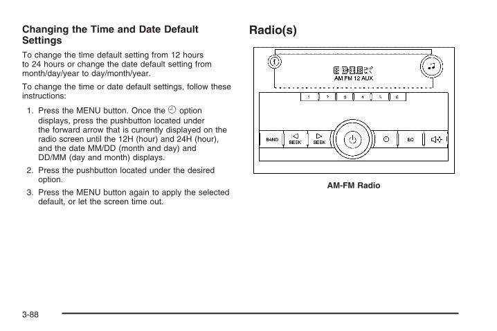
Changing the Time and Date DefaultSettingsTo change the time default setting from 12 hoursto 24 hours or change the date default setting frommonth/day/year to day/month/year.
To change the time or date default settings, follow theseinstructions:
1. Press the MENU button. Once the H optiondisplays, press the pushbutton located underthe forward arrow that is currently displayed on theradio screen until the 12H (hour) and 24H (hour),and the date MM/DD (month and day) andDD/MM (day and month) displays.
2. Press the pushbutton located under the desiredoption.
3. Press the MENU button again to apply the selecteddefault, or let the screen time out.
Radio(s)
AM-FM Radio
3-88

The vehicle has one of these radios as its audio system.
Radio with CD (MP3) shown, Radio withSix-Disc CD (MP3) similar
Radio with CD and DVD (MP3)
3-89

Radios with CD and DVDRadios with CD and DVD have a Bose® SurroundSound System. Some of its features are explainedlater in this section under, “Adjusting the Speakers(Balance/Fade)”.
If the vehicle has a Rear Seat Entertainment (RSE)system, it has a CD/DVD radio. See Rear SeatEntertainment (RSE) System on page 3-121 for moreinformation on the vehicle’s RSE system.
The DVD player is the top slot on the radio faceplate.The player is capable of reading the DTS programmedDVD Audio or DVD Video media, (DTS and DTSDigital Surround are registered trademarks of DigitalTheater Systems, Inc.).
Manufactured under license from Dolby Laboratories.Dolby and the double-D symbol are trademarks ofDolby Laboratories.
Radio Data System (RDS)The audio system has a Radio Data System (RDS).The RDS feature is available for use only on FM stationsthat broadcast RDS information. This system reliesupon receiving specific information from these stationsand only works when the information is available.While the radio is tuned to an FM-RDS station, thestation name or call letters displays. In rare cases,a radio station could broadcast incorrect information thatcauses the radio features to work improperly. If thishappens, contact the radio station.
Playing the RadioO(Power/Volume): Press to turn the system onand off.
Turn clockwise or counterclockwise to increase ordecrease the volume.
4 (Information) (AM-FM Radio): Press to switch thedisplay between the radio station frequency andthe time. While the ignition is off, press this button todisplay the time.
3-90

H (Clock) (AM-FM Radio): The radio may have aclock button for setting the time. With this type of radio,the clock can be set with either the radio turned onor off. See Setting the Clock on page 3-86 for moreinformation.
Speed Compensated Volume (SCV): Radios withSpeed Compensated Volume (SCV) automaticallyadjusts the radio volume to compensate for road andwind noise as the vehicle’s speed changes while driving,so that the volume level stays consistent.
To activate SCV:
1. Set the radio volume to the desired level.
2. Press the MENU button to display the radiosetup menu.
3. Press the pushbutton under the AUTO VOLUM(automatic volume) label on the radio display.
4. Press the pushbutton under the desired SpeedCompensated Volume setting (OFF, Low, Med,or High) to select the level of radio volumecompensation. The display times out afterapproximately 10 seconds. Each higher settingallows for more radio volume compensation atfaster vehicle speeds.
Finding a Station
BAND: Press to switch between AM, FM, or XM™(if equipped). The selection displays.
f (Tune): Turn to select radio stations.
©SEEK ¨: Press either arrow to go to the previousor to the next station and stay there.
To scan stations, press and hold either arrow for afew seconds until a beep sounds. The radio goes to astation, plays for a few seconds, then goes to the nextstation.
For AM-FM Radio, the station frequency flashes while theradio is in the scan mode.
Press either arrow again to stop scanning.
The radio only seeks and scans stations with a strongsignal that are in the selected band.
For the AM-FM Radio, scan presets within the currentselected band by pressing and holding either seek arrowfor four seconds until a double beep sounds. The radiogoes to a stored preset, plays for a few seconds if astrong signal is present, then goes to the next storedpreset. The station frequency flashes while the radio isin the scan mode.
3-91

4 (Information) (XM™ Satellite Radio Service, MP3,and RDS Features): Press to display additionaltext information related to the current FM-RDS or XM™station, or MP3 song. A choice of additional informationsuch as: Channel, Song, Artist, and CAT (category)can display. Continue pressing to highlight the desiredlabel, or press the pushbutton positioned under any oneof the labels and the information about that label displays.
When information is not available, No Info displays.
Setting Preset Stations (AM-FM Radio)If the radio does not have XM™, up to 18 stations(six FM1, six FM2, and six AM), can be programmed onthe six numbered pushbuttons, by performing thefollowing steps:
1. Turn the radio on.
2. Press BAND to select FM1, FM2, or AM.
3. Tune in the desired station.
4. Press and hold one of the six numberedpushbuttons for three seconds until a beep sounds.Whenever that pushbutton is pressed andreleased, the station that was set, returns.
5. Repeat the Steps 2 through 4 for each pushbutton.
Storing a Radio Station as a FavoriteDrivers are encouraged to set up their radio stationfavorites while the vehicle is parked. Tune to favoritestations using the presets, favorites button, andsteering wheel controls, if the vehicle has this feature.See Defensive Driving on page 4-2.
FAV (Favorites): If the vehicle has XM™ and hasa FAV button, a maximum of 36 stations can beprogrammed as favorites using the six pushbuttonspositioned below the radio station frequency labels andby using the radio favorites page button (FAV button).Press the FAV button to go through up to six pagesof favorites, each having six favorite stations availableper page. Each page of favorites can contain anycombination of AM, FM, or XM™ (if equipped) stations.
The balance/fade and tone settings that werepreviously adjusted, are stored with the favorite stations.
To store a station as a favorite, perform thefollowing steps:
1. Tune to the desired radio station.
2. Press the FAV button to display the page where thestation will be stored.
3-92

3. Press and hold one of the six pushbuttons until abeep sounds. When that pushbutton is pressedand released, the station that was set, returns.
4. Repeat the steps for each pushbutton radio stationto store as a favorite.
The number of favorites pages can be setup using theMENU button. To setup the number of favorites pages,perform the following steps:
1. Press the MENU button to display the radiosetup menu.
2. Press the pushbutton located below theFAV 1-6 label.
3. Select the desired number of favorites pages bypressing the pushbutton located below thedisplayed page numbers.
4. Press the FAV button, or let the menu time out, toreturn to the original main radio screen showing theradio station frequency labels and to begin theprocess of programming favorites for the chosenamount of numbered pages.
Setting the Tone (Bass/Treble)(AM-FM Radio)
Bass/Treble: To adjust the bass or treble, press thetune knob or the EQ button until the desired tone controllabel displays. Turn the tune knob clockwise orcounterclockwise to increase or decrease the setting.The display shows the current bass or treble level.If a station’s frequency is weak, or if there is static,decrease the treble.
Setting the Tone(Bass/Midrange/Treble)
BASS/MID/TREB (Bass, Midrange, or Treble):To adjust bass, midrange, or treble, press the f knob
until the tone control labels display. Continue pressingto highlight the desired label, or press the pushbuttonpositioned under the desired label. Turn the f knobclockwise or counterclockwise to adjust the highlightedsetting, or adjust the highlighted setting by pressingeither SEEK arrow, \FWD (forward), or sREV(reverse) button until the desired levels are obtained.If a station’s frequency is weak or if there is static,decrease the treble.
3-93

To quickly adjust bass, midrange, or treble to the middleposition, press the pushbutton positioned under theBASS, MID, or TREB label for more than two seconds.A beep sounds and the level adjusts to the middleposition.
To quickly adjust all tone and speaker controls to themiddle position, press the f knob for more thantwo seconds until a beep sounds.
EQ (Equalization): Press this button to choose bassand treble equalization settings designed for differenttypes of music. The choices are pop, rock, country, talk,jazz, and classical. Selecting MANUAL or changingbass or treble, returns the EQ to the manual bass andtreble settings.
Unique EQ settings can be saved for each source.
If the radio has a Bose® audio system, the EQ settingsare either MANUAL or TALK.
Adjusting the Speakers (Balance/Fade)(AM-FM Radio)
` (Balance/Fade): To adjust the balance or fade,press this button or the tune knob until the desiredspeaker control label displays. Turn the tune knobclockwise or counterclockwise to adjust the setting.
The setting can also be adjusted by pressing theseek arrows.
Adjusting the Speakers (Balance/Fade)
BAL/FADE (Balance/Fade): To adjust balance orfade, press the f knob until the speaker control labelsdisplay. Continue pressing to highlight the desiredlabel, or press the pushbutton positioned under thedesired label. Turn the f knob clockwise orcounterclockwise to adjust the highlighted setting, oradjust the highlighted setting by pressing eitherSEEK arrow, \FWD, or sREV button until thedesired levels are obtained.
To quickly adjust balance or fade to the middle position,press the pushbutton positioned under the BAL orFADE label for more than two seconds. A beep soundsand the level adjusts to the middle position.
3-94

To quickly adjust all speaker and tone controls to themiddle position, press the f knob for more thantwo seconds.
If the Rear Seat Audio (RSA) is turned on, the radiodisables FADE and mutes the rear speakers.
Finding a Category (CAT) Station
CAT (Category): The CAT button is used to find XM™stations when the radio is in the XM™ mode. To findXM™ channels within a desired category, performthe following:
1. Press the BAND button until the XM™ frequencydisplays. Press the CAT button to display thecategory labels. Continue pressing the CAT buttonuntil the desired category name displays.
• Radios with CD and DVD can also navigate thecategory list by pressing the \FWD or thesREV button.
2. Press either of the two buttons below the desiredcategory label to immediately tune to the firstXM™ station associated with that category.
3. Turn the f knob, press the buttons below the rightor left arrows displayed, or press either SEEK arrowto go to the previous or to the next XM™ stationwithin the selected category.
4. To exit the category search mode, press theFAV button or BAND button to display thefavorites again.
Undesired XM™ categories can be removed throughthe setup menu. To remove an undesired category,perform the following:1. Press the MENU button to display the radio
setup menu.2. Press the pushbutton located below the XM CAT
label.
3. Turn the f knob to display the category to beremoved.
4. Press the pushbutton located under the Removelabel until the category name along with the wordRemoved displays.
5. Repeat the steps to remove more categories.
Removed categories can be restored by pressing thepushbutton under the Add label when a removedcategory is displayed or by pressing the pushbuttonunder the Restore All label.
Categories cannot be removed or added while thevehicle is moving faster than 5 mph (8 km/h).
3-95

Radio MessagesCalibration Error: The audio system has beencalibrated for the vehicle from the factory. If CalibrationError displays, it means that the radio has not beenconfigured properly for the vehicle and it must bereturned to your dealer/retailer for service.
Locked or Loc: One of these messages will displaywhen the THEFTLOCK® system has locked up theradio. Take the vehicle to your dealer/retailer for service.
If any error occurs repeatedly or if an error cannot becorrected, contact your dealer/retailer.
XM™ Satellite Radio ServiceXM™ is a satellite radio service that is based in the48 contiguous United States and 10 Canadianprovinces. XM™ Satellite Radio has a wide varietyof programming and commercial-free music,coast-to-coast, and in digital-quality sound. During yourtrial or when you subscribe, you will get unlimitedaccess to XM™ Radio Online for when you are not inyour vehicle. A service fee is required to receivethe XM™ service. For more information, contact XM™at www.xmradio.com or call 1-800-929-2100 in theU.S. and www.xmradio.ca or call 1-877-438-9677in Canada.
Radio Messages for XM™ OnlySee XM Radio Messages on page 3-119 later in thissection for further detail.
Playing a CD (Single CD Player)Insert a CD partway into the slot, label side up.The player pulls it in and the CD should begin playing.
Playing a CD(s) (Six-Disc CD Player)LOAD ^: Press to load CDs into the CD player.This CD player holds up to six CDs.
To insert one CD, do the following:
1. Press and release the ^button.
2. Wait for the message to insert the disc.
3. Load a CD. Insert the CD partway into the slot,label side up. The player pulls the CD in.
3-96
To insert multiple CDs, do the following:
1. Press and hold the ^button for two seconds.A beep sounds and Load All Discs displays.
2. Follow the displayed instruction on when to insertthe discs. The CD player takes up to six CDs.
3. Press the ^button again to cancel loadingmore CDs.
Insert a CD partway into the slot, label side up.The player pulls it in and the CD should begin playing.To insert a CD with the ignition off, first press theZbutton or the DISP knob.
If the ignition or radio is turned off with a CD in theplayer it stays in the player. When the ignition or radiois turned on, the CD starts to play where it stopped,if it was the last selected audio source.
When the CD is inserted, the CD symbol displays.As each new track starts to play, the track numberdisplays.
The CD player can play the smaller 3 inch (8 cm)single CDs with an adapter ring. Full-size CDs and thesmaller CDs are loaded in the same manner.
Playing a CD(In Either the DVD or CD Slot)Insert a CD partway into the slot, label side up.The player pulls it in and the CD should begin playing(loading a disc into the system, depending on mediatype and format ranges from 5 to 20 seconds for a CD,and up to 30 seconds for a DVD to begin playing).
If the ignition or radio is turned off, with a CD inthe player, it stays in the player. When the ignition orradio is turned on, the CD starts playing where itstopped, if it was the last selected audio source.The CD is controlled by the buttons on the radiofaceplate or by the RSA unit. See Rear Seat Audio(RSA) on page 3-130 for more information. The DVD/CDdecks, (upper slot is the DVD deck and the lower slotis the CD deck) of the radio are compatible withmost audio CDs, CD-R, CD-RW, and MP3s.
When a CD is inserted, the text label DVD or CDsymbol displays on the left side of the radio display.As each new track starts to play, the track numberdisplays.
The CD player can play the smaller 3 inch (8 cm)single CDs with an adapter ring. Full-size CDs andthe smaller CDs are loaded in the same manner.
3-97

Care of CDsIf playing a CD-R, the sound quality can be reduceddue to CD-R or CD-RW quality, the method of recording,the quality of the music that has been recorded, andthe way the CD-R or CD-RW has been handled.Handle them carefully. Store CD-R(s) or CD-RW(s) intheir original cases or other protective cases andaway from direct sunlight and dust. The CD or DVDplayer scans the bottom surface of the disc. If thesurface of a CD is damaged, such as cracked, broken,or scratched, the CD does not play properly or notat all. Do not touch the bottom side of a CD whilehandling it; this could damage the surface. Pick up CDsby grasping the outer edges or the edge of the holeand the outer edge.
If the surface of a CD is soiled, take a soft, lint freecloth or dampen a clean, soft cloth in a mild, neutraldetergent solution mixed with water, and clean it.Make sure the wiping process starts from the centerto the edge.
Care of the CD and DVD PlayerDo not add any label to a CD, it could get caught in theCD or DVD player. If a CD is recorded on a personalcomputer and a description label is needed, try labelingthe top of the recorded CD with a marking pen instead.
The use of CD lens cleaners for CDs is not advised, dueto the risk of contaminating the lens of the CD optics withlubricants internal to the CD and DVD player mechanism.
Notice: If a label is added to a CD, or more thanone CD is inserted into the slot at a time, or anattempt is made to play scratched or damaged CDs,the CD player could be damaged. While using theCD player, use only CDs in good condition withoutany label, load one CD at a time, and keep theCD player and the loading slot free of foreignmaterials, liquids, and debris.
If an error displays, see “CD Messages” later in thissection.
Z EJECT or CD (Eject): Press and release to ejectthe disc that is currently playing. A CD ejecting froma radio with CD and DVD, ejects from the bottom slot.A beep sounds and Ejecting Disc displays. Once thedisc is ejected, Remove Disc displays. The disccan be removed. If the disc is not removed, afterseveral seconds, the disc automatically pulls backinto the player.
3-98

For the Six-Disc CD player, press and hold fortwo seconds to eject all discs.
ZDVD (Eject): Press and release to eject the discthat is currently playing in the top slot. A beep soundsand Ejecting Disc displays.
If loading and reading of a disc cannot be completed,such as unknown format, etc., and the disc fails to eject,press and hold for more than five seconds to forcethe disc to eject.
f (Tune): Turn to select tracks on the CD that iscurrently playing.
©SEEK ¨: Press the left arrow to go to the start ofthe current track, if more than ten seconds on theCD have played. Press the right arrow to go to thenext track.
For Radios with CD and DVD, Press the left arrow to goto the start of the current track, if more than five secondson the CD have played. If less than five seconds onthe CD have played, the previous track plays. Press theright arrow to go to the next track.
If either arrow is held, or pressed multiple times, theplayer continues moving backward or forward throughthe tracks on the CD.
sREV (Fast Reverse): Press and hold to reverseplayback quickly within a track. Sound will be heardat a reduced volume. Release to resume playingthe track. The elapsed time of the track displays.
\FWD (Fast Forward): Press and hold to advanceplayback quickly within a track. Sound will be heardat a reduced volume. Release to resume playingthe track. The elapsed time of the track displays.
RDM (Random): With the random setting, the trackscan be listened to in random, rather than sequentialorder. To use random, do one of the following:
• Press the CD/AUX button, or for a single CD player,insert a disc partway into the slot of the CD player.A RDM label displays.To play the tracks from the single CD in randomorder, press the pushbutton positioned under theRDM label until Random Current Disc displays.Press the pushbutton again to turn off random play.
3-99
• Press the CD/AUX button, or for a six-discCD player, press and hold the^button. A beepsounds and Load All Discs displays. Insert one ormore discs partway into the slot of the CD player.To play tracks from all CDs loaded in a six-discCD player in random order, press the pushbuttonpositioned under the RDM label until Randomize AllDiscs displays. Press the same pushbutton again toturn off random play.To play the tracks from a CD loaded in the radio withCD and DVD, press the DVD/CD AUX button whennot sourced to the CD, or insert a disc partway intothe slot. A RDM label displays.To play tracks from a single CD in random order,press the pushbutton positioned under the RDM labeluntil Random Current Disc displays. Press thepushbutton again to turn off random play.
BAND: Press to listen to the radio when a CD is playing.The CD remains inside the radio for future listening.
For the radio with CD and DVD, press to listen to theradio when a CD or DVD is playing. The CD or DVDremains inside the radio for future listening or for viewingentertainment.
CD/AUX (CD/Auxiliary): Press to play a CD whenlistening to the radio. The CD icon and a messageshowing the disc and/or track number displays whena CD is in the player. Press again and the systemautomatically searches for an auxiliary input device, suchas a portable audio player. If a portable audio player isnot connected, “No Input Device Found” displays.
DVD/CD AUX (Auxiliary): Press this button to cyclethrough DVD, CD, or Auxiliary when listening tothe radio. The DVD/CD text label and a messageshowing the track or chapter number displays when adisc is in either slot. Press this button again andthe system automatically searches for an auxiliary inputdevice, such as a portable audio player. If a portableaudio player is not connected, “No Aux Input Device”displays. If a disc is in both the DVD slot and theCD slot the DVD/CD AUX button cycles between thetwo sources and not indicate “No Aux Input Device”.If a front auxiliary device is connected, the DVD/CD AUXbutton cycles through all available options, such as:DVD slot, CD slot, Front Auxiliary, and Rear Auxiliary(if available). See “Using the Auxiliary Input Jack(s)”later in this section, or “Audio/Video (A/V) Jacks” under,Rear Seat Entertainment (RSE) System on page 3-121for more information.
If a disc is inserted into top DVD slot, the rear seatoperator can turn on the video screen and use the remotecontrol to navigate the CD (tracks only) through theremote control.
3-100

Radios with CD and DVD Audio OutputOnly one audio source can be heard through thespeakers at one time. An audio source is defined asDVD slot, CD slot, XM™, FM/AM, Front Auxiliary Jack,or Rear Auxiliary Jack.
Press the Obutton to turn the radio on. The radio canbe heard through all of the vehicle speakers.
Front seat passengers can listen to the radio (AM, FM,or XM) by pressing the BAND button or the DVD/CDAUX button to select CD slot, DVD slot, front or rearauxiliary input (if available).
If a playback device is plugged into the radio’s frontauxiliary input jack or the rear auxiliary jack, the frontseat passengers are able to listen to playback from thissource through the vehicle speakers. See “Using theAuxiliary Input Jack(s)” later in this section, or“Audio/Video (A/V) Jacks” under, Rear SeatEntertainment (RSE) System on page 3-121 formore information.
In some vehicles, depending on audio options, the rearspeakers can be muted when the RSA power isturned on. See Rear Seat Audio (RSA) on page 3-130for more information.
Playing an MP3 CD-R or CD-RW DiscRadios with a Single CD player or a Six-Disc CD playerhas the capability of playing an MP3 CD-R or CD-RWdisc. For more information on how to play an MP3 CD-Ror CD-RW disc, see “Using an MP3” in the index.
Playing an MP3/WMA CD-R orCD-RW DiscRadios with CD and DVD has the capability of playingan MP3/WMA CD-R or CD-RW disc. For moreinformation on how to play an MP3/WMA CD-R orCD-RW disc, see “Using an MP3” in the index.
CD MessagesCHECK DISC: Radios with a Single CD player orradios with a Six-Disc player displays CHECK DISCand/or ejects the CD if an error occurs.
Radios with a CD and DVD player may display othermessages when an error occurs:
Optical Error: The disc was inserted upside down.
Disk Read Error: A disc was inserted with an invalidor unknown format.
3-101

Player Error: There are disc LOAD or disc EJECTproblems.
• It is very hot. When the temperature returns tonormal, the CD should play.
• The road is very rough. When the road becomessmoother, the CD should play.
• The CD is dirty, scratched, wet, or upside down.
• The air is very humid. If so, wait about an hourand try again.
• There could have been a problem while burningthe CD.
• The label could be caught in the CD player.
If the CD is not playing correctly, for any other reason,try a known good CD.
Radios with a CD and DVD player displays
If any error occurs repeatedly or if an error cannot becorrected, contact your dealer/retailer. If the radiodisplays an error message, write it down and provide itto your dealer/retailer when reporting the problem.
Using the DVD PlayerThe DVD player is controlled by the buttons on theremote control, or by the RSA system, or by the buttonson the radio faceplate. See “Remote Control”, underRear Seat Entertainment (RSE) System on page 3-121and Rear Seat Audio (RSA) on page 3-130 for moreinformation.
The DVD player is only compatible with DVDs of theappropriate region code that is printed on the jacket ofmost DVDs.
The DVD slot of the radio is compatible with mostaudio CDs, CD-R, CD-RW, DVD-Video, DVD-Audio,DVD-R/RW, DVD+R/RW media along with MP3and WMA formats.
If an error message displays on the video screen or theradio, see “DVD Display Error Messages” under,Rear Seat Entertainment (RSE) System on page 3-121and “DVD Radio Error Messages” in this section formore information.
3-102

Playing a DVD
DVD/CD AUX (Auxiliary): Press this button to cyclethrough DVD, CD, or Auxiliary when listening tothe radio. The DVD/CD text label and a messageshowing track or chapter number displays when a discis in either slot. Press this button again and thesystem automatically searches for an auxiliary inputdevice, such as a portable audio player. If a portableaudio player is not connected, “No Aux Input Device”displays. If a disc is in both the DVD slot and theCD slot the DVD/CD AUX button cycles between thetwo sources and not indicate “No Aux Input Device”.If a front auxiliary device is connected, the DVD/CD AUXbutton cycles through all available options, such as:DVD slot, CD slot, Front Auxiliary, and Rear Auxiliary(if available). See “Using the Auxiliary Input Jack(s)”later in this section, or “Audio/Video (A/V) Jacks” under,Rear Seat Entertainment (RSE) System on page 3-121for more information.
O(Power): Press to turn the radio on or off. Turn thisknob clockwise or counterclockwise to increase ordecrease the volume. Press and hold for more thantwo seconds to turn off the entire radio and Rear SeatEntertainment (RSE) system and to start the parentalcontrol feature. Parental control prevents the rear seatoccupant from operating the Rear Seat Audio (RSA)system or remote control.
A lock symbol displays next to the clock display.The parental control feature remains on until the knobis pressed and held for more than two seconds again,or until the driver turns the ignition off and exits thevehicle.
f (Tune): Turn to change tracks on a CD or DVD,to manually tune a radio station, or to change clock ordate settings, while in the clock or date setting mode. Seethe information given earlier in this section specific to theradio, CD, and the DVD. Also, see “Setting the Time” inthe index, for setting the clock and date.
©SEEK (Previous Track/Chapter): Press the leftarrow to return to the start of the current track orchapter. Press the left arrow again to go to the previoustrack or chapter. This button might not work when theDVD is playing the copyright information or the previews.
3-103

SEEK ¨(Next Track/Chapter): Press the right arrowto go to the next track or chapter. This button mightnot work when the DVD is playing the copyrightinformation or the previews.
sREV (Fast Reverse): Press to quickly reverse theCD or DVD at five times the normal speed. The radiodisplays the elapsed time while in fast reverse. To stopfast reversing, press again. This button might not workwhen the DVD is playing the copyright information or thepreviews.
\FWD (Fast Forward): Press to fast forward the CDor DVD. The radio displays the elapsed time and fastforwards five times the normal speed. To stop fastforwarding, press again. This button might not workwhen the DVD is playing the copyright information orthe previews.
Z(Eject): Press to eject a CD or DVD. If a CD orDVD is ejected, but not removed, the playerautomatically pulls it back in after 15 seconds.
If loading and reading of a CD cannot be completed,because of an unknown format, etc., and the disc failsto eject, press and hold for more than five secondsto force the disc to eject.
DVD-V (Video) Display ButtonsOnce a DVD-V is inserted, the radio display menushows several tag options for DVD playing. Press thepushbuttons located under any desired tag optionduring DVD playback. See the tag options listed after,for more information.
The rear seat passenger can navigate the DVD-Vmenus and controls through the remote control.See “Remote Control”, under Rear Seat Entertainment(RSE) System on page 3-121 for more information.The Video Screen automatically turns on whenthe DVD-V is inserted into the DVD slot.
r/ j(Play/Pause): Press either the play or pauseicon displayed on the radio system, to toggle betweenpausing or restarting playback of a DVD. If theforward arrow is showing on display, the system is inpause mode. If the pause icon is showing on display, thesystem is in playback mode. If the DVD screen is off,press the play button to turn the screen on.
Some DVDs begin playing after the previews havefinished, although there could be a delay of up to30 seconds. If the DVD does not begin playing themovie automatically, press the pushbutton locatedunder the play/pause symbol tag displayed on the radio.If the DVD still does not play, refer to the on-screeninstructions, if available.
3-104
c(Stop): Press to stop playing, rewinding, or fastforwarding a DVD.
r (Enter): Press to select the choices that arehighlighted in any menu.
y (Menu): Press to access the DVD menu. The DVDmenu is different on every DVD. Use the pushbuttonslocated under the navigation arrows to navigatethe cursor through the DVD menu. After making aselection press this button. This button only operateswhen using a DVD.
Nav (Navigate): Press to display directional arrows fornavigating through the menus.
q(Return): Press to exit the current active menuand return to the previous menu. This button operatesonly when a DVD is playing and a menu is active.
DVD-A (Audio) Display ButtonsOnce a DVD-A is inserted, radio display menu showsseveral tag options for DVD playing. Press thepushbuttons located under any desired tag optionduring DVD playback. See the tag options listed after,for more information.
The rear seat operator can navigate the DVD-A menusand controls through the remote control. See “RemoteControl”, under Rear Seat Entertainment (RSE) Systemon page 3-121 for more information. The VideoScreen does not automatically power on when theDVD-A is inserted into the DVD slot. It must be manuallyturned on by the rear seat occupant through theremote control power button.
r/ j(Play/Pause): Press either the play or pauseicon displayed on the radio system, to toggle betweenpausing or restarting playback of a DVD. If theforward arrow is showing on the display, the system isin pause mode. If the pause icon is showing on thedisplay, the system is in playback mode.
qGroup r: Press to cycle through musical groupingson the DVD-A disc.
Nav (Navigate): Press to display directional arrows fornavigating through the menus.
e(Audio Stream): Press to cycle through audiostream formats located on the DVD-A disc. The videoscreen shows the audio stream changing.
3-105

Inserting a DiscTo play a disc, gently insert the disc, with the label sideup, into the loading slot. The DVD player might notaccept some paper labeled media. The player startsloading the disc into the system and show “LoadingDisc” on the radio display. At the same time, the radiodisplays a softkey menu of option(s). Some discsautomatically play the movie while others default to thesoftkey menu display, which requires the Play, Enter,or Navigation softkeys to be pressed; either by softkeyor by the rear seat passenger using the remote control.
Loading a disc into the system, depending on mediatype and format, ranges from 5 to 20 seconds for a CD,and up to 30 seconds for a DVD.
Stopping and Resuming PlaybackTo stop playing a DVD without turning off the system,press the cbutton on the remote control, or press thepushbutton located under the stop or the play/pausesymbol tags displayed on the radio. If the radio head issourced to something other than DVD-V, press theDVD/CD AUX button to make DVD-V the active source.
To resume DVD playback, press the r/ jbutton onthe remote control, or press the pushbutton locatedunder the play/pause symbol tag displayed on the radio.The DVD should resume play from where it laststopped if the disc has not been ejected and the stopbutton has not been pressed twice on the remotecontrol. If the disc has been ejected or the stop buttonhas been pressed twice on the remote control, thedisc resumes playing at the beginning of the disc.
Ejecting a Disc
Press the Zbutton on the radio to eject the disc.If a disc is ejected from the radio, but not removed,the radio reloads the disc after a short period of time.The disc is stored in the radio. The radio does notresume play of the disc automatically. If the RSA systemis sourced to the DVD, the movie when reloaded intothe DVD player begins to play again. In case loadingand reading of a DVD or CD cannot be completed(unknown format, etc.), and the disc fails to eject, pressand hold the DVD Z button more than five secondsto force the disc to eject.
3-106

DVD Radio Error MessagesPlayer Error: This message displays when there aredisc load or eject problems.
Disc Format Error: This message displays, if the discis inserted with the disc label wrong side up, or ifthe disc is damaged.
Disc Region Error: This message displays, if the discis not from a correct region.
No Disc Inserted: This message displays, if no disc ispresent when the Zor DVD/CD AUX button ispressed on the radio.
Using the Auxiliary Input JackThe radio system has an auxiliary input jack located onthe lower right side of the faceplate. This is not anaudio output; do not plug the headphone set into thefront auxiliary input jack. An external audio device suchas an iPod, laptop computer, MP3 player, CD player,etc. can be connected to the auxiliary input jack for useas another source for audio listening.
Drivers are encouraged to set up any auxiliary devicewhile the vehicle is in P (Park). See Defensive Drivingon page 4-2 for more information on driver distraction.
To use a portable audio player, connect a 3.5 mm(1/8 inch) cable to the radio’s front auxiliary input jack.When a device is connected, press the radio CD/AUXbutton to begin playing audio from the device overthe vehicle speakers.
For optimal sound quality, increase the portable audiodevice’s volume to the loudest level.
It is always best to power the portable audio devicethrough its own battery while playing.
O(Power/Volume): Turn clockwise orcounterclockwise to increase or decrease the volume ofthe portable player. Additional volume adjustmentsmight have to be made from the portable device if thevolume is not loud or soft enough.
BAND: Press to listen to the radio when a portableaudio device is playing. The portable audio devicecontinues playing.
3-107

CD/AUX (CD/Auxiliary): Press to play a CD when aportable audio device is playing. Press again andthe system begins playing audio from the connectedportable audio player. If a portable audio player isnot connected, “No Input Device Found” displays.
DVD/CD AUX (CD/Auxiliary): Press to cycle throughDVD, CD, or Auxiliary when listening to the radio.The DVD/CD text label and a message showing track orchapter number displays when a disc is in either slot.Press again and the system automatically searchesfor an auxiliary input device, such as a portable audioplayer. If a portable audio player is not connected,“No Aux Input Device” displays. If a disc is in both theDVD slot and the CD slot the DVD/CD AUX buttoncycles between the two sources and not indicate“No Aux Input Device”. If a front auxiliary device isconnected, the DVD/CD AUX button cycles throughall available options, such as: DVD slot, CD slot,Front Auxiliary, and Rear Auxiliary (if available).See “Using the Auxiliary Input Jack(s)” later in thissection, or “Audio/Video (A/V) Jacks” under, RearSeat Entertainment (RSE) System on page 3-121for more information.
Using an MP3 (Radio with CD orSix-Disc CD Player)
MP3 CD-R or CD-RW DiscThe radio plays MP3 files that were recorded on aCD-R or CD-RW disc. The files can be recorded withthe following fixed bit rates: 32 kbps, 40 kbps, 56 kbps,64 kbps, 80 kbps, 96 kbps, 112 kbps, 128 kbps,160 kbps, 192 kbps, 224 kbps, 256 kbps, and 320 kbpsor a variable bit rate. Song title, artist name, andalbum are available for display by the radio whenrecorded using ID3 tags version 1 and 2.
Compressed AudioThe radio also plays discs that contain bothuncompressed CD audio (.CDA files) and MP3 files.By default the radio shows the MP3 label on theleft side of the screen but plays both file formats inthe order in which they were recorded to the disc.
3-108

MP3 FormatBurning an MP3 disc on a personal computer:
• Make sure the MP3 files are recorded on a CD-Ror CD-RW disc.
• Do not mix standard audio and MP3 files onone disc.
• Make sure the CD does not have more than amaximum of 50 folders, 15 playlists, and 512 foldersand files to read and play.
• Create a folder structure that makes it easy to findsongs while driving. Organize songs by albumsusing one folder for each album. Each folderor album should contain 18 songs or less.
• Avoid subfolders. The system can support up toeight subfolders deep, however, keep the totalnumber of folders to a minimum in order to reducethe complexity and confusion in trying to locatea particular folder during playback.
• Make sure playlists have a .mp3 or .wpl extension(other file extensions might not work).
• Minimize the length of the file, folder, or playlistnames. Long file, folder, or playlist names, or acombination of a large number of files and folders,or playlists could cause the player to be unableto play up to the maximum number of files, folders,playlists, or sessions. To play a large number offiles, folders, playlists or sessions, minimizethe length of the file, folder, or playlist name.Long names also take up more space on thedisplay, potentially getting cut off.
• Finalize the audio disc before burning it. Trying toadd music to an existing disc could cause thedisc not to function in the player.
Playlists can be changed by using the Sc (previous)and cT (next) folder buttons, the f knob, or the©SEEK ¨ arrows. MP3 CD-R or CD-RW that havebeen recorded without using file folders can be played.If a CD-R or CD-RW contains more than the maximum of50 folders, 15 playlists, and 512 folders and files, theplayer allows access and navigates up to the maximum,but all items over the maximum are not accessible.
3-109

Root DirectoryThe root directory of the CD-R or CD-RW is treated asa folder. If the root directory has compressed audiofiles, the directory displays as the CD label. All filescontained directly under the root directory are accessedprior to any root directory folders. However, playlists (Px)are always accessed before root folders or files.
If a disc contains both uncompressed CD audio (.CDA)and MP3 files, a folder under the root directory calledCD accesses all of the CD audio tracks on the disc.
Empty Directory or FolderIf a root directory or a folder exists somewhere in the filestructure that contains only folders/subfolders and nocompressed files directly beneath them, the playeradvances to the next folder in the file structure thatcontains compressed audio files. The empty folderdoes not display.
No FolderWhen the CD contains only compressed files, the filesare located under the root folder. The next and previousfolder function does not display on a CD that wasrecorded without folders or playlists.
When the CD contains only playlists and compressedaudio files, but no folders, all files are located under theroot folder. The folder down and up buttons searchplaylists (Px) first and then goes to the root folder.
Order of PlayTracks recorded to the CD-R or CD-RW are played inthe following order:
• Play begins from the first track in the first playlistand continues sequentially through all tracks ineach playlist. When the last track of the last playlisthas played, play continues from the first track ofthe first playlist.
• Play begins from the first track in the first folder andcontinues sequentially through all tracks in eachfolder. When the last track of the last folderhas played, play continues from the first track of thefirst folder.
When play enters a new folder, the display does notautomatically show the new folder name unlessthe folder mode has been chosen as the default display.The new track name displays.
3-110
File System and NamingThe song name that displays is the song name that iscontained in the ID3 tag. If the song name is not presentin the ID3 tag, then the radio displays the file namewithout the extension (such as .mp3) as the track name.
Track names longer than 32 characters or four pagesare shortened. Parts of words on the last page oftext and the extension of the filename does not display.
Preprogrammed PlaylistsPreprogrammed playlists that were created usingWinAmp™, MusicMatch™, or Real Jukebox™ softwarecan be accessed, however, they cannot be editedusing the radio. These playlists are treated as specialfolders containing compressed audio song files.
Playing an MP3Insert a CD-R or CD-RW partway into the slot (SingleCD Player), or press the load button and wait forthe message to insert disc (Six-Disc CD Player), labelside up. The player pulls it in, and the CD-R or CD-RWshould begin playing.
If the ignition or radio is turned off with a CD-R orCD-RW in the player it stays in the player. When theignition or radio is turned on, the CD-R or CD-RW startsto play where it stopped, if it was the last selectedaudio source.
As each new track starts to play, the track number andsong title displays.
ZEJECT: Press this button to eject CD-R(s) orCD-RW(s). To eject the CD-R or CD-RW that is currentlyplaying, press and release this button. A beep soundsand Ejecting Disc displays. Once the disc is ejected,Remove Disc displays. The CD-R or CD-RW canbe removed. If the CD-R or CD-RW is not removed,after several seconds, the CD-R or CD-RWautomatically pulls back into the player and beginsplaying. For the Six-Disc CD player, press and hold thisbutton for two seconds to eject all discs.
f (Tune): Turn this knob to select MP3 files on theCD-R currently playing.
3-111
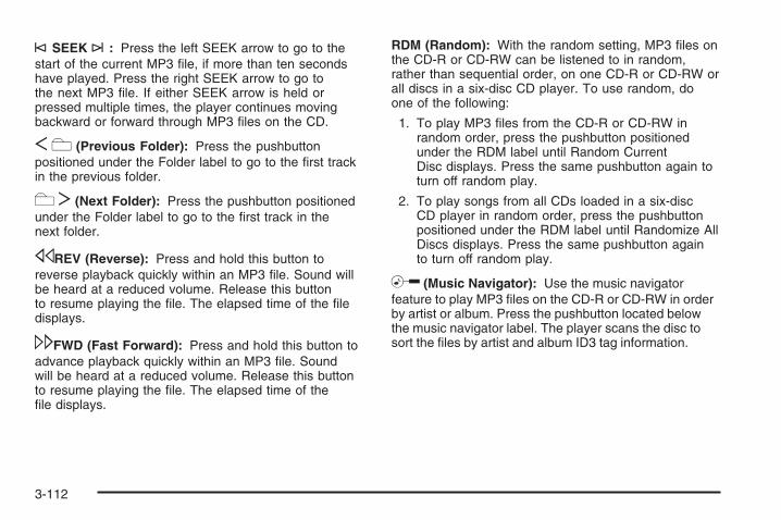
©SEEK ¨: Press the left SEEK arrow to go to thestart of the current MP3 file, if more than ten secondshave played. Press the right SEEK arrow to go tothe next MP3 file. If either SEEK arrow is held orpressed multiple times, the player continues movingbackward or forward through MP3 files on the CD.
S c (Previous Folder): Press the pushbuttonpositioned under the Folder label to go to the first trackin the previous folder.
c T (Next Folder): Press the pushbutton positionedunder the Folder label to go to the first track in thenext folder.
sREV (Reverse): Press and hold this button toreverse playback quickly within an MP3 file. Sound willbe heard at a reduced volume. Release this buttonto resume playing the file. The elapsed time of the filedisplays.
\FWD (Fast Forward): Press and hold this button toadvance playback quickly within an MP3 file. Soundwill be heard at a reduced volume. Release this buttonto resume playing the file. The elapsed time of thefile displays.
RDM (Random): With the random setting, MP3 files onthe CD-R or CD-RW can be listened to in random,rather than sequential order, on one CD-R or CD-RW orall discs in a six-disc CD player. To use random, doone of the following:
1. To play MP3 files from the CD-R or CD-RW inrandom order, press the pushbutton positionedunder the RDM label until Random CurrentDisc displays. Press the same pushbutton again toturn off random play.
2. To play songs from all CDs loaded in a six-discCD player in random order, press the pushbuttonpositioned under the RDM label until Randomize AllDiscs displays. Press the same pushbutton againto turn off random play.
h (Music Navigator): Use the music navigatorfeature to play MP3 files on the CD-R or CD-RW in orderby artist or album. Press the pushbutton located belowthe music navigator label. The player scans the disc tosort the files by artist and album ID3 tag information.
3-112

It could take several minutes to scan the disc dependingon the number of MP3 files recorded to the CD-R orCD-RW. The radio can begin playing while it is scanningthe disc in the background. When the scan is finished,the CD-R or CD-RW begins playing again.
Once the disc has scanned, the player defaults to playingMP3 files in order by artist. The current artist playing isshown on the second line of the display between thearrows. Once all songs by that artist are played, theplayer moves to the next artist in alphabetical order onthe CD-R or CD-RW and begins playing MP3 files by thatartist. To listen to MP3 files by another artist, press thepushbutton located below either arrow button. The next orprevious artist in alphabetical order plays. Continuepressing either button until the desired artist is displayed.
To change from playback by artist to playback by album,press the pushbutton located below the Sort By label.From the sort screen, push one of the buttons below thealbum button. Press the pushbutton below the backlabel to return to the main music navigator screen.
Now the album name is displayed on the second linebetween the arrows and songs from the current albumbegins to play. Once all songs from that album areplayed, the player moves to the next album inalphabetical order on the CD-R or CD-RW and beginsplaying MP3 files from that album.
To exit music navigator mode, press the pushbuttonbelow the Back label to return to normal MP3 playback.
BAND: Press this button to listen to the radio when aCD is playing. The CD remains safely inside the radio forfuture listening.
CD/AUX (CD/Auxiliary): Press this button to playa CD when listening to the radio. The CD icon and amessage showing disc and/or track number displayswhen a CD is in the player. Press this button again andthe system automatically searches for an auxiliaryinput device such as a portable audio player. If aportable audio player is not connected, “No Input DeviceFound” displays.
3-113

Using an MP3 (Radio with CDand DVD Player)
MP3/WMA CD-R or CD-RW Disc
Compressed Audio or Mixed Mode DiscsThe radio also plays discs that contain bothuncompressed CD audio (.CDA files) and MP3/WMAfiles depending on which slot the disc is loaded into.By default the radio reads only the uncompressed audio(.CDA) and ignores the MP3/WMA files on the DVDdeck. On the CD deck, press the CAT (category) buttonto toggle between compressed and uncompressedaudio format, the default being the uncompressedformat (.CDA).
MP3/WMA FormatBurning an MP3/WMA disc on a personal computer:
• Make sure the MP3/WMA files are recordedon a CD-R or CD-RW disc.
• Do not mix standard audio and MP3/WMA files onone disc.
• The CD player (lower slot) is able to read and playa maximum combination of 512 files and folders.The DVD player (upper slot) is able to read255 folders, 15 playlists and 40 sessions.
• Create a folder structure that makes it easy to findsongs while driving. Organize songs by albumsusing one folder for each album. Each folderor album should contain 18 songs or less.
• Avoid subfolders. The system can support up toeight subfolders deep, however, keep the totalnumber of folders to a minimum in order to reducethe complexity and confusion in trying to locatea particular folder during playback.
• Make sure playlists have a .m3u, .wpl or .plsextension as other file extensions might not work.
• Minimize the length of the file, folder, or playlistnames. Long file, folder, or playlist names, or acombination of a large number of files and folders,or playlists could cause the player to be unableto play up to the maximum number of files, folders,playlists, or sessions. To play a large number offiles, folders, playlists, or sessions, minimizethe length of the file, folder, or playlist name.Long names also take up more space on thedisplay, potentially getting cut off.
• Finalize the audio disc before burning it. Trying toadd music to an existing disc could cause thedisc not to function in the player.
3-114

Root DirectoryThe root directory of the CD-R or CD-RW is treated asa folder. If the root directory has compressed audiofiles, the directory is displayed as F1 ROOT. All filescontained directly under the root directory are accessedprior to any root directory folders. However, playlists (Px)are always accessed before root folders or files.
Empty Directory or FolderIf a root directory or a folder exists somewhere in thefile structure that contains only folders/subfolders andno compressed files directly beneath them, the playeradvances to the next folder in the file structure thatcontains compressed audio files. The empty folder doesnot display.
No FolderWhen the CD contains only compressed files, the filesare located under the root folder. The next and previousfolder function does not function on a CD that wasrecorded without folders or playlists. When displayingthe name of the folder the radio displays ROOT.
When the CD contains only playlists and compressedaudio files, but no folders, all files are located under theroot folder. The folder down and the folder up buttonssearch playlists (Px) first and then goes to the rootfolder. When the radio displays the name of the folderthe radio displays ROOT.
Order of PlayTracks recorded to the CD-R or CD-RW are played inthe following order:
• Play begins from the first track in the first playlistand continues sequentially through all tracks ineach playlist. When the last track of the last playlisthas played, play continues from the first track ofthe first playlist.
• Play begins from the first track in the first folder andcontinues sequentially through all tracks in eachfolder. When the last track of the last folder hasplayed, play continues from the first track of thefirst folder.
When play enters a new folder, the display does notautomatically show the new folder name unlessfolder mode has been chosen as the default display.The new track name displays.
3-115

File System and NamingThe song name that is displayed is the song name that iscontained in the ID3 tag. If the song name is not presentin the ID3 tag, then the radio displays the file namewithout the extension (such as .mp3) as the track name.
Track names longer than 32 characters or four pagesare shortened. Parts of words on the last page oftext and the extension of the filename displays.
Preprogrammed PlaylistsPreprogrammed playlists that were created usingWinAmp™, MusicMatch™, or Real Jukebox™ softwarecan be accessed, however, they cannot be editedusing the radio. These playlists are treated as specialfolders containing compressed audio song files.
Playing an MP3/WMA(In Either the DVD or CD Slot)Insert a CD-R or CD-RW partway into either the top orbottom slot, label side up. The player pulls it in, andthe CD-R or CD-RW should begin playing.
Depending on the format of the disc, a softkey menuappears and allows navigation of the disc. The menureads left to right as RDM (Randomize song play order),
a Folder icon with left and right arrows (to move up ordown through available folders), a PL tag if the disc hasa Playlist available, and a Music Navigator tag. If aPlaylist tag is shown, toggling this key brings up a Foldersoftkey only or the menu as previously described.
If the ignition or radio is turned off with a CD-R orCD-RW in the player it stays in the player. When theignition or radio is turned back on, the CD-R startsto play where it stopped, if it was the last selectedaudio source.
As each new track starts to play, the track number andsong title displays.
Z CD (Eject): Press and release this button to ejectthe CD-R or CD-RW that is currently playing in thebottom slot. A beep sounds and Ejecting Disc displays.Once the disc is ejected, Remove Disc displays.The CD-R or CD-RW can be removed. If the CD-R orCD-RW is not removed, after several seconds, the CD-Ror CD-RW automatically pulls back into the player.
If loading and reading of a CD cannot be completed,such as unknown format, etc., and the disc fails to eject,press and hold this button for more than five secondsto force the disc to eject.
3-116

Z DVD (Eject): Press and release this button toeject the CD-R or CD-RW that is currently playing in thetop slot. A beep sounds and Ejecting Disc displays. Oncethe disc is ejected, Remove Disc displays. The CD-R orCD-RW can be removed. If the CD-R or CD-RW is notremoved, after several seconds, the CD-R automaticallypulls back into the player. If loading and reading of a CDcannot be completed, such as unknown format, etc., andthe disc fails to eject, press and hold this button for morethan five seconds to force the disc to eject.
f (Tune): Turn this knob to select MP3/WMA files onthe CD-R or CD-RW that is currently playing.
©SEEK ¨: Press the left SEEK arrow to go to thestart of the current MP3/WMA file, if more thanfive seconds have played. If less than five seconds haveplayed, the previous MP3/WMA file plays. Press theright SEEK arrow to go to the next MP3/WMA file.If either SEEK arrow is held, or pressed multiple times,the player continues moving backward or forwardthrough the MP3/WMA files on the CD.
S c (Previous Folder): Press the pushbuttonpositioned under the Folder label to go to the first trackin the previous folder.
cT (Next Folder): Press the pushbutton positionedunder the Folder label to go to the first track in thenext folder.
sREV (Reverse): Press and hold this button toreverse playback quickly within an MP3/WMA file. Soundis heard at a reduced volume. Release this button toresume playing the file. The elapsed time of thefile displays.
\FWD (Fast Forward): Press and hold this button toadvance playback quickly within an MP3/WMA file.Sound is heard at a reduced volume. Release thisbutton to resume playing the file. The elapsed time ofthe file displays.
RDM (Random): With the random setting, MP3/WMAfiles on the CD-R or CD-RW can be listened to inrandom, rather than sequential order. To play MP3/WMAfiles from the CD-R or CD-RW in random order, pressthe pushbutton positioned under the RDM label untilRandom Current Disc displays. Press the samepushbutton again to turn off random play.
3-117

h (Music Navigator): Use the music navigatorfeature to play MP3/WMA files on the CD-R or CD-RWin order by artist or album. Press the pushbuttonlocated below the music navigator label. The playerscans the disc to sort the files by artist and album ID3tag information. It could take several minutes to scan thedisc depending on the number of MP3/WMA filesrecorded to the CD-R or CD-RW.
To cancel music navigator while the player is scanning,press the pushbutton located below the musicnavigator label or eject the disc.
The radio can begin playing while it is scanning the discin the background. When the scan is finished, theCD-R or CD-RW begins playing again.
Once the disc has been scanned, the player defaults toplaying MP3/WMA files in order by artist. The currentartist playing is shown on the second line of the displaybetween the arrows. To listen to MP3/WMA files byanother artist, press the pushbutton located below eitherarrow button. The disc goes to the next or previousartist in alphabetical order. Continue pressing eitherbutton until the desired artist is displayed.
To change from playback by artist to playback byalbum, press the pushbutton located below the Sort Bylabel. From the sort screen, push one of the buttonsbelow the album button. Press the pushbutton belowthe back label to return to the main music navigatorscreen. Now the album name displays on the secondline between the arrows and songs from the currentalbum begin to play. Once all songs from that albumare played, the player moves to the next album inalphabetical order on the CD-R or CD-RW and beginsplaying MP3/WMA files from that album.
To exit music navigator mode, press the pushbuttonbelow the Back label to return to normal MP3/WMAplayback.
BAND: Press this button to listen to the radio when aCD or a DVD is playing. The CD or DVD remains insidethe radio for future listening or viewing entertainment.
3-118

DVD/CD AUX (Auxiliary): Press this button to cyclethrough DVD, CD, or Auxiliary when listening tothe radio. The DVD/CD text label and a messageshowing track or chapter number displays when a discis in either slot. Press this button again and thesystem automatically searches for an auxiliary inputdevice, such as a portable audio player. If a portableaudio player is not connected, “No Aux Input Device”displays. If a disc is in both the DVD slot and theCD slot the DVD/CD AUX button cycles between thetwo sources and not indicate “No Aux Input Device”. If afront auxiliary device is connected, the DVD/CD AUXbutton cycles through all available options, suchas: DVD slot, CD slot, Front Auxiliary, and Rear Auxiliary(if available). See “Using the Auxiliary Input Jack(s)”later in this section, or “Audio/Video (A/V) Jacks” under,Rear Seat Entertainment (RSE) System on page 3-121for more information.
If a MP3/WMA is inserted into top DVD slot, the rearseat operator can turn on the video screen and use theremote control to navigate the CD (tracks only)through the remote control.
XM Radio MessagesXL (Explicit Language Channels): These channels, orany others, can be blocked at a customer’s request,by calling 1-800-852-XMXM (9696).
XM Updating: The encryption code in the receiver isbeing updated, and no action is required. This processshould take no longer than 30 seconds.
No XM Signal: The system is functioning correctly, butthe vehicle is in a location that is blocking the XM™signal. When you move into an open area, the signalshould return.
Loading XM: The audio system is acquiring andprocessing audio and text data. No action is needed.This message should disappear shortly.
Channel Off Air: This channel is not currently inservice. Tune to another channel.
Channel Unavail: This previously assigned channel isno longer assigned. Tune to another station. If thisstation was one of the presets, choose another stationfor that preset button.
3-119
No Artist Info: No artist information is available at thistime on this channel. The system is working properly.
No Title Info: No song title information is availableat this time on this channel. The system is workingproperly.
No CAT Info: No category information is available atthis time on this channel. The system is workingproperly.
No Information: No text or informational messages areavailable at this time on this channel. The system isworking properly.
CAT Not Found: There are no channels available forthe selected category. The system is working properly.
XM TheftLocked: The XM receiver in the vehiclecould have previously been in another vehicle. Forsecurity purposes, XM receivers cannot be swappedbetween vehicles. If this message appears after havingyour vehicle serviced, check with your dealer/retailer.
XM Radio ID: If tuned to channel 0, this messagealternates with the XM Radio eight digit radio ID label.This label is needed to activate the service.
Unknown: If this message is received when tuned tochannel 0, there could be a receiver fault. Consultwith your dealer/retailer.
Check XM Receivr: If this message does not clearwithin a short period of time, the receiver could have afault. Consult with your dealer/retailer.
XM Not Available: If this message does not clearwithin a short period of time, the receiver could have afault. Consult with your dealer/retailer.
Navigation/Radio SystemYour vehicle may have a navigation radio system.
The navigation system has built-in features intended tominimize driver distraction. Technology alone, nomatter how advanced, can never replace your ownjudgment. See the Navigation System manual for sometips to help you reduce distractions while driving.
3-120
Rear Seat Entertainment (RSE)SystemThe vehicle may have a DVD Rear Seat Entertainment(RSE) system. The RSE system works with thevehicle’s audio system. The DVD player is part of thefront radio. The RSE system includes a radio with aDVD player, a video display screen, audio/video jacks,two wireless headphones, and a remote control.See Radio(s) on page 3-88 for more information onthe vehicle’s audio/DVD system.
Before DrivingThe RSE is designed for rear seat passengers only.The driver cannot safely view the video screenwhile driving and should not try to do so.
In severe or extreme weather conditions the RSEsystem might not work until the temperature is withinthe operating range. The operating range for theRSE system is above −4°F (−20°C) or below140°F (60°C). If the temperature of the vehicle isoutside of this range, heat or cool the vehicle until thetemperature is within the operating range of theRSE system.
Parental ControlThe RSE system may have a Parental Control feature,depending on which radio the vehicle has. To startParental Control, press and hold the radio power buttonfor more than two seconds to stop all system featuressuch as: radio, video screen, RSA, DVD and/or CD.While Parental Control is on, a padlock icon displays.
The radio can be turned back on with a single press ofthe power button, but the RSE system will remainunder Parental Control.
To turn Parental Control off, press and hold the radiopower button for more than two seconds. The RSEreturns from where it was previously left and the padlockicon disappears from the radio display.
Parental Control can also be turned off by inserting orejecting any disc, pressing the play icon on the radioDVD display menu, or changing an ignition position.
3-121

Headphones
The RSE includes two 2-channel wireless headphonesthat are dedicated to this system. Channel 1 isdedicated to the video screen, while Channel 2 isdedicated to RSA selections. These headphones canused to listen to the radio, CDs, DVDs, MP3s, DVDAs,any auxiliary source connected to A/V jacks, or theauxiliary input jack, if the vehicle has this feature.The wireless headphones have an On/Off button,channel 1/2 switch, and a volume control.
Push the power button to turn on the headphones.An indicator light located on the headphones comes on.If the light comes on but, there is intermittent soundand/or static on the headphones, or if the indicator lightdoes not come on, the batteries might need to bereplaced. See “Battery Replacement” later in this sectionfor more information. Switch the headphones to Offwhen not in use.
Infrared transmitters are located at the rear of theoverhead console. The headphones shut offautomatically to save the battery power if the RSEsystem and RSA are shut off or if the headphonesare out of range of the transmitters for more thanthree minutes. If you move too far forward or step outof the vehicle, the headphones lose the audio signal.
The headphones automatically turns off after four hoursof continuous use.
To adjust the volume on the headphones, use thevolume control located on the right side.
For optimal audio performance, the headphones mustbe worn correctly. The symbol L (Left) appears onthe upper left side, above the ear pad and should bepositioned on the left ear. The symbol R (Right) appearson the upper right side, above the ear pad and shouldbe positioned on the right ear.
3-122
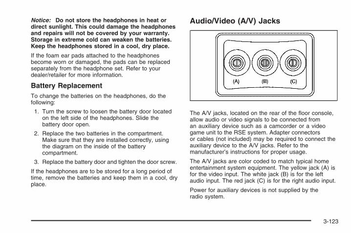
Notice: Do not store the headphones in heat ordirect sunlight. This could damage the headphonesand repairs will not be covered by your warranty.Storage in extreme cold can weaken the batteries.Keep the headphones stored in a cool, dry place.
If the foam ear pads attached to the headphonesbecome worn or damaged, the pads can be replacedseparately from the headphone set. Refer to yourdealer/retailer for more information.
Battery ReplacementTo change the batteries on the headphones, do thefollowing:
1. Turn the screw to loosen the battery door locatedon the left side of the headphones. Slide thebattery door open.
2. Replace the two batteries in the compartment.Make sure that they are installed correctly, usingthe diagram on the inside of the batterycompartment.
3. Replace the battery door and tighten the door screw.
If the headphones are to be stored for a long period oftime, remove the batteries and keep them in a cool, dryplace.
Audio/Video (A/V) Jacks
The A/V jacks, located on the rear of the floor console,allow audio or video signals to be connected froman auxiliary device such as a camcorder or a videogame unit to the RSE system. Adapter connectorsor cables (not included) may be required to connect theauxiliary device to the A/V jacks. Refer to themanufacturer’s instructions for proper usage.
The A/V jacks are color coded to match typical homeentertainment system equipment. The yellow jack (A) isfor the video input. The white jack (B) is for the leftaudio input. The red jack (C) is for the right audio input.
Power for auxiliary devices is not supplied by theradio system.
3-123

To use the auxiliary inputs of the RSE system, connectan external auxiliary device to the color-coded A/Vjacks and turn both the auxiliary device and the videoscreen power on. If the video screen is in the DVDplayer mode, pressing the AUX (auxiliary) button on theremote control switches the video screen from theDVD player mode to the auxiliary device. The radio canlisten to the audio of the connected auxiliary deviceby sourcing to auxiliary. See Radio(s) on page 3-88 formore information.
How to Change the RSE Video ScreenSettingsThe screen display mode (normal, full, and zoom),screen brightness, and setup menu language can bechanged from the on screen setup menu. To change anyfeature, do the following:
1. Press the z (display) menu button on the remotecontrol.
2. Use the remote control menu n,q,p , o(navigation) arrows and the r (enter) buttonto use the setup menu.
3. Press the z button again to remove the setupmenu from the screen.
Audio OutputAudio from the DVD player or auxiliary inputs canbe heard through the following possible sources:
• Wireless Headphones
• Vehicle Speakers
• Vehicle wired headphone jacks on the rear seataudio system, if the vehicle has this feature.
The RSE system always transmits the audio signal tothe wireless headphones, if there is audio available.See “Headphones” earlier in this section for moreinformation.
The DVD player is capable of outputting audio to thewired headphone jacks on the RSA system, if thevehicle has this feature. The DVD player can beselected as an audio source on the RSA system.See Rear Seat Audio (RSA) on page 3-130 for moreinformation.
When a device is connected to the A/V jacks, or theradio’s auxiliary input jack, if the vehicle has this feature,the rear seat passengers are able to hear audio fromthe auxiliary device through the wireless or wiredheadphones. The front seat passengers are able tolisten to playback from this device through the vehiclespeakers by selecting AUX as the source on the radio.
3-124

Video ScreenThe video screen is located in the overhead console.
To use the video screen, do the following:
1. Push the release button located on the overheadconsole.
2. Move the screen to the desired position.
When the video screen is not in use, push it up into itslocked position.
If a DVD is playing and the screen is raised to its lockedposition, the screen remains on. This is normal, andthe DVD continues to play through the previous audiosource. Use the remote control power button or eject thedisc to turn off the screen.
The overhead console contains the infrared transmittersfor the wireless headphones and the infrared receiversfor the remote control. They are located at the rearof the console.
Notice: Avoid directly touching the video screen,as damage may occur. See “Cleaning the VideoScreen” later in this section for more information.
Remote ControlTo use the remote control, aim it at the transmitterwindow at the rear of the RSE overhead console andpress the desired button. Direct sunlight or verybright light could affect the ability of the RSE transmitterto receive signals from the remote control. If theremote control does not seem to be working, thebatteries might need to be replaced. See “BatteryReplacement” later in this section. Objects blocking theline of sight could also affect the function of theremote control.
If a CD or DVD is in the Radio DVD slot, the remotecontrol O(power) button can be used to turn on thevideo screen display and start the disc. The radiocan also turn on the video screen display. See Radio(s)on page 3-88 for more information.
Notice: Storing the remote control in a hot area orin direct sunlight can damage it, and the repairswill not be covered by your warranty. Storagein extreme cold can weaken the batteries. Keep theremote control stored in a cool, dry place.
If the remote control becomes lost or damaged, a newuniversal remote control can be purchased. If thishappens, make sure the universal remote control usesa code set of Toshiba®.
3-125

Remote Control Buttons
O (Power): Press this button to turn the video screenon and off.
P (Illumination): Press this button to turn the remotecontrol backlight on. The backlight automatically timesout after seven to ten seconds if no other button ispressed while the backlight is on.
v (Title): Press this button to return the DVD to themain menu of the DVD. This function could vary foreach disc.
y (Main Menu): Press this button to access the DVDmenu. The DVD menu is different on every DVD.Use the navigation arrows to move the cursor aroundthe DVD menu. After making a selection press the enterbutton. This button only operates when using a DVD.
n, q, p, o (Menu Navigation Arrows): Use thearrow buttons to navigate through a menu.
r (Enter): Press this button to select the choice thatis highlighted in any menu.
z (Display Menu): Press this button to adjust thebrightness, screen display mode (normal, full, or zoom),and display the language menu.
q(Return): Press this button to exit the current activemenu and return to the previous menu. This buttonoperates only when the display menu or a DVD menuis active.
c(Stop): Press this button to stop playing, fastreversing, or fast forwarding a DVD. Press this buttontwice to return to the beginning of the DVD.
s (Play/Pause): Press this button to start playinga DVD. Press this button while a DVD is playing topause it. Press it again to continue playing the DVD.
3-126

While the DVD is playing, the DVD can be playedslowly by pressing the play/pause button then pressingthe fast forward button. The DVD continues playingin a slow play mode. Also, reverse can be played slowlyby pressing the play/pause button and then pressingthe fast reverse button. To cancel slow play mode,press the play/pause button.
t (Previous Track/Chapter): Press this button toreturn to the start of the current track or chapter.Press this button again to go to the previous track orchapter. This button might not work when the DVDis playing the copyright information or the previews.
u (Next Track/Chapter): Press this button to go to thebeginning of the next chapter or track. This buttonmight not work while the DVD is playing the copyrightinformation or the previews.
r(Fast Reverse): Press this button to quickly reversethe DVD or CD. To stop fast reversing a DVD video,press the play/pause button. To stop fast reversinga DVD audio or CD, release the fast reverse button.This button might not work when the DVD is playing thecopyright information or the previews.
[ (Fast Forward): Press this button to fast forwardthe DVD or CD. To stop fast forwarding a DVD video,press the play/pause button. To stop fast forwardinga DVD audio or CD, release the fast forward button.
This button might not work while the DVD is playing thecopyright information or the previews.
e(Audio): Press this button to change audio tracks onDVDs that have this feature when the DVD is playing.The format and content of this function vary for each disc.
{ (Subtitles): Press this button to turn ON/OFFsubtitles and to move through subtitle options when aDVD is playing. The format and content of this functionvary for each disc.
AUX (Auxiliary): Press this button to switch the systembetween the DVD player and an auxiliary source.
d (Camera): Press this button to change cameraangles on DVDs that have this feature while a DVD isplaying. The format and content of this function vary foreach disc.
1 through 0 (Numeric Keypad): The numeric keypadprovides the capability of direct chapter or tracknumber selection.
\ (Clear): Press this button within three seconds afterentering a numeric selection, to clear all numerical inputs.
} 10 (Double Digit Entries): Press this button toselect chapter or track numbers greater than nine.Press this button before entering the number.
3-127

Battery ReplacementTo change the remote control batteries, do the following:
1. Slide the rear cover back on the remote control.
2. Replace the two batteries in the compartment.Make sure they are installed correctly using thediagram on the inside of the remote control.
3. Replace the battery cover.
If the remote control is to be stored for a long period oftime, remove the batteries and keep them in a cool,dry place.
Problem Recommended ActionNo power. The ignition might not be
turned ON/RUN or inACC/ACCESSORY.
The picture does not fillthe screen. There areblack borders on thetop and bottom or onboth sides or it looksstretched out.
Check the display modesettings in the setup menuby pressing the displaymenu button on theremote control.
In auxiliary mode, thepicture moves or scrolls.
Check the auxiliary inputconnections at bothdevices.
Problem Recommended ActionThe remote control doesnot work.
Check to make sure thereis no obstruction betweenthe remote control andthe transmitter window.Check the batteries tomake sure they are notdead or installedincorrectly.
After stopping the player,I push Play but sometimesthe DVD starts where I leftoff and sometimes at thebeginning.
If the stop button waspressed one time, theDVD player resumesplaying where the DVDwas stopped. If the stopbutton was pressed twotimes the DVD playerbegins to play from thebeginning of the DVD.
The auxiliary source isrunning but there is nopicture or sound.
Check that the RSE videoscreen is in the auxiliarysource mode.Check the auxiliary inputconnections at bothdevices.
3-128

Problem Recommended ActionSometimes the wirelessheadphone audio cuts outor buzzes.
Check for obstructions,low batteries, receptionrange, and interferencefrom cellular telephonetowers or by using acellular telephone inthe vehicle.Check that theheadphones are oncorrectly using the L (left)and R (right) on theheadphones.
I lost the remote and/orthe headphones.
See your dealer/retailerfor assistance.
The DVD is playing, butthere is no picture orsound.
Check that the RSE videoscreen is sourced to theDVD player.
DVD Display Error MessagesThe DVD display error message depends on the radiothat is in the vehicle. The video screen can displayone of the following:
Disc Load/Eject Error: This message displays whenthere are disc load or eject problems.
Disc Format Error: This message displays, if the discis inserted with the disc label wrong side up, or ifthe disc is damaged.
Disc Region Error: This message displays, if the discis not from a correct region.
No Disc Inserted: This message displays, if no discis present when EJECT or DVD AUX is pressed onthe radio.
3-129
DVD DistortionVideo distortion can occur when operating cellularphones, scanners, CB radios, Global Position Systems(GPS)*, two-way radios, mobile fax, or walkie talkies.
It might be necessary to turn off the DVD player whenoperating one of these devices in or near the vehicle.
*Excludes the OnStar® System.
Cleaning the RSE Overhead ConsoleWhen cleaning the RSE overhead console surface, useonly a clean cloth dampened with clean water.
Cleaning the Video ScreenWhen cleaning the video screen, use only a clean clothdampened with clean water. Use care when directlytouching or cleaning the screen, as damage could result.
Rear Seat Audio (RSA)This feature lets rear seat passengers listen to andcontrol any of the music sources: radio, CDs, DVDs,or other auxiliary sources. However, the rear seatpassengers can only control the music sources the frontseat passengers are not listening to (except on someradios where dual control is allowed). For example, rearseat passengers can control and listen to a CD throughthe headphones, while the driver listens to the radiothrough the front speakers. The rear seat passengershave control of the volume for each set of headphones.
The RSA functions can be used even while the mainradio is off. The front audio system will display theheadphone icon when the RSA is on, and will disappearfrom the display when it is off.
Audio can be heard through wired headphones(not included) plugged into the jacks on the RSA.If the vehicle has this feature, audio can also beheard on Channel 2 of the wireless headphones.
Depending on the audio system, the rear speakers maycontinue to play when the RSA audio is active throughthe headphones.
3-130

To listen to an iPod or portable audio device throughthe RSA, attach the iPod or portable audio device to thefront auxiliary input (if available), located on the frontaudio system. Turn the iPod on, then choose thefront auxiliary input with the RSA SRCE button.
P(Power): Press this button to turn the RSA on or off.
Volume: Turn the volume knob to increase or todecrease the volume of the wired headphones. The leftknob controls the left headphones and the right knobcontrols the right headphones.
SRCE (Source): Press this button to switch betweenthe radio (AM/FM), XM™ (if equipped), CD, and ifthe vehicle has these features, DVD, front auxiliary,and rear auxiliary.
©¨(Seek): When listening to FM, AM, or XM™(if equipped), press the seek arrows to go to theprevious or to the next station or channels and staythere. This function is inactive, with some radios, if thefront seat passengers are listening to the radio.
Press and hold either seek arrow until the displayflashes, to tune to an individual station. The displaystops flashing after the buttons have not been pushedfor more than two seconds. This function is inactive, withsome radios, if the front seat passengers are listeningto the radio.
While listening to a disc, press the left seek arrow togo back to the start of the current track or chapter(if more than ten seconds have played). Press the rightseek arrow to go the next track or chapter on thedisc. This function is inactive, with some radios, if thefront seat passengers are listening to the disc.
While a DVD video menu is being displayed, presseither seek arrow to perform a cursor up or down on themenu. Hold either seek arrow to perform a cursor leftor right on the menu.
RSA with Rear Climate Controls shown,RSA without Rear Climate Controls similar
3-131

PROG (Program): Press this button to go to the nextpreset radio station or channel set on the mainradio. This function is inactive, with some radios, if thefront seat passengers are listening to the radio.
While a CD or DVD audio disc is playing, press thisbutton to go to the beginning of the CD or DVD audio.This function is inactive, with some radios, if thefront seat passengers are listening to the CD orDVD audio.
While a disc is playing in the CD or DVD changer, pressthis button to select the next disc, if multiple discs areloaded. This function is inactive, with some radios,if the front seat passengers are listening to the disc.
While a DVD video menu is being displayed, press thePROG button to perform the menu function, Enter.
Theft-Deterrent FeatureTHEFTLOCK® is designed to discourage theft of thevehicle’s radio. The feature works automatically bylearning a portion of the Vehicle IdentificationNumber (VIN). If the radio is moved to a differentvehicle, it does not operate and LOC, LOCK, orLOCKED could display.
With THEFTLOCK® activated, the radio does notoperate if stolen.
Audio Steering Wheel ControlsVehicles with audiosteering wheel controlscould differ depending onyour vehicle’s options.Some audio controls canbe adjusted at the steeringwheel. They include thefollowing:
xw(Next/Previous): Press the down or up arrow togo to the next or to the previous radio station storedas a favorite.
When a CD/DVD is playing, press the down or up arrowto go to the next or to the previous track or chapter.
g (Mute/Voice Recognition): Press and release thisbutton to silence the vehicle speakers only. Theaudio of the wireless and wired headphones, if yourvehicle has these features, does not mute. Press andrelease this button again, to turn the sound on.
3-132
If your vehicle has the navigation system, press andhold this button for longer than one second to initiatevoice recognition. See “Voice Recognition” in theNavigation System manual for more information.
If your vehicle has OnStar®, press and hold this buttonfor longer than one second to interact with theOnStar® system. If your vehicle also has the navigationsystem, press and hold this button for longer thanone second to initiate voice recognition and say “OnStar”to enter OnStar® mode. See the OnStar® System onpage 2-67 in this manual for more information.
SRCE (Source): Press this button to switch betweenthe radio (AM, FM), XM™ (if equipped), CD, and if yourvehicle has these features, DVD, front auxiliary, andrear auxiliary.
+ e − e (Volume): Press the plus or minus volumebutton to increase or to decrease the radio volume.
¨(Seek): Press the seek arrow to go to the nextradio station while in AM, FM, or XM™ (if equipped).Press the seek arrow to go to the next track or chapterwhile sourced to the CD or DVD slot.
Press the seek arrow to go to the next disc whilesourced to a six-disc CD player, if multiple discsare loaded.
Radio ReceptionFrequency interference and static can occur duringnormal radio reception if items such as cell phonechargers, vehicle convenience accessories, and externalelectronic devices are plugged into the accessorypower outlet. If there is interference or static, unplug theitem from the accessory power outlet.
AMThe range for most AM stations is greater than for FM,especially at night. The longer range can causestation frequencies to interfere with each other.For better radio reception, most AM radio stationsboost the power levels during the day, and then reducethese levels during the night. Static can also occurwhen things like storms and power lines interfere withradio reception. When this happens, try reducingthe treble on the radio.
FM StereoFM stereo gives the best sound, but FM signals onlyreach about 10 to 40 miles (16 to 65 km). Tall buildingsor hills can interfere with FM signals, causing thesound to fade in and out.
3-133
XM™ Satellite Radio ServiceXM™ Satellite Radio Service gives digital radioreception from coast-to-coast in the 48 contiguousUnited States, and in Canada. Just as with FM,tall buildings or hills can interfere with satellite radiosignals, causing the sound to fade in and out. Inaddition, traveling or standing under heavy foliage,bridges, garages, or through tunnels could cause loss ofthe XM signal for a period of time. The radio maydisplay NO XM SIGNAL to indicate interference.
Fixed Mast AntennaThe fixed mast antenna can withstand most car washeswithout being damaged. If the mast should everbecome slightly bent, straighten it out by hand. If themast is badly bent, replace it.
Check occasionally to make sure the mast is stilltightened to its base. If tightening is required, tighten byhand, then with a wrench one quarter turn.
XM™ Satellite Radio AntennaSystemThe XM™ Satellite Radio antenna is located on the roofof the vehicle. Keep this antenna clear of snow andice build up for clear radio reception.
If the vehicle has a sunroof, the performance of theXM™ system may be affected if the sunroof is open.
Loading items onto the roof of the vehicle can interferewith the performance of the XM™ system. Makesure the XM™ Satellite Radio antenna is not obstructed.
3-134

Your Driving, the Road, and Your Vehicle ..........4-2Defensive Driving ...........................................4-2Drunk Driving .................................................4-2Control of a Vehicle ........................................4-3Braking .........................................................4-3Antilock Brake System (ABS) ...........................4-4Braking in Emergencies ...................................4-5Locking Rear Axle ..........................................4-5StabiliTrak® System ........................................4-6Steering ........................................................4-8Off-Road Recovery .......................................4-10Passing .......................................................4-11Loss of Control .............................................4-11Off-Road Driving ...........................................4-12Driving at Night ............................................4-27Driving in Rain and on Wet Roads ..................4-28Before Leaving on a Long Trip .......................4-29
Highway Hypnosis ........................................4-29Hill and Mountain Roads ................................4-30Winter Driving ..............................................4-31If Your Vehicle is Stuck in Sand, Mud,
Ice, or Snow .............................................4-34Rocking Your Vehicle to Get It Out .................4-34Recovery Hooks ...........................................4-35Loading Your Vehicle ....................................4-36Adding a Snow Plow or Similar Equipment .......4-43Truck-Camper Loading Information ..................4-47Pickup Conversion to Chassis Cab ..................4-50
Towing ..........................................................4-50Towing Your Vehicle .....................................4-50Recreational Vehicle Towing ...........................4-50Towing a Trailer ...........................................4-55Trailer Recommendations ...............................4-93
Section 4 Driving Your Vehicle
4-1

Your Driving, the Road, andYour Vehicle
Defensive DrivingDefensive driving means “always expect theunexpected.” The first step in driving defensively is towear your safety belt — See Safety Belts: They Are forEveryone on page 1-14.
{CAUTION:
Assume that other road users (pedestrians,bicyclists, and other drivers) are going to becareless and make mistakes. Anticipate whatthey might do and be ready. In addition:
• Allow enough following distance betweenyou and the driver in front of you.
• Focus on the task of driving.
Driver distraction can cause collisionsresulting in injury or possible death. Thesesimple defensive driving techniques couldsave your life.
Drunk Driving
{CAUTION:
Drinking and then driving is very dangerous.Your reflexes, perceptions, attentiveness, andjudgment can be affected by even a smallamount of alcohol. You can have a serious — oreven fatal — collision if you drive after drinking.Do not drink and drive or ride with a driver whohas been drinking. Ride home in a cab; or if youare with a group, designate a driver who willnot drink.
Death and injury associated with drinking and driving isa global tragedy.
Alcohol affects four things that anyone needs to drive avehicle: judgment, muscular coordination, vision, andattentiveness.
Police records show that almost 40 percent of all motorvehicle-related deaths involve alcohol. In most cases,these deaths are the result of someone who was drinkingand driving. In recent years, more than 17,000 annualmotor vehicle-related deaths have been associated withthe use of alcohol, with about 250,000 people injured.
4-2

For persons under 21, it is against the law in everyU.S. state to drink alcohol. There are good medical,psychological, and developmental reasons forthese laws.
The obvious way to eliminate the leading highwaysafety problem is for people never to drink alcohol andthen drive.
Medical research shows that alcohol in a person’ssystem can make crash injuries worse, especiallyinjuries to the brain, spinal cord, or heart. This meansthat when anyone who has been drinking — driveror passenger — is in a crash, that person’s chance ofbeing killed or permanently disabled is higher than if theperson had not been drinking.
Control of a VehicleThe following three systems help to control your vehiclewhile driving — brakes, steering, and accelerator. Attimes, as when driving on snow or ice, it is easy to askmore of those control systems than the tires androad can provide. Meaning, you can lose control of yourvehicle. See StabiliTrak® System on page 4-6.
Adding non-dealer/non-retailer accessories can affectyour vehicle’s performance. See Accessories andModifications on page 5-4.
BrakingSee Brake System Warning Light on page 3-46.
Braking action involves perception time and reactiontime. First, you have to decide to push on the brakepedal. That is perception time. Then you have to bringup your foot and do it. That is reaction time.
Average reaction time is about three-fourths of asecond. But that is only an average. It might be lesswith one driver and as long as two or three seconds ormore with another. Age, physical condition, alertness,coordination, and eyesight all play a part. So do alcohol,drugs, and frustration. But even in three-fourths of asecond, a vehicle moving at 60 mph (100 km/h) travels66 feet (20 m). That could be a lot of distance in anemergency, so keeping enough space betweenyour vehicle and others is important.
And, of course, actual stopping distances vary greatlywith the surface of the road, whether it is pavement orgravel; the condition of the road, whether it is wet, dry, oricy; tire tread; the condition of the brakes; the weight ofthe vehicle; and the amount of brake force applied.
4-3

Avoid needless heavy braking. Some people drive inspurts — heavy acceleration followed by heavybraking — rather than keeping pace with traffic. This is amistake. The brakes might not have time to cool betweenhard stops. The brakes will wear out much faster if you doa lot of heavy braking. If you keep pace with the trafficand allow realistic following distances, you will eliminate alot of unnecessary braking. That means better brakingand longer brake life.
If your vehicle’s engine ever stops while you are driving,brake normally but do not pump the brakes. If you do,the pedal could get harder to push down. If theengine stops, you will still have some power brakeassist. But you will use it when you brake. Once thepower assist is used up, it can take longer to stop andthe brake pedal will be harder to push.
Adding non-dealer/non-retailer accessories can affectyour vehicle’s performance. See Accessories andModifications on page 5-4.
Antilock Brake System (ABS)Your vehicle has the Antilock Brake System (ABS),an advanced electronic braking system that willhelp prevent a braking skid.
When you start the engine and begin to drive away,ABS will check itself. You might hear a momentarymotor or clicking noise while this test is going on.This is normal.
If there is a problem withABS, this warning light willstay on. See Anti-lockBrake System (ABS)Warning Light onpage 3-47.
Along with ABS, your vehicle has a Dynamic RearProportioning (DRP) system. If there is a DRP problem,both the brake and ABS warning lights come onaccompanied by a 10-second chime. The lights andchime will come on each time the ignition is turned onuntil the problem is repaired. See your dealer/retailerfor service.
4-4

Let us say the road is wet and you are driving safely.Suddenly, an animal jumps out in front of you. You slamon the brakes and continue braking. Here is whathappens with ABS:
A computer senses that wheels are slowing down. Ifone of the wheels is about to stop rolling, the computerwill separately work the brakes at each front wheeland at both rear wheels.
ABS can change the brake pressure faster than anydriver could. The computer is programmed to make themost of available tire and road conditions. This canhelp you steer around the obstacle while braking hard.
As you brake, the computer keeps receiving updates onwheel speed and controls braking pressure accordingly.
Remember: ABS does not change the time you need toget your foot up to the brake pedal or always decreasestopping distance. If you get too close to the vehiclein front of you, you will not have time to apply the brakesif that vehicle suddenly slows or stops. Always leaveenough room up ahead to stop, even though youhave ABS.
Using ABSDo not pump the brakes. Just hold the brake pedaldown firmly and let antilock work for you. You mightfeel the brakes vibrate or notice some noise, but thisis normal.
Braking in EmergenciesWith ABS, you can steer and brake at the same time. Inmany emergencies, steering can help you more thaneven the very best braking.
Locking Rear AxleIf your vehicle has this feature, your locking rear axlecan give you additional traction on snow, mud, ice, sandor gravel. It works like a standard axle most of thetime, but when one of the rear wheels has no tractionand the other does, this feature will allow the wheel withtraction to move the vehicle.
4-5

StabiliTrak® SystemYour vehicle may have the StabiliTrak® system whichcombines antilock brake, traction and stability controlsystems and helps the driver maintain directional controlof the vehicle in most driving conditions.
When you first start your vehicle and begin to drive away,the system performs several diagnostic checks to ensurethere are no problems. You may hear or feel the systemworking. This is normal and does not mean there is aproblem with your vehicle. The system should initializebefore the vehicle reaches 20 mph (32 km/h). In somecases, it may take approximately two miles of drivingbefore the system initializes.
If the system fails to turn on or activate, the StabiliTrak®
light along with one of the following messages will bedisplayed on the Driver Information Center (DIC):TRACTION CONTROL OFF, SERVICE TRACTIONCONTROL, STABILITRAK OFF, SERVICESTABILITRAK. If these DIC messages appear, makesure the StabiliTrak® system has not been turnedoff using the StabiliTrak® on/off button.
Then turn the steering wheel clockwise from the nineo’clock position to the three o’clock position. If this clearsthe message(s), your vehicle does not need servicing. Ifthis does not clear the message(s), then turn the vehicleoff, wait 15 seconds, and then turn it back on again toreset the system. If any of these messages still appear onthe Driver Information Center (DIC), your vehicle shouldbe taken in for service. For more information on the DICmessages, see Driver Information Center (DIC) onpage 3-56.
The StabiliTrak® light willflash on the instrumentpanel cluster whenthe system is both on andactivated.
You may also feel or hear the system working; this isnormal.
4-6

The traction control disablebutton is located on theinstrument panel below theclimate controls.
The traction control part of StabiliTrak® can be turnedoff by pressing and releasing the StabiliTrak® buttonif both systems (traction control and StabiliTrak®) werepreviously on. To disable both traction control andStabiliTrak®, press and hold the button for five seconds.
Traction control and StabiliTrak® can be turned on bypressing and releasing the StabiliTrak® button ifnot automatically shut off for any other reason.
When the TCS or StabiliTrak® system is turned off, theStabiliTrak® light and the appropriate TCS off orStabiliTrak® off message will be displayed on the DIC towarn the driver. Your vehicle will still have brake-tractioncontrol when traction control is off, but will not beable to use the engine speed management system. See“Traction Control Operation” next for more information.
When the traction control system has been turnedoff, you may still hear system noises as a result of thebrake-traction control coming on.
It is recommended to leave the system on for normaldriving conditions, but it may be necessary to turn thesystem off if your vehicle is stuck in sand, mud, ice orsnow, and you want to “rock” your vehicle to attempt tofree it. It may also be necessary to turn off the systemwhen driving in extreme off-road conditions where highwheel spin is required. See If Your Vehicle is Stuck inSand, Mud, Ice, or Snow on page 4-34.
When the transfer case is in 4LO, the stability system isautomatically disabled, the StabiliTrak® light will comeon and the STABILITRAK OFF message will appear onthe DIC. Both traction control and StabiliTrak® areautomatically disabled in this condition.
Traction Control OperationThe traction control system is part of the StabiliTrak®
system. Traction control limits wheel spin by reducingengine power to the wheels (engine speedmanagement) and by applying brakes to each individualwheel (brake-traction control) as necessary.
The traction control system is enabled automaticallywhen you start your vehicle. It will activate and theStabiliTrak® light will flash if it senses that any of thewheels are spinning or beginning to lose traction whiledriving. If you turn off traction control, only thebrake-traction control portion of traction control willwork. The engine speed management will be disabled.
4-7

In this mode, engine power is not reduced automaticallyand the driven wheels can spin more freely. This cancause the brake-traction control to activate constantly.
Notice: If you allow the wheel(s) of one axle to spinexcessively while the StabiliTrak®, ABS and brakewarning lights and the SERVICE STABILITRAKmessage are displayed, you could damage thetransfer case. The repairs would not be covered byyour warranty. Reduce engine power and do notspin the wheel(s) excessively while these lights andthis message are displayed.
The traction control system may activate on dry orrough roads or under conditions such as heavyacceleration while turning or abrupt upshifts/downshiftsof the transmission. When this happens, you maynotice a reduction in acceleration, or may hear a noiseor vibration. This is normal.
If your vehicle is in cruise control when the systemactivates, the StabiliTrak® light will flash and the cruisecontrol will automatically disengage. When roadconditions allow you to use cruise again, you mayre-engage the cruise control. See Cruise Control onpage 3-13.
StabiliTrak® may also turn off automatically if itdetermines that a problem exists with the system. If theproblem does not clear itself after restarting thevehicle, you should see your dealer/retailer for service.
Steering
Power SteeringIf you lose power steering assist because the enginestops or the system is not functioning, you can steer butit will take much more effort.
Steering TipsIt is important to take curves at a reasonable speed.
A lot of the “driver lost control” accidents mentioned onthe news happen on curves. Here is why:
Experienced driver or beginner, each of us is subject tothe same laws of physics when driving on curves.The traction of the tires against the road surface makesit possible for the vehicle to change its path whenyou turn the front wheels. If there is no traction, inertiawill keep the vehicle going in the same direction. Ifyou have ever tried to steer a vehicle on wet ice, youwill understand this.
Traction in a curve depends on the condition of the tiresand the road surface, the angle at which the curve isbanked, and your speed. While in a curve, speed is theone factor you can control.
4-8

Suppose you are steering through a sharp curve. Thenyou suddenly accelerate. Both control systems —steering and acceleration — have to do their work wherethe tires meet the road. Adding the sudden accelerationcan demand too much of those places. You can losecontrol. See StabiliTrak® System on page 4-6.
What should you do if this ever happens? Ease up onthe accelerator pedal, steer the vehicle the way youwant it to go, and slow down.
Speed limit signs near curves warn that you shouldadjust your speed. Of course, the posted speedsare based on good weather and road conditions. Underless favorable conditions you will want to go slower.
If you need to reduce speed when approaching a curve,do it before you enter the curve, while the frontwheels are straight ahead.
Try to adjust the speed so you can drive through thecurve. Maintain a reasonable, steady speed. Waitto accelerate until you are out of the curve, and thenaccelerate gently into the straightaway.
Adding non-dealer/non-retailer accessories can affectyour vehicle’s performance. See Accessories andModifications on page 5-4.
Steering in EmergenciesThere are times when steering can be more effectivethan braking. For example, you come over a hill and finda truck stopped in your lane, or a car suddenly pullsout from nowhere, or a child darts out from betweenparked cars and stops right in front of you. Youcan avoid these problems by braking — if you can stopin time. But sometimes you cannot; there is not room.That is the time for evasive action — steering around theproblem.
Your vehicle can perform very well in emergencies likethese. First, apply the brakes. See Braking onpage 4-3. It is better to remove as much speed as youcan from a possible collision. Then steer around theproblem, to the left or right depending on the spaceavailable.
4-9
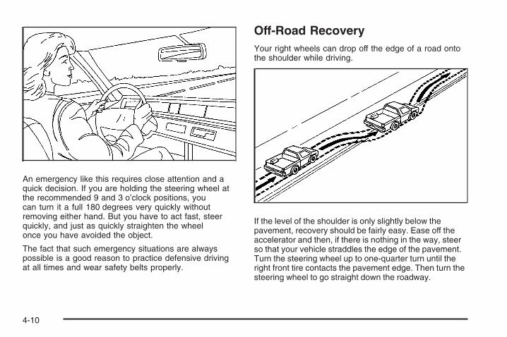
An emergency like this requires close attention and aquick decision. If you are holding the steering wheel atthe recommended 9 and 3 o’clock positions, youcan turn it a full 180 degrees very quickly withoutremoving either hand. But you have to act fast, steerquickly, and just as quickly straighten the wheelonce you have avoided the object.
The fact that such emergency situations are alwayspossible is a good reason to practice defensive drivingat all times and wear safety belts properly.
Off-Road RecoveryYour right wheels can drop off the edge of a road ontothe shoulder while driving.
If the level of the shoulder is only slightly below thepavement, recovery should be fairly easy. Ease off theaccelerator and then, if there is nothing in the way, steerso that your vehicle straddles the edge of the pavement.Turn the steering wheel up to one-quarter turn until theright front tire contacts the pavement edge. Then turn thesteering wheel to go straight down the roadway.
4-10

PassingPassing another vehicle on a two-lane road can bedangerous. To reduce the risk of danger while passing:
• Look down the road, to the sides, and to crossroadsfor situations that might affect a successful pass. Ifin doubt, wait.
• Watch for traffic signs, pavement markings, andlines that could indicate a turn or an intersection.Never cross a solid or double-solid line on your sideof the lane.
• Do not get too close to the vehicle you want topass. Doing so can reduce your visibility.
• Wait your turn to pass a slow vehicle.
• When you are being passed, ease to the right.
Loss of ControlLet us review what driving experts say about whathappens when the three control systems — brakes,steering, and acceleration — do not have enough frictionwhere the tires meet the road to do what the driver hasasked.
In any emergency, do not give up. Keep trying to steerand constantly seek an escape route or area of lessdanger.
SkiddingIn a skid, a driver can lose control of the vehicle.Defensive drivers avoid most skids by taking reasonablecare suited to existing conditions, and by not overdrivingthose conditions. But skids are always possible.
The three types of skids correspond to your vehicle’sthree control systems. In the braking skid, the wheels arenot rolling. In the steering or cornering skid, too muchspeed or steering in a curve causes tires to slip and losecornering force. And in the acceleration skid, too muchthrottle causes the driving wheels to spin.
A cornering skid is best handled by easing your foot offthe accelerator pedal.
Remember: StabiliTrak® helps avoid only theacceleration skid. See StabiliTrak® System on page 4-6.If the StabiliTrak® System is off, then an accelerationskid is also best handled by easing your foot offthe accelerator pedal.
If your vehicle starts to slide, ease your foot off theaccelerator pedal and quickly steer the way you wantthe vehicle to go. If you start steering quickly enough,your vehicle may straighten out. Always be readyfor a second skid if it occurs.
4-11

Of course, traction is reduced when water, snow, ice,gravel, or other material is on the road. For safety, youwill want to slow down and adjust your driving tothese conditions. It is important to slow down on slipperysurfaces because stopping distance will be longer andvehicle control more limited.
While driving on a surface with reduced traction, try yourbest to avoid sudden steering, acceleration, or braking,including reducing vehicle speed by shifting to a lowergear. Any sudden changes could cause the tires to slide.You may not realize the surface is slippery until yourvehicle is skidding. Learn to recognize warningclues —such as enough water, ice, or packed snow onthe road to make a mirrored surface — and slow downwhen you have any doubt.
Remember: Any Antilock Brake System (ABS) helpsavoid only the braking skid.
Off-Road DrivingThis off-road guide is for vehicles that have four-wheeldrive. Also, see Braking on page 4-3. If your vehicledoes not have four-wheel drive or is equipped with20-inch tire/wheel assemblies, you should not driveoff-road unless you are on a level, solid surface.
The airbag system is designed to work properly under awide range of conditions, including off-road usage.Observe safe driving speeds, especially on roughterrain. As always, wear your safety belt.
Off-road driving can be great fun. But it does havesome definite hazards. The greatest of these isthe terrain itself.
“Off-roading” means you have left the great NorthAmerican road system behind. Traffic lanes are notmarked. Curves are not banked. There are noroad signs. Surfaces can be slippery, rough, uphill, ordownhill. In short, you have gone right back to nature.
Off-road driving involves some new skills. And thatis why it is very important that you read this guide. Youwill find many driving tips and suggestions. Thesewill help make your off-road driving safer and moreenjoyable.
4-12

If you think you will need some more ground clearanceat the front of your vehicle, you can remove the frontfascia lower air dam.
The front fascia lower air dam is held in place by twobolts and 10 snap features. The bolts and snap featuresare accessible from underneath the front fascia.
The following steps must be performed on the bolts andsnap features to remove the air dam:
1. Remove the two outboard air dam bolts.
2. With a flat-blade screwdriver, push down on thesnap features and disengage the snaps.
3. After the bolts are removed and the snaps aredisengaged, push forward on the air dam until itis free.
When you are back on roads, though, be sure toreplace the air dam.
Notice: Operating your vehicle for extendedperiods without the front fascia lower air daminstalled can cause improper air flow to the engine.Always be sure to replace the front fascia airdam when you are finished off-road driving.
To reinstall the lower air dam do the following:
1. Line up the snap features and push the air damrearward to engage the snaps.
2. Install the two outboard bolts.
Before You Go Off-RoadingThere are some things to do before you go out. Forexample, be sure to have all necessary maintenanceand service work done. Check to make sure allunderbody shields, if the vehicle has them, are properlyattached. Be sure you read all the information aboutyour four-wheel-drive vehicle in this manual. Isthere enough fuel? Is the spare tire fully inflated? Arethe fluid levels up where they should be? What are thelocal laws that apply to off-roading where you will bedriving? If you do not know, you should check with lawenforcement people in the area. Will you be onsomeone’s private land? If so, be sure to get thenecessary permission.
4-13

Loading Your Vehicle for Off-RoadDriving
{CAUTION:
• Cargo on the load floor piled higher thanthe seatbacks can be thrown forwardduring a sudden stop. You or yourpassengers could be injured. Keep cargobelow the top of the seatbacks.
• Unsecured cargo on the load floor can betossed about when driving over roughterrain. You or your passengers can bestruck by flying objects. Secure the cargoproperly.
• Heavy loads on the roof raise the vehicle’scenter of gravity, making it more likely toroll over. You can be seriously or fatallyinjured if the vehicle rolls over. Put heavyloads inside the cargo area, not on theroof. Keep cargo in the cargo area as farforward and low as possible.
There are some important things to remember abouthow to load your vehicle.
• The heaviest things should be on the load floor andforward of the rear axle. Put heavier items as farforward as you can.
• Be sure the load is secured properly, so driving onthe off-road terrain does not toss things around.
You will find other important information in this manual.See Loading Your Vehicle on page 4-36 and Tireson page 5-68.
4-14
Environmental ConcernsOff-road driving can provide wholesome and satisfyingrecreation. However, it also raises environmentalconcerns. We recognize these concerns and urge everyoff-roader to follow these basic rules for protectingthe environment:
• Always use established trails, roads, and areas thathave been specially set aside for public off-roadrecreational driving; obey all posted regulations.
• Avoid any driving practice that could damage theenvironment — shrubs, flowers, trees, grasses — ordisturb wildlife. This includes wheel-spinning,breaking down trees, or unnecessary driving throughstreams or over soft ground.
• Always carry a litter bag — make sure all refuse isremoved from any campsite before leaving.
• Take extreme care with open fires where permitted,camp stoves, and lanterns.
• Never park your vehicle over dry grass or othercombustible materials that could catch fire from theheat of the vehicle’s exhaust system.
Traveling to Remote AreasIt makes sense to plan your trip, especially when goingto a remote area. Know the terrain and plan yourroute. You are much less likely to get bad surprises.Get accurate maps of trails and terrain. Try to learn ofany blocked or closed roads.
It is also a good idea to travel with at least one othervehicle. If something happens to one of them, the othercan help quickly.
Does your vehicle have a winch? If so, be sure to readthe winch instructions. In a remote area, a winchcan be handy if you get stuck. But you will want to knowhow to use it properly.
Getting Familiar with Off-Road DrivingIt is a good idea to practice in an area that is safeand close to home before you go into the wilderness.Off-road driving does require some new and differentdriving skills. Here is what we mean.
Tune your senses to different kinds of signals. Youreyes, for example, need to constantly sweep the terrainfor unexpected obstacles. Your ears need to listenfor unusual tire or engine sounds. With your arms,hands, feet, and body, you will need to respond tovibrations and vehicle bounce.
4-15

Controlling your vehicle is the key to successful off-roaddriving. One of the best ways to control your vehicleis to control your speed. Here are some things to keepin mind. At higher speeds:
• You approach things faster and you have less timeto scan the terrain for obstacles.
• You have less time to react.
• You have more vehicle bounce when you drive overobstacles.
• You will need more distance for braking, especiallysince you are on an unpaved surface.
{CAUTION:
When you are driving off-road, bouncing andquick changes in direction can easily throwyou out of position. This could cause you tolose control and crash. So, whether you aredriving on or off the road, you and yourpassengers should wear safety belts.
Scanning the TerrainOff-road driving can take you over many different kinds ofterrain. You need to be familiar with the terrain and itsmany different features. Here are some things toconsider.
Surface Conditions: Off-roading can take you overhard-packed dirt, gravel, rocks, grass, sand, mud, snow,or ice. Each of these surfaces affects the steering,acceleration, and braking of your vehicle in differentways. Depending upon the kind of surface you are on,you may experience slipping, sliding, wheel spinning,delayed acceleration, poor traction, and longer brakingdistances.
Surface Obstacles: Unseen or hidden obstacles canbe hazardous. A rock, log, hole, rut, or bump can startleyou if you are not prepared for them. Often theseobstacles are hidden by grass, bushes, snow, or eventhe rise and fall of the terrain itself. Here are somethings to consider:
• Is the path ahead clear?
• Will the surface texture change abruptly up ahead?
• Does the travel take you uphill or downhill?There is more discussion of these subjects later.
• Will you have to stop suddenly or change directionquickly?
4-16
When you drive over obstacles or rough terrain, keep afirm grip on the steering wheel. Ruts, troughs, orother surface features can jerk the wheel out of yourhands if you are not prepared.
When you drive over bumps, rocks, or other obstacles,the wheels can leave the ground. If this happens,even with one or two wheels, you cannot control thevehicle as well or at all.
Because you will be on an unpaved surface, it isespecially important to avoid sudden acceleration,sudden turns, or sudden braking.
In a way, off-road driving requires a different kind ofalertness from driving on paved roads and highways.There are no road signs, posted speed limits, or signallights. You have to use your own good judgmentabout what is safe and what is not.
Drinking and driving can be very dangerous on anyroad. And this is certainly true for off-road driving. At thevery time you need special alertness and drivingskills, your reflexes, perceptions, and judgment can beaffected by even a small amount of alcohol. Youcould have a serious — or even fatal — accident if youdrink and drive or ride with a driver who has beendrinking. See Drunk Driving on page 4-2.
Driving on Off-Road HillsOff-road driving often takes you up, down, or across ahill. Driving safely on hills requires good judgmentand an understanding of what your vehicle can andcannot do. There are some hills that simply cannot bedriven, no matter how well built the vehicle.
{CAUTION:
Many hills are simply too steep for any vehicle.If you drive up them, you will stall. If you drivedown them, you cannot control your speed. Ifyou drive across them, you will roll over. Youcould be seriously injured or killed. If you haveany doubt about the steepness, do not drivethe hill.
4-17

Approaching a HillWhen you approach a hill, you need to decide if it is oneof those hills that is just too steep to climb, descend, orcross. Steepness can be hard to judge. On a very smallhill, for example, there may be a smooth, constant inclinewith only a small change in elevation where you caneasily see all the way to the top. On a large hill, the inclinemay get steeper as you near the top, but you may not seethis because the crest of the hill is hidden by bushes,grass or shrubs.
Here are some other things to consider as you approacha hill.
• Is there a constant incline, or does the hill getsharply steeper in places?
• Is there good traction on the hillside, or will thesurface cause tire slipping?
• Is there a straight path up or down the hill so youwill not have to make turning maneuvers?
• Are there obstructions on the hill that can block yourpath, such as boulders, trees, logs, or ruts?
• What is beyond the hill? Is there a cliff, anembankment, a drop-off, a fence? Get out and walkthe hill if you do not know. It is the smart way tofind out.
• Is the hill simply too rough? Steep hills often haveruts, gullies, troughs, and exposed rocks becausethey are more susceptible to the effects of erosion.
4-18

Driving UphillOnce you decide you can safely drive up the hill, youneed to take some special steps.
• Use a low gear and get a firm grip on the steeringwheel.
• Get a smooth start up the hill and try to maintainyour speed. Do not use more power than youneed, because you do not want the wheels to startspinning or sliding.
{CAUTION:
Turning or driving across steep hills can bedangerous. You could lose traction, slidesideways, and possibly roll over. You could beseriously injured or killed. When driving uphills, always try to go straight up.
• Try to drive straight up the hill if at all possible. Ifthe path twists and turns, you might want to findanother route.
• Ease up on your speed as you approach the top ofthe hill.
• Attach a flag to the vehicle to make you morevisible to approaching traffic on trails or hills.
• Sound the horn as you approach the top of the hillto let opposing traffic know you are there.
• Use your headlamps even during the day. Theymake your vehicle more visible to oncomingtraffic.
{CAUTION:
Driving to the top (crest) of a hill at full speedcan cause an accident. There could be adrop-off, embankment, cliff, or even anothervehicle. You could be seriously injured orkilled. As you near the top of a hill, slow downand stay alert.
4-19

There are some things you should do if the vehicle stalls,or is about to stall, and you cannot make it up the hill:
• Push the brake pedal to stop the vehicle and keep itfrom rolling backwards. Also, apply the parkingbrake.
• If the engine is still running, shift the transmission toREVERSE (R), release the parking brake, and slowlyback down the hill in REVERSE (R).
• If the engine has stopped running, you will need torestart it. With the brake pedal pressed and theparking brake still applied, shift the transmission toPARK (P) and restart the engine. Then, shift toREVERSE (R), release the parking brake, and slowlyback down the hill as straight as possible inREVERSE (R).
• As you are backing down the hill, put your left handon the steering wheel at the 12 o’clock position. Thisway, you will be able to tell if the wheels are straightand maneuver as you back down. It is best that youback down the hill with the wheels straight ratherthan in the left or right direction. Turning the wheeltoo far to the left or right will increase the possibilityof a rollover.
There are also some things you must not do if you stall,or are about to stall, when going up a hill:
• Never attempt to prevent a stall by shifting intoNEUTRAL (N) to rev-up the engine and regainforward momentum. This will not work. Your vehiclewill roll backwards very quickly and you could goout of control.
Instead, apply the regular brake to stop the vehicle.Then apply the parking brake. Shift to REVERSE (R),release the parking brake, and slowly backstraight down.
• Never attempt to turn around if you are about tostall when going up a hill. If the hill is steepenough to stall your vehicle, it is steep enough tocause you to roll over if you turn around. If youcannot make it up the hill, you must back straightdown the hill.
4-20

If, after stalling, you try to back down the hill and decideyou just cannot do it, set the parking brake, put thetransmission in PARK (P) and turn off the engine. Leavethe vehicle and go get some help. Exit on the uphill sideand stay clear of the path the vehicle would take if it rolleddownhill. Do not shift the transfer case to NEUTRALwhen you leave the vehicle. Leave it in some gear.
{CAUTION:
Shifting the transfer case to NEUTRAL cancause your vehicle to roll even if thetransmission is in PARK (P). This is because theNEUTRAL position on the transfer caseoverrides the transmission. You or someoneelse could be injured. If you are going to leaveyour vehicle, set the parking brake and shift thetransmission to PARK (P). But do not shift thetransfer case to NEUTRAL. Leave the transfercase in the Two-Wheel High, Four-Wheel Highor Four-Wheel Low position.
Driving DownhillWhen off-roading takes you downhill, you will want toconsider a number of things:
• How steep is the downhill? Will I be able to maintainvehicle control?
• What is the surface like? Smooth? Rough?Slippery? Hard-packed dirt? Gravel?
• Are there hidden surface obstacles? Ruts? Logs?Boulders?
• What is at the bottom of the hill? Is there a hiddencreek bank or even a river bottom with large rocks?
4-21
If you decide you can go down a hill safely, then try tokeep your vehicle headed straight down, and use alow gear. This way, engine drag can help the brakes andthey will not have to do all the work. Descend slowly,keeping your vehicle under control at all times.
{CAUTION:
Heavy braking when going down a hill cancause your brakes to overheat and fade. Thiscould cause loss of control and a seriousaccident. Apply the brakes lightly whendescending a hill and use a low gear to keepvehicle speed under control.
There some things not to do when driving down a hill.These are important because, if you ignore them,you could lose control and have a serious accident:
• When driving downhill, avoid turns that takeyou across the incline of the hill. A hill that is nottoo steep to drive down may be too steep todrive across. You could roll over if you do not drivestraight down.
• Never go downhill with the transmission inNEUTRAL (N). This is called “free-wheeling.”The brakes will have to do all the work and couldoverheat and fade.
Your vehicle is much more likely to stall when goinguphill. But if it happens when going downhill:
1. Stop your vehicle by applying the regular brakes.Apply the parking brake.
2. Shift to PARK (P) and, while still braking, restart theengine.
3. Shift back to a low gear, release the parking brake,and drive straight down.
4. If the engine will not start, get out and get help.
4-22

Driving Across an InclineSooner or later, an off-road trail will probably go acrossthe incline of a hill. If this happens, you have todecide whether to try to drive across the incline. Hereare some things to consider:
{CAUTION:
Driving across an incline that is too steep willmake your vehicle roll over. You could beseriously injured or killed. If you have anydoubt about the steepness of the incline, donot drive across it. Find another route instead.
• A hill that can be driven straight up or down may betoo steep to drive across. When you go straight upor down a hill, the length of the wheel base — thedistance from the front wheels to the rearwheels — reduces the likelihood the vehicle willtumble end over end. But when you drive across anincline, the much more narrow track width — thedistance between the left and right wheels — maynot prevent the vehicle from tilting and rolling over.Also, driving across an incline puts more weight onthe downhill wheels. This could cause a downhillslide or a rollover.
• Surface conditions can be a problem when you driveacross a hill. Loose gravel, muddy spots, or even wetgrass can cause your tires to slip sideways, downhill.If the vehicle slips sideways, it can hit something thatwill trip it — a rock, a rut, etc. — and roll over.
• Hidden obstacles can make the steepness of theincline even worse. If you drive across a rock with theuphill wheels, or if the downhill wheels drop into a rutor depression, your vehicle can tilt even more.
For reasons like these, you need to decide carefullywhether to try to drive across an incline. Just because thetrail goes across the incline does not mean you have todrive it. The last vehicle to try it might have rolled over.
When driving across an incline that is not too steep,the vehicle can hit some loose gravel and start to slidedownhill. If you feel your vehicle starting to slidesideways, turn downhill. This should help straighten outthe vehicle and prevent the side slipping. However,a much better way to prevent this is to get out and“walk the course” so you know what the surface is likebefore you drive it.
4-23

Stalling on an Incline
{CAUTION:
Getting out on the downhill (low) side of avehicle stopped across an incline isdangerous. If the vehicle rolls over, you couldbe crushed or killed. Always get out on theuphill (high) side of the vehicle and stay wellclear of the rollover path.
If your vehicle stalls when you are crossing an incline,be sure you, and any passengers, get out on theuphill side, even if the door there is harder to open.If you get out on the downhill side and the vehicle startsto roll over, you will be right in its path.
If you have to walk down the slope, stay out of the paththe vehicle will take if it does roll over.
4-24
Driving in Mud, Sand, Snow, or IceWhen you drive in mud, snow, or sand, your wheels willnot get good traction. You cannot accelerate asquickly, turning is more difficult, and you will need longerbraking distances. If your vehicle has four-wheeldrive, see Four-Wheel Drive on page 2-36 for transfercase mode selection.
It is best to use a low gear when you are in mud — thedeeper the mud, the lower the gear. In really deep mud,the idea is to keep your vehicle moving so you donot get stuck.
When you drive on sand, you will sense a change inwheel traction. But it will depend upon how looselypacked the sand is. On loosely packed sand, such ason beaches or sand dunes, your tires will tend tosink into the sand. This has an effect on steering,accelerating, and braking. Drive at a reduced speed andavoid sharp turns or abrupt maneuvers.
Hard packed snow and ice offer the worst tire traction.On these surfaces, it is very easy to lose control.On wet ice, for example, the traction is so poor that youwill have difficulty accelerating. And if you do getmoving, poor steering and difficult braking can causeyou to slide out of control.
{CAUTION:
Driving on frozen lakes, ponds, or rivers canbe dangerous. Underwater springs, currentsunder the ice, or sudden thaws can weakenthe ice. Your vehicle could fall through the iceand you and your passengers could drown.Drive your vehicle on safe surfaces only.
4-25

Driving in Water
{CAUTION:
Driving through rushing water can bedangerous. Deep water can sweep your vehicledownstream and you and your passengerscould drown. If it is only shallow water, it canstill wash away the ground from under yourtires, and you could lose traction and roll thevehicle over. Do not drive through rushingwater.
Heavy rain can mean flash flooding, and flood watersdemand extreme caution.
Find out how deep the water is before you drive throughit. If it is deep enough to cover the wheel hubs, axles,or exhaust pipe, do not try it — you probably will not getthrough. Also, water that deep can damage the axleand other vehicle parts.
If the water is not too deep, drive slowly through it.At faster speeds, water splashes on the ignition systemand your vehicle can stall. Stalling can also occur if youget the tailpipe under water. And, as long as the tailpipe isunder water, you will never be able to start the engine.When you go through water, remember that when thebrakes get wet, it may take you longer to stop.
See Driving in Rain and on Wet Roads on page 4-28for more information on driving through water.
After Off-Road DrivingRemove any brush or debris that has collected on theunderbody, chassis, or under the hood. Theseaccumulations can be a fire hazard.
After operation in mud or sand, have the brake liningscleaned and checked. These substances can causeglazing and uneven braking. Check the body structure,steering, suspension, wheels, tires, and exhaustsystem for damage. Also, check the fuel lines andcooling system for any leakage.
Your vehicle will require more frequent service due tooff-road use. Refer to the Maintenance Schedulefor additional information.
4-26

Driving at NightNight driving is more dangerous than day driving becausesome drivers are likely to be impaired — by alcohol ordrugs, with night vision problems, or by fatigue.
Night driving tips include:
• Drive defensively.
• Do not drink and drive.
• Reduce headlamp glare by adjusting the insiderearview mirror.
• Slow down and keep more space between you andother vehicles because headlamps can only light upso much road ahead.
• Watch for animals.
• When tired, pull off the road.
• Do not wear sunglasses.
• Avoid staring directly into approaching headlamps.
• Keep the windshield and all glass on your vehicleclean — inside and out.
• Keep your eyes moving, especially during turns orcurves.
No one can see as well at night as in the daytime.But, as we get older, these differences increase.A 50-year-old driver might need at least twice as muchlight to see the same thing at night as a 20-year-old.
4-27

Driving in Rain and on Wet RoadsRain and wet roads can reduce vehicle tractionand affect your ability to stop and accelerate. Alwaysdrive slower in these types of driving conditionsand avoid driving through large puddles anddeep-standing or flowing water.
{CAUTION:
Wet brakes can cause crashes. They might notwork as well in a quick stop and could causepulling to one side. You could lose control ofthe vehicle.
After driving through a large puddle of wateror a car/vehicle wash, lightly apply the brakepedal until the brakes work normally.
CAUTION: (Continued)
CAUTION: (Continued)
Flowing or rushing water creates strongforces. Driving through flowing water couldcause your vehicle to be carried away. If thishappens, you and other vehicle occupantscould drown. Do not ignore police warningsand be very cautious about trying to drivethrough flowing water.
HydroplaningHydroplaning is dangerous. Water can build up underyour vehicle’s tires so they actually ride on thewater. This can happen if the road is wet enough andyou are going fast enough. When your vehicle ishydroplaning, it has little or no contact with the road.
There is no hard and fast rule about hydroplaning.The best advice is to slow down when the road is wet.
4-28
Other Rainy Weather TipsBesides slowing down, other wet weather driving tipsinclude:
• Allow extra following distance.
• Pass with caution.
• Keep windshield wiping equipment in good shape.
• Keep the windshield washer fluid reservoir filled.
• Have good tires with proper tread depth. See Tireson page 5-68.
Before Leaving on a Long TripTo prepare your vehicle for a long trip, consider havingit serviced by your dealer/retailer before departing.
Things to check on your own include:
• Windshield Washer Fluid: Reservoir full? Windowsclean — inside and outside?
• Wiper Blades: In good shape?
• Fuel, Engine Oil, Other Fluids: All levels checked?
• Lamps: Do they all work and are lenses clean?
• Tires: Are treads good? Are tires inflated torecommended pressure?
• Weather and Maps: Safe to travel? Haveup-to-date maps?
Highway HypnosisAlways be alert and pay attention to your surroundingswhile driving. If you become tired or sleepy, find asafe place to park your vehicle and rest.
Other driving tips include:
• Keep the vehicle well ventilated.
• Keep interior temperature cool.
• Keep your eyes moving — scan the road aheadand to the sides.
• Check the rearview mirror and vehicle instrumentsoften.
4-29

Hill and Mountain RoadsDriving on steep hills or through mountains is differentthan driving on flat or rolling terrain. Tips for drivingin these conditions include:
• Keep your vehicle serviced and in good shape.
• Check all fluid levels and brakes, tires, coolingsystem, and transmission.
• Going down steep or long hills, shift to alower gear.
{CAUTION:
If you do not shift down, the brakes could getso hot that they would not work well. Youwould then have poor braking or even nonegoing down a hill. You could crash. Shift downto let the engine assist the brakes on a steepdownhill slope.
{CAUTION:
Coasting downhill in NEUTRAL (N) or with theignition off is dangerous. The brakes will haveto do all the work of slowing down and theycould get so hot that they would not work well.You would then have poor braking or evennone going down a hill. You could crash.Always have the engine running and yourvehicle in gear when you go downhill.
• Stay in your own lane. Do not swing wide or cutacross the center of the road. Drive at speedsthat let you stay in your own lane.
• Top of hills: Be alert — something could be in yourlane (stalled car, accident).
• Pay attention to special road signs (falling rocksarea, winding roads, long grades, passing orno-passing zones) and take appropriate action.
See Off-Road Driving on page 4-12 for informationabout driving off-road.
4-30

Winter DrivingHere are some tips for winter driving:
• Have your vehicle in good shape for winter.
• You might want to put winter emergency supplies inyour vehicle.
Include an ice scraper, a small brush or broom, asupply of windshield washer fluid, a rag, some winterouter clothing, a small shovel, a flashlight, a redcloth, and reflective warning triangles. And, if you will bedriving under severe conditions, include a small bagof sand, a piece of old carpet, or a couple of burlap bagsto help provide traction. Be sure you properly securethese items in your vehicle.
Also see Tires on page 5-68.
Driving on Snow or IceMost of the time, those places where the tires meet theroad probably have good traction.
However, if there is snow or ice between the tires andthe road, you can have a very slippery situation.You have a lot less traction, or grip, and need to bevery careful.
What is the worst time for this? Wet ice. Very cold snowor ice can be slick and hard to drive on. But wet ice canbe even more trouble because it can offer the leasttraction of all. You can get wet ice when it is aboutfreezing, 32°F (0°C), and freezing rain begins to fall. Tryto avoid driving on wet ice until salt and sand crews canget there.
Whatever the condition — smooth ice, packed, blowing,or loose snow — drive with caution.
4-31

StabiliTrak® improves your ability to accelerate whendriving on a slippery road. But you can turn StabiliTrak®
off if you ever need to. See StabiliTrak® System onpage 4-6 and If Your Vehicle is Stuck in Sand, Mud, Ice,or Snow on page 4-34. Even with StabiliTrak®, slowdown and adjust your driving to the road conditions.Under certain conditions, you might want to turnStabiliTrak® off, such as when driving through deepsnow and loose gravel, to help maintain vehicle motionat lower speeds.
The Antilock Brake System (ABS) improves yourvehicle’s stability when you make a hard stop on aslippery road. Even though you have ABS, beginstopping sooner than you would on dry pavement. SeeAntilock Brake System (ABS) on page 4-4.
• Allow greater following distance on any slippery road.
• Watch for slippery spots. The road might be fine untilyou hit a spot that is covered with ice. On anotherwise clear road, ice patches can appear inshaded areas where the sun cannot reach, such asaround clumps of trees, behind buildings, or underbridges. Sometimes the surface of a curve or anoverpass can remain icy when the surrounding roadsare clear. If you see a patch of ice ahead of you,brake before you are on it. Try not to brake while youare actually on the ice, and avoid sudden steeringmaneuvers.
If You Are Caught in a BlizzardIf you are stopped by heavy snow, you could be in aserious situation. You should probably stay withyour vehicle unless you know for sure that you are nearhelp and you can hike through the snow. Here aresome things to do to summon help and keep yourselfand your passengers safe:
• Turn on the hazard warning flashers.
• Tie a red cloth to your vehicle to alert police thatyou have been stopped by the snow.
• Put on extra clothing or wrap a blanket around you.If you do not have blankets or extra clothing, makebody insulators from newspapers, burlap bags,rags, floor mats — anything you can wrap aroundyourself or tuck under your clothing to keep warm.
4-32
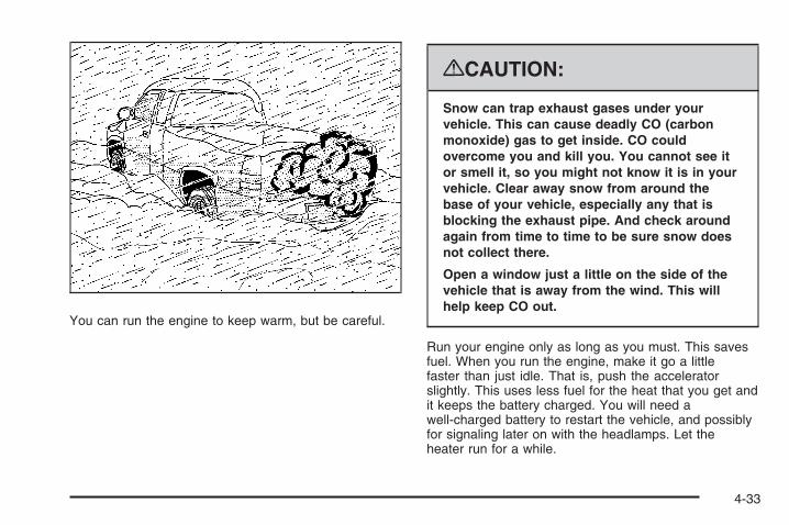
You can run the engine to keep warm, but be careful.
{CAUTION:
Snow can trap exhaust gases under yourvehicle. This can cause deadly CO (carbonmonoxide) gas to get inside. CO couldovercome you and kill you. You cannot see itor smell it, so you might not know it is in yourvehicle. Clear away snow from around thebase of your vehicle, especially any that isblocking the exhaust pipe. And check aroundagain from time to time to be sure snow doesnot collect there.
Open a window just a little on the side of thevehicle that is away from the wind. This willhelp keep CO out.
Run your engine only as long as you must. This savesfuel. When you run the engine, make it go a littlefaster than just idle. That is, push the acceleratorslightly. This uses less fuel for the heat that you get andit keeps the battery charged. You will need awell-charged battery to restart the vehicle, and possiblyfor signaling later on with the headlamps. Let theheater run for a while.
4-33
Then, shut the engine off and close the window almostall the way to preserve the heat. Start the engineagain and repeat this only when you feel reallyuncomfortable from the cold. But do it as little aspossible. Preserve the fuel as long as you can. To helpkeep warm, you can get out of the vehicle and dosome fairly vigorous exercises every half hour or so untilhelp comes.
If Your Vehicle is Stuck in Sand,Mud, Ice, or SnowSlowly and cautiously spin the wheels to free yourvehicle when stuck in sand, mud, ice, or snow. SeeRocking Your Vehicle to Get It Out on page 4-34.
If your vehicle has a traction system, it can often help tofree a stuck vehicle. Refer to your vehicle’s tractionsystem in the Index. If the stuck condition is too severefor the traction system to free the vehicle, turn thetraction system off and use the rocking method.
{CAUTION:
If you let your vehicle’s tires spin at highspeed, they can explode, and you or otherscould be injured. The vehicle can overheat,causing an engine compartment fire or otherdamage. Spin the wheels as little as possibleand avoid going above 35 mph (55 km/h) asshown on the speedometer.
For information about using tire chains on your vehicle,see Tire Chains on page 5-92.
Rocking Your Vehicle to Get It OutFirst, turn the steering wheel left and right to clearthe area around the front wheels. For four-wheel-drivevehicles, shift into Four-Wheel High. For vehicleswith StabiliTrak®, turn the traction control part of thesystem off. See StabiliTrak® System on page 4-6. Thenshift back and forth between REVERSE (R) and aforward gear, spinning the wheels as little as possible.
4-34
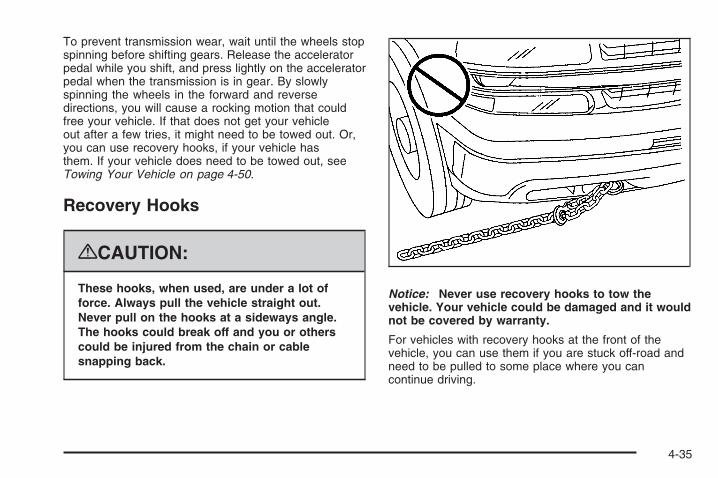
To prevent transmission wear, wait until the wheels stopspinning before shifting gears. Release the acceleratorpedal while you shift, and press lightly on the acceleratorpedal when the transmission is in gear. By slowlyspinning the wheels in the forward and reversedirections, you will cause a rocking motion that couldfree your vehicle. If that does not get your vehicleout after a few tries, it might need to be towed out. Or,you can use recovery hooks, if your vehicle hasthem. If your vehicle does need to be towed out, seeTowing Your Vehicle on page 4-50.
Recovery Hooks
{CAUTION:
These hooks, when used, are under a lot offorce. Always pull the vehicle straight out.Never pull on the hooks at a sideways angle.The hooks could break off and you or otherscould be injured from the chain or cablesnapping back.
Notice: Never use recovery hooks to tow thevehicle. Your vehicle could be damaged and it wouldnot be covered by warranty.
For vehicles with recovery hooks at the front of thevehicle, you can use them if you are stuck off-road andneed to be pulled to some place where you cancontinue driving.
4-35

Loading Your VehicleIt is very important to know how much weight yourvehicle can carry. This weight is called thevehicle capacity weight and includes the weight ofall occupants, cargo, and all nonfactory-installedoptions. Two labels on your vehicle show howmuch weight it was designed to carry, the Tireand Loading Information label and theCertification/Tire label.
{CAUTION:
Do not load the vehicle any heavier thanthe Gross Vehicle Weight Rating (GVWR),or either the maximum front or rear GrossAxle Weight Rating (GAWR). If you do,parts on the vehicle can break, and it canchange the way your vehicle handles.These could cause you to lose controland crash. Also, overloading can shortenthe life of the vehicle.
Tire and Loading Information Label
A vehicle specific Tire and Loading Informationlabel is attached to the center pillar (B-pillar).With the driver’s door open, you will find the labelattached below the door lock post (striker). The tireand loading information label shows the number ofoccupant seating positions (A), and the maximumvehicle capacity weight (B) in kilograms andpounds.
Label Example
4-36

The Tire and Loading Information label also showsthe size of the original equipment tires (C) andthe recommended cold tire inflation pressures (D).For more information on tires and inflation seeTires on page 5-68 and Inflation - Tire Pressure onpage 5-76.
There is also important loading information on thevehicle Certification/Tire label. It tells you theGross Vehicle Weight Rating (GVWR) andthe Gross Axle Weight Rating (GAWR) for thefront and rear axles. See “Certification/Tire Label”later in this section.
Steps for Determining Correct Load Limit1. Locate the statement “The combined weight of
occupants and cargo should never exceedXXX kg or XXX lbs” on your vehicle’s placard.
2. Determine the combined weight of the driverand passengers that will be riding in yourvehicle.
3. Subtract the combined weight of the driverand passengers from XXX kg or XXX lbs.
4. The resulting figure equals the availableamount of cargo and luggage load capacity.For example, if the “XXX” amount equals1400 lbs and there will be five 150 lbpassengers in your vehicle, the amount ofavailable cargo and luggage load capacity is650 lbs (1400 − 750 (5 x 150) = 650 lbs).
5. Determine the combined weight of luggageand cargo being loaded on the vehicle. Thatweight may not safely exceed the availablecargo and luggage load capacity calculatedin Step 4.
6. If your vehicle will be towing a trailer, the loadfrom your trailer will be transferred to yourvehicle. Consult this manual to determine howthis reduces the available cargo and luggageload capacity of your vehicle. See Towinga Trailer on page 4-55 for importantinformation on towing a trailer, towing safetyrules and trailering tips.
4-37
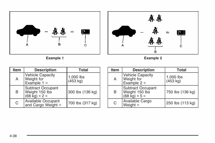
Item Description Total
AVehicle CapacityWeight forExample 1 =
1,000 lbs(453 kg)
BSubtract OccupantWeight 150 lbs(68 kg) × 2 =
300 lbs (136 kg)
C Available Occupantand Cargo Weight = 700 lbs (317 kg)
Item Description Total
AVehicle CapacityWeight forExample 2 =
1,000 lbs(453 kg)
BSubtract OccupantWeight 150 lbs(68 kg) × 5 =
750 lbs (136 kg)
C Available CargoWeight = 250 lbs (113 kg)
Example 1 Example 2
4-38

Item Description Total
AVehicle CapacityWeight forExample 3 =
1,000 lbs(453 kg)
BSubtract OccupantWeight 200 lbs(91 kg) × 5 =
1000 lbs(453 kg)
C Available CargoWeight = 0 lbs (0 kg)
Refer to your vehicle’s tire and loading informationlabel for specific information about your vehicle’scapacity weight and seating positions.
The combined weight of the driver, passengers,and cargo should never exceed your vehicle’scapacity weight.
Certification/Tire Label
A vehicle specific Certification/Tire label is foundon the rear edge of the driver’s door. The labelshows the size of your vehicle’s original tires andthe inflation pressures needed to obtain thegross weight capacity of your vehicle. This is calledGross Vehicle Weight Rating (GVWR).
Example 3
4-39

The GVWR includes the weight of the vehicle,all occupants, fuel, and cargo.
The Certification/Tire label also tells you themaximum weights for the front and rear axles,called Gross Axle Weight Rating (GAWR). To findout the actual loads on your front and rearaxles, you need to go to a weigh station andweigh your vehicle. Your dealer can help you withthis. Be sure to spread out your load equally onboth sides of the centerline.
Never exceed the GVWR for your vehicle, or theGAWR for either the front or rear axle.
The Certification/Tire label also contains importantinformation about your Front Axle ReserveCapacity. See “What is front axle reserve capacity,and how do I calculate it?” under Adding aSnow Plow or Similar Equipment on page 4-43.
{CAUTION:
In the case of a sudden stop or collision,things carried in the bed of your truckcould shift forward and come into thepassenger area, injuring you and others.If you put things in the bed of your truck,you should make sure they are properlysecured.
{CAUTION:
Do not load the vehicle any heavier thanthe Gross Vehicle Weight Rating (GVWR),or either the maximum front or rear GrossAxle Weight Rating (GAWR). If you do,parts on the vehicle can break, and it canchange the way your vehicle handles.These could cause you to lose controland crash. Also, overloading can shortenthe life of the vehicle.
4-40

Notice: Overloading your vehicle may causedamage. Repairs would not be covered by yourwarranty. Do not overload your vehicle.Using heavier suspension components to getadded durability might not change your weightratings. Ask your dealer to help you load yourvehicle the right way.
If you put things inside your vehicle — likesuitcases, tools, packages, or anythingelse — they go as fast as the vehicle goes. If youhave to stop or turn quickly, or if there is acrash, they will keep going.
{CAUTION:
Things you put inside your vehicle canstrike and injure people in a sudden stopor turn, or in a crash.
• Put things in the cargo area of yourvehicle. Try to spread the weightevenly.
• Never stack heavier things, likesuitcases, inside the vehicle so thatsome of them are above the tops ofthe seats.
• Do not leave an unsecured childrestraint in your vehicle.
• When you carry something inside thevehicle, secure it whenever you can.
• Do not leave a seat folded downunless you need to.
There is also important loading information foroff-road driving in this manual. See “Loading YourVehicle for Off-Road Driving“ under Off-RoadDriving on page 4-12.
4-41

Two-Tiered LoadingDepending on the model of your pick-up, you cancreate an upper load platform by positioningtwo or four 2 inches (5 cm) by 6 inches (15 cm)wooden planks across the width of the pickup box.The planks must be inserted in the pickup boxdepressions. The length of the planks must allowfor at least a 3/4 inch (2 cm) bearing surfaceon each end of the plank.
When using this upper load platform, be sure theload is securely tied down to prevent it fromshifting. The load’s center of gravity should bepositioned in a zone over the rear axle. The zoneis located in the area between the front of eachwheel well and the rear of each wheel well.The center of gravity height must not extend abovethe top of the pickup box flareboard.
Any load that extends beyond the vehicle’staillamp area must be properly marked accordingto local laws and regulations.
Remember not to exceed the Gross Axle WeightRating (GAWR) of the front or rear axle.
Add-On EquipmentWhen you carry removable items, you may needto put a limit on how many people you carryinside your vehicle. Be sure to weigh your vehiclebefore you buy and install the new equipment.
Notice: Overloading your vehicle may causedamage. Repairs would not be covered by yourwarranty. Do not overload your vehicle.Remember not to exceed the Gross Axle WeightRating (GAWR) of the front or rear axle.
* Equipment Maximum WeightLadder Rack andCargo 750 lbs (340 kg)
Cross Toolbox andCargo 400 lbs (181 kg)
Side Boxes and Cargo 250 lbs per side(113 kg per side)
* The combined weight for all rail-mountedequipment should not exceed 1,000 lbs (454 kg).
4-42
Adding a Snow Plow or SimilarEquipmentBefore installing a snow plow on your vehicle, here aresome things you will need to know:
Notice: If your vehicle does not have the snow plowprep package, adding a plow can damage yourvehicle, and the repairs would not be covered bywarranty. Unless your vehicle was built to carry asnow plow, do not add one to your vehicle. If yourvehicle has the snow plow prep package, called RPOVYU, then the payload your vehicle can carry will bereduced when a snow plow is installed. Your vehiclecan be damaged if either the front or rear axle ratingsor the Gross Vehicle Weight (GVW) are exceeded.
Some vehicles are built with a special snow plow preppackage, called RPO VYU. If your vehicle has thisoption, you can add a plow to it, provided certainweights, such as the weights on the vehicle’s axles andthe Gross Vehicle Weight (GVW), are not exceeded.
The plow your vehicle can carry depends on manythings, such as:
• The options your vehicle came with, and the weightof those options.
• The weight and number of passengers you intendto carry.
• The weight of items you have added to yourvehicle, like a tool box or truck cap.
• The total weight of any additional cargo you intendto carry.
Say, for example, you have a 700 lb (318 kg) snow plow.The total weight of all occupants and cargo inside the cabshould not exceed 300 lb (135 kg). This means that youmay only be able to carry one passenger. But, even thismay be too much if you have got other equipment alreadyadding to the weight of your vehicle.
4-43
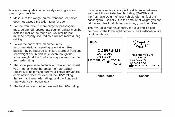
Here are some guidelines for safely carrying a snowplow on your vehicle:
• Make sure the weight on the front and rear axlesdoes not exceed the axle rating for each.
• For the front axle, if more cargo or passengersmust be carried, appropriate counter ballast must beinstalled rear of the rear axle. Counter ballastmust be properly secured so it will not move duringdriving.
• Follow the snow plow manufacturer’srecommendations regarding rear ballast. Rearballast may be required to ensure a proper front andrear weight distribution ratio, even though theactual weight at the front axle may be less than thefront axle rating.
• The snow plow manufacturer or installer can assistyou in determining the amount of rear ballastrequired, to help make sure your snowplow/vehiclecombination does not exceed the GVW rating,the front and rear axle ratings, and the front andrear weight distribution ratio.
• The total vehicle must not exceed the GVW rating.
Front axle reserve capacity is the difference betweenyour front Gross Axle Weight Rating (GAWR) andthe front axle weight of your vehicle with full fuel andpassengers. Basically, it is the amount of weight you canadd to your front axle before reaching your front GAWR.
The front axle reserve capacity for your vehicle canbe found in the lower right corner of the Certification/Tirelabel, as shown.
United States Canada
4-44
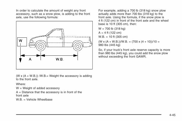
In order to calculate the amount of weight any frontaccessory, such as a snow plow, is adding to the frontaxle, use the following formula:
(W x (A + W.B.)) /W.B.= Weight the accessory is addingto the front axle.
Where:W = Weight of added accessoryA = Distance that the accessory is in front of thefront axleW.B. = Vehicle Wheelbase
For example, adding a 700 lb (318 kg) snow plowactually adds more than 700 lbs (318 kg) to thefront axle. Using the formula, if the snow plow is4 ft (122 cm) in front of the front axle and the wheelbase is 10 ft (305 cm), then:
W = 700 lb (318 kg)A = 4 ft (122 cm)W.B. = 10 ft (305 cm)
(W x (A + W.B.))/W.B. = (700 x (4 + 10))/10 =980 lbs (445 kg)
So, if your truck’s front axle reserve capacity is morethan 980 lbs (445 kg), you could add the snow plowwithout exceeding the front GAWR.
4-45

You can add heavier equipment on the front of the vehicleif you compensate for it by carrying fewer passengers,less cargo, or by positioning cargo towards the rear.This has the effect of reducing the load on the front.However, the front GAWR, rear GAWR, and the GrossVehicle Weight Rating (GVWR) must never be exceeded.
{CAUTION:
On some vehicles that have certain frontmounted equipment, such as a snow plow, itmay be possible to load the front axle to thefront gross axle weight rating (GAWR) but nothave enough weight on the rear axle to haveproper braking performance. If your brakes cannot work properly, you could have a crash.
CAUTION: (Continued)
CAUTION: (Continued)
To help your brakes work properly when asnow plow is installed, always follow thesnow plow manufacturer or installer’srecommendation for rear ballast to ensure aproper front and rear weight distribution ratio,even though the actual front weight may beless than the front GAWR, and the total vehicleweight is less than the gross vehicle weightrating (GVWR). Maintaining a proper front andrear weight distribution ratio is necessary toprovide proper braking performance.
Total vehicle reserve capacity is the difference betweenyour GVWR and the weight of your truck with full fueland passengers. It is the amount of weight you canadd to your vehicle before reaching your GVWR.
4-46
Keep in mind that reserve capacity numbers areintended as a guide when selecting the amount ofequipment or cargo your truck can carry. If youare unsure of your vehicle’s front, rear, or total weight,go to a weigh station and weigh your vehicle. Yourdealer/retailer can also help you with this.
The total vehicle reserve capacity for your vehicle canbe found in the lower right corner of the Certification/Tirelabel as shown previously.
See your dealer/retailer for additional advice andinformation about using a snow plow on your vehicle.Also, see Loading Your Vehicle on page 4-36.
Emergency Roof Lamp ProvisionsVehicles with the RPO VYU snow plow prep packagealso have an emergency roof lamp provision package,RPO TRW. Wiring for the emergency roof lamp isprovided above the overhead console. See AuxiliaryRoof Mounted Lamp on page 3-20 for switch location.
Truck-Camper Loading InformationA vehicle specific Truck-Camper Loadinginformation label is attached to the inside of yourvehicle’s glove box. This label will tell you ifyour vehicle can carry a slide-in camper, howmuch of a load your vehicle can carry, and how tocorrectly spread out the load. Also, it will helpyou match the right slide-in camper to your vehicle.
When you carry a slide-in camper, the totalcargo load of your vehicle is the weight of thecamper, plus the following:• Everything else added to the camper after it
left the factory• Everything in the camper• All the people inside
The Cargo Weight Rating (CWR) is the maximumweight of the load your vehicle can carry. It does notinclude the weight of the people inside. But, youcan figure about 150 lbs (68 kg) for each seat.
The total cargo load must not be more than yourvehicle’s CWR.
4-47
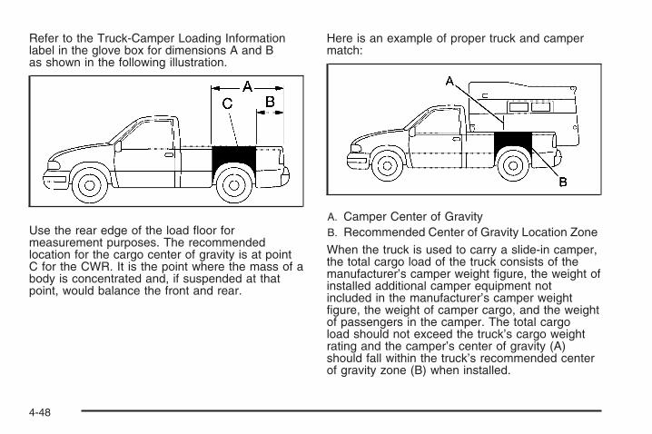
Refer to the Truck-Camper Loading Informationlabel in the glove box for dimensions A and Bas shown in the following illustration.
Use the rear edge of the load floor formeasurement purposes. The recommendedlocation for the cargo center of gravity is at pointC for the CWR. It is the point where the mass of abody is concentrated and, if suspended at thatpoint, would balance the front and rear.
Here is an example of proper truck and campermatch:
A. Camper Center of GravityB. Recommended Center of Gravity Location Zone
When the truck is used to carry a slide-in camper,the total cargo load of the truck consists of themanufacturer’s camper weight figure, the weight ofinstalled additional camper equipment notincluded in the manufacturer’s camper weightfigure, the weight of camper cargo, and the weightof passengers in the camper. The total cargoload should not exceed the truck’s cargo weightrating and the camper’s center of gravity (A)should fall within the truck’s recommended centerof gravity zone (B) when installed.
4-48

You must weigh any accessories or otherequipment that you add to your vehicle. Then,subtract this extra weight from the CWR. This extraweight may shorten the center of gravity zone ofyour vehicle. Your dealer can help you with this.
If your slide-in camper and its load weighsless than the CWR, the center of gravity zone foryour vehicle may be larger.
Your dealer can help you make a goodvehicle-camper match and help you determinethe CWR.
After you have loaded your vehicle and camper,drive to a weigh station and weigh the front and rearwheels separately. This will tell you the loads on theaxles. The loads on the front and rear axles shouldnot be more than either of the Gross Axle WeightRatings (GAWR). The total of the axle loads shouldnot be more than the Gross Vehicle WeightRating (GVWR).
Open the driver’s door and look at theCertification/Tire label to find out your vehicle’sGAWRs and GVWR.
If your vehicle has gone over the weight ratings,move or take out some things until all theweight falls below the ratings.
Secure loose items to prevent weight shifts thatcould affect the balance of your vehicle. When thetruck-camper is loaded, drive to a scale and weighon the front and on the rear wheels separately todetermine axle loads. Individual axle loads shouldnot exceed either of the gross axle weight ratings(GAWR). The total axle loads should not exceedyour vehicle’s gross vehicle weight rating (GVWR).These ratings are given on the vehicle certificationlabel attached to the rear edge of the driver’s door.See “Certification/Tire Label” under Loading YourVehicle on page 4-36. If weight ratings areexceeded, move or remove items to bring allweights below the ratings.
When you install and load your slide-in camper,check the manufacturer’s instructions.
If you want more information on curb weights,cargo weights, Cargo Weight Rating and thecorrect center of gravity zone for your vehicle, yourdealer can help you. Just ask for a copy of“Consumer Information, Truck-Camper Loading.”
4-49

Pickup Conversion to Chassis CabWe are aware that some vehicle owners might considerhaving the pickup box removed and a commercial orrecreational body installed. Owners should be aware that,as manufactured, there are differences between achassis cab and a pickup with the box removed whichcould affect vehicle safety. The components necessary toadapt a pickup to permit its safe use with a specializedbody should be installed by the body builder.
Towing
Towing Your VehicleTo avoid vehicle damage, a platform or flatbed trailershould be used to transport this vehicle. Consultyour dealer/retailer or a professional towing service ifyou need to have your disabled vehicle towed. SeeRoadside Assistance Program on page 7-7.
If you want to tow your vehicle behind another vehiclefor recreational purposes (such as behind a motorhome),see “Recreational Vehicle Towing” following.
Recreational Vehicle TowingRecreational vehicle towing means towing your vehiclebehind another vehicle – such as behind a motorhome.The two most common types of recreational vehicletowing are known as dinghy towing, towing your vehiclewill all four wheels on the ground, and dolly towing,towing your vehicle with two wheels on the ground andtwo wheels up on a device known as a “dolly”.
With the proper preparation and equipment, manyvehicles can be towed in these ways. See “DinghyTowing” and “Dolly Towing” following.
Here are some important things to consider before youdo recreational vehicle towing:
• What’s the towing capacity of the towing vehicle?Be sure you read the tow vehicle manufacturer’srecommendations.
• How far will you tow? Some vehicles haverestrictions on how far and how long they can tow.
• Do you have the proper towing equipment?See your dealer or trailering professional foradditional advice and equipment recommendations.
• Is your vehicle ready to be towed? Just as youwould prepare your vehicle for a long trip, you’llwant to make sure your vehicle is prepared to betowed. See Before Leaving on a Long Trip onpage 4-29.
4-50

Dinghy Towing
Two-Wheel-Drive Vehicles
Notice: If you tow your vehicle with all four wheelson the ground, the drivetrain components couldbe damaged. The repairs would not be covered byyour warranty. Do not tow your vehicle with allfour wheels on the ground.
Two-wheel-drive vehicles should not be towed withall four wheels on the ground. Two-wheel-drivetransmissions have no provisions for internal lubricationwhile being towed.
Four-Wheel-Drive Vehicles
Use the following procedure to tow your vehicle:
1. Shift the transmission to PARK (P).
2. Turn the engine off, but leave the ignition on.
3. Firmly set the parking brake.
4. Securely attach the vehicle being towed to thetow vehicle.
4-51

{CAUTION:
Shifting a four-wheel-drive vehicle’s transfercase into NEUTRAL can cause your vehicle toroll even if the transmission is in PARK (P).You or others could be injured. Make sure theparking brake is firmly set before you shift thetransfer case to NEUTRAL.
5. Shift the transfer case to NEUTRAL. SeeFour-Wheel Drive on page 2-36 for the properprocedure to select the neutral position foryour vehicle.
6. Release the parking brake only after the vehiclebeing towed is firmly attached to the towing vehicle.
7. Turn the ignition to LOCK/OFF.
Dolly Towing
Front Towing (Front Wheels Off theGround)
Two-Wheel-Drive Vehicles
Notice: If you tow a two-wheel-drive vehicle withthe rear wheels on the ground, the transmissioncould be damaged. The repairs would not becovered by your warranty. Never tow your vehiclewith the rear wheels on the ground.
Two-wheel-drive vehicles should not be towed with therear wheels on the ground. Two-wheel-drivetransmissions have no provisions for internal lubricationwhile being towed.
To dolly tow a two-wheel-drive vehicle, you must towthe vehicle with the rear wheels on the dolly. See “RearTowing (Rear Wheels Off the Ground)” later in thissection for more information.
4-52

Four-Wheel-Drive Vehicles
Use the following procedure to tow your vehicle:
1. Drive the vehicle up onto the tow dolly.
2. Shift the transmission to PARK (P).
3. Turn the engine off, but leave the ignition on.
4. Firmly set the parking brake.
5. Securely attach the vehicle being towed to thetow dolly.
{CAUTION:
Shifting a four-wheel-drive vehicle’s transfercase into NEUTRAL can cause your vehicle toroll even if the transmission is in PARK (P).You or others could be injured. Make sure theparking brake is firmly set before you shift thetransfer case to NEUTRAL.
6. Shift the transfer case to NEUTRAL. SeeFour-Wheel Drive on page 2-36 for the properprocedure to select the neutral position foryour vehicle.
7. Release the parking brake only after the vehiclebeing towed is firmly attached to the towingvehicle.
8. Turn the ignition to LOCK/OFF.
4-53

Rear Towing (Rear Wheels Off theGround)
Two-Wheel-Drive VehiclesUse the following procedure to tow your vehicle fromthe rear:
1. Drive the vehicle onto the dolly.
2. Firmly set the parking brake. See Parking Brake onpage 2-50.
3. Put the transmission in PARK (P).
4. Follow the dolly manufacturer’s instructions toattach and secure the vehicle being towed tothe dolly and then the loaded dolly to the towvehicle. Make sure the wheels are straight beforetowing.Use an adequate clamping device to ensure thatthe front wheels are locked into the straight position.
5. Release the parking brake only after the vehiclebeing towed is firmly attached to the tow vehicle.
6. Turn the ignition to LOCK/OFF.
Four-Wheel-Drive VehiclesUse the following procedure to tow your vehicle fromthe rear:
1. Drive the vehicle onto the dolly.
2. Firmly set the parking brake. See Parking Brake onpage 2-50.
3. Put the transmission in PARK (P).
4. Follow the dolly manufacturer’s instructions to attachand secure the vehicle being towed to the dolly andthen the loaded dolly to the tow vehicle.Use an adequate clamping device to ensure thatthe front wheels are locked into the straight position.
{CAUTION:
Shifting a four-wheel-drive vehicle’s transfercase into NEUTRAL can cause your vehicle toroll even if the transmission is in PARK (P).You or others could be injured. Make sure theparking brake is firmly set before you shift thetransfer case to NEUTRAL.
4-54

5. Shift the transfer case to NEUTRAL. SeeFour-Wheel Drive on page 2-36.
6. Release the parking brake only after the vehiclebeing towed is firmly attached to the tow vehicle.
7. Turn the ignition to LOCK/OFF.
Towing a TrailerIf your vehicle has a diesel engine, see the DURAMAX®
Diesel manual for more information.
Do not tow a trailer during break-in. See New VehicleBreak-In on page 2-22 for more information.
{CAUTION:
If you do not use the correct equipment anddrive properly, you can lose control when youpull a trailer. For example, if the trailer is tooheavy, the brakes may not work well — or evenat all. You and your passengers could beseriously injured. Pull a trailer only if you havefollowed all the steps in this section. Ask yourdealer for advice and information about towinga trailer with your vehicle.
Notice: Pulling a trailer improperly can damageyour vehicle and result in costly repairs not coveredby your warranty. To pull a trailer correctly, followthe advice in this part, and see your dealer forimportant information about towing a trailer withyour vehicle.
To identify the trailering capacity of your vehicle, youshould read the information in “Weight of the Trailer” thatappears later in this section.
Trailering is different than just driving your vehicle byitself. Trailering means changes in acceleration, braking,handling, durability and fuel economy. Successful,safe trailering takes correct equipment, and it has to beused properly.
That’s the reason for this part. In it are many time-tested,important trailering tips and safety rules. Many ofthese are important for your safety and that of yourpassengers. So please read this section carefully beforeyou pull a trailer.
4-55

If You Do Decide To Pull A TrailerIf you do, here are some important points:
• There are many different laws, including speed limitrestrictions, having to do with trailering. Make sureyour rig will be legal, not only where you livebut also where you’ll be driving. A good source forthis information can be state or provincial police.
• Consider using a sway control. See “Hitches” laterin this section.
• Don’t tow a trailer at all during the first 500 miles(800 km) your new vehicle is driven. Your engine,axle or other parts could be damaged.
• Then, during the first 500 miles (800 km) that youtow a trailer, don’t drive over 50 mph (80 km/h)and don’t make starts at full throttle. This helps yourengine and other parts of your vehicle wear in atthe heavier loads.
• You can tow in DRIVE (D). You may want to shiftthe transmission to THIRD (3), or FOURTH (4)with the Allison or Hydra-matic 6-speedtransmissions, or if necessary, a lower gearselection if the transmission shifts too often, suchas under heavy loads and/or hilly conditions.See “Tow/Haul Mode” later in this section.
Three important considerations have to do with weight:
• The weight of the trailer
• The weight of the trailer tongue
• The weight on your vehicle’s tires
Tow/Haul Mode
Press this button at theend of the shift leverto enable/disable thetow/haul mode.
Tow/Haul is a feature that assists when pulling aheavy trailer or a large or heavy load. See Tow/HaulMode on page 2-34 for more information.
4-56
Tow/Haul is designed to be most effective when thevehicle and trailer combined weight is at least 75 percentof the vehicle’s Gross Combined Weight Rating (GCWR).See “Weight of the Trailer” later in the section. Tow/Haulis most useful under the following driving conditions:
• When pulling a heavy trailer or a large or heavy loadthrough rolling terrain.
• When pulling a heavy trailer or a large or heavy loadin stop and go traffic.
• When pulling a heavy trailer or a large or heavy loadin busy parking lots where improved low speedcontrol of the vehicle is desired.
Operating the vehicle in Tow/Haul when lightly loadedor with no trailer at all will not cause damage. However,there is no benefit to the selection of Tow/Haul whenthe vehicle is unloaded. Such a selection when unloadedmay result in unpleasant engine and transmissiondriving characteristics and reduced fuel economy.Tow/Haul is recommended only when pulling a heavytrailer or a large or heavy load.
Weight of the TrailerHow heavy can a trailer safely be?
It depends on how you plan to use your rig.For example, speed, altitude, road grades, outsidetemperature and how much your vehicle is used to pulla trailer are all important. It can also depend on anyspecial equipment that you have on your vehicle,and the amount of tongue weight the vehicle can carry.See “Weight of the Trailer Tongue” later in this sectionfor more information.
Maximum trailer weight is calculated assuming only thedriver is in the tow vehicle and it has all the requiredtrailering equipment. The weight of additional optionalequipment, passengers and cargo in the tow vehiclemust be subtracted from the maximum trailer weight.
4-57
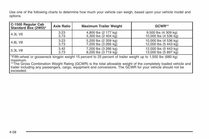
Use one of the following charts to determine how much your vehicle can weigh, based upon your vehicle model andoptions.
C-1500 Regular CabStandard Box (2WD)* Axle Ratio Maximum Trailer Weight GCWR**
4.3L V6 3.233.73
4,800 lbs (2 177 kg)5,300 lbs (2 404 kg)
9,500 lbs (4 309 kg)10,000 lbs (4 536 kg)
4.8L V8 3.233.73
5,200 lbs (2 359 kg)7,200 lbs (3 266 kg)
10,000 lbs (4 536 kg)12,000 lbs (5 443 kg)
5.3L V8 3.423.73
7,200 lbs (3 266 kg)8,200 lbs (3 719 kg)
12,000 lbs (5 443 kg)13,000 lbs (5 897 kg)
*Fifth-wheel or gooseneck kingpin weight 15 percent to 25 percent of trailer weight up to 1,500 lbs (680 kg)maximum.**The Gross Combination Weight Rating (GCWR) is the total allowable weight of the completely loaded vehicle andtrailer including any passengers, cargo, equipment and conversions. The GCWR for your vehicle should not beexceeded.
4-58

C-1500 Extended CabStandard Box (2WD)* Axle Ratio Maximum Trailer Weight GCWR**
4.3L V6 3.233.73
4,300 lbs (1 950 kg)4,800 lbs (2 177 kg)
9,500 lbs (4 309 kg)10,000 lbs (4 536 kg)
4.8L V8 3.233.73
4,700 lbs (2 132 kg)6,700 lbs (3 039 kg)
10,000 lbs (4 536 kg)12,000 lbs (5 443 kg)
5.3L V8 3.423.73
6,700 lbs (3 039 kg)7,700 lbs (3 493 kg)
12,000 lbs (5 443 kg)13,000 lbs (5 897 kg)
6.0L V8 3.73 8,800 lbs (3 992 kg) 14,000 lbs (6 350 kg)6.0L V8+ 3.73 10,200 lbs (4 627 kg) 15,500 lbs (7 031 kg)*Fifth-wheel or gooseneck kingpin weight 15 percent to 25 percent of trailer weight up to 1,500 lbs (680 kg)maximum.**The Gross Combination Weight Rating (GCWR) is the total allowable weight of the completely loaded vehicle andtrailer including any passengers, cargo, equipment and conversions. The GCWR for your vehicle should not beexceeded.+NHT Enhanced Trailering Performance Package required.
4-59

C-1500 Extended CabShort Box (2WD)* Axle Ratio Maximum Trailer Weight GCWR**
4.3L V6 3.233.73
4,400 lbs (1 196 kg)4,900 lbs (2 223 kg)
9,500 lbs (4 309 kg)10,000 lbs (4 536 kg)
4.8L V8 3.233.73
4,800 lbs (2 177 kg)6,800 lbs (3 084 kg)
10,000 lbs (4 536 kg)12,000 lbs (5 448 kg)
5.3L V8 3.423.73
6,800 lbs (3 084 kg)7,800 lbs (3 538 kg)
12,000 lbs (5 448 kg)13,000 lbs (5 902 kg)
6.0L V8 3.73 8,800 lbs (3 992 kg) 14,000 lbs (6 350 kg)*This model is neither designed nor intended to tow fifth-wheel or gooseneck trailers.**The Gross Combination Weight Rating (GCWR) is the total allowable weight of the completely loaded vehicle andtrailer including any passengers, cargo, equipment and conversions. The GCWR for your vehicle should not beexceeded.
C-1500 Crew Cab ShortBox (2WD)* Axle Ratio Maximum Trailer Weight GCWR**
4.8L V8 3.233.73
4,600 lbs (2 086 kg)6,600 lbs (2 994 kg)
10,000 lbs (4 536 kg)12,000 lbs (5 443 kg)
5.3L V8 3.423.73
6,600 lbs (2 994 kg)7,600 lbs (3 447 kg)
12,000 lbs (5 443 kg)13,000 lbs (5 897 kg)
6.0L V8 3.73 8,700 lbs (3 946 kg) 14,000 lbs (6 350 kg)6.0L V8+ 3.73 10,200 lbs (4 627 kg) 15,500 lbs (7 031 kg)*This model is neither designed nor intended to tow fifth-wheel or gooseneck trailers.**The Gross Combination Weight Rating (GCWR) is the total allowable weight of the completely loaded vehicle andtrailer including any passengers, cargo, equipment and conversions. The GCWR for your vehicle should not beexceeded.+NHT Enhanced Trailering Performance Package required.
4-60

C-1500 Regular CabLong Box (2WD)* Axle Ratio Maximum Trailer Weight GCWR**
4.3L V6 3.233.73
4,700 lbs (2 132 kg)5,200 lbs (2 359 kg)
9,500 lbs (4 309 kg)10,000 lbs (4 536 kg)
4.8L V8 3.233.73
5,100 lbs (2 313 kg)7,100 lbs (3 221 kg)
10,000 lbs (4 536 kg)12,000 lbs (5 448 kg)
5.3L V8 3.423.73
7,000 lbs (3 175 kg)8,000 lbs (3 629 kg)
12,000 lbs (5 443 kg)13,000 lbs (5 896 kg)
*Fifth-wheel or gooseneck kingpin weight 15 percent to 25 percent of trailer weight up to 1,500 lbs (680 kg)maximum.**The Gross Combination Weight Rating (GCWR) is the total allowable weight of the completely loaded vehicle andtrailer including any passengers, cargo, equipment and conversions. The GCWR for your vehicle should not beexceeded.
C-1500 Extended CabLong Box (2WD)* Axle Ratio Maximum Trailer Weight GCWR**
5.3L V8 3.423.73
6,500 lbs (2 948 kg)7,500 lbs (3 402 kg)
12,000 lbs (5 443 kg)13,000 lbs (5 897 kg)
*Fifth-wheel or gooseneck kingpin weight 15 percent to 25 percent of trailer weight up to 1,500 lbs (680 kg)maximum.**The Gross Combination Weight Rating (GCWR) is the total allowable weight of the completely loaded vehicle andtrailer including any passengers, cargo, equipment and conversions. The GCWR for your vehicle should not beexceeded.
4-61

K-1500 Regular CabStandard Box (4WD)* Axle Ratio Maximum Trailer Weight GCWR**
4.3L V6 3.73 5,100 lbs (2 313 kg) 10,000 lbs (4 536 kg)
4.8L V8 3.424.10
5,900 lbs (2 676 kg)7,900 lbs (3 583 kg)
11,000 lbs (4 989 kg)13,000 lbs (5 902 kg)
5.3L V8 3.734.10
7,900 lbs (3 583 kg)8,900 lbs (4 037 kg)
13,000 lbs (5 896 kg)14,000 lbs (6 350 kg)
*Fifth-wheel or gooseneck kingpin weight 15 percent to 25 percent of trailer weight up to 1,500 lbs (680 kg)maximum.*Fifth-wheel or gooseneck trailer rating limited to 7,300 lbs (3 311 kg).**The Gross Combination Weight Rating (GCWR) is the total allowable weight of the completely loaded vehicle andtrailer including any passengers, cargo, equipment and conversions. The GCWR for your vehicle should not beexceeded.
K-1500 Extended CabStandard Box (4WD)* Axle Ratio Maximum Trailer Weight GCWR**
4.8L V8 3.424.10
5,500 lbs (2 495 kg)7,500 lbs (3 402 kg)
11,000 lbs (4 989 kg)13,000 lbs (5 897 kg)
5.3L V8 3.734.10
7,500 lbs (3 402 kg)8,500 lbs (3 855 kg)
13,000 lbs (5 897 kg)14,000 lbs (6 350 kg)
6.0L V8 3.73 8,500 lbs (3 855 kg) 14,000 lbs (6 350 kg)6.0L V8+ 4.10 10,500 lbs (4 763 kg) 16,000 lbs (7 257 kg)*Fifth-wheel or gooseneck kingpin weight 15 percent to 25 percent of trailer weight up to 1,500 lbs (680 kg)maximum.**The Gross Combination Weight Rating (GCWR) is the total allowable weight of the completely loaded vehicle andtrailer including any passengers, cargo, equipment and conversions. The GCWR for your vehicle should not beexceeded.+NHT Enhanced Trailering Performance Package required.
4-62

K-1500 Extended CabShort Box (4WD)* Axle Ratio Maximum Trailer Weight GCWR**
4.8L V8 3.424.10
5,500 lbs (2 495 kg)7,500 lbs (3 402 kg)
11,000 lbs (4 989 kg)13,000 lbs (5 897 kg)
5.3L V8 3.734.10
7,500 lbs (3 402 kg)8,500 lbs (3 855 kg)
13,000 lbs (5 897 kg)14,000 lbs (6 350 kg)
6.0L V8 3.73 8,500 lbs (3 856 kg) 14,000 lbs (6 350 kg)*This model is neither designed nor intended to tow fifth-wheel or gooseneck trailers.**The Gross Combination Weight Rating (GCWR) is the total allowable weight of the completely loaded vehicle andtrailer including any passengers, cargo, equipment and conversions. The GCWR for your vehicle should not beexceeded.
K-1500 Crew Cab ShortBox (4WD)* Axle Ratio Maximum Trailer Weight GCWR**
4.8L V8 3.424.10
5,400 lbs (2 449 kg)7,400 lbs (3 356 kg)
11,000 lbs (4 989 kg)13,000 lbs (5 897 kg)
5.3L V8 3.734.10
7,500 lbs (3 402 kg)8,500 lbs (3 855 kg)
13,000 lbs (5 897 kg)14,000 lbs (6 350 kg)
6.0L V8 3.73 8,400 lbs (3 810 kg) 14,000 lbs (6 350 kg)6.0L V8+ 4.10 10,500 lbs (4 763 kg) 16,000 lbs (7 257 kg)*This model is neither designed nor intended to tow fifth-wheel or gooseneck trailers.**The Gross Combination Weight Rating (GCWR) is the total allowable weight of the completely loaded vehicle andtrailer including any passengers, cargo, equipment and conversions. The GCWR for your vehicle should not beexceeded.+NHT Enhanced Trailering Performance Package required.
4-63

K-1500 Regular CabLong Box (4WD)* Axle Ratio Maximum Trailer Weight GCWR**
4.3L V6 3.73 4,900 lbs (2 223 kg) 10,000 lbs (4 536 kg)
4.8L V8 3.424.10
5,900 lbs (2 676 kg)7,900 lbs (3 583 kg)
11,000 lbs (4 989 kg)13,000 lbs (5 896 kg)
5.3L V8 3.734.10
7,900 lbs (3 583 kg)8,900 lbs (4 037 kg)
13,000 lbs (5 896 kg)14,000 lbs (6 350 kg)
*Fifth-wheel or gooseneck kingpin weight 15 percent to 25 percent of trailer weight up to 1,500 lbs (680 kg)maximum.**The Gross Combination Weight Rating (GCWR) is the total allowable weight of the completely loaded vehicle andtrailer including any passengers, cargo, equipment and conversions. The GCWR for your vehicle should not beexceeded.
K-1500 Extended CabLong Box (4WD)* Axle Ratio Maximum Trailer Weight GCWR**
5.3L V8 3.734.10
7,300 lbs (3 311 kg)8,300 lbs (3 765 kg)
13,000 lbs (5 896 kg)14,000 lbs (6 350 kg)
*Fifth-wheel or gooseneck kingpin weight 15 percent to 25 percent of trailer weight up to 1,500 lbs (680 kg)maximum.**The Gross Combination Weight Rating (GCWR) is the total allowable weight of the completely loaded vehicle andtrailer including any passengers, cargo, equipment and conversions. The GCWR for your vehicle should not beexceeded.
4-64

C-2500 ExtendedCab Standard BoxHD (2WD)* Axle Ratio
Maximum Trailer Weight GCWR**
6.0L V8 3.734.10
10,200 lbs (4 627 kg)12,700 lbs (5 761 kg)
16,000 lbs (7 257 kg)18,500 lbs (8 391 kg)
*Fifth-wheel or gooseneck kingpin tongue weight should be 15 percent to 25 percent of trailer weight up to 3,000lbs (1 361 kg) maximum.*Trailer rating limited to 13,000 lbs (5 897 kg) with weight distributing hitch.**The Gross Combination Weight Rating (GCWR) is the total allowable weight of the completely loaded vehicle andtrailer including any passengers, cargo, equipment and conversions. The GCWR for your vehicle should not beexceeded.
C-2500 CrewCab Standard BoxHD (2WD)*
Axle Ratio Maximum Trailer Weight GCWR**
6.0L V8 3.734.10
10,000 lbs (4 536 kg)12,500 lbs (5 670 kg)
16,000 lbs (7 257 kg)18,500 lbs (8 391 kg)
*Fifth-wheel or gooseneck kingpin weight should be 15 percent to 25 percent of trailer weight up to 3,000 lbs(1 361 kg) maximum.*Trailer rating limited to 13,000 lbs (5 897 kg) with weight distributing hitch.**The Gross Combination Weight Rating (GCWR) is the total allowable weight of the completely loaded vehicle andtrailer including any passengers, cargo, equipment and conversions. The GCWR for your vehicle should not beexceeded.
4-65

C-2500 Regular CabLong Box HD (2WD)* Axle Ratio Maximum Trailer Weight GCWR**
6.0L V8 3.734.10
10,400 lbs (4 717 kg)12,900 lbs (5 851 kg)
16,000 lbs (7 257 kg)18,500 lbs (8 391 kg)
*Fifth-wheel or gooseneck kingpin tongue weight should be 15 percent to 25 percent of trailer weight up to 3,000lbs (1 361 kg) maximum.*Trailer ratings above 13,000 lbs (5 897 kg) require a fifth-wheel or gooseneck hitch.**The Gross Combination Weight Rating (GCWR) is the total allowable weight of the completely loaded vehicle andtrailer including any passengers, cargo, equipment and conversions. The GCWR for your vehicle should not beexceeded.
C-2500 Extended CabLong Box HD (2WD)* Axle Ratio Maximum Trailer Weight GCWR**
6.0L V8 3.734.10
10,000 lbs (4 536 kg)12,500 lbs (5 670 kg)
16,000 lbs (7 257 kg)18,500 lbs (8 391 kg)
*Fifth-wheel or gooseneck kingpin weight should be 15 percent to 25 percent of trailer weight up to 3,000 lbs(1 361 kg) maximum.*Trailer rating limited to 13,000 lbs (5 897 kg) with weight distributing hitch.**The Gross Combination Weight Rating (GCWR) is the total allowable weight of the completely loaded vehicle andtrailer including any passengers, cargo, equipment and conversions. The GCWR for your vehicle should not beexceeded.
4-66

C-2500 Crew Cab LongBox HD (2WD)* Axle Ratio Maximum Trailer Weight GCWR**
6.0L V8 3.734.10
9,900 lbs (4 490 kg)12,400 lbs (5 624 kg)
16,000 lbs (7 257 kg)18,500 lbs (8 391 kg)
*Fifth-wheel or gooseneck kingpin weight should be 15 percent to 25 percent of trailer weight up to 3,000 lbs(1 361 kg) maximum.*Trailer rating limited to 13,000 lbs (5 897 kg) with weight distributing hitch.**The Gross Combination Weight Rating (GCWR) is the total allowable weight of the completely loaded vehicle andtrailer including any passengers, cargo, equipment and conversions. The GCWR for your vehicle should not beexceeded.
K-2500 ExtendedCab Standard BoxHD (4WD)*
Axle Ratio Maximum Trailer Weight GCWR**
6.0L V8 3.734.10
9,900 lbs (4 490 kg)12,400 lbs (5 624 kg)
16,000 lbs (7 257 kg)18,500 lbs (8 391 kg)
*Fifth-wheel or gooseneck kingpin weight should be 15 percent to 25 percent of trailer weight up to 3,000 lbs(1 361 kg) maximum.*Trailer rating limited to 13,000 lbs (5 897 kg) with weight distributing hitch.**The Gross Combination Weight Rating (GCWR) is the total allowable weight of the completely loaded vehicle andtrailer including any passengers, cargo, equipment and conversions. The GCWR for your vehicle should not beexceeded.
4-67

K-2500 CrewCab Standard BoxHD (4WD)* Axle Ratio
Maximum Trailer Weight GCWR**
6.0L V8 3.734.10
9,800 lbs (4 445 kg)12,300 lbs (5 579 kg)
16,000 lbs (7 257 kg)18,500 lbs (8 391 kg)
*Fifth-wheel or gooseneck kingpin weight should be 15 percent to 25 percent of trailer weight up to 3,000 lbs(1 361 kg) maximum.*Trailer rating limited to 13,000 lbs (5 897 kg) with weight distributing hitch.**The Gross Combination Weight Rating (GCWR) is the total allowable weight of the completely loaded vehicle andtrailer including any passengers, cargo, equipment and conversions. The GCWR for your vehicle should not beexceeded.
K-2500 Regular CabLong Box HD (4WD)* Axle Ratio Maximum Trailer Weight GCWR**
6.0L V8 3.734.10
10,200 lbs (4 627 kg)12,700 lbs (5 761 kg)
16,000 lbs (7 257 kg)18,500 lbs (8 391 kg)
*Fifth-wheel or gooseneck kingpin weight should be 15 percent to 25 percent of trailer weight up to 3,000 lbs(1 361 kg) maximum.*Trailer rating limited to 13,000 lbs (5 897 kg) with weight distributing hitch.**The Gross Combination Weight Rating (GCWR) is the total allowable weight of the completely loaded vehicle andtrailer including any passengers, cargo, equipment and conversions. The GCWR for your vehicle should not beexceeded.
4-68

K-2500 Extended CabLong Box HD (4WD)* Axle Ratio Maximum Trailer Weight GCWR**
6.0L V8 3.734.10
9,700 lbs (4 400 kg)12,200 lbs (5 534 kg)
16,000 lbs (7 257 kg)18,500 lbs (8 391 kg)
*Fifth-wheel or gooseneck kingpin weight should be 15 percent to 25 percent of trailer weight up to 3,000 lbs(1 361 kg) maximum.*Trailer rating limited to 13,000 lbs (5 897 kg) with weight distributing hitch.**The Gross Combination Weight Rating (GCWR) is the total allowable weight of the completely loaded vehicle andtrailer including any passengers, cargo, equipment and conversions. The GCWR for your vehicle should not beexceeded.
K-2500 Crew Cab LongBox HD (4WD)* Axle Ratio Maximum Trailer Weight GCWR**
6.0L V8 3.734.10
9,600 lbs (4 354 kg)12,100 lbs (5 488 kg)
16,000 lbs (7 257 kg)18,500 lbs (8 391 kg)
*Fifth-wheel or gooseneck kingpin weight should be 15 percent to 25 percent of trailer weight up to 3,000 lbs(1 361 kg) maximum.*Trailer rating limited to 13,000 lbs (5 897 kg) with weight distributing hitch.**The Gross Combination Weight Rating (GCWR) is the total allowable weight of the completely loaded vehicle andtrailer including any passengers, cargo, equipment and conversions. The GCWR for your vehicle should not beexceeded.
4-69

C-3500 RegularCab (2WD)* Axle Ratio Maximum Trailer Weight GCWR**
6.0L V8 3.734.10
10,100 lbs (4 581 kg)12,600 lbs (5 715 kg)
16,000 lbs (7 257 kg)18,500 lbs (8 391 kg)
*Fifth-wheel or gooseneck kingpin weight should be 15 percent to 25 percent of trailer weight up to 3,500 lbs(1 587 kg) maximum.*Trailer rating limited to 13,000 lbs (5 897 kg) with weight distributing hitch.**The Gross Combination Weight Rating (GCWR) is the total allowable weight of the completely loaded vehicle andtrailer including any passengers, cargo, equipment and conversions. The GCWR for your vehicle should not beexceeded.
C-3500 ExtendedCab (2WD)* Axle Ratio Maximum Trailer Weight GCWR**
6.0L V8 3.734.10
9,700 lbs (4 400 kg)12,200 lbs (5 534 kg)
16,000 lbs (7 257 kg)18,500 lbs (8 391 kg)
6.0L V8 (Dual RearWheels)
3.734.10
9,500 lbs (4 309 kg)12,000 lbs (5 443 kg)
16,000 lbs (7 257 kg)18,500 lbs (8 391 kg)
*Fifth-wheel or gooseneck kingpin weight should be 15 percent to 25 percent of trailer weight up to 3,500 lbs(1 587 kg) maximum.*Trailer rating limited to 13,000 lbs (5 897 kg) with weight distributing hitch.**The Gross Combination Weight Rating (GCWR) is the total allowable weight of the completely loaded vehicle andtrailer including any passengers, cargo, equipment and conversions. The GCWR for your vehicle should not beexceeded.
4-70

C-3500 CrewCab (2WD)* Axle Ratio Maximum Trailer Weight GCWR**
6.0L V8 3.734.10
9,600 lbs (4 354 kg)12,100 lbs (5 488 kg)
16,000 lbs (7 257 kg)18,500 lbs (8 391 kg)
6.0L V8 (Dual RearWheels)
3.734.10
9,300 lbs (4 218 kg)11,800 lbs (5 352 kg)
16,000 lbs (7 257 kg)18,500 lbs (8 391 kg)
*Fifth-wheel or gooseneck kingpin weight should be 15 percent to 25 percent of trailer weight up to 3,500 lbs(1 587 kg) maximum.*Trailer rating limited to 13,000 lbs (5 897 kg) with weight distributing hitch.**The Gross Combination Weight Rating (GCWR) is the total allowable weight of the completely loaded vehicle andtrailer including any passengers, cargo, equipment and conversions. The GCWR for your vehicle should not beexceeded.
K-3500 RegularCab (4WD)* Axle Ratio Maximum Trailer Weight GCWR**
6.0L V8 3.734.10
9,900 lbs (4 490 kg)12,400 lbs (5 624 kg)
16,000 lbs (7 257 kg)18,500 lbs (8 391 kg)
6.0L V8 (Dual RearWheels)
3.734.10
9,700 lbs (4 400 kg)12,200 lbs (5 534 kg)
16,000 lbs (7 257 kg)18,500 lbs (8 391 kg)
*Fifth-wheel or gooseneck kingpin weight should be 15 percent to 25 percent of trailer weight up to 3,500 lbs(1 587 kg) maximum.*Trailer rating limited to 13,000 lbs (5 897 kg) with weight distributing hitch.**The Gross Combination Weight Rating (GCWR) is the total allowable weight of the completely loaded vehicle andtrailer including any passengers, cargo, equipment and conversions. The GCWR for your vehicle should not beexceeded.
4-71
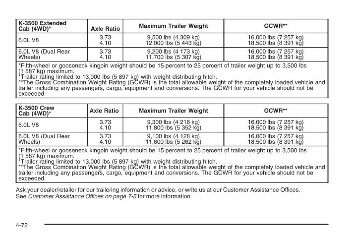
K-3500 ExtendedCab (4WD)* Axle Ratio Maximum Trailer Weight GCWR**
6.0L V8 3.734.10
9,500 lbs (4 309 kg)12,000 lbs (5 443 kg)
16,000 lbs (7 257 kg)18,500 lbs (8 391 kg)
6.0L V8 (Dual RearWheels)
3.734.10
9,200 lbs (4 173 kg)11,700 lbs (5 307 kg)
16,000 lbs (7 257 kg)18,500 lbs (8 391 kg)
*Fifth-wheel or gooseneck kingpin weight should be 15 percent to 25 percent of trailer weight up to 3,500 lbs(1 587 kg) maximum.*Trailer rating limited to 13,000 lbs (5 897 kg) with weight distributing hitch.**The Gross Combination Weight Rating (GCWR) is the total allowable weight of the completely loaded vehicle andtrailer including any passengers, cargo, equipment and conversions. The GCWR for your vehicle should not beexceeded.
K-3500 CrewCab (4WD)* Axle Ratio Maximum Trailer Weight GCWR**
6.0L V8 3.734.10
9,300 lbs (4 218 kg)11,800 lbs (5 352 kg)
16,000 lbs (7 257 kg)18,500 lbs (8 391 kg)
6.0L V8 (Dual RearWheels)
3.734.10
9,100 lbs (4 128 kg)11,600 lbs (5 262 kg)
16,000 lbs (7 257 kg)18,500 lbs (8 391 kg)
*Fifth-wheel or gooseneck kingpin weight should be 15 percent to 25 percent of trailer weight up to 3,500 lbs(1 587 kg) maximum.*Trailer rating limited to 13,000 lbs (5 897 kg) with weight distributing hitch.**The Gross Combination Weight Rating (GCWR) is the total allowable weight of the completely loaded vehicle andtrailer including any passengers, cargo, equipment and conversions. The GCWR for your vehicle should not beexceeded.
Ask your dealer/retailer for our trailering information or advice, or write us at our Customer Assistance Offices.See Customer Assistance Offices on page 7-5 for more information.
4-72
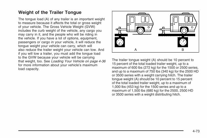
Weight of the Trailer TongueThe tongue load (A) of any trailer is an important weightto measure because it affects the total or gross weightof your vehicle. The Gross Vehicle Weight (GVW)includes the curb weight of the vehicle, any cargo youmay carry in it, and the people who will be riding inthe vehicle. If you have a lot of options, equipment,passengers or cargo in your vehicle, it will reduce thetongue weight your vehicle can carry, which willalso reduce the trailer weight your vehicle can tow. Andif you will tow a trailer, you must add the tongue loadto the GVW because your vehicle will be carryingthat weight, too. See Loading Your Vehicle on page 4-36for more information about your vehicle’s maximumload capacity.
The trailer tongue weight (A) should be 10 percent to15 percent of the total loaded trailer weight, up to amaximum of 600 lbs (272 kg) for the 1500 or 2500 series,and up to a maximum of 750 lbs (340 kg) for the 2500 HDor 3500 series with a weight carrying hitch. The trailertongue weight (A) should be 10 percent to 15 percentof the total loaded trailer weight, up to a maximum of1,000 lbs (453 kg) for the 1500 series and up to amaximum of 1,500 lbs (680 kg) for the 2500, 2500 HDor 3500 series with a weight distributing hitch.
4-73

Fifth wheel or gooseneck kingpin weight should be 15 to25 percent of the trailer weight up to the maximumamount specified in the trailering chart for your vehicle.See “Weight of the Trailer”, and “Fifth-Wheel andGooseneck Trailering” in this section.
Do not exceed the maximum allowable tongue weightfor your vehicle. Choose the shortest hitch extensionthat will position the hitch ball closest to the vehicle. Thiswill help reduce the effect of trailer tongue weight onthe rear axle.
After you have loaded the trailer, weigh the trailer andthen the tongue separately, to see if the weightsare proper. If they are not, you may be able to get themright by moving some items around in the trailer.
Trailering may be limited by the vehicle’s ability to carrytongue weight. Tongue weight cannot cause the vehicleto exceed the GVWR (Gross Vehicle Weight Rating) orthe RGAWR (Rear Gross Axle Weight Rating). The effectof additional weight may reduce your trailering capacitymore than the total of the additional weight.
Consider the following example:
A vehicle model base weight is 5,500 lbs (2 495 kg);2,800 lbs (1 270 kg) at the front axle and 2,700 lbs(1 225 kg) at the rear axle. It has a GVWR of 7,200 lbs(3 266 kg), a RGAWR of 4,000 lbs (1 814 kg) and aGCWR (Gross Combination Weight Rating) of14,000 lbs (6 350 kg). The trailer rating should be:
You can expect tongue weight to be at least 10 percentof trailer weight (850 lbs (386 kg)) and because theweight is applied well behind the rear axle, the effect onthe rear axle will be greater than just the weightitself, as much as 1.5 times as much. The weight at therear axle could be 850 lbs (386 kg) X 1.5 = 1,275 lbs(578 kg). Since the rear axle already weighs 2,700 lbs(1 225 kg), adding 1,275 lbs (578 kg) brings thetotal to 3,975 lbs (1 803 kg). This is very close to, butwithin the limit for RGAWR as well. The vehicle is set totrailer up to 8,500 lbs (3 856 kg).
4-74

But let’s say your specific vehicle is equipped with someof the latest options and you have a front seat passengerand two rear seat passengers with some luggage andgear in the vehicle as well. You may add 300 lbs (136 kg)to the front axle weight and 400 lbs (181 kg) to the rearaxle weight. Your vehicle now weighs:
Weight is still below 7,200 lbs (3 266 kg) and you maythink that you should subtract 700 additional pounds(318 kg) from your trailering capacity to stay withinGCWR limits. Your maximum trailer would only be7,800 lbs (3 538 kg). You may go further and think youmust limit tongue weight to less than 1,000 lbs (454 kg) toavoid exceeding GVWR. But, you must still consider theeffect on the rear axle. Because your rear axle nowweighs 3,100 lbs (1 406 kg), you can only put 900 lbs(408 kg) on the rear axle without exceeding RGAWR.
The effect of tongue weight is about 1.5 times the actualweight. Dividing the 900 lbs (408 kg) by 1.5 leaves youwith being able to handle only 600 lbs (272 kg) of tongueweight. Since tongue weight is usually at least 10 percentof total loaded trailer weight, you can expect that thelargest trailer your vehicle can properly handle is6,000 lbs (2 721 kg).
It is important that you make sure your vehicle does notexceed any of its ratings — GCWR, GVWR, RGAWR,Maximum Trailer Rating or Tongue Weight. Theonly way to be sure you are not exceeding any of theseratings is to weigh your vehicle and trailer.
Total Weight on Your Vehicle’s TiresBe sure your vehicle’s tires are inflated to the upper limitfor cold tires. You’ll find these numbers on theCertification label at the rear edge of the driver’s door orsee Loading Your Vehicle for more information. Thenbe sure you don’t go over the GVW limit for your vehicle,or the GAWR, including the weight of the trailertongue. If you use a weight distributing hitch, make sureyou don’t go over the rear axle limit before you applythe weight distribution spring bars.
4-75
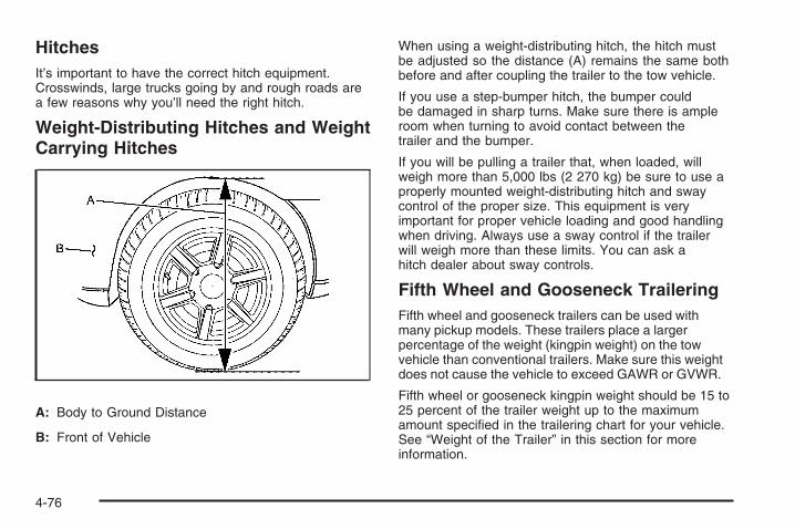
HitchesIt’s important to have the correct hitch equipment.Crosswinds, large trucks going by and rough roads area few reasons why you’ll need the right hitch.
Weight-Distributing Hitches and WeightCarrying Hitches
A: Body to Ground Distance
B: Front of Vehicle
When using a weight-distributing hitch, the hitch mustbe adjusted so the distance (A) remains the same bothbefore and after coupling the trailer to the tow vehicle.
If you use a step-bumper hitch, the bumper couldbe damaged in sharp turns. Make sure there is ampleroom when turning to avoid contact between thetrailer and the bumper.
If you will be pulling a trailer that, when loaded, willweigh more than 5,000 lbs (2 270 kg) be sure to use aproperly mounted weight-distributing hitch and swaycontrol of the proper size. This equipment is veryimportant for proper vehicle loading and good handlingwhen driving. Always use a sway control if the trailerwill weigh more than these limits. You can ask ahitch dealer about sway controls.
Fifth Wheel and Gooseneck TraileringFifth wheel and gooseneck trailers can be used withmany pickup models. These trailers place a largerpercentage of the weight (kingpin weight) on the towvehicle than conventional trailers. Make sure this weightdoes not cause the vehicle to exceed GAWR or GVWR.
Fifth wheel or gooseneck kingpin weight should be 15 to25 percent of the trailer weight up to the maximumamount specified in the trailering chart for your vehicle.See “Weight of the Trailer” in this section for moreinformation.
4-76

The hitch should be located in the pickup bed so that it’scenterline is over or slightly in front of the rear axle. Takecare that it is not so far forward that it will contact the backof the cab in sharp turns. This is especially important forshort box pickups. Trailer pin box extensions and slidingfifth wheel hitch assemblies can help this condition. Thereshould be at least six inches of clearance between the topof the pickup box and the bottom of the trailer shelf thatextends over the box.
Make sure the hitch is attached to the tow vehicle framerails. Do not use the pickup box for support.
Safety ChainsYou should always attach chains between your vehicleand your trailer. Cross the safety chains under the tongueof the trailer to help prevent the tongue from contactingthe road if it becomes separated from the hitch.Instructions about safety chains may be provided by thehitch manufacturer or by the trailer manufacturer. If youare towing a trailer up to 5,000 lbs (2 271 kg) with afactory-installed step bumper, you may attach the safetychains to the attaching points on the bumper. If you aretowing a trailer up to your vehicle’s trailer rating limit youmay attach the safety chains to the attaching point on thehitch platform. If you are towing with an aftermarket hitchfollow the trailer or hitch manufacturer’s recommendationfor attaching safety chains. Always leave just enoughslack so you can turn with your rig. Never allow safetychains to drag on the ground.
Trailer BrakesIf your trailer weighs more than 2,000 lbs (900 kg)loaded, then it needs its own brakes – and they must beadequate. Be sure to read and follow the instructionsfor the trailer brakes so you’ll be able to install,adjust and maintain them properly.
If your vehicle is equipped with StabiliTrak®, your trailercannot tap into the vehicle’s hydraulic brake system.
Your trailer brake system can tap into the vehicle’shydraulic brake system only if:
• The trailer parts can withstand 3,000 psi(20 650 kPa) of pressure.
• The trailer’s brake system will use less than0.02 cubic inch (0.3 cc) of fluid from your vehicle’smaster cylinder. Otherwise, both braking systemswon’t work well. You could even lose your brakes.
If everything checks out this far, make the brake tap atthe port on the master cylinder that sends the fluidto the rear brakes. But don’t use copper tubing for this.If you do, it will bend and finally break off. Use steelbrake tubing.
4-77

Integrated Trailer Brake ControlSystem
Your vehicle may have anIntegrated Trailer BrakeControl (ITBC) system forelectric trailer brakes.
This symbol is located on the Trailer Brake ControlPanel on vehicles with an Integrated Trailer BrakeControl System. The power output to the trailer brakesis based on the amount of brake pressure beingapplied by your vehicle’s brake system. This availablepower output to the trailer brakes can be adjustedto a wide range of trailering situations.
The ITBC system is integrated with your vehicle’s brake,anti-lock brake and StabiliTrak (if equipped) systems.In trailering conditions that cause your vehicle’s anti-lockbrake or StabiliTrak systems to activate, power sentto the trailer’s brakes will be automatically adjusted tominimize trailer wheel lock-up. This does not implythat your trailer has the StabiliTrak system.
If your vehicle’s brake, anti-lock brake or StabiliTraksystems are not functioning properly, your ITBC systemmay not be fully functional or may not function at all.Make sure all of these systems are fully operational toensure full functionality of the ITBC system.
The ITBC system is powered through your vehicle’selectrical system. Turning the ignition off will also turn offthe ITBC system. The ITBC system is fully functionalonly when the ignition is in ON or in RUN.
The ITBC system can only be used with trailers withelectric brakes.
4-78

{CAUTION:
Connecting a trailer that is not compatible withthe ITBC system may result in reduced orcomplete loss of trailer braking. There may bean increase in stopping distance or trailerinstability which could result in personal injuryor damage to your vehicle, trailer, or otherproperty. An aftermarket controller may beavailable for use with trailers with surge, air orelectric-over-hydraulic trailer brake systems.To determine the type of brakes on your trailerand the availability of controllers, check withyour trailer manufacturer or dealer.
When trailering, make sure of the following:
• The ITBC system is used only with trailers that areequipped with electric brakes.
• All applicable local and federal laws and regulationsare followed.
• All electrical and mechanical connections to thetrailer are made correctly.
• The trailer’s brakes are in proper working condition.
• The trailer and vehicle are properly loaded forthe towing condition.
The ITBC system is a factory installed item.Out-of-factory installation of this system should not beattempted. GM is not responsible for warranty orperformance of the system resulting from out-of-factoryinstallation.
4-79

Trailer Brake Control Panel
A. Manual Trailer Brake Apply LeverB. Trailer Gain Adjustment Buttons
The ITBC system has a control panel located on theinstrument panel to the left of the steering column. SeeInstrument Panel Overview (Base/Uplevel version) onpage 3-4 or Instrument Panel Overview (Premiumversion) on page 3-6 for more information on location.The control panel allows you to adjust the amount ofoutput, referred to as trailer gain, available to the electrictrailer brakes and allows you to manually apply the trailerbrakes. The Trailer Brake Control Panel is used alongwith the Trailer Brake Display Page on the DIC to adjustand display power output to the trailer brakes.
Trailer Brake DIC Display PageThe ITBC system displays messages into the vehicle’sDriver Information Center (DIC). See DIC Warningsand Messages on page 3-66 for more information.
4-80
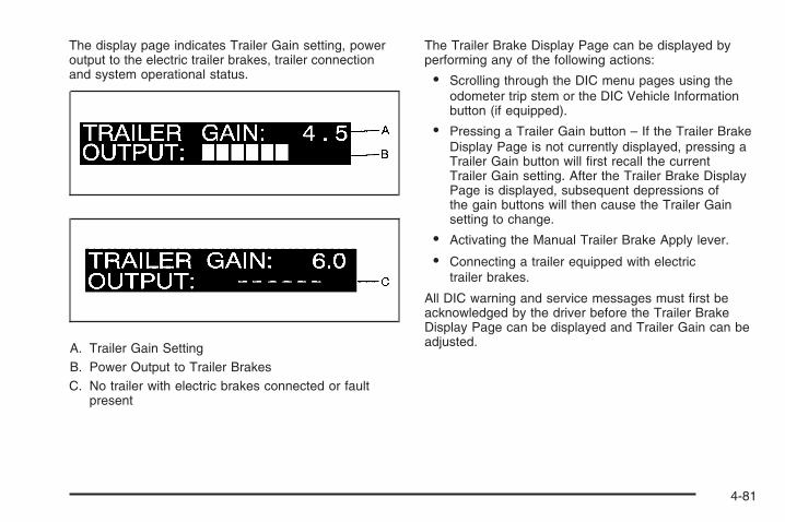
The display page indicates Trailer Gain setting, poweroutput to the electric trailer brakes, trailer connectionand system operational status.
A. Trailer Gain SettingB. Power Output to Trailer BrakesC. No trailer with electric brakes connected or fault
present
The Trailer Brake Display Page can be displayed byperforming any of the following actions:
• Scrolling through the DIC menu pages using theodometer trip stem or the DIC Vehicle Informationbutton (if equipped).
• Pressing a Trailer Gain button – If the Trailer BrakeDisplay Page is not currently displayed, pressing aTrailer Gain button will first recall the currentTrailer Gain setting. After the Trailer Brake DisplayPage is displayed, subsequent depressions ofthe gain buttons will then cause the Trailer Gainsetting to change.
• Activating the Manual Trailer Brake Apply lever.
• Connecting a trailer equipped with electrictrailer brakes.
All DIC warning and service messages must first beacknowledged by the driver before the Trailer BrakeDisplay Page can be displayed and Trailer Gain can beadjusted.
4-81

TRAILER GAIN – This setting is displayed anytime theTrailer Brake Display Page is active. This settingcan be adjusted from 0.0 to 10.0 with either a trailerconnected or disconnected. To adjust the Trailer Gain,press one of the Trailer Gain adjustment buttonslocated on the Trailer Brake Control Panel. Press andhold a gain button to cause the Trailer Gain tocontinuously adjust. To turn the output to the trailer off,adjust the Trailer Gain setting to 0.0 (zero).
0.0 (zero) gain is the factory default setting. To properlyadjust trailer gain, see the Trailer Gain AdjustmentProcedure later in this section.
TRAILER OUTPUT – This is displayed any time a trailerwith electric brakes is connected. Output to the electricbrakes is based on the amount of vehicle brakingpresent and relative to the Trailer Gain setting. Output isdisplayed from 0 to 10 bars for each gain setting.
The Trailer Output will indicate “- - - - - -“ on the TrailerBrake Display Page whenever the following occur:
• No trailer is connected.
• A trailer without electric brakes is connected (noDIC message is displayed).
• A trailer with electric brakes has becomedisconnected (a CHECK TRAILER WIRINGmessage will also be displayed on the DIC).
• There is a fault present in the wiring to the electrictrailer brakes (a CHECK TRAILER WIRINGmessage will also be displayed on the DIC).
• There is a fault in the ITBC system (a SERVICETRAILER BRAKE SYSTEM message will alsobe displayed in the DIC).
Manual Trailer Brake ApplyThe Manual Trailer Brake Apply Lever is located on theTrailer Brake Control Panel and is used to apply thetrailer’s electric brakes independent of your vehicle’sbrakes. This lever is used in the Trailer Gain AdjustmentProcedure to properly adjust the power output to thetrailer brakes. Sliding the lever to the left will apply onlythe trailer brakes. The power output to the trailer isindicated in the Trailer Brake Display Page in the DIC. Ifyour vehicle’s service brakes are applied while using theManual Trailer Brake Apply Lever, the trailer outputpower will be the greater of the two.
The trailer and the vehicle’s brake lamps will come onwhen either vehicle braking or manual trailer brakesare applied.
4-82

Trailer Gain Adjustment ProcedureTrailer Gain should be set for a specific traileringcondition and must be adjusted any time vehicle loading,trailer loading or road surface conditions change.
Setting the Trailer Gain properly is needed for the besttrailer stopping performance. A trailer that isover-gained may result in locked trailer brakes. A trailerthat is under-gained may result in not enough trailerbraking. Both of these conditions may result in poorerstopping and stability of the vehicle and trailer.
Use the following procedure to correctly adjust TrailerGain for each towing condition:
1. Make sure the trailer brakes are in proper workingcondition.
2. Connect a properly loaded trailer to the vehicle andmake all necessary mechanical and electricalconnections. See Loading Your Vehicle onpage 4-36 for more information.
3. After the electrical connection is made to a trailerequipped with electric brakes:
• A TRAILER CONNECTED message will bebriefly displayed on the DIC display.
• The Trailer Brake Display Page will appear onthe DIC showing TRAILER GAIN and TRAILEROUTPUT.
• In the Trailer Output display on the DIC, “- - - - - -“will disappear if there is no error present.Connecting a trailer without electric brakes will notclear the six dashed lines.
4. Adjust the Trailer Gain by using the gain adjustment(+ / -) buttons on the Trailer Brake Control Panel.
5. Drive the vehicle with the trailer attached on a levelroad surface representative of the towing conditionand free of traffic at about 20 to 25 mph (32 to40 km/h) and fully apply the Manual Trailer BrakeApply lever.Adjusting trailer gain at speeds lower than20 to 25 mph (32 to 40 km/h) may result in anincorrect gain setting.
4-83

6. Adjust the Trailer Gain to just below the point oftrailer wheel lock-up, indicated by trailer wheelsqueal or puffs of tire smoke when a trailerwheel locks.Trailer wheel lock-up may not occur if towing aheavily loaded trailer. In this case, adjust the TrailerGain to the highest allowable setting for thetowing condition.
7. Re-adjust Trailer Gain any time vehicle loading,trailer loading or road surface conditions changeor if you notice trailer wheel lock-up at anytime while you are towing.
Other ITBC Related DIC MessagesIn addition to displaying TRAILER GAIN and TRAILEROUTPUT through the DIC, trailer connection andITBC system status is displayed in the DIC.
TRAILER CONNECTED – This message will be brieflydisplayed when a trailer with electric brakes is firstconnected to the vehicle. This message willautomatically turn off in about ten seconds. The drivercan also acknowledge this message before itautomatically turns off.
CHECK TRAILER WIRING – This message will bedisplayed if:
1. The ITBC system first determines connection to atrailer with electric brakes and then the trailerharness becomes disconnected from the vehicle.If the disconnect occurs while the vehicle isstationary, this message will automatically turn off inabout thirty seconds. This message will also turnoff if the driver acknowledges this message off or ifthe trailer harness is re-connected.If the disconnect occurs while the vehicle is moving,this message will continue until the ignition isturned off. This message will also turn off if thedriver acknowledges this message off or if the trailerharness is re-connected.
2. There is an electrical fault in the wiring to theelectric trailer brakes. This message will continue aslong as there is an electrical fault in the trailerwiring. This message will also turn off if the driveracknowledges this message off.
4-84

To determine if the electrical fault is on the vehicle sideor trailer side of the trailer wiring harness connection,do the following:
1. Disconnect the trailer wiring harness from thevehicle.
2. Turn the ignition OFF.
3. Wait ten seconds, then turn the ignition backto RUN.
4. If the CHECK TRAILER WIRING messagere-appears, the electrical fault is on the vehicle side.If the CHECK TRAILER WIRING message onlyre-appears when you connect the trailer wiringharness to the vehicle, the electrical fault is on thetrailer side.
SERVICE TRAILER BRAKE SYSTEM – This messagewill be displayed when there is a problem with theITBC system. If this message persists over multipleignition cycles there is problem with the ITBC system.Take your vehicle to an authorized GM dealer tohave the ITBC system diagnosed and repaired.
If either the CHECK TRAILER WIRING or SERVICETRAILER BRAKE SYSTEM message is displayed whileyou are driving your vehicle, you no longer havepower available to your trailer brakes. When trafficconditions allow, carefully pull your vehicle over to theside of the road and turn the ignition off. Check thewiring connection to the trailer and turn the ignition backon. If either of these messages continues, either yourvehicle or your trailer needs service.
An authorized GM dealer may be able to diagnose andrepair problems with your trailer. However, anydiagnosis and repair of your trailer is not covered underyour GM Warranty. Please contact your trailer dealerfor assistance with trailer repairs and trailer warrantyinformation.
4-85

Driving with a Trailer
{CAUTION:
If you have a rear-most window open and youpull a trailer with your vehicle, carbon monoxide(CO) could come into your vehicle. You cannotsee or smell CO. It can cause unconsciousnessor death. See Engine Exhaust on page 2-54. Tomaximize your safety when towing a trailer:
• Have your exhaust system inspected forleaks, and make necessary repairs beforestarting on your trip.
• Keep the rear-most windows closed.
CAUTION: (Continued)
CAUTION: (Continued)
• If exhaust does come into your vehiclethrough a window in the rear or anotheropening, drive with your front, mainheating or cooling system on and with thefan on any speed. This will bring fresh,outside air into your vehicle. Do not usethe climate control setting for maximum airbecause it only recirculates the air insideyour vehicle. See Climate Control System(With Air Conditioning ) on page 3-25 orClimate Control System (Heater Only) onpage 3-28.
Towing a trailer requires a certain amount of experience.Before setting out for the open road, you’ll want to getto know your rig. Acquaint yourself with the feel ofhandling and braking with the added weight of the trailer.And always keep in mind that the vehicle you aredriving is now a good deal longer and not nearly asresponsive as your vehicle is by itself.
4-86

Before you start, check all trailer hitch parts andattachments, safety chains, electrical connector, lamps,tires and mirror adjustment. If the trailer has electricbrakes, start your vehicle and trailer moving and thenapply the trailer brake controller by hand to be surethe brakes are working. This lets you check yourelectrical connection at the same time.
During your trip, check occasionally to be sure that theload is secure, and that the lamps and any trailerbrakes are still working.
While towing a trailer or when exposed to long periodsof sunshine, the floor of the truck bed may becomevery warm. Avoid putting items in the truck bedthat might be affected by high ambient temperatures.
Following DistanceStay at least twice as far behind the vehicle ahead asyou would when driving your vehicle without a trailer.This can help you avoid situations that requireheavy braking and sudden turns.
PassingYou’ll need more passing distance up ahead whenyou’re towing a trailer. And, because you’re a good deallonger, you’ll need to go much farther beyond thepassed vehicle before you can return to your lane.
Backing UpHold the bottom of the steering wheel with one hand.Then, to move the trailer to the left, just move that handto the left. To move the trailer to the right, move yourhand to the right. Always back up slowly and, if possible,have someone guide you.
Making Turns
Notice: Making very sharp turns while traileringcould cause the trailer to come in contact with thevehicle. Your vehicle could be damaged. Avoidmaking very sharp turns while trailering.
When you’re turning with a trailer, make wider turns thannormal. Do this so your trailer won’t strike soft shoulders,curbs, road signs, trees or other objects. Avoid jerky orsudden maneuvers. Signal well in advance.
4-87

Turn Signals When Towing a TrailerThe arrows on your instrument panel will flash wheneveryou signal a turn or lane change. Properly hooked up,the trailer lamps will also flash, telling other driversyou’re about to turn, change lanes or stop.
When towing a trailer, the arrows on your instrumentpanel will flash for turns even if the bulbs on the trailerare burned out. Thus, you may think drivers behindyou are seeing your signal when they are not. It’simportant to check occasionally to be sure the trailerbulbs are still working.
Driving On GradesReduce speed and shift to a lower gear before you startdown a long or steep downgrade. If you don’t shiftdown, you might have to use your brakes so much thatthey would get hot and no longer work well.
You can tow in DRIVE (D). You may want to shift thetransmission to lower gear selection if the transmissionshifts too often (e.g., under heavy loads and/or hillyconditions).
You may also want to activate the tow/haul mode if thetransmission shifts too often. See “Tow/Haul Mode”later in this section.
When towing at high elevation on steep uphill grades,consider the following: Engine coolant at higherelevations will boil at a lower temperature than at ornear sea level. If you turn your engine off immediatelyafter towing at high elevation on steep uphill grades,your vehicle may show signs similar to engineoverheating. To avoid this, let the engine run whileparked, preferably on level ground, with the transmissionin PARK (P) at least five minutes before turning theengine off. If you do get the overheat warning, seeEngine Overheating on page 5-32.
4-88
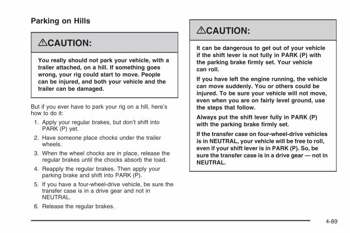
Parking on Hills
{CAUTION:
You really should not park your vehicle, with atrailer attached, on a hill. If something goeswrong, your rig could start to move. Peoplecan be injured, and both your vehicle and thetrailer can be damaged.
But if you ever have to park your rig on a hill, here’show to do it:
1. Apply your regular brakes, but don’t shift intoPARK (P) yet.
2. Have someone place chocks under the trailerwheels.
3. When the wheel chocks are in place, release theregular brakes until the chocks absorb the load.
4. Reapply the regular brakes. Then apply yourparking brake and shift into PARK (P).
5. If you have a four-wheel-drive vehicle, be sure thetransfer case is in a drive gear and not inNEUTRAL.
6. Release the regular brakes.
{CAUTION:
It can be dangerous to get out of your vehicleif the shift lever is not fully in PARK (P) withthe parking brake firmly set. Your vehiclecan roll.
If you have left the engine running, the vehiclecan move suddenly. You or others could beinjured. To be sure your vehicle will not move,even when you are on fairly level ground, usethe steps that follow.
Always put the shift lever fully in PARK (P)with the parking brake firmly set.
If the transfer case on four-wheel-drive vehiclesis in NEUTRAL, your vehicle will be free to roll,even if your shift lever is in PARK (P). So, besure the transfer case is in a drive gear — not inNEUTRAL.
4-89

When You Are Ready to Leave AfterParking on a Hill1. Apply your regular brakes and hold the pedal down
while you:
• Start your engine
• Shift into a gear
• Release the parking brake
2. Let up on the brake pedal.
3. Drive slowly until the trailer is clear of the chocks.
4. Stop and have someone pick up and store thechocks.
Maintenance When Trailer TowingYour vehicle will need service more often when you’repulling a trailer. See Scheduled Maintenance (GasolineEngine) on page 6-4 for more information. Thingsthat are especially important in trailer operation areautomatic transmission fluid (don’t overfill), engine oil,axle lubricant, belt, cooling system and brake system.Each of these is covered in this manual, and the Indexwill help you find them quickly. If you’re trailering, it’sa good idea to review these sections before youstart your trip.
Check periodically to see that all hitch nuts and boltsare tight.
Trailer Wiring HarnessYour vehicle is equipped with one of the following wiringharnesses for towing a trailer or hauling a slide-incamper.
Basic Trailer WiringAll regular, extended cab and crew cab pickups have aseven-wire trailer towing harness.
For vehicles not equipped with heavy duty trailering, theharness is clipped to the vehicle’s frame behind thespare tire mount. The harness requires the installationof a trailer connector, which is available throughyour dealer.
If you need to tow a light-duty trailer with a standardfour-way round pin connector, you can also get anadapter from your dealer.
4-90

Heavy-Duty Trailer Wiring HarnessPackage
For vehicles equipped with heavy duty trailering, theharness is connected to a bracket on the hitch platform.The seven-wire harness contains the following trailercircuits:
• Yellow: Left Stop/Turn Signal
• Dark Green: Right Stop/Turn Signal
• Brown: Taillamps
• White: Ground
• Light Green: Back-up Lamps
• Red: Battery Feed*
• Dark Blue: Trailer Brake*
*The fuses for these two circuits are installed in theunderhood electrical center, but the wires are notconnected. They should be connected by your dealer ora qualified service center. The fuse and wire for theITBC is factory installed and connected if the vehicle isequipped with an ITBC. The fuse for the batteryfeed is not required if your vehicle has an auxiliarybattery. If your vehicle does not have an auxiliarybattery, have your dealer or authorized service centerinstall the required fuse.
If you are charging a remote (non-vehicle) battery, pressthe tow/haul mode button located at the end of theshift lever. This will boost the vehicle system voltage andproperly charge the battery. If the trailer is too light fortow/haul mode, you can turn on the headlamps asa second way to boost the vehicle system and chargethe battery.
4-91

Camper/Fifth-Wheel Trailer Wiring PackageThe seven-wire camper harness is located under thefront edge of the pickup box on the driver’s side of thevehicle, attached to the frame bracket. A connectorwill have to be added to the wiring harness whichconnects to the camper.
The harness contains the following camper/trailercircuits:
• Yellow: Left Stop/Turn Signal
• Dark Green: Right Stop/Turn Signal
• Brown: Taillamps
• White: Ground
• Light Green: Back-up Lamps
• Red: Battery Feed
• Dark Blue: Trailer Brake
If your vehicle is equipped with the “Heavy-DutyTrailering” option, please refer to “Heavy-Duty TrailerWiring Package” earlier in this section.
When the camper-wiring harness is ordered without theheavy-duty trailering package, an eight-wire harnesswith a seven-pin connector is located at the rear of thevehicle and is tied to the vehicle’s frame.
4-92
Electric Brake Control WiringProvisionsThese wiring provisions are included with your vehicleas part of the trailer wiring package. These provisionsare for an electric brake controller. The instrument panelcontains blunt cut wires near the data link connectorfor the trailer brake controller. The harness contains thefollowing wires:
• Dark Blue: Brake Signal to Trailer Connector
• Red/Black: Battery
• Light Blue/White: Brake Switch
• White: Ground
It should be installed by your dealer or a qualifiedservice center.
If your vehicle is equipped with an ITBC, the blunt cutsexist, but are not connected further in the harness. Ifyou install an aftermarket trailer brake controller,the ITBC must be disconnected. Do not power bothITBC and aftermarket controllers to control the trailerbrakes at the same time.
Auxiliary BatteryThe auxiliary battery provision can be used to supplyelectrical power to additional equipment that you maychoose to add, such as a slide-in camper. If your vehiclehas this provision, this relay will be located on the driver’sside of the vehicle, next to the underhood electricalcenter.
Be sure to follow the proper installation instructions thatare included with any electrical equipment that you install.
Notice: Leaving electrical equipment on forextended periods will drain the battery. Always turnoff electrical equipment when not in use and donot use equipment that exceeds the maximumamperage rating for the auxiliary battery provision.
Trailer RecommendationsYou must subtract your hitch loads from the CWR foryour vehicle. Weigh your vehicle with the trailerattached, so that you won’t go over the GVWR orGAWR. If you are using a weight-distributing hitch,weigh the vehicle without the spring bars in place.
You’ll get the best performance if you spread out theweight of your load the right way, and if you choose thecorrect hitch and trailer brakes.For more information, see Towing a Trailer onpage 4-55.
4-93

✍ NOTES
4-94
Service ............................................................5-4Accessories and Modifications ..........................5-4California Proposition 65 Warning .....................5-4California Perchlorate Materials Requirements .....5-5Doing Your Own Service Work .........................5-5Adding Equipment to the Outside of
Your Vehicle ..............................................5-5Fuel ................................................................5-6
Gasoline Octane ............................................5-6Gasoline Specifications ....................................5-6California Fuel ...............................................5-7Additives .......................................................5-7Fuel E85 (85% Ethanol) ..................................5-8Fuels in Foreign Countries ...............................5-9Filling the Tank ............................................5-10Filling a Portable Fuel Container .....................5-12
Checking Things Under the Hood ....................5-12Hood Release ..............................................5-13Engine Compartment Overview .......................5-14Engine Oil (Gasoline Engine) ..........................5-15Engine Oil Life System ..................................5-18Engine Air Cleaner/Filter (Gasoline Engines) .....5-20Automatic Transmission Fluid
(6-Speed Transmission) ..............................5-22
Automatic Transmission Fluid(4-Speed Transmission) ..............................5-26
Engine Coolant .............................................5-29Coolant Surge Tank Pressure Cap ..................5-32Engine Overheating .......................................5-32Overheated Engine Protection
Operating Mode (V8 Engines Only) ..............5-34Cooling System ............................................5-35Engine Fan Noise .........................................5-40Power Steering Fluid .....................................5-41Windshield Washer Fluid ................................5-42Brakes ........................................................5-43Battery ........................................................5-46Jump Starting ...............................................5-47
Rear Axle .......................................................5-52Four-Wheel Drive ............................................5-54Front Axle ......................................................5-56Noise Control System .....................................5-57
Tampering with Noise Control SystemProhibited .................................................5-57
Headlamp Aiming ...........................................5-58
Section 5 Service and Appearance Care
5-1

Bulb Replacement ..........................................5-61Halogen Bulbs ..............................................5-61Headlamps ..................................................5-62Center High-Mounted Stoplamp (CHMSL) and
Cargo Lamp .............................................5-63Pickup Box Identification and
Fender Marker Lamps ................................5-64Taillamps, Turn Signal, Stoplamps and
Back-up Lamps .........................................5-64License Plate Lamp ......................................5-66Replacement Bulbs .......................................5-66
Windshield Wiper Blade Replacement ..............5-67Tires ..............................................................5-68
Tire Sidewall Labeling ...................................5-69Tire Terminology and Definitions .....................5-73Inflation - Tire Pressure .................................5-76Dual Tire Operation .......................................5-77Tire Pressure Monitor System .........................5-78Tire Pressure Monitor Operation .....................5-79Tire Inspection and Rotation ...........................5-83When It Is Time for New Tires .......................5-86Buying New Tires .........................................5-86Different Size Tires and Wheels ......................5-88Uniform Tire Quality Grading ..........................5-89
Wheel Alignment and Tire Balance ..................5-90Wheel Replacement ......................................5-90Tire Chains ..................................................5-92If a Tire Goes Flat ........................................5-93Changing a Flat Tire .....................................5-94Removing the Spare Tire and Tools ................5-95Removing the Flat Tire and Installing the
Spare Tire ..............................................5-100Secondary Latch System ..............................5-106Storing a Flat or Spare Tire and Tools ...........5-110Spare Tire .................................................5-113
Appearance Care ..........................................5-114Interior Cleaning .........................................5-114Fabric/Carpet ..............................................5-115Leather ......................................................5-116Instrument Panel, Vinyl, and Other Plastic
Surfaces .................................................5-117Care of Safety Belts ....................................5-117Weatherstrips .............................................5-117Washing Your Vehicle ..................................5-118Cleaning Exterior Lamps/Lenses ....................5-118Finish Care ................................................5-119Windshield and Wiper Blades .......................5-120Aluminum or Chrome-Plated Wheels
and Trim ................................................5-120
Section 5 Service and Appearance Care
5-2

Tires .........................................................5-121Sheet Metal Damage ...................................5-121Finish Damage ...........................................5-122Underbody Maintenance ...............................5-122Chemical Paint Spotting ...............................5-122Vehicle Care/Appearance Materials ................5-123
Vehicle Identification .....................................5-124Vehicle Identification Number (VIN) ................5-124Service Parts Identification Label ...................5-124
Electrical System ..........................................5-125Add-On Electrical Equipment .........................5-125Windshield Wiper Fuses ...............................5-125Power Windows and Other Power Options ......5-125Fuses and Circuit Breakers ..........................5-125Instrument Panel Fuse Block ........................5-126Center Instrument Panel Fuse Block ..............5-128Underhood Fuse Block ................................5-129
Capacities and Specifications ........................5-133
Section 5 Service and Appearance Care
5-3

ServiceFor service and parts needs, visit your dealer/retailer.You will receive genuine GM parts and GM-trained andsupported service people.
Genuine GM parts have one of these marks:
Accessories and ModificationsWhen non-dealer/non-retailer accessories are added toyour vehicle they can affect your vehicle’s performanceand safety, including such things as, airbags, braking,stability, ride and handling, emissions systems,aerodynamics, durability, and electronic systems likeantilock brakes, traction control and stability control.Some of these accessories could even causemalfunction or damage not covered by warranty.
GM Accessories are designed to complement andfunction with other systems on your vehicle. Your GMdealer/retailer can accessorize your vehicle usinggenuine GM Accessories. When you go to yourGM dealer/retailer and ask for GM Accessories, you willknow that GM-trained and supported service technicianswill perform the work using genuine GM Accessories.
Also, see Adding Equipment to Your Airbag-EquippedVehicle on page 1-86.
California Proposition 65 WarningMost motor vehicles, including this one, contain and/oremit chemicals known to the State of California tocause cancer and birth defects or other reproductiveharm. Engine exhaust, many parts and systems(including some inside the vehicle), many fluids, andsome component wear by-products contain and/or emitthese chemicals.
5-4

California Perchlorate MaterialsRequirementsCertain types of automotive applications, such as airbaginitiators, seat belt pretensioners, and lithium batteriescontained in remote keyless entry transmitters, maycontain perchlorate materials. Special handling may benecessary. For additional information, seewww.dtsc.ca.gov/hazardouswaste/perchlorate.
Doing Your Own Service Work
{CAUTION:
You can be injured and your vehicle could bedamaged if you try to do service work on avehicle without knowing enough about it.
• Be sure you have sufficient knowledge,experience, the proper replacement parts,and tools before you attempt any vehiclemaintenance task.
• Be sure to use the proper nuts, bolts,and other fasteners. English and metricfasteners can be easily confused. If youuse the wrong fasteners, parts can laterbreak or fall off. You could be hurt.
If you want to do some of your own service work, youshould use the proper service manual. It tells you muchmore about how to service your vehicle than thismanual can. To order the proper service manual, seeService Publications Ordering Information on page 7-15.
Your vehicle has an airbag system. Before attemptingto do your own service work, see Servicing YourAirbag-Equipped Vehicle on page 1-86.
You should keep a record with all parts receipts and listthe mileage and the date of any service work youperform. See Maintenance Record on page 6-18.
Adding Equipment to the Outsideof Your VehicleThings you might add to the outside of your vehicle canaffect the airflow around it. This can cause windnoise and can affect fuel economy and windshieldwasher performance. Check with your dealer/retailerbefore adding equipment to the outside of your vehicle.
5-5

FuelIf your vehicle has a diesel engine, see “Diesel FuelRequirements and Fuel System” in the DURAMAX®
Diesel manual.
For vehicles with gasoline engines, please read this.
GasolineUse of the recommended fuel is an important part of theproper maintenance of your vehicle. To help keep theengine clean and maintain optimum vehicle performance,we recommend the use of gasoline advertised as TOPTIER Detergent Gasoline.
The 8th digit of the Vehicle Identification Number (VIN)shows the code letter or number that identifies yourvehicle’s engine. The VIN is at the top left of theinstrument panel. See Vehicle Identification Number(VIN) on page 5-124.
If your vehicle has the 5.3L V8 engine (VIN Code 0) orthe 5.3L V8 engine (VIN Code 3), you can use eitherregular unleaded gasoline or ethanol fuel containing up to85% ethanol (E85); also see Fuel E85 (85% Ethanol) onpage 5-8. In all other gasoline engines, use only regularunleaded gasoline.
Gasoline OctaneUse regular unleaded gasoline with a posted octanerating of 87 or higher. If the octane rating is less than 87,you might notice an audible knocking noise when youdrive, commonly referred to as spark knock. If thisoccurs, use a gasoline rated at 87 octane or higher assoon as possible. If you are using gasoline rated at87 octane or higher and you hear heavy knocking,the engine needs service.
Gasoline SpecificationsAt a minimum, gasoline should meet ASTMspecification D 4814 in the United States orCAN/CGSB-3.5 or 3.511 in Canada. Some gasolinescontain an octane-enhancing additive calledmethylcyclopentadienyl manganese tricarbonyl (MMT).We recommend against the use of gasolinescontaining MMT. See Additives on page 5-7 foradditional information.
5-6
California FuelIf your vehicle is certified to meet California EmissionsStandards, it is designed to operate on fuels thatmeet California specifications. See the underhoodemission control label. If this fuel is not availablein states adopting California emissions standards,your vehicle will operate satisfactorily on fuels meetingfederal specifications, but emission control systemperformance might be affected. The malfunctionindicator lamp could turn on and your vehicle might faila smog-check test. See Malfunction Indicator Lampon page 3-49. If this occurs, return to your authorizeddealer/retailer for diagnosis. If it is determined thatthe condition is caused by the type of fuel used, repairsmight not be covered by the vehicle warranty.
AdditivesTo provide cleaner air, all gasolines in the United Statesare now required to contain additives that help preventengine and fuel system deposits from forming, allowingthe emission control system to work properly. In mostcases, you should not have to add anything to the fuel.However, some gasolines contain only the minimumamount of additive required to meet U.S. EnvironmentalProtection Agency regulations. To help keep fuelinjectors and intake valves clean, or if your vehicleexperiences problems due to dirty injectors or valves,
look for gasoline that is advertised as TOP TIERDetergent Gasoline. Also, your dealer/retailer hasadditives that will help correct and prevent mostdeposit-related problems.
Gasolines containing oxygenates, such as ethers andethanol, and reformulated gasolines might be available inyour area. We recommend that you use these gasolines,if they comply with the specifications described earlier.However, E85 (85% ethanol) and other fuels containingmore than 10% ethanol must not be used in vehicles thatwere not designed for those fuels.
Notice: Your vehicle was not designed for fuelthat contains methanol. Do not use fuel containingmethanol. It can corrode metal parts in the fuelsystem and also damage plastic and rubber parts.That damage would not be covered under yourwarranty.
Some gasolines that are not reformulated for lowemissions can contain an octane-enhancing additivecalled methylcyclopentadienyl manganese tricarbonyl(MMT); ask the attendant where you buy gasolinewhether the fuel contains MMT. We recommend againstthe use of such gasolines. Fuels containing MMT canreduce the life of spark plugs and the performance ofthe emission control system could be affected.The malfunction indicator lamp might turn on. If thisoccurs, return to your dealer/retailer for service.
5-7

Fuel E85 (85% Ethanol)The 8th digit of the Vehicle Identification Number (VIN)shows the code letter or number that identifies yourvehicle’s engine. The VIN is at the top left of theinstrument panel. See Vehicle Identification Number(VIN) on page 5-124.
If your vehicle has the 5.3L V8 engine (VIN Code 0) orthe 5.3L V8 engine (VIN Code 3), you can use eitherregular unleaded gasoline or ethanol fuel containingup to 85% ethanol (E85); also see Fuel on page 5-6.In all other engines, use only the unleaded gasolinedescribed under Gasoline Octane on page 5-6.
Only vehicles that have the 5.3L V8 engine (VIN Code 0)or the 5.3L V8 engine (VIN Code 3) can use 85% ethanolfuel (E85). We encourage the use of E85 in vehiclesthat are designed to use it. The ethanol in E85 is a“renewable” fuel, meaning it is made from renewablesources such as corn and other crops.
Many service stations will not have an 85% ethanolfuel (E85) pump available. The U. S. Departmentof Energy has an alternative fuels website(www.eere.energy.gov/afdc/infrastructure/locator.html)that can help you find E85 fuel. Those stations thatdo have E85 should have a label indicating ethanolcontent. Do not use the fuel if the ethanol contentis greater than 85%.
At a minimum, E85 should meet ASTM SpecificationD 5798. By definition, this means that fuel labeled E85will have an ethanol content between 70% and 85%.Filling the fuel tank with fuel mixtures that do not meetASTM specifications can affect driveability and couldcause the malfunction indicator lamp to come on.
To ensure quick starts in the wintertime, the E85 fuelmust be formulated properly for your climate accordingto ASTM specification D 5798. If you have troublestarting on E85, it could be because the E85 fuel is notproperly formulated for your climate. If this happens,switching to gasoline or adding gasoline to the fuel tankcan improve starting. For good starting and heaterefficiency below 32°F (0°C), the fuel mix in the fuel tankshould contain no more than 70% ethanol. It is bestnot to alternate repeatedly between gasoline and E85.
5-8
If you do switch fuels, it is recommended that you addas much fuel as possible — do not add less thanthree gallons (11 L) when refueling. You should drivethe vehicle immediately after refueling for at leastseven miles (11 km) to allow the vehicle to adaptto the change in ethanol concentration.
E85 has less energy per gallon than gasoline, so youwill need to refill the fuel tank more often when usingE85 than when you are using gasoline. See Filling theTank on page 5-10.
Notice: Some additives are not compatible withE85 fuel and can harm your vehicle’s fuel system.Do not add anything to E85. Damage caused byadditives would not be covered by your newvehicle warranty.
Notice: Your vehicle was not designed for fuel thatcontains methanol. Do not use fuel containingmethanol. It can corrode metal parts in the fuelsystem and also damage plastic and rubber parts.That damage would not be covered under yourwarranty.
Fuels in Foreign CountriesIf you plan on driving in another country outside theUnited States or Canada, the proper fuel might behard to find. Never use leaded gasoline or any otherfuel not recommended in the previous text on fuel.Costly repairs caused by use of improper fuel wouldnot be covered by your warranty.
To check the fuel availability, ask an auto club, orcontact a major oil company that does business in thecountry where you will be driving.
5-9

Filling the TankIf your vehicle has the DURAMAX Diesel engine, seethe DURAMAX Diesel manual for more information.
{CAUTION:
Fuel vapor burns violently and a fuel fire cancause bad injuries. To help avoid injuries to youand others, read and follow all the instructionson the pump island. Turn off your engine whenyou are refueling. Do not smoke if you are nearfuel or refueling your vehicle. Do not usecellular phones. Keep sparks, flames, andsmoking materials away from fuel. Do not leavethe fuel pump unattended when refueling yourvehicle. This is against the law in some places.Do not re-enter the vehicle while pumping fuel.Keep children away from the fuel pump; neverlet children pump fuel.
The tethered fuel cap is located behind a hinged fueldoor on the driver’s side of the vehicle. If the vehiclehas E85 fuel capability, a yellow cap with the words“E85 / Gasoline” can be seen.
To remove the fuel cap, turn it slowly counterclockwise.
5-10

{CAUTION:
Fuel can spray out on you if you open the fuelcap too quickly. If you spill fuel and thensomething ignites it, you could be badly burned.This spray can happen if your tank is nearly full,and is more likely in hot weather. Open the fuelcap slowly and wait for any hiss noise to stop.Then unscrew the cap all the way.
If your vehicle is a dual fuel tank chassis cab model,and it runs out of fuel, refuel the front fuel tank firstto ensure a quick restart.
Be careful not to spill fuel. Do not top off or overfill thetank and wait a few seconds after you have finishedpumping before removing the nozzle. Clean fuelfrom painted surfaces as soon as possible.See Washing Your Vehicle on page 5-118.
When replacing the fuel cap, turn it clockwise until itclicks. It will require more effort to turn the fuel cap onthe last turn as you tighten it. Make sure the cap isfully installed. The diagnostic system can determine ifthe fuel cap has been left off or improperly installed.This would allow fuel to evaporate into the atmosphere.See Malfunction Indicator Lamp on page 3-49.
The TIGHTEN GAS CAP message will be displayed onthe Driver Information Center (DIC) if the fuel cap isnot properly installed. See DIC Warnings and Messageson page 3-66 for more information.
{CAUTION:
If a fire starts while you are refueling, do notremove the nozzle. Shut off the flow of fuel byshutting off the pump or by notifying thestation attendant. Leave the area immediately.
Notice: If you need a new fuel cap, be sure to getthe right type. Your dealer/retailer can get onefor you. If you get the wrong type, it may not fitproperly. This may cause your malfunction indicatorlamp to light and may damage your fuel tank andemissions system. See Malfunction Indicator Lampon page 3-49.
5-11

Filling a Portable Fuel Container
{CAUTION:
Never fill a portable fuel container while it isin your vehicle. Static electricity dischargefrom the container can ignite the fuel vapor.You can be badly burned and your vehicledamaged if this occurs. To help avoid injury toyou and others:
• Dispense fuel only into approvedcontainers.
• Do not fill a container while it is inside avehicle, in a vehicle’s trunk, pickup bed, oron any surface other than the ground.
• Bring the fill nozzle in contact with theinside of the fill opening before operatingthe nozzle. Contact should be maintaineduntil the filling is complete.
• Do not smoke while pumping fuel.• Do not use a cellular phone while
pumping fuel.
Checking Things Underthe Hood
{CAUTION:
An electric engine cooling fan can start evenwhen the engine is not running. To avoidinjury, always keep hands, clothing, and toolsaway from any engine cooling fan.
{CAUTION:
Things that burn can get on hot engine partsand start a fire. These include liquids like fuel,oil, coolant, brake fluid, windshield washer andother fluids, and plastic or rubber. You orothers could be burned. Be careful not to dropor spill things that will burn onto a hot engine.
5-12

Hood ReleaseTo open the hood do the following:
1. Pull the handle withthis symbol on it. It islocated inside thevehicle to the left of thebrake pedal.
2. Then go to the front of the vehicle and locate thesecondary hood release. This is located under thehood, near the center of the grille.
3. Push the secondary hood release to the right.
4. Lift the hood.Before closing the hood, be sure all the filler capsare on properly. Then bring the hood from full opento within 6 inches (152 mm) from the closedposition, pause, then push the front center of thehood with a swift, firm motion to fully close the hood.
5-13

Engine Compartment OverviewIf your vehicle has the DURAMAX® Diesel engine, see the DURAMAX® Diesel manual for more information.
When you open the hood on the 5.3L engine (4.3L, 4.8L and 6.0L similar), this is what you will see:
5-14

A. Engine Air Cleaner/Filter. See Engine AirCleaner/Filter (Gasoline Engines) on page 5-20.
B. Air Filter Restriction Indicator (If Equipped).See Engine Air Cleaner/Filter (Gasoline Engines)on page 5-20.
C. Coolant Surge Tank and Pressure Cap. See CoolingSystem on page 5-35 and Coolant Surge TankPressure Cap on page 5-32.
D. Positive (+) Terminal. See Jump Starting onpage 5-47.
E. Battery. See Battery on page 5-46.F. Engine Oil Fill Cap. See “When to Add Engine Oil”
under Engine Oil (Gasoline Engine) on page 5-15.G. Automatic Transmission Dipstick. See “Checking the
Fluid Level” under Automatic Transmission Fluid(6-Speed Transmission) on page 5-22 or AutomaticTransmission Fluid (4-Speed Transmission) onpage 5-26.
H. Remote Negative (−) Terminal (Out of View).See Jump Starting on page 5-47.
I. Engine Oil Dipstick (Out of View). See “CheckingEngine Oil” under Engine Oil (Gasoline Engine)on page 5-15.
J. Engine Cooling Fan. See Cooling System onpage 5-35.
K. Power Steering Fluid Reservoir. See Power SteeringFluid on page 5-41.
L. Brake Master Cylinder Reservoir. See “Brake Fluid”under Brakes on page 5-43.
M. Underhood Fuse Block. See Underhood Fuse Blockon page 5-129.
N. Windshield Washer Fluid Reservoir. See “AddingWasher Fluid” under Windshield Washer Fluidon page 5-42.
Engine Oil (Gasoline Engine)If your vehicle has a diesel engine, see “Engine Oil” inthe DURAMAX® Diesel manual.
Checking Engine OilIt is a good idea to check the engine oil every time youget fuel. In order to get an accurate reading, the oilmust be warm and the vehicle must be on level ground.
The engine oil dipstick handle is a yellow loop.See Engine Compartment Overview on page 5-14 forthe location of the engine oil dipstick.
1. Turn off the engine and give the oil several minutesto drain back into the oil pan. If you do not do this,the oil dipstick might not show the actual level.
2. Pull out the dipstick and clean it with a paper towelor cloth, then push it back in all the way. Remove itagain, keeping the tip down, and check the level.
5-15

When to Add Engine Oil
If the oil is below the cross-hatched area at the tipof the dipstick, add at least one quart/liter of therecommended oil. This section explains what kind ofoil to use. For engine oil crankcase capacity, seeCapacities and Specifications on page 5-133.
Notice: Do not add too much oil. If the engine hasso much oil that the oil level gets above thecross-hatched area that shows the proper operatingrange, the engine could be damaged.
See Engine CompartmentOverview on page 5-14for the location of theengine oil fill cap.
Be sure to add enough oil to put the level somewhere inthe proper operating range. Push the dipstick all theway back in when you are through.
5-16

What Kind of Engine Oil to Use
Look for three things:
• GM6094M
Your vehicle’s engine requires oil meetingGM Standard GM6094M. Look for and use onlyan oil that meets GM Standard GM6094M.
• SAE 5W-30
As shown in the viscosity chart, SAE 5W-30 is bestfor your vehicle.These numbers on an oil container show itsviscosity, or thickness. Do not use other viscosityoils such as SAE 20W-50.
• Oils meeting theserequirements shouldhave the starburstsymbol on the container.This symbol indicatesthat the oil hasbeen certified by theAmerican PetroleumInstitute (API).
Look for this information on the oil container, and useonly those oils that are identified as meeting GMStandard GM6094M and have the starburst symbol onthe front of the oil container.
Notice: Use only engine oil identified as meetingGM Standard GM6094M and showing the AmericanPetroleum Institute Certified For Gasoline Enginesstarburst symbol. Failure to use the recommendedoil can result in engine damage not covered byyour warranty.
5-17

If you are in an area of extreme cold, where thetemperature falls below −20°F (−29°C), it isrecommended that you use either an SAE 5W-30synthetic oil or an SAE 0W-30 oil. Both provide easiercold starting and better protection for the engine atextremely low temperatures.
Engine Oil AdditivesDo not add anything to the oil. The recommended oilswith the starburst symbol that meet GM StandardGM6094M are all you need for good performance andengine protection.
Engine Oil Life System
When to Change Engine OilYour vehicle has a computer system that lets you knowwhen to change the engine oil and filter. This is basedon engine revolutions and engine temperature, andnot on mileage. Based on driving conditions, the mileageat which an oil change will be indicated can varyconsiderably. For the oil life system to work properly,you must reset the system every time the oil is changed.
When the system has calculated that oil life has beendiminished, it will indicate that an oil change isnecessary. A CHANGE ENGINE OIL SOON messagewill come on. See DIC Warnings and Messages onpage 3-66. Change the oil as soon as possible within thenext 600 miles (1 000 km). It is possible that, if youare driving under the best conditions, the oil life systemmight not indicate that an oil change is necessary forover a year. However, the engine oil and filter must bechanged at least once a year and at this time thesystem must be reset. Your dealer/retailer has trainedservice people who will perform this work using genuineparts and reset the system. It is also important tocheck the oil regularly and keep it at the proper level.
If the system is ever reset accidentally, you must changethe oil at 3,000 miles (5 000 km) since your last oilchange. Remember to reset the oil life system wheneverthe oil is changed.
5-18

How to Reset the Engine Oil Life SystemThe Engine Oil Life System calculates when to changethe engine oil and filter based on vehicle use.Whenever the oil is changed, reset the system so itcan calculate when the next oil change is required.If a situation occurs where you change the oil prior to aCHANGE ENGINE OIL SOON message coming on,reset the system.
Always reset the engine oil life to 100% after every oilchange. It will not reset itself. To reset the EngineOil Life System:
1. Display the OIL LIFE REMAINING on the DIC.If your vehicle does not have DIC buttons, thevehicle must be in PARK (P) to access this display.See DIC Operation and Displays (With DICButtons) on page 3-57 or DIC Operation andDisplays (Without DIC Buttons) on page 3-63.
2. Press and hold the SET/RESET button on the DIC,or the trip odometer reset stem if your vehicle doesnot have DIC buttons, for more than five seconds.The oil life will change to 100%.
If the CHANGE ENGINE OIL SOON message comesback on when you start your vehicle, the Engine Oil LifeSystem has not reset. Repeat the procedure.
What to Do with Used OilUsed engine oil contains certain elements that can beunhealthy for your skin and could even cause cancer.Do not let used oil stay on your skin for very long.Clean your skin and nails with soap and water, or agood hand cleaner. Wash or properly dispose ofclothing or rags containing used engine oil. See themanufacturer’s warnings about the use and disposal ofoil products.
Used oil can be a threat to the environment. If youchange your own oil, be sure to drain all the oil from thefilter before disposal. Never dispose of oil by putting itin the trash, pouring it on the ground, into sewers,or into streams or bodies of water. Instead, recycle it bytaking it to a place that collects used oil. If you havea problem properly disposing of used oil, ask yourdealer/retailer, a service station, or a local recyclingcenter for help.
5-19
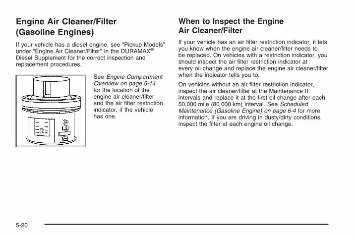
Engine Air Cleaner/Filter(Gasoline Engines)If your vehicle has a diesel engine, see “Pickup Models”under “Engine Air Cleaner/Filter” in the DURAMAX®
Diesel Supplement for the correct inspection andreplacement procedures.
See Engine CompartmentOverview on page 5-14for the location of theengine air cleaner/filterand the air filter restrictionindicator, if the vehiclehas one.
When to Inspect the EngineAir Cleaner/FilterIf your vehicle has an air filter restriction indicator, it letsyou know when the engine air cleaner/filter needs tobe replaced. On vehicles with a restriction indicator, youshould inspect the air filter restriction indicator atevery oil change and replace the engine air cleaner/filterwhen the indicator tells you to.
On vehicles without an air filter restriction indicator,inspect the air cleaner/filter at the Maintenance IIintervals and replace it at the first oil change after each50,000 mile (80 000 km) interval. See ScheduledMaintenance (Gasoline Engine) on page 6-4 for moreinformation. If you are driving in dusty/dirty conditions,inspect the filter at each engine oil change.
5-20
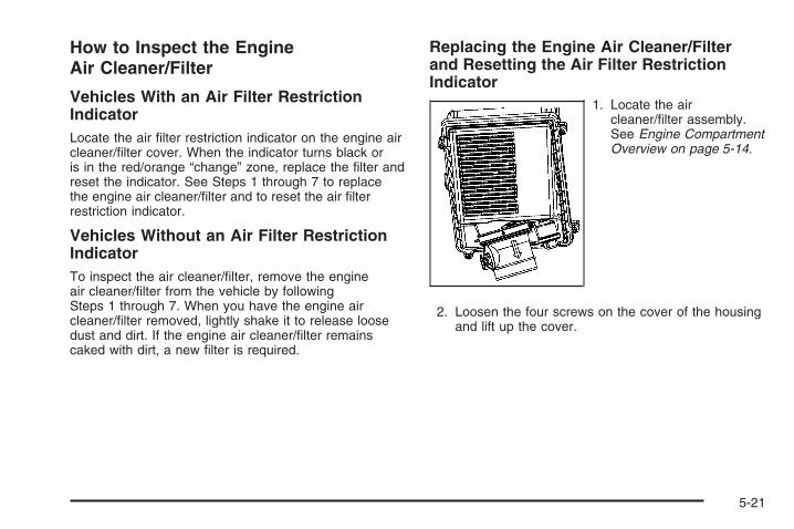
How to Inspect the EngineAir Cleaner/Filter
Vehicles With an Air Filter RestrictionIndicatorLocate the air filter restriction indicator on the engine aircleaner/filter cover. When the indicator turns black oris in the red/orange “change” zone, replace the filter andreset the indicator. See Steps 1 through 7 to replacethe engine air cleaner/filter and to reset the air filterrestriction indicator.
Vehicles Without an Air Filter RestrictionIndicatorTo inspect the air cleaner/filter, remove the engineair cleaner/filter from the vehicle by followingSteps 1 through 7. When you have the engine aircleaner/filter removed, lightly shake it to release loosedust and dirt. If the engine air cleaner/filter remainscaked with dirt, a new filter is required.
Replacing the Engine Air Cleaner/Filterand Resetting the Air Filter RestrictionIndicator
1. Locate the aircleaner/filter assembly.See Engine CompartmentOverview on page 5-14.
2. Loosen the four screws on the cover of the housingand lift up the cover.
5-21
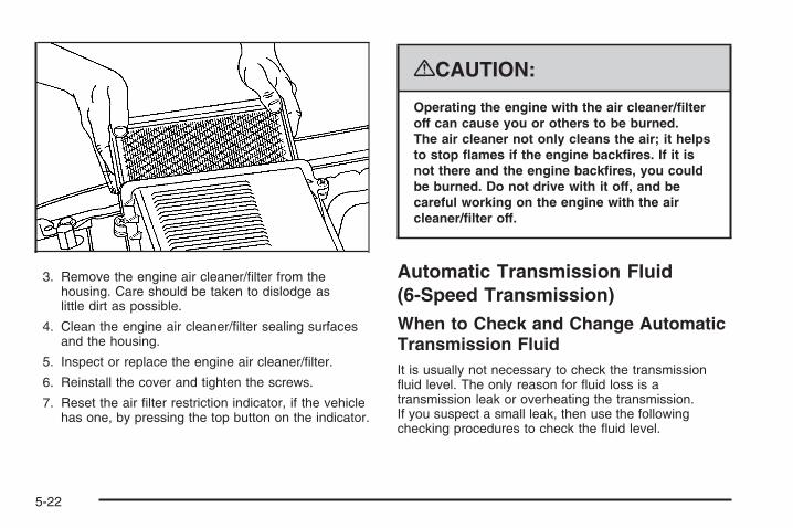
3. Remove the engine air cleaner/filter from thehousing. Care should be taken to dislodge aslittle dirt as possible.
4. Clean the engine air cleaner/filter sealing surfacesand the housing.
5. Inspect or replace the engine air cleaner/filter.
6. Reinstall the cover and tighten the screws.
7. Reset the air filter restriction indicator, if the vehiclehas one, by pressing the top button on the indicator.
{CAUTION:
Operating the engine with the air cleaner/filteroff can cause you or others to be burned.The air cleaner not only cleans the air; it helpsto stop flames if the engine backfires. If it isnot there and the engine backfires, you couldbe burned. Do not drive with it off, and becareful working on the engine with the aircleaner/filter off.
Automatic Transmission Fluid(6-Speed Transmission)When to Check and Change AutomaticTransmission FluidIt is usually not necessary to check the transmissionfluid level. The only reason for fluid loss is atransmission leak or overheating the transmission.If you suspect a small leak, then use the followingchecking procedures to check the fluid level.
5-22

However, if there is a large leak, then it may benecessary to have the vehicle towed to a dealer/retailerservice department and have it repaired before drivingthe vehicle further.
Notice: Use of the incorrect automatic transmissionfluid may damage your vehicle, and the damagesmay not be covered by your warranty. Alwaysuse the automatic transmission fluid listed inRecommended Fluids and Lubricants on page 6-14.
Change the fluid and filter at the intervals listed inthe Maintenance Schedule. See Scheduled Maintenance(Gasoline Engine) on page 6-4. Be sure to use thetransmission fluid listed in Recommended Fluids andLubricants on page 6-14.
How to Check AutomaticTransmission FluidNotice: Too much or too little fluid can damageyour transmission. Too much can mean that someof the fluid could come out and fall on hot engineparts or exhaust system parts, starting a fire.Too little fluid could cause the transmission tooverheat. Be sure to get an accurate reading if youcheck your transmission fluid.
Before checking the fluid level, prepare your vehicleas follows:
1. Start the engine and park your vehicle on a levelsurface. Keep the engine running.
2. Apply the parking brake and place the shift leverin P (PARK).
3. With your foot on the brake pedal, move the shiftlever through each gear range, pausing for aboutthree seconds in each range. Then, move theshift lever back to P (PARK).
4. Allow the engine to idle (500 – 800 rpm) for at leastone minute. Slowly release the brake pedal.
5. Keep the engine running and press the Trip/Fuelbutton or trip odometer reset stem until TRANSTEMP (Transmission Temperature) displays on theDriver Information Center (DIC).
6. Using the TRANS TEMP reading, determine andperform the appropriate check procedure. If theTRANS TEMP reading is not within the requiredtemperature ranges, allow the vehicle to cool,or operate the vehicle until the appropriatetransmission fluid temperature is reached.
5-23
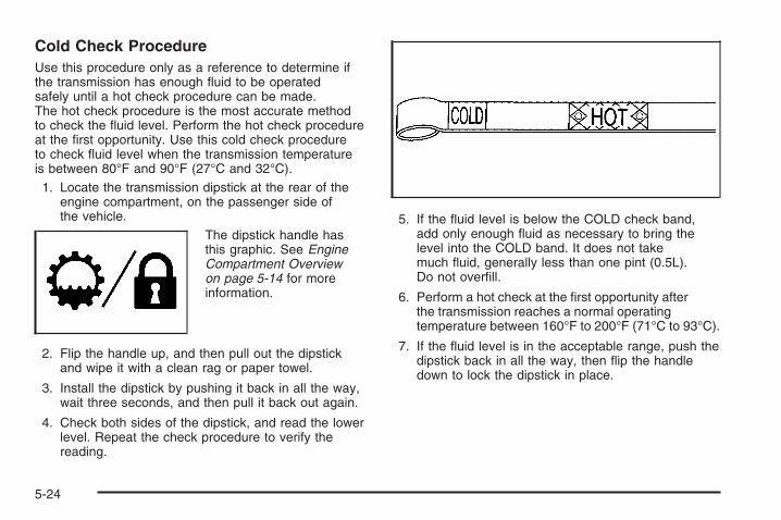
Cold Check ProcedureUse this procedure only as a reference to determine ifthe transmission has enough fluid to be operatedsafely until a hot check procedure can be made.The hot check procedure is the most accurate methodto check the fluid level. Perform the hot check procedureat the first opportunity. Use this cold check procedureto check fluid level when the transmission temperatureis between 80°F and 90°F (27°C and 32°C).1. Locate the transmission dipstick at the rear of the
engine compartment, on the passenger side ofthe vehicle.
The dipstick handle hasthis graphic. See EngineCompartment Overviewon page 5-14 for moreinformation.
2. Flip the handle up, and then pull out the dipstickand wipe it with a clean rag or paper towel.
3. Install the dipstick by pushing it back in all the way,wait three seconds, and then pull it back out again.
4. Check both sides of the dipstick, and read the lowerlevel. Repeat the check procedure to verify thereading.
5. If the fluid level is below the COLD check band,add only enough fluid as necessary to bring thelevel into the COLD band. It does not takemuch fluid, generally less than one pint (0.5L).Do not overfill.
6. Perform a hot check at the first opportunity afterthe transmission reaches a normal operatingtemperature between 160°F to 200°F (71°C to 93°C).
7. If the fluid level is in the acceptable range, push thedipstick back in all the way, then flip the handledown to lock the dipstick in place.
5-24

Hot Check ProcedureUse this procedure to check the transmission fluid levelwhen the transmission fluid temperature is between160°F and 200°F (71°C and 93°C).
The hot check is the most accurate method to check thefluid level. The hot check should be performed at the firstopportunity in order to verify the cold check. The fluidlevel rises as fluid temperature increases, so it isimportant to ensure the transmission temperature iswithin range.1. Locate the transmission dipstick at the rear of the
engine compartment, on the passenger side of thevehicle.
The dipstick handle hasthis graphic. See EngineCompartment Overviewon page 5-14 for moreinformation.
2. Flip the handle up, and then pull out the dipstickand wipe it with a clean rag or paper towel.
3. Install the dipstick by pushing it back in all the way,wait three seconds, and then pull it back out again.
4. Check both sides of the dipstick, and read the lowerlevel. Repeat the check procedure to verify thereading.
5. Safe operating level is within the HOT cross hatchband on the dipstick. If the fluid level is not withinthe HOT band, and the transmission temperature isbetween 160°F and 200°F (71°C and 93°C), addor drain fluid as necessary to bring the level intothe HOT band. If the fluid level is low, add onlyenough fluid to bring the level into the HOT band.It does not take much fluid, generally less thanone pint (0.5L). Do not overfill.
6. If the fluid level is in the acceptable range, push thedipstick back in all the way, then flip the handledown to lock the dipstick in place.
5-25

Consistency of ReadingsAlways check the fluid level at least twice using theprocedures described. Consistency (repeatablereadings) is important to maintaining proper fluid level.If fluid is added, it may take 15 minutes or longer toobtain an accurate reading because of residualfluid draining down the dipstick tube. If inconsistentreadings persist, check the transmission breather to besure it is clean and not clogged. If readings are stillinconsistent, contact your dealer/retailer.
Automatic Transmission Fluid(4-Speed Transmission)
When to Check and ChangeAutomatic Transmission FluidA good time to check your automatic transmission fluidlevel is when the engine oil is changed.
Change the fluid and filter at the intervals listed inAdditional Required Services on page 6-6, and be sureto use the transmission fluid listed in RecommendedFluids and Lubricants on page 6-14.
How to Check AutomaticTransmission FluidBecause this operation can be a little difficult, you maychoose to have this done at the dealer/retailer servicedepartment.
If you do it yourself, be sure to follow all the instructionshere, or you could get a false reading on the dipstick.
Notice: Too much or too little fluid can damageyour transmission. Too much can mean that someof the fluid could come out and fall on hot engineparts or exhaust system parts, starting a fire.Too little fluid could cause the transmission tooverheat. Be sure to get an accurate reading if youcheck your transmission fluid.
Wait at least 30 minutes before checking thetransmission fluid level if you have been driving:
• When outside temperatures are above 90°F (32°C).
• At high speed for quite a while.
• In heavy traffic — especially in hot weather.
• While pulling a trailer.
To get the right reading, the fluid should be at normaloperating temperature, which is 180°F to 200°F(82°C to 93°C).
5-26

Get the vehicle warmed up by driving about 15 miles(24 km) when outside temperatures are above 50°F(10°C). If it is colder than 50°F (10°C), drive the vehiclein 3 (Third) until the engine temperature gage movesand then remains steady for 10 minutes.
A cold fluid check can be made after the vehicle hasbeen sitting for eight hours or more with the engine off,but this is used only as a reference. Let the enginerun at idle for five minutes if outside temperatures are50°F (10°C) or more. If it is colder than 50°F (10°C), youmay have to idle the engine longer. Should the fluidlevel be low during this cold check, you must check thefluid hot before adding fluid. Checking the fluid hotwill give you a more accurate reading of the fluid level.
Checking the Fluid LevelPrepare your vehicle as follows:
1. Park your vehicle on a level place. Keep the enginerunning.
2. With the parking brake applied, place the shift leverin P (Park).
3. With your foot on the brake pedal, move the shiftlever through each gear range, pausing for aboutthree seconds in each range. Then, positionthe shift lever in P (Park).
4. Let the engine run at idle for three minutes or more.
Then, without shutting off the engine, follow these steps:
The transmission dipstickhandle with this graphic islocated at the rear ofthe engine compartment,on the passenger’sside of the vehicle.
See Engine Compartment Overview on page 5-14 formore information on location.
1. Flip the handle up and then pull out the dipstickand wipe it with a clean rag or paper towel.
2. Push it back in all the way, wait three seconds andthen pull it back out again.
5-27
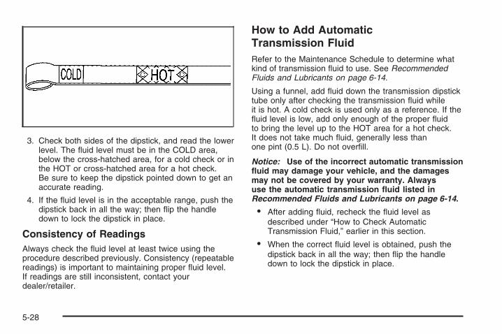
3. Check both sides of the dipstick, and read the lowerlevel. The fluid level must be in the COLD area,below the cross-hatched area, for a cold check or inthe HOT or cross-hatched area for a hot check.Be sure to keep the dipstick pointed down to get anaccurate reading.
4. If the fluid level is in the acceptable range, push thedipstick back in all the way; then flip the handledown to lock the dipstick in place.
Consistency of ReadingsAlways check the fluid level at least twice using theprocedure described previously. Consistency (repeatablereadings) is important to maintaining proper fluid level.If readings are still inconsistent, contact yourdealer/retailer.
How to Add AutomaticTransmission FluidRefer to the Maintenance Schedule to determine whatkind of transmission fluid to use. See RecommendedFluids and Lubricants on page 6-14.
Using a funnel, add fluid down the transmission dipsticktube only after checking the transmission fluid whileit is hot. A cold check is used only as a reference. If thefluid level is low, add only enough of the proper fluidto bring the level up to the HOT area for a hot check.It does not take much fluid, generally less thanone pint (0.5 L). Do not overfill.
Notice: Use of the incorrect automatic transmissionfluid may damage your vehicle, and the damagesmay not be covered by your warranty. Alwaysuse the automatic transmission fluid listed inRecommended Fluids and Lubricants on page 6-14.
• After adding fluid, recheck the fluid level asdescribed under “How to Check AutomaticTransmission Fluid,” earlier in this section.
• When the correct fluid level is obtained, push thedipstick back in all the way; then flip the handledown to lock the dipstick in place.
5-28
Engine CoolantIf your vehicle has the DURAMAX® Diesel engine, seethe DURAMAX® Diesel manual for more information.
The cooling system in your vehicle is filled withDEX-COOL® engine coolant. This coolant is designedto remain in your vehicle for five years or 150,000 miles(240 000 km), whichever occurs first, if you add onlyDEX-COOL® extended life coolant.
The following explains your cooling system and how toadd coolant when it is low. If you have a problemwith engine overheating, see Engine Overheating onpage 5-32.
A 50/50 mixture of clean, drinkable water andDEX-COOL® coolant will:
• Give freezing protection down to −34°F (−37°C).
• Give boiling protection up to 265°F (129°C).
• Protect against rust and corrosion.
• Help keep the proper engine temperature.
• Let the warning lights and gages work as theyshould.
Notice: Using coolant other than DEX-COOL® maycause premature engine, heater core, or radiatorcorrosion. In addition, the engine coolant mayrequire changing sooner, at the first maintenanceservice after each 30,000 miles (50 000 km) or24 months, whichever occurs first. Any repairswould not be covered by your warranty. Always useDEX-COOL® (silicate-free) coolant in your vehicle.
5-29

What to UseUse a mixture of one-half clean, drinkable water andone-half DEX-COOL® coolant which will not damagealuminum parts. If you use this coolant mixture, you donot need to add anything else.
{CAUTION:
Adding only plain water to your cooling systemcan be dangerous. Plain water, or some otherliquid such as alcohol, can boil before theproper coolant mixture will. Your vehicle’scoolant warning system is set for the propercoolant mixture. With plain water or the wrongmixture, your engine could get too hot but youwould not get the overheat warning. Yourengine could catch fire and you or others couldbe burned. Use a 50/50 mixture of clean,drinkable water and DEX-COOL® coolant.
Notice: If you use an improper coolant mixture,your engine could overheat and be badly damaged.The repair cost would not be covered by yourwarranty. Too much water in the mixture can freezeand crack the engine, radiator, heater core, andother parts.
If you have to add coolant more than four times a year,have your dealer/retailer check your cooling system.
Notice: If you use extra inhibitors and/or additivesin your vehicle’s cooling system, you coulddamage your vehicle. Use only the proper mixtureof the engine coolant listed in this manual forthe cooling system. See Recommended Fluids andLubricants on page 6-14 for more information.
5-30

Checking CoolantThe coolant surge tank is located in the enginecompartment on the passenger’s side of the vehicle.See Engine Compartment Overview on page 5-14for more information on location.
{CAUTION:
Turning the surge tank pressure cap when theengine and radiator are hot can allow steamand scalding liquids to blow out and burn youbadly. Never turn the surge tank pressurecap — even a little — when the engine andradiator are hot.
The vehicle must be on a level surface. When yourengine is cold, the coolant level should be at theFULL COLD mark on the coolant surge tank.
If your vehicle has a low coolant sensor and theLOW COOLANT LEVEL message comes on andstays on, it means you are low on engine coolant.See “LOW COOLANT LEVEL” under DIC Warningsand Messages on page 3-66.
Adding CoolantIf you need more coolant, add the proper DEX-COOL®
coolant mixture at the surge tank, but only when theengine is cool. See Cooling System on page 5-35for more information.
{CAUTION:
You can be burned if you spill coolant on hotengine parts. Coolant contains ethylene glycol,and it will burn if the engine parts are hotenough. Do not spill coolant on a hot engine.
When replacing the pressure cap, make sure it ishand-tight and fully seated.
5-31

Coolant Surge Tank Pressure CapNotice: If the pressure cap is not tightly installed,coolant loss and possible engine damage may occur.Be sure the cap is properly and tightly secured.
The coolant surge tank pressure cap must be fullyinstalled on the coolant surge tank. See EngineCompartment Overview on page 5-14 for moreinformation on location.
Engine OverheatingIf your vehicle has the DURAMAX® Diesel engine, seethe DURAMAX® Diesel manual for more information.
You will find a coolant temperature gage on yourvehicle’s instrument panel. See Engine CoolantTemperature Gage on page 3-48.
In addition, you will find ENGINE OVERHEATED STOPENGINE, ENGINE OVERHEATED IDLE ENGINE,and ENGINE POWER IS REDUCED messages in theDriver Information Center (DIC) on the instrument panel.See DIC Warnings and Messages on page 3-66.
If Steam Is Coming From Your Engine
{CAUTION:
Steam from an overheated engine can burnyou badly, even if you just open the hood.Stay away from the engine if you see or hearsteam coming from it. Turn it off and geteveryone away from the vehicle until it coolsdown. Wait until there is no sign of steam orcoolant before you open the hood.
If you keep driving when the vehicles engineis overheated, the liquids in it can catch fire.You or others could be badly burned. Stopyour engine if it overheats, and get out of thevehicle until the engine is cool.
See Overheated Engine Protection OperatingMode (V8 Engines Only) on page 5-34 forinformation on driving to a safe place in anemergency.
5-32

Notice: If your engine catches fire because youkeep driving with no coolant, your vehicle canbe badly damaged. The costly repairs would not becovered by your warranty. See Overheated EngineProtection Operating Mode (V8 Engines Only)on page 5-34 for information on driving to a safeplace in an emergency.
If No Steam Is Coming FromYour EngineThe ENGINE OVERHEATED STOP ENGINE or theENGINE OVERHEATED IDLE ENGINE message,along with a low coolant condition, can indicate aserious problem.
If you get an engine overheat warning, but see or hearno steam, the problem may not be too serious.Sometimes the engine can get a little too hot when you:
• Climb a long hill on a hot day.
• Stop after high-speed driving.
• Idle for long periods in traffic.
• Tow a trailer. See Towing a Trailer on page 4-55.
If you get the ENGINE OVERHEATED STOP ENGINE orthe ENGINE OVERHEATED IDLE ENGINE messagewith no sign of steam, try this for a minute or so:
1. If you have an air conditioner and it is on, turn it off.
2. Turn on your heater to full hot at the highest fanspeed and open the windows as necessary.
3. If you are stopped in a traffic jam, apply the brake,shift to N (NEUTRAL); otherwise, shift to the highestgear while driving — D (DRIVE) or 3 (THIRD).
If you no longer have the overheat warning, you candrive. Just to be safe, drive slower for about 10 minutes.If the warning does not come back on, you can drivenormally.
5-33

If the warning continues, pull over, stop, and park yourvehicle immediately.
If there is still no sign of steam and your vehicle has anengine-driven cooling fan, push down the acceleratoruntil the engine speed is about twice as fast as normalidle speed for at least five minutes while you are parked.
If there is still no sign of steam and your vehicle has anelectric cooling fan, idle the engine for five minuteswhile you are parked.
If you still have the warning, turn off the engine andget everyone out of the vehicle until it cools down.Also, see “Overheated Engine Protection OperatingMode” later in this section.
You may decide not to lift the hood but to get servicehelp right away.
Overheated Engine ProtectionOperating Mode (V8 Engines Only)If an overheated engine condition exists and theREDUCED ENGINE POWER message is displayed,an overheat protection mode which alternates firinggroups of cylinders helps prevent engine damage.In this mode, you will notice a loss in power and engineperformance. This operating mode allows your vehicleto be driven to a safe place in an emergency. Drivingextended miles (km) and/or towing a trailer in theoverheat protection mode should be avoided.
Notice: After driving in the overheated engineprotection operating mode, to avoid engine damage,allow the engine to cool before attempting anyrepair. The engine oil will be severely degraded.Repair the cause of coolant loss, change the oil andreset the oil life system. See Engine Oil (GasolineEngine) on page 5-15.
5-34

Cooling SystemIf your vehicle has the DURAMAX® Diesel engine, seethe DURAMAX® Diesel manual for more information.
When you decide it is safe to lift the hood, here is whatyou will see:
A. Coolant Surge TankB. Coolant Surge Tank Pressure CapC. Engine Cooling Fan
{CAUTION:
An electric engine cooling fan can start evenwhen the engine is not running. To avoidinjury, always keep hands, clothing, and toolsaway from any engine cooling fan.
If the coolant inside the coolant surge tank is boiling,do not do anything else until it cools down. The vehicleshould be parked on a level surface. Check thecoolant level after the system cools down. Some amountof coolant may be lost due to overheating.
5.3L Engine (4.3L, 4.8L and 6.0L Similar)
5-35

The coolant level should be at or above the FULL COLDmark. If it is not, you may have a leak at the pressure capor in the radiator hoses, heater hoses, radiator, waterpump, or somewhere else in the cooling system.
{CAUTION:
Heater and radiator hoses, and other engineparts, can be very hot. Do not touch them.If you do, you can be burned.
Do not run the engine if there is a leak. If yourun the engine, it could lose all coolant.That could cause an engine fire, and you couldbe burned. Get any leak fixed before you drivethe vehicle.
Notice: Engine damage from running your enginewithout coolant is not covered by your warranty.See Overheated Engine Protection Operating Mode(V8 Engines Only) on page 5-34 for informationon driving to a safe place in an emergency.
Notice: Using coolant other than DEX-COOL® maycause premature engine, heater core, or radiatorcorrosion. In addition, the engine coolant couldrequire changing sooner, at 30,000 miles (50 000 km)or 24 months, whichever occurs first. Any repairswould not be covered by the warranty. Always useDEX-COOL® (silicate-free) coolant in the vehicle.
5-36

How to Add Coolant to the CoolantSurge Tank for Gasoline EnginesIf your vehicle has a diesel engine, see “CoolingSystem” in the DURAMAX® Diesel Supplement for theproper coolant fill procedure.
If you have not found a problem yet, check to seeif coolant is visible in the surge tank. If coolant isvisible but the coolant level is not at or above theFULL COLD mark, add a 50/50 mixture of clean,drinkable water and DEX-COOL® coolant at the coolantsurge tank, but be sure the cooling system, includingthe coolant surge tank pressure cap, is cool beforeyou do it. See Engine Coolant on page 5-29 for moreinformation.
If no coolant is visible in the surge tank, add coolantas follows:
{CAUTION:
Steam and scalding liquids from a hot coolingsystem can blow out and burn you badly.They are under pressure, and if you turn thecoolant surge tank pressure cap — even alittle — they can come out at high speed.Never turn the cap when the cooling system,including the coolant surge tank pressure cap,is hot. Wait for the cooling system and coolantsurge tank pressure cap to cool if you everhave to turn the pressure cap.
5-37
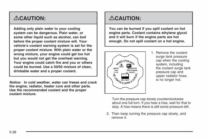
{CAUTION:
Adding only plain water to your coolingsystem can be dangerous. Plain water, orsome other liquid such as alcohol, can boilbefore the proper coolant mixture will. Yourvehicle’s coolant warning system is set for theproper coolant mixture. With plain water or thewrong mixture, your engine could get too hotbut you would not get the overheat warning.Your engine could catch fire and you or otherscould be burned. Use a 50/50 mixture of clean,drinkable water and a proper coolant.
Notice: In cold weather, water can freeze and crackthe engine, radiator, heater core and other parts.Use the recommended coolant and the propercoolant mixture.
{CAUTION:
You can be burned if you spill coolant on hotengine parts. Coolant contains ethylene glycoland it will burn if the engine parts are hotenough. Do not spill coolant on a hot engine.
1. Remove the coolantsurge tank pressurecap when the coolingsystem, includingthe coolant surge tankpressure cap andupper radiator hose,is no longer hot.
Turn the pressure cap slowly counterclockwiseabout one full turn. If you hear a hiss, wait for that tostop. A hiss means there is still some pressure left.
2. Then keep turning the pressure cap slowly, andremove it.
5-38

3. Fill the coolant surge tank with the proper mixture,to the FULL COLD mark.
4. With the coolant surge tank pressure cap off, startthe engine and let it run until the engine coolanttemperature gage indicates approximately195°F (90°C).By this time, the coolant level inside the coolantsurge tank may be lower. If the level is lower, addmore of the proper mixture to the coolant surge tankuntil the level reaches the FULL COLD mark.
5. Then replace the pressure cap. Be sure thepressure cap is hand-tight and fully seated.
6. Verify coolant level after engine is shut off and thecoolant is cold. If necessary, repeat coolant fillprocedure Steps 1 through 6.
5-39

Engine Fan NoiseIf your vehicle has a clutched engine cooling fan, whenthe clutch is engaged, the fan spins faster to providemore air to cool the engine. In most everyday drivingconditions, the fan is spinning slower and the clutch isnot fully engaged. This improves fuel economy andreduces fan noise. Under heavy vehicle loading, trailertowing, and/or high outside temperatures, the fanspeed increases as the clutch more fully engages, soyou may hear an increase in fan noise. This is normaland should not be mistaken as the transmission slippingor making extra shifts. It is merely the cooling systemfunctioning properly. The fan will slow down whenadditional cooling is not required and the clutchdisengages.
You may also hear this fan noise when you start theengine. It will go away as the fan clutch partiallydisengages.
If your vehicle has electric cooling fans, you may hearthe fans spinning at low speed during most everydaydriving. The fans may turn off if no cooling is required.Under heavy vehicle loading, trailer towing, and/orhigh outside temperatures, or if you are operating yourair conditioning system, the fans may change tohigh speed and you may hear an increase in fan noise.This is normal and indicates that the cooling systemis functioning properly. The fans will change to lowspeed when additional cooling is no longer required.
5-40
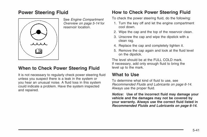
Power Steering FluidSee Engine CompartmentOverview on page 5-14 forreservoir location.
When to Check Power Steering FluidIt is not necessary to regularly check power steering fluidunless you suspect there is a leak in the system oryou hear an unusual noise. A fluid loss in this systemcould indicate a problem. Have the system inspectedand repaired.
How to Check Power Steering FluidTo check the power steering fluid, do the following:1. Turn the key off and let the engine compartment
cool down.2. Wipe the cap and the top of the reservoir clean.3. Unscrew the cap and wipe the dipstick with a
clean rag.4. Replace the cap and completely tighten it.5. Remove the cap again and look at the fluid level
on the dipstick.
The level should be at the FULL COLD mark.If necessary, add only enough fluid to bring thelevel up to the mark.
What to UseTo determine what kind of fluid to use, seeRecommended Fluids and Lubricants on page 6-14.Always use the proper fluid.
Notice: Use of the incorrect fluid may damage yourvehicle and the damages may not be covered byyour warranty. Always use the correct fluid listed inRecommended Fluids and Lubricants on page 6-14.
5-41

Windshield Washer Fluid
What to UseWhen windshield washer fluid needs to be added, besure to read the manufacturer’s instructions before use.Use a fluid that has sufficient protection againstfreezing in an area where the temperature may fallbelow freezing.
Adding Washer FluidYour vehicle has a low washer fluid message in theDIC that comes on when the washer fluid is low.The message is displayed for 15 seconds at the start ofeach ignition cycle. When the WASHER FLUID LOWADD FLUID message displays, you will need to addwasher fluid to the windshield washer fluid reservoir.
Open the cap with thewasher symbol on it.Add washer fluid until thetank is full. See EngineCompartment Overview onpage 5-14 for reservoirlocation.
Notice:
• When using concentrated washer fluid,follow the manufacturer’s instructions foradding water.
• Do not mix water with ready-to-use washer fluid.Water can cause the solution to freeze anddamage your washer fluid tank and other partsof the washer system. Also, water does notclean as well as washer fluid.
• Fill the washer fluid tank only three-quarters fullwhen it is very cold. This allows for fluidexpansion if freezing occurs, which coulddamage the tank if it is completely full.
• Do not use engine coolant (antifreeze) in yourwindshield washer. It can damage the vehicle’swindshield washer system and paint.
5-42
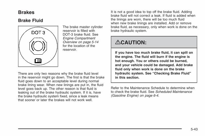
Brakes
Brake FluidThe brake master cylinderreservoir is filled withDOT-3 brake fluid. SeeEngine CompartmentOverview on page 5-14for the location of thereservoir.
There are only two reasons why the brake fluid levelin the reservoir might go down. The first is that the brakefluid goes down to an acceptable level during normalbrake lining wear. When new linings are put in, the fluidlevel goes back up. The other reason is that fluid isleaking out of the brake hydraulic system. If it is, havethe brake hydraulic system fixed, since a leak meansthat sooner or later the brakes will not work well.
It is not a good idea to top off the brake fluid. Addingbrake fluid will not correct a leak. If fluid is added whenthe linings are worn, there will be too much fluidwhen new brake linings are installed. Add or removebrake fluid, as necessary, only when work is done on thebrake hydraulic system.
{CAUTION:
If you have too much brake fluid, it can spill onthe engine. The fluid will burn if the engine ishot enough. You or others could be burned,and your vehicle could be damaged. Add brakefluid only when work is done on the brakehydraulic system. See “Checking Brake Fluid”in this section.
Refer to the Maintenance Schedule to determine whento check the brake fluid. See Scheduled Maintenance(Gasoline Engine) on page 6-4.
5-43

Checking Brake FluidThe brake fluid can be checked without taking off thecap by looking at the brake fluid reservoir.
The fluid level should beabove MIN. If it is not,have the brake hydraulicsystem checked tosee if there is a leak.
After work is done on the brake hydraulic system,make sure the level is above the MIN but not over theMAX mark.
What to AddWhen you do need brake fluid, use only DOT-3 brakefluid. Use new brake fluid from a sealed containeronly. See Recommended Fluids and Lubricants onpage 6-14.
Always clean the brake fluid reservoir cap and the areaaround the cap before removing it. This helps keepdirt from entering the reservoir.
{CAUTION:
With the wrong kind of fluid in the brakehydraulic system, the brakes might not workwell. This could cause a crash. Always use theproper brake fluid.
Notice:
• Using the wrong fluid can badly damage brakehydraulic system parts. For example, just afew drops of mineral-based oil, such as engineoil, in the brake hydraulic system can damagebrake hydraulic system parts so badly that theywill have to be replaced. Do not let someoneput in the wrong kind of fluid.
• If you spill brake fluid on your vehicle’s paintedsurfaces, the paint finish can be damaged.Be careful not to spill brake fluid on yourvehicle. If you do, wash it off immediately.See Washing Your Vehicle on page 5-118.
5-44

Brake WearYour vehicle has front disc brakes and could have reardrum brakes or rear disc brakes.
Disc brake pads have built-in wear indicators that makea high-pitched warning sound when the brake padsare worn and new pads are needed. The sound cancome and go or be heard all the time your vehicleis moving, except when you are pushing on the brakepedal firmly.
{CAUTION:
The brake wear warning sound means that soonthe brakes will not work well. That could lead toan accident. When you hear the brake wearwarning sound, have your vehicle serviced.
Notice: Continuing to drive with worn-out brakepads could result in costly brake repair.
Some driving conditions or climates can cause a brakesqueal when the brakes are first applied or lightlyapplied. This does not mean something is wrong withthe brakes.
Properly torqued wheel nuts are necessary to helpprevent brake pulsation. When tires are rotated,inspect brake pads for wear and evenly tighten wheelnuts in the proper sequence to torque specificationsin Capacities and Specifications on page 5-133.
If you have rear drum brakes, they do not have wearindicators, but if you ever hear a rear brake rubbingnoise, have the rear brake linings inspected immediately.Rear brake drums should be removed and inspectedeach time the tires are removed for rotation or changing.Drum brakes have an inspection hole to inspect liningwear during scheduled maintenance. When youhave the front brake pads replaced, have the rearbrakes inspected, too.
Brake linings should always be replaced as completeaxle sets.
Brake Pedal TravelSee your dealer/retailer if the brake pedal does notreturn to normal height, or if there is a rapid increase inpedal travel. This could be a sign that brake servicemight be required.
Brake AdjustmentEvery time you make a brake stop, the brakes adjustfor wear.
5-45

Replacing Brake System PartsThe braking system on a vehicle is complex. Its manyparts have to be of top quality and work well together ifthe vehicle is to have really good braking. Your vehiclewas designed and tested with top-quality brake parts.When you replace parts of the braking system — forexample, when the brake linings wear down and youneed new ones put in — be sure you get new approvedreplacement parts. If you do not, the brakes might notwork properly. For example, if someone puts in brakelinings that are wrong for your vehicle, the balancebetween the front and rear brakes can change — for theworse. The braking performance you have come toexpect can change in many other ways if someone putsin the wrong replacement brake parts.
BatteryYour vehicle has a maintenance free battery(or batteries). When it is time for a new battery, seeyour dealer/retailer for one that has the replacementnumber shown on the original battery’s label.See Engine Compartment Overview on page 5-14for battery location.
Warning: Battery posts, terminals, and relatedaccessories contain lead and lead compounds,chemicals known to the State of California to causecancer and reproductive harm. Wash hands afterhandling.
Vehicle Storage
{CAUTION:
Batteries have acid that can burn you and gasthat can explode. You can be badly hurt if youare not careful. See Jump Starting on page 5-47for tips on working around a battery withoutgetting hurt.
Infrequent Usage: If you drive your vehicle infrequently,remove the black, negative (−) cable from the battery.This will help keep the battery from running down.
Extended Storage: For extended storage of your vehicle,remove the black, negative (−) cable from the batteryor use a battery trickle charger. This will help maintainthe charge of the battery over an extended periodof time.
5-46
Jump StartingIf your vehicle’s battery (or batteries) has run down, youmay want to use another vehicle and some jumpercables to start your vehicle. Be sure to use the followingsteps to do it safely.
{CAUTION:
Batteries can hurt you. They can be dangerousbecause:
• They contain acid that can burn you.• They contain gas that can explode or
ignite.• They contain enough electricity to
burn you.
If you do not follow these steps exactly, someor all of these things can hurt you.
Notice: Ignoring these steps could result in costlydamage to your vehicle that would not be coveredby your warranty.
Trying to start your vehicle by pushing or pulling itwill not work, and it could damage your vehicle.
1. Check the other vehicle. It must have a12-volt battery with a negative ground system.
Notice: If the other vehicle’s system is not a 12-voltsystem with a negative ground, both vehicles canbe damaged. Only use vehicles with 12-volt systemswith negative grounds to jump start your vehicle.
2. If you have a vehicle with a diesel engine withtwo batteries, you should know before you beginthat, especially in cold weather, you may not be ableto get enough power from a single battery in anothervehicle to start your diesel engine. If your vehicle hasmore than one battery, use the battery that is closerto the starter — this will reduce electrical resistance.This is located on the passenger side, in the rear ofthe engine compartment.
5-47

3. Get the vehicles close enough so the jumper cablescan reach, but be sure the vehicles are not touchingeach other. If they are, it could cause an unwantedground connection. You would not be able tostart your vehicle, and the bad grounding coulddamage the electrical systems.To avoid the possibility of the vehicles rolling, set theparking brake firmly on both vehicles involved in thejump start procedure. Put the automatic transmissionin P (PARK) or a manual transmission in NEUTRALbefore setting the parking brake. If you have afour-wheel-drive vehicle, be sure the transfer caseis in a drive gear, not in NEUTRAL.
Notice: If you leave your radio or other accessorieson during the jump starting procedure, they couldbe damaged. The repairs would not be coveredby your warranty. Always turn off your radio andother accessories when jump starting your vehicle.
4. Turn off the ignition on both vehicles. Unplugunnecessary accessories plugged into the cigarettelighter or the accessory power outlets. Turn offthe radio and all the lamps that are not needed.This will avoid sparks and help save both batteries.And it could save the radio!
5. Open the hood on the other vehicle and locate thepositive (+) and negative (−) terminal locations onthat vehicle.The positive (+) terminal, is located under a redplastic cover at the positive battery post. To uncoverthe positive (+) terminal, open the red plastic cover.
The remote negative (-) terminal is a stud locatedon the right front passenger side of the engine,where the negative battery cable attaches.See Engine Compartment Overview on page 5-14.
5-48

{CAUTION:
An electric fan can start up even when theengine is not running and can injure you.Keep hands, clothing and tools away from anyunderhood electric fan.
{CAUTION:
Using a match near a battery can cause batterygas to explode. People have been hurt doingthis, and some have been blinded. Use aflashlight if you need more light.
CAUTION: (Continued)
CAUTION: (Continued)
Be sure the battery has enough water. You donot need to add water to the battery installedin your new vehicle. But if a battery has fillercaps, be sure the right amount of fluid is there.If it is low, add water to take care of that first.If you do not, explosive gas could be present.
Battery fluid contains acid that can burn you.Do not get it on you. If you accidentally get itin your eyes or on your skin, flush the placewith water and get medical help immediately.
{CAUTION:
Fans or other moving engine parts can injureyou badly. Keep your hands away from movingparts once the engine is running.
5-49

6. Check that the jumper cables do not have loose ormissing insulation. If they do, you could get ashock. The vehicles could be damaged too.Before you connect the cables, here are somebasic things you should know. Positive (+) will go topositive (+) or to a remote positive (+) terminal ifthe vehicle has one. Negative (−) will go to a heavy,unpainted metal engine part or to a remotenegative (−) terminal if the vehicle has one.Do not connect positive (+) to negative (−) or youwill get a short that would damage the batteryand maybe other parts too. And do not connect thenegative (−) cable to the negative (−) terminal onthe dead battery because this can cause sparks.
7. Connect the redpositive (+) cable to thepositive (+) terminalof the vehicle with thedead battery.
8. Do not let the other end touch metal. Connect it tothe positive (+) terminal of the good battery. Use aremote positive (+) terminal if the vehicle has one.
9. Now connect the black negative (−) cable to thenegative (−) terminal of the good battery. Use aremote negative (−) terminal if the vehicle has one.Do not let the other end touch anything until thenext step.
10. Connect the other end of the negative (−) cable to aheavy, unpainted metal engine part or to the remotenegative (−) terminal, on the vehicle with the deadbattery.
11. Start the vehicle with the good battery and run theengine for a while.
12. Try to start the vehicle that had the dead battery.If it will not start after a few tries, it probablyneeds service.
5.3L engine (4.3L, 4.8Land 6.0L similar),
5-50

Notice: If the jumper cables are connected orremoved in the wrong order, electrical shorting mayoccur and damage the vehicle. The repairs wouldnot be covered by your warranty. Always connectand remove the jumper cables in the correctorder, making sure that the cables do not toucheach other or other metal.
A. Heavy, Unpainted Metal Engine Part or RemoteNegative (−) Terminal
B. Good Battery or Remote Positive (+) and RemoteNegative (−) Terminals
C. Dead Battery or Remote Positive (+) Terminal
To disconnect the jumper cables from both vehiclesdo the following:
1. Disconnect the black negative (−) cable from thevehicle that had the bad battery.
2. Disconnect the black negative (−) cable from thevehicle with the good battery.
3. Disconnect the red positive (+) cable from thevehicle with the good battery.
4. Disconnect the red positive (+) cable from theother vehicle.
5. Return the positive (+) terminal cover, to its originalposition.
Jumper Cable Removal
5-51

Rear AxleWhen to Check LubricantIt is not necessary to regularly check rear axle fluidunless you suspect there is a leak or you hear anunusual noise. A fluid loss could indicate a problem.Have it inspected and repaired.
All axle assemblies are filled by volume of fluid duringproduction. They are not filled to reach a certainlevel. When checking the fluid level on any axle,variations in the readings can be caused by factory filldifferences between the minimum and the maximumfluid volume. Also, if a vehicle has just been drivenbefore checking the fluid level, it may appear lower thannormal because fluid has traveled out along the axletubes and has not drained back to the sump area.Therefore, a reading taken five minutes after the vehiclehas been driven will appear to have a lower fluidlevel than a vehicle that has been stationary for an houror two. Remember that the rear axle assembly mustbe supported to get a true reading.
How to Check Lubricant
2500HD with 6.0L
5-52

To get an accurate reading, the vehicle should be on alevel surface.
• For all 4.3L, 4.8L and 5.3L 1500 Series applications,the proper level is 0.04 inches to 0.75 inches(1.0 mm to 19.0 mm) below the bottom of the fillerhole, located on the rear axle. Add only enoughfluid to reach the proper level.
• For all 6.0L 1500 Series applications, the properlevel is from 0.6 inches to 1.6 inches (15 mm to40 mm) below the bottom of the filler plughole, located on the rear axle. Add only enoughfluid to reach the proper level.
• For all 6.0L 2500HD Series applications, the properlevel is from 0 to 0.5 inches (0 mm to 13 mm)below the bottom of the filler plug hole, located onthe rear axle. Add only enough fluid to reachthe proper level.
• For all 6.6L DURAMAX DIESEL 2500HD Seriesapplications and all 3500 Series applications,the proper level is from 0.6 inches to 0.8 inches(17 mm to 21 mm) below the bottom of the filler plughole, located on the rear axle. Add only enoughfluid to reach the proper level.
What to UseRefer to the Maintenance Schedule to determine whatkind of lubricant to use. See Recommended Fluidsand Lubricants on page 6-14.
All Other Series and Engines
5-53

Four-Wheel DriveLubricant checks in this section also apply to thesevehicles.
Transfer Case
When to Check LubricantIt is not necessary to regularly check transfer case fluidunless you suspect there is a leak, or you hear anunusual noise. A fluid loss could indicate a problem.Have it inspected and repaired.
How to Check Lubricant
A. Fill PlugB. Drain Plug
Electric Shift Transfer Case
5-54
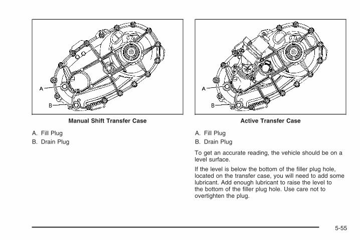
A. Fill PlugB. Drain Plug
A. Fill PlugB. Drain Plug
To get an accurate reading, the vehicle should be on alevel surface.
If the level is below the bottom of the filler plug hole,located on the transfer case, you will need to add somelubricant. Add enough lubricant to raise the level tothe bottom of the filler plug hole. Use care not toovertighten the plug.
Manual Shift Transfer Case Active Transfer Case
5-55

When to Change LubricantRefer to the Maintenance Schedule to determine howoften to change the lubricant. See ScheduledMaintenance (Gasoline Engine) on page 6-4.
What to UseRefer to the Maintenance Schedule to determine whatkind of lubricant to use. See Recommended Fluidsand Lubricants on page 6-14.
Front AxleWhen to Check and Change LubricantIt is not necessary to regularly check front axle fluidunless you suspect there is a leak or you hear anunusual noise. A fluid loss could indicate a problem.Have it inspected and repaired.
How to Check Lubricant
A. Fill PlugB. Drain Plug
1500 Series
5-56

To get an accurate reading, the vehicle should be on alevel surface.
• When the differential is cold, add enough lubricantto raise the level from 0 (0 mm) to 1/8 inch(3.2 mm) below the filler plug hole.
• When the differential is at operating temperature(warm), add enough lubricant to raise the levelto the bottom of the filler plug hole.
What to UseRefer to the Maintenance Schedule to determine whatkind of lubricant to use. See Recommended Fluidsand Lubricants on page 6-14.
Noise Control System
Tampering with Noise ControlSystem ProhibitedThe following information relates to compliance withfederal noise emission standards for vehicles with aGross Vehicle Weight Rating (GVWR) of more than10,000 lbs (4 536 kg). The Maintenance Scheduleprovides information on maintaining the noise controlsystem to minimize degradation of the noise emissioncontrol system during the life of your vehicle. The noisecontrol system warranty is given in your warranty booklet.
These standards apply only to vehicles sold in theUnited States.
Federal law prohibits the following acts or thecausing thereof:1. The removal or rendering inoperative by any person,
other than for purposes of maintenance, repair orreplacement, of any device or element of designincorporated into any new vehicle for the purpose ofnoise control, prior to its sale or delivery to theultimate purchaser or while it is in use; or
2. The use of the vehicle after such device orelement of design has been removed or renderedinoperative by any person.
5-57

Among those acts presumed to constitute tampering arethe acts listed below.
Insulation:• Removal of the noise shields or any underhood
insulation.
Engine:• Removal or rendering engine speed governor, if the
vehicle has one, inoperative so as to allow enginespeed to exceed manufacturer specifications.
Fan and Drive:• Removal of fan clutch, if the vehicle has one, or
rendering clutch inoperative.
• Removal of the fan shroud, if the vehicle has one.
Air Intake:• Removal of the air cleaner silencer.
• Modification of the air cleaner.
Exhaust:• Removal of the muffler and/or resonator.
• Removal of the exhaust pipes and exhaust pipeclamps.
Headlamp AimingThe vehicle has a visual optical headlamp aimingsystem. The aim of the headlamps have been preset atthe factory and should need no further adjustment.
However, if the vehicle is damaged in a crash, the aimof the headlamps can be affected and adjustmentcan be necessary.
If oncoming vehicles flash their high beams at you, thiscan mean the vertical aim of your headlamps needsto be adjusted.
It is recommended that the vehicle is taken to yourdealer/retailer for service if the headlamps need to beadjusted. It is possible however, to re-aim theheadlamps as described.
5-58

The vehicle should:
• Be placed so the headlamps are 25 ft. (7.6 m) froma light colored wall.
• Have all four tires on a level surface which is levelall the way to the wall.
• Be placed so it is perpendicular to the wall.
• Not have any snow, ice, or mud on it.
• Be fully assembled and all other work stopped whileheadlamp aiming is being performed.
• Be normally loaded with a full tank of fuel and oneperson or 160 lbs (75 kg) sitting on the driver seat.
• Have tires properly inflated.
• Have the spare tire is in its proper location in thevehicle.
Headlamp aiming is done with the vehicle’s low-beamheadlamps. The high-beam headlamps will be correctlyaimed if the low-beam headlamps are aimed properly.
To adjust the vertical aim:
1. Open the hood. See Hood Release on page 5-13for more information.
2. Locate the aim dot on the lens of the low-beamheadlamp.
3. Record the distance from the ground to the aim doton the low-beam headlamp.
5-59
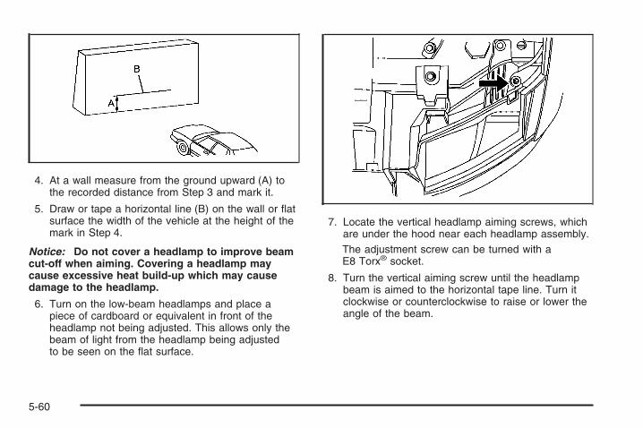
4. At a wall measure from the ground upward (A) tothe recorded distance from Step 3 and mark it.
5. Draw or tape a horizontal line (B) on the wall or flatsurface the width of the vehicle at the height of themark in Step 4.
Notice: Do not cover a headlamp to improve beamcut-off when aiming. Covering a headlamp maycause excessive heat build-up which may causedamage to the headlamp.
6. Turn on the low-beam headlamps and place apiece of cardboard or equivalent in front of theheadlamp not being adjusted. This allows only thebeam of light from the headlamp being adjustedto be seen on the flat surface.
7. Locate the vertical headlamp aiming screws, whichare under the hood near each headlamp assembly.The adjustment screw can be turned with aE8 Torx® socket.
8. Turn the vertical aiming screw until the headlampbeam is aimed to the horizontal tape line. Turn itclockwise or counterclockwise to raise or lower theangle of the beam.
5-60
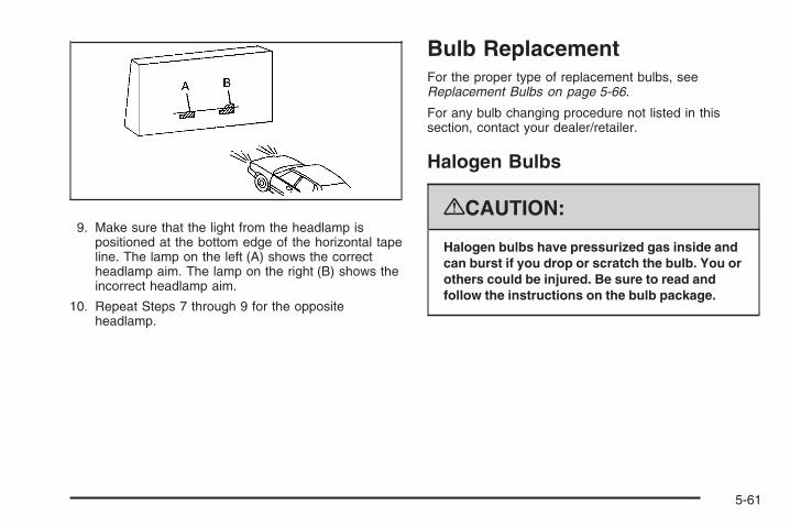
9. Make sure that the light from the headlamp ispositioned at the bottom edge of the horizontal tapeline. The lamp on the left (A) shows the correctheadlamp aim. The lamp on the right (B) shows theincorrect headlamp aim.
10. Repeat Steps 7 through 9 for the oppositeheadlamp.
Bulb ReplacementFor the proper type of replacement bulbs, seeReplacement Bulbs on page 5-66.
For any bulb changing procedure not listed in thissection, contact your dealer/retailer.
Halogen Bulbs
{CAUTION:
Halogen bulbs have pressurized gas inside andcan burst if you drop or scratch the bulb. You orothers could be injured. Be sure to read andfollow the instructions on the bulb package.
5-61

HeadlampsTo replace one of these bulbs:
1. Open the hood. See Hood Release on page 5-13for more information.
2. If you are replacing the bulb on the passenger sideremove the Engine Air Cleaner cover. See EngineAir Cleaner/Filter (Gasoline Engines) on page 5-20for more information.
3. Reach in and access the bulb sockets from insidethe engine compartment.
4. Turn the bulb socket counterclockwise to remove itfrom the headlamp assembly and pull it straight out.
5. Unplug the electrical connector from the old bulb byreleasing the clips on the bulb socket.
6. Replace it with a new bulb socket.
7. Plug in the electrical connector to the new bulbsocket.
8. Reinstall the new bulb socket into the headlampassembly and turn it clockwise to secure.
9. Close the hood.
5-62
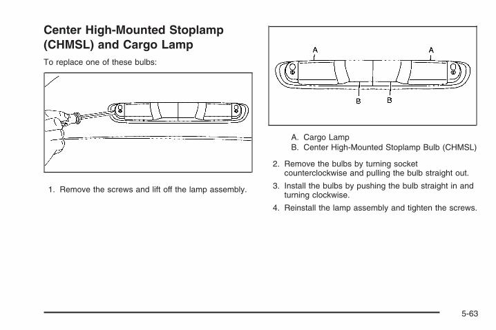
Center High-Mounted Stoplamp(CHMSL) and Cargo LampTo replace one of these bulbs:
1. Remove the screws and lift off the lamp assembly.
A. Cargo LampB. Center High-Mounted Stoplamp Bulb (CHMSL)
2. Remove the bulbs by turning socketcounterclockwise and pulling the bulb straight out.
3. Install the bulbs by pushing the bulb straight in andturning clockwise.
4. Reinstall the lamp assembly and tighten the screws.
5-63

Pickup Box Identification andFender Marker LampsTo replace a pickup box identification or fender markerlamp bulb:
1. Press the tab from the back to remove the lamp.
2. Unplug the lamp assembly harness.
3. Gently pry the individual lamp from the lampassembly.
4. Unplug the lamp.
5. Plug in a new lamp and snap it into the assembly.
6. Reinstall the lamp assembly.
Taillamps, Turn Signal, Stoplampsand Back-up LampsTo replace one of these bulbs:
A. Stoplamp/TurnSignal/Taillamp
B. Back-up LampC. Stoplamp/Turn
Signal/Taillamp
1. Open the tailgate. Tailgate on page 2-13 for moreinformation.
5-64

2. Remove the two rearlamp assembly screwsnear the tailgatelatch strikerpost andpull out the lampassembly.
3. Turn the bulb socket counterclockwise to remove itfrom the taillamp assembly.
4. Pull the old bulb straight out from the socket.
5. Press a new bulb into the socket and turn the socketclockwise into the taillamp assembly.
6. Reinstall the taillamp assembly.
Taillamps (Chassis Cab Models)
A. Backup LampB. Stoplamp/Taillamp/Turn Signal Lamp
To replace one of these bulbs:1. Remove the four screws.2. Lift the lens off the lamp assembly.3. Turn the old bulb counterclockwise and pull the old
bulb straight out from the socket.4. Install a new bulb into the socket, turn it clockwise,
and press it in until it is tight.5. Reinstall the lens and the four screws.
5-65

License Plate LampTo replace one of these bulbs:
1. Reach under the rear bumper for the bulb socket.
2. Turn the bulb socket counterclockwise and pull thebulb socket out of the connector.
3. Pull the old bulb from the bulb socket, keeping thebulb straight as you pull it out.
4. Install the new bulb.
5. Reverse Steps 1 through 3 to reinstall the bulbsocket.
Replacement Bulbs
Exterior Lamp Bulb Number
Back-up Lamp 3047
Back-up Lamp* 1156
Cargo Lamp and CenterHigh-Mounted Stoplamp (CHMSL) 912
Daytime Running Lamps (DRL) 4114K
Fender Marker Lamp W5WLL
High-Beam Headlamp 9005
Low-Beam Headlamp H11
License Plate Lamp 168
Sidemarker Lamp/Stoplamp/Taillamp/Turn Signal Lamp 3047
Stoplamp/Turn SignalLamp/Taillamp* 1157
* Chassis Cab Models
For replacement bulbs not listed here, contact yourdealer/retailer.
5-66

Windshield Wiper BladeReplacementWindshield wiper blades should be inspected for wearor cracking. See Scheduled Maintenance (GasolineEngine) on page 6-4 for more information on wiper bladeinspection.
Replacement blades come in different types and areremoved in different ways. Here is how to removethe wiper blade:
1. Pull the windshield wiper arm connector away fromthe windshield.
2. Squeeze the grooved areas on each side of theblade, and turn the blade assembly away fromthe arm connector.
3. Install the new blade onto the arm connector andmake sure the grooved areas are fully set in thelocked position.
For the proper type and size, see MaintenanceReplacement Parts on page 6-16.
5-67
TiresYour new vehicle comes with high-quality tiresmade by a leading tire manufacturer. If you everhave questions about your tire warranty and whereto obtain service, see your vehicle Warrantybooklet for details.
{CAUTION:
Poorly maintained and improperly usedtires are dangerous.
• Overloading your vehicle’s tires cancause overheating as a result of toomuch flexing. You could have an air-outand a serious accident. See LoadingYour Vehicle on page 4-36.
• Underinflated tires pose the samedanger as overloaded tires. Theresulting accident could cause seriousinjury. Check all tires frequently tomaintain the recommended pressure.Tire pressure should be checked whenyour vehicle’s tires are cold. SeeInflation - Tire Pressure on page 5-76.
CAUTION: (Continued)
CAUTION: (Continued)
• Overinflated tires are more likely tobe cut, punctured, or broken by asudden impact — such as when youhit a pothole. Keep tires at therecommended pressure.
• Worn, old tires can cause accidents.If the tire’s tread is badly worn,or if your vehicle’s tires have beendamaged, replace them.
20-Inch TiresIf your vehicle has the optional 20-inchP275/55R20 size tires, they are classified astouring tires and are designed for on road use.The low-profile, wide tread design is notrecommended for “off-road” driving or commercialuses such as snow plowing. See Off-RoadDriving on page 4-12 and Adding a Snow Plow orSimilar Equipment on page 4-43 for additionalinformation.
5-68

Tire Sidewall LabelingUseful information about a tire is molded into thesidewall. The following illustrations are examplesof a typical P-Metric and a LT-Metric tire sidewall.
(A) Tire Size: The tire size code is a combinationof letters and numbers used to define a particulartire’s width, height, aspect ratio, constructiontype, and service description. See the “Tire Size”illustration later in this section for more detail.
(B) TPC Spec (Tire Performance CriteriaSpecification): Original equipment tires designedto GM’s specific tire performance criteria havea TPC specification code molded onto the sidewall.GM’s TPC specifications meet or exceed allfederal safety guidelines.
(C) DOT (Department of Transportation):The Department of Transportation (DOT) codeindicates that the tire is in compliance with theU.S. Department of Transportation Motor VehicleSafety Standards.
(D) Tire Identification Number (TIN): The lettersand numbers following DOT code are the TireIdentification Number (TIN). The TIN shows themanufacturer and plant code, tire size, and datethe tire was manufactured. The TIN is moldedonto both sides of the tire, although only one sidemay have the date of manufacture.
Passenger (P-Metric) Tire
5-69

(E) Tire Ply Material: The type of cord and numberof plies in the sidewall and under the tread.
(F) Uniform Tire Quality Grading (UTQG):Tire manufacturers are required to gradetires based on three performance factors:treadwear, traction, and temperature resistance.For more information, see Uniform Tire QualityGrading on page 5-89.
(G) Maximum Cold Inflation Load Limit:Maximum load that can be carried and themaximum pressure needed to support that load.For information on recommended tire pressuresee Inflation - Tire Pressure on page 5-76and Loading Your Vehicle on page 4-36.
(A) Tire Size: The tire size code is a combinationof letters and numbers used to define a particulartire’s width, height, aspect ratio, constructiontype, and service description. See the “Tire Size”illustration later in this section for more detail.
Light Truck (LT-Metric) Tire
5-70

(B) TPC Spec (Tire Performance CriteriaSpecification): Original equipment tires designedto GM’s specific tire performance criteria havea TPC specification code molded onto the sidewall.GM’s TPC specifications meet or exceed allfederal safety guidelines.
(C) Dual Tire Maximum Load: Maximum loadthat can be carried and the maximum pressureneeded to support that load when used in a dualconfiguration. For information on recommendedtire pressure see Inflation - Tire Pressure onpage 5-76 and Loading Your Vehicle on page 4-36.
(D) DOT (Department of Transportation):The Department of Transportation (DOT) codeindicates that the tire is in compliance with theU.S. Department of Transportation Motor VehicleSafety Standards.
(E) Tire Identification Number (TIN): The lettersand numbers following DOT code are the TireIdentification Number (TIN). The TIN shows themanufacturer and plant code, tire size, and datethe tire was manufactured. The TIN is moldedonto both sides of the tire, although only one sidemay have the date of manufacture.
(F) Tire Ply Material: The type of cord and numberof plies in the sidewall and under the tread.
(G) Single Tire Maximum Load: Maximum loadthat can be carried and the maximum pressureneeded to support that load when used as a single.For information on recommended tire pressure seeInflation - Tire Pressure on page 5-76 and LoadingYour Vehicle on page 4-36.
5-71

Tire SizeThe following examples show the different parts ofa tire size.
(A) Passenger (P-Metric) Tire: The United Statesversion of a metric tire sizing system. The letter Pas the first character in the tire size means apassenger vehicle tire engineered to standards setby the U.S. Tire and Rim Association.
(A) Light Truck (LT-Metric) Tire: The UnitedStates version of a metric tire sizing system.The letters LT as the first two characters in thetire size means a light truck tire engineeredto standards set by the U.S. Tire and RimAssociation.
(B) Tire Width: The three-digit number indicatesthe tire section width in millimeters from sidewallto sidewall.
(C) Aspect Ratio: A two-digit number thatindicates the tire height-to-width measurements.For example, if the tire size aspect ratio is 75,as shown in item C of the light truck (LT-Metric)tire illustration, it would mean that the tire’ssidewall is 75 percent as high as it is wide.
(D) Construction Code: A letter code is used toindicate the type of ply construction in the tire.The letter R means radial ply construction;the letter D means diagonal or bias plyconstruction; and the letter B means belted-biasply construction.
(E) Rim Diameter: Diameter of the wheel ininches.
(F) Service Description: The service descriptionindicates the load range and speed rating of atire. The load index can range from 1 to 279.Speed ratings range from A to Z.
Passenger (P-Metric) Tire
Light Truck (LT-Metric) Tire
5-72

Tire Terminology and DefinitionsAir Pressure: The amount of air inside thetire pressing outward on each square inch of thetire. Air pressure is expressed in pounds persquare inch (psi) or kilopascal (kPa).
Accessory Weight: This means the combinedweight of optional accessories. Some examples ofoptional accessories are, automatic transmission,power steering, power brakes, power windows,power seats, and air conditioning.
Aspect Ratio: The relationship of a tire’s heightto its width.
Belt: A rubber coated layer of cords that is locatedbetween the plies and the tread. Cords may bemade from steel or other reinforcing materials.
Bead: The tire bead contains steel wires wrappedby steel cords that hold the tire onto the rim.
Bias Ply Tire: A pneumatic tire in which the pliesare laid at alternate angles less than 90 degreesto the centerline of the tread.
Cold Tire Pressure: The amount of air pressurein a tire, measured in pounds per square inch (psi)or kilopascals (kPa) before a tire has built up heatfrom driving. See Inflation - Tire Pressure onpage 5-76.
Curb Weight: The weight of a motor vehicle withstandard and optional equipment including themaximum capacity of fuel, oil, and coolant,but without passengers and cargo.
DOT Markings: A code molded into the sidewallof a tire signifying that the tire is in compliancewith the U.S. Department of Transportation (DOT)motor vehicle safety standards. The DOT codeincludes the Tire Identification Number (TIN),an alphanumeric designator which can also identifythe tire manufacturer, production plant, brand,and date of production.
GVWR: Gross Vehicle Weight Rating.See Loading Your Vehicle on page 4-36.
GAWR FRT: Gross Axle Weight Rating for thefront axle. See Loading Your Vehicle onpage 4-36.
5-73

GAWR RR: Gross Axle Weight Rating for the rearaxle. See Loading Your Vehicle on page 4-36.
Intended Outboard Sidewall: The side of anasymmetrical tire, that must always face outwardwhen mounted on a vehicle.
Kilopascal (kPa): The metric unit for air pressure.
Light Truck (LT-Metric) Tire: A tire used onlight duty trucks and some multipurpose passengervehicles.
Load Index: An assigned number ranging from1 to 279 that corresponds to the load carryingcapacity of a tire.
Maximum Inflation Pressure: The maximum airpressure to which a cold tire can be inflated.The maximum air pressure is molded onto thesidewall.
Maximum Load Rating: The load rating for a tireat the maximum permissible inflation pressurefor that tire.
Maximum Loaded Vehicle Weight: The sum ofcurb weight, accessory weight, vehicle capacityweight, and production options weight.
Normal Occupant Weight: The number ofoccupants a vehicle is designed to seat multipliedby 150 lbs (68 kg). See Loading Your Vehicleon page 4-36.
Occupant Distribution: Designated seatingpositions.
Outward Facing Sidewall: The side of anasymmetrical tire that has a particular side thatfaces outward when mounted on a vehicle.The side of the tire that contains a whitewall, bearswhite lettering, or bears manufacturer, brand,and/or model name molding that is higheror deeper than the same moldings on the othersidewall of the tire.
Passenger (P-Metric) Tire: A tire used onpassenger cars and some light duty trucks andmultipurpose vehicles.
Recommended Inflation Pressure: Vehiclemanufacturer’s recommended tire inflationpressure as shown on the tire placard.See Inflation - Tire Pressure on page 5-76and Loading Your Vehicle on page 4-36.
5-74

Radial Ply Tire: A pneumatic tire in which theply cords that extend to the beads are laidat 90 degrees to the centerline of the tread.
Rim: A metal support for a tire and upon whichthe tire beads are seated.
Sidewall: The portion of a tire between the treadand the bead.
Speed Rating: An alphanumeric code assigned toa tire indicating the maximum speed at which atire can operate.
Traction: The friction between the tire and theroad surface. The amount of grip provided.
Tread: The portion of a tire that comes intocontact with the road.
Treadwear Indicators: Narrow bands, sometimescalled wear bars, that show across the tread ofa tire when only 1/16 inch (1.6 mm) of treadremains. See When It Is Time for New Tireson page 5-86.
UTQGS (Uniform Tire Quality GradingStandards): A tire information system thatprovides consumers with ratings for a tire’straction, temperature, and treadwear. Ratings aredetermined by tire manufacturers usinggovernment testing procedures. The ratings aremolded into the sidewall of the tire. See UniformTire Quality Grading on page 5-89.
Vehicle Capacity Weight: The number ofdesignated seating positions multiplied by 150 lbs(68 kg) plus the rated cargo load. See LoadingYour Vehicle on page 4-36.
Vehicle Maximum Load on the Tire: Load on anindividual tire due to curb weight, accessoryweight, occupant weight, and cargo weight.
Vehicle Placard: A label permanently attachedto a vehicle showing the vehicle’s capacityweight and the original equipment tire size andrecommended inflation pressure. See “Tireand Loading Information Label” under LoadingYour Vehicle on page 4-36.
5-75

Inflation - Tire PressureTires need the correct amount of air pressure tooperate effectively.
Notice: Do not let anyone tell you thatunder-inflation or over-inflation is all right.It is not. If your tires do not have enough air(under-inflation), you can get the following:• Too much flexing• Too much heat• Tire overloading• Premature or irregular wear• Poor handling• Reduced fuel economy
If your tires have too much air (over-inflation),you can get the following:• Unusual wear• Poor handling• Rough ride• Needless damage from road hazards
A vehicle specific Tire and Loading Informationlabel is attached to your vehicle. This label showsyour vehicle’s original equipment tires and thecorrect inflation pressures for your tires when theyare cold. The recommended cold tire inflationpressure, shown on the label, is the minimumamount of air pressure needed to supportyour vehicle’s maximum load carrying capacity.
For additional information regarding how muchweight your vehicle can carry, and an example ofthe Tire and Loading Information label, seeLoading Your Vehicle on page 4-36. How you loadyour vehicle affects vehicle handling and ridecomfort. Never load your vehicle with more weightthan it was designed to carry.
When to CheckCheck your tires once a month or more.
Do not forget to check the pressure of the sparetire, if your vehicle has one. See Spare Tireon page 5-113 for additional information.
5-76

How to CheckUse a good quality pocket-type gage to checktire pressure. You cannot tell if your tires areproperly inflated simply by looking at them.Radial tires may look properly inflated even whenthey’re underinflated. Check the tire’s inflationpressure when the tires are cold. Cold means yourvehicle has been sitting for at least three hoursor driven no more than 1 mile (1.6 km).
Remove the valve cap from the tire valve stem.Press the tire gage firmly onto the valve toget a pressure measurement. If the cold tireinflation pressure matches the recommendedpressure on the tire and loading information label,no further adjustment is necessary. If thepressure is low, add air until you reach therecommended amount.
If you overfill the tire, release air by pushing onthe metal stem in the center of the tire valve.Recheck the tire pressure with the tire gage.
Be sure to put the valve caps back on the valvestems. They help prevent leaks by keeping out dirtand moisture.
Dual Tire OperationWhen the vehicle is new, or whenever a wheel, wheelbolt or wheel nut is replaced, check the wheel nut torqueafter 100, 1,000 and 6,000 miles (160, 1 600 and10 000 km) of driving. For proper torque and wheelnut tightening information, see Removing the SpareTire and Tools on page 5-95.
The outer tire on a dual wheel setup generally wearsfaster than the inner tire. Your tires will wear more evenlyand last longer if you rotate the tires periodically, seeTire Inspection and Rotation on page 5-83. Also seeScheduled Maintenance (Gasoline Engine) on page 6-4.
{CAUTION:
If you operate your vehicle with a tire that isbadly underinflated, the tire can overheat. Anoverheated tire can lose air suddenly or catchfire. You or others could be injured. Be sure alltires (including the spare) are properly inflated.
See Inflation - Tire Pressure on page 5-76, for informationon proper tire inflation.
5-77

Tire Pressure Monitor SystemThe Tire Pressure Monitor System (TPMS) uses radioand sensor technology to check tire pressure levels.The TPMS sensors monitor the air pressure in yourvehicle’s tires and transmit tire pressure readings to areceiver located in the vehicle.
Each tire, including the spare (if provided), should bechecked monthly when cold and inflated to the inflationpressure recommended by the vehicle manufactureron the vehicle placard or tire inflation pressure label.(If your vehicle has tires of a different size than the sizeindicated on the vehicle placard or tire inflationpressure label, you should determine the proper tireinflation pressure for those tires.)
As an added safety feature, your vehicle has beenequipped with a tire pressure monitoring system (TPMS)that illuminates a low tire pressure telltale when oneor more of your tires is significantly under-inflated.
Accordingly, when the low tire pressure telltaleilluminates, you should stop and check your tires assoon as possible, and inflate them to the properpressure. Driving on a significantly under-inflated tirecauses the tire to overheat and can lead to tire failure.Under-inflation also reduces fuel efficiency and tiretread life, and may affect the vehicle’s handlingand stopping ability.
Please note that the TPMS is not a substitute for propertire maintenance, and it is the driver’s responsibility tomaintain correct tire pressure, even if under-inflationhas not reached the level to trigger illumination ofthe TPMS low tire pressure telltale.
Your vehicle has also been equipped with a TPMSmalfunction indicator to indicate when the system is notoperating properly. The TPMS malfunction indicator iscombined with the low tire pressure telltale. When thesystem detects a malfunction, the telltale will flash forapproximately one minute and then remain continuouslyilluminated. This sequence will continue uponsubsequent vehicle start-ups as long as the malfunctionexists.
When the malfunction indicator is illuminated, thesystem may not be able to detect or signal low tirepressure as intended. TPMS malfunctions may occurfor a variety of reasons, including the installationof replacement or alternate tires or wheels on the vehiclethat prevent the TPMS from functioning properly.Always check the TPMS malfunction telltale afterreplacing one or more tires or wheels on your vehicle toensure that the replacement or alternate tires andwheels allow the TPMS to continue to function properly.
See Tire Pressure Monitor Operation on page 5-79for additional information.
5-78

Federal CommunicationsCommission (FCC) and Industry andScience CanadaThe Tire Pressure Monitor System (TPMS) operates ona radio frequency and complies with Part 15 of theFCC Rules. Operation is subject to the followingtwo conditions:
1. This device may not cause harmful interference.
2. This device must accept any interference received,including interference that may cause undesiredoperation.
The TPMS operates on a radio frequency and complieswith RSS-210 of Industry and Science Canada.Operation is subject to the following two conditions:
1. This device may not cause interference.
2. This device must accept any interference received,including interference that may cause undesiredoperation of the device.
Changes or modifications to this system by other thanan authorized service facility could void authorization touse this equipment.
Tire Pressure Monitor OperationThe Tire Pressure Monitor System (TPMS), if yourvehicle has this feature, is designed to warn the driverwhen a low tire pressure condition exists. TPMS sensorsare mounted onto each tire and wheel assembly,excluding the spare tire and wheel assembly. The TPMSsensors monitor the air pressure in the vehicle’s tiresand transmits the tire pressure readings to a receiverlocated in the vehicle.
When a low tire pressurecondition is detected, theTPMS will illuminate thelow tire pressure warningsymbol located on theinstrument panel cluster.
5-79

At the same time a message to check the pressurein a specific tire appears on the Driver InformationCenter (DIC) display. The low tire pressure warninglight and the DIC warning message come on ateach ignition cycle until the tires are inflated to thecorrect inflation pressure. If your vehicle has DICbuttons, tire pressure levels can be viewed by the driver.For additional information and details about the DICoperation and displays see DIC Operation and Displays(With DIC Buttons) on page 3-57 or DIC Operationand Displays (Without DIC Buttons) on page 3-63 andDIC Warnings and Messages on page 3-66.
The low tire pressure warning light may come on incool weather when the vehicle is first started, and thenturn off as you start to drive. This could be an earlyindicator that the air pressure in the tire(s) are gettinglow and need to be inflated to the proper pressure.
A Tire and Loading Information label, attached to yourvehicle, shows the size of your vehicle’s originalequipment tires and the correct inflation pressure foryour vehicle’s tires when they are cold. See LoadingYour Vehicle on page 4-36, for an example of theTire and Loading Information label and its location onyour vehicle. Also see Inflation - Tire Pressure onpage 5-76.
Your vehicle’s TPMS can warn you about a low tirepressure condition but it does not replace normaltire maintenance. See Tire Inspection and Rotationon page 5-83 and Tires on page 5-68.
Notice: Liquid tire sealants could damage theTire Pressure Monitor System (TPMS) sensors.Sensor damage caused by using a tire sealant isnot covered by your warranty. Do not use liquidtire sealants.
5-80

TPMS Malfunction Light and MessageThe TPMS will not function properly if one or more of theTPMS sensors are missing or inoperable. When thesystem detects a malfunction, the low tire warning lightflashes for about one minute and then stays on forthe remainder of the ignition cycle. A DIC warningmessage is also displayed. The low tire warning lightand DIC warning message come on at each ignitioncycle until the problem is corrected. Some of theconditions that can cause the malfunction light andDIC message to come on are:
• One of the road tires has been replaced with thespare tire. The spare tire does not have a TPMSsensor. The TPMS malfunction light and DICmessage should go off once you re-install the roadtire containing the TPMS sensor.
• The TPMS sensor matching process was startedbut not completed or not completed successfullyafter rotating the vehicle’s tires. The DIC messageand TPMS malfunction light should go off oncethe TPMS sensor matching process is performedsuccessfully. See “TPMS Sensor Matching Process”later in this section.
• One or more TPMS sensors are missing ordamaged. The DIC message and the TPMSmalfunction light should go off when the TPMSsensors are installed and the sensor matchingprocess is performed successfully. See yourdealer/retailer for service.
• Replacement tires or wheels do not match yourvehicle’s original equipment tires or wheels.Tires and wheels other than those recommendedfor your vehicle could prevent the TPMS fromfunctioning properly. See Buying New Tires onpage 5-86.
• Operating electronic devices or being near facilitiesusing radio wave frequencies similar to the TPMScould cause the TPMS sensors to malfunction.
If the TPMS is not functioning it cannot detect or signala low tire condition. See your dealer/retailer for serviceif the TPMS malfunction light and DIC message comeson and stays on.
5-81

TPMS Sensor Matching ProcessEach TPMS sensor has a unique identification code.Any time you rotate your vehicle’s tires or replace one ormore of the TPMS sensors, the identification codeswill need to be matched to the new tire/wheel position.The sensors are matched to the tire/wheel positionsin the following order: driver side front tire, passengerside front tire, passenger side rear tire, and driverside rear tire using a TPMS diagnostic tool. See yourdealer/retailer for service.
The TPMS sensors can also be matched to eachtire/wheel position by increasing or decreasing the tire’sair pressure. If increasing the tire’s air pressure, donot exceed the maximum inflation pressure indicated onthe tire’s sidewall.
To decrease air-pressure out of a tire you can use thepointed end of the valve cap, a pencil-style air pressuregage, or a key.
You have two minutes to match the first tire/wheelposition, and five minutes overall to match allfour tire/wheel positions. If it takes longer thantwo minutes, to match the first tire and wheel, or morethan five minutes to match all four tire and wheelpositions the matching process stops and you need tostart over.
The TPMS sensor matching process is outlined below:
1. Set the parking brake.
2. Turn the ignition switch to ON/RUN with theengine off.
3. Press the Remote Keyless Entry (RKE) transmitter’sLOCK and UNLOCK buttons at the same time forapproximately five seconds. The horn sounds twiceto signal the receiver is in relearn mode andTIRE LEARNING ACTIVE message displays on theDIC screen.If your vehicle does not have RKE, press the DriverInformation Center (DIC) vehicle informationbutton until the PRESS V TO RELEARN TIREPOSITIONS message displays. The horn soundstwice to signal the receiver is in relearn modeand TIRE LEARNING ACTIVE message displays onthe DIC screen.If your vehicle does not have RKE or DIC buttons,press the trip odometer reset stem located onthe instrument panel cluster until the PRESS V TORELEARN TIRE POSITIONS message displays.The horn sounds twice to signal the receiveris in relearn mode and TIRE LEARNING ACTIVEmessage displays on the DIC screen.
4. Start with the driver side front tire.
5-82

5. Remove the valve cap from the valve cap stem.Activate the TPMS sensor by increasing ordecreasing the tire’s air pressure for five seconds,or until a horn chirp sounds. The horn chirp,which may take up to 30 seconds to sound,confirms that the sensor identification code hasbeen matched to this tire and wheel position.
6. Proceed to the passenger side front tire, and repeatthe procedure in Step 5.
7. Proceed to the passenger side rear tire, and repeatthe procedure in Step 5.
8. Proceed to the driver side rear tire, and repeat theprocedure in Step 5. The horn sounds two times toindicate the sensor identification code has beenmatched to the driver side rear tire, and thatthe TPMS sensor matching process is no longeractive. The TIRE LEARNING ACTIVE message onthe DIC display screen goes off.
9. Turn the ignition switch to LOCK/OFF.
10. Set all four tires to the recommended air pressurelevel as indicated on the Tire and LoadingInformation label.
11. Put the valve caps back on the valve stems.
Tire Inspection and RotationWe recommend that you regularly inspect yourvehicle’s tires, including the spare tire, for signs ofwear or damage. See When It Is Time for NewTires on page 5-86 for more information.
Tires should be rotated every 5,000 to 8,000 miles(8 000 to 13 000 km). See Scheduled Maintenance(Gasoline Engine) on page 6-4.
The purpose of a regular tire rotation is to achievea uniform wear for all tires on the vehicle.This will ensure that your vehicle continues toperform most like it did when the tires were new.
Any time you notice unusual wear, rotate yourtires as soon as possible and check wheelalignment. Also check for damaged tires or wheels.See When It Is Time for New Tires on page 5-86and Wheel Replacement on page 5-90.
If your vehicle has dual rear wheels, also seeDual Tire Operation on page 5-77.
5-83
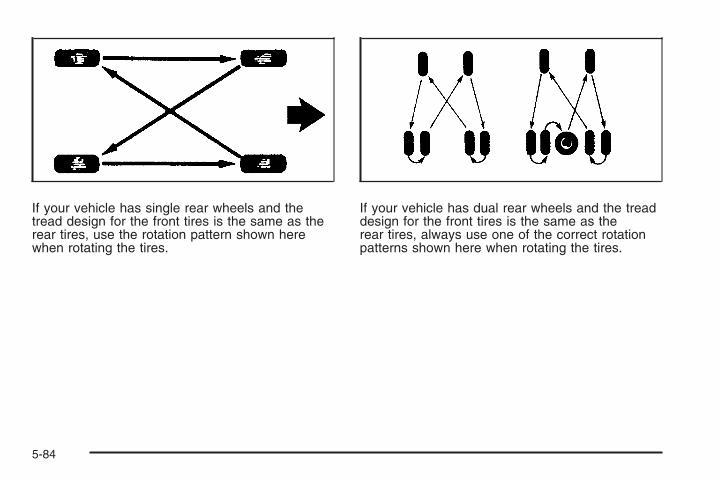
If your vehicle has single rear wheels and thetread design for the front tires is the same as therear tires, use the rotation pattern shown herewhen rotating the tires.
If your vehicle has dual rear wheels and the treaddesign for the front tires is the same as therear tires, always use one of the correct rotationpatterns shown here when rotating the tires.
5-84

If your vehicle has dualrear wheels and thetread design for the fronttires is different fromthe dual rear tires,always use the correctrotation patternshown here whenrotating the tires.
The dual tires are rotated as a pair, and the insiderear tires become the outside rear tires.
When you install dual wheels, be sure the ventholes in the inner and outer wheels on each sideare lined up.
After the tires have been rotated, adjust thefront and rear inflation pressures as shownon the Tire and Loading Information label.See Inflation - Tire Pressure on page 5-76and Loading Your Vehicle on page 4-36.
Make certain that all wheel nuts are properlytightened. See “Wheel Nut Torque” underCapacities and Specifications on page 5-133.
{CAUTION:
Rust or dirt on a wheel, or on the parts towhich it is fastened, can make wheel nutsbecome loose after time. The wheel couldcome off and cause an accident. Whenyou change a wheel, remove any rust ordirt from places where the wheel attachesto the vehicle. In an emergency, you canuse a cloth or a paper towel to do this;but be sure to use a scraper or wire brushlater, if needed, to get all the rust or dirtoff. See Changing a Flat Tire on page 5-94.
If your vehicle has a Tire Pressure MonitorSystem (TPMS), reset the TPMS sensors afterrotating the tires. See Tire Pressure MonitorOperation on page 5-79.
Make sure the spare tire, if your vehicle has one,is stored securely. Push, pull, and then try torotate or turn the tire. If it moves, tighten the cable.See Storing a Flat or Spare Tire and Tools onpage 5-110.
5-85

When It Is Time for New TiresVarious factors, such as maintenance, temperatures,driving speeds, vehicle loading, and road conditions,influence when you need new tires.
One way to tell when it istime for new tires is tocheck the treadwearindicators, which appearwhen your tires haveonly 1/16 inch (1.6 mm) orless of tread remaining.Some commercialtruck tires may not havetreadwear indicators.
You need new tires if any of the following statementsare true:
• You can see the indicators at three or more placesaround the tire.
• You can see cord or fabric showing through thetire’s rubber.
• The tread or sidewall is cracked, cut, or snaggeddeep enough to show cord or fabric.
• The tire has a bump, bulge, or split.
• The tire has a puncture, cut, or other damage thatcannot be repaired well because of the size orlocation of the damage.
The rubber in tires degrades over time, even if they arenot being used. This is also true for the spare tire, ifyour vehicle has one. Multiple conditions affect how fastthis aging takes place, including temperatures, loadingconditions, and inflation pressure maintenance. Withproper care and maintenance tires will typically wear outbefore they degrade due to age. If you are unsureabout the need to replace your tires as they get older,consult the tire manufacturer for more information.
Buying New TiresGM has developed and matched specific tires for yourvehicle. The original equipment tires installed on yourvehicle, when it was new, were designed to meet GeneralMotors Tire Performance Criteria Specification (TPCspec) system rating. If you need replacement tires, GMstrongly recommends that you get tires with the sameTPC Spec rating. This way, your vehicle will continueto have tires that are designed to give the sameperformance and vehicle safety, during normal use,as the original tires.
5-86

GM’s exclusive TPC Spec system considers over adozen critical specifications that impact the overallperformance of your vehicle, including brake systemperformance, ride and handling, traction control, and tirepressure monitoring performance. GM’s TPC Specnumber is molded onto the tire’s sidewall near the tiresize. If the tires have an all-season tread design, the TPCspec number will be followed by a MS, for mud and snow.See Tire Sidewall Labeling on page 5-69 for additionalinformation.GM recommends replacing tires in sets of four (or sixif your vehicle has dual rear wheels). This is becauseuniform tread depth on all tires will help keep your vehicleperforming most like it did when the tires were new.Replacing less than a full set of tires can affect thebraking and handling performance of your vehicle.See Tire Inspection and Rotation on page 5-83 forinformation on proper tire rotation.
{CAUTION:
Mixing tires could cause you to losecontrol while driving. If you mix tires ofdifferent sizes, brands, or types (radial
CAUTION: (Continued)
CAUTION: (Continued)
and bias-belted tires) the vehicle may nothandle properly, and you could have acrash. Using tires of different sizes,brands, or types may also cause damageto your vehicle. Be sure to use the correctsize, brand, and type of tires on yourvehicle’s wheels.
{CAUTION:
If you use bias-ply tires on your vehicle,the wheel rim flanges could developcracks after many miles of driving. A tireand/or wheel could fail suddenly, causinga crash. Use only radial-ply tires with thewheels on your vehicle.
If you must replace your vehicle’s tires with those thatdo not have a TPC Spec number, make sure theyare the same size, load range, speed rating, andconstruction type (radial and bias-belted tires) as yourvehicle’s original tires.
5-87

Vehicles that have a tire pressure monitoring systemcould give an inaccurate low-pressure warning ifnon-TPC Spec rated tires are installed on your vehicle.Non-TPC Spec rated tires may give a low-pressurewarning that is higher or lower than the proper warninglevel you would get with TPC Spec rated tires. SeeTire Pressure Monitor System on page 5-78.
Your vehicle’s original equipment tires are listed onthe Tire and Loading Information label. See LoadingYour Vehicle on page 4-36, for more information aboutthe Tire and Loading Information label and its locationon your vehicle.
Different Size Tires and WheelsIf you add wheels or tires that are a different size thanyour original equipment wheels and tires, this couldaffect the way your vehicle performs, including itsbraking, ride and handling characteristics, stability, andresistance to rollover. Additionally, if your vehiclehas electronic systems such as anti-lock brakes, rolloverairbags, traction control, and electronic stability control,the performance of these systems can be affected.
{CAUTION:
If you add different sized wheels, your vehiclemay not provide an acceptable level ofperformance and safety if tires notrecommended for those wheels are selected.You may increase the chance that you willcrash and suffer serious injury. Only useGM specific wheel and tire systems developedfor your vehicle, and have them properlyinstalled by a GM certified technician.
See Buying New Tires on page 5-86 and Accessoriesand Modifications on page 5-4 for additional information.
5-88

Uniform Tire Quality GradingQuality grades can be found where applicable onthe tire sidewall between tread shoulder andmaximum section width. For example:
Treadwear 200 Traction AATemperature AThe following information relates to the systemdeveloped by the United States National HighwayTraffic Safety Administration (NHTSA), whichgrades tires by treadwear, traction, andtemperature performance. This applies only tovehicles sold in the United States. The grades aremolded on the sidewalls of most passenger cartires. The Uniform Tire Quality Grading (UTQG)system does not apply to deep tread, winter-typesnow tires, space-saver, or temporary usespare tires, tires with nominal rim diameters of10 to 12 inches (25 to 30 cm), or to somelimited-production tires.
While the tires available on General Motorspassenger cars and light trucks may vary withrespect to these grades, they must also conformto federal safety requirements and additionalGeneral Motors Tire Performance Criteria (TPC)standards.
TreadwearThe treadwear grade is a comparative ratingbased on the wear rate of the tire when testedunder controlled conditions on a specifiedgovernment test course. For example, a tiregraded 150 would wear one and a half (1.5) timesas well on the government course as a tiregraded 100. The relative performance of tiresdepends upon the actual conditions of their use,however, and may depart significantly from thenorm due to variations in driving habits, servicepractices, and differences in road characteristicsand climate.
Traction – AA, A, B, CThe traction grades, from highest to lowest,are AA, A, B, and C. Those grades representthe tire’s ability to stop on wet pavement asmeasured under controlled conditions onspecified government test surfaces of asphaltand concrete. A tire marked C may have poortraction performance.
Warning: The traction grade assigned to thistire is based on straight-ahead braking tractiontests, and does not include acceleration,cornering, hydroplaning, or peak tractioncharacteristics.
5-89

Temperature – A, B, CThe temperature grades are A (the highest), B,and C, representing the tire’s resistance tothe generation of heat and its ability to dissipateheat when tested under controlled conditions on aspecified indoor laboratory test wheel. Sustainedhigh temperature can cause the material of the tireto degenerate and reduce tire life, and excessivetemperature can lead to sudden tire failure.The grade C corresponds to a level of performancewhich all passenger car tires must meet underthe Federal Motor Vehicle Safety StandardNo. 109. Grades B and A represent higher levelsof performance on the laboratory test wheelthan the minimum required by law.
Warning: The temperature grade for this tireis established for a tire that is properlyinflated and not overloaded. Excessive speed,underinflation, or excessive loading, eitherseparately or in combination, can cause heatbuildup and possible tire failure.
Wheel Alignment and Tire BalanceThe tires and wheels on your vehicle were alignedand balanced carefully at the factory to give you thelongest tire life and best overall performance.Adjustments to wheel alignment and tire balancing willnot be necessary on a regular basis. However, ifyou notice unusual tire wear or your vehicle pulling toone side or the other, the alignment might need tobe checked. If you notice your vehicle vibrating whendriving on a smooth road, the tires and wheelsmight need to be rebalanced. See your dealer/retailerfor proper diagnosis.
Wheel ReplacementReplace any wheel that is bent, cracked, or badly rustedor corroded. If wheel nuts keep coming loose, thewheel, wheel bolts and wheel nuts should be replaced.If the wheel leaks air, replace it (except somealuminum wheels, which can sometimes be repaired).See your dealer if any of these conditions exist.
Your dealer will know the kind of wheel you need.
5-90

Each new wheel should have the same load-carryingcapacity, diameter, width, offset and be mountedthe same way as the one it replaces.
If you need to replace any of your wheels, wheel boltsor wheel nuts, replace them only with new GMoriginal equipment parts. This way, you will be sure tohave the right wheel, wheel bolts and wheel nutsfor your vehicle.
{CAUTION:
Using the wrong replacement wheels, wheelbolts, or wheel nuts on your vehicle can bedangerous. It could affect the braking andhandling of your vehicle, make your tires loseair and make you lose control. You could havea collision in which you or others could beinjured. Always use the correct wheel, wheelbolts, and wheel nuts for replacement.
Notice: The wrong wheel can also cause problemswith bearing life, brake cooling, speedometer orodometer calibration, headlamp aim, bumper height,vehicle ground clearance, and tire or tire chainclearance to the body and chassis.
Whenever a wheel, wheel bolt or wheel nut is replacedon a dual wheel setup, check the wheel nut torqueafter 100, 1,000 and 6,000 miles (160, 1 600 and10 000 km) of driving. For proper torque, see “WheelNut Torque” under Capacities and Specificationson page 5-133.
See Changing a Flat Tire on page 5-94 for moreinformation.
Used Replacement Wheels
{CAUTION:
Putting a used wheel on the vehicle isdangerous. You cannot know how it has beenused or how far it has been driven. It could failsuddenly and cause a crash. If you have toreplace a wheel, use a new GM originalequipment wheel.
5-91

Tire Chains
{CAUTION:
If your vehicle has dual wheels or P265/65R18,P275/55R20 or LT265/70R17 size tires, do notuse tire chains. They can damage your vehiclebecause there is not enough clearance. Tirechains used on a vehicle without the properamount of clearance can cause damage to thebrakes, suspension, or other vehicle parts.The area damaged by the tire chains couldcause you to lose control of your vehicle andyou or others may be injured in a crash.
Use another type of traction device only if itsmanufacturer recommends it for use on yourvehicle and tire size combination and roadconditions. Follow that manufacturer’sinstructions. To help avoid damage to yourvehicle, drive slowly, readjust, or remove thedevice if it is contacting your vehicle, and donot spin your vehicle’s wheels.
If you do find traction devices that will fit,install them on the rear tires.
Notice: If your vehicle does not have dual wheelsand has a tire size other than P265/65R18,P275/55R20 or LT265/70R17, use tire chains onlywhere legal and only when you must. Use chainsthat are the proper size for your tires. Install themon the tires of the rear axle. Do not use chainson the tires of the front axle. Tighten them astightly as possible with the ends securely fastened.Drive slowly and follow the chain manufacturer’sinstructions. If you can hear the chains contactingyour vehicle, stop and retighten them. If thecontact continues, slow down until it stops.Driving too fast or spinning the wheels withchains on will damage your vehicle.
5-92

If a Tire Goes FlatIt is unusual for a tire to blowout while you are driving,especially if you maintain your vehicle’s tires properly.If air goes out of a tire, it is much more likely to leak outslowly. But if you should ever have a blowout, hereare a few tips about what to expect and what to do:
If a front tire fails, the flat tire creates a drag that pullsthe vehicle toward that side. Take your foot off theaccelerator pedal and grip the steering wheel firmly.Steer to maintain lane position, and then gently brake toa stop well out of the traffic lane.
A rear blowout, particularly on a curve, acts much like askid and may require the same correction you woulduse in a skid. In any rear blowout remove your foot fromthe accelerator pedal. Get the vehicle under controlby steering the way you want the vehicle to go. It maybe very bumpy and noisy, but you can still steer.Gently brake to a stop, well off the road if possible.
{CAUTION:
Lifting a vehicle and getting under it to domaintenance or repairs is dangerous withoutthe appropriate safety equipment and training.The jack provided with your vehicle isdesigned only for changing a flat tire. If it isused for anything else, you or others could bebadly injured or killed if the vehicle slips offthe jack. Use the jack provided with yourvehicle only for changing a flat tire.
If a tire goes flat, the next part shows how to use thejacking equipment to change a flat tire safely.
5-93

Changing a Flat TireIf a tire goes flat, avoid further tire and wheel damageby driving slowly to a level place. Turn on your hazardwarning flashers. See Hazard Warning Flashers onpage 3-8 for more information.
{CAUTION:
Changing a tire can be dangerous. The vehiclecan slip off the jack and roll over or fall on youor other people. You and they could be badlyinjured or even killed. Find a level place tochange your tire. To help prevent the vehiclefrom moving:
1. Set the parking brake firmly.2. Put the shift lever in PARK (P).3. If you have a four-wheel-drive vehicle,
be sure the transfer case is in adrive gear – not in NEUTRAL.
4. Turn off the engine and do not restartwhile the vehicle is raised.
5. Do not allow passengers to remain inthe vehicle.
CAUTION: (Continued)
CAUTION: (Continued)
To be even more certain the vehicle will notmove, put blocks at the front and rear of thetire farthest away from the one being changed.That would be the tire on the other side, at theopposite end of the vehicle.
When your vehicle has a flat tire, use the followingexample as a guide to assist you in the placement ofthe wheel blocks.
The following information will tell you next how to usethe jack and change a tire.
5-94

Removing the Spare Tire and Tools
A. Wing NutRetaining Tool Kit
B. Tool KitC. Wheel Blocks
D. JackE. Wing Nut Retaining
Wheel Blocks
A. Wing Nut RetainingWheel Blocks
B. Wheel BlocksC. Wing Nut Retaining
Tool Kit
D. Tool KitE. JackF. Knob
Crew Cab
Regular Cab
5-95
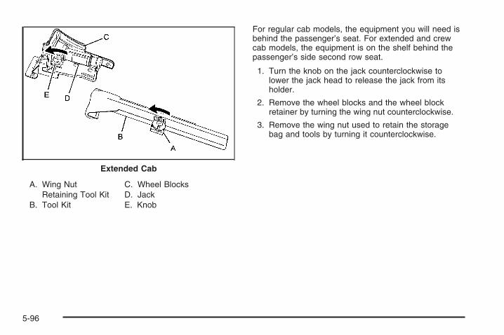
A. Wing NutRetaining Tool Kit
B. Tool Kit
C. Wheel BlocksD. JackE. Knob
For regular cab models, the equipment you will need isbehind the passenger’s seat. For extended and crewcab models, the equipment is on the shelf behind thepassenger’s side second row seat.
1. Turn the knob on the jack counterclockwise tolower the jack head to release the jack from itsholder.
2. Remove the wheel blocks and the wheel blockretainer by turning the wing nut counterclockwise.
3. Remove the wing nut used to retain the storagebag and tools by turning it counterclockwise.
Extended Cab
5-96

You will use the jack handle extensions and the wheelwrench to remove the underbody-mounted spare tire.
A. Spare Tire (ValveStem Pointed Down)
B. Hoist AssemblyC. Hoist Cable
D. Tire/WheelRetainer
E. Hoist ShaftF. Hoist End of
Extension Tool
G. Hoist ShaftAccess Hole
H. Wheel Wrench
I. Jack HandleExtensions
J. Spare Tire Lock(If equipped)
1. Open the spare tire lock cover on the bumperand use the ignition key to remove the sparetire lock (J). To remove the spare tire lock,insert the ignition key turn and pull straight out.
2. Assemble the wheel wrench (H) and the two jackhandle extensions (I) as shown.
5-97

3. Insert the hoist end(open end) (F) of theextension throughthe hole (G) in therear bumper.Do not use thechiseled end of thewheel wrench.
Be sure the hoist end of the extension (F) connectsto the hoist shaft (E). The ribbed square end ofthe extension is used to lower the spare tire.
4. Turn the wheel wrench (H) counterclockwise tolower the spare tire to the ground. Continue toturn the wheel wrench until the spare tire can bepulled out from under the vehicle.If the spare tire does not lower to the ground, thesecondary latch is engaged causing the tirenot to lower. See Secondary Latch System onpage 5-106.
5. Use the wheel wrenchhook which allowsyou to pull the hoistcable towards youto assist in reaching thespare tire.
5-98
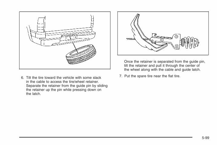
6. Tilt the tire toward the vehicle with some slackin the cable to access the tire/wheel retainer.Separate the retainer from the guide pin by slidingthe retainer up the pin while pressing down onthe latch.
Once the retainer is separated from the guide pin,tilt the retainer and pull it through the center ofthe wheel along with the cable and guide latch.
7. Put the spare tire near the flat tire.
5-99

Removing the Flat Tire andInstalling the Spare TireUse the following pictures and instructions to removethe flat tire and raise the vehicle.
The tools you will be using include the jack (A), thewheel blocks (B), the jack handle (C), the jack handleextensions (D), and the wheel wrench (E).
1. Do a safety check before proceeding.See Changing a Flat Tire on page 5-94for more information.
2. If your vehicle haswheel nut caps, loosenthem by turning thewheel wrenchcounterclockwise.
If the vehicle has a center cap with wheel nut caps,the wheel nut caps are designed to stay with thecenter cap after they are loosened. Removethe entire center cap.
5-100
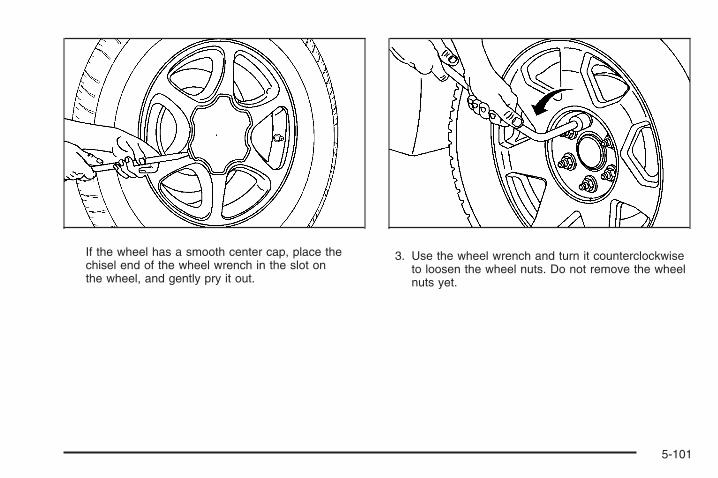
If the wheel has a smooth center cap, place thechisel end of the wheel wrench in the slot onthe wheel, and gently pry it out.
3. Use the wheel wrench and turn it counterclockwiseto loosen the wheel nuts. Do not remove the wheelnuts yet.
5-101
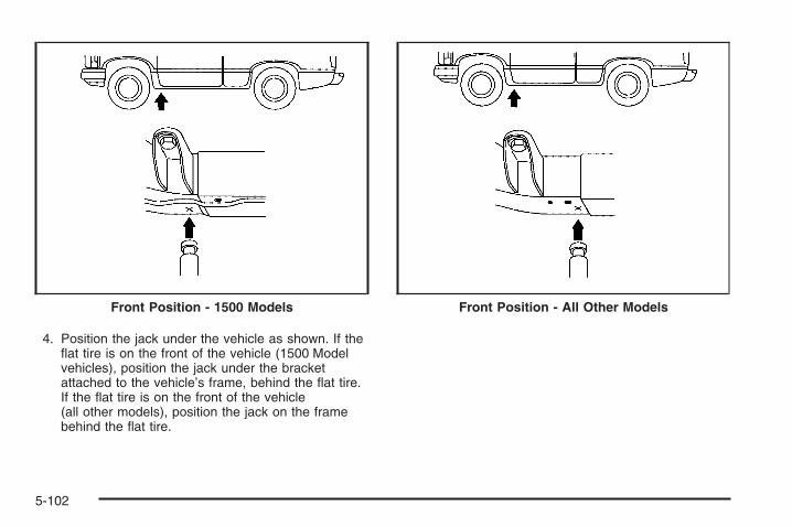
4. Position the jack under the vehicle as shown. If theflat tire is on the front of the vehicle (1500 Modelvehicles), position the jack under the bracketattached to the vehicle’s frame, behind the flat tire.If the flat tire is on the front of the vehicle(all other models), position the jack on the framebehind the flat tire.
Front Position - 1500 Models Front Position - All Other Models
5-102

If the flat tire is on the rear, position the jack underthe rear axle between the spring anchor and theshock absorber bracket.If you have added a snow plow to the front of yourvehicle, lower the snow plow fully before raisingthe vehicle.Make sure that the jack head is positioned so thatthe rear axle is resting securely between thegrooves that are on the jack head.
{CAUTION:
Getting under a vehicle when it is jacked up isdangerous. If the vehicle slips off the jack, youcould be badly injured or killed. Never get undera vehicle when it is supported only by a jack.
{CAUTION:
Raising your vehicle with the jack improperlypositioned can damage the vehicle and evenmake the vehicle fall. To help avoid personalinjury and vehicle damage, be sure to fit thejack lift head into the proper location beforeraising the vehicle.
5. Turn the wheel wrench clockwise to raise thevehicle. Raise the vehicle far enough off the groundso there is enough room for the spare tire to fitunder the wheel well.
Rear Position – All Models
5-103
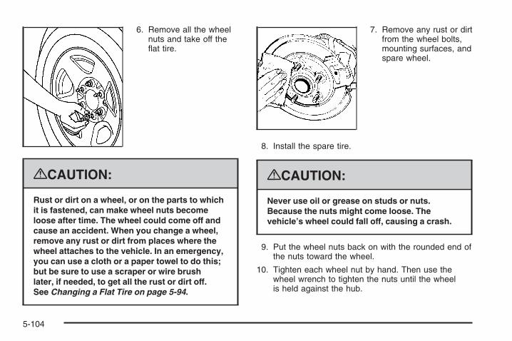
6. Remove all the wheelnuts and take off theflat tire.
{CAUTION:
Rust or dirt on a wheel, or on the parts to whichit is fastened, can make wheel nuts becomeloose after time. The wheel could come off andcause an accident. When you change a wheel,remove any rust or dirt from places where thewheel attaches to the vehicle. In an emergency,you can use a cloth or a paper towel to do this;but be sure to use a scraper or wire brushlater, if needed, to get all the rust or dirt off.See Changing a Flat Tire on page 5-94.
7. Remove any rust or dirtfrom the wheel bolts,mounting surfaces, andspare wheel.
8. Install the spare tire.
{CAUTION:
Never use oil or grease on studs or nuts.Because the nuts might come loose. Thevehicle’s wheel could fall off, causing a crash.
9. Put the wheel nuts back on with the rounded end ofthe nuts toward the wheel.
10. Tighten each wheel nut by hand. Then use thewheel wrench to tighten the nuts until the wheelis held against the hub.
5-104
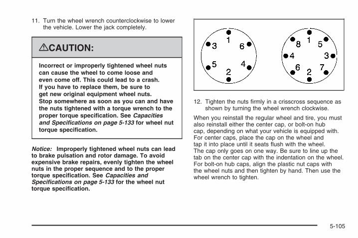
11. Turn the wheel wrench counterclockwise to lowerthe vehicle. Lower the jack completely.
{CAUTION:
Incorrect or improperly tightened wheel nutscan cause the wheel to come loose andeven come off. This could lead to a crash.If you have to replace them, be sure toget new original equipment wheel nuts.Stop somewhere as soon as you can and havethe nuts tightened with a torque wrench to theproper torque specification. See Capacitiesand Specifications on page 5-133 for wheel nuttorque specification.
Notice: Improperly tightened wheel nuts can leadto brake pulsation and rotor damage. To avoidexpensive brake repairs, evenly tighten the wheelnuts in the proper sequence and to the propertorque specification. See Capacities andSpecifications on page 5-133 for the wheel nuttorque specification.
12. Tighten the nuts firmly in a crisscross sequence asshown by turning the wheel wrench clockwise.
When you reinstall the regular wheel and tire, you mustalso reinstall either the center cap, or bolt-on hubcap, depending on what your vehicle is equipped with.For center caps, place the cap on the wheel andtap it into place until it seats flush with the wheel.The cap only goes on one way. Be sure to line up thetab on the center cap with the indentation on the wheel.For bolt-on hub caps, align the plastic nut caps withthe wheel nuts and then tighten by hand. Then use thewheel wrench to tighten.
5-105

Secondary Latch SystemYour vehicle has an underbody-mounted tire hoistassembly equipped with a secondary latch system. It isdesigned to stop the spare tire from suddenly fallingoff your vehicle. For the secondary latch to work,the spare must be installed with the valve stem pointingdown. See Storing a Flat or Spare Tire and Tools onpage 5-110.
{CAUTION:
Before beginning this procedure read all theinstructions. Failure to read and follow theinstructions could damage the hoist assemblyand you and others could get hurt. Read andfollow the instructions listed next.
To release the spare tire from the secondary latch:
1. Check under thevehicle to see if thecable end is visible.If the cable is notvisible proceedto Step 6.
2. If it is visible, first try to tighten the cable byturning the wheel wrench clockwise until youhear two clicks or feel it skip twice. You cannotovertighten the cable.
3. Loosen the cable by turning the wrenchcounterclockwise three or four turns.
4. Repeat this procedure at least two times. If thespare tire lowers to the ground, continue withStep 5 of Removing the Spare Tire and Toolson page 5-95.
5. If the spare does not lower, turn the wrenchcounterclockwise until approximately 6 inches(15 cm) of cable is exposed.
5-106

6. Stand the wheel blocks on their shortest ends,with the backs facing each other.
7. Place the bottom edgeof the jack (A) on thewheel blocks (B),separating them so thatthe jack is balancedsecurely.
8. Attach the jack handle, extension, and wheelwrench to the jack and place it (with the wheelblocks) under the vehicle toward the front of therear bumper.
5-107

9. Position the center lift point of the jack under thecenter of the spare tire.
10. Turn the wrench clockwise to raise the jack until itlifts the end fitting.
11. Continue raising the jack until the spare tire stopsmoving upward and is held firmly in place.The secondary latch has released and the sparetire is balancing on the jack.
12. Lower the jack by turning the wheel wrenchcounterclockwise. Keep lowering the jack untilthe spare tire slides off the jack or is hanging bythe cable.
{CAUTION:
Someone standing too close during theprocedure could be injured by the jack.If the spare tire does not slide off the jackcompletely, make sure no one is behind you oron either side of you as you pull the jack outfrom under the spare.
5-108

13. Disconnect the jack handle from the jack andcarefully remove the jack. Use one hand topush against the spare while firmly pulling the jackout from under the spare tire with the other hand.
If the spare tire is hanging from the cable, insert thehoist end of extension, and wheel wrench intothe hoist shaft hole in the bumper and turnthe wheel wrench counterclockwise to lower thespare the rest of the way.
14. Tilt the tire retainer at the end of the cable and pullit through the wheel opening. Pull the tire out fromunder the vehicle.
15. Turn the wheel wrench in the hoist shaft hole in thebumper clockwise to raise the cable back up if thecable is hanging under the vehicle.
Have the hoist assembly inspected as soon as you can.You will not be able to store a spare or flat tire usingthe hoist assembly until it has been replaced.
To continue changing the flat tire, see Removing theFlat Tire and Installing the Spare Tire on page 5-100.
5-109

Storing a Flat or Spare Tireand Tools
{CAUTION:
Storing a jack, a tire, or other equipment in thepassenger compartment of the vehicle couldcause injury. In a sudden stop or collision,loose equipment could strike someone.Store all these in the proper place.
Notice: Storing an aluminum wheel with a flat tireunder your vehicle for an extended period of time orwith the valve stem pointing up can damage thewheel. Always stow the wheel with the valve stempointing down and have the wheel/tire repairedas soon as possible.
Store the tire under the rear of the vehicle in the sparetire carrier.
A. Flat or Spare Tire(Valve StemPointed Down)
B. Hoist AssemblyC. Hoist Cable
D. Tire/WheelRetainer
E. Hoist ShaftF. Hoist End of
Extension Tool
5-110

G. Hoist ShaftAccess Hole
H. Wheel Wrench
I. Jack HandleExtensions
J. Spare Tire Lock(If Equipped)
1. Put the tire on the ground at the rear of the vehiclewith the valve stem pointed down, and to the rear.
2. Separate the tire/wheel retainer (D) from the guidepin. Pull the pin through the center of the wheel.Tilt the retainer down and through the centerwheel opening.Make sure the retainer is fully seated acrossthe underside of the wheel.
3. Attach the wheel wrench (H) and extensions (I)together, as shown.
4. Insert the hoist end (F)through the hole (G) inthe rear bumper andonto the hoist shaft.Do not use thechiseled end of thewheel wrench.
5-111

5. Raise the tire part way upward. Make sure theretainer is seated in the wheel opening.
6. Raise the tire fully against the underside of thevehicle by turning the wheel wrench clockwiseuntil you hear two clicks or feel it skip twice.You cannot overtighten the cable.
7. Make sure the tire is stored securely. Push, pull (A),and then try to turn (B) the tire. If the tire moves,use the wheel wrench to tighten the cable.
8. Reinstall the spare tire lock, if the vehicle has one.
To store the jack and jack tools:
A. Wing NutB. Wheel BlocksC. Retaining Bracket
and Wing NutD. Wheel Wrench and
Extensions
E. Tool BagF. Jack Mounting BracketG. JackH. Retaining Bolt
1. Put the tools (D) in the tool bag (E) and place themin the retaining bracket (C).
2. Tighten down the wing nut (C).
5-112

3. Assemble the wheel blocks (B) and jack (G)together with the wing nut (A) and retaining bolt (H).
4. Position the jack (G) in the mounting bracket (F).Position the holes in the base of the jack (G) ontothe pin in the mounting bracket (F).
5. Return them to their original location in the vehicle.For more information, refer to Removing the SpareTire and Tools on page 5-95 for more information.
Spare TireYour vehicle, when new, had a fully-inflated spare tire.A spare tire may lose air over time, so check itsinflation pressure regularly. See Inflation - Tire Pressureon page 5-76 and Loading Your Vehicle on page 4-36for information regarding proper tire inflation and loadingyour vehicle. For instruction on how to remove, installor store a spare tire, see Removing the Flat Tire andInstalling the Spare Tire on page 5-100 and Storing aFlat or Spare Tire and Tools on page 5-110.
Notice: If your vehicle has four-wheel drive andthe different size spare tire is installed on yourvehicle, do not drive in four-wheel drive until youcan have your flat tire repaired and/or replaced.
You could damage your vehicle, and the repair costswould not be covered by your warranty. Never usefour-wheel drive when the different size spare tire isinstalled on your vehicle.
Your vehicle may have a different size spare tire than theroad tires originally installed on your vehicle. This sparetire was developed for use on your vehicle, so it is all rightto drive on it. If your vehicle has four-wheel drive and thedifferent size spare tire is installed, keep the vehicle intwo-wheel drive.
After installing the spare tire on your vehicle, you shouldstop as soon as possible and make sure the spare tire iscorrectly inflated. Have the damaged or flat road tirerepaired or replaced as soon as you can and installedback onto your vehicle. This way, the spare tire will beavailable in case you need it again.
Do not mix tires and wheels of different sizes, becausethey will not fit. Keep your spare tire and its wheeltogether. If your vehicle has a spare tire that does notmatch your vehicle’s original road tires and wheels in sizeand type, do not include the spare in the tire rotation.
5-113
Appearance Care
Interior CleaningYour vehicle’s interior will continue to look its best if it iscleaned often. Although not always visible, dust anddirt can accumulate on your upholstery. Dirt can damagecarpet, fabric, leather, and plastic surfaces. Regularvacuuming is recommended to remove particlesfrom your upholstery. It is important to keep yourupholstery from becoming and remaining heavily soiled.Soils should be removed as quickly as possible. Yourvehicle’s interior may experience extremes of heatthat could cause stains to set rapidly.
Lighter colored interiors may require more frequentcleaning. Use care because newspapers and garmentsthat transfer color to your home furnishings may alsotransfer color to your vehicle’s interior.
When cleaning your vehicle’s interior, only use cleanersspecifically designed for the surfaces being cleaned.Permanent damage may result from using cleaners onsurfaces for which they were not intended. Use glasscleaner only on glass. Remove any accidental over-sprayfrom other surfaces immediately. To prevent over-spray,apply cleaner directly to the cleaning cloth.
Notice: If you use abrasive cleaners when cleaningglass surfaces on your vehicle, you could scratchthe glass and/or cause damage to the rear windowdefogger. When cleaning the glass on yourvehicle, use only a soft cloth and glass cleaner.
Many cleaners contain solvents that may becomeconcentrated in your vehicle’s breathing space.Before using cleaners, read and adhere to all safetyinstructions on the label. While cleaning your vehicle’sinterior, maintain adequate ventilation by openingyour vehicle’s doors and windows.
Dust may be removed from small buttons and knobsusing a small brush with soft bristles.
5-114

Your dealer/retailer has a product for cleaning yourvehicle’s glass. Should it become necessary, you canalso obtain a product from your dealer/retailer to removeodors from your vehicle’s upholstery.
Do not clean your vehicle using:
• A knife or any other sharp object to remove a soilfrom any interior surface.
• A stiff brush. It can cause damage to your vehicle’sinterior surfaces.
• Heavy pressure or aggressive rubbing with acleaning cloth. Use of heavy pressure can damageyour interior and does not improve the effectivenessof soil removal.
• Laundry detergents or dishwashing soaps withdegreasers can leave residue that streaks andattracts dirt. For liquid cleaners, about 20 drops pergallon (3.78 L) of water is a good guide. Use onlymild, neutral-pH soaps.
• Too much cleaner that saturates the upholstery.
• Organic solvents such as naptha, alcohol, etc. thatcan damage your vehicle’s interior.
Fabric/CarpetUse a vacuum cleaner with a soft brush attachmentfrequently to remove dust and loose dirt. A canistervacuum with a beater bar in the nozzle may onlybe used on floor carpet and carpeted floor mats.For any soil, always try to remove it first with plain wateror club soda. Before cleaning, gently remove as muchof the soil as possible using one of the followingtechniques:
• For liquids: gently blot the remaining soil with apaper towel. Allow the soil to absorb into thepaper towel until no more can be removed.
• For solid dry soils: remove as much as possibleand then vacuum.
To clean:
1. Saturate a lint-free, clean white cloth with water orclub soda.
2. Wring the cloth to remove excess moisture.
3. Start on the outside edge of the soil and gently rubtoward the center. Continue cleaning, using a cleanarea of the cloth each time it becomes soiled.
5-115

4. Continue to gently rub the soiled area until thecleaning cloth remains clean.
5. If the soil is not completely removed, use a mildsoap solution and repeat the cleaning processthat was used with plain water.
If any of the soil remains, a commercial fabric cleaner orspot lifter may be necessary. When a commercialupholstery cleaner or spot lifter is to be used, test asmall hidden area for colorfastness first. If the locallycleaned area gives any impression that a ring formationmay result, clean the entire surface.
After the cleaning process has been completed, a papertowel can be used to blot excess moisture from thefabric or carpet.
LeatherA soft cloth dampened with water can be used toremove dust. If a more thorough cleaning is necessary,a soft cloth dampened with a mild soap solution canbe used. Allow the leather to dry naturally. Do not useheat to dry. Never use steam to clean leather. Neveruse spot lifters or spot removers on leather. Manycommercial leather cleaners and coatings that are soldto preserve and protect leather may permanentlychange the appearance and feel of your leather and arenot recommended. Do not use silicone or wax-basedproducts, or those containing organic solvents to cleanyour vehicle’s interior because they can alter theappearance by increasing the gloss in a non-uniformmanner. Never use shoe polish on leather.
5-116

Instrument Panel, Vinyl, and OtherPlastic SurfacesA soft cloth dampened with water may be used toremove dust. If a more thorough cleaning is necessary,a clean soft cloth dampened with a mild soap solutioncan be used to gently remove dust and dirt. Neveruse spot lifters or removers on plastic surfaces.Many commercial cleaners and coatings that are soldto preserve and protect soft plastic surfaces maypermanently change the appearance and feel of yourinterior and are not recommended. Do not use siliconeor wax-based products, or those containing organicsolvents to clean your vehicle’s interior because theycan alter the appearance by increasing the glossin a non-uniform manner.
Some commercial products may increase gloss on yourinstrument panel. The increase in gloss may causeannoying reflections in the windshield and even make itdifficult to see through the windshield under certainconditions.
Care of Safety BeltsKeep belts clean and dry.
{CAUTION:
Do not bleach or dye safety belts. If you do,it may severely weaken them. In a crash,they might not be able to provide adequateprotection. Clean safety belts only with mildsoap and lukewarm water.
WeatherstripsSilicone grease on weatherstrips will make them lastlonger, seal better, and not stick or squeak. Applysilicone grease with a clean cloth. During very cold,damp weather frequent application may be required.See Recommended Fluids and Lubricants on page 6-14.
5-117

Washing Your VehicleThe best way to preserve your vehicle’s finish is to keepit clean by washing it often.
Notice: Certain cleaners contain chemicals that candamage the emblems or nameplates on yourvehicle. Check the cleaning product label. If it statesthat it should not be used on plastic parts, do notuse it on your vehicle or damage may occurand it would not be covered by the warranty.
Do not wash the vehicle in direct sunlight. Use a carwashing soap. Do not use cleaning agents thatare petroleum based or that contain acid or abrasives,as they can damage the paint, metal or plastic onyour vehicle. Approved cleaning products can beobtained from your dealer/retailer. See VehicleCare/Appearance Materials on page 5-123.Follow all manufacturers’ directions regarding correctproduct usage, necessary safety precautions andappropriate disposal of any vehicle care product.
Rinse the vehicle well, before washing and after toremove all cleaning agents completely. If they areallowed to dry on the surface, they could stain.
Dry the finish with a soft, clean chamois or an all-cottontowel to avoid surface scratches and water spotting.
High pressure car washes may cause water to enter thevehicle. Avoid using high pressure washes closerthan 12 inches (30 cm) to the surface of the vehicle.Use of power washers exceeding 1,200 psi (8 274 kPa)can result in damage or removal of paint and decals.
Cleaning Exterior Lamps/LensesUse only lukewarm or cold water, a soft cloth and acar washing soap to clean exterior lamps and lenses.Follow instructions under Washing Your Vehicle onpage 5-118.
5-118
Finish CareOccasional waxing or mild polishing of your vehicle byhand may be necessary to remove residue from thepaint finish. You can get approved cleaning productsfrom your dealer/retailer. See Vehicle Care/AppearanceMaterials on page 5-123.
If your vehicle has a basecoat/clearcoat paint finish,the clearcoat gives more depth and gloss to thecolored basecoat. Always use waxes and polishes thatare non-abrasive and made for a basecoat/clearcoatpaint finish.
Notice: Machine compounding or aggressivepolishing on a basecoat/clearcoat paint finish maydamage it. Use only non-abrasive waxes andpolishes that are made for a basecoat/clearcoatpaint finish on your vehicle.
Foreign materials such as calcium chloride and othersalts, ice melting agents, road oil and tar, tree sap, birddroppings, chemicals from industrial chimneys, etc.,
can damage your vehicle’s finish if they remain onpainted surfaces. Wash the vehicle as soon as possible.If necessary, use non-abrasive cleaners that aremarked safe for painted surfaces to remove foreignmatter.
Exterior painted surfaces are subject to aging, weatherand chemical fallout that can take their toll over aperiod of years. You can help to keep the paint finishlooking new by keeping your vehicle garaged or coveredwhenever possible.
Protecting Exterior Bright Metal PartsBright metal parts should be cleaned regularly to keeptheir luster. Washing with water is all that is usuallyneeded. However, you may use chrome polish onchrome or stainless steel trim, if necessary.
Use special care with aluminum trim. To avoid damagingprotective trim, never use auto or chrome polish,steam or caustic soap to clean aluminum. A coating ofwax, rubbed to high polish, is recommended for allbright metal parts.
5-119
Windshield and Wiper BladesClean the outside of the windshield with glass cleaner.
Clean the rubber blades using a lint free cloth orpaper towel soaked with windshield washer fluid or amild detergent. Wash the windshield thoroughly whencleaning the blades. Bugs, road grime, sap, and abuildup of vehicle wash/wax treatments may cause wiperstreaking. Replace the wiper blades if they are wornor damaged.
Wipers can be damaged by:
• Extreme dusty conditions
• Sand and salt
• Heat and sun
• Snow and ice, without proper removal
Aluminum or Chrome-PlatedWheels and TrimYour vehicle may have either aluminum orchrome-plated wheels.Keep the wheels clean using a soft clean cloth with mildsoap and water. Rinse with clean water. After rinsingthoroughly, dry with a soft clean towel. A wax may thenbe applied.
Notice: Chrome wheels and other chrome trim maybe damaged if you do not wash your vehicle afterdriving on roads that have been sprayed withmagnesium, calcium or sodium chloride. Thesechlorides are used on roads for conditions such asice and dust. Always wash your vehicle’s chromewith soap and water after exposure.
Notice: If you use strong soaps, chemicals,abrasive polishes, cleaners, brushes, or cleanersthat contain acid on aluminum or chrome-platedwheels, you could damage the surface of thewheel(s). The repairs would not be covered by yourwarranty. Use only approved cleaners on aluminumor chrome-plated wheels.
5-120

The surface of these wheels is similar to the paintedsurface of your vehicle. Do not use strong soaps,chemicals, abrasive polishes, abrasive cleaners,cleaners with acid, or abrasive cleaning brushes onthem because you could damage the surface. Do notuse chrome polish on aluminum wheels.
Notice: Using chrome polish on aluminum wheelscould damage the wheels. The repairs would notbe covered by your warranty. Use chrome polish onchrome wheels only.
Use chrome polish only on chrome-plated wheels, butavoid any painted surface of the wheel, and buff offimmediately after application.
Notice: If you drive your vehicle through anautomatic car wash that has silicone carbide tirecleaning brushes, you could damage the aluminumor chrome-plated wheels. The repairs would notbe covered by your warranty. Never drive a vehicleequipped with aluminum or chrome-plated wheelsthrough an automatic car wash that uses siliconecarbide tire cleaning brushes.
TiresTo clean the tires, use a stiff brush with tire cleaner.
Notice: Using petroleum-based tire dressingproducts on your vehicle may damage the paintfinish and/or tires. When applying a tire dressing,always wipe off any overspray from all paintedsurfaces on your vehicle.
Sheet Metal DamageIf the vehicle is damaged and requires sheet metalrepair or replacement, make sure the body repair shopapplies anti-corrosion material to parts repaired orreplaced to restore corrosion protection.
Original manufacturer replacement parts will provide thecorrosion protection while maintaining the warranty.
5-121

Finish DamageAny stone chips, fractures or deep scratches in thefinish should be repaired right away. Bare metalwill corrode quickly and may develop into majorrepair expense.
Minor chips and scratches can be repaired with touch-upmaterials available from your dealer/retailer. Largerareas of finish damage can be corrected in yourdealer’s/retailer’s body and paint shop.
Underbody MaintenanceChemicals used for ice and snow removal and dustcontrol can collect on the underbody. If these are notremoved, corrosion and rust can develop on theunderbody parts such as fuel lines, frame, floor pan,and exhaust system even though they have corrosionprotection.
At least every spring, flush these materials from theunderbody with plain water. Clean any areas where mudand debris can collect. Dirt packed in close areas ofthe frame should be loosened before being flushed.Your dealer/retailer or an underbody car washing systemcan do this for you.
Chemical Paint SpottingSome weather and atmospheric conditions can create achemical fallout. Airborne pollutants can fall upon andattack painted surfaces on the vehicle. This damage cantake two forms: blotchy, ring-shaped discolorations,and small, irregular dark spots etched into the paintsurface.
Although no defect in the paint job causes this, we willrepair, at no charge to the owner, the surfaces ofnew vehicles damaged by this fallout condition within12 months or 12,000 miles (20 000 km) of purchase,whichever occurs first.
5-122

Vehicle Care/Appearance Materials
Description Usage
Polishing Cloth Interior and exteriorpolishing cloth.
Tar and RoadOil Remover
Removes tar, road oil,and asphalt.
Chrome Cleanerand Polish
Use on chrome orstainless steel.
White SidewallTire Cleaner
Removes soil and blackmarks from whitewallsand raised white lettering.
Vinyl Cleaner Cleans vinyl.
Glass Cleaner Removes dirt, grime,smoke and fingerprints.
Chrome Wheel Cleaner Removes dirt and grimefrom chrome wheels.
Finish Enhancer
Removes dust,fingerprints, and surfacecontaminants. Spray onand wipe off.
Description Usage
Swirl Remover PolishRemoves swirl marks, finescratches, and other lightsurface contamination.
Cleaner Wax Removes light scratchesand protects finish.
Foaming Tire ShineLow Gloss
Cleans, shines, andprotects tires. No wipingnecessary.
Wash Wax Concentrate
Medium foamingshampoo. Cleans andlightly waxes.Biodegradable andphosphate free.
Spot LifterQuickly removes spotsand stains from carpets,vinyl, and cloth upholstery.
Odor EliminatorOdorless spray odoreliminator used on fabrics,vinyl, leather and carpet.
5-123

Vehicle Identification
Vehicle Identification Number (VIN)
This is the legal identifier for your vehicle. It appears ona plate in the front corner of the instrument panel, onthe driver side. It can be seen through the windshieldfrom outside the vehicle. The VIN also appears onthe Certification/Tire and Service Parts labels and thecertificates of title and registration.
Engine IdentificationThe eighth character in the VIN is the engine code. Thiscode helps identify the vehicle’s engine, specifications,and replacement parts. See “Engine Specifications”under Capacities and Specifications on page 5-133 foryour vehicle’s engine code.
Service Parts Identification LabelThis label is on the inside of the glove box. It isvery helpful if you ever need to order parts. The labelhas the following information:
• Vehicle Identification Number (VIN)
• Model designation
• Paint information
• Production options and special equipment
Do not remove this label from the vehicle.
5-124

Electrical System
Add-On Electrical EquipmentNotice: Do not add anything electrical to yourvehicle unless you check with your dealer/retailerfirst. Some electrical equipment can damage yourvehicle and the damage would not be covered byyour warranty. Some add-on electrical equipment cankeep other components from working as they should.
Add-on equipment can drain your vehicle’s battery, evenif your vehicle is not operating.
Your vehicle has an airbag system. Before attempting toadd anything electrical to your vehicle, see ServicingYour Airbag-Equipped Vehicle on page 1-86.
Windshield Wiper FusesThe windshield wiper motor is protected by an internalcircuit breaker and a fuse. If the motor overheats due toheavy snow, etc., the wiper will stop until the motorcools. If the overload is caused by some electricalproblem and not snow, etc., be sure to get it fixed.
Power Windows and OtherPower OptionsCircuit breakers protect the power windows and otherpower accessories. If the current load is too heavy,the circuit breaker opens and then closes after a cooldown period, protecting the circuit until the problemis fixed or goes away.
Fuses and Circuit BreakersThe wiring circuits in your vehicle are protected fromshort circuits by a combination of fuses, circuit breakersand fusible thermal links. This greatly reduces thechance of fires caused by electrical problems.
Look at the silver-colored band inside the fuse. If theband is broken or melted, replace the fuse. Be sure youreplace a bad fuse with a new one of the identical sizeand rating.
Fuses of the same amperage can be temporarilyborrowed from another fuse location, if a fuse goes out.Replace the fuse as soon as you can.
5-125
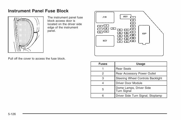
Instrument Panel Fuse BlockThe instrument panel fuseblock access door islocated on the driver sideedge of the instrumentpanel.
Pull off the cover to access the fuse block.
Fuses Usage
1 Rear Seats
2 Rear Accessory Power Outlet
3 Steering Wheel Controls Backlight
4 Driver Door Module
5 Dome Lamps, Driver SideTurn Signal
6 Driver Side Turn Signal, Stoplamp
5-126

Fuses Usage
7 Instrument Panel Back Lighting
8 Passenger Side Turn Signal,Stoplamp
9 Universal Home Remote
10 Power Door Lock 2 (Unlock Feature)
11 Power Door Lock 2 (Lock Feature)
12 Stoplamps, Center-High MountedStoplamp
13 Rear Climate Controls
14 Power Mirror
15 Body Control Module (BCM)
16 Accessory Power Outlets
17 Interior Lamps
18 Power Door Lock 1 (Unlock Feature)
19 Rear Seat Entertainment
20 Ultrasonic Rear Parking Assist
21 Power Door Lock 1 (Lock Feature)
Fuses Usage
22 Driver Information Center (DIC)
23 Not Used
24 Not Used
25 Driver Seat Module, RemoteKeyless Entry System
26 Driver Power Door Lock(Unlock Feature)
Circuit Breaker Usage
LT DR Driver Side Power WindowCircuit Breaker
HarnessConnector Usage
LT DR Driver Door Harness Connection
BODY Harness Connector
BODY Harness Connector
5-127

Center Instrument Panel Fuse BlockThe center instrument panel fuse block is locatedunderneath the instrument panel, to the left of thesteering column.
Top View
HarnessConnector Usage
BODY 2 Body Harness Connector 2
BODY 1 Body Harness Connector 1
HarnessConnector Usage
BODY 3 Body Harness Connector 3
HEADLINER 3 Headliner Harness Connector 3
HEADLINER 2 Headliner Harness Connector 2
HEADLINER 1 Headliner Harness Connector 1
SEO/UPFITTER Special Equipment Option UpfitterHarness Connector
Circuit Breaker Usage
CB1 Passenger Side Power WindowCircuit Breaker
CB2 Passenger Seat Circuit Breaker
CB3 Driver Seat Circuit Breaker
CB4 Rear Sliding Window
5-128

Underhood Fuse BlockIf your vehicle has the DURAMAX® Diesel engine, seethe DURAMAX® Diesel manual for more information.
The underhood fuse block is located in the enginecompartment, on the driver side of the vehicle.
Lift the cover to access the fuse block.
Notice: Spilling liquid on any electrical componentson your vehicle may damage it. Always keep thecovers on any electrical component.
To remove fuses, hold the end of the fuse between yourthumb and index finger and pull straight out.
Fuses Usage
1 Right Trailer Stop/Turn Lamp
2 Electronic Suspension Control,Automatic Level Control Exhaust
3 Left Trailer Stop/Turn Lamp
4 Engine Controls
5 Engine Control Module,Throttle Control
5-129
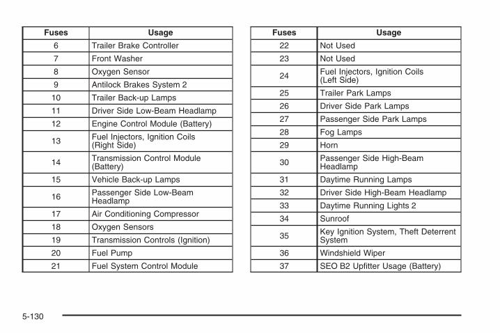
Fuses Usage
6 Trailer Brake Controller
7 Front Washer
8 Oxygen Sensor
9 Antilock Brakes System 2
10 Trailer Back-up Lamps
11 Driver Side Low-Beam Headlamp
12 Engine Control Module (Battery)
13 Fuel Injectors, Ignition Coils(Right Side)
14 Transmission Control Module(Battery)
15 Vehicle Back-up Lamps
16 Passenger Side Low-BeamHeadlamp
17 Air Conditioning Compressor
18 Oxygen Sensors
19 Transmission Controls (Ignition)
20 Fuel Pump
21 Fuel System Control Module
Fuses Usage
22 Not Used
23 Not Used
24 Fuel Injectors, Ignition Coils(Left Side)
25 Trailer Park Lamps
26 Driver Side Park Lamps
27 Passenger Side Park Lamps
28 Fog Lamps
29 Horn
30 Passenger Side High-BeamHeadlamp
31 Daytime Running Lamps
32 Driver Side High-Beam Headlamp
33 Daytime Running Lights 2
34 Sunroof
35 Key Ignition System, Theft DeterrentSystem
36 Windshield Wiper
37 SEO B2 Upfitter Usage (Battery)
5-130

Fuses Usage
38 Electric Adjustable Pedals
39 Climate Controls (Battery)
40 Airbag System (Ignition)
41 Amplifier
42 Audio System
43 Miscellaneous (Ignition), CruiseControl
44 Not Used
45 Airbag System (Battery)
46 Instrument Panel Cluster
47 Power Take-Off
48 Auxiliary Climate Control (Ignition),Compass-Temperature Mirror
49 Center High-MountedStoplamp (CHMSL)
50 Rear Defogger
51 Heated Mirrors
52 SEO B1 Upfitter Usage (Battery)
Fuses Usage
53 Cigarette Lighter, Auxiliary PowerOutlet
54 Automatic Level Control CompressorRelay, SEO Upfitter Usage
55 Climate Controls (Ignition)
56 Engine Control Module, SecondaryFuel Pump (Ignition)
J-Case Fuses Usage
57 Cooling Fan 1
58 Not Used
59 Heavy Duty Antilock Brake System
60 Cooling Fan 2
61 Antilock Brake System 1
62 Starter
63 Stud 2 (Trailer Brakes)
64 Left Bussed Electrical Center 1
65 Not Used
5-131
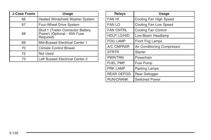
J-Case Fuses Usage
66 Heated Windshield Washer System
67 Four-Wheel Drive System
68Stud 1 (Trailer Connector BatteryPower) (Optional - 40A FuseRequired)
69 Mid-Bussed Electrical Center 1
70 Climate Control Blower
72 Not Used
73 Left Bussed Electrical Center 2
Relays Usage
FAN HI Cooling Fan High Speed
FAN LO Cooling Fan Low Speed
FAN CNTRL Cooling Fan Control
HDLP LO/HID Low-Beam Headlamp
FOG LAMP Front Fog Lamps
A/C CMPRSR Air Conditioning Compressor
STRTR Starter
PWR/TRN Powertrain
FUEL PMP Fuel Pump
PRK LAMP Parking Lamps
REAR DEFOG Rear Defogger
RUN/CRANK Switched Power
5-132

Capacities and SpecificationsThe following approximate capacities are given in English and metric conversions. See Recommended Fluids andLubricants on page 6-14 for more information.
If your vehicle has the DURAMAX® Diesel engine, see the DURAMAX® Diesel manual for more information.
ApplicationCapacities
English Metric
Air Conditioning Refrigerant R134a
For the air conditioning system refrigerant chargeamount, see the refrigerant caution label located
under the hood. See your dealer for moreinformation.
Cooling System
4.3L V6 16.5 qt 15.6 L
4.8L V8 16.9 qt 16.0 L
5.3L V8 16.9 qt 16.0 L
6.0L V8 1500 Series 16.8 qt 15.9 L
6.0L V8 2500, 3500 Series 16.4 qt 15.5 L
Engine Oil with Filter
4.3L V6 4.5 qt 4.3 L
4.8L V8; 5.3L V8; 6.0L V8 6.0 qt 5.7 L
5-133

ApplicationCapacities
English Metric
Fuel Tank
1500 Series Standard and Short Box 26.0 gal 98.0 L
1500 Series Long Box 34.0 gal 128.7 L
2500 Series Standard Box 26.0 gal 98.0 L
2500 Series and 3500 Series Long Box 34.0 gal 128.7 L
3500 Series Chassis Cab 50.0 gal 189.0 L
3500 Chassis Cab – Front Tank 27.0 gal 102.0 L
3500 Chassis Cab – Rear Tank 23.0 gal (if equipped) 87.0 L
Transmission Fluid (Pan Removal and Filter Replacement)
Auto 4-Speed Transmission 4L60-E Electronic Transmission 5.0 qt 4.7 L
Auto 4-Speed Transmission 4L70-E Super Duty Transmission 5.0 qt 4.7 L
Auto 6-Speed Transmission 6L80-E 6.0 qt 5.7 L
Auto 6-Speed Transmission 6L90-E 6.3 qt 6.0 L
Auto 6-Speed Transmission Allison 7.4 qt 7.0 L
Transfer Case Fluid 1.6 qt 1.5 L
Wheel Nut Torque 140 ft lb 190 Y
After refill, the level must be rechecked. Add enough engine coolant so that the fluid is within the proper operatingrange.
5-134

Engine SpecificationsEngine VIN Code Transmission Spark Plug Gap4.3L V6 X Automatic 0.060 in (1.52 mm)
4.8L V8 C Automatic 0.040 in (1.01 mm)
5.3L V8 Flexible Fuel withActive Fuel Management™
(Iron Block)0 Automatic 0.040 in (1.01 mm)
5.3L V8 Flexible Fuel withActive Fuel Management™
(Aluminum Block)3 Automatic 0.040 in (1.01 mm)
5.3L V8 with ActiveFuel Management™
(Aluminum Block)M Automatic 0.040 in (1.01 mm)
5.3L V8 with Active FuelManagement™ (Iron Block) J Automatic 0.040 in (1.01 mm)
6.0L V8 (Iron Block) K Automatic 0.040 in (1.01 mm)
6.0L V8 with ActiveFuel Management™
(Aluminum Block)Y Automatic 0.040 in (1.01 mm)
5-135

✍ NOTES
5-136

Maintenance Schedule ......................................6-2Introduction ...................................................6-2Maintenance Requirements ..............................6-2Your Vehicle and the Environment ....................6-2Using the Maintenance Schedule ......................6-2Scheduled Maintenance (Gasoline Engine) .........6-4Additional Required Services ............................6-6Maintenance Footnotes (Gasoline Engine) ..........6-8Owner Checks and Services ..........................6-10
At the First 100, 1,000 and 6,000 Miles(160, 1 600 and 10 000 km) .......................6-10
At Each Fuel Fill ..........................................6-10At Least Once a Month .................................6-11At Least Once a Year ...................................6-12Recommended Fluids and Lubricants ...............6-14Maintenance Replacement Parts .....................6-16Engine Drive Belt Routing ..............................6-17Maintenance Record .....................................6-18
Section 6 Maintenance Schedule
6-1

Maintenance Schedule
IntroductionThis maintenance section applies to vehicles with agasoline engine. If your vehicle has a diesel engine, seethe maintenance schedule section in the DURAMAXDiesel manual.Important: Keep engine oil at the proper level andchange as recommended.
Have you purchased the GM Protection Plan? The Plansupplements your new vehicle warranties. See yourWarranty and Owner Assistance booklet or your dealer/retailer for details.
Maintenance RequirementsNotice: Maintenance intervals, checks, inspections,replacement parts, and recommended fluids andlubricants as prescribed in this manual are necessaryto keep your vehicle in good working condition. Anydamage caused by failure to follow scheduledmaintenance might not be covered by warranty.
Your Vehicle and the EnvironmentProper vehicle maintenance not only helps to keep yourvehicle in good working condition, but also helps theenvironment. All recommended maintenance isimportant. Improper vehicle maintenance can evenaffect the quality of the air we breathe. Improper fluidlevels or the wrong tire inflation can increase the level ofemissions from your vehicle. To help protect ourenvironment, and to keep your vehicle in good condition,be sure to maintain your vehicle properly.
Using the Maintenance ScheduleWe want to help you keep your vehicle in good workingcondition. But we do not know exactly how you willdrive it. You might drive very short distances only a fewtimes a week. Or you might drive long distances allthe time in very hot, dusty weather. You might use yourvehicle in making deliveries. Or you might drive it towork, to do errands, or in many other ways.
6-2

Because of all the different ways people use theirvehicles, maintenance needs vary. You might need morefrequent checks and replacements. So please readthe following and note how you drive. If you have anyquestions on how to keep your vehicle in good condition,see your dealer/retailer.
This schedule is for vehicles that:
• carry passengers and cargo within recommendedlimits. You will find these limits on the Tire andLoading Information label. See Loading YourVehicle on page 4-36.
• are driven on reasonable road surfaces within legaldriving limits.
• are driven off-road in the recommended manner.See Off-Road Driving on page 4-12.
• use the recommended fuel. See Gasoline Octaneon page 5-6.
The services in Scheduled Maintenance (GasolineEngine) on page 6-4 should be performed whenindicated. See Additional Required Services on page 6-6and Maintenance Footnotes (Gasoline Engine) onpage 6-8 for further information.
{CAUTION:
Performing maintenance work on a vehicle canbe dangerous. In trying to do some jobs, youcan be seriously injured. Do your ownmaintenance work only if you have the requiredknow-how and the proper tools and equipmentfor the job. If you have any doubt, see yourdealer/retailer to have a qualified technician dothe work. See Doing Your Own Service Work onpage 5-5.
Some maintenance services can be complex. So,unless you are technically qualified and have thenecessary equipment, you should have yourdealer/retailer do these jobs.
When you go to your dealer/retailer for your serviceneeds, you will know that trained and supported servicetechnicians will perform the work using genuine parts.
If you want to purchase service information, see ServicePublications Ordering Information on page 7-15.
Owner Checks and Services on page 6-10 tells you whatshould be checked, when to check it, and what you caneasily do to help keep your vehicle in good condition.
6-3

The proper replacement parts, fluids, and lubricants touse are listed in Recommended Fluids and Lubricantson page 6-14 and Maintenance Replacement Partson page 6-16. When your vehicle is serviced, make surethese are used. All parts should be replaced and allnecessary repairs done before you or anyone elsedrives the vehicle. We recommend the use of genuineparts from your dealer/retailer.
Scheduled Maintenance (GasolineEngine)This maintenance section applies to vehicles with agasoline engine. If your vehicle has a diesel engine, seethe maintenance schedule section in the DURAMAX®
Diesel manual.
When the CHANGE ENGINE OIL SOON messagecomes on, it means that service is required for yourvehicle. Have your vehicle serviced as soon as possiblewithin the next 600 miles (1 000 km). It is possiblethat, if you are driving under the best conditions, theengine oil life system may not indicate that vehicleservice is necessary for over a year. However, yourengine oil and filter must be changed at least once ayear and at this time the system must be reset.Your dealer/retailer has trained service technicians whowill perform this work using genuine parts and resetthe system.
If the engine oil life system is ever reset accidentally,you must service your vehicle within 3,000 miles(5 000 km) since your last service. Remember to resetthe oil life system whenever the oil is changed. SeeEngine Oil Life System on page 5-18 for information onthe Engine Oil Life System and resetting the system.
When the CHANGE ENGINE OIL SOON messageappears, certain services, checks, and inspections arerequired. Required services are described in thefollowing for “Maintenance I” and “Maintenance II.”Generally, it is recommended that your first service beMaintenance I, your second service be Maintenance II,and that you alternate Maintenance I and Maintenance IIthereafter. However, in some cases, Maintenance IImay be required more often.
Maintenance I — Use Maintenance I if theCHANGE ENGINE OIL SOON message comes onwithin 10 months since the vehicle was purchased orMaintenance II was performed.
Maintenance II — Use Maintenance II if theprevious service performed was Maintenance I. Alwaysuse Maintenance II whenever the message comeson 10 months or more since the last service or if themessage has not come on at all for one year.
6-4

Scheduled MaintenanceService Maintenance I Maintenance II
Change engine oil and filter. See Engine Oil (Gasoline Engine) on page 5-15.Reset oil life system. See Engine Oil Life System on page 5-18. An EmissionControl Service.
• •
Allison Transmission® only: Replace external transmission filter at the firstmaintenance service performed on the vehicle.Lubricate chassis components. See footnote #. • •Visually check for any leaks or damage. See footnote (j). • •Inspect engine air cleaner filter or change indicator (if equipped). If necessary,replace filter. See Engine Air Cleaner/Filter (Gasoline Engines) on page 5-20.See footnote (p).
•
Rotate tires and check inflation pressures and wear. See Tire Inspection andRotation on page 5-83 and “Tire Wear Inspection” in At Least Once a Month onpage 6-11.
• •
Inspect brake system. See footnote (a). • •Check engine coolant and windshield washer fluid levels and add fluid as needed. • •Perform any needed additional services. See “Additional Required Services” in thissection. • •
Inspect suspension and steering components. See footnote (b). •Inspect engine cooling system. See footnote (c). •Inspect wiper blades. See footnote (d). •Inspect restraint system components. See footnote (e). •Lubricate body components. See footnote (f). •
6-5

Scheduled Maintenance (cont’d)Service Maintenance I Maintenance II
Check transmission fluid level and add fluid as needed. •Inspect shields, vehicles with diesel engine or with GVWR above 10,000 lbs(4 536 kg) only. See footnote (n). •
Additional Required ServicesThis maintenance section applies to vehicles with agasoline engine. If your vehicle has a diesel engine, seethe maintenance schedule section in the DURAMAX®
Diesel manual.
The following services should be performed at the firstmaintenance service (I or II) after the indicatedmiles (kilometers) shown for each item.
Additional Required Services
Service and Miles (Kilometers) 25,000(40 000)
50,000(80 000)
75,000(120 000)
100,000(160 000)
125,000(200 000)
150,000(240 000)
Inspect fuel system for damage orleaks. • • • • • •
Inspect exhaust system for loose ordamaged components. • • • • • •
Vehicles without a filter restrictionindicator: Replace engine air cleanerfilter. See Engine Air Cleaner/Filter(Gasoline Engines) on page 5-20.
• • •
Change automatic transmission fluid andfilter (severe service). See footnote (h). • • •
6-6

Additional Required Services (cont’d)
Service and Miles (Kilometers) 25,000(40 000)
50,000(80 000)
75,000(120 000)
100,000(160 000)
125,000(200 000)
150,000(240 000)
Change automatic transmission fluidand filter (normal service). •
Four-wheel drive only: Change transfercase fluid (extreme duty service).See footnotes (g) and (l).
• • • • • •
Four-wheel drive only: Change transfercase fluid (severe service).See footnotes (g) and (m).
• • •
Four-wheel drive only: Changetransfer case fluid (normal service).See footnote (g).
• • •
Inspect evaporative control system.An Emission Control Service.See footnotes † and (k).
• • •
Replace spark plugs and inspect sparkplug wires. An Emission ControlService.
•
Engine cooling system service(or every five years, whichever occursfirst). An Emission Control Service.See footnote (i).
•
Inspect engine accessory drive belt.An Emission Control Service.See footnote (q).
•
6-7

Maintenance Footnotes (GasolineEngine)This maintenance section applies to vehicles with agasoline engine. If your vehicle has a diesel engine, seethe maintenance schedule section in the DURAMAX®
Diesel manual.
† The U.S. Environmental Protection Agency or theCalifornia Air Resources Board has determined that thefailure to perform this maintenance item will not nullify theemission warranty or limit recall liability prior to thecompletion of the vehicle’s useful life. We, however, urgethat all recommended maintenance services beperformed at the indicated intervals and the maintenancebe recorded.
# Lubricate the front suspension, steering linkage, andparking brake cable guides. Control arm ball joints on2500/3500 series vehicles require lubrication but shouldnot be lubricated unless their temperature is 10°F(−12°C) or higher, or they could be damaged. Control armball joints on 1500 series vehicles are maintenance-free.Vehicles used under severe commercial operatingconditions require lubrication on a regular basis every3,000 miles (5 000 km).
(a) Visually inspect brake lines and hoses for properhook-up, binding, leaks, cracks, chafing, etc. Inspect discbrake pads for wear and rotors for surface condition.Inspect drum brake linings/shoes for wear or cracks.Inspect other brake parts, including drums, wheelcylinders, calipers, parking brake, etc.
(b) Visually inspect front and rear suspension andsteering system for damaged, loose or missing parts,signs of wear or lack of lubrication. Inspect powersteering lines and hoses for proper hook-up, binding,leaks, cracks, chafing, etc. Visually check constantvelocity joints, rubber boots, and axle seals for leaks.
(c) Visually inspect hoses and have them replaced if theyare cracked, swollen, or deteriorated. Inspect all pipes,fittings and clamps; replace with genuine parts asneeded. To help ensure proper operation, a pressure testof the cooling system and pressure cap and cleaning theoutside of the radiator and air conditioning condenser isrecommended at least once a year.
(d) Inspect wiper blades for wear, cracking, orcontamination. Clean the windshield and wiper blades, ifcontaminated. Replace wiper blades that are worn ordamaged. See Windshield Wiper Blade Replacement onpage 5-67 and Windshield and Wiper Blades onpage 5-120 for more information.
6-8

(e) Make sure the safety belt reminder light and safetybelt assemblies are working properly. Look for any otherloose or damaged safety belt system parts. If you seeanything that might keep a safety belt system from doingits job, have it repaired. Have any torn or frayed safetybelts replaced. Also see Checking the Restraint Systemson page 1-88.
(f) Lubricate all key lock cylinders, body door hinges,hood latch assembly, secondary latch, pivots, springanchor, release pawl, tailgate hinges, tailgate linkage,tailgate handle pivot points, latch bolt, fuel doorhinge, locks, and folding seat hardware. More frequentlubrication may be required when exposed to acorrosive environment. Applying silicone grease onweatherstrips with a clean cloth will make themlast longer, seal better, and not stick or squeak.
(g) Check vent hose at transfer case for kinks andproper installation. Check to be sure vent hoseis unobstructed, clear, and free of debris. During anymaintenance, if a power washer is used to cleanmud and dirt from the underbody, care should be takento not directly spray the transfer case output seals.High pressure water can overcome the seals andcontaminate the transfer case fluid. Contaminated fluidwill decrease the life of the transfer case and shouldbe replaced.
(h) Change automatic transmission fluid and filter if thevehicle Gross Vehicle Weight Rating (GVWR) isover 8600 lbs or if the vehicle is mainly driven underone or more of these conditions:
− In heavy city traffic where the outside temperatureregularly reaches 90°F (32°C) or higher.
− In hilly or mountainous terrain.− When doing frequent trailer towing.− Uses such as found in taxi, police or delivery
service.
(i) Drain, flush, and refill cooling system. This servicecan be complex; you should have your dealer/retailerperform this service. See Engine Coolant on page 5-29for what to use. Inspect hoses. Clean radiator,condenser, pressure cap, and filler neck. Pressure testthe cooling system and pressure cap.
(j) A fluid loss in any vehicle system could indicate aproblem. Have the system inspected and repaired andthe fluid level checked. Add fluid if needed.
(k) Inspect system. Check all fuel and vapor lines andhoses for proper hook-up, routing, and condition. Checkthat the purge valve, if the vehicle has one, worksproperly. Replace as needed.
6-9

(l) Extreme Duty Service: Change transfer case fluid ifthe vehicle is mainly driven off-road in four-wheeldrive, or is used for heavy trailer towing. Farming,mining, forestry, and Department of NaturalResources (DNR) vehicles meet this definition.
(m) Severe Service: Change transfer case fluid if thevehicle is mainly used for trailer towing or driven in citytraffic, wet environment, or high ambient temperatures.
(n) Vehicles with diesel engine or with GVWR above10,000 lbs (4 536 kg) only: Inspect shields for damageor looseness. Adjust or replace as required. This isa Noise Emission Control Service. Applicable to vehiclessold in the United States and recommended forvehicles sold in Canada.
(p) If you drive regularly under dusty conditions, inspectthe filter or change indicator (if equipped) at eachengine oil change.
(q) Visually inspect belt for fraying, excessive cracks, orobvious damage. Replace belt if necessary.
Owner Checks and ServicesThese owner checks and services should be performedat the intervals specified to help ensure the safety,dependability, and emission control performance of yourvehicle. Your dealer/retailer can assist you with thesechecks and services.
Be sure any necessary repairs are completed at once.Whenever any fluids or lubricants are added to yourvehicle, make sure they are the proper ones, as shownin Recommended Fluids and Lubricants on page 6-14.
At the First 100, 1,000 and 6,000Miles (160, 1 600 and 10 000 km)For vehicles with dual wheels, check dual wheelnut torque. For proper torque, see Capacities andSpecifications on page 5-133.
At Each Fuel FillIt is important to perform these underhood checks ateach fuel fill.
6-10
Engine Oil Level Check
Notice: It is important to check the engine oilregularly and keep it at the proper level. Failure tokeep the engine oil at the proper level can causedamage to the engine not covered by your warranty.
Check the engine oil level and add the proper oil ifnecessary. See Engine Oil (Gasoline Engine) onpage 5-15.
Engine Coolant Level CheckCheck the engine coolant level and add DEX-COOL®
coolant mixture if necessary. See Engine Coolanton page 5-29.
Windshield Washer Fluid Level CheckCheck the windshield washer fluid level in the windshieldwasher fluid reservoir and add the proper fluid ifnecessary.
At Least Once a Month
Tire Inflation CheckInspect your vehicle’s tires and make sure they areinflated to the correct pressures. Do not forget to checkthe spare tire. See Inflation - Tire Pressure onpage 5-76. Check to make sure the spare tire is storedsecurely. See Changing a Flat Tire on page 5-94.
Tire Wear InspectionTire rotation may be required for high mileage highwaydrivers prior to the Engine Oil Life System servicenotification. Check the tires for wear and, if necessary,rotate the tires. See Tire Inspection and Rotation onpage 5-83.
6-11
At Least Once a Year
Starter Switch Check
{CAUTION:
When you are doing this inspection, thevehicle could move suddenly. If the vehiclemoves, you or others could be injured.
1. Before you start, be sure you have enough roomaround the vehicle.
2. Firmly apply both the parking brake and the regularbrake. See Parking Brake on page 2-50.Do not use the accelerator pedal, and be ready toturn off the engine immediately if it starts.
3. Try to start the engine in each gear. The vehicleshould start only in PARK (P) or NEUTRAL (N). Ifthe vehicle starts in any other position, contact yourdealer/retailer for service.
Automatic Transmission Shift LockControl System Check
{CAUTION:
When you are doing this inspection, thevehicle could move suddenly. If the vehiclemoves, you or others could be injured.
1. Before you start, be sure you have enough roomaround the vehicle. It should be parked on a levelsurface.
2. Firmly apply the parking brake. See Parking Brakeon page 2-50.Be ready to apply the regular brake immediately ifthe vehicle begins to move.
3. With the engine off, turn the ignition to ON/RUN,but do not start the engine. Without applying theregular brake, try to move the shift lever outof PARK (P) with normal effort. If the shift levermoves out of PARK (P), contact your dealer/retailerfor service.
6-12

Ignition Transmission Lock CheckWhile parked, and with the parking brake set, try to turnthe ignition to LOCK/OFF in each shift lever position.
• The ignition should turn to LOCK/OFF onlywhen the shift lever is in PARK (P).
• The ignition key should come out only inLOCK/OFF.
Contact your dealer/retailer if service is required.
Parking Brake and AutomaticTransmission Park (P) MechanismCheck
{CAUTION:
When you are doing this check, your vehiclecould begin to move. You or others could beinjured and property could be damaged. Makesure there is room in front of your vehicle incase it begins to roll. Be ready to apply theregular brake at once should the vehicle beginto move.
Park on a fairly steep hill, with the vehicle facingdownhill. Keeping your foot on the regular brake, set theparking brake.
• To check the parking brake’s holding ability: Withthe engine running and the transmission inNEUTRAL (N), slowly remove foot pressure fromthe regular brake pedal. Do this until the vehicle isheld by the parking brake only.
• To check the PARK (P) mechanism’s holding ability:With the engine running, shift to PARK (P). Thenrelease the parking brake followed by the regularbrake.
Contact your dealer/retailer if service is required.
Underbody Flushing ServiceAt least every spring, use plain water to flush anycorrosive materials from the underbody. Take care toclean thoroughly any areas where mud and other debriscan collect.
6-13

Recommended Fluids andLubricantsThis maintenance section applies to vehicles with agasoline engine. If your vehicle has a diesel engine, seethe maintenance schedule section in the DURAMAX®
Diesel manual.
Fluids and lubricants identified below by name, partnumber, or specification can be obtained from yourdealer/retailer.
Usage Fluid/Lubricant
Engine Oil
Engine oil which meets GMStandard GM6094M and displaysthe American Petroleum InstituteCertified for Gasoline Enginesstarburst symbol. To determine theproper viscosity for your vehicle’sengine, see Engine Oil (GasolineEngine) on page 5-15.
Engine Coolant
50/50 mixture of clean, drinkablewater and use only DEX-COOL®
coolant. See Engine Coolant onpage 5-29.
Hydraulic BrakeSystem
Delco® Supreme 11 Brake Fluid orequivalent DOT-3 brake fluid.
WindshieldWasher Optikleen® Washer Solvent.
Usage Fluid/Lubricant
Power SteeringSystem
GM Power Steering Fluid(GM Part No. U.S. 89021184, inCanada 89021186).
AutomaticTransmission
DEXRON®-VI AutomaticTransmission Fluid.
Key LockCylinders
Multi-Purpose Lubricant, Superlube(GM Part No. U.S. 12346241, inCanada 10953474).
Floor ShiftLinkage
Lubriplate Lubricant Aerosol(GM Part No. U.S. 12346293, inCanada 992723) or lubricantmeeting requirements of NLGI #2Category LB or GC-LB.
ChassisLubrication
Chassis Lubricant(GM Part No. U.S. 12377985, inCanada 88901242) or lubricantmeeting requirements of NLGI #2,Category LB or GC-LB.
Front Axle(1500 Series) -
Four-WheelDrive
SAE 80W-90 Axle Lubricant(GM Part No. U.S. 89021671, inCanada 89021672).
Front Axle(1500 HD,
1500 AWD,2500, 2500 HD,
and3500 Series)
SAE 75W-90 SyntheticAxle Lubricant(GM Part No. U.S. 89021677, inCanada 89021678) meeting GMSpecification 9986115.
6-14
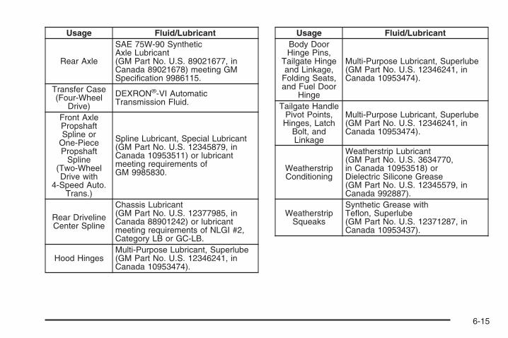
Usage Fluid/Lubricant
Rear Axle
SAE 75W-90 SyntheticAxle Lubricant(GM Part No. U.S. 89021677, inCanada 89021678) meeting GMSpecification 9986115.
Transfer Case(Four-Wheel
Drive)
DEXRON®-VI AutomaticTransmission Fluid.
Front AxlePropshaftSpline or
One-PiecePropshaft
Spline(Two-WheelDrive with
4-Speed Auto.Trans.)
Spline Lubricant, Special Lubricant(GM Part No. U.S. 12345879, inCanada 10953511) or lubricantmeeting requirements ofGM 9985830.
Rear DrivelineCenter Spline
Chassis Lubricant(GM Part No. U.S. 12377985, inCanada 88901242) or lubricantmeeting requirements of NLGI #2,Category LB or GC-LB.
Hood HingesMulti-Purpose Lubricant, Superlube(GM Part No. U.S. 12346241, inCanada 10953474).
Usage Fluid/LubricantBody DoorHinge Pins,
Tailgate Hingeand Linkage,
Folding Seats,and Fuel Door
Hinge
Multi-Purpose Lubricant, Superlube(GM Part No. U.S. 12346241, inCanada 10953474).
Tailgate HandlePivot Points,
Hinges, LatchBolt, andLinkage
Multi-Purpose Lubricant, Superlube(GM Part No. U.S. 12346241, inCanada 10953474).
WeatherstripConditioning
Weatherstrip Lubricant(GM Part No. U.S. 3634770,in Canada 10953518) orDielectric Silicone Grease(GM Part No. U.S. 12345579, inCanada 992887).
WeatherstripSqueaks
Synthetic Grease withTeflon, Superlube(GM Part No. U.S. 12371287, inCanada 10953437).
6-15
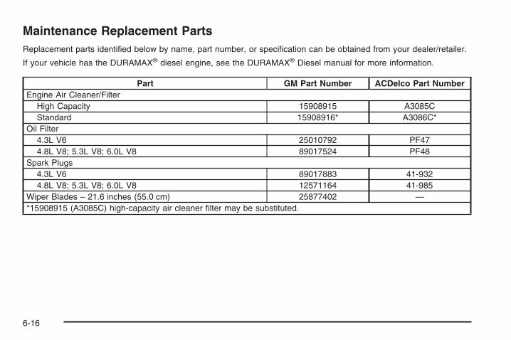
Maintenance Replacement PartsReplacement parts identified below by name, part number, or specification can be obtained from your dealer/retailer.
If your vehicle has the DURAMAX® diesel engine, see the DURAMAX® Diesel manual for more information.
Part GM Part Number ACDelco Part NumberEngine Air Cleaner/Filter
High Capacity 15908915 A3085CStandard 15908916* A3086C*
Oil Filter4.3L V6 25010792 PF474.8L V8; 5.3L V8; 6.0L V8 89017524 PF48
Spark Plugs4.3L V6 89017883 41-9324.8L V8; 5.3L V8; 6.0L V8 12571164 41-985
Wiper Blades – 21.6 inches (55.0 cm) 25877402 —*15908915 (A3085C) high-capacity air cleaner filter may be substituted.
6-16

Engine Drive Belt Routing
(A) Air Conditioning Compressor
If your vehicle has the DURAMAX ® Diesel engine, seethe DURAMAX ® Diesel manual for more information.
V6 Engines
V8 Engines
6-17
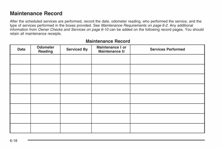
Maintenance RecordAfter the scheduled services are performed, record the date, odometer reading, who performed the service, and thetype of services performed in the boxes provided. See Maintenance Requirements on page 6-2. Any additionalinformation from Owner Checks and Services on page 6-10 can be added on the following record pages. You shouldretain all maintenance receipts.
Maintenance Record
Date OdometerReading Serviced By Maintenance I or
Maintenance II Services Performed
6-18
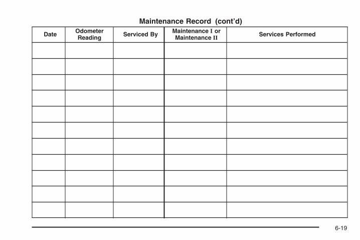
Maintenance Record (cont’d)
Date OdometerReading Serviced By Maintenance I or
Maintenance II Services Performed
6-19

Maintenance Record (cont’d)
Date OdometerReading Serviced By Maintenance I or
Maintenance II Services Performed
6-20

Customer Assistance and Information ...............7-2Customer Satisfaction Procedure ......................7-2Online Owner Center ......................................7-4Customer Assistance for
Text Telephone (TTY) Users .........................7-5Customer Assistance Offices ............................7-5GM Mobility Reimbursement Program ................7-6Roadside Assistance Program ..........................7-7Scheduling Service Appointments .....................7-9Courtesy Transportation ...................................7-9Collision Damage Repair ................................7-11
Reporting Safety Defects ................................7-14Reporting Safety Defects to the
United States Government ..........................7-14Reporting Safety Defects to the
Canadian Government ................................7-14Reporting Safety Defects to General Motors .....7-15Service Publications Ordering Information .........7-15
Vehicle Data Recording and Privacy ................7-16Event Data Recorders ...................................7-17OnStar® ......................................................7-18Navigation System ........................................7-18Radio Frequency Identification (RFID) ..............7-18
Section 7 Customer Assistance Information
7-1

Customer Assistance andInformation
Customer Satisfaction ProcedureYour satisfaction and goodwill are important toyour dealer and to Chevrolet. Normally, any concernswith the sales transaction or the operation of the vehiclewill be resolved by the dealer’s sales or servicedepartments. Sometimes, however, despite the bestintentions of all concerned, misunderstandings canoccur. If your concern has not been resolved to yoursatisfaction, the following steps should be taken:
STEP ONE: Discuss your concern with a member ofdealership management. Normally, concerns canbe quickly resolved at that level. If the matter hasalready been reviewed with the sales, service, or partsmanager, contact the owner of the dealership or thegeneral manager.
STEP TWO: If after contacting a member of dealershipmanagement, it appears your concern cannot beresolved by the dealership without further help, in theU.S., call the Chevrolet Customer Assistance Center at1-800-222-1020. In Canada, call General Motors ofCanada Customer Communication Centre at1-800-263-3777 (English), or 1-800-263-7854 (French).
We encourage you to call the toll-free number in orderto give your inquiry prompt attention. Have thefollowing information available to give the CustomerAssistance Representative:
• Vehicle Identification Number (VIN). This isavailable from the vehicle registration or title, or theplate at the top left of the instrument panel andvisible through the windshield.
• Dealership name and location.
• Vehicle delivery date and present mileage.
When contacting Chevrolet, remember that yourconcern will likely be resolved at a dealer’s facility. Thatis why we suggest following Step One first.
STEP THREE — U.S. Owners: Both General Motorsand your dealer are committed to making sure youare completely satisfied with your new vehicle. However,if you continue to remain unsatisfied after followingthe procedure outlined in Steps One and Two,you should file with the Better Business Bureau (BBB)Auto Line Program to enforce your rights.
7-2

The BBB Auto Line Program is an out of court programadministered by the Council of Better Business Bureausto settle automotive disputes regarding vehicle repairs orthe interpretation of the New Vehicle Limited Warranty.Although you may be required to resort to this informaldispute resolution program prior to filing a court action,use of the program is free of charge and your case willgenerally be heard within 40 days. If you do not agreewith the decision given in your case, you may reject it andproceed with any other venue for relief available to you.
You may contact the BBB Auto Line Program using thetoll-free telephone number or write them at the followingaddress:
BBB Auto Line ProgramCouncil of Better Business Bureaus, Inc.4200 Wilson BoulevardSuite 800Arlington, VA 22203-1838
Telephone: 1-800-955-5100
This program is available in all 50 states and the Districtof Columbia. Eligibility is limited by vehicle age, mileage,and other factors. General Motors reserves the right tochange eligibility limitations and/or discontinue itsparticipation in this program.
STEP THREE — Canadian Owners: In the event thatyou do not feel your concerns have been addressed afterfollowing the procedure outlined in Steps 1 and 2,General Motors of Canada Limited wants you to be aware
of its participation in a no-charge Mediation/ArbitrationProgram. General Motors of Canada Limited hascommitted to binding arbitration of owner disputesinvolving factory-related vehicle service claims. Theprogram provides for the review of the facts involved byan impartial third party arbiter, and may include aninformal hearing before the arbiter. The program isdesigned so that the entire dispute settlement process,from the time you file your complaint to the final decision,should be completed in about 70 days. We believe ourimpartial program offers advantages over courts in mostjurisdictions because it is informal, quick, and free ofcharge.
For further information concerning eligibility in theCanadian Motor Vehicle Arbitration Plan (CAMVAP), calltoll-free 1-800-207-0685, or call the General MotorsCustomer Communication Centre, 1-800-263-3777(English), 1-800-263-7854 (French), or write to:
The Mediation/Arbitration Programc/o Customer Communication CentreGeneral Motors of Canada LimitedMail Code: CA1-163-0051908 Colonel Sam DriveOshawa, Ontario L1H 8P7
Your inquiry should be accompanied by the VehicleIdentification Number (VIN).
7-3

Online Owner Center
(United States only)The Owner Center is a resource for your GM ownershipneeds. Specific vehicle information can be found inone place.
The Online Owner Center allows you to:
• Get e-mail service reminders.
• Access information about your specific vehicle,including tips and videos and an electronicversion of this owner manual.
• Keep track of your vehicle’s service history andmaintenance schedule.
• Find GM dealers/retailers for service nationwide.
• Receive special promotions and privileges onlyavailable to members.
Refer to www.MyGMLink.com on the web for updatedinformation and to register your vehicle.
My GM Canada (Canada only)My GM Canada is a password-protected section ofgmcanada.com where you can save information on GMvehicles, get personalized offers, and use handytools and forms with greater ease.
Here are a few of the valuable tools and services youwill have access to:
− My Showroom: Find and save information onvehicles and current offers in your area.
− My Dealers/Retailers: Save details such asaddress and phone number for each of yourpreferred GM Dealers or Retailers.
− My Driveway: Receive service reminders andhelpful advice on owning and maintainingyour vehicle.
− My Preferences: Manage your profile, subscribe toE-News and use tools and forms with greater ease.
To sign up to My GM Canada, visit the My GM Canadasection within www.gmcanada.com.
7-4

Customer Assistance for TextTelephone (TTY) UsersTo assist customers who are deaf, hard of hearing, orspeech-impaired and who use Text Telephones (TTYs),Chevrolet has TTY equipment available at its CustomerAssistance Center. Any TTY user in the U.S. cancommunicate with Chevrolet by dialing: 1-800-833-CHEV(2438). (TTY users in Canada can dial 1-800-263-3830.)
Customer Assistance OfficesChevrolet encourages customers to call the toll-freenumber for assistance. However, if a customer wishesto write or e-mail Chevrolet, the letter should beaddressed to:
United States — Customer AssistanceChevrolet Motor DivisionChevrolet Customer Assistance CenterP.O. Box 33170Detroit, MI 48232-5170
www.Chevrolet.com1-800-222-10201-800-833-2438 (For Text Telephone devices (TTYs))Roadside Assistance: 1-800-CHEV-USA (243-8872)Fax Number: 313-381-0022
From Puerto Rico:1-800-496-9992 (English)1-800-496-9993 (Spanish)Fax Number: 313-381-0022
From U.S. Virgin Islands:1-800-496-9994Fax Number: 313-381-0022
Canada — Customer AssistanceGeneral Motors of Canada LimitedCustomer Communication Centre, CA1-163-0051908 Colonel Sam DriveOshawa, Ontario L1H 8P7
www.gmcanada.com1-800-263-3777 (English)1-800-263-7854 (French)1-800-263-3830 (For Text Telephone devices (TTYs))Roadside Assistance: 1-800-268-6800
7-5

Overseas — Customer AssistancePlease contact the local General Motors Business Unit.
Mexico, Central America andCaribbean Islands/Countries(Except Puerto Rico and U.S. VirginIslands) — Customer Assistance
General Motors de Mexico, S. de R.L. de C.V.Customer Assistance CenterPaseo de la Reforma # 2740Col. Lomas de BezaresC.P. 11910, Mexico, D.F.01-800-508-0000Long Distance: 011-52-53 29 0 800
GM Mobility ReimbursementProgram
This program, available to qualified applicants, canreimburse you up to $1,000 of the cost of eligibleaftermarket adaptive equipment required for your vehicle,such as hand controls or a wheelchair/scooter lift.
The offer is available for a very limited period of timefrom the date of vehicle purchase/lease. For moredetails, or to determine your vehicle’s eligibility, visitgmmobility.com or call the GM Mobility AssistanceCenter at 1-800-323-9935. Text telephone (TTY) users,call 1-800-833-9935.
General Motors of Canada also has a Mobility Program.Call 1-800-GM-DRIVE (463-7483) for details.TTY users call 1-800-263-3830.
7-6

Roadside Assistance ProgramFor vehicles purchased in the U.S.,call 1-800-CHEV-USA (1-800-243-8872);(Text telephone (TTY): 1-888-889-2438).
For vehicles purchased in Canada, call 1-800-268-6800.
Service is available 24 hours a day, 365 days a year.As the owner of a new Chevrolet vehicle, you areautomatically enrolled in the Chevrolet RoadsideAssistance program.
Who is Covered?Roadside Assistance coverage is for the vehicle operator,regardless of ownership. In Canada, a person driving thisvehicle without the consent of the owner is not eligible forcoverage.
Services ProvidedThe following services are provided in the U.S. andCanada up to 5 years/100,000 miles (160 000 km),whichever occurs first, and, in Canada only, up to amaximum coverage of $100.• Fuel Delivery: Delivery of enough fuel for the vehicle
to get to the nearest service station (approximately$5 in Canada). In Canada, service to provide dieselmay be restricted. For safety reasons, propane andother alternative fuels will not be provided throughthis service.
• Lock-out Service: Lock-out service will be coveredat no charge if you are unable to gain entry into yourvehicle. A remote unlock may be available if youhave an active OnStar® subscription. To ensuresecurity, the driver must present personalidentification before lock-out service is provided. InCanada, the vehicle registration is also required.
• Emergency Tow From a Public Roadway orHighway: Tow to the nearest dealership for warrantyservice or in the event of a vehicle-disabling crash.Winch-out assistance is provided when the vehicle ismired in sand, mud, or snow.
• Flat Tire Change: Installation of a spare tire in goodcondition, when equipped and properly inflated, iscovered at no charge. The customer is responsiblefor the repair or replacement of the tire if not coveredby a warrantable failure.
• Jump Start: A battery jump start is covered at nocharge if the vehicle does not start.
• Trip Routing Service (Canada only): Upon request,Roadside Assistance will send you detailed,computer personalized maps, highlighting yourchoice of either the most direct route or the mostscenic route to your destination, anywhere in NorthAmerica, along with helpful travel informationpertaining to your trip.
7-7
Please allow three weeks before your planneddeparture date. Trip routing requests will be limited tosix per calendar year.
• Trip Interruption Benefits and Assistance(Canada only): In the event of a warranty relatedvehicle disablement, while en route and over250 kilometres from the original point of departure,you may qualify for trip interruption expenseassistance. This assistance covers reasonablereimbursement of up to a maximum of $500(Canadian) for (A) meals (maximum of $50/day),(B) lodging (maximum of $100/night) and(C) alternate ground transportation (maximum of$40/day). This benefit is to assist you with some ofthe unplanned expense you may incur while waitingfor your vehicle to be repaired.
Pre-authorization, original detailed receipts and acopy of the repair order are required.Once authorization has been given, your advisor willhelp you make any necessary arrangements andexplain how to claim for trip interruption expenseassistance.
• Alternative Service (Canada only): There may betimes, when Roadside Assistance cannot providetimely assistance. Your advisor may authorize you tosecure local emergency road service, and you will bereimbursed up to $100 upon submission of theoriginal receipt to Roadside Assistance.
In many instances, mechanical failures may be covered.However, any cost for parts and labor for non-warrantyrepairs are the responsibility of the driver.
Chevrolet and General Motors of Canada Limited reservethe right to limit services or reimbursement to an owner ordriver when, in their sole discretion, the claims becomeexcessive in frequency or type of occurrence.
Calling for AssistanceFor prompt and efficient assistance when calling, pleaseprovide the following to the Roadside AssistanceRepresentative:
• Your name, home address, and home telephonenumber
• Telephone number of your location
• Location of the vehicle
• Model, year, color, and license plate number of thevehicle
• Odometer reading, Vehicle IdentificationNumber (VIN), and delivery date of the vehicle
• Description of the problem
7-8

Towing and Road Service ExclusionsSpecifically excluded from Roadside Assistancecoverage are towing or services for vehicles operated ona non-public roadway or highway, fines, impound towingcaused by a violation of local, Municipal, State,Provincial, or Federal law, and mounting, dismounting orchanging of snow tires, chains, or other traction devices.
Roadside Assistance is not part of or included in thecoverage provided by the New Vehicle Limited Warranty.Chevrolet and General Motors of Canada Limitedreserve the right to make any changes or discontinuethe Roadside Assistance program at any time withoutnotification.
Scheduling Service AppointmentsWhen your vehicle requires warranty service, contactyour dealer/retailer and request an appointment.By scheduling a service appointment and advising yourservice consultant of your transportation needs, yourdealer/retailer can help minimize your inconvenience.
If your vehicle cannot be scheduled into the servicedepartment immediately, keep driving it until it can bescheduled for service, unless, of course, the problem issafety-related. If it is, please call your dealership/retailer,let them know this, and ask for instructions.
If the dealer/retailer requests that you simply drop thevehicle off for service, you are urged to do so as early inthe work day as possible to allow for the same day repair.
Courtesy TransportationTo enhance your ownership experience, we and ourparticipating dealers are proud to offer CourtesyTransportation, a customer support program for vehicleswith the Bumper to Bumper (Base Warranty Coverageperiod in Canada) and extended powertrain warrantyin both the U.S. and Canada.
Several courtesy transportation options are available toassist in reducing your inconvenience when warrantyrepairs are required.
Courtesy Transportation is not a part of the New VehicleLimited Warranty. A separate booklet entitled “Warrantyand Owner Assistance Information” furnished witheach new vehicle provides detailed warranty coverageinformation.
7-9

Transportation OptionsWarranty service can generally be completed while youwait. However, if you are unable to wait, GM helps tominimize your inconvenience by providing severaltransportation options. Depending on the circumstances,your dealer can offer you one of the following:
Shuttle ServiceShuttle service is the preferred means of offeringCourtesy Transportation. Dealers may provide you withshuttle service to get you to your destination with minimalinterruption of your daily schedule. This includes one-wayor round trip shuttle service within reasonable time anddistance parameters of the dealer’s area.
Public Transportation or FuelReimbursementIf your vehicle requires overnight warranty repairs, andpublic transportation is used instead of the dealer’sshuttle service, the expense must be supported byoriginal receipts and can only be up to the maximumamount allowed by GM for shuttle service. In addition, forU.S. customers, should you arrange transportationthrough a friend or relative, limited reimbursement forreasonable fuel expenses may be available. Claimamounts should reflect actual costs and be supported byoriginal receipts. See your dealer for informationregarding the allowance amounts for reimbursement offuel or other transportation costs.
Courtesy Rental VehicleYour dealer may arrange to provide you with a courtesyrental vehicle or reimburse you for a rental vehiclethat you obtain if your vehicle is kept for an overnightwarranty repair. Rental reimbursement will be limitedand must be supported by original receipts. Thisrequires that you sign and complete a rental agreementand meet state/provincial, local, and rental vehicleprovider requirements. Requirements vary and mayinclude minimum age requirements, insurance coverage,credit card, etc. You are responsible for fuel usagecharges and may also be responsible for taxes, levies,usage fees, excessive mileage, or rental usagebeyond the completion of the repair.
It may not be possible to provide a like-vehicle as acourtesy rental.
Additional Program InformationAll program options, such as shuttle service, may not beavailable at every dealer. Please contact your dealerfor specific information about availability. All CourtesyTransportation arrangements will be administeredby appropriate dealer personnel.
General Motors reserves the right to unilaterally modify,change or discontinue Courtesy Transportation atany time and to resolve all questions of claim eligibilitypursuant to the terms and conditions describedherein at its sole discretion.
7-10

Collision Damage RepairIf your vehicle is involved in a collision and it is damaged,have the damage repaired by a qualified technician usingthe proper equipment and quality replacement parts.Poorly performed collision repairs diminish your vehicle’sresale value, and safety performance can becompromised in subsequent collisions.
Collision PartsGenuine GM Collision parts are new parts made withthe same materials and construction methods asthe parts with which your vehicle was originally built.Genuine GM Collision parts are your best choiceto ensure that your vehicle’s designed appearance,durability, and safety are preserved. The use of GenuineGM parts can help maintain your GM New VehicleWarranty.
Recycled original equipment parts may also be used forrepair. These parts are typically removed from vehiclesthat were total losses in prior crashes. In most cases,the parts being recycled are from undamaged sectionsof the vehicle. A recycled original equipment GMpart, may be an acceptable choice to maintain your
vehicle’s originally designed appearance and safetyperformance, however, the history of these parts is notknown. Such parts are not covered by your GM NewVehicle Limited Warranty, and any related failuresare not covered by that warranty.
Aftermarket collision parts are also available. These aremade by companies other than GM and may not havebeen tested for your vehicle. As a result, these parts mayfit poorly, exhibit premature durability/corrosion problems,and may not perform properly in subsequent collisions.Aftermarket parts are not covered by your GM NewVehicle Limited Warranty, and any vehicle failure relatedto such parts are not covered by that warranty.
Repair FacilityWe recommend that you choose a collision repairfacility that meets your needs before you ever needcollision repairs. Your dealer/retailer may have acollision repair center with GM-trained technicians andstate of the art equipment, or be able to recommenda collision repair center that has GM-trained techniciansand comparable equipment.
7-11

Insuring Your VehicleProtect your investment in your GM vehicle withcomprehensive and collision insurance coverage. Thereare significant differences in the quality of coverageafforded by various insurance policy terms. Manyinsurance policies provide reduced protection to yourGM vehicle by limiting compensation for damage repairsby using aftermarket collision parts. Some insurancecompanies will not specify aftermarket collisionparts. When purchasing insurance, we recommend thatyou assure your vehicle will be repaired with GMoriginal equipment collision parts. If such insurancecoverage is not available from your current insurancecarrier, consider switching to another insurance carrier.
If your vehicle is leased, the leasing company mayrequire you to have insurance that assures repairs withGenuine GM Original Equipment Manufacturer (OEM)parts or Genuine Manufacturer replacement parts. Readyour lease carefully, as you may be charged at theend of your lease for poor quality repairs.
If a Crash OccursHere is what to do if you are involved in a crash.
• Check to make sure that you are all right. If you areuninjured, make sure that no one else in yourvehicle, or the other vehicle, is injured.
• If there has been an injury, call emergency servicesfor help. Do not leave the scene of a crash until allmatters have been taken care of. Move yourvehicle only if its position puts you in danger or youare instructed to move it by a police officer.
• Give only the necessary and requested informationto police and other parties involved in the crash.Do not discuss your personal condition, mentalframe of mind, or anything unrelated to the crash.This will help guard against post-crash legal action.
• If you need roadside assistance, call GM RoadsideAssistance. See Roadside Assistance Program onpage 7-7 for more information.
• If your vehicle cannot be driven, know where thetowing service will be taking it. Get a card fromthe tow truck operator or write down the driver’sname, the service’s name, and the phone number.
• Remove any valuables from your vehicle before it istowed away. Make sure this includes your insuranceinformation and registration if you keep theseitems in your vehicle.
7-12
• Gather the important information you will need fromthe other driver. Things like name, address, phonenumber, driver’s license number, vehicle licenseplate, vehicle make, model and model year, VehicleIdentification Number (VIN), insurance companyand policy number, and a general description of thedamage to the other vehicle.
• If possible, call your insurance company from thescene of the crash. They will walk you through theinformation they will need. If they ask for a policereport, phone or go to the police departmentheadquarters the next day and you can get a copy ofthe report for a nominal fee. In some states/provinceswith “no fault” insurance laws, a report may not benecessary. This is especially true if there are noinjuries and both vehicles are driveable.
• Choose a reputable collision repair facility for yourvehicle. Whether you select a dealer/retailer or aprivate collision repair facility to fix the damage,make sure you are comfortable with them.Remember, you will have to feel comfortable withtheir work for a long time.
• Once you have an estimate, read it carefully andmake sure you understand what work will beperformed on your vehicle. If you have a question,ask for an explanation. Reputable shops welcomethis opportunity.
Managing the Vehicle Damage RepairProcessIn the event that your vehicle requires damage repairs,GM recommends that you take an active role in itsrepair. If you have a pre-determined repair facility ofchoice, take your vehicle there, or have it towed there.Specify to the facility that any required replacementcollision parts be original equipment parts, either newGenuine GM parts or recycled original GM parts.Remember, recycled parts will not be covered by yourGM vehicle warranty.
Insurance pays the bill for the repair, but you must livewith the repair. Depending on your policy limits, yourinsurance company may initially value the repair usingaftermarket parts. Discuss this with your repairprofessional, and insist on Genuine GM parts. Rememberif your vehicle is leased you may be obligated to have thevehicle repaired with Genuine GM parts, even if yourinsurance coverage does not pay the full cost.
If another party’s insurance company is paying for therepairs, you are not obligated to accept a repairvaluation based on that insurance company’s collisionpolicy repair limits, as you have no contractual limits withthat company. In such cases, you can have control ofthe repair and parts choices as long as cost stays withinreasonable limits.
7-13

Reporting Safety Defects
Reporting Safety Defects to theUnited States GovernmentIf you believe that your vehicle has a defect whichcould cause a crash or could cause injury ordeath, you should immediately inform the NationalHighway Traffic Safety Administration (NHTSA)in addition to notifying General Motors.
If NHTSA receives similar complaints, it may openan investigation, and if it finds that a safety defectexists in a group of vehicles, it may order a recalland remedy campaign. However, NHTSA cannotbecome involved in individual problems betweenyou, your dealer/retailer, or General Motors.
To contact NHTSA, you may call the VehicleSafety Hotline toll-free at 1-888-327-4236(TTY: 1-800-424-9153); go tohttp://www.safercar.gov; or write to:
Administrator, NHTSA400 Seventh Street, SW.Washington D.C., 20590
You can also obtain other information about motorvehicle safety from http://www.safercar.gov.
Reporting Safety Defects tothe Canadian GovernmentIf you live in Canada, and you believe that yourvehicle has a safety defect, notify Transport Canadaimmediately, in addition to notifying General Motors ofCanada Limited. Call them at 1-800-333-0510 or write to:
Transport CanadaRoad Safety Branch2780 Sheffield RoadOttawa, Ontario K1B 3V9
7-14

Reporting Safety Defects to GeneralMotorsIn addition to notifying NHTSA (or Transport Canada) ina situation like this, please notify General Motors.
Call 1-800-222-1020, or write:
Chevrolet Motor DivisionChevrolet Customer Assistance CenterP.O. Box 33170Detroit, MI 48232-5170
In Canada, call 1-800-263-3777 (English) or1-800-263-7854 (French), or write:
General Motors of Canada LimitedCustomer Communication Centre, CA1-163-0051908 Colonel Sam DriveOshawa, Ontario L1H 8P7
Service Publications OrderingInformation
Service ManualsService Manuals have the diagnosis and repairinformation on engines, transmission, axle suspension,brakes, electrical, steering, body, etc.
Service BulletinsService Bulletins’ give additional technical serviceinformation needed to knowledgeably service GeneralMotors cars and trucks. Each bulletin containsinstructions to assist in the diagnosis and service ofyour vehicle.
Owner InformationOwner publications are written specifically for ownersand intended to provide basic operational informationabout the vehicle. The owner manual includes theMaintenance Schedule for all models.
In-Portfolio: Includes a Portfolio, Owner Manual, andWarranty Booklet.
RETAIL SELL PRICE: $35.00 (U.S.) plus processing fee
Without Portfolio: Owner Manual only.
RETAIL SELL PRICE: $25.00 (U.S.) plus processing fee
Current and Past Model Order FormsTechnical Service Bulletins and Manuals are availablefor current and past model GM vehicles. To requestan order form, specify year and model name ofthe vehicle.
7-15

ORDER TOLL FREE: 1-800-551-4123Monday-Friday 8:00 AM - 6:00 PMEastern TimeFor Credit Card Orders Only(VISA-MasterCard-Discover), visit Helm, Inc. on theWorld Wide Web at: www.helminc.com
Or you can write to:
Helm, IncorporatedP.O. Box 07130Detroit, MI 48207
Prices are subject to change without notice and withoutincurring obligation. Allow ample time for delivery.
Note to Canadian Customers: All listed prices arequoted in U.S. funds. Canadian residents are to makechecks payable in U.S. funds.
Vehicle Data Recording andPrivacyYour GM vehicle has a number of sophisticatedcomputers that record information about the vehicle’sperformance and how it is driven. For example,your vehicle uses computer modules to monitor andcontrol engine and transmission performance, to monitorthe conditions for airbag deployment and deployairbags in a crash and, if so equipped, to provideantilock braking to help the driver control the vehicle.These modules may store data to help yourdealer/retailer technician service your vehicle. Somemodules may also store data about how you operate thevehicle, such as rate of fuel consumption or averagespeed. These modules may also retain the owner’spersonal preferences, such as radio pre-sets, seatpositions, and temperature settings.
7-16
Event Data RecordersThis vehicle has an Event Data Recorder (EDR). Themain purpose of an EDR is to record, in certain crash ornear crash-like situations, such as an airbag deploymentor hitting a road obstacle, data that will assist inunderstanding how a vehicle’s systems performed. TheEDR is designed to record data related to vehicledynamics and safety systems for a short period of time,typically 30 seconds or less. The EDR in this vehicle isdesigned to record such data as:
• How various systems in your vehicle were operating
• Whether or not the driver and passenger safety beltswere buckled/fastened
• How far, if at all, the driver was pressing theaccelerator and/or brake pedal
• How fast the vehicle was traveling
This data can help provide a better understanding of thecircumstances in which crashes and injuries occur.
Important: EDR data is recorded by your vehicleonly if a non-trivial crash situation occurs; no data isrecorded by the EDR under normal driving conditions andno personal data (e.g., name, gender, age, and crashlocation) is recorded. However, other parties, such as lawenforcement, could combine the EDR data with the typeof personally identifying data routinely acquired during acrash investigation.
To read data recorded by an EDR, special equipment isrequired, and access to the vehicle or the EDR is needed.In addition to the vehicle manufacturer, other parties,such as law enforcement, that have the specialequipment, can read the information if they have accessto the vehicle or the EDR.
GM will not access this data or share it with othersexcept: with the consent of the vehicle owner or, if thevehicle is leased, with the consent of the lessee; inresponse to an official request of police or similargovernment office; as part of GM’s defense of litigationthrough the discovery process; or, as required by law.Data that GM collects or receives may also be used forGM research needs or may be made available to othersfor research purposes, where a need is shown and thedata is not tied to a specific vehicle or vehicle owner.
7-17
OnStar®
If your vehicle has OnStar and you subscribe to theOnStar services, please refer to the OnStar Terms andConditions for information on data collection anduse. See also OnStar® System on page 2-67 in thismanual for more information.
Navigation SystemIf your vehicle has a navigation system, use of thesystem may result in the storage of destinations,addresses, telephone numbers, and other tripinformation. Refer to the navigation system operatingmanual for information on stored data and for deletioninstructions.
Radio FrequencyIdentification (RFID)RFID technology is used in some vehicles for functionssuch as tire pressure monitoring and ignition systemsecurity, as well as in connection with conveniencessuch as key fobs for remote door locking/unlocking andstarting, and in-vehicle transmitters for garage dooropeners. RFID technology in GM vehicles does not useor record personal information or link with any otherGM system containing personal information.
7-18

AAccessories and Modifications ............................ 5-4Accessory Power Outlets ................................. 3-23Adding a Snow Plow or Similar Equipment ......... 4-43Adding Equipment to Your Airbag-Equipped
Vehicle ....................................................... 1-86Additives, Fuel ................................................. 5-7Add-On Electrical Equipment ........................... 5-125Adjustable Throttle and Brake Pedal .................. 2-26Air Cleaner/Filter, Engine ................................. 5-20Air Conditioning .............................. 3-25, 3-28, 3-29Airbag
Off Light ..................................................... 3-41Passenger Status Indicator ........................... 3-43Readiness Light .......................................... 3-40
Airbag System ................................................ 1-69Adding Equipment to Your Airbag-Equipped
Vehicle ................................................... 1-86Airbag Off Switch ........................................ 1-78How Does an Airbag Restrain? ...................... 1-76Passenger Sensing System ........................... 1-81Servicing Your Airbag-Equipped Vehicle .......... 1-86What Makes an Airbag Inflate? ...................... 1-75What Will You See After an Airbag Inflates? .... 1-76When Should an Airbag Inflate? .................... 1-74Where Are the Airbags? ............................... 1-72
Antenna, Fixed Mast ...................................... 3-134Antenna, XM™ Satellite Radio Antenna
System ..................................................... 3-134Antilock Brake System (ABS) ............................. 4-4Anti-lock Brake, System Warning Light ............... 3-47Appearance Care
Aluminum or Chrome-Plated Wheels ............. 5-120Care of Safety Belts ................................... 5-117Chemical Paint Spotting .............................. 5-122Cleaning Exterior Lamps/Lenses .................. 5-118Fabric/Carpet ............................................ 5-115Finish Care ............................................... 5-119Finish Damage .......................................... 5-122Instrument Panel, Vinyl, and Other Plastic
Surfaces ............................................... 5-117Interior Cleaning ........................................ 5-114Leather .................................................... 5-116Sheet Metal Damage .................................. 5-121Tires ........................................................ 5-121Underbody Maintenance ............................. 5-122Vehicle Care/Appearance Materials ............... 5-123Washing Your Vehicle ................................. 5-118Weatherstrips ............................................ 5-117Windshield and Wiper Blades ...................... 5-120
Appointments, Scheduling Service ....................... 7-9Ashtray ......................................................... 3-24
1

Audio System ................................................. 3-84Audio Steering Wheel Controls .................... 3-132Fixed Mast Antenna ................................... 3-134Navigation/Radio System,
see Navigation Manual ............................ 3-120Radio Reception ........................................ 3-133Rear Seat Audio (RSA) ............................... 3-130Setting the Clock ......................................... 3-86Theft-Deterrent Feature ............................... 3-132XM™ Satellite Radio Antenna System ........... 3-134
Audio System(s) ............................................. 3-88Automatic Headlamp System ............................ 3-19Automatic Transmission
Fluid .................................................. 5-22, 5-26Operation ................................................... 2-28
Auxiliary Roof Mounted Lamp Switch ................. 3-20
BBattery .......................................................... 5-46
Electric Power Management .......................... 3-22Run-Down Protection ................................... 3-23
BrakeEmergencies ................................................ 4-5
Brakes .......................................................... 5-43System Warning Light .................................. 3-46
Braking ........................................................... 4-3Braking in Emergencies ..................................... 4-5Break-In, New Vehicle ..................................... 2-22
Bulb Replacement ........................................... 5-61Center High-Mounted Stoplamp (CHMSL) and
Cargo Lamp ............................................ 5-63Halogen Bulbs ............................................ 5-61Headlamp Aiming ........................................ 5-58Headlamps ................................................. 5-62License Plate Lamps .................................... 5-66Pickup Box Identification and Fender Marker
Lamps .................................................... 5-64Replacement Bulbs ...................................... 5-66Taillamps, Turn Signal, Stoplamps and
Back-up Lamps ........................................ 5-64Buying New Tires ........................................... 5-86
CCalibration ............................................. 2-56, 2-58California Fuel .................................................. 5-7California Perchlorate Materials Requirements ....... 5-5California Proposition 65 Warning ....................... 5-4Canadian Owners ................................................ iiCapacities and Specifications .......................... 5-133Carbon Monoxide ........................... 2-13, 2-54, 4-31Care of
Safety Belts .............................................. 5-117Cargo Lamp ................................................... 3-22Cargo Management System ............................. 2-80CD, MP3 ............................................ 3-108, 3-114Center Console Storage Area ........................... 2-79
2
Center High-Mounted Stoplamp (CHMSL) andCargo Lamp ............................................... 5-63
Center Seat ................................................... 1-12Chains, Tire ................................................... 5-92Charging System Light .................................... 3-45Check
Engine Light ............................................... 3-49Checking Things Under the Hood ...................... 5-12Chemical Paint Spotting ................................. 5-122Child Restraints
Child Restraint Systems ............................... 1-42Infants and Young Children ........................... 1-39Lower Anchors and Tethers for Children .......... 1-45Older Children ............................................. 1-35Securing a Child Restraint in a
Rear Seat Position ................................... 1-54Securing a Child Restraint in the
Center Front Seat Position ........................ 1-57Securing a Child Restraint in the
Right Front Seat Position .......... 1-57, 1-62, 1-66Where to Put the Restraint ........................... 1-44
Cigarette Lighter ............................................. 3-24Cleaning
Aluminum or Chrome-Plated Wheels ............. 5-120Exterior Lamps/Lenses ................................ 5-118Fabric/Carpet ............................................ 5-115Finish Care ............................................... 5-119
Cleaning (cont.)Instrument Panel, Vinyl, and Other Plastic
Surfaces ............................................... 5-117Interior ..................................................... 5-114Leather .................................................... 5-116Tires ........................................................ 5-121Underbody Maintenance ............................. 5-122Washing Your Vehicle ................................. 5-118Weatherstrips ............................................ 5-117Windshield and Wiper Blades ...................... 5-120
Climate Control System ........................... 3-25, 3-28Dual Automatic ............................................ 3-29Outlet Adjustment ........................................ 3-35
Clock, Setting ................................................. 3-86Collision Damage Repair .................................. 7-11Compass ............................................... 2-56, 2-58Content Theft-Deterrent .................................... 2-18Control of a Vehicle .......................................... 4-3Coolant
Engine ....................................................... 5-29Engine Temperature Gage ............................ 3-48Surge Tank Pressure Cap ............................. 5-32
Cooling System .............................................. 5-35Cruise Control ................................................ 3-13Cruise Control Light ........................................ 3-54Cupholders .................................................... 2-78
3
Customer Assistance InformationCourtesy Transportation .................................. 7-9Customer Assistance for Text Telephone (TTY)
Users ....................................................... 7-5Customer Assistance Offices ........................... 7-5Customer Satisfaction Procedure ..................... 7-2GM Mobility Reimbursement Program ............... 7-6Reporting Safety Defects to General Motors .... 7-15Reporting Safety Defects to the
Canadian Government .............................. 7-14Reporting Safety Defects to the
United States Government ......................... 7-14Roadside Assistance Program ......................... 7-7Service Publications Ordering Information ........ 7-15
DDaytime Running Lamps .................................. 3-18Defensive Driving ............................................. 4-2Delayed Locking ............................................. 2-11Diesel
Running Out of Fuel .................................... 2-54Disc, MP3 .......................................... 3-108, 3-114Doing Your Own Service Work ........................... 5-5Dome Lamp Override ...................................... 3-21Dome Lamps ................................................. 3-21
DoorDelayed Locking .......................................... 2-11Locks ........................................................ 2-10Power Door Locks ....................................... 2-10Programmable Automatic Door Locks ............. 2-11Rear Door Security Locks ............................. 2-11Rear Doors ................................................. 2-12
Driver Information Center (DIC) ......................... 3-56DIC Operation and Displays .................. 3-57, 3-63DIC Vehicle Customization ............................ 3-76DIC Warnings and Messages ........................ 3-66
DrivingAt Night ..................................................... 4-27Before a Long Trip ...................................... 4-29Defensive ..................................................... 4-2Drunken ....................................................... 4-2Highway Hypnosis ....................................... 4-29Hill and Mountain Roads .............................. 4-30In Rain and on Wet Roads ........................... 4-28Off-Road .................................................... 4-12Recovery Hooks .......................................... 4-35Rocking Your Vehicle to Get it Out ................. 4-34Winter ........................................................ 4-31
Dual Automatic Climate Control System ............. 3-29Dual Tire Operation ......................................... 5-77DVD
Rear Seat Entertainment System .................. 3-121
4
EEDR ............................................................. 7-16Electrical System
Add-On Equipment ..................................... 5-125Center Instrument Panel Fuse Block ............. 5-128Fuses and Circuit Breakers ......................... 5-125Instrument Panel Fuse Block ....................... 5-126Power Windows and Other Power Options .... 5-125Underhood Fuse Block ............................... 5-129Windshield Wiper Fuses ............................. 5-125
Electronic ImmobilizerPASS-Key® III+ ........................................... 2-20
Electronic Immobilizer OperationPASS-Key® III+ ........................................... 2-20
EngineAir Cleaner/Filter ......................................... 5-20Check and Service Engine Soon Light ............ 3-49Coolant ...................................................... 5-29Coolant Heater ............................................ 2-27Coolant Temperature Gage ........................... 3-48Drive Belt Routing ....................................... 6-17Engine Compartment Overview ...................... 5-14Exhaust ..................................................... 2-54Fan Noise .................................................. 5-40Fast Idle System ......................................... 2-25Oil ............................................................. 5-15Oil Life System ........................................... 5-18Overheated Protection Operating Mode ........... 5-34
Engine (cont.)Overheating ................................................ 5-32Starting ...................................................... 2-24
Entry Lighting ................................................. 3-21Event Data Recorders ..................................... 7-17Exit Lighting ................................................... 3-21Extender, Safety Belt ....................................... 1-35Exterior Lamps ............................................... 3-17
FFast Idle System ............................................ 2-25Filter
Engine Air Cleaner ...................................... 5-20Finish Damage ............................................. 5-122Fixed Mast Antenna ....................................... 3-134Flashers, Hazard Warning .................................. 3-8Flash-to-Pass ................................................. 3-11Flat Tire ........................................................ 5-93Flat Tire, Changing ......................................... 5-94Flat Tire, Storing ........................................... 5-110Fluid
Automatic Transmission ........................ 5-22, 5-26Power Steering ........................................... 5-41Windshield Washer ...................................... 5-42
Fog LampFog ........................................................... 3-20
Fog Lamp Light .............................................. 3-53Four-Wheel Drive .................................... 2-36, 5-54
5

Four-Wheel-Drive Light .................................... 3-54Front Axle ...................................................... 5-56Fuel ............................................................... 5-6
Additives ...................................................... 5-7California Fuel .............................................. 5-7E85 (85% Ethanol) ........................................ 5-8Filling a Portable Fuel Container .................... 5-12Filling the Tank ........................................... 5-10Fuels in Foreign Countries .............................. 5-9Gage ......................................................... 3-55Gasoline Octane ........................................... 5-6Gasoline Specifications .................................. 5-6Low Warning Light ....................................... 3-56Running Out of ........................................... 2-54
FusesCenter Instrument Panel Fuse Block ............. 5-128Fuses and Circuit Breakers ......................... 5-125Instrument Panel Fuse Block ....................... 5-126Underhood Fuse Block ............................... 5-129Windshield Wiper ....................................... 5-125
GGage
Engine Coolant Temperature ......................... 3-48Fuel .......................................................... 3-55Oil Pressure ............................................... 3-52Speedometer .............................................. 3-38Tachometer ................................................. 3-38Voltmeter Gage ........................................... 3-45
Garage Door Opener ....................................... 2-71Gasoline
Octane ........................................................ 5-6Specifications ............................................... 5-6
Glove Box ..................................................... 2-78GM Mobility Reimbursement Program .................. 7-6
6

HHazard Warning Flashers ................................... 3-8Head Restraints .............................................. 1-11Headlamp
Aiming ....................................................... 5-58Headlamps .................................................... 5-62
Bulb Replacement ....................................... 5-61Daytime Running Lamps ............................... 3-18Exterior Lamps ............................................ 3-17Flash-to-Pass .............................................. 3-11Halogen Bulbs ............................................ 5-61High/Low Beam Changer .............................. 3-10On Reminder .............................................. 3-18Pickup Box Identification and
Fender Marker Lamps ............................... 5-64Heated Seats ................................................... 1-5Heater ................................................... 3-25, 3-28
Engine Coolant ........................................... 2-27Heater ........................................................... 3-29Highbeam On Light ......................................... 3-54Highway Hypnosis ........................................... 4-29Hill and Mountain Roads .................................. 4-30Hood
Checking Things Under ................................ 5-12Release ..................................................... 5-13
Horn ............................................................... 3-8How to Wear Safety Belts Properly ................... 1-19
IIgnition Positions ............................................. 2-22Infants and Young Children, Restraints ............... 1-39Inflation - Tire Pressure ................................... 5-76Instrument Panel
Brightness .................................................. 3-21Cluster ....................................................... 3-37Overview ............................................... 3-4, 3-6Storage Area .............................................. 2-78
JJump Starting ................................................. 5-47
KKeyless Entry System ....................................... 2-4Keys ............................................................... 2-3
7
LLabeling, Tire Sidewall ..................................... 5-69Lamps
Auxiliary Roof Mounted Lamp ........................ 3-20Cargo ........................................................ 3-22Dome ........................................................ 3-21Dome Lamp Override ................................... 3-21Puddle ....................................................... 3-20Reading ..................................................... 3-22
Lap Belt ........................................................ 1-34Lap-Shoulder Belt ........................................... 1-28LATCH System
Child Restraints ........................................... 1-45Latches, Seatback .......................................... 1-12License Plate Lamps ....................................... 5-66Light
Airbag Off .................................................. 3-41Airbag Readiness ........................................ 3-40Anti-lock Brake System (ABS) Warning ........... 3-47Brake System Warning ................................. 3-46Charging System ......................................... 3-45Cruise Control ............................................. 3-54Fog Lamp .................................................. 3-53Four-Wheel-Drive ......................................... 3-54Highbeam On ............................................. 3-54Low Fuel Warning ....................................... 3-56Malfunction Indicator .................................... 3-49Oil Pressure ............................................... 3-53Passenger Airbag Status Indicator .................. 3-43
Light (cont.)Safety Belt Reminders .................................. 3-39Security ..................................................... 3-53StabiliTrak® Indicator .................................... 3-48Tire Pressure .............................................. 3-49Tow/Haul Mode ........................................... 3-54
LightingEntry ......................................................... 3-21Exit ........................................................... 3-21
LightsExterior Lamps ............................................ 3-17Flash-to-Pass .............................................. 3-11High/Low Beam Changer .............................. 3-10On Reminder .............................................. 3-18
Loading Your Vehicle ....................................... 4-36Locking Rear Axle ............................................ 4-5Lockout Protection .......................................... 2-12Locks
Delayed Locking .......................................... 2-11Door .......................................................... 2-10Lockout Protection ....................................... 2-12Power Door ................................................ 2-10Programmable Automatic Door Locks ............. 2-11Rear Door Security Locks ............................. 2-11
Loss of Control ............................................... 4-11Low Fuel Warning Light ................................... 3-56Luggage Carrier .............................................. 2-79Lumbar
Manual Controls ............................................ 1-4Power Controls ............................................. 1-4
8

MMaintenance Schedule
Additional Required Services ........................... 6-6At Each Fuel Fill ......................................... 6-10At Least Once a Month ................................ 6-11At Least Once a Year .................................. 6-12At the First 100, 1,000 and 6,000 Miles
(160, 1 600 and 10 000km) ....................... 6-10Introduction .................................................. 6-2Maintenance Footnotes .................................. 6-8Maintenance Record .................................... 6-18Maintenance Replacement Parts .................... 6-16Maintenance Requirements ............................. 6-2Owner Checks and Services ......................... 6-10Recommended Fluids and Lubricants ............. 6-14Scheduled Maintenance ................................. 6-4Using .......................................................... 6-2Your Vehicle and the Environment ................... 6-2
Malfunction Indicator Light ................................ 3-49Manual Lumbar Controls .................................... 1-4Manual Seats ................................................... 1-2Manual, Using .................................................... iiiManual Windows ............................................ 2-15
Memory Seat, Mirrors, and Pedals ...................... 1-6Message
DIC Warnings and Messages ........................ 3-66Mirrors
Automatic Dimming Rearview with Compassand Temperature Display ........................... 2-58
Automatic Dimming Rearview with OnStar®,Compass and Temperature Display ............. 2-56
Manual Rearview Mirror ................................ 2-56Outside Manual Mirrors ................................ 2-59Outside Power Foldaway Mirrors .................... 2-62Outside Power Mirrors .................................. 2-61Outside Towing Mirrors ................................. 2-60
MP3 .................................................. 3-108, 3-114MyGMLink.com ................................................ 7-4
NNavigation System, Privacy .............................. 7-18Navigation/Radio System,
see Navigation Manual ............................... 3-120New Vehicle Break-In ...................................... 2-22Noise Control System, Tampering ...................... 5-57
9

OOdometer ...................................................... 3-38Odometer, Trip ............................................... 3-38Off-Road Driving ............................................. 4-12Off-Road Recovery .......................................... 4-10Oil
Engine ....................................................... 5-15Pressure Gage ............................................ 3-52Pressure Light ............................................. 3-53
Oil, Engine Oil Life System .............................. 5-18Older Children, Restraints ................................ 1-35Online Owner Center ........................................ 7-4OnStar, Privacy .............................................. 7-18OnStar® System, see OnStar® Manual ............... 2-67Operation, Universal Home Remote System ........ 2-71Other Warning Devices ...................................... 3-8Outlet Adjustment ............................................ 3-35Outlets
Accessory Power ......................................... 3-23Outside
Manual Mirrors ............................................ 2-59Power Foldaway Mirrors ............................... 2-62Power Mirrors ............................................. 2-61Towing Mirrors ............................................ 2-60
Overheated Engine Protection Operating Mode .... 5-34Owner Checks and Services ............................. 6-10Owners, Canadian ............................................... ii
PPaint, Damage .............................................. 5-122Park
Shifting Into ................................................ 2-51Shifting Out of ............................................ 2-53
Park Aid ........................................................ 2-64Park Brake .................................................... 2-50Parking
Assist ........................................................ 2-64Over Things That Burn ................................. 2-53
Passenger Airbag Status Indicator ..................... 3-43Passenger Sensing System .............................. 1-81Passing ......................................................... 4-11PASS-KEY® III+ Electronic Immobilizer ............... 2-20PASS-Key® III+ Electronic Immobilizer
Operation ................................................... 2-20Perchlorate Materials Requirements, California ...... 5-5Pickup Conversion to Chassis Cab .................... 4-50Power
Door Locks ................................................. 2-10Electrical System ....................................... 5-125Lumbar Controls ........................................... 1-4Retained Accessory (RAP) ............................ 2-24Seat ............................................................ 1-3Sliding Rear Window .................................... 2-17Steering Fluid ............................................. 5-41Windows .................................................... 2-16
10

Privacy .......................................................... 7-16Event Data Recorders .................................. 7-17Navigation System ....................................... 7-18OnStar ....................................................... 7-18Radio Frequency Identification ....................... 7-18
Programmable Automatic Door Locks ................. 2-11Puddle Lamps ................................................ 3-20
RRadio Frequency Identification (RFID), Privacy .... 7-18Radio(s) ........................................................ 3-88Radios
Navigation/Radio System,see Navigation Manual ............................ 3-120
Rear Seat Audio ........................................ 3-130Reception ................................................. 3-133Setting the Clock ......................................... 3-86Theft-Deterrent .......................................... 3-132
Rainsense™ II Wipers ..................................... 3-12Reading Lamps .............................................. 3-22Rear Axle ...................................................... 5-52
Locking ........................................................ 4-5Rear Door Security Locks ................................ 2-11Rear Doors .................................................... 2-12Rear Seat Armrest .......................................... 2-80
Rear Seat Audio (RSA) .................................. 3-130Rear Seat Entertainment System ..................... 3-121Rear Seat Operation ............................... 1-12, 1-13Rearview Mirror, Automatic Dimming with
Compass and Temperature Display ................ 2-58Rearview Mirror, Automatic Dimming with
OnStar®, Compass and Temperature Display ... 2-56Rearview Mirrors ............................................. 2-56Reclining Seatbacks .......................................... 1-8Recommended Fluids and Lubricants ................. 6-14Recovery Hooks ............................................. 4-35Recreational Vehicle Towing ............................. 4-50Remote Keyless Entry (RKE) System .................. 2-4Remote Keyless Entry (RKE) System, Operation ... 2-5Remote Vehicle Start ........................................ 2-7Removing the Flat Tire and Installing the
Spare Tire ................................................ 5-100Removing the Spare Tire and Tools ................... 5-95Replacement Bulbs ......................................... 5-66Replacement Parts, Maintenance ...................... 6-16Reporting Safety Defects
Canadian Government .................................. 7-14General Motors ........................................... 7-15United States Government ............................ 7-14
Restraint System CheckChecking the Restraint Systems .................... 1-88Replacing Restraint System Parts
After a Crash .......................................... 1-89
11

Retained Accessory Power (RAP) ...................... 2-24Roadside
Assistance Program ....................................... 7-7Rocking Your Vehicle to Get it Out .................... 4-34Routing, Engine Drive Belt ............................... 6-17Running Out of Fuel ........................................ 2-54
SSafety Belt
Reminder Light ............................................ 3-39Safety Belts
Care of .................................................... 5-117How to Wear Safety Belts Properly ................ 1-19Lap Belt ..................................................... 1-34Lap-Shoulder Belt ........................................ 1-28Safety Belt Extender .................................... 1-35Safety Belt Use During Pregnancy ................. 1-33Safety Belts Are for Everyone ....................... 1-14
Safety Warnings and Symbols .............................. iiiScheduled Maintenance ..................................... 6-4Seatback Latches ........................................... 1-12Seats
Center Seat ................................................ 1-12Head Restraints .......................................... 1-11Heated Seats ............................................... 1-5Manual Lumbar ............................................. 1-4Memory, Mirrors and Pedals ........................... 1-6Power Lumbar .............................................. 1-4
Seats (cont.)Power Seats ................................................. 1-3Rear Seat Operation ............................ 1-12, 1-13Reclining Seatbacks ...................................... 1-8Seatback Latches ........................................ 1-12
Secondary Latch System ................................ 5-106Securing a Child Restraint
Center Front Seat Position ............................ 1-57Rear Seat Position ...................................... 1-54Right Front Seat Position .............. 1-57, 1-62, 1-66
Security Light ................................................. 3-53Service ........................................................... 5-4
Accessories and Modifications ......................... 5-4Adding Equipment to the Outside of
Your Vehicle .............................................. 5-5California Perchlorate Materials Requirements .... 5-5California Proposition 65 Warning .................... 5-4Doing Your Own Work ................................... 5-5Engine Soon Light ....................................... 3-49Publications Ordering Information ................... 7-15
Service, Scheduling Appointments ....................... 7-9Servicing Your Airbag-Equipped Vehicle .............. 1-86Setting the Clock ............................................ 3-86Sheet Metal Damage ..................................... 5-121Shifting Into Park ............................................ 2-51Shifting Out of Park ........................................ 2-53Signals, Turn and Lane-Change ........................ 3-10Sliding Rear Window, Power ............................. 2-17Snow Plow .................................................... 4-43
12

Spare Tire .................................................... 5-113Installing ................................................... 5-100Removing ................................................... 5-95Storing ..................................................... 5-110
Specifications, Capacities ............................... 5-133Speedometer .................................................. 3-38StabiliTrak® Indicator Light ............................... 3-48Stabilitrak® System ........................................... 4-6Start Vehicle, Remote ....................................... 2-7Starting the Engine ......................................... 2-24Steering .......................................................... 4-8Steering Wheel Controls, Audio ....................... 3-132Steering Wheel, Tilt Wheel ................................. 3-8Storage Areas
Cargo Management System .......................... 2-80Center Console Storage Area ........................ 2-79Cupholders ................................................. 2-78Glove Box .................................................. 2-78Instrument Panel Storage Area ...................... 2-78Luggage Carrier .......................................... 2-79Rear Seat Armrest ....................................... 2-80
Stuck in Sand, Mud, Ice, or Snow ..................... 4-34Sun Visors ..................................................... 2-18Sunroof ......................................................... 2-82
TTachometer .................................................... 3-38Tailgate ......................................................... 2-13Taillamps
Turn Signal, Stoplamps and Back-up Lamps .... 5-64Theft-Deterrent, Radio .................................... 3-132Theft-Deterrent Systems ................................... 2-18
Content Theft-Deterrent ................................ 2-18PASS-Key® III+ Electronic Immobilizer ............ 2-20PASS-Key® III+ Electronic Immobilizer
Operation ................................................ 2-20Tilt Wheel ........................................................ 3-8Time, Setting .................................................. 3-86Tire
Pressure Light ............................................. 3-49Tires ............................................................. 5-68
Aluminum or Chrome-Plated Wheels,Cleaning ............................................... 5-120
Buying New Tires ........................................ 5-86Chains ....................................................... 5-92Changing a Flat Tire .................................... 5-94Cleaning ................................................... 5-121Different Size .............................................. 5-88
13
Tires (cont.)Dual Tire Operation ..................................... 5-77If a Tire Goes Flat ....................................... 5-93Inflation - Tire Pressure ................................ 5-76Inspection and Rotation ................................ 5-83Installing the Spare Tire .............................. 5-100Pressure Monitor Operation ........................... 5-79Pressure Monitor System .............................. 5-78Removing the Flat Tire ............................... 5-100Removing the Spare Tire and Tools ............... 5-95Secondary Latch System ............................ 5-106Spare Tire ................................................ 5-113Storing a Flat or Spare Tire and Tools .......... 5-110Tire Sidewall Labeling .................................. 5-69Tire Terminology and Definitions .................... 5-73Uniform Tire Quality Grading ......................... 5-89Wheel Alignment and Tire Balance ................. 5-90Wheel Replacement ..................................... 5-90When It Is Time for New Tires ...................... 5-86
Tow/Haul Mode ............................................... 2-34Tow/Haul Mode Light ....................................... 3-54
TowingRecreational Vehicle ..................................... 4-50Towing a Trailer .......................................... 4-55Your Vehicle ............................................... 4-50
TractionStabilitrak® System ........................................ 4-6
TrailerRecommendations ....................................... 4-93
TransmissionFluid, Automatic .................................. 5-22, 5-26
Transmission Operation, Automatic .................... 2-28Trip Odometer ................................................ 3-38Truck-Camper Loading Information .................... 4-47Turn and Lane-Change Signals ......................... 3-10Turn Signal/Multifunction Lever ........................... 3-9
UUltrasonic Rear Parking Assist (URPA) ............... 2-64Uniform Tire Quality Grading ............................ 5-89Universal Home Remote System ....................... 2-71
Operation ................................................... 2-71Using this Manual ............................................... iii
14
VVehicle
Control ........................................................ 4-3Damage Warnings ........................................... ivLoading ...................................................... 4-36Symbols ......................................................... iv
Vehicle Customization, DIC .............................. 3-76Vehicle Data Recording and Privacy .................. 7-16Vehicle Identification
Number (VIN) ............................................ 5-124Service Parts Identification Label .................. 5-124
Vehicle, Remote Start ....................................... 2-7Ventilation Adjustment ...................................... 3-35Visors ........................................................... 2-18Voltmeter Gage .............................................. 3-45
WWarning Lights, Gages and Indicators ................ 3-36Warnings
DIC Warnings and Messages ........................ 3-66Hazard Warning Flashers ............................... 3-8Other Warning Devices .................................. 3-8Safety and Symbols ......................................... iiiVehicle Damage .............................................. iv
WheelsAlignment and Tire Balance .......................... 5-90Different Size .............................................. 5-88Replacement ............................................... 5-90
Where to Put the Restraint ............................... 1-44Windows ....................................................... 2-15
Manual ...................................................... 2-15Power ........................................................ 2-16Sliding Rear ................................................ 2-17
15

WindshieldRainsense™ II Wipers .................................. 3-12Washer ...................................................... 3-12Washer Fluid .............................................. 5-42Wiper Blade Replacement ............................. 5-67Wiper Blades, Cleaning .............................. 5-120Wiper Fuses ............................................. 5-125Wipers ....................................................... 3-11
Winter Driving ................................................ 4-31
XXM Radio Messages ..................................... 3-119XM™ Satellite Radio Antenna System .............. 3-134
YYour Vehicle and the Environment ....................... 6-2
16