Embed Size (px)
Citation preview

Supplementaryequipotentialbonding
WIRINGMATTERS
Summer 08 Issue 27
Requirements for cablesconcealed in a wall or partition
IEE Ring final circuit meeting
543.7 and lighting circuits
The Regulatory Reform (Fire Safety)Order 2005, BS 7671: 2008
Changes to the Building Regulations

Save time, save cost! Using MT32 means your electrical installation cannow be completed up to 80% faster. Even with material costs the overallsavings can be up to 50% and deadlines are much more achievable.
No on-site cable preparation equals less wastage of time and materials
Lower project costs due to faster installation of pre-wired and pre-tested components
Easy re-configuration with re-usable components
Greater coverage than busbar from one source of supply in underfloor applications
For further information call
01424 856600or visit www.marshall-tufflex.com/mt32email [email protected]
It’s history! The traditional electrical wiringkit could soon be a thing of the past. With MT32,installations can now be completed in recordtime thanks to this revolutionary pre-wiredpower connection system with the compact 32 amp plug & play connector.
MT32Connecting power willnever be the same again!

IEE Wiring Matters | Summer 08 | www.theiet.org
CABLES
1
A new series of Regulations(522.6.6 - 522.6.8) havebeen introduced in the17th Edition of the IEEWiring Regulationsconcerning cables concealedin a wall or partition.These new Regulationsintroduce the concept ofskilled person, instructedperson and ordinaryperson.
RCD PROTECTIONIt is now a requirement toprotect cables concealed in awall or partition (at a depthof less than 50 mm) by a30 mA RCD where theinstallation is not intendedto be under the supervisionof a skilled or instructedperson where other methods
of protection, including theuse of cables with anearthed metallic covering,earthed conduit/trunkingor mechanical protection,can not be employed.Irrespective of the depth,
a cable in a partition wherethe construction includesmetallic parts other thanfixings shall be protected bya 30 mA RCD.For example, this means
that in a domesticinstallation, whereinsulated and sheathedcables are concealed in awall at a depth of less than50 mm and have nomechanical protection, theyneed to be installed withinthe safe zones and protectedby a 30 mA RCD.
DEFINITIONSSkilled personA person with technicalknowledge or sufficientexperience to enablehim/her to avoid dangerswhich electricity may create.
Instructed personA person adequatelyadvised or supervised byskilled persons to enablehim/her to avoid dangerswhich electricity maycreate.
Ordinary personA person who is neither askilled person nor aninstructed person.
WIRING SYSTEMSTo conform with therequirements of BS 7671,wiring systems must utilisecables complying with therelevant requirements ofthe applicable BritishStandard or HarmonisedStandard.Alternatively, if
equipment complying witha foreign national standard,based on an IEC Standard isto be used, the designer orother person responsible forspecifying the installationmust verify that anydifferences between thatstandard and thecorresponding BritishStandard or HarmonisedStandard will not result in alesser degree of safety thanthat afforded by compliance
Requirements for cables concealed ina wall or partition – A brief overviewby Geoff Cronshaw
Figure 1: RCBO – Residualcurrent circuit-breaker withovercurrent protection
Figure 2: RCCB - Residual currentcircuit-breaker

CABLES
2
IEE Wiring Matters | Summer 08 | www.theiet.org PWRRFP82
Wiring Matters is produced by IET Services Limited, a subsidiary of The Institution of Engineering and Technology (IET), for the IET.Michael Faraday House, Six Hills Way, Stevenage, Herts, SG1 2AY, United Kingdom Tel: +44 (0)1438 313311 Fax: +44 (0)1438 313465
Advertising Sales D Smith +44 (0)1438 767224 [email protected] | Editor G D Cronshaw +44 (0)1438 [email protected] | Contributing Editors M Coles, J Elliott | Design Sable Media SolutionsIEE Wiring Matters is a quarterly publication from the Institution of Engineering and Technology (IET). The IET is not as a body responsible forthe opinions expressed.
©2008: The Institution of Engineering and Technology. All rights reserved. No part of this publication may be reproduced, stored in a retrievalsystem, or transmitted in any form or by any means without the permission in writing of the publisher. Copying of articles is not permittedexcept for personal and internal use. Multiple copying of the content of this publication without permission is always illegal. Web-offsetprinting by Wyndeham Heron, The Bentall Complex, Colchester Road, Heybridge, Maldon, Essex, UK
Co-operating Organisations The Institution of Engineering & Technology acknowledges the contribution made by the followingorganisations in the preparation of this publication: British Electrotechnical & Allied Manufacturers Association Ltd – R Lewington,P D Galbraith, M H Mullins | Department for Communities and Local Government – I Drummond | Electrical Contractors Association – D Locke,S Burchell | City & Guilds of London Institute – H R Lovegrove | Energy Networks Association – D J Start | Electrical Contractors Associationof Scotland SELECT – D Millar, N McGuiness | Health & Safety Executive – K Morton | Electrical Safety Council | ERA Technology Limited –M Coates | British Cables Association – C Reed | Scottish Building Standards Agency | DTI – D Tee | CORGI – P Collins | GAMBICA –M. Hadley, A. Sedhev | Lighting Association – K KearneyISSN 1749-978-X
with the British Standard.The effect of
environmental conditionsand general characteristicsaround various parts of theinstallation must beassessed to enable suitableelectrical equipment,including the wiringsystem, to be specified.For example, cables and
equipment used inagricultural andhorticultural premisesshould be installed awayfrom areas or routes used byanimals or be of a type towithstand such attack.Any part of the fixed
installation which may beexposed to a severe impactmust be able to survive it. Inworkshops, for example,where heavy objects aremoved, installation ofwiring systems in trafficroutes should be avoided orlocalised protection must beprovided.Therefore, when
designing a concealedinstallation, the designermust select a suitablewiring system. Under the17th Edition, depending onthe type of wiring selected,the method of installation
and whether the installationwill be under the control ofa skilled person, orinstructed person orordinary person will dependwhether the concealedwiring will require RCDprotection or not.For example, in a
domestic installation, whereinsulated and sheathedcables are concealed in awall at a depth of less than50 mm and have nomechanical protection, theyneed to be installed withinthe safe zones and need tobe protected by a 30 mA RCD.Regulations 522.6.6 and
522.6.8 are reproduced herefor information.
522.6.6 A cable concealed ina wall or partition at a
depth of less than 50 mmfrom a surface of the wall orpartition shall:(i) incorporate an earthedmetallic covering whichcomplies with therequirements of theseRegulations for a protectiveconductor of the circuitconcerned, the cablecomplying with BS 5467,BS 6346, BS 6724, BS 7846,BS EN 60702-1 or BS 8436, or(ii) be enclosed in earthedconduit complying withBS EN 61386 and satisfyingthe requirements ofthese Regulations for aprotective conductor, or(iii) be enclosed in earthedtrunking or ductingcomplying with BS EN 50085and satisfying therequirements of these
Regulations for a protectiveconductor, or(iv) be mechanicallyprotected against damagesufficient to preventpenetration of the cable bynails, screws and the like, or(v) be installed in a zonewithin 150 mm from the topof the wall or partition orwithin 150 mm of anangle formed by twoadjoining walls orpartitions. Where the cableis connected to a point,accessory or switchgear onany surface of the wall orpartition, the cable may beinstalled in a zone eitherhorizontally or vertically, tothe point, accessory orswitchgear. Where thelocation of the accessory,point or switchgear can be
Figure 3:Permittedcable routes

SALESTARTS3rd JUNE
MUST END
JULY14thSALE
DECORATIVE SOCKETSSAVE 20%
ELECTRICALSAVE UP TO 40%
LIGHTINGSAVE UP TO 50%
SHOWERSSAVE 25%
POWER TOOLSSAVE UP TO £100
ACCESS & STORAGESAVE 20%
PICK UPA SALE
CATALOGUE
100s MORE GREAT SAVINGS IN OUR SALE CATALOGUEINCLUDING: KITCHENS SAVE UP TO 20% • BATHROOMS SAVE UP TO 20%
CLICK VISITCALLwww.screwfix.com0500 414141 Trade Counters
TRADE PRICESMASSIVE RANGEFAST & RELIABLE
INTRADE COUNTERS
3rd JUNE
59540-12 2G DP BS White Insert £4.95
34396-12 2G DP BS Black Insert £4.95
BRUSHEDSTAINLESSROUND EDGE
ONLY£4.95
SAVE20%SAVE20%
EMERGENCYLUMINAIRES
SAVE20%SAVE20%
ULTRA+ALKALINEBATTERIES
ONLY£1.58
SAVE40%SAVE40%
TRITON T70siELECTRICSHOWER
ONLY£62.99
FROM ONLY£71.99
SAVE25%SAVE25%
FIBREGLASSPLATFORMSTEP
SAVE20%SAVE20%
CABLE REEL
FROM ONLY£14.98
SAVE16%
SAVEUPTO 16%
SAVE26%
SAVEUPTO26%
WEATHERPROOFHPF FITTINGS
FROM ONLY£17.82
FROM ONLY£18.49
SAVE15%SAVE15%
LOW ENERGYCANDLES
SAVE50%SAVE50%
DOCKASPOTLIGHTS
POLISHEDCHROMEANGLED EDGE
ONLY£4.95
SAVE20%SAVE20%
62980-12 2G DP White Insert £4.95
23157-12 2G DP Black Insert £4.95
CONSUMER UNIT+ FREE SCREWDRIVER SET
WYLEX 17th EDITION10W DUAL RCD +SCREWDRIVER SET
44925-12 Dual RCD + Drivers £111.95
*
ONLY£199.99
18V TRIPLE PACK2kg SDS PLUSHAMMER DRILL
92579-12 KC18DK £199.99
SAVESAVE£100£100
23674-12 ERH-650V 240V £39.99
SAVE50%SAVE50%
ONLY£39.99
Volt No. per pk. Pack
85426-12 AA 1.5 4 £1.58
82223-12 AAA 1.5 4 £1.58
48535-12 C 1.5 2 £1.58
15592-12 240V 25m 4 Skt £14.98
15712-12 240V 50m 4 Skt £22.45
Specification:WRAS and BEAB Approved.
35910-12 8.5kW White £62.99
94655-12 5 Tread £71.99
52466-12 6 Tread £79.99
93019-12 7 Tread £87.99
96564-12 8 Tread £95.99
Quote Cap Lg (mm) Each
74163-12 5W SBC 118 £1.48
71609-12 5W BC 118 £1.48
86027-12 5W ES 118 £1.48
20159-12 7W SBC 125 £1.48
33919-12 7W BC 125 £1.48
88430-12 7W ES 125 £1.48
3 Plate
4 Bar
96323-12 3 Plate £18.49
47258-12 4 Bar £22.49
ALL SAVINGS SHOWN RELATE TO PRODUCTS IN THIS ADVERT - SEE CATALOGUE FOR FURTHER SAVINGS. ALL PRICES INCLUDE VAT.
ONLY£111.95
*See www.screwfix.comfor Quote 48601
WORTH£19.99
£299.99*£239.99
• 2 x 2.0Ah Ni-CdBatteries
• 240V IP65
• IP65
*Was price relates to www.screwfix.com price from 03/03/08 - 31/03/08.
7 DAYDELIVERY
87042-12 Non-Maintained £11.98
49925-12 Maintained £14.79
85160-12 1 x 58W £17.82
52968-12 2 x 58W £25.47
SDS+
Torch
Drill /Driver
FROM ONLY£11.98
For your nearest text screwfix to 84880

CABLES
4
IEE Wiring Matters | Summer 08 | www.theiet.org
determined from the reverseside, a zone formed on oneside of a wall of 100 mmthickness or less orpartition of 100 mmthickness or less extends tothe reverse side.
522.6.7 Where Regulation522.6.6 applies and theinstallation is not intendedto be under the supervisionof a skilled or instructedperson, a cable installed inaccordance with Regulation522.6.6 (v), and notcomplying with Regulation522.6.6 (i), (ii), (iii) or (iv),shall be provided withadditional protection bymeans of an RCD having thecharacteristics specified inRegulation 415.1.1.
522.6.8 Irrespective of thedepth of the cable from asurface of the wall orpartition, in an installationnot intended to be under thesupervision of a skilled orinstructed person, a cableconcealed in a wall orpartition the internalconstruction of whichincludes metallic parts,other than metallic fixingssuch as nails, screws andthe like, shall:(i) incorporate an earthedmetallic covering whichcomplies with therequirements of theseRegulations for a protectiveconductor of the circuitconcerned, the cablecomplying with BS 5467,BS 6346, BS 6724, BS 7846,BS EN 60702-1 or BS 8436, or(ii) be enclosed in earthedconduit complying withBS EN 61386 and satisfyingthe requirements ofthese Regulations for a
protective conductor, or(iii) be enclosed in earthedtrunking or ductingcomplying with BS EN 50085and satisfying therequirements of theseRegulations for a protectiveconductor, or(iv) be mechanicallyprotected sufficiently toavoid damage to the cableduring construction of thewall or partition and duringinstallation of the cable, or(v) be provided withadditional protection bymeans of an RCD having thecharacteristics specifiedin Regulation 415.1.1.
NOTE: If the cable isinstalled at a depth of 50 mmor less from the surface of awall or partition therequirements of Regulation522.6.6 also apply.
RCD PROTECTIONAn RCD is a protectivedevice used to automaticallydisconnect the electricalsupply when an imbalance isdetected between liveconductors. In the case of asingle-phase circuit, thedevice monitors thedifference in currentsbetween the line and neutralconductors. If a line to earthfault develops, a portion ofthe line conductor currentwill not return through theneutral conductor. Thedevice monitors thisdifference, operates anddisconnects the circuit whenthe residual current reachesa preset limit, the residualoperating current (IΔn). AnRCD on its own does notprovide protection againstovercurrents. Overcurrentprotection is provided by a
fuse or a circuit-breaker.However, combined RCDand circuit-breakers areavailable and are designatedRCBOs.
Unwanted trippingUnwanted tripping of RCDscan occur when a protectiveconductor current or leakagecurrent causes unnecessaryoperation of the RCD. AnRCDmust be so selected andthe electrical circuits sosubdivided that anyprotective conductor currentthat may be expected tooccur during normaloperation of the connectedload(s) will be unlikely tocause unnecessary trippingof the device.
DiscriminationWhere two, or more, RCDsare connected in series,discrimination must beprovided, if necessary, toprevent danger. During afault, discrimination will beachieved when the deviceelectrically nearest to thefault operates and does notaffect other upstreamdevices. Discrimination willbe achieved when ‘S’(Selective) types are used inconjunction withdownstream general typeRCDs. The ‘S’ type has abuilt-in time delay andprovides discrimination bysimply ignoring the fault
for a set period of timeallowing more sensitivedownstream devices tooperate and remove thefault. For example, whentwo RCDs are connected inseries, to providediscrimination, the firstRCD should be an ‘S’ type.RCDs with built in timedelays should not be used toprovide personal protection.
LabellingRegulation 514.12.2 requiresthat where an installationincorporates an RCD anotice shall be fixed in aprominent position at ornear the origin of theinstallation. The Regulationrequires that the noticeshall be in indeliblecharacters not smaller thanillustrated in BS 7671, seefig. 4.
TestingRefer to Regulations 612.8.1,612.13.1 and 415.1.1 forrequirements in terms ofverification of installedRCDs.
CONCLUSIONUnder the 17th Edition,designers will now have todetermine from the clientwhether the installation isgoing to be under thesupervision of a skilledperson, instructed person orordinary person.
This installation, or part of it, is protected by a devicewhich automatically switches off the supply if an earthfault develops. Test quarterly by pressing the buttonmarked ‘T’ or ‘Test’. The device should switch off thesupply and should then be switched on to restore thesupply. If the device does not switch off the supply whenthe button is pressed, seek expert advice.
Figure 4: Labelling requirement of 514.12.2

The NEW Megger MTB7671 instrument test box is the only one that does it right!
The only one that fully tests your instrumentsto the regs.
n The only one that actively checks what your testeroutputs as well as passive resistance checks
n The only one that really gives your tester the green light
Why waste your money on a lesser product?
Find out more call 01304 502 101 now
Megger Limited Archcliffe Road Dover CT17 9EN UK
T +44 (0) 1304 502 101F +44 (0) 1304 207 342E [email protected]
WW
W.M
EG
GER
.CO
M
Do it right.

BO
ND
ING
6
IET Wiring Matters | Summer 08 | www.theiet.org
Questions relating to therequirements forsupplementaryequipotential bonding arefrequently asked; a verycommon one is whereshould it be installed.This article looks at the
requirements forsupplementary equipotentialbonding in BS 7671:2008,where supplementaryequipotential bondingshould be installed andoffers help on the process ofevaluation.
TERMINOLOGYFirstly, it is important thatthe terminology is correct.Earthing and bonding aretwo different concepts yet theterms are often used together.Once we have establishedthat "earth-bonding"* isa nonsensical expression andshould never be used, wecan look at the requirementsof supplementaryequipotential bonding inBS 7671:2008.
*Earthing and bondingare two separate concepts
EarthingConnection of the exposed-conductive-parts of aninstallation to the mainearthing terminal of thatinstallation.
An example of earthing iswhere the metallic outer-caseof a class I appliance isconnected by the circuitprotective conductor to themeans of earthingproviding a safe pathfor fault or highleakage/high protectiveconductor currents.
EquipotentialbondingElectrical connectionmaintaining variousexposed-conductive-partsand extraneous-conductive-parts at substantiallythe same potential.
There are two types ofequipotential bondingconductor:
Main protective bondingconductor Used to connectextraneous-conductive-parts,such as a metallic waterpipe, to the main earthingterminal.
Supplementaryequipotential bondingconductors Used tosupplement to faultprotection by maintainingvarious exposed conductive-parts and extraneous-conductive-parts atsubstantially the samepotential, such as theconnection of all exposed-conductive-parts andextraneous-conductive-partsthat can be touched bylivestock in an agriculturalinstallation.
HISTORYThe change from the 14th tothe 15th Edition of the IEEWiring Regulations in 1981created a big upheaval in theelectrical installationindustry as many new
concepts were introducedand many existing practiceswere expanded or enhanced -one of those beingsupplementary equipotentialbonding. To a great extent,the 15th Edition was basedon CENELEC harmoniseddocuments (HDs) (more sonow with the introduction ofthe 17th Edition).
HD 384.4.41 was the basis forChapter 41 of the 15thEdition - Protection againstelectric shock, which hadrequirements forsupplementary equipotentialbonding in Regulation 413-7,reproduced here:
413-7 Within the zone formedby the main equipotentialbonding, localsupplementary equipotentialbonding connections shall bemade to metal parts, tomaintain the equipotentialzone, where those parts -(i) are extraneous conductiveparts, and(ii) are simultaneouslyaccessible with exposedconductive parts or otherextraneous conductive parts,and(iii) are not electricallyconnected to the mainequipotential bonding bypermanent and reliablemetal-to-metal joints ofnegligible impedance.NOTE - Where localequipotential bonding isprovided in accordance withRegulation 413-7, metalworkwhich may be required to bebonded includes baths andexposed metal pipes, sinks,taps, tanks, and radiatorsand, where practicable,accessible structuralmetalwork
Supplementaryequipotential bondingby Mark Coles
Cou
rtesy
ofYo
rksh
ireW
ater

Those far reaching changes,issued on 31st March 1981,are still being felt todaywith designers andspecifiers stillimplementing therequirements forsupplementaryequipotential bonding fromthe 15th Edition. Much ofthe confusion can beattributed to the note ofRegulation 413-7 whichrequired the bonding of allmetallic items, essentially,those within the designatedequipotential zone. This ledto the installation ofsupplementaryequipotential bonding ofgeneral metallic items suchas baths, ceiling grids, handrails, kitchen sinks,radiators, pipework atboilers, etc. Thankfully, wehave moved on from thisgeneral concept.
THE REQUIREMENTS FORSUPPLEMENTARYEQUIPOTENTIAL BONDINGWe'll look at therequirements forsupplementary equipotentialbonding then at instanceswhere it would be required.Initially, the scene is set
by Regulation 410.3.7 whichrequires that if theconditions of a protectivemeasure cannot be met,supplementary provisionsshall be applied to achievethe same degree of safety.
What is a protectivemeasure?There are four protectivemeasures generally permittedby BS 7671:2008, given inRegulation 410.3.3:(i) Automatic disconnectionof supply (Section 411)
(ii) Double or reinforcedinsulation (Section 412)(iii) Electrical separation forthe supply to one item ofcurrent-using equipment(Section 413)(iv) Extra-low voltage (SELVand PELV) (Section 414).
A note at the end of thisRegulation acknowledgesthat, in electricalinstallations, the mostcommonly used protectivemeasure is automaticdisconnection ofsupply.
DISCONNECTION TIMESRegulation 411.3.2.6 statesthat where automaticdisconnection cannot beachieved in the requiredtime, supplementaryequipotential bonding shallbe provided.In this instance, if
disconnection will not occurin the required 0.4 s, forexample, supplementaryequipotential bonding isused to hold various exposed-conductive-parts andextraneous-conductive-partsat substantially the samepotential to limit the risk ofa dangerous electric shock -this clears the confusioncreated by Regulation 413-7of the 15th Edition.Do bear in mind that
supplementary equipotentialbonding need not bephysically carried out by theinstallation of single-coregreen-and-yellow conductorsin every instance. There maybe a situation where, forexample, two simultaneouslyaccessible metallic parts arein reliable contact and theresistance between the twoparts is sufficiently low.
www.brother.co.uk
Brother UK, Shepley Street, Audenshaw, Manchester, M34 5JD. www.brother.co.uk
Brother TZ tapes have a unique construction comprising of six layers of material.
These immensely durable labels can resist temperatures from -80ºC to 180ºC
PT-7600
PT-9600
The toughestjobs need
thetoughestlabels...
All Brother professional industrial labelling machines use
our tough TZ tapes, so whether you choose the entry level
PT-1260VP or the top of the range PT-9600 you will be
producing labels that have been tested to the extreme.
The toughestjobs need
thetoughestlabels...
PT-1260
Electronic label prices from £59.99
For full product information phone 0845 606 0626 quoting ref. WM0608. To buy a Brother labellingprinter visit your preferred electrical wholesaler.

BONDING
8
IET Wiring Matters | Summer 08 | www.theiet.org
Where doubt existsregarding the effectivenessof supplementaryequipotential bonding,Regulation 415.2.2 requiresthat the resistance, R,between simultaneouslyaccessible exposed-conductive-parts andextraneous-conductive-partsfulfils the followingcondition:
In a.c. systems R ≤ 50 VIa
Where:Ia is the operating currentin amperes of either: the protective device forRCDs, IΔn.
overcurrent devices, thecurrent causingautomatic operation in 5 s
Example 1Let's take the scenario thatthe protective device is anRCD rated at 30 mA:
R ≤ 50 VIa
R ≤ 50 V0.03
R ≤ 1666 Ω
Therefore, a maximumresistance of 1666 Ω willensure there is sufficientcurrent to operate the RCD.Note that the touch voltagemay rise above 50 v; thevalue of 50 v is used as aconstant in the formula toensure sufficient current isflowing to operate the RCD.
Example 2Let's take the scenario thatthe protective device is aBS EN 60898 Type B circuit-
breaker, rated at 32 A. Firstwe must establish thecurrent causing operation ofthe circuit-breaker byreferring to the correcttime/currentcharacteristics graph inAppendix 3 of BS 7671.Therefore, looking at fig. 1
(extract from fig.3.4 ofBS 7671:2008), we canestablish that the currentcausing operation of thecircuit breaker is 160 A.
R ≤ 50 VIa
R ≤ 50 V160
R ≤ 0.31 Ω
Therefore, a maximumresistance of 0.31 Ω willensure there is sufficientcurrent to operate thecircuit breaker within fiveseconds.Note that in fig. 1 the
current causing operation ofthe device between 0.1 and5 s is the same; this will notbe the case for fuses. If manycircuits are present in aparticular area and areprotected by differentprotective devices/types, etc.,the worst case characteristicshould be used.The IET publication,
Guidance Note 3, with thelatest edition due forimminent publication,advises that the resistanceof supplementaryequipotential bondingconductors should be nomore than 0.05 Ω. Whenverifying supplementaryequipotential bondingconductors, Regulation612.2.1 requires that a
continuity test be madewith a recommendation thatthe test instrument has ano-load voltage of between4 V and 24 V, d.c. or a.c. anda short-circuit current ofnot less than 200 mA.
WORKING STANDARDSThe installation ofsupplementaryequipotential bonding doesnot mean that a lowerstandard of work ispermitted, nor therequirements for faultprotection or the need todisconnect the supply forother reasons, such asprotection against fire,thermal stresses inequipment, etc., can beomitted.Regulation 522.6.1
requires that the correctwiring system is selected forthe application to minimizethe risk of damage arisingfrom mechanical stress, e.g.by impact, abrasion,penetration, tension orcompression duringinstallation, use ormaintenance.Fundamentally, this
means that if there is adanger of a metallic part
not forming part of theelectrical installationbecoming live due todamage to a cable, then theprotection of that cable isparamount and must formpart of the design. Simplyinstalling supplementaryequipotential bonding as ameans of omittingmechanical protection willjust result in more metallicparts becoming live in theevent of damage to a cable.
SIZING OF SUPPLEMENTARYEQUIPOTENTIALCONDUCTORSBS 7671:2008 hasrequirements for the sizingof supplementaryequipotential bondingconductors in Regulation544.2, the table shownoverleaf, fig. 2, will aid withthe choice of conductor.
WHERE SUPPLEMENTARYEQUIPOTENTIAL BONDINGIS REQUIREDUltimately, responsibility iswith the designer of theinstallation, who is acompetent person, fullyaware of the installationconditions and will usetheir skill and engineering
Figure 1: Time/current characteristics of circuit-breakers toBS EN 60898 Type B and BS EN 61009-1

The ECA guide to the17th Edition.
Representing the best in electricalengineering and building services
Electrical Contractors’ Association ESCA House 34 Palace Court London W2 4HY www.eca.co.uk The
EC
ALo
gois
aR
egis
tere
dC
olle
ctiv
eM
ark
A practical guidefrom the peoplewho helpedwrite the newregulations.Developed and written by the ECA, this guide contains everything you need to know about the 17th Edition of the Wiring Regulations. It clearly explains the changes and provides practical solutions.
• Authoritative and accessible
• Designed for the electrical professional
• Explores the new legal requirements
• Provides expert advice on circuit design, wiring systems, earthing etc
• Features information on new and existing special locations
To obtain your copy go to www.eca.co.uk/17thEdition. The guide costs £22 including postage and packing with discounts available to ECA members who purchase the guide from the ECA.
TRAINING COURSESAn ECA Wiring Regulations training course will be coming to your part of the country soon. For prices, dates and locations, go to www.eca.co.uk/17
E C A - H E R E T O H E L P Y O U R B U S I N E S S

BONDIN
G
10
IET Wiring Matters | Summer 08 | www.theiet.org
judgement to design theinstallation accordingly.
Where supplementaryequipotential bonding isrequired, it may involve theentire installation, a part ofthe installation, an item ofequipment or a location, etc.Where supplementaryequipotential bonding isinstalled, it should includeall simultaneouslyaccessible exposed-conductive-parts of fixed
equipment and allextraneous-conductive-parts.
Exposed-conductive-partConductive part ofequipment which can betouched and which is notnormally live, but which canbecome live when basicinsulation fails.
An example of an exposed-conductive-part is themetallic outer case of anelectrical class I
appliance, designed to beconnected to the means ofearthing at all times ofoperation
Extraneous-conductive-partA conductive part liable tointroduce a potential,generally Earth potential,and not forming part of theelectrical installation.
An example of anextraneous-conductive-part isa metallic water pipe whichis buried in the groundand subsequently entersa building
To generalise, as statedearlier, supplementaryequipotential bonding isrequired where adisconnection time can notbe met or where a SpecialInstallation or Location, i.e.those in Part 7 ofBS 7671:2008, has anincreased risk of electricshock. The followingSections of Part 7 directlyreference supplementaryequipotential bonding - notethat other measures will benecessary to meet therequirements ofBS 7671:2008.
Section 701 - Locationscontaining a Bath orShowerSection 701 now has arelaxed requirement forsupplementaryequipotential bonding whenthe following threeconditions of Regulation701.415.2 are met;(i) All final circuits of thelocation comply with therequirements for automaticdisconnection(ii) All final circuits of thelocation have additional
protection by means of a30 mA RCD(iii) All extraneous-conductive-parts of thelocation are effectivelyconnected to the protectiveequipotential bonding
Section 702 - SwimmingPools and Other BasinsSupplementaryequipotential bonding willconnect all extraneous-conductive-parts in zones 0,1 and 2 to the protectiveconductors of exposed-conductive-parts ofequipment situated in thesezones, in Regulation702.411.3.3.Regulation 702.522.21
requires that in zones 0, 1and 2, any metallic sheathor metallic covering of awiring system shall beconnected to thesupplementaryequipotential bonding. Thenote at the end of thisRegulation states that cablesshould preferably beinstalled in conduits madeof insulating material. Thisis a relaxation from the16th Edition as Regulation602-06-01 states that in zonesA and B, a surface wiringsystem shall not employmetallic conduit or metallictrunking or an exposedmetallic cable sheath or anexposed earthing orbonding conductor.Regulation 702.55.1
permits the installation ofan electric heating unitembedded in the floor,provided that itincorporates an earthedmetallic sheath, is coveredby an embedded earthedmetallic grid and connectedto the supplementary
Figure 3: Application of supplementary equipotential bonding
Figure 2: Minimum cross-sectional area of supplementaryequipotential bonding
Size ofCPC
mm²
Minimum cross-sectional area of supplementary bonding conductors
Exposed-conductive-part to extraneous-conductive-part
Exposed-conductive-part to exposed-conductive-part
Extraneous-conductive-part to extraneous-conductive-part (1)
mechanicallyprotectedmm²
mechanicallyprotectedmm²
mechanicallyprotectedmm²
mechanicallyprotectedmm²
mechanicallyprotectedmm²
mechanicallyprotectedmm²
1.0 1.0 4.0 1.0 4.0 2.5 4.0
1.5 1.0 4.0 1.5 4.0 2.5 4.0
2.5 1.5 4.0 2.5 4.0 2.5 4.0
4.0 2.5 4.0 4.0 4.0 2.5 4.0
6.0 4.0 4.0 6.0 6.0 2.5 4.0
10.0 6.0 6.0 10.0 10.0 2.5 4.0
16.0 10.0 10.0 16.0 16.0 2.5 4.0

BONDING
IET Wiring Matters | Summer 08 | www.theiet.org
11
equipotential bonding ofthe location (otherrequirements are alsonecessary).
Section 705 - Agriculturaland Horticultural PremisesSupplementaryequipotential bonding isrequired to connect allexposed-conductive-partsand extraneous-conductive-parts that can be touched bylivestock, the metal grid laidin the floor, concretereinforcement in general orreinforcement of cellars forliquid manure (otherrequirements are alsonecessary), in Regulation705.415.2.1.Regulation 705.544.2
requires thatsupplementaryequipotential bondingconductors are protectedagainst mechanical damageand corrosion and chosen toavoid electrolytic effects,with examples given as:(i) Hot-dip galvanized steelstrip with dimensions of atleast 30 mm × 3 mm(ii) Hot-dip galvanizedround steel of at least 8 mmdiameter(iii) Copper conductorhaving a minimum cross-sectional area of 4 mm2.Other suitable materialsmay be used.
Section 706 - ConductingLocations with RestrictedMovementIn a conducting locationwith restricted movement,Regulation 706.410.3.10requires that a supply tofixed equipment shallincorporate supplementaryequipotential bonding isused to connect exposed-
conductive-parts of fixedequipment and theconductive parts of thelocation where automaticdisconnection of the supplyis the protective measure.Part e) of this Regulationrequires that where theprotective measure is PELV,equipotential bonding isprovided between allexposed-conductive-parts,all extraneous-conductive-parts inside the conductinglocation with restrictedmovement, and theconnection of the PELVsystem to Earth.
Section 740 - TemporaryElectrical Installations forStructures, AmusementDevices and Booths atFairgrounds, AmusementParks and CircusesRegulation 740.415.2.1reiterates the requirementsof 705.415.2.1, shown aboveunder Agricultural andHorticultural Premises.
CONCLUSIONTo summarise,supplementaryequipotential bonding isrequired where adisconnection time can notbe met or where a SpecialInstallation or Location, i.e.those in Part 7 ofBS 7671:2008, has anincreased risk of electricshock. Confusion created byRegulation 413-7 of the 15thEdition of the IEE WiringRegulations, whicheffectively requiredsupplementaryequipotential bonding toconnect all accessiblemetallic parts within theequipotential zone, has beenclarified by Regulations
411.3.2.6 and 415.2. Otherinstallations, such as thoseof hazardous locations, willhave further requirementsfor supplementaryequipotential bonding toreduce the risks of sparkingdue to the build up of staticelectricity, for example. Insuch installations, therequirements of BS 7671will be supplemented by therequirements orrecommendations of otherBritish Standards or by therequirements of the personordering the work.
FURTHER INFORMATION BS 7671:2008Requirements forElectrical Installations,IEE Wiring Regulations,
Seventeenth EditionGuidance Note 3 -Inspection and Testing
PD CLC/TR 50404:2003Electrostatics — Code ofpractice for the avoidanceof hazards due to staticelectricity
BS EN 60079 Electricalapparatus for explosivegas atmospheres (suite ofstandards)
BS EN 60079−14:2003Electrical apparatus forexplosive gasatmospheres - Part 14:Electrical installations inhazardous areas (otherthan mines)
Thanks to Richard Rennieof Yorkshire Water for theimage used.
Figure 4: Application of supplementary equipotential bonding ina Special Location

RINGFINALCIRC
UIT
12
IET Wiring Matters | Summer 08 | www.theiet.org
On Wednesday 31st October2007, a public meeting washeld in the CouncilChamber at Savoy Place,London - home of the IET, todiscuss the perceived meritsand shortcomings of ringfinal circuits. The meetingwas well attended with anaudience of approximately100 people.
The programme for themeeting was as follows:
Introduction by ChairmanMr N C Friswell
The History of the Ring Circuitby Mr D W M Latimer
2.40pm Disadvantages ofthe Ring Circuit by Mr H RLovegrove
3.10pm Advantages of theRing Circuit by Mr M White
3.40pm Comfort Break(10 mins)
3.50pm General Discussion& Comments
4.40pm Chairman’sSummary
All three papers were wellreceived. Some of the mainpoints that came out of themeeting were as follows:
1. Earth Continuity –advantage of thering circuit?The presentation byMr White claimed that ifone cpc was to becomedisconnected at a pointaround the ring, therewould still be earthcontinuity (albeit of higherresistance) via theremaining cpc at eachsocket-outlet within thecircuit. To this extent, thering circuit is safer than theradial circuit. It isacknowledged that loss ofthe earth conductor on aradial circuit may not benoticed until a shock isreceived.
2. Ring circuits – lessprotective devices needed?Another positive attribute
claimed for ring circuitswas reduction in thenumber of protectivedevices needed atdistribution boardswhen compared to radialcircuits.
3. Amount of copper used inan installation?The presentation byMr Lovegrove claimed thatradial circuits offer greater
flexibility, require the use ofless cable, shorterinstallation time, lowerinstallation cost and asmaller drain on the world’sresources of copper.
Conversely, the presentationby Mr White claimed one ofthe primary aims when ringcircuits were developedafter the Second World Warwas to minimise the use of
IEE Ring final circuit meeting by Jon Elliott

copper in the face ofshortages of materialsduring the massivereconstruction that wasrequired following thecessation of hostilities. Itwas agreed that both ringand radial circuits may bothbe best suited to certainapplications.
4. Testing and quality ofworkmanship?The presentation byMr Lovegrove claimednumerous disadvantagesof the ring circuitincluding:
difficulty in complyingwith Regulation 433-02-04(433.1.5 in the 17thEdition) concerningdistributing the loadevenly in a ring circuit,
lack of training tofamiliarise electriciansfrom other countries to awiring practice that is notcommon in othercountries,
susceptibility to faultconditions from additionsand alterations to thecircuit,
testing and fault findingis more time consumingand costly,
fault conditions are notapparent when in use.
On the other hand, thepresentation by Mr Whiteclaimed that the ring circuithas proved its value over thelast 60 years. The testingregime has been proven towork effectively andproblems seldom arise oneither ring or radial circuitsif they are installed andtested correctly.Mr Lovegrove’s view on
the potential problems thatcould be attributed to ringcircuits received supportfrom the floor however, anumber of people held theview that ring circuits didnot present a problem onlarger projects that aredesigned and specified byconsultants, who monitorthe installations as theyprogress and ensure testingis carried out properly byelectricians who are skilledand competent. Bettertraining of electricians isrequired.
5. EMC issuesSome members of theaudience raised the issueof EMC and ring circuits ifthe circuit was not installedand tested correctly. It wasstated that this issue is thesubject of a report beingproduced by a group ofexperts of the StakeholderAdvisory Group on ELFEMFs (SAGE).
CONCLUSIONSTo summarise the followingpoints arose from thismeeting:
both ring and radial finalcircuits have their placein a modern electricalinstallation and neithercircuit layout should beused to the exclusion ofthe other
more guidance on thesecircuit arrangements isrequired in IEE GuidanceNotes
Better initial training wasrequired for personsworking in the electricalinstallation industry,including domesticinstallers
The introduction of the 17th Edition of the Wiring
Regulations on the 1st January 2008 has major
implications for all Electrical Contractors,
Designers and Consultants.
Hager has created the Consumer Unit Guide to
the 17th Editon to guide you through these
changes. Order your copy online from
www.hager.co.uk

LIGHTINGCIRCUITS
14
IET Wiring Matters | Summer 08 | www.theiet.org
Where high protectiveconductor currents ofsufficient magnitude exist,protective measures are tobe taken, the requirementsof which can be found in543.7 of BS 7671:2008. Thelast issue of Wiring Mattersgenerally covered thoserequirements but particularissues are apparent.
HIGH-FREQUENCYFLUORESCENT LUMINAIRESIt is known that electronicballasts in high-frequencyfluorescent luminairescreate currents in theprotective conductor. Theelectronic control gearoperates lamps atfrequencies in the region of40 kHz and designers limitthe capacitance between
conductors to keep leakagecurrents as low as possible;this is usually achieved byrestricting the length ofconductors within theluminaire to a minimum.Electronic ballasts haveprimary and secondarycircuits, often referred to as"hot" and "cold", i.e. 230 vac50 Hz supply (cold) and40 kHz output (hot).Capacitive coupling betweenthe primary and secondarycircuits also contribute toleakage currents.For luminairesincorporating a.c. suppliedelectronic ballast andelectronic dimming ballasts,the leakage current may begreatly dependent upon thespacing between the lampand the earthed starting aid
due to the high frequencyoperation of the lamp.Information from themanufacturer/data sheetsmust be sought to establishleakage current as typesor models of luminaireswill have differentcharacteristics.
CONVENTIONALLUMINAIRESThe table in fig. 1 showsexpected leakagecurrents extracted fromBS EN 60598-1:2004Luminaires - Generalrequirements and tests.Compliance is checked inaccordance with Clause 7 ofBS EN IEC 60990 -Methodsof measurement of touchcurrent and protectiveconductor current.
MEETING THEREQUIREMENTS OFBS 7671:2008Regulations 543.7.1.1 and543.7.1.2 have requirementsfor individual items ofequipment with highprotective conductorcurrents in excess of3.5 mA; it is, therefore,unlikely that individualmodern luminaires willhave leakage currents ofthat magnitude.Regulation 543.7.1.3 isspecific, however, when theaccumulative protectiveconductor current of thecircuit is likely to exceed10 mA. In this case, thefollowing options arepermitted:(i) A single protectiveconductor having a cross-
Following on from the article on Regulation 543.7 of BS 7671 in the last issue ofWiring Matters (Spring 08, Issue 26), many readers contacted the IET to discuss wider issuesrelating to high protective conductor currents. This article looks further at lighting circuits.
543.7 and lighting circuits by Mark Coles

sectional area of not lessthan 10 mm²(ii) A single copperprotective conductor havinga cross-sectional area of notless than 4 mm²,with additional protectionagainst mechanical damage,for example, within aflexible conduit(iii) Two individualprotective conductors(iv) An earth monitoringsystem to BS 4444 may beinstalled which, in the eventof a continuityfault occurring in theprotective conductor,automatically disconnectsthe supply to theequipment
For the majority oflighting circuits incommercial installations, itis unlikely that items (i), (ii)and (iv) offer sensiblesolutions; this leaves item(iii).Therefore, looking at fig.1,
if eleven class I luminairesare installed on one circuit,for example, the designedprotective conductorcurrent is greater than10 mA, i.e. 11 mA, thenduplicate protectiveconductors would berequired for that circuit.Regulation 543.7.1.4 requiresthat the end of eachprotective conductor isterminated independentlyat all connection pointsthroughout the circuit, i.e.separate terminals at thedistribution board,luminaire, lightingdistribution unit and at thelight switch.It is unlikely that
luminaires are providedwith two earth terminals
but compliance may beachieved by installing afour-terminal connectionblock within the luminaire.Regulation 543.7.1.3 (iii)
states that one of theprotective conductors couldbe an earthed metallicconduit, metallic sheath ofMICC or armour thearmour of a SWA cable.Class I luminaires mounteddirectly onto metalliclighting trunking may meetthis requirement, similarlyif luminaires are linked byearthed metallic conduit.A different process may be
required when installingluminaires in a ceiling gridsupplied from lightingdistribution units through aplug and outlet arrangement.Links to individualluminaires will be unaffectedas the protective conductorcurrent is likely to be lessthan 3.5 mA per luminaire.Depending on what isconnected to the overallcircuit, it may only benecessary to take the highintegrity protectiveconnection as far as thelighting distribution unit/switching point, see fig. 2.
FURTHER INFORMATION BS 7671:2008 Wiring Matters -
Spring 08, Issue 26 -www.theiet.org/wm
Guidance Note 1 -Selection and Erection(imminent publication)
BS EN 60598-1:2004Luminaires - Generalrequirements and tests
BS EN IEC 60990 -Methods ofmeasurement of touchcurrent and protectiveconductor current
IET Wiring Matters | Summer 08 | www.theiet.org
LIGHTINGCIRCUITS
15
Figure 2: Lighting distribution with high integrity earthing
Table 1: Leakage current from conventional luminaires ectracted fromBS EN 60598-1, clause 10.3
Luminaire typeMaximum, r.m.s. valuesof leakage current mA
Class II¹ 0.5
Portable, class I² 1.0
Fixed, class I up to 1 kVA ratedinput increasing by 1.0 mA/kVA upto a maximum of 5.0 mA¹
1.0
¹Measured in accordance with 5.1.1 of IEC 60990 weightedfor perception reaction (a.c.)
²Measured in accordance with 5.1.2 of IEC 60990 weightedfor let-go (a.c.)
Light switch/controlpoint - accessoryprovided withtwo separateearth terminals
Wiring systemincorporating twoindividual protectiveconductors
Wiring systemto each luminaireincorporates oneprotectiveconductors
Wiring systemof the circuitsupplying theLDU incorporates twoindividual protectiveconductors
LDU -Lightingdistribution unitprovided with twoseparate earthterminals

FIR
ESA
FETY
16
IET Wiring Matters | Summer 08 | www.theiet.org
As a result of theintroduction of the 17thEdition of the WiringRegulations, it has beennecessary to revise theseries of Guidance Notespublished by the IEE toaccompany the WiringRegulations so that theircontent relates to thecurrent requirements ofboth BS 7671 and relevantstatutory legislation.Since BS 7671 was last
amended (in March 2004)significant changes haveoccurred in a number ofStatutory Instrumentswhich have a directinfluence on its content.One such change was theintroduction of theRegulatory Reform (FireSafety) Order in 2005.This article briefly
introduces this Order andsummarizes some of therequirements therein whichhave an influence on thoseinvolved in electricalinstallation andmaintenance. It also looks at
in particular therequirements forfirefighters’ switchescontained in both the Orderand BS 7671: 2008 tohighlight the relationshipbetween the statutory andnon-statutory requirementsthey contain respectivelyrelating to this topic.
THE REGULATORY REFORM(FIRE SAFETiY) ORDER 2005The Regulatory Reform(Fire Safety) Order 2005(henceforth referred to asthe Order) has a directinfluence on many otherpieces of primary andsecondary statutorylegislation, requiringmodifications and, in somecases, partial or fullrevocation of therequirements therein. Itreplaces fire certificationunder the Fire PrecautionsAct 1971 with a general dutyto ensure, so far as isreasonably practicable, thesafety of employees and ageneral duty, in relation to
non-employees to take suchfire precautions as mayreasonably be required toensure that premises aresafe.The Order came into
effect fully in October 2006and has an effect on over 70pieces of fire safetylegislation. It applies to non-domestic premises inEngland and Wales,including any communalareas of blocks of flats orhouses in multipleoccupation and places anumber of legal obligationsand responsibilities uponthe individual identifiedtherein as the responsibleperson.The responsible person
has duties placed upon themto: carry out a risk
assessment to confirmthat any fire safetyprecautions in placewithin the premises areadequate (article 9). Italso requires this riskassessment to be
regularly updated take the necessary
general fire precautions(article 10)
make arrangements forplanning, organisation,control, monitoring andreview of preventativeand protective measures(article 11)
ensure that premisesunder their control areadequately equippedwith fire-fighting and firedetection / alarmequipment (article 13)
maintain theaccessibility of escaperoutes to emergencyexits at all times;confirm that emergencyexits lead as directly aspossible to a place ofsafety; ensure thatemergency doors openoutwards; and confirmthe adequacy ofprovision of indicationsigns and emergencylighting arrangements(article 14)
put in place and keep up
The RegulatoryReform (Fire Safety)Order 2005,BS 7671: 2008 andrequirements forfirefighters’ switchesby Jon Elliott

wredforskills
17th Edition of the IEE Wiring Regulations (BS7671:2008)
With a commitment to quality and exceptional service,our flexible qualifications provide a recognised mark ofexcellence for the building services engineering sector.
• Portfolio of four new qualifications for 17th Edition
• Allows new entrants and existing electricians toreach national standards of achievement
• Developed through consultation with SummitSkillsalong with the ECA and NICEIC
For further information, visit www.eal.org.ukor contact Customer Services on:Tel: +44 (0)870 240 6889Fax: +44 (0)870 240 6890Email: [email protected]
17th EditionIEEWiring Regs BS7671
Three day course leading to the City & Guilds 2382Part 10 – Exam on the evening of the third day
15th, 16th & 17th September 2008or 24th, 25th & 26th November 2008
All-inclusive cost: £465, which covers On-Line Exam entry,manuals, lunch and all refreshments.
One day update course leading to City & Guilds 2382Part 20 – Exam takes place after course
1 day update on 18 Septemberor 27 November 2008
All inclusive cost: £200 which covers On-Line Exam entry,manuals, lunch and all refreshments
Places are limited, so to join this successful course(excellent pass rate) please call as soon as possible:-
Mrs Penny O’HareHOUNSLOW BUSINESS CENTRE
West Thames College, London RoadIsleworth, Middlesex. TW7 4HS
Telephone: 0208 569 7173 Fax: 0208 847 2421
NEWfrom Publishing The IEE is a registered trademark of
The Institution of Engineering and Technology
To find out more about books offered by the IET, please visit www.theiet.org/books or email [email protected]
This book provides step-by-step guidance on the design of electrical installations, from domestic installation final circuit design to fault level calculations for LV/large LV systems.
Apprentices and trainees will find it very helpful in carrying out the calculations necessary for a basic installation. It has also been prepared to provide a design sequence, calculations and data for a complete design to be carried out. It is intended to include all necessary cable and equipment data to carry out the calculations. Consultants will be able to check the calculations of their design packages.
It includes calculations and necessary reference data not found in the design packages, such as cable conductor and sheath temperatures and allowances for harmonics.
Contents Design sequence Simple installations and final circuits Maximum demand and diversity Selection of cables for current-carrying capacity Voltage drop Fault current Shock protection Protective conductors Calculations associated with testing Impedance of copper and aluminium conductors Harmonics Protection against voltage disturbances Busbar trunking
Electrical Installation Design Guide:
Paperback Spiral bound 200ppISBN 978-0-86341-550-0Published May 2008£20
Calculations for Electricians and Designers
The Institution of Engineering and Technology is registered as a Charity in England & Wales (no 211014) and Scotland (no SC038698).

FIR
ESA
FETY
18
IET Wiring Matters | Summer 08 | www.theiet.org
a suitable maintenanceregime to ensure anyequipment provided forthe purposes of firesafety remains functional(article 17)
appoint competentpersons to assist themto comply with theirduties under this Order(article 18)
put in place and provideadequate safety training(article 21)
Of course, the Order alsoplaces a duty on employeesto take reasonable care andto co-operate with theiremployer in relation to theduties placed upon them.Article 23 requiresemployees to: take reasonable care for
the safety of themselvesand of other persons whomay be affected by theiracts or omissions at work;
co-operate with theiremployer as regards anyduty or requirementimposed by or under anyprovision of the Order, sofar as is necessary toenable that duty orrequirement to beperformed or compliedwith; and
inform their employer orany other employee withspecific responsibility forthe safety of fellowemployees—
(i) of any work situationwhich they wouldreasonably considerrepresented a serious andimmediate danger to safety;and(ii) of any matter theywould reasonably considerrepresented a shortcomingin the employer’s protectionarrangements for safety, inso far as that situation ormatter either affects the
safety of the employee orarises out of or inconnection with theiractivities at work, that hasnot previously beenreported to the employer.
PROVISON OFFIREFIGHTERS’ SWITCHESThe Order contains anumber of statutoryrequirements relating tofirefighters’ switches forluminous tube signs, etc. Weshall consider these inconjunction with the non-statutory requirements of537.6 of BS 7671: 2008. Note,provision of firefighters’switches is also consideredin IEE Guidance Note 2 -Isolation & switching andGuidance Note 4 - Protectionagainst fire.Article 37 (4) of the Order
states that a firefighters’switch must be so placedand coloured or marked as
to satisfy such reasonablerequirements that a fire andrescue authority mayimpose so that it is readilyrecognisable by andaccessible to firefighters.However, article 37 (5) statesthat if a firefighters’ switchcomplies in position, colourand marking with thecurrent edition of the IEEWiring Regulations, fire andrescue authorities shouldnot impose any furtherrequirements pursuant toparagraph (4).BS 7671:2008 contains a
number of requirementsrelating to firefighters’switches which aresummarized below.
1. A firefighters’ switchshould be provided on thelow-voltage side of a circuitthat supplies any exterior electrical
installation, or an interior discharge
lighting installation (notincluding a portableluminaire of rating notexceeding 100 W) thatoperates at a voltage inexcess of low voltage(537.6.1 refers).
It should be noted at thispoint that in relation to theprovision of firefighters’switches, installations incovered markets, arcades orshopping malls areconsidered to be exteriorinstallations, while atemporary installation in apermanent buildingintended for hostingexhibitions is not.
2. Wherever practicallypossible, every exteriorinstallation covered by the

FIR
ESA
FETY
IET Wiring Matters | Summer 08 | www.theiet.org
19
requirements of 537.6.1above within a singlepremises such as, forexample, a covered market,should be controlled by asingle firefighters’ switch tosimplify the process ofmaking dead all circuitstherein operating a voltageexceeding low voltage.Further, any internalinstallation subject to therequirements of 537.6.1 ineach single premises shouldbe controlled by a singlefirefighters’ switch, thisswitch being independent ofa firefighters’ switch for anyexterior installation of thesame premises; 537.6.2 refers.
3. Any firefighters’ switchprovided should: in the case of an exterior
installation, be outsidethe building and beplaced adjacent to theequipment it controls.Alternatively whereswitch and equipmentare not adjacent to eachother, notices should beplaced adjacent to boththe switch, indicatingwhat it controls and theequipment controlled,indicating the location ofthe appropriate switch
for an interiorinstallation, the switchshould be placed in themain entrance of thebuilding or otherlocation agreed to by thelocal fire authority
in all cases, the switchshould be in aconspicuous position thatremains accessible to fire-fighters. The switchshould be mounted at aheight not more than2.75 m from the ground orthe standing beneath theswitch
where more than oneswitch is providedon any building, noticesare required clearlydescribing the installationor part thereof whicheach switch controls(537.6.3 refers)
4. Any firefighters’ switchprovided should be soplaced to facilitate operationby a fire-fighter and: be coloured red be accompanied by a
durable notice with thewording as shown below.The lettering should bein 36 point
have its ON and OFFpositions clearly markedsuch that it is legible to aperson standing in aposition to operate theswitch
have its OFF positionuppermost
be so constructed suchthat it cannot beinadvertently switched tothe OFF positionIt is worth mentioning at
this point that the topic offirefighters’ switches is agood example of the
simplified structure of theWiring Regulations. Whilstall requirements relatingspecifically to such switchescan now be found in 537.6,previously in the 16thEdition it would have beennecessary to have consultedregulations 476-03-05, 476-03-06 and 476-03-07 to determinein which installations suchswitches were required, howthey should be arranged andwhere they should be locatedand Regulation 537-04-06 forrequirements relating to theswitch itself and itsidentification and labelling.
SUMMARYThe Fire Safety (RegulatoryReform) Order 2005 is
probably the single mostinfluential statutoryinstrument in the field ofprotection against fire. Itsintroduction hasconsolidated the general firesafety precautions of a largenumber of pieces oflegislation, many of whichhave been modified by theOrder and some of whichhave been partially or fullyrevoked. It has introduced arisk assessment drivenapproach to consideringwhether fire precautionswhich have been providedare adequate and it hasplaced far greater emphasison the need to plan,organize, control, monitorand review any preventative
Specialist Electrical Training & Consultancy
High voltage accredited courses & competence assessment, including:
• HV safety training: land based & marine/offshore power systems
• HV ‘authorised person’ training courses
• Electrical protection & switchgear maintenance
• 17th Edition Wiring Regulations
• HV safety rules auditing and developing
• Electrical Testing
• Basic Electrical Safety
• Electrical Equipment in Hazardous Area
• Electrical for Non-electrical Personnel
Training centres in the UK & Cyprus
The Faraday Centre Tel: 01642 467236
www.faradaycentre.co.uk
MoD ELCAS
Approved
Training
Provider
Minimum 150mm
Minimum100mm
Minimum13mm
Minimum13mm
FIREFIGHTERS’SWITCH

FIR
ESA
FETY
20
IET Wiring Matters | Summer 08 | www.theiet.org
Join the IET nowand receive 20% discountoff the IEE WiringRegulations17th Edition*
Up to 20%discount onall electricaltraining coursesand books*
Call now on 01438 765678 and quote WM08 to join and receive your discountimmediately. Alternatively you can visit our website www.theiet.org/join
*Discount received on the first copy of each title only.
The Institution ofEngineering and Technology
or protective measuresrelating to the fire safety ofa building.Article 37 of the Order
contains a number ofspecific requirementsrelating to the selection andinstallation of firefighters’switches. These wereconsidered in conjunctionwith the requirements forfirefighters’ switches in537.6 of BS 7671: 2008.The relationship between
the statutory requirementsof the Order and the non-statutory requirements ofthe 17th Edition relating tofirefighters’ switches shouldbe noted. The Ordercontains the broad and non-
specific requirement thatsuch a switch “must be soplaced and coloured ormarked as to satisfy suchreasonable requirements thata fire and rescue authoritymay impose so that it isreadily recognisable by andaccessible to firefighters”.In contrast, 537.6 of
BS 7671 contains a numberof clear and specificrequirements on when suchswitches are required,where the switches shouldbe installed, at what heightthey should be installed,what colour they should be,how they should beidentified, in what positionthe switch should be when
OFF and indeed contains arequirement to provide ameans to preventinadvertent re-closing.Although the detailed
requirements of BS 7671 areof themselves non-statutory,article 37 (5) of the Ordermakes it clear that “if afirefighters’ switch compliesin position, colour andmarking with the currentedition of the IEE WiringRegulations, fire and rescueauthorities should notimpose any furtherrequirements…” on suchmatters. It can be seentherefore that meeting therequirements of BS 7671 forthe selection and
installation of firefighters’switches will in itself meetthe relevant statutoryrequirements of therelevant fire safetylegislation.As a result of the
simplified structure of the17th Edition, allrequirements relating tofirefighters’ switches cannow be found in 537.6.The newly revised
Guidance Note 2 Isolationand Switching and GuidanceNote 4 Protection against firewill be available shortly.More information can be
found here:http://www.opsi.gov.uk/si/si2005/20051541.htm
REVIEW
IET Wiring Matters | Summer 08 | www.theiet.org
21
Since of the publication ofthe IEE's Electrician's Guideto the Building Regulationsin 2005, there have beenmany changes to theBuilding Regulations thatelectricians (and designers)need to be aware of, forexample:
when rewiring a house,Part L of the buildingregulations requires youto install energy efficientluminaries
conservatories are notSpecial Locations -alterations and additionsto existing circuitscomprising of sockets-outlets and lights, notrequiring a new circuit,can be installed withoutnotifying buildingcontrol
wireless interlinksbetween fire alarms areacceptable
The Electrician's Guide tothe Building Regulations,prepared to provide all theinformation an electricianneeds when carrying outdomestic installation work,has been completely revisedto include changes to theBuilding Regulations andalso to align with therequirements of the 17thEdition of BS 7671.A chapter has also been
included on the ScottishBuilding Regulations.
APPROVED DOCUMENT P -ELECTRICAL INSTALLATIONSThe changes to Approved
Document P generallyconcern work which is, or isnot, notifiable. Guidance isgiven on a range ofparticular situations, forexample:
Conservatories andattached garagesConservatories and attachedgarages are not SpecialLocations. Work withinthese structures is notnotifiable unless it involvesthe installation of a newcircuit or the extension of acircuit from a kitchen,Special Location orassociated with a SpecialInstallation.
Detached garages and shedsDetached garages and shedsare not Special Locations.Work within thesestructures is notifiable onlyif it involves new outdoorwiring.
Outside lightsThe installation ofequipment attached to theoutside wall of a house, forexample, securitylighting, air conditioningequipment, radon fans, etc.,is not notifiable providedthat there are no outdoorconnection units or jointboxes and the work does notinvolve the installation of anew circuit or the extensionof a circuit from a kitchenor Special Location.
Outside socket-outletsThe installation of a socket-outlet on an external wall is
notifiable, since the socket-outlet is an outdoorconnection unit.
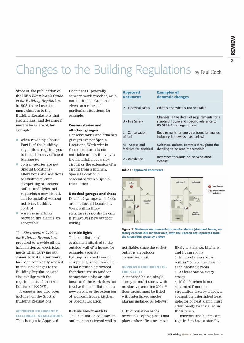
APPROVED DOCUMENT B -FIRE SAFETYA standard house, singlestorey or multi-storey withno storey exceeding 200 m²floor areas, must be fittedwith interlinked smokealarms installed as follows:
1. In circulation areasbetween sleeping places andplaces where fires are most
likely to start e.g. kitchensand living rooms2. In circulation spaceswithin 7.5 m of the door toeach habitable room3. At least one on everystorey4. If the kitchen is notseparated from thecirculation area by a door, acompatible interlinked heatdetector or heat alarm mustadditionally be installed inthe kitchen.Detectors and alarms are
required to have a standby
Changes to the Building Regulations by Paul Cook
ApprovedDocument
Examples ofdomestic changes
P - Electrical safety What is and what is not notifiable
B - Fire SafetyChanges in the detail of requirements for astandard house and specific reference toBS 5839-6 for large houses.
L - Conservationof fuel
Requirements for energy efficient luminaries,including for rewires, (see below)
M - Access andfacilities for disabled
Switches, sockets, controls throughout thedwelling to be readily accessible
V - VentilationReference to whole house ventilationsystems
Table 1: Approved Documents
Figure 1: Minimum requirements for smoke alarms (standard house, nostorey exceeds 200 m² floor area) with the kitchen not separated fromthe circulation space by a door

NEW
NEW
The On-Site Guide is intended to enable thecompetent electrician to deal with smallinstallations (up to 100 A, 3-phase). Itprovides essential information in aconvenient, easy to use form, avoiding theneed for detailed calculations.
ON-SITE GUIDE(BS 7671: 2008 17thEdition)
The law requires you from 1 January 2005to meet the requirements of theBuilding Regulations. This guide has beenupdated to align with the 17th edition of theIEE Wiring Regulations. It also includes a newchapter on requirements for Scotland.
STANDARDSANDCOMPLIAN
CE
The Wiring Regulations are the nationalstandard to which all domesticand industrial wiring must conform.Substantial changes have beenincorporated in BS 7671: 2008 to alignwith European documents. Essential for allelectricians, electrical contractors and theirmanagers, installation designers, andstudents in further education andprofessional training.
Contents: Scope, Object and FundamentalPrinciples. Definitions. Assessment ofGeneral Characteristics. Protection for Safety.Selection and Erection of Equipment.Special Installations or Locations. Inspectionand Testing.
REQUIREMENTSFOR ELECTRICALINSTALLATIONSBS 7671: 2008
(IEE Wiring Regulations,
17th Edition)
• Paperback 389pp• 2008• ISBN 978-0-86341-844-0• Order book PWR1700B
£65
ELECTRICIAN’SGUIDE TO THEBUILDINGREGULATIONS(PART P, 2nd EDITION)
£
• Paperback 183pp• 2008• ISBN 978-0-86341-854-9• Order book PWGO170B
£20£
• Paperback 210pp• 2008• ISBN 978-0-86341-862-4• Order book PWGP170B
£20• 2nd Edition 2008£
EXAMSUCCESS:The IEE WiringRegulations 2382-20
• Paperback 68pp• 2008• ISBN 978-0-86341-886-0• Order book PWR05090
£12
EXAMSUCCESS:IEE Code of Practice2377
• Paperback 116pp• 2007• ISBN 978-0-86341-805-1• Order book PWR05070
£12£
EXAMSUCCESS:The IEE WiringRegulations 2382-10
• Paperback 136pp• 2008• ISBN 978-0-86341-885-3• Order book PWR05080
£12
NEW
EXAMSUCCESS:The IEE WiringRegulations 2391-10
• Paperback 84pp• 2008• ISBN 978-0-86341-899-0• Order book PWR05110
£15
The Institution prepares regulations for the safety of electrical installations for buildings, the IEE Wiring Regulations (BS 7671)which have now become the standard for the UK and many other countries. It also recommends, internationally, therequirements for ships and offshore installations. The Institution provides guidance on the application of the installationregulations through publications focused on the various activities from design of the installation through to final test and thenmaintenance. This includes a series of eight guidance notes, two codes of practice, a CD-ROM, and model forms for use in wiringinstallations. During the course of 2008 all guidance publications will be updated to align with the 17th Edition of the IEEWiring Regulations
CODE OFPRACTICE FORIN-SERVICEINSPECTIONAND TESTING OFELECTRICALEQUIPMENT3rd Edition 2007
• Paperback 152pp• 2007• ISBN 978-0-86341-833-4• Order book PWR08630
£35£
This Code of Practice has been revised toreflect current best practice. It givesguidance to those responsible for theinspection, testing and maintenance ofelectrical appliances. The text specifies thefrequency and scope of inspections andtesting in different environments. The newrevision is printed in colour and includesmany drawings aimed at helping to identifycommon problems.
Call: 01438 767328 Fax: 01438 767375
£
££

AVAILABLENOW!

REV
IEW
24
IET Wiring Matters | Summer 08 | www.theiet.org
power supply, for example, abattery or capacitor. Theinterconnection may be byradio links.See fig 1. of aninstallation for a standardhouse, where no storeyexceeds 200 m² floor area,with the kitchen notseparated from thecirculation space by a door
PART L - CONSERVATION OFFUEL AND ENERGYIn new buildings, extensionsand rewires to existingbuildings, the minimumnumber of fixed energyefficient light fittings mustbe either:1. One per 25 m² of the floorarea, excluding garages, or2. One energy-efficient lightfitting per four fixed lightfittings.Energy efficient fittingsare fixed light fittings thatcan only accept lamps witha luminous efficacyexceeding 40 lumens percircuit-watt, such ascompact fluorescent lamps.Lamp holders which acceptEdison screw or bayonetlamps do not, unless theyare of a certain unique non-standardised type made toaccept only lamps of therequired efficacy. The lampholder must not acceptlamps of a lesser efficacythan that specified.
PART M - ACCESS ANDFACILITIES FOR THEDISABLEDThe Building Regulations arenow understood to requireswitches, socket-outlets andcontrols in dwellings to beinstalled so that all persons,including those whose reachis limited, can easily use
them. One way of satisfyingthe requirements is to installswitches, socket-outlets andcontrols throughout thedwelling in accessiblepositions; detailed guidanceis given.It is also worth notingPart C, Airtightness andPart E, Acoustics, sinceeach of these can imposerequirements on theinstallation of, for example,luminaires. In the case ofPart C (see BS 9250 Code ofpractice for the design ofairtightness of ceilings inpitched roofs), it may benecessary to make good thebreaching of an acousticbarrier between, forinstance, flats and could,therefore, affect theinstallation of wall mountedsocket-outlets, switches,luminaires, etc., in bothwalls and ceilings.
17TH EDITION OF BS 7671The Electrician's Guide tothe Building Regulationshas been completelyrevised to reflect changes inboth the BuildingRegulations and the WiringRegulation.Perhaps the mostsignificant changes in the17th Edition are therequirements for RCDs.Additional 30 mA RCDprotection is required indwellings for: all socket outlets forgeneral use,
all bathroom circuits, all circuits with cablesburied in walls at a depthless than 50 mm unlessprotected by an earthedmetal sheath, steelconduit or similar
all circuits supplying
mobile equipmentoutdoors
all circuits with cablesinstalled in walls orpartitions of metallicconstruction.
The Guide provides arange of solutions, forexample, see fig. 2.
DISCONNECTION TIMESFor TN Systems, a 0.4 sdisconnection time isrequired for all finalcircuits up to 32 A ratingwith a 5 s disconnectiontime allowed fordistribution circuits andfinal circuits of ratingexceeding 32 A.
VOLTAGE DROPThe requirements aredeemed to be satisfied if thevoltage drop between theorigin of the installation(usually the supplyterminals) and any socket-outlet or the terminals offixed current-usingequipment does not exceedthe following, see table 2.
The book is a must forall electricians anddesigners.
The Electrician’s Guide tothe Building Regulations(2nd edition) will bepublished in the summer.
Lighting Otheruses
(i) Low voltage installations supplieddirectly from a public low voltagedistribution system
3% 5%
(ii) Low voltage installations suppliedfrom private LV supply (*)
6% 8%
(*) The voltage drop within each final circuit should not exceed the valuesgiven in (i). Where the wiring systems of the installations are longer than100 m, the voltage drops indicated above may be increased by 0.005% permetre of the wiring system beyond 100 m, without this increase benggreater than 0.5%.The voltage drop is determined from the demand by the current-usingequipment, applying diversity factors where applicable, or from the value ofthe design current of the circuit.
Table 2: Voltage drop
Figure 2: Split consumer unit with separate main switch and two 30 mARCDs, suitable for all installations

SAVE 30%ON STANDARD PRICES BY BOOKING YOUR TRAINING AND EXAMS BEFORE 30 JUNE
TRAIN NOWto the 17th Edition01 July implementation day is fast approaching
17th Edition Workshop upgrade and City & Guilds 2382-20 examLocation Course & ExamStevenage 04 & 12 SeptemberGlasgow 10 & 17 SeptemberBirmingham 16 & 25 SeptemberWakefield 08 & 14 OctoberBristol 29 October and 04 November
17th Edition Certificate in the Requirements forElectrical Installations and City & Guilds 2382-10 examLocation Course & ExamGlasgow 02 - 04 & 17 SeptemberManchester 07 - 09 & 15 OctoberStevenage 10 - 12 & 19 NovemberBirmingham 18 - 20 & 27 November
17th Edition DesignLocation Course DatesBirmingham 22 - 24 JulyWakefield 21 - 23 OctoberGlasgow 11 - 13 November
London - All above courses are also available in London – see website for further details
Further training courses available from the IETInspection and Testing (City & Guilds 2391-10)Testing of Electrical InstallationsPortable Appliance Testing (City & Guilds 2377)Earthing and Bonding - Principles and SizingElectrical BasicsElectrical MaintenanceElectricity at Work
Course fees from £171
For bookings and course information visitwww.theiet.org/wmscourses or Tel: +44 (0) 1438 767289
“I found the courseinformative and easyto follow. The trainerexplains thingsthoroughly whichhelps to understandthings fully”Daniel Williams, March 2008
Reduce your external costs – enquire about in-company training
95%PASSRATE!
Buy your copy atwww.theiet.org/wr1
The Institution of Engineering and Technology is registered as a Charity in England & Wales (no 211014) and Scotland (no SC038698).

Only awardedfor expertise
NAPIT Administration Centre,4th Floor, Mill 3,Pleasley Vale Business Park,Mansfield,Nottinghamshire NG19 8RL
www.napit.org.uk
Electrical Ventilation Plumbing Heating
Customers and employers hold NAPIT members in the highestregard. That’s because only fully trained electrical engineers can joinNAPIT. Their skills are their own – not their supervisor’s.
NAPIT’s Part P scheme is designed by electricians for electricians,and we offer practical help and advice on Building Regulations,Training, Self Certification and Works Notification.
So if you are a highly skilled electrician, make sure you get therecognition you deserve. Join NAPIT now. Call 0870 444 1392.
FREEWHENYOUJOIN
Choose a Megger Multitesterworth £75 or a Kewtech Clamp
Meter worth £115Or, if you are already registered with
another Registration Scheme get£180 off*your initial application
*Offer applies to new applicants to NAPIT who have been membersof an existing Registration Scheme for 12 months. Not to be used inconjunction with any other offer. Offer expires 12 September 2008.
Photos are for illustration purposes only.