Embed Size (px)
Citation preview
Seats and Restraint Systems ........................ 7Front Seats .............................................. 8Rear Seats ............................................. 16Safety Belts ............................................ 17Child Restraints ...................................... 39Airbag System ........................................ 64Restraint System Check ......................... 80
Features and Controls ................................. 83Keys ....................................................... 84Doors and Locks .................................... 93Windows ................................................ 99Theft-Deterrent Systems ....................... 102Starting and Operating Your Vehicle ..... 107Mirrors .................................................. 124OnStar® System ................................... 125Storage Areas ...................................... 129Sunroof ................................................ 131
Instrument Panel ........................................ 133Instrument Panel Overview ................... 136Climate Controls ................................... 161Warning Lights, Gages, and Indicators ... 172Driver Information Center (DIC) ............ 190Audio System(s) ................................... 237
Driving Your Vehicle .................................. 287Your Driving, the Road,
and Your Vehicle .............................. 288Towing ................................................. 327
Service and Appearance Care ................... 339Service ................................................. 342Fuel ...................................................... 344Checking Things Under the Hood ......... 350Headlamp Aiming ................................. 394Bulb Replacement ................................ 397Windshield Replacement ....................... 405
2007 Pontiac Grand Prix Owner Manual M
1

Windshield Wiper Blade Replacement ... 405Tires ..................................................... 406Appearance Care .................................. 455Vehicle Identification ............................. 465Electrical System .................................. 466Capacities and Specifications ................ 474
Maintenance Schedule ............................... 477Maintenance Schedule .......................... 478
Customer Assistance Information ............. 497Customer Assistance and Information .... 498Reporting Safety Defects ...................... 512Vehicle Data Recording
and Privacy ....................................... 515
Index ........................................................... 519
2

GENERAL MOTORS, GM, the GM Emblem,PONTIAC, the PONTIAC Emblem, and the namesGRAND PRIX, GTP, and GXP are registeredtrademarks of General Motors Corporation.
This manual includes the latest information atthe time it was printed. We reserve the rightto make changes after that time without notice.For vehicles first sold in Canada, substitutethe name “General Motors of Canada Limited”for Pontiac Division whenever it appears inthis manual.
This manual describes features that may beavailable in this model, but your vehicle may nothave all of them. For example, more than oneentertainment system may be offered or yourvehicle may have been ordered without a frontpassenger or rear seats.
Keep this manual in the vehicle, so it will be thereif it is needed while you are on the road. If thevehicle is sold, leave this manual in the vehicle.
Canadian OwnersA French language copy of this manual can beobtained from your dealer/retailer or from:
Helm, IncorporatedP.O. Box 07130Detroit, MI 48207
Litho in U.S.A.Part No. 15863016 B Second Printing ©2006 General Motors Corporation. All Rights Reserved.
3
How to Use This ManualMany people read the owner manual frombeginning to end when they first receive theirnew vehicle. If this is done, it can help you learnabout the features and controls for the vehicle.Pictures and words work together in the ownermanual to explain things.
IndexA good place to quickly locate information aboutthe vehicle is the Index in the back of the manual.It is an alphabetical list of what is in the manualand the page number where it can be found.
Safety Warnings and SymbolsThere are a number of safety cautions in thisbook. We use a box and the word CAUTION totell about things that could hurt you if you wereto ignore the warning.
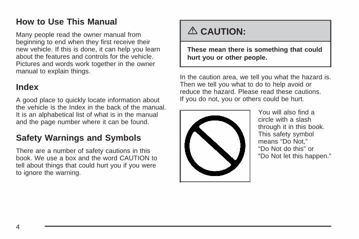
{CAUTION:
These mean there is something that couldhurt you or other people.
In the caution area, we tell you what the hazard is.Then we tell you what to do to help avoid orreduce the hazard. Please read these cautions.If you do not, you or others could be hurt.
You will also find acircle with a slashthrough it in this book.This safety symbolmeans “Do Not,”“Do Not do this” or“Do Not let this happen.”
4

Vehicle Damage WarningsAlso, in this manual you will find these notices:
Notice: These mean there is somethingthat could damage your vehicle.
A notice tells about something that can damagethe vehicle. Many times, this damage would not becovered by your vehicle’s warranty, and it couldbe costly. But the notice will tell what to do to helpavoid the damage.
When you read other manuals, you might seeCAUTION and NOTICE warnings in different colorsor in different words.
There are also warning labels on the vehicle.They use the same words, CAUTION or NOTICE.
Vehicle SymbolsThe vehicle has components and labels that usesymbols instead of text. Symbols are shownalong with the text describing the operation orinformation relating to a specific component,control, message, gage, or indicator.
If you need help figuring out a specific name ofa component, gage, or indicator, referencethe following topics:
• Seats and Restraint Systems in Section 1
• Features and Controls in Section 2
• Instrument Panel Overview in Section 3
• Climate Controls in Section 3
• Warning Lights, Gages, and Indicators inSection 3
• Audio System(s) in Section 3
• Engine Compartment Overview in Section 5
5

These are some examples of symbols that may be found on the vehicle:
6

Front Seats ..................................................... 8Manual Passenger Seat ................................ 8Power Seat ................................................... 8Power Lumbar .............................................. 9Heated Seats .............................................. 10Reclining Seatbacks .................................... 10Head Restraints .......................................... 13Passenger Folding Seatback ....................... 14
Rear Seats .................................................... 16Split Folding Rear Seat ............................... 16
Safety Belts .................................................. 17Safety Belts: They Are for Everyone ........... 17Questions and Answers About Safety Belts .... 21How to Wear Safety Belts Properly ............. 22Driver Position ............................................. 22Shoulder Belt Height Adjustment ................. 30Safety Belt Use During Pregnancy .............. 31Right Front Passenger Position ................... 31Rear Seat Passengers ................................ 32Rear Safety Belt Comfort Guides ................ 35Safety Belt Pretensioners ............................ 38Safety Belt Extender ................................... 38
Child Restraints ............................................ 39Older Children ............................................. 39Infants and Young Children ......................... 42
Child Restraint System ................................ 45Where to Put the Restraint .......................... 49Lower Anchors and Tethers for
Children (LATCH) .................................... 51Securing a Child Restraint in a
Rear Seat Position ................................... 58Securing a Child Restraint in the
Right Front Seat Position ......................... 60Airbag System .............................................. 64
Where Are the Airbags? .............................. 67When Should an Airbag Inflate? .................. 70What Makes an Airbag Inflate? ................... 71How Does an Airbag Restrain? ................... 72What Will You See After an
Airbag Inflates? ........................................ 72Passenger Sensing System ......................... 74Servicing Your Airbag-Equipped Vehicle ...... 78Adding Equipment to Your
Airbag-Equipped Vehicle .......................... 79Restraint System Check ............................... 80
Checking the Restraint Systems .................. 80Replacing Restraint System Parts
After a Crash ........................................... 81
Section 1 Seats and Restraint Systems
7

Front Seats
Manual Passenger Seat
Lift the bar located under the front of the seat tounlock it. Slide the seat to where you want itand release the bar. Try to move the seat with yourbody to be sure the seat is locked in place.
Power Seat
The driver’s seat power control is located on theoutboard side of the seat.
Driver’s Seat Power Seat Control, Power Lumbar,and Manual Recline shown
8
To adjust the seat, do any of the following:
• Move the seat forward or rearward by slidingthe control forward or rearward.
• Raise or lower the front part of the seatcushion by moving the front of the control upor down.
• Raise or lower the rear part of the seatcushion by moving the rear of the control upor down.
• Raise or lower the entire seat by moving theentire control up or down.
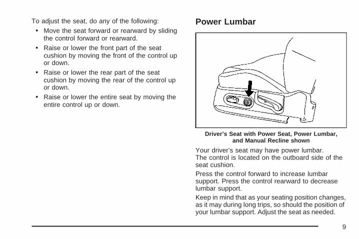
Power Lumbar
Your driver’s seat may have power lumbar.The control is located on the outboard side of theseat cushion.Press the control forward to increase lumbarsupport. Press the control rearward to decreaselumbar support.Keep in mind that as your seating position changes,as it may during long trips, so should the position ofyour lumbar support. Adjust the seat as needed.
Driver’s Seat with Power Seat, Power Lumbar,and Manual Recline shown
9

Heated Seats
If the vehicle has thisfeature, the buttons arelocated on the climatecontrol panel. SeeClimate Control Systemon page 161 formore information.
Press the button once to activate the high heatsetting. Both indicator lights next to the button willcome on.
Press the button again to select the lowertemperature setting. Only the bottom indicator lightwill come on.
Press the button a third time to turn the heat off.
This feature only works when the ignition is on.
Reclining Seatbacks
{CAUTION:
You can lose control of the vehicle if youtry to adjust a manual driver’s seat whilethe vehicle is moving. The suddenmovement could startle and confuse you,or make you push a pedal when you donot want to. Adjust the driver’s seat onlywhen the vehicle is not moving.
{CAUTION:
If the seatback is not locked, it couldmove forward in a sudden stop or crash.That could cause injury to the personsitting there. Always push and pull on theseatback to be sure it is locked.
10

The seats have manual reclining seatbacks.The lever used to operate them is located on theoutboard side of the seats.
To recline the seatback, do the following:
1. Lift the recline lever.
2. Move the seatback to the desired position,then release the lever to lock the seatbackin place.
3. Push and pull on the seatback to make sure itis locked.
To return the seatback to an upright position,do the following:
1. Lift the lever fully without applying pressure tothe seatback and the seatback will return tothe upright position.
2. Push and pull on the seatback to make sure itis locked.
Driver’s Seat with Power Seat, Power Lumbar,and Manual Recline shown
11
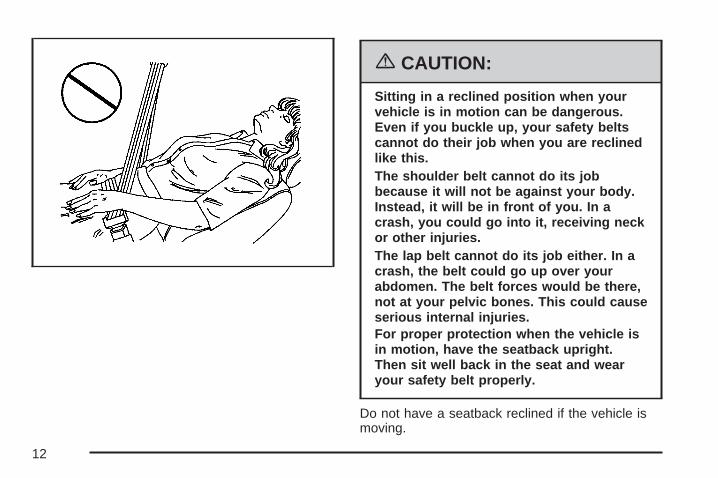
{CAUTION:
Sitting in a reclined position when yourvehicle is in motion can be dangerous.Even if you buckle up, your safety beltscannot do their job when you are reclinedlike this.The shoulder belt cannot do its jobbecause it will not be against your body.Instead, it will be in front of you. In acrash, you could go into it, receiving neckor other injuries.The lap belt cannot do its job either. In acrash, the belt could go up over yourabdomen. The belt forces would be there,not at your pelvic bones. This could causeserious internal injuries.For proper protection when the vehicle isin motion, have the seatback upright.Then sit well back in the seat and wearyour safety belt properly.
Do not have a seatback reclined if the vehicle ismoving.
12
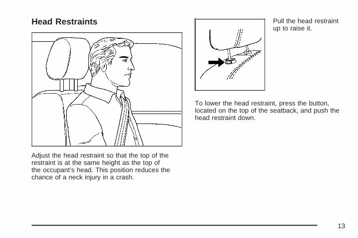
Head Restraints
Adjust the head restraint so that the top of therestraint is at the same height as the top ofthe occupant’s head. This position reduces thechance of a neck injury in a crash.
Pull the head restraintup to raise it.
To lower the head restraint, press the button,located on the top of the seatback, and push thehead restraint down.
13

Passenger Folding Seatback
{CAUTION:
If you fold the seatback forward to carrylonger objects, such as skis, be sure anysuch cargo is not near an airbag. In acrash, an inflating airbag might force thatobject toward a person. This could causesevere injury or even death. Secureobjects away from the area in whichan airbag would inflate. For moreinformation, see Where Are the Airbags?on page 67 and Loading Your Vehicle onpage 322.
{CAUTION:
Things you put on this seatback canstrike and injure people in a sudden stopor turn, or in a crash. Remove or secureall items before driving.
If the vehicle has this feature, the front passengerseat can be folded flat for more cargo space.
14

To fold the front passenger seatback flat, pull upon the lever located on back of the seat. Push theseatback forward until it locks in place.
To return the seatback to the upright position,pull up on the lever on the back of the seat.Push the seatback up until it locks in place.
{CAUTION:
If the seatback is not locked, it couldmove forward in a sudden stop or crash.That could cause injury to the personsitting there. Always push and pull on theseatback to be sure it is locked.
Push and pull on the seatback to make sureit is locked.
15

Rear Seats
Split Folding Rear SeatBoth sides of the rear seatback can be folded down.This gives direct access to the trunk. Make sure thefront seats are not reclined. If they are, the rearseatback(s) may not fold down all the way.
Notice: Folding a rear seat with the safetybelts still fastened may cause damage to theseat or the safety belts. Always unbucklethe safety belts and return them to their normalstowed position before folding a rear seat.
To lower the rearseatback, pull the tablocated on the outboardside of the seatbackand fold the seatbackforward.
{CAUTION:
If the seatback is not locked, it couldmove forward in a sudden stop or crash.That could cause injury to the personsitting there. Always push and pull on theseatback to be sure it is locked.
To raise the rear seatback, lift the seatback upuntil it latches. Push and pull on the seatback to besure it is locked in position.
The seatbacks should be kept in the upright,locked position when they are not being used toextend the cargo area.
16
Safety Belts
Safety Belts: They Are for EveryoneThis part of the manual tells you how to usesafety belts properly. It also tells you some thingsyou should not do with safety belts.
{CAUTION:
Do not let anyone ride where he or shecannot wear a safety belt properly. If youare in a crash and you are not wearing asafety belt, your injuries can be muchworse. You can hit things inside thevehicle or be ejected from it. You can beseriously injured or killed. In the samecrash, you might not be, if you arebuckled up. Always fasten your safetybelt, and check that your passengers’belts are fastened properly too.
{CAUTION:
It is extremely dangerous to ride in acargo area, inside or outside of a vehicle.In a collision, people riding in these areasare more likely to be seriously injured orkilled. Do not allow people to ride in anyarea of your vehicle that is not equippedwith seats and safety belts. Be sureeveryone in your vehicle is in a seat andusing a safety belt properly.
Your vehicle has indicators to remind you andyour passengers to buckle your safety belts.See Safety Belt Reminder Light on page 175and Passenger Safety Belt Reminder Lighton page 176.
17
In most states and in all Canadian provinces, thelaw says to wear safety belts. Here is why:They work.
You never know if you will be in a crash. If you dohave a crash, you do not know if it will be abad one.
A few crashes are mild, and some crashes can beso serious that even buckled up, a personwould not survive. But most crashes are inbetween. In many of them, people who buckle upcan survive and sometimes walk away. Withoutbelts they could have been badly hurt or killed.
After more than 40 years of safety belts invehicles, the facts are clear. In most crashesbuckling up does matter... a lot!
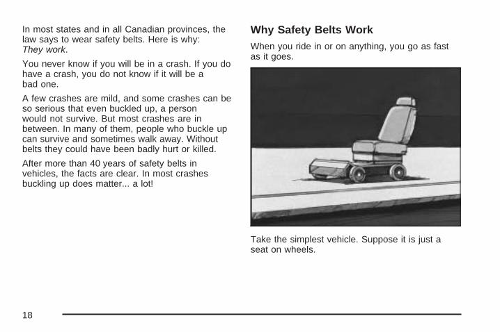
Why Safety Belts WorkWhen you ride in or on anything, you go as fastas it goes.
Take the simplest vehicle. Suppose it is just aseat on wheels.
18
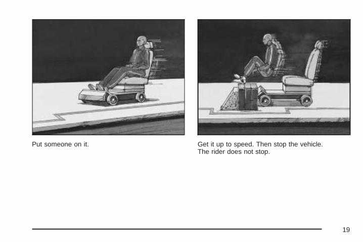
Put someone on it. Get it up to speed. Then stop the vehicle.The rider does not stop.
19

The person keeps going until stopped bysomething. In a real vehicle, it could be thewindshield...
or the instrument panel...
20

or the safety belts!
With safety belts, you slow down as the vehicledoes. You get more time to stop. You stopover more distance, and your strongest bonestake the forces. That is why safety beltsmake such good sense.
Questions and Answers AboutSafety Belts
Q: Will I be trapped in the vehicle after anaccident if I am wearing a safety belt?
A: You could be — whether you are wearing asafety belt or not. But you can unbuckle asafety belt, even if you are upside down. Andyour chance of being conscious during andafter an accident, so you can unbuckle and getout, is much greater if you are belted.
Q: If my vehicle has airbags, why should Ihave to wear safety belts?
A: Airbags are supplemental systems only; sothey work with safety belts — not instead ofthem. Every airbag system ever offeredfor sale has required the use of safety belts.Even if you are in a vehicle that has airbags,you still have to buckle up to get the mostprotection. That is true not only in frontalcollisions, but especially in side and othercollisions.
21
Q: If I am a good driver, and I never drive farfrom home, why should I wear safety belts?
A: You may be an excellent driver, but if you arein an accident — even one that is not yourfault — you and your passengers can be hurt.Being a good driver does not protect youfrom things beyond your control, such asbad drivers.
Most accidents occur within 25 miles (40 km) ofhome. And the greatest number of seriousinjuries and deaths occur at speeds of less than40 mph (65 km/h).
Safety belts are for everyone.
How to Wear Safety Belts ProperlyThis part is only for people of adult size.
Be aware that there are special things to knowabout safety belts and children. And thereare different rules for smaller children and babies.If a child will be riding in your vehicle, seeOlder Children on page 39 or Infants and YoungChildren on page 42. Follow those rules foreveryone’s protection.
First, you will want to know which restraintsystems your vehicle has.
We will start with the driver position.
Driver Position
Lap-Shoulder BeltThe driver has a lap-shoulder belt. Here is how towear it properly.
1. Close and lock the door.
2. Adjust the seat so you can sit up straight.To see how, see “Seats” in the Index.
22

3. Pick up the latch plate and pull the belt acrossyou. Do not let it get twisted.The lap-shoulder belt may lock if you pull thebelt across you very quickly. If this happens,let the belt go back slightly to unlock it.Then pull the belt across you more slowly.
4. Push the latch plate into the buckle untilit clicks.Pull up on the latch plate to make sure it issecure. If the belt is not long enough,see Safety Belt Extender on page 38.Make sure the release button on the buckle ispositioned so you would be able to unbucklethe safety belt quickly if you ever had to.
5. Move the shoulder belt height adjuster to theheight that is right for you. Improper shoulderbelt height adjustment could reduce theeffectiveness of the safety belt in a crash. SeeShoulder Belt Height Adjustment on page 30.
23
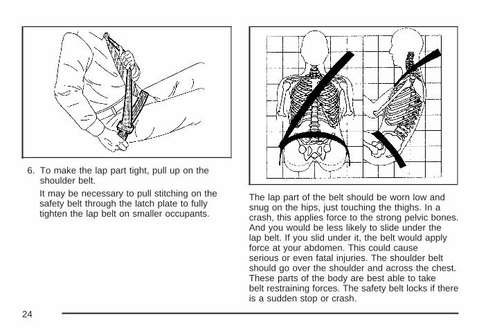
6. To make the lap part tight, pull up on theshoulder belt.It may be necessary to pull stitching on thesafety belt through the latch plate to fullytighten the lap belt on smaller occupants.
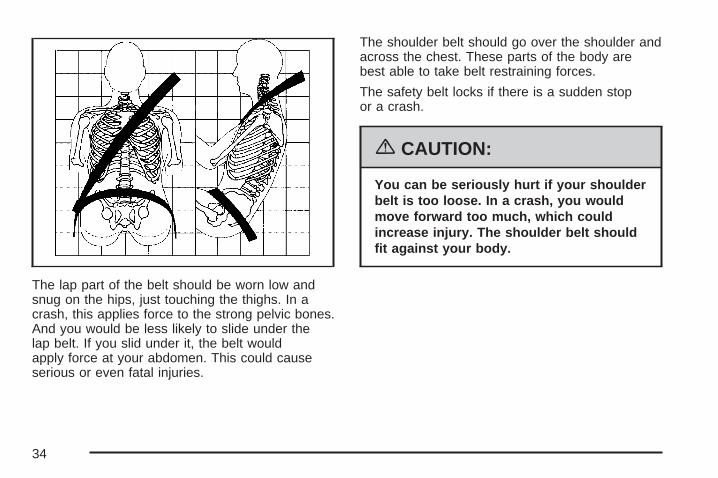
The lap part of the belt should be worn low andsnug on the hips, just touching the thighs. In acrash, this applies force to the strong pelvic bones.And you would be less likely to slide under thelap belt. If you slid under it, the belt would applyforce at your abdomen. This could causeserious or even fatal injuries. The shoulder beltshould go over the shoulder and across the chest.These parts of the body are best able to takebelt restraining forces. The safety belt locks if thereis a sudden stop or crash.
24
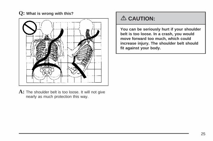
Q: What is wrong with this?
A: The shoulder belt is too loose. It will not givenearly as much protection this way.
{CAUTION:
You can be seriously hurt if your shoulderbelt is too loose. In a crash, you wouldmove forward too much, which couldincrease injury. The shoulder belt shouldfit against your body.
25

Q: What is wrong with this?
A: The lap belt is too loose. It will not give nearlyas much protection this way.
{CAUTION:
You can be seriously hurt if your lap beltis too loose. In a crash, you could slideunder the lap belt and apply force at yourabdomen. This could cause serious oreven fatal injuries. The lap belt should beworn low and snug on the hips, justtouching the thighs.
26

Q: What is wrong with this?
A: The belt is buckled in the wrong place.
{CAUTION:
You can be seriously injured if your belt isbuckled in the wrong place like this. In acrash, the belt would go up over yourabdomen. The belt forces would be there,not at the pelvic bones. This could causeserious internal injuries. Always buckleyour belt into the buckle nearest you.
27

Q: What is wrong with this?
A: The shoulder belt is worn under the arm.It should be worn over the shoulder atall times.
{CAUTION:
You can be seriously injured if you wearthe shoulder belt under your arm. In acrash, your body would move too farforward, which would increase the chanceof head and neck injury. Also, the beltwould apply too much force to the ribs,which are not as strong as shoulderbones. You could also severely injureinternal organs like your liver or spleen.
28

Q: What is wrong with this?
A: The belt is twisted across the body.
{CAUTION:
You can be seriously injured by a twistedbelt. In a crash, you would not have thefull width of the belt to spread impactforces. If a belt is twisted, make it straightso it can work properly, or ask yourdealer/retailer to fix it.
29

To unlatch the belt, push the button on the buckle.The belt should go back out of the way.
Before you close the door, be sure the belt is outof the way. If you slam the door on it, you candamage both the belt and your vehicle.
Shoulder Belt Height AdjustmentBefore you begin to drive, move the shoulder beltheight adjuster to the height that is right for you.
Adjust the height so that the shoulder portion ofthe belt is centered on your shoulder. The beltshould be away from your face and neck, but notfalling off your shoulder. Improper shoulderbelt height adjustment could reduce theeffectiveness of the safety belt in a crash.
To move it down, pullthe release button (A)out and move the heightadjuster to the desiredposition. You canmove the heightadjuster up just bypushing up onthe shoulder belt guide.
After you move the height adjuster to where youwant it, try to move it down without pulling therelease button to make sure it has lockedinto position.
30
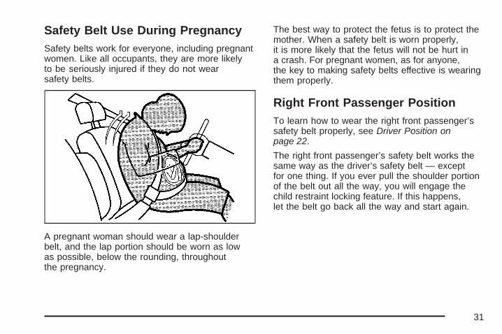
Safety Belt Use During PregnancySafety belts work for everyone, including pregnantwomen. Like all occupants, they are more likelyto be seriously injured if they do not wearsafety belts.
A pregnant woman should wear a lap-shoulderbelt, and the lap portion should be worn as lowas possible, below the rounding, throughoutthe pregnancy.
The best way to protect the fetus is to protect themother. When a safety belt is worn properly,it is more likely that the fetus will not be hurt ina crash. For pregnant women, as for anyone,the key to making safety belts effective is wearingthem properly.
Right Front Passenger PositionTo learn how to wear the right front passenger’ssafety belt properly, see Driver Position onpage 22.
The right front passenger’s safety belt works thesame way as the driver’s safety belt — exceptfor one thing. If you ever pull the shoulder portionof the belt out all the way, you will engage thechild restraint locking feature. If this happens,let the belt go back all the way and start again.
31

Rear Seat PassengersIt is very important for rear seat passengers tobuckle up! Accident statistics show that unbeltedpeople in the rear seat are hurt more often incrashes than those who are wearing safety belts.
Rear passengers who are not safety beltedcan be thrown out of the vehicle in a crash.And they can strike others in the vehicle who arewearing safety belts.
Lap-Shoulder BeltAll rear seat positions have lap-shoulder belts.Here is how to wear one properly.
1. Pick up the latch plate and pull the belt acrossyou. Do not let it get twisted.The shoulder belt may lock if you pull the beltacross you very quickly. If this happens, letthe belt go back slightly to unlock it. Then pullthe belt across you more slowly.
32

2. Push the latch plate into the buckle untilit clicks.Pull up on the latch plate to make sure itis secure.When the shoulder belt is pulled out all theway, it will lock. If it does, let it go back all theway and start again.If the belt is not long enough, see Safety BeltExtender on page 38.Make sure the release button on the buckle ispositioned so you would be able to unbucklethe safety belt quickly if you ever had to.
3. To make the lap part tight, pull up on theshoulder part.
33
The lap part of the belt should be worn low andsnug on the hips, just touching the thighs. In acrash, this applies force to the strong pelvic bones.And you would be less likely to slide under thelap belt. If you slid under it, the belt wouldapply force at your abdomen. This could causeserious or even fatal injuries.
The shoulder belt should go over the shoulder andacross the chest. These parts of the body arebest able to take belt restraining forces.
The safety belt locks if there is a sudden stopor a crash.
{CAUTION:
You can be seriously hurt if your shoulderbelt is too loose. In a crash, you wouldmove forward too much, which couldincrease injury. The shoulder belt shouldfit against your body.
34

To unlatch the belt, push the button on the buckle.
Rear Safety Belt Comfort GuidesRear shoulder belt comfort guides may provideadded safety belt comfort for older childrenwho have outgrown booster seats and for someadults. When installed on a shoulder belt, thecomfort guide positions the belt away fromthe neck and head.
There is one guide for each outboard passengerposition in the rear seat. Here is how to installa comfort guide to the safety belt:
1. Pull the elastic cord out from between theedge of the seatback and the interior bodyto remove the guide from its storage clip.
35
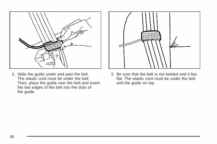
2. Slide the guide under and past the belt.The elastic cord must be under the belt.Then, place the guide over the belt and insertthe two edges of the belt into the slots ofthe guide.
3. Be sure that the belt is not twisted and it liesflat. The elastic cord must be under the beltand the guide on top.
36
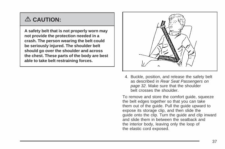
{CAUTION:
A safety belt that is not properly worn maynot provide the protection needed in acrash. The person wearing the belt couldbe seriously injured. The shoulder beltshould go over the shoulder and acrossthe chest. These parts of the body are bestable to take belt restraining forces.
4. Buckle, position, and release the safety beltas described in Rear Seat Passengers onpage 32. Make sure that the shoulderbelt crosses the shoulder.
To remove and store the comfort guide, squeezethe belt edges together so that you can takethem out of the guide. Pull the guide upward toexpose its storage clip, and then slide theguide onto the clip. Turn the guide and clip inwardand slide them in between the seatback andthe interior body, leaving only the loop ofthe elastic cord exposed.
37
Safety Belt PretensionersYour vehicle has safety belt pretensioners for thedriver and right front passenger. Although youcannot see them, they are part of the safety beltassembly. They help tighten the safety belts duringthe early stages of a moderate to severe frontalor near frontal crash if the threshold conditions forpretensioner activation are met.
Pretensioners work only once. If they activate in acrash, you will need to get new ones, andprobably other new parts for your safety beltsystem. See Replacing Restraint System PartsAfter a Crash on page 81.
Safety Belt ExtenderIf the vehicle’s safety belt will fasten around you,you should use it.
But if a safety belt is not long enough, yourdealer/retailer will order you an extender. Whenyou go in to order it, take the heaviest coat you willwear, so the extender will be long enough foryou. To help avoid personal injury, do notlet someone else use it, and use it only for theseat it is made to fit. The extender has beendesigned for adults. Never use it for securing childseats. To wear it, attach it to the regular safetybelt. For more information, see the instructionsheet that comes with the extender.
38

Child Restraints
Older Children
Older children who have outgrown booster seatsshould wear the vehicle’s safety belts.
Q: What is the proper way to wear safety belts?
A: An older child should wear a lap-shoulder beltand get the additional restraint a shoulder beltcan provide. The shoulder belt should notcross the face or neck. The lap belt should fitsnugly below the hips, just touching thetop of the thighs. It should never be worn overthe abdomen, which could cause severe oreven fatal internal injuries in a crash.
According to accident statistics, children are saferwhen properly restrained in the rear seatingpositions than in the front seating positions.
In a crash, children who are not buckled up canstrike other people who are buckled up, or can bethrown out of the vehicle. Older children needto use safety belts properly.
39

{CAUTION:
Never do this.Here two children are wearing the samebelt. The belt cannot properly spread theimpact forces. In a crash, the two childrencan be crushed together and seriouslyinjured. A belt must be used by onlyone person at a time.
Q: What if a child is wearing a lap-shoulderbelt, but the child is so small that theshoulder belt is very close to the child’sface or neck?
A: If the child is sitting in a seat next to awindow, move the child toward the center ofthe vehicle. Also see Rear Safety BeltComfort Guides on page 35. If the child issitting in the center rear seat passengerposition, move the child toward the safety beltbuckle. In either case, be sure that theshoulder belt still is on the child’s shoulder, sothat in a crash the child’s upper body wouldhave the restraint that belts provide.
40

{CAUTION:
Never do this.Here a child is sitting in a seat that has alap-shoulder belt, but the shoulder part isbehind the child. If the child wears thebelt in this way, in a crash the child mightslide under the belt. The belt’s forcewould then be applied right on the child’sabdomen. That could cause serious orfatal injuries.
Wherever the child sits, the lap portion of the beltshould be worn low and snug on the hips, justtouching the child’s thighs. This applies belt forceto the child’s pelvic bones in a crash.
41
Infants and Young ChildrenEveryone in a vehicle needs protection! Thisincludes infants and all other children. Neither thedistance traveled nor the age and size of thetraveler changes the need, for everyone, to usesafety restraints. In fact, the law in every statein the United States and in every Canadianprovince says children up to some age must berestrained while in a vehicle.
{CAUTION:
Children can be seriously injured orstrangled if a shoulder belt is wrappedaround their neck and the safety beltcontinues to tighten. Never leave childrenunattended in a vehicle and never allowchildren to play with the safety belts.
Every time infants and young children ride invehicles, they should have the protection providedby appropriate restraints. Young children shouldnot use the vehicle’s adult safety belts alone,unless there is no other choice. Instead, they needto use a child restraint.
{CAUTION:
People should never hold a baby in theirarms while riding in a vehicle. A babydoes not weigh much — until a crash.During a crash a baby will become soheavy it is not possible to hold it. Forexample, in a crash at only 25 mph(40 km/h), a 12 lb (5.5 kg) baby willsuddenly become a 240 lb (110 kg) forceon a person’s arms. A baby should besecured in an appropriate restraint.
42

{CAUTION:
Children who are up against, or very closeto, any airbag when it inflates can beseriously injured or killed. Airbags pluslap-shoulder belts offer protection for
CAUTION: (Continued)
CAUTION: (Continued)
adults and older children, but not foryoung children and infants. Neither thevehicle’s safety belt system nor its airbagsystem is designed for them. Youngchildren and infants need the protectionthat a child restraint system can provide.
43
Q: What are the different types of add-onchild restraints?
A: Add-on child restraints, which are purchased bythe vehicle’s owner, are available in four basictypes. Selection of a particular restraint shouldtake into consideration not only the child’sweight, height, and age but also whether or notthe restraint will be compatible with the motorvehicle in which it will be used.
For most basic types of child restraints, thereare many different models available. Whenpurchasing a child restraint, be sure it isdesigned to be used in a motor vehicle. If it is,the restraint will have a label saying that itmeets federal motor vehicle safety standards.
The restraint manufacturer’s instructionsthat come with the restraint state the weightand height limitations for a particular childrestraint. In addition, there are many kindsof restraints available for children withspecial needs.
{CAUTION:
Newborn infants need complete support,including support for the head and neck.This is necessary because a newborninfant’s neck is weak and its head weighsso much compared with the rest of itsbody. In a crash, an infant in a rear-facingseat settles into the restraint, so the crashforces can be distributed across thestrongest part of an infant’s body, the backand shoulders. Infants always should besecured in appropriate infant restraints.
44
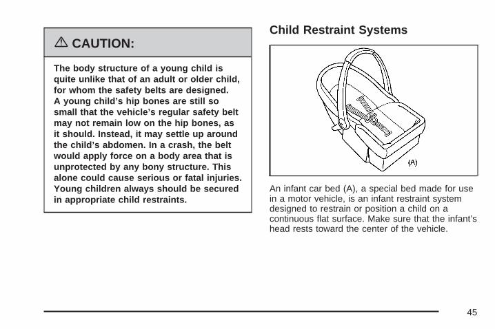
{CAUTION:
The body structure of a young child isquite unlike that of an adult or older child,for whom the safety belts are designed.A young child’s hip bones are still sosmall that the vehicle’s regular safety beltmay not remain low on the hip bones, asit should. Instead, it may settle up aroundthe child’s abdomen. In a crash, the beltwould apply force on a body area that isunprotected by any bony structure. Thisalone could cause serious or fatal injuries.Young children always should be securedin appropriate child restraints.
Child Restraint Systems
An infant car bed (A), a special bed made for usein a motor vehicle, is an infant restraint systemdesigned to restrain or position a child on acontinuous flat surface. Make sure that the infant’shead rests toward the center of the vehicle.
45
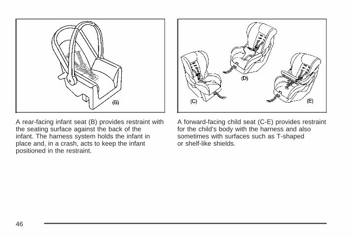
A rear-facing infant seat (B) provides restraint withthe seating surface against the back of theinfant. The harness system holds the infant inplace and, in a crash, acts to keep the infantpositioned in the restraint.
A forward-facing child seat (C-E) provides restraintfor the child’s body with the harness and alsosometimes with surfaces such as T-shapedor shelf-like shields.
46
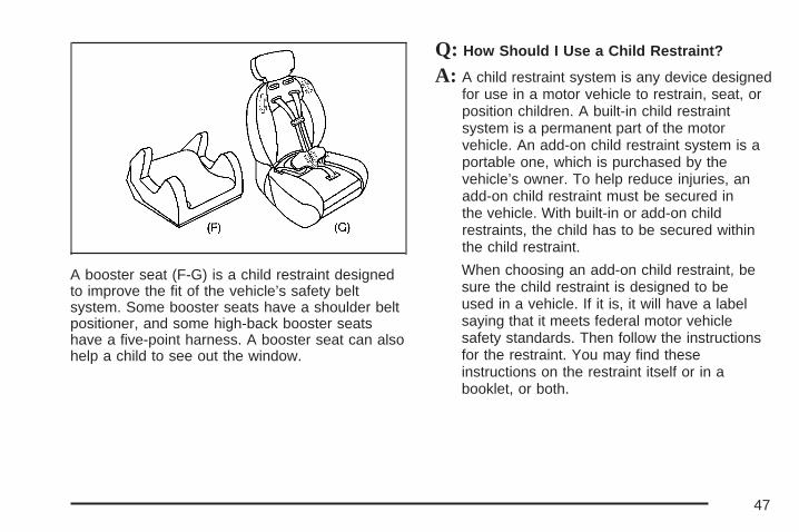
A booster seat (F-G) is a child restraint designedto improve the fit of the vehicle’s safety beltsystem. Some booster seats have a shoulder beltpositioner, and some high-back booster seatshave a five-point harness. A booster seat can alsohelp a child to see out the window.
Q: How Should I Use a Child Restraint?
A: A child restraint system is any device designedfor use in a motor vehicle to restrain, seat, orposition children. A built-in child restraintsystem is a permanent part of the motorvehicle. An add-on child restraint system is aportable one, which is purchased by thevehicle’s owner. To help reduce injuries, anadd-on child restraint must be secured inthe vehicle. With built-in or add-on childrestraints, the child has to be secured withinthe child restraint.
When choosing an add-on child restraint, besure the child restraint is designed to beused in a vehicle. If it is, it will have a labelsaying that it meets federal motor vehiclesafety standards. Then follow the instructionsfor the restraint. You may find theseinstructions on the restraint itself or in abooklet, or both.
47

Securing an Add-on Child Restraint inthe Vehicle
{CAUTION:
A child can be seriously injured or killedin a crash if the child restraint is notproperly secured in the vehicle. Make surethe child restraint is properly installed inthe vehicle using the vehicle’s safety beltor LATCH system, following theinstructions that came with that restraint,and also the instructions in this manual.
To help reduce the chance of injury, the childrestraint must be secured in the vehicle. Childrestraint systems must be secured in vehicle seatsby lap belts or the lap belt portion of a lap-shoulderbelt, or by the LATCH system.
See Lower Anchors and Tethers for Children(LATCH) on page 51 for more information. A childcan be endangered in a crash if the childrestraint is not properly secured in the vehicle.
When securing an add-on child restraint, refer tothe instructions that come with the restraintwhich may be on the restraint itself or in a booklet,or both, and to this manual. The child restraintinstructions are important, so if they are notavailable, obtain a replacement copy from themanufacturer.
Keep in mind that an unsecured child restraint canmove around in a collision or sudden stop andinjure people in the vehicle. Be sure to properlysecure any child restraint in your vehicle — evenwhen no child is in it.
48

Securing the Child Within theChild RestraintThere are several systems for securing the childwithin the child restraint. One system, thethree-point harness, has straps that come downover each of the infant’s shoulders and buckletogether at the crotch. The five-point harnesssystem has two shoulder straps, two hip straps, anda crotch strap. A shield may take the place of hipstraps. A T-shaped shield has shoulder straps thatare attached to a flat pad which rests low againstthe child’s body. A shelf- or armrest-type shield hasstraps that are attached to a wide, shelf-like shieldthat swings up or to the side.
{CAUTION:
A child can be seriously injured or killed ina crash if the child is not properly securedin the child restraint. Make sure the childis properly secured, following theinstructions that came with that restraint.
Because there are different systems, it is importantto refer to the instructions that come with therestraint. A child can be endangered in a crashif the child is not properly secured in the childrestraint.
Where to Put the RestraintAccident statistics show that children are saferif they are restrained in the rear rather thanthe front seat.
We recommend that children be secured in a rearseat, including: an infant or a child riding in arear-facing child restraint; a child riding in aforward-facing child seat; an older child ridingin a booster seat; and children, who are largeenough, using safety belts.
49

A label on your sun visor says, “Never put arear-facing child seat in the front.” This is becausethe risk to the rear-facing child is so great, if theairbag deploys.
{CAUTION:
A child in a rear-facing child restraint canbe seriously injured or killed if the rightfront passenger’s airbag inflates. This isbecause the back of the rear-facing childrestraint would be very close to theinflating airbag.
Even though the passenger sensingsystem is designed to turn off the rightfront passenger’s frontal airbag if thesystem detects a rear-facing child restraint,no system is fail-safe, and no one can
CAUTION: (Continued)
CAUTION: (Continued)
guarantee that an airbag will not deployunder some unusual circumstance, eventhough it is turned off. We recommendthat rear-facing child restraints be securedin the rear seat, even if the airbag is off.
If you need to secure a forward-facingchild restraint in the right front seat,always move the front passenger seat asfar back as it will go. It is better to securethe child restraint in a rear seat.
Wherever you install a child restraint, be sure tosecure the child restraint properly.
Keep in mind that an unsecured child restraint canmove around in a collision or sudden stop andinjure people in the vehicle. Be sure to properlysecure any child restraint in your vehicle — evenwhen no child is in it.
50
Lower Anchors and Tethers forChildren (LATCH)The LATCH system holds a child restraint duringdriving or in a crash. This system is designedto make installation of a child restraint easier.The LATCH system uses anchors in the vehicleand attachments on the child restraint thatare made for use with the LATCH system.
Make sure that a LATCH-compatible child restraintis properly installed using the anchors, or usethe vehicle’s safety belts to secure the restraint,following the instructions that came with thatrestraint, and also the instructions in this manual.When installing a child restraint with a toptether, you must also use either the lower anchorsor the safety belts to properly secure the childrestraint. A child restraint must never be installedusing only the top tether and anchor.
In order to use the LATCH system in your vehicle,you need a child restraint that has LATCHattachments. The child restraint manufacturerwill provide you with instructions on how touse the child restraint and its attachments.The following explains how to attach a childrestraint with these attachments in your vehicle.
Not all vehicle seating positions or child restraintshave lower anchors and attachments or toptether anchors and attachments.
51

Lower Anchors
Lower anchors (A) are metal bars built into thevehicle. There are two lower anchors for eachLATCH seating position that will accommodate achild restraint with lower attachments (B).
Top Tether Anchor
A top tether (A, C) anchors the top of the childrestraint to the vehicle. A top tether anchor is builtinto the vehicle. The top tether attachment (B)on the child restraint connects to the top tetheranchor in the vehicle in order to reduce the forwardmovement and rotation of the child restraintduring driving or in a crash.
52
Your child restraint may have a single tether (A)or a dual tether (C). Either will have a singleattachment (B) to secure the top tether tothe anchor.
Some child restraints that have a top tether aredesigned for use with or without the top tetherbeing attached. Others require the top tetheralways to be attached. In Canada, the law requiresthat forward-facing child restraints have a toptether, and that the tether be attached. In theUnited States, some child restraints also have atop tether. Be sure to read and follow theinstructions for your child restraint.
If the child restraint does not have a top tether,one can be obtained, in kit form, for manychild restraints. Ask the child restraintmanufacturer whether or not a kit is available.
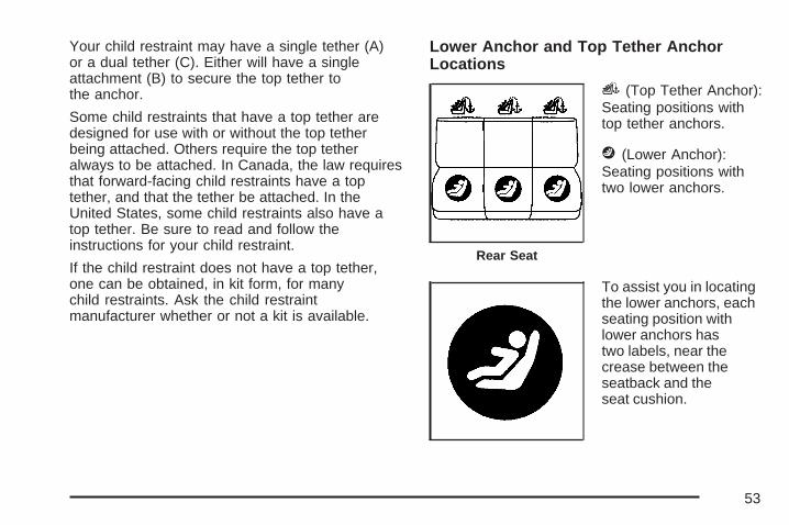
Lower Anchor and Top Tether AnchorLocations
i (Top Tether Anchor):Seating positions withtop tether anchors.
j (Lower Anchor):Seating positions withtwo lower anchors.
To assist you in locatingthe lower anchors, eachseating position withlower anchors hastwo labels, near thecrease between theseatback and theseat cushion.
Rear Seat
53

To assist you in locatingthe top tether anchors,the top tether anchorsymbol is located on thetrim cover.
The top tether anchors are located on the rearseatback filler panel. Open the trim cover toaccess the anchors. Be sure to use an anchorlocated on the same side of the vehicle asthe seating position where the child restraint willbe placed. Do not secure a child restraint in the right front
passenger’s position if a national or local lawrequires that the top tether be attached, or if theinstructions that come with the child restraintsay that the top tether must be attached. There isno place to attach the top tether in this position.
Accident statistics show that children are saferif they are restrained in the rear rather thanthe front seat. See Where to Put the Restraint onpage 49 for additional information.
54
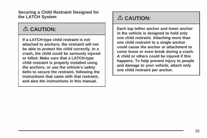
Securing a Child Restraint Designed forthe LATCH System
{CAUTION:
If a LATCH-type child restraint is notattached to anchors, the restraint will notbe able to protect the child correctly. In acrash, the child could be seriously injuredor killed. Make sure that a LATCH-typechild restraint is properly installed usingthe anchors, or use the vehicle’s safetybelts to secure the restraint, following theinstructions that came with that restraint,and also the instructions in this manual.
{CAUTION:
Each top tether anchor and lower anchorin the vehicle is designed to hold onlyone child restraint. Attaching more thanone child restraint to a single anchorcould cause the anchor or attachment tocome loose or even break during a crash.A child or others could be injured if thishappens. To help prevent injury to peopleand damage to your vehicle, attach onlyone child restraint per anchor.
55
{CAUTION:
Children can be seriously injured orstrangled if a shoulder belt is wrappedaround their neck and the safety beltcontinues to tighten. Secure any unusedsafety belts behind the child restraint sochildren cannot reach them. Pull theshoulder belt all the way out of theretractor to set the lock, if your vehicle hasone, after the child restraint has beeninstalled. Be sure to follow the instructionsof the child restraint manufacturer.
Notice: Contact between the child restraint orthe LATCH attachment parts and the vehicle’ssafety belt assembly may cause damage tothese parts. Make sure when securing unusedsafety belts behind the child restraint thatthere is no contact between the child restraintor the LATCH attachment parts and thevehicle’s safety belt assembly.
Folding an empty rear seat with the safetybelts secured may cause damage to the safetybelt or the seat. When removing the childrestraint, always remember to return the safetybelts to their normal, stowed position beforefolding the rear seat.
1. Attach and tighten the lower attachments tothe lower anchors. If the child restraint doesnot have lower attachments or the desiredseating position does not have lower anchors,secure the child restraint with the top tetherand the safety belts. Refer to your childrestraint manufacturer instructions and theinstructions in this manual.
1.1. Find the lower anchors for the desiredseating position.
1.2. Put the child restraint on the seat.1.3. Attach and tighten the lower
attachments on the child restraint to thelower anchors.
56

2. If the child restraint manufacturer recommendsthat the top tether be attached, attach andtighten the top tether to the top tether anchor,if equipped. Refer to the child restraintinstructions and the following steps:
2.1. Find the top tether anchor.2.2. Pull open the top tether anchor trim
cover to expose the anchor.2.3. Route, attach, and tighten the top tether
according to your child restraintinstructions and the followinginstructions:
If the position you areusing does not have aheadrest and youare using a singletether, route the tetherover the seatback.
If the position you areusing does not have aheadrest and youare using a dual tether,route the tether overthe seatback.
If the position you areusing has a fixedheadrest and you areusing a single tether,route the tether over thehead restraint.
57
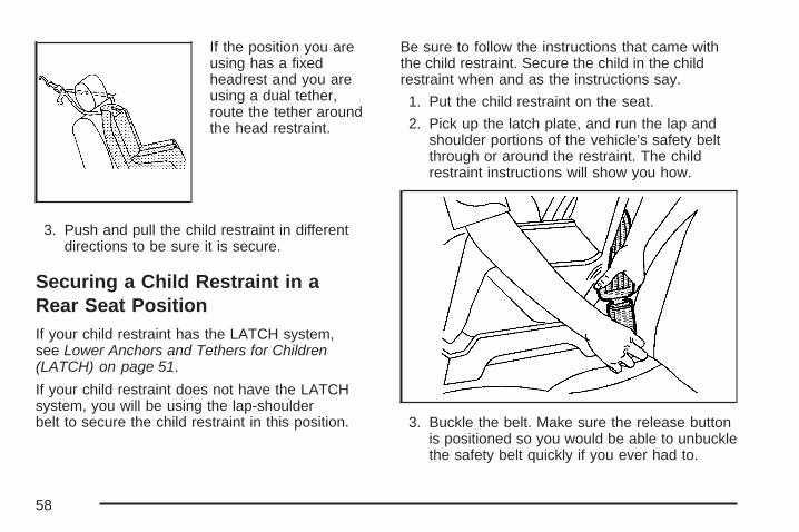
If the position you areusing has a fixedheadrest and you areusing a dual tether,route the tether aroundthe head restraint.
3. Push and pull the child restraint in differentdirections to be sure it is secure.
Securing a Child Restraint in aRear Seat PositionIf your child restraint has the LATCH system,see Lower Anchors and Tethers for Children(LATCH) on page 51.
If your child restraint does not have the LATCHsystem, you will be using the lap-shoulderbelt to secure the child restraint in this position.
Be sure to follow the instructions that came withthe child restraint. Secure the child in the childrestraint when and as the instructions say.
1. Put the child restraint on the seat.
2. Pick up the latch plate, and run the lap andshoulder portions of the vehicle’s safety beltthrough or around the restraint. The childrestraint instructions will show you how.
3. Buckle the belt. Make sure the release buttonis positioned so you would be able to unbucklethe safety belt quickly if you ever had to.
58

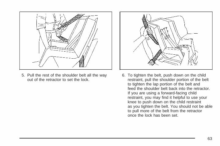
4. Pull the rest of the shoulder belt all the wayout of the retractor to set the lock.
5. To tighten the belt, push down on the childrestraint, pull the shoulder portion of the beltto tighten the lap portion of the belt, andfeed the shoulder belt back into the retractor.If you are using a forward-facing childrestraint, you may find it helpful to use yourknee to push down on the child restraintas you tighten the belt.
59
6. If your child restraint manufacturerrecommends using a top tether, attach andtighten the top tether to the top tether anchor.Refer to the instructions that came with thechild restraint and see Lower Anchorsand Tethers for Children (LATCH) on page 51.
7. Push and pull the child restraint in differentdirections to be sure it is secure.
To remove the child restraint, if the top tether isattached to the top tether anchor, disconnectit. Unbuckle the vehicle’s safety belt and let it goback all the way. The safety belt will movefreely again and be ready to work for an adult orlarger child passenger.
Securing a Child Restraint in theRight Front Seat PositionYour vehicle has a right front passenger’s airbag.A rear seat is a safer place to secure aforward-facing child restraint. See Where to Putthe Restraint on page 49.
In addition, your vehicle has a passenger sensingsystem. The passenger sensing system isdesigned to turn off the right front passenger’sfrontal airbag when an infant in a rear-facinginfant seat or a small child in a forward-facingchild restraint or booster seat is detected.See Passenger Sensing System on page 74 andPassenger Airbag Status Indicator on page 177for more information on this including importantsafety information.
A label on your sun visor says, “Never put arear-facing child seat in the front.” This is becausethe risk to the rear-facing child is so great, if theairbag deploys.
60

{CAUTION:
A child in a rear-facing child restraint canbe seriously injured or killed if the rightfront passenger’s airbag inflates. This isbecause the back of the rear-facing childrestraint would be very close to theinflating airbag.Even though the passenger sensingsystem is designed to turn off the rightfront passenger’s frontal airbag if thesystem detects a rear-facing child restraint,no system is fail-safe, and no one canguarantee that an airbag will not deployunder some unusual circumstance, eventhough it is turned off. We recommend thatrear-facing child restraints be secured inthe rear seat, even if the airbag is off.If you need to secure a forward-facing childrestraint in the right front seat, alwaysmove the front passenger seat as far backas it will go. It is better to secure the childrestraint in a rear seat.
If you need to secure a forward-facing childrestraint in the right front seat position, move theseat as far back as it will go before securingthe forward-facing child restraint. See ManualPassenger Seat on page 8.
If your child restraint has the LATCH system,see Lower Anchors and Tethers for Children(LATCH) on page 51.
There is no top tether anchor at the right frontseating position. Do not secure a child seat in thisposition if a national or local law requires thatthe top tether be anchored or if the instructionsthat come with the child restraint say that the toptether must be anchored. See Lower Anchorsand Tethers for Children (LATCH) on page 51if the child restraint has a top tether.
61

You will be using the lap-shoulder belt to securethe child restraint in this position. Be sure to followthe instructions that came with the child restraint.Secure the child in the child restraint when and asthe instructions say.1. Your vehicle has a right front passenger’s
frontal airbag. See Passenger SensingSystem on page 74. We recommend thatrear-facing child restraints be secured in a rearseat, even if the airbag is off. If your childrestraint is forward-facing, move the seat asfar back as it will go before securing thechild restraint in this seat. See ManualPassenger Seat on page 8.When the passenger sensing system hasturned off the right front passenger’s frontalairbag, the off indicator in the passengerairbag status indicator should light and stay litwhen you turn the ignition to RUN or START.See Passenger Airbag Status Indicator onpage 177.
2. Put the child restraint on the seat.
3. Pick up the latch plate, and run the lap andshoulder portions of the vehicle’s safety beltthrough or around the restraint. The childrestraint instructions will show you how.
4. Buckle the belt. Make sure the release buttonis positioned so you would be able to unbucklethe safety belt quickly if you ever had to.
62
5. Pull the rest of the shoulder belt all the wayout of the retractor to set the lock.
6. To tighten the belt, push down on the childrestraint, pull the shoulder portion of the beltto tighten the lap portion of the belt andfeed the shoulder belt back into the retractor.If you are using a forward-facing childrestraint, you may find it helpful to use yourknee to push down on the child restraintas you tighten the belt. You should not be ableto pull more of the belt from the retractoronce the lock has been set.
63
7. Push and pull the child restraint in differentdirections to be sure it is secure.
8. If the airbag is off, the off indicator on theinstrument panel will be lit and stay litwhen the key is turned to RUN or START.
If a child restraint has been installed and the onindicator is lit, turn the vehicle off. Removethe child restraint from the vehicle and reinstall thechild restraint.
If, after reinstalling the child restraint and restartingthe vehicle, the on indicator is still lit, check tomake sure that the vehicle’s seatback is notpressing the child restraint into the seat cushion.If this happens, slightly recline the vehicle’sseatback and adjust the seat cushion if possible.Also make sure the child restraint is not trappedunder the vehicle head restraint. If this happens,adjust the head restraint.
If the on indicator is still lit, secure the child in thechild restraint in a rear seat position in thevehicle and check with your dealer.
To remove the child restraint, just unbuckle thevehicle’s safety belt and let it go back all the way.The safety belt will move freely again and be readyto work for an adult or larger child passenger.
Airbag SystemYour vehicle has a frontal airbag for the driver anda frontal airbag for the right front passenger.Your vehicle may also have roof-mounted sideimpact airbags. Roof-mounted side impact airbagsare available for the driver and the passengerseated directly behind the driver and for the rightfront passenger and the passenger seateddirectly behind that passenger.
If your vehicle has roof-mounted side impactairbags, the word AIRBAG will appear onthe airbag covering on the headliner near thedriver’s and right front passenger’s window.
Airbags are designed to supplement the protectionprovided by safety belts. Even though today’sairbags are also designed to help reduce the riskof injury from the force of an inflating bag, allairbags must inflate very quickly to do their job.
64
Here are the most important things to know aboutthe airbag system:
{CAUTION:
You can be severely injured or killed in acrash if you are not wearing your safetybelt — even if you have airbags. Wearingyour safety belt during a crash helpsreduce your chance of hitting thingsinside the vehicle or being ejected from it.Airbags are “supplemental restraints” tothe safety belts. All airbags are designedto work with safety belts, but do notreplace them.
{CAUTION:
Frontal airbags for the driver and rightfront passenger are designed to deploy inmoderate to severe frontal and nearfrontal crashes. They are not designed toinflate in rollover, rear crashes, or in manyside crashes. And, for some unrestrainedoccupants, frontal airbags may provideless protection in frontal crashes thanmore forceful airbags have provided inthe past.
Roof-mounted side impact airbagsare designed to inflate in moderate tosevere crashes where something hits theside of your vehicle. They are notdesigned to inflate in frontal, in rollover,or in rear crashes.
Everyone in your vehicle should wear asafety belt properly — whether or notthere is an airbag for that person.
65
{CAUTION:
Both frontal and side impact airbagsinflate with great force, faster than theblink of an eye. If you are too close to aninflating airbag, as you would be if youwere leaning forward, it could seriouslyinjure you. Safety belts help keep you inposition for airbag inflation before andduring a crash. Always wear your safetybelt even with frontal airbags. The drivershould sit as far back as possible whilestill maintaining control of the vehicle.Occupants should not lean on or sleepagainst the door.
{CAUTION:
Anyone who is up against, or very closeto, any airbag when it inflates can beseriously injured or killed. Airbags pluslap-shoulder belts offer the bestprotection for adults, but not for youngchildren and infants. Neither the vehicle’ssafety belt system nor its airbag system isdesigned for them. Young children andinfants need the protection that a childrestraint system can provide. Alwayssecure children properly in your vehicle.To read how, see Older Children onpage 39 or Infants and Young Childrenon page 42.
66

There is an airbagreadiness light on theinstrument panel cluster,which shows theairbag symbol.
The system checks the airbag electrical system formalfunctions. The light tells you if there is anelectrical problem. See Airbag Readiness Light onpage 176 for more information.
Where Are the Airbags?
The driver’s frontal airbag is in the middle of thesteering wheel.
67
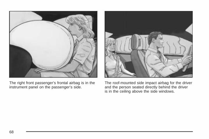
The right front passenger’s frontal airbag is in theinstrument panel on the passenger’s side.
The roof-mounted side impact airbag for the driverand the person seated directly behind the driveris in the ceiling above the side windows.
68

The roof-mounted side impact airbag for the rightfront passenger and the person seated directlybehind that passenger is in the ceiling above theside windows.
{CAUTION:
If something is between an occupantand an airbag, the bag might not inflateproperly or it might force the object intothat person causing severe injury or evendeath. The path of an inflating airbag mustbe kept clear. Do not put anything betweenan occupant and an airbag, and do notattach or put anything on the steeringwheel hub or on or near any other airbagcovering. And, if your vehicle hasroof-mounted side impact airbags, neversecure anything to the roof of your vehicleby routing the rope or tie down through anydoor or window opening. If you do, the pathof an inflating side impact airbag will beblocked. The path of an inflating airbagmust be kept clear.
69
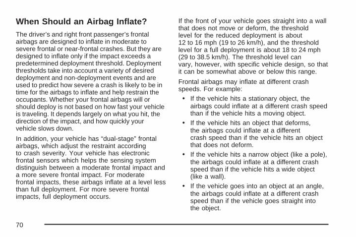
When Should an Airbag Inflate?The driver’s and right front passenger’s frontalairbags are designed to inflate in moderate tosevere frontal or near-frontal crashes. But they aredesigned to inflate only if the impact exceeds apredetermined deployment threshold. Deploymentthresholds take into account a variety of desireddeployment and non-deployment events and areused to predict how severe a crash is likely to be intime for the airbags to inflate and help restrain theoccupants. Whether your frontal airbags will orshould deploy is not based on how fast your vehicleis traveling. It depends largely on what you hit, thedirection of the impact, and how quickly yourvehicle slows down.
In addition, your vehicle has “dual-stage” frontalairbags, which adjust the restraint accordingto crash severity. Your vehicle has electronicfrontal sensors which helps the sensing systemdistinguish between a moderate frontal impact anda more severe frontal impact. For moderatefrontal impacts, these airbags inflate at a level lessthan full deployment. For more severe frontalimpacts, full deployment occurs.
If the front of your vehicle goes straight into a wallthat does not move or deform, the thresholdlevel for the reduced deployment is about12 to 16 mph (19 to 26 km/h), and the thresholdlevel for a full deployment is about 18 to 24 mph(29 to 38.5 km/h). The threshold level canvary, however, with specific vehicle design, so thatit can be somewhat above or below this range.
Frontal airbags may inflate at different crashspeeds. For example:
• If the vehicle hits a stationary object, theairbags could inflate at a different crash speedthan if the vehicle hits a moving object.
• If the vehicle hits an object that deforms,the airbags could inflate at a differentcrash speed than if the vehicle hits an objectthat does not deform.
• If the vehicle hits a narrow object (like a pole),the airbags could inflate at a different crashspeed than if the vehicle hits a wide object(like a wall).
• If the vehicle goes into an object at an angle,the airbags could inflate at a different crashspeed than if the vehicle goes straight intothe object.
70
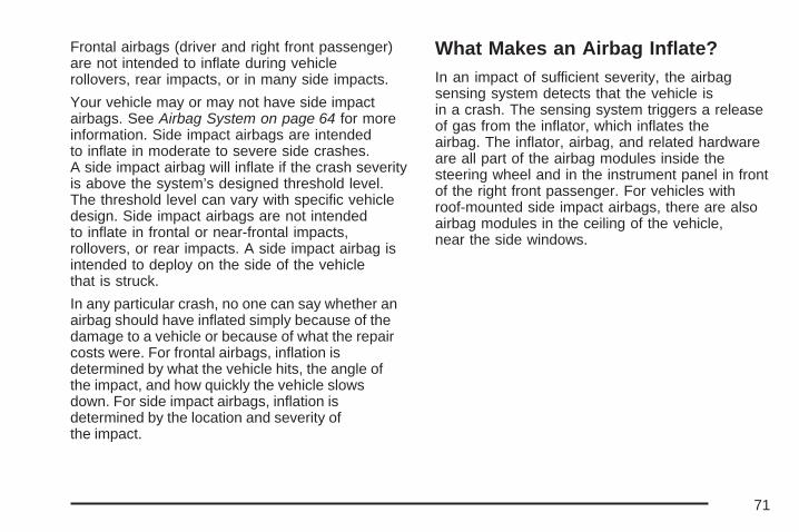
Frontal airbags (driver and right front passenger)are not intended to inflate during vehiclerollovers, rear impacts, or in many side impacts.
Your vehicle may or may not have side impactairbags. See Airbag System on page 64 for moreinformation. Side impact airbags are intendedto inflate in moderate to severe side crashes.A side impact airbag will inflate if the crash severityis above the system’s designed threshold level.The threshold level can vary with specific vehicledesign. Side impact airbags are not intendedto inflate in frontal or near-frontal impacts,rollovers, or rear impacts. A side impact airbag isintended to deploy on the side of the vehiclethat is struck.
In any particular crash, no one can say whether anairbag should have inflated simply because of thedamage to a vehicle or because of what the repaircosts were. For frontal airbags, inflation isdetermined by what the vehicle hits, the angle ofthe impact, and how quickly the vehicle slowsdown. For side impact airbags, inflation isdetermined by the location and severity ofthe impact.
What Makes an Airbag Inflate?In an impact of sufficient severity, the airbagsensing system detects that the vehicle isin a crash. The sensing system triggers a releaseof gas from the inflator, which inflates theairbag. The inflator, airbag, and related hardwareare all part of the airbag modules inside thesteering wheel and in the instrument panel in frontof the right front passenger. For vehicles withroof-mounted side impact airbags, there are alsoairbag modules in the ceiling of the vehicle,near the side windows.
71

How Does an Airbag Restrain?In moderate to severe frontal or near frontalcollisions, even belted occupants can contact thesteering wheel or the instrument panel. Inmoderate to severe side collisions, even beltedoccupants can contact the inside of the vehicle.Airbags supplement the protection providedby safety belts. Airbags distribute the force of theimpact more evenly over the occupant’s upperbody, stopping the occupant more gradually. Butthe frontal airbags would not help you in manytypes of collisions, including rollovers, rearimpacts, and many side impacts, primarily becausean occupant’s motion is not toward the airbag.Side impact airbags would not help you in manytypes of collisions, including many frontal ornear frontal collisions, rollovers, and rear impacts.
Airbags should never be regarded as anythingmore than a supplement to safety belts, and thenonly in moderate to severe frontal or near-frontalcollisions for the driver’s and right frontpassenger’s frontal airbags, and only in moderateto severe side collisions for vehicles with sideimpact airbags.
What Will You See After anAirbag Inflates?After a frontal airbag inflates, it quickly deflates,so quickly that some people may not even realizethe airbag inflated. Roof-mounted side impactairbags may still be at least partially inflatedminutes after the vehicle comes to rest. Somecomponents of the airbag module — the steeringwheel hub for the driver’s airbag, the instrumentpanel for the right front passenger’s airbag, or thegarnish trim and ceiling of your vehicle nearthe side windows for vehicles with roof–mountedside impact airbags — may be hot for a short time.The parts of the airbag that come into contactwith you may be warm, but not too hot to touch.There may be some smoke and dust coming fromthe vents in the deflated airbags. Airbag inflationdoes not prevent the driver from seeing out of thewindshield or being able to steer the vehicle,nor does it prevent people from leaving the vehicle.
72
{CAUTION:
When an airbag inflates, there may bedust in the air. This dust could causebreathing problems for people with ahistory of asthma or other breathingtrouble. To avoid this, everyone in thevehicle should get out as soon as it issafe to do so. If you have breathingproblems but cannot get out of the vehicleafter an airbag inflates, then get fresh airby opening a window or a door. If youexperience breathing problems followingan airbag deployment, you should seekmedical attention.
Your vehicle has a feature that may automaticallyunlock the doors, turn the interior lamps on, andturn on the hazard warning flashers when theairbags inflate. You can lock the doors again, turnthe interior lamps off, and turn the hazard warningflashers off by using the controls for those features.
In many crashes severe enough to inflate an airbag,windshields are broken by vehicle deformation.Additional windshield breakage may also occurfrom the right front passenger airbag.
• Airbags are designed to inflate only once.After an airbag inflates, you will need some newparts for the airbag system. If you do not getthem, the airbag system will not be there to helpprotect you in another crash. A new system willinclude airbag modules and possibly otherparts. The service manual for your vehiclecovers the need to replace other parts.
• Your vehicle has a crash sensing anddiagnostic module which records informationafter a crash. See Vehicle Data Recording andPrivacy on page 515 and Event DataRecorders on page 516.
• Let only qualified technicians work on theairbag system. Improper service can meanthat your airbag system will not work properly.See your dealer/retailer for service.
73

Passenger Sensing SystemYour vehicle has a passenger sensing system.The passenger airbag status indicator on theinstrument panel will be visible when you turn yourignition key to RUN or START.
The words ON and OFF, or the symbol for onand off, will be visible during the system check.If you use remote start to start your vehicle from adistance, if your vehicle has this feature, youmay not see the system check. When the systemcheck is complete, either the word ON or theword OFF, or the symbol for on or the symbol foroff, will be visible. See Passenger Airbag StatusIndicator on page 177.
The passenger sensing system will turn off theright front passenger’s frontal airbag under certainconditions. The driver’s airbags are not part ofthe passenger sensing system.
The passenger sensing system works withsensors that are part of the right front passenger’sseat. The sensors are designed to detect thepresence of a properly-seated occupant anddetermine if the passenger’s frontal airbag shouldbe enabled (may inflate) or not.
Accident statistics show that children are safer ifthey are restrained in the rear rather than the frontseat. We recommend that child restraints besecured in a rear seat, including an infant riding ina rear-facing infant seat, a child riding in aforward-facing child seat, and an older child ridingin a booster seat.
Your vehicle has a rear seat that will accommodatea rear-facing child restraint. A label on your sunvisor says, “Never put a rear-facing child seatin the front.” This is because the risk to therear-facing child is so great, if the airbag deploys.
United States Canada
74
{CAUTION:
A child in a rear-facing child restraint canbe seriously injured or killed if the rightfront passenger’s airbag inflates. This isbecause the back of the rear-facing childrestraint would be very close to theinflating airbag.Even though the passenger sensingsystem is designed to turn off thepassenger’s frontal airbag if the systemdetects a rear-facing child restraint, nosystem is fail-safe, and no one canguarantee that an airbag will not deployunder some unusual circumstance, eventhough it is turned off. We recommendthat rear-facing child restraints be securedin the rear seat, even if the airbag is off.If you need to secure a forward-facingchild restraint in the right front seat,always move the front passenger seat asfar back as it will go. It is better to securethe child restraint in a rear seat.
The passenger sensing system is designed to turnoff the right front passenger’s frontal airbag if:
• The right front passenger seat is unoccupied.
• The system determines that an infant ispresent in a rear-facing infant seat.
• The system determines that a small child ispresent in a forward-facing child restraint.
• The system determines that a small child ispresent in a booster seat.
• A right front passenger takes his/her weight offof the seat for a period of time.
• The right front passenger seat is occupied bya smaller person, such as a child who hasoutgrown child restraints.
• Or, if there is a critical problem with the airbagsystem or the passenger sensing system.
When the passenger sensing system has turnedoff the right front passenger’s frontal airbag, the offindicator on the instrument panel will light andstay lit to remind you that the airbag is off.
75
If a child restraint has been installed and the onindicator is lit, turn the vehicle off. Remove thechild restraint from the vehicle and reinstallthe child restraint following the child restraintmanufacturer’s directions and refer to Securing aChild Restraint in the Right Front Seat Positionon page 60.
If, after reinstalling the child restraint and restartingthe vehicle, the on indicator is still lit, check tomake sure that the vehicle’s seatback is notpressing the child restraint into the seat cushion.If this happens, slightly recline the vehicle’sseatback and adjust the seat cushion if possible.Also make sure the child restraint is not trappedunder the vehicle head restraint. If this happens,adjust the head restraint.
If the on indicator is still lit, secure the child in thechild restraint in a rear seat position in thevehicle and check with your dealer.
The passenger sensing system is designed toenable (may inflate) the right front passenger’sfrontal airbag anytime the system sensesthat a person of adult size is sitting properly in theright front passenger’s seat. When the passenger
sensing system has allowed the airbag to beenabled, the on indicator will light and stay lit toremind you that the airbag is active.
For some children who have outgrown childrestraints and for very small adults, the passengersensing system may or may not turn off the rightfront passenger’s frontal airbag, depending uponthe person’s seating posture and body build.Everyone in your vehicle who has outgrownchild restraints should wear a safety beltproperly — whether or not there is an airbagfor that person.
If a person of adult-size is sitting in the rightfront passenger’s seat, but the off indicator is lit,it could be because that person is not sittingproperly in the seat. If this happens, turnthe vehicle off and ask the person to place theseatback in the fully upright position, then situpright in the seat, centered on the seat cushion,with the person’s legs comfortably extended.Restart the vehicle and have the person remain inthis position for about two minutes. This willallow the system to detect that person and thenenable the passenger’s airbag.
76
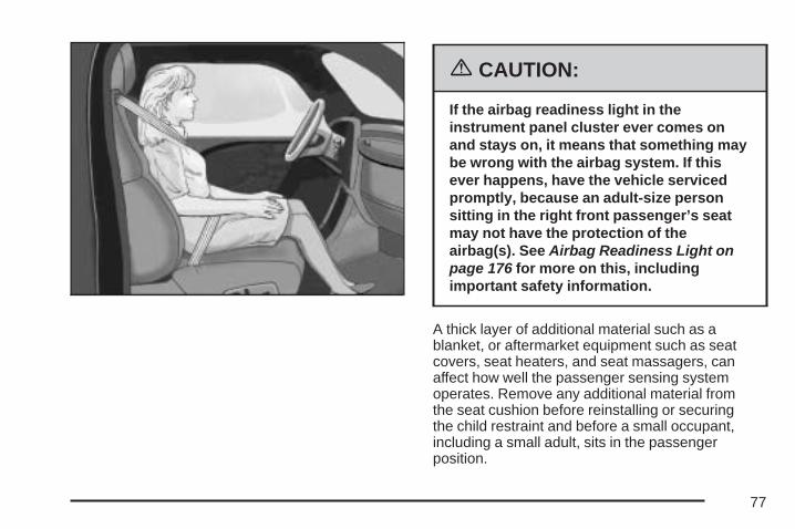
{CAUTION:
If the airbag readiness light in theinstrument panel cluster ever comes onand stays on, it means that something maybe wrong with the airbag system. If thisever happens, have the vehicle servicedpromptly, because an adult-size personsitting in the right front passenger’s seatmay not have the protection of theairbag(s). See Airbag Readiness Light onpage 176 for more on this, includingimportant safety information.
A thick layer of additional material such as ablanket, or aftermarket equipment such as seatcovers, seat heaters, and seat massagers, canaffect how well the passenger sensing systemoperates. Remove any additional material fromthe seat cushion before reinstalling or securingthe child restraint and before a small occupant,including a small adult, sits in the passengerposition.
77

You may want to consider not using seat covers orother aftermarket equipment if your vehicle has thepassenger sensing system. See Adding Equipmentto Your Airbag-Equipped Vehicle on page 79 formore information about modifications that can affecthow the system operates.
The passenger sensing system may suppress theairbag deployment when liquid is soaked intothe seat. If this happens, the off indicator in thepassenger airbag status indicator and theairbag readiness light on the instrument panel willbe lit. The system should resume normaloperation after the seat is allowed to dry. If thesystem operates incorrectly after the seathas dried, have your dealer check the system.
{CAUTION:
Stowing of articles under the passenger’sseat or between the passenger’s seatcushion and seatback may interfere withthe proper operation of the passengersensing system.
Servicing Your Airbag-EquippedVehicleAirbags affect how your vehicle should beserviced. There are parts of the airbag system inseveral places around your vehicle. You donot want the system to inflate while someone isworking on your vehicle. Your dealer/retailerand the service manual have information aboutservicing your vehicle and the airbag system.To purchase a service manual, see ServicePublications Ordering Information on page 514.
78

{CAUTION:
For up to 10 seconds, after the ignition isturned off and the battery is disconnected,an airbag can still inflate during improperservice. You can be injured if you areclose to an airbag when it inflates. Avoidyellow connectors. They are probably partof the airbag system. Be sure to followproper service procedures, and make surethe person performing work for you isqualified to do so.
The airbag system does not need regularmaintenance.
Adding Equipment to YourAirbag-Equipped Vehicle
Q: Is there anything I might add to the frontor sides of the vehicle that could keep theairbags from working properly?
A: Yes. If you add things that change yourvehicle’s frame, bumper system, height,front end or side sheet metal, they may keepthe airbag system from working properly.Also, the airbag system may not work properlyif you relocate any of the airbag sensors.If you have any questions about this,you should contact Customer Assistancebefore you modify your vehicle. The phonenumbers and addresses for CustomerAssistance are in Step Two of the CustomerSatisfaction Procedure in this manual.See Customer Satisfaction Procedure onpage 498.
79
Q: Because I have a disability, I have to getmy vehicle modified. How can I find outwhether this will affect my airbag system?
A: Changing or moving any parts of thefront seats, safety belts, the airbag sensingand diagnostic module, steering wheel,instrument panel, ceiling headliner, ceiling andpillar garnish trim, roof-mounted airbagmodules, or airbag wiring can affect theoperation of the airbag system. If you havequestions, call Customer Assistance. Thephone numbers and addresses for CustomerAssistance are in Step Two of the CustomerSatisfaction Procedure in this manual.See Customer Satisfaction Procedure onpage 498.
Restraint System Check
Checking the Restraint SystemsNow and then, make sure the safety belt reminderlight and all your belts, buckles, latch plates,retractors and anchorages are working properly.Look for any other loose or damaged safetybelt system parts. If you see anything that mightkeep a safety belt system from doing its job, haveit repaired. See Care of Safety Belts on page 460for more information.
Torn or frayed safety belts may not protect you ina crash. They can rip apart under impact forces.If a belt is torn or frayed, get a new one right away.
80
Also look for any opened or broken airbag covers,and have them repaired or replaced. The airbagsystem does not need regular maintenance.
Notice: If you damage the covering for thedriver’s or the right front passenger’s airbag,or the side impact airbag covering (if equipped)on the ceiling near the side windows, theairbag may not work properly. You may haveto replace the airbag module in the steeringwheel, both the airbag module and theinstrument panel for the right front passenger’sairbag, or side impact airbag module andceiling covering for roof-mounted side impactairbags (if equipped.) Do not open or breakthe airbag coverings.
Replacing Restraint System PartsAfter a Crash
{CAUTION:
A crash can damage the restraint systemsin your vehicle. A damaged restraintsystem may not properly protect theperson using it, resulting in serious injuryor even death in a crash. To help make sureyour restraint systems are workingproperly after a crash, have them inspectedand any necessary replacements made assoon as possible.
If you have had a crash, do you need new belts orLATCH system parts?
After a very minor collision, nothing may benecessary. But if the belts were stretched, as theywould be if worn during a more severe crash,then you need new parts.
81
If the LATCH system was being used during amore severe crash, you may need new LATCHsystem parts.
If belts are cut or damaged, replace them.Collision damage also may mean you will need tohave LATCH system, safety belt or seat partsrepaired or replaced. New parts and repairs maybe necessary even if the belt or LATCH systemwas not being used at the time of the collision.
If an airbag inflates, you will need to replace airbagsystem parts. See the part on the airbag systemearlier in this section.
If the frontal airbags inflate, you will also need toreplace the driver’s and right front passenger’ssafety belt buckle assembly. Be sure to doso. Then the new buckle assembly will be there tohelp protect you in a collision.
After a crash you may need to replace the driverand front passenger’s safety belt buckleassemblies, even if the frontal airbags have notdeployed. The driver and front passenger’s safetybelt buckle assemblies contain the safety beltpretensioners. Have your safety belt pretensionerschecked if your vehicle has been in a collision,or if your airbag readiness light stays on afteryou start your vehicle or while you are driving.See Airbag Readiness Light on page 176.
82
Keys .............................................................. 84Remote Keyless Entry (RKE) System .......... 86Remote Keyless Entry (RKE)
System Operation .................................... 87Doors and Locks .......................................... 93
Door Locks ................................................. 93Power Door Locks ....................................... 94Delayed Locking .......................................... 95Programmable Automatic Door Locks .......... 95Rear Door Security Locks ........................... 96Lockout Protection ....................................... 97Trunk .......................................................... 97
Windows ....................................................... 99Power Windows ........................................ 100Sun Visors ................................................ 102
Theft-Deterrent Systems ............................. 102Content Theft-Deterrent ............................. 102PASS-Key® III ........................................... 104PASS-Key® III Operation ........................... 105
Starting and Operating Your Vehicle ......... 107New Vehicle Break-In ................................ 107Ignition Positions ....................................... 108Retained Accessory Power (RAP) ............. 109
Starting the Engine .................................... 110Engine Coolant Heater .............................. 111Active Fuel Management™ ........................ 112Automatic Transaxle Operation .................. 113Parking Brake ........................................... 118Shifting Into Park (P) ................................. 119Shifting Out of Park (P) ............................. 121Parking Over Things That Burn ................. 121Engine Exhaust ......................................... 122Running the Engine While Parked ............. 123
Mirrors ......................................................... 124Manual Rearview Mirror with OnStar® ....... 124Outside Power Mirrors ............................... 124Outside Convex Mirror ............................... 125
OnStar® System .......................................... 125Storage Areas ............................................. 129
Glove Box ................................................. 129Cupholder(s) .............................................. 129Sunglasses Storage Compartment ............. 130Center Console Storage Area .................... 130Convenience Net ....................................... 130
Sunroof ....................................................... 131
Section 2 Features and Controls
83
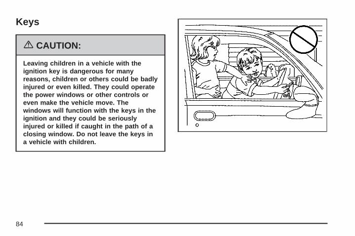
Keys
{CAUTION:
Leaving children in a vehicle with theignition key is dangerous for manyreasons, children or others could be badlyinjured or even killed. They could operatethe power windows or other controls oreven make the vehicle move. Thewindows will function with the keys in theignition and they could be seriouslyinjured or killed if caught in the path of aclosing window. Do not leave the keys ina vehicle with children.
84
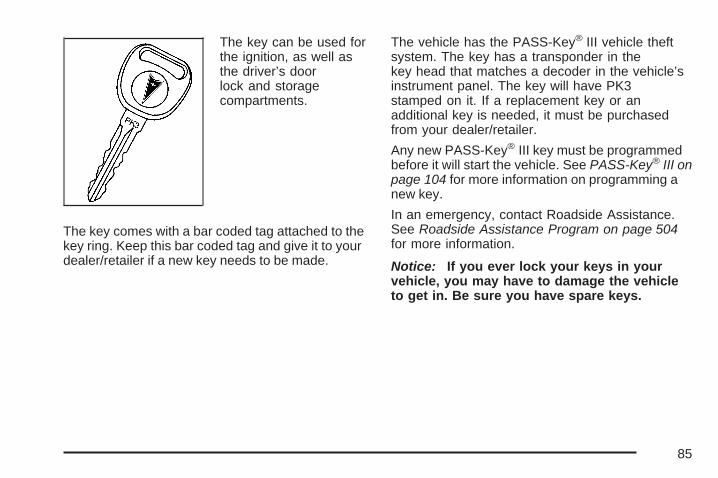
The key can be used forthe ignition, as well asthe driver’s doorlock and storagecompartments.
The key comes with a bar coded tag attached to thekey ring. Keep this bar coded tag and give it to yourdealer/retailer if a new key needs to be made.
The vehicle has the PASS-Key® III vehicle theftsystem. The key has a transponder in thekey head that matches a decoder in the vehicle’sinstrument panel. The key will have PK3stamped on it. If a replacement key or anadditional key is needed, it must be purchasedfrom your dealer/retailer.
Any new PASS-Key® III key must be programmedbefore it will start the vehicle. See PASS-Key® III onpage 104 for more information on programming anew key.
In an emergency, contact Roadside Assistance.See Roadside Assistance Program on page 504for more information.
Notice: If you ever lock your keys in yourvehicle, you may have to damage the vehicleto get in. Be sure you have spare keys.
85
Remote Keyless Entry (RKE)SystemYour Remote Keyless Entry (RKE) systemoperates on a radio frequency subject to FederalCommunications Commission (FCC) Rulesand with Industry Canada.
This device complies with Part 15 of the FCCRules. Operation is subject to the followingtwo conditions:
1. This device may not cause interference.
2. This device must accept any interferencereceived, including interference that maycause undesired operation of the device.
This device complies with RSS-210 of IndustryCanada. Operation is subject to the followingtwo conditions:
1. This device may not cause interference.
2. This device must accept any interferencereceived, including interference that maycause undesired operation of the device.
Changes or modifications to this system by otherthan an authorized service facility could voidauthorization to use this equipment.
At times you may notice a decrease in operatingrange. This is normal for any RKE system. Ifthe transmitter does not work or if you have tostand closer to your vehicle for the transmitter towork, try this:
• Check the distance. You may be too far fromyour vehicle. You may need to stand closerduring rainy or snowy weather.
• Check the location. Other vehicles or objectsmay be blocking the signal. Take a few stepsto the left or right, hold the transmitterhigher, and try again.
• Check to determine if battery replacement isnecessary. See “Battery Replacement”under Remote Keyless Entry (RKE) SystemOperation on page 87.
• If you are still having trouble, see yourdealer/retailer or a qualified technicianfor service.
86
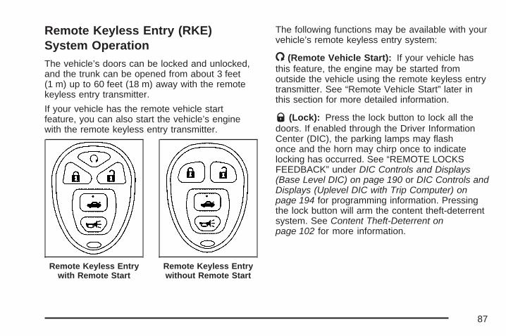
Remote Keyless Entry (RKE)System OperationThe vehicle’s doors can be locked and unlocked,and the trunk can be opened from about 3 feet(1 m) up to 60 feet (18 m) away with the remotekeyless entry transmitter.
If your vehicle has the remote vehicle startfeature, you can also start the vehicle’s enginewith the remote keyless entry transmitter.
The following functions may be available with yourvehicle’s remote keyless entry system:
/ (Remote Vehicle Start): If your vehicle hasthis feature, the engine may be started fromoutside the vehicle using the remote keyless entrytransmitter. See “Remote Vehicle Start” later inthis section for more detailed information.
Q (Lock): Press the lock button to lock all thedoors. If enabled through the Driver InformationCenter (DIC), the parking lamps may flashonce and the horn may chirp once to indicatelocking has occurred. See “REMOTE LOCKSFEEDBACK” under DIC Controls and Displays(Base Level DIC) on page 190 or DIC Controls andDisplays (Uplevel DIC with Trip Computer) onpage 194 for programming information. Pressingthe lock button will arm the content theft-deterrentsystem. See Content Theft-Deterrent onpage 102 for more information.
Remote Keyless Entrywith Remote Start
Remote Keyless Entrywithout Remote Start
87

" (Unlock): Press the unlock button one time tounlock the driver’s door. Press the unlockbutton again within five seconds to unlock theother doors. The interior lamps will come on andstay on for 20 seconds or until the ignition is turnedon. If enabled through the DIC, the parkinglamps may flash once and the horn may chirponce to indicate unlocking has occurred. See“REMOTE LOCKS FEEDBACK” under DICControls and Displays (Base Level DIC) onpage 190 or DIC Controls and Displays (UplevelDIC with Trip Computer) on page 194. Pressingthe unlock button on the remote keyless entrytransmitter will disarm the content theft-deterrentsystem. See Content Theft-Deterrent on page 102for more details.
V (Trunk Release): Press and hold this buttonfor about one second to release the trunk lid.The transaxle must be in PARK (P) for this featureto operate.
L (Panic Alarm): Press this button to activatethe alarm. The ignition must be in OFF forthe remote alarm to work. When the remote alarmbutton is pressed the headlamps will flash andthe horn will sound repeatedly for two minutes. Thealarm will turn off when the ignition is moved toRUN or the remote alarm button is pressed again.
Matching Transmitter(s) toYour VehicleEach remote keyless entry transmitter is coded toprevent another transmitter from unlocking yourvehicle. If a transmitter is lost or stolen, areplacement can be purchased through yourGM dealer. Remember to bring any additionaltransmitters with you when you go to your dealer.When the dealer matches the replacementtransmitter to your vehicle, any remainingtransmitters must also be matched. Once yourdealer has coded the new transmitter, thelost transmitter cannot unlock your vehicle. Thevehicle can have a maximum of four transmittersmatched to it.
88

Battery ReplacementUnder normal use, the battery in the remotekeyless entry transmitter should last aboutfour years.
If the battery is weak the transmitter will not workwithin its normal range. It is probably time tochange the battery if you have to be very close tothe vehicle before the transmitter works.
The KEY FOB BATTERY LOW message, in thevehicle’s DIC, will display, if the remote keylessentry transmitter battery is low.
Notice: When replacing the battery, use carenot to touch any of the circuitry. Staticfrom your body transferred to these surfacesmay damage the transmitter.
To replace the battery in the remote keyless entrytransmitter, do the following:
1. Insert a flat object with a thin edge into thenotch, located below the panic alarm button,and separate the bottom half from the tophalf of the transmitter.
2. Remove the old battery and replace it with thenew one. Make sure the positive side (+) ofthe battery faces up. Use one three-volt,CR2032 battery, or equivalent type.
89

3. Put the two halves back together. Make surethe cover is on tight so water will not getinside the transmitter.
4. Test the operation of the transmitter withthe vehicle.
Remote Vehicle StartYour vehicle may have a remote start feature.This feature allows you to start the enginefrom outside the vehicle. It may also start thevehicle’s heating or air conditioning systems andrear window defogger. When the remote startsystem is active, the climate control system willheat or cool the inside of the vehicle based on theoutside temperature. The rear window defoggerwill be turned on by the climate control systemwhen it is heating the inside of the vehicle. Normaloperation of the system will return after the keyis turned to RUN.
Laws in some communities may restrict the use ofremote starters. For example, some laws mayrequire a person using remote start to havethe vehicle in view when doing so. Check localregulations for any requirements on remote startingof vehicles.
Do not use the remote start feature if your vehicleis low on fuel. Your vehicle may run out of fuel.
The remote start feature provides two separatestarts per ignition cycle, each with 10 minutes ofengine running time.
After your vehicle’s engine has been startedtwo times using the remote start button, thevehicle’s ignition switch must be turned to RUNand then back to OFF using the key beforethe remote start procedure can be used again.See Ignition Positions on page 108 for informationregarding the ignition positions on your vehicle.
Your remote keyless entry transmitter withthe remote start button provides an increasedrange of operation. You can start your vehicle fromabout 492 feet (150 m) away. However, therange may be less while the vehicle is running,and as a result you may need to be closer to yourvehicle to turn it off than you were to turn it on.
There are other conditions which can affectthe performance of the transmitter, see RemoteKeyless Entry (RKE) System on page 86 foradditional information.
90
/ (Remote Start): If your vehicle has the remotevehicle start feature, the keyless entry transmitterwill have a button with this symbol on it.
To start the vehicle using the remote start feature,do the following:
1. Aim the transmitter at the vehicle.
2. Press and release the transmitter’s lock button,then immediately press and hold thetransmitter’s remote start button for 4 secondsor until the vehicle’s turn signal lamps flash.The vehicle’s doors will be locked.When the vehicle starts, the parking lamps willturn on and remain on while the engine isrunning, and the DIC will display REMOTESTART ACTIVE PRESS HAZARD SWITCHTO CANCEL.
3. If it is the first remote start since the vehiclehas been driven, repeat these steps, whilethe engine is still running, to extend the enginerunning time by 10 minutes. Remote startcan be extended one time.
After entering the vehicle during a remote start,insert and turn the key to RUN to drive the vehicle.
The engine will shut off automatically after10 minutes, unless a time extension has beendone or the vehicle’s key is inserted into theignition switch and turned to RUN.
To manually shut off a remote start, do any of thefollowing. The parking lamps will turn off.
• Aim the remote keyless entry transmitter at thevehicle, and press the remote start button.
• Turn on the hazard warning flashers.
• Turn the ignition switch to RUN and thento OFF.
Your vehicle’s engine can be started two timesusing the transmitter’s remote start feature.
If the remote start procedure is used again beforethe first 10 minute time frame has ended, thefirst 10 minutes will immediately expire andthe second 10 minute time frame will start.
91
The remote vehicle start feature will not operate ifany of the following occur:
• The remote start system is disabled throughthe DIC.
• The vehicle’s key is in the ignition.
• A door on the vehicle is open.
• The vehicle’s hood is open.
• The hazard warning flashers are on.
• There is an emission control systemmalfunction.
• The engine coolant temperature is too high.
• The oil pressure is low.
• Two remote vehicle starts have already beenprovided for that ignition cycle.
If a remote start is attempted and is unsuccessful,the Driver Information Center (DIC) will displayREMOTE START DISABLED.
Vehicles that have the remote vehicle start featureare shipped from the factory with the remotestart system enabled. The system may beenabled/disabled through the DIC. See “REMOTESTART” under DIC Controls and Displays(Base Level DIC) on page 190 or DIC Controlsand Displays (Uplevel DIC with Trip Computer) onpage 194 for additional information.
Remote Start ReadyIf your vehicle does not have the remote vehiclestart feature, it may have the remote startready feature. This feature gives you the abilityto lock or unlock your vehicle from about492 feet (150 m) away and allows your dealerto add the manufacturer’s remote vehiclestart feature.
See your dealer if you would like to add themanufacturer’s remote vehicle start feature toyour vehicle.
92

Doors and Locks
Door Locks
{CAUTION:
Unlocked doors can be dangerous.• Passengers, especially children, can
easily open the doors and fall out of amoving vehicle. When a door islocked, the handle will not open it.You increase the chance of beingthrown out of the vehicle in a crash ifthe doors are not locked. So, wearsafety belts properly and lock thedoors whenever you drive.
CAUTION: (Continued)
CAUTION: (Continued)
• Young children who get into unlockedvehicles may be unable to get out. Achild can be overcome by extremeheat and can suffer permanent injuriesor even death from heat stroke.Always lock your vehicle wheneveryou leave it.
• Outsiders can easily enter through anunlocked door when you slow downor stop your vehicle. Locking yourdoors can help prevent this fromhappening.
There are several ways to lock and unlock thevehicle.
From the outside, use the key or remote keylessentry transmitter.
93
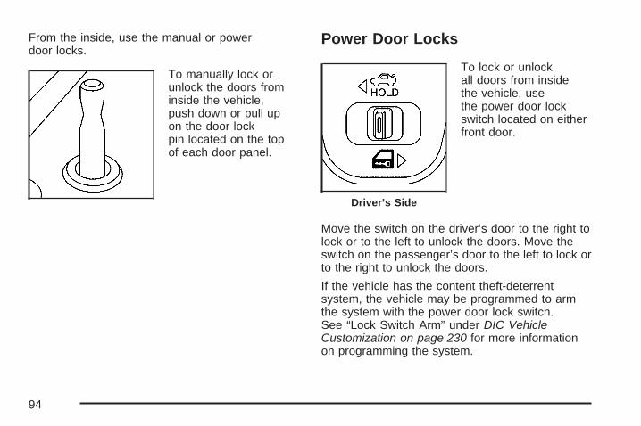
From the inside, use the manual or powerdoor locks.
To manually lock orunlock the doors frominside the vehicle,push down or pull upon the door lockpin located on the topof each door panel.
Power Door Locks
To lock or unlockall doors from insidethe vehicle, usethe power door lockswitch located on eitherfront door.
Move the switch on the driver’s door to the right tolock or to the left to unlock the doors. Move theswitch on the passenger’s door to the left to lock orto the right to unlock the doors.
If the vehicle has the content theft-deterrentsystem, the vehicle may be programmed to armthe system with the power door lock switch.See “Lock Switch Arm” under DIC VehicleCustomization on page 230 for more informationon programming the system.
Driver’s Side
94

Delayed LockingThis feature delays the locking of the vehicle’sdoors for five seconds after the last door is closed.Two chimes will sound when the power doorlock switch or the LOCK button on the remotekeyless entry transmitter is pressed when a dooris open. The chimes indicate that the delayedlocking feature is on.
The doors can be locked immediately by pressingthe power door lock switch or the LOCK buttonon the transmitter a second time.
The delayed locking feature will not activate whenthe ignition is in RUN or ACC.
You can program this feature on or off through theDriver Information Center (DIC) See “PersonalProgramming Mode Screens” under DIC VehicleCustomization on page 230.
Programmable AutomaticDoor LocksThe vehicle’s doors are programmed from thefactory to lock when the shift lever is moved into aforward gear, and to unlock when the shift leveris moved into PARK (P).
If someone needs to get in or out of the vehicle afterthe doors have been locked, place the shift leverinto PARK (P). You may also unlock all doors usingthe power door lock switch or unlock one door usingthe inside manual door lock.
To program the door unlocking feature, see“Personal Programming Mode Screens” under DICVehicle Customization on page 230. The lockingfeature cannot be disabled or programmed.
95

Rear Door Security LocksYour vehicle has rear door security locks, thatprevent passengers from opening the rear doorsfrom the inside.
The rear door security locks are located on theinside edge of each rear door. You must open therear doors to access them.
To assist you in finding the lock, your vehicle willhave one of the following:
To use these locks, do the following:
1. Insert the key into the security lock slot andturn it so the slot is in the horizontal position.
2. Close the door.
3. Do the same for the other rear door.
When you want to open a rear door when thesecurity lock is on, do the following:
1. Unlock the door using the remote keylessentry transmitter, if the vehicle has one, thepower door lock switch, or by lifting therear door manual lock.
2. Open the door from the outside.
To cancel the rear door security lock, do thefollowing:
1. Unlock the door and open it from the outside.
2. Insert the key into the security lock slotand turn it so the slot is in the vertical position.
3. Do the same for the other rear door.
96

Lockout ProtectionThe lockout protection feature makes it moredifficult to lock the key in the vehicle. If the driver’sdoor is open while the key is in the ignition, thedoor cannot be locked with the power doorlock switch.
This feature cannot guarantee that you will never belocked out of the vehicle. If the key is not left in theignition, or, if the manual door lock pin is used, thekey could still be locked inside the vehicle. Alwaysremember to take the key with you.
Trunk
{CAUTION:
It can be dangerous to drive with thetrunk lid open because carbon monoxide(CO) gas can come into your vehicle. You
CAUTION: (Continued)
CAUTION: (Continued)
cannot see or smell CO. It can causeunconsciousness and even death. If youmust drive with the trunk lid open or ifelectrical wiring or other cableconnections must pass through the sealbetween the body and the trunk lid:
• Make sure all other windows are shut.• Turn the fan on your heating or
cooling system to its highest speedand select the control setting that willforce outside air into your vehicle. SeeClimate Control System.
• If you have air outlets on or underthe instrument panel, open them allthe way.
See Engine Exhaust on page 122.
To unlock and open the trunk from the outside,press the trunk button on the remote keyless entrytransmitter. See Remote Keyless Entry (RKE)System Operation on page 87.
97
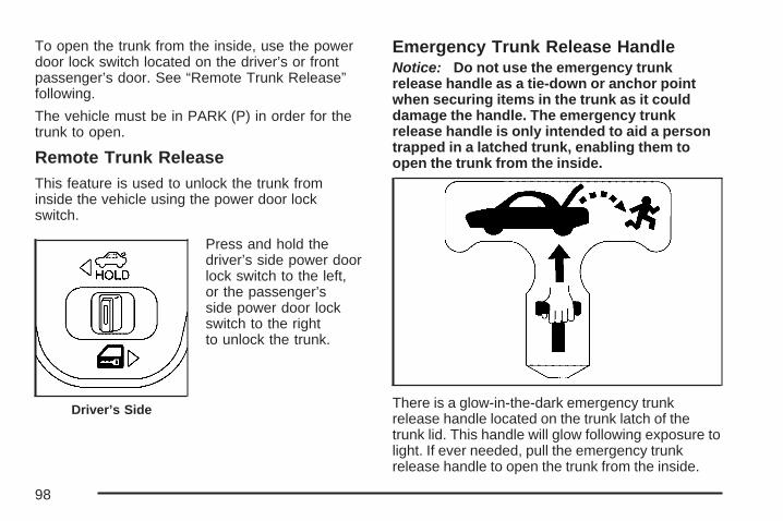
To open the trunk from the inside, use the powerdoor lock switch located on the driver’s or frontpassenger’s door. See “Remote Trunk Release”following.
The vehicle must be in PARK (P) in order for thetrunk to open.
Remote Trunk ReleaseThis feature is used to unlock the trunk frominside the vehicle using the power door lockswitch.
Press and hold thedriver’s side power doorlock switch to the left,or the passenger’sside power door lockswitch to the rightto unlock the trunk.
Emergency Trunk Release HandleNotice: Do not use the emergency trunkrelease handle as a tie-down or anchor pointwhen securing items in the trunk as it coulddamage the handle. The emergency trunkrelease handle is only intended to aid a persontrapped in a latched trunk, enabling them toopen the trunk from the inside.
There is a glow-in-the-dark emergency trunkrelease handle located on the trunk latch of thetrunk lid. This handle will glow following exposure tolight. If ever needed, pull the emergency trunkrelease handle to open the trunk from the inside.
Driver’s Side
98
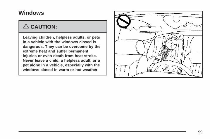
Windows
{CAUTION:
Leaving children, helpless adults, or petsin a vehicle with the windows closed isdangerous. They can be overcome by theextreme heat and suffer permanentinjuries or even death from heat stroke.Never leave a child, a helpless adult, or apet alone in a vehicle, especially with thewindows closed in warm or hot weather.
99

Power Windows
{CAUTION:
Leaving children, helpless adults, or petsin a vehicle with the windows closed isdangerous. They can be overcome fromextreme heat in warm or hot weather andsuffer permanent injuries or even deathfrom heat stroke.
Leaving children in a vehicle with theignition key is dangerous for manyreasons, children or others could be badlyinjured or even killed. They could operatethe power windows or other controls or
CAUTION: (Continued)
CAUTION: (Continued)
even make the vehicle move. Thewindows will function with the keys in theignition and they could be seriouslyinjured or killed if caught in the path of aclosing window. Do not leave keys in avehicle with children.
When there are children in the rear seatuse the window lockout button to preventunintentional operation of the windows.
100
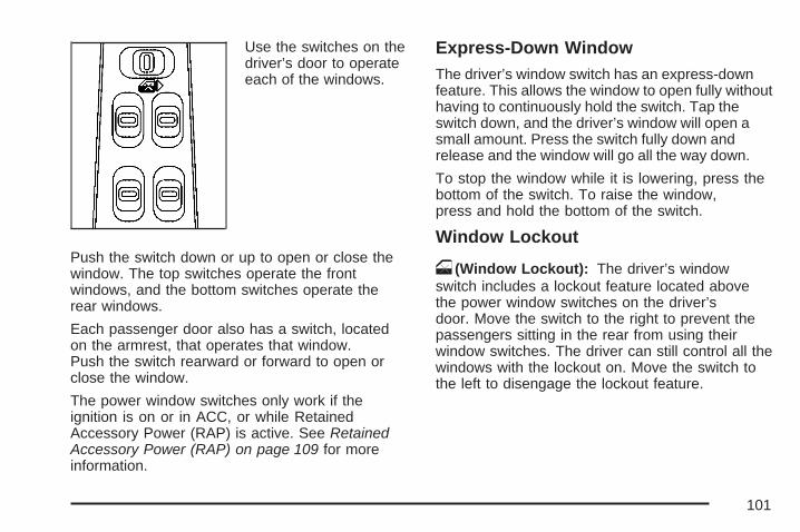
Use the switches on thedriver’s door to operateeach of the windows.
Push the switch down or up to open or close thewindow. The top switches operate the frontwindows, and the bottom switches operate therear windows.
Each passenger door also has a switch, locatedon the armrest, that operates that window.Push the switch rearward or forward to open orclose the window.
The power window switches only work if theignition is on or in ACC, or while RetainedAccessory Power (RAP) is active. See RetainedAccessory Power (RAP) on page 109 for moreinformation.
Express-Down WindowThe driver’s window switch has an express-downfeature. This allows the window to open fully withouthaving to continuously hold the switch. Tap theswitch down, and the driver’s window will open asmall amount. Press the switch fully down andrelease and the window will go all the way down.
To stop the window while it is lowering, press thebottom of the switch. To raise the window,press and hold the bottom of the switch.
Window Lockout
o (Window Lockout): The driver’s windowswitch includes a lockout feature located abovethe power window switches on the driver’sdoor. Move the switch to the right to prevent thepassengers sitting in the rear from using theirwindow switches. The driver can still control all thewindows with the lockout on. Move the switch tothe left to disengage the lockout feature.
101

Sun VisorsTo help block out glare, pull the sun visors down.Pull on the inside edges of the sun visors toswing them from the front windshield to theside window.
Visor Vanity MirrorRaise the cover on the top of the sun visor toexpose the vanity mirror. If the vehicle has lightedvanity mirrors, the lamps come on when thecover is opened.
Theft-Deterrent SystemsVehicle theft is big business, especially in somecities. Although your vehicle has a number oftheft-deterrent features, we know that nothing weput on it can make it impossible to steal.
Content Theft-DeterrentThe vehicle has a content theft-deterrentalarm system.
A red light located ontop of the instrumentpanel, toward the centerof the vehicle andnear the windshield, willflash slowly when thesystem is armed.
The theft-deterrent alarm system needs to beactivated through the Driver’s Information Center(DIC). See “Theft Deterrent” under the PersonalProgramming Mode Screens in DIC VehicleCustomization on page 230. While armed, thedoors will not unlock with the power door lockswitch. The remote alarm will sound if someonetampers with the trunk or enters the vehicle withoutusing the Remote Keyless Entry (RKE) transmitteror key to unlock the doors. The horn will sound andthe headlamps will flash for up to two minutes. Thesystem will also cut off the fuel supply, preventingthe vehicle from being driven.
102
Arming with the Power Lock SwitchThe vehicle’s content theft-deterrent alarm systemcan be activated when the key is removed fromthe ignition and the power door lock switchof either the driver’s or front passenger’s door isused to lock the vehicle. The door needs tobe in the open position when pressing the powerdoor lock switch. The alarm system will notactivate if the door is closed and the power doorlock switch is pressed. This system can beactivated through the Driver’s InformationCenter (DIC). See “Lock Switch Arm” under thePersonal Programming Mode Screens in DICVehicle Customization on page 230.
When the doors are locked using the power doorlock switch of either front door, the red light,on top of the instrument panel will start flashingindicating that the system is arming. After allthe doors are closed there will be a time delay andthen the red light will begin to flash at a veryslow rate indicating the system is armed.
Arming with the RKE TransmitterThe alarm system will arm when the RKEtransmitter is used to lock the doors after the keyis removed from the ignition. The red light willcome on to indicate that the system is arming.After all doors are closed and locked, and after atime delay, the red light will begin flashing at avery slow rate to show the system is armed.
Arming ConfirmationA red light located on top of the instrument panel,towards the center of the vehicle and near thewindshield, will flash slowly to confirm whenthe system is armed.
Disarming with the RKE TransmitterThe alarm system will disarm when the RKEtransmitter is used to unlock the doors. The redlight will go out to show that the system isdisarmed.
103
Disarming with Your KeyThe alarm system will disarm when the key isused to unlock the doors. The red light will stopflashing when the system is disarmed. If you wouldlike the key to disarm the alarm system, see“Personal Programming Mode Screens” under DICVehicle Customization on page 230 for moreinformation.
PASS-Key® IIIYour PASS-Key® III system operates on a radiofrequency subject to Federal CommunicationsCommission (FCC) Rules and with IndustryCanada.
This device complies with Part 15 of the FCCRules. Operation is subject to the followingtwo conditions:
1. This device may not cause harmfulinterference.
2. This device must accept any interferencereceived, including interference that maycause undesired operation.
This device complies with RSS-210 of IndustryCanada. Operation is subject to the followingtwo conditions:
1. This device may not cause interference.
2. This device must accept any interferencereceived, including interference that maycause undesired operation of the device.
Changes or modifications to this system by otherthan an authorized service facility could voidauthorization to use this equipment.
PASS-Key® III uses a radio frequency transponderin the key that matches a decoder in your vehicle.
104
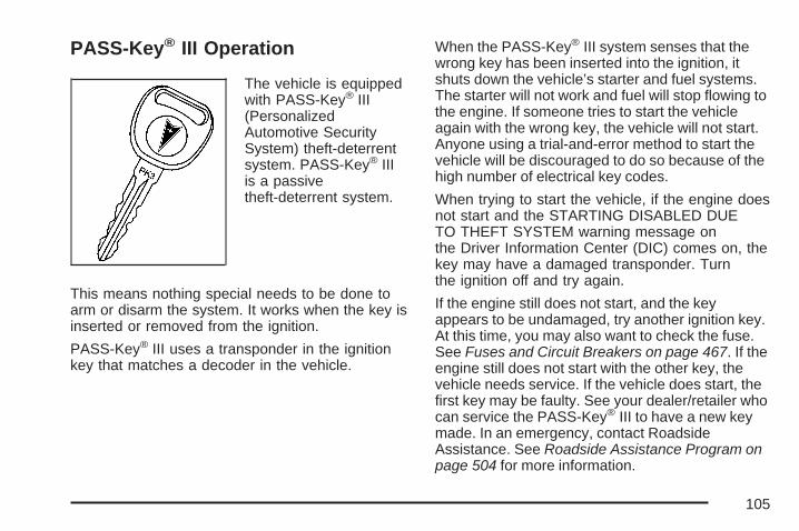
PASS-Key® III Operation
The vehicle is equippedwith PASS-Key® III(PersonalizedAutomotive SecuritySystem) theft-deterrentsystem. PASS-Key® IIIis a passivetheft-deterrent system.
This means nothing special needs to be done toarm or disarm the system. It works when the key isinserted or removed from the ignition.
PASS-Key® III uses a transponder in the ignitionkey that matches a decoder in the vehicle.
When the PASS-Key® III system senses that thewrong key has been inserted into the ignition, itshuts down the vehicle’s starter and fuel systems.The starter will not work and fuel will stop flowing tothe engine. If someone tries to start the vehicleagain with the wrong key, the vehicle will not start.Anyone using a trial-and-error method to start thevehicle will be discouraged to do so because of thehigh number of electrical key codes.
When trying to start the vehicle, if the engine doesnot start and the STARTING DISABLED DUETO THEFT SYSTEM warning message onthe Driver Information Center (DIC) comes on, thekey may have a damaged transponder. Turnthe ignition off and try again.
If the engine still does not start, and the keyappears to be undamaged, try another ignition key.At this time, you may also want to check the fuse.See Fuses and Circuit Breakers on page 467. If theengine still does not start with the other key, thevehicle needs service. If the vehicle does start, thefirst key may be faulty. See your dealer/retailer whocan service the PASS-Key® III to have a new keymade. In an emergency, contact RoadsideAssistance. See Roadside Assistance Program onpage 504 for more information.
105

It is possible for the PASS-Key® III decoder toaccept the transponder value of a new orreplacement key. Up to 10 keys may beprogrammed for the vehicle. If all the programmedkeys are lost or do not operate, see yourdealer/retailer or a locksmith who can servicePASS-Key® III to have keys made andprogrammed to the system.
Canadian Owners: If all the keys are lost ordamaged, only a dealer/retailer can servicePASS-Key® III to have new keys made andprogrammed to the system.
The following procedure is for programming a newor replacement key when you have at least onealready programmed key. To program the new keydo the following:
1. Verify that the new key has PK3 stampedon it.
2. Insert the master key in the ignition and startthe engine. If the engine will not start, seeyour dealer/retailer for service.
3. After the engine has started, turn the key toOFF, and remove the key.
4. Insert the key to be programmed and turn it toRUN within five seconds of removing theoriginal key.
5. The STARTING DISABLED DUE TO THEFTSYSTEM warning message on the DIC willturn off, once the key has been programmed.It may not be apparent that the SERVICETHEFT SYSTEM warning message went ondue to how quickly the key is programmed.
6. Repeat Steps 1 through 5 if additional keysare to be programmed.
If the STARTING DISABLED DUE TO THEFTSYSTEM warning message appears and stays onthe DIC while the vehicle is being driven, theengine will be able to be restarted if it is turnedoff. Your PASS-Key® III system, however, isnot working properly and must be serviced by yourdealer/retailer. The vehicle is not protected bythe PASS-Key® III system at this time.
If the PASS-Key® III key is lost or stolen, see yourdealer/retailer or a locksmith who can servicePASS-Key® III to have a new key made.
Do not leave the key or device that disarms ordeactivates the theft deterrent system in thevehicle.
106
Starting and Operating YourVehicle
New Vehicle Break-In
Notice: Your vehicle does not need anelaborate break-in. But it will perform better inthe long run if you follow these guidelines:• Do not drive at any one constant speed,
fast or slow, for the first 500 miles(805 km). Do not make full-throttle starts.Avoid downshifting to brake, or slow,the vehicle.
• Avoid making hard stops for the first200 miles (322 km) or so. During this timethe new brake linings are not yet brokenin. Hard stops with new linings canmean premature wear and earlierreplacement. Follow this breaking-inguideline every time you get new brakelinings.
• Do not tow a trailer during break-in. SeeTowing a Trailer on page 329 for thetrailer towing capabilities of your vehicleand more information.
Following break-in, engine speed and load canbe gradually increased.
107
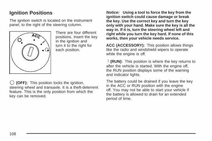
Ignition PositionsThe ignition switch is located on the instrumentpanel, to the right of the steering column.
There are four differentpositions. Insert the keyin the ignition andturn it to the right foreach position.
9 (OFF): This position locks the ignition,steering wheel and transaxle. It is a theft-deterrentfeature. This is the only position from which thekey can be removed.
Notice: Using a tool to force the key from theignition switch could cause damage or breakthe key. Use the correct key and turn the keyonly with your hand. Make sure the key is all theway in. If it is, turn the steering wheel left andright while you turn the key hard. If none of thisworks, then your vehicle needs service.
ACC (ACCESSORY): This position allows thingslike the radio and windshield wipers to operatewhile the engine is off.
R (RUN): This position is where the key returns toafter the vehicle is started. With the engine off,the RUN position displays some of the warningand indicator lights.
The battery could be drained if you leave the keyin the ACC or RUN position with the engineoff. You may not be able to start your vehicle ifthe battery is allowed to drain for an extendedperiod of time.
108

/ (START): This position starts the engine. Letgo of the key when the engine starts. The key willreturn to the RUN for normal driving.
A continuous warning chime will sound and a KEYIN IGNITION message will display on the DriverInformation Center (DIC) if the key is turnedto OFF or ACC and the driver’s door is opened.
Key In the IgnitionNever leave your vehicle with the keys inside, as itis an easy target for joy riders or thieves. If youleave the key in the ignition and park your vehicle,a chime will sound, when you open the driver’sdoor. Always remember to remove your key fromthe ignition and take it with you. This will lockyour ignition and transaxle. Also, always rememberto lock the doors.
The battery could be drained if you leave the keyin the ignition while your vehicle is parked.You may not be able to start your vehicle after ithas been parked for an extended period of time.
Retained Accessory Power (RAP)These vehicle accessories can be used for up to10 minutes after the engine is turned off:
• Audio System
• Power Windows
• Sunroof (if equipped)
Power to these features will continue to operatefor up to 10 minutes after the key is turned to OFFuntil a door is opened.
109
Starting the EnginePlace the transaxle in the proper gear.
Move your shift lever to PARK (P) orNEUTRAL (N). Your engine will not start inany other position -- this is a safety feature. Torestart when you are already moving, useNEUTRAL (N) only.
Notice: Shifting into PARK (P) with the vehiclemoving could damage the transaxle. Shift intoPARK (P) only when your vehicle is stopped.
Starting Procedure1. With your foot off the accelerator pedal, turn
the ignition key to START. When the enginestarts, let go of the key. The idle speed will godown as your engine gets warm. Do notrace the engine immediately after starting it.Operate the engine and transaxle gentlyto allow the oil to warm up and lubricate allmoving parts.
Your vehicle has a Computer-ControlledCranking System. This feature assists instarting the engine and protects components. Ifthe ignition key is turned to the START position,and then released when the engine beginscranking, the engine will continue cranking for afew seconds or until the vehicle starts. If theengine does not start and the key is held inSTART for many seconds, cranking will bestopped after 15 seconds to prevent crankingmotor damage. To prevent gear damage, thissystem also prevents cranking if the engine isalready running. Engine cranking can bestopped by turning the ignition switch to theACC or OFF position.
Notice: Cranking the engine for long periodsof time, by returning the key to the STARTposition immediately after cranking has ended,can overheat and damage the crankingmotor, and drain the battery. Wait at least15 seconds between each try, to allowthe cranking motor to cool down.
110

2. If the engine does not start after 5-10 seconds,especially in very cold weather (below 0°F or−18°C), it could be flooded with too muchgasoline. Try pushing the accelerator pedal allthe way to the floor and holding it there asyou hold the key in START for up to amaximum of 15 seconds. Wait at least15 seconds between each try, to allow thecranking motor to cool down. When the enginestarts, let go of the key and accelerator. Ifthe vehicle starts briefly but then stops again,do the same thing. This clears the extragasoline from the engine. Do not race theengine immediately after starting it. Operatethe engine and transaxle gently until theoil warms up and lubricates all moving parts.
Notice: Your engine is designed to work withthe electronics in your vehicle. If you addelectrical parts or accessories, you couldchange the way the engine operates. Beforeadding electrical equipment, check withyour dealer. If you do not, your engine mightnot perform properly. Any resulting damagewould not be covered by your vehicle’swarranty.
Engine Coolant HeaterThe vehicle may be equipped with an enginecoolant heater. In very cold weather, 0°F (−18°C)or colder, the engine coolant heater can help.The vehicle will start easier and get betterfuel economy during engine warm-up. Usually, thecoolant heater should be plugged in a minimumof four hours prior to starting the vehicle. Attemperatures above 32°F (0°C), use of the coolantheater is not required. Your vehicle may alsohave an internal thermostat in the plug end of thecord. This will prevent operation of the enginecoolant heater when the temperature is at or above0°F (−18°C) as noted on the cord.
111

To Use the Engine Coolant Heater1. Turn off the engine.
2. Open the hood and unwrap the electricalcord. The cord is located above the engineair cleaner/filter. See Engine CompartmentOverview on page 352 for more informationon location.
3. Plug the cord into a normal, grounded110-volt AC outlet.
{CAUTION:
Plugging the cord into an ungroundedoutlet could cause an electrical shock.Also, the wrong kind of extension cordcould overheat and cause a fire. Youcould be seriously injured. Plug the cordinto a properly grounded three-prong110-volt AC outlet. If the cord will notreach, use a heavy-duty three-prongextension cord rated for at least 15 amps.
4. Before starting the engine, be sure to unplugand store the cord as it was before, makingsure to keep it away from moving engineparts. If this is not done, the cord could bedamaged.
How long should the coolant heater be keptplugged in? The answer depends on the outsidetemperature, the kind of oil that is in thevehicle, and some other things. Instead of trying tolist everything here, we ask that you contactyour dealer/retailer in the area where the vehiclewill be parked. The dealer/retailer can give you thebest advice for that particular area.
Active Fuel Management™Your vehicle’s engine may be equipped with ActiveFuel Management™. This system allows the engineto operate on either all or half of its cylinders,depending on your driving conditions.
When less power is required, such as cruising at aconstant vehicle speed, the system will operatein the half cylinder mode, allowing your vehicle toachieve better fuel economy. When greaterpower demands are required, such as acceleratingfrom a stop, passing, or merging onto a freeway,the system will maintain full-cylinder operation.
112

Automatic Transaxle OperationThe shift lever for the automatic transaxle islocated on the console between the seats.
Maximum engine speed is limited when the vehicleis in PARK (P) or NEUTRAL (N) to protectdriveline components from improper operation.
There are severaldifferent positions forthe shift lever.
PARK (P): This position locks the front wheels. Itis the best position to use when the engine isstarted because the vehicle cannot move easily.
{CAUTION:
It is dangerous to get out of your vehicle ifthe shift lever is not fully in PARK (P) withthe parking brake firmly set. Your vehiclecan roll.Do not leave your vehicle when the engineis running unless you have to. If you haveleft the engine running, the vehicle canmove suddenly. You or others could beinjured. To be sure your vehicle will notmove, even when you are on fairly levelground, always set your parking brake andmove the shift lever to PARK (P). SeeShifting Into Park (P) on page 119. If youare pulling a trailer, see Towing a Trailer onpage 329.
Make sure the shift lever is fully in PARK (P) beforestarting the engine. The vehicle has an automatictransaxle shift lock control system.
3800 V6 Engine
113
You must fully apply your regular brakes first andthen press the shift lever button, located on thefront of the shift lever, before you can shift fromPARK (P) when the ignition key is in RUN. If thevehicle cannot be shifted out of PARK (P), easepressure on the shift lever by pushing it all the wayinto PARK (P) as you maintain brake application.Then press the shift lever button and move the shiftlever into another gear. See Shifting Out of Park (P)on page 121.
REVERSE (R): Use this gear to back up.
Notice: Shifting to REVERSE (R) while yourvehicle is moving forward could damage thetransaxle. The repairs would not be covered byyour warranty. Shift to REVERSE (R) only afteryour vehicle is stopped.
To rock the vehicle back and forth to get out ofsnow, ice or sand without damaging the transaxle,see If Your Vehicle is Stuck in Sand, Mud, Ice,or Snow on page 321.
NEUTRAL (N): In this position, the engine doesnot connect with the wheels. To restart whenthe vehicle is already moving, use NEUTRAL (N)only. Also, use NEUTRAL (N) when the vehicleis being towed.
{CAUTION:
Shifting into a drive gear while yourengine is running at high speed isdangerous. Unless your foot is firmly onthe brake pedal, your vehicle could movevery rapidly. You could lose control andhit people or objects. Do not shift into adrive gear while your engine is running athigh speed.
Notice: Shifting out of PARK (P) orNEUTRAL (N) while the engine is running athigh speed may damage the transaxle.The repairs would not be covered by yourwarranty. Be sure the engine is not running athigh speeds when shifting your vehicle.
114

DRIVE (D): This position is for normal driving. Itprovides the best fuel economy for your vehicle. Ifthe vehicle needs more power for passing, andit is:
• Going less than 35 mph (55 km/h), push theaccelerator pedal about halfway down.
• Going about 35 mph (55 km/h) or more, pushthe accelerator pedal all the way down.The vehicle will shift down to the next gearand have more power.
Downshifting the transaxle in slippery roadconditions could result in skidding, see Skiddingunder Loss of Control on page 305.
Notice: If your vehicle seems to start uprather slowly or not shift gears when you gofaster, and you continue to drive your vehiclethat way, you could damage the transaxle.Have your vehicle serviced right away. You candrive in SECOND (2) when you are drivingless than 35 mph (55 km/h) and DRIVE (D) forhigher speeds until then.
THIRD (3): This position is also used for normaldriving. However, it reduces vehicle speed morethan DRIVE (D) without using your brakes. Youmight choose THIRD (3) instead of DRIVE (D)when driving on hilly, winding roads, when towing atrailer, so there is less shifting between gears, whengoing down a steep hill and when driving onnon-highway scenarios (i.e. city streets etc.).
SECOND (2): This position reduces vehicle speedeven more than THIRD (3) without using yourbrakes. You can use SECOND (2) on hills. It canhelp control the vehicle’s speed as it goesdown steep mountain roads, but then you wouldalso want to use the brakes off and on.
Notice: Driving in SECOND (2) for more than25 miles (40 km) or at speeds over 55 mph(90 km/h), can cause damage to your engineand/or transaxle. Also, shifting intoSECOND (2) at speeds above 65 mph(105 km/h) can cause damage. Drive inDRIVE (D) instead of SECOND (2).
115

FIRST (1): This position reduces vehicle speedeven more than SECOND (2) without usingyour brakes. It can be used on very steep hills, orin deep snow or mud. If the shift lever is movedto FIRST (1), while the vehicle is moving forward,the transaxle will not shift into first gear untilthe vehicle is going slowly enough.
Notice: Spinning the tires or holding thevehicle in one place on a hill using only theaccelerator pedal may damage the transaxle. Ifyou are stuck, do not spin the tires. Whenstopping on a hill, use the brakes, or parkingbrake to hold the vehicle in place.
Performance Shifting with TAP-Shift®
If the vehicle is equipped with the 3800 V6Supercharged engine or the 5.3L V8 engine, yourvehicle may have this feature. It allows you tochange gears similar to a manual transaxle.
To fully use this feature, do the following:
1. The MANUAL (M) position can be selectedwhile the vehicle is moving. The currenttransaxle position will continue to be displayedon the Driver Information Center (DIC) andHead-Up Display (HUD), if equipped.
2. Move the shift leverto the MANUAL (M).
116
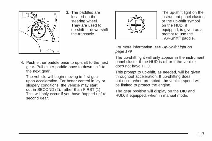
3. The paddles arelocated on thesteering wheel.They are used toup-shift or down-shiftthe transaxle.
4. Push either paddle once to up-shift to the nextgear. Pull either paddle once to down-shift tothe next gear.The vehicle will begin moving in first gearupon acceleration. For better control in icy orslippery conditions, the vehicle may startout in SECOND (2), rather than FIRST (1).This will only occur if you have “tapped up” tosecond gear.
The up-shift light on theinstrument panel cluster,or the up-shift symbolon the HUD, ifequipped, is given as aprompt to use theTAP-Shift® paddle.
For more information, see Up-Shift Light onpage 179
The up-shift light will only appear in the instrumentpanel cluster if the HUD is off or if the vehicledoes not have HUD.
This prompt to up-shift, as needed, will be giventhroughout acceleration. If up-shifting doesnot occur when prompted, the vehicle speed willbe limited to protect the engine.
The gear position will display on the DIC andHUD, if equipped, when in manual mode.
117

Pressing the accelerator while driving in thehighest gear (FOURTH (4)) between 20 mph(32 km/h) and 50 mph (80 km/h), will makethe transaxle automatically downshift. As yourspeed gets closer to 50 mph (80 km/h), youwill need to increase accelerator pedal travel toget the vehicle to downshift. At 50 mph (80 km/h),even with the accelerator fully depressed, thetransaxle will always remain in FOURTH (4). Thetransaxle will also automatically downshift asthe vehicle decelerates and comes to a stop.
If a paddle is pushed or pulled and the vehiclecannot respond to a transaxle gear change,a chime will sound. The system will not allow eitheran up-shift or a down-shift if the vehicle speedis too fast or too slow, nor will it allow a start fromTHIRD (3) or higher gear.
Parking Brake
The parking brake islocated to the left of thebrake pedal near thedriver’s door. To set theparking brake, holdthe regular brake pedaldown with the rightfoot. Push down on theparking brake pedal,with the left foot.
To release the parking brake, hold the regularbrake pedal down with the right foot and push theparking brake pedal with the left foot. When theleft foot is lifted, the parking brake pedal will lift tothe released position.
A warning chime will sound if the parking brake isset, the ignition is on, and the shift lever is notin PARK (P) or NEUTRAL (N).
The brake light will also appear on the instrumentpanel cluster when the parking brake is set. It willstay on if the parking brake does not release fully.
118

The PARKING BRAKE ON message will alsoappear in the Driver Information Center (DIC)when the parking brake is set. See DIC Warningsand Messages on page 204 for more information.
Notice: Driving with the parking brake oncan overheat the brake system and causepremature wear or damage to brake systemparts. Verify that the parking brake is fullyreleased and the brake warning light isoff before driving.If the vehicle is towing a trailer and parked on ahill, see Towing a Trailer on page 329. Thatsection shows what to do first to keep the trailerfrom moving.
Shifting Into Park (P)
{CAUTION:
It can be dangerous to get out of yourvehicle if the shift lever is not fully inPARK (P) with the parking brake firmlyset. Your vehicle can roll. If you have left
CAUTION: (Continued)
CAUTION: (Continued)
the engine running, the vehicle can movesuddenly. You or others could be injured.To be sure your vehicle will not move,even when you are on fairly level ground,use the steps that follow. If you arepulling a trailer, see Towing a Trailer onpage 329.
1. Hold the brake pedal down with your right footand set the parking brake.
2. Move the shift lever into PARK (P) by holdingin the button on the shift lever and pushingthe shift lever all the way toward the frontof the vehicle.
3. Turn the ignition key to OFF.
4. Remove the key and take it with you. If youcan leave your vehicle with the ignition key inyour hand, your vehicle is in PARK (P).
119

Leaving Your Vehicle With the EngineRunning
{CAUTION:
It can be dangerous to leave your vehiclewith the engine running. Your vehiclecould move suddenly if the shift lever isnot fully in PARK (P) with the parkingbrake firmly set. And, if you leave thevehicle with the engine running, it couldoverheat and even catch fire. You orothers could be injured. Do not leave yourvehicle with the engine running.
If you have to leave your vehicle with the enginerunning, be sure your vehicle is in PARK (P) andyour parking brake is firmly set before you leave it.After you have moved the shift lever into PARK (P),hold the regular brake pedal down. Then, see if youcan move the shift lever away from PARK (P)without first pushing the button.If you can, it means that the shift lever was notfully locked in PARK (P).
Torque LockIf you are parking on a hill and you do not shift yourtransaxle into PARK (P) properly, the weight of thevehicle may put too much force on the parking pawlin the transaxle. You may find it difficult to pull theshift lever out of PARK (P). This is called torquelock. To prevent torque lock, set the parking brakeand then shift into PARK (P) properly before youleave the driver’s seat. To find out how, see ShiftingInto Park (P) on page 119.
When you are ready to drive, move the shiftlever out of PARK (P) before you release theparking brake.
If torque lock does occur, you may need to haveanother vehicle push your vehicle a little uphillto take some of the pressure from the parking pawlin the transaxle, so you can pull the shift leverout of PARK (P).
120
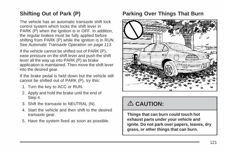
Shifting Out of Park (P)The vehicle has an automatic transaxle shift lockcontrol system which locks the shift lever inPARK (P) when the ignition is in OFF. In addition,the regular brakes must be fully applied beforeshifting from PARK (P) while the ignition is in RUN.See Automatic Transaxle Operation on page 113.
If the vehicle cannot be shifted out of PARK (P),ease pressure on the shift lever and push the shiftlever all the way up into PARK (P) as brakeapplication is maintained. Then move the shift leverinto the desired gear.
If the brake pedal is held down but the vehicle stillcannot be shifted out of PARK (P), try this:
1. Turn the key to ACC or RUN.
2. Apply and hold the brake until the end ofStep 4.
3. Shift the transaxle to NEUTRAL (N).
4. Start the vehicle and then shift to the desiredtransaxle gear.
5. Have the system fixed as soon as possible.
Parking Over Things That Burn
{CAUTION:
Things that can burn could touch hotexhaust parts under your vehicle andignite. Do not park over papers, leaves, drygrass, or other things that can burn.
121
Engine Exhaust
{CAUTION:
Engine exhaust can kill. It contains thegas carbon monoxide (CO), which youcannot see or smell. It can causeunconsciousness and death.
You might have exhaust coming in if:• The exhaust system sounds strange
or different.• Your vehicle gets rusty underneath.• Your vehicle was damaged in a
collision.
CAUTION: (Continued)
CAUTION: (Continued)
• Your vehicle was damaged whendriving over high points on the roador over road debris.
• Repairs were not done correctly.• Your vehicle or the exhaust system
has been modified improperly.
If you ever suspect exhaust is coming intoyour vehicle:
• Drive it only with all the windowsdown to blow out any CO; and
• Have your vehicle fixed immediately.
122
Running the Engine While ParkedIt is better not to park with the engine running. But ifyou ever have to, here are some things to know.
{CAUTION:
Idling the engine with the climate controlsystem off could allow dangerous exhaustinto your vehicle. See the earlier cautionunder Engine Exhaust on page 122.
Also, idling in a closed-in place can letdeadly carbon monoxide (CO) into yourvehicle even if the climate control fan is atthe highest setting. One place this canhappen is a garage. Exhaust — withCO — can come in easily. NEVER park ina garage with the engine running.
Another closed-in place can be a blizzard.See Winter Driving on page 316.
{CAUTION:
It can be dangerous to get out of yourvehicle if the shift lever is not fully inPARK (P) with the parking brake firmlyset. Your vehicle can roll. Do not leaveyour vehicle when the engine is runningunless you have to. If you have left theengine running, the vehicle can movesuddenly. You or others could be injured.To be sure your vehicle will not move,even when you are on fairly level ground,always set the parking brake and movethe shift lever to PARK (P).
Follow the proper steps to be sure your vehiclewill not move. See Shifting Into Park (P) onpage 119.
If you are parking on a hill and if you are pulling atrailer, also see Towing a Trailer on page 329.
123

Mirrors
Manual Rearview Mirrorwith OnStar®
Your vehicle has this feature located at the bottomof the mirror, to change the mirror from the dayto the night position. To reduce the glare ofheadlamps from behind, turn the controlcounterclockwise. To return the mirror to the dayposition, turn the control clockwise.
There are also three OnStar® buttons located atthe bottom of the mirror face. See your dealerfor more information on the system and howto subscribe to OnStar®. See OnStar® System onpage 125 for more information about theservices OnStar® provides.
Outside Power Mirrors
The power mirrorcontrols are locatednear the driver’swindow, on the driver’sdoor armrest.
Move the top control to the left to adjust thedriver’s side outside mirror. Move the control tothe right to adjust the passenger’s side mirror. Thecenter position turns the power control off andwill not allow the mirrors to move if the control padis touched.
The round control pad adjusts the angle of theselected outside mirror. Press the arrows on thecontrol pad to adjust the angle of the mirror.Adjust each mirror so that the sides and the areabehind the vehicle can be seen.
124
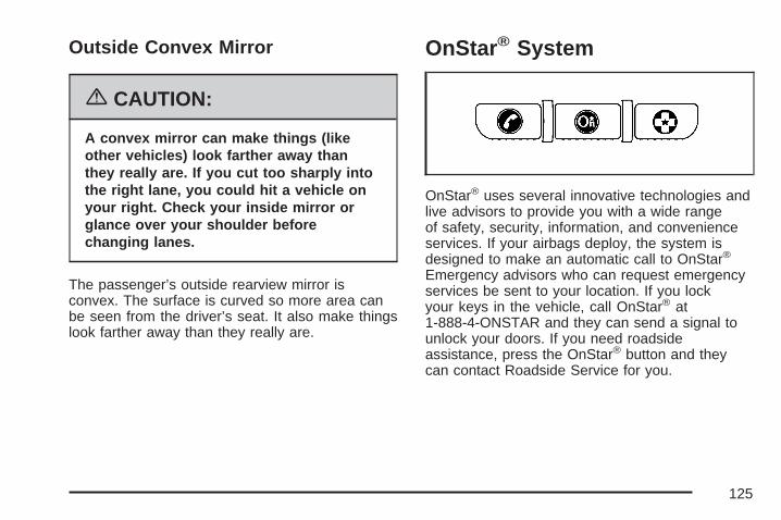
Outside Convex Mirror
{CAUTION:
A convex mirror can make things (likeother vehicles) look farther away thanthey really are. If you cut too sharply intothe right lane, you could hit a vehicle onyour right. Check your inside mirror orglance over your shoulder beforechanging lanes.
The passenger’s outside rearview mirror isconvex. The surface is curved so more area canbe seen from the driver’s seat. It also make thingslook farther away than they really are.
OnStar® System
OnStar® uses several innovative technologies andlive advisors to provide you with a wide rangeof safety, security, information, and convenienceservices. If your airbags deploy, the system isdesigned to make an automatic call to OnStar®
Emergency advisors who can request emergencyservices be sent to your location. If you lockyour keys in the vehicle, call OnStar® at1-888-4-ONSTAR and they can send a signal tounlock your doors. If you need roadsideassistance, press the OnStar® button and theycan contact Roadside Service for you.
125

OnStar® service is provided to you subject to theOnStar® Terms and Conditions. You maycancel your OnStar® service at any time bycontacting OnStar® as provided below. A completeOnStar® Owners Guide and the OnStar® Termsand Conditions are included in the vehicle’sOnStar® Subscriber glove box literature. For moreinformation, visit onstar.com or onstar.ca,contact OnStar® at 1-888-4-ONSTAR(1-888-466-7827) or TTY 1-877-248-2080, orpress the OnStar® button to speak with anOnStar® advisor 24 hours a day, 7 days a week.
Not all OnStar® features are available on allvehicles. To check if your vehicle is equipped toprovide the services described below, or for afull description of OnStar® services and systemlimitations, see the OnStar® Owner’s Guide in yourglove box or visit onstar.com.
OnStar® ServicesFor new vehicles with OnStar®, the Safe & SoundPlan, or the Directions & Connections® Plan isincluded for one year from the date of purchase.You can extend this plan beyond the first year,or upgrade to the Directions & Connections® Plan.
For more information, press the OnStar® button tospeak with an advisor. Some OnStar® services(such as Remote Door Unlock or Stolen VehicleLocation Assistance) may not be availableuntil you register with OnStar®.
Available Services with Safe &Sound® Plan• Automatic Notification of Airbag Deployment
• Advanced Automatic Crash Notification(AACN) (If equipped)
• Link to Emergency Services
• Roadside Assistance
• Stolen Vehicle Location Assistance
• AccidentAssist
• Remote Door Unlock/Vehicle Alert
• OnStar® Vehicle Diagnostics
• GM Goodwrench® On Demand Diagnostics
• OnStar® Hands-Free Calling with30 complimentary minutes
• OnStar® Virtual Advisor (U.S. Only)
126
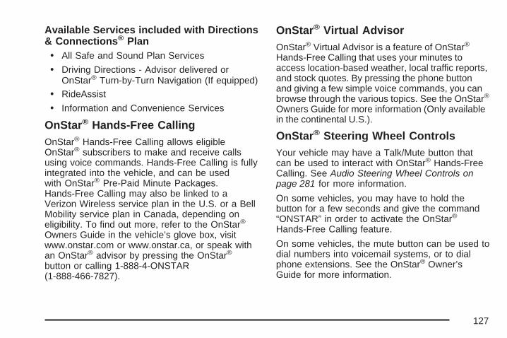
Available Services included with Directions& Connections® Plan• All Safe and Sound Plan Services
• Driving Directions - Advisor delivered orOnStar® Turn-by-Turn Navigation (If equipped)
• RideAssist
• Information and Convenience Services
OnStar® Hands-Free CallingOnStar® Hands-Free Calling allows eligibleOnStar® subscribers to make and receive callsusing voice commands. Hands-Free Calling is fullyintegrated into the vehicle, and can be usedwith OnStar® Pre-Paid Minute Packages.Hands-Free Calling may also be linked to aVerizon Wireless service plan in the U.S. or a BellMobility service plan in Canada, depending oneligibility. To find out more, refer to the OnStar®
Owners Guide in the vehicle’s glove box, visitwww.onstar.com or www.onstar.ca, or speak withan OnStar® advisor by pressing the OnStar®
button or calling 1-888-4-ONSTAR(1-888-466-7827).
OnStar® Virtual AdvisorOnStar® Virtual Advisor is a feature of OnStar®
Hands-Free Calling that uses your minutes toaccess location-based weather, local traffic reports,and stock quotes. By pressing the phone buttonand giving a few simple voice commands, you canbrowse through the various topics. See the OnStar®
Owners Guide for more information (Only availablein the continental U.S.).
OnStar® Steering Wheel ControlsYour vehicle may have a Talk/Mute button thatcan be used to interact with OnStar® Hands-FreeCalling. See Audio Steering Wheel Controls onpage 281 for more information.
On some vehicles, you may have to hold thebutton for a few seconds and give the command“ONSTAR” in order to activate the OnStar®
Hands-Free Calling feature.
On some vehicles, the mute button can be used todial numbers into voicemail systems, or to dialphone extensions. See the OnStar® Owner’sGuide for more information.
127

How OnStar® Service WorksIn order to provide you with OnStar® services,your vehicle’s OnStar® system has the capabilityof recording and transmitting vehicle information.This information is automatically sent to anOnStar® Call Center at the time of an OnStar®
button press, Emergency button press or ifyour airbags or AACN system deploys. The vehicleinformation usually includes your GPS locationand, in the event of a crash, additional informationregarding the accident that your vehicle hasbeen involved in (e.g. the direction from whichyour vehicle was hit). When you use the VirtualAdvisor feature of OnStar® Hands-Free Calling,your vehicle also sends OnStar® your GPSlocation so that we can provide you withlocation-based services.
OnStar® service cannot work unless your vehicle isin a place where OnStar® has an agreement with awireless service provider for service in that area.OnStar® service also cannot work unless you are ina place where the wireless service providerOnStar® has hired for that area has coverage,network capacity and reception when the service isneeded, and technology that is compatible with the
OnStar® service. Not all services are availableeverywhere, particularly in remote or enclosedareas, or at all times.
OnStar® service that involves location informationabout your vehicle cannot work unless GPSsatellite signals are unobstructed and available inthat place as well.
Your vehicle must have a working electricalsystem (including adequate battery power) for theOnStar® equipment to operate. There are otherproblems OnStar® cannot control that may preventOnStar® from providing OnStar® service to youat any particular time or place. Some examples aredamage to important parts of your vehicle in anaccident, hills, tall buildings, tunnels, weatheror wireless phone network congestion.
Your ResponsibilityYou may need to increase the volume of your radioto hear the OnStar® advisor. If the light next to theOnStar® buttons is red, this means that your systemis not functioning properly and should be checkedby your dealer/retailer. If the light appears clear (nolight is appearing), your OnStar® subscription hasexpired. You can always press the OnStar® buttonto confirm that your OnStar® equipment is active.
128
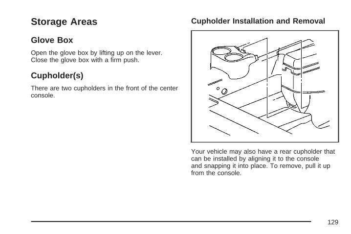
Storage Areas
Glove BoxOpen the glove box by lifting up on the lever.Close the glove box with a firm push.
Cupholder(s)There are two cupholders in the front of the centerconsole.
Cupholder Installation and Removal
Your vehicle may also have a rear cupholder thatcan be installed by aligning it to the consoleand snapping it into place. To remove, pull it upfrom the console.
129
Sunglasses Storage CompartmentYour vehicle may have a storage compartmentlocated to the rear on the overhead console.To open the sunglasses storage compartment,press the release latch forward and pull thecompartment down.
Center Console Storage AreaTo open the armrest storage area, pull up on thelatch located on the front drivers side of thestorage area. The storage area may have acassette/compact disc holder. A storage pocket islocated on the passenger side of the console.
Convenience NetThe vehicle may have a convenience net locatedon the back wall of the trunk.
Put small loads, like grocery bags, behind the net.It can help keep them from falling over.
The net is not for larger, heavier loads. Storethose in the trunk as far forward as possible.
Unhook the net so that it will lie flat when not in use.
130

SunroofIf the vehicle has a sunroof, it includes a slidingglass panel and a sunshade.
The switch to controlthe sunroof is located inthe headliner.
The switch works only while the ignition is on, orin ACC, or Retained Accessory Power (RAP) is on.See Retained Accessory Power (RAP) onpage 109.
Vent: Open the sunshade by hand. Push theswitch toward the rear of the vehicle once and thesunroof will open to the vent position. Push theswitch forward to close.
Open/Express-Open: Push the switch toward therear of the vehicle a second time and thesunroof will open the remainder of the way. Thesunshade will open with the sunroof if the switch ispushed toward the rear of the vehicle twice.
Close: Push and hold the front of the switch untilthe sunroof motor stops. The sunshade mustbe closed by hand.
131

✍ NOTES
132

Instrument Panel Overview ........................ 136Hazard Warning Flashers .......................... 138Other Warning Devices ............................. 138Horn .......................................................... 138Tilt Wheel .................................................. 139Turn Signal/Multifunction Lever .................. 139Turn and Lane-Change Signals ................. 140Headlamp High/Low-Beam Changer .......... 141Flash-to-Pass ............................................ 141Windshield Wiper Lever ............................. 142Cruise Control ........................................... 144Exterior Lamps .......................................... 148Headlamps on Reminder ........................... 149Daytime Running Lamps (DRL) ................. 149Fog Lamps ................................................ 150Exterior Lighting Battery Saver .................. 150Interior Lamps ........................................... 150Instrument Panel Brightness ...................... 151Courtesy Lamps ........................................ 151Dome Lamp .............................................. 151Entry Lighting ............................................ 152Delayed Entry Lighting .............................. 152Delayed Exit Lighting ................................. 153
Front Reading Lamps ................................ 153Overhead Console Reading Lamps ........... 153Rear Assist Handle Reading Lamps .......... 153Electric Power Management ...................... 154Battery Run-Down Protection ..................... 155Head-Up Display (HUD) ............................ 155Accessory Power Outlet(s) ........................ 160Ashtray(s) and Cigarette Lighter ................ 161
Climate Controls ......................................... 161Climate Control System ............................. 161Dual Automatic Climate Control System ....... 166Outlet Adjustment ...................................... 170Passenger Compartment Air Filter ............. 170
Warning Lights, Gages, and Indicators ..... 172Instrument Panel Cluster ........................... 173Speedometer and Odometer ...................... 174Tachometer ............................................... 175Safety Belt Reminder Light ........................ 175Passenger Safety Belt Reminder Light ....... 176Airbag Readiness Light ............................. 176Passenger Airbag Status Indicator ............. 177Up-Shift Light ............................................ 179
Section 3 Instrument Panel
133

Brake System Warning Light ..................... 180Anti-Lock Brake System Warning Light ...... 181Low Tire Pressure Warning Light .............. 182Traction Control System (TCS)
Warning Light ........................................ 182Enhanced Traction System
Warning Light ........................................ 183Engine Coolant Temperature
Warning Light ........................................ 183Engine Coolant Temperature Gage ............ 184Malfunction Indicator Lamp ........................ 184Oil Pressure Light ..................................... 188Fog Lamp Light ......................................... 189Cruise Control Light .................................. 189Highbeam On Light ................................... 189Fuel Gage ................................................. 189
Driver Information Center (DIC) .................. 190DIC Controls and Displays
(Base Level DIC) ................................... 190DIC Controls and Displays
(Uplevel DIC with Trip Computer) ........... 194
DIC Compass (Uplevel DIC) ...................... 202DIC Warnings and Messages .................... 204DIC Vehicle Customization ........................ 230
Audio System(s) ......................................... 237Setting the Time ........................................ 238Radio with CD (Base Level) ...................... 239Radio with CD (MP3) ................................ 248Radio with Six-Disc CD ............................. 259Using an MP3 ........................................... 273XM Radio Messages ................................. 279Theft-Deterrent Feature ............................. 281Audio Steering Wheel Controls .................. 281Radio Reception ........................................ 282Care of Your CDs ..................................... 283Care of the CD Player .............................. 283Backglass Antenna .................................... 284XM™ Satellite Radio Antenna
System .................................................. 285Chime Level Adjustment ............................ 285
Section 3 Instrument Panel
134

✍ NOTES
135
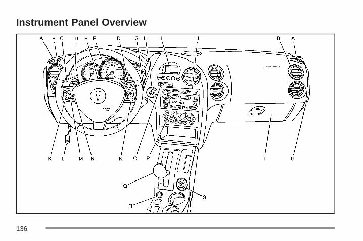
Instrument Panel Overview
136
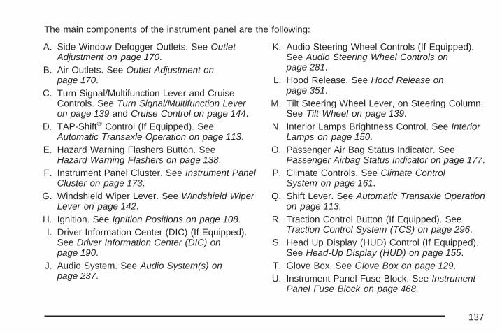
The main components of the instrument panel are the following:
A. Side Window Defogger Outlets. See OutletAdjustment on page 170.
B. Air Outlets. See Outlet Adjustment onpage 170.
C. Turn Signal/Multifunction Lever and CruiseControls. See Turn Signal/Multifunction Leveron page 139 and Cruise Control on page 144.
D. TAP-Shift® Control (If Equipped). SeeAutomatic Transaxle Operation on page 113.
E. Hazard Warning Flashers Button. SeeHazard Warning Flashers on page 138.
F. Instrument Panel Cluster. See Instrument PanelCluster on page 173.
G. Windshield Wiper Lever. See Windshield WiperLever on page 142.
H. Ignition. See Ignition Positions on page 108.I. Driver Information Center (DIC) (If Equipped).
See Driver Information Center (DIC) onpage 190.
J. Audio System. See Audio System(s) onpage 237.
K. Audio Steering Wheel Controls (If Equipped).See Audio Steering Wheel Controls onpage 281.
L. Hood Release. See Hood Release onpage 351.
M. Tilt Steering Wheel Lever, on Steering Column.See Tilt Wheel on page 139.
N. Interior Lamps Brightness Control. See InteriorLamps on page 150.
O. Passenger Air Bag Status Indicator. SeePassenger Airbag Status Indicator on page 177.
P. Climate Controls. See Climate ControlSystem on page 161.
Q. Shift Lever. See Automatic Transaxle Operationon page 113.
R. Traction Control Button (If Equipped). SeeTraction Control System (TCS) on page 296.
S. Head Up Display (HUD) Control (If Equipped).See Head-Up Display (HUD) on page 155.
T. Glove Box. See Glove Box on page 129.U. Instrument Panel Fuse Block. See Instrument
Panel Fuse Block on page 468.
137
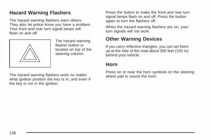
Hazard Warning FlashersThe hazard warning flashers warn others.They also let police know you have a problem.Your front and rear turn signal lamps willflash on and off.
The hazard warningflasher button islocated on top of thesteering column.
The hazard warning flashers work no matterwhat ignition position the key is in, and even ifthe key is not in the ignition.
Press the button to make the front and rear turnsignal lamps flash on and off. Press the buttonagain to turn the flashers off.
When the hazard warning flashers are on, yourturn signals will not work.
Other Warning DevicesIf you carry reflective triangles, you can set themup at the side of the road about 300 feet (100 m)behind your vehicle.
HornPress on or near the horn symbols on the steeringwheel pad to sound the horn.
138
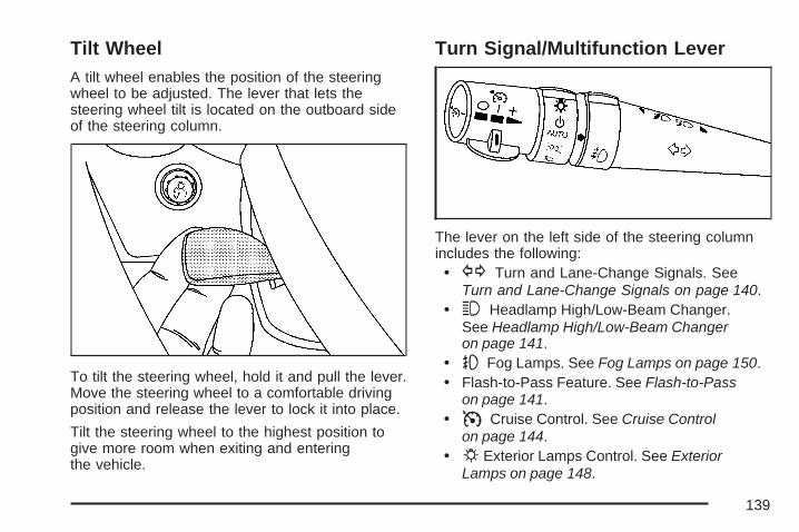
Tilt WheelA tilt wheel enables the position of the steeringwheel to be adjusted. The lever that lets thesteering wheel tilt is located on the outboard sideof the steering column.
To tilt the steering wheel, hold it and pull the lever.Move the steering wheel to a comfortable drivingposition and release the lever to lock it into place.
Tilt the steering wheel to the highest position togive more room when exiting and enteringthe vehicle.
Turn Signal/Multifunction Lever
The lever on the left side of the steering columnincludes the following:• G Turn and Lane-Change Signals. See
Turn and Lane-Change Signals on page 140.• 3 Headlamp High/Low-Beam Changer.
See Headlamp High/Low-Beam Changeron page 141.
• - Fog Lamps. See Fog Lamps on page 150.• Flash-to-Pass Feature. See Flash-to-Pass
on page 141.• I Cruise Control. See Cruise Control
on page 144.• P Exterior Lamps Control. See Exterior
Lamps on page 148.
139
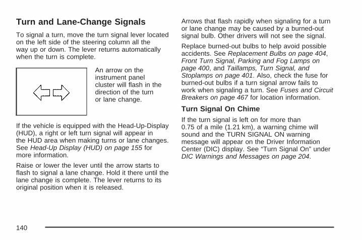
Turn and Lane-Change SignalsTo signal a turn, move the turn signal lever locatedon the left side of the steering column all theway up or down. The lever returns automaticallywhen the turn is complete.
An arrow on theinstrument panelcluster will flash in thedirection of the turnor lane change.
If the vehicle is equipped with the Head-Up-Display(HUD), a right or left turn signal will appear inthe HUD area when making turns or lane changes.See Head-Up Display (HUD) on page 155 formore information.
Raise or lower the lever until the arrow starts toflash to signal a lane change. Hold it there until thelane change is complete. The lever returns to itsoriginal position when it is released.
Arrows that flash rapidly when signaling for a turnor lane change may be caused by a burned-outsignal bulb. Other drivers will not see the signal.
Replace burned-out bulbs to help avoid possibleaccidents. See Replacement Bulbs on page 404,Front Turn Signal, Parking and Fog Lamps onpage 400, and Taillamps, Turn Signal, andStoplamps on page 401. Also, check the fuse forburned-out bulbs if a turn signal arrow fails towork when signaling a turn. See Fuses and CircuitBreakers on page 467 for location information.
Turn Signal On ChimeIf the turn signal is left on for more than0.75 of a mile (1.21 km), a warning chime willsound and the TURN SIGNAL ON warningmessage will appear on the Driver InformationCenter (DIC) display. See “Turn Signal On” underDIC Warnings and Messages on page 204.
140
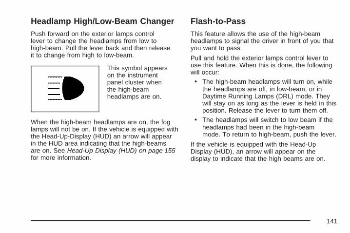
Headlamp High/Low-Beam ChangerPush forward on the exterior lamps controllever to change the headlamps from low tohigh-beam. Pull the lever back and then releaseit to change from high to low-beam.
This symbol appearson the instrumentpanel cluster whenthe high-beamheadlamps are on.
When the high-beam headlamps are on, the foglamps will not be on. If the vehicle is equipped withthe Head-Up-Display (HUD) an arrow will appearin the HUD area indicating that the high-beamsare on. See Head-Up Display (HUD) on page 155for more information.
Flash-to-PassThis feature allows the use of the high-beamheadlamps to signal the driver in front of you thatyou want to pass.
Pull and hold the exterior lamps control lever touse this feature. When this is done, the followingwill occur:
• The high-beam headlamps will turn on, whilethe headlamps are off, in low-beam, or inDaytime Running Lamps (DRL) mode. Theywill stay on as long as the lever is held in thisposition. Release the lever to turn them off.
• The headlamps will switch to low beam if theheadlamps had been in the high-beammode. To return to high-beam, push the lever.
If the vehicle is equipped with the Head-UpDisplay (HUD), an arrow will appear on thedisplay to indicate that the high beams are on.
141

Windshield Wiper LeverBe sure to clear ice and snow from the wiperblades before using them. If they are frozen to thewindshield, gently loosen or thaw them. Damagedwiper blades may not clear the windshield well,making it harder to see and drive safely. If theblades do become damaged, install new blades orblade inserts. For more information, see WindshieldWiper Blade Replacement on page 405.Heavy snow or ice can overload the wiper motor. Acircuit breaker will stop the motor until it cools down.Clear away snow or ice to prevent an overload.
N (Windshield Wipers): The lever with thissymbol, located on the right side of the steeringcolumn, operates the windshield wipers.
9 (Off): Lower the lever to its original position toturn the wipers off.
& (Delay): Push the lever up once to thisposition to set a delay between wiping cycles.Turn the delay adjustment band to set the lengthof the delay.
x (Delay Adjustment): Turn the band, locatedon the left of the windshield wiper lever, to setthe length of the delay between wiper cycles whenusing the delay feature. There are five delayadjustment settings. Turn the band up to makethe delays shorter in between wiper cycles.Turn the band down to make the delays longerbetween wiper cycles. The windshield wiper levermust be in delay for this feature to work.
142

6 (Low Speed): Push the lever up to thesecond position for steady wiping cycles at aslow speed.
1 (High Speed): Push the lever up to the thirdposition for steady wiping cycles at a high speed.
7 (Mist): For a single wiping cycle, push thelever down once and let go. The wipers willstop after one cycle. For additional cycles, holdthe lever down.
About 30 seconds after the wipers are on, theheadlamps, taillamps, and instrument panellighting will come on, and the Driver InformationCenter (DIC) back lighting will decrease tothe night time mode. About ten seconds after thewipers are turned off, all the lamps will go backto the AUTO (Automatic) mode. See ExteriorLamps on page 148.
Windshield Washer
{CAUTION:
In freezing weather, do not use yourwasher until the windshield is warmed.Otherwise the washer fluid can form iceon the windshield, blocking your vision.
The windshield washer button is located at theend of the windshield wiper lever.
K (Washer Fluid): Press this button to activatethe washer fluid to spray onto the windshield.The wipers will run for a few cycles to clear thewindshield. For more wash cycles, press andhold the button.
If the vehicle is low on washer fluid, the LOWWASHER FLUID message will appear onthe Driver Information Center (DIC) display. See“LOW WASHER FLUID” under DIC Warningsand Messages on page 204 for more information.
143
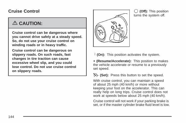
Cruise Control
{CAUTION:
Cruise control can be dangerous whereyou cannot drive safely at a steady speed.So, do not use your cruise control onwinding roads or in heavy traffic.
Cruise control can be dangerous onslippery roads. On such roads, fastchanges in tire traction can causeexcessive wheel slip, and you couldlose control. Do not use cruise controlon slippery roads.
9 (Off): This positionturns the system off.
R (On): This position activates the system.
+ (Resume/Accelerate): This position to makesthe vehicle accelerate or resume to a previouslyset speed.
T (Set): Press this button to set the speed.
With cruise control, you can maintain a speedof about 25 mph (40 km/h) or more withoutkeeping your foot on the accelerator. This canreally help on long trips. Cruise control does notwork at speeds below about 25 mph (40 km/h).
Cruise control will not work if your parking brake isset, or if the master cylinder brake fluid level is low.
144
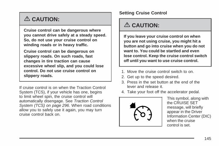
{CAUTION:
Cruise control can be dangerous whereyou cannot drive safely at a steady speed.So, do not use your cruise control onwinding roads or in heavy traffic.
Cruise control can be dangerous onslippery roads. On such roads, fastchanges in tire traction can causeexcessive wheel slip, and you could losecontrol. Do not use cruise control onslippery roads.
If cruise control is on when the Traction ControlSystem (TCS), if your vehicle has one, beginsto limit wheel spin, the cruise control willautomatically disengage. See Traction ControlSystem (TCS) on page 296. When road conditionsallow you to safely use it again, you may turncruise control back on.
Setting Cruise Control
{CAUTION:
If you leave your cruise control on whenyou are not using cruise, you might hit abutton and go into cruise when you do notwant to. You could be startled and evenlose control. Keep the cruise control switchoff until you want to use cruise control.
1. Move the cruise control switch to on.2. Get up to the speed desired.3. Press in the set button at the end of the
lever and release it.4. Take your foot off the accelerator pedal.
This symbol, along withthe CRUISE SETmessage, will brieflyappear in the DriverInformation Center (DIC)when the cruisecontrol is set.
145
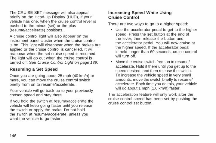
The CRUISE SET message will also appearbriefly on the Head-Up Display (HUD), if yourvehicle has one, when the cruise control lever ispushed to the minus (set) or the plus(resume/accelerate) positions.
A cruise control light will also appear on theinstrument panel cluster when the cruise controlis on. This light will disappear when the brakes areapplied or the cruise control is cancelled. It willreappear when the set cruise speed is resumed.The light will go out when the cruise control isturned off. See Cruise Control Light on page 189.
Resuming a Set SpeedOnce you are going about 25 mph (40 km/h) ormore, you can move the cruise control switchbriefly from on to resume/accelerate.
Your vehicle will go back up to your previouslychosen speed and stay there.
If you hold the switch at resume/accelerate thevehicle will keep going faster until you releasethe switch or apply the brake. Do not holdthe switch at resume/accelerate, unless youwant the vehicle to go faster.
Increasing Speed While UsingCruise ControlThere are two ways to go to a higher speed:
• Use the accelerator pedal to get to the higherspeed. Press the set button at the end ofthe lever, then release the button andthe accelerator pedal. You will now cruise atthe higher speed. If the accelerator pedalis held longer than 60 seconds, cruise controlwill turn off.
• Move the cruise switch from on to resume/accelerate. Hold it there until you get up to thespeed desired, and then release the switch.To increase the vehicle speed in very smallamounts, move the switch briefly to resume/accelerate. Each time you do this, your vehiclewill go about 1 mph (1.6 km/h) faster.
The acceleration feature will only work after thecruise control speed has been set by pushing thecruise control set button.
146

Reducing Speed While UsingCruise ControlThere are two ways to reduce the vehicle’s speedwhile using cruise control:
• Press and hold the set button until you reachthe lower speed desired, then release it.
• To slow down in very small amounts, brieflypress the set button. Each time you dothis your vehicle will slow down aboutone mph (1.6 km/h).
Passing Another Vehicle While UsingCruise ControlUse the accelerator pedal to increase the vehicle’sspeed. When you take your foot off the pedal,the vehicle will slow down to the cruise controlspeed set earlier.
Using Cruise Control on HillsHow well the cruise control will work on hillsdepends upon the vehicle’s speed, its load,and the steepness of the hills. When going upsteep hills, the accelerator pedal might have to beused in order to maintain the vehicle’s speed.When going downhill, the brakes might have tobe applied, or the transaxle might have to beshifted to a lower gear to keep the vehicle’s speeddown. Doing either of these things will take thevehicle out of cruise. It may be better not touse the cruise control if the brakes constantly haveto be applied, or the vehicle continuously needsto be shifted to a lower gear.
Ending Cruise ControlThere are two ways to turn off the cruise control:
• Step lightly on the brake pedal
• Move the cruise control switch to off
Erasing Speed MemoryWhen the cruise control or the ignition is turnedoff, the cruise control set speed memory is erased.
147
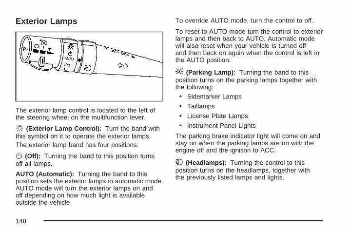
Exterior Lamps
The exterior lamp control is located to the left ofthe steering wheel on the multifunction lever.
O (Exterior Lamp Control): Turn the band withthis symbol on it to operate the exterior lamps.The exterior lamp band has four positions:
O (Off): Turning the band to this position turnsoff all lamps.
AUTO (Automatic): Turning the band to thisposition sets the exterior lamps in automatic mode.AUTO mode will turn the exterior lamps on andoff depending on how much light is availableoutside the vehicle.
To override AUTO mode, turn the control to off.
To reset to AUTO mode turn the control to exteriorlamps and then back to AUTO. Automatic modewill also reset when your vehicle is turned offand then back on again when the control is left inthe AUTO position.
; (Parking Lamp): Turning the band to thisposition turns on the parking lamps together withthe following:
• Sidemarker Lamps
• Taillamps
• License Plate Lamps
• Instrument Panel Lights
The parking brake indicator light will come on andstay on when the parking lamps are on with theengine off and the ignition to ACC.
5 (Headlamps): Turning the control to thisposition turns on the headlamps, together withthe previously listed lamps and lights.
148

Headlamps on ReminderA warning chime will sound if the vehicle’signition is off and the driver’s door is openedwhen the exterior lamp control is left on ineither the headlamp or parking lamp position.
Daytime Running Lamps (DRL)Daytime Running Lamps (DRL) can make it easierfor others to see the front of your vehicle duringthe day. DRL can be helpful in many differentdriving conditions, but they can be especiallyhelpful in the short periods after dawn and beforesunset. Daytime running lamps are required tofunction at all times on all vehicles first soldin Canada.
A light sensor on top of the instrument panelmakes the DRL work, so be sure it is not covered.
The DRL system will make the low-beamheadlamps come on at reduced brightness whenthe following conditions are met:
• The ignition is on.
• The exterior lamps control is off.
• The parking brake is released.
While the DRL are on, only the vehicle’s low-beamheadlamps will be on at reduced brightness.The turn signal, taillamps, sidemarker and otherlamps will not be on. The instrument panel clusterwill not be lit up either.
When it is dark enough outside, the DRL will turnoff and the vehicle’s headlamps and parkinglamps will turn on. The other lamps that come onwith the headlamps will also come on.
When it is bright enough outside, the headlampswill go off and the DRL will come on.
To idle the vehicle with the DRL off, turn theexterior lamp control off and then do one ofthe following:
• Turn the exterior lamp control to the parkinglamp position.
• Turn the exterior lamp control to theheadlamp position.
• Turn the exterior lamp control from AUTOto off and back to AUTO.
This feature is not available for vehicles first soldin Canada.
149
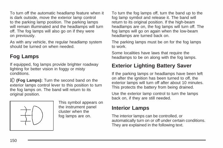
To turn off the automatic headlamp feature when itis dark outside, move the exterior lamp controlto the parking lamp position. The parking lampswill remain illuminated and the headlamps will turnoff. The fog lamps will also go on if they wereon previously.
As with any vehicle, the regular headlamp systemshould be turned on when needed.
Fog LampsIf equipped, fog lamps provide brighter roadwaylighting for better vision in foggy or mistyconditions.
- (Fog Lamps): Turn the second band on theexterior lamps control lever to this position to turnthe fog lamps on. The band will return to itsoriginal position.
This symbol appears onthe instrument panelcluster when thefog lamps are on.
To turn the fog lamps off, turn the band up to thefog lamp symbol and release it. The band willreturn to its original position. If the high-beamheadlamps are on, the fog lamps will turn off. Thefog lamps will go on again when the low-beamheadlamps are turned back on.
The parking lamps must be on for the fog lampsto work.
Some localities have laws that require theheadlamps to be on along with the fog lamps.
Exterior Lighting Battery SaverIf the parking lamps or headlamps have been lefton after the ignition has been turned to off, theexterior lamps will turn off after about 10 minutes.This protects the battery from being drained.
Use the exterior lamp control to turn the lampsback on, if they are still needed.
Interior LampsThe interior lamps can be controlled, orautomatically turn on or off under certain conditions.They are explained in the following text.
150

Instrument Panel BrightnessThis feature controls the brightness of theinstrument panel lights.
The interior lampscontrol is located onthe instrument panel,to the left of thesteering column.
Turn the control to adjust the brightness of theinstrument panel lights.
Courtesy LampsWhen a door is opened, the courtesy lamps willautomatically come on. These lamps will alsocome on when the interior lamps control is fullyturned clockwise.
Dome LampIf the vehicle does not have an overhead console,it will have a dome light located in the front ofthe headliner.
The switch on this lamp has three positions.The on position will turn on the lamp anytime.The door position will turn on the lamp whenevera door is opened. The off position will shut offthe lamp completely, even while a door is opened.
151

Entry LightingThe entry lighting feature turns the interiorlights on before anyone enters the vehicle.The interior lamps will come on for 40 secondswhen the doors are unlocked using the remotekeyless entry transmitter and the ignition is in OFF.After 40 seconds have elapsed, the interiorlamps will slowly fade out. The lamps will fade outbefore 40 seconds have elapsed if one of thefollowing is done:
• Lock all doors using the remote keylessentry transmitter.
• Lock the doors using the power doorlock switch.
When any door is opened, entry lighting iscancelled. The interior lamps will stay on whileany door is opened and slowly fade out when alldoors are closed. The interior lamps may stayon for up to 25 seconds after all doors have beenclosed if they have not been locked.
Delayed Entry LightingThe delayed lighting feature will continue to lightthe interior of the vehicle for 25 seconds afterall the doors have been closed. Delayed lightingwill not occur while the ignition is in RUN or ACC.After 25 seconds have elapsed, the interiorlamps will slowly fade out. The lamps will fade outbefore the 25 seconds have elapsed if one ofthe following is done:
• The ignition is turned to RUN or ACC.
• The doors are locked using the remotekeyless entry transmitter.
• The doors are locked using the powerdoor lock switch.
To turn the delayed lighting feature off or on,see “Personal Programming Modes” underDIC Vehicle Customization on page 230 DICControls and Displays.
152

Delayed Exit LightingFor exiting the vehicle at night, the vehicle isequipped with the delayed exit lighting feature. Afterthe key is removed from the ignition, the interiorlamps will light for up the amount of seconds set inthe Driver Information Center (DIC). See “PersonalProgramming Mode Screens” under DIC VehicleCustomization on page 230. After the set time haselapsed, the interior lamps will slowly fade. Thelamps will fade before the set time has elapsed ifone of the following is done:• The ignition is turned to RUN or ACC.• The doors are locked using the remote keyless
entry transmitter.• The doors are locked using the power door
lock switch.When any door is opened, delayed exit lighting iscancelled. The interior lamps will stay on whileany door is opened and will slowly fade out whenall the doors are closed. The interior lamps willstay on for the set time after all the doorshave been closed if they have not been locked.To turn the delayed exit lighting feature off oron, see “Personal Programming Mode Screens”under DIC Vehicle Customization on page 230.
Front Reading LampsIf the vehicle has a sunroof, there are readinglamps in front of the sunroof switch located on theheadliner. These lamps will come on when thedoors are opened. Press the side of each readinglamp to turn them on and off when the doorsare closed.
Overhead Console Reading LampsThe vehicle may have reading lamps on theoverhead console. These lamps will turn onwhen the doors are opened. When the doorsare closed, press the side of each lamp to turnthem on and off.
Rear Assist Handle Reading LampsIf the vehicle has a reading lamp on each rearassist handle, press the side of each lamp toturn it on or off.
153
Electric Power ManagementThe vehicle has Electric Power Management (EPM)that estimates the battery’s temperature and stateof charge. It then adjusts the voltage for bestperformance and extended life of the battery.
When the battery’s state of charge is low, thevoltage is raised slightly to quickly put the chargeback in. When the state of charge is high, thevoltage is lowered slightly to prevent overcharging.If the vehicle has a voltmeter gage or voltagedisplay on the Driver Information Center (DIC),you may see the voltage move up or down.This is normal. If there is a problem, an alert willbe displayed.
The battery can be discharged at idle if theelectrical loads are very high. This is true for allvehicles. This is because the generator (alternator)may not be spinning fast enough at idle toproduce all the power that is needed for veryhigh electrical loads.
A high electrical load occurs when several of thefollowing loads are on: headlamps, high beams,fog lamps, rear window defogger, climatecontrol fan at high speed, heated seats, enginecooling fans, trailer loads, and loads pluggedinto accessory power outlets.
EPM works to prevent excessive dischargeof the battery. It does this by balancing thegenerator’s output and the vehicle’s electricalneeds. It can increase engine idle speed togenerate more power, whenever needed. It cantemporarily reduce the power demands ofsome accessories.
Normally, these actions occur in steps or levels,without being noticeable. In rare cases at thehighest levels of corrective action, this actionmay be noticeable to the driver. If so, a DriverInformation Center (DIC) message might bedisplayed, such as Battery Saver Active. If thismessage is displayed, it is recommended thatthe driver reduce the electrical loads as muchas possible. See DIC Warnings and Messageson page 204.
154
Battery Run-Down ProtectionThe vehicle has a feature to help prevent thebattery from draining in case the interior, trunk,or underhood lamps are accidentally left on.If any of these lamps are left on while the ignitionis in OFF, they will automatically turn off after10 minutes. The lamps will not come backon again until any of the following are done:
• The ignition is turned to RUN or ACC.
• The interior lamps control is turned completelyto the right, then back slightly to the left.
• Open, or close and reopen, a door thatis closed.
If the vehicle has less than 15 miles (25 km)on the odometer, the battery saver will turnoff the lamps after only three minutes.
Head-Up Display (HUD)
{CAUTION:
If the HUD image is too bright or too highin your field of view, it may take you moretime to see things you need to see whenit is dark outside. Be sure to keep theHUD image dim and placed low in yourfield of view.
If the vehicle has the Head-Up Display (HUD),some information concerning the operation ofthe vehicle is projected onto the windshield.This includes the speedometer reading,transaxle positions, compass direction, outsideair temperature, the tap shift gear and theupshift symbol if active, and a brief display of thecurrent radio station, including XM informationor CD track. It will also display turn-by-turnguidance information if the vehicle is has anavigation radio. The images are projected bythe HUD lens located on the driver’s side ofthe instrument panel.
155

The tap shift gear and the upshift symbol willalso appear on the HUD if the vehicle hastap shift and it is active.
The HUD information can be displayed in one ofthree languages, English, French, or Spanish. Thespeedometer reading and other numerical valuescan be displayed in either English or metric units.
The language selection and the units ofmeasurement are changed through the tripcomputer in the Driver Information Center (DIC).See “Options” under DIC Controls and Displays(Base Level DIC) on page 190 or DIC Controlsand Displays (Uplevel DIC with Trip Computer)on page 194. The HUD information appears as an image
focused out toward the front of the vehicle.
When the ignition key is turned to RUN, the HUDwill display an introductory message for a shorttime, until the HUD has warmed up.
The following indicator lights come on theinstrument panel when activated and will alsoappear on the HUD:
• Turn Signal Indicators
• High-Beam Indicator Symbol
156
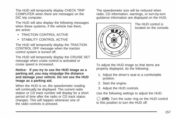
The HUD will temporarily display CHECK TRIPCOMPUTER when there are messages on theDIC trip computer.
The HUD will also display the following messageswhen these systems, if the vehicle has them,are active:
• TRACTION CONTROL ACTIVE
• STABILITY CONTROL ACTIVE
The HUD will temporarily display the TRACTIONCONTROL OFF message when the tractioncontrol system is turned off.
The HUD will temporarily display the CRUISE SETmessage when cruise control is activated orcruise speed is increased.
Notice: If you try to use the HUD image as aparking aid, you may misjudge the distanceand damage your vehicle. Do not use the HUDimage as a parking aid.
When the HUD is on, the speedometer readingwill continually be displayed. The current radiostation or CD track number will display for a shortperiod of time after the radio or CD track statuschanges. This will happen whenever one ofthe radio controls is pressed.
The speedometer size will be reduced whenradio, CD information, warnings, or turn-by-turnguidance information are displayed on the HUD.
The HUD control islocated on the console.
To adjust the HUD image so that items areproperly displayed, do the following:
1. Adjust the driver’s seat to a comfortableposition.
2. Start the engine.
3. Adjust the HUD controls.
Use the following settings to adjust the HUD.
9 (Off): Turn the outer ring on the HUD controlto this position to turn the HUD off.
157

I II III IIII (Brightness): Turn the outer ring on theHUD control clockwise to dim the display andcounterclockwise to brighten it.
w (Up): Press this portion of the switch on theHUD control to move the image up.
x (Down): Press this portion of the switch on theHUD control to move the image down. Movethe image as low as possible on the windshield,keeping it in full view.
? (Page): Press this button to select the displayformats. Release the page button when theformat number with the desired display is shownon the HUD.• Format One: This display gives the
speedometer reading (in English or metricunits), transaxle positions, compass direction,and the outside air temperature.
• Format Two: This display includes theinformation in Format One without thecompass direction and the outside airtemperature.
• Format Three: This display includes all theinformation in Format One, but turns theinstrument cluster lighting off. Format three isonly available at night.
All formats will show the turn-by-turn guidanceinformation. It will display the next turn, direction,street name, and distance to the selecteddestination. When you near your destination,the HUD will display a distance bar that willfill in the closer you get to your destination.All navigation information is provided to the HUDby the navigation radio, if the vehicle has one.
The warning indicators still appear on theinstrument panel when required. The HUD willdisplay Stealth Mode On.
The HUD will store the last display format selected.If the last format displayed was Format One orFormat Three, then Format One will be displayedwhen the vehicle is started.
If the last format was Format Two, then FormatTwo will be displayed.
The HUD image displayed on the windshield willautomatically dim and brighten to compensatefor outside lighting.
158

The HUD image can temporarily light updepending on the angle and position of thesunlight on the HUD display. This is normal andwill change when the angle of the sunlight onthe HUD display changes.
Polarized sunglasses could make the HUD imageharder to see.
Care of the HUDClean the inside of the windshield as needed toremove any dirt or film that could reduce thesharpness or clarity of the HUD image.
To clean the HUD lens, use a soft, clean cloththat has household glass cleaner sprayedon it. Wipe the HUD lens gently, then dry it.Do not spray cleaner directly on the lensbecause the cleaner could leak into the unit.
If You Cannot See the HUD ImageWhen the Ignition Is On• Is anything covering the HUD lens?
• Is the HUD dimmer setting bright enough?
• Is the HUD image adjusted to theproper height?
• Are you wearing polarized sunglasses?
• Still no HUD image? Check the fuse in theinstrument panel fuse block. See InstrumentPanel Fuse Block on page 468.
If the HUD Image Is Not Clear• Is the HUD image too bright?
• Are the windshield and HUD lens clean?
If the HUD image is not correct, contactyour dealer.
Keep in mind that the windshield is part of theHUD system. See Windshield Replacementon page 405.
159
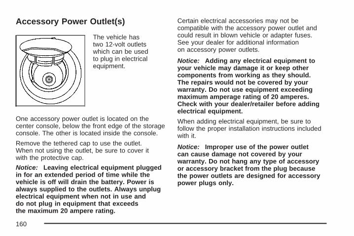
Accessory Power Outlet(s)
The vehicle hastwo 12-volt outletswhich can be usedto plug in electricalequipment.
One accessory power outlet is located on thecenter console, below the front edge of the storageconsole. The other is located inside the console.
Remove the tethered cap to use the outlet.When not using the outlet, be sure to cover itwith the protective cap.
Notice: Leaving electrical equipment pluggedin for an extended period of time while thevehicle is off will drain the battery. Power isalways supplied to the outlets. Always unplugelectrical equipment when not in use anddo not plug in equipment that exceedsthe maximum 20 ampere rating.
Certain electrical accessories may not becompatible with the accessory power outlet andcould result in blown vehicle or adapter fuses.See your dealer for additional informationon accessory power outlets.
Notice: Adding any electrical equipment toyour vehicle may damage it or keep othercomponents from working as they should.The repairs would not be covered by yourwarranty. Do not use equipment exceedingmaximum amperage rating of 20 amperes.Check with your dealer/retailer before addingelectrical equipment.
When adding electrical equipment, be sure tofollow the proper installation instructions includedwith it.
Notice: Improper use of the power outletcan cause damage not covered by yourwarranty. Do not hang any type of accessoryor accessory bracket from the plug becausethe power outlets are designed for accessorypower plugs only.
160

Ashtray(s) and Cigarette LighterYour vehicle may have a removable muffintin ashtray and cigarette lighter. The muffin tinashtray can be placed into the front center consolecupholder. To use the lighter, located on thecenter console, push it in all the way and let go.When it is ready, it will pop back out by itself.
Notice: Holding a cigarette lighter in whileit is heating does not let the lighter back awayfrom the heating element when it is hot.Damage from overheating can occur to thelighter or heating element, or a fuse could beblown. Do not hold a cigarette lighter in whileit is heating.
Notice: If you put papers, pins, or otherflammable items in the ashtray, hot cigarettesor other smoking materials could ignitethem and possibly damage your vehicle.Never put flammable items in the ashtray.
Climate Controls
Climate Control SystemThe climate control system allows manual control ofthe heating, cooling, and ventilation in the vehicle.
Fan9 (Fan): Turn the knob by this symbol, locatedon the left side of the climate control panel,clockwise or counterclockwise to increase ordecrease the fan speed. The fan speed will betemporarily reduced between the transitionto a new mode. The fan will resume the originalspeed when the transition to the new modeis complete.
161

9 (Off): Turn the knob to this position to turnthe climate control system off. Only the heatedseat and/or rear defrost can be operated whenthe fan is off.
ModeTurn the middle knob to select thefollowing modes:
H (Vent) (Outside Air): This mode directsoutside air to the instrument panel outlets. If drivingin city traffic, and the vehicle is stopped andidling, or the weather is hot, press the recirculationbutton. To prevent the air inside the vehiclefrom becoming stale, be sure to turn offrecirculation periodically.
) (Bi-Level): This mode directs half of the air tothe instrument panel outlets, and the remainingair to the floor outlets. Some air may be directedtoward the windshield. Slightly cooler air is directedto the instrument panel outlets and warmer air isdirected to the floor outlets.
6 (Floor): This mode directs most of the air tothe floor outlets with some air directed towardthe side window outlets and a little air directed tothe windshield.
In this mode, the system will automatically useoutside air. The air conditioning compressor willbe engaged unless the outside temperature is40°F (4°C) or below.
Recirculation cannot be selected when in thismode even though the indicator light comes onwhen the recirculation button is pressed.
The middle knob on the climate control panel canalso be used to select the defog or defrost mode.
162
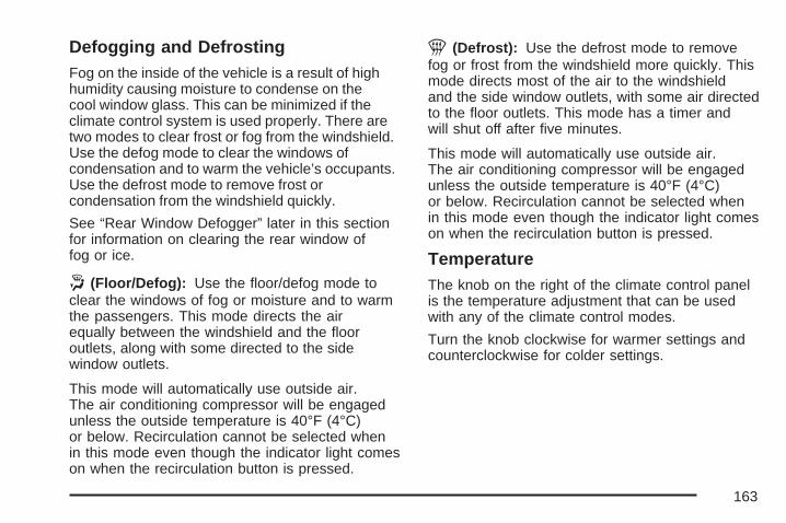
Defogging and DefrostingFog on the inside of the vehicle is a result of highhumidity causing moisture to condense on thecool window glass. This can be minimized if theclimate control system is used properly. There aretwo modes to clear frost or fog from the windshield.Use the defog mode to clear the windows ofcondensation and to warm the vehicle’s occupants.Use the defrost mode to remove frost orcondensation from the windshield quickly.
See “Rear Window Defogger” later in this sectionfor information on clearing the rear window offog or ice.
. (Floor/Defog): Use the floor/defog mode toclear the windows of fog or moisture and to warmthe passengers. This mode directs the airequally between the windshield and the flooroutlets, along with some directed to the sidewindow outlets.
This mode will automatically use outside air.The air conditioning compressor will be engagedunless the outside temperature is 40°F (4°C)or below. Recirculation cannot be selected whenin this mode even though the indicator light comeson when the recirculation button is pressed.
1 (Defrost): Use the defrost mode to removefog or frost from the windshield more quickly. Thismode directs most of the air to the windshieldand the side window outlets, with some air directedto the floor outlets. This mode has a timer andwill shut off after five minutes.
This mode will automatically use outside air.The air conditioning compressor will be engagedunless the outside temperature is 40°F (4°C)or below. Recirculation cannot be selected whenin this mode even though the indicator light comeson when the recirculation button is pressed.
TemperatureThe knob on the right of the climate control panelis the temperature adjustment that can be usedwith any of the climate control modes.
Turn the knob clockwise for warmer settings andcounterclockwise for colder settings.
163
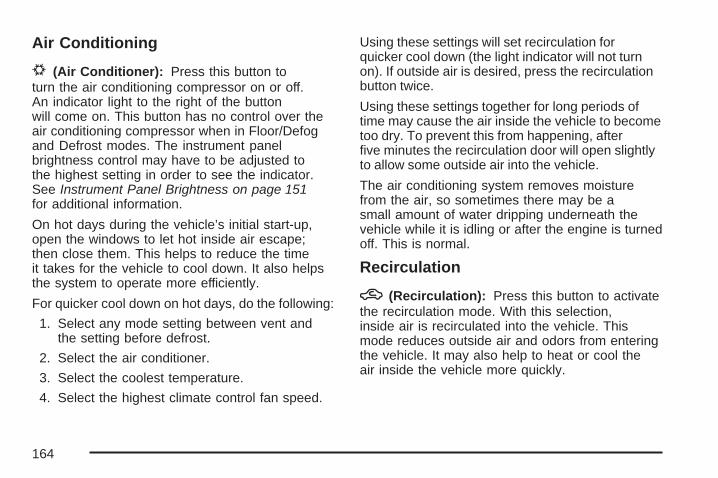
Air Conditioning
# (Air Conditioner): Press this button toturn the air conditioning compressor on or off.An indicator light to the right of the buttonwill come on. This button has no control over theair conditioning compressor when in Floor/Defogand Defrost modes. The instrument panelbrightness control may have to be adjusted tothe highest setting in order to see the indicator.See Instrument Panel Brightness on page 151for additional information.
On hot days during the vehicle’s initial start-up,open the windows to let hot inside air escape;then close them. This helps to reduce the timeit takes for the vehicle to cool down. It also helpsthe system to operate more efficiently.
For quicker cool down on hot days, do the following:
1. Select any mode setting between vent andthe setting before defrost.
2. Select the air conditioner.
3. Select the coolest temperature.
4. Select the highest climate control fan speed.
Using these settings will set recirculation forquicker cool down (the light indicator will not turnon). If outside air is desired, press the recirculationbutton twice.
Using these settings together for long periods oftime may cause the air inside the vehicle to becometoo dry. To prevent this from happening, afterfive minutes the recirculation door will open slightlyto allow some outside air into the vehicle.
The air conditioning system removes moisturefrom the air, so sometimes there may be asmall amount of water dripping underneath thevehicle while it is idling or after the engine is turnedoff. This is normal.
Recirculation
h (Recirculation): Press this button to activatethe recirculation mode. With this selection,inside air is recirculated into the vehicle. Thismode reduces outside air and odors from enteringthe vehicle. It may also help to heat or cool theair inside the vehicle more quickly.
164

An indicator light to the right of the button willcome on to show that the recirculation button hasbeen pressed. The instrument panel brightnesscontrol may have to be adjusted to the highestsetting to see the indicator.
The recirculation mode has a timer. Afterfive minutes, the system’s air inlet door will moveslightly to allow for ten percent fresh outsideair to maintain interior air quality. The only way toreset the system to full recirculation is to restartthe five minute timer by selecting vent/outside airand recirculation again.
Rear Window DefoggerThe rear window defogger uses a warming gridto remove fog or frost from the rear window.Be sure to clear as much snow from the rearwindow as possible.
Notice: Do not use a razor blade or sharpobject to clear the inside rear window. Do notadhere anything to the defogger grid linesin the rear glass. These actions may damagethe rear defogger. Repairs would not becovered by your warranty.
= (Rear Window Defogger): Press this buttonto turn the rear window defogger on or off.
An indicator light to the right of the button will comeon to show that the rear window defogger is on.The instrument panel brightness control may haveto be adjusted to the highest setting during thedaytime in order to see the indicator light.
The rear window defogger will turn off about20 minutes after the button is pressed. If the buttonis pressed again, it will run another 20 minutes.The defogger can be turned off by pressing thebutton again or by turning off the engine.
Do not drive the vehicle until all windowsare clear.
z (Heated Seats): Press this button to turnthe heated seats on and off. The button on the leftcontrols the driver’s seat and the button on theright controls the passenger’s seat. See HeatedSeats on page 10 for additional information.
165
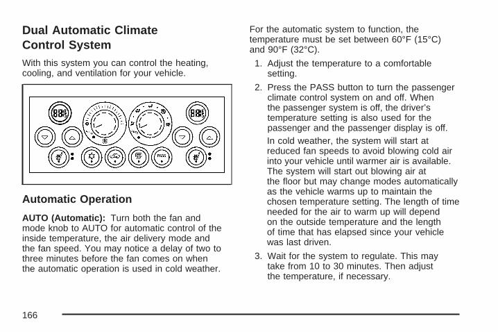
Dual Automatic ClimateControl SystemWith this system you can control the heating,cooling, and ventilation for your vehicle.
Automatic Operation
AUTO (Automatic): Turn both the fan andmode knob to AUTO for automatic control of theinside temperature, the air delivery mode andthe fan speed. You may notice a delay of two tothree minutes before the fan comes on whenthe automatic operation is used in cold weather.
For the automatic system to function, thetemperature must be set between 60°F (15°C)and 90°F (32°C).
1. Adjust the temperature to a comfortablesetting.
2. Press the PASS button to turn the passengerclimate control system on and off. Whenthe passenger system is off, the driver’stemperature setting is also used for thepassenger and the passenger display is off.In cold weather, the system will start atreduced fan speeds to avoid blowing cold airinto your vehicle until warmer air is available.The system will start out blowing air atthe floor but may change modes automaticallyas the vehicle warms up to maintain thechosen temperature setting. The length of timeneeded for the air to warm up will dependon the outside temperature and the lengthof time that has elapsed since your vehiclewas last driven.
3. Wait for the system to regulate. This maytake from 10 to 30 minutes. Then adjustthe temperature, if necessary.
166

Do not cover the solar sensor located in thecenter of the instrument panel, near thewindshield. For more information on the solarsensor, see “Sensors” later in this section.
Manual Operation
x w (Temperature): To manually adjust thetemperature inside the vehicle, press the up arrowon the temperature control to raise the temperatureand press the down arrow to lower thetemperature. The display will show your selection.
When one temperature is displayed, the drivertemperature is set. When both temperatures aredisplayed, the temperature for both the driverand passenger are set. Pressing PASS will turnthe passenger temperature setting on andoff. If only the driver temperature is set, the drivertemperature is used for the passenger and thepassenger display is off.
9 (Fan): Turn the fan knob clockwise to increasethe fan speed and counterclockwise to decreasethe fan speed. Turning the fan knob cancelsthe automatic fan operation and places the system
in manual. Turn the knob to AUTO to return toautomatic fan operation. If the airflow seemslow when the fan is at the highest setting,the passenger compartment air filter, if equipped,may need to be replaced. See PassengerCompartment Air Filter on page 170 for additionalinformation.
9 (Off): Turning the fan knob off will turn thecontroller completely off.
Mode: This control has several settings to controlthe direction of airflow.
To change the current mode, select one of thefollowing:
AUTO: This mode is automatically set dependingon the temperature in the vehicle and solarsensor information.
H (Vent): This mode directs air to the instrumentpanel outlets.
% (Bi-Level): This mode directs airflow to theinstrument panel outlets and to the floor outlets.A small amount of air is also directed to thewindshield and the side window outlets.
167

6 (Floor): This mode directs most of the air tothe floor outlets with some air directed to theside window outlets, and a little air directed to thewindshield.
# (Air Conditioning): Press this button to turnthe air conditioning compressor on or off. Theindicator light on the button will come on whenthe air conditioning is on.
? (Recirculation): Press this button to turn therecirculation mode on or off. This mode keepsoutside air from coming in the vehicle. It can beused to help reduce the outside air and odorsthat may enter the vehicle or help to cool theair inside the vehicle quicker.
Recirculation is not available in defrost orfloor/defog mode. Pressing the recirculationbutton will turn on the indicator light.
Using recirculation for long periods of time maycause the air inside your vehicle to becometoo dry. To prevent this from happening, afterthe air in your vehicle has cooled, turn therecirculation mode off.
z (Heated Seats): Press this button to turn theheated seats on and off. The button on theleft controls the driver’s seat and the button on theright controls the passenger’s seat. See HeatedSeats on page 10 for additional information.
SensorsThe solar sensor on your vehicle monitors thesolar radiation and the air inside of your vehicle,then uses the information to maintain the selectedtemperature by initiating needed adjustments tothe temperature, the fan speed and the air deliverysystem. The system may also supply cooler airto the side of the vehicle facing the sun. Therecirculation mode will also be activated, asnecessary. Do not cover the solar sensor locatedin the center of the instrument panel, near thewindshield, or the system will not work properly.
168

Defogging and DefrostingFog on the inside of windows is a result of highhumidity (moisture) condensing on the cool windowglass. This can be minimized if the climate controlsystem is used properly. There are two modes toclear fog or frost from your windshield. Use thefloor/defog mode to clear the windows of fog ormoisture and warm the passengers. Use the defrostmode to remove fog or frost from the windshieldmore quickly.
- (Floor/Defog): This mode directs the airbetween the windshield, floor outlets and sidewindows. When you select this mode, the systemturns off recirculation and runs the air-conditioningcompressor unless the outside temperature isnear or below freezing. Pressing the recirculationbutton, while in this mode, will have no effectother than turning on the indicator light.
1 (Defrost): This mode directs most of theair to the windshield, with some air directed tothe side windows. In this mode, the system willautomatically turn off the recirculation and run theair conditioning compressor, unless the outsidetemperature is near or below freezing. Pressing therecirculation button, while in this mode, will haveno affect other than turning on the indicator light.
Rear Window DefoggerThe rear window defogger uses a warming grid toremove fog or frost from the rear window.
The rear window defogger will only work when theengine is running.
= (Rear Window Defogger): Press this buttonto turn the rear window defogger on and off.Be sure to clear as much snow from the rearwindow as possible.
The rear window defogger will turn off about20 minutes after the button is pressed. If turnedon again, the defogger will only run for about20 minutes before turning off. The defogger canalso be turned off by pressing the button again orby turning off the engine.
Do not drive the vehicle until all the windowsare clear.
Notice: Do not use anything sharp on theinside of the rear window. If you do, you couldcut or damage the warming grid, and therepairs would not be covered by your warranty.Do not attach a temporary vehicle license,tape, a decal or anything similar to thedefogger grid.
169
Outlet AdjustmentTurn the air outlets, located in the middle andat each outboard side of the instrument panel,to adjust the direction of the airflow.
Operation Tips• Clear away any ice, snow, or leaves from the
air inlets at the base of the windshield thatmay block the flow of air into the vehicle.
• Use of non-GM approved hood deflectorsmay adversely affect the performance ofthe system.
• Keep the path under the front seats clearof objects to help circulate the air insideof the vehicle more effectively.
• If the airflow seems low when the fan isat the highest setting, the passengercompartment air filter may need to bereplaced. See “Passenger CompartmentAir Filter” following, for more information.
Passenger Compartment Air FilterThe passenger compartment air filter is locatednear the passenger’s side windshield wiperarm, under the inlet grille.
The filter traps most of the pollen from enteringthe climate control system. Similar to the engine’sair filter, it may need to be changed periodicallyto insure system performance. See ScheduledMaintenance on page 480 for more information.
To change the passenger compartment airfilter, do the following:
1. Turn the ignition to ACC and the windshieldwipers on.
2. Turn the ignition to OFF when the windshieldwipers are in the upright position.
3. Raise the hood.
4. Disconnect the windshield washer pump hosefrom the fender rail and the air inlet grille.
5. Remove the hood weather-strip from thepassenger’s side of the vehicle, peeling itback halfway.
170
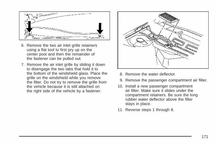
6. Remove the two air inlet grille retainersusing a flat tool to first pry up on thecenter post and then the remainder ofthe fastener can be pulled out.
7. Remove the air inlet grille by sliding it downto disengage the two tabs that hold it tothe bottom of the windshield glass. Place thegrille on the windshield while you removethe filter. Do not try to remove the grille fromthe vehicle because it is still attached onthe right side of the vehicle by a fastener.
8. Remove the water deflector.
9. Remove the passenger compartment air filter.
10. Install a new passenger compartmentair filter. Make sure it slides under thecompartment retainers. Be sure the longrubber water deflector above the filterstays in place.
11. Reverse steps 1 through 8.
171

Warning Lights, Gages,and IndicatorsThis part describes the warning lights and gageson your vehicle. The pictures help to locate them.
Warning lights and gages can signal that somethingis wrong before it becomes serious enough tocause an expensive repair or replacement. Payingattention to the warning lights and gages could alsosave you or others from injury.
Warning lights come on when there may be oris a problem with one of your vehicle’s functions.As the details show on the next few pages,some warning lights come on briefly when youstart the engine just to let you know they areworking. If you are familiar with this section, youshould not be alarmed when this happens.
Gages can indicate when there may be or is aproblem with one of your vehicle’s functions.Often gages and warning lights work togetherto let you know when there is a problem withyour vehicle.
When one of the warning lights comes on andstays on as you are driving, or when one ofthe gages shows there may be a problem, checkthe section that tells you what to do about it.Please follow this manual’s advice. Waiting todo repairs can be costly and even dangerous.So please get to know your vehicle’s warning lightsand gages. They can be a big help.
Your vehicle may also have a Driver InformationCenter (DIC) that works along with the warninglights and gages. See Driver InformationCenter (DIC) on page 190 for more information.
172

Instrument Panel ClusterThe instrument panel cluster is designed to show at a glance how the vehicle is running. It will showhow fast the vehicle is going, about how much fuel is in the fuel tank, and many other things neededto drive the vehicle safely and economically.
United States version shown, Canada similar
173

The vehicle is equipped with this cluster or onevery similar to it. It has indicator warning lights thatare explained on the following pages. Be sure toread about them.
Speedometer and OdometerThe speedometer shows the vehicle’s speed inboth miles per hour (mph) and kilometers perhour (km/h). The odometer, located on the DriverInformation Center (DIC) display, shows howfar the vehicle has been driven, in either miles orkilometers. See DIC Controls and Displays(Base Level DIC) on page 190 or DIC Controlsand Displays (Uplevel DIC with Trip Computer)on page 194 for more information.
If the vehicle has the Head-Up Display (HUD) thespeed will also be displayed on the HUD screen.
If a vehicle has to have a new odometer installed,a new one can be set to the mileage total ofthe old odometer, if that can be done. If it cannot,than it will be set at zero and a label must beput on the driver’s door to show the old mileagereading when the new odometer was installed.
Trip OdometerThe trip odometer, located in the DriverInformation Center (DIC), tells how far the vehiclehas driven since it was last reset. The miles(kilometers) for two different trips can be viewed.See DIC Controls and Displays (Base LevelDIC) on page 190 or DIC Controls and Displays(Uplevel DIC with Trip Computer) on page 194 formore information on setting the trip odometer.
174
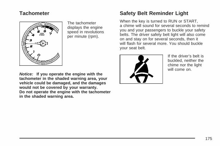
Tachometer
The tachometerdisplays the enginespeed in revolutionsper minute (rpm).
Notice: If you operate the engine with thetachometer in the shaded warning area, yourvehicle could be damaged, and the damageswould not be covered by your warranty.Do not operate the engine with the tachometerin the shaded warning area.
Safety Belt Reminder LightWhen the key is turned to RUN or START,a chime will sound for several seconds to remindyou and your passengers to buckle your safetybelts. The driver safety belt light will also comeon and stay on for several seconds, then itwill flash for several more. You should buckleyour seat belt.
If the driver’s belt isbuckled, neither thechime nor the lightwill come on.
175

Passenger Safety BeltReminder LightSeveral seconds after the key is turned to RUN orSTART, a chime will sound for several seconds toremind the front passenger to buckle their safetybelt. This would only occur if the passenger airbagis enabled. See Passenger Sensing System onpage 74 for more information. The passengersafety belt light will also come on and stay on forseveral seconds, then it will flash for several more.
This chime and lightwill be repeated ifthe passenger remainsunbuckled and thevehicle is in motion.
If the passenger’s safety belt is buckled, neitherthe chime nor the light will come on.
Airbag Readiness LightThere is an airbag readiness light on theinstrument panel cluster, which shows theairbag symbol. The system checks the airbag’selectrical system for malfunctions. The lightindicates if there is an electrical problem.The system check includes the airbag sensors,the airbag modules, the wiring, and the diagnosticmodule. For more information on the airbagsystem, see Airbag System on page 64.
This light will comeon when the vehicleis started, and it willflash for a few seconds.Then the light shouldgo out.
This means the system is functioning properly.
If the airbag readiness light stays on after thevehicle is started, or comes on as the vehicle isbeing driven, the airbag system may not workproperly. Have the vehicle serviced right away.
176
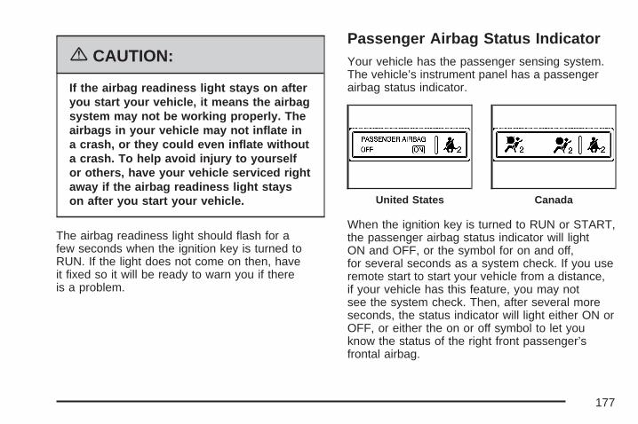
{CAUTION:
If the airbag readiness light stays on afteryou start your vehicle, it means the airbagsystem may not be working properly. Theairbags in your vehicle may not inflate ina crash, or they could even inflate withouta crash. To help avoid injury to yourselfor others, have your vehicle serviced rightaway if the airbag readiness light stayson after you start your vehicle.
The airbag readiness light should flash for afew seconds when the ignition key is turned toRUN. If the light does not come on then, haveit fixed so it will be ready to warn you if thereis a problem.
Passenger Airbag Status IndicatorYour vehicle has the passenger sensing system.The vehicle’s instrument panel has a passengerairbag status indicator.
When the ignition key is turned to RUN or START,the passenger airbag status indicator will lightON and OFF, or the symbol for on and off,for several seconds as a system check. If you useremote start to start your vehicle from a distance,if your vehicle has this feature, you may notsee the system check. Then, after several moreseconds, the status indicator will light either ON orOFF, or either the on or off symbol to let youknow the status of the right front passenger’sfrontal airbag.
United States Canada
177
If the word ON or the on symbol is lit on thepassenger airbag status indicator, it means thatthe right front passenger’s frontal airbag isenabled (may inflate).
{CAUTION:
If the on indicator comes on when you havea rear-facing child restraint installed in theright front passenger’s seat, it means thatthe passenger sensing system has notturned off the passenger’s frontal airbag.A child in a rear-facing child restraint canbe seriously injured or killed if the rightfront passenger’s airbag inflates. This isbecause the back of the rear-facing childrestraint would be very close to theinflating airbag. Do not use a rear-facingchild restraint in the right front passenger’sseat if the airbag is turned on.
Your vehicle has a rear seat that will accommodatea rear-facing child restraint. A label on your sunvisor says, “Never put a rear-facing child seatin the front.” This is because the risk to therear-facing child is so great, if the airbag deploys.
{CAUTION:
Even though the passenger sensingsystem is designed to turn off the rightfront passenger’s frontal airbag if thesystem detects a rear-facing childrestraint, no system is fail-safe, andno one can guarantee that an airbagwill not deploy under some unusualcircumstance, even though it is turned off.We recommend that rear-facing childrestraints be secured in the rear seat,even if the airbag is off.
178

If the word OFF or the off symbol is lit on theairbag status indicator, it means that the passengersensing system has turned off the right frontpassenger’s frontal airbag. See Passenger SensingSystem on page 74 for more on this, includingimportant safety information.
If, after several seconds, all status indicator lightsremain on, or if there are no lights at all, theremay be a problem with the lights or the passengersensing system. See your dealer for service.
{CAUTION:
If the off indicator and the airbagreadiness light ever come on together,it means that something may be wrongwith the airbag system. If this everhappens, have the vehicle servicedpromptly, because an adult-size personsitting in the right front passenger seatmay not have the protection of the frontalairbag. See Airbag Readiness Lighton page 176.
Up-Shift Light
If your vehicle has thislight, it will come onwhen the shift leveris in the manualtransaxle position.
It will appear as a prompt to up-shift to the nextgear using one of the Tap-Shift® paddles locatedon the steering wheel.
If your vehicle has the Head-Up Display (HUD),it will only appear on it.
See Automatic Transaxle Operation on page 113and Head-Up Display (HUD) on page 155 formore information.
179
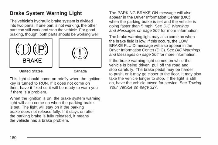
Brake System Warning LightThe vehicle’s hydraulic brake system is dividedinto two parts. If one part is not working, the otherpart can still work and stop the vehicle. For goodbraking, though, both parts should be working well.
This light should come on briefly when the ignitionkey is turned to RUN. If it does not come onthen, have it fixed so it will be ready to warn youif there is a problem.
When the ignition is on, the brake system warninglight will also come on when the parking brakeis set. The light will stay on if the parkingbrake does not release fully. If it stays on afterthe parking brake is fully released, it meansthe vehicle has a brake problem.
The PARKING BRAKE ON message will alsoappear in the Driver Information Center (DIC)when the parking brake is set and the vehicle isgoing faster than 5 mph. See DIC Warningsand Messages on page 204 for more information.
The brake warning light may also come on whenthe brake fluid is low. If this occurs, the LOWBRAKE FLUID message will also appear in theDriver Information Center (DIC). See DIC Warningsand Messages on page 204 for more information.
If the brake warning light comes on while thevehicle is being driven, pull off the road andstop carefully. The brake pedal may be harderto push, or it may go closer to the floor. It may alsotake the vehicle longer to stop. If the light is stillon, have the vehicle towed for service. See TowingYour Vehicle on page 327.
United States Canada
180
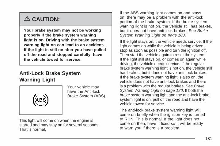
{CAUTION:
Your brake system may not be workingproperly if the brake system warninglight is on. Driving with the brake systemwarning light on can lead to an accident.If the light is still on after you have pulledoff the road and stopped carefully, havethe vehicle towed for service.
Anti-Lock Brake SystemWarning Light
Your vehicle mayhave the Anti-lockBrake System (ABS).
This light will come on when the engine isstarted and may stay on for several seconds.That is normal.
If the ABS warning light comes on and stayson, there may be a problem with the anti-lockportion of the brake system. If the brake systemwarning light is not on, the vehicle still has brakes,but it does not have anti-lock brakes. See BrakeSystem Warning Light on page 180.
If the light stays on, the vehicle needs service. If thelight comes on while the vehicle is being driven,stop as soon as possible and turn the ignition off.Then start the vehicle again to reset the system.If the light still stays on, or comes on again whiledriving, the vehicle needs service. If the regularbrake system warning light is not on, the vehicle stillhas brakes, but it does not have anti-lock brakes.If the brake system warning light is also on, thevehicle does not have anti-lock brakes and thereis a problem with the regular brakes. See BrakeSystem Warning Light on page 180. If both thebrake system warning light and the anti-lock brakesystem light is on, pull off the road and have thevehicle towed for service.
The anti-lock brake system warning light willcome on briefly when the ignition key is turnedto RUN. This is normal. If the light does notcome on then, have it fixed so it will be readyto warn you if there is a problem.
181

Low Tire Pressure Warning Light
This light should comeon briefly as you startthe engine.
This light will also come on when one or more ofyour tires is significantly under-inflated. Stop andcheck your tires as soon as it is safe to do so.If underinflated, inflate them to the proper pressure.See Tires on page 406 for more information.This light will flash for 60 seconds and then turnon solid if a problem is detected with the TirePressure Monitor System. See Tire PressureMonitor System on page 415 for more information.
Traction Control System (TCS)Warning Light
If the vehicle hasthe Traction ControlSystem (TCS), this lightmay come on for thefollowing reasons:
• The traction control button, located on thecenter console, is pressed, turning the systemoff. The light will stay on. To turn the systemback on, press the button again and thewarning light should go out. See TractionControl System (TCS) on page 296 for moreinformation.
• If there is a brake system problem that isspecifically related to traction control, the TCSwill turn off and the warning light will come on.
• If the brakes begin to overheat, the TCS willturn off and the warning light will come on untilthe brakes cool down.
If the TCS warning light comes on and stays onfor an extended period of time when the systemis turned on, the vehicle needs service.
182

Enhanced Traction SystemWarning Light
If the vehicle has theEnhanced TractionSystem (ETS), this lightmay come on for thefollowing reasons:
• If the traction control button located onthe center console is pressed, turningthe system off. This light will come on andstay on. To turn the system back on, pressthe button again and the warning lightshould turn off. See Enhanced TractionSystem (ETS) on page 298.
• If the system is affected by an engine-relatedproblem, the system will turn off and thewarning light will come on.
If the light comes on and stays on for an extendedperiod of time when the system is turned on,the vehicle needs service.
Engine Coolant TemperatureWarning Light
This light indicatesthat the engine coolanthas overheated orthe radiator coolingfan is not working.
If the vehicle has been operating under normaldriving conditions, pull off the road, stop thevehicle, and turn off the engine as soon aspossible.
See Cooling System on page 372 for moreinformation.
183

Engine Coolant Temperature Gage
The vehicle has a gagethat shows the enginecoolant temperature.
If the gage pointer moves into the shaded area,the engine is too hot. That reading meansthe engine coolant has overheated. If you havebeen operating the vehicle under normaldriving conditions, you should pull off the road,stop the vehicle, and turn off the engine assoon as possible.
See Cooling System on page 372 for moreinformation.
Malfunction Indicator Lamp
Check Engine Light
Your vehicle has acomputer whichmonitors operationof the fuel, ignition,and emissioncontrol systems.
This system is called OBD II (On-BoardDiagnostics-Second Generation) and is intendedto assure that emissions are at acceptablelevels for the life of the vehicle, helping to producea cleaner environment. The check engine lightcomes on to indicate that there is a problem andservice is required. Malfunctions often will beindicated by the system before any problem isapparent. This may prevent more serious damageto your vehicle. This system is also designed toassist your service technician in correctlydiagnosing any malfunction.
184

Notice: If you keep driving your vehicle withthis light on, after awhile, the emission controlsmight not work as well, your vehicle’s fueleconomy might not be as good, and the enginemight not run as smoothly. This could leadto costly repairs that might not be covered byyour warranty.
Notice: Modifications made to the engine,transaxle, exhaust, intake, or fuel systemof your vehicle or the replacement of theoriginal tires with other than those of thesame Tire Performance Criteria (TPC) canaffect your vehicle’s emission controlsand may cause this light to come on.Modifications to these systems could lead tocostly repairs not covered by your warranty.This may also result in a failure to pass arequired Emission Inspection/Maintenancetest. See Accessories and Modificationson page 342.
This light should come on, as a check to showyou it is working, when the ignition is on andthe engine is not running. If the light doesnot come on, have it repaired. This light will alsocome on during a malfunction in one of two ways:
• Light Flashing — A misfire condition hasbeen detected. A misfire increases vehicleemissions and may damage the emissioncontrol system on your vehicle. Diagnosisand service may be required.
• Light On Steady — An emission controlsystem malfunction has been detected onyour vehicle. Diagnosis and service may berequired.
185
If the Light is FlashingThe following may prevent more serious damageto your vehicle:
• Reducing vehicle speed
• Avoiding hard accelerations
• Avoiding steep uphill grades
• If you are towing a trailer, reduce the amountof cargo being hauled as soon as it ispossible
If the light stops flashing and remains on steady,see “If the Light Is On Steady” following.
If the light continues to flash, when it is safe to doso, stop the vehicle. Find a safe place to parkyour vehicle. Turn the key off, wait at least10 seconds and restart the engine. If the lightremains on steady, see “If the Light Is On Steady”following. If the light is still flashing, follow theprevious steps, and see your dealer for service assoon as possible.
If the Light Is On SteadyYou may be able to correct the emission systemmalfunction by considering the following:
Did you recently put fuel into your vehicle?
If so, reinstall the fuel cap, making sure to fullyinstall the cap. See Filling the Tank on page 348.The diagnostic system can determine if the fuel caphas been left off or improperly installed. A loose ormissing fuel cap will allow fuel to evaporate into theatmosphere. A few driving trips with the capproperly installed should turn the light off.
Did you just drive through a deep puddle of water?
If so, your electrical system may be wet. Thecondition will usually be corrected when theelectrical system dries out. A few driving tripsshould turn the light off.
186
Have you recently changed brands of fuel?
If so, be sure to fuel your vehicle with quality fuel.See Gasoline Octane on page 344. Poor fuelquality will cause your engine not to run asefficiently as designed. You may notice this asstalling after start-up, stalling when you putthe vehicle into gear, misfiring, hesitation onacceleration, or stumbling on acceleration. (Theseconditions may go away once the engine iswarmed up.) This will be detected by the systemand cause the light to turn on.
If you experience one or more of these conditions,change the fuel brand you use. It will require atleast one full tank of the proper fuel to turn thelight off.
If none of the above steps have made the lightturn off, your dealer can check the vehicle.Your dealer has the proper test equipment anddiagnostic tools to fix any mechanical or electricalproblems that may have developed.
Emissions Inspection andMaintenance ProgramsSome state/provincial and local governments haveor may begin programs to inspect the emissioncontrol equipment on your vehicle. Failure to passthis inspection could prevent you from getting avehicle registration.
Here are some things you need to know to helpyour vehicle pass an inspection:
Your vehicle will not pass this inspection if thecheck engine light is on or not working properly.
Your vehicle will not pass this inspection ifthe OBD (on-board diagnostic) system determinesthat critical emission control systems have notbeen completely diagnosed by the system.The vehicle would be considered not ready forinspection. This can happen if you have recentlyreplaced your battery or if your battery hasrun down. The diagnostic system is designedto evaluate critical emission control systemsduring normal driving. This may take severaldays of routine driving. If you have done this andyour vehicle still does not pass the inspectionfor lack of OBD system readiness, your dealercan prepare the vehicle for inspection.
187

Oil Pressure LightIf there is a problemwith the vehicle’s oilpressure, this lightmay stay on whenthe engine is started.
It may also come on while the vehicle is beingdriven. This indicates that the engine could below on oil or could have some other oil problem.Have it fixed right away.
The oil light could also come on in two othersituations:
• When the ignition is on but the engine is notrunning, the light will come on as a test toindicate it is working. The light will go out whenthe ignition is turned to RUN. If it does not comeon while the ignition is in the on position, theremay be a problem with the fuse or bulb. SeeFuses and Circuit Breakers on page 467.
• If the brakes are applied quickly and the vehiclemakes a hard stop, the light may come on fora moment. This is normal.
{CAUTION:
Do not keep driving if the oil pressure islow. If you do, your engine can become sohot that it catches fire. You or others couldbe burned. Check your oil as soon aspossible and have your vehicle serviced.
Notice: Lack of proper engine oil maintenancemay damage the engine. The repairs wouldnot be covered by your warranty. Always followthe maintenance schedule in this manual forchanging engine oil.
188

Fog Lamp Light
This light will comeon when the fog lampsare in use.
The light will go out when the fog lamps areturned off. See Fog Lamps on page 150 formore information.
Cruise Control Light
This light comes onwhenever you set thecruise control.
The light goes out when the cruise control isturned off. See Cruise Control on page 144 formore information.
Highbeam On LightThis light comeson whenever thehigh-beam headlampsare on.
See “Headlamp High/Low-Beam Changer” underExterior Lamps on page 148 for additionalinformation.
Fuel GageThe fuel gage showsabout how much fuelis left in the fueltank when the ignition ison.
When the indicator nears empty, there is still alittle fuel left, but you should get more soon.
189
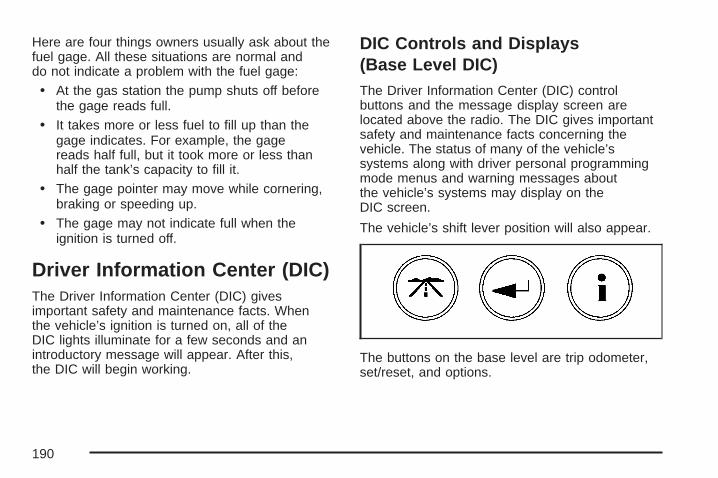
Here are four things owners usually ask about thefuel gage. All these situations are normal anddo not indicate a problem with the fuel gage:
• At the gas station the pump shuts off beforethe gage reads full.
• It takes more or less fuel to fill up than thegage indicates. For example, the gagereads half full, but it took more or less thanhalf the tank’s capacity to fill it.
• The gage pointer may move while cornering,braking or speeding up.
• The gage may not indicate full when theignition is turned off.
Driver Information Center (DIC)The Driver Information Center (DIC) givesimportant safety and maintenance facts. Whenthe vehicle’s ignition is turned on, all of theDIC lights illuminate for a few seconds and anintroductory message will appear. After this,the DIC will begin working.
DIC Controls and Displays(Base Level DIC)The Driver Information Center (DIC) controlbuttons and the message display screen arelocated above the radio. The DIC gives importantsafety and maintenance facts concerning thevehicle. The status of many of the vehicle’ssystems along with driver personal programmingmode menus and warning messages aboutthe vehicle’s systems may display on theDIC screen.
The vehicle’s shift lever position will also appear.
The buttons on the base level are trip odometer,set/reset, and options.
190
Trip Odometer
3 (Trip Odometer): Press this button to accessthe odometer and trip distance modes.
The first menu on the DIC screen will be theodometer reading, or cumulative mileage of thevehicle. The odometer cannot be reset.
Press the trip odometer button to advance to thenext menu.
Trip Distances: This menu shows the distancesthat the vehicle has driven between specificpoints. The trip odometer will record the number ofmiles up to 9,999.9 miles or 9 999.9 km travelledfor up to two trips. When 9,999.9 miles or9 999.9 km is reached for either trip, the odometerfor that trip will go back to zero.
Press the trip odometer button again to accessTRIP A. Press the trip odometer button againto access TRIP B. To reset the trip odometer(s)back to zero miles or kilometers, access the tripto reset and press the set/reset button.
The trip odometer has a feature called theretro-active reset. This can be used to set the tripodometer to the number of miles or kilometersdriven since the ignition was last turned on. Thiscan be used if the trip odometer was not resetat the beginning of the trip.
To use the retro-active reset feature, press andhold the set/reset button for at least three seconds.The trip odometer will display the number ofmiles or kilometers driven since the ignition waslast turned on and the vehicle began moving. Oncethe vehicle has begun moving, the trip odometerwill accumulate mileage. For example, if thevehicle was driven 5.0 miles (8.0 km) before thevehicle is started again, and then the retro-activereset feature is activated, the display will show5.0 miles (8.0 km). As the vehicle begins moving,the display will increase to 5.1 miles (8.2 km),5.2 miles (8.4 km), etc.
If the retro-active reset feature is activated after thevehicle is started, but before it begins moving, thedisplay will show the number of miles or kilometersthat were driven during the last ignition cycle.
Press the trip odometer button again to accessthe odometer.
191

Set/Reset
r (Set/Reset): Press this button to set or reseta menu item when using the trip odometer oroptions buttons.
Options
4 (Options): Press this button to access theDate, Language, Display Units, Daytime DisplayEnhancement, Engine Oil Monitor System,Personal Programming modes, and TirePressure readings.
Date: This menu sets the date.
The time is set through the radio. See Setting theTime on page 238 for more information.
To set the date, use the following procedure:
1. Press the options button until the dateis displayed on the DIC.
2. Press the set/reset button to access theRESET YEAR screen. The second positionin the year will be selected. Press and hold theset/reset button to scroll through the availabledigits. Release the button when the correctdigit appears.
3. Press the options button to advance to thefirst position in the year. Press and hold theset/reset button to scroll through the availabledigits. Release the button when the correctdigit appears.
4. Press the options button to advance to themonths of the year.
5. Press the set/reset button to scroll through themonths of the year, releasing the button whenthe correct month appears.
6. Press the options button to advance to thedays of the month.
7. Press the set/reset button to scroll through thedays of the month, releasing the button whenthe correct day appears.
8. Press the options button again to advance tothe main date screen. The screen will nowdisplay the new date.
Language: This menu allows the selectionof the language in which the DIC messageswill appear. The DIC can be programmed toone of three languages: English, French, orSpanish. The message on the HUD, if equipped,will also appear in the language selected.See Head-Up Display (HUD) on page 155.
192

To change the language, use the followingprocedure:
1. Press the options button to enter thelanguage screen.
2. Press the set/reset button to scroll throughand set the language choice.
3. Press the options button again to advance tothe next screen.
DISPLAY UNITS: This menu allows selection ofmeasurements to be displayed in English or metricunits. The messages on the HUD, if equipped, andthe instrument panel cluster will also appear withthe type of measurement selected.
To set the measurement when Display Units isshown, use the following procedure:
1. Press the set/reset button to select ENGLISHor METRIC.
2. Press the options button again to advance tothe next screen.
DAYTIME DISPLAY ENHANCEMENT: Thismenu allows selection of the color of the displaymessage. When ON is selected for the daytimeenhancement, the messages will appear black ona red screen. This combination makes it easierto see the DIC messages during the daytime.When OFF is selected, or when the headlampsare on, the messages will appear red on ablack background.
To set the daytime display enhancement, use thefollowing procedure:
1. Press the set/reset button to select OFF or ON.
2. Press the options button again to advance tothe next screen.
ENGINE OIL MONITOR SYSTEM: This menuallows the engine oil monitor system to be reset.To reset the engine oil monitor system, seeEngine Oil Life System on page 359.
PERSONAL PROGRAMMING MODE: Thismenu allows you to customize several featureson your vehicle. See DIC Vehicle Customizationon page 230 for more information.
Press the options button again to advance tothe next screen.
193
TIRE PRESSURE: This menu shows the tirepressure for each tire. The tire pressure will beshown in either pounds per square inch (psi)or kilopascals (kPa). Press the options button untilthe DIC shows the tire pressure for the fronttires. Press the options button again to view thepressure for the rear tires.
If a low or high tire pressure condition is detectedby the system while driving, a message advisingyou to check the pressure in a specific tirewill appear in the display. See Inflation - TirePressure on page 414 and DIC Warningsand Messages on page 204 for more information.
If the tire pressure display shows dashesinstead of a value, there may be a problem withyour vehicle. If this consistently occurs, seeyou dealer/retailer for service.
DISPLAY OFF will appear on the next screen.The screen will count down and then go blank.Press the options button to advance to anew screen.
Press the options button to return to themain (date) screen.
DIC Controls and Displays(Uplevel DIC with Trip Computer)The Driver Information Center (DIC) controlbuttons and the message display screen arelocated above the radio. The DIC gives importantsafety and maintenance facts concerning thevehicle. The status of many of the vehicle’ssystems along with driver personalization menusand warning messages about the vehicle’ssystems may display on the DIC screen.
The outside temperature automatically appearson the bottom right corner of the DIC displayscreen. If the outside temperature is below38°F (3°C), the temperature reading will togglebetween displaying the outside temperatureand the word ICE for two minutes. If thereis a problem with the system that controls thetemperature display, the letters OC (Open Circuit)or SC (Short Circuit) will appear on the display.If this occurs, have the vehicle serviced byyour dealer/retailer.
The vehicle’s shift lever position and the directionthe vehicle is traveling will also appear on theDIC screen.
194
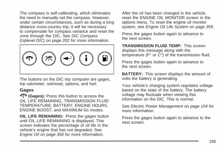
The compass is self-calibrating, which eliminatesthe need to manually set the compass. However,under certain circumstances, such as during a longdistance cross-country trip, it will be necessaryto compensate for compass variance and reset thezone through the DIC. See DIC Compass(Uplevel DIC) on page 202 for more information.
The buttons on the DIC trip computer are gages,trip odometer, set/reset, options, and fuel.
Gages2 (Gages): Press this button to access theOIL LIFE REMAINING, TRANSMISSION FLUIDTEMPERATURE, BATTERY, ENGINE HOURS,ENGINE BOOST, and MAXIMUM Gs modes.
OIL LIFE REMAINING: Press the gages buttonuntil OIL LIFE REMAINING is displayed. Thisscreen indicates the percentage of oil life in thevehicle’s engine that has not degraded. SeeEngine Oil on page 356 for more information.
After the oil has been changed in the vehicle,reset the ENGINE OIL MONITOR screen in theoptions menu. To reset the engine oil monitorsystem, see Engine Oil Life System on page 359.
Press the gages button again to advance tothe next screen.
TRANSMISSION FLUID TEMP: This screendisplays this message along with thetemperature (F° or C°) of the transmission fluid.
Press the gages button again to advance tothe next screen.
BATTERY: This screen displays the amount ofvolts the battery is generating.
Your vehicle’s charging system regulates voltagebased on the state of the battery. The batteryvoltage may fluctuate when viewing thisinformation on the DIC. This is normal.
See Electric Power Management on page 154 formore information.
Press the gages button again to advance to thenext screen.
195

ENGINE HOURS: This screen shows the numberof cumulative hours the engine has operatedwhile the key was in the RUN position. This screencannot be reset.
Press the gages button to advance to thenext screen.
ENGINE BOOST: If the vehicle has thesupercharged engine, this screen will appear.It shows a graphic that indicates the amount ofboost the engine is receiving.
Press the gages button again to advance to thenext screen.
MAXIMUM Gs: If you have the GXP option,this screen will appear. The DIC monitorsand keeps track of the maximum levels foracceleration, deceleration, and lateral-accelerationachieved since the screen was last reset. If youtry to select this screen while the vehicle ismoving, the message MAXIMUM Gs NOTAVAILABLE WHILE MOVING will display.To view the maximum accelerations achievedsince last reset, you must bring the vehicleto a stop. Then the values will be displayed.
To reset the values to zero, press and hold theset/reset button.
Press the gages button again to advance to thenext screen.
Trip Odometer
3 (Trip Odometer): Press this button toaccess the Odometer, Trip Distances, AVERAGESPEED, and TIME ELAPSED modes.
Odometer: When the trip odometer button ispressed, the first menu displayed on the DIC screenis the odometer reading, or cumulative mileage ofthe vehicle. The odometer cannot be reset.
Press the trip odometer button again to advance tothe next menu.
Trip Distances: This menu shows the distancesthat the vehicle has driven between specificpoints. The trip odometer will record the numberof miles up to 9,999.9 miles or 9 999.9 km travelledfor up to two trips. When 9,999.9 miles or9 999.9 km is reached for either trip, the odometerfor that trip will go back to zero.
196

To reset the trip distances, use the followingprocedures:
1. Press the trip odometer button again toaccess TRIP A. Press the trip odometer buttonagain to access TRIP B. To reset the tripodometer(s) back to zero miles or tozero kilometers, access the trip that needs tobe reset and press the set/reset button.
2. Press the trip odometer button again toadvance to the next screen.
The trip odometer has a feature called theretro-active reset. This can be used to set thetrip odometer to the number of miles (kilometers)driven since the ignition was last turned on.This can be used if the trip odometer is notreset at the beginning of the trip.
To use the retro-active reset feature, press andhold the set/reset button for at least three seconds.The trip odometer will display the number ofmiles or kilometers driven since the ignition waslast turned on and the vehicle was moving.Once the vehicle begins moving, the trip odometerwill accumulate mileage. For example, if thevehicle was driven 5.0 miles (8.0 km) before it isstarted again, and then the retro-active resetfeature is activated, the display will show 5.0 miles(8.0 km). As the vehicle begins moving, thedisplay will then increase to 5.1 miles (8.2 km),5.2 miles (8.4 km), etc.
If the retro-active reset feature is activated after thevehicle is started, but before it begins moving, thedisplay will show the number of miles or kilometersthat were driven during the last ignition cycle.
197

AVERAGE SPEED: The average speed isdisplayed in miles per hour (mph) or kilometersper hour (km/h). The average speed is calculatedfrom the various vehicle speeds recorded sincethe last reset of this menu item. To reset theaverage speed, press the set/reset button. Thedisplay will return to zero.
Press the trip odometer button again to advanceto the next screen.
TIME ELAPSED: This screen can be used asa stopwatch. The display can show the hours,minutes and seconds. The elapsed time indicatorwill record up to 99 hours, 59 minutes and59 seconds, then it will reset to zero andcontinue counting.
To set the time elapsed function, use the followingprocedures:
1. Press the set/reset button for less thantwo seconds to start or stop the timer.
2. Press and hold the set/reset button formore than two seconds to reset the timerback to zero.
Press the trip odometer button again to advanceto the next screen.
Set/Reset
r (Set/Reset): Press this button to set or reseta mode item when using the trip odometer oroption buttons.
Options
4 (Options): Press this button to access the Date,Language, Display Units, Daytime DisplayEnhancement, Engine Oil Monitor System,Compass Calibration, Personal Programmingmodes, and Tire Pressure readings.
Date: This menu sets the date.
The time is set through the radio. See Setting theTime on page 238 for more information.
To set the date, use the following procedure:
1. Press the options button until the dateis displayed on the DIC.
2. Press the set/reset button to access theRESET YEAR screen. The second positionin the year will be selected. Press and hold theset/reset button to scroll through the availabledigits. Release the button when the correctdigit appears.
198

3. Press the options button to advance to thefirst position in the year. Press and hold theset/reset button to scroll through the availabledigits. Release the button when the correctdigit appears.
4. Press the options button to advance to themonths of the year.
5. Press the set/reset button to scroll through themonths of the year, releasing the button whenthe correct month appears.
6. Press the options button to advance to thedays of the month.
7. Press the set/reset button to scroll through thedays of the month, releasing the button whenthe correct day appears.
8. Press the options button again to advance tothe main date screen. The screen will nowdisplay the new date.
9. Press the options button to advance to thenext screen.
Language: This menu allows selection of thelanguage in which the DIC messages willappear. The DIC can be programmed in one ofthree languages: English, French, or Spanish.The message on the HUD, if equipped, will alsoappear in the language selected. See Head-UpDisplay (HUD) on page 155.
To change the language, use the followingprocedure:
1. Press the options button to enter thelanguage screen.
2. Press the set/reset button to scroll throughand set the language choice.
3. Press the options button again to advanceto the next screen.
DISPLAY UNITS: This menu allows selectionof measurements to be displayed in Englishor metric units. The messages on the HUD,if equipped, and the instrument panel cluster willalso appear in the type of measurement selected.
199
To set the display units function, use the followingprocedure:
1. Press the set/reset button to select ENGLISHor METRIC.
2. Press the options button to advance to thenext screen.
DAYTIME DISPLAY ENHANCEMENT: Thismenu allows selection of the color of the displaymessage. When ON is selected for the daytimeenhancement, the messages will appear black ona red screen. This combination makes it easierto see the DIC messages during the daytime.When OFF is selected, or when the headlampsare on, the messages will appear red on ablack background.
To set the daytime display enhancement function,use the following procedure:
1. Press the set/reset button to select OFF or ON.
2. Press the options button to advance to thenext screen.
ENGINE OIL MONITOR SYSTEM: This menuallows the engine oil monitor system to bereset. To reset the engine oil monitor system,see Engine Oil Life System on page 359.
Press the options button to advance to thenext screen.
COMPASS CALIBRATION MODE: This menuallows you to adjust for compass variance.See DIC Compass (Uplevel DIC) on page 202for more information.
Press the options button again to advance to thenext screen.
PERSONAL PROGRAMMING MODE: Thismenu allows you to customize several featureson your vehicle. See DIC Vehicle Customizationon page 230 for more information.
Press the options button again to advance to thenext screen.
200

TIRE PRESSURE: This menu shows the tirepressure for each tire. The tire pressure will beshown in either pounds per square inch (psi)or kilopascals (kPa). Press the options button untilthe DIC shows the tire pressure for the fronttires. Press the options button again to view thepressure for the rear tires.
If a low or high tire pressure condition is detectedby the system while driving, a message advisingyou to check the pressure in a specific tirewill appear in the display. See Inflation - TirePressure on page 414 and DIC Warningsand Messages on page 204 for more information.
If the tire pressure display shows dashesinstead of a value, there may be a problemwith your vehicle. If this consistently occurs,see you dealer/retailer for service.
Press the options button to advance to thenext screen.
DISPLAY OFF will appear on the next screen.The screen will count down and then go blank.
Press the options button to return to the main(date) screen.
Fuel
. (Fuel): Press this button to access the AverageFuel Economy, Instantaneous Fuel Economy,and Fuel Range modes.
AVG ECONOMY (Average Fuel Economy):This screen will display the approximate averagemiles per gallon (mpg) or liters per 100 kilometers(L/100 km). This number is calculated basedon the number of mpg (L/100 km) recorded sincethe last time this menu item was reset.
To reset the average fuel economy for the vehicle,follow this procedure:
1. Press the set/reset button to reset to zero.
2. Press the fuel button again to advance tothe next screen.
INST ECONOMY (Instantaneous Fuel Economy):This screen displays the current fuel economy at aparticular moment and will change frequently asdriving conditions change. Unlike average fueleconomy, this screen cannot be reset.
Press the fuel button again to advance to thenext screen.
201
RANGE: This screen displays the approximatenumber of remaining miles or kilometers thevehicle can be driven without refueling. Thisestimate is based on the average fuel economyfor the amount of fuel remaining in the fueltank and the current driving conditions. Thisestimate will change if driving conditions change.For example, if driving in traffic and makingfrequent stops, the display may read one number,but if the vehicle is driven on a freeway thenumber may change even though the sameamount of fuel is in the fuel tank. This is becausedifferent driving conditions produce differentfuel economies. Generally, freeway drivingproduces better fuel economy than city driving.
If the fuel tank contains less than 2 gallons (7.6 L),the LOW FUEL message will appear on the DICscreen. Fill the fuel tank as soon as possibleto avoid running out of fuel. See “Low Fuel” underDIC Warnings and Messages on page 204.
Press the fuel button again to advance to thenext screen.
DIC Compass (Uplevel DIC)Your vehicle may have a compass in the DriverInformation Center (DIC).
Setting the CompassThe compass is self-calibrating, which eliminatesthe need to manually set the compass.
However, under certain circumstances, such asduring a long distance cross-country trip, it will benecessary to compensate for compass varianceand reset the zone through the DIC.
Compass variance is the difference between theearth’s magnetic north and true geographicnorth. If not adjusted to account for compassvariance, the compass in the vehicle could givefalse readings.
In order to do this, the compass must be set orcalibrated to the variance zone in which the vehicleis traveling.
202
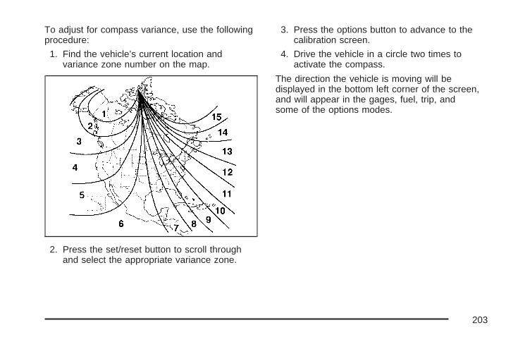
To adjust for compass variance, use the followingprocedure:
1. Find the vehicle’s current location andvariance zone number on the map.
2. Press the set/reset button to scroll throughand select the appropriate variance zone.
3. Press the options button to advance to thecalibration screen.
4. Drive the vehicle in a circle two times toactivate the compass.
The direction the vehicle is moving will bedisplayed in the bottom left corner of the screen,and will appear in the gages, fuel, trip, andsome of the options modes.
203
DIC Warnings and MessagesThese messages display if there is a problem inone of the vehicle’s systems. They overrideany other mode or screen the Driver InformationCenter (DIC) may be in.
Some messages can be cleared from the DICscreen. In order to do this, the message must beacknowledged. To acknowledge or clear themessage from the screen, press the set/resetbutton on the DIC. See DIC Controls and Displays(Base Level DIC) on page 190 or DIC Controlsand Displays (Uplevel DIC with Trip Computer)on page 194 for DIC button descriptions.
Other warning messages are not allowed to becleared until the problem indicated by the warningmessage is taken care of. When the problemindicated by the message is resolved, it can beacknowledged and the screen can be reset.
Be sure to take any message that appears onthe DIC screen seriously and remember thatclearing the messages that are able to beacknowledged, will only make the messagedisappear, not correct the problem.
A/C OFF FOR ENGINE PROTECTIONThis message displays when the engine coolantbecomes hotter than the normal operatingtemperature. To avoid added strain on a hotengine, the air conditioning compressor isautomatically turned off. When the coolanttemperature returns to normal, the air conditioningcompressor turns back on. The vehicle canthen continue to be driven.
This message comes on while the ignition is inRUN. A chime sounds for two seconds whenthis message is displayed. Press the set/resetbutton to acknowledge this warning messageand to clear it from the screen.
This message continues to display forthree seconds if it has not been acknowledgedwhen the engine is turned off. It also re-displaysfor three seconds if the message has beenacknowledged, but the condition still existswhen the engine is turned off.
If the condition still exists, the message re-appearswhen the engine is turned on.
204
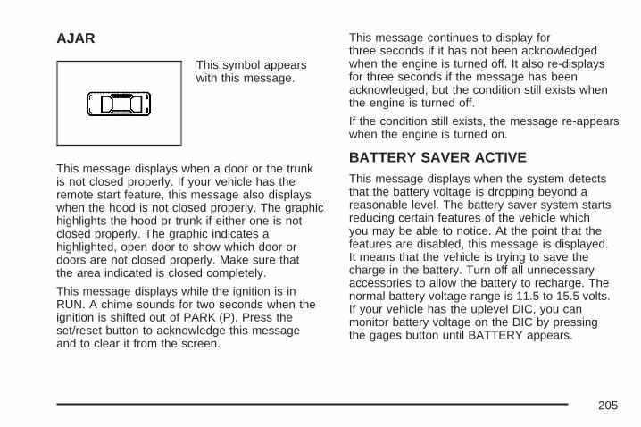
AJAR
This symbol appearswith this message.
This message displays when a door or the trunkis not closed properly. If your vehicle has theremote start feature, this message also displayswhen the hood is not closed properly. The graphichighlights the hood or trunk if either one is notclosed properly. The graphic indicates ahighlighted, open door to show which door ordoors are not closed properly. Make sure thatthe area indicated is closed completely.
This message displays while the ignition is inRUN. A chime sounds for two seconds when theignition is shifted out of PARK (P). Press theset/reset button to acknowledge this messageand to clear it from the screen.
This message continues to display forthree seconds if it has not been acknowledgedwhen the engine is turned off. It also re-displaysfor three seconds if the message has beenacknowledged, but the condition still exists whenthe engine is turned off.
If the condition still exists, the message re-appearswhen the engine is turned on.
BATTERY SAVER ACTIVEThis message displays when the system detectsthat the battery voltage is dropping beyond areasonable level. The battery saver system startsreducing certain features of the vehicle whichyou may be able to notice. At the point that thefeatures are disabled, this message is displayed.It means that the vehicle is trying to save thecharge in the battery. Turn off all unnecessaryaccessories to allow the battery to recharge. Thenormal battery voltage range is 11.5 to 15.5 volts.If your vehicle has the uplevel DIC, you canmonitor battery voltage on the DIC by pressingthe gages button until BATTERY appears.
205

CHANGE OIL SOON
This symbol comes onwith this message.
This message displays when service is requiredfor the vehicle. See your dealer. See Engine Oilon page 356 and Scheduled Maintenance onpage 480 for more information.
The CHANGE OIL SOON message is reset byacknowledging the message. The ENGINEOIL MONITOR SYSTEM screen under theoptions menu on the DIC must also be reset.See “Engine Oil Monitor System” in options underDIC Controls and Displays (Base Level DIC)on page 190 or DIC Controls and Displays(Uplevel DIC with Trip Computer) on page 194for more information.
This message displays while the ignition is inRUN. Press the set/reset button to acknowledgethis message and to clear it from the screen.
This message continues to display forthree seconds if it has not been acknowledgedwhen the engine is turned off. It also re-displaysfor three seconds if the message has beenacknowledged, but the condition still exists whenthe engine is turned off.
If the condition still exists, the message re-appearswhen the engine is turned on.
CHARGING SYSTEM FAILURE
This symbol comes onwith this message.
This message displays when there is a problemwith the generator and battery charging systems.Driving with this problem could drain the battery.Turn off all unnecessary accessories. Stopand turn off the vehicle as soon as it is safe to doso. Have the electrical system checked by yourdealer as soon as possible.
206
This message displays while the ignition is inRUN. A chime sounds for two seconds whenthis message is displayed. Press the set/resetbutton to acknowledge this message and to clearit from the screen.
This message continues to display if it has notbeen acknowledged when the engine is turnedoff. It also re-displays for three seconds ifthe message has been acknowledged, but thecondition still exists when the engine is turned off.
If the condition still exists, the messagere-appears when the engine is turned on.
CHECK GAS CAPThis message displays when the fuel cap is noton, or is not fully tightened. Check the fuel capto ensure it is on and properly tightened. Thediagnostic system can determine if the fuel caphas been left off or improperly installed. A looseor missing fuel cap allows fuel to evaporateinto the atmosphere. A few driving trips with thecap properly installed should turn this messageoff. See Filling the Tank on page 348 for moreinformation.
This message displays while the ignition is inRUN. A chime sounds for two seconds when thismessage is displayed and then the messagecontinues to display. Press the set/reset button toacknowledge this message and to clear it fromthe screen.
This message continues to display forthree seconds if it has not been acknowledgedwhen the engine is turned off. It also re-displaysfor three seconds if the message has beenacknowledged, but the condition still exists whenthe engine is turned off.
If the condition still exists, the message re-appearswhen the engine is turned on.
207
CHECK TIRE PRESSUREThis message displays when the tire pressure inone of the tires needs to be checked. This messagealso displays LEFT FRONT, RIGHT FRONT, LEFTREAR, or RIGHT REAR to indicate which tire needsto be checked. You can receive more than one tirepressure message at a time. To read the othermessages that may have been sent at the sametime, press the set/reset button. If a tire pressuremessage appears on the DIC, stop as soon as youcan. Have the tire pressures checked and set tothose shown on the Tire Loading Information label.See Tires on page 406, Loading Your Vehicle onpage 322, and Inflation - Tire Pressure onpage 414. The DIC display also shows the tirepressure values for the front and rear tires bypressing the options button. See DIC Controls andDisplays (Base Level DIC) on page 190 or DICControls and Displays (Uplevel DIC with TripComputer) on page 194. If the tire pressure is low,the low tire pressure warning light comes on. SeeLow Tire Pressure Warning Light on page 182 formore information.
This message displays while the ignition is inRUN. Press the set/reset button to acknowledgethis message and to clear it from the screen.
This message continues to display forthree seconds if it has not been acknowledgedwhen the engine is turned off. It also re-displaysfor three seconds if the message has beenacknowledged, but the condition still exists whenthe engine is turned off.
If the condition still exists, the message re-appearswhen the engine is turned on.
CRUISE SET
This symbol comes onwith this message.
This message and symbol display briefly wheneverthe cruise control is set.
208
The cruise control light on the instrument panelcluster also comes on when cruise control isset. See Cruise Control Light on page 189.CRUISE SET also appears briefly in the Head-UpDisplay (HUD), if your vehicle has this feature.This message displays when the ignition isin RUN. See Cruise Control on page 144 for moreinformation.
This message does not need to be acknowledged.
DELAYED LOCKINGThis message displays when the doors of thevehicle are closed and the delayed locking featurehas been programmed through the DIC. See“DELAYED LOCKING” under DIC VehicleCustomization on page 230 for more information.
This message displays when the ignition is inOFF. A chime sounds for two seconds when thismessage is displayed.
This message cannot be acknowledged.
HEADLAMPS SUGGESTEDThis message displays when the amount ofavailable light outside the vehicle is low and theexterior lamps control has been turned off. Thiscondition happens when the headlamps are turnedoff at night or the Daytime Running Lamps (DRL)are turned off during the day. This message informsthe driver that it has become dark enough outsideto require the headlamps to be turned on. When theheadlamps are turned on, this message clears fromthe screen. See Exterior Lamps on page 148 andDaytime Running Lamps (DRL) on page 149 formore information.
This message displays while the ignition is inRUN. A chime sounds for two seconds whenthis message is displayed. Press the set/resetbutton to acknowledge this warning messageand to clear it from the screen.
This message continues to display if it has notbeen acknowledged when the engine is turnedoff. It also re-displays for three seconds ifthe message has been acknowledged, but thecondition still exists when the engine is turned off.
If the condition still exists, the messagere-appears when the engine is turned on.
209
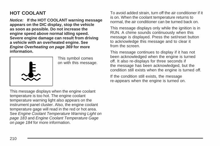
HOT COOLANTNotice: If the HOT COOLANT warning messageappears on the DIC display, stop the vehicleas soon as possible. Do not increase theengine speed above normal idling speed.Severe engine damage can result from drivinga vehicle with an overheated engine. SeeEngine Overheating on page 369 for moreinformation.
This symbol comeson with this message.
This message displays when the engine coolanttemperature is too hot. The engine coolanttemperature warning light also appears on theinstrument panel cluster. Also, the engine coolanttemperature gage will read in the red or hot area.See Engine Coolant Temperature Warning Light onpage 183 and Engine Coolant Temperature Gageon page 184 for more information.
To avoid added strain, turn off the air conditioner if itis on. When the coolant temperature returns tonormal, the air conditioner can be turned back on.
This message displays only while the ignition is inRUN. A chime sounds continuously when thismessage is displayed. Press the set/reset buttonto acknowledge this message and to clear itfrom the screen.
This message continues to display if it has notbeen acknowledged when the engine is turnedoff. It also re-displays for three seconds ifthe message has been acknowledged, but thecondition still exists when the engine is turned off.
If the condition still exists, the messagere-appears when the engine is turned on.
210
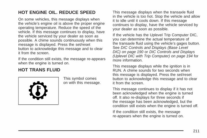
HOT ENGINE OIL. REDUCE SPEEDOn some vehicles, this message displays whenthe vehicle’s engine oil is above the proper engineoperating temperature. Reduce the speed of thevehicle. If this message continues to display, havethe vehicle serviced by your dealer as soon aspossible. A chime sounds continuously when thismessage is displayed. Press the set/resetbutton to acknowledge this message and to clearit from the screen.
If the condition still exists, the message re-appearswhen the engine is turned on.
HOT TRANS FLUID
This symbol comeson with this message.
This message displays when the transaxle fluidin the vehicle is too hot. Stop the vehicle and allowit to idle until it cools down. If this messagecontinues to display, have the vehicle serviced byyour dealer as soon as possible.
If the vehicle has the Uplevel Trip Computer DIC,you can determine the actual temperature ofthe transaxle fluid using the vehicle’s gages button.See DIC Controls and Displays (Base LevelDIC) on page 190 or DIC Controls and Displays(Uplevel DIC with Trip Computer) on page 194 formore information.
This message displays while the ignition is inRUN. A chime sounds for two seconds whenthis message is displayed. Press the set/resetbutton to acknowledge this message and to clearit from the screen.
This message continues to display if it has notbeen acknowledged when the engine is turnedoff. It also re-displays for three seconds ifthe message has been acknowledged, but thecondition still exists when the engine is turned off.
If the condition still exists, the messagere-appears when the engine is turned on.
211

KEY FOB BATTERY LOW
This symbol comes onwith this message.
This message displays when the battery in theRemote Keyless Entry (RKE) transmitter needs tobe replaced. To replace the battery, see “BatteryReplacement” under Remote Keyless Entry (RKE)System Operation on page 87.
This message displays while the ignition is inRUN. A chime sounds for two seconds whenthis message is displayed. Press the set/resetbutton to acknowledge this message and to clearit from the screen.
This message continues to display if it has notbeen acknowledged when the engine is turnedoff. It also re-displays for three seconds ifthe message has been acknowledged, but thecondition still exists when the engine is turned off.
The message re-appears when the engine isturned on and the condition still exists.
KEY IN IGNITIONThis message displays and a chime soundscontinuously when the driver exits the vehiclewhile the key is in the ignition after the engineis turned off.
This message cannot be acknowledged.
This message disappears and the chiming stopswhen the key is removed from the ignition.
212
LEFT FRONT TURN LAMP OUTThis message displays when the left front turnsignal lamp needs to be replaced. See Taillamps,Turn Signal, and Stoplamps on page 401 forreplacement procedures.
This message displays while the ignition is inRUN. A chime sounds for two seconds whenthis message is displayed. Press the set/resetbutton to acknowledge this message and to clearit from the screen.
This message continues to display if it has notbeen acknowledged when the engine is turnedoff. It also re-displays for three seconds ifthe message has been acknowledged, but thecondition still exists when the engine is turned off.
If the condition still exists, the messagere-appears when the engine is turned on.
LEFT REAR TURN LAMP OUTThis message displays when the left rear turnsignal lamp needs to be replaced. See Taillamps,Turn Signal, and Stoplamps on page 401 forreplacement procedures.
This message displays while the ignition is inRUN. A chime sounds for two seconds whenthis message is displayed. Press the set/resetbutton to acknowledge this message and to clearit from the screen.
This message continues to display if it has notbeen acknowledged when the engine is turnedoff. It also re-displays for three seconds ifthe message has been acknowledged, but thecondition still exists when the engine is turned off.
If the condition still exists, the messagere-appears when the engine is turned on.
213
LOW BRAKE FLUID
This symbol comes onwith this message.
This message displays when the brake fluidlevel is low. Have the brake system servicedby your dealer as soon as possible. See Brakeson page 383.
The brake system warning light also appears onthe instrument panel cluster when this messageappears on the DIC. See Brake System WarningLight on page 180.
This message displays only while the ignition is inRUN. A chime sounds for two seconds whilethis message is displayed. Press the set/resetbutton to acknowledge this message and to clearit from the screen.
This message continues to display if it has notbeen acknowledged when the engine is turnedoff. It also re-displays for three seconds ifthe message has been acknowledged, but thecondition still exists when the engine is turned off.
If the condition exists, the message re-appearswhen the engine is turned on.
214
LOW FUEL
This symbol comes onwith this message.
This message displays when the vehicle is lowon fuel. Refill the fuel tank as soon as possible.
This message displays while the ignition is inRUN. A chime sounds for two seconds whenthis message is displayed. Press the set/resetbutton to acknowledge this message and to clearit from the screen.
This message continues to display if it has notbeen acknowledged when the engine is turnedoff. It also re-displays for three seconds ifthe message has been acknowledged, but thecondition still exists when the engine is turned off.
If the condition still exists, the messagere-appears when the engine is turned on.
LOW OIL LEVEL
This symbol comeson with this message.
On some vehicles, this message displays whenthe vehicle’s engine oil is low. Fill the oil to theproper level as soon as possible. See EngineCompartment Overview on page 352 for engine oilfill location. Also, see Engine Oil on page 356 forinformation on the kind of oil to use and proper oillevel. If the vehicle has a supercharged engine, seeSupercharger Oil on page 361 for information onthe kind of oil to use and proper oil level.
This message displays while the ignition is inRUN. A chime sounds for two seconds whenthis message is displayed. Press the set/resetbutton to acknowledge this message and toclear it from the screen.
215
This message continues to display if it has notbeen acknowledged when the engine is turnedoff. It also re-displays for three seconds ifthe message has been acknowledged, but thecondition still exists when the engine is turned off.
If the condition still exists, the messagere-appears when the engine is turned on.
LOW OIL PRESSURE
Notice: If the LOW OIL PRESSURE warningmessage appears on the DIC display, stop thevehicle immediately. Do not drive the vehicleuntil the cause of the low oil pressure iscorrected. Severe engine damage can resultfrom driving a vehicle with low oil pressure. SeeEngine Oil on page 356 for more information.
This symbol comes onwith this message.
This message displays when the vehicle’s engineoil pressure is low. The low oil pressure warninglight also appears on the instrument panel cluster.See Oil Pressure Light on page 188.
Stop the vehicle immediately, as engine damagecan result from driving a vehicle with low oilpressure. Have the vehicle serviced by your dealeras soon as possible when this warning messageis displayed.
This message displays only while the ignition is inRUN. A chime sounds continuously when thismessage is displayed. Press the set/reset buttonto acknowledge this message and to clear itfrom the screen.
This message continues to display if it has notbeen acknowledged when the engine is turnedoff. It also re-displays for three seconds ifthe message has been acknowledged, but thecondition still exists when the engine is turned off.
If the condition still exists, the messagere-appears when the engine is turned on.
216
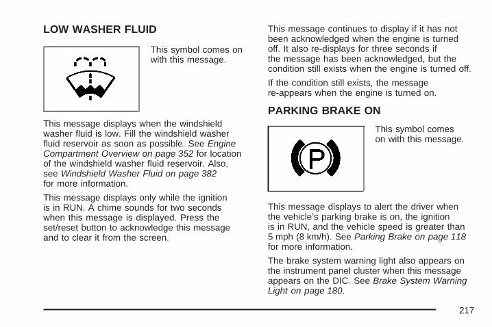
LOW WASHER FLUID
This symbol comes onwith this message.
This message displays when the windshieldwasher fluid is low. Fill the windshield washerfluid reservoir as soon as possible. See EngineCompartment Overview on page 352 for locationof the windshield washer fluid reservoir. Also,see Windshield Washer Fluid on page 382for more information.
This message displays only while the ignitionis in RUN. A chime sounds for two secondswhen this message is displayed. Press theset/reset button to acknowledge this messageand to clear it from the screen.
This message continues to display if it has notbeen acknowledged when the engine is turnedoff. It also re-displays for three seconds ifthe message has been acknowledged, but thecondition still exists when the engine is turned off.
If the condition still exists, the messagere-appears when the engine is turned on.
PARKING BRAKE ON
This symbol comeson with this message.
This message displays to alert the driver whenthe vehicle’s parking brake is on, the ignitionis in RUN, and the vehicle speed is greater than5 mph (8 km/h). See Parking Brake on page 118for more information.
The brake system warning light also appears onthe instrument panel cluster when this messageappears on the DIC. See Brake System WarningLight on page 180.
217
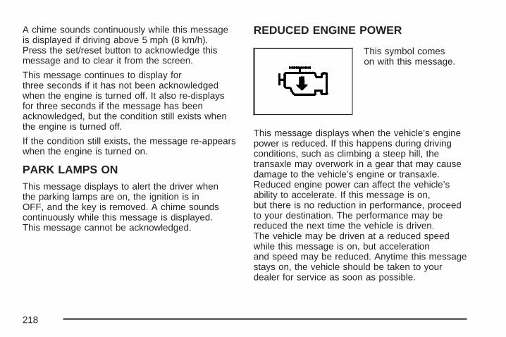
A chime sounds continuously while this messageis displayed if driving above 5 mph (8 km/h).Press the set/reset button to acknowledge thismessage and to clear it from the screen.
This message continues to display forthree seconds if it has not been acknowledgedwhen the engine is turned off. It also re-displaysfor three seconds if the message has beenacknowledged, but the condition still exists whenthe engine is turned off.
If the condition still exists, the message re-appearswhen the engine is turned on.
PARK LAMPS ONThis message displays to alert the driver whenthe parking lamps are on, the ignition is inOFF, and the key is removed. A chime soundscontinuously while this message is displayed.This message cannot be acknowledged.
REDUCED ENGINE POWER
This symbol comeson with this message.
This message displays when the vehicle’s enginepower is reduced. If this happens during drivingconditions, such as climbing a steep hill, thetransaxle may overwork in a gear that may causedamage to the vehicle’s engine or transaxle.Reduced engine power can affect the vehicle’sability to accelerate. If this message is on,but there is no reduction in performance, proceedto your destination. The performance may bereduced the next time the vehicle is driven.The vehicle may be driven at a reduced speedwhile this message is on, but accelerationand speed may be reduced. Anytime this messagestays on, the vehicle should be taken to yourdealer for service as soon as possible.
218
This message displays only when the ignition isin RUN. A chime sounds for two seconds while thismessage is displayed. Press the set/reset buttonto acknowledge this message and to clear itfrom the screen.
This message continues to display if it has notbeen acknowledged when the engine is turnedoff. It also re-displays for three seconds ifthe message has been acknowledged, but thecondition still exists when the engine is turned off.
If the condition still exists, the messagere-appears when the engine is turned on.
REMOTE START ACTIVE PRESSHAZARD SWITCH TO CANCELIf your vehicle has the remote start feature, thismessage displays when a remote start is initiated.If you would like to cancel the remote start, turnon the hazard warning flashers. See HazardWarning Flashers on page 138.
REMOTE START DISABLEDIf your vehicle has the remote start feature, thismessage displays if a remote start attempt isunsuccessful. This may be caused if any of thefollowing conditions are true when a remotestart attempt is made:• The remote start system is disabled through
the DIC.• The key is in the ignition.• The hood or the doors are not closed.• There is an emission control system
malfunction.• The engine coolant temperature is too high.• The oil pressure is low.• The hazard warning flashers are turned on.• The maximum number of remote starts
or remote start attempts between ignitioncycles has been reached.
• The content theft-deterrent alarm is on whileattempting to remote start the vehicle.
See “REMOTE START” under DIC VehicleCustomization on page 230 and “Remote VehicleStart” under Remote Keyless Entry (RKE) SystemOperation on page 87 for more information.
219

RIGHT FRONT TURN LAMP OUTThis message displays when the vehicle’s rightfront turn signal needs to be replaced. See FrontTurn Signal, Parking and Fog Lamps onpage 400 for bulb replacement procedures.
This message displays only while the ignition isin RUN. A chime sounds for two seconds while thismessage is displayed. Press the set/reset buttonto acknowledge this message and to clear itfrom the screen.
This message continues to display if it has notbeen acknowledged when the engine is turnedoff. It also re-displays for three seconds ifthe message has been acknowledged, but thecondition still exists when the engine is turned off.
If the condition still exists, the messagere-appears when the engine is turned on.
RIGHT REAR TURN LAMP OUTThis message displays when the vehicle’s rightrear turn signal needs to be replaced. SeeTaillamps, Turn Signal, and Stoplamps onpage 401 for bulb replacement procedures.
This message displays only while the ignition isin RUN. A chime sounds for two seconds whilethis message is displayed. Press the set/resetbutton to acknowledge this message and to clearit from the screen.
This message continues to display if it has notbeen acknowledged when the engine is turnedoff. It also re-displays for three seconds ifthe message has been acknowledged, but thecondition still exists when the engine is turned off.
If the condition still exists, the messagere-appears when the engine is turned on.
220
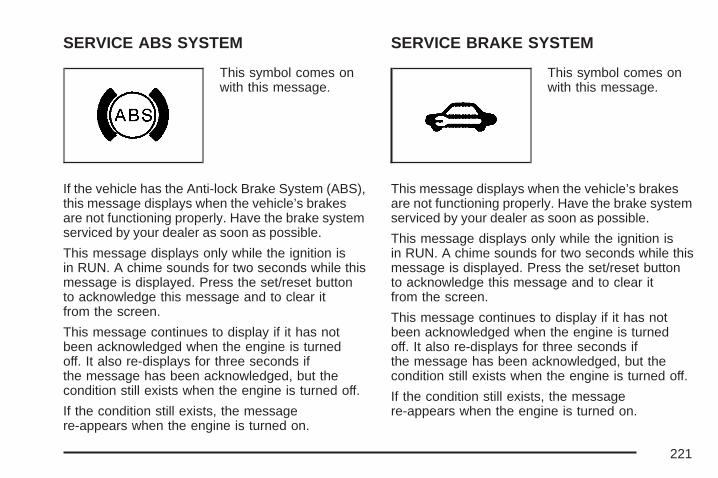
SERVICE ABS SYSTEM
This symbol comes onwith this message.
If the vehicle has the Anti-lock Brake System (ABS),this message displays when the vehicle’s brakesare not functioning properly. Have the brake systemserviced by your dealer as soon as possible.
This message displays only while the ignition isin RUN. A chime sounds for two seconds while thismessage is displayed. Press the set/reset buttonto acknowledge this message and to clear itfrom the screen.
This message continues to display if it has notbeen acknowledged when the engine is turnedoff. It also re-displays for three seconds ifthe message has been acknowledged, but thecondition still exists when the engine is turned off.
If the condition still exists, the messagere-appears when the engine is turned on.
SERVICE BRAKE SYSTEM
This symbol comes onwith this message.
This message displays when the vehicle’s brakesare not functioning properly. Have the brake systemserviced by your dealer as soon as possible.
This message displays only while the ignition isin RUN. A chime sounds for two seconds while thismessage is displayed. Press the set/reset buttonto acknowledge this message and to clear itfrom the screen.
This message continues to display if it has notbeen acknowledged when the engine is turnedoff. It also re-displays for three seconds ifthe message has been acknowledged, but thecondition still exists when the engine is turned off.
If the condition still exists, the messagere-appears when the engine is turned on.
221

SERVICE BRAKE APPLY SENSORThis message displays when the brake applysensor is not functioning properly. The vehicle stillhas brakes when this warning message displays,but you should have the vehicle serviced byyour dealer as soon as possible.
This message displays only while the ignition isin RUN. A chime sounds for two seconds while thismessage is displayed. Press the set/reset buttonto acknowledge this message and to clear itfrom the screen.
This message continues to display if it has notbeen acknowledged when the engine is turnedoff. It also re-displays for three seconds ifthe message has been acknowledged, but thecondition still exists when the engine is turned off.
If the condition still exists, the messagere-appears when the engine is turned on.
SERVICE PARK LAMPSThis message displays if one of the vehicle’sparking lamps needs to be replaced. See FrontTurn Signal, Parking and Fog Lamps on page 400for bulb replacement procedures.
This message displays only while the ignition is inRUN. A chime sounds for two seconds whilethis message is displayed. Press the set/resetbutton to acknowledge this message and to clearit from the screen.
This message continues to display if it has notbeen acknowledged when the engine is turnedoff. It also re-displays for three seconds ifthe message has been acknowledged, but thecondition still exists when the engine is turned off.
If the condition still exists, the messagere-appears when the engine is turned on.
222
SERVICE STABILITY SYSTEM
This symbol comes onwith this message.
If the vehicle has the StabiliTrak® Plus system,this message displays when it is not functioningproperly. A warning light also appears on theinstrument panel cluster. See Traction ControlSystem (TCS) Warning Light on page 182or Enhanced Traction System Warning Lighton page 183. See StabiliTrak® Plus Systemon page 299 for more information. Have theStabiliTrak® Plus system serviced by yourdealer as soon as possible.
This message displays only while the ignition isin RUN. A chime sounds for two seconds while thismessage is displayed. Press the set/reset buttonto acknowledge this message and to clear itfrom the screen.
This message continues to display if it has notbeen acknowledged when the engine is turnedoff. It also re-displays for three seconds ifthe message has been acknowledged, but thecondition still exists when the engine is turned off.
If the condition still exists, the messagere-appears when the engine is turned on.
223
SERVICE THEFT SYSTEMThis message displays if there is a problem withthe theft-deterrent system programmed in the key.A fault has been detected in the system whichmeans that the system is disabled and it isnot protecting the vehicle. The vehicle usuallyrestarts; however, you may want to take thevehicle to your dealer before turning off the engine.See Keys on page 84 for information on thePASS-Key® III system.
This message displays only while the ignition isin RUN. A chime sounds for two seconds while thismessage is displayed. Press the set/reset buttonto acknowledge this message and to clear itfrom the screen.
This message continues to display if it has notbeen acknowledged when the engine is turnedoff. It also re-displays for three seconds ifthe message has been acknowledged, but thecondition still exists when the engine is turned off.
If the condition still exists, the messagere-appears when the engine is turned on.
SERVICE TIRE MONITOR SYSTEMThis message displays if a part on the TirePressure Monitor (TPM) system is not workingproperly. If you drive your vehicle while any ofthe four sensors are missing or inoperable,the warning comes on in about 20 minutes.A sensor would be missing, for example, if youput different wheels on your vehicle withouttransferring the sensors. If the warning comeson and stays on, there may be a problem withthe TPM. See your dealer.
This message displays only while the ignition is inRUN. Press the set/reset button to acknowledgethis message and to clear it from the screen.
This message continues to display if it hasnot been acknowledged when the engine is turnedoff. It also re-displays for three seconds if themessage has been acknowledged, but thecondition still exists when the engine is turned off.
If the condition still exists, the messagere-appears when the engine is turned on.
224
SERVICE TRACTION SYSTEM
This symbol comes onwith this message.
If the vehicle has the Traction ControlSystem (TCS), this message displays when thesystem is not functioning properly. A warning lightalso appears on the instrument panel cluster. SeeTraction Control System (TCS) Warning Light onpage 182 or Enhanced Traction System WarningLight on page 183. See Traction Control System(TCS) on page 296 for more information. Have theTCS serviced by your dealer as soon as possible.
This message displays only while the ignition isin RUN. A chime sounds for two seconds while thismessage is displayed. Press the set/reset buttonto acknowledge this message and to clear itfrom the screen.
This message continues to display if it has notbeen acknowledged when the engine is turnedoff. It also re-displays for three seconds ifthe message has been acknowledged, but thecondition still exists when the engine is turned off.
If the condition still exists, the messagere-appears when the engine is turned on.
225
SERVICE VARIABLE EFFORTSTEERING
This symbol comes onwith this message.
If the vehicle has the variable effort steeringsystem, this message displays if this system is notfunctioning properly. See Steering on page 300for more information. Have the system servicedby your dealer as soon as possible.This message displays only while the ignition isin RUN. A chime sounds for two seconds while thismessage is displayed. Press the set/reset buttonto acknowledge this message and to clear itfrom the screen.This message continues to display if it has notbeen acknowledged when the engine is turnedoff. It also re-displays for three seconds ifthe message has been acknowledged, but thecondition still exists when the engine is turned off.If the condition still exists, the messagere-appears when the engine is turned on.
SERVICE VEHICLE SOON
This symbol comes onwith this message.
This message displays when a non-emissionsrelated malfunction occurs. Have the vehicleserviced by your dealer as soon as possible.
This message displays only while the ignition isin RUN. A chime sounds for two seconds while thismessage is displayed. Press the set/reset buttonto acknowledge this message and to clear itfrom the screen.
This message continues to display if it has notbeen acknowledged when the engine is turnedoff. It also re-displays for three seconds ifthe message has been acknowledged, but thecondition still exists when the engine is turned off.
If the condition still exists, the messagere-appears when the engine is turned on.
226
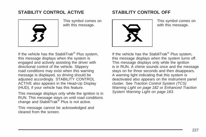
STABILITY CONTROL ACTIVE
This symbol comes onwith this message.
If the vehicle has the StabiliTrak® Plus system,this message displays when the system isengaged and actively assisting the driver withdirectional control of the vehicle. Slipperyroad conditions may exist when this warningmessage is displayed, so driving should beadjusted accordingly. STABILITY CONTROLACTIVE also appears in the Head-Up Display(HUD), if your vehicle has this feature.
This message displays only while the ignition is inRUN. This message stays on until road conditionschange and StabiliTrak® Plus is not active.
This message cannot be acknowledged andcleared from the screen.
STABILITY CONTROL OFF
This symbol comes onwith this message.
If the vehicle has the StabiliTrak® Plus system,this message displays when the system turns off.This message displays only while the ignitionis in RUN. A chime sounds once and the messagestays on for three seconds and then disappears.A warning light indicating that this system isdeactivated also appears on the instrument panelcluster. See Traction Control System (TCS)Warning Light on page 182 or Enhanced TractionSystem Warning Light on page 183.
227

When the StabiliTrak® Plus system is off, thesystem will not be engaged and will not activelyassist the driver with directional control of thevehicle. See StabiliTrak® Plus System onpage 299.
Any of the following conditions may cause theStabiliTrak® Plus system to turn off:
• The StabiliTrak® Plus system on theGXP option is manually turned off.See StabiliTrak® Plus System on page 299for more information.
• The battery is low.
• There is a StabiliTrak® Plus system failure.See your dealer for service.
STARTING DISABLED DUE TOELECTRONIC THROTTLE CONTROLThis message displays when there is a malfunctionwith the electronic throttle control which preventsthe vehicle from starting. Have the vehicleserviced by your dealer.
This message only appears while the ignition isin RUN, and will not disappear until the problemis resolved. A chime sounds for two seconds.This message cannot be acknowledged.
STARTING DISABLED DUE TOTHEFT SYSTEMThis message displays when the system detects amalfunction in the content theft-deterrent systemand prevents the vehicle from starting.
This message only appears while the ignition isin RUN, and will not disappear until the problemis resolved. A chime sounds for two seconds.This message cannot be acknowledged.
228

TRACTION CONTROL ACTIVE
This symbol comes onwith this message.
If the vehicle has the Traction Control System(TCS), this message displays when the system ison. TRACTION CONTROL ACTIVE alsoappears in the Head-Up Display (HUD), if yourvehicle has this feature.
This message only displays while the ignition is inRUN and will not disappear until driving conditionschange and the TCS is no longer active.
This message cannot be acknowledged or clearedfrom the screen.
TRACTION CONTROL OFF
This symbol comes onwith this message.
If the vehicle has the Traction Control System(TCS), this message displays when the TCS turnsoff. TRACTION CONTROL OFF also appearsin the Head-Up Display (HUD), if your vehicle hasthis feature. This message only displays whilethe ignition is in RUN and disappears afterthree seconds. A chime sounds once and themessage stays on for three seconds andthen disappears. A warning light indicating thatthis system is deactivated also appears onthe instrument panel cluster. See Traction ControlSystem (TCS) Warning Light on page 182 orEnhanced Traction System Warning Lighton page 183.
229

Any of the following conditions may cause theTCS to turn off:
• The TCS is turned off by pressing theTC (traction control) button located onthe center console. See Traction ControlSystem (TCS) on page 296 or EnhancedTraction System (ETS) on page 298 formore information.
• The battery is low.
• There is a TCS failure. See your dealerfor service.
TURN SIGNAL ONThis message displays if the vehicle is drivenfor more than 0.75 mile (1.21 km) while one ofthe turn signals are on. It appears as a reminderto turn off the turn signal.
This message only displays when the ignition is inRUN. A chime sounds for two seconds and themessage will not disappear until the turn signal ismanually turned off, or a turn is completed.
DIC Vehicle CustomizationYour vehicle may have customization capabilitiesthat allow you to program certain features toone preferred setting. Customization featurescan only be programmed to one setting onthe vehicle and cannot be programmed to apreferred setting for two different drivers.
All of the customization options may not beavailable on your vehicle. Only the optionsavailable will be displayed on your DIC.
The default settings for the customization featureswere set when your vehicle left the factory, butmay have been changed from their defaultstate since then. The customization preferencesare automatically recalled.
To change customization preferences, use thefollowing procedure.
230

Entering the Personal Programming Mode1. Turn the ignition on and make sure the
vehicle is in PARK (P).To avoid excessive drain on the battery,it is recommended that the headlamps areturned off.
2. Press the options button until PERSONALPROGRAMMING MODE appears on the DIC.
3. Press the set/reset button to display thefirst screen.
4. Press the options button to accessthese modes:
Personal Programming Mode Screens
EXTERIOR LIGHTING DELAY: This screenallows this feature to be turned off, or allows theselection of the number of seconds the headlamps,sidelamps, taillamps, fog lamps, and back-uplamps are turned on after the key is removed fromthe ignition, or the vehicle is unlocked using theremote keyless entry transmitter.
If OFF is selected, the exterior lamps will notturn on.
If a time delay is chosen, the lamps will turnon for the selected time. The time delay will becancelled and the exterior lamps will turn onautomatically when the key is removed from theignition, or the vehicle is unlocked using theremote keyless entry transmitter.
To program this mode, use the followingprocedure:
1. Press and release the set/reset button toscroll to the selection you want to program.Choose from OFF, 15, 30, 60, or 90 seconds.
2. Press the options button again to advance tothe next screen.
INTERIOR LIGHTS WHEN DOOR CLOSED: Thisscreen allows this feature to be turned OFF or ON.
If OFF is selected, the interior lamps will turn offimmediately when the ignition is turned off and thelast open door is closed.
If ON is selected, the interior lamps will stay on forabout 25 seconds after the vehicle’s ignition isturned off and the last open door is closed.
231
To program this mode, use the following procedure:
1. Press and release the set/reset button toscroll to either OFF or ON.
2. Press the options button again to advanceto the next screen.
INTERIOR LIGHTS WHEN KEY REMOVED:This screen allows this feature to be turned OFFor ON. This feature enables the interior lampsin the vehicle to turn on for about 25 seconds afterthe key is removed from the ignition.
If OFF is selected, removing the key from theignition will not cause the interior lamps to turn on.
If ON is selected, removing the key from theignition will cause the interior lamps to be turnedon for about 25 seconds.
To program this mode, use the followingprocedure:
1. Press and release the set/reset button toscroll to either OFF or ON.
2. Press the options button again to advanceto the next screen.
AUTO DOOR UNLOCK: This screen allows thisfeature to be turned off, used for the driver’sdoor only, or for all the doors.
If OFF is selected, none of the doors will unlockwhen the vehicle’s transaxle is shifted intoPARK (P).
If DRIVER is selected, only the driver’s door willunlock when the vehicle’s transaxle is shiftedinto PARK (P).
If ALL is selected, all the doors will unlock whenthe vehicle’s transaxle is shifted into PARK (P).
To program this mode, use the followingprocedure:
1. Press and release the set/reset button toscroll to either OFF, DRIVER, or ALL.
2. Press the options button again to advanceto the next screen.
232

AUTO DOOR UNLOCK ON: If DRIVER or ALLwas selected on the AUTO DOOR UNLOCKscreen, this screen allows selection of when thevehicle’s doors will unlock. The choices arewhen the key is removed from the ignition or whenthe vehicle is shifted into PARK (P).
If KEY-OUT is selected, the auto door unlock willfunction when the key is taken out of the ignition.
If PARK is selected, the auto door unlock willfunction when the transaxle is shifted intoPARK (P).
To program this mode, use the following procedure:
1. Press and release the set/reset button toscroll to either KEY-OUT or PARK.
2. Press the options button again to advanceto the next screen.
DELAYED LOCKING: This screen allows thisfeature to be turned OFF or ON. The key mustbe out of the ignition for this feature to work.
If OFF is selected, there will be no delayed lockingof the vehicle’s doors.
If ON is selected, the locking of the vehicle’s doorswill be delayed by five seconds after a power doorlock switch is pressed while the door is open, orthe LOCK button on the remote keyless entrytransmitter is pressed while any door is open.
To program this mode, use the following procedure:
1. Press and release the set/reset button toscroll to either OFF or ON.
2. Press the options button again to advanceto the next screen.
233

REMOTE LOCKS FEEDBACK: This screenallows selection for this option to be turned OFF,or gives the choice of two methods of verification;LIGHTS or LIGHTS and HORN; that indicatethe vehicle’s doors are locked when the LOCKbutton on the remote keyless entry transmitter ispressed.
If OFF is selected, this feature will not beprogrammed.
If LIGHTS is selected, the exterior lamps will flashwhen the LOCK button on the remote keylessentry transmitter is pressed.
If LIGHTS and HORN is selected, the exteriorlamps will flash when the LOCK button on theremote keyless entry transmitter is pressed, and thehorn will sound when the LOCK button on theremote keyless entry transmitter is pressed againwithin five seconds of the previous command.
To program this mode, use the following procedure:
1. Press the set/reset button to scroll to OFF,LIGHTS, or LIGHTS and HORN.
2. Press the options button again to advance tothe next screen.
If the vehicle does not have a contenttheft-deterrent system, the next screens withPROGRAMMING FINISHED and DISPLAY OFFwill appear.
If the vehicle does have a content theft-deterrentsystem, the next screen will appear.
THEFT DETERRENT: The vehicle may have acontent theft-deterrent system. Once it isturned on, the system will activate if someone triesto enter the vehicle without using the remotekeyless entry transmitter or the correct key. Thisscreen allows this feature to be turned OFF or ON.
If OFF is selected, the content theft-deterrentsystem will not function.
If ON is selected, the content theft-deterrentsystem will be activated.
234

To program this mode, use the following procedure:1. Press the set/reset button to scroll to
OFF or ON.2. Press the options button again to advance to
the next screen.
KEY CYLINDER DISARM: If the vehicle has acontent theft-deterrent system, and ON wasselected on the THEFT DETERRENT screen, thisscreen allows this feature to be turned OFF orON. This feature determines whether the driver’sdoor key cylinder may be used to disarm thecontent theft-deterrent system.
If OFF is selected, the vehicle’s contenttheft-deterrent system can not be disarmed byunlocking the driver’s door using the driver’s doorkey cylinder. Selecting OFF prevents a thieffrom disarming the vehicle’s content theft-deterrentsystem by attacking the driver’s door keycylinder, and may make the vehicle more secure.However, if OFF is selected, unlocking anarmed vehicle by using the driver’s door keycylinder and opening the door will causethe content theft alarm to activate. For this reason,it is recommended that the vehicle be unlockedusing the remote keyless entry system whenthis feature is set to OFF.
If ON is selected, the vehicle’s contenttheft-deterrent system can be disarmed byunlocking the driver’s door using the driver’sdoor key cylinder.
To program this mode, use the following procedure:
1. Press the set/reset button to scroll toOFF or ON.
2. Press the options button again to advance tothe next screen.
LOCK SWITCH ARM: If the vehicle has thecontent theft-deterrent system and ON wasselected on the THEFT DETERRENT screen, thisscreen allows this feature to be turned OFF orON. This feature controls whether the vehicle’scontent theft system can be activated using a doorlock switch.
If OFF is selected, locking the vehicle using adoor lock switch will not cause the vehicle’scontent theft system to arm.
235
If ON is selected, the content theft-deterrentsystem can be armed using the driver’s door lockswitch by pressing the driver’s door lock switchwhile the driver’s door is open and the key is not inthe ignition, or by pressing the front passenger’sdoor lock switch while the front passenger’s door isopen and the key is not in the ignition.
To program this mode, use the following procedure:
1. Press the set/reset button to scroll toOFF or ON.
2. Press the options button again to advance tothe next screen.
REMOTE START: If your vehicle has the remotestart feature, this screen allows this feature tobe turned OFF or ON. The remote start featureallows you to start the engine from outside ofthe vehicle using your remote keyless entrytransmitter. See “Remote Vehicle Start” underRemote Keyless Entry (RKE) System Operationon page 87 for more information.
If OFF is selected, the remote start feature will bedisabled.
If ON is selected, the remote start feature will beenabled.
To program this mode, use the following procedure:
1. Press the set/reset button to scroll toOFF or ON.
2. Press the options button again to advance tothe next screen.
PROGRAMMING FINISHED will appear on thenext screen. This confirms that the personaloptions programming is complete.
236

Audio System(s)Determine which radio your vehicle has and thenread the pages following to familiarize yourselfwith its features.
Driving without distraction is a necessity for asafer driving experience. See Defensive Driving onpage 288. By taking a few moments to read thismanual and get familiar with your vehicle’saudio system, you can use it with less effort, aswell as take advantage of its features. While yourvehicle is parked, set up your audio system bypresetting your favorite radio stations, setting thetone and adjusting the speakers. Then, whendriving conditions permit, you can tune toyour favorite stations using the presets andsteering wheel controls if the vehicle has them.
{CAUTION:
This system provides you with a far greateraccess to audio stations and song listings.Giving extended attention to entertainmenttasks while driving can cause a crash andyou or others can be injured or killed.Always keep your eyes on the road andyour mind on the drive — avoid engagingin extended searching while driving.
Keeping your mind on the drive is important forsafe driving. Here are some ways in which youcan help avoid distraction while driving.
237
While your vehicle is parked:
• Familiarize yourself with all of its controls.
• Familiarize yourself with its operation.
• Set up your audio system by presetting yourfavorite radio stations, setting the tone, andadjusting the speakers. Then, when drivingconditions permit, you can tune to your favoriteradio stations using the presets and steeringwheel controls if the vehicle has them.
Notice: Before adding any sound equipmentto your vehicle, such as an audio system,CD player, CB radio, mobile telephone,or two-way radio, make sure that it can beadded by checking with your dealer/retailer.Also, check federal rules covering mobile radioand telephone units. If sound equipment canbe added, it is very important to do it properly.Added sound equipment may interfere withthe operation of your vehicle’s engine, radio,or other systems, and even damage them.Your vehicle’s systems may interfere withthe operation of sound equipment that hasbeen added.
Setting the TimeThe radio might have a button marked with an Hor HR to represent hours and an M or MIN torepresent minutes.
Press and hold the hour button until the correcthour displays. AM appears for morning hours.Press and hold the minute button until the correctminute displays. The time can be set with theignition on or off.
To synchronize the time with an FM stationbroadcasting Radio Data System (RDS)information, press and hold the hour and minutebuttons at the same time until UPDATED displays.If the time is not available from the station,NO UPDATE displays.
RDS time is broadcast once a minute. After tuningto an RDS broadcast station, it could take afew minutes for the time to update.
238

Radio with CD (Base Level)
Radio Data System (RDS)The audio system has a Radio Data System (RDS).RDS features are available for use only on FMstations that broadcast RDS information.
With RDS, the radio can do the following:
• Seek to stations broadcasting the selectedtype of programming
• Receive announcements concerning local andnational emergencies
• Display messages from radio stations
• Seek to stations with traffic announcements
This system relies upon receiving specificinformation from these stations and only workswhen the information is available. In rare cases, aradio station may broadcast incorrect informationthat causes the radio features to work improperly.If this happens, contact the radio station.
While the radio is tuned to an RDS station, thestation name or call letters appear on the displayinstead of the frequency. RDS stations mayalso provide the time of day, a program type (PTY)for current programming, and the name of theprogram being broadcast.
XM™ Satellite Radio ServiceXM™ is a satellite radio service that is based inthe 48 contiguous United States and Canada.XM™ offers a large variety of coast-to-coastchannels including music, news, sports, talk,traffic/weather (U.S. subscribers), and children’sprogramming. XM™ provides digital qualityaudio and text information that includes song titleand artist name. A service fee is required inorder to receive the XM™ service. For moreinformation, contact XM™; In the U.S. atwww.xmradio.com or call 1-800-852-XMXM (9696)or in Canada at www.xmradio.ca or call1-877-GET-XMSR (438-9677).
239
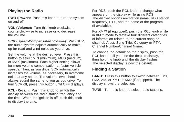
Playing the Radio
PWR (Power): Push this knob to turn the systemon and off.
VOL (Volume): Turn this knob clockwise orcounterclockwise to increase or to decreasethe volume.
SCV (Speed-Compensated Volume): With SCV,the audio system adjusts automatically to makeup for road and wind noise as you drive.
Set the volume at the desired level. Press thisbutton to select MIN (minimum), MED (medium),or MAX (maximum). Each higher setting allowsfor more volume compensation at faster vehiclespeeds. Then, as you drive, SCV automaticallyincreases the volume, as necessary, to overcomenoise at any speed. The volume level shouldalways sound the same to you as you drive. Toturn SCV off, press this button until OFF displays.
RCL (Recall): Push this knob to switch thedisplay between the radio station frequency andthe time. When the ignition is off, push this knobto display the time.
For RDS, push the RCL knob to change whatappears on the display while using RDS.The display options are station name, RDS stationfrequency, PTY, and the name of the program(if available).
For XM™ (if equipped), push the RCL knob whilein XM™ mode to retrieve four different categoriesof information related to the current song orchannel: Artist, Song Title, Category or PTY,Channel Number/Channel Name.
To change the default on the display, push theRCL knob until you see the desired display,then hold the knob until the display flashes.The selected display is now the default.
Finding a Station
BAND: Press this button to switch between FM1,FM2, AM, or XM1 or XM2 (if equipped). Thedisplay shows the selection.
TUNE: Turn this knob to select radio stations.
240

w SEEK x: Press the up or the down arrow togo to the next or to the previous station andstay there.
The radio only seeks stations with a strong signalthat are in the selected band.
w SCAN x: Press and hold either arrow fortwo seconds until SCAN displays and a beepsounds. The radio goes to a station, plays for afew seconds, then goes to the next station.Press either arrow again to stop scanning.
To scan preset stations, press and hold eitherSCAN arrow for more than four seconds untilPSCAN and the preset number appear onthe display and two beeps sound. The radiogoes to the first preset station stored on thepushbuttons, plays for a few seconds, then goesto the next preset station. Press either SCANarrow again to stop scanning presets.
The radio only scan stations with a strong signalthat are in the selected band.
Setting Preset StationsUp to 30 stations (six FM1, six FM2, and six AM,six XM1 and six XM2 (if equipped)), can beprogrammed on the six numbered pushbuttons,by performing the following steps:
1. Turn the radio on.
2. Press BAND to select FM1, FM2, AM, or XM1or XM2.
3. Tune in the desired station.
4. Press EQ to select the equalization.
5. Press and hold one of the six numberedpushbuttons until a beep sounds. Wheneverthat numbered pushbutton is pressed,the station that was set returns and theequalization that was selected is stored forthat pushbutton.
6. Repeat the steps for each pushbutton.
241

Setting the Tone(Bass/Midrange/Treble)
TONE: Press and release this button until BASS,MID (midrange), or TREB (treble) displays. TheSELECT LED indicator lights to show that the tonecontrol can be adjusted. Turn the SELECT knobto increase or to decrease. If a station is weakor has static, decrease the treble.
To return all of the tone controls to the middleposition, press and hold the TONE buttonuntil FLAT displays.
EQ (Equalizer): Press this button to selectcustomized equalization settings.
Up to six customized equalization settings, can beprogrammed, by performing the following steps:
1. Turn the radio on.
2. Use the TONE button and the SELECT knobto create the equalization.
3. Press and hold the EQ button for two seconds.SELECT EQ # displays and the EQ symbolflashes.
4. Press EQ or turn the SELECT knob to selectthe EQ number.
5. Press and hold the EQ button or push theSELECT knob to store the equalizationsetting and the number. EQ SAVED displaysand a beep sounds.
6. Repeat the steps for the other EQ settingsand numbers.
EQ 5 has been programmed at the factory foruse with talk radio, but it can be preset to adifferent tone.
Adjusting the Speakers (Balance/Fade)BAL (Balance): To adjust the balance betweenthe right and the left speakers, press and releasethis button until BAL displays. The SELECTLED indicator lights to show that the speakers canbe adjusted. Turn the SELECT knob to movethe sound toward the right or the left speakers.
FADE: To adjust the fade between the front andthe rear speakers, press and release thisbutton until FADE displays. The SELECT LEDindicator lights to show that the speakers can beadjusted. Turn the SELECT knob to move thesound toward the front or the rear speakers.
Pressing and holding the BAL FADE button fortwo seconds returns all speaker settings tothe middle position.
242

Finding a Program Type (PTY) Station(RDS and XM™)To select and find a desired PTY perform thefollowing:
1. Press the PROG TYPE button to activateprogram type select mode. PTY displays.
2. Turn the SELECT knob to select a PTY.
3. Once the desired PTY displays, press eitherSEEK arrow to select the PTY and take youto the PTY’s first station.
4. To go to another station within that PTY,while the PTY displays, press either SEEKarrow once. If the PTY is not displayed,press either SEEK arrow twice to displaythe PTY and then to go to another station.
5. Press PROG TYPE to exit program typeselect mode.If PTY times out and is no longer on thedisplay, go back to Step 1.
If both PTY and TRAF are on, the radio searchesfor stations with the selected PTY and trafficannouncements.
SCAN: Scan the stations within a PTY byperforming the following:
1. Press PROG TYPE to activate program typeselect mode. PTY displays.
2. Turn the SELECT knob to select a PTY.
3. Once the desired PTY displays, press andhold either SCAN arrow, and the radiobegins scanning the stations in the PTY.
4. Press either SCAN arrow to stop at a station.
If both PTY and TRAF are on, the radio scansfor stations with the selected PTY and trafficannouncements.
BAND (Alternate Frequency): Alternatefrequency allows the radio to switch to a strongerstation with the same program type. To turnalternate frequency on, press and hold BAND fortwo seconds. AF ON displays. The radio canswitch to stations with a stronger frequency.
To turn alternate frequency off, press and holdBAND again for two seconds. AF OFF displays.The radio does not switch to other stations.
This function does not apply for XM™ SatelliteRadio Service.
243

Setting Preset PTYs (RDS Only)These pushbuttons have factory PTY presets.Up to 12 PTYs (six FM1 and six FM2), canbe programmed on the six numbered pushbuttons,by performing the following steps:
1. Press BAND to select FM1 or FM2.
2. Press PROG TYPE to activate program typeselect mode. PTY displays.
3. Turn the SELECT knob to select a PTY.
4. Press and hold one of the six numberedpushbuttons until a beep sounds. Wheneverthat numbered pushbutton is pressed, the PTYthat was set returns, if program type selectmode is activated.
5. Repeat the steps for each pushbutton.
RDS Messages
ALERT!: Alert warns of local or nationalemergencies. When an alert announcementcomes on the current radio station, ALERT!displays. You will hear the announcement, evenif the volume is low or a CD is playing. If a CD isplaying, play stops during the announcement.Alert announcements cannot be turned off.
ALERT! is not affected by tests of the emergencybroadcast system. This feature is not supported byall RDS stations.
INFO (Information): If the current station has amessage, INFO displays. Press this button tosee the message. The message may display theartist, song title, call in phone numbers, etc.
If the entire message is not displayed, parts of themessage appears every three seconds. To scrollthrough the message, press and release the INFObutton. A new group of words appear on the displayafter every press of the button. Once the completemessage has been displayed, INFO disappearsfrom the display until another new message isreceived. The last message can be displayed bypressing the INFO button. You can view the lastmessage until a new message is received or adifferent station is tuned to.
TRAF (Traffic): If TRAF displays, the tunedstation broadcasts traffic announcements.To receive the traffic announcement from thetuned station, press this button. Bracketsare displayed around TRAF and when a trafficannouncement broadcasts on the tuned radiostation, you will hear it.
244
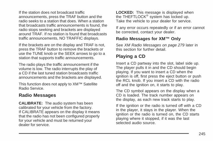
If the station does not broadcast trafficannouncements, press the TRAF button and theradio seeks to a station that does. When a stationthat broadcasts traffic announcements is found, theradio stops seeking and brackets are displayedaround TRAF. If no station is found that broadcaststraffic announcements, NO TRAFFIC displays.
If the brackets are on the display and TRAF is not,press the TRAF button to remove the brackets oruse the TUNE knob or the SEEK arrows to go to astation that supports traffic announcements.
The radio plays the traffic announcement if thevolume is low. The radio interrupts the play ofa CD if the last tuned station broadcasts trafficannouncements and the brackets are displayed.
This function does not apply to XM™ SatelliteRadio Service.
Radio Messages
CALIBRATE: The audio system has beencalibrated for your vehicle from the factory.If CALIBRATE appears on the display it meansthat the radio has not been configured properlyfor your vehicle and must be returned yourdealer for service.
LOCKED: This message is displayed whenthe THEFTLOCK® system has locked up.Take the vehicle to your dealer for service.
If any error occurs repeatedly or if an error cannotbe corrected, contact your dealer.
Radio Messages for XM™ OnlySee XM Radio Messages on page 279 later inthis section for further detail.
Playing a CDInsert a CD partway into the slot, label side up.The player pulls it in and the CD should beginplaying. If you want to insert a CD when theignition is off, first press the eject button or pushthe RCL knob. If you insert a CD with the radiooff and the ignition on, it starts to play.
The CD symbol appears on the display when aCD is loaded. The track number appears onthe display, as each new track starts to play.
If the ignition or the radio is turned off with a CDin the player, it stays in the player. When theignition or the radio is turned on, the CD startsplaying where it stopped, if it was the lastselected audio source.
245
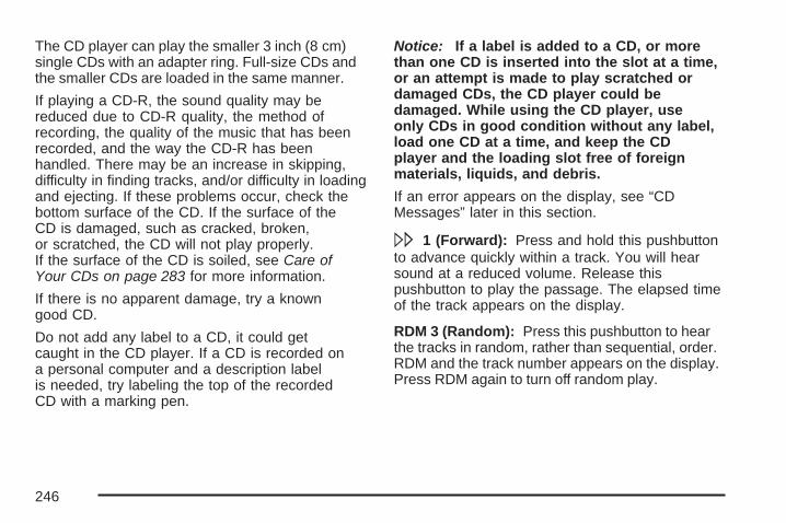
The CD player can play the smaller 3 inch (8 cm)single CDs with an adapter ring. Full-size CDs andthe smaller CDs are loaded in the same manner.
If playing a CD-R, the sound quality may bereduced due to CD-R quality, the method ofrecording, the quality of the music that has beenrecorded, and the way the CD-R has beenhandled. There may be an increase in skipping,difficulty in finding tracks, and/or difficulty in loadingand ejecting. If these problems occur, check thebottom surface of the CD. If the surface of theCD is damaged, such as cracked, broken,or scratched, the CD will not play properly.If the surface of the CD is soiled, see Care ofYour CDs on page 283 for more information.
If there is no apparent damage, try a knowngood CD.
Do not add any label to a CD, it could getcaught in the CD player. If a CD is recorded ona personal computer and a description labelis needed, try labeling the top of the recordedCD with a marking pen.
Notice: If a label is added to a CD, or morethan one CD is inserted into the slot at a time,or an attempt is made to play scratched ordamaged CDs, the CD player could bedamaged. While using the CD player, useonly CDs in good condition without any label,load one CD at a time, and keep the CDplayer and the loading slot free of foreignmaterials, liquids, and debris.
If an error appears on the display, see “CDMessages” later in this section.
\ 1 (Forward): Press and hold this pushbuttonto advance quickly within a track. You will hearsound at a reduced volume. Release thispushbutton to play the passage. The elapsed timeof the track appears on the display.
RDM 3 (Random): Press this pushbutton to hearthe tracks in random, rather than sequential, order.RDM and the track number appears on the display.Press RDM again to turn off random play.
246
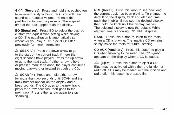
4s (Reverse): Press and hold this pushbuttonto reverse quickly within a track. You will hearsound at a reduced volume. Release thispushbutton to play the passage. The elapsedtime of the track appears on the display.
EQ (Equalizer): Press EQ to select the desiredcustomized equalization setting while playinga CD. The equalization is automatically setwhenever you play a CD. See “EQ” listedpreviously for more information.
w SEEK x: Press the down arrow to goto the start of the current track if more thaneight seconds have played. Press the up arrowto go to the next track. If either arrow is heldor pressed more than once, the player continuesmoving backward or forward through the CD.
w SCAN x: Press and hold either arrowfor more than two seconds until SCAN and thetrack number appear on the display and abeep sounds. The CD goes to the next track,plays for a few seconds, then goes to thenext track. Press either arrow again to stopscanning.
RCL (Recall): Push this knob to see how longthe current track has been playing. To change thedefault on the display, track and elapsed time,push the knob until you see the desired display,then hold the knob until the display flashes.The selected display is now the default. Whileelapsed time is showing, CD TIME displays.
BAND: Press this button to listen to the radiowhen a CD is playing. The inactive CD remainssafely inside the radio for future listening.
CD AUX (Auxiliary): Press this button to play aCD when listening to the radio. The CD symbolappears on the display when a CD is loaded.
Z (Eject): Press this button to eject a CD.Eject may be activated with either the ignition orradio off. CDs may be loaded with the ignition andradio off, if this button is pressed first.
247
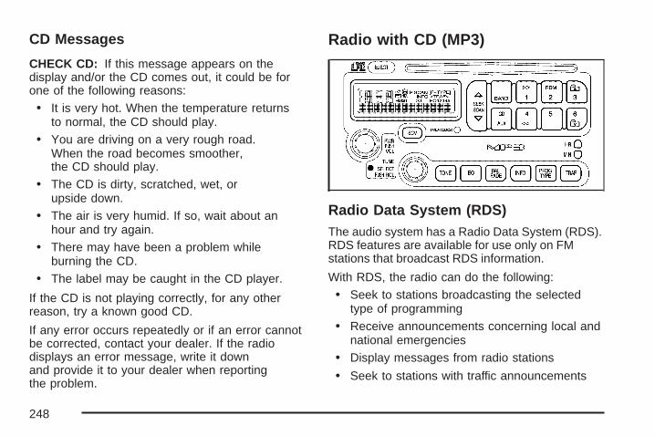
CD Messages
CHECK CD: If this message appears on thedisplay and/or the CD comes out, it could be forone of the following reasons:
• It is very hot. When the temperature returnsto normal, the CD should play.
• You are driving on a very rough road.When the road becomes smoother,the CD should play.
• The CD is dirty, scratched, wet, orupside down.
• The air is very humid. If so, wait about anhour and try again.
• There may have been a problem whileburning the CD.
• The label may be caught in the CD player.
If the CD is not playing correctly, for any otherreason, try a known good CD.
If any error occurs repeatedly or if an error cannotbe corrected, contact your dealer. If the radiodisplays an error message, write it downand provide it to your dealer when reportingthe problem.
Radio with CD (MP3)
Radio Data System (RDS)The audio system has a Radio Data System (RDS).RDS features are available for use only on FMstations that broadcast RDS information.
With RDS, the radio can do the following:
• Seek to stations broadcasting the selectedtype of programming
• Receive announcements concerning local andnational emergencies
• Display messages from radio stations
• Seek to stations with traffic announcements
248
This system relies upon receiving specificinformation from these stations and only workswhen the information is available. In rare cases, aradio station may broadcast incorrect informationthat causes the radio features to work improperly.If this happens, contact the radio station.
While the radio is tuned to an RDS station, thestation name or the call letters appear on thedisplay instead of the frequency. RDS stations mayalso provide the time of day, a program type(PTY) for current programming, and the name ofthe program being broadcast.
XM™ Satellite Radio ServiceXM™ is a satellite radio service that is based inthe 48 contiguous United States and Canada.XM™ offers a large variety of coast-to-coastchannels including music, news, sports, talk,traffic/weather (U.S. subscribers), and children’sprogramming. XM™ provides digital qualityaudio and text information that includes song titleand artist name. A service fee is required inorder to receive the XM™ service. For moreinformation, contact XM™; In the U.S. atwww.xmradio.com or call 1-800-852-XMXM (9696)or in Canada at www.xmradio.ca or call1-877-GET-XMSR (438-9677).
Playing the Radio
PWR (Power): Push this knob to turn the systemon and off.
VOL (Volume): Turn this knob clockwise orcounterclockwise to increase or to decreasethe volume.
RCL (Recall): Push this knob to switch thedisplay between the radio station frequency andthe time. When the ignition is turned off, push thisknob to display the time.
For XM™ (if equipped), push the RCL knob whilein XM™ mode to retrieve four different categoriesof information related to the current song orchannel: Artist, Song Title, Category or PTY,Channel Number/Channel Name.
To change the default on the display, push theRCL knob until you see the desired display,then hold the knob until the display flashes.The selected display is now the default.
249
SCV (Speed-Compensated Volume): With SCV,the audio system adjusts automatically to makeup for road and wind noise as you drive.
Set the volume at the desired level. Press thisbutton to select MIN (minimum), MED (medium),or MAX (maximum). Each higher setting allows formore volume compensation at faster vehiclespeeds. Then, as you drive, SCV automaticallyincreases the volume, as necessary, to overcomenoise at any speed. The volume level shouldalways sound the same to you as you drive. Toturn SCV off, press this button until OFF displays.
Finding a Station
BAND: Press this button to switch between FM1,FM2, AM, or XM1 or XM2 (if equipped). Thedisplay shows the selection.
TUNE: Turn this knob to select radio stations.
w SEEK x: Press the up or the down arrow togo to the next or to the previous station andstay there.
The radio only seeks stations with a strong signalthat are in the selected band.
w SCAN x: Press and hold either SCAN arrowfor two seconds until SCAN displays and abeep sounds. The radio goes to a station, playsfor a few seconds, then goes to the nextstation. Press either SCAN arrow again to stopscanning.
To scan preset stations, press and hold eitherSCAN arrow for more than four seconds untilPSCAN and the preset number appear on thedisplay and a double beep sounds. The radio goesto the first preset station, plays for a few seconds,then goes to the next preset station. Press eitherSCAN arrow again to stop scanning presets.
The radio only scans stations with a strong signalthat are in the selected band.
Setting Preset StationsUp to 30 stations (six FM1, six FM2, and six AM,six XM1 and six XM2 (if equipped)), can beprogrammed on the six numbered pushbuttons,by performing the following steps:
1. Turn the radio on.
2. Press BAND to select FM1, FM2, AM, or XM1or XM2.
250
3. Tune in the desired station.
4. Press EQ to select the equalization.
5. Press and hold one of the six numberedpushbuttons until a beep sounds. Wheneverthat numbered pushbutton is pressed,the station that was set returns and theequalization that was selected is stored forthat pushbutton.
6. Repeat the steps for each pushbutton.
Setting the Tone(Bass/Midrange/Treble)
TONE: Press and release this button until BASS,MID (midrange), or TREB (treble) displays. TheSELECT LED indicator lights to show that the tonecontrol can be adjusted. Turn the SELECT knobto increase or to decrease. If a station is weakor has static, decrease the treble.
Pressing and holding the TONE button until FLATdisplays, returns all of the tone controls to themiddle position.
EQ (Equalizer): Press this button to selectcustomized bass, midrange, and trebleequalization settings.
Up to six customized equalization settings, can beprogrammed on the six numbered pushbuttons,by performing the following steps:
1. Turn the radio on.
2. Use the TONE button and the SELECT knobto create the desired equalization.
3. Press and hold the EQ button for two seconds.SELECT EQ # displays and the EQ symbolflashes.
4. Press EQ or turn the SELECT knob to selectthe desired EQ number.
5. Press and hold the EQ button or push theSELECT knob to store the equalizationsetting and the number. A beep sounds andEQ SAVED displays.
6. Repeat the steps for the other EQ settingsand numbers.
EQ 5 has been programmed at the factory for usewith talk radio, but it can be set to a different tone.
251

Adjusting the Speakers (Balance/Fade)
BAL (Balance): To adjust the balance betweenthe right and the left speakers, press and releasethis button until BAL displays. The SELECTLED indicator lights to show that the speakers canbe adjusted. Turn the SELECT knob to movethe sound toward the right or the left speakers.
FADE: To adjust the fade between the front andthe rear speakers, press and release thisbutton until FADE displays. The SELECT LEDindicator lights to show that the speakers can beadjusted. Turn the SELECT knob to move thesound toward the front or the rear speakers.
Pressing and holding the BAL FADE button fortwo seconds returns all speaker settings tothe middle position.
Finding a Program Type (PTY) Station(RDS and XM™)To select and find a desired PTY performthe following:
1. Press PROG TYPE to activate program typeselect mode. The PTY symbol appears onthe display.
2. Turn the SELECT knob to select a PTY.
3. Once the desired PTY is displayed, presseither SEEK arrow to select the PTY and totake you to the PTY’s first station.
4. To go to another station within that PTY, andthe PTY is displayed, press either SEEKarrow once. If the PTY is not displayed, presseither SEEK arrow twice to display the PTYand then to go to another station.
5. Press PROG TYPE to exit program typeselect mode.If PTY times out and is no longer on thedisplay, go back to Step 1.
If both PTY and TRAF are on, the radio searchesfor stations with the selected PTY and trafficannouncements.
252

w SCAN x: Scan the stations within a PTY byperforming the following:1. Press PROG TYPE to activate program type
select mode. The PTY symbol appears on thedisplay.
2. Turn the SELECT knob to select a PTY.3. Once the desired PTY is displayed, press and
hold either SCAN arrow, and the radio beginsscanning the stations in the PTY.
4. Press either SCAN arrow to stop at a station.If both PTY and TRAF are on, the radio scansfor stations with the selected PTY and trafficannouncements.
BAND (Alternate Frequency): Alternatefrequency allows the radio to switch to a strongerstation with the same program type. To turnalternate frequency on, press and hold BAND fortwo seconds. AF ON displays. The radio canswitch to stations with a stronger frequency.
To turn alternate frequency off, press and holdBAND again for two seconds. AF OFF displays.The radio does not switch to other stations.
This function does not apply for XM™ SatelliteRadio Service.
Setting Preset PTYs (RDS Only)These pushbuttons have factory PTY presets.Up to 12 PTYs (six FM1 and six FM2), canbe programmed on the six numbered pushbuttons,by performing the following steps:
1. Press BAND to select FM1 or FM2.
2. Press PROG TYPE to activate program typeselect mode. The PTY symbol appears onthe display.
3. Turn the SELECT knob to select a PTY.
4. Press and hold one of the six numberedpushbuttons until a beep sounds. Wheneverthat numbered pushbutton is pressed, the PTYthat was set returns, if program type selectmode is activated.
5. Repeat the steps for each pushbutton.
253

RDS Messages
ALERT!: Alert warns of local or nationalemergencies. When an alert announcementcomes on the current radio station, ALERT!displays. You will hear the announcement, evenif the volume is low or a CD is playing. If a CD isplaying, play stops during the announcement.Alert announcements cannot be turned off.
ALERT! is not affected by tests of the emergencybroadcast system. This feature is not supported byall RDS stations.
INFO (Information): If the current station has amessage, INFO displays. Press this button tosee the message. The message may display theartist, song title, call in phone numbers, etc.
If the entire message is not displayed, parts ofthe message appears every three seconds.To scroll through the message, press and releasethe INFO button. A new group of words appearon the display after every press of this button.
Once the complete message has been displayed,the information symbol disappears from thedisplay until another new message is received.The last message can be displayed by pressingthe INFO button. You can view the last messageuntil a new message is received or a differentstation is tuned to.
TRAF (Traffic): If TRAF displays, the tunedstation broadcasts traffic announcements.To receive the traffic announcement from thetuned station, press this button. Bracketsare displayed around TRAF and when a trafficannouncement broadcasts on the tuned radiostation, you will hear it.
If the station does not broadcast trafficannouncements, press the TRAF button and theradio seeks to a station that does. When a stationthat broadcasts traffic announcements is found, theradio stops seeking and brackets are displayedaround TRAF. If no station is found that broadcaststraffic announcements, NO TRAFFIC displays.
254
If the brackets are on the display and TRAF is not,press the TRAF button to remove the brackets oruse the TUNE knob or the SEEK arrows to go to astation that supports traffic announcements. If nostation is found that broadcasts trafficannouncements, NO TRAFFIC displays.
The radio plays the traffic announcement if thevolume is low. The radio interrupts the play of aCD if the last tuned station broadcasts trafficannouncements and the brackets are displayed.
This function does not apply to XM™ SatelliteRadio Service.
Radio Messages
CALIBRATE: The audio system has beencalibrated for your vehicle from the factory. IfCALIBRATE displays it means that the radio hasnot been configured properly for your vehicleand it must be returned to your dealer for service.
Radio Messages for XM™ OnlySee XM Radio Messages on page 279 later inthis section for further detail.
Playing a CDInsert a CD partway into the slot, label side up.The player pulls it in and READING DISC and theCD symbol appears on the display. If you wantto insert a CD with the ignition off, first press theEJECT button or push the RCL knob.
If the ignition or radio is turned off with a CD in theplayer it stays in the player. When the ignition orradio is turned on, the CD starts to play where itstopped, if it was the last selected audio source.
When the CD is inserted, the CD symbol appearson the display. As each new track starts toplay, the track number appears on the display.
The CD player can play the smaller 3 inch (8 cm)single CDs with an adapter ring. Full-size CDs andthe smaller CDs are loaded in the same manner.
255
If playing a CD-R, the sound quality may bereduced due to CD-R quality, the method ofrecording, the quality of the music that has beenrecorded, and the way the CD-R has beenhandled. There may be an increase in skipping,difficulty in finding tracks, and/or difficulty in loadingand ejecting. If these problems occur, check thebottom surface of the CD. If the surface of theCD is damaged, such as cracked, broken,or scratched, the CD will not play properly.If the surface of the CD is soiled, see Care ofYour CDs on page 283 for more information.
If there is no apparent damage, try a knowngood CD.
Do not add any label to a CD, it could get caughtin the CD player. If a CD is recorded on apersonal computer and a description label isneeded, try labeling the top of the recorded CDwith a marking pen.
Notice: If a label is added to a CD, or morethan one CD is inserted into the slot at a time,or an attempt is made to play scratchedor damaged CDs, the CD player could bedamaged. While using the CD player, useonly CDs in good condition without any label,load one CD at a time, and keep the CDplayer and the loading slot free of foreignmaterials, liquids, and debris.
If an error appears on the display, see “CDMessages” later in this section.
\ 1 (Forward): Press and hold this pushbuttonto advance quickly within a track. You will hearsound at a reduced volume. Release thispushbutton to play the passage. The elapsedtime of the track appears on the display.
RDM 2 (Random): Press this pushbutton to hearthe tracks in random, rather than sequential, order.RDM and the track number appears on the display.Press RDM again to turn off random play.
256
3 # (Next Folder): This button does not havea function for non-MP3 CDs.
4s (Reverse): Press and hold this pushbuttonto reverse quickly within a track. You will hearsound at a reduced volume. Release thispushbutton to play the passage. The elapsedtime of the track appears on the display.
6 ! (Previous Folder): This button does nothave a function for non-MP3 CDs.
EQ (Equalizer): Press EQ to select the desiredcustomized equalization setting while playinga CD. The equalization is automatically setwhenever a CD is played. See “EQ” listedpreviously for more information.
w SEEK x: Press the up arrow to go to thestart of the next track. Press the down arrow togo to the start of the previous track. Pressingeither arrow for more than two seconds searchesthe previous or next tracks at two tracks persecond. When the track number that you wouldlike to play appears on the display, releasethe arrow to stop searching and to play the track.
w SCAN x: Press and hold either arrow formore than two seconds until SCAN and the tracknumber appear on the display and a beepsounds. The CD goes to the next track, plays for afew seconds, then goes to the next track. Presseither arrow again to stop scanning.
RCL (Recall): Push this knob to see how longthe current track has been playing. To changethe default on the display, track and elapsed time,push the knob until you see the desired display,then hold the knob until the display flashes.The selected display is now the default. Whileelapsed time appears on the display, CDTIME displays.
BAND: Press this button to listen to the radiowhen a CD is playing. The inactive CD remainssafely inside the radio for future listening.
CD AUX (Auxiliary): Press this button to play aCD when listening to the radio. The CD symbolappears on the display when a CD is loaded.
EJECT: Press this button to eject a CD. Eject maybe activated with either the ignition or radio off.CDs may be loaded with the radio and ignition offif this button is pressed first.
257

Playing an MP3 CD-R DiscYour vehicle’s radio system may have the MP3feature. If it has this feature, it is capable of playingan MP3 CD-R disc. For more information onhow to play an MP3 CD-R disc, see Using anMP3 on page 273 later in this section.
CD Messages
CHECK CD: If this message appears on thedisplay and/or the CD comes out, it could be forone of the following reasons:
• It is very hot. When the temperature returnsto normal, the CD should play.
• You are driving on a very rough road.When the road becomes smoother,the CD should play.
• The CD is dirty, scratched, wet, orupside down.
• The air is very humid. If so, wait about anhour and try again.
• The format of the CD may not be compatible.See Using an MP3 on page 273 later in thissection.
• There may have been a problem whileburning the CD.
• The label may be caught in the CD player.
If the CD is not playing correctly, for any otherreason, try a known good CD.
If any error occurs repeatedly or if an errorcannot be corrected, contact your dealer. If theradio displays an error message, write it downand provide it to your dealer when reportingthe problem.
258

Radio with Six-Disc CD
If your vehicle has the Monsoon audio system,included are nine speakers and an eight channelamplifier. The radio displays MONSOON whenthe radio or the ignition is turned on. Seeyour dealer for details.
Radio Data System (RDS)The audio system has a Radio Data System (RDS).RDS features are available for use only on FMstations that broadcast RDS information.
With RDS, the radio can do the following:
• Seek to stations broadcasting the selectedtype of programming
• Receive announcements concerning local andnational emergencies
• Display messages from radio stations
• Seek to stations with traffic announcements
This system relies upon receiving specificinformation from these stations and only workswhen the information is available. In rare cases, aradio station may broadcast incorrect informationthat causes the radio features to work improperly.If this happens, contact the radio station.
While the radio is tuned to an RDS station, thestation name or call letters appear on the displayinstead of the frequency. RDS stations mayalso provide the time of day, a program type (PTY)for current programming, and the name of theprogram being broadcast.
259

XM™ Satellite Radio ServiceXM™ is a satellite radio service that is based inthe 48 contiguous United States and Canada.XM™ offers a large variety of coast-to-coastchannels including music, news, sports, talk,traffic/weather (U.S. subscribers), and children’sprogramming. XM™ provides digital qualityaudio and text information that includes song titleand artist name. A service fee is required inorder to receive the XM™ service. For moreinformation, contact XM™; In the U.S. atwww.xmradio.com or call 1-800-852-XMXM (9696)or in Canada at www.xmradio.ca or call1-877-GET-XMSR (438-9677).
Playing the Radio
PWR (Power): Push this knob to turn the systemon and off.
VOLUME: Turn this knob clockwise orcounterclockwise to increase or to decreasethe volume.
RCL (Recall): Press this knob to switch thedisplay between the radio station frequency andthe time. When the ignition is off, press thisknob to display the time.
For RDS, press the RCL knob to change whatappears on the display while using RDS. Thedisplay options are station name, RDS stationfrequency, PTY, and the name of the program(if available).
For XM™ (if equipped), press the RCL knob whilein XM mode to retrieve four different categoriesof information related to the current song orchannel: Artist, Song Title, Category or PTY,Channel Number/Channel Name.
To change the default on the display, press theRCL knob until you see the desired display,then hold the knob until the display flashes.The selected display is now the default.
260

AUTO VOL (Automatic Volume): With automaticvolume, the audio system adjusts automaticallyto make up for road and wind noise as you drive.
Set the volume at the desired level. Press thisbutton to select MIN (minimum), MED (medium),or MAX (maximum). Each higher setting allows formore volume compensation at faster vehiclespeeds. Then, as you drive, automatic volumeincreases the volume, as necessary, to overcomenoise at any speed. The volume level shouldalways sound the same to you as you drive. Toturn automatic volume off, press this buttonuntil OFF displays.
Finding a Station
BAND: Press this button to switch between FM1,FM2, AM, or XM1 or XM2 (if equipped). Thedisplay shows the selection.
TUNE: Turn this knob to select radio stations.
sSEEK t: Press the right or the left arrow to goto the next or to the previous station and stay there.
The radio only seeks stations with a strong signalthat are in the selected band.
sSCAN t: Press and hold either SCAN arrowfor two seconds until SC displays and a beepsounds. The radio goes to a station, plays for afew seconds, then goes to the next station. Presseither SCAN arrow again to stop scanning.
To scan preset stations, press and hold eitherSCAN arrow for more than four seconds. PRESETSCAN appears on the display and a double beepsounds. The radio goes to the first preset stationstored on the pushbuttons, plays for a few seconds,then goes to the next preset station. Press eitherSCAN arrow again to stop scanning presets.
The radio only scans stations with a strong signalthat are in the selected band.
261
Setting Preset StationsUp to 30 stations (six FM1, six FM2, and six AM,six XM1 and six XM2 (if equipped)), can beprogrammed on the six numbered pushbuttons,by performing the following steps:
1. Turn the radio on.
2. Press BAND to select FM1, FM2, AM,or XM1 or XM2.
3. Tune in the desired station.
4. Press AUTO EQ to select the equalization.
5. Press and hold one of the six numberedpushbuttons until a beep sounds. Wheneverthat numbered pushbutton is pressed,the station that was set returns and theequalization that was selected is stored forthat pushbutton.
6. Repeat the steps for each pushbutton.
Setting the Tone(Bass/Midrange/Treble)
AUDIO: Push the AUDIO knob until BASS, MID(midrange), or TREB (treble) displays. Turnthe knob to increase or to decrease. If a stationis weak or noisy, decrease the treble.
To adjust bass, midrange, or treble to the middleposition, select BASS, MID, or TREB and pushand hold the AUDIO knob. The display leveladjusts to the middle position and a beep sounds.
To adjust all tone and speaker controls to themiddle position, push and hold the AUDIO knobwhen no tone or speaker control is displayed.CENTERED displays and one beep sounds.
AUTO EQ (Automatic Equalization): Press thisbutton to select customized equalization settingsdesigned for country, jazz, talk, pop, rock, andclassical.
To return to the manual mode, press the AUTOEQ button until CUSTOM displays. Then manuallyadjust the bass, midrange, and treble using theAUDIO knob.
262
Adjusting the Speakers (Balance/Fade)
AUDIO: To adjust the balance between theright and the left speakers, push the AUDIO knobuntil BAL (balance) displays. Turn the knob tomove the sound toward the right or the leftspeakers.
To adjust the fade between the front and rearspeakers, push and hold the AUDIO knobuntil FAD (fade) displays. Turn the knob to movethe sound toward the front or the rear speakers.
To adjust the balance and the fade to themiddle position, select balance or fade and pushand hold the AUDIO knob. The display leveladjusts to the middle position and a beep sounds.
To adjust all tone and speaker controls to themiddle position, push and hold the AUDIO knobwhen no tone or speaker controls are displayed.CENTERED displays and one beep sounds.
Finding a Program Type (PTY) Station(RDS and XM™)To select and find a desired PTY perform thefollowing:
1. Press the P-TYPE button to activate programtype select mode. P-TYPE and the lastselected PTY displays.
2. Turn the P-TYPE knob to select a PTY.
3. Once the desired PTY is displayed, presseither SEEK arrow to select and to takeyou to the PTY’s first station.
4. To go to another station within that PTY, andthe PTY is displayed, press either SEEKarrow once. If the PTY is not displayed, presseither SEEK arrow twice to display the PTYand then to go to another station.
5. Press P-TYPE to exit program typeselect mode.If PTY times out and is no longer on thedisplay, go back to Step 1.
263

If both P-TYPE and TRAF are on, the radiosearches for stations with the selected PTY andtraffic announcements.
To use the PTY interrupt feature, press and holdthe P-TYPE button until a beep sounds on thePTY you want to interrupt with. When selected, anasterisk appears beside that PTY on the display.You may select multiple interrupts, if desired.When you are listening to a CD, the last selectedRDS station interrupts play, if that selectedprogram type format is broadcast.
SCAN: Scan the stations within a PTY byperforming the following:
1. Press the P-TYPE button to activate programtype select mode. P-TYPE and the lastselected PTY displays.
2. Turn the P-TYPE knob to select a PTY.
3. Once the desired PTY is displayed, press andhold either SCAN arrow, and the radio beginsscanning the stations in the PTY.
4. Press either SCAN arrow to stop at a station.
If both P-TYPE and TRAF are on, the radioscans for stations with the selected PTY and trafficannouncements.
BAND (Alternate Frequency): Alternatefrequency allows the radio to switch to a strongerstation with the same program type. To turnalternate frequency on, press and hold BAND fortwo seconds. AF ON displays. The radio canswitch to stations with a stronger frequency.
To turn alternate frequency off, press and holdBAND again for two seconds. AF OFF displays.The radio does not switch to other stations.
This function does not apply for XM™ SatelliteRadio Service.
264

Setting Preset PTYs (RDS Only)These buttons have factory PTY presets.Up to 12 PTYs (six FM1 and six FM2), can beprogrammed on the six numbered pushbuttons,by performing the following steps:
1. Press BAND to select FM1 or FM2.
2. Press the P-TYPE button to activate programtype select mode. P-TYPE and the lastselected PTY displays.
3. Turn the P-TYPE knob to select a PTY.
4. Press and hold one of the six numberedpushbuttons until a beep sounds. Wheneverthat numbered pushbutton is pressed,the PTY that was set returns.
5. Repeat the steps for each pushbutton.
RDS Messages
ALERT!: Alert warns of local or nationalemergencies. When an alert announcementcomes on the current radio station, ALERT!displays. You will hear the announcement, evenif the volume is low or a CD is playing. If a CD isplaying, play stops during the announcement.Alert announcements cannot be turned off.
ALERT! is not affected by tests of the emergencybroadcast system. This feature is not supported byall RDS stations.
INFO (Information): If the current station has amessage, INFO displays. Press this button tosee the message. The message may display theartist, song title, call in phone numbers, etc.
If the entire message is not displayed, parts ofthe message appears every three seconds.To scroll through the message, press and releasethe INFO button. A new group of words appearon the display after every press of this button.Once the complete message has displayed, INFOdisappears from the display until another newmessage is received. The last message can bedisplayed by pressing the INFO button. Youcan view the last message until a new messageis received or a different station is tuned to.
TRAF (Traffic): If TRAF displays, the tunedstation broadcasts traffic announcements.To receive the traffic announcement from thetuned station, press this button. Bracketsare displayed around TRAF and when a trafficannouncement broadcasts on the tuned radiostation, you will hear it.
265
If the current tuned station does not broadcasttraffic announcements, press the TRAF button andthe radio seeks to a station that does. When astation that broadcasts traffic announcements isfound, the radio stops seeking and bracketsare displayed around TRAF. If no station is found,NO TRAFFIC displays.
If the brackets are on the display and TRAF is not,press the TRAF button to remove the bracketsor use the TUNE knob or the SEEK arrows to goto a station that supports traffic announcements.If no station is found that broadcasts trafficannouncements, NO TRAFFIC displays.
The radio plays the traffic announcement if thevolume is low. The radio interrupts the playof a CD if the last tuned station broadcasts trafficannouncements and the brackets are displayed.
This function does not apply to XM™ SatelliteRadio Service.
Radio Messages for XM™ OnlySee XM Radio Messages on page 279 later inthis section for further detail.
Radio Messages
CAL ERR (Calibration Error): The audio systemhas been calibrated for your vehicle from thefactory. If CAL ERR displays it means thatthe radio has not been configured properly forthe vehicle and it must be returned to your dealerfor service.
LOCKED: This message is displayed whenthe THEFTLOCK® system has locked up.Take your vehicle to your dealer for service.
If any error occurs repeatedly or if an errorcannot be corrected, contact your dealer.
Playing a CDIf the ignition or radio is turned off, with a CD in theplayer, it stays in the player. When the ignition orradio is turned on, the CD starts playing where itstopped, if it was the last selected audio source.
When a CD is inserted, the CD symbol appearson the CD. As each new track starts to play,the track number appears on the display.
266

The CD player can play the smaller 3 inch (8 cm)single CDs with an adapter ring. Full-size CDsand the smaller CDs are loaded in the samemanner.
If playing a CD-R, the sound quality may bereduced due to CD-R quality, the method ofrecording, the quality of the music that has beenrecorded, and the way the CD-R has beenhandled. There may be an increase in skipping,difficulty in finding tracks, and/or difficulty in loadingand ejecting. If these problems occur, check thebottom surface of the CD. If the surface of theCD is damaged, such as cracked, broken,or scratched, the CD will not play properly. If thesurface of the CD is soiled, see Care of Your CDson page 283 for more information.
If there is no apparent damage, try a knowngood CD.
Do not add any label to a CD, it could get caughtin the CD player. If a CD is recorded on apersonal computer and a description label isneeded, try labeling the top of the recorded CDwith a marking pen.
Notice: If a label is added to a CD, or morethan one CD is inserted into the slot at a time,or an attempt is made to play scratchedor damaged CDs, the CD player could bedamaged. While using the CD player, useonly CDs in good condition without any label,load one CD at a time, and keep the CDplayer and the loading slot free of foreignmaterials, liquids, and debris.
If an error appears on the display, see “CDMessages” later in this section.
LOAD CDZ: Press the LOAD side of thisbutton to load CDs into the CD player. This CDplayer holds up to six CDs.
To insert one CD, do the following:
1. Turn the ignition on.
2. Press and release the LOAD button.
3. Wait for the light, located to the right of theslot, to turn green.
4. Load a CD. Insert the CD partway into the slot,label side up. The player pulls the CD in.
267

To insert multiple CDs, do the following:
1. Turn the ignition on.
2. Press and hold the LOAD button fortwo seconds.A beep sounds and the light, located to theright of the slot, begins to flash.
3. Once the light stops flashing and turns green,load a CD. Insert the CD partway into the slot,label side up. The player pulls the CD in.
4. Once the CD is loaded, the light beginsflashing again. Press the LOAD buttonagain. Once the light turns green, load thenext disc. Repeat this procedure for each CD.The CD player takes up to six CDs. Do nottry to load more than six.
To load more than one CD but less than six,complete Steps 1 through 3. When finished loadingCDs, the radio begins to play the last CD loaded.
If more than one CD has been loaded, anumber for each CD displays.
Playing a Specific Loaded CDFor every CD loaded, a number appears on thedisplay. To play a specific CD, first press theCD AUX button, then press the numberedpushbutton that corresponds to the CD. A smallbar appears under the CD number that isplaying and the track number appears.
If an error appears on the display, see “CDMessages” later in this section.
LOAD CDZ (Eject): Press the CD eject side ofthis button to eject a CD(s). A beep sounds andthe indicator light flashes to let you know when aCD is being ejected.
REMOVE CD displays. The CD can be removed.If the CD is not removed, after 25 seconds,the CD is automatically pulled back into the player.If the CD is pushed back into the player, beforethe 25 second time period is complete, theplayer senses an error and tries to eject the CDseveral times before stopping.
268
Do not repeatedly press the CD eject button toeject a CD after trying to push it in manually. Theplayer’s 25-second eject timer resets at eachpress of eject, causing the player to not eject theCD until the 25-second time period has elapsed.
Once the player stops and the CD is ejected,remove the CD. After removing the CD, push thePWR knob off and then on again, or wait forthe system to reset. This clears the CD-sensingfeature and enables CDs to be loaded intothe player again.
{ REV (Reverse): Press and hold this buttonto reverse quickly within a track. You will hearsound at a reduced volume. Release this button toplay the passage. The elapsed time of the trackappears on the display.
FWD | (Forward): Press and hold this buttonto advance quickly within a track. You willhear sound at a reduced volume. Release thisbutton to play the passage. The elapsed time ofthe track appears on the display.
RPT (Repeat): With repeat, one track or an entireCD can be repeated.
To use repeat, do the following:
• To repeat the track you are listening to, pressand release the RPT button. RPT displays.Press RPT again to turn off repeat play.
• To repeat the CD you are listening to, pressand hold the RPT button for two seconds.RPT displays. Press RPT again to turnoff repeat play.
RDM (Random): With random, you can listento the tracks in random, rather than sequential,order, on one CD or on all of the CDs.
To use random, do one of the following:
• To play the tracks on the CD you are listeningto in random order, press and release theRDM button. RANDOM ONE displays. PressRDM again to turn off random play.
• To play the tracks on all of the CDs that areloaded, in random order, press and holdRDM for more than two seconds. A beepsounds and RANDOM ALL displays.Press RDM again to turn off random play.
269

AUTO EQ (Automatic Equalization): PressAUTO EQ to select the desired equalization settingwhile playing a CD. The equalization is setwhenever a CD is played. For more informationon AUTO EQ, see “AUTO EQ” listed previously inthis section.
sSEEK t: Press the left arrow to go to thestart of the current track, if more than ten secondshave played. Press the right arrow to go to thenext track. If either arrow is held or pressed morethan once, the player continues moving backwardor forward through the CD.
sSCAN t: To scan one CD, press and holdeither SCAN arrow for more than two seconds untilSCAN displays and a beep sounds. Use thisfeature to listen to 10 seconds of each track of thecurrently selected CD. Press either SCAN arrowagain, to stop scanning.
To scan all loaded CDs, press and hold eitherSCAN arrow for more than four seconds until CDSCAN displays and a beep sounds. Use thisfeature to listen to 10 seconds of the first track ofeach loaded CD. Press either SCAN arrowagain, to stop scanning.
RCL (Recall): Press this knob to see how longthe current track has been playing. To change thedefault on the display, track and elapsed time,press the knob until you see the desired display,then hold the knob until the display flashes.The selected display is now the default.
BAND: Press this button to play the radio whena CD is playing. The inactive CD(s) remains safelyinside the radio for future listening.
CD AUX (Auxiliary): Press this button to play aCD when listening to the radio.
270
Using Song List ModeThe six-disc CD changer has a feature calledsong list. This feature is capable of saving 20 trackselections.To save tracks into the song list feature, performthe following steps:1. Turn the CD player on and load it with at least
one CD. See “LOAD CD” listed previously inthis section for more information.
2. Check to see that the CD changer is not insong list mode. S-LIST should not appear inthe display. If S-LIST is present, pressthe SONG LIST button to turn it off.
3. Select the desired CD by pressing thenumbered pushbutton and then use the SEEKSCAN right arrow to locate the track to besaved. The track begins to play.
4. Press and hold the SONG LIST button tosave the track into memory. When SONGLIST is pressed, one beep sounds. Aftertwo seconds of continuously pressingthe SONG LIST button, two beeps sound toconfirm that the track has been saved.
5. Repeat Steps 3 and 4 for saving otherselections.
S-LIST FULL displays if you try to save more than20 selections.
To play the song list, press the SONG LISTbutton. One beep sounds and S-LIST displays.The recorded tracks begins to play in theorder they were saved.
Seek through the song list by using the SEEKSCAN arrows. Seeking past the last saved trackreturns the song list to the first saved track.
To delete tracks from the song list, perform thefollowing steps:
1. Turn the CD player on.
2. Press the SONG LIST button to turn song liston. S-LIST displays.
3. Press the SEEK SCAN arrows to select thedesired track to be deleted.
4. Press and hold the SONG LIST button fortwo seconds. When SONG LIST is pressed,one beep sounds. After two seconds ofcontinuously pressing the SONG LIST button,two beeps sound to confirm that the trackhas been deleted.
271

After a track has been deleted, the remainingtracks are moved up the list. When another trackis added to the song list, the track is added tothe end of the list.
To delete the entire song list, perform thefollowing steps:
1. Turn the CD player on.
2. Press the SONG LIST button to turn song liston. S-LIST displays.
3. Press and hold the SONG LIST button formore than four seconds. One beep sounds,followed by two beeps after two seconds,and a final beep sounds after four seconds.S-LIST EMPTY displays indicating thesong list has been deleted.
If a CD is ejected, and the song list containssaved tracks from that CD, those tracks areautomatically deleted from the song list. Any trackssaved to the song list again are added to thebottom of the list.
To end song list mode, press the SONG LISTbutton. One beep sounds and S-LIST is removedfrom the display.
CD Messages
CHECK CD: If this message appears on thedisplay and/or the CD comes out, it could be forone of the following reasons:
• It is very hot. When the temperature returnsto normal, the CD should play.
• You are driving on a very rough road.When the road becomes smoother,the CD should play.
• The CD is dirty, scratched, wet, orupside down.
• The air is very humid. If so, wait about anhour and try again.
• There may have been a problem whileburning the CD.
• The label may be caught in the CD player.
If the CD is not playing correctly, for any otherreason, try a known good CD.
If any error occurs repeatedly or if an error cannotbe corrected, contact your dealer. If the radiodisplays an error message, write it down andprovide it to your dealer when reporting theproblem.
272
Using an MP3
MP3 CD-R DiscMP3 FormatIf you burn your own MP3 disc on a personalcomputer:
• Make sure the MP3 files are recorded on aCD-R disc.
• Do not mix standard audio and MP3 files onone disc.
• Make sure playlists have a .mp3 or .wplextension, other file extensions may not work.
• Files can be recorded with a variety of fixed orvariable bit rates. Song title, artist name, andalbum are available for display by the radiowhen recorded using ID3 tags version 1 and 2.
• Create a folder structure that makes it easy tofind songs while driving. Organize songs byalbums using one folder for each album.Each folder or album should contain 18 songsor less.
• Make sure to finalize the disc when burning anMP3 disc, using multiple sessions. It is usuallybetter to burn the disc all at once.
The player is able to read and play a maximumof 50 folders, 50 playlists, 10 sessions, and255 files. Long file names, folder names, or playlistnames may use more disc memory space thannecessary. To conserve space on the disc,minimize the length of the file, folder or playlistnames. You can also play an MP3 CD thatwas recorded using no file folders. The systemcan support up to 11 folders in depth, though, keepthe depth of the folders to a minimum in orderto keep down the complexity and confusionin trying to locate a particular folder duringplayback. If a CD contains more than themaximum of 50 folders, 50 playlists, 10 sessions,and 255 files the player lets you access andnavigate up to the maximum, but all items overthe maximum are ignored.
Root DirectoryThe root directory is treated as a folder. If theroot directory has compressed audio files,the directory is displayed as F1 ROOT. All filescontained directly under the root directoryare accessed prior to any root directory folders.However, playlists (Px) are always be accessedbefore root folders or files.
273

Empty Directory or FolderIf a root directory or a folder exists somewhere inthe file structure that contains only folders/subfolders and no compressed files directlybeneath them, the player advances to the nextfolder in the file structure that contains compressedaudio files. The empty folder does not display.
No FolderWhen the CD contains only compressed files, thefiles are located under the root folder. The nextand previous folder functions do not function on aCD that was recorded without folders or playlists.When displaying the name of the folder theradio displays ROOT.
When the CD contains only playlists andcompressed audio files, but no folders, all files arelocated under the root folder. The folder down andthe folder up buttons search playlists (Px) first andthen go to the root folder. When the radio displaysthe name of the folder the radio displays ROOT.
Order of PlayTracks are played in the following order:
• Play begins from the first track in the firstplaylist and continues sequentially throughall tracks in each playlist. When the last trackof the last playlist has played, play continuesfrom the first track of the first playlist.
• If the CD does not contain any playlists,then play begins from the first track underthe root directory. When all tracks from the rootdirectory have played, play continues fromfiles according to their numerical listing. Afterplaying the last track from the last folder, playbegins again at the first track of the first folderor root directory.
When play enters a new folder, the display does notautomatically show the new folder name unless youhave chosen the folder mode as the default display.See RCL later in this section for more information.The new track name appears on the display.
274
File System and NamingThe song name that is displayed is the songname that is contained in the ID3 tag. If thesong name is not present in the ID3 tag, thenthe radio displays the file name without theextension (such as .mp3) as the track name.
Track names longer than 32 characters or 4 pagesare shortened. The display does not show partsof words on the last page of text and the extensionof the filename is not displayed.
Preprogrammed PlaylistsYou can access preprogrammed playlists whichwere created by WinAmp™, MusicMatch™,or Real Jukebox™ software, however, you donot have editing capability. These playlistsare treated as special folders containingcompressed audio song files.
Playing an MP3Insert a CD partway into the slot, label side up.The player pulls it in, and READING displays.The CD should begin playing and the CD symbolappears on the display. If you want to insert aCD with the ignition off, first press the EJECTbutton or the RCL knob.
If the ignition or radio is turned off with a CD in theplayer it stays in the player. When the ignition orradio is turned on, the CD starts to play where itstopped, if it was the last selected audio source.
As each new track starts to play, the track numberappears on the display.
The CD player can play the smaller 3 inch (8 cm)single CDs with an adapter ring. Full-size CDsand the smaller CDs are loaded in the samemanner.
If playing a CD-R, the sound quality may bereduced due to CD-R quality, the method ofrecording, the quality of the music that has beenrecorded, and the way the CD-R has beenhandled. There may be an increase in skipping,difficulty in finding tracks, and/or difficulty in loadingand ejecting. If these problems occur, check thebottom surface of the CD. If the surface of theCD is damaged, such as cracked, broken,or scratched, the CD will not play properly. If thesurface of the CD is soiled, see Care of YourCDs on page 283 for more information.
If there is no apparent damage, try a knowngood CD.
275
Do not add any label to a CD, it could get caughtin the CD player. If a CD is recorded on apersonal computer and a description label isneeded, try labeling the top of the recorded CDwith a marking pen.
Notice: If a label is added to a CD, or morethan one CD is inserted into the slot at a time,or an attempt is made to play scratchedor damaged CDs, the CD player could bedamaged. While using the CD player, useonly CDs in good condition without any label,load one CD at a time, and keep the CDplayer and the loading slot free of foreignmaterials, liquids, and debris.
If an error appears on the display, see “CDMessages” later in this section.
\ 1 (Forward): Press and hold this pushbuttonto advance quickly within a track. Press andhold this pushbutton for less than two seconds toadvance at 10 times the normal playing speed.Press and hold it for more than two secondsto advance at 20 times the normal playing speed.Release this pushbutton to play the track.FWD and the elapsed time of the trackappears on the display.
RDM 2 (Random): To repeat the tracks in thecurrent folder or playlist, press and releasethis pushbutton. FOLDER RANDOM displays.Once all of the tracks in the current folderor playlist have been played, the system moveson to the next folder or playlist and plays all of thetracks in random order.
To repeat the tracks on the CD, press and holdthis pushbutton for two seconds. A beep soundsand DISC RANDOM displays. This featuredoes not work with playlists.
When in random, pressing and releasing eitherSEEK arrow takes you to the next or previousrandom track.
Press and release this pushbutton again to turn offrandom play. NO RANDOM displays.
3 # (Next Folder): Press this pushbutton togo to the first track in the next folder or playlist.If the disc contains playlists, it goes throughthe playlist, then the folders. Pressing this buttonwhile in folder random mode takes you to thenext folder and random the tracks in that folder.This function does not work on a CD that does notcontain folders or playlists.
276
4 REV (Reverse): Press and hold this pushbuttonto reverse quickly within a track. Press and hold thispushbutton for less than two seconds to reverse at10 times the normal playing speed. Press and holdit for more than two seconds to reverse at 20 timesthe normal playing speed. Release this pushbuttonto play the track. REV and the elapsed time of thetrack appears on the display. If this pushbutton ispressed for more than 20 seconds, the radio stopsreversing and begins to play.
6 ! (Previous Folder): Press this pushbuttonto go to the first track in the previous folder orplaylist. If the disc contains playlists, it goesthrough the playlist, then the folders. Pressing thispushbutton while in folder random mode takesyou to the previous folder and random the tracksin that folder. This function does not work ona CD that does not contain folders or playlists.
w SEEK x: Press the up arrow to go to thestart of the next track. Press the down arrow togo to the start of the previous track. Pressingeither arrow for more than two seconds searchesthe previous or next tracks at two tracks persecond. When the track number that you wouldlike to play appears on the display, releasethe arrow to stop searching and to play the track.
TUNE: Turn this knob to fast track reverse oradvance through tracks in all folders or playlists.The track number and file name appears onthe display for each track. Turn this knob while inrandom to fast track reverse or advance thetracks in sequential order.
277

RCL (Recall): Push this knob to switch betweentrack mode, folder/playlist mode, and time of daymode. The display shows only 13 characters, butthere can be up to three pages of text. If there aremore than 13 characters in the song, folder, orplaylist name pushing this knob within two secondstakes you to the next page of text. If there are noother pages to be shown, pushing this knob withintwo seconds takes you to the next display mode.
Track mode displays the current track number andthe ID3 tag song name.
Folder/playlist mode displays the current folder orplaylist number and the folder/playlist name.
Time of day mode displays the time of day and theID3 tag song name.
To change the default on the display, push thisknob until you see the desired display, then holdthis knob for two seconds. The radio producesone beep and the selected display is now thedefault.
INFO (Information): INFO displays whenever acurrent track has ID3 tag information. Pressthis button to display the artist name and albumcontained in the tag. INFO disappears fromthe display when the information in the ID3 taghas finished.
BAND: Press this button to listen to the radiowhen a CD is playing. The inactive CD remainssafely inside the radio for future listening.
CD AUX (Auxiliary): Press this button to play aCD when listening to the radio. The CD symbolappears on the display when a CD is loaded.
EJECT: Press this button to eject a CD. Eject maybe activated with either the ignition or radio off.CDs may be loaded with the radio and ignition offif this button is pressed first.
278
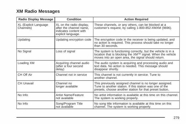
XM Radio Messages
Radio Display Message Condition Action Required
XL (Explicit LanguageChannels)
XL on the radio display,after the channel name,indicates content withexplicit language.
These channels, or any others, can be blocked at acustomer’s request, by calling 1-800-852-XMXM (9696).
Updating Updating encryption code The encryption code in the receiver is being updated, andno action is required. This process should take no longerthan 30 seconds.
No Signal Loss of signal The system is functioning correctly, but the vehicle is in alocation that is blocking the XM™ signal. When the vehiclemoves into an open area, the signal should return.
Loading XM Acquiring channel audio(after a four seconddelay)
The audio system is acquiring and processing audio andtext data. No action is needed. This message shoulddisappear shortly.
CH Off Air Channel not in service This channel is not currently in service. Tune toanother channel.
CH Unavail Channel nolonger available
This previously assigned channel is no longer assigned.Tune to another station. If this station was one of thepresets, choose another station for that preset button.
No Info Artist Name/Featurenot available
No artist information is available at this time on this channel.The system is working properly.
No Info Song/Program Titlenot available
No song title information is available at this time on thischannel. The system is working properly.
279
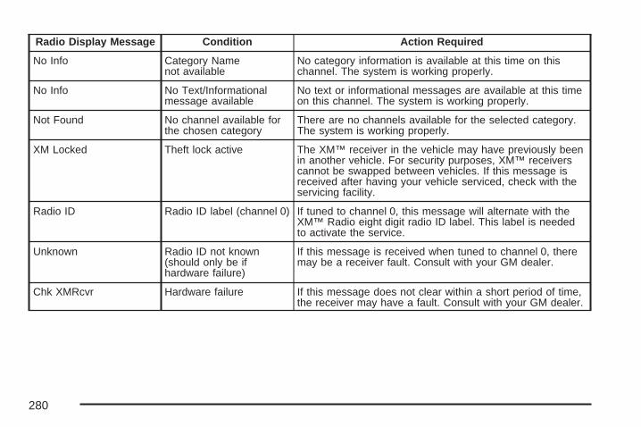
Radio Display Message Condition Action Required
No Info Category Namenot available
No category information is available at this time on thischannel. The system is working properly.
No Info No Text/Informationalmessage available
No text or informational messages are available at this timeon this channel. The system is working properly.
Not Found No channel available forthe chosen category
There are no channels available for the selected category.The system is working properly.
XM Locked Theft lock active The XM™ receiver in the vehicle may have previously beenin another vehicle. For security purposes, XM™ receiverscannot be swapped between vehicles. If this message isreceived after having your vehicle serviced, check with theservicing facility.
Radio ID Radio ID label (channel 0) If tuned to channel 0, this message will alternate with theXM™ Radio eight digit radio ID label. This label is neededto activate the service.
Unknown Radio ID not known(should only be ifhardware failure)
If this message is received when tuned to channel 0, theremay be a receiver fault. Consult with your GM dealer.
Chk XMRcvr Hardware failure If this message does not clear within a short period of time,the receiver may have a fault. Consult with your GM dealer.
280

Theft-Deterrent FeatureTHEFTLOCK® is designed to discouragetheft of your vehicle’s radio. The feature worksautomatically by learning a portion of theVehicle Identification Number (VIN). If theradio is moved to a different vehicle, it willnot operate and LOCKED will appear onthe display.
When the radio and vehicle are turned off,the blinking red light indicates thatTHEFTLOCK® is armed.
With THEFTLOCK® activated, the radio willnot operate if stolen.
Audio Steering Wheel Controls
If your vehicle has this feature, some audiocontrols can be adjusted at the steering wheel.They include the following:
wtux (Seek): Press the up or the downarrow to go to the next or previous station andstay there.
To scan stations, press and hold either arrow fortwo seconds until FREQUENCY SCAN appearson the display. The radio will go to a station, playfor a few seconds, then go to the next station.Press either arrow again to stop scanning.
281

The sound will mute while seeking or scanning.The radio will only seek or scan stations with astrong signal that are in the selected band.
When a CD is playing, press either arrow to goto the previous or next track, if more thaneight seconds have played. If either arrow is held orpressed more than once, the player will continuemoving backward or forward through the CD.
BAND: Press this button to switch between FM1,FM2, AM, or XM1 or XM2 (if equipped).
1 - 6: Press this button to scan the stations thatare programmed on the radio preset pushbuttons.The radio will go to the next preset stationstored on the pushbuttons, play for a few seconds,then go on to the next preset station. Press thisbutton again to stop scanning. The radio willonly scan preset stations with a strong signalthat are in the selected band.
$ (Mute/OnStar®): Press and release this buttonto silence the audio system. Press it again, orany other radio button to turn the sound on.
If your vehicle is equipped with OnStar, pressand hold this button to interact with the OnStarsystem. See the OnStar® System on page 125in this manual for more information.
r (Play): When listening to the radio, press thisbutton to play a cassette tape or CD.
wux (Volume): Press the up or down arrowto increase or decrease the volume.
Radio ReceptionFrequency interference and static can occurduring normal radio reception if items such as cellphone chargers, vehicle convenience accessories,and external electronic devices are pluggedinto the accessory power outlet. If there isinterference or static, unplug the item from theaccessory power outlet.
AMThe range for most AM stations is greater than forFM, especially at night. The longer range can causestation frequencies to interfere with each other.For better radio reception, most AM radio stationsboosts the power levels during the day, and thenreduce these levels during the night. Static can alsooccur when things like storms and power linesinterfere with radio reception. When this happens,try reducing the treble on your radio.
282

FM StereoFM stereo gives the best sound, but FM signalsonly reach about 10 to 40 miles (16 to 65 km).Tall buildings or hills can interfere with FM signals,causing the sound to fade in and out.
XM™ Satellite Radio ServiceXM™ Satellite Radio Service gives digital radioreception from coast-to-coast in the 48 contiguousUnited States, and in Canada. Just as with FM,tall buildings or hills can interfere with satelliteradio signals, causing the sound to fade in and out.In addition, traveling or standing under heavyfoliage, bridges, garages, or tunnels could causeloss of the XM™ signal for a period of time.The radio might display NO XM SIGNAL toindicate interference.
Care of Your CDsHandle CDs carefully. Store them in their originalcases or other protective cases and away fromdirect sunlight and dust. The CD player scansthe bottom surface of the disc. If the surface ofa CD is damaged, such as cracked, broken,or scratched, the CD does not play properly ornot at all. If the surface of a CD is soiled, takea soft, lint free cloth or dampen a clean, soft clothin a mild, neutral detergent solution mixed withwater, and clean it. Make sure the wiping processstarts from the center to the edge.
Do not touch the bottom side of a CD whilehandling it; this could damage the surface. Pick upCDs by grasping the outer edges or the edge ofthe hole and the outer edge.
Care of the CD PlayerDo not use CD lens cleaners for CD playersbecause the lens of the CD optics can becomecontaminated by lubricants.
283
Backglass AntennaThe AM-FM antenna is integrated with the rearwindow defogger, located in the rear window. Makesure that the inside surface of the rear window isnot scratched and that the lines on the glass are notdamaged. If the inside surface is damaged, it couldinterfere with radio reception. Also, for proper radioreception, the antenna connector at the top-centerof the rear window needs to be properly attached tothe post on the glass.
Notice: Do not apply aftermarket glass tintingwith metallic film. The metallic film in sometinting materials will interfere with or distortthe incoming radio reception. Any damagecaused to your backglass antenna dueto metallic tinting materials will not becovered by your warranty.
Notice: Using a razor blade or sharp objectto clear the inside rear window may damagethe rear window antenna and/or the rearwindow defogger. Repairs would not becovered by your warranty. Do not clear theinside rear window with sharp objects.
Because this antenna is built into the rear window,there is a reduced risk of damage caused bycar washes and vandals.
If static is heard on the radio, when the rearwindow defogger is turned on, it could meanthat a defogger grid line has been damaged andthe grid line must be repaired.
If adding a cellular telephone to your vehicle, andthe antenna needs to be attached to the glass,make sure that you do not damage the grid linesfor the AM-FM antenna. There is enough spacebetween the lines to attach a cellular telephoneantenna without interfering with radio reception.
284
XM™ Satellite RadioAntenna SystemThe XM™ Satellite Radio antenna is located onthe roof of your vehicle. Keep this antenna clear ofsnow and ice build up for clear radio reception.
A vehicle with a sunroof might not get thebest performance from the XM™ system if thesunroof is open.
Loading items onto the roof of your vehicle caninterfere with the performance of the XM™ system.Make sure the XM™ Satellite Radio antenna isnot obstructed.
Chime Level AdjustmentThe radio is used to adjust the vehicle’s chimelevel. To change the volume level of the chime,press and hold pushbutton 6 with the ignitionon and the radio power off. The volume levelwill change from the normal level to loud,and LOUD will appear on the radio display.To change back to the default or normal setting,press and hold pushbutton 6 again. The volumelevel will change from the loud level to normal,and NORMAL will appear on the radio display.Each time the chime volume is changed,three chimes will sound to indicate the newvolume selected. Removing the radio and notreplacing it with a factory radio or chime modulewill disable vehicle chimes.
285

✍ NOTES
286

Your Driving, the Road, andYour Vehicle ............................................ 288Defensive Driving ...................................... 288Drunken Driving ........................................ 289Control of a Vehicle .................................. 292Braking ...................................................... 292Anti-Lock Brake System (ABS) .................. 293Braking in Emergencies ............................. 295Traction Control System (TCS) .................. 296Enhanced Traction System (ETS) .............. 298StabiliTrak® Plus System ........................... 299Steering .................................................... 300Off-Road Recovery .................................... 303Passing ..................................................... 303Loss of Control .......................................... 305Driving at Night ......................................... 307
Driving in Rain and on Wet Roads ............ 308City Driving ............................................... 311Freeway Driving ........................................ 312Before Leaving on a Long Trip .................. 313Highway Hypnosis ..................................... 314Hill and Mountain Roads ........................... 314Winter Driving ........................................... 316If Your Vehicle is Stuck in Sand,
Mud, Ice, or Snow ................................. 321Rocking Your Vehicle to Get It Out ........... 322Loading Your Vehicle ................................ 322
Towing ........................................................ 327Towing Your Vehicle ................................. 327Recreational Vehicle Towing ...................... 327Towing a Trailer ........................................ 329
Section 4 Driving Your Vehicle
287
Your Driving, the Road, andYour Vehicle
Defensive DrivingThe best advice anyone can give about driving is:Drive defensively.
Please start with a very important safety device inyour vehicle: Buckle up. See Safety Belts: TheyAre for Everyone on page 17.
{CAUTION:
Defensive driving really means “Be readyfor anything.” On city streets, rural roads,or expressways, it means “Always expectthe unexpected.” Assume that pedestriansor other drivers are going to be carelessand make mistakes. Anticipate what theymight do and be ready. Rear-end collisionsare about the most preventable ofaccidents. Yet they are common. Allowenough following distance. Defensivedriving requires that a driver concentrateon the driving task. Anything that distractsfrom the driving task makes properdefensive driving more difficult and caneven cause a collision, with resultinginjury. Ask a passenger to help do thesethings, or pull off the road in a safe placeto do them. These simple defensive drivingtechniques could save your life.
288
Drunken DrivingDeath and injury associated with drinking anddriving is a national tragedy. It is the number onecontributor to the highway death toll, claimingthousands of victims every year.
Alcohol affects four things that anyone needs todrive a vehicle:
• Judgment
• Muscular Coordination
• Vision
• Attentiveness
Police records show that almost half of all motorvehicle-related deaths involve alcohol. In mostcases, these deaths are the result of someonewho was drinking and driving. In recent years,more than 16,000 annual motor vehicle-relateddeaths have been associated with the useof alcohol, with more than 300,000 people injured.
Many adults — by some estimates, nearly half theadult population — choose never to drink alcohol,so they never drive after drinking. For personsunder 21, it is against the law in every U.S. stateto drink alcohol. There are good medical,psychological, and developmental reasonsfor these laws.
The obvious way to eliminate the leading highwaysafety problem is for people never to drinkalcohol and then drive. But what if people do?How much is “too much” if someone plansto drive? It is a lot less than many might think.Although it depends on each person and situation,here is some general information on the problem.
The Blood Alcohol Concentration (BAC) ofsomeone who is drinking depends upon four things:
• The amount of alcohol consumed
• The drinker’s body weight
• The amount of food that is consumed beforeand during drinking
• The length of time it has taken the drinker toconsume the alcohol
289

According to the American Medical Association,a 180 lb (82 kg) person who drinks three 12 ounce(355 ml) bottles of beer in an hour will end upwith a BAC of about 0.06 percent. The personwould reach the same BAC by drinking three4 ounce (120 ml) glasses of wine or three mixeddrinks if each had 1-1/2 ounces (45 ml) ofliquors like whiskey, gin, or vodka.
It is the amount of alcohol that counts. For example,if the same person drank three double martinis(3 ounces or 90 ml of liquor each) within an hour,the person’s BAC would be close to 0.12 percent.A person who consumes food just before or duringdrinking will have a somewhat lower BAC level.
There is a gender difference, too. Womengenerally have a lower relative percentage ofbody water than men. Since alcohol is carried inbody water, this means that a woman generallywill reach a higher BAC level than a man ofher same body weight will when each has thesame number of drinks.
The law in most U.S. states, and throughoutCanada, sets the legal limit at 0.08 percent.In some other countries, the limit is even lower.For example, it is 0.05 percent in both Franceand Germany. The BAC limit for all commercialdrivers in the United States is 0.04 percent.
The BAC will be over 0.10 percent after three tosix drinks (in one hour). Of course, as we haveseen, it depends on how much alcohol is in thedrinks, and how quickly the person drinks them.
290
But the ability to drive is affected well below a BACof 0.10 percent. Research shows that the drivingskills of many people are impaired at a BACapproaching 0.05 percent, and that the effects areworse at night. All drivers are impaired at BAClevels above 0.05 percent. Statistics show that thechance of being in a collision increases sharply fordrivers who have a BAC of 0.05 percent or above.A driver with a BAC level of 0.06 percent hasdoubled his or her chance of having a collision. At aBAC level of 0.10 percent, the chance of this driverhaving a collision is 12 times greater; at a level of0.15 percent, the chance is 25 times greater!
The body takes about an hour to rid itself of thealcohol in one drink. No amount of coffee or numberof cold showers will speed that up. “I will be careful”is not the right answer. What if there is anemergency, a need to take sudden action, as whena child darts into the street? A person with even amoderate BAC might not be able to react quicklyenough to avoid the collision.
There is something else about drinking and drivingthat many people do not know. Medical researchshows that alcohol in a person’s system can makecrash injuries worse, especially injuries to thebrain, spinal cord, or heart. This means thatwhen anyone who has been drinking — driveror passenger — is in a crash, that person’s chanceof being killed or permanently disabled is higherthan if the person had not been drinking.
{CAUTION:
Drinking and then driving is verydangerous. Your reflexes, perceptions,attentiveness, and judgment can beaffected by even a small amount ofalcohol. You can have a serious — oreven fatal — collision if you drive afterdrinking. Please do not drink and drive orride with a driver who has been drinking.Ride home in a cab; or if you are with agroup, designate a driver who will notdrink.
291

Control of a VehicleThe following three systems help to control yourvehicle while driving — brakes, steering, andaccelerator. At times, as when driving on snowor ice, it is easy to ask more of those controlsystems than the tires and road can provide.Meaning, you can lose control of your vehicle. SeeTraction Control System (TCS) on page 296 andEnhanced Traction System (ETS) on page 298.
Adding non-dealer/non-retailer accessoriescan affect your vehicle’s performance. SeeAccessories and Modifications on page 342.
BrakingSee Brake System Warning Light on page 180.
Braking action involves perception time andreaction time.
First, you have to decide to push on the brakepedal. That is perception time. Then you have tobring up your foot and do it. That is reaction time.
Average reaction time is about three-fourths of asecond. But that is only an average. It might be lesswith one driver and as long as two or three secondsor more with another. Age, physical condition,alertness, coordination, and eyesight all play a part.So do alcohol, drugs, and frustration. But evenin three-fourths of a second, a vehicle movingat 60 mph (100 km/h) travels 66 feet (20 m).That could be a lot of distance in an emergency,so keeping enough space between your vehicleand others is important.
And, of course, actual stopping distances varygreatly with the surface of the road, whether itis pavement or gravel; the condition of the road,whether it is wet, dry, or icy; tire tread; thecondition of the brakes; the weight of the vehicle;and the amount of brake force applied.
292
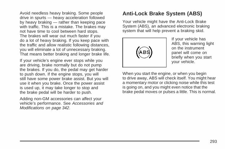
Avoid needless heavy braking. Some peopledrive in spurts — heavy acceleration followedby heavy braking — rather than keeping pacewith traffic. This is a mistake. The brakes maynot have time to cool between hard stops.The brakes will wear out much faster if youdo a lot of heavy braking. If you keep pace withthe traffic and allow realistic following distances,you will eliminate a lot of unnecessary braking.That means better braking and longer brake life.
If your vehicle’s engine ever stops while youare driving, brake normally but do not pumpthe brakes. If you do, the pedal may get harderto push down. If the engine stops, you willstill have some power brake assist. But you willuse it when you brake. Once the power assistis used up, it may take longer to stop andthe brake pedal will be harder to push.
Adding non-GM accessories can affect yourvehicle’s performance. See Accessories andModifications on page 342.
Anti-Lock Brake System (ABS)Your vehicle might have the Anti-Lock BrakeSystem (ABS), an advanced electronic brakingsystem that will help prevent a braking skid.
If your vehicle hasABS, this warning lighton the instrumentpanel will come onbriefly when you startyour vehicle.
When you start the engine, or when you beginto drive away, ABS will check itself. You might heara momentary motor or clicking noise while this testis going on, and you might even notice that thebrake pedal moves or pulses a little. This is normal.
293

Let us say the road is wet and you are drivingsafely. Suddenly, an animal jumps out in front ofyou. You slam on the brakes and continue braking.Here is what happens with ABS:
A computer senses that wheels are slowing down.If one of the wheels is about to stop rolling, thecomputer will separately work the brakes at eachwheel.
ABS can change the brake pressure faster thanany driver could. The computer is programmedto make the most of available tire and roadconditions. This can help you steer aroundthe obstacle while braking hard.
As you brake, the computer keeps receivingupdates on wheel speed and controls brakingpressure accordingly.
294
Remember: ABS does not change the time youneed to get your foot up to the brake pedal oralways decrease stopping distance. If you get tooclose to the vehicle in front of you, you will not havetime to apply the brakes if that vehicle suddenlyslows or stops. Always leave enough room upahead to stop, even though you have ABS.
Using ABSDo not pump the brakes. Just hold the brakepedal down firmly and let anti-lock work for you.You might feel a slight brake pedal pulsationor notice some noise, but this is normal.
Braking in EmergenciesAt some time, nearly every driver gets into asituation that requires hard braking.
If you have ABS, you can steer and brake at thesame time. However, if you do not have ABS, yourfirst reaction — to hit the brake pedal hard and holdit down — might be the wrong thing to do. Yourwheels can stop rolling. Once they do, the vehiclecannot respond to your steering.
Momentum will carry it in whatever direction it washeaded when the wheels stopped rolling. Thatcould be off the road, into the very thing you weretrying to avoid, or into traffic.
If you do not have ABS, use a “squeeze” brakingtechnique. This will give you maximum brakingwhile maintaining steering control. You can dothis by pushing on the brake pedal with steadilyincreasing pressure.
In an emergency, you will probably want tosqueeze the brakes hard without locking thewheels. If you hear or feel the wheels sliding,ease off the brake pedal. This will help youretain steering control. If you do have ABS, it isdifferent. See Anti-Lock Brake System (ABS)on page 293.
In many emergencies, steering can help you morethan even the very best braking.
295
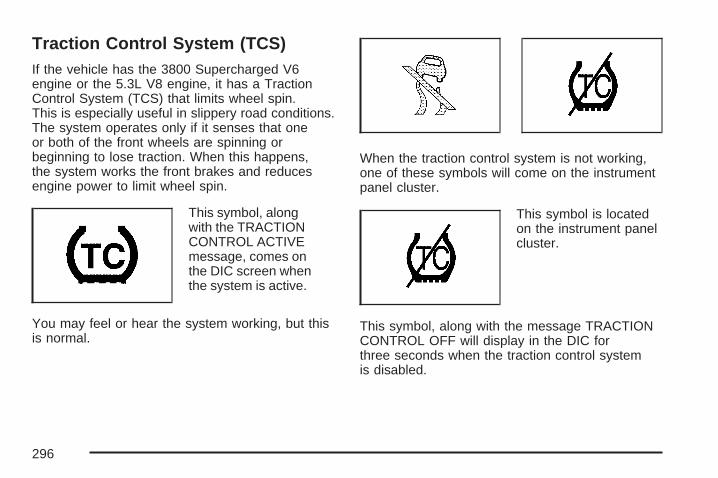
Traction Control System (TCS)If the vehicle has the 3800 Supercharged V6engine or the 5.3L V8 engine, it has a TractionControl System (TCS) that limits wheel spin.This is especially useful in slippery road conditions.The system operates only if it senses that oneor both of the front wheels are spinning orbeginning to lose traction. When this happens,the system works the front brakes and reducesengine power to limit wheel spin.
This symbol, alongwith the TRACTIONCONTROL ACTIVEmessage, comes onthe DIC screen whenthe system is active.
You may feel or hear the system working, but thisis normal.
When the traction control system is not working,one of these symbols will come on the instrumentpanel cluster.
This symbol is locatedon the instrument panelcluster.
This symbol, along with the message TRACTIONCONTROL OFF will display in the DIC forthree seconds when the traction control systemis disabled.
296

If there is a problem with the system, the servicetraction system will also appear on the DIC.When these symbols and messages appear onthe instrument panel and the DIC, the system willnot limit wheel spin. Adjust driving accordingly.
The traction control system automatically comeson whenever the vehicle is started. To limitwheel spin, especially in slippery road conditions,always leave the system on. But the tractioncontrol system can be turned off if needed.The system should be turned off if the vehicleever gets stuck in sand, mud, or snow and rockingthe vehicle is required. See Rocking YourVehicle to Get It Out on page 322 and If YourVehicle is Stuck in Sand, Mud, Ice, or Snow onpage 321 for more information.
Press the tractioncontrol button locatedon the console toturn the system off.
If the system is limiting wheel spin when thetraction control button is pressed, the systemwill turn off instantly. Turn the system back onat any time by pressing the button again.
If the vehicle is in cruise control when the tractioncontrol system begins to limit wheel spin, thecruise control will automatically disengage. Whenroad conditions allow safe use of it, the cruisecontrol can be used again. See Cruise Controlon page 144.
Adding non-GM accessories can affect yourvehicle’s performance. See Accessories andModifications on page 342 for more information.
297

Enhanced Traction System (ETS)If the vehicle has the 3800 V6 engine and anti-lockbrakes, it has an Enhanced Traction System(ETS) that limits wheel spin. This is especiallyuseful in slippery road conditions. The systemoperates only if it senses that one or both of thefront wheels are spinning or beginning to losetraction. When this happens, the system reducesengine power and may also upshift the transaxleto limit wheel spin.
This symbol comes onthe Driver InformationCenter (DIC) whenthe ETS is limitingwheel spin.
If the vehicle is in cruise control when ETSbegins to limit wheel spin, the cruise control willautomatically disengage. When road conditionsallow safe use of it, the cruise control can be usedagain. See Cruise Control on page 144.
ETS operates in all transaxle shift lever positions.But the system can upshift the transaxle only ashigh as the chosen shift lever position, so use thelower gears only when necessary. See AutomaticTransaxle Operation on page 113.
One of these lights will appear on the instrumentpanel to indicate that the ETS is not on.
This symbol, alongwith the messageTRACTION CONTROLOFF will display on theDIC for three secondswhen the ETS is not on.
298

If there is a problem with the system, the servicetraction system will also come on in the DIC.See Enhanced Traction System Warning Lighton page 183. When this warning light is on,the system will not limit wheel spin. Adjustdriving accordingly.To limit wheel spin, especially in slippery roadconditions, the ETS should always be left on.But the system can be turned off. The systemshould be turned off if the vehicle ever gets stuckin sand, mud, or snow and rocking the vehicleis required. See Rocking Your Vehicle to Get ItOut on page 322 and If Your Vehicle is Stuckin Sand, Mud, Ice, or Snow on page 321 formore information.
Press the tractioncontrol button locatedon the console toturn the system off.
If the system is limiting wheel spin when thebutton is pressed, the system will turn off instantly.Press the traction control button again to turnthe system on.
StabiliTrak® Plus SystemThe vehicle may have a vehicle stabilityenhancement system called StabiliTrak® Plus.It is an advanced computer controlled system thatassists with directional control of the vehicle indifficult driving conditions.
StabiliTrak® Plus comes on whenever the vehicle isstarted. It activates when the computer senses adiscrepancy between the intended path and thedirection the vehicle is actually traveling.StabiliTrak® Plus selectively applies brakingpressure at any one of the vehicle’s brakes tohelp control the vehicle in the steering direction.
This symbol, alongwith the STABILITYCONTROL ACTIVEmessage comes onthe Driver InformationCenter (DIC).
See DIC Warnings and Messages on page 204.You may also hear a noise or feel vibration in thebrake pedal. This is normal. Continue to steerthe vehicle in the desired direction.
299

This symbol will appearon the DIC.
If there is a problem detected with StabiliTrak®
Plus, this symbol along with the SERVICESTABILITY SYSTEM warning message willcome on the DIC.
See DIC Warnings and Messages on page 204.When this message is displayed, the systemis not operational. Driving should be adjustedaccordingly.
To turn the StabiliTrak® system off (GXP only),press and hold the traction control button for morethan five seconds. A message will appear onthe DIC indicating that StabiliTrak® has beenturned off. You can turn the system back onat any time by pressing the button again.
If the vehicle is in cruise control when StabiliTrak®
Plus activates, the cruise control will automaticallydisengage. When road conditions allow safeuse of it, the cruise control can be used again.See Cruise Control on page 144 for moreinformation.
Steering
Power SteeringIf you lose power steering assist because theengine stops or the system is not functioning,you can steer but it will take much more effort.
Variable Effort SteeringIf your vehicle has this steering system, thesystem provides less steering effort for parkingand when driving at speeds below 20 mph(32 km/h). Steering effort will increase at higherspeeds for improved road feel.
300

Steering TipsIt is important to take curves at a reasonablespeed.
A lot of the “driver lost control” accidentsmentioned on the news happen on curves.Here is why:
Experienced driver or beginner, each of us issubject to the same laws of physics when driving oncurves. The traction of the tires against the roadsurface makes it possible for the vehicle to changeits path when you turn the front wheels. If there isno traction, inertia will keep the vehicle going in thesame direction. If you have ever tried to steer avehicle on wet ice, you will understand this.
The traction you can get in a curve depends onthe condition of the tires and the road surface,the angle at which the curve is banked, and yourspeed. While you are in a curve, speed is theone factor you can control.
Suppose you are steering through a sharp curve.Then you suddenly apply the brakes. Bothcontrol systems — steering and braking — haveto do their work where the tires meet the road.
Unless you have four-wheel anti-lock brakes,adding the hard braking can demand too muchof those places. You can lose control.
The same thing can happen if you are steeringthrough a sharp curve and you suddenlyaccelerate. Those two control systems — steeringand acceleration — can overwhelm those placeswhere the tires meet the road and make you losecontrol. See Traction Control System (TCS) onpage 296 or Enhanced Traction System (ETS) onpage 298.
What should you do if this ever happens? Easeup on the brake or accelerator pedal, steer thevehicle the way you want it to go, and slow down.
Speed limit signs near curves warn that you shouldadjust your speed. Of course, the posted speedsare based on good weather and road conditions.Under less favorable conditions you will want togo slower.
If you need to reduce your speed as you approacha curve, do it before you enter the curve, whilethe front wheels are straight ahead.
301

Try to adjust your speed so you can “drive”through the curve. Maintain a reasonable, steadyspeed. Wait to accelerate until you are out ofthe curve, and then accelerate gently intothe straightaway.
Adding non-dealer/non-retailer accessories canaffect your vehicle’s performance. See Accessoriesand Modifications on page 342.
Steering in EmergenciesThere are times when steering can be moreeffective than braking. For example, you comeover a hill and find a truck stopped in your lane,or a car suddenly pulls out from nowhere, ora child darts out from between parked carsand stops right in front of you. You can avoidthese problems by braking — if you can stop intime. But sometimes you cannot; there is not room.That is the time for evasive action — steeringaround the problem.
Your vehicle can perform very well in emergencieslike these. First apply the brakes. See Brakingon page 292. It is better to remove as much speedas you can from a possible collision. Then steeraround the problem, to the left or right dependingon the space available.
An emergency like this requires close attention anda quick decision. If you are holding the steeringwheel at the recommended 9 and 3 o’clockpositions, you can turn it a full 180 degrees veryquickly without removing either hand. But youhave to act fast, steer quickly, and just as quicklystraighten the wheel once you have avoided theobject.
The fact that such emergency situations arealways possible is a good reason to practicedefensive driving at all times and wear safetybelts properly.
302

Off-Road RecoveryYou may find that your vehicle’s right wheels havedropped off the edge of a road onto the shoulderwhile you are driving.
If the level of the shoulder is only slightly below thepavement, recovery should be fairly easy. Ease offthe accelerator and then, if there is nothing in theway, steer so that your vehicle straddles the edgeof the pavement. You can turn the steering wheelup to one-quarter turn until the right front tirecontacts the pavement edge. Then turn the steeringwheel to go straight down the roadway.
PassingThe driver of a vehicle about to pass another on atwo-lane highway waits for just the right moment,accelerates, moves around the vehicle ahead, thengoes back into the right lane again. A simplemaneuver?
Not necessarily! Passing another vehicle on atwo-lane highway is a potentially dangerous move,since the passing vehicle occupies the samelane as oncoming traffic for several seconds.A miscalculation, an error in judgment, or a briefsurrender to frustration or anger can suddenly putthe passing driver face to face with the worst of alltraffic accidents — the head-on collision.
303
So here are some tips for passing:
• Drive ahead. Look down the road, to thesides, and to crossroads for situationsthat might affect your passing patterns. If youhave any doubt whatsoever about makinga successful pass, wait for a better time.
• Watch for traffic signs, pavement markings,and lines. If you can see a sign up aheadthat might indicate a turn or an intersection,delay your pass. A broken center lineusually indicates it is all right to pass, providingthe road ahead is clear. Never cross a solidline on your side of the lane or a doublesolid line, even if the road seems empty ofapproaching traffic.
• Do not get too close to the vehicle you wantto pass while you are awaiting an opportunity.For one thing, following too closely reducesyour area of vision, especially if you arefollowing a larger vehicle. Also, you will nothave adequate space if the vehicle aheadsuddenly slows or stops. Keep back areasonable distance.
• When it looks like a chance to pass is comingup, start to accelerate but stay in the rightlane and do not get too close. Time your moveso you will be increasing speed as the timecomes to move into the other lane. If the wayis clear to pass, you will have a runningstart that more than makes up for the distanceyou would lose by dropping back. And ifsomething happens to cause you to cancelyour pass, you need only slow down and dropback again and wait for another opportunity.
• If other vehicles are lined up to pass a slowvehicle, wait your turn. But take care thatsomeone is not trying to pass you as you pullout to pass the slow vehicle. Remember toglance over your shoulder and check theblind spot.
• Check your vehicle’s mirrors, glance over yourshoulder, and start your left lane change signalbefore moving out of the right lane to pass.When you are far enough ahead of the passedvehicle to see its front in your vehicle’s insidemirror, activate the right lane change signal andmove back into the right lane. Remember thatan outside convex mirror makes the vehicle youjust passed seem farther away from you than itreally is.
304

• Try not to pass more than one vehicle at a timeon two-lane roads. Reconsider before passingthe next vehicle.
• Do not overtake a slowly moving vehicle toorapidly. Even though the brake lamps are notflashing, it might be slowing down or startingto turn.
• If you are being passed, make it easy for thefollowing driver to get ahead of you. Perhapsyou can ease a little to the right.
Loss of ControlLet us review what driving experts say about whathappens when the three control systems — brakes,steering, and acceleration — do not have enoughfriction where the tires meet the road to do what thedriver has asked.
In any emergency, do not give up. Keep trying tosteer and constantly seek an escape route orarea of less danger.
SkiddingIn a skid, a driver can lose control of the vehicle.Defensive drivers avoid most skids by takingreasonable care suited to existing conditions, andby not overdriving those conditions. But skidsare always possible.
The three types of skids correspond to yourvehicle’s three control systems. In the brakingskid, the wheels are not rolling. In the steering orcornering skid, too much speed or steering ina curve causes tires to slip and lose corneringforce. And in the acceleration skid, too muchthrottle causes the driving wheels to spin.
A cornering skid is best handled by easing yourfoot off the accelerator pedal.
If you do not have the Enhanced Traction System(ETS) or the Traction Control System (TCS), orif the system is off, then an acceleration skidis also best handled by easing your foot off theaccelerator pedal. See Enhanced Traction System(ETS) on page 298 or Traction Control System(TCS) on page 296.
305
If your vehicle starts to slide, ease your foot off theaccelerator pedal and quickly steer the way youwant the vehicle to go. If you start steering quicklyenough, your vehicle may straighten out. Always beready for a second skid if it occurs.
Of course, traction is reduced when water, snow,ice, gravel, or other material is on the road. Forsafety, you will want to slow down and adjust yourdriving to these conditions. It is important to slowdown on slippery surfaces because stoppingdistance will be longer and vehicle control morelimited.
While driving on a surface with reduced traction,try your best to avoid sudden steering, acceleration,or braking, including reducing vehicle speed byshifting to a lower gear. Any sudden changes could
cause the tires to slide. You may not realize thesurface is slippery until your vehicle is skidding.Learn to recognize warning clues — such asenough water, ice, or packed snow on the road tomake a mirrored surface — and slow down whenyou have any doubt.
If you have the Anti-Lock Brake System (ABS),remember: It helps avoid only the braking skid.If you do not have ABS, then in a brakingskid, where the wheels are no longer rolling,release enough pressure on the brakes to getthe wheels rolling again. This restores steeringcontrol. Push the brake pedal down steadily whenyou have to stop suddenly. As long as thewheels are rolling, you will have steering control.
306

Driving at NightNight driving is more dangerous than day driving.One reason is that some drivers are likely tobe impaired — by alcohol or drugs, with nightvision problems, or by fatigue.
Here are some tips on night driving.
• Drive defensively.
• Do not drink and drive.
• Adjust the inside rearview mirror to reduce theglare from headlamps behind you.
• Since you cannot see as well, slow down andkeep more space between you and othervehicles.
• Slow down, especially on higher speed roads.Your vehicle’s headlamps can light up only somuch road ahead.
• In remote areas, watch for animals.
• If you are tired, pull off the road in a safeplace and rest.
No one can see as well at night as in the daytime.But as we get older these differences increase.A 50-year-old driver might require at least twiceas much light to see the same thing at night as a20-year-old.
What you do in the daytime can also affect yournight vision. For example, if you spend theday in bright sunshine you are wise to wearsunglasses. Your eyes will have less troubleadjusting to night. But if you are driving, do notwear sunglasses at night. They might cut down onglare from headlamps, but they also make a lotof things invisible.
You can be temporarily blinded by approachingheadlamps. It can take a second or two, oreven several seconds, for your eyes to re-adjustto the dark. When you are faced with severe glare,as from a driver who does not lower the highbeams, or a vehicle with misaimed headlamps,slow down a little. Avoid staring directly intothe approaching headlamps.
307

Keep the windshield and all the glass on yourvehicle clean — inside and out. Glare at night ismade much worse by dirt on the glass. Eventhe inside of the glass can build up a film causedby dust. Dirty glass makes lights dazzle andflash more than clean glass would, making thepupils of your eyes contract repeatedly.
Remember that the headlamps light up far less of aroadway when you are in a turn or curve. Keep youreyes moving; that way, it is easier to pick out dimlylighted objects. Just as the headlamps should bechecked regularly for proper aim, so should youreyes be examined regularly. Some drivers sufferfrom night blindness — the inability to see in dimlight — and are not even aware of it.
Driving in Rain and on Wet Roads
Rain and wet roads can mean driving trouble. On awet road, you cannot stop, accelerate, or turn aswell because your tire-to-road traction is not asgood as on dry roads. And, if your tires do not havemuch tread left, you will get even less traction. It isalways wise to go slower and be cautious if rainstarts to fall while you are driving. The surface mayget wet suddenly when your reflexes are tuned fordriving on dry pavement.
308

The heavier the rain, the harder it is to see.Even if your windshield wiper blades are in goodshape, a heavy rain can make it harder to seeroad signs and traffic signals, pavement markings,the edge of the road, and even people walking.
It is wise to keep your windshield wiping equipmentin good shape and keep your windshield washerfluid reservoir filled with washer fluid. Replace yourwindshield wiper inserts when they show signs ofstreaking or missing areas on the windshield, orwhen strips of rubber start to separate from theinserts.
{CAUTION:
Wet brakes can cause accidents. Theymay not work as well in a quick stop andmay cause pulling to one side. You couldlose control of the vehicle.
After driving through a large puddle ofwater or a car wash, apply the brake pedallightly until the brakes work normally.
Driving too fast through large water puddles oreven going through some car washes can causeproblems, too. The water may affect yourbrakes. Try to avoid puddles. But if you cannot,try to slow down before you hit them.
HydroplaningHydroplaning is dangerous. So much water canbuild up under your tires that they can actually rideon the water. This can happen if the road is wetenough and you are going fast enough. When yourvehicle is hydroplaning, it has little or no contactwith the road.
Hydroplaning does not happen often. But it can ifyour tires do not have much tread or if the pressurein one or more is low. It can happen if a lot of wateris standing on the road. If you can see reflectionsfrom trees, telephone poles, or other vehicles, andraindrops dimple the water’s surface, there could behydroplaning.
Hydroplaning usually happens at higher speeds.There just is not a hard and fast rule abouthydroplaning. The best advice is to slow downwhen it is raining.
309
Driving Through Deep Standing Water
Notice: If you drive too quickly throughdeep puddles or standing water, water cancome in through the engine’s air intakeand badly damage the engine. Never drivethrough water that is slightly lower than theunderbody of your vehicle. If you cannot avoiddeep puddles or standing water, drivethrough them very slowly.
Driving Through Flowing Water
{CAUTION:
Flowing or rushing water creates strongforces. If you try to drive through flowingwater, as you might at a low watercrossing, your vehicle can be carried away.As little as six inches of flowing watercan carry away a smaller vehicle. If thishappens, you and other vehicle occupantscould drown. Do not ignore police warningsigns, and otherwise be very cautiousabout trying to drive through flowing water.
Some Other Rainy Weather Tips• Besides slowing down, allow some extra
following distance. And be especially carefulwhen you pass another vehicle. Allow yourselfmore clear room ahead, and be prepared tohave your view restricted by road spray.
• Have good tires with proper tread depth.See Tires on page 406.
310
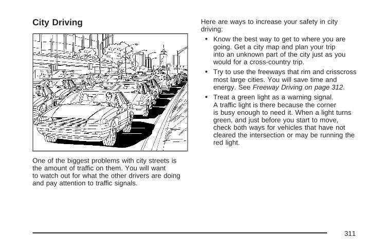
City Driving
One of the biggest problems with city streets isthe amount of traffic on them. You will wantto watch out for what the other drivers are doingand pay attention to traffic signals.
Here are ways to increase your safety in citydriving:
• Know the best way to get to where you aregoing. Get a city map and plan your tripinto an unknown part of the city just as youwould for a cross-country trip.
• Try to use the freeways that rim and crisscrossmost large cities. You will save time andenergy. See Freeway Driving on page 312.
• Treat a green light as a warning signal.A traffic light is there because the corneris busy enough to need it. When a light turnsgreen, and just before you start to move,check both ways for vehicles that have notcleared the intersection or may be running thered light.
311

Freeway Driving
Mile for mile, freeways — also called thruways,parkways, expressways, turnpikes, orsuperhighways — are the safest of all roads.But they have their own special rules.
The most important advice on freeway drivingis: Keep up with traffic and keep to the right. Driveat the same speed most of the other drivers are
driving. Too-fast or too-slow driving breaks asmooth traffic flow. Treat the left lane on a freewayas a passing lane.
At the entrance, there is usually a ramp that leadsto the freeway. If you have a clear view of thefreeway as you drive along the entrance ramp,you should begin to check traffic. Try to determinewhere you expect to blend with the flow. Try tomerge into the gap at close to the prevailing speed.Switch on your turn signal, check your mirrors, andglance over your shoulder as often as necessary.Try to blend smoothly with the traffic flow.
Once you are on the freeway, adjust your speedto the posted limit or to the prevailing rate if it isslower. Stay in the right lane unless you wantto pass.
Before changing lanes, check your mirrors.Then use your turn signal.
Just before you leave the lane, glance quicklyover your shoulder to make sure there is notanother vehicle in your blind spot.
Once you are moving on the freeway, makecertain you allow a reasonable following distance.
Expect to move slightly slower at night.
312
When you want to leave the freeway, move to theproper lane well in advance. If you miss yourexit, do not, under any circumstances, stop andback up. Drive on to the next exit.
The exit ramp can be curved, sometimes quitesharply. The exit speed is usually posted. Reduceyour speed according to your speedometer, notto your sense of motion. After driving for anydistance at higher speeds, you may tend to thinkyou are going slower than you actually are.
Before Leaving on a Long TripMake sure you are ready. Try to be well rested.If you must start when you are not fresh — such asafter a day’s work — do not plan to make toomany miles that first part of the journey. Wearcomfortable clothing and shoes you can easilydrive in.
Is your vehicle ready for a long trip? If you keep itserviced and maintained, it is ready to go. If it needsservice, have it done before starting out. Of course,you will find experienced and able service expertsin GM dealerships all across North America. Theywill be ready and willing to help if you need it.
Here are some things you can check before a trip:
• Windshield Washer Fluid: Is the reservoirfull? Are all windows clean inside and outside?
• Wiper Blades: Are they in good shape?
• Fuel, Engine Oil, Other Fluids: Have youchecked all levels?
• Lamps: Are they all working? Are the lensesclean?
• Tires: They are vitally important to a safe,trouble-free trip. Is the tread good enoughfor long-distance driving? Are the tiresall inflated to the recommended pressure?
• Weather Forecasts: What is the weatheroutlook along your route? Should youdelay your trip a short time to avoid a majorstorm system?
• Maps: Do you have up-to-date maps?
313
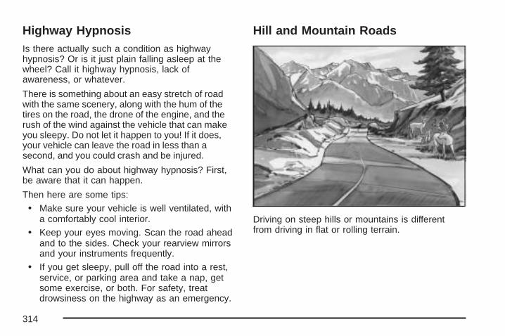
Highway HypnosisIs there actually such a condition as highwayhypnosis? Or is it just plain falling asleep at thewheel? Call it highway hypnosis, lack ofawareness, or whatever.
There is something about an easy stretch of roadwith the same scenery, along with the hum of thetires on the road, the drone of the engine, and therush of the wind against the vehicle that can makeyou sleepy. Do not let it happen to you! If it does,your vehicle can leave the road in less than asecond, and you could crash and be injured.
What can you do about highway hypnosis? First,be aware that it can happen.
Then here are some tips:
• Make sure your vehicle is well ventilated, witha comfortably cool interior.
• Keep your eyes moving. Scan the road aheadand to the sides. Check your rearview mirrorsand your instruments frequently.
• If you get sleepy, pull off the road into a rest,service, or parking area and take a nap, getsome exercise, or both. For safety, treatdrowsiness on the highway as an emergency.
Hill and Mountain Roads
Driving on steep hills or mountains is differentfrom driving in flat or rolling terrain.
314

If you drive regularly in steep country, or if you areplanning to visit there, here are some tips thatcan make your trips safer and more enjoyable.
• Keep your vehicle in good shape. Checkall fluid levels and also the brakes, tires,cooling system, and transaxle. These partscan work hard on mountain roads.
{CAUTION:
If you do not shift down, the brakes couldget so hot that they would not work well.You would then have poor braking oreven none going down a hill. You couldcrash. Shift down to let the engine assistthe brakes on a steep downhill slope.
{CAUTION:
Coasting downhill in NEUTRAL (N) or withthe ignition off is dangerous. The brakeswill have to do all the work of slowingdown. They could get so hot that theywould not work well. You would then havepoor braking or even none going down ahill. You could crash. Always have theengine running and your vehicle in gearwhen you go downhill.
• Know how to go down hills. The most importantthing to know is this: let your engine do some ofthe slowing down. Shift to a lower gear whenyou go down a steep or long hill.
315

• Stay in your own lane when driving on two-laneroads in hills or mountains. Do not swing wideor cut across the center of the road. Drive atspeeds that let you stay in your own lane.
• As you go over the top of a hill, be alert. Therecould be something in your lane, like a stalledcar or an accident.
• You may see highway signs on mountains thatwarn of special problems. Examples are longgrades, passing or no-passing zones, a fallingrocks area, or winding roads. Be alert to theseand take appropriate action.
Winter Driving
Here are some tips for winter driving:
• Have your vehicle in good shape for winter.
• You may want to put winter emergencysupplies in your trunk.
Also see Tires on page 406.
316
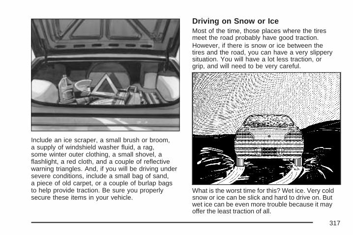
Include an ice scraper, a small brush or broom,a supply of windshield washer fluid, a rag,some winter outer clothing, a small shovel, aflashlight, a red cloth, and a couple of reflectivewarning triangles. And, if you will be driving undersevere conditions, include a small bag of sand,a piece of old carpet, or a couple of burlap bagsto help provide traction. Be sure you properlysecure these items in your vehicle.
Driving on Snow or IceMost of the time, those places where the tiresmeet the road probably have good traction.However, if there is snow or ice between thetires and the road, you can have a very slipperysituation. You will have a lot less traction, orgrip, and will need to be very careful.
What is the worst time for this? Wet ice. Very coldsnow or ice can be slick and hard to drive on. Butwet ice can be even more trouble because it mayoffer the least traction of all.
317
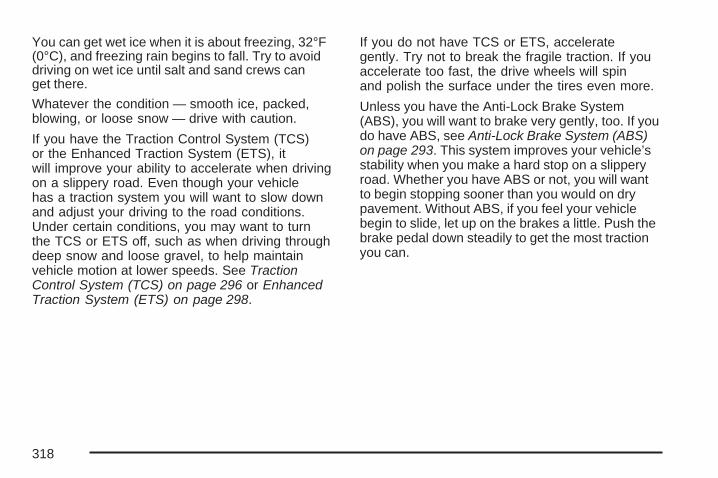
You can get wet ice when it is about freezing, 32°F(0°C), and freezing rain begins to fall. Try to avoiddriving on wet ice until salt and sand crews canget there.
Whatever the condition — smooth ice, packed,blowing, or loose snow — drive with caution.
If you have the Traction Control System (TCS)or the Enhanced Traction System (ETS), itwill improve your ability to accelerate when drivingon a slippery road. Even though your vehiclehas a traction system you will want to slow downand adjust your driving to the road conditions.Under certain conditions, you may want to turnthe TCS or ETS off, such as when driving throughdeep snow and loose gravel, to help maintainvehicle motion at lower speeds. See TractionControl System (TCS) on page 296 or EnhancedTraction System (ETS) on page 298.
If you do not have TCS or ETS, accelerategently. Try not to break the fragile traction. If youaccelerate too fast, the drive wheels will spinand polish the surface under the tires even more.
Unless you have the Anti-Lock Brake System(ABS), you will want to brake very gently, too. If youdo have ABS, see Anti-Lock Brake System (ABS)on page 293. This system improves your vehicle’sstability when you make a hard stop on a slipperyroad. Whether you have ABS or not, you will wantto begin stopping sooner than you would on drypavement. Without ABS, if you feel your vehiclebegin to slide, let up on the brakes a little. Push thebrake pedal down steadily to get the most tractionyou can.
318
Remember, unless you have ABS, if you brake sohard that your wheels stop rolling, you will justslide. Brake so your wheels always keep rollingand you can still steer.
• Whatever your braking system, allow greaterfollowing distance on any slippery road.
• Watch for slippery spots. The road might befine until you hit a spot that is covered withice. On an otherwise clear road, ice patchesmay appear in shaded areas where thesun cannot reach, such as around clumps oftrees, behind buildings, or under bridges.Sometimes the surface of a curve or anoverpass may remain icy when thesurrounding roads are clear. If you see apatch of ice ahead of you, brake before youare on it. Try not to brake while you areactually on the ice, and avoid sudden steeringmaneuvers.
If You Are Caught in a BlizzardIf you are stopped by heavy snow, you could bein a serious situation. You should probably stay withyour vehicle unless you know for sure that you arenear help and you can hike through the snow. Hereare some things to do to summon help and keepyourself and your passengers safe:
• Turn on your hazard flashers.
• Tie a red cloth to your vehicle to alert police thatyou have been stopped by the snow.
• Put on extra clothing or wrap a blanketaround you. If you do not have blankets orextra clothing, make body insulators fromnewspapers, burlap bags, rags, floormats — anything you can wrap around yourselfor tuck under your clothing to keep warm.
319

You can run the engine to keep warm, but becareful.
{CAUTION:
Snow can trap exhaust gases underyour vehicle. This can cause deadly CO(carbon monoxide) gas to get inside.CO could overcome you and kill you.You cannot see it or smell it, so you mightnot know it is in your vehicle. Clear awaysnow from around the base of yourvehicle, especially any that is blockingthe exhaust pipe. And check around againfrom time to time to be sure snow doesnot collect there.
Open a window just a little on the side ofthe vehicle that is away from the wind.This will help keep CO out.
Run your engine only as long as you must.This saves fuel. When you run the engine, makeit go a little faster than just idle. That is, push theaccelerator slightly. This uses less fuel for the heatthat you get and it keeps the battery charged.
320
You will need a well-charged battery to restart thevehicle, and possibly for signaling later on with yourheadlamps. Let the heater run for a while.
Then, shut the engine off and close the windowalmost all the way to preserve the heat. Startthe engine again and repeat this only when youfeel really uncomfortable from the cold. But do itas little as possible. Preserve the fuel as longas you can. To help keep warm, you can getout of the vehicle and do some fairly vigorousexercises every half hour or so until help comes.
If Your Vehicle is Stuck in Sand,Mud, Ice, or SnowIn order to free your vehicle when it is stuck, youwill need to spin the wheels, but you do notwant to spin your wheels too fast. The methodknown as rocking can help you get out when youare stuck, but you must use caution.
{CAUTION:
If you let your vehicle’s tires spin at highspeed, they can explode, and you orothers could be injured. And, thetransaxle or other parts of the vehicle canoverheat. That could cause an enginecompartment fire or other damage. Whenyou are stuck, spin the wheels as little aspossible. Do not spin the wheels above35 mph (55 km/h) as shown on thespeedometer.
Notice: Spinning the wheels can destroyparts of your vehicle as well as the tires. If youspin the wheels too fast while shifting thetransaxle back and forth, you can destroy thetransaxle. See Rocking Your Vehicle to GetIt Out on page 322.
For information about using tire chains on yourvehicle, see Tire Chains on page 428.
321
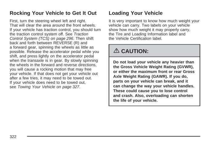
Rocking Your Vehicle to Get It OutFirst, turn the steering wheel left and right.That will clear the area around the front wheels.If your vehicle has traction control, you should turnthe traction control system off. See TractionControl System (TCS) on page 296. Then shiftback and forth between REVERSE (R) anda forward gear, spinning the wheels as little aspossible. Release the accelerator pedal while youshift, and press lightly on the accelerator pedalwhen the transaxle is in gear. By slowly spinningthe wheels in the forward and reverse directions,you will cause a rocking motion that may freeyour vehicle. If that does not get your vehicle outafter a few tries, it may need to be towed out.If your vehicle does need to be towed out,see Towing Your Vehicle on page 327.
Loading Your VehicleIt is very important to know how much weight yourvehicle can carry. Two labels on your vehicleshow how much weight it may properly carry,the Tire and Loading Information label andthe Vehicle Certification label.
{CAUTION:
Do not load your vehicle any heavier thanthe Gross Vehicle Weight Rating (GVWR),or either the maximum front or rear GrossAxle Weight Rating (GAWR). If you do,parts on your vehicle can break, and itcan change the way your vehicle handles.These could cause you to lose controland crash. Also, overloading can shortenthe life of your vehicle.
322
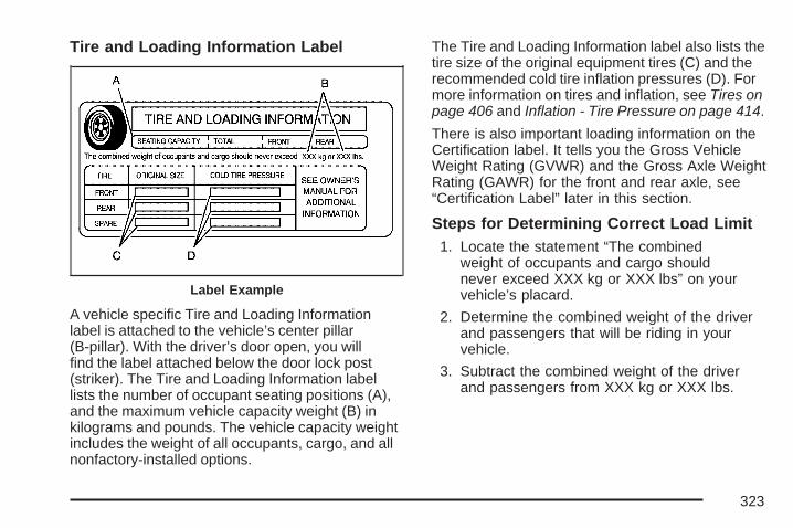
Tire and Loading Information Label
A vehicle specific Tire and Loading Informationlabel is attached to the vehicle’s center pillar(B-pillar). With the driver’s door open, you willfind the label attached below the door lock post(striker). The Tire and Loading Information labellists the number of occupant seating positions (A),and the maximum vehicle capacity weight (B) inkilograms and pounds. The vehicle capacity weightincludes the weight of all occupants, cargo, and allnonfactory-installed options.
The Tire and Loading Information label also lists thetire size of the original equipment tires (C) and therecommended cold tire inflation pressures (D). Formore information on tires and inflation, see Tires onpage 406 and Inflation - Tire Pressure on page 414.
There is also important loading information on theCertification label. It tells you the Gross VehicleWeight Rating (GVWR) and the Gross Axle WeightRating (GAWR) for the front and rear axle, see“Certification Label” later in this section.
Steps for Determining Correct Load Limit1. Locate the statement “The combined
weight of occupants and cargo shouldnever exceed XXX kg or XXX lbs” on yourvehicle’s placard.
2. Determine the combined weight of the driverand passengers that will be riding in yourvehicle.
3. Subtract the combined weight of the driverand passengers from XXX kg or XXX lbs.
Label Example
323
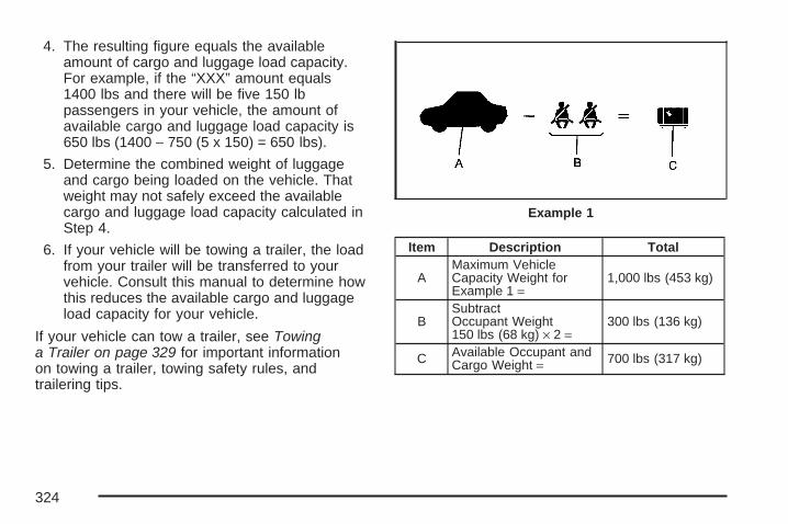
4. The resulting figure equals the availableamount of cargo and luggage load capacity.For example, if the “XXX” amount equals1400 lbs and there will be five 150 lbpassengers in your vehicle, the amount ofavailable cargo and luggage load capacity is650 lbs (1400 − 750 (5 x 150) = 650 lbs).
5. Determine the combined weight of luggageand cargo being loaded on the vehicle. Thatweight may not safely exceed the availablecargo and luggage load capacity calculated inStep 4.
6. If your vehicle will be towing a trailer, the loadfrom your trailer will be transferred to yourvehicle. Consult this manual to determine howthis reduces the available cargo and luggageload capacity for your vehicle.
If your vehicle can tow a trailer, see Towinga Trailer on page 329 for important informationon towing a trailer, towing safety rules, andtrailering tips.
Item Description Total
AMaximum VehicleCapacity Weight forExample 1 =
1,000 lbs (453 kg)
BSubtractOccupant Weight150 lbs (68 kg) × 2 =
300 lbs (136 kg)
C Available Occupant andCargo Weight = 700 lbs (317 kg)
Example 1
324
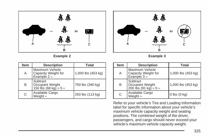
Item Description Total
AMaximum VehicleCapacity Weight forExample 2 =
1,000 lbs (453 kg)
BSubtractOccupant Weight150 lbs (68 kg) × 5 =
750 lbs (340 kg)
C Available CargoWeight = 250 lbs (113 kg)
Item Description Total
AMaximum VehicleCapacity Weight forExample 3 =
1,000 lbs (453 kg)
BSubtractOccupant Weight200 lbs (91 kg) × 5 =
1,000 lbs (453 kg)
C Available CargoWeight = 0 lbs (0 kg)
Refer to your vehicle’s Tire and Loading Informationlabel for specific information about your vehicle’smaximum vehicle capacity weight and seatingpositions. The combined weight of the driver,passengers, and cargo should never exceed yourvehicle’s maximum vehicle capacity weight.
Example 2 Example 3
325

Certification Label
A vehicle specific Certification label is found onthe rear edge of the driver’s door.
The label shows the gross weight capacity of yourvehicle, called the Gross Vehicle Weight Rating(GVWR). The GVWR includes the weight ofthe vehicle, all occupants, fuel, and cargo.
Never exceed the GVWR for your vehicle or theGross Axle Weight Rating (GAWR) for eitherthe front or rear axle.
If the vehicle is going to carry a heavy load,spread it out. See “Steps for Determining CorrectLoad Limit” earlier in this section.
{CAUTION:
Do not load your vehicle any heavier thanthe Gross Vehicle Weight Rating (GVWR),or either the maximum front or rear GrossAxle Weight Rating (GAWR). If you do,parts on your vehicle can break, and itcan change the way your vehicle handles.These could cause you to lose controland crash. Also, overloading can shortenthe life of your vehicle.
Notice: Overloading your vehicle may causedamage. Repairs would not be covered by yourwarranty. Do not overload your vehicle.
If things like suitcases, tools, packages, oranything else are put inside the vehicle, they willgo as fast as the vehicle goes. If you have tostop or turn quickly, or if there is a crash, theywill keep going.
326
{CAUTION:
Things you put inside your vehicle canstrike and injure people in a sudden stopor turn, or in a crash.
• Put things in the trunk of your vehicle.In a trunk, put them as far forward asyou can. Try to spread the weightevenly.
• Never stack heavier things, likesuitcases, inside the vehicle so thatsome of them are above the tops ofthe seats.
• Do not leave an unsecured childrestraint in your vehicle.
• When you carry something inside thevehicle, secure it whenever you can.
• Do not leave a seat folded downunless you need to.
Towing
Towing Your VehicleConsult your dealer or a professional towingservice if you need to have your disabled vehicletowed. See Roadside Assistance Program onpage 504.
If you want to tow your vehicle behind anothervehicle for recreational purposes (such as behinda motorhome), see “Recreational VehicleTowing” following.
Recreational Vehicle TowingRecreational vehicle towing means towing yourvehicle behind another vehicle – such as behinda motorhome. The two most common typesof recreational vehicle towing are known as dinghytowing, towing your vehicle with all four wheelson the ground, and dolly towing, towing yourvehicle with two wheels on the ground andtwo wheels up on a device known as a dolly.
327

With the proper preparation and equipment,many vehicles can be towed in these ways. See“Dinghy Towing” and “Dolly Towing,” following.
Here are some important things to consider beforeyou do recreational vehicle towing:
• What is the towing capacity of the towingvehicle? Be sure to read the tow vehiclemanufacturer’s recommendations.
• How far will the vehicle be towed? Somevehicles have restrictions on how far and howlong they can tow.
• Do you have the proper towing equipment?See your dealer or trailering professionalfor additional advice and equipmentrecommendations.
• Is the vehicle ready to be towed? Just asyou would prepare your vehicle for a long trip,you will want to make sure the vehicle isprepared to be towed. See Before Leavingon a Long Trip on page 313.
Dinghy Towing
Notice: If you tow your vehicle with allfour wheels on the ground, the drivetraincomponents could be damaged. The repairswould not be covered by your warranty. Do nottow your vehicle with all four wheels on theground.
The vehicle was not designed to be towed withall four wheels on the ground. If the vehicle mustbe towed, use a dolly. See “Dolly Towing”following for more information.
328
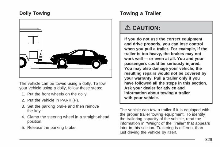
Dolly Towing
The vehicle can be towed using a dolly. To towyour vehicle using a dolly, follow these steps:
1. Put the front wheels on the dolly.
2. Put the vehicle in PARK (P).
3. Set the parking brake and then removethe key.
4. Clamp the steering wheel in a straight-aheadposition.
5. Release the parking brake.
Towing a Trailer
{CAUTION:
If you do not use the correct equipmentand drive properly, you can lose controlwhen you pull a trailer. For example, if thetrailer is too heavy, the brakes may notwork well — or even at all. You and yourpassengers could be seriously injured.You may also damage your vehicle; theresulting repairs would not be covered byyour warranty. Pull a trailer only if youhave followed all the steps in this section.Ask your dealer for advice andinformation about towing a trailerwith your vehicle.
The vehicle can tow a trailer if it is equipped withthe proper trailer towing equipment. To identifythe trailering capacity of the vehicle, read theinformation in “Weight of the Trailer” that appearslater in this section. Trailering is different thanjust driving the vehicle by itself.
329

Trailering means changes in handling, durability,and fuel economy. Successful, safe trailering takescorrect equipment, and it has to be used properly.
That is the reason for this part. In it are manytime-tested, important trailering tips and safetyrules. Many of these are important for your safetyand that of your passengers. So please readthis section carefully before pulling a trailer.
Load-pulling components such as the engine,transaxle, wheel assemblies, and tires are forcedto work harder against the drag of the addedweight. The engine is required to operateat relatively higher speeds and under greaterloads, generating extra heat. The trailer also addsconsiderably to wind resistance, increasing thepulling requirements.
If You Do Decide To Pull A TrailerHere are some important points:
• There are many different laws, includingspeed limit restrictions, having to do withtrailering. Make sure your rig will be legal, notonly where you live but also where you willbe driving. A good source for this informationcan be state or provincial police.
• Consider using a sway control. Ask a hitchdealer about sway controls.
• Do not tow a trailer at all during the first1,000 miles (1 600 km) the new vehicleis driven. The engine, axle, or other partscould be damaged.
• Then, during the first 500 miles (800 km) thatthe vehicle tows a trailer, do not drive over50 mph (80 km/h) and do not make starts at fullthrottle. This helps the engine and other partsof the vehicle wear in at the heavier loads.
• Obey speed limit restrictions when towing atrailer. Do not drive faster than the maximumposted speed for trailers, or no more than55 mph (90 km/h), to save wear on thevehicle’s parts.
Three important considerations have to do withweight:
• The weight of the trailer
• The weight of the trailer tongue
• The total weight on your vehicle’s tires
330

Weight of the TrailerHow heavy can a trailer safely be?
It should never weigh more than 1,000 lbs(454 kg). But even that can be too heavy.
It depends on how you plan to use your rig.For example, speed, altitude, road grades, outsidetemperature, and how much the vehicle is usedto pull a trailer are all important. It can also dependon any special equipment that is on the vehicle,and the amount of tongue weight the vehiclecan carry. See “Weight of the Trailer Tongue”later in this section for more information.
Maximum trailer weight is calculated assumingonly the driver is in the tow vehicle and it hasall the required trailering equipment. The weightof additional optional equipment, passengersand cargo in the tow vehicle must be subtractedfrom the maximum trailer weight.
Ask your dealer for our trailering information oradvice, or write us at our Customer AssistanceOfices. See Customer Assistance Offices onpage 502 for more information.
Weight of the Trailer TongueThe tongue load (A) of any trailer is an importantweight to measure because it affects the totalor gross weight of the vehicle. The Gross VehicleWeight (GVW) includes the curb weight of thevehicle, any cargo in it, and the people who will beriding in the vehicle. If there are a lot of options,equipment, passengers and cargo in the vehicle,it will reduce the tongue weight the vehiclecan carry, which will also reduce the trailer weightthe vehicle can tow. And if towing a trailer, thetongue load must be added to the GVW becausethe vehicle will be carrying that weight, too.See Loading Your Vehicle on page 322 formore information about your vehicle’s maximumload capacity.
331
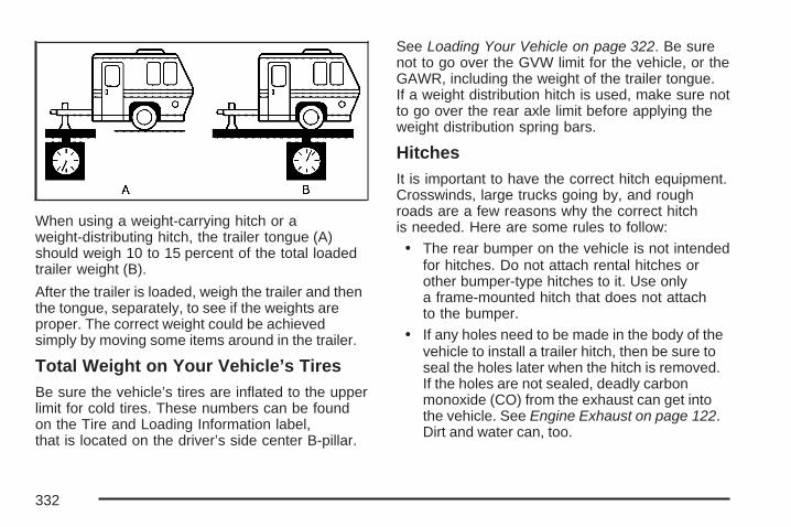
When using a weight-carrying hitch or aweight-distributing hitch, the trailer tongue (A)should weigh 10 to 15 percent of the total loadedtrailer weight (B).
After the trailer is loaded, weigh the trailer and thenthe tongue, separately, to see if the weights areproper. The correct weight could be achievedsimply by moving some items around in the trailer.
Total Weight on Your Vehicle’s TiresBe sure the vehicle’s tires are inflated to the upperlimit for cold tires. These numbers can be foundon the Tire and Loading Information label,that is located on the driver’s side center B-pillar.
See Loading Your Vehicle on page 322. Be surenot to go over the GVW limit for the vehicle, or theGAWR, including the weight of the trailer tongue.If a weight distribution hitch is used, make sure notto go over the rear axle limit before applying theweight distribution spring bars.
HitchesIt is important to have the correct hitch equipment.Crosswinds, large trucks going by, and roughroads are a few reasons why the correct hitchis needed. Here are some rules to follow:
• The rear bumper on the vehicle is not intendedfor hitches. Do not attach rental hitches orother bumper-type hitches to it. Use onlya frame-mounted hitch that does not attachto the bumper.
• If any holes need to be made in the body of thevehicle to install a trailer hitch, then be sure toseal the holes later when the hitch is removed.If the holes are not sealed, deadly carbonmonoxide (CO) from the exhaust can get intothe vehicle. See Engine Exhaust on page 122.Dirt and water can, too.
332
Safety ChainsAlways attach chains between the vehicle and thetrailer. Cross the safety chains under the tongueof the trailer so that the tongue will not drop tothe road if it becomes separated from the hitch.Instructions about safety chains may be providedby the hitch manufacturer or by the trailermanufacturer. Follow the manufacturer’srecommendation for attaching safety chains and donot attach them to the bumper. Always leave justenough slack so the rig can be turned around. And,never allow safety chains to drag on the ground.
Trailer BrakesDoes your trailer have its own brakes? Be sureto read and follow the instructions for thetrailer brakes so you’ll be able to install,adjust and maintain them properly.
• If your vehicle has anti-lock brakes, do not try totap into your vehicle’s brake system. If you do,both brake systems won’t work well, or at all.
• Even if your vehicle doesn’t have anti-lockbrakes, don’t tap into your vehicle’s brakesystem if the trailer’s brake system will usemore than 0.02 cubic inch (0.3 cc) of fluid fromyour vehicle’s master cylinder. If it does, bothbraking systems won’t work well. You couldeven lose your brakes.
• Will the trailer brake parts take 3,000 psi(20 650 kPa) of pressure? If not, the trailerbrake system must not be used with yourvehicle.
• If everything checks out this far, then make thebrake fluid tap at the upper rear master cylinderport. But don’t use copper tubing for this. If youdo, it will bend and break off. Use steel braketubing.
333
Driving with a TrailerTowing a trailer requires a certain amount ofexperience. Before setting out for the open road,get to know the rig. Acquaint yourself with thefeel of handling and braking with the added weightof the trailer. And always keep in mind that thevehicle is now a good deal longer and not nearlyas responsive as the vehicle is by itself.
Before starting, check the trailer hitch andplatform (and attachments), safety chains,electrical connector, lamps, tires, and mirroradjustment. If the trailer has electric brakes,start the vehicle and trailer moving and thenapply the trailer brake controller by hand to besure the brakes are working. This lets you checkthe electrical connection at the same time.
During your trip, check occasionally to be surethat the load is secure, and that the lamps and anytrailer brakes are still working.
Following DistanceStay at least twice as far behind the vehicle aheadas when driving the vehicle without a trailer.This can prevent situations that require heavybraking and sudden turns.
PassingMore passing distance is needed up ahead whentowing a trailer. And, because the vehicle andtrailer are a good deal longer, distances betweenany vehicles that are passed must be greater,before returning to the proper lane.
Backing UpHold the bottom of the steering wheel withone hand. Then, to move the trailer to the left,move that hand to the left. To move the trailer tothe right, move that hand to the right. Alwaysback up slowly and, if possible, have someoneguide you.
334
Making TurnsNotice: Making very sharp turns whiletrailering could cause the trailer to come incontact with the vehicle. Your vehicle could bedamaged. Avoid making very sharp turns whiletrailering.
When turning with a trailer, make wider turns thannormal. Do this so the trailer will not strike softshoulders, curbs, road signs, trees, or otherobjects. Avoid jerky or sudden maneuvers.Signal well in advance.Turn Signals When Towing a TrailerWhen towing a trailer, the vehicle may need adifferent turn signal flasher and/or extra wiring.Check with your dealer. The arrows on theinstrument panel will flash whenever signaling aturn or lane change. Properly hooked up, the trailerlamps will also flash, telling other drivers the vehicleand trailer are about to turn, change lanes, or stop.
When towing a trailer, the arrows on the instrumentpanel will flash for turns even if the bulbs on thetrailer are burned out. You may think drivers behindyou are seeing the turn signal when they are not.It is important to check occasionally to be sure thetrailer bulbs are still working.
The vehicle has bulb warning lights. When a trailerlighting system is plugged into the vehicle’s lightingsystem, its bulb warning lights may not indicateif one of the lamps goes out. So, when a trailerlighting system is plugged in, be sure to check thevehicle and trailer lamps from time to time to besure they are all working. Once the trailer lampshave been disconnected, the bulb warning lightscan once again indicate if one of the vehicle lampsis out.
335

Driving On GradesReduce speed and shift to a lower gear beforestarting down a long or steep downgrade. If thevehicle is not shifted down, the brakes may have tobe used so much that they would get hot and nolonger work well.
On a long uphill grade, shift down and reduce thevehicle’s speed to around 45 mph (70 km/h) toreduce the possibility of engine and transaxleoverheating.
If the vehicle has overdrive, it may be driven inTHIRD (3) instead of DRIVE (D).
Parking on Hills
{CAUTION:
You really should not park yourvehicle, with a trailer attached, on a hill.If something goes wrong, your rig couldstart to move. People can be injured, andboth your vehicle and the trailer can bedamaged.
But if the rig ever has to be parked on a hill, hereis how to do it:
1. Apply the regular brakes, but do not shift intoPARK (P) yet.
2. Have someone place chocks under thetrailer wheels.
3. When the wheel chocks are in place,release the regular brakes until the chocksabsorb the load.
4. Reapply the regular brakes. Then apply theparking brake, and then shift to PARK (P).
5. Release the regular brakes.
336
When You Are Ready to Leave AfterParking on a Hill1. Apply the regular brakes and hold the pedal
down while you:
• Start the engine
• Shift into a gear
• Release the parking brake
2. Let up on the brake pedal.
3. Drive slowly until the trailer is clear of thechocks.
4. Stop and have someone pick up and store thechocks.
Maintenance When Trailer TowingThe vehicle will need service more often when itpulls a trailer. See Scheduled Maintenance onpage 480 for more information. Things that areespecially important in trailer operation areautomatic transaxle fluid, which should not beoverfilled, engine oil, drive belts, cooling, andbrake systems. Each of these is covered in thismanual, and the Index will help locate themquickly. If trailering, it is a good idea to reviewthis information before starting on a trip.
Check periodically to see that all hitch nuts andbolts are tight.
Engine Cooling When Trailer TowingThe cooling system may temporarily overheatduring severe operating conditions. See EngineOverheating on page 369.
337

✍ NOTES
338
Service ........................................................ 342Accessories and Modifications ................... 342California Proposition 65 Warning .............. 343Doing Your Own Service Work .................. 343Adding Equipment to the Outside of
Your Vehicle .......................................... 344Fuel ............................................................. 344
Gasoline Octane ........................................ 344Gasoline Specifications .............................. 345California Fuel ........................................... 346Additives ................................................... 346Fuels in Foreign Countries ........................ 347Filling the Tank ......................................... 348Filling a Portable Fuel Container ............... 350
Checking Things Under the Hood .............. 350Hood Release ........................................... 351Engine Compartment Overview .................. 352Engine Oil ................................................. 356Engine Oil Life System .............................. 359Supercharger Oil ....................................... 361Engine Air Cleaner/Filter ............................ 361Automatic Transaxle Fluid ......................... 363Engine Coolant .......................................... 366
Pressure Cap ............................................ 369Engine Overheating ................................... 369Overheated Engine Protection
Operating Mode ..................................... 371Cooling System ......................................... 372Power Steering Fluid ................................. 381Windshield Washer Fluid ........................... 382Brakes ...................................................... 383Battery ...................................................... 387Jump Starting ............................................ 388
Headlamp Aiming ........................................ 394Bulb Replacement ....................................... 397
Halogen Bulbs ........................................... 397Headlamps and Sidemarker Lamps ........... 397Front Turn Signal, Parking and
Fog Lamps ............................................ 400Taillamps, Turn Signal, and Stoplamps ...... 401Back-Up Lamps ......................................... 403License Plate Lamp ................................... 404Replacement Bulbs ................................... 404
Windshield Replacement ............................ 405Windshield Wiper Blade Replacement ....... 405
Section 5 Service and Appearance Care
339
Tires ............................................................ 406Tire Sidewall Labeling ............................... 407Tire Terminology and Definitions ............... 411Inflation - Tire Pressure ............................. 414Tire Pressure Monitor System ................... 415Tire Inspection and Rotation ...................... 420When It Is Time for New Tires .................. 422Buying New Tires ...................................... 422Different Size Tires and Wheels ................ 424Uniform Tire Quality Grading ..................... 425Wheel Alignment and Tire Balance ............ 426Wheel Replacement .................................. 426Tire Chains ............................................... 428If a Tire Goes Flat .................................... 429Tire Inflator Kit (GXP) ................................ 431Changing a Flat Tire ................................. 442Removing the Spare Tire and Tools .......... 444Removing the Flat Tire and Installing
the Spare Tire ....................................... 445Storing a Flat or Spare Tire and Tools ...... 452Compact Spare Tire .................................. 454
Appearance Care ........................................ 455Cleaning the Inside of Your Vehicle .......... 455Fabric/Carpet ............................................. 456Leather ...................................................... 458Ultra Lux Suede ........................................ 459Instrument Panel, Vinyl, and
Other Plastic Surfaces ........................... 459Care of Safety Belts .................................. 460Weatherstrips ............................................ 460Washing Your Vehicle ............................... 460Cleaning Exterior Lamps/Lenses ................ 461Finish Care ............................................... 461Windshield and Wiper Blades .................... 462Aluminum Wheels ...................................... 462Tires ......................................................... 463Sheet Metal Damage ................................. 463Finish Damage .......................................... 463Underbody Maintenance ............................ 464Chemical Paint Spotting ............................ 464Vehicle Care/Appearance Materials ............ 464
Section 5 Service and Appearance Care
340
Vehicle Identification .................................. 465Vehicle Identification Number (VIN) ........... 465Service Parts Identification Label ............... 466
Electrical System ........................................ 466Add-On Electrical Equipment ..................... 466Headlamp Wiring ....................................... 467
Windshield Wiper Fuses ............................ 467Power Windows and Other
Power Options ....................................... 467Fuses and Circuit Breakers ....................... 467Instrument Panel Fuse Block ..................... 468Underhood Fuse Block .............................. 469
Capacities and Specifications .................... 474
Section 5 Service and Appearance Care
341
ServiceYour dealer knows your vehicle best and wantsyou to be happy with it. We hope you will goto your dealer for all your service needs. You willget genuine GM parts and GM-trained andsupported service people.
We hope you will want to keep your GM vehicle allGM. Genuine GM parts have one of these marks:
Accessories and ModificationsWhen you add non-GM accessories to your vehiclethey can affect your vehicle’s performance andsafety, including such things as, airbags, braking,stability, ride and handling, emissions systems,aerodynamics, durability, and electronic systemslike anti-lock brakes, traction control andstability control. Some of these accessories mayeven cause malfunction or damage not covered bywarranty.
GM Accessories are designed to complement andfunction with other systems on your vehicle.Your GM dealer/retailer can accessorize yourvehicle using genuine GM Accessories. When yougo to your GM dealer/retailer and ask for GMAccessories, you will know that GM-trained andsupported service technicians will perform the workusing genuine GM Accessories.
342

California Proposition 65 WarningMost motor vehicles, including this one, containand/or emit chemicals known to the State ofCalifornia to cause cancer and birth defects or otherreproductive harm. Engine exhaust, many parts andsystems (including some inside the vehicle), manyfluids, and some component wear by-productscontain and/or emit these chemicals.
Doing Your Own Service Work
{CAUTION:
You can be injured and your vehicle couldbe damaged if you try to do service workon a vehicle without knowing enoughabout it.
• Be sure you have sufficient knowledge,experience, the proper replacementparts, and tools before you attempt anyvehicle maintenance task.
CAUTION: (Continued)
CAUTION: (Continued)
• Be sure to use the proper nuts, bolts,and other fasteners. English andmetric fasteners can be easilyconfused. If you use the wrongfasteners, parts can later breakor fall off. You could be hurt.
If you want to do some of your own service work,you should use the proper service manual. Ittells you much more about how to service yourvehicle than this manual can. To order the properservice manual, see Service PublicationsOrdering Information on page 514.
Your vehicle has an airbag system. Beforeattempting to do your own service work, seeServicing Your Airbag-Equipped Vehicle onpage 78.
You should keep a record with all parts receiptsand list the mileage and the date of any servicework you perform. See Maintenance Recordon page 494.
343

Adding Equipment to the Outside ofYour VehicleThings you might add to the outside of yourvehicle can affect the airflow around it. This maycause wind noise and affect windshield washerperformance. Check with your dealer beforeadding equipment to the outside of your vehicle.
FuelUse of the recommended fuel is an important partof the proper maintenance of your vehicle. Tohelp keep the engine clean and maintain optimumvehicle performance, GM recommends the useof gasoline advertised as TOP TIER DetergentGasoline.
The 8th digit of the Vehicle Identification Number(VIN) shows the code letter or number thatidentifies your vehicle’s engine. The VIN is at thetop left of the instrument panel. See VehicleIdentification Number (VIN) on page 465.
Gasoline OctaneIf your vehicle has the 3800 V6 engine(VIN Code 2), use regular unleaded gasoline witha posted octane rating of 87 or higher. If theoctane rating is less than 87, you may notice anaudible knocking noise when you drive, commonlyreferred to as spark knock. If this occurs, use agasoline rated at 87 octane or higher as soonas possible. If you are using gasoline rated at87 octane or higher and you hear heavy knocking,your engine needs service.
344

If your vehicle has the 3800 SuperchargedV6 engine (VIN Code 4) or the 5.3L V8 engine(VIN Code C), use premium unleaded gasolinewith a posted octane rating of 91 or higher.You may also use regular unleaded gasolinerated at 87 octane or higher, but your vehicle’sacceleration may be slightly reduced, and you maynotice a slight audible knocking noise, commonlyreferred to as spark knock. If the octane isless than 87, you may notice a heavy knockingnoise when you drive. If this occurs, use a gasolinerated at 87 octane or higher as soon as possible.Otherwise, you might damage your engine. Ifyou are using gasoline rated at 87 octane or higherand you hear heavy knocking, your engineneeds service.
Gasoline SpecificationsAt a minimum, gasoline should meet ASTMspecification D 4814 in the United States orCAN/CGSB-3.5 in Canada. Some gasolines maycontain an octane-enhancing additive calledmethylcyclopentadienyl manganese tricarbonyl(MMT). General Motors recommends against theuse of gasolines containing MMT. See Additiveson page 346 for additional information.
345
California FuelIf your vehicle is certified to meet CaliforniaEmissions Standards, it is designed to operateon fuels that meet California specifications. See theunderhood emission control label. If this fuel is notavailable in states adopting California emissionsstandards, your vehicle will operate satisfactorily onfuels meeting federal specifications, but emissioncontrol system performance may be affected. Themalfunction indicator lamp may turn on and yourvehicle may fail a smog-check test. See MalfunctionIndicator Lamp on page 184. If this occurs, return toyour authorized GM dealer for diagnosis. If it isdetermined that the condition is caused by the typeof fuel used, repairs may not be covered by yourwarranty.
AdditivesTo provide cleaner air, all gasolines in theUnited States are now required to contain additivesthat will help prevent engine and fuel systemdeposits from forming, allowing your emissioncontrol system to work properly. In most cases,you should not have to add anything to your fuel.However, some gasolines contain only theminimum amount of additive required to meet U.S.Environmental Protection Agency regulations.To help keep fuel injectors and intake valves clean,or if your vehicle experiences problems due todirty injectors or valves, look for gasoline that isadvertised as TOP TIER Detergent Gasoline.Also, your dealer has additives that will help correctand prevent most deposit-related problems.
346

Gasolines containing oxygenates, such as ethersand ethanol, and reformulated gasolines maybe available in your area. General Motorsrecommends that you use these gasolines if theycomply with the specifications described earlier.However, E85 (85% ethanol) and other fuelscontaining more than 10% ethanol must not beused in vehicles that were not designed forthose fuels.
Notice: Your vehicle was not designed forfuel that contains methanol. Do not usefuel containing methanol. It can corrode metalparts in the fuel system and also damageplastic and rubber parts. That damage wouldnot be covered under your warranty.
Some gasolines that are not reformulated for lowemissions may contain an octane-enhancingadditive called methylcyclopentadienyl manganesetricarbonyl (MMT); ask the attendant where youbuy gasoline whether the fuel contains MMT.
General Motors recommends against the use ofsuch gasolines. Fuels containing MMT can reducethe life of spark plugs and the performance ofthe emission control system may be affected.The malfunction indicator lamp may turn on.If this occurs, return to your dealer for service.
Fuels in Foreign CountriesIf you plan on driving in another country outsidethe United States or Canada, the proper fuel mightbe hard to find. Never use leaded gasoline orany other fuel not recommended in the previoustext on fuel. Costly repairs caused by use ofimproper fuel would not be covered by yourwarranty.
To check the fuel availability, ask an auto club, orcontact a major oil company that does businessin the country where you will be driving.
347
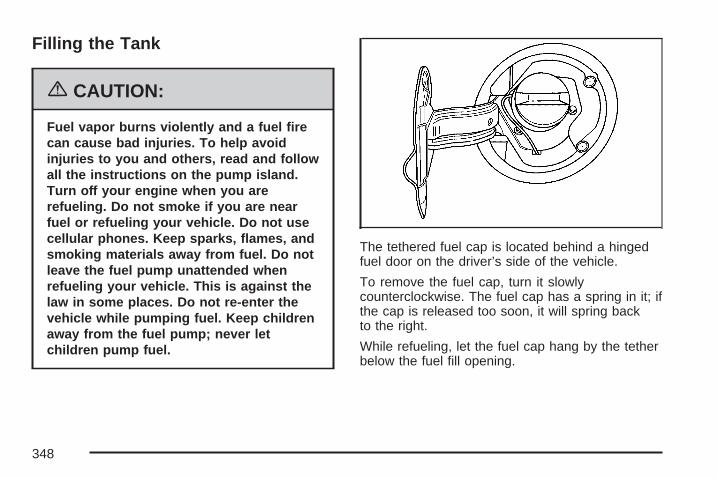
Filling the Tank
{CAUTION:
Fuel vapor burns violently and a fuel firecan cause bad injuries. To help avoidinjuries to you and others, read and followall the instructions on the pump island.Turn off your engine when you arerefueling. Do not smoke if you are nearfuel or refueling your vehicle. Do not usecellular phones. Keep sparks, flames, andsmoking materials away from fuel. Do notleave the fuel pump unattended whenrefueling your vehicle. This is against thelaw in some places. Do not re-enter thevehicle while pumping fuel. Keep childrenaway from the fuel pump; never letchildren pump fuel.
The tethered fuel cap is located behind a hingedfuel door on the driver’s side of the vehicle.
To remove the fuel cap, turn it slowlycounterclockwise. The fuel cap has a spring in it; ifthe cap is released too soon, it will spring backto the right.
While refueling, let the fuel cap hang by the tetherbelow the fuel fill opening.
348

{CAUTION:
Fuel can spray out on you if you open thefuel cap too quickly. If you spill fuel andthen something ignites it, you could bebadly burned. This spray can happen ifyour tank is nearly full, and is more likelyin hot weather. Open the fuel cap slowlyand wait for any hiss noise to stop. Thenunscrew the cap all the way.
Be careful not to spill fuel. Do not top off or overfillthe tank and wait a few seconds after you havefinished pumping before removing the nozzle.Clean fuel from painted surfaces as soonas possible. See Washing Your Vehicle onpage 460.
When replacing the fuel cap, turn it clockwiseuntil it clicks. Make sure the cap is fully installed.The diagnostic system can determine if thefuel cap has been left off or improperly installed.This would allow fuel to evaporate into theatmosphere. See Malfunction Indicator Lampon page 184.
The CHECK GAS CAP message will be displayedon the Driver Information Center (DIC) if thefuel cap is not properly installed. See DICWarnings and Messages on page 204 for moreinformation.
{CAUTION:
If a fire starts while you are refueling,do not remove the nozzle. Shut off theflow of fuel by shutting off the pump orby notifying the station attendant. Leavethe area immediately.
Notice: If you need a new fuel cap, be sureto get the right type. Your dealer/retailercan get one for you. If you get the wrong type,it may not fit properly. This may cause yourmalfunction indicator lamp to light andmay damage your fuel tank and emissionssystem. See Malfunction Indicator Lampon page 184.
349
Filling a Portable Fuel Container
{CAUTION:
Never fill a portable fuel container whileit is in your vehicle. Static electricitydischarge from the container can ignite thegasoline vapor. You can be badly burnedand your vehicle damaged if this occurs.To help avoid injury to you and others:
• Dispense gasoline only into approvedcontainers.
• Do not fill a container while it is inside avehicle, in a vehicle’s trunk, pickupbed, or on any surface other than theground.
• Bring the fill nozzle in contact withthe inside of the fill opening beforeoperating the nozzle. Contact shouldbe maintained until the filling iscomplete.
• Do not smoke while pumping gasoline.• Do not use a cellular phone while
pumping gasoline.
Checking Things Underthe Hood
{CAUTION:
An electric fan under the hood can start upand injure you even when the engine is notrunning. Keep hands, clothing, and toolsaway from any underhood electric fan.
{CAUTION:
Things that burn can get on hot engineparts and start a fire. These includeliquids like fuel, oil, coolant, brake fluid,windshield washer and other fluids, andplastic or rubber. You or others could beburned. Be careful not to drop or spillthings that will burn onto a hot engine.
350

Hood ReleaseTo open the hood, do the following:
1. Pull the hoodrelease handle withthis symbol on it.It is locatedinside the vehiclenear the parkingbrake pedal.
2. Go to the front of the vehicle and release thesecondary hood latch, located near the centerfront of the engine compartment, by movingit to the right.
3. Lift the hood.
Before closing the hood, be sure all the filler capsare on properly. Then pull the hood down andclose it firmly.
351

Engine Compartment OverviewWhen you open the hood on the 3800 V6 Supercharged engine (3800 V6 engine similar), here is whatyou will see:
352

A. Windshield Washer Fluid Reservoir. See“Adding Washer Fluid” under WindshieldWasher Fluid on page 382.
B. Battery. See Battery on page 387.C. Remote Positive (+) Terminal. See Jump
Starting on page 388.D. Underhood Fuse Block. See Underhood Fuse
Block on page 469.E. Engine Coolant Recovery Tank. See Cooling
System on page 372.F. Pressure Cap. See Pressure Cap on page 369.G. Power Steering Fluid Reservoir (low in
engine compartment). See Power SteeringFluid on page 381.
H. Supercharger Oil Fill Location (If Equipped).See Supercharger Oil on page 361.
I. Electric Cooling Fan. See Cooling System onpage 372.
J. Engine Oil Dipstick. See “Checking Engine Oil”under Engine Oil on page 356.
K. Engine Oil Fill Cap. See “When to Add EngineOil” under Engine Oil on page 356.
L. Engine Coolant Bleed Valve. See “How to AddCoolant to the Radiator” under CoolingSystem on page 372.
M. Automatic Transaxle Fluid Dipstick. See“Checking the Fluid Level” under AutomaticTransaxle Fluid on page 363.
N. Brake Master Cylinder Reservoir. See “BrakeFluid” under Brakes on page 383.
O. Engine Air Cleaner/Filter. See Engine AirCleaner/Filter on page 361.
353
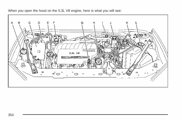
When you open the hood on the 5.3L V8 engine, here is what you will see:
354

A. Windshield Washer Fluid Reservoir. See“Adding Washer Fluid” under WindshieldWasher Fluid on page 382.
B. Battery. See Battery on page 387.C. Underhood Fuse Block. See Underhood Fuse
Block on page 469.D. Remote Positive (+) Terminal. See Jump
Starting on page 388.E. Pressure Cap. See Pressure Cap on page 369.F. Power Steering Fluid Reservoir. See Power
Steering Fluid on page 381.G. Engine Oil Dipstick. See “Checking Engine Oil”
under Engine Oil on page 356.
H. Engine Oil Fill Cap. See “When to Add EngineOil” under Engine Oil on page 356.
I. Automatic Transaxle Fluid Dipstick. See“Checking the Fluid Level” under AutomaticTransaxle Fluid on page 363.
J. Brake Master Cylinder Reservoir. See “BrakeFluid” under Brakes on page 383.
K. Engine Air Cleaner/Filter. See Engine AirCleaner/Filter on page 361.
L. Engine Coolant Recovery Tank. See CoolingSystem on page 372.
355
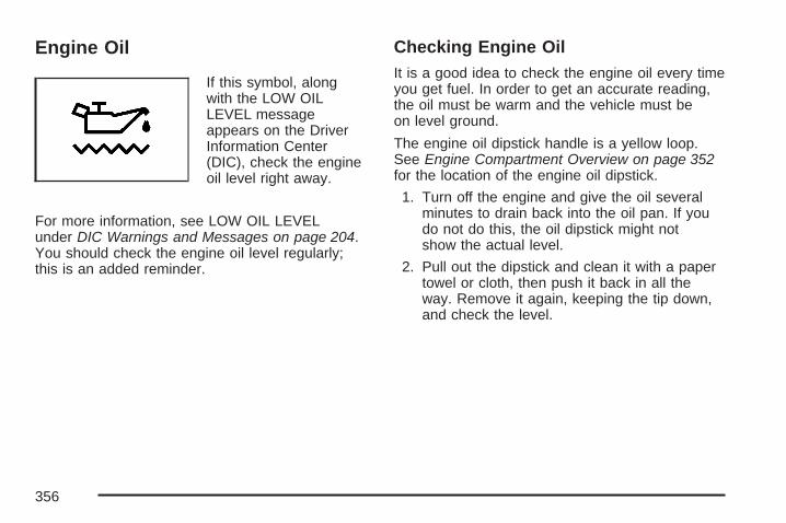
Engine Oil
If this symbol, alongwith the LOW OILLEVEL messageappears on the DriverInformation Center(DIC), check the engineoil level right away.
For more information, see LOW OIL LEVELunder DIC Warnings and Messages on page 204.You should check the engine oil level regularly;this is an added reminder.
Checking Engine OilIt is a good idea to check the engine oil every timeyou get fuel. In order to get an accurate reading,the oil must be warm and the vehicle must beon level ground.
The engine oil dipstick handle is a yellow loop.See Engine Compartment Overview on page 352for the location of the engine oil dipstick.
1. Turn off the engine and give the oil severalminutes to drain back into the oil pan. If youdo not do this, the oil dipstick might notshow the actual level.
2. Pull out the dipstick and clean it with a papertowel or cloth, then push it back in all theway. Remove it again, keeping the tip down,and check the level.
356

When to Add Engine Oil
If the oil is below the cross-hatched area at thetip of the dipstick, you need to add at leastone quart/liter of oil. But you must use the right
kind. This section explains what kind of oil to use.For engine oil crankcase capacity, see Capacitiesand Specifications on page 474.
Notice: Do not add too much oil. If the enginehas so much oil that the oil level gets abovethe cross-hatched area that shows theproper operating range, the engine couldbe damaged.
See EngineCompartment Overviewon page 352 for thelocation of the engineoil fill cap.
Be sure to add enough oil to put the levelsomewhere in the proper operating range in thecross-hatched area. Push the dipstick all theway back in when you are through.
3800 V6 Engine
5.3L V8 Engine
357

What Kind of Engine Oil to Use
Look for three things:
• GM6094M
Your vehicle’s engine requires oil meeting GMStandard GM6094M. Look for and use onlyan oil that meets GM Standard GM6094M.
• SAE 5W-30
As shown in the viscosity chart, SAE 5W-30 isbest for your vehicle.
These numbers on an oil container show itsviscosity, or thickness. Do not use otherviscosity oils such as SAE 20W-50.
• Oils meeting theserequirements shouldhave the starburstsymbol on thecontainer. Thissymbol indicatesthat the oil has beencertified by theAmerican PetroleumInstitute (API).
Look for this information on the oil container, anduse only those oils that are identified as meetingGM Standard GM6094M and have the starburstsymbol on the front of the oil container.
Notice: Use only engine oil identified asmeeting GM Standard GM6094M and showingthe American Petroleum Institute CertifiedFor Gasoline Engines starburst symbol. Failureto use the recommended oil can result inengine damage not covered by your warranty.
358

If you are in an area of extreme cold, where thetemperature falls below −20°F (−29°C), it isrecommended that you use either an SAE 5W-30synthetic oil or an SAE 0W-30 oil. Both provideeasier cold starting and better protection forthe engine at extremely low temperatures.
Engine Oil AdditivesDo not add anything to the engine oil. Therecommended oils with the starburst symbol thatmeet GM Standard GM6094M are all you need forgood performance and engine protection.
Engine Oil Life System
When to Change Engine OilYour vehicle has a computer system that lets youknow when to change the engine oil and filter.This is based on engine revolutions and enginetemperature, and not on mileage. Based on drivingconditions, the mileage at which an oil changewill be indicated can vary considerably. For the oillife system to work properly, you must reset thesystem every time the oil is changed.
When the system has calculated that oil life hasbeen diminished, it will indicate that an oil change isnecessary. A CHANGE OIL SOON message willcome on. See DIC Warnings and Messages onpage 204. Change the oil as soon as possiblewithin the next 600 miles (1 000 km). It is possiblethat, if you are driving under the best conditions, theoil life system might not indicate that an oil changeis necessary for over a year. However, the engineoil and filter must be changed at least once a yearand at this time the system must be reset. Yourdealer/retailer has trained service people who willperform this work using genuine parts and reset thesystem. It is also important to check the oil regularlyand keep it at the proper level.
If the system is ever reset accidentally, you mustchange the oil at 3,000 miles (5 000 km) sincethe last oil change. Remember to reset the oil lifesystem whenever the oil is changed.
359
How to Reset the Engine Oil LifeSystemThe Engine Oil Life System calculates when tochange the engine oil and filter based on vehicleuse. Whenever the oil is changed, reset thesystem so it can calculate when the next oilchange is required. If a situation occurs whereyou change the oil prior to a CHANGE OIL SOONmessage appearing on the DIC, reset thesystem.
To reset the oil life system, after the oil has beenchanged:
1. Press the options button on the DIC untilENGINE OIL MONITOR appears on theDIC screen.
2. Press the set/reset button to reset the system.The next screen indicates that the engine oilmonitor system has been reset.If the vehicle is equipped with the tripcomputer DIC, when the gage button ispressed and the OIL LIFE REMAINING modeappears, it should read 100 percent OILLIFE REMAINING.
3. Turn the key to OFF.
If the CHANGE OIL SOON message comes backon when you start your vehicle, the engine oillife system has not reset. Repeat the procedure.
What to Do with Used OilUsed engine oil contains certain elements that canbe unhealthy for your skin and could even causecancer. Do not let used oil stay on your skin for verylong. Clean your skin and nails with soap andwater, or a good hand cleaner. Wash or properlydispose of clothing or rags containing used engineoil. See the manufacturer’s warnings about the useand disposal of oil products.
Used oil can be a threat to the environment. If youchange your own oil, be sure to drain all the oilfrom the filter before disposal. Never dispose ofoil by putting it in the trash, pouring it on theground, into sewers, or into streams or bodies ofwater. Instead, recycle it by taking it to a placethat collects used oil. If you have a problemproperly disposing of used oil, ask yourdealer/retailer, a service station, or a localrecycling center for help.
360
Supercharger OilBecause they are technically qualified and havethe proper tools, you should have your dealerperform this maintenance.
When to CheckSee Additional Required Services on page 482 forwhen the oil level should be checked.
What Kind of Oil to UseUse only the recommended supercharger oil.See Recommended Fluids and Lubricantson page 490.
Engine Air Cleaner/FilterThe engine air cleaner/filter is located in theengine compartment on the driver’s side of thevehicle. See Engine Compartment Overviewon page 352 for more information on location.
When to Inspect the Engine AirCleaner/FilterInspect the air cleaner/filter at the Maintenance IIintervals and replace it at the first oil changeafter each 50,000 mile (83 000 km) interval.See Scheduled Maintenance on page 480 formore information. If you are driving in dusty/dirtyconditions, inspect the filter at each engine oilchange.
361

How to Inspect the Engine AirCleaner/FilterTo inspect the air cleaner/filter, remove the filterfrom the vehicle and lightly shake the filter torelease loose dust and dirt. If the filter remainscaked with dirt, a new filter is required.
To inspect or replace the engine air cleaner/filterdo the following:
1. Lift the filter cover tabs on top of the engineair cleaner/filter housing.
2. Push the filter cover housing toward theengine.
3. Pull out the filter.
4. Inspect or replace the engine air cleaner/filter.
3800 V6 Supercharged Engine shown, 3800 V6Engine similar
5.3L V8 Engine
362

5. To reinstall the cover, position the tabsthrough the slots on the housing. If yourvehicle has one of the 3800 V6 engines, anotch on the sides of the filter cover willindicate the correct engagement.
6. Push the cover tabs on top of the housing tolock the cover in place.
{CAUTION:
Operating the engine with the aircleaner/filter off can cause you or othersto be burned. The air cleaner not onlycleans the air; it helps to stop flames ifthe engine backfires. If it is not there andthe engine backfires, you could beburned. Do not drive with it off, and becareful working on the engine with theair cleaner/filter off.
Notice: If the air cleaner/filter is off, a backfirecan cause a damaging engine fire. And, dirtcan easily get into your engine, which willdamage it. Always have the air cleaner/filterin place when you are driving.
Automatic Transaxle Fluid
When to Check and Change AutomaticTransaxle FluidA good time to check the automatic transaxle fluidlevel is when the engine oil is changed.
Change the fluid and filter at the intervals listedin Additional Required Services on page 482,and be sure to use the transaxle fluid listedin Recommended Fluids and Lubricants onpage 490.
363
How to Check Automatic TransaxleFluidBecause this operation can be a little difficult, youmay choose to have this done at the dealershipservice department.
If you do it yourself, be sure to follow all theinstructions here, or you could get a false readingon the dipstick.
Notice: Too much or too little fluid can damagethe transaxle. Too much can mean that some ofthe fluid could come out and fall on hot engineor exhaust system parts, starting a fire. Toolittle fluid could cause the transaxle to overheat.Be sure to get an accurate reading if you checkthe transaxle fluid.
Wait at least 30 minutes before checking thetransaxle fluid level if you have been driving:
• When outside temperatures are above90°F (32°C).
• At high speed for quite a while.
• In heavy traffic — especially in hot weather.
• While pulling a trailer.
To get the right reading, the fluid should be atnormal operating temperature, which is 180°F to200°F (82°C to 93°C).
Get the vehicle warmed up by driving about15 miles (24 km) when outside temperatures areabove 50°F (10°C). If it is colder than 50°F (10°C),you may have to drive longer.
364

Checking the Fluid LevelPrepare the vehicle as follows:
1. Park the vehicle on a level place. Keep theengine running.
2. With the parking brake applied, place the shiftlever in PARK (P).
3. With your foot on the brake pedal, move theshift lever through each gear, pausing forabout three seconds in each one. Then,position the shift lever in PARK (P).
4. Let the engine run at idle for three tofive minutes.
Then, without shutting off the engine, followthese steps:
The transaxle fluiddipstick handle hasthis symbol on it,and is located nearthe rear of the enginecompartment.
See Engine Compartment Overview on page 352for more information on location.
1. Pull out the dipstick and wipe it with a cleanrag or paper towel.
2. Push it back in all the way, wait three secondsand then pull it back out again.
3. Check both sides of the dipstick, and readthe lower level. The fluid level must be inthe crosshatched area.
4. If the fluid level is in the acceptable range,push the dipstick back in all the way.
365
How to Add Automatic Transaxle FluidRefer to the Maintenance Schedule to determinewhat kind of transaxle fluid to use. SeeRecommended Fluids and Lubricants on page 490.
If the fluid level is low, add only enough of theproper fluid to bring the level into the crosshatchedarea on the dipstick.
1. Pull out the dipstick.
2. Using a long-neck funnel, add enough fluid atthe dipstick hole to bring it to the proper level.It does not take much fluid, generally lessthan one pint (0.5 L). Do not overfill.
Notice: Use of the incorrect automatictransaxle fluid may damage your vehicle,and the damages may not be covered by yourwarranty. Always use the automatic transaxlefluid listed in Recommended Fluids andLubricants on page 490.
3. After adding fluid, recheck the fluid level asdescribed under “How to Check AutomaticTransaxle Fluid,” earlier in this section.
4. When the correct fluid level is obtained, pushthe dipstick back in all the way.
Engine CoolantThe cooling system in the vehicle is filled withDEX-COOL® engine coolant. This coolantis designed to remain in the vehicle for five yearsor 150,000 miles (240 000 km), whicheveroccurs first, if only DEX-COOL® extended lifecoolant is added.
The following explains the cooling system andhow to add coolant when it is low. If there isa problem with engine overheating or if coolantneeds to be added to the radiator, see EngineOverheating on page 369.
A 50/50 mixture of clean, drinkable water andDEX-COOL® engine coolant will:
• Give freezing protection down to−34°F (−37°C).
• Give boiling protection up to 265°F (129°C).
• Protect against rust and corrosion.
• Help keep the proper engine temperature.
• Let the warning lights and gages work as theyshould.
366

Notice: Using coolant other than DEX-COOL®
may cause premature engine, heater core,or radiator corrosion. In addition, the enginecoolant may require changing sooner, atthe first maintenance service after each30,000 miles (50 000 km) or 24 months,whichever occurs first. Any repairs wouldnot be covered by your warranty. Always useDEX-COOL® (silicate-free) coolant in yourvehicle.
What to UseUse a mixture of one-half clean, drinkable waterand one-half DEX-COOL® engine coolant which willnot damage aluminum parts. If this coolant mixtureis used, nothing else needs to be added.
{CAUTION:
Adding only plain water to your coolingsystem can be dangerous. Plain water, orsome other liquid such as alcohol, canboil before the proper coolant mixture will.Your vehicle’s coolant warning system is
CAUTION: (Continued)
CAUTION: (Continued)
set for the proper coolant mixture. Withplain water or the wrong mixture, yourengine could get too hot but you wouldnot get the overheat warning. Your enginecould catch fire and you or others couldbe burned. Use a 50/50 mixture of clean,drinkable water and DEX-COOL® coolant.
Notice: If you use an improper coolantmixture, your engine could overheat and bebadly damaged. The repair cost would not becovered by your warranty. Too much waterin the mixture can freeze and crack the engine,radiator, heater core, and other parts.If coolant needs to be added more than four times ayear, have your dealer check the cooling system.
Notice: If you use extra inhibitors and/oradditives in your vehicle’s cooling system,you could damage your vehicle. Use only theproper mixture of the engine coolant listedin this manual for the cooling system.See Recommended Fluids and Lubricantson page 490 for more information.
367
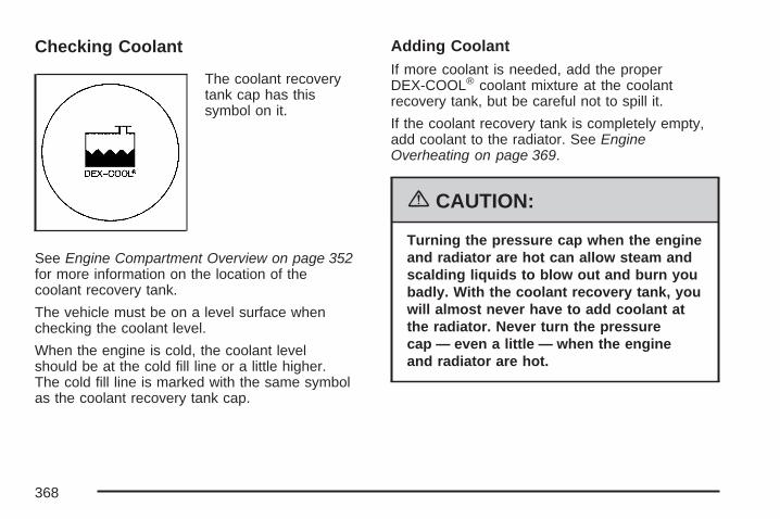
Checking Coolant
The coolant recoverytank cap has thissymbol on it.
See Engine Compartment Overview on page 352for more information on the location of thecoolant recovery tank.
The vehicle must be on a level surface whenchecking the coolant level.
When the engine is cold, the coolant levelshould be at the cold fill line or a little higher.The cold fill line is marked with the same symbolas the coolant recovery tank cap.
Adding CoolantIf more coolant is needed, add the properDEX-COOL® coolant mixture at the coolantrecovery tank, but be careful not to spill it.
If the coolant recovery tank is completely empty,add coolant to the radiator. See EngineOverheating on page 369.
{CAUTION:
Turning the pressure cap when the engineand radiator are hot can allow steam andscalding liquids to blow out and burn youbadly. With the coolant recovery tank, youwill almost never have to add coolant atthe radiator. Never turn the pressurecap — even a little — when the engineand radiator are hot.
368
{CAUTION:
You can be burned if you spill coolant onhot engine parts. Coolant containsethylene glycol, and it will burn if theengine parts are hot enough. Do not spillcoolant on a hot engine.
Occasionally check the coolant level in theradiator. For information on how to add coolant tothe radiator, see Cooling System on page 372.
Pressure Cap
Notice: If the pressure cap is not tightlyinstalled, coolant loss and possible enginedamage may occur. Be sure the cap is properlyand tightly secured.
See Engine Compartment Overview on page 352for more information on location.
Engine OverheatingThere is a coolant temperature gage and awarning light on the instrument panel that indicatean overheated engine condition. See EngineCoolant Temperature Gage on page 184and Engine Coolant Temperature Warning Lighton page 183.
369

If Steam Is Coming From Your Engine
{CAUTION:
Steam from an overheated engine canburn you badly, even if you just open thehood. Stay away from the engine if yousee or hear steam coming from it. Turn itoff and get everyone away from thevehicle until it cools down. Wait untilthere is no sign of steam or coolantbefore you open the hood.
If you keep driving when the vehiclesengine is overheated, the liquids in it cancatch fire. You or others could be badlyburned. Stop your engine if it overheats,and get out of the vehicle until the engineis cool.
See Overheated Engine ProtectionOperating Mode on page 371 forinformation on driving to a safe place inan emergency.
Notice: If your engine catches fire becauseyou keep driving with no coolant, your vehiclecan be badly damaged. The costly repairswould not be covered by your warranty. SeeOverheated Engine Protection Operating Modeon page 371 for information on driving to asafe place in an emergency.
If No Steam is Coming From YourEngineAn overheat warning can indicate a seriousproblem.
If you get an engine overheat warning but seeor hear no steam, the problem may not betoo serious. Sometimes the engine can geta little too hot when you:
• Climb a long hill on a hot day.
• Stop after high-speed driving.
• Idle for long periods in traffic.
• Tow a trailer.
370
If an overheat warning occurs without any sign ofsteam, try this for a minute or so:
1. In heavy traffic, let the engine idle inNEUTRAL (N) while stopped. If it is safe todo so, pull off the road, shift to PARK (P)or NEUTRAL (N) and let the engine idle.
2. Set the heater at the highest setting and thefan at the highest speed and open thewindows as necessary.
If the overheat warning no longer exists, thevehicle can be driven. Just to be safe, drive slowerfor about 10 minutes. If the warning does notcome back on, the vehicle can be driven normally.
If the warning continues, and you have not stopped,pull over, stop, and park the vehicle right away.
If there is still no sign of steam, idle the enginefor three minutes while parked. If the warningis still there, turn off the engine and get everyoneout of the vehicle until it cools down. Also, see“Overheated Engine Protection Operating Mode”later in this section.
You may decide not to lift the hood but to getservice help right away.
Overheated Engine ProtectionOperating ModeThe overheated engine protection operating modeallows the vehicle to be driven to a safe placein an emergency situation. If an overheated enginecondition exists, this protection mode alternatesfiring groups of cylinders to help preventengine damage. In this mode, there will be asignificant loss in power and engine performance.The engine coolant temperature gage indicatorwill move to the shaded area, and the enginecoolant temperature warning light will come on,showing that an overheated engine conditionexists. Driving extended miles (km) and/or towinga trailer in the overheated engine protectionmode should be avoided.
Notice: After driving in the overheated engineprotection operating mode, to avoid enginedamage, allow the engine to cool beforeattempting any repair. The engine oil will beseverely degraded. Repair the cause of coolantloss, change the oil and reset the oil lifesystem. See Engine Oil on page 356.
371

Cooling SystemWhen you decide it is safe to lift the hood, here iswhat you will see:
A. Coolant Recovery TankB. Electric Engine Cooling Fan(s)C. Pressure Cap
A. Pressure CapB. Electric Engine Cooling FansC. Coolant Recovery Tank3800 V6 Supercharged Engine shown, 3800 V6
Engine similar
5.3L V8 Engine
372

{CAUTION:
An electric engine cooling fan under thehood can start up even when the engineis not running and can injure you. Keephands, clothing, and tools away from anyunderhood electric fan.
If the coolant inside the coolant recovery tank isboiling, do not do anything else until it cools down.The vehicle should be parked on a level surface.
The coolant recovery tank is located in the rear ofthe engine compartment on the passenger’s side ofthe vehicle on the 3800 V6 engines. The coolantrecovery tank on the 5.3L V8 engine is located inthe rear of the engine compartment on the driver’sside of the vehicle, behind the engine aircleaner/filter.
When the engine is cold, the coolant level shouldbe at or above the cold fill line on the coolantrecovery tank. To check the coolant level, look forthe cold fill line on the side of the coolant recoverytank that faces the engine. If the level is not correct,there may be a leak at the pressure cap or in theradiator hoses, heater hoses, radiator, water pump,or somewhere else in the cooling system.
{CAUTION:
Heater and radiator hoses, and otherengine parts, can be very hot. Do nottouch them. If you do, you can be burned.
Do not run the engine if there is a leak.If you run the engine, it could lose allcoolant. That could cause an engine fire,and you could be burned. Get any leakfixed before you drive the vehicle.
373
If there seems to be no leak, with the engine on,check to see if the electric engine coolingfan(s) are running. If the engine is overheating,the fan(s) should be running. If the fan(s) are notrunning, the vehicle needs service.
Notice: Engine damage from running yourengine without coolant is not covered by yourwarranty. See Overheated Engine ProtectionOperating Mode on page 371 for information ondriving to a safe place in an emergency.
Notice: Using coolant other than DEX-COOL®
may cause premature engine, heater core,or radiator corrosion. In addition, the enginecoolant could require changing sooner,at 30,000 miles (50 000 km) or 24 months,whichever occurs first. Any repairs would notbe covered by your warranty. Always useDEX-COOL® (silicate-free) coolant in yourvehicle.
How to Add Coolant to the CoolantRecovery Tank
{CAUTION:
Adding only plain water to your coolingsystem can be dangerous. Plain water, orsome other liquid such as alcohol, canboil before the proper coolant mixture will.Your vehicle’s coolant warning system isset for the proper coolant mixture. Withplain water or the wrong mixture, yourengine could get too hot but you wouldnot get the overheat warning. Your enginecould catch fire and you or others couldbe burned. Use a 50/50 mixture of clean,drinkable water and DEX-COOL® coolant.
374

If you have not found a problem yet, but thecoolant level is not at the cold fill line, add a50/50 mixture of clean, drinkable water andDEX-COOL® engine coolant at the coolantrecovery tank. See Engine Coolant on page 366for more information.
Notice: In cold weather, water can freeze andcrack the engine, radiator, heater core andother parts. Use the recommended coolantand the proper coolant mixture.
{CAUTION:
You can be burned if you spill coolanton hot engine parts. Coolant containsethylene glycol and it will burn if theengine parts are hot enough. Do notspill coolant on a hot engine.
When the coolant level in the coolant recoverytank is at the cold fill line, start the vehicle.
If the overheat warning continues, there is onemore thing you can try. You can add the propercoolant mixture directly to the radiator, but be surethe system is cool before you do it.
{CAUTION:
Steam and scalding liquids from a hotcooling system can blow out and burnyou badly. They are under pressure, andif you turn the pressure cap — even alittle — they can come out at high speed.Never turn the cap when the coolingsystem, including the pressure cap, is hot.Wait for the cooling system and pressurecap to cool if you ever have to turn thepressure cap.
375

How to Add Coolant to the Radiator(3800 V6 Engines)
Notice: Your engine has a specific radiator fillprocedure. Failure to follow this procedurecould cause your engine to overheat andbe severely damaged.
1. You can remove the pressure cap when thecooling system, including the pressure capand upper radiator hose, is no longer hot.Turn the cap slowly counterclockwise.
If you hear a hiss, wait for that to stop. A hissmeans there is still some pressure left.
2. Then keep turning the pressure cap andremove it.
{CAUTION:
You can be burned if you spill coolanton hot engine parts. Coolant containsethylene glycol and it will burn if theengine parts are hot enough. Do not spillcoolant on a hot engine.
3800 V6 Supercharged Engine shown,3800 V6 Engine similar
376

3. Remove the Series III V6 engine cover shieldto access the bleed valve.
3.1. Clean the area around the engine oil filltube and cap before removing. Twistthe oil fill tube, with cap attached,counterclockwise and remove it.
3.2. Lift the engine cover shield at the front,slide the catch tab out of the enginebracket and remove the cover shield.
3.3. Put the oil fill tube, with cap attached, inthe valve cover oil fill hole until you areready to replace the cover shield.3800 V6 Engine
3800 V6 Supercharged Engine
377

4. After the enginecools, open thecoolant air bleedvalve located on thethermostat housingnear the upperradiator hose.
5. Fill the radiator with the proper DEX-COOL®
coolant mixture, up to the base of the fillerneck. See Engine Coolant on page 366for more information about the proper coolantmixture.If you see a stream of coolant coming fromthe air bleed valve, close the valve. Otherwise,close the valve after the radiator is filled.
Thermostat Housing
3800 V6 Supercharged Engine shown, 3800 V6Engine similar
378
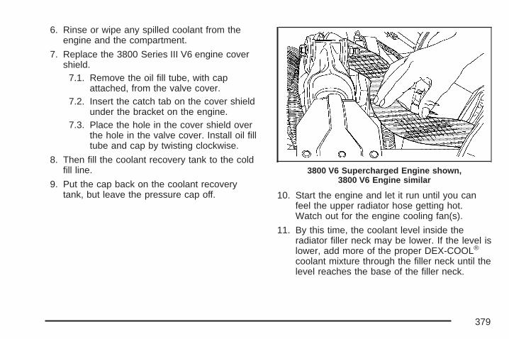
6. Rinse or wipe any spilled coolant from theengine and the compartment.
7. Replace the 3800 Series III V6 engine covershield.
7.1. Remove the oil fill tube, with capattached, from the valve cover.
7.2. Insert the catch tab on the cover shieldunder the bracket on the engine.
7.3. Place the hole in the cover shield overthe hole in the valve cover. Install oil filltube and cap by twisting clockwise.
8. Then fill the coolant recovery tank to the coldfill line.
9. Put the cap back on the coolant recoverytank, but leave the pressure cap off. 10. Start the engine and let it run until you can
feel the upper radiator hose getting hot.Watch out for the engine cooling fan(s).
11. By this time, the coolant level inside theradiator filler neck may be lower. If the level islower, add more of the proper DEX-COOL®
coolant mixture through the filler neck until thelevel reaches the base of the filler neck.
3800 V6 Supercharged Engine shown,3800 V6 Engine similar
379
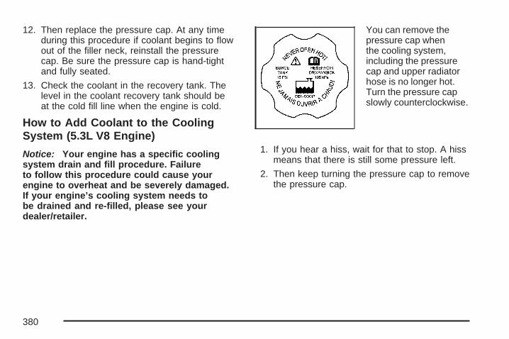
12. Then replace the pressure cap. At any timeduring this procedure if coolant begins to flowout of the filler neck, reinstall the pressurecap. Be sure the pressure cap is hand-tightand fully seated.
13. Check the coolant in the recovery tank. Thelevel in the coolant recovery tank should beat the cold fill line when the engine is cold.
How to Add Coolant to the CoolingSystem (5.3L V8 Engine)
Notice: Your engine has a specific coolingsystem drain and fill procedure. Failureto follow this procedure could cause yourengine to overheat and be severely damaged.If your engine’s cooling system needs tobe drained and re-filled, please see yourdealer/retailer.
You can remove thepressure cap whenthe cooling system,including the pressurecap and upper radiatorhose is no longer hot.Turn the pressure capslowly counterclockwise.
1. If you hear a hiss, wait for that to stop. A hissmeans that there is still some pressure left.
2. Then keep turning the pressure cap to removethe pressure cap.
380

{CAUTION:
You can be burned if you spill coolanton hot engine parts. Coolant containsethylene glycol and it will burn if theengine parts are hot enough. Do not spillcoolant on a hot engine.
3. Fill the cooling system with the properDEX-COOL® coolant mixture, up to the baseof the filler neck. See Engine Coolant onpage 366 for more information aboutthe proper coolant mixture.
4. Rinse or wipe any spilled coolant from theengine and the compartment.
5. Then fill the coolant recovery tank to the coldfill line.
6. Install the coolant recovery tank cap and thepressure cap.
7. If the coolant in the recovery tank is constantlylow, you should have a dealership servicedepartment inspect your vehicle for leaks.
Power Steering Fluid
See EngineCompartment Overviewon page 352 forreservoir location.
When to Check Power Steering FluidIt is not necessary to regularly check powersteering fluid unless a leak is suspected in thesystem, or an unusual noise is heard. A fluid lossin this system could indicate a problem. Havethe system inspected and repaired.
381

How to Check Power Steering FluidTo check the power steering fluid, do the following:
1. Turn the key off and let the enginecompartment cool down.
2. Wipe the cap and the top of the reservoirclean.
3. Unscrew the cap and wipe the dipstick with aclean rag.
4. Replace the cap and completely tighten it.
5. Remove the cap again and look at thefluid level on the dipstick
The fluid level should be between the ADD andHOT marks when the engine is cold.
When the engine compartment is hot, the levelshould be at the HOT mark.
If the fluid is at the ADD mark when the engineis cold or hot, power steering fluid should beadded.
What to UseTo determine what kind of fluid to use, seeRecommended Fluids and Lubricants on page 490.Always use the proper fluid. Failure to use theproper fluid can cause leaks and damage hosesand seals.
Windshield Washer Fluid
What to UseWhen you need windshield washer fluid, be sureto read the manufacturer’s instructions beforeuse. If you will be operating the vehicle in an areawhere the temperature may fall below freezing,use a fluid that has sufficient protection againstfreezing.
Adding Washer FluidWhen the windshield washer fluid reservoir is low,a LOW WASHER FLUID message along withthe washer symbol, comes on in the DriverInformation Center (DIC). See DIC Warnings andMessages on page 204 for more information.
382
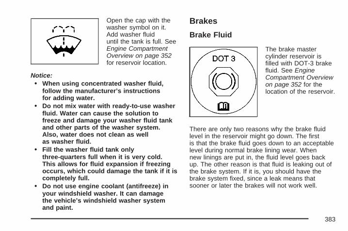
Open the cap with thewasher symbol on it.Add washer fluiduntil the tank is full. SeeEngine CompartmentOverview on page 352for reservoir location.
Notice:• When using concentrated washer fluid,
follow the manufacturer’s instructionsfor adding water.
• Do not mix water with ready-to-use washerfluid. Water can cause the solution tofreeze and damage your washer fluid tankand other parts of the washer system.Also, water does not clean as wellas washer fluid.
• Fill the washer fluid tank onlythree-quarters full when it is very cold.This allows for fluid expansion if freezingoccurs, which could damage the tank if it iscompletely full.
• Do not use engine coolant (antifreeze) inyour windshield washer. It can damagethe vehicle’s windshield washer systemand paint.
Brakes
Brake Fluid
The brake mastercylinder reservoir isfilled with DOT-3 brakefluid. See EngineCompartment Overviewon page 352 for thelocation of the reservoir.
There are only two reasons why the brake fluidlevel in the reservoir might go down. The firstis that the brake fluid goes down to an acceptablelevel during normal brake lining wear. Whennew linings are put in, the fluid level goes backup. The other reason is that fluid is leaking out ofthe brake system. If it is, you should have thebrake system fixed, since a leak means thatsooner or later the brakes will not work well.
383

So, it is not a good idea to top off the brake fluid.Adding brake fluid will not correct a leak. If you addfluid when the linings are worn, then you will havetoo much fluid when you get new brake linings.You should add or remove brake fluid, asnecessary, only when work is done on thebrake hydraulic system.
{CAUTION:
If your vehicle has too much brake fluid, itcan spill on the engine. The fluid will burnif the engine is hot enough. You or otherscould be burned, and your vehicle couldbe damaged. Add brake fluid only whenwork is done on the brake hydraulicsystem.
When the brake fluid falls to a low level, the brakewarning light comes on. See Brake SystemWarning Light on page 180.
What to AddWhen you need brake fluid, use only DOT-3 brakefluid. Use new brake fluid from a sealed containeronly. See Recommended Fluids and Lubricantson page 490.
Always clean the brake fluid reservoir cap and thearea around the cap before removing it. Thiswill help keep dirt from entering the reservoir.
{CAUTION:
With the wrong kind of fluid in the brakesystem, the brakes may not work well.This could cause a crash. Always use theproper brake fluid.
384
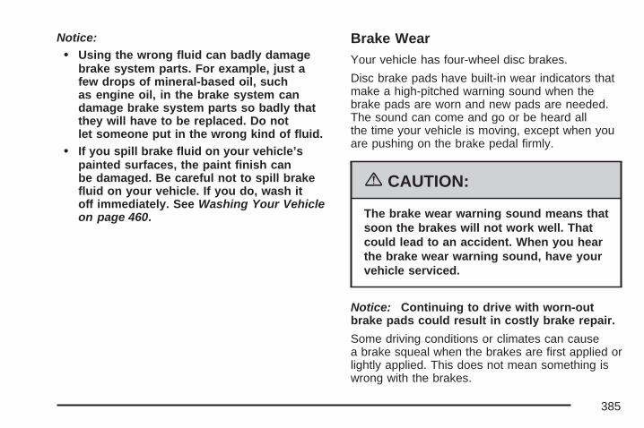
Notice:• Using the wrong fluid can badly damage
brake system parts. For example, just afew drops of mineral-based oil, suchas engine oil, in the brake system candamage brake system parts so badly thatthey will have to be replaced. Do notlet someone put in the wrong kind of fluid.
• If you spill brake fluid on your vehicle’spainted surfaces, the paint finish canbe damaged. Be careful not to spill brakefluid on your vehicle. If you do, wash itoff immediately. See Washing Your Vehicleon page 460.
Brake WearYour vehicle has four-wheel disc brakes.
Disc brake pads have built-in wear indicators thatmake a high-pitched warning sound when thebrake pads are worn and new pads are needed.The sound can come and go or be heard allthe time your vehicle is moving, except when youare pushing on the brake pedal firmly.
{CAUTION:
The brake wear warning sound means thatsoon the brakes will not work well. Thatcould lead to an accident. When you hearthe brake wear warning sound, have yourvehicle serviced.
Notice: Continuing to drive with worn-outbrake pads could result in costly brake repair.
Some driving conditions or climates can causea brake squeal when the brakes are first applied orlightly applied. This does not mean something iswrong with the brakes.
385

Properly torqued wheel nuts are necessary to helpprevent brake pulsation. When tires are rotated,inspect brake pads for wear and evenly tightenwheel nuts in the proper sequence to torquespecifications in Capacities and Specifications onpage 474.
Brake linings should always be replaced ascomplete axle sets.
Brake Pedal TravelSee your dealer/retailer if the brake pedal doesnot return to normal height, or if there is arapid increase in pedal travel. This could bea sign that brake service might be required.
Brake AdjustmentEvery time you apply the brakes, with or withoutthe vehicle moving, the brakes adjust for wear.
Replacing Brake System PartsThe braking system on a vehicle is complex.Its many parts have to be of top quality and workwell together if the vehicle is to have really goodbraking. Your vehicle was designed and tested withtop-quality brake parts. When you replace parts ofthe braking system — for example, when the brakelinings wear down and you need new ones putin — be sure you get new approved replacementparts. If you do not, the brakes might not workproperly. For example, if someone puts in brakelinings that are wrong for your vehicle, thebalance between the front and rear brakes canchange — for the worse. The braking performanceyou have come to expect can change in many otherways if someone puts in the wrong replacementbrake parts.
386

BatteryYour vehicle has a maintenance free battery.When it is time for a new battery, get one that hasthe replacement number shown on the originalbattery’s label. We recommend an ACDelco®
replacement battery. See Engine CompartmentOverview on page 352 for battery location.Warning: Battery posts, terminals, and relatedaccessories contain lead and lead compounds,chemicals known to the State of Californiato cause cancer and reproductive harm. Washhands after handling.
If the battery has a very low charge or is dead, youmay not be able to remove the ignition key from theignition switch or shift out of PARK (P). Refer toShifting Out of Park (P) on page 121.
Vehicle StorageIf you are not going to drive your vehicle for25 days or more, remove the black, negative (−)cable from the battery. This will help keep thebattery from running down.
{CAUTION:
Batteries have acid that can burn you andgas that can explode. You can be badlyhurt if you are not careful. See JumpStarting on page 388 for tips on workingaround a battery without getting hurt.
387

Jump StartingIf your vehicle’s battery has run down, you maywant to use another vehicle and some jumpercables to start your vehicle. Be sure to usethe following steps to do it safely.
{CAUTION:
Batteries can hurt you. They can bedangerous because:
• They contain acid that can burn you.• They contain gas that can explode or
ignite.• They contain enough electricity to
burn you.
If you do not follow these steps exactly,some or all of these things can hurt you.
Notice: Ignoring these steps could result incostly damage to your vehicle that wouldnot be covered by your warranty.
Trying to start your vehicle by pushing orpulling it will not work, and it could damageyour vehicle.
1. Check the other vehicle. It must have a12-volt battery with a negative ground system.
Notice: If the other vehicle’s system is not a12-volt system with a negative ground,both vehicles can be damaged. Only usevehicles with 12-volt systems with negativegrounds to jump start your vehicle.
2. Get the vehicles close enough so the jumpercables can reach, but be sure the vehicles arenot touching each other. If they are, it couldcause a ground connection you do notwant. You would not be able to start yourvehicle, and the bad grounding could damagethe electrical systems.To avoid the possibility of the vehicles rolling,set the parking brake firmly on both vehiclesinvolved in the jump start procedure. Putan automatic transaxle in PARK (P) ora manual transaxle in NEUTRAL beforesetting the parking brake.
388

Notice: If you leave your radio or otheraccessories on during the jump startingprocedure, they could be damaged. The repairswould not be covered by your warranty.Always turn off your radio and otheraccessories when jump starting your vehicle.
3. Turn off the ignition on both vehicles.Unplug unnecessary accessories plugged intothe cigarette lighter or the accessory poweroutlet. Turn off the radio and all lamps that arenot needed. This will avoid sparks and helpsave both batteries. And it could savethe radio!
4. Open the hood on the other vehicle andlocate the positive (+) and negative (−)terminal locations on that vehicle.You will not use your vehicle’s battery forjump starting. It has a remote positive (+) jumpstarting terminal, located on the underhoodfuse block, for that purpose.
If your vehicle has oneof the 3800 V6 engines,to uncover the remotepositive (+) terminal,press the tab atthe bottom of the fuseblock and lift thecover up.
3800 V6 and 3800 V6Supercharged Engines
389

If your vehicle has the5.3L V8 engine, touncover the remotepositive (+) terminal,remove the fuseblock cover.
Always use the remote positive (+) terminalinstead of the positive (+) terminal on thebattery. See Engine Compartment Overviewon page 352 for more information on location.
{CAUTION:
An electric fan can start up even when theengine is not running and can injure you.Keep hands, clothing and tools away fromany underhood electric fan.
{CAUTION:
Fans or other moving engine parts caninjure you badly. Keep your hands awayfrom moving parts once the engine isrunning.
5.3L V8 Engine
390
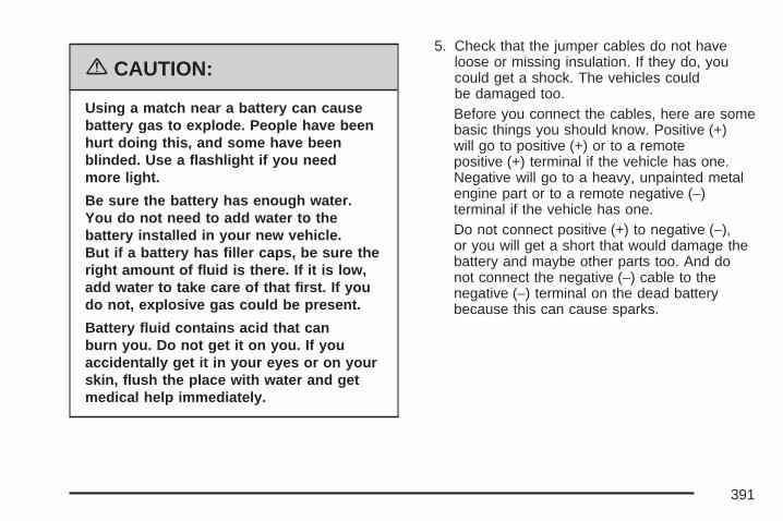
{CAUTION:
Using a match near a battery can causebattery gas to explode. People have beenhurt doing this, and some have beenblinded. Use a flashlight if you needmore light.
Be sure the battery has enough water.You do not need to add water to thebattery installed in your new vehicle.But if a battery has filler caps, be sure theright amount of fluid is there. If it is low,add water to take care of that first. If youdo not, explosive gas could be present.
Battery fluid contains acid that canburn you. Do not get it on you. If youaccidentally get it in your eyes or on yourskin, flush the place with water and getmedical help immediately.
5. Check that the jumper cables do not haveloose or missing insulation. If they do, youcould get a shock. The vehicles couldbe damaged too.Before you connect the cables, here are somebasic things you should know. Positive (+)will go to positive (+) or to a remotepositive (+) terminal if the vehicle has one.Negative will go to a heavy, unpainted metalengine part or to a remote negative (−)terminal if the vehicle has one.Do not connect positive (+) to negative (−),or you will get a short that would damage thebattery and maybe other parts too. And donot connect the negative (−) cable to thenegative (−) terminal on the dead batterybecause this can cause sparks.
391

6. Connect the red positive (+) cable to thepositive (+) terminal location on the vehiclewith the dead battery. Use a remotepositive (+) terminal if the vehicle has one.
7. Do not let the other end touch metal. Connect itto the positive (+) terminal location on thevehicle with the good battery. Use a remotepositive (+) terminal if the vehicle has one.
8. Now connect the black negative (−) cable tothe negative (−) terminal location on thevehicle with the good battery. Use a remotenegative (−) terminal if the vehicle has one.Do not let the other end touch anythinguntil the next step. The other end of thenegative (−) cable does not go to the deadbattery. It goes to a heavy, unpaintedmetal engine part or to a remote negative (–)terminal on the vehicle with the deadbattery.
9. Connect the other end of the negative (−) cableat least 18 inches (45 cm) away from the deadbattery, but not near engine parts that move.The electrical connection is just as good there,and the chance of sparks getting back to thebattery is much less.
10. Now start the vehicle with the good batteryand run the engine for a while.
11. Try to start the vehicle that had the deadbattery. If it will not start after a few tries, itprobably needs service.
392
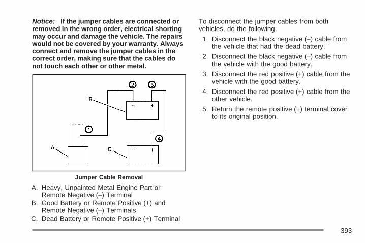
Notice: If the jumper cables are connected orremoved in the wrong order, electrical shortingmay occur and damage the vehicle. The repairswould not be covered by your warranty. Alwaysconnect and remove the jumper cables in thecorrect order, making sure that the cables donot touch each other or other metal.
A. Heavy, Unpainted Metal Engine Part orRemote Negative (−) Terminal
B. Good Battery or Remote Positive (+) andRemote Negative (−) Terminals
C. Dead Battery or Remote Positive (+) Terminal
To disconnect the jumper cables from bothvehicles, do the following:
1. Disconnect the black negative (−) cable fromthe vehicle that had the dead battery.
2. Disconnect the black negative (−) cable fromthe vehicle with the good battery.
3. Disconnect the red positive (+) cable from thevehicle with the good battery.
4. Disconnect the red positive (+) cable from theother vehicle.
5. Return the remote positive (+) terminal coverto its original position.
Jumper Cable Removal
393
Headlamp AimingThe visual optical headlamp aiming system hasbeen preset at the factory and should needno further adjustment.
However, If the vehicle is damaged in an accident,the headlamp aim may be affected and adjustmentmay be necessary.
If oncoming vehicles flash their high beams atyou, this may also mean the vertical aim needs tobe adjusted.
It is recommended that the vehicle is taken toyour dealer/retailer for service if the headlampsneed to be re-aimed. It is possible however,to re-aim the headlamps as described in thefollowing procedure.
The vehicle should be properly prepared asfollows:
• The vehicle should be placed so theheadlamps are 25 ft. (7.6 m) from a lightcolored wall.
• The vehicle must have all four tires on aperfectly level surface which is level allthe way to the wall.
• The vehicle should be placed so it isperpendicular to the wall.
• The vehicle should not have any snow, ice, ormud on it.
• The vehicle should be fully assembled and allother work stopped while headlamp aiming isbeing done.
• The vehicle should be normally loaded with afull tank of fuel and one person or 160 lbs(75 kg) sitting on the driver’s seat.
• Tires should be properly inflated.
Headlamp aiming is done with the low-beamheadlamps. The high-beam headlamps will becorrectly aimed if the low-beam headlampsare aimed properly.
394

To adjust the vertical aim, do the following:
1. Open the hood. See Hood Release onpage 351 for more information.Find the aim dot on the lens of thelow-beam lamp.
2. Locate the aim dot on the lens of thelow-beam headlamp.
3. Measure the distance from the ground to theaim dot on the lamp. Record the distance.
4. At the wall measure from the groundupward (A) to the recorded distancefrom Step 3 and mark it.
5. Draw or tape a horizontal line (B) on the wallthe width of the vehicle at the height of themark in Step 4.
6. Turn on the low-beam headlamps and place apiece of cardboard or equivalent in front of theheadlamp not being aimed. This shouldallow only the beam of light from the headlampbeing aimed to be seen on the flat surface.
Notice: Do not cover a headlamp to improvebeam cut-off when aiming. Covering aheadlamp may cause excessive heat build-upwhich may cause damage to the headlamp.
395
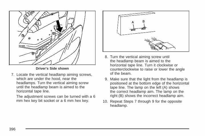
7. Locate the vertical headlamp aiming screws,which are under the hood, near theheadlamps. Turn the vertical aiming screwuntil the headlamp beam is aimed to thehorizontal tape line.The adjustment screws can be turned with a 6mm hex key bit socket or a 6 mm hex key.
8. Turn the vertical aiming screw untilthe headlamp beam is aimed to thehorizontal tape line. Turn it clockwise orcounterclockwise to raise or lower the angleof the beam.
9. Make sure that the light from the headlamp ispositioned at the bottom edge of the horizontaltape line. The lamp on the left (A) showsthe correct headlamp aim. The lamp on theright (B) shows the incorrect headlamp aim.
10. Repeat Steps 7 through 9 for the oppositeheadlamp.
Driver’s Side shown
396

Bulb ReplacementFor the proper type of replacement bulbs, seeReplacement Bulbs on page 404.
For any bulb changing procedure not listed in thissection, contact your dealer.
Halogen Bulbs
{CAUTION:
Halogen bulbs have pressurized gasinside and can burst if you drop orscratch the bulb. You or others could beinjured. Be sure to read and follow theinstructions on the bulb package.
Headlamps and Sidemarker LampsTo replace a headlamp or sidemarker bulb:
A. High-Beam HeadlampB. Low-Beam HeadlampC. Sidemarker Lamp
1. Open the hood. See Hood Release onpage 351 for more information.
397

2. Locate the metal retaining clip. Removethe bolt.
3. Pull up half-way on the metal retaining clipwhile pushing rearward on the headlamp.Align the square cut-out on the retaining clipwith the notch on the headlamp.
4. Pull the headlamp assembly straight out fromthe vehicle. Moving the headlamp up anddown slightly may help with its removal.
398

A. High-Beam HeadlampB. Low-Beam HeadlampC. Sidemarker Lamp
5. Turn the bulb socket ring one-quarter of a turncounterclockwise to remove it from theheadlamp assembly.
6. Pull the old bulb from the socket.
7. Place the new bulb into the socket.
8. Turn the bulb socket ring one-quarter turnclockwise to reinstall it back into theheadlamp assembly.
9. Carefully reinstall the headlamp assembly.
10. Push down on the metal retaining clipwhile pushing rearward on the headlamp,making sure the headlamp assembly issecure.
11. Reinstall the bolt and tighten to secure.
399
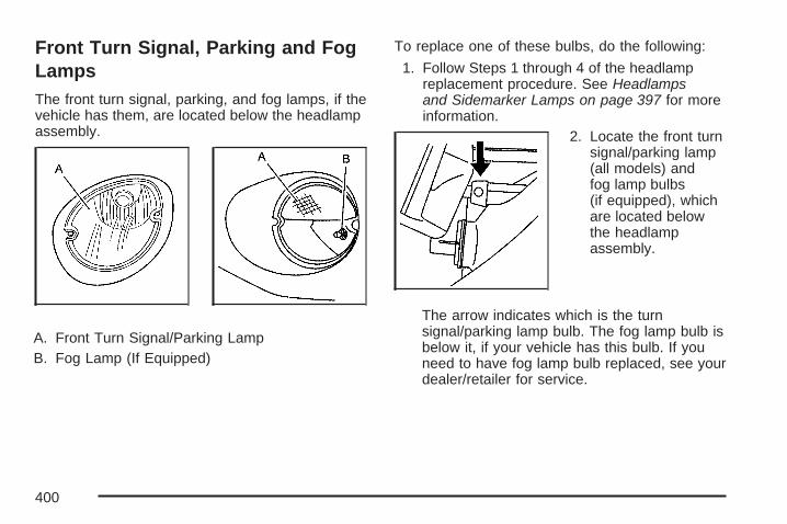
Front Turn Signal, Parking and FogLampsThe front turn signal, parking, and fog lamps, if thevehicle has them, are located below the headlampassembly.
A. Front Turn Signal/Parking LampB. Fog Lamp (If Equipped)
To replace one of these bulbs, do the following:
1. Follow Steps 1 through 4 of the headlampreplacement procedure. See Headlampsand Sidemarker Lamps on page 397 for moreinformation.
2. Locate the front turnsignal/parking lamp(all models) andfog lamp bulbs(if equipped), whichare located belowthe headlampassembly.
The arrow indicates which is the turnsignal/parking lamp bulb. The fog lamp bulb isbelow it, if your vehicle has this bulb. If youneed to have fog lamp bulb replaced, see yourdealer/retailer for service.
400

3. Turn the bulb socket one-quarter of a turncounterclockwise to remove it from itsassembly.
4. Pull the old bulb from the socket and replaceit with a new one.
5. Turn the bulb socket a quarter turn clockwiseto reinstall it.
6. Reinstall the headlamp assembly.
7. Push down on the metal retaining clip whilepushing rearward on the headlamp, makingsure the headlamp assembly is secure.
8. Reinstall the bolt and tighten to secure.
Taillamps, Turn Signal, andStoplamps
A. TaillampB. Taillamps, Turn
Signal and Stoplamps
1. Open the trunk. See Trunk on page 97 formore information.
2. Remove the convenience net, if equipped, byremoving the net hook attachments.
3. Remove the plastic cap from the trunk trim.
4. Pull the trunk trim and carpet away fromthe back of the trunk.
5. Remove the bottom bolt and two nuts.
401

6. Remove the taillampassembly by pullingit out from thevehicle.
7. Turn the appropriatelamp socket aquarter turncounterclockwiseand remove it.
8. Remove the old bulb.
9. Replace with a new bulb into the socket andturn the lamp socket clockwise to install it.
10. Reinstall the taillamp assembly by reversingSteps 2 through 5.
402
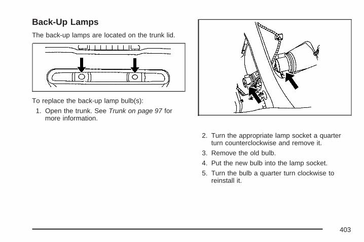
Back-Up LampsThe back-up lamps are located on the trunk lid.
To replace the back-up lamp bulb(s):
1. Open the trunk. See Trunk on page 97 formore information.
2. Turn the appropriate lamp socket a quarterturn counterclockwise and remove it.
3. Remove the old bulb.
4. Put the new bulb into the lamp socket.
5. Turn the bulb a quarter turn clockwise toreinstall it.
403
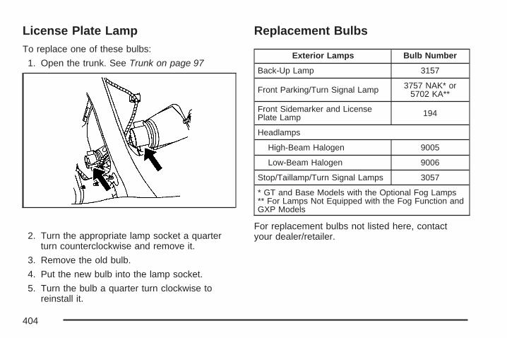
License Plate LampTo replace one of these bulbs:
1. Open the trunk. See Trunk on page 97
2. Turn the appropriate lamp socket a quarterturn counterclockwise and remove it.
3. Remove the old bulb.
4. Put the new bulb into the lamp socket.
5. Turn the bulb a quarter turn clockwise toreinstall it.
Replacement Bulbs
Exterior Lamps Bulb Number
Back-Up Lamp 3157
Front Parking/Turn Signal Lamp 3757 NAK* or5702 KA**
Front Sidemarker and LicensePlate Lamp 194
Headlamps
High-Beam Halogen 9005
Low-Beam Halogen 9006
Stop/Taillamp/Turn Signal Lamps 3057
* GT and Base Models with the Optional Fog Lamps** For Lamps Not Equipped with the Fog Function andGXP Models
For replacement bulbs not listed here, contactyour dealer/retailer.
404

Windshield ReplacementIf your vehicle is equipped with the Head-UpDisplay (HUD) system, keep in mind that yourwindshield is part of the HUD system. If you everhave to get your windshield replaced, be sureto get one that is designed for HUD or your HUDimage may look blurred or out of focus.
Windshield Wiper BladeReplacementWindshield wiper blades should be inspected forwear or cracking. See Scheduled Maintenanceon page 480 for more information on wiper bladeinspection.
Replacement blades come in different types andare removed in different ways. For the proper typeand length, see Normal Maintenance ReplacementParts on page 491. Here is how to remove thewiper blade:
1. Pull the windshield wiper arm connector awayfrom the windshield.
2. While holding the wiper arm, pull the clip upfrom the blade connecting point, and pull theblade assembly down toward the windshieldto remove it from the wiper arm.
3. Install the new wiper blade onto the wiper armand snap the clip into place.
405

TiresYour new vehicle comes with high-quality tiresmade by a leading tire manufacturer. If you everhave questions about your tire warranty and whereto obtain service, see your GM Warranty booklet fordetails. For additional information refer to the tiremanufacturer’s booklet included with your vehicle.
{CAUTION:
Poorly maintained and improperly usedtires are dangerous.
• Overloading your vehicle’s tires cancause overheating as a result of toomuch friction. You could have anair-out and a serious accident. SeeLoading Your Vehicle on page 322.
CAUTION: (Continued)
CAUTION: (Continued)
• Underinflated tires pose the samedanger as overloaded tires. Theresulting accident could cause seriousinjury. Check all tires frequently tomaintain the recommended pressure.Tire pressure should be checked whenyour vehicle’s tires are cold. SeeInflation - Tire Pressure on page 414.
• Overinflated tires are more likely to becut, punctured, or broken by a suddenimpact — such as when you hit apothole. Keep tires at therecommended pressure.
• Worn, old tires can cause accidents.If the tire’s tread is badly worn, or ifyour vehicle’s tires have beendamaged, replace them.
406

Low-Profile Performance Tire (GXP)If your vehicle has P255/45R18 size tires on thefront wheels and P225/50R18 size tires on therear wheels, they are classified as low-profileperformance tires. These tires are designed for veryresponsive driving on wet or dry pavement. Youmay also notice more road noise with low-profileperformance tires and that they tend to wear faster.
Notice: If your vehicle has low-profile tires,they are more susceptible to damage from roadhazards or curb impact than standard profiletires. Tire and/or wheel assembly damagecan occur when coming into contact withroad hazards like, potholes, or sharp edgedobjects, or when sliding into a curb. Your GMwarranty does not cover this type of damage.Keep tires set to the correct inflation pressureand, when possible avoid contact withcurbs, potholes, and other road hazards.
Tire Sidewall LabelingUseful information about a tire is molded into itssidewall. The examples below show a typicalpassenger vehicle tire and a compact spare tiresidewall.
(A) Tire Size: The tire size is a combination ofletters and numbers used to define a particulartire’s width, height, aspect ratio, construction type,and service description. See the “Tire Size”illustration later in this section for more detail.
Passenger (P-Metric) Tire Example
407

(B) TPC Spec (Tire Performance CriteriaSpecification): Original equipment tires designedto GM’s specific tire performance criteria havea TPC specification code molded onto the sidewall.GM’s TPC specifications meet or exceed allfederal safety guidelines.
(C) DOT (Department of Transportation):The Department of Transportation (DOT) codeindicates that the tire is in compliance with the U.S.Department of Transportation Motor VehicleSafety Standards.
(D) Tire Identification Number (TIN): The lettersand numbers following DOT (Department ofTransportation) code is the Tire IdentificationNumber (TIN). The TIN shows the manufacturerand plant code, tire size, and date the tirewas manufactured. The TIN is molded onto bothsides of the tire, although only one side may havethe date of manufacture.
(E) Tire Ply Material: The type of cord andnumber of plies in the sidewall and under thetread.
(F) Uniform Tire Quality Grading (UTQG):Tire manufacturers are required to gradetires based on three performance factors:treadwear, traction, and temperature resistance.For more information see Uniform Tire QualityGrading on page 425.
(G) Maximum Cold Inflation Load Limit:Maximum load that can be carried and themaximum pressure needed to support that load.
408

(A) Temporary Use Only: The compact sparetire or temporary use tire has a tread life ofapproximately 3,000 miles (5 000 km) and shouldnot be driven at speeds over 65 mph (105 km/h).The compact spare tire is for emergency use whena regular road tire has lost air and gone flat.If your vehicle has a compact spare tire,see Compact Spare Tire on page 454 andIf a Tire Goes Flat on page 429.
(B) Tire Ply Material: The type of cord andnumber of plies in the sidewall and under thetread.
(C) Tire Identification Number (TIN): The lettersand numbers following the DOT (Department ofTransportation) code is the Tire IdentificationNumber (TIN). The TIN shows the manufacturerand plant code, tire size, and date the tirewas manufactured. The TIN is molded onto bothsides of the tire, although only one side may havethe date of manufacture.
(D) Maximum Cold Inflation Load Limit:Maximum load that can be carried and themaximum pressure needed to support that load.
(E) Tire Inflation: The temporary use tire orcompact spare tire should be inflated to 60 psi(420 kPa). For more information on tire pressureand inflation see Inflation - Tire Pressure onpage 414.
(F) Tire Size: A combination of letters andnumbers define a tire’s width, height, aspect ratio,construction type, and service description. Theletter T as the first character in the tire size meansthe tire is for temporary use only.
Compact Spare Tire Example
409

(G) TPC Spec (Tire Performance CriteriaSpecification): Original equipment tires designedto GM’s specific tire performance criteria havea TPC specification code molded onto the sidewall.GM’s TPC specifications meet or exceed allfederal safety guidelines.
Tire SizeThe following illustration shows an example of atypical passenger vehicle tire size.
(A) Passenger (P-Metric) Tire: The United Statesversion of a metric tire sizing system. The letter Pas the first character in the tire size means apassenger vehicle tire engineered to standards setby the U.S. Tire and Rim Association.
(B) Tire Width: The three-digit number indicatesthe tire section width in millimeters from sidewallto sidewall.
(C) Aspect Ratio: A two-digit number thatindicates the tire height-to-width measurements.For example, if the tire size aspect ratio is60, as shown in item C of the illustration, it wouldmean that the tire’s sidewall is 60 percent ashigh as it is wide.
(D) Construction Code: A letter code is used toindicate the type of ply construction in the tire.The letter R means radial ply construction;the letter D means diagonal or bias plyconstruction; and the letter B means belted-biasply construction.
(E) Rim Diameter: Diameter of the wheel ininches.
(F) Service Description: These charactersrepresent the load range and speed rating of thetire. The load index represents the load carrycapacity a tire is certified to carry. The load indexcan range from 1 to 279. The speed rating isthe maximum speed a tire is certified to carrya load. Speed ratings range from A to Z.
410

Tire Terminology and Definitions
Air Pressure: The amount of air inside the tirepressing outward on each square inch of thetire. Air pressure is expressed in poundsper square inch (psi) or kilopascal (kPa).
Accessory Weight: This means the combinedweight of optional accessories. Some examples ofoptional accessories are, automatic transmission,power steering, power brakes, power windows,power seats, and air conditioning.
Aspect Ratio: The relationship of a tire’s heightto its width.
Belt: A rubber coated layer of cords that islocated between the plies and the tread. Cordsmay be made from steel or other reinforcingmaterials.
Bead: The tire bead contains steel wires wrappedby steel cords that hold the tire onto the rim.
Bias Ply Tire: A pneumatic tire in which the pliesare laid at alternate angles less than 90 degreesto the centerline of the tread.
Cold Tire Pressure: The amount of air pressurein a tire, measured in pounds per square inch(psi) or kilopascals (kPa) before a tire has built upheat from driving. See Inflation - Tire Pressureon page 414.
Curb Weight: This means the weight of a motorvehicle with standard and optional equipmentincluding the maximum capacity of fuel, oil, andcoolant, but without passengers and cargo.
DOT Markings: A code molded into the sidewallof a tire signifying that the tire is in compliancewith the U.S. Department of Transportation (DOT)motor vehicle safety standards. The DOT codeincludes the Tire Identification Number (TIN),an alphanumeric designator which can also identifythe tire manufacturer, production plant, brand,and date of production.
GVWR: Gross Vehicle Weight Rating. SeeLoading Your Vehicle on page 322.
GAWR FRT: Gross Axle Weight Rating for thefront axle. See Loading Your Vehicle on page 322.
411

GAWR RR: Gross Axle Weight Rating for the rearaxle. See Loading Your Vehicle on page 322.
Intended Outboard Sidewall: The side ofan asymmetrical tire, that must always faceoutward when mounted on a vehicle.
Kilopascal (kPa): The metric unit for air pressure.
Light Truck (LT-Metric) Tire: A tire used onlight duty trucks and some multipurpose passengervehicles.
Load Index: An assigned number ranging from 1to 279 that corresponds to the load carryingcapacity of a tire.
Maximum Inflation Pressure: The maximum airpressure to which a cold tire may be inflated.The maximum air pressure is molded ontothe sidewall.
Maximum Load Rating: The load rating for a tireat the maximum permissible inflation pressurefor that tire.
Maximum Loaded Vehicle Weight: The sum ofcurb weight, accessory weight, vehicle capacityweight, and production options weight.
Normal Occupant Weight: The number ofoccupants a vehicle is designed to seat multipliedby 150 lbs (68 kg). See Loading Your Vehicleon page 322.
Occupant Distribution: Designated seatingpositions.
Outward Facing Sidewall: The side of anasymmetrical tire that has a particular side thatfaces outward when mounted on a vehicle.The side of the tire that contains a whitewall,bears white lettering, or bears manufacturer,brand, and/or model name molding that is higheror deeper than the same moldings on the othersidewall of the tire.
Passenger (P-Metric) Tire: A tire used onpassenger cars and some light duty trucks andmultipurpose vehicles.
Recommended Inflation Pressure: Vehiclemanufacturer’s recommended tire inflationpressure as shown on the tire placard. SeeInflation - Tire Pressure on page 414 and LoadingYour Vehicle on page 322.
412
Radial Ply Tire: A pneumatic tire in which theply cords that extend to the beads are laid at90 degrees to the centerline of the tread.
Rim: A metal support for a tire and upon whichthe tire beads are seated.
Sidewall: The portion of a tire between the treadand the bead.
Speed Rating: An alphanumeric code assignedto a tire indicating the maximum speed atwhich a tire can operate.
Traction: The friction between the tire and theroad surface. The amount of grip provided.
Tread: The portion of a tire that comes intocontact with the road.
Treadwear Indicators: Narrow bands, sometimescalled wear bars, that show across the tread ofa tire when only 1/16 inch (1.6 mm) of treadremains. See When It Is Time for New Tires onpage 422.
UTQGS (Uniform Tire Quality GradingStandards): A tire information system thatprovides consumers with ratings for a tire’straction, temperature, and treadwear. Ratingsare determined by tire manufacturers usinggovernment testing procedures. The ratings aremolded into the sidewall of the tire. See UniformTire Quality Grading on page 425.
Vehicle Capacity Weight: The number ofdesignated seating positions multiplied by 150 lbs(68 kg) plus the rated cargo load. See LoadingYour Vehicle on page 322.
Vehicle Maximum Load on the Tire: Load onan individual tire due to curb weight, accessoryweight, occupant weight, and cargo weight.
Vehicle Placard: A label permanently attachedto a vehicle showing the vehicle’s capacityweight and the original equipment tire size andrecommended inflation pressure. See “Tireand Loading Information Label” under LoadingYour Vehicle on page 322.
413

Inflation - Tire PressureTires need the correct amount of air pressure tooperate effectively.
Notice: Do not let anyone tell you thatunder-inflation or over-inflation is all right.It is not. If your tires do not have enough air(under-inflation), you can get the following:• Too much flexing
• Too much heat
• Tire overloading
• Premature or irregular wear
• Poor handling
• Reduced fuel economy
If your tires have too much air (over-inflation),you can get the following:• Unusual wear
• Poor handling
• Rough ride
• Needless damage from road hazards
A vehicle specific Tire and Loading Informationlabel is attached to your vehicle. This label showsyour vehicle’s original equipment tires and thecorrect inflation pressures for your tires when theyare cold. The recommended cold tire inflationpressure, shown on the label, is the minimumamount of air pressure needed to supportyour vehicle’s maximum load carrying capacity.
For additional information regarding how muchweight your vehicle can carry, and an exampleof the Tire and Loading Information label,see Loading Your Vehicle on page 322. How youload your vehicle affects vehicle handling andride comfort. Never load your vehicle with moreweight than it was designed to carry.
When to CheckCheck your tires once a month or more. Do notforget to check the compact spare tire, it should beat 60 psi (420 kPa). For additional informationregarding the compact spare tire, see CompactSpare Tire on page 454.
414
How to CheckUse a good quality pocket-type gage to checktire pressure. You cannot tell if your tires areproperly inflated simply by looking at them. Radialtires may look properly inflated even when they areunder-inflated. Check the tire’s inflation pressurewhen the tires are cold. Cold means your vehiclehas been sitting for at least three hours or driven nomore than 1 mile (1.6 km).
Remove the valve cap from the tire valve stem.Press the tire gage firmly onto the valve toget a pressure measurement. If the cold tireinflation pressure matches the recommendedpressure on the Tire and Loading Informationlabel, no further adjustment is necessary. If theinflation pressure is low, add air until you reach therecommended amount.
If you overfill the tire, release air by pushing onthe metal stem in the center of the tire valve.Re-check the tire pressure with the tire gage.
Be sure to put the valve caps back on the valvestems. They help prevent leaks by keeping out dirtand moisture.
Tire Pressure Monitor SystemThe Tire Pressure Monitor System (TPMS) usesradio and sensor technology to check tire pressurelevels. If your vehicle has this feature, sensorsare mounted onto each tire and wheel assembly,except for the spare tire. The TPMS sensorsmonitor the air pressure in your vehicle’s tiresand transmit tire pressure readings to a receiverlocated in the vehicle.
When a low tire pressure condition is detected, theTPMS will illuminate the low tire pressure warningsymbol on the instrument panel cluster, and atthe same time a warning message to check thepressure in a specific tire displays on the DriverInformation Center (DIC). The low tire pressurewarning light and the DIC warning messageCHECK TIRE PRESSURE come on at each ignitioncycle until the tires are inflated to the correctinflation pressure. For additional information anddetails about the DIC operation and displays seeDIC Controls and Displays (Base Level DIC) onpage 190 or DIC Controls and Displays (UplevelDIC with Trip Computer) on page 194 and DICWarnings and Messages on page 204.
415
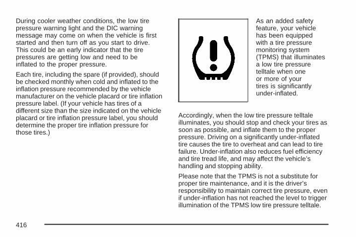
During cooler weather conditions, the low tirepressure warning light and the DIC warningmessage may come on when the vehicle is firststarted and then turn off as you start to drive.This could be an early indicator that the tirepressures are getting low and need to beinflated to the proper pressure.
Each tire, including the spare (if provided), shouldbe checked monthly when cold and inflated to theinflation pressure recommended by the vehiclemanufacturer on the vehicle placard or tire inflationpressure label. (If your vehicle has tires of adifferent size than the size indicated on the vehicleplacard or tire inflation pressure label, you shoulddetermine the proper tire inflation pressure forthose tires.)
As an added safetyfeature, your vehiclehas been equippedwith a tire pressuremonitoring system(TPMS) that illuminatesa low tire pressuretelltale when oneor more of yourtires is significantlyunder-inflated.
Accordingly, when the low tire pressure telltaleilluminates, you should stop and check your tires assoon as possible, and inflate them to the properpressure. Driving on a significantly under-inflatedtire causes the tire to overheat and can lead to tirefailure. Under-inflation also reduces fuel efficiencyand tire tread life, and may affect the vehicle’shandling and stopping ability.
Please note that the TPMS is not a substitute forproper tire maintenance, and it is the driver’sresponsibility to maintain correct tire pressure, evenif under-inflation has not reached the level to triggerillumination of the TPMS low tire pressure telltale.
416
Your vehicle has also been equipped with a TPMSmalfunction indicator to indicate when the systemis not operating properly. The TPMS malfunctionindicator is combined with the low tire pressuretelltale. When the system detects a malfunction,the telltale will flash for approximately one minuteand then remain continuously illuminated. Thissequence will continue upon subsequent vehiclestart-ups as long as the malfunction exists.
When the malfunction indicator is illuminated, thesystem may not be able to detect or signal lowtire pressure as intended. TPMS malfunctionsmay occur for a variety of reasons, including theinstallation of replacement or alternate tires orwheels on the vehicle that prevent the TPMS fromfunctioning properly. Always check the TPMSmalfunction telltale after replacing one or moretires or wheels on your vehicle to ensure that thereplacement or alternate tires and wheels allowthe TPMS to continue to function properly.
A Tire and Loading Information label, attached toyour vehicle, shows the size of your vehicle’soriginal equipment tires and the correct inflationpressure for your vehicle’s tires when they
are cold. See Loading Your Vehicle on page 322,for an example of the Tire and LoadingInformation label and its location on your vehicle.Also see Inflation - Tire Pressure on page 414.
Your vehicle’s TPMS system can warn you about alow tire pressure condition but it does not replacenormal tire maintenance. See Tire Inspection andRotation on page 420 and Tires on page 406.
Notice: Do not use a tire sealant if yourvehicle has Tire Pressure Monitors. The liquidsealant can damage the tire pressure monitorsensors.
The TPMS will not function properly if one or moreof the TPMS sensors are missing or inoperable. Ifthe system detects a missing or inoperable sensor,an error message SERVICE TIRE MONITORSYSTEM appears on the DIC display. If you havereplaced a tire/wheel assembly without transferringthe TPMS sensors, the error message displays.Once you re-install the TPMS sensors, the errormessage should go off. See your dealer for serviceif all TPMS sensors are installed and the errormessage comes on and stays on.
417
TPMS Sensor Identification CodesEach TPMS sensor has a unique identificationcode. Any time you replace one or more ofthe TPMS sensors or rotate the vehicle’s tires, theidentification codes need to be matched to thenew tire/wheel position. The sensors are matched,to the tire/wheel positions, in the following order:driver side front tire, passenger side front tire,passenger side rear tire, and driver side rear tireusing a TPMS diagnostic tool. See your dealerfor service.
The TPMS sensors may also be matched to eachtire/wheel position by increasing or decreasingthe tire’s air pressure. When increasing the tire’spressure, do not exceed the maximum inflationpressure indicated on the tire’s sidewall.
You have two minutes to match each tire and wheelposition. If it takes longer than two minutes to matchany tire and wheel position, the matching processstops and you need to start over.
The TPMS matching process is outlined below:
1. Set the parking brake.
2. Turn the ignition switch to RUN with theengine off.
3. Press the Remote Keyless Entry (RKE)transmitter’s Lock and Unlock buttons atthe same time for approximately five seconds.The horn sounds twice to signal the receiveris in relearn mode and the TPMS sensormatching process can begin.
4. Start with the driver’s side front tire.
5. Remove the valve cap from the tire’s valvestem. Activate the TPMS sensor by increasingor decreasing the tire’s air pressure for tenseconds, or until a horn chirp sounds. Thehorn chirp, which may take up to 30 seconds tosound, confirms that the sensor identificationcode has been matched to the tire/wheelposition. To decrease the tire’s air-pressureuse the pointed end of the valve cap, apencil-style air pressure gage, or a key.
418
6. Proceed to the passenger side front tire, andrepeat the procedure in Step 5.
7. Proceed to the passenger side rear tire, andrepeat the procedure in Step 5.
8. Proceed to the driver side rear tire, andrepeat the procedure in Step 5.
9. After hearing the confirming horn chirp for thedriver side rear tire, the horn chirps two moretimes to signal the tire learning processhas ended. Turn the ignition switch to OFF.
10. Set all four tires to the recommended airpressure level as indicated on the tire andloading information label.
11. Put the valve caps back on the valve stems.
The spare tire does not have a TPMS sensor. If youreplace one of the road tires with the spare, theSERVICE TIRE MONITOR SYSTEM message willbe displayed on the DIC. This message should gooff once you re-install the road tire containing theTPMS sensor.
Federal Communications Commission(FCC) and Industry and ScienceCanadaThe Tire Pressure Monitor System (TPMS)operates on a radio frequency and complies withPart 15 of the FCC Rules. Operation is subjectto the following two conditions:
1. This device may not cause harmfulinterference.
2. This device must accept any interferencereceived, including interference that maycause undesired operation.
419
The Tire Pressure Monitor System (TPMS)operates on a radio frequency and complies withRSS-210 of Industry and Science Canada.Operation is subject to the following twoconditions:
1. This device may not cause interference.
2. This device must accept any interferencereceived, including interference that maycause undesired operation of the device.
Changes or modifications to this system by otherthan an authorized service facility could voidauthorization to use this equipment.
Tire Inspection and RotationTire rotation is not recommended if your vehicle isa GXP model equipped with P255/45R18 sizetires on the front wheels and P225/50R18 size tireson the rear wheels. Different tire sizes front torear should not be rotated.
Tire rotation is recommended if the originalequipment tires installed on your vehicle are of thesame size and type on all four tire/wheel positions.Original equipment tires of the same size and typeshould be rotated every 5,000 to 8,000 miles(8 000 to 13 000 km).
Any time you notice unusual wear, rotate yourvehicle’s tires as soon as possible and check thewheel alignment. Also check for damaged tiresor wheels. See When It Is Time for New Tires onpage 422 and Wheel Replacement on page 426for more information.
The purpose of regular rotation is to achieve moreuniform wear for all tires on the vehicle. Thefirst rotation is the most important. See ScheduledMaintenance on page 480 for scheduled rotationintervals.
420

The correct rotation pattern shown here is only fornon-GXP tires.
Do not include the compact spare tire, if equipped,in your vehicle’s tire rotation.
After the tires have been rotated, adjust the frontand rear inflation pressures as shown on theTire and Loading Information label, and resetthe Tire Pressure Monitor System. See TirePressure Monitor System on page 415 foradditional information.
Make certain that all wheel nuts are properlytightened. See “Wheel Nut Torque” underCapacities and Specifications on page 474.
{CAUTION:
Rust or dirt on a wheel, or on the parts towhich it is fastened, can make wheel nutsbecome loose after time. The wheel couldcome off and cause an accident. Whenyou change a wheel, remove any rust ordirt from places where the wheel attachesto the vehicle. In an emergency, you canuse a cloth or a paper towel to do this;but be sure to use a scraper or wire brushlater, if needed, to get all the rust or dirtoff. See Changing a Flat Tire on page 442.
Rotation Pattern for Non-GXP Tires Only
421

When It Is Time for New Tires
One way to tell when itis time for new tires isto check the treadwearindicators, which willappear when your tireshave only 1/16 inch(1.6 mm) or less of treadremaining.
You need a new tire if any of the followingstatements are true:
• You can see the indicators at three or moreplaces around the tire.
• You can see cord or fabric showing throughthe tire’s rubber.
• The tread or sidewall is cracked, cut, orsnagged deep enough to show cord or fabric.
• The tire has a bump, bulge, or split.• The tire has a puncture, cut, or other damage
that cannot be repaired well because of thesize or location of the damage.
Buying New TiresGM has developed and matched specific tiresfor your vehicle. The original equipment tiresinstalled on your vehicle, when it was new,were designed to meet General Motors TirePerformance Criteria Specification (TPC spec)system rating. If you need replacement tires, GMstrongly recommends that you get tires withthe same TPC Spec rating. This way, your vehiclewill continue to have tires that are designed togive the same performance and vehicle safety,during normal use, as the original tires.
GM’s exclusive TPC Spec system considers overa dozen critical specifications that impact theoverall performance of your vehicle, includingbrake system performance, ride and handling,traction control, and tire pressure monitoringperformance. GM’s TPC Spec number is moldedonto the tire’s sidewall by the tire manufacturer.If the tires have an all-season tread design,the TPC spec number will be followed by an MSfor mud and snow. See Tire Sidewall Labelingon page 407 for additional information.
422

{CAUTION:
Mixing tires could cause you to losecontrol while driving. If you mix tires ofdifferent sizes (other than those originallyinstalled on your vehicle), brands, ortypes (radial and bias-belted tires), thevehicle may not handle properly, andyou could have a crash. Using tires ofdifferent sizes (other than those originallyinstalled on your vehicle) may also causedamage to your vehicle. Be sure to usethe correct size, brand, and type tires onall wheels. If your vehicle has a compactspare tire, it is all right to drive yourvehicle with the compact sparetemporarily. It was developed for use onyour vehicle. See Compact Spare Tire onpage 454.
{CAUTION:
If you use bias-ply tires on your vehicle,the wheel rim flanges could developcracks after many miles of driving. A tireand/or wheel could fail suddenly, causinga crash. Use only radial-ply tires with thewheels on your vehicle.
If you must replace your vehicle’s tires with thosethat do not have a TPC Spec number, makesure they are the same size, load range,speed rating, and construction type (radial andbias-belted tires) as your vehicle’s original tires.
Your vehicle’s original equipment tires are listedon the Tire and Loading Information label.This label is attached to the vehicle’s center pillar(B-pillar). See Loading Your Vehicle on page 322,for more information about the Tire and LoadingInformation label and its location on your vehicle.
423
Different Size Tires and WheelsIf you add wheels or tires that are a different sizethan your original equipment wheels and tires, thismay affect the way your vehicle performs, includingits braking, ride and handling characteristics,stability, and resistance to rollover. Additionally,if your vehicle has electronic systems such as,anti-lock brakes, traction control, and electronicstability control, the performance of these systemscan be affected.
{CAUTION:
If you add different sized wheels, yourvehicle may not provide an acceptablelevel of performance and safety if tiresnot recommended for those wheels areselected. You may increase the chancethat you will crash and suffer seriousinjury. Only use GM specific wheel andtire systems developed for your vehicle,and have them properly installed by a GMcertified technician.
See Buying New Tires on page 422 andAccessories and Modifications on page 342 foradditional information.
424
Uniform Tire Quality GradingQuality grades can be found where applicable onthe tire sidewall between tread shoulder andmaximum section width. For example:
Treadwear 200 Traction AA Temperature AThe following information relates to the systemdeveloped by the United States National HighwayTraffic Safety Administration (NHTSA), whichgrades tires by treadwear, traction, andtemperature performance. This applies only tovehicles sold in the United States. The grades aremolded on the sidewalls of most passenger cartires. The Uniform Tire Quality Grading (UTQG)system does not apply to deep tread, winter-typesnow tires, space-saver, or temporary usespare tires, tires with nominal rim diameters of10 to 12 inches (25 to 30 cm), or to somelimited-production tires.
While the tires available on General Motorspassenger cars and light trucks may vary withrespect to these grades, they must also conformto federal safety requirements and additionalGeneral Motors Tire Performance Criteria (TPC)standards.
TreadwearThe treadwear grade is a comparative rating basedon the wear rate of the tire when tested undercontrolled conditions on a specified governmenttest course. For example, a tire graded 150 wouldwear one and a half (1.5) times as well on thegovernment course as a tire graded 100. Therelative performance of tires depends upon theactual conditions of their use, however, and maydepart significantly from the norm due to variationsin driving habits, service practices, and differencesin road characteristics and climate.
Traction – AA, A, B, CThe traction grades, from highest to lowest, are AA,A, B, and C. Those grades represent the tire’sability to stop on wet pavement as measured undercontrolled conditions on specified government testsurfaces of asphalt and concrete. A tire marked Cmay have poor traction performance.
Warning: The traction grade assigned to thistire is based on straight-ahead braking tractiontests, and does not include acceleration, cornering,hydroplaning, or peak traction characteristics.
425

Temperature – A, B, CThe temperature grades are A (the highest), B,and C, representing the tire’s resistance to thegeneration of heat and its ability to dissipate heatwhen tested under controlled conditions on aspecified indoor laboratory test wheel. Sustainedhigh temperature can cause the material of the tireto degenerate and reduce tire life, and excessivetemperature can lead to sudden tire failure. Thegrade C corresponds to a level of performancewhich all passenger car tires must meet under theFederal Motor Vehicle Safety Standard No. 109.Grades B and A represent higher levels ofperformance on the laboratory test wheel thanthe minimum required by law.
Warning: The temperature grade for this tire isestablished for a tire that is properly inflatedand not overloaded. Excessive speed,underinflation, or excessive loading, eitherseparately or in combination, can cause heatbuildup and possible tire failure.
Wheel Alignment and Tire BalanceThe tires and wheels on your vehicle were alignedand balanced carefully at the factory to give youthe longest tire life and best overall performance.Adjustments to wheel alignment and tire balancingwill not be necessary on a regular basis. However,if you notice unusual tire wear or your vehiclepulling to one side or the other, the alignment mayneed to be checked. If you notice your vehiclevibrating when driving on a smooth road, your tiresand wheels may need to be rebalanced. See yourdealer/retailer for proper diagnosis.
Wheel ReplacementReplace any wheel that is bent, cracked, or badlyrusted or corroded. If wheel nuts keep comingloose, the wheel, wheel bolts, and wheelnuts should be replaced. If the wheel leaks air,replace it (except some aluminum wheels,which can sometimes be repaired). See yourdealer/retailer if any of these conditions exist.
Your dealer/retailer will know the kind of wheelyou need.
426

Each new wheel should have the sameload-carrying capacity, diameter, width, offsetand be mounted the same way as the oneit replaces.
If you need to replace any of your wheels, wheelbolts, or wheel nuts, replace them only withnew GM original equipment parts. This way,you will be sure to have the right wheel, wheelbolts, and wheel nuts for your vehicle.
{CAUTION:
Using the wrong replacement wheels,wheel bolts, or wheel nuts on your vehiclecan be dangerous. It could affect thebraking and handling of your vehicle,make your tires lose air and make youlose control. You could have a collisionin which you or others could be injured.Always use the correct wheel, wheel bolts,and wheel nuts for replacement.
Notice: The wrong wheel can also causeproblems with bearing life, brake cooling,speedometer or odometer calibration,headlamp aim, bumper height, vehicle groundclearance, and tire or tire chain clearanceto the body and chassis.
See Changing a Flat Tire on page 442 for moreinformation.
Used Replacement Wheels
{CAUTION:
Putting a used wheel on your vehicle isdangerous. You cannot know how it hasbeen used or how far it has been driven. Itcould fail suddenly and cause a crash. Ifyou have to replace a wheel, use a newGM original equipment wheel.
427

Tire Chains
{CAUTION:
If your vehicle has P225/55R17,P255/45R18 or P225/50R18 size tires, donot use tire chains, there is not enoughclearance.
Tire chains used on a vehicle without theproper amount of clearance can causedamage to the brakes, suspension orother vehicle parts. The area damaged bythe tire chains could cause you to losecontrol of your vehicle and you or othersmay be injured in a crash.
Use another type of traction device only ifits manufacturer recommends it for useon your vehicle and tire size combinationand road conditions. Follow that
CAUTION: (Continued)
CAUTION: (Continued)
manufacturer’s instructions. To help avoiddamage to your vehicle, drive slowly,readjust or remove the device if it iscontacting your vehicle, and do not spinyour wheels.
If you do find traction devices that will fit,install them on the front tires.
Notice: If your vehicle does not have P225/55R17, P255/45R18 or P225/50R18 size tires,use tire chains only where legal and only whenyou must. Use only SAE Class S-type chainsthat are the proper size for your tires. Installthem on the front tires and tighten them astightly as possible with the ends securelyfastened. Drive slowly and follow the chainmanufacturer’s instructions. If you can hearthe chains contacting your vehicle, stop andretighten them. If the contact continues, slowdown until it stops. Driving too fast or spinningthe wheels with chains on will damage yourvehicle.
428

If a Tire Goes FlatIt is unusual for a tire to blowout while you aredriving, especially if you maintain your tiresproperly. See Tires on page 406. If air goes out ofa tire, it is much more likely to leak out slowly.But if you should ever have a blowout, here are afew tips about what to expect and what to do:
If a front tire fails, the flat tire will create a dragthat pulls the vehicle toward that side. Takeyour foot off the accelerator pedal and grip thesteering wheel firmly. Steer to maintain laneposition, and then gently brake to a stop wellout of the traffic lane.
A rear blowout, particularly on a curve, acts muchlike a skid and may require the same correctionyou’d use in a skid. In any rear blowout, removeyour foot from the accelerator pedal. Get thevehicle under control by steering the way you wantthe vehicle to go. It may be very bumpy andnoisy, but you can still steer. Gently brake to astop, well off the road if possible.
If a tire goes flat, and your vehicle has a sparetire, see Changing a Flat Tire on page 442.This information shows you how to use yourvehicle’s tire changing equipment and howto change a flat tire safely.
{CAUTION:
Lifting a vehicle and getting under it to domaintenance or repairs is dangerouswithout the appropriate safety equipmentand training. The jack provided with yourvehicle is designed only for changing aflat tire. If it is used for anything else, youor others could be badly injured or killedif the vehicle slips off the jack. Use thejack provided with your vehicle only forchanging a flat tire.
429

If a Tire Goes Flat (GXP)GXP models have no spare tire, no tire changingequipment, and no place for storing a spare orflat tire. If a tire goes flat, avoid further tireand wheel damage by driving slowly to a levelplace and stopping. Then do this:
1. Turn on the hazard warning flashers. SeeHazard Warning Flashers on page 138.
2. Park your vehicle. Set the parking brake firmlyand put the shift lever in PARK (P). SeeShifting Into Park (P) on page 119 foradditional information.
3. Turn off the engine.
4. Inspect the flat tire.
If the tire has been separated from the wheel orhas damaged sidewalls or large tears thatallow rapid air loss, call a tire repair facility. SeeRoadside Assistance Program on page 504.
If the flat tire is due to a slow leak caused by a nailor other similar road hazard, the tire inflator kit maybe used to temporarily repair the damaged tire. Thekit uses a liquid tire sealant to seal small punctures
in the tread area of the tire. The flat tire is theninflated to at least 30 psi (207 kPa) and driven toevenly distribute the tire sealant. The tire pressureis checked after driving for a maximum of five miles(8.0 km) to see if the slow leak has been stopped.If the tire pressure is 19 psi (131 kPa) or more,inflate the tire up to the standard operating pressureas shown on the tire and loading information label.This label is attached to the vehicle’s center-pillarbelow the driver’s door latch. See Inflation - TirePressure on page 414.
Notice: If the tire pressure has dropped below19 psi (131 kPa), the vehicle should not bedriven. Damage to the tire may be severeand the sealant will not be effective. ContactRoadside Assistance, see Roadside AssistanceProgram on page 504.
You should have the damaged tire repaired assoon as possible. The tire sealant is a temporaryrepair only. If the tire has been filled with tiresealant, take the tire to a GM dealer for inspectionand repair. See Tire Inflator Kit (GXP) onpage 431 for additional information.
430
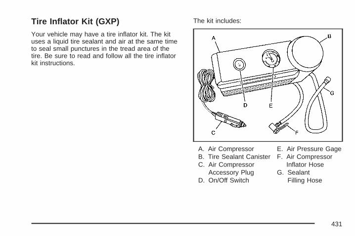
Tire Inflator Kit (GXP)Your vehicle may have a tire inflator kit. The kituses a liquid tire sealant and air at the same timeto seal small punctures in the tread area of thetire. Be sure to read and follow all the tire inflatorkit instructions.
The kit includes:
A. Air CompressorB. Tire Sealant CanisterC. Air Compressor
Accessory PlugD. On/Off Switch
E. Air Pressure GageF. Air Compressor
Inflator HoseG. Sealant
Filling Hose
431
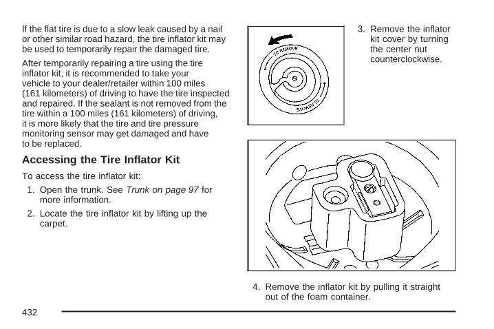
If the flat tire is due to a slow leak caused by a nailor other similar road hazard, the tire inflator kit maybe used to temporarily repair the damaged tire.
After temporarily repairing a tire using the tireinflator kit, it is recommended to take yourvehicle to your dealer/retailer within 100 miles(161 kilometers) of driving to have the tire inspectedand repaired. If the sealant is not removed from thetire within a 100 miles (161 kilometers) of driving,it is more likely that the tire and tire pressuremonitoring sensor may get damaged and haveto be replaced.
Accessing the Tire Inflator KitTo access the tire inflator kit:
1. Open the trunk. See Trunk on page 97 formore information.
2. Locate the tire inflator kit by lifting up thecarpet.
3. Remove the inflatorkit cover by turningthe center nutcounterclockwise.
4. Remove the inflator kit by pulling it straightout of the foam container.
432

Tire SealantThe kit contains a liquid sealant that when injectedinto a flat tire, may temporarily repair nail holesor cuts in the tread area of the tire. The tire sealantcannot repair tire damage caused while drivingon a flat tire or a tire that has had a “blow out” ora tire that has punctures in the sidewall areas.The tire sealant solution is to be used for a singletire and can only be used once.
Check the tire sealant expiration date on thesealant canister. The sealant may not be aseffective beyond the expiration date. If needed,see your dealer/retailer for a replacement canister.
After temporarily repairing a tire using the tiresealant, take your vehicle to your dealer/retailer tohave the tire inspected and repaired.
Using the Tire Inflator KitTo use the tire inflator kit:
1. Place the inflator kit on the ground andunwrap the sealant filling hose from thecompressor.
2. Remove the air compressor accessory plugfrom the unit. To do this, pull the top portionof the wrapped cord out first, then the bottom,then unsnap the plug. Do not insert theplug into an accessory outlet yet.
3. Remove the valve stem cap from the flat tireby turning it counterclockwise.If an object, such as a nail, has penetratedthe tire, do not remove it.
433

4. Attach the sealant filling hose (A) onto the tirevalve stem. Turn it clockwise until it is tight.Make sure the inflator kit on/off switch (B) is inthe O (off) position.
5. Plug the air compressor accessory plug (C)into an accessory power outlet in the vehicle.See Accessory Power Outlet(s) on page 160for more information.
{CAUTION:
Idling the engine in a closed-in place orwith the climate control system off cancause deadly carbon monoxide (CO).See Engine Exhaust on page 122.
6. Start the vehicle. See Starting the Engine onpage 110 for more information. The vehiclemust be running while using the aircompressor.
434
{CAUTION:
Inflating something too much can make itexplode, and you or others could beinjured. Be sure to read the inflatorinstructions, and inflate the tire to itsrecommended pressure. Do not exceed36 psi (248 kPa).
7. Move the inflator kit switch to the I (on)position.The inflator kit will force sealant and air intothe tire. Sealant may leak from the puncturehole until the vehicle is driven and thehole has sealed.
8. Make sure there is a proper connectionbetween the tire valve stem and thesealant filling hose by looking at the airpressure gage. If there is not a pressurereading while the compressor is running,the connection between the inflator kit andthe tire is bad.Check the attachment between the sealantfilling hose and the tire valve stem.
9. Inflate the tire up to the recommendedinflation pressure, found on the Tire andLoading Information label located onthe vehicle’s center pillar (B-pillar) below thevehicle’s door latch, using the air pressuregage on the top of the unit as a guide.The pressure gage reading is slightlyhigh while the compressor is on. Turn thecompressor off to get an accurate pressurereading.
Notice: If the recommended pressure cannotbe reached after 15 minutes, the vehicleshould not be driven farther. Damage to thetire is severe and the sealant will not beeffective. Remove the air compressor plugfrom the accessory power outlet and unscrewthe inflating hose from the tire valve. SeeRoadside Assistance Program on page 504.
10. Move the inflator kit switch to the O (off)position once the correct tire pressure isobtained.
11. Turn off the engine.
435

12. Unplug the air compressor accessory plugfrom the accessory power outlet in thevehicle.
13. Disconnect the sealant filling hose from thetire valve stem, by turning it counterclockwise,and replace the tire valve stem cap.Be careful when handling the tire inflatorcomponents as they may be hot after usage.
14. Wrap the sealant filling hose around the aircompressor channel to stow it in its originallocation.
15. Stow the air compressor accessory plug backin the air compressor. To do this, wrap the aircompressor accessory plug, snap in theplug, and then push in the bottom and thenthe top of the wrapped air compressoraccessory plug.
16. If the flat tire wasable to inflate to therecommendedinflation pressure,remove themaximum speedlabel from thesealant canister.
Place it in a highly visible location suchas the inside of the upper left corner of thewindshield or to the face of the radio/clock.The maximum speed label reminds youto drive cautiously and not to exceed 55 mph(90 km/h) until you have the damaged tireinspected and repaired.
436

{CAUTION:
Storing the tire inflator kit or otherequipment in the passenger compartmentof the vehicle could cause injury. In asudden stop or collision, loose equipmentcould strike someone. Store the tireinflator kit in the proper place.
17. Return the equipment to the proper storagelocation in the trunk of your vehicle.
18. Immediately drive the vehicle 5 miles (8 km)to distribute the sealant evenly in the tire.Stop at a safe location and check thetire pressure. Refer to Steps 1 through 8under “Using the Air Compressor withoutSealant” next in this section. If the tirepressure has fallen more than 10 psi (68 kPa)
below the recommended inflation pressure,stop driving the vehicle. The tire is toodamaged for the sealant to work. SeeRoadside Assistance Program on page 504.If the tire pressure has not dropped morethan 10 psi (68 kPa) from the recommendedinflation pressure, you can inflate the tire backup to the recommended inflation pressure.
19. Dispose of the sealant canister at yourdealer/retailer or in accordance with yourlocal state codes and practices.After using the sealant canister, replace it witha new canister from your dealer/retailer.
20. After temporarily repairing a tire with theemergency flat tire repair kit, take yourvehicle to your dealer/retailer to have thetire inspected and repaired.
437
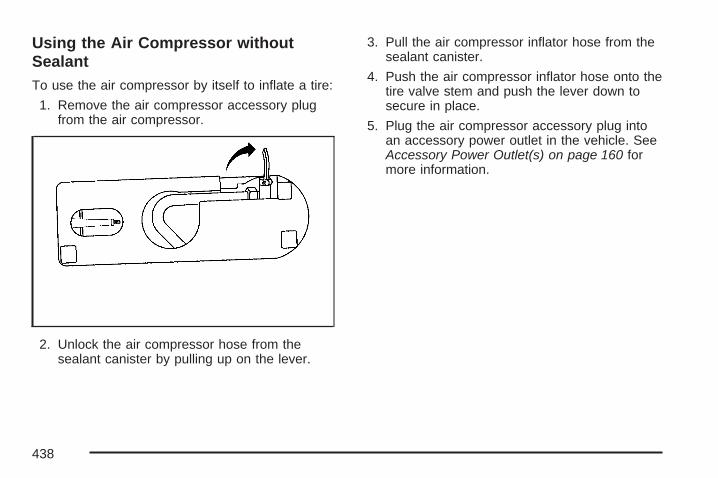
Using the Air Compressor withoutSealantTo use the air compressor by itself to inflate a tire:
1. Remove the air compressor accessory plugfrom the air compressor.
2. Unlock the air compressor hose from thesealant canister by pulling up on the lever.
3. Pull the air compressor inflator hose from thesealant canister.
4. Push the air compressor inflator hose onto thetire valve stem and push the lever down tosecure in place.
5. Plug the air compressor accessory plug intoan accessory power outlet in the vehicle. SeeAccessory Power Outlet(s) on page 160 formore information.
438

{CAUTION:
Idling the engine in a closed-in place orwith the climate control system off cancause deadly carbon monoxide (CO).See Engine Exhaust on page 122.
6. Start the vehicle. See Starting the Engine onpage 110 for more information. The vehiclemust be running while using the aircompressor.
{CAUTION:
Inflating something too much can makeit explode, and you or others could beinjured. Be sure to read the inflatorinstructions, and inflate the tire to itsrecommended pressure. Do not exceed36 psi (248 kPa).
7. Move the inflator kit switch to the I (on)position.
439
8. Make sure there is a proper connectionbetween the tire valve stem and the aircompressor hose by looking at the airpressure gage. If there is not a pressurereading while the compressor is running,the connection between the inflator kit andthe tire is bad.Check the attachment between the aircompressor hose and the tire valve stem.
9. Inflate the tire up to the recommended inflationpressure using the air pressure gage on thetop of the unit as a guide.
10. Turn off the air compressor by moving theswitch to the O (off) position.
{CAUTION:
Storing the tire inflator kit or otherequipment in the passenger compartmentof the vehicle could cause injury. In asudden stop or collision, loose equipmentcould strike someone. Store the tireinflator kit in the proper place.
11. Disconnect the compressor inflator hose andwrap the hose in the bottom of the inflator kit.
12. Place the equipment in the original location inthe trunk of your vehicle.
440

Removal and Installation of the SealantCanisterTo remove the sealant canister:
1. Unlock the air compressor inflator hose fromthe sealant canister by pulling the lever up.
2. Disconnect the air compressor inflator hosefrom the sealant canister.
3. Unwrap the sealant filling hose from thecompressor.
4. Turn the sealant canister so the inflator fillinghose is aligned with the slot in thecompressor.
5. Lift the sealant canister from the aircompressor and replace with a new sealantcanister. See your dealer/retailer for moreinformation.
441
To install a new sealant canister:
1. Align the sealant filling hose with the slot inthe air compressor.
2. Push the sealant canister down and turn itclockwise.
3. Wrap the sealant filling hose around the aircompressor channel to stow it in its originallocation.
4. Push the air compressor inflator hose onto thesealant canister inlet and push the lever down.
Changing a Flat TireIf a tire goes flat, avoid further tire and wheeldamage by driving slowly to a level place.Turn on your vehicle’s hazard warning flashers.See Hazard Warning Flashers on page 138for more information.
{CAUTION:
Changing a tire can be dangerous. Thevehicle can slip off the jack and roll overor fall on you or other people. You andthey could be badly injured or even killed.Find a level place to change your tire.To help prevent the vehicle from moving:
1. Set the parking brake firmly.
2. Put the shift lever in PARK (P).
CAUTION: (Continued)
442
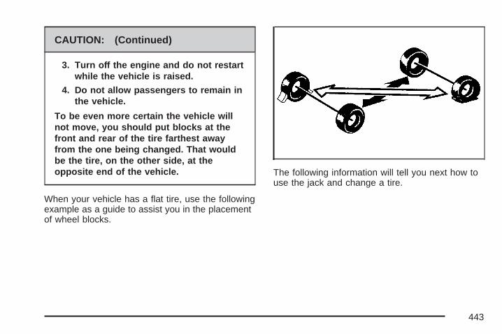
CAUTION: (Continued)
3. Turn off the engine and do not restartwhile the vehicle is raised.
4. Do not allow passengers to remain inthe vehicle.
To be even more certain the vehicle willnot move, you should put blocks at thefront and rear of the tire farthest awayfrom the one being changed. That wouldbe the tire, on the other side, at theopposite end of the vehicle.
When your vehicle has a flat tire, use the followingexample as a guide to assist you in the placementof wheel blocks.
The following information will tell you next how touse the jack and change a tire.
443

Removing the Spare Tire and ToolsThe equipment needed to change a tire islocated in the trunk.
1. Open the trunk. See Trunk on page 97 formore information.
2. Remove the convenience net, if equipped,by removing the net hook attachments.
3. Lift up the carpet.4. Turn the center nut
on the compactspare tire covercounterclockwiseto remove it.
5. Remove the cover.
6. Remove the compact spare tire. See CompactSpare Tire on page 454 for more information.
7. Turn the nut holding the jack counterclockwiseand remove it. Then remove the jack andwrench.
444
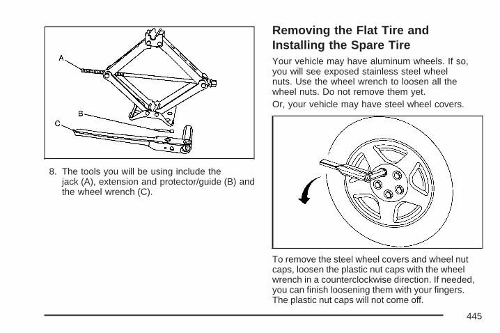
8. The tools you will be using include thejack (A), extension and protector/guide (B) andthe wheel wrench (C).
Removing the Flat Tire andInstalling the Spare TireYour vehicle may have aluminum wheels. If so,you will see exposed stainless steel wheelnuts. Use the wheel wrench to loosen all thewheel nuts. Do not remove them yet.Or, your vehicle may have steel wheel covers.
To remove the steel wheel covers and wheel nutcaps, loosen the plastic nut caps with the wheelwrench in a counterclockwise direction. If needed,you can finish loosening them with your fingers.The plastic nut caps will not come off.
445
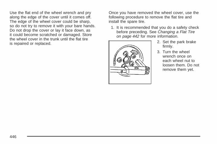
Use the flat end of the wheel wrench and pryalong the edge of the cover until it comes off.The edge of the wheel cover could be sharp,so do not try to remove it with your bare hands.Do not drop the cover or lay it face down, asit could become scratched or damaged. Storethe wheel cover in the trunk until the flat tireis repaired or replaced.
Once you have removed the wheel cover, use thefollowing procedure to remove the flat tire andinstall the spare tire.
1. It is recommended that you do a safety checkbefore preceding. See Changing a Flat Tireon page 442 for more information.
2. Set the park brakefirmly.
3. Turn the wheelwrench once oneach wheel nut toloosen them. Do notremove them yet.
446

4. Find the jacking location located on theunderside of the rocker trim using the diagram.For jacking at the vehicle’s front location,put the jack lift head (C) about 6 inches(15 cm) from the rear edge of the frontwheel opening (B). Line up the jack withthe arrow (A) as shown.
For jacking at the vehicle’s rear location, putthe jack lift head (B) about 9 inches (23 cm)from the front edge of the rear wheelopening (C). Line up the jack with the arrow (A)as shown.
447

5. Put the compact spare tire near you.
{CAUTION:
Getting under a vehicle when it is jackedup is dangerous. If the vehicle slips offthe jack you could be badly injured orkilled. Never get under a vehicle whenit is supported only by a jack.
{CAUTION:
Raising your vehicle with the jackimproperly positioned can damage thevehicle and even make the vehicle fall.To help avoid personal injury and vehicledamage, be sure to fit the jack lift headinto the proper location before raising thevehicle.
{CAUTION:
Lifting a vehicle and getting under it to domaintenance or repairs is dangerouswithout the appropriate safety equipmentand training. The jack provided with yourvehicle is designed only for changing aflat tire. If it is used for anything else, youor others could be badly injured or killedif the vehicle slips off the jack. Use thejack provided with your vehicle only forchanging a flat tire.
448

6. Raise the vehicle by turning the jack handleclockwise. Raise the vehicle far enough offthe ground for the compact spare tire to attachto the vehicle.
7. Remove all wheel nuts and take off theflat tire.
{CAUTION:
Rust or dirt on the wheel, or on the partsto which it is fastened, can make thewheel nuts become loose after time. Thewheel could come off and cause anaccident. When changing a wheel, removeany rust or dirt from the places where thewheel attaches to the vehicle. In anemergency, a cloth or a paper towel canbe used to do this; but be sure to use ascraper or wire brush later, if needed, toget all the rust or dirt off.
8. Remove any rust ordirt from the wheelbolts, mountingsurfaces andspare wheel.
449
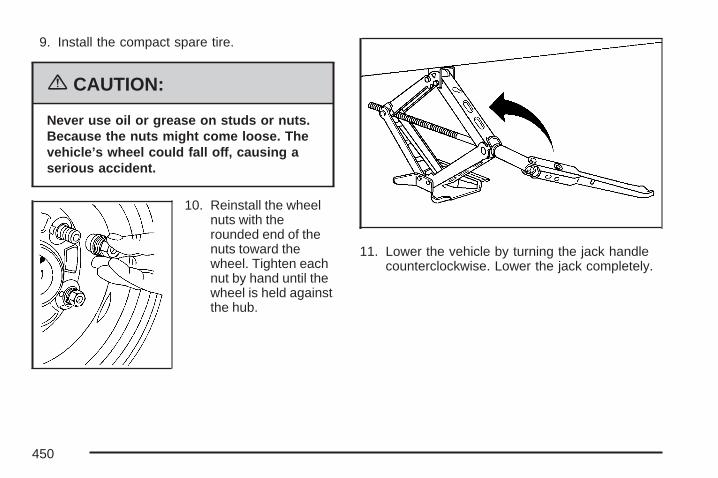
9. Install the compact spare tire.
{CAUTION:
Never use oil or grease on studs or nuts.Because the nuts might come loose. Thevehicle’s wheel could fall off, causing aserious accident.
10. Reinstall the wheelnuts with therounded end of thenuts toward thewheel. Tighten eachnut by hand until thewheel is held againstthe hub.
11. Lower the vehicle by turning the jack handlecounterclockwise. Lower the jack completely.
450
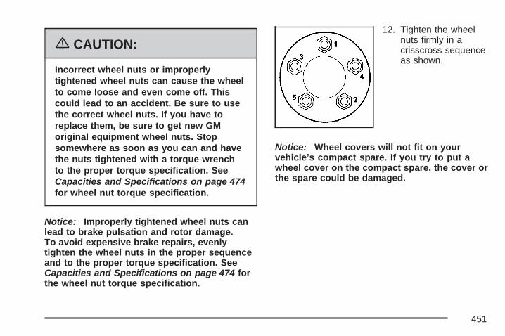
{CAUTION:
Incorrect wheel nuts or improperlytightened wheel nuts can cause the wheelto come loose and even come off. Thiscould lead to an accident. Be sure to usethe correct wheel nuts. If you have toreplace them, be sure to get new GMoriginal equipment wheel nuts. Stopsomewhere as soon as you can and havethe nuts tightened with a torque wrenchto the proper torque specification. SeeCapacities and Specifications on page 474for wheel nut torque specification.
Notice: Improperly tightened wheel nuts canlead to brake pulsation and rotor damage.To avoid expensive brake repairs, evenlytighten the wheel nuts in the proper sequenceand to the proper torque specification. SeeCapacities and Specifications on page 474 forthe wheel nut torque specification.
12. Tighten the wheelnuts firmly in acrisscross sequenceas shown.
Notice: Wheel covers will not fit on yourvehicle’s compact spare. If you try to put awheel cover on the compact spare, the cover orthe spare could be damaged.
451

Storing a Flat or Spare Tire andTools
{CAUTION:
Storing a jack, a tire, or other equipmentin the passenger compartment of thevehicle could cause injury. In a suddenstop or collision, loose equipment couldstrike someone. Store all these in theproper place.
After the compact spare tire is put on the vehicle,store the flat tire in the trunk. Use the followingprocedure to secure it in the trunk. When storing afull-size tire, use the extension and protector/guide,located in the foam holder, to help avoid wheelsurface damage.
To store a full-size tire:
1. Install the tools in their original location in thetrunk area and secure.
2. Place the tire in the trunk with the valve stemfacing down, and the protector/guide placedthrough a wheel bolt hole.
3. Remove the protector and attach the retainersecurely.
4. Place the protector/guide back in the foamholder when putting the compact spare backin the trunk. Store the cover as far forwardas possible.
The compact spare tire is for temporary use only.Replace the compact spare tire with a full-sizetire as soon as possible. See Compact Spare Tireon page 454 for more information. Use thefollowing as a guide for storing the compact sparetire and tools.
452
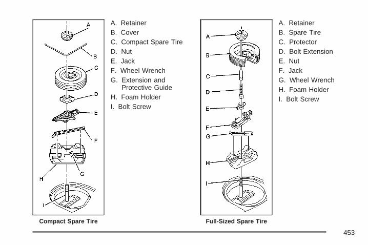
A. RetainerB. CoverC. Compact Spare TireD. NutE. JackF. Wheel WrenchG. Extension and
Protective GuideH. Foam HolderI. Bolt Screw
A. RetainerB. Spare TireC. ProtectorD. Bolt ExtensionE. NutF. JackG. Wheel WrenchH. Foam HolderI. Bolt Screw
Compact Spare Tire Full-Sized Spare Tire
453
Compact Spare TireAlthough the compact spare tire was fully inflatedwhen the vehicle was new, it can lose air aftera time. Check the inflation pressure regularly.It should be 60 psi (420 kPa).
After installing the compact spare on the vehicle,you should stop as soon as possible and makesure the spare tire is correctly inflated. Thecompact spare is made to perform well at speedsup to 65 mph (105 km/h) for distances up to3,000 miles (5 000 km), so you can finish your tripand have the full-size tire repaired or replacedwhere you want. You must calibrate the tireinflation monitor system, if your vehicle has thisfeature, after installing or removing the compactspare. See Tire Pressure Monitor System onpage 415. The system may not work correctlywhen the compact spare is installed on the vehicle.Of course, it’s best to replace the spare with afull-size tire as soon as you can. The spare will lastlonger and be in good shape in case you needit again.
Notice: When the compact spare is installed,do not take your vehicle through an automaticcar wash with guide rails. The compactspare can get caught on the rails. That candamage the tire and wheel, and maybeother parts of your vehicle.
Do not use the compact spare on other vehicles.
And do not mix the compact spare tire orwheel with other wheels or tires. They will not fit.Keep the spare tire and its wheel together.
Notice: Tire chains will not fit your compactspare. Using them can damage your vehicleand can damage the chains too. Do not use tirechains on your compact spare.
454
Appearance Care
Cleaning the Inside of Your VehicleYour vehicle’s interior will continue to look itsbest if it is cleaned often. Although not alwaysvisible, dust and dirt can accumulate on yourupholstery. Dirt can damage carpet, fabric, leather,and plastic surfaces. Regular vacuuming isrecommended to remove particles from yourupholstery. It is important to keep your upholsteryfrom becoming and remaining heavily soiled.Soils should be removed as quickly as possible.Your vehicle’s interior may experience extremesof heat that could cause stains to set rapidly.
Lighter colored interiors may require more frequentcleaning. Use care because newspapers andgarments that transfer color to your homefurnishings may also transfer color to yourvehicle’s interior.
When cleaning your vehicle’s interior, only usecleaners specifically designed for the surfacesbeing cleaned. Permanent damage may resultfrom using cleaners on surfaces for which
they were not intended. Use glass cleaner only onglass. Remove any accidental over-spray fromother surfaces immediately. To prevent over-spray,apply cleaner directly to the cleaning cloth.
Notice: If you use abrasive cleaners whencleaning glass surfaces on your vehicle, youcould scratch the glass and/or cause damageto the integrated radio antenna and therear window defogger. When cleaning theglass on your vehicle, use only a soft clothand glass cleaner.
Many cleaners contain solvents that may becomeconcentrated in your vehicle’s breathing space.Before using cleaners, read and adhere to all safetyinstructions on the label. While cleaning yourvehicle’s interior, maintain adequate ventilationby opening your vehicle’s doors and windows.
Dust may be removed from small buttons andknobs using a small brush with soft bristles.
Your dealer has a product for cleaning yourvehicle’s glass. Should it become necessary,you can also obtain a product from your dealerto remove odors from your vehicle’s upholstery.
455

Do not clean your vehicle using the followingcleaners or techniques:
• Never use a knife or any other sharp object toremove a soil from any interior surface.
• Never use a stiff brush. It can cause damageto your vehicle’s interior surfaces.
• Never apply heavy pressure or rubaggressively with a cleaning cloth. Use ofheavy pressure can damage your interior anddoes not improve the effectiveness of soilremoval.
• Use only mild, neutral-pH soaps. Avoidlaundry detergents or dishwashing soaps withdegreasers. Using too much soap will leavea residue that leaves streaks and attracts dirt.For liquid cleaners, about 20 drops pergallon (3.78 L) of water is a good guide.
• Do not heavily saturate your upholstery whilecleaning.
• Damage to your vehicle’s interior may resultfrom the use of many organic solvents suchas naptha, alcohol, etc.
Fabric/Carpet
Cleaning Fabric/CarpetUse a vacuum cleaner often to get rid of dust andloose dirt. Wipe vinyl, leather, plastic, andpainted surfaces with a clean, damp cloth.Your dealer has cleaners for the cleaning of fabricand carpet. They will clean normal spots andstains very well.If the vehicle has the Ultra Lux® suede fabric,follow the listed procedures except do not use anysolvents or dry cleaning products.Here are some cleaning tips:
• Always read the instructions on the cleanerlabel.
• Clean up stains as soon as you can, beforethey set.
• Carefully scrape off any excess stain.
• Use a clean cloth or sponge, and change to aclean area often. A soft brush may be used ifstains are stubborn.
• To avoid forming a ring on fabric after spotcleaning, clean the entire area immediatelyor it will set.
456

Most stains can be removed with club soda water.To clean, use the following instructions:
1. For liquids: blot with a clean, soft white cloth.For solids: remove as much as possible andthen vacuum or brush.
2. Apply club soda water to a clean, soft whitecloth. Do not over-saturate; the cloth shouldnot drip water.
3. Clean the entire area. Avoid getting the fabrictoo wet.
4. Start cleaning from the seams into the stain toavoid a ring effect.
5. Continue cleaning, using a clean area of thecloth each time it becomes soiled.
6. When the stain is removed, blot the cleanedarea with another dry clean, soft white cloth.
Using Cleaner on Fabric1. First, try the cleaner in an inconspicuous area
to make sure the cleaner does not affect thecolor of the fabric.
2. For liquids: blot the stain with a clean, softwhite cloth.For solids: remove as much as possible andthen vacuum or brush.
3. Spray a small amount of the cleaner onto aclean, soft white cloth. Do not apply spraydirectly to the fabric.
4. Start cleaning from the seams into the stain toavoid a ring effect.
5. Continue cleaning, using a clean area of thecloth each time it becomes soiled.
6. When the stain is removed, blot the cleanedarea with another dry clean, soft white cloth.
7. If the cleaner leaves a ring effect, follow upwith the club soda water instructions givenearlier in this section.
457

Special Fabric Cleaning ProblemsStains caused by such things as catsup, coffee,tea, milk, fruit, fruit juice, jelly, cheese, chocolate,vomit, urine, and blood can be removed usingthe club soda water instructions given earlier in thissection. If an odor lingers after cleaning vomit orurine, treat the area with a water and baking sodasolution: 1 teaspoon (5 ml) of baking soda to1 cup (250 ml) of lukewarm water. Let dry.
Stains caused by oil and grease can be cleanedwith an approved GM cleaner and a clean,white cloth.
1. Carefully scrape off excess stain.2. Clean with cool water and allow to dry
completely.3. If a stain remains, follow the cleaner
instructions described earlier.
LeatherA soft cloth dampened with water may be usedto remove dust. If a more thorough cleaningis necessary, a soft cloth dampened with a mildsoap solution can be used. Allow the leather todry naturally. Do not use heat to dry. Neveruse steam to clean leather. Never use spot liftersor spot removers on leather. Many commercialleather cleaners and coatings that are soldto preserve and protect leather may permanentlychange the appearance and feel of your leatherand are not recommended. Do not use silicone orwax-based products, or those containing organicsolvents to clean your vehicle’s interior becausethey can alter the appearance by increasingthe gloss in a non-uniform manner. Never useshoe polish on your leather.
458

Ultra Lux Suede
Cleaning Ultra Lux SuedeUse a mild solution of lukewarm water and aneutral dish soap on a soft cloth or sponge.For the following stains, follow these instructions:
Coffee, Tea, and Milk: Blot with a clean, soft,white cloth. Then clean with mild soapy water anda clean white cloth.
Cosmetics: Clean with mild soapy water and aclean white cloth.
Jelly, Syrup, and Fruit: Remove most of thesolids, then clean with warm tap water and a cleanwhite cloth.
Oil and Grease: Sprinkle baking soda on thespot, brush, then wipe with a clean white cloth.
Instrument Panel, Vinyl, and OtherPlastic SurfacesA soft cloth dampened with water may be usedto remove dust. If a more thorough cleaning isnecessary, a clean soft cloth dampened with a mildsoap solution can be used to gently remove dustand dirt. Never use spot lifters or removers onplastic surfaces. Many commercial cleaners andcoatings that are sold to preserve and protect softplastic surfaces may permanently change theappearance and feel of your interior and are notrecommended. Do not use silicone or wax-basedproducts, or those containing organic solvents toclean your vehicle’s interior because they can alterthe appearance by increasing the gloss in anon-uniform manner.
Some commercial products may increase glosson your instrument panel. The increase ingloss may cause annoying reflections in thewindshield and even make it difficult to seethrough the windshield under certain conditions.
459
Care of Safety BeltsKeep belts clean and dry.
{CAUTION:
Do not bleach or dye safety belts. If youdo, it may severely weaken them. In acrash, they might not be able to provideadequate protection. Clean safety beltsonly with mild soap and lukewarm water.
WeatherstripsSilicone grease on weatherstrips will make themlast longer, seal better, and not stick or squeak.Apply silicone grease with a clean cloth. Duringvery cold, damp weather frequent application maybe required. See Recommended Fluids andLubricants on page 490.
Washing Your VehicleThe paint finish on the vehicle provides beauty,depth of color, gloss retention, and durability.
The best way to preserve the vehicle’s finish is tokeep it clean by washing it often with lukewarmor cold water.
Do not wash the vehicle in the direct rays of thesun. Use a car washing soap. Do not use strongsoaps or chemical detergents. Be sure to rinse thevehicle well, removing all soap residue completely.Approved cleaning products can be obtained fromyour dealer. See Vehicle Care/AppearanceMaterials on page 464. Do not use cleaning agentsthat are petroleum based, or that contain acid orabrasives. All cleaning agents should be flushedpromptly and not allowed to dry on the surface, orthey could stain. Dry the finish with a soft, cleanchamois or an all-cotton towel to avoid surfacescratches and water spotting.
High pressure car washes may cause water toenter the vehicle.
460
Cleaning Exterior Lamps/LensesUse only lukewarm or cold water, a soft cloth anda car washing soap to clean exterior lampsand lenses. Follow instructions under WashingYour Vehicle on page 460.
Finish CareOccasional waxing or mild polishing of the vehicleby hand may be necessary to remove residuefrom the paint finish. Approved cleaning productscan be obtained from your dealer. See VehicleCare/Appearance Materials on page 464.
Notice: Machine compounding or aggressivepolishing on a basecoat/clearcoat paintfinish may damage it. Use only non-abrasivewaxes and polishes that are made for abasecoat/clearcoat paint finish on your vehicle.
The vehicle has a basecoat/clearcoat paint finish.The clearcoat gives more depth and gloss tothe colored basecoat. Always use waxesand polishes that are non-abrasive and madefor a basecoat/clearcoat paint finish.
Foreign materials such as calcium chloride andother salts, ice melting agents, road oil andtar, tree sap, bird droppings, chemicals fromindustrial chimneys, etc., can damage the vehicle’sfinish if they remain on painted surfaces. Washthe vehicle as soon as possible. If necessary, usenon-abrasive cleaners that are marked safe forpainted surfaces to remove foreign matter.
Exterior painted surfaces are subject to aging,weather, and chemical fallout that can take theirtoll over a period of years. To help keep thepaint finish looking new, keep the vehicle in agarage or covered whenever possible.
461

Windshield and Wiper BladesClean the outside of the windshield with glasscleaner.
Clean the rubber blades using a lint free cloth orpaper towel soaked with windshield washer fluid ora mild detergent. Wash the windshield thoroughlywhen cleaning the blades. Bugs, road grime,sap, and a buildup of vehicle wash/wax treatmentsmay cause wiper streaking. Replace the wiperblades if they are worn or damaged.
Wipers can be damaged by:
• Extreme dusty conditions
• Sand and salt
• Heat and sun
• Snow and ice, without proper removal
Aluminum Wheels
Notice: If you use strong soaps, chemicals,abrasive polishes, cleaners, brushes, orcleaners that contain acid on aluminum orchrome-plated wheels, you could damage thesurface of the wheel(s). The repairs wouldnot be covered by your warranty. Useonly approved cleaners on aluminum orchrome-plated wheels.
Keep the wheels clean using a soft clean clothwith mild soap and water. Rinse with clean water.After rinsing thoroughly, dry with a soft cleantowel. A wax may then be applied.
Notice: Using chrome polish on aluminumwheels could damage the wheels. The repairswould not be covered by your warranty.Use chrome polish on chrome wheels only.
The surface of these wheels is similar to thepainted surface of the vehicle. Do not use strongsoaps, chemicals, abrasive polishes, abrasivecleaners, cleaners with acid, or abrasive cleaningbrushes on them because the surface couldbe damaged. Do not use chrome polish onaluminum wheels.
462

Notice: If you drive your vehicle through anautomatic car wash that has silicone carbidetire cleaning brushes, you could damage thealuminum or chrome-plated wheels. The repairswould not be covered by your warranty. Neverdrive a vehicle equipped with aluminum orchrome-plated wheels through an automatic carwash that uses silicone carbide tire cleaningbrushes.
TiresTo clean the tires, use a stiff brush with tirecleaner.
Notice: Using petroleum-based tire dressingproducts on your vehicle may damage thepaint finish and/or tires. When applying atire dressing, always wipe off any oversprayfrom all painted surfaces on your vehicle.
Sheet Metal DamageIf the vehicle is damaged and requires sheet metalrepair or replacement, make sure the body repairshop applies anti-corrosion material to partsrepaired or replaced to restore corrosion protection.
Original manufacturer replacement parts willprovide the corrosion protection while maintainingthe warranty.
Finish DamageAny stone chips, fractures or deep scratches inthe finish should be repaired right away. Baremetal will corrode quickly and may develop intomajor repair expense.
Minor chips and scratches can be repaired withtouch-up materials available from your dealer.Larger areas of finish damage can be corrected inyour dealer’s body and paint shop.
463
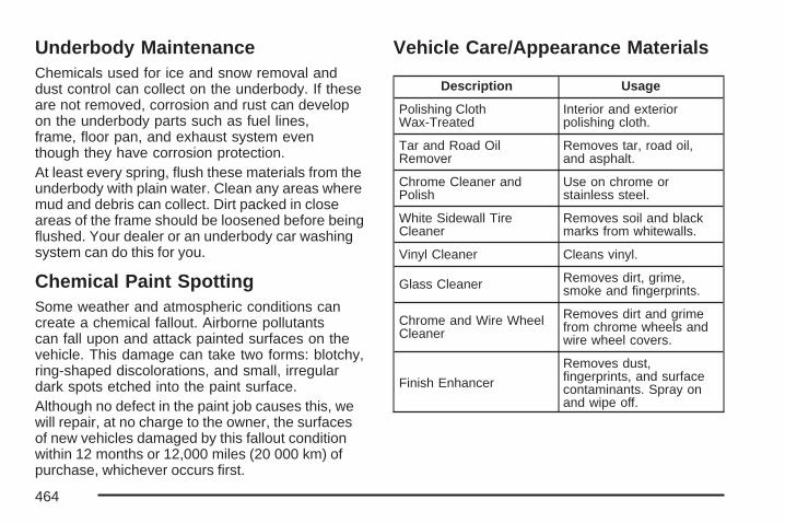
Underbody MaintenanceChemicals used for ice and snow removal anddust control can collect on the underbody. If theseare not removed, corrosion and rust can developon the underbody parts such as fuel lines,frame, floor pan, and exhaust system eventhough they have corrosion protection.At least every spring, flush these materials from theunderbody with plain water. Clean any areas wheremud and debris can collect. Dirt packed in closeareas of the frame should be loosened before beingflushed. Your dealer or an underbody car washingsystem can do this for you.
Chemical Paint SpottingSome weather and atmospheric conditions cancreate a chemical fallout. Airborne pollutantscan fall upon and attack painted surfaces on thevehicle. This damage can take two forms: blotchy,ring-shaped discolorations, and small, irregulardark spots etched into the paint surface.Although no defect in the paint job causes this, wewill repair, at no charge to the owner, the surfacesof new vehicles damaged by this fallout conditionwithin 12 months or 12,000 miles (20 000 km) ofpurchase, whichever occurs first.
Vehicle Care/Appearance Materials
Description Usage
Polishing ClothWax-Treated
Interior and exteriorpolishing cloth.
Tar and Road OilRemover
Removes tar, road oil,and asphalt.
Chrome Cleaner andPolish
Use on chrome orstainless steel.
White Sidewall TireCleaner
Removes soil and blackmarks from whitewalls.
Vinyl Cleaner Cleans vinyl.
Glass Cleaner Removes dirt, grime,smoke and fingerprints.
Chrome and Wire WheelCleaner
Removes dirt and grimefrom chrome wheels andwire wheel covers.
Finish Enhancer
Removes dust,fingerprints, and surfacecontaminants. Spray onand wipe off.
464
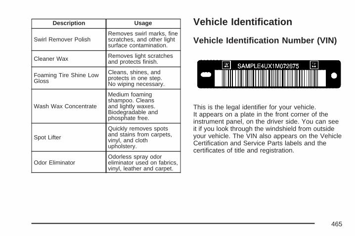
Description Usage
Swirl Remover PolishRemoves swirl marks, finescratches, and other lightsurface contamination.
Cleaner Wax Removes light scratchesand protects finish.
Foaming Tire Shine LowGloss
Cleans, shines, andprotects in one step.No wiping necessary.
Wash Wax Concentrate
Medium foamingshampoo. Cleansand lightly waxes.Biodegradable andphosphate free.
Spot Lifter
Quickly removes spotsand stains from carpets,vinyl, and clothupholstery.
Odor EliminatorOdorless spray odoreliminator used on fabrics,vinyl, leather and carpet.
Vehicle Identification
Vehicle Identification Number (VIN)
This is the legal identifier for your vehicle.It appears on a plate in the front corner of theinstrument panel, on the driver side. You can seeit if you look through the windshield from outsideyour vehicle. The VIN also appears on the VehicleCertification and Service Parts labels and thecertificates of title and registration.
465
Engine IdentificationThe eighth character in the VIN is the enginecode. This code helps you identify your vehicle’sengine, specifications, and replacement parts.
Service Parts Identification LabelThis label is in the trunk. It is very helpful ifyou ever need to order parts. The label has thefollowing information:
• Vehicle Identification Number (VIN)
• Model designation
• Paint information
• Production options and special equipment
Do not remove this label from the vehicle.
Electrical System
Add-On Electrical Equipment
Notice: Do not add anything electrical to yourvehicle unless you check with your dealerfirst. Some electrical equipment can damageyour vehicle and the damage would notbe covered by your warranty. Some add-onelectrical equipment can keep othercomponents from working as they should.
Add-on equipment can drain your vehicle’s battery,even if your vehicle is not operating.
Your vehicle has an airbag system. Beforeattempting to add anything electrical to yourvehicle, see Servicing Your Airbag-EquippedVehicle on page 78.
466
Headlamp WiringThe headlamp wiring is protected by fuses in thefuse block. An electrical overload will causethe lamps to turn off. If this happens, have yourheadlamp wiring checked right away.
Windshield Wiper FusesThe windshield wiper motor is protected by acircuit breaker and a fuse. If the motor overheatsdue to heavy snow, etc., the wiper will stopuntil the motor cools. If the overload is caused bysome electrical problem, have it fixed.
Power Windows and Other PowerOptionsCircuit breakers in the fuse panel protect thepower windows and other power accessories.When the current load is too heavy, the circuitbreaker opens and closes, protecting the circuituntil the problem is fixed.
Fuses and Circuit BreakersThe wiring circuits in the vehicle are protectedfrom short circuits by a combination of fuses,circuit breakers and fusible thermal links in thewiring itself. This greatly reduces the chanceof fires caused by electrical problems.
Look at the silver-colored band inside the fuse.If the band is broken or melted, replace the fuse.Be sure to replace a bad fuse with a new oneof the identical size and rating. Spare fuses anda fuse puller are located in the underhoodfuse block. See Underhood Fuse Block later inthis section.
467

Instrument Panel Fuse Block
Some fuses are in afuse block locatedon the end of theinstrument panel onthe passenger side.
To get to the fuse block lift up on the side panel.A fuse usage chart is on the inside of this panel.
Fuse UsageRAP Retained Accessory Power
SUN ROOF SunroofCRUISE SW Cruise Switch
PK LP Parking LampsRR DEFOG Rear Window Defogger
DR LK/TRUNK Door Lock/TrunkONSTAR/ALDL Onstar®/Diagnostic Link
CANISTER Fuel Tank Solenoid Canister
468

Fuse UsagePK LAMPS Parking LampsRADIO/AMP Radio Amplifier
RFA/MOD Remote Function Activator(Remote Keyless Entry)
DISPLAYSInstrument Panel Displays/Head-UpDisplay (HUD), Driver InformationCenter (DIC)
INT LIGHT Interior LampsHVAC Climate Controls
CHMSL/BKUP Center High Mounted StopLamp/Back-Up Lamps
PWR WDO Power WindowsSPRINGCOIL 2 Steering Wheel Control Switches
PWR SEAT Power Seat
TURN/HAZ Turn Signals/Hazard WarningLamps
PWR MIRS Power MirrorsHTD SEAT Heated Seat
To reinstall the end panel, position the lowersection with the edge of the instrument panel,and press the sides of the panel until it snapsinto place.
Underhood Fuse Block
The underhood fuseblock is located on thepassenger’s side ofthe vehicle in the enginecompartment.
To remove the fuse block cover, press in on thetab at the bottom of the cover and pull up.
469
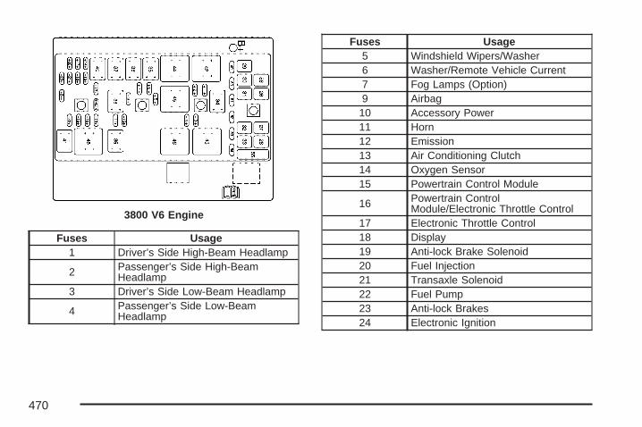
Fuses Usage1 Driver’s Side High-Beam Headlamp
2 Passenger’s Side High-BeamHeadlamp
3 Driver’s Side Low-Beam Headlamp
4 Passenger’s Side Low-BeamHeadlamp
Fuses Usage5 Windshield Wipers/Washer6 Washer/Remote Vehicle Current7 Fog Lamps (Option)9 Airbag
10 Accessory Power11 Horn12 Emission13 Air Conditioning Clutch14 Oxygen Sensor15 Powertrain Control Module
16 Powertrain ControlModule/Electronic Throttle Control
17 Electronic Throttle Control18 Display19 Anti-lock Brake Solenoid20 Fuel Injection21 Transaxle Solenoid22 Fuel Pump23 Anti-lock Brakes24 Electronic Ignition
3800 V6 Engine
470

Fuses Usage26 Battery Main 127 Battery Main 228 Battery Main 329 Fan 130 Battery Main 431 Anti-lock Brake Motor32 Fan 233 Starter56 Air Pump
Relays Usage34 High-Beam Headlamps
35 Low-Beam Headlamps, HeadlampDriver Module
36 Fog Lamps (Option)37 Ignition 138 Air Conditioner Compressor39 Horn40 Powertrain41 Fuel Pump
Relays Usage42 Fan 143 Fan 344 Windshield Wiper/High45 Windshield Wiper46 Fan 248 Crank49 Spare Fuse50 Spare Fuse51 Spare Fuse52 Blank53 Blank54 Blank55 Fuse Puller
§ Air Conditioning Clutch
471

Fuses UsageHVAC Climate Control System
FUEL/PUMP Fuel PumpAIRBAG/DISPLAY Airbag, Display
COMPASS CompassABS Anti-lock Brake System
ETC/ECM Electronic Throttle Control, EngineControl Module
Fuses UsageA/C CMPRSR Air Conditioning Compressor
INJ 1 Injectors 1
ECM/TCM Engine Control Module, TransaxleControl Module
TRANS TransaxleEMISSIONS1 Emissions 1
ABS SOL Anti-lock Brake SolenoidECM IGN Engine Control Module, Ignition
INJ 2 Injectors 2EMISSIONS2 Emissions 2
WPR Windshield WipersAUX PWR Auxiliary Power
WSW/RVC Windshield Washer, RegulatedVoltage Control
LT LO BEAM Driver’s Side Low-Beam Headlamp
RT LO BEAM Passenger’s Side Low-BeamHeadlamp
FOG LAMPS Fog LampsLT HI BEAM Driver’s Side High-Beam Headlamp
HORN Horn
RT HI BEAM Passenger’s Side High-BeamHeadlamp
SPARE Spare
5.3L V8 Engine
472

Fuses UsageSPARE SpareSPARE SpareSPARE SpareSPARE Spare
Relays UsageBATT 4 Battery 4
FUEL/PUMP Fuel PumpBATT 1 Battery 1
A/C CMPRSR Air Conditioning CompressorSTRTR Starter
PWR/TRN Powertrain
Relays UsageSTRTR Starter
ABS MTR Anti-lock Brake System MotorBATT 3 Battery 3BATT 2 Battery 2FAN 2 Cooling Fan 2FAN 3 Cooling Fan 3FAN 2 Cooling Fan 2FAN 1 Cooling Fan 1FAN 1 Cooling Fan 1HDM Headlamp Driver Module
473
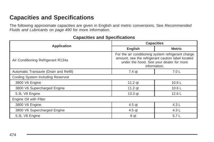
Capacities and SpecificationsThe following approximate capacities are given in English and metric conversions. See RecommendedFluids and Lubricants on page 490 for more information.
Capacities and Specifications
ApplicationCapacities
English Metric
Air Conditioning Refrigerant R134a
For the air conditioning system refrigerant chargeamount, see the refrigerant caution label located
under the hood. See your dealer for moreinformation.
Automatic Transaxle (Drain and Refill) 7.4 qt 7.0 L
Cooling System Including Reservoir
3800 V6 Engine 11.2 qt 10.6 L
3800 V6 Supercharged Engine 11.2 qt 10.6 L
5.3L V8 Engine 13.3 qt 12.6 L
Engine Oil with Filter
3800 V6 Engine 4.5 qt 4.3 L
3800 V6 Supercharged Engine 4.5 qt 4.3 L
5.3L V8 Engine 6 qt 5.7 L
474

Capacities and Specifications (cont’d)
ApplicationCapacities
English Metric
Fuel Tank
3.8L Engine (with NU6 emissions) sold new in CA, ME, VT,NY, MA (see your dealer for bordering states) 17.0 gal 64.4 L
3.8L Engine (without NU6 emissions) sold new in all otherstates (see your dealer for more information) 17.5 gal 66.2 L
5.3L V8 Engine sold new in all states 17.5 gal 66.2 L
Wheel Nut Torque 100 ft lb 140 Y
All capacities are approximate. When adding fluid, be sure to fill to the appropriate level, as recommended in thismanual. Recheck fluid level after filling.
Engine SpecificationsEngine VIN Code Transaxle Spark Plug Gap
3800 V6(3.8L L26) 2 Automatic 0.060 inches (1.52 mm)
3800 V6 Supercharged(3.8L L32) 4 Automatic 0.060 inches (1.52 mm)
5.3L V8 Engine C Automatic 0.040 inches (1.01 mm)
475

✍ NOTES
476

Maintenance Schedule ................................ 478Introduction ............................................... 478Maintenance Requirements ........................ 478Your Vehicle and the Environment ............ 478Using the Maintenance Schedule ............... 479Scheduled Maintenance ............................. 480Additional Required Services ..................... 482Maintenance Footnotes .............................. 484
Owner Checks and Services ..................... 486At Each Fuel Fill ....................................... 486At Least Once a Month ............................. 487At Least Once a Year ............................... 487Recommended Fluids and Lubricants ........ 490Normal Maintenance Replacement Parts .... 491Engine Drive Belt Routing ......................... 492Maintenance Record .................................. 494
Section 6 Maintenance Schedule
477

Maintenance Schedule
IntroductionImportant: Keep engine oil at the proper leveland change as recommended.
Have you purchased the GM Protection Plan? ThePlan supplements your new vehicle warranties.See your Warranty and Owner Assistance bookletor your dealer for details.
Maintenance Requirements
Notice: Maintenance intervals, checks,inspections, replacement parts, andrecommended fluids and lubricants asprescribed in this manual are necessary tokeep your vehicle in good working condition.Any damage caused by failure to followscheduled maintenance might not be coveredby warranty.
Your Vehicle and the EnvironmentProper vehicle maintenance not only helps to keepyour vehicle in good working condition, but alsohelps the environment. All recommendedmaintenance is important. Improper vehiclemaintenance can even affect the quality of the airwe breathe. Improper fluid levels or the wrongtire inflation can increase the level of emissionsfrom your vehicle. To help protect our environment,and to keep your vehicle in good condition, besure to maintain your vehicle properly.
478

Using the Maintenance ScheduleWe at General Motors want to help you keep yourvehicle in good working condition. But we do notknow exactly how you will drive it. You may drivevery short distances only a few times a week. Oryou may drive long distances all the time in veryhot, dusty weather. You may use your vehicle inmaking deliveries. Or you may drive it to work, to doerrands, or in many other ways.Because of all the different ways people use theirvehicles, maintenance needs vary. You may needmore frequent checks and replacements. So pleaseread the following and note how you drive. If youhave any questions on how to keep your vehicle ingood condition, see your GM Goodwrench® dealer.
This schedule is for vehicles that:• carry passengers and cargo within
recommended limits. You will find these limitson the Tire and Loading Information label. SeeLoading Your Vehicle on page 322.
• are driven on reasonable road surfaces withinlegal driving limits.
• use the recommended fuel. See GasolineOctane on page 344.
The services in Scheduled Maintenance onpage 480 should be performed when indicated.See Additional Required Services on page 482 andMaintenance Footnotes on page 484 for furtherinformation.
{CAUTION:
Performing maintenance work on a vehiclecan be dangerous. In trying to do somejobs, you can be seriously injured. Do yourown maintenance work only if you have therequired know-how and the proper toolsand equipment for the job. If you have anydoubt, see your GM Goodwrench® dealer tohave a qualified technician do the work.
Some maintenance services can be complex. So,unless you are technically qualified and havethe necessary equipment, you should have yourGM Goodwrench® dealer do these jobs.
479

When you go to your GM Goodwrench® dealer foryour service needs, you will know that GM-trainedand supported service technicians will performthe work using genuine GM parts.
If you want to purchase service information, seeService Publications Ordering Information onpage 514.
Owner Checks and Services on page 486 tells youwhat should be checked, when to check it, andwhat you can easily do to help keep your vehicle ingood condition.
The proper replacement parts, fluids, andlubricants to use are listed in RecommendedFluids and Lubricants on page 490 and NormalMaintenance Replacement Parts on page 491.When your vehicle is serviced, make sure theseare used. All parts should be replaced and allnecessary repairs done before you or anyone elsedrives the vehicle. We recommend the use ofgenuine GM parts.
Scheduled MaintenanceWhen the CHANGE OIL SOON message comeson, it means that service is required for yourvehicle. See DIC Warnings and Messages onpage 204. Have your vehicle serviced as soon aspossible within the next 600 miles (1 000 km). It ispossible that, if you are driving under the bestconditions, the engine oil life system may notindicate that vehicle service is necessary for over ayear. However, your engine oil and filter must bechanged at least once a year and at this time thesystem must be reset. Your dealer/retailer hastrained service technicians who will perform thiswork using genuine parts and reset the system.
If the engine oil life system is ever resetaccidentally, you must service your vehicle within3,000 miles (5 000 km) since your last service.Remember to reset the oil life system wheneverthe oil is changed. See Engine Oil Life System onpage 359 for information on the Engine Oil LifeSystem and resetting the system.
When the CHANGE OIL SOON message appears,certain services, checks, and inspections arerequired. Required services are described in thefollowing for “Maintenance I” and “Maintenance II.”
480
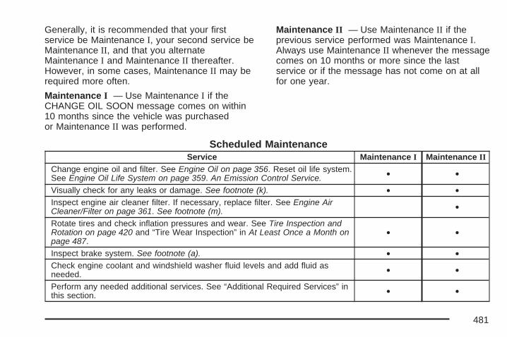
Generally, it is recommended that your firstservice be Maintenance I, your second service beMaintenance II, and that you alternateMaintenance I and Maintenance II thereafter.However, in some cases, Maintenance II may berequired more often.
Maintenance I — Use Maintenance I if theCHANGE OIL SOON message comes on within10 months since the vehicle was purchasedor Maintenance II was performed.
Maintenance II — Use Maintenance II if theprevious service performed was Maintenance I.Always use Maintenance II whenever the messagecomes on 10 months or more since the lastservice or if the message has not come on at allfor one year.
Scheduled MaintenanceService Maintenance I Maintenance II
Change engine oil and filter. See Engine Oil on page 356. Reset oil life system.See Engine Oil Life System on page 359. An Emission Control Service. • •
Visually check for any leaks or damage. See footnote (k). • •Inspect engine air cleaner filter. If necessary, replace filter. See Engine AirCleaner/Filter on page 361. See footnote (m). •
Rotate tires and check inflation pressures and wear. See Tire Inspection andRotation on page 420 and “Tire Wear Inspection” in At Least Once a Month onpage 487.
• •
Inspect brake system. See footnote (a). • •Check engine coolant and windshield washer fluid levels and add fluid asneeded. • •
Perform any needed additional services. See “Additional Required Services” inthis section. • •
481

Scheduled Maintenance (cont’d)Service Maintenance I Maintenance II
Inspect suspension and steering components. See footnote (b). •Inspect engine cooling system. See footnote (c). •Inspect wiper blades. See footnote (d). •Inspect restraint system components. See footnote (e). •Lubricate body components. See footnote (f). •Check transmission fluid level and add fluid as needed. •Replace passenger compartment air filter. See footnote (g). •Inspect throttle system. See footnote (j). •
Additional Required ServicesThe following services should be performed at the first maintenance service (I or II) after the indicatedmiles (kilometers) shown for each item.
Additional Required Services
Service and Miles (Kilometers) 25,000(40 000)
50,000(80 000)
75,000(120 000)
100,000(160 000)
125,000(200 000)
150,000(240 000)
Inspect fuel system for damage or leaks. • • • • • •Inspect exhaust system for loose ordamaged components. • • • • • •
Replace engine air cleaner filter. SeeEngine Air Cleaner/Filter on page 361. • • •
482

Additional Required Services (cont’d)
Service and Miles (Kilometers) 25,000(40 000)
50,000(80 000)
75,000(120 000)
100,000(160 000)
125,000(200 000)
150,000(240 000)
Supercharger service, if equipped.An Emission Control Service. Seefootnotes † and (l).
• • • • • •
Change automatic transmissionfluid and filter (severe service). Seefootnote (h).
• • •
Change automatic transmission fluidand filter (normal service). •
Replace spark plugs and inspect sparkplug wires. An Emission ControlService.
•
Engine cooling system service(or every five years, whichever occursfirst). An Emission Control Service. Seefootnote (i).
•
Inspect engine accessory drive belt.An Emission Control Service. Seefootnote (n).
•
483

Maintenance Footnotes† The U.S. Environmental Protection Agency orthe California Air Resources Board has determinedthat the failure to perform this maintenance itemwill not nullify the emission warranty or limitrecall liability prior to the completion of thevehicle’s useful life. We, however, urge that allrecommended maintenance services be performedat the indicated intervals and the maintenancebe recorded.
(a) Visually inspect brake lines and hoses forproper hook-up, binding, leaks, cracks, chafing,etc. Inspect disc brake pads for wear and rotors forsurface condition. Inspect other brake parts,including calipers, parking brake, etc.
(b) Visually inspect front and rear suspension andsteering system for damaged, loose, or missingparts or signs of wear. Inspect power steering linesand hoses for proper hook-up, binding, leaks,cracks, chafing, etc.
(c) Visually inspect hoses and have them replacedif they are cracked, swollen, or deteriorated.Inspect all pipes, fittings, and clamps; replace withgenuine parts as needed. To help ensure properoperation, a pressure test of the cooling systemand pressure cap and cleaning the outside of theradiator and air conditioning condenser isrecommended at least once a year.
(d) Inspect wiper blades for wear, cracking, orcontamination. Clean the windshield andwiper blades, if contaminated. Replace wiperblades that are worn or damaged. See WindshieldWiper Blade Replacement on page 405 andWindshield and Wiper Blades on page 462 formore information.
(e) Make sure the safety belt reminder light and allbelts, buckles, latch plates, retractors, andanchorages are working properly. Look for anyother loose or damaged safety belt system parts.If you see anything that might keep a safetybelt system from doing its job, have it repaired.Have any torn or frayed safety belts replaced. Alsolook for any opened or broken airbag coverings,and have them repaired or replaced. Theairbag system does not need regular maintenance.
484

(f) Lubricate all key lock cylinders. Lubricate allhinges and latches, including those for thebody doors, hood, secondary latch, pivots, springanchor, release pawl, rear compartment, glovebox door, console door, and any folding seathardware. More frequent lubrication maybe required when exposed to a corrosiveenvironment. Applying silicone grease onweatherstrips with a clean cloth will make themlast longer, seal better, and not stick or squeak.
(g) If you drive regularly under dusty conditions,the filter may require replacement more often.
(h) Change automatic transmission fluid and filterif the vehicle is mainly driven under one ormore of these conditions:
− In heavy city traffic where the outsidetemperature regularly reaches 90°F (32°C)or higher.
− In hilly or mountainous terrain.− When doing frequent trailer towing.− Uses such as found in taxi, police, or
delivery service.
(i) Drain, flush, and refill cooling system. Thisservice can be complex; you should haveyour dealer/retailer perform this service. See
Engine Coolant on page 366 for what to use.Inspect hoses. Clean radiator, condenser, pressurecap, and filler neck. Pressure test the coolingsystem and pressure cap.
(j) Check throttle system for interference orbinding and for damaged or missing parts. Replaceparts as needed. Replace any components thathave high effort or excessive wear. Do notlubricate accelerator or cruise control cables.
(k) A fluid loss in any vehicle system could indicatea problem. Have the system inspected andrepaired and the fluid level checked. Add fluidif needed.
(l) For supercharged engines only: Have yourdealer/retailer check the supercharger oil level andadd the proper supercharger oil as needed (orevery 36 months, whichever occurs first). SeeRecommended Fluids and Lubricants on page 490.
(m) If you drive regularly under dusty conditions,inspect the filter at each engine oil change.
(n) Visually inspect belt for fraying, excessivecracks, or obvious damage. Replace belt ifnecessary.
485

Owner Checks and ServicesThese owner checks and services should beperformed at the intervals specified to helpensure the safety, dependability, and emissioncontrol performance of your vehicle. YourGM Goodwrench® dealer can assist you withthese checks and services.
Be sure any necessary repairs are completed atonce. Whenever any fluids or lubricants are addedto your vehicle, make sure they are the properones, as shown in Recommended Fluids andLubricants on page 490.
At Each Fuel FillIt is important to perform these underhood checksat each fuel fill.
Engine Oil Level CheckCheck the engine oil level and add the proper oil ifnecessary. See Engine Oil on page 356 forfurther details.
Notice: It is important to check the engine oilregularly and keep it at the proper level.Failure to keep the engine oil at the properlevel can cause damage to the engine notcovered by your warranty.
Engine Coolant Level CheckCheck the engine coolant level and addDEX-COOL® coolant mixture if necessary. SeeEngine Coolant on page 366 for further details.
Windshield Washer Fluid Level CheckCheck the windshield washer fluid level inthe windshield washer fluid reservoir and add theproper fluid if necessary.
486

At Least Once a Month
Tire Inflation CheckInspect your vehicle’s tires and make sure theyare inflated to the correct pressures. Do not forgetto check the spare tire. See Inflation - TirePressure on page 414. Check to make sure thespare tire is stored securely. See Changing a FlatTire on page 442.
Tire Wear InspectionTire rotation may be required for high mileagehighway drivers prior to the Engine Oil Life Systemservice notification. Check the tires for wearand, if necessary, rotate the tires. See TireInspection and Rotation on page 420.
At Least Once a Year
Starter Switch Check
{CAUTION:
When you are doing this inspection, thevehicle could move suddenly. If the vehiclemoves, you or others could be injured.
1. Before you start, be sure you have enoughroom around the vehicle.
2. Firmly apply both the parking brake and theregular brake. See Parking Brake onpage 118.Do not use the accelerator pedal, and beready to turn off the engine immediately ifit starts.
3. Try to start the engine in each gear. Thevehicle should start only in PARK (P) orNEUTRAL (N). If the vehicle starts in anyother position, contact your dealer/retailerfor service.
487

Automatic Transmission Shift LockControl System Check
{CAUTION:
When you are doing this inspection, thevehicle could move suddenly. If the vehiclemoves, you or others could be injured.
1. Before you start, be sure you have enoughroom around the vehicle. It should be parkedon a level surface.
2. Firmly apply the parking brake. See ParkingBrake on page 118.Be ready to apply the regular brakeimmediately if the vehicle begins to move.
3. With the engine off, turn the ignition to RUN,but do not start the engine. Without applyingthe regular brake, try to move the shiftlever out of PARK (P) with normal effort. If theshift lever moves out of PARK (P), contactyour dealer/retailer for service.
Ignition Transmission Lock CheckWhile parked, and with the parking brake set, tryto turn the ignition to OFF in each shift leverposition.
• The ignition should turn to OFF only when theshift lever is in PARK (P).
• The ignition key should come out only in OFF.
Contact your dealer/retailer if service is required.
488

Parking Brake and AutomaticTransmission Park (P) Mechanism Check
{CAUTION:
When you are doing this check, yourvehicle could begin to move. You orothers could be injured and propertycould be damaged. Make sure there isroom in front of your vehicle in case itbegins to roll. Be ready to apply theregular brake at once should the vehiclebegin to move.
Park on a fairly steep hill, with the vehicle facingdownhill. Keeping your foot on the regularbrake, set the parking brake.
• To check the parking brake’s holding ability:With the engine running and transmission inNEUTRAL (N), slowly remove foot pressurefrom the regular brake pedal. Do this until thevehicle is held by the parking brake only.
• To check the PARK (P) mechanism’s holdingability: With the engine running, shift toPARK (P). Then release the parking brakefollowed by the regular brake.
Contact your dealer/retailer if service is required.
Underbody Flushing ServiceAt least every spring, use plain water to flush anycorrosive materials from the underbody. Takecare to clean thoroughly any areas where mud andother debris can collect.
489
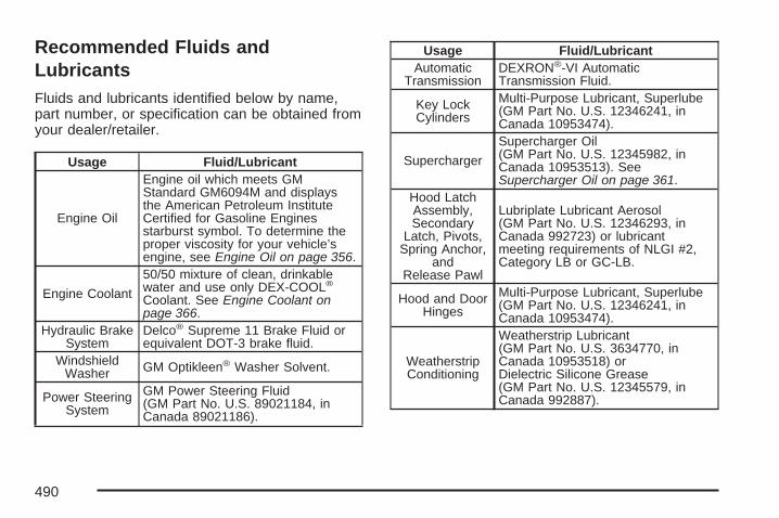
Recommended Fluids andLubricantsFluids and lubricants identified below by name,part number, or specification can be obtained fromyour dealer/retailer.
Usage Fluid/Lubricant
Engine Oil
Engine oil which meets GMStandard GM6094M and displaysthe American Petroleum InstituteCertified for Gasoline Enginesstarburst symbol. To determine theproper viscosity for your vehicle’sengine, see Engine Oil on page 356.
Engine Coolant
50/50 mixture of clean, drinkablewater and use only DEX-COOL®
Coolant. See Engine Coolant onpage 366.
Hydraulic BrakeSystem
Delco® Supreme 11 Brake Fluid orequivalent DOT-3 brake fluid.
WindshieldWasher GM Optikleen® Washer Solvent.
Power SteeringSystem
GM Power Steering Fluid(GM Part No. U.S. 89021184, inCanada 89021186).
Usage Fluid/LubricantAutomatic
TransmissionDEXRON®-VI AutomaticTransmission Fluid.
Key LockCylinders
Multi-Purpose Lubricant, Superlube(GM Part No. U.S. 12346241, inCanada 10953474).
Supercharger
Supercharger Oil(GM Part No. U.S. 12345982, inCanada 10953513). SeeSupercharger Oil on page 361.
Hood LatchAssembly,Secondary
Latch, Pivots,Spring Anchor,
andRelease Pawl
Lubriplate Lubricant Aerosol(GM Part No. U.S. 12346293, inCanada 992723) or lubricantmeeting requirements of NLGI #2,Category LB or GC-LB.
Hood and DoorHinges
Multi-Purpose Lubricant, Superlube(GM Part No. U.S. 12346241, inCanada 10953474).
WeatherstripConditioning
Weatherstrip Lubricant(GM Part No. U.S. 3634770, inCanada 10953518) orDielectric Silicone Grease(GM Part No. U.S. 12345579, inCanada 992887).
490
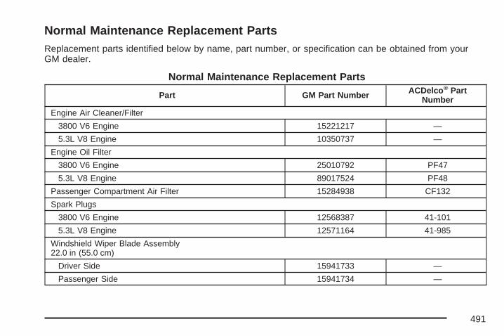
Normal Maintenance Replacement PartsReplacement parts identified below by name, part number, or specification can be obtained from yourGM dealer.
Normal Maintenance Replacement Parts
Part GM Part Number ACDelco® PartNumber
Engine Air Cleaner/Filter
3800 V6 Engine 15221217 —
5.3L V8 Engine 10350737 —
Engine Oil Filter
3800 V6 Engine 25010792 PF47
5.3L V8 Engine 89017524 PF48
Passenger Compartment Air Filter 15284938 CF132
Spark Plugs
3800 V6 Engine 12568387 41-101
5.3L V8 Engine 12571164 41-985
Windshield Wiper Blade Assembly22.0 in (55.0 cm)
Driver Side 15941733 —
Passenger Side 15941734 —
491
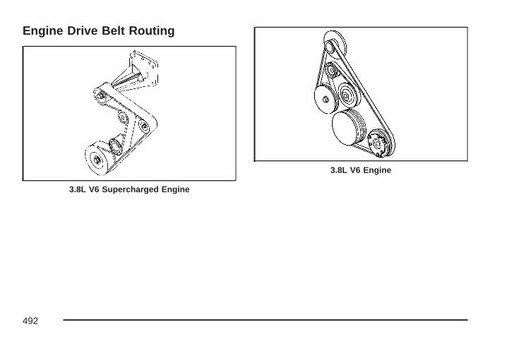
Engine Drive Belt Routing
3.8L V6 Supercharged Engine
3.8L V6 Engine
492

5.3L V8 Engine
493

Maintenance RecordAfter the scheduled services are performed, record the date, odometer reading, who performed theservice, and the type of services performed in the boxes provided. See Maintenance Requirements onpage 478. Any additional information from Owner Checks and Services on page 486 can be added on thefollowing record pages. You should retain all maintenance receipts.
Maintenance Record
Date OdometerReading Serviced By Maintenance I or
Maintenance II Services Performed
494

Maintenance Record (cont’d)
Date OdometerReading Serviced By Maintenance I or
Maintenance II Services Performed
495

Maintenance Record (cont’d)
Date OdometerReading Serviced By Maintenance I or
Maintenance II Services Performed
496
Customer Assistance and Information ....... 498Customer Satisfaction Procedure ............... 498Online Owner Center ................................. 501Customer Assistance for
Text Telephone (TTY) Users .................. 502Customer Assistance Offices ..................... 502GM Mobility Reimbursement Program ........ 503Roadside Assistance Program ................... 504Courtesy Transportation ............................. 506Collision Damage Repair ........................... 509
Reporting Safety Defects ............................ 512Reporting Safety Defects to the
United States Government ..................... 512Reporting Safety Defects to the
Canadian Government ............................ 513Reporting Safety Defects to
General Motors ...................................... 513Service Publications Ordering Information ... 514
Vehicle Data Recording and Privacy ......... 515Event Data Recorders ............................... 516OnStar ...................................................... 517Navigation System ..................................... 517Radio Frequency Identification (RFID) ........ 517
Section 7 Customer Assistance Information
497
Customer Assistance andInformation
Customer Satisfaction ProcedureYour satisfaction and goodwill are importantto your dealer and to Pontiac. Normally, anyconcerns with the sales transaction or theoperation of your vehicle will be resolved byyour dealer’s sales or service departments.Sometimes, however, despite the best intentionsof all concerned, misunderstandings can occur.If your concern has not been resolved to yoursatisfaction, the following steps should be taken:
STEP ONE: Discuss your concern with a memberof dealership management. Normally, concernscan be quickly resolved at that level. If the matterhas already been reviewed with the sales,service, or parts manager, contact the ownerof the dealership or the general manager.
STEP TWO: If after contacting a member ofdealership management, it appears your concerncannot be resolved by the dealership without furtherhelp, in the U.S., contact the Pontiac CustomerAssistance Center by calling 1-800-762-2737.In Canada, contact General Motors of CanadaCustomer Communication Centre in Oshawaby calling 1-800-263-3777 (English) or1-800-263-7854 (French).
We encourage you to call the toll-free number inorder to give your inquiry prompt attention. Pleasehave the following information available to give theCustomer Assistance Representative:
• Vehicle Identification Number (VIN). This isavailable from the vehicle registration or title, orthe plate at the top left of the instrument paneland visible through the windshield.
• Dealership name and location.
• Vehicle delivery date and present mileage.
When contacting Pontiac, please remember thatyour concern will likely be resolved at a dealer’sfacility. That is why we suggest you followStep One first if you have a concern.
498

STEP THREE — U.S. Owners: Both GeneralMotors and your dealer are committed to makingsure you are completely satisfied with yournew vehicle. However, if you continue to remainunsatisfied after following the procedure outlinedin Steps One and Two, you should file withthe BBB Auto Line Program to enforce your rights.
The BBB Auto Line Program is an out of courtprogram administered by the Council of BetterBusiness Bureaus to settle automotive disputesregarding vehicle repairs or the interpretation ofthe New Vehicle Limited Warranty. Although youmay be required to resort to this informal disputeresolution program prior to filing a court action, useof the program is free of charge and your case willgenerally be heard within 40 days. If you do notagree with the decision given in your case, you mayreject it and proceed with any other venue for reliefavailable to you.
You can contact the BBB Auto Line Program usingthe toll-free telephone number or write them at thefollowing address:
BBB Auto Line ProgramCouncil of Better Business Bureaus, Inc.4200 Wilson BoulevardSuite 800Arlington, VA 22203-1838
Telephone: 1-800-955-5100
This program is available in all 50 states and theDistrict of Columbia. Eligibility is limited by vehicleage, mileage and other factors. General Motorsreserves the right to change eligibility limitationsand/or discontinue its participation in this program.
499
STEP THREE — Canadian Owners: In the eventthat you do not feel your concerns have beenaddressed after following the procedure outlined inSteps One and Two, General Motors of CanadaLimited wants you to be aware of its participationin a no-charge Mediation/Arbitration Program.General Motors of Canada Limited has committedto binding arbitration of owner disputes involvingfactory-related vehicle service claims. The programprovides for the review of the facts involved byan impartial third party arbiter, and may include aninformal hearing before the arbiter. The programis designed so that the entire dispute settlementprocess, from the time you file your complaintto the final decision, should be completedin approximately 70 days. We believe our impartialprogram offers advantages over courts in mostjurisdictions because it is informal, quick, and freeof charge.
For further information concerning eligibility inthe Canadian Motor Vehicle Arbitration Plan(CAMVAP), call toll-free 1-800-207-0685.Alternatively, you can call the General MotorsCustomer Communication Centre, 1-800-263-3777(English), 1-800-263-7854 (French), or write to:
Mediation/Arbitration Programc/o Customer Communication CentreGeneral Motors of Canada LimitedMail Code: CA1-163-0051908 Colonel Sam DriveOshawa, Ontario L1H 8P7
Your inquiry should be accompanied by yourVehicle Identification Number (VIN).
500

Online Owner Center
Online Owner Center(United States only)The Owner Center is a resource for your GMownership needs. Specific vehicle information canbe found in one place.
The Online Owner Center allows you to:• Get e-mail service reminders.
• Access information about your specificvehicle, including tips and videos andan electronic version of this owner manual.
• Keep track of your vehicle’s service historyand maintenance schedule.
• Find GM dealers/retailers for servicenationwide.
• Receive special promotions and privilegesonly available to members.
Refer to www.MyGMLink.com on the web forupdated information and to register your vehicle.
My GM Canada (Canada only)My GM Canada is a password-protected sectionof gmcanada.com where you can save informationon GM vehicles, get personalized offers, anduse handy tools and forms with greater ease.
Here are a few of the valuable tools and servicesyou will have access to:
− My Showroom: Find and save information onvehicles and current offers in your area.
− My Dealers/Retailers: Save details such asaddress and phone number for each ofyour preferred GM Dealers or Retailers.
− My Driveway: Receive service reminders andhelpful advice on owning and maintainingyour vehicle.
− My Preferences: Manage your profile,subscribe to E-News and use tools and formswith greater ease.
To sign up to My GM Canada, visit the My GMCanada section within www.gmcanada.com.
501
Customer Assistance for TextTelephone (TTY) UsersTo assist customers who are deaf, hard ofhearing, or speech-impaired and who use TextTelephones (TTYs), Pontiac has TTY equipmentavailable at its Customer Assistance Center.Any TTY user in the U.S. can communicate withPontiac by dialing: 1-800-833-PONT (7668).(TTY users in Canada can dial 1-800-263-3830.)
Customer Assistance OfficesPontiac encourages customers to call the toll-freenumber for assistance. However, if a customerwishes to write or e-mail Pontiac, the letter shouldbe addressed to:
United States — Customer AssistancePontiac Customer Assistance CenterP.O. Box 33172Detroit, MI 48232-5172
www.Pontiac.com1-800-762-2737 or1-800-833-7668 (For Text Telephonedevices (TTYs))
Roadside Assistance: 1-800-ROADSIDE(762-3743)Fax Number: 313-381-0022
From Puerto Rico:1-800-496-9992 (English)1-800-496-9993 (Spanish)Fax Number: 313-381-0022
From U.S. Virgin Islands:1-800-496-9994Fax Number: 313-381-0022
Canada — Customer AssistanceGeneral Motors of Canada LimitedCustomer Communication Centre, CA1-163-0051908 Colonel Sam DriveOshawa, Ontario L1H 8P7
www.gmcanada.com1-800-263-3777 (English)1-800-263-7854 (French)1-800-263-3830 (For Text Telephonedevices (TTYs))Roadside Assistance: 1-800-268-6800
502

Overseas — Customer AssistancePlease contact the local General MotorsBusiness Unit.
Mexico, Central America and CaribbeanIslands/Countries (Except Puerto Ricoand U.S. Virgin Islands) — CustomerAssistance
General Motors de Mexico, S. de R.L. de C.V.Customer Assistance CenterPaseo de la Reforma #2740Col. Lomas de BezaresC.P. 11910, Mexico, D.F.01-800-508-0000Long Distance: 011-52-53 29 0 800
GM Mobility ReimbursementProgram
This program, available to qualified applicants, canreimburse you up to $1,000 of the cost of eligibleaftermarket adaptive equipment required foryour vehicle, such as hand controls or awheelchair/scooter lift.
The offer is available for a very limited period oftime from the date of vehicle purchase/lease.For more details, or to determine your vehicle’seligibility, visit gmmobility.com or call the GMMobility Assistance Center at 1-800-323-9935.Text telephone (TTY) users, call 1-800-833-9935.
General Motors of Canada also has a MobilityProgram. Call 1-800-GM-DRIVE (463-7483)for details. TTY users call 1-800-263-3830.
503
Roadside Assistance ProgramIn the U.S., call 1-800-ROADSIDE (762-3743);(Text telephone (TTY): 1-800-833-6000).
In Canada, call 1-800-268-6800.
Service is available 24 hours a day, 365 daysa year.
As the owner of a new Pontiac vehicle, you areautomatically enrolled in the Pontiac RoadsideAssistance program.
Who is Covered?Roadside Assistance coverage is for the vehicleoperator, regardless of ownership. In Canada,a person driving this vehicle without the consentof the owner is not eligible for coverage.
The following services are provided in the U.S.during the Bumper-to-Bumper warranty period and,in Canada, during the Base Warranty coverageperiod of the New Vehicle Limited Warranty,up to a maximum coverage of $100.
• Fuel Delivery: Delivery of enough fuel for thevehicle to get to the nearest service station(approximately $5 in Canada). Service
to provide diesel may be restricted. For safetyreasons, propane and other alternativefuels will not be provided through this service.
• Lock-out Service: To ensure security,the driver must present personal identificationbefore lock-out service is provided. In Canada,the vehicle registration is also required.Lock-out service is covered at no charge ifyou are unable to gain entry into your vehicle.A remote unlock may be available if you havean active OnStar® subscription.
• Emergency Tow From a Public Roadwayor Highway: Tow to the nearest dealershipfor warranty service or in the event of avehicle-disabling accident. Winch-outassistance when the vehicle is mired insand, mud, or snow.
• Flat Tire Change: Installation of a spare tire ingood condition, when equipped and properlyinflated, is covered at no charge. The customeris responsible for the repair or replacement ofthe tire if not covered by a warrantable failure.
• Jump Start: No-start occurrences whichrequire a battery jump start is covered at nocharge.
504
• Trip Routing Service (Canada only): Uponrequest, Roadside Assistance will send youdetailed, computer personalized maps,highlighting your choice of either the most directroute or the most scenic route to yourdestination, anywhere in North America, alongwith helpful travel information pertaining to yourtrip.We will make every attempt to send yourpersonalized trip routing as quickly as possible,but it’s best to allow three weeks before yourplanned departure date. Trip routing requestswill be limited to six per calendar year.
• Trip Interruption Benefits and Assistance(Canada only): In the event of a warrantyrelated vehicle disablement, while en routeand over 250 kilometres from original point ofdeparture, you may qualify for trip interruptionexpense assistance. This assistance coversreasonable reimbursement of up to a maximumof $500 (Canadian) for (A) meals (maximum of$50/day), (B) lodging (maximum of $100/night)and (C) alternate ground transportation(maximum of $40/day). This benefit is to assistyou with some of the unplanned expense youmay incur while waiting for your vehicle to berepaired.
Pre-authorization, original detailed receipts anda copy of the repair order are required.Once authorization has been given, youradvisor will help you make any necessaryarrangements and explain how to claim for tripinterruption expense assistance.
• Alternative Service (Canada only): Theremay be times, when Roadside Assistancecannot provide timely assistance. Your advisormay authorize you to secure local emergencyroad service, and you will be reimbursed up to$100 upon submission of the original receipt toRoadside Assistance.
In many instances, mechanical failures are coveredunder Pontiac’s Bumper-to-Bumper warranty, forU.S. customers, and the duration of the BaseWarranty Coverage of the New Vehicle LimitedWarranty, for Canadian customers. However, anycost for parts and labor for non-warranty repairs arethe responsibility of the driver.
505
For prompt and efficient assistance when calling,please provide the following to the RoadsideAssistance Representative:
• Your name, home address, and hometelephone number
• Telephone number of your location
• Location of the vehicle
• Model, year, color, and license plate numberof the vehicle
• Odometer reading, Vehicle IdentificationNumber (VIN), and delivery date of the vehicle
• Description of the problem
Pontiac and General Motors of Canada Limitedreserve the right to limit services or reimbursementto an owner or driver when, in their sole discretion,the claims become excessive in frequency or typeof occurrence.
Roadside Assistance is not part of or included inthe coverage provided by the New Vehicle LimitedWarranty. Pontiac and General Motors of CanadaLimited reserve the right to make any changes ordiscontinue the Roadside Assistance program atany time without notification.
Towing and Road Service ExclusionsSpecifically excluded from Roadside Assistancecoverage are towing or services for vehiclesoperated on a non-public roadway or highway,fines, impound towing caused by a violationof local, Municipal, State, Provincial, or Federallaw, and mounting, dismounting or changingof snow tires, chains, or other traction devices.
Courtesy TransportationTo enhance your ownership experience, weand our participating dealers are proud to offerCourtesy Transportation, a customer supportprogram for new vehicles.
For warranty repairs during the Bumper-to-Bumper(U.S.) or Base Warranty Coverage period(Canada), provided by the New Vehicle LimitedWarranty, interim transportation may be availableunder the Courtesy Transportation program.Several courtesy transportation options areavailable to assist in reducing your inconveniencewhen warranty repairs are required.
506

Courtesy Transportation is not a part of the NewVehicle Limited Warranty and is available onlyat participating dealers. A separate booklet entitled“Warranty and Owner Assistance Information”furnished with each new vehicle provides detailedwarranty coverage information.
Scheduling Service AppointmentsWhen your vehicle requires warranty service,contact your dealer and request an appointment.By scheduling a service appointment andadvising your service consultant of yourtransportation needs, your dealer can helpminimize your inconvenience.
If your vehicle cannot be scheduled into theservice department immediately, keep driving ituntil it can be scheduled for service, unless,of course, the problem is safety-related. If it is,please call your dealership, let them know this,and ask for instructions.
If the dealer requests that you simply drop thevehicle off for service, you are urged to do so asearly in the work day as possible to allow forthe same day repair.
Transportation OptionsWarranty service can generally be completed whileyou wait. However, if you are unable to wait, GMhelps to minimize your inconvenience by providingseveral transportation options. Depending on thecircumstances, your dealer can offer you one of thefollowing:
Shuttle ServiceShuttle service is the preferred means of offeringCourtesy Transportation and participating dealerscan provide you with shuttle service to get you toyour destination with minimal interruption of yourdaily schedule. This includes one-way or round tripshuttle service within reasonable time and distanceparameters for the dealer’s area.
507

Public Transportation or FuelReimbursementIf your vehicle requires overnight warranty repairs,and public transportation is used as “shuttleservice”, the reimbursement is limited to theassociated shuttle allowance and must besupported by original receipts. In addition, for U.S.customers, should you arrange transportationthrough a friend or relative, limited reimbursementfor reasonable fuel expenses may be available.Claim amounts should reflect actual costs andbe supported by original receipts.
Courtesy Rental VehicleYour dealer may arrange to provide you with acourtesy rental vehicle or reimburse you for a rentalvehicle that you obtain if your vehicle is kept for anovernight warranty repair. Rental reimbursementwill be limited and must be supported by originalreceipts. This requires that you sign and completea rental agreement and meet state/provincial,local, and rental vehicle provider requirements.Requirements vary and may include minimum agerequirements, insurance coverage, credit card, etc.
You are responsible for fuel usage charges andmay also be responsible for taxes, levies, usagefees, excessive mileage, or rental usage beyondthe completion of the repair.
Generally it is not possible to provide a like-vehicleas a courtesy rental.
Additional Program InformationAll program options, such as shuttle service, maynot be available at every dealer. Please contactyour dealer for specific information aboutavailability. All Courtesy Transportationarrangements will be administered byappropriate dealer personnel.
General Motors reserves the right to unilaterallymodify, change or discontinue CourtesyTransportation at any time and to resolve allquestions of claim eligibility pursuant to the termsand conditions described herein at its solediscretion.
508

Collision Damage RepairIf your vehicle is involved in a collision and it isdamaged, have the damage repaired by a qualifiedtechnician using the proper equipment andquality replacement parts. Poorly performedcollision repairs diminish your vehicle’s resalevalue, and safety performance can becompromised in subsequent collisions.
Collision PartsGenuine GM Collision parts are new parts madewith the same materials and construction methodsas the parts with which your vehicle was originallybuilt. Genuine GM Collision parts are your bestchoice to assure that your vehicle’s designedappearance, durability, and safety are preserved.The use of Genuine GM parts can help maintainyour GM New Vehicle Warranty.
Recycled original equipment parts may alsobe used for repair. These parts are typicallyremoved from vehicles that were total losses inprior accidents. In most cases, the parts beingrecycled are from undamaged sections of thevehicle. A recycled original equipment GM part,may be an acceptable choice to maintain your
vehicle’s originally designed appearance and safetyperformance, however, the history of these parts isnot known. Such parts are not covered by your GMNew Vehicle Limited Warranty, and any relatedfailures are not covered by that warranty.
Aftermarket collision parts are also available.These are made by companies other than GMand may not have been tested for your vehicle.As a result, these parts may fit poorly, exhibitpremature durability/corrosion problems, and maynot perform properly in subsequent collisions.Aftermarket parts are not covered by your GMNew Vehicle Limited Warranty, and any vehiclefailure related to such parts are not covered bythat warranty.
Repair FacilityGM also recommends that you choose a collisionrepair facility that meets your needs before you everneed collision repairs. Your dealer/retailer mayhave a collision repair center with GM-trainedtechnicians and state of the art equipment, or beable to recommend a collision repair center thathas GM-trained technicians and comparableequipment.
509
Insuring Your VehicleProtect your investment in your GM vehicle withcomprehensive and collision insurance coverage.There are significant differences in the quality ofcoverage afforded by various insurance policyterms. Many insurance policies provide reducedprotection to your GM vehicle by limitingcompensation for damage repairs by usingaftermarket collision parts. Some insurancecompanies will not specify aftermarket collisionparts. When purchasing insurance, we recommendthat you assure your vehicle will be repaired withGM original equipment collision parts. If suchinsurance coverage is not available from yourcurrent insurance carrier, consider switchingto another insurance carrier.
If your vehicle is leased, the leasing companymay require you to have insurance that assuresrepairs with Genuine GM Original EquipmentManufacturer (OEM) parts or GenuineManufacturer replacement parts. Read yourlease carefully, as you may be charged at theend of your lease for poor quality repairs.
If an Accident OccursHere is what to do if you are involved in anaccident.
• Try to relax and then check to make sure youare all right. If you are uninjured, make surethat no one else in your vehicle, or theother vehicle, is injured.
• If there has been an injury, call 911 for help.Do not leave the scene of an accident untilall matters have been taken care of. Moveyour vehicle only if its position puts youin danger or you are instructed to move itby a police officer.
• Give only the necessary and requestedinformation to police and other parties involvedin the accident. Do not discuss your personalcondition, mental frame of mind, or anythingunrelated to the accident. This will help guardagainst post-accident legal action.
• If you need roadside assistance, call GMRoadside Assistance. See RoadsideAssistance Program on page 504 formore information.
510

• If your vehicle cannot be driven, know wherethe towing service will be taking it. Get acard from the tow truck operator or write downthe driver’s name, the service’s name, andthe phone number.
• Remove any valuables from your vehiclebefore it is towed away. Make sure thisincludes your insurance information andregistration if you keep these items in yourvehicle.
• Gather the important information you willneed from the other driver. Things like name,address, phone number, driver’s licensenumber, vehicle license plate, vehicle make,model and model year, Vehicle IdentificationNumber (VIN), insurance company andpolicy number, and a general descriptionof the damage to the other vehicle.
• If possible, call your insurance company fromthe scene of the accident. They will walk youthrough the information they will need. Ifthey ask for a police report, phone or go tothe police department headquarters thenext day and you can get a copy of the reportfor a nominal fee. In some states/provinceswith “no fault” insurance laws, a report may notbe necessary. This is especially true if thereare no injuries and both vehicles are driveable.
• Choose a reputable collision repair facilityfor your vehicle. Whether you select adealer/retailer or a private collision repairfacility to fix the damage, make sure you arecomfortable with them. Remember, youwill have to feel comfortable with their workfor a long time.
• Once you have an estimate, read it carefullyand make sure you understand what workwill be performed on your vehicle. If you havea question, ask for an explanation. Reputableshops welcome this opportunity.
511

Managing the Vehicle Damage RepairProcessIn the event that your vehicle requires damagerepairs, GM recommends that you take an activerole in its repair. If you have a pre-determinedrepair facility of choice, take your vehicle there,or have it towed there. Specify to the facility thatany required replacement collision parts be originalequipment parts, either new Genuine GM parts orrecycled original GM parts. Remember, recycledparts will not be covered by your GM vehiclewarranty.
Insurance pays the bill for the repair, but you mustlive with the repair. Depending on your policy limits,your insurance company may initially value therepair using aftermarket parts. Discuss this withyour repair professional, and insist on GenuineGM parts. Remember if your vehicle is leased youmay be obligated to have the vehicle repaired withGenuine GM parts, even if your insurance coveragedoes not pay the full cost.
If another party’s insurance company is paying forthe repairs, you are not obligated to accept a repairvaluation based on that insurance company’scollision policy repair limits, as you have nocontractual limits with that company. In such cases,you can have control of the repair and parts choicesas long as cost stays within reasonable limits.
Reporting Safety Defects
Reporting Safety Defects to theUnited States GovernmentIf you believe that your vehicle has a defect whichcould cause a crash or could cause injury ordeath, you should immediately inform the NationalHighway Traffic Safety Administration (NHTSA),in addition to notifying General Motors.
If NHTSA receives similar complaints, it may openan investigation, and if it finds that a safety defectexists in a group of vehicles, it may order a recalland remedy campaign. However, NHTSA cannotbecome involved in individual problems betweenyou, your dealer/retailer, or General Motors.
512

To contact NHTSA, you may call the VehicleSafety Hotline toll-free at 1-888-327-4236(TTY: 1-800-424-9153); go tohttp://www.safercar.gov; or write to:
Administrator, NHTSA400 Seventh Street, SW.Washington, D.C. 20590
You can also obtain other information about motorvehicle safety from http://www.safercar.gov.
Reporting Safety Defects tothe Canadian GovernmentIf you live in Canada, and you believe thatyour vehicle has a safety defect, you shouldimmediately notify Transport Canada, in additionto notifying General Motors of Canada Limited.You may call them at 1-800-333-0510 or write to:
Transport CanadaRoad Safety Branch2780 Sheffield RoadOttawa, Ontario K1B 3V9
Reporting Safety Defects toGeneral MotorsIn addition to notifying NHTSA (or TransportCanada) in a situation like this, we certainly hopeyou’ll notify us. Please call us at 1-800-762-2737,or write:
Pontiac Customer Assistance CenterP.O. Box 33172Detroit, MI 48232-5172
In Canada, please call us at 1-800-263-3777(English) or 1-800-263-7854 (French). Or, write:
General Motors of Canada LimitedCustomer Communication Centre, CA1-163-0051908 Colonel Sam DriveOshawa, Ontario L1H 8P7
513
Service Publications OrderingInformation
Service ManualsService Manuals have the diagnosis and repairinformation on engines, transmission, axlesuspension, brakes, electrical, steering, body, etc.
Transmission, Transaxle, TransferCase Unit Repair ManualThis manual provides information on unitrepair service procedures, adjustments, andspecifications for GM transmissions, transaxles,and transfer cases.
Service BulletinsService Bulletins give technical service informationneeded to knowledgeably service General Motorscars and trucks. Each bulletin contains instructionsto assist in the diagnosis and service of yourvehicle.
In Canada, the service bulletin referencenumber can be obtained by contactingyour General Motors dealer or by calling1-800-GM-DRIVE (1-800-463-7483). Thisreference number is needed to order the servicebulletin from Helm, Inc.
RETAIL SELL PRICE: $6.00 US +Processing Fee
Owner InformationOwner publications are written specifically forowners and intended to provide basic operationalinformation about the vehicle. The owner manualincludes the Maintenance Schedule for all models.
In-Portfolio: Includes a Portfolio, Owner Manual,and Warranty Booklet.
RETAIL SELL PRICE: $35.00 US +Processing Fee
Without Portfolio: Owner Manual only.
RETAIL SELL PRICE: $25.00 US +Processing Fee
514
Current and Past Model Order FormsTechnical Service Bulletins and Manuals areavailable for current and past model GM vehicles.To request an order form, specify year andmodel name of the vehicle.
ORDER TOLL FREE: 1-800-551-4123Monday-Friday 8:00 AM - 6:00 PMEastern TimeFor Credit Card Orders Only(VISA-MasterCard-Discover), visit Helm, Inc. onthe World Wide Web at: www.helminc.com
Or you can write to:
Helm, IncorporatedP.O. Box 07130Detroit, MI 48207
Prices are subject to change without notice andwithout incurring obligation. Allow ample timefor delivery.
Note to Canadian Customers: All listed prices arequoted in U.S. funds. Canadian residents areto make checks payable in U.S. funds.
Vehicle Data Recordingand PrivacyYour GM vehicle has a number of sophisticatedcomputers that record information about thevehicle’s performance and how it is driven.For example, your vehicle uses computer modulesto monitor and control engine and transmissionperformance, to monitor the conditions for airbagdeployment and deploy airbags in a crash and, if soequipped, to provide anti-lock braking to help thedriver control the vehicle. These modules may storedata to help your dealer/retailer technician serviceyour vehicle. Some modules may also store dataabout how you operate the vehicle, such as rateof fuel consumption or average speed. Thesemodules may also retain the owner’s personalpreferences, such as radio pre-sets, seat positions,and temperature settings.
515
Event Data RecordersSome information about your vehicle’s performanceand how it is driven may be recorded on variousmodules if a crash occurs. Some people refer tothese modules as event data recorders (EDRs).These modules may record several seconds ofpre-crash and crash data, such as data relatedto engine speed, brake application, throttleposition, vehicle speed, yaw rate, steeringwheel angle, lateral acceleration, safety beltusage, airbag readiness, airbag performanceand the severity of the collision. Unlike the flightdata recorders on airplanes, these modules do notrecord sounds or conversations.
To retrieve this data, special equipment andaccess to the vehicle or the module that storesthe data are required. Certain data may alsobe sent to or retrieved by OnStar® (see below).GM will not access this information or share itwith others except: with the consent of the vehicleowner or, if the vehicle is leased, with theconsent of the lessee; in response to an officialrequest of police or similar government office;as part of GM’s defense of litigation throughthe discovery process; or, as required by law.Data that GM collects or receives may alsobe used for GM research needs or may bemade available to others for research purposes,where a need is shown and the data is not tiedto a specific vehicle or vehicle owner.
Others may be able to retrieve this data if theyhave access to the vehicle and have the specialequipment necessary to download the data.
516
OnStarIf your vehicle has OnStar® and you subscribeto the OnStar® services, please refer to theOnStar® Terms and Conditions for informationon data collection and use. See also OnStar®
System on page 125 for more information.
Navigation SystemIf your vehicle has a navigation system,use of the system may result in the storage ofdestinations, addresses, telephone numbers,and other trip information. Please refer tothe navigation system operating manual forinformation on stored data and for deletioninstructions.
Radio FrequencyIdentification (RFID)RFID technology is used in some vehicles forfunctions such as tire pressure monitoringand ignition system security, as well as inconnection with conveniences such as key fobsfor remote door locking/unlocking and starting, andin-vehicle transmitters for garage door openers.RFID technology in GM vehicles does notuse or record personal information or link with anyother GM system containing personal information.
517

✍ NOTES
518

AAccessories and Modifications ..................... 342Adding Equipment to Your Airbag-Equipped
Vehicle ....................................................... 79Additives, Fuel ............................................ 346Add-On Electrical Equipment ....................... 466Air Cleaner/Filter, Engine ............................. 361Air Conditioning .................................. 161, 166Airbag
Passenger Status Indicator ....................... 177Readiness Light ....................................... 176
Airbag System ............................................... 64What Will You See After an
Airbag Inflates? ...................................... 72When Should an Airbag Inflate? ................. 70Where Are the Airbags? ............................. 67
Airbag SystemsAdding Equipment to Your
Airbag-Equipped Vehicle ......................... 79How Does an Airbag Restrain? .................. 72Passenger Sensing System ....................... 74Servicing Your Airbag-Equipped Vehicle ..... 78What Makes an Airbag Inflate? .................. 71
Antenna, Backglass ..................................... 284
Antenna, XM™ Satellite RadioAntenna System ....................................... 285
Anti-Lock Brake System .............................. 293Anti-Lock Brake, System Warning Light ....... 181Appearance Care
Aluminum Wheels .................................... 462Care of Safety Belts ................................ 460Chemical Paint Spotting ........................... 464Cleaning Exterior Lamps/Lenses .............. 461Cleaning the Inside of Your Vehicle .......... 455Fabric/Carpet ........................................... 456Finish Care .............................................. 461Finish Damage ......................................... 463Instrument Panel, Vinyl, and Other
Plastic Surfaces .................................... 459Leather .................................................... 458Sheet Metal Damage ............................... 463Tires ........................................................ 463Ultra Lux Suede ....................................... 459Underbody Maintenance ........................... 464Vehicle Care/Appearance Materials .......... 464Washing Your Vehicle .............................. 460Weatherstrips ........................................... 460Windshield and Wiper Blades ................... 462
Ashtray ....................................................... 161
519

Audio System .............................................. 237Audio Steering Wheel Controls ................. 281Backglass Antenna ................................... 284Care of Your CD Player ........................... 283Care of Your CDs .................................... 283Chime Level Adjustment ........................... 285Radio with CD ................................ 239, 248Radio with Six-Disc CD ............................ 259Setting the Time ...................................... 238Theft-Deterrent Feature ............................ 281Understanding Radio Reception ............... 282XM™ Satellite Radio Antenna System ...... 285
Automatic TransaxleFluid ........................................................ 363Operation ................................................. 113
BBackglass Antenna ...................................... 284Battery ........................................................ 387
Electric Power Management ..................... 154Exterior Lighting Battery Saver ................. 150Run-Down Protection ............................... 155
Before Leaving on a Long Trip .................... 313Brake
Emergencies ............................................ 295Parking .................................................... 118
Brakes ........................................................ 383System Warning Light .............................. 180
Braking ....................................................... 292Braking in Emergencies ............................... 295Break-In, New Vehicle ................................. 107Bulb Replacement ....................................... 397
Back-Up Lamps ....................................... 403Front Turn Signal, Parking and
Fog Lamps ........................................... 400Halogen Bulbs ......................................... 397Headlamp Aiming ..................................... 394License Plate Lamps ................................ 404Replacement Bulbs .................................. 404Taillamps, Turn Signal, and Stoplamps ..... 401
Buying New Tires ........................................ 422
520
CCalibration ................................................... 202California Fuel ............................................. 346California Proposition 65 Warning ................ 343Canadian Owners ........................................... 3Capacities and Specifications ...................... 474Carbon Monoxide ............... 97, 122, 316, 329Care of
Safety Belts ............................................. 460Your CD Player ........................................ 283Your CDs ................................................. 283
CD, MP3 ..................................................... 273Center Console Storage Area ...................... 130Chains, Tire ................................................. 428Check
Engine Light ............................................ 184Checking Things Under the Hood ................ 350Chemical Paint Spotting .............................. 464Child Restraints
Child Restraint Systems ............................. 45Infants and Young Children ........................ 42Lower Anchors and Tethers for Children ..... 51Older Children ........................................... 39Securing a Child Restraint in a
Rear Seat Position ................................. 58
Child Restraints (cont.)Securing a Child Restraint in the
Right Front Seat Position ........................ 60Where to Put the Restraint ........................ 49
Chime Level Adjustment .............................. 285Cigarette Lighter .......................................... 161Cleaning
Aluminum Wheels .................................... 462Exterior Lamps/Lenses ............................. 461Fabric/Carpet ........................................... 456Finish Care .............................................. 461Inside of Your Vehicle .............................. 455Instrument Panel, Vinyl, and Other
Plastic Surfaces .................................... 459Leather .................................................... 458Tires ........................................................ 463Ultra Lux Suede ....................................... 459Underbody Maintenance ........................... 464Washing Your Vehicle .............................. 460Weatherstrips ........................................... 460Windshield and Wiper Blades ................... 462
Climate Control System ............................... 161Air Filter, Passenger Compartment ........... 170Dual Automatic ......................................... 166Outlet Adjustment ..................................... 170
Clock .......................................................... 238
521
Collision Damage Repair ............................. 509Comfort Guides, Rear Safety Belt ................. 35Compact Spare Tire .................................... 454Compass ..................................................... 202Content Theft-Deterrent ............................... 102Control of a Vehicle ..................................... 292Convenience Net ......................................... 130Coolant
Engine Temperature Gage ........................ 184Engine Temperature Warning Light ........... 183Heater, Engine ......................................... 111
Cooling System ........................................... 372Courtesy Lamps .......................................... 151Cruise Control ............................................. 144Cruise Control Light .................................... 189Cupholder(s) ................................................ 129Customer Assistance Information
Courtesy Transportation ........................... 506Customer Assistance for
Text Telephone (TTY) Users ................. 502Customer Assistance Offices .................... 502Customer Satisfaction Procedure .............. 498GM Mobility Reimbursement Program ...... 503Reporting Safety Defects to
General Motors ..................................... 513
Customer Assistance Information (cont.)Reporting Safety Defects to the
Canadian Government .......................... 513Reporting Safety Defects to the
United States Government .................... 512Roadside Assistance Program .................. 504Service Publications Ordering
Information ........................................... 514
DDaytime Running Lamps ............................. 149Defensive Driving ........................................ 288Delayed Entry Lighting ................................ 152Delayed Exit Lighting ................................... 153Delayed Locking ............................................ 95DIC Compass .............................................. 202Disc, MP3 ................................................... 273Doing Your Own Service Work .................... 343Dome Lamp ................................................ 151Door
Delayed Locking ........................................ 95Locks ......................................................... 93Power Door Locks ..................................... 94
522

Door (cont.)Programmable Automatic Door Locks ......... 95Rear Door Security Locks .......................... 96
DriverPosition, Safety Belt ................................... 22
Driver Information Center (DIC) ................... 190DIC Controls and Displays .............. 190, 194DIC Vehicle Customization ....................... 230DIC Warnings and Messages ................... 204
DrivingAt Night ................................................... 307City .......................................................... 311Defensive ................................................. 288Drunken ................................................... 289Freeway ................................................... 312Hill and Mountain Roads .......................... 314In Rain and on Wet Roads ...................... 308Rocking Your Vehicle to Get it Out .......... 322Winter ...................................................... 316
Dual Automatic Climate Control System ....... 166
EEDR ............................................................ 515Electrical System
Add-On Equipment ................................... 466Fuses and Circuit Breakers ...................... 467Headlamp Wiring ..................................... 467Instrument Panel Fuse Block ................... 468Power Windows and Other
Power Options ...................................... 467Underhood Fuse Block ............................. 469Windshield Wiper Fuses ........................... 467
EngineAir Cleaner/Filter ...................................... 361Check and Service Engine Soon Light ..... 184Coolant .................................................... 366Coolant Heater ......................................... 111Coolant Temperature Gage ...................... 184
523
Engine (cont.)Coolant Temperature Warning Light .......... 183Drive Belt Routing .................................... 492Engine Compartment Overview ................ 352Exhaust ................................................... 122Oil ........................................................... 356Oil Life System ........................................ 359Overheated Protection Operating Mode .... 371Overheating ............................................. 369Running While Parked ............................. 123Starting .................................................... 110Supercharger Oil ...................................... 361
Enhanced Traction System (ETS) ................ 298Warning Light ........................................... 183
Entry Lighting .............................................. 152Event Data Recorders ................................. 516Extender, Safety Belt ..................................... 38Exterior Lamps ............................................ 148Exterior Lighting Battery Saver .................... 150
FFilter
Engine Air Cleaner ................................... 361Finish Damage ............................................ 463Flashers, Hazard Warning ........................... 138Flash-to-Pass .............................................. 141
Flat Tire ...................................................... 429Flat Tire, Changing ...................................... 442Flat Tire, Storing ......................................... 452Fluid
Power Steering ........................................ 381Windshield Washer .................................. 382
Fog LampFog .......................................................... 150
Fog Lamp Light ........................................... 189Folding Rear Seat ......................................... 16Folding Seatback, Passenger ........................ 14Front Reading Lamps .................................. 153Fuel ............................................................ 344
Additives .................................................. 346California Fuel .......................................... 346Filling a Portable Fuel Container .............. 350Filling Your Tank ...................................... 348Fuels in Foreign Countries ....................... 347Gage ....................................................... 189Gasoline Octane ...................................... 344Gasoline Specifications ............................ 345
FusesFuses and Circuit Breakers ...................... 467Instrument Panel Fuse Block ................... 468Underhood Fuse Block ............................. 469Windshield Wiper ..................................... 467
524
GGage
Engine Coolant Temperature .................... 184Fuel ......................................................... 189Speedometer ........................................... 174Tachometer .............................................. 175
GasolineOctane ..................................................... 344Specifications ........................................... 345
Glove Box ................................................... 129GM Mobility Reimbursement Program .......... 503
HHazard Warning Flashers ............................ 138Head Restraints ............................................ 13Headlamp
Aiming ..................................................... 394Headlamp Wiring ......................................... 467Headlamps
Bulb Replacement .................................... 397Daytime Running Lamps .......................... 149
Headlamps (cont.)Exterior Lamps ......................................... 148Flash-to-Pass ........................................... 141Front Turn Signal, Parking and
Fog Lamps ........................................... 400Halogen Bulbs ......................................... 397Headlamps and Sidemarker Lamps .......... 397High/Low Beam Changer ......................... 141On Reminder ........................................... 149
Headlamps and Sidemarker Lamps ............. 397Head-Up Display (HUD) .............................. 155Heated Seats ................................................ 10Heater ......................................................... 161Heater ......................................................... 166Highbeam On Light ..................................... 189Highway Hypnosis ....................................... 314Hill and Mountain Roads ............................. 314Hood
Checking Things Under ............................ 350Release ................................................... 351
Horn ............................................................ 138How to Use This Manual ................................ 4How to Wear Safety Belts Properly ............... 22
525
IIgnition Positions ......................................... 108Infants and Young Children, Restraints .......... 42Inflation - Tire Pressure ............................... 414Inflator Kit, Tire ........................................... 431Instrument Panel
Overview .................................................. 136Instrument Panel (I/P)
Brightness ................................................ 151Cluster ..................................................... 173
Interior Lamps ............................................. 150
JJump Starting .............................................. 388
KKeyless Entry System ................................... 86Keys ............................................................. 84
LLabeling, Tire Sidewall ................................. 407Lamps
Courtesy .................................................. 151Dome ....................................................... 151Exterior Lighting Battery Saver ................. 150Front Reading .......................................... 153Overhead Console Reading ..................... 153Rear Assist Handle Reading .................... 153
LATCH SystemChild Restraints ......................................... 51
License Plate Lamps ................................... 404Light
Airbag Readiness ..................................... 176Anti-Lock Brake System Warning ............. 181Brake System Warning ............................. 180Cruise Control .......................................... 189Engine Coolant Temperature Warning ....... 183Enhanced Traction System (ETS)
Warning Light ....................................... 183Fog Lamp ................................................ 189
526

Light (cont.)Highbeam On .......................................... 189Low Tire Pressure Warning Light ............. 182Malfunction Indicator ................................ 184Oil Pressure ............................................. 188Passenger Airbag Status Indicator ............ 177Passenger Safety Belt Reminder .............. 176Safety Belt Reminder ............................... 175TCS Warning Light .................................. 182Traction Control System (TCS) Warning .... 182Up-Shift ................................................... 179
LightingDelayed Entry .......................................... 152Delayed Exit ............................................ 153Entry ........................................................ 152
LightsExterior Lamps ......................................... 148Flash-to-Pass ........................................... 141High/Low Beam Changer ......................... 141Interior Lamps .......................................... 150On Reminder ........................................... 149
Loading Your Vehicle ................................... 322Lockout Protection ......................................... 97
LocksDelayed Locking ........................................ 95Door .......................................................... 93Lockout Protection ..................................... 97Power Door ............................................... 94Programmable Automatic Door Locks ......... 95Rear Door Security Locks .......................... 96
Loss of Control ........................................... 305Lumbar
Power Controls ............................................ 9
MMaintenance Schedule
Additional Required Services .................... 482At Each Fuel Fill ...................................... 486At Least Once a Month ............................ 487At Least Once a Year .............................. 487Introduction .............................................. 478Maintenance Footnotes ............................ 484Maintenance Record ................................ 494Maintenance Requirements ...................... 478Normal Maintenance Replacement Parts ... 491
527

Maintenance Schedule (cont.)Owner Checks and Services .................... 486Recommended Fluids and Lubricants ....... 490Scheduled Maintenance ........................... 480Using ....................................................... 479Your Vehicle and the Environment ............ 478
Malfunction Indicator Light ........................... 184Manual Passenger Seat .................................. 8Message
DIC Warnings and Messages ................... 204Mirrors
Manual Rearview Mirror with OnStar® ...... 124Outside Convex Mirror ............................. 125Outside Power Mirrors ............................. 124
MP3 ............................................................ 273MyGMLink.com ............................................ 501
NNavigation System, Privacy ......................... 517New Vehicle Break-In .................................. 107Normal Maintenance Replacement Parts ..... 491
OOdometer .................................................... 174Off-Road Recovery ...................................... 303Oil
Engine ..................................................... 356Pressure Light .......................................... 188Supercharger, Engine ............................... 361
Oil, Engine Oil Life System ......................... 359Older Children, Restraints ............................. 39Online Owner Center ................................... 501OnStar, Privacy ........................................... 517OnStar® System, see OnStar® Manual ........ 125Other Warning Devices ................................ 138Outlet Adjustment ........................................ 170Outlets
Accessory Power ..................................... 160Outside
Convex Mirror .......................................... 125Power Mirrors .......................................... 124
Overhead Console Reading Lamps ............. 153Overheated Engine Protection
Operating Mode ....................................... 371Owner Checks and Services ....................... 486Owners, Canadian .......................................... 3
528

PPaint, Damage ............................................ 463Park (P)
Shifting Into ............................................. 119Shifting Out of ......................................... 121
ParkingBrake ....................................................... 118Over Things That Burn ............................ 121
Passenger Airbag Status Indicator ............... 177Passenger Compartment Air Filter ............... 170Passenger Sensing System ........................... 74Passing ....................................................... 303PASS-Key® III ............................................. 104PASS-Key® III Operation ............................. 105Power
Door Locks ................................................ 94Electrical System ..................................... 467Lumbar Controls .......................................... 9
Power (cont.)Retained Accessory (RAP) ....................... 109Seat ............................................................ 8Steering Fluid .......................................... 381Windows .................................................. 100
Pressure Cap .............................................. 369Pretensioners, Safety Belt ............................. 38Privacy ........................................................ 515
Event Data Recorders .............................. 516Navigation System ................................... 517OnStar ..................................................... 517Radio Frequency Identification .................. 517
Programmable Automatic Door Locks ............ 95
QQuestions and Answers About Safety Belts .... 21
529
RRadio Frequency Identification (RFID),
Privacy ..................................................... 517Radios ........................................................ 237
Care of Your CD Player ........................... 283Care of Your CDs .................................... 283Radio with CD ................................ 239, 248Radio with Six-Disc CD ............................ 259Setting the Time ...................................... 238Theft-Deterrent ......................................... 281Understanding Reception ......................... 282
Rear Assist Handle Reading Lamps ............ 153Rear Door Security Locks ............................. 96Rear Safety Belt Comfort Guides .................. 35Rear Seat Passengers, Safety Belts .............. 32Rearview Mirror with OnStar® ...................... 124Reclining Seatbacks ...................................... 10Recommended Fluids and Lubricants .......... 490Recreational Vehicle Towing ........................ 327Remote Keyless Entry (RKE) System ............ 86Remote Keyless Entry (RKE) System,
Operation ................................................... 87
Removing the Flat Tire and Installing theSpare Tire ................................................ 445
Removing the Spare Tire and Tools ............ 444Replacement Bulbs ..................................... 404Replacement, Windshield ............................. 405Reporting Safety Defects
Canadian Government ............................. 513General Motors ........................................ 513United States Government ....................... 512
Restraint System CheckChecking the Restraint Systems ................. 80Replacing Restraint System Parts
After a Crash ......................................... 81Retained Accessory Power (RAP) ................ 109Right Front Passenger Position,
Safety Belts ............................................... 31Roadside
Assistance Program ................................. 504Rocking Your Vehicle to Get it Out .............. 322Routing, Engine Drive Belt .......................... 492Running the Engine While Parked ............... 123
530
SSafety Belt
Passenger Reminder Light ....................... 176Pretensioners ............................................. 38Reminder Light ........................................ 175
Safety BeltsCare of .................................................... 460Driver Position ........................................... 22How to Wear Safety Belts Properly ............ 22Questions and Answers About
Safety Belts ............................................ 21Rear Safety Belt Comfort Guides ............... 35Rear Seat Passengers ............................... 32Right Front Passenger Position .................. 31Safety Belt Extender .................................. 38Safety Belt Use During Pregnancy ............. 31Safety Belts Are for Everyone .................... 17Shoulder Belt Height Adjuster .................... 30
Safety Warnings and Symbols ......................... 4Scheduled Maintenance ............................... 480Seatback, Folding Passenger ........................ 14
SeatsHead Restraints ......................................... 13Heated Seats ............................................. 10Manual Passenger ....................................... 8Passenger Folding Seatback ...................... 14Power Lumbar ............................................. 9Power Seat ................................................. 8Reclining Seatbacks ................................... 10Split Folding Rear Seat .............................. 16
Securing a Child RestraintRear Seat Position ..................................... 58Right Front Seat Position ........................... 60
Service ........................................................ 342Accessories and Modifications .................. 342Adding Equipment to the Outside of
Your Vehicle ......................................... 344California Proposition 65 Warning ............. 343Doing Your Own Work ............................. 343Engine Soon Light ................................... 184Publications Ordering Information ............. 514
Servicing Your Airbag-Equipped Vehicle ......... 78Sheet Metal Damage ................................... 463
531
Shifting Into Park (P) ................................... 119Shifting Out of Park (P) ............................... 121Shoulder Belt Height Adjuster ........................ 30Signals, Turn and Lane-Change .................. 140Spare Tire
Compact .................................................. 454Installing .................................................. 445Removing ................................................ 444Storing ..................................................... 452
Specifications, Capacities ............................ 474Speedometer ............................................... 174Split Folding Rear Seat ................................. 16StabiliTrak® Plus System ............................. 299Starting Your Engine ................................... 110Steering ...................................................... 300Steering Wheel Controls, Audio ................... 281Steering Wheel, Tilt Wheel .......................... 139Storage Areas
Center Console Storage Area ................... 130Convenience Net ..................................... 130Cupholder(s) ............................................ 129Glove Box ................................................ 129Sunglasses Storage Compartment ............ 130
Stuck in Sand, Mud, Ice, or Snow ............... 321Sun Visors .................................................. 102Sunroof ....................................................... 131
TTachometer ................................................. 175Taillamps
Turn Signal, and Stoplamps ..................... 401TCS Warning Light ...................................... 182Theft-Deterrent, Radio ................................. 281Theft-Deterrent Systems .............................. 102
Content Theft-Deterrent ............................ 102PASS-Key® III .......................................... 104PASS-Key® III Operation .......................... 105
Tilt Wheel .................................................... 139Time, Setting ............................................... 238Tires ........................................................... 406
Aluminum Wheels, Cleaning ..................... 462Buying New Tires ..................................... 422Chains ..................................................... 428Changing a Flat Tire ................................ 442Cleaning .................................................. 463Compact Spare Tire ................................. 454Different Size ........................................... 424If a Tire Goes Flat ................................... 429Inflation - Tire Pressure ............................ 414Inspection and Rotation ............................ 420Installing the Spare Tire ........................... 445Pressure Monitor System ......................... 415Removing the Flat Tire ............................. 445
532

Tires (cont.)Removing the Spare Tire and Tools ......... 444Storing a Flat or Spare Tire and Tools ..... 452Tire Inflator Kit ......................................... 431Tire Sidewall Labeling .............................. 407Tire Terminology and Definitions ............... 411Uniform Tire Quality Grading .................... 425Wheel Alignment and Tire Balance ........... 426Wheel Replacement ................................. 426When It Is Time for New Tires ................. 422
TowingRecreational Vehicle ................................. 327Towing a Trailer ....................................... 329Your Vehicle ............................................. 327
TractionControl System (TCS) .............................. 296Control System Warning Light .................. 182Enhanced Traction System (ETS) ............. 298Enhanced Traction System (ETS)
Warning Light ....................................... 183StabiliTrak® Plus System .......................... 299
TransmissionUp-Shift Light ........................................... 179
Trunk ............................................................ 97Turn and Lane-Change Signals ................... 140Turn Signal/Multifunction Lever .................... 139
UUnderstanding Radio Reception ................... 282Uniform Tire Quality Grading ....................... 425Up-Shift Light .............................................. 179
VVehicle
Control ..................................................... 292Damage Warnings ....................................... 5Loading .................................................... 322Symbols ...................................................... 5
Vehicle Customization, DIC ......................... 230Vehicle Data Recording and Privacy ............ 515Vehicle Identification
Number (VIN) .......................................... 465Service Parts Identification Label .............. 466
Ventilation Adjustment .................................. 170Visors .......................................................... 102
533

WWarning Lights, Gages and Indicators ......... 172Warnings
DIC Warnings and Messages ................... 204Hazard Warning Flashers ......................... 138Other Warning Devices ............................ 138Safety and Symbols ..................................... 4Vehicle Damage .......................................... 5
WheelsAlignment and Tire Balance ..................... 426Different Size ........................................... 424Replacement ............................................ 426
Where to Put the Restraint ............................ 49Windows ....................................................... 99
Power ...................................................... 100
WindshieldReplacement ............................................ 405Washer Fluid ........................................... 382Wiper Blade Replacement ........................ 405Wiper Blades, Cleaning ............................ 462Wiper Fuses ............................................ 467Wiper Lever ............................................. 142
Winter Driving ............................................. 316
XXM Radio Messages ................................... 279XM™ Satellite Radio Antenna System ......... 285
YYour Vehicle and the Environment ............... 478
534


![INDEX [] · lumina/monte carlo 3.4l 95-97 52. tt10052 10049094 89341 pontiac sunbird 87-94 53. tt10052 -1 36141 pulley only 54. tt10053 12564506 89367 pontiac grand prix – turbocharged](https://img.dokumen.tips/doc/110x75/5ea02908a86e5a7fc427002d/index-luminamonte-carlo-34l-95-97-52-tt10052-10049094-89341-pontiac-sunbird.jpg)