Embed Size (px)
Citation preview

Seats and Restraint System ......................... 7Airbag System .......................................... 8Restraint System Check ........................... 8
Features and Controls .................................. 9Features and Controls ............................ 10Starting and Operating Your Vehicle ....... 18
Instrument Panel ......................................... 23Climate Controls ..................................... 24Driver Information Center (DIC) .............. 24
Driving Your Vehicle ................................... 31Your Driving, the Road, and
Your Vehicle ....................................... 32Towing ................................................... 32
Service and Appearance Care .................... 35Service ................................................... 37Checking Things Under the Hood ........... 38Electrical System .................................... 54Tires ....................................................... 59Capacities and Specifications .................. 63
Maintenance Schedule ................................ 65Maintenance Schedule ............................ 66
Index ............................................................ 67
2007 Hybrid Owner Manual M
1

GENERAL MOTORS, GM and the GM Emblem,CHEVROLET, the CHEVROLET Emblem,GMC, the GMC Emblem, and the namesSILVERADO and SIERRA are registeredtrademarks of General Motors Corporation.
The information in this manual supplements theowner manual. This manual includes the latestinformation available at the time it was printed. Wereserve the right to make changes in the productafter that time without notice.
Please keep this manual with the owner manual inyour vehicle, so it will be there if you ever needit while you are on the road. If you sell yourvehicle, leave this manual and the owner manualwith the vehicle.
IntroductionYour hybrid pickup truck is designed to be more fuelefficient than the standard pickup truck, whichresults in reduced carbon dioxide emissions. Yournew vehicle also features a 120-volt (2,400 watt)auxiliary power outlet system, enabling you topower most electrical/electronic devices.
Litho in U.S.A.Part No. 15238978 A First Printing ©2006 General Motors Corporation. All Rights Reserved.
2

Warranty InformationFor vehicles sold in the United States, in addition tothe Bumper-to-Bumper Coverage described in theWarranty Booklet, General Motors will warrantcertain Hybrid components for each 2007 ChevroletSilverado Hybrid and GMC Sierra Hybrid (hereafterreferred to as Hybrid) for 8 years or 100,000 miles(160 000 kilometres), whichever comes first, fromthe original in-service date of the vehicle, againstwarrantable repairs to the specific Hybridcomponents of the vehicle. For vehicles sold inCanada, in addition to the Complete VehicleCoverage described in the GM TOTAL Warranty,Maintenance and Owner Assistance Booklet,General Motors of Canada Limited will warrantcertain Hybrid components for each 2007 ChevroletSilverado Hybrid and GMC Sierra Hybrid(hereafter referred to as Hybrid) for 8 years, or160,000 kilometres, whichever comes first, from theoriginal in-service date of the vehicle, againstwarrantable repairs to the specific Hybridcomponents of the vehicle.
In addition to the initial owner of the vehicle, thecoverage described in this Hybrid warranty istransferable at no cost to any subsequent person(s)who assumes ownership of the vehicle within theabove described 8 years or 100,000-mile(160 000 kilometres) term. No deductibles areassociated with this Hybrid warranty.
This Hybrid warranty is in addition to the expressconditions and warranties described in theWarranty Booklet. The coverage and benefitsdescribed in the Warranty Booklet under “NewVehicle Limited Warranty” are not extendedor altered because of this special HybridComponent Warranty.
For 2007 Hybrid owners requiring morecomprehensive coverage than that provided underthis Hybrid warranty, a GM Protection Plan may beavailable. See your Chevrolet or GMC dealer formore details.
3

What is CoveredThis Hybrid warranty covers repairs to correct anyvehicle defect related to materials or workmanshipoccurring during the 8 year or 100,000 mile(160 000 kilometres) term for the following:
TransmissionAll automatic transmission components includingthe auxiliary transmission fluid pump assembly,flexplate assembly, electric machine rotorand stator.
SteeringElectrohydraulic power steering pump andreservoir.
BrakesBrake apply system sensor on the brake pedalassembly.
Other Hybrid ComponentsStarter Generator Control Module (SGCM), SGCMradiator, SGCM coolant pump and bottle; Energystorage box and components including batteriesand control module; hood switch, electricpower outlets, 3 phase cable assembly, hybridcontrol module.
TowingDuring the 8-year or 100,000 mile(160 000 kilometres) Hybrid warranty period,towing is covered to the nearest Chevrolet orGMC Hybrid servicing dealer if your vehicle cannotbe driven because of a warranted defect.Contact the Chevrolet or GMC RoadsideAssistance Center for towing. Refer to theWarranty Booklet for details.
Courtesy TransportationDuring the 8-year or 100,000 mile(160 000 kilometres) Hybrid warranty period,interim transportation may be available under theChevrolet or GMC Courtesy TransportationProgram. Please consult your dealer for details.
4

What is Not CoveredIn addition to the “What is Not Covered” section ofthe Warranty Booklet, this Hybrid warranty doesnot cover the following items:
Wear ItemsWear items, such as brake linings, are notcovered in this Hybrid warranty.
MaintenanceAs the vehicle owner, you are responsible for theperformance of the scheduled maintenancelisted in your owner’s manual. Maintenanceintervals, checks, inspections, and recommendedfluids and lubricants as prescribed in theowner’s manual are necessary to keep yourvehicle in good working condition. Any damagecaused by owner/lessee failure to follow scheduledmaintenance may not be covered by warranty.Scheduled maintenance includes such items as:
• Filters
• Coolants and Fluids
• Brake Pads/Linings
How to Use This SupplementThis supplement contains information specific tothe restraint system, auxiliary power outlet system,hybrid cooling system, and fuel system on yourvehicle. It does not explain everything you need toknow about your vehicle. You must use thissupplement along with your GM owner manual.Only then will you be able to properly operate andmaintain your vehicle. Many people read theirowner’s manual supplement from beginning to endwhen they first receive their new vehicle. If youdo this, it will help you learn about the features andcontrols for your vehicle. In this supplement, youwill find that pictures and words work togetherto explain things quickly.
IndexA good place to look for what you need is theIndex in back of this supplement. It is analphabetical list of what is in the supplement, andthe page number where you will find it.
5

✍ NOTES
6

Airbag System ................................................ 8What Will You See After an Airbag
Inflates? ..................................................... 8
Restraint System Check ................................. 8Replacing Restraint System Parts
After a Crash ............................................. 8
Section 1 Seats and Restraint System
7

Airbag System
What Will You See After an AirbagInflates?After an airbag inflates or if there is a driver’s orpassenger’s side impact detected, the automaticbattery disconnect will open and the 42-volt batterywill be disconnected. The 42-volt electricalpower to the vehicle will be off and the vehicle willnot start.
To operate the vehicle, the automatic batterydisconnect must be reconnected by a qualifiedservice technician at your dealership. Haveyour vehicle serviced right away.
Restraint System Check
Replacing Restraint System PartsAfter a CrashIf you have been in a collision in which either sideof your vehicle has been hit, the vehicle’ssensing system may alert the automatic batterydisconnect to open. The battery will disconnect.The 42-volt electrical power to the vehicle willbe off and the vehicle will not start. The airbagreadiness light will come on. See “AirbagReadiness Light” in the Index of your ownermanual.
To operate your vehicle, the automatic batterydisconnect must be reconnected by a qualifiedservice technician and sensing system partswill need to be replaced. Have your vehicleserviced right away.
8

Features and Controls .................................. 10Auxiliary Power Outlet (APO) System .......... 10
Starting and Operating Your Vehicle ........... 18Starting Your Vehicle .................................. 18
Section 2 Features and Controls
9

Features and Controls
Auxiliary Power Outlet (APO)SystemThe Auxiliary Power Outlet (APO) system providesup to 2,400 watts of 120-volt AC power. Withthese power outlets, you can plug in most auxiliaryelectrical equipment and devices with a maximumlimit of 2,400 watts. If you try to use equipmentthat requires more than the limit, a 20-ampprotection circuit will cut the power supply and alight in the APO switch will flash along with aDriver Information Center (DIC) message that willflash 120V OVERLOAD. Once this occurs, thesystem must be reset. See “Resetting theShort Circuit, Overload or Ground Fault Detection(GFD) Circuit” later in this section and DICWarnings and Messages on page 24 for moreinformation.
When running the APO, do not have the front ofthe vehicle obstructed. Leave at least five feet(1.5 m) of space between the front of the vehicleand any other object. This will allow airflowthrough the radiator and help to keep the SGCMcooler.
There are outlets located inside the cabin and inthe truck bed. Inside the vehicle, they areunder the rear seat in the middle.
10

In the truck bed, they are located on the passengerside near the tailgate.
The power outlets are not designed for equipmentwith high initial peak starting power of greaterthan 2,400 watts, such as some air compressors,table saws, etc.
Short Circuits, Overloads andGround Fault Detection (GFD)The 120-volt AC power outlets are protectedagainst short circuits, overloads and ground faults.If the system detects a short or overloadedcircuit, it will immediately shut down the outletsand the light next to the APO button will flash,while at the same time a 120V OVERLOADmessage will appear in the Driver InformationCenter (DIC). After the fault condition is corrected,the system can be reset by pressing andreleasing the APO button. See “APO OperatingModes” for more information on the APO button.Short circuits may occur because a defectiveextension cord or defective electrical deviceis plugged into an outlet.
11

Some electrical devices, such as motor-drivenappliances and tools, have high start-up currents.During this start-up period, the 120-volt ACsupply will attempt to start the electrical device forup to five seconds. If the current does not fallbelow the maximum 20 amp rating of theAPO within this five-second timeframe, the systemwill shut down the outlets and the light next tothe APO button will flash, while at the same time a120V OVERLOAD message in the DIC willappear. This type of situation is unlikely, but if itdoes happen, press the APO button and try to startthe electrical device again. If the electricaldevice fails to start a second time, it is probablybecause the device needs more start-up powerthan is available.
The Ground Fault Detection (GFD) system checksfor leakage current to ground, or the truckframe, that could potentially be a shock hazard, inmuch the same way as the Ground Fault CircuitInterrupt (GFCI) outlets protect you in your home.The GFD self-test is automatically performedduring the activation of the APO system.Thereafter, if the GFD system detects a significantleakage current, it will immediately shut downthe outlets and the light next to the APO button willflash, while at the same time a 120V GROUNDFAULT message will appear in the DIC. If thishappens, unplug all electrical devices and resetthe system by pressing the APO button. Then plugin each electrical device individually until themalfunctioning extension cord or electrical deviceis identified.
If, after unplugging all electrical devices andcords and resetting the system, either the120V OVERLOAD message or the 120V GROUNDFAULT message continues to be displayed,have the vehicle serviced.
12
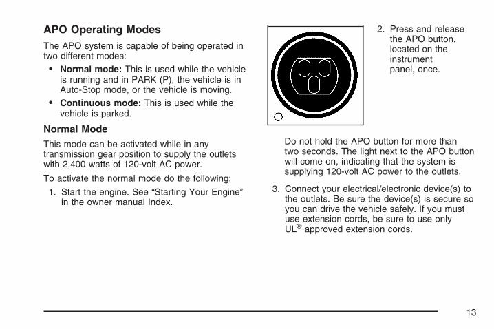
APO Operating ModesThe APO system is capable of being operated intwo different modes:
• Normal mode: This is used while the vehicleis running and in PARK (P), the vehicle is inAuto-Stop mode, or the vehicle is moving.
• Continuous mode: This is used while thevehicle is parked.
Normal ModeThis mode can be activated while in anytransmission gear position to supply the outletswith 2,400 watts of 120-volt AC power.
To activate the normal mode do the following:
1. Start the engine. See “Starting Your Engine”in the owner manual Index.
2. Press and releasethe APO button,located on theinstrumentpanel, once.
Do not hold the APO button for more thantwo seconds. The light next to the APO buttonwill come on, indicating that the system issupplying 120-volt AC power to the outlets.
3. Connect your electrical/electronic device(s) tothe outlets. Be sure the device(s) is secure soyou can drive the vehicle safely. If you mustuse extension cords, be sure to use onlyUL® approved extension cords.
13

If the system stops supplying 120-volt AC powerunexpectedly and the APO button starts flashing,the system has detected an overload or groundfault condition. To reset the system see “Resettingthe Short Circuit, Overload or Ground FaultDetection (GFD) Circuit” later in this section.
The APO system will operate in the normal modeuntil you turn it off by doing one of the following:
• Pressing the APO button. The light in theAPO button will turn off.
• Turning the ignition switch to ACCESSORY orLOCK. See “Ignition Positions” in your ownermanual Index.
Continuous ModeThis mode can be operated only when the vehicle isnot moving and the transmission is in PARK (P) andwill provide up to 2,400 watts of 120-volt AC powerto the outlets.
Continuous mode can be operated with the keyremoved from the ignition. The engine willrun continuously in this mode to supply electricalpower to the APO system.
You can use the vehicle as a generator in thismode when no electrical power outlets areavailable or during instances such as poweroutages. Use this mode to power criticalappliances rather than an entire circuit in ahome/building. Never connect the APO systemoutlets directly to a building’s circuitry or anotherpower supply.
For more information on running your vehiclewhile it is parked, see “Parking Over Things thatBurn,” “Engine Exhaust,” and “Running YourEngine While You Are Parked” in your ownermanual Index.
14

To activate the continuous mode, do the following:
1. Place the transmission in PARK (P) withthe ignition in RUN and the engine running.See “Ignition Positions” in your owner manualIndex.
2. Press and hold theAPO button, locatedon the instrumentpanel, for more thantwo seconds.
The light next to the APO button should begin toflash and the DIC message, 120V READY willappear.
3. Turn the ignition key to LOCK while the lightis flashing. The light will flash for up to30 seconds. When the ignition key has beenturned to LOCK, the light next to the APOswitch will stop flashing and remain on. Theengine will continue to run.
4. Connect your 120-volt AC electrical/electronicdevice(s) to the outlets. If you must useextension cords, be sure to use onlyUL® approved extension cords.
15

You can remove the key from the ignition at thispoint.
{CAUTION:
Leaving children in a vehicle with theignition key is dangerous for manyreasons. They could operate the powerwindows or other controls or even makethe vehicle move. The children or otherscould be badly injured or even killed.Do not leave the keys in a vehicle withchildren.
16

If the system stops supplying 120-volt AC powerunexpectedly and the light next to the APObutton starts flashing, the system has detected anoverload or ground fault condition. To reset thesystem see “Resetting the Short Circuit, Overloador Ground Fault Detection (GDF) Circuit” laterin this section.
The APO system will operate in the continuousmode with the engine running until one ofthe following occurs:
• You press the APO button. The light in theAPO button will turn off and the engine willturn off.
• If the fuel level gets low.
A FUEL LEVEL LOW message will appear inthe DIC and the horn will sound intermittentlyfor five seconds every minute for five minutes.
If the vehicle is left unattended for the fullfive minute warning, the engine and APOsystem will shut down, unless the APO button ispressed during the five minute warning period.See DIC Warnings and Messages on page 24for more information on the FUEL LEVEL LOWmessage.
• An overload or ground fault condition isdetected and not reset in five minutes.
• Vehicle security is violated.
• Engine oil pressure becomes too low.
• Engine coolant temperature becomes too hot.
• The ignition key is moved out of LOCK.
This may display an OIL PRESSURE LOW DICwarning message and chimes which is anormal condition when the APO button was notused to shut off the continuous mode.
• The Hybrid power system becomes too hot.
17

Resetting the Short Circuit, Overloador Ground Fault Detection (GFD) CircuitTo reset the Short Circuit, Overload or GroundFault Detection (GFD) Circuit while operatingin both the normal and continuous modes, ensureany observed fault is removed, and press theAPO button. The light next to the button willilluminate indicating that the system is supplying120-volt AC power to the outlets. In the case of anengine shutdown due to a ground fault while inthe continuous mode, restart the engine by turningthe key from LOCK to START, then follow theinstructions for entering APO Continuous Modeearlier in this section.
Starting and Operating YourVehicle
Starting Your Vehicle
{CAUTION:
There is something about your vehiclethat can make it move suddenly, and youor others can be seriously injured. Thiscan happen if the vehicle is in the AutoStop mode, and the shift lever is inDRIVE (D). Because your vehicle has theAutomatic Engine Start/Stop feature, yourvehicle’s engine might seem to be shut offwhen you come to a complete stop.
CAUTION: (Continued)
18

CAUTION: (Continued)
However, if you then start to exit thevehicle, as soon as you take your foot offthe brake pedal, the engine will start againand the vehicle can move forward. If youare going to exit your vehicle, first shift toPARK (P) and turn the ignition to LOCK.Then exit.
Your vehicle has an automatic engine start/stopfeature. This feature can cause the engine to turnoff when you are applying the brake and goingless than 10 mph (16 km/h), or when you come toa complete stop. When you take your foot offthe brake pedal, the engine will start again and youwill continue forward. However, if you are on anincline, your vehicle may roll backwards ashort distance until the engine performs the autostart. To be sure your vehicle will not move or roll,always keep your foot firmly on the brake pedaluntil you are ready for the vehicle to move.
Start the engine just as you would any normalengine. Also see “Starting Your Engine” inthe Index of the owner manual for moreinformation on starting. After the engine is startedand has reached operating temperature, it willshut off automatically when bringing the vehicle toa stop — usually the engine will shut off beforea complete stop if you are braking at speeds belowabout 13 mph (21 km/h). If you are pulling atrailer and your trailer is equipped with trailerbrakes, see Towing a Trailer on page 32 for moreinformation.
To restart the engine during the auto stop, releasethe brake pedal and the engine will startimmediately. The vehicle will operate as a normalvehicle, until the next stop.
19

Automatic Engine Start/Stop OverrideThe automatic engine start/stop overridefeature may cause the engine to remain running ata complete stop or may start the engine at acomplete stop. The following are reasonswhy either of these conditions may beencountered.
The engine will stay running at a complete stop orwill automatically start from a complete stop if:
• The outside temperatures are high — usuallyabove 95°F (35°C). The climate control systemis working to cool the cabin in AUTO mode. SeeClimate Controls on page 24.
• You release the brake pedal in DRIVE (D) orTHIRD (3) — even slightly.
• The shift lever is in NEUTRAL, REVERSE (R),SECOND (2) or FIRST (1).
• The battery pack charge is low.
• The tow/haul mode is active.
• The transfer case is in 4LO.
• The brake pedal has been released for morethan three seconds while the vehicle is inPARK (P).
• It is necessary to maintain 120-volt APOoperation for loads greater than 1kw.
• The hood is not fully closed.
20

Manual Override System
To manually override the automatic enginestart/stop system, press the tow/haul switch,located on the end of the column shift lever.
When the tow/haulmode has beenactivated, this light willcome on in theinstrument cluster.
This system disables the engine from performingthe auto stop function. While not required, youmight choose to use this during frequentstart/stops, while driving on grades or in heavytraffic.
Press the tow/haul switch again, or turn theignition off, to enable the auto stop function.The indicator light on the cluster will go out.
21

✍ NOTES
22

Climate Controls ........................................... 24Driver Information Center (DIC) ................... 24
DIC Warnings and Messages ...................... 24
Section 3 Instrument Panel
23

Climate ControlsFor more information on your vehicle’s climatecontrol system, see “Climate Control System” inthe owner manual Index.
Air Conditioning Engine Start/StopOverrideWith the system in AUTO mode in warm or hotweather, the engine may continue to run ata complete stop, or it may re-start during acomplete stop if the system determines that it isnecessary to run the air conditioning compressorto cool the cabin and/or dehumidify the air.
The system may allow the engine to shut off if thecabin temperature selected is met, but engineoff time will usually be short.
If you would like to get maximum engine off timein hot weather, select manual operation for vent orbi-level mode; this will prevent the system fromkeeping the engine running at complete stops;however, this does not provide maximum airconditioning performance.
Selecting a higher air conditioning temperature inhot weather will maximize engine off time.
Driver Information Center (DIC)
DIC Warnings and MessagesWarning messages are displayed on the DIC tonotify the driver that the status of the vehiclehas changed and that some action may be neededby the driver to correct the condition. If there ismore than one message that needs to bedisplayed they will appear one after another.Some messages may not require immediate actionbut you should press the select button or thetrip odometer reset stem on the instrument panelcluster to acknowledge that you received themessage and clear it from the display. Somemessages cannot be cleared from the displaybecause they are more urgent; these messagesrequire action before they can be removedfrom the DIC display. The following are thepossible messages that can be displayed andsome information about them. For information onother DIC messages, see “DIC Warnings andMessages” in the owner manual Index.
24

42V SWITCH OFFWhen a fuse in the 42-volt battery system isblown, the battery cut off (BCO) switch is open orthe battery disconnect switch is open, thismessage will appear. It will clear when the problemis fixed, when the battery disconnect switch isclosed or by pressing the DIC select button or thetrip reset stem on the instrument panel cluster.The fuse on the 42-volt battery pack can only bereplaced and the automatic battery disconnectcan only be closed by a qualified servicetechnician. See Fuses and Circuit Breakers onpage 56 and Battery Disconnect Switch onpage 54 and “Instrument Panel Cluster” in theowner manual Index for more information.
120V DISABLEDThis message will display when the hybrid’s powersystem is too hot to function in the APO normalmode. This message will display for 10 seconds oruntil the system cools down. This message willalso display for 10 seconds each time the APO isactivated while the system is too hot to function.See “Normal Mode” under Auxiliary PowerOutlet (APO) System on page 10.
120V GROUND FAULTThis message will display when the APO normalor continuous mode turns off due to an electricalground fault.
When in the normal mode, the message willdisplay for 10 seconds.
When in the continuous mode, the engine willcontinue to run for five minutes after a ground faultcondition is identified and the APO is not reset.The message will be displayed the entire time theengine is running. See “Resetting the ShortCircuit, Overload or Ground Fault Detection (GFD)Circuit” under Auxiliary Power Outlet (APO)System on page 10.
25

120V OVERLOADThis message will display when the APO normalor continuous mode turns off due to an electricaloverload fault.
When in the normal mode, the message willdisplay for 10 seconds.
When in the continuous mode, the engine willcontinue to run for five minutes after an overloadcondition is identified and the APO is not reset.The message will be displayed the entire time theengine is running. See “Resetting the ShortCircuit, Overload or Ground Fault Detection (GFD)Circuit” under Auxiliary Power Outlet (APO)System on page 10.
120V READYThis message will display and the light in the APObutton will flash when the system is ready/waitingto enter the continuous mode for 30 secondsor until the ignition is turned to LOCK. See“Continuous Mode” under Auxiliary PowerOutlet (APO) System on page 10.
120V SYSTEM FAULTThis message will display when the APO normalor continuous mode turns off due to a system fault.
When in the normal mode, the message willdisplay for 10 seconds.
When in the continuous mode, the message willdisplay for 60 seconds and the engine will turn off.It will also display for 10 seconds the next timethe engine is started until the problem is fixed. SeeAuxiliary Power Outlet (APO) System on page 10.
BATTERY NOT CHARGINGIf the hybrid battery system faults or fails(42-volt or 12-volt system), this message willappear on the DIC. The engine auto start/stopfeature will be disabled and the battery/chargingsystem light will appear in the instrumentpanel cluster. See “Battery Warning Light” in theowner manual Index.
Driving with this light on could drain your batteries.Have the electrical system checked as soon aspossible. Pressing the select button or thetrip odometer reset stem on the instrument panelcluster will acknowledge this message andclear it from the DIC display.
26

ENGINE AUTO START MODEWhen the vehicle is in PARK (P) and the autostop function is active, this message will display tolet you know that the engine may startautomatically at any given time. This message willclear when the vehicle is taken out of PARK(P), if the key is turned to LOCK, or whenthe engine auto starts.
Pressing the DIC select button or the trip odometerreset stem on the instrument panel cluster willalso clear the message.
ENGINE COOLANT HOTIf the engine cooling system temperature gets hot,this message will appear on the DIC. Stop thevehicle and let the engine idle in PARK (P) to allowthe coolant to reach a safe temperature. Thismessage will clear when the coolant temperaturedrops to a safe operating temperature. See“Cooling System” in the owner manual Index formore information.
The APO continuous mode will also stop operatingwhen this message comes on. See “ContinuousMode” under Auxiliary Power Outlet (APO) Systemon page 10.
FUEL LEVEL LOWIf the fuel level is low while the APO system is incontinuous mode, this message will appear onthe DIC and the horn will sound for five secondsevery minute for five minutes. Refuel as soonas possible. If the vehicle is left unattended for thefull five minute warning, the engine and APOsystem will shut down, unless the APO button ispressed during the five minute warning period. See“Continuous Mode” under Auxiliary PowerOutlet (APO) System on page 10.
Pressing the select button or the trip odometerreset stem on the instrument panel clusterwill acknowledge this message immediately andclear it from the DIC display. It will also clear itselfafter five minutes. The low fuel light near thefuel gage will still remain on in either case. See“Fuel Gage” and “Instrument Panel Cluster” in theowner manual Index.
27

HOOD AJARIf the hood is not fully closed, this message willappear on the display. Close the hood to clear themessage. Pressing the select button or the tripstem on the instrument panel cluster willacknowledge this message and clear it from theDIC display also.
When this message is displayed, the autostart/stop function will not operate with the hoodopen. If the vehicle is in auto stop mode when thismessage appears, you will have to restart theengine with the ignition key. See StartingYour Vehicle on page 18.
OIL PRESSURE LOWIf engine oil pressure is low, this message will bedisplayed on the DIC. Stop the vehicle as soonas safely possible and do not operate it untilthe cause of the low oil pressure has beencorrected. Check your oil as soon as possible andhave your vehicle serviced. See “Engine Oil” inthe owner manual Index.
The APO continuous mode will stop operatingwhen this message comes on. The message willreappear for 60 seconds when the vehicle isshut off and 10 seconds when restarted to let youknow why the APO continuous mode wascanceled. See “Continuous Mode” under AuxiliaryPower Outlet (APO) System on page 10.
SECURITYThis message, along with the security light on theinstrument panel cluster, will appear on theDIC for 60 seconds when a security violation hasoccurred. The APO continuous mode willcancel at this time. See “Theft-Deterrent Systems”in the owner manual Index.
SERVICE 42V BATTERIESThis message will display when the 42-voltbatteries need service or replacement due to ageor if a failure condition is present. This messagewill be displayed for 10 seconds and then willdisplay again each time the ignition key is turnedfrom LOCK to RUN. See Battery on page 47for more information.
28

SERVICE BRAKE SYSTEMIf you hear four short chimes along with the brakesystem warning light and this message alternatingwith the SERVICE STEER SYSTEM message,the power assist system is not working. Youwill still be able to steer and brake, but it will bemuch more difficult. Pull off the road to a safelocation and have your vehicle towed to thenearest dealer for service. See “Brakes,” “BrakeSystem Warning Light,” and “ABS Brake SystemWarning Light” in the owner manual Index.
SERVICE STEER SYSTEMIf the SERVICE STEER SYSTEM message isdisplayed without any chimes, the power assistsystem will continue to function, but it maybe more difficult to steer. Have the steering systemserviced as soon as possible. Also, see “SERVICEBRAKE SYSTEM” listed previously.
29

✍ NOTES
30

Your Driving, the Road, andYour Vehicle .............................................. 32Regenerative Braking .................................. 32
Towing .......................................................... 32Towing a Trailer .......................................... 32
Section 4 Driving Your Vehicle
31

Your Driving, the Road, andYour Vehicle
Regenerative BrakingYour vehicle has a regenerative braking system.This system works whenever you take your foot offthe accelerator pedal while your vehicle ismoving in DRIVE (D). This causes your vehicle toslow down slightly faster. It may feel like thebrake pedal is being pressed, even when it is not.
Regenerative braking takes some of the energyfrom the moving vehicle and turns it back intoelectrical energy. This energy is then stored backinto the vehicle’s 42-volt battery system,contributing to increased fuel efficiency.
Towing
Towing a TrailerFor more information, see “Towing a Trailer” inyour owner manual Index.
Weight of the TrailerHow heavy can a trailer safely be?
It depends on how you plan to use your rig. Forexample, speed, altitude, road grades, outsidetemperature and how much your vehicle is used topull a trailer are all important. And, it can alsodepend on any special equipment that you haveon your vehicle.
Use the charts following to determine how muchyour vehicle can weigh, based upon yourvehicle model and options.
Maximum trailer weight is calculated assuming thedriver and one passenger are in the tow vehicleand it has all the required trailering equipment. Theweight of additional optional equipment,passengers and cargo in the tow vehicle must besubtracted from the maximum trailer weight.
Above the 5,000 lbs (2 268 kg) trailer rating, thehandling/trailering suspension is required ontwo-wheel drive 1500 series models and thehandling/trailering or off-road suspension isrequired on four-wheel drive 1500 series models.
32

C-1500 Extended Cab Short Box (2WD)Vehicle Axle Ratio Maximum Trailer Weight GCWR
5300 V8 3.233.73
6,700 lbs (3 039 kg)7,700 lbs (3 493 kg)
12,000 lbs (5 443 kg)13,000 lbs (5 897 kg)
Hybrid vehicles are neither designed nor intended to tow fifth-wheel or gooseneck trailers.
K-1500 Extended Cab Short Box (4WD)Vehicle Axle Ratio Maximum Trailer Weight GCWR
5300 V8 3.423.73
7,400 lbs (3 356 kg)7,400 lbs (3 356 kg)
13,000 lbs (5 897 kg)13,000 lbs (5 897 kg)
Hybrid vehicles are neither designed nor intended to tow fifth-wheel or gooseneck trailers.
The Gross Combination Weight Rating (GCWR) isthe total allowable weight of the completelyloaded vehicle and trailer including anypassengers, cargo, equipment and conversions.The GCWR for your vehicle should not beexceeded.
Trailer BrakesIf you are towing a trailer that is equipped withtrailer brakes and you manually apply thetrailer brakes while driving slower than 13 mph(21 km/h), your vehicle may go into auto stopmode even if you are not pressing on the vehicle’sbrakes.
Using the trailer brake system manually can makeyour hybrid vehicle perform as if you are usingthe brake pedal in the vehicle. The trailerbrake operation check will still work. If youmanually apply the trailer brakes for an extendedperiod of time, the SERVICE BRAKE SYSTEMDIC message will come on. The message will gooff after the trailer brakes have been released.No other action is necessary. For moreinformation, see “Trailer Brakes” in the ownermanual Index.
33

✍ NOTES
34

Service .......................................................... 37Doing Your Own Service Work .................... 37
Checking Things Under the Hood ............... 38Engine Compartment Overview ................... 38Automatic Transmission Fluid ...................... 40SGCM Coolant Surge Tank
Pressure Cap ........................................... 40Cooling System ........................................... 41Power Steering Fluid ................................... 46Battery ........................................................ 47Jump Starting .............................................. 48
Electrical System .......................................... 54Battery Disconnect Switch ........................... 54Fuses and Circuit Breakers ......................... 56
Tires .............................................................. 59Changing a Flat Tire ................................... 59
Capacities and Specifications ...................... 63
Section 5 Service and Appearance Care
35

✍ NOTES
36

Service
Doing Your Own Service Work
{CAUTION:
Never try to do your own service onhybrid components. You can be injuredand your vehicle can be damaged if youtry to do your own service work. Serviceand repair of these hybrid componentsshould only be performed by a GM-trainedservice technician with the properknowledge and tools.
37

Checking Things Under the Hood
Engine Compartment OverviewWhen you open the hood on your vehicle, you will see the following:
38

A. Starter Generator Control Module (SGCM)Coolant Surge Tank. See Cooling Systemon page 41.
B. Starter Generator Control Module (SGCM).See Cooling System on page 41.
C. Engine Oil Dipstick. See “Engine Oil” in theowner manual Index.
D. Automatic Transmission Dipstick. SeeAutomatic Transmission Fluid on page 40.
E. Brake Fluid Reservoir. See “Brakes” inthe owner manual Index.
F. Hybrid Underhood Fuse Block. See Fuses andCircuit Breakers on page 56.
G. Underhood Fuse Block. See “Underhood FuseBlock” in the owner manual Index.
H. Engine Air Cleaner/Filter. See “Engine AirCleaner/Filter” in the owner manual Index.
I. Air Filter Restriction Indicator (If Equipped).See “Engine Air Cleaner/Filter” in the ownermanual Index.
J. Engine Coolant Surge Tank. See “CoolingSystem” in the owner manual Index.
K. Engine Oil Fill. See “Engine Oil” in the ownermanual Index.
L. Remote Negative (−) Terminal (GND). SeeJump Starting on page 48.
M. Electrohydraulic Power Steering Fluid Reservoir.See Power Steering Fluid on page 46.
N. Remote Positive (+) Terminal. See JumpStarting on page 48.
O. 12-Volt Battery. See Battery on page 47.P. Windshield Washer Fluid Reservoir. See
“Windshield Washer Fluid” in the ownermanual Index.
39

Automatic Transmission FluidFor more information, see “AutomaticTransmission Fluid” in the owner manual Index.
Checking the Fluid Level
Your vehicle’s automatic transmission dipsticklooks like this. For more information on location,see Engine Compartment Overview on page 38.
SGCM Coolant Surge TankPressure Cap
See EngineCompartment Overviewon page 38 for moreinformation on location.
The hybrid coolant surge tank pressure capmust be fully installed on the hybrid coolantsurge tank.
Notice: If the pressure cap is not tightlyinstalled, coolant loss and possible damage tothe Starter Generator Control Module (SGCM)may occur. Be sure the cap is properly andtightly secured.
40

Cooling System
Starter Generator ControlModule (SGCM) Cooling SystemIn addition to your vehicle’s regular cooling system,your vehicle is also equipped with a coolingsystem for the SGCM system. This system isserviced differently than the vehicle’s main coolingsystem. The SGCM cooling system includesthe SGCM coolant surge tank, SGCM surge tankpressure cap, SGCM cooling pump and theStarter Generator Control Module (SGCM). TheSGCM cooling system uses the same type ofcoolant as the vehicle’s regular cooling system, butthe two systems operate separately andindependently. See “Engine Coolant” and “CoolingSystem” in the Index of the owner’s manual formore information.
When you decide it is safe to lift the hood, here iswhat you will see:
A. SGCM CoolantPressure Tank Cap
B. Starter GeneratorControl Module(SGCM)
C. SGCM Cooling Hoses
D. SGCM CoolantSurge Tank
E. Engine CoolantSurge Tank andPressure Cap
F. SGCM CoolingPump (Out of View)
41

If the coolant inside the SGCM coolant surge tank isboiling, do not do anything else until it cools down.
The coolant level should be at or above the FULLCOLD mark with the vehicle parked on a levelsurface. If it is not, you may have a leak atthe SGCM heat transfer core, SGCM pressurecap, SGCM auxiliary radiator hoses, SGCMcooling pump or somewhere else in the SGCMcooling system.
Notice: Running the engine when there is aleak in the hybrid cooling system cancause the hybrid cooling system to lose allcoolant and can damage the system. Get anyleak fixed before you drive the vehicle orrun the engine.
42
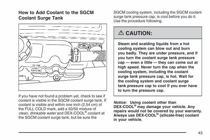
How to Add Coolant to the SGCMCoolant Surge Tank
If you have not found a problem yet, check to see ifcoolant is visible in the SGCM coolant surge tank. Ifcoolant is visible and within one inch (2.54 cm) ofthe FULL COLD mark, add a 50/50 mixture ofclean, drinkable water and DEX-COOL® coolant atthe SGCM coolant surge tank, but be sure the
SGCM cooling system, including the SGCM coolantsurge tank pressure cap, is cool before you do it.Use the procedure following.
{CAUTION:
Steam and scalding liquids from a hotcooling system can blow out and burnyou badly. They are under pressure, and ifyou turn the coolant surge tank pressurecap — even a little — they can come out athigh speed. Never turn the cap when thecooling system, including the coolantsurge tank pressure cap, is hot. Wait forthe cooling system and coolant surgetank pressure cap to cool if you ever haveto turn the pressure cap.
Notice: Using coolant other thanDEX-COOL® may damage your vehicle. Anyrepairs would not be covered by your warranty.Always use DEX-COOL® (silicate-free) coolantin your vehicle.
43

{CAUTION:
You can be burned if you spill coolant onhot engine parts. Coolant containsethylene glycol and it will burn if theengine parts are hot enough. Do not spillcoolant on a hot engine.
If the SGCM coolant is more than one inch(2.54 cm) below the FULL COLD mark, yourvehicle must be serviced by your dealer and aspecial fill procedure must be followed.
Notice: Attempting to fill the hybrid coolingsurge tank yourself when the fluid level is morethan 1 inch (2.54 cm) below the FULL COLDmark can damage your vehicle. Your vehiclemust be serviced.
1. Park the vehicle on a level surface and turnthe vehicle off. You can remove the SGCMcoolant surge tank pressure cap whenthe SGCM cooling system, including theSGCM coolant surge tank pressure cap andSGCM cooling hoses, are no longer hot.Turn the SGCM coolant surge tank pressurecap slowly counterclockwise (left) aboutone full turn. Wait 30 seconds.
44

2. Then keep turning the SGCM coolant surgetank pressure cap slowly, and remove it.
3. Add the proper coolant mixture to the SGCMcoolant surge tank until the level reaches theFULL COLD mark.
4. Then replace theSGCM coolantsurge tank pressurecap. Be sure thepressure capis hand-tight andfully seated.
Notice: Using cooling system sealers orconditioners in an attempt to stop coolantleaks can damage the SGCM and enginecooling systems. Never use cooling systemsealers or conditioners in your cooling system.
45

Power Steering Fluid
When to Check Power Steering FluidIt is not necessary to regularly check powersteering fluid unless you suspect there is a leak inthe system or you hear an unusual noise. Afluid loss in this system could indicate a problem.Have the system inspected and repaired. SeeEngine Compartment Overview on page 38for reservoir location.
How to Check Power Steering FluidTurn the key off, let the engine compartmentcool down.
Locate the power steering reservoir and cap. Wipethe cap and the top of the reservoir clean, thenunscrew the cap and wipe the dipstick with a cleanrag. Replace the cap and completely tighten it.Then remove the cap again and look at thefluid level on the dipstick.
The level should be at the FULL COLD mark. Ifnecessary, add only enough fluid to bring the levelup to the mark.
46

What to UseTo determine what kind of fluid to use, seeRecommended Fluids and Lubricants on page 66for more information. Your hybrid vehiclerequires a special power steering fluid. Always usethe proper fluid. Failure to use the proper fluidcan cause leaks and damage hoses, sealsand other steering system parts and repairs maynot be covered by your vehicle’s warranty.
BatteryYour vehicle has a standard 12-volt battery and a42-volt hybrid battery system.
When it is time for a new standard 12-volt battery,get one that has the replacement numbershown on the original battery’s label. Werecommend an ACDelco® replacement battery.
When it is time for a new 42-volt hybrid batterysystem, see your dealer.Warning: Battery posts, terminals, and relatedaccessories contain lead and lead compounds,chemicals known to the State of Californiato cause cancer and reproductive harm. Washhands after handling.
Vehicle StorageIf you are not going to drive your vehicle for30 days or more you should disconnect thestandard 12-volt battery. Remember to reconnectthe battery when you are ready to drive yourvehicle. You should also disconnect the 42-volthybrid battery system. See Battery DisconnectSwitch on page 54.
{CAUTION:
Batteries have acid that can burn you andgas that can explode. You can be badlyhurt if you are not careful. See JumpStarting on page 48 for tips on workingaround a battery without getting hurt.
47

Jump StartingIf your 42-volt battery has run down, you maywant to use another vehicle’s 12-volt battery andjumper cables to start your vehicle. Jumpstarting your hybrid vehicle may take considerablylonger than a regular vehicle. You may have towait 10 to 20 minutes total for your vehicleto charge from the other vehicle’s good 12-voltbattery in order to start your vehicle. Use thefollowing steps to do it safely:
{CAUTION:
Batteries can hurt you. They can bedangerous because:
• They contain acid that can burn you.• They contain gas that can explode or
ignite.• They contain enough electricity to
burn you.
If you do not follow these steps exactly,some or all of these things can hurt you.
Notice: Ignoring these steps could result incostly damage to your vehicle that wouldnot be covered by your warranty.
Trying to start your vehicle by pushing orpulling it will not work, and it could damageyour vehicle.
1. Check to see that the battery disconnectswitch on your hybrid vehicle is in thepower position. If it is not, turn it clockwiseuntil it stops and then try to start your vehicle.See Battery Disconnect Switch on page 54for more information. If your vehicle still won’tstart, continue to Step 2.
2. Check the other vehicle. It must have a12-volt battery with a negative ground system.
Notice: If the other vehicle’s system is not a12-volt system with a negative ground,both vehicles can be damaged. Only usevehicles with 12-volt systems with negativegrounds to jump start your vehicle.
48

3. Get the vehicles close enough so the jumpercables can reach, but be sure the vehicles arenot touching each other. If they are, it couldcause a ground connection you do notwant. You would not be able to start yourvehicle, and the bad grounding could damagethe electrical systems.To avoid the possibility of the vehicles rolling,set the parking brake firmly on both vehiclesinvolved in the jump start procedure. Putan automatic transmission in PARK (P) or amanual transmission in NEUTRAL beforesetting the parking brake.
Notice: If you leave your radio or otheraccessories on during the jump startingprocedure, they could be damaged. The repairswould not be covered by your warranty.Always turn off your radio and otheraccessories when jump starting your vehicle.
4. Turn off the ignition on both vehicles.Unplug unnecessary accessories plugged intothe cigarette lighter and accessory poweroutlets. Turn off the radio and all lamps thatare not needed. This will avoid sparksand help save both batteries. And it couldsave your radio!
5. Open the hoods and locate the positive (+)and negative (−) terminal locations of theother vehicle.Your vehicle has a remote positive (+) 12-voltjump starting terminal and a remotenegative (−) jump starting terminal. You shouldalways use these remote terminals insteadof the terminals on the battery.
The remote positive (+) terminal is locatedunder a red plastic cover near the center of theengine compartment. See Engine CompartmentOverview on page 38. To access the remotepositive (+) terminal, open the red plastic cover.
49
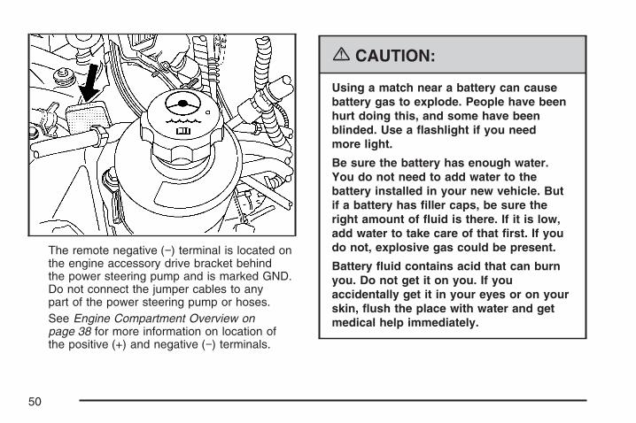
The remote negative (−) terminal is located onthe engine accessory drive bracket behindthe power steering pump and is marked GND.Do not connect the jumper cables to anypart of the power steering pump or hoses.See Engine Compartment Overview onpage 38 for more information on location ofthe positive (+) and negative (−) terminals.
{CAUTION:
Using a match near a battery can causebattery gas to explode. People have beenhurt doing this, and some have beenblinded. Use a flashlight if you needmore light.
Be sure the battery has enough water.You do not need to add water to thebattery installed in your new vehicle. Butif a battery has filler caps, be sure theright amount of fluid is there. If it is low,add water to take care of that first. If youdo not, explosive gas could be present.
Battery fluid contains acid that can burnyou. Do not get it on you. If youaccidentally get it in your eyes or on yourskin, flush the place with water and getmedical help immediately.
50

{CAUTION:
An electric fan can start up even when theengine is not running and can injure you.Keep hands, clothing and tools away fromany underhood electric fan.
{CAUTION:
Fans or other moving engine parts caninjure you badly. Keep your hands awayfrom moving parts once the engine isrunning.
6. Check that the jumper cables do not haveloose or missing insulation. If they do, youcould get a shock. The vehicles couldbe damaged too.Before you connect the cables to the othervehicle, here are some basic things you shouldknow. Positive (+) will go to positive (+) or to
a remote positive terminal (+) if the vehicle hasone. Negative (−) will go to a heavy, unpaintedmetal engine part or to a remote negative (−)terminal, if the vehicle has one.Do not connect positive (+) to negative (−) oryou will get a short that would damagethe battery and maybe other parts too.
7. Connect the red positive (+) cable to theremote positive (+) terminal of your hybridvehicle.
51

8. Do not let the other end touch metal. Connectit to the positive (+) terminal of the goodbattery. Use a remote positive (+) terminal ifthe other vehicle has one.
9. Now connect the black negative (−) cable tothe negative (−) terminal of the good battery.Use a remote negative (−) terminal if thevehicle has one.
Do not let the other end touch anything untilthe next step. The other end of the negative (−)cable doesn’t go to the dead battery. It goesto your vehicle’s remote negative (−) terminal,marked GND. The electrical connection isjust as good there, and the chance of sparksgetting back to the battery is much less.
10. Now start the vehicle with the good battery.
11. Try to start the hybrid vehicle. Hold the key inthe start position for at least three seconds.If the hybrid vehicle still does not start, turn thekey to LOCK and wait 5 minutes.
12. After 5 minutes try to start the hybrid vehicleagain.
13. Repeat steps 11 and 12 several more timesas necessary. If the hybrid vehicle still will notstart, your vehicle needs service.
Notice: If the jumper cables are connected orremoved in the wrong order, electricalshorting may occur and damage the vehicle.The repairs would not be covered by yourwarranty. Always connect and removethe jumper cables in the correct order, makingsure that the cables do not touch each otheror other metal.
52

A. Remote Negative (−) Terminal on hybridvehicle.
B. Good Battery or Remote Positive (+) andNegative (−) Terminals on other vehicle.
C. Remote Positive (+) Terminal on hybrid vehicle.
To disconnect the jumper cables from bothvehicles do the following:
1. Disconnect the black negative (−) cable fromthe hybrid vehicle.
2. Disconnect the black negative (−) cable fromthe vehicle with the good battery.
3. Disconnect the red positive (+) cable from thevehicle with the good battery.
4. Disconnect the red positive (+) cable from thehybrid vehicle.
5. Return the positive (+) remote terminal coveron your hybrid vehicle to its original position.
Jumper Cable Removal
53

Electrical System
Battery Disconnect Switch
Notice: Placing items that weigh more than200 lbs (90 kg) on the battery box maycause damage to the battery box and electricalsystem. Never place items weighing morethan 200 lbs (90 kg) on the battery box.
If you will not be using your vehicle for a period of30 days or more, you will need to disconnect42-volt battery power from the vehicle to preventthe batteries from discharging.
Open the passenger side rear door to access thebattery box. The battery disconnect switch islocated on the passenger side of the battery box.
54

To access the battery disconnect switch anddisconnect battery power, do the following:
1. Turn the ignition key to LOCK.
2. Grab the tab at the top of the access doorand pull the top of the door out.
3. Pull the access cover up and out from theaccess opening.
4. Locate the battery disconnect switch.
5. Turn the switch counterclockwise until it stops.The 42-volt battery power is now disconnectedfrom the vehicle.This switch can be removed when it is in theoff (no power) position.When you are ready to reconnect batterypower to the vehicle, turn the switch clockwiseuntil it stops.
55

6. Reinstall the access door by first placing thetab on the access door into the slot on thelower edge of the battery box access opening.
7. Push the corners of the access door in untilthey snap into place.
If your 42-volt battery system is disconnected dueto an airbag inflation or right-side impact, youmust take your vehicle to a qualified service
technician to have the 42-volt battery systemreconnected. See What Will You See Afteran Airbag Inflates? on page 8 for more information.
Fuses and Circuit BreakersThe wiring circuits in your vehicle are protectedfrom short circuits by a combination of fuses,circuit breakers and fusible thermal links.This greatly reduces the chance of fires caused byelectrical problems.
Be sure you replace a bad fuse with a new one ofthe identical size and rating.
If you ever have a problem on the road and do nothave a spare fuse, you can borrow one that has thesame amperage. Just pick some feature of yourvehicle that you can get along without — like theradio or cigarette lighter — and use its fuse, if it isthe correct amperage. Replace it as soon asyou can.
Your vehicle also has a special fuse in the batterybox for the 42-volt batteries. If this fuse hasfailed and needs to be replaced, the vehicle willbe disabled and you will need to have your vehiclerepaired by your dealer. Do not attempt toself-service this fuse.
56

Hybrid Underhood Fuse Block
The hybrid underhood fuse block is located in theengine compartment on the driver’s side of thevehicle near the main underhood fuse block.
Lift the cover for access to the fuse/relay block.See Engine Compartment Overview on page 38 formore information on its location. For moreinformation on the main underhood fuse block see“Underhood Fuse Block” in the Index of yourowner manual.
To remove fuses, hold the end of the fusebetween your thumb and index finger and pullstraight out.
57

Relays UsageSGCM COOLANT
PUMP RELAYSGCM Coolant Fan Pump
RelayAUX HTR PUMP
RELAY Auxiliary Heater Pump
TRANS PUMP RELAY Transmission PumpPWR MAINT RELAY Power Maintain
Fuses UsageHYBRID PWR Hybrid CoolingCOOL PUMP SGCM Cooling PumpHYBRID 02B Hybrid Oxygen Sensors – Bank BHYBRID 02A Hybrid Oxygen Sensors – Bank APWR MAINT Power Maintain
AUX HTRPUMP Auxiliary Heater Pump
TRANS PUMP Transmission PumpEmpty Not UsedESCM Energy Storage Control ModuleHCM-B Hybrid Control Module – BatteryEmpty Not UsedHCM-I Hybrid Control Module – Ignition
EHPS-I Electrohydraulic PowerSteering – Ignition
Empty Not Used
58

Tires
Changing a Flat Tire
Removing the Jack and ToolsYour hybrid vehicle requires a different procedureto remove the jack and tools from the vehicle.See “Changing a Flat Tire” in the owner manualIndex for complete instructions on changing aflat tire.
The equipment is under the passenger’s sidesecond row seat behind the battery box. You mustfirst fold the seat cushion before removing thejack and tools. Use the following procedure:
1. Push down on thefront of the seatcushion while pullingdown on therelease strap locatedunder the seatcushion.
59

2. Fold the seat cushion upward until it latcheswith the seatback.
3. Push and pull on the seat cushion to makesure the seat is secure.
A. Jack and Wheel BlocksB. Wing NutC. Tool Kit
4. Turn the wing nut (B) counterclockwise untilloosened and flip the black retaining clip backto remove the storage bag and tools (C)from the vehicle.
60

5. Release the jack and wheel blocks (A) fromthe holder as an assembly by turning theyellow knob on the jack counterclockwise tolower the jack head.
6. Pull the jack back toward the seat bracket.
61
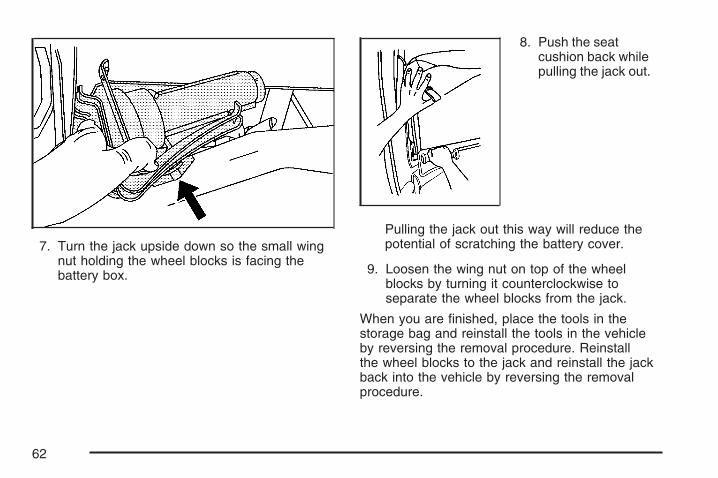
7. Turn the jack upside down so the small wingnut holding the wheel blocks is facing thebattery box.
8. Push the seatcushion back whilepulling the jack out.
Pulling the jack out this way will reduce thepotential of scratching the battery cover.
9. Loosen the wing nut on top of the wheelblocks by turning it counterclockwise toseparate the wheel blocks from the jack.
When you are finished, place the tools in thestorage bag and reinstall the tools in the vehicleby reversing the removal procedure. Reinstallthe wheel blocks to the jack and reinstall the jackback into the vehicle by reversing the removalprocedure.
62

Capacities and Specifications
ApplicationCapacities
English Metric
Hybrid Cooling System 2.1 quarts 2.0 L
After refill, the level must be rechecked.
Auxiliary Power Outlet (APO) SpecificationsMaximum Output Power 2.4 kw
Output Voltage 120 VAC +5% −8% measured at the outlets
Current Output (Maximum Continuous) 20 Amps
Output Frequency 60 Hz ± 0.25 Hz
Total Harmonic Distortion (THD) ≤10%
Overload Protection Level 21 A(rms) current limit for 5 seconds
Ground Fault Detection Level ≥6ma
63

✍ NOTES
64

Maintenance Schedule .................................. 66Recommended Fluids and Lubricants .......... 66Engine Drive Belt Routing ........................... 66
Section 6 Maintenance Schedule
65

Maintenance Schedule
Recommended Fluids andLubricantsFluids and lubricants identified below by name,part number, or specification may be obtained fromyour dealer.
Usage Fluid/Lubricant
Power SteeringSystem
Electrohydraulic PowerSteering Fluid(GM Part No. U.S. 88901975,in Canada 88901976).
StarterGenerator
Control Module(SGCM) Engine
Coolant
50/50 mixture of clean, drinkablewater and use only DEX-COOL®
Coolant. See “Engine Coolant” inthe owner manual.
For all other recommended fluids and lubricants,see “Recommended Fluids and Lubricants” inthe Index of your owner manual.
Engine Drive Belt Routing
66

120V DISABLED ........................................... 25120V GROUND FAULT ................................. 25120V OVERLOAD ......................................... 26120V READY ................................................ 26120V SYSTEM FAULT .................................. 2642V SWITCH OFF ........................................ 25
AAir Conditioning Engine Start/Stop Override ... 24Airbag System
What Will You See After an AirbagInflates? ................................................... 8
APO Operating Modes .................................. 13Automatic Engine Start/Stop Override ............ 20Automatic Transmission, Fluid ....................... 40Auxiliary Power Outlet (APO) System ............ 10
BBattery .......................................................... 47Battery Disconnect Switch ............................. 54BATTERY NOT CHARGING .......................... 26Braking
Regenerative ............................................. 32
CCapacities and Specifications ........................ 63Changing a Flat Tire ..................................... 59Checking the Fluid Level ............................... 40Climate Controls ............................................ 24Coolant
SGCM Surge Tank Pressure Cap .............. 40Cooling System ............................................. 41
67

DDriver Information Center (DIC)
Warnings and Messages ............................ 24
EEngine
Battery ....................................................... 47Compartment Overview .............................. 38
ENGINE AUTO START MODE ...................... 27ENGINE COOLANT HOT .............................. 27
FFluid, Power Steering .................................... 46FUEL LEVEL LOW ........................................ 27Fuses and Circuit Breakers ........................... 56
HHOOD AJAR ................................................. 28How to Add Coolant to the SGCM Coolant
Surge Tank ................................................ 43How to Check Power Steering Fluid .............. 46Hybrid Underhood Fuse Block ....................... 57
JJump Starting ................................................ 48
MManual Override System ............................... 21
68

OOIL PRESSURE LOW ................................... 28
PPower Steering Fluid ..................................... 46
RRegenerative Braking .................................... 32Removing the Jack and Tools ....................... 59Resetting the Short Circuit, Overload or
Ground Fault Detection (GFD) Circuit ........ 18Restraint System Check
Replacing Restraint System PartsAfter a Crash ........................................... 8
SSECURITY .................................................... 28SERVICE 42V BATTERIES ........................... 28SERVICE BRAKE SYSTEM .......................... 29Service, Doing Your Own Work ..................... 37SERVICE STEER SYSTEM .......................... 29Short Circuits, Overloads and Ground Fault
Detection (GFD) ......................................... 11Specifications, Capacities .............................. 63Starter Generator Control Module (SGCM)
Cooling System .......................................... 41Starting Your Vehicle ..................................... 18Surge Tank Pressure Cap, SGCM Coolant .... 40
69

TTires
Changing a Flat ......................................... 59Towing
Trailer ........................................................ 32Trailer Brakes ................................................ 33Transmission, Automatic Fluid ....................... 40
VVehicle Storage ............................................. 47
WWarranty Information ....................................... 3Weight of the Trailer ..................................... 32What is Covered ............................................. 4What is Not Covered ...................................... 5What to Use ................................................. 47When to Check Power Steering Fluid ............ 46
70