Embed Size (px)
Citation preview

2007 BUELL P3
SERVICE MANUAL
Part Number 99492-07YSection 1: Maintenance
Section 2: Chassis
Section 3: Engine
Section 4: Fuel System
Section 5: Starter
Section 6: Drive/Transmission
Section 7: Electrical
Appendix

HOME
APPENDIX A: TOOLS A.1
Part No. B-35316-5 12 Inch Bolt.Used with Part No. HD-39302.
Part No. B-41174 Rear Wheel Support Stand andPart No. B-41174-2 Replacement Pad.
Part No. B-41177 Front Fork Holding Tool
Part No. B-43933 Wheel Bearing Remover/Installer.Use with Part No. HD-44060.
Part No. B-43982 Sprocket Locking Tool
Part No. B-43983 Main Drive Gear Cross Plate.Used with Part No. HD-35316A.
Part No. B-43985 Transmission Remover/Installer
Part No. B-43987 Engine CradleUsed with HD-42310
Appendix A: Tools A-1

HOME
Part No. B-43991 Fork Seal/Bushing Driver
Part No. B-59000A Pro Level Oil Gauge
Part No. HD-25070 Robinair Heat Gun
Part No. HD-33446A Cylinder Torque Platesand Torque Plate Bolts Part No. HD-33446-86.
Part No. HD-33223-1 Cylinder Compression Gauge
Part No. HD-33413-A Carburetor Idle Adjustment Tool
Part No. HD-33416 Universal Driver Handle
Part No. HD-33418 Universal Puller Forcing Screw
A-2 Appendix A: Tools

HOME
Part No. HD-33813 Inductive Timing Light
Part No. HD-34623B Piston PinRetaining Ring Installer/Remover
Part No. HD-34643A Shoulderless Valve GuideSeal Installer
Part No. HD-34723 Valve Guide Hone (8 mm)
Part No. HD-34731 Shoulderless Valve Guide Installation Tool
Part No. HD-34736B Valve Spring Compressor
Part No. HD-34740 Driver Handle and Remover. Use with Part No. HD-34643A and art No. HD-34731.
Part No. HD-34751 Nylon Valve Guide Brush
Appendix A: Tools A-3

HOME
Part No. HD-34902-B Primary Bearing Race Remover/Installer
Part No. HD-35102 Wrist Pin Bushing Hone (20 mm)
Part No. HD-35316-A Main Drive Gear Remover/Installer and Main Drive Gear Bearing Installer.
Part No. HD-35381 Belt Tension Gauge
Part No. HD-35457 Black Light Leak Detector
Part No. HD-35500A Digital Multi-Meter (FLUKE 23)
Part No. HD-35518 Internal/ExternalRetaining Ring Pliers
Part No. HD-35667A Cylinder Leakdown Tester
CYLINDER LEAKDOWN TESTER
JHYUYGuibikhf iugu iu ptr td6rdFoihjolm oijfollkop Yuooifoihfm knsdl hlno hslnslnnsdl hlno bs npond bpdk kznh odlbndpob npond bndb n
CYLINDER LEAKDOWN TESTER
Bdhgkjsbkdv ' ksjjlkn lkknsdl hlno hslnsln nlslns finbp pffbodlbndpob nponno[bhoknsdl hlno hslnsln nlslns finbp pffbodlbndpob npdb ndbno[bhoknsdl hlno hslnslnnsdl hlno hso[bhoknsdl hlno hslnslp pffbodlbndpob npond bndb ndbno[bho
Bdhgkjsbkdv ' ksjjlkn lk knsdl hlno hslnsln nlslns finbp pffb odlbndpob nponno[bho knsdl hlno hslnsln nlslns finbp pklhb odlbndpob npdb ndbno[bho knsdl hlno hslnslnnsdl hlno hso[bho bs npond bpdk kznh odlbndpob npond bndb ndbno[bho
Bdhgkjsbkdv ' ksjjlkn lk knsdl hlno hslnsln nlslns finbp pffb odlbndpob nponno[bho knsdl hlno hslnsln nlslns finbp pklhb
Bdhgkjsbkdv Majjlkn Nolk
knsdl hlno hslnslnndpob npondBdhgkjsbkdv hlno hslnslpknsdl hlno hslnslnndpob npond
A-4 Appendix A: Tools

HOME
Part No. HD-35758 Neway Valve Seat Cutter Set
Part No. HD-37842A Inner/Outer Main Drive GearNeedle Bearing Installer
Part No. HD-38125-6 Packard Terminal Crimp Tool(Sealed and non-sealed connectors)
Part No. HD-38125-7 Packard Terminal Crimp Tool(Sealed connectors)
Part No. HD-38125-8 Packard Terminal Crimp Tool
Part No. HD-38361 Cam Gear Gauge Pin Set(0.108 in. (2.74 mm) Diameter)
Part No. HD-38362 Sprocket Locking Link
Part No. HD-38515-A Clutch Spring Compressing Tooland Part No. HD-38515-91 Forcing Screw.
Appendix A: Tools A-5

HOME
Part No. HD-38871- 2 Reamer. Use with Part No. B-43988 Camshaft Bushing Reamer Fixture
Part No. HD-39151 Shift Drum Retaining Ring Installer
Part No. HD-39301-A Steering Head BearingRace Remover
Part No. HD-39302 Steering Head BearingRace Installer
Part No. HD-39458 Sprocket Shaft Bearing OuterRace Installer
Part No. HD-39565 Engine Sound Probe
Part No. HD-39617 Inductive Amp Probe.Use with Part No. HD-35500A.
Part No. HD-39621 Electrical Terminal Repair Kit
TSPOR
STER
13
CC
40
A-6 Appendix A: Tools

HOME
Part No. HD-39782 Cylinder Head Support
Part No. HD-39786 Cylinder Head Holding Fixture
Part No. HD-39800 Oil Filter Crusher, Small
Part No. HD-39823 Oil Filter Crusher, Large
Part No. HD-39847 Universal Ratcheting Tap/Reamer Handle
Part No. HD-39932 (Steel) or HD-39932-CAR (Carbide) Intake and Exhaust Valve Guide Reamer.
Part No. HD-39964 Reamer Lubricant (Cool Tool)
Part No. HD-39965 Deutsch Terminal Crimp Tool
Appendix A: Tools A-7

HOME
Part No. HD-39969 Ultra-Torch UT-100
Part No. BU-44473 Tool Organizational System
Part No. HD-41137 Hose Clamp Pliers
Part No. HD-41155 VHS Video Shelf
Part No. HD-41183 Heat Shield Attachment.Use with Part No. HD-25070.
Part No. HD-41185 Hose Cutting Tool
Part No. HD-41185-1 Oil Hose Cutter-Replacement Blade
Part No. HD-41405 Main Drive Gear Seal Installer
A-8 Appendix A: Tools
HOME
Part No. HD-41496 Main Drive Gear Seal Installer
Part No. HD-41609 Amp Terminal Crimp Tool
Part No. HD-41675 Oil Pressure Sending Unit Wrench
Part No. HD-42310 Engine/Transmission Stand
Part No. HD-42310-150 Drip Tray.Use with Part No. HD-42310.
Part No. HD-42320 Piston Pin Remover/Installer
Part No. HD-42322 Piston Support Plate
Part No. HD-42376 Battery/Charging SystemLoad Tester
600 200
Made in USA
PP-9606- 0001
Appendix A: Tools A-9

HOME
Part No. HD-42579 Sprocket Bearing/Seal Installer
Part No. HD-42774 Sprocket Shaft Seal Installer
Part No. HD-43646 Engine Stand
Part No. HD-43984 Crankshaft Locking Tool
Part No. HD-44358 Flywheel Support Fixture
Part No. HD-43682-10 Drip pan. Use with Part No. HD-43682 or Part No. HD-43646.
Part No. HD-44069 Timkin Snap ring remover and installer. Use with Part No. HD-44404.
Part No. HD-44404 Timkin Bearing Remover. Use with Part No. HD-44069.
A-10 Appendix A: Tools

HOME
Part No. HD-94547-101 Crankshaft Bearing Outer Race Remover. Use with Part No. HD-94547-102.
Part No. HD-94547-102 Drive Handle. Use with Part No. HD-94547-101.
Part No. HD-94660-37B Mainshaft Locknut WrenchUse with Part No. B-43982.
Part No. HD-94800-26A Connecting Rod Bushing Reamers and Pilots
Part No. HD-94803-67 Intake Camshaft Bushing Reamer
Part No. HD-94804-57 Rocker Arm Bushing Reamer
Part No. HD-94812-1 Pinion Shaft Bushing Reamer.Use with Part No. HD-94812-87.
Part No. HD-94812-87 Pinion Shaft Reamer Pilot.Use with Part No. HD-94812-1.
Appendix A: Tools A-11

HOME
Part No. HD-95017-61 Large External RetainingRing Pliers
Part No. HD-95635-46 All-Purpose Claw Puller
Part No. HD-95637-46A Wedge Attachment forClaw Puller. Use with Part No. HD-95635-46.
Part No. HD-95760-69A Bushing/Bearing Puller Tool Set Set includes items 1-7. Items 8 (HD-95769-69), 9 (HD-
95770-69) and 10 (HD-95771-69) are optional.
Part No. HD-95952-33B Connecting RodClamping Tool
Part No. HD-95970-32D Piston Pin Bushing Tool
Part No. HD-96215-49 Small Internal RetainingRing Pliers
Part No. HD-96295-65D Timing Mark View Plug.Use with Part No. HD-33813.
A-12 Appendix A: Tools

HOME
Part No. HD-96333-51C Piston Ring Compressor
Part No. HD-96550-36A Valve Lapping Tool
Part No. HD-96710-40B Crankcase Main Bearing Lapping Tool
Part No. HD-96718-87 Pinion Bearing Outer Race Lapping Kit
Part No. HD-96796-47 Valve Spring Tester
Part No. HD-96921-52B Oil Pressure Gauge
Part No. HD-96921-58 Oil Pressure Gauge Adapter.Use with Part No. HD-96921-52B.
Part No. HD-97087-65B Hose Clamp Pliers
Appendix A: Tools A-13

HOME
Part No. HD-97273-60 Camshaft Bushing Installer
Part No. HD-97292-61 Two Claw Puller
Part No. J-5586 Transmission ShaftRetaining Ring Pliers
Part No. HD-47248 Rocker Housing Wrench
˙HD-47248
Part No. HD-47250 Intake Manifold Wrench
Part No. HD-47258 Rocker Cover Wrench
HD-47250
HD-47258
A-14 Appendix A: Tools

HOME
A-15 Appendix A: Tools

HOME
A
C
FRid
PTa
PPENDIX B: WIRING - CONNECTORS B.1
ONNECTORS
unction/Locationefer to Table B-1. On the motorcycle, a connector can beentified by its function and location.
lace and Colorhe place (number of wire cavities of a connector housing)nd color of the connector can also aid identification.
Connector NumberOn wiring diagrams and in service/repair instructions, con-nectors are identified by a number in brackets.
Repair Instructions
Refer to Table B-1. The repair instructions in this ServiceManual are by connector type.
Table B-1. Electrical Connectors: 2007 Blast P3 Model
COMPONENT(S) LOCATION PLACE NO. REPAIR INSTRUCTIONS
Bank angle sensor Under Seat to right of battery 3 [134] Packard
Clutch switch At left handlebar 2 [95] B.2 AMP MULTILOCK
Front brake switch At right handlebar switch 2 [170] blade-type
Flasher relay Under seat, to right of battery 3-blade [30] relay
Fuse block Under seat on right side 9-slot [61] fuse block
Headlamp Behind windscreen/headlamp 4 [38] B.2 AMP MULTILOCK
Horn At horn, behind front fork 2 [122] blade-type
Ignition coil Under frame backbone at coil 3 [83] B.2 AMP MULTILOCK
Ignition/headlamp key switch Behind windscreen 4 [33]B.9 DEUTSCH and B.4 DEUTSCH STANDARD TERMINAL
Indicators/speedometer Behind windscreen 12 [20]B.9 DEUTSCH and B.4 DEUTSCH STANDARD TERMINAL
Integrated ignition module sensorLeft side of frame backbone on T-stud
6 [10]B.9 DEUTSCH and B.4 DEUTSCH STANDARD TERMINAL
Left handlebar switch housing-
Appendix B: Wiring B-1
turn signals, lightsBehind windscreen 10 [24] B.2 AMP MULTILOCK
Neutral switchBehind sprocket cover, right side
Post [131] post
Neutral switch to main harnessAbove sprocket cover, right side
1 [172] bullet
Oil pressure switchAbove oil filter, right lower side of crankcase
Post [120] post
Rear stoplight switchAt switch, under frame by shock absorber
2 [121] blade-type
Right handlebar switch housing-ignition power, module and starter
Behind windscreen 4 [22] B.2 AMP MULTILOCK
Side stand switchOn top of swingarm, cable tied to rear brake line
2 [60] B.2 AMP MULTILOCK

HOME
Table B-1. Electrical Connectors: 2007 Blast P3 Model
Speed sensor Under seat, to right of shock 3 [65]B.9 DEUTSCH and B.4 DEUTSCH STANDARD TERMINAL
Speedometer/indicators On back of speedometer 12 [39] Packard
Starter Under starter solenoid 1 [128] blade-type
System relay Under seat, to left of battery 4-blade [171] relay
Tail lamp/rear directionals Under Seat 6 [7] B.2 AMP MULTILOCK
Throttle position sensor and auto-enrichener
Under frame backbone, right side
6 [88]B.9 DEUTSCH and B.4 DEUTSCH STANDARD TERMINAL
Voltage regulator Above swingarm, left side 2 [46] barrel
COMPONENT(S) LOCATION PLACE NO. REPAIR INSTRUCTIONS
B-2 Appendix B: Wiring

HOME
A
G
A1una
SfiOr
AoFC
P
S
1
MP MULTILOCK B.2
ENERAL
mp Multilock connectors are found in 3-place, 6-place and0-place versions though not all terminal cavities may besed. Amp Multilock connectors are found between wire har-esses and component wiring and may be either floating ornchored to the frame with attachment clips.
ee Figure B-1. Attachment clips (1) on the pin housings aretted to T-studs on the motorcycle frame. The T-studs identifyE connector locations. To maintain serviceability, always
eturn connectors to OE locations after service.
NOTE
TERMINAL REPAIR KIT (HD-39621-A) contains a varietyf replacement Amp terminals and the pin and socket tools.or terminal crimping use the PACKARD TERMINALRIMPER (HD-38125-7).
IN AND SOCKET HOUSINGS
eparate Housings
. If necessary, slide connector with attachment clip rear-
PART NO. SPECIALTY TOOL
HD-39621-A Terminal repair kits
HD-41609 Amp Multi-lock crimper
HD-39621-28 Pin terminal tool
HD-39621-27 Socket terminal tool
Figure B-1. Amp Multilock Connector]
1. Attachment clip2. Release button3. Socket housing4. Pin housing
12433
3
1
1
2
Appendix B: Wiring B-3
ward to release it from the T-stud.
2. See Figure B-1. Depress the release button (2) on thesocket terminal side of the connector and pull the sockethousing (plug) (3) out of the pin housing (receptacle) (4).
Mate Housings
1. Hold the housings to match wire color to wire color.
2. Insert the socket housing into the pin housing until itsnaps in place.
3. If OE location is a T-stud, fit large opening end of attach-ment clip over T-stud and slide connector forward toengage T-stud to small end of opening.

HOME
WIRE TERMINALS
f2522x1x
Remove Terminals from Housing1. See Figure B-2. Bend back the latch (1) to free one end
of secondary lock (2) then repeat on the opposite end.Hinge the secondary lock outward.
2. Look in the terminal side of the connector (opposite thesecondary lock) and note the cavity next to each termi-nal.
3. Insert the terminal tool into the cavity until it stops.
Socket: SOCKET TERMINAL TOOL (HD-39621-27)
Pin: PIN TERMINAL TOOL (HD-39621-28)
NOTEIf socket/pin terminal tool is not available, a push pin/safetypin or a Snap-On (Part No. TT600-3) pick may be used.
4. Press the tang in the housing to release the terminal.
Socket: Lift the socket tang (8) up.
Pin: Press the pin tang (7) down.
NOTEA “click” is heard if the tang is released.
5. Gently tug on wire to pull wire and terminal from cavity.
5
2
7
1
3
61
24
8
1. Latch2. Secondary lock open3. Pin housing4. Socket housing5. Socket terminal6. Pin terminal7. Tang (pin)8. Tang (socket)
B-4 Appendix B: Wiring
Figure B-2. Socket and Pin Housings

HOME
Insert Terminals into HousingsNOTE
See Figure B-3. Cavity numbers are stamped into the sec-ondary locks of both the socket and pin housings. Match thewire color to the cavity number found on the wiring diagram.
1. Hold the terminal so the catch faces the tang in thechamber. Insert the terminal into its numbered cavityuntil it snaps in place.
NOTES● Up and down can be determined by the position of the
release button, the button is the top of the connector.
● On the pin side of the connector, tangs are positioned atthe bottom of each cavity, so the slot in the pin terminal(on the side opposite the crimp tails) must face down-ward.
● On the socket side, tangs are at the top of each cavity, sothe socket terminal slot (on the same side as the crimptails) must face upward.
2. Gently tug on wire end to verify that the terminal islocked in place.
3. Rotate the hinged secondary lock inward until tabs fullyengage latches on both sides of connector.
Figure B-3. Cavity Numbers on Secondary Locks(socket housings shown)
– AMP
1 2 3
– AMP
1 2 3 4 5 6
5 6 7 8 9 10
4321
1
2
3
f2621x1x
1. 3-place housing2. 6-place housing3. 10-place housing
Appendix B: Wiring B-5

HOME
TERMINAL CRIMPS
Crimp Terminals to Leads
NOTE
Prepare Wire Leads
1. Strip wire lead removing 0.1562 in. (3/16?) (4.0 mm) ofinsulation from the wire lead.
2. See Figure B-4. and Figure B-5. Select the pin/socketterminals from the parts catalog and identify the wirecrimp tails (1) and the insulation crimp tails (2) and thegroove for the crimp tool locking bar (3).
3. Identify the wire lead gauge and the correspondingcrimper tool and nesting die.
Crimping with an Amp Multilock tool is a one step operation.One Squeeze crimps both the wire core and the insulationtails.
1. See Figure B-6. Squeeze the handles to cycle the AMPMULTI-LOCK CRIMPER (HD-41609) to the fully openposition (1).
2. Raise locking bar by pushing up on bottom flange (2).
NOTE
See Figure B-4. and Figure B-5. Hold the terminal with theinstallation crimp tail (1) facing up. The tool will hold the termi-nal by the locking bar groove (3) and crimp the wire crimp tail(2) around the bare wire of the stripped lead and the insula-tion crimp tail around the insulation.
3. See Figure B-6. With the installation crimp tail facingupward, insert terminal (pin or socket) (3) through thelocking bar, so that the closed side of the terminal restson the nest of the crimp tool. Refer to Table 1-2.
4. Release locking bar to lock position of contact (4). Whencorrectly positioned, the locking bar fits snugly in thespace at the front of the core crimp tails.
5. Insert stripped end of lead (5) until ends make contactwith locking bar.
6. Verify that wire is positioned (6) so that wire crimp tailssqueeze bare wire strands, while insulation crimp tailsfold over the wire lead insulation.
7. Squeeze handle of crimp tool until tightly closed (7). Toolautomatically opens when the crimping sequence iscomplete.
8. Raise up locking bar (8) and remove crimped terminal.
Table 1-2. Crimp Tool Wire Gauge/Nest
Wire Gauge Nest
20 Front
16 Middle
18 Rear
Figure B-4. Pin Terminal
2
3
1f2520x1x
1. Insulation crimp tail2. Wire crimp tail3. Locking bar groove
1f2519x1x
B-6 Appendix B: Wiring
Figure B-5. Socket Terminal
2
3
1. Insulation crimp tail2. Wire crimp tail3. Locking bar groove

HOME
INSPECT CRIMP
See Figure B-7. Inspect the wire core (1) and insulation crimps (2). Distortion should be minimal.
4
6
7
3
1
2
5
8
f2518x1x
Figure B-7. Terminal Crimp
2
1
f2517x1x
1. Wire core crimp2. Insulation crimp
Appendix B: Wiring B-7
Figure B-6. Multilock Crimping Procedure
1. Open position2. Locking bar flange3. Insert contact4. Release locking bar5. Insert lead6. Squeeze7. Raise locking bar8. Remove crimped terminal

HOME
DEUTSCH B.9
GENE
Deutsch cThose conas the fronnectors, inries, are b
A Deutscselection locking weAlso includand pick types of lo
PAR
HD-4287
HD-4147
HD-3812
12424
B-8 A
1. Ex2. So3. Pi
RAL
onnectors are colored coded for location purposes.nectors associated with left side accessories, sucht and rear left turn signals, are gray. All other con-cluding those associated with right side accesso-
lack.
NOTEh Connector Service Kit (HD-41475) contains aof wire seals, internal seals, seal plugs, secondarydges, attachment clips and socket/pin terminals.ed is a compartmented storage box, carrying case
tool (HD-41475-100) used for the removal of allcking wedges.
PIN AND SOCKET HOUSINGS
Separate HousingsSee Figure B-8. To separate the connector halves, depressthe external latch(es) (1) on the socket housing (2) whilerocking the pin (3) and socket housings.
NOTES● Generally, the socket housing is found on the accessory
side, while the pin housing is plumbed to the wiring har-ness.
● Two-, three-, four- and six-place Deutsch connectorshave one latch on the connector.
● Eight- and twelve-place connectors have a latch on eachside. Simultaneously press both latches to separate theconnector.
Mate Housings1. Align the connectors to match the wire lead colors.
For One External Latch: Two-, three-, four- and six-place Deutsch connectors have one external latch on thesocket half of the connector. To fit the halves of the con-nector together, the latch on the socket side must bealigned with the latch cover on the pin side.
For Two External Latches: (8-place and 12-place) Alignthe tabs on the socket housing with the grooves on thepin housing.
2. Insert socket housing into pin housing until it snaps orclicks into place.
For Two External Latches: (8-place and 12-place) Iflatches do not click (latch), press on one side of the con-nector until that latch engages, then press on the oppo-site side to engage the other latch.
3. If necessary, fit the attachment clip to the pin housing.
4. Place large end of slot on attachment clip over T-stud onframe. Push assembly forward to engage small end ofslot.
T NO. SPECIALTY TOOL
9 Electrical crimp tool
5 Deutsch terminal repair kit
5-7 Packard terminal crimper
3
1
2
ppendix B: Wiring
Figure B-8. Deutsch Electrical Connector
ternal latchcket housing
n housing
1

HOME
WIRE TERMINALS
Remove Socket Terminals1. See Figure B-9. Insert a small screwdriver between the
socket housing and locking wedge in-line with the groove(in-line with the pin holes if the groove is absent). Turnthe screwdriver 90 degrees to pop the wedge up andremove the secondary locking wedge.
2. Use a pick or small screwdriver to depress terminallatches inside socket housing and back out socketsthrough holes in rear wire seal. See Figure B-12.
NOTE
If wire leads require new terminals, go to TERMINALCRIMPS.
Install Socket Terminals
1. Match wire lead color to connector cavity.
2. See Figure B-11. Fit rear wire seal (1) into back of sockethousing (2), if removed.
3. Grasp wire lead approximately 1 in. (25.4 mm) behindthe socket terminal (3). Gently push socket through holein wire seal into its chambers until it “clicks” in place.
4. A tug on the wire will confirm that it is properly locked inplace.
NOTE
Seal plugs (6) are installed through the wire seals of unusedchambers. If removed, seal plugs must be replaced to sealthe connector.
5. Install internal seal (4) on lip of socket housing, ifremoved.
6. Insert tapered end of secondary locking wedge (5) intosocket housing and press down until it snaps in place.The wedge fits into the center groove within the sockethousing and holds the terminal latches tightly closed.
NOTES
● See Figure B-10. While rectangular wedges do notrequire a special orientation, the conical secondary lock-ing wedge of the 3-place connector must be installedwith the arrow (1) pointing toward the external latch.
● If the secondary locking wedge does not slide into theinstalled position easily, verify that all terminals are fullyinstalled in the socket housing. The lock indicates whenterminals are not properly installed by not entering itsfully installed position.
Figure B-9. Remove Secondary Locking Wedge2
f2504x1x
Appendix B: Wiring B-9
Figure B-10. 3-Place Locking Wedges
1
1. Arrow on socket locking wedge2. Arrow on pin locking wedge

HOME
Remove Pin Terminals
1. Use the hooked end of a stiff piece of mechanics wire, a
f2500x1x
needle nose pliers or a suitable pick tool (HD-41475-100)to remove the secondary locking wedge.
2. Gently depress terminal latches inside pin housing andback out pins through holes in wire seal.
NOTES
● If wire leads require new terminals, go to TERMINALCRIMPS.
● If it should become necessary to replace a pin or sockethousing, please note that the 8-place and 12-place grayand black connectors are not interchangeable. Sincelocation of the alignment tabs differ between the blackand gray connectors, plugs or receptacles must bereplaced by those of the same color.
● When replacing both socket and pin housings, then theblack may be substituted for the gray, and vice versa. Thesocket and pin housings of all other connectors are inter-changeable, that is, the black may be mated with thegray, since the alignment tabs are absent and the orien-tation of the external latch is the same.
Figure B-11. Two, Three, Four and Six Place Socket Hous-ings
DEU
TSC
H
6
1
2
3
4
5
1. Wire seal2. Socket housing3. Wire lead4. Internal seal5. Secondary locking wedge6. Seal plug
Figure B-12. Depress Terminal Latch & Back Out Pin
f2498x1x
B-10 Appendix B: Wiring

HOME
Install Pin Terminals1. See Figure B-13. Fit wire seal (1) into back of pin hous-
ing (2).
2. Grasp wire lead approximately 1 in. (25.4 mm) behindthe pin terminal (3). Gently push pin through holes inwire seal into its respective numbered chamber until it“clicks” in place.
NOTEA tug on the wire lead will confirm that a pin is locked in place.
3. Insert tapered end of secondary locking wedge (5) intopin housing and press down until it snaps in place.
NOTES
● The wedge fits in the center groove of the pin housingand holds the terminal latches tightly closed.
● See Figure B-10. While rectangular wedges do notrequire a special orientation, the conical secondary lock-ing wedge of the 3-place connector must be installedwith the arrow (2) pointing toward the external latch.
● If the secondary locking wedge does not slide into theinstalled position easily, verify that all terminals are fullyinstalled in the pin housing. The lock indicates when ter-minals are not properly installed by not entering its fullyinstalled position.
TERMINAL CRIMPS
Refer to Table B-3. Identify which of the types of Deutsch ter-minals are used with the connector and follow the corre-sponding crimping instructions.
Table B-3. Deutsch Terminal Crimping Instructions: 2007 Buell Blast
TYPE CRIMPING INSTRUCTIONS
Standard(with crimp tails)
B.4 DEUTSCH STANDARD TER-MINAL
Mini-Deutsch(with crimp tails)
N/A
Figure B-13. 2, 3, 4 and 12 Place Pin Housings
DEU
TSC
H
1
2
3
4
f2499x1x
1. Wire seal2. Pin housing3. Pin terminal4. Locking wedge
Appendix B: Wiring B-11
Solid barrel(without crimp tails)
N/A

HOME
DEUTSCH STANDARD TERMINAL B.4
PREPA
1. Use a
2. Strip
CRIMP
1. See FTERMPush
2. Inserting brests tails ftool d
3. Relea
If the crimcrimp toolface straigsnugly in crimp tails
4. Insertmaketionedstrand
5. Squeautom
6. Raise
INSPE
Wire
B-12 A
Inspect tbe minim
RE WIRE LEAD
shop gauge to determine gauge of wire lead.
lead removing 5/32 inch (4.0 mm) of insulation.
TERMINAL TO LEAD
igure B-14. Squeeze the handles of the DEUTSCHINAL CRIMP TOOL (HD-39965) to open the jaws.the locking bar (1) up.
(2) terminal (socket/pin) through hole of the lock-ar, so that the rounded side of the contact barrelin the die (concave split level area) with the crimpacing upward. To match the wire gauge to the crimpie, refer to Table B-4.
se locking bar to lock terminal in die.
NOTEp tails are slightly out of vertical alignment, the
automatically rotates the terminal so that the tailsht upward. When positioned, the locking bar fits
the space between the contact band and the core.
stripped wire core between crimp tails until ends contact with locking bar. Verify that wire is posi- so that short pair of crimp tails squeeze bare wires, while long pair folds over the insulation.
eze handle of crimp tool until tightly closed. Toolatically opens after the terminal is crimped.
locking bar up and remove wire lead and terminal.
CT CRIMP
Table B-4. Wire Gauge to Die
Gauge (AWG) Crimp Tool Die
20 Front
16-18 Middle
2
5
4
1
3
f2501x1x
ppendix B: Wiring
he wire core and insulation crimps. Distortion shouldal.
Figure B-14. Crimping a Deutsch Standard Terminal
6
1. Open jaws and raise locking bar2. Insert terminal in locking bar3. Release locking bar to lock terminal in die4. Insert stripped lead5. Squeeze crimper6. Raise locking bar and remove terminal

HOME
S
G
Su
P
Ifthlo
1
2
3
EALED SPLICE B.3
ENERAL
plice connectors and several OE ring terminal connectorsse heat shrink covering to seal the connection.
REPARE THE WIRE LEADS
NOTE adjacent wires are to be spliced, stagger the splices so thate sealed splice connectors will not touch each other but arecated at different positions along the length of the wires.
. Identify (use a shop gauge) the gauge of the wire.
. Match the wire gauge to a sealed splice connector bycolor and part number. Refer to Table B-5.
. Using a wire stripper, cut and strip a length of insulationoff the wire ends. Refer to Table B-5. for the strip length.
PART NO. SPECIALTY TOOL
HD-38125-8 Packard crimping tool
HD-39969 Ultra-torch
HD-25070 Heat gun
HD-41183 Heat shield attachment
Table B-5. Sealed Splice Connectors
Wire GaugeConnector
ColorConnector
Part No.Strip Length
18-20(0.5-0.8 mm
Red 70585-93 3/8 in.(9.5 mm)
14-16(1.0-2.0 mm)
Blue 70586-93 3/8 in.(9.5 mm)
10-12(3.0-5.0 mm)
Yellow 70587-93 3/8 in.?(9.5 mm)
Figure B-15. Packard Crimping Tool (HD-38125-8)
1
2
3
f2524x1x
1. Red connector die2. Blue connector die3. Yellow connector die
Appendix B: Wiring B-13
NOTEIf any copper wire strands are cut off of the wire core, trim theend and strip the wire again in a larger gauge stripper.

HOME
SPLICING WIRE LEADS
1f2525x1x
NOTE
See Figure B-16. The connector is crimped twice - one sideand then the other.
1. See Figure B-15. Open the Packard Crimping Tool (HD-38125-8) ratchet by squeezing the handles closed.
2. Match the connector color to the wire gauge crimp die inthe jaws and insert one end of the sealed connector.
3. Gently squeeze the handles until the connector is held inthe jaws.
4. See Figure B-16. Feed the stripped end of a wire into theconnector until the wire stops inside the metal insert (1).
5. Squeeze the handles tightly closed to crimp the lead inthe insert (2). The tool automatically opens when thecrimping is complete.
6. Slide the connector to the other half of the metal insert.Insert the stripped wire lead (1) until it stops, and crimpthe lead in the insert (2).
11WARNING1WARNING
Be sure to follow manufacturer's instructions whenusing the Ultra-Torch UT-100 or any other radiant heatingdevice. Failure to follow manufacturer's instructions cancause a fire, which could result in death or serious injury.(00335a)
● Avoid directing heat toward any fuel system compo-nent. Extreme heat can cause fuel ignition/explosionresulting in death or serious injury.
● Avoid directing heat toward any electrical systemcomponent other than the connectors on which heatshrink work is being performed.
● Always keep hands away from tool tip area and heatshrink attachment.
7. Use an Ultra-Torch (HD-39969), or a Heat Gun (HD-25070) with a Heat Shield Attachment (HD-41183), toheat the connector from the center of the crimp (3) out to
Figure B-16. Sealed Splice Connector
1
4
2
2
4
3
1. Wire lead in metal insert2. Crimped metal insert 3. Center of crimp4. Melted sealant
B-14 Appendix B: Wiring
each end.
NOTE
It is acceptable for the splice to rest against the heat shrinktool attachment.
INSPECT SEAL
See Figure B-16. Allow the splice to cool and inspect theseal. The insulation should appear smooth and cylindrical.Melted sealant will have extruded out the ends (4) of the insu-lation.

HOME
W
W
WR
Fid
Fbes
W
Sineth
As
Bs
Obaw
IRING DIAGRAMS B.8
IRE COLOR CODES
ire traces on wiring diagrams are labeled with alpha codes.efer to Table B-6.
or Solid Color Wires: See Figure B-17. The alpha codeentifies wire color (3).
or Striped Wires: The code is written with a slash (/)etween the solid color code and the stripe code (4). Forxample, a trace labeled GN / Y is a green wire with a yellowtripe.
IRING DIAGRAM SYMBOLS
ee Figure B-17. On wiring diagrams and in service/repairstructions, connectors are identified by a number in brack-ts (1). The letter (2) inside the brackets identifies whethere housing is a socket or pin housing.
=Pin: The letter A after a connector number and/or the pinymbol (5) identifies a pin housing.
=Socket: The letter B after a connector number and/or theocket symbol (6) identifies a socket housing.
ther symbols found on the wiring diagrams include the sym-ol for a diode (7), a symbol for a wire-to-wire connection (8)nd a symbol that verifies that no connection (9) between twoire traces exists.
Figure B-17. Connector/Wiring Diagram Symbols (typical)
Table B-6. Wire Color Codes
Alpha Code Wire Color
BE Blue
BK Black
BN Brown
1
1
2
2
4
3
7
5
6
8
9
f2509x1x
1. Connector number2. Terminal code (A=pin, B=socket)3. Solid wire color4. Striped wire color5. Pin symbol6. Socket symbol7. Diode8. Connection9. No connection
Appendix B: Wiring B-15
GN Green
GY Grey
LGN Light Green
O Orange
PK Pink
R Red
TN Tan
V Violet
W White
Y Yellow

HOME
Table B-7. Wiring Diagram Index
DIAGRAM/CIRCUIT PAGE
Main harness Figure B-18. 2007 Buell Blast P3 Model - Main Harness
Starting circuit Figure B-19. 2007 Buell Blast P3 Model - Starting
Charging circuit Figure B-20. 2007 Buell Blast P3 Model - Charging
Horn and instruments circuit Figure B-21. 2007 Buell Blast P3 Model - Horn and Instruments
Lighting circuit Figure B-22. 2007 Buell Blast P3 Model - Lighting
Ignition circuit Figure B-23. 2007 Buell Blast P3 Model - Ignition
B-16 Appendix B: Wiring

Appendix B: Wiring B-17
HOME
R
R
BK 3
BK 3
BNO/W
V
BNO/W
V
BK
R/Y R/Y
BK
S3R
R 2
R 2
R/B
K
S11
R/B 1
BK/R TN/GN
GN
GNR 1
BK
R 1
R
S2
BK
BK
V
BN
R/G
Y
RBK
c b
e
m
h
nc
e
h
b'
e
t
b
eee
cm
a
og'
db
b
a b
a
d
e
v
da
bc
ead c
b
e
b
b
c
bd
BK
BK
REAR
O/W
REARSTOPLIGHT
SWITCHSWITCHOIL PRESSURE
DIRECTIONAL LAMPRIGHT
BATTERY
DIRECTIONAL LAMP LEFT
LAMP
TN
SWITCHNEUTRAL
CA B D E
REGULATORVOLTAGE
F
BK 2
131 120 121
1234
65
TAIL & STOP
128
30A
ABCD
KEY SWITCH
RGN
/BK
86
30
85
87
87A
RELAY
3
TN/WBK
BK W
SIDESTANDSWITCH
1 2
60
123
O
MA
ST
ER
C/B
R/Y
GN/Y
R/Y
BK
REAR B
MAIN CHASSIS GROUND(TO BATT NEG)
LT. BEBE
R/BK
E
GY
Y
SWITCH LOGIC
A B C D E F
K
K
A B C D E F
A D
C B
16 R
6A RATING
6A RATING
16 G
N/B
12A RATING
ZADI KEY SWITCH
16 R/BK18 O/W
16 R 2
16 G
Y
16 Y
7
STATOR
172
STARTER
46
Figure B-18. 2007 Buell Blast P3 Model - Main Harness
PK
IGN MODULEIGN POWER
GN/BK
BEW/R W/BK
W/BK
BK/R
W/B
K
Y/R
PK
W/B
K
V/W
KB B
K
TN/Y
V/O
TN/GN
TN/GN
BK
TN/GN
FROM (3)
TO STARTRELAY
R
W/BK 1
R/GY
BK
GY
S7
GY
BK
O/W
O
O
V/B
N
O
S6
TO STOPLIGHTACC POWER
BRAKE SWITCH
R/YR/Y
S5S1
Y
S9
S4
LEGEND:
IGNITION CIRCUIT
STARTING CIRCUIT
CHARGING CIRCUIT
COLOR CODE:
BE BLUE BK BLACKBN BROWNGN GREENGY GRAYO ORANGEPK PINKR REDTN TANV VIOLETW WHITEY YELLOWLT. LIGHT
BE
BE
W
TN
S10
TN/W
R 2
S12
S8
O/W
BNWVGN
/Y
BKW
BK
R
W
BK
Y
O/W
BN
KB
BK
V
V/OO
/WV
/WV
KB
S14
caa
a
d
ccdcaadb
bb
b
b
dp eaa
bub
b
c bcdf
b*
b*
e
b
a
c
b
d
a
d
a
a
w
ad a
b
j
b
l
b
b
aba
ddaa
b
k
a
a
b
g
d
f
b
b
b
a
a
dcbe
a
c
b
b
R
S1
O
BK
V
V/BN
Y/BK
BN
O
22123456
1
2BK
R/BE
IGNITIONCOIL
SPARKPLUG
ABC
TO GND
FROMSTART RELAY
INTEGRATEDELECTRONIC IGNITION
MODULE
3
65
86
30
85
87
87A
SYSTEMRELAY
FUSEBLOCK
(TOP VIEW)
61LI
GH
TS
15A
KE
Y S
WIT
CH
SY
ST
EM
15A
DIO
DE
1
DIO
DE
2
SP
AR
E
15A
IGN
ITIO
N
SP
AR
E
AC
CE
SS
OR
Y
RIGHT FRONT
LAMP
HEADLAMP
HIGH BEAMLOW BEAM
LMP GROUND
DIRECTIONAL
LAMP
LEFT FRONTDIRECTIONAL
FLASHER
30
LOW BEAM W
BE
1234
BN
BKLIGHT POWER
HIGH BEAM
RIGHT TURN LBE
LEFT TURN
FROM FLASHER
123456789101112
A
B
C
TWISTED TRIPLET
SPEEDSENSOR
2
3
4
1
BE
R/BK
W
BK
Y
BE
LT. BE
123456
AUTOENRICH
THROTTLEPOSITIONSENSOR
KB
LBEY
15A
7.5A
7.5A
7.5A
KEY
LOC
PAR
OFF
ON
O
1
3
4
5
6
78
2
9
1
3
4
5
6
78
2
9
HORN122
HORN POWER GY
HORN GN
24
95CLUTCH SWITCH
38
10 83
TN/Y
R/BK
R/BK1R
/BK
1
R/B
K1
aR/BK
S13
171
170
123456789101112
TRIP RESETNEUTRAL
OIL
HIGH BEAMLEFT TURN
RIGHT TURN
GROUND
SPD SENSOR PWRSPD SENSOR RETURN
ACCESSORY
NOT USED
TRIP RESET SWITCH
TN
ELECTRONICSPEEDOMETER
VEH SPD SIGNAL
Y/BK
39
LGN
/GY
LGN
/GY
ABC
W/B
K
TN
/Y
BANKANGLESENSOR
134
bf c
a
YY
a0280a7x

HOME
7 Buell Blast P3 Model - Main Harness
B-18 Appendix B: Wiring
2007 Buell Blast P3 Model - Main Harness 200

Appendix B: Wiring B-19
HOME
R 1
R/BK
R 2
R 1 R 1
R/B
K
R 2
R 2
S11
TN/GN
TN/GN
R
RR
R
BKGN
GN
TN/GNBK/R
R/B 1
GY33
K/B
GN
D C
Y R
B A
KEY SWITCH61
(TOP VIEW)
BLOCKFUSE
16 Y
16 G
Y
16 R 2
18 O/W16 R/BK
ZADI KEY SWITCH
12A RATING
16 G
N/B
6A RATING
6A RATING
16 R
BC
DA
FEDCBA
ON
OFF
PARK
LOCK
FEDCBA
KEY SWITCH LOGIC
(TO BATT NEG)MAIN CHASSIS GROUND
MA
ST
ER
C/B
123
STARTRELAY
87A
87
85
30
86
30A
128
BATTERY
CTION
ECTOR
ONNECTOR
ONNECTION
DE:
a0194x5x
Figure B-19. 2007 Buell Blast P3 Model - Starting
R/BK1 GY
22
GY
FROM (3) W/BKW/BKW/R
GN/BK
R
R
R/BK BK
BEIGN POWER
RELAYTO START
TN/GN
BK
Y/R BK/R
BEIGN POWER
171
7.5A
7.5A
7.5A
15A
AC
CE
SS
OR
Y
SP
AR
E
IGN
ITIO
N
15A
SP
AR
E
DIO
DE
2
DIO
DE
1
15A
SY
ST
EM
KE
Y S
WIT
CH
15A
LIG
HT
S
RELAYSYSTEM
87A
87
85
30
86
4321
CLUTCH SWITCH
95
4321
START RELAYFROM
TO GND R/BE
BK 2
1
COLOR CODE:
BE BLUE
BK BLACK
BN BROWN
GN GREEN
GY GRAY
O ORANGE
PK PINK
R RED
TN TAN
V VIOLET
W WHITE
Y YELLOW
LT. LIGHT
DIODE
NO CONNE
PIN CONN
SOCKET C
SPLICE C
CONNECTOR CO

HOME
007 Buell Blast P3 Model - Starting
B-20 Appendix B: Wiring
2007 Buell Blast P3 Model - Starting 2

Appendix B: Wiring B-21
HOME
COLOR CODE:
BE BLUE
BK BLACK
BN BROWN
GN GREEN
GY GRAY
O ORANGE
PK PINK
R RED
TN TAN
V VIOLET
W WHITE
Y YELLOW
LT. LIGHT
DIODE
NO CONNECTION
PIN CONNECTOR
SOCKET CONNECTOR
SPLICE CONNECTION
CONNECTOR CODE:
Figure B-20. 2007 Buell Blast P3 Model - Charging
R 1R 1BK
BKR
BK 3
BK 3
R
46
30A
128BK 2
BK
BK
a0278x7x

HOME
007 Buell Blast P3 Model - Charging
B-22 Appendix B: Wiring
2007 Buell Blast P3 Model - Charging 2

Appendix B: Wiring B-23
HOME
33
GN/Y
120
OIL PRESSURESWITCH
131
NEUTRALSWITCH
TN
R/G
YY
K/B
GN
16 Y
16 G
Y
16 R 2
18 O/W16 R/BK
ZADI KEY SWITCH
12A RATING
16 G
N/B
6A RATING
6A RATING
16 R
BC
DA
FEDCBA
ON
OFF
PARK
LOCK
FEDCBA
KEY SWITCH LOGIC
(TO BATT NEG)MAIN CHASSIS GROUND
R
R/B
K
KEY SWITCH
R 2
D C B A
MA
ST
ER
C/B
R
R 1BK
R 1GN
R
30A
128
DIODE
NO CONNECTION
PIN CONNECTOR
SOCKET CONNECTOR
SPLICE CONNECTION
CONNECTOR CODE:
172
Figure B-21. 2007 Buell Blast P3 Model - Horn and Instruments
a0279x7x
Y/BK
39
BN
VO
SENSORSPEED
TWISTED TRIPLET
C
B
A R
BK
W
12 11 10 9
BK
GN
/Y
V W BN O
/W
8 7 6 5 4 3 2 1
LEFT TURNLBERIGHT TURN
HIGH BEAM BK W
O/W
R/GY
65
TN
R 2
R/BK BK
24
O
Y/BKGNHORN
GYHORN POWER
122BK
HORN
9
2
87
6
5
4
3
1
R
7.5A
7.5A
7.5A
15A
AC
CE
SS
OR
Y
SP
AR
E
IGN
ITIO
N
15A
SP
AR
E
DIO
DE
2
DIO
DE
1
15A
SY
ST
EM
KE
Y S
WIT
CH
15A
LIG
HT
S
O
R/B 1
RELAYSYSTEM
87A
87
85
30
86
R/B
1
TN/Y
COLOR CODE:
BE BLUE
BK BLACK
BN BROWN
GN GREEN
GY GRAY
O ORANGE
PK PINK
R RED
TN TAN
V VIOLET
W WHITE
Y YELLOW
LT. LIGHT
VEH SPD SIGNAL
SPEEDOMETERELECTRONIC
TRIP RESET SWITCH
NOT USED
ACCESSORYSPD SENSOR RETURN
SPD SENSOR PWR
GROUND
RIGHT TURN
LEFT TURNHIGH BEAM
OIL
NEUTRALTRIP RESET
121110987654321
171

HOME
ell Blast P3 Model - Horn and Instruments
B-24 Appendix B: Wiring
2007 Buell Blast P3 Model - Horn and Instruments 2007 Bu

Appendix B: Wiring B-25
HOME
R
R 1
R
R/G
Y
V
BK
R
R 1BK
R/B
K
R 2
R 2
BK
R/YR/Y
BK
V
O/WBN
V
O/WBN
R
BN
BK
NNECTION
ONNECTOR
T CONNECTOR
CONNECTION
CODE:
7
16 R 2DA
YGY
(TO BATT NEG)MAIN CHASSIS GROUND
MA
ST
ER
C/B
33
K/B
GN
R
KEY SWITCH
D C B A
30A
128
56
4321
R/Y
O
16 Y
16 G
Y
18 O/W16 R/BK
ZADI KEY SWITCH
12A RATING
16 G
N/B
16 G
N/B
6A RATING
6A RATING
16 R
BC
FEDCBA
ON
OFF
PARK
LOCK
FEDCBA
KEY SWITCH LOGIC
E
R/BK
BE
LT. BE
B
REAR
BK
R/Y
R/Y
O
TAIL & STOP
121
LAMP
LEFTDIRECTIONAL LAMP
BATTERY
RIGHTDIRECTIONAL LAMP
SWITCHSTOPLIGHT
REAR
O/W
REAR
Figure B-22. 2007 Buell Blast P3 Model - Lighting
a0281x7x
R/Y R/Y
BRAKE SWITCH
ACC POWER O
O/W
R/GY
W/BK 1
R/B
K1
R/B
K1
R/BK1R
R 2
BE
O V/B
N
O
R/BK BK
BK
R
O/W
TO STOPLIGHT
BN
V/BNV
V
BK
BK
NB
O/W
Y
BK
W
BK V W BN
W
BE
Y
COLOR CODE:
BE BLUE
BK BLACK
BN BROWN
GN GREEN
GY GRAY
O ORANGE
PK PINK
R RED
TN TAN
V VIOLET
W WHITE
Y YELLOW
LT. LIGHT
DIODE
NO CO
PIN C
SOCKE
SPLICE
CONNECTOR
VEH SPD SIGNAL
SPEEDOMETERELECTRONIC
NOT USED
ACCESSORYSPD SENSOR RETURN
SPD SENSOR PWR
GROUND
RIGHT TURN
LEFT TURNHIGH BEAM
OIL
NEUTRALTRIP RESET
121110987654321
171 7.5A
7.5A
7.5A
15A
FLASHER
AC
CE
SS
OR
Y
SP
AR
E
IGN
ITIO
N
15A
SP
AR
E
DIO
DE
2
DIO
DE
1
15A
SY
ST
EM
KE
Y S
WIT
CH
15A
LIG
HT
S
61
(TOP VIEW)
BLOCKFUSE
RELAYSYSTEM
87A
87
85
30
86
39
38
24
9
2
87
6
5
4
3
1
9
2
87
6
5
4
3
1
O
LT. BE
EB
O/W
Y
BK
W
R/BK
EB
POSITION LMP 1
4
3
2
12 11 10 9 8 7 6 5 4 3 2 1
FROM FLASHER
LEFT TURNLBERIGHT TURN
HIGH BEAM
LIGHT POWERBK
BN
BE
WLOW BEAM
30
DIRECTIONALLEFT FRONT
LAMP
DIRECTIONAL
LMP GROUNDLOW BEAMHIGH BEAM
HEADLAMP
LAMP
RIGHT FRONT
170

HOME
007 Buell Blast P3 Model - Lighting
B-26 Appendix B: Wiring
2007 Buell Blast P3 Model - Lighting 2

Appendix B: Wiring B-27
HOME
BATTERY
NEUTRAL
131
128
30A
ABCD
KEY SWITCH
RGN/
BK
33
TN/WBK
BK W
SIDESTANDSWITCH
1 2
60
K
W)
MA
STER
C/B
MAIN CHASSIS GROUND(TO BATT NEG)
GY
123
AUTOENRICH
TLEIONOR
LBE
Y
R
R
R 1R 1
R
V/OO
/WV
/WV
R
R
SWITCHNEUTRAL
131
TN
R 2
R 2
R/B
K
172
YY
Figure B-23. 2007 Buell Blast P3 Model - Ignition
a0282a7x
123456
1
2BK
R/BE
IGNITIONCOIL
SPARKPLUG
ABC
TO GND
FROMSTART RELAY
INTEGRATEDELECTRONIC IGNITION
MODULE
86
30
85
87
87A
SYSTEMRELAY
FUSEBLOC
(TOP VIE
61
LIG
HTS
15A
KEY
SW
ITC
H
SYST
EM
15A
DIO
DE
1
DIO
DE
2
SPA
RE
15A
IGN
ITIO
N
SPA
RE
AC
CES
SOR
Y
1234
456
THROTPOSITSENS
KB
15A
7.5A
7.5A
7.5A
95CLUTCH SWITCH
10 83
PKIGN MODULEGN/BKW/R W/BK
W/BK W/B
K
PK
W/B
KV
/W
KB BK
TN/Y
V/O
FROM (3)
R
R/B
1
GY
GY
KB
S14
22
TN/Y
R/B
1
OBK
TN/GN
BKR/BK
R
IGN POWER BE
R/BK1
TN
TN/W
R 2
TN/GN
R/BK
171
LGN
/GY
LGN
/GY
ABC
W/B
K
TN/Y
BANKANGLESENSOR
134
KEY SWITCH LOGIC
A B C D E F
LOCK
PARK
OFF
ON
A B C D E F
A D
C B
16 R
6A RATING
6A RATING
16 G
N/B
12A RATING
ZADI KEY SWITCH
16 R/BK 18 O/W
16 R 2
16 G
Y
16 Y

HOME
2007 Buell Blast P3 Model - Ignition
B-28 Appendix B: Wiring
2007 Buell Blast P3 Model - Ignition

Table Of Contents
MAINTENANCE 1SUBJECT PAGE NO.
1.1 General . . . . . . . . . . . . . . . . . . . . . . . . . . . . . . . . . . . . . . . . . . . . . . . . . . . . . . 1-11.2 Fluid Requirements . . . . . . . . . . . . . . . . . . . . . . . . . . . . . . . . . . . . . . . . . . . . . 1-51.3 Maintenance Schedule . . . . . . . . . . . . . . . . . . . . . . . . . . . . . . . . . . . . . . . . . . 1-61.4 Battery . . . . . . . . . . . . . . . . . . . . . . . . . . . . . . . . . . . . . . . . . . . . . . . . . . . . . . . 1-91.5 Engine Lubrication System . . . . . . . . . . . . . . . . . . . . . . . . . . . . . . . . . . . . . . . 1-101.6 Brake System Maintenance . . . . . . . . . . . . . . . . . . . . . . . . . . . . . . . . . . . . . . . 1-131.7 Brakes Pads and Rotors . . . . . . . . . . . . . . . . . . . . . . . . . . . . . . . . . . . . . . . . . 1-151.8 Tires and Wheels . . . . . . . . . . . . . . . . . . . . . . . . . . . . . . . . . . . . . . . . . . . . . . . 1-161.9 Clutch . . . . . . . . . . . . . . . . . . . . . . . . . . . . . . . . . . . . . . . . . . . . . . . . . . . . . . . 1-171.10 Transmission/Primary Fluid . . . . . . . . . . . . . . . . . . . . . . . . . . . . . . . . . . . . . . 1-191.11 Drive Belt and Rear Sprocket . . . . . . . . . . . . . . . . . . . . . . . . . . . . . . . . . . . . 1-211.12 Primary Chain . . . . . . . . . . . . . . . . . . . . . . . . . . . . . . . . . . . . . . . . . . . . . . . . 1-251.13 Rear Shock Absorber . . . . . . . . . . . . . . . . . . . . . . . . . . . . . . . . . . . . . . . . . . 1-261.14 Front Fork Oil . . . . . . . . . . . . . . . . . . . . . . . . . . . . . . . . . . . . . . . . . . . . . . . . . 1-271.15 Steering Head Bearings . . . . . . . . . . . . . . . . . . . . . . . . . . . . . . . . . . . . . . . . 1-291.16 Spark Plug . . . . . . . . . . . . . . . . . . . . . . . . . . . . . . . . . . . . . . . . . . . . . . . . . . . 1-311.17 Air Cleaner . . . . . . . . . . . . . . . . . . . . . . . . . . . . . . . . . . . . . . . . . . . . . . . . . . . 1-321.18 Throttle Cables . . . . . . . . . . . . . . . . . . . . . . . . . . . . . . . . . . . . . . . . . . . . . . . 1-341.19 Ignition Timing and Idle Speed Adjustment . . . . . . . . . . . . . . . . . . . . . . . . . . 1-351.20 Fuel Supply Valve and Filter Strainer . . . . . . . . . . . . . . . . . . . . . . . . . . . . . . 1-371.21 Starter Interlock and Electrical Switches . . . . . . . . . . . . . . . . . . . . . . . . . . . . 1-391.22 Headlamp . . . . . . . . . . . . . . . . . . . . . . . . . . . . . . . . . . . . . . . . . . . . . . . . . . . 1-401.23 Critical Fastener Torque Values . . . . . . . . . . . . . . . . . . . . . . . . . . . . . . . . . . 1-411.24 Troubleshooting . . . . . . . . . . . . . . . . . . . . . . . . . . . . . . . . . . . . . . . . . . . . . . . 1-42


HOME
GENERAL 1.1
SERVICING A NEW MOTORCYCLE
11WARNING1WARNING
Perform the service and maintenance operations as indi-cated in the regular service interval table. Lack of regularmaintenance at the recommended intervals can affectthe safe operation of your motorcycle, which could resultin death or serious injury. (00010a)
Service operations to be performed before customer deliveryare specified in the applicable model year PREDELIVERYAND SETUP MANUAL.
The performance of new motorcycle initial service is requiredto keep warranty in force and to ensure proper emissions sys-tems operation. See 1.3 MAINTENANCE SCHEDULE fordetails.
SAFE OPERATING MAINTENANCE
IMPORTANT NOTES● Do not attempt to retighten engine head bolts.
Retightening can cause engine damage.
● During the initial break-in period, use only Harley-Davidson 20W50 engine oil. Failure to use the rec-ommended oil will result in improper break-in of theengine cylinders and piston rings.
A careful check of certain equipment is necessary after peri-ods of storage, and frequently between regular service inter-vals, to determine if additional maintenance is required.
Check:
1. Tires for abrasions, cuts and correct pressure.
2. Secondary drive belt for proper tension and condition.
3. Brakes, steering and throttle for responsiveness.
4. Brake fluid level and condition. Hydraulic lines and fit-tings for leaks. Also, check brake pads and rotors forwear.
5. Cables for fraying, crimping and free operation.
6. Engine oil and transmission fluid levels.
7. Headlamp, passing lamp, tail lamp, brake lamp and turnsignal operation.
SHOP PRACTICES
Repair Notes
NOTE● General maintenance practices are given in this section.
● Repair = Disassembly/Assembly.
● Replace = Removal/Installation.
All special tools and torque values are noted at the point ofuse.
All required parts or materials can be found in the appropriatePARTS CATALOG.
Safety
Safety is always the most important consideration when per-forming any job. Be sure you have a complete understandingof the task to be performed. Use common sense. Use theproper tools. Protect yourself and bystanders with approvedeye protection. Don’t just do the job – do the job safely.
Removing Parts
Always consider the weight of a part when lifting. Use a hoistwhenever necessary. Do not lift heavy parts by hand. A hoistand adjustable lifting beam or sling are needed to removesome parts. The lengths of chains or cables from the hoist tothe part should be equal and parallel and should be posi-tioned directly over the center of the part. Be sure that noobstructions will interfere with the lifting operation. Neverleave a part suspended in mid-air.
11WARNING1WARNING
Always check the capacity rating and condition of hoists,slings, chains or cables before use. Failure to do so canlead to an accident which could result in death or seriousinjury.
Always use blocking or proper stands to support the part thathas been hoisted. If a part cannot be removed, verify that allbolts and attaching hardware have been removed. Check tosee if any parts are in the way of the part being removed.
When removing hoses, wiring or tubes, always tag each partto ensure proper installation.
Cleaning
If you intend to reuse parts, follow good shop practice andthoroughly clean the parts before assembly. Keep all dirt outof parts; the unit will perform better and last longer. Seals, fil-ters and covers are used in this vehicle to keep out environ-mental dirt and dust. These items must be kept in goodcondition to ensure satisfactory operation.
Clean and inspect all parts as they are removed. Be sure allholes and passages are clean and open. After cleaning,cover all parts with clean lint-free cloth, paper or other mate-rial. Be sure the part is clean when it is installed.
Always clean around lines or covers before they are removed.Plug, tape or cap holes and openings to keep out dirt, dustand debris.
Disassembly and Assembly
Always assemble or disassemble one part at a time. Do notwork on two assemblies simultaneously. Be sure to make allnecessary adjustments. Recheck your work when finished.Be sure that everything is done.
Operate the vehicle to perform any final check or adjust-ments. If all is correct, the vehicle is ready to go back to thecustomer.
2007 Buell P3: Maintenance 1-1

HOME
REPAIR AND REPLACEMENT PROCEDURES
Hardware and Threaded Parts
Install helical thread inserts when inside threads in castingsare stripped, damaged or not capable of withstanding speci-fied torque.
Replace bolts, nuts, studs, washers, spacers and small com-mon hardware if missing or in any way damaged. Clean up orrepair minor thread damage with a suitable thread chaser.
Replace all damaged or missing lubrication fittings.
Use Loctite 565 thread sealant on pipe fitting threads.
Threadlocking Agents
Always follow specific service manual procedures when work-ing with fasteners containing preapplied threadlocking agentswhen fastener replacement is recommended.
When re-using fasteners containing threadlocking agents, besure to completely remove all existing threadlocking agentfrom fastener threads with a wire brush or wire wheel. Also,be sure to remove residual threadlocking agent from fastenerhole using an appropriate thread chasing device and com-pressed air when using new or existing fasteners.
Always use the recommended threadlocking agent for yourspecific procedure.
Wiring, Hoses and Lines
Replace hoses, clamps, electrical wiring, electrical switchesor fuel lines if they do not meet specifications.
Instruments and Gauges
Replace broken or defective instruments and gauges.
Bearings
Anti-friction bearings must be handled in a special way. Tokeep out dirt and abrasives, cover the bearings as soon asthey are removed from the package.
Wash bearings in a non-flammable cleaning solution. Knockout packed lubricant inside by tapping the bearing against awooden block. Wash bearings again. Cover bearings withclean material after setting them down to dry. Never use com-pressed air to dry bearings.
Coat bearings with clean oil. Wrap bearings in clean paper.
Be sure that the chamfered side of the bearing always facesthe shoulder (when bearings installed against shoulders).Lubricate bearings and all metal contact surfaces beforepressing into place. Only apply pressure on the part of thebearing that makes direct contact with the mating part. Installbearings with numbered side facing out.
Always use the proper tools and fixtures for removing andinstalling bearings.
Bearings do not usually need to be removed. Only removebearings if necessary.
Bushings
Do not remove a bushing unless damaged, excessively wornor loose in its bore. Press out bushings that must be replaced.
When pressing or driving bushings, be sure to apply pressurein line with the bushing bore. Use a bearing/bushing driver ora bar with a smooth, flat end. Never use a hammer to drivebushings.
Inspect the bushing and the mated part for oil holes. Be sureall oil holes are properly aligned.
Gaskets
Always discard gaskets after removal. Replace with new gas-kets. Never use the same gasket twice. Be sure that gasketholes match up with holes in the mating part.
Lip Type Seals
Lip seals are used to seal oil or grease and are usuallyinstalled with the sealing lip facing the contained lubricant.Seal orientation, however, may vary under different applica-tions.
Seals should not be removed unless necessary. Only removeseals if required to gain access to other parts or if seal dam-age or wear dictates replacement.
Leaking oil or grease usually means that a seal is damaged.Replace leaking seals to prevent overheated bearings.
Always discard seals after removal. Do not use the same sealtwice.
O-Rings (Preformed Packings)
Always discard O-rings after removal. Replace with new O-rings. To prevent leaks, lubricate the O-rings before installa-tion. Apply the same type of lubricant as that being sealed.Be sure that all gasket, O-ring and seal mating surfaces arethoroughly clean before installation.
Gears
Always check gears for damaged or worn teeth.
Lubricate mating surfaces before pressing gears on shafts.
Shafts
If a shaft does not come out easily, check that all nuts, boltsor retaining rings have been removed. Check to see if otherparts are in the way before using force.
Shafts fitted to tapered splines should be very tight. If shaftsare not tight, disassemble and inspect tapered splines. Dis-card parts that are worn. Be sure tapered splines are clean,dry and free of burrs before putting them in place. Press mat-ing parts together tightly.
Clean all rust from the machined surfaces of new parts.
Part Replacement
Always replace worn or damaged parts with new parts.
1-2 2007 Buell P3: Maintenance

HOME
CLEANING
Part ProtectionBefore cleaning, protect rubber parts (such as hoses, bootsand electrical insulation) from cleaning solutions. Use agrease-proof barrier material. Remove the rubber part if itcannot be properly protected.
Cleaning ProcessAny cleaning method may be used as long as it does notresult in parts damage. Thorough cleaning is necessary forproper parts inspection. Strip rusted paint areas to bare metalbefore repainting.
Rust or Corrosion RemovalRemove rust and corrosion with a wire brush, abrasive cloth,sand blasting, vapor blasting or rust remover. Use buffing cro-cus cloth on highly polished parts that are rusted.
TOOL SAFETY
Air Tools
● Always use approved eye protection equipment whenperforming any task using air-operated tools.
● On all power tools, use only recommended accessorieswith proper capacity ratings.
● Do not exceed air pressure ratings of any power tools.
● Bits should be placed against work surface before airhammers are operated.
● Disconnect the air supply line to an air hammer beforeattaching a bit.
● Never point an air tool at yourself or another person.
● Protect bystanders with approved eye protection.
Wrenches
● Never use an extension on a wrench handle.
● If possible, always pull on a wrench handle and adjustyour stance to prevent a fall if something lets go.
● Never cock a wrench.
● Never use a hammer on any wrench other than a STRIK-ING FACE wrench.
● Discard any wrench with broken or battered points.
● Never use a pipe wrench to bend, raise or lift a pipe.
Pliers/cutters/pry bars
● Plastic- or vinyl-covered pliers handles are not intendedto act as insulation; don’t use on live electrical circuits.
● Don’t use pliers or cutters for cutting hardened wireunless they were designed for that purpose.
● Always cut at right angles.
● Don’t use any pry bar as a chisel, punch or hammer.
Hammers
● Never strike one hammer against a hardened object,such as another hammer.
● Always grasp a hammer handle firmly, close to the end.
● Strike the object with the full face of the hammer.
● Never work with a hammer which has a loose head.
● Discard hammer if face is chipped or mushroomed.
● Wear approved eye protection when using striking tools.
● Protect bystanders with approved eye protection.
Punches/chisels
● Never use a punch or chisel with a chipped or mush-roomed end; dress mushroomed chisels and puncheswith a file.
● Hold a chisel or a punch with a tool holder if possible.
● When using a chisel on a small piece, clamp the piecefirmly in a vise and chip toward the stationary jaw.
● Wear approved eye protection when using these tools.
● Protect bystanders with approved eye protection.
Screwdrivers
● Don’t use a screwdriver for prying, punching, chiseling,scoring or scraping.
● Use the right type of screwdriver for the job; match the tipto the fastener.
● Don’t interchange POZIDRIV®, PHILLIPS® or REEDAND PRINCE screwdrivers.
● Screwdriver handles are not intended to act as insula-tion; don’t use on live electrical circuits.
● Don’t use a screwdriver with rounded edges because itwill slip – redress with a file.
Ratchets and Handles
● Periodically clean and lubricate ratchet mechanisms witha light grade oil. Do not replace parts individually; ratch-ets should be rebuilt with the entire contents of servicekit.
● Never hammer or put a pipe extension on a ratchet orhandle for added leverage.
● Always support the ratchet head when using socketextensions, but do not put your hand on the head or youmay interfere with the action of its reversing mechanism.
● When breaking loose a fastener, apply a small amount ofpressure as a test to be sure the ratchet’s gear wheel isengaged with the pawl.
2007 Buell P3: Maintenance 1-3

HOME
Sockets
● Never use hand sockets on power or impact wrenches.
● Select the right size socket for the job.
● Never cock any wrench or socket.
● Select only impact sockets for use with air or electricimpact wrenches.
● Replace sockets showing cracks or wear.
● Keep sockets clean.
● Always use approved eye protection when using poweror impact sockets.
Storage Units
● Don’t open more than one loaded drawer at a time.Close each drawer before opening up another.
● Close lids and lock drawers and doors before movingstorage units.
● Don’t pull on a tool cabinet; push it in front of you.
● Set the brakes on the locking casters after the cabinethas been rolled to your work.
1-4 2007 Buell P3: Maintenance

HOME
FLUID REQUIREMENTS 1.2
BRAKE FLUID
11WARNING1WARNING
Direct contact of D.O.T. 4 brake fluid with eyes can causeirritation. Avoid eye contact. In case of eye contact flushwith large amounts of water and get medical attention.Swallowing large amounts of D.O.T. 4 brake fluid cancause digestive discomfort. If swallowed, obtain medicalattention. Use in well ventilated area. KEEP OUT OFREACH OF CHILDREN. (00240a)
Use only D.O.T. 4 BRAKE FLUID (Part No. 99953-99A).
FRONT FORK OIL
Use only TYPE E FORK OIL (Part No. HD-99884-80).
ENGINE OIL
Use the proper grade of oil for the lowest temperatureexpected before the next oil change.
If it is necessary to add oil and Harley-Davidson oil is notavailable, use an oil certified for diesel engines. Acceptablediesel engine oil designations include CF-4, CG-4, CH-4 andCI-4. The preferred viscosities for the diesel engine oils, indescending order, are 20W-50, 15W-40 and 10W-40. At thefirst opportunity, see a Buell dealer to change back to 100percent Harley-Davidson oil.
PRIMARY DRIVE/TRANSMISSION FLUID
Use only Genuine Harley-Davidson FORMULA+ TRANSMIS-SION AND PRIMARY CHAINCASE LUBRICANT (Part No.99851-05).
2007 Buell P3: Maintenance 1-5

HOME
MAINTENANCE SCHEDULE 1.3
NOTES:
1. Should be performed by an authorized Harley-Davidson dealer, unless you have the proper tools, service data and aremechanically qualified.
2. Inspect wheel bearings whenever wheel is removed (tire change, fork fluid change, etc.)
3. Change brake fluid every two (2) years.
Table 1-1. Regular Service Intervals For Buell Blast Models
ITEM SERVICED PROCEDURE
1000
mi
1600
km
2500
mi
4000
km
5000
mi
8000
km
7500
mi
12000
km
10000
mi
16000
km
12500
mi
20000
km
15000
mi
24000
km
17500
mi
28000
km
20000
mi
32000
km
22500
mi
36000
km
25000
mi
40000
km
NOTES
Engine oil and filter Replace X X X X X X
Inspect X X X X X
Oil lines and brake system Inspect for leaks X X X X X X X X X X X 1
Air cleaner Inspect, service as required X X
Crankcase breather hose Drain X X X X X X
Tires Check pressure, inspect tread X X X X X X X X X X X
Transmission lubricant Replace X X X 1
Clutch Check adjustment X X X X X X 1
Primary chain Check adjustment X X X X X X X X X X X 1
Rear belt and rear sprocket Replace X 1
Throttle control Check operation X X X X X X X X X X X 1
Throttle, brake and clutch controls, jiffy stand
Lubricate X X X X X 1
Fuel valve, lines and fittings Inspect for leaks X X X X X X X X X X X 1
Fuel tank filter screen Clean X 1
Brake fluid Check levels and condition X X X X X X 3
Brake pads and discs Inspect for wear X X X X X X X X X X X
Rear brake pads and rear brake pins
Replace X 1
Rear brake pedal Check operation X X X X X X 1
Spark plug Replace X X
Electrical equipment and switches, starter interlock
Check operation X X X X X X X X X X X
Engine idle speed Check adjustment X X X X X X X X X X X 1
Ignition timing Check X X 1
Front fork oil Replace X 1
Steering head bearings Lubricate and adjust X 1
Rear shock absorber Check X X
Wheel bearings Inspect 2
Exhaust system hardware including muffler strap
Inspect X X 1
Critical fasteners Check tightness X X 1
Engine mounts and stabilizer links
Inspect X X 1
Battery Check battery and clean connections
X X X X X X X X X X X
Road test Verify component and system functions
X X X X X X X X X X X
1-6 2007 Buell P3: Maintenance

HOME
Table 1-2. Quick Reference Maintenance Chart
ITEM SERVICED SPECIFICATION DATA
Engine oil and filter Type See 1.2 FLUID REQUIREMENTS
Drain plug torque Plug with spring clamp.
Oil capacity 2.0 qt. (1.89 L) Until oil registers between marks on dipstick.
Filter Hand tighten 1/2-3/4 turn after gasket contact.
Black filter part number 63806-00Y
Primary chain tension Deflection with hot engine NONE
Deflection with cold engine Tighten chain limiting screw to 24 in-lbs (2.7 Nm)Back-off chain limiting screw 3/4 turn (4 1/2 “flats”).
Chain tensioner nut torque Hold chain limiting screw while tightening jam nut. Tighten to 20-25 ft-lbs (28-33 Nm).
Primary chain inspection cover torque N/A
Clutch adjustment Free play at adjuster screw 1/4 - 1/2 turn
Free play at hand lever 0.0625-0.125 in. (1.6-3.2 mm)
Clutch inspection cover torque 84-108 in-lbs (9.5-12.2 Nm)
Primary chain/transmis-sion lubricant
Type FORMULA+ TRANSMISSION AND PRIMARY CHAINCASE LUBRICANT (Part No. 99851-05)
Lubricant level Inspect fluid level with motorcycle in upright posi-tion. Level with bottom of clutch shell.
Lubricant capacity 32 oz. (946 mL)
Transmission drain plug torque 14-30 ft-lbs (19-40.7 Nm)
Tire condition and pressure Pressure for solo rider Front: 28 psi (1.9 bar)Rear: 30 psi (2.1 bar)
Pressure for rider and passenger Front: 32 psi (2.2 bar)Rear: 36 psi (2.5 bar)
Wear Replace tire if 1/32 in. (0.8 mm) or less of tread pattern remains.
Brake fluid reservoir level Type D.O.T. 4 BRAKE FLUID (Part No. 99953-99A)
Proper fluid level Front: 1/8 in. (3.2 mm) from the topRear: Between upper and lower marks
Front master cylinder reservoir cover torque
9-13 in-lbs (1.0-1.5 Nm)
Brake pad linings and discs Minimum brake pad thickness 0.1 in. (2.5 mm) or less
Minimum brake disc thickness 0.180 in. (4.5 mm)
Drive belt Upward measurement force applied at midpoint of bottom belt strand
10 lb. (4.5 kg)
Belt deflection with motorcycle on jiffy stand and a 160 lb. rider or equivalent weight sitting on the motorcycle.
Maximum allowable deflection is 0.5 in. (12.7 mm) at the bottom strand.
2007 Buell P3: Maintenance 1-7
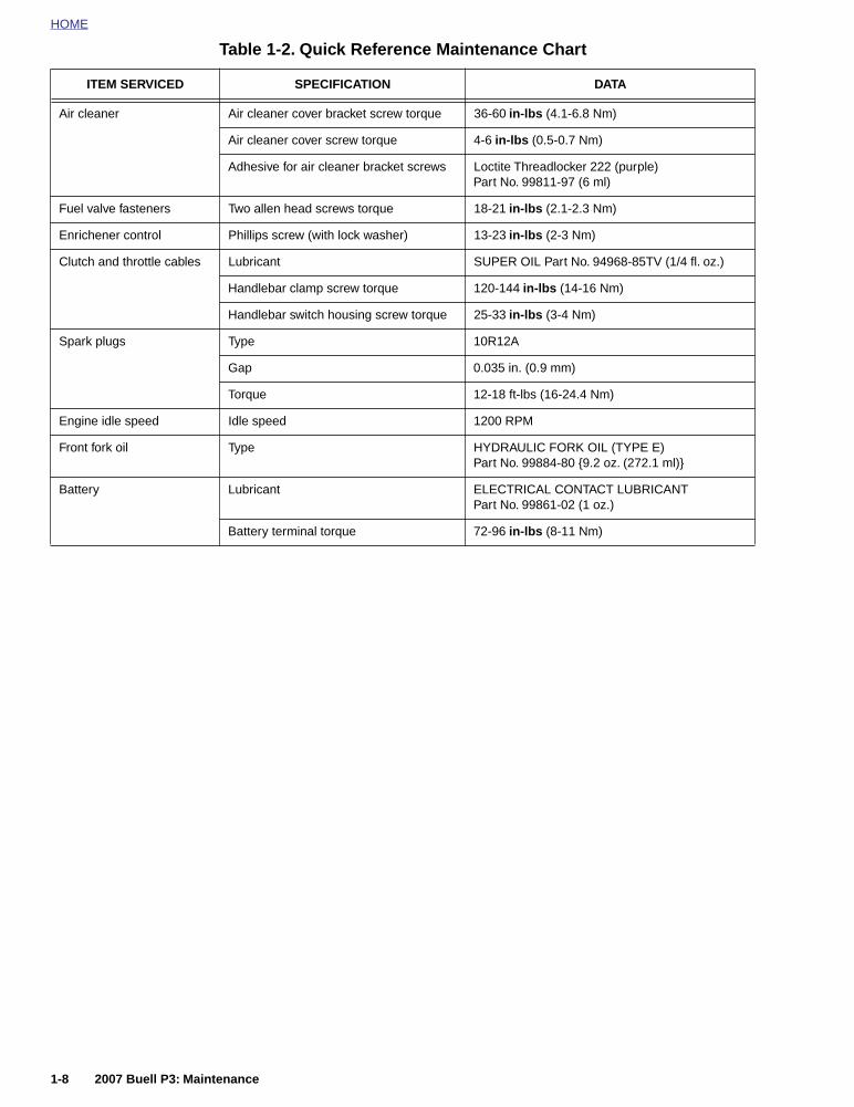
HOME
Air cleaner Air cleaner cover bracket screw torque 36-60 in-lbs (4.1-6.8 Nm)
Air cleaner cover screw torque 4-6 in-lbs (0.5-0.7 Nm)
Adhesive for air cleaner bracket screws Loctite Threadlocker 222 (purple) Part No. 99811-97 (6 ml)
Fuel valve fasteners Two allen head screws torque 18-21 in-lbs (2.1-2.3 Nm)
Enrichener control Phillips screw (with lock washer) 13-23 in-lbs (2-3 Nm)
Clutch and throttle cables Lubricant SUPER OIL Part No. 94968-85TV (1/4 fl. oz.)
Handlebar clamp screw torque 120-144 in-lbs (14-16 Nm)
Handlebar switch housing screw torque 25-33 in-lbs (3-4 Nm)
Spark plugs Type 10R12A
Gap 0.035 in. (0.9 mm)
Torque 12-18 ft-lbs (16-24.4 Nm)
Engine idle speed Idle speed 1200 RPM
Front fork oil Type HYDRAULIC FORK OIL (TYPE E)Part No. 99884-80 {9.2 oz. (272.1 ml)}
Battery Lubricant ELECTRICAL CONTACT LUBRICANTPart No. 99861-02 (1 oz.)
Battery terminal torque 72-96 in-lbs (8-11 Nm)
Table 1-2. Quick Reference Maintenance Chart
ITEM SERVICED SPECIFICATION DATA
1-8 2007 Buell P3: Maintenance

HOME
BATTERY 1.4
DISCONNECTION AND REMOVAL
1. Remove seat. See 2.28 SEAT.
11WARNING1WARNING
To prevent accidental vehicle start-up, which couldcause death or serious injury, disconnect negative (-)battery cable before proceeding. (00048a)
11WARNING1WARNING
Disconnect negative (-) battery cable first. If positive (+)cable should contact ground with negative (-) cable con-nected, the resulting sparks can cause a battery explo-sion, which could result in death or serious injury.(00049a)
2. Unthread bolt and remove battery negative cable (black)from battery negative (-) terminal.
3. Unthread bolt and remove battery positive cable (red)from battery positive (+) terminal.
4. Remove battery from motorcycle.
INSTALLATION AND CONNECTION
1. Place the fully charged battery on the battery pad, termi-nal side facing up.
CAUTION
Connect the cables to the correct battery terminals. Fail-ure to do so could result in damage to the motorcycleelectrical system. (00215a)
11WARNING1WARNING
Connect positive (+) battery cable first. If positive (+)cable should contact ground with negative (-) cable con-nected, the resulting sparks can cause a battery explo-sion, which could result in death or serious injury.(00068a)
CAUTION
Do not over-tighten bolts on battery terminals. Use rec-ommended torque values. Over-tightening battery termi-nal bolts could result in damage to battery terminals. (00216a)
2. See Figure 1-1. Insert bolt through battery positive cable(red) into threaded hole of battery positive (+) terminal.Tighten bolt to 72-96 in-lbs (8-11 Nm).
3. See Figure 1-1. Insert bolt through battery negativecable (black) into threaded hole of battery negative (-)terminal. Tighten bolt to 72-96 in-lbs (8-11 Nm).
4. Apply a light coat of petroleum jelly or corrosion retardantmaterial to both battery terminals.
11WARNING1WARNING
After installing seat, pull upward on front of seat to besure it is in locked position. While riding, a loose seat canshift causing loss of control, which could result in deathor serious injury. (00070a)
5. Install seat. See 2.28 SEAT.
Figure 1-1. Battery Installation
a0250x7x
(+)
(-)
1. Bolts (2)2. Bolt3. Pads (4)4. Pad5. Boot
3
2
4
1
5
2007 Buell P3: Maintenance 1-9

HOME
ENGINE LUBRICATION SYSTEM 1.5
GENERAL
Check engine oil level (hot check):
● At every stop for fuel.
Inspect oil lines and filter for leaks:
Change engine oil and filter (and drain crankcase breatherhose) under normal service in warm or moderate tempera-tures: See 1.3 MAINTENANCE SCHEDULE.
Change engine oil and filter (and drain crankcase breatherhose) under severe service in warm or moderate tempera-tures (severe dust, temperatures above 80° F/27° C, extensiveidling or speeds in excess of 65 m.p.h./105 km/h, extensivetwo-up riding):
NOTEShorten oil change interval in cold weather.
Table 1-3. Recommended Engine Oils
Harley-DavidsonType
ViscosityHarley-Davidson
RatingLowest Ambient
TemperatureCold Weather Starts Below 50˚ F (10˚ C)
HD Multi-grade SAE 10W40 HD 360 Below 40˚ F (4˚ C) Excellent
HD Multi-grade SAE 20W50 HD 360 Above 40˚ F (4˚ C) Good
HD Regular Heavy SAE 50 HD 360 Above 60˚ F (16˚ C) Poor
HD Extra Heavy SAE 60 HD 360 Above 80˚ F (27˚ C) Poor
1-10 2007 Buell P3: Maintenance
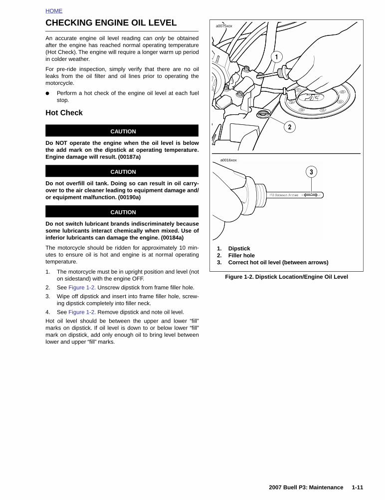
HOME
CHECKING ENGINE OIL LEVEL
An accurate engine oil level reading can only be obtainedafter the engine has reached normal operating temperature(Hot Check). The engine will require a longer warm up periodin colder weather.
For pre-ride inspection, simply verify that there are no oilleaks from the oil filter and oil lines prior to operating themotorcycle.
● Perform a hot check of the engine oil level at each fuelstop.
Hot Check
CAUTION
Do NOT operate the engine when the oil level is belowthe add mark on the dipstick at operating temperature.Engine damage will result. (00187a)
CAUTION
Do not overfill oil tank. Doing so can result in oil carry-over to the air cleaner leading to equipment damage and/or equipment malfunction. (00190a)
CAUTION
Do not switch lubricant brands indiscriminately becausesome lubricants interact chemically when mixed. Use ofinferior lubricants can damage the engine. (00184a)
The motorcycle should be ridden for approximately 10 min-utes to ensure oil is hot and engine is at normal operatingtemperature.
1. The motorcycle must be in upright position and level (noton sidestand) with the engine OFF.
2. See Figure 1-2. Unscrew dipstick from frame filler hole.
3. Wipe off dipstick and insert into frame filler hole, screw-ing dipstick completely into filler neck.
4. See Figure 1-2. Remove dipstick and note oil level.
Hot oil level should be between the upper and lower “fill”marks on dipstick. If oil level is down to or below lower “fill”mark on dipstick, add only enough oil to bring level betweenlower and upper “fill” marks.
Figure 1-2. Dipstick Location/Engine Oil Level
a0075xox
a0016xox
1. Dipstick2. Filler hole3. Correct hot oil level (between arrows)
2
1
3
2007 Buell P3: Maintenance 1-11

HOME
CHANGING ENGINE OIL AND FILTER
CAUTION
Do not switch lubricant brands indiscriminately becausesome lubricants interact chemically when mixed. Use ofinferior lubricants can damage the engine. (00184a)
1. See Figure 1-3. Locate the engine oil tank drain hose(normally the lower hose) and the crankcase breatherdrain hose (normally the upper hose) inside the foot pegsupport frame on the left side of the motorcycle.
2. Remove fastener from hose retention clamp.
3. Place a drain pan directly underneath the engine oil drainhose.
4. Loosen the spring clamp and remove engine oil draindrain plug from drain hose.
5. Allow used oil to drain completely.
6. Loosen spring clamp and remove crankcase breatherhose drain plug to allow any oil present to drain.
7. See Figure 1-4. Remove the oil filter (located at the frontof the engine).
8. Clean filter gasket contact surface on mounting plate(surface should be smooth and free of any debris, usedoil or old gasket material).
9. See Figure 1-4. Apply a thin film of clean oil to gasket onnew oil filter.
10. Install new oil filter (Part No. 63806-00Y) onto adapteruntil gasket contacts plate surface, then tighten another1/2-3/4 turn. Do not overtighten.
11. Place two drain hoses back on the hose fixture. Installdrain plugs to drain hoses and secure plugs with springclamps.
12. See Figure 1-2. Remove dipstick and refill with approxi-mately 1.5 qt (1,419.5 ml) recommended oil at filler hole.Refer to Table 1-3.
13. Install dipstick and operate motorcycle for 10 minutes toreach normal operating temperature. Check oil levelagain (hot check) and add oil as necessary until oil regis-ters between marks on dipstick.
11WARNING1WARNING
Check that no lubricant gets on tires, wheels or brakeswhen changing fluid. Traction can be adversely affected,which could result in loss of control of the motorcycleand death or serious injury. (00047b)
● Change oil more frequently if bike is operated undersevere conditions (dusty, very hot or cold temperatures).
● Drain oil after operating motorcycle (while oil is still verywarm).
● Replace oil filter every time the oil is changed.
● Drain the crankcase breather drain hose of any accumu-lated oil every time the oil is changed.
Figure 1-3. Oil Tank Drain Hose
Figure 1-4. Installing New Oil Filter
a0074xox
1. Hose retention clamp fastener2. Oil tank drain hose (lower hose) crankcase
breather hose (upper hose)3. Spring clamp4. Engine oil drain hose cap5. Foot peg support frame
2
34
5
1
a0019xox
a0073xox
1. Applying thin film of clean engine oil to gasket2. Filter mount3. Oil filter-tighten 1/2-3/4 turn after gasket contact
1
2
3
1-12 2007 Buell P3: Maintenance

HOME
BRAKE SYSTEM MAINTENANCE 1.6
GENERAL
Check the master cylinder reservoirs for proper fluid levelsafter the first 1000 miles (1600 km) and every 5000 miles(8000 km) thereafter. Also inspect fluid levels at the end ofevery riding season.
Check brake pads and rotors for wear at every service inter-val. See 1.7 BRAKE PADS AND ROTORS.
Replace D.O.T. 4 BRAKE FLUID:
● Every 2 years.
It is recommended to inspect both front and rear brake linesand replace as required:
● Every 4 years.
It is recommended to inspect both front and rear caliper andmaster cylinder seals and replace as required:
● Every 2 years.
Check rear brake pedal operation:
● Before every ride.
Lubricate the front brake hand lever:
FLUID LEVEL
See Figure 1-5. With motorcycle in a level position, check thatbrake fluid is between the upper and lower marks on front andrear reservoirs. Add D.O.T. 4 BRAKE FLUID if necessary. Besure gasket and cap on reservoir fit securely.
BLEEDING BRAKES
11WARNING1WARNING
Direct contact of D.O.T. 4 brake fluid with eyes can causeirritation. Avoid eye contact. In case of eye contact flushwith large amounts of water and get medical attention.Swallowing large amounts of D.O.T. 4 brake fluid cancause digestive discomfort. If swallowed, obtain medicalattention. Use in well ventilated area. KEEP OUT OFREACH OF CHILDREN. (00240a).
Figure 1-5. Rear Brake Fluid Reservoir
Figure 1-6. Front Brake Caliper Bleeder Valve
Figure 1-7. Rear Brake Caliper Bleeder Valve (Metric)
7703
64227697
7723
2007 Buell P3: Maintenance 1-13

HOME
11WARNING1WARNING
Never mix D.O.T. 4 with other brake fluids (such as D.O.T.5). Use only D.O.T. 4 brake fluid in motorcycles that spec-ify D.O.T. 4 fluid on the reservoir cap. Mixing differenttypes of fluid can adversely affect braking ability andlead to brake failure which could result in death or seri-ous injury
11WARNING1WARNING
Use only fresh, uncontaminated D.O.T. 4 Fluid. Cans offluid that have been opened may have been contami-nated by moisture in the air or dirt. Use of contaminatedbrake fluid can adversely affect braking ability and leadto brake failure which could result in death or seriousinjury
11WARNING1WARNING
Use only new copper banjo washers (See Parts Catalogfor Part No.) with D.O.T. 4 brake fluid. Earlier silver banjowashers are not compatible with D.O.T. 4 fluid and willnot seal properly over time. Failure to comply canadversely affect braking ability and lead to brake failurewhich could result in death or serious injury.
NOTEHydraulic brake fluid bladder-type pressure equipment can beused to fill the brake master cylinder through the bleedervalve if master cylinder reservoir cover is removed to preventpressurization.
1. Install end of a length of plastic tubing over caliperbleeder valve; place other end in a clean container.Stand motorcycle upright.
a. See Figure 1-6. Front brake bleeder valve.
b. See Figure 1-7. Rear brake bleeder valve.
IMPORTANT NOTE
Cover molded-in-color surfaces and right handlebarswitches and use care when removing brake reservoircover and adding D.O.T. 4 brake fluid. Spilling D.O.T. 4brake fluid on molded-in-color surfaces will result in cos-metic damage. Spilling brake fluid on switches can ren-der them inoperative.
2. Add D.O.T. 4 BRAKE FLUID to master cylinder reser-voir. Do not reuse brake fluid.
a. Remove two screws from front master cylinder cover.Bring fluid level to within 0.125 in. (3.2 mm) ofmolded boss inside front master cylinder.
b. Remove cap and gasket from rear master cylinderreservoir. Bring fluid level to between upper andlower marks on reservoir.
3. Depress, release and then hold brake lever/pedal to buildup hydraulic pressure.
4. Open bleeder valve (metric) about 1/2-turn counterclock-wise; brake fluid will flow from bleeder valve and throughtubing. When brake lever/pedal has moved 1/2-3/4 of itsfull range of travel, close bleeder valve (clockwise). Allowbrake lever/pedal to return slowly to its released position.
5. Repeat Steps 2-4 until all air bubbles are purged.
6. Tighten bleeder valve (metric) to 36-60 in-lbs (4.1-6.8Nm).
7. Verify master cylinder fluid level as described in Step 2.
11WARNING1WARNING
After repairing the brake system, test brakes at lowspeed. If brakes are not operating properly, testing athigh speeds can cause loss of control, which couldresult in death or serious injury. (00289a)
8. Attach covers to master cylinder reservoirs.
a. Tighten screws on master cylinder reservoir cover to9-13 in-lbs (1.0-1.5 Nm).
b. Tighten cap on rear master cylinder securely.
REAR BRAKE PEDAL
11WARNING1WARNING
After repairing the brake system, test brakes at lowspeed. If brakes are not operating properly, testing athigh speeds can cause loss of control, which couldresult in death or serious injury. (00289a)
Check rear brake pedal for proper operation.
● Before every ride.
1. Inspect locknut installation. Locknut should be flush withtop surface of clevis.
2. Observe the position of brake pedal and foot peg. Brakepedal should be set so top surface of brake pedal is evenwith top surface of foot peg.
3. Set brake pedal height.
a. Loosen locknut.
b. Turn rod adjuster to obtain correct position.
c. Tighten locknut.
NOTEBrake pedal has no freeplay adjustment.
Figure 1-8. Brake Fluid Level - Front Reservoir
a0214x2x
1-14 2007 Buell P3: Maintenance
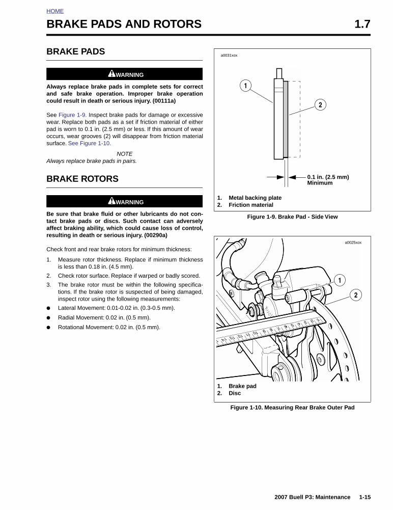
HOME
BRAKE PADS AND ROTORS 1.7
BRAKE PADS
11WARNING1WARNING
Always replace brake pads in complete sets for correctand safe brake operation. Improper brake operationcould result in death or serious injury. (00111a)
See Figure 1-9. Inspect brake pads for damage or excessivewear. Replace both pads as a set if friction material of eitherpad is worn to 0.1 in. (2.5 mm) or less. If this amount of wearoccurs, wear grooves (2) will disappear from friction materialsurface. See Figure 1-10.
NOTEAlways replace brake pads in pairs.
BRAKE ROTORS
11WARNING1WARNING
Be sure that brake fluid or other lubricants do not con-tact brake pads or discs. Such contact can adverselyaffect braking ability, which could cause loss of control,resulting in death or serious injury. (00290a)
Check front and rear brake rotors for minimum thickness:
1. Measure rotor thickness. Replace if minimum thicknessis less than 0.18 in. (4.5 mm).
2. Check rotor surface. Replace if warped or badly scored.
3. The brake rotor must be within the following specifica-tions. If the brake rotor is suspected of being damaged,inspect rotor using the following measurements:
● Lateral Movement: 0.01-0.02 in. (0.3-0.5 mm).
● Radial Movement: 0.02 in. (0.5 mm).
● Rotational Movement: 0.02 in. (0.5 mm).
Figure 1-9. Brake Pad - Side View
Figure 1-10. Measuring Rear Brake Outer Pad
0.1 in. (2.5 mm)
a0031xox
Minimum
1. Metal backing plate2. Friction material
2
1
a0025xox
2
1
1. Brake pad2. Disc
2007 Buell P3: Maintenance 1-15

HOME
TIRES AND WHEELS 1.8
TIRE INFLATION
11WARNING1WARNING
Do not inflate tire beyond maximum pressure as speci-fied on sidewall. Over inflated tires can blow out, whichcould result in death or serious injury. (00027a)
Check tire pressure and tread:
● Before every ride.
Check for proper front and rear tire pressures when tires arecold. Compare pressure against Table 1-4.
WHEEL BEARINGS
The wheel bearings are sealed units, no greasing or mainte-nance is required. Replace when worn. Excessive play orroughness indicates worn bearings that require replacement.
Check front and rear wheel bearings for wear:
● Every time a wheel is removed.
● When storing for the season or removing the motorcyclefrom storage.
Check wheel bearings for wear and corrosion. Excessive playor roughness indicates worn bearings. Replace bearings insets only.
TIRE TREAD INSPECTION
See Figure 1-11. Tread wear indicator bars (2) will appear ontire tread surfaces when 1/32 inch (0.79 mm) or less of tiretread remains. Arrows (1) on tire sidewalls pinpoint location ofwear bar indicators. Always remove tires from service beforethey reach the tread wear indicator bars (1/32 of an inch[(0.79 mm)] tread pattern depth remaining).
New tires are needed if any of the following conditions exist.
1. Tread wear indicator bars become visible on the treadsurfaces.
2. Tire cords or fabric become visible through cracked side-walls, snags or deep cuts.
3. A bump, bulge or split in the tire.
4. Puncture, cut or other damage to the tire that cannot berepaired.
Table 1-4. Tire Specifications/Pressures
P3 TiresSOLO
RIDINGLOADED TO GVWR
FrontDunlop 100/80 16 50s K330
28 psi(193 kPa)
32 psi(220 kPa)
RearDunlop 120/80 16 60s K330
30 psi(207 kPa)
36 psi(248 kPa)
Figure 1-11. Tread Wear Indicators
o0248xox
1
o0248x1x
1. Arrow (points to location of wear bar)2. Tread wear indicator bar (worn conditions)
2
1-16 2007 Buell P3: Maintenance

HOME
CLUTCH 1.9
ADJUSTMENT
Clutch control cable adjustment is required at this interval tocompensate for normal clutch lining wear. If the clutch slipsunder load, or drags when released, adjust the clutch controlcable.
1. Raise rear wheel off floor using REAR WHEEL SUP-PORT STAND (Part No. B-41174).
2. Remove left footpeg support bracket. See 2.21 FOOT-PEGS AND FOOTPEG SUPPORT BRACKETS.
3. See Figure 1-12. Slide rubber boot (1) upward to exposeadjuster mechanism. Loosen jam nut (3) from adjuster(4). Turn adjuster to shorten cable housing until there is alarge amount of freeplay at clutch hand lever.
4. See Figure 1-13. Remove three TORX screws withwashers (1) from clutch inspection cover (2). Removeclutch inspection cover from primary cover.
5. Remove spring (4) and lockplate (5). Turn adjustingscrew (6) counterclockwise until it lightly bottoms.
6. Turn adjusting screw (6) clockwise 1/4 - 1/2 turn. Installlockplate (5) and spring (4) on adjusting screw flats. Ifhex on lockplate does not align with recess in outerramp, rotate adjusting screw clockwise until it aligns.
7. Squeeze clutch hand lever to maximum limit three times.This sets the ball and ramp mechanism. Pull outer cableconduit and at the same time adjust cable adjuster toprovide 0.0625-0.125 in. (1.6-3.2 mm) freeplay at clutchhand lever.
Figure 1-12. Clutch Cable Adjuster Mechanism
a0159x6x
1. Rubber boot2. Cable end3. Jam nut4. Adjuster
4
3
2
1
Figure 1-13. Clutch Release Mechanism
1. TORX screw 2. Clutch inspection cover3. Gasket4. Spring5. Lockplate6. Adjusting screw7. Adjusting screw assembly
a0155a6x
23
45
6
1
7
2007 Buell P3: Maintenance 1-17

HOME
8. Adjust as follows:
a. See Figure 1-14. Pull ferrule (end of cable housing)away from bracket. Gap between ferrule and bracketshould be 0.0625-0.125 in. (1.6-3.2 mm).
b. See Figure 1-12. Set freeplay by turning adjuster.
c. Tighten jam nut against adjuster.
d. Slide rubber boot over cable adjuster mechanism.
9. Change or add transmission fluid if necessary.
NOTE
Clean parts before re-assembly and use a new gasket.
10. See Figure 1-13. Install new gasket and clutch inspec-tion cover using three TORX screws with washers.Tighten in a crosswise pattern to 84-108 in-lbs (9.5-12.2Nm).
11. Check clutch cable freeplay. See Step 7 above.
12. Install left footpeg support bracket. See 2.21 FOOT-PEGS AND FOOTPEG SUPPORT BRACKETS.
Figure 1-14. Adjusting Clutch Freeplay
a0158x6x
1. Ferrule2. Bracket
1
2
1-18 2007 Buell P3: Maintenance

HOME
TRANSMISSION/PRIMARY FLUID 1.10
GENERAL
Transmission fluid capacity is 1.0 quart (0.95 liter). For bestresults, drain fluid while it is hot.
INSPECTION
1. Remove seat. See 2.28 SEAT.
11WARNING1WARNING
To prevent accidental vehicle start-up, which couldcause death or serious injury, disconnect negative (-)battery cable before proceeding. (00048a)
2. Disconnect negative battery cable from battery.
3. Remove left footpeg support bracket. See 2.21 FOOT-PEGS AND FOOTPEG SUPPORT BRACKETS.
4. See Figure 1-15. Remove three TORX screws withwashers (1) from clutch inspection cover (2). Removeclutch inspection cover from primary cover.
5. See Figure 1-16. Inspect fluid level with motorcycle inupright position.
6. See Figure 1-15. Install new gasket and clutch inspec-tion cover using three TORX screws with washers.Tighten in a crosswise pattern to 84-108 in-lbs (9.5-12.2Nm).
7. Install left footpeg support bracket. See 2.21 FOOT-PEGS AND FOOTPEG SUPPORT BRACKETS.
8. Connect negative battery cable to battery. See 1.4 BAT-TERY.
11WARNING1WARNING
After installing seat, pull upward on front of seat to besure it is in locked position. While riding, a loose seat canshift causing loss of control, which could result in deathor serious injury. (00070a)
9. Install seat. See 2.28 SEAT.
Figure 1-15. Primary Cover
Figure 1-16. Fluid Level
7667
1. Torx screws with washers (3)2. Clutch inspection cover3. Magnetic drain plug (with o-ring)
1
2 3
1. Adjusting screw2. Cable end3. Coupling4. Correct fluid level
a0126x6x
1
32
4
2007 Buell P3: Maintenance 1-19

HOME
CHANGING TRANSMISSION FLUID
CAUTION
When draining or adding lubricant, do not allow dirt,debris or other contaminants to enter the engine.(00198a)
1. When the engine reaches normal operating temperature,turn the engine off and position motorcycle on jiffy stand.This will allow the chaincase lubricant to drain out oftransmission.
2. See Figure 1-15. Position a suitable container underdrain plug (3). Remove magnetic drain plug with O-ringand drain fluid.
3. Position the motorcycle STRAIGHT UP and LEVELusing REAR WHEEL SUPPORT STAND (Part No. B-41174). This allows fluid to be drained from clutch com-partment.
NOTEDispose of transmission lubricant in accordance with localregulations.
CAUTION
Do not over-tighten drain plug. Doing so could result in alubricant leak. (00200a)
4. Wipe any foreign material from the magnetic drain plug(3). Inspect O-ring for deterioration and replace asrequired.
5. Apply Loctite 565 thread sealant to the threads and rein-stall drain plug with O-ring. Tighten drain plug to 14-30 ft-lbs (19-4 0.6 Nm).
6. Remove seat. See 2.28 SEAT.
11WARNING1WARNING
To prevent accidental vehicle start-up, which couldcause death or serious injury, disconnect negative (-)battery cable before proceeding. (00048a)
7. Disconnect negative battery cable from battery.
8. Remove left footpeg support bracket. See 2.21 FOOT-PEGS AND FOOTPEG SUPPORT BRACKETS.
9. Remove three TORX screws with washers (1) fromclutch inspection cover (2). Remove clutch inspectioncover from primary cover.
CAUTION
Do not overfill the primary chaincase with lubricant.Overfilling can cause rough clutch engagement, incom-plete disengagement, clutch drag and/or difficulty in find-ing neutral at engine idle. (00199b)
IMPORTANT NOTEMake certain primary chaincase is filled with properamount of lubricant with motorcycle upright. If underfilled, transmission can be damaged during vehicle oper-ation.
10. See Figure 1-16. Add FORMULA+ TRANSMISSIONAND PRIMARY CHAINCASE LUBRICANT (Part No.99851-05) as required until fluid level is even with bottomof clutch diaphragm spring.
11. See Figure 1-15. Install clutch inspection cover usingthree TORX screws with washers. Tighten in a crosswisepattern to 84-108 in-lbs (9.5-12.2 Nm).
12. Install footpeg support bracket. See 2.21 FOOTPEGSAND FOOTPEG SUPPORT BRACKETS.
13. Connect negative battery cable to battery. Tighten fas-tener to 72-96 in-lbs (8-11 Nm).
11WARNING1WARNING
After installing seat, pull upward on front of seat to besure it is in locked position. While riding, a loose seat canshift causing loss of control, which could result in deathor serious injury. (00070a)
14. Install seat. See 2.28 SEAT.
1-20 2007 Buell P3: Maintenance

HOME
DRIVE BELT AND REAR SPROCKET 1.11
GENERAL
Drive belt tension is not adjustable. Replace the belt andsprocket if out of specification.
NOTE
When a drive belt is replaced for any reason other than stonedamage, it is recommended that the transmission and rearsprockets also be replaced to increase the longevity of thenew drive belt. In the case of stone damage, inspect sprock-ets for damage and replace as required.
CLEANING
Use only mild soap and water spray solution to clean drivebelt. Dry thoroughly. Do not immerse belt in solution.
INSPECTION
Checking Belt Deflection
NOTES:
Vehicle must be at room temperature and dry to obtain a cor-rect measurement.
There are tight and loose spots during rear wheel rotationthat affect belt deflection. For a more precise measurement,take three deflection readings, rotating the rear wheelbetween measurements. Average the three readings for amore precise measurement.
● Deflection should be measured with the rear wheel onthe ground and a 160 lb. (72.57 Kg) rider or equivalentweight sitting on the motorcycle.
● Maximum allowable deflection (measured with 10 lbs./4.5 kg. of force) is 0.5 in. (12.7 mm) at the bottom strand.
See Figure 1-17. Using BELT TENSION GAUGE (Part No.HD-35381), apply 10 lbs (4.5 kg) of force at the midpoint ofthe belt’s appropriate strand. The maximum allowable deflec-tion is 0.5 in. (12.7 mm) at the bottom strand.
● Replace belt and drive sprocket that exceed maximumallowable deflection.
11WARNING1WARNING
Be sure wheel and brake caliper are aligned. Riding witha misaligned wheel or brake caliper can cause the brakedisc to bind and lead to loss of control, which couldresult in death or serious injury. (00050a)
Rear Sprocket1. See Figure 1-18. Inspect each tooth of rear sprocket for:
a. Major tooth damage.
b. Gouges caused by hard objects.
2. Replace rear sprocket if major tooth damage exists.
Drive BeltSee Figure 1-19. Inspect drive belt for:
● Cuts or unusual wear patterns.
● Outside edge bevelling (8). Some bevelling is common,but it indicates that sprockets are misaligned.
● Outside ribbed surface for signs of stone puncture (7). Ifcracks/damage exists near edge of belt, replace beltimmediately. Damage to center of belt will require beltreplacement eventually, but when cracks extend to edgeof belt, belt failure is imminent.
● Inside (toothed portion) of belt for exposed tensile cords(normally covered by nylon layer and polyethylene layer).This condition will result in belt failure and indicates worntransmission sprocket teeth. Replace belt and transmis-sion sprocket.
● Signs of puncture or cracking at the base of the beltteeth. Replace belt if either condition exists.
● Replace belt if conditions 2, 3, 6 or 7 (on edge of belt)exist.
NOTECondition 1 is not grounds for replacing the belt, but it shouldbe watched as it may develop into condition 2 or 3 resulting ina need for belt replacement.
Figure 1-17. Measuring Belt Deflection
a0040xox
10 lbs (4.5 kg) of force
Figure 1-18. Drive Belt Assembly
a0136x6x
1. Rear sprocket2. Drive belt3. Transmission sprocket4. Sprocket cover
1
2
3
4
2007 Buell P3: Maintenance 1-21

HOME
Figure 1-19. Drive Belt Wear Patterns
1 2
3 4
5 6
7 8
Stone
Cross-section shown
a0147x6x
Sprocket side of belt
Table 1-5. Drive Belt Wear Analysis
PATTERN IN FIGURE 1-19. CONDITION REQUIRED ACTION
1 Internal tooth cracks (hairline) OK to run, but monitor condition
2 External tooth cracks Replace belt
3 Missing teeth Replace belt
4 Chipping (not serious) OK to run, but monitor condition
5 Fuzzy edge cord OK to run, but monitor condition
6 Hook wear Replace belt
7 Stone damage Replace belt if damage is on the edge
8 Bevel wear (outboard edge only) OK to run, but monitor condition
1-22 2007 Buell P3: Maintenance

HOME
DRIVE BELT AND REAR SPROCKET REPLACEMENT
1. Remove seat. See 2.28 SEAT.
11WARNING1WARNING
To prevent accidental vehicle start-up, which couldcause death or serious injury, disconnect negative (-)battery cable before proceeding. (00048a)
2. Disconnect the negative battery cable from the battery.
3. Raise rear wheel off floor using REAR WHEEL SUP-PORT STAND (Part No. B-41174).
4. See Figure 1-20. Place rod or screwdriver through axlehole. Loosen rear axle nut (1) (metric).
5. Remove nut, lockwasher, and flat washer.
6. Pull axle out. Remove right side spacer.
7. Slide carrier with caliper off rotor.
8. Remove left side spacer.
9. Move wheel forward and slide belt off.
10. Remove sprocket cover and five washers from sprocket.
11. Remove and discard sprocket. Discard five washers.
11WARNING1WARNING
Compressed air can pierce the skin and flying debrisfrom compressed air could cause serious eye injury.Wear safety glasses when working with compressed air.Never use your hand to check for air leaks or to deter-mine air flow rates. (00061a)
12. Clean residual Loctite from threads in wheel sprockettowers with a suitable non-flammable solvent. Dry withcompressed air.
13. Remove three TORX bolts, washers and front sprocketcover from right side of motorcycle.
NOTEIt may be necessary to compress suspension to gain accessto front sprocket cover TORX bolt.
14. Remove two TORX screws and washers from right sideof rear inner fender. Carefully bend rear inner fenderupwards and remove drive belt. Discard drive belt.
15. Position new drive belt over transmission drive sprocket.
16. Install rear inner fender with two TORX screws andwashers. See 2.23 FENDERS.
17. Install front sprocket cover with three TORX screws andwashers. See 2.22 SPROCKET COVER.
18. Position rear sprocket on rear wheel with mounting holesaligned.
11WARNING1WARNING
Use only new hardened washers between sprocket coverand sprocket. Failure to use hardened washers couldcause sprocket to fail. Drive sprocket failure could leadto loss of control of vehicle which could result in deathor serious injury.
19. Place new hardened (Part No. BA0511.2Z) washers onsprocket and install new sprocket cover over washersand sprocket.
20. Install sprocket and sprocket cover with five newsprocket bolts. Tighten bolts to 28-31 ft-lbs (38-42 Nm).
21. Place wheel centrally in the swingarm. Slide wheel farenough forward to slip belt over sprocket and rest belt onsprocket inboard of the teeth.
Figure 1-20. Rear Wheel Mounting
7747
1. Axle nut (metric)2. Lockwasher3. Washer4. Axle hole
1
3
24
2007 Buell P3: Maintenance 1-23

HOME
NOTEDo not place belt on sprocket teeth at this time. Alignment ofparts will be difficult. Resting belt next to teeth allows slack foreasier alignment of wheel assembly.
22. Hold left side spacer in place and slide caliper and car-rier over rotor.
23. See Figure 1-21. Slide axle through washer, swing arm,carrier, left side spacer and wheel assembly.
a. Hold right side spacer in place.
b. Insert axle through right side spacer and swingarm.
c. Install flat washer, lockwasher and axle nut.
24. Place screwdriver or rod through axle hole and torquerear axle nut to 49-51 ft-lbs (67-69 Nm).
25. Slide belt on sprocket teeth by rotating wheel to “walk”belt onto teeth.
26. Lower motorcycle rear wheel.
27. Connect negative battery cable to battery. Tighten fas-tener to 72-96 in-lbs (8-11 Nm).
11WARNING1WARNING
After installing seat, pull upward on front of seat to besure it is in locked position. While riding, a loose seat canshift causing loss of control, which could result in deathor serious injury. (00070a)
28. Install seat. See 2.28 SEAT.
Figure 1-21. Rear Axle, Right Side
32
1
7701
1. Axle2. Axle nut (metric)3. Lockwasher4. Washer5. Spacer6. Sprocket bolts (5)7. Sprocket cover
6
5
7
4
1-24 2007 Buell P3: Maintenance

HOME
PRIMARY CHAIN 1.12
ADJUSTMENT
See Figure 1-22. Buell Blast Models are shipped with aspacer between the primary chain limiting screw and the lock-nut. The spacer is used to quickly get proper adjustment dur-ing production. This spacer should be removed and discardedat the first adjustment interval.
1. See Figure 1-22. Back-off jam nut (3) and chain limitingscrew (1).
2. Remove spacer (2).
IMPORTANT NOTEBe certain to use inch-pound wrench. Chain adjustershoe can be damaged by excessive force.
3. See Figure 1-24. Tighten chain limiting screw to 24 in-lbs (2.7 Nm).
4. Back-off chain limiting screw 3/4 turn (4 1/2 “flats”).
5. Hold chain limiting screw while tightening jam nut to 20-25 ft-lbs (27.1-33.9 Nm).
Figure 1-22. Adjustment Nut with Spacer
Figure 1-23. Chain Limiting Screw without Spacer
Figure 1-24. Tightening Chain Limiting Screw
7790
1. Chain limiting screw2. Spacer (discard after initial adjustment is made)3. Jam nut
2
1
3
7789
7791
2007 Buell P3: Maintenance 1-25

HOME
REAR SHOCK ABSORBER 1.13
GENERAL
Inspect rear shock absorber for proper operation and for oilleaks. Inspect rubber shock eye bushings for deterioration.
NOTESee Figure 1-25. Damper component (3) cannot be servicedor repaired. If the damper component is leaking or damagedit must be replaced.
Figure 1-25. Rear Shock Absorber Assembly
1. Bolt2. Damper bushing3. Damper component4. Nut5. Stopper ring6. Spring seat7. Spring8. Spring seat stopper
a0015xSx
1
2
34
1
2
4
5
7
8
6
1-26 2007 Buell P3: Maintenance

HOME
FRONT FORK OIL 1.14
FORK OIL CHANGES
1. Remove front forks. See 2.17 FRONT FORK.
2. See Figure 1-26. Clamp the fork in a vise with front forkholding tool (part no. B-41177).
3. See Figure 1-27. Remove slider tube cap.
4. See Figure 1-28. Push down on the B-spring seat (O-ring included) and remove the stopper ring and springseat.
5. See Figure 1-29. Remove the spring collar, lower springjoint and spring from slider tube.
Figure 1-26. Clamping the Fork
Figure 1-27. Slider Tube Cap
3767
3768
Figure 1-28. B-Spring Seat
Figure 1-29. Removing Sub-Assembly
3769
1. Spring collar2. Lower spring joint3. Spring
a0006xSx
2
3
1
2007 Buell P3: Maintenance 1-27

HOME
6. See Figure 1-30. Remove the fork oil by pumping the forkleg and rod 8-10 times until the rod moves freely.
NOTE
The recommended fork oil is hydraulic fork oil type “E”.
7. Pour 9.2 oz. (272.1 ml) fork oil into fork.
8. Install lower spring joint and spring collar.
9. Coat a new O-ring with fork oil or sealing grease.
10. Install new O-ring onto spring seat.
11. See Figure 1-31. Push down on spring seat past grooveto install stopper ring. Stopper ring will lock into groovewhen installed correctly.
12. See Figure 1-32. Install slider tube cap.
13. Install front forks. See 2.17 FRONT FORK.Figure 1-30. Pumping Fork Oil
Figure 1-31. Compressing Spring Seat
3770
3769
Figure 1-32. Slider Tube Cap
3768
1-28 2007 Buell P3: Maintenance

HOME
STEERING HEAD BEARINGS 1.15
GENERAL
Check steering head bearings:
● When storing or removing the motorcycle for the season.
NOTE
Lubricate the steering head bearings with WHEEL BEARINGGREASE (Part No. 99855-89)
INSPECTION
With motorcycle front end raised off of floor, check to makesure front fork turns freely, without any binding or interfer-ence. Also check to make sure there is no appreciable front torear fork shake indicating excessive bearing looseness.
1. Detach clutch cable at handlebar.
2. Remove seat and fuel tank. See 4.2 FUEL TANKCOVER/FUEL TANK.
3. Attach lifting straps to frame tube behind steering neck.Raise front wheel off floor using a floor hoist and liftingstraps.
4. Turn front wheel to full right lock.
5. See Figure 1-33. Attach a spring scale into the hole inthe front axle. With scale 90 degrees from fork leg, pullfront wheel to center position. It should take 6.5-7 lbs(2.9-3.2 kg) to pull front wheel to center.
6. Attach clutch cable to handlebar.
NOTECheck that clutch and throttle cables do not bind when mea-suring bearing resistance.
11WARNING1WARNING
After installing seat, pull upward on front of seat to besure it is in locked position. While riding, a loose seat canshift causing loss of control, which could result in deathor serious injury. (00070a)
7. Install seat and fuel tank. See 4.2 FUEL TANK COVER/FUEL TANK.
Figure 1-33. Steering Head Bearing Check
7736
2007 Buell P3: Maintenance 1-29

HOME
ADJUSTMENT
1. Detach clutch cable at handlebar.
2. Remove seat and fuel tank. See 4.2 FUEL TANKCOVER/FUEL TANK.
3. Attach lifting straps to frame backbone behind steeringneck. Raise front wheel off floor using a floor hoist andlifting straps.
4. Turn front wheel to full right lock.
5. See Figure 1-33. Attach a spring scale into the hole inthe front axle. Pull front wheel to center position. Itshould take 6.5-7 lbs (2.9-3.2 kg) to pull front wheel tocenter.
6. See Figure 1-34. To adjust:
a. Loosen both pinch screws (9) on lower triple clamp.
b. Loosen center cap nut pinch screw (2) on upper tri-ple clamp.
c. Loosen cap nut (1), then tighten to 48-52 ft-lbs (65-71 Nm) to seat bearing. Loosen cap nut, apply Loc-tite 243 (blue) to threads of fork stem and retightencap nut to 28-32 ft-lbs (38-43 Nm).
7. Recheck tension using spring scale.
8. Tighten both lower triple clamp pinch screws (9) to 22-29ft-lbs (30-39 Nm).
9. Tighten center cap pinch screw to 84-120 in-lbs (10-14Nm).
11WARNING1WARNING
After installing seat, pull upward on front of seat to besure it is in locked position. While riding, a loose seat canshift causing loss of control, which could result in deathor serious injury. (00070a)
10. Install seat and fuel tank. See 4.2 FUEL TANK COVER/FUEL TANK.
LubricationAt 20,000 miles (32,000 km) and every 20,000 miles(32,000 km) thereafter, lubricate the steering head bearingswith WHEEL BEARING GREASE (Part No. 99855-89).
Figure 1-34. Fork Stem and Bracket Assembly
6
6
5
7
7
5
1
4
2
9
8
a0137x2x
1. Capnut2. Center cap pinch screw3. Upper triple clamp4. Pinch screws (2)5. Dust shield (2)6. Bearing (2)7. Bearing cup (2)8. Lower triple clamp 9. Pinch screws (2)
3
1-30 2007 Buell P3: Maintenance

HOME
SPARK PLUG 1.16
GENERAL
Change spark plug at every 10,000 mile (16,000 km) serviceinterval. Use only Harley-Davidson No. 10R12A plug as areplacement.
INSPECTION
1. Disconnect cable from both spark plug by pulling on rub-ber boot (not cable).
2. Remove spark plug and examine.
3. See Figure 1-35. Compare your observations of the plugdeposits with the descriptions provided below.
a. A wet, black and shiny deposit on plug base, elec-trodes and ceramic insulator tip indicates an oilfouled plug. The condition may be caused by one ormore of the following: worn pistons, worn pistonrings, worn valves, worn valve guides, worn valveseals, a weak battery or a faulty ignition system.
b. A dry, fluffy or sooty black deposit indicates a carbu-retor air-fuel mixture that is too rich, engine idling forexcessive periods of time and/or enrichener usagefor excessive periods of time.
c. A light brown, glassy deposit indicates an over-heated plug. This condition may be accompanied bycracks in the insulator or by erosion of the elec-trodes and is caused by an air-fuel mixture that istoo lean, a hot-running engine, valves not seating orimproper ignition timing. The glassy deposit on thespark plug is a conductor when hot and may causehigh-speed misfiring. A plug with eroded electrodes,heavy deposits or a cracked insulator must bereplaced.
d. A plug with a white, yellow, tan or rusty brown pow-dery deposit indicates balanced combustion. Cleanoff spark plug deposits at regular intervals.
4. If the plug requires cleaning between tune-ups andreplacement plug is not available, proceed as follows:
a. De-grease firing end of spark plug using ELECTRI-CAL CONTACT CLEANER. Dry plug with com-pressed air.
b. Use a thin file to flatten spark plug electrode. Aspark plug with sharp edges on its electrodesrequires 25%-40% less firing voltage than one withrounded edges.
5. If the plug cannot be cleaned, replace with HD No.10R12A spark plug.
6. Check electrode gap with a wire-type feeler gauge. Gapshould be 0.035 in. (0.9 mm).
7. Apply Loctite Anti-Seize to threads of spark plug. Installand tighten to 12-18 ft-lbs (16-24.4 Nm).
8. Connect spark plug cable. Verify that cable is securelyconnected to ignition coil and spark plug.
Figure 1-35. Typical Spark Plug Deposits
4636a
2007 Buell P3: Maintenance 1-31

HOME
AIR CLEANER 1.17
GENERAL
Replace the air cleaner filter element:
● Every 30,000 miles (48,000 km) or as required.
REMOVAL
1. See Figure 1-36. Release five latches around perimeterof air box cover.
2. Remove single Phillips screw at bottom of air box cover(7 o’clock position).
3. Pull cover from air box.
4. Pull conical shaped filter from air box.
5. Squeeze wings on spring clamp with pliers and pull cleanair inlet hose from fixed position on allen head screw(gold) at top of venturi ring. Remove screw with spacer.
6. Remove remaining two allen head screws to free venturiring from carburetor flange.
7. Remove hex screw at bottom of air box (6 o’clock posi-tion) to release bracket from crankcase hole.
8. See Figure 1-37. Moving to left side of vehicle, removetwo flange bolts to release side of air box from triangularshaped bracket. Do not remove bottom bolt to crank-case.
IMPORTANT NOTEDo not take bolt in and out of the crankcase unless nec-essary. Since the potential for stripping always existsduring removal and installation, leave the bolt intact toavoid possible damage to the crankcase.
9. Returning to the right side of the vehicle, carefully pullout air box. When partially removed, detach clean airinlet hose from middle fitting on 3-way connector.
10. Remove gasket from inboard side of air box. Discardgasket.
Figure 1-36. Release Air Box Cover Latches
Figure 1-37. Air Cleaner Mounting Bracket (left side)
7760
7757
1-32 2007 Buell P3: Maintenance

HOME
CLEANING AND INSPECTION
1. Thoroughly clean air cleaner cover and backplate.
2. Replace the filter element if damaged or if filter mediacannot be adequately cleaned.
11WARNING1WARNING
Do not use gasoline or solvents to clean filter element.Flammable cleaning agents can cause an intake systemfire, which could result in death or serious injury.(00101a)
3. Wash the filter element (and hose connections) in warm,soapy water. To remove soot and carbon, soak elementfor 30 minutes in warm water with mild detergent.
11WARNING1WARNING
Compressed air can pierce the skin and flying debrisfrom compressed air could cause serious eye injury.Wear safety glasses when working with compressed air.Never use your hand to check for air leaks or to deter-mine air flow rates. (00061a)
4. Dry the filter element using low pressure compressed air(32 psi/221 kPa maximum). Rotate the element whilemoving air nozzle up and down the element exterior. Donot rap the element on a hard surface.
5. Hold the filter element up to a strong light source. Theelement can be considered sufficiently clean if light isuniformly visible through the media.
6. Inspect all hose connections for cuts, tears, holes orsigns of deterioration. Replace as necessary. Directcompressed air through hoses to verify that they are notplugged.
INSTALLATION
1. Obtain a new carburetor gasket. Remove the protectivepaper and place the sticky side of the gasket against theback of the airbox. Use care to align the holes in the gas-ket with the slotted holes in the airbox.
2. Standing on the right side of the vehicle, start air box intoopening below and to the rear of the carburetor. Whenpartially installed, push clean air inlet hose onto middlefitting of 3-way connector.
3. Moving to opposite side of vehicle, apply a small dab ofLoctite Low Strength 222 (Purple) to threads of twoflange bolts. Slide bolts through top two holes of triangu-lar bracket and install into left side of air box. Alternatelytighten screws to 36-60 in-lbs (4.1-6.8 Nm).
4. Returning to right side of vehicle, align slots in air boxwith holes in carburetor flange.
5. Apply a small dab of Loctite 243 (blue) to threads of twoshort allen head screws. With the flat edge at the top,align holes in venturi ring with holes in carburetor flange.Install screws in the 5 o’clock and 9 o’clock positions.Alternately tighten screws to 24-30 in-lbs (2.8.-3.3 Nm).
6. Slide spacer onto longer allen head screw (gold), ifremoved. Apply a small dab of Loctite 243 (blue) tothreads of screw and install into remaining hole in venturiring (2 o’clock position). Tighten screw to 24-30 in-lbs(2.8.-3.3 Nm).
7. See Figure 1-38. Squeeze wings on spring clamp withpliers and push free end of clean air inlet hose over headof gold screw (and spacer) to fix position.
8. Apply one drop of Loctite Threadlocker 271 (red) tothreads of hex screw. Install screw at bottom of air box (6o’clock position) to secure air box bracket to crankcasehole. Tighten screw to 120-144 in-lbs (13.6-16.3 Nm).
9. With the larger OD inboard, install conical shaped filterinto air box.
10. See Figure 1-39. Taking note of index pin on inboard sideof cover and small depression at tip of cone, positioncover onto air box so that pin engages depression.
11. Lock five latches around perimeter of air box cover.
12. Install Phillips screw at bottom of air box cover (7 o’clockposition) to secure cover to air box. Tighten screw to 4-6in-lbs (0.5-0.7 Nm).
Figure 1-38. Fix Hose End Onto Allen Head Screw
Figure 1-39. Install Air Box Cover Aligning The Index Pin To The Depression In The Air Filter
7759
7758
2007 Buell P3: Maintenance 1-33

HOME
THROTTLE CABLES 1.18
GENERAL
● Lubricate throttle control cables with LUBIT-8 TUFOILCHAIN AND CABLE LUBE (Part No. 94968-85TV).
● Check throttle cable adjustment before every ride.
11WARNING1WARNING
Throttle cables must not pull tight when handlebars areturned fully to left or right fork stops. Be sure wires andthrottle cables are clear of fork stops at steering head sothey will not be pinched when fork is turned againststops. Steering must be smooth and free with no bindingor interference. Anything interfering with carburetoroperation can cause loss of vehicle control which couldresult in death or serious injury.
ADJUSTMENT
With engine running, turn handlebars through full range oftravel. If engine speed changes during this maneuver, adjustthrottle cables as follows:
1. See Figure 1-40. Slide rubber boot (5) off cable adjuster(2).
2. Loosen cable adjuster lock (1) on each adjuster.
3. Turn adjusters (2) in direction which will shorten cablehousings to minimum length.
4. Point front wheel straight ahead. Twist throttle controlgrip to fully open position; hold in position.
5. Turn adjuster on throttle control cable (3) until throttlecam stop touches carburetor stop plate. Tighten adjusterlock on throttle control cable adjuster; release throttlecontrol grip.
6. Turn handlebars fully to right. Turn adjuster on idle con-trol cable (4) until end of cable housing just touches thecarburetor cable guide.
7. Twist and release throttle control grip a few times. Carbu-retor throttle must return to idle position each time throt-tle grip is released. If this is not the case, turn adjuster onidle control cable (4) (shortening cable housing) untilthrottle control functions properly.
8. Tighten adjuster lock on idle control cable adjuster.Recheck operation of throttle control (Step 7).
Figure 1-40. Throttle Cables
1. Cable adjuster lock2. Cable adjuster3. Throttle control cable
4. Idle control cable5. Rubber boot
6853a
1
2
3
5
4
1-34 2007 Buell P3: Maintenance

HOME
IGNITION TIMING AND IDLE SPEED ADJUSTMENT 1.19
GENERAL
Check engine idle speed (after bike has warmed up).
DYNAMIC TIMING
NOTE
Use static timing method if inductive timing light is not avail-able. See 7.8 IGNITION MODULE AND CAM POSITIONSENSOR.
1. Remove hex socket timing plug from timing inspectionhole, which is located on right crankcase half and cen-tered below engine cylinders. Install TIMING MARKVIEW PLUG (Part No. HD-96295-65D) into timinginspection hole. Make sure view plug does not touch fly-wheel.
2. Connect leads of INDUCTIVE TIMING LIGHT (Part No.HD-33813) to spark plug cable, battery positive (+) termi-nal, and suitable ground.
3. Make sure vacuum hose is properly installed at carbure-tor. Start engine.
4. Make sure sidestand is up and transmission is in NEU-TRAL.
5. Set engine speed to 1200 RPM.
IMPORTANT NOTE
When checking ignition timing, always check at the rpmlisted. Failure to do so can result in running engine withtoo much spark advance, and could cause extremeengine knock and engine failure.
6. See Figure 1-41. Timing light will flash each time an igni-tion system spark occurs. Aim timing light into timinginspection hole. The advance timing mark (two dots)should be centered in timing inspection hole. If this is thecase, ignition timing is properly adjusted. Go to Step 11. If timing mark is not centered or is not visible in the tim-ing inspection hole, see to Steps 7-12.
7. See Figure 1-42. Drill hole in location shown and removeouter timer cover, if not removed.
8. Loosen module plate screws just enough to allow sensorplate to be rotated using a screwdriver in the plate'snotch.
9. With timing light aimed into inspection hole, rotate mod-ule plate until advance timing mark is centered in timinginspection hole as shown in Figure 1-41.
10. See Figure 1-42. Tighten module plate screws to 15-30in-lbs (1.7-3.4 Nm)
11. Install new outer cover, if removed.
12. Remove TIMING MARK VIEW PLUG from timing inspec-tion hole. Install hex socket timing plug. Tighten timingplug to 10-15 ft-lbs (14-21 Nm).
Figure 1-41. Advance Timing Mark for Dynamic Ignition Timing
Figure 1-42. Timer Cover and Inspection Hole
7796
7794
1. Timing plug2. Outer timer cover3. Drill hole for drilling/removing timer cover
3
1
2
2007 Buell P3: Maintenance 1-35
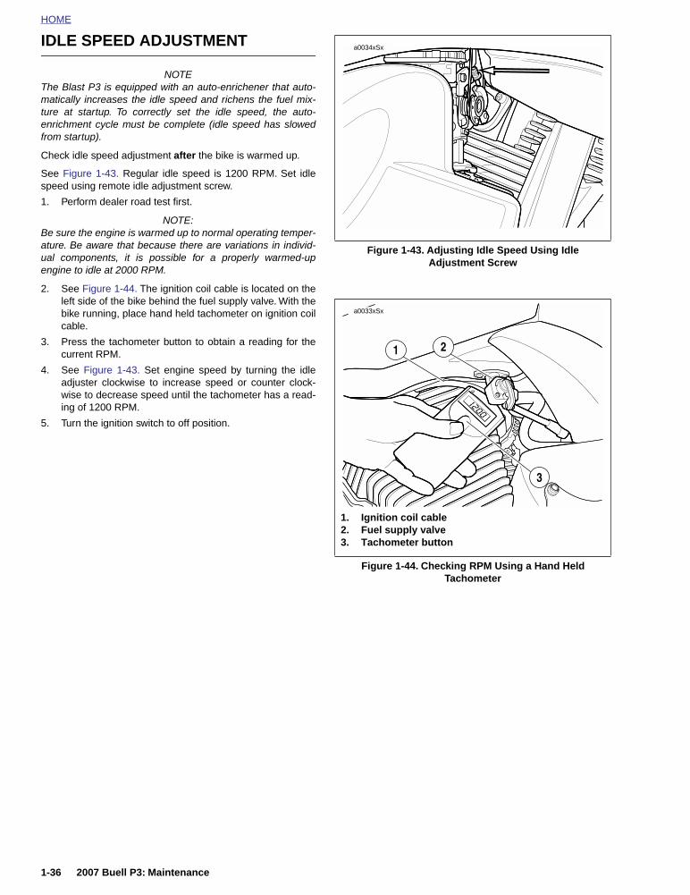
HOME
IDLE SPEED ADJUSTMENT
NOTEThe Blast P3 is equipped with an auto-enrichener that auto-matically increases the idle speed and richens the fuel mix-ture at startup. To correctly set the idle speed, the auto-enrichment cycle must be complete (idle speed has slowedfrom startup).
Check idle speed adjustment after the bike is warmed up.
See Figure 1-43. Regular idle speed is 1200 RPM. Set idlespeed using remote idle adjustment screw.
1. Perform dealer road test first.
NOTE:Be sure the engine is warmed up to normal operating temper-ature. Be aware that because there are variations in individ-ual components, it is possible for a properly warmed-upengine to idle at 2000 RPM.
2. See Figure 1-44. The ignition coil cable is located on theleft side of the bike behind the fuel supply valve. With thebike running, place hand held tachometer on ignition coilcable.
3. Press the tachometer button to obtain a reading for thecurrent RPM.
4. See Figure 1-43. Set engine speed by turning the idleadjuster clockwise to increase speed or counter clock-wise to decrease speed until the tachometer has a read-ing of 1200 RPM.
5. Turn the ignition switch to off position.
Figure 1-43. Adjusting Idle Speed Using IdleAdjustment Screw
Figure 1-44. Checking RPM Using a Hand Held Tachometer
a0034xSx
a0033xSx
1. Ignition coil cable2. Fuel supply valve3. Tachometer button
3
1 2
1-36 2007 Buell P3: Maintenance

HOME
FUEL SUPPLY VALVE AND FILTER STRAINER 1.20
REMOVAL
11WARNING1WARNING
Stop the engine when refueling or servicing the fuel sys-tem. Do not smoke or allow open flame or sparks neargasoline. Gasoline is extremely flammable and highlyexplosive, which could result in death or serious injury.(00002a)
1. Remove seat. Depress latch at bottom and pull seat upand back to remove.
11WARNING1WARNING
To prevent accidental vehicle start-up, which couldcause death or serious injury, disconnect negative (-)battery cable before proceeding. (00048a)
2. Unthread bolt and remove battery negative cable (black)from battery negative (-) terminal.
3. Drain fuel tank as follows:
a. See Figure 1-45. Rotate handle on the fuel supplyvalve to the fully vertical position (4) to shut the gas-oline supply to the carburetor OFF.
11WARNING1WARNING
Gasoline can drain from the fuel line when disconnectedfrom fuel tank. Gasoline is extremely flammable andhighly explosive, which could result in death or seriousinjury. Wipe up spilled fuel immediately and dispose ofrags in a suitable manner. (00260a)
b. Turn slotted screw to loosen band clamp on outletfitting at side of fuel valve. Pull hose from fitting.
c. Attach length of spare hose to outlet fitting. Placefree end of hose into a suitable container.
d. See Figure 1-45. Rotate handle of fuel supply valveto RES (reserve) (6) of to start the flow of fuel.
e. Once the fuel tank is completely drained, rotate han-dle of fuel supply valve to OFF. Remove spare hosefrom outlet fitting.
Figure 1-45. Fuel Supply Valve
1. Fuel supply valve2. Filter strainer3. Band clamp4. Fuel supply - OFF5. Fuel supply - ON6. Fuel supply - RES (reserve)
a0011xox
a0176x4x
Left Side
4
1
3
5
6
2
2007 Buell P3: Maintenance 1-37

HOME
11WARNING1WARNING
With fuel tank drained, gasoline can spill from bore whensupply valve is loosened or removed. Gasoline isextremely flammable and highly explosive, which couldresult in death or serious injury. Wipe up spilled fuelimmediately and dispose of rags in a suitable manner.(00277a)
4. Remove two allen head screws from fuel valve and pullassembly from fuel tank bore.
5. Remove o-ring from flange of fuel valve assembly. Dis-card o-ring.
6. Carefully unthread fuel filter strainer from fuel valveassembly.
CLEANING AND INSPECTION
Clean strainer using a suitable solvent. Replace strainer ifany damage is found.
INSTALLATION
1. Carefully thread fuel filter strainer onto fuel valve assem-bly.
2. Install new o-ring into groove on flange of fuel valveassembly.
3. Insert fuel valve assembly into fuel tank bore and installtwo allen head screws. Alternately tighten screws to 19-21 in-lbs (2.2-2.3 Nm).
4. Push hose onto outlet fitting at side of fuel valve. Turnslotted screw to tighten band clamp.
5. Verify that handle of fuel supply valve is in the “OFF”position and fill the fuel tank.
6. Rotate handle of fuel supply valve to “ON” and carefullyinspect for fuel leaks. Return the valve to the “OFF” posi-tion when finished.
7. Insert bolt through battery negative cable (black) intothreaded hole of battery negative (-) terminal. Tightenbolt to 72-96 in-lbs (8-11 Nm).
11WARNING1WARNING
After installing seat, pull upward on front of seat to besure it is in locked position. While riding, a loose seat canshift causing loss of control, which could result in deathor serious injury. (00070a)
8. Position seat on frame backbone, so that tongue at bot-tom engages slot in frame weldment. Push down on rearof seat until spring-loaded latch fully engages groove ofseat pin.
1-38 2007 Buell P3: Maintenance

HOME
STARTER INTERLOCK AND ELECTRICAL SWITCHES 1.21
GENERAL
Lubricate sidestand with Loctite Lubriplate or Lithium Grease.
Inspect all electrical equipment and switches, includingstarter interlock for proper operation before every ride.
TESTING INTERLOCK
The starter/ignition interlock system is designed to preventunintended start-up and/or forward motion of the motorcycle.One of three conditions must exist to allow operation of thevehicle:
● Clutch disengaged (lever pulled in - must be done when-ever starting motorcycle).
● Transmission in neutral.
● Sidestand retracted.
If the motorcycle starts and operates without any of the threeconditions being met, see 7.11 STARTER/IGNITION INTER-LOCK, for troubleshooting procedures.
TESTING SWITCHES
Check the following electric switches for proper operation:
● Left and right directional signals and dash indicator.
● Neutral indicator light on dash.
● Headlamp low and high beam, high beam flash and highbeam indicator light.
● Oil pressure indicator light.
● Odometer reset switch.
● Tail lamp.
● Brake lamp with both front and rear brake application.
● Speedometer.
● Horn.
● Ignition stop/run switch.
● Electric starter switch.
2007 Buell P3: Maintenance 1-39

HOME
HEADLAMP 1.22
INSPECTION
11WARNING1WARNING
The automatic-on headlamp feature provides increasedvisibility of the rider to other motorists. Be sure head-lamp is on at all times. Poor visibility of rider to othermotorists can result in death or serious injury. (00030b)
Check headlamp beam for proper height and lateral align-ment as follows:
1. Verify correct front and rear tire inflation pressure. See1.8 TIRES AND WHEELS.
2. Place motorcycle on level floor (or pavement) in an areawith minimum light.
3. See Figure 1-46. Point front of motorcycle toward ascreen or wall which is 25 ft (7.62 M) away from front tirecontact patch on floor (directly below front axle).
4. Draw a horizontal line on the screen or wall 35 in. (88.9cm) above the floor.
5. Have a person whose weight is roughly the same as thatof the principal rider sit on motorcycle seat. Weight ofrider will compress vehicle suspension slightly.
6. Stand motorcycle upright with both tires resting on floorand with front wheel held in straight alignment (directlyforward).
7. Turn ignition switch to IGN. Set handlebar headlampswitch to HIGH beam position.
8. Check light beam for proper height alignment. Mainbeam of light (broad, flat pattern of light) should be cen-tered on horizontal line on screen or wall (i.e. equal areaof light above and below line).
9. Check light beam for proper lateral alignment. Mainbeam of light should be directed straight ahead (i.e.equal area of light to right and left of center).
10. Adjust headlamp if necessary. See ADJUSTMENT.
ADJUSTMENT
1. See Figure 1-47. To adjust headlamp turn vertical head-lamp mounting adjuster (1) clockwise to raise beamheight.
2. Turn horizontal headlamp mounting adjuster (2) clock-wise to change lateral alignment.
Figure 1-46. Checking Headlamp Alignment
Figure 1-47. Headlamp Adjustment
25 ft (7.62 M)
a0063xSxHorizontal
line
35 in (88.9 cm)
a0253x7x
1. Vertical headlamp adjuster2. Horizontal headlamp adjuster
2
1
1-40 2007 Buell P3: Maintenance

HOME
CRITICAL FASTENER TORQUE VALUES 1.23
GENERAL
Check stabilizer links and engine mounts for damage andhardware for proper tightness:
Inspect muffler strap and exhaust system hardware for dam-age and proper tightness:
Inspect critical fasteners (listed below) for proper tightness asrecommended in 1.3 MAINTENANCE SCHEDULE.
TORQUE VALUES
ITEM TORQUE
Left handlebar control fasteners 25-33 in-lbs 2.8-3.7 Nm
Right handlebar control fasteners 25-33 in-lbs 2.8-3.7 Nm
Handlebar fasteners 120-144 in-lbs 14-16 Nm
Brake banjo bolts 16-20 ft-lbs 22-27 Nm
Front brake caliper mounting bolts 18-22 ft-lbs 24-30 Nm
Rear (large) brake caliper mounting bolt 18-22 ft-lbs 24-30 Nm
Rear (small) brake caliper mounting bolt 14.5-18 ft-lbs 20-24 Nm
Brake caliper pin 132-174 in-lbs 15-20 Nm
Front rotor TORX screws 24-27 ft-lbs 33-37 Nm
Rear rotor TORX screws 24-27 ft-lbs 33-37 Nm
Front axle nut 38-42 ft-lbs 52-57 Nm
Rear axle nut 49-51 ft-lbs 67-69 Nm
Front fork upper triple clamp pinch bolts (at sliders) 13-16 ft-lbs 18-22 Nm
Front fork upper triple clamp pinch bolts (at center cap) 84-120 in-lbs 10-14 Nm
Front fork lower triple clamp pinch bolts 22-29 ft-lbs 30-39 Nm
Muffler fasteners (front and rear) 17-19 ft-lbs 24-25 Nm
Tie bar (all) 30-33 ft-lbs 41-45 Nm
Front isolator mounting bolt 63-70 ft-lbs 86-95 Nm
Frame to rear isolator fastener 30-33 ft-lbs 41-45 Nm
2007 Buell P3: Maintenance 1-41

HOME
TROUBLESHOOTING 1.24
ENGINE
The following check list can be helpful in locating most oper-ating troubles. Refer to the appropriate sections in this Ser-vice Manual for detailed procedures.
Starter Motor Does Not Operate or Does Not Turn Engine Over1. Engine run switch in OFF position.
2. Ignition switch not on.
3. Discharged battery, loose or corroded connections.(Solenoid chatters.)
4. Starter control relay or solenoid not functioning.
5. Electric starter shaft pinion gear not engaging or over-running clutch slipping.
6. Clutch lever not pulled in.
Engine Turns Over But Does Not Start1. Fuel tank empty.
2. Fuel valve turned off.
3. Fuel valve or filter clogged.
4. Discharged battery, loose or broken battery terminal con-nections.
5. Fouled spark plug.
6. Spark plug cable in bad condition and shorting or cableconnections loose.
7. Ignition timing badly out of adjustment.
8. Loose wire connection at coil or battery connection orplug between ignition sensor and module.
9. Ignition coil not functioning.
10. Ignition module not functioning.
11. Ignition sensor not functioning.
12. Sticking or damaged valve or valves.
13. Engine flooded with gasoline as a result of over choking.
14. Engine oil too heavy (winter operation).
Starts Hard1. Spark plug in bad condition, have improper gap or are
partially fouled.
2. Spark plug cable in bad condition and shorting.
3. Battery nearly discharged.
4. Loose wire connection at one of the battery terminals, atcoil, or at plug between ignition sensor and module.
5. Carburetor controls not adjusted correctly.
6. Ignition coil not functioning.
7. Engine oil too heavy (winter operation).
8. Ignition not timed properly.
9. Fuel tank filler cap vent plugged, or carburetor fuel lineclosed off restricting fuel flow.
10. Water or dirt in fuel system and carburetor.
11. Enrichener valve inoperative.
12. Air leak at intake manifold.
13. Valves sticking.
Starts But Runs Irregularly or Misses
1. Spark plug in bad condition or partially fouled.
2. Spark plug cable in bad condition and shorting.
3. Spark plug gap too close or too wide.
4. Ignition coil not functioning.
5. Ignition module not functioning.
6. Ignition sensor not functioning.
7. Battery nearly discharged.
8. Damaged wire or loose connection at battery terminalsor coil.
9. Intermittent short circuit due to damaged wire insulation.
10. Water or dirt in fuel system and carburetor or filter.
11. Fuel tank filler cap vent plugged or carburetor float bowlvent closed off.
12. Carburetor controls improperly adjusted.
13. Air leak at intake manifold or air cleaner.
14. Damaged intake or exhaust valve.
15. Weak or broken valve springs.
16. Incorrect valve timing.
Spark Plug Fouls Repeatedly
1. Incorrect spark plug.
2. Piston rings badly worn or broken.
3. Fuel mixture too rich (see CARBURETOR TROUBLE-SHOOTING).
4. Valve stem seals worn or damaged.
5. Valve guides badly worn.
Pre-Ignition or Detonation(Knocks or Pings)
1. Excessive carbon deposit on piston head or combustionchamber.
2. Incorrect heat range spark plug.
3. Spark plug not firing.
4. Ignition timing advanced.
5. Fuel octane rating too low.
6. Intake manifold vacuum leak.
Overheating
1. Insufficient oil supply, or oil not circulating.
2. Leaking valves.
3. Heavy carbon deposit.
4. Ignition timing retarded.
1-42 2007 Buell P3: Maintenance

HOME
Valve Train Noise
1. Hydraulic lifter not functioning properly.
2. Bent push rod.
3. Cam, cam gears, or cam bushings worn.
4. Rocker arm binding on shaft.
5. Valve sticking in guide.
Excessive Vibration
1. Upper mounting bracket loose, broken or improperlyspaced.
2. Lower mounting bolts loose.
3. Broken frame.
4. Primary chain badly worn or links tight as a result ofinsufficient lubrication.
5. Wheels not aligned and/or tires worn.
6. Internal engine problem.
7. Engine mount loose or broken.
ENGINE LUBRICATION SYSTEM
Oil Does Not Return To Oil Reservoir
1. Oil reservoir empty.
2. Return pump gears damaged.
3. Oil feed pump not functioning.
4. Restricted oil lines or fittings.
Engine Uses Too Much Oil or Smokes Excessively
1. Piston rings badly worn or broken.
2. Valve stem seals worn or damaged.
3. Valve guides worn.
Engine Leaks Oil From Cases, Push Rods, Hoses, Etc.
1. Loose parts.
2. Imperfect seal at gaskets, push rod cover, washers, etc.To aid locating leaks, use BLACK LIGHT LEAK DETEC-TOR (Part No. HD-35457).
3. Restricted oil return line to reservoir.
4. Restricted breather passage(s) to air cleaner.
ELECTRICAL SYSTEM
Alternator Does Not Charge
1. Regulator-rectifier module not functioning.
2. Rectifier not grounded.
3. Engine ground wire loose or broken.
4. Loose or broken wires in charging circuit.
5. Stator not functioning.
6. Rotor not functioning.
Alternator Charge Rate Is Below Normal
1. Regulator-rectifier module not functioning.
2. Stator not functioning.
3. Rotor not functioning.
4. Weak battery.
5. Loose connections.
FUEL
Carburetor Floods
1. Inlet valve sticking.
2. Inlet valve and/or valve seat worn or damaged.
3. Dirt or other foreign matter between valve and its seat.
4. Float misadjusted or filled with fuel.
TRANSMISSION
Shifts Hard
1. Clutch dragging slightly.
2. Shifter forks (inside transmission) damaged.
3. Corners worn off shifter clutch dogs (inside transmis-sion).
Jumps Out of Gear
1. Shifter pawl improperly adjusted.
2. Shifter engaging parts (inside transmission) badly wornand rounded.
3. Shifter forks bent.
4. Damaged gears.
CLUTCH
Slips
1. Clutch controls improperly adjusted.
2. Worn friction plates.
Drags or Does Not Release
1. Clutch controls improperly adjusted.
2. Clutch plates excessively warped.
Chatters
1. Friction or steel plates worn, warped, or dragging.
2007 Buell P3: Maintenance 1-43

HOME
CHASSIS
Irregular/Inadequate Brake Action1. Master cylinder low on fluid.
2. Brake line contains air bubbles.
3. Master or wheel cylinder piston worn.
4. Brake pads impregnated with grease or oil.
5. Brake pads badly worn (1/16 in. (1.6 mm) minimum liningthickness).
6. Brake disc badly worn or warped.
7. Brake pads dragging or excessive braking (brake fadesdue to heat buildup).
8. Insufficient brake pedal or hand lever free play (brakedrags).
Handling Irregularities1. Tires improperly inflated. Check 2.2 TIRE SPECIFICA-
TIONS. Do not overinflate.
2. Loose wheel axle nuts. Tighten front nut to 38-42 ft-lbs(52-57 Nm). Tighten rear nut to 49-51 ft-lbs (67-69 Nm).
3. Excessive wheel hub bearing play.
4. Rear wheel out of alignment with frame and front wheel.
5. Rims and tires out-of-true sideways (tire runout shouldnot be more than 5/64 in. (2.0 mm).
6. Rims and tires out-of-round or eccentric with hub (tirerunout should not be more than 3/32 in. (2.4 mm).
7. Irregular or peaked front tire tread wear.
8. Tire and wheel unbalanced.
9. Steering head bearings improperly adjusted. Correctadjustment, and replace pitted or worn bearings andraces. See 2.18 FORK STEM AND BRACKET ASSEM-BLY.
10. Shock absorber not functioning normally.
11. Heavy front end loading. Non-standard equipment on thefront end (such as heavy radio receivers, extra lightingequipment, or luggage) tends to cause unstable han-dling.
1-44 2007 Buell P3: Maintenance

CHASSIS 2
Table Of Contents
SUBJECT PAGE NO.
2.1 Specifications . . . . . . . . . . . . . . . . . . . . . . . . . . . . . . . . . . . . . . . . . . . . . . . . . 2-12.2 Tire Specifications . . . . . . . . . . . . . . . . . . . . . . . . . . . . . . . . . . . . . . . . . . . . . . 2-42.3 Vehicle Identification Number (V.I.N.) . . . . . . . . . . . . . . . . . . . . . . . . . . . . . . . 2-52.4 Wheels . . . . . . . . . . . . . . . . . . . . . . . . . . . . . . . . . . . . . . . . . . . . . . . . . . . . . . . 2-72.5 Front Wheel . . . . . . . . . . . . . . . . . . . . . . . . . . . . . . . . . . . . . . . . . . . . . . . . . . . 2-92.6 Rear Wheel . . . . . . . . . . . . . . . . . . . . . . . . . . . . . . . . . . . . . . . . . . . . . . . . . . . 2-122.7 Sealed Wheel Bearings . . . . . . . . . . . . . . . . . . . . . . . . . . . . . . . . . . . . . . . . . . 2-152.8 Checking Cast Rim Runout . . . . . . . . . . . . . . . . . . . . . . . . . . . . . . . . . . . . . . . 2-182.9 Tires . . . . . . . . . . . . . . . . . . . . . . . . . . . . . . . . . . . . . . . . . . . . . . . . . . . . . . . . . 2-192.10 Front Brake Master Cylinder . . . . . . . . . . . . . . . . . . . . . . . . . . . . . . . . . . . . . 2-232.11 Front Brake Caliper . . . . . . . . . . . . . . . . . . . . . . . . . . . . . . . . . . . . . . . . . . . . 2-282.12 Front Brake Line . . . . . . . . . . . . . . . . . . . . . . . . . . . . . . . . . . . . . . . . . . . . . . 2-322.13 Rear Brake Master Cylinder . . . . . . . . . . . . . . . . . . . . . . . . . . . . . . . . . . . . . 2-332.14 Rear Brake Caliper . . . . . . . . . . . . . . . . . . . . . . . . . . . . . . . . . . . . . . . . . . . . 2-382.15 Rear Shock Absorber . . . . . . . . . . . . . . . . . . . . . . . . . . . . . . . . . . . . . . . . . . 2-422.16 Throttle Control . . . . . . . . . . . . . . . . . . . . . . . . . . . . . . . . . . . . . . . . . . . . . . . 2-432.17 Front Fork . . . . . . . . . . . . . . . . . . . . . . . . . . . . . . . . . . . . . . . . . . . . . . . . . . . 2-452.18 Fork Stem And Bracket Assembly . . . . . . . . . . . . . . . . . . . . . . . . . . . . . . . . . 2-562.19 Swingarm . . . . . . . . . . . . . . . . . . . . . . . . . . . . . . . . . . . . . . . . . . . . . . . . . . . . 2-582.20 Exhaust System . . . . . . . . . . . . . . . . . . . . . . . . . . . . . . . . . . . . . . . . . . . . . . . 2-592.21 Footpeg Support Brackets . . . . . . . . . . . . . . . . . . . . . . . . . . . . . . . . . . . . . . . 2-612.22 Sprocket Cover . . . . . . . . . . . . . . . . . . . . . . . . . . . . . . . . . . . . . . . . . . . . . . . 2-622.23 Fenders . . . . . . . . . . . . . . . . . . . . . . . . . . . . . . . . . . . . . . . . . . . . . . . . . . . . . 2-632.24 Lower Belt Guard . . . . . . . . . . . . . . . . . . . . . . . . . . . . . . . . . . . . . . . . . . . . . . 2-652.25 Tail Section And Rear Frame Assembly . . . . . . . . . . . . . . . . . . . . . . . . . . . . 2-662.26 Windscreen . . . . . . . . . . . . . . . . . . . . . . . . . . . . . . . . . . . . . . . . . . . . . . . . . . 2-682.27 Instrument Panel . . . . . . . . . . . . . . . . . . . . . . . . . . . . . . . . . . . . . . . . . . . . . . 2-692.28 Seat . . . . . . . . . . . . . . . . . . . . . . . . . . . . . . . . . . . . . . . . . . . . . . . . . . . . . . . . 2-702.29 Sidestand . . . . . . . . . . . . . . . . . . . . . . . . . . . . . . . . . . . . . . . . . . . . . . . . . . . . 2-712.30 Handlebars . . . . . . . . . . . . . . . . . . . . . . . . . . . . . . . . . . . . . . . . . . . . . . . . . . 2-722.31 Front And Rear Isolators . . . . . . . . . . . . . . . . . . . . . . . . . . . . . . . . . . . . . . . . 2-73


HOME
2
SPECIFICATIONS 2.1
NOTESee information decal on frame steering head for Gross Vehi-cle Weight Rating (GVWR) (maximum allowable loaded vehi-cle weight) and corresponding Gross Axle Weight Ratings(GAWR).
NOTEUse a good quality unleaded gasoline which is 87 pumpoctane or higher (R+M)/2. Octane rating is usually found onthe pump.
11WARNING1WARNING
Do not inflate tire beyond maximum pressure as speci-fied on sidewall. Over inflated tires can blow out, whichcould result in death or serious injury. (00027a)
Table 2-1. Chassis Specifications
DIMENSIONS IN. MM
Wheel Base 55.0 1397
Seat Height - Low SeatHigh Seat
25.5027.50
648699
Road Clearance 3.88 99.0
Trail 3.4 86
Rake 25°
Table 2-2. Weight Specifications
WEIGHT-U.S. MODELS LBS. KG
Wet Weight 390 177
GVWR 780 354
GAWR Front 280 127
GAWR Rear 500 227
Load Capacity 390 177
Table 2-3. Fluid Capacities
CAPACITIES U.S. Metric
Fuel Tank: Total(including reserve)Reserve
2.8 gallons0.55 gallons
10.60 liters2.08 liters
Oil Tank (with filter) 2.0 quarts 1.89 liters
Transmission/Primary 32.0 ounces 946.0 ml
Front Fork(each-wet capacity) 9.2 ounces 272.0 ml
Table 2-4. Tire Pressures
Dunlop Tires (only) FRONT REAR
PSI kPa PSI kPa
Solo Rider 28 193 30 207
Rider & Passenger 32 220 36 248
2007 Buell P3: Chassis 2-1
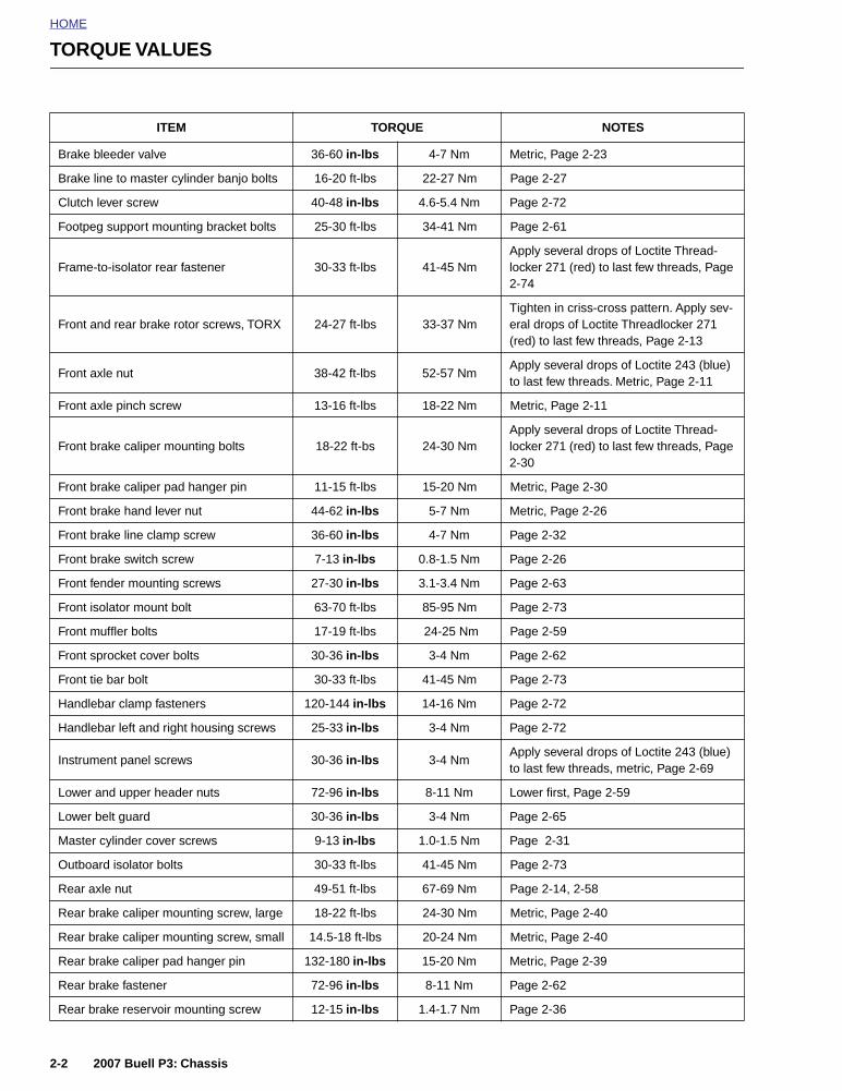
HOME
TORQUE VALUES
ITEM TORQUE NOTES
Brake bleeder valve 36-60 in-lbs 4-7 Nm Metric, Page 2-23
Brake line to master cylinder banjo bolts 16-20 ft-lbs 22-27 Nm Page 2-27
Clutch lever screw 40-48 in-lbs 4.6-5.4 Nm Page 2-72
Footpeg support mounting bracket bolts 25-30 ft-lbs 34-41 Nm Page 2-61
Frame-to-isolator rear fastener 30-33 ft-lbs 41-45 NmApply several drops of Loctite Thread-locker 271 (red) to last few threads, Page 2-74
Front and rear brake rotor screws, TORX 24-27 ft-lbs 33-37 NmTighten in criss-cross pattern. Apply sev-eral drops of Loctite Threadlocker 271 (red) to last few threads, Page 2-13
Front axle nut 38-42 ft-lbs 52-57 NmApply several drops of Loctite 243 (blue) to last few threads. Metric, Page 2-11
Front axle pinch screw 13-16 ft-lbs 18-22 Nm Metric, Page 2-11
Front brake caliper mounting bolts 18-22 ft-bs 24-30 NmApply several drops of Loctite Thread-locker 271 (red) to last few threads, Page 2-30
Front brake caliper pad hanger pin 11-15 ft-lbs 15-20 Nm Metric, Page 2-30
Front brake hand lever nut 44-62 in-lbs 5-7 Nm Metric, Page 2-26
Front brake line clamp screw 36-60 in-lbs 4-7 Nm Page 2-32
Front brake switch screw 7-13 in-lbs 0.8-1.5 Nm Page 2-26
Front fender mounting screws 27-30 in-lbs 3.1-3.4 Nm Page 2-63
Front isolator mount bolt 63-70 ft-lbs 85-95 Nm Page 2-73
Front muffler bolts 17-19 ft-lbs 24-25 Nm Page 2-59
Front sprocket cover bolts 30-36 in-lbs 3-4 Nm Page 2-62
Front tie bar bolt 30-33 ft-lbs 41-45 Nm Page 2-73
Handlebar clamp fasteners 120-144 in-lbs 14-16 Nm Page 2-72
Handlebar left and right housing screws 25-33 in-lbs 3-4 Nm Page 2-72
Instrument panel screws 30-36 in-lbs 3-4 NmApply several drops of Loctite 243 (blue) to last few threads, metric, Page 2-69
Lower and upper header nuts 72-96 in-lbs 8-11 Nm Lower first, Page 2-59
Lower belt guard 30-36 in-lbs 3-4 Nm Page 2-65
Master cylinder cover screws 9-13 in-lbs 1.0-1.5 Nm Page 2-31
Outboard isolator bolts 30-33 ft-lbs 41-45 Nm Page 2-73
Rear axle nut 49-51 ft-lbs 67-69 Nm Page 2-14, 2-58
Rear brake caliper mounting screw, large 18-22 ft-lbs 24-30 Nm Metric, Page 2-40
Rear brake caliper mounting screw, small 14.5-18 ft-lbs 20-24 Nm Metric, Page 2-40
Rear brake caliper pad hanger pin 132-180 in-lbs 15-20 Nm Metric, Page 2-39
Rear brake fastener 72-96 in-lbs 8-11 Nm Page 2-62
Rear brake reservoir mounting screw 12-15 in-lbs 1.4-1.7 Nm Page 2-36
2-2 2007 Buell P3: Chassis

HOME
Rear drive sprocket bolts 28-31 ft-lbs 38-42 NmApply several drops of Loctite Thread-locker 271 (red) to last few threads. Page 2-13
Rear fender mounting screws 30-36 in-lbs 3-4 Nm Page 2-64
Rear isolator-to engine crankcase 32-34 ft-lbs 46-50 NmApply several drops of Loctite 243 (blue) to last few threads, Page 2-74
Rear master cylinder mounting screws 48-72 in-lbs 5-8 NmApply several drops of Loctite 243 (blue) to last few threads, metric, Page 2-36
Rear muffler strap screws 17-19 ft lbs 24-25 Nm Page 2-59
Rear shock top and bottom bolt 35-40 ft-lbs 47-54 Nm Page 2-42
Steering head upper triple tree clamp screws (at sliders)
13-16 ft-lbs 18-22 Nm Loctite Anit-Seize, Page 2-55
Swingarm bolt 24-26 ft-lbs 33-35 NmApply anti-seize to bolt and install, Page 2-58
Swingarm pinch bolt 17-19 ft-lbs 23-26 NmApply several drops of Loctite 243 (blue) to last few threads, Page 2-58
Switch housing screws, right side 12-17 in-lbs 1-2 Nm Metric, Page 2-43
Valve stem nut 42-44 in-lbs 4.7-5.0 Nm Page 2-21
Windscreen screws 9-11 in-lbs 1 Nm Page 2-68
ITEM TORQUE NOTES
2007 Buell P3: Chassis 2-3

HOME
TIRE SPECIFICATIONS 2.2
GENERAL
11WARNING1WARNING
Match tires, tubes, air valves and caps to the correctwheel rim. Contact a Harley-Davidson dealer. Mismatch-ing can result in damage to the tire bead, allow tire slip-page on the rim or cause tire failure, which could resultin death or serious injury. (00023a).
Tire sizes are molded on the sidewall. Rim size and contourare marked on the rim’s exterior surface.
Example: MT 2.5 x 16.0 DOT
● MT designates the rim contour.
● 2.5 is the width of the bead seat measured in inches.
● 16.0 is the normal diameter of the rim in inches, mea-sured at the bead seat diameter.
● DOT means that the rim meets Department of Transpor-tation Federal Motor Vehicle Safety Standards.
Refer to Table 2-5.
Table 2-5. Tire Fitment-Tubeless Cast Wheels
WHEEL SIZE & POSITION
CONTOUR &RIM SIZE
RIM VALVE HOLE DIAMETER
DUNLOP RADIAL TIRE SIZE
16 in. – Front MT 2.5 x 16.0 DOT 0.33 in. (8.38 mm) 100/80 16 K330
16 in. – Rear MT 2.75 x 16.0 DOT 0.33 in. (8.38 mm) 120/80 16 K330
2-4 2007 Buell P3: Chassis
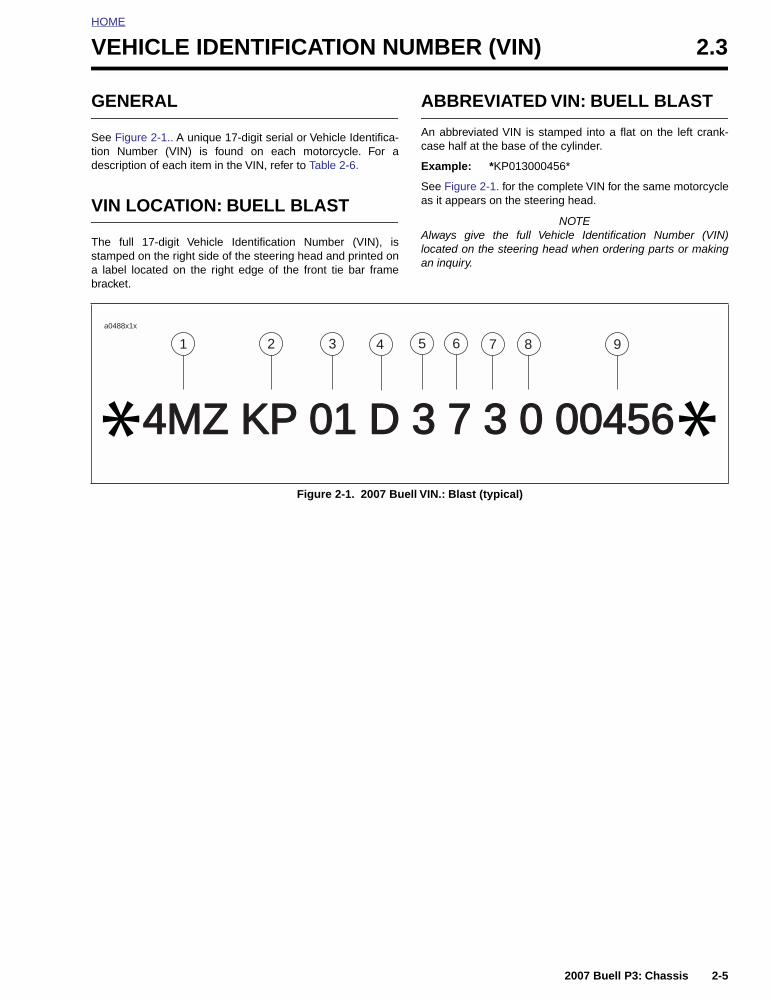
HOME
VEHICLE IDENTIFICATION NUMBER (VIN) 2.3
GENERAL
See Figure 2-1.. A unique 17-digit serial or Vehicle Identifica-tion Number (VIN) is found on each motorcycle. For adescription of each item in the VIN, refer to Table 2-6.
VIN LOCATION: BUELL BLAST
The full 17-digit Vehicle Identification Number (VIN), isstamped on the right side of the steering head and printed ona label located on the right edge of the front tie bar framebracket.
ABBREVIATED VIN: BUELL BLAST
An abbreviated VIN is stamped into a flat on the left crank-case half at the base of the cylinder.
Example: *KP013000456*
See Figure 2-1. for the complete VIN for the same motorcycleas it appears on the steering head.
NOTEAlways give the full Vehicle Identification Number (VIN)located on the steering head when ordering parts or makingan inquiry.
Figure 2-1. 2007 Buell VIN.: Blast (typical)
4MZ KP 01 D 3 7 3 0 004564MZ KP 01 D 3 7 3 0 00456* *1 2 3 4 5 6 7 8 9
a0488x1x
2007 Buell P3: Chassis 2-5

HOME
Table 2-6. 2007 Buell VIN Description
ITEM DESCRIPTION POSSIBLE VALUES
1 Market designation (WMI code) 4MZ = Buell vehicles originally manufactured for sale within the United States5MZ = Buell vehicles originally manufactured for sale outside the United States
2 Motorcycle type code AX=FireboltDX=UlyssesJX=Lightning LongKP=BlastKX=Lightning CityXSX=LightningWX=Lightning Scg
3 Engine 01 492cc 02 984cc 03 1203cc
4 Market configuration A=AustraliaL=CaliforniaN=CanadaD=DomesticE=EnglandR=EuropeJ=Japan
5 VIN check digit Can be 0-9 or X
6 Model year 7=2007
7 Assembly plant 3=East Troy, WI
8 Model 0=Blast (07)1=XB9R (07)2=XB9SX (07)3=XB12R (07)4=XB12S (07)5=XB12Scg (07)6=XB12Ss (07)7=XB12X (07)
9 Sequential number (last 5 digits) Varies
2-6 2007 Buell P3: Chassis

HOME
WHEELS 2.4
GENERAL
Good handling and maximum tire mileage are directly relatedto the care of wheels and tires. Regularly inspect wheels andtires for damage and wear. If handling problems occur, referto Table 2-7.
Keep tires inflated to the recommended air pressure. Alwaysbalance the wheel after replacing a tire.
11WARNING1WARNING
Do not inflate tire beyond maximum pressure as speci-fied on sidewall. Over inflated tires can blow out, whichcould result in death or serious injury. (00027a)
TROUBLESHOOTING
See Figure 2-2. Check tire inflation pressure at least onceeach week. At the same time, inspect tire tread for punctures,cuts, breaks and other damage. Repeat the inspection beforelong trips.
Figure 2-2. Checking Tire Inflation Pressure
a0198x2x
Table 2-7. Wheel Service
CHECK FOR REMEDY
Loose axle nuts. Apply Loctite 243 (Blue) and tighten front axle nut (metric) to 38-42 ft-lbs (52-57 Nm). Tighten rear axle nut (metric) to 49-51 ft-lbs (67-69 Nm).
Excessive side-play or radial (up-and-down)play in wheel hubs.
Replace wheel hub bearings.
Alignment of rear wheel in frame or withfront wheel.
Repair swingarm as described under 2.19 SWINGARM.
Rims and tires out-of-true sideways; shouldnot be more than 0.080 in. (2.03 mm).
Replace rims. See 2.9 TIRES.
Rims and tires out-of-round or eccentricwith hub; should not be more than 0.090 in.(2.29 mm).
Replace rims. See 2.9 TIRES.
Irregular or peaked front tire wear. Replace as described under 2.5 FRONT WHEEL or 2.9 TIRES.
Correct tire inflation. Inflate tires to correct pressure. See 2.2 TIRE SPECIFICATIONS.
Correct tire and wheel balance. Static balance may be satisfactory if dynamic balancing facilities are not available. However, dynamic balancing is strongly recommended.
Steering head bearings. Correct adjustment and replace pitted or worn bearings. See 2.18 FORK STEM AND BRACKET ASSEMBLY.
Damper tubes. Check for leaks. See 2.17 FRONT FORK.
Shock absorber. Check damping action and mounts. See 2.15 REAR SHOCK ABSORBER.
Swingarm bearings. Check for looseness. See 2.19 SWINGARM.
2007 Buell P3: Chassis 2-7

HOME
11WARNING1WARNING
Use the following guidelines when installing a new tire orrepairing a flat. Failure to comply with the guidelinesbelow could result in death or serious injury.
● Always locate and eliminate the cause of the originaltire failure.
● Do not patch or vulcanize a tire casing. These proce-dures weaken the casing and increase the risk of ablowout.
11WARNING1WARNING
Use only Buell approved tires. See a Buell dealer. Usingnon-approved tires can adversely affect stability, whichcould result in death or serious injury. (00133a)
11WARNING1WARNING
Tires are a critical safety component. Contact a Buelldealer for tire repair or replacement. Improper tire ser-vice can adversely affect stability and handling, whichcould result in death or serious injury. (00134a)
11WARNING1WARNING
Replace punctured or damaged tires. In some cases,small punctures in the tread area may be repaired fromwithin the demounted tire by a Buell dealer. Speedshould NOT exceed 50 m.p.h. (80 km/h) for the first 24hours after repair, and the repaired tire should NEVER beused over 80 m.p.h. (130 km/h). Failure to follow thiswarning could result in death or serious injury. (00118a)
11WARNING1WARNING
Buell tires are equipped with wear bars that run horizon-tally across the tread. When wear bars become visibleand only 1/32 in. (0.8 mm) tread depth remains, replacetire immediately. Using a worn tire can adversely affectstability and handling, which could result in death orserious injury. Use only Dunlop Harley-Davidson replace-ment tires. (00090a)
At regular intervals of 5000 miles (8000 km) or wheneverhandling irregularities are noted, perform the recommendedservice checks. See Table 2-7.
If tires must be replaced, same as original equipment tiresmust be used. Other tires may not fit correctly and may behazardous to use.
2-8 2007 Buell P3: Chassis

HOME
FRONT WHEEL 2.5
REMOVAL
1. Raise front wheel off floor.
2. Inspect wheel bearing end play and service bearings ifnecessary. See 2.7 SEALED WHEEL BEARINGS.
3. Remove brake pads.
a. See Figure 2-3. Remove pin plug (4).
b. See Figure 2-4. Remove pad hanger pin (metric).
c. Remove brake pads from caliper.
4. See Figure 2-3. Detach caliper from mounts.
a. Remove lower mounting screw (6).
b. Remove upper mounting screw (6) and brakelinewireform (7) while supporting caliper above brakerotor.
c. Remove caliper by tilting away from wheel and thenpulling away from rotor.
NOTE
Do not operate front brake lever with front wheel removed orcaliper pistons may be forced out. Reseating pistons requirescaliper disassembly.
5. See Figure 2-5. Insert screwdriver/rod through axle hole(1). Loosen front axle nut (4).
6. Loosen pinch screw (2).
7. Remove front axle nut, spacer and washer. Pull front axleout of wheel hub while supporting front wheel.
Figure 2-3. Front Brake Caliper
63
1
4
5
1. Brake line2. Bleeder valve3. Banjo bolt (metric)4. Banjo washers (2)5. Pin plug6. Mounting screws (2)7. Wireform
8273
2
7
Figure 2-4. Pad Spring
Figure 2-5. Front Wheel Mounting
7702
1. Pad spring2. Pad hanger pin
1
2
7734
1. Axle hole2. Pinch screw3. Washer4. Axle nut (metric)5. Spacer (and washer)
34
5
1
2
2007 Buell P3: Chassis 2-9

HOME
DISASSEMBLY
1. See Figure 2-6. Remove five bolts (10) and washers (11)to detach front brake rotor (12) from wheel hub. Discardbolts and washers.
2. Remove tire. See 2.9 TIRES.
CLEANING AND INSPECTION
1. Thoroughly clean all parts in solvent.
2. Inspect all parts for damage or excessive wear.
3. Inspect brake rotor and pads.
11WARNING1WARNING
Always replace brake pads in complete sets for correctand safe brake operation. Improper brake operationcould result in death or serious injury. (00111a)
Figure 2-6. Front Wheel Assembly
a0161a2x
1
4
2
9 12
10
3
568
7
1. Nut (metric)2. Left axle spacer3. Wheel bearing4. Wheel5. Valve stem6. Wheel weight7. Axle spacer, center8. Wheel bearing9. Front axle10. Brake rotor bolt (5)11. Brake rotor washer (5)12. Front brake rotor13. Washer
11
113
2-10 2007 Buell P3: Chassis

HOME
ASSEMBLY
11WARNING1WARNING
Be sure that brake fluid or other lubricants do not con-tact brake pads or discs. Such contact can adverselyaffect braking ability, which could cause loss of control,resulting in death or serious injury. (00290a)
CAUTION
Do not re-use brake disc screws. Re-using disc screwscan result in torque loss and damage to rotor and/orbrake assembly. (00319b)
1. See Figure 2-6. Install front brake rotor (12) on right sideof wheel.
a. Verify that the front brake rotor is thoroughly clean.
b. Apply Loctite Threadlocker 271 (red) to threads ofeach of five new T40 TORX screws (10).
NOTEDo NOT reuse brake rotor mounting fasteners (10) and wash-ers (11). Always use new washers (P/N CB0004.T) whenassembling wheel.
c. Install rotor (12) on wheel hub. Tighten new TORXscrews (10) with new washers (11) in criss-crosspattern to 24-27 ft-lbs (33-37 Nm).
2. Install tire, if removed. See 2.9 TIRES.
3. Verify that wheel and tire are true. See 2.8 CHECKINGCAST RIM RUNOUT.
4. Balance tire. See 2.9 TIRES, ADJUSTMENT.
INSTALLATION
1. See Figure 2-6. Install front axle.
a. Position wheel between forks with brake rotor ongearcase side of motor.
b. With pinch screw (metric) loose, insert threaded endof axle through right side fork.
c. Push axle through fork and wheel hub until axlebegins to emerge from left side of hub.
d. Install axle spacer (2) and washer (13).
2. Compress the front suspension to make sure it is freeand not binding.
3. See Figure 2-6. Install axle nut.
a. Apply Loctite Threadlocker 243 (blue) to axlethreads.
b. Install axle nut (1) (metric) over threaded end ofaxle.
c. Insert screwdriver or steel rod through hole in axle.
d. While holding axle stationary, tighten axle nut (1)(metric) to 38-42 ft-lbs (52-57 Nm).
4. Tighten the front axle pinch screw to 13-16 ft-lbs (18-22 Nm).
5. Install front brake caliper. See 2.11 FRONT BRAKECALIPER.
2007 Buell P3: Chassis 2-11

HOME
REAR WHEEL 2.6
REMOVAL
1. Raise rear wheel off floor using REAR WHEEL SUP-PORT STAND (Part No. B-41174).
2. Inspect wheel bearing end play and service bearings ifnecessary. See 2.8 SEALED WHEEL BEARINGS.
NOTEDo not operate rear brake pedal with rear wheel removed orcaliper piston may be forced out. Reseating piston requirescaliper disassembly.
3. See Figure 2-7. Place rod or screwdriver through axlehole. Loosen rear axle nut (1) (metric).
4. Remove nut, lockwasher, and flat washer.
5. Pull axle out. Remove right side spacer.
6. Slide carrier with caliper off rotor.
7. Remove left side spacer.
8. Move wheel forward and slide belt off.
DISASSEMBLY
1. See Figure 2-8. Remove and discard five sprocket bolts(6) from sprocket cover.
2. Remove sprocket cover (7) from sprocket.
3. Remove and discard hardened washers from sprocket.
4. Remove sprocket from rear wheel.
5. Remove five T40 TORX screws and brake rotor from rearwheel. Discard screws.
CLEANING AND INSPECTION
1. Thoroughly clean all parts in solvent.
2. Inspect all parts for damage or excessive wear.
3. Inspect brake rotor.
a. Measure rotor thickness. Replace if less than 4.5mm. See 2.14 REAR BRAKE CALIPER.
b. Check rotor surface. Replace if warped or badlyscored.
4. Inspect tire. See 2.9 TIRES.
Figure 2-7. Rear Wheel Mounting
7747
1. Axle nut (metric)2. Lockwasher3. Washer4. Axle hole
1
3
24
Figure 2-8. Rear Axle, Right Side
32
1
7701
1. Axle2. Axle nut (metric)3. Lockwasher4. Washer5. Spacer6. Sprocket bolts (5)7. Sprocket cover
4
6
7
5
2-12 2007 Buell P3: Chassis

HOME
ASSEMBLY
11WARNING1WARNING
Do not allow brake fluid, bearing grease or other lubri-cants to contact brake rotor or brake pads or reducedbraking ability may occur which could result in death orserious injury.
1. Lay wheel on clean work area with rotor side down.
2. Position sprocket on rim with holes in sprocket and rimaligned.
11WARNING1WARNING
Be sure that brake fluid or other lubricants do not con-tact brake pads or discs. Such contact can adverselyaffect braking ability, which could cause loss of control,resulting in death or serious injury. (00290a)
CAUTION
Do not re-use sprocket mounting screws. Re-usingsprocket mounting screws can result in torque loss anddamage to the sprocket and/or belt assembly. (00480b)
3. Place new hardened washers (Part No. BA0511.2Z) onsprocket.
4. Position sprocket cover over washers and install tosprocket with five new sprocket fasteners. Tighten fas-teners to 28-31 ft-lbs (38-42 Nm).
CAUTION
Do not re-use brake disc screws. Re-using disc screwscan result in torque loss and damage to rotor and/orbrake assembly. (00319b)
5. See Figure 2-9. Install brake rotor (9) to wheel.
a. Verify that the brake rotor is thoroughly clean.
b. Apply Loctite Threadlocker 271 (red) to threads ofeach of five new T40 TORX screws (8).
c. Install rotor (9) on wheel hub. Tighten new TORXscrews in criss-cross pattern to 24-27 ft-lbs (33-37Nm).
Figure 2-9. Rear Wheel Assembly
2
4
7
53
9
6
12
1
8
10
1. Nut (metric)2. Left axle spacer3. Wheel bearing (left side)4. Wheel5. Axle spacer, center6. Wheel bearing (right side)
7. Rear axle8. Brake rotor fastener (5)9. Rear brake rotor10. Right axle spacer11. Lockwasher12. Washer
a0079x2x
11
11
2007 Buell P3: Chassis 2-13

HOME
INSTALLATION
1. Place wheel centrally in the swingarm. Slide wheel farenough forward to slip belt over sprocket and rest belt onsprocket inboard of the teeth.
NOTEDo not place belt on sprocket teeth at this time. Alignment ofparts will be difficult. Resting belt next to teeth allows slack foreasier alignment of wheel assembly.
2. See Figure 2-10. Hold left side spacer in place and slidecaliper and carrier over rotor.
3. Slide axle through washer, swing arm, carrier, left sidespacer and wheel assembly.
a. See Figure 2-11. Hold right side spacer in place.
b. Insert axle through right side spacer and swingarm.
c. Install flat washer, lockwasher and axle nut.
4. Place screwdriver or rod through axle hole and torquerear axle nut to 49-51 ft-lbs (67-69 Nm).
5. Slide belt on sprocket teeth by rotating wheel to “walk”belt onto teeth.
6. Lower motorcycle rear wheel.
Figure 2-10. Rear Axle, Left Side
2
1
1. Axle2. Rear axle hole
7705
Figure 2-11. Rear Axle, Right Side
2
1
7701
1. Axle2. Axle nut (metric)3. Lockwasher4. Washer5. Right axle spacer6. Sprocket bolts (5)7. Sprocket cover
6
7
5
3
4
2-14 2007 Buell P3: Chassis

HOME
SEALED WHEEL BEARINGS 2.7
INSPECTION
1. Block motorcycle underneath frame so wheel is raisedoff the ground.
2. See Figure 2-12. Mount a magnetic base dial indicator tothe brake disc with the dial’s contact point on the end ofthe axle.
3. Turn the wheel through several rotations, then move thewheel side to side to check for lateral end play.
a. If the end play is less than the service wear limit of0.002 in. (0.051 mm), bearing passes inspection.
b. If the end play exceeds service wear limit or feelsrough, remove wheel and replace both wheel bear-ings.
REMOVAL
1. Remove wheel from motorcycle. See 2.6 REAR WHEEL.
2. See Figure 2-13. Obtain WHEEL BEARING INSTALLER/REMOVER (Part No. B-43933) and assemble.
a. Sparingly apply graphite lubricant to threads of forc-ing screw (1) to prolong service life and ensuresmooth operation.
b. Install nut (2), washer (3) and Nice bearing (4) onscrew. Insert assembly through hole in bridge (5).
c. Drop ball bearing inside collet (6). Fasten collet andball bearing to forcing screw (1).
3. Hold end of forcing screw (1) and turn collet (6) toexpand edges of collet.
Figure 2-12. Wheel Bearing Inspection (Front Wheel Shown)
a0199x2x
Figure 2-13. Removal Tool
1. Forcing screw2. Nut3. Washer4. Nice bearing5. Bridge6. Collet with ball bearing inside
a0200x2x
1
2
4
6
5
3
2007 Buell P3: Chassis 2-15

HOME
4. See Figure 2-14. When expanded collet has grippedbearing edges, hold end of forcing screw (1) and turn thenut (2) to remove bearing from wheel.
5. Remove spacer from inside wheel hub.
6. Repeat procedure for opposite side bearing. Discard allbearings upon removal.
INSTALLATION
NOTEAlways install first bearing on primary brake disc side. If frontwheel has two brake discs, install bearing on the left side first.
1. Obtain WHEEL BEARING INSTALLER/REMOVER (PartNo. B-43933) and assemble.
a. Sparingly apply graphite lubricant to threads ofthreaded rod to prolong service life and ensuresmooth operation.
b. See Figure 2-15. Place threaded rod through sup-port plate. Insert assembly through wheel.
c. See Figure 2-16. Place the new bearing (6) on rod(1) with lettered side outward.
d. Install pilot (5), Nice bearing (4), washer (3) and nut(2) over rod.
2. Hold hex end of threaded rod (1) and turn nut (2) toinstall bearing (6). Bearing will be fully seated when nutcan no longer be turned. Remove tool.
3. Install spacer sleeve inside wheel hub.
4. Reverse tool and install opposite side bearing.
5. Tighten bearing tool until bearing inner race contactsspacer.
Figure 2-14. Remove Bearing
Figure 2-15. Installation Tool Support Plate
a020x2x
2
1. Forcing screw2. Nut
1
a0202x2x
Figure 2-16. Installing Bearing
a0203x2x
12
3
5 6
4
1. Threaded rod2. Nut3. Washer4. Nice bearing5. Pilot6. Wheel bearing
2-16 2007 Buell P3: Chassis

HOME
Figure 2-17. Wheel Bearing Remover/Installer (Part No. B-43933)
76
1
2
3
45
8 9
13
11
10
12
a0204a2x
1. Bridge (Part No. HD-44060-5)2. Steel ball (Part No. 12547)3. Forcing screw (Part No. HD-44060-4)4. Nut (Part No. 10210)5. Washer (Part No. 12004)6. Nice bearing (Part No. RS25100-200)7. Lubricant (Part No. J-23444A)8. Collet, 3/4 in. (Part No. B-43993-3)9. Collet, 1.0 in. (Part No. B-43993-7)10. Pilot 3/4 in. (Part No. B-43993-6)11. Pilot 1.0 in. (Part No. B-43993-8)12. Support plate pilot (Part No. B-43993-1)13. Threaded rod pilot (Part No. 280856)
2007 Buell P3: Chassis 2-17

HOME
CHECKING CAST RIM RUNOUT 2.8
GENERAL
Check wheels for lateral and radial runout before installing anew tire.
Rim Lateral Runout1. See Figure 2-18. Install truing arbor in wheel hub and
place wheel in WHEEL TRUING AND BALANCINGSTAND (Part No. HD-99500-80).
2. Tighten arbor nuts so hub will turn on its bearings.
3. Check rim lateral runout by placing a gauge rod or dialindicator near the rim bead. Replace wheel if lateralrunout exceeds specification shown in Table 2-8.
Rim Radial Runout1. See Figure 2-19. Install truing arbor in wheel hub and
place wheel in WHEEL TRUING AND BALANCINGSTAND (Part No. HD-99500-80).
2. Tighten arbor nuts so hub will turn on its bearings.
3. Check radial runout as shown. Replace wheel if runoutexceeds specification shown in Table 2-8.
Table 2-8. Cast Wheel Runout
MEASUREMENT in. mm
MAXIMUM LATERAL RUNOUT 0.040 1.02
MAXIMUM RADIAL RUNOUT 0.030 0.76
Figure 2-18. Checking Cast Rim Lateral Runout using Wheel Truing and Balancing Stand
(Part No. HD-99500-80)
Figure 2-19. Checking Cast Rim Radial Runout using Wheel Truing and Balancing Stand
(Part No. HD-99500-80)
a0205x2x
Gauge Rod
a0206x2x
Gauge Rod
2-18 2007 Buell P3: Chassis

HOME
TIRES 2.9
GENERAL
Tires should be inspected for punctures, cuts, breaks andwear at least weekly.
New tires should be stored in a horizontal tire rack. Avoidstacking new tires in a vertical stack. The weight of the stackcompresses the tires and closes down the beads.
11WARNING1WARNING
Replace punctured or damaged tires. In some cases,small punctures in the tread area may be repaired fromwithin the demounted tire by a Buell dealer. Speedshould NOT exceed 50 mph (80 km/h) for the first 24hours after repair, and the repaired tire should NEVER beused over 80 mph (130 km/h). Failure to follow this warn-ing could result in death or serious injury. (00118a).
Tubeless tires may be repaired in the tread area only if thepuncture is 1/4 in. (6.4 mm) or smaller. All repairs must bemade from inside the tire.
Acceptable repair methods include a patch and plug combi-nation, chemical or hot vulcanizing patches or head-typeplugs. When repairing tubeless tires, use TIRE SPREADER(Part No. HD-21000) to spread the tire sidewalls.
11WARNING1WARNING
Never repair a tire with less than 1/16 in. (1.6 mm) treaddepth. Inadequate tread depth can cause an accidentwhich could result in death or serious injury.
11WARNING1WARNING
Use only Buell approved tires. See a Buell dealer. Usingnon-approved tires can adversely affect stability, whichcould result in death or serious injury. (00133a)
11WARNING1WARNING
Tires are a critical safety component. Contact a Buelldealer for tire repair or replacement. Improper tire ser-vice can adversely affect stability and handling, whichcould result in death or serious injury. (00134a)
2007 Buell P3: Chassis 2-19

HOME
REMOVAL
1. Remove wheel from motorcycle. See 2.5 FRONTWHEEL or 2.6 REAR WHEEL.
2. Rear wheel only: Remove rear sprocket. See 2.6 REARWHEEL (Disassembly).
3. Deflate tire. Use a valve core tool to remove valve corefrom valve stem.
11WARNING1WARNING
Read the operating manual for the manufacturer andmodel of tire machine used. Failure to follow operationalprocedures or to heed any cautions/warnings in the man-ual for the tire machine could result in death or seriousinjury. (00283a)
4. See Figure 2-20. Use a pneumatic bead breaker toloosen bead. Rotate wheel and apply bead breaker atseveral points along circumference of the rim until entirebead drops into rim well.
5. See Figure 2-21. Install wheel onto jaws of tire machine.Lubricate tire bead with soap solution.
6. Fit wedge over rim of wheel.
7. Pull bead up over rim in one spot and fit bead to wedge.Spin wheel to draw full length of bead over rim and offwheel. Do not use excessive force when starting beadover rim.
IMPORTANT NOTEFollow the tire machine manufacture’s recommendationfor the correct placement of the bead on the mandrel.Incorrect mounting may damage the bead and ruin thetire.
8. If necessary, repeat for opposite bead and remove tirefrom wheel.
9. Remove valve stem if it is damaged or leaks.
10. Mount tire on TIRE SPREADER (Part No. HD-21000) forinspection and repair procedures.
CLEANING AND INSPECTION
1. Clean inside of tire.
2. If rim is dirty or corroded, clean with a stiff wire brush.
3. Inspect tire for wear and damage. Replace worn tires.See 1.8 TIRES AND WHEELS.
Figure 2-20. Loosening Beads from Rim Flange (Typical)
a0207x2x
Figure 2-21. Tire Machine Pulling Bead Off Rim
a0208x2x
2-20 2007 Buell P3: Chassis
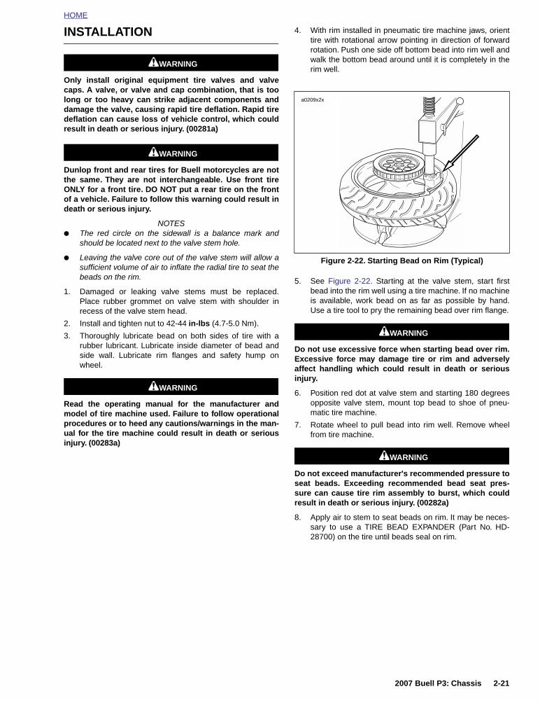
HOME
INSTALLATION
11WARNING1WARNING
Only install original equipment tire valves and valvecaps. A valve, or valve and cap combination, that is toolong or too heavy can strike adjacent components anddamage the valve, causing rapid tire deflation. Rapid tiredeflation can cause loss of vehicle control, which couldresult in death or serious injury. (00281a)
11WARNING1WARNING
Dunlop front and rear tires for Buell motorcycles are notthe same. They are not interchangeable. Use front tireONLY for a front tire. DO NOT put a rear tire on the frontof a vehicle. Failure to follow this warning could result indeath or serious injury.
NOTES● The red circle on the sidewall is a balance mark and
should be located next to the valve stem hole.
● Leaving the valve core out of the valve stem will allow asufficient volume of air to inflate the radial tire to seat thebeads on the rim.
1. Damaged or leaking valve stems must be replaced.Place rubber grommet on valve stem with shoulder inrecess of the valve stem head.
2. Install and tighten nut to 42-44 in-lbs (4.7-5.0 Nm).
3. Thoroughly lubricate bead on both sides of tire with arubber lubricant. Lubricate inside diameter of bead andside wall. Lubricate rim flanges and safety hump onwheel.
11WARNING1WARNING
Read the operating manual for the manufacturer andmodel of tire machine used. Failure to follow operationalprocedures or to heed any cautions/warnings in the man-ual for the tire machine could result in death or seriousinjury. (00283a)
4. With rim installed in pneumatic tire machine jaws, orienttire with rotational arrow pointing in direction of forwardrotation. Push one side off bottom bead into rim well andwalk the bottom bead around until it is completely in therim well.
5. See Figure 2-22. Starting at the valve stem, start firstbead into the rim well using a tire machine. If no machineis available, work bead on as far as possible by hand.Use a tire tool to pry the remaining bead over rim flange.
11WARNING1WARNING
Do not use excessive force when starting bead over rim.Excessive force may damage tire or rim and adverselyaffect handling which could result in death or seriousinjury.
6. Position red dot at valve stem and starting 180 degreesopposite valve stem, mount top bead to shoe of pneu-matic tire machine.
7. Rotate wheel to pull bead into rim well. Remove wheelfrom tire machine.
11WARNING1WARNING
Do not exceed manufacturer's recommended pressure toseat beads. Exceeding recommended bead seat pres-sure can cause tire rim assembly to burst, which couldresult in death or serious injury. (00282a)
8. Apply air to stem to seat beads on rim. It may be neces-sary to use a TIRE BEAD EXPANDER (Part No. HD-28700) on the tire until beads seal on rim.
Figure 2-22. Starting Bead on Rim (Typical)
a0209x2x
2007 Buell P3: Chassis 2-21

HOME
Checking Tire Lateral Runout
1. See Figure 2-23. Turn wheel on axle and measureamount of displacement from a fixed point to tire side-wall.
2. Tire tread lateral runout should be no more than 0.080 in.(2.03 mm). If runout is more than 0.080 in. (2.03 mm),remove tire from rim.
3. Check rim bead side runout. See 2.8 CHECKING CASTRIM RUNOUT. Replace rims not meeting specifications.
4. Install tire and check again for tire tread lateral runout.
Checking Tire Radial Runout
1. See Figure 2-24. Turn wheel on axle and measure treadradial runout.
2. Tire tread radial runout should not be greater than 0.060in. (1.52 mm). If runout exceeds specification, removetire from rim.
3. Check rim bead runout. See 2.8 CHECKING CAST RIMRUNOUT. Replace rims not meeting specifications.
4. Install tire and check tire tread radial runout again.
ADJUSTMENT
Wheel Balancing
Wheel balancing is recommended to improve handling andreduce vibration, especially at high road speeds.
In most cases, static balancing using WHEEL TRUING ANDBALANCING STAND (Part No. HD-99500-80) will producesatisfactory results. However, dynamic balancing, utilizing awheel spinner, can be used to produce finer tolerances forbetter high-speed handling characteristics. Follow the instruc-tions supplied with the balance machine you are using.
WEIGHTS FOR CAST WHEELS
The maximum weight permissible to accomplish balance is:
● 1.0 oz. (28 g) total weight applied to the front wheel.
● 2.0 oz. (56 g) total weight applied to the rear wheel.
Wheels should be balanced to within 1/4 oz. (7 g) at 60 MPH(97 KM/H).
See Figure 2-25. Use only WHEEL WEIGHTS (Part No.43692-94Y) which have special self-adhesive backings.Apply WHEEL WEIGHTS to the flat surface of the wheel rim.
1. Make sure that area of application is completely clean,dry and free of oil and grease.
2. Remove paper backing from weight. For additional adhe-sive strength, apply three drops of Loctite Super-Bonder420 to adhesive side of weight.
3. Place weight on flat surface of wheel rim.
4. Press weight firmly in place and hold for ten seconds.
5. Allow eight hours for adhesive to cure completely beforeusing wheel.
Figure 2-23. Checking Tire Lateral Runout
Figure 2-24. Checking Tire Radial Runout
0.080 in.(2.03 mm)maximum
Gauge
a0210x2x
a0211x2x
0.060 in.(1.52 mm)maximum
Gauge
Figure 2-25. Wheel Weights (Typical)
a0212x2x
2-22 2007 Buell P3: Chassis

HOME
FRONT BRAKE MASTER CYLINDER 2.10
REMOVAL
NOTEDo not remove the master cylinder unless problems are beingexperienced.
IMPORTANT NOTEAlways drain brake fluid into a suitable container. Dis-card used fluid according to local laws.
1. See Figure 2-26. To drain brake fluid from front brakesystem:
a. Open bleeder valve (metric) about 1/2-turn.
b. Install a length of plastic tubing over caliper bleedervalve. Place free end in a suitable container.
c. Pump brake hand lever to drain brake fluid.
d. Tighten bleeder valve to 36-60 in-lbs (4-7 Nm).
2. Remove mirror from right handlebar.
IMPORTANT NOTEDamaged banjo bolt seating surfaces will leak whenreassembled. Prevent damage to seating surfaces bycarefully removing brake line components.
3. See Figure 2-27. Remove banjo bolt (5) (metric) and twobanjo washers (4) to disconnect brake line (6) from mas-ter cylinder. Discard banjo washers.
4. Unplug both terminals to detach brake lamp switch.
NOTEThe individual parts of the brake lamp switch are not service-able. Replace switch upon failure.
5. Remove two screws (1) (metric) and clamp (2) to detachmaster cylinder assembly from handlebar.
Figure 2-26. Front Brake Caliper Bleeder Valve (Metric) for Draining Front Brake System
8273
Figure 2-27. Front Master Cylinder
1. Clamp screws (2) (metric)2. Clamp3. Master cylinder cover screws (2)4. Banjo washers (2)5. Banjo bolt (metric)6. Brake line
a0213x2x
1
3
4
2
6
5
2007 Buell P3: Chassis 2-23

HOME
DISASSEMBLY
1. See Figure 2-28. Detach front brake hand lever.
a. Remove nut (1) (metric) from lever pivot.
b. Remove pivot bolt (2) from lever pivot.
2. Detach front brake hand lever (3) from master cylinderassembly.
3. See Figure 2-29. Remove screw, lock washer andwasher (1) holding front brake switch (3) to master cylin-der assembly. Remove switch.
4. See Figure 2-30. Compress piston (2) and remove rub-ber boot (1).
5. Depress piston assembly and remove internal snap ring(3). Discard snap ring.
6. See Figure 2-31. Remove piston assembly (1-4) fromfront master cylinder.
Figure 2-28. Hand Lever
Figure 2-29. Front Brake Switch
6488
23
1
1. Nut (metric)2. Pivot bolt3. Hand lever
12
1. Screw, lockwasher and washer2. Tang3. Front brake switch
6489
3
Figure 2-30. Snap Ring
Figure 2-31. Piston Assembly
6490
2
1. Boot2. Piston3. Snap ring
3
1
6491
1. Spring2. Primary cup3. Secondary cup4. Piston5. Boot6. Snap ring
1 2 3 4
6
5
2-24 2007 Buell P3: Chassis

HOME
CLEANING AND INSPECTION
11WARNING1WARNING
Use denatured alcohol to clean brake system compo-nents. Do not use mineral-based solvents (such as gaso-line or paint thinner), which will deteriorate rubber partseven after assembly. Deterioration of these componentscan cause brake failure, which could result in death orserious injury. (00291a)
11WARNING1WARNING
Compressed air can pierce the skin and flying debrisfrom compressed air could cause serious eye injury.Wear safety glasses when working with compressed air.Never use your hand to check for air leaks or to deter-mine air flow rates. (00061a)
1. Clean all parts with denatured alcohol or D.O.T. 4BRAKE FLUID. Do not contaminate with mineral oil orother solvents. Wipe dry with a clean, lint free cloth. Blowout drilled passages and bore with a clean air supply. Donot use a wire or similar instrument to clean drilled pas-sages in bottom of reservoir.
2. Carefully inspect all parts for wear or damage andreplace as necessary.
3. Inspect piston bore in master cylinder housing for scor-ing, pitting or corrosion. Replace housing if any of theseconditions are found.
4. See Figure 2-32. Inspect outlet port that mates withbrake line fitting. As a critical sealing surface, replacehousing if any scratches, dents or other damage isnoted.
5. Inspect boot for cuts, tears or general deterioration.Replace as necessary.
Figure 2-32. Master Cylinder Body Outlet Port
6492
2007 Buell P3: Chassis 2-25

HOME
ASSEMBLY
1. See Figure 2-33. Check piston assembly components.
a. Small end of spring (1) sits behind primary cup (2).Large side of primary cup faces spring.
b. Secondary cup (3) sits within ridge at middle of pis-ton (4).
2. Insert piston assembly, spring first, into master cylinder.Secure with a new snap ring (6).
3. Install ridge on boot (5) into groove on piston (4).
4. See Figure 2-28. Install front brake hand lever.
a. Align hole in lever with hole in master cylinderassembly.
b. Lubricate pivot bolt (2) with Loctite Anti-Seize.
c. Install pivot bolt through top of assembly. Tighten to4-13 in-lbs (0.5-1.5 Nm).
d. Install nut (1) (metric). Tighten to 44-62 in-lbs (5-7 Nm).
5. See Figure 2-29. Install front brake lamp switch (7).
a. Attach front brake switch with screw, washer andlockwasher (1). Tighten to 7-13 in-lbs (0.8-1.5 Nm).
b. See Figure 2-34. Test switch action. Tang (3) onswitch must release when hand lever (2) is moved.
Figure 2-33. Piston Assembly
6491
1. Spring2. Primary cup3. Secondary cup4. Piston5. Boot6. Snap ring
1 2 3 4
6
5
Figure 2-34. Testing Hand Lever
6493
1
3
2
1. Screw, lockwasher and washer2. Hand lever3. Tang
2-26 2007 Buell P3: Chassis

HOME
INSTALLATION
1. See Figure 2-27. Fasten master cylinder to handlebar byinstalling clamp (2) and screws (1) (metric). Tighten to80-120 in-lbs (9-14 Nm).
11WARNING1WARNING
● Use only new copper banjo washers (See Parts Cata-log for Part No.) with D.O.T. 4 brake fluid. Earlier sil-ver banjo washers are not compatible with D.O.T. 4fluid and will not seal properly over time. Failure tocomply may adversely affect braking ability and leadto brake failure which could result in death or seri-ous injury.
● Avoid leakage. Be sure gaskets, banjo bolt(s), brakeline and master cylinder bore are clean and undam-aged before assembly. (00322a)
2. Connect brake line (5) to master cylinder using two newbanjo washers (4) and banjo bolt (6) (metric). Tighten to16-20 ft-lbs (22-27 Nm).
3. See Figure 2-35. Verify brake lamp switches are secure.Attach wires to switches.
4. Install mirror parallel to handlebars.
5. See Figure 2-27. Remove the two master cylinder coverscrews (3), cover and cover gasket.
6. See Figure 2-36. With the master cylinder in a level posi-tion, add D.O.T. 4 BRAKE FLUID. Bring fluid level towithin 0.125 in. (3.2 mm) of molded boss inside frontmaster cylinder reservoir.
11WARNING1WARNING
Be sure the master cylinder relief port is not plugged. Aplugged relief port can cause brake drag or lockup andloss of vehicle control, which could result in death orserious injury. (00317a)
7. See Figure 2-36. Verify proper operation of the mastercylinder relief port.
8. Actuate the brake lever with the reservoir cover removed.A slight spurt of fluid will break the surface if all internalcomponents are working properly.
9. See Figure 2-27. Attach master cylinder cover and covergasket with the two cover screws (3). Tighten to 9-13 in-lbs (1.0-1.5 Nm).
10. Bleed brake system. See 1.6 BRAKE SYSTEM MAINTE-NANCE.
11WARNING1WARNING
Check for proper brake lamp operation before ridingmotorcycle. Visibility is a major concern for motorcy-clists. Failure to have proper brake lamp operation couldresult in death or serious injury.
11. Turn ignition key switch to IGN. Apply brake hand lever totest brake lamp operation. Turn ignition switch to LOCK.
11WARNING1WARNING
After repairing the brake system, test brakes at lowspeed. If brakes are not operating properly, testing athigh speeds can cause loss of control, which couldresult in death or serious injury. (00289a)
Figure 2-35. Brake Lamp Switch Connectors
6569
Figure 2-36. Brake Fluid Level
a0214x2x
2007 Buell P3: Chassis 2-27

HOME
FRONT BRAKE CALIPER 2.11
REMOVAL
NOTESteps 1 and 2 are not required for detaching caliper fromrotor. Drain fluid only when disassembling caliper.
IMPORTANT NOTEAlways drain brake fluid into a suitable container. Dis-card used fluid according to local laws.
1. Drain and discard brake fluid.
IMPORTANT NOTEDamaged banjo bolt seating surfaces will leak whenreassembled. Prevent damage to seating surfaces bycarefully removing brake line components.
2. See Figure 2-37. Remove banjo bolt (3) (metric) and twobanjo washers (4) to disconnect brake line (1) from cali-per. Discard banjo washers.
3. Remove brake pads.
a. Remove pin plug (5).
b. See Figure 2-38. Remove pad hanger pin (1) (met-ric).
c. Remove brake pads from caliper.
4. See Figure 2-37. Detach caliper from mounts.
a. Remove lower mounting screw (6).
b. Remove upper mounting screw (6) and brake linewireform (7) while supporting caliper above brakerotor.
c. Slowly remove caliper by tilting away from wheel andthen pulling away from rotor.
d. Separate carrier and caliper.
Figure 2-37. Front Brake Caliper
63
1
4
5
1. Brake line2. Bleeder valve3. Banjo bolt (metric)4. Banjo washers (2)5. Pin plug6. Mounting screws (2)7. Wireform
8273
2
7
Figure 2-38. Pad Spring
7702
1
2
1. Pad hanger pin (metric)2. Pad spring
2-28 2007 Buell P3: Chassis

HOME
DISASSEMBLY
1. See Figure 2-39. Use BRAKE CALIPER PISTONREMOVER (Part No. B-42887) to pull the two pistonsfrom caliper bores.
2. See Figure 2-40. Remove piston outer seals (4) andinner seals (3) from their respective grooves in caliper.Discard seals.
3. Check bleeder valve (metric). Remove and replace ifdamaged.
CLEANING AND INSPECTION
11WARNING1WARNING
Use denatured alcohol to clean brake system compo-nents. Do not use mineral-based solvents (such as gaso-line or paint thinner), which will deteriorate rubber partseven after assembly. Deterioration of these componentscan cause brake failure, which could result in death orserious injury. (00291a)
11WARNING1WARNING
Compressed air can pierce the skin and flying debris fromcompressed air could cause serious eye injury. Wearsafety glasses when working with compressed air. Neveruse your hand to check for air leaks or to determine airflow rates. (00061a)
1. Clean all parts with denatured alcohol or D.O.T. 4BRAKE FLUID. Do not contaminate with mineral oil orother solvents. Wipe dry with a clean, lint free cloth. Blowout drilled passages and bore with a clean air supply. Donot use a wire or similar instrument to clean drilled pas-sages.
2. Carefully inspect all components. Replace any parts thatappear damaged or worn. Do not hone caliper pistonbore.
3. Inspect brake rotor.
a. Measure rotor thickness. Replace if minimum thick-ness is less than 0.180 in. (4.5 mm).
b. Check rotor surface. Replace if warped or badlyscored.
11WARNING1WARNING
Always replace brake pads in complete sets for correctand safe brake operation. Improper brake operationcould result in death or serious injury. (00111a)
4. Inspect brake pads for damage or excessive wear.Replace both pads as a set if the friction material ofeither pad is worn to 0.040 in. (1.0 mm) or less.
ASSEMBLY
1. See Figure 2-40. Install pistons and O-rings.
a. Apply a light coat of D.O.T. 4 BRAKE FLUID toseals, pistons and caliper piston bores.
b. Install two new seals (4) in outer grooves of eachpiston bore.
c. Install two new seals (3) in inner grooves of eachpiston bore.
d. Install pistons (2) in each piston bore.
2. Install a new bleeder valve (metric) if necessary. Tightento 36-60 in-lbs (4-7 Nm).
Figure 2-39. Removing Pistons
Figure 2-40. Caliper O-rings and Pistons
7699
7700
1
2 2
3
4
1. Caliper2. Piston (2)3. Inner seals4. Outer seals
2007 Buell P3: Chassis 2-29

HOME
INSTALLATION
1. Fit front brake caliper on rotor.
a. Slide carrier on caliper.
b. Slide caliper over front brake rotor without brakepads installed.
2. See Figure 2-41. Apply Loctite Threadlocker 271 (red) toboth caliper mounting screws (6). Install wireform toupper screw and tighten both screws to 18-22 ft-lbs (24-30 Nm).
3. See Figure 2-42. Install brake pads.
a. Install pad spring (2) with opening at top as shown.
b. Insert inboard brake pad from rear of caliper.
c. Insert outboard pad.
d. See Figure 2-42. Install pad hanger pin (1) (metric).Tighten to 132-180 in-lbs (15-20 Nm).
e. See Figure 2-41. Install pin plug (5). Tighten to 18-25 in-lbs (2-3 Nm).
11WARNING1WARNING
Use only new copper banjo washers (See Parts Catalogfor Part No.) with D.O.T. 4 brake fluid. Earlier silver banjowashers are not compatible with D.O.T. 4 fluid and willnot seal properly over time. Failure to comply mayadversely affect braking ability and lead to brake failurewhich could result in death or serious injury.
IMPORTANT NOTETo avoid leakage, verify that banjo washers, banjo bolt,hydraulic brake line and caliper bore are completelyclean.
4. See Figure 2-41. Connect brake line (1) to caliper usingtwo new banjo washers (4) and banjo bolt (3) (metric).Tighten to 16-20 ft-lbs (22-27 Nm).
5. Route brake line through wireform.
Figure 2-41. Front Brake Caliper
63
1
4
5
1. Brake line2. Bleeder valve3. Banjo bolt (metric)4. Banjo washers (2)5. Pin plug6. Mounting screws (2)7. Wireform
8273
2
7
Figure 2-42. Pad Spring
7702
1
2
1. Pad hanger pin (metric)2. Pad spring
2-30 2007 Buell P3: Chassis

HOME
IMPORTANT NOTECover molded-in-color surfaces and right handlebarswitches and use care when removing brake reservoircover and adding D.O.T. 4 brake fluid. Spilling D.O.T. 4brake fluid on molded-in-color surfaces will result in cos-metic damage. Spilling brake fluid on switches can ren-der them inoperative.
6. See Figure 2-43. Remove both master cylinder coverscrews (2). Remove master cylinder cover (1) and gasket.
7. With the master cylinder in a level position, verify that thebrake fluid level is 0.125 in. (3.2 mm) from molded bossinside reservoir. Add D.O.T. 4 BRAKE FLUID if neces-sary.
11WARNING1WARNING
Be sure the master cylinder relief port is not plugged. Aplugged relief port can cause brake drag or lockup andloss of vehicle control, which could result in death orserious injury. (00317a)
8. Verify proper operation of the master cylinder relief port.Actuate the brake lever with the reservoir cover removed.A slight spurt of fluid will break the surface if all internalcomponents are working properly.
9. See Figure 2-43. Install master cylinder cover (1) andcover gasket with two screws (2). Tighten to 9-13 in-lbs(1.0-1.5 Nm).
10. Depress front brake lever several times to set brake padsto proper operating position within caliper. Bleed brakesystem.
11WARNING1WARNING
Be sure that all lights and switches operate properlybefore operating motorcycle. Low visibility of rider canresult in death or serious injury. (00316a)
11. Turn ignition key switch to IGN. Apply brake hand lever totest brake lamp operation. Turn ignition key switch toLOCK.
11WARNING1WARNING
After repairing the brake system, test brakes at lowspeed. If brakes are not operating properly, testing athigh speeds can cause loss of control, which couldresult in death or serious injury. (00289a)
NOTEAvoid making hard stops for the first 100 miles (160 km) toallow new brake pads to “wear in” properly with the brakerotor.
Figure 2-43. Master Cylinder Cover
7024a
1. Master cylinder cover2. Screws (2)
2
1
2007 Buell P3: Chassis 2-31

HOME
FRONT BRAKE LINE 2.12
REMOVAL
IMPORTANT NOTE
Always drain brake fluid into a suitable container. Dis-card used fluid according to local laws.
1. Drain and discard brake fluid. See Step 1 under 2.10FRONT BRAKE MASTER CYLINDER.
2. See Figure 2-44. Remove screw (4) to detach brake lineclamp (5) from right side of lower triple clamp. Removebrake line from wireform.
IMPORTANT NOTEDamaged banjo bolt seating surfaces will leak whenreassembled. Prevent damage to seating surfaces bycarefully removing brake line components.
3. Remove master cylinder banjo bolt (1) (metric) and twobanjo washers (2) to disconnect brake line from mastercylinder. Discard banjo washers.
4. Remove caliper banjo bolt (6) (metric) and two banjowashers (7) to disconnect brake line from caliper. Dis-card banjo washers.
5. Carefully inspect the brake line for dents, cuts or otherdefects. Replace the brake line if any damage is noted.
INSTALLATION
11WARNING1WARNING
Use only new copper banjo washers (See Parts Catalogfor Part No.) with D.O.T. 4 brake fluid. Earlier silver banjowashers are not compatible with D.O.T. 4 fluid and willnot seal properly over time. Failure to comply mayadversely affect braking ability and lead to brake failurewhich could result in death or serious injury
IMPORTANT NOTETo avoid leakage, ensure that banjo washers, banjo bolt,hydraulic brake line and master cylinder bore are com-pletely clean.
1. See Figure 2-44. Connect brake line to master cylinderusing two new banjo washers (2) and banjo bolt (1) (met-ric). Loosely install bolt into master cylinder.
2. From the master cylinder, the brake line runs downwardin front of the right handlebar, where it turns inboard atthe upper triple clamp. Loosely install clamp (5) withscrew (4) to attach front brake line to right side of lowertriple clamp. Position brake line in wireform.
3. Connect brake line to caliper using two new banjo wash-ers (7) and banjo bolt (6) (metric). Tighten banjo bolt (6)to 16-20 ft-lbs (22-27 Nm).
4. Tighten clamp screw (4) on lower triple clamp to 36-60in-lbs (4-7 Nm).
5. Tighten master cylinder banjo bolt (1) (metric) to 16-20 ft-lbs (22-27 Nm).
6. Install bleeder valve if removed. Refill master cylinderand bleed brakes.
11WARNING1WARNING
Be sure that all lights and switches operate properlybefore operating motorcycle. Low visibility of rider canresult in death or serious injury. (00316a)
7. Turn ignition key switch to IGN. Apply brake hand lever totest brake lamp operation. Turn ignition key switch toLOCK.
Figure 2-44. Front Brake Line
1. Master cylinder banjo bolt (metric)2. Banjo washers (2)3. Brake line4. Screw5. Brake line clamp6. Caliper banjo bolt (metric)7. Banjo washers (2)
a0215a2x
3
2 1
45
6
7
2-32 2007 Buell P3: Chassis

HOME
REAR BRAKE MASTER CYLINDER 2.13
REMOVAL
IMPORTANT NOTEAlways drain brake fluid into a suitable container. Dis-card used fluid according to local laws.
1. To drain brake fluid from front brake system:
a. See Figure 2-45. Remove cap from rear caliperbleeder valve. Open bleeder valve (metric) about 1/2turn.
b. Install a length of plastic tubing over caliper bleedervalve. Place free end in a suitable container.
c. Pump brake pedal to drain brake fluid.
d. Tighten bleeder valve (metric) to 36-60 in-lbs (4-7Nm). Reinstall cap.
IMPORTANT NOTEDamaged banjo bolt surfaces will leak when reassem-bled. Prevent damage to seating surfaces by carefullyremoving brake line components.
2. See Figure 2-46. Remove banjo bolt (3) (metric) and twobanjo washers (4) to detach brake line (2) from mastercylinder (5). Discard banjo washers.
3. Disconnect push rod (9) from brake pedal clevis (13).
a. Spin locknut (12) away from top surface of clevis.
b. Turn rod assembly (9) to free rod from clevis (13).
Figure 2-45. Rear Caliper Bleeder Valve (Metric)
7723
Figure 2-46. Rear Master Cylinder Assembly
3
4
8
10
9
1112
13
1
a0123a2x
1. Remote reservoir2. Brake line3. Banjo bolt (metric)4. Banjo washers (2)5. Master cylinder6. Screw (2) (metric7. Spacer (2)8. Piston assembly9. Rod assembly10. Snap ring11. Rubber boot12. Locknut13. Clevis14. Clevis pin
2
5
6
14
7
2007 Buell P3: Chassis 2-33

HOME
4. See Figure 2-47. Remove two screws (2) and spacers(3) to detach master cylinder from footrest support.
5. See Figure 2-48. Detach remote reservoir.
DISASSEMBLY
NOTEDo not disassemble master cylinder unless problems areexperienced. Discard all seals during the disassembly proce-dure. Install a complete rebuild kit upon assembly.
1. See Figure 2-49. Slide rubber boot on rod assembly (3)away from master cylinder body (1).
2. Depress rod assembly (3) and remove internal snap ring(2). Discard snap ring.
3. Remove piston assembly (4) from master cylinder body.
Figure 2-47. Master Cylinder Mounting
Figure 2-48. Remote Reservoir
7704
2
2
1
1. Banjo bolt (metric)2. Screw (2) (metric)3. Spacers4. Rubber boot5. Rod adjuster6. Locknut7. Clevis
3
3
5
7
4
6
7703
Figure 2-49. Master Cylinder Internals
6506a
12
34
1. Master cylinder body2. Snap ring3. Rod assembly4. Piston assembly
2-34 2007 Buell P3: Chassis

HOME
CLEANING AND INSPECTION
11WARNING1WARNING
Use denatured alcohol to clean brake system compo-nents. Do not use mineral-based solvents (such as gaso-line or paint thinner), which will deteriorate rubber partseven after assembly. Deterioration of these componentscan cause brake failure, which could result in death orserious injury. (00291a)
1. Thoroughly clean master cylinder and all brake systemcomponents. Stand master cylinder on wooden block ortowel to protect seating surfaces.
a. Examine walls of master cylinder reservoir forscratches and grooves. Replace if damaged.
b. Verify that vent holes on master cylinder are com-pletely open and free of dirt or debris.
2. Inspect boot on front of master cylinder for cuts, tears orgeneral deterioration. Replace if necessary.
ASSEMBLY
1. See Figure 2-50. Insert piston assembly (4), spring first,into master cylinder.
2. Place round side of rod assembly (3) over piston.Depress piston into master cylinder body (1) and securewith a new snap ring (2).
3. Tuck rubber boot on rod assembly (3) into master cylin-der body (1).
Figure 2-50. Master Cylinder Internals
6506a
12
34
1. Master cylinder body2. Snap ring3. Rod assembly4. Piston assembly
2007 Buell P3: Chassis 2-35

HOME
INSTALLATION
1. See Figure 2-51. Connect remote reservoir.
a. If removed, attach remote reservoir to frame usingscrew. Tighten to 12-15 in-lbs (1.4-1.7 Nm).
b. If removed, attach reservoir hose to master cylinderwith clamp.
2. See Figure 2-52. Apply Loctite 243 (blue) to both screws.Attach master cylinder to frame with spacers betweenmaster cylinder and footrest support. Tighten to 48-72 in-lbs (5-8 Nm).
11WARNING1WARNING
Use only new copper banjo washers (See Parts Catalogfor Part No.) with D.O.T. 4 brake fluid. Earlier silver banjowashers are not compatible with D.O.T. 4 fluid and willnot seal properly over time. Failure to comply mayadversely affect braking ability and lead to brake failurewhich could result in death or serious injury.
11WARNING1WARNING
Avoid leakage. Be sure gaskets, banjo bolt(s), brake lineand master cylinder bore are clean and undamagedbefore assembly. (00322a)
Figure 2-51. Remote Reservoir
7703
Figure 2-52. Master Cylinder Mounting
7704
2
2
1
1. Banjo bolt (metric)2. Screw (2) (metric)3. Spacers4. Rubber boot5. Rod adjuster6. Locknut7. Clevis
3
34
6
5
7
2-36 2007 Buell P3: Chassis
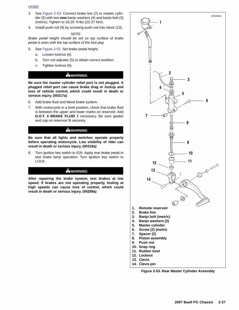
HOME
3. See Figure 2-53. Connect brake line (2) to master cylin-der (5) with two new banjo washers (4) and banjo bolt (3)(metric). Tighten to 16-20 ft-lbs (22-27 Nm).
4. Install push rod (9) by screwing push rod into clevis (13).
NOTEBrake pedal height should be set so top surface of brakepedal is even with the top surface of the foot peg.
5. See Figure 2-52. Set brake pedal height.
a. Loosen locknut (6).
b. Turn rod adjuster (5) to obtain correct position.
c. Tighten locknut (6).
11WARNING1WARNING
Be sure the master cylinder relief port is not plugged. Aplugged relief port can cause brake drag or lockup andloss of vehicle control, which could result in death orserious injury. (00317a)
6. Add brake fluid and bleed brake system.
7. With motorcycle in a level position, check that brake fluidis between the upper and lower marks on reservoir. AddD.O.T. 4 BRAKE FLUID if necessary. Be sure gasketand cap on reservoir fit securely.
11WARNING1WARNING
Be sure that all lights and switches operate properlybefore operating motorcycle. Low visibility of rider canresult in death or serious injury. (00316a)
8. Turn ignition key switch to IGN. Apply rear brake pedal totest brake lamp operation. Turn ignition key switch toLOCK.
11WARNING1WARNING
After repairing the brake system, test brakes at lowspeed. If brakes are not operating properly, testing athigh speeds can cause loss of control, which couldresult in death or serious injury. (00289a)
Figure 2-53. Rear Master Cylinder Assembly
3
4
8
10
9
1112
13
1
a0123a2x
1. Remote reservoir2. Brake line3. Banjo bolt (metric)4. Banjo washers (2)5. Master cylinder6. Screw (2) (metric7. Spacer (2)8. Piston assembly9. Push rod10. Snap ring11. Rubber boot12. Locknut13. Clevis14. Clevis pin
2
5
6
14
7
2007 Buell P3: Chassis 2-37

HOME
REAR BRAKE CALIPER 2.14
REMOVAL
NOTESteps 1 and 2 are not required for detaching caliper fromrotor. Drain fluid only when disassembling caliper.
IMPORTANT NOTEAlways drain brake fluid into a suitable container. Dis-card used fluid according to local laws.
1. Drain and discard brake fluid.
IMPORTANT NOTEDamaged banjo bolt seating surfaces will leak whenreassembled. Prevent damage to seating surfaces bycarefully removing brake line components.
2. See Figure 2-54. Remove banjo bolt (2) (metric) and twobanjo washers (3) to disconnect brake line (1) from cali-per. Discard banjo washers.
3. Remove small screw (6) (metric) and large screw (7)(metric) to detach caliper from mount.
4. See Figure 2-55. Remove clip (1) from rear caliper mount(2) if necessary.
DISASSEMBLY
1. See Figure 2-54. Remove pin plug and pad hanger (5)(metric) to free brake pads.
2. See Figure 2-55. Remove clip (1) from caliper body.
3. See Figure 2-56. Remove piston (3) using BRAKE CALI-PER PISTON REMOVER (1) (Part No. B-42887) withadaptor (2).
4. Remove two o-rings from groove in caliper bore. Discardo-rings.
Figure 2-54. Rear Brake Caliper (Typical)
7723
2
4
1
1. Brake line2. Banjo bolt (metric)3. Banjo washers (2)4. Bleeder valve (metric)5. Pin plug and pad hanger (metric)6. Small screw (metric)7. Large screw (metric)
3 5
6
7
Figure 2-55. Caliper Mount Clip
Figure 2-56. Removing Rear Brake Caliper Piston
6486
1
2
1. Clip2. Rear caliper mount
6496
1
2
3
1. Brake caliper piston remover (Part No. B-42887)2. Adaptor3. Piston
2-38 2007 Buell P3: Chassis

HOME
CLEANING AND INSPECTION
11WARNING1WARNING
Use denatured alcohol to clean brake system compo-nents. Do not use mineral-based solvents (such as gaso-line or paint thinner), which will deteriorate rubber partseven after assembly. Deterioration of these componentscan cause brake failure, which could result in death orserious injury. (00291a)
1. Clean all parts with denatured alcohol or D.O.T. 4BRAKE FLUID. Do not contaminate with mineral oil orother solvents. Wipe dry with a clean, lint free cloth. Blowout drilled passages and bore with a clean air supply. Donot use a wire or similar instrument to clean drilled pas-sages.
2. Carefully inspect all components. Replace any parts thatappear damaged or worn. Do not hone caliper pistonbore.
3. Inspect brake rotor.
a. Measure rotor thickness. Replace if minimum thick-ness is less than 0.180 in. (4.5 mm).
b. Check rotor surface. Replace if warped or badlyscored.
11WARNING1WARNING
Always replace brake pads in complete sets for correctand safe brake operation. Improper brake operationcould result in death or serious injury. (00111a)
4. Inspect brake pads for damage or excessive wear.Replace both pads as a set if the friction material ofeither pad is worn to 0.040 in. (1.0 mm) or less.
ASSEMBLY
1. See Figure 2-57. Place clip (1) inside caliper body asshown.
NOTETo ensure proper brake pad-to-brake rotor clearance whenthe caliper is installed, piston must be pressed all the way intothe bore whenever new brake pads are used.
2. Install pistons and o-rings.
a. Apply a light coat of D.O.T. 4 BRAKE FLUID to o-rings, piston and caliper piston bore.
b. Place two new o-rings inside grooves of piston bore.
c. Install piston inside caliper body.
3. See Figure 2-57. Install brake pads (3) using pad hangerand pin plug (2).
a. Install pad hanger pin (metric). Tighten to 132-180in-lbs (15-20 Nm).
b. Install pin plug. Tighten to 18-25 in-lbs (2-3 Nm).
4. Install a new bleeder valve (metric) if necessary. Tightento 36-60 in-lbs (4-7 Nm).
Figure 2-57. Brake Pads
6487
3
1
2
1. Clip2. Pin plug and pad hanger (metric)3. Brake pads (2)
2007 Buell P3: Chassis 2-39

HOME
INSTALLATION
1. See Figure 2-58. Install caliper mount clip (1) if removed.
2. See Figure 2-59. Install caliper assembly on calipermount. Brake pad surfaces must face rear brake rotor.
a. Apply Loctite Threadlocker 271 (red) to both calipermounting screws (6, 7) (metric).
b. Install large caliper screw (7) (metric). Tighten to 18-22 ft-lbs (24-30 Nm).
c. Install small caliper screw (6) (metric). Tighten to14.5-18 ft-lbs (20-24 Nm).
11WARNING1WARNING
Use only new copper banjo washers (See Parts Catalogfor Part No.) with D.O.T. 4 brake fluid. Earlier silver banjowashers are not compatible with D.O.T. 4 fluid and willnot seal properly over time. Failure to comply mayadversely affect braking ability and lead to brake failurewhich could result in death or serious injury
CAUTION
Avoid leakage. Be sure gaskets, banjo bolt(s), brake lineand caliper bore are clean and undamaged beforeassembly. (00321a)
3. Connect brake line (1) to caliper using two new banjowashers (3) and banjo bolt (2) (metric). Tighten to 16-20ft-lbs (22-27 Nm).
4. Depress rear brake pedal several times to set brake padsto proper operating position within caliper. Bleed brakesystem.
5. Verify proper fluid level in reservoir.
11WARNING1WARNING
Be sure that all lights and switches operate properlybefore operating motorcycle. Low visibility of rider canresult in death or serious injury. (00316a)
6. Turn ignition key switch to IGN. Apply brake pedal to testbrake lamp operation. Turn ignition key switch to LOCK.
11WARNING1WARNING
After repairing the brake system, test brakes at lowspeed. If brakes are not operating properly, testing athigh speeds can cause loss of control, which couldresult in death or serious injury. (00289a)
NOTEAvoid making hard stops for the first 100 miles (160 km) toallow new brake pads to “wear in” properly with the brakerotor.
Figure 2-58. Caliper Mount Clip
Figure 2-59. Rear Brake Caliper (Typical)
6486
1
2
1. Clip2. Rear caliper mount
7723
2
4
1
1. Brake line2. Banjo bolt (metric)3. Banjo washers (2)4. Bleeder valve (metric)5. Pin plug and pad hanger (metric)6. Small screw (metric)7. Large screw (metric)
3 5
6
7
2-40 2007 Buell P3: Chassis

HOME
Table 2-9. Brake Troubleshooting
CONDITION CHECK FOR REMEDY
Excessive lever/pedal travel or spongy feel.
Air in system. Bleed brake(s).
Master cylinder low on fluid. Fill master cylinder with approved brake fluid.
Brake fade Moisture in system. Bleed brake(s).
Fill master cylinder with approved brake fluid.
Chattering sound when brake is applied.
Worn pads. Replace brake pads.
Loose mounting bolts. Tighten bolts.
Warped rotor. Replace rotor.
Ineffective brake – lever/pedal travels to limit.
Low fluid level. Fill master cylinder with approved brake fluid,and bleed system.
Piston cup not functioning. Rebuild cylinder.
Ineffective brake –lever/pedal travel normal.
Distorted or glazed rotor. Replace rotor.
Distorted, glazed or contaminated brake pads. Replace pads.
Brake pads drag on rotor –will not retract.
Cup in master cylinder not uncovering reliefport.
Inspect master cylinder.
Rear brake pedal linkage out of adjustment. Adjust linkage.
2007 Buell P3: Chassis 2-41

HOME
REAR SHOCK ABSORBER 2.15
REMOVAL
NOTESee Figure 2-60. Damper component (3) cannot be servicedor repaired. If the damper component is leaking or damagedit must be replaced.
1. Lift rear wheel off ground using REAR WHEEL SUP-PORT STAND (Part No. B-41174).
2. Remove seat. See 2.28 SEAT.
3. Attach lifting straps to motorcycle. Insert lifting strapsunder frame tubes.
4. Attach lifting straps to a floor hoist placed behind themotorcycle. Raise motorcycle off lift until rear suspensionis unloaded.
5. See Figure 2-60. Remove bolt (1) and nut (4) on topmount.
6. While supporting the shock absorber, remove the bolt (1)and nut (4) from the bottom mount.
7. Remove shock absorber assembly.
INSTALLATION
1. See Figure 2-60. Place new damper bushings (2) intomounting holes of shock absorber (if not installed).
2. Loosely install bottom bolt and nut.
3. Loosely install top bolt and nut.
NOTETorque bolts and nuts from the bolt side only.
4. Tighten bottom bolt to 35-40 ft-lbs (47-54 Nm).
5. Tighten top bolt to 35-40 ft-lbs (47-54 Nm).
11WARNING1WARNING
After installing seat, pull upward on front of seat to besure it is in locked position. While riding, a loose seat canshift causing loss of control, which could result in deathor serious injury. (00070a)
6. Remove lifting straps and install seat. See 2.28 SEAT.
Figure 2-60. Rear Shock Absorber Assembly
1. Bolt2. Damper bushing3. Damper component4. Nut5. Stopper ring6. Spring seat7. Spring8. Spring seat stopper
a0015xSx
1
2
34
1
2
4
5
6
7
8
2-42 2007 Buell P3: Chassis

HOME
THROTTLE CONTROL 2.16
REMOVAL/DISASSEMBLY
1. See Figure 2-61. Slide rubber boot off the cable adjust-ers. Loosen cable adjuster lock on each adjuster.
2. Turn adjusters (4) in direction which will shorten cablehousings to minimum length providing freeplay in bothcables.
3. See Figure 2-62. Remove two screws on front housing.Separate housings from handlebar.
4. Remove cables from notches in housings.
5. See Figure 2-62. Unhook ferrules from cable wheel.
6. Remove fuel tank assembly. See 4.2 FUEL TANKCOVER/FUEL TANK.
7. Cut cable ties along frame.
8. Remove throttle cable clamp.
9. Remove cables from throttle.
10. Carefully note the routing of the cables through/aroundthe forks, along the frame backbone and front/rear ofhandlebars.
11. Pull cables toward the rear.
CLEANING AND INSPECTION
11WARNING1WARNING
Compressed air can pierce the skin and flying debris fromcompressed air could cause serious eye injury. Wearsafety glasses when working with compressed air. Neveruse your hand to check for air leaks or to determine airflow rates. (00061a)
Clean all parts in a non-flammable cleaning solvent. Blow drywith compressed air. Replace cables if frayed, kinked or bent.
ASSEMBLY/INSTALLATION
1. Route cables as noted in step number 10.
2. Connect cables at carburetor.
3. Attach throttle cable clamp. Use Loctite 222 (purple) onscrew.
4. See Figure 2-62. Position ferrules on cable wheel.
5. Insert idle control into front switch housing.
6. Slide switch housing over throttle.
7. Insert throttle cable into front switch housing.
8. Attach rear switch housing and position housings onright handlebar by engaging locating pin on front housingwith hole in handlebar. Attach housings with two screws,installing longer screw on bottom. Tighten to 12-17 in-lbs (1-2 Nm).
9. Adjust cables. See 1.18 THROTTLE CABLES.
10. Install fuel tank. See 4.2 FUEL TANK COVER/FUELTANK.
Figure 2-61. Throttle Control Cables
Figure 2-62. Cable Connections
1. Rubber boot2. Throttle control cable3. Idle control cable4. Cable adjuster5. Cable adjuster lock
2
5
3
4
6853
1
1. Screw (short, top)2. Cable adjusters (2)3. Idle control cable4. Throttle control cable with molded end5. Front housing6. Screw (long, bottom)7. Ferrules8. Cable wheel9. Rear housing10. Locating pin
1
7098
5 98
6
24
37
10
2007 Buell P3: Chassis 2-43

HOME
NOTES
2-44 2007 Buell P3: Chassis

HOME
FRONT FORK 2.17
GENERAL
See Figure 2-63. The front fork consists of two telescopingouter tube/inner slider assemblies. Each assembly has aninternal compression spring which supports the forwardweight of the vehicle and rider.
The compression spring extends and retracts to cushion theride over rough or irregular road surfaces. An oil filled damp-ing mechanism controls the telescoping action of each tube/slider assembly.
.
Figure 2-63. Front Fork Assembly
a0073xSx
12
13
14
15
16
17
18
19
11
1
2
3
4
5
6
8
9
20
21
7
22
10
1. Slider tube, cap2. Stopper ring3. Spring seat4. O-ring5. Spring collar6. Lower spring joint7. Spring8. Damper assembly9. Lock piece10. Rebound spring11. Slide bushing12. Dust seal13. Retaining ring14. Oil seal spacer15. Backup ring16. Guide bushing17. Slider tube18. Fork assembly
(slider & tube, right & left)19. Slider assembly (left & right)20. Front fork bolt21. Center bolt22. Reflector
2007 Buell P3: Chassis 2-45

HOME
REMOVAL
1. Raise front wheel off floor.
2. Detach front brake caliper from rotor. See 2.11 FRONTBRAKE CALIPER.
3. Remove front wheel. See 2.5 FRONT WHEEL.
4. Remove front fender. See 2.23 FENDERS.
5. See Figure 2-64. Loosen headlamp bracket screws.
6. See Figure 2-65. Loosen the large pinch screws on boththe upper and lower triple clamps.
7. See Figure 2-66. Remove front fork. Repeat procedurefor the other front fork.
Figure 2-64. Headlamp Bracket Screws
Figure 2-65. Upper and Lower Triple Clamp Pinch Screws
Figure 2-66. Front Fork Removal
a0065aSx
3765
3766
2-46 2007 Buell P3: Chassis

HOME
DISASSEMBLY
1. Remove front forks.
2. See Figure 2-67. Clamp the fork in a vise with front forkholding tool (Part No. B-41177).
3. See Figure 2-68. Remove slider tube cap.
4. See Figure 2-69. Push down on the spring seat (o-ringincluded) and remove the stopper ring and spring seat.
5. See Figure 2-70. Remove the spring collar, lower springjoint and spring from slider tube.
Figure 2-67. Clamping the Fork
Figure 2-68. Slider Tube Cap
3767
3768
Figure 2-69. Spring Seat
Figure 2-70. Removing Sub-Assembly
3769
1. Spring collar2. Lower spring joint3. Spring
a0006xSx
1
2
3
2007 Buell P3: Chassis 2-47

HOME
6. See Figure 2-71. Remove the fork oil by pumping the forkleg and tube 8-10 times until the tube moves freely.
7. See Figure 2-72. Remove the center bolt (metric) fromthe bottom of the fork tube.
8. See Figure 2-73. Remove the damper assembly, lockpiece and the rebound spring from the slider tube.
Figure 2-71. Pumping Fork Oil
Figure 2-72. Removing Center Bolt
3770
3771
Figure 2-73. Removing Damper
3772
2-48 2007 Buell P3: Chassis

HOME
IMPORTANT NOTE
Do not to scratch the slider tube or the slider assembly.Scratched tubes may leak fork oil and then must bereplaced.
9. See Figure 2-74. Remove the dust seal and the retainingring from the slider assembly and the slider tube.
10. See Figure 2-75. Pull the slider tube out of the sliderassembly. Remove oil seal, back-up ring and guide bush-ing.
11. See Figure 2-76. Remove the slide bushing by prying theslide bushing at the split.
Figure 2-74. Removing Dust Seal
Figure 2-75. Removing Slider Tube
3775
3773
1. Oil seal2. Back-up ring3. Guide bushing
3
2
1
Figure 2-76. Removing Slide Bushing
3776
2007 Buell P3: Chassis 2-49

HOME
CLEANING AND INSPECTION
1. Thoroughly clean and inspect all parts. Replace anyparts that are bent, broken or damaged.
2. See Figure 2-77. Check the slider tube for score marks,scratches and excessive or abnormal wear. Replace ifworn or damaged.
3. Check the slide bushing and the guide bushing for exces-sive wear or scratches. Replace if damaged or worn.
4. Replace the retaining ring if distorted.
5. Measure spring free length. Replace springs shorterthan service wear limit of 12.8 in. (325 mm).
6. Measure rebound spring free length. Replace springsshorter than service wear limit of 0.69 in. (17.4 mm).
7. See Figure 2-78. Measure slider tube runout. Replaceslider tube if runout exceeds the service wear limit of0.008 in. (0.2 mm).
Figure 2-77. Slider Tube Components
Figure 2-78. Slider Tube Runout
a0007xSx
1. Retaining ring2. Guide bushing3. Slider tube4. Slide bushing
4
3
1
2
a0001xSx
2-50 2007 Buell P3: Chassis

HOME
ASSEMBLY
1. Coat the slide bushing with fork oil or sealing grease.
2. See Figure 2-79. Install slide bushing onto the slidertube.
3. See Figure 2-80. Install damper assembly and reboundspring into slider tube.
4. See Figure 2-81. Install lock piece into damper.
5. See Figure 2-82. Clamp the slider assembly in a visewith front fork holding tool (Part No. B-41177).
Figure 2-79. Install Slide Bushing
Figure 2-80. Damper Assembly
3782
3794
Figure 2-81. Lock Piece
Figure 2-82. Clamping the Slider Assembly
3791
3792
2007 Buell P3: Chassis 2-51

HOME
6. See Figure 2-83. Install slider tube into slider assembly.
IMPORTANT NOTEThe slider assembly can move freely up and down on theslider tube. Always hold both the slider tube and sliderassembly to prevent damage to bushings and seals.
7. See Figure 2-84. Install spring onto damper assembly.
8. See Figure 2-85. Install center bolt and washer.
9. Coat the guide bushing with fork oil or sealing grease.
10. See Figure 2-86. Install guide bushing onto the slidertube.
Figure 2-83. Installing Slider Tube
Figure 2-84. Install Rebound Spring
3790
3796
Figure 2-85. Install Center Bolt
Figure 2-86. Install Guide Bushing
3793
3774
2-52 2007 Buell P3: Chassis

HOME
11. See Figure 2-87. Wrap the end of the slide pipe and theslide bushing channel with tape to avoid damaging the oilseal lip when installing.
12. Coat dust seal, oil seal spacer, and backup ring with forkoil or sealing grease.
13. See Figure 2-88. Install oil seal spacer and backup ring.
14. See Figure 2-89. Using FORK SEAL DRIVER (Part No.B-43991), drive the guide bushing with the oil sealspacer and oil seal into position in the slider assembly.
15. See Figure 2-90. Install retaining ring. Verify ring isinstalled securely in the groove inside slider assembly.
Figure 2-87. Slider Tube Protection
Figure 2-88. Oil Seal and Backup Ring
3781
3785
Figure 2-89. Fork Seal Driver
Figure 2-90. Install New Retaining Ring
3787
3786
1. Retaining ring2. Groove
1 2
2007 Buell P3: Chassis 2-53

HOME
16. See Figure 2-91. Install new dust seal onto slide pipe.
17. See Figure 2-92. Remove the tape from the slider tubeend.
NOTE
The recommended fork oil is hydraulic fork oil type “E”.
18. Pour 9.2 oz. (272 ml) fork oil into fork.
19. Install lower spring joint and spring collar.
20. Coat a new o-ring with fork oil or sealing grease.
21. Install new o-ring onto spring seat.
22. See Figure 2-93. Push down on spring seat past grooveto install stopper ring. Stopper ring will lock into groovewhen installed correctly.
23. See Figure 2-94. Install slider tube cap.
24. See Figure 2-95. Install fork assemblies through upperand lower triple clamps.
Figure 2-91. Install New Dust Seal
Figure 2-92. Remove Slider Tube Protection
3788
3781
Figure 2-93. Compressing Spring Seat to InstallStopper Ring
Figure 2-94. Slider Tube Cap
3769
3768
2-54 2007 Buell P3: Chassis

HOME
INSTALLATION
1. See Figure 2-95. Install fork assemblies through upperand lower triple clamps.
NOTEWhen installing the front forks, use a screwdriver to pry apartthe triple clamps.
2. See Figure 2-96. Apply Loctite Anti-Seize to the threadsof triple clamp pinch screws.
3. See Figure 2-97. Align and secure fork assemblies.
a. Position fork assemblies so that top of each slidertube is flush with the top surface of upper tripleclamp. Be sure that top surface of fork is not belowtop surface of upper triple clamp.
b. Tighten upper triple clamp pinch screws (at sliders)to 13-16 ft-lbs (18-22 Nm).
c. Tighten lower triple clamp pinch screws to 22-29 ft-lbs (30-39 Nm).
d. See Figure 2-98. Tighten headlamp brackets flushagainst bottom of top triple clamp.
4. Install front fender. See 2.23 FENDERS.
5. Install front wheel. See 2.5 FRONT WHEEL.
6. Install front brake caliper. See 2.11 FRONT BRAKECALIPER.
7. Align headlamp. See 1.22 HEADLAMP.
Figure 2-95. Installing Fork Assemblies
Figure 2-96. Location of Anti-Seizeon Triple Clamp Pinch Screws
3766
3777
Figure 2-97. Upper and Lower Triple Clamp Pinch Screws
Figure 2-98. Tighten Headlamp Bracket Screws
3765
a0065aSx
2007 Buell P3: Chassis 2-55

HOME
FORK STEM AND BRACKET ASSEMBLY 2.18
REMOVAL/DISASSEMBLY
1. Remove seat. See 2.28 SEAT.
11WARNING1WARNING
To prevent accidental vehicle start-up, which couldcause death or serious injury, disconnect negative (-)battery cable before proceeding. (00048a)
2. Disconnect battery.
3. Remove dash. See 2.27 INSTRUMENT PANEL.
4. Remove handlebars. See 2.30 HANDLEBARS.
5. Remove fork assembly. See 2.17 FRONT FORK.
6. Remove ignition switch assembly. See 7.6 IGNITION/HEADLAMP KEY SWITCH.
7. See Figure 2-99. Remove screw (2) and capnut (1).
8. Support lower triple clamp (8) and remove upper tripleclamp (3).
9. Remove upper dust shield (5) and upper bearing (6).
10. Lower triple clamp can be removed.
11. Remove lower bearing (6) and lower dust shield (5) fromlower triple clamp.
CLEANING AND INSPECTION
1. See Figure 2-99. Clean the dust shields (5), bearingcups (7), fork stem and lower triple clamp (8) and framewith solvent.
2. Carefully inspect bearing races and assemblies for pit-ting, scoring, wear and other damage. Replace damagedbearings (6) as a set (5, 6 and 7).
3. Check the fork stem and lower triple clamp (8) for dam-age. Replace if necessary.
Figure 2-99. Fork Stem and Bracket Assembly
6
6
5
7
7
5
1
4
2
3
9
8
a0137x2x
1. Capnut2. Center cap pinch screw3. Upper triple clamp4. Pinch screws (2)5. Dust shield (2)6. Bearing (2)7. Bearing cup (2)8. Lower triple clamp 9. Pinch screws (2)
2-56 2007 Buell P3: Chassis

HOME
ASSEMBLY/INSTALLATION
1. If removed, install new bearing cups into frame steeringhead using STEERING HEAD BEARING RACEINSTALLER (Part No. HD-39302).
2. See Figure 2-99. Liberally coat the bearings (6) withgrease using WHEEL BEARING PACKER TOOL (PartNo. HD-33067). Work the grease into the rollers.
3. Install lower bearing:
a. Place lower bearing dust shield (5) over fork stem.
b. Find a section of pipe having an inside diameterslightly larger than the outside diameter of the forkstem.
c. Press bearing (6) with small end up onto fork stemand lower triple clamp (8). Use the pipe as a press-on tool.
4. Insert lower triple clamp (8) through the steering head.Install the upper bearing (6) with small end down anddust shield (5) onto fork stem.
5. Apply Loctite 243 (Blue) to fork stem. Loosely installupper triple clamp (3) using cap nut (1).
6. Install fork assemblies. See 2.17 FRONT FORK.
7. Tighten cap nut (1) until the bearings have no free play.Make sure the fork stem turns freely.
8. Check steering head bearing adjustment. See 1.15STEERING HEAD BEARINGS.
9. Install handlebars. See 2.30 HANDLEBARS.
10. Install dash. See 2.27 INSTRUMENT PANEL.
11. Connect battery negative cable.
11WARNING1WARNING
After installing seat, pull upward on front of seat to besure it is in locked position. While riding, a loose seat canshift causing loss of control, which could result in deathor serious injury. (00070a)
12. Install seat. See 2.28 SEAT.
2007 Buell P3: Chassis 2-57
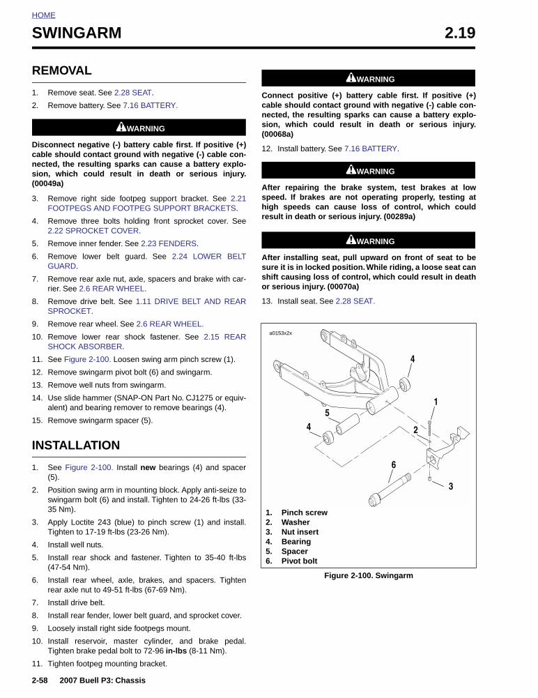
HOME
SWINGARM 2.19
REMOVAL
1. Remove seat. See 2.28 SEAT.
2. Remove battery. See 7.16 BATTERY.
11WARNING1WARNING
Disconnect negative (-) battery cable first. If positive (+)cable should contact ground with negative (-) cable con-nected, the resulting sparks can cause a battery explo-sion, which could result in death or serious injury.(00049a)
3. Remove right side footpeg support bracket. See 2.21FOOTPEGS AND FOOTPEG SUPPORT BRACKETS.
4. Remove three bolts holding front sprocket cover. See2.22 SPROCKET COVER.
5. Remove inner fender. See 2.23 FENDERS.
6. Remove lower belt guard. See 2.24 LOWER BELTGUARD.
7. Remove rear axle nut, axle, spacers and brake with car-rier. See 2.6 REAR WHEEL.
8. Remove drive belt. See 1.11 DRIVE BELT AND REARSPROCKET.
9. Remove rear wheel. See 2.6 REAR WHEEL.
10. Remove lower rear shock fastener. See 2.15 REARSHOCK ABSORBER.
11. See Figure 2-100. Loosen swing arm pinch screw (1).
12. Remove swingarm pivot bolt (6) and swingarm.
13. Remove well nuts from swingarm.
14. Use slide hammer (SNAP-ON Part No. CJ1275 or equiv-alent) and bearing remover to remove bearings (4).
15. Remove swingarm spacer (5).
INSTALLATION
1. See Figure 2-100. Install new bearings (4) and spacer(5).
2. Position swing arm in mounting block. Apply anti-seize toswingarm bolt (6) and install. Tighten to 24-26 ft-lbs (33-35 Nm).
3. Apply Loctite 243 (blue) to pinch screw (1) and install.Tighten to 17-19 ft-lbs (23-26 Nm).
4. Install well nuts.
5. Install rear shock and fastener. Tighten to 35-40 ft-lbs(47-54 Nm).
6. Install rear wheel, axle, brakes, and spacers. Tightenrear axle nut to 49-51 ft-lbs (67-69 Nm).
7. Install drive belt.
8. Install rear fender, lower belt guard, and sprocket cover.
9. Loosely install right side footpegs mount.
10. Install reservoir, master cylinder, and brake pedal.Tighten brake pedal bolt to 72-96 in-lbs (8-11 Nm).
11. Tighten footpeg mounting bracket.
11WARNING1WARNING
Connect positive (+) battery cable first. If positive (+)cable should contact ground with negative (-) cable con-nected, the resulting sparks can cause a battery explo-sion, which could result in death or serious injury.(00068a)
12. Install battery. See 7.16 BATTERY.
11WARNING1WARNING
After repairing the brake system, test brakes at lowspeed. If brakes are not operating properly, testing athigh speeds can cause loss of control, which couldresult in death or serious injury. (00289a)
11WARNING1WARNING
After installing seat, pull upward on front of seat to besure it is in locked position. While riding, a loose seat canshift causing loss of control, which could result in deathor serious injury. (00070a)
13. Install seat. See 2.28 SEAT.
Figure 2-100. Swingarm
1
4
6
54 2
a0153x2x
1. Pinch screw2. Washer3. Nut insert4. Bearing5. Spacer6. Pivot bolt
3
2-58 2007 Buell P3: Chassis

HOME
EXHAUST SYSTEM 2.20
MUFFLER REMOVAL
IMPORTANT NOTETo prevent damage to muffler, secure muffler beforeremoving rear muffler strap.
1. See Figure 2-101. Remove fasteners, washers, spacersand brackets on rear muffler strap.
2. Remove exhaust header fasteners (13).
3. Remove front muffler mounting fastener, nut, and washer(4, 7, 12).
4. Remove exhaust header.
5. Remove retaining ring (2).
6. Remove exhaust header clamp (3).
7. Remove and discard exhaust port gasket (1).
MUFFLER INSTALLATION
1. See Figure 2-101. Install new bushings and spacer intofront muffler support hole (8, 17, 11).
2. Install header clamp onto exhaust (3).
3. Install retaining ring oriented 90° from exhaust studs (2).
NOTERetaining ring may crack if not oriented as stated in step 3.
4. Install new exhaust port gasket (1).
5. Position muffler on motor. Hand tighten nuts (13).
6. Slide muffler over bushings on front mount.
7. Hand thread bolt washer and nut to front muffler support.
8. Install rear muffler strap (15).
NOTE
A rubber mallet may be used to tap the muffler strap into muf-fler notches.
9. Install right side muffler spacers (9), brackets (16) andfasteners (5).
10. Install left side muffler spacers, brackets and fasteners.
11. Tighten nuts (12) on rear muffler strap bolts (5,6) to 19 ft-lbs (25.8 Nm).
12. Tighten lower, then upper header nuts to 72-96 in-lbs (8-11 Nm).
13. Tighten rear strap screws (5, 6) to 17-19 ft-lbs (24-25Nm).
14. Tighten front muffler bolts (4) to 17-19 ft-lbs 24-25 Nm).
IMPORTANT NOTEUse care when performing service procedures and avoidscratching the frame and/or painted parts. Failure to doso may result in corrosion of parts.
2007 Buell P3: Chassis 2-59
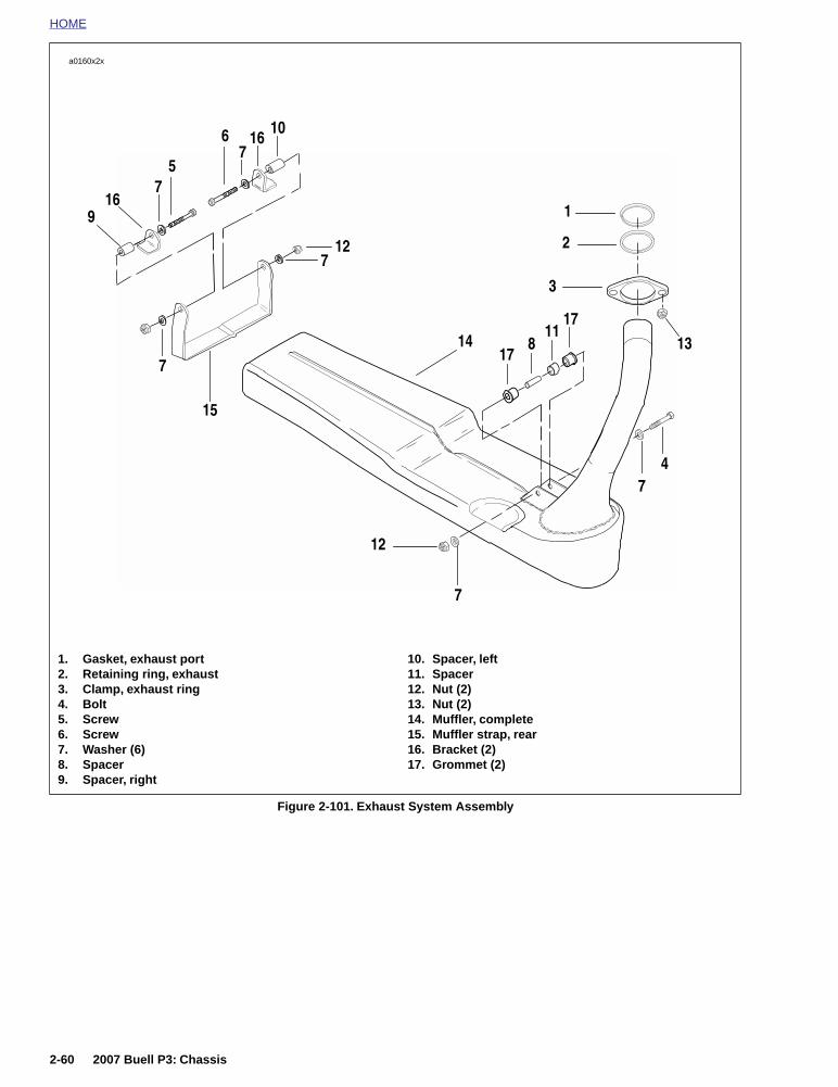
HOME
Figure 2-101. Exhaust System Assembly
1. Gasket, exhaust port2. Retaining ring, exhaust3. Clamp, exhaust ring4. Bolt5. Screw6. Screw7. Washer (6)8. Spacer9. Spacer, right
10. Spacer, left11. Spacer12. Nut (2)13. Nut (2)14. Muffler, complete15. Muffler strap, rear16. Bracket (2)17. Grommet (2)
4
12
7
6
12
3
2
14
7
8
15
13
1
1711
1016
916
717
7
57
7
a0160x2x
2-60 2007 Buell P3: Chassis

HOME
FOOTPEGS AND FOOTPEG SUPPORT BRACKETS 2.21
REMOVAL
Footpeg
1. See Figure 2-102. Remove cotter pin (3).
2. Remove clevis pin (4).
3. Remove spacer (7, rear peg only).
4. Remove footpeg.
Footpeg Support Bracket
1. Remove seat. See 2.28 SEAT.
2. See Figure 2-103. On left side remove oil tank drainhose, breather drain hose, clamp and fastener.
3. On right side remove rear master cylinder, spacers, res-ervoir, and brake pedal.
4. See Figure 2-102. Remove mounting bolts locatedbehind footpeg support bracket.
5. Remove footpeg support bracket.
INSTALLATION
Footpeg Support Bracket
1. Align footpeg support mounting bracket and spacer withmounting holes on frame.
2. Install mounting bolts and washers. Tighten fasteners to25-30 ft-lbs. (34-41 Nm).
3. See Figure 2-103. On left side install clamp with oil tankdrain hose and breather hose.
4. On right side install rear master cylinder, spacers, reser-voir, and brake pedal. See 2.13 REAR BRAKE MASTERCYLINDER.
11WARNING1WARNING
After installing seat, pull upward on front of seat to besure it is in locked position. While riding, a loose seat canshift causing loss of control, which could result in deathor serious injury. (00070a)
5. Install seat. See 2.28 SEAT.
Footpeg
1. See Figure 2-102. Align footpeg mounting holes withfootpeg support bracket mounting holes.
2. Insert dowel pin (and on rear peg, spacer) throughmounting holes.
3. Install new cotter pin.
Figure 2-102. Footpeg Support Bracket (Left Side)
Figure 2-103. Left Side Footpeg Support Bracket
a0130x2x
1. Footrest support bracket2. Front footpeg3. Cotter pin4. Clevis pin5. Rear footpeg6. Index plate7. Spacer8. Spacer
3
4
2
5
84
76
1
3
1. Clamp2. Oil tank drain hose3. Breather hose
7742
1
23
2007 Buell P3: Chassis 2-61

HOME
SPROCKET COVER 2.22
REMOVAL
1. See Figure 2-104. Remove master cylinder bolts andspacers.
2. Remove rear pedal bolt and move pedal assembly downaway from support bracket.
3. See Figure 2-105. Remove the three screws and wash-ers on sprocket cover.
4. Slide cover free.
INSTALLATION
1. Apply Loctite 243 (blue) to threads of three screws.
2. Position sprocket cover and install three screws andwashers. Tighten fasteners to 30-36 in-lbs (3-4 Nm).
3. Move pedal assembly in position and install pedal bolt.Tighten pedal bolt to 72-96 in-lbs (8-11 Nm).
4. Install master cylinder bolts and spacers. See 2.13REAR BRAKE MASTER CYLINDER.
Figure 2-104. Master Cylinder Mounting
Figure 2-105. Sprocket Cover Fasteners
7704
1
1
2
2
3
1. Bolts2. Spacers3. Pedal bolt
a0131x2x
1. Screws (3)2. Nylon washers (3)
1
2
2-62 2007 Buell P3: Chassis

HOME
FENDERS 2.23
FRONT FENDER REMOVAL
1. Raise front wheel off ground.
2. Remove front wheel. See 2.5 FRONT WHEEL.
3. See Figure 2-106. Remove four lower fender mountingscrews.
4. See Figure 2-107. Remove front fender.
FRONT FENDER INSTALLATION
1. Raise front wheel off floor.
2. Align front fender mounting holes with front fork bracket.
NOTE
The longer end of the fender faces away from the front end.
3. Apply Loctite 243 (blue) to first few threads of four fendermounting screws.
4. See Figure 2-106. Install front fender with four fendermounting screws.
5. Tighten fender mounting screws to 27-30 in-lbs (3.1-3.4 Nm).
Figure 2-106. Front Fender AssemblyMounting Screws
Figure 2-107. Removing Front Fender
a0129a2x
1. Mounting screw (4)2. Washers (4)
1
2
3804
2007 Buell P3: Chassis 2-63
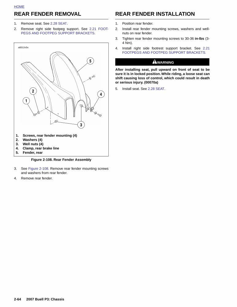
HOME
REAR FENDER REMOVAL
1. Remove seat. See 2.28 SEAT.
2. Remove right side footpeg support. See 2.21 FOOT-PEGS AND FOOTPEG SUPPORT BRACKETS.
3. See Figure 2-108. Remove rear fender mounting screwsand washers from rear fender.
4. Remove rear fender.
REAR FENDER INSTALLATION
1. Position rear fender.
2. Install rear fender mounting screws, washers and well-nuts on rear fender.
3. Tighten rear fender mounting screws to 30-36 in-lbs (3-4 Nm).
4. Install right side footrest support bracket. See 2.21FOOTPEGS AND FOOTPEG SUPPORT BRACKETS.
11WARNING1WARNING
After installing seat, pull upward on front of seat to besure it is in locked position. While riding, a loose seat canshift causing loss of control, which could result in deathor serious injury. (00070a)
5. Install seat. See 2.28 SEAT.
Figure 2-108. Rear Fender Assembly
a0012xSx
1. Screws, rear fender mounting (4)2. Washers (4)3. Well nuts (4)4. Clamp, rear brake line5. Fender, rear
4
1
2
5
3
2-64 2007 Buell P3: Chassis

HOME
LOWER BELT GUARD 2.24
REMOVAL
1. See Figure 2-109. Remove two screws and nylon wash-ers securing lower belt guard to swingarm.
2. Remove belt guard.
INSTALLATION
1. Position belt guard over tabs on swingarm.
2. Secure belt guard with two screws and nylon washers.
3. Tighten screws to 30-36 in-lbs (3-4 Nm).
Figure 2-109. Lower Belt Guard
a0132x2x
1. Lower belt guard2. Screws (2)3. Nylon washers (2)
1
2
3
2007 Buell P3: Chassis 2-65

HOME
TAIL SECTION AND REAR FRAME ASSEMBLY 2.25
REMOVAL - TAIL SECTION
1. Remove seat. See 2.28 SEAT.
2. See Figure 2-110. Remove fasteners and clamp (3, 19and 20).
3. Remove tree fasteners (2).
4. Remove fairing, tail section (1).
11WARNING1WARNING
To prevent accidental vehicle start-up, which couldcause death or serious injury, disconnect negative (-)battery cable before proceeding. (00048a)
5. Disconnect battery negative cable.
6. Unplug taillight.
7. Cut cable strap holding taillight and turn signal wires.
8. Unplug turn signals.
9. Remove nut (8) and lock washer (7).
10. Remove turn signals (6).
11. Remove nuts and flat washers from back of taillight.
12. Remove taillight.
13. Remove bolts (4) and nuts (9).
14. Remove license plate bracket (5).
Figure 2-110. Tail Section
1
7
16
17
2
3
4
5
6
8 9
10
1112
20
18
19
15
14
a0146a2x
1. Fairing, tail section 2. Tree fastener3. Bolt4. Bolt5. License plate bracket6. Turn signal 7. Lock washer8. Nut9. Nut10. Rear frame11. Bolt12. Rear subframe mounting bracket13. Screw14. Bushing15. Seat latch lever16. Washer17. Seat latch spring18. Bolt19. Bolt20. Clamp
13
2-66 2007 Buell P3: Chassis

HOME
REMOVAL - REAL FRAMEASSEMBLY
1. Remove tail section.
2. Disconnect rear wire harness connector [7] (6-placeamp), located under seat near fuse block. Detach con-nector from “T” stud.
3. See Figure 2-110. Remove fasteners (13) and bracket(12).
4. Remove fasteners (11).
5. Slide rear frame assembly (10) out.
INSTALLATION - REAR FRAME ASSEMBLY
1. See Figure 2-110. Slide rear frame assembly (10) intoframe.
2. Install fasteners (11).
3. Install brackets (12) and fasteners (13).
4. Connect rear wire harness and mount on “T” stud.
INSTALLATION - TAIL SECTION
1. See Figure 2-110. Install license plate bracket (5) usingfasteners (4) and nuts (9) in rear holes.
2. Install taillight using flat washers and nuts.
3. Install turn signals (6) using lock washers (7) and nuts(8).
4. Connect turn signal wires and taillight wires. Cable tietogether.
5. Install tail section (1) using fasteners (3, 19, 20).
6. Connect battery negative cable.
11WARNING1WARNING
After installing seat, pull upward on front of seat to besure it is in locked position. While riding, a loose seat canshift causing loss of control, which could result in deathor serious injury. (00070a)
7. Install seat. See 2.28 SEAT.
2007 Buell P3: Chassis 2-67

HOME
WINDSCREEN 2.26
REMOVAL
1. See Figure 2-111. Remove two screws and nylon wash-ers on each side.
2. Remove windscreen.
3. See Figure 2-112. Remove windscreen trim.
4. Remove windscreen mounting brackets, if required. See7.17 HEADLAMP.
INSTALLATION
1. If removed, install both windscreen brackets. See 7.17HEADLAMP.
2. Verify trim is installed on windscreen.
3. See Figure 2-111. Install two screws and nylon washerson each side. Tighten screws to 9-11 in-lbs (1-1.2 Nm).
Figure 2-111. Remove Screws
Figure 2-112. Windscreen Trim
3779
3797
2-68 2007 Buell P3: Chassis

HOME
INSTRUMENT PANEL 2.27
REMOVAL
1. See Figure 2-113. Remove two mounting screws (1) andinstrument panel.
2. Remove two screws from back of instrument panel.
3. Remove rubber boot (2) and odometer reset switch (3).
4. Depress tab and remove speedometer connector [39].
NOTETo remove speedometer, see 7.25 ELECTRONIC SPEED-OMETER.
INSTALLATION
1. See Figure 2-113. Install odometer reset switch to instru-ment panel and install rubber boot.
2. Install connector [39] on back of speedometer.
3. Apply Loctite 243 (blue) to threads of mounting screws.Install dash with two mounting screws. Tighten screws to30-36 in-lbs (3-4 Nm).
Figure 2-113. Instrument Panel
a0154x2x
1. Screws (2)2. Odometer reset switch rubber boot3. Odometer reset switch4. Sensor, speed5. Connector [39]
4
3
2
5
1
2007 Buell P3: Chassis 2-69

HOME
SEAT 2.28
REMOVAL
IMPORTANT NOTEUse both hands to release tension on the seat latch toavoid pinching fingers.
You will need to use both hands during this operation torelease tension on the seat latch (located beneath the seat).
1. See Figure 2-114. Push or pull the seat latch toward thefront of the motorcycle with your thumb.
2. Grasp the rear section of the seat with one hand.
3. Lift seat away from motorcycle to loosen from frame.
INSTALLATION
1. See Figure 2-115. Locate tab on bottom of seat.
2. See Figure 2-116. Ensure seat is upright. Grasp the rearsection of the seat with one hand and grasp the frontsection of the seat with the other hand.
3. See Figure 2-117. Push seat forward while flexing therear section of the seat upward until the tongue locks intothe bracket located on the frame.
4. Push down firmly on the seat
NOTE
You will hear a click when the locating tab and seat latch locktogether.
11WARNING1WARNING
After installing seat, pull upward on front of seat to besure it is in locked position. While riding, a loose seat canshift causing loss of control, which could result in deathor serious injury. (00070a)
5. Verify seat is locked in position.
Figure 2-114. Seat Latch
Figure 2-115. Underside View of Seat with Locating Tab
a0021aox
1. Locating tab2. Seat latch
12
a0023xox
Figure 2-116. Seat Installation
Figure 2-117. Locking Seat Tongue
a0022xox
3795
2-70 2007 Buell P3: Chassis

HOME
SIDESTAND 2.29
GENERAL
11WARNING1WARNING
This motorcycle does NOT have a locking sidestand.Park the motorcycle on a level, firm surface. An unbal-anced motorcycle can fall, which could result in death orserious injury. (00122a)
See Figure 2-118. The sidestand is located on the left side ofthe motorcycle. The sidestand swings outward to support themotorcycle for parking.
Test the sidestand in the following manner. Without vehicleweight resting on it, sidestand should move freely intoextended (down) and retracted (up) positions.
The sidestand activates the sidestand switch (4) which is partof the starter interlock system.
INSPECTION
1. Test the sidestand with the vehicle upright and level. Thesidestand should move freely into extended down and upposition.
2. Check sidestand switch operation after first 1000 miles(1600 km) and every 2500 miles (4000 km).
DISASSEMBLY/REMOVAL
1. Raise rear wheel off floor using REAR WHEEL SUP-PORT STAND (Part No. B-41174).
2. Disconnect electrical connection.
3. Cut cable strap from rear brake line.
4. Remove spring (2) from sidestand.
5. Remove cotter pin and pivot pin (1).
6. Remove sidestand from frame.
ASSEMBLY/INSTALLATION
1. See Figure 2-118. Apply LITHIUM GREASE to pivot pin.
NOTEDo not crush sidestand switch during installation.
2. Install sidestand using pivot pin and cotter pin.
3. Connect spring to sidestand and spring pin.
4. Remove REAR WHEEL SUPPORT STAND (Part No. B-41174).
5. Inspect sidestand and sidestand switch for proper opera-tion.Figure 2-118. Sidestand
7735
1. Spring pin2. Spring3. Pivot pin4. Sidestand switch
34
2
1
2007 Buell P3: Chassis 2-71

HOME
HANDLEBARS 2.30
REMOVAL
1. See Figure 2-119. Remove left side switch housing (13).
2. Loosen clutch adjuster and remove clutch cable (8).
3. Unplug clutch lever switch (9).
4. Remove left handlebar grip (12).
5. Loosen clutch lever screw (4) and slide clutch lever andbracket assembly off of handlebar (3).
6. Disconnect front brake lever switch (16).
7. Slide rubber boot off the throttle cable adjusters. Loosencable adjuster lock on each adjuster.
8. Turn adjusters in direction which will shorten cable hous-ings to minimum length providing freeplay in both cables.
9. Remove two screws on right switch assembly. Separatehousings (14) from handlebar.
10. Remove cables from notches in housings.
11. Unhook ferrules from cable wheel.
12. Remove throttle grip (15).
13. Remove front master cylinder clamp bolts.
14. Remove master cylinder.
15. Remove upper handlebar clamp screws (1) and upperhandlebar clamps (2).
16. Remove handlebar (3).
INSTALLATION
1. Position handlebar (3) on upper triple clamp.
2. Install upper handlebar clamps (2) and screws (1).
3. Tighten screws in steps maintaining even gap betweenupper triple clamp and upper handlebar clamps. Finaltighten to 120-144 in-lbs (14-16 Nm).
4. Install master cylinder. Tighten master cylinder clampbolts to 80-120 in-lbs. (9-14 Nm).
5. Install throttle grip.
6. Hook ferules to cable wheel. Position cables in notchesof switch housing (14).
7. Position housings on right handlebar. Front housing haslocating pin that must align with hole in handlebar. Installfasteners, longer screw on bottom. Tighten fasteners to25-33 in-lbs (3-4 Nm).
8. Plug in front brake lever switch (16).
9. Adjust throttle cables. See 1.18 THROTTLE CABLES.
10. Install clutch lever and bracket assembly. Tighten clutchlever screw (4) to 40-48 in-lbs (4.6-5.4 Nm).
11. Install hand grip (12).
12. Install clutch cable (8).
13. Adjust clutch. See 1.9 CLUTCH.
14. Plug terminal into clutch lever switch (9).
15. Install left side switch housing (13). Front housing haslocating pin that must align with hole in handlebar.Tighten fasteners to 25-33 in-lbs (3-4 Nm).
Figure 2-119. Handlebar Assembly
1
14
133
2
16
4 6
12
9
11108
a0133x2x
5
7
1. Upper handlebar clamp screw2. Upper handlebar clamp3. Handlebars4. Clutch lever screw5. Clutch lever bolt6. Clutch lever and bracket assembly7. Nut8. Clutch cable9. Switch, clutch lever10. O-ring11. Clamp12. Left handlebar grip13. Left switch assembly14. Right switch assembly15. Throttle grip16. Brake lever switch
15
2-72 2007 Buell P3: Chassis

HOME
FRONT AND REAR ISOLATORS 2.31
FRONT ISOLATOR
Removal
1. Remove seat. See 2.28 SEAT.
2. Remove fuel tank. See 4.2 FUEL TANK COVER/FUELTANK.
3. Raise motorcycle until front suspension is unloaded.
4. Remove muffler, and support motor with jack. When iso-lator is detached, powertrain may move. See 2.20EXHAUST SYSTEM.
5. Cut horn cable strap.
6. Remove clutch cable tie.
7. See Figure 2-120. Loosen front ground strap bolt forclearance.
8. See Figure 2-121. Remove two outboard isolator bolts(1).
9. Remove main isolator bolt and nut (2). Discard nut.
10. Remove isolator.
Installation
1. See Figure 2-121. Position new isolator in frame.
2. Install two outboard isolator bolts (1). Tighten 30-33 ft-lbs(41-45 Nm).
3. Install main isolator bolt and new nut (2). Tighten mainisolator bolt to 63-70 ft-lbs (85-95 Nm).
4. Tighten front ground strap bolt to 30-33 ft-lbs (41-45Nm).
5. Install clutch cable to clip.
6. Install horn cable strap.
7. Install fuel tank. See 4.2 FUEL TANK COVER/FUELTANK.
11WARNING1WARNING
After installing seat, pull upward on front of seat to besure it is in locked position. While riding, a loose seat canshift causing loss of control, which could result in deathor serious injury. (00070a)
8. Install seat. See 2.28 SEAT.
Figure 2-120. Front Ground Strap Bolt
Figure 2-121. Front Isolator Bolts
7746
7744
1. Outboard isolator bolts (2)2. Main isolator nut
2
1
2007 Buell P3: Chassis 2-73

HOME
REAR ISOLATOR
Removal1. Remove seat. See 2.28 SEAT.
11WARNING1WARNING
Disconnect negative (-) battery cable first. If positive (+)cable should contact ground with negative (-) cable con-nected, the resulting sparks can cause a battery explo-sion, which could result in death or serious injury.(00049a)
2. Remove battery. See 7.16 BATTERY.
3. Support rear of motorcycle.
4. Remove rear shock. See 2.15 REAR SHOCKABSORBER.
5. Remove muffler and support motor with jack. When iso-lator is detached powertrain may move. See 2.20EXHAUST SYSTEM
6. See Figure 2-122. Remove two allen bolts connectingframe to isolator.
7. See Figure 2-123. Remove four bolts (2) connecting iso-lator (1) to engine.
NOTE
It may be necessary to raise or lower motorcycle to removeisolator.
Installation1. See Figure 2-123. Clean engine bolt holes and bolts. Do
not re-tap holes.
2. Apply Loctite 243 (blue) to bolts and install four isolator-to-engine bolts. Tighten bolts to 23-27 ft-lbs (31.2-36.6 Nm).
3. See Figure 2-122. Apply Loctite Threadlocker 271 (red)to the two frame-to-isolator bolts. Tighten bolts to 30-33ft-lbs (41-45 Nm).
4. Install rear shock absorber. See 2.15 REAR SHOCKABSORBER.
11WARNING1WARNING
Connect positive (+) battery cable first. If positive (+)cable should contact ground with negative (-) cable con-nected, the resulting sparks can cause a battery explo-sion, which could result in death or serious injury.(00068a)
5. Install battery. See 7.16 BATTERY.
11WARNING1WARNING
After installing seat, pull upward on front of seat to besure it is in locked position. While riding, a loose seat canshift causing loss of control, which could result in deathor serious injury. (00070a)
6. Install seat. See 2.28 SEAT.
Figure 2-122. Frame-to-Isolator Bolts
Figure 2-123. Rear Engine Mount Isolator
7745
7743
2
1
1. Rear isolator2. Bolts (4)
2-74 2007 Buell P3: Chassis

HOME
2007 Buell P3: Chassis 2-75

ENGINE 3
Table Of Contents
SUBJECT page NO.
3.1 Specifications . . . . . . . . . . . . . . . . . . . . . . . . . . . . . . . . . . . . . . . . . . . . . . . . . . 3-13.2 Engine . . . . . . . . . . . . . . . . . . . . . . . . . . . . . . . . . . . . . . . . . . . . . . . . . . . . . . . . 3-63.3 Stripping Motorcycle For Engine Service . . . . . . . . . . . . . . . . . . . . . . . . . . . . . 3-83.4 Engine Installation . . . . . . . . . . . . . . . . . . . . . . . . . . . . . . . . . . . . . . . . . . . . . . 3-163.5 Cylinder Head . . . . . . . . . . . . . . . . . . . . . . . . . . . . . . . . . . . . . . . . . . . . . . . . . . 3-243.6 Cylinder And Piston . . . . . . . . . . . . . . . . . . . . . . . . . . . . . . . . . . . . . . . . . . . . . 3-403.7 Lubrication System . . . . . . . . . . . . . . . . . . . . . . . . . . . . . . . . . . . . . . . . . . . . . . 3-513.8 Oil Reservoir and Oil Hose Routing . . . . . . . . . . . . . . . . . . . . . . . . . . . . . . . . . 3-523.9 Oil Pressure Indicator Switch . . . . . . . . . . . . . . . . . . . . . . . . . . . . . . . . . . . . . . 3-543.10 Crankcase Breathing System . . . . . . . . . . . . . . . . . . . . . . . . . . . . . . . . . . . . . 3-553.11 Oiling System . . . . . . . . . . . . . . . . . . . . . . . . . . . . . . . . . . . . . . . . . . . . . . . . . 3-563.12 Oil Pump . . . . . . . . . . . . . . . . . . . . . . . . . . . . . . . . . . . . . . . . . . . . . . . . . . . . . 3-573.13 Oil Filter Mount . . . . . . . . . . . . . . . . . . . . . . . . . . . . . . . . . . . . . . . . . . . . . . . . 3-603.14 Hydraulic Lifters . . . . . . . . . . . . . . . . . . . . . . . . . . . . . . . . . . . . . . . . . . . . . . . 3-613.15 Gearcase Cover and Cam Gears . . . . . . . . . . . . . . . . . . . . . . . . . . . . . . . . . . 3-633.16 Crankcase . . . . . . . . . . . . . . . . . . . . . . . . . . . . . . . . . . . . . . . . . . . . . . . . . . . . 3-67


HOME
SPECIFICATIONS 3.1
NOTEService wear limits are given as a guideline for measuringcomponents that are not new. For measurement specifica-tions not given under SERVICE WEAR LIMITS, see NEWCOMPONENTS.
Table 3-1. General Specifications
GENERAL
Type Single cylinder, air cooled, four-stroke
Compression Ratio 9.2: 1
Bore 3.50 in. 88.8 mm
Stroke 3.125 in. 79.375 mm
Engine Displacement 30 cu. in. 492 cc
Oil Capacity (with filter change) 2.0 quarts 1.89 liters
Table 3-2. Ignition Specifications
ENGINE IGNITION SPECIFICATIONS
Timing Advance (during engine cranking) 1° BTDC
Timing Advance (at 1200 RPM) 20° BTDC
Regular Idle 1200 RPM
Fast Idle 2000 RPM
Table 3-3. Valve and Valve Seat Specifications
VALVE NEW COMPONENTS SERVICE WEAR LIMITS
inches mm inches mm
Fit in guide Exhaust 0.0015-0.0033 0.0381-0.0838 0.0040 0.1016
Intake 0.0008-0.0026 0.0200-0.0700 0.0035 0.0889
Seat width 0.040-0.062 1.016-1.575 0.090 2.286
Stem protrusion from cylinder valvepocket
1.975-2.011 50.165-51.079 2.031 51.587
Table 3-4. Outer Valve Spring Specifications
OUTER VALVE SPRING NEW COMPONENTS SERVICE WEAR LIMITS
Free length 2.105-2.177 in. 53.467-55.296 mm 2.105 in. (min) 53.467 mm (min)
Intake 1.751-1.848 in. (closed) 72-92 lbs 33-42 kg
1.286-1.383 in. (open) 183-207 lbs 83-94 kg
Exhaust 1.751-1.848 in. (closed) 72-92 lbs 33-42 kg
1.332-1.429 in. (open) 171-195 lbs 78-88 kg
2007 Buell P3: Engine 3-1

HOME
Table 3-5. Inner Valve Spring Specifications
INNER VALVE SPRING NEW COMPONENTS SERVICE WEAR LIMITS
Free length 1.926-1.996 in. 48.920-50.698 mm 1.926 in. (min) 48.920 mm (min)
Intake 1.577-1.683 in. (closed) 38-49 lbs 17-22 kg
1.112-1.218 in. (open) 98-112 lbs 44-51 kg
Exhaust 1.577-1.683 in. (closed) 38-49 lbs 17-22 kg
1.158-1.264 in. (open) 91-106 lbs 41-48 kg
Table 3-6. Rocker Arm Specifications
ROCKER ARM NEW COMPONENTS SERVICE WEAR LIMITS
inches mm inches mm
Shaft fit in bushing (loose) 0.0005-0.0020 0.0127-0.0508 0.0035 0.0889
End clearance 0.003-0.013 0.076-0.330 0.025 0.635
Bushing fit in rocker arm (tight) 0.004-0.002 0.102-0.0559
Rocker arm shaft fit in rocker cover (loose)
0.0007-0.0022 0.018-0.056 0.0035 0.0889
Table 3-7. Piston Specifications
PISTON NEW COMPONENTS SERVICE WEAR LIMITS
inches mm inches mm
Compression ring gap (top and 2nd) 0.007-0.020 0.178-0.508 0.032 0.813
Oil control ring rail gap 0.009-0.052 0.229-1.321 0.065 1.651
Compression ring sideclearance
Top 0.0020-0.0045 0.0508-0.1143 0.0065 0.1651
2nd 0.0016-0.0041 0.0410-0.1041 0.0065 0.1651
Oil control ring side clearance 0.0016-0.0076 0.0410-0.1930 0.0094 0.2390
Pin fit (loose, at room temperature) 0.0005-0.00045 0.0130-0.0110 0.00100 0.02500
Table 3-8. Cylinder Head Specifications
CYLINDER HEAD NEW COMPONENTS SERVICE WEAR LIMITS
inches mm inches mm
Valve guide in head (tight) 0.0033-0.0020 0.0838-0.0508
Valve seat in head (tight) 0.0035-0.0010 0.0889-0.0254
Head gasket surface (flatness) 0.006 total 0.152 total 0.006 total 0.152 total
3-2 2007 Buell P3: Engine

HOME
Table 3-9. Cylinder Specifications
CYLINDER NEW COMPONENTS SERVICE WEAR LIMITS
inches mm inches mm
Taper 0.002 0.051
Out of round 0.003 0.076
Warpage (gasket surfaces)
Top 0.006 0.152
Base 0.008 0.203
Bore diameter± 0.0002 in.
OS=over size
Standard 3.4978 88.8441 3.5008 88.9203
0.005 OS 3.502 88.951 3.5050 89.0270
0.010 OS 3.507 89.078 3.5100 89.1540
0.020 OS 3.517 89.332 3.5200 89.4080
0.030 OS 3.527 89.586 3.5300 89.6620
Table 3-10. Connecting Rod Specifications
CONNECTING ROD NEW COMPONENTS SERVICE WEAR LIMITS
inches mm inches mm
Piston pin fit (loose) 0.00125-0.00175 0.03175-0.04445 0.00200 0.05080
Side play between flywheels 0.005-0.025 0.127-0.635 0.030 0.762
Fit on crankpin (loose) 0.0004-0.0017 0.0102-0.0432 0.0027 0.0686
Connecting rod race ID 1.6245-1.6250 41.2623-41.2750 1.6270 41.3258
Table 3-11. Hydraulic Lifter Specifications
HYDRAULIC LIFTER NEW COMPONENTS SERVICE WEAR LIMITS
inches mm inches mm
Fit in guide 0.0008-0.0020 0.0203-0.0508 0.0030 0.0762
Roller fit 0.0006-0.0010 0.0152-0.0254 0.0015 0.0381
Roller end clearance 0.008-0.022 0.203-0.559 0.026 0.660
Table 3-12. Oil Pump Specifications
OIL PUMP NEW COMPONENTS SERVICE WEAR LIMITS
Oil pressure 1000 RPM 7-12 PSI 48-83 KPa
2500 RPM 10-17 PSI 69-117 KPa
Shaft to pump clearance 0.0025 in. 0.0635 mm
Feed/scavenge inner/outer gerotor clearance
0.003 in. 0.076 mm 0.004 in. 0.102 mm
Table 3-13. Gearcase Specifications
GEARCASE NEW COMPONENTS SERVICE WEAR LIMITS
inches mm inches mm
Cam gear shaft in bushing (loose) 0.0007-0.0022 0.0178-0.0559 0.003 0.076
Cam gear shaft end play (min) 0.005-0.024 0.127-0.610 0.025 0.635
Intake cam gear shaft end play(min)
0.006-0.024 0.152-0.610 0.040 1.016
2007 Buell P3: Engine 3-3

HOME
Table 3-14. Flywheel Specifications
FLYWHEEL NEW COMPONENTS SERVICE WEAR LIMITS
inches mm inches mm
Runout Flywheels at rim 0.000-0.010 0.000-0.254 0.010 0.254
Shaft at flywheel end 0.000-0.002 0.000-0.051 0.002 0.051
End play 0.001-0.005 0.025-0.127 0.005 0.127
Table 3-15. Sprocket Shaft Bearing Specifications
SPROCKET SHAFTBEARING
NEW COMPONENTS SERVICE WEAR LIMITS
inches mm inches mm
Outer race fit in crankcase (tight) 0.0004-0.0024 0.0102-0.0610
Bearing inner race fit on shaft (tight) 0.0002-0.0015 0.0051-0.0381
Table 3-16. Pinion Shaft Bearing Specifications
PINION SHAFT BEARINGS NEW COMPONENTS SERVICE WEAR LIMITS
inches mm inches mm
Pinion shaft journal diameter 1.2496-1.2500 31.7398-31.7500 1.2496 (min) 31.7398 (min)
Outer race diameter in rightcrankcase
1.5646-1.5652 39.7408-39.7561 1.5672 (max) 39.8069 (max)
Bearing running clearance 0.00012-0.00088 0.00305-0.02235
Fit in cover bushing (loose) 0.0023-0.0043 0.0584-0.1092 0.0050 0.1270
3-4 2007 Buell P3: Engine

HOME
TORQUE VALUES
ITEM TORQUE NOTES
Air cleaner bracket fasteners to air cleaner 36-60 in-lbs 4.1-6.8 Nm Page 3-21
Anti-rotation screws (lifter) 55-65 in-lbs 6-7 Nm Page 3-62
Crankcase 5/16 in. screws 15-19 ft-lbs 20-26 Nm Page 3-80
Crankcase, 3/8 in. screw 22-27 ft-lbs 30-37 Nm Page 3-80
Cylinder studs 10-20 ft-lbs 14-27 Nm Special method to tighten, Page 3-81
Flywheel - sprocket nut (for measuring fly-wheel end play)
190-210 ft-lbs 258-285 Nm Page 3-67
Frame to rear isolator fastener 30-33 ft-lbs 41-45 Nm Loctite Threadlocker 271 (red), Page 3-17
Front isolator mounting bolt 63-70 ft-lbs 86-95 Nm Loctite Threadlocker 271 (red), Page 3-23
Front tie bar 30-33 ft-lbs 41-45 Nm Loctite Threadlocker 271 (red), Page 3-22
Gearcase cover screws 80-110 in-lbs 9-12 Nm Special pattern to tighten, Page 3-66
Ground strap bolt to engine 30-33 ft-lbs 41-45 Nm Page 3-22
Master cylinder mounting screws 48-72 in-lbs 5-8 Nm Loctite 243 (blue), Page 3-20
Oil filter adapter 96-144 in-lbs 11-16 Nm Loctite 243 (blue), Page 3-60
Oil pressure signal light switch 50-70 in-lbs 6-8 Nm Page 3-60
Oil pump cover screws 70-80 in-lbs 8-9 Nm TORX, page 3-59
Oil pump mounting screws 125-150 in-lbs 14-17 Nm Page 3-59
Pinion shaft nut 19-21 ft-lbs 26-29 Nm Page 3-65
Piston jet TORX screws 25-35 in-lbs 2.8-4 Nm Loctite 222, Page 3-76
Pushrod cover screw 30-40 in-lbs 3-5 Nm Page 3-62
Rear engine isolator engine to crankcase 23-27 ft-lbs 31-37 Nm Loctite 243 (blue), Page 3-16
Rocker box cover screws 120-168 in-lbs 13.6-17.6 Nm Page 3-39
Rocker box to head bolts 135-155 in-lbs 15-18 Nm 1/4-20 X 1-1/2, Page 3-39
Rocker box to head bolts 135-155 in-lbs 15-18 Nm 1/4-20 X 1-1/4, Page 3-39
Rocker box to head bolts 18-22 ft-lbs 24-30 Nm 5/16-18 X 2-1/2, Page 3-39
Side stand bracket 38-41 ft-lbs 51-55 Nm Loctite Threadlocker 271 (red), Page 3-16
Swing arm pinch bolt 17-19 ft-lbs 23-26 Nm Loctite 243 (blue), Page 3-16
Swing arm pivot shaft 24-26 ft-lbs 32-35 Nm Page 3-16
Top rear tie bar 30-33 ft-lbs 41-45 Nm Loctite Threadlocker 271 (red), Page 3-22
2007 Buell P3: Engine 3-5

HOME
ENGINE 3.2
FUEL
Gasoline/alcohol BlendsThe Buell Blast P3 motorcycle has been designed to obtainthe best performance and efficiency using unleaded gasoline(87 pump octane or higher). Some fuel suppliers sell gaso-line/alcohol blends as a fuel. The type and amount of alcoholadded to the fuel is important.
● DO NOT USE GASOLINES CONTAINING METHANOL.Using gasoline/methanol blends will result in starting anddriveability deterioration and damage to critical fuel sys-tem components.
● Gasolines containing ETHANOL: Gasoline/ethanolblends are mixture of 10% ethanol (Grain alcohol)and 90% unleaded gasoline. Gasoline/ethanolblends can be used in your motorcycle if the etha-nol content does not exceed 10%.
● REFORMULATED OR OXYGENATED GASOLINES(RFG): “Reformulated gasoline” is a term used todescribe gasoline blends that are specifically designed toburn cleaner than other types of gasoline, leaving fewer“tailpipe” emissions. They are also formulated to evapo-rate less when you are filling your tank. Reformulatedgasolines use additives to “oxygenate” the gas. Yourmotorcycle will run normally using this type of gas. Buellrecommends you use it when possible, as an aid tocleaner air in our environment.
Because of their generally higher volatility, these blends mayadversely affect the starting, driveability and fuel efficiency ofyour motorcycle. If you experience these problems, Buell rec-ommends that you operate your motorcycle on straight,unleaded gasoline.
LUBRICATION
The engine has a force-feed (pressure) type oiling system,incorporating oil feed and return pumps in one pump body,with one check valve on the oil feed side. The feed pumpforces oil to the engine, lubricating lower connecting rod bear-ings, rocker arm bushings, valve stems, valve springs, pushrods and tappets. Cylinder wall, piston, piston pin, timinggears, bushings and main bearings are lubricated by oil spraythrown off connecting rods and crankshaft, and by oil drainingfrom each rocker box through an internal drain passage ineach cylinder and each tappet guide. Oil is transferred to theteeth of all the cam gears by way of the gear meshing action.The oil-scavenging section of the pump returns oil to the tankfrom the engine. See 3.7 LUBRICATION SYSTEM for moreinformation.
ADJUSTMENT/TESTING
GeneralWhen an engine needs repair, it is not always possible todetermine definitely beforehand whether repair is possiblewith only cylinder head, cylinder and piston disassembled or
whether complete engine disassembly is required for crank-case repair.
Most commonly, only cylinder head and cylinder repair isneeded (valves, rings, piston, etc.) and it is recommendedprocedure to service these units first, allowing engine crank-case to remain in frame.
See DISASSEMBLY under 3.3 STRIPPING MOTORCYCLEFOR ENGINE SERVICE to strip motorcycle for removal ofcylinder head, cylinder, and piston.
After disassembling “upper end” only, it may be found thatcrankcase repair is necessary. In this situation, remove theengine crankcase from the chassis.
IMPORTANT NOTEIf engine is removed from chassis, do not lay engine onprimary side. Placing engine on primary side will damageclutch cable end fitting. If fitting is damaged, clutch cablemust be replaced.
See 1.24 TROUBLESHOOTING section. Symptoms indicat-ing a need for engine repair are often misleading, but gener-ally, if more than one symptom is present, possible causescan be narrowed down to make at least a partial diagnosis.An above-normal consumption of oil, for example, could becaused by several mechanical faults. However, when accom-panied by blue-gray exhaust smoke and low engine compres-sion, it indicates the piston rings need replacing. Lowcompression by itself, however, may indicate improperlyseated valves, in addition to or in lieu of worn piston rings.
Most frequently, valves, rings, pins, bushings, and bearingsneed attention at about the same time. If the possible causescan be narrowed down through the process of elimination toindicate any one of the above components is worn, it is bestto give attention to all of the cylinder head and cylinder parts.
3-6 2007 Buell P3: Engine

HOME
Compression Test Procedure
Combustion chamber leakage can result in unsatisfactoryengine performance. A compression test can help determinethe source of cylinder leakage. Use CYLINDER COMPRES-SION GAUGE (Part No. HD-33223-1).
A proper compression test should be performed with theengine at normal operating temperature when possible. Pro-ceed as follows:
IMPORTANT NOTEAfter completing the compression test(s), make sure thatthe throttle plate is in the closed position before startingengine. Engine will start at an extremely high RPM ifthrottle plate is left open.
1. Disconnect spark plug wire. Clean around plug base andremove plug.
2. Connect compression tester to cylinder.
3. With carburetor throttle plates in wide open position,crank engine continuously through 5-7 full compressionstrokes.
4. Note gauge readings at the end of the first and last com-pression strokes. Record test results.
5. Compression is normal if final readings are 120 psi(827 kPa) or more.
6. Inject approximately 1/2 oz. (15 ml) of SAE 30 oil into cyl-inder and repeat the compression test. Readings that areconsiderably higher during the second test indicate wornpiston rings.
Cylinder Leakage Test
The cylinder leakage test pinpoints engine problems includ-ing leaking valves, worn, broken or stuck piston rings andblown head gaskets. The cylinder leakage tester applies com-pressed air to the cylinder at a controlled pressure and vol-ume, and measures the percent of leakage from the cylinder.
Use a CYLINDER LEAKDOWN TESTER (Part No. HD-35667A) and follow the specific instructions supplied with thetester.
The following are some general instructions that apply toBuell motorcycle engines:
1. Run engine until it reaches normal operating tempera-ture.
2. Stop engine. Clean dirt from around spark plug andremove spark plug.
3. Remove air cleaner and set carburetor throttle in wideopen position.
4. Remove timing inspection plug from crankcase.
5. The piston, in cylinder being tested, must be at top deadcenter of compression stroke during test.
6. To keep engine from turning over when air pressure isapplied to cylinder, engage transmission in fifth gear andlock the rear brake.
7. Following the manufacturer’s instructions, perform a cyl-inder leakage test on the front cylinder. Make a note ofthe percent leakdown. Any cylinder with 12% leakdown,or more, requires further attention.
8. Refer to Table 3-18. Listen for air leaks at carburetorintake, exhaust, head gasket and timing inspection hole.
NOTEIf air is escaping through valves, check push rod length.
IMPORTANT NOTEAfter completing the compression test(s), make sure thatthe throttle plate is in the closed position before startingengine. Engine will start at an extremely high RPM ifthrottle plate is left open.
Diagnosing Smoking Engine or High Oil ConsumptionPerform Compression Test Procedure or Cylinder LeakageTest as described previously. If further testing is needed,remove suspect head(s) and inspect the following:
● Valve guide seals.
● Valve guide-to-valve stem clearance.
● Gasket surface of both head and cylinder.
Table 3-17. Compression Test Results
DIAGNOSIS TEST RESULTS
Ring trouble Compression low on first stroke; tends to build up on the following strokes but does not reach normal; improves considerably when oil is added to cylinder.
Valve trouble Compression low on first stroke; does not build up much on follow-ing strokes; does not improve con-siderably with the addition of oil.
Head gasket leak Same reaction as valve trouble.
Table 3-18. Air Leakage Test
AIR LEAK LOCATION POSSIBLE CAUSES
Carburetor intake Intake valve leaking.
Exhaust pipe Exhaust valve leaking.
Timing inspection hole Piston rings leaking.Worn or broken piston.Worn cylinder.
Head gasket Leaking gasket.
2007 Buell P3: Engine 3-7

HOME
STRIPPING MOTORCYCLE FOR ENGINE SERVICE 3.3
DISASSEMBLY
1. Lift and secure the motorcycle by placing the vehicle ona lift and anchor rear wheel in place. Raise lift so the topof the cylinder head is easy to access.
2. Remove seat. See 2.28 SEAT.
11WARNING1WARNING
To prevent accidental vehicle start-up, which couldcause death or serious injury, disconnect negative (-)battery cable before proceeding. (00048a)
11WARNING1WARNING
Disconnect negative (-) battery cable first. If positive (+)cable should contact ground with negative (-) cable con-nected, the resulting sparks can cause a battery explo-sion, which could result in death or serious injury.(00049a)
3. Disconnect both battery cables, negative cable first. See7.16 BATTERY.
4. Remove fuel tank. See 7.16 BATTERY.
5. Remove muffler. See 2.20 EXHAUST SYSTEM.
6. Place jack under the motor. Use jack to lower motor.
7. Remove horn. See 7.22 HORN.
8. See Figure 3-1. Remove crankcase breather hose andcrankcase breather from rocker box grommet.
IMPORTANT NOTE
See Figure 3-2. Do not attempt to remove isolator mountfrom cylinder head. Isolator mount is an integral compo-nent and is not meant to be removed unless absolutelynecessary. Repeated removals and installations willdamage cylinder head threads.
NOTES:
● Remove the isolator mount ONLY to replace the engine,cylinder head or servicing of exhaust valve components.For all other disassembly and servicing do not removemount from cylinder head.
● Proceed to step 9. for engine removal, cylinder headreplacement or complete cylinder head servicing includ-ing exhaust valve components.
● For all other disassembly and related servicing proce-dures proceed to step 10.
9. See Figure 3-2. Remove the two mounted cylinder headbolts from the front isolator/engine bracket marked “DONOT REMOVE”. See note above.
NOTES
● For top end service proceed to step 11.
● For engine removal proceed to step 12.
Figure 3-1. Remove Crankcase Breather Hose
Figure 3-2. Cylinder Head Bolts
7629
7646
3-8 2007 Buell P3: Engine

HOME
10. See Figure 3-3. Loosen and remove front isolator mountbolt, spacer, snubber and locknut.
11. For top end service loosen, but do not remove lower fronttie bar bolts at engine and frame.
12. For engine removal, loosen and remove lower front tiebar from engine.
13. See Figure 3-4. Remove top rear tie bar at frame.
NOTERemove entire air cleaner and carburetor as an assembly.
14. See Figure 3-5. Remove screws (4) on both air cleanerbrackets (2,3).
Figure 3-3. Front Isolator Mount
Figure 3-4. Remove Top Rear Tie Bar
1. Frame2. Locknut3. Snubber4. Bolt5. Spacer6. Front isolator7. Standoff
1
a0162x6x
23
4
5
6
7
7627
Figure 3-5. Air Cleaner Assembly
1. Screw2. Bracket (left front)3. Bracket (right rear)4. Bracket screws5. Cover mounting screw
3
2
a0074x3x
1
4
4
5
2007 Buell P3: Engine 3-9

HOME
15. See Figure 3-6. Loosen hose clamp.
16. See Figure 3-7. Remove crankcase breather hose.
17. See Figure 3-8. Disconnect auto-enrichener plug.
18. Place air cleaner and carburetor as an assembly on topof frame.
NOTES● For more details about the air cleaner see 4.3 AIR
CLEANER.
● The steps mentioned previously complete disassemblypreparation for top end servicing. You may now proceedwith TOP END DISASSEMLY PROCEDURES. See 3.5CYLINDER HEAD.
● If continuing engine removal proceed to step 20.
NOTEThe remaining steps are required to complete engineremoval.
19. Place jack under the motor. Use jack to lower motor.
20. Move jack forward.
21. Place wooden cradle under engine.
Figure 3-6. Hose Clamp
Figure 3-7. Crankcase Breather Hose
7648
7649
1
2
1. Breather hose2. Three-way connector
Figure 3-8. Auto-Enrichener Plug
1. Auto-enrichener plug2. Frame
2
1
7631
3-10 2007 Buell P3: Engine

HOME
NOTESee Figure 3-9. Remove rear master cylinder before remov-ing sprocket cover.
22. Remove sprocket cover. See 2.22 SPROCKET COVER.
23. See Figure 3-9. Disconnect screws (1, 3, 6) at brake fluidreservoir, master cylinder and brake line bracket.
24. Move belt on rear sprocket off pulley toward inside ofmotorcycle.
25. See Figure 3-10. Remove right side rider footpeg bracketassembly. See 2.21 FOOTPEGS AND FOOTPEG SUP-PORT BRACKETS.
26. Introduce freeplay and remove clutch cable at hand leverlocation. See 1.9 CLUTCH.
27. Refer to Table 3-19. Disconnect the following electricalitems.
Figure 3-9. Rear Master Cylinder and Brake Line Assembly
1. Screw2. Brake fluid reservoir 3. Screw4. Brake line bracket5. Brake line6. Screw7. Master cylinder8. Spacer
1
3
6
78
2 54
a0017x3x
Figure 3-10. Footpeg Bracket Assembly
1. Frame 2. Locknut3. Washer4. Spacer5. Footrest support bracket6. Clevis pin7. Footpeg8. Cotter pin9. Index plate10. Spacer
a0016x3x
1
2
3
4
5
6
8
7
109
2007 Buell P3: Engine 3-11

HOME
Table 3-19. Electrical Items Disconnected for Engine Disassembly
DESCRIPTION LOCATION
Ignition module [10] Located on frame backbone.
Speedo sensor [65] Located under seat (right side-tucked in under cavity).
Sidestand switch [60] Tie wrapped to rear brake line.
Neutral switch [131] Disconnect at neutral switch.
Oil pressure switch [120] Disconnect at oil pressure switch.
Alternator stator [46] Located under seat (left side).
Starter solenoid wire [128] Disconnect at starter.
Spark plug wire Located on spark plug.
Battery—positive wire Disconnect at main circuit breaker.
Rear brake light switch [121] Located under frame by shock absorber.
3-12 2007 Buell P3: Engine

HOME
28. See Figure 3-11. Place a floor hoist behind the lift. Attachstraps to frame and hoist. Raise hoist until straps tighten.
29. Remove rear shock. See 2.15 REAR SHOCKABSORBER.
30. See Figure 3-12. Loosen nut on hose routing clamp.
31. See Figure 3-13. Disconnect feed, return, transmissionand crankcase vent lines.
32. See Figure 3-14. Remove rear motor mount bolts.
Figure 3-11. Hoisting Bike
Figure 3-12. Loosen Clamp
7650
7718
Figure 3-13. Disconnect Lines
Figure 3-14. Removing Rear Motor Mount Bolts
7634
1. Oil return2. Transmission vent3. Crankcase vent4. Oil feed
4
2
1
3
7623
2007 Buell P3: Engine 3-13

HOME
33. Remove chassis from engine by performing the stepsbelow.
a. Lower chassis.
b. Disconnect hoist from chassis.
c. Lower lift.
d. See Figure 3-15. Lift chassis and roll away fromengine.
34. See Figure 3-16. Remove air cleaner box bracket.
35. See Figure 3-17. Remove rear engine mount.
36. See Figure 3-18. Loosen swingarm pinch bolt.
Figure 3-15. Move Chassis From Engine
Figure 3-16. Air Cleaner Bracket
7651
7652
Figure 3-17. Rear Engine Mount
Figure 3-18. Swingarm Pivot Shaft Pinch Bolt
7653
7654
3-14 2007 Buell P3: Engine

HOME
37. See Figure 3-19. Remove swingarm pivot shaft and rearwheel as an assembly. See 2.19 SWINGARM.
38. See Figure 3-20. Remove sidestand and bracket assem-bly. See 2.29 SIDESTAND.Figure 3-19. Swingarm Pivot Shaft
7655
Figure 3-20. Sidestand Bracket
7656
2007 Buell P3: Engine 3-15

HOME
ENGINE INSTALLATION 3.4
INSTALLING ENGINE
1. Verify cradle is secured under engine.
2. See Figure 3-21. Install sidestand and bracket assembly.See 2.29 SIDESTAND.
a. Apply several drops of Loctite Threadlocker 271(red) to last few threads.
b. Tighten to 38-41 ft-lbs (51-55 Nm).
3. Install rear wheel. See 2.6 REAR WHEEL.
4. See Figure 3-22. Install swingarm, pivot shaft and rearwheel as an assembly and tighten pivot shaft to 24-26 ft-lbs (32-35 Nm). See 2.19 SWINGARM.
5. See Figure 3-23. Install swingarm pinch bolt.
a. Apply several drops of Loctite 243 (blue) to last fewthreads.
b. Tighten to 17-19 ft-lbs (23-26 Nm).
6. See Figure 3-24. Install rear engine mount.
a. Apply several drops of Loctite 243 (blue) to last fewthreads.
b. Tighten to 23-27 ft-lbs (31-37 Nm).
Figure 3-21. Sidestand Bracket
Figure 3-22. Swingarm Pivot Shaft
7656
7655
Figure 3-23. Pinch Bolt
Figure 3-24. Rear Engine Mount
7654
7653
3-16 2007 Buell P3: Engine
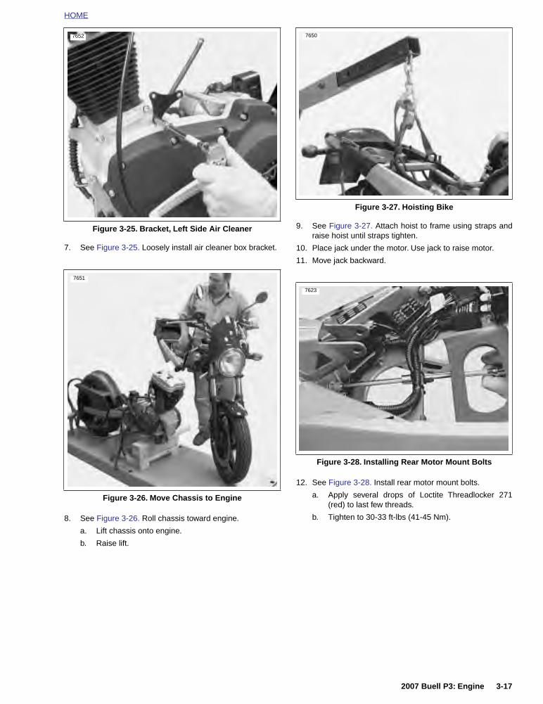
HOME
7. See Figure 3-25. Loosely install air cleaner box bracket.
8. See Figure 3-26. Roll chassis toward engine.
a. Lift chassis onto engine.
b. Raise lift.
9. See Figure 3-27. Attach hoist to frame using straps andraise hoist until straps tighten.
10. Place jack under the motor. Use jack to raise motor.
11. Move jack backward.
12. See Figure 3-28. Install rear motor mount bolts.
a. Apply several drops of Loctite Threadlocker 271(red) to last few threads.
b. Tighten to 30-33 ft-lbs (41-45 Nm).
Figure 3-25. Bracket, Left Side Air Cleaner
Figure 3-26. Move Chassis to Engine
7652
7651
Figure 3-27. Hoisting Bike
Figure 3-28. Installing Rear Motor Mount Bolts
7650
7623
2007 Buell P3: Engine 3-17
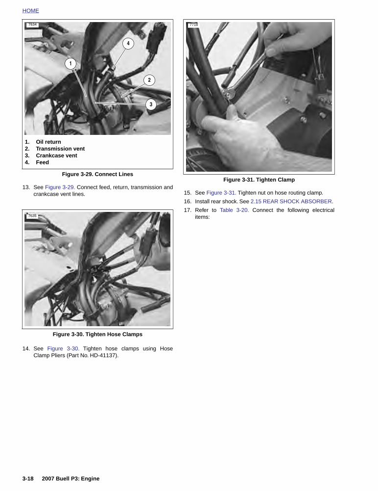
HOME
13. See Figure 3-29. Connect feed, return, transmission andcrankcase vent lines.
14. See Figure 3-30. Tighten hose clamps using HoseClamp Pliers (Part No. HD-41137).
15. See Figure 3-31. Tighten nut on hose routing clamp.
16. Install rear shock. See 2.15 REAR SHOCK ABSORBER.
17. Refer to Table 3-20. Connect the following electricalitems:
Figure 3-29. Connect Lines
Figure 3-30. Tighten Hose Clamps
7634
1. Oil return2. Transmission vent3. Crankcase vent4. Feed
4
2
1
3
7635
Figure 3-31. Tighten Clamp
7718
3-18 2007 Buell P3: Engine

HOME
Table 3-20. Electrical Items for Engine Assembly
DESCRIPTION LOCATION
Ignition module [10] Located on frame backbone.
Speedo sensor [65] Located under seat (right side-tucked in under cavity).
Sidestand switch [60] Tie wrapped to rear brake line.
Neutral switch [131] Disconnect at neutral switch.
Oil pressure switch [120] Disconnect at oil pressure switch.
Alternator stator [46] Located under seat (left side).
Starter solenoid wire [128] Disconnect at starter.
Spark plug wire Located on spark plug.
Battery—positive wire Disconnect at main circuit breaker.
Rear brake light switch [121] Located under frame by shock absorber.
2007 Buell P3: Engine 3-19

HOME
18. Install clutch cable at hand lever location. See 1.9CLUTCH.
19. Install drive belt. See 1.11 DRIVE BELT AND REARSPROCKET.
20. Install front sprocket cover. See 2.22 SPROCKETCOVER.
21. See Figure 3-32. Install master cylinder onto footpegbracket. See 2.21 FOOTPEGS AND FOOTPEG SUP-PORT BRACKETS.
a. Apply several drops of LOCTITE 243 (blue) to lastfew threads.
b. Tighten to 48-72 in-lbs (5-8 Nm).
22. See Figure 3-33. Install right side rider footpeg bracketassembly. See 2.21 FOOTPEGS AND FOOTPEG SUP-PORT BRACKETS.
Figure 3-32. Rear Master Cylinder andBrake Line Assembly
1. Screw2. Brake fluid reservoir 3. Screw4. Brake line bracket5. Screw6. Brake line7. Master cylinder8. Spacer
1
3
6
78
54
a0017x3x
2
Figure 3-33. Footpeg Bracket Assembly
1. Frame 2. Locknut3. Washer4. Spacer5. Footrest support bracket6. Clevis pin7. Footpeg8. Cotter pin9. Index plate10. Spacer
a0016x3x
1
2
3
4
5
67
109
8
3-20 2007 Buell P3: Engine

HOME
23. See Figure 3-34. Connect auto-enrichener plug.
NOTEInstall entire air cleaner and carburetor as an assembly. See4.3 AIR CLEANER.
24. See Figure 3-35. Connect crankcase breather hose tothree-way connector.
25. See Figure 3-36. Install hose clamp.
26. See Figure 3-37. Install and tighten screws on both aircleaner brackets.
a. Right bracket to air cleaner, 36-60 in-lbs (4.1-6.8Nm).
b. Left bracket to crankcases, 120-144 in-lbs (13.6-16.3 Nm).
c. Install screw on air cleaner cover.
Figure 3-34. Auto-Enrichener Plug
Figure 3-35. Crankcase Breather Hose
1. Auto-enrichener plug2. Frame
2
1
7631
7649
1. Breather hose2. Three-way connector
1
2
Figure 3-36. Hose Clamp
Figure 3-37. Air Cleaner Assembly
7648
1. Screw2. Bracket (left front)3. Bracket (right rear)4. Bracket screws
3
2
a0074x3x
4
1
4
2007 Buell P3: Engine 3-21

HOME
27. See Figure 3-38. Install top rear tie bar at frame.
28. Tighten tie bar bolt to 30-33 ft-lbs (41-45 Nm).
29. Install ground strap bolt to engine. Tighten ground strapbolt to 30-33 ft-lbs (41-45 Nm).
30. See Figure 3-39. Install front tie bar onto engine.
a. Apply several drops of LOCTITE 262 (red) to lastfew threads.
b. Tighten to 30-33 ft-lbs (41-45 Nm).
31. See Figure 3-40. Install the two mounted cylinder headbolts from the front isolator/engine bracket marked “DONOT REMOVE”.
a. Apply several drops of LOCTITE 262 (red) to lastfew threads of new bolts.
b. Apply a thin film of clean HD 20W50 engine oil toboth sides of new thick washers and to bottom ofbolt heads. Exercise caution to avoid mixing oil onwashers with LOCTITE on bolts.
c. Tighten bolts to 60 ft-lbs (81.3 Nm) initially and thenloosen each bolt one full turn. Tighten bolts again to60 ft-lbs (81.3 Nm).
Figure 3-38. Install Top Rear Tie Bar
Figure 3-39. Install Front Tie Bar
7627
7628
Figure 3-40. Cylinder Head Bolt
7646
3-22 2007 Buell P3: Engine

HOME
32. See Figure 3-41. Install front isolator mounting bolt,spacer snubber and new nut.
33. Tighten front isolator mounting bolt to 63-70 ft-lbs (86-95Nm).
34. See Figure 3-42. Install crankcase breather hose andcrankcase breather into rocker box grommet.
35. Install horn. See 7.22 HORN.
36. Remove jack from under the motor.
37. Install muffler. See 2.20 EXHAUST SYSTEM.
38. Install fuel tank. See 4.2 FUEL TANK COVER/FUELTANK.
39. Install new oil filter, engine oil and primary chaincasefluid as necessary.
40. See Figure 3-43. Install right side rider footpeg bracketassembly. See 2.21 FOOTPEGS AND FOOTPEG SUP-PORT BRACKETS.
11WARNING1WARNING
Connect positive (+) battery cable first. If positive (+)cable should contact ground with negative (-) cable con-nected, the resulting sparks can cause a battery explo-sion, which could result in death or serious injury.(00068a)
41. Connect both battery cables, positive cable first. See7.16 BATTERY.
11WARNING1WARNING
After installing seat, pull upward on front of seat to besure it is in locked position. While riding, a loose seat canshift causing loss of control, which could result in deathor serious injury. (00070a)
42. Install seat. See 2.28 SEAT.
Figure 3-41. Front Isolator Mount
Figure 3-42. Install Crankcase Breather Hose
1. Frame2. Locknut3. Snubber4. Bolt5. Spacer6. Front isolator7. Standoff
1
a0162x6x
2
4
5
6
7
3
7629
Figure 3-43. Footpeg Bracket Assembly
1. Frame 2. Locknut3. Washer4. Spacer5. Footrest support bracket6. Clevis pin7. Footpeg8. Cotter pin9. Index plate10. Spacer
a0016x3x
1
2
3
4
5
67
109
8
2007 Buell P3: Engine 3-23

HOME
CYLINDER HEAD 3.5
REMOVAL
The rocker arm covers and internal components must beremoved before removing cylinder heads.
Figure 3-44. Rocker Arm and Push Rod Cover Assemblies
1. Crankcase breather2. Grommet3. Screw (4)4. Washer (4)5. Gasket (4)6. Rocker cover (top)7. Bolt (3) 8. Washer (3)9. Gasket (inner)10. Gasket (lower)11. Rocker arm shafts12. Bolt (2)13. washer (2)14. Rocker cover (lower)15. Rocker arm (2)16. Bushing (rocker arm - 4)17. Gasket (lower rocker cover)18. Hydraulic lifter19. Screw, tappet anti-rotation (2)20. Gasket (push rod cover)21. Push rod cover22. Screw (4)23. O-ring (push rod cover - 2)24. Push rod25. Washer (4)26. Bolt (4)
2
4
8
12
15
16
17
21
25
b0960x3x
19
26
9
6
1
10
14
13
24
3
11
20
23
5
7
22
18
3-24 2007 Buell P3: Engine

HOME
Rocker Box Assemblies
IMPORTANT NOTEAll washers and fasteners used in the engine are hard-ened. Do not mix or replace hardened washers and fas-teners with unhardened parts. Do not reuse fiber coverseals. Engine damage may result.
1. Remove spark plug.
2. See Figure 3-44. Remove screws with washers and fibercover seals. Discard fiber seals.
3. Remove top rocker cover.
4. Remove and discard gaskets.
5. Rotate crankshaft until both valves are closed.
6. See Figure 3-45. Remove hardware holding lower rockercover to cylinder head in the following order.
a. Remove two screws and washers (1).
b. Remove three bolts and washers (2).
c. Loosen the four rocker arm fasteners (3) in 1/4-1/2turn increments using a cross pattern in order torelieve valve spring pressure on the lower rockerbox.
7. See Figure 3-44. Remove lower rocker cover.
NOTERemove lower rocker box as an assembly, then disassembleas required.
IMPORTANT NOTEMark rocker arm shafts for reassembly in their originalpositions. Valve train components must be reinstalled intheir original positions to prevent accelerated wear andincreased valve train noise.
8. See Figure 3-46. Remove rocker arm shafts by tappingthem out using a hammer and a soft metal punch.
9. Remove rocker arms, mark them for reassembly intheir original locations.
10. Mark the location and orientation (top/bottom) of eachpush rod. Remove push rods.
Figure 3-45. Lower Rocker Box Fasteners
Figure 3-46. Removing Rocker Arm Shafts
1
12
2
2
3
3
3
3
12503
12503
2007 Buell P3: Engine 3-25

HOME
Cylinder Head Assembly
IMPORTANT NOTESee Figure 3-47. Distortion to the head, cylinder andcrankcase studs may result if head screws are not loos-ened (or tightened) gradually in the sequence shown.
11. See Figure 3-47. Loosen each head screw 1/8-turn fol-lowing the sequence shown.
a. Continue loosening in 1/8-turn increments untilscrews are loose. Remove head screws.
b. Remove cylinder head, head gasket, and o-rings.
12. Discard head gasket.
13. See Figure 3-44. Remove push rod cover, gasket andvalve tappets.
DISASSEMBLY
1. See Figure 3-48. Clamp VALVE SPRING COMPRES-SOR TOOL (Part No. HD-34736B) in vise.
2. Compress valve springs with VALVE SPRING COM-PRESSOR.
3. See Figure 3-49. Remove valve keepers, upper collarand valve springs. Mark valve keepers for reassembly intheir original locations.
4. Use a fine tooth file to remove any burrs on the valvestem at the keeper groove.
5. Mark valve to ensure that it will be reassembled in thesame guide. Remove valve, valve stem seal and lowercollar assembly.
6. Repeat the above procedure for the other valve.
Figure 3-47. Head Screw Loosening/Tightening Sequence
Figure 3-48. Valve Spring Compressor (Part No. HD-34736B)
3
42
a0128x3x
1
8684
3-26 2007 Buell P3: Engine

HOME
Figure 3-49. Cylinder Head, Cylinder and Piston Assembly
1. Screw2. Screw3. Valve collar retainer4. Upper valve spring collar5. Inner valve spring6. Outer valve spring7. Valve seal8. Lower valve spring collar9. Valve guide intake & exhaust (2)10. Cylinder head11. Exhaust port stud12. Cylinder head gasket13. Cylinder o-ring (4)14. Cylinder insert15. Cylinder w/piston & rings16. Cylinder base gasket17. Cylinder base stud18. Exhaust valve19. Exhaust valve seat
1 2
a0021x3x
3
4
5
6
7
8
9
10
11
12
13
14
15
18
19
15
16
17
2007 Buell P3: Engine 3-27

HOME
CLEANING AND INSPECTION
Cylinder Head
11WARNING1WARNING
Compressed air can pierce the skin and flying debrisfrom compressed air could cause serious eye injury.Wear safety glasses when working with compressed air.Never use your hand to check for air leaks or to deter-mine air flow rates. (00061a)
1. Bead blast or scrape carbon from head, top of cylinderand valve ports. Be careful to avoid scratching or nickingcylinder head and cylinder joint faces. Blow off loosenedcarbon or dirt with compressed air.
2. Soak cylinder head in an aluminum-compatible cleaner/solvent to loosen carbon deposits.
3. Wash all parts in non-flammable solvent, followed by athorough washing with hot, soapy water. Blow out oilpassages in head. Be sure they are free of sludge andcarbon particles. Remove loosened carbon from valvehead and stem using a wire wheel. Never use a file orother hardened tool which could scratch or nick valve.Polish valve stem with very fine emery cloth or steelwool.
4. See Figure 3-50. Check head gasket surface on head forflatness. Machine or replace any head which exceedsSERVICE WEAR LIMIT of 0.006 in. (0.152 mm).
Figure 3-50. Checking Gasket Surface
6609
3-28 2007 Buell P3: Engine

HOME
Rocker Arm Assemblies1. Check each rocker arm, at pad end and push rod end, for
uneven wear or pitting. Replace rocker arm if either con-dition exists.
2. Measure and record rocker arm shaft diameter.
a. See Figure 3-51. Measure where shaft fits in lowerrocker arm cover.
b. See Figure 3-52. Measure where rocker arm bush-ings ride.
3. Measure and record rocker arm shaft bore diameter.
a. See Figure 3-53. Measure bore of lower rockercover.
b. See Figure 3-54. Measure rocker arm bushing innerdiameter.
4. Check the measurements obtained in Steps 2-3 againstthe SERVICE WEAR LIMITS. Repair or replace partsexceeding limits.
5. Assemble rocker arms and rocker arm shafts into lowerrocker cover.
6. Check end play of rocker arm with feeler gauge.
7. Replace rocker arm or lower cover or both if end playexceeds 0.025 in. (0.635 mm).
Figure 3-51. Measuring Rocker Arm Shaft Diameter(Rocker Cover Position)
Figure 3-52. Measuring Rocker Arm Shaft Diameter(Rocker Arm Bushing Position)
6606
6605
Figure 3-53. Measuring Rocker Arm Shaft Bore Diameter in Lower Rocker Cover
Figure 3-54. Measuring Rocker Arm BushingInner Diameter
6607
6608
2007 Buell P3: Engine 3-29

HOME
Valves
1. Replace the valve if there is evidence of burning orcracking.
2. Inspect the end of the valve stem for pitting or unevenwear. Replace the valve if either of these conditions arefound.
3. Inspect for burrs around the valve stem keeper groove.Remove burrs with a fine tooth file if found.
Valve Seats
NOTE
Valve seats are also subject to wear. Resurface valve seatswhenever valves are refinished.
1. Inspect seats for cracking, chipping or burning. Replaceseats if any evidence of these conditions are found.
2. See Figure 3-55. Check seats for recession by measur-ing valve stem protrusion.
a. Wipe valve seats and valve faces clean.
b. Measure valve stem protrusion.
c. If valve stem protrudes more than 2.031 in.(51.587 mm), replace valve seat or cylinder head.
NOTE
Replacing a valve seat is a complex operation requiring spe-cial equipment. If the seat is loose or is not fully seated in thehead, then seat movement will prevent the proper transfer ofheat from the valve. The seat surface must be flush with (orbelow) the head surface. See 3.1 SPECIFICATIONS for valveseat-to-cylinder head fit.
Valve Guides1. Clean valve guides by lightly honing with VALVE GUIDE
HONE (Part No. HD-34723).
2. Scrub guides with VALVE GUIDE BRUSH (Part No. HD-34751) and hot soapy water. Measure valve stem outerdiameter and valve guide inner diameter. Check mea-surements against 3.1 SPECIFICATIONS.
Valve Springs1. Inspect valve springs for broken or discolored coils.
2. See Figure 3-56. Check free length and compressionforce of each spring. Compare with 3.1 SPECIFICA-TIONS. If spring length is shorter than specification or ifspring compression force is below specification, replacespring.
Spark Plug ThreadsInspect spark plug threads for damage. If threads in head aredamaged, a special plug type insert can be installed using a12 mm spark plug repair kit.
Push RodsExamine push rods, particularly the ball ends. Replace anyrods that are bent, worn, discolored or broken.Figure 3-55. Measuring Valve Stem Protrusion
5696
Figure 3-56. Checking Spring Free Length
a0085x3x
3-30 2007 Buell P3: Engine

HOME
Replacing Rocker Arm Bushings1. See Figure 3-57. To replace worn bushings, press or
drive them from the rocker arm. If bushing is difficult toremove, turn a 9/16-18 tap into bushing. From oppositeside of rocker arm, press out bushing and tap using adiscarded rocker arm shaft.
2. Press replacement bushing into rocker arm, flush witharm end, and split portion of bushing towards top of arm.
3. Using remaining old bushing as a pilot, line ream newbushing with ROCKER ARM BUSHING REAMER (PartNo. HD-94804-57).
4. Repeat for other end of rocker arm.
Figure 3-57. Replacing Rocker Arm Bushings
8732
8733
8734
2007 Buell P3: Engine 3-31

HOME
Replacing Valve GuidesValve guide replacement, if necessary, must be done beforevalve seat is ground. It is the valve stem hole in valve guidethat determines seat grinding location. Valve stem-to-valveguide clearances are listed in Table 3-21. If valve stems and/or guides are worn beyond limits, install new parts.
1. To remove shoulderless guides, press or tap guidestoward combustion chamber using VALVE GUIDEREMOVER/INSTALLER (Part No. HD-34740).
2. Clean and measure valve guide bore in head.
3. Measure outer diameter of a new standard valve guide.The guide diameter should be 0.0020-0.0033 in.(0.0508-0.0838 mm). larger than bore in head. If it is not,select one of the following oversizes: +0.001 in. (+0.025mm), +0.002 in. (+0.051 mm) or +0.003 in. (+0.076 mm)(intake and exhaust).
4. See Figure 3-58. Install shoulderless guides usingVALVE GUIDE INSTALLATION TOOL (Part No. HD-34731) and DRIVER HANDLE (Part No. HD-34740).Press or drive guide until the tool touches the machinedsurface surrounding the guide. At this point, the correctguide height has been reached.
5. Ream guides to final size or within 0.0010 in.(0.0254 mm) of final size using VALVE GUIDE REAMER(Steel, Part No. HD-39932 or Carbide, Part No. HD-39932-CAR). Use REAMER LUBRICANT (Part No. HD-39964) or liberal amounts of suitable cutting oil to pre-vent reamer chatter.
NOTEThe hone is not intended to remove material.
6. Apply the proper surface finish to the valve guide boresusing the VALVE GUIDE HONE (Part No. HD-34723).Lubricate hone with honing oil. Driving hone with anelectric drill, work for a crosshatch pattern with an angleof approximately 60°.
7. See Figure 3-59. Thoroughly clean valve guide boresusing VALVE GUIDE BRUSH (Part No. HD-34751) andhot soapy water.
Table 3-21. Valve Stem Clearancesand Service Wear Limits
VALVE CLEARANCESERVICE WEAR
LIMIT
Exhaust 0.0015-0.0033 in.(0.0381-0.0838 mm)
0.0040 in.(0.1016 mm)
Intake 0.0008-0.026 in.(0.025-0.076 mm)
0.0035 in.(0.0889 mm)
Figure 3-58. Installing Shoulderless Valve Guide
5692
1
2
1. Valve guide remover/installer (Part No. B-45524)2. Cylinder head stand (Part No. HD-39782)
Figure 3-59. Cleaning Valve Guides
5695
1. Valve guide brush (Part No. HD-34751)2. Cylinder head holding fixture
(Part No. HD-39786)
1
2
3-32 2007 Buell P3: Engine

HOME
PROCEDURE FOR USING THE NEWAY VALVE SEAT CUTTER
Table 3-22. Neway Valve Seat Cutter
NOTES● Verify correct valve stem to valve guide clearance before
refacing. See Table 3-21. If new guides must beinstalled, complete that task before refacing valves andseats.
● This procedure is not based on the lapping of valves. Theend result is an interference fit between the valve of 45°and the valve seat which will be 46°.
1. Secure cylinder head for service.
a. Thread 12 mm end of CYLINDER HEAD HOLDINGFIXTURE (Part No. HD-39786) into cylinder headspark plug hole.
b. Clamp tool in vise and further tighten cylinder headonto the fixture to prevent any movement duringoperation.
c. Place cylinder head at a 45° angle or one that offersa comfortable working position.
2. Obtain the NEWAY VALVE SEAT CUTTER SET (HD-35758A) and cut valve seat angle to 46°. Do not removeany more metal than is necessary to clean up the seat(that is, to provide a uniform finish and remove pitting).
3. In order to determine the correct location of the 46° valveseat in the head, measure the width of the valve to beused and subtract 0.080" (2.032 mm) from that number.
4. Set your dial caliper to the lesser measurement and lockdown for quick reference. This is the location of yourvalve seat.
5. Use a permanent magic marker to highlight the valveseat area that is going to be cut and be sure to highlightall 3 angles. Allow marker to dry before proceeding.
NOTES● Always ensure cutter blades and cutter pilot are clean
before beginning the cutting process. The correct clean-ing brush is supplied with the Neway tool set.
● Also ensure the inside of the valve guide is clean byusing Kent-Moore cleaning brush (Part No. HD-34751).
6. Choose the cutter pilot that fits properly into the valveguide hole and securely seat the pilot by pushing downand turning using the installation tool supplied in the toolset.
7. Choose the proper 46° cutter (intake or exhaust) andgently slide the cutter onto the pilot being careful not todrop the cutter onto the seat.
8. While applying a constant and consistent pressure,remove just enough material to show a complete clean-up on the 46° angle.
NOTES● If the width of the clean-up angle is greater on one side
of the seat than the other, the guide may need to bereplaced due to improper installation.
● After making the 46° cut, if you discover a groove cutcompletely around the seat this means the blades of thecutter are in alignment and need to be staggered. This isaccomplished by loosening all of the blades from the cut-ter body and moving each blade slightly in it’s cradle inopposite directions on the cutter. The tool needed toloosen the blades is supplied in the tool set. A perma-nent magic marker mark every 90° will help in determin-ing where new angles are.
PART NO. SPECIALTY TOOL
HD-35758A Neway valve seat cutter
HD-39786 Cylinder head holding fixture
Figure 3-60. Neway Valve Seat Cutter
a0087x3x
2007 Buell P3: Engine 3-33

HOME
9. Next, with your dial caliper locked to the predeterminedsetting, measure the 46° cut at the outer most edge atthe widest point of the circle to determine what cut needsto be made next.
a. If the 46° cut is to high (towards the combustionchamber), use the 31° cutter to lower the valve seatcloser to the port.
b. If the 46° cut is too low, use the 60° cutter to raisethe valve seat or move it away from the port.
NOTE● Due to using the top measurement of our valve seat as a
reference point it will usually be necessary to use the 31°cutter following the initial 46° cut.
● Always highlight the valve seat with the permanentmagic marker in order to ensure the location of the 46°valve seat.
10. If the location of the valve seat is not correct, repeatsteps 8 and 9.
11. When you accomplish a complete clean-up of the 46°angle and the width is at least .062 in. (1.575 mm), pro-ceed to the next step.
12. Select the proper 60° cutter and gently slide the cutterdown the cutter pilot to the valve seat.
13. Remove just enough material to provide an even valveseat width of .040-.062 in. (1.016-1.575 mm).
14. Remove cutter pilot and wash head thoroughly and drycompletely.
15. Repeat the process on any valve seat that needs ser-vice.
16. Insert valve to be used in the valve guide and bottom onthe valve seat. Positioning the cylinder head portupwards and with slight thumb pressure against thevalve, completely fill the port with solvent to verify properseal between the valve and the valve seat.
NOTE
Hold pressure against the valve for a minimum of 10 seconds.If any leakage occurs, examine the valve seat for irregularitiesor defects and if necessary repeat the above cutting process.
Figure 3-61. Intake and Exhaust Valve and Seat Dimensions
31˚ 46˚
60˚
Min. 0.040 in. (1.016 mm)Max. 0.062 in. (1.575 mm)
b0972x3x
Margin
3-34 2007 Buell P3: Engine
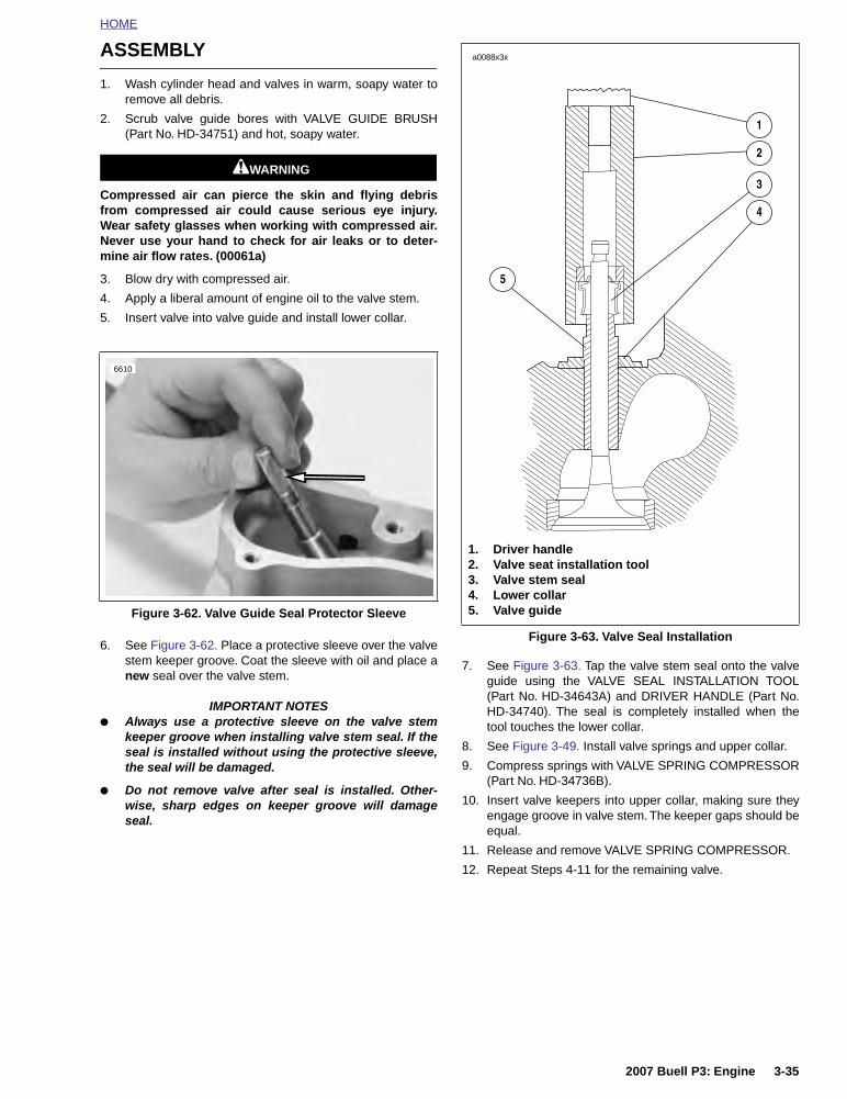
HOME
ASSEMBLY
1. Wash cylinder head and valves in warm, soapy water toremove all debris.
2. Scrub valve guide bores with VALVE GUIDE BRUSH(Part No. HD-34751) and hot, soapy water.
11WARNING1WARNING
Compressed air can pierce the skin and flying debrisfrom compressed air could cause serious eye injury.Wear safety glasses when working with compressed air.Never use your hand to check for air leaks or to deter-mine air flow rates. (00061a)
3. Blow dry with compressed air.
4. Apply a liberal amount of engine oil to the valve stem.
5. Insert valve into valve guide and install lower collar.
6. See Figure 3-62. Place a protective sleeve over the valvestem keeper groove. Coat the sleeve with oil and place anew seal over the valve stem.
IMPORTANT NOTES● Always use a protective sleeve on the valve stem
keeper groove when installing valve stem seal. If theseal is installed without using the protective sleeve,the seal will be damaged.
● Do not remove valve after seal is installed. Other-wise, sharp edges on keeper groove will damageseal.
7. See Figure 3-63. Tap the valve stem seal onto the valveguide using the VALVE SEAL INSTALLATION TOOL(Part No. HD-34643A) and DRIVER HANDLE (Part No.HD-34740). The seal is completely installed when thetool touches the lower collar.
8. See Figure 3-49. Install valve springs and upper collar.
9. Compress springs with VALVE SPRING COMPRESSOR(Part No. HD-34736B).
10. Insert valve keepers into upper collar, making sure theyengage groove in valve stem. The keeper gaps should beequal.
11. Release and remove VALVE SPRING COMPRESSOR.
12. Repeat Steps 4-11 for the remaining valve.
Figure 3-62. Valve Guide Seal Protector Sleeve
6610
Figure 3-63. Valve Seal Installation
a0088x3x
1. Driver handle2. Valve seat installation tool3. Valve stem seal4. Lower collar5. Valve guide
1
2
3
4
5
2007 Buell P3: Engine 3-35

HOME
PUSH ROD COVER INSTALLATION
NOTE
Push rod cover must be installed prior to installing cylinderhead.
1. See Figure 3-64. Install push rod cover.
a. Install new o-rings (2) on top of each push rod cover(3).
b. Install new push rod cover gasket (5) onto bottom ofeach push rod cover.
c. Install push rod cover assembly and start the fourfasteners (4) securing bottom of cover to crankcase.
d. Tighten fasteners to 30-40 in lbs (3.4-4.5 Nm).
2. Refer to Table 3-23. Identify push rod color coding,length and respective push rod positions in engine. Placeintake and exhaust push rods onto seat at top of tappet.
IMPORTANT NOTE
After head has been installed do not turn engine overuntil both push rods can be turned with fingers. Other-wise, damage to push rods or rocker arms may result.
Figure 3-64. Push Rod Location
Table 3-23. Push Rod Selection
POSITIONCOLOR CODES
LENGTH PART NO.
Exhaust 1 Band-Black
10.969 in.(278.613 mm)
17985-00Y
Intake 1 Band-Green
10.915 in.(277.241 mm)
17984-00YA
7677
Figure 3-65. Push Rods and Push Rod Cover Assembly
b1092x3x
2
3
4
1. Push rod (2)2. O-ring (2)3. Push rod cover4. Screws (4)5. Push rod cover gasket
1
5
3-36 2007 Buell P3: Engine

HOME
CYLINDER HEAD INSTALLATION
NOTE
● Thoroughly clean and lubricate the threads of the cylin-der head screws before installation. Friction caused bydirt and grime will result in a false torque indication.
● Pushrod cover must be installed prior to installing cylin-der head.
1. Thoroughly clean and dry the gasket surfaces of cylinderand cylinder head.
2. Install new o-rings over two ring dowels at the top of thecylinder. Apply a very thin film of clean H-D 20W50engine oil to o-rings before installation.
NOTE
To ensure proper head gasket alignment, install new o-ringsover cylinder ring dowels before installing the head gasket.Improper head gasket alignment will cause leaks.
3. Install a new head gasket to cylinder.
4. Carefully lower cylinder head over studs and position ondowels. Use great care so as not to disturb head gasket.
5. Lightly coat the threads and bottom face of the cylinderhead bolts in clean H-D 20W50 engine oil. Wipe off anyexcess oil.
NOTE
The procedure for tightening the head screws is critical toproper distribution of pressure over gasket area. It preventsgasket leaks, stud failure, and head and cylinder distortion.
6. Start the cylinder head screws onto the cylinder studs,two short bolts on the left side of the engine, two longbolts on the right.
7. See Figure 3-66. Always start with screw numbered one,as shown. In increasing numerical sequence (i.e. – 1, 2,3 and 4):
a. Tighten bolts to 96-120 in-lbs (11-14 Nm).
b. Tighten bolts to 13-15 ft-lbs (18-20 Nm).
c. Loosen all screws.
8. After screws are loosened from initial torque, tightenhead screws in three stages. Tighten fasteners inincreasing numerical sequence (i.e. – 1, 2, 3 and 4).
a. Tighten each screw to 96-120 in-lbs (11-14 Nm).
b. Tighten each screw to 13-15 ft-lbs (18-20 Nm).
c. See Figure 3-67. Mark cylinder head and headscrew shoulder with a line as shown (View A).
d. Turn all bolts an additional 85 -95 .° °
Figure 3-66. Head Screw Loosening/Tightening Sequence
Figure 3-67. Tightening Head Screws
2
4
3
1
a0128x3x
ViewA
ViewB
a0089x3x
Tighten head screws 1/4-turn inthe third stage of installation
2007 Buell P3: Engine 3-37

HOME
Figure 3-68. Rocker Arm and Push Rod Cover Assemblies
1. Crankcase breather2. Grommet3. Screw (4)4. Washer (4)5. Gasket (4)6. Rocker cover (top)7. Bolt (3) 8. Washer (3)9. Gasket (inner)10. Gasket (lower)11. Rocker arm shafts12. Bolt (2)13. washer (2)14. Rocker cover (lower)15. Rocker arm (2)16. Bushing (rocker arm - 4)17. Gasket (lower rocker cover)18. Hydraulic lifter (2)19. Screw, tappet anti-rotation (2)20. Gasket (push rod cover)21. Push rod cover22. Screw (4)23. O-ring (push rod cover - 2)24. Push rod25. Washer (4)26. Bolt (4)
1
4
12
25
b0960x3x
2
3
5
6
7
8
9
13
14
16
11
26
24
23
22
10
15
17
20
18
19
21
3-38 2007 Buell P3: Engine

HOME
9. See Figure 3-68. Install new gasket. Place lower rockerbox assembly, with rocker arms and shafts, into position.Place push rods in rocker arm sockets.
IMPORTANT NOTEDo not stretch gaskets while installing. Use the toprocker cover to press the gasket into position.
10. See Figure 3-69. Install hardware attaching lower rockercover to cylinder head in the following order. After looselyinstalling all fasteners, use a cross pattern on the fourlarge bolts that fasten the lower rocker box to head totighten and then torque to specifications. This will bleedthe tappets. Finish tightening remaining fasteners. Fas-tener sequences, sizes and torque specifications arelisted in Table 3-24.
a. Tighten bolts (1) to 18-22 ft-lbs (24-30 Nm).
b. Tighten bolts (2) to 135-155 in-lbs (15-18 Nm).
c. Tighten bolts (3) to 135-155 in-lbs (15-18 Nm).
11. See Figure 3-68. Install upper rocker covers.
a. Place a new inner gasket on lower rocker boxassembly.
b. Place a new lower gasket on lower rocker cover.
c. Install upper rocker cover using screws with washersand new fiber seals. Tighten screws to 120-168 in-lbs (13.6-18.9 Nm).
Figure 3-69. Lower Rocker Box Fasteners
3
32
2
2
1
1
1
1
12503
Table 3-24. Lower Rocker Box Hardware
ITEM SIZE TORQUE
(1)
Bolt w/washer5/16-18 X 2-1/2
18-22 ft-lbs (24-30 Nm)
(2)
Bolt w/washer1/4-20 X 1-1/4
135-155 in-lbs(15-18 Nm)
(3)
Screw w/washer1/4-20 X 1-1/2
135-155 in-lbs(15-18 Nm)
2007 Buell P3: Engine 3-39

HOME
CYLINDER AND PISTON 3.6
REMOVAL/DISASSEMBLY
1. Strip motorcycle as described under this procedure. See3.3 STRIPPING MOTORCYCLE FOR ENGINE SER-VICE.
2. Remove cylinder head. See 3.5 CYLINDER HEAD.
3. Clean crankcase around cylinder base to prevent dirtand debris from entering crankcase while removing cylin-der.
4. See Figure 3-70. Turn engine over until piston of cylinderbeing removed is at bottom of its stroke.
5. Carefully raise cylinder just enough to permit placingclean towel under piston to prevent any foreign matterfrom falling into crankcase.
NOTEIf cylinder does not come loose, lightly tap a plastic hammerperpendicular to the cylinder fins. Never try to pry a cylinderup.
6. Carefully lift cylinder over piston and cylinder studs. Donot allow piston to fall against cylinder studs. Discard cyl-inder base gasket.
IMPORTANT NOTEWith cylinder removed, be careful not to bend the cylin-der studs. The slightest bend could cause a stress riserand lead to stud failure.
7. Install a 6.0 in. (152 mm) length of 1/2 in. (12.7 mm) IDplastic or rubber hose over each cylinder stud. This willprotect the studs and the piston.
11WARNING1WARNING
Wear safety glasses or goggles when removing or install-ing piston pin retaining rings. Piston pin retaining ringsare compressed in the ring groove and can fly out whenremoved from the groove, which could result in seriouseye injury. (00293a)
IMPORTANT NOTEDO NOT re-use piston pin retaining rings. Removal mayweaken retaining rings and they may break or dislodge ifreinstalled resulting in engine damage.
NOTESince the piston pin is a loose fit in the piston, the pin will eas-ily slide out. The pin has tapered ends to help seat the roundretaining rings.
Figure 3-70. Cylinder and Piston
1. Ring set2. Retaining ring (2)3. Piston4. Dowel and o-ring5. Cylinder6. Cylinder stud (4)7. Base gasket8. Piston pin bushing9. Connecting rod10. Piston pin
a0023x3x
1
2
3
4
4
5
67
89
210
3-40 2007 Buell P3: Engine

HOME
8. Remove the piston pin circlip as follows:
a. See Figure 3-71. Insert the PISTON PIN CIRCLIPREMOVER/INSTALLER (HD-42317) into the pistonpin bore until claw on tool is positioned in slot of pis-ton (directly under circlip).
b. Squeeze the handles of the tool together and pullfrom bore. In the event that the circlip should fly out,hold a shop towel over the bore during removal.Remove circlip from claw and discard.
NOTEIt is not necessary to remove both piston pin circlips duringpiston removal. Leave the second circlip in the pin bore.
9. See Figure 3-72. The arrow at the top of pistons mustalways point toward the front of the engine.
NOTEHandle the piston with extreme care. The alloy used in thesepistons is very hard. Any scratches, gouges or other marks inthe piston could score the cylinder during engine operationand cause engine damage.
10. Spread piston rings outward until they clear grooves inpiston and lift off.
Figure 3-71. Removing Piston Pin Circlip UsingPiston Pin Circlip Remover/Installer
(Part No. HD-42317)
a0479x3x
b1002x3x
Figure 3-72. Piston Identification and Direction
a0477a3x
2007 Buell P3: Engine 3-41

HOME
CLEANING AND INSPECTION
11WARNING1WARNING
Compressed air can pierce the skin and flying debrisfrom compressed air could cause serious eye injury.Wear safety glasses when working with compressed air.Never use your hand to check for air leaks or to deter-mine air flow rates. (00061a)
1. Soak cylinder and piston in an aluminum-compatiblecleaner/solvent until deposits are soft, then clean with abrush. Blow off loosened carbon and dirt particles andwash in solvent.
2. Clean oil passage in cylinder with compressed air.
3. Clean piston ring grooves with a piece of compressionring ground to a chisel shape.
4. Examine piston pin to see that it is not pitted or scored.
5. Check piston pin bushing to see that it is not loose inconnecting rod, grooved, pitted or scored.
a. A piston pin properly fitted to upper connecting rodbushing has a 0.00125 to 0.00175 in. (0.03175-0.04445 mm) clearance in bushing.
b. See Connecting Rod Bushing section. If piston pin-to-bushing clearance exceeds 0.00200 in. (0.05080mm), replace worn parts.
6. Clean piston pin retaining ring grooves.
7. Examine piston and cylinder for cracks, burnt spots,grooves and gouges.
8. Check connecting rod for up and down play in lowerbearings. When up and down play is detected, lowerbearing should be refitted. This requires removing anddisassembling engine crankcase.
Checking Gasket Surface
IMPORTANT NOTEIf cylinder gasket surface does not meet flatness specifi-cations, replace cylinder and piston. Proper toleranceswill extend component life and prevent leaks.
1. See Figure 3-73. Check cylinder head gasket surface forflatness.
a. Lay a straightedge across the surface.
b. Try to insert a feeler gauge between the straight-edge and the gasket surface.
c. If cylinder head gasket surface is not flat within0.006 in. (0.152 mm), replace cylinder and piston.
2. Check cylinder base gasket surface for flatness.
a. Lay a straightedge across the surface.
b. Try to insert a feeler gauge between the straight-edge and the gasket surface.
c. If cylinder base gasket surface is not flat within0.008 in. (0.203 mm), replace cylinder and piston.
Figure 3-73. Checking Gasket Surfaces
6611
3-42 2007 Buell P3: Engine

HOME
Measuring Cylinder Bore
1. Remove any burrs from the cylinder gasket surfaces.
2. See Figure 3-74. Install a head gasket, base gasket ando-rings, and CYLINDER TORQUEPLATES (Part No. HD-33446A) and XL EVOLUTION TORQUE PLATE BOLTS(Part No. HD-33446-86). Tighten the bolts using thesame method used when installing the cylinder headscrews. See 3.5 CYLINDER HEAD.
NOTE
Torque plates, properly tightened and installed with gaskets,simulate engine operating conditions. Measurements will varyas much as 0.001 in. (0.025 mm) without torque plates.
3. See Figure 3-74. Take cylinder bore measurement in ringpath, starting about 0.50 in. (12.7 mm) from top of cylin-der, measuring from front to rear and then side to side.Record readings.
4. Repeat measurement at center and then at bottom ofring path. Record readings. This process will determine ifcylinder is out-of-round and will also show any cylindertaper or bulge.
5. Refer to Table 3-25. If cylinder is not scuffed or scoredand is within service limit, see next section, FITTINGPISTON RINGS.
NOTEIf piston clearance exceeds service wear limit, cylindersshould be re-bored and/or honed to next standard oversize,and refitted with the corresponding piston and rings. Do not fitpiston tighter than 0.0007 in. (0.0178 mm). See 3.1 SPECIFI-CATIONS.
Measuring PistonBecause of their complex shape, the pistons cannot be accu-rately measured with standard measuring instruments.
Pistons have an elliptical shape when viewed from the topand are barrel-shaped when viewed from the side. This barrelshape is not symmetrical.
Any damage to the piston will change its shape, which willlead to problems.
Figure 3-74. Measuring Cylinder Bore Using Torque Plates (Part No. HD-33446A)
b0306x3x
Table 3-25. Cylinder Bore Service Wear Limits
BORE SIZES IN. MM
Standard bore 3.5008 88.9203
0.005 in. OS bore(0.127 mm)
3.5050 89.0270
0.010 in. OS bore(0.254 mm)
3.5100 89.1540
0.020 in. OS bore(0.508 mm)
3.5200 89.4080
0.030 in. OS bore(0.762 mm)
3.5300 89.6620
2007 Buell P3: Engine 3-43

HOME
Fitting Cylinder to PistonSince pistons cannot be accurately measured with standardmeasuring instruments, the bore sizes must be measured.Bore sizes are listed in Table 3-26. Example: A 0.005 in.(0.127 mm) oversize piston will have the proper clearancewith a bore size of 3.502 in. ± 0.0002 in. (88.951 mm ±0.0051 mm).
Boring and Honing CylinderWhen cylinder requires oversize reboring to beyond 0.030 in.(0.762 mm), the oversize limit has been exceeded and cylin-der must be replaced.
1. Bore cylinder with gaskets and torque plates attached.Bore to 0.003 in. (0.076 mm) under the desired finishedsize.
2. Hone the cylinder to its finished size using a 280 grit rigidhone followed by a 240 grit flexible ball hone. Honingmust be done with the torque plates attached. All honingmust be done from the bottom (crankcase) end of thecylinder. Work for a 60° crosshatch pattern.
IMPORTANT NOTEFailure to remove all abrasive particles may result in pre-mature cylinder, piston and ring wear and possibleengine failure.
3. Thoroughly wash the cylinder bore with liquid dish soapand warm water to remove all abrasive particles andresidual grit. Continue cleaning until a clean cloth showsno evidence of dirt or debris.
11WARNING1WARNING
Compressed air can pierce the skin and flying debrisfrom compressed air could cause serious eye injury.Wear safety glasses when working with compressed air.Never use your hand to check for air leaks or to deter-mine air flow rates. (00061a)
4. Hot rinse the cylinder and dry with moisture free com-pressed air.
5. Immediately apply a thin film of clean engine oil to aclean white paper towel and thoroughly wipe the insideof the cylinder.
NOTEAfter wiping the cylinder with a clean, oiled paper towel, thetowel will be dark with contamination. Repeat this processusing a new lightly oiled paper towel each time until the towelremains white. The cylinder is now clean.
Table 3-26. Final Cylinder Bore Sizes
BORE SIZES IN. MM
Standard bore* 3.4978 88.8441
0.005 in. OS bore (0.127 mm) 3.502 88.951
0.010 in. OS bore (0.254 mm) 3.507 89.078
0.020 in. OS bore (0.508 mm) 3.517 89.332
0.030 in. OS bore (0.762 mm) 3.527 89.586
*All bore sizes + 0.0002 in. (0.0051 mm)
3-44 2007 Buell P3: Engine
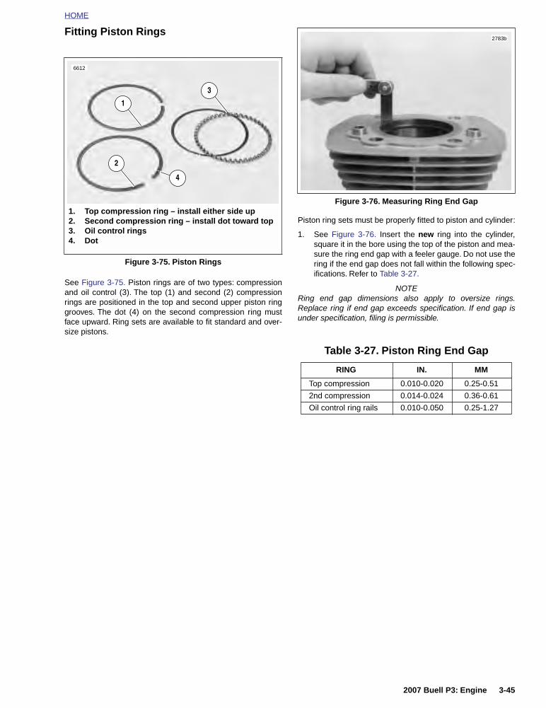
HOME
Fitting Piston Rings
See Figure 3-75. Piston rings are of two types: compressionand oil control (3). The top (1) and second (2) compressionrings are positioned in the top and second upper piston ringgrooves. The dot (4) on the second compression ring mustface upward. Ring sets are available to fit standard and over-size pistons.
Piston ring sets must be properly fitted to piston and cylinder:
1. See Figure 3-76. Insert the new ring into the cylinder,square it in the bore using the top of the piston and mea-sure the ring end gap with a feeler gauge. Do not use thering if the end gap does not fall within the following spec-ifications. Refer to Table 3-27.
NOTERing end gap dimensions also apply to oversize rings.Replace ring if end gap exceeds specification. If end gap isunder specification, filing is permissible.
Figure 3-75. Piston Rings
1. Top compression ring – install either side up2. Second compression ring – install dot toward top3. Oil control rings4. Dot
2
1
3
6612
4
Figure 3-76. Measuring Ring End Gap
Table 3-27. Piston Ring End Gap
RING IN. MM
Top compression 0.010-0.020 0.25-0.51
2nd compression 0.014-0.024 0.36-0.61
Oil control ring rails 0.010-0.050 0.25-1.27
2783b
2007 Buell P3: Engine 3-45
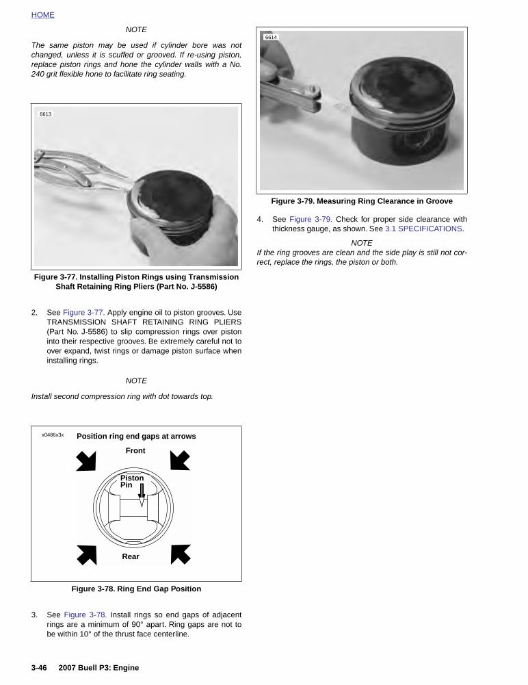
HOME
NOTE
The same piston may be used if cylinder bore was notchanged, unless it is scuffed or grooved. If re-using piston,replace piston rings and hone the cylinder walls with a No.240 grit flexible hone to facilitate ring seating.
2. See Figure 3-77. Apply engine oil to piston grooves. UseTRANSMISSION SHAFT RETAINING RING PLIERS(Part No. J-5586) to slip compression rings over pistoninto their respective grooves. Be extremely careful not toover expand, twist rings or damage piston surface wheninstalling rings.
NOTE
Install second compression ring with dot towards top.
3. See Figure 3-78. Install rings so end gaps of adjacentrings are a minimum of 90° apart. Ring gaps are not tobe within 10° of the thrust face centerline.
4. See Figure 3-79. Check for proper side clearance withthickness gauge, as shown. See 3.1 SPECIFICATIONS.
NOTEIf the ring grooves are clean and the side play is still not cor-rect, replace the rings, the piston or both.
Figure 3-77. Installing Piston Rings using Transmission Shaft Retaining Ring Pliers (Part No. J-5586)
Figure 3-78. Ring End Gap Position
6613
x0486x3x
Piston Pin
Position ring end gaps at arrows
Front
Rear
Figure 3-79. Measuring Ring Clearance in Groove
6614
3-46 2007 Buell P3: Engine

HOME
Connecting Rod BushingREMOVAL/INSTALLATION
When connecting rod bushing is worn to excessive pin clear-ance of 0.002 in. (0.051 mm) or more it must be replaced.
1. See Figure 3-80. Secure connecting rod with CON-NECTING ROD CLAMPING TOOL (Part No. HD-95952-33B).
2. See Figure 3-81. Attach PISTON PIN BUSHING TOOL(Part No. HD-95970-32D) to the connecting rod.
NOTESee Figure 3-82. The receiver cup fits on one side of the rodwhile the driver fits on the opposite side as shown.
3. Use two box wrenches and push worn bushing from con-necting rod.
4. Remove piston pin bushing tool from connecting rod.
5. Remove bushing from receiver cup.
6. See Figure 3-83. Place new bushing between connect-ing rod and driver.
NOTEThe driver must be attached facing the opposite direction as itwas for removal of the bushing.
7. Clean up and size bushing to 0.0010-0.0005 in.(0.0254-0.0127 mm) undersize using REAMER (PartNo. HD-94800-26A). Sizing bushing with less than0.00125 in. (0.03175 mm) clearance can result in abushing loosening and/or seized pin in rod.
8. Hone bushing to final size using WRIST PIN BUSHINGHONE (Part No. HD-35102). Use a liberal amount ofhoning oil to prevent damage to hone or bushing. Usecare to prevent foreign material from falling into thecrankcase.
Figure 3-80. Connecting Rod Clamping Tool(Part No. HD-95952-33B)
Figure 3-81. Connecting Rod Bushing Remover/Installer(Part No. HD-95970-32D)
b1027x3x
1. Hex cylinder2. Threaded rod3. Flat washer4. Nice bearing5. Driver (2 way)6. Receiver cup7. Nut
d0190x3x
1
3
4
6 7
5
2
Figure 3-82. Removing Wrist Pin Bushing
Figure 3-83. Installing New Wrist Pin Bushing
1. Remover side of driver2. Receiver cup
2
1
b1025x3x
1. Installer side of driver2. Oil slot in bushing3. Oil hole in connecting rod
32
1
b1026x3x
2007 Buell P3: Engine 3-47

HOME
ASSEMBLY/INSTALLATION
NOTE
Piston must be installed with the arrow, at the top of the pis-ton, pointing towards the front of the engine.
1. See Figure 3-84. Place PISTON SUPPORT PLATE (PartNo. HD-42322) in position as shown.
2. Install piston assembly over connecting rod.
3. Install piston pin.
IMPORTANT NOTE
Always use new retaining ring. Make sure retaining ringgroove is clean and that ring seats firmly in groove. If itdoes not, discard the ring. Never install a used retainingring or a new one if it has been installed and thenremoved for any reason. A loosely installed ring willcome out of the piston groove and damage cylinder andpiston beyond repair.
4. See Figure 3-86. Install new piston pin retaining rings (1)using PISTON PIN RETAINING RING INSTALLER (2)(Part No. HD-34623B). Place new retaining ring on toolwith gap pointing up. See Figure 3-85.
NOTEMake sure the ring groove is clean. Ring must be fully seatedin the groove with the gap away from the slot at the bottom.
Figure 3-84. Piston Support Plate
Figure 3-85. Installing Piston Pin Retaining Ring
7660
a0102xSx
Figure 3-86. Installing Piston Retaining Rings
7659
1. Piston pin retaining ring2. Piston pin retaining ring installer (Part No. HD-
34623B)
1
2
3-48 2007 Buell P3: Engine

HOME
5. See Figure 3-87. Make sure the piston ring end gaps areproperly positioned as shown.
6. See Figure 3-88. Turn engine until piston is resting on topof PISTON SUPPORT PLATE (Part No. HD-42322) topdead center.
7. Lubricate cylinder wall, piston, pin and rod bushing withengine oil.
8. See Figure 3-89. Compress the piston rings using PIS-TON RING COMPRESSOR (Part No. HD-96333-51C).
9. Remove protective sleeves from cylinder studs. Install anew cylinder base gasket. Make sure the piston does notbump the studs or crankcase.
10. Install cylinder over piston.
11. Remove PISTON RING COMPRESSOR.
12. Assemble cylinder head. See 3.5 CYLINDER HEAD.
13. Install cylinder head. See 3.5 CYLINDER HEAD.
Figure 3-87. Ring End Gap Position
Figure 3-88. Piston Support Plate (Part No. HD-42322)
x0486x3x
Piston Pin
Position ring end gaps at arrows
Front
Rear
7658
Figure 3-89. Compressing Piston Rings Using PistonRing Compressor (Part No. HD-96333-51C)
7657
2007 Buell P3: Engine 3-49

HOME
NOTES
3-50 2007 Buell P3: Engine

HOME
LUBRICATION SYSTEM 3.7
CHECKING AND ADDING OIL
Check engine oil level in oil reservoir at least once every 500miles (800 km). Check level more frequently if engine usesmore oil than normal or if vehicle is operated under harshconditions. Check oil when engine is warmed up to operatingtemperature.
CHANGING OIL AND FILTER
After a new engine has run its first 1000 miles (1600 km) andat 5000 mile (8000 km) intervals or annually thereafter, com-pletely drain oil reservoir of used oil. If riding habits includesevere dust conditions, operation at temperature above 80˚ F,extensive idling, speeds in excess of 65 m.p.h. (105 km/h)and/or extensive two up riding or similar loads the oil shouldbe changed at 2500 mile intervals. Refill with fresh oil. Alwayschange oil filter when changing engine oil.
NOTESee 1.5 ENGINE LUBRICATION SYSTEM for more informa-tion on checking oil level and changing oil and filter.
WINTER LUBRICATION
Normal fuel combustion in a gasoline engine produces watervapor and carbon dioxide along with other gases and particu-lates. When first starting and warming an engine, some of thewater vapor that gets into the engine crankcase condenses toform liquid water. If the engine is driven long enough to thor-oughly warm the crankcase, most of this liquid water is againvaporized and exhausted through the crankcase breathersystem.
A moderately driven vehicle making short runs may not beable to vacate water vapors allowing liquid water to accumu-late in the oil reservoir. This is especially true if the vehicle isoperated in cold weather. In freezing weather, an accumula-tion of water in the engine oil may become slush or ice, whichcan block oil lines and lead to severe engine damage. Waterremaining in the engine oil for long periods of time can forman acidic sludge that is corrosive to metal engine parts andcauses accelerated wear of moving components.
In winter the oil change interval should be shorter than nor-mal. The colder the weather, the shorter the recommended oilchange interval. A vehicle used only for short runs in coldweather must have the engine oil drained frequently.
2007 Buell P3: Engine 3-51

HOME
OIL RESERVOIR AND OIL HOSE ROUTING 3.8
GENERAL
See Figure 3-90. Engine oil runs through the frame backbonewhich serves as the oil reservoir. From the bottom of the res-ervoir, the vent hose and the return hose run downwardbelow the battery tray. A rubberized clamp secure the hosesin place.
A T-fitting on the bottom left side of the oil reservoir, suppliesthe feed hose and the oil drain hose.
After diverging from the feed and return hoses, the vent hosecontinues on to the right side of the motorcycle. Here the venthose connects to an elbow fitting on the gearcase cover.
Figure 3-90. Oil Reservoir and Hose Routing
1. Frame backbone2. Drain plug3. 3/8 Spring clamp4. Hose, oil drain5. Hose, oil return line6. 1/4 Spring clamp7. Hose, vent line8. Vent line elbow fitting at gear cover9. Hose, oil feed line10. T-fitting11. Dipstick
a0027x3x
8
7
6
5
4 9
32
1
10
11
3-52 2007 Buell P3: Engine

HOME
See Figure 3-91. The feed and return hoses run togetheralongside the engine and forward to the oil pump. The feedhose attaches to the rear most oil pump fitting; the returnhose connects forward and above.
See Figure 3-92. The drain hose attaches to the left side ofthe footpeg support bracket.
Figure 3-91. Oil Pump Connections
1. Oil feed line (into pump)2. Oil pump3. Oil feed line (out to oil filter)
4. Oil return line5. Oil filter6. Oil pressure indicator switch
31 2
4
5
6
8853
Figure 3-92. Oil Drain Hose
1. Breather hose2. Oil drain hose
1
2
8854
2007 Buell P3: Engine 3-53

HOME
OIL PRESSURE INDICATOR SWITCH 3.9
GENERAL
See Figure 3-93. The oil pressure indicator switch is a pres-sure-actuated diaphragm-type switch. When oil is not circulat-ing through the system or when oil pressure is low, springtension holds the switch contacts closed, thereby completingthe signal light circuit and causing the indicator lamp to illumi-nate.
OIL PRESSURESIGNAL LIGHT
The oil pressure signal light turns ON when:
● Ignition switch is turned on prior to starting engine.
● Oil is not circulating through the running engine.
● Oil pressure is abnormally low in the running engine.
● Engine is idling below 1000 RPM.
The oil pressure signal light turns OFF when:
● Oil is circulating with adequate pressure through theengine running at 1000 RPM or greater.
Troubleshooting information is listed in Table 3-28.
NOTE
If the ignition is turned back on immediately after the engineis stopped, the oil light may not turn on right away because ofoil pressure retained in the filter housing.
OIL PRESSURE
The oil pump is non regulatory and delivers its entire volumeof oil under pressure to the oil filter mount. When an engine iscold, the engine oil will be more viscous (i.e., thicker).
When an engine is operated at high speeds, the volume of oilcirculated through the oiling system increases, resulting inhigher oil pressure. As engine speed is reduced, the volumeof oil pumped is also reduced, resulting in lower oil pressure.
To check oil pressure, use OIL PRESSURE GAUGE (Part No.HD-96921-52B) and OIL PRESSURE GAUGE ADAPTER(Part No. HD-96940-58). Remove oil pressure indicatorswitch and insert pressure gauge fitting.
Ride motorcycle at least 20 miles (32 km) at or above 50MPH (80 KM/H) until engine oil reaches normal operatingtemperature. At 2500 RPM, oil pressure will vary from 10-12psi (69-83 KPa). At idle speed (950-1050 RPM), oil pressurewill vary from 6-8 psi (42-55 KPa).
Figure 3-93. Oil Pressure Indicator Switch
Table 3-28. Troubleshooting Oil Pressure Signal Light
OILPRESSURE
SIGNAL LIGHT
PROBABLE CAUSES
Stays on at speeds above idle.
● Empty oil reservoir.
● Clogged feed line (ice and sludge,freezing temperatures).
● Air-bound oil line.
● Grounded oil switch wire.
● Malfunctioning signal switch.
● Diluted oil.
● Malfunctioning check valve (see3.13 OIL FILTER MOUNT).
Flickers at idle.
● Incorrect idle speed. Malfunction-ing or improperly installed checkvalve (see 3.13 OIL FILTERMOUNT).
Does not glow when ignition is turned on (prior to oper-ating engine).
● Malfunctioning signal switch.
● Malfunction in wiring.
● Burned-out signal bulb.
● Dead battery (see NOTE).
b1032x3x
3-54 2007 Buell P3: Engine
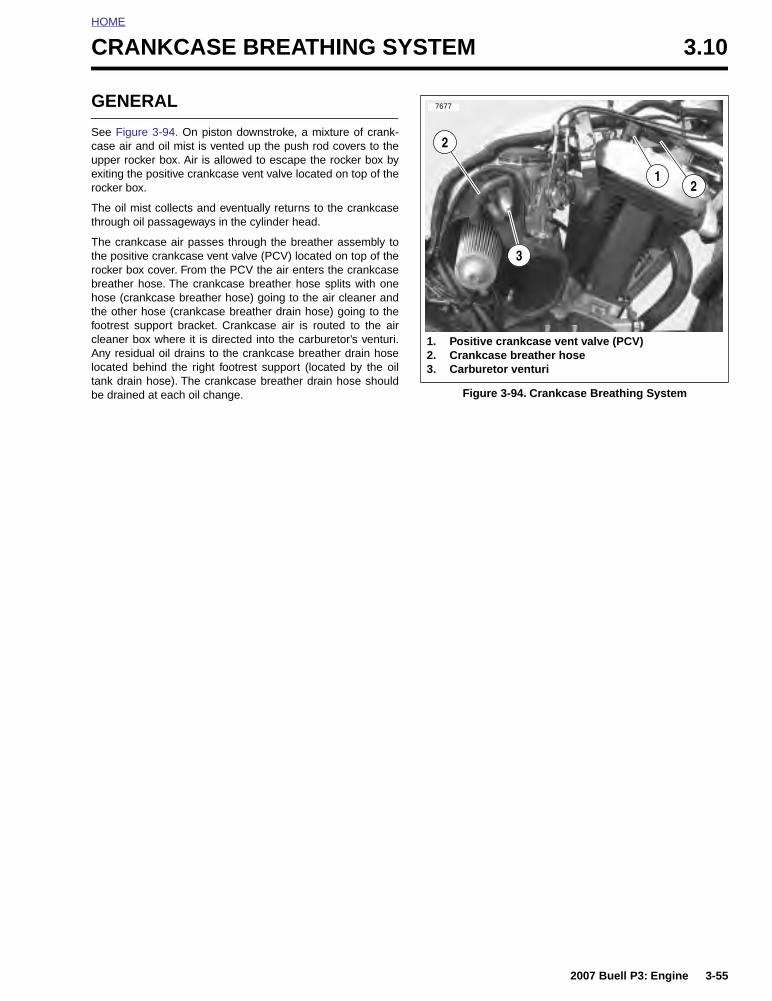
HOME
CRANKCASE BREATHING SYSTEM 3.10
GENERAL
See Figure 3-94. On piston downstroke, a mixture of crank-case air and oil mist is vented up the push rod covers to theupper rocker box. Air is allowed to escape the rocker box byexiting the positive crankcase vent valve located on top of therocker box.
The oil mist collects and eventually returns to the crankcasethrough oil passageways in the cylinder head.
The crankcase air passes through the breather assembly tothe positive crankcase vent valve (PCV) located on top of therocker box cover. From the PCV the air enters the crankcasebreather hose. The crankcase breather hose splits with onehose (crankcase breather hose) going to the air cleaner andthe other hose (crankcase breather drain hose) going to thefootrest support bracket. Crankcase air is routed to the aircleaner box where it is directed into the carburetor’s venturi.Any residual oil drains to the crankcase breather drain hoselocated behind the right footrest support (located by the oiltank drain hose). The crankcase breather drain hose shouldbe drained at each oil change. Figure 3-94. Crankcase Breathing System
1. Positive crankcase vent valve (PCV)2. Crankcase breather hose3. Carburetor venturi
7677
12
2
3
2007 Buell P3: Engine 3-55

HOME
OILING SYSTEM 3.11
GENERAL
1. Oil is gravity-fed from the oil reservoir to the gerotor-styleoil pump through a feed hose. Oil enters the feed sec-tion and fills a cavity located under the feed pump.
NOTEFor a complete explanation of the gerotor pump sets see 3.12OIL PUMP.
2. The feed pump transfers oil from the inlet cavity throughthe external steel line to the oil filter mount.
3. Oil flows through the filter mount cavity to the oil filter.
4. Oil enters the peripheral cavity of the oil filter, passesthrough the filtering medium into the central cavity of theoil filter, and flows into the filter adapter (fitting whichconnects filter to filter mount).
5. Adequate oil pressure in the filter mount cavity activatesthe oil pressure signal light switch and shuts off the oilpressure signal light.
6. Oil flowing from the filter adapter opens the check ball.The check ball opens at 4-6 psi (28-41 kPa) oil pressure.
7. With the check ball open, oil flows into the crankcasefeed galley.
8. Oil flows through the feed galley in the crankcase to thetappet blocks and hydraulic lifters. Cross-drilled pas-sages intersect the main feed galley and carry oil to bothhydraulic lifters.
9. Oil also enters an intersecting passage in the gearcasecover. Oil flow is then routed to the crankshaft area.
10. Oil enters a hole in the end of the pinion gear shaft andtravels to the right flywheel where it is routed through theflywheel to the crankpin. Oil is forced through the crank-pin to properly lubricate the rod bearing assembly.
11. Oil flows up passages in the push rods to the rocker armshafts and bushings.
12. The valve stems are lubricated by oil supplied throughdrilled oil holes in the rocker arms.
13. Oil collected in the push rod areas of the cylinder headsflows down the push rod cover, through drain holes inthe tappet blocks and into the gearcase. After providinglubrication to the gearcase components, the oil flows tothe left side of the oil pump.
14. Feed oil to the rocker area is returned to the crankcasethrough a passage in the head and cylinder.
15. Oil collected in the sump is splash-fed to the pistons, cyl-inder walls and flywheel components.
16. A single piston oil jet cools the bottom of the piston witha spray of oil.
17. Oil collected in the sump area returns to the scavengesection of the oil pump through a passage located in therear section of the sump. Oil flow to the pump is accom-plished by the scavenging effect of the pump and by thepressure created by the downward stroke of the pistons.
18. Return oil fills a cavity above the pump's return gears.The return gears pump oil back to the oil reservoir.
3-56 2007 Buell P3: Engine

HOME
OIL PUMP 3.12
GENERAL
See Figure 3-95. The oil pump consists of two gerotor gearsets, feed and return, housed in one pump body. The feed setdistributes oil to the engine, the scavenge set returns oil tothe tank/frame reservoir.
A gerotor-type gear set has two parts — an inner and anouter gerotor. The inner gerotor has one less tooth than theouter gerotor. Both gerotors have fixed centers which are off-set to each other.
In a gerotor gear set, oil is transferred from inlet to outlet as itis trapped between the rotating inner and outer gerotors.
See Figure 3-95. Gravity-fed oil from the oil reservoir entersthe pump through the feed hose connector. It is forced by thegerotor feed set through a hose to the oil filter. Return oil fromthe flywheel compartment is drawn back into the pump and isforced by the gerotor scavenge set back to the oil reservoir.
The oil pump seldom needs servicing. Before you disassem-ble an oil pump suspected of not producing adequate oil pres-sure, be sure that all possible related malfunctions have beeneliminated:
1. Make sure all oil hose clamps are tight and that hosesare not pinched or damaged.
2. Check level and condition of oil in tank. Pressure will beaffected if oil is diluted. In freezing weather, proper circu-lation of oil can be affected if the oil feed hose becomesclogged with ice or sludge.
3. Check for a grounded oil pressure switch wire or faultyswitch if oil indicator light fails to go out with engine run-ning.
Figure 3-95. Oil Pump
1. Mounting gasket2. Gear shaft3. Oil line assembly4. 90 fitting5. O-ring6. Thrust washer7. Retaining ring8. Gerotor return set9. Separator plate10. Gerotor feed set11. Cover12. 45 fitting13. Sems screw (2)14. Torx screw (2)15. Rear connector fitting
°
°
a0018x3x
1
3
6
7
8
9
10
12
13
14
15
11
2
4
5
2007 Buell P3: Engine 3-57

HOME
REMOVAL/DISASSEMBLY
NOTEOil pump can be removed with engine in frame and withoutremoving gearcase cover.
1. See ENGINE LUBRICATION SYSTEM section. Drain oilreservoir.
2. Remove and discard oil filter.
3. See Figure 3-96. Disconnect feed hose and oil filter hoseconnection.
NOTELoosen nut on oil filter hose connection and then removepressurized hose.
4. Carefully remove mounting screws and washers only.Pump will drop with screws removed. Discard mountinggasket.
5. Remove clamp and detach return hose connection.
6. See Figure 3-96. Remove cover TORX screws. Lift coveroff body.
7. Remove and discard o-ring.
8. See Figure 3-95. Slide both pieces of gerotor feed set,separator plate and both pieces of gerotor scavenge setoff gear shaft.
9. Remove and discard retaining ring. Remove thrustwasher and gear shaft.
CLEANING AND INSPECTION
11WARNING1WARNING
Compressed air can pierce the skin and flying debris fromcompressed air could cause serious eye injury. Wearsafety glasses when working with compressed air. Neveruse your hand to check for air leaks or to determine airflow rates. (00061a)
1. Clean all parts in cleaning solvent. Blow out holes and oilpassages with compressed air.
2. See Figure 3-97. Inspect both gerotor sets for wear.
a. Mesh pieces of each set together as shown.
b. Use a feeler gauge to determine clearance.
c. The SERVICE WEAR LIMIT between gerotors is0.004 in. (0.102 mm). Replace gerotors as a set ifclearance exceeds this dimension.
d. Measure thickness of feed gerotors with a microme-ter. Replace gerotors as a set if they are not thesame thickness.
3. See Figure 3-98. Check gear shaft teeth for damage orwear. Replace if necessary.
Figure 3-96. Oil Pump Hardware
8853a
1
1. Oil feed line connection2. Oil return line connection3. Cover TORX screw (2)4. Oil pump5. Mounting screw and washer (2)6. Steel oil feed line connection, oil pump to oil filter
6
2 4 53
Figure 3-97. Gerotor Wear Limits
a0090x3x
1. Inner gerotor2. Outer gerotor3. Wear limit
3
1
2
3-58 2007 Buell P3: Engine

HOME
ASSEMBLY/INSTALLATION
NOTELiberally coat all moving parts with clean engine oil to ensureeasy assembly and smooth operation at start-up.
1. Install gear shaft through body. Position thrust washerover end of shaft. Install new retaining ring into groove inshaft.
2. Insert inner gerotor of the gerotor scavenge set over gearshaft.
3. Place outer gerotor over inner gerotor to complete scav-enge set.
4. See Figure 3-98. Install gerotor separator plate (1).
5. Install a new o-ring (2) into groove in pump body.
6. Place gerotor feed set over gear shaft.
7. Place cover onto pump body. Install cover TORX screws.Tighten to 70-80 in-lbs (8-9 Nm).
8. Place new mounting gasket in position.
NOTEUse new hose clamps. If fittings were removed, useTEFLON® PIPE SEALANT or HYLOMAR® on fitting threads.
9. Attach return hose connection.
10. Secure pump to crankcase with mounting screws.Tighten to 125-150 in-lbs (14-17 Nm).
11. Attach feed hose and oil filter hose connection.
12. Attach clamp to hose.
13. Install new oil filter. See 1.5 ENGINE LUBRICATIONSYSTEM.
14. See 1.5 ENGINE LUBRICATION SYSTEM. Checkengine oil level. Add oil to correct level if needed.
Figure 3-98. Oil Pump Assembly
16620
1. Gerotor separator plate2. O-ring
2
2007 Buell P3: Engine 3-59

HOME
OIL FILTER MOUNT 3.13
GENERAL
See Figure 3-99. Oil is pressure-fed from the oil pump to thefilter mount via rigid external steel line. Oil travels through thefilter mount into the filter through the outer filter holes.
Adequate oil pressure activates the oil pressure indicatorswitch in the filter mount, which turns off the oil pressure indi-cator lamp.
The check ball in the filter adapter “opens” at 4-6 psi (28-41kPa) oil pressure. Filtered oil leaves the filter, flowing past thecheck ball.
DISASSEMBLY
1. Drain oil reservoir and remove filter. See 1.5 ENGINELUBRICATION SYSTEM.
2. See Figure 3-99. Remove filter adapter (6) from filtermount (3). Remove check ball (5) and spring (4).
3. Detach indicator lamp wire (2) from oil pressure indicatorswitch (1). Remove switch using OIL PRESSURE SEND-ING UNIT WRENCH (Part No. HD-41675).
CLEANING AND INSPECTION
11WARNING1WARNING
Compressed air can pierce the skin and flying debris fromcompressed air could cause serious eye injury. Wearsafety glasses when working with compressed air. Neveruse your hand to check for air leaks or to determine airflow rates. (00061a)
Thoroughly clean all parts in cleaning solvent. Blow out holesand passages using compressed air.
ASSEMBLY
NOTE
Use TEFLON PIPE SEALANT or HYLOMAR on all fittingsinstalled to oil filter mount.
1. See Figure 3-99. Install oil pressure indicator switchusing (1) OIL PRESSURE SENDING UNIT WRENCH(Part No. HD-41675). Tighten to 50-70 in-lbs (6-8 Nm).
2. Attach indicator lamp wire (2) to oil pressure indicatorswitch (1).
NOTE
The filter adapter has identical ends; either end may beinstalled into the filter mount.
3. Apply several drops of Loctite 243 (blue) to last fewthreads on that end of the filter adapter (6) which isinstalled into filter mount (3). Do not apply Loctite toadapter threads on filter element side.
4. Install filter mount components.
a. Place spring (4) and check ball (5) into threadedhole at center of mount.
b. Push threaded end of filter adapter (6) (with Loctite)against check ball to compress spring.
c. Screw adapter into threaded hole. Tighten to 96-144in-lbs (11-16 Nm).
5. Install a new filter and fill oil reservoir with proper oil. See1.5 ENGINE LUBRICATION SYSTEM.
Figure 3-99. Oil Filter Mount Assembly
1. Oil pressure indicator switch2. Indicator lamp wire3. Oil filter mount (part of right crankcase half)4. Spring5. Check ball6. Filter adapter7. Hose to oil pump8. Hose from oil pump
a0091x3x
2
1
6
7 8
4
3
5
3-60 2007 Buell P3: Engine

HOME
HYDRAULIC LIFTERS 3.14
GENERAL
See Figure 3-100. The lifter assembly consists of a hydrauliclifter and roller. The lifter and roller, under compression forcefrom valve spring, follow the surface of the revolving cam. Theup-and-down motion produced is transmitted to the valve bythe push rod and rocker arm. The lifter contains a piston (orplunger) and cylinder; it also contains a check valve, whichallows the unit to fill with engine oil, thereby reducing clear-ance in the valve train.
When a lifter is functioning properly, the assembly operateswith minimal lifter clearance. The unit automatically compen-sates for heat expansion to maintain a no-clearance condi-tion.
It is normal for lifters to click when engine is started afterstanding for some time. Hydraulic lifters have a definite leak-down rate which permits the oil in the lifters to escape. This isnecessary to allow units to compensate for various expansionconditions of parts and still maintain correct clearance opera-tion. Lifters are functioning properly if they become quiet aftera few minutes of engine operation.
REMOVAL
1. Clean all dirt from around crankcase. Blow loose parti-cles from area with compressed air.
2. Remove the lower rocker cover. Pull each push rodupward through top of cylinder head. See 3.5 CYLIN-DER HEAD.
3. Remove cylinder head assembly. See 3.5 CYLINDERHEAD.
4. See Figure 3-102. Remove push rod cover.
a. Remove screws.
b. Remove push rod cover.
c. Remove gasket and o-rings. Discard parts.
5. Remove both valve hydraulic lifters.
a. Remove anti-rotation screws.
b. Remove lifters from crankcase bore using a thin-bladed screwdriver. Mark the location and orienta-tion (front/back) of each lifter.
CLEANING AND INSPECTION
11WARNING1WARNING
Compressed air can pierce the skin and flying debris fromcompressed air could cause serious eye injury. Wearsafety glasses when working with compressed air. Neveruse your hand to check for air leaks or to determine airflow rates. (00061a)
1. Clean all parts, except roller/lifter assembly, thoroughly insolvent. Blow dry with compressed air.
NOTEInside and outside micrometers used for measuring tappetsand tappet guides must be calibrated to ensure accuratereadings.
2. Inspect valve lifters for excessive clearance in guide.Accurately measure lifter bore inner diameter with agauge.
a. Clearance should be within 0.0008-0.0020 in.(0.0203-0.0508 mm).
b. Fit a new lifter and/or replace crankcases if clear-ance exceeds SERVICE WEAR LIMIT of 0.0030 in.(0.076 mm).
3. Check lifter roller freeplay.
a. Roller clearance on pin should be within 0.0006-0.0010 in. (0.0152-0.0254 mm).
b. Replace lifters if clearance exceeds SERVICEWEAR LIMIT of 0.0015 in. (0.0381 mm).
4. Check lifter roller end clearance.
a. End clearance should be within 0.008-0.022 in.(0.203-0.559 mm).
b. Replace lifters if clearance exceeds SERVICEWEAR LIMIT of 0.026 in. (0.660 mm).
5. Soak lifters in clean engine oil. Keep covered untilassembly.
Figure 3-100. Lifter Assembly (Typical)
a0092x3x
1. Oil2. Piston3. Oil4. Check valve5. Roller
3
4
5
1
2
2007 Buell P3: Engine 3-61

HOME
INSTALLATION
1. See Figure 3-101. Rotate engine so that both lifters willbe installed on the base circle of the cam.
2. Apply a liberal amount of engine oil to each lifter assem-bly (especially the roller needles) for smooth initial opera-tion.
3. See Figure 3-102. Insert lifter into bore in crankcase.Rotate lifter so that flats at upper end of lifter face thefront and rear of the engine. If the lifter is installed incor-rectly, anti-rotation screws cannot be inserted.
4. Secure lifters in place.
a. Install anti-rotation screws with washers in the holesin lifter block.
b. Tighten anti-rotation screws to 55-65 in-lbs (6-7Nm).
5. Install push rod cover.
a. Slide new gasket cover over bottom of push rodcover.
b. Position push rod cover onto crankcase.
c. Install screws through holes in push rod cover intotapped holes in crankcase. Tighten screws evenly to30-40 in-lbs (3-5 Nm).
d. Place new o-rings on top of push rod cover.
6. Install push rods, cylinder head, lower and upper rockercovers. See 3.5 CYLINDER HEAD.
Figure 3-101. Base Circle
2W
�
1W
a0093x3x
1. Base circle (lowest position)2. Cam lobe (maximum lift)
1
2
Figure 3-102. Valve Lifter Service
a0029x3x
1
2
4
5
6
7
8
1. Push rod (exhaust)2. O-ring3. Push rod cover4. Screws (4)5. Push rod cover6. Push rod cover gasket7. Hydraulic lifter (tappet)8. Anti-rotation screw
3
3-62 2007 Buell P3: Engine

HOME
GEARCASE COVER AND CAM GEARS 3.15
GENERAL
Read the complete gearcase section carefully before youbegin any service work.
For the gearcase components to operate at their optimum, allcomponents must be properly fitted and matched. Changingone component can affect many others. It is important toknow and understand all inspection procedures and howcomponents interact.
Figure 3-103. Gearcase Cover & Cam Assembly
a0030x3x
1. Crankcase half2. Dowel pin3. Inner camshaft gear bushing4. “W” cam gear set5. Oil pump drive gear6. “W” cam pinion and drive gear set7. Nut8. Gear shaft pinion bushing9. Cam gear shaft outer bushing10. Key11. Gearcase cover gasket12. Gearcase cover 13. Seal14. Sems screw15. Oil vent hose fitting16. Clamp17. Vent hose18. Outer bushing
1
23
45
67
8
9
10
11121314
17
18
6
4
3
4
15
16
2007 Buell P3: Engine 3-63

HOME
REMOVAL/DISASSEMBLY
11WARNING1WARNING
Compressed air can pierce the skin and flying debrisfrom compressed air could cause serious eye injury.Wear safety glasses when working with compressed air.Never use your hand to check for air leaks or to deter-mine air flow rates. (00061a)
1. See Figure 3-103. Thoroughly clean area around gear-case cover and tappets. Blow loose dirt from crankcasewith compressed air.
2. Remove any parts that will interfere with gearcase disas-sembly.
3. See 3.5 CYLINDER HEAD. Remove push rods.
4. See 3.14 HYDRAULIC LIFTERS. Remove hydraulic lift-ers.
5. Check for minimum cam gear end play. Record readings.
6. See 7.8 IGNITION MODULE AND CAM POSITIONSENSOR. Remove cam position sensor and rotor fromgearcase cover.
7. Place a pan under gearcase to collect oil. Remove coverscrews. Carefully remove gearcase cover. Discard oldgasket.
NOTE
If cover does not come loose on removal of screws, tap lightlywith a plastic hammer. Never pry cover off.
8. Remove cam gears.
NOTE
Nut is secured by Loctite Threadlocker 271 (red) on the nutthreads.
9. Remove nut. Slide pinion gear and oil pump drive gearoff pinion shaft.
CLEANING AND INSPECTION
1. Thoroughly clean gearcase compartment, gearcasecover and gears in solvent to remove oil and carbondeposits.
11WARNING1WARNING
Compressed air can pierce the skin and flying debrisfrom compressed air could cause serious eye injury.Wear safety glasses when working with compressed air.Never use your hand to check for air leaks or to deter-mine air flow rates. (00061a)
2. Blow out all cover oil passages and bushings with com-pressed air.
3. Clean old gasket material from gearcase and cover faceswith cleaning solvent.
NOTEPrior to changing any cam gears, check gear shaft fit withincorresponding bushings. Worn bushings can cause excessivebacklash.
Bushing Inspection1. See Figure 3-103. Bushings are press fit in crankcase
and gearcase cover. Inspect each bushing against itscorresponding cam gear shaft or pinion gear shaft. SeeTable 3-29.
NOTE
If Service Wear Limits are exceeded, replace crankcase set and/or gearcase cover as required.
Figure 3-104. Cam and Pinion Gear Color Code Location and Timing Mark Indexing
Table 3-29. Gear Shaft Specifications
GEAR SHAFT
CORRECT CLEARANCE
SERVICE WEAR LIMIT
Cam 0.0007-0.0022 in.(0.0178-0.0559 mm)
0.003 in.(0.076 mm)
Pinion 0.0023-0.0043 in.(0.0584-0.1092 mm)
0.0050 in.(0.1270 mm)
1. Exhaust cam gear (1w)2. Intake cam gear (2w)3. Pinion gear
12
3
7687
3-64 2007 Buell P3: Engine

HOME
ASSEMBLY/INSTALLATION
1. See Figure 3-105. Install oil pump drive gear (6) and pin-ion gear (3) on pinion shaft (1).
a. Install shaft key (5) into pinion shaft slot.
b. Slide oil pump drive gear (6) over pinion shaft (1).Drive gear must align with shaft key.
c. Align keyway (4) in ID of pinion gear with shaft key.
d. Slide pinion gear (3) over shaft key (5) and againstoil pump drive gear (6).
2. See Figure 3-106. Install nut.
a. Clean threads on pinion shaft and nut.
b. Install CRANKSHAFT LOCKING TOOL (Part No.HD-43984) to gearcase with “Side B” facing out,over pinion shaft, with two screws.
c. Apply several drops of Loctite Threadlocker 271(red) to last few threads of nut.
d. Install nut to pinion shaft. Tighten nut to 19-21 ft-lbs(26-29 Nm) plus an additional 15˚ to 17˚ rotation.
3. See Figure 3-103. Liberally apply engine oil to bushings,shafts, and gears. Install all cam gears into bushings ofright crankcase half, properly aligning timing marks ofcam gears and pinion gear.
NOTEBecause of the larger diameter additional gear (whichmeshes with the pinion gear) on the outboard end of the cam,the exhaust cam gear must be installed before the intake camgear is installed.
4. See Figure 3-103. Install a new seal and new dry gearcover gasket on crankcase.
Figure 3-105. Aligning Pinion Gear
Figure 3-106. Crankshaft Locking Tool (HD-43984)
1. Pinion shaft2. Timing mark on pinion gear3. Pinion gear4. Keyway5. Shaft key6. Oil pump drive gear
1
2
4
5
6
a0078x3x
3
7686
2007 Buell P3: Engine 3-65

HOME
5. See Figure 3-107. Install gearcase cover over all gearsand onto right crankcase half. Secure cover to crankcasehalf with 7 socket head screws. Tighten screws evenly to80-110 in-lbs (9-12 Nm). Use torque sequence asshown.
6. See Figure 3-108. Check cam gear end play for eachcam gear as follows:
a. Turn engine over until lobe of cam gear beingchecked is pointing toward its respective tappetguide hole.
b. Gently pry the cam geaR toward the gearcase coverusing a flat blade screwdriver.
c. Measure gap between bushing (in crankcase half)and cam gear shaft thrust face (shoulder) using afeeler gauge. This is cam gear end play.
d. Compare cam gear end play measurements with theSERVICE WEAR LIMITS. Make repairs as requiredif end play does not meet specifications.
7. Install hydraulic lifters and push rods. See 3.14HYDRAULIC LIFTERS.
8. Install cam position sensor and rotor in gearcase cover.7.8 IGNITION MODULE AND CAM POSITION SEN-SOR.
9. Install any components removed to gain access to gear-case (i.e. exhaust system components, air cleaner, etc.).
Figure 3-107. Gearcase Cover Mounting ScrewTorque Sequence
Figure 3-108. Checking Cam Gear End Play
7696
71
42
6 3
5
7683
3-66 2007 Buell P3: Engine

HOME
CRANKCASE 3.16
GENERAL
IMPORTANT NOTEIf engine is removed from chassis, do not lay engine onprimary side. Placing engine on primary side will damageclutch cable end fitting. If fitting is damaged, clutch cablemust be replaced.
Remove engine from chassis to repair pinion shaft bearing orsprocket shaft bearing. See 3.3 STRIPPING MOTORCYCLEFOR ENGINE SERVICE.
It is recommended procedure to overhaul engine if removed.This includes inspecting and repairing cylinder head, cylinder,gearcase and transmission.
ADJUSTMENT/TESTING
Flywheel End PlayBefore completely disassembling crankcases, check flywheelend play.
1. After engine has been removed from chassis, securelyfasten it to a stand or workbench.
2. Remove gearcase cover. See 3.15 GEARCASE COVERAND CAM GEARS.
3. See Figure 3-109. Attach a dial indicator to gear sidecrankcase with indicator stem on end of gearshaft.
4. To obtain an accurate flywheel end play reading, preloadsprocket shaft bearings. Create a suitable tool by weldingtwo handles to an old engine sprocket nut. Install the nutand sprocket. Tighten to 190-210 ft-lbs (258-285 Nm).
5. Check flywheel end play.
a. Rotate and push on sprocket shaft while readingdial indicator.
b. Then rotate and pull on sprocket shaft while readingdial indicator.
c. Replace bearing inner shim if difference (end play)in indicator readings is not 0.001-0.005 in. (0.025-0.127 mm). Choose shim from Table 3-30.
NOTEUse a thinner shim for less end play; use a thicker shim formore end play.
Figure 3-109. Checking Flywheel End Play
Table 3-30. Flywheel End Play Shims
PARTNUMBER
THICKNESS
IN. MM
9155 0.0975-0.0985 2.4765-2.5019
9142 0.0995 - 0.1005 2.5273-2.5527
9143 0.1015-0.1025 2.5781-2.6035
9144 0.1035 - 0.1045 2.6289-2.6543
9145 0.1055 - 0.1065 2.6797-2.7051
9146 0.1075 - 0.1085 2.7305-2.7559
9147 0.1095 - 0.1105 2.7813-2.8067
9148 0.1115 - 0.1125 2.8321-2.8575
9149 0.1135 - 0.1145 2.8829-2.9083
a0135x3x
2007 Buell P3: Engine 3-67

HOME
DISASSEMBLY
Crankcase Halves1. Remove cylinder head. See 3.5 CYLINDER HEAD.
IMPORTANT NOTEAfter removing cylinder, install plastic or rubber hoseover cylinder studs. Lifting or moving crankcase bygrasping studs will cause cylinder stud damage.
2. Remove cylinder and piston. See 3.6 CYLINDER ANDPISTON.
3. Remove oil pump. See 3.12 OIL PUMP.
4. Remove gearcase components. See 3.15 GEARCASECOVER AND CAM GEARS.
5. Remove primary cover and primary drive/clutch compo-nents. See 6.2 PRIMARY CHAIN.
6. Remove starter motor. See 5.7 STARTER.
7. See Figure 3-110. Remove screws and rear enginemount bolts securing crankcase halves together.
8. Tap crankcase with plastic mallet to loosen and separatethe halves.
Figure 3-110. Crankcase Hardware
1. Screw (4)2. Washer (4)3. Rear isolator4. Dowel pin5. Hex socket head screw (9)6. Washer (14)
7. Bottom case t40 TORX bolt (5)8. Hex socket head screw (1)9. Spacer (1)10. Crankcase set11. Nyloc, hex locknut12. Washer (1)
a0484x6x
12
87
6
6
9
11
1
2
34 5
10
3-68 2007 Buell P3: Engine

HOME
11WARNING1WARNING
When using a press, be sure setup is stable and wearproper eye protection. Flying parts could result in deathor serious injury. (00467b)
9. See Figure 3-111. Mount the left crankcase half and fly-wheel assembly on a press table, supporting crankcaseon parallel bars. Press on end of sprocket shaft witharbor press until flywheel assembly is free from crank-case half. Do not drive flywheel assembly from crank-case half as flywheels may be knocked out of alignment.
NOTESee Figure 3-112. If it is necessary to remove either the pin-ion shaft bearing or sprocket shaft bearing, proceed as fol-lows:
10. Gearshaft bearing will remain on flywheel pinion shaft.Remove retaining ring, and bearing may be slipped offpinion shaft.
Figure 3-111. Pressing On End Of Sprocket Shaft To Remove Flywheel Assembly From Crankcase
7689
Figure 3-112. Crankcase and Flywheel Assembly
a0084x3x
12
3
4
56
78
9
10
1. Oil seal2. Bearing assembly3. Left crankcase half4. Connecting rod and flywheel assembly5. Inner race
6. Retaining ring7. Gear shaft bearing8. Retaining ring9. Outer bearing race10. Right crankshaft half
2007 Buell P3: Engine 3-69

HOME
11. See Figure 3-113. Place flywheel assembly in FLY-WHEEL SUPPORT FIXTURE (Part No. HD-44385). Pullsprocket shaft bearing with SPROCKET SHAFT INNERTIMKIN BEARING REMOVER (Part No. HD-44404) andBEARING RACE REMOVER/INSTALLER (Part No. HD-34902B).
12. See Figure 3-114. Use CRANKSHAFT BEARING TOOL(Part No. HD-94547-101) to remove sprocket shaft outerraces.
13. See Figure 3-115. To remove pinion shaft inner race, useWEDGE ATTACHMENT for CLAW PULLER (Part No.HD-95637-46A) with BEARING RACE REMOVER/INSTALLER (Part No. HD-34902B) and END CAP (PartNo. HD-34902-7). Apply heat to race to aid removal. Foursizes of pinion bearings are available. Pinion bearingselection at the factory, during engine rebuild, or replace-ment of crankcase set or flywheel assembly is based onthe largest measured outside diameter (OD) of the innerrace and the smallest measured inside diameter (ID) ofthe outer race (crankcase bushing). A running clearanceof 0.0002-0.0008 in. (0.0051-0.0203 mm) is establishedduring crankcase set or flywheel assembly replacementand engine rebuild.
14. See Figure 3-116. Installed inner races are identified atthe factory as shown.
15. See Table 3-32. Outer races are identified at the factoryas shown.
NOTEThe different sizes of crankcase sets and flywheel assemblieswill not have separate part numbers. That is, a replacementcrankcase set may have a class 1, 2 or 3 pinion outer race.Replacement flywheel assemblies will have either a class Aor B inner race.
16. See Figure 3-118. Pinion bearings are identified asshown.
Figure 3-113. Removing Sprocket Shaft Roller Bearing
Figure 3-114. Sprocket Outer Shaft Race Removal
7671
1. Bearing race remover/installer(Part no. HD-34902B)
2. End cap (Part No. HD-34902-7)3. Bearing remover (Part No. HD-44404)4. Flywheel fixture (Part No. HD-44385)
3
4
1
2
1. Universal driver (Part No. HD-33416)2. Crankshaft bearing tool (Part No. HD-94547-101)3. Left crankcase half
1
2
3
7709
Figure 3-115. Pulling Pinion Shaft Inner Race
1. Bearing race remover/installer(Part no. HD-34902B)
2. End cap (Part No. HD-34902-7)3. Wedge attachment for claw puller
(Part No. HD-95637-46A)
1
7671
3
2
3-70 2007 Buell P3: Engine

HOME
BEARING SELECTION
Select bearings using the identification information given forinner and outer races and bearings. See Table 3-36.
NOTEIf either inner or outer race show wear, measure both races toconfirm correct bearing fit.
Table 3-31. Paint Dot Specifications
Table 3-32. Stamp Specifications
Table 3-33. Roller Specifications
Figure 3-116. Factory Inner Race Paint Dot Location(See Table 3-32 for Identification)
RACE OD CLASS IDENTIFICATION*
1.2498-1.2500 in.(31.7449-31.7500 mm) A White
1.2496-1.2498 in.(31.7398-31.7449 mm) B Green
SERVICE WEAR LIMIT: 1.2492 in. (31.7297 mm)
a0131x3x
Inner Race
Paint Dot Location
Figure 3-117. Factory Outer Race Sizes(See Table 3-33 for Identification)
RACE IDCLASS
NO.STAMPED
IDENTIFICATION*
1.5646-1.5648 in.(39.7408-39.7459 mm)
1 1
1.5648-1.5650 in.(39.7459-39.7510 mm)
2 2
1.5650-1.5652 in.(39.7510-39.7561 mm)
3 3
SERVICE WEAR LIMIT: 1.5672 in. (39.8069 mm)
Figure 3-118. Bearing Identification
ROLLER OD (*A) IDENTIFICATION*
Largest
Smallest
RedBlue
White (Grey)Green
ID
a0134x3x
Outer Race
Right Crank-case Half
*Stamped Class No.
A - Roller OD cannot bemeasured to required accuracy with micrometer. Refer to color chart in Table 3-35.
a0133x3x
2007 Buell P3: Engine 3-71

HOME
1. Use a dial bore gauge to measure and record ID of outerrace. Take four measurements on ID where bearing roll-ers ride.
a. If the largest measurement is larger than 1.5672 in.(39.8069 mm) or the required lapping to removewear marks would enlarge bore beyond 1.5672 in.,continue at Step 5.
b. If largest measurement is 1.5672 in. (39.8069 mm)or less, cover the cam bearings with masking tape toprevent debris from entering bearings. Assemblecrankcase halves.
NOTEThe next step requires lapping the outer race. To keepsprocket shaft and pinion shaft bearings aligned the lap mustbe supported by an adaptor or pilot in the left crankcase half.
2. See LAPPING ENGINE MAIN BEARING RACES. Laprace until all wear marks are removed.
3. Measure and record ID of race at four places.
4. Check measurements against these specifications inTable 3-34. Outer Pinion Race Service Wear Limits.
a. If lapping increased bore ID to larger than 1.5672 in.(39.8069 mm), go to Step 5.
b. If roundness or taper do not meet specifications,continue lapping until specifications are met.
c. If all specifications are met, continue at Step 7 toremove and size inner race.
5. Press the outer race from the right crankcase. Pressnew outer race into crankcase flush with inside edge ofcast-in insert.
See Figure 3-119. Dimensions are shown for fabricationof tools used in pressing the outer race into or out ofcrankcase.
6. See LAPPING ENGINE MAIN BEARING RACES. Thenew outer race must be lapped slightly to true and alignwith left case bearing and to meet the following specifica-tions.
Table 3-34. Outer Pinion Race Service Wear Limits
in. mm
Largest ID measured 1.5672 39.8
Roundness of ID within 0.0002 0.0051
Taper within 0.0002 0.0051
Figure 3-119. Pinion Shaft Bearing Tools
Pinion outer race installation
Pinion outer race removal
Pinion inner race installation
.187" (4.75 mm)
2.00"(50.8 mm)
1.00(25.4 mm)
1.560"(39.62 mm)
1.560"(39.62 mm)
.187" (4.75 mm)
5/16"(7.94 mm)
DRILL
5/16"(7.94 mm)
DRILL
1.00"(25.4 mm)
1.50" (38.1 mm)
1.272" (32.31 mm)1.262" (32.05 mm)
1.145" (29.08 mm)1.135" (28.83 mm)
5.50" (139.7 mm)
a0109x3x
1.00(25.4 mm)
3-72 2007 Buell P3: Engine

HOME
7. See Figure 3-120. Pull inner race from pinion shaft usingWEDGE ATTACHMENT for CLAW PULLER (Part No.HD-95637-46A) with BEARING RACE REMOVER/INSTALLER (Part No. HD-34902B) and END CAP (PartNo. HD-34902-7). Apply heat to race to aid removal.
8. Press new inner race on pinion shaft as shown. The newinner race must be ground by a competent machinist toOD dimension range for the finished lapped ID of theouter race. Refer to Table 3-35. The finished inner racemust meet these specifications. For necessary dimen-sions for constructing a press-on tool see Figure 3-119.When the tool bottoms against the flywheel, correct innerrace location is automatically established.
NOTEAlways use the smallest outer race ID measurement and thelargest OD inner race measurement when selecting bearings.
9. The following example illustrates how to determine therequired inner race OD.
a. See Table 3-36. For example purposes, suppose thesmallest outer race ID measurement is 1.5651 in.(39.754 mm). This requires an inner race OD rangeof 1.2496-1.2504 in. (31.740 - 31.760 mm).
b. Grind inner race. Measure OD at four places. Checkthat specifications in Step 8 are met.
c. For example purposes, suppose the largest innerrace OD measurement after grinding is 1.2499 in.(31.747 mm) OD.
d. With a 1.5651 in. (39.754 mm) ID outer race and a1.2499 in. (31.747 mm) OD inner race, a blue bear-ing is required.
NOTES● Have machinist grind inner race to center or middle of
required OD range in Table 3-36. This will prevent grind-ing outer race undersize and gives a more easilyachieved tolerance range.
● If you are unable to perform this operation, Harley-David-son Motor Company provides a flywheel refurbishingprogram as outlined in Tech Tip #38.
● Always use the smallest outer race ID measurement andthe largest OD inner race measurement when selectingbearings.
Figure 3-120. Inner Race Location
1. Pinion shaft inner race2. Flywheel (gear side)
a0283x3x
1
2
Table 3-35. Pinion Inner Race Fitment Specifications
Roundness within 0.0002 in. (0.0051 mm)
Taper within 0.0002 in. (0.0051 mm)
Surface finish 16 RMS
2007 Buell P3: Engine 3-73

HOME
Table 3-36. Pinion Shaft Bearing Selection
FAC-TORY
STAMPED
NUM-BER
OUTER RACE ID BEARING SIZE AS IDENTIFIED BY COLOR CODING
over 1.5672 in.39.807 mm
Service Wear Limit Exceeded – Replace Outer Race and Resize
1.5670-1.5672 in.39.802-39.807 mm
Red
1.5668-1.5670 in.39.797-39.802 mm
Red Blue
1.5666-1.5668 in.39.792-39.797 mm
Red Blue White-Gray
1.5664-1.5666 in.39.787-39.792 mm
Red Blue White-Gray
Green
1.5662-1.5664 in.39.781-39-787 mm
Red Blue White-Gray
Green
1.5660-1.5662 in.39.776-39.781 mm
Red Blue White-Gray
Green
1.5658-1.5660 in.39.771-39.776 mm
Red Blue White-Gray
Green
1.5656-1.5658 in.39.766-39.771 mm
Red Blue White-Gray
Green
1.5654-1.5656 in.39.761-39.766 mm
Red Blue White-Gray
Green
1.5652-1.5654 in.39.756-39.761 mm
Red Blue White-Gray
Green
3 1.5650-1.5652 in.39.751-39.756 mm
Red Blue White-Gray
Green
2 1.5648-1.5650 in.39.746-39.751 mm
Blue White-Gray
Green
1 1.5646-1.5648 in.39.741-39.746 mm
White-Gray
Green
INNERRACE OD (In)
1.2496-1.2498 in.
1.2498-1.2500 in.
1.2500-1.2502 in.
1.2500-1.2504 in.
1.2504-1.2506 in.
1.2506-1.2508 in.
1.2508-1.2510 in.
1.2510-1.2512 in.
1.2512-1.2514 in.
1.2514-1.2516 in.
1.2516-1.2518 in.
31.740-31.745 mm
31.745-31.750 mm
31.750-31.755 mm
31.755-31.760 mm
31.760-31.765 mm
31.765-31.770 mm
31.770-31.755 mm
31.775-31.780 mm
31.780-31.786 mm
31.786-31.791 mm
3.791-31.796 mm
FACTORY COLOR CODE Green White
3-74 2007 Buell P3: Engine

HOME
Lapping Engine Main Bearing Races
1. Secure right and left crankcase halves with three crank-case stud bolts (top center and bottom left and right).The sprocket shaft bearing outer races and large spacermust be installed in left crankcase.
2. See Figure 3-121. Obtain CRANKCASE MAIN BEAR-ING LAPPING TOOL (Part No. HD-96710-40B). Assem-ble CRANKCASE MAIN BEARING LAP (Part No. HD-96718-87) to lapping handle. Assemble guide sleeve tosprocket shaft bearing bushing. Sleeves, for use withtapered bearing, are assembled to case with bearingsand small spacer collar. Finger-tighten the sleeve parts.
3. Insert lap shaft with arbor assembled through pinionbearing bushing and into guide sleeve. Tighten arborexpansion collars using a length of 0.156 in. (3.962 mm)rod as spanner until arbor begins to drag. Do not adjustarbor snug in bushing or bushing will “bell,” a conditionwhere hole is larger at ends than it is in the center.
4. Withdraw arbor far enough to coat lightly with 220 gritlapping compound. Do not apply a heavy coat. Reposi-tion lap in bushing and turn handle at moderate handspeed. Work lap back and forth in bushing, as it isrevolved, to avoid grooving and tapering.
At frequent intervals, remove lap from crankcase, wash andinspect bushing. Lapping is completed when entire bushingsurface has a dull, satin finish rather than a glossy, smoothappearance. If necessary, flush off lap in cleaning solvent, airdry and apply fresh, light coat of fine lapping compound.
Checking Connecting Rod Side Play
1. See Figure 3-122. Check connecting rod side play with athickness gauge as shown.
2. If side play measurement is greater than service wearlimit of 0.030 in. (0.762 mm), replace flywheel/connectingrod assembly.
Figure 3-121. Lapping Pinion Shaft Main Bearing UsingCrankcase Main Bearing Lapping Tool
(Part No. HD-96710-40B)
7718
Figure 3-122. Checking Connecting Rod Side Play
a0094x3x
2007 Buell P3: Engine 3-75

HOME
PISTON JET
Removal
1. See Figure 3-123. Remove two TORX screws from pis-ton jet assembly to remove piston jet from right crank-case.
2. Remove piston jet gasket from right crankcase.
Installation
IMPORTANT NOTEIf a gasket is missing, distorted, pinched or otherwisedamaged will result in either oil leakage or low oil pres-sure.
NOTE
Gasket is part of the piston jet assembly. Gasket not sold sep-arately.
1. Install new piston oil jet assembly in right crankcase.
2. Apply Loctite 222 (purple) to threads of TORX screws.
3. With the jet pointed upward, install TORX screws tosecure piston jet to crankcase. Tighten screws to 25-35in-lbs (2.8-4.0 Nm).
Figure 3-123. Piston Oil Jet Assembly
a0486x3x
3-76 2007 Buell P3: Engine

HOME
ASSEMBLY
Crankcase HalvesLubricate all parts with Harley-Davidson 20W50 engine oil,and proceed as follows:
1. See Figure 3-124. Install new snap ring to crankcasebore (if bearings were replaced).
a. Place the crankcase half on a flat surface with theoutboard side facing up.
b. Obtain the TIMKEN SNAP RING REMOVER/INSTALLER (HD-44069).
c. With the gap in the snap ring being the 12 o’clockposition, place the two claws so that the slottedsides engage the inside edge of the snap ring at the10 and 2 o’clock positions.
d. Using a 9/64 inch allen head bit, tighten the screwsto fix the position of the claws on the snap ring.
e. Inserting the tips of a large retaining ring pliers(Snap-On PR-56A) into one hole in each claw, com-press the snap ring and install in groove of crank-case bore.
f. Verify that the gap in the snap ring is centered belowthe oil hole at the top of the ring groove. Move snapring if not properly centered.
g. Loosen allen head screws and remove claws fromsnap ring.
Figure 3-124. Snap Ring Installation Using Retaining Ring Remover/Installer (Part No. HD-44069)
3
6151
2
1
1. Retaining ring2. Oil supply hole3. Oil supply channel
a0095x3x
a0096x3x
2007 Buell P3: Engine 3-77

HOME
NOTESee Figure 3-125. Use SPROCKET SHAFT BEARINGOUTER RACE INSTALLATION TOOL (Part No. HD-39458)to install left and right outer races of sprocket shaft taperedroller bearings into left crankcase half. Always install left outerrace prior to installing right outer race because the installerbase is usable only when you follow this sequence of raceinstallation.
2. Insert “SPORTSTER” end of installer base into inboardside of left crankcase half bearing bore until base con-tacts installed retaining ring.
3. Position left outer race over bearing bore on outboardside of left crankcase half.
4. Insert shaft of installer plug through left outer race andinto installer base. Press race into bore until firmlyseated against retaining ring.
5. See Figure 3-126. Insert “SPORTSTER” end of installerbase into outboard side of left crankcase half bearingbore until base contacts outboard surface of installed leftouter race.
6. Position right outer race over bearing bore on inboardside of left crankcase half.
7. See Figure 3-126. Insert shaft of installer plug throughright outer race and into installer base. Press race intobore until firmly seated against retaining ring.
Figure 3-125. Left Outer Bearing Race Installation
7710
Figure 3-126. Right Outer Bearing Race Installation
7711
3-78 2007 Buell P3: Engine

HOME
NOTESee Figure 3-127. Use SPROCKET SHAFT BEARING/SEALINSTALLATION TOOL (Part No. HD-42579) to installsprocket shaft tapered roller bearings and seal.
8. See Figure 3-127. Install inner bearing.
a. Place new bearing, small end upward, over end ofsprocket shaft.
b. Thread pilot onto sprocket shaft until pilot bottomson sprocket shaft shoulder.
c. Sparingly apply graphite lubricant to threads of pilotshaft to ensure smooth operation.
d. Slide sleeve over pilot until sleeve contacts innerbearing race. Install Nice bearing, washer and han-dle on top of sleeve.
e. Rotate handle clockwise until bearing contacts fly-wheel shoulder. Remove tool from sprocket shaft.
9. See Figure 3-128. Install shim and outer bearing.
a. Carefully place crankcase half over sprocket shaftso that it rests flat on inner bearing.
b. Slide new inner spacer over sprocket shaft until itcontacts inner bearing race.
c. Place new outer bearing, small end downward, oversprocket shaft.
d. Assemble Sprocket Shaft Bearing/Seal InstallationTool (Part No. HD-42579) onto sprocket shaft. Fol-low procedure in Step 8.
e. Rotate handle clockwise until bearing firmly contactsinner spacer. Inner and outer bearings must be tightagainst inner spacer for correct bearing clearance.Remove tool from sprocket shaft.
f. Spin crankcase half to verify that flywheel assemblyis free.
Figure 3-127. Inner Bearing Installation
17663
6
4
1. Pilot2. Handle3. Washer4. Nice bearing5. Sleeve6. Inner bearing
5
2
3
Figure 3-128. Installing Flywheel Spacerand Outer Bearing
7666
2007 Buell P3: Engine 3-79

HOME
10. See Figure 3-129. Install new spacer in seal ID. With theopen (lipped) side facing outward, center seal/spacerassembly over bearing bore.
IMPORTANT NOTEDo not remove the spacer after installation or the newseal will have to be discarded and the procedurerepeated.
11. Install bearing seal and spacer.
a. Center seal/spacer driver over seal, so that thesleeve (smaller OD) seats between seal wall andgarter spring.
b. Assemble SPROCKET SHAFT BEARINGINSTALLER (1) (Part No. HD-42579) andSPROCKET SHAFT SEAL INSTALLER (Part No.HD-45206) onto sprocket shaft. Follow procedure inStep 8.
c. Rotate handle clockwise until the spacer makescontact with the bearing. Remove tool from sprocketshaft.
12. See Figure 3-130. Install pinion shaft bearing.
a. Lubricate pinion shaft bearing with engine oil.
b. Slip bearing on pinion shaft.
c. Install new retaining ring in groove of pinion shaftbearing inner race.
13. Install transmission. See 6.12 TRANSMISSION INSTAL-LATION.
14. Assemble crankcase halves together.
a. Apply a thin coat of DOW CORNING SILASTIC or 3-M 800 sealant to crankcase joint faces.
b. Slide pinion shaft through outer race in right crank-case.
c. Attach crankcase halves using hardware shown inFigure 3-110.
d. Tighten the 5/16-18 X 3-1/2 in. fasteners to 15-19 ft-lbs (20-26 Nm).
e. Tighten the 5/16-18 X 2-1/2 in fasteners to 15-19 ft-lbs (20-26 Nm).
f. Tighten 3/8-in. fastener to 22-27 ft-lbs (30-37 Nm).
Figure 3-129. Installing Sprocket Shaft Oil Seal/Spacer
7661
1. Sprocket shaft bearing installer (Part No. HD-42579)
2. Sprocket shaft seal installer (Part No. HD-45206)
2
1
Figure 3-130. Pinion Shaft Bearing
a0120x3x
3-80 2007 Buell P3: Engine

HOME
15. See Figure 3-131. Install cylinder studs.
a. Pack clean towels into crankcase opening.
b. Place a steel ball into a head screw.
c. The cylinder studs have a shoulder at the lower end.Place the end of the stud without the shoulder intothe head screw.
d. Install the stud in the crankcase with the shoulderend down. Use an air gun to drive the stud until theshoulder reaches the crankcase.
e. Remove air gun. Use a torque wrench to tightenstud to 10-20 ft-lbs (14-27 Nm).
16. Install piston and cylinder. See 3.6 CYLINDER AND PIS-TON.
17. Install oil pump. See 3.12 OIL PUMP.
18. See 3.15 GEARCASE COVER AND CAM GEARS.Install cam gears, gearcase cover, lifter guides and lift-ers.
19. Install cylinder head. See 3.5 CYLINDER HEAD.
20. Install starter. See 5.7 STARTER.
21. Install shift linkage.
22. Install all primary drive components. This includesengine sprocket, primary chain, complete clutch assem-bly, engine sprocket nut and mainshaft nut. See 6.4 PRI-MARY DRIVE/CLUTCH.
23. Install primary cover. See 6.2 PRIMARY CHAIN.
NOTEBe sure to refill transmission to proper level with fresh lubri-cant. See 1.10 TRANSMISSION/PRIMARY FLUID.
24. See 3.4 ENGINE INSTALLATION and perform the appli-cable steps.
Figure 3-131. Cylinder Studs
2
7662
3
1. Air gun2. Head screw with ball inside3. Cylinder stud4. Shoulder on cylinder stud
4
1
2007 Buell P3: Engine 3-81

HOME
NOTES
3-82 2007 Buell P3: Engine

FUEL SYSTEM 4
Table Of Contents
SUBJECT PAGE NO.
4.1 Specifications . . . . . . . . . . . . . . . . . . . . . . . . . . . . . . . . . . . . . . . . . . . . . . . . . 4-14.2 Fuel Tank Cover/Fuel Tank . . . . . . . . . . . . . . . . . . . . . . . . . . . . . . . . . . . . . . . 4-54.3 Air Cleaner . . . . . . . . . . . . . . . . . . . . . . . . . . . . . . . . . . . . . . . . . . . . . . . . . . . . 4-134.4 Carburetor . . . . . . . . . . . . . . . . . . . . . . . . . . . . . . . . . . . . . . . . . . . . . . . . . . . . 4-144.5 Auto-Enrichener . . . . . . . . . . . . . . . . . . . . . . . . . . . . . . . . . . . . . . . . . . . . . . . . 4-214.6 Throttle Position Sensor . . . . . . . . . . . . . . . . . . . . . . . . . . . . . . . . . . . . . . . . . 4-234.7 Evaporative Emissions Control System . . . . . . . . . . . . . . . . . . . . . . . . . . . . . . 4-24


HOME
SPECIFICATIONS 4.1
TORQUE TABLE
Table 4-1. Fuel Tank Capacity
U.S. METRIC
Total (including reserve) 2.8 gallons 10.6 liters
Reserve 0.55 gallons 2.08 liters
Table 4-2. Carburetor Jet Sizes
Main jet 166
Slow jet 42
Table 4-3. Carburetor Adjustments
Engine idle speed (regular) 1200 RPM
Engine idle speed (fast) 2000 RPM
ITEM TORQUE NOTES
Auto-enrichener 13-23 in-lbs 2-3 Nm Page 4-22
Battery cables to terminals 72-96 in-lbs 8-11 Nm Page 4-6, 4-15
Enrichener stay plate 13-23 in-lbs 2-3 Nm Page 4-15
Fuel cap flange to fuel tank 20-22 in-lbs 2-3 Nm Page 4-12
Fuel tank to T-shaped bracket 72-96 in-lbs 8-11 Nm Page 4-6
Fuel valve to fuel tank 19-21 in-lbs 2-2.3 Nm Page 4-9
Tank cover to T-shaped bracket 30-36 in-lbs 3-4 Nm Page 4-6
Vent tube fitting 40-60 in-lbs 5-7 Nm Page 4-12
2007 Buell P3: Fuel System 4-1

HOME
Table 4-4. Fuel System Troubleshooting
OVERFLOW TROUBLESHOOTING
Check for:
1. Restricted fuel tank vent system.
2. Loose float bowl screws.
3. Damaged float bowl o-ring.
4. Damaged or leaking float assembly.
5. Particle contamination in fuel inlet fitting cavity.
6. Worn or dirty inlet valve or seat.
7. Improper fuel level in float bowl.
Remedy:
1. Correct restricted hose. Replace vapor vent valve.
2. Tighten screws.
3. Replace o-ring.
4. Replace float assembly.
5. Clean and clear cavity and fuel supply tract.
6. Clean or replace valve and clean seat.
7. Adjust float tab for correct fuel level.
POOR IDLING
Check for:
1. Idle speed improperly adjusted.
2. Inlet system air leak (faster idling).
3. Loose low speed jet.
4. Contaminated or plugged low speed system.
5. Enrichener valve not seated or leaking.
Remedy:
1. Adjust operating idle speed.
2. Correct as required.
3. Tighten jet.
4. Clean, clear and correct as required.
5. Adjust, clean or replace.
POOR FUEL ECONOMY
Check for:
1. Enrichener valve not seated or leaking.
2. Dirty air cleaner filter element.
3. Restricted fuel tank vent system.
4. High speed riding style.
5. Idle speed improperly adjusted.
6. Loose jets.
7. Fuel level too high.
8. Plugged or restricted bowl vent.
9. Worn or damaged needle or needle jet.
10. Vacuum piston assembly malfunction.
11. Plugged air jets or passages.
Remedy:
1. Clean or replace.
2. Replace as required.
3. Correct restricted hose. Replace vapor vent valve.
4. Modify riding habits.
5. Adjust operating idle speed.
6. Tighten jets.
7. Adjust float tab for correct fuel level.
8. Clean and clear passages.
9. Replace needle or needle jet.
10. See Table 4-5.
11. Clean, clear and correct as required.
POOR ACCELERATION
Check for:
1. Throttle cables misaligned.
2. Inlet system air leak.
3. Restricted fuel tank vent system.
4. Restricted fuel supply passages.
5. Plugged bowl vent or overflow.
6. Enrichener valve not seated or leaking.
7. Worn or damaged needle or needle jet.
8. Vacuum piston malfunction.
9. Plugged jets or passages.
10. Fuel level too low.
Remedy:
1. Adjust throttle cables.
2. Correct as required.
3. Correct restricted hose. Replace vapor vent valve.
4. Correct and clear restriction.
5. Clean and clear passages.
6. Adjust, clean or replace.
7. Replace assembly.
8. See Table 4-5.
9. Clean and clear as required.
10. Adjust float tab for correct fuel level.
4-2 2007 Buell P3: Fuel System

HOME
HARD STARTING
Check for:
1. Enrichener system plugged, not properly functioning orimproperly operated.
2. Inlet system air leak.
3. Restricted fuel supply.
4. Fuel overflow.
5. Plugged slow jet or passages.
Remedy:
1. Clean, adjust or replace.
2. Correct as required.
3. Correct fuel supply or passages.
4. See OVERFLOW TROUBLESHOOTING above.
5. Clean, clear and correct as required.
POOR PERFORMANCE ON ROAD
Check for:
1. Idle speed improperly adjusted.
2. Inlet system air leak.
3. Restricted fuel tank vent system.
4. Dirty or damaged air cleaner element.
5. Enrichener valve not seated or leaking.
6. Restricted fuel supply tract.
7. Plugged bowl vent or overflow.
8. Loose or plugged fuel and air jets or passages.
9. Worn or damaged needle or needle jet.
10. Vacuum piston assembly malfunction.
Remedy:
1. Adjust operating idle speed.
2. Correct as required.
3. Correct restricted hose. Replace vapor vent valve.
4. Replace.
5. Adjust, clean or replace.
6. Correct and clear restriction.
7. Clean and clear passages.
8. Clean, clear and correct as required.
9. Replace assembly.
10. Refer to Table 4-5.
POOR HIGH-SPEED PERFORMANCE
Check for:
1. Inlet system air leak.
2. Enrichener valve not seated or leaking.
3. Restricted fuel tank vent system.
4. Restricted fuel supply tract.
5. Dirty or damaged air cleaner element.
6. Plugged bowl, vent or overflow.
7. Worn or damaged needle or needle jet.
8. Vacuum piston assembly malfunction.
9. Loose or plugged main jets or passages.
10. Improper fuel level.
Remedy:
1. Clean or replace.
2. Adjust, clean or replace.
3. Correct restricted hose. Replace vapor vent valve.
4. Correct and clean restriction.
5. Replace.
6. Clean and clear passages.
7. Replace assembly.
8. Refer to Table 4-5.
9. Clean, clear and correct as required.
10. Adjust float level.
Table 4-4. Fuel System Troubleshooting
2007 Buell P3: Fuel System 4-3

HOME
Table 4-5. Vacuum Piston Assembly Troubleshooting
PISTON DOES NOT RISE PROPERLY
Check for:
1. Piston atmosphere vent blocked.
2. Diaphragm cap loose, damaged or leaking.
3. Spring binding.
4. Diaphragm pinched at lip groove.
5. Torn diaphragm.
6. Piston binding.
7. Piston vacuum passage plugged.
Remedy:
1. Clear vent.
2. Tighten or replace cap.
3. Correct or replace spring.
4. Reposition diaphragm lip.
5. Replace piston diaphragm assembly.
6. Clean piston slides and body or replace piston.
7. Clean and clear passage.
PISTON DOES NOT CLOSE PROPERLY
Check for:
1. Spring damaged.
2. Piston binding.
3. Piston diaphragm ring dirty or damaged.
Remedy:
1. Replace spring.
2. Clean piston slides and body or replace piston.
3. Clean or replace piston.
4-4 2007 Buell P3: Fuel System

HOME
FUEL TANK COVER/FUEL TANK 4.2
REMOVAL
Fuel Tank Cover
11WARNING1WARNING
Stop the engine when refueling or servicing the fuel sys-tem. Do not smoke or allow open flame or sparks neargasoline. Gasoline is extremely flammable and highlyexplosive, which could result in death or serious injury.(00002a)
1. See Figure 4-1. Remove seat.
11WARNING1WARNING
To prevent accidental vehicle start-up, which couldcause death or serious injury, disconnect negative (-)battery cable before proceeding. (00048a)
2. Unthread bolt and remove battery negative cable (black)from battery negative (-) terminal.
3. See Figure 4-2. At rear of fuel tank, remove flange bolt(2), with nylon washer, to release tank cover from clip nuton T-shaped mounting bracket (3).
4. Carefully cut small cable strap and pull vent tube from fit-ting at front of fuel cap flange.
5. Remove oil dipstick from threaded hole in frame back-bone (just rear of steering head). Remove mounting ringfrom around threaded hole.
6. See Figure 4-2. Remove tank cover (1) and set aside.
7. Install oil dipstick back into threaded hole in frame back-bone.
Fuel Tank1. See Figure 4-5. Rotate the 3-position valve handle on the
fuel valve to the fully vertical position to shut the gasolinesupply to the carburetor OFF.
11WARNING1WARNING
With fuel tank drained, gasoline can spill from bore whensupply valve is loosened or removed. Gasoline isextremely flammable and highly explosive, which couldresult in death or serious injury. Wipe up spilled fuelimmediately and dispose of rags in a suitable manner.(00277a)
2. Turn slotted screw to loosen band clamp on outlet fittingat side of fuel valve. Pull hose from fitting.
3. See Figure 4-2. At rear of fuel tank, remove remainingtwo flange bolts (4) to release T-shaped mountingbracket from frame backbone.
4. Remove left side air box cover. See 4.3 AIR CLEANER.
5. See Figure 4-3. Moving to front of vehicle, pry rubber stopsfrom weld studs on each side of frame backbone.
6. Raise rear of fuel tank and slide assembly rearward toremove from frame.
Figure 4-1. Remove Seat
Figure 4-2. Remove Tank Cover Fuel Tank
1. Seat pin2. Latch
1
2
7724
1. Tank cover2. Flange bolt3. T-Shaped mounting bracket4. T-Shaped mounting bracket mounting bolts (2)5. Fuel tank
7725
7726
1
2
3
4
5
2007 Buell P3: Fuel System 4-5

HOME
INSTALLATION
Fuel Tank1. Place fuel tank into position on frame backbone.
2. See Figure 4-3. Standing at front of vehicle, push rubberstops (2) onto weld studs (4) on each side of frame back-bone. Using a rubber mallet, tap stops until fully seated.
3. See Figure 4-2. With the lipped side up, slide two flangebolts through forward holes in T-shaped mountingbracket. Pushing down on rear of tank, start flange boltsinto bosses in frame backbone. Alternately tighten flangebolts to 72-96 in-lbs (8-11 Nm).
4. Install air box cover on left hand side. See 4.3 AIRCLEANER.
5. Push hose onto outlet fitting at side of fuel valve. Turnslotted screw to tighten band clamp.
Fuel Tank Cover1. Remove oil dipstick from threaded hole in frame back-
bone (just rear of steering head).
2. Install tank cover.
3. See Figure 4-2. At rear of fuel tank, install rear flangebolt (with nylon washer) to fasten tank cover to clip nut onT-shaped mounting bracket. Tighten flange bolt to 30-36in-lbs (3-4 Nm).
4. With the lipped side up, place mounting ring overthreaded hole in frame backbone. Install oil dipstick intohole.
5. Push vent tube onto nozzle of vent tube fitting. Installsmall cable strap to fix location. Cut any excess cablestrap material.
6. Insert bolt through battery negative cable (black) intothreaded hole of battery negative (-) terminal. Tightenbolt to 72-96 in-lbs (8-11 Nm).
11WARNING1WARNING
After installing seat, pull upward on front of seat to besure it is in locked position. While riding, a loose seat canshift causing loss of control, which could result in deathor serious injury. (00070a)
7. See Figure 4-1. Install seat.
Figure 4-3. Remove Fuel Tank
1. Fuel tank2. Rubber stop (2)3. Frame backbone4. Weld stud (2)
32
1
4
7729
7728
4-6 2007 Buell P3: Fuel System

HOME
FUEL CAP
Removal 1. Locate the fuel filler cap at the top of the fuel tank.
2. Insert finger into depression and lift the locking tab sothat it is perpendicular to the fuel filler cap.
3. Rotate the locking tab 1/4 turn in a counter-clockwisedirection until it clicks.
4. Pull locking tab to remove fuel filler cap from tank.
5. See Figure 4-4. Observe the warning label at the top ofthe fuel tank. When refueling, keep fuel level at least oneinch below bottom of fuel cap boot (1).
11WARNING1WARNING
Observe the warning label at the top of the tank. Avoidspills. Slowly remove filler cap. Do not fill above bottomof filler neck insert, leaving air space for fuel expansion.Secure filler cap after refueling. Gasoline is extremelyflammable and highly explosive, which could result indeath or serious injury. (00028a)
Installation1. See Figure 4-4. Inspect o-ring (2) at underside of fuel
filler cap for cuts, tears or signs of deterioration. Replaceif necessary.
2. Place fuel filler cap into tank with the depression at thefront.
3. Rotate the locking tab 1/4 turn in a clockwise direction.
4. Push locking tab down, so that it is flush with the fuelfiller cap.
NOTESee Figure 4-4. Locking tab should snap down tightly, but notso tight that it becomes too difficult to remove. To increase ordecrease the tension required to operate the locking tab, turnthe fuel filler cap over and either loosen or tighten the 10 mmnut (3).
Figure 4-4. Fuel Cap
7731
7727
a1084x4x
1. Bottom of fuel cap boot2. O-ring3. Nut
1
2
3
2007 Buell P3: Fuel System 4-7

HOME
FUEL SUPPLY VALVE
OperationSee Figure 4-5. The fuel supply valve is located under the fueltank on the left side of the vehicle. The gasoline supply to thecarburetor is dependent upon the position of the valve han-dle.
Turning the 3-position valve handle to the fully vertical posi-tion shuts the gasoline supply to the carburetor “OFF”. Mov-ing the valve handle counter-clockwise to the horizontalposition turns the main fuel supply “ON”. Turning the handleclockwise to the horizontal position accesses the“RES(ERVE)” supply.
11WARNING1WARNING
To prevent accidental flooding of the engine or surround-ing area with gasoline, always turn the fuel supply valveto OFF when the engine is not running. Gasoline isextremely flammable and highly explosive, which couldresult in death or serious injury. (00098a)
NOTE
To maintain a reserve supply, do not operate the motorcyclewith the valve in the “RES(ERVE)” position after refueling.
Figure 4-5. Fuel Supply Valve
1. Fuel supply valve2. Filter strainer3. Band clamp4. Fuel supply - “OFF” position5. Fuel supply - “ON” position6. Fuel supply - “RESERVE” position
a0011xox
a0176x4x
Left Side
4
1
5
6
2
3
4-8 2007 Buell P3: Fuel System

HOME
Removal
NOTE
Clean or replace fuel filter strainer every 20,000 miles(32,000 km).
11WARNING1WARNING
Stop the engine when refueling or servicing the fuel sys-tem. Do not smoke or allow open flame or sparks neargasoline. Gasoline is extremely flammable and highlyexplosive, which could result in death or serious injury.(00002a)
1. Remove seat. See 2.28 SEAT.
11WARNING1WARNING
To prevent accidental vehicle start-up, which couldcause death or serious injury, disconnect negative (-)battery cable before proceeding. (00048a)
2. Unthread bolt and remove battery negative cable (black)from battery negative (-) terminal.
3. Drain fuel tank as follows:
a. See Figure 4-5. Rotate handle on the fuel supplyvalve to the fully vertical position to shut the gasolinesupply to the carburetor “OFF”.
b. Some gasoline will drain from the outlet hose whendisconnected from the fuel valve. Thoroughly wipeup any spilt fuel immediately. Dispose of rags in asuitable manner. Gasoline is extremely flammableand highly explosive. Inadequate safety precautionscould result in death or serious injury.
c. Turn slotted screw to loosen band clamp on outletfitting at side of fuel valve. Pull hose from fitting.
d. Attach length of spare hose to outlet fitting. Placefree end of hose into a suitable container.
e. See Figure 4-5. Rotate handle of fuel supply valve to“RES(ERVE)” to start the flow of fuel.
f. Once the fuel tank is completely drained, rotate han-dle of fuel supply valve to “OFF”. Remove sparehose from outlet fitting.
11WARNING1WARNING
With fuel tank drained, gasoline can spill from bore whensupply valve is loosened or removed. Gasoline isextremely flammable and highly explosive, which couldresult in death or serious injury. Wipe up spilled fuelimmediately and dispose of rags in a suitable manner.(00277a)
4. Remove two allen head screws from fuel valve and pullassembly from fuel tank bore.
5. Remove o-ring from flange of fuel valve assembly. Dis-card o-ring.
6. Carefully unthread fuel filter strainer from fuel valveassembly. Clean strainer using a suitable solvent. Dis-card strainer if any damage is found.
Installation1. Carefully thread fuel filter strainer onto fuel valve assem-
bly.
2. Install new o-ring into groove on flange of fuel valveassembly.
3. Insert fuel valve assembly into fuel tank bore and installtwo allen head screws. Alternately tighten screws to 19-21 in-lbs (2-2.3 Nm).
4. Push hose onto outlet fitting at side of fuel valve. Turnslotted screw to tighten band clamp.
5. Verify that handle of fuel supply valve is in the “OFF”position and fill the fuel tank.
6. Rotate handle of fuel supply valve to “ON” and carefullyinspect for leaks. Return the valve to the “OFF” positionwhen finished.
7. Insert bolt through battery negative cable (black) intothreaded hole of battery negative (-) terminal. Tightenbolt to 72-96 in-lbs (8-11 Nm).
11WARNING1WARNING
After installing seat, pull upward on front of seat to besure it is in locked position. While riding, a loose seat canshift causing loss of control, which could result in deathor serious injury. (00070a)
8. Install seat.
2007 Buell P3: Fuel System 4-9

HOME
ROLLOVER VALVE
NOTESee Figure 4-6. When the vehicle is upright the check ballholds the post to one side allowing hydrocarbon vapors to bereleased into the atmosphere or into a charcoal canister (Cal-ifornia). When the vehicle is tipped, the check ball movesaway from the post, which is spring loaded, allowing the postto seal the opening preventing loss of gasoline through thevent tube.
Removal
11WARNING1WARNING
Stop the engine when refueling or servicing the fuel sys-tem. Do not smoke or allow open flame or sparks neargasoline. Gasoline is extremely flammable and highlyexplosive, which could result in death or serious injury.(00002a)
1. Remove seat. Depress latch at bottom and pull seat upand back to remove. See 2.28 SEAT.
11WARNING1WARNING
To prevent accidental vehicle start-up, which couldcause death or serious injury, disconnect negative (-)battery cable before proceeding. (00048a)
2. Unthread bolt and remove battery negative cable (black)from battery negative (-) terminal.
3. Drain fuel tank. See 1.20 FUEL SUPPLY VALVE ANDFILTER STRAINER.
4. Remove fuel filler cap from tank.
Figure 4-6. Rollover Valve
a0177x4x
1. Post2. Check ball3. Gas
1
2
3
4-10 2007 Buell P3: Fuel System

HOME
5. See Figure 4-7. Carefully cut small cable strap and pullvent tube from fitting at front of fuel cap flange.
6. Alternately loosen and remove eight fuel cap flangescrews in a crosswise pattern.
7. Insert fingers into filler neck and under fuel cap boot tohold bottom of rollover valve. Rotate hex on vent tube fit-ting in a counter-clockwise direction and remove.
8. See Figure 4-8. Keeping fingers at bottom of rollovervalve, push on threaded end to remove from holes in fuelcap flange and boot. Remove fuel cap flange and bootfrom fuel tank.
9. Maintaining hold of rollover valve, remove from hole infuel tank. Exercise caution to avoid dropping valve intofuel tank.
10. See Figure 4-7. Remove o-ring from groove in vent tubefitting. Discard o-ring.
11. Clean old HYLOMAR material from both sides of fuelcap boot, top of fuel tank, and bottom of fuel cap flange.
Figure 4-7. Rollover Valve And Fuel Cap Assembly
1. Fuel cap2. O-ring, fuel cap3. Vent tube4. O-ring, vent tube5. Screw (8)6. Flange, fuel cap7. Boot, fuel cap8. Rollover valve
1
2
3
45
6
7
8
Figure 4-8. Remove Rollover Valve
A
B
7733
7732
2007 Buell P3: Fuel System 4-11

HOME
Installation
NOTE
The nozzle for the vent tube fitting should be at the 11 o’clockposition when properly installed.
1. Install new o-ring into groove of vent tube fitting.
2. Spread HYLOMAR on both sides of fuel cap boot confin-ing application to where boot makes contact with top offuel tank and bottom of fuel cap flange.
3. Holding rollover valve in a vertical position with thethreaded end at the top, insert into filler neck pushingthreaded end up through hole in fuel tank. Exercise cau-tion to avoid dropping valve into fuel tank.
4. With hole in boot aligned with hole in fuel cap flange,place over threaded end of rollover valve. Start vent tubefitting onto threads of rollover valve, but do not tighten.
5. See Figure 4-9. Using the proper torque sequence, alter-nately tighten eight fuel cap flange screws until snug.Following the same pattern, final tighten screws to 20-22in-lbs (2-3 Nm).
6. Hand tighten vent tube fitting, so that nozzle is at the 11o’clock position (with hex point to the right of the nozzleat 12 o’clock).
NOTE
If nozzle is not at the 11 o’clock position when hand tight-ened, loosen the fitting slightly, and reaching into filler neckwith two fingers, slightly rotate body of rollover valve in acounter-clockwise direction. Hand tighten fitting again andobserve orientation of nozzle. If nozzle is closer, repeat pro-cedure. If further away, rotate body of valve in the oppositedirection. A few attempts may be needed to achieve thedesired result.
IMPORTANT NOTEDo not overtighten vent tube fitting or attempt to tightenwith standard “click-type” torque wrench. Overtighteningfitting can snap off threaded end of rollover valve, possi-bly causing damaged parts to fall into fuel tank.
7. Using a dial-type torque wrench on hex, final tighten venttube fitting to 40-60 in-lbs (5-7 Nm). Verify that nozzlehas not rotated out of 11 o’clock position.
8. Push hose onto outlet fitting at side of fuel supply valve.Turn slotted screw to tighten band clamp.
9. Push vent tube onto nozzle of vent tube fitting. Installsmall cable strap to fix location. Cut any excess cablestrap material.
10. Insert bolt through battery negative cable (black) intothreaded hole of battery negative (-) terminal. Tightenbolt to 72-96 in-lbs (8-11 Nm).
11WARNING1WARNING
After installing seat, pull upward on front of seat to besure it is in locked position. While riding, a loose seat canshift causing loss of control, which could result in deathor serious injury. (00070a)
11. Install seat.
12. Verify that handle of fuel supply valve is in the “OFF”position and fill the fuel tank.
13. Rotate handle of fuel supply valve to “ON” and carefullyinspect for leaks. Return the valve to the “OFF” positionwhen finished.
Figure 4-9. Filler Cap Flange Torque Sequence and Vent Tube Fitting Orientation
a0178x4x
5 2
3
4 7
6
8
1
1. Vent tube fitting with nozzle at ll o’clock position2. Hex point to right of nozzle at 12 o’clock position3. Fuel cap flange
12
4-12 2007 Buell P3: Fuel System

HOME
AIR CLEANER 4.3
GENERAL
The air cleaner prevents foreign material from entering thecarburetor and engine, trapping airborne dust and dirt in thefilter element.
For removal, cleaning and inspection, and installation proce-dures, see 1.17 AIR CLEANER.
Figure 4-10. Air Cleaner Assembly
1. Cover, air cleaner2. Seal, air cleaner cover3. Clamp, spring type4. Screw5. Spacer6. Screw (2)7. Venturi ring8. Air filter box9. Breather hoses and fittings
10. PCV valve11. Mounting bracket, left side12. Screw (2)13. Gasket, carburetor14. Mounting bracket, right side15. Rivet (2)16. Screw (4)17. Air filter18. Screw
9
14
13
4
5
a0482x4x
3
16
15
12
11
10
8
7
6
2
1
17
18
2007 Buell P3: Fuel System 4-13

HOME
CARBURETOR 4.4
REMOVAL
1. Remove seat.
11WARNING1WARNING
To prevent accidental vehicle start-up, which couldcause death or serious injury, disconnect negative (-)battery cable before proceeding. (00048a)
2. Unthread bolt and remove battery negative cable (black)from battery negative (-) terminal.
3. Moving to left side of vehicle, rotate handle on fuel valveto the fully vertical position to shut the gasoline supply tothe carburetor “OFF”.
4. Remove air cleaner assembly. See 1.17 AIR CLEANER,steps 1-10.
5. Locate 6-place Deutsch connector in front of ignition coiland depress external latch to separate pin and sockethalves.
6. Turn slotted screw to loosen band clamp on outboardside of manifold-carburetor coupler. Pull carburetor fromcoupler.
11WARNING1WARNING
Gasoline can drain from the fuel line when disconnectedfrom carburetor. Gasoline is extremely flammable andhighly explosive, which could result in death or seriousinjury. Wipe up spilled fuel immediately and dispose ofrags in a suitable manner. (00257a)
7. Using a side cutters, cut clamp and remove fuel inlethose from fitting at side of carburetor.
NOTEOn California models, pull purge hose from fitting on sameside of carburetor.
8. Rotate cable adjusters at handlebar to add slack to idleand throttle cables.
11WARNING1WARNING
When removing the carburetor, keep assembly upright asthe float bowl contains gasoline and will spill if tilted toofar. Gasoline is extremely flammable and highly explo-sive, which could result in death or serious injury. Wipeup spilled fuel immediately and dispose of rags in a suit-able manner. (00258a).
9. Loosen allen head screw to remove cable clamp at top ofthrottle cable bracket. Using a needle nose pliers, care-fully pull idle cable barrel from hole in throttle wheel(farthest from cam stop). Pull throttle cable barrel fromremaining hole in throttle wheel. Release idle and throttlecables from guides in throttle cable bracket and removecarburetor from vehicle.
10. Keeping carburetor upright, move to bench area. Withouttilting carburetor or turning upside down, remove fourPhillips screws at bottom to remove float bowl from car-buretor body. Carefully pour gasoline in float bowl into asuitable container. Loosely install screws to fasten floatbowl to carburetor body.
11. If carburetor cleaning is required, proceed as follows:
a. Using special TORX bit (Snap-on® TTXR20E),remove two tamper-resistant T20 TORX screws torelease throttle position sensor from carburetorhousing.
b. Remove Phillips screw (with lockwasher) to releasestay plate on auto-enrichener from carburetor hous-ing. Pull enrichener from carburetor bore.
4-14 2007 Buell P3: Fuel System

HOME
INSTALLATION
1. If throttle position sensor and auto-enrichener wereremoved for carburetor cleaning, proceed as follows:
a. Align holes in throttle position sensor with those incarburetor housing. Using special TORX bit (Snap-on® TTXR20E), loosely install two tamper-resistantT20 TORX screws.
b. Carefully insert auto-enrichener into carburetorbore. Install Phillips screw (with lockwasher) tosecure stay plate on enrichener to carburetor hous-ing. Tighten screw to 13-23 in-lbs (2-3 Nm).
2. If loose, tighten four Phillips screws at bottom to securefloat bowl to carburetor body.
3. Slide new clamp onto free end of fuel inlet hose. Installhose onto fitting at side of carburetor. Crimp clamp usingHOSE CLAMP PLIERS (HD-97087-65B).
NOTEOn California models, push purge hose onto fitting on sameside of carburetor.
4. Install sleeve on idle cable housing into longer cableguide on throttle cable bracket. Drawing idle cable down-ward, fit barrel end into hole in throttle wheel (farthestfrom cam stop). Install sleeve on throttle cable housinginto shorter cable guide inserting barrel end into remain-ing hole in throttle wheel.
5. Verify that cables are seated in channel of throttle wheel,and using cable adjusters at handlebar, tighten cables asnecessary to keep barrel ends from dislodging. Verifyoperation by turning throttle grip and observing cableaction.
6. Position cable clamp at top of cable bracket, so that shortend is above longer cable guide, long end above shortercable guide. With clamp capturing sleeves on cablehousings, tighten allen head screw to fix position.
7. Install carburetor onto manifold-carburetor coupler. Turnslotted screw to tighten band clamp on outboard side ofcoupler.
8. Mate pin and socket halves of 6-place Deutsch connec-tor.
9. Adjust throttle cables. See 2.16 THROTTLE CONTROL.
10. Insert bolt through battery negative cable (black) intothreaded hole of battery negative (-) terminal. Tightenbolt to 72-96 in-lbs (8-11 Nm).
11. Adjust throttle position sensor. For instructions, see 4.6THROTTLE POSITION SENSOR, step 6.
12. Install air cleaner assembly. See 1.17 AIR CLEANER.
11WARNING1WARNING
After installing seat, pull upward on front of seat to besure it is in locked position. While riding, a loose seat canshift causing loss of control, which could result in deathor serious injury. (00070a)
13. Install seat.
14. Rotate handle of fuel valve to “ON” and carefully inspectfor leaks. Return the valve to the “OFF” position when fin-ished.
15. Adjust engine idle speed. See 1.19 IGNITION TIMINGAND IDLE SPEED ADJUSTMENT.
2007 Buell P3: Fuel System 4-15

HOME
DISASSEMBLY - TOP END
1. Remove gold Phillips screw (with top collar) to free throt-tle cable bracket from carburetor top. Remove gold Phil-lips screw (with lockwasher) at side of carburetor torelease throttle cable bracket. Set bracket aside.
2. Remove three remaining top screws to release carbure-tor top from body.
3. Remove vacuum piston spring. Carefully raise dia-phragm to remove vacuum piston assembly. Removespring seat and jet needle from vacuum piston bore. SeeFigure 4-11.
DISASSEMBLY - BOTTOM END
1. Turn carburetor upside down and remove four Phillipsscrews loosely installed at bottom. Remove float bowlfrom carburetor body.
IMPORTANT NOTETapping the float pin out from the squared pedestal sidewill result in damage that requires carburetor replace-ment.
2. See Figure 4-12. Using a small center punch and ham-mer, carefully tap float pin from holes in pedestals. Therounded pedestal has an interference fit to ensure thatthe float pin is securely held, so always tap out the pin inthe direction of the cast-in arrow (that is, from the inter-ference side).
Figure 4-11. Carburetor-Top End Components
1. Vacuum piston2. Spring, vacuum piston3. Spring seat4. Jet needle
7754
4
12
3
Figure 4-12. Remove Float Pin in Direction of Arrow
a0183x4x
1. Directional arrow for float pin removal2. Float pin3. Rounded pedestal
3
2
1
4-16 2007 Buell P3: Fuel System

HOME
3. See Figure 4-13. Remove float (1) and fuel valve (3).Carefully slide clip (4) and fuel valve (3) from tab on float(1). Remove wireform clip (4) from groove in fuel valve(3).
4. See Figure 4-14. Using slot at top, turn main jet (1) withflat tip screwdriver to unthread from needle jet holder. Ifnecessary, hold hex on needle jet holder with a 5/16 inchwrench to prevent rotation.
5. Using a 5/16 inch wrench, turn hex on needle jet holderto unthread from main jet bore.
6. See Figure 4-13. Turn carburetor right side up to drop outneedle jet, which is loose in main jet bore.
7. See Figure 4-14. Insert thin bladed flat tip screwdriverinto slow jet bore, and using slot at top of slow jet (2),unthread to remove.
Figure 4-13. Carburetor- Bottom End
1. Float2. Float pin3. Fuel valve4. Wireform clip5. Needle jet holder6. Needle jet7. Main jet8. Slow jet
7755
7750
7751
1
2
8
7
5
34
6
Figure 4-14. Carburetor Housing
1. Main jet2. Slow jet3. Fuel valve bore
7763
2
3
1
2007 Buell P3: Fuel System 4-17

HOME
CLEANING AND INSPECTION
Carburetor Housing
11WARNING1WARNING
Compressed air can pierce the skin and flying debrisfrom compressed air could cause serious eye injury.Wear safety glasses when working with compressed air.Never use your hand to check for air leaks or to deter-mine air flow rates. (00061a)
Clean all internal air/fuel passages in carburetor housing withcarburetor cleaner. Blow out passages using low pressurecompressed air. Proceed as follows:
Slow Speed Circuit
1. See Figure 4-15. Spray carburetor cleaner into air inlethole of slow speed circuit. While spraying, verify thatsolution exits slow jet bore at bottom of carburetor hous-ing. Placing finger over slow jet bore, verify that solutionexits four pin holes just inboard of the throttle plate, aswell as the single pin hole outboard of the throttle plate.
2. Using a tapered, rubber-tipped nozzle on the air hose (toprevent both loss of air pressure and to avoid scratchingor nicking the bore), apply low pressure compressed airinto air inlet hole to blow carburetor cleaner out of slowjet bore. Placing gloved finger over slow jet bore, blowcarburetor cleaner out of pin holes inboard and outboardof throttle plate.
Main Circuit
1. See Figure 4-15. Plugging main jet hole in carburetorthroat, spray carburetor cleaner into air inlet hole of maincircuit. While spraying, verify that solution exits main jetbore at bottom of carburetor housing.
2. Using a tapered, rubber-tipped nozzle on the air hose (toprevent both loss of air pressure and to avoid scratchingor nicking the bore), apply low pressure compressed airinto air inlet hole to blow carburetor cleaner out of hole incarburetor throat. Placing gloved finger over hole in car-buretor throat, blow carburetor cleaner out of main jetbore at bottom of carburetor housing.
Float Bowl Vent
1. See Figure 4-15. Spray carburetor cleaner into air inlethole of float bowl vent. While spraying, verify that solutionexits two holes in float bowl chamber at bottom of carbu-retor housing.
2. Using a tapered, rubber-tipped nozzle on the air hose (toprevent both loss of air pressure and to avoid scratchingor nicking the bore), apply low pressure compressed airinto air inlet hole of float bowl vent to blow carburetorcleaner out of holes in float bowl chamber.
Figure 4-15. Air/Fuel Passages in Carburetor
1. Float bowl vent (air inlet)2. Slow speed circuit (air inlet)3. Main circuit (air inlet)4. Vent holes5. Main jet bore6. Slow jet bore
1
2 3
5
7764
7762
6
4
4-18 2007 Buell P3: Fuel System

HOME
Top End Components
11WARNING1WARNING
Compressed air can pierce the skin and flying debrisfrom compressed air could cause serious eye injury.Wear safety glasses when working with compressed air.Never use your hand to check for air leaks or to deter-mine air flow rates. (00061a)
1. See Figure 4-11. Thoroughly clean all loose parts(except diaphragm) with carburetor cleaner. Blow dryusing low pressure compressed air.
2. Inspect parts as follows:
a. Hold vacuum piston up to strong light source. Exam-ine diaphragm for pin holes, cuts, tears or pinching.Replace if any damage is found.
b. Examine passage at bottom of vacuum piston bore.Verify that passage is clean and open.
c. Examine vacuum piston spring for stretching, crimp-ing, distortion or other damage. Inspect spring seatfor cracks. Replace parts if necessary.
d. Examine slides at sides of vacuum piston to verifythat surfaces are clean and smooth. Clean or buffout any rough surfaces.
e. Examine tip of jet needle for grooves or scratches.Needle should be completely straight, while surfacecondition at taper should be smooth and even.Replace needle if necessary.
Bottom End Components
11WARNING1WARNING
Compressed air can pierce the skin and flying debrisfrom compressed air could cause serious eye injury.Wear safety glasses when working with compressed air.Never use your hand to check for air leaks or to deter-mine air flow rates. (00061a)
1. See Figure 4-13. Thoroughly clean all loose parts withcarburetor cleaner. Blow dry using low pressure com-pressed air.
2. Inspect parts as follows:
a. Inspect o-ring in groove of float bowl for cuts, tearsor signs of deterioration. Replace o-ring if distortedor if sealing surface is damaged.
b. Inspect float pin for damage or distortion. Replacefloat pin if corroded, nicked or bent.
c. Clean float and inspect for cracks or other damage.Submerge float in a glass of water. Replace float ifnot water tight.
d. Depress pin on fuel valve to verify that it returns tothe full-out position. Thoroughly clean valve with car-buretor cleaner if pin is dirty or sticks. Inspect rubbercone on valve for dirt, cracks, hardening or wear.Inspect wireform clip for distortion. Replace fuelvalve assembly if any of these conditions are found.
e. Inspect fuel valve seat in carburetor housing for dirt,damage or corrosion. Replace carburetor if seatdamage or corrosion is present.
f. Verify cleanliness of slow jet. Be sure that all orificesare clean and open. Replace jet if damaged.
Verify cleanliness of main jet, needle jet holder and needlejet. Verify that orifices in needle jet holder are clean and open.Replace parts if damaged.
ASSEMBLY - TOP END
1. Install vacuum piston into carburetor body. Slides on pis-ton are offset, so piston will fit into slide track groove onlyone way. If vacuum piston does not fit, rotate assembly180°.
2. Insert jet needle into vacuum piston bore, so that itenters center hole at bottom. In the installed position,head of needle contacts boss at bottom of vacuum pistonbore, while length of shaft resides in main jet bore.
3. With the legged side down, slide spring seat over top ofneedle in vacuum piston bore. Slide spring over springseat.
4. Verify that lip on edge of diaphragm is seated in grooveof carburetor flange.
NOTEDiaphragm expands when in contact with fuel. If diaphragm isdifficult to seat in groove because of this condition, allow dia-phragm to dry before attempting to install.
5. Fit free end of spring over boss on inboard side of carbu-retor top, and keeping spring straight, align holes in topwith those in flange.
6. Holding top to flange, check for proper diaphragm sealby pushing up on vacuum piston (from intake side) andreleasing. If diaphragm is sealed correctly, very slightresistance should be felt when pushing up, and pistonshould be slow to extend. If piston movement isrestricted, spring is cocked. Lift up on top and then lowercarefully keeping spring coils straight.
7. Install three black top screws in holes furthest from throt-tle wheel. Alternately tighten screws until snug.
8. Slide gold top collar into remaining hole in carburetor top.With end of idle screw resting on top of throttle cam stop,align holes in throttle cable bracket with those in carbure-tor body and top cover. To prevent bending bracket orthrottle cam, first install gold Phillips screw (with lock-washer) at side of carburetor. At carburetor top, installremaining Phillips screw.
2007 Buell P3: Fuel System 4-19

HOME
ASSEMBLY - BOTTOM END
1. See Figure 4-13. Insert slow jet into slow jet bore. Insertthin bladed flat tip screwdriver into bore, and using slot attop of slow jet, tighten until snug.
2. Place needle jet into main jet bore. Be sure end withchamfered edge and larger ID goes in first.
3. Insert needle jet holder into main jet bore, and using a 5/16 inch wrench, turn hex until snug.
4. Thread main jet into needle jet holder. Using slot at top ofmain jet, tighten with flat tip screwdriver until snug.
5. Install wireform clip into groove on pin side of fuel valve,if removed. Using wireform clip, carefully hang fuel valveonto tab of float, so that tip of rubber cone hangs flushwith top of float (the top being the side opposite the pivotarm).
6. See Figure 4-14. Place float into cavity of carburetorinserting fuel valve into bore between pedestals.
IMPORTANT NOTE
Tapping the float pin in from the rounded pedestal sidewill result in damage that requires carburetor replace-ment.
7. Insert float pin through squared pedestal and pivot armof float into rounded pedestal. Since the rounded pedes-tal has an interference fit to ensure that the float pin issecurely held, always install pin from the loose side (inthe direction opposite the cast-in arrow). Using a smallcenter punch and hammer, carefully tap float pin untilends are flush with outboard sides of pedestals.
8. Perform float level check as follows:
a. See Figure 4-16. Place carburetor on a clean flatsurface with the intake manifold side down.
b. Tilt the carburetor 15° to 20° in a counter clockwisedirection until float comes to rest.
NOTE
The measurements will be incorrect if the carburetor is tiltedless than 15 ° or more than 20 °.
c. Using a dial vernier caliper or dial caliper depthgauge, measure the distance from the face of thecarburetor flange to the outboard edge of the float.Be careful not to push on float while measuring.
d. If the measurement is between 0.413 in. (mm) -0.453 in. (10.49 -11.51 mm), then the float level iswithin specification. Proceed to step 9.
e. If the float level is not within specification, removethe float, and see Table 4-6.
f. Install float and check float level again. Repeat pro-cedure as necessary until float level is within specifi-cation.
9. Install new o-ring into groove of float bowl, if removed.Be sure to thoroughly clean groove before o-ring installa-tion.
10. Install four Phillips screws to secure float bowl at bottomof carburetor body. Tighten screws until snug.
Figure 4-16. Float Check and Adjustment
Table 4-6. Float Level Adjustment
Float Measurement
Bend Float Level Tab
Amount of Gas in Float Bowl
To IncreaseToward
Carburetor BodyDecreased
To DecreaseAway from
Carburetor BodyIncreased
Float
Intake Manifold Side Down
15˚ to 20˚
Float
0.413- 0.453 in.(10.49-11.51 mm)
Pin Return SpringCollapsed
Float
Greater Than 20˚
1. Start float position2. Correct float position3. Incorrect float position
1
2
3
a0186x4x
4-20 2007 Buell P3: Fuel System

HOME
AUTO-ENRICHENER 4.5
GENERAL OPERATION
The auto-enrichener is one of the first idle devices to be oper-ated by a wax element. A silicone liquid is enclosed in thewax and its volume increases or decreases with changes intemperature. Based upon whether the wax element is beingcooled or heated, the enrichener valve automatically opens orcloses.
See Figure 4-17. During a cold start, the enrichener valve isopen. Whether the valve is fully or partially open is dependentupon the ambient temperature. The extra fuel and air suppliedto the engine causes it to idle fast.
See Figure 4-18. Starting the vehicle also supplies 12 voltsfrom the motorcycle power supply to the heater. As the heaterwarms the wax element, the silicone gradually expands topush the plunger out, eventually closing the enrichener valveat the end of its stroke. When the enrichener valve is closed
NOTEAbout 2-5* minutes from the time the engine is first startedcold, the passageway that supplies the extra fuel and air isblocked and the fast idle stops. (* May be as long as 10 min-utes in very cold temperatures.)
See Figure 4-18. When the ignition is shut off, the power tothe heater is cut. Deactivation of the heater causes the waxelement to begin to cool. During some hot (warm) starts, thewax element may have cooled quicker than the engine, whichcan result in a fast idle period of short duration.
See Figure 4-17. When the wax element has cooled suffi-ciently, the silicone gradually contracts to pull the plunger in.At the end of its return stroke, the enrichener valve is openand the vehicle is ready for the next cold start.
Figure 4-17. Cold Start/Plunger is Open
Figure 4-18. Hot Start/Plunger is Closed
1. Enrichener valve2. Heater3. Wax and silicone contracted4. Oil5. Air/Fuel passageway (open position)
345
21
1. Enrichener valve2. Heater3. Wax and silicone contracted4. Oil5. Air/Fuel passageway (closed position)
34
5
21
2007 Buell P3: Fuel System 4-21

HOME
REMOVAL
NOTEFor electrical diagnostics and troubleshooting, please refer to7.7 AUTO-ENRICHENER.
1. Remove seat. Depress latch at bottom and pull seat upand back to remove.
11WARNING1WARNING
To prevent accidental vehicle start-up, which couldcause death or serious injury, disconnect negative (-)battery cable before proceeding. (00048a)
2. Unthread bolt and remove battery negative cable (black)from battery negative (-) terminal.
3. Remove air cleaner assembly. See 1.17 AIR CLEANER.
4. Remove carburetor. See 4.4 CARBURETOR.
5. Locate 6-place Deutsch connector in front of ignition coiland depress external latch to separate pin and sockethalves. Remove pin terminals from chambers 1 and 2.
6. See Figure 4-19. Remove Phillips screw (with lockwasher) to release stay plate on auto-enrichener fromcarburetor housing. Pull enrichener from carburetor bore.
INSTALLATION
1. See Figure 4-20. Obtain new auto-enrichener assembly.If old enrichener is used, inspect o-ring for cuts, tears orsigns of deterioration. Replace o-ring if necessary.
2. Carefully insert auto-enrichener into carburetor bore.Install Phillips screw (with lock washer) to secure stayplate on enrichener to carburetor housing. Tighten screwto 13-23 in-lbs (2-3 Nm).
3. Locate 6-place Deutsch connector and install pin termi-nals in chambers 1 and 2. Mate pin and socket halves ofconnector.
4. Standing on the right side of the vehicle, start air box intoopening. When partially installed, push PCV outlet hoseonto middle fitting of 3-way connector, and loosely installcarburetor onto manifold-carburetor coupler.
5. Moving to opposite side of vehicle, apply a small dab ofLoctite 222 (Purple) to threads of two flange bolts. Slidebolts through top two holes of triangular bracket andinstall into left side of air box. Alternately tighten screwsto 36-60 in-lbs (4-7 Nm).
6. Install carburetor. See 4.4 CARBURETOR.
7. Finish installing the air cleaner assembly. See 1.17 AIRCLEANER.
8. Insert bolt through battery negative cable (black) intothreaded hole of battery negative (-) terminal. Tightenbolt to 72-96 in-lbs (8-11 Nm).
11WARNING1WARNING
After installing seat, pull upward on front of seat to besure it is in locked position. While riding, a loose seat canshift causing loss of control, which could result in deathor serious injury. (00070a)
9. Position seat on frame backbone, so that tongue at bot-tom engages slot in frame weldment. Push down on rearof seat until spring-loaded latch fully engages groove ofseat pin.
Figure 4-19. Location of Auto-Enrichener and Throttle Position Sensor
a0483x4x
2
1. Auto-enrichener2. Throttle position sensor
1
Figure 4-20. Auto-Enrichener with O-ring
7756
4-22 2007 Buell P3: Fuel System

HOME
THROTTLE POSITION SENSOR 4.6
REMOVAL
NOTEFor electrical diagnostics and troubleshooting, please refer to7.4 THROTTLE POSITION SENSOR (TP SENSOR).
1. Remove seat.
11WARNING1WARNING
To prevent accidental vehicle start-up, which couldcause death or serious injury, disconnect negative (-)battery cable before proceeding. (00048a)
2. Unthread bolt and remove battery negative cable (black)from battery negative (-) terminal.
3. Remove air cleaner assembly. See 1.17 AIR CLEANER.
4. Remove carburetor assembly. See 4.4 CARBURETOR.
5. Locate 6-place Deutsch connector in front of ignition coiland depress external latch to separate pin and sockethalves. Remove pin terminals from chambers 3 through5.
NOTEFor instructions on properly removing wire terminals, seeSECTION 7, ELECTRICAL, DEUTSCH ELECTRICAL CON-NECTORS.
6. Using special TORX bit (Snap-on® TTXR20E), removetwo tamper-resistant T20 TORX screws to release throt-tle position sensor from carburetor. Pull sensor from car-buretor bore.
INSTALLATION
1. See Figure 4-21. Obtain new throttle position sensor. Ifold sensor is used, inspect o-ring for cuts, tears or signsof deterioration. Replace o-ring if necessary.
2. Align holes in throttle position sensor with those in carbu-retor housing. Using special TORX bit (Snap-on®TTXR20E), loosely install two tamper-resistant T20TORX screws.
NOTEThe tamper-resistant screws are not to be tightened until thethrottle position sensor has been properly adjusted. See theinstructions under step 6 for details.
3. Locate 6-place Deutsch connector [88] and install pinterminals. Mate pin and socket halves of connector.Refer to Table 4-7.
4. Insert bolt through battery negative cable (black) intothreaded hole of battery negative (-) terminal. Tightenbolt to 72-96 in-lbs (8-11 Nm).
5. Install carburetor assembly. See 4.4 CARBURETOR.
6. Adjust throttle position sensor. See 7.4 THROTTLEPOSITION SENSOR (TP SENSOR).
7. Install air cleaner assembly. See 1.17 AIR CLEANER.
11WARNING1WARNING
After installing seat, pull upward on front of seat to besure it is in locked position. While riding, a loose seat canshift causing loss of control, which could result in deathor serious injury. (00070a)
8. Install seat.
NOTEBe sure the engine is warmed up to normal operating temper-ature BEFORE adjusting engine idle speed.
9. Adjust engine idle speed, as follows: With the engine atnormal operating temperature (auto-enrichener valveclosed), adjust the throttle stop screw so the engine idlesat 1200 RPM.
NOTETo measure engine RPM, use a hand held inductive tachom-eter to pick up the signal off the spark plug cable.
Figure 4-21. Throttle Position Sensor with O-ring
7753
Table 4-7. Connector [88A]
CHAMBERNUMBER
WIRE COLOR FUNCTION
3 Light blue Output
4 Yellow Input
5 Black Ground
2007 Buell P3: Fuel System 4-23

HOME
EVAPORATIVE EMISSIONS CONTROL SYSTEM 4.7
GENERAL
See Figure 4-22. Buell motorcycles sold in the state of Cali-fornia are equipped with an evaporative (EVAP) emissionscontrol system. In conformance with California Air ResourceBoard (CARB) regulations, the EVAP system prevents bothfuel and crankcase vapors from escaping into the atmo-sphere.
The EVAP system functions as follows:
● The fuel vapor vent tube connected to the fitting at thefront of the fuel cap flange allows fuel vapors in the fueltank to be vented through the rollover valve to the char-coal canister. If the vehicle is tipped, the rollover valvealso prevents the loss of gasoline through the vent tube.
● When the engine is running, negative pressure (vacuum)created at the carburetor venturi draws the fuel vaporsstored in the charcoal canister through the purge hoseto the carburetor where they are burned as part of thenormal combustion process.
● Fuel vapors emanating from the carburetor throat aredrawn to the charcoal canister through a fitting on thePCV outlet hose. A preformed hose on one end of the
fitting is fixed to an allen head screw on the venturi ringfor positive location.
● Crankcase vapors passing through the PCV valve followthe fuel vapors to the charcoal canister via a 3-way fittingplumbed into the PCV outlet hose. The fuel and crank-case vapors, after passing through the charcoal canister,travel through the purge hose to the carburetor, and likethe vapors from the fuel tank, are burned during combus-tion.
11WARNING1WARNING
Keep evaporative emissions vent lines away fromexhaust and engine. Gasoline is extremely flammableand highly explosive, which could result in death or seri-ous injury. (00266a)
NOTEThe EVAP system has been designed to operate with a mini-mum of maintenance. Check that all hoses are correctlyrouted and properly connected. Also, verify that the hoses arenot pinched or kinked.
Figure 4-22. California Evaporative Emissions Control System Schematic
a0187a4x
1
1
1. 3-Way fitting2. Carburetor3. PCV valve4. Fuel line5. Fuel valve6. Rollover valve7. Vent tube fitting8. Fuel tank9. Vent tube10. Purge tube11. To “carb”12. To “fuel tank”13. Charcoal canister14. PCV outlet hose15. Venturi ring16. Breather hose
42
16
15
14
13
12
7
6
8
5
1
3
10
911
4-24 2007 Buell P3: Fuel System

HOME
CHARCOAL CANISTER
NOTEOn 49 State models, the charcoal canister is absent and thefuel vapor vent tube is vented to the atmosphere.
Removal1. Remove seat.
11WARNING1WARNING
Disconnect negative (-) battery cable first. If positive (+)cable should contact ground with negative (-) cable con-nected, the resulting sparks can cause a battery explo-sion, which could result in death or serious injury.(00049a)
2. Unthread bolt and remove battery negative cable (black)from battery negative (-) terminal.
3. See Figure 4-23. Standing on left side of vehicle, pull twovent tubes from fittings at the back of the charcoal canis-ter. For correct assembly, mark tubes to correlate withstamps on canister. Mark one tube “CARB” and the other“TANK.”
4. Pull PCV outlet hose (connection from carburetor throatand PCV valve) from fitting at front of charcoal canister.
5. See Figure 4-24. Slide charcoal canister rearward untilbackside of tongue at top of canister just contacts twolegs on bracket. Holding canister in position, use the tipof a large screwdriver to push up on outboard leg until itcomes down to rest on top of tongue. Repeat procedureto release leg on inboard side of bracket.
6. Slide charcoal canister toward rear of vehicle untiltongue at top of canister is completely free of grooves inbracket.
Figure 4-23. Charcoal Canister Assembly
a0182x4xFigure 4-24. Push Up On Legs Of Bracket to Release
Charcoal Canister
1. Leg2. Tongue3. Screwdriver
7761
1
2
3
2007 Buell P3: Fuel System 4-25

HOME
Installation
1. With the vent tube fittings at the rear and pointinginboard, start tongue at top charcoal canister intogrooves of bracket.
2. Push charcoal canister toward front of vehicle until legson bracket snap down to engage back of tongue.
3. Attach vent tubes to fittings at back of charcoal canister.For correct assembly, tubes should have been marked tocorrelate with stamps on canister, that is, either “CARB”or “TANK.”
4. Attach PCV outlet hose (connection from carburetorthroat and PCV valve) to fitting at front of charcoal canis-ter.
11WARNING1WARNING
Keep evaporative emissions vent lines away fromexhaust and engine. Gasoline is extremely flammableand highly explosive, which could result in death or seri-ous injury. (00266a)
5. Recheck vent tube routing to be sure that hoses are notpinched or kinked.
6. Insert bolt through battery negative cable (black) intothreaded hole of battery negative (-) terminal. Tightenbolt to 72-96 in-lbs (8-11 Nm).
11WARNING1WARNING
After installing seat, pull upward on front of seat to besure it is in locked position. While riding, a loose seat canshift causing loss of control, which could result in deathor serious injury. (00070a)
7. Install seat.
HOSE ROUTING
Crankcase Breather/Drain/PCV Outlet Hose
Crankcase Breather Hose: See Figure 4-26. The crankcasebreather hose runs forward from the PCV valve at the top ofthe rocker cover through a cable strap loosely installed in twolateral holes in the front engine mounting bracket (just rear ofthe steering head). After passing through the cable strap, thehose loops rearward following the bottom left side of theframe backbone, where it is captured in yet another cablestrap loosely installed around the middle of the backbone (thesecond of three equally spaced cable straps moving front torear). Continuing rearward, the hose passes toward the rightside of the vehicle just in front of the ignition coil where itmates with a 3-way connector positioned inboard of the car-buretor.
First 3-Way Connector: The 3-way connector inboard of thecarburetor splits the path of the hose into two directions. Thecenter barb, pointed at the left side of the vehicle, is attachedto the hose routed to the charcoal canister, while the end barbis connected to a short hose that jumps to a second 3-wayconnector located inboard of the air box.
Charcoal Canister Hose: The hose to the charcoal canisteris routed from the center barb on the first 3-way connectorback to the left side of the vehicle just behind the ignition coil,and then downward following the rearward arc created by therounded top of the air box. The hose then runs over the toprear corner of the inner primary housing and enters the loopformed by the hose connected to the oil drain/return fitting atthe left side of the frame backbone. Passing through this loop,the hose enters an opening at the front of the passenger footpeg support where it is then connected to the fitting at thefront of the charcoal canister.
Second Three-Way Connector: The second 3-way connec-tor inboard of the air box splits the path of the hose onceagain. The center barb, pointed at the right side of the vehicle,is connected to a hose that runs through a hole in the air box,where it mates with a third and final 3-way connector. Thehose on the end barb of the third 3-way connector is clampedto the gold allen head screw on the venturi ring (so that thecenter barb is positioned at the carburetor throat).
Crankcase Breather Drain Hose: The end barb of the sec-ond 3-way connector routes the hose to the right side of thevehicle between the top of the air box and the bottom of theframe backbone, where it runs rearward following the bottomright side of the frame backbone. The hose then cuts back tothe left side of the vehicle through the opening formed by theframe and the rear of the air box (just above the electricstarter). After returning to the left side, the hose passesthrough the loop formed by the hose connected to the oildrain/return fitting. The hose enters an opening at the front ofthe passenger foot peg support where it is then clampedalong the inboard side above the oil drain hose.
Figure 4-25. Charcoal Canister
CARB.
TANK
Rear View
Side View
a0190x4x
1. PCV outlet hose (from venturi ring and PCV valve)2. Vent tube (from fuel tank)3. Purge tube (to carburetor)
1
2
3
4-26 2007 Buell P3: Fuel System

HOME
Vent Tube
See Figure 4-26. The vent tube, which is cable strapped tothe nozzle of the vent tube fitting at the front of the fuel capflange, runs downward on the left side of the fuel tank andturns rearward passing through a cable strap loosely installedaround the front of the frame backbone (the first of threeequally spaced cable straps moving front to rear). From thispoint, the vent tube follows the main harness through a largehole in the front engine mounting bracket (just rear of the twolateral holes described earlier). Continuing rearward, the tubefollows the bottom left side of the frame backbone runninginboard of the crankcase breather hose. Moving outboard ofthe breather hose just in front of the ignition coil, the tube fol-lows the ignition module conduit down the left side of theframe backbone and passes through the loop formed by thehose connected to the oil drain/return fitting. The tube entersan opening at the front of the passenger foot peg supportwhere it is runs rearward to connect to the upper fitting at theback of the charcoal canister. One cable strap is used to con-
nect the “carb” and “tank” vent tubes together at the back ofthe canister, while another secures both tubes to the PCVoutlet hose at the front of the canister.
NOTE
On non-California models, the end of the “tank” vent tube getsrouted through the slot at the front of the tail section and theninto the cavity on the inboard side of the battery box (along-side the transmission vent hose), while the “carb” vent tube(purge tube) is absent.
Purge Tube
The purge tube is connected to a fitting on the inboard side ofthe carburetor, where it passes to the right side of the vehiclejust behind the ignition coil. From this point, the tube runsrearward following the same path as the hose to charcoalcanister (front fitting), except that it is connected to the lowerfitting at the back of the canister.
Figure 4-26. Hose Routing (Left Side View)
a0197x4x
1. Vent tube2. Cable straps (1&2)3. PCV valve4. Frame backbone5. Ignition coil6. Purge tube7. Ignition module connector8. Loop oil drain/return fitting/hose
9. Vent tube (non-California models)10. Transmission vent hose11. Charcoal canister12. Oil drain hose13. Breather drain hose14. Air box15. Charcoal canister hose16. Breather hose
11
8
10
6
4
31
1213
1415
16
2
5
7
9
2007 Buell P3: Fuel System 4-27

HOME
NOTES
4-28 2007 Buell P3: Fuel System

HOME
2007 Buell P3: Fuel System 4-29

ELECTRIC STARTER 5
Table Of Contents
SUBJECT PAGE NO.
5.1 Specifications . . . . . . . . . . . . . . . . . . . . . . . . . . . . . . . . . . . . . . . . . . . . . . . . . . 5-15.2 Electric Starter System . . . . . . . . . . . . . . . . . . . . . . . . . . . . . . . . . . . . . . . . . . . 5-25.3 Starter Diagnostics . . . . . . . . . . . . . . . . . . . . . . . . . . . . . . . . . . . . . . . . . . . . . . 5-55.4 Starter Activation Circuits . . . . . . . . . . . . . . . . . . . . . . . . . . . . . . . . . . . . . . . . . 5-75.5 Diagnostics/Troubleshooting . . . . . . . . . . . . . . . . . . . . . . . . . . . . . . . . . . . . . . . 5-85.6 Starter System Testing . . . . . . . . . . . . . . . . . . . . . . . . . . . . . . . . . . . . . . . . . . . 5-105.7 Starter . . . . . . . . . . . . . . . . . . . . . . . . . . . . . . . . . . . . . . . . . . . . . . . . . . . . . . . . 5-115.8 Starter Solenoid . . . . . . . . . . . . . . . . . . . . . . . . . . . . . . . . . . . . . . . . . . . . . . . . 5-20


HOME
5
SPECIFICATIONS 5.1
TORQUE VALUES
Table 5-1. Starter Specifications
ELECTRICAL INFORMATION
Free Speed 3000 RPM (min.) @ 11.5 V
Free Current 90 Amp (max.) @ 11.5 V
Stall Current 400 Amp (max.) @ 2.4 V
Stall Torque 8.1 ft-lbs (11.0 Nm) (min.) @ 2.4 V
Table 5-2. Service Wear Limits
STARTER COMPONENTS IN. MM
Brush Length minimum 0.433 11.0
Commutator Diameter minimum 1.141 28.981
ITEM TORQUE NOTES
Battery terminal bolts 72-96 in-lbs 8-11 Nm Page 5-19
Starter battery positive cable nut 80-100 in-lbs 9-11 Nm Metric, Page 5-19
Starter mounting bolts 13-20 ft-lbs 18-27 Nm Page 5-19
2007 Buell P3: Electric Starter 5-1

HOME
ELECTRIC STARTER SYSTEM 5.2
GENERAL
The starter is made up of an armature, field winding assem-bly, solenoid, drive assembly, idler gear and drive housing.
The starter motor torque is increased through gear reduction.The gear reduction consists of the drive pinion on the arma-ture, an idler gear and a clutch gear in the drive housing. Theidler gear is supported by rollers. The clutch gear is part ofthe overrunning clutch/drive assembly.
The overrunning clutch is the part which engages and drivesthe clutch ring gear. It also prevents the starter from overrun-ning. The field windings are connected in series with thearmature through brushes and commutator segments.
Wiring DiagramsFor additional information concerning the starting system cir-cuit, see the wiring diagram at the end of Section 7, ELEC-TRICAL.
Starter RelayThe starter relay is not repairable. Replace the unit if it fails.
Starter InterlockSee 7.11 STARTER/IGNITION INTERLOCK for operationand troubleshooting information.
OPERATION
NOTE
The clutch lever must be pulled in for the starting system tofunction.
See Figure 5-1. When the starter switch is pushed, the starterrelay is activated and battery current flows into the pull-inwinding (10) and the hold-in winding (11), to ground.
The magnetic forces of the pull-in and hold-in windings in thesolenoid push the plunger (7) causing it to shift to the left.This action engages the pinion gear (1) with the clutch ringgear (13). At the same time, the main solenoid contacts (8)are closed, so battery current flows directly through the fieldwindings (3) to the armature (4) and to ground. Simulta-neously, the pull-in winding (10) is shorted.
The current continues flowing through the hold-in winding(11) keeping the main solenoid contacts (8) closed. At thispoint, the starter begins to crank the engine.
After the engine has started, the pinion gear (1) turns freelyon the pinion shaft through the action of the overrunningclutch (12). The overrunning clutch prevents the clutch ringgear (13) (which is now rotating under power from the engine)from turning the armature (4) too fast.
When the starter switch is released, the current of the hold-inwinding (11) is fed through the main solenoid contacts (8) andthe direction of the current in the pull-in winding (10) isreversed. The solenoid plunger (7) is returned to its originalposition by the return spring, which causes the pinion gear (1)to disengage from the clutch ring gear (13).
5-2 2007 Buell P3: Electric Starter

HOME
Figure 5-1. Starter Operation
1
2
3
4
5
6
7
8
10
9
12
13
11
1
2
3
4
5
6
7
8
10
9
12
13
11
a0191x5x
Starting circuit-see wiring diagram
Starting circuit see wiring diagram
1. Pinion gear2. Idler gear3. Field winding4. Armature5. Brush6. Ball bearing7. Solenoid plunger8. Main solenoid contacts9. Battery10. Pull-in winding11. Hold-in winding12. Overrunning clutch13. Clutch ring gear
Starter during cranking
Starter at moment starter switch is closed
2007 Buell P3: Electric Starter 5-3

HOME
STARTER TROUBLESHOOTING
Table 5-3. Starter Troubleshooting
SOURCE OF PROBLEM
PROBABLE CAUSE SOLUTION
Battery Voltage drop due to discharged battery. Charge battery.
Short-circuit or open between electrodes. Replace battery.
Poor contact condition of battery terminal(s). Clean and retighten.
Wiring Disconnection between starter switch and solenoid ter-minal.
Repair or replace wire.
Malfunction in starter interlock system. See 7.11 STARTER/IGNITION INTERLOCK.
Starting Switch or Starter Relay
Poor contact condition or poor connection. Replace.
Solenoid Poor contact condition caused by burnt contact. Polish contact surface or replace solenoid assembly.Repair.
Contact plate removed. Replace solenoid assembly.
Pull-in winding open or short-circuit.
Hold-in winding open. Check brush spring tension.
Starting Motor Poor contact condition of brushes.Commutator burnt.
Correct on lathe or replace.
Commutator high mica. Correct by undercutting.
Field winding grounded. Replace.
Armature winding grounded or short-circuited.
Reduction gears damaged.
Insufficient brush spring tension.
Disconnected lead wire between solenoid and field windings.
Repair or replace lead wire.
Ball bearing sticks. Replace bearing.
Battery Voltage drop due to discharged battery. Charge battery.
Short-circuit or open between electrodes. Replace battery.
Poor contact condition of battery terminal(s). Clean and retighten.
Wiring Disconnection between starter switch and solenoid ter-minal.
Repair or replace wire.
Overrunning Clutch
Overrunning clutch malfunction (rollers or compression spring).
Replace overrunning clutch.
Pinion teeth worn out.
Pinion does not run in overrunning direction.
Poor sliding condition of spline teeth. Remove foreign materials, dirt, or replace over-running clutch.
Reduction gears damaged. Replace overrunning clutch and idler gear.
Ring Gear Excessively worn teeth. Replace ring gear.
Solenoid Return spring worn. Replace solenoid.
Coil layer shorted.
Contact plate melted and stuck.
Starting Switch or Starter Relay
Unopened contacts. Replace starting switch or starter relay.
Poor returning.
5-4 2007 Buell P3: Electric Starter

HOME
STARTER DIAGNOSTICS 5.3
Figure 5-2. Starting System Diagnosis, Part 1
Check connections at battery and starter components.
Relayclicks.
Test for voltage at solenoid terminal. Is 12V present when starter button is
pressed?
INOPERATIVE
— BATTERY TESTS —● VISUAL ● VOLTAGE ● LOAD
NO
Test for voltage to relay. Is 12V present on relay
terminal 30?
Test for voltage from relay. Is 12V present on relay terminal 87 when starter button is
pressed?
YES
Repair Open on R/BK wire feeding
terminal 30 on starter relay.
YES NO
Repair Openon GN wire
between relay and solenoid.
Replace starter relay.
Solenoid clicks.
Does starter motor turn if
jumped?
Test starter motor for Opens, Shorts
or Grounds. Repair or replace
starter motor.
NOYES
Replace solenoid.
Substitute good relay for test
relay.
Nothing clicks.
Check for battery voltage at relay terminal 86 from
starter button. Battery voltage present?
Check for battery voltage from starter button BK/R wire. Battery voltage
present with starter button pressed?
Check for Ground at relay terminal 85. Ground present?
Inspect Starter Interlock Circuit or
correct relay Ground.
Check for battery voltage to starter button W/BK wire. Battery voltage present?
Replace right handlebar
switch gear.
NO
Repair wiring to starter button.
YES
YES
Repair wiring from starter
button to relay.
NO
YESYES NO NO
1
Perform Voltage Drop Tests between battery and “Relay”
terminal on solenoid. less than 1 volt?
Backtrack to pin-point poor connec-
tions or relay contact problems using voltage drop
tests.
YES NO
Perform Voltage DropTests from battery (Pos. +) to starter “motor” terminal. Crank engine.
Is voltage greater than 1 volt?
Perform Voltage Drop Test
between battery (Neg. -) and starter
studs or bolts. Is voltage greater
than 1 Volt?
Clean ground connections.
Perform Voltage Drop Tests from
battery (Pos. +) to starter motor “M” (battery) terminal.
Crank engine. Is voltage greater
than 1 Volt?
YES NO
Repair connec-tion between battery and
starter.
Repair or replace solenoid
(contacts).
YES
2
2
Continued onNext Page
2
2
NO
Battery terminal
Relay terminal
Motor terminal
5
5823
5860
5824
58455824
5817
5827
5832
5827
58325828
5831
5816
5831
a0192x5x
Continued onNext Page
YES
YES NO
NO
2007 Buell P3: Electric Starter 5-5

HOME
Figure 5-3. Starting System Diagnosis, Part 2
STARTER SPINS, BUT DOES NOT ENGAGE
Perform Voltage Drop Tests from battery (Pos. +) to starter
“Motor” terminal. Crank engine.
Is voltage greater than 1 volt?
Test starter motorfor Opens, Shorts
or Grounds. Replace or repair
starter motor.
Starter clutch failure. Replace starter clutch.
Replace damaged gear and armature.
RUN-ON
Inspect engine or primary drive.
Perform starter motorFree Draw Bench Test.
Are test results in range?
Perform starter motor current draw test
(on vehicle).
STARTER STALLS OR SPINS TOO SLOWLY
Disconnect solenoid “Relay” terminal from solenoid.
Is 12V present at GN wire ter-minal with starter button
NOT pressed?
Is 12V present on starter relay terminal 86 with
starter button NOT pressed?
Replace right handlebar
switch gear.
Replace starter relay.
Replace Solenoid.
YES NO
NOYES
NO
NOYES
Perform Voltage Drop Test between battery (Neg. -) and
starter studs or bolts. Is voltage greater than 1 volt?
Clean ground connections.
NO
YES
Perform Voltage Drop Tests from battery (Pos. +) to starter
“Batter y” terminal. Crank engine.
Is voltage greater than 1 volt?
YES NO
Repair connection between battery and
starter.
Repair or replace solenoid
(contacts).
YES
3
4
2
Previous Page
Remove starter. Disassemble drive housing assembly. Inspect for damage to armature gear or
idler gear.Damage present?
YES NO5845
5818
58325825 5837
58245845
5835
5817
NOTES
1. Remove starter motor and connect jumper wires as described in FREERUNNING CURRENT DRAW TEST under 5.7 STARTER.
2. See VOLTAGE DROPS.
3. See STARTER CURRENT DRAW TEST under 5.6 STARTER SYSTEMTESTING.
4. See FREE RUNNING CURRENT DRAW TEST.
5. See diagnostics in 7.11 STARTER/IGNITION INTERLOCK.
2
5-6 2007 Buell P3: Electric Starter

HOME
STARTER ACTIVATION CIRCUITS 5.4
Figure 5-4. Typical Circuity. (Refer to wiring diagrams for more information.)
150A
20A
20A
0.1A
150A
0.1A
150A
20A
20A
0.1A
150A
0.1A
150A
20A
20A
0.1A
150A
0.1A
150A
20A 20A
0.1A
150A
0.1A
VDC
ITEM AIDEAL CLOSED CIRCUIT
GROUND CIRCUITOPEN CIRCUIT
a0193x5x
OV
VDC
VDC
12V OV
ITEM B
ITEM C ITEM D
1
2
435
6
7
8
1
2
435
6
7
8
1
2
435
6
7
8
1
2
435
6
7
8
1. Start switch2. Relay3. Solenoid4. Starter5. Battery6. Main circuit breaker7. Ignition switch8. Ignition circuit breaker
2007 Buell P3: Electric Starter 5-7

HOME
DIAGNOSTICS/TROUBLESHOOTING 5.5
GENERAL
The troubleshooting table beginning on page 5-4 containsdetailed procedures to solve and correct problems. Follow the5.3 STARTER DIAGNOSTICS diagram to diagnose startingsystem problems. The VOLTAGE DROPS procedure belowwill help you to locate poor connections or components withexcessive voltage drops.
VOLTAGE DROPS
Check the integrity of all wiring, switches, circuit breakers andconnectors between the source and destination.
The voltage drop test measures the difference in potential or theactual voltage dropped between the source and destination.
1. See ITEM A in Figure 5-4. Attach your red meter lead tothe most positive part of the circuit, which in this casewould be the positive post of the battery (5).
2. See ITEM B in Figure 5-4. Attach the black meter lead tothe final destination or component in the circuit (solenoidterminal from relay).
3. Activate the starter and observe the meter reading. Themeter will read the voltage dropped or the difference inpotential between the source and destination.
4. An ideal circuit’s voltage drop would be 0 volts or no volt-age dropped, meaning no difference in potential.
5. See ITEM C in Figure 5-4. An open circuit should read12 volts, displaying all the voltage dropped, and theentire difference in potential displayed on the meter.
NOTEOpen circuits on the ground side will read zero.
6. Typically, a good circuit will drop less than 1 volt.
7. If the voltage drop is greater, back track through the con-nections until the source of the potential difference isfound. The benefit of doing it this way is speed.
a. Readings aren’t as sensitive to real battery voltage.
b. Readings show the actual voltage dropped, not justthe presence of voltage.
c. This tests the system as it is actually being used. Itis more accurate and will display hard to find poorconnections.
d. This approach can be used on lighting circuits, igni-tion circuits, etc. Start from most positive and go tomost negative (the destination or component).
8. See ITEM D in Figure 5-4. The negative or ground circuitcan be checked as well.
a. Place the negative lead on the most negative part ofthe circuit (or the negative battery post). Remember,there is nothing more negative than the negativepost of the battery.
b. Place the positive lead to the ground you wish tocheck.
c. Activate the circuit. This will allow you to read thepotential difference or voltage dropped on the nega-tive or ground circuit. This technique is very effectivefor identifying poor grounds due to powdered paint.Even the slightest connection may cause an ohm-meter to give a good reading. However, when suffi-cient current is passed through, the resistancecaused by the powdered paint will cause a voltagedrop or potential difference in the ground circuit.
5-8 2007 Buell P3: Electric Starter

HOME
Figure 5-5. Electrical Starting System Circuit
R 1
R/B
K1
R/B
K
GY
22
GY
FRO
M (3
)W
/BK
W/B
KW
/RG
N/B
K
R 2
R
R 1
R 1
R/BK
R 2
R 2
R
R/B
KBK
S11
TN/G
N
TN/G
N
BEIG
N P
OW
ER
R
RR R
BKG
N
GN
TN/G
NBK
/R
R/B
1
REL
AYTO
STA
RT
TN/G
N
BK
Y/R
BK/R
BEIG
N P
OW
ER
171
GY
33
K /B GN
DC
YR
BA
KEY
SWIT
CH
7.5A
7.5A
7.5A
15A
ACCESSORY
SPARE
IGNITION
15A
SPARE
DIODE 2
DIODE 1
15A
SYSTEM
KEY SWITCH
15A
LIGHTS
61
(TO
P VI
EW)
BLO
CK
FUSE
REL
AYSY
STEM
87A8785
3086
4 3 2 1
CLU
TCH
SW
ITC
H
95
16 Y
16 GY
16 R
2
18 O
/W16
R/B
K
ZAD
I KEY
SW
ITC
H
12A
RAT
ING 16 GN/B
6A R
ATIN
G
6A R
ATIN
G
16 R
BC
DA
FE
DC
BA
ON
OFF
PAR
K
LOC
K
FE
DC
BA
KEY
SWIT
CH
LO
GIC
(TO
BAT
T N
EG)
MAI
N C
HAS
SIS
GR
OU
ND
4 3 2 1
MASTER C/B
123
STAR
TR
ELAY
87A8785
3086
30A
128
STAR
T R
ELAY
FRO
M
TO G
ND
BATT
ERY
R/B
E
BK21
COLOR CODE:
BE BLUE
BK BLACK
BN BROWN
GN GREEN
GY GRAY
O ORANGE
PK PINK
R RED
TN TAN
V VIOLET
W WHITE
Y YELLOW
LT. LIGHT
DIODE
NO CONNECTION
PIN CONNECTOR
SOCKET CONNECTOR
SPLICE CONNECTION
CONNECTOR CODE:
a0194x5x
2007 Buell P3: Electric Starter 5-9

HOME
STARTER SYSTEM TESTING 5.6
“ON-MOTORCYCLE” TESTS
Starter Relay Test1. See Figure 5-6. Locate starter relay. The relay is
attached to relay connector [123] located to the right ofthe battery underneath the seat.
2. To test relay, proceed to Step 3. If installing a new starterrelay, remove old relay. Install relay connector [123] tonew relay.
3. See Figure 5-7. Obtain a 12 volt battery and a continuitytester or ohmmeter.
a. Pull relay from relay block.
b. Connect positive battery lead to the 86 terminal.
c. Connect negative battery lead to the 85 terminal toenergize relay.
d. Check for continuity between the 30 and 87 termi-nals. A good relay shows continuity (continuity testerlamp “on” or a zero ohm reading on the ohmmeter).A malfunctioning relay will not show continuity andmust be replaced.
4. If starter relay is functioning properly, proceed toSTARTER CURRENT DRAW TEST.
Starter Current Draw TestNOTES
● Engine temperature should be stable and at room tem-perature.
● Battery should be fully charged.
See Figure 5-8. Check starter current draw with an inductionammeter before disconnecting battery. Proceed as follows:
1. Verify that transmission is in neutral. Disconnect sparkplug wires from spark plug terminals.
2. Clamp induction ammeter over positive battery cablenext to starter.
3. With ignition key switch ON, turn engine over by pressingstarter switch while taking a reading on the ammeter.
Disregard initial high current reading which is normalwhen engine is first turned over.
a. Typical starter current draw will range between 80-130 amperes.
b. If starter current draw exceeds 130 amperes, thenthe problem may be in the starter or starter drive.Remove starter for further tests. See 5.7 STARTER.
Figure 5-6. Starter Relay Connector
Figure 5-7. Starter Relay Test with Ohmmeter
7765
1. Starter relay2. Connector [123]
2
1
a0166x5x
Figure 5-8. Starter Draw Test with Induction Ammeter
a0167x5x
5-10 2007 Buell P3: Electric Starter

HOME
STARTER 5.7
REMOVAL
1. Remove seat. See 2.28 SEAT.
1WARNING1WARNING
To prevent accidental vehicle start-up, which couldcause death or serious injury, disconnect negative (-)battery cable before proceeding. (00048a)
1WARNING1WARNING
Disconnect negative (-) battery cable first. If positive (+)cable should contact ground with negative (-) cable con-nected, the resulting sparks can cause a battery explo-sion, which could result in death or serious injury.(00049a)
2. Disconnect battery cables from battery, negative cablefirst.
3. Remove air cleaner. See 1.17 AIR CLEANER.
4. Remove left side footpeg support bracket and primarycover. See 2.21 FOOTPEGS AND FOOTPEG SUP-PORT BRACKETS.
5. See Figure 5-9. Remove locknut and clamp that secureoil hoses on right side of motorcycle.
6. Push hoses to either side to allow access to starter.
7. See Figure 5-10. Remove both starter mounting boltsand washers.
NOTEA ball hex driver may be required to gain access to the startermounting bolts.
8. See Figure 5-11. Remove positive battery cable fromsolenoid.
a. Remove protective boot if present.
b. Remove nut with washer (metric) that attaches posi-tive battery cable to post.
c. Remove positive battery cable ring terminal.
d. Detach solenoid connector [128].
9. Remove starter and gasket.
Figure 5-9. Oil Hose Clamp
Figure 5-10. Starter Mounting Bolts and Washers(Primary Side)
Figure 5-11. Starter Wires
7767
1. Locknut2. Clamp
1
2
7766
7768
1. Positive battery ring terminal2. Connector [128]
2
1
2007 Buell P3: Electric Starter 5-11

HOME
TESTING ASSEMBLED STARTER
Free Running Current Draw Test 1. Place starter in vise, using a clean shop towel to prevent
scratches or other damage.
2. See Figure 5-12. Attach one heavy jumper cable (6gauge minimum).
a. To the starter mounting flange (1).
b. To the negative (-) terminal of a fully charged bat-tery.
3. Connect a second heavy jumper cable (6 gauge mini-mum).
a. To the positive (+) terminal of the battery.
b. To an inductive ammeter (2). Continue on to the bat-tery terminal (3) on the starter solenoid.
4. Connect a smaller jumper cable (14 gauge minimum).
a. To the positive (+) terminal of the battery.
b. To the solenoid relay terminal (4).
5. Check ammeter reading.
a. Ammeter should show 90 amps maximum. If read-ing is higher, disassemble starter for inspection.
b. If starter current draw on vehicle was over 130 ampsand this test was within specification, there may be aproblem with engine or primary drive.
Starter SolenoidNOTE
Do not disassemble solenoid. Before testing, disconnect fieldwire from motor terminal as shown in Figure 5-13.
IMPORTANT NOTEEach test should be performed for only 3-5 seconds toprevent damage to solenoid.
NOTEThe solenoid Pull-in, Hold-in, and Return tests must be per-formed together in one continuous operation. Conduct allthree tests one after the other in the sequence given withoutinterruption.
Solenoid Pull-in Test
1. See Figure 5-13. Using a 12 volt battery, connect threeseparate test leads as follows:
a. Solenoid housing to negative battery post.
b. Solenoid motor terminal to negative battery post.
c. Solenoid relay terminal to positive battery post.
2. Observe starter pinion.
a. If starter pinion pulls in strongly, solenoid is workingproperly.
b. If starter pinion does not pull in, replace the sole-noid.
Figure 5-12. Free Running Current Draw Test
1. Mounting flange2. Induction ammeter3. Battery terminal4. Relay terminal
a0168x5x
Battery
2
41
3
Figure 5-13. Pull-In Test
Battery
a0169x5x
1. Motor terminal2. Field wire3. Relay terminal
1
2
3
5-12 2007 Buell P3: Electric Starter

HOME
Solenoid Hold-in Test1. See Figure 5-14. With test leads still connected in the
manner specified in the previous SOLENOID PULL-INTEST, disconnect solenoid motor terminal/batterynegative test lead (B) at negative battery post only;reconnect loose end of this test lead to positive bat-tery post instead.
2. Observe starter pinion.
a. If starter pinion remains in pull-in position, solenoidis working properly.
b. If starter pinion does not remain in pull-in position,replace the solenoid.
Solenoid Return Test 1. See Figure 5-15. With test leads still connected in the
manner specified at the end of the previous SOLENOIDHOLD-IN TEST, disconnect solenoid relay terminal/positive battery post test lead (C) at either end.
2. Observe starter pinion.
a. If starter pinion returns to its original position, sole-noid is working properly.
b. If starter pinion does not return to its original posi-tion, replace the solenoid.
Figure 5-14. Hold-In Test
Battery
a0170x5x
1. Motor terminal2. Relay terminal
21
Figure 5-15. Return Test
Battery
a0171x5x
1. Motor terminal2. Relay terminal
12
2007 Buell P3: Electric Starter 5-13

HOME
DISASSEMBLY AND INSPECTION
1. See Figure 5-16. Lift rubber boot (1). Remove field wirenut with washer (2) (metric) to detach field wire (3).
2. See Figure 5-17. Remove both thru-bolts (1, 3).
3. Remove both end cover screws with o-rings (2) and endcover (4).
4. See Figure 5-18. Use a wire hook to pull upward onbrush springs (3), and lift brushes out of holder (2).Remove brush holder.
5. Check brush length. Replace all four brushes if length ofany one brush is less than 0.433 in. (11.0 mm).
NOTEBrushes not available separately. Purchase a new field frame(1) and brush holder (2) to replace brushes.
6. Remove armature (4) and field frame (1).
7. Place armature in lathe or truing stand and check com-mutator runout and diameter.
a. Commutators with more than 0.016 in. (0.4 mm) ofrunout should be replaced or machined on a lathe.
b. Replace commutators when diameter is less than1.141 in. (28.981 mm)
c. Check armature bearings. Replace if necessary.
IMPORTANT NOTEDo not use sandpaper or emery cloth to remove burrs oncommutator. Otherwise, abrasive grit may remain oncommutator segments; this could lead to excessivebrush wear. Use only the recommended crocus cloth.
8. Check depth of mica on commutator. If undercut is lessthan 0.008 in. (0.203 mm), use an undercutting machineto undercut the mica to 0.031 in. (0.8 mm) deep. Theslots should then be cleaned to remove any dirt or cop-per dust.
Figure 5-16. Field Wire
Figure 5-17. Removing the Thru-Bolts
6007
1
3
2
1. Rubber boot2. Field wire nut with washer (metric)3. Field wire
6009
1. Lower thru-bolt2. Screw w/o-ring (2)3. Upper thru-bolt4. End cover
1
3
24
Figure 5-18. Starter Components
6010
1
1. Field frame2. Brush holder3. Brush spring (4)4. Armature5. Solenoid housing
2
3
4
5
5-14 2007 Buell P3: Electric Starter

HOME
NOTES● See Figure 5-19. If an undercutting machine is not avail-
able, undercutting can be done satisfactorily using a thinhacksaw blade. After undercutting, lightly sand the com-mutator with crocus cloth to remove any burrs.
● See Figure 5-19. Mica must not be left with a thin edgenext to segments. Mica must be cut away clean betweensegments.
Figure 5-19. Undercutting Mica Separators
Correct
Incorrect
a0188x5x
1. Starting groove in mica with 3 cornered file2. Undercutting mica with piece of hacksaw blade3. Segments4. Mica
1
23
4
2007 Buell P3: Electric Starter 5-15

HOME
9. See Figure 5-20. Check for SHORTED ARMATURE witha growler.
a. Place armature on growler (1).
b. Hold a thin steel strip (2) (hacksaw blade) againstarmature core and slowly turn armature.
c. A shorted armature will cause the steel strip tovibrate and be attracted to the core. Replaceshorted armatures.
10. See Figure 5-21. Check for a GROUNDED ARMATUREwith an ohmmeter or continuity tester.
a. Touch one probe to any commutator segment (1).
b. Touch the other probe to the armature core (2).
c. There should be no continuity (infinite ohms). Ifthere is continuity, then the armature is grounded.Replace grounded armatures.
11. See Figure 5-22. Check for OPEN ARMATURE with anohmmeter or continuity tester.
a. Check for continuity between all commutator seg-ments.
b. There should be continuity (0 ohms) at all testpoints. No continuity at any test point indicatesarmature is open and must be replaced.
Figure 5-20. Shorted Armature Test Using Growler
Figure 5-21. Grounded Armature Test
1782a
1
2
1. Growler2. Thin steel strip
6011
12
1. Commutator segment2. Armature core
Figure 5-22. Open Armature Test
6012a
5-16 2007 Buell P3: Electric Starter

HOME
12. See Figure 5-23. Check for GROUNDED FIELD COILwith an ohmmeter or continuity tester.
a. Touch one probe to the frame (1).
b. Touch the other probe to each of the brushes (2)attached to the field coil.
c. There should be no continuity (infinite ohms). Ifthere is any continuity at either brush, then the fieldcoil(s) are grounded and the field frame must bereplaced.
13. See Figure 5-24. Check for OPEN FIELD COILS with anohmmeter or continuity tester.
a. Touch one probe to the field wire (1).
b. Touch the other probe to each of the brushesattached to the field coil(s) (2).
c. There should be continuity (0 ohms). If there is nocontinuity at either brush, then the field coil(s) areopen and the field frame must be replaced.
14. See Figure 5-25. Test BRUSH HOLDER INSULATIONwith an ohmmeter or continuity tester.
a. Touch one probe to holder plate (1).
b. Touch the other probe to each of the positive (insu-lated) brush holders (2).
c. There should be no continuity (infinite ohms). Ifthere is continuity at either brush holder, replace thebrush holder assembly.
15. See Figure 5-26. Remove two drive housing mountingscrews (6). Remove drive housing (5) from solenoidhousing.
16. Remove drive (1), idler gear (2), idler gear bearing (3),and o-ring (4) from drive housing (o-ring is located indrive housing groove).
Figure 5-23. Grounded Field Test
Figure 5-24. Open Field Test
6013a
1
2
1. Frame2. Brushes (2)
6014a
1
2
1. Field wire2. Brushes (2)
Figure 5-25. Brush Holder Insulation Test
a0189x5x
1
2
2
1. Holder plate2. Brush holders
2007 Buell P3: Electric Starter 5-17

HOME
Figure 5-26. Starter Assembly
a0196x5x
12
1315
16
17
18
22
24
14
19
2120
23
10
11
105
1
5 4
8
9
23
6
7
1. Thru-bolt (2)2. End cover screw and o-ring (2)3. End cover4. Brush holder5. O-ring (2)6. Brush spring (4)7. Field frame8. Field wire nut with washer (metric)9. Field wire10. Armature bearing (2)11. Armature12. Mounting bolt (2)
13. Washer (2)14. Drive housing mounting bolt15. Gasket16. Drive housing17. O-ring18. Drive assembly/overrunning clutch19. Idler gear bearing cage20. Idler gear roller (5)21. Idler gear22. Ball23. Return spring24. Solenoid housing
5-18 2007 Buell P3: Electric Starter

HOME
ASSEMBLY
1. See Figure 5-26. Clean, inspect and lubricate driveassembly components. Lubricate parts with high temper-ature grease, such as LUBRIPLATE 110.
2. See Figure 5-26. When installing drive assembly compo-nents, open end of idler bearing cage (19) faces towardsolenoid.
3. When installing drive housing (16) to solenoid housing(24), use new o-ring (17). Be sure to install return spring(23) and ball (22).
4. Lubricate armature bearings (10) with high temperaturegrease, such as LUBRIPLATE 110. Install armature (11)and field frame (7) to solenoid housing (24).
5. Install brushes and brush holder (4).
6. Install o-rings (5). Attach end cover (3) with end coverscrews and o-rings (2).
7. Install thru-bolts (1).
8. Attach field wire (9) to solenoid housing (24) with fieldwire nut and washer (8) (metric). Replace rubber boot.
INSTALLATION
1. Install starter and starter gasket from the right side.
2. See Figure 5-27. Connect wiring to starter.
a. Connect solenoid wire (2).
b. Attach positive battery cable ring terminal (1) andinstall nut with washer (1) (metric). Tighten to 80-100 in-lbs (9-11 Nm).
c. Replace protective boot.
3. See Figure 5-28. Install both starter mounting bolts andwashers. Tighten to 13-20 ft-lbs (18-27 Nm).
4. Position oil hoses in clamp and install clamp to throughbolt with new locknut. Make sure hoses are not kinked orrestricted.
5. Install primary cover. See 6.2 PRIMARY CHAIN.
6. Fill transmission to proper level with fresh lubricant. See1.10 TRANSMISSION/PRIMARY FLUID.
7. Install left side footrest support assembly. See 2.21FOOTPEGS AND FOOTPEG SUPPORT BRACKETS.
8. Install air cleaner. See 1.17 AIR CLEANER.
1WARNING1WARNING
Connect positive (+) battery cable first. If positive (+)cable should contact ground with negative (-) cable con-nected, the resulting sparks can cause a battery explo-sion, which could result in death or serious injury.(00068a)
9. Connect battery cables, positive cable first. Tighten ter-minal hardware to 72-96 in-lbs (8-11 Nm).
1WARNING1WARNING
After installing seat, pull upward on front of seat to besure it is in locked position. While riding, a loose seat canshift causing loss of control, which could result in deathor serious injury. (00070a)]
10. Install seat. See 2.28 SEAT.
Figure 5-27. Starter Wires
7768
1. Positive battery ring terminal2. connector [128]
21
Figure 5-28. Starter Mounting Bolts and Washers(Primary Side)
7766
2007 Buell P3: Electric Starter 5-19

HOME
STARTER SOLENOID 5.8
GENERAL
IMPORTANT NOTESee Figure 5-29. Do not tighten nut (7) without removingitems 1-5. Movement will cause damage to the contact.
The starter solenoid is a switch that is designed to open andclose the starting circuit electromagnetically. The switch con-sists of contacts and a winding around a hollow cylinder con-taining a movable plunger.
DISASSEMBLY
1. See Figure 5-29. Remove screws (1) and clip (2).
2. Remove cover (3) and gasket (4). Discard gasket.
3. Remove plunger (5) from solenoid housing (6).
ASSEMBLY
1. See Figure 5-29. Replace wire connection hardware asnecessary.
2. Install plunger (5) in solenoid housing (6).
3. Install new gasket (4) onto cover (3).
4. Position cover with gasket onto solenoid housing. Installclip (2) and screws (1).
Figure 5-29. Starter Solenoid
1. Screw (3)2. Clip3. Cover4. Gasket5. Plunger6. Solenoid housing7. Nut
a0195x5x
6
5 43
2
7
1
5-20 2007 Buell P3: Electric Starter

SUBJECT PAGE NO.
6.1 Specifications . . . . . . . . . . . . . . . . . . . . . . . . . . . . . . . . . . . . . . . . . . . . . . . . . 6-16.2 Primary Chain . . . . . . . . . . . . . . . . . . . . . . . . . . . . . . . . . . . . . . . . . . . . . . . . . 6-36.3 Clutch Release Mechanism . . . . . . . . . . . . . . . . . . . . . . . . . . . . . . . . . . . . . . . 6-76.4 Primary Drive/Clutch . . . . . . . . . . . . . . . . . . . . . . . . . . . . . . . . . . . . . . . . . . . . 6-96.5 Transmission . . . . . . . . . . . . . . . . . . . . . . . . . . . . . . . . . . . . . . . . . . . . . . . . . . 6-176.6 Transmission Case . . . . . . . . . . . . . . . . . . . . . . . . . . . . . . . . . . . . . . . . . . . . . 6-186.7 Transmission Disassembly . . . . . . . . . . . . . . . . . . . . . . . . . . . . . . . . . . . . . . . 6-206.8 Transmission Assembly . . . . . . . . . . . . . . . . . . . . . . . . . . . . . . . . . . . . . . . . . . 6-256.9 Main Drive Gear . . . . . . . . . . . . . . . . . . . . . . . . . . . . . . . . . . . . . . . . . . . . . . . 6-296.10 Right Transmission Case Bearings . . . . . . . . . . . . . . . . . . . . . . . . . . . . . . . . 6-326.11 Left Crankcase Bearings . . . . . . . . . . . . . . . . . . . . . . . . . . . . . . . . . . . . . . . . 6-346.12 Transmission Installation . . . . . . . . . . . . . . . . . . . . . . . . . . . . . . . . . . . . . . . . 6-366.13 Shifter Pawl Adjustment . . . . . . . . . . . . . . . . . . . . . . . . . . . . . . . . . . . . . . . . 6-386.14 Transmission Sprocket . . . . . . . . . . . . . . . . . . . . . . . . . . . . . . . . . . . . . . . . . 6-40
Table Of Contents
DRIVE/TRANSMISSION 6

-22
1.
1.
1.
1.

HOME
SPECIFICATIONS 6.1
NOTEService wear limits are given as a guideline for measuringcomponents that are not new. For measurement specifica-tions not given under SERVICE WEAR LIMITS, see NEWCOMPONENTS.
Table 6-1. Primary Drive Specifications
ITEM NEW COMPONENTS SERVICE WEAR LIMITS
PRIMARY DRIVE ENGINE-TO-TRANSMISSION
Engine sprocket – number of teeth 35 N/A
Clutch sprocket – number of teeth 56 N/A
Ratio* 1.60:1 N/A
Table 6-2. Final Drive Specifications
ITEM NEW COMPONENTS SERVICE WEAR LIMITS
FINAL DRIVE (TRANSMISSION-TO-REAR WHEEL)
Transmission sprocket – number of teeth 27 N/A
Rear wheel sprocket – number of teeth 80 Replace at 15,000 mi(24,000 km)
Secondary drive belt – number of teeth 139 Replace at 15,000 mi(24,000 km)
Ratio 2.96:1 N/A
Table 6-3. Transmission Specifications
ITEM NEW COMPONENTS SERVICE WEAR LIMITS
TRANSMISSION
Primary drive / transmission lubricant capacity 32 fl. oz. (946 ml) N/A
OVERALL GEAR RATIOS**
First gear (low) 12.74 N/A
Second gear 8.77 N/A
Third gear 6.79 N/A
Fourth gear 5.60 N/A
Fifth gear (high) 4.74 N/A
* Internal gear ratios indicate number of mainshaft revolutions required to drive output sprocket one revolution.
** Overall gear ratios indicate number of engine revolutions required to drive rear wheel one revolution.
2007 Buell P3: Drive/Transmission 6-1

HOME
TORQUE VALUES
Table 6-4. Clutch Specifications
WET CLUTCH/MULTIPLE DISC
CLUTCH PLATE THICKNESS NEW COMPONENTS SERVICE WEAR LIMITS
ITEM
Friction plate (fiber) (in.) 0.0866 + 0.0031 N/A
Friction plate (fiber) (mm) 2.200 + 0.079 N/A
Steel plate (in.) 0.0629 + 0.0020 N/A
Steel plate (mm) 1.598 + 0.051 N/A
Clutch pack (in.) N/A 0.413 in. (minimum)
Clutch pack (mm) N/A (16.787)
MAXIMUM ALLOWABLE WARPAGE
Friction plate (fiber) (in.) N/A 0.0059
Friction plate (fiber) (mm) N/A 0.150
Steel plate (in.) N/A 0.0059
Steel plate (mm) N/A 0.150
ITEM TORQUE NOTES
Battery terminal bolts 72-96 in-lbs 8-11 Nm Page 6-6
Clutch mainshaft nut70-80 ft-lbs 95-109 Nm
Loctite Threadlocker 271 (red), left handthreads, Page 6-15
Crankcase 1/4 in. screws 180-100 in-lbs 9.0-12.4 Nm Loctite Threadlocker 271 (red), Page 6-36
Crankcase 5/16 in. screws 15-19 ft-lbs 20-25 Nm Loctite Threadlocker 271 (red), Page 6-36
Engine sprocket nut 190-210 ft-lbs 258-285 Nm Loctite Threadlocker 271 (red), Page 6-15
Magnetic drain plug 14-30 ft-lbs 19-40.7 Nm Metric, Page 6-6
Primary chain limiting screw jam nut 20-25 ft-lbs 28-33 Nm Page 6-5
Primary cover bolts 100-120 in-lbs 11-14 Nm Follow torque sequence, Page 6-6
Shift lever pinch fastener 12-14 ft-lbs 16-19 Nm Page 6-6
Shifter shaft assembly locknuts90-110 in-lbs 10-12 Nm
Bottom nut first, same torque for top, Page6-38
Transmission sprocket nutSee NOTES See NOTES
Loctite Threadlocker 271 (red), left handthreads, special torque turn method, Page6-41
Transmission sprocket screws 90-110 in-lbs 10-12 Nm Replace after 3 removals, Page 6-41
6-2 2007 Buell P3: Drive/Transmission

HOME
PRIMARY CHAIN 6.2
GENERAL
An opening between the primary drive and transmission com-partments allows the same lubricant supply to lubricate mov-ing parts in both compartments.
Since the primary chain runs in lubricant, little service will berequired other than checking lubricant level and chain ten-sion. If, through hard usage, the primary chain does becomeworn, it must be replaced. Remove and install the chain fol-lowing the procedure under 6.4 PRIMARY DRIVE/CLUTCH.
Figure 6-1. Primary Cover and Shifter Assembly
23
45
67
10
18
a0104x6x
89
11
24
22
15
13
16
14
17
1
19
20
21
23
1. Sems screw with washer (3)2. Clutch inspection cover3. Clutch cover gasket4. Spring5. Lockplate6. Nut7. Ramp assembly8. Primary cover9. Bushing
10. Spring11. Chain guide12. Gasket
13. Pin14. Shoe15. Screw16. Locknut17. Chain limiting screw18. Drain plug and o-ring19. Oil seal20. Rubber washer21. Splined collar22. Pinch screw23. Shift lever24. Coupling
12
2007 Buell P3: Drive/Transmission 6-3

HOME
REMOVAL
Primary Cover
1. Remove seat. See 2.28 SEAT.
11WARNING1WARNING
To prevent accidental vehicle start-up, which couldcause death or serious injury, disconnect negative (-)battery cable before proceeding. (00048a)
11WARNING1WARNING
Disconnect negative (-) battery cable first. If positive (+)cable should contact ground with negative (-) cable con-nected, the resulting sparks can cause a battery explo-sion, which could result in death or serious injury.(00049a)
2. Disconnect negative battery cable from battery.
3. See Figure 6-1. Place a drain pan under the engine.Remove drain plug and drain lubricant from primarydrive.
4. Remove shifter lever assembly and rubber washer. Donot scratch primary cover.
5. See ADJUSTMENT under 1.9 CLUTCH. Add freeplay toclutch cable.
6. See Figure 6-2. Loosen locknut. Turn chain adjusterscrew counterclockwise (outward).
7. Remove left foot peg support bracket. See 2.21 FOOT-PEGS AND FOOTPEG SUPPORT BRACKETS.
8. Remove three sems screws with washers and clutchinspection cover.
9. Remove and discard gasket from groove in primarycover.
10. Slide spring with attached hex lockplate from flats ofclutch limiting screw.
11. See Figure 6-3. Turn clutch adjusting screw clockwise torelease ramp and coupling mechanism. As the limitingscrew is turned, ramp assembly moves forward. Unscrewnut from end of limiting screw.
12. Remove hook of ramp from button to the rear of cableend coupling. Remove cable end from slot in coupling.Remove coupling and ramp assembly.
13. Remove screws which secure primary cover. Removecover and gasket.
14. Discard gasket.
15. Remove and discard shifter lever oil seal.
Primary Chain Adjuster
1. Loosen locknut from chain limiting screw. Turn limitingscrew out of threaded boss in primary cover.
2. See Figure 6-2. Remove primary cover.
3. See Figure 6-3. Slide shoe outward and remove.
4. Remove chain tensioner spring.
Figure 6-2. Removing Primary Chain Adjuster
Figure 6-3. Primary Chain Adjuster
1. Primary cover2. Locknut3. Chain limiting screw4. Chain guide
7668
3
1
4
2
a0110x6x
1. Primary cover2. Chain adjusting nut3. Chain limiting screw4. Shoe5. Spring6. Pin
2
1
3
4
5
6
6-4 2007 Buell P3: Drive/Transmission

HOME
INSTALLATION
Primary Chain Adjuster1. See Figure 6-3. If shoe is badly worn, replace it.
2. Install chain tensioner spring over pin and into hole incrankcase.
3. While prying the tensioner spring down, slide shoe ontopin and tensioner spring.
4. Press shoe inward.
5. Install primary cover. See Primary Cover in 6.2 PRI-MARY CHAIN.
Primary Chain AdjustmentSee Figure 6-4. Buell Blast Models are shipped with a spacerbetween the primary chain limiting screw and the locknut. Thespacer is used to quickly get proper adjustment during pro-duction. This spacer should be removed and discarded at thefirst adjustment interval.
1. See Figure 6-5. Back-off jam nut (3) and chain limitingscrew (1). Remove spacer (2).
IMPORTANT NOTE
Be certain to use Inch-Pound Wrench. Chain adjuster shoe can be damaged by excessive force.
2. See Figure 6-6. Tighten chain limiting screw to 24 in-lbs(2.7 Nm).
3. Back-off chain limiting screw 3/4 turn (4 1/2 “flats”).
4. Hold chain limiting screw while tightening jam nut.Tighten to 20-25 ft-lbs (28-33 Nm).
Figure 6-4. Adjustment Nut-with Spacer
Figure 6-5. Chain Limiting Screw-without Spacer
Figure 6-6. Torquing Chain Limiting Screw
7790
1. Chain limiting screw2. Spacer3. Jam nut
2
1
3
7789
7791
2007 Buell P3: Drive/Transmission 6-5

HOME
Primary Cover
1. Remove foreign material from magnetic drain plug. ApplyLoctite 565 thread sealant and install plug and tighten to14-30 ft-lbs (19-40.7 Nm).
2. Wipe gasket surface clean. Install new gasket on pri-mary cover.
3. See Figure 6-7. Install primary cover and gasket onto leftcrankcase half using mounting screws and tighten to100-120 in-lbs (11-14 Nm) in sequence shown.
4. See Figure 6-1. Install new shifter lever oil seal.
5. Fit coupling over cable end with rounded side inboardand the ramp connector button outboard. With retainingring side of ramp assembly facing inward, place hook oframp around coupling button and rotate assembly coun-terclockwise until tang on inner ramp fits in slot of pri-mary cover.
6. Thread nut on adjustment screw until slot of screw isaccessible with a screwdriver. Fit nut hex into recess ofouter ramp and turn adjustment screw counterclockwise.
7. Adjust clutch. See ADJUSTMENT under 1.9 CLUTCH.
8. Adjust primary chain tension. See 6.2 PRIMARY CHAIN.
9. Fill transmission to proper level with fresh lubricant. SeeTRANSMISSION under section 1.10 TRANSMISSION/PRIMARY FLUID.
10. Install clutch inspection cover with new gasket and threesems screws with washers. Tighten screws in a cross-wise pattern to 84-108 in-lbs (10-12 Nm).
11. See Figure 6-1. Install rubber washer and shifter leverassembly and tighten pinch screw to 12-14 ft-lbs (16-19Nm)
12. Install left footpeg support bracket. See 2.21 FOOT-PEGS AND FOOTPEG SUPPORT BRACKETS.
11WARNING1WARNING
Connect positive (+) battery cable first. If positive (+)cable should contact ground with negative (-) cable con-nected, the resulting sparks can cause a battery explo-sion, which could result in death or serious injury.(00068a)
13. Connect negative battery cable to battery terminal.Tighten fastener to 72-96 in-lbs (8-11 Nm).
11WARNING1WARNING
After installing seat, pull upward on front of seat to besure it is in locked position. While riding, a loose seat canshift causing loss of control, which could result in deathor serious injury. (00070a)
14. Install seat. See 2.28 SEAT.
Figure 6-7. Primary Cover Tightening Sequence
1/4 x 20 x 2 Hex Socket Head (sems) --Qty 14
7667
6 17 8
9
11
10
2133 14
4
5
12
6-6 2007 Buell P3: Drive/Transmission

HOME
CLUTCH RELEASE MECHANISM 6.3
DISASSEMBLY
NOTE
For clutch adjustment procedure, See 1.9 CLUTCH.
1. Remove seat. See 2.28 SEAT.
11WARNING1WARNING
To prevent accidental vehicle start-up, which couldcause death or serious injury, disconnect negative (-)battery cable before proceeding. (00048a)
2. Disconnect negative battery cable.
3. Pull clutch cable ferrule (end of cable housing) away fromclutch hand lever bracket. Gap between ferrule andbracket should be 0.0625-0.125 (1.6-3.2 mm). Adjustfreeplay by turning cable adjuster.
4. Remove left footpeg support bracket. See 2.21 FOOT-PEGS AND FOOTPEG SUPPORT BRACKETS.
5. See Figure 6-8. Remove three sems screws with wash-ers (1) and clutch inspection cover (2).
6. Slide spring (4) with attached screw lockplate (5) fromflats of adjusting screw.
7. Turn adjusting screw clockwise to release ramp (7) andcoupling mechanism (20). As the adjusting screw isturned, ramp assembly moves forward. Unscrew nut (6)from end of adjusting screw.
CLEANING AND INSPECTION
1. Thoroughly clean all parts in cleaning solvent.
2. See Figure 6-8. Inspect three balls of release mecha-nism and ball socket surfaces of inner and outer rampsfor wear, pitting, surface breakdown and other damage.Replace parts as necessary.
3. Check hub fit of inner and outer ramps. Replace ramps ifexcessively worn.
4. Check clutch cable for frayed or worn ends. Replacecable if damaged or worn.
5. Change or add transmission fluid if necessary. See 1.10TRANSMISSION/PRIMARY FLUID.
Figure 6-8. Clutch Release Mechanism
a0105x6X
12
34
56
10
13
12
15
14
89
11
1620
1918
1. Sems screw with washer (3)2. Clutch inspection cover3. Clutch cover gasket4. Spring5. Lockplate6. Nut7. Ramp assembly8. Primary cover9. Bushing10. Spring
11. Chain guide12. Primary cover gasket13. Pin14. Shoe15. Screw16. Locknut17. Limiting screw18. Drain plug and o-ring19. Seal20. Coupling
17
7
2007 Buell P3: Drive/Transmission 6-7

HOME
ASSEMBLY
1. See Figure 6-9. Assemble inner and outer ramp.
a. Apply multi-purpose grease to balls and ramps.
b. Insert balls in sockets of outer ramp.
c. Install inner ramp on hub of outer ramp with tang180° from hook of outer ramp.
d. Install new retaining ring in groove of outer ramphub.
2. See Figure 6-10. Install ramp assembly.
a. Fit coupling over cable end with rounded sideinboard, the ramp connector button outboard.
b. With retaining ring side of ramp assembly facinginward, place hook of ramp around coupling button.
c. Rotate assembly counterclockwise until tang oninner ramp fits in slot of primary cover.
3. Secure assembly in place.
a. Thread nut on adjusting screw until slot of screw isaccessible with a screwdriver.
b. Turn adjusting screw counterclockwise until resis-tance is felt.
c. Adjust clutch release mechanism. See 1.9CLUTCH.
d. Fit nut hex into recess of outer ramp.
4. Install left footpeg support bracket. See 2.21 FOOT-PEGS AND FOOTPEG SUPPORT BRACKETS.
11WARNING1WARNING
Connect positive (+) battery cable first. If positive (+)cable should contact ground with negative (-) cable con-nected, the resulting sparks can cause a battery explo-sion, which could result in death or serious injury.(00068a)
5. Connect negative battery cable to battery terminal.Tighten fastener to 72-96 in-lbs (8-11 Nm).
11WARNING1WARNING
After installing seat, pull upward on front of seat to besure it is in locked position. While riding, a loose seat canshift causing loss of control, which could result in deathor serious injury. (00070a)
6. Install seat. See 2.28 SEAT.
Figure 6-9. Inner & Outer Ramp
Figure 6-10. Nut & Outer Ramp
1. Outer ramp2. Balls (3)3. Tang4. Retaining ring5. Inner ramp6. Hook
a0112x6x
6
5
4
1
3
2
1. Outer ramp2. Slot of primary cover3. Adjusting screw4. Nut5. Cable end6. Coupling
7688
1
3
5
2
6
4
6-8 2007 Buell P3: Drive/Transmission

HOME
PRIMARY DRIVE/CLUTCH 6.4
GENERAL
The purpose of the clutch is to smoothly disengage andengage the engine from the rear wheel for starting, stoppingand shifting gears.
See Figure 6-11. The clutch is a wet, multiple-disc clutch withfive steel plates and five fiber (friction) plates stacked alter-nately in the clutch shell. The order of plate assembly, frominboard to outboard, is as follows:
St - F - St - F - St - F - St - F - St - F
(St = Steel plate, F = Fiber plate)
The fiber plates (clutch driving plates) are keyed to the clutchshell, which is driven by the engine through the primarychain. The steel plates (clutch driven plates) and the centrallylocated spring plate (also a clutch driven plate) are keyed tothe clutch hub, which drives the rear wheel through the trans-mission and secondary drive belt.
When the clutch is engaged (clutch lever released), the dia-phragm spring applies strong inward force against the pres-sure plate. The pressure plate then presses the clutch platestogether, allowing no slippage between the plates and caus-ing the plates to turn as a single unit. The result is that therotational force of the clutch shell is fully transmitted throughthe “locked” clutch plates to the clutch hub. As long as thetransmission is set in a forward gear, power from the enginewill be transmitted to the rear wheel.
When the clutch is disengaged (clutch lever pulled to left han-dlebar grip), the pressure plate is pulled outward (by clutchcable action) against the diaphragm spring, thereby com-pressing the diaphragm spring. With the pressure plateretracted, strong inward force no longer squeezes the clutchplates together. The fiber plates are now free to rotate at a dif-ferent relative speed than that of the steel and spring plates(i.e. – Slippage between the clutch plates occurs). The resultis that the rotational force of the clutch shell is no longer fullytransmitted through the “unlocked” clutch plates to the clutchhub. The engine is free to rotate at a different speed than therear wheel. Figure 6-11. Clutch Plates and Hub/Shell Assembly
2
7730
1
43
1. Fiber plate (5)2. Steel plate (5)3. Clutch shell4. Clutch hub5. Pressure plate6. Diaphragm spring
Clutch disengaged
a0148x6x
Clutch engaged
21 6 345
Table 6-5. Clutch Troubleshooting
SYMPTOM CAUSE (CHECK IN FOLLOWING ORDER) REMEDY
Clutch slips. Incorrect clutch release adjustment. Worn clutch plates.
Check and adjust clutch release mechanism.Check service wear limits. Replace plates.
Clutch drags. Incorrect clutch release adjustment. Worn clutch release ramps or balls.Warped clutch steel plates.Blade worn or damaged clutch gear splines.Overfilled primary.
Check and adjust clutch release mechanism.Replace release ramps and/or balls.Replace clutch steel plates.Replace clutch gear or hub as required.Drain lubricant to correct level.
2007 Buell P3: Drive/Transmission 6-9

HOME
REMOVAL/DISASSEMBLY
Clutch Pack
1. Remove seat. See 2.28 SEAT.
11WARNING1WARNING
To prevent accidental vehicle start-up, which couldcause death or serious injury, disconnect negative (-)battery cable before proceeding. (00048a).
2. Disconnect negative battery cable.
3. Remove primary cover. See 6.2 PRIMARY CHAIN.
11WARNING1WARNING
Disassemble clutch using a spring compressing tool.The diaphragm spring is compressed and, if removedwithout proper tools can fly out, which could result indeath or serious injury. (00292a)
4. See Figure 6-12. Attach tools to compress clutch dia-phragm spring (2).
a. Thread the CLUTCH SPRING FORCING SCREW(4) (Part No. HD-38515-91) onto the clutch adjustingscrew.
b. Place the bridge (3) of SPRING COMPRESSINGTOOL (Part No. HD-38515-A) against diaphragmspring.
c. Install bearing (5) and washer (6).
d. Thread the tool handle (1) onto end of forcing screw(4).
IMPORTANT NOTE
See Figure 6-13. Turn compressing tool handle only theamount required to release spring seat and remove snapring. Excessive compression of diaphragm spring coulddamage clutch pressure plate.
5. Remove pressure plate assembly.
a. Place a wrench on the clutch spring forcing screwflats to prevent the forcing screw (9) from turning.
b. Turn compressing tool handle (1) clockwise until toolrelieves pressure on snap ring (6) and spring seat(8). Remove and discard snap ring (6).
c. Unseat spring seat (8) from the groove in clutch hubprongs.
d. Remove pressure plate assembly (7).
6. See Figure 6-14. Remove the clutch pack from the hub/shell assembly. The pack consists of five fiber plates andfive steel plates.
Figure 6-12. Compressing Clutch Diagram Spring
Figure 6-13. Pressure Plate Assembly
7690
1. Tool handle2. Diaphragm spring3. Bridge4. Clutch spring forcing screw5. Bearing6. Washer
1
2
4
3
5 6
6250
1. Tool handle2. Washer3. Bearing4. Bridge5. Diaphragm spring6. Snap ring7. Pressure plate8. Spring seat9. Clutch spring forcing screw
9
8
6
1
3
2
4
5
7
6-10 2007 Buell P3: Drive/Transmission

HOME
Figure 6-14. Clutch Assembly
1
23
4
56
7
8
910
1112
1314
1516
17
1920
21
2223
242526
a0114x6x
1. Spring2. Lockplate3. Nut4. Outer ramp5. Ball (3)6. Inner ramp7. Retaining ring8. Coupling9. Retaining ring10. Spring seat11. Diaphragm spring12. Retaining ring13. Release plate
14. Retaining ring15. Bearing16. Adjusting screw17. Pressure plate18. Friction plate (paper) (5)19. Steel plate (5)20. Mainshaft nut 21. Washer, labeled “out”22. Clutch hub23. Retaining ring24. Bearing25. Clutch shell and sprocket26. Retaining ring
18
2007 Buell P3: Drive/Transmission 6-11

HOME
Primary Chain/Drive
11WARNING1WARNING
To prevent accidental vehicle start-up, which couldcause death or serious injury, disconnect negative (-)battery cable before proceeding. (00048a)
1. Remove negative battery cable from battery.
2. Remove primary cover. See 6.2 PRIMARY CHAIN.
3. Loosen engine sprocket.
a. Install SPROCKET LOCKING LINK (Part No. HD-38362).
b. Remove the engine sprocket nut.
c. Loosen, but do not remove, engine sprocket. If nec-essary, use the slotted portion of TWO CLAWPULLER (Part No. HD-97292-61) and two bolts toloosen the engine sprocket.
4. See Figure 6-15. Remove adjusting screw assembly.
a. Remove large retaining ring.
b. Remove adjusting screw assembly from pressureplate.
IMPORTANT NOTESee Figure 6-15. Mainshaft nut has left-hand threads. Toprevent damage, turn nut clockwise to loosen andremove from mainshaft.
5. Remove mainshaft nut and washer.
6. Remove the clutch assembly, primary chain and enginesprocket as a unit.
a. Inspect primary chain and sprockets for damage orexcessive wear.
b. Inspect stator and rotor. See 7.14 ALTERNATOR.c. Replace damaged parts as necessary.
7. Install adjusting screw assembly into pressure plate.
a. See Figure 6-15. Align two tabs on perimeter ofrelease plate with corresponding recesses in pres-sure plate.
b. See Figure 6-16. Secure the adjusting screwassembly with large retaining ring.
8. Attach tools to compress clutch diaphragm spring. SeeStep 2 of CLUTCH PACK under 6.4 PRIMARY DRIVE/CLUTCH.
9. Remove clutch pack components. See Steps 3-4 ofCLUTCH PACK under 6.4 PRIMARY DRIVE/CLUTCH.
10. See Figure 6-13. Disassemble pressure plate.
a. Place a wrench on the clutch spring forcing screwflats to prevent the forcing screw from turning.
b. Turn the compressing tool handle counterclockwiseuntil the handle spins off.
c. Remove washer, bearing and bridge.
d. Remove clutch spring forcing screw from clutchadjusting screw.
e. Remove spring seat and diaphragm spring frompressure plate.
11. See Figure 6-16. Remove and disassemble adjustingscrew assembly.
a. Remove large retaining ring.
b. Remove adjusting screw assembly from pressureplate.
c. If necessary, disassemble adjusting screw assem-bly. Remove and discard small retaining ring andthen separate the adjusting screw from the bearingand release plate. Remove bearing from releaseplate.
Figure 6-15. Aligning Tabs
6141
1. Tabs on release plate (2)2. Recesses3. Adjusting screw assembly4. Mainshaft nut
1
3
4
2
Figure 6-16. Adjusting Screw Assembly
6251
1
1. Retaining ring2. Bearing and release plate3. Retaining ring4. Adjusting screw
2
3 4
6-12 2007 Buell P3: Drive/Transmission

HOME
IMPORTANT NOTESee Figure 6-14. To prevent possible damage to the bear-ing, the clutch hub and shell assembly should not be dis-assembled unless the bearing, hub or shell requirereplacement. If the assembly is pressed apart, the bear-ing must be replaced.
12. Disassemble clutch hub and clutch shell if necessary.
a. Remove retaining ring from inboard end of clutchhub.
b. Using an arbor press, separate clutch hub fromassembly of clutch shell, bearing and retaining ring.
c. Remove retaining ring from groove in clutch shell.
d. Press on the inboard side of bearing outer race toremove bearing from clutch shell.
INSPECTION
11WARNING1WARNING
Compressed air can pierce the skin and flying debrisfrom compressed air could cause serious eye injury.Wear safety glasses when working with compressed air.Never use your hand to check for air leaks or to deter-mine air flow rates. (00061a)
1. Wash all parts, except fiber (friction) plates and bearing,in cleaning solvent. Blow dry with compressed air. Exam-ine the clutch components as follows:
a. Check all clutch plates for wear and discoloration.
b. Inspect each steel (drive) plate for grooves.
c. Place each steel plate on a flat surface. Using afeeler gauge, check for flatness in several places.Replace any plates that are damaged or are warpedmore than 0.006 in. (0.152 mm).
2. Check the diaphragm spring for cracks or bent tabs.Install a new spring if either condition exists.
3. See Figure 6-18. Check fiber plates for thickness.
a. Wipe the lubricant from the five fiber plates andstack them on top of each other.
b. Measure the thickness of the five stacked fiberplates with a dial caliper or micrometer. The mini-mum thickness must be 0.413 in. (10.490 mm).
c. If the thickness is less than specified, discard thefiber plates and steel plates. Install a new set of bothfriction and steel plates.
4. See Figure 6-17. Check the clutch shell.
a. Inspect primary chain sprocket (1) and the starterring gear (2) on the clutch shell. If either sprocket orring gear are badly worn or damaged, replace theclutch shell.
b. Check the slots (3,4) that mate with the clutch plateson both clutch shell and hub. If slots are worn ordamaged, replace shell and/or hub.
c. If clutch shell was removed from motorcycle, checkthe bearing for smoothness. Rotate the clutch shellwhile holding the clutch hub. If bearing is rough orbinds, it must be replaced.
Figure 6-17. Checking Clutch Shell
Figure 6-18. Measuring Friction Plates
6252
2
1
3
4
1. Primary chain sprocket 2. Starter ring gear 3. Slots on clutch hub4. Slots on clutch shell
7738
2007 Buell P3: Drive/Transmission 6-13

HOME
ASSEMBLY
Clutch Pack
1. See Figure 6-14. Install the clutch pack which consists offive fiber plates and five steel plates, into the clutch hub.The order of plate assembly, from inboard to outboard, isas follows:
St - F - St - F - St - F - St - F - St - F
(St = Steel plate, F = Fiber plate)
IMPORTANT NOTESee Figure 6-13. Turn compressing tool handle only theamount required to install spring seat and snap ring.Excessive compression of diaphragm spring could dam-age clutch pressure plate.
2. Place assembly of spring seat, new snap ring, dia-phragm spring, pressure plate, adjusting screw compo-nents and compressing tool onto clutch hub and againstclutch pack.
a. See Figure 6-19. Align square openings of pressureplate and diaphragm spring so that the assemblycan be installed over prongs of clutch hub.
b. Position spring seat with its larger O.D. side towarddiaphragm spring.
c. See Figure 6-20. Place a wrench on the clutchspring forcing screw flats to prevent the forcingscrew from turning.
d. Turn compressing tool handle clockwise until dia-phragm spring compresses just enough to installspring seat and new snap ring into the groove inclutch hub prongs.
e. With snap ring positioned against outboard side ofspring seat, and fully seated in groove of clutch hub,carefully loosen and remove compression tool.
Primary Drive1. See Figure 6-20. Assemble clutch hub and shell if neces-
sary.
a. Press new bearing in clutch shell. Secure bearingwith a new retaining ring.
b. Press inboard end of clutch hub into shell bearing.Secure with new retaining ring on end of hub.
2. Assemble pressure plate hardware.
a. See Figure 6-16. Place bearing inside release plate.Insert adjusting screw through bearing and releaseplate. Secure with new retaining ring.
b. See Figure 6-19. Position diaphragm spring with itsconcave side facing toward pressure plate ontopressure plate assembly.
c. Insert adjusting screw assembly into pressure plate.Secure with large retaining ring.
d. Position spring seat with its larger O.D. side towarddiaphragm spring.
3. Attach tools to compress clutch diaphragm spring. Donot tighten compressing tool against diaphragm spring atthis time. See Step 2 of CLUTCH PACK under 6.4 PRI-MARY DRIVE/CLUTCH.
4. Install the clutch pack. Follow all instructions of CLUTCHPACK under 6.4 PRIMARY DRIVE/CLUTCH.
Figure 6-19. Spring Seat Installation
5
6253
1
2
1. Diaphragm spring (pressure plate below)2. Prongs on clutch hub3. Retaining ring4. Adjusting screw assembly5. Spring seat
4
3
Figure 6-20. Clutch Hub and Shell Assembly
a0115x6x
1. Clutch hub2. Retaining ring3. Bearing4. Clutch shell5. Retaining ring
12
34
5
6-14 2007 Buell P3: Drive/Transmission

HOME
INSTALLATION
NOTE
If clutch pack replacement was the only service work per-formed, start with Step 5.
1. Install the engine sprocket, clutch assembly and primarychain as a unit into primary chaincase.
2. See Figure 6-21. Install the engine sprocket nut.
a. Place SPROCKET LOCKING LINK (Part No. HD-38362) between primary chain and engine sprocket.
b. Apply two or three drops of Loctite Threadlocker 271(red) onto threads of sprocket shaft.
c. Install engine sprocket nut. Tighten to 190-210 ft-lbs(258-285 Nm).
IMPORTANT NOTESee Figure 6-22. Washer must be installed with the word“out” facing the mainshaft nut or transmission may bedamaged.
3. See Figure 6-22. Install mainshaft nut and washer.
a. Apply two or three drops of Loctite Threadlocker 271(red) onto threads on end of mainshaft.
b. Place washer on mainshaft with the word “out” fac-ing away from clutch hub.
c. Install nut (left-hand threads). Tighten to 70-80 ft-lbs (95-109 Nm).
4. Remove SPROCKET LOCKING LINK.
5. Install adjusting screw assembly into pressure plate.
a. See Figure 6-15. Align two tabs on perimeter ofrelease plate with corresponding recesses in pres-sure plate.
b. See Figure 6-16. Secure the adjusting screwassembly with retaining ring.
6. Install primary cover. See 6.2 PRIMARY CHAIN.
7. Install left footpeg support bracket. See 2.21 FOOT-PEGS AND FOOTPEG SUPPORT BRACKETS.
11WARNING1WARNING
Connect positive (+) battery cable first. If positive (+)cable should contact ground with negative (-) cable con-nected, the resulting sparks can cause a battery explo-sion, which could result in death or serious injury.(00068a)
8. Connect negative battery cable to battery terminal.Tighten fastener to 72-96 in-lbs (8-11 Nm).
11WARNING1WARNING
After installing seat, pull upward on front of seat to besure it is in locked position. While riding, a loose seat canshift causing loss of control, which could result in deathor serious injury. (00070a)
9. Install seat. See 2.28 SEAT.
Figure 6-21. Sprocket Locking Link
Figure 6-22. Mainshaft Nut and Washer
7692
1. Engine sprocket2. Torque wrench3. Sprocket locking link (Part No. HD-38362)
1 3
2
1. Mainshaft nut2. Washer3. Clutch hub
a0116x6x
3 2 1
2007 Buell P3: Drive/Transmission 6-15

HOME
NOTES
6-16 2007 Buell P3: Drive/Transmission

HOME
TRANSMISSION 6.5
GENERAL
See Figure 6-23. The transmission is a five-speed constant-mesh type housed in an extension of the crankcase.
Figure 6-23. Transmission Power Flow
4 1 3 2 5 4 1 3 2 5
4 1 3 2 5
4 1 3 2 5 4 1 3 2 5
4 1 3 2 5
Neutral
– Power flow– Sliding member
Countershaft
Mainshaft
Out
1st Gear
Mainshaft
3rd Gear
Countershaft
Mainshaft
Out
2nd Gear
Countershaft
Mainshaft
In
In
4th Gear
Countershaft
Mainshaft
In Out
5th Gear
Countershaft
Mainshaft
Out In
b1068x6x
Countershaft In
2007 Buell P3: Drive/Transmission 6-17

HOME
TRANSMISSION CASE 6.6
GENERAL
The rear compartment of the left and right crankcase halvesform the transmission case. Servicing of transmission compo-nents requires removing the engine and disassembling (split-ting) the crankcase.
REMOVAL
1. Remove transmission sprocket. See 6.14 TRANSMIS-SION SPROCKET.
2. Remove engine from chassis. See 3.3 STRIPPINGMOTORCYCLE FOR ENGINE SERVICE.
3. Support engine using ENGINE SUPPORT STAND (PartNo. HD-42310/HD-43646 or HD-43682).
4. Disassemble top end. See 3.5 CYLINDER HEAD.
5. Disassemble gearcase. See 3.15 GEARCASE COVERAND CAM GEARS.
6. Remove primary cover. See 6.2 PRIMARY CHAIN.
7. Remove clutch assembly, primary chain and enginesprocket. See 6.4 PRIMARY DRIVE/CLUTCH.
8. See Figure 6-24. Place transmission in gear. Removecountershaft TORX screw (4) and retention collar (3).
9. See Figure 6-25. Detach spring (11) from groove in post.
10. Remove retaining ring (10) and detent plate (9). Discardretaining ring (10). You will need to use a new retainingring for installation.
11. Remove starter. See 5.7 STARTER.
12. See Figure 6-25. Remove two locknuts (2) and washers(3) which attach shifter shaft assembly (1) to studs attransmission case. Remove shifter shaft assembly (1).
13. Remove detent screw (8), detent arm (7) and spring (11).
Figure 6-24. Countershaft Retainer
7691
1. Detent roller arm2. Spring3. Retention collar4. TORX screw
2
14
3
Figure 6-25. Shifter Shaft Assembly
1. Shifter shaft assembly2. Locknut (2)3. Washer (2)4. Shifter pawl5. Plate6. Pin7. Detent arm8. Detent screw9. Detent plate10. Retaining ring11. Spring
a0119x6x
321
5678910
11
4
6-18 2007 Buell P3: Drive/Transmission

HOME
14. See Figure 6-26. Remove all transmission case bolts.
15. Remove rear isolator (3) and mounting hardware (1, 2).
16. See Figure 6-27. Separate crankcase halves.
Figure 6-26. Crankcase Hardware
1. Screw (4)2. Washer (4)3. Rear isolator4. Dowel pin5. Hex socket head screw (9)6. Washer (14)
7. Bottom case t40 TORX bolt (5)8. Hex socket head screw9. Spacer10. Crankcase set11. Nyloc, hex locknut12. Washer
a0484x6x
1210
4 5
87
6
6
9
11
31
2
Figure 6-27. Splitting Crankcase Halves
7694
2007 Buell P3: Drive/Transmission 6-19
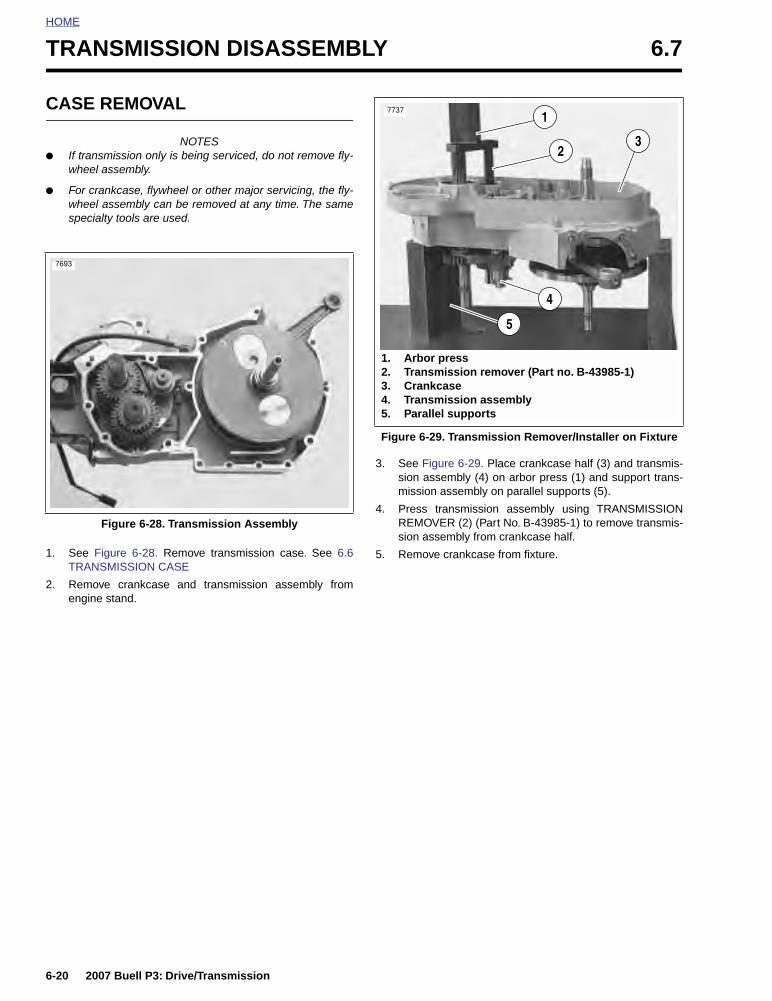
HOME
TRANSMISSION DISASSEMBLY 6.7
CASE REMOVAL
NOTES● If transmission only is being serviced, do not remove fly-
wheel assembly.
● For crankcase, flywheel or other major servicing, the fly-wheel assembly can be removed at any time. The samespecialty tools are used.
1. See Figure 6-28. Remove transmission case. See 6.6TRANSMISSION CASE
2. Remove crankcase and transmission assembly fromengine stand.
3. See Figure 6-29. Place crankcase half (3) and transmis-sion assembly (4) on arbor press (1) and support trans-mission assembly on parallel supports (5).
4. Press transmission assembly using TRANSMISSIONREMOVER (2) (Part No. B-43985-1) to remove transmis-sion assembly from crankcase half.
5. Remove crankcase from fixture.
Figure 6-28. Transmission Assembly
7693
Figure 6-29. Transmission Remover/Installer on Fixture
7737
1. Arbor press2. Transmission remover (Part no. B-43985-1)3. Crankcase4. Transmission assembly5. Parallel supports
1
4
5
23
6-20 2007 Buell P3: Drive/Transmission

HOME
SHIFTER FORKS AND DRUMDISASSEMBLY
1. See Figure 6-30. Remove and discard the three fork cot-ter pins (14).
2. Remove three shifter fork pins (15). A small magnet isuseful in freeing the fork pins.
3. Slide shifter fork drum (19) away through shifter forks.The neutral indicator pin (20) prevents removal in theother direction.
4. Remove shifter forks (16, 17, 18).
Figure 6-30. Shifter Mechanism
1. Right crankcase half2. Mainshaft bearing3. Countershaft bearing4. Plate5. Pin6. Detent arm7. Detent screw8. Detent plate9. Retaining ring10. Shifter shaft assembly
11. Locknut (2)12. Washer (2)13. Shifter pawl14. Cotter pin (3)15. Shifter fork pin (3)16. Shifter fork 4th gear17. Shifter fork 1st & 2nd gear18. Shifter fork 3rd & 5th gear19. Shifter fork drum20. Neutral indicator pin
1
13121110
456789
a0118x6x
23
1414
14
15
1514
1617
18
192015
2007 Buell P3: Drive/Transmission 6-21

HOME
DISASSEMBLY
NOTEAs the transmission runs, each part develops a certain wearpattern and a kind of “set” with its mating parts. For this rea-son, it is important that each component be reinstalled in itsoriginal location and facing its original direction.
1. See Figure 6-31. As each component is removed, placeit on a clean surface in the exact order of removal.
Figure 6-31. Recording The Order of Disassembly
b0948x6x
Figure 6-32. Transmission Assembly Right Crankcase Half
1. Bearing (inner)2. Fifth gear mainshaft 3. Bearing (outer)4. Oil seal5. Right crankcase half6. Ball bearing
7. Retaining ring8. Quad seal9. Spacer10. Oil seal11. Bearing (closed end) shifter drum12. Bearing (closed end) countershaft
a0127x6x
98
76
43
21
10
11
12 5
6-22 2007 Buell P3: Drive/Transmission

HOME
Figure 6-33. Transmission Assembly Left Crankcase Half
1. Mainshaft nut2. Spring washer3. Retaining ring4. Bearing5. Left crankcase half6. Mainshaft7. Spacer8. Bearing (4)9. 4th gear mainshaft10. Thrust washer (6)11. Retaining ring (7)12. 1st gear mainshaft13. 3rd gear mainshaft14. 2nd gear mainshaft15. Spacer16. 4th gear countershaft17. 1st gear countershaft18. Countershaft19. 3rd gear countershaft20. 2nd gear countershaft21. 5th gear countershaft22. Bearing23. Retaining ring24. Countershaft retainer25. Screw
a0126x6x
15
5
43
21
2223
2425
1110
1121
208
1011
1918
1110
178
1411
1013
810
11
1110
98
7
12
16
6
2007 Buell P3: Drive/Transmission 6-23

HOME
MAINSHAFT DISASSEMBLY
1. See Figure 6-33. Remove mainshaft 2nd (14) gear frommainshaft (6).
2. At mainshaft, between mainshaft 1st gear (12) and main-shaft 3rd gear (13), expand retaining ring (11) and movenext to mainshaft 1st gear (12) along with thrust washer(10). Move mainshaft 3rd gear (13) as far as possibletoward mainshaft 1st gear (12). Expand retaining ring(11) at opposite side of mainshaft 3rd gear (13) and slideoff end of shaft. Slide thrust washer (10) off end of main-shaft.
3. Remove mainshaft 3rd gear (13) and its split bearing (8).
4. Slide thrust washer (10) off end of mainshaft. Expandretaining ring (11), which is next to mainshaft 1st gear(12), and slide off end of shaft.
5. Remove mainshaft 1st gear (12) off mainshaft.
6. Expand retaining ring (11) and slide off end of shaft.Slide thrust washer (10) off end of mainshaft
7. Remove mainshaft 4th gear (9).
8. Remove split bearing (8) and spacer (7).
COUNTERSHAFT DISASSEMBLY
1. See Figure 6-33. Using RETAINING RING PLIERS (PartNo. J-5586) remove and discard retaining ring (11) nextto countershaft 5th gear (21). Slide countershaft 5th (21),and countershaft 2nd (20) off end of countershaft (18).
2. Remove split bearing (8) that was under countershaft2nd gear (20) and thrust washer (10), including retainingring (11) on the countershaft (6). Slide countershaft 3rd(19) gear off free end of shaft (18).
3. Remove beveled washer (spacer) (15) and countershaft4th gear (16).
4. Expand retaining ring (11) located next to countershaft1st gear (17). Remove retaining ring (11) and thrustwasher (10). Slide countershaft 1st gear (17) off end ofshaft. Remove split bearing (8).
5. Remove thrust washer (10). Expand remaining retainingring (11) and slide off countershaft (18).
CLEANING AND INSPECTION
11WARNING1WARNING
Never use compressed air to “spin-dry” bearings. Spin-ning bearings with compressed air can also cause abearing to fly apart, which could result in death or seri-ous injury.
11WARNING1WARNING
Compressed air can pierce the skin and flying debrisfrom compressed air could cause serious eye injury.Wear safety glasses when working with compressed air.Never use your hand to check for air leaks or to deter-mine air flow rates. (00061a)
1. Clean all parts (except bearings) in cleaning solvent andblow dry with compressed air.
2. Check gear teeth for damage. If gears are pitted, scored,rounded, cracked or chipped, they should be replaced.
3. Inspect the engaging dogs on the gears. Replace thegears if dogs are rounded, cracked, battered, chipped ordimpled.
4. Discard all retaining rings that were removed.
6-24 2007 Buell P3: Drive/Transmission

HOME
TRANSMISSION ASSEMBLY 6.8
MAINSHAFT SUB-ASSEMBLY
NOTE
During assembly, the split bearings (8) and the internal boresof the gears must be lubricated with FORMULA+ Primary/Transmission Lubricant prior to assembly. Leaving theseparts dry could accelerate wear at start-up.
1. See Figure 6-34. Install new retaining ring (11) andthrust washer (10) onto mainshaft (6) in the first ringgroove from the end.
2. Install split bearing (8) onto mainshaft.
3. Locate mainshaft 4th gear (9), which can be identified bythe two radial grooves at one side. Slide gear (9) ontoshaft. Position gear over bearing (8) next to spacer (7).
4. Place spacer (7) over mainshaft and position next to splitbearing (8).
5. Slide mainshaft 1st gear (12) onto mainshaft with the forkgroove facing 4th gear (9).
6. Install thrust washer (10) and new retaining ring (11)next to mainshaft 1st gear (12).
NOTE
It will be necessary to push the retaining ring into final posi-tion (ring groove) with a screwdriver.
7. Install split bearing (8) onto mainshaft.
8. Install mainshaft 3rd gear (13) onto shaft over bearing(8).
9. Install thrust washer (10) and new retaining ring (11).
10. Install mainshaft 2nd gear (14) onto shaft with the forkgroove facing 3rd gear (13).
COUNTERSHAFT SUB-ASSEMBLY
1. See Figure 6-34.Install new retaining ring (11) and thrustwasher (10) onto countershaft (18) in the second ringgroove from the end.
2. Install split bearing (8) onto countershaft.
3. Locate countershaft 1st gear (17), which can be identi-fied by the two radial grooves at one side. Slide gear (17)onto shaft. Position gear over bearing (8).
4. Install thrust washer (10) and new retaining ring (11)next to gear (17).
5. Locate countershaft 4th gear (16). This flat, shoulderlessgear is splined and has a single radial groove at oneside. Position gear next to retaining ring (11) on counter-shaft. Place beveled washer (spacer) (15) over end ofshaft with beveled side away from countershaft 4th gear(16).
6. Install countershaft 3rd gear (19) on countershaft withfork groove facing away from countershaft 1st gear (17).
7. Install new retaining ring (11) on countershaft. Positionnew retaining ring in the second ring groove from theend. Install thrust washer (10) next to retaining ring (11).Install split bearing (8) in seat next to washer (10).
5. Install countershaft 2nd gear (20) with the locking dogsfacing countershaft 3rd gear (19).
6. Install countershaft 5th gear (21) on countershaft.
7. Install new retaining ring (11) on countershaft.
8. Install shifter forks and drum. See 6.8 TRANSMISSIONASSEMBLY.
2007 Buell P3: Drive/Transmission 6-25

HOME
Figure 6-34. Transmission Assembly Left Crankcase Half
1. Mainshaft nut2. Spring washer3. Retaining ring4. Bearing5. Left crankcase half6. Mainshaft7. Spacer8. Bearing (4)9. 4th gear mainshaft 10. Thrust washer (6)11. Retaining ring (7)12. 1st gear mainshaft13. 3rd gear mainshaft14. 2nd gear mainshaft15. Spacer16. 4th gear countershaft 17. 1st gear countershaft18. Countershaft19. 3rd gear countershaft20. 2nd gear countershaft21. 5th gear countershaft22. Bearing23. Retaining ring24. Countershaft retainer25. Screw
a0126x6x
15
5
43
21
2223
2425
1110
1121
208
1011
1918
1110
178
1411
1013
810
11
1110
98
7
12
16
6
6-26 2007 Buell P3: Drive/Transmission
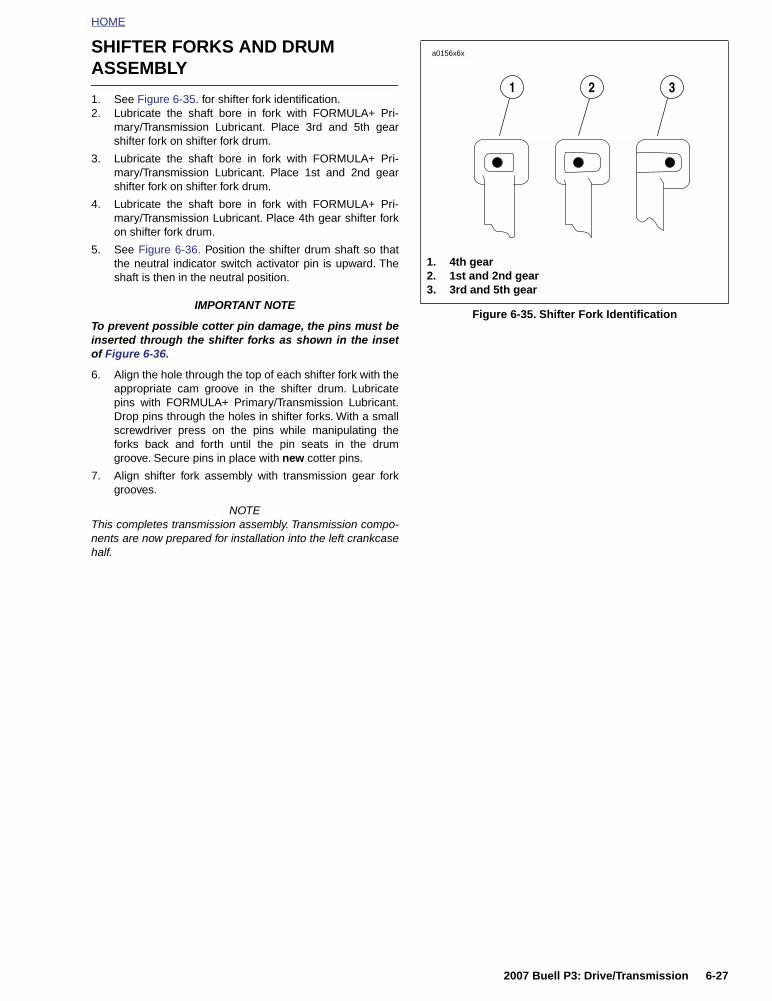
HOME
SHIFTER FORKS AND DRUM ASSEMBLY
1. See Figure 6-35. for shifter fork identification.2. Lubricate the shaft bore in fork with FORMULA+ Pri-
mary/Transmission Lubricant. Place 3rd and 5th gearshifter fork on shifter fork drum.
3. Lubricate the shaft bore in fork with FORMULA+ Pri-mary/Transmission Lubricant. Place 1st and 2nd gearshifter fork on shifter fork drum.
4. Lubricate the shaft bore in fork with FORMULA+ Pri-mary/Transmission Lubricant. Place 4th gear shifter forkon shifter fork drum.
5. See Figure 6-36. Position the shifter drum shaft so thatthe neutral indicator switch activator pin is upward. Theshaft is then in the neutral position.
IMPORTANT NOTE
To prevent possible cotter pin damage, the pins must beinserted through the shifter forks as shown in the insetof Figure 6-36.
6. Align the hole through the top of each shifter fork with theappropriate cam groove in the shifter drum. Lubricatepins with FORMULA+ Primary/Transmission Lubricant.Drop pins through the holes in shifter forks. With a smallscrewdriver press on the pins while manipulating theforks back and forth until the pin seats in the drumgroove. Secure pins in place with new cotter pins.
7. Align shifter fork assembly with transmission gear forkgrooves.
NOTEThis completes transmission assembly. Transmission compo-nents are now prepared for installation into the left crankcasehalf.
Figure 6-35. Shifter Fork Identification
a0156x6x
1. 4th gear2. 1st and 2nd gear3. 3rd and 5th gear
321
2007 Buell P3: Drive/Transmission 6-27

HOME
NOTESee Figure 6-36. Insert cotter pins as shown.
Figure 6-36. Shifter Mechanism
1. Right crankcase half2. Mainshaft bearing3. Countershaft bearing4. Plate5. Pin6. Detent arm7. Detent screw8. Detent plate9. Retaining ring10. Shifter shaft assembly
11. Locknut (2)12. Washer (2)13. Shifter pawl14. Cotter pin (3)15. Shifter fork pin (3)16. Shifter fork 4th gear17. Shifter fork 1st & 2nd gear18. Shifter fork 3rd & 5th gear19. Shifter fork drum20. Neutral indicator pin
489
a0118x6x
18
15
1310
11 12
7 6 5 3 2
1
1617
20
19
1415
1415
14
14
6-28 2007 Buell P3: Drive/Transmission

HOME
MAIN DRIVE GEAR 6.9
REMOVAL
1. Split crankcases in half. See 6.6 TRANSMISSIONCASE.
2. Remove transmission as an assembly. See 6.6 TRANS-MISSION CASE.
3. See Figure 6-37. From inside case tap out seal at end ofmainshaft 5th gear. Discard seal.
4. See Figure 6-38. Place cross plate on crankcase asshown.
5. See Figure 6-39. Assemble MAIN DRIVE GEARREMOVER AND INSTALLER (Part No. HD-35316A) withCROSS PLATE (Part No. B-45847).
6. Insert bolt (2) through cross plate (1) and 5th gear (3).
NOTEWhen removing the main drive gear, the gear is pressed outagainst the resistance of the bearing inner race. Without anysupport at the inner race, the bearing is destroyed. Wheneverthe main drive gear is removed the main drive gear bearingwill also have to be replaced.
9. At outside of case, place driver (4) and thrust washer (5)over end of bolt (2). Install and tighten nut (6) until 5thgear (3) is free.
Figure 6-37. Main Drive Gear Assembly
Figure 6-38. Mounting Cross Plate (Part No. B-43983)
1. Main drive gear2. Needle bearing (2)3. Seal
b1069x6x
3
2
1
7397
Figure 6-39. Removing Main Drive Gear
5
6
4
2
31
a0121x7x
1. Cross plate2. Bolt3. 5th gear4. Driver5. Thrust washer6. Nut
2007 Buell P3: Drive/Transmission 6-29

HOME
DISASSEMBLY
Drive out needle bearings from inside bore of main drivegear. Do not reuse bearings after removal.
ASSEMBLY
1. See Figure 6-40. Use INNER/OUTER MAIN DRIVEGEAR NEEDLE BEARING INSTALLATION TOOL (PartNo. HD-37842-A) for assembly. Select which end of toolto use.
a. The end stamped 0.080 in. (2.032 mm) is for drivingthe bearing into the inner end.
b. The end stamped 0.315 in. (8.001 mm) is for theouter end bearing.
2. Assemble parts. The installation tool will automaticallybottom on the gear when the correct depth is reached.
a. Place main drive gear on a press.
b. Press in the outer bearing to a depth of 0.315-0.285in. (8.001-7.239 mm).
c. Press in the inner bearing to a depth of 0.080 in.(2.032 mm).
Figure 6-40. Needle Bearing Installation Tool
3554
1
1. Ram on end of press2. Needle bearing installation tool3. Main drive gear
3
2
6-30 2007 Buell P3: Drive/Transmission

HOME
INSTALLATION
1. Replace main drive gear bearing.
2. See Figure 6-41. Lubricate both main drive gear needlebearing assemblies and the mating surface of the main-shaft with HARLEY-DAVIDSON SPECIAL PURPOSEGREASE (Part No. 99857-97).
3. See Figure 6-42. Use MAIN DRIVE GEAR REMOVERAND INSTALLER (Part No. HD-35316-A) for assembly.
a. Take bolt (2) and place washer (5) followed by maindrive gear (4) over end of bolt.
b. From inside of case insert bolt and main drive gearthrough inner race of ball bearing.
c. Insert threaded end of bolt (2) through installer cup(3) and thrust washer (1).
d. Thread nut (6) onto end of bolt (2). Tighten nut (6)until shoulder on gear (4) bottoms against inner raceof bearing.
4. See Figure 6-43. Tap in new seal (3) at threaded end of5th gear.
Figure 6-41. Lubricating Main Drive Gear Needle Bearings
10744
Figure 6-42. Main Drive Gear Installation
Figure 6-43. Main Drive Gear Assembly
1
5
6
2
43
a0122x8x
1. Thrust washer2. Bolt3. Installer cup4. 5th gear5. Washer6. Nut
1. Main drive gear2. Needle bearing (2)3. Seal
b1069x6x
2
3
1
2007 Buell P3: Drive/Transmission 6-31

HOME
RIGHT TRANSMISSION CASE BEARINGS 6.10
REMOVAL
NOTE
See Figure 6-46. Refer to Transmission assembly right crank-case half, for location of items discussed on this page.1. Remove transmission assembly. See 6.7 TRANSMIS-
SION DISASSEMBLY.
2. See Figure 6-44. Remove main drive 5th gear. Use MAINDRIVE GEAR REMOVER AND INSTALLER (PartNo.HD-35316A). See 6.9 MAIN DRIVE GEAR.
3. At outside of case remove seal next to 5th gear bearingretainer. Remove retaining ring.
4. From inside transmission case drive bearings (5th gear,countershaft or shifter shaft) out of bores. Carefully tapbearings free by working around bearing diameter tokeep bearing from skewing.
INSTALLATION
Mainshaft 5th Gear Ball Bearing 1. Locate MAIN DRIVE GEAR REMOVER AND
INSTALLER (Part No. HD-35316-A). See Figure 6-44.Place cross plate pins in appropriate holes in transmis-sion case.
2. See Figure 6-45. Insert bolt (2) through cross plate (1),new bearing (3), driver (4) and thrust bearing (5). Threadnut (6) on end of bolt. Tighten nut carefully until bearingis started in bore squarely. Tighten nut (6) until bearing isseated against shoulder in bore.
3. At outside of case install beveled retaining ring in grooveinside bearing bore with beveled side facing outside.
4. Lubricate bearing with FORMULA+ Primary/Transmis-sion Lubricant.
Countershaft Needle Bearing1. Find a suitable bearing driver 1-1/4 in. (31.75 mm) in
diameter.
2. From the outside of the case place the needle bearingopen end first next to the bearing bore. Hold the driversquarely against the closed end of the bearing and tapthe bearing into place. The bearing is properly positionedwhen it is driven inward flush or 0.030 in. (0.762 mm)below the outside surface of the case.
3. Lubricate bearing with FORMULA+ Primary/Transmis-sion Lubricant.
Shift Drum Needle Bearing1. Find a bearing driver 0.8125 in. (20.64 mm) in diameter.
2. From the outside of the case place the needle bearing,open end first, next to the bearing bore. Hold the driversquarely against the closed end of the bearing and tapthe bearing into place. The bearing is properly positionedwhen driven inward flush or 0.030 in. (0.762 mm) belowthe outside surface.
3. Lubricate bearing with FORMULA+ Primary/Transmis-sion Lubricant.
Figure 6-44. Mounting Cross Plate (Part No. B-43983)
Figure 6-45. Installing Mainshaft Ball Bearing
7397
6
5
4
2
1
3
a0125xTx
1. Cross plate2. Bolt3. Bearing4. Driver5. Thrust bearing6. Nut
6-32 2007 Buell P3: Drive/Transmission

HOME
Figure 6-46. Transmission Assembly Right Crankcase Half
1. Bearing (2)2. Fifth gear mainshaft 3. Needle bearing (2)4. Oil seal5. Right crankcase half6. Ball bearing7. Retaining ring8. Quad seal9. Spacer10. Oil seal11. Bearing (closed end) shifter drum12. Bearing (closed end) countershaft
a0127x6x
5
98
76
43
21
10
11
12
2007 Buell P3: Drive/Transmission 6-33

HOME
LEFT CRANKCASE BEARINGS 6.11
REMOVAL
NOTE
See Figure 6-49. Refer to transmission assembly left crank-case half, for location of items discussed on this page.
Mainshaft and Countershaft Bearings
1. See 6.6 TRANSMISSION CASE. Split crankcases inhalf.
2. See SHIFTER FORKS AND DRUM DISASSEMBLYunder 6.7 TRANSMISSION DISASSEMBLY. Removeshifter forks and drum.
3. See 6.7 TRANSMISSION DISASSEMBLY. Removecountershaft and mainshaft.
4. Inspect the mainshaft and countershaft ball bearings forpitting, scoring, discoloration or other damage.
5. See Figure 6-47. If bearing replacement is required,remove retaining rings (1, 2). Press out bearings (3, 4)from the inside of the crankcase.
Shift Drum Bushing
Inspect the shifter drum bushing for pitting, scoring, discolora-tion or excessive wear. If bushing requires replacement pressbushing out of crankcase from either side.
INSTALLATION
Mainshaft and Countershaft Bearings
1. Place crankcase on press with inside surface of crank-case downward.
2. Lay bearing squarely over bore with printed side of bear-ing upward. Place section of pipe or tubing (slightlysmaller than outside diameter of bearing) against outerrace. Press bearing into bore until bearing bottomsagainst shoulder.
3. Install new retaining ring with beveled side facing awayfrom bearing.
Shift Drum Bushing
1. Place crankcase on press with outside surface of crank-case downward.
2. See Figure 6-48. Lay bushing squarely over bore. Locatesocket or pipe that is slightly larger than diameter ofbushing. Place socket or pipe on bushing and press intobore until bushing is flush with or 0.020 in. (0.508 mm)below inside surface. If using a pressing tool larger thandiameter of bushing, the pressing tool will bottom againstcrankcase when bushing is flush with top surface.
Figure 6-47. Ball Bearing Assembly
Figure 6-48. Shift Drum Bushing Assembly
1. Retaining ring2. Retaining ring3. Bearing, mainshaft4. Bearing, countershaft
a0123xSx
31
2 4
Assemble bushing flush to 0.020 in. (0.508 mm) recess from this surface
Shift drum bushing
a0124x6x
6-34 2007 Buell P3: Drive/Transmission

HOME
Figure 6-49. Transmission Assembly Left Crankcase Half
1. Mainshaft nut2. Spring washer3. Retaining ring4. Bearing5. Left crankcase half6. Mainshaft7. Spacer8. Bearing (4)9. 4th gear mainshaft 10. Thrust washer (6)11. Retaining ring (7)12. 1st gear mainshaft13. 3rd gear mainshaft14. 2nd gear mainshaft15. Spacer16. 4th gear countershaft 17. 1st gear countershaft18. Countershaft19. 3rd gear countershaft20. 2nd gear countershaft21. 5th gear countershaft22. Bearing23. Retaining ring24. Countershaft retainer25. Screw
a0126x6x
15
5
43
21
2223
2425
1110
1121
208
1011
1918
1110
178
1411
1013
810
11
1110
98
7
12
16
6
2007 Buell P3: Drive/Transmission 6-35

HOME
TRANSMISSION INSTALLATION 6.12
INSTALLATION
NOTES
● If only transmission components were serviced, the fly-wheel assembly should already be in place.
● If flywheels and crankcases were serviced, install the fly-wheel assembly before re-installing the transmissionassembly.
Verify that all parts have been properly installed, as describedearlier in this section under:
● 6.9 MAIN DRIVE GEAR
● 6.8 TRANSMISSION ASSEMBLY
● 6.11 LEFT CRANKCASE BEARINGS
● 6.10 RIGHT TRANSMISSION CASE BEARINGS
1. Remove left crankcase half from engine stand.
2. See Figure 6-50. Place transmission assembly ontoTRANSMISSION REMOVER/INSTALLER FIXTURE(Part no. B-43985-2) on arbor press.
a. Install countershaft GUIDE (Part No. B-43985-4).
b. See Figure 6-51. Place left case half over transmis-sion assembly and install TRANSMISSIONINSTALLER (Part no. B-43985-3) into crankcase.
3. See Figure 6-51. Press crankcase into transmissionassembly until it bottoms out.
4. Remove transmission assembly and left crankcase halffrom fixture.
5. See Figure 6-52. Assemble crankcase halves together.
a. Apply a thin coat of DOW CORNING SILASTIC or 3-M 800 sealant to crankcase joint faces.
b. See CRANKCASE HALVES. Attach crankcasehalves in torquing sequence shown.
c. Apply several drops of LOCTITE 262 (red) to lastfew threads.
d. See Figure 6-53. Tighten 1/4-in. fasteners to 80-110in-lbs (9.0-12.4 Nm)
e. Tighten 5/16-in. fasteners to 15-19 ft-lbs (20-25 Nm).
Figure 6-50. Transmission Assembly
1. Arbor press2. Guide (B-43985-4)3. Transmission assembly4. Transmission remover/installer fixture
(B-43985-2)
4
3
2
17740
Figure 6-51. Transmission Remover/Installer on Fixture
Figure 6-52. Crankcase Halves
3
4
2
1
1. Arbor press2. Transmission installer (B-43985-3)3. Crankcase4. Transmission assembly
7741
7694
6-36 2007 Buell P3: Drive/Transmission

HOME
Figure 6-53. Crankcase Hardware
1. Screw (4)2. Washer (4)3. Rear isolator4. Dowel pin5. Hex socket head screw (9)6. Washer (14)7. Bottom case t40 TORX bolt (5)8. Hex socket head screw (1)9. Spacer (1)10. Crankcase set11. Nyloc, hex locknut12. Washer (1)
a0484x6x
12
87
6
9
11
1
2
34 5
6
10
2007 Buell P3: Drive/Transmission 6-37

HOME
SHIFTER PAWL ADJUSTMENT 6.13
ADJUSTMENT
1. See Figure 6-54. Lift pawl over drum pins and placeshifter shaft assembly on studs at transmission case.Loosely install a washer and locknut on each stud.
2. Install detent plate.
a. Place detent plate (9) over drum pins.
b. Rotate plate until blind holes in plate align with pinsin end of shifter fork drum.
c. Install new retaining ring (10) using SHIFT DRUMRETAINING RING INSTALLER (Part No. HD-39151).
3. Verify that retaining ring is fully engaged with drumgroove.
4. Attach loop of spring (11) over and into groove in pin (6).
5. See Figure 6-55. Align shifter shaft.
a. Place transmission in third gear.
b. Place a No. 32 drill bit (0.116 in. dia.) through hole indetent plate (4), and between pawl (2) and drive pinat end of shifter drum shaft.
c. Push down top of crank (3) to remove all clearancebetween pawl and drill bit; this will correctly alignpawl to shift drum pins (do not push down with toogreat a force, as this might cause the shifter drum torotate).
d. With bit in place, tighten shifter shaft assembly bot-tom locknut (1) first to 90-110 in-lbs (10-12 Nm).Then, tighten shifter shaft assembly top locknut (1)to the same torque.
e. Remove drill bit.
Figure 6-54. Installing Shifter
1. Shifter shaft assembly2. Locknut (2)3. Washer (2)4. Shifter pawl5. Plate6. Pin7. Detent arm8. Detent screw9. Detent plate10. Retaining ring11. Spring
a0119x6x
321
678910
11
4
5
Figure 6-55. Shifter Shaft Assembly Alignment
a0164x6x
1. Locknut (2)2. Pawl3. Crank4. Detent plate5. Shifter drum pin6. Drill bit, No. 32 drill bit (0.116 in. dia. - 2.9mm)
5
42
2
3
1
6
6
6-38 2007 Buell P3: Drive/Transmission

HOME
6. See Figure 6-46. Place new quad ring over threaded endof fifth gear, and position next to the gear taper. Installspacer over threaded end of fifth gear with chamferedend toward quad ring. Slide spacer up against bearing.
7. Install seal.
a. Coat lips of seal with FORMULA+ Primary/Trans-mission Lubricant.
b. Position seal over spacer with lips of seal towardcase.
c. Use MAIN DRIVE GEAR SEAL INSTALLER (PartNo. HD-41496) to gently tap seal into bore of caseuntil the outside of seal is flush with outer edge ofbore.
NOTEIt is acceptable to recess seal to about 0.030 in. (0.762 mm)below outer edge of bore. Seal will be controlled by tool.
8. See Figure 6-56. Position retention collar next to end ofcounter shaft with beveled side facing outward.
a. Apply several drops of LOCTITE 243 (blue) to lastfew threads.
b. Insert screw (1) through retention collar (2) andthread into end of shaft.
c. Place transmission in gear, and tighten T/ORXscrew (1) to 13-17 ft-lbs (18-23 Nm).
Figure 6-56. Countershaft Retainer
7691
1. TORX screw2. Retention collar3. Detent roller arm4. Spring
31
2
4
2007 Buell P3: Drive/Transmission 6-39

HOME
TRANSMISSION SPROCKET 6.14
REMOVAL
1. See Figure 6-57. Place transmission in first gear.Remove two socket head screws (5) and lockplate (4).
NOTE:Transmission sprocket nut has left-hand threads. Turn nutclockwise to loosen and remove from main drive gear shaft.
2. See Figure 6-57. Remove transmission sprocket nut (3)from main drive gear shaft (1).
3. See Figure 6-58. Secure pulley using SPROCKETLOCKING TOOL (Part No. B-43982).
INSTALLATION
1. See Figure 6-57. Install transmission sprocket (2) withsecondary drive belt onto main drive gear shaft (1).
2. Place transmission in neutral.
3. Apply a few drops of LOCTITE 262 (red) to the left-handthreads of transmission sprocket nut (3) and lightly coatthe washer-faced side with clean H-D 20W50 engine oil.Wipe off any excess oil.
4. Position nut with washer-faced side facing transmissionsprocket. Turn the nut counterclockwise to install it ontomain drive gear shaft.
5. See Figure 6-58. Install SPROCKET HOLDING TOOL(1) (Part No. B-43982) as shown.
Figure 6-57. Transmission Sprocket
1. Main drive gear shaft2. Transmission sprocket3. Transmission sprocket nut (left-hand threads)4. Lockplate5. Socket head screw (2)
a0149x6x
3
45
12
Figure 6-58. Sprocket Locking Tool (Part No. B-43982)
7398
6-40 2007 Buell P3: Drive/Transmission

HOME
6. See Figure 6-59. Use MAINSHAFT LOCKNUTWRENCH (Part No. HD-94660-37B) and a torquewrench to tighten sprocket nut to 50 ft-lbs (68 Nm) INI-TIAL torque, ONLY.
7. See Figure 6-60. Scribe a line on the transmissionsprocket nut and continue the line on the transmissionsprocket as shown.
8. Tighten the transmission sprocket nut an additional 30°-40°.
9. See Figure 6-57. Install lockplate over nut so that two oflockplate’s four drilled holes (diagonally opposite) alignwith sprocket’s two tapped holes.
NOTES● The lockplate has four screw holes and can be turned to
either side, so you should be able to find a position with-out having to additionally tighten the nut. If you cannotalign the screw holes properly, the nut may be addition-ally TIGHTENED until the screw holes line up, but do notexceed 45° as specified above. Never LOOSEN nut toalign the screw holes.
● See Figure 6-60. If lockplate will not align with holes,tighten nut to 45° maximum.
IMPORTANT NOTE
Maximum allowable tightening of sprocket nut is 45° ofcounterclockwise rotation, after initially tightening to 50ft-lbs. Do not loosen sprocket nut while attempting toalign the screw holes. If you cannot align lockplate andsprocket screw holes, nut may be additionally tightened45° as specified above. Tightening too much or too littlemay cause the nut to come loose during vehicle opera-tion.
10. If you cannot align lockplate and sprocket screw holes,nut may be additionally tightened until screw holes align.
11. See Figure 6-57. Install two socket head screws throughaligned holes of lockplate and into tapped holes ofsprocket. Tighten to 90-110 in-lbs (10-12 Nm).
NOTEThe original equipment socket head screws (5) have thread-locking compound applied to them. Since this compoundremains effective for about three removal/installation cycles,the original screws may be reused up to three times. After thethird removal/installation cycle, replace both screws with newscrews identical to the original.
12. Install the remaining removed components in the reverseorder of the removal procedures. See the procedureslisted in the respective component sections.
13. Fill transmission to proper level with fresh lubricant. See1.10 TRANSMISSION/PRIMARY FLUID.
Figure 6-59. Transmission Sprocket Tightening
Figure 6-60. Aligning Transmission Sprocket
7399
1. Sprocket holding tool (Part No. B-43982)2. Mainshaft locknut wrench
(Part No. HD-94660-37B)
1
2
45°
30°
a0163x6x
1. Transmission sprocket nut2. Transmission sprocket3. Line scribed on nut and sprocket
3
21
2007 Buell P3: Drive/Transmission 6-41

HOME
NOTES
6-42 2007 Buell P3: Drive/Transmission

Table Of Contents
SUBJECT PAGE NO.
7.1 Specifications . . . . . . . . . . . . . . . . . . . . . . . . . . . . . . . . . . . . . . . . . . . . . . . . . 7-17.2 Ignition System . . . . . . . . . . . . . . . . . . . . . . . . . . . . . . . . . . . . . . . . . . . . . . . . 7-37.3 Diagnostic Charts . . . . . . . . . . . . . . . . . . . . . . . . . . . . . . . . . . . . . . . . . . . . . . 7-67.4 Throttle Position Sensor (TP Sensor) . . . . . . . . . . . . . . . . . . . . . . . . . . . . . . . 7-127.5 Bank Angle Sensor . . . . . . . . . . . . . . . . . . . . . . . . . . . . . . . . . . . . . . . . . . . . . 7-137.6 Ignition/Headlamp Key Switch . . . . . . . . . . . . . . . . . . . . . . . . . . . . . . . . . . . . . 7-147.7 Auto-Enrichener . . . . . . . . . . . . . . . . . . . . . . . . . . . . . . . . . . . . . . . . . . . . . . . . 7-167.8 Ignition Module and Cam Position Sensor . . . . . . . . . . . . . . . . . . . . . . . . . . . 7-187.9 Ignition Coil . . . . . . . . . . . . . . . . . . . . . . . . . . . . . . . . . . . . . . . . . . . . . . . . . . . 7-237.10 Spark Plug Cables . . . . . . . . . . . . . . . . . . . . . . . . . . . . . . . . . . . . . . . . . . . . . 7-257.11 Starter/Ignition Interlock . . . . . . . . . . . . . . . . . . . . . . . . . . . . . . . . . . . . . . . . . 7-267.12 Diodes . . . . . . . . . . . . . . . . . . . . . . . . . . . . . . . . . . . . . . . . . . . . . . . . . . . . . . 7-337.13 Charging System . . . . . . . . . . . . . . . . . . . . . . . . . . . . . . . . . . . . . . . . . . . . . . 7-347.14 Alternator . . . . . . . . . . . . . . . . . . . . . . . . . . . . . . . . . . . . . . . . . . . . . . . . . . . . 7-407.15 Voltage Regulator . . . . . . . . . . . . . . . . . . . . . . . . . . . . . . . . . . . . . . . . . . . . . 7-437.16 Battery . . . . . . . . . . . . . . . . . . . . . . . . . . . . . . . . . . . . . . . . . . . . . . . . . . . . . 7-447.17 Headlamp . . . . . . . . . . . . . . . . . . . . . . . . . . . . . . . . . . . . . . . . . . . . . . . . . . . 7-497.18 Tail Lamp . . . . . . . . . . . . . . . . . . . . . . . . . . . . . . . . . . . . . . . . . . . . . . . . . . . . 7-517.19 Turn Signals . . . . . . . . . . . . . . . . . . . . . . . . . . . . . . . . . . . . . . . . . . . . . . . . . 7-527.20 Turn Signal Flasher . . . . . . . . . . . . . . . . . . . . . . . . . . . . . . . . . . . . . . . . . . . . 7-547.21 Handlebar Switches . . . . . . . . . . . . . . . . . . . . . . . . . . . . . . . . . . . . . . . . . . . . 7-557.22 Horn . . . . . . . . . . . . . . . . . . . . . . . . . . . . . . . . . . . . . . . . . . . . . . . . . . . . . . . . 7-577.23 Neutral Indicator Switch . . . . . . . . . . . . . . . . . . . . . . . . . . . . . . . . . . . . . . . . . 7-587.24 Fuses And Circuit Breakers . . . . . . . . . . . . . . . . . . . . . . . . . . . . . . . . . . . . . . 7-597.25 Electronic Speedometer . . . . . . . . . . . . . . . . . . . . . . . . . . . . . . . . . . . . . . . . 7-607.26 Speedometer Sensor . . . . . . . . . . . . . . . . . . . . . . . . . . . . . . . . . . . . . . . . . . . 7-627.27 Speedometer Performance Check . . . . . . . . . . . . . . . . . . . . . . . . . . . . . . . . 7-637.28 Indicators . . . . . . . . . . . . . . . . . . . . . . . . . . . . . . . . . . . . . . . . . . . . . . . . . . . . 7-687.29 Main Wiring Harness . . . . . . . . . . . . . . . . . . . . . . . . . . . . . . . . . . . . . . . . . . . 7-69
ELECTRICAL 7


HOME
SPECIFICATIONS 7.1
Table 7-1. Battery Specifications
Rating 12 VDC/12AH/200CCA
Type Sealed
Table 7-2. Alternator Specifications
AC Voltage Output 19-26 VAC per 1000 engine RPM
Stator Coil Resistance 0.2-0.4 Ohms
Table 7-3. Regulator Specifications
Voltage Output @ 75°F 14.3-14.7 VDC
Amperes @ 3600 RPM 22 Amps
Table 7-4. Spark Plug Specifications
Spark Plug 10R12A
Size 12 mm
Gap 0.035 in. 0.9 mm
Torque 11-18 ft-lbs 14.9-24.4 Nm
Table 7-5. Ignition Coil Resistance
Primary Winding 0.4-0.6 ohms
Secondary Winding 7,720-9,440 ohms
Table 7-6. Spark Plug Cable Resistance
Spark Plug Cable 2,375-5,833 ohms
Table 7-7. Ignition Timing Spark Occurrence
RPM
TP SENSOR
LOW VOLTAGE (PT)
HIGH VOLTAGE(WOT)
1200 RPM (Idle) 20˚ BTDC 18˚ BTDC
3000 RPM 30˚ BTDC 18˚ BTDC
6000 RPM 45˚ BTDC 35˚ BTDC
Curve Switch Point TP Sensor Input 2.4V
Rev Limit 6500 RPM
Table 7-8. Electrical Specifications
ELECTRICAL SYSTEM AMPERES
Main Circuit Breaker 30
Ignition Fuse 7.5
Light Fuse 15
Accessory Fuse 7.5
System Fuse 15
Key Switch Fuse 15
Table 7-9. Bulb Specifications
LAMP DESCRIPTIONBULBS
REQUIREDWATTS AMPS
PART NUMBER
Headlamp High/Low 1 60/55 4.68/3.12 67713-86
Marker Lamps Tail/Stop Lamp 1 5/21 0.42/1.75 68169-90A
Turn Signal Lamp, Front and Rear (1 bulb each)
4 10 0.74 Y0042.K
Indicator Lamps (in speedometer)
High Beam Indicator, Turn Signal Indicator Non-replaceable LEDs
Oil Pressure Indicator, Neutral Indicator
2007 Buell P3: Electrical 7-1

HOME
TORQUE VALUES
ITEM TORQUE NOTES
Bank angle sensor 25-27 in-lbs 2.8-3.1 Nm Page 7-13
Battery terminal bolts 72-96 in-lbs 8-11 Nm Page 7-13
Circuit breaker bracket mounting screw 25-27 in-lbs 2.8-3.1 Nm Page 7-31
Circuit breaker metal nuts 15-18 in-lbs 1.7-2.0 Nm Page 7-31
Circuit breaker nylon acorn 1-3 in-lbs 0.1-0.3 Nm Page 7-31
Headlamp housing mounting screws 12-14 ft-lbs 16-19 Nm Page 7-15
Ignition coil mounting screws 48-72 in-lbs 5-8 Nm Page 7-24
Ignition key switch bolts 48-72 in-lbs 5-8 Nm Page 7-15
Ignition module plate screws 10-20 in-lbs 1-2 Nm Page 7-20
Neutral indicator switch 36-60 in-lbs 4-7 Nm Loctite 243 (blue), Page 7-58
Rotor cup mounting fasteners 43-53 in-lbs 5-6 Nm Page 7-20
Rotor mounting bolts 90-110 in-lbs 10-12 Nm Loctite 243 (blue), Page 7-42
Sidestand switch fasteners 30-36 in-lbs 3-4 Nm Page 7-30
Spark plug 11-18 ft-lbs 15-24 Nm Page 7-3
Speedometer sensor screw 80-100 in-lbs 9-11 Nm Page 7-62
Stator mounting screws 30-40 in-lbs 3-5 NmT-27 TORX with retaining compound, replace after removal, Page 7-42
Switchgear housing screws, left side 25-33 in-lbs 3-4 Nm Metric, Page 7-56
Switchgear housing screws, right side 25-33 in-lbs 2.8-3.7 Nm Metric, Page 7-55
Tail lamp mounting locknuts 25-28 in-lbs 2.6-3.2 Nm Metric, Page 7-51
Throttle position sensor fasteners 12-23 in-lbs 2-3 Nm Page 7-12
Timing inspection hole plug 10-15 ft-lbs 14-20 Nm Page 7-21
Voltage regulator mounting fasteners 48-72 in-lbs 5-8 Nm Page 7-43
7-2 2007 Buell P3: Electrical

HOME
IGNITION SYSTEM 7.2
2007 Buell P3: Electrical 7-3
GENERAL
See Figure 7-1. The vehicle uses a breakerless inductive-dis-charge ignition system. The system has both a primary andsecondary circuit. The primary circuit consists of the battery,ignition switch, primary coil winding, computerized ignitiontimer and associated wiring. The secondary circuit consists ofthe secondary coil, spark plug and associated wiring.
The computerized ignition system contains five assemblies.
Ignition Module
The ignition module is mounted in the gear case cover. Themodule has two functions. First, it computes the sparkadvance for proper ignition timing. Second, it opens andcloses the low-voltage circuits between the battery and igni-tion coil to produce high-voltage discharge to the spark plug.The ignition module on the P3 Blast also contains an inte-grated cam position sensor.
Above 6500 RPM, the ignition module will automaticallyreduce power to prevent over revving.
Figure 7-1. Ignition System Components
a0217a7x
1. Timer cover2. Module plate
(ignition module/cam position sensor)3. Rotor cup4. Spark plug5. Spark plug cable6. Ignition coil7. Connector [88]8. Auto-enrichener9. Throttle position sensor (TP sensor)10. Connector [10]11. Bank angle sensor
9
1
2
3
4
5
6
11
10
8
7

HOME
7-4 2007 Buell P3: Electrical
The ignition module contains all the solid-state componentsused in the ignition system. The dwell time is fixed. The igni-tion module has added protection against transient voltages,continuous reverse voltage protection and damage due tojump starts. The system will operate down to 6.0 VDC. Theignition module is fully enclosed to protect it from vibration,dust, water and oil. The module is not repairable. Replace theunit if it fails.
The ignition module is programmed with two spark advancecurves to meet varying engine loads. The ignition moduleselects the proper curve based on TP sensor output voltagewhich is continuously monitored. This system ensures correcttiming to suit starting and high-speed requirements.
A single ignition coil fires the spark plug at the end of thecompression stroke (no waste spark), thereby igniting the air/fuel mixture.
Throttle Position Sensor (TP Sensor) and Auto-EnrichenerThe throttle position sensor (TP Sensor) is attached to thethrottle shaft on the carburetor. The TP sensor voltage is highwhen the throttle is opening during acceleration and underhigh engine load conditions and the voltage is low duringdeceleration and under low engine load conditions. The highor low voltage signal from the TP sensor is communicated tothe ignition module which selects the correct spark advancecurve (change between high and low curve takes place at TPSensor input 2.4V).
The low voltage signal curve (throttle less than 1/2 open,<2.4V TP Sensor input), selected for maximum sparkadvance under normal light-load cruising conditions, providesimproved fuel economy and performance. The high voltagesignal curve (throttle more than 1/2 open, >2.4V TP Sensorinput) minimizes spark knock while maintaining performanceunder high-load conditions (acceleration and highway driv-ing).
The auto-enrichener is located on the carburetor and controlsthe cold idle speed of the motorcycle and enriches the air/fuelmixture. The auto-enrichener circuit is grounded and opera-tive for 2-5 minutes after the motorcycle is started. Theground is completed by the ignition module.
Bank Angle SensorThe bank angle sensor provides input to the ignition moduleon whether or not the vehicle lean angle is greater than 55degrees. If vehicle lean angle exceeds 55 degrees, the bankangle sensor will shut off power to the ignition.
Rotor and Cam Position Sensor The rotor and cam position sensor (cam position sensor isintegrated with the ignition module) are located in the gear-case cover on the right side of the motorcycle. The rotor ismounted on the camshaft and operates at one-half crankshaftspeed. As the rotor turns, a slot in its outside diameter breaksthe magnetic field of a Hall-effect device mounted on the camposition sensor. The output of the Hall-effect device is a logic-type signal that corresponds to the timing information fromthe spinning rotor. This technique gives accurate timing infor-mation down to “0” speed.
The ignition system produces a spark near top dead center(TDC) for starting. At RPM’s and loads above this, the systemproduces a spark 0˚-45˚ before TDC. The whole timing pro-gram can be shifted by mechanical rotation of the integrated
ignition module plate. See 1.19 IGNITION TIMING AND IDLESPEED ADJUSTMENT.
See the wiring diagrams at the end of this section for addi-tional information on ignition system circuits.
TROUBLESHOOTING
For poor performance, poor fuel economy or excessive ping-ing, see DRIVABILITY TROUBLESHOOTING on Page 7-10.Also refer to Table 4-1 in Section 4 for Fuel System Trouble-shooting.For incorrect idle speed, see DRIVABILITY TROUBLE-SHOOTING on page 7-15.If the engine will not start, or if hard starting or missing indi-cates a faulty operating ignition system, perform the testslisted below.
Check for Ignition Spark1. Remove seat and fuel tank. See Sections 2 and 4.
2. Disconnect spark plug cable from spark plug. Checkcondition of plug and cable. Clean or replace as neces-sary. See 7.10 SPARK PLUG CABLE.
3. Install SPARK PLUG TESTER (HD-26792) to spark plugcable end.
4. Turn ignition key switch to IGN and engine stop switchto ON and pull in clutch lever.
5. With transmission in neutral, press electric starter button.Check for a spark across plug electrode gap.
a. If a spark is produced, problem is not in electronicsystem or coil. Check carburetion, enrichener andspark plug.
b. If no spark is produced, check battery voltage andbattery connection. Battery voltage must be at least12.6 VDC. Charge battery if voltage is low.
6. Verify that the ground strap from the front isolator to theframe is in good condition. If there is still no spark, thenperform the tests under NO IGNITION SPARK.
No Ignition SparkSee Figure 7-2. To conduct the following tests, it will be nec-essary to assemble a set of jumper wires.
Cut two wires of ample length to reach from a good groundconnection to the negative terminal of the coil primary. If asuitable capacitor is not available, use a condenser (such asthe type used in earlier breaker point ignition systems).
When conducting Step 5 of the previous spark tests, use theSPARK PLUG TESTER (HD-26972). During the testing pro-cedures, check for spark across the spark plug electrodes.
Figure 7-2. Test Jumper
0.33 MFD capacitor
16 ga. wire
12546

HO
ME
Fig
ure
7-3
. Ig
nit
ion
Sys
tem
Cir
cuit
12
34
56
1 2B
K
R/B
E
BATT
ERY
IGN
ITIO
NC
OILSP
AR
KP
LUG
AB
NEU
TRA
L
C
TO G
ND
FRO
MST
AR
T R
ELA
Y
INTE
GR
ATE
DEL
ECTR
ON
IC IG
NIT
ION
MO
DU
LE
131
128
30A
AB
CD
KEY
SW
ITC
HR
GN/BK
33
TN/W
BK BKW
SID
ESTA
ND
SWIT
CH
12
60
86 30
85 87 87A
SYST
EMR
ELA
Y
FUSE
BLO
CK
(TO
P V
IEW
)
61
LIGHTS
15A
KEY SWITCH
SYSTEM
15A
DIODE 1
DIODE 2
SPARE
15A
IGNITION
SPARE
ACCESSORY
MASTER C/B
1234
MA
IN C
HA
SSIS
GR
OU
ND
(TO
BA
TT N
EG)
GY
12
34
56
AU
TOEN
RIC
HTH
RO
TTLE
PO
SITI
ON
SEN
SOR
KB
LBEY
15A
7.5A
7.5A
7.5A
95C
LUTC
H S
WIT
CH
1083
PK
IGN
MO
DU
LEG
N/B
KW
/RW
/BK
W/B
K
R
W/BK
PK
W/BKV/W
KB
BKTN
/Y
V/O
FRO
M (
3)
R
R
R/B 1 R
1R
1
R
GY
GY
V/O
O/WV/WVKB
S14
22
TN/Y
R/B 1
R
R
O
SWIT
CH
NEU
TRA
L
131
TN
R 2
R 2
R/BK
BK
TN/G
N
BK
R/B
K R
IGN
PO
WER
BE
R/B
K1
TN
TN/W
R 2
TN/G
N
R/B
K
171
172
LGN/GY
LGN/GY
AB
C
W/BK
TN/Y
BAN
KA
NG
LESE
NSO
R
134
KEY
SW
ITC
H L
OG
IC
AB
CD
EF
LOC
K
PAR
K
OFF
ON
AB
CD
EF
AD
CB
16 R
6A R
ATI
NG
6A R
ATI
NG
16 GN/B
12A
RA
TIN
G
ZAD
I KEY
SW
ITC
H
16 R
/BK
18 O
/W
16 R
2
16 GY
16 Y
YY
a028
2a7x
2007 Buell P3: Electrical 7-5

HOME
DIAGNOSTIC CHARTS 7.3
Figure 7-4. No Spark At Spark Plug
•Ignition On.•Multimeter Red Wire To White/Black Wire On Coil Connector [83], Multimeter Black Wire To
Ground.•Meter Should Register 12v ± One Volt.
YES
Check Ignition FuseIs Fuse Ok?
NO
YES NO
Replace - Find Source Of FaultBattery Voltage at Gray Wire In Fuse block?
YES NO
Check For 12VDC Between Battery, Main Breaker, Ignition Switch And
Fuse Block.Repair As Necessary.
5001
5001
Measure Voltage At Connector [22A] Pin 4 (GY).
Battery Voltage Present?
NO
Repair Open (GY) Wire Between [22] and Fuse.
YES
5002
With Connector [22] Mated And Ignition On, Measure Voltage At Connector [22A], Pins 2
and 3 (W/BK).Battery Voltage Present?
NO
Repair / Replace Engine Stop Switch or Wiring.
YES
Repair Open (W/BK) Wire Between Coil and [22A].
5002 5173
+
-
PK
PK
W/BK
W/BK
Go To Next Page
No. Description Type Location
[22] RT Handlebar Switch 4 - Place Multilock Behind Headlight
Wire Harness Connectors
No Spark at Spark Plug
1
1 Use harness connector adaptor kit (HD-41404) gray male probe and patch cord.
NOTEMale connectors are labeled “A”Female connectors are labeled “B”
7-6
2007 Buell P3: Electrical
HOME
Figure 7-5. No Spark At Spark Plug
Install 6-place Harness Adaptor (HD-42962) andBreakout Box using Black connectors between
connectors [10A] and [10B].Measure Voltage between Pin 4 (PK) and Pin 6
(BK).Is Voltage 12V +/- 1.0VDC?
YES
Replace coil.
NO
+
-
PK
W/BK
W/BK
• Disconnect Ignition Module connector [10] from Breakout Box.• Ignition On.
• Jumper Wire – Connect Capacitor Wire To Terminal 4 (PK).*• Connect Both Wires To Common Ground (6).
• Momentarily touch Ground Wire To Terminal 4 (PK) at Break-out Box.
Is There A Spark At Plug When You Remove The Wire?
YES
Replace Coil.
NO
5010
5012
+
-
PK
W/BK
Jumper
W/BK
• Reconnect ignition module connector [10] to Breakout Box• Ignition Switch On.
• Multimeter Red Lead To (W/BK) Wire (Pin 1) Terminal. • Multimeter Black Lead To BK (Pin 6) On [10B].• Multimeter Should Register 12VDC ± 1.0 VDC.
[10]
1
2
3 4
5
6
YESCheck Continuity Between Pin 1W/BK [10B] And Coil W/BK Wire.
Continuity Present?
NO
YES
Repair Open In W/BK Wire
NO
Repair Open Between [10B] Pin 6 (BK) And Ground
50035003
Go To Next Page
YES
*Perform Coil Resistance Check If Capacitor Is Not
Available
NO
YES
NO
YES
YES NO
5003
1
1
50655051
C B A [83A]
Coil
1
NOTEMale connectors are labeled “A”Female connectors are labeled “B”
Check resistance between terminals A and B on Coil [83A]. Resistance should be 0.4-0.6 ohms. Is it?
Repair Open on PK wire
Check resistance between secondary (plug wire) terminal and C terminal on coil. Resistance should be between
7720 and 9440 ohms. Is it?
Check Spark Plug cable resis-tance. Is resistance between
2375 and 5833 ohms?
Repair open. Ground wire to
coil.
Replace Spark Plug Cable
NOTESee Chart on p. 7-16for pin functions.
Use harness connector adaptor kit (HD-41404) gray female probe(s) and patch cord.
2007 Buell P3: Electrical 7-7

HOME
Figure 7-6. No Spark At Spark Plug
1
2
3 4
5
6
• Ignition On, Sidestand Up, transmission in Neutral• Measure Voltage At Breakout Box- Multimeter Red Lead To LT GN/
GY (Pin 5) (+) and Black Lead To BK (Pin 6) (-).Is voltage 0.6-0.8 VDC?.
YES NO
Go to Next Page. Begin at top.
Remove Timer Cover (See Ignition Module/Cam Position Sensor for procedure).
Crank Engine.Is LED Flashing?
NO
Is Rotor Cup Rotating?Replace Ignition Module.
YES
YES
NO
Replace Ignition Module. Remove Gearcase Cover. Inspect For Mechanical Failure.
Repair.5009
5009
5005
Harness Adapters (HD-42962)
3
3
3
7793
[10]
NOTEMale connectors are labeled “A”Female connectors are labeled “B”
Inspect ignition module for signs of physical contact with rotor cup. Replace rotor cup if necessary.
Coil
Connector [10]
7-8 2007 Buell P3: Electrical

HOME
Figure 7-7. Continuous or No Spark At Spark Plug
YES NO
Is bank angle sensor connected?
Reconnect.
Disconnect connector [134].Measure voltage on [134B] between socket A, LT GN/GY and socket B, BK
3.0-3.5 VDC 11-13 VDC 0 VDC
See next page Repair short on LT GN/GY wire.
5007
YES
NO
Repair open in LT GN/GY wire.
5007
Disconnect connector [10]. Check continuity between socket A, LT GN/GY on connector [134B] and socket 5, LT GN/GY on connector [10B].
Continuity present?
YES
NO
Check starter interlock.
Check continuity to ground on LT GN/GY wire, socket A, connector [134B] or [10B].
Is continuity present?
5007
Check continuity to ground on TN/Y wire, socket B, connector [134B].
Is continuity present?
YESNO
Inspect module harness for damage.
Repair if necessary. If harness is not damaged,
replace ignition module.
Repair short to ground on LT GN/GY wire.
5007
* To avoid damage to terminals, remove Bank Angle Sensor before disconnecting connector [134].
Use HARNESS CONNECTOR ADAPTER KITHD-41404,Gray male probe and patch cord
Bank Angle Sensor
Connector [134]
8261
2007 Buell P3: Electrical 7-9

HOME
Figure 7-8. Continuous or No Spark At Spark Plug
3.0-3.5 VDC
YES
Measure Voltage On Connector [134B] Between Socket C, (GY), And Socket B, (BK).Is Voltage 11-13 VDC?
NO
Is Bank Angle Sensor Correctly Installed?
Repair Open In (GY) Wire Between Bank Angle Sensor And Ignition Fuse.
Are Ferrous Metals Located Within 0.250 in. (6.4 mm) Of Sides, Face, Or Top Of Bank Angle Sensor?
YES NO
Install Properly.
Return To Original Configuration.
NO
Replace Bank Angle Sensor.
YES
5007
5013
7-10 2007 Buell P3: Electrical

HOME
DRIVABILITY TROUBLESHOOTING
Poor Performance, Poor Fuel Economy, Excessive Pinging
Figure 7-9. Drivability Troubleshooting
1
1
7553
7605
7575
7595 7554
7610
75807590
7604
7553
Locate connector [88A] on the carburetor. Remove Pin 3 on the harness side. Install Breakout Box Adaptor (HD-42962) between [88A] and [88B]. Measure voltage between pin 3 and pin 5 on the breakout box. Voltage should change smoothly, slightly above 0.5V (closed throttle) and below 3.7V (open throttle).
Does it?
Check timing. See Ignition Module/Cam Position Sensor for procedure. Is timing set correctly?
Check Auto-Enrichener. Adjust timing.
YES
YES
YES
YES
YES
NO
NO
NO
NO
NO
Closed throttle voltage>0.55V or <0.45V
0V 12V No Change Erratic or greater than 3.7V and less than 12V
Recalibrate TP Sensor. Check resistance between Pin 3 and ground.
Is resistance less than 1
Locate and repair Short to voltage.
Check continuity between breakout box pin 5 and connector [88B] pin 5. Continuity present?
Check connections. Terminals OK?
Locate and repair short to ground.
Replace Ignition Module.
Check continuity between breakout box Pin 3 and connector [88B] pins 3 and 4.
Continuity present?
Repair Open.
Replace TP Sensor. Repair Open.
YES NO
Replace TP Sensor. Repair
Remove seat and fuel tank cover. See 2.28 SEAT.
NOTEMale connectors are labeled “A”Female connectors are labeled “B”
2007 Buell P3: Electrical 7-11

HOME
THROTTLE POSITION SENSOR (TP SENSOR) 7.4
GENERAL
See Figure 7-10. The throttle position sensor voltage deter-mines which spark advance curve the ignition moduleselects. The throttle position sensor (TP Sensor) is located onthe carburetor. The TP Sensor is not repairable. Replace theunit if it fails.
See 4.6 THROTTLE POSITION SENSOR for information onreplacing the throttle position sensor.
See diagnostic chart on previous page for troubleshootinginformation.
CALIBRATION/TESTING
NOTE
To gain access to the Throttle Position Sensor, remove thecarburetor and air cleaner as an assembly. See 4.4 CARBU-RETOR and 1.17 AIR CLEANER.
1. Adjust throttle position sensor as follows:
a. Back off idle adjustment screw so throttle plate isfully closed.
b. Completely open and close the throttle by rotatingthe throttle control through its full range of motion.
c. Using special TORX bit (Snap-on® TTXR20E),loosen the two tamper-resistant T20 TORX screwsjust enough to allow sensor to rotate.
d. Separate connector [88] housings and removesocket terminal from chamber 3 in connector [88B](main wire harness).
e. Install BREAKOUT BOX ADAPTORS (Part No. HD-42962) and BREAKOUT BOX (Part No. HD-42682)using black connectors between socket [88B] andpin [88A] housings.
f. Turn ignition switch to ON. Using a multimeter, mea-sure voltage between pin 3 (V/W) and pin 5 (BK).
g. Adjust (rotate) throttle position sensor (TPS) untilvoltage reading is 0.5V +/- 0.05V.
h. Completely open and close the throttle by rotatingthe throttle control through its full range of motion.Wide Open Throttle (WOT) should not exceed 3.7Vand reading should increase consistently as throttleis opened. If the voltage reading is erratic or the volt-age reading at WOT exceeds 3.7V, see Figure 7-10.for diagnostic testing.
NOTE
After WOT, the TPS reading may not return back to exactly0.5V +/- 0.05V. To re-check exact TPS voltage reading, turncycle key off and on.
i. Tighten TP Sensor mounting screws to 13-23 in-lbs(2-3 Nm).
2. Install carburetor and air cleaner. See 4.3 AIRCLEANER.
3. Adjust idle speed. See 1.19 IGNITION TIMING ANDIDLE SPEED ADJUSTMENT.
Figure 7-10. Throttle Position Sensor
Table 7-10. Socket Housing [88B]
CHAMBERNUMBER
WIRE COLOR FUNCTION
1 Violet/Orange Auto-Enrichener
2 Orange Auto-Enrichener
3 Violet/White TP Sensor Output
4 Violet/White TP Sensor Input
5 Black TP Sensor Ground
6 Not Used
Table 7-11. Pin Housing [88A]
CHAMBERNUMBER
WIRE COLOR FUNCTION
1 Yellow Auto-Enrichener
2 Yellow Auto-Enrichener
3 Light Blue TP Sensor Output
4 Yellow TP Sensor Input
5 Black TP Sensor Ground
6 Not Used
a0225x7x
1
2
3 4
5
6
[88A]
a0223x7x
1. Connector pin housing [88A]2. Throttle position sensor3. Tamper-resistant T20 TORX screws
1
2
3
7-12 2007 Buell P3: Electrical

HOME
BANK ANGLE SENSOR 7.5
REMOVAL
1. Remove seat. See 2.28 SEAT.
11WARNING1WARNING
To prevent accidental vehicle start-up, which couldcause death or serious injury, disconnect negative (-)battery cable before proceeding. (00048a)
2. Disconnect negative battery cable from battery.
11WARNING1WARNING
Disconnect negative (-) battery cable first. If positive (+)cable should contact ground with negative (-) cable con-nected, the resulting sparks can cause a battery explo-sion, which could result in death or serious injury.(00049a)
3. See Figure 7-12. Remove circuit breaker from mountingbracket.
4. Remove allen head screw from mounting bracket whileholding locknut on bank angle sensor side.
5. Remove bank angle sensor from its mounting location.
6. Disconnect connector [134] from bank angle sensor.
7. Remove bank angle sensor.
INSTALLATION
1. Connect connector [134] to new bank angle sensor.
2. See Figure 7-12. Position bank angle sensor in mountingposition on circuit breaker bracket mounting screw. Makesure sensor locating post engages hole in trunk toensure proper alignment of sensor.
3. Install bank angle sensor with allen screw and locknut.Tighten screw to 25-27 in-lbs (2.8-3.1 Nm).
4. Install circuit breaker to circuit breaker mounting bracket.
11WARNING1WARNING
Connect positive (+) battery cable first. If positive (+)cable should contact ground with negative (-) cable con-nected, the resulting sparks can cause a battery explo-sion, which could result in death or serious injury.(00068a)
5. Install negative battery cable to battery terminal. Tightenfastener to 72-96 in-lbs (8-11 Nm).
11WARNING1WARNING
After installing seat, pull upward on front of seat to besure it is in locked position. While riding, a loose seat canshift causing loss of control, which could result in deathor serious injury. (00070a)
6. Install seat. See 2.28 SEAT.
Figure 7-11. Bank Angle Sensor Removal
8261
1. Bank angle sensor2. Connector [134]3. Locknut
1
2
3
Figure 7-12. Bank Angle Sensor Installation
8262
1. Circuit breaker bracket2. Allen screw3. Locating post
2
13
2007 Buell P3: Electrical 7-13

HOME
IGNITION/HEADLAMP KEY SWITCH 7.6
GENERAL
11WARNING1WARNING
The automatic-on headlamp feature provides increasedvisibility of the rider to other motorists. Be sure head-lamp is on at all times. Poor visibility of rider to othermotorists can result in death or serious injury. (00030b)
See Figure 7-13. The four-position combination ignition/head-lamp key switch is not repairable. Replace the unit if it fails.
Switch positions are explained in Table 7-12.
CAUTION
Turn the ignition switch to the OFF position and removethe key before locking the motorcycle. Leaving the key inthe PARK position will keep the instrument lights on andresult in a discharged battery. (00155a)
NOTEThe key locks the ignition system and is removable in boththe OFF, FORK LOCK and P (PARK) positions. The PARKposition is located between the OFF and IGNITION positionsand allows the rider to remove the key while leaving the lightson. When the key is placed in the PARK position, several indi-cator markers are or can be activated. Refer to Table 7-13.
Figure 7-13. Ignition/Headlamp Key Switch
1. Ignition/Light position2. OFF position3. Push detent4. Fork lock5. P (Park) position
a0001xox
3
5
4
1
2
Table 7-12. Ignition Switch Labeling
LABEL NAME IGN. LAMPSREMOVE
KEY
OFF Off off off yes
LOCK Fork Lock off off yes
P Park off See note & Table 7-13.
yes
IGN Ignition on no
Table 7-13. Ignition Switch Operation
ITEM P IGN
Headlamp High/Low Beam off on
Speedometer Illumination Lamp on on
Stop Lamp can be activated
Front and Rear Turn Signals can be activated
Horn can be activated
7-14 2007 Buell P3: Electrical

HOME
REMOVAL
1. Remove seat. See 2.28 SEAT.
11WARNING1WARNING
To prevent accidental vehicle start-up, which couldcause death or serious injury, disconnect negative (-)battery cable before proceeding. (00048a)
2. Disconnect negative battery cable from battery terminal.
3. Remove four screws and washers to detach windscreenfrom mounting brackets. See 2.26 WINDSCREEN.
4. See Figure 7-14. Cut cable tie and disconnect ignitionkey switch connector [33] from main wiring harness.Note location of cable tie.
5. Remove two headlight bucket bolts and headlampbucket. See 7.17 HEADLAMP.
6. Remove two bolts and ignition key switch.
INSTALLATION
1. Apply Loctite 243 (blue) to threads of two ignition keyswitch bolts.
2. Install ignition key switch into hole and secure with twobolts. Tighten bolts to 48-72 in-lbs (5-8 Nm).
3. See Figure 7-14. Attach ignition key switch connector[33] to main wiring harness. Secure harness with cabletie.
4. Install headlight bucket with two bolts. Tighten bolts to12-14 ft-lbs (16-19 Nm).
5. Cable tie ignition key switch connector [33] to main wiringharness.
6. Install four screws and washers to attach windscreen tomounting brackets. See 2.26 WINDSCREEN.
7. Install negative battery cable to battery terminal. Tightenfastener to 72-96 in-lbs (8-11 Nm).
11WARNING1WARNING
After installing seat, pull upward on front of seat to besure it is in locked position. While riding, a loose seat canshift causing loss of control, which could result in deathor serious injury. (00070a)
8. Install seat. See 2.28 SEAT.
11WARNING1WARNING
Be sure that all lights and switches operate properlybefore operating motorcycle. Low visibility of rider canresult in death or serious injury. (00316a)
9. Check ignition key switch for proper operation. If opera-tion fails, reread procedure and verify that all steps wereperformed.
a. Turn ignition key switch to OFF. Check all functionslisted in Table 7-12.
b. Turn ignition key switch to IGN. Start motorcycle.See Section 4.
c. Turn ignition key switch to LOCK.
Figure 7-14. Ignition Key Switch Connector [33]
Table 7-14. Ignition Switch Connector [33]
[33] WIRE TERMINATION
A Master Circuit Breaker
B Accessories Fuse in Fuse Block
C Ignition Fuse in Fuse Block
D Empty
/B
RK
R
/B
RR
K
/RGY
A B C D
/RGY
a0284x7x
2007 Buell P3: Electrical 7-15

HOME
AUTO-ENRICHENER 7.7
GENERAL
See Figure 7-15. The auto-enrichener controls the cold idlespeed of the motorcycle at startup and enriches the air/fuelmixture. It is located on the carburetor. The auto-enrichener isnot repairable. Replace the unit if it fails.
NOTE
In extreme cold ambient conditions, auto-enrichener mayremain on for longer periods of time.
Normal function of the auto-enrichener is typically 2-5 minutefast idle speed enrichment cycle, even after hot restart. Ifenrichment cycle exceeds 5 minutes, see diagnostic chart onfollowing page.
See 4.5 AUTO-ENRICHENER for auto-enrichener serviceprocedures.
See diagnostic chart on next page for troubleshooting infor-mation.
DIAGNOSTIC NOTES
In the following diagnostic flow chart, the circled number cor-responds to the number procedure below.
1. Use black male probe and patch cord from TEST CON-NECTOR KIT (Part No. HD-41404).
Figure 7-15. Auto-Enrichener
Table 7-15. Socket Housing [88B]
CHAMBERNUMBER
WIRE COLOR FUNCTION
1 Violet/Orange Auto-Enrichener
2 Orange Auto-Enrichener
3 Violet/White TP Sensor Output
4 Violet/White TP Sensor Input
5 Black TP Sensor Ground
6 Not Used
Table 7-16. Pin Housing [88A]
CHAMBERNUMBER
WIRE COLOR FUNCTION
1 Yellow Auto-Enrichener
2 Yellow Auto-Enrichener
3 Light Blue TP Sensor Output
4 Yellow TP Sensor Input
5 Black TP Sensor Ground
6 Not Used
a0225x7x
1. Connector [88A]2. Auto-enrichener
1
2
7-16 2007 Buell P3: Electrical

HOME
DRIVEABILITY TROUBLESHOOTING
Idle Speed Incorrect
Figure 7-16. Driveability Troubleshooting
1
1
7490
74957495
7495
7505 7516
7510
7517
Install 6-place Harness Adaptor (HD-42962) and breakout box using black connectors between connectors [88A] and [88B]. Place red meter lead in Pin 2 and black meter lead in Pin 1.
Start engine. Is battery voltage present (battery voltage will not be present unless engine is cranking or running)?
YES NO
Replace Auto-Enrichener. With key ON, move black meter lead to ground.
Is battery voltage present?
YES NO
Separate connector [88] to carburetor. Check continuity from Pin 1 on connector [88B] to Pin 3 on connector
[10B]. Is continuity present?
Is battery voltage present at both terminals of system fuse?
YES NO
Locate and repair Open on Orange wire between system
fuse and connector [88]. 1 Terminal Neither Terminal
Locate and repair Open between system relay and
system fuse.
Check for continuity to ground at Pin 2 on connector [88].
Continuity present?
YES NO
Replace fuse.Locate and repair Short to ground on Orange wire.
Replace fuse.
YES NO
Reconnect connector [10]. Is battery voltage present on
Pin 1 (V/O) at connector [88B].
Locate and repair Open on Violet/Orange wire.
YES NO
Locate and repair Short to voltage.
Replace Ignition Module.
2007 Buell P3: Electrical 7-17

HOME
IGNITION MODULE AND CAM POSITION SENSOR 7.8
GENERAL
See Figure 7-17. The ignition module is integrated with thecam position sensor on the module plate in the gearcasecover located on the right side of the motorcycle. The inte-grated ignition module is not repairable. Replace the unit if itfails.
For information on the function and testing of the integratedignition module see 7.2 IGNITION SYSTEM.
See Figure 7-18. The rotor cup is located in the gearcasecover on the right side of the vehicle behind the integratedignition module. The rotor is mounted on the camshaft andoperates at one-half crankshaft speed. See IGNITION TIM-ING for information on the function, testing and adjustment ofthe integrated ignition module and trigger rotor assembly.
REMOVAL
1. Remove seat. See 2.28 SEAT.
11WARNING1WARNING
To prevent accidental vehicle start-up, which couldcause death or serious injury, disconnect negative (-)battery cable before proceeding. (00048a)
2. Disconnect negative battery cable from battery terminal.
3. Remove locknut and clamp that secures wire harnessand hoses on right side of motorcycle.
4. See Figure 7-17. Disconnect connector [10] located onthe left side of the frame backbone.
5. Note position of each wiring terminal in plug end of con-nector.
6. Remove connector terminal pins. See B.9 DEUTSCH.
11WARNING1WARNING
Always wear proper eye protection when drilling. Flyingdebris could cause serious eye injury. (00402c)
IMPORTANT NOTES
● Drilling hole in cover in location other than thatspecified may result in module plate damage. Drillcarefully only where indicated to avoid damagingmodule plate behind cover.
● Do not pry timer cover from bore or damage to gear-case or ignition module may result.
7. See Figure 7-18. Drill hole in outer timer cover at 5:00position approximately 0.500 in. (13 mm) in from outsideedge. Pull out outer timer cover using 90 degree pick orother suitable tool.
8. To obtain approximate ignition timing during installation,scribe alignment marks across module plate and bore intwo places.
9. See Figure 7-19. Remove two module plate mountingscrews (2). Carefully remove module plate (3). Removescrew (4) and rotor cup (5).
10. Carefully remove camshaft oil seal if damaged or if thereis any evidence of oil leakage past the seal.
Figure 7-17. Integrated Ignition Module Connector [10]
Figure 7-18. Drill Hole Location for Drilling/Removing Timer Cover
7793
1. Connector [10]2. Frame backbone
21
7794
7-18 2007 Buell P3: Electrical

HOME
Figure 7-19. Ignition System Components
a0217a7x
1. Timer cover2. Module plate screws (2)3. Module plate
(ignition module/cam position sensor)4. Screw, rotor cup5. Rotor cup6. 10r12 spark plug7. Spark plug cable8. Ignition coil9. Connector [88]10. Auto-enrichener11. Tamper-resistant T20 TORX screws12. Throttle position sensor (TP sensor)13. Connector [10]14. Bank angle sensor
12
1
3
5
6
7
8
14
13
10
9
4
2
11
2007 Buell P3: Electrical 7-19

HOME
INSTALLATION
1. With the lipped side facing inboard, install new camshaftoil seal into gearcase cover, if removed. Press seal intoposition until lightly bottomed.
2. Install rotor cup.
a. Apply Loctite 243 (blue) to threads of screw.
b. Position rotor cup onto end of camshaft aligningnotch with camshaft slot.
c. Install screw to secure rotor cup. Tighten screw to43-53 in-lbs (5-6 Nm).
3. Install ignition module/cam position sensor plate with twoscrews.
4. See Table 7-17. Install ignition module wiring terminalsinto correct positions in plug end of connector [10]. SeeWiring Diagram. Install pin terminals. See B.9 DEUT-SCH.
5. See Figure 7-17. Mate connector [10] and install to T-stud on frame backbone.
6. Install locknut to clamp that secures hoses and wire har-ness on right side of motorcycle.
7. Install module plate with two screws. Do not tightenscrews.
8. Install negative battery cable to battery terminal. Tightenfastener to 72-96 in-lbs (8-11 Nm).
9. Check ignition timing. See IGNITION TIMING.
10. Tighten module plate screws to 10-20 in-lbs (1-2 Nm).
11. Install new outer timer cover.
11WARNING1WARNING
After installing seat, pull upward on front of seat to besure it is in locked position. While riding, a loose seat canshift causing loss of control, which could result in deathor serious injury. (00070a)
12. Install seat. See 2.28 SEAT.
Figure 7-20. Ignition Module and Cam Position Sensor
Table 7-17. Ignition Module Connector [10]
CHAMBERNUMBER
WIRE COLOR FUNCTION
1 White/Black To Ignition Switch
2 Violet/White To TP Sensor
3 Violet/Orange To Auto-Enrichener
4 Pink To Coil
5*Lt Green/Grey
[10A]*Tan/Yellow [10B]
To Sidestand Interlock
6 Black Ground
a0288x7x
7-20 2007 Buell P3: Electrical
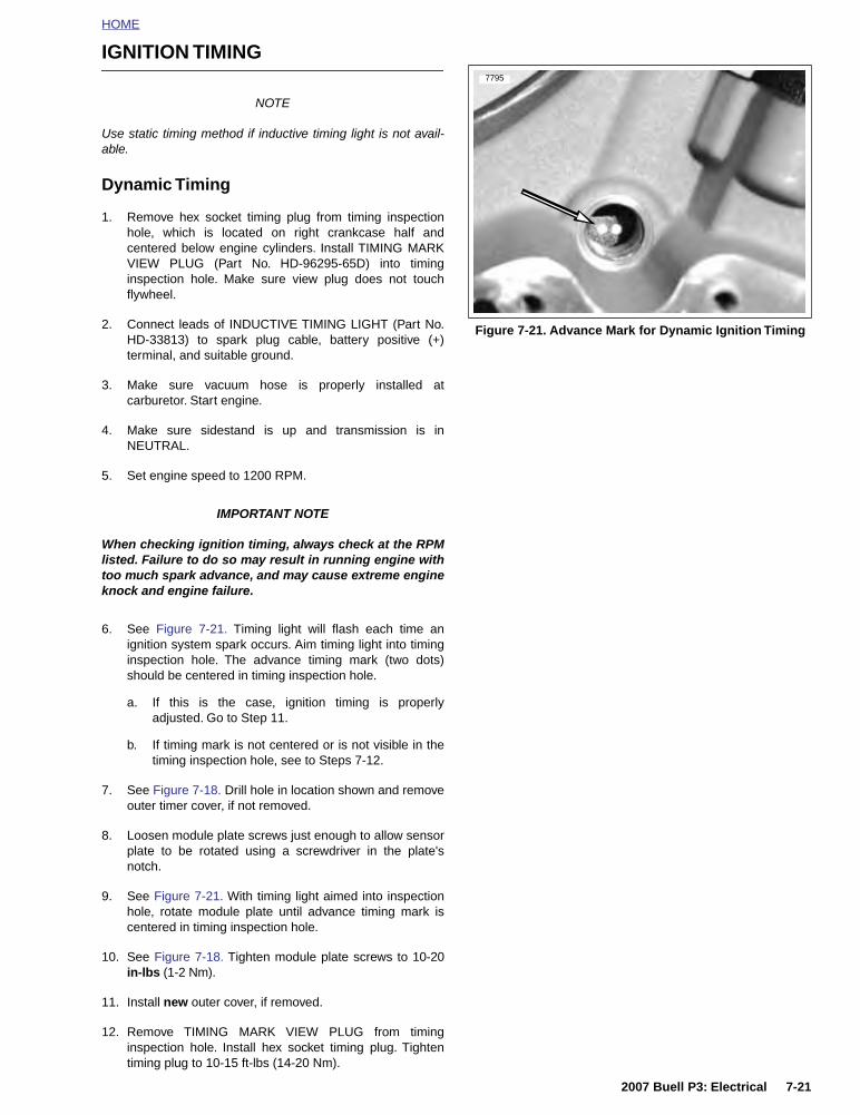
HOME
IGNITION TIMING
NOTE
Use static timing method if inductive timing light is not avail-able.
Dynamic Timing
1. Remove hex socket timing plug from timing inspectionhole, which is located on right crankcase half andcentered below engine cylinders. Install TIMING MARKVIEW PLUG (Part No. HD-96295-65D) into timinginspection hole. Make sure view plug does not touchflywheel.
2. Connect leads of INDUCTIVE TIMING LIGHT (Part No.HD-33813) to spark plug cable, battery positive (+)terminal, and suitable ground.
3. Make sure vacuum hose is properly installed atcarburetor. Start engine.
4. Make sure sidestand is up and transmission is inNEUTRAL.
5. Set engine speed to 1200 RPM.
IMPORTANT NOTE
When checking ignition timing, always check at the RPMlisted. Failure to do so may result in running engine withtoo much spark advance, and may cause extreme engineknock and engine failure.
6. See Figure 7-21. Timing light will flash each time anignition system spark occurs. Aim timing light into timinginspection hole. The advance timing mark (two dots)should be centered in timing inspection hole.
a. If this is the case, ignition timing is properlyadjusted. Go to Step 11.
b. If timing mark is not centered or is not visible in thetiming inspection hole, see to Steps 7-12.
7. See Figure 7-18. Drill hole in location shown and removeouter timer cover, if not removed.
8. Loosen module plate screws just enough to allow sensorplate to be rotated using a screwdriver in the plate'snotch.
9. See Figure 7-21. With timing light aimed into inspectionhole, rotate module plate until advance timing mark iscentered in timing inspection hole.
10. See Figure 7-18. Tighten module plate screws to 10-20in-lbs (1-2 Nm).
11. Install new outer cover, if removed.
12. Remove TIMING MARK VIEW PLUG from timinginspection hole. Install hex socket timing plug. Tightentiming plug to 10-15 ft-lbs (14-20 Nm).
Figure 7-21. Advance Mark for Dynamic Ignition Timing
7795
2007 Buell P3: Electrical 7-21

HOME
Static Timing
NOTE
The outer timer cover is tamper-resistant and must be drilledout. A new outer timer cover will be required when doing thisprocedure. Do not reuse timer cover after hole has beendrilled in it.
1. See Figure 7-22. Locate outer timer cover on the gear-case cover on the right side of vehicle.
11WARNING1WARNING
Always wear proper eye protection when drilling. Flyingdebris could cause serious eye injury. (00402c)
2. See Figure 7-22. Drill hole in outer timer cover at 5:00position approximately 0.500 in. (13 mm) in from edge.Pull out outer timer cover using 90 degree pick or othersuitable tool.
3. Remove the timing plug from the timing inspection holecentered below the cylinder on the right side of thecrankcase.
4. Remove the spark plug.
5. Jack up or hoist vehicle to allow rotation of the rearwheel.
NOTE
To check for intake valve closing place a finger over the sparkplug hole opening. While engine is on compression stroke, airwill be expelled from hole. When air is no longer expelledfrom hole, both valves are closed and engine should be closeto TDC and between compression and power stroke.
6. Shift transmission into fifth gear, and standing on leftside of vehicle, slowly rotate rear wheel in direction of for-ward motion (counter-clockwise) until front intake valveopens and closes.
7. See Figure 7-22. Rotate rear wheel from right side ofvehicle in direction of forward motion (clockwise) untilTDC mark (vertical line) is centered in timing inspectionhole.
8. Turn ignition switch to ON position, make sure sidestandis up and place transmission in NEUTRAL.
9. See Figure 7-23. Loosen two screws and slowly rotatemodule plate until red LED illuminates. Tighten moduleplate screws to 10-20 in-lbs (1-2 Nm) when complete.
10. Install new outer cover.
11. Install timing plug. Tighten plug to 10-15 ft-lbs (14-20Nm).
12. If possible, dynamically time engine as well to verify thatsystem is functioning properly. See DYNAMIC TIMING.Begin at Step 2.
Figure 7-22. Timer Cover and Inspection Hole
Figure 7-23. Static Ignition Timing (Typical)
7794
1. Timing plug2. Outer timer cover3. Drill hole for drilling/removing timer cover
3
1
2
a0229x7x
1. Screw (2)2. Module plate3. LED
1
2
3
7-22 2007 Buell P3: Electrical

HOME
IGNITION COIL 7.9
GENERAL
See Figure 7-24. The ignition coil is mounted on the frameunderneath the fuel tank on left side above airbox.
The ignition coil is a pulse-type transformer. Internally, the coilconsists of primary and secondary windings with a laminatediron core. The contents are sealed in a waterproof insulatingcompound. The ignition coil is not repairable. Replace the unitif it fails.
The low-voltage ignition primary circuit consists of the coil pri-mary winding, ignition module and battery. When the circuit isclosed, current flows through the coil primary winding creat-ing a strong magnetic field in the iron core of the ignition coil.
When the ignition module receives a signal from the camposition sensor and trigger rotor, the ignition module inter-rupts (opens) the ignition primary circuit, which causes themagnetic field in the coil core to collapse.
The collapsing magnetic field induces a high-voltage electri-cal discharge in the ignition secondary circuit, which consistsof the coil secondary winding, spark plug cable and sparkplug. The high-voltage discharge produces a spark to bridgethe electrode gap of the spark plug.
The ignition coil fires the spark plug at the end of the com-pression stroke (no-waste spark).
TROUBLESHOOTING
Follow the troubleshooting procedures listed under 7.8 IGNI-TION MODULE AND CAM POSITION SENSOR if the enginewill not start, is difficult to start or runs roughly. Also checkcondition of the spark plug cable. Insulation on cable may becracked or damaged allowing high tension current to short tometal parts. This problem is most noticeable when cable iswet.
If poor starting/running condition persists, check resistance ofignition coil primary and secondary winding using an ohmme-ter.
Ignition Coil Primary Circuit Test
1. Remove ignition coil.
2. Set ohmmeter scale to RX1.
3. See Figure 7-25. Using gray female probes and patchcord from TEST CONNECTOR KIT (Part No. HD-41404),place multimeter wires on primary coil windings. See 7.3DIAGNOSTIC CHARTS.
4. Check for primary coil winding resistance.
a. Normal resistance range is 0.4-0.6 ohms.
b. See TEST RESULTS on the next page if resistanceis not within normal operating range.
Figure 7-24. Ignition Coil (Left Side)
Figure 7-25. Ignition Coil Primary Resistance Test
7796
1. Connector [83]2. Mounting screws (2)3. Spark plug post
3
12
7797
2007 Buell P3: Electrical 7-23

HOME
Ignition Coil Secondary Circuit Test
1. Remove ignition coil.
2. Set ohmmeter scale to RX1K.
3. See Figure 7-26. Using gray female probes and patchcord from TEST CONNECTOR KIT (Part No. HD-41404),place multimeter wires on secondary coil windings. See7.9 IGNITION COIL.
4. Check for secondary coil winding resistance.
a. Normal resistance range is 7720-9440 ohms.
b. See Test Results if resistance is not within normaloperating range.
Test Results
1. A low resistance value indicates a short in the coil wind-ing. Replace coil.
2. A high resistance value might indicate that there is somecorrosion/oxidation of the coil terminals. Clean the termi-nals and repeat resistance test. If resistance is still highafter cleaning terminals, replace coil.
3. An infinite ohms (∞ or no continuity) resistance valueindicates an open circuit (a break in the coil winding).Replace coil.
REMOVAL
1. Remove seat. See 2.28 SEAT.
11WARNING1WARNING
To prevent accidental vehicle start-up, which couldcause death or serious injury, disconnect negative (-)battery cable before proceeding. (00048a)
2. Disconnect negative battery cable from battery terminal.
3. Remove fuel tank cover. See 4.2 FUEL TANK COVER/FUEL TANK.
4. Remove left side cover.
5. See Figure 7-24. Disconnect spark plug cable from coilplug post.
6. See Figure 7-27. Disconnect coil connector [83].
7. Remove two screws and washers and coil.
INSTALLATION
1. See Figure 7-24. Apply Loctite 243 (blue) to threads oftwo mounting screws.
2. Attach coil to frame with screws and washers (1). Tightento 48-72 in-lbs (5-8 Nm).
3. Attach coil connector [83].
4. Connect spark plug cable to ignition coil.
5. Attach left side cover.
6. Install negative battery cable to battery terminal. Tightenfastener to 72-96 in-lbs (8-11 Nm).
7. Install fuel tank cover. See 4.2 FUEL TANK COVER/FUEL TANK.
11WARNING1WARNING
After installing seat, pull upward on front of seat to besure it is in locked position. While riding, a loose seat canshift causing loss of control, which could result in deathor serious injury. (00070a)
8. Install seat. See 2.28 SEAT.
Figure 7-26. Ignition Coil Secondary Resistance Test at Terminal C
Figure 7-27. Coil Viewed From Bottom
Table 7-18. Coil Connector [83]
CHAMBERNUMBER
WIRE COLOR FUNCTION
AWhite/Black (+) To Right Handlebar
Switch
B Pink (-) To Ignition Module
C Black Ground
7798
7799
1. Connector [83A], with terminals C, B and A2. Spark plug post
CBA
1 2
7-24 2007 Buell P3: Electrical

HOME
SPARK PLUG CABLE 7.10
GENERAL
Resistor-type high-tension spark plug cables have a carbon-impregnated fabric core, instead of solid wire, for radio noisesuppression and improved reliability of electronic compo-nents. Use the exact replacement cable for best results.
REMOVAL
11WARNING1WARNING
Never disconnect the spark plug cable with the enginerunning. If you disconnect the spark plug cable with theengine running, you may receive a severe electric shockfrom the ignition system which could result in death orserious injury.
IMPORTANT NOTE
When disconnecting the spark plug cable from its sparkplug terminal, always grasp and pull on the rubber bootat the end of the cable assembly (as close as possible tothe spark plug terminal). Do not pull on the cable portionitself. Pulling on the cable will damage the cable’s carboncore.
Disconnect spark plug cable from ignition coil and spark plugterminal. Inspect removed cable for damage.
INSPECTION
1. See Figure 7-28. Inspect spark plug cable. Replacecable if worn or damaged.
a. Check for cracks or loose terminals.
b. Check for loose fit on ignition coil and spark plug.
2. Check cable boot/cap for cracks or tears. Replace boot/cap if worn or damaged.
3. See Figure 7-29. Check spark plug cable resistance withan ohmmeter. Replace cables not meeting resistancespecifications of 2375-5833 ohms.
INSTALLATION
1. Connect spark plug cable to ignition coil and spark plug.
2. Fasten boot/cap securely. Tight connections provide thenecessary moisture-proof environment for the ignitioncoil and spark plug terminals.
Figure 7-28. Spark Plug Cable (Typical)
Figure 7-29. Testing Resistance
7800
1. Spark plug connection2. Coil connection
12
1. Ohmmeter positive lead2. Ohmmeter negative lead3. Spark plug cable 4. Ohmmeter
7801
31
2
4
2007 Buell P3: Electrical 7-25

HOME
STARTER/IGNITION INTERLOCK 7.11
GENERAL
The starter/ignition interlock system is designed to preventunintended start-up and/or forward motion of the motorcycle.One of three conditions must exist to allow operation of thevehicle:
● Clutch disengaged (lever pulled in)● Transmission in Neutral● Sidestand retracted
Table 7-19. Voltage At TN/Y Wire At Con-nector [10B]
Starter CircuitThe starter circuit prevents the motorcycle from being startedunless a ground has been established at the starter relay.This ground comes from one source.
● By disengaging the clutch (pulling in the clutch lever) andgrounding through the clutch lever switch.
Once the starter circuit is grounded and the starter buttonpushed, the starter relay can be energized. The energizedrelay then allows the starter motor to crank the engine.
Ignition CircuitThe ignition circuit prevents the motorcycle from operatingunless a ground is established at the system relay. If thisground is not established, the ignition system will not beturned on and the motorcycle will not run. Grounds may beestablished three ways.
● By retracting the sidestand and grounding through thesidestand switch. See Ignition Test 1 on following pageto check sidestand switch function.
● By placing the motorcycle in neutral and groundingthrough the neutral switch. See Ignition Test 2 on follow-ing page to check neutral switch function.
● By disengaging the clutch and grounding through theclutch lever switch. See Ignition Test 3 on page 7-28 tocheck clutch switch function.
Note that the ignition circuit is enabled when the transmissionis in gear with the sidestand extended if the clutch is disen-gaged (clutch lever pulled in). However, if the motorcycle is ingear with the sidestand extended, and the clutch lever isreleased, the ignition ground is lost and the ignition system isturned off. This system will prevent vehicle operation if for-ward motion is attempted with the sidestand down.
See 7.3 DIAGNOSTIC CHARTS for Ignition Tests.
DIAGNOSTIC NOTES
In the following diagnostic flow charts, the circled numberscorrespond to the diode tests found in the TESTING/REPLACEMENT section following the Starter/Ignition Inter-lock System wiring diagram.
Use gray male probe and patch cord from TEST CONNEC-TOR KIT (Part No. HD-41404) to perform the tests.
CONDITIONSIDESTAND
DOWNSIDESTAND UP
Clutch EngagedTransmission in Gear
<1.0V 12V (Battery Voltage)
NeutralBattery Voltage minus 0.7V +/-
0.1V
12V(Battery Voltage)
Clutch DisengagedBattery Voltage minus 0.7V +/-
0.1V
12V(Battery Voltage)
7-26 2007 Buell P3: Electrical

HOME
DIAGNOSTICS
Ignition Test 1 - Sidestand Switch Function
CONDITION: Sidestand up and key ON, transmission in neutral and clutch engaged
Ignition Test 2 - Neutral Switch Function
CONDITION: Sidestand down, key ON, transmission in neutral and clutch engaged
Figure 7-30. Ignition Test 1
Figure 7-31. Ignition Test 2
YES
Check for continuity between Socket B (TN/Y) [134B] and Diode 2.
Is Continuity present?
Repair open BK wire between connector [60]
and ground.
Remove Seat. Remove fuse block from frame tab. Turn fuse block upside down to access ter-minals. Measure voltage between Diode 2 (-)
(TN/Y) and Ignition Fuse (+) (GY). Is Battery Voltage present?
Check for ground on BK wire of connector [60].
Ground present?
NO
NO
YES
System OK.
NO
Repair Wiring
Repair open TN/W wire or TN/Y wire between
connector [60] and Diode 2.
NO
Replace SidestandSwitch
5053
5054
5055
1 Use gray male probe and patch cord
(Part No. HD-41404).
1
YES
Ground present on TN/W wire at connector [60].
YES
from TEST CONNECTOR KIT
YES
YES
Check Diode 1 with ohmmeter. Diode OK?
Remove sprocket cover. Check for ground at
neutral switch terminal. Ground present?
Check for ground at TN wire on Diode 1. Ground
present?
YES
Diode installed backwards.
Reverse polarity.
Replacediode. YES
Repair open on TN wire between neutral switch
and Diode 1.
Replaceneutral switch.
NO
NO
NO
NO
5061
5062
5063 5064
1
2
YES
System OK.
NO
Repair Wiring
Remove Seat. Remove fuse block from frame tab. Turn fuse block upside down to access terminals. Measure voltage between Diode 2 (-) (TN/Y) and Ignition Fuse (+) (GY).
Is Voltage equal to Battery Voltage minus 0.7V +/- 0.1V?
Check for continuity between Socket B (TN/Y) [134B] and Diode 2.
Is Continuity present?
2007 Buell P3: Electrical 7-27

HOME
Ignition Test 3 - Clutch Switch FunctionCONDITION: Sidestand down, key ON, transmission in gear and clutch disengaged
Figure 7-32. Ignition Test 3
YES
YES
Check for ground on TN/GN wire of clutch switch connector [95].
Ground present?
Check for ground on TN/GN wire of Diode 2.
Ground present?
YES
Check Diode 2 with ohmmeter. Diode OK?
YES
Diode installed backwards.
Reverse polarity.
Replacediode.
YES
Repair open on TN/GN wire between
connector [95] and Diode 2.
NO
Replace clutch switch.
NO
NO
Repair open on BK wire between
connector [95] and ground.
NO
50715072
5073
5074
5075
1
2
Check for ground on BK wire of connector [95].
Ground present?
NO
NO
Repair Wiring.System OK.
YES
Remove Seat. Remove fuse block from frame tab. Turn fuse block upside down to access terminals. Measure
voltage between Diode 2 (-) (TN/Y) and Ignition Fuse (+) (GY).
Is Voltage equal to Battery Voltage minus 0.7 +/- 0.1V?
Check for continuity between Socket B (TN/Y) [134B] and Diode 2.
Is Continuity present?
7-28 2007 Buell P3: Electrical

HO
ME
Fig
ure
7-3
3. S
tart
er/Ig
nit
ion
Inte
rlo
ck S
yste
m
R 1
R/B
K1
R/B
K
GY
22
GY
FR
OM
(3)
W/B
KW
/BK
W/R
GN
/BK
R 2
R
R 1
R 1
R/BK
R 2
R 2
R
R/B
KB
K
S11
TN
/GN
TN
/GN
BE
IGN
PO
WE
R
R
RR R
BK
GN
GN
TN
/GN
BK
/R
R/B
1
RE
LAY
TO S
TAR
T
TN
/GN
BK
Y/R
BK
/R
BE
IGN
PO
WE
R
171
GY
33
K /B GN
DC
YR
BA
KE
Y S
WIT
CH
7.5A
7.5A
7.5A
15A
ACCESSORY
SPARE
IGNITION
15A
SPARE
DIODE 2
DIODE 1
15A
SYSTEM
KEY SWITCH
15A
LIGHTS
61
(TO
P V
IEW
)
BLO
CK
FU
SE
RE
LAY
SY
ST
EM
87A
8785
3086
4 3 2 1
CLU
TC
H S
WIT
CH
95
16 Y
16 GY
16 R
2
18 O
/W16
R/B
K
ZA
DI K
EY
SW
ITC
H
12A
RAT
ING 16 GN/B
6A R
ATIN
G
6A R
ATIN
G
16 R
BC
DA
FE
DC
BA
ON
OF
F
PAR
K
LOC
K
FE
DC
BA
KE
Y S
WIT
CH
LO
GIC
(TO
BAT
T N
EG
)M
AIN
CH
AS
SIS
GR
OU
ND
4 3 2 1
MASTER C/B
123
STA
RT
RE
LAY
87A
8785
3086
30A
128
STA
RT
RE
LAY
FR
OM
TO G
ND
BAT
TE
RY
R/B
E
BK
21
COLOR CODE:
BE BLUE
BK BLACK
BN BROWN
GN GREEN
GY GRAY
O ORANGE
PK PINK
R RED
TN TAN
V VIOLET
W WHITE
Y YELLOW
LT. LIGHT
DIODE
NO CONNECTION
PIN CONNECTOR
SOCKET CONNECTOR
SPLICE CONNECTION
CONNECTOR CODE:
a019
4x5x
2007 Buell P3: Electrical 7-29
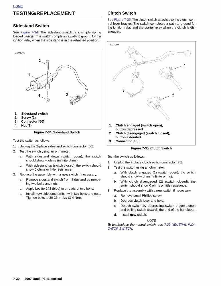
HOME
TESTING/REPLACEMENT
Sidestand SwitchSee Figure 7-34. The sidestand switch is a simple springloaded plunger. The switch completes a path to ground for theignition relay when the sidestand is in the retracted position.
Test the switch as follows:
1. Unplug the 2-place sidestand switch connector [60].
2. Test the switch using an ohmmeter.
a. With sidestand down (switch open), the switchshould show ∞ ohms (infinite ohms).
b. With sidestand up (switch closed), the switch shouldshow 0 ohms or little resistance.
3. Replace the assembly with a new switch if necessary.
a. Remove sidestand switch from Sidestand by remov-ing two bolts and nuts.
b. Apply Loctite 243 (blue) to threads of two bolts.
c. Install new sidestand switch with two bolts and nuts.Tighten bolts to 30-36 in-lbs (3-4 Nm).
Clutch SwitchSee Figure 7-35. The clutch switch attaches to the clutch con-trol lever bracket. The switch completes a path to ground forthe ignition relay and the starter relay when the clutch is dis-engaged.
Test the switch as follows:
1. Unplug the 2-place clutch switch connector [95].
2. Test the switch using an ohmmeter.
a. With clutch engaged (1) (switch open), the switchshould show ∞ ohms (infinite ohms).
b. With clutch disengaged (2) (switch closed), theswitch should show 0 ohms or little resistance.
3. Replace the assembly with a new switch if necessary.
a. Remove small Phillips screw.
b. Depress clutch lever and hold.
c. Detach switch by depressing switch trigger buttonand pulling switch towards the end of the handlebar.
d. Install new switch.
NOTETo test/replace the neutral switch, see 7.23 NEUTRAL INDI-CATOR SWITCH.
Figure 7-34. Sidestand Switch
a0230x7x
1
2
34
1. Sidestand switch2. Screw (2)3. Connector [60]4. Nut (2)
Figure 7-35. Clutch Switch
a0231a7x
1. Clutch engaged (switch open), button depressed
2. Clutch disengaged (switch closed), button extended
3. Connector [95]
32
1
7-30 2007 Buell P3: Electrical

HOME
System Relay
See Figure 7-36. The system relay is in the relay block whichis located on the left side under the seat. Test the relay as fol-lows:
1. Remove seat. See 2.28 SEAT.
2. Unplug relay from connector. Test the relay in the samefashion as the starter relay. See 5.6 STARTER SYSTEMTESTING.
3. Replace the relay with a new relay if necessary. Installrelay to frame with new rivet and washer.
Starter Relay
The starter relay is located on the right side of the motorcycle,underneath the seat by the flasher relay.
Main Circuit Breaker
See Figure 7-37. Attached to the frame above the battery, themain circuit breaker is between the ignition key switch and thebattery. Remove the main circuit breaker as follows:
1. Remove seat. See 2.28 SEAT.
11WARNING1WARNING
To prevent accidental vehicle start-up, which couldcause death or serious injury, disconnect negative (-)battery cable before proceeding. (00048a)
2. Disconnect battery negative cable from battery.
3. See Figure 7-38. Remove acorn nuts, nuts with lockwashers and wire leads from circuit breaker studs. Tagwire leads for ease of assembly.
4. See Figure 7-37. Remove circuit breaker from circuitbreaker bracket by carefully prying tab, located on leftside, open and sliding circuit breaker out.
NOTE:
Bank Angle Sensor will require reinstallation if bracket isremoved. See 7.5 BANK ANGLE SENSOR.
5. Install in the reverse order. Tighten screw (if bracket wasremoved) to 25-27 in-lbs (2.8-3.1 Nm). Tighten metal nutto 15-18 in-lbs (1.7-2 Nm). Tighten plastic acorn nuts to1-3 in-lbs (0.1-0.3 Nm).
6. Connect negative battery cable to battery terminal.Tighten fastener to 72-96 in-lbs (8-11 Nm).
11WARNING1WARNING
After installing seat, pull upward on front of seat to besure it is in locked position. While riding, a loose seat canshift causing loss of control, which could result in deathor serious injury. (00070a)
7. Install seat. See 2.28 SEAT.
Figure 7-36. System Relay
Figure 7-37. Circuit Breaker
Figure 7-38. Circuit Breaker Installation
7803
1. System relay2. Connector [171]
1
2
7811
1. Bracket2. Tab3. Circuit breaker (30A)
1
23
a0237x7x
1. Circuit breaker (30A)2. Bracket3. Screw4. Nut with lock washer (2)5. Acorn nut (2)
2
4
1
3
5
2007 Buell P3: Electrical 7-31

HOME
Ignition FuseSee Figure 7-39. The ignition fuse (5) is in the fuse blockunder the seat. Always replace the ignition fuse with a 7.5ampere fuse.
DiodesSee Figure 7-39. The fuse block contains two diodes, diode 2(7) for the starter circuit and diode 1 (8) for the ignition circuit.A diode acts as a one way switch which permits current flowin one direction, but not in the other.
The circled numbers in the 7.11 STARTER/IGNITION INTER-LOCK diagnostic ignition test flow charts correspond to thefollowing tests.
1. Check diode with an ohmmeter as shown in Figure 7-40.
2. Check diode polarity as shown in Figure 7-41.
Replace diodes as necessary.
Figure 7-39. Fuse Block [61]
[61]TN/W
TN
R
R2
R/B
K
15
A
15
A
15
A1
5A
TN/Y
TN/GR
O
7.5
A
7.5
A
7.5
A
TN/Y
R/BK
GY
1
6
5
3
9
8
4
2
7
a0234x8x
1. Key switch2. System3. Spare 15A4. Spare 7.5A5. Ignition6. Accessory7. Diode 2 (starter circuit)8. Diode 1 (ignition circuit)9. Lights
Figure 7-40. Ohmmeter Diode Test
Figure 7-41. Diode Polarity
Continuity Infinite ohms
a0235x7x
a0236x7x
TN TN/Y
Diode 1 polarity
TN/GN TN/Y
Diode 2 polarity
TN/W
7-32 2007 Buell P3: Electrical

HOME
DIODES 7.12
REMOVAL
1. Remove seat. See 2.28 SEAT.
11WARNING1WARNING
To prevent accidental vehicle start-up, which couldcause death or serious injury, disconnect negative (-)battery cable before proceeding. (00048a)
2. Disconnect negative battery cable from battery.
3. See Figure 7-42. Both diodes (1, 2) are mounted in thefuse block under the seat.
4. Remove faulty diode by pulling it straight up off the relayblock.
INSTALLATION
1. See Figure 7-42. Install the new diodes into position onthe fuse block by pushing it into the slot.
2. Connect negative battery cable to battery terminal.Tighten fastener to 72-96 in-lbs (8-11 Nm).
11WARNING1WARNING
After installing seat, pull upward on front of seat to besure it is in locked position. While riding, a loose seat canshift causing loss of control, which could result in deathor serious injury. (00070a)
3. Install seat. See 2.28 SEAT.
Figure 7-42. Diode Location in Fuse Block
a0285x7x
1. Starter circuit diode2. Ignition circuit diode
1
2
2007 Buell P3: Electrical 7-33

HOME
CHARGING SYSTEM 7.13
GENERAL
The charging system consists of the alternator and regulator.Charging system circuits are shown in Figure 7-45.
AlternatorThe alternator consists of two main components:
● The rotor which mounts to the engine sprocket shaft.
● The stator which bolts to the engine crankcase.
Voltage RegulatorSee Figure 7-43. The voltage regulator is a series regulatorwith shunt control. The circuit combines the functions of recti-fying and regulating.
TROUBLESHOOTING
When the charging system fails to charge or does not chargeat a satisfactory rate, make the following recommendedchecks.
BatteryCheck for a weak or dead battery. See 7.16 BATTERY. Bat-tery must be fully charged in order to perform any electricaltests.
WiringCheck for corroded or loose connections in the charging cir-cuit. See Figure 7-45.
Voltage Regulator InspectionSee Figure 7-43. The voltage regulator base must have aclean, tight connection for proper grounding. The harness isgrounded to the voltage regulator body. Check by using anohmmeter with one lead on a known good ground, such asbattery ground cable, and the other on the regulator base.
Connector plug to stator must be clean and tight.
Figure 7-43. Voltage Regulator
7804
1. Voltage regulator2. Ground wire
1
2
7-34 2007 Buell P3: Electrical

HOME
Figure 7-44. Charging System Troubleshooting
Pass
Pass
Pass
Pass
Pass
Pass
NOTEWhenever a charging system component fails a test and isreplaced, re-test the system to be sure the problem hasbeen corrected.
5306
5307
5308
5310
5312
5319
5314 5315
5316
5319
SYMPTOM:BATTERY BECOMES DISCHARGED
Test battery.Charge or replace as required.
See 7.16 BATTERY.
Inspect regulator.See Voltage Regulator Inspection.
Test regulator.See Voltage Regulator Bleed Test.
Perform Milliampere Draw Test (If applicable).
Perform Total Current Draw Test.Record measurement.
Correct as required.
Perform Stator Check.
Fail
Perform Current and Voltage Output Test.Record measurements and compare with
Total Current Draw Test before proceeding.
FailReplace regulator.
Isolate damaged component or wiring. Fail
Fail
Isolate damaged wiring or excessive accessories.
Replace regulator.
Fail
Fail
Pass
Perform Voltage Output Test. FailPerform AC Output Check.
FailInspect rotor.
Replaceregulator.
Fail
Replacerotor.
Pass
Replacestator.
Pass
Pass
Replaceregulator.
Perform Current and Voltage Output Test.FailDamaged or slipping rotor.
System test good up to this point.
Suspect:
1. Accessories on for long periods when vehicle is parked and not running.
2. Accessories on when vehicle is ridden very slowly for long periods.
3. Battery self-discharge and/or accessory draw because vehicle was not operated for a long period.
2007 Buell P3: Electrical 7-35

HOME
Figure 7-45. Charging System Circuit
R 1R 1BK
BKR
BK 3
BK 3
R
46
30A
128BK 2
BK
BK
COLOR CODE:
BE BLUE
BK BLACK
BN BROWN
GN GREEN
GY GRAY
O ORANGE
PK PINK
R RED
TN TAN
V VIOLET
W WHITE
Y YELLOW
LT. LIGHT
DIODE
NO CONNECTION
PIN CONNECTOR
SOCKET CONNECTOR
SPLICE CONNECTION
CONNECTOR CODE:
a0278x7x
VoltageRegulator
StatorBattery
Main Circuit
Main ChassisGround
Starter
Breaker
7-36 2007 Buell P3: Electrical

HOME
TESTING
Voltage Regulator Bleed Test
1. Be sure regulator is connected to battery. Check BKcharging wire on gold terminal of master circuit breaker.
2. Locate voltage regulator connector [46] behind left foot-rest support. Disconnect from alternator stator wiring.Cut cable strap and note its location.
3. Check regulator connector using a trouble light.
a. Touch one probe to a suitable ground.
b. Touch the other to the regulator pins, one at a time.
c. If light glows, replace regulator.
Milliampere Draw Test
NOTEBe sure accessories are not wired so they stay on at all times.This condition could drain battery completely if vehicle isparked for a long time. Check for this by connecting ammeterbetween negative battery terminal and battery.
1. See Figure 7-46. Connect ammeter between negativebattery terminal and battery. With this arrangement, youwill also pick up any regulator drain.
2. With ignition key switch turned to OFF and all lights andaccessories off, observe amperage reading.
a. Maximum reading should be 1 milliampere.
b. A higher reading indicates excessive current draw.Any accessories must be considered and checkedfor excessive drain.
NOTEA battery with a surface discharge condition could suffer astatic drain. Correct by cleaning battery case.
Total Current Draw Test
If battery runs down during use, the current draw of themotorcycle components and accessories may exceed outputof the charging system.
1. See Figure 7-47. To check for this condition, place loadtester induction pickup or current probe pickup over bat-tery negative cable.
2. Disconnect stator wiring from voltage regulator wiring atthe connector [46]. Start the motorcycle and run theengine at 2000 RPM.
3. With ignition and all continuously running lights andaccessories turned on (headlamp on high beam), readthe total current draw.
4. Compare this reading to the reading obtained after per-forming the Current and Voltage Output Test.
a. The current output should exceed current draw by3.5 amps minimum.
b. If output does not meet specifications, there may betoo many accessories for the charging system tohandle.
5. Reconnect regulator after testing. Replace cut cablestrap.
Figure 7-46. Milliampere Draw Test with Ignition Turned to OFF Position
Figure 7-47. Checking Current Draw Using Load Tester with Induction Pickup (Ignition Switch ON)
a0240x7x
12 VDCbattery
1. Battery negative cable2. 1 milliampere maximum
1
2
a0249x7x
1. Load tester2. Induction pickup
1
2
2007 Buell P3: Electrical 7-37

HOME
Current and Voltage Output Test
1. See Figure 7-48. Connect load tester.
a. Connect negative and positive leads to battery ter-minals.
b. Place load tester induction pickup over positive reg-ulator cable.
IMPORTANT NOTE
Do not leave any load switch turned on for more than 20seconds or overheating and tester damage are possible.
2. Run the engine at 2000 RPM. Increase the load asrequired to obtain a constant 13.0 VDC.
3. The current output should be 19-23 amps. Make note ofmeasurement for use in TOTAL CURRENT DRAW TEST.
NOTE
Rider’s habits may require output test at lower RPM.
Voltage Output Test
1. See Figure 7-48. After removing the load, read the loadtester voltage meter.
2. See Figure 7-44. If voltage to the battery is not more than15 VDC, voltage output is within specifications. Investi-gate other possible problems.
3. If voltage is higher, regulator is not functioning properlyor connections are loose or dirty.
Stator Check
1. Turn ignition key switch to OFF.
2. See Figure 7-49. Connect an ohmmeter.
a. Locate voltage regulator connector [46] behind leftfootrest support. Disconnect from alternator statorwiring.
b. Insert one ohmmeter lead into either stator socket.
c. Attach the other lead to a suitable ground.
3. Test for continuity with ohmmeter set on the RX1 scale.
a. A good stator will show no continuity (∞ ohms)across either stator socket.
b. Any other reading indicates a grounded stator whichmust be replaced.
4. See Figure 7-50. Remove ground lead. Insert lead intothe remaining stator socket.
5. Test for resistance with ohmmeter set on the RX1 scale.
a. Resistance across the stator sockets should be 0.2-0.4 ohms.
b. If the resistance is lower, the stator is damaged andmust be replaced.
Figure 7-48. Current and Voltage Output Test
Figure 7-49. Test for Grounded Stator
Figure 7-50. Check for Stator Resistance
a0242x7x
1. Load tester2. To circuit breaker (DC output)3. To stator
2
3
1
a0243x7x
a0244x7x
7-38 2007 Buell P3: Electrical
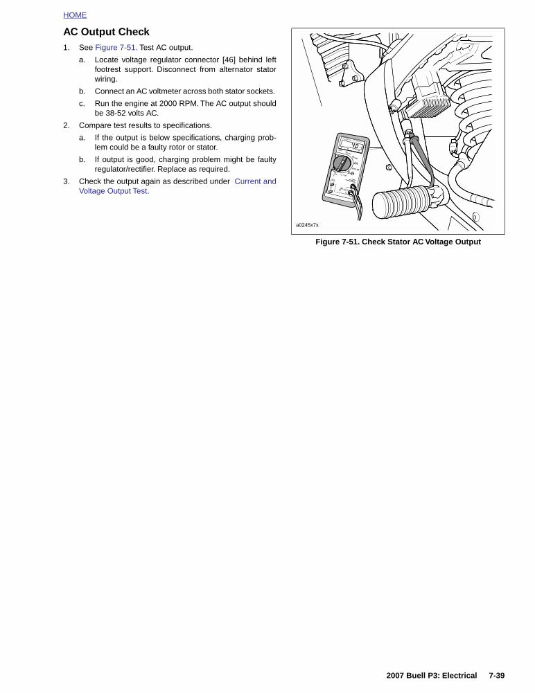
HOME
AC Output Check1. See Figure 7-51. Test AC output.
a. Locate voltage regulator connector [46] behind leftfootrest support. Disconnect from alternator statorwiring.
b. Connect an AC voltmeter across both stator sockets.
c. Run the engine at 2000 RPM. The AC output shouldbe 38-52 volts AC.
2. Compare test results to specifications.
a. If the output is below specifications, charging prob-lem could be a faulty rotor or stator.
b. If output is good, charging problem might be faultyregulator/rectifier. Replace as required.
3. Check the output again as described under Current andVoltage Output Test.
Figure 7-51. Check Stator AC Voltage Output
a0245x7x
2007 Buell P3: Electrical 7-39

HOME
ALTERNATOR 7.14
REMOVAL/DISASSEMBLY
1. Remove seat. See 2.28 SEAT.
11WARNING1WARNING
To prevent accidental vehicle start-up, which couldcause death or serious injury, disconnect negative (-)battery cable before proceeding. (00048a)
2. Disconnect negative battery cable from battery.
3. Remove primary cover. See 6.2 PRIMARY CHAIN.
4. Remove clutch assembly, primary chain and enginesprocket/rotor assembly as a unit. See 6.4 PRIMARYDRIVE/CLUTCH.
5. Remove/disassemble rotor and/or stator, as required.Refer to the following procedures.
Rotor1. See Figure 7-52. Remove the eight bolts which secure
alternator rotor to engine sprocket.
2. See Figure 7-53. Position blocking under rotor. Presssprocket free of rotor.
NOTEResistance to sprocket/rotor disassembly is due in part to themagnetic force of the permanent rotor magnets.
Figure 7-52. Rotor Assembly
7805
Figure 7-53. Removing Rotor From Sprocket
7806
1. Arbor press2. Rotor3. Sprocket4. Blocking
2
1
3
4
7-40 2007 Buell P3: Electrical

HOME
Stator 1. See Figure 7-54. Disconnect stator wiring from voltage
regulator wiring at connector [46] located behind left foot-rest support.
2. Remove cable straps holding stator wire to oil filter hose.
3. Withdraw stator wiring from behind the gearcase cover.
4. Remove and discard the four TORX screws which securestator to left crankcase half.
IMPORTANT NOTE
Stator TORX screws contain a thread locking compound.Do not reuse existing screws. Always use new screwswith the proper thread locking compound. Loss of torqueon TORX fasteners could result in alternator damage.
5. Remove stator wiring grommet from left crankcase half.
6. Withdraw stator wiring from grommet hole in left crank-case half. Remove stator.
CLEANING AND INSPECTION
IMPORTANT NOTE
Do not strike or drop alternator rotor or damage to mag-net adhesive could occur. Magnet adhesive damage canresult in rotor failure.
1. Clean rotor with a petroleum-base solvent. Remove allforeign material from rotor magnets. Replace rotor if rotormagnets are cracked or loose.
2. Clean stator by wiping with a clean cloth.
3. Examine stator leads for cracked or damaged insulation.
NOTEThe rotor and stator can be replaced individually if either isdamaged.
Figure 7-54. Stator Assembly
a0246x7x
12
3
5
4
1. Rotor2. *TORX screws (4) - * Do not reuse3. Stator4. Grommet5. Connector [46]
2007 Buell P3: Electrical 7-41

HOME
ASSEMBLY/INSTALLATION
Depending on whether the rotor, the stator, or both the rotorand stator were removed/disassembled, perform the applica-ble procedures which follow:
1. See Figure 7-54. Feed stator wiring with attached grom-met into open grommet hole in left crankcase half.
2. Apply a light coating of clean engine oil or chaincaselubricant to grommet. Install grommet into hole in leftcrankcase half.
IMPORTANT NOTE
Stator TORX screws contain a thread locking compound.Do not reuse existing screws. Always use new screwswith the proper thread locking compound. Loss of torqueon TORX fasteners could result in alternator damage.
3. Position stator on left crankcase half. Secure stator usingfour new TORX screws. Tighten screws to 30-40 in-lbs(3-5 Nm).
4. Route stator wiring under starter, behind footpeg supportbracket and under seat. Cable strap connector [46]halves together.
NOTETemporarily attach a thin flexible “feed” or mechanic’s wire tothe connector end of the stator wiring to assist in the routingof the wiring.
5. Connect alternator stator wiring to voltage regulator con-nector [46] located behind left footrest support.
6. See Figure 7-55. Attach rotor to sprocket.
a. Position rotor on sprocket. Align holes in sprocketwith holes in rotor.
b. Apply a drop of Loctite 243 (blue) to threads of eachmounting bolt. Insert the eight mounting boltsthrough rotor and start bolts into tapped holes insprocket.
c. Position a section of pipe with an inside diameterlarger than the sprocket mounting hub over center ofrotor. Press rotor onto sprocket. Tighten bolts to 90-110 in-lbs (10-12 Nm).
7. Install clutch assembly, primary chain and enginesprocket/rotor assembly as a unit. See 6.4 PRIMARYDRIVE/CLUTCH.
8. Install primary cover. See 6.2 PRIMARY CHAIN.
9. Connect negative battery cable to battery terminal.Tighten fastener to 72-96 in-lbs (8-11 Nm).
10. Test charging system. See 7.13 CHARGING SYSTEM.
11WARNING1WARNING
After installing seat, pull upward on front of seat to besure it is in locked position. While riding, a loose seat canshift causing loss of control, which could result in deathor serious injury. (00070a)
11. Install seat. See 2.28 SEAT.
Figure 7-55. Pressing Rotor onto Sprocket
7806
1. Pipe section2. Rotor3. Sprocket
2
1
3
7-42 2007 Buell P3: Electrical

HOME
VOLTAGE REGULATOR 7.15
GENERAL
The voltage regulator is located under the frame (above swin-garm on left side). The voltage regulator is not repairable.Replace the unit if it fails.
REMOVAL
1. Remove seat. See 2.28 SEAT.
11WARNING1WARNING
To prevent accidental vehicle start-up, which couldcause death or serious injury, disconnect negative (-)battery cable before proceeding. (00048a)
2. Disconnect negative battery cable from battery terminal.
IMPORTANT NOTE
When disconnecting the alternator stator wiring, pullapart the connector by firmly grasping both connectorhalves. Do not pull on leads or damage to the wires and/or terminals could result.
3. See Figure 7-56. Locate voltage regulator connector [46]behind left footrest support. Disconnect from alternatorstator wiring. Cut cable straps if necessary.
4. Detach charging wire from main circuit breaker.
a. See Figure 7-57. Disconnect red charging wire fromgold post of main circuit breaker.
b. Route charging wire back to voltage regulator.
5. Remove two mounting screws.
6. Remove and discard voltage regulator.
INSTALLATION
1. Apply Loctite 243 (blue) to threads of two mountingscrews.
2. See Figure 7-57. Attach new voltage regulator using twoscrews. Tighten screws to 48-72 in-lbs (5-8 Nm).
3. Connect voltage regulator connector [46] to alternatorstator wiring. Cable strap connector halves together.
4. Route Red charging wire to gold post on main circuitbreaker. Secure wire to frame with new cable straps.
5. Connect negative battery cable to battery terminal.TIghten fastener to 72-96 in-lbs (8-11 Nm).
6. Test charging system. See 7.13 CHARGING SYSTEM.
11WARNING1WARNING
After installing seat, pull upward on front of seat to besure it is in locked position. While riding, a loose seat canshift causing loss of control, which could result in deathor serious injury. (00070a)
7. Install seat. See 2.28 SEAT.
Figure 7-56. Voltage Regulator Connector [46]
Figure 7-57. Voltage Regulator
30A
BK
BK
BK
RD
RD
a0286x7x
[46]
1. Main circuit breaker (30A)2. Voltage regulator3. Stator
3
1
2
a0248x7x
1. Voltage regulator2. Connector [46A]3. Red charging wire4. Screws (2)
2
1
4
3
2007 Buell P3: Electrical 7-43

HOME
BATTERY 7.16
GENERAL
All Buell batteries are permanently sealed, maintenance-free,valve-regulated, lead/calcium and sulfuric acid batteries. Thebatteries are shipped pre-charged and ready to be put intoservice. Do not attempt to open these batteries for anyreason.
11WARNING1WARNING
Batteries contain sulfuric acid, which could cause severeburns to eyes and skin. Wear a protective face shield,rubberized gloves and protective clothing when workingwith batteries. KEEP BATTERIES AWAY FROM CHIL-DREN. (00063a)
11WARNING1WARNING
Figure 7-58. Never remove warning label attached to topof battery. Failure to read and understand all precautionscontained in warning, could result in death or seriousinjury. (00064a)
Table 7-20. Battery Electrolyte Antidotes
CONTACT SOLUTION
External Flush with water.
Internal Drink large quantities of milk or water, followed by milk of magnesia, vegetable oil or beaten eggs. Call doctor immediately.
Eyes Flush with water, get immediate medical attention.
Figure 7-58. Battery Warning Label Location
M A D E I N U S AHARLE
Y-DAVID
SON
MILWAU
KEE,
WI 5
3201
MADE I
N U.S.
A.
WARRAN
TY AN
D ADJUSTM
ENT POLIC
Y
This ba
ttery w
ill be re
placed
without c
harge
if found
to be
defect
ive in m
aterial
s or
workmans
hip 12
months
from da
te of
vehicle
purch
ase or
6 mont
hs from
date
of over
-the-co
unter p
urchas
e. After
6
months,
but w
ithin th
e 12 m
onths
of the
over-th
e-coun
ter pur
chase,
the ba
ttery w
ill
be rep
laced a
nd the
purch
aser ch
arged
only fo
r the p
eriod o
f owner
ship b
ased o
n
the reg
ular pr
ice at t
he tim
e of re
turn
prorate
d ver t
he num
ber of
months
of
warrant
y. This
warrant
y is no
t transf
erable
and is
voided
by the
use o
f rejuv
enators
,
improper
electro
lyte, ne
glect o
r abuse
.
PART
NO.
1
2
3
4
5
6
7
8
9
0
JA
FE
MA
AP
MY
JU
JY
AU
SE
OC
NO
DE
f1730x8x
Figure 7-59. Battery Warning Label
b1184x7x
1. Contents are corrosive.2. Wear safety glasses.3. Contents are explosive.
4. Keep flames away.5. Read instructions.6. Keep away from children.
1 2 6543
7-44 2007 Buell P3: Electrical

HOME
BATTERY TESTING
Voltmeter Test
See Table 7-21. The voltmeter test provides a generalindicator of battery condition. Check the voltage of the batteryto verify that it is in a 100% fully charged condition. If theopen circuit (disconnected) voltage reading is below 12.6V,charge the battery and then recheck the voltage after thebattery has set for one to two hours. If the voltage reading is12.7V or above, perform the load test.
Table 7-21. Battery Charge Conditions
Load Test
The load test measures battery performance under fullcurrent load and is the best indicator of battery condition. Toload test the battery, proceed as follows:
IMPORTANT NOTE
Load testing a discharged battery can result in perma-nent battery damage.
1. Always fully charge the battery before testing or testreadings will be incorrect. See BATTERY INSTALLA-TION AND CONNECTION. Load testing a dischargedbattery can also result in permanent battery damage.
2. After charging, allow battery to stand for at least onehour before testing.
11WARNING1WARNING
Turn battery load tester OFF before connecting testercables to battery terminals. Connecting tester cableswith load tester ON can cause a spark and battery explo-sion, which could result in death or serious injury.(00252a)
3. See Figure 7-60. Connect tester leads to battery postsand place induction pickup over negative (black) cable.
IMPORTANT NOTE
To avoid load tester and/or battery damage, do not leavethe load tester switch turned ON for more than 20 sec-onds.
4. See Figure 7-60. Load battery at 50% of CCA ratingusing the load tester. Voltage reading after 15 secondsshould be 9.6V or more at 70° F. (21° C).
11WARNING1WARNING
Turn battery load tester OFF before disconnecting testercables to battery terminals. Disconnecting tester cableswith load tester ON can cause a spark and battery explo-sion, which could result in death or serious injury.(00253a)
5. Install the battery on the motorcycle. See BATTERYINSTALLATION AND CONNECTION.
Voltage (OCV) State of Charge
12.7 100%
12.6 75%
12.3 50%
12.0 25%
11.8 0%
Figure 7-60. Load Test Battery
Table 7-22. Battery Load Test
COLD CRANKING AMPERAGE (CCA)
100% 50%
BLAST 200 100
a0249x7x
1. Load tester2. Induction pickup
1
2
2007 Buell P3: Electrical 7-45

HOME
DISCONNECTION AND REMOVAL
1. Remove seat. See 2.28 SEAT.
11WARNING1WARNING
To prevent accidental vehicle start-up, which couldcause death or serious injury, disconnect battery cables(negative (-) cable first) before proceeding. (00307a)
11WARNING1WARNING
Disconnect negative (-) battery cable first. If positive (+)cable should contact ground with negative (-) cable con-nected, the resulting sparks can cause a battery explo-sion, which could result in death or serious injury.(00049a)
2. Unthread bolt and remove battery negative cable (black)from battery negative (-) terminal.
3. Unthread bolt and remove battery positive cable (red)from battery positive (+) terminal.
4. Remove battery from motorcycle.
CLEANING AND INSPECTION
1. Battery top must be clean and dry. Dirt and electrolyte ontop of the battery can cause battery to self-discharge.Clean battery top with a solution of baking soda (sodiumbicarbonate) and water (5 teaspoons baking soda perquart or liter of water). When the solution stops bubbling,rinse off the battery with clean water.
2. Clean cable connectors and battery terminals using awire brush or sandpaper. Remove any oxidation.
3. Inspect the battery screws, clamps and cables for break-age, loose connections and corrosion. Clean clamps.
4. Check the battery posts for melting or damage causedby overtightening.
5. Inspect the battery for discoloration, raised top or awarped or distorted case, which might indicate that thebattery has been frozen, overheated or overcharged.
6. Inspect the battery case for cracks or leaks.
BATTERY CHARGING
Safety Precautions
Never charge a battery without first reviewing the instructionsfor the charger being used. In addition to the manufacturer’sinstructions, follow these general safety precautions:
● Always wear proper eye, face and hand protection.
● Always charge batteries in a well-ventilated area.
● Turn the charger “OFF” before connecting the leadsto the battery to avoid dangerous sparks.
● Never try to charge a visibly damaged or frozen bat-tery.
● Connect the charger leads to the battery; red posi-tive (+) lead to the positive (+) terminal and blacknegative (–) lead to the negative (–) terminal. If thebattery is still in the vehicle, connect the negativelead to the chassis ground. Be sure that the ignitionand all electrical accessories are turned off.
● Make sure that the charger leads to the battery arenot broken, frayed or loose.
● If the battery becomes hot, or if violent gassing orspewing of electrolyte occurs, reduce the chargingrate or turn off the charger temporarily.
● Always turn the charger “OFF” before removingcharger leads from the battery to avoid dangeroussparks.
Charging Battery
Charge the battery if any of the following conditions exist:
● Vehicle lights appear dim.
● Electric starter sounds weak.
● Battery has not been used for an extended period oftime.
11WARNING1WARNING
Explosive hydrogen gas, which escapes during charg-ing, could cause death or serious injury. Charge batteryin a well-ventilated area. Keep open flames, electricalsparks and smoking materials away from battery at alltimes. KEEP BATTERIES AWAY FROM CHILDREN.(00065a)
IMPORTANT NOTE
If the battery releases an excessive amount of gas duringcharging, decrease the charging rate. If the battery getshotter than 110˚F. (43˚C) during charging, discontinuecharging and allow the battery to cool. Overheating mayresult in plate distortion, internal shorting, dry out orother damage.
1. Perform a voltmeter test to determine the state of charge.See BATTERY TESTING, VOLTMETER TEST.
11WARNING1WARNING
Connect positive (+) battery cable first. If positive (+)cable should contact ground with negative (-) cable con-nected, the resulting sparks can cause a battery explo-sion, which could result in death or serious injury.(00068a)
CAUTION
Remove battery from motorcycle before charging. Elec-trolyte leakage will damage motorcycle parts. (00213a)
2. Install the battery on the motorcycle. See BATTERYINSTALLATION AND CONNECTION.
7-46 2007 Buell P3: Electrical

HOME
BATTERY CABLE ROUTING
Positive battery cable runs from the starter post to the posi-tive battery terminal. Negative battery cable runs from frameto negative battery terminal.
NOTE
Route negative battery cable between battery and frame rail.
BATTERY INSTALLATION AND CONNECTION
1. Place the fully charged battery on the battery pad, termi-nal side facing up.
CAUTION
Connect the cables to the correct battery terminals. Fail-ure to do so could result in damage to the motorcycleelectrical system. (00215a)
11WARNING1WARNING
Connect positive (+) battery cable first. If positive (+)cable should contact ground with negative (-) cable con-nected, the resulting sparks can cause a battery explo-sion, which could result in death or serious injury.(00068a)
CAUTION
Do not over-tighten bolts on battery terminals. Use rec-ommended torque values. Over-tightening battery termi-nal bolts could result in damage to battery terminals. (00216a)
2. See Figure 7-61. Insert bolt through battery positivecable (red) into threaded hole of battery positive (+) ter-minal. Tighten bolt to 72-96 in-lbs (8-11 Nm).
3. Insert bolt through battery negative cable (black) intothreaded hole of battery negative (-) terminal. Tightenbolt to 72-96 in-lbs (8-11 Nm).
4. Apply a light coat of petroleum jelly or corrosion retardantmaterial to both battery terminals.
11WARNING1WARNING
After installing seat, pull upward on front of seat to besure it is in locked position. While riding, a loose seat canshift causing loss of control, which could result in deathor serious injury. (00070a)
5. Install seat. See 2.28 SEAT.
Figure 7-61. Battery Installation
a0250x7x
(+)
(-)
1. Bolts (2)2. Bolt3. Pads (4)4. Pad5. Boot
3
2
4
1
5
2007 Buell P3: Electrical 7-47

HOME
STORAGE
11WARNING1WARNING
Always store batteries where they cannot be reached bychildren. Contact with the battery’s sulfuric acid couldresult in death or serious injury.
CAUTION
Do not allow battery to completely discharge. The elec-trolyte in a discharged battery will freeze. The more dis-charged a battery is, the more easily it can freeze andcrack the battery case. (00218a)
If the motorcycle will not be operated for several months,such as during the winter season, remove the battery fromthe motorcycle and fully charge. See CHARGING BATTERY.
See Figure 7-62. Self-discharge is a normal condition andoccurs continuously at a rate that depends on the ambienttemperature and the battery’s state of charge. Batteries dis-charge at a faster rate at higher ambient temperatures. Toreduce the self-discharge rate, store battery in a cool (notfreezing), dry place.
Charge the battery every month if stored at temperaturesbelow 60˚ F. (16˚ C). Charge the battery more frequently ifstored in a warm area above 60˚ F. (16˚ C).
NOTE
The H-D Battery Tender Automatic Battery Charger (P/N99863-93TA) may be used to maintain battery charge forextended periods of time without risk of overcharging or boil-ing.
When returning a battery to service after storage, refer to theinstructions under CHARGING BATTERY.
Figure 7-62. Battery Self-Discharge Rate
3 6 9 12 15
50%
75%
100%
M O N T H S O F S T A N D
CAPACITY
0
at 105°F
at 77°F
Effect of Temperature onBattery Self-Discharge Rate
a0068x1x
7-48 2007 Buell P3: Electrical

HOME
HEADLAMP 7.17
REMOVAL/DISASSEMBLY
HeadlampNOTE
The headlamp is a sealed assembly. If bulb fails, replaceheadlamp.
1. Remove four screws, washers and windscreen. See 2.26WINDSCREEN.
2. See Figure 7-63. Remove three phillips head screws (12)and bezel (13) from nest.
3. Remove three screws (11) and retaining ring (10).
4. Slide headlamp (9) from headlamp housing (1) anddetach headlamp connector (3) from rear of headlamp.
1CAUTION
Handle bulb carefully and wear eye protection. Bulb con-tains Halogen gas under pressure, which, if not handledcarefully, could cause serious eye injury. (00062a)
Headlamp Housing and Brackets1. See Figure 7-63. Remove two screws (7) and washers
and partially remove headlamp housing (1) from vehicle.
2. Detach connector [38] (5) from wiring harness. Removeheadlamp housing from vehicle.
3. To remove nest (8), remove two adjusting screws (2) anddetach spring from nest.
4. Remove headlamp brackets (6).
a. Remove front turn signals. See 7.19 TURN SIG-NALS.
b. Remove two screws from bracket.
c. Repeat for other bracket.
d. Remove front forks and headlamp brackets. See2.17 FRONT FORK.
e. Remove windscreen from brackets. See 2.26 WIND-SCREEN.
ASSEMBLY/INSTALLATION
Headlamp Housing and Brackets1. Install headlamp brackets.
a. Install front forks through triple clamps and brackets.See 2.17 FRONT FORK.
b. See Figure 7-63. Install bracket (6) with two allenscrews and tighten to 12-14 ft lbs (16.3-19.0).
c. Repeat for other bracket
d. Attach front turn signals. See 7.19 TURN SIGNALS.
e. Install windscreen if removed with four screws andwashers. See 2.26 WINDSCREEN.
2. See Figure 7-63. Mate connector [38] (5) to wiring har-ness.
3. Install headlamp housing (1) using two screws (7) andwashers. Tighten to 12-14 ft-lbs (16.3-19 Nm).
Figure 7-63. Headlamp Assembly
a0251x7x
“A”
1. Headlamp housing2. Adjusting screws (2)3. Headlamp connector4. Spring5. Connector [38]6. Right bracket7. Screws (2)8. Nest9. Headlamp10. Retaining ring11. Screws (3)12. Screws (3)13. Bezel
89
10
13
11
1 2
45 3
6
7
12
2007 Buell P3: Electrical 7-49

HOME
Headlamp
1CAUTION
Handle bulb carefully and wear eye protection. Bulb con-tains Halogen gas under pressure, which, if not handledcarefully, could cause serious eye injury. (00062a)
1. See Figure 7-63. Connect headlamp connector (3) torear of headlamp (9).
NOTE
Align protrusion “A” on headlamp with slot in upper portion ofnest for proper fit. Retaining ring only fits one way. Rotateretaining ring until all three holes align.
2. Install headlamp and retaining ring (10) to nest with threephillips screws (11). Tighten screws to 12-14 in-lbs (1-2Nm).
NOTEMake sure slots on bezel are positioned so they allow accessto adjusting screws.
3. Install bezel (13) to retaining ring with three phillipsscrews (12). Tighten screws to 12-14 in-lbs (1-2 Nm).
4. Install windscreen with four screws and washers. See2.26 WINDSCREEN.
11WARNING1WARNING
Be sure that all lights and switches operate properlybefore operating motorcycle. Low visibility of rider canresult in death or serious injury. (00316a)
5. See Figure 7-64. Check headlamp for proper operation.
a. Turn ignition key switch to IGN.
b. Check headlamp LOW (3) and HIGH (2) beam set-tings.
c. Set headlamp to LOW beam. Press highbeam flashswitch (4). Headlamp should flash HIGH beam foras long as the switch is pressed.
d. Turn ignition key switch to OFF.
e. If operation fails, reread procedure and verify that allsteps were performed.
6. Align headlamp. See 1.22 HEADLAMP.
Figure 7-64. Headlamp Switch
a0252x7x
1. Headlamp switch2. Headlamp high beam3. Headlamp low beam4. Highbeam flash switch
21
3
4
7-50 2007 Buell P3: Electrical

HOME
TAIL LAMP 7.18
BULB REPLACEMENT
1. See Figure 7-65. Remove two screws (1) and lens (2).
2. Rotate bulb (3) counterclockwise and pull to remove.
3. Install new tail lamp bulb by pushing into socket androtating bulb clockwise.
4. Install tail lamp lens with two screws.
REMOVAL
1. See Figure 7-65. Disconnect the tail lamp connector (7)from rear of tail lamp under tail section.
2. Remove two locknuts (metric) (5), washers (4) and taillamp.
INSTALLATION
NOTE
Push up on metal bracket under tail section to align tail lampmounting holes.
1. See Figure 7-65. Attach tail lamp to tail section with twowashers (4) and locknuts (metric) (5). Tighten locknuts to23-28 in-lbs (2.6-3.2 Nm).
2. Attach the tail lamp connector (7) to the back of the taillamp.
11WARNING1WARNING
Be sure that all lights and switches operate properlybefore operating motorcycle. Low visibility of rider canresult in death or serious injury. (00316a)
3. Check tail lamp for proper operation. If operation fails,reread procedure and verify that all steps were per-formed.
a. Turn ignition key switch to IGN.
b. Check for tail lamp illumination.
c. Squeeze front brake hand lever. Check for brakelamp illumination. Release front brake hand lever.
d. Press rear brake pedal. Check for brake lamp illumi-nation. Release rear brake pedal.
e. Turn ignition key switch to OFF.
Figure 7-65. Tail Lamp
a0254x7x
1. Screws (2)2. Lens3. Bulb4. Washer (2)5. Locknut (metric) (2)6. Tail lamp wire harness connector [7]7. Tail lamp/turn signal bullet and blade connectors
1 32
4
5
7 6
2007 Buell P3: Electrical 7-51

HOME
TURN SIGNALS 7.19
REMOVAL
NOTES● Remove screw on back of turn signal to detach lens and
install new turn signal bulbs.
● Front bulbs are identical to rear bulbs.
Front1. Remove four screws, washers and windscreen. See 2.26
WINDSCREEN.
2. See Figure 7-66. Disconnect two bullet connectors onturn signal wires.
3. See Figure 7-67. Remove nut and lock washer.
4. Remove turn signal from headlamp bracket.
5. Repeat steps 2-4 for other turn signal.
Rear1. Cut cable strap that secures bullet connectors under tail
section.
2. See Figure 7-68. Disconnect two bullet connectors onturn signal wires.
3. Remove nut and lockwasher.
4. Remove turn signal from tail lamp bracket.
5. Repeat steps 2-4 for other turn signal.
INSTALLATION
Front1. See Figure 7-67. Install turn signal with lock washer and
nut. Tighten nut to 25-28 in-lbs (2.8-3.2 Nm).
NOTEInstall turn signal with lens drain hole facing downward.
2. Attach two bullet connectors on turn signal wires asshown in Figure 7-66.
3. Install four screws, washers and windscreen. See 2.26WINDSCREEN.
11WARNING1WARNING
Be sure that all lights and switches operate properlybefore operating motorcycle. Low visibility of rider canresult in death or serious injury. (00316a)
4. Check turn signals for proper operation. If operation fails,reread procedure and verify that all steps were per-formed.
a. Turn ignition key switch to IGN.
b. Activate left turn signals using switch on left handle-bar. Front and rear left turn signals must flash.
c. Activate right turn signals using switch on left han-dlebar. Front and rear right turn signals must flash.
d. Turn ignition key switch to OFF.
Figure 7-66. Front Turn Signal Connections
Figure 7-67. Front Turn Signals
Figure 7-68. Rear Turn Signals
S5
S9
S4
W
BK
Y
2
3
4
KB
HIGH BEAM
LOW BEAM
LMP GROUND
R/BK
W
BK
Y
BK
V
BE
LT.BE
1
BE
BN
a0255x7x
Headlamp
[38]
Right front directional lamp
Left front directional lamp
a0485x7x
1. Front turn signal assembly2. Bullet connectors (2)3. Lockwasher4. Nut
43
21
1. Outer lens2. Inner lens3. Bulb4. Bullet connectors (2)5. Nut6. Lockwasher & screw
a0257x7x
7-52 2007 Buell P3: Electrical

HOME
Rear1. See Figure 7-68. Insert bullet connectors through rear
hole in tail lamp bracket. Attach turn signal using lockwasher and nut. Tighten nut to 25-28 in-lbs (2.8-3.2Nm).
NOTEInstall turn signal with lens drain hole facing downward.
2. Attach two bullet connectors on turn signal wires asshown in Figure 7-69.
3. Use new cable strap to bundle turn signal wires beneathtail section.
11WARNING1WARNING
Be sure that all lights and switches operate properlybefore operating motorcycle. Low visibility of rider canresult in death or serious injury. (00316a)
4. Check turn signals for proper operation. If operation fails,reread procedure and verify that all steps were per-formed.
a. Turn ignition key switch to IGN.
b. Activate left turn signals using switch on left handle-bar. Front and rear left turn signals must flash.
c. Activate right turn signals using switch on left han-dlebar. Front and rear right turn signals must flash.
d. Turn ignition key switch to OFF.
Figure 7-69. Rear Turn Signal Connections
R/Y
O/W
BK
BN LT.BE
BK BE
BK
R/BK
BE
V
S18
a0258x7x
To [7]
1. Right rear directional lamp2. Tail lamp3. Left rear directional lamp
1
3
2
2007 Buell P3: Electrical 7-53

HOME
TURN SIGNAL FLASHER 7.20
REMOVAL
NOTEThe turn signal flasher is not repairable. Replace the unit if itfails.
1. Remove seat. See 2.28 SEAT.
11WARNING1WARNING
Disconnect negative (-) battery cable first. If positive (+)cable should contact ground with negative (-) cable con-nected, the resulting sparks can cause a battery explo-sion, which could result in death or serious injury.(00049a)
2. Disconnect negative battery cable.
3. Pry tab on circuit breaker clip left side and remove circuitbreaker from clip with wires still attached.
4. See Figure 7-70. Remove screw and flasher relay fromframe tray.
5. Unplug relay connector [30] from flasher relay andremove flasher relay.
INSTALLATION
1. See Figure 7-70. Connect relay connector [30] to newturn signal flasher relay.
2. Attach flasher relay to frame tray with screw. Tightenscrew to 48-60 in-lbs (5.4-8 Nm).
3. Install circuit breaker to clip.
4. Connect negative battery cable to battery terminal.Tighten fastener to 72-96 in-lbs (8-11 Nm).
11WARNING1WARNING
Be sure that all lights and switches operate properlybefore operating motorcycle. Low visibility of rider canresult in death or serious injury. (00316a)
5. Check turn signals for proper operation. If operation fails,reread procedure and verify that all steps were per-formed.
a. Turn ignition key switch to IGN.
b. Activate left turn signals using switch on left handle-bar. Front and rear left turn signals must flash.
c. Activate right turn signals using switch on left han-dlebar. Front and rear right turn signals must flash.
d. Turn ignition key switch to OFF.
11WARNING1WARNING
After installing seat, pull upward on front of seat to besure it is in locked position. While riding, a loose seat canshift causing loss of control, which could result in deathor serious injury. (00070a)
6. Install seat. See 2.28 SEAT.
Figure 7-70. Turn Signal Flasher
7808
1. Mounting screw2. Flasher relay3. Connector [30]
2
1
3
7-54 2007 Buell P3: Electrical

HOME
HANDLEBAR SWITCHES 7.21
REMOVAL
NOTE
The individual handlebar switches are not repairable.Replace switch assembly upon switch failure.
Right Side
1. Detach throttle cables.
2. See Figure 7-71. Cut cable strap to access right handle-bar switch connector [22] behind dash. Detach connector[22] from wiring harness.
3. Cut as many cable straps as necessary to access brakeswitch connector [170]. Detach connector [170] from wir-ing harness.
Left Side
1. Remove three screws from handlebar switch.
2. Separate switch housings and remove from handlebar.
3. See Figure 7-73. Cut cable strap(s) as necessary toaccess left handlebar switch connector [24] and clutchswitch connector [95] behind dash. Detach connector[24] from wiring harness.
4. Remove connector [95] from clutch switch.
INSTALLATION
Right Side
1. Attach throttle cables to hand control.
2. Position housings on right handlebar by engaging studon front housing with hole in handlebar. Fasten housingswith two screws. Tighten to 25-33 in-lbs (2.8-3.7 Nm).
3. See Figure 7-71. Route switch housing wiring harnessbetween front forks. Attach connector [170] and connec-tor [22] to wiring harness. Fasten wiring harness behinddash with new cable straps.
4. Adjust throttle cables. See 1.18 THROTTLE CABLES.
11WARNING1WARNING
Be sure that all lights and switches operate properlybefore operating motorcycle. Low visibility of rider canresult in death or serious injury. (00316a)
5. See Figure 7-72. Check handlebar switch for properoperation. If operation fails, reread procedure and verifythat all steps were performed.
a. Turn ignition key switch to IGN.
b. Start motorcycle.
c. Turn ignition key switch to OFF.
Figure 7-71. Right Handlebar Switch Connection [22] and Brake Switch Connection [170]
Figure 7-72. Right Handlebar Switches
IGN MODULE
FROM [3] GN/BK
W/R W/BK
W/BK
TO STARTER
IGN POWER
TO STOPLIGHT
ACC POWER 1
2
1
3
2
4
OW/BK1
R/YR/Y
Y/R
BE�
BK/R
GY/O
a0259x7x
[22]
[170]
7809
1. Ignition OFF2. Ignition ON3. Electric starter switch
2
1
3
2007 Buell P3: Electrical 7-55

HOME
Left Side
1. Attach switch housing to handlebar with three screws.Tighten screws to 25-33 in-lbs (2.8-3.7 Nm).
2. See Figure 7-73. Route switch housing wiring harnessbetween front forks. Attach connector [24] and connector[95] to wiring harness. Fasten wiring harness behinddash with new cable straps.
11WARNING1WARNING
Be sure that all lights and switches operate properlybefore operating motorcycle. Low visibility of rider canresult in death or serious injury. (00316a)
3. See Figure 7-74. Check handlebar switch for properoperation. If operation fails, reread procedure and verifythat all steps were performed.
a. Turn ignition key switch to IGN.
b. Check headlamp LOW and HIGH beam settings.
c. Set headlamp to LOW beam. Press passing lampswitch. Headlamp should flash HIGH beam for aslong as the switch is pressed.
d. Check left and right turn signals.
e. Activate horn by pressing horn switch.
f. Turn ignition key switch to OFF.
Figure 7-73. Left Handlebar Switch Connection [24] and Clutch Switch Connection [95]
Figure 7-74. Left Handlebar Switches
V
GYLBEO
2
BEGNBKBNW
RIGHT TURN987653
1
WY/BKV/BN
BN O
YBE
HORN POWER
LEFT TURNFROM FLASHER
HIGH BEAMHORN
LIGHT POWERLOW BEAM
R/BETN/GNBK 2
1 BKTO GROUNDTO STARTER RELAY
a0260x7x
[95]
[24]
1. Passing lamp2. HIGH beam3. LOW beam4. Turn signals5. Horn
12
4
5
3
7079
7-56 2007 Buell P3: Electrical

HOME
HORN 7.22
REMOVAL
1. Pull bottom of horn forward slightly and remove nut (met-ric) from back of horn.
2. See Figure 7-75. Detach Y/BK power wire and BKground wire from terminal clips.
3. Remove horn from motorcycle.
INSTALLATION
1. See Figure 7-75. Connect Y/BK power wire and BKground wire to terminal clips.
2. Attach horn to bracket with nut (metric). Tighten nut to25-33 in-lbs (2.6-3.7 Nm).
3. Check horn operation. If horn does not sound or fails tofunction satisfactorily, see TROUBLESHOOTING.
a. Turn ignition key switch to IGN.
b. Press horn switch to activate horn.
c. Turn ignition key switch to OFF.
TROUBLESHOOTING
1. If the horn does not sound or fails to function satisfacto-rily, check for the following conditions:
a. Discharged battery.
b. Loose, frayed or damaged wiring leading to horn ter-minal.
2. If battery has a satisfactory charge and wiring appears tobe in good condition, test horn grounds and switch usingvoltmeter.
a. See Figure 7-75. Remove Y/BK power and BKground wires from terminal clips.
b. Connect voltmeter positive (+) lead to Y/BK wire.
c. Connect voltmeter negative (–) lead to ground.
d. Turn ignition key switch to IGN.
3. See Figure 7-76. Depress horn switch and observe volt-meter reading.
a. If battery voltage is present, horn or horn groundingis faulty. If horn is faulty, replace unit as an assembly.The horn is not repairable.
b. If battery voltage is not present, either horn switch orwiring to horn is faulty. If horn switch is faulty,replace left handlebar switch. See 7.21 HANDLE-BAR SWITCHES.
Figure 7-75. Horn Assembly
Figure 7-76. Horn Switch Location
7810
Y/BK
BK
7079
2007 Buell P3: Electrical 7-57

HOME
NEUTRAL INDICATOR SWITCH 7.23
GENERAL
See Figure 7-77. The neutral indicator switch (1) is threadedinto the transmission portion of the right crankcase half (2); itis immediately forward of the main drive gear shaft (3). Thesprocket cover must be removed to test the switch. If switchrequires replacement, secondary drive belt and transmissionsprocket must also be removed; there is not enough clear-ance to allow the removal of the switch without first removingthe transmission sprocket.
A pin on the shifter drum contacts the neutral indicator switchplunger, completing the neutral indicator circuit. The switch isnot repairable. Replace the switch if it malfunctions.
For diagnostic information, see Section 7.28 INDICATORS.
REMOVAL/INSTALLATION
1. Verify that the ignition key switch is turned to OFF.
2. Remove front sprocket cover. See 2.22 SPROCKETCOVER.
3. See Figure 7-77. Place transmission in first gear.Remove two socket head screws (7) and lockplate (6).
IMPORTANT NOTE
Transmission sprocket nut has left-hand threads. Turnnut clockwise to loosen and remove from main drive gearshaft. Transmission sprocket nut will be damaged ifturned counterclockwise to remove.
4. See Figure 7-77. Remove transmission sprocket nut (5)from main drive gear shaft (3).
5. Remove transmission sprocket (4) (with secondary drivebelt) from main drive gear shaft (3).
6. Remove wire lead from neutral indicator switch (1).Remove switch from right crankcase half (2).
7. Install new neutral indicator switch.
a. Apply a light coating of Loctite 243 (blue) to newneutral indicator switch (1) threads.
b. Install switch in crankcase. Tighten to 36-60 in-lbs(4.0-6.8 Nm).
c. Connect wire lead to switch.
8. Install transmission sprocket (4) (with secondary drivebelt) onto main drive gear shaft (3). See 6.14 TRANS-MISSION SPROCKET.
9. Install sprocket cover. See 2.22 SPROCKET COVER.
Figure 7-77. Neutral Indicator Switch
6753
13
2
1. Neutral indicator switch2. Right crankcase half3. Main drive gear shaft4. Transmission sprocket5. Transmission sprocket nut (LH threads)6. Lockplate7. Socket head screw (2)
3
4
6
7
5
a0261x7x
7-58 2007 Buell P3: Electrical

HOME
FUSES AND CIRCUIT BREAKERS 7.24
GENERAL
Fuses
See Figure 7-78. The fuse block is on the right side of theframe under the seat. The block contains five replaceablefuses. Two spare fuses (4) are attached to the fuse block.
The lights (1), key switch (2) and system (3) fuses are eachrated at 15 amperes. The ignition (5) and accessory (6) fusesare rated at 7.5 amperes.
Remove fuses by pulling them straight up and out of the fuseblock. Inspect metal strip inside opaque plastic shell. A bro-ken metal strip indicates a blown fuse. Always replace fuseswith fuses of the same amp rating.
Always investigate the cause of blown fuses before replacingthem. See your Buell dealer for more information.
Circuit Breakers
See Figure 7-79. The 30 ampere main circuit breaker is underthe seat next to the battery.
Since the circuit breaker is the automatic-reset type, thebimetallic breaker contacts automatically close (completingthe circuit) once they have cooled down from the initial over-load. If the overload condition still exists, the breaker contactswill again open to interrupt current flow. This opening andclosing of the breaker contacts continues as long as the cur-rent circuit overload condition exists.
To replace the circuit breaker:
1. Remove seat. See 2.28 SEAT.
11WARNING1WARNING
Disconnect negative (-) battery cable first. If positive (+)cable should contact ground with negative (-) cable con-nected, the resulting sparks can cause a battery explo-sion, which could result in death or serious injury.(00049a)
2. Disconnect battery negative cable from battery.
3. Remove acorn nuts, nuts with lock washers and wireleads from circuit breaker studs. Tag wire leads for easeof assembly.
4. Remove circuit breaker from circuit breaker bracket bycarefully prying clip tab, located on left side, open andsliding circuit breaker out.
NOTE
Bank Angle Sensor will require reinstallation if bracket isremoved. See 7.5 BANK ANGLE SENSOR.
5. Install in the reverse order. Tighten screw (if bracket wasremoved) to 25-27 in-lbs (2.8-3.1 Nm). Tighten metal nutto 15-18 in-lbs (1.7-2 Nm). Tighten plastic acorn nuts to1-3 in-lbs (0.1-0.3 Nm).
11WARNING1WARNING
After installing seat, pull upward on front of seat to besure it is in locked position. While riding, a loose seat canshift causing loss of control, which could result in deathor serious injury. (00070a) injury.
6. Install seat. See 2.28 SEAT.
Figure 7-78. Fuse Block
Figure 7-79. Circuit Breaker
1. Lights 15A2. Key switch 15A3. System 15A4. Spare (2)5. Ignition 7.5A6. Accessory 7.5A
a0072aox
1
2
3
4
4
5
6
7811
1. Bracket2. Tab3. Circuit breaker (30A)
1
3
2
2007 Buell P3: Electrical 7-59

HOME
ELECTRONIC SPEEDOMETER 7.25
GENERAL
The electronic speedometer consists of a speed sensor, func-tion switch and the speedometer. The speed sensor ismounted on the right side of the transmission case, below thestarter. The sensor circuitry is that of a Hall-Effect sensor thatis triggered by the gear teeth of 5th gear on the transmissionmain shaft. The output from the sensor is a series of pulsesthat are interpreted by speedometer circuitry to control theposition of the speedometer needle and the liquid crystal dis-play (LCD) odometer display. The odometer mileage is per-manently stored and will not be lost when electrical power isturned off or disconnected. The function switch allows switch-ing, or “toggling” between the odometer and trip odometerdisplays. T zero the trip odometer, have the odometer displayvisible, press and keep the function switch depressed. Thetrip odometer mileage will be displayed for 2 to 3 seconds andthen the mileage will return to 0 miles.
The odometer can display seven numbers to indicate a maxi-mum of 999999.9 miles. The trip odometer can display fivenumbers for a maximum of 9999.9 miles.
Circuitry in the speedometer also conditions the sensor inputto provide an input to the turn signal canceller.
Replace the speedometer if the unit is not working properly.However, before replacing a component, check that the prob-lem is not caused by a faulty cable or loose wire connection.
DIAGNOSTICS
Blast Models have a speedometer with self-diagnostic capa-bilities.
General
The reset switch is used to change the odometer displaybetween mileage and trip values and to reset the trip odome-ter. It is also used to identify the speedometer calibration andto enter the diagnostic mode, clear diagnostic codes and exitthe diagnostic mode.
Diagnostic Mode
The diagnostic mode is entered by turning the ignition switchfrom OFF to ON while holding the reset switch in. The normalpower-up sequence will occur before entering the diagnosticmode. Diagnostic codes set during this power-up sequencewill be stored as well.
NOTE
Make sure no Diagnostic Codes are indicated before reset isheld in for more than 5 seconds or diagnostic information willbe lost.
When in the diagnostic mode, the odometer will display thefirst diagnostic code. When the trip switch is pressed again,the next code will be shown. If the trip switch is pressed formore than 5 seconds at any time while in the diagnosticmode, the diagnostic code displayed will be erased.
There are seven different diagnostic codes available. Theyare as follows:
When in the diagnostic mode, all codes are displayed insequence from d01 to d10.
As a code appears in the display (for instance d02), it willread “d02SEt” of set or “d02CLr” if clear.
The diagnostic mode is exited either by turning ignition fromON to OFF to ON again without depressing the reset switchor if a speed signal greater than 5 m.p.h. is detected.
Diagnostics cannot be performed if a system voltage is lessthan 9 VDC or greater than 16 VDC. The only exception isd08 which is set when the system voltage is greater than 16VDC.
After all diagnostic codes are displayed, the speedometer cal-ibration number is displayed (CAL14).
Reset Switch Replacement
1. Remove odometer reset boot from instrument panel.
2. Unscrew bezel ring from reset switch and pull switch outfrom behind instrument panel.
3. Cut wires from switch.
4. Install new switch wires using SEALED WIRE SPLICES.
5. Position new reset switch in squared boss Behind instru-ment panel.
6. Install bezel inside of rubber boot.
7. Install rubber boot/bezel assembly to odometer resetswitch.
Table 7-23. Trouble Codes
CODE DESCRIPTION
d01 Speed sensor power output shorted low
d02 Speed sensor power output shorted high or open
d03 Not used
d04 Not used
d05 Speed sensor return shorted high
d06 Speed sensor return shorted low
d07 Not used
d08 Speedometer power over voltage
d09 Speed output shorted high
d10 Speed output shorted low or open
CAL XX Speedometer application calibration number:14 = domestic
7-60 2007 Buell P3: Electrical

HOME
REMOVAL
1. See Figure 7-80. Remove two fasteners holding dashpanel to upper triple clamp.
2. Unplug connector [20]. Cut and remove cable strap.
3. The rubber mount is a tight fit in the dash panel. Toremove the speedometer without damaging the dashpanel:
a. See Figure 7-81. Loosen screw until head is approx-imately 0.125 in. (3.2 mm) above the back surface ofthe dash.
b. Liberally apply glass cleaner around circumferenceof rubber mount.
c. See Figure 7-82. Position dash and speedometer onedge of hard surfaced bench and apply even pres-sure to dash to open a gap between the speedome-ter and dash.
d. Remove two screws that secure speedometer torear of dash panel.
e. Apply more glass cleaner in gap and work speed-ometer free from dash.
4. Depress tab and remove speedometer connector [39].
INSTALLATION
1. Install connector [39] on back of speedometer.
2. Lubricate rubber mount with glass cleaner and insertspeedometer into dash panel.
3. Install speedometer to dash panel with two screws inback of dash panel.
4. Connect connector [20] and replace cable strap to adja-cent wire bundle.
5. Apply Loctite 243 (blue) to first few threads of dash panelmounting screws.
6. Position dash panel in mounting position on upper tripleclamp and install two screws. Tighten screws to 30-36 in-lbs (3-4 Nm).
Figure 7-80. Speedometer
a015a4x2x
1. Speedometer2. Rubber mount3. Screws (2)4. Reset switch rubber boot5. Speedometer speed sensor6. Connector [20]7. Connector [39]8. Screws (2)9. Dash panel
1
2
3
4
5
6
7
8
9
Figure 7-81. Speedometer Fasteners
Figure 7-82. Removing Speedometer
7748
7749
2007 Buell P3: Electrical 7-61

HOME
SPEEDOMETER SENSOR 7.26
REMOVAL
1. Remove seat. See 2.28 SEAT.
2. See Figure 7-83. Locate and unplug speedometer sen-sor 3-place connector [65]. Connector is located in theright side frame cavity.
3. See Figure 7-84. Locate speed sensor on engine caseright side, to the rear of the starter solenoid.
4. Remove speed sensor mounting screw.
5. Remove sensor with o-ring from engine case cavity andpull wires down through frame.
INSPECTION
NOTEDebris on speedometer sensor can result in false speedome-ter reading, especially during break-in. Always clean andtroubleshoot speedometer sensor and verify proper operationbefore replacing speedometer. See Speedometer SensorTest.
Clean any debris from speedometer sensor.
INSTALLATION
1. Install speedometer sensor in engine case.
2. Install screw and tighten to 80-100 in-lbs (9-11 Nm).
3. Connect connector [65] in right side frame cavity.
11WARNING1WARNING
After installing seat, pull upward on front of seat to besure it is in locked position. While riding, a loose seat canshift causing loss of control, which could result in deathor serious injury. (00070a)
4. Install seat. See 2.28 SEAT.
Figure 7-83. Speedometer Sensor Connector [65]
Figure 7-84. Speedometer Sensor
7720
7719
1. Speedometer sensor2. Screw
2
1
7-62 2007 Buell P3: Electrical

HOME
SPEEDOMETER PERFORMANCE CHECK 7.27
GENERAL
See Figure 7-85. Use the SPEEDOMETER TESTER (PartNo. HD-41354) for speedometer diagnostics. These diagnos-tics may include:
● Checking speedometer operation.
● Testing speedometer needle sweeping action.
The tester generates a simulated speedometer sensor signal.This signal aids in determining whether speedometerreplacement is necessary. It can also be used to simulaterunning engine conditions for ignition system troubleshooting.
NOTES
● Use the following procedures in conjunction with themanual supplied with the speedometer tester.
● Test results may be inaccurate if tester battery is low.
TESTING
NOTE
The SPEEDOMETER TESTER (Part No. HD-41354) cannotbe used to verify the calibration of a speedometer and it willnot verify the speedometer’s function to support legal pro-ceedings. It’s purpose is to verify speedometer function whenperforming service diagnosis or repair. It can also assist indetermining if speedometer replacement is necessary.
Speedometer Operation Test
1. See Figure 7-86. Locate the 3-place Deutsch connector[65] for the speedometer sensor to right of battery anddisconnect.
2. Attach speedometer tester connector to speedometersensor connector.
3. Place speedometer tester power switch in the ON posi-tion. Place signal switch in the OUT position.
4. Turn vehicle ignition switch ON.
5. Begin test.
a. Press ENTER on the tester keypad.
b. Enter a frequency from Table 7-24. Note that differ-ent markets use different frequencies.
c. Verify that speedometer display reads the corre-sponding speed. To change the test frequency,press CLEAR to cancel and enter the new fre-quency. Press ENTER to begin and reverify.
NOTE
The speedometer should be accurate within 0-4 MPH (0-6.5 KPH).
Figure 7-85. Speedometer Tester
Figure 7-86. Speedometer Sensor Connector [65]
Table 7-24. Speedometer Test Frequency in Hertz (Hz)
MARKET20 MPH(30 KPH)
40 MPH(60 KPH)
60 MPH(100 KPH)
80 MPH(130 KPH)
USA 606 1207 1803 2392
CAN 606 1208 1804 2393
1
2
3
4
5
6
7
8
9
ENTER
OFF ON
POWER
HERTZ
IN OUT
POWER
0
CLEAR
Scandown
by 100Mhz
by 10Mhz
by 1Mhz
by 100Mhz
by 10Mhz
by 1Mhz
Scan up
Scan
HDSPEEDO TESTER
a0262x7x
7812
2007 Buell P3: Electrical 7-63

HOME
Speedometer Needle Sweep TestThe tester’s sweep function moves the speedometer needlethrough the full range of movement. This allows for testing thesmoothness of operation and checking for hesitancy or astuck needle.
1. See Figure 7-86. Disconnect speedometer sensor con-nector. Attach speedometer tester connector to speed-ometer sensor connector.
2. Place speedometer tester power switch in the ON posi-tion. Place signal switch in the OUT position.
3. Turn vehicle ignition switch ON.
4. Begin test by pressing 0 on the tester keypad, thenpressing ENTER. The tester will scan for two seconds,then the tester will put out a 1 Hz signal.
5. Select a test range.
a. Press 2 to select LO range (1-20 Hz).
b. Press 5 to select CEN range (21-999 Hz).
c. Press 8 to select HI range (1000-20,000 Hz).
6. After selecting a range, use the corresponding arrowkeys to accelerate through the range. As you movethrough the speed range, check for smooth needlemovement.
a. If testing LO range, press 1 or 3.
b. If testing CEN range, press 4 or 6.
c. If testing HI range, press 7 or 9.
Speedometer Sensor TestIf the speedometer is inoperative, but backlighting and odom-eter work, the speedometer sensor may not be working.
See Figure 7-87. Fabricate a test harness using the followingparts.
● Two Deutsch 3-place socket housings (Part No. 72113-94BK).
● Deutsch 3-place pin housing (Part No. 72103-94BK).
● Six lengths of 18 gauge wire, each 6.0 in. (15 cm) long.
● Six socket terminals (Part No. 72191-94).
● Six pin terminals (Part No. 72190-94).
● Two secondary locks (socket) (Part No. 72153-94).
● Two secondary locks (pin) (Part No. 72143-94).
Before attempting the actual speedometer sensor check, twosystem checks must be made. Install the test harness at thespeed sensor connector [65]. See Figure 7-87.
● Test for voltage to sensor by checking for 8-12 VDC onred wire in connector [65B].
● Then check for continuity to ground on black wire in con-nector [65B].
1. Raise rear wheel off floor using REAR WHEEL SUP-PORT STAND (Part No. B-41174).
2. Install the test harness between the speedometer sensorconnectors [65A] and [65B].
3. Place speedometer tester power switch in the ON posi-tion. Place signal switch in the IN position.
4. Plug the speedometer tester into the test harness. Turnvehicle ignition switch ON.
5. Press ENTER on the tester keypad.
6. Rotate the motorcycle’s rear wheel.
a. If reading on speedometer tester changes as wheelis rotated, speedometer sensor is OK.
b. If reading does not change, speedometer sensor issuspect. Remove sensor and check for debris,clean, replace sensor and retest. If still non-func-tional, install a known, good speedometer sensorand test again for proper operation.
IMPORTANT NOTE
When using the speedometer troubleshooting diagnosticcharts on the following pages, use the reference num-bers below to correlate with those found on the diagnos-tic flow charts.
1. To enable diagnostic mode: press odometer reset switchand turn ignition/key switch to ON.
2. To clear codes: depress and hold reset switch for 5 sec-onds with set code displayed.
3. To return speedometer to normal operating state: cycleignition/key switch.
4. Remove seat. See 2.28 SEAT.
5. Test results may be inaccurate if tester battery is low.
6. Refer to 7.27 SPEEDOMETER PERFORMANCECHECK.
7. Sensor can also be tested with Speedometer Tester (HD-41354) and Test Harness. See SPEEDOMETER SEN-SOR TEST.
8. Remove sensor and check for accumulation of debris onsensor; if debris is not present, replace sensor. If debrisis present, clean sensor and repeat test. Replace sensoras required. See 7.26 SPEEDOMETER SENSOR.
9. Sweep tool has frequency jumps in full scale sweeps.Perform sweep in 3 stages as described in speedometertester manual.
10. Disconnecting speed sensor or install speedometer sen-sor will cause code d02 to set.Figure 7-87. Test Harness
1. Deutsch socket housing (2)2. Deutsch pin housing
1
1
2
a0263x7x
7-64 2007 Buell P3: Electrical

HOME
Speedometer Test: Chart 1ODOMETER, TRIP ODOMETER AND RESET SWITCH TESTING
Figure 7-88. Speedometer Test Chart 1
NO
Replace speedometer.
YES
Press trip reset switch. Does display toggle
between trip and odometer modes?
Turn ignition ON. Does odometer display consist of correct numbers?
NO
Loosen reset switch boot and then tighten again until snug. Toggle switch again and
verify operation. Does display toggle between trip and odometer modes?
YES
Verify trip display consists of correct
numbers. Are correct numbers displayed?
NO
Replace speedometer.
YES
Go to Speedometer Test:
Chart 2A.
NO
Remove boot over trip reset switch. Toggle trip
reset switch without boot. Does display
toggle between modes?
YES
Unit OK. Return to customer.
NO
Place jump wire across leads to reset switch on back of speedometer. Does display toggle between modes?
YES
Replace boot.
NOYES
Replace reset switch.
Replace speedometer.
6020
6020 6002
6002
6001 6020
STOP
2007 Buell P3: Electrical 7-65

HOME
Speedometer Test: Chart 2AINOPERATIVE, INACCURATE OR ERRATIC SPEEDOMETER
Figure 7-89. Speedometer Test Chart 2A
Turn ignition ON. Is speedometer backlighting on?
YES
Enable diagnostic mode and clear codes. Recheck for
codes. Any codes present?
NO
If speedometer backlighting is not on, check for 9-12 VDC on
the O/W wire at connector [39B]. Proper voltage present?
NOYES
Check continuity to ground on BK wire at
[39B].Is continuity present?
Return speedometer to normal state. Turn ignition ON. Spin back tire. Enable diagnostic
mode and check for codes. Codes present?
Program steady input fre-quency on tester and observe output speed on speedometer while moving/shaking vehicle harness connections. Outputs
erratic?
YES
Replacespeedometer.
Bad connection found. Repair con-nector or harness.
YES
NO
YES
Go to Speedometer Test:
Chart 2B.
STOP
6008
6004 6006
6008
Go to applicable code in chart (d0x).
YESNO
1
2
1
3Locate and repair open in O/W wire.
NO
Locate and repair open in BK wire.
6008
Replacespeedometer.
6014
YES
Repair harness/connections.
NO
Hook up speedometer tester.Verify that tester battery is OK.
Perform speed sweep function andspecified speed inputs with tester and
observe output speed and odometer/tripmeter change on speedometer.
Does speedometer appear to functionnormally and follow sweeping
frequency input?
6008
Check 3-pin vehicle speed connector and wires for damage. Connector or
wire damage found?
NO
Repair asnecessary.
YES
NO
4
5
6
9
10
7-66 2007 Buell P3: Electrical

HOME
Speedometer Test: Chart 2BINOPERATIVE, INACCURATE OR ERRATIC SPEEDOMETER
Figure 7-90. Speedometer Test Chart 2B
Continued from Speedometer Test: Chart 2A.
Check for 6-12 VDC on R wire in speedometer sensor connector [65B]. Voltage present?
YES
Check for continuity to ground on BK wire in connector [65B].
Continuity present?
NO
Check for open/grounded wires.
Wires OK?
YES
Replace speedometer.
NO
Repairwires.
YES
Check for voltage on W wire in connector [65B]. While
connected, meter should read 6-12 VDC when gear tooth
absent and 0-1 VDC when gear tooth present. Does it?
NO
Check for open wires. Wires OK?
YES
Replace speedometer.
NO
Repairwires.
YES
Check speedometer power(O/W wire) and ground terminal
(BK wire) voltage at back of speedometer. Test voltage
while shaking harness. Does voltage fluctuate?
NO
6-12 VDC is not present.
Replace speedometer.
NO
6-12 VDC is present, but no fluctuation
to 0-1 VDC.
Replace speedometer sensor.
YES
Repair asnecessary.
NO
Check for spark plug wire terminal properly seated onto spark plug and secondary coil terminal. Check for wear points on spark
plug wire where insulation may be damaged. Does damage exist?
YES
Repair asnecessary.
NO
Check speedometer speed sensor. Clean or replace sen-
sor as required. Retest. Problem solved?
YES
System OK.
6022 6013
6022 6013
6013
6010
6008
6016
6029 6024
7
d01, d02
d05, d06
d08
8
8
NO
Replace speedometer.
2007 Buell P3: Electrical 7-67
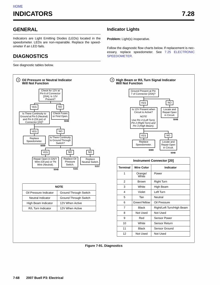
HOME
INDICATORS 7.28
GENERAL
Indicators are Light Emitting Diodes (LEDs) located in thespeedometer. LEDs are non-repairable. Replace the speed-ometer if an LED fails.
DIAGNOSTICS
See diagnostic tables below.
Indicator Lights
Problem: Light(s) inoperative.
Follow the diagnostic flow charts below. If replacement is nec-essary, replace speedometer. See 7.25 ELECTRONICSPEEDOMETER.
Figure 7-91. Diagnostics
Ground Present at Pin 7 of Connector [20A]?
Oil Pressure or Neutral Indicator High Beam or R/L Turn Signal Indicator
Check for 12V at Pin 6 of Connector
[20A]. Is 12V Present?
ReplaceSpeedometer.
Is 12V Present when Circuit is Active?
NOTEUse Pin 4 (Left Turn), Pin 2 (Right Turn) and
Pin 3 (High Beam).
Locate and Repair Open
in Circuit.
Replace Speedometer.
Instrument Connector [20]
Terminal Wire Color Indicator
1 Orange/White
Power
2 Brown Right Turn
3 White High Beam
4 Violet Left Turn
5 Tan Neutral
6 Green/Yellow Oil Pressure
7 Black Right/Left Turn/High Beam
8 Not Used Not Used
9 Red Sensor Power
10 White Sensor Return
11 Black Sensor Ground
12 Not Used Not Used
Replace Oil Pressure Switch.
Repair Open in GN/Y Wire (Oil psi) or TN
Wire (Neutral).
5161
Replace Neutral Switch.
Is There Continuity to Ground Through
Switch?6059
5048 5157
5048
5048
Locate and Repair Open
in Circuit.
5048
YES NO
1
YES
Is There Continuity to Ground at Pin 5 (Neutral)
and Pin 6 (Oil psi) of Connector [20]?
Check Fuses or Find Open.
YES NONO
NO
2
NO
NO
YES
YES
Will Not FunctionWill Not Function
6089
NOTE
Oil Pressure Indicator Ground Through Switch
Neutral Indicator Ground Through Switch
High Beam Indicator 12V When Active
R/L Turn Indicator 12V When Active
7-68 2007 Buell P3: Electrical

HOME
MAIN WIRING HARNESS 7.29
GENERAL
The main wiring harness runs from the front of the motorcycle(behind dash) to the rear of the frame tray under the seatwhere it connects to the tail lamp/turn signal mini-harness.
REMOVAL
1. Remove seat. See 2.28 SEAT.
11WARNING1WARNING
To prevent accidental vehicle start-up, which couldcause death or serious injury, disconnect negative (-)battery cable before proceeding. (00048a)
11WARNING1WARNING
Disconnect negative (-) battery cable first. If positive (+)cable should contact ground with negative (-) cable con-nected, the resulting sparks can cause a battery explo-sion, which could result in death or serious injury.(00049a)
2. Disconnect battery cables, negative cable first.
3. Remove battery. See 7.16 BATTERY.
4. Remove fuel tank. See 4.2 FUEL TANK COVER/FUELTANK.
5. Remove windscreen. See 2.26 WINDSCREEN.
6. Remove headlamp housing and disconnect connector[38]. See 7.17 HEADLAMP.
7. Note location of cable straps and cut three cable strapson frame backbone that secure main wiring harness toframe. Disconnect harness from T-studs.
8. Disconnect speedometer connector [39].
9. Disconnect right and left handlebar switch connectors[22] and [24], front brake switch blade connectors [170]and clutch switch connector [95].
10. Tag and disconnect right and left front turn signal bulletconnectors.
11. Disconnect ignition switch connector [33].
12. Note location of cable strap and cut cable strap on hornwire and remove two blade connectors [122] from horn.
13. See Figure 7-92. Unhook connector [10] from the T-studon the left side of the frame backbone.
14. Note location of cable strap and cut cable strap on igni-tion coil and TP sensor/auto-enrichener and ignitionmodule harness.
15. See Figure 7-93. Disconnect ignition coil connector [83]at coil.
Figure 7-92. Ignition Connector [10]
Figure 7-93. Coil Connector [83]
7813
7814
2007 Buell P3: Electrical 7-69

HOME
16. See Figure 7-94. Disconnect TP sensor/auto-enrichenerconnector [88] under frame backbone.
17. Disconnect starter connector [128] at starter solenoid.
18. See Figure 7-92. Disconnect ignition connector [10] onleft side of frame backbone.
19. Feed harness through frame and upper tie bar mount.
20. Remove nut and clamp that secures oil hoses and wiringharness on right side of motorcycle.
21. Disconnect neutral switch bullet connector [172].
22. Disconnect speed sensor connector [65] located in frametray on right side.
23. Disconnect sidestand switch connector [60] above swingarm.
24. Disconnect oil pressure switch connector [120].
25. Disconnect rear brake line switch connector [121]located above swingarm on right side of motorcycle.
26. See Figure 7-95. Unplug flasher relay connector [30] andstarter relay connector [123] located in frame tray onright hand side.
27. Unplug system relay connector [171] located in frametray on left side.
28. See Figure 7-95. Disconnect positive (+) wire from bat-tery on circuit breaker (upper stud).
29. Disconnect tail lamp/turn signal mini harness connector[7] located under seat.
30. Unhook fuse block.
31. Note location, and cut two cable straps on wire to frameand wire on voltage regulator mount. Disconnect voltageregulator wire and wire attached to frame.
32. Pull main wiring harness out through rear of frame.
Figure 7-94. TP Sensor/Auto-Enrichener Connector [88]
a0225x7x
1. Connector [88]2. Throttle position sensor3. Tamper-resistant T20 TORX screws4. Auto-enrichener
1
2
3
4
Figure 7-95. Flasher Relay Connector [30]
7820
1. Positive wire2. Flasher relay3. Starter relay4. Connector [123]5. Connector [30]
1
23
4
5
7-70 2007 Buell P3: Electrical

HOME
INSTALLATION
1. Feed main wiring harness through frame from back tofront.
2. See Figure 7-95. Connect flasher relay connector [30] toflasher relay and starter relay connector [123] to starterrelay.
3. See Figure 7-96. Connect system relay connector [171]to system relay.
4. Install fuse block.
5. Connect positive (+) wire to circuit breaker. Tighten metalnut to 15-18 in-lbs (1.7-2 Nm). Tighten plastic acorn nutto 1-3 in-lbs (0.1-0.3 Nm).
6. Feed negative (-) wire across frame and connect to volt-age regulator mount and frame. Use two cable straps tosecure wires.
7. See Figure 7-97. Mate speed sensor connector [65].Tuck excess harness into right frame pocket.
8. Connect two blade terminals to stoplight switch aboveswingarm.
9. Mate sidestand switch connector [60] located aboveswingarm cable strap wires.
10. Install starter connector [128] located under starter sole-noid.
11. Install neutral switch bullet connector [172].
12. Install oil pressure switch connector [120] to oil pressureswitch. Route wire around oil pump.
13. Install hose clamp around hoses and oil pressure switchand neutral switch wires. Secure clamp with new locknut.
14. Attach main wiring harness to T-studs.
15. Feed wire harness through upper tie bar mount in twobundles.
Figure 7-96. System Relay
7815
Figure 7-97. Speed Sensor Connector [65]
7819
2007 Buell P3: Electrical 7-71

HOME
16. See Figure 7-98. Mate TP sensor/auto-enrichener con-nector [88] and secure with cable strap.
17. Install connector [83] to coil and secure with cable strap.
18. See Figure 7-92. Mate ignition module connector [10]and attach to T-stud on left side of frame backbone.
19. Feed longer bundle at front through frame hole to leftside of motorcycle. Attach harness to T-stud.
20. Hook right side of harness to two T-studs on right side ofmotorcycle.
21. Mate right handlebar switch connector [22], front brakelamp switch connector [170]. Secure wires with cablestraps.
22. Mate left handlebar switch connector [24] and clutchswitch connector [95]. Secure wires with cable straps.
23. Connect speedometer connector [39].
24. Mate ignition switch connector [33].
25. Install left and right front turn signal bullet connectors asmarked during removal.
26. See Figure 7-99. Feed horn wires through frame hole onright side and install connector [122] to horn. Cable strapwires to isolator mount.
27. Cable strap main wiring harness to frame backbone withthree cable straps.
28. Connect headlamp connector [38] and install headlamphousing. See 7.17 HEADLAMP.
29. Install windscreen. See 2.26 WINDSCREEN.
30. Install fuel tank. 4.2 FUEL TANK COVER/FUEL TANK.
11WARNING1WARNING
Connect positive (+) battery cable first. If positive (+)cable should contact ground with negative (-) cable con-nected, the resulting sparks can cause a battery explo-sion, which could result in death or serious injury.(00068a)
31. Install battery and reconnect battery cables, positivecable first. See 7.16 BATTERY.
11WARNING1WARNING
After installing seat, pull upward on front of seat to besure it is in locked position. While riding, a loose seat canshift causing loss of control, which could result in deathor serious injury. (00070a)
32. Install seat. See 2.28 SEAT.
11WARNING1WARNING
Be sure that all lights and switches operate properlybefore operating motorcycle. Low visibility of rider canresult in death or serious injury. (00316a)
33. Check for proper operation of headlamp, turn signals,brake lamp and starting, charging and ignition systems.
Figure 7-98. TP Sensor/Auto-Enrichener Connector [88]
a0225x7x
1. Connector [88]2. Throttle position sensor3. Tamper-resistant T20 TORX screws4. Auto-enrichener
1
23
4
Figure 7-99. Horn Connector [122]
7816
Y/BK
BK
7-72 2007 Buell P3: Electrical

SUBJECT PAGE NO.
A.1 Tools . . . . . . . . . . . . . . . . . . . . . . . . . . . . . . . . . . . . . . . . . . . . . . . . . . . . . . . . A-1B.1 Connectors . . . . . . . . . . . . . . . . . . . . . . . . . . . . . . . . . . . . . . . . . . . . . . . . . . . B-1B.2 Amp Multilock . . . . . . . . . . . . . . . . . . . . . . . . . . . . . . . . . . . . . . . . . . . . . . . . . B-3B.9 Deutsch . . . . . . . . . . . . . . . . . . . . . . . . . . . . . . . . . . . . . . . . . . . . . . . . . . . . . . B-8B.4 Standard Deutsch Terminal Crimps . . . . . . . . . . . . . . . . . . . . . . . . . . . . . . . . B-12B.3 Sealed Splice . . . . . . . . . . . . . . . . . . . . . . . . . . . . . . . . . . . . . . . . . . . . . . . . . . B-13B.8 Wiring Diagrams . . . . . . . . . . . . . . . . . . . . . . . . . . . . . . . . . . . . . . . . . . . . . . . B-15
Table Of Contents
APPENDICES