Embed Size (px)
Citation preview

Seats and Restraint Systems ........................... 1-1Front Seats ............................................... 1-3Rear Seats ............................................... 1-9Safety Belts ............................................. 1-12Child Restraints ....................................... 1-31Airbag System ......................................... 1-70Restraint System Check ............................ 1-87
Features and Controls ..................................... 2-1Keys ........................................................ 2-3Doors and Locks ....................................... 2-8Windows ................................................. 2-15Theft-Deterrent Systems ............................ 2-18Starting and Operating Your Vehicle ........... 2-20Mirrors .................................................... 2-56OnStar® System ...................................... 2-69Universal Home Remote System ................ 2-71Storage Areas ......................................... 2-75Sunroof .................................................. 2-78Vehicle Personalization ............................. 2-79
Instrument Panel ............................................. 3-1Instrument Panel Overview .......................... 3-4Climate Controls ...................................... 3-20Warning Lights, Gages, and Indicators ........ 3-30Driver Information Center (DIC) .................. 3-51Audio System(s) ....................................... 3-70
Driving Your Vehicle ....................................... 4-1Your Driving, the Road, and Your Vehicle ..... 4-2Towing ................................................... 4-61
Service and Appearance Care .......................... 5-1Service ..................................................... 5-4Fuel ......................................................... 5-6Checking Things Under the Hood ............... 5-12Rear Axle ............................................... 5-56Four-Wheel Drive ..................................... 5-58Front Axle ............................................... 5-60Noise Control System ............................... 5-61Bulb Replacement .................................... 5-62Windshield Wiper Blade Replacement ......... 5-72Tires ...................................................... 5-73Appearance Care ................................... 5-114Vehicle Identification ............................... 5-122Electrical System .................................... 5-123Capacities and Specifications ................... 5-132
Maintenance Schedule ..................................... 6-1Maintenance Schedule ................................ 6-2
Customer Assistance and Information .............. 7-1Customer Assistance and Information ........... 7-2Reporting Safety Defects ........................... 7-13
Index ................................................................ 1
2006 Chevrolet Silverado Owner Manual M
Information Provided by:

GENERAL MOTORS, GM, the GM Emblem,CHEVROLET, the CHEVROLET Emblem, and thenames SILVERADO and Z71 are registered trademarksof General Motors Corporation.
This manual includes the latest information at the time itwas printed. We reserve the right to make changesafter that time without further notice. For vehicles firstsold in Canada, substitute the name “General Motors ofCanada Limited” for Chevrolet Motor Division wheneverit appears in this manual.
Keep this manual in the vehicle, so it will be there if it isneeded while you are on the road. If the vehicle issold, leave this manual in it the vehicle.
Canadian OwnersA French language copy of this manual can be obtainedfrom your dealer or from:
Helm, IncorporatedP.O. Box 07130Detroit, MI 48207
How to Use This ManualMany people read the owner manual from beginning toend when they first receive their new vehicle. If thisis done, it can help you learn about the featuresand controls for the vehicle. Pictures and words worktogether in the owner manual to explain things.
IndexA good place to quickly locate information about thevehicle is the Index in the back of the manual. It is analphabetical list of what is in the manual and thepage number where it can be found.
Litho in U.S.A.Part No. 06SILVERADO A First Printing ©2005 General Motors Corporation. All Rights Reserved.
iiInformation Provided by:

Safety Warnings and SymbolsThere are a number of safety cautions in this book. Weuse a box and the word CAUTION to tell about thingsthat could hurt you if you were to ignore the warning.
{CAUTION:
These mean there is something that could hurtyou or other people.
In the caution area, we tell you what the hazard is.Then we tell you what to do to help avoid or reduce thehazard. Please read these cautions. If you do not,you or others could be hurt.
You will also find a circlewith a slash through it inthis book. This safetysymbol means “Do Not,”“Do Not do this” or “Do Notlet this happen.”
iiiInformation Provided by:

Vehicle Damage WarningsAlso, in this manual you will find these notices:
Notice: These mean there is something that coulddamage your vehicle.
A notice tells about something that can damage thevehicle. Many times, this damage would not be coveredby your vehicle’s warranty, and it could be costly. Butthe notice will tell what to do to help avoid the damage.
When you read other manuals, you might seeCAUTION and NOTICE warnings in different colors or indifferent words.
There are also warning labels on the vehicle. They usethe same words, CAUTION or NOTICE.
Vehicle SymbolsThe vehicle has components and labels that usesymbols instead of text. Symbols are shown along withthe text describing the operation or informationrelating to a specific component, control, message,gage, or indicator.
If you need help figuring out a specific name of acomponent, gage, or indicator, reference the followingtopics:
• Seats and Restraint Systems in Section 1
• Features and Controls in Section 2
• Instrument Panel Overview in Section 3
• Climate Controls in Section 3
• Warning Lights, Gages, and Indicators in Section 3
• Audio System(s) in Section 3
• Engine Compartment Overview in Section 5
ivInformation Provided by:

These are some examples of symbols that may be found on the vehicle:
vInformation Provided by:

✍ NOTES
viInformation Provided by:
Front Seats ......................................................1-3Manual Seats ................................................1-3Power Seats ..................................................1-4Power Lumbar ...............................................1-4Heated Seats .................................................1-5Reclining Seatbacks ........................................1-6Head Restraints .............................................1-8Seatback Latches ...........................................1-8
Rear Seats .......................................................1-9Rear Seat Operation (Extended Cab) ................1-9Rear Seat Operation (Crew Cab) ....................1-10
Safety Belts ...................................................1-12Safety Belts: They Are for Everyone ................1-12Questions and Answers About Safety Belts ......1-16How to Wear Safety Belts Properly .................1-17Driver Position ..............................................1-17Safety Belt Use During Pregnancy ..................1-24Right Front Passenger Position .......................1-25Center Front Passenger Position .....................1-25Rear Seat Passengers ..................................1-26Rear Safety Belt Comfort Guides ....................1-29Safety Belt Extender .....................................1-30
Child Restraints .............................................1-31Older Children ..............................................1-31Infants and Young Children ............................1-33Child Restraint Systems .................................1-37Where to Put the Restraint .............................1-42Lower Anchors and Tethers for
Children (LATCH) ......................................1-44Securing a Child Restraint in a
Rear Seat Position ....................................1-54Securing a Child Restraint in the
Center Front Seat Position ..........................1-56Securing a Child Restraint in the Right Front
Seat Position (Crew Cab) ...........................1-57Securing a Child Restraint in the Right Front
Seat Position (Regular and Extended Cab)(With Airbag Off Switch) .............................1-60
Securing a Child Restraint in the Right FrontSeat Position (Regular and Extended Cab)(With Passenger Sensing System) ...............1-65
Section 1 Seats and Restraint Systems
1-1Information Provided by:

Airbag System ...............................................1-70Where Are the Airbags? ................................1-71When Should an Airbag Inflate? .....................1-73What Makes an Airbag Inflate? .......................1-75How Does an Airbag Restrain? .......................1-75What Will You See After an Airbag Inflates? .....1-76Airbag Off Switch ..........................................1-77
Passenger Sensing System ............................1-80Servicing Your Airbag-Equipped Vehicle ...........1-86Adding Equipment to Your Airbag-Equipped
Vehicle ....................................................1-86Restraint System Check ..................................1-87
Checking the Restraint Systems ......................1-87Replacing Restraint System Parts
After a Crash ............................................1-88
Section 1 Seats and Restraint Systems
1-2Information Provided by:

Front Seats
Manual Seats
{CAUTION:
You can lose control of the vehicle if you try toadjust a manual driver’s seat while the vehicleis moving. The sudden movement could startleand confuse you, or make you push a pedalwhen you do not want to. Adjust the driver’sseat only when the vehicle is not moving.
If your vehicle has a manual bucket or a split benchseat, you can adjust the seat forward or rearward withthe bar located under the front of the seat cushion.
Lift the bar to unlock the seat. Slide the seat to where youwant it and release the bar. Try to move the seat withyour body to be sure the seat is locked in place.
1-3Information Provided by:

Power Seats
If your vehicle has power seats, the controls are locatedon the outboard side of the seats.
• Raise or lower the front of the seat cushion byraising or lowering the front of the horizontal control.
• Raise or lower the rear of the seat cushion byraising or lowering the rear of the horizontal control.
• Raise or lower the entire seat cushion by raising orlowering the whole horizontal control.
• Move the seat forward or rearward by moving thehorizontal control forward or rearward.
If your vehicle has power reclining seatbacks, thecontrol is located rear of the power seat control on theoutboard side of the seats. Adjust the angle of theseatback by pressing the vertical control forwardor rearward. See Reclining Seatbacks on page 1-6.
If your vehicle has manual reclining seatbacks,see Reclining Seatbacks on page 1-6.
Power LumbarYour vehicle may have this feature.
The control is located onthe outboard side of theseat cushion.
To increase or decrease support, hold the controlforward or rearward. Keep in mind that as your seatingposition changes, as it may during long trips, soshould the position of your lumbar support. Adjust theseat as needed.
1-4Information Provided by:
Heated Seats
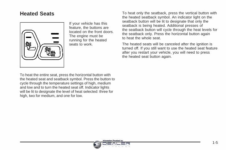
If your vehicle has thisfeature, the buttons arelocated on the front doors.The engine must berunning for the heatedseats to work.
To heat the entire seat, press the horizontal button withthe heated seat and seatback symbol. Press the button tocycle through the temperature settings of high, mediumand low and to turn the heated seat off. Indicator lightswill be lit to designate the level of heat selected: three forhigh, two for medium, and one for low.
To heat only the seatback, press the vertical button withthe heated seatback symbol. An indicator light on theseatback button will be lit to designate that only theseatback is being heated. Additional presses ofthe seatback button will cycle through the heat levels forthe seatback only. Press the horizontal button againto heat the whole seat.
The heated seats will be canceled after the ignition isturned off. If you still want to use the heated seat featureafter you restart your vehicle, you will need to pressthe heated seat button again.
1-5Information Provided by:

Reclining Seatbacks
{CAUTION:
If the seatback is not locked, it could moveforward in a sudden stop or crash. That couldcause injury to the person sitting there. Alwayspush and pull on the seatback to be sure it islocked.
To adjust the seatback, lift the manual lever located onthe outboard side of the seat. Release the lever tolock the seatback in the desired position. Lift the leveragain without pushing on the seatback and the seatbackwill go to an upright position.
1-6Information Provided by:

If your vehicle has power seats with a power recliner,see Power Seats on page 1-4 for further information onhow to operate the reclining seatback feature. {CAUTION:
Sitting in a reclined position when your vehicleis in motion can be dangerous. Even if youbuckle up, your safety belts cannot do theirjob when you are reclined like this.
The shoulder belt cannot do its job. In a crash,you could go into it, receiving neck or otherinjuries.
The lap belt cannot do its job either. In a crashthe belt could go up over your abdomen. Thebelt forces would be there, not at your pelvicbones. This could cause serious internalinjuries.
For proper protection when the vehicle is inmotion, have the seatback upright. Then sitwell back in the seat and wear your safety beltproperly.
Do not have a seatback reclined if your vehicle ismoving.
1-7Information Provided by:

Head Restraints
Adjust your head restraint so that the top of the restraintis closest to the top of your head. This positionreduces the chance of a neck injury in a crash.
Pull the head restraint up to raise it. Push the headrestraint down to lower it.
Your rear seats may have head restraints that can beadjusted up and down.
Seatback LatchesThe front seatbacks fold forward to allow access to therear of the cab.
To fold the seatback forward, lift the lever located onthe outboard side of the seat cushion.
{CAUTION:
If the seatback is not locked, it could moveforward in a sudden stop or crash. That couldcause injury to the person sitting there. Alwayspush and pull on the seatback to be sure it islocked.
To return the seatback to the upright position, push theseatback rearward until it latches. After returning theseatback to its upright position, push and pull onthe seatback to make sure it is locked.
1-8Information Provided by:

Rear Seats
Rear Seat Operation (Extended Cab)
Folding the Rear SeatThe rear seat in the extended cab can be folded up toprovide more cargo space.
To fold the seat up, do the following:1. Push down on the front
of the seat cushionwhile pulling down onthe release strapwhich is located underthe seat cushion.
2. Pull the seat cushion up until it latches with theseatback.
3. After latching the seat cushion up, pull forward on itto make sure it is locked.
The seat can also be folded down for more seatingspace.
To fold the seat down, do the following:
1. Push the seat cushion while pulling the releasestrap which is located under the seat cushion.Pull the seat cushion down until it latches.
2. After latching the seat cushion, pull up on it tomake sure it is locked.
1-9Information Provided by:

Rear Seat Operation (Crew Cab)The second row seat is a 60/40 split seat. Either side ofthe rear seat may be flipped and folded for addedcargo space.
Make sure that nothing is under or in front of the seatand that the head restraints are completely lowered.
To flip and fold the seat, do the following:1. Pull up on the strap
loop at the rear of theseat cushion. Then,pull the seat cushion upand flip it forward.
2. After folding the seat cushion fully forward, pull theseatback forward until it is flat. If the seatbackcannot fold flat because it interferes with thecushion, try moving the front seat forward and/orbringing the front seat more upright. The lever at thebase of the seat must be turned rearward torelease the seatback.
1-10Information Provided by:

To return the seat to the normal seating position, do thefollowing:
1. Lift the seatback up and push it rearward all the way.
{CAUTION:
If the seatback is not locked, it could moveforward in a sudden stop or crash. That couldcause injury to the person sitting there. Alwayspush and pull on the seatback to be sure it islocked.
2. Push and pull on the seatback to make sure it islocked into place.
3. Lower the seat cushion until it latches into position.Pull up on the cushion to make sure it is lockedinto place.
{CAUTION:
A safety belt that is improperly routed, notproperly attached, or twisted will not providethe protection needed in a crash. The personwearing the belt could be seriously injured.After raising the rear seatback, always checkto be sure that the safety belts are properlyrouted and attached, and are not twisted.
Make sure that the safety belt buckles on the driver’sside seatback are accessible to the outboard and centeroccupant and are not under the seat cushions.
1-11Information Provided by:

Safety Belts
Safety Belts: They Are for EveryoneThis part of the manual tells you how to use safetybelts properly. It also tells you some things you shouldnot do with safety belts.
{CAUTION:
Do not let anyone ride where he or she cannotwear a safety belt properly. If you are in acrash and you are not wearing a safety belt,your injuries can be much worse. You can hitthings inside the vehicle or be ejected from it.You can be seriously injured or killed. In thesame crash, you might not be, if you arebuckled up. Always fasten your safety belt,and check that your passengers’ belts arefastened properly too.
{CAUTION:
It is extremely dangerous to ride in a cargoarea, inside or outside of a vehicle. In acollision, people riding in these areas are morelikely to be seriously injured or killed. Do notallow people to ride in any area of your vehiclethat is not equipped with seats and safetybelts. Be sure everyone in your vehicle is in aseat and using a safety belt properly.
Your vehicle has a lightthat comes on as areminder to buckle up. SeeSafety Belt ReminderLight on page 3-33.
In most states and in all Canadian provinces, the lawsays to wear safety belts. Here is why: They work.
1-12Information Provided by:

You never know if you will be in a crash. If you do havea crash, you do not know if it will be a bad one.
A few crashes are mild, and some crashes can be soserious that even buckled up, a person would notsurvive. But most crashes are in between. In many ofthem, people who buckle up can survive and sometimeswalk away. Without belts they could have been badlyhurt or killed.
After more than 30 years of safety belts in vehicles, thefacts are clear. In most crashes buckling up doesmatter...a lot!
Why Safety Belts WorkWhen you ride in or on anything, you go as fast asit goes.
Take the simplest vehicle. Suppose it is just a seat onwheels.
1-13Information Provided by:

Put someone on it. Get it up to speed. Then stop the vehicle. The riderdoes not stop.
1-14Information Provided by:

The person keeps going until stopped by something. Ina real vehicle, it could be the windshield...
or the instrument panel...
1-15Information Provided by:
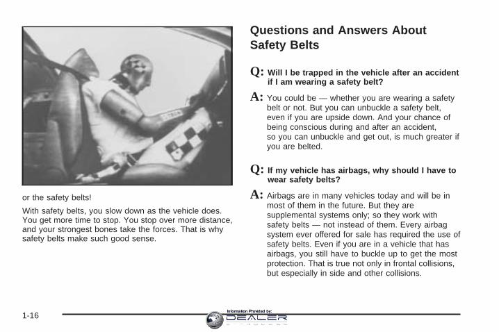
or the safety belts!
With safety belts, you slow down as the vehicle does.You get more time to stop. You stop over more distance,and your strongest bones take the forces. That is whysafety belts make such good sense.
Questions and Answers AboutSafety Belts
Q: Will I be trapped in the vehicle after an accidentif I am wearing a safety belt?
A: You could be — whether you are wearing a safetybelt or not. But you can unbuckle a safety belt,even if you are upside down. And your chance ofbeing conscious during and after an accident,so you can unbuckle and get out, is much greater ifyou are belted.
Q: If my vehicle has airbags, why should I have towear safety belts?
A: Airbags are in many vehicles today and will be inmost of them in the future. But they aresupplemental systems only; so they work withsafety belts — not instead of them. Every airbagsystem ever offered for sale has required the use ofsafety belts. Even if you are in a vehicle that hasairbags, you still have to buckle up to get the mostprotection. That is true not only in frontal collisions,but especially in side and other collisions.
1-16Information Provided by:

Q: If I am a good driver, and I never drive far fromhome, why should I wear safety belts?
A: You may be an excellent driver, but if you are in anaccident — even one that is not your fault — youand your passengers can be hurt. Being a gooddriver does not protect you from things beyond yourcontrol, such as bad drivers.
Most accidents occur within 25 miles (40 km) ofhome. And the greatest number of serious injuriesand deaths occur at speeds of less than 40 mph(65 km/h).
Safety belts are for everyone.
How to Wear Safety Belts ProperlyThis part is only for people of adult size.
Be aware that there are special things to know aboutsafety belts and children. And there are differentrules for smaller children and babies. If a child will beriding in your vehicle, see Older Children on page 1-31or Infants and Young Children on page 1-33. Followthose rules for everyone’s protection.
First, you will want to know which restraint systems yourvehicle has.
We will start with the driver position.
Driver PositionLap-Shoulder BeltThe driver has a lap-shoulder belt. Here is how to wearit properly.
1. Close and lock the door.2. Adjust the seat so you can sit up straight. To see
how, see “Seats” in the Index.
3. Pick up the latch plate and pull the belt across you.Do not let it get twisted.The shoulder belt may lock if you pull the beltacross you very quickly. If this happens, let the beltgo back slightly to unlock it. Then pull the beltacross you more slowly.
1-17Information Provided by:

4. Push the latch plate into the buckle until it clicks.Pull up on the latch plate to make sure it is secure.If the belt is not long enough, see Safety BeltExtender on page 1-30.Make sure the release button on the buckle ispositioned so you would be able to unbuckle thesafety belt quickly if you ever had to.
5. To make the lap part tight, pull up on theshoulder belt.
The lap part of the belt should be worn low and snug onthe hips, just touching the thighs. In a crash, thisapplies force to the strong pelvic bones. And you wouldbe less likely to slide under the lap belt. If you slidunder it, the belt would apply force at your abdomen.This could cause serious or even fatal injuries. Theshoulder belt should go over the shoulder and acrossthe chest. These parts of the body are best able to takebelt restraining forces.
The safety belt locks if there is a sudden stop or crash,or if you pull the belt very quickly out of the retractor.
1-18Information Provided by:

Q: What is wrong with this?
A: The shoulder belt is too loose. It will not give nearlyas much protection this way.
{CAUTION:
You can be seriously hurt if your shoulder beltis too loose. In a crash, you would moveforward too much, which could increase injury.The shoulder belt should fit against your body.
1-19Information Provided by:

Q: What is wrong with this?
A: The belt is buckled in the wrong place.
{CAUTION:
You can be seriously injured if your belt isbuckled in the wrong place like this. In a crash,the belt would go up over your abdomen. Thebelt forces would be there, not at the pelvicbones. This could cause serious internalinjuries. Always buckle your belt into thebuckle nearest you.
1-20Information Provided by:

Q: What is wrong with this?
A: The belt is over an armrest.
{CAUTION:
You can be seriously injured if your belt goesover an armrest like this. The belt would bemuch too high. In a crash, you can slide underthe belt. The belt force would then be appliedat the abdomen, not at the pelvic bones, andthat could cause serious or fatal injuries. Besure the belt goes under the armrests.
1-21Information Provided by:

Q: What is wrong with this?
A: The shoulder belt is worn under the arm. It shouldbe worn over the shoulder at all times.
{CAUTION:
You can be seriously injured if you wear theshoulder belt under your arm. In a crash, yourbody would move too far forward, which wouldincrease the chance of head and neck injury.Also, the belt would apply too much force tothe ribs, which are not as strong as shoulderbones. You could also severely injure internalorgans like your liver or spleen.
1-22Information Provided by:

Q: What is wrong with this?
A: The belt is twisted across the body.
{CAUTION:
You can be seriously injured by a twisted belt.In a crash, you would not have the full width ofthe belt to spread impact forces. If a belt istwisted, make it straight so it can workproperly, or ask your dealer to fix it.
1-23Information Provided by:

To unlatch the belt, just push the button on the buckle.The belt should go back out of the way.
Before you close the door, be sure the belt is out of theway. If you slam the door on it, you can damageboth the belt and your vehicle.
Safety Belt Use During PregnancySafety belts work for everyone, including pregnantwomen. Like all occupants, they are more likely to beseriously injured if they do not wear safety belts.
A pregnant woman should wear a lap-shoulder belt, andthe lap portion should be worn as low as possible,below the rounding, throughout the pregnancy.
The best way to protect the fetus is to protect themother. When a safety belt is worn properly, it is morelikely that the fetus will not be hurt in a crash. Forpregnant women, as for anyone, the key to makingsafety belts effective is wearing them properly.
1-24Information Provided by:

Right Front Passenger PositionTo learn how to wear the right front passenger’s safetybelt properly, see Driver Position on page 1-17.
The right front passenger’s safety belt works the sameway as the driver’s safety belt — except for one thing. Ifyou ever pull the shoulder portion of the belt out all theway, you will engage the child restraint locking featurewhich may turn off the passenger’s frontal airbag. If thishappens unintentionally, just let the belt go back all theway and start again.
Center Front Passenger Position
Lap BeltIf your vehicle has a front bench seat, someone can sitin the center position.
When you sit in the center front seating position, youhave a lap safety belt, which has no retractor. To makethe belt longer, tilt the latch plate and pull it alongthe belt.
1-25Information Provided by:

To make the belt shorter, pull its free end as shownuntil the belt is snug.
Buckle, position and release it the same way as the lappart of a lap-shoulder belt. If the belt is not longenough, see Safety Belt Extender on page 1-30.
Make sure the release button on the buckle is positionedso you would be able to unbuckle the safety beltquickly if you ever had to.
Rear Seat PassengersIt is very important for rear seat passengers to buckleup! Accident statistics show that unbelted people inthe rear seat are hurt more often in crashes than thosewho are wearing safety belts.
Rear passengers who are not safety belted can bethrown out of the vehicle in a crash. And they can strikeothers in the vehicle who are wearing safety belts.
1-26Information Provided by:

Lap-Shoulder BeltAll rear seat positions have lap-shoulder belts. Here ishow to wear one properly.
1. Pick up the latch plate and pull the belt across you.Do not let it get twisted.The shoulder belt may lock if you pull the beltacross you very quickly. If this happens, let the beltgo back slightly to unlock it. Then pull the beltacross you more slowly.
2. Push the latch plate into the buckle until it clicks.Pull up on the latch plate to make sure it is secure.When the shoulder belt is pulled out all the way,it will lock. If it does, let it go back all the way andstart again.If the belt is not long enough, see Safety BeltExtender on page 1-30.Make sure the release button on the buckle ispositioned so you would be able to unbuckle thesafety belt quickly if you ever had to.
3. To make the lap part tight, pull up on theshoulder part.
1-27Information Provided by:

The lap part of the belt should be worn low and snug onthe hips, just touching the thighs. In a crash, thisapplies force to the strong pelvic bones. And you wouldbe less likely to slide under the lap belt. If you slidunder it, the belt would apply force at your abdomen.This could cause serious or even fatal injuries. Theshoulder belt should go over the shoulder and acrossthe chest. These parts of the body are best able to takebelt restraining forces.
The safety belt locks if there is a sudden stop or a crash,or if you pull the belt very quickly out of the retractor.
{CAUTION:
You can be seriously hurt if your shoulder beltis too loose. In a crash, you would moveforward too much, which could increase injury.The shoulder belt should fit against your body.
To unlatch the belt, push the button on the buckle.
1-28Information Provided by:

Rear Safety Belt Comfort GuidesRear seat comfort guides may provide added safety beltcomfort for older children who have outgrown boosterseats and for some adults. When installed on a shoulderbelt, the comfort guide positions the belt away fromthe neck and head.There is one guide for each outside passenger in therear seat. Here is how to install a comfort guide and usethe safety belt:
1. Remove the guide from its storage clip on theinterior body.
2. Place the guide over the belt and insert thetwo edges of the belt into the slots of the guide.
3. Be sure that the belt is not twisted and it lies flat.The guide must be on top of the belt.
1-29Information Provided by:

{CAUTION:
A safety belt that is not properly worn may notprovide the protection needed in a crash. Theperson wearing the belt could be seriouslyinjured. The shoulder belt should go over theshoulder and across the chest. These parts ofthe body are best able to take belt restrainingforces.
4. Buckle, position, and release the safety belt asdescribed in Rear Seat Passengers on page 1-26.Make sure that the shoulder belt crosses theshoulder.
To remove and store the comfort guides, squeeze thebelt edges together so that you can take them out of theguides. Slide the guide onto the storage clip.
Safety Belt ExtenderIf the vehicle’s safety belt will fasten around you, youshould use it.
But if a safety belt is not long enough, your dealer willorder you an extender. It is free. When you go in toorder it, take the heaviest coat you will wear, sothe extender will be long enough for you. To help avoidpersonal injury, do not let someone else use it, anduse it only for the seat it is made to fit. The extender hasbeen designed for adults. Never use it for securingchild seats. To wear it, just attach it to the regular safetybelt. For more information, see the instruction sheetthat comes with the extender.
1-30Information Provided by:

Child Restraints
Older Children
Older children who have outgrown booster seats shouldwear the vehicle’s safety belts.
Q: What is the proper way to wear safety belts?
A: An older child should wear a lap-shoulder belt andget the additional restraint a shoulder belt canprovide. The shoulder belt should not cross the faceor neck. The lap belt should fit snugly below thehips, just touching the top of the thighs. It shouldnever be worn over the abdomen, which couldcause severe or even fatal internal injuries ina crash.
Accident statistics show that children are safer if theyare restrained in the rear seat.
In a crash, children who are not buckled up can strikeother people who are buckled up, or can be thrownout of the vehicle. Older children need to use safetybelts properly.
1-31Information Provided by:

{CAUTION:
Never do this.
Here two children are wearing the same belt.The belt can not properly spread the impactforces. In a crash, the two children can becrushed together and seriously injured. A beltmust be used by only one person at a time.
Q: What if a child is wearing a lap-shoulder belt,but the child is so small that the shoulder beltis very close to the child’s face or neck?
A: If the child is sitting in a seat next to a window,move the child toward the center of the vehicle.Also see Rear Safety Belt Comfort Guides onpage 1-29. If the child is sitting in the center rearseat passenger position, move the child toward thesafety belt buckle. In either case, be sure thatthe shoulder belt still is on the child’s shoulder, sothat in a crash the child’s upper body wouldhave the restraint the belts provide.
1-32Information Provided by:
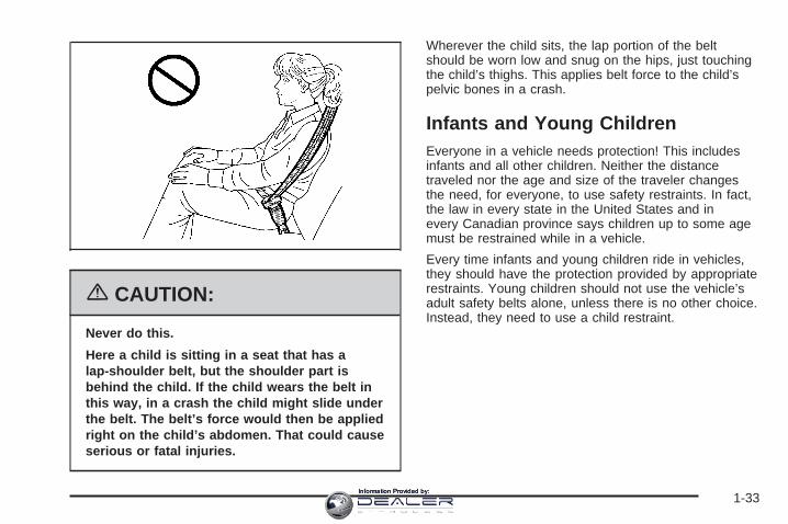
{CAUTION:
Never do this.
Here a child is sitting in a seat that has alap-shoulder belt, but the shoulder part isbehind the child. If the child wears the belt inthis way, in a crash the child might slide underthe belt. The belt’s force would then be appliedright on the child’s abdomen. That could causeserious or fatal injuries.
Wherever the child sits, the lap portion of the beltshould be worn low and snug on the hips, just touchingthe child’s thighs. This applies belt force to the child’spelvic bones in a crash.
Infants and Young ChildrenEveryone in a vehicle needs protection! This includesinfants and all other children. Neither the distancetraveled nor the age and size of the traveler changesthe need, for everyone, to use safety restraints. In fact,the law in every state in the United States and inevery Canadian province says children up to some agemust be restrained while in a vehicle.
Every time infants and young children ride in vehicles,they should have the protection provided by appropriaterestraints. Young children should not use the vehicle’sadult safety belts alone, unless there is no other choice.Instead, they need to use a child restraint.
1-33Information Provided by:

{CAUTION:
People should never hold a baby in their armswhile riding in a vehicle. A baby does notweigh much — until a crash. During a crash ababy will become so heavy it is not possible tohold it. For example, in a crash at only 25 mph(40 km/h), a 12 lb (5.5 kg) baby will suddenlybecome a 240 lb (110 kg) force on a person’sarms. A baby should be secured in anappropriate restraint.
1-34Information Provided by:

{CAUTION:
Children who are up against, or very close to,any airbag when it inflates can be seriouslyinjured or killed. Airbags plus lap-shoulderbelts offer protection for adults and olderchildren, but not for young children andinfants. Neither the vehicle’s safety belt systemnor its airbag system is designed for them.Young children and infants need the protectionthat a child restraint system can provide.
1-35Information Provided by:

Q: What are the different types of add-on childrestraints?
A: Add-on child restraints, which are purchased by thevehicle’s owner, are available in four basic types.Selection of a particular restraint should takeinto consideration not only the child’s weight, heightand age but also whether or not the restraint willbe compatible with the motor vehicle in which it willbe used.
For most basic types of child restraints, there aremany different models available. When purchasing achild restraint, be sure it is designed to be usedin a motor vehicle. If it is, the restraint will have alabel saying that it meets federal motor vehiclesafety standards.
The restraint manufacturer’s instructions that comewith the restraint, state the weight and heightlimitations for a particular child restraint. In addition,there are many kinds of restraints available forchildren with special needs.
{CAUTION:
Newborn infants need complete support,including support for the head and neck. Thisis necessary because a newborn infant’s neckis weak and its head weighs so muchcompared with the rest of its body. In a crash,an infant in a rear-facing seat settles into therestraint, so the crash forces can bedistributed across the strongest part of aninfant’s body, the back and shoulders. Infantsalways should be secured in appropriate infantrestraints.
1-36Information Provided by:

{CAUTION:
The body structure of a young child is quiteunlike that of an adult or older child, for whomthe safety belts are designed. A young child’ship bones are still so small that the vehicle’sregular safety belt may not remain low on thehip bones, as it should. Instead, it may settleup around the child’s abdomen. In a crash, thebelt would apply force on a body area that isunprotected by any bony structure. This alonecould cause serious or fatal injuries. Youngchildren always should be secured inappropriate child restraints.
Child Restraint Systems
An infant car bed (A), a special bed made for use in amotor vehicle, is an infant restraint system designedto restrain or position a child on a continuous flatsurface. Make sure that the infant’s head rests towardthe center of the vehicle.
1-37Information Provided by:

A rear-facing infant seat (B) provides restraint with theseating surface against the back of the infant. Theharness system holds the infant in place and, in a crash,acts to keep the infant positioned in the restraint.
A forward-facing child seat (C-E) provides restraint forthe child’s body with the harness and also sometimeswith surfaces such as T-shaped or shelf-like shields.
1-38Information Provided by:

A booster seat (F-G) is a child restraint designed toimprove the fit of the vehicle’s safety belt system. Somebooster seats have a shoulder belt positioner, andsome high-back booster seats have a five-point harness.A booster seat can also help a child to see out thewindow.
Q: How Should I Use a Child Restraint?
A: A child restraint system is any device designed foruse in a motor vehicle to restrain, seat, or positionchildren. A built-in child restraint system is apermanent part of the motor vehicle. An add-onchild restraint system is a portable one, whichis purchased by the vehicle’s owner. To help reduceinjuries, an add-on child restraint must be securedin the vehicle. With built-in or add-on childrestraints, the child has to be secured within thechild restraint.
When choosing an add-on child restraint, be surethe child restraint is designed to be used in avehicle. If it is, it will have a label saying that itmeets federal motor vehicle safety standards. Thenfollow the instructions for the restraint. You mayfind these instructions on the restraint itself or in abooklet, or both.
1-39Information Provided by:

Securing an Add-on Child Restraint inthe Vehicle
{CAUTION:
A child can be seriously injured or killed in acrash if the child restraint is not properlysecured in the vehicle. Make sure the childrestraint is properly installed in the vehicleusing the vehicle’s safety belt or LATCHsystem, following the instructions that camewith that restraint, and also the instructions inthis manual.
To help reduce the chance of injury, the child restraintmust be secured in the vehicle. Child restraint systemsmust be secured in vehicle seats by lap belts or thelap belt portion of a lap-shoulder belt, or by the LATCHsystem. See Lower Anchors and Tethers for Children(LATCH) on page 1-44 for more information. A child canbe endangered in a crash if the child restraint is notproperly secured in the vehicle.
When securing an add-on child restraint, refer to theinstructions that come with the restraint which may be onthe restraint itself or in a booklet, or both, and to thismanual. The child restraint instructions are important, soif they are not available, obtain a replacement copyfrom the manufacturer.
Keep in mind that an unsecured child restraint canmove around in a collision or sudden stop and injurepeople in the vehicle. Be sure to properly secureany child restraint in your vehicle — even when no childis in it.
1-40Information Provided by:

Securing the Child Within the ChildRestraintThere are several systems for securing the child withinthe child restraint. One system, the three-pointharness, has straps that come down over each of theinfant’s shoulders and buckle together at the crotch. Thefive-point harness system has two shoulder straps,two hip straps, and a crotch strap. A shield may take theplace of hip straps. A T-shaped shield has shoulderstraps that are attached to a flat pad which restslow against the child’s body. A shelf- or armrest-typeshield has straps that are attached to a wide, shelf-likeshield that swings up or to the side.
{CAUTION:
A child can be seriously injured or killed in acrash if the child is not properly secured in thechild restraint. Make sure the child is properlysecured, following the instructions that camewith that restraint.
Because there are different systems, it is important torefer to the instructions that come with the restraint.A child can be endangered in a crash if the child is notproperly secured in the child restraint.
1-41Information Provided by:
Where to Put the RestraintAccident statistics show that children are safer if theyare restrained in the rear rather than the front seat.
We recommend that child restraints be secured in a rearseat including an infant riding in a rear-facing infantseat, a child riding in a forward-facing child seat and anolder child riding in a booster seat.
Your vehicle may have a label on your sun visor thatsays, “Never put a rear-facing child seat in thefront.” This is because the risk to the rear-facing child isso great, if the airbag deploys.
Never put a child in a rear-facing child restraint in theright front passenger seat unless your vehicle hasthe passenger sensing system or an airbag off switchand the passenger airbag status indicator or theairbag off light shows off. Never put a rear facing childrestraint in the right front passenger seat unless theairbag is off.
Here is why:
{CAUTION:
A child in a rear-facing child restraint can beseriously injured or killed if the right frontpassenger’s airbag inflates. This is becausethe back of the rear-facing child restraintwould be very close to the inflating airbag. Besure the airbag is off before using a rear-facingchild restraint in the right front seat position.
Even though the passenger sensing system orairbag off switch are designed to turn off thepassenger’s frontal airbag under certainconditions, no system is fail-safe, and no onecan guarantee that an airbag will not deployunder some unusual circumstance, eventhough it is turned off. General Motorsrecommends that rear-facing child restraintsbe transported in vehicles with a rear seat thatwill accommodate a rear-facing child restraint,whenever possible.
CAUTION: (Continued)
1-42Information Provided by:

CAUTION: (Continued)
If you need to secure a forward-facing childrestraint in the right front seat, always movethe front passenger seat as far back as it willgo. It is better to secure the child restraint in arear seat.
{CAUTION:
A child in a child restraint in the center frontseat can be badly injured or killed by the rightfront passenger’s airbag if it inflates. Neversecure a child restraint in the center front seat.It is always better to secure a child restraint inthe rear seat.
Do not use child restraints in the center front seatposition. The restraints will not work properly.
There is limited space in the rear seating area of anextended cab model. If you want to secure a childrestraint in a rear seating position of an extended cabmodel, especially in the rear center position, besure to study the instructions that came with your childrestraint to see if there is enough room to secureyour seat properly.
If your vehicle has the passenger sensing system or theairbag off switch and you need to secure a rear-facingchild restraint in the right front passenger’s seat,the passenger’s frontal airbag must be off. SeePassenger Sensing System on page 1-80, Airbag OffSwitch on page 1-77,Securing a Child Restraint inthe Right Front Seat Position (Regular and ExtendedCab) (With Airbag Off Switch) on page 1-60 or Securinga Child Restraint in the Right Front Seat Position(Regular and Extended Cab) (With Passenger SensingSystem) on page 1-65 for more on this includingimportant safety information.
Wherever you install a child restraint, be sure to securethe child restraint properly.
Keep in mind that an unsecured child restraint canmove around in a collision or sudden stop and injurepeople in the vehicle. Be sure to properly secureany child restraint in your vehicle — even when no childis in it.
1-43Information Provided by:

Lower Anchors and Tethers forChildren (LATCH)Your vehicle has the LATCH system. The LATCHsystem holds a child restraint during driving or in acrash. This system is designed to make installation of achild restraint easier. The LATCH system usesanchors in the vehicle and attachments on the childrestraint that are made for use with the LATCH system
Make sure that a LATCH-compatible child restraintis properly installed using the anchors, or use thevehicle’s safety belts to secure the restraint, followingthe instructions that came with that restraint, andalso the instructions in this manual. When installing achild restraint with a top tether, you must also use eitherthe lower anchors or the safety belts to properlysecure the child restraint. A child restraint must neverbe installed using only the top tether and anchor.
In order to use the LATCH system in your vehicle, youneed a child restraint equipped with LATCHattachments. The child restraint manufacturer willprovide you with instructions on how to use the childrestraint and its attachments. The following explains howto attach a child restraint with these attachments inyour vehicle.
Your vehicle, except for regular cab models, has loweranchors and top tether anchors. Your child restraintmay have lower attachments and a top tether.
Not all vehicle seating positions or child restraints havelower anchors and attachments or top tether anchorsand attachments.
Lower Anchors
Lower anchors (A) are metal bars built into the vehicle.There are two lower anchors for each LATCH seatingposition that will accommodate a child restraint withlower attachments (B).
1-44Information Provided by:

Top Tether Anchor
A top tether (A, C) anchors the top of the child restraintto the vehicle. A top tether anchor is built into thevehicle. The top tether attachment (B) on the childrestraint connects to the top tether anchor in the vehiclein order to reduce the forward movement and rotationof the child restraint during driving or in a crash.
Your child restraint may have a single tether (A) or adual tether (C). Either will have a single attachment (B)to secure the top tether to the anchor.
Some top tether-equipped child restraints are designedfor use with or without the top tether being attached.Others require the top tether always to be attached. InCanada, the law requires that forward-facing childrestraints have a top tether, and that the tether beattached. In the United States, some child restraints alsohave a top tether. Be sure to read and follow theinstructions for your child restraint.
If the child restraint does not have a top tether, one canbe obtained, in kit form, for many child restraints. Askthe child restraint manufacturer whether or not a kitis available.
1-45Information Provided by:

Lower Anchor and Top Tether AnchorLocations
i (Top Tether Anchor):Seating positions with toptether anchors.
i (Top Tether Anchor):Seating positions with toptether anchors. Do notinstall a child restraint inthe center seat position.See Securing a ChildRestraint in the CenterFront Seat Positionon page 1-56 for moreinformation.
i (Top Tether Anchor):Seating positions with toptether anchors.
j (Lower Anchor):Seating positions with twolower anchors.
i (Top Tether Anchor):Seating positions with toptether anchors.
j (Lower Anchor):Seating positions withtwo lower anchors.
Regular Cab — Bucket
Regular Cab — Bench
Extended Cab
Crew Cab
1-46Information Provided by:

For crew cab models, the rear passenger side andcenter seating positions have exposed metal loweranchors located in the crease between the seatback andthe seat cushion.
For extended cab models, the rear outboard seatingpositions have exposed metal lower anchors located inthe crease between the seatback and the seatcushion.
For regular and crew cabmodels, there is an anchorsymbol on the trimcovers to assist you inlocating the top tetheranchors.
For regular cab models with a bench seat, the top tetheranchors are located under trim covers on the backpanel behind the center and passenger seats. Do notinstall a child restraint in the center seat position.See Securing a Child Restraint in the Center Front SeatPosition on page 1-56 for more information. Forregular cab models with bucket seats, the top tetheranchor is located under a trim covers on the back panelbehind the passenger seat. Remove the trim plug toaccess the anchor.
Regular Cab
1-47Information Provided by:

For extended cab models, the top tether anchors arelocated near the top of the seatback for each rearseating position. In addition to the top tether anchors,each seating position has a fabric loop at the top of theseatback that you will use to route the top tetherthrough. Be sure to use an anchor located on the sameside of the vehicle as the seating position where thechild restraint will be placed.
For crew cab models, there are covered top tetheranchors for each seating position located on the backpanel of your vehicle, behind the rear seat. Remove thetrim covers to access the anchors.
Do not secure a child restraint in the front passenger’sposition if your vehicle has rear seats, if a nationalor local law requires that the top tether be attached, or ifthe instructions that come with the child restraint saythat the top tether must be attached. There is no placeto attach the top tether in this position.
Extended Cab
Crew Cab
1-48Information Provided by:

Accident statistics show that children are safer if theyare restrained in the rear rather than the front seat. SeeWhere to Put the Restraint on page 1-42 for additionalinformation.
Securing a Child Restraint Designed forthe LATCH System
{CAUTION:
If a LATCH-type child restraint is not attachedto anchors, the restraint will not be able toprotect the child correctly. In a crash, the childcould be seriously injured or killed. Make surethat a LATCH-type child restraint is properlyinstalled using the anchors, or use thevehicle’s safety belts to secure the restraint,following the instructions that came with thatrestraint, and also the instructions in thismanual.
{CAUTION:
Each top tether anchor, except the center toptether anchor in an extended cab model, andlower anchors in the vehicle are designed tohold only one child restraint. Attaching morethan one child restraint to a single anchorcould cause the anchor or attachment to comeloose or even break during a crash. A child orothers could be injured if this happens. Tohelp prevent injury to people and damage toyour vehicle, attach only one child restraint peranchor.
1-49Information Provided by:

Regular Cab Models
1. If the child restraint manufacturer recommends thatthe top tether be attached, attach and tighten thetop tether to the top tether anchor, if equipped.Refer to the child restraint instructions andthe following steps:
1.1. Pull the passenger seatback forward bypulling the recliner handle upward to accessthe top tether anchor. See RecliningSeatbacks on page 1-6 for additionalinformation.
1.2. Find the top tether anchor.1.3. Remove the trim cover to expose the anchor.1.4. Route, attach and tighten the top tether
according to your child restraint instructionsand the following instructions:
If the position you areusing does not have ahead restraint and you areusing a single tether,route the tether over theseatback.
If the position you areusing does not have ahead restraint and you areusing a dual tether,route the tether over theseatback.
If the position you areusing has an adjustablehead restraint and you areusing a dual tether,route the tether around thehead restraint.
If the position you areusing has an adjustablehead restraint and you areusing a single tether,raise the head restraintand route the tether underthe head restraint andin between the headrestraint posts.
1-50Information Provided by:

2. See Securing a Child Restraint in the Right FrontSeat Position (Regular and Extended Cab) (WithAirbag Off Switch) on page 1-60 or Securing a ChildRestraint in the Right Front Seat Position (Regularand Extended Cab) (With Passenger SensingSystem) on page 1-65 for instructions on installingthe child restraint using the safety belts.
3. Push and pull the child restraint in differentdirections to be sure it is secure.
Extended Cab Models1. Attach and tighten the lower attachments to the
lower anchors. If the child restraint does not havelower attachments or the desired seating positiondoes not have lower anchors, secure the childrestraint with the top tether and the safety belts.Refer to your child restraint manufacturerinstructions and the instructions in this manual.
1.1. Find the lower anchors for the desiredseating position.
1.2. Put the child restraint on the seat.1.3. Attach and tighten the lower attachments on
the child restraint to the lower anchors.
2. If the child restraint manufacturer recommends thatthe top tether be attached, attach and tighten thetop tether to the top tether anchor, if equipped.Refer to the child restraint instructions andthe following steps:
2.1. When using a child restraint with a top tetherin the rear driver’s side position, raise thehead restraint and route the top tetherthrough the fabric loop and under the centershoulder belt. Then, attach the top tetherto the metal anchor point at the center rearseating position.
1-51Information Provided by:

2.2. When using a child restraint with a top tetherin the rear passenger position, raise thehead restraint and route the top tetherthrough the fabric loop. Then, attach the toptether to the metal anchor point at thecenter rear seating position.
2.3. When using a child restraint with a top tetherin the rear center position, route the toptether through the fabric loop. Then, raise thehead restraint on the passenger side andattach the top tether to the metal anchorpoint located at the rear passenger position.
2.4. Tighten the top tether when and as the childrestraint manufacturer’s instructions say.
3. Push and pull the child restraint in differentdirections to be sure it is secure.
Crew Cab Models1. If the child restraint manufacturer recommends that
the top tether be attached, attach and tighten thetop tether to the top tether anchor, if equipped.Refer to the child restraint instructions andthe following steps:
1.1. To access the top tether anchors, raise theseat cushion by pulling up on the strap loopat the rear of the seat cushion and foldthe seat cushion forward. Then foldthe seatback forward. See Rear SeatOperation (Extended Cab) on page 1-9 orRear Seat Operation (Crew Cab) onpage 1-10 for additional information.
1.2. Place the child restraint in the vehicle, nearthe seating position that you are using.
1.3. Route the top tether according to your childrestraint instructions and the followinginstructions:
If the position you areusing does not have ahead restraint and you areusing a single tether,route the tether over theseatback.
1-52Information Provided by:

If the position you areusing does not have ahead restraint and you areusing a dual tether,route the tether over theseatback.
If the position you areusing has an adjustablehead restraint and you areusing a dual tether,route the tether around thehead restraint.
If the position you are usinghas an adjustable headrestraint and you are usinga single tether, raise thehead restraint and route thetether under the headrestraint and in between thehead restraint posts.
1.4. Remove the trim cover to expose the toptether anchor.
1.5. Attach the top tether attachment to the toptether anchor.
{CAUTION:
If the seatback is not locked, it could moveforward in a sudden stop or crash. That couldcause injury to the person sitting there. Alwayspush and pull on the seatback to be sure it islocked.
1.6. Lift the seatback up and push it rearward.Then lower the seat cushion until theseatback and the seat cushion lock intoposition.
2. Attach and tighten the lower attachments to thelower anchors. If the child restraint does not havelower attachments or the desired seating positiondoes not have lower anchors, secure the childrestraint with the top tether and the safety belts.Refer to your child restraint manufacturerinstructions and the instructions in this manual.
2.1. Find the lower anchors for the desiredseating position.
2.2. Put the child restraint on the seat.2.3. Attach and tighten the lower attachments on
the child restraint to the lower anchors.3. Tighten the top tether.4. Push and pull the child restraint in different
directions to be sure it is secure.
1-53Information Provided by:
Securing a Child Restraint in a RearSeat Position
Extended Cab and Crew CabThere is limited space in the rear seating of an extendedcab model. If you want to secure a child restraint in arear seating position, be sure to study the instructionsthat came with your child restraint to see if there isenough room to secure your seat properly.
If your child restraint is equipped with the LATCHsystem, see Lower Anchors and Tethers for Children(LATCH) on page 1-44.
If your child restraint does not have the LATCH system,you will be using the lap-shoulder belt to secure thechild restraint in this position. Be sure to follow theinstructions that came with the child restraint. Securethe child in the child restraint when and as theinstructions say.
1. Put the child restraint on the seat.
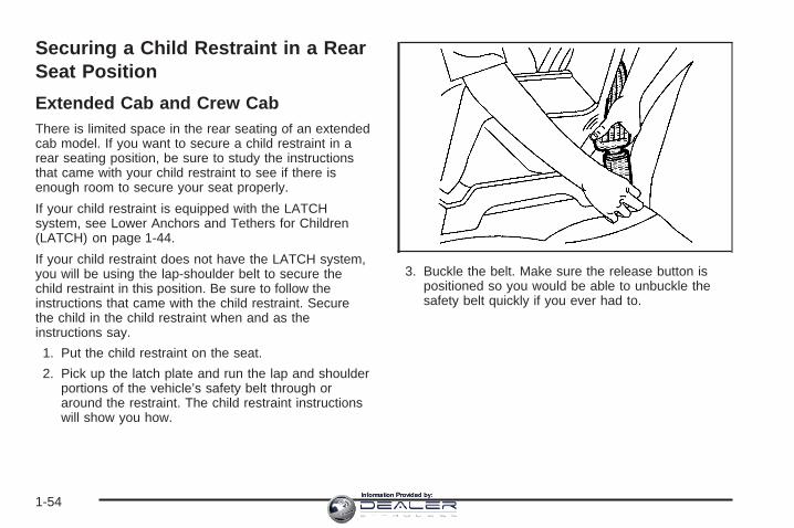
2. Pick up the latch plate and run the lap and shoulderportions of the vehicle’s safety belt through oraround the restraint. The child restraint instructionswill show you how.
3. Buckle the belt. Make sure the release button ispositioned so you would be able to unbuckle thesafety belt quickly if you ever had to.
1-54Information Provided by:

4. Pull the rest of the shoulder belt all the way out ofthe retractor to set the lock.
5. To tighten the belt, push down on the child restraint,pull the shoulder portion of the belt to tighten thelap portion of the belt and feed the shoulderbelt back into the retractor. If you are using aforward-facing child restraint, you may find it helpfulto use your knee to push down on the childrestraint as you tighten the belt.
1-55Information Provided by:

6. If your child restraint manufacturer recommendsusing a top tether, attach and tighten the toptether to the top tether anchor. Refer to theinstructions that came with the child restraint and toLower Anchors and Tethers for Children (LATCH)on page 1-44.
7. Push and pull the restraint in different directions tobe sure it is secure.
To remove the child restraint, if the top tether is attachedto a top tether anchor, disconnect it. Unbuckle thevehicle’s safety belt and let it go back all the way. Thesafety belt will move freely again and be ready towork for an adult or larger child passenger.
Securing a Child Restraint in theCenter Front Seat Position
{CAUTION:
A child in a child restraint in the center frontseat can be badly injured or killed by the rightfront passenger’s airbag if it inflates. Neversecure a child restraint in the center front seat.It is always better to secure a child restraint inthe rear seat.
Do not use child restraints in this position.
1-56Information Provided by:

Securing a Child Restraint in theRight Front Seat Position(Crew Cab)Your vehicle has a right front passenger airbag. Neverput a rear-facing child restraint in the right frontpassenger’s seat. Here is why:
{CAUTION:
A child in a rear-facing child restraint can beseriously injured or killed if the right frontpassenger’s airbag inflates. This is becausethe back of the rear-facing child restraintwould be very close to the inflating airbag.Always secure a rear-facing child restraint in arear seat.
A rear seat is a safer place to secure a forward-facingchild restraint. If you need to secure a forward-facingchild restraint in the right front seat position, see Whereto Put the Restraint on page 1-42.
If your child restraint is equipped with the LATCHsystem, see Lower Anchors and Tethers for Children(LATCH) on page 1-44.
There is no top tether anchor in the right frontpassenger’s position. Do not secure a child seat in thisposition if a national or local law requires that thetop tether be anchored, or if the instructions that comewith the child restraint say that the top tether mustbe anchored. See Lower Anchors and Tethersfor Children (LATCH) on page 1-44 if your child restrainthas a top tether.
You will be using the lap-shoulder belt to secure therestraint in this position. Be sure to follow theinstructions that came with the child restraint. Securethe child in the child restraint when and as theinstructions say.
1. Because your vehicle has a right front passenger’sfrontal airbag, always move the seat as far back asit will go before securing a forward-facing childrestraint. See Manual Seats on page 1-3 or PowerSeats on page 1-4.
2. Put the child restraint on the seat.
3. Pick up the latch plate, and run the lap and shoulderportions of the vehicle’s safety belt through oraround the restraint. The child restraint instructionswill show you how.
1-57Information Provided by:

4. Buckle the belt. Make sure the release button ispositioned so you would be able to unbuckle thesafety belt quickly if you ever had to.
5. Pull the rest of the shoulder belt all the way out ofthe retractor to set the lock.
1-58Information Provided by:

6. To tighten the belt, push down on the child restraint,pull the shoulder portion of the belt to tighten thelap portion of the belt and feed the shoulderbelt back into the retractor. If you are using aforward-facing child restraint, you may find it helpfulto use your knee to push down on the childrestraint as you tighten the belt. You should not beable to pull more of the belt out of the retractoronce the lock has been set.
7. Push and pull the child restraint in differentdirections to be sure it is secure.
To remove the child restraint, just unbuckle the vehicle’ssafety belt and let it go back all the way. The safetybelt will move freely again and be ready to work for anadult or larger child passenger.
1-59Information Provided by:

Securing a Child Restraint in theRight Front Seat Position (Regularand Extended Cab) (With AirbagOff Switch)Your vehicle has a right front passenger airbag.If your instrument panel has one of the switches picturedin the following illustrations, your vehicle has anairbag off switch that you can use to turn off the rightfront passenger’s airbag.
Your switch may vary slightly. See Airbag Off Switch onpage 1-77 for more on this, including important safetyinformation and illustrations of alternate switch designs.
{CAUTION:
A child in a rear-facing child restraint can beseriously injured or killed if the passenger’sairbag inflates. This is because the back of therear-facing child restraint would be very closeto the inflating airbag. Do not use a rear-facingchild restraint in this vehicle unless thepassenger’s airbag has been turned off.
Even though the airbag off switch is designedto turn off the passenger’s frontal airbag, nosystem is fail-safe, and no one can guaranteethat an airbag will not deploy under someunusual circumstance, even though it is turnedoff. We recommend that rear-facing childrestraints be transported in vehicles with arear seat that will accommodate a rear-facingchild restraint, whenever possible.
If you need to secure a forward-facing childrestraint in the right front static seat or theright front bench seat, always move thepassenger seat as far back as it will go.United States Canada
1-60Information Provided by:
Never put a rear facing child restraint in the right frontpassenger’s seat unless the airbag is off. Here is why:
{CAUTION:
A child in a rear-facing child restraint can beseriously injured or killed if the right frontpassenger’s airbag inflates. This is becausethe back of the rear-facing child restraintwould be very close to the inflating airbag. Besure the airbag is off before using a rear-facingchild restraint in the right front seat position. Ifyou secure a forward-facing child restraint inthe right front seat, always move the right frontpassenger seat as far back as it will go.
A rear seat is a safer place to secure a forward facingchild restraint. See Where to Put the Restraint onpage 1-42. If you need to secure a forward-facing childrestraint in the right front seat position, move theseat as far back as it will go before securing aforward-facing child restraint. See Manual Seats onpage 1-3 or Power Seats on page 1-4.
{CAUTION:
If the airbag readiness light in the instrumentpanel cluster ever comes on when you haveturned off the airbag, it means that somethingmay be wrong with the airbag system. Theright front passenger’s airbag could inflateeven though the switch is off. If this everhappens, have the vehicle serviced promptly.Until you have the vehicle serviced, do not letanyone whom the national government hasidentified as a member of a passenger airbagrisk group sit in the right front passenger’sposition (for example, do not secure arear-facing child restraint in the right frontpassenger’s seat). See Airbag Off Switch onpage 1-77.
If your child restraint is equipped with the LATCHsystem, see Lower Anchors and Tethers for Children(LATCH) on page 1-44.
1-61Information Provided by:
If your vehicle has a rear seat, there is no top tetheranchor at the right front seating position. Do not securea child seat in this position if a national or local lawrequires that the top tether be anchored or if theinstructions that come with the child restraint say thatthe top tether must be anchored. See Lower Anchorsand Tethers for Children (LATCH) on page 1-44 ifthe child restraint has a top tether.
You will be using the lap-shoulder belt to secure thechild restraint in this position. Be sure to follow theinstructions that came with the child restraint. Securethe child in the child restraint when and as theinstructions say.
1. Your vehicle has a right front passenger’s frontalairbag. See Airbag Off Switch on page 1-77. Ifyour child restraint is forward-facing, move the seatas far back as it will go before securing therestraint in this seat. See Manual Seats on page 1-3or Power Seats on page 1-4. If you need to use arear-facing child restraint in this seat, make sure theairbag is off once the child restraint has beeninstalled.When the airbag off switch has turned off the rightfront passenger’s frontal airbag, the off indicatorin the airbag off light should light and stay lit whenyou turn the ignition to RUN or START. SeeAirbag Off Light on page 3-34.
2. Put the child restraint on the seat.
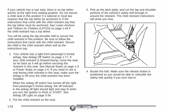
3. Pick up the latch plate, and run the lap and shoulderportions of the vehicle’s safety belt through oraround the restraint. The child restraint instructionswill show you how.
4. Buckle the belt. Make sure the release button ispositioned so you would be able to unbuckle thesafety belt quickly if you ever had to.
1-62Information Provided by:

5. Pull the rest of the shoulder belt all the way out ofthe retractor to set the lock.
6. To tighten the belt, push down on the child restraint,pull the shoulder belt to tighten the lap belt portionand feed the shoulder belt back into the retractor.If you are using a forward-facing child restraint, youmay find it helpful to use your knee to pushdown on the child restraint as you tighten the belt.You should not be able to pull more of the beltout of the retractor once the lock has been set.
1-63Information Provided by:

7. If your child restraint manufacturer recommendsusing a top tether, and the position you are usinghas a top tether anchor, attach and tighten thetop tether to the top tether anchor. Refer tothe instructions that came with the child restraintand to Lower Anchors and Tethers for Children(LATCH) on page 1-44.
8. Push and pull the child restraint in differentdirections to be sure it is secure.
To remove the child restraint, if the top tether is attachedto the top tether anchor, disconnect it. Unbuckle thevehicle’s safety belt and let it go back all the way. Thesafety belt will move freely again and be ready towork for an adult or larger child passenger.
If you had turned the airbag off with the switch,remember to be sure to use the airbag off switch to turnon the right front passenger’s airbag when you removethe child restraint from the vehicle unless the personwho will be sitting there is a member of a passengerairbag risk group. See Airbag Off Switch on page 1-77.
{CAUTION:
If the right front passenger’s airbag is turnedoff for a person who is not in a risk groupidentified by the national government, thatperson will not have the extra protection of anairbag. In a crash, the airbag will not be able toinflate and help protect the person sittingthere. Do not turn off the passenger’s airbagunless the person sitting there is in a riskgroup. See Airbag Off Switch on page 1-77 formore on this, including important safetyinformation.
1-64Information Provided by:

Securing a Child Restraint in theRight Front Seat Position (Regularand Extended Cab) (With PassengerSensing System)Your vehicle has a right front passenger airbag. A rearseat is a safer place to secure a forward-facing childrestraint. See Where to Put the Restraint on page 1-42.
If your rearview mirror has one of the indicatorspictured in the following illustrations, your vehicle has apassenger sensing system.
The passenger sensing system is designed to turn offthe right front passenger’s frontal airbag when an infantin a rear-facing infant seat or a small child in aforward-facing child restraint or booster seat is detected.See Passenger Sensing System on page 1-80 andPassenger Airbag Status Indicator on page 3-36for more information on this including important safetyinformation.
United States
Canada
1-65Information Provided by:

Your vehicle may have a label on your sun visor thatsays, “Never put a rear-facing child seat in thefront.” This is because the risk to the rear-facing child isso great, if the airbag deploys.
{CAUTION:
A child in a rear-facing child restraint can beseriously injured or killed if the right frontpassenger’s airbag inflates. This is becausethe back of the rear-facing child restraintwould be very close to the inflating airbag.
Even though the passenger sensing system isdesigned to turn off the passenger’s frontalairbag if the system detects a rear-facing childrestraint, no system is fail-safe, and no onecan guarantee that an airbag will not deployunder some unusual circumstance, eventhough it is turned off. We recommend thatrear-facing child restraints be secured in therear seat, even if the airbag is off.
Never put a child in a rear-facing child restraint in the rightfront passenger seat the unless passenger airbag statusindicator shows off. Never put a rear facing child restraintin the right front passenger seat unless the airbag is off.
Here is why:
{CAUTION:
A child in a rear-facing child restraint can beseriously injured or killed if the right frontpassenger’s airbag inflates. This is becausethe back of the rear facing child restraintwould be very close to the inflating airbag. Besure the airbag is off before using a rear-facingchild restraint in the right front seat position.
Even though the passenger sensing system isdesigned to turn off the passenger’s frontalairbag if the system detects a rear-facing childrestraint, no system is fail-safe, and no onecan guarantee that an airbag will not deployunder some unusual circumstance, eventhough it is turned off. We recommend thatrear-facing child restraints be transported invehicles with a rear seat that willaccommodate a rear-facing child restraint,whenever possible.
1-66Information Provided by:

If you need to secure a forward-facing child restraint inthe right front seat position, move the seat as farback as it will go before securing the forward-facingchild restraint. See Power Seats on page 1-4 or ManualSeats on page 1-3.
If your child restraint is equipped with the LATCHsystem, see Lower Anchors and Tethers for Children(LATCH) on page 1-44.
If your vehicle has a rear seat, there is no top tetheranchor at the right front seating position. Do not securea child seat in this position if a national or local lawrequires that the top tether be anchored or if theinstructions that come with the child restraint say thatthe top tether must be anchored. See Lower Anchorsand Tethers for Children (LATCH) on page 1-44 ifthe child restraint has a top tether.
You will be using the lap-shoulder belt to secure thechild restraint in this position. Be sure to follow theinstructions that came with the child restraint. Securethe child in the child restraint when and as theinstructions say.
1. Your vehicle has a right front passenger’s frontalairbag. See Passenger Sensing System onpage 1-80. General Motors recommends thatrear-facing child restraints be secured in a rear seat,even if the airbag is off. If your child restraint isforward-facing, move the seat as far back as it willgo before securing the child restraint in thisseat. See Power Seats on page 1-4 or ManualSeats on page 1-3.When the passenger sensing system has turned offthe right front passenger’s frontal airbag, the offindicator in the passenger airbag status indicatorshould light and stay lit when you turn the ignition toRUN or START. See Passenger Airbag StatusIndicator on page 3-36.
2. Put the child restraint on the seat.
3. Pick up the latch plate, and run the lap and shoulderportions of the vehicle’s safety belt through oraround the restraint. The child restraint instructionswill show you how.
1-67Information Provided by:
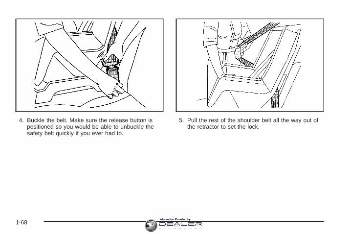
4. Buckle the belt. Make sure the release button ispositioned so you would be able to unbuckle thesafety belt quickly if you ever had to.
5. Pull the rest of the shoulder belt all the way out ofthe retractor to set the lock.
1-68Information Provided by:

6. To tighten the belt, push down on the child restraint,pull the shoulder portion of the belt to tighten thelap portion of the belt and feed the shoulderbelt back into the retractor. If you are using aforward-facing child restraint, you may find it helpfulto use your knee to push down on the childrestraint as you tighten the belt. You should not beable to pull more of the belt from the retractoronce the lock has been set.
7. If your child restraint manufacturer recommendsusing a top tether, and the position you are usinghas a top tether anchor, attach and tighten thetop tether to the top tether anchor.
Refer to the instructions that came with the childrestraint and to Lower Anchors and Tethersfor Children (LATCH) on page 1-44.
8. Push and pull the child restraint in differentdirections to be sure it is secure.
9. If your vehicle has a passenger sensing system andthe airbag is off, the off indicator in the insiderearview mirror will be lit and stay lit when the keyis turned to RUN or START.
If a child restraint has been installed and the onindicator is lit, turn the vehicle off. Remove the childrestraint from the vehicle and reinstall the child restraint.If after reinstalling the child restraint and restartingthe vehicle, the on indicator is still lit, check to makesure that the vehicle’s seatback is not pressing the childrestraint into the seat cushion. If this happens, slightlyrecline the vehicle’s seatback and adjust the seatcushion if possible. Also make sure the child restraint isnot trapped under the vehicle head restraint. If thishappens, adjust the head restraint.If the on indicator is still lit, secure the child in the childrestraint in a rear seat position in the vehicle if oneis available and check with your dealer.
To remove the child restraint, if the top tether is attachedto the top tether anchor, disconnect it. Unbuckle thevehicle’s safety belt and let it go back all the way. Thesafety belt will move freely again and be ready towork for an adult or larger child passenger.
1-69Information Provided by:

Airbag SystemYour vehicle has an airbag for the driver and an airbagfor the right front passenger.
Frontal airbags are designed to help reduce the risk ofinjury from the force of an inflating frontal airbag.But these airbags must inflate very quickly to do theirjob and comply with federal regulations.
Here are the most important things to know about theairbag system:
{CAUTION:
You can be severely injured or killed in a crashif you are not wearing your safety belt — even ifyou have airbags. Wearing your safety beltduring a crash helps reduce your chance ofhitting things inside the vehicle or being ejectedfrom it. Airbags are “supplemental restraints” tothe safety belts. Airbags are designed to workwith safety belts, but do not replace them.Airbags are designed to deploy in moderate tosevere frontal and near frontal crashes.
CAUTION: (Continued)
CAUTION: (Continued)
They are not designed to inflate in rollover,rear crashes, or in many side crashes. And, forsome unrestrained occupants, airbags mayprovide less protection in frontal crashes thanmore forceful airbags have provided in thepast. Everyone in your vehicle should wear asafety belt properly — whether or not there isan airbag for that person.
{CAUTION:
Airbags inflate with great force, faster than theblink of an eye. If you are too close to aninflating airbag, as you would be if you wereleaning forward, it could seriously injure you.Safety belts help keep you in position beforeand during a crash. Always wear your safetybelt, even with airbags. The driver should sitas far back as possible while still maintainingcontrol of the vehicle.
1-70Information Provided by:

{CAUTION:
Anyone who is up against, or very close to,any airbag when it inflates can be seriouslyinjured or killed. Airbags plus lap-shoulderbelts offer the best protection for adults, butnot for young children and infants. Neither thevehicle’s safety belt system nor its airbagsystem is designed for them. Young childrenand infants need the protection that a childrestraint system can provide. Always securechildren properly in your vehicle. To read how,see Older Children on page 1-31 and Infantsand Young Children on page 1-33.
There is an airbagreadiness light on theinstrument panel cluster,which shows the airbagsymbol.
The system checks the airbag electrical system formalfunctions. The light tells you if there is an electricalproblem. See Airbag Readiness Light on page 3-33for more information.
Where Are the Airbags?
The driver’s airbag is in the middle of the steeringwheel.
1-71Information Provided by:

The right front passenger’s airbag is in the instrumentpanel on the passenger’s side.
{CAUTION:
If something is between an occupant and anairbag, the bag might not inflate properly or itmight force the object into that person causingsevere injury or even death. The path of aninflating airbag must be kept clear. Do not putanything between an occupant and an airbag,and do not attach or put anything on thesteering wheel hub or on or near any otherairbag covering.
1-72Information Provided by:
When Should an Airbag Inflate?The driver’s and right front passenger’s frontal airbagsare designed to inflate in moderate to severe frontalor near-frontal crashes. But they are designed to inflateonly if the impact exceeds a predetermined deploymentthreshold. Deployment thresholds take into accounta variety of desired deployment and non-deploymentevents and are used to predict how severe a crashis likely to be in time for the airbags to inflate and helprestrain the occupants. Whether your frontal airbagswill or should deploy is not based on how fast yourvehicle is traveling. It depends largely on what you hit,the direction of the impact and how quickly yourvehicle slows down.
Frontal airbags may inflate at different crash speeds.For example:
• If the vehicle hits a stationary object, the airbagscould inflate at a different crash speed than if thevehicle hits a moving object.
• If the vehicle hits an object that deforms, theairbags could inflate at a different crash speed thanif the vehicle hits an object that does not deform.
• If the vehicle hits a narrow object (like a pole) theairbags could inflate at a different crash speedthan if the vehicle hits a wide object (like a wall).
• If the vehicle goes into an object at an angle theairbags could inflate at a different crash speedthan if the vehicle goes straight into the object.
The frontal airbags (driver and right front passenger) arenot intended to inflate during vehicle rollovers, rearimpacts, or in many side impacts.
In any particular crash, no one can say whether anairbag should have inflated simply because of thedamage to a vehicle or because of what the repair costswere. Inflation is determined by what the vehicle hits,the angle of the impact, and how quickly the vehicleslows down.
The airbag system is designed to work properly under awide range of conditions, including off-road usage.Observe safe driving speeds, especially on roughterrain. As always, wear your safety belt. See Off-RoadDriving on page 4-17 for more tips on off-road driving.
1-73Information Provided by:

Single Stage vs. Dual Stage AirbagsDepending on the weight of your vehicle you will haveeither “Single Stage Airbags” or “Dual Stage Airbags”.Vehicles that have a passenger sensing systemalso have dual stage airbags. If the rearview mirror inyour vehicle has a passenger airbag status indicatorprinted on it, your vehicle has the passenger sensingsystem and therefore, it has dual stage airbags. Ifthe rearview mirror in your vehicle does not have apassenger airbag status indicator printed on it, then yourvehicle does not have the passenger sensing systemand it has single stage airbags. See PassengerAirbag Status Indicator on page 3-36 or PassengerSensing System on page 1-80.
Dual Stage AirbagsIf your vehicle has frontal airbags with dual stagedeployment, the amount of restraint will adjust accordingto crash severity. Your vehicle is equipped withelectronic frontal sensors which help the sensing systemdistinguish between a moderate and a more severefrontal impact. For moderate frontal impacts, theseairbags inflate at a level less than full deployment. Formore severe frontal impacts, full deployment occurs.If the front of your vehicle goes straight into a wall thatdoes not move or deform, the threshold level for thereduced deployment is about 10 to 16 mph(16 to 25 km/h), and the threshold level for a fulldeployment is about 20 to 30 mph (32 to 48 km/h).(The threshold level can vary, however, with specificvehicle design, so that it can be somewhat aboveor below this range.)
Vehicle’s with dual stage airbags are also equipped withspecial sensors which enable the sensing system tomonitor the position of both the driver and passengerfront seats. The seat position sensor providesinformation which is used to determine if the airbagsshould deploy at a reduced level or at full deployment.
1-74Information Provided by:
Single Stage AirbagsIf your vehicle has frontal airbags with single stagedeployment and your vehicle goes straight into a wallthat does not move or deform, the threshold levelis about 13 to 16 mph (20 to 25 km/h). (The thresholdlevel can vary, however, with specific vehicle design, sothat it can be somewhat above or below this range.)
What Makes an Airbag Inflate?In an impact of sufficient severity, the airbag sensingsystem detects that the vehicle is in a crash. Thesensing system triggers a release of gas from theinflator, which inflates the airbag. The inflator, airbag,and related hardware are all part of the airbag modulesinside the steering wheel and in the instrument panelin front of the right front passenger.
How Does an Airbag Restrain?In moderate to severe frontal or near-frontal collisions,even belted occupants can contact the steering wheel orthe instrument panel. Airbags supplement the protectionprovided by safety belts. Airbags distribute the force ofthe impact more evenly over the occupant’s upper body,stopping the occupant more gradually. But airbags wouldnot help you in many types of collisions, includingrollovers, rear impacts and many side impacts, primarilybecause an occupant’s motion is not toward thoseairbags. Airbags should never be regarded as anythingmore than a supplement to safety belts, and then only inmoderate to severe frontal or near-frontal collisions.
1-75Information Provided by:

What Will You See After an AirbagInflates?After an airbag inflates, it quickly deflates, so quickly thatsome people may not even realize the airbag inflated.Some components of the airbag module — the steeringwheel hub for the driver’s airbag or the instrument panelfor the right front passenger’s bag — may be hot for ashort time. The parts of the bag that come into contactwith you may be warm, but not too hot to touch. There willbe some smoke and dust coming from the vents in thedeflated airbags. Airbag inflation does not prevent thedriver from seeing out of the windshield or being able tosteer the vehicle, nor does it stop people from leaving thevehicle.
{CAUTION:
When an airbag inflates, there is dust in theair. This dust could cause breathing problemsfor people with a history of asthma or otherbreathing trouble. To avoid this, everyone inthe vehicle should get out as soon as it is safeto do so. If you have breathing problems but
CAUTION: (Continued)
CAUTION: (Continued)
cannot get out of the vehicle after an airbaginflates, then get fresh air by opening awindow or a door. If you experience breathingproblems following an airbag deployment, youshould seek medical attention.
In many crashes severe enough to inflate an airbag,windshields are broken by vehicle deformation.Additional windshield breakage may also occur from theright front passenger airbag.• Airbags are designed to inflate only once. After an
airbag inflates, you will need some new parts for yourairbag system. If you do not get them, the airbagsystem will not be there to help protect you in anothercrash. A new system will include airbag modules andpossibly other parts. The service manual for yourvehicle covers the need to replace other parts.
• Your vehicle is equipped with a crash sensing anddiagnostic module which records information after acrash. See Vehicle Data Collection and Event DataRecorders on page 7-9.
• Let only qualified technicians work on your airbagsystem. Improper service can mean that your airbagsystem will not work properly. See your dealer forservice.
1-76Information Provided by:

Airbag Off SwitchIf your instrument panel has one of the switchespictured in the following illustrations your vehicle has anairbag off switch that you can use to turn off the rightfront passenger’s airbag.
This switch should only be turned to the off position ifthe person in the right front passenger’s position isa member of a passenger risk group identified by thenational government as follows:
Infant. An infant (less than 1 year old) mustride in the front seat because:• my vehicle has no rear seat;
• my vehicle has a rear seat too small toaccommodate a rear-facing infant seat; or
• the infant has a medical condition which, accordingto the infant’s physician, makes it necessary for theinfant to ride in the front seat so that the drivercan constantly monitor the child’s condition.
Child age 1 to 12. A child age 1 to 12 mustride in the front seat because:• my vehicle has no rear seat;
• although children ages 1 to 12 ride in the rearseat(s) whenever possible, children ages 1 to 12sometimes must ride in the front because no spaceis available in the rear seat(s) of my vehicle; or
• the child has a medical condition which, accordingto the child’s physician, makes it necessary for thechild to ride in the front seat so that the drivercan constantly monitor the child’s condition.
United States Canada
1-77Information Provided by:

Medical Condition. A passenger has amedical condition which, according to his orher physician:• causes the passenger airbag to pose a special risk
for the passenger; and
• makes the potential harm from the passengerairbag in a crash greater than the potentialharm from turning off the airbag and allowing thepassenger, even if belted, to hit the dashboardor windshield in a crash.
{CAUTION:
If the right front passenger’s airbag is turnedoff for a person who is not in a risk groupidentified by the national government, thatperson will not have the extra protection of anairbag. In a crash, the airbag will not be able toinflate and help protect the person sittingthere. Do not turn off the passenger’s airbagunless the person sitting there is in a riskgroup.
To turn off the right front passenger’s airbag, insert yourignition key into the switch, push in, and move theswitch to the off position.
United States Canada
1-78Information Provided by:
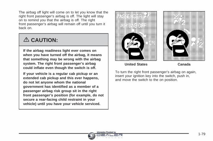
The airbag off light will come on to let you know that theright front passenger’s airbag is off. The light will stayon to remind you that the airbag is off. The rightfront passenger’s airbag will remain off until you turn itback on.
{CAUTION:
If the airbag readiness light ever comes onwhen you have turned off the airbag, it meansthat something may be wrong with the airbagsystem. The right front passenger’s airbagcould inflate even though the switch is off.
If your vehicle is a regular cab pickup or anextended cab pickup and this ever happens,do not let anyone whom the nationalgovernment has identified as a member of apassenger airbag risk group sit in the rightfront passenger’s position (for example, do notsecure a rear-facing child restraint in yourvehicle) until you have your vehicle serviced.
To turn the right front passenger’s airbag on again,insert your ignition key into the switch, push in,and move the switch to the on position.
United States Canada
1-79Information Provided by:

Passenger Sensing SystemIf your rearview mirror has one of the indicators picturedin the following illustrations, your vehicle has apassenger sensing system. The indicator will be visiblewhen you turn your ignition key to RUN or START.The words ON and OFF or the symbol for on and off,will be visible on the rearview mirror during the systemcheck. When the system check is complete, eitherthe word ON or the word OFF, or the symbol for on orthe symbol for off will be visible. See PassengerAirbag Status Indicator on page 3-36. If your rearviewmirror does not have either of the indicators picturedbelow, then your vehicle does not have the passengersensing system.
The passenger sensing system will turn off the rightfront passenger’s frontal airbag under certain conditions.The driver’s airbag is not part of the passengersensing system.
The passenger sensing system works with sensors thatare part of the right front passenger’s seat and safetybelt. The sensors are designed to detect the presence ofa properly seated occupant and determine if thepassenger’s frontal airbag should be enabled (mayinflate) or not.
Passenger Airbag Status Indicator – United States
Passenger Airbag Status Indicator − Canada
1-80Information Provided by:

Accident statistics show that children are safer if theyare restrained in the rear rather than the front seat.General Motors recommends that child restraintsbe secured in a rear seat, including an infant riding in arear-facing infant seat, a child riding in a forward-facingchild seat and an older child riding in a booster seat.Never put a child in a rear-facing child restraint inthe right front passenger seat unless the passengerairbag status indicator shows off. Never put a rear-facingchild restraint in the right front passenger seat unlessthe airbag is off.
Your vehicle may have a label on your sun visor thatsays, “Never put a rear-facing child seat in thefront.” This is because the risk to the rear-facing child isso great, if the airbag deploys.
{CAUTION:
A child in a rear-facing child restraint can beseriously injured or killed if the right frontpassenger’s airbag inflates. This is becausethe back of the rear-facing child restraintwould be very close to the inflating airbag.
Even though the passenger sensing system isdesigned to turn off the passenger’s frontalairbag if the system detects a rear-facing childrestraint, no system is fail-safe, and no onecan guarantee that an airbag will not deployunder some unusual circumstance, eventhough it is turned off. We recommend thatrear-facing child restraints be secured in therear seat, even if the airbag is off.
If you need to secure a forward-facing childrestraint in the right front seat, always movethe front passenger seat as far back as it willgo. It is better to secure the child restraint in arear seat.
1-81Information Provided by:

Never put a child in a rear-facing child restraint in theright front passenger seat the unless passengerairbag status indicator shows off. Never put a rearfacing child restraint in the right front passenger seatunless the airbag is off. Here is why:
{CAUTION:
A child in a rear-facing child restraint can beseriously injured or killed if the right frontpassenger’s airbag inflates. This is becausethe back of the rear-facing child restraintwould be very close to the inflating airbag. Besure the airbag is off before using a rear-facingchild restraint in the right front seat position.
CAUTION: (Continued)
CAUTION: (Continued)
Even though the passenger sensing system isdesigned to turn off the passenger’s frontalairbag if the system detects a rear-facing childrestraint, no system is fail-safe, and no onecan guarantee that an airbag will not deployunder some unusual circumstance, eventhough it is turned off. We recommend thatrear-facing child restraints be transported invehicles with a rear seat that willaccommodate a rear-facing child restraint,whenever possible.
If you need to secure a forward-facing childrestraint in the right front seat, always movethe front passenger seat as far back as it willgo. It is better to secure the child restraint in arear seat.
1-82Information Provided by:

The passenger sensing system is designed to turn offthe right front passenger’s frontal airbag if:
• the right front passenger seat is unoccupied
• the system determines that an infant is present in arear-facing infant seat
• the system determines that a small child is presentin a forward-facing child restraint
• the system determines that a small child is presentin a booster seat
• a right front passenger takes his/her weight off ofthe seat for a period of time
• the right front passenger seat is occupied by asmaller person, such as a child who has outgrownchild restraints
• or if there is a critical problem with the airbagsystem or the passenger sensing system
When the passenger’s frontal airbag has been turnedoff by the passenger sensing system, the off indicatorwill light and stay lit to remind you that the airbag is off.
If a child restraint has been installed and the onindicator is lit, turn the vehicle off. Remove the childrestraint from the vehicle and reinstall the child restraintfollowing the child restraint manufacturer’s directionsand refer to Securing a Child Restraint in the Right FrontSeat Position (Regular and Extended Cab) (WithPassenger Sensing System) in the Index.
If after reinstalling the child restraint and restarting thevehicle, the on indicator is still lit, check to makesure that the vehicle’s seatback is not pressing the childrestraint into the seat cushion. If this happens, slightlyrecline the vehicle’s seatback and adjust the seatcushion if possible. Also make sure the child restraint isnot trapped under the vehicle head restraint. If thishappens, adjust the head restraint.
If the on indicator is still lit, secure the child in the childrestraint in a rear seat position in the vehicle if oneis available and check with your dealer.
The passenger sensing system is designed to enable(may inflate) the right front passenger’s frontalairbag anytime the system senses that a person of adultsize is sitting properly in the right front passenger’sseat. When the passenger sensing system has allowedthe airbag to be enabled, the on indicator will lightand stay lit to remind you that the airbag is active.
For some children who have outgrown child restraintsand for very small adults, the passenger sensing systemmay or may not turn off the right front passenger’sfrontal airbag, depending upon the person’s seatingposture and body build. Everyone in your vehicle whohas outgrown child restraints should wear a safetybelt properly — whether or not there is an airbag for thatperson.
1-83Information Provided by:

If a person of adult-size is sitting in the right frontpassenger’s seat, but the off indicator is lit, it could bebecause that person is not sitting properly in the seat. Ifthis happens, turn the vehicle off and ask the personto place the seatback in the fully upright position, then situpright in the seat, centered on the seat cushion, withthe person’s legs comfortably extended. Restart thevehicle and have the person remain in this position forabout two minutes. This will allow the system todetect that person and then enable the passenger’sairbag.
1-84Information Provided by:

{CAUTION:
If the airbag readiness light in the instrumentpanel cluster ever comes on and stays on, itmeans that something may be wrong with theairbag system. If this ever happens, have thevehicle serviced promptly, because anadult-size person sitting in the right frontpassenger’s seat may not have the protectionof the frontal airbag. See Airbag ReadinessLight on page 3-33 for more on this, includingimportant safety information.
Aftermarket equipment, such as seat covers, can affecthow well the passenger sensing system operates.You may want to consider not using seat covers or otheraftermarket equipment if your vehicle has the passengersensing system. See Adding Equipment to YourAirbag-Equipped Vehicle on page 1-86 for moreinformation about modifications that can affect how thesystem operates.
{CAUTION:
Stowing of articles under the passenger’s seator between the passenger’s seat cushion andseatback may interfere with the properoperation of the passenger sensing system.
1-85Information Provided by:

Servicing Your Airbag-EquippedVehicleAirbags affect how your vehicle should be serviced.There are parts of the airbag system in several placesaround your vehicle. You do not want the system toinflate while someone is working on your vehicle. Yourdealer and the service manual have informationabout servicing your vehicle and the airbag system. Topurchase a service manual, see Service PublicationsOrdering Information on page 7-14.
{CAUTION:
For up to 10 seconds after the ignition key isturned off and the battery is disconnected, anairbag can still inflate during improper service.You can be injured if you are close to anairbag when it inflates. Avoid yellowconnectors. They are probably part of theairbag system. Be sure to follow properservice procedures, and make sure the personperforming work for you is qualified to do so.
The airbag system does not need regular maintenance.
Adding Equipment to YourAirbag-Equipped Vehicle
Q: Is there anything I might add to the front of thevehicle that could keep the airbags fromworking properly?
A: Yes. If you add things that change your vehicle’sframe, bumper system, front end sheet metal orheight, they may keep the airbag system fromworking properly. Also, the airbag system may notwork properly if you relocate any of the airbagsensors. If you have any questions about this, youshould contact Customer Assistance before youmodify your vehicle. The phone numbers andaddresses for Customer Assistance are in Step Twoof the Customer Satisfaction Procedure in thismanual. See Customer Satisfaction Procedure onpage 7-2
1-86Information Provided by:

Q: What if I added a snow plow? Will it keep theairbags from working properly?
A: We have designed our airbag systems to workproperly under a wide range of conditions,including snow plowing with vehicles equipped withthe optional Snow Plow Prep Package (RPOVYU). But do not change or defeat the snow plow’s“tripping mechanism.” If you do, it can damageyour snow plow and your vehicle, and it may causean airbag inflation.
Q: Because I have a disability, I have to get myvehicle modified. How can I find out whetherthis will affect my advanced airbag system?
A: Changing or moving any parts of the front seats,safety belts, the airbag sensing and diagnosticmodule (located under the driver’s seat), orthe inside rearview mirror can affect the operationof the advanced airbag system. If you havequestions, call Customer Assistance. The phonenumbers and addresses for Customer Assistanceare in Step Two of the Customer SatisfactionProcedure in this manual. See CustomerSatisfaction Procedure on page 7-2.
Restraint System Check
Checking the Restraint SystemsNow and then, make sure the safety belt reminder lightand all your belts, buckles, latch plates, retractorsand anchorages are working properly. Look for any otherloose or damaged safety belt system parts. If you seeanything that might keep a safety belt system from doingits job, have it repaired.
Torn or frayed safety belts may not protect you in acrash. They can rip apart under impact forces. If a beltis torn or frayed, get a new one right away.
Also look for any opened or broken airbag covers, andhave them repaired or replaced. (The airbag systemdoes not need regular maintenance.)
Notice: If you damage the covering for the driver’sor the right front passenger’s airbag, the airbagmay not work properly. You may have to replace theairbag module in the steering wheel or both theairbag module and the instrument panel for the rightfront passenger’s airbag. Do not open or breakthe airbag coverings.
1-87Information Provided by:

Replacing Restraint System PartsAfter a Crash
{CAUTION:
A crash can damage the restraint systems inyour vehicle. A damaged restraint system maynot properly protect the person using it,resulting in serious injury or even death in acrash. To help make sure your restraintsystems are working properly after a crash,have them inspected and any necessaryreplacements made as soon as possible.
If you have had a crash, do you need new belts orLATCH system parts?
After a very minor collision, nothing may be necessary.But if the belts were stretched, as they would be ifworn during a more severe crash, then you neednew parts.
If the LATCH system was being used during a moresevere crash, you may need new LATCH system parts.
If belts are cut or damaged, replace them. Collisiondamage also may mean you will need to have LATCHsystem, safety belt or seat parts repaired or replaced.New parts and repairs may be necessary even if the beltor LATCH system was not being used at the time ofthe collision.
If an airbag inflates, you will need to replace airbagsystem parts. See the part on the airbag system earlierin this section.
1-88Information Provided by:

Keys ...............................................................2-3Remote Keyless Entry System .........................2-4Remote Keyless Entry System Operation ...........2-5
Doors and Locks .............................................2-8Door Locks ....................................................2-8Power Door Locks ..........................................2-8Delayed Locking .............................................2-9Programmable Automatic Door Locks ..............2-10Rear Door Security Locks (Crew Cab) .............2-12Lockout Protection ........................................2-12Rear Doors ..................................................2-13Tailgate .......................................................2-14
Windows ........................................................2-15Manual Windows ..........................................2-15Power Windows ............................................2-16Swing-Out Windows ......................................2-17Sliding Rear Window .....................................2-17Sun Visors ...................................................2-17
Theft-Deterrent Systems ..................................2-18Content Theft-Deterrent .................................2-18Passlock® ....................................................2-19
Starting and Operating Your Vehicle ................2-20New Vehicle Break-In ....................................2-20Ignition Positions ..........................................2-20Retained Accessory Power (RAP) ...................2-22Starting the Engine .......................................2-22Engine Coolant Heater ..................................2-23Automatic Transmission Operation ...................2-24Tow/Haul Mode ............................................2-30Manual Transmission Operation ......................2-32Four-Wheel Drive ..........................................2-36Parking Brake ..............................................2-49Shifting Into Park (P)
(Automatic Transmission) ............................2-50Shifting Out of Park (P)
(Automatic Transmission) ............................2-52Parking Your Vehicle
(Manual Transmission) ...............................2-53Parking Over Things That Burn .......................2-53Engine Exhaust ............................................2-54Running the Engine While Parked ...................2-54
Section 2 Features and Controls
2-1Information Provided by:

Mirrors ...........................................................2-56Manual Rearview Mirror .................................2-56Automatic Dimming Rearview Mirror with
OnStar® and Compass ...............................2-56Automatic Dimming Rearview Mirror with
OnStar®, Compass and TemperatureDisplay ....................................................2-58
Automatic Dimming Rearview Mirror withCompass .................................................2-60
Automatic Dimming Rearview Mirror withCompass and Temperature Display ..............2-62
Outside Manual Mirrors ..................................2-64Outside Camper-Type Mirrors .........................2-65Outside West Coast-Type Mirrors ....................2-66Outside Power Mirrors ...................................2-66Outside Power Foldaway Mirrors .....................2-67Outside Automatic Dimming Mirror ..................2-68Outside Curb View Assist Mirrors ....................2-68Outside Convex Mirror ...................................2-68Outside Heated Mirrors ..................................2-68
OnStar ® System .............................................2-69Universal Home Remote System ......................2-71
Universal Home Remote System Operation ......2-72Storage Areas ................................................2-75
Glove Box ...................................................2-75Cupholder(s) ................................................2-75Coinholder(s) ................................................2-75Front Storage Area .......................................2-76Center Console Storage Area .........................2-76Tonneau Cover ............................................2-76
Sunroof .........................................................2-78Vehicle Personalization ...................................2-79
Memory Seat ...............................................2-79
Section 2 Features and Controls
2-2Information Provided by:

Keys
{CAUTION:
Leaving children in a vehicle with the ignitionkey is dangerous for many reasons. Theycould operate the power windows or othercontrols or even make the vehicle move. Thechildren or others could be badly injured oreven killed. Do not leave the keys in a vehiclewith children.
2-3Information Provided by:

Your vehicle has onedouble-sided key for theignition and all doorlocks as well as the sparetire hoist lock, if equipped.
If you ever lose your keys, your dealer will be able toassist you with obtaining replacements.
Notice: If you ever lock your keys in your vehicle,you may have to damage the vehicle to get in.Be sure you have spare keys.
If you ever do get locked out of your vehicle, call theGM Roadside Assistance Center. See RoadsideAssistance Program on page 7-6. If your vehicle isequipped with the OnStar® system with an activesubscription and you lock your keys inside the vehicle,OnStar® may be able to send a command to unlockyour vehicle. See OnStar® System on page 2-69for more information.
Remote Keyless Entry SystemIf equipped, the remote keyless entry system operateson a radio frequency subject to Federal CommunicationsCommission (FCC) Rules and with Industry Canada.
This device complies with Part 15 of the FCC Rules.Operation is subject to the following two conditions:
1. This device may not cause interference, and
2. This device must accept any interference received,including interference that may cause undesiredoperation of the device.
This device complies with RSS-210 of Industry Canada.Operation is subject to the following two conditions:
1. This device may not cause interference, and
2. This device must accept any interference received,including interference that may cause undesiredoperation of the device.
Changes or modifications to this system by other thanan authorized service facility could void authorization touse this equipment.
2-4Information Provided by:

At times you may notice a decrease in range. This isnormal for any remote keyless entry system. If thetransmitter does not work or if you have to stand closerto your vehicle for the transmitter to work, try this:
• Check the distance. You may be too far from yourvehicle. You may need to stand closer duringrainy or snowy weather.
• Check the location. Other vehicles or objects maybe blocking the signal. Take a few steps to theleft or right, hold the transmitter higher, andtry again.
• Check to determine if battery replacement orresynchronization is necessary. See “BatteryReplacement” and “Resynchronization” underRemote Keyless Entry System Operation onpage 2-5.
• If you are still having trouble, see your dealer or aqualified technician for service.
Remote Keyless Entry SystemOperationYou can lock and unlock your doors from about 3 feet(1 m) up to 100 feet (30 m) away using the remotekeyless entry transmitter supplied with your vehicle.
K (Unlock): Press thisbutton once to unlock thedriver’s door. Theinterior lamps will comeon. Pressing unlock againwithin three secondswill cause the remainingdoors to unlock.
You can choose different feedback options for eachpress of the unlock button. See “Lock Feedback” and“Unlock Feedback” under DIC Vehicle Customization onpage 3-64 for more information.
2-5Information Provided by:

Q (Lock): Press this button once to lock all of thedoors. Pressing lock again within three secondsmay cause the horn to chirp for lock confirmation. Youcan choose different feedback options for each pressof the lock button. See “Lock Feedback” and “UnlockFeedback” under DIC Vehicle Customization onpage 3-64 for more information.
L (Panic): Press this button to sound the horn andflash the headlamps and taillamps for up to 30 seconds.Panic can be turned off by pressing the button again,by waiting for 30 seconds, or by starting the vehicle.
Matching Transmitter(s) to YourVehicleEach remote keyless entry transmitter is coded toprevent another transmitter from unlocking your vehicle.If a transmitter is lost or stolen, a replacement canbe purchased through your dealer. Remember to bringany remaining transmitters with you when you go toyour dealer. When the dealer matches the replacementtransmitter to your vehicle, any remaining transmittersmust also be matched. Once your dealer has coded thenew transmitter, the lost transmitter will not unlockyour vehicle. Each vehicle can have a maximum of fourtransmitters matched to it.
Battery ReplacementUnder normal use, the battery in your remote keylessentry transmitter should last about two years.
You can tell the battery is weak if the transmitter will notwork at the normal range in any location. If you haveto get close to your vehicle before the transmitter works,it is probably time to change the battery.
Notice: When replacing the battery, use care not totouch any of the circuitry. Static from your bodytransferred to these surfaces may damage thetransmitter.
2-6Information Provided by:

To replace the battery in the keyless entry transmitter,do the following:
1. Insert a thin object, such as a coin, in the slotbetween the covers of the transmitter housingnear the key ring hole. Remove the bottomby twisting the coin.
2. Remove and replace the battery with athree-volt CR2032 or equivalent battery, positive (+)side up.
3. Align the covers and snap them together.
4. Resynchronize the transmitter. See“Resynchronization” following this information.
5. Check the operation of the transmitter.
ResynchronizationResynchronization may be necessary due to thesecurity method used by this system. The transmitterdoes not send the same signal twice to the receiver. Thereceiver will not respond to a signal that has beensent previously. This prevents anyone from recordingand playing back the signal from the transmitter.
To resynchronize your transmitter, stand close to yourvehicle and press and hold the lock and unlockbuttons on the transmitter at the same time for15 seconds. The door locks should cycle to confirmsynchronization. If the locks do not cycle, see yourdealer for service.
2-7Information Provided by:

Doors and Locks
Door Locks
{CAUTION:
Unlocked doors can be dangerous.• Passengers — especially children — can
easily open the doors and fall out of amoving vehicle. When a door is locked, thehandle will not open it. You increase thechance of being thrown out of the vehiclein a crash if the doors are not locked. So,wear safety belts properly and lock thedoors whenever you drive.
• Young children who get into unlockedvehicles may be unable to get out. A childcan be overcome by extreme heat and cansuffer permanent injuries or even deathfrom heat stroke. Always lock your vehiclewhenever you leave it.
• Outsiders can easily enter through anunlocked door when you slow down orstop your vehicle. Locking your doors canhelp prevent this from happening.
There are several ways to lock and unlock your vehicle.You can use the keyless entry system, if equipped,or you can also use your key.
To lock the door from theinside, slide the leverrearward. To unlock thedoor, slide the leverforward.
Power Door LocksIf your vehicle has thispower door lock switch,press the raised side of theswitch, with the locksymbol, on either frontdoor to lock all the doorsat once.
Press the recessed side of the switch with the unlocksymbol, to unlock all the doors at once.
2-8Information Provided by:

If your vehicle has thispower door lock switch,press the bottom ofthe switch on either frontdoor to lock all the doorsat once.
Press the top of the switch to unlock all the doorsat once.
The power door locks will operate at any time evenwhen the ignition is off.
The power door locks will also automatically lock whenthe vehicle is out of PARK (P), or for manualtransmission, when the vehicle reaches 8 mph(24 km/h).
Operating the power locks may interact with thetheft-deterrent system, if equipped. See ContentTheft-Deterrent on page 2-18.
Delayed LockingIf your vehicle is a crew cab, it may be equipped withthis feature. When locking the doors with the power lockswitch or the keyless entry transmitter and a door isopen, the doors will not lock until five seconds after thelast door is closed. You will hear three chimes tosignal that the delayed locking feature is in use.
Pressing the power lock switch or the lock button on thekeyless entry transmitter twice will override the delayedlocking feature and immediately lock all the doors.
You can turn the delayed locking feature off or back onagain by doing the following:
1. Press and hold the power door lock switch in thelock position.
2. Press unlock twice on the remote keyless entrytransmitter.
This feature will not operate if the key is in the ignition.
You can also program this feature using the DIC.See DIC Vehicle Customization on page 3-64.
2-9Information Provided by:
Programmable AutomaticDoor LocksYour vehicle may be equipped with an automaticlock/unlock feature which enables you to program yourvehicle’s power door locks. You can program thisfeature through the Driver Information Center (DIC), orby the following method. See DIC Vehicle Customizationon page 3-64.
Programmable Locking FeatureFollowing are the two available programming options:
Mode 1: All doors lock when the transmission is shiftedinto gear. This is the mode that is pre-programmed inthe factory for your vehicle for automatic transmissionvehicles.
Mode 2: All doors lock when the vehicle speed isgreater than 8 mph (13 km/h). This is the mode that ispre-programmed in the factory for manual transmissionvehicles.
The following instructions tell you how to change theautomatic door lock mode (automatic transmission only).Choose one of the two programming options listedabove before entering the program mode.
To enter the program mode, do the following:
1. Begin with the ignition off. Then pull the turnsignal/multifunction lever toward you and holdit there while you perform the next step.
2. Turn the key to RUN then back to LOCK twice.Then, with the key in LOCK, release the turnsignal/multifunction lever. Once you do this, thedoors will lock and unlock, the horn will chirp twice,and a 30-second timer will begin. You are nowready to program the automatic door lock feature.
3. Press the door lock switch once. You will hear eitherone or two chimes. The number of chimes tells youwhich lock mode is currently selected. Continueto press the door lock switch until the numberof chimes that you hear matches the number of themode that you want. If you take longer than30 seconds, the locks will automatically lock andunlock and the horn will chirp twice to indicate thatyou have left the program mode. If this occurs,you can repeat the procedure beginning with Step 1to re-enter the programming mode.
You can exit the program mode any time by turning theignition to RUN (the doors will automatically lock andunlock and the horn will chirp twice to indicate that youare leaving the program mode). If the lock/unlockswitches are not pressed while in the programming mode,the current automatic settings will not be modified.
See your dealer for more information.
2-10Information Provided by:

Programmable Unlocking FeatureThe following is the list of available programmingoptions:
Mode 1: Driver’s door unlocks when the transmission isshifted into PARK (P), for automatic transmissionvehicles only.
Mode 2: All doors unlock when the transmission isshifted into PARK (P), for automatic transmissionvehicles only. This is the mode that is pre-programmedin the factory for your vehicle.
Mode 3: All doors unlock when the key is removedfrom the ignition. This is the mode that ispre-programmed in the factory for manual transmissionvehicles.
Mode 4: No automatic door unlock.
The following instructions tell you how to change theautomatic door unlock mode (automatic transmissiononly). Choose one of the four programming optionslisted above before entering the program mode. To enterthe program mode, do the following:
1. Begin with the ignition off. Then pull the turnsignal/multifunction lever toward you and holdit there while you perform the next step.
2. Turn the key to RUN and LOCK twice. Then, withthe key in LOCK, release the turnsignal/multifunction lever. Once you do this, thedoors will lock and unlock, the horn will chirp twice,and a 30-second timer will begin. You are nowready to program the automatic door unlock feature.
3. Press the door unlock switch once. You will hearone, two, three, or four chimes. The number ofchimes tells you which unlock mode is currentlyselected. Continue to press the door unlock switchuntil the number of chimes that you hear matches thenumber of the mode that you want. If you take longerthan 30 seconds, the locks will automatically lockand unlock and the horn will chirp twice to indicatethat you have left the program mode. If this occurs,you can repeat the procedure beginning with Step 1to re-enter the programming mode.
You can exit the program mode any time by turning theignition to RUN. The doors will automatically lockand unlock and the horn will chirp twice to indicate thatyou are leaving the program mode. If the lock/unlockswitches are not pressed while in the programmingmode, the current automatic settings will not bemodified.
See your dealer for more information.
2-11Information Provided by:

Rear Door Security Locks(Crew Cab)With this feature, you can lock the rear side doors sothat they cannot be opened from the inside bypassengers.
This feature is located onthe inside edge of therear doors.
To use one of the locks do the following:
1. Open one of the rear doors.
2. To engage the rear door security lock, move thelever forward.
3. To disengage the lock, move the lever rearward.
4. Close the door.
5. Do the same thing to the other rear door.
The rear doors of your vehicle cannot be opened fromthe inside when this feature is in use. If you want toopen the rear door while the security lock is engaged,unlock the door and open the door from the outside.
Lockout ProtectionThis feature protects you from locking your key in thevehicle when the key is in the ignition and a dooris open.
If the power lock switch is pressed when a door is openand the key is in the ignition, all of the doors will lockand then the driver’s door will unlock.
2-12Information Provided by:

Rear Doors
Extended CabYour vehicle may be equipped with a rear accessdoor(s) that allows easier access to the rear area of theextended cab.
To open a rear accessdoor from the outside, firstopen the front door.Then, use the handlelocated on the front edgeof the rear access doorto open it.
You must fully close a rear access door before you canclose the front door.
To open a rear accessdoor from the inside, thefront door must be openedfirst. Then, use thehandle located on theinside of the rear accessdoor to open it.
Crew CabsIf your vehicle is a crew cab, you can open your doorsfrom the inside or outside. Your vehicle may alsohave a feature which prevents children from opening therear doors. See Rear Door Security Locks (CrewCab) on page 2-12 for more information.
2-13Information Provided by:

TailgateYou can open the tailgate by lifting up on its handlewhile pulling the tailgate toward you.To shut the tailgate, firmly push it upward until it latches.After you put the tailgate back up, pull it back towardsyou to be sure it latches securely.
Tailgate RemovalThe tailgate on your vehicle can be removed to allow fordifferent loading situations. Although the tailgate can beremoved without assistance, you may want someone toassist you with the removal to avoid possible damage tothe vehicle.
To remove the tailgate, do the following:1. Raise the tailgate
slightly and releaseboth retaining cableclips. To release theretaining cable clips, liftthe cable so it pointsstraight out and pushthe cable clip forward.
2. With the tailgate at aslight upward angle,pull back on the tailgateat the right edge andthen move thetailgate to the right torelease the left edge.
Reverse the above procedure to reinstall. Make sure thetailgate is secure.
2-14Information Provided by:

Windows
{CAUTION:
Leaving children, helpless adults, or pets in avehicle with the windows closed is dangerous.They can be overcome by the extreme heatand suffer permanent injuries or even deathfrom heat stroke. Never leave a child, ahelpless adult, or a pet alone in a vehicle,especially with the windows closed in warm orhot weather.
Manual WindowsTurn the hand crank on each door to manually raise orlower the manual windows.
2-15Information Provided by:

Power Windows
If your vehicle is equipped with power windows, thecontrols are located on each of the side doors inthe front and rear for crew cab models.
The driver’s door has a switch for the passenger’s andrear windows as well, if equipped. Your powerwindows will work when the ignition has been turned toACCESSORY or RUN or when Retained AccessoryPower (RAP) is active. See Retained Accessory Power(RAP) on page 2-22.
Press the switch down to lower the window.
Pull up the front of the switch to raise the window.
Express Down WindowsThe driver and front passenger windows also have anexpress down feature that allows the windows tobe lowered without holding the switch. Press down fullyon the window switch, then release, to activate theexpress down mode. The express down mode can becanceled at any time by pulling up on the switch.To open the window partway, press the switch to thefirst depression position, until the window is at thedesired position.
Window Lockout
o (Window Lockout): If you have power windows ona crew cab, the driver’s door power window switchhas a lockout feature. The lockout switch is located infront of the window switches. This feature preventsall windows from operating, except from the driver’sposition. To engage the lockout feature press the switch,and an indicator light on the switch will illuminate. Todisengage the lockout feature press the switchagain, and the indicator light will turn off.
2-16Information Provided by:

Swing-Out Windows
Your vehicle may haveswing-out windows. Toopen a rear swing-outwindow, flip the latch openand swing the glass out.
The latch will catch when the window is fully open and itwill also hold it in the open position.
Sliding Rear WindowIf your vehicle has this feature, squeeze the latch in thecenter of the window and slide the glass to open it.
When you close the window, be sure the latch isengaged.
The sliding rear window does not have rear defogger.
Sun VisorsPull the sun visor down to block glare. Swing the sunvisor to the side to cover the side window.
The passenger’s side sun visor may have a vanitymirror.
2-17Information Provided by:

Theft-Deterrent SystemsVehicle theft is big business, especially in some cities.Although your vehicle has a number of theft-deterrentfeatures, we know that nothing we put on it can make itimpossible to steal.
Content Theft-DeterrentYour vehicle may be equipped with a contenttheft-deterrent alarm system.
The security light islocated on the instrumentpanel cluster. SeeSecurity Light onpage 3-48 for additionalinformation.
To activate the theft-deterrent system, do the following:
1. Close all the doors.
2. Lock the door with the remote keyless entrytransmitter. The security light should come onand flash.
If the lock button on the remote keyless entry transmitteris pressed, but a door is open, you may hear threechimes indicating delayed locking is enabled. See
Delayed Locking on page 2-9 for additional information.Close the door and the content theft-deterrent systemwill be activated.
If a locked door is opened without using the remotekeyless entry transmitter or OnStar, if equipped with anactive subscription, the alarm will go off. Your vehicle’slamps will flash and the horn will sound for about twominutes, then will turn off to save the battery power. If thisoccurs, you can turn off the alarm by pressing unlock onthe remote keyless entry transmitter or by placing the keyin the ignition and turning it to START.
If your vehicle has a Driver Information Center (DIC),you can customize your alarm warning. See DIC VehicleCustomization on page 3-64 for additional information.
The horn may chirp for 10 seconds before the alarmgoes off if the theft-deterrent system is activated usingthe remote keyless entry transmitter and the driver’sdoor is opened. If this occurs, you can turn off the alarmby pressing unlock on the remote keyless entrytransmitter or by placing the key in the ignition andturning it to START.
Here is how to avoid setting off the alarm by accident:
• If you do not want to activate the theft-deterrentsystem, the vehicle should be locked with thedoor key after the doors are closed.
• Always unlock a door with the remote keyless entrytransmitter.
2-18Information Provided by:

If you set off the alarm by accident, turn off the alarm bypressing unlock on the remote keyless entry transmitteror by placing the key in the ignition and turning itto START.
Testing the AlarmThe alarm can be tested by following these steps:
1. From inside the vehicle, activate the system bylocking the doors with the remote keyless entrytransmitter.
2. Wait for the security light to go out.
3. Unlock the door with the manual door lock andopen the door. This should set off the alarm.
4. Turn off the alarm by pressing unlock on the remotekeyless entry transmitter or by placing the key inthe ignition and turning it to START.
If the alarm does not sound when it should, but thevehicle’s headlamps flash, check to see if the hornworks. The horn fuse may be blown. To replace thefuse, see Instrument Panel Fuse Block on page 5-124and Underhood Fuse Block on page 5-127.
If the alarm does not sound or the vehicle’s headlampsdo not flash, see your dealer for service.
Passlock ®
Your vehicle is equipped with the Passlock®
theft-deterrent system.
Passlock® is a passive theft-deterrent system.Passlock® enables fuel if the ignition lock cylinder isturned with a valid key. If a correct key is not used or theignition lock cylinder is tampered with, fuel is disabled.
If the engine stalls and the security light flashes,wait until the light stops flashing before trying to restartthe engine. Remember to release the key fromSTART as soon as the engine starts.
If the engine is running and the security light comes on,you will be able to restart the engine if you turn theengine off. However, your Passlock® system isnot working properly and must be serviced by yourdealer. Your vehicle is not protected by Passlock® at thistime. You may also want to check the fuse. SeeFuses and Circuit Breakers on page 5-124. See yourdealer for service.
In an emergency, call the GM Roadside AssistanceCenter. See Roadside Assistance Program on page 7-6.
2-19Information Provided by:

Starting and Operating YourVehicle
New Vehicle Break-InNotice: Your vehicle does not need an elaboratebreak-in. But it will perform better in the long run ifyou follow these guidelines:
• Keep your speed at 55 mph (88 km/h) or less forthe first 500 miles (805 km).
• Do not drive at any one constant speed, fast orslow, for the first 500 miles (805 km). Do notmake full-throttle starts. Avoid downshifting tobrake, or slow, the vehicle.
• Avoid making hard stops for the first 200 miles(322 km) or so. During this time your new brakelinings are not yet broken in. Hard stops with newlinings can mean premature wear and earlierreplacement. Follow this breaking-in guidelineevery time you get new brake linings.
• Do not tow a trailer during break-in. See Towing aTrailer on page 4-67 for the trailer towingcapabilities of your vehicle and moreinformation.
Following break-in, engine speed and load can begradually increased.
Ignition PositionsWith the key in the ignition switch, you can turn it to fourdifferent positions.
Notice: Using a tool to force the key from theignition switch could cause damage or break thekey. Use the correct key and turn the key only withyour hand. Make sure the key is all the way in. Ifit is, turn the steering wheel left and right while youturn the key hard. If none of this works, thenyour vehicle needs service.
2-20Information Provided by:

A (Lock): This position locks your ignition when the keyis removed. The steering locks when equipped with amanual transmission. It is a theft-deterrent feature. Youwill only be able to remove your key when the ignitionis turned to LOCK
B (Accessory): This position allows you to use thingslike the radio, power windows and the windshieldwipers when the engine is off.
{CAUTION:
On manual transmission vehicles, turning thekey to LOCK will lock the steering column andresult in a loss of ability to steer the vehicle.This could cause a collision. If you need toturn the engine off while the vehicle is moving,turn the key only to ACCESSORY. Do notpress the key release button while the vehicleis moving.
C (Run): This is the position for driving.
D (Start): This position starts your engine.
Key Release Button(Manual Transmission)
The ignition key cannot beremoved from the ignitionof manual transmissionvehicles unless thekey release button is used.
To remove the key on manual transmission vehicles, turnthe key to ACCESSORY, then press the button and turnthe key to LOCK. Do not hold the button in while turningthe key to ACCESSORY. Pull the key straight out.
2-21Information Provided by:
Retained Accessory Power (RAP)If the vehicle has Retained Accessory Power (RAP),certain features will continue to operate for up to10 minutes after the ignition key is turned to LOCKunless a door is opened.
Starting the EngineYour vehicle is equipped with Starter Motor Control.This feature assists in starting the engine and protectsthe electrical system. This feature may cause theengine to crank even after the ignition key is not inSTART
Automatic TransmissionMove your shift lever to PARK (P) or NEUTRAL (N).Your engine will not start in any other position — that isa safety feature. To restart when you are alreadymoving, use NEUTRAL (N) only. If you have a dieselengine refer to the diesel supplement for the startingprocedure.
Notice: Do not try to shift to PARK (P) if yourvehicle is moving. If you do, you could damage thetransmission. Shift to PARK (P) only when yourvehicle is stopped.
Manual TransmissionThe gear selector should be in neutral and the parkingbrake engaged. Hold the clutch pedal to the floorand start the engine. Your vehicle will not start if theclutch pedal is not all the way down — that is a safetyfeature.
1. With your foot off the accelerator pedal, turn theignition key to START. When the engine starts,let go of the key. The idle speed will go down asyour engine gets warm.
Notice: Holding your key in START for longer than15 seconds at a time will disengage the startermotor, cause your battery to be drained muchsooner, and add excessive heat that can damageyour starter motor. Try not to hold the key in STARTfor longer than 15 seconds and wait about15 seconds between each try to help avoid drainingyour battery or damaging your starter.
2. If it does not start within 10 seconds, push theaccelerator pedal all the way to the floor, whileyou hold the ignition key in START. Whenthe engine starts, let go of the key and let up on theaccelerator pedal. Wait about 15 seconds betweeneach try.
2-22Information Provided by:

When starting your engine in very cold weather (below0°F or −18°C), do this:
1. With your foot off the accelerator pedal, turn theignition key to START and hold it there up to15 seconds. When the engine starts, let go ofthe key.
2. If your engine still will not start, or starts but thenstops, it could be flooded with too much gasoline.Try pushing your accelerator pedal all the way to thefloor and holding it there as you hold the key inSTART for about three seconds. When the enginestarts, let go of the key and accelerator. If thevehicle starts briefly but then stops again, do thesame thing, but this time keep the pedal downfor five or six seconds. This clears the extragasoline from the engine.
Notice: Your engine is designed to work with theelectronics in your vehicle. If you add electricalparts or accessories, you could change the way theengine operates. Before adding electrical equipment,check with your dealer. If you do not, your enginemight not perform properly. Any resulting damagewould not be covered by your vehicle’s warranty.
Engine Coolant HeaterIn very cold weather, 0°F (−18°C) or colder, the enginecoolant heater can help. You will get easier startingand better fuel economy during engine warm-up.Usually, the coolant heater should be plugged in aminimum of four hours prior to starting your vehicle. Attemperatures above 32°F (0°C), use of the coolantheater is not required. Your vehicle may also have aninternal thermostat in the plug end of the cord. This willprevent operation of the engine coolant heater whenthe temperature is at or above 0°F (−18 C°) as noted onthe cord.
To Use the Engine Coolant Heater1. Turn off the engine.
2. Open the hood and unwrap the electrical cord. Thecord is located on the driver’s side of the enginecompartment, near the power steering fluidreservoir. If you have a diesel engine, refer todiesel supplement for location.
2-23Information Provided by:
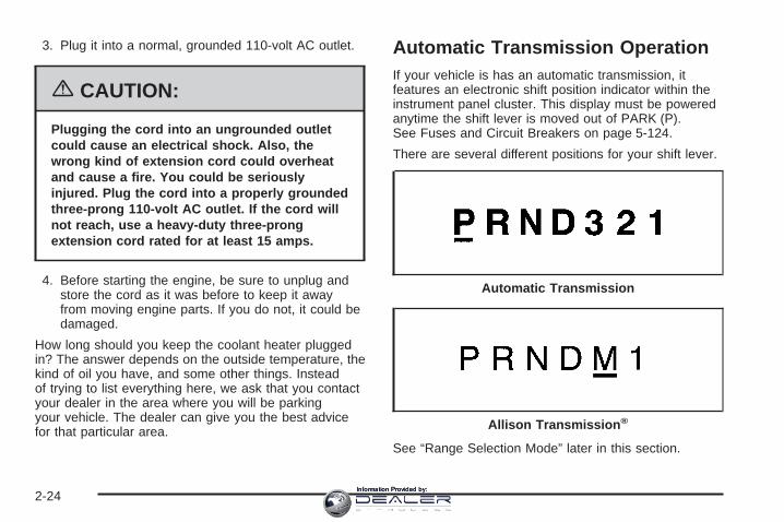
3. Plug it into a normal, grounded 110-volt AC outlet.
{CAUTION:
Plugging the cord into an ungrounded outletcould cause an electrical shock. Also, thewrong kind of extension cord could overheatand cause a fire. You could be seriouslyinjured. Plug the cord into a properly groundedthree-prong 110-volt AC outlet. If the cord willnot reach, use a heavy-duty three-prongextension cord rated for at least 15 amps.
4. Before starting the engine, be sure to unplug andstore the cord as it was before to keep it awayfrom moving engine parts. If you do not, it could bedamaged.
How long should you keep the coolant heater pluggedin? The answer depends on the outside temperature, thekind of oil you have, and some other things. Insteadof trying to list everything here, we ask that you contactyour dealer in the area where you will be parkingyour vehicle. The dealer can give you the best advicefor that particular area.
Automatic Transmission OperationIf your vehicle is has an automatic transmission, itfeatures an electronic shift position indicator within theinstrument panel cluster. This display must be poweredanytime the shift lever is moved out of PARK (P).See Fuses and Circuit Breakers on page 5-124.
There are several different positions for your shift lever.
See “Range Selection Mode” later in this section.
Automatic Transmission
Allison Transmission ®
2-24Information Provided by:

PARK (P): This position locks your rear wheels. It isthe best position to use when you start your enginebecause your vehicle cannot move easily. If your vehiclehas the Allison Transmission®, with the Power Takeoff(PTO), use PARK (P) when starting. The AllisonTransmission® has a park pawl that is designed to holdthe weight of commercial medium duty trucks.Therefore, the Allison Transmission® uses larger partsthan other automatic transmissions. These largerparts may sometimes make a clunk noise when theselector lever is moved from DRIVE (D) or REVERSE(R) to PARK (P). This is normal and there is no damageoccurring during these shifts. When parked on a hill,especially when loaded, you may notice an increase inthe effort to shift out of Park. See Torque Lock(Automatic Transmission) under Shifting Into Park (P)(Automatic Transmission) on page 2-50 for moreinformation.
{CAUTION:
It is dangerous to get out of your vehicle if theshift lever is not fully in PARK (P) with theparking brake firmly set. Your vehicle can roll.
Do not leave your vehicle when the engine isrunning unless you have to. If you have left theengine running, the vehicle can movesuddenly. You or others could be injured. Tobe sure your vehicle will not move, even whenyou are on fairly level ground, always set yourparking brake and move the shift lever toPARK (P). See Shifting Into Park (P) (AutomaticTransmission) on page 2-50. If you are pullinga trailer, see Towing a Trailer on page 4-67.
2-25Information Provided by:

{CAUTION:
If you have four-wheel drive, your vehicle willbe free to roll — even if your shift lever is inPARK (P) — if your transfer case is inNEUTRAL. So, be sure the transfer case is in adrive gear, two-wheel high (2H) or four-wheelhigh (4H) or four-wheel low (4L) — not inNEUTRAL. See Shifting Into Park (P)(Automatic Transmission) on page 2-50.
REVERSE (R): Use this gear to back up. If your vehiclehas the Allison Transmission®, the R on the shiftdisplay, may blink if the shift inhibitor is active.
Notice: Shifting to REVERSE (R) while your vehicleis moving forward could damage the transmission.The repairs would not be covered by your warranty.Shift to REVERSE (R) only after your vehicle isstopped.
To rock your vehicle back and forth to get out of snow,ice, or sand without damaging your transmission,see If Your Vehicle is Stuck in Sand, Mud, Ice or Snowon page 4-46.
NEUTRAL (N): In this position, your engine does notconnect with the wheels. To restart when you arealready moving, use NEUTRAL (N) only. Also, useNEUTRAL (N) when your vehicle is being towed.
{CAUTION:
Shifting into a drive gear while your engine isrunning at high speed is dangerous. Unlessyour foot is firmly on the brake pedal, yourvehicle could move very rapidly. You couldlose control and hit people or objects. Do notshift into a drive gear while your engine isrunning at high speed.
Notice: Shifting out of PARK (P) or NEUTRAL (N)with the engine running at high speed may damagethe transmission. The repairs would not becovered by your warranty. Be sure the engine is notrunning at high speed when shifting your vehicle.
2-26Information Provided by:

DRIVE (D): This position is for normal driving. If youneed more power for passing, and you are:
• Going less than about 35 mph (55 km/h), push youraccelerator pedal about halfway down.
• Going about 35 mph (55 km/h) or more, push theaccelerator all the way down.
By doing this, the vehicle shifts down to the next gearand has more power.
DRIVE (D) can be used when towing a trailer, carrying aheavy load, driving on steep hills, or for off-roaddriving. You may want to shift the transmission toTHIRD (3) or, if necessary, a lower gear selection if thetransmission shifts too often.
If your vehicle has the Allison Transmission®, it will shiftinto first range when DRIVE (D) is selected. Asvehicle speed increases, the transmission will upshiftautomatically through each available range up toSIXTH (6). As the vehicle slows, the transmission willdownshift automatically.
The Allison Transmission® uses a shift stabilizationfeature that adjusts the transmission shifting tothe current driving conditions in order to reduce rapidupshifts and downshifts. This shift stabilization feature isdesigned to determine before making an upshift if theengine will be able to maintain vehicle speed byanalyzing things such as throttle position, vehicle load,and hill grade. If the shift stabilization feature
determines that current vehicle speed cannot bemaintained, the transmission does not upshift andinstead holds the current gear. In some cases, this mayappear to be a delayed shift, however the transmissionis operating normally.
The Allison Transmission® also uses adaptive shiftcontrols. Adaptive shift controls continually compareskey shift parameters to pre-programmed ideal shiftconditions. The Allison Transmission® constantly makesadjustments to improve vehicle performance accordingto the way the vehicle is being used, such as with aheavy load. During this adaptive shift controls process,some shifts may feel different as the transmissiondetermines optimum settings for a particular shift.
MANUAL MODE (M): This position, is available onvehicles with the Allison Transmission®. It lets driversselect the range of gears appropriate for currentdriving conditions. If your vehicle has this feature, seeRange Select Mode (Allison Transmission®) later in thissection.
THIRD (3): This position is also used for normal driving,however it offers more power and lower fuel economythan DRIVE (D).
2-27Information Provided by:

SECOND (2): This position gives you more power butlower fuel economy. You can use SECOND (2) onhills. It can help control your speed as you go downsteep mountain roads, but then you would also want touse your brakes off and on.
If you manually select SECOND (2) in an automatictransmission, the transmission will start in second gear.You may use this feature for reducing the speed ofthe rear wheels when you are trying to start your vehiclefrom a stop on slippery road surfaces.
FIRST (1): This position gives you even more power(but lower fuel economy) than SECOND (2). Youcan use it on very steep hills, or in deep snow or mud.If the shift lever is put in FIRST (1) while the vehicleis moving forward, the transmission will not shift into firstgear until the vehicle is going slowly enough.
Notice: Spinning the tires or holding the vehicle inone place on a hill using only the acceleratorpedal may damage the transmission. If you arestuck, do not spin the tires. When stopping on a hill,use the brakes to hold the vehicle in place.
Range Selection Mode(Allison Transmission ®)
If your truck has an Allison Transmission® your vehicleis equipped with a Range Selection System.
2-28Information Provided by:

To use this feature, do the following:
1. Move the shift lever to the MANUAL MODE (M).When in the MANUAL MODE, the transmission’scurrent gear range will be the highest attainablerange with all the lower gears available.
2. Press the plus/minus buttons to upshift or downshiftselecting the desired range of gears for your currentdriving conditions.The Range Selection Mode allows you to control thevehicle’s engine and vehicle speed while drivingdown hill by allowing you to select a desired gear.
The DIC shows the six available ranges with the highestattainable range shown in brackets. See DriverInformation Center (DIC) on page 3-51 and DICOperation and Displays on page 3-52 for moreinformation.
While using the Range Selection mode feature, cruisecontrol and the Tow/Haul mode can be used.
Low Traction Mode(Allison Transmission ®)If your vehicle has the DURAMAX® diesel engine andthe Allison Transmission®, it is equipped with a LowTraction Mode that assists in vehicle acceleration whenroad conditions are slippery, such as ice or snow.
While at a stop, selecting the second gear range usingthe Range Selection system, will allow the AllisonTransmission® to limit torque to the wheels after itdetects wheel slip, preventing the tires from spinning.
Notice: Spinning the tires or holding the vehicle inone place on a hill using only the acceleratorpedal may damage the transmission. If you arestuck, do not spin the tires. When stopping on a hill,use the brakes to hold the vehicle in place.
Cold Weather Operation(Allison Transmission ®)On cold days, approximately 32°F (0°C) or colder, yourautomatic transmission is designed to shift differently.The transmission uses a warm-up mode shift scheduleuntil the engine reaches normal operating temperature.While the transmission is in warm-up mode it isnormal for transmission upshifts to be delayed or heldlonger. This feature improves heater performanceby giving quicker vehicle warm-ups.
When temperatures are below −13°F (−25°C), thetransmission will prevent certain operations to protectagainst damage. When active the DIC will displaythe message “Trans in Warm-up”.
See DIC Warnings and Messages on page 3-54 formore information.
2-29Information Provided by:

Tow/Haul Mode
If your vehicle has an automatic transmission, it mayhave a Tow/Haul mode. If your vehicle has an AllisonTransmission® see “Tow/Haul Mode (AllisonTransmission®) following. Tow/Haul mode adjusts thetransmission shift pattern to reduce shift cycling,providing increased performance, vehicle control, andtransmission cooling when towing or hauling heavy loads.
The selector button is located on the end of the shiftlever. Turn the Turn Tow/Haul on and off by pressing thebutton. When the Tow/Haul is on, a light on theinstrument panel cluster will come on.
See Tow/Haul Mode Light on page 3-49 for moreinformation.
If your vehicle is equipped with the PerformancePackage-Enhanced Towing, activating the manualselectable ride will adjust the shock absorbercharacteristics to enhance the ride and handling of thevehicle for towing or hauling heavy loads.Also see Tow Haul Mode under Towing a Trailer onpage 4-67 for more information.
Tow/Haul Mode(Allison Transmission ®)
If your vehicle has an Allison Transmission®, it may havea Tow/Haul mode. Tow/Haul mode adjusts thetransmission shift pattern to reduce shift cycling,providing increased performance, vehicle control, andtransmission cooling when towing or hauling heavy loads.
2-30Information Provided by:

The selector button is located on the end of the shiftlever. Turn the Turn Tow/Haul on and off by pressing thebutton. When the Tow/Haul is on, a light on theinstrument panel cluster will come on.
See Tow/Haul Mode Light on page 3-49 for moreinformation.
Also see “Tow Haul Mode” under Towing a Trailer onpage 4-67 for more information.
Grade Braking and Cruise GradeBraking (Allison Transmission ®)Grade Braking and Cruise Grade Braking assists whendriving on a downhill grade. It maintains the vehicle’sspeed by automatically implementing a shift schedulethat uses the engine and the transmission to slowthe vehicle. This reduces wear on the brakes systemand increases control of the vehicle. The systemconstantly monitors the vehicle’s speed, acceleration,engine torque, and brake pedal usage. It detectswhen the truck is on a downhill grade and the driver’sdesire to slow down by pressing the brake.
Cruise Grade Braking is available on the 6.6LDURAMAX® diesel engine. Cruise Grade Brakingmonitors a vehicle’s cruise state, engine torque,acceleration, vehicle speed, and the cruise set speed.Using this information, it detects when the truck isaccelerating on a downhill grade and will automaticallydownshift to slow the vehicle if it exceeds the cruiseset speed by a certain amount.
See Cruise Control on page 3-10 for more information.
The Tow/Haul mode and Grade Braking shift modescan be activated by pressing the button on the front ofthe shift control stalk. If your vehicle has theDURAMAX® Diesel Engine or the 8.1L Vortec gasolineengine, Grade Braking is only available while theTow/Haul Mode is selected. While in the RangeSelection Mode, Grade Braking is deactivated allowingthe driver to select a desired gear.
See Automatic Transmission Operation on page 2-24 formore information.
Also see Towing a Trailer on page 4-67 for moreinformation.
2-31Information Provided by:
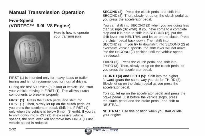
Manual Transmission Operation
Five-Speed(VORTEC™ 6.0L V8 Engine)
Here is how to operateyour transmission.
FIRST (1) is intended only for heavy loads or trailertowing and is not recommended for normal driving.
During the first 500 miles (805 km) of vehicle use, startyour vehicle moving in FIRST (1). This allows clutchcomponents to break-in properly.
FIRST (1): Press the clutch pedal and shift intoFIRST (1). Then, slowly let up on the clutch pedal asyou press the accelerator pedal. Shift into FIRST (1)only when the vehicle is below 5 mph (8 km/h). If you tryto shift down into FIRST (1) at excessive vehiclespeeds, the shift lever will not move into FIRST (1) untilvehicle speed is reduced.
SECOND (2): Press the clutch pedal and shift intoSECOND (2). Then, slowly let up on the clutch pedal asyou press the accelerator pedal.
You can shift into SECOND (2) when you are going lessthan 20 mph (32 km/h). If you have come to a completestop and it is hard to shift into SECOND (2), put theshift lever into NEUTRAL and let up on the clutch. Pressthe clutch pedal back down. Then shift intoSECOND (2). If you try to downshift into SECOND (2) atexcessive vehicle speeds, the shift lever will not moveinto the SECOND (2) position until the vehicle speedis reduced.
THIRD (3): Press the clutch pedal and shift intoTHIRD (3). Then, slowly let up on the clutch pedal asyou press the accelerator pedal.
FOURTH (4) and FIFTH (5): Shift into the higherforward gears the same way you do for THIRD (3).Slowly let up on the clutch pedal as you press theaccelerator pedal.
To stop, let up on the accelerator pedal and press thebrake pedal. Just before the vehicle stops, pressthe clutch pedal and the brake pedal, and shift toNEUTRAL.
NEUTRAL: Use this position when you start or idleyour engine.
2-32Information Provided by:

REVERSE (R): To back up, first press down the clutchpedal. Wait for the vehicle to stop moving and then,shift into REVERSE (R). Let up on the clutch pedalslowly while pressing the accelerator pedal.
Notice: Shifting to REVERSE (R) while your vehicleis moving forward could damage the transmission.The repairs would not be covered by your warranty.Shift to REVERSE (R) only after your vehicle isstopped.
Also, use REVERSE (R), along with the parking brake,when turning off your engine and parking yourvehicle.
Five-Speed (VORTEC™ 4.3L V6 and4.8L V8 Engines)Here is how to operate your transmission:
FIRST (1): Press the clutch pedal and shift intoFIRST (1). Then, slowly let up on the clutch pedal asyou press the accelerator pedal.
You can shift into FIRST (1) when you are going lessthan 20 mph (32 km/h). If you have come to a completestop and it is hard to shift into FIRST (1), put the shiftlever into NEUTRAL and let up on the clutch. Press theclutch pedal back down. Then shift into FIRST (1).
SECOND (2): Press the clutch pedal as you let up onthe accelerator pedal and shift into SECOND (2).Then, slowly let up on the clutch pedal as you press theaccelerator pedal.
THIRD (3), FOURTH (4) and FIFTH (5): Shift intoTHIRD (3), FOURTH (4) and FIFTH (5) the same wayyou do for SECOND (2). Slowly let up on the clutchpedal as you press the accelerator pedal.
To stop, let up on the accelerator pedal and press thebrake pedal. Just before the vehicle stops, pressthe clutch pedal and the brake pedal, and shift toNEUTRAL.
NEUTRAL: Use this position when you start or idleyour engine.
REVERSE (R): To back up, first press down the clutchpedal. Wait for the vehicle to stop moving and then,shift into REVERSE (R). Let up on the clutch pedalslowly while pressing the accelerator pedal.
Notice: Shifting to REVERSE (R) while your vehicleis moving forward could damage the transmission.The repairs would not be covered by your warranty.Shift to REVERSE (R) only after your vehicle isstopped.
Also, use REVERSE (R), along with the parking brake,when turning off your engine and parking your vehicle.
2-33Information Provided by:

Six-Speed (VORTEC™ 8.1L V8 andDURAMAX®™ 6.6L V8 Engines)
Here is how to operateyour transmission.
This six-speed pattern is unique to GM manualtransmissions. The transmission always repositions theshift lever to NEUTRAL, which is located betweenFOURTH (4) and FIFTH (5) gear.
To prevent unintentional gear selections, additionalforce is required to move the shift lever intoREVERSE (R) or FIRST (1). Use FIRST (1) when trailertowing, driving with payload in the pickup box orlaunching on a grade. Otherwise, start in SECOND (2)gear. Only shift into FIRST (1) when the vehicle hasstopped moving.
During the first 500 miles (805 km) of vehicle use, startthe vehicle moving in FIRST (1) gear. This allowsthe clutch components to wear-in properly.
FIRST (1): With the vehicle at a stop, release thebrake, press the clutch pedal and shift into FIRST (1).Then, slowly let up on the clutch pedal as you press theaccelerator pedal. Only downshift into FIRST (1)when the vehicle has come to a complete stop. If theshift lever will not go into FIRST (1), put the leverin NEUTRAL and let up on the clutch pedal to fullyengage the clutch. Press the clutch pedal again. Then,shift into FIRST (1).
SECOND (2): With the vehicle at a stop, release thebrake, press the clutch pedal and shift into SECOND (2).Then, slowly let up on the clutch pedal as you pressthe accelerator pedal. With the vehicle moving, press theclutch pedal and upshift into SECOND (2) fromFIRST (1) while applying light pressure to the right onthe shifter. Then, slowly let up on the clutch pedalas you press the accelerator pedal. If you come to acomplete stop and the shift lever will not go intoSECOND (2), put the lever in NEUTRAL and let up onthe clutch pedal to fully engage the clutch. Pressthe clutch pedal again. Then, shift into SECOND (2).
THIRD (3): Press the clutch pedal and upshift intoTHIRD (3). Then, slowly let up on the clutch pedal asyou press the accelerator pedal.
2-34Information Provided by:
FOURTH (4), FIFTH (5) and SIXTH (6): Upshift into thehigher forward gears the same way as you doTHIRD (3). Slowly let up on the clutch pedal as youpress the accelerator pedal.
NEUTRAL: Use this position when you start or idleyour engine.
REVERSE (R): To back up, press the clutch pedal.Wait for the vehicle to stop moving and then, shiftto REVERSE (R). Let up on the clutch slowly whilepressing the accelerator pedal. Also, use REVERSE (R),along with the parking brake, when turning off yourengine and parking your vehicle.
Shift Speeds
{CAUTION:
If you skip a gear when you downshift, youcould lose control of your vehicle. You couldinjure yourself or others. Do not shift downmore than one gear at a time when youdownshift.
Do not allow the engine rpm to overspeed and enter thetachometer red lines. Engine overspeed occurs whendownshifting, or descending a grade, at too high avehicle speed. When going down steep grades, alwaysselect a gear at least one position lower than youwould use on climbing a grade. This will allow thevehicle’s engine to provide some braking and help toslow the vehicle as it goes down the grade. Monitor yourvehicle speed, acceleration and engine rpm whileapplying the brakes as you go down the grade to ensureyou have complete control over the vehicle.
If your engine speed drops below 600 rpm, or if theengine is not running smoothly, you should downshift tothe next lower gear. When operating on slipperysurfaces, downshift at lower than normal vehicle speedsto prevent the tires from slipping.
In bench seat equipped vehicles, move the tallestbeverage containers to the right cupholder to provideadditional clearance for the shift lever.
For vehicles equipped with a center console, the frontcup holder pulls out and turns 180° to provide additionalclearance between tall beverage containers and theshift lever.
2-35Information Provided by:

Up-Shift Light
If you have a manualtransmission, you mayhave a shift light. This lightwill show you when toshift to the next higher gearfor best fuel economy.
When this light comes on, you can shift to the nexthigher gear if weather, road and traffic conditions allow.For the best fuel economy, accelerate slowly andshift when the light comes on.
While you accelerate, it is normal for the light to go onand off if you quickly change the position of theaccelerator.
If your vehicle has four-wheel drive and is equipped witha manual transmission, disregard the shift light whenthe transfer case is in Four-Wheel Low.
Ignore the shift light when you downshift.
Four-Wheel DriveIf your vehicle has four-wheel drive, you can send yourengine’s driving power to all four wheels for extratraction. To get the most satisfaction out of four-wheeldrive, you must be familiar with its operation. Readthe part that follows before using four-wheel drive. Seethe appropriate text for the transfer case in yourvehicle.
Front Axle Locking FeatureThe front axle locks and unlocks automatically whenyou shift the transfer case. Some delay for the axle tolock or unlock is normal.
2-36Information Provided by:

Manual Transfer Case
The transfer case shift lever is on the floor to the rightof the driver. Use this lever to shift into and out offour-wheel drive.
A 4WD indicator lightcomes on when you shiftinto four-wheel driveand the front axle engages.See Four-Wheel-DriveLight on page 3-49.
Some delay between shifting and when the indicatorlight comes on is normal.
Recommended Transfer Case Settings
Driving ConditionsTransfer Case Settings
2H 4H 4L N
Normal YES
Severe YES
Extreme YES
Vehicle in Tow* YES
*See Recreational Vehicle Towing on page 4-62 orTowing Your Vehicle on page 4-61 for furtherinformation.
2-37Information Provided by:

An indicator light near the lever shows you the transfercase settings:
Notice: Driving on clean, dry pavement infour-wheel drive for an extended period of time maycause premature wear on your vehicle’s powertrain.Do not drive on clean, dry pavement in four-wheeldrive for extended periods of time.
4L (Four-Wheel Low): This setting also engages yourfront axle and delivers extra torque. You may neverneed 4L. It sends maximum power to all four wheels.You might choose 4L if you are driving off-road in deepsand, deep mud, deep snow, and while climbing ordescending steep hills. When operating in Four-WheelLow, the gear ratio provides additional torque whencompared to four-wheel high. The transmissiongear shift feel will be exaggerated.
{CAUTION:
Shifting the transfer case to NEUTRAL cancause your vehicle to roll even if thetransmission is in PARK (P), or if you have amanual transmission, even if you are in gear.
CAUTION: (Continued)
CAUTION: (Continued)
You or someone else could be seriouslyinjured. Be sure to set the parking brakebefore placing the transfer case in NEUTRAL.See Parking Brake on page 2-49.
N (Neutral): Shift to this setting only when your vehicleneeds to be towed. See Recreational Vehicle Towingon page 4-62 or Towing Your Vehicle on page 4-61.
2H (Two-Wheel High): This setting is used for drivingin most street and highway situations. Your frontaxle is not engaged in two-wheel drive. This setting alsoprovides the best fuel economy.
4H (Four-Wheel High): Use this setting when youneed extra traction, such as on snowy or icy roads or inmost off-road situations. This setting also engagesyour front axle to help drive your vehicle. This is the bestsetting to use when plowing snow.
You can shift from 2H to 4H or 4H high to 2H while thevehicle is moving. Your front axle will engage fasterif you take your foot off of the accelerator for a coupleof seconds after you shift. In extremely cold weather, itmay be necessary to stop or slow the vehicle toshift into four-wheel high.
2-38Information Provided by:

When Using the Manual Transfer Case• Shifting should be made using quick motions.
Shifting slowly may make it more difficult to shift.
• You may notice that it is harder to shift when thevehicle is cold. After the vehicle warms up theshifting will return to normal.
• While in 4H or 4L you may experience reduced fueleconomy.
• Avoid driving in four-wheel drive on clean, drypavement. It may cause your tires to wearfaster, and make your transfer case harder to shiftand run noisier.
Shifting from 2H (Two-Wheel High) to 4H(Four-Wheel High)• Shifts between 2H and 4H can be made at any
vehicle speed.
• It is easiest to shift the transfer case whenmaintaining a constant speed or a slightacceleration. If possible, avoid shifting while slowingdown, as it will may make it harder to shift.
• Shift your transfer case lever in one continuousmotion into either the 4H or 2H position.
• In extremely cold weather, it may be necessary toslow or stop the vehicle to shift into four-wheelhigh until your vehicle has warmed up.
• While in 4H, your vehicle can be driven at anyposted legal speed limit.
Shifting In or Out of 4L (Four-Wheel Low)
Notice: Shifting the transfer case into 4L whilemoving at speeds faster than 3 mph (5 km/h) maycause premature wear to the transfer case, and maycause the gears to grind. To avoid causingpremature wear, and grinding the gears, do not shiftthe transfer case into 4L while the vehicle ismoving faster than 3 mph (5 km/h).
Shifts into 4L can be made with the vehicle at a stop, orwhile slowly rolling about 1 to 3 mph (2 to 5 km/h).
• Shift the automatic transmission into NEUTRAL (N),or with a manual transmission, press the clutchpedal, or shift into NEUTRAL (N).
• Shift the transfer case shift lever in one continuousmotion into the 4L position.
• When in 4L do not drive faster than 45 mph. Thiswill reduce wear and extend the life of yourtransfer case.
2-39Information Provided by:

Shifting In or Out of NEUTRAL1. With the vehicle running and the engine at an idle
set the parking brake.
2. Place the transmission into NEUTRAL (N).
Shift the transfer case in one continuous motion into orout of the NEUTRAL position.
Automatic Transfer Case
The transfer case buttonsare located to the left ofthe instrument panelcluster.
Use these switches to shift into and out of four-wheeldrive.
Recommended Transfer Case Settings
DrivingConditions
Transfer Case Settings
2 m AUTO4WD 4 m 4 n N
Normal YES
Variable YES
Severe YES
Extreme YES
Vehicle inTow* YES
*See Recreational Vehicle Towing on page 4-62 forfurther information.
You can choose among four driving settings:
Notice: Driving on clean, dry pavement inFour-Wheel-Drive High or Four-Wheel-Drive Low foran extended period of time may cause prematurewear on your vehicle’s powertrain. Do not drive onclean, dry pavement in Four-Wheel Drive High orFour-Wheel-Drive Low for extended periods of time.
2-40Information Provided by:

AUTO 4WD (Automatic Four-Wheel Drive): Thissetting is ideal for use when road surface tractionconditions are variable. When driving your vehicle inAutomatic Four-Wheel Drive, the front axle is engaged,but the vehicle’s power is sent to the rear wheels.When the vehicle detects a loss of traction, the systemwill automatically engage four-wheel drive. Driving inthis mode results in slightly lower fuel economythan Two-Wheel High.2 m (Two-Wheel High): This setting is used fordriving in most street and highway situations. Your frontaxle is not engaged in two-wheel drive. This settingalso provides the best fuel economy.
{CAUTION:
Shifting the transfer case to NEUTRAL cancause your vehicle to roll even if thetransmission is in PARK (P). You or someoneelse could be seriously injured. Be sure to setthe parking brake before placing the transfercase in NEUTRAL. See Parking Brake onpage 2-49.
N (NEUTRAL): Shift the vehicle’s transfer case to N(NEUTRAL) only when towing your vehicle. SeeRecreational Vehicle Towing on page 4-62 or TowingYour Vehicle on page 4-61 for more information.
4 m (Four-Wheel High): Use this setting when youneed extra traction, such a on snowy or icy roads or inmost off-road situations. This setting also engagesyour front axle to help drive your vehicle. This is the bestsetting to use when plowing snow.
4 n (Four-Wheel Low): This setting also engagesyour front axle and delivers extra torque. You may neverneed Four-Wheel Low. It sends maximum power to allfour wheels. You might choose Four-Wheel Low if youare driving off-road in deep sand, deep mud, deep snow,and while climbing or descending steep hills. Whenoperating in Four-Wheel Low, the gear ratio providesadditional torque when compared to four-wheel high. Thetransmission gear shift feel will be exaggerated.
Indicator lights in the switches show which setting yourtransfer case is in. The indicator lights will come onbriefly when you turn on the ignition and one will stay on.If the lights do not come on, you should take yourvehicle to your dealer for service. An indicator light willflash while the transfer case is being shifted. It willstay on when the shift is complete. If for some reasonthe transfer case cannot make a requested shift, itwill return to the last chosen setting.
If the SERVICE 4WD message stays on, you shouldtake your vehicle to your dealer for service. SeeDIC Warnings and Messages on page 3-54 for furtherinformation.
2-41Information Provided by:

Shifting into Four-Wheel High or AUTO4WD (Automatic Four-Wheel Drive)Press and release the four-wheel high or AUTO 4WDswitch. This can be done at any speed, exceptwhen shifting from Four-Wheel Low, and the indicatorlight will flash while shifting. It will remain on whenthe shift is completed.
Shifting into Two-Wheel HighPress and release the Two-Wheel High switch. This canbe done at any speed, except when shifting fromFour-Wheel Low.
Shifting into Four-Wheel Low
Notice: Shifting the transfer case into Four-WheelLow while moving at speeds faster than 3 mph(5 km/h) may cause premature wear to the transfercase, and may cause the gears to grind. To avoidcausing premature wear, and grinding the gears, donot shift the transfer case into Four-Wheel Low whilethe vehicle is moving faster than 3 mph (5 km/h).
To shift to Four-Wheel Low, the ignition must be in RUNand the vehicle must be stopped or moving less than3 mph (5 km/h) with the transmission in NEUTRAL (N).The preferred method for shifting into Four-Wheel Low isto have your vehicle moving 1 to 2 mph (1.6 to 3.2 km/h).
Press and release the Four-Wheel Low switch. You mustwait for the Four-Wheel Low indicator light to stopflashing and remain on before shifting your transmissionin gear.
Notice: Shifting the transmission into gear beforethe Four-Wheel Low indicator light has stoppedflashing could damage the transfer case. Tohelp avoid damaging your vehicle, always wait forthe Four-Wheel Low indicator light to stop flashingbefore shifting the transmission into gear.
It is typical for your vehicle to exhibit significantengagement noise and bump when shifting betweenFour-Wheel Low and Four-Wheel High ranges or fromNEUTRAL (N) with the engine running.
If the Four-Wheel Low switch is pressed when yourvehicle is in gear and/or moving, the Four-Wheel Lowindicator light will flash for 30 seconds and not completethe shift unless your vehicle is moving less than3 mph (5 km/h) and the transmission is in NEUTRAL (N).After 30 seconds the transfer case will shift tofour-wheel high mode.
2-42Information Provided by:

Shifting Out of Four-Wheel LowTo shift from Four-Wheel Low to Four-Wheel High, AUTO4WD, or Two-Wheel High, your vehicle must be stoppedor moving less than 3 mph (5 km/h) with the transmissionin NEUTRAL (N) and the ignition in RUN. The preferredmethod for shifting out of Four-Wheel Low is to have yourvehicle moving 1 to 2 mph (1.6 to 3.2 km/h). Press andrelease the Four-Wheel High, AUTO 4WD, or Two-WheelHigh switch. You must wait for the Four-Wheel High,AUTO 4WD, or Two-Wheel High indicator light to stopflashing and remain on before shifting your transmissioninto gear.
Notice: Shifting the transmission into gear beforethe Four-Wheel Low indicator light has stoppedflashing could damage the transfer case. Tohelp avoid damaging your vehicle, always wait forthe Four-Wheel Low indicator light to stop flashingbefore shifting the transmission into gear.
The transfer case may make noise and the vehicle mayjerk when the transfer case is shifted betweenFour-Wheel Low and Four-Wheel High ranges or fromNEUTRAL with the engine running.
If the four-wheel high, AUTO 4WD, or Two-Wheel Highswitch is pressed when your vehicle is in gear and/ormoving, the Four-Wheel High, AUTO 4WD, or
Two-Wheel High indicator light will flash for 30 secondsbut will not complete the shift unless your vehicle ismoving less than 3 mph (5 km/h) and the transmissionis in NEUTRAL (N).
Shifting Into NEUTRAL
{CAUTION:
Shifting the transfer case to NEUTRAL cancause your vehicle to roll even if thetransmission is in PARK (P). You or someoneelse could be seriously injured. Be sure to setthe parking brake before placing the transfercase in NEUTRAL. See Parking Brake onpage 2-49.
To shift the transfer case to NEUTRAL do the following:
1. Make sure the vehicle is parked so that it willnot roll.
2. Set the parking brake.
3. Start the vehicle or turn the ignition to RUN.
2-43Information Provided by:

4. Put the transmission in NEUTRAL (N).
5. Shift the transfer case to Two-Wheel High.
6. Simultaneously press and hold the Two-Wheel Highand Four-Wheel Low buttons for 10 seconds. Thered NEUTRAL light will come on when thetransfer case shift to NEUTRAL is complete.
7. If the engine is running, shift the transmission toREVERSE (R) for one second, then shift thetransmission to DRIVE (D) for one second, orFIRST (1) for vehicles equipped with a manualtransmission.
8. Turn the engine off, by turning the key toACCESSORY.
9. Place the transmission shift lever in PARK (P).
10. Turn the ignition to LOCK.
Shifting Out of NEUTRALTo shift out of NEUTRAL:
1. Set the parking brake and apply the regular brakepedal.
2. Turn the ignition to RUN with the engine off.
3. Shift the transmission to NEUTRAL (N).
4. Press the button for the desired transfer case shiftposition (Two-Wheel High, Four-Wheel High, AUTO4WD, or Four-Wheel Low).
5. After the transfer case has shifted out of NEUTRALthe red light will go out.
6. Release the parking brake.
7. You may start the engine and shift the transmissionto the desired position.
Excessively shifting the transfer case into or out of thedifferent modes may cause the transfer case toenter the shift protection mode. This will protect thetransfer case from possible damage and will only allowthe transfer case to respond to one shift per10 seconds. The transfer case may stay in this mode forup to three minutes.
2-44Information Provided by:

Electronic Transfer Case
If your four-wheel-drivevehicle has the electronictransfer case, thetransfer case switches arelocated to the left of theinstrument panel cluster.
Recommended Transfer Case Settings
Driving ConditionsTransfer Case Settings
2 m 4 m 4 n N
Normal YES
Severe YES
Extreme YES
Vehicle in Tow* YES
*See Recreational Vehicle Towing on page 4-62 orTowing Your Vehicle on page 4-61 for furtherinformation.
Use these switches to shift into and out of four-wheeldrive. You can choose among three driving settings:
2 m (Two-Wheel High): This setting is for driving inmost street and highway situations. Your front axle is notengaged in two-wheel drive.
{CAUTION:
Shifting the transfer case to NEUTRAL cancause your vehicle to roll even if thetransmission is in PARK (P). You or someoneelse could be seriously injured. Be sure to setthe parking brake before placing the transfercase in NEUTRAL. See Parking Brake onpage 2-49.
(N) NEUTRAL: Shift the vehicle’s transfer case toNEUTRAL only when towing your vehicle. SeeRecreational Vehicle Towing on page 4-62 or TowingYour Vehicle on page 4-61 for more information.
2-45Information Provided by:

4 m (Four-Wheel High): This setting engages yourfront axle to help drive your vehicle. Use four-wheel highwhen you need extra traction, such as on snowy oricy roads, or in most off-road situations.
4 n (Four-Wheel Low): This setting also engagesyour front axle to give you extra traction. You may neverneed Four-Wheel Low. It sends the maximum powerto all four wheels. You might choose Four-Wheel Low ifyou were driving off-road in sand, mud or deep snowand while climbing or descending steep hills. Whenoperating in Four-Wheel Low, the gear ratio providesadditional torque when compared to Four-WheelHigh. The transmission gear shift feel will beexaggerated.
Indicator lights in the switches show you which settingyou are in. The indicator lights will come on briefly whenyou turn on the ignition and the last chosen settingwill stay on. If the lights do not come on, you should takeyour vehicle in for service. An indicator light will flashwhile shifting. Fast flashing means the conditionswere not met to make the desired shift, typically thevehicle was going too fast, the automatic transmissionwas not in neutral, or the clutch pedal was not fullypressed. Slow flashing means the shift is in progress. Itwill stay on when the shift is completed. If for somereason the transfer cannot make a requested shift, it willreturn to the last chosen setting.
Shifting from Two-Wheel High toFour-Wheel HighPress and release the Four-Wheel High switch. Thiscan be done at any speed, and the front axle will lockautomatically with some delay.
Shifting from Four-Wheel High toTwo-Wheel HighPress and release the Two-Wheel High switch. This canbe done at any speed, and the front axle will unlockautomatically with some delay.
It is normal to hear and feel your vehicle’s transfer caseshift into Four-Wheel Low. If you shift with the vehiclestopped, the indicator light may remain flashing slowly. Itmay be necessary to shift the transmission momentarilyinto REVERSE (R) and DRIVE (D), for an automatictransmission, or REVERSE (R) and FIRST (1) fora manual transmission to have the light stop flashing.
2-46Information Provided by:

Shifting from Two-Wheel High orFour-Wheel High to Four-Wheel Low
Notice: Shifting the transfer case into Four-WheelLow while moving at speeds faster than 3 mph(5 km/h) may cause premature wear to the transfercase, and may cause the gears to grind. To avoidcausing premature wear, and grinding the gears, donot shift the transfer case into Four-Wheel Low whilethe vehicle is moving faster than 3 mph (5 km/h).
To shift from Two-Wheel High or Four-Wheel High toFour-Wheel Low, the vehicle must be stopped or movingless than 3 mph (5 km/h) with the transmission inNEUTRAL (N) for an automatic transmission or theclutch pedal pressed for a manual transmission.The preferred method for shifting into four-wheel low isto have your vehicle moving 3 mph (5 km/h).
Press and release the Four-Wheel Low switch. Youmust wait for the four-wheel low indicator light to stopflashing and stay on before shifting your transmissioninto gear or releasing the clutch pedal.
Notice: Shifting the transmission into gear beforethe Four-Wheel Low indicator light has stoppedflashing could damage the transfer case. Tohelp avoid damaging your vehicle, always wait forthe Four-Wheel Low indicator light to stop flashingbefore shifting the transmission into gear.
If the Four-Wheel Low switch is pressed when yourvehicle is in gear and/or moving, the Four-Wheel Lowindicator light will flash for 30 seconds and not completethe shift unless your vehicle is moving slower than3 mph (5 km/h) and the transmission is in NEUTRAL (N).The transfer case will shift to Four-Wheel High whilewaiting to complete the shift.
Shifting from Four-Wheel Low toFour-Wheel High or Two-Wheel HighTo shift from four-wheel low to Four-Wheel High orTwo-Wheel High, your vehicle must be stopped ormoving less than 3 mph (5 km/h) with the transmission inNEUTRAL (N) for an automatic transmission or the clutchpedal pressed for a manual transmission. The preferredmethod for shifting out of Four-Wheel Low is to have yourvehicle moving 3 mph (5 km/h).
Press and release the Two-Wheel High or Four-WheelHigh switch. You must wait for the Two-Wheel Highor Four-Wheel High indicator light to stop flashing andremain on before shifting your transmission intogear or releasing the clutch pedal.
If the Four-Wheel High switch is pressed when yourvehicle is in gear and/or moving, the Four-Wheel Highindicator light will flash for 30 seconds but will notcomplete the shift unless the vehicle is moving slowerthan 3 mph (5 km/h) and the transmission is inNEUTRAL (N).
2-47Information Provided by:

Shifting into NEUTRAL
{CAUTION:
Shifting the transfer case to NEUTRAL cancause your vehicle to roll even if thetransmission is in PARK (P). You or someoneelse could be seriously injured. Be sure to setthe parking brake before placing the transfercase in NEUTRAL. See Parking Brake onpage 2-49.
To shift the transfer case to NEUTRAL, first make surethe vehicle is parked so that it will not roll:
1. Set the parking brake.
2. Start the vehicle or turn the ignition to RUN.
3. Press the foot brake pedal and put the transmissionin NEUTRAL (N).
4. Shift the transfer case to Two-Wheel High.
5. Simultaneously press and hold the Two-Wheel Highand Four-Wheel Low buttons for 10 seconds. Thered NEUTRAL light will come on when thetransfer case shift to NEUTRAL is complete.
6. Start the engine if it is not already running.
7. Press and hold the foot brake pedal and Shift thetransmission to REVERSE (R) for one second,then shift the transmission for one second toDRIVE (D) for an automatic transmission, orFIRST (1) for vehicles equipped with a manualtransmission and then let out the clutch. This is toensure the transfer case is in NEUTRAL. If not,repeat this procedure starting at Step 3.
8. Turn the engine off, by turning the key toACCESSORY.
9. Place the transmission shift lever in PARK (P) foran automatic transmission, or FIRST (1) forvehicles equipped with a manual transmission.
10. Turn the ignition to LOCK.
Shifting Out of NEUTRALTo shift out of NEUTRAL:
1. Set the parking brake and press and hold theregular brake pedal.
2. Shift the transmission to NEUTRAL (N) for anautomatic transmission, or press the clutch pedal forvehicles equipped with a manual transmission.Then turn the ignition to RUN with the engine off.
3. Press the button for the desired transfer case shiftposition (Two-Wheel High, Four-Wheel High, orFour-Wheel Low).
2-48Information Provided by:

4. After the transfer case has shifted out of NEUTRALthe red light will go out.
5. Release the parking brake.
6. You may start the engine and shift the transmissionto the desired position. Excessively shifting thetransfer case into or out of the different modes maycause the transfer case to enter the shift protectionmode. This will protect the transfer case frompossible damage and will only allow the transfercase to respond to one shift per 10 seconds.The transfer case may stay in this mode for up tothree minutes.
7. After the transfer case has shifted out of NEUTRALthe red light will go out.
Parking BrakeTo set the parking brake, hold the regular brake pedaldown with your right foot. Push down the parkingbrake pedal with your left foot.
A chime will activate and the warning light will flashwhen the parking brake is applied and the vehicleis moving at least 3 mph (5 km/h) for at leastthree seconds.
To release the parking brake, hold the regular brakepedal down. Pull the bottom edge of the lever, locatedabove the parking brake pedal, with the parkingbrake symbol, to release the parking brake.
If the ignition is on when the parking brake is released,the brake system warning light will go off.
Notice: Driving with the parking brake on canoverheat the brake system and cause prematurewear or damage to brake system parts. Verify thatthe parking brake is fully released and the brakewarning light is off before driving.
If you are towing a trailer and are parking on any hill,see Towing a Trailer on page 4-67.
2-49Information Provided by:

Shifting Into Park (P)(Automatic Transmission)
{CAUTION:
It can be dangerous to get out of your vehicleif the shift lever is not fully in PARK (P) withthe parking brake firmly set. Your vehicle canroll. If you have left the engine running, thevehicle can move suddenly. You or otherscould be injured. To be sure your vehicle willnot move, even when you are on fairly levelground, use the steps that follow. Withfour-wheel drive, if your transfer case is inNEUTRAL, your vehicle will be free to roll,even if your shift lever is in PARK (P). So, besure the transfer case is in a drive gear — notin NEUTRAL. If you are pulling a trailer, seeTowing a Trailer on page 4-67.
1. Hold the brake pedal down with your right foot andset the parking brake.
2. Move the shift lever into the PARK (P) position bypulling the shift lever toward you and moving it upas far as it will go.
3. If your vehicle has four-wheel drive, be sure thetransfer case is in a drive gear – not inNEUTRAL (N).
4. Turn the ignition key to LOCK.
5. Remove the key and take it with you. If you canleave your vehicle with the ignition key in yourhand, your vehicle is in PARK (P).
2-50Information Provided by:
Leaving Your Vehicle With the EngineRunning (Automatic Transmission)
{CAUTION:
It can be dangerous to leave your vehiclewith the engine running. Your vehicle couldmove suddenly if the shift lever is not fully inPARK (P) with the parking brake firmly set.
If you have four-wheel drive and your transfercase is in NEUTRAL, your vehicle will be freeto roll, even if your shift lever is in PARK (P).So be sure the transfer case is in a drivegear — not in NEUTRAL.
And, if you leave the vehicle with the enginerunning, it could overheat and even catch fire.You or others could be injured. Do not leaveyour vehicle with the engine running unlessyou have to.
If you have to leave your vehicle with the enginerunning, be sure your vehicle is in PARK (P) and theparking brake is firmly set before you leave it. After youmove the shift lever into PARK (P), hold the regularbrake pedal down. Then, see if you can move the shiftlever away from PARK (P) without first pulling ittoward you. If you can, it means that the shift lever wasnot fully locked into PARK (P).
Torque Lock (Automatic Transmission)If you are parking on a hill and you do not shift yourtransmission into PARK (P) properly, the weight of thevehicle may put too much force on the parking pawlin the transmission. You may find it difficult to pull theshift lever out of PARK (P). This is called “torquelock.” To prevent torque lock, set the parking brake andthen shift into PARK (P) properly before you leavethe driver’s seat. To find out how, see “ShiftingInto PARK (P)” listed earlier in this section.
When you are ready to drive, move the shift lever out ofPARK (P) before you release the parking brake.
If torque lock does occur, you may need to have anothervehicle push yours a little uphill to take some of thepressure from the parking pawl in the transmission, soyou can pull the shift lever out of PARK (P).
2-51Information Provided by:

Shifting Out of Park (P)(Automatic Transmission)Your vehicle has an automatic transmission shift lockcontrol system which locks the shift lever in PARK (P)when the ignition is in the LOCK position. You haveto fully apply your regular brakes before you can shiftfrom PARK (P) when the ignition is in RUN. SeeAutomatic Transmission Operation on page 2-24 and“Torque Lock” under Shifting Out of Park (P) (AutomaticTransmission) on page 2-52.
If your vehicle has an Allison Transmission®, thetransmission is equipped with a park pawl designed tohold the higher weight of commercial medium dutytrucks. Therefore, the Allison Transmission® uses largerparts than other automatic transmissions. Theselarger parts may sometimes make a clunk noise whenthe selector lever is moved from DRIVE (D) orREVERSE (R) to PARK (P). This is normal and there isno damage occurring during these shifts.
If you cannot shift out of PARK (P), ease pressure onthe shift lever and push the shift lever all the way up intoPARK (P) as you maintain brake application. Then,move the shift lever into the gear you want.
If you ever hold the brake pedal down but still can’t shiftout of PARK (P), try this:
1. Turn the key to ACCESSORY. There is no shiftinterlock in this key position.
2. Apply and hold the brake until the end of Step 4.
3. Shift the transmission to NEUTRAL (N).
4. Start the vehicle and then shift to the gear youwant.
5. Have the system fixed as soon as you can.
2-52Information Provided by:

Parking Your Vehicle(Manual Transmission)
{CAUTION:
Shifting the transfer case to NEUTRAL cancause your vehicle to roll even if the manualtransmission is in gear. Your or someone elsecould be seriously injured. Be sure to set theparking brake before placing the transfer casein NEUTRAL. See Parking Brake on page 2-49for more information.
Before you get out of your vehicle, move the shift leverinto REVERSE (R), and firmly apply the parkingbrake. Once the shift lever has been placed intoREVERSE (R) with the clutch pedal pressed in, you canturn the ignition key to LOCK, press the key releasebutton, remove the key and release the clutch.
If you are parking on a hill, or if you are pulling a trailer,see Towing a Trailer on page 4-67.
Parking Over Things That Burn
{CAUTION:
Things that can burn could touch hot exhaustparts under your vehicle and ignite. Do notpark over papers, leaves, dry grass, or otherthings that can burn.
2-53Information Provided by:

Engine Exhaust
{CAUTION:
Engine exhaust can kill. It contains the gascarbon monoxide (CO), which you cannot seeor smell. It can cause unconsciousness anddeath.
You might have exhaust coming in if:• Your exhaust system sounds strange or
different.• Your vehicle gets rusty underneath.• Your vehicle was damaged in a collision.• Your vehicle was damaged when driving
over high points on the road or over roaddebris.
• Repairs were not done correctly.• Your vehicle or exhaust system had been
modified improperly.
If you ever suspect exhaust is coming intoyour vehicle:
• Drive it only with all the windows down toblow out any CO; and
• Have your vehicle fixed immediately.
Running the Engine While ParkedIt is better not to park with the engine running. But if youever have to, here are some things to know.
{CAUTION:
Idling the engine with the climate controlsystem off could allow dangerous exhaust intoyour vehicle. See the earlier caution underEngine Exhaust on page 2-54.
Also, idling in a closed-in place can let deadlycarbon monoxide (CO) into your vehicle even ifthe climate control fan is at the highest setting.One place this can happen is a garage.Exhaust — with CO — can come in easily.NEVER park in a garage with the enginerunning.
Another closed-in place can be a blizzard. SeeWinter Driving on page 4-42.
2-54Information Provided by:

{CAUTION:
It can be dangerous to get out of your vehicleif the automatic transmission shift lever is notfully in PARK (P) with the parking brake firmlyset. Your vehicle can roll. Do not leave yourvehicle when the engine is running unless youhave to. If you have left the engine running,the vehicle can move suddenly. You or otherscould be injured. To be sure your vehicle willnot move, even when it is on fairly levelground, always set the parking brake andmove the automatic transmission shift lever toPARK (P), or the manual transmission shiftlever to NEUTRAL.
{CAUTION:
Four-wheel drive vehicles with the transfercase in NEUTRAL will allow the vehicle to roll,even if your automatic transmission shift leveris in PARK (P). So, be sure the transfer case isin a drive gear — not in NEUTRAL. Always setyour parking brake.
Follow the proper steps to be sure your vehicle will notmove. See Shifting Into Park (P) (AutomaticTransmission) on page 2-50.
If you are pulling a trailer, see Towing a Trailer onpage 4-67.
2-55Information Provided by:

Mirrors
Manual Rearview MirrorPull or push the tab under the mirror to adjust it to thenight or daytime setting. In the nighttime setting,the glare from headlamps behind the vehicle will be lessintense.
Automatic Dimming Rearview Mirrorwith OnStar ® and CompassYour vehicle may have an automatic-dimming rearviewmirror with a compass and the OnStar® system.
There are three additional buttons for the OnStar®
system. See your dealer for more information on thesystem and how to subscribe to OnStar®. See OnStar®
System on page 2-69 for more information about theservices OnStar® provides.
Mirror OperationWhen turned on, this mirror automatically dims to theproper level to minimize glare from any headlampsbehind you after dark.
O(On/Off): This is the on/off button for the automaticdimming feature and compass. Press the far left button,located below the mirror face, for up to three secondsto turn the feature on and off. A light on the mirror will belit while the feature is turned on.
Compass OperationPress the on/off button once to turn the compass onor off.
There is a compass display in the window in the upperright corner of the mirror face. The compass displaysa maximum of two characters. For example, “NE”is displayed for north-east.
Compass CalibrationPress and hold the on/off button down for nine secondsto activate the compass calibration mode. CAL willbe displayed in the compass window on the mirror.
The compass can be calibrated by driving the vehicle incircles at 5 mph (8 km/h) or less until the displayreads a direction.
2-56Information Provided by:

Compass VarianceCompass variance is the difference between earth’smagnetic north and true geographic north. The mirror isset to zone eight upon leaving the factory. It will benecessary to adjust the compass to compensatefor compass variance if you live outside zone eight.Under certain circumstances, such as during along distance cross-country trip, it will be necessary toadjust for compass variance. If not adjusted toaccount for compass variance, your compass could givefalse readings.
To adjust for compass variance, do the following:
1. Find your current location and variance zonenumber on the map.
2. Press and hold the on/off button for six seconds.Release the button when ZONE is displayed. Thenumber shown is the current zone number.
3. Scroll through the zone numbers that appear in thecompass/temperature window on the mirror bypressing the on/off button. Once you find your zonenumber, release the button. After about fourseconds, the mirror will return to the compassdisplay, and the new zone number will be set.
2-57Information Provided by:

Automatic Dimming Rearview Mirrorwith OnStar ®, Compass andTemperature DisplayYour vehicle may have this feature. When on, anautomatic dimming mirror automatically dims to theproper level to minimize glare from lights behindyou after dark.
The mirror also includes a dual display in the upperright corner of the mirror face. The compass reading andthe outside temperature will both appear in the displayat the same time.
P (On/Off): This is the on/off button.
Temperature and Compass DisplayPress the on/off button, located to the far left, briefly toturn the compass/temperature display on or off.
If the display reads CAL, you will need to calibrate thecompass. For more information on calibration, seebelow.
To adjust between Fahrenheit and Celsius do thefollowing:
1. Press and hold the on/off button for approximatelyfour seconds until either a flashing F or C appears.
2. Press the button again to change the display to thedesired unit of measurement. After approximatelyfour seconds of inactivity, the new unit will be lockedin and the compass/temperature display will return.
If an abnormal temperature reading is displayed for anextended period of time, please consult your dealer.Under certain circumstances, a delay in updatingthe temperature is normal.
Automatic Dimming Mirror OperationThe automatic dimming mirror function is turnedon automatically each time the ignition is started. Tooperate the automatic dimming mirror, do the following:
1. Make sure the green indicator light, located to the leftof the on/off button, is lit. If it’s not, press and hold theon/off button for approximately six seconds until thegreen light comes on, indicating that the mirror is inautomatic dimming mode.
2. Turn off the automatic dimming mirror function bypressing and holding the on/off button forapproximately six seconds, until the green indicatorlight turns off.
2-58Information Provided by:

Compass VarianceThe mirror is set in zone eight upon leaving the factory.It will be necessary to adjust the compass tocompensate for compass variance if you live outside ofzone eight. Under certain circumstances, as during along distance cross-country trip, it will be necessary toadjust for compass variance. Compass variance isthe difference between earth’s magnetic north and truegeographic north. If not adjusted to account forcompass variance, your compass could give falsereadings.
To adjust for compass variance do the following:
1. Find your current location and variance zonenumber on the following zone map.
2. Press and hold the on/off button until a Z and azone number appear in the display. The compassis now in zone mode.
3. Keep pressing the on/off button until the desiredzone number appears in the display. Release thebutton. After approximately four seconds ofinactivity, the new zone number will be locked inand the compass/temperature display will return.
4. Calibrate the compass as described below.
2-59Information Provided by:

Compass CalibrationThe compass may need calibration if one of thefollowing occurs:
• After approximately five seconds, the display doesnot show a compass heading (N for North, forexample), there may be a strong magnetic fieldinterfering with the compass. Such interference maybe caused by a magnetic antenna mount, magneticnote pad holder or a similar magnetic item.
• The compass does not display the correct headingand the compass zone variance is set correctly.
In order to calibrate, CAL must be displayed in themirror compass windows. If CAL is not displayed, pushthe on/off button for approximately 12 seconds oruntil CAL is displayed.
The compass can be calibrated by driving the vehicle incircles at 5 mph (8 km/h) or less until the displayreads a direction.
Passenger Airbag IndicatorThe vehicle may be equipped with a passenger airbagindicator, on the mirror glass, just above the buttons.If the vehicle has this feature, the mirror will display theword ON, or an airbag symbol in Canada, when thepassenger airbag is enabled. For more information, seePassenger Sensing System on page 1-80.
Cleaning the MirrorWhen cleaning the mirror, use a paper towel or similarmaterial dampened with glass cleaner. Do not sprayglass cleaner directly on the mirror as that may causethe liquid cleaner to enter the mirror housing.
Automatic Dimming Rearview Mirrorwith CompassYour vehicle may have an automatic-dimming rearviewmirror with a compass.
Mirror OperationWhen turned on, this mirror automatically dims to theproper level to minimize glare from any headlampsbehind you after dark.
O(On/Off): This is the on/off button for the automaticdimming feature and compass. Press the far left button,located below the mirror face, for up to three secondsto turn the feature on and off. A light on the mirror will belit while the feature is turned on.
2-60Information Provided by:

Compass OperationPress the on/off button once to turn the compass onor off.
There is a compass display in the window in the upperright corner of the mirror face. The compass displaysa maximum of two characters. For example, “NE”is displayed for north-east.
Compass CalibrationPress and hold the on/off button down for nine secondsto activate the compass calibration mode. CAL willbe displayed in the compass window on the mirror.
The compass can be calibrated by driving the vehicle incircles at 5 mph (8 km/h) or less until the displayreads a direction.
Compass VarianceCompass variance is the difference between earth’smagnetic north and true geographic north. The mirror isset to zone eight upon leaving the factory. It will benecessary to adjust the compass to compensate forcompass variance if you live outside zone eight. Undercertain circumstances, such as during a long distancecross-country trip, it will be necessary to adjust forcompass variance. If not adjusted to account for compassvariance, your compass could give false readings.
To adjust for compass variance, do the following:1. Find your current location and variance zone
number on the map.
2. Press and hold the on/off button for six seconds.Release the button when ZONE is displayed. Thenumber shown is the current zone number.
3. Scroll through the zone numbers that appear in thecompass/temperature window on the mirror bypressing the on/off button. Once you find your zonenumber, release the button. After about fourseconds, the mirror will return to the compassdisplay, and the new zone number will be set.
2-61Information Provided by:
Automatic Dimming Rearview Mirrorwith Compass and TemperatureDisplayIf the vehicle is equipped with an automatic mirror, itwill, when on, automatically dim to the proper levelto minimize glare from lights behind you after dark.
The mirror also includes a display in the upperright corner of the mirror face. The compass readingand the outside temperature will both appear inthe display at the same time. The dual display can beturned on or off by briefly pressing either the TEMPor the COMP button.
Temperature DisplayThe temperature can be displayed by pressing theTEMP button. Pressing the TEMP button once briefly,will toggle the temperature reading on and off. Toalternate the temperature reading between Fahrenheitand Celsius, press and hold the TEMP button forapproximately four seconds until the display blinks Fand C. Press and release the TEMP button to togglebetween the Fahrenheit and Celsius readings. Afterapproximately four seconds of inactivity, the display willstop blinking and display the last selection made.
If an abnormal reading is displayed, for an extendedperiod of time, please consult your dealer. Under certaincircumstances, a delay in updating the temperature isnormal.
Automatic Dimming Mirror OperationThe time period you need to press and hold the TEMPbutton to turn the automatic dimming feature on oroff is approximately eight seconds. The indicator light tothe left of the TEMP button will still turn on or off toshow you when the automatic dimming feature isactivated. Once the mirror is turned off, it will remain offuntil it is turned back on, or until the vehicle isrestarted.
Compass OperationPress the COMP button once briefly to turn the compasson or off.
When the ignition and the compass feature are on, thecompass will show two character boxes forapproximately two seconds. After two seconds, themirror will display the compass heading.
2-62Information Provided by:

Compass CalibrationThe compass may need calibration if one of thefollowing occurs:
• If CAL is displayed while driving in the vehicle.
• After approximately five seconds, the display doesnot show a compass heading (N for North, forexample), there may be a strong magnetic fieldinterfering with the compass. Such interference maybe caused by a magnetic antenna mount, magneticnote pad holder or a similar magnetic item.
• The compass does not display the correct headingand the compass zone variance is set correctly.
In order to calibrate, CAL must be displayed in themirror compass windows. If CAL is not displayed, pushin the COMP button for approximately eight secondsor until CAL is displayed.
The compass can be calibrated by driving the vehicle incircles at 5 mph (8 km/h) or less until the displayreads a direction.
Compass VarianceThe mirror is set in zone eight upon leaving the factory.It will be necessary to adjust the compass tocompensate for compass variance if you live outsidezone eight. Under certain circumstances, as duringa long distance cross-country trip, it will be necessary toadjust for compass variance. Compass variance isthe difference between earth’s magnetic north and truegeographic north. If not adjusted to account forcompass variance, your compass could give falsereadings.
2-63Information Provided by:

To adjust for compass variance:
1. Find your current location and variance zonenumber on the following zone map.
2. Press and hold the COMP button for five secondsuntil a zone number appears in the display.
3. Press the COMP button on the bottom of the mirroruntil the new zone number appears in the display.After you stop pressing the button, the displaywill show a compass direction within a few seconds.
Passenger Airbag IndicatorThe mirror may be equipped with a passenger airbagindicator on the mirror glass, just above the buttons.If the vehicle has this feature the mirror will display theword ON, or an airbag symbol in Canada, when thepassenger airbag is enabled. For more information seePassenger Sensing System on page 1-80
Cleaning the MirrorWhen cleaning the mirror, use a paper towel or similarmaterial dampened with glass cleaner. Do not sprayglass cleaner directly on the mirror as that may causethe liquid cleaner to enter the mirror housing.
Outside Manual MirrorsAdjust your outside mirrors so you can just see the sideof your vehicle and have a clear view of objectsbehind you. The mirrors can be folded in to enter narrowareas.
The use of hood-mounted air deflectors and add-onconvex mirror attachments may adversely affect mirrorperformance.
2-64Information Provided by:

Outside Camper-Type Mirrors
If your vehicle is equipped with this style camper-typemirrors, they can be adjusted so you can have aclear view of the objects behind you.
Pull out the mirror head to extend it for better visibilitywhen towing a trailer.
If your vehicle is equippedwith this style camper-typemirrors, they can beadjusted so you can havea clear view of theobjects behind you.
Adjust the mirror by turning it left or right. Once themirror is adjusted to the correct position, tighten the setscrew to hold the mirror in place. These mirrors canalso be manually folded in.
On the lower portion of the mirror is a convex mirror. Aconvex mirror’s surface is curved so you can seemore from the driver’s seat.
If your vehicle is equipped with this trailer towing typemirror, they can be adjusted so you can have aclear view of the objects behind you. Pull out the mirrorhead to extend it for better visibility when towing atrailer.
These mirrors can also be manually folded in. On thelower portion of the mirror is a convex mirror. A convexmirror’s surface is curved so you can see more fromthe driver’s seat.
2-65Information Provided by:

Outside West Coast-Type MirrorsIf your vehicle is equipped with these mirrors, they canbe adjusted so you can have a clear view of objectsbehind you.
A. Outer Mirror FrameB. Mirror HeadC. Nut
The mirrors can be adjusted by turning the mirrorhead (B) and moving the outer mirror frame (A)backward or forward. You can also loosen the nut (C)on the top and bottom of the outer mirror frame to tilt themirror head.
Outside Power Mirrors
If your vehicle is equippedwith power outside mirrors,the controls are locatedon the driver’s doorarmrest.
Move the selector switch located above the control padto the left or right to choose the mirror you want toadjust, then press the dots located on the four-waycontrol pad to adjust the mirror.
The mirrors can be manually folded inward to preventdamage when going through an automatic car wash. Tofold, push the mirror toward the vehicle. To return themirror to its original position, push outward. Be sureto return both mirrors to their original unfolded positionbefore driving.
2-66Information Provided by:

Outside Power Foldaway Mirrors
If your vehicle is equippedwith this feature, thecontrols are located on thedriver’s door armrest.
Move the upper selector switch to the left or right tochoose the mirror you want to adjust; then pressthe dots located on the four-way control pad to adjustthe mirror.
The mirrors may also include a memory function whichworks together with the memory seats. See MemorySeat on page 2-79 for more information.
To fold or unfold the mirrors, move the selector switch,located above the mirror control, to the middleposition. The mirror control will illuminate. Press theright or left side of the mirror control to fold or unfold themirrors. You may notice the mirror glass adjust as themirrors fold in; this is normal. The mirror glass willreposition itself once the mirrors are unfolded.
If the mirrors are accidentally folded/unfolded manually,they may shake or flutter at normal driving speedsand may not stay in the unfolded position. If thishappens, you will need to reset the mirrors. See“Resetting the Power Foldaway Mirrors” next.
Resetting the Power Foldaway MirrorsYou will need to reset the power foldaway mirrors if thefollowing occurs:
• They are accidentally manually folded/unfolded.
• The mirrors will not stay in the unfolded position.
• The mirrors shake and flutter at normal drivingspeeds.
To reset the power foldaway mirrors, fold and unfoldthem at least three times using the mirror controls. Thiswill reset them to their normal position.
2-67Information Provided by:

Outside Automatic Dimming MirrorIf your vehicle is equipped with this feature, the driver’soutside mirror will adjust for the glare of headlampsbehind you. This feature is controlled by the on and offsettings found on the electrochromic mirror.
Outside Curb View Assist MirrorsIf the vehicle has the memory package, the outsidemirrors are able to perform the curb view assist mirrorfunction. This feature will cause the passenger’sand/or driver’s mirror to tilt to a preselected positionwhen the vehicle is in REVERSE (R). This feature maybe useful in allowing the driver to view the curb whenparallel parking. When the vehicle is shifted out ofREVERSE (R) and a short delay has occurred,the passenger’s and/or driver’s mirror will return to itsoriginal position.
To change the preselected tilt position, adjust themirrors to the desired position while the vehicle is inREVERSE (R). When the vehicle is shifted out ofREVERSE (R), this new position is saved in memory asthe tilt position.
This feature can be turned on or off through the DriverInformation Center (DIC). See Driver InformationCenter (DIC) on page 3-51 for more information.
Outside Convex MirrorYour passenger’s side mirror is convex. A convexmirror’s surface is curved so you can see more from thedriver’s seat.
{CAUTION:
A convex mirror can make things (like othervehicles) look farther away than they really are.If you cut too sharply into the right lane, youcould hit a vehicle on your right. Check yourinside mirror or glance over your shoulderbefore changing lanes.
Outside Heated MirrorsThe vehicle may have outside heated mirrors whichhelps clear them of condensation, snow, and ice.
The mirror heat is controlled by pressing the outsidemirror button, if the vehicle has a sliding rear window, orthe rear window defogger button. See “Rear WindowDefogger” under Dual Automatic Climate Control Systemon page 3-24 for further information.
The mirror heat will turn off about 10 minutes after thebutton is pressed. Press the button again if additionalwarming time is needed.
2-68Information Provided by:

OnStar ® System
OnStar® uses global positioning system (GPS) satellitetechnology, wireless communications, and live advisorsto provide you with a wide range of safety, security,information, and convenience services. If your airbagsdeploy, the system is designed to make an automatic callto OnStar® Emergency where we can request emergencyservices be sent to your location. If you lock your keys inthe car, call OnStar® at 1-888-4-ONSTAR and they cansend a signal to unlock your doors. If you need roadsideassistance, press the OnStar® button and they will getyou the help you need.
A complete OnStar® User’s Guide and the Terms andConditions of the OnStar® Subscription ServiceAgreement are included in the vehicle’s glove boxliterature. For more information, visit www.onstar.com orwww.onstar.ca. Contact OnStar® at 1-888-4-ONSTAR(1-888-466-7827), or press the OnStar® button to speakto an OnStar® advisor 24 hours a day, 7 days a week.
Terms and conditions of the Subscription ServiceAgreement can be found at www.onstar.com orwww.onstar.ca.
OnStar ® ServicesFor new vehicles equipped with OnStar®, the Safe andSound Plan is included for one year from the date ofpurchase. You can extend this plan beyond thefirst year, or upgrade to the Directions and Connections®
Plan to meet your needs. For more information, pressthe OnStar® button to speak to an advisor.
Safe and Sound Plan• Automatic Notification of Airbag Deployment
• Emergency Services
• Roadside Assistance
• Stolen Vehicle Tracking
• AccidentAssist
• Remote Door Unlock/Vehicle Alert
• Remote Diagnostics
• Online Concierge
2-69Information Provided by:

Directions and Connections ® Plan• All Safe and Sound Plan Services
• Driving Directions
• RideAssist
• Information and Convenience Services
OnStar ® Personal CallingAs an OnStar® subscriber, the Personal Callingcapability allows you to make hands-free calls using awireless system that is integrated into the vehicle.Calls can be placed nationwide using simple voicecommands with no additional contracts and no additionalroaming charges. To find out more about OnStar®
Personal Calling, refer to the OnStar® User’s Guide inthe vehicle’s glove box, visit www.onstar.com orwww.onstar.ca, or speak to an OnStar® advisor bypressing the OnStar® button or calling 1-888-4-ONSTAR(1-888-466-7827).
OnStar ® Virtual AdvisorYour vehicle may have Virtual Advisor. It is a feature ofOnStar® Personal Calling that uses minutes to accessweather, local traffic reports, and stock quotes. Bypressing the phone button and giving a few simple voicecommands, you can browse through the varioustopics. Customize your information profile atwww.myonstar.com. See the OnStar® User’s Guide formore information.
OnStar ® Steering Wheel Controls
Your vehicle may beequipped with a Talk/Mutebutton that can be usedto interact with OnStar®.See the Audio SteeringWheel Control section foryour specific vehicleoperation.
When calling into voice mail systems, or to dial directorynumbers, press this button once, wait for the response,say the number(s) to be dialed, wait for the number(s)to be repeated and then say “dial”. See the OnStar®
User’s Guide for more information.
2-70Information Provided by:

Universal Home RemoteSystem
The Universal Home Remote System, a combineduniversal transmitter and receiver, provides a way toreplace up to three hand-held transmitters used toactivate devices such as gate operators, garage dooropeners, entry door locks, security systems, andhome lighting.
If your vehicle is equipped with the Universal HomeRemote Transmitter, it complies with Part 15 of theFCC Rules. Operation is subject to the followingtwo conditions: (1) this device may not cause harmfulinterference, and (2) this device must accept anyinterference received, including interference that maycause undesired operation.
This device complies with RSS-210 of Industry Canada.Operation is subject to the following two conditions:(1) this device may not cause interference, and (2) thisdevice must accept any interference received,including interference that may cause undesiredoperation of the device.
Changes and modifications to this system by other thanan authorized service facility could void authorizationto use this equipment.
2-71Information Provided by:

Universal Home Remote SystemOperationDo not use the Universal Home Remote with anygarage door opener that does not have the “stop andreverse” feature. This includes any garage door openermodel manufactured before April 1, 1982. If youhave a newer garage door opener with rolling codes,please be sure to follow Steps 6 through 8 to completethe programming of your Universal Home RemoteTransmitter.
Read the instructions completely before attempting toprogram the Universal Home Remote. Because ofthe steps involved, it may be helpful to have anotherperson available to assist you in the programming steps.
Keep the original hand-held transmitter for use inother vehicles as well as for future Universal HomeRemote programming. It is also recommended that uponthe sale of the vehicle, the programmed UniversalHome Remote buttons should be erased for securitypurposes. See “Erasing Universal Home RemoteButtons” later in this section or, for assistance, seeCustomer Assistance Offices on page 7-4.
Be sure that people and objects are clear of the garagedoor or gate operator you are programming. Whenprogramming a garage door, it is advised to park outsideof the garage.
It is recommended that a new battery be installed inyour hand-held transmitter for quicker and moreaccurate transmission of the radio-frequency signal.
Programming Universal Home RemoteFollow these steps to program up to three channels:
1. Press and hold down the two outside UniversalHome Remote buttons, releasing only when theUniversal Home Remote indicator light begins toflash, after 20 seconds. Do not hold down thebuttons for longer than 30 seconds and do not repeatthis step to program a second and/or third hand-heldtransmitter to the remaining two Universal HomeRemote buttons.
2. Position the end of your hand-held transmitterabout 1 to 3 inches (3 to 8 cm) away from theUniversal Home Remote buttons while keeping theindicator light in view.
3. Simultaneously press and hold both the desiredUniversal Home Remote button and the hand-heldtransmitter button. Do not release the buttonsuntil Step 4 has been completed.Some entry gates and garage door openers mayrequire you to substitute Step 3 with the procedurenoted in “Gate Operator and CanadianProgramming” later in this section.
2-72Information Provided by:

4. The indicator light will flash slowly at first and thenrapidly after Universal Home Remote successfullyreceives the frequency signal from the hand-heldtransmitter. Release both buttons.
5. Press and hold the newly-trained Universal HomeRemote button and observe the indicator light.If the indicator light stays on constantly,programming is complete and your device shouldactivate when the Universal Home Remote button ispressed and released.To program the remaining two Universal HomeRemote buttons, begin with Step 2 under“Programming Universal Home Remote.” Do notrepeat Step 1 as this will erase all of theprogrammed channels.If the indicator light blinks rapidly for two secondsand then turns to a constant light, continue withSteps 6 through 8 following to complete theprogramming of a rolling-code equipped device,most commonly, a garage door opener.
6. Locate in the garage, the garage door openerreceiver (motor-head unit). Locate the “Learn”or “Smart” button. This can usually be found wherethe hanging antenna wire is attached to themotor-head unit.
7. Firmly press and release the “Learn” or “Smart”button. The name and color of the button mayvary by manufacturer.You will have 30 seconds to start Step 8.
8. Return to the vehicle. Firmly press and hold theprogrammed Universal Home Remote button fortwo seconds, then release. Repeat thepress/hold/release sequence a second time, anddepending on the brand of the garage door opener,or other rolling code device, repeat this sequencea third time to complete the programming.The Universal Home Remote should now activateyour rolling-code equipped device.
To program the remaining two Universal Home Remotebuttons, begin with Step 2 of “Programming UniversalHome Remote.” You do not want to repeat Step 1,as this will erase all previous programming fromthe Universal Home Remote buttons.
2-73Information Provided by:

Gate Operator and CanadianProgrammingCanadian radio-frequency laws require transmittersignals to time out or quit after several seconds oftransmission. This may not be long enough for UniversalHome Remote to pick up the signal during programming.Similarly, some U.S. gate operators are manufacturedto time out in the same manner.
If you live in Canada, or you are having difficultyprogramming a gate operator or garage door opener byusing the “Programming Universal Home Remote”procedures, regardless of where you live, replace Step3 under “Programming Universal Home Remote”with the following:
Continue to press and hold the Universal Home Remotebutton while you press and release every two seconds(cycle) the hand-held transmitter button until thefrequency signal has been successfully accepted by theUniversal Home Remote. The Universal Home Remoteindicator light will flash slowly at first and then rapidly.Proceed with Step 4 under “Programming UniversalHome Remote” to complete.
Using Universal Home RemotePress and hold the appropriate Universal Home Remotebutton for at least half of a second. The indicator lightwill come on while the signal is being transmitted.
Erasing Universal Home RemoteButtonsTo erase programming from the three Universal HomeRemote buttons do the following:
1. Press and hold down the two outside buttons untilthe indicator light begins to flash, after 20 seconds.Do not hold the two outside buttons for longerthan 30 seconds.
2. Release both buttons.
The Universal Home Remote is now in the train(learning) mode and can be programmed at any timebeginning with Step 2 under “Programming UniversalHome Remote” shown earlier in this section.
Individual buttons cannot be erased, but they can bereprogrammed. See “Reprogramming a Single UniversalHome Remote Button” following this section.
2-74Information Provided by:

Reprogramming a Single UniversalHome Remote ButtonTo program a device to Universal Home Remote usinga Universal Home Remote button previously trained,follow these steps:
1. Press and hold the desired Universal HomeRemote button. Do not release the button.
2. The indicator light will begin to flash after20 seconds. While still holding the Universal HomeRemote button, proceed with Step 2 under“Programming Universal Home Remote” shownearlier in this section.
For additional information on Universal Home Remote,see Customer Assistance Offices on page 7-4.
Storage Areas
Glove BoxOpen the glove box by pulling the bottom of the handleupward.
Cupholder(s)Your vehicle may have cupholders located in the frontconsole, or in the fold-down armrest.
Coinholder(s)Your vehicle may have a coin holder inside the centerconsole storage area.
2-75Information Provided by:

Front Storage AreaYour vehicle may have a center armrest storagecompartment in the front bench seat.
To open it, fold down the armrest and press the latchhandle located at the front of the armrest. Then, let thelid pop up and swing open.
The storage compartment may have a cassette/compactdisc holder.
Center Console Storage AreaYour vehicle may be equipped with a consolecompartment between the bucket seats.
To open it, press the button located on the right side ofthe front of the lid and swing the lid open.
Your vehicle may have a compact disc holder in theconsole.
Your console may have a cupholder that swings downfor the rear seat passengers to use. The front cupholderpulls out and swivels 180° to provide clearancebetween tall beverage containers and the manualtransmission shift lever (if equipped).
Tonneau CoverIf your vehicle is equipped with a tonneau cover, followthe directions below to remove the cover.
1. To remove, unsnap thecover. Roll it up andstow it using the buckleand the strap locatedat the front of the box.
2-76Information Provided by:

A. Back railB. Side railC. Rear bow
D. Center bowE. Front bowF. Front rail
2. Remove the tonneau cover from the notch in thefront rail on the driver’s side of the vehicle.
3. Remove the three bows by gently pushing themagainst the spring-loaded end. The three bowsare labeled front, center, rear to remind you of theorder in which to reinstall them.
2-77Information Provided by:
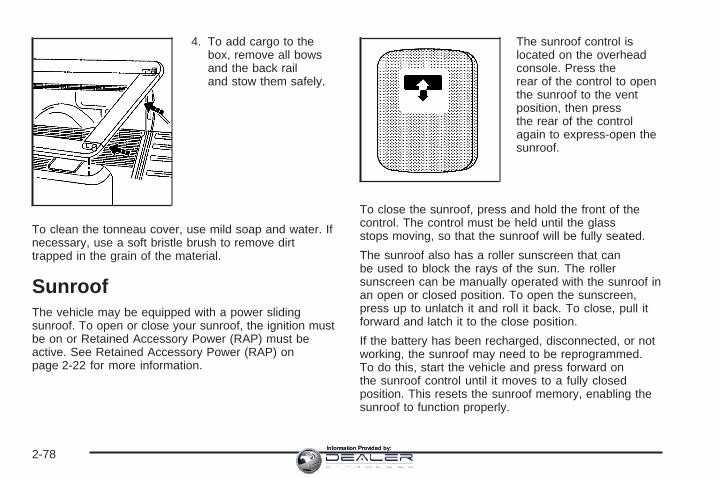
4. To add cargo to thebox, remove all bowsand the back railand stow them safely.
To clean the tonneau cover, use mild soap and water. Ifnecessary, use a soft bristle brush to remove dirttrapped in the grain of the material.
SunroofThe vehicle may be equipped with a power slidingsunroof. To open or close your sunroof, the ignition mustbe on or Retained Accessory Power (RAP) must beactive. See Retained Accessory Power (RAP) onpage 2-22 for more information.
The sunroof control islocated on the overheadconsole. Press therear of the control to openthe sunroof to the ventposition, then pressthe rear of the controlagain to express-open thesunroof.
To close the sunroof, press and hold the front of thecontrol. The control must be held until the glassstops moving, so that the sunroof will be fully seated.
The sunroof also has a roller sunscreen that canbe used to block the rays of the sun. The rollersunscreen can be manually operated with the sunroof inan open or closed position. To open the sunscreen,press up to unlatch it and roll it back. To close, pull itforward and latch it to the close position.
If the battery has been recharged, disconnected, or notworking, the sunroof may need to be reprogrammed.To do this, start the vehicle and press forward onthe sunroof control until it moves to a fully closedposition. This resets the sunroof memory, enabling thesunroof to function properly.
2-78Information Provided by:

Vehicle PersonalizationIn addition to the following features, your vehicle mayalso have features that can be programmed through theDriver Information Center (DIC). See DIC VehicleCustomization on page 3-64 for more information.
Memory SeatIf your vehicle has thisfeature, the controls for thememory function arelocated on the driver’s door.
These buttons are used to program and recall memorysettings for the driver’s seat and both the driver’sand passenger’s outside mirrors. The settings for thesefeatures can be saved for up to two drivers.To store the memory settings, do the following:
1. If you have an automatic transmission, place thevehicle in PARK (P).If you have a manual transmission, set the parkingbrake.
2. Adjust the driver’s seat, including the seatbackrecliner and lumbar, and both outside mirrors toyour preference.
3. Press and hold the 1 or 2 button of the memorycontrol for three seconds. A double chime will soundto let you know that the position has been stored.
To repeat the procedure for a second driver, follow thepreceding steps, but press the other numberedmemory control button.
To recall a memory position, do one of the following:
• If you have an automatic transmission, pressand release the desired button 1 or 2 whilethe vehicle is in PARK (P). A single chime willsound and the memory position will be recalled.If the vehicle is not in PARK (P), the memoryposition will not be recalled.
• If you have a manual transmission, press andrelease the desired button 1 or 2 while the parkingbrake is set. A single chime will sound and thememory position will be recalled.If the parking brake is not set, the memory positionwill not be recalled.
To stop recall movement of the memory seat feature atany time, press one of the memory buttons or powerseat controls.
2-79Information Provided by:

Easy Exit SeatThe controls for this memory function are located on thedriver’s door.
B (Easy Exit Seat): This button is used to programand recall the desired driver’s seat position when exitingor entering the vehicle. The seat position can besaved for up to two drivers.
To store the seat exit position, do the following:
1. If you have an automatic transmission, place thevehicle in PARK (P).If you have a manual transmission, set the parkingbrake.
2. Press and release the 1 or 2 button. The seat willmove to the stored memory position.
3. Adjust the seat to the desired exit position.
4. Press and hold the exit button of the memorycontrol for three seconds. A double chime will soundto let you know that the position has been storedfor the selected button 1 or 2.
To repeat the procedure for a second driver, follow thepreceding steps, but press the other numberedmemory control button.
To use the seat exit position, do one of the following:
• If you have an automatic transmission, pressand release the exit button on the memory controlwhile the vehicle is in PARK (P).
• If you have a manual transmission, press andrelease the exit button on the memory control whilethe parking brake is set.
• If this feature is activated in the Driver InformationCenter (DIC), removing the key from the ignitionwill move the seat to the exit position.
See “Easy Exit Seat” under DIC Vehicle Customizationon page 3-64 for more information on activating thisfeature in the DIC.
2-80Information Provided by:

Instrument Panel Overview ...............................3-4Hazard Warning Flashers ................................3-6Other Warning Devices ...................................3-6Horn .............................................................3-6Tilt Wheel .....................................................3-6Turn Signal/Multifunction Lever .........................3-7Turn and Lane-Change Signals ........................3-7Headlamp High/Low-Beam Changer ..................3-8Flash-to-Pass .................................................3-8Windshield Wipers ..........................................3-9Windshield Washer .........................................3-9Cruise Control ..............................................3-10Headlamps ..................................................3-13Headlamps on Reminder ................................3-14Daytime Running Lamps (DRL) .......................3-14Automatic Headlamp System ..........................3-14Fog Lamps ..................................................3-16Auxiliary Roof Mounted Lamp .........................3-16Instrument Panel Brightness ...........................3-17Dome Lamps ...............................................3-17Dome Lamp Override ....................................3-17Entry Lighting ...............................................3-17Exit Lighting .................................................3-17Front Reading Lamps ....................................3-18Cargo Lamp .................................................3-18Accessory Power Outlet(s) .............................3-18Ashtray(s) and Cigarette Lighter ......................3-19
Climate Controls ............................................3-20Climate Control System .................................3-20Dual Climate Control System ..........................3-21Dual Automatic Climate Control System ...........3-24Outlet Adjustment .........................................3-29
Warning Lights, Gages, and Indicators ............3-30Instrument Panel Cluster ................................3-31Speedometer and Odometer ...........................3-32Trip Odometer ..............................................3-32Tachometer .................................................3-32Safety Belt Reminder Light .............................3-33Airbag Readiness Light ..................................3-33Airbag Off Light ............................................3-34Passenger Airbag Status Indicator ...................3-36Battery Warning Light ....................................3-39Voltmeter Gage ............................................3-39Up-Shift Light (Manual Transmission) ...............3-40Brake System Warning Light ..........................3-41Anti-Lock Brake System Warning Light .............3-42Traction Off Light ..........................................3-42Engine Coolant Temperature Gage ..................3-43Transmission Temperature Gage .....................3-43Malfunction Indicator Lamp .............................3-45Oil Pressure Gage ........................................3-47Security Light ...............................................3-48Cruise Control Light ......................................3-48Highbeam On Light .......................................3-49
Section 3 Instrument Panel
3-1Information Provided by:

Four-Wheel-Drive Light ..................................3-49Tow/Haul Mode Light ....................................3-49Cargo Lamp Light .........................................3-49Fuel Gage ...................................................3-50Low Fuel Warning Light .................................3-50
Driver Information Center (DIC) .......................3-51DIC Operation and Displays ...........................3-52DIC Warnings and Messages .........................3-54DIC Vehicle Customization .............................3-64
Audio System(s) .............................................3-70Setting the Time for Radios without
Radio Data Systems (RDS) ........................3-71Setting the Time for Radios with
Radio Data Systems (RDS) ........................3-71AM-FM Radio ...............................................3-72
Radio with CD ..............................................3-74Radio with Cassette and CD ..........................3-85Radio with Six-Disc CD .................................3-99Rear Seat Entertainment System ...................3-114Rear Seat Audio (RSA) ................................3-125Theft-Deterrent Feature ................................3-126Audio Steering Wheel Controls ......................3-127Radio Reception .........................................3-128Care of the Cassette Tape Player .................3-128Care of Your CDs and DVDs ........................3-129Care of the CD and DVD Player ...................3-130Fixed Mast Antenna ....................................3-130XM™ Satellite Radio Antenna System ............3-130Chime Level Adjustment ...............................3-130
Section 3 Instrument Panel
3-2Information Provided by:

✍ NOTES
3-3Information Provided by:

Instrument Panel Overview
Automatic Transmission Version shown, Manual Transmission Version similar
3-4Information Provided by:

The main components of your instrument panel are the following:
A. Dome Lamp Override Button. See Dome LampOverride on page 3-17.
B. Headlamp Controls. See Headlamps on page 3-13.C. Air Outlets. See Outlet Adjustment on page 3-29.D. Automatic Transfer Case/Electronic Transfer
Case/Traction Assist System (TAS). See Four-WheelDrive on page 2-36 and Traction Assist System(TAS) on page 4-9.
E. Multifunction Lever. See Turn Signal/MultifunctionLever on page 3-7.
F. Instrument Panel Cluster. See Instrument PanelCluster on page 3-31.
G. Range Selection Mode (Allison Transmission® only)Button (If Equipped). See Automatic TransmissionOperation on page 2-24.
H. Gearshift Lever. See Automatic TransmissionOperation on page 2-24 or Manual TransmissionOperation on page 2-32 for manual transmissions.
I. Tow/Haul Selector Button (If Equipped). SeeTow/Haul Mode on page 2-30.
J. Audio System. See Audio System(s) on page 3-70.K. Climate Control System. See Climate Control
System on page 3-20, Dual Climate Control Systemon page 3-21 and Dual Automatic Climate ControlSystem on page 3-24.
L. Instrument Panel Fuse Block. Instrument Panel FuseBlock on page 5-124.
M. Cargo Lamp Button. See Cargo Lamp on page 3-18.N. Hood Release. See Hood Release on page 5-13.O. Steering Wheel Control Buttons (If Equipped).
See Driver Information Center (DIC) on page 3-51 orAudio Steering Wheel Controls on page 3-127.
P. Center Instrument Panel Fuse Block. See CenterInstrument Panel Fuse Block on page 5-126.
Q. Parking Brake Release. See Parking Brake onpage 2-49.
R. Tilt Wheel Lever. See Tilt Wheel on page 3-6.S. Cigarette Lighter. See Ashtray(s) and Cigarette
Lighter on page 3-19.T. Accessory Power Outlet. See Accessory Power
Outlet(s) on page 3-18.U. Manual Selectable Ride Control (If Equipped). See
Manual Selectable Ride on page 4-11.V. Auxiliary Roof Mounted Lamp Button (If Equipped).
See Auxiliary Roof Mounted Lamp on page 3-16.W. Passenger Airbag Off Switch (If Equipped). See
Airbag Off Switch on page 1-77.X. Glove Box. See Glove Box on page 2-75.
3-5Information Provided by:

Hazard Warning FlashersYour hazard warning flashers let you warn others. Theyalso let police know you have a problem. Your frontand rear turn signal lamps will flash on and off.
The hazard warningflasher button is located ontop of the steeringcolumn.
Your hazard warning flashers work no matter whatposition your key is in, and even if the key is not in theignition.
Press the button to make the front and rear turn signallamps flash on and off. Press the button again toturn the flashers off.
When the hazard warning flashers are on, your turnsignals will not work.
Other Warning DevicesIf you carry reflective triangles, you can set them up atthe side of the road about 300 feet (100 m) behindyour vehicle.
HornTo sound the horn, press the center pad on the steeringwheel.
Tilt WheelIf your vehicle is equipped with a tilt wheel, it will allowyou to adjust the steering wheel before you drive.You can raise it to the highest level to give your legsmore room when you exit and enter your vehicle.
The tilt steering wheel lever is located on the lower leftside of the column.
3-6Information Provided by:

To tilt the wheel, hold the steering wheel and pull thelever. Then move the steering wheel to a comfortableposition and release the lever to lock the wheel in place.
Turn Signal/Multifunction Lever
The lever on the left side of the steering columnincludes the following:
• G Turn and Lane Change Signals. See Turn andLane-Change Signals on page 3-7.
• 53 Headlamp High/Low-Beam Changer. SeeHeadlamp High/Low-Beam Changer on page 3-8.
• Flash-to-Pass. See Flash-to-Pass on page 3-8.
• N Windshield Wipers. See Windshield Wipers onpage 3-9.
• L Windshield Washer. See Windshield Washeron page 3-9.
• I Cruise Control. See Cruise Control onpage 3-10.
For information on the headlamps, see Headlamps onpage 3-13.
Turn and Lane-Change SignalsThe turn signal has two upward (for right) and twodownward (for left) positions. These positions allow youto signal a turn or a lane change.
To signal a turn, move the lever all the way up or down.When the turn is finished, the lever will returnautomatically.
To signal a lane change, just raise or lower the leveruntil the arrow starts to flash. Hold it there until youcomplete your lane change. The lever will return by itselfwhen you release it.
An arrow on the instrumentpanel cluster will flash inthe direction of theturn or lane change.
3-7Information Provided by:

As you signal a turn or a lane change, if the arrowsflash more quickly than normal, a signal bulb maybe burned out and other drivers won’t see your turnsignal.
If a bulb is burned out, replace it to help avoid anaccident. If the arrows don’t go on at all when you signala turn, check for burned-out bulbs and a blown fuse.See Fuses and Circuit Breakers on page 5-124.
Turn Signal On ChimeIf your turn signal is left on for more than 3/4 of a mile(1.2 km), a chime will sound at each flash of theturn signal and the message TURN SIGNAL ON willalso appear in the DIC. To turn the chime and messageoff, move the turn signal lever to the off position.
Headlamp High/Low-Beam Changer
53(Headlamp High/Low Beam Changer): Tochange the headlamps from low to high beam, push thelever toward the instrument panel. To return tolow-beam headlamps, pull the multifunction lever towardyou. Then release it.
When the high beams areon, this indicator light onthe instrument panelcluster will also be on.
Flash-to-PassThis feature lets you use your high-beam headlamps tosignal a driver in front of you that you want to pass.It works even if your headlamps are in the automaticposition.
To use it, pull the turn signal lever toward you, thenrelease it.
If your headlamps are in the automatic position or onlow beam, your high-beam headlamps will turn on.They’ll stay on as long as you hold the lever toward you.The high-beam indicator on the instrument panelcluster will come on. Release the lever to return tonormal operation.
3-8Information Provided by:

Windshield WipersBe sure to clear ice and snow from the wiper bladesbefore using them. If they are frozen to the windshield,gently loosen or thaw them. Damaged wiper bladesmay not clear the windshield well, making it harder tosee and drive safely. If the blades do become damaged,install new blades or blade inserts. For more information,see Windshield Wiper Blade Replacement on page 5-72Heavy snow or ice can overload the wiper motor. Acircuit breaker will stop the motor until it cools down.Clear away snow or ice to prevent an overload.You control the windshield wipers by turning the bandwith the wiper symbol on it.
8(Mist): For a single wiping cycle, turn the band tomist. Hold it there until the wipers start. Then let go. Thewipers will stop after one wipe. If you want morewipes, hold the band on mist longer.
N(Delay): You can set the wiper speed for a long orshort delay between wipes. This can be very usefulin light rain or snow. Turn the band to choose the delaytime. The closer to the top of the lever, the shorterthe delay.
6 (Low Speed): For steady wiping at low speed,turn the band away from you to the first solid band pastthe delay settings. For high-speed wiping, turn theband further, to the second solid band past the delaysettings. To stop the wipers, move the band to off.
1 (High Speed): For high-speed wiping, turn theband further, to the second solid band past thedelay settings.
9(Off): To stop the wipers, move the band to off.
Windshield Washer
LQ (Washer Fluid): There is a paddle marked withthe windshield washer symbol at the top of themultifunction lever. To spray washer fluid on thewindshield, push the paddle. The wipers will clear thewindow and then either stop or return to your presetspeed.
{CAUTION:
In freezing weather, do not use your washeruntil the windshield is warmed. Otherwise thewasher fluid can form ice on the windshield,blocking your vision.
3-9Information Provided by:

Cruise Control
9(Off): This positionturns the system off.
If your vehicle is equipped with an Allison® automatictransmission, see “Grade Braking and Cruise GradeBraking (Allison Transmission®) under Tow/Haul Modeon page 2-30 for an explanation of how cruise controlinteracts with the tap up/down gear selection, tow/hauland grade braking systems.
R(On): This position activates the system.
+ (Resume/Accelerate): Push the lever to this symbolto make the vehicle accelerate or resume to apreviously set speed.
T(Set): Press this button to set the speed.
With cruise control, you can maintain a speed of about25 mph (40 km/h) or more without keeping your footon the accelerator. This can really help on longtrips. Cruise control does not work at speeds belowabout 25 mph (40 km/h).
If you apply your brakes, the cruise control will shut off.
{CAUTION:
Cruise control can be dangerous where youcannot drive safely at a steady speed. So, donot use your cruise control on winding roadsor in heavy traffic.
Cruise control can be dangerous on slipperyroads. On such roads, fast changes in tiretraction can cause needless wheel spinning,and you could lose control. Do not use cruisecontrol on slippery roads.
3-10Information Provided by:

Setting Cruise Control
{CAUTION:
If you leave your cruise control on when youare not using cruise, you might hit a buttonand go into cruise when you do not want to.You could be startled and even lose control.Keep the cruise control switch off until youwant to use cruise control.
1. Move the cruise control switch to on.
2. Get up to the speed you want.
3. Press in the set button at the end of the lever andrelease it.
4. Take your foot off the accelerator pedal.
The cruise symbol on theinstrument panel willilluminate when the cruisecontrol is engaged.
Resuming a Set SpeedSuppose you set your cruise control at a desired speedand then you apply the brake. This, of course,disengages the cruise control. But you don’t need toreset it.
Once you’re going about 25 mph (40 km/h) or more, youcan move the cruise control switch briefly from on toresume/accelerate.
You’ll go right back up to your chosen speed and staythere.
If you hold the switch at resume/accelerate the vehiclewill keep going faster until you release the switch orapply the brake. So unless you want to go faster, don’thold the switch at resume/accelerate.
3-11Information Provided by:

Increasing Speed While Using CruiseControlThere are two ways to go to a higher speed:
• Use the accelerator pedal to get to the higherspeed. Press the set button at the end of the lever,then release the button and the acceleratorpedal. You’ll now cruise at the higher speed. If theaccelerator pedal is held longer than 60 seconds,cruise control will turn off.
• Move the cruise switch from on toresume/accelerate. Hold it there until you get up tothe speed you want, and then release the switch.To increase your speed in very small amounts,move the switch briefly to resume/accelerate. Eachtime you do this, your vehicle will go about1 mph (1.6 km/h) faster.
Reducing Speed While Using CruiseControl• Press in the button at the end of the lever until you
reach the lower speed you want, then release it.
• To slow down in very small amounts, briefly pressthe set button. Each time you do this, you’ll goabout 1 mph (1.6 km/h) slower.
Passing Another Vehicle While UsingCruise ControlUse the accelerator pedal to increase your speed.When you take your foot off the pedal, your vehicle willslow down to the cruise control speed you set earlier.
Using Cruise Control on HillsHow well your cruise control will work on hills dependsupon your speed, load and the steepness of thehills. When going up steep hills, you may want to stepon the accelerator pedal to maintain your speed.When going downhill, you may have to brake or shift toa lower gear to keep your speed down. Of course,applying the brake takes you out of cruise control. Manydrivers find this to be too much trouble and don’t usecruise control on steep hills.
Ending Cruise ControlThere are four ways to turn off the cruise control:
• Step lightly on the brake pedal,
• move the cruise control switch to off, or
• shift the transmission to NEUTRAL (N).
• If the accelerator pedal is held for 60 seconds orlonger, cruise control will turn off.
3-12Information Provided by:

Erasing Speed MemoryWhen you turn off the cruise control or the ignition, yourcruise control set speed memory is erased.
Headlamps
The control on the driver’s side of your instrument paneloperates the headlamps.
Turn the control clockwise to operate the lamps.
The headlamp control has four positions:
9 (Off): Turning the control to this position turns offthe Daytime Running Lamps (DRL) and the automaticheadlamps.
AUTO (Automatic): Turning the control to this positionputs the system into automatic headlamp mode.
; (Parking Lamps): Turning the control to thisposition turns on the parking lamps, together with thefollowing:
• Sidemarker Lamps• Taillamps• License Plate Lamps• Instrument Panel Lights• Roof Marker Lamps (If Equipped)
5 (Headlamps): Turning the control to this positionturns on the headlamps, together with the previouslylisted lamps and lights.
You can switch your headlamps from high to low-beamby pushing the turn signal/high-beam lever towardsthe instrument panel.
A circuit breaker protects your headlamps. If you havean electrical overload, your headlamps will flicker on andoff. Have your headlamp wiring checked right away ifthis happens.
3-13Information Provided by:
Headlamps on ReminderA reminder chime will sound when your headlamps orparking lamps are manually turned on and your ignition isoff, in LOCK, ACCESSORY, or a door is open. To disablethe chime, turn the light off then back on.
Daytime Running Lamps (DRL)Daytime Running Lamps (DRL) can make it easier forothers to see the front of your vehicle during theday. DRL can be helpful in many different drivingconditions, but they can be especially helpful in the shortperiods after dawn and before sunset. Fully functionaldaytime running lamps are required on all vehiclesfirst sold in Canada.
The DRL system will come on when the followingconditions are met:
• The ignition is on
• The exterior lamps control is in AUTO
• The automatic transmission is not in PARK (P)
• The light sensor determines it is daytime
When the DRL are on, only your DRL lamps will be on.The taillamps, sidemarker and other lamps won’t beon. The instrument panel won’t be lit up either.
When it begins to get dark, the automatic headlampsystem will switch from DRL to the headlamps.
When you turn the headlamp switch off, the headlampswill go off, and your DRL lamps will illuminate,provided it is not dark outside.
Shifting the transmission into PARK (P) will allow you toidle the vehicle with the DRL off. The DRL will stayoff until you shift the transmission out of PARK (P). Thisprocedure applies only to vehicles first sold in theUnited States.
Automatic Headlamp SystemWhen it is dark enough outside, your automaticheadlamp system will turn on your headlamps at thenormal brightness along with other lamps such asthe taillamps, sidemarker, parking lamps and theinstrument panel lights. The radio lights will also be dim.
To turn off the automatic headlamp system, turn theexterior lamps switch to the off position and thenrelease. Turning off the automatic headlamp systemwith the headlamp switch is not available for vehiclesfirst sold in Canada. For vehicles first sold in Canada,you can turn off the automatic headlamp systemwhen parked at night by applying the parking brakebefore starting your vehicle.
3-14Information Provided by:

The headlamps will remain off once the vehicle isstarted for as long as you are parked. If you release theparking brake, the lights will turn on. If the parkingbrake is not released before you begin to drive,the exterior lamps will turn on above 2 mph (3.2 km/h).
Your vehicle is equipped with a light sensor locatedon the top of the instrument panel in the defroster grille.Be sure it is not covered, or the system will be onwhenever the ignition is on.
The system may also turn on your headlamps whendriving through a parking garage, heavy overcastweather or a tunnel. This is normal.
There is a delay in the transition between the daytimeand nighttime operation of the Daytime RunningLamps (DRL) and the automatic headlamp systems sothat driving under bridges or bright overhead streetlights does not affect the system. The DRL andautomatic headlamp system will only be affected whenthe light sensor sees a change in lighting lastinglonger than the delay.
If you start your vehicle in a dark garage, the automaticheadlamp system will come on immediately. Onceyou leave the garage, it will take approximatelyone minute for the automatic headlamp system tochange to DRL if it is bright enough outside. During thatdelay, your instrument panel cluster may not be asbright as usual. Make sure your instrument panelbrightness control is in the full bright position. SeeInstrument Panel Brightness on page 3-17.
To idle your vehicle with the automatic headlampsystem off, turn the control to the off position.
You may be able to turn off your Automatic HeadlampSystem. See Daytime Running Lamps (DRL) onpage 3-14 for more information.
Your headlamps will also stay on after you exit thevehicle. You can program this feature using the DriverInformation Center (DIC). See DIC VehicleCustomization on page 3-64.
As with any vehicle, you should turn on the regularheadlamp system when you need them.
3-15Information Provided by:

Fog LampsIf your vehicle has fog lamps, use them for better visionin foggy or misty conditions.
The fog lamp button islocated on the left side ofthe instrument panel.
Your parking lamps and/or low-beam headlamps mustbe on for your fog lamps to work.
Press the button to turn the fog lamps on. Press thebutton again to turn them off. An indicator light will glowin the button when the fog lamps are on.
Remember, fog lamps alone will not give off as muchlight as your headlamps. Never use your fog lampsin the dark without turning on your headlamps.
The fog lamps will go off whenever your high-beamheadlamps come on. When the high beams go off, thefog lamps will come on again.
The fog lamps will be cancelled after the ignition isturned off. If you still want to use the fog lamps after yourestart the vehicle, you will need to press the foglamp button again.
Some localities have laws that require the headlamps tobe on along with the fog lamps.
Auxiliary Roof Mounted LampIf your vehicle has this feature, this button includeswiring provisions for a dealer or a qualified servicecenter to install an auxiliary roof lamp.
This button is locatedon the center of theinstrument panel nearthe climate controls.
3-16Information Provided by:

When the wiring is connected to an auxiliary roofmounted lamp, pressing the button will activate the lampand illuminate an indicator light near the button. Pressingthe button again will turn off the roof mounted lamp.
If your vehicle has this button, your vehicle may have thesnow plow prep package. For further information seeAdding a Snow Plow or Similar Equipment on page 4-54.
Instrument Panel Brightness
D (Instrument Panel Brightness): This featurecontrols the brightness of the instrument panel lights.
The thumbwheel for this feature is located next tothe headlamp control.
Turn the thumbwheel up to adjust the instrument panellights. Turn the thumbwheel up to return the radiodisplay to full brightness when the headlamps or parkinglamps are on. To turn on the dome lamps, turn thethumbwheel all the way up.
Dome LampsThe dome lamps will come on when you open a door.
You can also turn the dome lamps on by turningthe thumbwheel, located next to the exterior lampscontrol, all the way up. In this position, the dome lampswill remain on whether a door is opened or closed.
Dome Lamp Override
E (Dome Lamp Override): You can use the domeoverride button, located below the exterior lamps control,to set the dome lamps to come on automatically whena door is opened, or to remain off. To turn the lamps off,press the button into the in position. With the buttonin this position, the dome lamps will remain off when thedoors are open. To return the lamps to automaticoperation, press the button again and return it to the outposition. With the button in this position, the domelamps will come on when you open a door.
Entry LightingYour vehicle is equipped with an illuminated entryfeature.
When the doors are opened, the dome lamps will comeon if the dome override button is in the out position.If the dome override button is pressed in, the lamps willnot come on.
Exit LightingWith exit lighting, the interior lamps will come on whenyou remove the key from the ignition. The lights willnot come on if the dome override button is pressed in.
3-17Information Provided by:

Front Reading LampsThe reading lamps are located on the overhead console.
To turn on the reading lamps, press the button locatednext to each lamp. To turn them off, press the buttonagain.
The lamps can be adjusted to point in the directionyou want.
Your vehicle may also have reading lamps in otherlocations. To turn the lamps on or off, press the buttonlocated next to the lamp. The lamps are fixed andcannot be adjusted.
Cargo Lamp
The cargo lamp button islocated on the left side ofthe instrument panel.Press the button to turnthe cargo lamp on.Press the button again toturn it off.
An indicator light on the instrument panel cluster willilluminate when the cargo lamp is turned on, andthe ignition key is turned to RUN.
Accessory Power Outlet(s)With accessory power outlets you can plug in auxiliaryelectrical equipment such as a cellular telephone orCB radio.
Your vehicle may have two accessory power outlets, ormay have one accessory power outlet located nearthe cigarette lighter, if equipped. The cigarette lighter isdesigned to fit only in the receptacle to the right ofthe accessory power outlet.
3-18Information Provided by:
To use the outlet, lift the cover. When not using it,always close the cover.
Certain power accessory plugs may not be compatibleto the accessory power outlet and could result inblown vehicle or adapter fuses. If you experience aproblem, see your dealer for additional information onthe accessory power plugs.
Notice: Adding any electrical equipment to yourvehicle may damage it or keep other componentsfrom working as they should. The repairs would notbe covered by your warranty. Do not use equipmentexceeding maximum amperage rating. Checkwith your dealer before adding electrical equipment.
When adding electrical equipment, be sure to followthe proper installation instructions included withthe equipment.
Notice: Improper use of the power outlet can causedamage not covered by your warranty. Do nothang any type of accessory or accessory bracketfrom the plug because the power outlets aredesigned for accessory power plugs only.
Ashtray(s) and Cigarette LighterYour vehicle may be equipped with a front ashtraylocated near the center of the instrument panel. Pull onthe door to open it.
Notice: If you put papers, pins, or other flammableitems in the ashtray, hot cigarettes or othersmoking materials could ignite them and possiblydamage your vehicle. Never put flammable items inthe ashtray.
To remove the front ashtray, pull the ashtray towardyou. To replace the ashtray, place the ashtray onthe slides at the side of its location in the instrumentpanel. To use the cigarette lighter, push it in all the way,and let go. When it’s ready, it will pop back out byitself.
Notice: Holding a cigarette lighter in while it isheating will not allow the lighter to back away fromthe heating element when it is hot. Damage fromoverheating may occur to the lighter or heatingelement, or a fuse could be blown. Do not hold acigarette lighter in while it is heating.
3-19Information Provided by:

Climate Controls
Climate Control System
Fan KnobThe fan knob on the left side of the control paneladjusts the fan speed. To increase airflow, turn the knobclockwise. To decrease airflow, turn it counterclockwise.To turn the fan off, turn the knob to the off position.
9 (Off): If the fan is off, outside air will still enter thevehicle, and will be directed based on the position ofthe mode knob. The temperature can also be adjustedusing the temperature knob.
Temperature KnobThe middle knob on the control panel lets you select thetemperature of the air flowing into the passengerarea. Turn the knob clockwise toward the red area forwarmer air. Turn the knob counterclockwise towardthe blue area for cooler air.
Mode KnobThe right knob on the control panel allows you tochoose the direction of air delivery.
H (Vent): This setting directs the air through theinstrument panel outlets.
3-20Information Provided by:

) (Bi-Level): Air is delivered through the floor outletsas well as the instrument panel outlets. The flow canbe divided between vent and floor outlets dependingupon where the knob is placed between the settings.
6 (Floor): This setting directs most of the air throughthe floor outlets, and the rest of the air is dividedbetween the windshield defroster outlets and the sidewindow defroster outlets.
W (Defog): Airflow is delivered through the flooroutlets, the windshield defroster outlets and the sidewindow defroster outlets. The air flow can be dividedbetween floor and defrost depending upon wherethe knob is placed between the settings.
1 (Defrost): This setting directs most air through thewindshield defroster outlets, side window defrosteroutlets and some through the floor outlets.
Dual Climate Control SystemWith this system you can control the heating, coolingand ventilation for your vehicle.
Fan Control
9(Fan): Turn the left knob clockwise orcounterclockwise to increase or decrease the fan speed.Turn the knob to the off position to turn off the fan. Ifthe knob is in off, outside air will still enter the vehicleand will be directed based on the position of themode knob. The temperature can also be adjustedusing the temperature levers.
Turn the right knob clockwise or counterclockwise todirect the airflow inside of your vehicle.
3-21Information Provided by:

Mode Control
To change the current mode, select one of the following:
H (Vent): This mode directs air to the instrumentpanel outlets.
)(Bi-Level): This mode directs half of the air to theinstrument panel outlets; then directs most of theremaining air to the floor outlets. A little air is directedtoward the windshield and the side window outlets.Cooler air is directed to the upper outlets and warmerair to the floor outlets.
6 (Floor): This mode directs most of the air to thefloor outlets with a little air directed to the windshield andthe side window outlets.
h (Recirculation): The recirculation mode is usedto recirculate the air inside of your vehicle. Use thismode to help prevent outside odors and/or dustfrom entering your vehicle or to help cool the air insideof your vehicle more quickly. Press this button toturn the recirculation mode on or off. The light on therecirculation button will illuminate. Recirculation cannotbe used in floor, defog or defrost modes. An indicatoron the button will light up, flash three times and turn offwhen recirculation is selected in these modes.
The air-conditioning compressor will also come on whenthis mode is activated. While in recirculation modethe windows may fog when the weather is coldand damp. To clear the fog, select either the defog ordefrost mode and increase fan speed.
Temperature Control
Driver’s Side: The lever on the left side of the climatecontrol panel is used to raise or lower the temperatureon the driver’s side of the vehicle. This lever also adjuststhe temperature to the center console outlets(if equipped).
Passenger’s Side: The lever on the right side of theclimate control panel is used to raise or lower thetemperature on the passenger’s side of the vehicle.
#(Air Conditioning): Press this button to turn theair-conditioning system on or off. When the button ispressed, an indicator light will come on and the systemwill begin to cool and dehumidify the air inside of yourvehicle. You may notice a slight change in engineperformance when the air conditioning compressor shutsoff and turns on again. This is normal.
3-22Information Provided by:

Defogging and DefrostingFog on the inside of the windows is a result of highhumidity (moisture) condensing on the cool windowglass. This can be minimized if the climate controlsystem is used properly. There are two modes to choosefrom to clear fog or frost from your windshield. Usethe defog mode to clear the windows of fog or moistureand warm the passengers. Use the defrost mode toremove fog or frost from the windshield more quickly.
Turn the right knob to select one of the following modes:
-(Defog): This mode directs the air to the flooroutlets, windshield and the side window outlets. The airconditioning compressor will run automatically todehumidify the air to prevent window fogging. Therecirculation mode cannot be selected while in the defogmode.
1(Defrost): This mode directs most of the air to thewindshield and the side window outlets, with only alittle air directed to the floor outlets. The air conditioningcompressor will run automatically to dehumidify theair to prevent window fogging. The recirculation modecannot be selected while in defrost mode.
Do not drive the vehicle until all the windows are clear.
Rear Window DefoggerIf your vehicle has this feature, the lines you see on therear window warm the glass. The rear window defoggeruses a warming grid to remove fog from the rear window.If your vehicle has a sliding rear window, you will nothave a rear window defogger; however, your vehicle willstill have a mirror button to activate the heated outsiderearview mirrors, if equipped.
< (Rear): Press this button to turn the rear windowdefogger on or off. An indicator light in the buttonwill come on to let you know that the rear windowdefogger is activated. This button will also activate theheated mirrors, if equipped.The rear window defogger will automatically turn offseveral minutes after the button is pressed. Pressing thebutton while the defogger is running can also turn offthe defogger.
W (Mirror): If your vehicle does not have a reardefogger and is equipped with heated mirrors, yourvehicle will have this button to activate the heatedmirrors.
Notice: Do not use anything sharp on the inside ofthe rear window. If you do, you could cut ordamage the warming grid, and the repairs would notbe covered by your warranty. Do not attach atemporary vehicle license, tape, a decal or anythingsimilar to the defogger grid.
3-23Information Provided by:

Dual Automatic Climate ControlSystemWith this system, you can control the heating, coolingand ventilation in your vehicle. Your vehicle alsohas a flow-through ventilation system described later inthis section.
You can select different climate control settings for thedriver and passengers.
Driver’s Side Temperature KnobThe driver’s side knob is used to adjust the temperatureof the air coming through the system on the driver’sside. The temperature can be adjusted even if thesystem is turned off. This is possible since outside airwill always flow through the system as the vehicleis moving forward unless it is set to recirculation mode.See “Recirculation” later in this section.
Turn the knob counterclockwise or clockwise to lower orincrease the cabin temperature. The display will showthe temperature setting decreasing or increasing and anarrow pointing to the driver will be displayed underand to the left of the temperature setting.
3-24Information Provided by:

Passenger’s Side Temperature KnobThe passenger’s side knob can be used to change thetemperature of the air coming through the systemon the passenger’s side of the vehicle. The temperaturecan be adjusted even if the system is turned off. Thisis possible since outside air will always flow through thesystem as the vehicle is moving forward unless it isset to recirculation mode. See “Recirculation” later in thissection.
Turn the knob counterclockwise or clockwise to lower orincrease the cabin temperature. The display will showthe temperature setting decreasing or increasing and anarrow pointing to the passenger will be displayedunder and to the right of the temperature setting.
The passenger’s temperature setting can be set tomatch the driver’s temperature setting by pressing andholding the AUTO button for four seconds. Both thedriver and passenger arrows will be displayed.
Automatic Operation
AUTO (Automatic): When automatic operation isactive the system will control the inside temperature, theair delivery, and the fan speed.
Use the steps below to place the entire system inautomatic mode:
1. Press the AUTO button.When AUTO is selected, the display will change toshow the current driver’s set temperature, deliverymode and fan speed. Press the AUTO button againwithin five seconds to display the passenger’s settemperature.If the driver and passenger’s temperature settingsare not the same, the opposite side temperaturesetting will be displayed for an additional fiveseconds. To make the passenger’s temperature thesame as the driver’s press and hold the AUTObutton for about four seconds.When AUTO is selected, the air conditioningoperation and air inlet will be automaticallycontrolled. The air conditioning compressor will runwhen the outside temperature is over about40°F (4°C). The air inlet will normally be set tooutside air. If it’s hot outside, the air inlet mayautomatically switch to recirculate inside air to helpquickly cool down your vehicle. The light on thebutton will illuminate in recirculation.
3-25Information Provided by:

2. Set the driver’s and passenger’s temperature.To find your comfort setting, start with a 74°F (23°C)temperature setting and allow about 20 minutesfor the system to regulate. Turn the driver’s orpassenger’s side temperature knob to adjust thetemperature setting as necessary. If you choose thetemperature setting of 60°F (15°C) the systemwill remain at the maximum cooling setting. If youchoose the temperature setting of 90°F (32°C)the system will remain at the maximum heat setting.Choosing either maximum setting will not causethe vehicle to heat or cool any faster.Be careful not to cover the sensor located on thetop of the instrument panel near the windshield. Thissensor regulates air temperature based on sunload, and also turns on your headlamps.To avoid blowing cold air in cold weather, thesystem will delay turning on the fan until warm air isavailable. The length of delay depends on theengine coolant temperature. Pressing the fan switchwill override this delay and change the fan to aselected speed.
9(Off): Press this button to turn off the entire climatecontrol system. Outside air will still enter the vehicle,and will be directed to the floor. This direction canbe changed by pressing the mode button.
The temperature can also be adjusted using eithertemperature knob. Press the up or down arrows on thefan switch, the defrost button, the AUTO button, or the airconditioning button to turn the system on when it is off.
Manual OperationYou may manually adjust the air delivery mode or fanspeed.
w9x (Fan): The switch with the fan symbol allowsyou to manually adjust the fan speed. Press the uparrow to increase fan speed and the down arrowto decrease fan speed.
Pressing this button when the system is off will turn thesystem on.
C (Mode): Press this button to manually change thedirection of the airflow in your vehicle; repeatedlypress the button until the desired mode appears on thedisplay.
If you press the mode button to select an air deliverymode, the display will change to show you the selectedair mode delivery. The display will then show thecurrent status of the system. When the system is turnedoff, the display will go blank after displaying thecurrent status of the system.
3-26Information Provided by:

H (Panel): This setting will deliver air to theinstrument panel outlets.
)(Bi-Level): This setting will deliver warmer air to thefloor and cooler air to the instrument panel outlets.
6 (Floor): This setting will deliver air to the flooroutlets.
- (Defog): See “Defogging and Defrosting” later inthis section.
@(Recirculation): Press this button to limit theamount of outside air entering your vehicle. The light onthe recirculation button will glow. This is helpful when youare trying to limit odors entering your vehicle and formaximum air conditioning performance in hot weather.Press this button again to allow outside air to enter thevehicle. The light on the recirculation button will go off.
Pressing this button also cancels the auto recirculationfeature. To resume the auto recirculation function, pressthe AUTO button. Each time the vehicle is started, thesystem will revert to the auto recirculation function.
If you select recirculation while in defrost, defog or floor,the light in the button will flash and then go out to let youknow that this is not allowed. This is normal and helps toprevent fogging.
When the weather is cool or damp, operating the systemin recirculation for extended periods of time may causefogging of the vehicle’s windows. To clear the fog, selecteither defog or front defrost.
You may also notice that the A/C compressor will runwhile in recirculation mode. This is normal and helps toprevent fogging.
9(Off): Press this button to turn off the entire climatecontrol system. Outside air will still enter the vehicle, andwill be directed to the floor. This direction can be changedby pressing the mode button. The temperature can alsobe adjusted using either temperature knob. Press the upor down arrows on the fan switch, the defrost button, theAUTO button, or the air conditioning button to turn thesystem on when it is off.
DisplayIf you press the mode button to select an air deliverymode, the display will change to show you the selectedair delivery mode. After ten seconds, the display willchange to show the driver temperature setting and theselected mode.
If you press the up or down arrows on the fan switch,the display will change to show the selected fan speed.After ten seconds, the display will change to showthe driver temperature setting and the selected mode.
3-27Information Provided by:

Whenever you press AUTO, the display will change toshow the following:
• The current driver’s set temperature and an arrowfor five seconds
• The current passenger’s set temperature settingand an arrow for five seconds
• The automatic air delivery mode and fan speed
If the driver’s and passenger’s temperature settings arethe same when AUTO is pressed, the temperature settingand both arrows will be displayed for five seconds alongwith the automatic air delivery mode and fan speed. Afterthe five second update, the display will change to showthe temperature setting, both arrows and AUTO.
Air Conditioning
#(Air Conditioning): Press this button to turn the airconditioning (A/C) compressor on and off. Thesnowflake symbol will appear on the display when theA/C is on and will turn off when the air conditioning is off.
Pressing this button when the outside temperature istoo cool for air conditioning will make the snowflakesymbol flash three times and then turn off to letyou know the air conditioning mode is not available.
If the air conditioning is on and the outside temperaturedrops below a temperature which is too cool for airconditioning to be effective, the snowflake symbol willturn off to let you know the air conditioning modehas been canceled.
When air conditioning is selected or in AUTO mode, thesystem will run the air conditioning automatically tocool and dehumidify the air entering the vehicle. If youselect A/C off while in front defrost, defog orrecirculation, the A/C snowflake symbol will turn off, butthe A/C compressor will still run to help preventfogging.
On hot days, open the windows long enough to let hotinside air escape. This reduces the time it takes foryour vehicle to cool down. Then keep your windowsclosed for the air conditioner to work its best.
On cool, but sunny days while using manual operationof the automatic system, use bi-level to deliver warmair to the floor and cooler air to the instrumentpanel outlets. To warm or cool the air delivered, turn thetemperature knob to the desired setting.
In AUTO mode the system will cool and dehumidify theair inside the vehicle. Also while in AUTO mode, thesystem will maximize its performance by usingrecirculation as necessary.
3-28Information Provided by:

Defogging and DefrostingYou can use either defog or front defrost to clear fog orfrost from your windshield. Use the defog mode toclear the windows of fog or moisture. Use the frontdefrost button to defrost the front windshield.
-(Defog): Use this setting to clear the windows of fogor moisture. Press the mode button to select thissetting. This setting will deliver air to the floor andwindshield outlets.
0 (Front Defrost): Press the front defrost button todefrost the windshield. The system will automaticallycontrol the fan speed if you select defrost from AUTOmode. If the outside temperature is 40°F (4°C) orwarmer, your air conditioning compressor willautomatically run to help dehumidify the air and dry thewindshield.
Rear Window DefoggerIf your vehicle has this feature, the lines you see on therear window warm the glass. The rear windowdefogger uses a warming grid to remove fog from therear window.
If your vehicle has a sliding rear window, you will nothave a rear window defogger; however, your vehicle willstill have a mirror button to activate the heated outsiderearview mirrors, if equipped.
< (Rear): Press this button to turn the rear windowdefogger on or off. An indicator light in the buttonwill come on to let you know that the rear windowdefogger is activated. This button will also activate theheated mirrors, if equipped.
The rear window defogger will automatically turn offseveral minutes after the button is pressed. Pressing thebutton while the defogger is running can also turn offthe defogger.
W (Mirror): If your vehicle does not have a reardefogger and is equipped with heated mirrors, yourvehicle will have this button to activate them.
Notice: Do not use a razor blade or sharp object toclear the inside rear window. Do not adhereanything to the defogger grid lines in the rear glass.These actions may damage the rear defogger.Repairs would not be covered by your warranty.
Outlet AdjustmentUse the air outlets located in the center and on the sideof your instrument panel to direct the airflow.
3-29Information Provided by:
Operation Tips• Keep the hood and front air inlets free of ice, snow,
or any other obstruction (such as leaves). Theheater and defroster will work far better, reducingthe chance of fogging the inside of your windows.
• When you enter a vehicle in cold weather, turn thefan knob all the way to the right for a few momentsbefore driving. This helps clear the intake ductsof snow and moisture, and reduces the chance offogging the inside of your window.
• Keep the air path under the front seats clear ofobjects. This helps air to circulate throughoutyour vehicle.
• Adding outside equipment to the front of yourvehicle, such as hood-air deflectors, may affect theperformance of the heating and air conditioningsystem. Check with your dealer before addingequipment to the outside of your vehicle.
Warning Lights, Gages, andIndicatorsThis part describes the warning lights and gages onyour vehicle. The pictures will help you locate them.
Warning lights and gages can signal that something iswrong before it becomes serious enough to causean expensive repair or replacement. Paying attention toyour warning lights and gages could also save youor others from injury.
Warning lights come on when there may be or is aproblem with one of your vehicle’s functions. As you willsee in the details on the next few pages, somewarning lights come on briefly when you start theengine just to let you know they are working. If you arefamiliar with this section, you should not be alarmedwhen this happens.
Gages can indicate when there may be or is a problemwith one of your vehicle’s functions. Often gagesand warning lights work together to let you know whenthere is a problem with your vehicle.
When one of the warning lights comes on and stays onwhen you are driving, or when one of the gages showsthere may be a problem, check the section that tells youwhat to do about it. Please follow this manual’s advice.Waiting to do repairs can be costly – and evendangerous. So please get to know your warning lightsand gages. They are a big help.
Your vehicle also has a Driver Information Center (DIC)that works along with warning lights and gages. SeeDIC Warnings and Messages on page 3-54.
3-30Information Provided by:

Instrument Panel Cluster
Your instrument cluster is designed to let you know at a glance how your vehicle is running. You will know how fastyou are going, about how much fuel you have and many other things you will need to know to drive safely andeconomically.
United States Heavy Duty Automatic Transmission version shown. Canada, Light Duty Automatic and ManualTransmission Clusters similar.
3-31Information Provided by:

Speedometer and OdometerYour speedometer lets you see your speed in bothmiles per hour (mph) and kilometers per hour (km/h).Your odometer shows how far your vehicle hasbeen driven, in either miles (used in the United States)or kilometers (used in Canada).
Engine Hour Meter DisplayThe Driver Information Center (DIC) can also displaythe number of hours the engine has run. To display thehour meter, turn the ignition off, press and hold thereset button for at least four seconds. The hour meterwill be displayed for up to 30 seconds, or until theignition is turned on. See DIC Operation and Displayson page 3-52 for more information.
Trip OdometerThe trip odometer can tell you how far your vehicle hasbeen driven since you last set the trip odometer to zero.
Press the reset button, located on the instrument panelcluster next to the trip odometer display, to togglebetween the trip odometer and the regular odometer.Holding the reset button for approximately one secondwhile the trip odometer is displayed will reset it.
To display the odometer reading with the ignition off,press the reset button.
See DIC Operation and Displays on page 3-52 for moreinformation.
TachometerYour tachometer displays the engine speed inrevolutions per minute (rpm). See “Grade Braking(Allison Transmission®)” under Tow/Haul Mode onpage 2-30 for more information.
Notice: If you operate the engine with thetachometer in the solid red area, your vehicle couldbe damaged. The damages would not be coveredby your warranty. Do not operate the engine inthe solid red area.
3-32Information Provided by:

Safety Belt Reminder LightWhen the key is turned to RUN or START, a chime willbe provided for several seconds to remind people tobuckle their safety belts. The driver safety belt light willalso be provided and stay on for several seconds,then it will flash for several more. You should buckleyour seat belt.
This chime and light will berepeated if the driverremains unbuckled and thevehicle is in motion.
See DIC Warnings and Messages on page 3-54 formore information on driver and passenger safetybelt reminders.
If the driver’s belt is buckled, neither the chime nor thelight will come on.
See Passenger Sensing System on page 1-80 for moreinformation.
Airbag Readiness LightThere is an airbag readiness light on the instrumentpanel cluster, which shows the airbag symbol. Thesystem checks the airbag’s electrical system formalfunctions. The light tells you if there is an electricalproblem. The system check includes the airbagsensors, the airbag modules, the passenger sensingsystem (if equipped), the wiring and the crash sensingand diagnostic module. For more information on theairbag system, see Airbag System on page 1-70.
This light will come onwhen you start yourvehicle, and it will flash fora few seconds. Thismeans the system isready.
If the airbag readiness light stays on after you start thevehicle or comes on when you are driving, yourairbag system may not work properly. Have your vehicleserviced right away.
3-33Information Provided by:

Airbag Off Light
If your vehicle has an airbag off switch, it also has anairbag off light. See Airbag Off Switch on page 1-77 formore on this, including important safety information.
When you turn the right front passenger’s airbag off,this light will come on and stay on to remind you that theairbag has been turned off. This light will go off whenyou turn the airbag on.
{CAUTION:
If the right front passenger’s airbag is turnedoff for a person who is not in a risk groupidentified by the national government, thatperson will not have the extra protection of anairbag. In a crash, the airbag will not be able toinflate and help protect the person sittingthere. Do not turn off the passenger’s airbagunless the person sitting there is in a riskgroup. See Airbag Off Switch on page 1-77 formore on this, including important safetyinformation.
United States Canada
3-34Information Provided by:

{CAUTION:
If the airbag readiness light ever comes onwhen you have turned off the airbag, it meansthat something may be wrong with the airbagsystem. The right front passenger’s airbagcould inflate even though the switch is off.
If your vehicle is a regular cab pickup and thisever happens, do not let anyone whom thenational government has identified as amember of a passenger airbag risk group sit inthe right front passenger’s position (forexample, do not secure a rear-facing childrestraint in your vehicle) until you have yourvehicle serviced.
CAUTION: (Continued)
CAUTION: (Continued)
If your vehicle is an extended cab pickup andthis ever happens, do not let anyone whom thenational government has identified as amember of the passenger airbag risk group sitin the right front passenger’s position (forexample, do not secure a rear-facing childrestraint in the right front passenger’s seat)until you have your vehicle serviced.
3-35Information Provided by:

Passenger Airbag Status IndicatorIf your vehicle has the passenger sensing system, yourrearview mirror will have a passenger airbag statusindicator.
When the ignition key is turned to RUN or START, thepassenger airbag status indicator will light ON andOFF, or the symbol for on and off, for several secondsas a system check. Then, after several more seconds,the status indicator will light either ON or OFF, or eitherthe on or off symbol to let you know the status of theright front passenger’s frontal airbag.
Your vehicle may have a label on your sun visor thatsays, “Never put a rear-facing child seat in thefront.” This is because the risk to the rear-facing child isso great, if the airbag deploys.
{CAUTION:
Even though the passenger sensing system isdesigned to turn off the passenger’s frontalairbag if the system detects a rear-facing childrestraint, no system is failsafe, and no one canguarantee that an airbag will not deploy undersome unusual circumstance, even though it isturned off. We recommend that rear-facingchild restraints be secured in the rear seat,even if the airbag is off.
Passenger Airbag Status Indicator – United States
Passenger Airbag Status Indicator – Canada
3-36Information Provided by:

Never put a child in a rear-facing child restraint in theright front passenger seat the unless passengerairbag status indicator shows off. Never put a rearfacing child restraint in the right front passenger seatunless the airbag is off. Here is why:
{CAUTION:
Even though the passenger sensing system isdesigned to turn off the passenger’s frontalairbag if the system detects a rear-facing childrestraint, no system is fail-safe, and no onecan guarantee that an airbag will not deployunder some unusual circumstance, eventhough it is turned off. We recommend thatrear-facing child restraints be transported invehicles with a rear seat that willaccommodate a rear-facing child restraint,whenever possible.
If the word ON or the on symbol is lit on the passengerairbag status indicator, it means that the right frontpassenger’s frontal airbag is enabled (may inflate).
{CAUTION:
If the on indicator comes on when you have arear-facing child restraint installed in the rightfront passenger’s seat, it means that thepassenger sensing system has not turned offthe passenger’s frontal airbag. A child in arear-facing child restraint can be seriouslyinjured or killed if the right front passenger’sairbag inflates. This is because the back of therear-facing child restraint would be very closeto the inflating airbag. Do not use a rear-facingchild restraint in the right front passenger’sseat if the airbag is turned on.
3-37Information Provided by:

If the word OFF or the off symbol is lit on the passengerairbag status indicator, it means that the passengersensing system has turned off the right front passenger’sairbag. See Passenger Sensing System on page 1-80or Airbag Off Switch on page 1-77 for more on this,including important safety information.
{CAUTION:
If the right front passenger’s airbag is turnedoff for a person who is not in a risk groupidentified by the national government, thatperson will not have the extra protection of anairbag. In a crash, the airbag will not be able toinflate and help protect the person sittingthere. Do not turn off the passenger’s airbagunless the person sitting there is in a riskgroup. See Airbag Off Switch on page 1-77 formore on this, including important safetyinformation.
If, after several seconds, all status indicator lightsremain on, or if there are no lights at all, there may be aproblem with the lights or the passenger sensingsystem. See your dealer for service.
{CAUTION:
If the airbag off indicator and the airbagreadiness light ever come on together, itmeans that something may be wrong with theairbag system. If this ever happens, have thevehicle serviced promptly, because anadult-size person sitting in the right frontpassenger seat may not have the protection ofthe airbag. See Airbag Readiness Light onpage 3-33.
3-38Information Provided by:

Battery Warning Light
If this light is displayedwhen the engine isrunning, you may have aproblem with your chargingsystem.
The battery display will also stay on while the key is inRUN until the engine is started.
If the light stays on after starting the engine it couldindicate a problem with the generator drive belt, or someother charging system problem. Have it checked rightaway. Driving with this light displayed could drainyour battery.
If you must drive a short distance with this lightdisplayed, it helps to turn off all your accessories, suchas the radio and the air conditioner.
Voltmeter Gage
When your engine is notrunning, but the ignition isin RUN, this gageshows your battery’s stateof charge in DC volts.
When the engine is running, the gage shows thecondition of the charging system. The gage maytransition from a higher to lower or a lower to higherreading, this is normal. Readings between the low andhigh warning zones indicate the normal operatingrange. The voltmeter gage may also read lower when infuel economy mode. This is normal.
3-39Information Provided by:
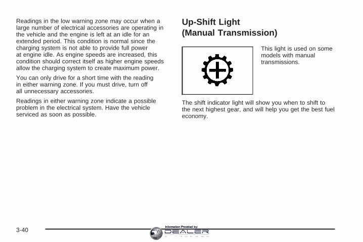
Readings in the low warning zone may occur when alarge number of electrical accessories are operating inthe vehicle and the engine is left at an idle for anextended period. This condition is normal since thecharging system is not able to provide full powerat engine idle. As engine speeds are increased, thiscondition should correct itself as higher engine speedsallow the charging system to create maximum power.
You can only drive for a short time with the readingin either warning zone. If you must drive, turn offall unnecessary accessories.
Readings in either warning zone indicate a possibleproblem in the electrical system. Have the vehicleserviced as soon as possible.
Up-Shift Light(Manual Transmission)
This light is used on somemodels with manualtransmissions.
The shift indicator light will show you when to shift tothe next highest gear, and will help you get the best fueleconomy.
3-40Information Provided by:

Brake System Warning LightWith the ignition on, the brake system warning light willflash when you set the parking brake. The light willflash if the parking brake doesn’t release fully. If you tryto drive with the parking brake engaged, a chime willsound when the vehicle speed is greater than 3 mph(5 km/h).
Your vehicle’s hydraulic brake system is divided into twoparts. If one part isn’t working, the other part can stillwork and stop you. For good braking, though, you needboth parts working well.
If the warning light comes on and a chime sounds therecould be a brake problem. Have your brake systeminspected right away.
This light should come on briefly when you turn theignition key to RUN. If it doesn’t come on then, have itfixed so it will be ready to warn you if there’s aproblem.
If the light comes on while you are driving, pull off theroad and stop carefully. You may notice that the pedal isharder to push or may go closer to the floor. It maytake longer to stop. If the light is still on, have the vehicletowed for service. See Towing Your Vehicle onpage 4-61.
{CAUTION:
Your brake system may not be workingproperly if the brake system warning light ison. Driving with the brake system warning lighton can lead to an accident. If the light is stillon after you have pulled off the road andstopped carefully, have the vehicle towed forservice.
United States Canada
3-41Information Provided by:

Anti-Lock Brake SystemWarning Light
With the anti-lock brakesystem, this light will comeon when you start yourengine and may stay on forseveral seconds.
That’s normal. If the light doesn’t come on then, have itfixed so it will be ready to warn you if there is aproblem.
If the light stays on, or comes on when you’re driving,your vehicle needs service. You will also hear achime sound when the light is on steady. If the regularbrake system warning light isn’t on, you still havebrakes, but you don’t have anti-lock brakes. If theregular brake system warning light is also on you don’thave anti-lock brakes and there’s a problem withyour regular brakes. In addition to both lights, you willalso hear a chime sound on the first occurrence ofa problem and each time the vehicle is shut off and thenrestarted. See Brake System Warning Light onpage 3-41.
Traction Off Light
If you have the TractionAssist System, this lightshould come on brieflywhen you turn the ignitionto RUN.
If the light does not come on then, the system mayrequire service; have it fixed so it will be there to warnyou if the system is turned off.
If the light stays on, or comes on when you are driving,there may be a problem with your Traction AssistSystem and your vehicle may need service. When thislight is on, the system will not limit wheel spin. Adjustyour driving accordingly.
3-42Information Provided by:

Engine Coolant Temperature Gage
This gage shows the engine coolant temperature.
It also provides an indicator of how hard your vehicle isworking. During a majority of the operation, the gagewill read 210°F (100°C) or less. If you are pulling a loador going up hills, it is normal for the temperature tofluctuate and approach the 250°F (122°C) mark. If thegage reaches the 260°F (125°C) mark, it indicatesthat the cooling system is working beyond its capacity.
See Engine Overheating on page 5-37.
Transmission Temperature Gage
Your vehicle may be equipped with a transmissiontemperature gage.When your ignition is on, the gage shows the temperatureof the transmission fluid. The normal operating range isfrom 180°F (82°C) to about 200°F (93°C).At approximately 265°F (125°C), the driver informationcenter will display a TRANSMISSION HOT messageand the transmission will enter a transmission protectionmode. When the transmission enters the protectionmode, you may notice a change in the transmissionshifting patterns. The transmission will return to normalshifting patterns when the transmission fluid temperaturefalls below 260°F (120°C).See Driver Information Center (DIC) on page 3-51 forfurther information.
United States Canada United States Canada
3-43Information Provided by:
If your vehicle has an Allison transmission, and the fluidreaches temperatures of approximately 275°F (135°C)or greater, the driver information center will displaya TRANS HOT IDLE ENGINE warning message and achime will sound until the temperature falls below265°F (129°C). Pull the vehicle off the roadway when itis safe to do so. Set the parking brake, place thetransmission in PARK (P) and allow the engine to idleuntil the transmission temperature falls below 265°F(129°C). If the transmission continues to operate above265°F (130°C), contact your nearest dealer or theGM Roadside Assistance Center. See RoadsideAssistance Program on page 7-6.
Notice: If you drive your vehicle with thetransmission temperature gage above normaloperating range, you can damage the transmission.This could lead to costly repairs that would notbe covered by your warranty. Do not drive yourvehicle while the transmission temperature gagereading is above normal. See your dealer for service.
The following situations can cause the transmission tooperate at higher temperatures:
• Towing a trailer
• Hot outside air temperatures
• Vehicle overloading
• Hauling a large or heavy load
• Low transmission fluid level
• High transmission fluid level
• Restricted air flow to the radiator and the auxiliarytransmission oil cooler (if equipped).
A temporary solution to hotter transmission operatingtemperatures may be to let the transmission cool down.If the transmission is operated at higher temperatureson a frequent basis, see Scheduled Maintenance(Gasoline Engine) on page 6-4 for the propertransmission maintenance intervals.
3-44Information Provided by:

Malfunction Indicator Lamp
Check Engine Light
Your vehicle is equippedwith a computer whichmonitors operation of thefuel, ignition, and emissioncontrol systems.
This system is called OBD II (On-BoardDiagnostics-Second Generation) and is intended toassure that emissions are at acceptable levels for thelife of the vehicle, helping to produce a cleanerenvironment. The check engine light comes on toindicate that there is a problem and service is required.Malfunctions often will be indicated by the systembefore any problem is apparent. This may prevent moreserious damage to your vehicle. This system is alsodesigned to assist your service technician in correctlydiagnosing any malfunction.
Notice: If you keep driving your vehicle with thislight on, after awhile, your emission controlsmay not work as well, your fuel economy may notbe as good, and your engine may not run assmoothly. This could lead to costly repairs that maynot be covered by your warranty.
Notice: Modifications made to the engine,transmission, exhaust, intake, or fuel system ofyour vehicle or the replacement of the original tireswith other than those of the same Tire PerformanceCriteria (TPC) can affect your vehicle’s emissioncontrols and may cause this light to come on.Modifications to these systems could lead to costlyrepairs not covered by your warranty. This mayalso result in a failure to pass a required EmissionInspection/Maintenance test. See Accessoriesand Modifications on page 5-4.
This light should come on, as a check to show you it isworking, when the ignition is on and the engine isnot running. If the light does not come on, have itrepaired. This light will also come on during amalfunction in one of two ways:
• Light Flashing — A misfire condition has beendetected. A misfire increases vehicle emissionsand may damage the emission control system onyour vehicle. Diagnosis and service may berequired.
• Light On Steady — An emission control systemmalfunction has been detected on your vehicle.Diagnosis and service may be required.
3-45Information Provided by:

If the Light is FlashingThe following may prevent more serious damage toyour vehicle:
• Reducing vehicle speed• Avoiding hard accelerations• Avoiding steep uphill grades• If you are towing a trailer, reduce the amount of
cargo being hauled as soon as it is possible
If the light stops flashing and remains on steady, see “Ifthe Light Is On Steady” following.
If the light continues to flash, when it is safe to do so,stop the vehicle. Find a safe place to park your vehicle.Turn the key off, wait at least 10 seconds and restartthe engine. If the light remains on steady, see “Ifthe Light Is On Steady” following. If the light is stillflashing, follow the previous steps, and see your dealerfor service as soon as possible.
If the Light Is On SteadyYou may be able to correct the emission systemmalfunction by considering the following:Did you recently put fuel into your vehicle?If so, reinstall the fuel cap, making sure to fully installthe cap. See Filling the Tank on page 5-10. Thediagnostic system can determine if the fuel cap hasbeen left off or improperly installed.
A loose or missing fuel cap will allow fuel to evaporateinto the atmosphere. A few driving trips with the capproperly installed should turn the light off.
Did you just drive through a deep puddle of water?
If so, your electrical system may be wet. The conditionwill usually be corrected when the electrical systemdries out. A few driving trips should turn the light off.
Have you recently changed brands of fuel?
If so, be sure to fuel your vehicle with quality fuel. SeeGasoline Octane on page 5-6. Poor fuel quality willcause your engine not to run as efficiently as designed.You may notice this as stalling after start-up, stallingwhen you put the vehicle into gear, misfiring, hesitationon acceleration, or stumbling on acceleration. (Theseconditions may go away once the engine is warmed up.)This will be detected by the system and cause thelight to turn on.
If you experience one or more of these conditions,change the fuel brand you use. It will require at leastone full tank of the proper fuel to turn the light off.
If none of the above steps have made the light turn off,your dealer can check the vehicle. Your dealer hasthe proper test equipment and diagnostic tools to fix anymechanical or electrical problems that may havedeveloped.
3-46Information Provided by:
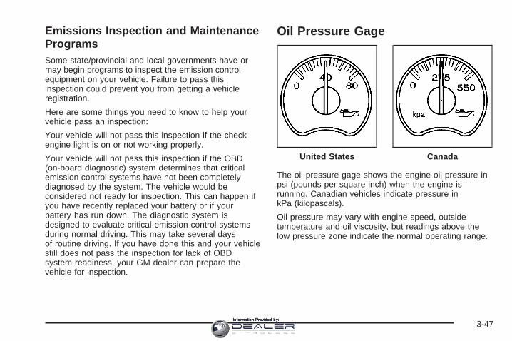
Emissions Inspection and MaintenanceProgramsSome state/provincial and local governments have ormay begin programs to inspect the emission controlequipment on your vehicle. Failure to pass thisinspection could prevent you from getting a vehicleregistration.
Here are some things you need to know to help yourvehicle pass an inspection:
Your vehicle will not pass this inspection if the checkengine light is on or not working properly.
Your vehicle will not pass this inspection if the OBD(on-board diagnostic) system determines that criticalemission control systems have not been completelydiagnosed by the system. The vehicle would beconsidered not ready for inspection. This can happen ifyou have recently replaced your battery or if yourbattery has run down. The diagnostic system isdesigned to evaluate critical emission control systemsduring normal driving. This may take several daysof routine driving. If you have done this and your vehiclestill does not pass the inspection for lack of OBDsystem readiness, your GM dealer can prepare thevehicle for inspection.
Oil Pressure Gage
The oil pressure gage shows the engine oil pressure inpsi (pounds per square inch) when the engine isrunning. Canadian vehicles indicate pressure inkPa (kilopascals).
Oil pressure may vary with engine speed, outsidetemperature and oil viscosity, but readings above thelow pressure zone indicate the normal operating range.
United States Canada
3-47Information Provided by:

A reading in the low pressure zone may be caused by adangerously low oil level or some other problemcausing low oil pressure. Check your oil as soon aspossible. See “OIL PRESSURE LOW” under DICWarnings and Messages on page 3-54 and Engine Oil(Gasoline Engine) on page 5-20.
{CAUTION:
Do not keep driving if the oil pressure is low. Ifyou do, your engine can become so hot that itcatches fire. You or others could be burned.Check your oil as soon as possible and haveyour vehicle serviced.
Notice: Lack of proper engine oil maintenance maydamage the engine. The repairs would not becovered by your warranty. Always follow themaintenance schedule in this manual for changingengine oil.
Security Light
This light flashes when thevehicle security system isactivated.
Cruise Control Light
This light comes onwhenever you set yourcruise control.
The light will go out when the cruise control is turnedoff. See Cruise Control on page 3-10 for moreinformation.
3-48Information Provided by:

Highbeam On Light
This light will come onwhen the high-beamheadlamps are in use.
See Headlamp High/Low-Beam Changer on page 3-8.
Four-Wheel-Drive Light
The four-wheel-driveindicator will light up whenyou shift a manualtransfer case intofour-wheel drive and thefront axle engages.
Some delay between shifting and the indicator’s lightingis normal.
See Four-Wheel Drive on page 2-36 for moreinformation.
Tow/Haul Mode Light
This light is displayedwhen the Tow/Haul modehas been activated.
For more information, see Tow/Haul Mode on page 2-30.
Cargo Lamp Light
This light will come onwhen the cargo lamp is inuse. For more informationsee Cargo Lamp onpage 3-18.
3-49Information Provided by:

Fuel Gage
When the ignition is on, the fuel gage tells you abouthow much fuel you have left in your tank.
The gage will first indicate empty before you are out offuel, and you should get more fuel as soon aspossible.
When the fuel tank is low the FUEL LEVEL LOWmessage will appear. See DIC Warnings and Messageson page 3-54 for more information.
Here are some situations you may experience with yourfuel gage. None of these indicate a problem with thefuel gage.
• At the gas station, the fuel pump shuts off beforethe gage reads full.
• It takes a little more or less fuel to fill up than thefuel gage indicated. For example, the gage mayhave indicated the tank was half full, but it actuallytook a little more or less than half the tank’scapacity to fill the tank.
• The gage goes back to empty when you turn off theignition.
If you have a diesel engine, see “Fuel Gage” in theDiesel Engine Supplement.
Low Fuel Warning LightThe light next to the fuel gage will come on briefly whenyou are starting the engine.
This light comes on when the fuel tank is low on fuel.To turn it off, add fuel to the fuel tank. See Fuel onpage 5-6.
United States Canada
3-50Information Provided by:

Driver Information Center (DIC)The Driver Information Center (DIC) display is locatedon the instrument panel cluster, below the speedometer.If your vehicle has DIC buttons, they are located onthe steering wheel. The DIC can display informationsuch as the trip odometer, fuel economy, customizationfeatures, and warning/status messages.
If your vehicle does not have DIC steering wheelbuttons, you will not have all of the features listed. Scrollthrough the odometer, trip odometer, engine hours,and selected range if your vehicle has an AllisonTransmission® by pressing the trip odometer reset stemlocated on the instrument panel cluster. Turn off, oracknowledge, DIC messages by pressing the tripodometer reset stem. See Speedometer and Odometeron page 3-32 for information on features for vehicleswithout DIC buttons.
If your vehicle has an Allison Transmission® and theshift lever is in the MANUAL MODE (M) position,the DIC will display the current gear range. The DIC willalso display the gear range as it is shifted up ordown. For example, if the gear range is currently setto 6, the DIC will display (6) 5 4 3 2 1. When thegear range is shifted down one time, the DIC will display6 (5) 4 3 2 1. See Automatic Transmission Operationon page 2-24 for more information.
3 (Trip Information): Press this button to displaythe odometer, trip odometers, timer, engine hours,and selected range if your vehicle has an AllisonTransmission®.
t (Fuel Information): Press this button to display thecurrent range, fuel used, average fuel economy, andengine oil life.
4 (Customization): Press this button to access thevehicle settings menu and customize the personalsettings on your vehicle.
r (Select): Press this button to reset certain DICfunctions and set your customization settings.
Pressing any of the four DIC buttons will acknowledgeDIC messages and clear them from the DIC display.
3-51Information Provided by:

DIC Operation and DisplaysThe Driver Information Center (DIC) comes on when theignition is on. After a short delay, the DIC will displaythe information that was last displayed before the enginewas turned off.
The DIC has different modes which can be accessed bypressing the four DIC buttons located on the steeringwheel. These buttons are trip information, fuelinformation, customization, and select. The buttonfunctions are detailed in the following pages.
Trip Information Button
3 (Trip Information): Press the trip informationbutton to scroll through the ODOMETER, TRIP A,TRIP B, TIMER, ENGINE HOURS, and SELECTEDRANGE.
Odometer: Press the trip information button untilODOMETER appears on the display. This mode showsthe total distance the vehicle has been driven ineither miles or kilometers. Pressing the reset stemlocated on the instrument cluster with the vehicle off willalso display the odometer.
Trip A: Press the trip information button until TRIP Aappears on the display. This mode shows the currentdistance traveled since the last reset for TRIP A in eithermiles or kilometers.
Trip B: Press the trip information button until TRIP Bappears on the display. This mode shows the currentdistance traveled since the last reset for TRIP B in eithermiles or kilometers.
To reset TRIP A or TRIP B information, press and holdthe select button for one second while in one of thetrip modes. This will reset the information for TRIP A orTRIP B.
You can also reset TRIP A or TRIP B while they aredisplayed by pressing the reset stem on the cluster. If youpress and hold the reset stem or the select button for fourseconds, the display will show the distance traveled sincethe last ignition cycle for TRIP A or TRIP B.
See Trip Odometer on page 3-32 for more information.
Timer: The DIC can be used as a timer. Press theselect button while TIMER is displayed to start the timer.The display will show the amount of time that haspassed since the timer was last reset, not including timethe ignition is off. Time will continue to be counted aslong as the ignition is on, even if another display is beingshown on the DIC. The timer will record up to 99 hours,59 minutes and 59 seconds (99:59:59) after whichthe display will roll back to zero.
To stop the counting of time, press the select buttonbriefly while TIMER is displayed.
To reset the timer to zero, press and hold the selectbutton while TIMER is displayed.
3-52Information Provided by:

Engine Hours: Press the trip information button untilENGINE HOURS appears on the display. Thismode shows the total number of hours the engine hasrun. Pressing and holding the reset stem located onthe instrument cluster for about four seconds will alsodisplay the engine hour information after the odometer isdisplayed when the vehicle is off.
Selected Range: If your vehicle has an AllisonTransmission® and the vehicle is in the MANUALMODE (M) position, press the trip information button untilSELECTED RANGE: M# appears on the display. TheDIC will display the current gear range. For example, ifthe gear range is set to 6, the DIC will display SELECTEDRANGE: M6. See Automatic Transmission Operation onpage 2-24 for more information.
Fuel Information Button
t (Fuel Information): Press the fuel informationbutton to scroll through the range, fuel used, averagefuel economy, and the engine oil life system.
Fuel Range: Press the fuel information button untilRANGE appears on the display. This mode shows theremaining distance you can drive without refueling.It is based on fuel economy and the fuel remaining inthe fuel tank. The display will show LOW if the fuel levelis low.
The fuel economy data used to determine fuel range isan average of recent driving conditions. As yourdriving conditions change, this data is gradually updated.Fuel range cannot be reset.
Fuel Used: Press the fuel information button untilFUEL USED appears on the display. This mode showsthe number of gallons or liters of fuel used since thelast reset of this menu item. To reset the fuel usedinformation, press and hold the select button for onesecond while FUEL USED is displayed.
Average Fuel Economy: Press the fuel informationbutton until AVG ECON appears on the display.This mode shows how many miles per gallon (MPG) orliters per 100 kilometers (L/100 km) your vehicle isgetting based on current and past driving conditions.
Press and hold the select button for one second whileAVG ECON is displayed to reset the average fueleconomy. Average fuel economy will then be calculatedstarting from that point. If the average fuel economy is notreset, it will be continually updated each time you drive.
3-53Information Provided by:

Engine Oil Life System: Press the fuel informationbutton until ENGINE OIL LIFE appears on the display.The engine oil life system shows an estimate of theoil’s remaining useful life. It will show 100% when thesystem is reset after an oil change. It will alert youto change your oil on a schedule consistent with yourdriving conditions.
Always reset the engine oil life system after an oilchange. To reset the engine oil life system, see EngineOil Life System (Gasoline Engine) on page 5-23.
In addition to the engine oil life system monitoring theoil life, additional maintenance is recommended inthe Maintenance Schedule in this manual. See EngineOil (Gasoline Engine) on page 5-20 and ScheduledMaintenance (Gasoline Engine) on page 6-4.
Customization Button
4 (Customization): Press the customization button toaccess the VEHICLE SETTINGS menu and customizethe settings to your vehicle. See DIC VehicleCustomization on page 3-64 for more information.
Select Button
r (Select): Press the select button to reset certainDIC functions and set your customization settings.For example, this button will reset the trip odometersand enables you to scroll through and select thelanguage in which the DIC information will appear.
DIC Warnings and MessagesWarning messages are displayed on the DriverInformation Center (DIC) to notify the driver that thestatus of the vehicle has changed and that some actionmay be needed by the driver to correct the condition.If there is more than one message that needs tobe displayed, they will appear one after another. Somemessages may not require immediate action, butyou should press any of the four DIC buttons on thesteering wheel to acknowledge that you receivedthe messages and to clear them from the display. Ifyour vehicle does not have DIC buttons on the steeringwheel, press the trip odometer reset stem, locatedon the instrument panel cluster, to acknowledgemessages and clear them from the display.
Some messages cannot be cleared from the displaybecause they are more urgent. These messages requireaction before they can be removed from the DICdisplay. You should take any messages that appear onthe display seriously and remember that clearing themessages will only make the messages disappear, notcorrect the problem.
3-54Information Provided by:

The following are the possible messages that can bedisplayed and some information about them.
BATTERY NOT CHARGINGOn some vehicles, if the battery is not charging duringoperation, this message will appear on the DIC.Driving with this problem could drain your battery. Havethe electrical system checked by your GM dealer assoon as possible. Pressing any of the four DIC buttonswill acknowledge the message and clear it from theDIC display. If your vehicle does not have the four DICbuttons, pressing the trip odometer reset stem willacknowledge the message and clear it from the DICdisplay. See Battery Warning Light on page 3-39and Voltmeter Gage on page 3-39.
BUCKLE PASSENGERIf your vehicle has the passenger sensing system, thismessage reminds you to buckle the passenger’sseat belt. See Passenger Sensing System on page 1-80.
This message will display and a chime will sound whenthe ignition is on, the driver’s seat belt is buckled, thepassenger’s seat belt is unbuckled with the passengerairbag enabled, and the vehicle is in motion. You shouldhave the passenger buckle their seat belt.
This reminder will be repeated if the ignition is on, thevehicle is in motion, the driver is buckled and thepassenger is still unbuckled, and the passenger airbagis enabled. If the passenger’s seat belt is alreadybuckled, this message and chime will not come on.
Pressing any of the four DIC buttons will acknowledgethe message and clear it from the DIC display. Ifyour vehicle does not have the four DIC buttons,pressing the trip odometer reset stem will acknowledgethe message and clear it from the DIC display.
BUCKLE SEATBELTIf your vehicle has the passenger sensing system, thismessage reminds you to buckle the driver’s seatbelt. See Passenger Sensing System on page 1-80.
This message will display and a chime will sound whenthe ignition is on, the driver’s seat belt is unbuckled,and the vehicle is in motion. You should buckleyour seat belt.
If the driver remains unbuckled when the ignition is onand the vehicle is in motion, the reminder will berepeated. If the driver’s seat belt is already buckled, thismessage and chime will not come on.
3-55Information Provided by:

This message is an additional reminder to the SafetyBelt Reminder Light in the instrument panel cluster. SeeSafety Belt Reminder Light on page 3-33 for moreinformation.
Pressing any of the four DIC buttons will acknowledgethe message and clear it from the DIC display. Ifyour vehicle does not have the four DIC buttons,pressing the trip odometer reset stem will acknowledgethe message and clear it from the DIC display.
CHANGE ENGINE OILThis message is displayed when the engine oil needs tobe changed.
When you change the engine oil, be sure to reset theCHANGE ENGINE OIL message. See Engine OilLife System (Gasoline Engine) on page 5-23, Engine Oil(Gasoline Engine) on page 5-20, and ScheduledMaintenance (Gasoline Engine) on page 6-4 for moreinformation.
CHARGING SYSTEM FAILUREOn some vehicles, if there is a problem with thegenerator and battery charging system, this messagewill appear on the DIC, a chime will sound, and thebattery warning light on the instrument panel cluster willcome on. Driving with this problem could drain yourbattery. Turn off all unnecessary accessories. Stop andturn off the vehicle as soon as it is safe to do so.Have the electrical system checked by your GM dealerimmediately. See Battery Warning Light on page 3-39and Voltmeter Gage on page 3-39 for more information.
CHECK OIL LEVELIf your vehicle has an oil level sensor, and the oil levelin the vehicle is low, this message will appear onthe DIC. Check the oil level and correct it as necessary.You may need to let the vehicle cool or warm up andcycle the ignition to be sure this message will clear.Once the problem is corrected, pressing any of the fourDIC buttons will acknowledge the message and clearit from the DIC display. If your vehicle does not have thefour DIC buttons, pressing the trip odometer resetstem will acknowledge the message and clear it fromthe DIC display. See Engine Oil (Gasoline Engine)on page 5-20 for additional information.
3-56Information Provided by:

CHECK WASHER FLUIDIf the washer fluid level is low, this message will appearon the DIC. See Windshield Washer Fluid onpage 5-47. Adding washer fluid to the windshieldwasher reservoir will clear the message. Pressing anyof the four DIC buttons will acknowledge the messageand clear it from the DIC display. If your vehicle does nothave the four DIC buttons, pressing the trip odometerreset stem will acknowledge the message and clearit from the DIC display.
DRIVER DOOR AJARIf the driver’s door is not fully closed, this message willappear on the display and you will hear a chime.Stop and turn off the vehicle, check the door forobstacles and close the door again. Check to see if themessage still appears on the DIC. Pressing any ofthe four DIC buttons will acknowledge the message andclear it from the DIC display. If your vehicle does nothave the four DIC buttons, pressing the trip odometerreset stem will acknowledge the message and clearit from the DIC display.
ENGINE COOLANT HOTIf the cooling system temperature gets hot, this messagewill appear in the DIC. Turn off the air conditioning. If themessage is still on, or if the engine coolant temperaturegage continues to rise, pull the vehicle over when it issafe to do so. See Engine Coolant Temperature Gage onpage 3-43 for more information. Stop the vehicle and letthe engine idle in PARK (P) for a few minutes, orNEUTRAL with the parking brake set for manualtransmissions, to allow the coolant to reach a safetemperature. This message will clear when the coolanttemperature drops to safe operating temperature.
ENGINE OVERHEATED
Notice: If you drive your vehicle while the engine isoverheating, severe engine damage may occur. Ifan overheat warning appears on the instrumentpanel cluster and/or DIC, stop the vehicle as soonas possible. Do not increase the engine speed abovenormal idling speed. See Engine Overheating onpage 5-37 for more information.
If the engine cooling system reaches unsafetemperatures for operation, this message will appear inthe DIC and you will hear a chime. Stop and turn offthe vehicle as soon as it is safe to do so to avoid severedamage. This message will clear when the enginehas cooled to a safe operating temperature.
3-57Information Provided by:
FUEL LEVEL LOWIf the fuel level is low, this message will appear on theDIC and you will hear a chime. Refuel as soon aspossible. Pressing any of the four DIC buttons willacknowledge the message and clear it from theDIC display. If your vehicle does not have the four DICbuttons, pressing the trip odometer reset stem willacknowledge the message and clear it from the DICdisplay. See Low Fuel Warning Light on page 3-50, FuelGage on page 3-50, and Fuel on page 5-6.
KEYFOB X BATTERY LOWIf a remote keyless entry transmitter battery is low, thismessage will appear on the DIC. The battery needsto be replaced in the transmitter. See “BatteryReplacement” under Remote Keyless Entry SystemOperation on page 2-5. Pressing any of the fourDIC buttons will acknowledge the message and clear itfrom the DIC display. If your vehicle does not havethe four DIC buttons, pressing the trip odometer resetstem will acknowledge the message and clear it from theDIC display.
LEFT REAR DOOR AJAR (Crew Cab)If the driver’s side rear door is not fully closed, thismessage will appear on the display and you will hear achime. Stop and turn off the vehicle, check the doorfor obstacles and close the door again. Check to see ifthe message still appears on the DIC. Pressing anyof the four DIC buttons will acknowledge the messageand clear it from the DIC display. If your vehicle does nothave the four DIC buttons, pressing the trip odometerreset stem will acknowledge the message and clearit from the DIC display.
LOW COOLANT LEVEL
Notice: Engine damage from running your enginewithout coolant is not covered by your warranty. See“Overheated Engine Protection Operating Mode”in the Index for information on driving to a safeplace in an emergency.If your vehicle has a low coolant level sensor, thismessage will appear on the DIC if the engine coolantlevel is low. Adding coolant to the coolant recovery tankwill clear the message. See Cooling System onpage 5-40. Pressing any of the four DIC buttons willacknowledge the message and clear it from theDIC display. If your vehicle does not have the four DICbuttons, pressing the trip odometer reset stem willacknowledge the message and clear it from the DICdisplay.
3-58Information Provided by:

OIL LIFE RESETThis message will appear on the display for about10 seconds after resetting the change engine oilmessage. See “Engine Oil Life System” under DICOperation and Displays on page 3-52 and Engine Oil(Gasoline Engine) on page 5-20 for more information.
OIL PRESSURE LOW
Notice: If you drive your vehicle while the engineoil pressure is low, severe engine damage mayoccur. If a low oil pressure warning appears on theDriver Information Center (DIC), stop the vehicleas soon as possible. Do not drive the vehicle untilthe cause of the low oil pressure is corrected.See Engine Oil (Gasoline Engine) on page 5-20 formore information.
If low oil pressure levels occur, this message will bedisplayed on the DIC and a chime will sound. Stop thevehicle as soon as safely possible and do not operateit until the cause of the low oil pressure has beencorrected. Check your oil as soon as possible and haveyour vehicle serviced by your GM dealer. See EngineOil (Gasoline Engine) on page 5-20.
PASSENGER DOOR AJARIf the passenger’s door is not fully closed, this messagewill appear on the display and you will hear a chime.Stop and turn off the vehicle, check the door forobstacles and close the door again. Check to see if themessage still appears on the DIC. Pressing any ofthe four DIC buttons will acknowledge the message andclear it from the DIC display. If your vehicle does nothave the four DIC buttons, pressing the trip odometerreset stem will acknowledge the message and clearit from the DIC display.
RANGE SHIFT INHIBITED(Allison Transmission ® Only)If the transmission is unable to shift into a selectedgear, this message will appear on the DIC. Theelectronic shift position indicator on the instrument panelcluster may blink when this occurs. To make thevehicle shift to the requested gear, you may have toshift back to PARK (P) or NEUTRAL (N) and re-selectthe desired gear.
3-59Information Provided by:

REDUCED ENGINE POWERThis message is displayed when the cooling systemtemperature gets too hot and the engine further entersthe engine coolant protection mode.
See Engine Overheating on page 5-37 for additionalinformation.
RIGHT REAR DOOR AJAR (Crew Cab)If the passenger’s side rear door is not fully closed,this message will appear on the display and youwill hear a chime. Stop and turn off the vehicle, checkthe door for obstacles and close the door again.Check to see if the message still appears on the DIC.Pressing any of the four DIC buttons will acknowledgethe message and clear it from the DIC display. Ifyour vehicle does not have the four DIC buttons,pressing the trip odometer reset stem will acknowledgethe message and clear it from the DIC display.
SERVICE 4WD (Four-Wheel-Drive)If a problem occurs with the four-wheel-drive system,this message will appear on the DIC. If this messageappears, stop as soon as possible and turn off thevehicle. Restart the vehicle and check for the messageon the DIC display. If the message is still displayedor appears again when you begin driving, thefour-wheel-drive system needs service. See yourGM dealer.
SERVICE AIRBAGIf there is a problem with the airbag system, thismessage will be displayed on the DIC. Have yourGM dealer inspect the system for problems. See AirbagReadiness Light on page 3-33 and Airbag System onpage 1-70 for more information. Pressing any of thefour DIC buttons will acknowledge the messageand clear it from the DIC display. If your vehicle doesnot have the four DIC buttons, pressing the tripodometer reset stem will acknowledge the message andclear it from the DIC display.
3-60Information Provided by:

SERVICE BRAKE BOOSTER
{CAUTION:
Your brake system may not be workingproperly if the SERVICE BRAKE BOOSTERmessage is displayed.
If the brake system warning light is also on,you should have the vehicle towed for service.See Brake System Warning Light on page 3-41.
If the brake system warning light is not on, youstill have brakes, but the supplemental brakeassist system on vehicles with rear discbrakes may not operate properly. In the eventof a vacuum loss, you may not have vacuumpower assist for braking. The brake pedal willbe harder to push and it will take longer tostop. If you continue to drive with thismessage displayed it can lead to a crash. Havethe brake system serviced as soon aspossible.
If your vehicle has vacuum assist power brakes, thismessage will be displayed on the DIC when there is aproblem with the Supplemental Brake Assist system.If the message is displayed immediately after startingthe vehicle or the message appears while driving,your Supplemental Brake Assist system needs service.See your GM dealer. See Brake System WarningLight on page 3-41 for additional information.
SERVICE BRAKE SYSTEMIf there is a problem with the brake system, thismessage will be displayed on the DIC. If this messageappears, stop as soon as possible and turn off thevehicle. Restart the vehicle and check for the messageon the DIC display. If the message is still displayedor appears again when you begin driving, the brakesystem needs service. See your GM dealer.
3-61Information Provided by:

SERVICE CHARGING SYSTEMOn some vehicles, if there is a problem with the batterycharging system, this message will appear on theDIC. Under certain conditions, the battery warning lightmay also turn on in the instrument panel cluster.See Battery Warning Light on page 3-39. The batterywill not be charging at an optimal rate and the vehiclewill lose the ability to enter the fuel economy mode. Thevehicle is safe to drive, however you should have theelectrical system checked by your GM dealer. Pressingany of the four DIC buttons will acknowledge themessage and clear it from the DIC display. If yourvehicle does not have the four DIC buttons, pressingthe trip odometer reset stem will acknowledge themessage and clear it from the DIC display.
TIGHTEN FUEL CAPIf the vehicle’s fuel cap is not tightened properly, thismessage may appear along with the check engine lighton the instrument panel. See Malfunction IndicatorLamp on page 3-45. Fully reinstall the fuel cap.See Filling the Tank on page 5-10. The diagnostic systemcan determine if the fuel cap has been left off orimproperly installed. A loose or missing fuel cap willallow fuel to evaporate into the atmosphere. A fewdriving trips with the cap properly installed should turnthe light and message off.
TRACTION ACTIVEWhen the traction control system had detected that anyof the vehicle’s wheels are slipping, the tractioncontrol system will activate and this message will appearon the DIC. For more information, see Traction AssistSystem (TAS) on page 4-9.
TRANS (Transmission) HOT IDLEENGINE
Notice: If you drive your vehicle while thetransmission fluid is overheating and thetransmission temperature warning is displayed onthe instrument panel cluster and/or DIC, youcan damage the transmission. This could lead tocostly repairs that would not be covered byyour warranty. Do not drive your vehicle withoverheated transmission fluid or while thetransmission temperature warning is displayed.
If the transmission fluid in the vehicle gets hot,this message will appear on the DIC along with acontinuous chime. Driving with the transmission fluidtemperature high can cause damage to the vehicle. Stopthe vehicle and let it idle to allow the transmission tocool. This message will clear and the chime willstop when the fluid temperature reaches a safe level.See Transmission Temperature Gage on page 3-43.
3-62Information Provided by:

TRANSMISSION HOT
Notice: If you drive your vehicle while thetransmission fluid is overheating and thetransmission temperature warning is displayed onthe instrument panel cluster and/or DIC, youcan damage the transmission. This could lead tocostly repairs that would not be covered byyour warranty. Do not drive your vehicle withoverheated transmission fluid or while thetransmission temperature warning is displayed.
If the transmission fluid temperature becomes high, thismessage will appear on the DIC display.
When the transmission enters the protection mode, youmay notice a change in the transmission shiftingpatterns. When the transmission fluid temperaturereturns to normal, the display will turn off and thetransmission shifting patterns will return to normal.
If the vehicle has the Tow/Haul mode, use this feature ifthe transmission is operating at higher temperaturesand/or the following situations exist, which can cause thetransmission to operate at higher temperatures:
• Towing a trailer
• Hot outside air temperatures
• Hauling a large or heavy load
• Over-loading
• Low transmission fluid level
• High transmission fluid level
• Restricted air flow to the radiator and the auxiliarytransmission oil cooler
A temporary solution to hotter transmission operatingtemperatures may be to let the transmission cool down.If the transmission is operated at higher temperatureson a frequent basis, see Scheduled Maintenance(Gasoline Engine) on page 6-4 for the transmission yourvehicle is equipped with for the proper transmissionmaintenance intervals. Also see TransmissionTemperature Gage on page 3-43 for more information.
TRANS (Transmission) IN WARMUP (Allison Transmission ® Only)When temperatures are very cold, the transmission willprevent certain operations such as shifts to certainranges and engaging the torque converter clutchto protect against damage. When active, the DIC willdisplay the message TRANS IN WARM UP.
3-63Information Provided by:
TURN SIGNAL ONIf a turn signal is left on for 3/4 of a mile (1.2 km), thismessage will appear on the display and you will hear achime. Move the turn signal/multifunction lever to theoff position. Pressing any of the four DIC buttonswill acknowledge the message and clear it from the DICdisplay. If your vehicle does not have the four DICbuttons, pressing the trip odometer reset stemwill acknowledge the message and clear it from the DICdisplay.
DIC Vehicle CustomizationYour vehicle may have customization capabilities thatallow you to program some features to one settingbased on your preference. All of the customizableoptions listed may not be available on your vehicle. Onlythe options available will be displayed on your DriverInformation Center (DIC).
The default settings for the customization features wereset when your vehicle left the factory, but may havebeen changed from their default state since then.
To change feature preferences, make sure the ignitionis on and the vehicle is in PARK (P). Press thecustomization button to scroll through the availablecustomizable options.
After pressing the customization button, VEHICLESETTINGS will momentarily display before going to acustomization option.
Lock Doors (Automatic Transmission only)If you have an automatic transmission vehicle, pressthe customization button until LOCK DOORS appears inthe display. To select your preference for automaticlocking, press the select button while LOCK DOORS isdisplayed on the DIC. Pressing the select button willscroll through the following choices:
LOCK DOORS: IN GEAR (default): The doors will lockwhen the vehicle is shifted out of PARK (P).
LOCK DOORS: WITH SPEED: The doors will lockwhen the vehicle speed is above 8 mph (13 km/h) forthree seconds.
Choose one of the available options and press thecustomization button while it is displayed on the DIC toselect it and move on to the next feature. For moreinformation on automatic door locks, see ProgrammableAutomatic Door Locks on page 2-10.
3-64Information Provided by:

Unlock Doors (AutomaticTransmission only)If you have an automatic transmission vehicle, press thecustomization button until UNLOCK DOORS appearsin the display. To select your preference for automaticunlocking, press the select button while UNLOCKDOORS is displayed on the DIC. Pressing the selectbutton will scroll through the following choices:
UNLOCK DOORS: IN PARK (default): All of the doorswill unlock when the vehicle is shifted into PARK (P).
UNLOCK DRIVER: IN PARK: The driver’s door will beunlocked when the vehicle is shifted into PARK (P).
UNLOCK DOORS: KEY OUT: All of the doorswill unlock when the key is taken out of the ignition.
UNLOCK DOORS: MANUALLY: The doors will not beunlocked automatically.
Choose one of the available options and press thecustomization button while it is displayed on the DIC toselect it and move on to the next feature. For moreinformation on automatic door locks, see ProgrammableAutomatic Door Locks on page 2-10.
Door Lock Delay (Crew Cab only)If your DIC does not have this feature, you still may beable to program the delayed locking feature. SeeDelayed Locking on page 2-9 for more information.
When locking the doors with the power lock switch orthe keyless entry transmitter and a door is open,the delayed locking feature will delay locking the doorsuntil five seconds after the last door is closed.
Press the customization button until DOOR LOCKDELAY appears in the display. To select your preferencefor delayed locking, press the select button while DOORLOCK DELAY is displayed on the DIC. Pressing theselect button will scroll through the following choices:
DOOR LOCK DELAY: OFF (default): The doors willlock immediately when pressing the power lock switch orthe lock button on the keyless entry transmitter.
DOOR LOCK DELAY: ON: The doors will not lock untilfive seconds after the last door is closed. You willhear three chimes to signal that the delayed lockingfeature is in use. You can temporarily override delayedlocking by pressing the lock button on the door orkeyless entry transmitter a second time.
Choose one of the available options and press thecustomization button while it is displayed on the DIC toselect it and move on to the next feature.
This feature will not operate if the key is in the ignition.
3-65Information Provided by:

Lock FeedbackPress the customization button until LOCK FEEDBACKappears in the display. To select your preference forthe feedback you receive when locking the vehicle withthe remote keyless entry transmitter, press the selectbutton while LOCK FEEDBACK is displayed on the DIC.Pressing the select button will scroll through thefollowing choices:
LOCK FEEDBACK: BOTH (default): The parkinglamps will flash each time you press the button with thelock symbol on the remote keyless entry transmitterand the horn will chirp the second time you press thelock button.
LOCK FEEDBACK: LAMPS: The parking lamps willflash each time you press the button with the locksymbol on the remote keyless entry transmitter.
LOCK FEEDBACK: HORN: The horn will chirp thesecond time you press the button with the lock symbolon the remote keyless entry transmitter.
LOCK FEEDBACK: OFF: There will be no feedbackwhen locking the vehicle.
Choose one of the available options and press thecustomization button while it is displayed on the DIC toselect it and move on to the next feature.
Unlock FeedbackPress the customization button until UNLOCKFEEDBACK appears in the display. To select yourpreference for the feedback you will receive whenunlocking the vehicle with the remote keyless entrytransmitter, press the select button while UNLOCKFEEDBACK is displayed on the DIC. Pressing the selectbutton will scroll through the following choices:
UNLOCK FEEDBACK: LAMPS (default): The parkinglamps will flash each time you press the button withthe unlock symbol on the remote keyless entrytransmitter.
UNLOCK FEEDBACK: HORN: The horn will chirp thesecond time you press the button with the unlocksymbol on the remote keyless entry transmitter.
UNLOCK FEEDBACK: BOTH: The parking lamps willflash each time you press the button with the unlocksymbol on the remote keyless entry transmitter and thehorn will chirp the second time you press the unlockbutton.
UNLOCK FEEDBACK: OFF: There will be no feedbackwhen unlocking the vehicle.
Choose one of the available options and press thecustomization button while it is displayed on the DIC toselect it and move on to the next feature.
3-66Information Provided by:

Headlamp DelayPress the customization button until HEADLAMPDELAY appears in the display. To select yourpreference for how long the headlamps will stay onwhen you turn off the vehicle, press the select buttonwhile HEADLAMP DELAY is displayed on the DIC.Pressing the select button will scroll through thefollowing choices:
• HEADLAMP DELAY: 10 SEC (Seconds) (default)
• HEADLAMP DELAY: 20 SEC
• HEADLAMP DELAY: 40 SEC
• HEADLAMP DELAY: 1 MIN (Minute)
• HEADLAMP DELAY: 2 MIN
• HEADLAMP DELAY: 3 MIN
• HEADLAMP DELAY: OFF
The amount of time you choose will be the amount oftime that the headlamps stay on after you turn offthe vehicle. If you choose off, the headlamps will turnoff as soon as you turn off the vehicle.
Choose one of the available options and press thecustomization button while it is displayed on the DIC toselect it and move on to the next feature.
Perimeter LightsPress the customization button until PERIMETERLIGHTS appears in the display. To select yourpreference for perimeter lighting, press the select buttonwhile PERIMETER LIGHTS is displayed on the DIC.Pressing the select button will scroll through thefollowing choices:
PERIMETER LIGHTS: ON (default): The headlampsand back-up lamps will come on for 40 seconds, ifit is dark enough outside, when you unlock the vehiclewith the remote keyless entry transmitter.
PERIMETER LIGHTS: OFF: The perimeter lights willnot come on when you unlock the vehicle with theremote keyless entry transmitter.
Choose one of the available options and press thecustomization button while it is displayed on the DIC toselect it and move on to the next feature.
Easy Exit SeatPress the customization button until EASY EXIT SEATappears in the display. To select your preference forseat position exit, press the select button whileEASY EXIT SEAT is displayed on the DIC. Pressing theselect button will scroll through the following choices:
EASY EXIT SEAT: OFF (default): No seat exitrecall will occur.
3-67Information Provided by:

EASY EXIT SEAT: ON: The driver’s seat will move tothe exit position when the key is removed from theignition.Choose one of the available options and press thecustomization button while it is displayed on the DIC toselect it and move on to the next feature. For moreinformation on seat position exit, see Memory Seat onpage 2-79.
Curb ViewPress the customization button until CURB VIEWappears in the display. To select your preference forcurb view, press the select button while CURB VIEW isdisplayed on the DIC. Pressing the select button willscroll through the following choices:
CURB VIEW: OFF (default): Neither outside mirror willbe tilted down when the vehicle is shifted intoREVERSE (R).
CURB VIEW: PASSENGER: The passenger’s outsidemirror will be tilted down when the vehicle is shiftedinto REVERSE (R).
CURB VIEW: DRIVER: The driver’s outside mirror willbe tilted down when the vehicle is shifted intoREVERSE (R).
CURB VIEW: BOTH: The driver’s and passenger’soutside mirror will be tilted down when the vehicleis shifted into REVERSE (R).
Choose one of the available options and press thecustomization button while it is displayed on the DIC toselect it and move on to the next feature. For moreinformation on tilt mirror in reverse, see Outside CurbView Assist Mirrors on page 2-68.
Alarm WarningPress the customization button until ALARM WARNINGappears in the display. To select your preference foralarm warning, press the select button while ALARMWARNING is displayed on the DIC. Pressing the selectbutton will scroll through the following choices:
ALARM WARNING: BOTH (default): The headlampswill flash and the horn will chirp when the alarm isactive.
ALARM WARNING: OFF: There will be no alarmwarning on activation.
ALARM WARNING: HORN: The horn will chirp whenthe alarm is active.
ALARM WARNING: LAMPS: The headlamps will flashwhen the alarm is active.
Choose one of the available options and press thecustomization button while your choice is displayed onthe DIC to select it and move on to the next feature.For more information on alarm warning type, seeContent Theft-Deterrent on page 2-18.
3-68Information Provided by:

LanguageTo select your preference for display language, pressthe select button while LANGUAGE is displayed on theDIC. Pressing the select button will scroll through thefollowing languages:
• ENGLISH
• FRANCAIS (French)
• ESPANOL (Spanish)
Choose one of the available options and press thecustomization button while it is displayed on the DIC toselect it.
If you accidentally choose a language that you do notwant or understand, press and hold the customizationbutton and the trip information button at the sametime. The DIC will begin scrolling through the languagesin their particular language. English will be in English,Francais will be in French and Espanol will be inSpanish. When you see the language that you wouldlike, release both buttons. The DIC will then display theinformation in the language you chose.
You can also scroll through the different languages bypressing and holding the trip reset stem for fourseconds, as long as you are in the odometer mode.
Display UnitsPress the customization button until DISPLAY UNITSappears in the display. To select English or metric, pressthe select button while DISPLAY UNITS is displayedon the DIC. Pressing the select button will scroll throughthe following choices:
• DISPLAY UNITS: ENGLISH
• DISPLAY UNITS: METRIC
If you choose English, all information will be displayedin English units. For example, distance in miles and fueleconomy in miles per gallon. If you choose metric, allinformation will be displayed in metric units. Forexample, distance in kilometers and fuel economy inliters per 100 kilometers.
Choose one of the available options and press thecustomization button while it is displayed on the DIC toselect it and end out of the customizable options.
3-69Information Provided by:

Audio System(s)Determine which radio your vehicle has and then read thepages following to familiarize yourself with its features.
Driving without distraction is a necessity for a saferdriving experience. See Defensive Driving on page 4-2.By taking a few moments to read this manual andget familiar with your vehicle’s audio system, you canuse it with less effort, as well as take advantage ofits features. While your vehicle is parked, set up youraudio system by presetting your favorite radio stations,setting the tone and adjusting the speakers. Then,when driving conditions permit, you can tune to yourfavorite stations using the presets and steeringwheel controls (if equipped).
{CAUTION:
This system provides you with a far greateraccess to audio stations and song listings.Giving extended attention to entertainmenttasks while driving can cause a crash and youor others can be injured or killed. Always keepyour eyes on the road and your mind on thedrive — avoid engaging in extended searchingwhile driving.
Keeping your mind on the drive is important for safedriving. For more information, see Defensive Driving onpage 4-2
Here are some ways in which you can help avoiddistraction while driving.
While your vehicle is parked:
• Familiarize yourself with all of its controls.
• Familiarize yourself with its operation.
• Set up your audio system by presetting yourfavorite radio stations, setting the tone, andadjusting the speakers. Then, when drivingconditions permit, you can tune to your favoriteradio stations using the presets and steering wheelcontrols (if equipped).
Notice: Before adding any sound equipment toyour vehicle, such as an audio system, CD player,CB radio, mobile telephone, or two-way radio, makesure that it can be added by checking with yourdealer. Also, check federal rules covering mobileradio and telephone units. If sound equipment canbe added, it is very important to do it properly.Added sound equipment may interfere withthe operation of your vehicle’s engine, radio, orother systems, and even damage them. Yourvehicle’s systems may interfere with the operationof sound equipment that has been added.
3-70Information Provided by:

Notice: The chime signals related to safety belts,parking brake, and other functions of your vehicleoperate through the GM radio/entertainment system.If that equipment is replaced or additionalequipment is added to your vehicle, the chimes maynot work. Make sure that replacement or additionalequipment is compatible with your vehicle beforeinstalling it. See Accessories and Modifications onpage 5-4.
Your vehicle may have a feature called RetainedAccessory Power (RAP). With RAP, the audio systemcan be played even after the ignition is turned off.See Retained Accessory Power (RAP) on page 2-22 formore information.
Setting the Time for Radios withoutRadio Data Systems (RDS)Press and hold HR until the correct hour appears on thedisplay. Press and hold MIN until the correct minuteappears on the display. There is an initial two-seconddelay before the clock goes into time-set mode.Display the time with the ignition off, by pressing RCL,HR, or MIN.
Setting the Time for Radios withRadio Data Systems (RDS)The radio may have a button marked with an H or HRto represent hours and an M or MN to representminutes.
Press and hold the hour button until the correct hourappears on the display. Press and hold the minutebutton until the correct minute appears on the display.The time can be set with the ignition on or off.
To synchronize the time with an FM station broadcastingRadio Data System (RDS) information, press andhold the hour and minute buttons at the same time untilRDS TIME appears on the display. To accept thistime, press and hold the hour and minute buttons, at thesame time, for another two seconds. If the time is notavailable from the station, NO UPDAT will appear on thedisplay.
RDS time is broadcast once a minute. After tuning to anRDS broadcast station, it may take a few minutes forthe time to update.
3-71Information Provided by:

AM-FM Radio
Playing the Radio
PWR (Power): Press this knob to turn the system onand off.
VOL (Volume): Turn this knob to increase or todecrease the volume.
RCL (Recall): Press this knob to switch the displaybetween the radio station frequency, band, and the time.When the ignition is off, press this knob to displaythe time.
Finding a Station
AM FM: Press this button to switch between FM1, FM2,or AM. The display will show the selection.
TUNE: Turn this knob to select radio stations.
o SEEK p: Press the right or the left arrow to go tothe next or to the previous station and stay there.
To scan stations, press and hold either SEEK arrow fortwo seconds until you hear a beep. The radio will goto a station, play for a few seconds, then go on tothe next station. Press either SEEK arrow again to stopscanning.
To scan preset stations, press and hold either SEEKarrow for more than four seconds until you heartwo beeps. The radio will go to the first preset stationstored on the pushbuttons, play for a few seconds, thengo on to the next preset station. Press either SEEKarrow again to stop scanning presets.
The radio will only seek and scan stations with a strongsignal that are in the selected band.
3-72Information Provided by:

Setting Preset StationsUp to 18 stations (six FM1, six FM2, and six AM) can beprogrammed on the six numbered pushbuttons, byperforming the following steps:
1. Turn the radio on.
2. Press AM FM to select FM1, FM2, or AM.
3. Tune in the desired station.
4. Press and hold one of the six numberedpushbuttons until you hear a beep. Whenever thatnumbered pushbutton is pressed, the stationthat was set will return.
5. Repeat the steps for each pushbutton.
Setting the Tone (Bass/Treble)
AUDIO: To adjust bass or treble, press and releaseAUDIO until BAS or TRE appears on the display. Thenpress and hold the up or the down arrow to increaseor to decrease. If a station is weak or noisy, decreasethe treble.
To adjust bass or treble to the middle position, selectBAS or TRE. Then press and hold AUDIO for more thantwo seconds until you hear a beep. B and a zero or Tand a zero will appear on the display.
To adjust all tone and speaker controls to the middleposition, first end out of audio mode by pressing anotherbutton, causing the radio to perform that function orby waiting five seconds for the display to return to timeof day. Then press and hold AUDIO for more thantwo seconds until you hear a beep. CEN will appear onthe display.
Adjusting the Speakers (Balance/Fade)
AUDIO: To adjust the balance between the rightand the left speakers, press and release AUDIO untilBAL appears on the display. Then press and hold the upor the down arrow to move the sound toward the rightor the left speakers.
To adjust the fade between the front and the rearspeakers, press and release AUDIO until FAD appearson the display. Then press and hold the up or thedown arrow to move the sound toward the front or therear speakers.
To adjust balance or fade to the middle position, selectBAL or FAD. Then press and hold AUDIO for morethan two seconds until you hear a beep. L (balance) anda zero or F and a zero will appear on the display.
3-73Information Provided by:

To adjust all tone and speaker controls to the middleposition, first end out of audio mode by pressing anotherbutton, causing the radio to perform that function orby waiting five seconds for the display to return to timeof day. Then press and hold AUDIO for more thantwo seconds until you hear a beep. CEN will appear onthe display.
Fade may not be available if the vehicle is a regularcab model.
Radio Messages
CAL (Calibrated): The audio system has beencalibrated for your vehicle from the factory. If CALappears on the display it means that the radio has notbeen configured properly for your vehicle and mustbe returned to your GM dealer for service.
LOC (Locked): This message is displayed when theTHEFTLOCK® system has locked up. Take the vehicleto your GM dealer for service.
If any error occurs repeatedly or if an error cannot becorrected, contact your GM dealer.
Radio with CD
If your vehicle has the Bose® audio system, yourvehicle will have six Bose® amplified speakers.
Base Radio Shown, Bose ® Similar
3-74Information Provided by:

Radio Data System (RDS)The audio system has a Radio Data System (RDS).RDS features are available for use only on FM stationsthat broadcast RDS information.
With RDS, the radio can do the following:
• Seek to stations broadcasting the selected type ofprogramming
• Receive announcements concerning local andnational emergencies
• Display messages from radio stations
This system relies upon receiving specific informationfrom these stations and will only work when theinformation is available. In rare cases, a radio stationmay broadcast incorrect information that will causethe radio features to work improperly. If this happens,contact the radio station.
While the radio is tuned to an RDS station, the stationname or call letters will appear on the display instead ofthe frequency. RDS stations may also provide thetime of day, a program type (PTY) for currentprogramming, and the name of the program beingbroadcast.
XM™ Satellite Radio ServiceXM™ is a satellite radio service that is based in the48 contiguous United States and in Canada (if available).XM™ offers over 100 coast-to-coast channels includingmusic, news, sports, talk, and children’s programming.XM™ provides digital quality audio and text informationthat includes song title and artist name. A service fee isrequired in order to receive the XM™ service. For moreinformation, contact XM™ at www.xmradio.com or call1-800-852-XMXM (9696).
Playing the Radio
PWR (Power): Press this knob to turn the system onand off.
o VOL p (Volume): Turn this knob to increase or todecrease the volume.
INFO (Information): When the ignition is off, press thisknob to display the time.
For RDS, press the INFO knob to change what appearson the display while using RDS. The display optionsare station name, RDS station frequency, PTY, and thename of the program (if available).
3-75Information Provided by:

For XM™ (if equipped), press the INFO knob while inXM™ mode to retrieve four different categories ofinformation related to the current song or channel: Artist,Song Title, Category or PTY, ChannelNumber/Channel Name.
To change the default on the display, press the INFOknob until you see the display you want, then holdthe knob until you hear a beep. The selected display willnow be the default.
AUTO VOL (Automatic Volume): With automaticvolume, the audio system will adjust automatically tomake up for road and wind noise as you drive byincreasing the volume as vehicle speed increases.
Set the volume at the desired level. Press this button toselect LOW, MEDIUM, or HIGH. AVOL will appearon the display. Each higher setting will provide morevolume compensation at faster vehicle speeds. To turnautomatic volume off, press this button until AVOLOFF appears on the display.
Finding a Station
BAND: Press this button to switch between FM1, FM2,AM, or XM1 or XM2 (if equipped). The display willshow the selection.
o TUNE p: Turn this knob to select radio stations.
© SEEK ¨: Press either the SEEK or the TYPEarrows to go to the next or to the previous station andstay there.
The radio will only seek stations with a strong signalthat are in the selected band.
© SCAN ¨: Press and hold either the SCAN or theTYPE arrows for two seconds until SCAN appearson the display and you hear a beep. The radio will go toa station, play for a few seconds, then go on to thenext station. Press either the SCAN or the TYPE arrowsagain to stop scanning.
To scan preset stations, press and hold either theSCAN or the TYPE arrows for more than four seconds.PSCN will appear on the display and you will hear adouble beep. The radio will go to a preset station, playfor a few seconds, then go on to the next presetstation. Press either the SCAN or the TYPE arrowsagain to stop scanning presets.
The radio will only scan stations with a strong signalthat are in the selected band.
3-76Information Provided by:

Setting Preset StationsUp to 30 stations (six FM1, six FM2, and six AM,six XM1 and six XM2 (if equipped)), can be programedon the six numbered pushbuttons, by performing thefollowing steps:
1. Turn the radio on.
2. Press BAND to select FM1, FM2, AM, or XM1or XM2.
3. Tune in the desired station.
4. Press and hold one of the six numberedpushbuttons until you hear a beep. Whenever thatnumbered pushbutton is pressed, the stationthat was set will return for that pushbutton.
5. Repeat the steps for each pushbutton.
To store an equalization setting to a preset stationperform the following:
1. Tune to the preset station.
2. Press and release the AUTO EQ button to selectthe equalization setting.Once the equalization no longer appears on thedisplay, the equalization will be set for that presetstation.
Setting the Tone (Bass/Treble)
AUDIO: Push and release the AUDIO knob until BASSor TREB appears on the display. Turn the knob toincrease or to decrease. The display will show the bassor treble level. If a station is weak or noisy, decreasethe treble.
To adjust the bass or treble to the middle position, whileit is displayed, push and hold the AUDIO knob. Theradio will produce one beep and adjust the display levelto the middle position.
To adjust all tone and speaker controls to the middleposition, push and hold the AUDIO knob when no toneor speaker control is displayed. ALL CENTERED willappear on the display, you will hear a beep, andthe display level will be adjusted to the middle position.
AUTO EQ (Automatic Equalization): Press thisbutton to select customized equalization settingsdesigned for country/western, jazz, talk, pop, rock, andclassical. Selecting CUSTOM or changing bass ortreble, returns the EQ to the manual bass and treblesettings.
The radio will save separate AUTO EQ settings for eachpreset and source.
If the radio is equipped with the Bose® audio system,the equalization settings are either CUSTOM or TALK.
3-77Information Provided by:

Adjusting the Speakers (Balance/Fade)
AUDIO: To adjust the balance between the rightand the left speakers, push and release the AUDIOknob until BAL appears on the display. Turn the knob tomove the sound toward the right or the left speakers.
To adjust the fade between the front and the rearspeakers, push and release the AUDIO knob until FADEappears on the display. Turn the knob to move thesound toward the front or the rear speakers.
To adjust the balance or fade to the middle position,while it is displayed, push the AUDIO knob, then push itagain and hold it until the radio produces one beep.The balance or fade will be adjusted to the middleposition and the display will show the speaker balance.
To adjust all tone and speaker controls to the middleposition, push and hold the AUDIO knob when no toneor speaker control is displayed. ALL CENTERED willappear on the display, you will hear a beep, andthe display level will be adjusted to the middle position.
Finding a Program Type (PTY) Station(RDS and XM™)To select and find a desired PTY perform the following:
1. Press the TYPE button to activate program typeselect mode. TYPE and a PTY will appear on thedisplay.
2. Turn the TYPE knob or press and release theTYPE button to select a PTY.
3. Once the desired PTY is displayed, press andrelease either the TYPE or the SEEK arrows toselect and to take you to the PTY’s first station.
4. To go to another station within that PTY and thePTY is displayed, press either the TYPE or theSEEK arrows once. If the PTY is not displayed, goback to Step 1.
5. Press either the TYPE or the SEEK arrows to exitprogram type select mode.
If the radio cannot find the desired program type, NONEwill appear on the display and the radio will return tothe last station you were listening to.
3-78Information Provided by:

SCAN: Scan the stations within a PTY by performingthe following:
1. Press the TYPE button to activate program typeselect mode. TYPE and the last selected PTY willappear on the display.
2. Turn the TYPE knob or press and release theTYPE button to select a PTY.
3. Once the desired PTY is displayed, press and holdeither the TYPE or the SCAN arrows for twoseconds, and the radio will begin scanning thestations in the PTY.
4. Press either the TYPE or the SCAN arrows to stopat a station.
BAND (Alternate Frequency): Alternate frequencyallows the radio to switch to a stronger station with thesame program type. To turn alternate frequency on,press and hold BAND for two seconds. AF ON willappear on the display. The radio may switch to stationswith a stronger frequency.
To turn alternate frequency off, press and hold BANDagain for two seconds. AF OFF will appear on thedisplay. The radio will not switch to other stations.
This function does not apply for XM™ Satellite RadioService.
Setting Preset PTYs (RDS Only)These buttons have factory PTY presets. Up to 12 PTYs(six FM1 and six FM2), can be programmed on thesix numbered pushbuttons, by performing thefollowing steps:
1. Press BAND to select FM1 or FM2.
2. Press the TYPE button to activate program typeselect mode. TYPE and the last selected PTY willappear on the display.
3. Turn the TYPE knob or press and release theTYPE button to select a PTY.
4. Press and hold one of the six numberedpushbuttons until you hear a beep. Whenever thatnumbered pushbutton is pressed, the PTY thatwas set will return.
5. Repeat the steps for each pushbutton.
3-79Information Provided by:

RDS Messages
INFO (Information): If the current station has amessage, the information symbol will appear on thedisplay. Press this button to see the message. Themessage may display the artist, song title, call in phonenumbers, etc.
If the entire message is not displayed, parts of themessage will appear every three seconds. To scrollthrough the message, press and release the INFObutton. A new group of words will appear on the displayafter every press of the button. Once the completemessage has been displayed, the information symbolwill disappear from the display until another newmessage is received. The last message can bedisplayed by pressing the INFO button. You can viewthe last message until a new message is receivedor a different station is tuned to.
Radio Messages
CAL ERR (Calibration Error): The audio system hasbeen calibrated for your vehicle from the factory. IfCAL ERR appears on the display, it means that the radiohas not been configured properly for the vehicle andmust be returned to your GM dealer for service.
LOCKED: This message is displayed when theTHEFTLOCK® system has locked up. Take the vehicleto your GM dealer for service.
If any error occurs repeatedly, or if an error cannot becorrected, contact your GM dealer.
3-80Information Provided by:

XM™ Radio MessagesRadio Display
Message Condition Action Required
XL (Explicit LanguageChannels)
XL on the radio display,after the channel name,indicates content withexplicit language.
These channels, or any others, can be blocked at acustomer’s request, by calling 1-800-852-XMXM (9696).
Updating Updating encryption code The encryption code in the receiver is being updated, andno action is required. This process should take no longerthan 30 seconds.
No Signal Loss of signal The system is functioning correctly, but the vehicle is in alocation that is blocking the XM™ signal. When you moveinto an open area, the signal should return.
Loading XM Acquiring channel audio(after 4 second delay)
The audio system is acquiring and processing audio andtext data. No action is needed. This message shoulddisappear shortly.
CH Off Air Channel not in service This channel is not currently in service. Tune to anotherchannel.
CH Unavail Channel no longeravailable
This previously assigned channel is no longer assigned.Tune to another station. If this station was one of thepresets, choose another station for that preset button.
No Info Artist Name/Feature notavailable
No artist information is available at this time on thischannel. The system is working properly.
No Info Song/Program Title notavailable
No song title information is available at this time on thischannel. The system is working properly.
3-81Information Provided by:

XM™ Radio Messages (cont’d)Radio Display
Message Condition Action Required
No Info Category Name notavailable
No category information is available at this time on thischannel. The system is working properly.
No Info No Text/Informationalmessage available
No text or informational messages are available at thistime on this channel. The system is working properly.
Not Found No channel available forthe chosen category
There are no channels available for the selected category.The system is working properly.
XM Locked Theft lock active The XM™ receiver in the vehicle may have previouslybeen in another vehicle. For security purposes, XM™receivers cannot be swapped between vehicles. If thismessage is received after having your vehicle serviced,check with your GM dealer.
Radio ID Radio ID label(channel 0)
If tuned to channel 0, this message will alternate with theXM™ Radio eight digit radio ID label. This label is neededto activate the service.
Unknown Radio ID not known(should only be ifhardware failure)
If this message is received when tuned to channel 0, theremay be a receiver fault. Consult with your GM dealer.
Chk XMRcvr Hardware failure If this message does not clear within a short period of time,the receiver may have a fault. Consult with your GMdealer.
3-82Information Provided by:

Playing a CDInsert a CD part way into the slot, label side up. Theplayer will pull it in and the CD should begin playing. Ifyou want to insert a CD with the ignition off, firstpress the eject button or the INFO knob.
If the ignition or radio is turned off with the CD in theplayer, it will stay in the player. When the ignitionor radio is turned on, the CD will start playing where itstopped, if it was the last selected audio source.
When a CD is inserted, the CD symbol will appear onthe display. As each new track starts to play, thetrack number will appear on the display.
The CD player can play the smaller 3 inch (8 cm) singleCDs with an adapter ring. Full-size CDs and thesmaller CDs are loaded in the same manner.
If playing a CD-R, the sound quality may be reduceddue to CD-R quality, the method of recording, the qualityof the music that has been recorded, and the way theCD-R has been handled. There may be an increasein skipping, difficulty in finding tracks, and/or difficulty inloading and ejecting. If these problems occur, checkthe bottom surface of the CD. If the surface of the CD isdamaged, such as cracked, broken, or scratched, theCD will not play properly. If the surface of the CDis soiled, see Care of Your CDs and DVDs onpage 3-129 for more information.
If there is no apparent damage, try a known good CD.
Do not add any label to a CD, it could get caught in theCD player. If a CD is recorded on a personal computerand a description label is needed, try labeling the top ofthe recorded CD with a marking pen instead.
Notice: If you add any label to a CD, insert morethan one CD into the slot at a time, or attemptto play scratched or damaged CDs, you coulddamage the CD player. When using the CD player,use only CDs in good condition without anylabel, load one CD at a time, and keep the CD playerand the loading slot free of foreign materials,liquids, and debris.
If an error appears on the display, see “CD Messages”later in this section.
1 PREV (Previous): Press this pushbutton to go to thebeginning of the current track if more than eightseconds have played. TRACK and the track number willappear on the display. If this pushbutton is held orpressed more than once, the player will continue movingbackward through the CD.
2 NEXT: Press this pushbutton to go to the next track.TRACK and the track number will appear on thedisplay. If this pushbutton is held or pressed more thanonce, the player will continue moving forward throughthe CD.
3-83Information Provided by:

3 REV (Reverse): Press and hold this pushbutton toquickly reverse within a track. Press and hold thispushbutton for less than two seconds to reverse atsix times the normal playing speed. Press and hold it formore than two seconds to reverse at 17 times thenormal playing speed. Release this pushbutton to playthe passage. ET and the elapsed time of the trackwill appear on the display.
4 FWD (Forward): Press and hold this pushbutton toquickly advance within a track. Press and hold thispushbutton for less than two seconds to advance atsix times the normal playing speed. Press and hold it formore than two seconds to advance at 17 times thenormal playing speed. Release this pushbutton to playthe passage. ET and the elapsed time of the trackwill appear on the display.
6 RDM (Random): Press this pushbutton to hear thetracks in random, rather than sequential, order. RDM ONwill appear on the display. RDM T and the tracknumber will appear on the display when each trackstarts to play. Press this pushbutton again to turnoff random play. RDM OFF will appear on the display.
© SEEK ¨: Press the left arrow to go to the startof the current or to the previous track. Press theright arrow to go to the start of the next track. If eitherarrow is held or pressed more than once, the player willcontinue moving backward or forward through the CD.
© SCAN ¨: Press and hold either the SCAN or theTYPE arrows for more than two seconds until SCANappears on the display and you hear a beep. The radiowill go to the next track, play for 10 seconds, then goon to the next track. Press either the SCAN or the TYPEarrows again, to stop scanning.
INFO (Information): Press this knob to see how longthe current track has been playing. ET and the elapsedtime will appear on the display. To change the defaulton the display, track or elapsed time, press theknob until you see the display you want, then hold theknob for two seconds. The radio will produce onebeep and the selected display will now be the default.
BAND: Press this button to listen to the radio whena CD is playing. The inactive CD will remain safelyinside the radio for future listening.
CD AUX (Auxiliary): Press this button to play a CDwhen listening to the radio. The inactive CD will remainsafely inside the radio for future listening.
Z (Eject): Press this button to stop and eject a CDwhen it is playing or to eject a CD when it is not playing.Eject may be activated with either the ignition or radiooff. CDs may be loaded with the radio and ignition off ifthis button is pressed first.
3-84Information Provided by:
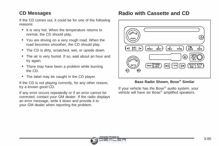
CD MessagesIf the CD comes out, it could be for one of the followingreasons:
• It is very hot. When the temperature returns tonormal, the CD should play.
• You are driving on a very rough road. When theroad becomes smoother, the CD should play.
• The CD is dirty, scratched, wet, or upside down.
• The air is very humid. If so, wait about an hour andtry again.
• There may have been a problem while burningthe CD.
• The label may be caught in the CD player.
If the CD is not playing correctly, for any other reason,try a known good CD.
If any error occurs repeatedly or if an error cannot becorrected, contact your GM dealer. If the radio displaysan error message, write it down and provide it toyour GM dealer when reporting the problem.
Radio with Cassette and CD
If your vehicle has the Bose® audio system, yourvehicle will have six Bose® amplified speakers.
Base Radio Shown, Bose ® Similar
3-85Information Provided by:

Radio Data System (RDS)The audio system has a Radio Data System (RDS).RDS features are available for use only on FM stationsthat broadcast RDS information.
With RDS, the radio can do the following:
• Seek to stations broadcasting the selected type ofprogramming
• Receive announcements concerning local andnational emergencies
• Display messages from radio stations
This system relies upon receiving specific informationfrom these stations and will only work when theinformation is available. In rare cases, a radio stationmay broadcast incorrect information that will causethe radio features to work improperly. If this happens,contact the radio station.
While the radio is tuned to an RDS station, the stationname or call letters will appear on the display instead ofthe frequency. RDS stations may also provide thetime of day, a program type (PTY) for currentprogramming, and the name of the program beingbroadcast.
XM™ Satellite Radio ServiceXM™ is a satellite radio service that is based in the48 contiguous United States and in Canada (if available).XM™ offers over 100 coast-to-coast channels includingmusic, news, sports, talk, and children’s programming.XM™ provides digital quality audio and text informationthat includes song title and artist name. A service fee isrequired in order to receive the XM™ service. For moreinformation, contact XM™ at www.xmradio.com or call1-800-852-XMXM (9696).
Playing the Radio
PWR (Power): Press this knob to turn the system onand off.
o VOL p (Volume): Turn this knob to increase or todecrease the volume.
INFO (Information): When the ignition is off, press thisknob to display the time.
For RDS, press the INFO knob to change what appearson the display while using RDS. The display optionsare station name, RDS station frequency, PTY, and thename of the program (if available).
3-86Information Provided by:

For XM™ (if equipped), press the INFO knob while inXM™ mode to retrieve four different categories ofinformation related to the current song or channel: Artist,Song Title, Category or PTY, Channel Number/ChannelName.
To change the default on the display, press the INFOknob until you see the display you want, then holdthe knob until the display flashes. The selected displaywill now be the default.
AUTO VOL (Automatic Volume): With automaticvolume, the audio system will adjust automatically tomake up for road and wind noise as you drive byincreasing the volume as vehicle speed increases.
Set the volume at the desired level. Press this button toselect LOW, MEDIUM, or HIGH. AVOL will appearon the display. Each higher setting will provide morevolume compensation at faster vehicle speeds. To turnautomatic volume off, press this button until AVOLOFF appears on the display.
Finding a Station
BAND: Press this button to switch between FM1, FM2,AM, or XM1 or XM2 (if equipped). The display willshow the selection.
o TUNE p: Turn this knob to select radio stations.
© SEEK ¨: Press either the SEEK or the TYPEarrows to go to the next or to the previous station andstay there.
The radio will only seek stations with a strong signalthat are in the selected band.
© SCAN ¨: Press and hold either the SCAN or theTYPE arrows for two seconds until SCAN appearson the display and you hear a beep. The radio will go toa station, play for a few seconds, then go on to thenext station. Press either the SCAN or the TYPE arrowsagain to stop scanning.
To scan preset stations, press and hold either theSCAN or the TYPE arrows for more than four seconds.PSCN will appear on the display and you will hear adouble beep. The radio will go to a preset station, playfor a few seconds, then go on to the next presetstation. Press either the SCAN or the TYPE arrowsagain to stop scanning presets.
The radio will only scan stations with a strong signalthat are in the selected band.
3-87Information Provided by:

Setting Preset StationsUp to 30 stations (six FM1, six FM2, and six AM,six XM1 and six XM2 (if equipped)), can be programedon the six numbered pushbuttons, by performing thefollowing steps:
1. Turn the radio on.
2. Press BAND to select FM1, FM2, AM, or XM1or XM2.
3. Tune in the desired station.
4. Press and hold one of the six numberedpushbuttons until you hear a beep. Whenever thatnumbered pushbutton is pressed, the stationthat was set will return for that pushbutton.
5. Repeat the steps for each pushbutton.
To store an equalization setting to a preset stationperform the following:
1. Tune to the preset station.
2. Press and release the AUTO EQ button to selectthe equalization setting.Once the equalization no longer appears on thedisplay, the equalization will be set for that presetstation.
Setting the Tone (Bass/Treble)
AUDIO: Push and release the AUDIO knob until BASSor TREB appears on the display. Turn the knob toincrease or to decrease. The display will show the bassor treble level. If a station is weak or noisy, decreasethe treble.
To adjust the bass or treble to the middle position whileit is displayed, push and hold the AUDIO knob. Theradio will produce one beep and adjust the display levelto the middle position.
To adjust all tone and speaker controls to the middleposition, push and hold the AUDIO knob when no toneor speaker control is displayed. ALL CENTERED willappear on the display, you will hear a beep, andthe display level will be adjusted to the middle position.
AUTO EQ (Automatic Equalization): Press thisbutton to select customized equalization settingsdesigned for country/western, jazz, talk, pop, rock, andclassical. Selecting CUSTOM or changing bass ortreble, returns the EQ to the manual bass and treblesettings.
The radio will save separate AUTO EQ settings for eachpreset and source.
If the radio is equipped with the Bose® audio system,the equalization settings are either CUSTOM or TALK.
3-88Information Provided by:

Adjusting the Speakers (Balance/Fade)
AUDIO: To adjust the balance between the rightand the left speakers, push and release the AUDIOknob until BAL appears on the display. Turn the knob tomove the sound toward the right or the left speakers.
To adjust the fade between the front and the rearspeakers, push and release the AUDIO knob until FADEappears on the display. Turn the knob to move thesound toward the front or the rear speakers.
To adjust the balance or fade to the middle positionwhile it is displayed, push the AUDIO knob, then push itagain and hold it until the radio produces one beep.The balance or fade will be adjusted to the middleposition.
To adjust all tone and speaker controls to the middleposition, push and hold the AUDIO knob when no toneor speaker control is displayed. ALL CENTERED willappear on the display, you will hear a beep, andthe display level will be adjusted to the middle position.
Finding a Program Type (PTY) Station(RDS and XM™)To select and find a desired PTY perform the following:
1. Press the TYPE button to activate program typeselect mode. TYPE and a PTY will appear on thedisplay.
2. Turn the TYPE knob or press and release theTYPE button to select a PTY.
3. Once the desired PTY is displayed, press andrelease either the TYPE or the SEEK arrows toselect and to take you to the PTY’s first station.
4. To go to another station within that PTY, press theTYPE button then, press either the TYPE or theSEEK arrows once.
5. Press either the TYPE or the SEEK arrows twice toexit program type select mode.
If the radio cannot find the desired program type, NONEwill appear on the display and the radio will return tothe last station you were listening to.
3-89Information Provided by:

SCAN: Scan the stations within a PTY by performingthe following:
1. Press the TYPE button to activate program typeselect mode. TYPE and the last selected PTY willappear on the display.
2. Turn the TYPE knob or press and release theTYPE button to select a PTY.
3. Once the desired PTY is displayed, press andhold either the TYPE or the SCAN arrows fortwo seconds, and the radio will begin scanningthe stations in the PTY.
4. Press either the TYPE or the SCAN arrows to stopat a station.
BAND (Alternate Frequency): Alternate frequencyallows the radio to switch to a stronger station with thesame program type. To turn alternate frequency on,press and hold BAND for two seconds. AF ON willappear on the display. The radio may switch to stationswith a stronger frequency.
To turn alternate frequency off, press and hold BANDagain for two seconds. AF OFF will appear on thedisplay. The radio will not switch to other stations.
This function does not apply for XM™ Satellite RadioService.
Setting Preset PTYs (RDS Only)These buttons have factory PTY presets. Up to 12 PTYs(six FM1 and six FM2), can be programmed on thesix numbered pushbuttons, by performing thefollowing steps:
1. Press BAND to select FM1 or FM2.
2. Press the TYPE button to activate program typeselect mode. TYPE and the last selected PTY willappear on the display.
3. Turn the TYPE knob or press and release theTYPE button to select a PTY.
4. Press and hold one of the six numberedpushbuttons until you hear a beep. Whenever thatnumbered pushbutton is pressed, while in PTYselect mode, the PTY that was set will return.
5. Repeat the steps for each pushbutton.
3-90Information Provided by:

RDS Messages
INFO (Information): If the current station has amessage, the information symbol will appear on thedisplay. Press this button to see the message. Themessage may display the artist, song title, call in phonenumbers, etc.
If the entire message is not displayed, parts of themessage will appear every three seconds. To scrollthrough the message, press and release the INFObutton. A new group of words will appear on the displayafter every press of the button. Once the completemessage has been displayed, the information symbolwill disappear from the display until another newmessage is received. The last message can bedisplayed by pressing the INFO button. You can viewthe last message until a new message is receivedor a different station is tuned to.
Radio Messages
CAL ERR (Calibration Error): The audio system hasbeen calibrated for your vehicle from the factory. IfCAL ERR appears on the display, it means that the radiohas not been configured properly for the vehicle andmust be returned to your GM dealer for service.
LOCKED: This message is displayed when theTHEFTLOCK® system has locked up. Take the vehicleto your GM dealer for service.
If any error occurs repeatedly, or if an error cannot becorrected, contact your GM dealer.
3-91Information Provided by:

XM™ Radio MessagesRadio Display
Message Condition Action Required
XL (Explicit LanguageChannels)
XL on the radio display,after the channel name,indicates content withexplicit language.
These channels, or any others, can be blocked at acustomer’s request, by calling 1-800-852-XMXM (9696).
Updating Updating encryption code The encryption code in the receiver is being updated, andno action is required. This process should take no longerthan 30 seconds.
No Signal Loss of signal The system is functioning correctly, but the vehicle is in alocation that is blocking the XM™ signal. When you moveinto an open area, the signal should return.
Loading XM Acquiring channel audio(after 4 second delay)
The audio system is acquiring and processing audio andtext data. No action is needed. This message shoulddisappear shortly.
CH Off Air Channel not in service This channel is not currently in service. Tune to anotherchannel.
CH Unavail Channel no longeravailable
This previously assigned channel is no longer assigned.Tune to another station. If this station was one of thepresets, choose another station for that preset button.
No Info Artist Name/Feature notavailable
No artist information is available at this time on thischannel. The system is working properly.
No Info Song/Program Title notavailable
No song title information is available at this time on thischannel. The system is working properly.
3-92Information Provided by:

XM™ Radio Messages (cont’d)Radio Display
Message Condition Action Required
No Info Category Name notavailable
No category information is available at this time on thischannel. The system is working properly.
No Info No Text/Informationalmessage available
No text or informational messages are available at thistime on this channel. The system is working properly.
Not Found No channel available forthe chosen category
There are no channels available for the selected category.The system is working properly.
XM Locked Theft lock active The XM™ receiver in the vehicle may have previouslybeen in another vehicle. For security purposes, XM™receivers cannot be swapped between vehicles. If thismessage is received after having your vehicle serviced,check with your GM dealer.
Radio ID Radio ID label (channel 0) If tuned to channel 0, this message will alternate with theXM™ Radio eight digit radio ID label. This label is neededto activate the service.
Unknown Radio ID not known(should only be ifhardware failure)
If this message is received when tuned to channel 0, theremay be a receiver fault. Consult with your GM dealer.
Chk XMRcvr Hardware failure If this message does not clear within a short period of time,the receiver may have a fault. Consult with your GMdealer.
3-93Information Provided by:

Playing a Cassette TapeThe tape player is built to work best with tapes that areup to 30 to 45 minutes long on each side. Tapeslonger than that are so thin they may not work well inthis player. The longer side with the tape visible shouldface to the right. If you hear nothing or hear a garbledsound, the tape may not be in squarely. Press the ejectbutton to remove the tape and start over.
If the ignition and radio are off, the tape can be inserted,but will not play until ignition and radio are on. If theignition is on and the radio is off, the tape can beinserted and will begin playing.
While the tape is playing, use the VOL, AUDIO, andSEEK controls just as you do for the radio. The cassettetape symbol will appear on the display and an arrowshowing which side of the tape is playing. The tapeplayer will play the other side of the tape when itreaches the end.
Cassette tape adapter kits for portable CD players willwork in the cassette tape player. See “CD Adapter Kits”later for more information.
The tape bias is set automatically when a metal orchrome tape is inserted.
If an error appears on the display, see “Cassette TapeMessages” later in this section.
1 PREV (Previous): The tape must have at leastthree seconds of silence between each selection forprevious to work. Press this pushbutton to go tothe previous selection on the tape if the current selectionhas been playing for less than three seconds. Ifpressed when the current selection has been playingfrom three to 13 seconds, it will go to the beginningof the previous selection or the beginning of the currentselection, depending on the position on the tape. Ifpressed when the current selection has been playing formore than 13 seconds, it will go to the beginning ofthe current selection.
SEEK and a negative number will appear on the displaywhile the cassette player is in the previous mode.Pressing this pushbutton multiple times will increase thenumber of selections to be searched back, up to −9.
2 NEXT: The tape must have at least three seconds ofsilence between each selection for next to work.Press this pushbutton to go to the next selection on thetape. Pressing this pushbutton multiple times, in nextmode, will increase the number of selections to besearched forward. SEEK and a positive numberwill appear on the display.
3-94Information Provided by:
3 REV (Reverse): Press this pushbutton to quicklyreverse the tape. The radio will play while the tapereverses. Press it again to return to playing speed. Thestation frequency and REV will appear on the display.Select stations during reverse operation by using TUNEand SEEK.4 FWD (Forward): Press this pushbutton to quicklyadvance the tape. The radio will play while thetape advances. Press this pushbutton again to return toplaying speed. The station frequency and FWD willappear on the display. Select stations during forwardoperation by using TUNE and SEEK.
5 X SIDE: Press this pushbutton to play the other sideof the tape.
© SEEK ¨: The right arrow is the same as theNEXT pushbutton, and the left arrow is the same as thePREV pushbutton. If either arrow is held or pressedmore than once, the player will continue moving forwardor backward through the tape. SEEK and a positiveor negative number will appear on the display.
© SCAN ¨: Press and hold either the SCAN or theTYPE arrows for more than two seconds until SCANappears on the display and you hear a beep. The radiowill go to the next selection, play for 10 seconds,then go on to the next selection. Press either the SCANor the TYPE arrows again, to stop scanning. Thetape must have at least three seconds of silencebetween each selection for scan to work.
BAND: Press this button to listen to the radio when acassette tape or CD is playing. The inactive tape or CDwill remain safely inside the radio for future listening.
TAPE DISC: Press this button to play a cassette tape orCD when listening to the radio. The inactive tape orCD will remain safely inside the radio for future listening.
Z (Eject): Press this button to stop and eject atape when it is playing or to eject a tape when it is notplaying. Eject may be activated with the radio off.
Cassette Tape Messages
CHK TAPE (Check Tape): If this message appears onthe display, the tape will not play due to one of thefollowing errors:
• The tape is tight and the player cannot turn thetape hubs. Remove the tape. Hold the tape withthe open end down and try to turn the righthub counterclockwise with a pencil. Turn the tapeover and repeat. If the hubs do not turn easily,the tape may be damaged and should not be usedin the player. Try a new tape to make sure yourplayer is working properly.
• The tape is broken. Try a new tape.
• The tape is wrapped around the tape head. Attemptto get the cassette out. Try a new tape.
3-95Information Provided by:

CLEAN: If this message appears on the display, thecassette tape player needs to be cleaned. It will still playtapes, but it should be cleaned as soon as possible toprevent damage to the tapes and player. See Careof the Cassette Tape Player on page 3-128.If the cassette tape is not playing correctly, for any otherreason, try a known good cassette.If any error occurs repeatedly or if an error cannot becorrected, contact your GM dealer. If the radio displaysan error message, write it down and provide it toyour GM dealer when reporting the problem.
CD Adapter KitsIt is possible to use a portable CD player with thecassette tape player after activating the bypass featureon your tape player.To activate the bypass feature, perform thefollowing steps:
1. Turn the ignition on.2. Turn the radio off.3. Press and hold the TAPE DISC button for five
seconds. READY will appear on the display andthe tape symbol on the display will flash, indicatingthe feature is active.
4. Insert the adapter into the cassette tape slot. It willpower up the radio and begin playing.
The override feature will remain active until the ejectbutton is pressed.
Playing a CDInsert a CD part way into the slot, label side up. Theplayer will pull it in and the CD should begin playing. Ifyou want to insert a CD with the ignition off, firstpress the eject button or the INFO knob.
If the ignition or radio is turned off with the CD in theplayer, it will stay in the player. When the ignitionor radio is turned on, the CD will start playing where itstopped, if it was the last selected audio source.
When a CD is inserted, the CD symbol will appear onthe display. As each new track starts to play, thetrack number will appear on the display.
The CD player can play the smaller 3 inch (8 cm) singleCDs with an adapter ring. Full-size CDs and thesmaller CDs are loaded in the same manner.
If playing a CD-R, the sound quality may be reduceddue to CD-R quality, the method of recording, the qualityof the music that has been recorded, and the way theCD-R has been handled. There may be an increasein skipping, difficulty in finding tracks, and/or difficulty inloading and ejecting. If these problems occur, checkthe bottom surface of the CD. If the surface of the CD isdamaged, such as cracked, broken, or scratched, theCD will not play properly. If the surface of the CDis soiled, see Care of Your CDs and DVDs onpage 3-129 for more information.
If there is no apparent damage, try a known good CD.
3-96Information Provided by:

Do not add any label to a CD, it could get caught in theCD player. If a CD is recorded on a personal computerand a description label is needed, try labeling the top ofthe recorded CD with a marking pen instead.
Notice: If you add any label to a CD, insert morethan one CD into the slot at a time, or attemptto play scratched or damaged CDs, you coulddamage the CD player. When using the CD player,use only CDs in good condition without anylabel, load one CD at a time, and keep the CD playerand the loading slot free of foreign materials,liquids, and debris.
If an error appears on the display, see “CD Messages”later in this section.
1 PREV (Previous): Press this pushbutton to go to thebeginning of the current track if more than eightseconds have played. TRACK and the track number willappear on the display. If this pushbutton is held orpressed more than once, the player will continue movingbackward through the CD.
2 NEXT: Press this pushbutton to go to the next track.TRACK and the track number will appear on thedisplay. If this pushbutton is held or pressed more thanonce, the player will continue moving forward throughthe CD.
3 REV (Reverse): Press and hold this pushbutton toquickly reverse within a track. Press and hold thispushbutton for less than two seconds to reverse atsix times the normal playing speed. Press and hold it formore than two seconds to reverse at 17 times thenormal playing speed. Release this pushbutton to playthe passage. ET and the elapsed time of the trackwill appear on the display.
4 FWD (Forward): Press and hold this pushbutton toquickly advance within a track. Press and hold thispushbutton for less than two seconds to advance atsix times the normal playing speed. Press and hold it formore than two seconds to advance at 17 times thenormal playing speed. Release this pushbutton to playthe passage. ET and the elapsed time of the trackwill appear on the display.
6 RDM (Random): Press this pushbutton to hear thetracks in random, rather than sequential, order. RDM ONwill appear on the display. RDM and the track numberwill appear on the display when each track starts to play.Press this pushbutton again to turn off random play.RDM OFF will appear on the display.
© SEEK ¨: Press the left arrow to go to the start ofthe current or to the previous track. Press the rightarrow to go to the start of the next track. If either arrowis pressed more than once, the player will continuemoving backward or forward through the CD.
3-97Information Provided by:

© SCAN ¨: Press and hold either the SCAN or theTYPE arrows for more than two seconds until SCANappears on the display and you hear a beep. The radiowill go to the next track, play for 10 seconds, then goon to the next track. Press either the SCAN or the TYPEarrows again, to stop scanning.
INFO (Information): Press this knob to see how longthe current track has been playing. ET and the elapsedtime will appear on the display. To change the defaulton the display, track or elapsed time, press theknob until you see the display you want, then press andhold the knob for two seconds. The radio will produceone beep and the selected display will now be thedefault.
BAND: Press this button to listen to the radio when acassette tape or CD is playing. The inactive tape or CDwill remain safely inside the radio for future listening.
TAPE DISC: Press this button to play a cassette tape orCD when listening to the radio. The inactive tape orCD will remain safely inside the radio for future listening.
Z (Eject): Press this button to stop and eject a CDwhen it is not playing. Eject may be activated with eitherthe ignition or radio off. CDs may be loaded with theradio and ignition off if this button is pressed first.
CD MessagesIf the CD comes out, it could be for one of the followingreasons:
• It is very hot. When the temperature returns tonormal, the CD should play.
• You are driving on a very rough road. When theroad becomes smoother, the CD should play.
• The CD is dirty, scratched, wet, or upside down.
• The air is very humid. If so, wait about an hour andtry again.
• There may have been a problem while burningthe CD.
• The label may be caught in the CD player.
If the CD is not playing correctly, for any other reason,try a known good CD.
If any error occurs repeatedly or if an error cannot becorrected, contact your GM dealer. If the radio displaysan error message, write it down and provide it toyour GM dealer when reporting the problem.
3-98Information Provided by:
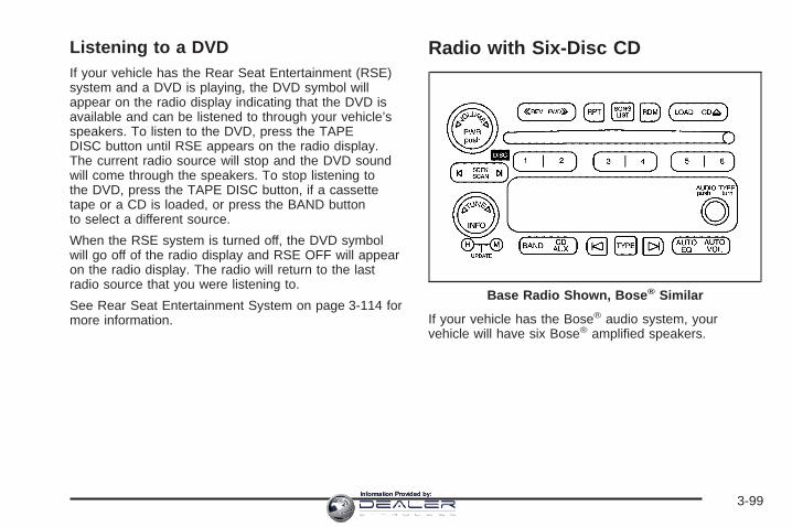
Listening to a DVDIf your vehicle has the Rear Seat Entertainment (RSE)system and a DVD is playing, the DVD symbol willappear on the radio display indicating that the DVD isavailable and can be listened to through your vehicle’sspeakers. To listen to the DVD, press the TAPEDISC button until RSE appears on the radio display.The current radio source will stop and the DVD soundwill come through the speakers. To stop listening tothe DVD, press the TAPE DISC button, if a cassettetape or a CD is loaded, or press the BAND buttonto select a different source.
When the RSE system is turned off, the DVD symbolwill go off of the radio display and RSE OFF will appearon the radio display. The radio will return to the lastradio source that you were listening to.
See Rear Seat Entertainment System on page 3-114 formore information.
Radio with Six-Disc CD
If your vehicle has the Bose® audio system, yourvehicle will have six Bose® amplified speakers.
Base Radio Shown, Bose ® Similar
3-99Information Provided by:

Radio Data System (RDS)The audio system has a Radio Data System (RDS).RDS features are available for use only on FM stationsthat broadcast RDS information.
With RDS, the radio can do the following:
• Seek to stations broadcasting the selected type ofprogramming
• Receive announcements concerning local andnational emergencies
• Display messages from radio stations
This system relies upon receiving specific informationfrom these stations and will only work when theinformation is available. In rare cases, a radio stationmay broadcast incorrect information that will causethe radio features to work improperly. If this happens,contact the radio station.
While the radio is tuned to an RDS station, the stationname or call letters will appear on the display instead ofthe frequency. RDS stations may also provide thetime of day, a program type (PTY) for currentprogramming, and the name of the program beingbroadcast.
XM™ Satellite Radio ServiceXM™ is a satellite radio service that is based in the48 contiguous United States and in Canada (if available).XM™ offers over 100 coast-to-coast channels includingmusic, news, sports, talk, and children’s programming.XM™ provides digital quality audio and text informationthat includes song title and artist name. A service fee isrequired in order to receive the XM™ service. For moreinformation, contact XM™ at www.xmradio.com or call1-800-852-XMXM (9696).
Playing the Radio
PWR (Power): Push this knob to turn the system onand off.
o VOLUME p: Turn this knob to increase or todecrease the volume.
INFO (Information): When the ignition is off, press thisknob to display the time.
For RDS, press the INFO knob to change what appearson the display while using RDS. The display optionsare station name, RDS station frequency, PTY, and thename of the program (if available).
3-100Information Provided by:

For XM™ (if equipped), press the INFO knob while inXM™ mode to retrieve four different categories ofinformation related to the current song or channel: Artist,Song Title, Category or PTY, ChannelNumber/Channel Name.
To change the default on the display, press the INFOknob until you see the display you want, then holdthe knob until you hear a beep. The selected display willnow be the default.
AUTO VOL (Automatic Volume): With automaticvolume, the audio system will adjust automatically tomake up for road and wind noise as you drive byincreasing the volume as vehicle speed increases.
Set the volume at the desired level. Press this button toselect MIN, MED, or MAX. AUTO VOL will appear onthe display. Each higher setting will provide morevolume compensation at faster vehicle speeds. To turnautomatic volume off, press this button until AUTOVOL OFF appears on the display.
Finding a Station
BAND: Press this button to switch between FM1, FM2,AM, or XM1 or XM2 (if equipped). The display willshow the selection.
o TUNE p: Turn this knob to select radio stations.
© SEEK ¨: Press either the SEEK or the TYPEarrows to go to the next or to the previous station andstay there.
The radio will only seek stations with a strong signalthat are in the selected band.
© SCAN ¨: Press and hold either the SCAN or theTYPE arrows for two seconds until SCN appears onthe display and you hear a beep. The radio will go to astation, play for a few seconds, then go on to thenext station. Press either the SCAN or the TYPE arrowsagain to stop scanning.
To scan preset stations, press and hold either theSCAN or the TYPE arrows for more than four seconds.PSC will appear on the display and you will hear adouble beep. The radio will go to a preset station, playfor a few seconds, then go on to the next presetstation. Press either the SCAN or the TYPE arrowsagain to stop scanning presets.
The radio will only scan stations with a strong signalthat are in the selected band.
3-101Information Provided by:

Setting Preset StationsUp to 30 stations (six FM1, six FM2, and six AM,six XM1 and six XM2 (if equipped)), can be programedon the six numbered pushbuttons, by performing thefollowing steps:
1. Turn the radio on.
2. Press BAND to select FM1, FM2, AM, or XM1or XM2.
3. Tune in the desired station.
4. Press and hold one of the six numberedpushbuttons until you hear a beep. Whenever thatnumbered pushbutton is pressed, the stationthat was set will return for that pushbutton.
5. Repeat the steps for each pushbutton.
To store an equalization setting to a preset stationperform the following:
1. Tune to the preset station.
2. Press and release the AUTO EQ button to selectthe equalization setting.Once the equalization no longer appears on thedisplay, the equalization will be set for that presetstation.
Setting the Tone (Bass/Treble)
AUDIO: Push and release the AUDIO knob until BASSor TREB appears on the display. Turn the knob toincrease or to decrease. The display will show the bassor treble level. If a station is weak or noisy, decreasethe treble.
To adjust the bass or treble to the middle position whileit is displayed, push and hold the AUDIO knob. Theradio will produce one beep and adjust the display levelto the middle position.
To adjust all tone and speaker controls to the middleposition, push and hold the AUDIO knob when no toneor speaker controls are displayed. ALL CENTEREDwill appear on the display and you will hear a beep.
AUTO EQ (Automatic Equalization): Press this buttonto select customized equalization settings designedfor country/western, jazz, talk, pop, rock, and classical.
The radio will save separate AUTO EQ settings foreach preset and source.
If the radio is equipped with the Bose® audio system,the equalization settings are either CUSTOM or TALK.
3-102Information Provided by:

Adjusting the Speakers (Balance/Fade)
AUDIO: To adjust the balance between the rightand the left speakers, push and release the AUDIOknob until BAL appears on the display. Turn the knob tomove the sound toward the right or the left speakers.
To adjust the fade between the front and rear speakers,push and release the AUDIO knob until FAD appearson the display. Turn the knob to move the sound towardthe front or the rear speakers.
To adjust the balance or fade to the middle positionwhile it is displayed, push and hold the AUDIO knob.The radio will produce one beep and adjust the displaylevel to the middle position.
To adjust all tone and speaker controls to the middleposition, push and hold the AUDIO knob when no toneor speaker controls are displayed. ALL CENTEREDwill appear on the display and you will hear a beep.
Finding a Program Type (PTY) Station(RDS and XM™)To select and find a desired PTY perform the following:
1. Press the TYPE button to activate program typeselect mode. P-TYPE and the last selected PTYwill appear on the display.
2. Turn the TYPE knob or press and release theTYPE button to select a PTY.
3. Once the desired PTY is displayed, press either theTYPE or the SEEK arrows to select and to take youto the PTY’s first station.
4. To go to another station within that PTY, press theTYPE button then, press either the TYPE or theSEEK arrows once. If the PTY is not displayed, goback to Step 1.
5. Press either the TYPE or the SEEK arrows twice toexit program type select mode.
3-103Information Provided by:
SCAN: Scan the stations within a PTY by performingthe following:
1. Press the TYPE button to activate program typeselect mode. P-TYPE and the last selected PTYwill appear on the display.
2. Turn the TYPE knob or press and release theTYPE button to select a PTY.
3. Once the desired PTY is displayed, press andhold either the TYPE or the SCAN arrows fortwo seconds, and the radio will begin scanningthe stations in the PTY.
4. Press either the TYPE or the SCAN arrows to stopscanning.
BAND (Alternate Frequency): Alternate frequencyallows the radio to switch to a stronger station with thesame program type. To turn alternate frequency on,press and hold BAND for two seconds. AF ON willappear on the display. The radio may switch to stationswith a stronger frequency.
To turn alternate frequency off, press and hold BANDagain for two seconds. AF OFF will appear on thedisplay. The radio will not switch to other stations.
This function does not apply for XM™ Satellite RadioService.
Setting Preset PTYs (RDS Only)These pushbuttons have factory PTY presets. Up to12 PTYs (six FM1 and six FM2), can be programmed onthe six numbered pushbuttons, by performing thefollowing steps:
1. Press BAND to select FM1 or FM2.
2. Press the TYPE button to activate program typeselect mode. P-TYPE and the last selected PTYwill appear on the display.
3. Turn the TYPE knob or press and release theTYPE button to select a PTY.
4. Press and hold one of the six numberedpushbuttons until you hear a beep. Whenever thatnumbered pushbutton is pressed, while in PTYmode, the PTY that was set will return.
5. Repeat the steps for each pushbutton.
3-104Information Provided by:
RDS Messages
INFO (Information): If the current station has amessage, INFO will appear on the display. Press thisbutton to see the message. The message may displaythe artist, song title, call in phone numbers, etc.
If the entire message is not displayed, parts of themessage will appear every three seconds. To scrollthrough the message, press and release the INFObutton. A new group of words will appear on the displayafter every press of this button. Once the completemessage has been displayed, INFO will disappear fromthe display until another new message is received.The last message can be displayed by pressingthe INFO button. You can view the last message until anew message is received or a different station istuned to.
Radio Messages
CAL ERR (Calibration Error): The audio system hasbeen calibrated for your vehicle from the factory. IfCAL ERR appears on the display, it means that the radiohas not been configured properly for the vehicle andmust be returned to your GM dealer for service.
LOCKED: This message is displayed when theTHEFTLOCK® system has locked up. Take the vehicleto your GM dealer for service.
If any error occurs repeatedly, or if an error cannot becorrected, contact your GM dealer.
3-105Information Provided by:

XM™ Radio MessagesRadio Display
Message Condition Action Required
XL (Explicit LanguageChannels)
XL on the radio display,after the channel name,indicates content withexplicit language.
These channels, or any others, can be blocked at acustomer’s request, by calling 1-800-852-XMXM (9696).
Updating Updating encryption code The encryption code in the receiver is being updated, andno action is required. This process should take no longerthan 30 seconds.
No Signal Loss of signal The system is functioning correctly, but the vehicle is in alocation that is blocking the XM™ signal. When you moveinto an open area, the signal should return.
Loading XM Acquiring channel audio(after 4 second delay)
The audio system is acquiring and processing audio andtext data. No action is needed. This message shoulddisappear shortly.
CH Off Air Channel not in service This channel is not currently in service. Tune to anotherchannel.
CH Unavail Channel no longeravailable
This previously assigned channel is no longer assigned.Tune to another station. If this station was one of thepresets, choose another station for that preset button.
No Info Artist Name/Feature notavailable
No artist information is available at this time on thischannel. The system is working properly.
No Info Song/Program Title notavailable
No song title information is available at this time on thischannel. The system is working properly.
3-106Information Provided by:

XM™ Radio Messages (cont’d)Radio Display
Message Condition Action Required
No Info Category Name notavailable
No category information is available at this time on thischannel. The system is working properly.
No Info No Text/Informationalmessage available
No text or informational messages are available at thistime on this channel. The system is working properly.
Not Found No channel available forthe chosen category
There are no channels available for the selected category.The system is working properly.
XM Locked Theft lock active The XM™ receiver in the vehicle may have previouslybeen in another vehicle. For security purposes, XM™receivers cannot be swapped between vehicles. If thismessage is received after having your vehicle serviced,check with your GM dealer.
Radio ID Radio ID label (channel 0) If tuned to channel 0, this message will alternate with theXM™ Radio eight digit radio ID label. This label is neededto activate the service.
Unknown Radio ID not known(should only be ifhardware failure)
If this message is received when tuned to channel 0, theremay be a receiver fault. Consult with your GM dealer.
Chk XMRcvr Hardware failure If this message does not clear within a short period of time,your receiver may have a fault. Consult with your GMdealer.
3-107Information Provided by:

Playing a CDIf the ignition or radio is turned off, with a CD in theplayer, it will stay in the player. When the ignitionor radio is turned on, the CD will start playing where itstopped, if it was the last selected audio source.
When a CD is inserted, the CD symbol will appear onthe display. As each new track starts to play, thetrack number will appear on the display.
The CD player can play the smaller 3 inch (8 cm) singleCDs with an adapter ring. Full-size CDs and thesmaller CDs are loaded in the same manner.
If playing a CD-R, the sound quality may be reduceddue to CD-R quality, the method of recording, the qualityof the music that has been recorded, and the way theCD-R has been handled. There may be an increasein skipping, difficulty in finding tracks, and/or difficulty inloading and ejecting. If these problems occur, checkthe bottom surface of the CD. If the surface of the CD isdamaged, such as cracked, broken, or scratched, theCD will not play properly. If the surface of the CDis soiled, see Care of Your CDs and DVDs onpage 3-129 for more information.
If there is no apparent damage, try a known good CD.
Do not add any label to a CD, it could get caught in theCD player. If a CD is recorded on a personal computerand a description label is needed, try labeling the top ofthe recorded CD with a marking pen instead.
Notice: If you add any label to a CD, insert morethan one CD into the slot at a time, or attemptto play scratched or damaged CDs, you coulddamage the CD player. When using the CD player,use only CDs in good condition without anylabel, load one CD at a time, and keep the CD playerand the loading slot free of foreign materials,liquids, and debris.
If an error appears on the display, see “CD Messages”later in this section.
LOAD: Press this button to load CDs into the CDplayer. This CD player will hold up to six CDs.
To insert one CD, do the following:
1. Turn the ignition on.
2. Press and release the LOAD button.
3. Wait for the indicator light, located to the right of theslot, to turn green.
4. Load a CD. Insert the CD part way into the slot,label side up. The player will pull the CD in.
3-108Information Provided by:

To insert multiple CDs, do the following:
1. Turn the ignition on.
2. Press and hold the LOAD button for two seconds.You will hear a beep and the indicator light, locatedto the right of the slot, will begin to flash andMULTI LOAD # will appear on the display.
3. Once the light stops flashing and turns green,INSERT CD # will appear on the display, loada CD. Insert the CD part way into the slot, label sideup. The player will pull the CD in.Once the CD is loaded, the indicator light will beginflashing again. Once the light stops flashing andturns green, you can load another CD. TheCD player takes up to six CDs. Do not try to loadmore than six.
To load more than one CD but less than six, completeSteps 1 through 3. When finished loading CDs,press the LOAD button to cancel the loading function.The radio will begin to play the last CD loaded.
If more than one CD has been loaded, a number foreach CD will appear on the display.
Playing a Specific Loaded CDFor every CD loaded, a number will appear on thedisplay. To play a specific CD, first press the CD AUXbutton, then press the numbered pushbutton thatcorresponds to the CD. A small bar will appear underthe CD number that is playing and the track number willappear on the display.
If an error appears on the display, see “CD Messages”later in this section.
CDZ (Eject): Press this button to eject CD(s).
To eject the CD that is currently playing, press andrelease this button.
To eject multiple CDs, do the following:
1. Press and hold the CD eject button for two seconds.You will hear a beep and the indicator light, locatedto the right of the slot, will begin to flash andEJECT ALL will appear on the display.
2. Once the light stops flashing, REMOVE CD # willappear on the display. The CD will eject and canbe removed.Once the CD is removed, the indicator light willbegin flashing again and another CD will eject.To stop ejecting the CDs, press the LOAD or theeject button.
3-109Information Provided by:
If the CD is not removed, after 25 seconds, the CD willbe automatically pulled back into the player. If CD ispushed back into the player, before the 25-second timeperiod is complete, the player will sense an errorand will try to eject the CD several times beforestopping.
Do not repeatedly press the CD eject button to eject aCD after you have tried to push it in manually. Theplayer’s 25-second eject timer will reset at each press ofeject, causing the player to not eject the CD until the25-second time period has elapsed.
{ REV (Reverse): Press and hold this button toreverse quickly within a track. You will hear sound at areduced volume. Release the button to play thepassage. The elapsed time of the track will appear onthe display.
FWD | (Forward): Press and hold this button toadvance quickly within a track. You will hear sound at areduced volume. Release the button to play thepassage. The elapsed time of the track will appear onthe display.
RPT (Repeat): With repeat, one track or an entire CDcan be repeated.
To use repeat, do the following:
• To repeat the track you are listening to, press andrelease the RPT button. RPT will appear on thedisplay. Press RPT again to turn off repeat play.
• To repeat the CD you are listening to, press andhold the RPT button for two seconds. RPT willappear on the display. Press RPT again to turn offrepeat play.
RDM (Random): With random, you can listen to thetracks in random, rather than sequential, order, on oneCD or on all of the CDs. To use random, do one ofthe following:
• To play the tracks on the CD you are listening to inrandom order, press and release the RDM button.RANDOM ONE will appear on the display. PressRDM again to turn off random play.
• To play the tracks on all of the CDs that are loadedin random order, press and hold RDM for morethan two seconds. You will hear a beep andRANDOM ALL will appear on the display. PressRDM again to turn off random play.
AUTO EQ (Automatic Equalization): Press AUTO EQto select the equalization setting while playing a CD.The equalization will be stored whenever a CD is played.For more information on AUTO EQ, see “AUTO EQ”listed previously in this section.
3-110Information Provided by:

©SEEK ¨: Press the left arrow to go to the start ofthe current track, if more than ten seconds have played.Press the right arrow to go to the next track. If eitherarrow is pressed more than once, the player willcontinue moving backward or forward through the CD.
©SCAN ¨: To scan one CD, press and holdeither SCAN arrow for more than two seconds untilTRACK SCAN appears on the display and you hear abeep. The radio will go to the next track, play for10 seconds, then go on to the next track. Press eitherSCAN arrow again, to stop scanning.
To scan all loaded CDs, press and hold either SCANarrow for more than four seconds until ALL CDSCAN appears on the display and you hear a beep.Use this feature to listen to 10 seconds of the first trackof each loaded CD. Press either SCAN arrow again,to stop scanning.
INFO (Information): Press this knob to see how longthe current track has been playing. To change thedefault on the display, track or elapsed time, press theknob until you see the display you want, then pressand hold the knob until you hear a beep. The selecteddisplay will now be the default.
BAND: Press this button to listen to the radio when aCD is playing. The inactive CD(s) will remain safelyinside the radio for future listening.
CD AUX (Auxiliary): Press this button to play a CDwhen listening to the radio. Inactive CD(s) will remainsafely inside the radio for future listening.
Using Song List ModeThe six-disc CD changer has a feature called song list.This feature is capable of saving 20 track selections.
To save tracks into the song list feature, performthe following steps:
1. Turn the CD player on and load it with at least oneCD. See “LOAD CD” listed previously in this sectionfor more information.
2. Check to see that the CD changer is not in song listmode. S-LIST should not appear on the display. IfS-LIST is present, press the SONG LIST buttonto turn it off.
3. Select the desired CD by pressing the numberedpushbutton and then use the SEEK or TYPE rightarrow to locate the track to be saved. The track willbegin to play.
4. Press and hold the SONG LIST button to save thetrack into memory. When SONG LIST is pressed,one beep will be heard immediately. After twoseconds of continuously pressing the SONG LISTbutton, two beeps will sound to confirm thetrack has been saved.
5. Repeat Steps 3 and 4 for saving other selections.
3-111Information Provided by:
S-LIST FULL will appear on the display if you try tosave more than 20 selections.
To play the song list, press the SONG LIST button.One beep will be heard and S-LIST will appear on thedisplay. The recorded tracks will begin to play inthe order they were saved.
Seek through the song list by using the SEEK or TYPEarrows. Seeking past the last saved track will returnto the first saved track.
To delete tracks from the song list, perform thefollowing steps:
1. Turn the CD player on.
2. Press the SONG LIST button to turn song list on.S-LIST will appear on the display.
3. Press either SEEK or TYPE arrow to select thedesired track to be deleted.
4. Press and hold the SONG LIST button fortwo seconds. When SONG LIST is pressed,one beep will be heard immediately. Aftertwo seconds of continuously pressing the SONGLIST button, two beeps will be heard to confirm thatthe track has been deleted.
After a track has been deleted, the remaining tracks aremoved up the list. When another track is added to thesong list, the track will be added to the end of the list.
To delete the entire song list, perform the following steps:
1. Turn the CD player on.
2. Press the SONG LIST button to turn song list on.S-LIST will appear on the display.
3. Press and hold the SONG LIST button for morethan four seconds. One beep will be heard,followed by two beeps after two seconds, and afinal beep will be heard after four seconds. S-LISTEMPTY will appear on the display indicating thesong list has been deleted.
If a CD is ejected, and the song list contains savedtracks from that CD, those tracks are automaticallydeleted from the song list. Any tracks saved to the songlist again are added to the bottom of the list.
To end song list mode, press the SONG LIST button.One beep will be heard and S-LIST will be removed fromthe display.
3-112Information Provided by:

CD Messages
CHECK CD: If this message appears on the displayand/or the CD comes out, it could be for one of thefollowing reasons:
• It is very hot. When the temperature returns tonormal, the CD should play.
• You are driving on a very rough road. When theroad becomes smoother, the CD should play.
• The CD is dirty, scratched, wet, or upside down.
• The air is very humid. If so, wait about an hour andtry again.
• There may have been a problem while burningthe CD.
• The label may be caught in the CD player.
If the CD is not playing correctly, for any other reason,try a known good CD.
If any error occurs repeatedly or if an error cannot becorrected, contact your GM dealer. If the radio displaysan error message, write it down and provide it toyour GM dealer when reporting the problem.
Listening to a DVDIf your vehicle has the Rear Seat Entertainment (RSE)system and a DVD is playing, the DVD symbol willappear on the radio display indicating that the DVD isavailable and can be listened to through your vehicle’sspeakers.
To listen to the DVD, press the CD AUX button untilRSE appears on the radio display. The currentradio source will stop and the DVD sound will comethrough the speakers.
To stop listening to the DVD, press the CD AUX button,if a CD is loaded, or press the BAND button to selecta different source.
When the RSE system is turned off, the DVD symbolwill go off of the radio display and RSE OFF will appearon the radio display. The radio will return to the lastradio source that you were listening to.
See Rear Seat Entertainment System on page 3-114 formore information.
3-113Information Provided by:
Rear Seat Entertainment SystemYour vehicle may have a DVD Rear Seat Entertainment(RSE) system. The RSE system includes a DVDplayer, a video display screen, two sets of wirelessheadphones, and a remote control.
Parental ControlThis button is located behind the video screen. Pressthis button while a DVD or CD is playing to freezethe video and mute the audio. The video screen willdisplay Parental Control ON and the power indicatorlight on the DVD player will flash. It will also disable allother button operations from the remote control andthe DVD player, with the exception of the eject button.Press this button again to restore operation of theDVD player.
This button may also be used to turn the DVD playerpower on and automatically resume play if the ignition isin RUN, ACCESSORY, or if RAP is active.
Before You DriveThe RSE system is for rear seat passengers only. Thedriver cannot safely view the video screen whiledriving and should not try to do so.
HeadphonesThe RSE system includes two sets of wirelessheadphones.
Each set of headphones has an ON/OFF control. Anindicator light will illuminate on the headphoneswhen they are on. If the light does not illuminate, thebatteries may need to be replaced. See “BatteryReplacement” following for more information.
Each set of headphones has a volume knob. To adjustthe volume, adjust this knob.
The transmitters are located below the video displayscreen. The headphones will shut off automaticallyif they lose the signal from the system after about fourminutes to save battery power. The signal may be lost ifthe system is turned off or if the headphones are outof range of the transmitters.
When using the wired headphones, if the front seatpassengers play a CD in the Radio with Six-Disc CD(if equipped) or use XM™ Satellite Radio Service(if equipped), you will hear the audio for these sources,instead of the DVD or CD that is currently playingthrough the RSE.
Notice: Do not store the headphones in heat ordirect sunlight. This could damage the headphonesand repairs will not be covered by your warranty.Keep the headphones stored in a cool, dry place.
3-114Information Provided by:

Both sets of rear seat headphones may include foamear pads that can be replaced.
Foam ear pads on these headphones may becomeworn or damaged. The headphone foam ear pads canbecome damaged if they are not handled or storedproperly. If the foam ear pads do become damaged orworn out, the pads can be replaced separately fromthe headphone set. It is not necessary to replacethe complete headphone set.
The headphone replacement foam ear pads can beordered in pairs. See your dealer for more information.
Battery ReplacementTo change the batteries, do the following:
1. Loosen the screw on the battery compartment doorlocated on the left side of the headphone earpiece.
2. Replace the two AAA batteries in the compartment.Make sure that they are installed correctly, usingthe diagram on the inside of the batterycompartment.
3. Tighten the screw to close the compartment door.
If the headphones are to be stored for a long periodof time, remove the batteries and keep them in a cool,dry place.
Stereo RCA JacksThe RCA jacks are located behind the video screen.The RCA jacks allow audio and video signals tobe connected from an auxiliary device such as acamcorder or a video game unit to the RSE system.Standard RCA cables, not included, are neededto connect the auxiliary device to the RCA jacks. Theyellow connector inputs video and the red and whiteconnectors input right and left audio. Refer to themanufacturer’s instructions for proper connection of theauxiliary device.
To use the auxiliary inputs on the RSE system, connectan external auxiliary device to the color-coded RCAjacks and turn both the auxiliary device and theRSE system power on. If the RSE system had beenpreviously in the DVD player mode, pressing the SRCEbutton on the faceplate or the remote control willswitch the RSE system between the auxiliary deviceand the DVD player.
3-115Information Provided by:

How to Change the Video Format when inthe Auxiliary ModeThe auxiliary input video format is preset to NTSC. Insome countries, the video format may be in thePAL system. To change the video format, perform thefollowing:
1. Press the display menu button.
2. Press the down arrow button to highlight the VideoFormat option.
3. Press the enter button to select Video Format.
4. Press the right or left arrow button to selectthe desired video format.
5. Press the enter button to accept the change.
Audio OutputAudio from the DVD player or auxiliary inputs may beheard through the following possible sources:
• Wireless Headphones
• Vehicle Speakers
• Vehicle wired headphone jacks on the Rear SeatAudio system (if equipped)
The RSE system will always transmit the audio signalby infrared to the wireless headphones, if there is audioavailable. See “Headphones” previously for moreinformation.
The RSE system is capable of outputting audio to thevehicle speakers by using the radio. The RSEsystem may be selected as an audio source on theradio if the RSE system power is on. Once theRSE system is selected as an audio source on theradio, adjust the speaker volume on the radio, ifnecessary. If the RSE system power is not on, the RSEsystem will not be an available source on the radio.Refer to the radio information for the radio thatyour vehicle has for more information.
The RSE system is capable of outputting audio to thewired headphone jacks on the rear seat audio system(if equipped). The RSE system may be selected asan audio source on the rear seat audio system ifthe RSE system power is on. Refer to Rear Seat Audio(RSA) on page 3-125 for more information.
3-116Information Provided by:

Video ScreenThe video screen is located in the overhead console. Touse the video screen, push forward on the releaselatch and the screen will fold down. Adjust the screen’sposition as desired. When the video screen is not inuse, push it up into its latched position.
The DVD player and display will continue to operatewhen the screen is in the up or the down position. Thevideo screen contains the transmitters for the wirelessheadphones and the remote control. If the screenis in the closed position, the signals will not be availablefor the operation of the headphones or the remotecontrol.
Notice: Avoid directly touching the video screen,as damage may occur. See “Cleaning the VideoScreen” later in this section for more information.
DVD PlayerThe DVD player is located in the overhead console. TheDVD player can be controlled by the buttons on theDVD player and/or by the buttons on the remote control.See “Remote Control” later in this section for moreinformation.
The DVD player power may be turned on when theignition is in RUN, ACCESSORY, or when RetainedAccessory Power (RAP) is active.
The RSE system DVD player is only compatible withDVDs of the appropriate region code for the country thatthe vehicle was sold in. The DVD region code isprinted on the jacket of most DVDs.
Standard audio CDs, CD-R, CD-RW, Video CD andPhoto CD/CD-R media are fully supported by this DVDplayer. DVD-R and DVD-RW media is supported ifformatted as DVD-Video. DVD+R and DVD+RW mediamay or may not be supported by the DVD player.The DVD player does not support DVD-RAM,DVD-ROM, and DVD Audio media. An error messagewill appear on the display if this type of media is insertedinto the DVD player.
When using the wired headphones, not included, if thefront seat passengers play a CD in the Radio withSix-Disc CD (if equipped) or use XM™ Satellite RadioService (if equipped), you will hear the audio forthese sources, instead of the DVD or CD that is currentlyplaying through the RSE.
If an error message appears on the video screen, see“DVD Messages” later in this section.
3-117Information Provided by:
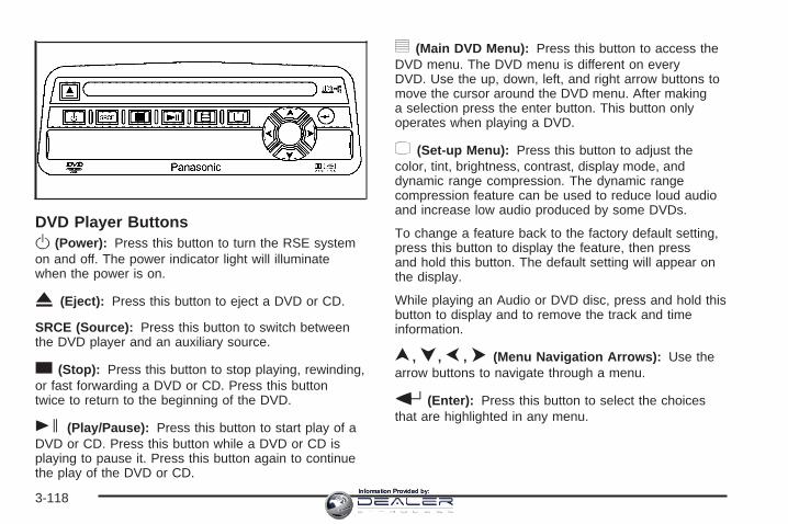
DVD Player ButtonsO(Power): Press this button to turn the RSE systemon and off. The power indicator light will illuminatewhen the power is on.
X (Eject): Press this button to eject a DVD or CD.
SRCE (Source): Press this button to switch betweenthe DVD player and an auxiliary source.
c(Stop): Press this button to stop playing, rewinding,or fast forwarding a DVD or CD. Press this buttontwice to return to the beginning of the DVD.
s (Play/Pause): Press this button to start play of aDVD or CD. Press this button while a DVD or CD isplaying to pause it. Press this button again to continuethe play of the DVD or CD.
y (Main DVD Menu): Press this button to access theDVD menu. The DVD menu is different on everyDVD. Use the up, down, left, and right arrow buttons tomove the cursor around the DVD menu. After makinga selection press the enter button. This button onlyoperates when playing a DVD.
z (Set-up Menu): Press this button to adjust thecolor, tint, brightness, contrast, display mode, anddynamic range compression. The dynamic rangecompression feature can be used to reduce loud audioand increase low audio produced by some DVDs.
To change a feature back to the factory default setting,press this button to display the feature, then pressand hold this button. The default setting will appear onthe display.
While playing an Audio or DVD disc, press and hold thisbutton to display and to remove the track and timeinformation.
n, q, p, o (Menu Navigation Arrows): Use thearrow buttons to navigate through a menu.
r (Enter): Press this button to select the choicesthat are highlighted in any menu.
3-118Information Provided by:

Playing a DiscTo play a disc, gently insert the disc with the label sideup into the loading slot. The DVD player will continueloading the disc and the player will automatically start, ifthe vehicle is in RUN, ACCESSORY, or when RAP isactive.
If a disc is already in the player, press the play/pausebutton on the DVD player faceplate or on the remotecontrol.
Some DVDs will not allow fast forwarding or skipping ofthe copyright information or the previews. SomeDVDs will begin playing after the previews have finished.If the DVD does not begin to play the main title, referto the on-screen instructions.
Stopping and Resuming PlaybackTo stop playing a disc, press and release the stopbutton on the DVD player faceplate or the remotecontrol.
To resume playback, press the play/pause button onthe DVD player faceplate or the remote control.The movie should resume play from where it was laststopped, if the disc has not been ejected and thestop button has not been pressed twice. If the disc hasbeen ejected or if the stop button has been pressedtwice, the disc will resume play at the beginning.
Ejecting a DiscPress the eject button on the DVD player faceplate toeject the disc. There is not an eject button on the remotecontrol.
If a disc is ejected from the player, but is not removed,the DVD player will reload the disc after a shortperiod of time. The disc will be stored in the DVD player.The DVD player will not resume play of the discautomatically.
Remote ControlTo use the remote control, aim it at the transmitterwindow below the video screen and press the desiredbutton. Direct sunlight or very bright light may affect theability of the RSE system to receive signals from theremote control. If the remote control does not seem tobe working, the batteries may need to be replaced.See “Battery Replacement” later in this section.
Objects blocking the line of sight may also affect thefunction of the remote control.
Notice: Storing the remote control in a hot area orin direct sunlight may damage it, and the repairswill not be covered by your warranty. Keep theremote control stored in a cool, dry place.
To extend the life of the batteries, the remote controldoes not have a press and hold feature.
3-119Information Provided by:

Remote Control Buttons
O (Power): Press this button to turn the DVD playeron and off.
v (Title): Press this button to return the DVD to themain menu of the DVD.
n, q, p, o (Menu Navigation Arrows): Use thearrow buttons to navigate through a menu.
z (Set-up Menu): Press this button to adjust thecolor, tint, brightness, contrast, display mode, anddynamic range compression. The dynamic rangecompression feature can be used to reduce loud audioand increase low audio produced by some DVDs.
e (Audio): Press this button to display a menu thatwill only appear when a DVD is being played. The formatand content of this function will vary for each disc.
r (Fast Reverse): Press this button to fast reversethe DVD or CD. To stop fast reversing, press this buttonagain. This button may not work when the DVD isplaying the copyright information or the previews.
SRCE (Source): Press this button to switch betweenthe DVD player and an auxiliary source.
c (Stop): Press this button to stop playing, rewinding,or fast forwarding a DVD or CD. Press this buttontwice to return to the beginning of the DVD.
t (Previous Track/Chapter): Press this button toreturn to the start of the current track or chapter. Pressthis button again to return to the previous track orchapter. This button may not work when the DVD isplaying the copyright information or the previews.
3-120Information Provided by:

1 through 0 (Numeric Keypad): The numeric keypadprovides you with the capability of direct chapter,title, and track number selection.
}10 (Double Digit Entries): Press this button toselect chapter, title, and track numbers greater than 9.Press this button before inputting the number.
\ (Clear): Press this button within three seconds afterinputting a number to clear the number(s).
P (Illumination): Press this button to turn the remotecontrol backlight on. The backlight will time out afterabout 7 to 10 seconds if no other button is pressed whilethe backlight is on.
y (Main DVD Menu): Press this button to access theDVD menu. The DVD menu is different on everyDVD. Use the up, down, left, and right arrow buttons tomove the cursor around the DVD menu. After makinga selection press the enter button. This button onlyoperates when playing a DVD.
r (Enter): Press this button to select the choicesthat are highlighted in any menu.
q (Return): Press this button to exit the currentactive menu and return to the previous menu. Thisbutton will operate only when a DVD is playing and amenu is active.
| (Camera Angle): Press this button to changecamera angles on DVDs that have this feature when aDVD is playing. The format and content of thisfunction will vary for each disc.
{ (Subtitle): Press this button to turn on subtitles andto move through subtitle options when a DVD isplaying. The format and content of this function will varyfor each disc.
[ (Fast Forward): Press this button to fast forwardthe DVD or CD. To stop fast forwarding, press thisbutton again. This button may not work when the DVDis playing the copyright information or the previews.
s (Play/Pause): Press this button to start play of aDVD or CD. Press this button while a DVD or CD isplaying to pause it. Press this button again to continuethe play of the DVD or CD.
When the DVD is playing, press the pause button thenpress the fast forward button. The DVD will continueplaying in a slow play mode. To cancel slow play mode,press the play/pause button.
u (Next Track/Chapter): Press this button to advanceto the beginning of the next track or chapter. Thisbutton may not work when the DVD is playing thecopyright information or the previews.
3-121Information Provided by:

Battery ReplacementTo change the batteries, do the following:
1. Remove the battery compartment door located onthe bottom of the remote control.
2. Replace the two AA batteries in the compartment.Make sure that they are installed correctly, usingthe diagram on the inside of the batterycompartment.
3. Close the battery door securely.
If the remote control is to be stored for a long period oftime, remove the batteries and keep them in a cool,dry place.
Problem Recommended ActionNo power. The ignition might not be
in on or accessory.The parental controlbutton might have beenturned on. The powerindicator light will flash.
Disc will not play. The system might be off.The parental controlbutton might have beenturned on. The powerindicator light will flash.The system might be inauxiliary mode.The disc is upside downor is not compatible.
The picture does not fillthe screen. There areblack borders on the topand bottom or on bothsides or it looksstretched out.
Check the display modesettings in thedisplay menu.
The disc was ejected, butit was pulled back into theDVD player.
The disc is being stored inthe DVD player. Press theeject button again to ejectthe disc.
3-122Information Provided by:
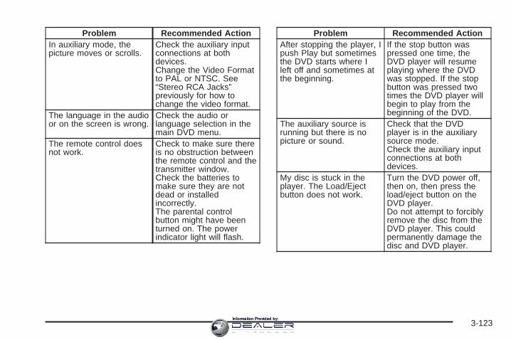
Problem Recommended ActionIn auxiliary mode, thepicture moves or scrolls.
Check the auxiliary inputconnections at bothdevices.Change the Video Formatto PAL or NTSC. See“Stereo RCA Jacks”previously for how tochange the video format.
The language in the audioor on the screen is wrong.
Check the audio orlanguage selection in themain DVD menu.
The remote control doesnot work.
Check to make sure thereis no obstruction betweenthe remote control and thetransmitter window.Check the batteries tomake sure they are notdead or installedincorrectly.The parental controlbutton might have beenturned on. The powerindicator light will flash.
Problem Recommended ActionAfter stopping the player, Ipush Play but sometimesthe DVD starts where Ileft off and sometimes atthe beginning.
If the stop button waspressed one time, theDVD player will resumeplaying where the DVDwas stopped. If the stopbutton was pressed twotimes the DVD player willbegin to play from thebeginning of the DVD.
The auxiliary source isrunning but there is nopicture or sound.
Check that the DVDplayer is in the auxiliarysource mode.Check the auxiliary inputconnections at bothdevices.
My disc is stuck in theplayer. The Load/Ejectbutton does not work.
Turn the DVD power off,then on, then press theload/eject button on theDVD player.Do not attempt to forciblyremove the disc from theDVD player. This couldpermanently damage thedisc and DVD player.
3-123Information Provided by:

Problem Recommended ActionSometimes the wirelessheadphone audio cuts outor buzzes.
Check for obstructions,low batteries, receptionrange, and interferencefrom cellular telephonetowers or by using yourcellular telephone in thevehicle.Check that theheadphones are facingthe front of the vehicle.
I lost the remote and/orthe headphones.
See your dealer forassistance.
The DVD is playing, butthere is no picture orsound.
Check that the DVDplayer is in DVD mode.
The audio/video skipsor jumps.
The DVD or CD could bedirty, scratched, ordamaged.
The audio from the radiofor the Radio withSix-Disc CD and XM™has taken over the audiofrom the DVD or CD whenusing the wiredheadphones.
The RSE is workingcorrectly.Use the wirelessheadphones or have thefront seat passengerslisten to another audiosource.
DVD MessagesThe following errors may be displayed on the videoscreen:
Disc Format Error: This message will be displayed if adisc is inserted upside down, if the disc is not readable,or if the format is not compatible with the DVD player.
Load/Eject Error: This message will be displayed if thedisc is not properly loaded or ejected.
Disc Play Error: This message will be displayed if theDVD player cannot play the disc. Scratched ordamaged discs will cause this error.
Region Code Error: This message will be displayed ifthe region code of the DVD is not compatible withthe region code of the DVD player.
No Disc: This message will be displayed if any of thebuttons on the DVD faceplate or remote control arepressed and no disc is present in the DVD player.
DVD DistortionThere may be an experience with audio distortion in thewireless headphones when operating cellular phones,scanners, CB radios, Global Positioning Systems(GPS)*, two-way radios, mobile fax, or walkie talkies.It may be necessary to turn off the DVD player whenoperating one of these devices in or near the vehicle.
* Excludes the OnStar® System.
3-124Information Provided by:

Cleaning the Video ScreenPour some isopropyl or rubbing alcohol on a clean clothand gently wipe the video screen. Do not spraydirectly onto the screen and do not press too hard ortoo long on the video screen.
Rear Seat Audio (RSA)This feature allows rear seat passengers to listen to anyof the sources: radio, cassette tapes, CDs, or DVDs.However, the rear seat passengers can only control thesources that the front seat passengers are notlistening to. For example, rear seat passengers maylisten to and control cassette tapes, CDs, or DVDsthrough the headphones while the driver listens to theradio through the front speakers. The rear seatpassengers have control of the volume for each set ofheadphones.
The front seat audio controls always have priority overthe RSA controls. If the front seat passengers switch thesource for the main radio to a remote source, the RSA willnot be able to control the source. You can operate therear seat audio when the main radio is off.
P (Power): Press this button to turn the system on oroff. The rear speakers will be muted when the poweris turned on unless your vehicle is equipped withthe Bose® audio system.
u (Volume): Turn this knob to increase or todecrease the volume. The left knob controls the leftheadphones and the right knob controls the rightheadphones.
SRC (Source): Press this button to select a source:radio, cassette tapes, CDs, or DVDs.
3-125Information Provided by:

x SEEK w: When listening to FM1, FM2, or AM,press the up or the down arrow to go to the next or to theprevious station and stay there. This function is inactive ifthe front seat passengers are listening to the radio.
When a cassette tape is playing, press the up or thedown arrow to go to the next or the previous selection.This function is inactive if the front seat passengers arelistening to a cassette tape.
When a CD is playing, press the up arrow to go to thenext track on the CD. Press the down arrow to go to thestart of the current track if more than eight seconds haveplayed. This function is inactive if the front seatpassengers are listening to a CD.
PROG (Program): Press this button to go to the nextpreset radio station set on the pushbuttons on themain radio. This function is inactive if the front seatpassengers are listening to the radio.
When a cassette tape is playing, press this button to go tothe other side of the tape. This function is inactive if thefront seat passengers are listening to a cassette tape.
When a CD is playing, press this button to go to thebeginning of the CD. This function is inactive if the frontseat passengers are listening to a CD.
When a CD is playing in the six-disc CD changer, pressthis button to select the next CD, if multiple CDs areloaded. This function is inactive if the front seatpassengers are listening to a CD.
Theft-Deterrent FeatureTHEFTLOCK® is designed to discourage theft of yourvehicle’s radio. The feature works automatically bylearning a portion of the Vehicle Identification Number(VIN). If the radio is moved to a different vehicle, itwill not operate and LOCKED will appear on the display.
When the radio and vehicle are turned off, the blinkingred light indicates that THEFTLOCK® is armed.
With THEFTLOCK® activated, the radio will not operateif stolen.
3-126Information Provided by:

Audio Steering Wheel Controls
If your vehicle has this feature, some audio controls canbe adjusted at the steering wheel. They include thefollowing:
g (OnStar ®/Mute): If your vehicle has OnStar, pressthis button to interact with the OnStar system. Seethe OnStar® System on page 2-69 in this manual formore information.
If your vehicle does not have OnStar, press this buttonto silence the system. Press it again, or any otherradio button, to turn on the sound.
PROG (Program): Press this button to play a stationyou have programmed on the radio preset pushbuttons.The radio will only seek preset stations with a strongsignal that are in the selected band.
When a cassette tape is playing, press this button toplay the other side of the tape.
When a CD is playing in the CD changer, press thisbutton to go to the next available CD, if multiple CDs areloaded.
Q SOURCE R: Press this button to switch betweenFM1, FM2, AM, or XM1 or XM2 (if equipped), or acassette tape or CD. The cassette or CD must be loadedto play. Available loaded sources are shown on thedisplay as a tape or a CD symbol.
Q SEEK R: Press the up or the down arrow to go tothe next or to the previous radio station and staythere. The radio will only seek stations with a strongsignal that are in the selected band.
When a cassette tape or CD is playing, press the up orthe down arrow to fast forward or reverse.
Q VOLR (Volume): Press the up or the down arrowto increase or to decrease the volume.
3-127Information Provided by:

Radio ReceptionYou may experience frequency interference and staticduring normal radio reception if items such as cellphonechargers, vehicle convenience accessories, andexternal electronic devices are plugged into theaccessory power outlet. If there is interference or static,unplug the item from the accessory power outlet.
AMThe range for most AM stations is greater than for FM,especially at night. The longer range can causestation frequencies to interfere with each other. Forbetter radio reception, most AM radio stations will boostthe power levels during the day, and then reducethese levels during the night. Static can also occur whenthings like storms and power lines interfere with radioreception. When this happens, try reducing the treble onyour radio.
FM StereoFM stereo will give the best sound, but FM signals willreach only about 10 to 40 miles (16 to 65 km). Tallbuildings or hills can interfere with FM signals, causingthe sound to fade in and out.
XM™ Satellite Radio ServiceXM™ Satellite Radio Service gives digital radioreception from coast-to-coast in the 48 contiguousUnited States, and in Canada (if available). Just as withFM, tall buildings or hills can interfere with satelliteradio signals, causing the sound to fade in and out. Inaddition, traveling or standing under heavy foliage,bridges, garages, or tunnels may cause loss of the XM™signal for a period of time. The radio may display NOSIGNAL to indicate interference.
Care of the Cassette Tape PlayerA tape player that is not cleaned regularly can causereduced sound quality, ruined cassettes, or a damagedmechanism. Cassette tapes should be stored in theircases away from contaminants, direct sunlight, andextreme heat. If they are not, they may not operateproperly or may cause failure of the tape player.
The tape player should be cleaned regularly after every50 hours of use. The radio may display CLEAN toindicate that the tape player has been used for 50 hourswithout resetting the tape clean timer. If this messageappears on the display, the cassette tape playerneeds to be cleaned. It will still play tapes, but it shouldbe cleaned as soon as possible to prevent damageto the tapes and player.
3-128Information Provided by:

If there is a reduction in sound quality, try a known goodcassette to see if the tape or the tape player is atfault. If this other cassette has no improvement in soundquality, clean the tape player.
For best results, use a scrubbing action, non-abrasivecleaning cassette with pads which scrub the tapehead as the hubs of the cleaner cassette turn. Therecommended cleaning cassette is available throughyour dealer.
When cleaning the cassette tape player with therecommended non-abrasive cleaning cassette, it ispossible that the cassette may eject, because the cuttape detection feature on the radio may recognize it as abroken tape, in error. To prevent the cleaning cassettefrom being ejected, use the following steps:
1. Turn the ignition on.
2. Turn the radio off.
3. Press and hold the TAPE DISC button for fiveseconds. READY will appear on the display andthe cassette symbol will flash for five seconds.
4. Insert the scrubbing action cleaning cassette.
5. Eject the cleaning cassette after the manufacturer’srecommended cleaning time.When the cleaning cassette has been ejected, thecut tape detection feature will be active again.
A non-scrubbing action, wet-type cleaner which uses acassette with a fabric belt to clean the tape headcan be used. This type of cleaning cassette will noteject on its own. A non-scrubbing action cleaner may notclean as thoroughly as the scrubbing type cleaner.The use of a non-scrubbing action, dry-type cleaningcassette is not recommended.
After the player is cleaned, press and hold the ejectbutton for five seconds to reset the CLEAN indicator.The radio will display --- or CLEANED to show theindicator was reset.
Cassettes are subject to wear and the sound quality maydegrade over time. Always make sure the cassette tapeis in good condition before the tape player is serviced.
Care of Your CDs and DVDsHandle CDs carefully. Store them in their original casesor other protective cases and away from directsunlight and dust. The CD player scans the bottomsurface of the disc. If the surface of a CD is damaged,such as cracked, broken, or scratched, the CD willnot play properly or not at all. If the surface of a CD issoiled, take a soft, lint free cloth or dampen a clean, softcloth in a mild, neutral detergent solution mixed withwater, and clean it. Make sure the wiping process startsfrom the center to the edge.
3-129Information Provided by:

Do not touch the bottom side of a CD while handling it;this could damage the surface. Pick up CDs bygrasping the outer edges or the edge of the hole andthe outer edge.
Care of the CD and DVD PlayerThe use of CD lens cleaners for CDs is not advised,due to the risk of contaminating the lens of the CD opticswith lubricants internal to the CD mechanism.
Fixed Mast AntennaThe fixed mast antenna can withstand most car washeswithout being damaged. If the mast should everbecome slightly bent, straighten it out by hand. If themast is badly bent, replace it.
Check occasionally to make sure the mast is stilltightened to the cowl. If tightening is required, tighten byhand, then with a wrench one quarter turn.
XM™ Satellite Radio AntennaSystemThe XM™ Satellite Radio antenna is located on the roofof your vehicle. Keep this antenna clear of snow andice build up for clear radio reception.
If your vehicle has a sunroof, the performance of theXM™ system may be affected if the sunroof is open.
Loading items onto the roof of your vehicle can interferewith the performance of the XM™ system. Make surethe XM™ Satellite Radio antenna is not obstructed.
Chime Level AdjustmentThe radio is used to adjust the vehicle’s chime level. Tochange the volume level of the chime, press andhold pushbutton 6 with the ignition on and the radiopower off. The volume level will change from the normallevel to loud, and LOUD will appear on the radiodisplay. To change back to the default or normal setting,press and hold pushbutton 6 again. The volume levelwill change from the loud level to normal, and NORMALwill appear on the radio display. Each time the chimevolume is changed, three chimes will sound as anexample of the new volume selected. Removing theradio and not replacing it with a factory radio or chimemodule will disable vehicle chimes.
3-130Information Provided by:

Your Driving, the Road, and Your Vehicle ..........4-2Defensive Driving ...........................................4-2Drunken Driving .............................................4-3Control of a Vehicle ........................................4-6Braking .........................................................4-6Anti-Lock Brake System (ABS) .........................4-7Braking in Emergencies ...................................4-9Traction Assist System (TAS) ...........................4-9Manual Selectable Ride .................................4-11Locking Rear Axle ........................................4-12Steering ......................................................4-12Off-Road Recovery .......................................4-14Passing .......................................................4-15Loss of Control .............................................4-16Off-Road Driving ...........................................4-17Driving at Night ............................................4-33Driving in Rain and on Wet Roads ..................4-34City Driving ..................................................4-37Freeway Driving ...........................................4-38
Before Leaving on a Long Trip .......................4-39Highway Hypnosis ........................................4-40Hill and Mountain Roads ................................4-40Winter Driving ..............................................4-42If Your Vehicle is Stuck in Sand, Mud,
Ice or Snow ..............................................4-46Rocking Your Vehicle to Get It Out .................4-46Recovery Hooks (Except SS Model) ..................4-47Loading Your Vehicle ....................................4-48Adding a Snow Plow or Similar Equipment .......4-54Truck-Camper Loading Information ..................4-59Pickup Conversion to Chassis Cab ..................4-61
Towing ..........................................................4-61Towing Your Vehicle .....................................4-61Recreational Vehicle Towing ...........................4-62Towing a Trailer ...........................................4-67Trailer Recommendations ...............................4-95Power Take-Off (PTO) ...................................4-95
Section 4 Driving Your Vehicle
4-1Information Provided by:

Your Driving, the Road, andYour Vehicle
Defensive DrivingThe best advice anyone can give about driving is: Drivedefensively.
Please start with a very important safety device in yourvehicle: Buckle up. See Safety Belts: They Are forEveryone on page 1-12.
{CAUTION:
Defensive driving really means “Be ready foranything.” On city streets, rural roads, orexpressways, it means “Always expect theunexpected.” Assume that pedestrians or otherdrivers are going to be careless and makemistakes. Anticipate what they might do andbe ready. Rear-end collisions are about themost preventable of accidents. Yet they arecommon. Allow enough following distance.Defensive driving requires that a driverconcentrate on the driving task. Anything thatdistracts from the driving task makes properdefensive driving more difficult and can evencause a collision, with resulting injury. Ask apassenger to help do these things, or pull offthe road in a safe place to do them. Thesesimple defensive driving techniques couldsave your life.
4-2Information Provided by:

Drunken DrivingDeath and injury associated with drinking and driving isa national tragedy. It is the number one contributorto the highway death toll, claiming thousands of victimsevery year.
Alcohol affects four things that anyone needs to drive avehicle:
• Judgment
• Muscular Coordination
• Vision
• Attentiveness
Police records show that almost half of all motorvehicle-related deaths involve alcohol. In most cases,these deaths are the result of someone who wasdrinking and driving. In recent years, more than16,000 annual motor vehicle-related deaths have beenassociated with the use of alcohol, with more than300,000 people injured.
Many adults — by some estimates, nearly half the adultpopulation — choose never to drink alcohol, so theynever drive after drinking. For persons under 21,it is against the law in every U.S. state to drink alcohol.There are good medical, psychological, anddevelopmental reasons for these laws.
The obvious way to eliminate the leading highwaysafety problem is for people never to drink alcohol andthen drive. But what if people do? How much is “toomuch” if someone plans to drive? It is a lot lessthan many might think. Although it depends on eachperson and situation, here is some general informationon the problem.
The Blood Alcohol Concentration (BAC) of someonewho is drinking depends upon four things:
• The amount of alcohol consumed
• The drinker’s body weight
• The amount of food that is consumed before andduring drinking
• The length of time it has taken the drinker toconsume the alcohol
4-3Information Provided by:

According to the American Medical Association, a 180 lb(82 kg) person who drinks three 12 ounce (355 ml)bottles of beer in an hour will end up with a BACof about 0.06 percent. The person would reach thesame BAC by drinking three 4 ounce (120 ml) glassesof wine or three mixed drinks if each had 1-1/2 ounces(45 ml) of liquors like whiskey, gin, or vodka.
It is the amount of alcohol that counts. For example, ifthe same person drank three double martinis (3 ouncesor 90 ml of liquor each) within an hour, the person’sBAC would be close to 0.12 percent. A personwho consumes food just before or during drinking willhave a somewhat lower BAC level.
There is a gender difference, too. Women generallyhave a lower relative percentage of body waterthan men. Since alcohol is carried in body water, thismeans that a woman generally will reach a higher BAClevel than a man of her same body weight will wheneach has the same number of drinks.
The law in most U.S. states, and throughout Canada,sets the legal limit at 0.08 percent. In some othercountries, the limit is even lower. For example, it is0.05 percent in both France and Germany. TheBAC limit for all commercial drivers in the United Statesis 0.04 percent.
The BAC will be over 0.10 percent after three tosix drinks (in one hour). Of course, as we have seen, itdepends on how much alcohol is in the drinks, andhow quickly the person drinks them.
4-4Information Provided by:

But the ability to drive is affected well below a BAC of0.10 percent. Research shows that the driving skillsof many people are impaired at a BAC approaching0.05 percent, and that the effects are worse at night. Alldrivers are impaired at BAC levels above 0.05 percent.Statistics show that the chance of being in a collisionincreases sharply for drivers who have a BAC of0.05 percent or above. A driver with a BAC level of0.06 percent has doubled his or her chance of having acollision. At a BAC level of 0.10 percent, the chanceof this driver having a collision is 12 times greater; at alevel of 0.15 percent, the chance is 25 times greater!
The body takes about an hour to rid itself of the alcoholin one drink. No amount of coffee or number of coldshowers will speed that up. “I will be careful” is not theright answer. What if there is an emergency, a needto take sudden action, as when a child darts intothe street? A person with even a moderate BAC mightnot be able to react quickly enough to avoid thecollision.
There is something else about drinking and driving thatmany people do not know. Medical research showsthat alcohol in a person’s system can make crashinjuries worse, especially injuries to the brain, spinalcord, or heart. This means that when anyone who hasbeen drinking — driver or passenger — is in a crash,that person’s chance of being killed or permanentlydisabled is higher than if the person had not beendrinking.
{CAUTION:
Drinking and then driving is very dangerous.Your reflexes, perceptions, attentiveness, andjudgment can be affected by even a smallamount of alcohol. You can have a serious — oreven fatal — collision if you drive after drinking.Please do not drink and drive or ride with adriver who has been drinking. Ride home in acab; or if you are with a group, designate adriver who will not drink.
4-5Information Provided by:

Control of a VehicleYou have three systems that make your vehicle gowhere you want it to go. They are the brakes, thesteering, and the accelerator. All three systems have todo their work at the places where the tires meetthe road.
Sometimes, as when you are driving on snow or ice, itis easy to ask more of those control systems thanthe tires and road can provide. That means you can losecontrol of your vehicle. See Traction Assist System(TAS) on page 4-9.
Adding non-GM accessories can affect your vehicle’sperformance. See Accessories and Modificationson page 5-4.
BrakingSee Brake System Warning Light on page 3-41.
Braking action involves perception time andreaction time.
First, you have to decide to push on the brake pedal.That is perception time. Then you have to bring up yourfoot and do it. That is reaction time.
Average reaction time is about three-fourths of asecond. But that is only an average. It might be lesswith one driver and as long as two or three seconds ormore with another. Age, physical condition, alertness,coordination, and eyesight all play a part. So do alcohol,drugs, and frustration. But even in three-fourths of asecond, a vehicle moving at 60 mph (100 km/h) travels66 feet (20 m). That could be a lot of distance in anemergency, so keeping enough space betweenyour vehicle and others is important.
And, of course, actual stopping distances vary greatlywith the surface of the road, whether it is pavementor gravel; the condition of the road, whether it iswet, dry, or icy; tire tread; the condition of your brakes;the weight of the vehicle; and the amount of brakeforce applied.
4-6Information Provided by:

Avoid needless heavy braking. Some people drive inspurts — heavy acceleration followed by heavybraking — rather than keeping pace with traffic. This isa mistake. Your brakes may not have time to coolbetween hard stops. Your brakes will wear out muchfaster if you do a lot of heavy braking. If you keep pacewith the traffic and allow realistic following distances,you will eliminate a lot of unnecessary braking.That means better braking and longer brake life.
If your engine ever stops while you are driving, brakenormally but do not pump your brakes. If you do,the pedal may get harder to push down. If your enginestops, you will still have some power brake assist.But you will use it when you brake. Once the powerassist is used up, it may take longer to stop andthe brake pedal will be harder to push.
Adding non-GM accessories can affect your vehicle’sperformance. See Accessories and Modificationson page 5-4.
Anti-Lock Brake System (ABS)Your vehicle has anti-lock brakes. ABS is an advancedelectronic braking system that will help prevent abraking skid.
When you start your engine and begin to drive away,your anti-lock brake system will check itself. Youmay hear a momentary motor or clicking noise whilethis test is going on. This is normal.
If there is a problem withthe anti-lock brake system,this warning light willstay on. See Anti-LockBrake System WarningLight on page 3-42.
Along with ABS, your vehicle has a Dynamic RearProportioning (DRP) system. If there is a DRP problem,both the brake and ABS warning lights will come onaccompanied by a 10-second chime. The lightsand chime will come on each time the ignition is turnedon until the problem is repaired. See your dealer forservice.
4-7Information Provided by:

Let us say the road is wet and you are driving safely.Suddenly, an animal jumps out in front of you. You slamon the brakes and continue braking. Here is whathappens with ABS:
A computer senses that wheels are slowing down. Ifone of the wheels is about to stop rolling, the computerwill separately work the brakes at each front wheeland at both rear wheels.
The anti-lock system can change the brake pressurefaster than any driver could. The computer isprogrammed to make the most of available tire and roadconditions. This can help you steer around the obstaclewhile braking hard.
As you brake, your computer keeps receiving updateson wheel speed and controls braking pressureaccordingly.
4-8Information Provided by:

Remember: Anti-lock does not change the time youneed to get your foot up to the brake pedal or alwaysdecrease stopping distance. If you get too close tothe vehicle in front of you, you will not have time to applyyour brakes if that vehicle suddenly slows or stops.Always leave enough room up ahead to stop, eventhough you have anti-lock brakes.
Using Anti-LockDo not pump the brakes. Just hold the brake pedaldown firmly and let anti-lock work for you. You may feelthe brakes vibrate, or you may notice some noise,but this is normal.
Braking in EmergenciesWith anti-lock brakes, you can steer and brake at thesame time. In many emergencies, steering can help youmore than even the very best braking.
Traction Assist System (TAS)Your vehicle may have a Traction Assist System (TAS)that limits wheel spin. This is especially useful inslippery road conditions. The system operates only if itsenses that one or both of the rear wheels arespinning or beginning to lose traction. When thishappens, the system reduces engine power to limitwheel spin.
The traction control system is enabled every time yourvehicle is started. The system will activate if it sensesthat any of the wheels are spinning or beginning to losetraction.
You may hear or feel the system working or notice alack of accelerator response, but this is normal.
The Traction Assist System may operate on dry roadsunder some conditions. When this happens, youmay notice a reduction in acceleration. This is normaland doesn’t mean there’s a problem with your vehicle.Examples of these conditions include a hardacceleration in a turn, an abrupt upshift or downshift ofthe transmission or driving on rough roads.
If your vehicle is in cruise control when the TAS beginsto limit wheel spin, the cruise control will automaticallydisengage. When road conditions allow you to safelyuse it again, you may re-engage the cruise control. SeeCruise Control on page 3-10.
When the traction off lightis on, the TAS is off andwill not limit wheelspin. Adjust your drivingaccordingly.
4-9Information Provided by:

The traction off light will come on under the followingconditions:
• The Traction Assist System is turned off, either bypressing the TAS on/off button, located on theinstrument panel, or by turning off the automaticengagement feature of the TAS.
• The transmission is in FIRST (1); TAS will notoperate in this gear. This is normal.
• The vehicle is driven on an extremely rough road.When the vehicle leaves the rough surface, slowsdown or stops, the light will go off and TAS will turnon again. This is normal.
• A Traction Assist System, Anti-Lock Brake Systemor engine-related problem has been detected andthe vehicle needs service.
• If the vehicle has been driven with the TAS systemon for long periods of time, or if the vehicle hasgone through many several high speed brakingmaneuvers the system may be automaticallydisabled. The system will automatically re-enableafter approximately two minutes of not usingthe brakes.
See Traction Off Light on page 3-42.
The Traction Assist System, as delivered from thefactory, will automatically come on whenever you startyour vehicle. To limit wheel spin, especially inslippery road conditions, you should always leave thesystem on. But you can turn the TAS off if you ever needto. You should turn the TAS off if your vehicle evergets stuck in sand, mud or snow and rocking the vehicleis required. See Rocking Your Vehicle to Get It Outon page 4-46 and If Your Vehicle is Stuck in Sand, Mud,Ice or Snow on page 4-46.
To turn the system on oroff, press the TAS on/offbutton located on theinstrument panel.
If you used the button to turn the system off, the tractionoff light will come on and stay on. You can turn thesystem back on at any time by pressing the buttonagain. The traction off light should go off.
Adding non-GM accessories can affect your vehicle’sperformance. See Accessories and Modificationson page 5-4 for more information.
4-10Information Provided by:
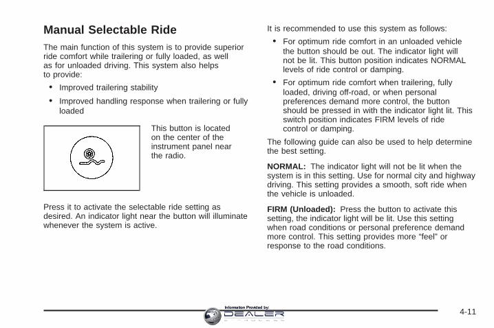
Manual Selectable RideThe main function of this system is to provide superiorride comfort while trailering or fully loaded, as wellas for unloaded driving. This system also helpsto provide:
• Improved trailering stability
• Improved handling response when trailering or fullyloaded
This button is locatedon the center of theinstrument panel nearthe radio.
Press it to activate the selectable ride setting asdesired. An indicator light near the button will illuminatewhenever the system is active.
It is recommended to use this system as follows:
• For optimum ride comfort in an unloaded vehiclethe button should be out. The indicator light willnot be lit. This button position indicates NORMALlevels of ride control or damping.
• For optimum ride comfort when trailering, fullyloaded, driving off-road, or when personalpreferences demand more control, the buttonshould be pressed in with the indicator light lit. Thisswitch position indicates FIRM levels of ridecontrol or damping.
The following guide can also be used to help determinethe best setting.
NORMAL: The indicator light will not be lit when thesystem is in this setting. Use for normal city and highwaydriving. This setting provides a smooth, soft ride whenthe vehicle is unloaded.
FIRM (Unloaded): Press the button to activate thissetting, the indicator light will be lit. Use this settingwhen road conditions or personal preference demandmore control. This setting provides more “feel” orresponse to the road conditions.
4-11Information Provided by:

FIRM (Loaded): Press the button to activate thissetting, the indicator light will be lit. Use this setting tominimize trailer inputs to the vehicle or when the vehicleis fully loaded. This setting is also appropriate foroff-road driving.
You can select a setting at any time based on road andtrailering conditions to provide the best ride andhandling. Select a new setting whenever drivingconditions change.
Locking Rear AxleIf your vehicle has this feature, your locking rear axlecan give you additional traction on snow, mud, ice, sandor gravel. It works like a standard axle most of thetime, but when one of the rear wheels has no tractionand the other does, this feature will allow the wheel withtraction to move the vehicle.
Steering
Power SteeringIf you lose power steering assist because the enginestops or the system is not functioning, you can steer butit will take much more effort.
Steering TipsIt is important to take curves at a reasonable speed.
A lot of the “driver lost control” accidents mentioned onthe news happen on curves. Here is why:
Experienced driver or beginner, each of us is subject tothe same laws of physics when driving on curves.The traction of the tires against the road surface makesit possible for the vehicle to change its path whenyou turn the front wheels. If there is no traction, inertiawill keep the vehicle going in the same direction. Ifyou have ever tried to steer a vehicle on wet ice, youwill understand this.
The traction you can get in a curve depends on thecondition of your tires and the road surface, the angle atwhich the curve is banked, and your speed. Whileyou are in a curve, speed is the one factor youcan control.
4-12Information Provided by:

Suppose you are steering through a sharp curve.Then you suddenly accelerate. Both controlsystems — steering and acceleration — have to dotheir work where the tires meet the road. Addingthe sudden acceleration can demand too much of thoseplaces. You can lose control. See Traction AssistSystem (TAS) on page 4-9.
What should you do if this ever happens? Ease up onthe accelerator pedal, steer the vehicle the way youwant it to go, and slow down.
Speed limit signs near curves warn that you shouldadjust your speed. Of course, the posted speedsare based on good weather and road conditions. Underless favorable conditions you will want to go slower.
If you need to reduce your speed as you approacha curve, do it before you enter the curve, while your frontwheels are straight ahead.
Try to adjust your speed so you can “drive” through thecurve. Maintain a reasonable, steady speed. Wait toaccelerate until you are out of the curve, and thenaccelerate gently into the straightaway.
Adding non-GM accessories can affect your vehicle’sperformance. See Accessories and Modificationson page 5-4.
Steering in EmergenciesThere are times when steering can be more effectivethan braking. For example, you come over a hill and finda truck stopped in your lane, or a car suddenly pullsout from nowhere, or a child darts out from betweenparked cars and stops right in front of you. Youcan avoid these problems by braking — if you can stopin time. But sometimes you cannot; there is not room.That is the time for evasive action — steering around theproblem.
Your vehicle can perform very well in emergencies likethese. First apply your brakes.
See Braking on page 4-6. It is better to remove as muchspeed as you can from a possible collision. Thensteer around the problem, to the left or right dependingon the space available.
4-13Information Provided by:

An emergency like this requires close attention and aquick decision. If you are holding the steering wheel atthe recommended 9 and 3 o’clock positions, youcan turn it a full 180 degrees very quickly withoutremoving either hand. But you have to act fast, steerquickly, and just as quickly straighten the wheelonce you have avoided the object.
The fact that such emergency situations are alwayspossible is a good reason to practice defensive drivingat all times and wear safety belts properly.
Off-Road RecoveryYou may find that your right wheels have dropped offthe edge of a road onto the shoulder while you aredriving.
If the level of the shoulder is only slightly below thepavement, recovery should be fairly easy. Ease off theaccelerator and then, if there is nothing in the way,steer so that your vehicle straddles the edge ofthe pavement. You can turn the steering wheel up toone-quarter turn until the right front tire contactsthe pavement edge. Then turn your steering wheel to gostraight down the roadway.
4-14Information Provided by:

PassingThe driver of a vehicle about to pass another on atwo-lane highway waits for just the right moment,accelerates, moves around the vehicle ahead, thengoes back into the right lane again. A simple maneuver?
Not necessarily! Passing another vehicle on a two-lanehighway is a potentially dangerous move, since thepassing vehicle occupies the same lane as oncomingtraffic for several seconds. A miscalculation, an error injudgment, or a brief surrender to frustration or angercan suddenly put the passing driver face to face with theworst of all traffic accidents — the head-on collision.
So here are some tips for passing:
• Drive ahead. Look down the road, to the sides andto crossroads for situations that might affect yourpassing patterns. If you have any doubt whatsoeverabout making a successful pass, wait for abetter time.
• Watch for traffic signs, pavement markings andlines. If you can see a sign up ahead that mightindicate a turn or an intersection, delay your pass.A broken center line usually indicates it is allright to pass, providing the road ahead is clear.Never cross a solid line on your side of the lane ora double solid line, even if the road seems emptyof approaching traffic.
• Do not get too close to the vehicle you want to passwhile you are awaiting an opportunity. For one thing,following too closely reduces your area of vision,especially if you are following a larger vehicle. Also,you will not have adequate space if the vehicleahead suddenly slows or stops. Keep back areasonable distance.
• When it looks like a chance to pass is coming up,start to accelerate but stay in the right lane and donot get too close. Time your move so you will beincreasing speed as the time comes to move into theother lane. If the way is clear to pass, you will have arunning start that more than makes up for thedistance you would lose by dropping back. And ifsomething happens to cause you to cancel yourpass, you need only slow down and drop back againand wait for another opportunity.
• If other vehicles are lined up to pass a slow vehicle,wait your turn. But take care that someone is nottrying to pass you as you pull out to pass the slowvehicle. Remember to glance over your shoulder andcheck the blind spot.
4-15Information Provided by:

• Check your mirrors, glance over your shoulder andstart your left lane change signal before moving outof the right lane to pass. When you are far enoughahead of the passed vehicle to see its front in yourinside mirror, activate your right lane change signaland move back into the right lane. Remember that ifyour passenger side outside mirror is convex, thevehicle you just passed may seem to be farther awayfrom you than it really is.
• Try not to pass more than one vehicle at a time ontwo-lane roads. Reconsider before passing the nextvehicle.
• Do not overtake a slowly moving vehicle too rapidly.Even though the brake lamps are not flashing, it maybe slowing down or starting to turn.
• If you are being passed, make it easy for thefollowing driver to get ahead of you. Perhaps you canease a little to the right.
Loss of ControlLet us review what driving experts say about whathappens when the three control systems — brakes,steering, and acceleration — do not have enough frictionwhere the tires meet the road to do what the driverhas asked.
In any emergency, do not give up. Keep trying to steerand constantly seek an escape route or area of lessdanger.
SkiddingIn a skid, a driver can lose control of the vehicle.Defensive drivers avoid most skids by taking reasonablecare suited to existing conditions, and by not overdrivingthose conditions. But skids are always possible.
The three types of skids correspond to your vehicle’sthree control systems. In the braking skid, your wheelsare not rolling. In the steering or cornering skid, too muchspeed or steering in a curve causes tires to slip and losecornering force. And in the acceleration skid, too muchthrottle causes the driving wheels to spin.
A cornering skid is best handled by easing your foot offthe accelerator pedal.
4-16Information Provided by:

If you have the Traction Assist System (TAS),remember: It helps avoid only the acceleration skid. SeeTraction Assist System (TAS) on page 4-9. If you donot have this system, or if the system is off, thenan acceleration skid is also best handled by easing yourfoot off the accelerator pedal.
If your vehicle starts to slide, ease your foot off theaccelerator pedal and quickly steer the way you wantthe vehicle to go. If you start steering quickly enough,your vehicle may straighten out. Always be readyfor a second skid if it occurs.
Of course, traction is reduced when water, snow, ice,gravel, or other material is on the road. For safety, youwill want to slow down and adjust your driving tothese conditions. It is important to slow down on slipperysurfaces because stopping distance will be longer andvehicle control more limited.
While driving on a surface with reduced traction, tryyour best to avoid sudden steering, acceleration,or braking, including engine braking by shifting to alower gear. Any sudden changes could cause the tiresto slide. You may not realize the surface is slipperyuntil your vehicle is skidding. Learn to recognize warningclues — such as enough water, ice, or packed snowon the road to make a mirrored surface — andslow down when you have any doubt.
Remember: Any Anti-Lock Brake System (ABS) helpsavoid only the braking skid.
Off-Road DrivingThis off-road guide is for vehicles that have four-wheeldrive. Also, see Braking on page 4-6. If your vehicleis an SS Model or does not have four-wheel drive, youshould not drive off-road unless you are on a level,solid surface. If your vehicle is equipped with 20-inchtire/wheel assemblies, do not use your vehicle foroff-road driving. See Tires on page 5-73.
Off-road driving can be great fun. But it does havesome definite hazards. The greatest of these isthe terrain itself.
“Off-roading” means you have left the great NorthAmerican road system behind. Traffic lanes are notmarked. Curves are not banked. There are noroad signs. Surfaces can be slippery, rough, uphill ordownhill. In short, you have gone right back to nature.
Off-road driving involves some new skills. And thatis why it is very important that you read this guide. Youwill find many driving tips and suggestions. Thesewill help make your off-road driving safer and moreenjoyable.
4-17Information Provided by:

If you think you will need some more ground clearanceat the front of your vehicle, you can remove the frontbumper lower air dam.
The front bumper lower air dam is held in place by aseries of push-pins located around the lower edge of thefront bumper. The push-pins are accessible fromunderneath the front bumper. The following steps mustbe performed on each of the push-pins to removethe air dam:
1. Insert a tool into thepush-pin slot and pulldownward until thepush-pin snaps loose.
4-18Information Provided by:

2. While continuing to pulldownward on thepush-pin, squeeze andturn the expandableend of the push-pinwith a tool until itreleases from theretainer.
3. Pull the push-pins andlower dam assemblyaway from the retainersuntil the lower damis free.
When you are back on roads, though, be sure toreplace the air dam.
Notice: Operating your vehicle for extendedperiods without the front bumper lower air daminstalled can cause improper air flow to the engineand may allow things like fog lamps or tow hookson the front of your vehicle to be damaged. Alwaysbe sure to replace the front bumper air dam whenyou are finished off-road driving.
4-19Information Provided by:
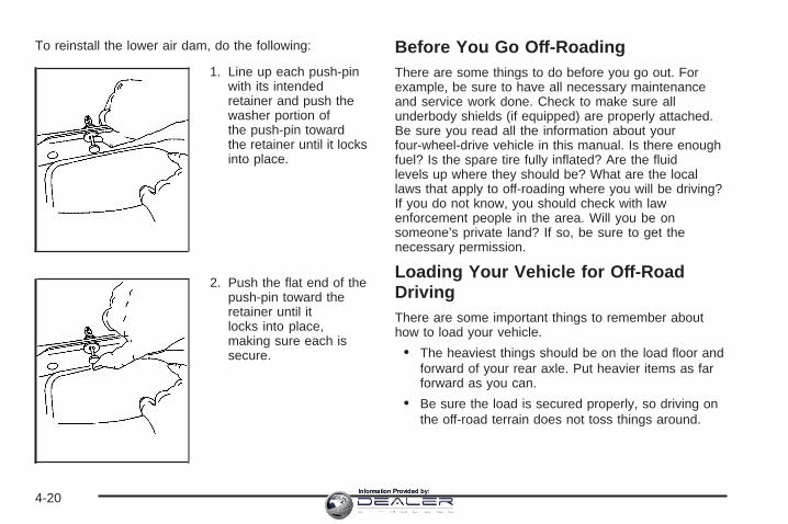
To reinstall the lower air dam, do the following:
1. Line up each push-pinwith its intendedretainer and push thewasher portion ofthe push-pin towardthe retainer until it locksinto place.
2. Push the flat end of thepush-pin toward theretainer until itlocks into place,making sure each issecure.
Before You Go Off-RoadingThere are some things to do before you go out. Forexample, be sure to have all necessary maintenanceand service work done. Check to make sure allunderbody shields (if equipped) are properly attached.Be sure you read all the information about yourfour-wheel-drive vehicle in this manual. Is there enoughfuel? Is the spare tire fully inflated? Are the fluidlevels up where they should be? What are the locallaws that apply to off-roading where you will be driving?If you do not know, you should check with lawenforcement people in the area. Will you be onsomeone’s private land? If so, be sure to get thenecessary permission.
Loading Your Vehicle for Off-RoadDrivingThere are some important things to remember abouthow to load your vehicle.
• The heaviest things should be on the load floor andforward of your rear axle. Put heavier items as farforward as you can.
• Be sure the load is secured properly, so driving onthe off-road terrain does not toss things around.
4-20Information Provided by:

{CAUTION:
• Cargo on the load floor piled higher thanthe seatbacks can be thrown forwardduring a sudden stop. You or yourpassengers could be injured. Keep cargobelow the top of the seatbacks.
• Unsecured cargo on the load floor can betossed about when driving over roughterrain. You or your passengers can bestruck by flying objects. Secure the cargoproperly.
• Heavy loads on the roof raise the vehicle’scenter of gravity, making it more likely toroll over. You can be seriously or fatallyinjured if the vehicle rolls over. Put heavyloads inside the cargo area, not on theroof. Keep cargo in the cargo area as farforward and low as possible.
You will find other important information in this manual.See Loading Your Vehicle on page 4-48 and Tireson page 5-73.
Environmental ConcernsOff-road driving can provide wholesome and satisfyingrecreation. However, it also raises environmentalconcerns. We recognize these concerns and urge everyoff-roader to follow these basic rules for protectingthe environment:
• Always use established trails, roads and areas thathave been specially set aside for public off-roadrecreational driving; obey all posted regulations.
• Avoid any driving practice that could damage theenvironment — shrubs, flowers, trees, grasses — ordisturb wildlife (this includes wheel-spinning,breaking down trees or unnecessary driving throughstreams or over soft ground).
• Always carry a litter bag — make sure all refuse isremoved from any campsite before leaving.
• Take extreme care with open fires (where permitted),camp stoves and lanterns.
• Never park your vehicle over dry grass or othercombustible materials that could catch fire from theheat of the vehicle’s exhaust system.
4-21Information Provided by:

Traveling to Remote AreasIt makes sense to plan your trip, especially when goingto a remote area. Know the terrain and plan yourroute. You are much less likely to get bad surprises.Get accurate maps of trails and terrain. Try to learn ofany blocked or closed roads.
It is also a good idea to travel with at least one othervehicle. If something happens to one of them, the othercan help quickly.
Does your vehicle have a winch? If so, be sure to readthe winch instructions. In a remote area, a winchcan be handy if you get stuck. But you will want to knowhow to use it properly.
Getting Familiar with Off-Road DrivingIt is a good idea to practice in an area that is safeand close to home before you go into the wilderness.Off-road driving does require some new and differentdriving skills. Here is what we mean.
Tune your senses to different kinds of signals. Youreyes, for example, need to constantly sweep the terrainfor unexpected obstacles. Your ears need to listenfor unusual tire or engine sounds. With your arms,hands, feet and body, you will need to respond tovibrations and vehicle bounce.
Controlling your vehicle is the key to successful off-roaddriving. One of the best ways to control your vehicleis to control your speed. Here are some things to keepin mind. At higher speeds:
• you approach things faster and you have less timeto scan the terrain for obstacles.
• you have less time to react.
• you have more vehicle bounce when you drive overobstacles.
• you will need more distance for braking, especiallysince you are on an unpaved surface.
{CAUTION:
When you are driving off-road, bouncing andquick changes in direction can easily throwyou out of position. This could cause you tolose control and crash. So, whether you aredriving on or off the road, you and yourpassengers should wear safety belts.
4-22Information Provided by:

Scanning the TerrainOff-road driving can take you over many different kindsof terrain. You need to be familiar with the terrainand its many different features. Here are some things toconsider.
Surface Conditions: Off-roading can take you overhard-packed dirt, gravel, rocks, grass, sand, mud, snowor ice. Each of these surfaces affects the steering,acceleration and braking of your vehicle in differentways. Depending upon the kind of surface you are on,you may experience slipping, sliding, wheel spinning,delayed acceleration, poor traction and longer brakingdistances.
Surface Obstacles: Unseen or hidden obstacles canbe hazardous. A rock, log, hole, rut or bump can startleyou if you are not prepared for them. Often theseobstacles are hidden by grass, bushes, snow or eventhe rise and fall of the terrain itself. Here are somethings to consider:
• Is the path ahead clear?
• Will the surface texture change abruptly up ahead?
• Does the travel take you uphill or downhill?There is more discussion of these subjects later.
• Will you have to stop suddenly or change directionquickly?
When you drive over obstacles or rough terrain, keep afirm grip on the steering wheel. Ruts, troughs orother surface features can jerk the wheel out of yourhands if you are not prepared.
When you drive over bumps, rocks, or other obstacles,your wheels can leave the ground. If this happens,even with one or two wheels, you cannot control thevehicle as well or at all.
Because you will be on an unpaved surface, it isespecially important to avoid sudden acceleration,sudden turns or sudden braking.
In a way, off-road driving requires a different kind ofalertness from driving on paved roads and highways.There are no road signs, posted speed limits orsignal lights. You have to use your own good judgmentabout what is safe and what is not.
Drinking and driving can be very dangerous on anyroad. And this is certainly true for off-road driving. At thevery time you need special alertness and drivingskills, your reflexes, perceptions and judgment can beaffected by even a small amount of alcohol. Youcould have a serious — or even fatal — accident if youdrink and drive or ride with a driver who has beendrinking. See Drunken Driving on page 4-3.
4-23Information Provided by:

Driving on Off-Road HillsOff-road driving often takes you up, down or across ahill. Driving safely on hills requires good judgmentand an understanding of what your vehicle can andcannot do. There are some hills that simply cannot bedriven, no matter how well built the vehicle.
{CAUTION:
Many hills are simply too steep for any vehicle.If you drive up them, you will stall. If you drivedown them, you cannot control your speed. Ifyou drive across them, you will roll over. Youcould be seriously injured or killed. If you haveany doubt about the steepness, do not drivethe hill.
Approaching a HillWhen you approach a hill, you need to decide if it isone of those hills that is just too steep to climb, descendor cross. Steepness can be hard to judge. On a verysmall hill, for example, there may be a smooth, constantincline with only a small change in elevation whereyou can easily see all the way to the top. On a large hill,the incline may get steeper as you near the top, butyou may not see this because the crest of the hillis hidden by bushes, grass or shrubs.Here are some other things to consider as you approacha hill.
• Is there a constant incline, or does the hill getsharply steeper in places?
• Is there good traction on the hillside, or will thesurface cause tire slipping?
• Is there a straight path up or down the hill so youwill not have to make turning maneuvers?
• Are there obstructions on the hill that can block yourpath, such as boulders, trees, logs, or ruts?
• What is beyond the hill? Is there a cliff, anembankment, a drop-off, a fence? Get out and walkthe hill if you do not know. It is the smart way tofind out.
• Is the hill simply too rough? Steep hills often haveruts, gullies, troughs and exposed rocks becausethey are more susceptible to the effects of erosion.
4-24Information Provided by:
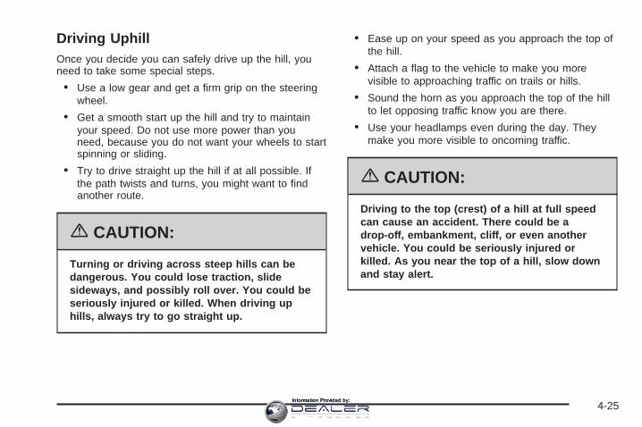
Driving UphillOnce you decide you can safely drive up the hill, youneed to take some special steps.
• Use a low gear and get a firm grip on the steeringwheel.
• Get a smooth start up the hill and try to maintainyour speed. Do not use more power than youneed, because you do not want your wheels to startspinning or sliding.
• Try to drive straight up the hill if at all possible. Ifthe path twists and turns, you might want to findanother route.
{CAUTION:
Turning or driving across steep hills can bedangerous. You could lose traction, slidesideways, and possibly roll over. You could beseriously injured or killed. When driving uphills, always try to go straight up.
• Ease up on your speed as you approach the top ofthe hill.
• Attach a flag to the vehicle to make you morevisible to approaching traffic on trails or hills.
• Sound the horn as you approach the top of the hillto let opposing traffic know you are there.
• Use your headlamps even during the day. Theymake you more visible to oncoming traffic.
{CAUTION:
Driving to the top (crest) of a hill at full speedcan cause an accident. There could be adrop-off, embankment, cliff, or even anothervehicle. You could be seriously injured orkilled. As you near the top of a hill, slow downand stay alert.
4-25Information Provided by:

Q: What should I do if my vehicle stalls, or is aboutto stall, and I cannot make it up the hill?
A: If this happens, there are some things you shoulddo, and there are some things you must not do.First, here is what you should do:
• Push the brake pedal to stop the vehicle and keepit from rolling backwards. Also, apply the parkingbrake.
• If your engine is still running, shift the transmissionto REVERSE (R), release the parking brake, andslowly back down the hill in REVERSE (R).
• If your engine has stopped running, you will need torestart it. With the brake pedal pressed and theparking brake still applied, shift the transmission toPARK (P) (or shift to NEUTRAL if your vehiclehas a manual transmission) and restart the engine.Then, shift to REVERSE (R), release the parkingbrake, and slowly back down the hill as straight aspossible in REVERSE (R).
• As you are backing down the hill, put your left handon the steering wheel at the 12 o’clock position.This way, you will be able to tell if your wheels arestraight and maneuver as you back down. It isbest that you back down the hill with your wheelsstraight rather than in the left or right direction.Turning the wheel too far to the left or rightwill increase the possibility of a rollover.
Here are some things you must not do if you stall, orare about to stall, when going up a hill.
• Never attempt to prevent a stall by shifting intoNEUTRAL (N) (or pressing the clutch, if you have amanual transmission) to rev-up the engine andregain forward momentum. This will not work. Yourvehicle will roll backwards very quickly and youcould go out of control.Instead, apply the regular brake to stop the vehicle.Then apply the parking brake. Shift toREVERSE (R), release the parking brake, andslowly back straight down.
• Never attempt to turn around if you are about tostall when going up a hill. If the hill is steepenough to stall your vehicle, it is steep enough tocause you to roll over if you turn around. If youcannot make it up the hill, you must back straightdown the hill.
4-26Information Provided by:

Q: Suppose, after stalling, I try to back down thehill and decide I just cannot do it. What shouldI do?
A: Set the parking brake, put your transmission inPARK (P), or the manual transmission in FIRST (1),and turn off the engine. Leave the vehicle andgo get some help. Exit on the uphill side and stayclear of the path the vehicle would take if itrolled downhill. Do not shift the transfer case toNEUTRAL when you leave the vehicle. Leave it insome gear.
{CAUTION:
Shifting the transfer case to NEUTRAL cancause your vehicle to roll even if thetransmission is in PARK (P) (or, if you havethe manual transmission, even if you are ingear). This is because the NEUTRAL positionon the transfer case overrides thetransmission. You or someone else could beinjured. If you are going to leave your vehicle,set the parking brake and shift thetransmission to PARK (P) (or, put your manualtransmission in FIRST (1)). But do not shift thetransfer case to NEUTRAL. Leave the transfercase in the Two-Wheel High, Four-Wheel Highor Four-Wheel Low position.
4-27Information Provided by:

Driving DownhillWhen off-roading takes you downhill, you will want toconsider a number of things:
• How steep is the downhill? Will I be able to maintainvehicle control?
• What is the surface like? Smooth? Rough?Slippery? Hard-packed dirt? Gravel?
• Are there hidden surface obstacles? Ruts? Logs?Boulders?
• What is at the bottom of the hill? Is there a hiddencreek bank or even a river bottom with large rocks?
If you decide you can go down a hill safely, then try tokeep your vehicle headed straight down, and use alow gear. This way, engine drag can help your brakesand they will not have to do all the work. Descendslowly, keeping your vehicle under control at all times.
{CAUTION:
Heavy braking when going down a hill cancause your brakes to overheat and fade. Thiscould cause loss of control and a seriousaccident. Apply the brakes lightly whendescending a hill and use a low gear to keepvehicle speed under control.
Q: Are there some things I should not do whendriving down a hill?
A: Yes! These are important because if you ignorethem you could lose control and have a seriousaccident.
• When driving downhill, avoid turns that take youacross the incline of the hill. A hill that is not toosteep to drive down may be too steep to driveacross. You could roll over if you do not drivestraight down.
• Never go downhill with the transmission inNEUTRAL (N), or with the clutch pedal presseddown with a manual transmission. This is called“free-wheeling.” Your brakes will have to do all thework and could overheat and fade.
4-28Information Provided by:

Q: Am I likely to stall when going downhill?
A: It is much more likely to happen going uphill. But ifit happens going downhill, here is what to do.
1. Stop your vehicle by applying the regular brakes.Apply the parking brake.
2. Shift to PARK (P), or to NEUTRAL with the manualtransmission, and, while still braking, restart theengine.
3. Shift back to a low gear, release the parking brake,and drive straight down.
4. If the engine will not start, get out and get help.
Driving Across an InclineSooner or later, an off-road trail will probably go acrossthe incline of a hill. If this happens, you have todecide whether to try to drive across the incline. Hereare some things to consider:
• A hill that can be driven straight up or down may betoo steep to drive across. When you go straight up ordown a hill, the length of the wheel base — thedistance from the front wheels to the rearwheels — reduces the likelihood the vehicle willtumble end over end. But when you drive across anincline, the much more narrow track width — thedistance between the left and right wheels — maynot prevent the vehicle from tilting and rolling over.
Also, driving across an incline puts more weight onthe downhill wheels. This could cause a downhillslide or a rollover.
• Surface conditions can be a problem when you driveacross a hill. Loose gravel, muddy spots, or even wetgrass can cause your tires to slip sideways, downhill.If the vehicle slips sideways, it can hit something thatwill trip it — a rock, a rut, etc. — and roll over.
• Hidden obstacles can make the steepness of theincline even worse. If you drive across a rock with theuphill wheels, or if the downhill wheels drop into a rutor depression, your vehicle can tilt even more.
For reasons like these, you need to decide carefullywhether to try to drive across an incline. Just because thetrail goes across the incline does not mean you have todrive it. The last vehicle to try it might have rolled over.
{CAUTION:
Driving across an incline that is too steep willmake your vehicle roll over. You could beseriously injured or killed. If you have anydoubt about the steepness of the incline, donot drive across it. Find another route instead.
4-29Information Provided by:

Q: What if I am driving across an incline that is nottoo steep, but I hit some loose gravel and startto slide downhill. What should I do?
A: If you feel your vehicle starting to slide sideways,turn downhill. This should help straighten out thevehicle and prevent the side slipping. However,a much better way to prevent this is to get out and“walk the course” so you know what the surfaceis like before you drive it.
Stalling on an InclineIf your vehicle stalls when you are crossing an incline,be sure you, and any passengers, get out on theuphill side, even if the door there is harder to open. Ifyou get out on the downhill side and the vehicle starts toroll over, you will be right in its path.
If you have to walk down the slope, stay out of the paththe vehicle will take if it does roll over.
{CAUTION:
Getting out on the downhill (low) side of avehicle stopped across an incline isdangerous. If the vehicle rolls over, you couldbe crushed or killed. Always get out on theuphill (high) side of the vehicle and stay wellclear of the rollover path.
4-30Information Provided by:

Driving in Mud, Sand, Snow or IceWhen you drive in mud, snow or sand, your wheels willnot get good traction. You cannot accelerate asquickly, turning is more difficult, and you will need longerbraking distances.
It is best to use a low gear when you are in mud — thedeeper the mud, the lower the gear. In really deepmud, the idea is to keep your vehicle moving so you donot get stuck.
When you drive on sand, you will sense a change inwheel traction. But it will depend upon how looselypacked the sand is. On loosely packed sand, such ason beaches or sand dunes, your tires will tend tosink into the sand. This has an effect on steering,accelerating and braking. Drive at a reduced speed andavoid sharp turns or abrupt maneuvers.
Hard packed snow and ice offer the worst tire traction.On these surfaces, it is very easy to lose control.On wet ice, for example, the traction is so poor that youwill have difficulty accelerating. And if you do getmoving, poor steering and difficult braking can causeyou to slide out of control.
{CAUTION:
Driving on frozen lakes, ponds, or rivers canbe dangerous. Underwater springs, currentsunder the ice, or sudden thaws can weaken theice. Your vehicle could fall through the ice andyou and your passengers could drown. Driveyour vehicle on safe surfaces only.
Driving in WaterHeavy rain can mean flash flooding, and flood watersdemand extreme caution.
Find out how deep the water is before you drive throughit. If it is deep enough to cover your wheel hubs,axles or exhaust pipe, do not try it — you probably willnot get through. Also, water that deep can damageyour axle and other vehicle parts.
4-31Information Provided by:

If the water is not too deep, drive slowly through it. Atfaster speeds, water splashes on your ignitionsystem and your vehicle can stall. Stalling can alsooccur if you get your tailpipe under water. And, as longas your tailpipe is under water, you will never beable to start your engine. When you go through water,remember that when your brakes get wet, it maytake you longer to stop.
{CAUTION:
Driving through rushing water can bedangerous. Deep water can sweep your vehicledownstream and you and your passengerscould drown. If it is only shallow water, it canstill wash away the ground from under yourtires, and you could lose traction and roll thevehicle over. Do not drive through rushingwater.
See Driving in Rain and on Wet Roads on page 4-34 formore information on driving through water.
After Off-Road DrivingRemove any brush or debris that has collected on theunderbody, chassis or under the hood. Theseaccumulations can be a fire hazard.
After operation in mud or sand, have the brake liningscleaned and checked. These substances can causeglazing and uneven braking. Check the body structure,steering, suspension, wheels, tires and exhaustsystem for damage. Also, check the fuel lines andcooling system for any leakage.
Your vehicle will require more frequent service due tooff-road use. Refer to the Maintenance Schedulefor additional information.
4-32Information Provided by:

Driving at NightNight driving is more dangerous than day driving.One reason is that some drivers are likely to beimpaired — by alcohol or drugs, with night visionproblems, or by fatigue.
Here are some tips on night driving.
• Drive defensively.
• Do not drink and drive.
• Adjust the inside rearview mirror to reduce the glarefrom headlamps behind you.
• Since you cannot see as well, you may need toslow down and keep more space between youand other vehicles.
• Slow down, especially on higher speed roads. Yourvehicle’s headlamps can light up only so much roadahead.
• In remote areas, watch for animals.
• If you are tired, pull off the road in a safe placeand rest.
No one can see as well at night as in the daytime. Butas we get older these differences increase. A50-year-old driver may require at least twice as muchlight to see the same thing at night as a 20-year-old.
What you do in the daytime can also affect yournight vision. For example, if you spend the day in brightsunshine you are wise to wear sunglasses. Youreyes will have less trouble adjusting to night. But if youare driving, do not wear sunglasses at night. Theymay cut down on glare from headlamps, but they alsomake a lot of things invisible.
4-33Information Provided by:

You can be temporarily blinded by approachingheadlamps. It can take a second or two, or even severalseconds, for your eyes to re-adjust to the dark. Whenyou are faced with severe glare, as from a driverwho does not lower the high beams, or a vehicle withmisaimed headlamps, slow down a little. Avoidstaring directly into the approaching headlamps.
Keep the windshield and all the glass on your vehicleclean — inside and out. Glare at night is mademuch worse by dirt on the glass. Even the inside of theglass can build up a film caused by dust. Dirty glassmakes lights dazzle and flash more than cleanglass would, making the pupils of your eyes contractrepeatedly.
Remember that the headlamps light up far less of aroadway when you are in a turn or curve. Keepyour eyes moving; that way, it is easier to pick out dimlylighted objects. Just as the headlamps should bechecked regularly for proper aim, so should your eyesbe examined regularly. Some drivers suffer fromnight blindness — the inability to see in dim light — andare not even aware of it.
Driving in Rain and on Wet Roads
Rain and wet roads can mean driving trouble. On a wetroad, you cannot stop, accelerate, or turn as wellbecause your tire-to-road traction is not as good as ondry roads. And, if your tires do not have much treadleft, you will get even less traction. It is always wise togo slower and be cautious if rain starts to fall whileyou are driving. The surface may get wet suddenly whenyour reflexes are tuned for driving on dry pavement.
4-34Information Provided by:

The heavier the rain, the harder it is to see. Even if yourwindshield wiper blades are in good shape, a heavyrain can make it harder to see road signs andtraffic signals, pavement markings, the edge of the road,and even people walking.It is wise to keep your wiping equipment in good shapeand keep your windshield washer fluid reservoir filledwith washer fluid. Replace your windshield wiper insertswhen they show signs of streaking or missing areason the windshield, or when strips of rubber startto separate from the inserts.
{CAUTION:
Wet brakes can cause accidents. They will notwork as well in a quick stop and may causepulling to one side. You could lose control ofthe vehicle.
After driving through a large puddle of wateror a car wash, apply your brake pedal lightlyuntil your brakes work normally.
Driving too fast through large water puddles or evengoing through some car washes can cause problems,too. The water may affect your brakes. Try to avoidpuddles. But if you cannot, try to slow down before youhit them.
HydroplaningHydroplaning is dangerous. So much water can build upunder your tires that they can actually ride on thewater. This can happen if the road is wet enough andyou are going fast enough. When your vehicle ishydroplaning, it has little or no contact with the road.
Hydroplaning does not happen often. But it can if yourtires do not have much tread or if the pressure inone or more is low. It can happen if a lot of water isstanding on the road. If you can see reflectionsfrom trees, telephone poles, or other vehicles, andraindrops dimple the water’s surface, there could behydroplaning.
Hydroplaning usually happens at higher speeds. Therejust is not a hard and fast rule about hydroplaning.The best advice is to slow down when it is raining.
4-35Information Provided by:

Driving Through Deep Standing Water
Notice: If you drive too quickly through deeppuddles or standing water, water can come inthrough your engine’s air intake and badly damageyour engine. Never drive through water that isslightly lower than the underbody of your vehicle. Ifyou cannot avoid deep puddles or standing water,drive through them very slowly.
Driving Through Flowing Water
{CAUTION:
Flowing or rushing water creates strong forces.If you try to drive through flowing water, as youmight at a low water crossing, your vehicle canbe carried away. As little as six inches offlowing water can carry away a smaller vehicle.If this happens, you and other vehicleoccupants could drown. Do not ignore policewarning signs, and otherwise be very cautiousabout trying to drive through flowing water.
Some Other Rainy Weather Tips• Turn on your low-beam headlamps — not just your
parking lamps — to help make you more visible toothers.
• Besides slowing down, allow some extra followingdistance. And be especially careful when youpass another vehicle. Allow yourself more clearroom ahead, and be prepared to have yourview restricted by road spray.
• Have good tires with proper tread depth. See Tireson page 5-73.
4-36Information Provided by:

City Driving
One of the biggest problems with city streets is theamount of traffic on them. You will want to watch out forwhat the other drivers are doing and pay attention totraffic signals.
Here are ways to increase your safety in city driving:
• Know the best way to get to where you aregoing. Get a city map and plan your trip intoan unknown part of the city just as you would for across-country trip.
• Try to use the freeways that rim and crisscrossmost large cities. You will save time and energy.See Freeway Driving on page 4-38.
• Treat a green light as a warning signal. A trafficlight is there because the corner is busy enoughto need it. When a light turns green, and just beforeyou start to move, check both ways for vehiclesthat have not cleared the intersection or maybe running the red light.
4-37Information Provided by:

Freeway Driving
Mile for mile, freeways — also called thruways, parkways,expressways, turnpikes, or superhighways — are thesafest of all roads. But they have their own special rules.
The most important advice on freeway driving is: Keepup with traffic and keep to the right. Drive at thesame speed most of the other drivers are driving.Too-fast or too-slow driving breaks a smooth traffic flow.Treat the left lane on a freeway as a passing lane.
At the entrance, there is usually a ramp that leads to thefreeway. If you have a clear view of the freeway as youdrive along the entrance ramp, you should begin to checktraffic. Try to determine where you expect to blend withthe flow. Try to merge into the gap at close to theprevailing speed. Switch on your turn signal, check yourmirrors, and glance over your shoulder as often asnecessary. Try to blend smoothly with the traffic flow.
Once you are on the freeway, adjust your speed to theposted limit or to the prevailing rate if it is slower.Stay in the right lane unless you want to pass.
Before changing lanes, check your mirrors. Then useyour turn signal.
Just before you leave the lane, glance quickly over yourshoulder to make sure there is not another vehicle inyour blind spot.
Once you are moving on the freeway, make certain youallow a reasonable following distance. Expect tomove slightly slower at night.
4-38Information Provided by:

When you want to leave the freeway, move to theproper lane well in advance. If you miss your exit, donot, under any circumstances, stop and back up. Driveon to the next exit.
The exit ramp can be curved, sometimes quite sharply.The exit speed is usually posted.
Reduce your speed according to your speedometer, notto your sense of motion. After driving for any distanceat higher speeds, you may tend to think you aregoing slower than you actually are.
Before Leaving on a Long TripMake sure you are ready. Try to be well rested. If youmust start when you are not fresh — such as aftera day’s work — do not plan to make too many miles thatfirst part of the journey. Wear comfortable clothingand shoes you can easily drive in.
Is your vehicle ready for a long trip? If you keep itserviced and maintained, it is ready to go. If it needsservice, have it done before starting out. Of course, youwill find experienced and able service experts in GMdealerships all across North America. They will be readyand willing to help if you need it.
Here are some things you can check before a trip:
• Windshield Washer Fluid: Is the reservoir full? Areall windows clean inside and outside?
• Wiper Blades: Are they in good shape?
• Fuel, Engine Oil, Other Fluids: Have you checkedall levels?
• Lamps: Are they all working? Are the lenses clean?
• Tires: They are vitally important to a safe,trouble-free trip. Is the tread good enough forlong-distance driving? Are the tires all inflated to therecommended pressure?
• Weather Forecasts: What is the weather outlookalong your route? Should you delay your trip ashort time to avoid a major storm system?
• Maps: Do you have up-to-date maps?
4-39Information Provided by:

Highway HypnosisIs there actually such a condition as highway hypnosis?Or is it just plain falling asleep at the wheel? Call ithighway hypnosis, lack of awareness, or whatever.
There is something about an easy stretch of road withthe same scenery, along with the hum of the tires on theroad, the drone of the engine, and the rush of thewind against the vehicle that can make you sleepy. Donot let it happen to you! If it does, your vehicle canleave the road in less than a second, and you couldcrash and be injured.
What can you do about highway hypnosis? First, beaware that it can happen.
Then here are some tips:
• Make sure your vehicle is well ventilated, with acomfortably cool interior.
• Keep your eyes moving. Scan the road ahead andto the sides. Check your mirrors and yourinstruments frequently.
• If you get sleepy, pull off the road into a rest,service, or parking area and take a nap, get someexercise, or both. For safety, treat drowsinesson the highway as an emergency.
Hill and Mountain Roads
Driving on steep hills or mountains is different fromdriving in flat or rolling terrain.
If you drive regularly in steep country, or if you areplanning to visit there, here are some tips that can makeyour trips safer and more enjoyable. See Off-RoadDriving on page 4-17 for information about drivingoff-road.
4-40Information Provided by:

• Keep your vehicle in good shape. Check all fluidlevels and also the brakes, tires, cooling system,and transmission. These parts can work hardon mountain roads.
{CAUTION:
If you do not shift down, your brakes could getso hot that they would not work well. Youwould then have poor braking or even nonegoing down a hill. You could crash. Shift downto let your engine assist your brakes on asteep downhill slope.
{CAUTION:
Coasting downhill in NEUTRAL (N) or with theignition off is dangerous. Your brakes will haveto do all the work of slowing down. They couldget so hot that they would not work well. Youwould then have poor braking or even nonegoing down a hill. You could crash. Alwayshave your engine running and your vehicle ingear when you go downhill.
• Know how to go down hills. The most importantthing to know is this: let your engine do some ofthe slowing down. Shift to a lower gear when you godown a steep or long hill.
• Know how to go uphill. You may want to shift down toa lower gear. The lower gears help cool your engineand transmission, and you can climb the hill better.
• Stay in your own lane when driving on two-laneroads in hills or mountains. Do not swing wide or cutacross the center of the road. Drive at speeds that letyou stay in your own lane.
• As you go over the top of a hill, be alert. There couldbe something in your lane, like a stalled car or anaccident.
• You may see highway signs on mountains that warnof special problems. Examples are long grades,passing or no-passing zones, a falling rocks area, orwinding roads. Be alert to these and take appropriateaction.
4-41Information Provided by:

Winter Driving
Here are some tips for winter driving:
• Have your vehicle in good shape for winter.
• You may want to put winter emergency supplies inyour vehicle.
Also see Tires on page 5-73.
Include an ice scraper, a small brush or broom, asupply of windshield washer fluid, a rag, some winterouter clothing, a small shovel, a flashlight, a redcloth, and reflective warning triangles. And, if you will bedriving under severe conditions, include a small bagof sand, a piece of old carpet, or a couple of burlap bagsto help provide traction. Be sure you properly securethese items in your vehicle.
Driving on Snow or IceMost of the time, those places where the tires meet theroad probably have good traction.
However, if there is snow or ice between the tires andthe road, you can have a very slippery situation. You willhave a lot less traction, or grip, and will need to bevery careful.
4-42Information Provided by:

What is the worst time for this? Wet ice. Very cold snowor ice can be slick and hard to drive on. But wet icecan be even more trouble because it may offer the leasttraction of all. You can get wet ice when it is aboutfreezing, 32°F (0°C), and freezing rain begins to fall. Tryto avoid driving on wet ice until salt and sand crewscan get there.
Whatever the condition — smooth ice, packed, blowing,or loose snow — drive with caution.
If you have the Traction Assist System (TAS), it willimprove your ability to accelerate when driving ona slippery road. But you can turn the TAS off if you everneed to. You should turn the TAS off if your vehicleever gets stuck in sand, mud, ice, or snow. See If YourVehicle is Stuck in Sand, Mud, Ice or Snow onpage 4-46. Even though your vehicle has TAS, you willwant to slow down and adjust your driving to theroad conditions. Under certain conditions, you may wantto turn the TAS off, such as when driving throughdeep snow and loose gravel, to help maintain vehiclemotion at lower speeds. See Traction Assist System(TAS) on page 4-9.
If you do not have TAS, accelerate gently. Try not tobreak the fragile traction. If you accelerate too fast, thedrive wheels will spin and polish the surface underthe tires even more.
4-43Information Provided by:

Your Anti-Lock Brake System (ABS) improves yourvehicle’s stability when you make a hard stop ona slippery road. Even though you have ABS, you willwant to begin stopping sooner than you would ondry pavement. See Anti-Lock Brake System (ABS) onpage 4-7.
• Allow greater following distance on any slippery road.
• Watch for slippery spots. The road might be fine untilyou hit a spot that is covered with ice. On anotherwise clear road, ice patches may appear inshaded areas where the sun cannot reach, such asaround clumps of trees, behind buildings, or underbridges. Sometimes the surface of a curve or anoverpass may remain icy when the surroundingroads are clear. If you see a patch of ice ahead ofyou, brake before you are on it. Try not to brake whileyou are actually on the ice, and avoid suddensteering maneuvers.
If You Are Caught in a BlizzardIf you are stopped by heavy snow, you could be in aserious situation. You should probably stay withyour vehicle unless you know for sure that you are nearhelp and you can hike through the snow.
Here are some things to do to summon help and keepyourself and your passengers safe:
• Turn on your hazard flashers.
• Tie a red cloth to your vehicle to alert police thatyou have been stopped by the snow.
• Put on extra clothing or wrap a blanket around you.If you do not have blankets or extra clothing, makebody insulators from newspapers, burlap bags,rags, floor mats — anything you can wrap aroundyourself or tuck under your clothing to keep warm.
4-44Information Provided by:

You can run the engine to keep warm, but be careful.
{CAUTION:
Snow can trap exhaust gases under yourvehicle. This can cause deadly CO (carbonmonoxide) gas to get inside. CO couldovercome you and kill you. You cannot see itor smell it, so you might not know it is in yourvehicle. Clear away snow from around thebase of your vehicle, especially any that isblocking your exhaust pipe. And check aroundagain from time to time to be sure snow doesnot collect there.
Open a window just a little on the side of thevehicle that is away from the wind. This willhelp keep CO out.
Run your engine only as long as you must. This savesfuel. When you run the engine, make it go a littlefaster than just idle. That is, push the acceleratorslightly. This uses less fuel for the heat that you get andit keeps the battery charged. You will need awell-charged battery to restart the vehicle, and possiblyfor signaling later on with your headlamps. Let theheater run for a while.
Then, shut the engine off and close the window almostall the way to preserve the heat. Start the engineagain and repeat this only when you feel reallyuncomfortable from the cold. But do it as little aspossible. Preserve the fuel as long as you can. To helpkeep warm, you can get out of the vehicle and dosome fairly vigorous exercises every half hour or so untilhelp comes.
4-45Information Provided by:

If Your Vehicle is Stuck in Sand,Mud, Ice or SnowIn order to free your vehicle when it is stuck, you willneed to spin the wheels, but you do not want tospin your wheels too fast. The method known as rockingcan help you get out when you are stuck, but youmust use caution.
{CAUTION:
If you let your tires spin at high speed, they canexplode, and you or others could be injured.And, the transmission or other parts of thevehicle can overheat. That could cause anengine compartment fire or other damage.When you are stuck, spin the wheels as little aspossible. Do not spin the wheels above 35 mph(55 km/h) as shown on the speedometer.
Notice: Spinning your wheels can destroy parts ofyour vehicle as well as the tires. If you spin thewheels too fast while shifting your transmissionback and forth, you can destroy your transmission.
For more information about using tire chains on yourvehicle, see Tire Chains on page 5-91.
Rocking Your Vehicle to Get It OutFirst, turn your steering wheel left and right. Thatwill clear the area around your front wheels. If you havea four-wheel-drive vehicle, shift into Four-WheelHigh. If your vehicle has the traction assist system, youshould turn it off by pressing the TAS on/off button.Then shift back and forth between REVERSE (R) and aforward gear, or with a manual transmission, betweenFIRST (1) or SECOND (2) and REVERSE (R), spinningthe wheels as little as possible. Release the acceleratorpedal while you shift, and press lightly on theaccelerator pedal when the transmission is in gear. Byslowly spinning your wheels in the forward andreverse directions, you will cause a rocking motion thatmay free your vehicle. If that does not get you outafter a few tries, you may need to be towed out. If yourvehicle is not an SS model, you can use your recoveryhooks if your vehicle has them. If you do need tobe towed out, see Towing Your Vehicle on page 4-61.
4-46Information Provided by:

Recovery Hooks (Except SS Model)Notice: SS Models have recovery hooks that areconcealed by the front bumper trim covering. Use ofthe recovery hooks could cause damage to yourvehicle. If you have the SS Model, do not usethe recovery hooks.
{CAUTION:
These hooks, when used, are under a lot offorce. Always pull the vehicle straight out.Never pull on the hooks at a sideways angle.The hooks could break off and you or otherscould be injured from the chain or cablesnapping back.
Notice: Never use recovery hooks to tow thevehicle. Your vehicle could be damaged and it wouldnot be covered by warranty.
Your vehicle may have recovery hooks at the front ofthe vehicle. You may need to use them if you are stuckoff-road and need to be pulled to some place whereyou can continue driving.
4-47Information Provided by:

Loading Your VehicleIt is very important to know how much weight yourvehicle can carry. This weight is called the vehiclecapacity weight and includes the weight of all occupants,cargo, and all nonfactory-installed options. Two labelson your vehicle show how much weight it was designedto carry, the Tire and Loading Information label andthe Certification/Tire label.
{CAUTION:
Do not load your vehicle any heavier than theGross Vehicle Weight Rating (GVWR), or eitherthe maximum front or rear Gross Axle WeightRating (GAWR). If you do, parts on yourvehicle can break, and it can change the wayyour vehicle handles. These could cause youto lose control and crash. Also, overloadingcan shorten the life of your vehicle.
Tire and Loading Information Label
A vehicle specific Tire and Loading Information label isattached to the center pillar (B-pillar). With the driver’sdoor open, you will find the label attached belowthe door lock post (striker). The tire and loadinginformation label shows the number of occupant seatingpositions (A), and the maximum vehicle capacityweight (B) in kilograms and pounds.
Label Example
4-48Information Provided by:

The Tire and Loading Information label also shows thesize of the original equipment tires (C) and therecommended cold tire inflation pressures (D). For moreinformation on tires and inflation see Tires on page 5-73and Inflation - Tire Pressure on page 5-80.
There is also important loading information on thevehicle Certification/Tire label. It tells you the GrossVehicle Weight Rating (GVWR) and the GrossAxle Weight Rating (GAWR) for the front and rear axles.See “Certification/Tire Label” later in this section.
Steps for Determining Correct Load Limit1. Locate the statement “The combined weight of
occupants and cargo should never exceedXXX kg or XXX lbs” on your vehicle’s placard.
2. Determine the combined weight of the driver andpassengers that will be riding in your vehicle.
3. Subtract the combined weight of the driver andpassengers from XXX kg or XXX lbs.
4. The resulting figure equals the available amount ofcargo and luggage load capacity. For example, ifthe “XXX” amount equals 1400 lbs and there will befive 150 lb passengers in your vehicle, the amountof available cargo and luggage load capacity is650 lbs (1400 − 750 (5 x 150) = 650 lbs).
5. Determine the combined weight of luggage andcargo being loaded on the vehicle. That weightmay not safely exceed the available cargoand luggage load capacity calculated in Step 4.
6. If your vehicle will be towing a trailer, the load fromyour trailer will be transferred to your vehicle.Consult this manual to determine how this reducesthe available cargo and luggage load capacity ofyour vehicle. See Towing a Trailer on page 4-67 forimportant information on towing a trailer, towingsafety rules and trailering tips.
4-49Information Provided by:

Item Description Total
A Vehicle Capacity Weightfor Example 1 = 1,000 lbs (453 kg)
BSubtract OccupantWeight 150 lbs(68 kg) × 2 =
300 lbs (136 kg)
C Available Occupant andCargo Weight = 700 lbs (317 kg)
Item Description Total
A Vehicle Capacity Weightfor Example 2 = 1,000 lbs (453 kg)
BSubtract OccupantWeight 150 lbs(68 kg) × 5 =
750 lbs (136 kg)
C Available CargoWeight = 250 lbs (113 kg)
Example 1 Example 2
4-50Information Provided by:
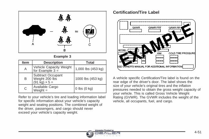
Item Description Total
A Vehicle Capacity Weightfor Example 3 = 1,000 lbs (453 kg)
BSubtract OccupantWeight 200 lbs(91 kg) × 5 =
1000 lbs (453 kg)
C Available CargoWeight = 0 lbs (0 kg)
Refer to your vehicle’s tire and loading information labelfor specific information about your vehicle’s capacityweight and seating positions. The combined weight ofthe driver, passengers, and cargo should neverexceed your vehicle’s capacity weight.
Certification/Tire Label
A vehicle specific Certification/Tire label is found on therear edge of the driver’s door. The label shows thesize of your vehicle’s original tires and the inflationpressures needed to obtain the gross weight capacity ofyour vehicle. This is called Gross Vehicle WeightRating (GVWR). The GVWR includes the weight of thevehicle, all occupants, fuel, and cargo.
Example 3
4-51Information Provided by:

The Certification/Tire label also tells you the maximumweights for the front and rear axles, called GrossAxle Weight Rating (GAWR). To find out the actual loadson your front and rear axles, you need to go to aweigh station and weigh your vehicle. Your dealer canhelp you with this. Be sure to spread out your loadequally on both sides of the centerline.
Never exceed the GVWR for your vehicle, or the GAWRfor either the front or rear axle.
The Certification/Tire label also contains importantinformation about your Front Axle Reserve Capacity.See “What is front axle reserve capacity, and how do Icalculate it?” under Adding a Snow Plow or SimilarEquipment on page 4-54.
{CAUTION:
In the case of a sudden stop or collision,things carried in the bed of your truck couldshift forward and come into the passengerarea, injuring you and others. If you put thingsin the bed of your truck, you should make surethey are properly secured.
{CAUTION:
Do not load your vehicle any heavier than theGross Vehicle Weight Rating (GVWR), or eitherthe maximum front or rear Gross Axle WeightRating (GAWR). If you do, parts on yourvehicle can break, and it can change the wayyour vehicle handles. These could cause youto lose control and crash. Also, overloadingcan shorten the life of your vehicle.
Notice: Overloading your vehicle may causedamage. Repairs would not be covered by yourwarranty. Do not overload your vehicle.
Using heavier suspension components to get addeddurability might not change your weight ratings. Ask yourdealer to help you load your vehicle the right way.
4-52Information Provided by:

If you put things inside your vehicle — like suitcases,tools, packages, or anything else — they go as fastas the vehicle goes. If you have to stop or turn quickly,or if there is a crash, they will keep going.
{CAUTION:
Things you put inside your vehicle can strikeand injure people in a sudden stop or turn, orin a crash.
• Put things in the cargo area of yourvehicle. Try to spread the weight evenly.
• Never stack heavier things, like suitcases,inside the vehicle so that some of themare above the tops of the seats.
• Do not leave an unsecured child restraintin your vehicle.
• When you carry something inside thevehicle, secure it whenever you can.
• Do not leave a seat folded down unlessyou need to.
There is also important loading information for off-roaddriving in this manual. See “Loading Your Vehiclefor Off-Road Driving“ under Off-Road Driving onpage 4-17.
Two-Tiered LoadingBy positioning four 2 inches (5 cm) by 6 inches (15 cm)wooden planks across the width of the pickup box,you can create an upper load platform. The planks mustbe inserted in the pickup box depressions. The lengthof the planks must allow for at least a 3/4 inch(2 cm) bearing surface on each end of the plank.
When using this upper load platform, be sure the load issecurely tied down to prevent it from shifting. Theload’s center of gravity should be positioned in a zoneover the rear axle. The zone is located in the areabetween the front of each wheel well and the rear ofeach wheel well. The center of gravity height must notextend above the top of the pickup box flareboard.
Any load that extends beyond the vehicle’s taillamp areamust be properly marked according to local laws andregulations.
Remember not to exceed the Gross Axle Weight Rating(GAWR) of the front or rear axle.
4-53Information Provided by:

Add-On EquipmentWhen you carry removable items, you may need to puta limit on how many people you carry inside yourvehicle. Be sure to weigh your vehicle before you buyand install the new equipment.
Notice: Overloading your vehicle may causedamage. Repairs would not be covered by yourwarranty. Do not overload your vehicle.
Remember not to exceed the Gross Axle Weight Rating(GAWR) of the front or rear axle.
*Equipment Maximum WeightLadder Rack and Cargo 750 lbs (340 kg)Cross Toolbox and Cargo 400 lbs (181 kg)Side Boxes and Cargo 250 lbs per side
(113 kg per side)*The combined weight for all rail-mounted equipmentshould not exceed 1,000 lbs (454 kg), excluded1500 crew cab models with 5 ft 8 in (173 cm) boxlength. A reinforcement kit for rail-mounted add-onequipment is recommended. See your dealer.Ladder racks are not recommended for 1500 crewcab models with 5 ft 8 in (173 cm) pick-up box length.Maximum recommended cross-mounted toolbox andcargo weight is 300 lbs (136 kg) for the 1500 crewcab with 5 ft 8 in (173 cm) pick-up box length.
Adding a Snow Plow or SimilarEquipmentBefore installing a snow plow on your vehicle, here aresome things you will need to know:
Notice: If your vehicle does not have the snowplow prep package, adding a plow can damage yourvehicle, and the repairs would not be covered bywarranty. Unless your vehicle was built to carrya snow plow, do not add one to your vehicle. If yourvehicle has the snow plow option called RPO VYU(snow plow prep package), then the payloadyour vehicle can carry will be reduced when a snowplow is installed. Your vehicle can be damaged ifeither the front or rear axle ratings or the grossvehicle weight (GVW) are exceeded.
Q: How do I know if my vehicle can handle asnow plow?
A: Some vehicles are built with a special package,called RPO VYU (snow plow prep package). Ifyour vehicle has this option, you can add a plow toit, provided certain weights, such as the weightson the vehicle’s axles and the GVW, are notexceeded.
4-54Information Provided by:

Q: How heavy can a snow plow safely be?
A: The plow your vehicle can carry depends on manythings, such as:
• The options your vehicle came with, and the weightof those options.
• The weight and number of passengers you intendto carry.
• The weight of items you have added to yourvehicle, like a tool box or truck cap.
• The total weight of any additional cargo you intendto carry.
Say, for example, you have a 700 lb (318 kg) snowplow. The total weight of all occupants and cargo insidethe cab should not exceed 300 lb (135 kg). Thismeans that you may only be able to carry onepassenger. But, even this may be too much if you havegot other equipment already adding to the weight ofyour vehicle.
Here are some guidelines for safely carrying a snowplow on your vehicle:
• Make sure the weight on the front and rear axlesdoes not exceed the axle rating for each.
• For the front axle, if more cargo or passengersmust be carried, appropriate counter ballast must beinstalled rear of the rear axle. Counter ballastmust be properly secured so it will not move duringdriving.
• Follow the snow plow manufacturer’srecommendations regarding rear ballast. Rearballast may be required to ensure a proper front andrear weight distribution ratio, even though theactual weight at the front axle may be less than thefront axle rating.
• The snow plow manufacturer or installer can assistyou in determining the amount of rear ballastrequired, to help make sure your snowplow/vehiclecombination does not exceed the GVW rating,the front and rear axle ratings, and the front andrear weight distribution ratio.
• The total vehicle must not exceed the GVW rating.
4-55Information Provided by:

Q: What is front axle reserve capacity, and how doI calculate it?
A: Front axle reserve capacity is the differencebetween your front gross axle weight rating (GAWR)and the front axle weight of your vehicle with fullfuel and passengers. Basically, it is the amount ofweight you can add to your front axle beforereaching your front GAWR.
The front axle reserve capacity for your vehicle can befound in the lower right corner of the Certification/Tirelabel, as shown.
In order to calculate the amount of weight any frontaccessory, such as a snow plow, is adding to the frontaxle, use the following formula:
(W x (A + W.B.)) /W.B.= Weight the accessory is addingto the front axle.
Where:W = Weight of added accessoryA = Distance that the accessory is in front of the front axleW.B. = Vehicle WheelbaseUnited States Canada
4-56Information Provided by:

For example, adding a 700 lb (318 kg) snow plow actuallyadds more than 700 lbs (318 kg) to the front axle. Usingthe formula, if the snow plow is 4 ft (122 cm) in front of thefront axle and the wheel base is 10 ft (305 cm), then:W = 700 lb (318 kg)A = 4 ft (122 cm)W.B. = 10 ft (305 cm)
(W x (A + W.B.))/W.B. = (700 x (4 + 10))/10 = 980 lbs(445 kg)
So, if your truck’s front axle reserve capacity is morethan 980 lbs (445 kg), you could add the snow plowwithout exceeding the front GAWR.
Q: What if I want to add heavier equipment to myvehicle?
A: You can add heavier equipment on the front of thevehicle if you compensate for it by carrying fewerpassengers, less cargo, or by positioning cargotowards the rear. This has the effect of reducing theload on the front. However, the front GAWR, rearGAWR and the gross vehicle weight rating (GVWR)must never be exceeded.
{CAUTION:
On some vehicles equipped with certain frontmounted equipment, such as a snow plow, itmay be possible to load the front axle to thefront GAWR but not have enough weight onthe rear axle to have proper brakingperformance. If your brakes can not workproperly, you could have a crash. To help yourbrakes work properly when a snow plow isinstalled, always follow the snow plowmanufacturer or installer’s recommendation forrear ballast to ensure a proper front and rearweight distribution ratio, even though theactual front weight may be less than the frontGAWR, and the total vehicle weight is lessthan the GVWR. Maintaining a proper front andrear weight distribution ratio is necessary toprovide proper braking performance.
4-57Information Provided by:

Q: What is total vehicle reserve capacity?
A: This is the difference between your GVWR and theweight of your truck with full fuel and passengers. Itis the amount of weight you can add to yourvehicle before reaching your GVWR. Keep in mindthat reserve capacity numbers are intended asa guide when selecting the amount of equipment orcargo your truck can carry. If you are unsure ofyour vehicle’s front, rear, or total weight, goto a weigh station and weigh your vehicle. Yourdealer can also help you with this.
The total vehicle reserve capacity for your vehiclecan be found in the lower right corner of theCertification/Tire label as shown previously.
See your dealer for additional advice and informationabout using a snow plow on your vehicle. Also,see Loading Your Vehicle on page 4-48.
Emergency Roof Lamp ProvisionsVehicles with the RPO VYU snow plow prep packagealso have an emergency roof lamp provision package,RPO TRW. Wiring for the emergency roof lamp isprovided in the B-pillar as shown. See Auxiliary RoofMounted Lamp on page 3-16 for switch location.
A. Body Side Inner PanelB. Emergency Roof Lamp Harness
4-58Information Provided by:

Truck-Camper Loading InformationNotice: Installing a truck-camper to a vehicle that isequipped with the SS trim package could damagethe vehicle. Do not install a truck-camper on avehicle equipped with the SS trim package.
A vehicle specific Truck-Camper Loading informationlabel is attached to the inside of your vehicle’sglove box. This label will tell you if your vehicle cancarry a slide-in camper, how much of a load your vehiclecan carry, and how to correctly spread out the load.Also, it will help you match the right slide-in camper toyour vehicle.
When you carry a slide-in camper, the total cargo loadof your vehicle is the weight of the camper, plus thefollowing:
• Everything else added to the camper after it left thefactory
• Everything in the camper
• All the people inside
The Cargo Weight Rating (CWR) is the maximumweight of the load your vehicle can carry. It does notinclude the weight of the people inside. But, youcan figure about 150 lbs (68 kg) for each seat.
The total cargo load must not be more than yourvehicle’s CWR.
Refer to the Truck-Camper Loading Information label inthe glove box for dimensions A and B as shown inthe following illustration.
Use the rear edge of the load floor for measurementpurposes. The recommended location for the cargocenter of gravity is at point C for the CWR. It is the pointwhere the mass of a body is concentrated and, ifsuspended at that point, would balance the front and rear.
4-59Information Provided by:

Here is an example of proper truck and camper match:
A. Camper Center of GravityB. Recommended Center of Gravity Location Zone
When the truck is used to carry a slide-in camper, thetotal cargo load of the truck consists of themanufacturer’s camper weight figure, the weight ofinstalled additional camper equipment not included inthe manufacturer’s camper weight figure, the weight ofcamper cargo, and the weight of passengers in thecamper. The total cargo load should not exceedthe truck’s cargo weight rating and the camper’s centerof gravity (A) should fall within the truck’s recommendedcenter of gravity zone (B) when installed.
You must weigh any accessories or other equipmentthat you add to your vehicle. Then, subtract thisextra weight from the CWR. This extra weight mayshorten the center of gravity zone of your vehicle. Yourdealer can help you with this.
If your slide-in camper and its load weighs less than theCWR, the center of gravity zone for your vehicle maybe larger.
Your dealer can help you make a good vehicle-campermatch and help you determine the CWR.
After you have loaded your vehicle and camper, drive toa weigh station and weigh the front and rear wheelsseparately. This will tell you the loads on the axles. Theloads on the front and rear axles should not be morethan either of the Gross Axle Weight Ratings (GAWR).The total of the axle loads should not be more thanthe Gross Vehicle Weight Rating (GVWR).
Open the driver’s door and look at the Certification/Tirelabel to find out your vehicle’s GAWRs and GVWR.
If your vehicle has gone over the weight ratings, moveor take out some things until all the weight fallsbelow the ratings.
4-60Information Provided by:

Secure loose items to prevent weight shifts that couldaffect the balance of your vehicle. When thetruck-camper is loaded, drive to a scale and weigh thefront and the rear wheels separately to determineaxle loads. Individual axle loads should not exceedeither of the GAWRs. The total of the front and rear axleloads should not exceed your vehicle’s GVWR. Theseratings are given on the vehicle certification labelattached to the rear edge of the driver’s door. See“Certification/Tire Label” under Loading Your Vehicle onpage 4-48. If weight ratings are exceeded, move orremove items to bring all weights below the ratings.
When you install and load your slide-in camper, checkthe manufacturer’s instructions.
If you want more information on curb weights, cargoweights, Cargo Weight Rating and the correct center ofgravity zone for your vehicle, your dealer can helpyou. Just ask for a copy of “Consumer Information,Truck-Camper Loading.”
Pickup Conversion to Chassis CabGeneral Motors is aware that some vehicle owners mayconsider having the pickup box removed and acommercial or recreational body installed. Before you doso, first contact GM Customer Assistance for informationon such conversions specific to this vehicle. Ownersshould be aware that, as manufactured, there aredifferences between a chassis cab and a pickup withthe box removed which may affect vehicle safety.The components necessary to adapt a pickup to permitits safe use with a specialized body should beinstalled by a body builder in accordance with theinformation available from GM Customer Assistance.See Customer Assistance Offices on page 7-4.
Towing
Towing Your VehicleConsult your dealer or a professional towing service ifyou need to have your disabled vehicle towed. SeeRoadside Assistance Program on page 7-6.
If you want to tow your vehicle behind another vehiclefor recreational purposes (such as behind a motorhome),see “Recreational Vehicle Towing” following.
4-61Information Provided by:
Recreational Vehicle TowingRecreational vehicle towing means towing your vehiclebehind another vehicle – such as behind a motorhome.The two most common types of recreational vehicletowing are known as dinghy towing, towing your vehiclewill all four wheels on the ground, and dolly towing,towing your vehicle with two wheels on the ground andtwo wheels up on a device known as a “dolly”.
With the proper preparation and equipment, manyvehicles can be towed in these ways. See “DinghyTowing” and “Dolly Towing” following.
Here are some important things to consider before youdo recreational vehicle towing:
• What’s the towing capacity of the towing vehicle?Be sure you read the tow vehicle manufacturer’srecommendations.
• How far will you tow? Some vehicles haverestrictions on how far and how long they can tow.
• Do you have the proper towing equipment?See your dealer or trailering professional foradditional advice and equipment recommendations.
• Is your vehicle ready to be towed? Just as youwould prepare your vehicle for a long trip, you’llwant to make sure your vehicle is prepared to betowed. See Before Leaving on a Long Trip onpage 4-39.
Dinghy TowingTwo-Wheel-Drive Vehicles
Notice: If you tow your vehicle with all four wheelson the ground, the drivetrain components couldbe damaged. The repairs would not be covered byyour warranty. Do not tow your vehicle with allfour wheels on the ground.
Two-wheel-drive vehicles should not be towed with allfour wheels on the ground. Two-wheel-drivetransmissions have no provisions for internal lubricationwhile being towed.
4-62Information Provided by:

Four-Wheel-Drive Vehicles
Use the following procedure to tow your vehicle:
1. Shift an automatic transmission to PARK (P), or amanual transmission to FIRST (1).
2. Turn the engine off, but leave the ignition on.
3. Firmly set the parking brake.
4. Securely attach the vehicle being towed to the towvehicle.
{CAUTION:
Shifting a four-wheel-drive vehicle’s transfercase into NEUTRAL can cause your vehicle toroll even if the transmission is in PARK (P) foran automatic transmission, or if your vehicle isin gear, for a manual transmission. You orothers could be injured. Make sure the parkingbrake is firmly set before you shift the transfercase to NEUTRAL.
5. Shift the transfer case to NEUTRAL. SeeFour-Wheel Drive on page 2-36 for the properprocedure to select the neutral position foryour vehicle.
6. Release the parking brake only after the vehiclebeing towed is firmly attached to the towingvehicle.
7. Turn the ignition off and leave the steering columnunlocked.
4-63Information Provided by:

Dolly TowingFront Towing (Front Wheels Off theGround)
Two-Wheel-Drive Vehicles
Notice: If you tow a two-wheel-drive vehicle withthe rear wheels on the ground, the transmissioncould be damaged. The repairs would not becovered by your warranty. Never tow your vehiclewith the rear wheels on the ground.
Two-wheel-drive vehicles should not be towed with therear wheels on the ground. Two-wheel-drivetransmissions have no provisions for internal lubricationwhile being towed.
To dolly tow a two-wheel-drive vehicle, you must towthe vehicle with the rear wheels on the dolly. See “RearTowing (Rear Wheels Off the Ground)” later in thissection for more information.
Four-Wheel-Drive Vehicles
Use the following procedure to tow your vehicle:
1. Drive the vehicle up onto the tow dolly.
2. Shift an automatic transmission to PARK (P), or amanual transmission to FIRST (1).
3. Turn the engine off, but leave the ignition on.
4. Firmly set the parking brake.
5. Securely attach the vehicle being towed to the towdolly.
4-64Information Provided by:

{CAUTION:
Shifting a four-wheel-drive vehicle’s transfercase into NEUTRAL can cause your vehicle toroll even if the transmission is in PARK (P) foran automatic transmission, or if your vehicle isin gear, for a manual transmission. You orothers could be injured. Make sure the parkingbrake is firmly set before you shift the transfercase to NEUTRAL.
6. Shift the transfer case to NEUTRAL. SeeFour-Wheel Drive on page 2-36 for the properprocedure to select the neutral position foryour vehicle.
7. Release the parking brake only after the vehiclebeing towed is firmly attached to the towingvehicle.
8. Turn the ignition off and lock the steering column.
Rear Towing (Rear Wheels Off theGround)Two-Wheel-Drive VehiclesUse the following procedure to tow your vehicle fromthe rear:
1. Drive the vehicle onto the dolly.
2. Firmly set the parking brake. See Parking Brake onpage 2-49
3. Put an automatic transmission in PARK (P) or amanual transmission in FIRST (1).
4. Follow the dolly manufacturer’s instructions toattach and secure the vehicle being towed tothe dolly and then the loaded dolly to the towvehicle. Make sure the wheels are straight beforetowing.For manual transmission vehicles, make sure thewheels are straight before proceeding to thenext steps. On automatic transmission vehicles, usean adequate clamping device to ensure that thefront wheels are locked into the straight position.
5. Release the parking brake only after the vehiclebeing towed is firmly attached to the tow vehicle.
6. Turn the ignition to LOCK.
4-65Information Provided by:

Four-Wheel-Drive VehiclesUse the following procedure to tow your vehicle fromthe rear:
1. Drive the vehicle onto the dolly.
2. Firmly set the parking brake. See Parking Brake onpage 2-49
3. Put an automatic transmission in PARK (P) or amanual transmission in FIRST (1).
4. Follow the dolly manufacturer’s instructions toattach and secure the vehicle being towed tothe dolly and then the loaded dolly to the towvehicle.For manual transmission vehicles, make sure thewheels are straight before proceeding to thenext steps. On automatic transmission vehicles, usean adequate clamping device to ensure that thefront wheels are locked into the straight position.
{CAUTION:
Shifting a four-wheel-drive vehicle’s transfercase into NEUTRAL can cause your vehicle toroll even if the transmission is in PARK (P) foran automatic transmission, or if your vehicle isin gear, for a manual transmission. You orothers could be injured. Make sure the parkingbrake is firmly set before you shift the transfercase to NEUTRAL.
5. Shift the transfer case to NEUTRAL. SeeFour-Wheel Drive on page 2-36
6. Release the parking brake only after the vehiclebeing towed is firmly attached to the tow vehicle.
7. Turn the ignition to LOCK.
4-66Information Provided by:

Towing a TrailerDo not tow a trailer during break-in. See New VehicleBreak-In on page 2-20 for more information.
{CAUTION:
If you do not use the correct equipment anddrive properly, you can lose control when youpull a trailer. For example, if the trailer is tooheavy, the brakes may not work well — or evenat all. You and your passengers could beseriously injured. Pull a trailer only if you havefollowed all the steps in this section. Ask yourdealer for advice and information about towinga trailer with your vehicle.
Notice: Pulling a trailer improperly can damageyour vehicle and result in costly repairs not coveredby your warranty. To pull a trailer correctly, followthe advice in this part, and see your dealer forimportant information about towing a trailer withyour vehicle.
Notice: Pulling a fifth-wheel trailer with a vehiclethat is equipped with the SS trim package coulddamage the vehicle. Do not pull a fifth-wheel trailerwith a vehicle equipped with the SS trim package.
To identify the trailering capacity of your vehicle,you should read the information in “Weight of the Trailer”that appears later in this section.
Trailering is different than just driving your vehicle byitself. Trailering means changes in acceleration, braking,handling, durability and fuel economy. Successful,safe trailering takes correct equipment, and it has to beused properly.
That’s the reason for this part. In it are many time-tested,important trailering tips and safety rules. Many ofthese are important for your safety and that of yourpassengers. So please read this section carefully beforeyou pull a trailer.
4-67Information Provided by:

If You Do Decide To Pull A Trailer
Notice: Pulling a fifth-wheel trailer with a vehiclethat is equipped with the SS trim package coulddamage the vehicle. Do not pull a fifth-wheel trailerwith a vehicle equipped with the SS trim package.
If you do, here are some important points:
• There are many different laws, including speed limitrestrictions, having to do with trailering. Make sureyour rig will be legal, not only where you livebut also where you’ll be driving. A good source forthis information can be state or provincial police.
• Consider using a sway control. See “Hitches” laterin this section.
• Don’t tow a trailer at all during the first 500 miles(800 km) your new vehicle is driven. Your engine,axle or other parts could be damaged.
• Then, during the first 500 miles (800 km) that youtow a trailer, don’t drive over 50 mph (80 km/h)and don’t make starts at full throttle. This helps yourengine and other parts of your vehicle wear in atthe heavier loads.
• If you have an automatic transmission, you can towin DRIVE (D). You may want to shift thetransmission to THIRD (3) or, if necessary, a lowergear selection if the transmission shifts too often,such as under heavy loads and/or hilly conditions. Ifyou have a manual transmission and you aretowing a trailer, it’s better not to use the highestgear. See Tow/Haul Mode Light on page 3-49.
Three important considerations have to do with weight:
• The weight of the trailer
• The weight of the trailer tongue
• The weight on your vehicle’s tires
4-68Information Provided by:

Tow/Haul ModeTow/Haul is a feature on automatic transmissionequipped vehicles that assists when pulling a heavytrailer or a large or heavy load. See Tow/Haul Mode onpage 2-30 for more information.
Tow/Haul is designed to be most effective when thevehicle and trailer combined weight is at least 75% ofthe vehicle’s Gross Combined Weight Rating (GCWR).See “Weight of the Trailer” later in the section.Tow/Haul is most useful under the following drivingconditions:
• When pulling a heavy trailer or a large or heavyload through rolling terrain.
• When pulling a heavy trailer or a large or heavyload in stop and go traffic.
• When pulling a heavy trailer or a large or heavyload in busy parking lots where improved lowspeed control of the vehicle is desired.
Operating the vehicle in Tow/Haul when lightly loadedor with no trailer at all will not cause damage. However,there is no benefit to the selection of Tow/Haul whenthe vehicle is unloaded. Such a selection when unloadedmay result in unpleasant engine and transmissiondriving characteristics and reduced fuel economy.Tow/Haul is recommended only when pulling a heavytrailer or a large or heavy load.
Weight of the TrailerHow heavy can a trailer safely be?
It depends on how you plan to use your rig. Forexample, speed, altitude, road grades, outsidetemperature and how much your vehicle is used to pulla trailer are all important. It can also depend on anyspecial equipment that you have on your vehicle,and the amount of tongue weight the vehicle can carry.See “Weight of the Trailer Tongue” later in thissection for more information.
Maximum trailer weight is calculated assuming only thedriver is in the tow vehicle and it has all the requiredtrailering equipment. The weight of additional optionalequipment, passengers and cargo in the tow vehiclemust be subtracted from the maximum trailer weight.
Above the 5,000 lbs (2 268 kg) trailer rating, thehandling/trailering suspension is required on two-wheeldrive1500 series models and the handling/traileringor off-road suspension is required on four-wheel drive1500 series models.
Use one of the following charts to determine how muchyour vehicle can weigh, based upon your vehiclemodel and options.
4-69Information Provided by:

Vehicle* Axle Ratio Maximum Trailer Weight GCWRC-1500 Regular Cab Short Box (2WD)*4300 V6 (Auto) 3.23 5,000 lbs (2 268 kg) 9,500 lbs (4 309 kg)4300 V6 (Manual) 3.23 4,000 lbs (1 814 kg) 8,500 lbs (3 855 kg)
4800 V8 (Auto) 3.233.73
6,400 lbs (2 903 kg)7,400 lbs (3 357 kg)
11,000 lbs (4 994 kg)12,000 lbs (5 443 kg)
4800 V8 (Manual) 3.233.73
4,400 lbs (1 996 kg)5,400 lbs (2 449 kg)
9,000 lbs (4 082 kg)10,000 lbs (4 535 kg)
5300 V8 3.233.73
7,400 lbs (3 357 kg)8,400 lbs (3 810 kg)
12,000 lbs (5 443 kg)13,000 lbs (5 897 kg)
* Fifth-wheel or gooseneck kingpin weight 15 percent to 25 percent of trailer weight up to 1,500 lbs (680 kg)maximum.
Vehicle* Axle Ratio Maximum Trailer Weight GCWRC-1500 Extended Cab Short Box (2WD)*
4300 V6 (Auto) 3.233.73
4,600 lbs (2 087 kg)5,100 lbs (2 313 kg)
9,500 lbs (4 309 kg)10,000 lbs (4 536 kg)
4300 V6 (Manual) 3.23 3,600 lbs (1 633 kg) 8,500 lbs (3 859 kg)
4800 V8 (Auto) 3.233.73
5,900 lbs (2 676 kg)6,900 lbs (3 130 kg)
11,000 lbs (4 990 kg)12,000 lbs (5 443 kg)
4800 V8 (Manual) 3.233.73
3,900 lbs (1 769 kg)4,900 lbs (2 222 kg)
9,000 lbs (4 086 kg)10,000 lbs (4 540 kg)
5300 V8 3.233.73
6,900 lbs (3 130 kg)7,900 lbs (3 583 kg)**
12,000 lbs (5 443 kg)13,000 lbs (5 897 kg)
* Fifth-wheel or gooseneck kingpin weight 15 percent to 25 percent of trailer weight up to 1,500 lbs (680 kg)maximum.**Maximum 8,000 lbs (3 628 kg) for fifth-wheel or gooseneck.
4-70Information Provided by:

Vehicle* Axle Ratio Maximum Trailer Weight GCWRC-1500 HD (2WD)*
6000 V8 3.734.10
8,300 lbs (3 765 kg)10,300 lbs (4 672 kg)
14,000 lbs (6 350 kg)16,000 lbs (7 257 kg)
* Fifth-wheel or gooseneck kingpin weight 15 percent to 25 percent of trailer weight up to 2,500 lbs (1 133 kg)maximum.
Vehicle* Axle Ratio Maximum Trailer Weight GCWRC-1500 Crew Cab (2WD)*
5300 V8 3.233.73
6,700 lbs (3 039 kg)7,700 lbs (3 493 kg)
12,000 lbs (5 443 kg)13,000 lbs (5 897 kg)
6000 V8 3.73 10,100 lbs (4 581 kg) 15,500 lbs (7 031 kg)*Fifth-wheel or gooseneck trailering is neither designed nor intended for this vehicle
Vehicle* Axle Ratio Maximum Trailer Weight GCWRC-1500 Regular Cab Long Box (2WD)*4300 V6 (Auto) 3.23 4,800 lbs (2 177 kg) 9,500 lbs (4 313 kg)4300 V6 (Manual) 3.23 3,800 lbs (1 724 kg) 8,500 lbs (3 859 kg)
4800 V8 (Auto) 3.233.73
6,200 lbs (2 812 kg)7,200 lbs (3 266 kg)
11,000 lbs (4 994 kg)12,000 lbs (5 448 kg)
4800 V8 (Manual) 3.233.73
4,200 lbs (1 905 kg)5,200 lbs (2 359 kg)
9,000 lbs (4 086 kg)10,000 lbs (4 540 kg)
5300 V8 3.233.73
7,200 lbs (3 266 kg)8,200 lbs (3 719 kg)
12,000 lbs (5 448 kg)13,000 lbs (5 902 kg)
*Fifth-wheel or gooseneck kingpin weight 15 percent to 25 percent of trailer weight up to 1,500 lbs (680 kg)maximum.
4-71Information Provided by:

Vehicle* Axle Ratio Maximum Trailer Weight GCWRC-1500 Extended Cab Long Box (2WD)*
4800 V8 (Auto) 3.233.73
5,800 lbs (2 631 kg)6,800 lbs (3 084 kg)
11,000 lbs (4 994 kg)12,000 lbs (5 448 kg)
4800 V8 (Manual) 3.233.73
3,800 lbs (1 724 kg)4,800 lbs (2 177 kg)
9,000 lbs (4 086 kg)10,000 lbs (4 540 kg)
5300 V8 3.423.73
6,800 lbs (3 084 kg)7,800 lbs (3 538 kg)
12,000 lbs (5 448 kg)13,000 lbs (5 902 kg)
* Fifth-wheel or gooseneck kingpin weight 15 percent to 25 percent of trailer weight up to 1,500 lbs (680 kg)maximum.
Vehicle* Axle Ratio Maximum Trailer Weight GCWRK-1500 Regular Cab Short Box (4WD)4300 V6 (Auto) 3.73 5,100 lbs (2 313 kg) 10,000 lbs (4 540 kg)4300 V6 (Manual) 3.73 4,100 lbs (1 860 kg) 9,000 lbs (4 086 kg)
4800 V8 (Auto)3.423.734.10
7,100 lbs (3 221 kg)7,100 lbs (3 221 kg)8,100 lbs (3 674 kg)
12,000 lbs (5 448 kg)12,000 lbs (5 448 kg)13,000 lbs (5 902 kg)
4800 V8 (Manual)3.423.734.10
5,100 lbs (2 313 kg)5,100 lbs (2 313 kg)6,100 lbs (2 767 kg)
10,000 lbs (4 540 kg)10,000 lbs (4 540 kg)11,000 lbs (4 994 kg)
5300 V83.423.734.10
8,100 lbs (3 674 kg)8,000 lbs (3 674 kg)9,100 lbs (4 128 kg)
13,000 lbs (5 902 kg)13,000 lbs (5 902 kg)14,000 lbs (6 356 kg)
* Fifth-wheel or gooseneck kingpin weight 15 percent to 25 percent of trailer weight up to 1,500 lbs (680 kg)maximum.
4-72Information Provided by:

Vehicle* Axle Ratio Maximum Trailer Weight GCWRK-1500 Extended Cab Short Box (4WD)*
4800 V8 (Auto)3.423.734.10
6,700 lbs (3 039 kg)6,700 lbs (3 039 kg)
7,700 lbs (3 493 kg)**
12,000 lbs (5 443 kg)12,000 lbs (5 443 kg)13,000 lbs (5 897 kg)
4800 V8 (Manual)3.423.734.10
4,700 lbs (2 132 kg)4,700 lbs (2 132 kg)5,700 lbs (2 585 kg)
10,000 lbs (4 535 kg)10,000 lbs (4 535 kg)11,000 lbs (4 990 kg)
5300 V83.423.734.10
7,700 lbs (3 493 kg)**7,700 lbs (3 493 kg)**8,700 lbs (3 946 kg)**
13,000 lbs (5 897 kg)13,000 lbs (5 897 kg)14,000 lbs (6 350 kg)
** Maximum weight 7,700 lbs. (3 492 kg) for fifth-wheel or gooseneck.K-1500 HD (4WD)*
6000 V8 3.734.10
7,900 lbs (3 583 kg)9,900 lbs (4 491 kg)
14,000 lbs (6 350 kg)16,000 lbs (7 257 kg)
Vehicle* Axle Ratio Maximum Trailer Weight GCWRK-1500 Crew Cab (4WD)*
5300 V83.423.734.10
7,400 lbs (3 357 kg)7,400 lbs (3 357 kg)8,400 lbs (3 810 kg)
13,000 lbs (5 897 kg)13,000 lbs (5 897 kg)14,000 lbs (6 350 kg)
6000 V8** 4.10 9,800 lbs (4 445 kg) 15,500 lbs (7 031 kg)*Fifth-wheel or gooseneck trailering is neither designed nor intended for this vehicle.**Trailer tongue weight should be 10 to 15 percent of total loaded trailer weight up to 1,200 lbs (544 kg) on modelswith NHT Enhanced Trailering Performance.
4-73Information Provided by:

Vehicle* Axle Ratio Maximum Trailer Weight GCWRK-1500 Regular Cab Long Box (4WD)*4300 V6 (Auto) 3.73 5,000 lbs (2 268 kg) 10,000 lbs (4 536 kg)4300 V6 (Manual) 3.73 4,000 lbs (1 814 kg) 9,000 lbs (4 082 kg)
4800 V8 (Auto)3.423.734.10
6,900 lbs (3 130 kg)6,900 lbs (3 130 kg)7,900 lbs (3 583 kg)
12,000 lbs (5 443 kg)12,000 lbs (5 443 kg)13,000 lbs (5 897 kg)
4800 V8 (Manual)3.423.734.10
4,900 lbs (2 223 kg)4,900 lbs (2 223 kg)5,900 lbs (2 676 kg)
10,000 lbs (4 536 kg)10,000 lbs (4 536 kg)11,000 lbs (4 990 kg)
5300 V83.423.734.10
7,900 lbs (3 583 kg)7,900 lbs (3 583 kg)
8,900 lbs (4 037 kg)**
13,000 lbs (5 897 kg)13,000 lbs (5 897 kg)14,000 lbs (6 350 kg)
*Fifth-wheel or gooseneck kingpin weight 15 percent to 25 percent of trailer weight up to 1,500 lbs (680 kg)maximum.**Maximum weight 8,900 lbs (4 036 kg) for fifth-wheel and gooseneck.
4-74Information Provided by:

Vehicle* Axle Ratio Maximum Trailer Weight GCWRK-1500 Extended Cab Long Box (4WD)*
4800 V83.423.734.10
6,500 lbs (2 948 kg)6,500 lbs (2 948 kg)7,500 lbs (3 402 kg)
12,000 lbs (5 443 kg)12,000 lbs (5 443 kg)13,000 lbs (5 897 kg)
4800 V8 (Manual)3.423.734.10
4,500 lbs (2 041 kg)4,500 lbs (2 041 kg)5,500 lbs (2 495 kg)
10,000 lbs (4 536 kg)10,000 lbs (4 536 kg)11,000 lbs (4 990 kg)
5300 V83.423.734.10
7,500 lbs (3 402 kg)**7,500 lbs (3 402 kg)**8,500 lbs (3 856 kg)**
13,000 lbs (5 897 kg)13,000 lbs (5 897 kg)14,000 lbs (6 350 kg)
*Fifth-wheel or gooseneck kingpin weight should be 15 percent to 25 percent of trailer weight up to 1,500 lbs(680 kg) maximum.**Maximum weight 6,800 lbs (3 084 kg) for fifth-wheel and gooseneck.
Vehicle* Axle Ratio Maximum Trailer Weight GCWRSilverado SS6000 V8 3.73 7,800 lbs (3 538 kg) 13,000 lbs (5 897 kg)
Vehicle* Axle Ratio Maximum Trailer Weight GCWRC-2500 Regular Cab Long Box HD (2WD)*6000 V8 4.10 10,500 lbs (4 763 kg) 16,000 lbs (7 257 kg)
8100 V8 3.734.10
12,000 lbs (5 443 kg)12,000 lbs (5 443 kg)
20,000 lbs (9 072 kg)22,000 lbs (9 979 kg)
6.6L V8 Diesel 3.73 12,000 lbs (5 443 kg) 22,000 lbs (9 979 kg)
4-75Information Provided by:

Vehicle* Axle Ratio Maximum Trailer Weight GCWRC-2500 Extended Cab Short Box HD (2WD)*6000 V8 4.10 10,200 lbs (4 627 kg) 16,000 lbs (7 257 kg)
8100 V8 3.734.10
12,000 lbs (5 443 kg)12,000 lbs (5 443 kg)
20,000 lbs (9 072 kg)22,000 lbs (9 979 kg)
6.6L V8 Diesel 3.73 12,000 lbs (5 443 kg) 22,000 lbs (9 979 kg)*Fifth-wheel or gooseneck kingpin tongue weight should be 15 percent to 25 percent of trailer weight up to3,000 lbs (1 361 kg) maximum.Fifth-wheel or gooseneck GCWR for 6.6L V8 Diesel 2500 HD models is 23,200 lbs (10 523 kg).
Vehicle* Axle Ratio Maximum Trailer Weight GCWRC-2500 Extended Cab Long Box HD (2WD)*6000 V8 4.10 10,100 lbs (4 581 kg) 16,000 lbs (7 257 kg)
8100 V8 3.734.10
12,000 lbs (5 443 kg)12,000 lbs (5 443 kg)
20,000 lbs (9 072 kg)22,000 lbs (9 979 kg)
6.6L V8 Diesel 3.73 12,000 lbs (5 443 kg) 22,000 lbs (9 979 kg)C-2500 Crew Cab Short Box HD (2WD)6000 V8 4.10 10,100 lbs (4 581 kg) 16,000 lbs (7 257 kg)
8100 V8 3.734.10
12,000 lbs (5 443 kg)12,000 lbs. (5 443 kg)
20,000 lbs (9 072 kg)22,000 lbs. (9 979 kg)
6.6L V8 Diesel 3.73 12,000 lbs (5 443 kg) 22,000 lbs (9 979 kg)*Fifth-wheel or gooseneck kingpin weight should be 15 percent to 25 percent of trailer weight up to 3,000 lbs(1 361 kg) maximum.
4-76Information Provided by:

Vehicle* Axle Ratio Maximum Trailer Weight GCWRC-2500 Crew Cab Long Box HD (2WD)6000 V8 4.10 10,000 lbs (4 536 kg) 16,000 lbs (7 257 kg)
8100 V8 3.734.10
12,000 lbs (5 443 kg)12,000 lbs (5 443 kg)
20,000 lbs (9 072 kg)22,000 lbs (9 979 kg)
6.6L V8 Diesel 3.73 12,000 lbs (5 443 kg) 22,000 lbs (9 979 kg)*Fifth-wheel or gooseneck kingpin weight should be 15 percent to 25 percent of trailer weight up to 3,000 lbs(1 361 kg) maximum.
Vehicle* Axle Ratio Maximum Trailer Weight GCWRK-1500 HD (4WD)*
6000 V8 3.734.10
7,900 lbs (3 583 kg)9,900 lbs (4 491 kg)
14,000 lbs (6 350 kg)16,000 lbs (7 257 kg)
*Fifth-wheel or gooseneck kingpin weight should be 15 percent to 25 percent of trailer weight up to 3,000 lbs(1 361 kg) maximum.
Vehicle* Axle Ratio Maximum Trailer Weight GCWRK-2500 Regular Cab Long Box HD (4WD)*6000 V8 4.10 10,300 lbs (4 672 kg) 16,000 lbs (7 257 kg)
8100 V8 3.734.10
12,000 lbs (5 443 kg)12,000 lbs (5 443 kg)
20,000 lbs (9 072 kg)22,000 lbs (9 979 kg)
6.6L V8 Diesel 3.73 12,000 lbs (5 443 kg) 22,000 lbs (9 979 kg)*Fifth-wheel or gooseneck kingpin weight should be 15 percent to 25 percent of trailer weight up to 3,000 lbs(1 361 kg) maximum.Fifth-wheel or gooseneck GCWR for 6.6L V8 Diesel 2500 HD models is 23,200 lbs (10 523 kg).
4-77Information Provided by:

Vehicle* Axle Ratio Maximum Trailer Weight GCWRK-2500 Extended Cab Short Box HD (4WD)*6000 V8 4.10 10,000 lbs (4 536 kg) 16,000 lbs (7 257 kg)
8100 V8 3.734.10
12,000 lbs (5 443 kg)12,000 lbs (5 443 kg)
20,000 lbs (9 072 kg)22,000 lbs (9 979 kg)
6.6L V8 Diesel 3.73 12,000 lbs (5 443 kg) 22,000 lbs (9 979 kg)*Fifth-wheel or gooseneck kingpin weight should be 15 percent to 25 percent of trailer weight up to 3,000 lbs(1 361 kg) maximum.Fifth-wheel or gooseneck GCWR for 6.6L V8 Diesel 2500 HD models is 23,200 lbs (10 523 kg).
Vehicle* Axle Ratio Maximum Trailer Weight GCWRK-2500 Extended Cab Long Box HD (4WD)*6000 V8 4.10 9,900 lbs (4 490 kg) 16,000 lbs (7 257 kg)
8100 V8 3.734.10
12,000 lbs (5 443 kg)12,000 lbs (5 443 kg)
20,000 lbs (9 072 kg)22,000 lbs (9 979 kg)
6.6L V8 Diesel 3.73 12,000 lbs (5 443 kg) 22,000 lbs (9 979 kg)K-2500 Crew Cab Short Box HD (4WD)*6000 V8 4.10 9,800 lbs (4 445 kg) 16,000 lbs (7 257 kg)
8100 V8 3.734.10
12,000 lbs (5 443 kg)12,000 lbs (5 443 kg)
20,000 lbs (9 072 kg)22,000 lbs (9 979 kg)
6.6L V8 Diesel 3.73 12,000 lbs (5 443 kg) 22,000 lbs (9 979 kg)*Fifth-wheel or gooseneck kingpin weight should be 15 percent to 25 percent of trailer weight up to 3,300 lbs(1 361 kg) maximum.
4-78Information Provided by:

Vehicle* Axle Ratio Maximum Trailer Weight GCWRK-2500 Crew Cab Long Box HD (4WD)6000 V8 4.10 9,700 lbs (4 400 kg) 16,000 lbs (7 257 kg)
8100 V8 3.734.10
12,000 lbs (5 443 kg)12,000 lbs (5 443 kg)
20,000 lbs (9 072 kg)22,000 lbs (9 979 kg)
6.6L V8 Diesel 3.73 12,000 lbs (5 443 kg) 22,000 lbs (9 979 kg)* Fifth-wheel or gooseneck kingpin weight should be 15 percent to 25 percent of trailer weight up to 3,000 lbs(1 361 kg) maximum.
Vehicle* Axle Ratio Maximum Trailer Weight GCWRC-3500 Extended Cab (2WD)6000 V8 4.10 9,700 lbs (4 400 kg) 16,000 lbs (7 257 kg)8100 V8 4.10 12,000 lbs (5 543 kg)** 22,000 lbs (9 979 kg)6.6L V8 Diesel (Manual) 3.73 12,000 lbs (5 543 kg)** 23,500 lbs (10 659 kg)6.6L V8 Diesel (Auto) 3.73 12,000 lbs (5 443 kg) 23,500 lbs (10 659 kg)C-3500 Crew Cab (2WD)*6000 V8 4.10 9,500 lbs (4 309 kg) 16,000 lbs (7 257 kg)8100 V8 4.10 12,000 lbs (5 443 kg)** 22,000 lbs (9 979 kg)6.6L V8 Diesel (Manual) 3.73 12,000 lbs (5 443 kg)** 23,500 lbs (10 659 kg)6.6L V8 Diesel (Auto) 3.73 12,000 lbs (5 443 kg) 23,500 lbs (10 659 kg)*Fifth-wheel or gooseneck kingpin weight should be 15 percent to 25 percent of trailer weight up to 3,500 lbs(1 587 kg) maximum.Fifth-wheel or gooseneck GCWR for 6.6L V8 Diesel 3500 SRW models is 23,200 lbs (10 523 kg).** Limited to 12,000 lbs (5 443 kg) with weight distributing hitch.
4-79Information Provided by:

Vehicle* Axle Ratio Maximum Trailer Weight GCWRK-3500 Regular Cab (4WD)6000 V8 Dual Rear Wheel 4.10 9,800 lbs (4 445 kg) 16,000 lbs (7 257 kg)6000 V8 Single Rear Wheel 4.10 10,000 lbs (4 536 kg) 16,000 lbs (7 257 kg)8100 V8 Dual Rear Wheel 4.10 15,400 lbs (6 985 kg) 22,000 lbs (9 979 kg)8100 V8 Single Rear Wheel 4.10 15,600 lbs (7 067 kg) 22,000 lbs (9 979 kg)6.6L V8 Dual RearWheel (Auto) 3.73 16,700 lbs (7 575 kg) 23,500 lbs (10 659 kg)
6.6L V8 Dual RearWheel (Manual) 3.73 16,700 lbs (7 575 kg) 23,500 lbs (10 659 kg)
6.6L V8 Single Rear Wheel 3.73 15,400 lbs (6 985 kg) 22,000 lbs (9 979 kg)K-3500 Extended Cab (4WD)*6000 V8 Dual Rear Wheel 4.10 9,400 lbs (4 264 kg) 16,000 lbs (7 257 kg)6000 V8 Single Rear Wheel 4.10 9,600 lbs (4 354 kg) 16,000 lbs (7 257 kg)8100 V8 Dual Rear Wheel 4.10 15,000 lbs (6 804 kg) 22,000 lbs (9 979 kg)8100 V8 Single Rear Wheel 4.10 15,000 lbs (6 804 kg) 22,000 lbs (9 979 kg)6.6L V8 Diesel Dual RearWheel (Manual) 3.73 16,300 lbs (7 394 kg) 23,500 lbs (10 659 kg)
6.6L V8 Diesel Dual RearWheel (Auto) 3.73 16,300 lbs (7 394 kg) 23,500 lbs (10 659 kg)
6.6L V8 Diesel Single RearWheel 3.73 15,000 lbs (6 804 kg) 22,000 lbs (9 979 kg)
* Fifth-wheel or gooseneck kingpin weight should be 15 percent to 25 percent of trailer weight up to 3,500 lbs(1 587 kg) maximum.Fifth-wheel or gooseneck GCWR for 6.6L V8 Diesel 3500 SRW models is 23,200 lbs (10 523 kg).
4-80Information Provided by:

Vehicle* Axle Ratio Maximum Trailer Weight GCWRK-3500 Crew Cab (4WD)*6000 V8 Dual Rear Wheel 4.10 9,200 lbs (4 173 kg) 16,000 lbs (7 264 kg)6000 V8 Single Rear Wheel 4.10 9,400 lbs (4 264 kg) 16,000 lbs (7 264 kg)8100 V8 Dual Rear Wheel 4.10 12,000 lbs (5 443 kg) 22,000 lbs (9 979 kg)8100 V8 Single Rear Wheel 4.10 12,000 lbs (5 443kg) 22,000 lbs (9 979 kg)6.6L V8 Diesel Single RearWheel (Auto) 3.73 12,000 lbs (5 443 kg) 22,000 lbs (9 979 kg)
6.6L V8 Diesel Single RearWheel (Manual) 3.73 12,000 lbs (5 443 kg) 22,000 lbs (9 979 kg)
6.6L V8 Diesel Dual RearWheel (Auto) 3.73 12,000 lbs (5 443 kg) 23,500 lbs (10 659 kg)
6.6L V8 Diesel Dual RearWheel (Manual) 3.73 12,000 lbs (5 443 kg) 23,500 lbs (10 659 kg)
*Fifth-wheel or gooseneck kingpin weight should be 15 percent to 25 percent of trailer weight up to 3,500 lbs(1 587 kg) maximum.Fifth-wheel or gooseneck GCWR for 6.6L V8 Diesel 3500 SRW models is 23,200 lbs (10 523 kg).
The Gross Combination Weight Rating (GCWR) is thetotal allowable weight of the completely loadedvehicle and trailer including any passengers, cargo,equipment and conversions. The GCWR for your vehicleshould not be exceeded.
You can ask your dealer for our trailering information oradvice, or you can write us at the address listed in yourWarranty and Owner Assistance Information Booklet.In Canada, write to:
General Motors of Canada LimitedCustomer Communications Centre, 163-0051908 Colonel Sam DriveOshawa, Ontario L1H 8P7
4-81Information Provided by:

Weight of the Trailer TongueThe tongue load (A) of any trailer is an important weightto measure because it affects the total or gross weightof your vehicle. The Gross Vehicle Weight (GVW)includes the curb weight of the vehicle, any cargo youmay carry in it, and the people who will be riding inthe vehicle. If you have a lot of options, equipment,passengers or cargo in your vehicle, it will reduce thetongue weight your vehicle can carry, which willalso reduce the trailer weight your vehicle can tow. Andif you will tow a trailer, you must add the tongue loadto the GVW because your vehicle will be carryingthat weight, too. See Loading Your Vehicle on page 4-48for more information about your vehicle’s maximumload capacity.
The trailer tongue weight (A) should be 10 percent to15 percent of the total loaded trailer weight, up to amaximum of 600 lbs (272 kg) for the 1500 or 2500 series,and up to a maximum of 750 lbs (340 kg) for the 2500 HDor 3500 series with a weight carrying hitch. The trailertongue weight (A) should be 10 percent to 15 percent ofthe total loaded trailer weight, up to a maximum of1,000 lbs (453 kg) for the 1500 series and up to amaximum of 1,500 lbs (680 kg) for the 2500, 2500 HD or3500 series with a weight distributing hitch.
Fifth wheel or gooseneck kingpin weight should be 15 to25 percent of the trailer weight up to the maximumamount specified in the trailering chart for your vehicle.See “Weight of the Trailer”, and “Fifth-Wheel andGooseneck Trailering” in this section.
Do not exceed the maximum allowable tongue weightfor your vehicle. Choose the shortest hitch extensionthat will position the hitch ball closest to the vehicle. Thiswill help reduce the effect of trailer tongue weight onthe rear axle.
After you have loaded the trailer, weigh the trailer andthen the tongue separately, to see if the weightsare proper. If they are not, you may be able to get themright by moving some items around in the trailer.
4-82Information Provided by:

Trailering may be limited by the vehicle’s ability to carrytongue weight. Tongue weight cannot cause the vehicleto exceed the GVWR (Gross Vehicle Weight Rating) orthe RGAWR (Rear Gross Axle Weight Rating). The effectof additional weight may reduce your trailering capacitymore than the total of the additional weight.
Consider the following example:
A vehicle model base weight is 5,500 lbs (2 495 kg);2,800 lbs (1 270 kg) at the front axle and 2,700 lbs(1 225 kg) at the rear axle. It has a GVWR of 7,200 lbs(3 266 kg), a RGAWR of 4,000 lbs (1 814 kg) and aGCWR (Gross Combination Weight Rating) of14,000 lbs (6 350 kg). The trailer rating should be:
You can expect tongue weight to be at least 10 percent oftrailer weight (850 lbs (386 kg)) and because the weightis applied well behind the rear axle, the effect on the rearaxle will be greater than just the weight itself, as much as1.5 times as much. The weight at the rear axle could be850 lbs (386 kg) X 1.5 = 1,275 lbs (578 kg).
Since the rear axle already weighs 2,700 lbs (1 225 kg),adding 1,275 lbs (578 kg) brings the total to 3,975 lbs(1 803 kg). This is very close to, but within the limit forRGAWR as well. The vehicle is set to trailer up to8,500 lbs (3 856 kg).
But let’s say your specific vehicle is equipped with someof the latest options and you have a front seat passengerand two rear seat passengers with some luggage andgear in the vehicle as well. You may add 300 lbs (136 kg)to the front axle weight and 400 lbs (181 kg) to the rearaxle weight. Your vehicle now weighs:
Weight is still below 7,200 lbs (3 266 kg) and you maythink that you should subtract 700 additional pounds(318 kg) from your trailering capacity to stay withinGCWR limits. Your maximum trailer would only be7,800 lbs (3 538 kg). You may go further and think youmust limit tongue weight to less than 1,000 lbs (454 kg) toavoid exceeding GVWR. But, you must still consider theeffect on the rear axle. Because your rear axle nowweighs 3,100 lbs (1 406 kg), you can only put 900 lbs(408 kg) on the rear axle without exceeding RGAWR.
4-83Information Provided by:
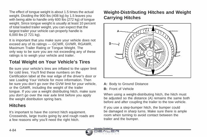
The effect of tongue weight is about 1.5 times the actualweight. Dividing the 900 lbs (408 kg) by 1.5 leaves youwith being able to handle only 600 lbs (272 kg) of tongueweight. Since tongue weight is usually at least 10 percentof total loaded trailer weight, you can expect that thelargest trailer your vehicle can properly handle is6,000 lbs (2 721 kg).
It is important that you make sure your vehicle does notexceed any of its ratings — GCWR, GVWR, RGAWR,Maximum Trailer Rating or Tongue Weight. Theonly way to be sure you are not exceeding any of theseratings is to weigh your vehicle and trailer.
Total Weight on Your Vehicle’s TiresBe sure your vehicle’s tires are inflated to the upper limitfor cold tires. You’ll find these numbers on theCertification label at the rear edge of the driver’s door orsee Loading Your Vehicle for more information. Thenbe sure you don’t go over the GVW limit for your vehicle,or the GAWR, including the weight of the trailertongue. If you use a weight distributing hitch, make sureyou don’t go over the rear axle limit before you applythe weight distribution spring bars.
HitchesIt’s important to have the correct hitch equipment.Crosswinds, large trucks going by and rough roads area few reasons why you’ll need the right hitch.
Weight-Distributing Hitches and WeightCarrying Hitches
A: Body to Ground DistanceB: Front of Vehicle
When using a weight-distributing hitch, the hitch mustbe adjusted so the distance (A) remains the same bothbefore and after coupling the trailer to the tow vehicle.
If you use a step-bumper hitch, the bumper couldbe damaged in sharp turns. Make sure there is ampleroom when turning to avoid contact between thetrailer and the bumper.
4-84Information Provided by:

If you will be pulling a trailer that, when loaded, willweigh more than 5,000 lbs (2 270 kg) be sure to use aproperly mounted weight-distributing hitch and swaycontrol of the proper size. This equipment is veryimportant for proper vehicle loading and good handlingwhen driving. Always use a sway control if the trailerwill weigh more than these limits. You can ask ahitch dealer about sway controls.
Fifth Wheel and Gooseneck Trailering
Notice: Pulling a fifth-wheel trailer with a vehiclethat is equipped with the SS trim package coulddamage the vehicle. Do not pull a fifth-wheel trailerwith a vehicle equipped with the SS trim package.
Fifth wheel and gooseneck trailers can be used withmany pickup models. These trailers place a largerpercentage of the weight (kingpin weight) on the towvehicle than conventional trailers. Make sure this weightdoes not cause the vehicle to exceed GAWR or GVWR.
Fifth wheel or gooseneck kingpin weight should be 15 to25 percent of the trailer weight up to the maximumamount specified in the trailering chart for your vehicle.See “Weight of the Trailer” in this section for moreinformation.
The hitch should be located in the pickup bed so thatit’s centerline is over or slightly in front of the rear axle.Take care that it is not so far forward that it willcontact the back of the cab in sharp turns.
This is especially important for short box pickups. Trailerpin box extensions and sliding fifth wheel hitchassemblies can help this condition. There should be atleast six inches of clearance between the top of thepickup box and the bottom of the trailer shelf thatextends over the box.
Make sure the hitch is attached to the tow vehicle framerails. Do not use the pickup box for support.
Safety ChainsYou should always attach chains between your vehicleand your trailer. Cross the safety chains under thetongue of the trailer to help prevent the tongue fromcontacting the road if it becomes separated fromthe hitch. Instructions about safety chains may beprovided by the hitch manufacturer or by the trailermanufacturer. If you are towing a trailer up to 5,000 lbs(2 271 kg) with a factory-installed step bumper, youmay attach the safety chains to the attaching points onthe bumper. If you are towing a trailer up to yourvehicle’s trailer rating limit you may attach the safetychains to the attaching point on the hitch platform. If youare towing with an aftermarket hitch follow the traileror hitch manufacturer’s recommendation for attachingsafety chains. Always leave just enough slack soyou can turn with your rig. Never allow safety chains todrag on the ground.
4-85Information Provided by:
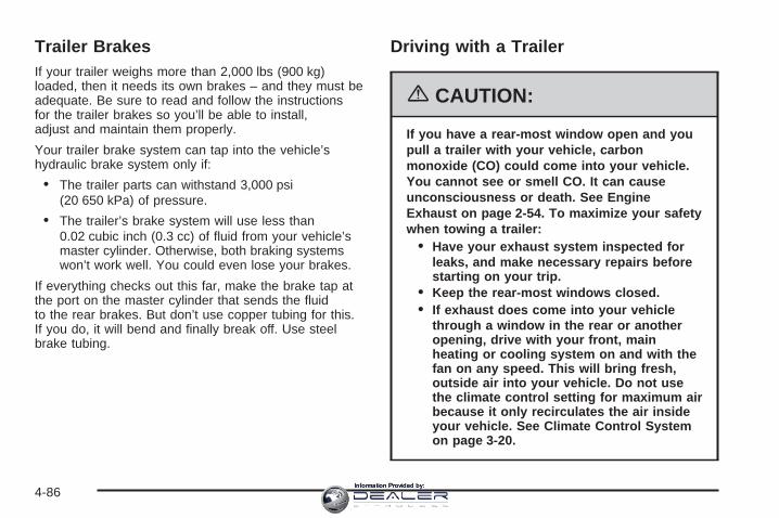
Trailer BrakesIf your trailer weighs more than 2,000 lbs (900 kg)loaded, then it needs its own brakes – and they must beadequate. Be sure to read and follow the instructionsfor the trailer brakes so you’ll be able to install,adjust and maintain them properly.
Your trailer brake system can tap into the vehicle’shydraulic brake system only if:
• The trailer parts can withstand 3,000 psi(20 650 kPa) of pressure.
• The trailer’s brake system will use less than0.02 cubic inch (0.3 cc) of fluid from your vehicle’smaster cylinder. Otherwise, both braking systemswon’t work well. You could even lose your brakes.
If everything checks out this far, make the brake tap atthe port on the master cylinder that sends the fluidto the rear brakes. But don’t use copper tubing for this.If you do, it will bend and finally break off. Use steelbrake tubing.
Driving with a Trailer
{CAUTION:
If you have a rear-most window open and youpull a trailer with your vehicle, carbonmonoxide (CO) could come into your vehicle.You cannot see or smell CO. It can causeunconsciousness or death. See EngineExhaust on page 2-54. To maximize your safetywhen towing a trailer:
• Have your exhaust system inspected forleaks, and make necessary repairs beforestarting on your trip.
• Keep the rear-most windows closed.• If exhaust does come into your vehicle
through a window in the rear or anotheropening, drive with your front, mainheating or cooling system on and with thefan on any speed. This will bring fresh,outside air into your vehicle. Do not usethe climate control setting for maximum airbecause it only recirculates the air insideyour vehicle. See Climate Control Systemon page 3-20.
4-86Information Provided by:

Towing a trailer requires a certain amount of experience.Before setting out for the open road, you’ll want to getto know your rig. Acquaint yourself with the feel ofhandling and braking with the added weight of the trailer.And always keep in mind that the vehicle you aredriving is now a good deal longer and not nearly asresponsive as your vehicle is by itself.
Before you start, check all trailer hitch parts andattachments, safety chains, electrical connector, lamps,tires and mirror adjustment. If the trailer has electricbrakes, start your vehicle and trailer moving and thenapply the trailer brake controller by hand to be surethe brakes are working. This lets you check yourelectrical connection at the same time.
During your trip, check occasionally to be sure that theload is secure, and that the lamps and any trailerbrakes are still working.
While towing a trailer or when exposed to long periodsof sunshine, the floor of the truck bed may becomevery warm. Avoid putting items in the truck bedthat might be affected by high ambient temperatures.
Following DistanceStay at least twice as far behind the vehicle ahead asyou would when driving your vehicle without a trailer.This can help you avoid situations that requireheavy braking and sudden turns.
PassingYou’ll need more passing distance up ahead whenyou’re towing a trailer. And, because you’re a good deallonger, you’ll need to go much farther beyond thepassed vehicle before you can return to your lane.
Backing UpHold the bottom of the steering wheel with one hand.Then, to move the trailer to the left, just move that handto the left. To move the trailer to the right, move yourhand to the right. Always back up slowly and, if possible,have someone guide you.
Making Turns
Notice: Making very sharp turns while traileringcould cause the trailer to come in contact with thevehicle. Your vehicle could be damaged. Avoidmaking very sharp turns while trailering.
When you’re turning with a trailer, make wider turnsthan normal. Do this so your trailer won’t strikesoft shoulders, curbs, road signs, trees or other objects.Avoid jerky or sudden maneuvers. Signal well inadvance.
4-87Information Provided by:

Turn Signals When Towing a TrailerThe arrows on your instrument panel will flash wheneveryou signal a turn or lane change. Properly hooked up,the trailer lamps will also flash, telling other driversyou’re about to turn, change lanes or stop.
When towing a trailer, the arrows on your instrumentpanel will flash for turns even if the bulbs on the trailerare burned out. Thus, you may think drivers behindyou are seeing your signal when they are not. It’simportant to check occasionally to be sure the trailerbulbs are still working.
Driving On GradesReduce speed and shift to a lower gear before you startdown a long or steep downgrade. If you don’t shiftdown, you might have to use your brakes so much thatthey would get hot and no longer work well.
If you have an automatic transmission, you can tow inDRIVE (D). You may want to shift the transmissionto lower gear selection if the transmission shifts too often(e.g., under heavy loads and/or hilly conditions).
You may also want to activate the tow/haul mode if thetransmission shifts too often. See Tow/Haul ModeLight on page 3-49.
If you have a 5-speed manual transmission and you aretowing a trailer, it’s better not to use FIFTH (5) gear.Just drive in FOURTH (4) gear (or, as you needto, a lower gear).
If you have a 6-speed manual transmission and you aretowing a trailer, it’s better not to use SIXTH (6) gear.Drive in FIFTH (5) gear (or, as you need to, a lower gear).
When towing at high altitude on steep uphill grades,consider the following: Engine coolant at or nearsea level will boil at a lower temperature than at higheraltitudes. If you turn your engine off immediatelyafter towing at high altitude on steep uphill grades, yourvehicle may show signs similar to engine overheating.To avoid this, let the engine run while parked, preferablyon level ground, with the automatic transmission inPARK (P) for a few minutes before turning the engineoff. For manual transmissions, let the engine runwhile parked, preferably on level ground, with thetransmission out of gear and the parking brake applied,for a few minutes before turning the engine off. Ifyou do get the overheat warning, see EngineOverheating on page 5-37.
4-88Information Provided by:

Parking on Hills
{CAUTION:
You really should not park your vehicle, with atrailer attached, on a hill. If something goeswrong, your rig could start to move. Peoplecan be injured, and both your vehicle and thetrailer can be damaged.
But if you ever have to park your rig on a hill, here’show to do it:
1. Apply your regular brakes, but don’t shift intoPARK (P) yet for an automatic transmission, or intogear for a manual transmission.
2. Have someone place chocks under the trailerwheels.
3. When the wheel chocks are in place, release theregular brakes until the chocks absorb the load.
4. Reapply the regular brakes. Then apply yourparking brake and shift into PARK (P) for anautomatic transmission, or REVERSE (R) for amanual transmission.
5. If you have a four-wheel-drive vehicle, be sure thetransfer case is in a drive gear and not inNEUTRAL.
6. Release the regular brakes.
{CAUTION:
It can be dangerous to get out of your vehicleif the automatic transmission shift lever is notfully in PARK (P) with the parking brake firmlyset. Your vehicle can roll.
If you have left the engine running, the vehiclecan move suddenly. You or others could beinjured. To be sure your vehicle will not move,even when you are on fairly level ground, usethe steps that follow.
Always put the automatic transmission shiftlever fully in PARK (P) with the parking brakefirmly set. If you have a manual transmission,turn the engine off and firmly set the parkingbrake.
If the transfer case on four-wheel-drivevehicles is in NEUTRAL, your vehicle will befree to roll, even if your automatictransmission shift lever is in PARK (P). So, besure the transfer case is in a drive gear — notin NEUTRAL.
4-89Information Provided by:

When You Are Ready to Leave AfterParking on a Hill
1. Apply your regular brakes and hold the pedal downwhile you:
• Start your engine
• Shift into a gear
• Release the parking brake
2. Let up on the brake pedal.
3. Drive slowly until the trailer is clear of the chocks.
4. Stop and have someone pick up and store thechocks.
Maintenance When Trailer TowingYour vehicle will need service more often when you’repulling a trailer. See Scheduled Maintenance (GasolineEngine) on page 6-4 for more information. Thingsthat are especially important in trailer operation areautomatic transmission fluid (don’t overfill), engine oil,axle lubricant, belt, cooling system and brake system.Each of these is covered in this manual, and the Indexwill help you find them quickly. If you’re trailering, it’sa good idea to review these sections before youstart your trip.
Check periodically to see that all hitch nuts and boltsare tight.
Trailer Wiring HarnessYour vehicle is equipped with one of the following wiringharnesses for towing a trailer or hauling a slide-incamper.
Basic Trailer WiringAll regular, extended cab and crew cab pickups have aneight-wire trailer towing harness.
For vehicles not equipped with heavy duty trailering, theharness is clipped to the vehicle’s frame behind thespare tire mount. The harness requires the installationof a trailer connector, which is available throughyour dealer.
4-90Information Provided by:

If your trailer is equipped with electric brakes, you canget a jumper harness (electric trailer brake control)with a trailer battery feed fuse from your dealer.
If you need to tow a light-duty trailer with a standardfour-way round pin connector, you can also get anadapter from your dealer.
Heavy-DutyTrailer Wiring HarnessPackage
For vehicles equipped with heavy duty trailering, theharness is connected to the trailer mounted to the hitchplatform. The eight-wire harness contains the followingtrailer circuits:
• Yellow: Left Stop/Turn Signal
• Dark Green: Right Stop/Turn Signal
• Brown: Taillamps
• White: Ground
• Light Green: Back-up Lamps
• Light Blue: CHMSL*
• Red: Battery Feed**
• Dark Blue: Trailer Brake
*The Center High-Mounted Stoplamp (CHMSL) wire istied next to the trailer wiring harness for use with atrailer, slide-in camper or cap.
**If you are charging a remote (non-vehicle) battery,turn on the headlamps to boost the vehicle systemvoltage and properly charge the battery.
4-91Information Provided by:

Camper/Fifth-Wheel Trailer Wiring Package
Notice: Pulling a fifth-wheel trailer with a vehiclethat is equipped with the SS trim package coulddamage the vehicle. Do not pull a fifth-wheel trailerwith a vehicle equipped with the SS trim package.
The eight-wire camper harness is located under the frontedge of the pickup box on the driver’s side of thevehicle, attached to the frame bracket. A connector willhave to be added to the wiring harness whichconnects to the camper.
The eight-wire harness contains the followingcamper/trailer circuits:
• Yellow: Left Stop/Turn Signal
• Dark Green: Right Stop/Turn Signal
• Brown: Taillamps
• White: Ground
• Light Green: Back-up Lamps
• Light Blue: Center High-Mounted Stoplamp(CHMSL)
• Red: Battery Feed
• Dark Blue: Trailer Brake
If your vehicle is equipped with the “Heavy-DutyTrailering” option, please refer to “Heavy-Duty TrailerWiring Package” earlier in this section.
When the camper-wiring harness is ordered without theheavy-duty trailering package, an eight-wire harnesswith a seven-pin connector and separate CHMSLconnector are located at the rear of the vehicle and aretied to the vehicle’s frame.
4-92Information Provided by:

Electric Brake Control Jumper
{CAUTION:
Be sure to use only the correct trailer brakeharness, the one intended for use on yourvehicle. If you use some other trailer brakeharness, even if it seems to fit, your trailerbrakes may not work at all. You could have acrash in which you or others could be injured.Use only the trailer brake harness intended foryour vehicle. If it is no longer available to you,be sure to get a proper replacement from yourdealer. This harness is included with your vehicle as part of the
heavy-duty trailer wiring package.
This harness is for an electric brake controller andincludes a trailer battery feed fuse. It should be installedby your dealer or a qualified service center.
4-93Information Provided by:

Auxiliary BatteryThe auxiliary battery provision can be used to supplyelectrical power to additional equipment that youmay choose to add, such as a slide-in camper.
If your vehicle has thisprovision, this relay will belocated on the passenger’sside of the vehicle, nextto the auxiliary battery.
When using this provision, connection should only bemade to the upper stud (A) of the relay. Do notmake connections to the lower stud (B) of the relay.
The auxiliary battery circuit is protected by a megafuselocated behind the auxiliary battery.
Be sure to follow the proper installation instructions thatare included with any electrical equipment that youinstall.
Notice: Leaving electrical equipment on forextended periods will drain the battery. Always turnoff electrical equipment when not in use and donot use equipment that exceeds the maximumamperage rating for the auxiliary battery provision.
Power WinchesIf you wish to use a power winch on your vehicle, onlyuse it when your vehicle is stationary or anchored.
4-94Information Provided by:
Trailer RecommendationsYou must subtract your hitch loads from the CWR foryour vehicle. Weigh your vehicle with the trailerattached, so that you won’t go over the GVWR orGAWR. If you are using a weight-distributing hitch,weigh the vehicle without the spring bars in place.
You’ll get the best performance if you spread out theweight of your load the right way, and if you choose thecorrect hitch and trailer brakes.
For more information, see Towing a Trailer onpage 4-67.
Power Take-Off (PTO)Before using a Power Take-Off (PTO), if equipped, referto the manufacturer’s or installer’s instructions.
To engage a PTO on a vehicle with a manualtransmission do the following:
1. Hold the clutch pedal down.
2. Set the parking brake.
3. Shift the transmission into NEUTRAL.
4. Engage the PTO. Refer to the manufacturer’s orinstaller’s for instructions on electricallyengaged PTOs.
5. For mobile operations, shift the transmission intothe gear you want, apply the regular brakes andrelease the parking brake. For stationary operations,leave the parking brake applied.
6. Release the clutch and regular brakes as younormally would. When the clutch is released,the PTO will start.
7. Turn the PTO rotary switch to ON.
To engage a PTO on a vehicle with an automatictransmission do the following:
1. For stationary use shift the transmissioninto PARK (P).
2. Turn the PTO rotary switch ON.
3. If the engine speed is below the PTO engagespeed limit, the PTO will start. The blinking LEDon the PTO control switch indicates PTO engage isrequested. When PTO engages the LED willswitch from blinking to a steady light.
4-95Information Provided by:
To use PTO speed control in Preset Mode (FactorySetting) do the following:
1. Engage the PTO.2. Select PARK (P) or NEUTRAL (N) range. Apply the
parking brake if NEUTRAL (N) is selected. TorqueConverter Clutch (TCC) is not available inNEUTRAL (N) and is available only in PARK (P)when engine speed is above 1,100 rpm.
3. Make sure your foot is off the brake pedal (and offthe clutch on vehicles equipped with a manualtransmission).
4. Select the desired engine speed for PTO operation.Read the following preset mode informationregarding operation.
Preset Mode: PTO speed control mode is used forstationary applications. (PTO will remain engaged whilemobile in the preset mode, however PTO set andresume speed controls will be inoperative.) This modeprovides a default standby speed of 800 or 850 rpm(depending on the engine/transmission combination) andtwo default PTO control speeds which follow:
1. PTO Set Speed of 1,250 rpm, or2. PTO Resume Speed of 1,700 rpm.
Please note that the standby speed (800/850 rpm) isnot to be used as a PTO control speed. Vehiclesnot equipped with cruise control will not have the resumespeed capability.
To use PTO speed control in variable mode (whilemobile) do the following:
1. Engage the PTO.
2. Vehicle speed must be greater than 5 mph.
3. Make sure your foot is off the brake pedal (and offthe clutch for vehicles equipped with a manualtransmission).
4. Select the desired engine speed by using the footpedal, and select SET on the PTO switch or thecruise control.
To use PTO speed control in variable mode (whilestationary) do the following:
1. Engage the PTO.
2. Vehicle speed must be less than 5 mph.
3. Make sure your foot is off the brake pedal (and offthe clutch for vehicles equipped with a manualtransmission).
4. Select the desired engine speed by using the footpedal, and select SET on the PTO switch or thecruise control.
4-96Information Provided by:

Variable Mode: PTO speed control mode can be usedfor both stationary and mobile applications. Thismode allows PTO to be controlled in a fashion similar tohow cruise control sets vehicle speed. The operatorcan set to an rpm (between 800 and 2,200) withthe cruise control feature or with the SET position onthe PTO switch. The operator is then able to increaserpm in increments of 100, or “tap up” with the resumeposition on the cruise control. The operator canalso decrease rpm in increments of 100 with the SETswitch on the PTO or the cruise control.
Vehicles not equipped with cruise control will not havethe “tap up” capability.
All engine speed values listed above are factory presetvalues. With the exception of the TCC lockup speed(1,100 rpm) and the “tap” increment (100 rpm), allof these values are programmable and can be adjustedby your dealer or body upfitter. If the PTO softwaresettings do not match the settings shown here, then theymay have already been altered in order to satisfy therequirements of the installed PTO system and bodyequipment.
When the PTO switch is turned on, the engine is limitedto 2,200 rpms. If there are no accessories installedon the vehicle, make sure the PTO switch is turned off.
Step-Bumper PadYour vehicle has a rear step bumper with a rear steppad at the center of the bumper.
If you will be using thebumper to tow a trailer,and your step-bumper hasthree cutout circles, youmust push out thecenter cutout circle toinstall the trailer ball.
If your step-bumper has only one cutout circle, you willhave to cut out the circle, then remove it to installthe trailer ball.
4-97Information Provided by:

✍ NOTES
4-98Information Provided by:

Service ............................................................5-4Accessories and Modifications ..........................5-4California Proposition 65 Warning .....................5-4Doing Your Own Service Work .........................5-5Adding Equipment to the Outside of
Your Vehicle ..............................................5-5Fuel ................................................................5-6
Gasoline Octane ............................................5-6Gasoline Specifications ....................................5-6California Fuel ...............................................5-7Additives .......................................................5-7Fuel E85 (85% Ethanol) ..................................5-8Fuels in Foreign Countries ...............................5-9Filling the Tank ............................................5-10Filling a Portable Fuel Container .....................5-12
Checking Things Under the Hood ....................5-12Hood Release ..............................................5-13Engine Compartment Overview .......................5-14Engine Oil (Gasoline Engine) ..........................5-20Engine Oil Life System (Gasoline Engine) ........5-23Engine Air Cleaner/Filter (Gasoline Engines) .....5-25Automatic Transmission Fluid
(Except Allison Transmission®) ....................5-27Automatic Transmission Fluid
(Allison Transmission®) ...............................5-30
Manual Transmission Fluid .............................5-32Hydraulic Clutch ...........................................5-34Engine Coolant .............................................5-35Coolant Surge Tank Pressure Cap ..................5-37Engine Overheating .......................................5-37Overheated Engine Protection Operating
Mode (V8 Engines Only) ............................5-40Cooling System ............................................5-40Engine Fan Noise .........................................5-45Power Steering Fluid .....................................5-46Windshield Washer Fluid ................................5-47Brakes ........................................................5-48Battery ........................................................5-51Jump Starting ...............................................5-52
Rear Axle .......................................................5-56Four-Wheel Drive ............................................5-58Front Axle ......................................................5-60Noise Control System .....................................5-61
Tampering with Noise Control SystemProhibited .................................................5-61
Section 5 Service and Appearance Care
5-1Information Provided by:

Bulb Replacement ..........................................5-62Halogen Bulbs ..............................................5-62Headlamps ..................................................5-62Front Turn Signal, Sidemarker and Daytime
Running Lamps .........................................5-64Roof Marker Lamps ......................................5-66Center High-Mounted Stoplamp (CHMSL) and
Cargo Lamp .............................................5-67Pickup Box Identification and Fender
Marker Lamps ...........................................5-69Taillamps, Turn Signal, Stoplamps and
Back-up Lamps .........................................5-69Replacement Bulbs .......................................5-71
Windshield Wiper Blade Replacement ..............5-72Tires ..............................................................5-73
Tire Sidewall Labeling ...................................5-74Tire Terminology and Definitions .....................5-77Inflation - Tire Pressure .................................5-80Dual Tire Operation .......................................5-82Tire Inspection and Rotation ...........................5-82When It Is Time for New Tires .......................5-85Buying New Tires .........................................5-86Different Size Tires and Wheels ......................5-87Uniform Tire Quality Grading ..........................5-88
Wheel Alignment and Tire Balance ..................5-89Wheel Replacement ......................................5-89Tire Chains ..................................................5-91If a Tire Goes Flat ........................................5-92Changing a Flat Tire .....................................5-92Removing the Spare Tire and Tools ................5-94Removing the Flat Tire and Installing the
Spare Tire ................................................5-98Secondary Latch System ..............................5-107Storing a Flat or Spare Tire and Tools ...........5-110Spare Tire .................................................5-114
Appearance Care ..........................................5-114Cleaning the Inside of Your Vehicle ...............5-114Fabric/Carpet ..............................................5-116Leather ......................................................5-116Instrument Panel, Vinyl, and Other Plastic
Surfaces .................................................5-117Care of Safety Belts ....................................5-117Weatherstrips .............................................5-117Washing Your Vehicle ..................................5-118Cleaning Exterior Lamps/Lenses ....................5-118Finish Care ................................................5-118Windshield and Wiper Blades .......................5-119Aluminum or Chrome-Plated Wheels ..............5-119
Section 5 Service and Appearance Care
5-2Information Provided by:

Tires .........................................................5-120Sheet Metal Damage ...................................5-120Underbody Maintenance ...............................5-120Chemical Paint Spotting ...............................5-121Vehicle Care/Appearance Materials ................5-121
Vehicle Identification .....................................5-122Vehicle Identification Number (VIN) ................5-122Service Parts Identification Label ...................5-123
Electrical System ..........................................5-123Add-On Electrical Equipment .........................5-123Windshield Wiper Fuses ...............................5-123Power Windows and Other Power Options ......5-124Fuses and Circuit Breakers ..........................5-124Instrument Panel Fuse Block ........................5-124Center Instrument Panel Fuse Block ..............5-126Underhood Fuse Block ................................5-127
Capacities and Specifications ........................5-132
Section 5 Service and Appearance Care
5-3Information Provided by:

ServiceYour dealer knows your vehicle best and wants you tobe happy with it. We hope you will go to your dealerfor all your service needs. You will get genuine GM partsand GM-trained and supported service people.
We hope you will want to keep your GM vehicle all GM.Genuine GM parts have one of these marks:
Accessories and ModificationsWhen you add non-GM accessories to your vehicle theycan affect your vehicle’s performance and safety,including such things as, braking, stability, ride andhandling, emissions systems, aerodynamics, durability,and electronic systems like antilock brakes, tractioncontrol and stability control. Some of these accessoriesmay even cause malfunction or damage not coveredby warranty.
GM Accessories are designed to complement andfunction with other systems on your vehicle. Your GMdealer can accessorize your vehicle using genuineGM Accessories. When you go to your GM dealer andask for GM Accessories, you will know that GM-trainedand supported service technicians will perform thework using genuine GM Accessories.
California Proposition 65 WarningMost motor vehicles, including this one, contain and/oremit chemicals known to the State of California tocause cancer and birth defects or other reproductiveharm. Engine exhaust, many parts and systems(including some inside the vehicle), many fluids, andsome component wear by-products contain and/or emitthese chemicals.
5-4Information Provided by:

Doing Your Own Service Work
{CAUTION:
You can be injured and your vehicle could bedamaged if you try to do service work on avehicle without knowing enough about it.
• Be sure you have sufficient knowledge,experience, the proper replacement parts,and tools before you attempt any vehiclemaintenance task.
• Be sure to use the proper nuts, bolts, andother fasteners. English and metricfasteners can be easily confused. If youuse the wrong fasteners, parts can laterbreak or fall off. You could be hurt.
If you want to do some of your own service work, youwill want to use the proper service manual. It tellsyou much more about how to service your vehicle thanthis manual can. To order the proper service manual,see Service Publications Ordering Information onpage 7-14.
Your vehicle has an airbag system. Before attempting todo your own service work, see Servicing YourAirbag-Equipped Vehicle on page 1-86.
You should keep a record with all parts receipts and listthe mileage and the date of any service work youperform. See Maintenance Record on page 6-19.
Adding Equipment to the Outside ofYour VehicleThings you might add to the outside of your vehicle canaffect the airflow around it. This may cause windnoise and affect windshield washer performance. Checkwith your dealer before adding equipment to theoutside of your vehicle.
5-5Information Provided by:
FuelIf your vehicle has a diesel engine, see “Diesel FuelRequirements and Fuel System” in the DURAMAX®
Diesel Supplement.For vehicles with gasoline engines, please read this.
GasolineThe 8th digit of your vehicle identification number (VIN)shows the code letter or number that identifies yourengine. You will find the VIN at the top left of theinstrument panel. See Vehicle Identification Number(VIN) on page 5-122.If your vehicle has the 5.3L V8 engine (VIN Code Z),you may use either regular unleaded gasoline or ethanolfuel containing up to 85% ethanol (E85); also seeFuel E85 (85% Ethanol) on page 5-8. In all othergasoline engines, use only regular unleaded gasoline.
Gasoline OctaneFor all vehicles, except those with the 6.0L V8 engine(VIN Code N), use regular unleaded gasoline witha posted octane rating of 87 or higher. If the octanerating is less than 87, you may notice an audibleknocking noise when you drive, commonly referred toas spark knock. If this occurs, use a gasoline rated at87 octane or higher as soon as possible. If you are usinggasoline rated at 87 octane or higher and you hearheavy knocking, your engine needs service.
If your vehicle has the 6.0L V8 engine (VIN Code N),use premium unleaded gasoline with a postedoctane rating of 91 or higher. You may also use regularunleaded gasoline rated at 87 octane or higher, butyour vehicle’s acceleration may be slightly reduced, andyou may notice a slight audible knocking noise,commonly referred to as spark knock. If the octane isless than 87, you may notice a heavy knockingnoise when you drive. If this occurs, use a gasolinerated at 87 octane or higher as soon as possible.Otherwise, you might damage your engine. If you areusing gasoline rated at 87 octane or higher and you hearheavy knocking, your engine needs service.
Gasoline SpecificationsAt a minimum, gasoline should meet ASTM specificationD 4814 in the United States or CAN/CGSB-3.5 inCanada. Some gasolines may contain anoctane-enhancing additive called methylcyclopentadienylmanganese tricarbonyl (MMT). General Motorsrecommends against the use of gasolines containingMMT. See Additives on page 5-7 for additionalinformation.
5-6Information Provided by:

California FuelIf your vehicle is certified to meet California EmissionsStandards, it is designed to operate on fuels thatmeet California specifications. See the underhoodemission control label. If this fuel is not availablein states adopting California emissions standards, yourvehicle will operate satisfactorily on fuels meetingfederal specifications, but emission control systemperformance may be affected. The malfunction indicatorlamp may turn on and your vehicle may fail asmog-check test. See Malfunction Indicator Lamp onpage 3-45. If this occurs, return to your authorized GMdealer for diagnosis. If it is determined that thecondition is caused by the type of fuel used, repairsmay not be covered by your warranty.
AdditivesTo provide cleaner air, all gasolines in the United Statesare now required to contain additives that will helpprevent engine and fuel system deposits from forming,allowing your emission control system to workproperly. In most cases, you should not have to addanything to your fuel. However, some gasolines containonly the minimum amount of additive required tomeet U.S. Environmental Protection Agency regulations.To help keep fuel injectors and intake valves clean,or if your vehicle experiences problems due todirty injectors or valves, look for gasoline that is
advertised as TOP TIER Detergent Gasoline. Also, yourGM dealer has additives that will help correct andprevent most deposit-related problems.
Gasolines containing oxygenates, such as ethers andethanol, and reformulated gasolines may be available inyour area. General Motors recommends that you usethese gasolines if they comply with the specificationsdescribed earlier. However, E85 (85% ethanol) and otherfuels containing more than 10% ethanol must not be usedin vehicles that were not designed for those fuels.
Notice: Your vehicle was not designed for fuel thatcontains methanol. Do not use fuel containingmethanol. It can corrode metal parts in your fuelsystem and also damage the plastic and rubberparts. That damage would not be covered underyour warranty.
Some gasolines that are not reformulated for lowemissions may contain an octane-enhancing additivecalled methylcyclopentadienyl manganese tricarbonyl(MMT); ask the attendant where you buy gasolinewhether the fuel contains MMT. General Motorsrecommends against the use of such gasolines. Fuelscontaining MMT can reduce the life of spark plugsand the performance of the emission control system maybe affected. The malfunction indicator lamp may turnon. If this occurs, return to your authorized GM dealer forservice.
5-7Information Provided by:

Fuel E85 (85% Ethanol)The 8th digit of your vehicle identification number (VIN)shows the code letter or number that identifies yourengine. You will find the VIN at the top left of theinstrument panel. See Vehicle Identification Number(VIN) on page 5-122.
If your vehicle has the 5.3L V8 engine (VIN Code Z only),you may use either regular unleaded gasoline or ethanolfuel containing up to 85% ethanol (E85); also see Fuel onpage 5-6. In all other engines, including the 5.3L V8 (VINCode T), use only regular unleaded gasoline.
Only vehicles that have the 5.3L V8 engine (VIN Code Z)may use 85% ethanol fuel (E85). General Motorsencourages the use of E85 in vehicles that are designedto use it. The ethanol in E85 is a “renewable” fuel,meaning it is made from renewable sources such as cornand other crops.
Many service stations will not have an 85% ethanolfuel (E85) pump available. The U. S. Departmentof Energy has an alternative fuels website(http://www.eere.energy.gov/afdc/infrastructure/locator.html)that can help you find E85 fuel. Those stations that dohave E85 should have a label indicating ethanolcontent. Do not use the fuel if the ethanol content isgreater than 85%.
At a minimum, E85 should meet ASTMSpecification D 5798.
To ensure quick starts in the wintertime, the E85 fuelmust be formulated properly for your climate accordingto ASTM specification D 5798. If you have troublestarting on E85, it may be because your E85 fuel is notproperly formulated for your climate. If this happens,switching to gasoline or adding gasoline to your fuel tankmay improve starting. Your vehicle is designed toaccommodate a mixture of gasoline and E85 fuel. Forgood starting and heater efficiency below 32°F (0°C), thefuel mix in the fuel tank should contain no more than70% ethanol.
5-8Information Provided by:

E85 has less energy per gallon than gasoline, so youwill need to refill your fuel tank more often whenusing E85 than when you are using gasoline. Regularunleaded gasoline is recommended when pulling atrailer. For payload capacity with ethanol fuel, seeLoading Your Vehicle on page 4-48.
Notice: Some additives are not compatible withE85 fuel and may harm your fuel system. Damagecaused by additives would not be covered byyour new vehicle warranty. Do not use additiveswith E85 fuel.
Notice: Your vehicle was not designed for fuel thatcontains methanol. Do not use fuel containingmethanol. It can corrode metal parts in your fuelsystem and also damage the plastic and rubberparts. That damage would not be covered underyour warranty.
Fuels in Foreign CountriesIf you plan on driving in another country outside theUnited States or Canada, the proper fuel may be hardto find. Never use leaded gasoline or any other fuelnot recommended in the previous text on fuel. Costlyrepairs caused by use of improper fuel would notbe covered by your warranty.
To check the fuel availability, ask an auto club, orcontact a major oil company that does business in thecountry where you will be driving.
5-9Information Provided by:

Filling the Tank
{CAUTION:
Fuel vapor burns violently and a fuel fire cancause bad injuries. To help avoid injuries toyou and others, read and follow all theinstructions on the pump island. Turn off yourengine when you are refueling. Do not smokeif you are near fuel or refueling your vehicle.Keep sparks, flames, and smoking materialsaway from fuel. Do not leave the fuel pumpunattended when refueling your vehicle — thisis against the law in some places. Keepchildren away from the fuel pump; never letchildren pump fuel.
The tethered fuel cap is located behind a hinged fueldoor on the driver’s side of the vehicle.
To remove the fuel cap, turn it slowly counterclockwise.It will require more effort to turn the fuel cap on thelast turn as you loosen it.
{CAUTION:
If you spill fuel and then something ignites it,you could be badly burned. Fuel can spray outon you if you open the fuel cap too quickly.This spray can happen if your tank is nearlyfull, and is more likely in hot weather. Openthe fuel cap slowly and wait for any hiss noiseto stop. Then unscrew the cap all the way.
5-10Information Provided by:

If your vehicle is a dual fuel tank chassis cab model,and it runs out of fuel, refuel the front fuel tank firstto ensure a quick restart.
Be careful not to spill fuel. Do not top off or overfill thetank and wait a few seconds after you have finishedpumping before removing the nozzle. Clean fuelfrom painted surfaces as soon as possible. SeeWashing Your Vehicle on page 5-118.
When replacing the fuel cap, turn it clockwise until itclicks. It will require more effort to turn the fuel cap onthe last turn as you tighten it. Make sure the cap isfully installed. The diagnostic system can determine ifthe fuel cap has been left off or improperly installed. Thiswould allow fuel to evaporate into the atmosphere.See Malfunction Indicator Lamp on page 3-45.
The TIGHTEN FUEL CAP message will be displayed onthe Driver Information Center (DIC) if the fuel cap isnot properly installed. See DIC Warnings and Messageson page 3-54 for more information.
{CAUTION:
If a fire starts while you are refueling, do notremove the nozzle. Shut off the flow of fuel byshutting off the pump or by notifying thestation attendant. Leave the area immediately.
Notice: If you need a new fuel cap, be sure to getthe right type. Your dealer can get one for you.If you get the wrong type, it may not fit properly.This may cause your malfunction indicator lamp tolight and may damage your fuel tank and emissionssystem. See Malfunction Indicator Lamp onpage 3-45.
5-11Information Provided by:

Filling a Portable Fuel Container
{CAUTION:
Never fill a portable fuel container while it is inyour vehicle. Static electricity discharge fromthe container can ignite the gasoline vapor.You can be badly burned and your vehicledamaged if this occurs. To help avoid injury toyou and others:
• Dispense gasoline only into approvedcontainers.
• Do not fill a container while it is inside avehicle, in a vehicle’s trunk, pickup bed, oron any surface other than the ground.
• Bring the fill nozzle in contact with theinside of the fill opening before operatingthe nozzle. Contact should be maintaineduntil the filling is complete.
• Do not smoke while pumping gasoline.
Checking Things Underthe Hood
{CAUTION:
An electric fan under the hood can start upand injure you even when the engine is notrunning. Keep hands, clothing and tools awayfrom any underhood electric fan.
{CAUTION:
Things that burn can get on hot engine partsand start a fire. These include liquids like fuel,oil, coolant, brake fluid, windshield washer andother fluids, and plastic or rubber. You orothers could be burned. Be careful not to dropor spill things that will burn onto a hot engine.
5-12Information Provided by:

Hood ReleaseTo open the hood do the following:
1. Pull the handle with thissymbol on it. It islocated inside thevehicle to the lower leftof the steering wheel.
2. Then go to the front of the vehicle and pull up onthe secondary hood release located near thecenter of the grille.
3. Lift the hood.Before closing the hood, be sure all the filler capsare on properly. Then pull down the hood and closeit firmly.
5-13Information Provided by:

Engine Compartment OverviewWhen you open the hood on the 4.3L V6 engine, here is what you will see:
5-14Information Provided by:

A. Engine Air Cleaner/Filter. See Engine AirCleaner/Filter (Gasoline Engines) on page 5-25.
B. Coolant Surge Tank and Pressure Cap. See EngineCoolant on page 5-35 and Coolant Surge TankPressure Cap on page 5-37.
C. Air Filter Restriction Indicator (If Equipped). SeeEngine Air Cleaner/Filter (Gasoline Engines)on page 5-25.
D. Engine Oil Dipstick. See “Checking Engine Oil”under Engine Oil (Gasoline Engine) on page 5-20.
E. Automatic Transmission Fluid Dipstick (If Equipped).See “Checking the Fluid Level” under AutomaticTransmission Fluid (Except Allison Transmission®)on page 5-27 or Automatic Transmission Fluid(Allison Transmission®) on page 5-30.
F. Engine Cooling Fan. See Cooling System onpage 5-40.
G. Engine Oil Fill Cap. See “When to Add Engine Oil”under Engine Oil (Gasoline Engine) on page 5-20.
H. Power Steering Fluid Reservoir. See Power SteeringFluid on page 5-46.
I. Remote Negative (−) Terminal (GND). See JumpStarting on page 5-52.
J. Remote Positive (+) Terminal. See Jump Starting onpage 5-52.
K. Brake Fluid Reservoir. See “Brake Fluid” underBrakes on page 5-48.
L. Clutch Fluid Reservoir (If Equipped). See HydraulicClutch on page 5-34.
M. Underhood Fuse Block. See Underhood Fuse Blockon page 5-127.
N. Battery. See Battery on page 5-51.O. Windshield Washer Fluid Reservoir. See “Adding
Washer Fluid” under Windshield Washer Fluidon page 5-47.
5-15Information Provided by:

When you open the hood on the 5.3L V8 engine (4.8L and 6.0L V8 engines similar), here is what you will see:
5-16Information Provided by:

A. Engine Air Cleaner/Filter. See Engine AirCleaner/Filter (Gasoline Engines) on page 5-25.
B. Coolant Surge Tank and Pressure Cap. See EngineCoolant on page 5-35 and Coolant Surge TankPressure Cap on page 5-37.
C. Air Filter Restriction Indicator (If Equipped). SeeEngine Air Cleaner/Filter (Gasoline Engines)on page 5-25.
D. Engine Oil Dipstick. See “Checking Engine Oil”under Engine Oil (Gasoline Engine) on page 5-20.
E. Automatic Transmission Fluid Dipstick (If Equipped).See “Checking the Fluid Level” under AutomaticTransmission Fluid (Except Allison Transmission®)on page 5-27 or Automatic Transmission Fluid(Allison Transmission®) on page 5-30.
F. Engine Oil Fill Cap. See “When to Add Engine Oil”under Engine Oil (Gasoline Engine) on page 5-20.
G. Engine Cooling Fan. See Cooling System onpage 5-40.
H. Remote Negative (−) Terminal (GND). See JumpStarting on page 5-52.
I. Power Steering Fluid Reservoir. See Power SteeringFluid on page 5-46.
J. Remote Positive (+) Terminal. See Jump Starting onpage 5-52.
K. Brake Fluid Reservoir. See “Brake Fluid” underBrakes on page 5-48.
L. Clutch Fluid Reservoir (If Equipped). See HydraulicClutch on page 5-34.
M. Underhood Fuse Block. See Underhood Fuse Blockon page 5-127.
N. Battery. See Battery on page 5-51.O. Windshield Washer Fluid Reservoir. See “Adding
Washer Fluid” under Windshield Washer Fluidon page 5-47.
5-17Information Provided by:

When you open the hood on the 8.1L V8 engine, here is what you will see:
5-18Information Provided by:

A. Engine Air Cleaner/Filter. See Engine AirCleaner/Filter (Gasoline Engines) on page 5-25.
B. Coolant Surge Tank and Pressure Cap. See EngineCoolant on page 5-35 and Coolant Surge TankPressure Cap on page 5-37.
C. Air Filter Restriction Indicator (If Equipped). SeeEngine Air Cleaner/Filter (Gasoline Engines)on page 5-25.
D. Engine Oil Dipstick. See “Checking Engine Oil”under Engine Oil (Gasoline Engine) on page 5-20.
E. Automatic Transmission Fluid Dipstick (If Equipped).See “Checking the Fluid Level” under AutomaticTransmission Fluid (Except Allison Transmission®)on page 5-27 or Automatic Transmission Fluid(Allison Transmission®) on page 5-30.
F. Engine Oil Fill Cap. See “When to Add Engine Oil”under Engine Oil (Gasoline Engine) on page 5-20.
G. Engine Cooling Fan. See Cooling System onpage 5-40.
H. Remote Negative (−) Terminal (GND). See JumpStarting on page 5-52.
I. Remote Positive (+) Terminal. See Jump Starting onpage 5-52.
J. Power Steering Fluid Reservoir. See Power SteeringFluid on page 5-46.
K. Brake Fluid Reservoir. See “Brake Fluid” underBrakes on page 5-48.
L. Clutch Fluid Reservoir (If Equipped). See HydraulicClutch on page 5-34.
M. Underhood Fuse Block. See Underhood Fuse Blockon page 5-127.
N. Battery. See Battery on page 5-51.O. Windshield Washer Fluid Reservoir. See “Adding
Washer Fluid” under Windshield Washer Fluidon page 5-47.
5-19Information Provided by:
Engine Oil (Gasoline Engine)If your vehicle has a diesel engine, see “Engine Oil” inthe DURAMAX® Diesel Engine Supplement.
If the CHECK OIL LEVEL light appears on theinstrument cluster (except vehicles equipped with the4.3L engine), it means you need to check your engine oillevel right away.
For more information, see Driver Information Center(DIC) on page 3-51.
You should check your engine oil level regularly; this isan added reminder.
Checking Engine OilIt is a good idea to check your engine oil every time youget fuel. In order to get an accurate reading, the oilmust be warm and the vehicle must be on level ground.
The engine oil dipstick handle is a yellow loop. SeeEngine Compartment Overview on page 5-14 forthe location of the engine oil dipstick.
1. Turn off the engine and give the oil several minutesto drain back into the oil pan. If you do not do this,the oil dipstick might not show the actual level.
2. Pull out the dipstick and clean it with a paper towelor cloth, then push it back in all the way. Remove itagain, keeping the tip down, and check the level.
5-20Information Provided by:

When to Add Engine Oil
If the oil is below the cross-hatched area at the tip ofthe dipstick, you will need to add at least one quart/literof oil. But you must use the right kind. This sectionexplains what kind of oil to use. For engine oil crankcasecapacity, see Capacities and Specifications onpage 5-132.
Notice: Do not add too much oil. If the engine hasso much oil that the oil level gets above thecross-hatched area that shows the proper operatingrange, the engine could be damaged.
See Engine CompartmentOverview on page 5-14 forthe location of theengine oil fill cap.
Be sure to add enough oil to put the level somewhere inthe proper operating range. Push the dipstick all theway back in when you are through.
All Except 8.1L Engine
8.1L Engine
5-21Information Provided by:

What Kind of Engine Oil to Use
Look for two things:
• GM6094M
Your vehicle’s engine requires oil meeting GMStandard GM6094M. You should look for and useonly an oil that meets GM Standard GM6094M.
• SAE 5W-30
As shown in the viscosity chart, SAE 5W-30 is bestfor your vehicle.
These numbers on an oil container show itsviscosity, or thickness. Do not use other viscosityoils such as SAE 20W-50.
Oils meeting theserequirements should alsohave the starburstsymbol on the container.This symbol indicatesthat the oil has beencertified by the AmericanPetroleum Institute (API).
You should look for this information on the oil container,and use only those oils that are identified as meetingGM Standard GM6094M and have the starburst symbolon the front of the oil container.
Notice: Use only engine oil identified as meetingGM Standard GM6094M and showing the AmericanPetroleum Institute Certified For Gasoline Enginesstarburst symbol. Failure to use the recommendedoil can result in engine damage not covered byyour warranty.
GM Goodwrench® oil meets all the requirements foryour vehicle.
5-22Information Provided by:

If you are in an area of extreme cold, where thetemperature falls below −20°F (−29°C), it isrecommended that you use either an SAE 5W-30synthetic oil or an SAE 0W-30 oil. Both will provideeasier cold starting and better protection for your engineat extremely low temperatures.
Engine Oil AdditivesDo not add anything to your oil. The recommended oilswith the starburst symbol that meet GM StandardGM6094M are all you will need for good performanceand engine protection.
Engine Oil Life System(Gasoline Engine)
When to Change Engine OilYour vehicle has a computer system that lets you knowwhen to change the engine oil and filter. This is based onengine revolutions and engine temperature, and not onmileage. Based on driving conditions, the mileage atwhich an oil change will be indicated can varyconsiderably. For the oil life system to work properly, youmust reset the system every time the oil is changed.
When the system has calculated that oil life has beendiminished, it will indicate that an oil change isnecessary. A CHANGE ENGINE OIL message willcome on. See DIC Warnings and Messages onpage 3-54. Change your oil as soon as possible withinthe next 600 miles (1 000 km). It is possible that, ifyou are driving under the best conditions, the oillife system may not indicate that an oil change isnecessary for over a year. However, your engine oil andfilter must be changed at least once a year and atthis time the system must be reset. Your dealer hasGM-trained service people who will perform thiswork using genuine GM parts and reset the system. It isalso important to check your oil regularly and keep itat the proper level.
If the system is ever reset accidentally, you mustchange your oil at 3,000 miles (5 000 km) since yourlast oil change. Remember to reset the oil life systemwhenever the oil is changed.
5-23Information Provided by:

How to Reset the Engine Oil LifeSystemThe Engine Oil Life System calculates when to changeyour engine oil and filter based on vehicle use.Anytime your oil is changed, reset the system so it cancalculate when the next oil change is required. If asituation occurs where you change your oil prior to aCHANGE ENGINE OIL message being turned on, resetthe system.
To reset the Engine Oil Life System, do the following:
1. Turn the ignition key to RUN with the engine off.
2. Fully press and release the accelerator pedal threetimes within five seconds.If the OIL LIFE RESET message flashes for10 seconds, the system is resetting.
3. Turn the key to LOCK.
If the CHANGE ENGINE OIL message comes back onwhen you start your vehicle, the engine oil life systemhas not reset. Repeat the procedure. If it still doesnot reset, see your dealer for service.
What to Do with Used OilUsed engine oil contains certain elements that may beunhealthy for your skin and could even cause cancer.Do not let used oil stay on your skin for very long. Cleanyour skin and nails with soap and water, or a goodhand cleaner. Wash or properly dispose of clothing orrags containing used engine oil. See the manufacturer’swarnings about the use and disposal of oil products.
Used oil can be a threat to the environment. If youchange your own oil, be sure to drain all the oil from thefilter before disposal. Never dispose of oil by putting itin the trash, pouring it on the ground, into sewers, or intostreams or bodies of water. Instead, recycle it bytaking it to a place that collects used oil. If you have aproblem properly disposing of your used oil, askyour dealer, a service station or a local recycling centerfor help.
5-24Information Provided by:

Engine Air Cleaner/Filter(Gasoline Engines)If your vehicle has a diesel engine, see “Pickup Models”under “Engine Air Cleaner/Filter” in the DURAMAX®
Diesel Supplement for the correct inspection andreplacement procedures.
See Engine CompartmentOverview on page 5-14 forthe location of theengine air cleaner/filter andthe air filter restrictionindicator, if equipped.
When to Inspect the Engine AirCleaner/FilterIf your vehicle is equipped with an air filter restrictionindicator, it lets you know when the engine air cleaner/filter needs to be replaced. On vehicles with a restrictionindicator, you should inspect the air filter restrictionindicator at every oil change and replace the engine aircleaner/filter when the indicator tells you to.
On vehicles without an air filter restriction indicator,inspect the air cleaner/filter at the Maintenance IIintervals and replace it at the first oil change after each50,000 mile (83 000 km) interval. See ScheduledMaintenance (Gasoline Engine) on page 6-4 for moreinformation. If you are driving in dusty/dirty conditions,inspect the filter at each engine oil change.
How to Inspect the Engine AirCleaner/FilterVehicles With an Air Filter RestrictionIndicatorLocate the air filter restriction indicator on the engine aircleaner/filter cover. When the indicator turns black oris in the red/orange “change” zone, replace the filter andreset the indicator. See the steps following to replacethe engine air cleaner/filter and to reset the air filterrestriction indicator.
Vehicles Without an Air Filter RestrictionIndicatorTo inspect the air cleaner/filter, remove the engine aircleaner/filter from the vehicle using the steps following.When you have the engine air cleaner/filter removed,lightly shake it to release loose dust and dirt. If theengine air cleaner/filter remains caked with dirt, a newfilter is required.
5-25Information Provided by:

Replacing the Engine Air Cleaner/Filterand Resetting the Air Filter RestrictionIndicator
1. Locate the air cleaner/filter assembly on the frontcorner of the engine compartment on thepassenger’s side of the vehicle.
2. Loosen the screws on the cover of the housing andlift up the cover.
3. Remove the engine air cleaner/filter from thehousing. Care should be taken to dislodge aslittle dirt as possible.
4. Clean the engine air cleaner/filter sealing surfacesand the housing.
5. Inspect or replace the engine air cleaner/filter.
6. Reinstall the cover and tighten the screws.
7. Reset the air filter restriction indicator, if equipped,by pressing the top button on the indicator.
5-26Information Provided by:

{CAUTION:
Operating the engine with the air cleaner/filteroff can cause you or others to be burned. Theair cleaner not only cleans the air; it helps tostop flames if the engine backfires. If it is notthere and the engine backfires, you could beburned. Do not drive with it off, and be carefulworking on the engine with the aircleaner/filter off.
Automatic Transmission Fluid(Except Allison Transmission ®)
When to Check and Change AutomaticTransmission FluidA good time to check your automatic transmission fluidlevel is when the engine oil is changed.
Change the fluid and filter at the intervals listed inAdditional Required Services (Gasoline Engine) onpage 6-7, and be sure to use the transmission fluid listedin Recommended Fluids and Lubricants (GasolineEngine) on page 6-14.
How to Check AutomaticTransmission FluidBecause this operation can be a little difficult, you maychoose to have this done at the dealership servicedepartment.
If you do it yourself, be sure to follow all the instructionshere, or you could get a false reading on the dipstick.
Notice: Too much or too little fluid can damageyour transmission. Too much can mean that someof the fluid could come out and fall on hot enginepart or exhaust system parts, starting a fire.Too little fluid could cause the transmission tooverheat. Be sure to get an accurate reading if youcheck your transmission fluid.
Wait at least 30 minutes before checking thetransmission fluid level if you have been driving:
• When outside temperatures are above 90°F (32°C).
• At high speed for quite a while.
• In heavy traffic — especially in hot weather.
• While pulling a trailer.
To get the right reading, the fluid should be at normaloperating temperature, which is 180°F to 200°F(82°C to 93°C).
5-27Information Provided by:
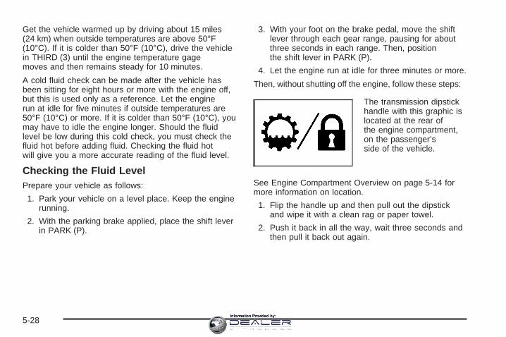
Get the vehicle warmed up by driving about 15 miles(24 km) when outside temperatures are above 50°F(10°C). If it is colder than 50°F (10°C), drive the vehiclein THIRD (3) until the engine temperature gagemoves and then remains steady for 10 minutes.
A cold fluid check can be made after the vehicle hasbeen sitting for eight hours or more with the engine off,but this is used only as a reference. Let the enginerun at idle for five minutes if outside temperatures are50°F (10°C) or more. If it is colder than 50°F (10°C), youmay have to idle the engine longer. Should the fluidlevel be low during this cold check, you must check thefluid hot before adding fluid. Checking the fluid hotwill give you a more accurate reading of the fluid level.
Checking the Fluid LevelPrepare your vehicle as follows:
1. Park your vehicle on a level place. Keep the enginerunning.
2. With the parking brake applied, place the shift leverin PARK (P).
3. With your foot on the brake pedal, move the shiftlever through each gear range, pausing for aboutthree seconds in each range. Then, positionthe shift lever in PARK (P).
4. Let the engine run at idle for three minutes or more.
Then, without shutting off the engine, follow these steps:
The transmission dipstickhandle with this graphic islocated at the rear ofthe engine compartment,on the passenger’sside of the vehicle.
See Engine Compartment Overview on page 5-14 formore information on location.
1. Flip the handle up and then pull out the dipstickand wipe it with a clean rag or paper towel.
2. Push it back in all the way, wait three seconds andthen pull it back out again.
5-28Information Provided by:

3. Check both sides of the dipstick, and read the lowerlevel. The fluid level must be in the COLD area,below the cross-hatched area, for a cold check or inthe HOT or cross-hatched area for a hot check.Be sure to keep the dipstick pointed down to get anaccurate reading.
4. If the fluid level is in the acceptable range, push thedipstick back in all the way; then flip the handledown to lock the dipstick in place.
Consistency of ReadingsAlways check the fluid level at least twice using theprocedure described previously. Consistency (repeatablereadings) is important to maintaining proper fluid level. Ifinconsistent readings persist, check the transmissionbreather hose to be sure it is clean and unclogged. Ifreadings are still inconsistent, contact your dealer.
How to Add AutomaticTransmission FluidRefer to the Maintenance Schedule to determine whatkind of transmission fluid to use. See RecommendedFluids and Lubricants (Gasoline Engine) on page 6-14.
Add fluid only after checking the transmission fluidwhile it is hot. A cold check is used only as a reference.If the fluid level is low, add only enough of the properfluid to bring the level up to the HOT area for a hotcheck. It does not take much fluid, generally less thanone pint (0.5 L). Do not overfill.
Notice: Use of the incorrect automatic transmissionfluid may damage your vehicle, and the damagesmay not be covered by your warranty. Alwaysuse the automatic transmission fluid listed inRecommended Fluids and Lubricants (GasolineEngine) on page 6-14.
• After adding fluid, recheck the fluid level asdescribed under “How to Check AutomaticTransmission Fluid,” earlier in this section.
• When the correct fluid level is obtained, push thedipstick back in all the way; then flip the handledown to lock the dipstick in place.
5-29Information Provided by:

Automatic Transmission Fluid(Allison Transmission ®)
When to Check and Change AutomaticTransmission FluidA good time to check your automatic transmission fluidlevel is when the engine oil is changed.
Change the fluid and filter at the intervals listed inAdditional Required Services (Gasoline Engine) onpage 6-7, and be sure to use the transmission fluid listedin Recommended Fluids and Lubricants (GasolineEngine) on page 6-14.
How to Check AutomaticTransmission FluidBecause this operation can be a little difficult, you maychoose to have this done at the dealership servicedepartment.
If you do it yourself, be sure to follow all the instructionshere, or you could get a false reading on the dipstick.
Notice: Too much or too little fluid can damageyour transmission. Too much can mean that someof the fluid could come out and fall on hot enginepart or exhaust system parts, starting a fire.
Too little fluid could cause the transmission tooverheat. Be sure to get an accurate reading if youcheck your transmission fluid.
Wait at least 30 minutes before checking thetransmission fluid level if you have been driving:
• When outside temperatures are above 90°F (32°C).
• At high speed for quite a while.
• In heavy traffic — especially in hot weather.
• While pulling a trailer.
Checking the Fluid LevelPrepare your vehicle as follows:
1. Park your vehicle on a level place. Keep the enginerunning.
2. With the parking brake applied, place the shift leverin PARK (P).
3. With your foot on the brake pedal, run the enginefor at least once minute and shift to DRIVE (D).Then shift to NEUTRAL (N) and then REVERSE (R)to fill the hydraulic system. Then, position theshift lever in PARK (P).
4. Allow the engine to run at idle (500–800 rpm).Slowly release the brake pedal.
5-30Information Provided by:

Then, without shutting off the engine, follow these steps:
Cold Check ProcedureThe purpose of the cold check is to determine if thetransmission has enough fluid to be operated safely untila hot check can be made. The fluid level rises as fluidtemperature increases. Do not fill above the COLDCHECK band if the transmission fluid is below normaloperating temperatures.
1. Pull out the dipstick and wipe it with a clean rag orpaper towel.
2. Push it back in all the way, wait three seconds andthen pull it back out again.
3. Check the fluid level reading. Repeat the checkprocedure to verify the reading.
4. If the fluid level is within the COLD CHECK band,the transmission may be operated until the fluid ishot enough to perform a hot check. If the fluidlevel is not within the COLD CHECK band, add ordrain fluid as necessary to bring the level intothe middle of the COLD CHECK band.
5. Perform a hot check at the first opportunity after thenormal operating temperature of 160°F (71°C) to200°F (93°C) is reached.
6. If the fluid level is in the acceptable range, push thedipstick back in all the way.
Hot Check ProcedureThe fluid must be hot to ensure an accurate check. Thefluid level rises as the temperature increases.
1. Operate the transmission in DRIVE (D) range untilthe normal operating temperature of 160°F (71°C)to 200°F (93°C) is reached.
2. Pull out the dipstick and wipe it with a clean rag orpaper towel.
3. Push it back in all the way, wait three seconds andthen pull it back out again. Repeat the checkprocedure to verify the reading.
4. Safe operating level is within the HOT RUN bandon the dipstick. The width of the HOT RUN bandrepresents approximately 1.06 quart (1.0 liter)of fluid at normal operating temperature.
5. If the fluid level is not within the HOT RUN band,add or drain fluid as necessary to bring the fluidlevel to within the HOT RUN band.
6. If the fluid level is in the acceptable range, push thedipstick back in all the way.
5-31Information Provided by:

Consistency of ReadingsAlways check the fluid level at least twice using theprocedures described previously. Consistency(repeatable readings) is important to maintaining properfluid level. If inconsistent readings persist, check thetransmission breather to be sure it is clean andunclogged. If readings are still inconsistent, contact yourdealer.
How to Add AutomaticTransmission FluidRefer to the Maintenance Schedule to determine whatkind of transmission fluid to use. See RecommendedFluids and Lubricants (Gasoline Engine) on page 6-14.
Add fluid only after checking the transmission fluidwhile it is hot. A cold check is used only as a reference.If the fluid level is low, add only enough of the properfluid to bring the level up to the HOT area for a hotcheck. It does not take much fluid, generally less thanone pint (0.5 L). Do not overfill.
Notice: Use of the incorrect automatic transmissionfluid may damage your vehicle, and the damagesmay not be covered by your warranty. Alwaysuse the automatic transmission fluid listed inRecommended Fluids and Lubricants (GasolineEngine) on page 6-14.
• After adding fluid, recheck the fluid level asdescribed under “How to Check AutomaticTransmission Fluid,” earlier in this section.
• When the correct fluid level is obtained, push thedipstick back in all the way.
Manual Transmission Fluid
When to Check ManualTransmission FluidA good time to have your manual transmission fluidchecked is when the engine oil is changed. SeeAdditional Required Services (Gasoline Engine) onpage 6-7 to find out when to change yourtransmission fluid.
5-32Information Provided by:

How to Check ManualTransmission FluidBecause this operation can be a little difficult, you maychoose to have this done at the dealership servicedepartment.
If you do it yourself, be sure to follow all the instructionshere, or you could get a false reading.
Notice: Too much or too little fluid can damageyour transmission. Too much can mean that someof the fluid could come out and fall on hot enginepart or exhaust system parts, starting a fire.Too little fluid could cause the transmission tooverheat. Be sure to get an accurate reading if youcheck your transmission fluid.
Check the fluid level only when your engine is off, thevehicle is parked on a level place, and the transmissionis cool enough for you to rest your fingers on thetransmission case.
Then, follow these steps:
1. Remove the filler plug.
2. Check that the lubricant level is up to the bottom ofthe filler plug hole.
3. If the fluid level is good, install the plug and be sureit is fully seated. If the fluid level is low, add morefluid as described in the next steps.
5-speed for VORTEC™ 4300 V6 and 4800 V8 enginesshown, other manual transmissions similar
5-33Information Provided by:

How to Add Manual Transmission FluidHere is how to add fluid. Refer to the MaintenanceSchedule to determine what kind of fluid to use. SeeRecommended Fluids and Lubricants (Gasoline Engine)on page 6-14.
1. Remove the filler plug.
2. Add fluid at the filler plug hole. Add only enoughfluid to bring the fluid level up to the bottom of thefiller plug hole.
3. Install the filler plug. Be sure the plug is fullyseated.
Hydraulic ClutchThe hydraulic clutch linkage in your vehicle isself-adjusting. The clutch master cylinder reservoir isfilled with hydraulic clutch fluid.
It is not necessary to regularly check clutch fluid unlessyou suspect there is a leak in the system. Addingfluid will not correct a leak.
A fluid loss in this system could indicate a problem.Have the system inspected and repaired.
When to Check and What to Use
The clutch master cylinderreservoir is located in therear of the enginecompartment on thedriver’s side of the vehicle.See Engine CompartmentOverview on page 5-14for more informationon location.
Refer to the Maintenance Schedule to determine howoften you should check the fluid level in your clutchmaster cylinder reservoir and for the proper fluid. SeeOwner Checks and Services on page 6-11 andRecommended Fluids and Lubricants (Gasoline Engine)on page 6-14.
5-34Information Provided by:

How to Check and Add FluidThe proper fluid should be added if the level does notreach the bottom of the diaphragm when it is in place inthe reservoir. See the instructions on the reservoir cap.
Engine CoolantThe cooling system in your vehicle is filled withDEX-COOL® engine coolant. This coolant is designedto remain in your vehicle for five years or 150,000 miles(240 000 km), whichever occurs first, if you add onlyDEX-COOL® extended life coolant.
The following explains your cooling system and how toadd coolant when it is low. If you have a problemwith engine overheating, see Engine Overheating onpage 5-37.
A 50/50 mixture of clean, drinkable water andDEX-COOL® coolant will:
• Give freezing protection down to −34°F (−37°C).
• Give boiling protection up to 265°F (129°C).
• Protect against rust and corrosion.
• Help keep the proper engine temperature.
• Let the warning lights and gages work as theyshould.
Notice: Using coolant other than DEX-COOL ® maycause premature engine, heater core, or radiatorcorrosion. In addition, the engine coolant mayrequire changing sooner, at the first maintenanceservice after each 25,000 miles (41 500 km) or24 months, whichever occurs first. Any repairswould not be covered by your warranty. Always useDEX-COOL® (silicate-free) coolant in your vehicle.
5-35Information Provided by:

What to UseUse a mixture of one-half clean, drinkable water andone-half DEX-COOL® coolant which will not damagealuminum parts. If you use this coolant mixture, you donot need to add anything else.
{CAUTION:
Adding only plain water to your coolingsystem can be dangerous. Plain water, orsome other liquid such as alcohol, can boilbefore the proper coolant mixture will. Yourvehicle’s coolant warning system is set for theproper coolant mixture. With plain water or thewrong mixture, your engine could get too hotbut you would not get the overheat warning.Your engine could catch fire and you or otherscould be burned. Use a 50/50 mixture of clean,drinkable water and DEX-COOL ® coolant.
Notice: If you use an improper coolant mixture, yourengine could overheat and be badly damaged. Therepair cost would not be covered by your warranty.Too much water in the mixture can freeze and crackthe engine, radiator, heater core and other parts.If you have to add coolant more than four times a year,have your dealer check your cooling system.
Notice: If you use extra inhibitors and/or additives inyour vehicle’s cooling system, you could damageyour vehicle. Use only the proper mixture of theengine coolant listed in this manual for the coolingsystem. See Recommended Fluids and Lubricants(Gasoline Engine) on page 6-14 for more information.
Checking CoolantThe coolant surge tank is located in the enginecompartment on the passenger’s side of the vehicle.See Engine Compartment Overview on page 5-14for more information on location.
{CAUTION:
Turning the surge tank pressure cap when theengine and radiator are hot can allow steamand scalding liquids to blow out and burn youbadly. Never turn the surge tank pressurecap — even a little — when the engine andradiator are hot.
The vehicle must be on a level surface. When yourengine is cold, the coolant level should be at the FULLCOLD mark.
5-36Information Provided by:

If your vehicle is equipped with a low coolant sensorand the LOW COOLANT LEVEL message comeson and stays on, it means you are low on enginecoolant. See “LOW COOLANT LEVEL” under DICWarnings and Messages on page 3-54.
Adding CoolantIf you need more coolant, add the proper DEX-COOL®
coolant mixture at the surge tank, but only when theengine is cool.
{CAUTION:
You can be burned if you spill coolant on hotengine parts. Coolant contains ethylene glycol,and it will burn if the engine parts are hotenough. Do not spill coolant on a hot engine.
When replacing the pressure cap, make sure it ishand-tight and fully seated.
Coolant Surge Tank Pressure CapNotice: If the pressure cap is not tightly installed,coolant loss and possible engine damage mayoccur. Be sure the cap is properly and tightlysecured.
The coolant surge tank pressure cap must be fullyinstalled on the coolant surge tank. See EngineCompartment Overview on page 5-14 for moreinformation on location.
Engine OverheatingYou will find a coolant temperature gage on yourvehicle’s instrument panel. See Engine CoolantTemperature Gage on page 3-43.
In addition, you will find an ENGINE OVERHEATEDand a REDUCED ENGINE POWER message inthe Driver Information Center (DIC) on the instrumentpanel. See DIC Warnings and Messages on page 3-54.
5-37Information Provided by:

If Steam Is Coming From Your Engine
{CAUTION:
Steam from an overheated engine can burnyou badly, even if you just open the hood. Stayaway from the engine if you see or hear steamcoming from it. Just turn it off and geteveryone away from the vehicle until it coolsdown. Wait until there is no sign of steam orcoolant before you open the hood.
If you keep driving when your engine isoverheated, the liquids in it can catch fire. Youor others could be badly burned. Stop yourengine if it overheats, and get out of thevehicle until the engine is cool.
See Overheated Engine Protection OperatingMode (V8 Engines Only) on page 5-40 forinformation on driving to a safe place in anemergency.
Notice: If your engine catches fire because youkeep driving with no coolant, your vehicle canbe badly damaged. The costly repairs would not becovered by your warranty. See Overheated EngineProtection Operating Mode (V8 Engines Only)on page 5-40 for information on driving to a safeplace in an emergency.
If No Steam Is Coming From YourEngineThe ENGINE COOLANT HOT message, along with alow coolant condition, can indicate a serious problem.
If you get an engine overheat warning, but see orhear no steam, the problem may not be too serious.Sometimes the engine can get a little too hot when you:
• Climb a long hill on a hot day.
• Stop after high-speed driving.
• Idle for long periods in traffic.
• Tow a trailer. See Towing a Trailer on page 4-67.
5-38Information Provided by:

If you get the ENGINE COOLANT HOT message withno sign of steam, try this for a minute or so:
1. If your air conditioner is on, turn it off.
2. Turn on your heater to full hot at the highest fanspeed and open the windows as necessary.
3. If you are in a traffic jam, shift to NEUTRAL (N);otherwise, shift to the highest gear whiledriving — DRIVE (D) or THIRD (3).
If you no longer have the overheat warning, you candrive. Just to be safe, drive slower for about 10 minutes.If the warning does not come back on, you can drivenormally.
If the warning continues, pull over, stop, park, and fastidle your vehicle right away.
If there is still no sign of steam and your vehicle isequipped with an engine-driven cooling fan, push downthe accelerator until the engine speed is about twiceas fast as normal idle speed for at least three minuteswhile you are parked.
If there is still no sign of steam and your vehicle isequipped with an electric engine cooling fan, idle theengine for three minutes while you are parked.
If you still have the warning, turn off the engine and geteveryone out of the vehicle until it cools down. Also,see “Overheated Engine Protection Operating Mode”later in this section.
You may decide not to lift the hood but to get servicehelp right away.
5-39Information Provided by:

Overheated Engine ProtectionOperating Mode (V8 Engines Only)If an overheated engine condition exists and theREDUCED ENGINE POWER message is displayed, anoverheat protection mode which alternates firinggroups of cylinders helps prevent engine damage. Inthis mode, you will notice a loss in power and engineperformance. This operating mode allows your vehicle tobe driven to a safe place in an emergency. Drivingextended miles (km) and/or towing a trailer in theoverheat protection mode should be avoided.
Notice: After driving in the overheated engineprotection operating mode, to avoid engine damage,allow the engine to cool before attempting anyrepair. The engine oil will be severely degraded.Repair the cause of coolant loss, change the oil andreset the oil life system. See Engine Oil (GasolineEngine) on page 5-20.
Cooling SystemWhen you decide it is safe to lift the hood, here is whatyou will see:
A. Coolant Surge TankB. Coolant Surge Tank Pressure CapC. Engine Cooling Fan
8.1L V8 Engines
5-40Information Provided by:

A. Coolant Surge TankB. Coolant Surge Tank Pressure CapC. Engine Cooling Fan
{CAUTION:
An electric fan under the hood can start upand injure you even when the engine is notrunning. Keep hands, clothing and tools awayfrom any underhood electric fan.
If the coolant inside the coolant surge tank is boiling, donot do anything else until it cools down. The vehicleshould be parked on a level surface. Check the coolantlevel after the system cools down. Some amount ofcoolant may be lost due to overheating.
The coolant level shouldbe at or above the FULLCOLD mark. If it is not, youmay have a leak at thepressure cap or inthe radiator hoses, heaterhoses, radiator, waterpump, or somewhere elsein the cooling system.
All Other Engines
5-41Information Provided by:

{CAUTION:
Heater and radiator hoses, and other engineparts, can be very hot. Do not touch them. Ifyou do, you can be burned.
Do not run the engine if there is a leak. If yourun the engine, it could lose all coolant. Thatcould cause an engine fire, and you could beburned. Get any leak fixed before you drive thevehicle.
If your vehicle is equipped with an electric enginecooling fan, check the coolant temperature gage. If thecoolant temperature is approximately 232°F (111°C),the electric cooling fan should be running. If it isnot, your vehicle needs service. Turn off the engine.
If your vehicle is equipped with an engine-driven coolingfan, start the engine again and see if the fan speedincreases when idle speed is doubled by pushing theaccelerator pedal down. If it does not, your vehicleneeds service. Turn off the engine.
Notice: Engine damage from running your enginewithout coolant is not covered by your warranty. SeeOverheated Engine Protection Operating Mode (V8Engines Only) on page 5-40 for information ondriving to a safe place in an emergency.
Notice: Using coolant other than DEX-COOL ® maycause premature engine, heater core or radiatorcorrosion. In addition, the engine coolant mayrequire changing sooner, at 30,000 miles (50 000 km)or 24 months, whichever occurs first. Any repairswould not be covered by your warranty. Always useDEX-COOL® (silicate-free) coolant in your vehicle.
How to Add Coolant to the CoolantSurge Tank for Gasoline EnginesIf your vehicle has a diesel engine, see “CoolingSystem” in the DURAMAX® Diesel Supplement for theproper coolant fill procedure.
If you have not found a problem yet, check to see ifcoolant is visible in the surge tank. If coolant is visiblebut the coolant level is not at or above the FULL COLDmark, add a 50/50 mixture of clean, drinkable waterand DEX-COOL® coolant at the coolant surge tank, butbe sure the cooling system, including the coolantsurge tank pressure cap, is cool before you do it. SeeEngine Coolant on page 5-35 for more information.
5-42Information Provided by:

If no coolant is visible in the surge tank, add coolant asfollows:
{CAUTION:
Steam and scalding liquids from a hot coolingsystem can blow out and burn you badly. Theyare under pressure, and if you turn the coolantsurge tank pressure cap — even a little — theycan come out at high speed. Never turn thecap when the cooling system, including thecoolant surge tank pressure cap, is hot. Waitfor the cooling system and coolant surge tankpressure cap to cool if you ever have to turnthe pressure cap.
{CAUTION:
Adding only plain water to your coolingsystem can be dangerous. Plain water, orsome other liquid such as alcohol, can boilbefore the proper coolant mixture will. Yourvehicle’s coolant warning system is set for theproper coolant mixture. With plain water or thewrong mixture, your engine could get too hotbut you would not get the overheat warning.Your engine could catch fire and you or otherscould be burned. Use a 50/50 mixture of clean,drinkable water and a proper coolant.
Notice: In cold weather, water can freeze and crackthe engine, radiator, heater core and other parts.Use the recommended coolant and the propercoolant mixture.
5-43Information Provided by:

{CAUTION:
You can be burned if you spill coolant on hotengine parts. Coolant contains ethylene glycoland it will burn if the engine parts are hotenough. Do not spill coolant on a hot engine.
1. You can remove thecoolant surge tankpressure cap when thecooling system,including the coolantsurge tank pressurecap and upper radiatorhose, is no longer hot.
Turn the pressure cap slowly counterclockwiseabout one full turn. If you hear a hiss, wait for thatto stop. A hiss means there is still somepressure left.
2. Then keep turning the pressure cap slowly, andremove it.
3. Fill the coolant surge tank with the proper mixture,to the FULL COLD mark.
5-44Information Provided by:

4. With the coolant surge tank pressure cap off, startthe engine and let it run until you can feel the upperradiator hose getting hot. Watch out for theengine cooling fan.By this time, the coolant level inside the coolantsurge tank may be lower. If the level is lower, addmore of the proper mixture to the coolant surge tankuntil the level reaches the FULL COLD mark.
5. Then replace the pressure cap. Be sure thepressure cap is hand-tight and fully seated.
Engine Fan NoiseIf your vehicle is equipped with a clutched enginecooling fan, when the clutch is engaged, the fan spinsfaster to provide more air to cool the engine. Inmost everyday driving conditions, the fan is spinningslower and the clutch is not fully engaged. This improvesfuel economy and reduces fan noise. Under heavyvehicle loading, trailer towing, and/or high outsidetemperatures, the fan speed increases as the clutchmore fully engages, so you may hear an increase in fannoise. This is normal and should not be mistaken asthe transmission slipping or making extra shifts. Itis merely the cooling system functioning properly. Thefan will slow down when additional cooling is notrequired and the clutch disengages.
You may also hear this fan noise when you start theengine. It will go away as the fan clutch partiallydisengages.
If your vehicle is equipped with electric cooling fans, youmay hear the fans spinning at low speed during mosteveryday driving. The fans may turn off if no cooling isrequired. Under heavy vehicle loading, trailer towing,and/or high outside temperatures, or if you are operatingyour air conditioning system, the fans change to highspeed and you may hear an increase in fan noise. Thisis normal and indicates that the cooling system isfunctioning properly. The fans will change to low speedwhen additional cooling is no longer required.
5-45Information Provided by:

Power Steering Fluid
See Engine CompartmentOverview on page 5-14 forreservoir location.
When to Check Power Steering FluidIt is not necessary to regularly check power steering fluidunless you suspect there is a leak in the system oryou hear an unusual noise. A fluid loss in this systemcould indicate a problem. Have the system inspectedand repaired.
How to Check Power Steering FluidTo check the power steering fluid, do the following:
1. Turn the key off and let the engine compartmentcool down.
2. Wipe the cap and the top of the reservoir clean.
3. Unscrew the cap and wipe the dipstick with aclean rag.
4. Replace the cap and completely tighten it.
5. Remove the cap again and look at the fluid level onthe dipstick.
The level should be at the FULL COLD mark. Ifnecessary, add only enough fluid to bring the level up tothe mark.
What to UseTo determine what kind of fluid to use, seeRecommended Fluids and Lubricants (Gasoline Engine)on page 6-14. Always use the proper fluid. Failure touse the proper fluid can cause leaks and damage hosesand seals.
5-46Information Provided by:

Windshield Washer Fluid
What to UseWhen you need windshield washer fluid, be sure to readthe manufacturer’s instructions before use. If you willbe operating your vehicle in an area where thetemperature may fall below freezing, use a fluid that hassufficient protection against freezing.
Adding Washer FluidYour vehicle has a low washer fluid message thatcomes on when the washer fluid is low. The message isdisplayed for 15 seconds at the start of each ignitioncycle. When the CHECK WASHER FLUID message isdisplayed, you will need to add washer fluid to thewindshield washer fluid reservoir.
Open the cap with thewasher symbol on it. Addwasher fluid until thetank is full. See EngineCompartment Overview onpage 5-14 for reservoirlocation.
Notice:
• When using concentrated washer fluid, followthe manufacturer’s instructions for addingwater.
• Do not mix water with ready-to-use washer fluid.Water can cause the solution to freeze anddamage your washer fluid tank and other partsof the washer system. Also, water does notclean as well as washer fluid.
• Fill your washer fluid tank only three-quartersfull when it is very cold. This allows forexpansion if freezing occurs, which coulddamage the tank if it is completely full.
• Do not use engine coolant (antifreeze) in yourwindshield washer. It can damage your washersystem and paint.
5-47Information Provided by:

Brakes
Brake Fluid
Your brake master cylinderreservoir is filled withDOT-3 brake fluid. SeeEngine CompartmentOverview on page 5-14 forthe location of thereservoir.
There are only two reasons why the brake fluid level inthe reservoir might go down. The first is that thebrake fluid goes down to an acceptable level duringnormal brake lining wear. When new linings are put in,the fluid level goes back up. The other reason isthat fluid is leaking out of the brake system. If it is, youshould have your brake system fixed, since a leakmeans that sooner or later your brakes will not workwell, or will not work at all.
So, it is not a good idea to top off your brake fluid.Adding brake fluid will not correct a leak. If you add fluidwhen your linings are worn, then you will have toomuch fluid when you get new brake linings. You shouldadd or remove brake fluid, as necessary, only whenwork is done on the brake hydraulic system.
{CAUTION:
If you have too much brake fluid, it can spill onthe engine. The fluid will burn if the engine ishot enough. You or others could be burned,and your vehicle could be damaged. Add brakefluid only when work is done on the brakehydraulic system. See “Checking Brake Fluid”in this section.
Refer to the Maintenance Schedule to determine whento check your brake fluid. See Scheduled Maintenance(Gasoline Engine) on page 6-4.
5-48Information Provided by:

Checking Brake FluidYou can check the brake fluid without taking off the cap.
Just look at the brake fluidreservoir. The fluid levelshould be above MIN. If itis not, have your brakesystem checked tosee if there is a leak.
After work is done on the brake hydraulic system, makesure the level is above the MIN but not over theMAX mark.
What to AddWhen you do need brake fluid, use only DOT-3 brakefluid. Use new brake fluid from a sealed containeronly. See Recommended Fluids and Lubricants(Gasoline Engine) on page 6-14.
Always clean the brake fluid reservoir cap and the areaaround the cap before removing it. This will helpkeep dirt from entering the reservoir.
{CAUTION:
With the wrong kind of fluid in your brakesystem, your brakes may not work well, or theymay not even work at all. This could cause acrash. Always use the proper brake fluid.
Notice:
• Using the wrong fluid can badly damage brakesystem parts. For example, just a few drops ofmineral-based oil, such as engine oil, in yourbrake system can damage brake system parts sobadly that they will have to be replaced. Do notlet someone put in the wrong kind of fluid.
• If you spill brake fluid on your vehicle’s paintedsurfaces, the paint finish can be damaged. Becareful not to spill brake fluid on your vehicle. Ifyou do, wash it off immediately. See WashingYour Vehicle on page 5-118.
5-49Information Provided by:

Brake WearYour vehicle has front disc brakes and may have reardrum brakes or rear disc brakes.
Disc brake pads have built-in wear indicators that makea high-pitched warning sound when the brake padsare worn and new pads are needed. The soundmay come and go or be heard all the time your vehicleis moving, except when you are pushing on thebrake pedal firmly.
{CAUTION:
The brake wear warning sound means thatsoon your brakes will not work well. Thatcould lead to an accident. When you hear thebrake wear warning sound, have your vehicleserviced.
Notice: Continuing to drive with worn-out brakepads could result in costly brake repair.
Some driving conditions or climates may cause a brakesqueal when the brakes are first applied or lightlyapplied. This does not mean something is wrong withyour brakes.
Properly torqued wheel nuts are necessary to helpprevent brake pulsation. When tires are rotated, inspectbrake pads for wear and evenly tighten wheel nuts inthe proper sequence to GM torque specifications.
If you have rear drum brakes, they do not have wearindicators, but if you ever hear a rear brake rubbingnoise, have the rear brake linings inspected immediately.Rear brake drums should be removed and inspectedeach time the tires are removed for rotation or changing.Drum brakes have an inspection hole to inspect liningwear during scheduled maintenance. When youhave the front brake pads replaced, have the rearbrakes inspected, too.
Brake linings should always be replaced as completeaxle sets.
Brake Pedal TravelSee your dealer if the brake pedal does not return tonormal height, or if there is a rapid increase inpedal travel. This could be a sign of brake trouble.
Brake AdjustmentEvery time you make a brake stop, your brakes adjustfor wear.
5-50Information Provided by:

Replacing Brake System PartsThe braking system on a vehicle is complex. Its manyparts have to be of top quality and work well together ifthe vehicle is to have really good braking. Yourvehicle was designed and tested with top-quality GMbrake parts. When you replace parts of your brakingsystem — for example, when your brake liningswear down and you need new ones put in — be sureyou get new approved GM replacement parts. If you donot, your brakes may no longer work properly. Forexample, if someone puts in brake linings that are wrongfor your vehicle, the balance between your front andrear brakes can change — for the worse. The brakingperformance you have come to expect can changein many other ways if someone puts in the wrongreplacement brake parts.
BatteryYour vehicle has a maintenance free battery. When it istime for a new battery, get one that has the replacementnumber shown on the original battery’s label. Werecommend an ACDelco® replacement battery. SeeEngine Compartment Overview on page 5-14 for batterylocation.
Warning: Battery posts, terminals, and relatedaccessories contain lead and lead compounds,chemicals known to the State of California to causecancer and reproductive harm. Wash hands afterhandling.
Vehicle StorageIf you are not going to drive your vehicle for 25 days ormore, remove the black, negative (−) cable from thebattery. This will help keep your battery fromrunning down.
{CAUTION:
Batteries have acid that can burn you and gasthat can explode. You can be badly hurt if youare not careful. See Jump Starting onpage 5-52 for tips on working around a batterywithout getting hurt.
5-51Information Provided by:

Jump StartingIf your vehicle’s battery (or batteries) has run down, youmay want to use another vehicle and some jumpercables to start your vehicle. Be sure to use the followingsteps to do it safely.
{CAUTION:
Batteries can hurt you. They can be dangerousbecause:
• They contain acid that can burn you.• They contain gas that can explode or
ignite.• They contain enough electricity to
burn you.
If you do not follow these steps exactly, someor all of these things can hurt you.
Notice: Ignoring these steps could result in costlydamage to your vehicle that would not be coveredby your warranty.
Trying to start your vehicle by pushing or pulling itwill not work, and it could damage your vehicle.
1. Check the other vehicle. It must have a 12-voltbattery with a negative ground system.
Notice: If the other vehicle’s system is not a 12-voltsystem with a negative ground, both vehicles canbe damaged. Only use vehicles with 12-volt systemswith negative grounds to jump start your vehicle.
2. If you have a vehicle with a diesel engine with twobatteries (or more), you should know before youbegin that, especially in cold weather, you may notbe able to get enough power from a singlebattery in another vehicle to start your diesel engine.If your vehicle has more than one battery, usethe battery that is closer to the starter — this willreduce electrical resistance.
5-52Information Provided by:

3. Get the vehicles close enough so the jumper cablescan reach, but be sure the vehicles are not touchingeach other. If they are, it could cause a groundconnection you do not want. You would not be ableto start your vehicle, and the bad groundingcould damage the electrical systems.To avoid the possibility of the vehicles rolling, setthe parking brake firmly on both vehicles involved inthe jump start procedure. Put an automatictransmission in PARK (P) or a manual transmissionin NEUTRAL before setting the parking brake. Ifyou have a four-wheel-drive vehicle, be surethe transfer case is in a drive gear, not inNEUTRAL.
Notice: If you leave your radio or other accessorieson during the jump starting procedure, they couldbe damaged. The repairs would not be coveredby your warranty. Always turn off your radio andother accessories when jump starting your vehicle.
4. Turn off the ignition on both vehicles. Unplugunnecessary accessories plugged into the cigarettelighter or accessory power outlets. Turn off theradio and all lamps that are not needed. This willavoid sparks and help save both batteries. Andit could save the radio!
5. Open the hoods and locate the positive (+) andnegative (−) terminal locations of the other vehicle.Your vehicle has a remote positive (+) jumpstarting terminal and a remote negative (−) jumpstarting terminal. You should always use theseremote terminals instead of the terminals on thebattery.The remote positive (+) terminal is located behind ared plastic cover, if equipped, near the engineaccessory drive bracket. To uncover the remotepositive (+) terminal, open the red plastic cover, ifequipped.The remote negative (−) terminal is located on theengine drive bracket on all V8 and diesel engines,and on the thermostat housing on the 8.1L engine.On V8 engines it is marked GND (Ground).On V6 engines the remote negative (−) terminal islocated on a tab attached to the engine accessorydrive bracket where it is marked GND (Ground).See Engine Compartment Overview on page 5-14for more information on the location of theremote positive (+) and remote negative (−)terminals.
5-53Information Provided by:

{CAUTION:
Using a match near a battery can cause batterygas to explode. People have been hurt doingthis, and some have been blinded. Use aflashlight if you need more light.
Be sure the battery has enough water. You donot need to add water to the battery installedin your new vehicle. But if a battery has fillercaps, be sure the right amount of fluid is there.If it is low, add water to take care of that first.If you do not, explosive gas could be present.
Battery fluid contains acid that can burn you.Do not get it on you. If you accidentally get itin your eyes or on your skin, flush the placewith water and get medical help immediately.
{CAUTION:
Fans or other moving engine parts can injureyou badly. Keep your hands away from movingparts once the engine is running.
6. Check that the jumper cables do not have loose ormissing insulation. If they do, you could get ashock. The vehicles could be damaged too.Before you connect the cables, here are somebasic things you should know. Positive (+) will go topositive (+) or a remote positive terminal (+) if thevehicle has one. Negative (−) will go to a heavy,unpainted metal engine part or a remotenegative (−) terminal if the vehicle has one.Do not connect positive (+) to negative (−) or youwill get a short that would damage the batteryand maybe other parts too. And do not connect thenegative (−) cable to the negative (−) terminal onthe dead battery because this can cause sparks.On vehicles equipped with dual batteries, make allbattery connections to the remote positive (+)and remote negative (−) terminals.
5-54Information Provided by:

7. Connect the redpositive (+) cable to thepositive (+) terminalof the vehicle with thedead battery. Usea remote positive (+)terminal if thevehicle has one.
8. Do not let the other end touch metal. Connect it tothe positive (+) terminal of the good battery. Use aremote positive (+) terminal if the vehicle has one.
9. Now connect the black negative (−) cable to thenegative (−) terminal of the good battery. Use aremote negative (−) terminal if the vehicle has one.The vehicle’s remote negative (–) terminal ismarked GND.
10. Do not let the other end touch anything until thenext step. The other end of the negative (−) cabledoes not go to the dead battery. It goes to a heavyunpainted metal engine part of the vehicle withthe dead battery, or to a remote negative (–)terminal if the vehicle has one.
11. Connect the other endof the negative (−)cable to the remotenegative (−) terminal,marked GND, onthe vehicle with thedead battery. SeeEngine CompartmentOverview on page 5-14for the location ofyour vehicle’s remotenegative (−) terminal.
12. Now start the vehicle with the good battery and runthe engine for a while.
13. Try to start the vehicle that had the dead battery. Ifit will not start after a few tries, it probably needsservice.
V8 engine shown, otherengines similar
5-55Information Provided by:

Notice: If the jumper cables are connected orremoved in the wrong order, electrical shorting mayoccur and damage the vehicle. The repairs wouldnot be covered by your warranty. Always connectand remove the jumper cables in the correctorder, making sure that the cables do not toucheach other or other metal.
A. Heavy, Unpainted Metal Engine Part or RemoteNegative (−) Terminal
B. Good Battery or Remote Positive (+) and RemoteNegative (−) Terminals
C. Dead Battery or Remote Positive (+) Terminal
To disconnect the jumper cables from both vehicles dothe following:
1. Disconnect the black negative (−) cable from thevehicle that had the bad battery.
2. Disconnect the black negative (−) cable from thevehicle with the good battery.
3. Disconnect the red positive (+) cable from thevehicle with the good battery.
4. Disconnect the red positive (+) cable from the othervehicle.
5. Return the remote positive (+) terminal cover, ifequipped, to its original position.
Rear AxleWhen to Check LubricantIt is not necessary to regularly check rear axle fluidunless you suspect there is a leak or you hear anunusual noise. A fluid loss could indicate a problem.Have it inspected and repaired.
All axle assemblies are filled by volume of fluid duringproduction. They are not filled to reach a certain level.When checking the fluid level on any axle, variations inthe readings can be caused by factory fill differencesbetween the minimum and the maximum fluid volume.
Jumper Cable Removal
5-56Information Provided by:

Also, if a vehicle has just been driven before checking thefluid level, it may appear lower than normal because fluidhas traveled out along the axle tubes and has not drainedback to the sump area. Therefore, a reading taken fiveminutes after the vehicle has been driven will appear tohave a lower fluid level than a vehicle that has beenstationary for an hour or two. Remember that the rearaxle assembly must be supported to get a true reading.
How to Check Lubricant
To get an accurate reading, the vehicle should be on alevel surface.
• The proper level for the 1500 Series is from5/8 inch to 1 5/8 inch (15 mm to 40 mm) below thebottom of the filler plug hole.
• The proper level for the 1500HD Series,2500 Series and 2500HD Series with the 6.0L V8engine (RPO LQ4) is from 0 to 1/2 inch (0 to13 mm) below the bottom of the filler plug hole.
• The proper level for the 2500HD with the 6.6L dieselengine (RPO LLY) or 8.1L V8 engine (RPO L18),and 3500 Series is from 0.6 to 0.8 inch (17 mmto 21 mm) below the bottom of the filler plug hole.
Add only enough fluid to reach the proper level.
What to UseTo determine what kind of lubricant to use seeRecommended Fluids and Lubricants (Gasoline Engine)on page 6-14.
1500 Series Shown, 2500 Series Similar
5-57Information Provided by:

Four-Wheel DriveLubricant checks in this section also apply to thesevehicles. There are two additional systems that needlubrication.
Transfer CaseWhen to Check LubricantIt is not necessary to regularly check transfer case fluidunless you suspect there is a leak or you hear anunusual noise. A fluid loss could indicate a problem.Have it inspected and repaired.
How to Check Lubricant
Manual Transfer Case
5-58Information Provided by:

To get an accurate reading, the vehicle should be on alevel surface.
If the level is below the bottom of the filler plug hole,located on the transfer case, you’ll need to addsome lubricant. Add enough lubricant to raise the levelto the bottom of the filler plug hole. Use care not toovertighten the plug.
When to Change LubricantRefer to the Maintenance Schedule to determine howoften to change the lubricant. See ScheduledMaintenance (Gasoline Engine) on page 6-4.
What to UseRefer to the Maintenance Schedule to determine whatkind of lubricant to use. See Recommended Fluidsand Lubricants (Gasoline Engine) on page 6-14.
Automatic Transfer Case
5-59Information Provided by:

Front AxleWhen to Check LubricantIt is not necessary to regularly check front axle fluidunless you suspect there is a leak or you hear anunusual noise. A fluid loss could indicate a problem.Have it inspected and repaired.
How to Check Lubricant
To get an accurate reading, the vehicle should be on alevel surface.
If the level is below the bottom of the filler plug hole,located on the front axle, you may need to addsome lubricant:
• When the differential is cold, add enough lubricantto raise the level to 0 to 3/8 inch (9.5 mm) belowthe filler plug hole.
• When the differential is at operating temperature(warm), add enough lubricant to raise the levelto the bottom of the filler plug hole.
What to UseTo determine what kind of lubricant to use seeRecommended Fluids and Lubricants (Gasoline Engine)on page 6-14.
5-60Information Provided by:

Noise Control System
Tampering with Noise ControlSystem ProhibitedThe following information relates to compliance withfederal noise emission standards for vehicles with aGross Vehicle Weight Rating (GVWR) of more than10,000 lbs (4 536 kg). The Maintenance Scheduleprovides information on maintaining the noise controlsystem to minimize degradation of the noise emissioncontrol system during the life of your vehicle. The noisecontrol system warranty is given in your warranty booklet.
These standards apply only to vehicles sold in theUnited States.
Federal law prohibits the following acts or the causingthereof:
1. The removal or rendering inoperative by any person,other than for purposes of maintenance, repair orreplacement, of any device or element of designincorporated into any new vehicle for the purpose ofnoise control, prior to its sale or delivery to theultimate purchaser or while it is in use; or
2. The use of the vehicle after such device or elementof design has been removed or rendered inoperativeby any person.
Among those acts presumed to constitute tampering arethe acts listed below.
Insulation:• Removal of the noise shields or any underhood
insulation.
Engine:• Removal or rendering engine speed governor (if
equipped) inoperative so as to allow enginespeed to exceed manufacturer specifications.
Fan and Drive:• Removal of fan clutch (if equipped) or rendering
clutch inoperative.
• Removal of the fan shroud (if equipped).
Air Intake:• Removal of the air cleaner silencer.
• Modification of the air cleaner.
Exhaust:• Removal of the muffler and/or resonator.
• Removal of the exhaust pipes and exhaust pipeclamps.
5-61Information Provided by:

Bulb ReplacementFor the proper type of replacement bulbs, seeReplacement Bulbs on page 5-71.
For any bulb changing procedure not listed in thissection, contact your dealer.
Halogen Bulbs
{CAUTION:
Halogen bulbs have pressurized gas insideand can burst if you drop or scratch the bulb.You or others could be injured. Be sure to readand follow the instructions on the bulbpackage.
HeadlampsTo replace a headlamp bulb, do the following:
1. Open the hood. See Hood Release on page 5-13for more information.
2. Remove the pin on the headlamp assembly byturning the pin up and pulling it straight out.
5-62Information Provided by:

3. Pull the headlamp assembly out.
A. Low-Beam HeadlampB. High-Beam Headlamp
4. Unplug the electrical connector.
5. Turn the old bulb counterclockwise and remove itfrom the headlamp assembly.
6. Put the new bulb into the assembly and turn itclockwise until it is tight.
7. Plug in the electrical connector.
8. Reinstall the headlamp assembly.
9. Install the pin and turn it into the locking feature.
5-63Information Provided by:

Front Turn Signal, Sidemarker andDaytime Running LampsTo replace a front turn signal, sidemarker, or DRL bulb,do the following:
1. Remove the headlamp assembly as mentionedpreviously. See Headlamps on page 5-62 formore information.
2. Press the retainer clip (arrow), located behind theturn signal assembly, towards the outside of thevehicle.
3. Pull the turn signal assembly out from the vehicle.
5-64Information Provided by:

A. Daytime Running Lamp (DRL)B. Front Turn Signal/Parking LampC. Sidemarker Lamp
4. Press the locking release lever (the sidemarkerlamp does not have a locking release lever), turnthe bulb socket counterclockwise and remove it fromthe turn signal assembly.
5. Remove the old bulb from the bulb socket.
6. Install a new bulb into the bulb socket.
7. Reinstall the bulb socket into the turn signalassembly and turn it clockwise until it locks(the sidemarker lamps does not lock into place).
8. Reinstall the turn signal assembly back onto thevehicle placing the hook and posts on the innerside into the alignment holes first and then the outerside into the retainer bracket. Push until you heara click.
9. Reinstall the headlamp assembly back into thevehicle.
5-65Information Provided by:

Roof Marker LampsTo replace a roof marker lamp bulb, do the following:
1. Remove the twoscrews and lift offthe lens.
2. Install a new bulb intothe socket and turnclockwise until it locksinto place.
3. Reinstall the lens and tighten the screws.
5-66Information Provided by:

To replace a center roof marker lamp bulb, do thefollowing:
1. Remove the six screws from the center roof markerlamp assembly.
2. Turn the old bulb counterclockwise to remove itfrom the socket.
3. Reinstall the lens and tighten the screws.
Center High-Mounted Stoplamp(CHMSL) and Cargo LampTo replace one of these bulbs, do the following:
1. Remove the screws and lift off the lamp assembly.
5-67Information Provided by:

A. Cargo LampB. Center High-Mounted Stoplamp Bulb
2. Remove the back plate from the assembly bypressing the release tabs.
3. Remove the CHMSL bulb by pulling the bulbstraight out from the holder back plate.Remove a cargo bulb by turning the socketcounterclockwise and pulling the bulb straight out.
4. If a CHMSL bulb is replaced, put the new bulb intothe socket and press it in until it is tight.If a cargo lamp is replaced, put a new cargo lampbulb into the socket and press it in until it istight before turning the socket counterclockwise.
5. Reinstall the back plate into the lamp assembly.
6. Reinstall the lamp assembly and tighten the screws.
5-68Information Provided by:

Pickup Box Identification andFender Marker LampsTo replace a pickup box identification or fender markerlamp bulb, do the following:
1. Remove the screws and lamp assembly.
2. Unplug the lamp assembly harness.
3. Gently pry the individual lamp from the lampassembly.
4. Unplug the lamp.
5. Plug in a new lamp and snap it into the assembly.
6. Reinstall the lamp assembly.
Taillamps, Turn Signal, Stoplampsand Back-up LampsTo replace one of these bulbs, do the following:
1. Open the tailgate. Tailgate on page 2-14 for moreinformation.
2. Remove the two rearlamp assembly screwsnear the tailgatelatch and pull out thelamp assembly.
5-69Information Provided by:

3. Determine which of the following taillamp assemblyapplies to your vehicle.
A. Stoplamp/TaillampB. Turn SignalC. Back-up Lamp
A. Stoplamp/TaillampB. Turn Signal LampC. Back-up LampD. Sidemarker Lamp
4. Press the release tab, if equipped, and turn thebulb socket counterclockwise to remove it fromthe taillamp assembly.
5. Pull the old bulb straight out from the socket.
6. Press a new bulb into the socket and turn the socketclockwise into the taillamp assembly.
7. Reinstall the taillamp assembly.
5-70Information Provided by:

Taillamps (Chassis Cab Models)A. Turn Signal LampB. Taillamp/StoplampC. Back-up Lamp
To replace one of these bulbs, do the following:
1. Peel the rubber seal away from the lens usingyour hands.
2. Lift the lens off the lamp assembly.
3. Pull the old bulb straight out from the socket.
4. Install a new bulb into the socket and press it inuntil it is tight.
5. Reinstall the lens and the lens seal.
Replacement BulbsExterior Lamp Bulb Number
Back-up Lamp 3157Back-up Lamp* 1156Cargo Lamp and CenterHigh-Mounted Stoplamp (CHMSL) 912
Daytime Running Lamps (DRL) 4114KFender Marker, Front Roof Markerand Sidemarker Lamp (If Equipped) 194
Front Parking and Turn Lamp 3457AHeadlamps
High-Beam 9005Low-Beam 9006
Rear Marker Lamp, Taillamp andStoplamp* 3157
Rear Turn Signal Lamp 3157Rear Turn Signal Lamp* 1156Stoplamp and Taillamp* 1157* Chassis Cab Models
For replacement bulbs not listed here, contact yourdealer.
5-71Information Provided by:

Windshield Wiper BladeReplacementWindshield wiper blades should be inspected for wearand cracking. See Scheduled Maintenance (GasolineEngine) on page 6-4 for more information.
Replacement blades come in different types and areremoved in different ways. For proper type and length,see Normal Maintenance Replacement Parts (GasolineEngines) on page 6-17.
To replace the windshield wiper blade assembly do thefollowing:
1. Lift the wiper arm away from the windshield.
2. Push the release lever (B) to disengage the hookand push the wiper arm (A) out of the blade (C).
3. Push the new wiper blade securely on the wiper armuntil you hear the release lever click into place.
5-72Information Provided by:
TiresYour new vehicle comes with high-quality tires made bya leading tire manufacturer. If you ever have questionsabout your tire warranty and where to obtain service,see your GM Warranty booklet for details. For additionalinformation refer to the tire manufacturer’s bookletincluded with your vehicle’s Owner’s Manual.
{CAUTION:
Poorly maintained and improperly used tiresare dangerous.
• Overloading your tires can causeoverheating as a result of too muchfriction. You could have an air-out and aserious accident. See Loading YourVehicle on page 4-48.
CAUTION: (Continued)
CAUTION: (Continued)
• Underinflated tires pose the same dangeras overloaded tires. The resulting accidentcould cause serious injury. Check all tiresfrequently to maintain the recommendedpressure. Tire pressure should be checkedwhen your tires are cold. See Inflation - TirePressure on page 5-80.
• Overinflated tires are more likely to becut, punctured, or broken by a suddenimpact — such as when you hit a pothole.Keep tires at the recommended pressure.
• Worn, old tires can cause accidents. If yourtread is badly worn, or if your tires havebeen damaged, replace them.
20-Inch TiresIf your vehicle has the optional 20-inch P275/55R20size tires, they are classified as touring tires andare designed for on road use. The low-profile, widetread design is not recommended for “off-road” drivingor commercial uses such as snow plowing. SeeOff-Road Driving on page 4-17 and Adding a SnowPlow or Similar Equipment on page 4-54 for additionalinformation.
5-73Information Provided by:

Tire Sidewall LabelingUseful information about a tire is molded into thesidewall. The following illustrations are examples of atypical P-Metric and a LT-Metric tire sidewall.
(A) Tire Size: The tire size code is a combination ofletters and numbers used to define a particulartire’s width, height, aspect ratio, construction type andservice description. See the “Tire Size” illustrationlater in this section for more detail.
(B) TPC Spec (Tire Performance CriteriaSpecification): Original equipment tires designed toGM’s specific tire performance criteria have a TPCspecification code molded onto the sidewall. GM’s TPCspecifications meet or exceed all federal safetyguidelines.(C) DOT (Department of Transportation): TheDepartment of Transportation (DOT) code indicates thatthe tire is in compliance with the U.S. Department ofTransportation Motor Vehicle Safety Standards.(D) Tire Identification Number (TIN): The letters andnumbers following DOT code are the Tire IdentificationNumber (TIN). The TIN shows the manufacturer andplant code, tire size, and date the tire was manufactured.The TIN is molded onto both sides of the tire, althoughonly one side may have the date of manufacture.(E) Tire Ply Material: The type of cord and number ofplies in the sidewall and under the tread.(F) Uniform Tire Quality Grading (UTQG): Tiremanufacturers are required to grade tires based on threeperformance factors: treadwear, traction andtemperature resistance. For more information, seeUniform Tire Quality Grading on page 5-88.(G) Maximum Cold Inflation Load Limit: Maximumload that can be carried and the maximum pressureneeded to support that load. For information onrecommended tire pressure see Inflation - Tire Pressureon page 5-80 and Loading Your Vehicle on page 4-48.
Passenger (P-Metric) Tire
5-74Information Provided by:

(A) Tire Size: The tire size code is a combination ofletters and numbers used to define a particulartire’s width, height, aspect ratio, construction type andservice description. See the “Tire Size” illustrationlater in this section for more detail.(B) TPC Spec (Tire Performance CriteriaSpecification): Original equipment tires designed toGM’s specific tire performance criteria have a TPCspecification code molded onto the sidewall. GM’s TPCspecifications meet or exceed all federal safetyguidelines.
(C) Dual Tire Maximum Load: Maximum load that canbe carried and the maximum pressure needed tosupport that load when used in a dual configuration. Forinformation on recommended tire pressure seeInflation - Tire Pressure on page 5-80 and Loading YourVehicle on page 4-48.
(D) DOT (Department of Transportation): TheDepartment of Transportation (DOT) code indicates thatthe tire is in compliance with the U.S. Department ofTransportation Motor Vehicle Safety Standards.
(E) Tire Identification Number (TIN): The letters andnumbers following DOT code are the Tire IdentificationNumber (TIN). The TIN shows the manufacturerand plant code, tire size, and date the tire wasmanufactured. The TIN is molded onto both sides of thetire, although only one side may have the date ofmanufacture.
(F) Tire Ply Material: The type of cord and number ofplies in the sidewall and under the tread.
(G) Single Tire Maximum Load: Maximum load thatcan be carried and the maximum pressure neededto support that load when used as a single. Forinformation on recommended tire pressure seeInflation - Tire Pressure on page 5-80 and LoadingYour Vehicle on page 4-48.
Light Truck (LT-Metric) Tire
5-75Information Provided by:
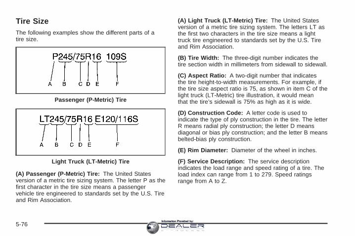
Tire SizeThe following examples show the different parts of atire size.
(A) Passenger (P-Metric) Tire: The United Statesversion of a metric tire sizing system. The letter P as thefirst character in the tire size means a passengervehicle tire engineered to standards set by the U.S. Tireand Rim Association.
(A) Light Truck (LT-Metric) Tire: The United Statesversion of a metric tire sizing system. The letters LT asthe first two characters in the tire size means a lighttruck tire engineered to standards set by the U.S. Tireand Rim Association.
(B) Tire Width: The three-digit number indicates thetire section width in millimeters from sidewall to sidewall.
(C) Aspect Ratio: A two-digit number that indicatesthe tire height-to-width measurements. For example, ifthe tire size aspect ratio is 75, as shown in item C of thelight truck (LT-Metric) tire illustration, it would meanthat the tire’s sidewall is 75% as high as it is wide.
(D) Construction Code: A letter code is used toindicate the type of ply construction in the tire. The letterR means radial ply construction; the letter D meansdiagonal or bias ply construction; and the letter B meansbelted-bias ply construction.
(E) Rim Diameter: Diameter of the wheel in inches.
(F) Service Description: The service descriptionindicates the load range and speed rating of a tire. Theload index can range from 1 to 279. Speed ratingsrange from A to Z.
Passenger (P-Metric) Tire
Light Truck (LT-Metric) Tire
5-76Information Provided by:

Tire Terminology and Definitions
Air Pressure: The amount of air inside the tire pressingoutward on each square inch of the tire. Air pressureis expressed in pounds per square inch (psi) orkilopascal (kPa).
Accessory Weight: This means the combined weightof optional accessories. Some examples of optionalaccessories are, automatic transmission, power steering,power brakes, power windows, power seats, and airconditioning.
Aspect Ratio: The relationship of a tire’s height toits width.
Belt: A rubber coated layer of cords that is locatedbetween the plies and the tread. Cords may be madefrom steel or other reinforcing materials.
Bead: The tire bead contains steel wires wrapped bysteel cords that hold the tire onto the rim.
Bias Ply Tire: A pneumatic tire in which the plies arelaid at alternate angles less than 90 degrees to thecenterline of the tread.
Cold Inflation Pressure: The amount of air pressure ina tire, measured in pounds per square inch (psi) orkilopascals (kPa) before a tire has built up heatfrom driving. See Inflation - Tire Pressure on page 5-80.
Curb Weight: This means the weight of a motorvehicle with standard and optional equipment includingthe maximum capacity of fuel, oil and coolant, butwithout passengers and cargo.
DOT Markings: A code molded into the sidewall of atire signifying that the tire is in compliance with theU.S. Department of Transportation (DOT) motor vehiclesafety standards. The DOT code includes the TireIdentification Number (TIN), an alphanumeric designatorwhich can also identify the tire manufacturer, productionplant, brand and date of production.
GVWR: Gross Vehicle Weight Rating, see LoadingYour Vehicle on page 4-48.
GAWR FRT: Gross Axle Weight Rating for the frontaxle, see Loading Your Vehicle on page 4-48.
GAWR RR: Gross Axle Weight Rating for the rear axle,see Loading Your Vehicle on page 4-48.
5-77Information Provided by:

Intended Outboard Sidewall: The side of anasymmetrical tire, that must always face outward whenmounted on a vehicle.
Kilopascal (kPa): The metric unit for air pressure.
Light Truck (LT-Metric) Tire: A tire used on light dutytrucks and some multipurpose passenger vehicles.
Load Index: An assigned number ranging from1 to 279 that corresponds to the load carrying capacityof a tire.
Maximum Inflation Pressure: The maximum airpressure to which a cold tire may be inflated. Themaximum air pressure is molded onto the sidewall.
Maximum Load Rating: The load rating for a tire at themaximum permissible inflation pressure for that tire.
Maximum Loaded Vehicle Weight: The sum of curbweight; accessory weight; vehicle capacity weight;and production options weight.
Normal Occupant Weight: The number of occupants avehicle is designed to seat multiplied by 150 lbs (68 kg).See Loading Your Vehicle on page 4-48.
Occupant Distribution: Designated seating positions.
Outward Facing Sidewall: The side of anasymmetrical tire that has a particular side that facesoutward when mounted on a vehicle. The side of the tirethat contains a whitewall, bears white lettering, orbears manufacturer, brand, and/or model name moldingthat is higher or deeper than the same moldings onthe other sidewall of the tire.
Passenger (P-Metric) Tire: A tire used on passengercars and some light duty trucks and multipurposevehicles.
Recommended Inflation Pressure: Vehiclemanufacturer’s recommended tire inflation pressure andshown on the tire placard. See Inflation - Tire Pressureon page 5-80 and Loading Your Vehicle on page 4-48.
Radial Ply Tire: A pneumatic tire in which the ply cordsthat extend to the beads are laid at 90 degrees to thecenterline of the tread.
Rim: A metal support for a tire and upon which the tirebeads are seated.
5-78Information Provided by:

Sidewall: The portion of a tire between the tread andthe bead.
Speed Rating: An alphanumeric code assigned to atire indicating the maximum speed at which a tirecan operate.
Traction: The friction between the tire and the roadsurface. The amount of grip provided.
Tread: The portion of a tire that comes into contactwith the road.
Treadwear Indicators: Narrow bands, sometimescalled wear bars, that show across the tread of a tirewhen only 1/16 inch (1.6 mm) of tread remains.See When It Is Time for New Tires on page 5-85.
UTQGS (Uniform Tire Quality Grading Standards): Atire information system that provides consumers withratings for a tire’s traction, temperature, and treadwear.Ratings are determined by tire manufacturers usinggovernment testing procedures. The ratings are moldedinto the sidewall of the tire. See Uniform Tire QualityGrading on page 5-88.
Vehicle Capacity Weight: The number of designatedseating positions multiplied by 150 lbs (68 kg) plusthe rated cargo load. See Loading Your Vehicleon page 4-48.
Vehicle Maximum Load on the Tire: Load on anindividual tire due to curb weight, accessory weight,occupant weight, and cargo weight.
Vehicle Placard: A label permanently attached to avehicle showing the vehicle’s capacity weight andthe original equipment tire size and recommendedinflation pressure. See “Tire and Loading InformationLabel” under Loading Your Vehicle on page 4-48.
5-79Information Provided by:

Inflation - Tire PressureTires need the correct amount of air pressure to operateeffectively.
Notice: Do not let anyone tell you thatunder-inflation or over-inflation is all right. It is not.If your tires do not have enough air (under-inflation),you can get the following:
• Too much flexing
• Too much heat
• Tire overloading
• Premature or irregular wear
• Poor handling
• Reduced fuel economy
If your tires have too much air (over-inflation), youcan get the following:
• Unusual wear
• Poor handling
• Rough ride
• Needless damage from road hazards
A Tire and Loading Information label is attached to thevehicle’s center pillar (B-pillar), below the driver’sdoor lock post (striker). This label lists your vehicle’soriginal equipment tires and their recommended cold tireinflation pressures. The recommended cold tireinflation pressure, shown on the label, is the minimumamount of air pressure needed to support your vehicle’smaximum load carrying capacity.
For additional information regarding how much weightyour vehicle can carry, and an example of the tireand loading information label, see Loading Your Vehicleon page 4-48.
When to CheckCheck your tires once a month or more. Do not forget tocheck the spare tire. For additional informationregarding the spare tire, see Spare Tire on page 5-114.
How to CheckUse a good quality pocket-type gage to check tirepressure. You cannot tell if your tires are properly inflatedsimply by looking at them. Radial tires may look properlyinflated even when they’re underinflated. Check the tire’sinflation pressure when the tires are cold. Cold meansyour vehicle has been sitting for at least three hours ordriven no more than 1 mile (1.6 km).
5-80Information Provided by:

Remove the valve cap from the tire valve stem. Pressthe tire gage firmly onto the valve to get a pressuremeasurement. If the cold tire inflation pressure matchesthe recommended pressure on the Tire and LoadingInformation label, no further adjustment is necessary. Ifthe inflation pressure is low, add air until you reachthe recommended amount.If you overfill the tire, release air by pushing on themetal stem in the center of the tire valve. Recheck thetire pressure with the tire gage.Be sure to put the valve caps back on the valve stems.They help prevent leaks by keeping out dirt and moisture.
High Speed Operation (SS Silverado)
{CAUTION:
Driving at high speeds, 100 mph (160 km/h) orhigher, puts an additional strain on tires.Sustained high-speed driving causesexcessive heat build up and can cause suddentire failure. You could have a crash and you orothers could be killed. Some high-speed ratedtires require inflation pressure adjustment forhigh speed operation.
CAUTION: (Continued)
CAUTION: (Continued)
When speed limits and road conditions aresuch that a vehicle can be driven at highspeeds, make sure the tires are rated for highspeed operation, in excellent condition, andset to the correct cold tire inflation pressurefor the vehicle load.
If your vehicle has P275/55R20 size tires and you willbe driving at high speeds, speeds of 100 mph(160 km/h) or higher, set the cold inflation pressure tothe maximum inflation pressure shown on the tiresidewall, or 38 psi (265 kPa), whichever is lower. Seethe example following. When you end this high-speeddriving, return the tires to the cold inflation pressureshown on the Tire and Loading Information label. SeeLoading Your Vehicle on page 4-48.
Example:
You will find the maximum load and inflation pressuremolded on the tire’s sidewall, in small letters, nearthe rim flange. It will read something like this: Maximumload 690 kg (1521 lbs) 300 kPa (44 psi) Max. Press.
For this example, you would set the inflation pressure forhigh-speed driving at 38 psi (265 kPa).
5-81Information Provided by:

Dual Tire OperationWhen the vehicle is new, or whenever a wheel, wheel boltor wheel nut is replaced, check the wheel nut torque after100, 1,000 and 6,000 miles (160, 1 600 and 10 000 km)of driving. For proper torque and wheel nut tighteninginformation, see Removing the Spare Tire and Tools onpage 5-94.
The outer tire on a dual wheel setup generally wearsfaster than the inner tire. Your tires will wear moreevenly and last longer if you rotate the tires periodically,see Tire Inspection and Rotation on page 5-82. Alsosee Scheduled Maintenance (Gasoline Engine) onpage 6-4.
{CAUTION:
If you operate your vehicle with a tire that isbadly underinflated, the tire can overheat. Anoverheated tire can lose air suddenly or catchfire. You or others could be injured. Be sure alltires (including the spare) are properly inflated.
See Inflation - Tire Pressure on page 5-80, forinformation on proper tire inflation.
Tire Inspection and RotationTires should be rotated every 5,000 to 8,000 miles(8 000 to 13 000 km).
Any time you notice unusual wear, rotate your tires assoon as possible and check wheel alignment. Alsocheck for damaged tires or wheels. See When It Is Timefor New Tires on page 5-85 and Wheel Replacementon page 5-89 for more information.
Make sure the spare tire is stored securely. Push, pull,and then try to rotate or turn the tire. If it moves,use the wheel wrench/hoist shaft to tighten the cable.See Changing a Flat Tire on page 5-92.
If your vehicle has dual rear wheels, also see Dual TireOperation on page 5-82.
The purpose of regular rotation is to achieve moreuniform wear for all tires on the vehicle. The first rotationis the most important. See Scheduled Maintenance(Gasoline Engine) on page 6-4.
5-82Information Provided by:

If your vehicle has single rear wheels and the treaddesign for your front tires is the same as your rear tires,use the rotation pattern shown here when rotatingyour tires.
If your vehicle has dual rear wheels and the treaddesign for your front tires is the same as your rear tires,always use one of the correct rotation patterns shownhere when rotating your tires.
5-83Information Provided by:

If your vehicle has dualrear wheels and the treaddesign for the fronttires is different from thedual rear tires, always usethe correct rotationpattern shown here whenrotating your tires.
The dual tires are rotated as a pair, and the inside reartires become the outside rear tires.
When you install dual wheels, be sure the vent holes inthe inner and outer wheels on each side are lined up.
After the tires have been rotated, adjust the front andrear inflation pressures as shown on the Tire andLoading Information label. See Loading Your Vehicle onpage 4-48.
Make certain that all wheel nuts are properly tightened.See “Wheel Nut Torque” under Capacities andSpecifications on page 5-132.
{CAUTION:
Rust or dirt on a wheel, or on the parts towhich it is fastened, can make wheel nutsbecome loose after a time. The wheel couldcome off and cause an accident. When youchange a wheel, remove any rust or dirt fromplaces where the wheel attaches to the vehicle.In an emergency, you can use a cloth or apaper towel to do this; but be sure to use ascraper or wire brush later, if needed, to get allthe rust or dirt off. See Changing a Flat Tire onpage 5-92.
5-84Information Provided by:

When It Is Time for New Tires
One way to tell when it istime for new tires is tocheck the treadwearindicators, which willappear when your tireshave only 1/16 inch(1.6 mm) or less of treadremaining. Somecommercial truck tires maynot have treadwearindicators.
You need a new tire if any of the following statementsare true:
• You can see the indicators at three or more placesaround the tire.
• You can see cord or fabric showing through thetire’s rubber.
• The tread or sidewall is cracked, cut or snaggeddeep enough to show cord or fabric.
• The tire has a bump, bulge, or split.
• The tire has a puncture, cut, or other damage thatcannot be repaired well because of the size orlocation of the damage.
5-85Information Provided by:

Buying New TiresGM has developed and matched specific tires for yourvehicle. The original equipment tires installed onyour vehicle, when it was new, were designed to meetGeneral Motors Tire Performance Criteria Specification(TPC spec) system rating. If you need replacementtires, GM strongly recommends that you get tires withthe same TPC Spec rating. This way, your vehiclewill continue to have tires that are designed to give thesame performance and vehicle safety, during normaluse, as the original tires.
GM’s exclusive TPC Spec system considers over adozen critical specifications that impact the overallperformance of your vehicle, including brake systemperformance, ride and handling, traction control, and tirepressure monitoring performance. GM’s TPC Specnumber is molded onto the tire’s sidewall by thetire manufacturer. If the tires have an all-season treaddesign, the TPC spec number will be followed by an MSfor mud and snow. See Tire Sidewall Labeling onpage 5-74 for additional information.
{CAUTION:
Mixing tires could cause you to lose controlwhile driving. If you mix tires of different sizes,brands or types (radial and bias-belted tires),the vehicle may not handle properly, and youcould have a crash. Using tires of differentsizes, brands or types may also cause damageto your vehicle. Be sure to use the same size,brand, and type tires on all wheels.
Your vehicle may have a different size sparethan the road tires (those originally installedon your vehicle). When new, your vehicleincluded a spare tire and wheel assembly witha similar overall diameter as your vehicle’sroad tires and wheels, so it is all right to driveon it. Because this spare was developed foruse on your vehicle, it will not affect vehiclehandling.
5-86Information Provided by:

{CAUTION:
If you use bias-ply tires on your vehicle, thewheel rim flanges could develop cracks aftermany miles of driving. A tire and/or wheelcould fail suddenly, causing a crash. Use onlyradial-ply tires with the wheels on your vehicle.
If you must replace your vehicle’s tires with those thatdo not have a TPC Spec number, make sure theyare the same size, load range, speed rating, andconstruction type (radial and bias-belted tires) as yourvehicle’s original tires.
Your vehicle’s original equipment tires are listed on theTire and Loading Information Label. This label isattached to the vehicle’s center pillar (B-pillar). SeeLoading Your Vehicle on page 4-48, for more informationabout the Tire and Loading Information Label and itslocation on your vehicle.
Different Size Tires and WheelsIf you add wheels or tires that are a different size thanyour original equipment wheels and tires, this mayaffect the way your vehicle performs, including itsbraking, ride and handling characteristics, stability andresistance to rollover. Additionally, if your vehiclehas electronic systems such as, antilock brakes; tractioncontrol; and electronic stability control, the performanceof these systems can be affected.
{CAUTION:
If you add different sized wheels, your vehiclemay not provide an acceptable level ofperformance and safety if tires notrecommended for those wheels are selected.You may increase the chance that you willcrash and suffer serious injury. Only use GMspecific wheel and tire systems developed foryour vehicle, and have them properly installedby a GM certified technician.
See Buying New Tires on page 5-86 and Accessoriesand Modifications on page 5-4 for additional information.
5-87Information Provided by:

Uniform Tire Quality GradingQuality grades can be found where applicable on thetire sidewall between tread shoulder and maximumsection width. For example:
Treadwear 200 Traction AA Temperature AThe following information relates to the systemdeveloped by the United States National HighwayTraffic Safety Administration, which grades tires bytreadwear, traction and temperature performance. (Thisapplies only to vehicles sold in the United States.)The grades are molded on the sidewalls of mostpassenger car tires. The Uniform Tire Quality Gradingsystem does not apply to deep tread, winter-typesnow tires, space-saver or temporary use spare tires,tires with nominal rim diameters of 10 to 12 inches(25 to 30 cm), or to some limited-production tires.
While the tires available on General Motors passengercars and light trucks may vary with respect to thesegrades, they must also conform to federal safetyrequirements and additional General Motors TirePerformance Criteria (TPC) standards.
TreadwearThe treadwear grade is a comparative rating based onthe wear rate of the tire when tested under controlledconditions on a specified government test course.For example, a tire graded 150 would wear one anda half (1.5) times as well on the government course asa tire graded 100. The relative performance of tiresdepends upon the actual conditions of their use,however, and may depart significantly from the normdue to variations in driving habits, service practices anddifferences in road characteristics and climate.
Traction – AA, A, B, CThe traction grades, from highest to lowest, are AA, A,B, and C. Those grades represent the tire’s abilityto stop on wet pavement as measured under controlledconditions on specified government test surfaces ofasphalt and concrete. A tire marked C may have poortraction performance. Warning: The traction gradeassigned to this tire is based on straight-ahead brakingtraction tests, and does not include acceleration,cornering, hydroplaning, or peak traction characteristics.
5-88Information Provided by:

Temperature – A, B, CThe temperature grades are A (the highest), B, and C,representing the tire’s resistance to the generationof heat and its ability to dissipate heat when testedunder controlled conditions on a specified indoorlaboratory test wheel. Sustained high temperature cancause the material of the tire to degenerate andreduce tire life, and excessive temperature can lead tosudden tire failure. The grade C corresponds to alevel of performance which all passenger car tires mustmeet under the Federal Motor Vehicle Safety StandardNo. 109. Grades B and A represent higher levels ofperformance on the laboratory test wheel than theminimum required by law.
Warning: The temperature grade for this tire isestablished for a tire that is properly inflated and notoverloaded. Excessive speed, underinflation, orexcessive loading, either separately or in combination,can cause heat buildup and possible tire failure.
Wheel Alignment and Tire BalanceThe tires and wheels on your vehicle were alignedand balanced carefully at the factory to give you thelongest tire life and best overall performance.Adjustments to wheel alignment and tire balancing willnot be necessary on a regular basis. However, ifyou notice unusual tire wear or your vehicle pulling toone side or the other, the alignment may need tobe checked. If you notice your vehicle vibrating whendriving on a smooth road, your tires and wheelsmay need to be rebalanced. See your dealer for properdiagnosis.
Wheel ReplacementReplace any wheel that is bent, cracked, or badly rustedor corroded. If wheel nuts keep coming loose, thewheel, wheel bolts and wheel nuts should be replaced.If the wheel leaks air, replace it (except somealuminum wheels, which can sometimes be repaired).See your dealer if any of these conditions exist.
Your dealer will know the kind of wheel you need.
5-89Information Provided by:

Each new wheel should have the same load-carryingcapacity, diameter, width, offset and be mountedthe same way as the one it replaces.
If you need to replace any of your wheels, wheel boltsor wheel nuts, replace them only with new GMoriginal equipment parts. This way, you will be sure tohave the right wheel, wheel bolts and wheel nutsfor your vehicle.
{CAUTION:
Using the wrong replacement wheels, wheelbolts, or wheel nuts on your vehicle can bedangerous. It could affect the braking andhandling of your vehicle, make your tires loseair and make you lose control. You could havea collision in which you or others could beinjured. Always use the correct wheel, wheelbolts and wheel nuts for replacement.
Notice: The wrong wheel can also cause problemswith bearing life, brake cooling, speedometer orodometer calibration, headlamp aim, bumper height,vehicle ground clearance, and tire or tire chainclearance to the body and chassis.
Whenever a wheel, wheel bolt or wheel nut is replacedon a dual wheel setup, check the wheel nut torqueafter 100, 1,000 and 6,000 miles (160, 1 600 and10 000 km) of driving. For proper torque, see “WheelNut Torque” under Capacities and Specificationson page 5-132.
See Changing a Flat Tire on page 5-92 for moreinformation.
Used Replacement Wheels
{CAUTION:
Putting a used wheel on your vehicle isdangerous. You cannot know how it has beenused or how far it has been driven. It could failsuddenly and cause a crash. If you have toreplace a wheel, use a new GM originalequipment wheel.
5-90Information Provided by:

Tire Chains
{CAUTION:
If your vehicle has dual wheels or P265/75R16,LT265/75R16, P265/70R17 or P275/55R20 sizetires, do not use tire chains. They can damageyour vehicle because there is not enoughclearance. Tire chains used on a vehiclewithout the proper amount of clearance cancause damage to the brakes, suspension orother vehicle parts. The area damaged by thetire chains could cause you to lose control ofyour vehicle and you or others may be injuredin a crash.
Use another type of traction device only if itsmanufacturer recommends it for use on yourvehicle and tire size combination and roadconditions. Follow that manufacturer’sinstructions. To help avoid damage to yourvehicle, drive slowly, readjust or remove thedevice if it is contacting your vehicle, and donot spin your vehicle’s wheels.
If you do find traction devices that will fit,install them on the rear tires.
Notice: If your vehicle does not have dual wheelsand is equipped with a tire size other thanP265/75R16, LT265/75R16, P265/70R17 orP275/55R20, use tire chains only where legal andonly when you must. Use chains that are the propersize for your tires. Install them on the tires of therear axle. Don’t use chains on the tires of the frontaxle. Tighten them as tightly as possible withthe ends securely fastened. Drive slowly and followthe chain manufacturer’s instructions. If you canhear the chains contacting your vehicle, stopand retighten them. If the contact continues, slowdown until it stops. Driving too fast or spinning thewheels with chains on will damage your vehicle.
5-91Information Provided by:

If a Tire Goes FlatIt is unusual for a tire to blowout while you are driving,especially if you maintain your vehicle’s tires properly.If air goes out of a tire, it is much more likely to leak outslowly. But if you should ever have a blowout, hereare a few tips about what to expect and what to do:
If a front tire fails, the flat tire will create a drag that pullsthe vehicle toward that side. Take your foot off theaccelerator pedal and grip the steering wheel firmly.Steer to maintain lane position, and then gently brake toa stop well out of the traffic lane.
A rear blowout, particularly on a curve, acts much like askid and may require the same correction you woulduse in a skid. In any rear blowout remove your foot fromthe accelerator pedal. Get the vehicle under controlby steering the way you want the vehicle to go. It maybe very bumpy and noisy, but you can still steer. Gentlybrake to a stop, well off the road if possible.
{CAUTION:
Lifting a vehicle and getting under it to domaintenance or repairs is dangerous withoutthe appropriate safety equipment and training.The jack provided with your vehicle isdesigned only for changing a flat tire. If it isused for anything else, you or others could bebadly injured or killed if the vehicle slips offthe jack. Use the jack provided with yourvehicle only for changing a flat tire.
If a tire goes flat, the next part shows how to use thejacking equipment to change a flat tire safely.
Changing a Flat TireIf a tire goes flat, avoid further tire and wheel damageby driving slowly to a level place. Turn on yourhazard warning flashers. See Hazard Warning Flasherson page 3-6 for more information.
5-92Information Provided by:

{CAUTION:
Changing a tire can be dangerous. The vehiclecan slip off the jack and roll over or fall on youor other people. You and they could be badlyinjured or even killed. Find a level place tochange your tire. To help prevent the vehiclefrom moving:
1. Set the parking brake firmly.
2. Put an automatic transmission shift leverin PARK (P), or shift a manualtransmission to FIRST (1) or REVERSE (R).
3. If you have a four-wheel-drive vehicle, besure the transfer case is in a drivegear – not in NEUTRAL.
4. Turn off the engine and do not restartwhile the vehicle is raised.
5. Do not allow passengers to remain in thevehicle.
CAUTION: (Continued)
CAUTION: (Continued)
To be even more certain the vehicle will notmove, put blocks at the front and rear of thetire farthest away from the one being changed.That would be the tire on the other side, at theopposite end of the vehicle.
When your vehicle has a flat tire, use the followingexample as a guide to assist you in the placement ofthe wheel blocks.
The following information will tell you next how to usethe jack and change a tire.
5-93Information Provided by:

Removing the Spare Tire and Tools
A. KnobB. Retaining HookC. Wheel Blocks
D. Wing Nut RetainingWheel Blocks
E. Jack
A. Wing Nut RetainingWheel Blocks
B. Wheel BlocksC. Retaining Bracket
and Wing Nut
D. Tool Kit and JackTools
E. Retaining HookF. JackG. Knob
1500 Crew Cab
Regular Cab and Crew Cab (Except 1500 Crew Cab)
5-94Information Provided by:

A. Wing Nut RetainingWheel Blocks
B. Wheel BlocksC. Retaining HookD. Jack
E. KnobF. Retaining Bracket
and Wing NutG. Tool Kit and Jack
Tools
A. Wing Nut RetainingWheel Blocks
B. Wheel BlocksC. JackD. Retaining Hook
E. KnobF. Retaining Bracket
and Wing NutG. Tool Kit and Jack
ToolsFor regular cab models, the equipment you will need isbehind the passenger’s seat. For extended and crewcab models, the equipment is on the shelf behindthe passenger’s side second row seat.
Extended Cab Extended Cab Short Box
5-95Information Provided by:
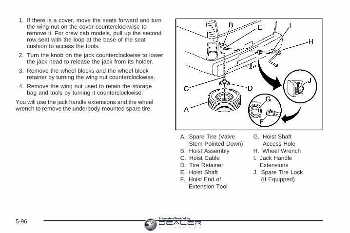
1. If there is a cover, move the seats forward and turnthe wing nut on the cover counterclockwise toremove it. For crew cab models, pull up the secondrow seat with the loop at the base of the seatcushion to access the tools.
2. Turn the knob on the jack counterclockwise to lowerthe jack head to release the jack from its holder.
3. Remove the wheel blocks and the wheel blockretainer by turning the wing nut counterclockwise.
4. Remove the wing nut used to retain the storagebag and tools by turning it counterclockwise.
You will use the jack handle extensions and the wheelwrench to remove the underbody-mounted spare tire.
A. Spare Tire (ValveStem Pointed Down)
B. Hoist AssemblyC. Hoist CableD. Tire RetainerE. Hoist ShaftF. Hoist End of
Extension Tool
G. Hoist ShaftAccess Hole
H. Wheel WrenchI. Jack Handle
ExtensionsJ. Spare Tire Lock
(If Equipped)
5-96Information Provided by:

1. Open the spare tire lock cover on the bumper anduse the ignition key to remove the lock, if equippedwith a spare tire lock (J).
2. Assemble the wheel wrench (H) and the two jackhandle extensions (I) as shown.
3. Insert the hoist end(open end) (F) of theextension throughthe hole (G) in the rearbumper.
Be sure the hoist end of the extension connects tothe hoist shaft (E). The ribbed square end of theextension is used to lower the spare tire.
4. Turn the wheel wrench (H) counterclockwise tolower the spare tire to the ground. Continue toturn the wheel wrench until the spare tire can bepulled out from under the vehicle.If the spare tire does not lower to the ground, thesecondary latch is engaged causing the tirenot to lower. See Secondary Latch System onpage 5-107.
5-97Information Provided by:

5. Use the wheel wrenchhook which allows youto pull the hoistcable towards you toassist in reachingthe spare tire.
6. Tilt the retainer at theend of the cable whenthe tire has beenlowered, so it can bepulled up throughthe wheel opening.
7. Put the spare tire near the flat tire.
Removing the Flat Tire andInstalling the Spare TireUse the following pictures and instructions to removethe flat tire and raise the vehicle.
The tools you will be using include the jack (A), thewheel blocks (B), the jack handle (C), the jack handleextensions (D), and the wheel wrench (E).
5-98Information Provided by:

1. If your vehicle haswheel nut caps, loosenthem by turning thewheel wrenchcounterclockwise.
If the vehicle has a center cap with wheel nut caps,the wheel nut caps are designed to stay with thecenter cap after they are loosened. Removethe entire center cap.
If the wheel has a smooth center cap, place thechisel end of the wheel wrench in the slot onthe wheel, and gently pry it out.
5-99Information Provided by:

2. Use the wheel wrench and turn it counterclockwiseto loosen the wheel nuts. Do not remove the wheelnuts yet.
A. Front Location (Two-Wheel-Drive 1500 Series)B. Front Location (All Other Series)C. Rear Location (All Series)
3. Position the jack under the vehicle as shown. If theflat tire is on the front of the vehicle (two-wheel-drive1500 Series vehicles), position the jack under thebracket attached to the vehicle’s frame, behindthe flat tire. If the flat tire is on the front of thevehicle (all other models), position the jack on theframe behind the flat tire.If the flat tire is on the rear, position the jack underthe rear axle between the spring anchor and theshock absorber bracket.If you have added a snow plow to the front of yourvehicle, lower the snow plow fully before raisingthe vehicle.
Jacking Locations
5-100Information Provided by:

{CAUTION:
Getting under a vehicle when it is jacked up isdangerous. If the vehicle slips off the jack youcould be badly injured or killed. Never get undera vehicle when it is supported only by a jack.
{CAUTION:
Raising your vehicle with the jack improperlypositioned can damage the vehicle and evenmake the vehicle fall. To help avoid personalinjury and vehicle damage, be sure to fit thejack lift head into the proper location beforeraising the vehicle.
Front Position - 2WD 1500 Series
5-101Information Provided by:

4. Make sure the jack head is positioned so that therear axle is resting securely between the groovesthat are on the jack head.
5. Turn the wheel wrench clockwise to raise thevehicle. Raise the vehicle far enough off the groundso there is enough room for the spare tire to fitunder the wheel well.
Front Position - All Other Models Rear Position
5-102Information Provided by:

6. Remove all the wheelnuts and take off theflat tire.
{CAUTION:
Rust or dirt on the wheel, or on the parts towhich it is fastened, can make the wheel nutsbecome loose after a time. The wheel couldcome off and cause an accident. When youchange a wheel, remove any rust or dirt fromthe places where the wheel attaches to the
CAUTION: (Continued)
CAUTION: (Continued)
vehicle. In an emergency, you can use a clothor a paper towel to do this; but be sure to usea scraper or wire brush later, if needed, to getall the rust or dirt off.
7. Remove any rust or dirtfrom the wheel bolts,mounting surfaces, andspare wheel.
5-103Information Provided by:
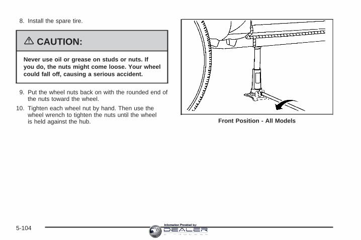
8. Install the spare tire.
{CAUTION:
Never use oil or grease on studs or nuts. Ifyou do, the nuts might come loose. Your wheelcould fall off, causing a serious accident.
9. Put the wheel nuts back on with the rounded end ofthe nuts toward the wheel.
10. Tighten each wheel nut by hand. Then use thewheel wrench to tighten the nuts until the wheelis held against the hub. Front Position - All Models
5-104Information Provided by:

11. Turn the wheel wrench counterclockwise to lowerthe vehicle. Lower the jack completely.
Front Position - 2WD 1500 Series Rear Position
5-105Information Provided by:

{CAUTION:
Incorrect wheel nuts or improperly tightenedwheel nuts can cause the wheel to come looseand even come off. This could lead to anaccident. Be sure to use the correct wheelnuts. If you have to replace them, be sure toget new GM original equipment wheel nuts.Stop somewhere as soon as you can and havethe nuts tightened with a torque wrench to theproper torque specification. See Capacitiesand Specifications on page 5-132 for wheel nuttorque specification.
Notice: Improperly tightened wheel nuts can leadto brake pulsation and rotor damage. To avoidexpensive brake repairs, evenly tighten the wheelnuts in the proper sequence and to the propertorque specification. See Capacities andSpecifications on page 5-132 for the wheel nuttorque specification.
12. Tighten the nuts firmly in a crisscross sequence asshown by turning the wheel wrench clockwise.
When you reinstall the regular wheel and tire, you mustalso reinstall either the center cap, or bolt-on hubcap, depending on what your vehicle is equipped with.For center caps, place the cap on the wheel andtap it into place until it seats flush with the wheel. Thecap only goes on one way. Be sure to line up the tab onthe center cap with the indentation on the wheel. Forbolt-on hub caps, align the plastic nut caps withthe wheel nuts and then tighten by hand. Then use thewheel wrench to tighten.
5-106Information Provided by:

Secondary Latch SystemYour vehicle has an underbody-mounted tire hoistassembly equipped with a secondary latch system. It isdesigned to stop the spare tire from suddenly fallingoff your vehicle. For the secondary latch to work,the spare must be installed with the valve stem pointingdown. See Storing a Flat or Spare Tire and Tools onpage 5-110.
{CAUTION:
Before beginning this procedure read all theinstructions. Failure to read and follow theinstructions could damage the hoist assemblyand you and others could get hurt. Read andfollow the instructions listed below.
To release the spare tire from the secondary latch, dothe following:
1. Check under the vehicle to see if the cable end isvisible.If the cable is not visible, proceed to Step 6.
2. If it is visible, first try to tighten the cable by turningthe wheel wrench clockwise until you hear twoclicks or feel it skip twice. You cannot overtightenthe cable.
3. Loosen the cable by turning the wheel wrenchcounterclockwise three or four turns.
5-107Information Provided by:
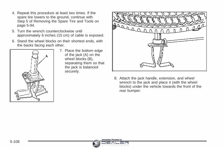
4. Repeat this procedure at least two times. If thespare tire lowers to the ground, continue withStep 5 of Removing the Spare Tire and Tools onpage 5-94.
5. Turn the wrench counterclockwise untilapproximately 6 inches (15 cm) of cable is exposed.
6. Stand the wheel blocks on their shortest ends, withthe backs facing each other.
7. Place the bottom edgeof the jack (A) on thewheel blocks (B),separating them so thatthe jack is balancedsecurely.
8. Attach the jack handle, extension, and wheelwrench to the jack and place it (with the wheelblocks) under the vehicle towards the front of therear bumper.
5-108Information Provided by:

9. Position the center lift point of the jack under thecenter of the spare tire.
10. Turn the wheel wrench clockwise to raise the jackuntil it lifts the end fitting.
11. Continue raising the jack until the spare tire stopsmoving upward and is held firmly in place. Thesecondary latch has released and the spare tire isbalancing on the jack.
12. Lower the jack by turning the wheel wrenchcounterclockwise. Keep lowering the jack until thespare tire slides off the jack or is hanging bythe cable.
{CAUTION:
Someone standing too close during theprocedure could be injured by the jack. If thespare tire does not slide off the jackcompletely, make sure no one is behind you oron either side of you as you pull the jack outfrom the spare.
13. Disconnect the jack handle from the jack. Carefullyremove the jack from underneath the vehicle.
14. Use one hand to push against the spare whilefirmly pulling the jack out from under the sparetire with the other hand.If the spare tire is hanging from the cable, insert thehoist handle, extension and wheel wrench intothe hoist shaft hole in the bumper and turnthe wheel wrench counterclockwise to lower thespare the rest of the way.
5-109Information Provided by:

15. Tilt the retainer at theend of the cable andpull it through thewheel opening. Pull thetire out from underthe vehicle.
16. Turn the wheel wrench clockwise to raise the cableback up if the cable is hanging under the vehicle.
Have the hoist assembly inspected as soon as you can.You will not be able to store a spare or flat tire usingthe hoist assembly until it has been replaced.
To continue changing the flat tire, see Removing theFlat Tire and Installing the Spare Tire on page 5-98.
Storing a Flat or Spare Tireand Tools
{CAUTION:
Storing a jack, a tire, or other equipment in thepassenger compartment of the vehicle couldcause injury. In a sudden stop or collision,loose equipment could strike someone. Storeall these in the proper place.
Notice: Storing an aluminum wheel with a flat tireunder your vehicle for an extended period of time orwith the valve stem pointing up may damage thewheel. Always stow the wheel with the valvestem pointing down and have the wheel/tire repairedas soon as possible.
5-110Information Provided by:

Store the tire under the rear of the vehicle in the spare tirecarrier. Use the following art and text to assist you:
A. Spare Tire (ValveStem Pointed Down)
B. Hoist AssemblyC. Hoist CableD. Tire RetainerE. Hoist ShaftF. Hoist End of
Extension Tool
G. Hoist ShaftAccess Hole
H. Wheel WrenchI. Jack Handle
ExtensionsJ. Spare Tire Lock
(If Equipped)
1. Put the tire on the ground at the rear of the vehiclewith the valve stem pointed down, and to the rear.
2. Tilt the retainerdownward and throughthe wheel opening.Make sure the retaineris fully seated acrossthe underside ofthe wheel.
3. Attach the wheel wrench (H) and extensions (I)together.
5-111Information Provided by:

4. Insert the hoist end (F)through the hole (G) inthe rear bumper andinto the hoist shaft.
5. Raise the tire part way upward. Make sure theretainer is seated in the wheel opening.
6. Raise the tire fully against the underside of thevehicle by turning the wheel wrench clockwiseuntil you hear two clicks or feel it skip twice. Youcannot overtighten the cable.
7. Make sure the tire is stored securely. Push, pull (A),and then try to turn (B) the tire. If the tire moves,use the wheel wrench to tighten the cable.
8. Reinstall the spare tire lock (if equipped).
5-112Information Provided by:

To store the jack and jack tools, do the following:
A. Wing NutB. Wheel BlocksC. Retaining Bracket
and Wing NutD. Wheel Wrench
and Extensions
E. Tool BagF. Mounting BracketG. JackH. Retaining Hook
1. Put the tools (D) in the tool bag (E) and place themin the retaining bracket (C).
2. Tighten down the wing nut (C).
3. Assemble the wheel blocks (B) and jack (G)together with the wing nut (A) and retaininghook (H).
4. Position the jack (G) in the mounting bracket (F).Position the holes in the base of the jack (G) ontothe pin in the mounting bracket (F).
5. Return them to their original location in the vehicle.For more information, refer to Removing the SpareTire and Tools on page 5-94 for more information.
5-113Information Provided by:

Spare TireYour vehicle, when new, had a fully-inflated spare tire.A spare tire may lose air over time, so check itsinflation pressure regularly. See Inflation - Tire Pressureon page 5-80 and Loading Your Vehicle on page 4-48for information regarding proper tire inflation and loadingyour vehicle. For instruction on how to remove, installor store a spare tire, see Removing the Flat Tireand Installing the Spare Tire on page 5-98 and Storinga Flat or Spare Tire and Tools on page 5-110.
Your vehicle may have a different size spare tire thanthe road tires originally installed on your vehicle.This spare tire was developed for use on your vehicle,so it is all right to drive on it. If your vehicle hasfour-wheel drive and the different size spare tire isinstalled, keep the vehicle in two-wheel drive.
Notice: If your vehicle has four-wheel drive and thedifferent size spare tire is installed on your vehicle,do not drive in four-wheel drive until you canhave your flat tire repaired and/or replaced. Youcould damage your vehicle, and the repair costswould not be covered by your warranty. Never usefour-wheel drive when the different size sparetire is installed on your vehicle.
After installing the spare tire on your vehicle, you shouldstop as soon as possible and make sure the sparetire is correctly inflated. Have the damaged or flat roadtire repaired or replaced as soon as you can andinstalled back onto your vehicle. This way, the spare tirewill be available in case you need it again.
Do not mix tires and wheels of different sizes, becausethey will not fit. Keep your spare tire and its wheeltogether. If your vehicle has a spare tire that does notmatch your vehicle’s original road tires and wheelsin size and type, do not include the spare in thetire rotation.
Appearance Care
Cleaning the Inside of Your VehicleYour vehicle’s interior will continue to look its best ifit is cleaned often. Although not always visible, dust anddirt can accumulate on your upholstery. Dirt candamage carpet, fabric, leather, and plastic surfaces.Regular vacuuming is recommended to remove particlesfrom your upholstery. It is important to keep yourupholstery from becoming and remaining heavily soiled.Soils should be removed as quickly as possible. Yourvehicle’s interior may experience extremes of heatthat could cause stains to set rapidly.
5-114Information Provided by:

Lighter colored interiors may require more frequentcleaning. Use care because newspapers and garmentsthat transfer color to your home furnishings may alsotransfer color to your vehicle’s interior.
When cleaning your vehicle’s interior, only use cleanersspecifically designed for the surfaces being cleaned.Permanent damage may result from using cleaners onsurfaces for which they were not intended. Use glasscleaner only on glass. Remove any accidental over-sprayfrom other surfaces immediately. To prevent over-spray,apply cleaner directly to the cleaning cloth.
Notice: If you use abrasive cleaners when cleaningglass surfaces on your vehicle, you could scratchthe glass. When cleaning the glass on your vehicle,use only a soft cloth and glass cleaner.
Many cleaners contain solvents that may becomeconcentrated in your vehicle’s breathing space. Beforeusing cleaners, read and adhere to all safetyinstructions on the label. While cleaning your vehicle’sinterior, maintain adequate ventilation by openingyour vehicle’s doors and windows.
Dust may be removed from small buttons and knobsusing a small brush with soft bristles.
Your GM dealer has a product for cleaning yourvehicle’s glass. Should it become necessary, you canalso obtain a product from your GM dealer to removeodors from your vehicle’s upholstery.
Do not clean your vehicle using the following cleanersor techniques:
• Never use a knife or any other sharp object toremove a soil from any interior surface.
• Never use a stiff brush. It can cause damage toyour vehicle’s interior surfaces.
• Never apply heavy pressure or rub aggressivelywith a cleaning cloth. Use of heavy pressurecan damage your interior and does not improve theeffectiveness of soil removal.
• Use only mild, neutral-pH soaps. Avoid laundrydetergents or dishwashing soaps with degreasers.Using too much soap will leave a residue thatleaves streaks and attracts dirt. For liquid cleaners,about 20 drops per gallon (3.78 L) of water is agood guide.
• Do not heavily saturate your upholstery whilecleaning.
• Damage to your vehicle’s interior may result fromthe use of many organic solvents such as naptha,alcohol, etc.
5-115Information Provided by:

Fabric/CarpetUse a vacuum cleaner with a soft brush attachmentfrequently to remove dust and loose dirt. A canistervacuum with a beater bar in the nozzle may only be usedon floor carpet and carpeted floor mats. For soils, alwaystry to remove them first with plain water or club soda.Before cleaning, gently remove as much of the soil aspossible using one of the following techniques:
• For liquids: gently blot the remaining soil with a papertowel. Allow the soil to absorb into the paper toweluntil no more can be removed.
• For solid dry soils: remove as much as possible andthen vacuum.
To clean, use the following instructions:
1. Saturate a lint-free, clean white cloth with water orclub soda.
2. Wring the cloth to remove excess moisture.
3. Start on the outside edge of the soil and gently rubtoward the center. Continue cleaning, using a cleanarea of the cloth each time it becomes soiled.
4. Continue to gently rub the soiled area until thecleaning cloth remains clean.
5. If the soil is not completely removed, use a mildsoap solution and repeat the cleaning processthat was used with plain water.
If any of the soil remains, a commercial fabric cleaner orspot lifter may be necessary. When a commercialupholstery cleaner or spot lifter is to be used, test asmall hidden area for colorfastness first. If the locallycleaned area gives any impression that a ring formationmay result, clean the entire surface.
After the cleaning process has been completed, a papertowel can be used to blot excess moisture from thefabric or carpet.
LeatherA soft cloth dampened with water may be used toremove dust. If a more thorough cleaning is necessary,a soft cloth dampened with a mild soap solution canbe used. Allow the leather to dry naturally. Do not useheat to dry. Never use steam to clean leather. Neveruse spot lifters or spot removers on leather. Manycommercial leather cleaners and coatings that are soldto preserve and protect leather may permanentlychange the appearance and feel of your leather and arenot recommended. Do not use silicone or wax-basedproducts, or those containing organic solvents to cleanyour vehicle’s interior because they can alter theappearance by increasing the gloss in a non-uniformmanner. Never use shoe polish on your leather.
5-116Information Provided by:

Instrument Panel, Vinyl, and OtherPlastic SurfacesA soft cloth dampened with water may be used toremove dust. If a more thorough cleaning is necessary,a clean soft cloth dampened with a mild soap solutioncan be used to gently remove dust and dirt. Never usespot lifters or removers on plastic surfaces. Manycommercial cleaners and coatings that are sold topreserve and protect soft plastic surfaces maypermanently change the appearance and feel of yourinterior and are not recommended. Do not use siliconeor wax-based products, or those containing organicsolvents to clean your vehicle’s interior becausethey can alter the appearance by increasing the gloss ina non-uniform manner.
Some commercial products may increase gloss on yourinstrument panel. The increase in gloss may causeannoying reflections in the windshield and even make itdifficult to see through the windshield under certainconditions.
Care of Safety BeltsKeep belts clean and dry.
{CAUTION:
Do not bleach or dye safety belts. If you do, itmay severely weaken them. In a crash, theymight not be able to provide adequateprotection. Clean safety belts only with mildsoap and lukewarm water.
WeatherstripsSilicone grease on weatherstrips will make them lastlonger, seal better, and not stick or squeak. Applysilicone grease with a clean cloth. During very cold,damp weather frequent application may be required. SeeRecommended Fluids and Lubricants (GasolineEngine) on page 6-14.
5-117Information Provided by:

Washing Your VehicleThe paint finish on the vehicle provides beauty, depth ofcolor, gloss retention, and durability.
The best way to preserve the vehicle’s finish is to keep itclean by washing it often with lukewarm or cold water.
Do not wash the vehicle in the direct rays of the sun.Use a car washing soap. Do not use strong soapsor chemical detergents. Be sure to rinse the vehicle well,removing all soap residue completely. GM-approvedcleaning products can be obtained from your dealer. SeeVehicle Care/Appearance Materials on page 5-121.Do not use cleaning agents that are petroleum based,or that contain acid or abrasives. All cleaning agentsshould be flushed promptly and not allowed to dry on thesurface, or they could stain. Dry the finish with a soft,clean chamois or an all-cotton towel to avoid surfacescratches and water spotting.
High pressure car washes may cause water to enter thevehicle.
Cleaning Exterior Lamps/LensesUse only lukewarm or cold water, a soft cloth and a carwashing soap to clean exterior lamps and lenses.Follow instructions under Washing Your Vehicle onpage 5-118.
Finish CareOccasional waxing or mild polishing of your vehicle byhand may be necessary to remove residue from thepaint finish. You can get GM-approved cleaning productsfrom your dealer. See Vehicle Care/AppearanceMaterials on page 5-121.If your vehicle has a “basecoat/clearcoat” paint finish,the clearcoat gives more depth and gloss to the coloredbasecoat. Always use waxes and polishes that arenon-abrasive and made for a basecoat/clearcoat paintfinish.
Notice: Machine compounding or aggressivepolishing on a basecoat/clearcoat paint finish maydamage it. Use only non-abrasive waxes andpolishes that are made for a basecoat/clearcoatpaint finish on your vehicle.Foreign materials such as calcium chloride and othersalts, ice melting agents, road oil and tar, tree sap, birddroppings, chemicals from industrial chimneys, etc., candamage your vehicle’s finish if they remain on paintedsurfaces. Wash the vehicle as soon as possible. Ifnecessary, use non-abrasive cleaners that are markedsafe for painted surfaces to remove foreign matter.Exterior painted surfaces are subject to aging, weatherand chemical fallout that can take their toll over aperiod of years. You can help to keep the paint finishlooking new by keeping your vehicle garaged or coveredwhenever possible.
5-118Information Provided by:

Protecting Exterior Bright Metal PartsBright metal parts should be cleaned regularly to keeptheir luster. Washing with water is all that is usuallyneeded. However, you may use chrome polish onchrome or stainless steel trim, if necessary.
Use special care with aluminum trim. To avoid damagingprotective trim, never use auto or chrome polish,steam or caustic soap to clean aluminum. A coating ofwax, rubbed to high polish, is recommended for allbright metal parts.
Windshield and Wiper BladesIf the windshield is not clear after using the windshieldwasher, or if the wiper blade chatters when running,wax, sap, or other material may be on the bladeor windshield.
Clean the outside of the windshield with a glasscleaning liquid or powder and water solution. Thewindshield is clean if beads do not form when it is rinsedwith water.
Grime from the windshield will stick to the wiper bladesand affect their performance. Clean the blade by wipingvigorously with a cloth soaked in full-strength windshieldwasher solvent. Then rinse the blade with water.
Check the wiper blades and clean them as necessary;replace blades that look worn.
Aluminum or Chrome-Plated WheelsThe vehicle may be equipped with either aluminum orchrome-plated wheels.Keep the wheels clean using a soft clean cloth with mildsoap and water. Rinse with clean water. After rinsingthoroughly, dry with a soft clean towel. A wax may thenbe applied.
Notice: If you use strong soaps, chemicals,abrasive polishes, cleaners, brushes, or cleanersthat contain acid on aluminum or chrome-platedwheels, you could damage the surface of thewheel(s). The repairs would not be covered by yourwarranty. Use only GM-approved cleaners onaluminum or chrome-plated wheels.The surface of these wheels is similar to the paintedsurface of your vehicle. Do not use strong soaps,chemicals, abrasive polishes, abrasive cleaners,cleaners with acid, or abrasive cleaning brushes onthem because you could damage the surface. Do notuse chrome polish on aluminum wheels.
Notice: Using chrome polish on aluminum wheelscould damage the wheels. The repairs would notbe covered by your warranty. Use chrome polish onchrome wheels only.
Use chrome polish only on chrome-plated wheels, butavoid any painted surface of the wheel, and buff offimmediately after application.
5-119Information Provided by:

Notice: If you drive your vehicle through anautomatic car wash that has silicone carbide tirecleaning brushes, you could damage the aluminumor chrome-plated wheels. The repairs would notbe covered by your warranty. Never drive a vehicleequipped with aluminum or chrome-plated wheelsthrough an automatic car wash that uses siliconecarbide tire cleaning brushes.
Do not take your vehicle through an automatic car washthat has silicone carbide tire cleaning brushes. Thesebrushes can also damage the surface of these wheels.
TiresTo clean the tires, use a stiff brush with tire cleaner.
Notice: Using petroleum-based tire dressingproducts on your vehicle may damage the paintfinish and/or tires. When applying a tire dressing,always wipe off any overspray from all paintedsurfaces on your vehicle.
Sheet Metal DamageIf the vehicle is damaged and requires sheet metalrepair or replacement, make sure the body repair shopapplies anti-corrosion material to parts repaired orreplaced to restore corrosion protection.
Original manufacturer replacement parts will provide thecorrosion protection while maintaining the warranty.
Underbody MaintenanceChemicals used for ice and snow removal and dustcontrol can collect on the underbody. If these are notremoved, corrosion and rust can develop on theunderbody parts such as fuel lines, frame, floor pan,and exhaust system even though they have corrosionprotection.
At least every spring, flush these materials from theunderbody with plain water. Clean any areas where mudand debris can collect. Dirt packed in close areas ofthe frame should be loosened before being flushed.Your dealer or an underbody car washing system cando this for you.
5-120Information Provided by:

Chemical Paint SpottingSome weather and atmospheric conditions can create achemical fallout. Airborne pollutants can fall upon andattack painted surfaces on the vehicle. This damage cantake two forms: blotchy, ring-shaped discolorations,and small, irregular dark spots etched into thepaint surface.
Although no defect in the paint job causes this, GM willrepair, at no charge to the owner, the surfaces ofnew vehicles damaged by this fallout condition within12 months or 12,000 miles (20 000 km) of purchase,whichever occurs first.
Vehicle Care/Appearance MaterialsDescription Usage
Polishing ClothWax-Treated
Interior and exteriorpolishing cloth.
Tar and Road OilRemover
Removes tar, road oil,and asphalt.
Chrome Cleaner andPolish
Use on chrome orstainless steel.
White Sidewall TireCleaner
Removes soil and blackmarks from whitewalls.
Vinyl Cleaner Cleans vinyl.
Glass Cleaner Removes dirt, grime,smoke and fingerprints.
Chrome and Wire WheelCleaner
Removes dirt and grimefrom chrome wheels andwire wheel covers.
Finish Enhancer
Removes dust,fingerprints, and surfacecontaminants. Spray onand wipe off.
5-121Information Provided by:
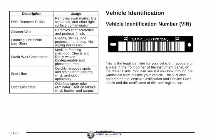
Description Usage
Swirl Remover PolishRemoves swirl marks, finescratches, and other lightsurface contamination.
Cleaner Wax Removes light scratchesand protects finish.
Foaming Tire ShineLow Gloss
Cleans, shines, andprotects in one step. Nowiping necessary.
Wash Wax Concentrate
Medium foamingshampoo. Cleans andlightly waxes.Biodegradable andphosphate free.
Spot Lifter
Quickly removes spotsand stains from carpets,vinyl, and clothupholstery.
Odor EliminatorOdorless spray odoreliminator used on fabrics,vinyl, leather and carpet.
Vehicle Identification
Vehicle Identification Number (VIN)
This is the legal identifier for your vehicle. It appears ona plate in the front corner of the instrument panel, onthe driver’s side. You can see it if you look through thewindshield from outside your vehicle. The VIN alsoappears on the Vehicle Certification and Service Partslabels and the certificates of title and registration.
5-122Information Provided by:

Engine IdentificationThe eighth character in the VIN is the engine code. Thiscode will help you identify your vehicle’s engine,specifications, and replacement parts.
Service Parts Identification LabelYou will find this label on the inside of the glove box. Itis very helpful if you ever need to order parts. Onthis label, you will find the following:
• VIN
• Model designation
• Paint information
• Production options and special equipment
Be sure that this label is not removed from the vehicle.
Electrical System
Add-On Electrical EquipmentNotice: Don’t add anything electrical to your vehicleunless you check with your dealer first. Someelectrical equipment can damage your vehicle andthe damage wouldn’t be covered by your warranty.Some add-on electrical equipment can keep othercomponents from working as they should.
Your vehicle has an airbag system. Before attempting toadd anything electrical to your vehicle, see ServicingYour Airbag-Equipped Vehicle on page 1-86.
Windshield Wiper FusesThe windshield wiper motor is protected by an internalcircuit breaker and a fuse. If the motor overheats due toheavy snow, etc., the wiper will stop until the motorcools. If the overload is caused by some electricalproblem and not snow, etc., be sure to get it fixed.
5-123Information Provided by:

Power Windows and Other PowerOptionsCircuit breakers protect the power windows and otherpower accessories. When the current load is too heavy,the circuit breaker opens and closes, protecting thecircuit until the problem is fixed or goes away.
Fuses and Circuit BreakersThe wiring circuits in your vehicle are protected fromshort circuits by a combination of fuses, circuit breakersand fusible thermal links. This greatly reduces thechance of fires caused by electrical problems.
Look at the silver-colored band inside the fuse. If theband is broken or melted, replace the fuse. Be sure youreplace a bad fuse with a new one of the identicalsize and rating.
If you ever have a problem on the road and don’t havea spare fuse, you can borrow one that has the sameamperage. Just pick some feature of your vehiclethat you can get along without – like the radio orcigarette lighter – and use its fuse, if it is the correctamperage. Replace it as soon as you can.
Instrument Panel Fuse Block
The fuse block accessdoor is on the driver’s sideedge of the instrumentpanel. Pull off the cover toaccess the fuse block.
To remove fuses, hold the end of the fuse between yourthumb and index finger and pull straight out.
You may have spare fuses located behind the fuseblock access door. These can be used to replace a badfuse. However, make sure it is of the correct amperage.
5-124Information Provided by:

Fuses UsageRR WPR Not Used
SEO ACCY Special Equipment OptionAccessory
WS WPR Windshield Wipers
TBC ACCY Truck Body ControllerAccessory
IGN 3 Ignition, Heated Seats
Fuses Usage
4WD Four-Wheel Drive System,Auxiliary Battery
HTR A/C Climate Control System
LOCK (Relay) Power Door Lock Relay(Lock Function)
HVAC 1 Climate Control System
LT DR Driver’s Door HarnessConnection
CRUISE Cruise Control, Power TakeOff (PTO)
UNLCK (Relay) Power Door Lock Relay(Unlock Function)
RR FOG LP Not UsedBRAKE Anti-Lock Brake System
DRIVER UNLCKPower Door Lock Relay(Driver’s Door UnlockFunction)
IGN 0 TCMTBC IGN 0 Truck Body Controller
VEH CHMSL Vehicle and Trailer HighMounted Stoplamp
LT TRLR ST/TRN Left Turn Signal/Stop Trailer
5-125Information Provided by:

Fuses Usage
LT TRN Left Turn Signals andSidemarkers
VEH STOPVehicle Stoplamps, BrakeModule, Electronic ThrottleControl Module
RT TRLR ST/TRN Right Turn Signal/Stop Trailer
RT TRN Right Turn Signals andSidemarkers
BODY Harness ConnectorDDM Driver Door ModuleAUX PWR 2, M/GATE Not UsedLCKS Power Door Lock System
ECC, TPM Tire Pressure MonitoringSystem
TBC 2C Truck Body ControllerHAZRD Flasher Module
CB LT DRS Left Power Windows CircuitBreaker
TBC 2B Truck Body ControllerTBC 2A Truck Body Controller
Center Instrument Panel Fuse BlockThe center instrument panel utility block is locatedunderneath the instrument panel, to the left of thesteering column.
Device UsageSEO Special Equipment OptionTRAILER Trailer Brake WiringUPFIT Upfitter (Not Used)
SL RIDE Ride Control HarnessConnection
5-126Information Provided by:

Device UsageHDLR 2 Headliner Wiring ConnectorBODY Body Wiring ConnectorDEFOG Rear Defogger RelayHDLNR 1 Headliner Wiring Connector 1SPARE RELAY Not Used
CB SEAT Driver and Passenger SeatModule Circuit Breaker
CB RT DOOR Right Power Windows CircuitBreaker
SPARE Not Used
INFO Infotainment HarnessConnection
Underhood Fuse Block
The underhood fuse block in the engine compartmenton the driver’s side of the vehicle near the battery.Lift the cover for access to the fuse/relay block.
To remove fuses hold the end of the fuse between yourthumb and index finger and pull straight out.
See Engine Compartment Overview on page 5-14 formore information on its location.
5-127Information Provided by:

5-128Information Provided by:

*1 Fuel Injection Rail #2-Gasoline Engine; EngineControl Module-Diesel Engine.
*2 Fuel Injection Rail #1-Gasoline Engine;Actuator-Diesel Engine.
*3 Oxygen Sensors-Gasoline Engine; Fuel Heater-DieselEngine.
*4 Oxygen Sensors-Gasoline Engine; Engine ControlModule 1-Diesel Engine.
*5 Ignition 1-Gasoline Engine; Engine ControlModule-Diesel Engine.
*6 Powertrain Control Module B-Gasoline Engine;Engine Control Module B-Diesel Engine.
*7 Rear Climate Control.
*8 Sunroof.
Fuses Usage
GLOW PLUG Diesel Glow Plugs and IntakeAir Heater
CUST FEED Gasoline Accessory PowerHYBRID Hybrid
STUD #1
Auxiliary Power (SingleBattery and Diesels Only)/Dual Battery (TP2) Do notinstall fuse.
MBECMid Bussed Electrical CenterPower Feed, Front Seats,Right Doors
Fuses UsageBLWR Front Climate Control Fan
LBEC
Left Bussed Electrical Center,Door Modules, Door Locks,Auxiliary Power Outlet—RearCargo Area and InstrumentPanel
STUD #2* Accessory Power/TrailerWiring Brake Feed
ABS Anti-lock BrakesVSES/ECAS Vehicle StabilityIGN A Ignition PowerIGN B Ignition Power
LBEC 1Left Bussed Electrical Center,Left Doors, Truck BodyController, Flasher Module
TRL PARK Parking Lamps Trailer Wiring
RR PARK Right Rear Parking andSidemarker Lamps
LR PARK Left Rear Parking andSidemarker Lamps
PARK LP Parking Lamps RelaySTRTR Starter RelayINTPARK Interior LampsSTOP LP Stoplamps
TBC BATT Truck Body ControllerBattery Feed
5-129Information Provided by:

Fuses UsageSEO B2 Off-Road Lamps4WS Not Used
AUX PWR Auxiliary PowerOutlet — Console
PCM 1 Powertrain Control Module
ETC/ECM
Electronic Throttle Control,Electronic BrakeController-Gasoline Engine,Fan Clutch-Diesel Engines
IGN E
Instrument Panel Cluster,Air Conditioning Relay, TurnSignal/Hazard Switch,Starter Relay
RTD Ride ControlTRL B/U Backup Lamps Trailer WiringF/PMP Fuel Pump (Relay)
B/U LPBack-up Lamps, AutomaticTransmission Shift LockControl System
RR DEFOG Rear Window DefoggerHDLP-HI Headlamp High Beam RelayPRIME Not Used
AIRBAG Supplemental InflatableRestraint System
FRT PARK Front Parking Lamps,Sidemarker Lamps
Fuses Usage
DRL Daytime RunningLamps (Relay)
SEO IGN Rear Defog RelayTBC IGN1 Truck Body Controller IgnitionHI HDLP-LT High Beam Headlamp-LeftLH HID Not UsedDRL Daytime Running LampsRVC Regulated Voltage Control
IPC/DICInstrument PanelCluster/Driver InformationCenter
HVAC/ECAS Climate Control ControllerCIG LTR Cigarette LighterHI HDLP-RT High Beam Headlamp-RightHDLP-LOW Headlamp Low Beam Relay
A/C COMP Air Conditioning CompressorRelay
A/C COMP Air Conditioning CompressorTCMB Transmission Control ModuleRR WPR Not UsedRADIO Audio System
SEO B1
Mid Bussed Electrical Center,Rear Heated Seats,Universal Home RemoteSystem
5-130Information Provided by:

Fuses UsageLO HDLP-LT Headlamp Low Beam-Left
BTSI Brake Transmission ShiftInterlock System
CRNK Starting SystemLO HDLP-RT Headlamp Low Beam-RightFOG LP Fog Lamps RelayFOG LP Fog LampsHORN Horn Relay
W/S WASH Windshield Washer PumpRelay
W/S WASH Windshield Washer Pump
INFO OnStar®/Rear SeatEntertainment
RADIO AMP Radio AmplifierRH HID Not UsedHORN HornEAP Not UsedTREC Not UsedSBA Supplemental Brake Assist
Auxiliary Electric Cooling FanFuse Block
The auxiliary electriccooling fan fuse block islocated in the enginecompartment on thedriver’s side of the vehiclenext to the underhoodfuse block.
Lift the cover for access to the fuse/relay block.
Fuses UsageCOOL/FAN Cooling FanCOOL/FAN Cooling Fan Relay FuseCOOL/FAN Cooling Fan Fuse
Relays UsageCOOL/FAN 1 Cooling Fan Relay 1COOL/FAN 3 Cooling Fan Relay 3COOL/FAN 2 Cooling Fan Relay 2
5-131Information Provided by:

Capacities and SpecificationsThe following approximate capacities are given in English and metric conversions. See Recommended Fluids andLubricants (Gasoline Engine) on page 6-14 for more information.
ApplicationCapacities
English MetricCooling System
4.3L V6 Automatic with Front A/C* 14.8 qt 14.0 L4.3L V6 Automatic with Front A/C** 16.5 qt 15.6 L4.3L V6 Manual with Front A/C* 15.1 qt 14.3 L4.3L V6 Manual with Front A/C** 16.6 qt 15.7 L4.8L V8 Automatic with Front A/C* 15.2 qt 14.4 L4.8L V8 Automatic with Front A/C** 16.8 qt 15.9 L4.8L V8 Manual with Front A/C* 15.5 qt 14.7 L4.8L V8 Manual with Front A/C** 17.0 qt 16.1 L5.3L V8 Automatic with Front A/C* 15.2 qt 14.4 L5.3L V8 Automatic with Front A/C** 16.8 qt 15.9 L6.0L V8 Automatic* 16.2 qt 15.3 L6.0L V8 Automatic** 16.7 qt 15.8 L6.0L V8 Manual* 16.7 qt 15.8 L8.1L V8 HD Automatic* 25.0 qt 23.7 L8.1L V8 Automatic* 26.9 qt 25.5 L8.1 V8 Manual* 27.1 qt 25.6 L
* Engine Fan Driven cooling system** Electric Cooling Fan system
5-132Information Provided by:

ApplicationCapacities
English MetricEngine Oil with Filter
4.3 V6 4.5 qt 4.3 L4.8 V8; 5.3 V8; 6.0 V8 6.0 qt 5.7 L8.1 V8 6.5 qt 6.1 L
Fuel TankShort Bed and 2500 LD 26.0 gal 98.0 LLong Bed and Chassis Cab (Pickup Box Delete) 34.0 gal 128.7 LChassis Cab 3500 and 3500HD — front 27.0 gal 102.0 LChassis Cab 3500 and 3500HD — rear 23.0 gal 87.0 L
Transfer Case Fluid 2.0 qt 1.9 LWheel Nut Torque 140 ft lb 190 YAfter refill, the level must be rechecked. Add enough engine coolant so that the fluid is within the properoperating range.
5-133Information Provided by:

Engine SpecificationsEngine VIN Code Transmission Spark Plug Gap
VORTEC™ 4.3L V6 X AutomaticManual 0.060 inches (1.52 mm)
VORTEC™ 4.8L V8 V AutomaticManual 0.040 inches (1.01 mm)
VORTEC™ 5.3L V8 Z Automatic 0.040 inches (1.01 mm)
VORTEC™ 5.3L V8 T Automatic 0.040 inches (1.01 mm)
VORTEC™ 6.0 V8 U AutomaticManual 0.040 inches (1.01 mm)
VORTEC™ 6.0L V8 N AutomaticManual 0.040 inches (1.01 mm)
VORTEC™ 8.1L V8 G AutomaticManual 0.060 inches (1.52 mm)
5-134Information Provided by:

Maintenance Schedule ......................................6-2Introduction ...................................................6-2Maintenance Requirements ..............................6-2Your Vehicle and the Environment ....................6-2Using the Maintenance Schedule ......................6-3Scheduled Maintenance (Gasoline Engine) .........6-4Additional Required Services
(Gasoline Engine) .......................................6-7Maintenance Footnotes (Gasoline Engine) ..........6-9Owner Checks and Services ..........................6-11
At the First 100, 1,000 and 6,000 Miles(160, 1 600 and 10 000 km) .......................6-11
At Each Fuel Fill ..........................................6-11At Least Once a Month .................................6-11At Least Once a Year ...................................6-12Recommended Fluids and Lubricants
(Gasoline Engine) ......................................6-14Normal Maintenance Replacement Parts
(Gasoline Engines) ....................................6-17Engine Drive Belt Routing ..............................6-18Maintenance Record .....................................6-19
Section 6 Maintenance Schedule
6-1Information Provided by:

Maintenance Schedule
IntroductionThis maintenance section applies to vehicles with agasoline engine. If your vehicle has a diesel engine, seethe maintenance schedule section in theDURAMAX® Diesel Engine Supplement.
Important: Keep engine oil at the proper level andchange as recommended.
Have you purchased the GM Protection Plan? The Plansupplements your new vehicle warranties. See yourWarranty and Owner Assistance booklet or your dealerfor details.
Maintenance RequirementsNotice: Maintenance intervals, checks, inspections,replacement parts, and recommended fluids andlubricants as prescribed in this manual arenecessary to keep your vehicle in good workingcondition. Any damage caused by failure to followscheduled maintenance may not be covered bywarranty.
Your Vehicle and the EnvironmentProper vehicle maintenance not only helps to keep yourvehicle in good working condition, but also helps theenvironment. All recommended maintenance isimportant. Improper vehicle maintenance can evenaffect the quality of the air we breathe. Improper fluidlevels or the wrong tire inflation can increase the level ofemissions from your vehicle. To help protect ourenvironment, and to keep your vehicle in good condition,be sure to maintain your vehicle properly.
6-2Information Provided by:

Using the Maintenance ScheduleWe at General Motors want to help you keep yourvehicle in good working condition. But we do not knowexactly how you will drive it. You may drive veryshort distances only a few times a week. Or you maydrive long distances all the time in very hot, dustyweather. You may use your vehicle in making deliveries.Or you may drive it to work, to do errands, or in manyother ways.
Because of all the different ways people use theirvehicles, maintenance needs vary. You may need morefrequent checks and replacements. So please readthe following and note how you drive. If you have anyquestions on how to keep your vehicle in good condition,see your GM Goodwrench® dealer.
This schedule is for vehicles that:
• carry passengers and cargo within recommendedlimits. You will find these limits on the tire andloading information label. See Loading Your Vehicleon page 4-48.
• are driven on reasonable road surfaces within legaldriving limits.
• are driven off-road in the recommended manner.See Off-Road Driving on page 4-17.
• use the recommended fuel. See Gasoline Octaneon page 5-6.
The services in Scheduled Maintenance (GasolineEngine) on page 6-4 should be performed whenindicated. See Additional Required Services (GasolineEngine) on page 6-7 and Maintenance Footnotes(Gasoline Engine) on page 6-9 for further information.
{CAUTION:
Performing maintenance work on a vehicle canbe dangerous. In trying to do some jobs, youcan be seriously injured. Do your ownmaintenance work only if you have therequired know-how and the proper tools andequipment for the job. If you have any doubt,see your GM Goodwrench ® dealer to have aqualified technician do the work. See DoingYour Own Service Work on page 5-5.
Some maintenance services can be complex. So,unless you are technically qualified and have thenecessary equipment, you should have your GMGoodwrench® dealer do these jobs.
When you go to your GM Goodwrench® dealer for yourservice needs, you will know that GM-trained andsupported service technicians will perform the workusing genuine GM parts.
6-3Information Provided by:

If you want to purchase service information, see ServicePublications Ordering Information on page 7-14.
Owner Checks and Services on page 6-11 tells youwhat should be checked, when to check it, and what youcan easily do to help keep your vehicle in goodcondition.
The proper replacement parts, fluids, and lubricants touse are listed in Recommended Fluids and Lubricants(Gasoline Engine) on page 6-14 and NormalMaintenance Replacement Parts (Gasoline Engines) onpage 6-17. When your vehicle is serviced, make surethese are used. All parts should be replaced andall necessary repairs done before you or anyone elsedrives the vehicle. We recommend the use of genuineGM parts.
Scheduled Maintenance(Gasoline Engine)This maintenance section applies to vehicles with agasoline engine. If your vehicle has a diesel engine, seethe maintenance schedule section in the DURAMAX®
Diesel Engine Supplement.
When the CHANGE ENGINE OIL message comes on, itmeans that service is required for your vehicle. Haveyour vehicle serviced as soon as possible within the next600 miles (1 000 km). It is possible that, if you aredriving under the best conditions, the engine oillife system may not indicate that vehicle service isnecessary for over a year. However, your engine oil andfilter must be changed at least once a year and atthis time the system must be reset. Your GMGoodwrench® dealer has GM-trained service technicianswho will perform this work using genuine GM partsand reset the system.
If the engine oil life system is ever reset accidentally,you must service your vehicle within 3,000 miles(5 000 km) since your last service. Remember to resetthe oil life system whenever the oil is changed. SeeEngine Oil Life System (Gasoline Engine) on page 5-23for information on the Engine Oil Life System andresetting the system.
6-4Information Provided by:

When the CHANGE ENGINE OIL message appears,certain services, checks, and inspections are required.Required services are described in the following for“Maintenance I” and “Maintenance II.” Generally,it is recommended that your first service beMaintenance I, your second service be Maintenance II,and that you alternate Maintenance I and Maintenance IIthereafter. However, in some cases, Maintenance IImay be required more often.
Maintenance I — Use Maintenance I if the CHANGEENGINE OIL message comes on within 10 months sincethe vehicle was purchased or Maintenance II wasperformed.
Maintenance II — Use Maintenance II if the previousservice performed was Maintenance I. Always useMaintenance II whenever the message comes on10 months or more since the last service or if themessage has not come on at all for one year.
Scheduled MaintenanceService Maintenance I Maintenance II
Change engine oil and filter. See Engine Oil (Gasoline Engine) on page 5-20.Reset oil life system. See Engine Oil Life System (Gasoline Engine) onpage 5-23. An Emission Control Service.
• •
Allison Transmission® only: Replace external control-main filter only at the firstmaintenance service performed on the vehicle.
Lubricate chassis components. See footnote #. • •Visually check for any leaks or damage. See footnote (j). • •Inspect engine air cleaner filter or change indicator (if equipped). If necessary,replace filter. See Engine Air Cleaner/Filter (Gasoline Engines) on page 5-25.See footnote (p).
•
Rotate tires and check inflation pressures and wear. See Tire Inspection andRotation on page 5-82 and “Tire Wear Inspection” in At Least Once a Monthon page 6-11.
• •
6-5Information Provided by:

Scheduled Maintenance (cont’d)Service Maintenance I Maintenance II
Inspect brake system. See footnote (a). • •Check engine coolant and windshield washer fluid levels and add fluid asneeded. • •
Perform any needed additional services. See “Additional Required Services”in this section. • •
Inspect suspension and steering components. See footnote (b). •Inspect engine cooling system. See footnote (c). •Inspect wiper blades. See footnote (d). •Inspect restraint system components. See footnote (e). •Lubricate body components. See footnote (f). •Check transmission fluid level and add fluid as needed. •Inspect shields, vehicles with diesel engine or with GVWR above 10,000 lbs(4 536 kg) only. See footnote (n). •
6-6Information Provided by:
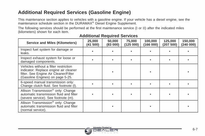
Additional Required Services (Gasoline Engine)This maintenance section applies to vehicles with a gasoline engine. If your vehicle has a diesel engine, see themaintenance schedule section in the DURAMAX® Diesel Engine Supplement.The following services should be performed at the first maintenance service (I or II) after the indicated miles(kilometers) shown for each item.
Additional Required Services
Service and Miles (Kilometers) 25,000(41 500)
50,000(83 000)
75,000(125 000)
100,000(166 000)
125,000(207 500)
150,000(240 000)
Inspect fuel system for damage orleaks. • • • • • •
Inspect exhaust system for loose ordamaged components. • • • • • •
Vehicles without a filter restrictionindicator: Replace engine air cleanerfilter. See Engine Air Cleaner/Filter(Gasoline Engines) on page 5-25.
• • •
6-speed manual transmission only:Change clutch fluid. See footnote (l). • • • • • •
Allison Transmission® only: Changeautomatic transmission fluid and filter(severe service). See footnote (m).
• • • • • •
Allison Transmission® only: Changeautomatic transmission fluid and filter(normal service).
• • •
6-7Information Provided by:

Additional Required Services (cont’d)
Service and Miles (Kilometers) 25,000(41 500)
50,000(83 000)
75,000(125 000)
100,000(166 000)
125,000(207 500)
150,000(240 000)
Except Allison Transmission®: Changeautomatic transmission fluid and filter(severe service). See footnote (h).
• • •
Except Allison Transmission®: Changeautomatic transmission fluid and filter(normal service).
•
Four-wheel drive with automatic transfercase only: Change transfer case fluid.See footnote (g).
• • •
Inspect evaporative control system.An Emission Control Service. Seefootnotes † and (k).
• • •
Replace spark plugs and inspect sparkplug wires. An Emission ControlService.
•
5-speed manual transmission only:Change manual transmission fluid. •
Engine cooling system service (or everyfive years, whichever occurs first).An Emission Control Service. Seefootnote (i).
•
Inspect engine accessory drive belt.An Emission Control Service. Seefootnote (q).
•
6-8Information Provided by:

Maintenance Footnotes(Gasoline Engine)This maintenance section applies to vehicles with agasoline engine. If your vehicle has a diesel engine, seethe maintenance schedule section in the DURAMAX®
Diesel Engine Supplement.
† The U.S. Environmental Protection Agency or theCalifornia Air Resources Board has determined that thefailure to perform this maintenance item will not nullifythe emission warranty or limit recall liability prior tothe completion of the vehicle’s useful life. We, however,urge that all recommended maintenance services beperformed at the indicated intervals and themaintenance be recorded.
# Lubricate the front suspension, ball joints, steeringlinkage, transmission shift linkage, and parkingbrake cable guides. Ball joints should not be lubricatedunless their temperature is 10°F (−12°C) or higher,or they could be damaged. Vehicles used under severecommercial operating conditions require lubricationon a regular basis every 3,000 miles (5 000 km).
(a) Visually inspect brake lines and hoses for properhook-up, binding, leaks, cracks, chafing, etc. Inspectdisc brake pads for wear and rotors for surfacecondition. Inspect drum brake linings/shoes for wear orcracks. Inspect other brake parts, including drums,wheel cylinders, calipers, parking brake, etc.
(b) Visually inspect front and rear suspension andsteering system for damaged, loose or missing parts,signs of wear or lack of lubrication. Inspect powersteering lines and hoses for proper hook-up, binding,leaks, cracks, chafing, etc. Visually check constantvelocity joints, rubber boots, and axle seals for leaks.
(c) Visually inspect hoses and have them replaced if theyare cracked, swollen, or deteriorated. Inspect all pipes,fittings and clamps; replace with genuine GM parts asneeded. To help ensure proper operation, a pressure testof the cooling system and pressure cap and cleaning theoutside of the radiator and air conditioning condenser isrecommended at least once a year.
(d) Visually inspect wiper blades for wear or cracking.Replace wiper blades that appear worn or damagedor that streak or miss areas of the windshield.
(e) Make sure the safety belt reminder light and all yourbelts, buckles, latch plates, retractors, and anchoragesare working properly. Look for any other loose ordamaged safety belt system parts. If you see anythingthat might keep a safety belt system from doing itsjob, have it repaired. Have any torn or frayed safety beltsreplaced. Also look for any opened or broken airbagcoverings, and have them repaired or replaced.The airbag system does not need regular maintenance.
6-9Information Provided by:

(f) Lubricate all key lock cylinders, body door hinges,hood latch assembly, secondary latch, pivots, springanchor, release pawl, tailgate hinges, tailgate linkage,tailgate handle pivot points, latch bolt, fuel doorhinge, locks, and folding seat hardware. More frequentlubrication may be required when exposed to acorrosive environment. Applying silicone grease onweatherstrips with a clean cloth will make themlast longer, seal better and not stick or squeak.
(g) Check vent hose at transfer case for kinks andproper installation.
(h) Change automatic transmission fluid and filter if thevehicle Gross Vehicle Weight Rating (GVWR) isover 8600 lbs or if the vehicle is mainly driven underone or more of these conditions:
− In heavy city traffic where the outside temperatureregularly reaches 90°F (32°C) or higher.
− In hilly or mountainous terrain.− When doing frequent trailer towing.− Uses such as found in taxi, police or delivery
service.
(i) Drain, flush, and refill cooling system. This servicecan be complex; you should have your dealer performthis service. See Engine Coolant on page 5-35 forwhat to use. Inspect hoses. Clean radiator, condenser,pressure cap, and filler neck. Pressure test thecooling system and pressure cap.
(j) A fluid loss in any vehicle system could indicate aproblem. Have the system inspected and repaired andthe fluid level checked. Add fluid if needed.(k) Inspect system. Check all fuel and vapor lines andhoses for proper hook-up, routing, and condition. Checkthat the purge valve works properly, if equipped.Replace as needed.(l) Change clutch fluid (or every 24 months, whicheveroccurs first).(m) Change automatic transmission fluid and filter if thevehicle is mainly driven under one or more of theseconditions:
− In heavy city traffic where the outside temperatureregularly reaches 90°F (32°C) or higher.
− In hilly or mountainous terrain.− When doing frequent trailer towing.− Uses such as found in taxi, police, or delivery
service.(n) Vehicles with diesel engine or with GVWR above10,000 lbs (4 536 kg) only: Inspect shields for damage orlooseness. Adjust or replace as required. This is aNoise Emission Control Service. Applicable to vehiclessold in the United States and recommended forvehicles sold in Canada.(p) If you drive regularly under dusty conditions, inspectthe filter or change indicator (if equipped) at eachengine oil change.(q) Visually inspect belt for fraying, excessive cracks, orobvious damage. Replace belt if necessary.
6-10Information Provided by:

Owner Checks and ServicesThese owner checks and services should be performedat the intervals specified to help ensure the safety,dependability, and emission control performance of yourvehicle. Your GM Goodwrench® dealer can assist youwith these checks and services.
Be sure any necessary repairs are completed at once.Whenever any fluids or lubricants are added to yourvehicle, make sure they are the proper ones, as shownin Recommended Fluids and Lubricants (GasolineEngine) on page 6-14.
At the First 100, 1,000 and 6,000 Miles(160, 1 600 and 10 000 km)Check dual wheel nut torque. For proper torque, seeCapacities and Specifications on page 5-132.
At Each Fuel FillIt is important to perform these underhood checks ateach fuel fill.
Engine Oil Level CheckCheck the engine oil level and add the proper oil ifnecessary. See Engine Oil (Gasoline Engine) onpage 5-20 for further details.
Notice: It is important to check your oil regularlyand keep it at the proper level. Failure to keep yourengine oil at the proper level can cause damageto your engine not covered by your warranty.
Engine Coolant Level CheckCheck the engine coolant level and addDEX-COOL® coolant mixture if necessary. See EngineCoolant on page 5-35 for further details.
Windshield Washer Fluid Level CheckCheck the windshield washer fluid level in the windshieldwasher fluid reservoir and add the proper fluid ifnecessary.
At Least Once a MonthTire Inflation CheckVisually inspect your vehicle’s tires and make sure theyare inflated to the correct pressures. Do not forget tocheck the spare tire. See Tires on page 5-73 for furtherdetails. Check to make sure the spare tire is storedsecurely. See Changing a Flat Tire on page 5-92.
Tire Wear InspectionTire rotation may be required for high mileage highwaydrivers prior to the Engine Oil Life System servicenotification. Check the tires for wear and, if necessary,rotate the tires. See Tire Inspection and Rotation onpage 5-82.
6-11Information Provided by:

At Least Once a Year
Starter Switch Check
{CAUTION:
When you are doing this inspection, thevehicle could move suddenly. If the vehiclemoves, you or others could be injured.
1. Before you start, be sure you have enough roomaround the vehicle.
2. Firmly apply both the parking brake and the regularbrake. See Parking Brake on page 2-49.Do not use the accelerator pedal, and be ready toturn off the engine immediately if it starts.
3. Try to start the engine in each gear. The vehicleshould start only in PARK (P) or NEUTRAL (N). Ifthe vehicle starts in any other position, contact yourGM Goodwrench® dealer for service.
Automatic Transmission Shift LockControl System Check
{CAUTION:
When you are doing this inspection, thevehicle could move suddenly. If the vehiclemoves, you or others could be injured.
1. Before you start, be sure you have enough roomaround the vehicle. It should be parked on a levelsurface.
2. Firmly apply the parking brake. See Parking Brakeon page 2-49.Be ready to apply the regular brake immediately ifthe vehicle begins to move.
3. With the engine off, turn the ignition to RUN, but donot start the engine. Without applying the regularbrake, try to move the shift lever out of PARK (P)with normal effort. If the shift lever moves outof PARK (P), contact your GM Goodwrench® dealerfor service.
6-12Information Provided by:

Ignition Transmission Lock CheckWhile parked, and with the parking brake set, try to turnthe ignition to LOCK in each shift lever position.
• The ignition should turn to LOCK only when theshift lever is in PARK (P).
• The key should come out only in LOCK.
Contact your GM Goodwrench® dealer if service isrequired.
Parking Brake and AutomaticTransmission Park (P) Mechanism Check
{CAUTION:
When you are doing this check, your vehiclecould begin to move. You or others could beinjured and property could be damaged. Makesure there is room in front of your vehicle incase it begins to roll. Be ready to apply theregular brake at once should the vehicle beginto move.
Park on a fairly steep hill, with the vehicle facingdownhill. Keeping your foot on the regular brake, set theparking brake.
• To check the parking brake’s holding ability: Withthe engine running and transmission inNEUTRAL (N), slowly remove foot pressure fromthe regular brake pedal. Do this until the vehicle isheld by the parking brake only.
• To check the PARK (P) mechanism’s holding ability:With the engine running, shift to PARK (P). Thenrelease the parking brake followed by the regularbrake.
Contact your GM Goodwrench® dealer if service isrequired.
Underbody Flushing ServiceAt least every spring, use plain water to flush anycorrosive materials from the underbody. Take care toclean thoroughly any areas where mud and other debriscan collect.
6-13Information Provided by:

Recommended Fluids andLubricants (Gasoline Engine)This maintenance section applies to vehicles with agasoline engine. If your vehicle has a diesel engine, seethe maintenance schedule section in the DURAMAX®
Diesel Engine Supplement.
Fluids and lubricants identified below by name, partnumber, or specification may be obtained fromyour dealer.
Usage Fluid/Lubricant
Engine Oil
Engine oil which meets GMStandard GM6094M and displaysthe American Petroleum InstituteCertified for Gasoline Enginesstarburst symbol. GM Goodwrench®
oil meets all the requirements foryour vehicle. To determine theproper viscosity for your vehicle’sengine, see Engine Oil (GasolineEngine) on page 5-20.
Engine Coolant
50/50 mixture of clean, drinkablewater and use only DEX-COOL®
coolant. See Engine Coolant onpage 5-35.
Usage Fluid/LubricantHydraulic Brake
SystemDelco® Supreme 11 Brake Fluid orequivalent DOT-3 brake fluid.
WindshieldWasher GM Optikleen® Washer Solvent.
HydraulicClutch System
(5–SpeedTrans.)
Hydraulic Clutch Fluid(GM Part No. U.S. 12345347, inCanada 10953517) or equivalentDOT-3 brake fluid.
HydraulicClutch System
(6–SpeedTrans.)
Hydraulic Clutch Fluid. Use only GMPart No. U.S. 88958860, in Canada88901244, Super DOT-4 brake fluid.
Power SteeringSystem
GM Power Steering Fluid(GM Part No. U.S. 89021184, inCanada 89021186).
ManualTransmission(5–Speed with
Low Gear,RPO MW3)
GM Goodwrench® Synthetic ManualTransmission Fluid(GM Part No. U.S. 12346190, inCanada 10953477) or equivalentSAE 75W-85 GL-4 gear oil.
6-14Information Provided by:

Usage Fluid/LubricantManual
Transmission(5–Speed
withoutLow Gear,RPO MG5)
Synchromesh Transmission Fluid(GM Part No. U.S. 12345349, inCanada 10953465).
ManualTransmission
(6–Speed)
Synthetic Transmission Fluidapproved to Allison Transmission®
specification TES-295(GM Part No. U.S. 12378515, inCanada 88900701).
AutomaticTransmission
DEXRON®-VI AutomaticTransmission Fluid.
Key LockCylinders
Multi-Purpose Lubricant, Superlube(GM Part No. U.S. 12346241, inCanada 10953474).
Floor ShiftLinkage
Lubriplate Lubricant Aerosol(GM Part No. U.S. 12346293, inCanada 992723) or lubricantmeeting requirements of NLGI #2Category LB or GC-LB.
Usage Fluid/Lubricant
ChassisLubrication
Chassis Lubricant(GM Part No. U.S. 12377985, inCanada 88901242) or lubricantmeeting requirements of NLGI #2,Category LB or GC-LB.
Front Axle(1500 Series)
SAE 80W-90 Axle Lubricant(GM Part No. U.S. 1052271, inCanada 10950849).
Front Axle(1500 HD,
2500, 2500 HD,and 3500Series)
SAE 75W-90 SyntheticAxle Lubricant(GM Part No. U.S. 12378261, inCanada 10953455) meeting GMSpecification 9986115.
Rear Axle
SAE 75W-90 SyntheticAxle Lubricant(GM Part No. U.S. 12378261, inCanada 10953455) meeting GMSpecification 9986115.
ManualTransfer Case
DEXRON®-III AutomaticTransmission Fluid. Look for“Approved for the H-Specification”on the label.
6-15Information Provided by:

Usage Fluid/Lubricant
AutomaticTransfer Case
AUTO-TRAK II Fluid(GM Part No. U.S. 12378508, inCanada 10953626).
Front AxlePropshaftSpline or
One-PiecePropshaft
Spline(Two-Wheel
Drive with Auto.Trans.)
Spline Lubricant, Special Lubricant(GM Part No. U.S. 12345879, inCanada 10953511) or lubricantmeeting requirements ofGM 9985830.
Rear DrivelineCenter Spline
Chassis Lubricant(GM Part No. U.S. 12377985, inCanada 88901242) or lubricantmeeting requirements of NLGI #2,Category LB or GC-LB.
Usage Fluid/Lubricant
Hood HingesMulti-Purpose Lubricant, Superlube(GM Part No. U.S. 12346241, inCanada 10953474).
Body DoorHinge Pins,
Tailgate Hingeand Linkage,
Folding Seats,and Fuel Door
Hinge
Multi-Purpose Lubricant, Superlube(GM Part No. U.S. 12346241, inCanada 10953474).
Tailgate HandlePivot Points,
Hinges, LatchBolt, andLinkage
Multi-Purpose Lubricant, Superlube(GM Part No. U.S. 12346241, inCanada 10953474).
WeatherstripConditioning
Dielectric Silicone Grease(GM Part No. U.S. 12345579, inCanada 992887).
WeatherstripSqueaks
Synthetic Grease with Teflon,Superlube (GM Part No. U.S.12371287, in Canada 10953437).
6-16Information Provided by:
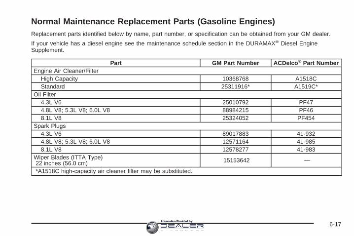
Normal Maintenance Replacement Parts (Gasoline Engines)Replacement parts identified below by name, part number, or specification can be obtained from your GM dealer.
If your vehicle has a diesel engine see the maintenance schedule section in the DURAMAX® Diesel EngineSupplement.
Part GM Part Number ACDelco ® Part NumberEngine Air Cleaner/Filter
High Capacity 10368768 A1518CStandard 25311916* A1519C*
Oil Filter4.3L V6 25010792 PF474.8L V8; 5.3L V8; 6.0L V8 88984215 PF468.1L V8 25324052 PF454
Spark Plugs4.3L V6 89017883 41-9324.8L V8; 5.3L V8; 6.0L V8 12571164 41-9858.1L V8 12578277 41-983
Wiper Blades (ITTA Type)22 inches (56.0 cm) 15153642 —
*A1518C high-capacity air cleaner filter may be substituted.
6-17Information Provided by:

Engine Drive Belt Routing
V6 Engines
V8 Engines
6-18Information Provided by:

Maintenance RecordAfter the scheduled services are performed, record the date, odometer reading, who performed the service, and thetype of services performed in the boxes provided. See Maintenance Requirements on page 6-2. Any additionalinformation from Owner Checks and Services on page 6-11 can be added on the following record pages. You shouldretain all maintenance receipts.
Maintenance Record
Date OdometerReading Serviced By Maintenance I or
Maintenance II Services Performed
6-19Information Provided by:

Maintenance Record (cont’d)
Date OdometerReading Serviced By Maintenance I or
Maintenance II Services Performed
6-20Information Provided by:

Customer Assistance and Information ...............7-2Customer Satisfaction Procedure ......................7-2Online Owner Center ......................................7-3Customer Assistance for Text
Telephone (TTY) Users ................................7-4Customer Assistance Offices ............................7-4GM Mobility Reimbursement Program ................7-5Roadside Assistance Program ..........................7-6Courtesy Transportation ...................................7-7Vehicle Data Collection and Event Data
Recorders ..................................................7-9Collision Damage Repair ................................7-10
Reporting Safety Defects ................................7-13Reporting Safety Defects to the
United States Government ..........................7-13Reporting Safety Defects to the
Canadian Government ................................7-14Reporting Safety Defects to General Motors .....7-14Service Publications Ordering Information .........7-14
Section 7 Customer Assistance and Information
7-1Information Provided by:

Customer Assistance andInformation
Customer Satisfaction ProcedureYour satisfaction and goodwill are important toyour dealer and to Chevrolet. Normally, any concernswith the sales transaction or the operation of yourvehicle will be resolved by your dealer’s sales or servicedepartments. Sometimes, however, despite the bestintentions of all concerned, misunderstandings canoccur. If your concern has not been resolved to yoursatisfaction, the following steps should be taken:
STEP ONE: Discuss your concern with a member ofdealership management. Normally, concerns canbe quickly resolved at that level. If the matter hasalready been reviewed with the sales, service or partsmanager, contact the owner of the dealership orthe general manager.
STEP TWO: If after contacting a member of dealershipmanagement, it appears your concern cannot beresolved by the dealership without further help, contactthe Chevrolet Customer Assistance Center by calling1-800-222-1020. In Canada, contact GM of CanadaCustomer Communication Centre by calling1-800-263-3777 (English) or 1-800-263-7854 (French).
We encourage you to call the toll-free number in orderto give your inquiry prompt attention. Please havethe following information available to give the CustomerAssistance Representative:
• Vehicle Identification Number (VIN). This isavailable from the vehicle registration or title, or theplate at the top left of the instrument panel andvisible through the windshield.
• Dealership name and location.
• Vehicle delivery date and present mileage(kilometers).
When contacting Chevrolet, please remember that yourconcern will likely be resolved at a dealer’s facility.That is why we suggest you follow Step One first if youhave a concern.
STEP THREE: Both General Motors and your dealerare committed to making sure you are completelysatisfied with your new vehicle. However, if you continueto remain unsatisfied after following the procedureoutlined in Steps One and Two, you should file with theBBB Auto Line Program to enforce any additionalrights you may have. Canadian owners refer to yourWarranty and Owner Assistance Information booklet forinformation on the Canadian Motor Vehicle ArbitrationPlan (CAMVAP).
7-2Information Provided by:

The BBB Auto Line Program is an out of court programadministered by the Council of Better BusinessBureaus to settle automotive disputes regarding vehiclerepairs or the interpretation of the New VehicleLimited Warranty. Although you may be required toresort to this informal dispute resolution program prior tofiling a court action, use of the program is free ofcharge and your case will generally be heard within40 days. If you do not agree with the decision given inyour case, you may reject it and proceed with any othervenue for relief available to you.
You may contact the BBB Auto Line Program using thetoll-free telephone number or write them at thefollowing address:
BBB Auto Line ProgramCouncil of Better Business Bureaus, Inc.4200 Wilson BoulevardSuite 800Arlington, VA 22203-1838
Telephone: 1-800-955-5100
This program is available in all 50 states and the Districtof Columbia. Eligibility is limited by vehicle age,mileage, and other factors. General Motors reserves theright to change eligibility limitations and/or discontinueits participation in this program.
Online Owner CenterThe Owner Center is a resource for your GM ownershipneeds. Specific vehicle information can be found inone place.
The Online Owner Center allows you to:
• Get e-mail service reminders.
• Access information about your specific vehicle,including tips and videos and an electronicversion of this owner’s manual (United States only).
• Keep track of your vehicle’s service history andmaintenance schedule.
• Find GM dealers for service nationwide.
• Receive special promotions and privileges onlyavailable to members (United States only).
Refer to the web for updated information.
To register your vehicle, visit www.MyGMLink.com(United States) or My GM Canada withinwww.gmcanada.com (Canada).
7-3Information Provided by:

Customer Assistance for TextTelephone (TTY) UsersTo assist customers who are deaf, hard of hearing, orspeech-impaired and who use Text Telephones (TTYs),Chevrolet has TTY equipment available at its CustomerAssistance Center. Any TTY user can communicatewith Chevrolet by dialing: 1-800-833-CHEV (2438).(TTY users in Canada can dial 1-800-263-3830.)
Customer Assistance OfficesChevrolet encourages customers to call the toll-freenumber for assistance. However, if a customer wishes towrite or e-mail Chevrolet, refer to the addresses below.
United States — Customer AssistanceChevrolet Motor DivisionChevrolet Customer Assistance CenterP.O. Box 33170Detroit, MI 48232-5170
www.Chevrolet.com1-800-222-10201-800-833-2438 (For Text Telephone devices (TTYs))Roadside Assistance: 1-800-CHEV-USA (243-8872)Fax Number: 313-381-0022
From Puerto Rico:1-800-496-9992 (English)1-800-496-9993 (Spanish)Fax Number: 313-381-0022
From U.S. Virgin Islands:1-800-496-9994Fax Number: 313-381-0022
Canada — Customer AssistanceGeneral Motors of Canada LimitedCustomer Communication Centre, 163-0051908 Colonel Sam DriveOshawa, Ontario L1H 8P7
1-800-263-3777 (English)1-800-263-7854 (French)1-800-263-3830 (For Text Telephone devices (TTYs))Roadside Assistance: 1-800-268-6800
7-4Information Provided by:

Overseas — Customer AssistancePlease contact the local General Motors Business Unit.
Mexico, Central America andCaribbean Islands/Countries(Except Puerto Rico and U.S. VirginIslands) — Customer Assistance
General Motors de Mexico, S. de R.L. de C.V.Customer Assistance CenterPaseo de la Reforma # 2740Col. Lomas de BezaresC.P. 11910, Mexico, D.F.01-800-508-0000Long Distance: 011-52-53 29 0 800
GM Mobility ReimbursementProgram
This program, available to qualified applicants, canreimburse you up to $1,000 of the cost of eligibleaftermarket adaptive equipment required for your vehicle,such as hand controls or a wheelchair/scooter lift.
The offer is available for a very limited period of timefrom the date of vehicle purchase/lease. For moredetails, or to determine your vehicle’s eligibility, visitgmmobility.com or call the GM Mobility AssistanceCenter at 1-800-323-9935. Text telephone (TTY) users,call 1-800-833-9935.
GM of Canada also has a Mobility Program. Call1-800-GM-DRIVE (463-7483) for details. TTY users call1-800-263-3830.
7-5Information Provided by:

Roadside Assistance ProgramAs the owner of a new Chevrolet vehicle, you areautomatically enrolled in the Chevrolet RoadsideAssistance program. This value-added service isintended to provide you with peace of mind as you drivein the city or travel the open road. Call Chevrolet’sRoadside Assistance at 1-800-CHEV-USA,(1-800-243-8872) 24 hours a day, 365 days a year tospeak with a Chevrolet Roadside Assistancerepresentative.
We will provide the following services during theBumper-to-Bumper warranty period, at no expense toyou:
• Fuel Delivery: Delivery of enough fuel($5 maximum) for the customer to get to thenearest service station.
• Lock-out Service (identification required):Replacement keys or locksmith service willbe covered at no charge if you are unable to gainentry into your vehicle. Delivery of the replacementkey will be covered within 10 miles (16 km).
• Emergency Tow: Tow to the nearest dealership forwarranty service or in the event of avehicle-disabling accident. Assistance providedwhen the vehicle is mired in sand, mud, or snow.
• Flat Tire Change: Installation of a spare tire will becovered at no charge. The customer is responsiblefor the repair or replacement of the tire if notcovered by a warrantable failure.
• Jump Start: No-start occurrences which require abattery jump start will be covered at no charge.
• Dealer Locator Service
In many instances, mechanical failures are coveredunder Chevrolet’s Bumper-to-Bumper warranty.However, when other services are utilized, our RoadsideAssistance Representatives will explain any paymentobligations you might incur.
For prompt and efficient assistance when calling, pleaseprovide the following to the Roadside AssistanceRepresentative:
• Your name, home address, and home telephonenumber.
• Telephone number of your location.
• Location of the vehicle.
• Model, year, color, and license plate number.
• Mileage, Vehicle Identification Number (VIN), anddelivery date of the vehicle.
• Description of the problem.
7-6Information Provided by:

While we hope you never have the occasion to use ourservice, it is added security while traveling for youand your family. Remember, we are only a phone callaway. Chevrolet Roadside Assistance:1-800-CHEV-USA (1-800-243-8872), text telephone(TTY) users, call 1-888-889-2438.
Chevrolet reserves the right to limit services orreimbursement to an owner or driver when, inChevrolet’s judgement, the claims become excessive infrequency or type of occurrence.
Roadside Assistance is not part of or included in thecoverage provided by the New Vehicle Limited Warranty.Chevrolet reserves the right to make any changes ordiscontinue the Roadside Assistance program atany time without notification.
Canadian Roadside AssistanceVehicles purchased in Canada have an extensiveroadside assistance program accessible from anywherein Canada or the United States. Please refer to theWarranty and Owner Assistance Information book.
Courtesy TransportationTo enhance your ownership experience, we and ourparticipating dealers are proud to offer CourtesyTransportation, a customer support program for newvehicles.
The Courtesy Transportation program is offered tocustomers in conjunction with the Bumper-to-Bumpercoverage provided by the New Vehicle Limited Warranty.Several transportation options are available whenwarranty repairs are required. This will reduce yourinconvenience during warranty repairs.
Scheduling Service AppointmentsWhen your vehicle requires warranty service, you shouldcontact your dealer and request an appointment. Byscheduling a service appointment and advisingyour service consultant of your transportation needs,your dealer can help minimize your inconvenience.
If your vehicle cannot be scheduled into the servicedepartment immediately, keep driving it until it can bescheduled for service, unless, of course, the problem issafety-related. If it is, please call your dealership, letthem know this, and ask for instructions.
If the dealer requests that you simply drop the vehicle offfor service, you are urged to do so as early in the workday as possible to allow for the same day repair.
7-7Information Provided by:

Transportation OptionsWarranty service can generally be completed while youwait. However, if you are unable to wait, GM helpsto minimize your inconvenience by providing severaltransportation options. Depending on the circumstances,your dealer can offer you one of the following:
Shuttle ServiceParticipating dealers can provide you with shuttleservice to get you to your destination with minimalinterruption of your daily schedule. This includesone-way or round trip shuttle service to a destination upto 10 miles (16 km) from the dealership.
Public Transportation or FuelReimbursementIf your vehicle requires overnight warranty repairs,reimbursement of public transportation expenses maybe available, for up to a maximum of five days. Inaddition, should you arrange transportation through afriend or relative, reimbursement for reasonablefuel expenses may be available, up to a five-daymaximum. Claim amounts should reflect actual costsand be supported by original receipts.
Courtesy Rental VehicleYour dealer may arrange to provide you with a courtesyrental vehicle or reimburse you for a rental vehiclethat you obtain if your vehicle is kept for a warrantyrepair. Reimbursement will be limited to a maximumamount per day and must be supported by receipts. Thisrequires that you sign and complete a rental agreementand meet state, local and rental vehicle providerrequirements. Requirements vary and may includeminimum age requirements, insurance coverage, creditcard, etc. You are responsible for fuel usage chargesand may also be responsible for taxes, levies,usage fees, excessive mileage or rental usage beyondthe completion of the repair.
Generally it is not possible to provide a like-vehicle as acourtesy rental.
Additional Program InformationCourtesy Transportation is available during theBumper-to-Bumper warranty coverage period, but it isnot part of the New Vehicle Limited Warranty. Aseparate booklet entitled Warranty and OwnerAssistance Information furnished with each new vehicleprovides detailed warranty coverage information.
Courtesy Transportation is available only at participatingdealers and all program options, such as shuttleservice, may not be available at every dealer.
7-8Information Provided by:

Please contact your dealer for specific information aboutavailability. All Courtesy Transportation arrangementswill be administered by appropriate dealer personnel.
Canadian Vehicles: For warranty repairs duringthe Complete Vehicle Coverage period of the GeneralMotors of Canada New Vehicle Limited Warranty,alternative transportation may be available under theCourtesy Transportation Program. Please consultyour dealer for details.
General Motors reserves the right to unilaterally modify,change or discontinue Courtesy Transportation atany time and to resolve all questions of claim eligibilitypursuant to the terms and conditions describedherein at its sole discretion.
Vehicle Data Collection and EventData RecordersYour vehicle, like other modern motor vehicles, has anumber of sophisticated computer systems that monitorand control several aspects of the vehicle’sperformance. Your vehicle uses on-board vehiclecomputers to monitor emission control components tooptimize fuel economy, to monitor conditions forairbag deployment and, if so equipped, to provideanti-lock braking and to help the driver control thevehicle in difficult driving situations.
Some information may be stored during regularoperations to facilitate repair of detected malfunctions;other information is stored only in a crash event bycomputer systems, such as those commonly calledevent data recorders (EDR).
In a crash event, computer systems, such as the AirbagSensing and Diagnostic Module (SDM) in your vehiclemay record information about the condition of the vehicleand how it was operated, such as data related toengine speed, brake application, throttle position, vehiclespeed, safety belt usage, airbag readiness, airbagperformance, and the severity of a collision. Thisinformation has been used to improve vehicle crashperformance and may be used to improve crashperformance of future vehicles and driving safety. Unlikethe data recorders on many airplanes, these on-boardsystems do not record sounds, such as conversation ofvehicle occupants.
7-9Information Provided by:

To read this information, special equipment is neededand access to the vehicle or the device that storesthe data is required. GM will not access informationabout a crash event or share it with others other than:
• with the consent of the vehicle owner or, if thevehicle is leased, with the consent of the lessee,
• in response to an official request of police or similargovernment office,
• as part of GM’s defense of litigation through thediscovery process, or
• as required by law.
In addition, once GM collects or receives data, GM may:
• use the data for GM research needs,• make it available for research where appropriate
confidentiality is to be maintained and need isshown, or
• share summary data which is not tied to a specificvehicle with non-GM organizations for researchpurposes.
Others, such as law enforcement, may have access tothe special equipment that can read the informationif they have access to the vehicle or the devicethat stores the data.
If your vehicle is equipped with OnStar®, please checkthe OnStar® subscription service agreement or manualfor information on its operations and data collection.
Collision Damage RepairIf your vehicle is involved in a collision and it is damaged,have the damage repaired by a qualified technician usingthe proper equipment and quality replacement parts.Poorly performed collision repairs will diminish yourvehicle’s resale value, and safety performance can becompromised in subsequent collisions.
Collision PartsGenuine GM Collision parts are new parts made with thesame materials and construction methods as the partswith which your vehicle was originally built. Genuine GMCollision parts are your best choice to assure that yourvehicle’s designed appearance, durability and safety arepreserved. The use of Genuine GM parts can helpmaintain your GM New Vehicle Warranty.
Recycled original equipment parts may also be used forrepair. These parts are typically removed from vehiclesthat were total losses in prior accidents. In mostcases, the parts being recycled are from undamagedsections of the vehicle. A recycled original equipmentGM part, may be an acceptable choice to maintain yourvehicle’s originally designed appearance and safetyperformance, however, the history of these parts is notknown. Such parts are not covered by your GM NewVehicle Limited Warranty, and any related failuresare not covered by that warranty.
7-10Information Provided by:

Aftermarket collision parts are also available. These aremade by companies other than GM and may nothave been tested for your vehicle. As a result, theseparts may fit poorly, exhibit prematuredurability/corrosion problems, and may not performproperly in subsequent collisions. Aftermarket parts arenot covered by your GM New Vehicle LimitedWarranty, and any vehicle failure related to such partsare not covered by that warranty.
Repair FacilityGM also recommends that you choose a collision repairfacility that meets your needs before you ever needcollision repairs. Your GM dealer may have a collisionrepair center with GM-trained technicians and stateof the art equipment, or be able to recommend acollision repair center that has GM-trained techniciansand comparable equipment.
Insuring Your VehicleProtect your investment in your GM vehicle withcomprehensive and collision insurance coverage. Thereare significant differences in the quality of coverageafforded by various insurance policy terms. Manyinsurance policies provide reduced protection to yourGM vehicle by limiting compensation for damage repairsby using aftermarket collision parts. Some insurancecompanies will not specify aftermarket collisionparts. When purchasing insurance, we recommend thatyou assure your vehicle will be repaired with GMoriginal equipment collision parts. If such insurancecoverage is not available from your current insurancecarrier, consider switching to another insurance carrier.
If your vehicle is leased, the leasing company mayrequire you to have insurance that assures repairs withGenuine GM Original Equipment Manufacturer (OEM)parts or Genuine Manufacturer replacement parts. Readyour lease carefully, as you may be charged at theend of your lease for poor quality repairs.
7-11Information Provided by:

If an Accident OccursHere is what to do if you are involved in an accident.
• Try to relax and then check to make sure you are allright. If you are uninjured, make sure that no one elsein your vehicle, or the other vehicle, is injured.
• If there has been an injury, call 911 for help. Do notleave the scene of an accident until all matters havebeen taken care of. Move your vehicle only if itsposition puts you in danger or you are instructed tomove it by a police officer.
• Give only the necessary and requested informationto police and other parties involved in the accident.Do not discuss your personal condition, mental frameof mind, or anything unrelated to the accident. Thiswill help guard against post-accident legal action.
• If you need roadside assistance, call GM RoadsideAssistance. See Roadside Assistance Program onpage 7-6 for more information.
• If your vehicle cannot be driven, know where thetowing service will be taking it. Get a card from thetow truck operator or write down the driver’s name,the service’s name, and the phone number.
• Remove any valuables from your vehicle before it istowed away. Make sure this includes your insuranceinformation and registration if you keep these itemsin your vehicle.
• Gather the important information you will need fromthe other driver. Things like name, address, phonenumber, driver’s license number, vehicle licenseplate, vehicle make, model and model year, VehicleIdentification Number (VIN), insurance company andpolicy number, and a general description of thedamage to the other vehicle.
• If possible, call your insurance company from thescene of the accident. They will walk you through theinformation they will need. If they ask for a policereport, phone or go to the police departmentheadquarters the next day and you can get a copy ofthe report for a nominal fee. In some states with “nofault” insurance laws, a report may not be necessary.This is especially true if there are no injuries and bothvehicles are driveable.
• Choose a reputable collision repair facility for yourvehicle. Whether you select a GM dealer or a privatecollision repair facility to fix the damage, make sureyou are comfortable with them. Remember, you willhave to feel comfortable with their work for along time.
• Once you have an estimate, read it carefully andmake sure you understand what work will beperformed on your vehicle. If you have a question,ask for an explanation. Reputable shops welcomethis opportunity.
7-12Information Provided by:

Managing the Vehicle Damage RepairProcessIn the event that your vehicle requires damage repairs,GM recommends that you take an active role in itsrepair. If you have a pre-determined repair facility ofchoice, take your vehicle there, or have it towed there.Specify to the facility that any required replacementcollision parts be original equipment parts, either newGenuine GM parts or recycled original GM parts.Remember, recycled parts will not be covered by yourGM vehicle warranty.
Insurance pays the bill for the repair, but you must livewith the repair. Depending on your policy limits, yourinsurance company may initially value the repair usingaftermarket parts. Discuss this with your repairprofessional, and insist on Genuine GM parts.Remember if your vehicle is leased you may beobligated to have the vehicle repaired with Genuine GMparts, even if your insurance coverage does not paythe full cost.
If another party’s insurance company is paying for therepairs, you are not obligated to accept a repairvaluation based on that insurance company’s collisionpolicy repair limits, as you have no contractual limits withthat company. In such cases, you can have control ofthe repair and parts choices as long as cost stays withinreasonable limits.
Reporting Safety Defects
Reporting Safety Defects to theUnited States GovernmentIf you believe that your vehicle has a defect which couldcause a crash or could cause injury or death, youshould immediately inform the National Highway TrafficSafety Administration (NHTSA), in addition to notifyingGeneral Motors.
If NHTSA receives similar complaints, it may open aninvestigation, and if it finds that a safety defect exists ina group of vehicles, it may order a recall and remedycampaign. However, NHTSA cannot become involved inindividual problems between you, your dealer, orGeneral Motors.
To contact NHTSA, you may either call the Auto SafetyHotline toll-free at 1-800-424-9393 (or 366-0123 inthe Washington, D.C. area) or write to:
NHTSA, U.S. Department of TransportationWashington, D.C. 20590
You can also obtain other information about motorvehicle safety from the hotline.
7-13Information Provided by:

Reporting Safety Defects to theCanadian GovernmentIf you live in Canada, and you believe that your vehiclehas a safety defect, you should immediately notifyTransport Canada, in addition to notifying GeneralMotors of Canada Limited. You may call them at1-800-333-0510 or write to:
Transport CanadaPlace de Ville Tower C330 Sparks StreetOttawa, Ontario K1A 0N5
Reporting Safety Defects toGeneral MotorsIn addition to notifying NHTSA (or Transport Canada) ina situation like this, we certainly hope you will notifyGeneral Motors. Please call the Chevrolet CustomerAssistance Center at 1-800-222-1020, or write:
Chevrolet Motor DivisionChevrolet Customer Assistance CenterP.O. Box 33170Detroit, MI 48232-5170
In Canada, please call us at 1-800-263-3777 (English)or 1-800-263-7854 (French). Or, write:
General Motors of Canada LimitedCustomer Communication Centre, 163-0051908 Colonel Sam DriveOshawa, Ontario L1H 8P7
Service Publications OrderingInformation
Service ManualsService Manuals have the diagnosis and repairinformation on engines, transmission, axle suspension,brakes, electrical, steering, body, etc.
Transmission, Transaxle, TransferCase Unit Repair ManualThis manual provides information on unit repair serviceprocedures, adjustments, and specifications for GMtransmissions, transaxles, and transfer cases.
7-14Information Provided by:

Service BulletinsService Bulletins give technical service informationneeded to knowledgeably service General Motors carsand trucks. Each bulletin contains instructions toassist in the diagnosis and service of your vehicle.
In Canada, information pertaining to Product ServiceBulletins can be obtained by contacting your GeneralMotors dealer or by calling 1-800-GM-DRIVE(1-800-463-7483).
Owner’s InformationOwner publications are written specifically for ownersand intended to provide basic operational informationabout the vehicle. The owner’s manual will includethe Maintenance Schedule for all models.
In-Portfolio: Includes a Portfolio, Owner’s Manual, andWarranty Booklet.
RETAIL SELL PRICE: $35.00
Without Portfolio: Owner’s Manual only.
RETAIL SELL PRICE: $25.00
Current and Past Model Order FormsService Publications are available for current andpast model GM vehicles. To request an order form,please specify year and model name of the vehicle.
ORDER TOLL FREE: 1-800-551-4123Monday-Friday 8:00 AM - 6:00 PMEastern TimeFor Credit Card Orders Only(VISA-MasterCard-Discover), visit Helm, Inc. on theWorld Wide Web at: www.helminc.com
Or you can write to:
Helm, IncorporatedP.O. Box 07130Detroit, MI 48207
Prices are subject to change without notice and withoutincurring obligation. Allow ample time for delivery.
Note to Canadian Customers: All listed prices arequoted in U.S. funds. Canadian residents are to makechecks payable in U.S. funds.
7-15Information Provided by:

✍ NOTES
7-16Information Provided by:

AAccessories and Modifications ............................ 5-4Accessory Power Outlet(s) ............................... 3-18Adding a Snow Plow or Similar Equipment ......... 4-54Adding Equipment to Your Airbag-Equipped
Vehicle ....................................................... 1-86Additives, Fuel ................................................. 5-7Add-On Electrical Equipment ........................... 5-123Air Cleaner/Filter, Engine ................................. 5-25Air Conditioning .............................. 3-20, 3-21, 3-24Airbag
Off Light ..................................................... 3-34Passenger Status Indicator ........................... 3-36Readiness Light .......................................... 3-33
Airbag Sensing and Diagnostic Module (SDM) ...... 7-9Airbag System ................................................ 1-70
Adding Equipment to Your Airbag-EquippedVehicle ................................................... 1-86
Airbag Off Switch ........................................ 1-77How Does an Airbag Restrain? ...................... 1-75Passenger Sensing System ........................... 1-80Servicing Your Airbag-Equipped Vehicle .......... 1-86What Makes an Airbag Inflate? ...................... 1-75What Will You See After an Airbag Inflates? .... 1-76When Should an Airbag Inflate? .................... 1-73Where Are the Airbags? ............................... 1-71
AM-FM Radio ................................................. 3-72Antenna, Fixed Mast ...................................... 3-130Antenna, XM™ Satellite Radio Antenna System ... 3-130
Anti-Lock Brake System (ABS) ........................... 4-7Anti-Lock Brake, System Warning Light .............. 3-42Appearance Care
Aluminum or Chrome-Plated Wheels ............. 5-119Care of Safety Belts ................................... 5-117Chemical Paint Spotting .............................. 5-121Cleaning Exterior Lamps/Lenses .................. 5-118Cleaning the Inside of Your Vehicle .............. 5-114Fabric/Carpet ............................................ 5-116Finish Care ............................................... 5-118Instrument Panel, Vinyl, and Other
Plastic Surfaces ..................................... 5-117Leather .................................................... 5-116Sheet Metal Damage .................................. 5-120Tires ........................................................ 5-120Underbody Maintenance ............................. 5-120Vehicle Care/Appearance Materials ............... 5-121Washing Your Vehicle ................................. 5-118Weatherstrips ............................................ 5-117Windshield and Wiper Blades ...................... 5-119
Ashtray(s) ...................................................... 3-19Audio System(s) ............................................. 3-70
AM-FM Radio ............................................. 3-72Audio Steering Wheel Controls .................... 3-127Care of Your Cassette Tape Player ............... 3-128Care of Your CD and DVD Player ................ 3-130Care of Your CDs and DVDs ....................... 3-129Chime Level Adjustment ............................. 3-130Fixed Mast Antenna ................................... 3-130Radio with Cassette and CD ......................... 3-85
1Information Provided by:

Audio System(s) (cont.)Radio with CD ............................................ 3-74Radio with Six-Disc CD ................................ 3-99Rear Seat Audio (RSA) ............................... 3-125Setting the Time for Radios with Radio Data
Systems (RDS) ........................................ 3-71Setting the Time for Radios without Radio
Data Systems (RDS) ................................ 3-71Theft-Deterrent Feature ............................... 3-126Understanding Radio Reception ................... 3-128XM™ Satellite Radio Antenna System ........... 3-130
Automatic Headlamp System ............................ 3-14Automatic Transmission
Fluid .................................................. 5-27, 5-30Operation ................................................... 2-24
Auxiliary Roof Mounted Lamp Switch ................. 3-16
BBattery .......................................................... 5-51Battery Warning Light ...................................... 3-39Before Leaving on a Long Trip ......................... 4-39Brake
Anti-Lock Brake System (ABS) ........................ 4-7Emergencies ................................................ 4-9Parking ...................................................... 2-49System Warning Light .................................. 3-41
Brakes .......................................................... 5-48Braking ........................................................... 4-6
Braking in Emergencies ..................................... 4-9Break-In, New Vehicle ..................................... 2-20Bulb Replacement ........................................... 5-62
Center High-Mounted Stoplamp (CHMSL) andCargo Lamp ............................................ 5-67
Front Turn Signal, Sidemarker and DaytimeRunning Lamps ........................................ 5-64
Halogen Bulbs ............................................ 5-62Headlamps ................................................. 5-62Pickup Box Identification and Fender Marker
Lamps .................................................... 5-69Replacement Bulbs ...................................... 5-71Roof Marker Lamps ..................................... 5-66Taillamps, Turn Signal, Stoplamps and
Back-up Lamps ........................................ 5-69Buying New Tires ........................................... 5-86
CCalifornia Fuel .................................................. 5-7California Proposition 65 Warning ....................... 5-4Canadian Owners ................................................ iiCapacities and Specifications .......................... 5-132Carbon Monoxide ................... 2-14, 2-54, 4-42, 4-67Care of
Safety Belts .............................................. 5-117Your Cassette Tape Player .......................... 3-128Your CD and DVD Player ........................... 3-130Your CDs and DVDs .................................. 3-129
Cargo Lamp ................................................... 3-18
2Information Provided by:

Cargo Lamp Light ........................................... 3-49Center Console Storage Area ........................... 2-76Center Front Passenger Position, Safety Belts .... 1-25Center High-Mounted Stoplamp (CHMSL) and
Cargo Lamp ............................................... 5-67Chains, Tire ................................................... 5-91Check
Engine Light ............................................... 3-45Checking Things Under the Hood ...................... 5-12Chemical Paint Spotting ................................. 5-121Child Restraints
Child Restraint Systems ............................... 1-37Infants and Young Children ........................... 1-33Lower Anchors and Tethers for Children .......... 1-44Older Children ............................................. 1-31Securing a Child Restraint in a Rear
Seat Position ........................................... 1-54Securing a Child Restraint in the Center
Front Seat Position ................................... 1-56Securing a Child Restraint in the Right
Front Seat Position (Crew Cab) .................. 1-57Securing a Child Restraint in the Right
Front Seat Position (Regular andExtended Cab) ................................ 1-60, 1-65
Where to Put the Restraint ........................... 1-42Chime Level Adjustment ................................. 3-130Cigarette Lighter ............................................. 3-19Cleaning
Aluminum or Chrome-Plated Wheels ............. 5-119Exterior Lamps/Lenses ................................ 5-118
Cleaning (cont.)Fabric/Carpet ............................................ 5-116Finish Care ............................................... 5-118Inside of Your Vehicle ................................. 5-114Instrument Panel, Vinyl, and Other
Plastic Surfaces ..................................... 5-117Leather .................................................... 5-116Tires ........................................................ 5-120Underbody Maintenance ............................. 5-120Washing Your Vehicle ................................. 5-118Weatherstrips ............................................ 5-117Windshield and Wiper Blades ...................... 5-119
Climate Control System ................................... 3-20Dual .......................................................... 3-21Dual Automatic ............................................ 3-24Outlet Adjustment ........................................ 3-29
Clutch, Hydraulic ............................................. 5-34Coinholder(s) .................................................. 2-75Collision Damage Repair .................................. 7-10Comfort Guides, Rear Safety Belt ..................... 1-29Content Theft-Deterrent .................................... 2-18Control of a Vehicle .......................................... 4-6Coolant
Engine Temperature Gage ............................ 3-43Heater, Engine ............................................ 2-23Surge Tank Pressure Cap ............................. 5-37
Cooling System .............................................. 5-40Cruise Control ................................................ 3-10Cruise Control Light ........................................ 3-48Cupholder(s) .................................................. 2-75
3Information Provided by:

Customer Assistance InformationCourtesy Transportation .................................. 7-7Customer Assistance for Text
Telephone (TTY) Users ............................... 7-4Customer Assistance Offices ........................... 7-4Customer Satisfaction Procedure ..................... 7-2GM Mobility Reimbursement Program ............... 7-5Reporting Safety Defects to General Motors .... 7-14Reporting Safety Defects to the Canadian
Government ............................................ 7-14Reporting Safety Defects to the United States
Government ............................................ 7-13Roadside Assistance Program ......................... 7-6Service Publications Ordering Information ........ 7-14
DDaytime Running Lamps .................................. 3-14Defensive Driving ............................................. 4-2Delayed Locking ............................................... 2-9Doing Your Own Service Work ........................... 5-5Dome Lamp Override ...................................... 3-17Dome Lamps ................................................. 3-17Door
Delayed Locking ........................................... 2-9Locks .......................................................... 2-8Power Door Locks ......................................... 2-8
Door (cont.)Programmable Automatic Door Locks ............. 2-10Rear Door Security Locks ............................. 2-12Rear Doors ................................................. 2-13
DriverPosition, Safety Belt ..................................... 1-17
Driver Information Center (DIC) ......................... 3-51DIC Operation and Displays .......................... 3-52DIC Vehicle Customization ............................ 3-64DIC Warnings and Messages ........................ 3-54
DrivingAt Night ..................................................... 4-33City ........................................................... 4-37Defensive ..................................................... 4-2Drunken ....................................................... 4-3Freeway ..................................................... 4-38Hill and Mountain Roads .............................. 4-40In Rain and on Wet Roads ........................... 4-34Off-Road .................................................... 4-17Recovery Hooks .......................................... 4-47Rocking Your Vehicle to Get it Out ................. 4-46Winter ........................................................ 4-42
Dual Automatic Climate Control System ............. 3-24Dual Climate Control System ............................ 3-21Dual Tire Operation ......................................... 5-82DVD
Rear Seat Entertainment System .................. 3-114
4Information Provided by:

EElectrical System
Add-On Equipment ..................................... 5-123Center Instrument Panel Fuse Block ............. 5-126Fuses and Circuit Breakers ......................... 5-124Instrument Panel Fuse Block ....................... 5-124Power Windows and Other Power Options .... 5-124Underhood Fuse Block ............................... 5-127Windshield Wiper Fuses ............................. 5-123
EngineAir Cleaner/Filter ......................................... 5-25Battery ....................................................... 5-51Check and Service Engine Soon Light ............ 3-45Coolant ...................................................... 5-35Coolant Heater ............................................ 2-23Coolant Temperature Gage ........................... 3-43Drive Belt Routing ....................................... 6-18Engine Compartment Overview ...................... 5-14Exhaust ..................................................... 2-54Fan Noise .................................................. 5-45Oil ............................................................. 5-20Oil Life System ........................................... 5-23Overheated Protection Operating Mode ........... 5-40Overheating ................................................ 5-37Starting ...................................................... 2-22
Entry Lighting ................................................. 3-17Event Data Recorders (EDR) ............................. 7-9Exit Lighting ................................................... 3-17Extender, Safety Belt ....................................... 1-30
FFilter
Engine Air Cleaner ...................................... 5-25Fixed Mast Antenna ....................................... 3-130Flash-to-Pass ................................................... 3-8Flat Tire ........................................................ 5-92Flat Tire, Changing ......................................... 5-92Flat Tire, Storing ........................................... 5-110Fluid
Automatic Transmission ........................ 5-27, 5-30Manual Transmission .................................... 5-32Power Steering ........................................... 5-46Windshield Washer ...................................... 5-47
Fog Lamps .................................................... 3-16Four-Wheel Drive .................................... 2-36, 5-58Four-Wheel-Drive Light .................................... 3-49Front Axle ...................................................... 5-60Front Reading Lamps ...................................... 3-18Front Storage Area ......................................... 2-76
5Information Provided by:

Fuel ............................................................... 5-6Additives ...................................................... 5-7California Fuel .............................................. 5-7E85 (85% Ethanol) ........................................ 5-8Filling a Portable Fuel Container .................... 5-12Filling Your Tank .......................................... 5-10Fuels in Foreign Countries .............................. 5-9Gage ......................................................... 3-50Gasoline Octane ........................................... 5-6Gasoline Specifications .................................. 5-6Low Warning Light ....................................... 3-50
FusesCenter Instrument Panel Fuse Block ............. 5-126Fuses and Circuit Breakers ......................... 5-124Instrument Panel Fuse Block ....................... 5-124Underhood Fuse Block ............................... 5-127Windshield Wiper ....................................... 5-123
GGage
Engine Coolant Temperature ......................... 3-43Fuel .......................................................... 3-50Oil Pressure ............................................... 3-47Speedometer .............................................. 3-32Tachometer ................................................. 3-32Transmission Temperature ............................. 3-43Voltmeter Gage ........................................... 3-39
Garage Door Opener ....................................... 2-71
GasolineOctane ........................................................ 5-6Specifications ............................................... 5-6
Glove Box ..................................................... 2-75GM Mobility Reimbursement Program .................. 7-5
HHazard Warning Flashers ................................... 3-6Head Restraints ............................................... 1-8Headlamps ............................................ 3-13, 5-62
Automatic Headlamp System ......................... 3-14Bulb Replacement ....................................... 5-62Daytime Running Lamps ............................... 3-14Flash-to-Pass ............................................... 3-8Front Turn Signal, Sidemarker and Daytime
Running Lamps ........................................ 5-64Halogen Bulbs ............................................ 5-62High/Low Beam Changer ................................ 3-8On Reminder .............................................. 3-14Pickup Box Identification and Fender Marker
Lamps .................................................... 5-69Roof Marker Lamps ..................................... 5-66
Heated Seats ................................................... 1-5Heater ................................................... 3-20, 3-21Heater ........................................................... 3-24Highbeam On Light ......................................... 3-49Highway Hypnosis ........................................... 4-40Hill and Mountain Roads .................................. 4-40
6Information Provided by:
HoodChecking Things Under ................................ 5-12Release ..................................................... 5-13
Horn ............................................................... 3-6How to Use This Manual ...................................... iiHow to Wear Safety Belts Properly ................... 1-17Hydraulic Clutch ............................................. 5-34
IIgnition Positions ............................................. 2-20Infants and Young Children, Restraints ............... 1-33Inflation -- Tire Pressure .................................. 5-80Instrument Panel
Overview ..................................................... 3-4Instrument Panel (I/P)
Brightness .................................................. 3-17Cluster ....................................................... 3-31
JJump Starting ................................................. 5-52
KKeyless Entry System ....................................... 2-4Keys ............................................................... 2-3
LLabeling, Tire Sidewall ..................................... 5-74Lamps
Auxiliary Roof Mounted Lamp ........................ 3-16Cargo ........................................................ 3-18Dome ........................................................ 3-17Dome Lamp Override ................................... 3-17Fog ........................................................... 3-16Front Reading ............................................. 3-18
LATCH SystemChild Restraints ........................................... 1-44
Latches, Seatback ............................................ 1-8Light
Airbag Off .................................................. 3-34Airbag Readiness ........................................ 3-33Anti-Lock Brake System Warning ................... 3-42Battery Warning .......................................... 3-39Brake System Warning ................................. 3-41Cargo Lamp ............................................... 3-49Cruise Control ............................................. 3-48Four-Wheel-Drive ......................................... 3-49Highbeam On ............................................. 3-49Low Fuel Warning ....................................... 3-50Malfunction Indicator .................................... 3-45Passenger Airbag Status Indicator .................. 3-36Safety Belt Reminder ................................... 3-33Security ..................................................... 3-48
7Information Provided by:

Light (cont.)Tow/Haul Mode ........................................... 3-49Traction Off ................................................ 3-42Up-Shift ..................................................... 3-40
LightingEntry ......................................................... 3-17Exit ........................................................... 3-17
Loading Your Vehicle ....................................... 4-48Locking Rear Axle ........................................... 4-12Lockout Protection .......................................... 2-12Locks
Delayed Locking ........................................... 2-9Door ........................................................... 2-8Lockout Protection ....................................... 2-12Power Door .................................................. 2-8Programmable Automatic Door Locks ............. 2-10Rear Door Security Locks ............................. 2-12
Loss of Control ............................................... 4-16Low Fuel Warning Light ................................... 3-50Lumbar
Power Controls ............................................. 1-4
MMaintenance Schedule
Additional Required Services ........................... 6-7At Each Fuel Fill ......................................... 6-11At Least Once a Month ................................ 6-11At Least Once a Year .................................. 6-12
Maintenance Schedule (cont.)At the First 100, 1,000 and 6,000 Miles
(160, 1 600 and 10 000km) ....................... 6-11Introduction .................................................. 6-2Maintenance Footnotes .................................. 6-9Maintenance Record .................................... 6-19Maintenance Requirements ............................. 6-2Normal Maintenance Replacement Parts ......... 6-17Owner Checks and Services ......................... 6-11Recommended Fluids and Lubricants ............. 6-14Scheduled Maintenance ................................. 6-4Using .......................................................... 6-3Your Vehicle and the Environment ................... 6-2
Malfunction Indicator Light ................................ 3-45Manual Seats ................................................... 1-3Manual Selectable Ride ................................... 4-11Manual Transmission
Fluid .......................................................... 5-32Operation ................................................... 2-32
Manual Windows ............................................ 2-15Memory Seat ................................................. 2-79Message
DIC Warnings and Messages ........................ 3-54Mirrors
Automatic Dimming Rearview with Compass .... 2-60Automatic Dimming Rearview with Compass
and Temperature Display ........................... 2-62Automatic Dimming Rearview with OnStar®
and Compass .......................................... 2-56
8Information Provided by:

Mirrors (cont.)Automatic Dimming Rearview with OnStar®,
Compass and Temperature Display ............. 2-58Manual Rearview Mirror ................................ 2-56Outside Automatic Dimming Mirror ................. 2-68Outside Camper-Type Mirrors ........................ 2-65Outside Convex Mirror ................................. 2-68Outside Curb View Assist Mirrors ................... 2-68Outside Heated Mirrors ................................ 2-68Outside Manual Mirrors ................................ 2-64Outside Power Foldaway Mirrors .................... 2-67Outside Power Mirrors .................................. 2-66Outside West Coast-Type Mirrors ................... 2-66
MyGMLink.com ................................................ 7-3
NNew Vehicle Break-In ...................................... 2-20Noise Control System, Tampering ...................... 5-61Normal Maintenance Replacement Parts ............ 6-17
OOdometer ...................................................... 3-32Odometer, Trip ............................................... 3-32Off-Road Driving ............................................. 4-17Off-Road Recovery .......................................... 4-14
OilEngine ....................................................... 5-20Pressure Gage ............................................ 3-47
Oil, Engine Oil Life System .............................. 5-23Older Children, Restraints ................................ 1-31Online Owner Center ........................................ 7-3OnStar® System, see OnStar® Manual ............... 2-69Other Warning Devices ...................................... 3-6Outlet Adjustment ............................................ 3-29Outside
Automatic Dimming Mirror ............................. 2-68Camper-Type Mirrors .................................... 2-65Convex Mirror ............................................. 2-68Curb View Assist Mirrors .............................. 2-68Heated Mirrors ............................................ 2-68Manual Mirrors ............................................ 2-64Power Foldaway Mirrors ............................... 2-67Power Mirrors ............................................. 2-66West Coast-Type Mirrors .............................. 2-66
Overheated Engine ProtectionOperating Mode .......................................... 5-40
Owner Checks and Services ............................. 6-11Owners, Canadian ............................................... ii
9Information Provided by:
PPark (P)
Shifting Into ................................................ 2-50Shifting Out of ............................................ 2-52
ParkingBrake ........................................................ 2-49Over Things That Burn ................................. 2-53
Parking Your Vehicle ....................................... 2-53Passenger Airbag Status Indicator ..................... 3-36Passenger Sensing System .............................. 1-80Passing ......................................................... 4-15Passlock® ...................................................... 2-19Pickup Conversion to Chassis Cab .................... 4-61Power
Accessory Outlet(s) ...................................... 3-18Door Locks .................................................. 2-8Electrical System ....................................... 5-124Lumbar Controls ........................................... 1-4Retained Accessory (RAP) ............................ 2-22Seat ............................................................ 1-4Steering Fluid ............................................. 5-46Windows .................................................... 2-16
Programmable Automatic Door Locks ................. 2-10
QQuestions and Answers About Safety Belts ......... 1-16
RRadios .......................................................... 3-70
AM-FM Radio ............................................. 3-72Care of Your Cassette Tape Player ............... 3-128Care of Your CD and DVD Player ................ 3-130Care of Your CDs and DVDs ....................... 3-129Radio with Cassette and CD ......................... 3-85Radio with CD ............................................ 3-74Radio with Six-Disc CD ................................ 3-99Rear Seat Audio ........................................ 3-125Setting the Time for Radios with Radio
Data Systems (RDS) ................................ 3-71Setting the Time for Radios without
Radio Data Systems (RDS) ....................... 3-71Theft-Deterrent .......................................... 3-126Understanding Reception ............................ 3-128
Rear Axle ...................................................... 5-56Locking ...................................................... 4-12
Rear Door Security Locks ................................ 2-12Rear Doors .................................................... 2-13Rear Safety Belt Comfort Guides ...................... 1-29Rear Seat Audio (RSA) .................................. 3-125Rear Seat Entertainment System ..................... 3-114Rear Seat Operation ................................. 1-9, 1-10Rear Seat Passengers, Safety Belts .................. 1-26Rearview Mirror, Automatic Dimming with
Compass .................................................... 2-60Rearview Mirror, Automatic Dimming with
Compass and Temperature Display ................ 2-62
10Information Provided by:

Rearview Mirror, Automatic Dimming withOnStar® and Compass ................................. 2-56
Rearview Mirror, Automatic Dimming withOnStar®, Compass and Temperature Display ... 2-58
Rearview Mirrors ............................................. 2-56Reclining Seatbacks .......................................... 1-6Recommended Fluids and Lubricants ................. 6-14Recovery Hooks ............................................. 4-47Recreational Vehicle Towing ............................. 4-62Remote Keyless Entry System ............................ 2-4Remote Keyless Entry System, Operation ............ 2-5Removing the Flat Tire and Installing the
Spare Tire .................................................. 5-98Removing the Spare Tire and Tools ................... 5-94Replacement Bulbs ......................................... 5-71Reporting Safety Defects
Canadian Government .................................. 7-14General Motors ........................................... 7-14United States Government ............................ 7-13
Restraint System CheckChecking the Restraint Systems .................... 1-87Replacing Restraint System Parts
After a Crash .......................................... 1-88Retained Accessory Power (RAP) ...................... 2-22Right Front Passenger Position, Safety Belts ...... 1-25Roadside
Assistance Program ....................................... 7-6Rocking Your Vehicle to Get it Out .................... 4-46Routing, Engine Drive Belt ............................... 6-18Running the Engine While Parked ..................... 2-54
SSafety Belt
Reminder Light ............................................ 3-33Safety Belts
Care of .................................................... 5-117Center Front Passenger Position .................... 1-25Driver Position ............................................ 1-17How to Wear Safety Belts Properly ................ 1-17Questions and Answers About Safety Belts ..... 1-16Rear Safety Belt Comfort Guides ................... 1-29Rear Seat Passengers ................................. 1-26Right Front Passenger Position ...................... 1-25Safety Belt Extender .................................... 1-30Safety Belt Use During Pregnancy ................. 1-24Safety Belts Are for Everyone ....................... 1-12
Safety Warnings and Symbols .............................. iiiScheduled Maintenance ..................................... 6-4Seatback Latches ............................................. 1-8Seats
Head Restraints ............................................ 1-8Heated Seats ............................................... 1-5Manual ........................................................ 1-3Memory ..................................................... 2-79Power Lumbar .............................................. 1-4Power Seats ................................................. 1-4Rear Seat Operation .............................. 1-9, 1-10Reclining Seatbacks ...................................... 1-6Seatback Latches .......................................... 1-8
Secondary Latch System ................................ 5-107
11Information Provided by:

Securing a Child RestraintCenter Front Seat Position ............................ 1-56Rear Seat Position ...................................... 1-54Right Front Seat Position (Crew Cab) ............. 1-57Right Front Seat Position (Regular and
Extended Cab) ................................ 1-60, 1-65Security Light ................................................. 3-48Service ........................................................... 5-4
Accessories and Modifications ......................... 5-4Adding Equipment to the Outside of Your
Vehicle ..................................................... 5-5California Proposition 65 Warning .................... 5-4Doing Your Own Work ................................... 5-5Engine Soon Light ....................................... 3-45Publications Ordering Information ................... 7-14
Servicing Your Airbag-Equipped Vehicle .............. 1-86Setting the Time
Radios with Radio Data Systems (RDS) ......... 3-71Radios without Radio Data Systems (RDS) ..... 3-71
Sheet Metal Damage ..................................... 5-120Shifting Into Park (P) ....................................... 2-50Shifting Out of Park (P) ................................... 2-52Signals, Turn and Lane-Change .......................... 3-7Sliding Rear Windows ..................................... 2-17Snow Plow .................................................... 4-54Spare Tire .................................................... 5-114
Installing .................................................... 5-98Removing ................................................... 5-94Storing ..................................................... 5-110
Specifications, Capacities ............................... 5-132Speedometer .................................................. 3-32Starting Your Engine ....................................... 2-22Steering ........................................................ 4-12Steering Wheel Controls, Audio ....................... 3-127Steering Wheel, Tilt Wheel ................................. 3-6Storage Areas
Center Console Storage Area ........................ 2-76Coinholder(s) .............................................. 2-75Cupholder(s) ............................................... 2-75Front Storage Area ...................................... 2-76Glove Box .................................................. 2-75
Stuck in Sand, Mud, Ice or Snow ...................... 4-46Sun Visors ..................................................... 2-17Sunroof ......................................................... 2-78Swing-Out Windows ........................................ 2-17
TTachometer .................................................... 3-32Tailgate ......................................................... 2-14Taillamps
Turn Signal, Stoplamps and Back-up Lamps .... 5-69Theft-Deterrent, Radio .................................... 3-126Theft-Deterrent Systems ................................... 2-18
Content Theft-Deterrent ................................ 2-18Passlock® ................................................... 2-19
Tilt Wheel ........................................................ 3-6Tires ............................................................. 5-73
12Information Provided by:

Aluminum or Chrome-Plated Wheels,Cleaning ............................................... 5-119
Buying New Tires ........................................ 5-86Chains ....................................................... 5-91Changing a Flat Tire .................................... 5-92Cleaning ................................................... 5-120Different Size .............................................. 5-87Dual Tire Operation ..................................... 5-82If a Tire Goes Flat ....................................... 5-92Inflation -- Tire Pressure ............................... 5-80Inspection and Rotation ................................ 5-82Installing the Spare Tire ................................ 5-98Removing the Flat Tire ................................. 5-98Removing the Spare Tire and Tools ............... 5-94Secondary Latch System ............................ 5-107Spare Tire ................................................ 5-114Storing a Flat or Spare Tire and Tools .......... 5-110Tire Sidewall Labeling .................................. 5-74Tire Terminology and Definitions .................... 5-77Uniform Tire Quality Grading ......................... 5-88Wheel Alignment and Tire Balance ................. 5-89Wheel Replacement ..................................... 5-89When It Is Time for New Tires ...................... 5-85
Tonneau Cover ............................................... 2-76Tow/Haul Mode ............................................... 2-30Tow/Haul Mode Light ....................................... 3-49Towing
Power Take-Off (PTO) .................................. 4-95Recreational Vehicle ..................................... 4-62
Towing (cont.)Towing a Trailer .......................................... 4-67Your Vehicle ............................................... 4-61
TractionAssist System (TAS) ...................................... 4-9Manual Selectable Ride ................................ 4-11Off Light ..................................................... 3-42
TrailerRecommendations ....................................... 4-95
TransmissionFluid, Automatic .................................. 5-27, 5-30Fluid, Manual .............................................. 5-32Temperature Gage ....................................... 3-43Up-Shift Light .............................................. 3-40
Transmission Operation, Automatic .................... 2-24Transmission Operation, Manual ........................ 2-32Trip Odometer ................................................ 3-32Truck-Camper Loading Information .................... 4-59Turn and Lane-Change Signals .......................... 3-7Turn Signal/Multifunction Lever ........................... 3-7
UUnderstanding Radio Reception ....................... 3-128Uniform Tire Quality Grading ............................ 5-88Universal Home Remote System ....................... 2-71
Operation ................................................... 2-72Up-Shift Light ................................................. 3-40
13Information Provided by:

VVehicle
Control ........................................................ 4-6Damage Warnings ........................................... ivLoading ...................................................... 4-48Parking Your ............................................... 2-53Symbols ......................................................... iv
Vehicle Customization, DIC .............................. 3-64Vehicle Data Collection and Event Data
Recorders .................................................... 7-9Vehicle Identification
Number (VIN) ............................................ 5-122Service Parts Identification Label .................. 5-123
Vehicle Personalization .................................... 2-79Memory Seat .............................................. 2-79
Ventilation Adjustment ...................................... 3-29Visors ........................................................... 2-17Voltmeter Gage .............................................. 3-39
WWarning Lights, Gages and Indicators ................ 3-30Warnings
DIC Warnings and Messages ........................ 3-54Hazard Warning Flashers ............................... 3-6Other Warning Devices .................................. 3-6Safety and Symbols ......................................... iiiVehicle Damage .............................................. iv
WheelsAlignment and Tire Balance .......................... 5-89Different Size .............................................. 5-87Replacement ............................................... 5-89
Where to Put the Restraint ............................... 1-42Windows ....................................................... 2-15
Manual ...................................................... 2-15Power ........................................................ 2-16Sliding Rear ................................................ 2-17Swing-Out Windows ..................................... 2-17
WindshieldWiper Blades, Cleaning .............................. 5-119
Windshield Washer ........................................... 3-9Fluid .......................................................... 5-47
Windshield WiperBlade Replacement ...................................... 5-72Fuses ...................................................... 5-123Windshield Wipers ......................................... 3-9
Winter Driving ................................................ 4-42
XXM™ Satellite Radio Antenna System .............. 3-130
YYour Vehicle and the Environment ....................... 6-2
14Information Provided by: