Embed Size (px)
Citation preview
Seats and Restraint Systems ........................... 1-1Front Seats ............................................... 1-3Rear Seats ............................................... 1-8Safety Belts ............................................. 1-22Child Restraints ....................................... 1-43Airbag System ......................................... 1-66Restraint System Check ............................ 1-81
Features and Controls ..................................... 2-1Keys ........................................................ 2-3Doors and Locks ....................................... 2-8Windows ................................................. 2-14Theft-Deterrent Systems ............................ 2-17Starting and Operating Your Vehicle ........... 2-19Mirrors .................................................... 2-41OnStar® System ...................................... 2-50HomeLink® Wireless Control System ........... 2-52Storage Areas ......................................... 2-56Sunroof .................................................. 2-60Vehicle Personalization ............................. 2-61
Instrument Panel ............................................. 3-1Instrument Panel Overview .......................... 3-4Climate Controls ...................................... 3-21Warning Lights, Gages, and Indicators ........ 3-36Driver Information Center (DIC) .................. 3-54Audio System(s) ....................................... 3-74
Driving Your Vehicle ....................................... 4-1Your Driving, the Road, and Your Vehicle ..... 4-2Towing ................................................... 4-62
Service and Appearance Care .......................... 5-1Service ..................................................... 5-3Fuel ......................................................... 5-5Checking Things Under the Hood ............... 5-10All-Wheel Drive ........................................ 5-45Rear Axle ............................................... 5-46Four-Wheel Drive ..................................... 5-47Front Axle ............................................... 5-48Bulb Replacement .................................... 5-49Windshield Wiper Blade Replacement ......... 5-56Tires ...................................................... 5-57Appearance Care ..................................... 5-95Vehicle Identification ............................... 5-104Electrical System .................................... 5-105Capacities and Specifications ................... 5-114
Maintenance Schedule ..................................... 6-1Maintenance Schedule ................................ 6-2
Customer Assistance and Information .............. 7-1Customer Assistance and Information ........... 7-2Reporting Safety Defects ........................... 7-10
Index .................................................................1
2005 GMC Yukon/Yukon XL Owner Manual M
GENERAL MOTORS, GM, the GM Emblem, GMC, theGMC Truck Emblem, and the name YUKON areregistered trademarks of General Motors Corporation.
This manual includes the latest information at the time itwas printed. We reserve the right to make changesafter that time without further notice. For vehicles firstsold in Canada, substitute the name “General Motors ofCanada Limited” for GMC whenever it appears in thismanual.
Keep this manual in the vehicle, so it will be there if it isneeded while you are on the road. If the vehicle issold, leave this manual in the vehicle.
Canadian OwnersA French language copy of this manual can be obtainedfrom your dealer or from:
Helm, IncorporatedP.O. Box 07130Detroit, MI 48207
How to Use This ManualMany people read the owner manual from beginning toend when they first receive their new vehicle. If thisis done, it can help you learn about the featuresand controls for the vehicle. Pictures and words worktogether in the owner manual to explain things.
IndexA good place to quickly locate information about thevehicle is the Index in the back of the manual. It is analphabetical list of what is in the manual and thepage number where it can be found.
Litho in U.S.A.Part No. 05YUKON B First Edition ©2004 General Motors Corporation. All Rights Reserved.
ii

Safety Warnings and SymbolsThere are a number of safety cautions in this book. Weuse a box and the word CAUTION to tell about thingsthat could hurt you if you were to ignore the warning.
{CAUTION:
These mean there is something that could hurtyou or other people.
In the caution area, we tell you what the hazard is.Then we tell you what to do to help avoid or reduce thehazard. Please read these cautions. If you do not,you or others could be hurt.
You will also find a circlewith a slash through it inthis book. This safetysymbol means “Do Not,”“Do Not do this” or “Do Notlet this happen.”
iii

Vehicle Damage WarningsAlso, in this manual you will find these notices:
Notice: These mean there is something that coulddamage your vehicle.
A notice tells about something that can damage thevehicle. Many times, this damage would not be coveredby your vehicle’s warranty, and it could be costly. Butthe notice will tell what to do to help avoid the damage.
When you read other manuals, you might seeCAUTION and NOTICE warnings in different colors or indifferent words.
There are also warning labels on the vehicle. They usethe same words, CAUTION or NOTICE.
Vehicle SymbolsThe vehicle has components and labels that usesymbols instead of text. Symbols are shown along withthe text describing the operation or informationrelating to a specific component, control, message,gage, or indicator.
If you need help figuring out a specific name of acomponent, gage, or indicator, reference the followingtopics:
• Seats and Restraint Systems in Section 1
• Features and Controls in Section 2
• Instrument Panel Overview in Section 3
• Climate Controls in Section 3
• Warning Lights, Gages, and Indicators in Section 3
• Audio System(s) in Section 3
• Engine Compartment Overview in Section 5
iv

These are some examples of symbols that may be found on the vehicle:
v

✍ NOTES
vi

Front Seats ......................................................1-3Manual Seats ................................................1-3Power Seats ..................................................1-4Power Lumbar ...............................................1-5Heated Seats .................................................1-5Reclining Seatbacks ........................................1-6Head Restraints .............................................1-7
Rear Seats .......................................................1-8Rear Seat Operation .......................................1-860/40 Split Bench Seat ...................................1-850/50 Split Bench Seat ..................................1-11Bench Seat ..................................................1-15Bucket Seats ...............................................1-19
Safety Belts ...................................................1-22Safety Belts: They Are for Everyone ................1-22Questions and Answers About Safety Belts ......1-26How to Wear Safety Belts Properly .................1-27Driver Position ..............................................1-28Safety Belt Use During Pregnancy ..................1-35Right Front Passenger Position .......................1-36Center Passenger Position .............................1-36Rear Seat Passengers ..................................1-37
Rear Safety Belt Comfort Guides for Childrenand Small Adults .......................................1-40
Safety Belt Extender .....................................1-42Child Restraints .............................................1-43
Older Children ..............................................1-43Infants and Young Children ............................1-45Child Restraint Systems .................................1-49Where to Put the Restraint .............................1-52Top Strap ....................................................1-53Top Strap Anchor Location .............................1-54Lower Anchorages and Top Tethers for
Children (LATCH System) ...........................1-56Securing a Child Restraint Designed for the
LATCH System .........................................1-58Securing a Child Restraint in a Rear Outside
Seat Position ............................................1-59Securing a Child Restraint in a Center Rear
Seat Position ............................................1-61Securing a Child Restraint in the Center Front
Seat Position ............................................1-62Securing a Child Restraint in the Right Front
Seat Position ............................................1-63
Section 1 Seats and Restraint Systems
1-1

Airbag System ...............................................1-66Where Are the Airbags? ................................1-69When Should an Airbag Inflate? .....................1-71What Makes an Airbag Inflate? .......................1-73How Does an Airbag Restrain? .......................1-73What Will You See After an Airbag Inflates? .....1-74Passenger Sensing System ............................1-75Servicing Your Airbag-Equipped Vehicle ...........1-80Adding Equipment to Your Airbag-Equipped
Vehicle ....................................................1-80
Restraint System Check ..................................1-81Checking the Restraint Systems ......................1-81Replacing Restraint System Parts
After a Crash ............................................1-82
Section 1 Seats and Restraint Systems
1-2

Front Seats
Manual Seats
{CAUTION:
You can lose control of the vehicle if you try toadjust a manual driver’s seat while the vehicleis moving. The sudden movement could startleand confuse you, or make you push a pedalwhen you do not want to. Adjust the driver’sseat only when the vehicle is not moving.
If your vehicle has a manual bucket or a split benchseat, you can adjust it with this lever located at the frontof the seat.
Lift the lever to unlock the seat. Using your body, slidethe seat to where you want it and release the lever.Try to move the seat with your body to make sure theseat is locked into place.
1-3

Power Seats
If your vehicle has a power seat, you can adjust it withthese controls located on the outboard sides of the seats.
• Raise or lower the front of the seat cushion by raisingor lowering the forward edge of the horizontal control.
• Move the seat forward or rearward by moving thewhole horizontal control forward or rearward.
• Raise or lower the rear of the seat cushion by raisingor lowering the rear edge of the horizontal control.
• Moving the whole horizontal control up or downraises or lowers the entire seat cushion.
If your vehicle has power reclining seats, you can usethe vertical control to adjust the angle of the seatback.Move the reclining front seatback rearward or forwardby moving the control toward the rear or the front of thevehicle. See Reclining Seatbacks on page 1-6.
1-4

Power LumbarYour vehicle’s seats may be equipped with power lumbar.
You can increase ordecrease lumbar supportin an area of the lowerseatback with this control,located on the outboardsides of the front seat(s).
To increase support, press and hold the front of thecontrol. To decrease support, press and hold the rear ofthe control. Let go of the control when the lowerseatback reaches the desired level of support.You can also reshape the side wing area of the lowerseatback for more lateral support.To increase support, press and hold the top of thecontrol. To decrease support, press and hold the bottomof the control. Let go of the control when the lowerseatback reaches the desired level of support.Your vehicle may have a memory function which allowsseat settings to be saved and recalled. See MemorySeat on page 2-61 for more information.
Heated Seats
If your vehicle has thisfeature, the button used tocontrol the driver’sheated seat is located onthe driver’s door panel.The button used to controlthe passenger’s heatedseat is located on thepassenger’s door panel.
To heat the entire seat, press the horizontal button.Press the button to cycle through the temperaturesettings of high, medium, and low. The indicator lightwill glow to indicate the level of heat selected.
To heat only the seatback, press the vertical button withthe heated seatback symbol. An indicator light on thebutton will glow to designate that only the seatbackis being heated.
The engine must be running for them to operate.
The heated front seats will be canceled after the ignitionis turned off. If you still want to use the heated frontseat feature after you restart your vehicle, you will needto press the heated seat button again.
1-5

Reclining Seatbacks
To adjust the front seatback, lift the manual leverlocated on the outboard side of the seat. Release thelever to lock the seatback where you want it. Liftthe lever again without pushing on the seatback and theseatback will go to an upright position.
If your vehicle has power seats with a power recliner,see Power Seats on page 1-4 for further information onhow to operate the reclining seatback feature.
But don’t have a seatback reclined if your vehicle ismoving.
1-6

{CAUTION:
Sitting in a reclined position when your vehicleis in motion can be dangerous. Even if youbuckle up, your safety belts cannot do theirjob when you are reclined like this.
The shoulder belt cannot do its job. In a crash,you could go into it, receiving neck or otherinjuries.
The lap belt cannot do its job either. In a crashthe belt could go up over your abdomen. Thebelt forces would be there, not at your pelvicbones. This could cause serious internalinjuries.
For proper protection when the vehicle is inmotion, have the seatback upright. Then sitwell back in the seat and wear your safety beltproperly.
Head Restraints
Adjust your head restraint so that the top of the restraintis closest to the top of your head. This positionreduces the chance of a neck injury in a crash.
To raise the head restraint pull up on the head restraint.
Your vehicle may have rear seat head restraints thatcan be adjusted up and down.
1-7

Rear Seats
Rear Seat Operation
Entering or Exiting the Third RowSeats
{CAUTION:
If the seatback is not locked, it could moveforward in a sudden stop or crash. That couldcause injury to the person sitting there. Alwayspress rearward on the seatback to be sure it islocked.
Extended models: The passenger’s side of the secondrow 60/40 or rear bucket seats has an easy entryfeature. This makes it easy to get in and out of the thirdseat, if your vehicle has one.
To operate the easy entry seat turn the release lever,located on the back of the seat upward.
Tilt the seatback toward the front of the vehicle bypulling the top of the seat forward. When you do the seatbottom will release. Pull the seat forward until it stops.
Be sure to return the seat to the passenger positionwhen finished. Push and pull on the seat to make sureit is locked in place.
60/40 Split Bench Seat
Yukon models: The rear seat may have a 60/40 splitseat which may be folded down to give you morecargo space.
Extended models: The second row rear seat ofextended models may have a 60/40 split seat. Eitherside of the rear seat my be folded down to provide morecargo space.
1-8
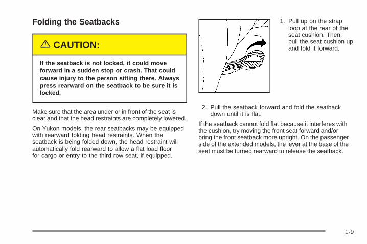
Folding the Seatbacks
{CAUTION:
If the seatback is not locked, it could moveforward in a sudden stop or crash. That couldcause injury to the person sitting there. Alwayspress rearward on the seatback to be sure it islocked.
Make sure that the area under or in front of the seat isclear and that the head restraints are completely lowered.
On Yukon models, the rear seatbacks may be equippedwith rearward folding head restraints. When theseatback is being folded down, the head restraint willautomatically fold rearward to allow a flat load floorfor cargo or entry to the third row seat, if equipped.
1. Pull up on the straploop at the rear of theseat cushion. Then,pull the seat cushion upand fold it forward.
2. Pull the seatback forward and fold the seatbackdown until it is flat.
If the seatback cannot fold flat because it interferes withthe cushion, try moving the front seat forward and/orbring the front seatback more upright. On the passengerside of the extended models, the lever at the base of theseat must be turned rearward to release the seatback.
1-9
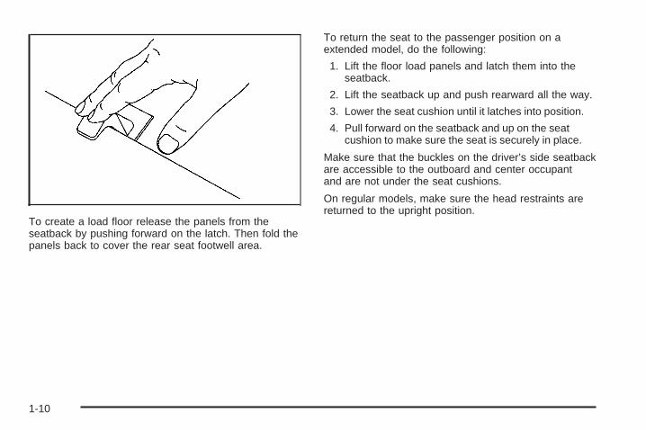
To create a load floor release the panels from theseatback by pushing forward on the latch. Then fold thepanels back to cover the rear seat footwell area.
To return the seat to the passenger position on aextended model, do the following:
1. Lift the floor load panels and latch them into theseatback.
2. Lift the seatback up and push rearward all the way.
3. Lower the seat cushion until it latches into position.
4. Pull forward on the seatback and up on the seatcushion to make sure the seat is securely in place.
Make sure that the buckles on the driver’s side seatbackare accessible to the outboard and center occupantand are not under the seat cushions.
On regular models, make sure the head restraints arereturned to the upright position.
1-10
50/50 Split Bench SeatIf your vehicle has a 50/50 split bench, the seatback(s)can be folded and the entire seat(s) tilted or removedfrom the vehicles.
Folding the Seatbacks
{CAUTION:
If the seatback is not locked, it could moveforward in a sudden stop or crash. That couldcause injury to the person sitting there. Alwayspress rearward on the seatback to be sure it islocked.
To fold the seatbacks do the following:
• Pull up on the release lever, labeled 1, located onthe rear of the seatback, and push the seatbackforward.
• To return the seat to the passenger position, pull upon the release lever labeled 1 and then pull up onthe seatback until the seatback locks into the uprightposition.
Push forward on the seatback to make sure it is lockedinto position.
1-11

Tilting the 50/50 Split Bench Seat
{CAUTION:
If the seatback is not locked, it could moveforward in a sudden stop or crash. That couldcause injury to the person sitting there. Alwayspress rearward on the seatback to be sure it islocked.
{CAUTION:
If the support rod is not properly engaged, thefolded third row seat could come loose in asudden stop or crash. That could cause injuryto people and damage to your vehicle. Alwaysbe sure the support rod is properly engagedwhen the third row seat is folded forward.
Once the third seatback has been folded down, theentire seat can be tilted forward to create a flatload floor. To do this, do the following:
1. Enter the rear cargo area of the vehicle.
2. Make sure the head restraints have been loweredcompletely.
3. With the seat folded, unlatch the seat from the floorby pulling up on the lever located under thecarrying handle at the rear of the seat labeled 2.
4. Lift the rear of the seat up, off the floor. You will notbe able to unlatch the seat from the floor unless theseatback is folded down.
5. Tilt the seat fully forward and secure it in placeusing the support rod located on the undersideof the seat on the passenger’s side. Make sure therod pin is fully engaged in the lock.
6. Push and pull on the seat. Make sure the supportrod is holding it firmly in place. Use the seat in thisposition only when necessary for additionalcargo space.
To return the seat to the seating position do thefollowing:
1. Push forward on the seat and release the supportlock rod.
2. Secure the support rod in its stored position on theunderside of the seat.
1-12

3. Lower the seat to the floor and let the seat dropinto place.
4. Lift up on the carrying handle to make sure the seatis locked in place.
5. Return the seatback to the upright position bypulling up on the release lever labeled 1 beforethe back can be folded upright.
6. Pull the seatback forward to make sure it is lockedin place.
Removing the 50/50 Split Bench SeatTo remove the 50/50 split bench seat, do the following:
1. Open the rear doors and enter the rear of thevehicle.
2. Fold the seatbackforward onto the seatcushion by usingthe lever labeled 1.The seat cannotbe removed unless theseatback is folded.
3. To unlatch the seatfrom the floor, pull upon the release leverlabeled 2, located at therear of the seat, and liftthe rear of the seat upoff the floor.
4. Squeeze the release lever, located in the lowermiddle to unlatch the seat from the floor, whilepulling the seat out.
5. While holding the rear of the seat up, roll the seatout of the vehicle.
1-13

Replacing the 50/50 Split Bench Seat
{CAUTION:
If the seatback is not locked, it could moveforward in a sudden stop or crash. That couldcause injury to the person sitting there. Alwayspress rearward on the seatback to be sure it islocked.
{CAUTION:
A seat that is not locked into place properlycan move around in a collision or sudden stop.People in the vehicle could be injured. Be sureto lock the seat into place properly wheninstalling it.
{CAUTION:
A safety belt that is improperly routed, notproperly attached, or twisted will not providethe protection needed in a crash. The personwearing the belt could be seriously injured.After raising the rear seatback, always checkto be sure that the safety belts are properlyrouted and attached, and are not twisted.
To reinstall the 50/50 split bench, do the following:
1. While holding the rear of the seat up, slide the frontwheels into the slots on the floor. The front latchesshould lock into place. If the latches do not lock,try tilting the rear of the seats upwards.
2. Once the latches are engaged, let the seat dropinto place. Release the lever labeled 1 to returnthe seat to its upright position.
3. Push and pull on the seat to make sure it is lockedinto place. The seatback cannot be raised to theupright position unless the seat is secured to thefloor.
1-14

Bench SeatIf your vehicle has a full bench seat, the seatback canbe folded and the seat can be tilted or removed from thevehicle.
Folding the Seatback
{CAUTION:
If the seatback is not locked, it could moveforward in a sudden stop or crash. That couldcause injury to the person sitting there. Alwayspress rearward on the seatback to be sure it islocked.
To fold the seatback on the bench seat, do the following:1. Pull up on the release
lever, labeled 1,located on the rear ofthe seatback andpush the seatbackforward.
2. To return the seat to an upright position, pull up onthe release lever labeled 1 and then pull up on theseatback until the seatback locks into the uprightposition.
Push and pull on the seatback to check that it is lockedinto place.
1-15

Tilting the Bench Seat
{CAUTION:
If the seatback is not locked, it could moveforward in a sudden stop or crash. That couldcause injury to the person sitting there. Alwayspress rearward on the seatback to be sure it islocked.
{CAUTION:
If the support rod is not properly engaged, thefolded third row seat could come loose in asudden stop or crash. That could cause injuryto people and damage to your vehicle. Alwaysbe sure the support rod is properly engagedwhen the third row seat is folded forward.
Once the third seatback has been folded down, theentire seat can be tilted forward to create a flatload floor. To do this, do the following:
1. Enter the rear cargo area of the vehicle.
2. Make sure the head restraints have been loweredcompletely.
3. With the seat folded,unlatch the seat fromthe floor by pullingup on the lever locatedunder the carryinghandle at the rear ofthe seat labeled 2.
4. Lift the rear of the seat up, off the floor. You will notbe able to unlatch the seat from the floor unless theseatback is folded down.
5. Tilt the seat fully forward and secure it in placeusing the support rod located on the undersideof the seat on the passenger’s side. Make sure therod pin is fully engaged in the lock.
1-16

6. Push and pull on the seat. Make sure the supportrod is holding it firmly in place. Use the seat in thisposition only when necessary for additionalcargo space.
To return the seat to the seating position do thefollowing:
1. Push forward on the seat and release the supportlock rod.
2. Secure the support rod in its stored position on theunderside of the seat.
3. Lower the seat to the floor and let the seat dropinto place.
4. Lift up on the carrying handle to make sure the seatis locked in place.
5. Return the seatback to the upright position bypulling up on the release lever labeled 1 beforethe back can be folded upright.
6. Pull the seatback forward to make sure it is lockedin place.
Removing the Bench SeatTo remove the full bench seat, do the following:
1. Open the rear doors and enter the rear of thevehicle.
2. Fold the seatbackforward onto the seatcushion by usingthe lever labeled 1.The seat cannotbe removed unless theseatback is folded.
1-17

3. To unlatch the seatfrom the floor, pull upon the release leverlabeled 2, located at therear of the seat, and liftthe rear of the seat upoff the floor.
4. Squeeze the release lever, located in the lowermiddle to unlatch the seat from the floor whilepulling the seat out.
5. While holding the rear of the seat up, roll the seatout of the vehicle.
Replacing the Bench Seat
{CAUTION:
If the seatback is not locked, it could moveforward in a sudden stop or crash. That couldcause injury to the person sitting there. Alwayspress rearward on the seatback to be sure it islocked.
{CAUTION:
A seat that is not locked into place properlycan move around in a collision or sudden stop.People in the vehicle could be injured. Be sureto lock the seat into place properly wheninstalling it.
1-18

{CAUTION:
A safety belt that is improperly routed, notproperly attached, or twisted will not providethe protection needed in a crash. The personwearing the belt could be seriously injured.After raising the rear seatback, always checkto be sure that the safety belts are properlyrouted and attached, and are not twisted.
To reinstall the full bench seat, do the following:
1. While holding the rear of the seat up, slide the frontwheels into the slots on the floor. The front latchesshould lock into place. If the latches do not lock,try tilting the rear of the seats upwards.
2. Once the latches are engaged, let the seat dropinto place. Release the lever labeled 1 to returnthe seat to its upright position.
3. Push and pull on the seat to make sure it is lockedinto place. The seatback cannot be raised to theupright position unless the seat is secured tothe floor.
Bucket SeatsIf your vehicle has bucket seats, the seatbacks can bereclined and the seats can be folded to give youmore cargo room.
Reclining the SeatbacksOn the extended models with bucket seats, theseatbacks can be reclined. To adjust the seatbackdo the following:
1. Pull forward the lever located at the baseof the seat.
2. Release the lever to lock the seatback where youwant it. If you pull the lever without pushing on theseatback, the seatback will go to an uprightposition.
1-19

Folding the Seatbacks
{CAUTION:
If the seatback is not locked, it could moveforward in a sudden stop or crash. That couldcause injury to the person sitting there. Alwayspress rearward on the seatback to be sure it islocked.
The seatbacks on the bucket seats may be foldedforward to give you more cargo space.
On extended models with rear bucket seats, the headrestraints need to be removed in order to fold therear seats. To do this follow these directions:
1. Lift the head restraints up until they stop.
2. Press in the button on the side of the head restraintguide cap and lift up on the head restraint.
3. Do the same for the other cap.
The head restraint can be removed and stored in thespace provided in the folded up seat cushion.
To fold the seatbacks on the bucket seats, do thefollowing:
1. Pull up on the straploop located at the rearof the seat cushionand pull the seatcushion up. Thenfold it forward.
1-20

2. Pull the seatbackrelease lever up andpull the seatbackforward. Then fold ituntil it is flat.
If the seatback cannot fold flat because it interferes withthe cushion, try moving the front seat forward and/orbringing the front seatback more upright.
Once the seatbacks are folded down, the rear seatfootwell area will be exposed and will have to becovered by the load floor panel. To create a load floor,do the following:
1. Release the panels from the seatbacks by pushingforward on the latches.
2. Then fold the panels back to cover the rear seatfootwell area.
If you have removed the head restraints to fold the rearbucket seat, be sure to reinstall them on the seatbackafter it has been returned to the normal seating position.
1-21

Safety Belts
Safety Belts: They Are for EveryoneThis part of the manual tells you how to use safetybelts properly. It also tells you some things you shouldnot do with safety belts.
{CAUTION:
Do not let anyone ride where he or she can notwear a safety belt properly. If you are in acrash and you are not wearing a safety belt,your injuries can be much worse. You can hitthings inside the vehicle or be ejected from it.You can be seriously injured or killed. In thesame crash, you might not be, if you arebuckled up. Always fasten your safety belt,and check that your passengers’ belts arefastened properly too.
{CAUTION:
It is extremely dangerous to ride in a cargoarea, inside or outside of a vehicle. In acollision, people riding in these areas are morelikely to be seriously injured or killed. Do notallow people to ride in any area of your vehiclethat is not equipped with seats and safetybelts. Be sure everyone in your vehicle is in aseat and using a safety belt properly.
Your vehicle has a lightthat comes on as areminder to buckle up. SeeSafety Belt ReminderLight on page 3-39.
In most states and in all Canadian provinces, the lawsays to wear safety belts. Here is why: They work.
You never know if you will be in a crash. If you do havea crash, you do not know if it will be a bad one.
1-22

A few crashes are mild, and some crashes can be soserious that even buckled up, a person would notsurvive. But most crashes are in between. In many ofthem, people who buckle up can survive and sometimeswalk away. Without belts they could have been badlyhurt or killed.
After more than 30 years of safety belts in vehicles, thefacts are clear. In most crashes buckling up doesmatter...a lot!
Why Safety Belts WorkWhen you ride in or on anything, you go as fastas it goes.
Take the simplest vehicle. Suppose it is just a seat onwheels.
1-23
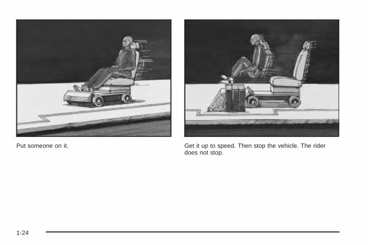
Put someone on it. Get it up to speed. Then stop the vehicle. The riderdoes not stop.
1-24

The person keeps going until stopped by something.In a real vehicle, it could be the windshield...
or the instrument panel...
1-25

or the safety belts!
With safety belts, you slow down as the vehicle does.You get more time to stop. You stop over more distance,and your strongest bones take the forces. That is whysafety belts make such good sense.
Questions and Answers AboutSafety Belts
Q: Will I be trapped in the vehicle after an accidentif I am wearing a safety belt?
A: You could be — whether you are wearing a safetybelt or not. But you can unbuckle a safety belt,even if you are upside down. And your chance ofbeing conscious during and after an accident,so you can unbuckle and get out, is much greater ifyou are belted.
1-26

Q: If my vehicle has airbags, why should I have towear safety belts?
A: Airbags are in many vehicles today and will be inmost of them in the future. But they aresupplemental systems only; so they work withsafety belts — not instead of them. Every airbagsystem ever offered for sale has required the use ofsafety belts. Even if you are in a vehicle that hasairbags, you still have to buckle up to get the mostprotection. That is true not only in frontal collisions,but especially in side and other collisions.
Q: If I am a good driver, and I never drive far fromhome, why should I wear safety belts?
A: You may be an excellent driver, but if you are in anaccident — even one that is not your fault — youand your passengers can be hurt. Being a gooddriver does not protect you from things beyond yourcontrol, such as bad drivers.
Most accidents occur within 25 miles (40 km) ofhome. And the greatest number of serious injuriesand deaths occur at speeds of less than40 mph (65 km/h).
Safety belts are for everyone.
How to Wear Safety Belts ProperlyThis part is only for people of adult size.
Be aware that there are special things to know aboutsafety belts and children. And there are differentrules for smaller children and babies. If a child will beriding in your vehicle, see Older Children on page 1-43or Infants and Young Children on page 1-45. Followthose rules for everyone’s protection.
First, you will want to know which restraint systems yourvehicle has.
We will start with the driver position.
1-27

Driver Position
Lap-Shoulder BeltThe driver has a lap-shoulder belt. Here is how to wearit properly.
1. Close and lock the door.
2. Adjust the seat so you can sit up straight. To seehow, see “Seats” in the Index.
3. Pick up the latch plate and pull the belt across you.Do not let it get twisted.The shoulder belt may lock if you pull the beltacross you very quickly. If this happens, let the beltgo back slightly to unlock it. Then pull the beltacross you more slowly.
4. Push the latch plate into the buckle until it clicks.Pull up on the latch plate to make sure it is secure.If the belt is not long enough, see Safety BeltExtender on page 1-42.Make sure the release button on the buckle ispositioned so you would be able to unbuckle thesafety belt quickly if you ever had to.
1-28

5. To make the lap part tight, pull down on the buckleend of the belt as you pull up on the shoulder belt.
The lap part of the belt should be worn low and snug onthe hips, just touching the thighs. In a crash, thisapplies force to the strong pelvic bones. And you wouldbe less likely to slide under the lap belt. If you slidunder it, the belt would apply force at your abdomen.This could cause serious or even fatal injuries. Theshoulder belt should go over the shoulder and acrossthe chest. These parts of the body are best able to takebelt restraining forces.
The safety belt locks if there is a sudden stop or crash,or if you pull the belt very quickly out of the retractor.
1-29

Q: What is wrong with this?
A: The shoulder belt is too loose. It will not give nearlyas much protection this way.
{CAUTION:
You can be seriously hurt if your shoulder beltis too loose. In a crash, you would moveforward too much, which could increase injury.The shoulder belt should fit against your body.
1-30

Q: What is wrong with this?
A: The belt is buckled in the wrong place.
{CAUTION:
You can be seriously injured if your belt isbuckled in the wrong place like this. In a crash,the belt would go up over your abdomen. Thebelt forces would be there, not at the pelvicbones. This could cause serious internalinjuries. Always buckle your belt into thebuckle nearest you.
1-31

Q: What is wrong with this?
A: The belt is over an armrest.
{CAUTION:
You can be seriously injured if your belt goesover an armrest like this. The belt would bemuch too high. In a crash, you can slide underthe belt. The belt force would then be appliedat the abdomen, not at the pelvic bones, andthat could cause serious or fatal injuries.Be sure the belt goes under the armrests.
1-32

Q: What is wrong with this?
A: The shoulder belt is worn under the arm. It shouldbe worn over the shoulder at all times.
{CAUTION:
You can be seriously injured if you wear theshoulder belt under your arm. In a crash, yourbody would move too far forward, which wouldincrease the chance of head and neck injury.Also, the belt would apply too much force tothe ribs, which are not as strong as shoulderbones. You could also severely injure internalorgans like your liver or spleen.
1-33

Q: What is wrong with this?
A: The belt is twisted across the body.
{CAUTION:
You can be seriously injured by a twisted belt.In a crash, you would not have the full width ofthe belt to spread impact forces. If a belt istwisted, make it straight so it can workproperly, or ask your dealer to fix it.
1-34

To unlatch the belt, just push the button on the buckle.The belt should go back out of the way.
Before you close the door, be sure the belt is out of theway. If you slam the door on it, you can damageboth the belt and your vehicle.
Safety Belt Use During PregnancySafety belts work for everyone, including pregnantwomen. Like all occupants, they are more likely to beseriously injured if they do not wear safety belts.
A pregnant woman should wear a lap-shoulder belt, andthe lap portion should be worn as low as possible,below the rounding, throughout the pregnancy.
The best way to protect the fetus is to protect themother. When a safety belt is worn properly, it is morelikely that the fetus will not be hurt in a crash. Forpregnant women, as for anyone, the key to makingsafety belts effective is wearing them properly.
1-35

Right Front Passenger PositionTo learn how to wear the right front passenger’s safetybelt properly, see Driver Position on page 1-28.
The right front passenger’s safety belt works the sameway as the driver’s safety belt — except for onething. If you ever pull the shoulder portion of the belt outall the way, you will engage the child restraint lockingfeature which may turn off the passenger’s frontalairbag. If this happens unintentionally, just let the beltgo back all the way and start again.
Center Passenger PositionIf your vehicle has front and rear bench seats, someonecan sit in the center positions.
When you sit in the center seating position in thesecond row you have a lap-shoulder belt which is similarto the belt in the rear outside seating positions. Tolearn how to wear this belt see “Lap-Shoulder Belt”under Rear Seat Passengers on page 1-37.
Lap BeltWhen you sit in a center seating position, other than inthe second row, you have a lap belt.
A lap safety belt does not have a retractor. To make thebelt longer, tilt the latch plate and pull it along the belt.
1-36

To make the belt shorter, pull its free end as shownuntil the belt is snug.
Buckle, position and release it the same way as the lappart of a lap-shoulder belt. If the belt is not longenough, see Safety Belt Extender on page 1-42.
Make sure the release button on the buckle is positionedso you would be able to unbuckle the safety beltquickly if you ever had to.
Rear Seat PassengersIt is very important for rear seat passengers to buckleup! Accident statistics show that unbelted people inthe rear seat are hurt more often in crashes than thosewho are wearing safety belts.
Rear passengers who are not safety belted can bethrown out of the vehicle in a crash. And they can strikeothers in the vehicle who are wearing safety belts.
1-37

Rear Seat Outside Passenger PositionsThe positions next to the windows have lap-shoulderbelts.
Lap-Shoulder BeltHere is how to wear a lap-shoulder belt properly.
1. Pick up the latch plate and pull the belt across you.Do not let it get twisted.The shoulder belt may lock if you pull the beltacross you very quickly. If this happens, let the beltgo back slightly to unlock it. Then pull the beltacross you more slowly.
2. Push the latch plate into the buckle until it clicks.Pull up on the latch plate to make sure it is secure.When the shoulder belt is pulled out all the way,it will lock. If it does, let it go back all the way andstart again.If the belt is not long enough, see Safety BeltExtender on page 1-42.Make sure the release button on the buckle ispositioned so you would be able to unbuckle thesafety belt quickly if you ever had to.
1-38
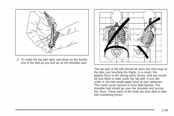
3. To make the lap part tight, pull down on the buckleend of the belt as you pull up on the shoulder part.
The lap part of the belt should be worn low and snug onthe hips, just touching the thighs. In a crash, thisapplies force to the strong pelvic bones. And you wouldbe less likely to slide under the lap belt. If you slidunder it, the belt would apply force at your abdomen.This could cause serious or even fatal injuries. Theshoulder belt should go over the shoulder and acrossthe chest. These parts of the body are best able to takebelt restraining forces.
1-39

The safety belt locks if there is a sudden stop or a crash.
{CAUTION:
You can be seriously hurt if your shoulder beltis too loose. In a crash, you would moveforward too much, which could increase injury.The shoulder belt should fit against your body.
To unlatch the belt, just push the button on the buckle.
Rear Safety Belt Comfort Guides forChildren and Small AdultsRear shoulder belt comfort guides may provide addedsafety belt comfort for older children who have outgrownbooster seats and for some adults. When installed ona shoulder belt, the comfort guide positions the beltaway from the neck and head.
There is one guide for each outside passenger positionin the rear seat. Here is how to install a comfortguide and use the safety belt:
1. For the second row, remove the guide from itsstorage clip on the trim panel near the side ofthe seatback or from the side of the center seat.For the third row, remove the guide from its storageclip on the side of the seatback.
1-40

2. Place the guide over the belt and insert the twoedges of the belt into the slots of the guide.
3. Be sure that the belt is not twisted and it lies flat.The guide must be on top of the belt.
1-41

{CAUTION:
A safety belt that is not properly worn may notprovide the protection needed in a crash. Theperson wearing the belt could be seriouslyinjured. The shoulder belt should go over theshoulder and across the chest. These parts ofthe body are best able to take belt restrainingforces.
4. Buckle, position, and release the safety belt asdescribed in Rear Seat Passengers on page 1-37.Make sure that the shoulder belt crosses theshoulder.
To remove and store the comfort guides, squeeze thebelt edges together so that you can take them out of theguides. Make sure you remove the comfort guidefrom the belt before you fold a rear seat down or use aneasy-entry seat, if your vehicle has one.
Safety Belt ExtenderIf the vehicle’s safety belt will fasten around you, youshould use it.
But if a safety belt is not long enough, your dealer willorder you an extender. It is free. When you go in toorder it, take the heaviest coat you will wear, sothe extender will be long enough for you. To help avoidpersonal injury, do not let someone else use it, anduse it only for the seat it is made to fit. The extender hasbeen designed for adults. Never use it for securingchild seats. To wear it, just attach it to the regular safetybelt. For more information, see the instruction sheetthat comes with the extender.
1-42
Child Restraints
Older Children
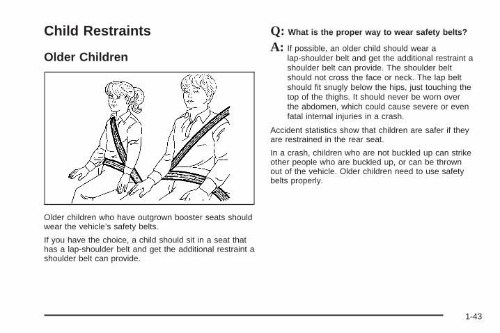
Older children who have outgrown booster seats shouldwear the vehicle’s safety belts.
If you have the choice, a child should sit in a seat thathas a lap-shoulder belt and get the additional restraint ashoulder belt can provide.
Q: What is the proper way to wear safety belts?
A: If possible, an older child should wear alap-shoulder belt and get the additional restraint ashoulder belt can provide. The shoulder beltshould not cross the face or neck. The lap beltshould fit snugly below the hips, just touching thetop of the thighs. It should never be worn overthe abdomen, which could cause severe or evenfatal internal injuries in a crash.
Accident statistics show that children are safer if theyare restrained in the rear seat.
In a crash, children who are not buckled up can strikeother people who are buckled up, or can be thrownout of the vehicle. Older children need to use safetybelts properly.
1-43

{CAUTION:
Never do this.
Here two children are wearing the same belt.The belt can not properly spread the impactforces. In a crash, the two children can becrushed together and seriously injured. A beltmust be used by only one person at a time.
Q: What if a child is wearing a lap-shoulder belt,but the child is so small that the shoulder beltis very close to the child’s face or neck?
A: If the child is sitting in a rear seat outside position,move the child toward the center of the vehicle. Ifthe child is sitting in the second row center position,move the child toward the safety belt buckle. Ineither case, be sure that the shoulder belt still is onthe child’s shoulder, so that in a crash the child’supper body would have the restraint that beltsprovide. See Rear Safety Belt Comfort Guides forChildren and Small Adults on page 1-40. If the childis so small that the shoulder belt is still veryclose to the child’s face or neck, you might want toplace the child a seat that has a lap belt, if yourvehicle has one.
1-44

{CAUTION:
Never do this.
Here a child is sitting in a seat that has alap-shoulder belt, but the shoulder part isbehind the child. If the child wears the belt inthis way, in a crash the child might slide underthe belt. The belt’s force would then be appliedright on the child’s abdomen. That could causeserious or fatal injuries.
Wherever the child sits, the lap portion of the beltshould be worn low and snug on the hips, just touchingthe child’s thighs. This applies belt force to the child’spelvic bones in a crash.
Infants and Young ChildrenEveryone in a vehicle needs protection! This includesinfants and all other children. Neither the distancetraveled nor the age and size of the traveler changesthe need, for everyone, to use safety restraints. In fact,the law in every state in the United States and inevery Canadian province says children up to some agemust be restrained while in a vehicle.
Every time infants and young children ride in vehicles,they should have the protection provided by appropriaterestraints. Young children should not use the vehicle’sadult safety belts alone, unless there is no other choice.Instead, they need to use a child restraint.
1-45

{CAUTION:
People should never hold a baby in their armswhile riding in a vehicle. A baby does notweigh much — until a crash. During a crash ababy will become so heavy it is not possible tohold it. For example, in a crash at only25 mph (40 km/h), a 12 lb (5.5 kg) baby willsuddenly become a 240 lb (110 kg) force on aperson’s arms. A baby should be secured inan appropriate restraint.
1-46

{CAUTION:
Children who are up against, or very close to,any airbag when it inflates can be seriouslyinjured or killed. Airbags plus lap-shoulderbelts offer protection for adults and olderchildren, but not for young children andinfants. Neither the vehicle’s safety belt systemnor its airbag system is designed for them.Young children and infants need the protectionthat a child restraint system can provide.
1-47
Q: What are the different types of add-on childrestraints?
A: Add-on child restraints, which are purchased by thevehicle’s owner, are available in four basic types.Selection of a particular restraint should takeinto consideration not only the child’s weight, height,and age but also whether or not the restraint willbe compatible with the motor vehicle in which it willbe used.
For most basic types of child restraints, there aremany different models available. When purchasing achild restraint, be sure it is designed to be usedin a motor vehicle. If it is, the restraint will have alabel saying that it meets federal motor vehiclesafety standards.
The restraint manufacturer’s instructions that comewith the restraint state the weight and heightlimitations for a particular child restraint. In addition,there are many kinds of restraints available forchildren with special needs.
{CAUTION:
Newborn infants need complete support,including support for the head and neck. Thisis necessary because a newborn infant’s neckis weak and its head weighs so muchcompared with the rest of its body. In a crash,an infant in a rear-facing seat settles into therestraint, so the crash forces can bedistributed across the strongest part of aninfant’s body, the back and shoulders. Infantsalways should be secured in appropriate infantrestraints.
1-48

{CAUTION:
The body structure of a young child is quiteunlike that of an adult or older child, for whomthe safety belts are designed. A young child’ship bones are still so small that the vehicle’sregular safety belt may not remain low on thehip bones, as it should. Instead, it may settleup around the child’s abdomen. In a crash, thebelt would apply force on a body area that isunprotected by any bony structure. This alonecould cause serious or fatal injuries. Youngchildren always should be secured inappropriate child restraints.
Child Restraint Systems
An infant car bed (A), a special bed made for use in amotor vehicle, is an infant restraint system designedto restrain or position a child on a continuous flatsurface. Make sure that the infant’s head rests towardthe center of the vehicle.
1-49
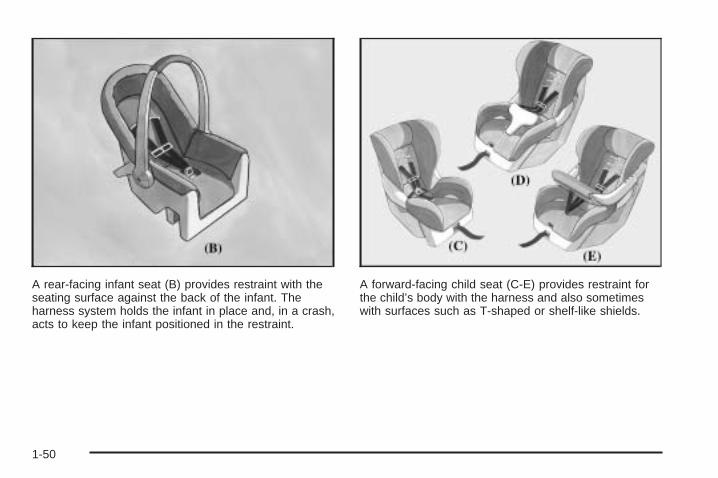
A rear-facing infant seat (B) provides restraint with theseating surface against the back of the infant. Theharness system holds the infant in place and, in a crash,acts to keep the infant positioned in the restraint.
A forward-facing child seat (C-E) provides restraint forthe child’s body with the harness and also sometimeswith surfaces such as T-shaped or shelf-like shields.
1-50

A booster seat (F-G) is a child restraint designed toimprove the fit of the vehicle’s safety belt system. Somebooster seats have a shoulder belt positioner, andsome high-back booster seats have a five-point harness.A booster seat can also help a child to see out thewindow.
Q: How do child restraints work?
A: A child restraint system is any device designed foruse in a motor vehicle to restrain, seat, or positionchildren. A built-in child restraint system is apermanent part of the motor vehicle. An add-onchild restraint system is a portable one, whichis purchased by the vehicle’s owner.
For many years, add-on child restraints have usedthe adult belt system in the vehicle. To helpreduce the chance of injury, the child also has to besecured within the restraint. The vehicle’s beltsystem secures the add-on child restraint in thevehicle, and the add-on child restraint’s harnesssystem holds the child in place within the restraint.
One system, the three-point harness, has straps thatcome down over each of the infant’s shoulders andbuckle together at the crotch. The five-point harnesssystem has two shoulder straps, two hip straps and acrotch strap. A shield may take the place of hipstraps. A T-shaped shield has shoulder straps thatare attached to a flat pad which rests low against thechild’s body. A shelf- or armrest-type shield hasstraps that are attached to a wide, shelf-like shieldthat swings up or to the side.
1-51

When choosing a child restraint, be sure the childrestraint is designed to be used in a vehicle. If it is, itwill have a label saying that it meets federal motorvehicle safety standards.
Then follow the instructions for the restraint. You mayfind these instructions on the restraint itself or in abooklet, or both. These restraints use the belt system orthe LATCH system in your vehicle, but the child alsohas to be secured within the restraint to help reduce thechance of personal injury. When securing an add-onchild restraint, refer to the instructions that come with therestraint which may be on the restraint itself or in abooklet, or both, and to this manual. The child restraintinstructions are important, so if they are not available,obtain a replacement copy from the manufacturer.
Where to Put the RestraintAccident statistics show that children are safer if theyare restrained in the rear rather than the front seat.General Motors recommends that child restraintsbe secured in a rear seat, including an infant riding in arear-facing infant seat, a child riding in a forward-facingchild seat and an older child riding in a booster seat.
Your vehicle has a rear seat that will accommodatea rear-facing child restraint. A label on your sun visorsays, “Never put a rear-facing child seat in thefront.” This is because the risk to the rear-facing child isso great, if the airbag deploys.
{CAUTION:
A child in a rear-facing child restraint can beseriously injured or killed if the right frontpassenger’s airbag inflates. This is becausethe back of the rear-facing child restraintwould be very close to the inflating airbag.
Even though the passenger sensing system isdesigned to turn off the passenger’s frontalairbag if the system detects a rear-facing childrestraint, no system is fail-safe, and no onecan guarantee that an airbag will not deployunder some unusual circumstance, eventhough it is turned off. General Motorsrecommends that rear-facing child restraintsbe secured in the rear seat, even if the airbagis off.
If you need to secure a forward-facing childrestraint in the right front seat, always movethe front passenger seat as far back as it willgo. It is better to secure the child restraint in arear seat.
1-52

Do not use child restraints in the center front seatposition. The restraints will not work properly.
Wherever you install it, be sure to secure the childrestraint properly.
Keep in mind that an unsecured child restraint canmove around in a collision or sudden stop and injurepeople in the vehicle. Be sure to properly secureany child restraint in your vehicle — even when no childis in it.
Top StrapSome child restraints have a top strap, or “top tether.”It can help restrain the child restraint during a collision.For it to work, a top strap must be properly anchoredto the vehicle. Some top strap-equipped child restraintsare designed for use with or without the top strapbeing anchored. Others require the top strap always tobe anchored. Be sure to read and follow theinstructions for your child restraint. If yours requires thatthe top strap be anchored, do not use the restraintunless it is anchored properly.
If the child restraint does not have a top strap, onecan be obtained, in kit form, for many child restraints.Ask the child restraint manufacturer whether or nota kit is available.
In Canada, the law requires that forward-facing childrestraints have a top strap, and that the strap beanchored. In the United States, some child restraintsalso have a top strap. If your child restraint has atop strap, it should be anchored.
Anchor the top strap to one of the following anchorpoints. Be sure to use an anchor point located on thesame side of the vehicle as the seating positionwhere the child restraint will be placed.
1-53

If you have an adjustable head restraint, route the topstrap under it.
{CAUTION:
Each top tether bracket is designed to anchoronly one child restraint. Attaching more thanone child restraint to a single bracket couldcause the anchor to come loose or even breakduring a crash. A child or others could beinjured if this happens. To help prevent injuryto people and damage to your vehicle, attachonly one child restraint per bracket.
Once you have the top strap anchored, you will beready to secure the child restraint itself. Tighten the topstrap when and as the child restraint manufacturer’sinstructions say.
Top Strap Anchor LocationA child restraint with a top strap should only be used inthe second or third row.
Yukon XL Second Row Seat (Bucket Seats Similar)
1-54
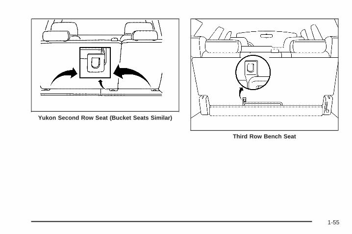
Yukon Second Row Seat (Bucket Seats Similar)
Third Row Bench Seat
1-55

Your vehicle has a top strap anchor for each seatingposition in the second row, and for the center seatingposition in the third row. The anchors are located at thebottom rear of the seat cushion.
Do not secure a child restraint with a top strap in theright front passenger’s position or in the third rowoutboard seating positions if a national or local lawrequires that the top strap be anchored, or if theinstructions that come with the child restraint say thatthe top strap must be anchored. There is no placeto anchor the top strap in these positions.
Lower Anchorages and Top Tethersfor Children (LATCH System)Your vehicle has the LATCH system. There are anchorsfor the center and right side passenger second rowseating positions for bench seats, and the outboardpassenger positions for bucket seats.
This system, designed to make installation of childrestraints easier, does not use the vehicle’s safety belts.Instead, it uses vehicle anchors and child restraintattachments to secure the restraints. Some restraintsalso use another vehicle anchor to secure a toptether strap.
Third Row 50/50 Split Bench Seat
1-56

A. Lower AnchorageB. Lower AnchorageC. Top Tether
A. Lower AnchorageB. Lower Anchorage
In order to use the LATCH system in your vehicle, youneed a child restraint designed for that system.
1-57

To assist you in locating the lower anchors for this childrestraint system, each seating position with theLATCH system has visible metal anchors in the seatwhere the seatback meets the seat cushion.
{CAUTION:
If a LATCH-type child restraint is not attachedto its anchorage points, the restraint will notbe able to protect the child correctly. In acrash, the child could be seriously injured orkilled. Make sure that a LATCH-type childrestraint is properly installed using theanchorage points, or use the vehicle’s safetybelts to secure the restraint, following theinstructions that came with that restraint, andalso the instructions in this manual.
Securing a Child Restraint Designedfor the LATCH System
1. Find the LATCH anchorages for the seatingposition you want to use, where the bottom of theseatback meets the back of the seat cushion.See Lower Anchorages and Top Tethers forChildren (LATCH System) on page 1-56.
2. Put the child restraint on the seat.
3. Attach and tighten the LATCH attachments on thechild restraint to the LATCH anchorages in thevehicle. The child restraint instructions will showyou how.
4. If the child restraint is forward-facing, attach andtighten the top tether to the top tether anchorage.The child restraint instructions will show youhow. Also see Top Strap on page 1-53.
5. Push and pull the child restraint in differentdirections to be sure it is secure.
To remove the child restraint, simply unhook the toptether from the top tether anchorage and thendisconnect the LATCH attachments from the LATCHanchorages.
1-58

Securing a Child Restraint in a RearOutside Seat PositionIf your child restraint is equipped with the LATCHsystem, see Lower Anchorages and Top Tethers forChildren (LATCH System) on page 1-56. See Top Strapon page 1-53 if the child restraint has one.
For the third row, if your vehicle has a bench seat, thereare no top strap anchors in the outboard seatingpositions. If your vehicle has a 50/50 split bench seat inthe third row, there is no top strap anchor in thedriver-side seating position. Do not secure a childrestraint in these positions if a national or locallaw requires that the top strap be anchored or if theinstructions that come with the child restraint say that thetop strap must be anchored.
If your child restraint does not have the LATCH system,you will be using the lap-shoulder belt to secure thechild restraint in this position. Be sure to follow theinstructions that came with the child restraint. Securethe child in the child restraint when and as theinstructions say.
1. Put the child restraint on the seat.
2. Pick up the latch plate, and run the lap and shoulderportions of the vehicle’s safety belt through oraround the restraint. The child restraint instructionswill show you how.
3. Buckle the belt. Make sure the release button ispositioned so you would be able to unbuckle thesafety belt quickly if you ever had to.
1-59

4. Pull the rest of the shoulder belt all the way out ofthe retractor to set the lock.
5. To tighten the belt, push down on the child restraint,pull the shoulder portion of the belt to tighten thelap portion of the belt and feed the shoulderbelt back into the retractor. If you are using aforward-facing child restraint, you may find it helpfulto use your knee to push down on the childrestraint as you tighten the belt.
6. Push and pull the child restraint in differentdirections to be sure it is secure.
To remove the child restraint, just unbuckle the vehicle’ssafety belt and let it go back all the way. The safetybelt will move freely again and be ready to work for anadult or larger child passenger.
1-60
Securing a Child Restraint in aCenter Rear Seat Position
Second RowThe center seat position in the second row has alap-shoulder belt which works the same way as thesafety belt in the rear outside seat positions. Forinstructions on how to secure a child restraint using alap-shoulder belt see, Securing a Child Restraint ina Rear Outside Seat Position on page 1-59.
Third RowIf your child restraint is equipped with the LATCHsystem, see Lower Anchorages and Top Tethers forChildren (LATCH System) on page 1-56. See Top Strapon page 1-53 if the child restraint has one.
If your vehicle has 50/50 split bench seat in the thirdrow, there is no top strap anchor in the center seatingposition. Do not secure a child restraint in this position ifa national or local law requires that the top strap beanchored or if the instructions that come with the childrestraint say that the top strap must be anchored.
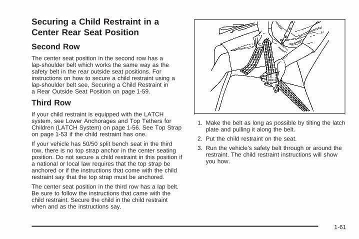
The center seat position in the third row has a lap belt.Be sure to follow the instructions that came with thechild restraint. Secure the child in the child restraintwhen and as the instructions say.
1. Make the belt as long as possible by tilting the latchplate and pulling it along the belt.
2. Put the child restraint on the seat.
3. Run the vehicle’s safety belt through or around therestraint. The child restraint instructions will showyou how.
1-61

4. Buckle the belt. Make sure the release button ispositioned so you would be able to unbuckle thesafety belt quickly if you ever had to.
5. To tighten the belt, pull its free end while you pushdown on the child restraint. If you are using aforward-facing child restraint, you may find it helpfulto use your knee to push down on the childrestraint as you tighten the belt.
6. Push and pull the child restraint in differentdirections to be sure it is secure.
To remove the child restraint, just unbuckle the vehicle’ssafety belt. It will be ready to work for an adult orlarger child passenger.
Securing a Child Restraint in theCenter Front Seat Position
{CAUTION:
A child in a child restraint in the center frontseat can be badly injured or killed by the rightfront passenger’s airbag if it inflates. Neversecure a child restraint in the center front seat.It is always better to secure a child restraint inthe rear seat.
If you need to secure a forward-facing childrestraint in the right front passenger seat,always move the front passenger seat as farback as it will go. It is better to secure thechild restraint in a rear seat.
Do not use child restraints in this position. The restraintswill not work properly.
1-62

Securing a Child Restraint in theRight Front Seat PositionYour vehicle has a right front passenger airbag. A rearseat is a safer place to secure a forward-facing childrestraint. See Where to Put the Restraint on page 1-52.
In addition, your vehicle may have a passengersensing system. The passenger sensing system isdesigned to turn off the right front passenger’s frontalairbag when an infant in a rear-facing infant seator a small child in a forward-facing child restraint orbooster seat is detected. See Passenger SensingSystem on page 1-75 and Passenger Airbag StatusIndicator on page 3-40 for more information onthis including important safety information.
A label on your sun visor says, “Never put a rear-facingchild seat in the front.” This is because the risk to therear-facing child is so great, if the airbag deploys.
{CAUTION:
A child in a rear-facing child restraint can beseriously injured or killed if the right frontpassenger’s airbag inflates. This is becausethe back of the rear-facing child restraintwould be very close to the inflating airbag.
Even though the passenger sensing system isdesigned to turn off the passenger’s frontalairbag if the system detects a rear-facing childrestraint, no system is fail-safe, and no onecan guarantee that an airbag will not deployunder some unusual circumstance, eventhough it is turned off. General Motorsrecommends that rear-facing child restraintsbe secured in the rear seat, even if the airbagis off.
If you need to secure a forward-facing child restraint inthe right front seat position, move the seat as farback as it will go before securing the forward-facingchild restraint. See Power Seats on page 1-4 or ManualSeats on page 1-3.
1-63

If your child restraint is equipped with the LATCHsystem, see Lower Anchorages and Top Tethers forChildren (LATCH System) on page 1-56.There is no top strap anchor at the right front seatingposition. Do not secure a child seat in this position if anational or local law requires that the top strap beanchored or if the instructions that come with the childrestraint say that the top strap must be anchored. SeeTop Strap on page 1-53 if your child restraint has one.You will be using the lap-shoulder belt to secure thechild restraint in this position. Be sure to followthe instructions that came with the child restraint.Secure the child in the child restraint when and as theinstructions say.
1. Your vehicle has a right front passenger’s frontalairbag. See Passenger Sensing System onpage 1-75. General Motors recommends thatrear-facing child restraints be secured in a rear seat,even if the airbag is off. If your child restraint isforward-facing, move the seat as far back as it willgo before securing the child restraint in thisseat. See Power Seats on page 1-4 or ManualSeats on page 1-3.When the passenger sensing system has turned offthe right front passenger’s frontal airbag, the offindicator in the passenger airbag status indicatorshould light and stay lit when you turn the ignition toRUN or START. See Passenger Airbag StatusIndicator on page 3-40.
2. Put the child restraint on the seat.
3. Pick up the latch plate, and run the lap and shoulderportions of the vehicle’s safety belt through oraround the restraint. The child restraint instructionswill show you how.
4. Buckle the belt. Make sure the release button ispositioned so you would be able to unbuckle thesafety belt quickly if you ever had to.
1-64

5. Pull the rest of the shoulder belt all the way out ofthe retractor to set the lock.
6. To tighten the belt, push down on the child restraint,pull the shoulder portion of the belt to tighten thelap portion of the belt and feed the shoulderbelt back into the retractor. If you are using aforward-facing child restraint, you may find it helpfulto use your knee to push down on the childrestraint as you tighten the belt. You should not beable to pull more of the belt from the retractoronce the lock has been set.
1-65

7. Push and pull the child restraint in differentdirections to be sure it is secure.
8. If your vehicle has the passenger sensing systemand the airbag is off, the off indicator in the rearviewmirror will be lit and stay lit when the key isturned to RUN or START.
If a child restraint has been installed and the onindicator is lit, turn the vehicle off. Remove the childrestraint from the vehicle and reinstall the child restraint.
If after reinstalling the child restraint and restartingthe vehicle, the on indicator is still lit, check to makesure that the vehicle’s seatback is not pressing the childrestraint into the seat cushion. If this happens, slightlyrecline the vehicle’s seatback and adjust the seatcushion if possible. Also make sure the child restraint isnot trapped under the vehicle head restraint. If thishappens, adjust the head restraint.
If the on indicator is still lit, secure the child in the childrestraint in a rear seat position in the vehicle andcheck with your dealer.
To remove the child restraint, just unbuckle the vehicle’ssafety belt and let it go back all the way. The safetybelt will move freely again and be ready to work for anadult or larger child passenger.
Airbag SystemYour vehicle has airbags — a frontal airbag for thedriver and another frontal airbag for the right frontpassenger. Your vehicle may also have side impactairbags. Side impact airbags are available for the driverand right front passenger.
If your vehicle has a side impact airbag for the driverand/or the right front passenger, the words AIR BAG willappear on the airbag covering on the side of theseatback closest to the door.
1-66

Frontal airbags are designed to help reduce the risk ofinjury from the force of an inflating frontal airbag.But these airbags must inflate very quickly to do theirjob and comply with federal regulations.
Here are the most important things to know about theairbag system:
{CAUTION:
You can be severely injured or killed in a crashif you are not wearing your safety belt — evenif you have airbags. Wearing your safety beltduring a crash helps reduce your chance ofhitting things inside the vehicle or beingejected from it. Airbags are designed to workwith safety belts but do not replace them.
Frontal airbags for the driver and right frontpassenger are designed to deploy only inmoderate to severe frontal and near frontalcrashes. They are not designed to inflate inrollover, rear or low-speed frontal crashes, or inmany side crashes. And, for some unrestrained
CAUTION: (Continued)
CAUTION: (Continued)
occupants, frontal airbags may provide lessprotection in frontal crashes than moreforceful airbags have provided in the past.
Side impact airbags for the driver and rightfront passenger are designed to inflate only inmoderate to severe crashes where somethinghits the side of your vehicle. They are notdesigned to inflate in frontal, in rollover or inrear crashes.
Everyone in your vehicle should wear a safetybelt properly — whether or not there is anairbag for that person.
1-67

{CAUTION:
Both frontal and side impact airbags inflate withgreat force, faster than the blink of an eye. If youare too close to an inflating airbag, as youwould be if you were leaning forward, it couldseriously injure you. Safety belts help keep youin position for airbag inflation before and duringa crash. Always wear your safety belt, even withfrontal airbags. The driver should sit as far backas possible while still maintaining control of thevehicle. Front occupants should not lean on orsleep against the door.
{CAUTION:
Anyone who is up against, or very close to,any airbag when it inflates can be seriouslyinjured or killed. Airbags plus lap-shoulder
CAUTION: (Continued)
CAUTION: (Continued)
belts offer the best protection for adults, butnot for young children and infants. Neither thevehicle’s safety belt system nor its airbagsystem is designed for them. Young childrenand infants need the protection that a childrestraint system can provide. Always securechildren properly in your vehicle. To read how,see Older Children on page 1-43 or Infants andYoung Children on page 1-45.
There is an airbagreadiness light on theinstrument panel cluster,which shows the airbagsymbol.
The system checks the airbag electrical system formalfunctions. The light tells you if there is an electricalproblem. See Airbag Readiness Light on page 3-39for more information.
1-68

Where Are the Airbags?
The driver’s frontal airbag is in the middle of thesteering wheel.
The right front passenger’s frontal airbag is in theinstrument panel on the passenger’s side.
1-69

If your vehicle has one, the driver’s side impact airbagis in the side of the driver’s seatback closest to the door.
If your vehicle has one, the right front passenger’s sideimpact airbag is in the side of the passenger’sseatback closest to the door.
1-70

{CAUTION:
If something is between an occupant and anairbag, the airbag might not inflate properly orit might force the object into that personcausing severe injury or even death. The pathof an inflating airbag must be kept clear.Do not put anything between an occupant andan airbag, and do not attach or put anythingon the steering wheel hub or on or near anyother airbag covering. Do not let seat coversblock the inflation path of a side impact airbag.
When Should an Airbag Inflate?The driver’s and right front passenger’s frontal airbagsare designed to inflate in moderate to severe frontalor near-frontal crashes. But they are designed to inflateonly if the impact exceeds a predetermined deploymentthreshold. Deployment thresholds take into accounta variety of desired deployment and non-deploymentevents and are used to predict how severe a crashis likely to be in time for the airbags to inflate and helprestrain the occupants. Whether your frontal airbagswill or should deploy is not based on how fast your
vehicle is traveling. It depends largely on what you hit,the direction of the impact and how quickly yourvehicle slows down.
In addition, your vehicle has “dual stage” frontal airbags,which adjust the restraint according to crash severity.Your vehicle is equipped with electronic frontal sensorswhich help the sensing system distinguish between amoderate and a more severe frontal impact. Formoderate frontal impacts, these airbags inflate at a levelless than full deployment. For more severe frontalimpacts, full deployment occurs. If the front of yourvehicle goes straight into a wall that does not move ordeform, the threshold level for the reduced deploymentis about 10 to 16 mph (16 to 25 km/h), and thethreshold level for a full deployment is about20 to 30 mph (32 to 48 km/h). (The threshold level canvary, however, with specific vehicle design, so that it canbe somewhat above or below this range.)
Airbags may inflate at different crash speeds. Forexample:
• If the vehicle hits a stationary object, the airbagcould inflate at a different crash speed than ifthe object were moving.
• If the object deforms, the airbag could inflate at adifferent crash speed than if the object does notdeform.
1-71

• If the vehicle hits a narrow object (like a pole) theairbag could inflate at a different crash speedthan if the vehicle hits a wide object (like a wall).
• If the vehicle goes into an object at an angle theairbag could inflate at a different crash speedthan if the vehicle goes straight into the object.
The frontal airbags (driver and right front passenger) arenot intended to inflate during vehicle rollovers, rearimpacts, or in many side impacts because inflationwould not likely help the occupants.
Vehicles with dual stage airbags are also equipped withspecial sensors which enable the sensing system tomonitor the position of both the driver and passengerfront seats. The seat position sensor providesinformation which is used to determine if the airbagsshould deploy at a reduced level or at full deployment.
Your vehicle may or may not have a side impact airbag.See Airbag System on page 1-66. Side impact airbagsare designed to inflate in moderate to severe sidecrashes. A side impact airbag will inflate if the crashseverity is above the system’s designed “thresholdlevel.” The threshold level can vary with specific vehicledesign. Side impact airbags are not designed toinflate in frontal or near-frontal impacts, rollovers or rearimpacts, because inflation would not likely help theoccupant. A side impact airbag will only deploy on theside of the vehicle that is struck.
In any particular crash, no one can say whether anairbag should have inflated simply because of thedamage to a vehicle or because of what the repair costswere. For frontal airbags, inflation is determined bythe angle of the impact and how quickly the vehicleslows down in frontal and near-frontal impacts. For sideimpact airbags, inflation is determined by the locationand severity of the impact.
The airbag system is designed to work properly under awide range of conditions, including off-road usage.Observe safe driving speeds, especially on roughterrain. As always, wear your safety belt. See Off-RoadDriving on page 4-21 for tips on off-road driving.
1-72

What Makes an Airbag Inflate?In an impact of sufficient severity, the airbag sensingsystem detects that the vehicle is in a crash. For bothfrontal and side impact airbags, the sensing systemtriggers a release of gas from the inflator, which inflatesthe airbag. The inflator, the airbag and related hardwareare all part of the airbag modules. Frontal airbag modulesare located inside the steering wheel and instrumentpanel. For vehicles with side impact airbags, the airbagmodules are located in the seatback closest to thedriver’s and/or right front passenger’s door.
How Does an Airbag Restrain?In moderate to severe frontal or near frontal collisions,even belted occupants can contact the steering wheel orthe instrument panel. In moderate to severe sidecollisions, even belted occupants can contact the insideof the vehicle. The airbag supplements the protectionprovided by safety belts. Airbags distribute the force ofthe impact more evenly over the occupant’s upperbody, stopping the occupant more gradually. But the
frontal airbags would not help you in many types ofcollisions, including rollovers, rear impacts, and manyside impacts, primarily because an occupant’s motion isnot toward the airbag. Side impact airbags would nothelp you in many types of collisions, including frontal ornear frontal collisions, rollovers, and rear impacts,primarily because an occupant’s motion is not towardthose airbags. Airbags should never be regardedas anything more than a supplement to safety belts, andthen only in moderate to severe frontal or near-frontalcollisions for the driver’s and right front passenger’sfrontal airbags, and only in moderate to severeside collisions for vehicles with a driver’s and right frontpassenger’s side impact airbag.
1-73
What Will You See After an AirbagInflates?After the airbag inflates, it quickly deflates, so quicklythat some people may not even realize the airbaginflated. Some components of the airbag module will behot for a short time. These components include thesteering wheel hub for the driver’s frontal airbag and theinstrument panel for the right front passenger’s frontalairbag. For vehicles with side impact airbags, the side ofthe seatback closest to the driver’s and/or right frontpassenger’s door will be hot. The parts of the bag thatcome into contact with you may be warm, but nottoo hot to touch. There will be some smoke and dustcoming from the vents in the deflated airbags.Airbag inflation does not prevent the driver from seeingor being able to steer the vehicle, nor does it stoppeople from leaving the vehicle.
{CAUTION:
When an airbag inflates, there is dust in theair. This dust could cause breathing problemsfor people with a history of asthma or otherbreathing trouble. To avoid this, everyone inthe vehicle should get out as soon as it is safeto do so. If you have breathing problems butcannot get out of the vehicle after an airbaginflates, then get fresh air by opening awindow or a door. If you experience breathingproblems following an airbag deployment, youshould seek medical attention.
In many crashes severe enough to inflate an airbag,windshields are broken by vehicle deformation.Additional windshield breakage may also occur from theright front passenger airbag.
• Airbags are designed to inflate only once. After anairbag inflates, you will need some new parts for yourairbag system. If you do not get them, the air bagsystem will not be there to help protect you in anothercrash. A new system will include airbag modules andpossibly other parts. The service manual for yourvehicle covers the need to replace other parts.
1-74

• Your vehicle is equipped with a crash sensing anddiagnostic module which records information after acrash. See Vehicle Data Collection and Event DataRecorders on page 7-8.
• Let only qualified technicians work on your airbagsystem. Improper service can mean that an airbagsystem will not work properly. See your dealer forservice.
Notice: If you damage the covering for the driver’sor the right front passenger’s airbag, or the airbagcovering on the driver’s and right front passenger’sseatback, the airbag may not work properly. You mayhave to replace the airbag module in the steeringwheel, both the airbag module and the instrumentpanel for the right front passenger’s airbag, or boththe airbag module and seatback for the driver’s andright front passenger’s side impact airbag. Do notopen or break the airbag coverings.
Passenger Sensing SystemIf your rearview mirror has one of the indicators picturedin the following illustrations, your vehicle has a passengersensing system. The indicator will be visible when youturn your ignition key to START or RUN. The words ONand OFF or the symbol for on and off, will be visible onthe rearview mirror during the system check. When thesystem check is complete, either the word ON or the wordOFF, or the symbol for on or the symbol for off will bevisible. See Passenger Airbag Status Indicator onpage 3-40. If your rearview mirror does not have either ofthe indicators pictured, then your vehicle does not havethe passenger sensing system.
Passenger Airbag Status Indicator – United States
1-75

The passenger sensing system will turn off the rightfront passenger’s frontal airbag under certain conditions.The driver’s airbag and the side airbags are not partof the passenger sensing system.
The passenger sensing system works with sensors thatare part of the right front passenger’s seat and safetybelt. The sensors are designed to detect the presence ofa properly-seated occupant and determine if thepassenger’s frontal airbag should be enabled (mayinflate) or not.
Accident statistics show that children are safer if theyare restrained in the rear rather than the front seat.General Motors recommends that child restraintsbe secured in a rear seat, including an infant riding in arear-facing infant seat, a child riding in a forward-facingchild seat and an older child riding in a booster seat.
Your vehicle has a rear seat that will accommodate arear-facing child restraint. A label on your sun visor says,“Never put a rear-facing child seat in the front.” Thisis because the risk to the rear-facing child is so great, ifthe airbag deploys.
{CAUTION:
A child in a rear-facing child restraint can beseriously injured or killed if the right frontpassenger’s airbag inflates. This is becausethe back of the rear-facing child restraintwould be very close to the inflating airbag.
Even though the passenger sensing system isdesigned to turn off the passenger’s frontalairbag if the system detects a rear-facing childrestraint, no system is fail-safe, and no one canguarantee that an airbag will not deploy undersome unusual circumstance, even though it isturned off. General Motors recommends thatrear-facing child restraints be secured in therear seat, even if the airbag is off.
Passenger Airbag Status Indicator – Canada
1-76

The passenger sensing system is designed to turn offthe right front passenger’s frontal airbag if:
• the right front passenger seat is unoccupied
• the system determines that an infant is present in arear-facing infant seat
• the system determines that a small child is presentin a forward-facing child restraint
• the system determines that a small child is presentin a booster seat
• a right front passenger takes his/her weight off ofthe seat for a period of time
• the right front passenger seat is occupied by asmaller person, such as a child who has outgrownchild restraints
• or if there is a critical problem with the airbagsystem or the passenger sensing system.
When the passenger sensing system has turned off thepassenger’s frontal airbag, the off indicator will lightand stay lit to remind you that the airbag is off.
If a child restraint has been installed and the on indicatoris lit, turn the vehicle off. Remove the child restraintfrom the vehicle and reinstall the child restraint followingthe child restraint manufacturer’s directions and referto Securing a Child Restraint in the Right FrontSeat Position on page 1-63.
If after reinstalling the child restraint and restarting thevehicle, the on indicator is still lit, check to makesure that the vehicle’s seatback is not pressing the childrestraint into the seat cushion. If this happens, slightlyrecline the vehicle’s seatback and adjust the seatcushion if possible. Also make sure the child restraint isnot trapped under the vehicle head restraint. If thishappens, adjust the head restraint.
If the on indicator is still lit, secure the child in the childrestraint in a rear seat position in the vehicle andcheck with your dealer.
The passenger sensing system is designed to enable(may inflate) the right front passenger’s frontalairbag anytime the system senses that a person of adultsize is sitting properly in the right front passenger’sseat. When the passenger sensing system has allowedthe airbag to be enabled, the on indicator will lightand stay lit to remind you that the airbag is active.
1-77

For some children who have outgrown child restraintsand for very small adults, the passenger sensing systemmay or may not turn off the right front passenger’sfrontal airbag, depending upon the person’s seatingposture and body build. Everyone in your vehicle whohas outgrown child restraints should wear a safetybelt properly — whether or not there is an airbag forthat person.
If a person of adult-size is sitting in the right frontpassenger’s seat, but the off indicator is lit, it could bebecause that person is not sitting properly in the seat.If this happens, turn the vehicle off and ask the person toplace the seatback in the fully upright position, then situpright in the seat, centered on the seat cushion, with theperson’s legs comfortably extended. Restart the vehicleand have the person remain in this position for about twominutes. This will allow the system to detect that personand then enable the passenger’s airbag.
1-78

{CAUTION:
If the airbag readiness light in the instrumentpanel cluster ever comes on and stays on, itmeans that something may be wrong with theairbag system. If this ever happens, have thevehicle serviced promptly, because anadult-size person sitting in the right frontpassenger’s seat may not have the protectionof the frontal airbag. See Airbag ReadinessLight on page 3-39 for more on this, includingimportant safety information.
Aftermarket equipment, such as seat covers, can affecthow well the passenger sensing system operates.You may want to consider not using seat covers or otheraftermarket equipment if your vehicle has the passengersensing system. See Adding Equipment to YourAirbag-Equipped Vehicle on page 1-80 for moreinformation about modifications that can affect how thesystem operates.
{CAUTION:
Stowing of articles under the passenger’s seator between the passenger’s seat cushion andseatback may interfere with the properoperation of the passenger sensing system.
1-79

Servicing Your Airbag-EquippedVehicleAirbags affect how your vehicle should be serviced.There are airbag system parts in several places aroundyour vehicle. You do not want the system to inflatewhile someone is working on your vehicle. Your dealerand the service manual have information aboutservicing your vehicle and the airbag system. Topurchase a service manual, see Service PublicationsOrdering Information on page 7-11.
{CAUTION:
For up to 10 seconds after the ignition key isturned off and the battery is disconnected, anairbag can still inflate during improper service.You can be injured if you are close to anairbag when it inflates. Avoid yellowconnectors. They are probably part of theairbag system. Be sure to follow properservice procedures, and make sure the personperforming work for you is qualified to do so.
The airbag system does not need regular maintenance.
Adding Equipment to YourAirbag-Equipped Vehicle
Q: Is there anything I might add to the front orsides of the vehicle that could keep theairbags from working properly?
A: Yes. If you add things that change your vehicle’sframe, bumper system, front end or side sheetmetal or height, they may keep the airbag systemfrom working properly. Also, the airbag system maynot work properly if you relocate any of the airbagsensors. If you have any questions about this,you should contact Customer Assistance before youmodify your vehicle. The phone numbers andaddresses for Customer Assistance are in Step Twoof the Customer Satisfaction Procedure in thismanual. See Customer Satisfaction Procedure onpage 7-2.
1-80

Q: Because I have a disability, I have to get myvehicle modified. How can I find out whetherthis will affect my advanced airbag system?
A: Changing or moving any parts of the front seats,safety belts, the airbag sensing and diagnosticmodule (located under the driver’s seat), orthe inside rearview mirror can affect the operationof the advanced airbag system. If you havequestions, call Customer Assistance. The phonenumbers and addresses for Customer Assistanceare in Step Two of the Customer SatisfactionProcedure in this manual. See CustomerSatisfaction Procedure on page 7-2.
Restraint System Check
Checking the Restraint SystemsNow and then, make sure the safety belt reminder lightand all your belts, buckles, latch plates, retractorsand anchorages are working properly. Look for any otherloose or damaged safety belt system parts. If you seeanything that might keep a safety belt system from doingits job, have it repaired.
Torn or frayed safety belts may not protect you in acrash. They can rip apart under impact forces. If a beltis torn or frayed, get a new one right away.
Also look for any opened or broken airbag covers, andhave them repaired or replaced. (The airbag systemdoes not need regular maintenance.)
1-81

Replacing Restraint System PartsAfter a Crash
{CAUTION:
A crash can damage the restraint systems inyour vehicle. A damaged restraint system maynot properly protect the person using it,resulting in serious injury or even death in acrash. To help make sure your restraintsystems are working properly after a crash,have them inspected and any necessaryreplacements made as soon as possible.
If you have had a crash, do you need new belts orLATCH system parts?
After a very minor collision, nothing may be necessary.But if the belts were stretched, as they would be if wornduring a more severe crash, then you need new parts.
If the LATCH system was being used during a moresevere crash, you may need new LATCH system parts.
If belts are cut or damaged, replace them. Collisiondamage also may mean you will need to have LATCHsystem, safety belt or seat parts repaired or replaced.New parts and repairs may be necessary even if the beltor LATCH system was not being used at the time ofthe collision.
If an airbag inflates, you will need to replace airbagsystem parts. See the part on the airbag system earlierin this section.
1-82
Keys ...............................................................2-3Remote Keyless Entry System .........................2-4Remote Keyless Entry System Operation ...........2-5
Doors and Locks .............................................2-8Door Locks ....................................................2-8Power Door Locks ..........................................2-9Delayed Locking ...........................................2-10Programmable Automatic Door Locks ..............2-10Rear Door Security Locks ..............................2-12Lockout Protection ........................................2-13Liftgate ........................................................2-13
Windows ........................................................2-14Manual Windows ..........................................2-15Power Windows ............................................2-15Sun Visors ...................................................2-16
Theft-Deterrent Systems ..................................2-17Content Theft-Deterrent .................................2-17Passlock® ....................................................2-19
Starting and Operating Your Vehicle ................2-19New Vehicle Break-In ....................................2-19Ignition Positions ..........................................2-20Retained Accessory Power (RAP) ...................2-20Starting the Engine .......................................2-21Adjustable Throttle and Brake Pedal ................2-22Engine Coolant Heater ..................................2-22
Automatic Transmission Operation ...................2-23Tow/Haul Mode ............................................2-26Four-Wheel Drive ..........................................2-27All-Wheel Drive with StabiliTrak® .....................2-31Parking Brake ..............................................2-35Shifting Into Park (P) .....................................2-36Shifting Out of Park (P) .................................2-38Parking Over Things That Burn .......................2-39Engine Exhaust ............................................2-39Running the Engine While Parked ...................2-40
Mirrors ...........................................................2-41Manual Rearview Mirror .................................2-41Automatic Dimming Rearview Mirror with
OnStar®, Compass and TemperatureDisplay ....................................................2-41
Automatic Dimming Rearview Mirror withCompass and Temperature Display ..............2-44
Outside Manual Mirrors ..................................2-46Outside Camper-Type Mirrors .........................2-47Outside Power Mirrors ...................................2-47Outside Power Camper-Type Mirror .................2-47Outside Power Foldaway Mirrors .....................2-48Outside Automatic Dimming Mirror ..................2-49Outside Curb View Assist Mirrors ....................2-49Outside Convex Mirror ...................................2-49Outside Heated Mirrors ..................................2-49
Section 2 Features and Controls
2-1

OnStar ® System .............................................2-50HomeLink ® Wireless Control System ...............2-52
HomeLink® Wireless Control System Operation ...2-52Storage Areas ................................................2-56
Glove Box ...................................................2-56Cupholder(s) ................................................2-56Front Storage Area .......................................2-56Center Console Storage Area .........................2-56
Luggage Carrier ...........................................2-56Rear Storage Area ........................................2-57Convenience Net ..........................................2-58Cargo Cover ................................................2-58
Sunroof .........................................................2-60Vehicle Personalization ...................................2-61
Memory Seat ...............................................2-61
Section 2 Features and Controls
2-2

Keys
{CAUTION:
Leaving children in a vehicle with the ignitionkey is dangerous for many reasons. Theycould operate the power windows or othercontrols or even make the vehicle move. Thechildren or others could be badly injured oreven killed. Do not leave the keys in a vehiclewith children.
2-3

Your vehicle has onedouble-sided key for theignition and all doorlocks as well as the sparetire hoist lock, if equipped.
If you ever lose your keys, your dealer will be able toassist you with obtaining replacements.
Notice: If you ever lock your keys in your vehicle,you may have to damage the vehicle to get in.Be sure you have spare keys.
If you ever do get locked out of your vehicle, call theGM Roadside Assistance Center. See RoadsideAssistance Program on page 7-5. If your vehicle isequipped with the OnStar® system with an activesubscription and you lock your keys inside the vehicle,OnStar® may be able to send a command to unlockyour vehicle. See OnStar® System on page 2-50for more information.
Remote Keyless Entry SystemYour keyless entry system operates on a radiofrequency subject to Federal CommunicationsCommission (FCC) Rules and with Industry Canada.
This device complies with Part 15 of the FCC Rules.Operation is subject to the following two conditions:
1. This device may not cause interference.
2. This device must accept any interference received,including interference that may cause undesiredoperation of the device.
This device complies with RSS-210 of Industry Canada.Operation is subject to the following two conditions:
1. This device may not cause interference.
2. This device must accept any interference received,including interference that may cause undesiredoperation of the device.
Changes or modifications to this system by other thanan authorized service facility could void authorization touse this equipment.
2-4

At times you may notice a decrease in range. This isnormal for any remote keyless entry system. If thetransmitter does not work or if you have to stand closerto your vehicle for the transmitter to work, try this:
• Check the distance. You may be too far from yourvehicle. You may need to stand closer duringrainy or snowy weather.
• Check the location. Other vehicles or objects maybe blocking the signal. Take a few steps to theleft or right, hold the transmitter higher, andtry again.
• Check to determine if battery replacement isnecessary. See “Battery Replacement” underRemote Keyless Entry System Operation onpage 2-5.
• If you are still having trouble, see your dealer or aqualified technician for service.
Remote Keyless Entry SystemOperationYou can lock and unlock your doors from about3 feet (1 m) up to 100 feet (30 m) away using the remotekeyless entry transmitter supplied with your vehicle.
K (Unlock): Press thisbutton once to unlock thedriver’s door. Theinterior lamps will comeon. Pressing unlock againwithin three secondswill cause the remainingdoors to unlock.
You can choose different feedback options for eachpress of the unlock button. See “Lock Feedback” and“Unlock Feedback” under DIC Vehicle Customization onpage 3-68 for more information.
2-5

Q (Lock): Press this button once to lock all of thedoors. Pressing lock again within three secondsmay cause the horn to chirp for lock confirmation. Youcan choose different feedback options for each pressof the lock button. See “Lock Feedback” and “UnlockFeedback” under DIC Vehicle Customization onpage 3-68 for more information.
L (Panic): Press this button to sound the horn andflash the headlamps and taillamps for up to 30 seconds.Panic can be turned off by pressing the button again,by waiting for 30 seconds, or by starting the vehicle.
Matching Transmitter(s) to YourVehicleEach remote keyless entry transmitter is coded toprevent another transmitter from unlocking your vehicle.If a transmitter is lost or stolen, a replacement canbe purchased through your dealer. Remember to bringany remaining transmitters with you when you go toyour dealer. When the dealer matches the replacementtransmitter to your vehicle, any remaining transmittersmust also be matched. Once your dealer has coded thenew transmitter, the lost transmitter will not unlockyour vehicle. Each vehicle can have a maximum of fourtransmitters matched to it.
Battery ReplacementUnder normal use, the battery in your remote keylessentry transmitter should last about two years.
You can tell the battery is weak if the transmitter will notwork at the normal range in any location. If you haveto get close to your vehicle before the transmitter works,it is probably time to change the battery.
Notice: When replacing the battery, use care not totouch any of the circuitry. Static from your bodytransferred to these surfaces may damage thetransmitter.
2-6

To replace the battery in the keyless entry transmitter,do the following:
1. Insert a thin object, such as a coin, in the slotbetween the covers of the transmitter housingnear the key ring hole. Remove the bottomby twisting the coin.
2. Remove and replace the battery with athree-volt CR2032 or equivalent battery,positive (+) side up.
3. Align the covers and snap them together.4. Resynchronize the transmitter. See
“Resynchronization” following this information.5. Check the operation of the transmitter.
ResynchronizationResynchronization may be necessary due to thesecurity method used by this system. The transmitterdoes not send the same signal twice to the receiver. Thereceiver will not respond to a signal that has beensent previously. This prevents anyone from recordingand playing back the signal from the transmitter.
To resynchronize your transmitter, stand close to yourvehicle and press and hold the lock and unlockbuttons on the transmitter at the same time for15 seconds. The door locks should cycle to confirmsynchronization. If the locks do not cycle, see yourdealer for service.
2-7

Doors and Locks
Door Locks
{CAUTION:
Unlocked doors can be dangerous.• Passengers — especially children — can
easily open the doors and fall out of amoving vehicle. When a door is locked, thehandle will not open it. You increase thechance of being thrown out of the vehiclein a crash if the doors are not locked. So,wear safety belts properly and lock thedoors whenever you drive.
• Young children who get into unlockedvehicles may be unable to get out. A childcan be overcome by extreme heat and cansuffer permanent injuries or even deathfrom heat stroke. Always lock your vehiclewhenever you leave it.
• Outsiders can easily enter through anunlocked door when you slow down orstop your vehicle. Locking your doors canhelp prevent this from happening.
There are several ways to lock and unlock your vehicle.
You can use the keyless entry system, if equipped,or you can also use your key.
To lock the door from theinside, slide the leverrearward. To unlock thedoor, slide the leverforward.
2-8

Power Door Locks
If your vehicle is equippedwith power door locks,press the raised side of theswitch, with the locksymbol, on either frontdoor to lock all the doorsat once.
Press the recessed side of the switch with the unlocksymbol, to unlock all the doors at once.
If your vehicle has the delayed locking feature, see“Delayed Locking” later in this section.
If your vehicle has thispower door lock switch,press the bottom of theswitch on either front doorto lock all the doorsat once.
Press the top of the switch to unlock all the doorsat once.
The power door locks will operate at any time evenwhen the ignition is off.
Operating the power locks may interact with thetheft-deterrent system (if equipped). See ContentTheft-Deterrent on page 2-17.
2-9

Delayed LockingWhen locking the doors with the power lock switch orthe keyless entry transmitter and a door or the liftgate (ifequipped) is open, the delayed locking feature willdelay locking the doors until five seconds after the lastdoor is closed. You will hear three chimes to signalthat the delayed locking feature is in use.
Pressing the power lock switch or the lock button on thekeyless entry transmitter twice will override the delayedlocking feature and immediately lock all the doors.
You can turn the delayed locking feature off or back onagain by doing the following:
1. Press and hold the power door lock switch in thelock position.
2. Press unlock twice on the remote keyless entrytransmitter.
This feature will not operate if the key is in the ignition.
You can also program this feature using the DriverInformation Center (DIC). See “Door Lock Delay”under DIC Vehicle Customization on page 3-68.
Programmable Automatic DoorLocksYour vehicle is equipped with an automatic lock/unlockfeature which enables you to program your vehicle’spower door locks. You can program this feature throughthe Driver Information Center (DIC), or by the followingmethod.
Programmable Locking FeatureFollowing are the two available programming options:
Mode 1: All doors lock when the transmission is shiftedinto gear.
Mode 2: All doors lock when the vehicle speed isgreater than 8 mph (13 km/h).
The automatic door locks were pre-programmed at thefactory to lock all the doors when the transmissionis shifted into gear. The following instructions detail howto program your door locks differently than the factorysetting. Choose one of the two programming optionslisted above before entering the program mode.
To enter the program mode, do the following:
1. Begin with the ignition off. Then pull the turnsignal/multifunction lever toward you and holdit there while you perform the next step.
2-10

2. Turn the key to RUN and LOCK twice. Then, with thekey in LOCK, release the turn signal/multifunctionlever. Once you do this, you will hear the lock switchlock and unlock, the horn will chirp twice, and a30 second program timer will begin. You are nowready to program the automatic door locks.
3. Select one of the two programming options listedpreviously, and press the lock side of the power doorlock switch to cycle through the lock options. You willhave 30 seconds to begin programming. If youexceed the 30 second limit, the locks willautomatically lock and unlock and the horn will chirptwice to indicate that you have left the programmode. If this occurs, repeat the procedure beginningwith Step 1 to re-enter the programming mode.
You can exit the program mode any time by turning theignition to RUN (the locks will automatically lock andunlock and the horn will chirp twice to indicate that youare leaving the program mode). If the lock/unlockswitches are not pressed while in the programmingmode, the current auto lock/unlock setting will notbe modified.
See your dealer for more information.
Programmable Unlocking FeatureThe following is the list of available programming options:
Mode 1: Driver’s door unlocks when the transmission isshifted into PARK (P).
Mode 2: All doors unlock when the transmission isshifted into PARK (P).
Mode 3: All doors unlock when the key is removedfrom the ignition.
Mode 4: No automatic door unlock.
The automatic door locks were pre-programmed at thefactory to unlock the driver’s door once the transmissionis shifted to PARK (P). The following instructions detailhow to program your door locks differently than thefactory setting. Choose one of the four programmingoptions listed above before entering the program mode.
To enter the program mode, do the following:
1. Begin with the ignition off. Then pull the turnsignal/multifunction lever toward you and holdit there while you perform the next step.
2. Turn the key to RUN and LOCK twice. Then, with thekey in LOCK, release the turn signal/multifunctionlever. Once you do this, you will hear the lock switchlock and unlock, the horn will chirp twice, and a30-second program timer will begin.
2-11

3. You are now ready to program the automatic doorlocks. Select one of the four programming optionslisted previously, and press the unlock side ofthe power door lock switch to cycle through theunlocking options. You will have 30 secondsto begin programming. If you exceed the 30-secondlimit, the locks will automatically lock and unlockand the horn will chirp twice to indicate thatyou have left the program mode. If this occurs,repeat the procedure beginning with Step 1to re-enter the programming mode.
You can exit the program mode any time by turning theignition to RUN. The locks will automatically lock andunlock and the horn will chirp twice to indicate that youare leaving the program mode. If the lock/unlock switchesare not pressed while in the programming mode, thecurrent auto lock/unlock setting will not be modified.
See your dealer for more information.
Rear Door Security LocksIf your vehicle is equipped with this feature, you canlock the rear side doors so they cannot be opened fromthe inside by passengers.
This feature is locatedon the inside edge ofthe rear doors.
To use one of the locks do the following:
1. Open one of the rear doors.
2. To engage the rear door security locks, move thelever forward.
3. To disengage the lock, move the lever rearward.
4. Close the door.
5. Do the same thing to the other rear door.
2-12

The rear doors of your vehicle cannot be opened fromthe inside when this feature is in use. If you want toopen the rear door while the security lock is engaged,unlock the door and open the door from the outside.
Lockout ProtectionThis feature protects you from locking your key in thevehicle when the key is in the ignition and a dooris open.
If the power lock switch is pressed when a door is openand the key is in the ignition, all of the doors will lockand then the driver’s door will unlock.
Liftgate
{CAUTION:
It can be dangerous to drive with the liftgateglass, liftgate or rear doors open becausecarbon monoxide (CO) gas can come into yourvehicle. You cannot see or smell CO. It cancause unconsciousness and even death.
If you must drive with the liftgate glass,liftgate, or rear doors open, or if electricalwiring or other cable connections must passthrough the seal between the body and theliftgate glass, liftgate, or rear doors:
• Make sure all other windows are shut.• Turn the fan on your heating or cooling
system to its highest speed with thesetting on VENT or OUTSIDE AIR. That willforce outside air into your vehicle. SeeClimate Control System on page 3-21.
• If you have air outlets on or under theinstrument panel, open them all the way.
See Engine Exhaust on page 2-39.
2-13

Liftgate Glass and LiftgateTo open a mechanical lock system from the outside,insert the key into the lock and turn it counterclockwiseto unlock the glass and liftgate.
The liftgate glass can be opened using the button onthe liftgate after the doors have been unlocked. This canbe done by using either the power door locks or theremote keyless entry system.
To open the entire liftgate, lift the handle located in thecenter of the door.
To lock a power lock system from the outside, insert thekey into the lock button and turn clockwise. All doors willlock. You may also use the keyless entry system or thepower door locks to lock the liftgate and liftgate glass.
Windows
{CAUTION:
Leaving children, helpless adults, or pets in avehicle with the windows closed is dangerous.They can be overcome by the extreme heatand suffer permanent injuries or even deathfrom heat stroke. Never leave a child, ahelpless adult, or a pet alone in a vehicle,especially with the windows closed in warm orhot weather.
2-14

Manual WindowsTurn the hand crank on each door to manually raise orlower the manual windows.
Power WindowsIf you have power windows, the controls are located oneach of the side doors.
The driver’s door has a switch for the passenger and rearwindows as well. Your power windows will work when theignition has been turned to ACCESSORY or RUN orwhen Retained Accessory Power (RAP) is active. SeeRetained Accessory Power (RAP) on page 2-20.
Press the switch to lower the window.
Pull up the front edge of the switch to raise the window.
2-15

Express-Down WindowsThe driver and front passenger windows have anexpress-down feature that allows the windows to belowered without holding the switch. Press down fully onthe window switch, then release, to activate theexpress-down mode. The express-down mode can becanceled at any time by pulling up on the switch. To openthe window in small amounts, press the switch to the firstposition until the window is at the desired level.
Window Lockout
o (Window Lockout): The window lockout switch islocated in front of the power window switches onthe driver’s door armrest. This feature prevents allpassenger windows from operating, except fromthe driver’s position. To engage the lockout featurepress the switch, and an indicator light will illuminate. Todisengage the feature, press the switch again and theindicator light will go off.
Sun VisorsTo block out glare, you can swing down the top andbottom visors (if equipped). You can also swingthe bottom visor from side-to-side. Your visors mayhave an extension that can be pulled out for additionalglare protection.
Lighted Visor Vanity MirrorIf equipped, pull the sun visor down and lift the mirrorcover to turn on the lamps. There is a slide switchto adjust the brightness of the lamps.
2-16

Theft-Deterrent SystemsVehicle theft is big business, especially in some cities.Although your vehicle has a number of theft-deterrentfeatures, we know that nothing we put on it can make itimpossible to steal.
Content Theft-DeterrentYour vehicle may be equipped with a contenttheft-deterrent alarm system.
The security light, locatedon the instrument panelcluster, will flash asyou open the door, whilethe ignition is off, toindicate the system isbeing activated.
This message reminds you to activate the theft-deterrentsystem. Here is how to do it:
1. Open the door.
2. Lock the door with the power door lock switch orthe remote keyless entry transmitter. The securitylight should come on and flash. If using theremote keyless entry transmitter, the door does notneed to be open.If the delayed locking feature is active, the alarmwill not be activated until all doors are closedand the security light goes off.
3. Close all doors. The security light will stop flashingand go off after approximately 30 seconds. Thecontent theft deterrent alarm is not armed until thesecurity light goes off.
If a door is opened without using the key or the remotekeyless entry transmitter, the alarm will go off. Yourvehicle’s headlamps will flash and the horn will sound forabout two minutes, then will turn off to save thebattery power.
2-17

The theft-deterrent system will not activate if you lockthe doors with a key or use the manual door lock.It activates only if you use a power door lock switch withthe door open, or with the remote keyless entrytransmitter. You should also remember that you canstart your vehicle with the correct ignition key if the alarmhas been set off.
Here is how to avoid setting off the alarm by accident:
• If you do not want to activate the theft-deterrentsystem, the vehicle should be locked with thedoor key after the doors are closed.
• Always unlock a door with a key, or use the remotekeyless entry transmitter. Unlocking a door anyother way will set off the alarm if the systemhas been armed.
If you set off the alarm by accident, unlock any doorwith the key. You can also turn off the alarm by pressingunlock on the remote keyless entry transmitter or byplacing the key in the ignition and turning it to start.
Testing the AlarmThe alarm can be tested by following these steps:
1. From inside the vehicle, lower the driver’s windowand open the driver’s door.
2. Activate the system by locking the doors with thepower door lock switch while the door is open, orwith the remote keyless entry transmitter.
3. Get out of the vehicle, close the door and wait forthe security light to go out.
4. Then reach in through the window, unlock the doorwith the manual door lock and open the door. Thisshould set off the alarm.
If the alarm does not sound when it should, but thevehicle’s headlamps flash, check to see if the hornworks. The horn fuse may be blown. To replace thefuse, see Fuses and Circuit Breakers on page 5-105.
If the alarm does not sound or the vehicle’s headlampsdo not flash, see your dealer for service.
2-18

Passlock ®
Your vehicle is equipped with thePasslock® theft-deterrent system.
Passlock® is a passive theft-deterrent system.Passlock® enables fuel if the ignition lock cylinder isturned with a valid key. If a correct key is not used or theignition lock cylinder is tampered with, fuel is disabled.
If the engine stalls and the security light flashes,wait until the light stops flashing before trying to restartthe engine. Remember to release the key fromSTART as soon as the engine starts.
If the engine is running and the security light comes on,you will be able to restart the engine if you turn theengine off. However, your Passlock® system isnot working properly and must be serviced by yourdealer. Your vehicle is not protected by Passlock® at thistime. You may also want to check the fuse. SeeFuses and Circuit Breakers on page 5-105. See yourdealer for service.
In an emergency, call the GM Roadside AssistanceCenter. See Roadside Assistance Program on page 7-5.
Starting and Operating YourVehicle
New Vehicle Break-InNotice: Your vehicle does not need an elaboratebreak-in. But it will perform better in the long run ifyou follow these guidelines:
• Keep your speed at 55 mph (88 km/h) or less forthe first 500 miles (805 km).
• Do not drive at any one speed, fast or slow, forthe first 500 miles (805 km). Do not makefull-throttle starts.
• Avoid making hard stops for the first 200 miles(322 km) or so. During this time your newbrake linings are not yet broken in. Hard stopswith new linings can mean premature wearand earlier replacement. Follow this breaking-inguideline every time you get new brakelinings.
• Do not tow a trailer during break-in. See Towinga Trailer on page 4-67 for more information.
2-19

Ignition Positions
Use the key to turn the ignition switch to four differentpositions.
A (LOCK): This position locks the ignition andtransmission. It is a theft-deterrent feature. You will onlybe able to remove the key when the ignition is turnedto LOCK.
Notice: Using a tool to force the key from theignition switch could cause damage or break thekey. Use the correct key and turn the key only withyour hand. Make sure the key is all the way in. If
it is, turn the steering wheel left and right while youturn the key hard. If none of this works, thenyour vehicle needs service.
B (ACCESSORY): This position lets you use thingslike the radio and the windshield wipers when the engineis off.
Notice: Lengthy operation of features such as theradio in the accessory ignition position may drain thebattery and prevent your vehicle from starting. Do notoperate your vehicle in the accessory ignitionposition for a long period of time.
C (RUN): This is the position for driving.
D (START): This position starts the engine.
Retained Accessory Power (RAP)Your vehicle may be equipped with a RetainedAccessory Power (RAP) feature which will allow certainfeatures on your vehicle to continue to work up to10 minutes after the ignition key is turned to OFF.
Your radio, power windows, sunroof (if equipped), andOnStar® System (if equipped) will work when the ignitionkey is in RUN or ACCESSORY. Once the key isturned from RUN to LOCK, these features will continueto work for up to 10 minutes or until a door is opened.
2-20

Starting the EngineYour vehicle is equipped with Starter Motor Control. Thisfeature assists in starting the engine and protects theelectrical system. This feature may cause the engine tocrank even after the ignition key is not in START.
Move your shift lever to PARK (P) or NEUTRAL (N).Your engine will not start in any other position — that isa safety feature. To restart when you are alreadymoving, use NEUTRAL (N) only.
Notice: Do not try to shift to PARK (P) if yourvehicle is moving. If you do, you could damage thetransmission. Shift to PARK (P) only when yourvehicle is stopped.
1. With your foot off the accelerator pedal, turn theignition key to START. When the engine starts,let go of the key. The idle speed will go down asyour engine gets warm.
Notice: Holding your key in START for longer than15 seconds at a time will disengage the startermotor, cause your battery to be drained muchsooner, and add excessive heat that can damageyour starter motor. Try not to hold the key in STARTfor longer than 15 seconds and wait about15 seconds between each try to help avoid drainingyour battery or damaging your starter.
2. If it does not start within 10 seconds, push theaccelerator pedal all the way to the floor, while youhold the ignition key in START. When the enginestarts, let go of the key and let up on the acceleratorpedal. Wait about 15 seconds between each try.
When starting your engine in very cold weather (below0°F or −18°C), do this:
1. With your foot off the accelerator pedal, turn theignition key to START and hold it there up to15 seconds. When the engine starts, let goof the key.
2. If your engine still will not start, or starts but thenstops, it could be flooded with too much gasoline.Try pushing your accelerator pedal all the way to thefloor and holding it there as you hold the key inSTART for about three seconds. When the enginestarts, let go of the key and accelerator. If thevehicle starts briefly but then stops again, do thesame thing, but this time keep the pedal downfor five or six seconds. This clears the extragasoline from the engine.
Notice: Your engine is designed to work with theelectronics in your vehicle. If you add electricalparts or accessories, you could change the way theengine operates. Before adding electrical equipment,check with your dealer. If you do not, your enginemight not perform properly.
2-21

Adjustable Throttle and Brake PedalIf your vehicle is equipped with this feature, you canchange the position of the throttle and brake pedals. Thisfeature is designed for shorter drivers, since the pedalscan not move farther away from the standard position,but can move toward the driver for better pedal reach.
The vehicle must be in PARK (P) for this feature tooperate.
The switch used to adjustthe pedals is located onthe driver’s side doorpanel.
Press the arrow at the end of the switch closest to youto move the pedals closer to your body. Press thearrow at the far end of the switch to move the pedalsaway from your body.
Engine Coolant HeaterYour vehicle may be equipped with an engine coolantheater.
In very cold weather, 0°F (−18°C) or colder, the enginecoolant heater can help. You will get easier startingand better fuel economy during engine warm-up.
Usually, the coolant heater should be plugged in aminimum of four hours prior to starting your vehicle.At temperatures above 32°F (0°C), use of the coolantheater is not required. Your vehicle may also havean internal thermostat in the plug end of the cord. Thiswill prevent operation of the engine coolant heaterwhen the temperature is at or above 0°F (−18°C) asnoted on the cord.
2-22
To Use the Engine Coolant Heater1. Turn off the engine.
2. Open the hood and unwrap the electrical cord. Thecord is located on the driver’s side of the enginecompartment, near the power steering fluidreservoir.
3. Plug it into a normal, grounded 110-volt AC outlet.
{CAUTION:
Plugging the cord into an ungrounded outletcould cause an electrical shock. Also, thewrong kind of extension cord could overheatand cause a fire. You could be seriouslyinjured. Plug the cord into a properly groundedthree-prong 110-volt AC outlet. If the cord willnot reach, use a heavy-duty three-prongextension cord rated for at least 15 amps.
4. Before starting the engine, be sure to unplug andstore the cord as it was before to keep it awayfrom moving engine parts. If you do not, it could bedamaged.
How long should you keep the coolant heater pluggedin? The answer depends on the outside temperature, thekind of oil you have, and some other things. Insteadof trying to list everything here, we ask that you contactyour dealer in the area where you will be parkingyour vehicle. The dealer can give you the best advicefor that particular area.
Automatic Transmission OperationThere are several different positions for your shift lever.
Your vehicle is equipped with an automatic transmissionand features an electronic shift position indicatorwithin the instrument panel cluster. This display must bepowered anytime the shift lever is capable of beingmoved out of PARK (P).
2-23
PARK (P): This position locks your rear wheels. It isthe best position to use when you start your enginebecause your vehicle cannot move easily.
{CAUTION:
It is dangerous to get out of your vehicle if theshift lever is not fully in PARK (P) with theparking brake firmly set. Your vehicle can roll.
Do not leave your vehicle when the engine isrunning unless you have to. If you have left theengine running, the vehicle can move suddenly.You or others could be injured. To be sure yourvehicle will not move, even when you are onfairly level ground, always set your parkingbrake and move the shift lever to PARK (P). SeeShifting Into Park (P) on page 2-36. If you arepulling a trailer, see Towing a Trailer onpage 4-67.
{CAUTION:
If you have four-wheel drive, your vehicle willbe free to roll — even if your shift lever is inPARK (P) — if your transfer case is inNEUTRAL. So, be sure the transfer case is in adrive gear, two-wheel high (2H) or four-wheelhigh (4H) or four-wheel low (4L) — not inNEUTRAL. See Shifting Into Park (P) onpage 2-36.
REVERSE (R): Use this gear to back up.
Notice: Shifting to REVERSE (R) while your vehicleis moving forward could damage the transmission.The repairs would not be covered by your warranty.Shift to REVERSE (R) only after your vehicle isstopped.
To rock your vehicle back and forth to get out of snow,ice or sand without damaging your transmission,see If Your Vehicle is Stuck in Sand, Mud, Ice or Snowon page 4-49.
2-24
NEUTRAL (N): In this position, your engine does notconnect with the wheels. To restart when you arealready moving, use NEUTRAL (N) only. Also, useNEUTRAL (N) when your two-wheel drive vehicleis being towed.
{CAUTION:
Shifting into a drive gear while your engine isrunning at high speed is dangerous. Unlessyour foot is firmly on the brake pedal, yourvehicle could move very rapidly. You couldlose control and hit people or objects. Do notshift into a drive gear while your engine isrunning at high speed.
Notice: Shifting out of PARK (P) or NEUTRAL (N)with the engine running at high speed may damagethe transmission. The repairs would not becovered by your warranty. Be sure the engine is notrunning at high speed when shifting your vehicle.
DRIVE (D): This position is for normal driving. If youneed more power for passing, and you are:
• Going less than about 35 mph (56 km/h), push youraccelerator pedal about halfway down.
• Going about 35 mph (56 km/h) or more, push theaccelerator all the way down.
You will shift down to the next gear and have morepower.
DRIVE (D) can be used when towing a trailer, carrying aheavy load, driving on steep hills or for off-roaddriving. You may want to shift the transmission toTHIRD (3) or, if necessary, a lower gear selection if thetransmission shifts too often.
THIRD (3): This position is also used for normal driving,however it offers more power and lower fuel economythan DRIVE (D).
SECOND (2): This position gives you more power butlower fuel economy. You can use SECOND (2) onhills. It can help control your speed as you go downsteep mountain roads, but then you would also want touse your brakes off and on.
If you manually select SECOND (2) in a light dutyautomatic transmission, the transmission will drive insecond gear. You may use this feature for reducing thespeed of the rear wheels when you are trying to startyour vehicle from a stop on slippery road surfaces.
2-25

FIRST (1): This position gives you even more power(but lower fuel economy) than SECOND (2). Youcan use it on very steep hills, or in deep snow or mud.If the shift lever is put in FIRST (1) while the vehicleis moving forward, the transmission will not shift into firstgear until the vehicle is going slowly enough.
Notice: Spinning the tires or holding the vehicle inone place on a hill using only the acceleratorpedal may damage the transmission. If you arestuck, do not spin the tires. When stopping on a hill,use the brakes to hold the vehicle in place.
On cold days, approximately 32°F (0°C) or colder, yourtransmission is designed to shift differently until theengine reaches normal operating temperature. This isintended to improve heater performance.
Tow/Haul Mode
Your vehicle may be equipped with a Tow/Haul mode.If so, the selector button is located on the end ofthe column shift lever. You can use this feature to assistwhen towing or hauling a heavy load. See Towing aTrailer on page 4-67 for more information.
2-26

When Tow/Haul mode isselected the Tow/Haulindicator light willilluminate.
The Tow/Haul mode also interacts with the Autoride®™feature, if equipped, to enhance the ride whentrailering or with a loaded vehicle. See Autoride® onpage 4-66.
Four-Wheel DriveIf your vehicle has four-wheel drive, you will see thebuttons shown below. You can send your engine’sdriving power to all four wheels for extra traction. To getthe most satisfaction out of four-wheel drive, youmust be familiar with its operation. Read the part thatfollows before using four-wheel drive.
Notice: Driving on clean, dry pavement infour-wheel drive for an extended period of time maycause premature wear on your vehicle’s powertrain.Do not drive on clean, dry pavement in four-wheeldrive for extended periods of time.
The transfer case buttonsare located to the left ofthe instrument panelcluster.
Front Axle Locking FeatureThe front axle locks and unlocks automatically whenyou shift the transfer case. Some delay for the axle tolock or unlock is normal.
2-27
Automatic Transfer CaseFor four-wheel drive vehicles with StabiliTrak®, seeStabiliTrak® System on page 4-10.
Use these buttons to shift into and out of four-wheeldrive.
You can choose among four driving settings:
AUTO 4WD (Automatic Four-Wheel Drive): Thissetting is ideal for use when road surface tractionconditions are variable. When driving your vehicle inAUTO 4WD, the front axle is engaged, but the vehicle’spower is sent only to the rear wheels. When thevehicle senses a loss of traction, the system willautomatically engage four-wheel drive. Driving in thismode results in slightly lower fuel economy thanTwo-Wheel High.
2 m (Two Wheel-High): This setting is used fordriving in most street and highway situations. Your frontaxle is not engaged in two-wheel drive. This settingalso provides the best fuel economy.
4 m (Four Wheel-High): Use the four-wheel highposition when you need extra traction, such as on snowyor icy roads or in most off-road situations. This settingalso engages your front axle to help drive your vehicle.This is the best setting to use when plowing snow.
4 n (Four Wheel-Low): This setting also engagesyour front axle and delivers extra torque. You may neverneed this setting. It sends maximum power to all fourwheels. You might choose Four Wheel-Low if youare driving off-road in deep sand, deep mud, deep snow,and while climbing or descending steep hills.StabiliTrak® will not engage in this mode. SeeStabiliTrak® System on page 4-10 for more information.
{CAUTION:
Shifting the transfer case to NEUTRAL cancause your vehicle to roll even if thetransmission is in PARK (P). You or someoneelse could be seriously injured. Be sure to setthe parking brake before placing the transfercase in NEUTRAL. See Parking Brake onpage 2-35.
NEUTRAL (N): Shift the vehicle’s transfer case toNEUTRAL only when towing your vehicle. SeeRecreational Vehicle Towing on page 4-62 or TowingYour Vehicle on page 4-62 for more information.
2-28
Indicator lights in the button show which setting you arein. The indicator lights will come on briefly when youturn on the ignition and one will stay on. If the lights donot come on, you should take your vehicle to yourdealer for service. An indicator light will flash whileshifting the transfer case. It will remain illuminated whenthe shift is complete. If for some reason the transfercase cannot make a requested shift, it will return to thelast chosen setting.
If the SERVICE 4WD message stays on, you shouldtake your vehicle to your dealer for service. See “Service4WD message” under Driver Information Center (DIC)on page 3-54.
Shifting Into Four-Wheel High or AUTO4WD (Automatic Four Wheel Drive)Press and release the Four-Wheel High or automaticfour wheel drive button. This can be done at any speed,except when shifting from Four Wheel-Low, and theindicator light will flash while shifting. It will remain onwhen the shift is completed.
Shifting Into Two-Wheel HighPress and release the Two-Wheel High button. This canbe done at any speed, except when shifting fromFour-Wheel Low.
Shifting Into Four-Wheel LowTo shift to the Four-Wheel Low position, the ignitionmust be in RUN and the vehicle must be stoppedor moving less than 3 mph (5 km/h) with thetransmission in NEUTRAL (N). The preferred method forshifting into four-wheel low is to have your vehiclemoving 1 to 2 mph (1.6 to 3.2 km/h). Press and releasethe Four-Wheel Low button. You must wait for thefour-wheel low indicator light to stop flashing and remainon before shifting your transmission in gear.
Notice: Shifting the transmission into gear beforethe Four-Wheel Low indicator light has stoppedflashing could damage the transfer case. To helpavoid damaging your vehicle, always wait for theFour-Wheel Low indicator light to stop flashingbefore shifting the transmission into gear.
It is typical for your vehicle to exhibit significantengagement noise and bump when shifting betweenFour-Wheel Low and Four-Wheel High ranges or fromNEUTRAL with the engine running.
If the Four-Wheel Low button is pressed when yourvehicle is in gear and/or moving, the Four-Wheel Lowindicator light will flash for 30 seconds and not completethe shift unless your vehicle is moving less than3 mph (5 km/h) and the transmission is in NEUTRAL (N).After 30 seconds the transfer case will shift toFour-Wheel High mode.
2-29

Shifting Out of Four-Wheel LowTo shift from Four-Wheel Low to Four-Wheel High, AUTO4WD or Two-Wheel High, your vehicle must be stoppedor moving less than 3 mph (5 km/h) with the transmissionin NEUTRAL (N) and the ignition in RUN. The preferredmethod for shifting out of Four-Wheel Low is to have yourvehicle moving 1 to 2 mph (1.6 to 3.2 km/h). Press andrelease the Four-Wheel High, AUTO 4WD or Two-WheelHigh button. You must wait for the Four-Wheel High,AUTO 4WD or Two-Wheel High indicator light to stopflashing and remain on before shifting your transmissioninto gear.
Notice: Shifting the transmission into gear beforethe Four-Wheel Low indicator light has stoppedflashing could damage the transfer case. Tohelp avoid damaging your vehicle, always wait forthe Four-Wheel Low indicator light to stop flashingbefore shifting the transmission into gear.It is typical for your vehicle to exhibit significantengagement noise and bump when shifting betweenFour-Wheel Low and Four-Wheel High ranges or fromNEUTRAL with the engine running.If the Four-Wheel High, AUTO 4WD or Two Wheel Highswitch is pressed when your vehicle is in gear and/ormoving, the Four-Wheel High, AUTO 4WD or Two-WheelHigh indicator light will flash for 30 seconds but will notcomplete the shift unless your vehicle is moving less than3 mph (5 km/h) and the transmission is in NEUTRAL (N).
Shifting into NEUTRALTo shift the transfer case to NEUTRAL do the following:
1. Make sure the vehicle is parked so that it willnot roll.
2. Set the parking brake.
3. Start the vehicle or turn the ignition to RUN.
4. Put the transmission in NEUTRAL (N).
5. Shift the transfer case to Two-Wheel High.
6. Simultaneously press and hold the Two-Wheel Highand Four-Wheel Low buttons for 10 seconds. TheNEUTRAL light will come on when the transfer caseshift to NEUTRAL is complete.
7. If the engine is running, verify that the transmissionis in NEUTRAL (N) by shifting the transmission toREVERSE (R) for one second, then shift thetransmission to DRIVE (D) for one second.
8. Turn the ignition to ACCESSORY, which will turnthe engine off.
9. Place the transmission shift lever in PARK (P).
10. Turn the ignition to LOCK.
2-30

Shifting Out of NEUTRALTo shift out of NEUTRAL do the following:
1. Set the parking brake and apply the regular brakepedal.
2. Shift the transmission to NEUTRAL (N) and turn theignition to RUN with the engine off.
3. Press the button for the desired transfer case shiftposition (Two-Wheel High, Four-Wheel High, AUTO4WD, or Four-Wheel Low).
4. After the transfer case has shifted out of NEUTRALthe NEUTRAL light will go out.
5. Release the parking brake.
6. Start the engine and shift the transmission to thedesired position.
Excessively shifting the transfer case into or out of thedifferent modes may cause the transfer case toenter the shift protection mode. This will protect thetransfer case from possible damage and will onlyallow the transfer case to respond to one shift per10 seconds. The transfer case may stay in thismode for up to three minutes.
All-Wheel Drive with StabiliTrak ®
If your vehicle has this system, you will see the buttonsshown below. With this system, engine power is sentto all four wheels when you select the AWD button.
The transfer case buttonsare located to the left ofthe instrument panelcluster. Use these buttonsto shift between thevarious modes offour-wheel drive.
All-wheel drive is like four-wheel drive, but there isno separate lever or switch to engage or disengagethe front axle. It is fully automatic, and when combinedwith StabiliTrak®, the all-wheel drive system adjustsitself as needed for road conditions.
2-31

The three modes you can choose between are:
d (StabiliTrak ®): This button is used to enable ordisable the StabiliTrak® and is also used to shift thetransfer case into Neutral (N). For more information onusing StabiliTrak®, see StabiliTrak® System onpage 4-10.
f (All-Wheel Drive): This button allows the transfercase to distribute power to all four wheels as neededdepending on road and driving conditions.
4 n (4LO): This button allows the transfer case todeliver extra torque to the wheels, and provides forprecise control of wheel speed by engine braking. Youmay never need this setting. It sends maximum power toall four wheels. You might choose four-wheel low if youare driving off-road in deep sand, deep mud, deep snow,and while climbing or descending steep hills.
{CAUTION:
Shifting the transfer case to NEUTRAL cancause your vehicle to roll even if thetransmission is in PARK (P). You or someoneelse could be seriously injured. Be sure to setthe parking brake before placing the transfercase in NEUTRAL. See Parking Brake onpage 2-35.
N (Neutral): Shift the vehicle’s transfer case toNEUTRAL only when towing your vehicle. SeeRecreational Vehicle Towing on page 4-62 or TowingYour Vehicle on page 4-62 for more information.
Indicator lights in the buttons show which mode you arein. The indicator lights will come on briefly when youturn on the ignition and one will stay on. If the lights donot come on, you should take your vehicle to yourdealer for service. An indicator light will flash while thetransfer case is shifting. It will remain on when theshift is complete. If for some reason the transfer casecannot make a requested shift, it will return to thelast chosen setting.
2-32

If the SERVICE 4WD message stays on, you shouldtake your vehicle to your dealer for service. SeeSERVICE 4WD under Driver Information Center (DIC)on page 3-54.
Shifting Into Four Wheel LowTo shift to the Four-Wheel Low position, the ignitionmust be in RUN and the vehicle must be stoppedor moving less than 3 mph (5 km/h) with thetransmission in NEUTRAL (N). Press and release theFour-Wheel Low switch. You must wait for theFour-Wheel Low indicator light to stop flashing andremain on before shifting your transmission in gear.
Notice: Shifting the transmission into gear beforethe Four-Wheel Low indicator light has stoppedflashing could damage the transfer case. Tohelp avoid damaging your vehicle, always wait forthe Four-Wheel Low indicator light to stop flashingbefore shifting the transmission into gear.If the Four-Wheel Low button is pressed when yourvehicle is in gear and/or moving, the Four-Wheel Lowindicator light will flash for 30 seconds and not completethe shift unless your vehicle is moving less than3 mph (5 km/h) and the transmission is in NEUTRAL (N).After 30 seconds, the transfer case will return to thesetting last chosen.When in Four-Wheel Low, StabiliTrak® is automaticallydisabled. For more information see StabiliTrak®
System on page 4-10.
Shifting Out of Four Wheel-LowTo shift from Four-Wheel Low to All-Wheel Drive, yourvehicle must be stopped or moving less than 3 mph(5 km/h) with the transmission in NEUTRAL (N) and theignition in RUN. Press and release the all-wheel drivebutton. You must wait for the All-Wheel Drive indicatorlight to stop flashing and remain illuminated beforeshifting your transmission into gear.
If the All-Wheel Drive button is pressed when yourvehicle is in gear and/or moving, the All-Wheel Driveindicator light will flash for 30 seconds but will notcomplete the shift unless your vehicle is moving lessthan 3 mph (5 km/h) and the transmission is inNEUTRAL (N).
Shifting Into NEUTRALTo shift the transfer case to NEUTRAL, do the following:
1. Make sure the vehicle is parked so that it willnot roll.
2. Set the parking brake. See Parking Brake onpage 2-35 for more information.
3. Start the vehicle or turn the ignition to RUN.
4. Put the transmission in NEUTRAL (N).
5. Shift the transfer case to All-Wheel Drive.
2-33

6. Simultaneously press and hold the StabiliTrak® andfour-wheel low buttons for 10 seconds. The redNEUTRAL light will come on when the transfer caseshift to NEUTRAL is complete.
7. If the engine is running, verify that the transmissionis in NEUTRAL (N) by shifting the transmission toREVERSE (R) for one second, then shift thetransmission to DRIVE (D) for one second.
8. Place the transmission shift lever in PARK (P).
9. Turn the ignition to LOCK.
Shifting Out of NEUTRALTo shift out of NEUTRAL do the following:
1. Set the parking brake and apply the regular brakepedal.
2. Shift the transmission to NEUTRAL (N) and turn theignition to RUN with the engine off.
3. Press the button for the desired transfer case shiftposition (All-Wheel Drive or Four-Wheel Low).
4. After the transfer case has shifted out of NEUTRALthe NEUTRAL light will go out.
5. Release the parking brake.
6. Start the engine and shift the transmission to thedesired position.
2-34

Parking BrakeTo set the parking brake, hold the regular brake pedaldown with your right foot. Push down the parkingbrake pedal with your left foot.
A chime will activate and the warning light will flashwhen the parking brake is applied and the vehicleis moving at least 3 mph (5 km/h) for at leastthree seconds.
To release the parking brake, hold the regular brakepedal down. Pull the bottom edge of the lever, locatedabove the parking brake pedal, with the parkingbrake symbol, to release the parking brake.
If the ignition is on when the parking brake is released,the brake system warning light will go off.
Notice: Driving with the parking brake on canoverheat the brake system and cause prematurewear or damage to brake system parts. Verify thatthe parking brake is fully released and the brakewarning light is off before driving.
If you are towing a trailer and are parking on any hill,see Towing a Trailer on page 4-67.
2-35

Shifting Into Park (P)
{CAUTION:
It can be dangerous to get out of your vehicleif the shift lever is not fully in PARK (P) withthe parking brake firmly set. Your vehicle canroll. If you have left the engine running, thevehicle can move suddenly. You or otherscould be injured. To be sure your vehicle willnot move, even when you are on fairly levelground, use the steps that follow. Withfour-wheel drive, if your transfer case is inNEUTRAL, your vehicle will be free to roll,even if your shift lever is in PARK (P). So, besure the transfer case is in a drive gear — notin NEUTRAL. If you are pulling a trailer, seeTowing a Trailer on page 4-67.
1. Hold the brake pedal down with your right foot andset the parking brake.
2. Move the shift lever into the PARK (P) position bypulling the shift lever toward you and moving it upas far as it will go.
3. Be sure the transfer case is in a drive gear — notin NEUTRAL (N).
4. Turn the ignition key to LOCK.
5. Remove the key and take it with you. If you canleave your vehicle with the ignition key in yourhand, your vehicle is in PARK (P).
2-36
Leaving Your Vehicle With the EngineRunning
{CAUTION:
It can be dangerous to leave your vehicle withthe engine running. Your vehicle could movesuddenly if the shift lever is not fully inPARK (P) with the parking brake firmly set.
If you have four-wheel drive and your transfercase is in NEUTRAL, your vehicle will be freeto roll, even if your shift lever is in PARK (P).So be sure the transfer case is in a drivegear — not in NEUTRAL.
And, if you leave the vehicle with the enginerunning, it could overheat and even catch fire.You or others could be injured. Do not leaveyour vehicle with the engine running unlessyou have to.
If you have to leave your vehicle with the enginerunning, be sure your vehicle is in PARK (P) and theparking brake is firmly set before you leave it. After youmove the shift lever into PARK (P), hold the regularbrake pedal down. Then, see if you can move the shiftlever away from PARK (P) without first pulling ittoward you. If you can, it means that the shift lever wasnot fully locked into PARK (P).
Torque LockIf you are parking on a hill and you do not shift yourtransmission into PARK (P) properly, the weight of thevehicle may put too much force on the parking pawlin the transmission. You may find it difficult to pull theshift lever out of PARK (P). This is called “torquelock.” To prevent torque lock, set the parking brake andthen shift into PARK (P) properly before you leavethe driver’s seat. To find out how, see Shifting IntoPark (P) on page 2-36.
When you are ready to drive, move the shift lever out ofPARK (P) before you release the parking brake.
If torque lock does occur, you may need to have anothervehicle push yours a little uphill to take some of thepressure from the parking pawl in the transmission, soyou can pull the shift lever out of PARK (P).
2-37

Shifting Out of Park (P)
Automatic TransmissionYour vehicle has an automatic transmission shift lockcontrol system which locks the shift lever in PARK (P)when the ignition is in the LOCK position. You haveto fully apply your regular brakes before you can shiftfrom PARK (P) when the ignition is in RUN. SeeAutomatic Transmission Operation on page 2-23.
If you cannot shift out of PARK (P), ease pressure onthe shift lever and push the shift lever all the way up intoPARK (P) as you maintain brake application. Then,move the shift lever into the gear you want.
If you ever hold the brake pedal down but still can’t shiftout of PARK (P), try this:
1. Turn the key to ACCESSORY. There is no shiftinterlock in this key position.
2. Apply and hold the brake until the end of Step 4.
3. Shift the transmission to NEUTRAL (N).
4. Start the vehicle and then shift to the gearyou want.
5. Have the system fixed as soon as you can.
2-38

Parking Over Things That Burn
{CAUTION:
Things that can burn could touch hot exhaustparts under your vehicle and ignite. Do notpark over papers, leaves, dry grass or otherthings that can burn.
Engine Exhaust
{CAUTION:
Engine exhaust can kill. It contains the gascarbon monoxide (CO), which you cannot seeor smell. It can cause unconsciousness anddeath.
You might have exhaust coming in if:• Your exhaust system sounds strange or
different.• Your vehicle gets rusty underneath.• Your vehicle was damaged in a collision.• Your vehicle was damaged when driving
over high points on the road or over roaddebris.
• Repairs were not done correctly.• Your vehicle or exhaust system had been
modified improperly.
If you ever suspect exhaust is coming intoyour vehicle:
• Drive it only with all the windows down toblow out any CO; and
• Have your vehicle fixed immediately.
2-39

Running the Engine While ParkedIt is better not to park with the engine running. But if youever have to, here are some things to know.
{CAUTION:
Idling the engine with the climate controlsystem off could allow dangerous exhaust intoyour vehicle. See the earlier caution underEngine Exhaust on page 2-39.
Also, idling in a closed-in place can let deadlycarbon monoxide (CO) into your vehicle even ifthe climate control fan is at the highest setting.One place this can happen is a garage.Exhaust — with CO — can come in easily.NEVER park in a garage with the enginerunning.
Another closed-in place can be a blizzard. SeeWinter Driving on page 4-45.
{CAUTION:
It can be dangerous to get out of your vehicleif the shift lever is not fully in PARK (P) withthe parking brake firmly set. Your vehicle canroll. Do not leave your vehicle when the engineis running unless you have to. If you have leftthe engine running, the vehicle can movesuddenly. You or others could be injured. Tobe sure your vehicle will not move, even whenyou are on fairly level ground, always set yourparking brake and move the shift lever toPARK (P).
2-40
{CAUTION:
Four-wheel drive vehicles with the transfercase in NEUTRAL will allow the vehicle to roll,even if your shift lever is in PARK (P). So, besure the transfer case is in a drive gear — notin NEUTRAL. Always set your parking brake.
Follow the proper steps to be sure your vehicle will notmove. See Shifting Into Park (P) on page 2-36.
If you are pulling a trailer, see Towing a Trailer onpage 4-67.
Mirrors
Manual Rearview MirrorPull the tab under the mirror toward you to reduce glarefrom headlamps behind you after dark. Push the tabaway from you for normal daytime operation.
Automatic Dimming Rearview Mirrorwith OnStar ®, Compass andTemperature DisplayYour vehicle may have this feature. When on, theautomatic dimming mirror dims to the proper level tominimize glare from lights behind you after dark.
The mirror has a dual display in the upper right cornerof the mirror face that shows the compass readingand the outside temperature.
Control buttons for the OnStar® system are at thebottom of the mirror. See OnStar® System on page 2-50for more information about the services OnStar®
provides.
P (On/Off): This is the on/off button.
2-41

Temperature and Compass DisplayPress the on/off button, located to the far left, briefly toturn the compass/temperature display on or off.
If the display reads CAL, the compass needs to becalibrated. For more information, see “CompassCalibration” following.
To adjust between Fahrenheit and Celsius, do thefollowing:
1. Press and hold the on/off button for approximatelyfour seconds until either a flashing F or C appears.
2. Press the button again to change the display to thedesired unit of measurement. After approximatelyfour seconds of inactivity, the new unit will be lockedin and the compass/temperature display will return.
If an abnormal temperature reading is displayed for anextended period of time, please see your GM dealer.Under certain circumstances, a delay in updatingthe temperature is normal.
Automatic Dimming Mirror OperationThe automatic dimming mirror function is turnedon automatically each time the ignition is started. Tooperate the automatic dimming mirror, do the following:
1. Make sure the green indicator light, located to the leftof the on/off button, is lit. If it is not, press and holdthe on/off button for approximately six seconds untilthe green light comes on, indicating that the mirror isin automatic dimming mode.
2. Turn off the automatic dimming mirror function bypressing and holding the on/off button forapproximately six seconds, until the green indicatorlight turns off.
Compass VarianceThe mirror is set in zone eight upon leaving the factory.It will be necessary to adjust the compass tocompensate for compass variance if the vehicle isoutside of zone eight. Under certain circumstances, asduring a long distance cross-country trip, it will benecessary to adjust for compass variance. Compassvariance is the difference between earth’s magneticnorth and true geographic north. If not adjustedto account for compass variance, the compass couldgive false readings.
2-42

To adjust for compass variance, do the following:
1. Find your current location and variance zonenumber on the following zone map.
2. Press and hold the on/off button until a Z and azone number appears in the display. The compassis now in zone mode.
3. Keep pressing the on/off button until the desiredzone number appears in the display. Release thebutton. After approximately four seconds ofinactivity, the new zone number will be locked inand the compass/temperature display will return.
4. Calibrate the compass as described next.
Compass CalibrationThe compass may need calibration if one of thefollowing occurs:
• After approximately five seconds, the display doesnot show a compass heading, N for North, forexample, there may be a strong magnetic fieldinterfering with the compass. Such interference maybe caused by a magnetic antenna mount, magneticnote pad holder, or a similar magnetic item.
• The compass does not display the correct headingand the compass zone variance is set correctly.
In order to calibrate, CAL must be displayed in themirror compass windows. If CAL is not displayed, pushthe on/off button for approximately 12 seconds oruntil CAL is displayed.
The compass can be calibrated by driving the vehicle incircles at 5 mph (8 km/h) or less until the displayreads a direction.
2-43

Passenger Airbag IndicatorThe vehicle may be equipped with a passenger airbagindicator, on the mirror glass, just above the buttons.For more information, see Passenger Sensing Systemon page 1-75 and Passenger Airbag Status Indicatoron page 3-40.
Cleaning the MirrorWhen cleaning the mirror, use a paper towel or similarmaterial dampened with glass cleaner. Do not sprayglass cleaner directly on the mirror as that may causethe liquid cleaner to enter the mirror housing.
Automatic Dimming Rearview Mirrorwith Compass and TemperatureDisplayYour vehicle may be equipped with this feature. Whenon, an automatic dimming mirror will dim to theproper level to minimize glare from lights behind youafter dark.
The mirror also includes a dual display in the upperright corner of the mirror with the compass reading andthe outside temperature. The display can be turnedon or off by briefly pressing either the TEMP orthe COMP button.
Temperature DisplayThe temperature can be displayed by pressing theTEMP button. Pressing the TEMP button once briefly,will toggle the temperature reading on and off. Toalternate the temperature reading between Fahrenheitand Celsius, press and hold the TEMP button forapproximately four seconds until the display blinks Fand C. Press and release the TEMP button to togglebetween the Fahrenheit and Celsius readings. Afterapproximately four seconds of inactivity, the display willstop blinking and display the last selection made.
Press and release the TEMP button to toggle thetemperature display between Fahrenheit or Celsius.
If an abnormal reading is displayed, please consult yourGM dealer.
Automatic Dimming Mirror OperationPress and hold the TEMP button for approximately eightseconds to turn the automatic dimming feature on oroff. The indicator light to the left of the TEMP button willturn on or off to indicate when the feature is on. Oncethe mirror is turned off, it will remain off until it is turnedback on, or until the vehicle is restarted.
2-44

Compass OperationPress the COMP button once briefly to turn the compasson or off.
When the ignition is started and the compass feature ison, the compass will show two character boxes forapproximately two seconds. After two seconds,the mirror will display the compass heading.
Compass CalibrationThe compass may need calibration if one of thefollowing occurs:
• If CAL is displayed while driving in the vehicle.
• After approximately five seconds, the display doesnot show a compass heading, N for North, forexample, there may be a strong magnetic fieldinterfering with the compass. Such interference maybe caused by a magnetic antenna mount, magneticnote pad holder, or a similar magnetic item.
• The compass does not display the correct headingand the compass zone variance is set correctly.
In order to calibrate, CAL must be displayed in themirror compass windows. If CAL is not displayed, pushin the COMP button for approximately eight secondsor until CAL is displayed.
The compass can be calibrated by driving the vehicle incircles at 5 mph (8 km/h) or less until the displayreads a direction.
Compass VarianceThe mirror is set in zone eight upon leaving the factory.It will be necessary to adjust the compass tocompensate for compass variance if the vehicle isoutside zone eight. Under certain circumstances, asduring a long distance cross-country trip, it will benecessary to adjust for compass variance. Compassvariance is the difference between earth’s magneticnorth and true geographic north. If not adjustedto account for compass variance, your compass couldgive false readings.
2-45
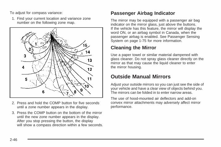
To adjust for compass variance:
1. Find your current location and variance zonenumber on the following zone map.
2. Press and hold the COMP button for five secondsuntil a zone number appears in the display.
3. Press the COMP button on the bottom of the mirroruntil the new zone number appears in the display.After you stop pressing the button, the displaywill show a compass direction within a few seconds.
Passenger Airbag IndicatorThe mirror may be equipped with a passenger air bagindicator on the mirror glass, just above the buttons.If the vehicle has this feature, the mirror will display theword ON, or an airbag symbol in Canada, when thepassenger airbag is enabled. See Passenger SensingSystem on page 1-75 for more information.
Cleaning the MirrorUse a paper towel or similar material dampened withglass cleaner. Do not spray glass cleaner directly on themirror as that may cause the liquid cleaner to enterthe mirror housing.
Outside Manual MirrorsAdjust your outside mirrors so you can just see the side ofyour vehicle and have a clear view of objects behind you.The mirrors can be folded in to enter narrow areas.
The use of hood-mounted air deflectors and add-onconvex mirror attachments may adversely affect mirrorperformance.
2-46
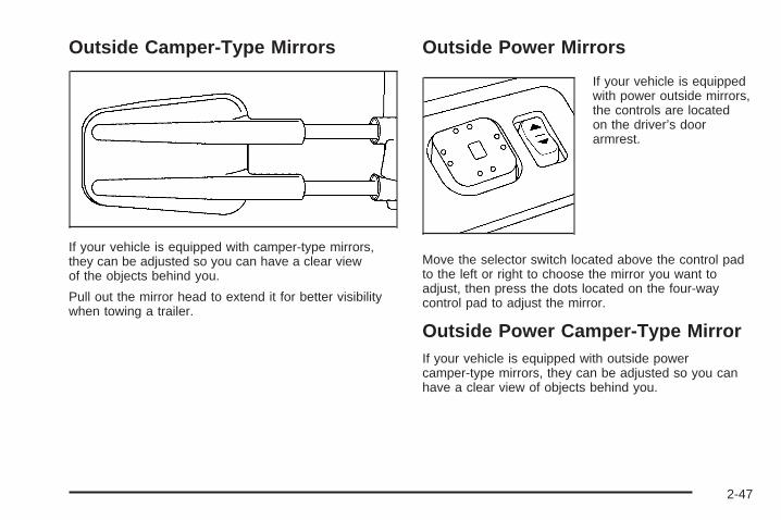
Outside Camper-Type Mirrors
If your vehicle is equipped with camper-type mirrors,they can be adjusted so you can have a clear viewof the objects behind you.
Pull out the mirror head to extend it for better visibilitywhen towing a trailer.
Outside Power Mirrors
If your vehicle is equippedwith power outside mirrors,the controls are locatedon the driver’s doorarmrest.
Move the selector switch located above the control padto the left or right to choose the mirror you want toadjust, then press the dots located on the four-waycontrol pad to adjust the mirror.
Outside Power Camper-Type MirrorIf your vehicle is equipped with outside powercamper-type mirrors, they can be adjusted so you canhave a clear view of objects behind you.
2-47

To extend the mirrors move the selector switch, locatedabove the mirror control, to the middle position. Themirror control will illuminate. Press the left side ofthe mirror control to slide the mirror heads away fromthe body of the vehicle. Press the right side of the mirrorcontrol to slide the mirror heads toward the body ofthe vehicle.
Outside Power Foldaway Mirrors
If your vehicle is equippedwith this feature, thecontrols are located on thedriver’s door armrest.
Move the upper selector switch to the left or right tochoose the mirror you want to adjust; then pressthe dots located on the four-way control pad to adjustthe mirror.
The mirrors may also include a memory function whichworks together with the memory seats. See MemorySeat on page 2-61 for more information.
To fold or unfold the mirrors, move the selector switch,located above the mirror control, to the middleposition. The mirror control will illuminate. Press theright or left side of the mirror control to fold or unfold themirrors. You may notice the mirror glass adjust as themirrors fold in; this is normal. The mirror glass willreposition itself once the mirrors are unfolded.
If the mirrors are accidentally folded/unfolded manually,they may shake or flutter at normal driving speedsand may not stay in the unfolded position. If thishappens, you will need to reset the mirrors. See“Resetting the Power Foldaway Mirrors” next.
Resetting the Power Foldaway MirrorsYou will need to reset the power foldaway mirrors if thefollowing occurs:
• They are accidentally manually folded/unfolded.
• The mirrors will not stay in the unfolded position.
• The mirrors shake and flutter at normal drivingspeeds.
To reset the power foldaway mirrors, fold and unfoldthem at least three times using the mirror controls. Thiswill reset them to their normal position.
2-48

Outside Automatic Dimming MirrorIf your vehicle is equipped with this feature, thedriver’s outside mirror will adjust for the glare ofheadlamps behind you. This feature is controlled by theon and off settings found on the electrochromicmirror. See Automatic Dimming Rearview Mirror withCompass and Temperature Display on page 2-44.
Outside Curb View Assist MirrorsIf the vehicle has the memory package, the outsidemirrors are able to perform the curb view assist mirrorfunction. This feature will cause the passenger’sand/or driver’s mirror to tilt to a preselected positionwhen the vehicle is in REVERSE (R). This feature maybe useful in allowing the driver to view the curb whenparallel parking. When the vehicle is shifted out ofREVERSE (R) and a short delay has occurred,the passenger’s and/or driver’s mirror will return to itsoriginal position.
To change the preselected tilt position, adjust themirrors to the desired position while the vehicle is inREVERSE (R). When the vehicle is shifted out ofREVERSE (R), this new position is saved in memory asthe tilt position.
This feature can be turned on or off through the DriverInformation Center (DIC).
Outside Convex MirrorYour passenger’s side mirror is convex. A convexmirror’s surface is curved so you can see more from thedriver’s seat.
{CAUTION:
A convex mirror can make things (like othervehicles) look farther away than they really are.If you cut too sharply into the right lane, youcould hit a vehicle on your right. Check yourinside mirror or glance over your shoulderbefore changing lanes.
Outside Heated MirrorsThe vehicle may have outside heated mirrors whichhelp clear them of condensation, snow, and ice.
When the rear window defogger button is pressed, theheated mirrors are also turned on. See “Rear WindowDefogger” under Dual Automatic Climate Control Systemon page 3-24 for more information.
2-49

OnStar ® SystemOnStar® uses global positioning system (GPS) satellitetechnology, wireless communications, and call centersto provide you with a wide range of safety, security,information, and convenience services.
A complete OnStar® user’s guide and the terms andconditions of the OnStar® Subscription ServiceAgreement are included in the vehicle’s glove boxliterature. For more information, visit www.onstar.com orwww.onstarcanada.com. Contact OnStar® at1-888-4-ONSTAR (1-888-466-7827), or press theOnStar® button to speak to an OnStar® advisor 24 hoursa day, 7 days a week.
Terms and conditions of the Subscription ServiceAgreement can be found at www.onstar.com orwww.onstarcanada.com.
OnStar ® ServicesFor new vehicles equipped with OnStar®, the Safe andSound Plan is included for the first year. You canextend this plan beyond the first year, or upgrade to theDirections and Connections Plan to meet your needs.For more information, press the OnStar® button to speakwith an advisor.
Safe and Sound Plan• Automatic Notification of Airbag Deployment
• Emergency Services
• Roadside Assistance
• Stolen Vehicle Tracking
• AccidentAssist
• Remote Door Unlock/Vehicle Alert
• Remote Diagnostics
• Online Concierge
2-50

Directions and Connections Plan• All Safe and Sound Plan Services
• Driving Directions
• RideAssist
• Information and Convenience Services
OnStar ® Personal CallingAs an OnStar® subscriber, the Personal Callingcapability is an available hands-free wireless phone thatis integrated into the vehicle. Calls can be placednationwide using simple voice commands with noadditional contracts and no additional roaming charges.To find out more about OnStar® Personal Calling,refer to the OnStar® user’s guide in the vehicle’s glovebox, visit www.onstar.com or www.onstarcanada.com;or speak to an OnStar® advisor by pressing the OnStar®
button or calling 1-888-4-ONSTAR (1-888-466-7827).
OnStar ® Virtual AdvisorVirtual Advisor is a feature of OnStar® Personal Callingthat uses minutes to access up-to-date weather andtraffic reports for your area, news and sports updates,stock quotes, entertainment, and more. Customizeyour information profile at www.myonstar.com. See theOnStar® user’s guide for more information.
OnStar ® Steering Wheel ControlsA steering wheel control can be used to interact with theOnStar® personal calling feature.
Press the control with thissymbol on the steeringwheel to make aphone call.
When calling into voice mail systems, or to dial directorynumbers, press the control, say the number(s), thensay “dial.”
See the OnStar® user’s guide for more information.
2-51

HomeLink ® Wireless ControlSystem
HomeLink® a combined universal transmitter andreceiver, provides a way to replace up to threehand-held transmitters used to activate devices such asgate operators, garage door openers, entry doorlocks, security systems and home lighting. AdditionalHomeLink® information can be found on the internet atwww.homelink.com or by calling 1-800-355-3515.
This device complies with Part 15 of the FCC Rules.Operation is subject to the following two conditions:(1) this device may not cause harmful interference, and(2) this device must accept any interference received,including interference that may cause undesiredoperation.
This device complies with RSS-210 of Industry Canada.Operation is subject to the following two conditions:(1) this device may not cause interference, and (2) thisdevice must accept any interference, includinginterference that may cause undesired operation of thedevice.
Changes and modifications to this system by other thanan authorized service facility could void authorizationto use this equipment.
HomeLink ® Wireless ControlSystem OperationDo not use the HomeLink® Transmitter with any garagedoor opener that does not have the “stop and reverse”feature. This includes any garage door opener modelmanufactured before April 1, 1982. If you have a newergarage door opener with rolling codes, please besure to follow Steps 6 through 8 to complete theprogramming of your HomeLink® Transmitter.
Read the instructions completely before attempting toprogram the HomeLink® Transmitter. Because ofthe steps involved, it may be helpful to have anotherperson available to assist you in programming thetransmitter.
2-52
Keep the original transmitter for use in other vehicles aswell as for future HomeLink® programming. It is alsorecommended that upon the sale of the vehicle,the programmed HomeLink® buttons should be erasedfor security purposes. Refer to “Erasing HomeLink®
Buttons” or, for assistance, contact HomeLink® on theInternet at: www.homelink.com or by calling1-800-355-3515.
Be sure that people and objects are clear of the garagedoor or gate operator you are programming. Whenprogramming a garage door, it is advised to park outsideof the garage.
It is recommended that a new battery be installed inyour hand-held transmitter for quicker and moreaccurate transmission of the radio frequency.
Programming HomeLink ®
Your vehicle’s engine should be turned off whileprogramming the transmitter. Follow these steps toprogram up to three channels:
1. Press and hold down the two outside buttons,releasing only when the indicator light begins toflash, after 20 seconds. Do not hold down thebuttons for longer than 30 seconds and do notrepeat this step to program a second and/or thirdtransmitter to the remaining two HomeLink® buttons.
2. Position the end of your hand-held transmitterabout 1 to 3 inches (3 to 8 cm) away from theHomeLink® buttons while keeping the indicator lightin view.
3. Simultaneously press and hold both the desiredbutton on HomeLink® and the hand-held transmitterbutton. Do not release the buttons until Step 4has been completed.Some entry gates and garage door openers mayrequire you to substitute Step 3 with the procedurenoted in “Gate Operator and CanadianProgramming” later in this section.
4. The indicator light will flash slowly at first and thenrapidly after HomeLink® successfully receives thefrequency signal from the hand-held transmitter.Release both buttons.
5. Press and hold the newly-trained HomeLink® buttonand observe the indicator light.If the indicator light stays on constantly, programmingis complete and your device should activate when theHomeLink® button is pressed and released.To program the remaining two HomeLink® buttons,begin with Step 2 under “Programming HomeLink®.”Do not repeat Step 1 as this will erase all of theprogrammed channels.
2-53

If the indicator light blinks rapidly for two secondsand then turns to a constant light, continue withSteps 6 through 8 following to complete theprogramming of a rolling-code equipped device(most commonly, a garage door opener).
6. Locate in the garage, the garage door openerreceiver (motor-head unit). Locate the “Learn”or “Smart” button. This can usually be found wherethe hanging antenna wire is attached to themotor-head unit.
7. Firmly press and release the “Learn” or “Smart”button. The name and color of the button mayvary by manufacturer.You will have 30 seconds to start Step 8.
8. Return to the vehicle. Firmly press and hold theprogrammed HomeLink® button for two seconds,then release. Repeat the press/hold/releasesequence a second time, and depending on thebrand of the garage door opener (or other rollingcode device), repeat this sequence a third timeto complete the programming.HomeLink® should now activate your rolling-codeequipped device.
To program the remaining two HomeLink® buttons,begin with Step 2 of “Programming HomeLink®.”You do not want to repeat Step 1, as this will erase allprevious programming.
Gate Operator and CanadianProgrammingCanadian radio-frequency laws require transmittersignals to “time out” or quit after several seconds oftransmission. This may not be long enough forHomeLink® to pick up the signal during programming.Similarly, some U.S. gate operators are manufactured to“time out” in the same manner.
If you live in Canada, or you are having difficultyprogramming a gate operator by using the“Programming HomeLink®” procedures (regardless ofwhere you live), replace Step 3 under “ProgrammingHomeLink®” with the following:
Continue to press and hold the HomeLink® button whileyou press and release every two seconds (cycle)your hand-held transmitter until the frequency signal hasbeen successfully accepted by HomeLink®. Theindicator light will flash slowly at first and then rapidly.Proceed with Step 4 under “Programming HomeLink®”to complete.
2-54

Using HomeLink ®
Press and hold the appropriate HomeLink® button for atleast half of a second. The indicator light will comeon while the signal is being transmitted.
Erasing HomeLink ® ButtonsTo erase programming from the three buttons do thefollowing:
1. Press and hold down the two outside buttons untilthe indicator light begins to flash, after 20 seconds.Do not hold the two outside buttons for longerthan 30 seconds.
2. Release both buttons.
HomeLink® is now in the train (learning) mode and canbe programmed at any time beginning with Step 2under “Programming HomeLink®” shown earlier in thissection.
Individual buttons cannot be erased, but they can bereprogrammed. See “Reprogramming a SingleHomeLink® Button” following this section.
Reprogramming a Single HomeLink ®
ButtonTo program a device to HomeLink® using a HomeLink®
button previously trained, follow these steps:
1. Press and hold the desired HomeLink® button.Do not release the button.
2. The indicator light will begin to flash after20 seconds. While still holding the HomeLink®
button, proceed with Step 2 under “ProgrammingHomeLink®” shown earlier in this section.
Resetting DefaultsTo reset HomeLink® to default settings do the following:
1. Hold down the two outside buttons for about20 seconds until the indicator light begins to flash.
2. Continue to hold both buttons until the HomeLink®
indicator light turns off.
3. Release both buttons.
For questions or comments, contact HomeLink® at1-800-355-3515, or on the Internet atwww.homelink.com.
2-55

Storage Areas
Glove BoxOpen the glove box by pulling the bottom of the handleupward.
Cupholder(s)Your vehicle may have cupholders located in the frontand rear floor console or in the fold down armrest, and inthe quarter trim.
Front Storage AreaYour vehicle may be equipped with a center armreststorage compartment in the front bench seat.
To open it, fold down the armrest and press the latchhandle located at the front of the armrest. Then, let thelid pop up and swing open.
The storage compartment may have a cassette/compactdisc holder.
Center Console Storage AreaYour vehicle may have a console compartment withcupholders between the bucket seats.
To open it, press the button and swing the consolelid open.
The rear of the console has a cupholder that swingsdown for the rear seat passenger to use.
Luggage CarrierIf you have the luggage carrier, you can load things ontop of your vehicle.
The luggage carrier has slats and siderails attached tothe roof and crossrails which can be moved backand forth to help secure cargo. Tie the load to thesiderails or siderail supports.
Notice: Loading cargo on the luggage carrier thatweighs more than 200 lbs (91 kg) or hangs overthe rear or sides of the vehicle may damage yourvehicle. Load cargo so that it rests on the slatsas far forward as possible and against the side rails,making sure to fasten it securely.
Don’t exceed the maximum vehicle capacity whenloading your vehicle. For more information on vehiclecapacity and loading, see “Loading Your Vehicle”.
2-56

To prevent damage or loss of cargo as you’re leaving,check now and then to make sure the luggage andcargo are still securely fastened.
Be sure the cargo is properly loaded.
• If small heavy objects are placed on the roof, placethe load in the area over the rear wheels (behindthe rear side door on extended models). If you needto, cut a piece of 3/8 inch plywood to fit inside thecrossrails and siderails to spread the load. Ifplywood is used, tie it to the siderail supports.
• Tie the load to the crossrails or the siderail supports.Use the crossrails only to keep the load from sliding.To move the crossrails, pull out on the latch releasehandle at each end. Slide the crossrail to the desiredposition balancing the force side to side. Push therelease handle back into the latched position andslide the crossrail back and forth slightly to be surethe latch snaps securely into place.
• If you need to carry long items, move the crossrailsas far apart as they will go. Tie the load to thecrossrails and the siderails or siderail supports. Alsotie the load to the bumpers. Do not tie the load sotightly that the crossrails or siderails are damaged.
• After moving a crossrail, be sure it is securely lockedinto the siderail.
Your vehicle has a Center High-Mounted Stoplamp(CHMSL) located above the glass or above the rearload doors.
If items are loaded on the roof of the vehicle, careshould be taken not to block or damage the CHMSL unit.
If your vehicle has the Z71 option, your vehicle’sluggage carrier has a roller crossrail at the rearof the vehicle.
To load cargo, place cargo on the roller and roll thecargo forward onto the two front crossrails.
To move the crossrails do the following:
1. Loosen the thumbscrew at each end.
2. Move crossrail to desired position.
3. Tighten the thumbscrews.
Make sure the crossrail is secured.
Rear Storage AreaYour vehicle may have a storage compartment locatedin the rear cargo area of the vehicle in the driver’sside trim panel.
To open the utility compartment, press in on the releaselatch and swing the compartment door open.
To open the compartment on extended models, pull thelatch to access.
2-57

Convenience NetThe convenience net (if equipped) in the rear of yourvehicle helps to keep small loads in place during sharpturns or quick stops and starts.
The net is not designed for larger, heavier items.
To install the net, attach the hooks to the raised cargotie downs. Then, attach the cord loops to the buttonretainers in the side trim.
You can unhook the net so that it will lie flat whenyou’re not using it.
Cargo Cover
{CAUTION:
An improperly stored cargo cover could bethrown about the vehicle during a collision orsudden maneuver. You or others could beinjured. If you remove the cover, always storeit in the proper storage location. When you putit back, always be sure that it is securelyreattached.
If you have a cargo cover, you can use it to cover itemsin the cargo area of your vehicle.
To use the cover, do the following:
1. Pull the cover handle toward the rear of the vehicle.
2. Latch the cover posts into the retaining socketson the cargo area trim panels.
To return the cover to the retracted position, do thefollowing:
1. Pull up on the cover handle to release the coverposts from the retaining sockets.
2. Let the cover move forward to the full retractedposition.
To remove the cover from the vehicle, do the following:
1. Let the cover go all the way into the holder.
2. Then, grasping the passenger’s side cover endcap,push the cover endcap toward the driver’s side ofthe vehicle. The endcap should lock in thecompressed position.
3. Lift the cover up on the passenger’s side, swing thecover rearward and take it out of the vehicle.
2-58

To put the cover in the vehicle, do the following:
1. Make sure the cover slot in the holder facesrearward with the round surface facing down.
2. Then, hold the cover at an angle and place thecover holder tab into the slot in the driver’s sidetrim panel.
3. Move the other end of the cover forward and hold itnext to the passenger’s side trim panel slot.
4. Push the button on top of the passenger’s sideendcap. This will allow the cover to extend intothe trim slot.
5. Lightly pull on the cover holder to make sure it issecure.On some models there are two slots. The slotsfurthest forward allow the cover to be used if thethird seat is removed or folded down.
Cargo Tie Downs
Your vehicle may beequipped with cargo tiedowns in the rearcargo area that allow youto strap cargo in andkeep it from moving insidethe vehicle.
When not using the tie downs, flip them down out ofthe way.
2-59

Sunroof
Your vehicle may be equipped with a power slidingsunroof. To open or close your sunroof, the ignitionneeds to be on or RAP needs to be active. See“Retained Accessory Power” under Ignition Positions onpage 2-20.
Press and release the rear side of the button located inthe front overhead console to express-open the glasspanel and sunshade. To stop the express-open motion,press the front or rear of the button again. To closethe glass panel, press and hold the front of the button.The glass will not be fully seated unless the buttonis held until the glass stops moving. With the sunroofclosed, press the forward side of the button to open thesunroof to the vent position.
The sunroof is also equipped with a sunshade whichyou can pull forward to block sun rays.
If a hand, arm, or other object is blocking the sunroofglass panel as it is closing, the glass panel will stopat the obstruction. After the obstruction is removed, theglass panel can be closed or opened.
Use care not to leave the sunroof open for long periodsof time as debris may collect in the tracks.
If the battery has been recharged, disconnected or isnot working, you may need to reprogram the sunroof. Todo this, start the vehicle and press the forward side ofthe sunroof button until the glass panel moves to a fullyclosed position. Release, and press again to move tothe vent position, which occurs when the sunroof is fullytilted upward and the button is held for an additionaltwenty seconds. This will reset the memory and enablethe sunroof to function properly.
2-60

Vehicle Personalization
Memory Seat
If your vehicle has thisfeature, the controls forthe memory function arelocated on the driver’s door.
These buttons are used to program and recall memorysettings for the driver’s seat, throttle and brakepedals and both the driver’s and passenger’s outsidemirrors. The settings for these features can be saved forup to two drivers.
To store the settings, do the following:
1. While the vehicle is in PARK (P), adjust the driver’sseat, including the seatback recliner, lumbar, andside wing area, throttle and brake pedals andboth of the outside mirrors to your preference.
2. Press and hold the 1 or 2 button of the memorycontrol for three seconds. A double chime willsound to let you know that the position has beenstored.
To repeat the procedure for a second driver, follow thepreceding steps, but press the other numberedmemory control button.
Each time button 1 or 2 is pressed and released whilethe vehicle is in PARK (P), a single chime will sound andthe memory position will be recalled.
To stop recall movement of the memory seat feature atany time, press one of the memory buttons or powerseat controls.
2-61

Easy Exit SeatThe controls for this memory function are located on thedriver’s door.
B (Easy Exit Seat): This button is used to programand recall the desired driver’s seat position whenexiting/entering the vehicle. The seat position can besaved for up to two drivers.
To store the seat exit position, do the following:
1. Press and release the 1 or 2 button. The seat willmove to the stored memory position.
2. Adjust the seat to the desired exit position.
3. Press and hold the exit button of the memorycontrol for three seconds. A double chime will soundto let you know that the position has been storedfor the selected button (1 or 2).
To repeat the procedure for a second driver, follow thepreceding steps, but press the other numberedmemory control button.
To use the seat exit position, do one of the following:
• Press the exit button on the memory control.
• Or, if this feature is activated in the DriverInformation Center (DIC), removing the key fromthe ignition will move the seat to the exit position.
See “Easy Exit Seat” under DIC Vehicle Customizationon page 3-68 for more information on activating thisfeature in the DIC.
2-62

Instrument Panel Overview ...............................3-4Hazard Warning Flashers ................................3-6Other Warning Devices ...................................3-6Horn .............................................................3-6Tilt Wheel .....................................................3-6Turn Signal/Multifunction Lever .........................3-7Turn and Lane-Change Signals ........................3-8Headlamp High/Low-Beam Changer ..................3-8Flash-to-Pass .................................................3-9Windshield Wipers ..........................................3-9Windshield Washer .......................................3-10Cruise Control ..............................................3-11Headlamps ..................................................3-14Headlamps on Reminder ................................3-15Daytime Running Lamps (DRL) .......................3-15Automatic Headlamp System ..........................3-16Fog Lamps ..................................................3-17Auxiliary Roof Mounted Lamp .........................3-17Instrument Panel Brightness ...........................3-18Dome Lamps ...............................................3-18Dome Lamp Override ....................................3-18Entry Lighting ...............................................3-18Exit Lighting .................................................3-18Front Reading Lamps ....................................3-19Battery Run-Down Protection ..........................3-19Accessory Power Outlets ...............................3-20Ashtrays and Cigarette Lighter ........................3-20
Climate Controls ............................................3-21Climate Control System .................................3-21Dual Climate Control System ..........................3-22Dual Automatic Climate Control System ...........3-24Outlet Adjustment .........................................3-30Rear Air Conditioning System .........................3-30Rear Air Conditioning and Heating System .......3-31Rear Air Conditioning and Heating System and
Electronic Climate Controls .........................3-34Warning Lights, Gages, and Indicators ............3-36
Instrument Panel Cluster ................................3-37Speedometer and Odometer ...........................3-38Trip Odometer ..............................................3-38Tachometer .................................................3-38Safety Belt Reminder Light .............................3-39Airbag Readiness Light ..................................3-39Passenger Airbag Status Indicator ...................3-40Battery Warning Light ....................................3-42Voltmeter Gage ............................................3-42Brake System Warning Light ..........................3-43Anti-Lock Brake System Warning Light .............3-44Traction Off Light ..........................................3-45Engine Coolant Temperature Gage ..................3-46Transmission Temperature Gage .....................3-46Tire Pressure Light .......................................3-48Malfunction Indicator Lamp .............................3-48Oil Pressure Gage ........................................3-51
Section 3 Instrument Panel
3-1

Security Light ...............................................3-52Cruise Control Light ......................................3-52Highbeam On Light .......................................3-52Four-Wheel-Drive Light ..................................3-52Tow/Haul Mode Light ....................................3-53Fuel Gage ...................................................3-53Low Fuel Warning Light .................................3-53
Driver Information Center (DIC) .......................3-54DIC Operation and Displays ...........................3-55DIC Warnings and Messages .........................3-58DIC Vehicle Customization .............................3-68
Audio System(s) .............................................3-74Setting the Time for Radios without Radio
Data Systems (RDS) ..................................3-75Setting the Time for Radios with Radio Data
Systems (RDS) .........................................3-75
AM-FM Radio ...............................................3-76Radio with CD ..............................................3-78Radio with Cassette and CD ..........................3-89Radio with Six-Disc CD ................................3-103Navigation/Radio System ..............................3-118Rear Seat Entertainment System ...................3-118Rear Seat Audio (RSA) ................................3-129Theft-Deterrent Feature ................................3-131Audio Steering Wheel Controls ......................3-131Radio Reception .........................................3-132Care of the Cassette Tape Player .................3-133Care of Your CDs and DVDs ........................3-134Care of the CD and DVD Player ...................3-134Fixed Mast Antenna ....................................3-135XM™ Satellite Radio Antenna System ............3-135Chime Level Adjustment ...............................3-135
Section 3 Instrument Panel
3-2

✍ NOTES
3-3

Instrument Panel Overview
3-4
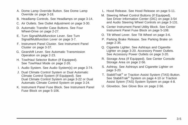
A. Dome Lamp Override Button. See Dome LampOverride on page 3-18.
B. Headlamp Controls. See Headlamps on page 3-14.C. Air Outlets. See Outlet Adjustment on page 3-30.D. Automatic Transfer Case Buttons. See Four
Wheel-Drive on page 2-27.E. Turn Signal/Multifunction Lever. See Turn
Signal/Multifunction Lever on page 3-7.F. Instrument Panel Cluster. See Instrument Panel
Cluster on page 3-37.G. Gearshift Lever. See Automatic Transmission
Operation on page 2-23.H. Tow/Haul Selector Button (If Equipped).
See Tow/Haul Mode on page 2-26.I. Audio System. See Audio System(s) on page 3-74.J. Dual Climate Control System or Dual Automatic
Climate Control System (If Equipped). SeeDual Climate Control System on page 3-22 or DualAutomatic Climate Control System on page 3-24.
K. Instrument Panel Fuse Block. See Instrument PanelFuse Block on page 5-106.
L. Hood Release. See Hood Release on page 5-11.M. Steering Wheel Control Buttons (If Equipped).
See Driver Information Center (DIC) on page 3-54and Audio Steering Wheel Controls on page 3-131.
N. Center Instrument Panel Utility Block. See CenterInstrument Panel Fuse Block on page 5-108.
O. Tilt Wheel Lever. See Tilt Wheel on page 3-6.P. Parking Brake Release. See Parking Brake on
page 2-35.Q. Cigarette Lighter. See Ashtrays and Cigarette
Lighter on page 3-20. Accessory Power Outlets.See Accessory Power Outlets on page 3-20.
R. Storage Area (If Equipped). See Center ConsoleStorage Area on page 2-56.
S. Ashtray. See Ashtrays and Cigarette Lighter onpage 3-20.
T. StabiliTrak® or Traction Assist System (TAS) Button.See StabiliTrak® System on page 4-10 or TractionAssist Sytem (TAS) System System on page 4-8.
U. Glovebox. See Glove Box on page 2-56.
3-5

Hazard Warning FlashersYour hazard warning flashers let you warn others. Theyalso let police know you have a problem. Your frontand rear turn signal lamps will flash on and off.
The hazard warningflasher button is locatedon top of the steeringcolumn.
Your hazard warning flashers work no matter whatposition your key is in, and even if the key is not in theignition.
Press the button to make the front and rear turn signallamps flash on and off. Press the button again toturn the flashers off.
When the hazard warning flashers are on, your turnsignals will not work.
Other Warning DevicesIf you carry reflective triangles, you can set them up atthe side of the road about 300 feet (100 m) behindyour vehicle.
HornTo sound the horn, press the center pad on thesteering wheel.
Tilt WheelYour vehicle is equipped with a tilt wheel that allowsyou to adjust the steering wheel before you drive. Youcan raise it to the highest level to give your legsmore room when you exit and enter your vehicle.
3-6

The tilt steering wheel lever is located on the lower leftside of the column.
To tilt the wheel, hold the steering wheel and pull thelever. Then move the steering wheel to a comfortableposition and release the lever to lock the wheel in place.
Turn Signal/Multifunction Lever
The lever on the left side of the steering columnincludes the following:• G Turn and Lane Change Signals. See Turn and
Lane-Change Signals on page 3-8.• 53 Headlamp High/Low-Beam Changer. See
Headlamp High/Low-Beam Changer on page 3-8.• Flash-to-Pass. See Flash-to-Pass on page 3-9.
• N Windshield Wipers. See Windshield Wipers onpage 3-9.
• L Windshield Washer. See Windshield Washeron page 3-10.
• I Cruise Control. See Cruise Control onpage 3-11.
For information on the headlamps, see Headlampson page 3-14.
3-7

Turn and Lane-Change SignalsThe turn signal has two upward (for right) and twodownward (for left) positions. These positions allow youto signal a turn or a lane change.
To signal a turn, move the lever all the way up or down.When the turn is finished, the lever will returnautomatically.
To signal a lane change, just raise or lower the leveruntil the arrow starts to flash. Hold it there until youcomplete your lane change. The lever will return by itselfwhen you release it.
An arrow on the instrumentpanel cluster will flash inthe direction of theturn or lane change.
As you signal a turn or a lane change, if the arrowsflash more quickly than normal, a signal bulb maybe burned out and other drivers won’t see your turnsignal.
If a bulb is burned out, replace it to help avoid anaccident. If the arrows don’t go on at all when you signala turn, check for burned-out bulbs and a blown fuse.See Fuses and Circuit Breakers on page 5-105.
Turn Signal On ChimeIf your turn signal is left on for more than 3/4 of a mile(1.2 km), a chime will sound at each flash of theturn signal and the message TURN SIGNAL ON willalso appear in the DIC. To turn the chime and messageoff, move the turn signal lever to the off position.
Headlamp High/Low-Beam Changer
53(Headlamp High/Low Beam Changer): Tochange the headlamps from low to high beam, push thelever toward the instrument panel. To return tolow-beam headlamps, pull the multifunction lever towardyou. Then release it.
When the high beams areon, this indicator light onthe instrument panelcluster will also be on.
3-8

Flash-to-PassThis feature lets you use your high-beam headlamps tosignal a driver in front of you that you want to pass.It works even if your headlamps are in the automaticposition.
To use it, pull the turn signal lever toward you, thenrelease it.
If your headlamps are in the automatic position or onlow beam, your high-beam headlamps will turn on.They’ll stay on as long as you hold the lever toward you.The high-beam indicator on the instrument panelcluster will come on. Release the lever to return tonormal operation.
Windshield WipersYou control the windshield wipers by turning the bandwith the wiper symbol on it.
8(Mist): For a single wiping cycle, turn the band tomist. Hold it there until the wipers start. Then let go.The wipers will stop after one wipe. If you wantmore wipes, hold the band on mist longer.
N(Delay): You can set the wiper speed for a long orshort delay between wipes. This can be very usefulin light rain or snow. Turn the band to choose the delaytime. The closer to the top of the lever, the shorterthe delay.
6 (Low Speed): For steady wiping at low speed,turn the band away from you to the first solid band pastthe delay settings. For high-speed wiping, turn theband further, to the second solid band past the delaysettings. To stop the wipers, move the band to off.
1 (High Speed): For high-speed wiping, turnthe band further, to the second solid band past thedelay settings.
9(Off): To stop the wipers, move the band to off.
Be sure to clear ice and snow from the wiper bladesbefore using them. If they’re frozen to the windshield,carefully loosen or thaw them. If your blades do becomeworn or damaged, get new blades or blade inserts.
3-9

Windshield Washer
L(Washer Fluid): There is a paddle marked with thewindshield washer symbol at the top of the multifunctionlever. To spray washer fluid on the windshield, pushthe paddle. The wipers will clear the window and theneither stop or return to your preset speed.
{CAUTION:
In freezing weather, do not use your washeruntil the windshield is warmed. Otherwise thewasher fluid can form ice on the windshield,blocking your vision.
Rear Window Washer/Wiper
This knob is located on theinstrument panel to the leftof the steering wheel.
To turn the rear wiper on, turn the knob to either 1 or 2.For long delayed wiping, turn the knob to 1. For shortdelayed wiping, turn the knob to 2.
9(Off): To turn the wiper off, turn the knob to thissymbol.
=(Washer Fluid): To wash the window, press theknob with this symbol.
The rear window washer uses the same fluid bottle asthe windshield washer. However, the rear windowwasher will run out of fluid before the windshield washer.If you can wash your windshield but not your rearwindows, check the fluid level.
3-10

Cruise Control
9(Off): This positionturns the system off.
R(On): This position activates the system.
+ (Resume/Accelerate): Push the lever to this symbolto make the vehicle accelerate or resume to apreviously set speed.
T(Set): Press this button to set the speed.
With cruise control, you can maintain a speed of about25 mph (40 km/h) or more without keeping your footon the accelerator. This can really help on longtrips. Cruise control does not work at speeds belowabout 25 mph (40 km/h).
If you apply your brakes, the cruise control will shut off.
{CAUTION:
Cruise control can be dangerous where youcannot drive safely at a steady speed. So, donot use your cruise control on winding roadsor in heavy traffic.
Cruise control can be dangerous on slipperyroads. On such roads, fast changes in tiretraction can cause needless wheel spinning,and you could lose control. Do not use cruisecontrol on slippery roads.
3-11

Setting Cruise Control
{CAUTION:
If you leave your cruise control on when youare not using cruise, you might hit a buttonand go into cruise when you do not want to.You could be startled and even lose control.Keep the cruise control switch off until youwant to use cruise control.
1. Move the cruise control switch to on.
2. Get up to the speed you want.
3. Press in the set button at the end of the lever andrelease it.
4. Take your foot off the accelerator pedal.
The cruise symbol on theinstrument panel willilluminate when the cruisecontrol is engaged.
Resuming a Set SpeedSuppose you set your cruise control at a desired speedand then you apply the brake. This, of course,disengages the cruise control. But you don’t need toreset it.
Once you’re going about 25 mph (40 km/h) or more, youcan move the cruise control switch briefly from on toresume/accelerate.
You’ll go right back up to your chosen speed andstay there.
If you hold the switch at resume/accelerate the vehiclewill keep going faster until you release the switch orapply the brake. So unless you want to go faster, don’thold the switch at resume/accelerate.
3-12

Increasing Speed While Using CruiseControlThere are two ways to go to a higher speed:
• Use the accelerator pedal to get to the higherspeed. Press the set button at the end of the lever,then release the button and the acceleratorpedal. You’ll now cruise at the higher speed. If theaccelerator pedal is held longer than 60 seconds,cruise control will turn off.
• Move the cruise switch from on toresume/accelerate. Hold it there until you get up tothe speed you want, and then release the switch.To increase your speed in very small amounts,move the switch briefly to resume/accelerate.Each time you do this, your vehicle will go about1 mph (1.6 km/h) faster.
Reducing Speed While Using CruiseControl• Press in the button at the end of the lever until you
reach the lower speed you want, then release it.
• To slow down in very small amounts, briefly pressthe set button. Each time you do this, you’ll goabout 1 mph (1.6 km/h) slower.
Passing Another Vehicle While UsingCruise ControlUse the accelerator pedal to increase your speed.When you take your foot off the pedal, your vehicle willslow down to the cruise control speed you set earlier.
Using Cruise Control on HillsHow well your cruise control will work on hills dependsupon your speed, load and the steepness of thehills. When going up steep hills, you may want to stepon the accelerator pedal to maintain your speed.When going downhill, you may have to brake or shift toa lower gear to keep your speed down. Of course,applying the brake takes you out of cruise control. Manydrivers find this to be too much trouble and don’t usecruise control on steep hills.
Ending Cruise ControlThere are four ways to turn off the cruise control:• Step lightly on the brake pedal,• move the cruise control switch to off, or• shift the transmission to NEUTRAL (N).• If your vehicle has the StabiliTrak® feature, cruise
control will turn off if road conditions causeStabiliTrak® to activate.
• If the accelerator pedal is held for 60 seconds orlonger, cruise control will turn off.
3-13

Erasing Speed MemoryWhen you turn off the cruise control or the ignition, yourcruise control set speed memory is erased.
Headlamps
The control on the driver’s side of your instrument paneloperates the headlamps.
Turn the control clockwise to operate the lamps.
The headlamp control has four positions:
9 (Off): Turning the control to this position turns offthe Daytime Running Lamps (DRL) and the automaticheadlamps.
AUTO (Automatic): Turning the control to this positionputs the system into automatic headlamp mode.
; (Parking Lamps): Turning the control to thisposition turns on the parking lamps, together with thefollowing:
• Sidemarker Lamps
• Taillamps
• License Plate Lamps
• Instrument Panel Lights
• Roof Marker Lamps (If Equipped)
5 (Headlamps): Turning the control to this positionturns on the headlamps, together with the previouslylisted lamps and lights.
You can switch your headlamps from high to low-beamby pushing the turn signal/high-beam lever towardsthe instrument panel.
3-14

A circuit breaker protects your headlamps. If you havean electrical overload, your headlamps will flicker on andoff. Have your headlamp wiring checked right away ifthis happens.
Headlamps on ReminderA reminder chime will sound when your headlamps orparking lamps are manually turned on and your ignitionis off, in LOCK, ACCESSORY, or your door is open.To disable the chime, turn the light off then back on.
Daytime Running Lamps (DRL)Daytime Running Lamps (DRL) can make it easier forothers to see the front of your vehicle during theday. DRL can be helpful in many different drivingconditions, but they can be especially helpful in the shortperiods after dawn and before sunset. Fully functionaldaytime running lamps are required on all vehiclesfirst sold in Canada.
The DRL system will come on when the followingconditions are met:• The ignition is on• The exterior lamps control is in AUTO• The automatic transmission is not in PARK (P)• The light sensor determines it is daytime
When the DRL are on, only your DRL lamps will be on.The taillamps, sidemarker and other lamps won’t beon. The instrument panel won’t be lit up either.
When it begins to get dark, the automatic headlampsystem will switch from DRL to the headlamps.
When you turn the headlamp switch off, the headlampswill go off, and your DRL lamps will illuminate,provided it is not dark outside.
Shifting the transmission into PARK (P) will allow youto idle the vehicle with the DRL off. The DRL will stayoff until you shift the transmission out of PARK (P).This procedure applies only to vehicles first sold in theUnited States.
3-15

Automatic Headlamp SystemWhen it is dark enough outside, your automaticheadlamp system will turn on your headlamps at thenormal brightness along with other lamps such asthe taillamps, sidemarker, parking lamps and theinstrument panel lights. The radio lights will also be dim.
To turn off the automatic headlamp system, turn theexterior lamps switch to the off position and thenrelease. Turning off the automatic headlamp systemwith the headlamp switch is not available for vehiclesfirst sold in Canada. For vehicles first sold in Canada,you can turn off the automatic headlamp systemwhen parked at night by applying the parking brakebefore starting your vehicle. The headlamps will remainoff once the vehicle is started for as long as you areparked. If you release the parking brake, the lights willturn on. If the parking brake is not released beforeyou begin to drive, the exterior lamps will turn onabove 2 mph (3.2 km/h).
Your vehicle is equipped with a light sensor located onthe top of the instrument panel in the defroster grille.Be sure it is not covered, or the system will be onwhenever the ignition is on.
The system may also turn on your headlamps whendriving through a parking garage, heavy overcastweather or a tunnel. This is normal.
There is a delay in the transition between the daytimeand nighttime operation of the Daytime RunningLamps (DRL) and the automatic headlamp systems sothat driving under bridges or bright overhead streetlights does not affect the system. The DRL andautomatic headlamp system will only be affected whenthe light sensor sees a change in lighting lastinglonger than the delay.
If you start your vehicle in a dark garage, the automaticheadlamp system will come on immediately. Onceyou leave the garage, it will take approximatelyone minute for the automatic headlamp system tochange to DRL if it is bright enough outside. During thatdelay, your instrument panel cluster may not be asbright as usual. Make sure your instrument panelbrightness control is in the full bright position. SeeInstrument Panel Brightness on page 3-18.
To idle your vehicle with the automatic headlampsystem off, turn the control to the off position.
You may be able to turn off your Automatic HeadlampSystem. See Daytime Running Lamps (DRL) onpage 3-15 for more information.
Your headlamps will also stay on after you exit thevehicle. You can program this feature using the DriverInformation Center (DIC). See DIC VehicleCustomization on page 3-68.
As with any vehicle, you should turn on the regularheadlamp system when you need them.
3-16

Fog LampsIf your vehicle has fog lamps, use them for better visionin foggy or misty conditions.
The fog lamp button islocated on the left side ofthe instrument panel.
Your parking lamps and/or low-beam headlamps mustbe on for your fog lamps to work.
Press the button to turn the fog lamps on. Press thebutton again to turn them off. An indicator light will glowin the button when the fog lamps are on.
Remember, fog lamps alone will not give off as muchlight as your headlamps. Never use your fog lampsin the dark without turning on your headlamps.
The fog lamps will go off whenever your high-beamheadlamps come on. When the high beams go off, thefog lamps will come on again.
The fog lamps will be cancelled after the ignition isturned off. If you still want to use the fog lamps afteryou restart the vehicle, you will need to press thefog lamp button again.
Auxiliary Roof Mounted LampIf your vehicle has this feature, this button includeswiring provisions for a dealer or a qualified servicecenter to install an auxiliary roof lamp.
This button is locatedon the center of theinstrument panel nearthe climate controls.
When the wiring is connected to an auxiliary roofmounted lamp, pressing the button will activate thelamp and illuminate an indicator light near the button.Pressing the button again will turn off the roofmounted lamp.
3-17

If your vehicle has this button, your vehicle may have thesnow plow prep package. For further information seeAdding a Snow Plow or Similar Equipment on page 4-57.
Instrument Panel Brightness
D (Instrument Panel Brightness): This featurecontrols the brightness of the instrument panel lights.
The thumbwheel for this feature is located next tothe headlamp control.
Turn the thumbwheel up to adjust the instrument panellights. Turn the thumbwheel up to return the radiodisplay to full brightness when the headlamps or parkinglamps are on. To turn on the dome lamps, turn thethumbwheel all the way up.
Dome LampsThe dome lamps will come on when you open a door.
You can also turn the dome lamps on by turningthe thumbwheel, located next to the exterior lampscontrol, all the way up. In this position, the dome lampswill remain on whether a door is opened or closed.
Dome Lamp Override
E (Dome Lamp Override): You can use the domeoverride button, located below the exterior lamps control,to set the dome lamps to come on automatically whena door is opened, or to remain off. To turn the lamps off,press the button into the in position. With the buttonin this position, the dome lamps will remain off when thedoors are open. To return the lamps to automaticoperation, press the button again and return it to the outposition. With the button in this position, the domelamps will come on when you open a door.
Entry LightingYour vehicle is equipped with an illuminated entryfeature.
When the doors are opened, the dome lamps will comeon if the dome override button is in the out position.If the dome override button is pressed in, the lamps willnot come on.
Exit LightingWith exit lighting, the interior lamps will come on whenyou remove the key from the ignition. The lights willnot come on if the dome override button is pressed in.
3-18
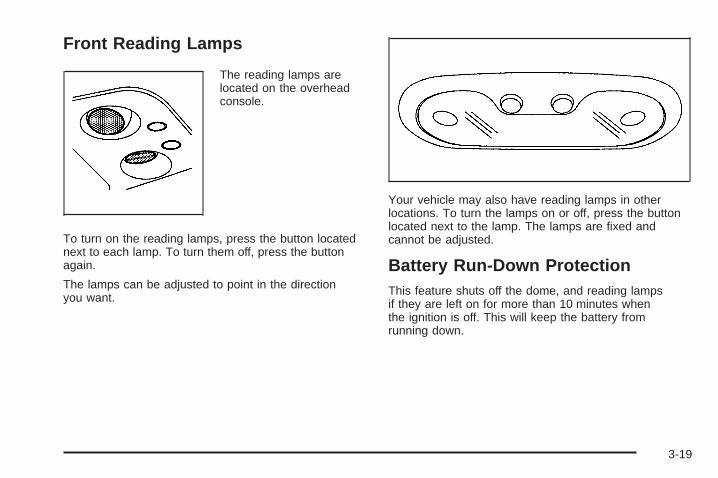
Front Reading Lamps
The reading lamps arelocated on the overheadconsole.
To turn on the reading lamps, press the button locatednext to each lamp. To turn them off, press the buttonagain.
The lamps can be adjusted to point in the directionyou want.
Your vehicle may also have reading lamps in otherlocations. To turn the lamps on or off, press the buttonlocated next to the lamp. The lamps are fixed andcannot be adjusted.
Battery Run-Down ProtectionThis feature shuts off the dome, and reading lampsif they are left on for more than 10 minutes whenthe ignition is off. This will keep the battery fromrunning down.
3-19

Accessory Power OutletsWith accessory power outlets you can plug in auxiliaryelectrical equipment such as a cellular telephone orCB radio.
Your vehicle may have two accessory power outlets, ormay have one accessory power outlet located nearthe cigarette lighter, if equipped. The cigarette lighter isdesigned to fit only in the receptacle to the right ofthe accessory power outlet.
To use the outlet, lift the cover. When not using it,always close the cover.
Certain power accessory plugs may not be compatibleto the accessory power outlet and could result inblown vehicle or adapter fuses. If you experience aproblem, see your dealer for additional information onthe accessory power plugs.
Notice: Adding any electrical equipment to yourvehicle may damage it or keep other componentsfrom working as they should. The repairs would notbe covered by your warranty. Do not use equipmentexceeding maximum amperage rating. Checkwith your dealer before adding electrical equipment.
When adding electrical equipment, be sure to followthe proper installation instructions included withthe equipment.
Notice: Improper use of the power outlet can causedamage not covered by your warranty. Do nothang any type of accessory or accessory bracketfrom the plug because the power outlets aredesigned for accessory power plugs only.
Ashtrays and Cigarette LighterThe front ashtray is located near the center of theinstrument panel or on the front console, if equipped.Pull on the ashtray door to open it.
Notice: If you put papers, pins, or other flammableitems in the ashtray, hot cigarettes or othersmoking materials could ignite them and possiblydamage your vehicle. Never put flammable items inthe ashtray.
To remove the front ashtray pull the ashtray up.
To use the cigarette lighter, push it in all the way, andlet go. When it’s ready, it will pop back out by itself.
Notice: Holding a cigarette lighter in while itis heating will not allow the lighter to back awayfrom the heating element when it is hot. Damagefrom overheating may occur to the lighter or heatingelement, or a fuse could be blown. Do not hold acigarette lighter in while it is heating.
3-20

Climate Controls
Climate Control System
Fan KnobThe fan knob on the left side of the control paneladjusts the fan speed. To increase airflow, turn the knobclockwise. To decrease airflow, turn it counterclockwise.To turn the fan off, turn the knob to the off position.
9 (Off): If the fan is off, outside air will still enter thevehicle, and will be directed based on the position ofthe mode knob. The temperature can also be adjustedusing the temperature knob.
Temperature KnobThe middle knob on the control panel lets you selectthe temperature of the air flowing into the passengerarea. Turn the knob clockwise toward the red area forwarmer air. Turn the knob counterclockwise towardthe blue area for cooler air.
Mode KnobThe right knob on the control panel allows you tochoose the direction of air delivery.
H (Vent): This setting directs the air through theinstrument panel outlets.
) (Bi-Level): Air is delivered through the floor outletsas well as the instrument panel outlets. The flow canbe divided between vent and floor outlets dependingupon where the knob is placed between the settings.
6 (Floor): This setting directs most of the air throughthe floor outlets, and the rest of the air is dividedbetween the windshield defroster outlets and the sidewindow defroster outlets.
W (Defog): Airflow is delivered through the flooroutlets, the windshield defroster outlets and the sidewindow defroster outlets. The air flow can be dividedbetween floor and defrost depending upon wherethe knob is placed between the settings.
1 (Defrost): This setting directs most air through thewindshield defroster outlets, side window defrosteroutlets and some through the floor outlets.
3-21

Dual Climate Control SystemWith this system you can control the heating, coolingand ventilation for your vehicle.
9(Fan): Turn the left knob clockwise orcounterclockwise to increase or decrease the fan speed.Turn the knob to the off position to turn off the fan. Ifthe knob is in off outside air will still enter the vehicle,and will be directed based on the position of themode knob. The temperature can also be adjustedusing the temperature levers.Turn the right knob clockwise or counterclockwise todirect the airflow inside of your vehicle.To change the current mode, select one of the following:
H (Vent): This mode directs air to the instrumentpanel vents.
)(Bi-Level): This mode directs half of the air to theinstrument panel vents; then directs most of theremaining air to the floor vents. A little air is directedtoward the windshield and the side window vents. Coolerair is directed to the upper vents and warmer air tothe floor vents.
6 (Floor): This mode directs most of the air to thefloor vents with a little air directed to the windshield andthe side window vents.
@ (Recirculation): The recirculation mode is usedto recirculate the air inside of your vehicle. Use thismode to help prevent outside odors and/or dustfrom entering your vehicle or to help cool the air insideof your vehicle more quickly. Press this button toturn the recirculation mode on or off. The light on therecirculation button will illuminate. Recirculation cannotbe used in floor, bi-level, defog or defrost modes.An indicator on the button will light up, flash three timesand turn off when recirculation is selected in thesemodes. The air-conditioning compressor will also comeon when this mode is activated. While in recirculationmode the windows may fog when the weather iscold and damp. To clear the fog, select either the blendor defrost mode and increase fan speed.
3-22

Temperature Control
Driver’s Side: The lever on the left side of the climatecontrol panel is used to raise or lower the temperatureon the driver’s side of the vehicle. This lever alsoadjusts the temperature to the center console outlets(if equipped).
Passenger’s Side: The lever on the right side of theclimate control panel is used to raise or lower thetemperature on the passenger’s side of the vehicle.
#(Air Conditioning): Press this button to turnthe air-conditioning system on or off. When the buttonis pressed, an indicator light will come on and thesystem will begin to cool and dehumidify the air insideof your vehicle. You may notice a slight change inengine performance when the air conditioningcompressor shuts off and turns on again. This isnormal.
Defogging and DefrostingFog on the inside of the windows is a result of highhumidity (moisture) condensing on the cool windowglass. This can be minimized if the climate controlsystem is used properly. There are two modes to choosefrom to clear fog or frost from your windshield. Usethe defog mode to clear the windows of fog or moistureand warm the passengers. Use the defrost mode toremove fog or frost from the windshield more quickly.
Turn the right knob to select one of the following modes:
-(Defog): This mode directs the air to the flooroutlets, windshield and the side window vents. The airconditioning compressor will run automatically todehumidify the air to prevent window fogging. Therecirculation mode cannot be selected while in thedefog mode.
1(Defrost): This mode directs most of the air to thewindshield and the side window vents, with only alittle air directed to the floor vents. The air conditioningcompressor will run automatically to dehumidify theair to prevent window fogging. The recirculation modecannot be selected while in defrost mode.
Do not drive the vehicle until all the windows are clear.
3-23
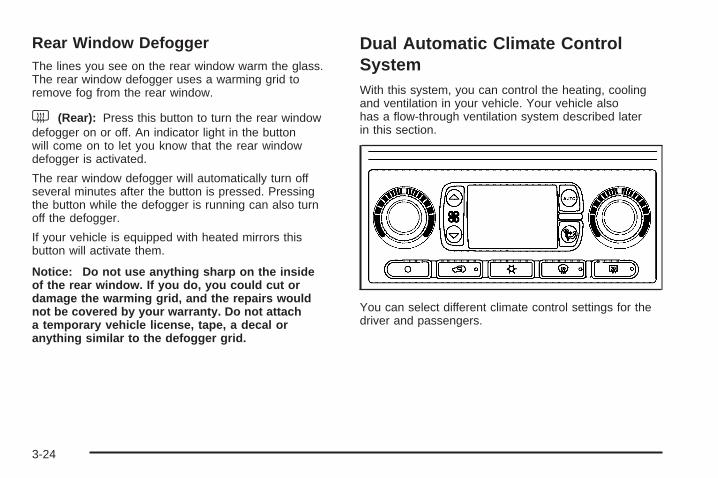
Rear Window DefoggerThe lines you see on the rear window warm the glass.The rear window defogger uses a warming grid toremove fog from the rear window.
< (Rear): Press this button to turn the rear windowdefogger on or off. An indicator light in the buttonwill come on to let you know that the rear windowdefogger is activated.
The rear window defogger will automatically turn offseveral minutes after the button is pressed. Pressingthe button while the defogger is running can also turnoff the defogger.
If your vehicle is equipped with heated mirrors thisbutton will activate them.
Notice: Do not use anything sharp on the insideof the rear window. If you do, you could cut ordamage the warming grid, and the repairs wouldnot be covered by your warranty. Do not attacha temporary vehicle license, tape, a decal oranything similar to the defogger grid.
Dual Automatic Climate ControlSystemWith this system, you can control the heating, coolingand ventilation in your vehicle. Your vehicle alsohas a flow-through ventilation system described laterin this section.
You can select different climate control settings for thedriver and passengers.
3-24

Driver’s Side Temperature KnobThe driver’s side knob is used to adjust the temperatureof the air coming through the system on the driver’sside. The temperature can be adjusted even if thesystem is turned off. This is possible since outside airwill always flow through the system as the vehicleis moving forward unless it is set to recirculation mode.See “Recirculation” later in this section.Turn the knob counterclockwise or clockwise to lower orincrease the cabin temperature. The display will showthe temperature setting decreasing or increasing and anarrow pointing to the driver will be displayed underand to the left of the temperature setting.
Passenger’s Side Temperature KnobThe passenger’s side knob can be used to change thetemperature of the air coming through the systemon the passenger’s side of the vehicle. The temperaturecan be adjusted even if the system is turned off. Thisis possible since outside air will always flow through thesystem as the vehicle is moving forward unless it isset to recirculation mode. See “Recirculation” later inthis section.Turn the knob counterclockwise or clockwise to loweror increase the temperature inside the vehicle. Thedisplay will show the temperature setting decreasing orincreasing and an arrow pointing to the passengerwill be displayed under and to the right of thetemperature setting.
The passenger’s temperature setting can be set tomatch the driver’s temperature setting by pressing andholding the AUTO button for four seconds. Both thedriver and passenger arrows will be displayed.
Automatic Operation
AUTO (Automatic): When automatic operation isactive the system will control the inside temperature, theair delivery, and the fan speed.
Use the steps below to place the entire system inautomatic mode:
1. Press the AUTO button.When AUTO is selected, the display will change toshow the current driver’s set temperature, deliverymode and fan speed. Press the AUTO button againwithin five seconds to display the passenger’s settemperature.If the driver and passenger’s temperature settingsare not the same, the opposite side temperaturesetting will be displayed for an additional fiveseconds. To make the passenger’s temperature thesame as the driver’s, press and hold the AUTObutton for about four seconds.
3-25
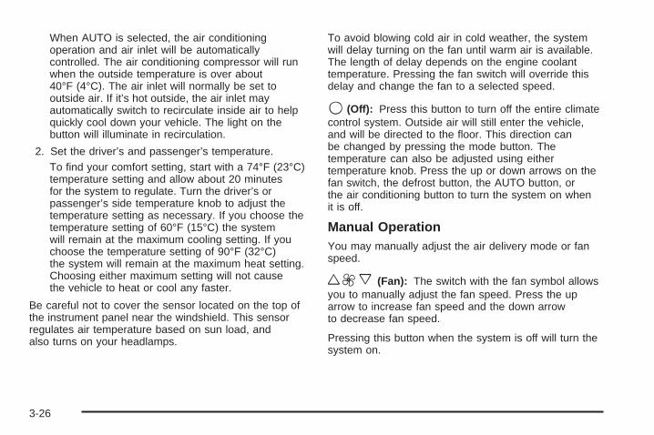
When AUTO is selected, the air conditioningoperation and air inlet will be automaticallycontrolled. The air conditioning compressor will runwhen the outside temperature is over about40°F (4°C). The air inlet will normally be set tooutside air. If it’s hot outside, the air inlet mayautomatically switch to recirculate inside air to helpquickly cool down your vehicle. The light on thebutton will illuminate in recirculation.
2. Set the driver’s and passenger’s temperature.To find your comfort setting, start with a 74°F (23°C)temperature setting and allow about 20 minutesfor the system to regulate. Turn the driver’s orpassenger’s side temperature knob to adjust thetemperature setting as necessary. If you choose thetemperature setting of 60°F (15°C) the systemwill remain at the maximum cooling setting. If youchoose the temperature setting of 90°F (32°C)the system will remain at the maximum heat setting.Choosing either maximum setting will not causethe vehicle to heat or cool any faster.
Be careful not to cover the sensor located on the top ofthe instrument panel near the windshield. This sensorregulates air temperature based on sun load, andalso turns on your headlamps.
To avoid blowing cold air in cold weather, the systemwill delay turning on the fan until warm air is available.The length of delay depends on the engine coolanttemperature. Pressing the fan switch will override thisdelay and change the fan to a selected speed.
9(Off): Press this button to turn off the entire climatecontrol system. Outside air will still enter the vehicle,and will be directed to the floor. This direction canbe changed by pressing the mode button. Thetemperature can also be adjusted using eithertemperature knob. Press the up or down arrows on thefan switch, the defrost button, the AUTO button, orthe air conditioning button to turn the system on whenit is off.
Manual OperationYou may manually adjust the air delivery mode or fanspeed.
w9x (Fan): The switch with the fan symbol allowsyou to manually adjust the fan speed. Press the uparrow to increase fan speed and the down arrowto decrease fan speed.
Pressing this button when the system is off will turn thesystem on.
3-26

C (Mode): Press this button to manually change thedirection of the airflow in your vehicle; keep pressing thebutton until the desired mode appears on the display.
If you press the mode button to select an air deliverymode, the display will change to show you the selectedair mode delivery. The display will then show thecurrent status of the system. When the system is turnedoff, the display will go blank after displaying thecurrent status of the system.
H (Panel): This setting will deliver air to theinstrument panel outlets.
)(Bi-Level): This setting will deliver warmer air to thefloor and cooler air to the instrument panel outlets.
6 (Floor): This setting will deliver air to the flooroutlets.
- (Defog): See “Defogging and Defrosting” later inthis section.
@(Recirculation): Press this button to limit theamount of outside air entering your vehicle. The light onthe recirculation button will glow. This is helpful when youare trying to limit odors entering your vehicle and formaximum air conditioning performance in hot weather.Press this button again to allow outside air to enter thevehicle. The light on the recirculation button will go off.
Pressing this button also cancels the auto recirculationfeature. To resume the auto recirculation function, pressthe AUTO button. Each time the vehicle is started, thesystem will revert to the auto recirculation function.
If you select recirculation while in defrost, defog or floor,the light in the button will flash and then go out to let youknow that this is not allowed. This is normal and helps toprevent fogging.
When the weather is cool or damp, operating the systemin recirculation for extended periods of time may causefogging of the vehicle’s windows. To clear the fog, selecteither defog or front defrost.
You may also notice that the A/C compressor will runwhile in recirculation mode. This is normal and helps toprevent fogging.
9(Off): Press this button to turn off the entire climatecontrol system. Outside air will still enter the vehicle, andwill be directed to the floor. This direction can be changedby pressing the mode button. The temperature can alsobe adjusted using either temperature knob. Press the upor down arrows on the fan switch, the defrost button, theAUTO button, or the air conditioning button to turn thesystem on when it is off.
3-27
DisplayIf you press the MODE button to select an air deliverymode, the display will change to show you the selectedair delivery mode. After 10 seconds, the display willchange to show the driver’s temperature setting and theselected mode.
If you press the up or down arrows on the fan switch,the display will change to show the selected fan speed.After 10 seconds, the display will change to show thedriver temperature setting and the selected mode.
Whenever you press AUTO, the display will change toshow the following:
• The current driver’s set temperature and an arrowfor five seconds
• The current passenger’s set temperature settingand an arrow for five seconds
• The automatic air delivery mode and fan speed
If the driver’s and passenger’s temperature settings arethe same when AUTO is pressed, the temperature settingand both arrows will be displayed for five seconds alongwith the automatic air delivery mode and fan speed. Afterthe five second update, the display will change to showthe temperature setting, both arrows and AUTO.
Air Conditioning
#(Air Conditioning): Press this button to turn theair conditioning (A/C) compressor on and off. Thesnowflake symbol will appear on the display when theA/C is on and will turn off when the air conditioning is off.
Pressing this button when the outside temperature istoo cool for air conditioning will make the snowflakesymbol flash three times and then turn off to letyou know the air conditioning mode is not available. Ifthe air conditioning is on and the outside temperaturedrops below a temperature which is too cool for airconditioning to be effective, the snowflake symbol willturn off to let you know the air conditioning modehas been canceled.
When air conditioning is selected or in AUTO mode,the system will run the air conditioning automaticallyto cool and dehumidify the air entering the vehicle.If you select A/C off while in front defrost, defogor recirculation, the A/C snowflake symbol will turn off,but the A/C compressor will still run to help preventfogging.
On hot days, open the windows long enough to let hotinside air escape. This reduces the time it takes foryour vehicle to cool down. Then keep your windowsclosed for the air conditioner to work its best.
3-28

On cool, but sunny days while using manual operationof the automatic system, use bi-level to deliver warmair to the floor and cooler air to the instrumentpanel outlets. To warm or cool the air delivered, turn thetemperature knob to the desired setting.
In AUTO mode the system will cool and dehumidify theair inside the vehicle. Also while in AUTO mode, thesystem will maximize its performance by usingrecirculation as necessary.
Defogging and DefrostingYou can use either defog or front defrost to clear fogor frost from your windshield. Use the defog modeto clear the windows of fog or moisture. Use the frontdefrost button to defrost the front windshield.
-(Defog): Use this setting to clear the windows offog or moisture. Press the mode button to selectthis setting. This setting will deliver air to the floorand windshield outlets.
0 (Defrost): Press the defrost button to defrost thewindshield. The system will automatically control the fanspeed if you select defrost from AUTO mode. If theoutside temperature is 40°F (4°C) or warmer, your airconditioning compressor will automatically run tohelp dehumidify the air and dry the windshield.
Rear Window DefoggerYour vehicle has this feature. The lines you seeon the rear window warm the glass. The rear windowdefogger uses a warming grid to remove fog fromthe rear window.
<(Rear): Press this button to turn the rear windowdefogger on or off. An indicator light in the buttonwill come on to let you know that the rear windowdefogger is activated.
The rear window defogger will turn off about 10 minutesafter the button is pressed. If you need additionalwarming time, press the button again.
Your vehicle is equipped with heated mirrors. Thisbutton will activate them.
Notice: Using a razor blade or sharp object toclear the inside rear window may damage the rearwindow defogger. Repairs would not be coveredby your warranty. Do not clear the inside of the rearwindow with sharp objects.
3-29

Outlet AdjustmentUse the air outlets located in the center and on the sideof your instrument panel to direct the airflow.
Operation Tips• Keep the hood and front air inlets free of ice, snow,
or any other obstruction (such as leaves). Theheater and defroster will work far better, reducingthe chance of fogging the inside of your windows.
• When you enter a vehicle in cold weather, turn thefan knob all the way to the right for a few momentsbefore driving. This helps clear the intake ductsof snow and moisture, and reduces the chance offogging the inside of your window.
• Keep the air path under the front seats clear ofobjects. This helps air to circulate throughoutyour vehicle.
• Adding outside equipment to the front of yourvehicle, such as hood-air deflectors, may affect theperformance of the heating and air conditioningsystem. Check with your dealer before addingequipment to the outside of your vehicle.
Rear Air Conditioning SystemIf your vehicle has the optional rear air conditioner, ithas two rear air conditioning fan speed selectors.One fan speed selector is located in the overheadconsole and the other is located in the headliner abovethe second row seats.
To increase and decrease the flow of cooled air to therear vents, turn the knob to the fan speed you want.
The knob has three speed positions. To increasethe flow of cooled air, turn the knob clockwise. Todecrease the flow of cooled air, turn it counterclockwise.To turn the fan off, turn the knob to the off position.
Front Control
3-30

To operate the rear system using the front control, justturn the knob to the fan position you want.
To use the rear control, first turn the front control to theAUX position. Then, the rear control can be used toincrease and decrease the airflow.
Rear Air Conditioning and HeatingSystemIf your vehicle is equipped with this system, there aretwo rear heat and air conditioning controls. One controlis located in the overhead console and the other islocated in the headliner above the second row seats.The system can be controlled from the front controls aswell as the rear controls.
The front control has three knobs that control airflowspeed, temperature and airflow location.
Rear Control
Front Control
3-31

Fan KnobThe fan knob on the left side of the control paneladjusts the fan speed. To increase airflow, turn the knobclockwise. To decrease airflow, turn it counterclockwise.To turn the fan off, turn the knob to the off position.
9 (Off): An off setting, located on the front climatecontrol panel also allows the driver to turn off therear seat passenger seat controls from the front seat.
Temperature KnobThe middle knob on the control panel lets you selectthe temperature of the air flowing into the passengerarea. Turn the knob clockwise toward the red area forwarmer air. Turn the knob counterclockwise towardthe blue area for cooler air.
Mode KnobThe right knob on the control panel allows you tochoose the direction of air delivery.
H (Vent): This setting directs the air through theheadliner outlets.
) (Bi-Level): Air is delivered through the floor outletsas well as the headliner outlets. The flow can bedivided between vent and floor outlets depending uponwhere the knob is placed between the settings.
6 (Floor): This setting directs most of the air throughthe floor outlets.
To use the rear control, first turn the front control to theAUX position. Then, the rear control can be used toadjust the airflow speed, temperature, and airflowlocation.
Rear Controls
3-32

Fan KnobThe fan knob on the left side of the control paneladjusts the fan speed. To increase airflow, turn the knobclockwise. To decrease airflow, turn it counterclockwise.To turn the fan off, turn the knob to the off position.
9(Off): Turn the knob to this position to turn the rearseat comfort controls on or off.
Temperature KnobThe middle knob on the control panel lets you select thetemperature of the air flowing into the passengerarea. Turn the knob clockwise toward the red area forwarmer air. Turn the knob counterclockwise towardthe blue area for cooler air.
Mode KnobThe right knob on the control panel allows you tochoose the direction of air delivery.
H (Vent): This setting directs the air through theheadliner outlets.
) (Bi-Level): Air is delivered through the floor outletsas well as the headliner outlets. The flow can bedivided between vent and floor outlets depending uponwhere the knob is placed between the settings.
6 (Floor): This setting directs most of the air throughthe floor outlets.
3-33

Rear Air Conditioning and HeatingSystem and Electronic ClimateControlsWith this system, the front or rear passengers cancontrol the air temperature, airflow and fan speed forthe rear seat passengers. The climate control hasan overhead control near the driver and a control onthe back of the center console.
Driver Overhead Control
To control the rear climate control from the front seatposition, use the driver overhead control. The rearconsole control must be on.
AUX: Turn the knob, located on the left side of thecontrol panel, to this position to allow the rear seatpassengers to have control over the rear climate controlsystem. See “Rear Passenger Console Control” laterfor more information.
9 (Off): Turn the knob, located on the left side of thecontrol panel, to this position to turn the rear climatecontrol system off.
9(Fan): To adjust the airflow speed, turn the fanknob located on the left side of the control panel to thedesired setting. Choose AUTO if you want the systemto automatically choose the fan speed to maintaina selected temperature. See “Auto Mode” later in thissection for more information on using this feature.
°F (°C): To adjust the air temperature, turn thetemperature knob on the center of the control panel. Forcooler or warmer air, turn the knob counterclockwisetoward 66°F (19°C) or clockwise toward 82°F (27°C).
To regulate the airflow direction, adjust the right knob onthe control panel. Turn the knob clockwise for floorvent airflow or counterclockwise for headliner ventairflow. Generally, the upper vents are used for airconditioning and the floor vents for heating. The knobcan be set to any blend setting. Choose AUTO ifyou want the system to automatically regulate theairflow. See “Auto Mode” later in this section for moreinformation on using this feature.
Front Controls - United States shown,Canada similar
3-34

Rear Passenger Console ControlTo control the rear climate control from the rearpassenger seat position, use the rear passenger consolecontrol. The driver overhead control fan knob must beset to the AUX position.
The rear seat controls have the following settings:
O (On/Off): Press this button to turn the rear seatcomfort controls on or off when the front overheadcontrol is set to AUX.
%(Mode): Press this button to select the air deliverymode and AUTO mode. Choose AUTO if you wantthe system to automatically regulate the airflow.See “Auto Mode” later in this section for moreinformation on using this feature.
b (Temperature): Press this button up or down toincrease or decrease the temperature setting.
w9x(Fan): Press this button up or down to adjustthe fan speed. Choose AUTO if you want the systemto automatically choose the fan speed to maintaina selected temperature. See “Auto Mode” following formore information on using this feature.
AUTO ModeWhen using the system in auto mode, find yourcomfort setting by placing the temperature control to74°F (23°C) and allowing about 20 minutes for thesystem to regulate. Then adjust the temperature settingas necessary. If you choose full cold 60° F (15°C),the system will remain at the maximum cooling setting.If you choose full hot 90°F (32°C), the system willremain at the maximum heat setting.
Rear Controls
3-35

Warning Lights, Gages, andIndicatorsThis part describes the warning lights and gages that maybe on your vehicle. The pictures will help you locate them.
Warning lights and gages can signal that something iswrong before it becomes serious enough to causean expensive repair or replacement. Paying attention toyour warning lights and gages could also save youor others from injury.
Warning lights come on when there may be or is aproblem with one of your vehicle’s functions. As youwill see in the details on the next few pages, somewarning lights come on briefly when you start the enginejust to let you know they’re working. If you are familiarwith this section, you should not be alarmed whenthis happens.
Gages can indicate when there may be or is a problemwith one of your vehicle’s functions. Often gagesand warning lights work together to let you know whenthere’s a problem with your vehicle.
When one of the warning lights comes on and stays onwhen you are driving, or when one of the gagesshows there may be a problem, check the section thattells you what to do about it. Please follow thismanual’s advice. Waiting to do repairs can becostly – and even dangerous. So please get to knowyour warning lights and gages. They’re a big help.
Your vehicle also has a driver information system thatworks along with the warning lights and gages. SeeDriver Information Center (DIC) on page 3-54.
3-36
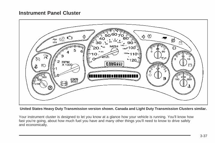
Instrument Panel Cluster
Your instrument cluster is designed to let you know at a glance how your vehicle is running. You’ll know howfast you’re going, about how much fuel you have and many other things you’ll need to know to drive safelyand economically.
United States Heavy Duty Transmission version shown. Canada and Light Duty Transmission Clusters similar.
3-37

Speedometer and OdometerYour speedometer lets you see your speed in bothmiles per hour (mph) and kilometers per hour (km/h).Your odometer shows how far your vehicle hasbeen driven, in either miles (used in the United States)or kilometers (used in Canada).
Engine Hour Meter DisplayThe Driver Information Center (DIC) can also displaythe number of hours the engine has run. To display theengine hours, turn the ignition off, press and hold thereset button for at least four seconds. The hourmeter will be displayed for up to 30 seconds, or until theignition is turned on. See DIC Operation and Displayson page 3-55 for more information.
Trip OdometerThe trip odometer can tell you how far your vehiclehas been driven since you last set the trip odometerto zero.
Press the reset button, located on the instrument panelcluster next to the trip odometer display, to togglebetween the trip odometer and the regular odometer.Holding the reset button for approximately one secondwhile the trip odometer is displayed will reset it.
To display the odometer reading with the ignition off,press the reset button. See DIC Operation and Displayson page 3-55 for more information.
TachometerYour tachometer displays the engine speed inrevolutions per minute (rpm).
3-38

Safety Belt Reminder LightWhen the key is turned to RUN or START, a chime willbe provided for several seconds to remind people tobuckle their safety belts. The driver safety belt light willalso be provided and stay on for several seconds,then it will flash for several more. You should buckleyour seat belt.
If your vehicle is notequipped with thepassenger sensing system,this chime and light will berepeated if the driverremains unbuckled andthe vehicle is in motion.
See Passenger Sensing System on page 1-75 for moreinformation.
If the driver’s belt is buckled, neither the chime nor thelight will come on.
Airbag Readiness LightThere is an airbag readiness light on the instrumentpanel cluster, which shows the airbag symbol. Thesystem checks the airbag’s electrical system formalfunctions. The light tells you if there is an electricalproblem. The system check includes the airbagsensors, the airbag modules, the passenger sensingsystem (if equipped), the wiring and the crash sensingand diagnostic module. For more information on theairbag system, see Airbag System on page 1-66.
This light will come onwhen you start yourvehicle, and it will flashfor a few seconds.This means the systemis ready.
If the airbag readiness light stays on after you startthe vehicle or comes on when you are driving,your airbag system may not work properly.Have your vehicle serviced right away.
3-39

Passenger Airbag Status IndicatorIf your vehicle has a passenger sensing system,your rearview mirror will have a passenger airbagstatus indicator.
When the ignition key is turned to RUN or START, thepassenger airbag status indicator will light ON andOFF, or the symbol for on and off, for several secondsas a system check. Then, after several more seconds,the status indicator will light either ON or OFF, or eitherthe on or off symbol to let you know the status of theright front passenger’s frontal airbag.
If the word ON or the on symbol is lit on the passengerairbag status indicator, it means that the right frontpassenger’s frontal airbag is enabled (may inflate).
{CAUTION:
If the on indicator comes on when you have arear-facing child restraint installed in the rightfront passenger’s seat, it means that thepassenger sensing system has not turned offthe passenger’s frontal airbag. A child in arear-facing child restraint can be seriouslyinjured or killed if the right front passenger’sairbag inflates. This is because the back of therear-facing child restraint would be very closeto the inflating airbag. Do not use a rear-facingchild restraint in the right front passenger’sseat if the airbag is turned on.
Passenger Airbag Status Indicator – United States
Passenger Airbag Status Indicator – Canada
3-40

Your vehicle has a rear seat that will accommodate arear-facing child restraint. A label on your sun visor says,“Never put a rear-facing child seat in the front.” Thisis because the risk to the rear-facing child is so great,if the airbg deploys.
{CAUTION:
Even though the passenger sensing system isdesigned to turn off the passenger’s frontalairbag if the system detects a rear-facing childrestraint, no system is failsafe, and no one canguarantee that an airbag will not deploy undersome unusual circumstance, even though it isturned off. General Motors recommends thatrear-facing child restraints be secured in therear seat, even if the airbag is off.
If the word OFF or the off symbol is lit on the airbagstatus indicator, it means that the passenger sensingsystem has turned off the right front passenger’s frontalairbag. See Passenger Sensing System on page 1-75for more on this, including important safety information.
If, after several seconds, all status indicator lightsremain on, or if there are no lights at all, there may bea problem with the lights or the passenger sensingsystem. See your dealer for service.
{CAUTION:
If the off indicator and the airbag readinesslight ever come on together, it means thatsomething may be wrong with the airbagsystem. If this ever happens, have the vehicleserviced promptly, because an adult-sizeperson sitting in the right front passenger seatmay not have the protection of the frontalairbag. See Airbag Readiness Light onpage 3-39.
3-41
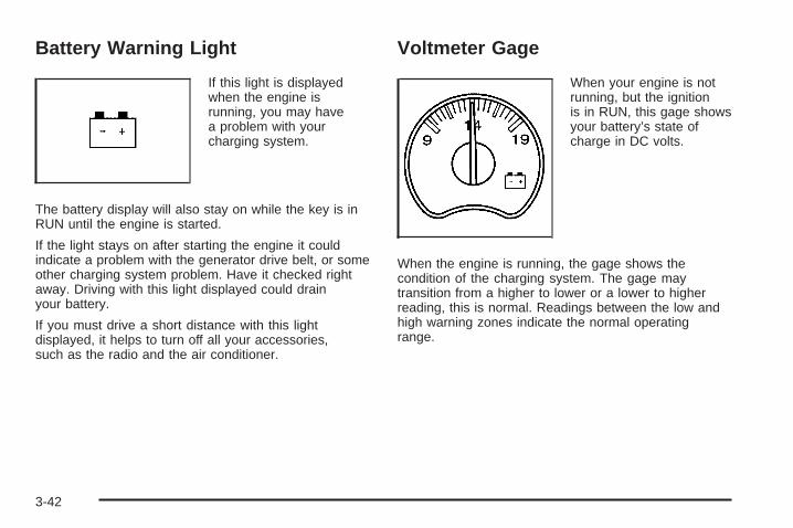
Battery Warning Light
If this light is displayedwhen the engine isrunning, you may havea problem with yourcharging system.
The battery display will also stay on while the key is inRUN until the engine is started.
If the light stays on after starting the engine it couldindicate a problem with the generator drive belt, or someother charging system problem. Have it checked rightaway. Driving with this light displayed could drainyour battery.
If you must drive a short distance with this lightdisplayed, it helps to turn off all your accessories,such as the radio and the air conditioner.
Voltmeter Gage
When your engine is notrunning, but the ignitionis in RUN, this gage showsyour battery’s state ofcharge in DC volts.
When the engine is running, the gage shows thecondition of the charging system. The gage maytransition from a higher to lower or a lower to higherreading, this is normal. Readings between the low andhigh warning zones indicate the normal operatingrange.
3-42

Readings in the low warning zone may occur when alarge number of electrical accessories are operating inthe vehicle and the engine is left at an idle for anextended period. This condition is normal since thecharging system is not able to provide full powerat engine idle. As engine speeds are increased, thiscondition should correct itself as higher engine speedsallow the charging system to create maximum power.
You can only drive for a short time with the readingin either warning zone. If you must drive, turn offall unnecessary accessories.
Readings in either warning zone indicate a possibleproblem in the electrical system. Have the vehicleserviced as soon as possible.
Brake System Warning LightWith the ignition on, the brake system warning lightwill flash when you set the parking brake. The light willflash if the parking brake doesn’t release fully. If youtry to drive with the parking brake engaged, a chimewill sound when the vehicle speed is greater than3 mph (5 km/h).
Your vehicle’s hydraulic brake system is divided intotwo parts. If one part isn’t working, the other part canstill work and stop you. For good braking, though,you need both parts working well.
If the warning light comes on and a chime sounds therecould be a brake problem. Have your brake systeminspected right away.
This light should come on briefly when you turn theignition key to RUN. If it doesn’t come on then, haveit fixed so it will be ready to warn you if there’s aproblem.
United States Canada
3-43

If the light comes on while you are driving, pull off theroad and stop carefully. You may notice that the pedal isharder to push or may go closer to the floor. It maytake longer to stop. If the light is still on, have the vehicletowed for service. See Towing Your Vehicle onpage 4-62.
{CAUTION:
Your brake system may not be workingproperly if the brake system warning light ison. Driving with the brake system warning lighton can lead to an accident. If the light is stillon after you have pulled off the road andstopped carefully, have the vehicle towed forservice.
Anti-Lock Brake System WarningLight
With the anti-lock brakesystem, this light will comeon when you start yourengine and may stay onfor several seconds.
That’s normal. If the light doesn’t come on then, haveit fixed so it will be ready to warn you if there is aproblem.
If the light stays on, or comes on when you’re driving,your vehicle needs service. You will also hear achime sound when the light is on steady. If the regularbrake system warning light isn’t on, you still havebrakes, but you don’t have anti-lock brakes. If theregular brake system warning light is also on you don’thave anti-lock brakes and there’s a problem withyour regular brakes. In addition to both lights, you willalso hear a chime sound on the first occurrence ofa problem and each time the vehicle is shut off andthen restarted. See Brake System Warning Lighton page 3-43.
3-44

Traction Off Light
If you have the TractionAssist System, this lightshould come on brieflywhen you turn the ignitionto RUN.
If the light doesn’t come on then, the system mayrequire service; have it fixed so it will be there to warnyou if the system is turned off.
If the light stays on, or comes on when you’re driving,there may be a problem with your Traction AssistSystem and your vehicle may need service. When thislight is on, the system will not limit wheel spin. Adjustyour driving accordingly.
The traction off light may come on for the followingreasons:
• If you turn the system off by pressing the TASon/off button located to the left of the steering wheel,the light will come on and stay on. To turn thesystem back on, press the button again; the lightshould go off.
• If you move the shift lever to FIRST (1), the lightwill come on and stay on to indicate that thetraction system is off. This is normal operation.To turn the system back on, move the shift leverback to a position other than FIRST (1); thelight should go off. See Traction Assist System(TAS) on page 4-8.
• The light will come on and stay on if the TASautomatic engagement feature has been turned off.To turn the system on, press the TAS off/onbutton; the light should go off. To turn the automaticengagement feature back on, see Traction AssistSystem (TAS) on page 4-8.
• If the Traction Assist System is affected by ananti-lock brake system, TAS or engine-relatedproblem, the system will turn off and the light willcome on. Have your vehicle serviced.
• If the vehicle is driven over an extremely rough road,the system will turn off and the light will come on. Thelight will go off a few seconds after the rough roadconditions go away or when the vehicle comes to acomplete stop. This is normal operation.
3-45

Engine Coolant Temperature Gage
This gage shows the engine coolant temperature.
It also provides an indicator of how hard your vehicle isworking. During a majority of the operation, the gagewill read 210°F (100°C) or less. If you are pulling a loador going up hills, it is normal for the temperature tofluctuate and approach the 250°F (122°C) mark. If thegage reaches the 260°F (125°C) mark, it indicatesthat the cooling system is working beyond its capacity.
See Engine Overheating on page 5-27.
Transmission Temperature Gage
Your vehicle may be equipped with a transmissiontemperature gage.
When your ignition is on, the gage shows thetemperature of the transmission fluid. The normaloperating range is from 180°F to 200°F (82°C to 93°C).
At approximately 265°F (130°C), the message centerwill display a TRANSMISSION HOT message andthe transmission will enter a transmission protectionmode. When the transmission enters the protectionmode, you may notice a change in the transmissionshifting patterns. The transmission will return to normalshifting patterns when the transmission fluid temperaturefalls below 260°F (127°C).
United States Canada United States Canada
3-46

See Driver Information Center (DIC) on page 3-54 forfurther information.
If the transmission fluid reaches temperatures ofapproximately 275°F (135°C) or greater, the DriverInformation Center will display a TRANS HOT IDLEENGINE warning message, and a chime will sound.Pull the vehicle off the roadway when it is safe to doso. Set the parking brake, place the transmissionin PARK (P) and allow the engine to idle until thetransmission temperature falls below 260°F (127°C).If the transmission continues to operate above265°F (130°C), contact your nearest dealer or theGM Roadside Assistance Center. See RoadsideAssistance Program on page 7-5.
Notice: If you drive your vehicle with thetransmission temperature gage above normaloperating range, you can damage the transmission.This could lead to costly repairs that would notbe covered by your warranty. Do not drive yourvehicle while the transmission temperature gagereading is above normal. See your dealer for service.
The following situations can cause the transmission tooperate at higher temperatures:
• Towing a trailer
• Hot outside air temperatures
• Hauling a large or heavy load
• Vehicle overloading
• Low transmission fluid level
• High transmission fluid level
• Restricted air flow to the radiator and the auxiliarytransmission oil cooler (if equipped).
A temporary solution to hotter transmission operatingtemperatures may be to let the transmission cool down.If the transmission is operated at higher temperatureson a frequent basis, see Scheduled Maintenanceon page 6-4 for the proper transmission maintenanceintervals.
3-47

Tire Pressure Light
If your vehicle is equippedwith the Tire PressureMonitor system, this lightwill come on if thesystem detects low tirepressure.
A CHECK TIRE PRESSURE DIC message willaccompany the light.
This light will also come on for a bulb check when thevehicle is started.
See Tire Pressure Monitor System on page 5-65 formore information.
For more information on your tires, see Tires onpage 5-57.
Malfunction Indicator LampCheck Engine Light
Your vehicle is equippedwith a computer whichmonitors operation of thefuel, ignition, and emissioncontrol systems.
This system is called OBD II (On-BoardDiagnostics-Second Generation) and is intended toassure that emissions are at acceptable levels for thelife of the vehicle, helping to produce a cleanerenvironment. The check engine light comes on toindicate that there is a problem and service is required.Malfunctions often will be indicated by the systembefore any problem is apparent. This may prevent moreserious damage to your vehicle. This system is alsodesigned to assist your service technician in correctlydiagnosing any malfunction.
Notice: If you keep driving your vehicle with thislight on, after awhile, your emission controls may notwork as well, your fuel economy may not be as good,and your engine may not run as smoothly. This couldlead to costly repairs that may not be covered byyour warranty.
3-48

Notice: Modifications made to the engine,transmission, exhaust, intake, or fuel system ofyour vehicle or the replacement of the original tireswith other than those of the same Tire PerformanceCriteria (TPC) can affect your vehicle’s emissioncontrols and may cause this light to come on.Modifications to these systems could lead to costlyrepairs not covered by your warranty. This mayalso result in a failure to pass a required EmissionInspection/Maintenance test.
This light should come on, as a check to show you itis working, when the ignition is on and the engine is notrunning. If the light does not come on, have it repaired.This light will also come on during a malfunction inone of two ways:
• Light Flashing — A misfire condition has beendetected. A misfire increases vehicle emissionsand may damage the emission control system onyour vehicle. Diagnosis and service may berequired.
• Light On Steady — An emission control systemmalfunction has been detected on your vehicle.Diagnosis and service may be required.
If the Light is FlashingThe following may prevent more serious damage toyour vehicle:
• Reducing vehicle speed
• Avoiding hard accelerations
• Avoiding steep uphill grades
• If you are towing a trailer, reduce the amount ofcargo being hauled as soon as it is possible
If the light stops flashing and remains on steady, see“If the Light Is On Steady” following.
If the light continues to flash, when it is safe to do so,stop the vehicle. Find a safe place to park your vehicle.Turn the key off, wait at least 10 seconds and restartthe engine. If the light remains on steady, see “Ifthe Light Is On Steady” following. If the light is stillflashing, follow the previous steps, and see your dealerfor service as soon as possible.
3-49

If the Light Is On SteadyYou may be able to correct the emission systemmalfunction by considering the following:
Did you recently put fuel into your vehicle?
If so, reinstall the fuel cap, making sure to fully installthe cap. See Filling the Tank on page 5-8. Thediagnostic system can determine if the fuel cap hasbeen left off or improperly installed. A loose or missingfuel cap will allow fuel to evaporate into the atmosphere.A few driving trips with the cap properly installedshould turn the light off.
Did you just drive through a deep puddle of water?
If so, your electrical system may be wet. The conditionwill usually be corrected when the electrical systemdries out. A few driving trips should turn the light off.
Have you recently changed brands of fuel?
If so, be sure to fuel your vehicle with quality fuel. SeeGasoline Octane on page 5-5. Poor fuel quality willcause your engine not to run as efficiently as designed.You may notice this as stalling after start-up, stallingwhen you put the vehicle into gear, misfiring, hesitationon acceleration, or stumbling on acceleration. (Theseconditions may go away once the engine is warmed up.)This will be detected by the system and cause thelight to turn on.
If you experience one or more of these conditions,change the fuel brand you use. It will require at leastone full tank of the proper fuel to turn the light off.If none of the above steps have made the light turn off,your dealer can check the vehicle. Your dealer hasthe proper test equipment and diagnostic tools to fix anymechanical or electrical problems that may havedeveloped.
Emissions Inspection and MaintenanceProgramsSome state/provincial and local governments have ormay begin programs to inspect the emission controlequipment on your vehicle. Failure to pass this inspectioncould prevent you from getting a vehicle registration.Here are some things you need to know to help yourvehicle pass an inspection:Your vehicle will not pass this inspection if the checkengine light is on or not working properly.Your vehicle will not pass this inspection if the OBD(on-board diagnostic) system determines that criticalemission control systems have not been completelydiagnosed by the system. The vehicle would beconsidered not ready for inspection. This can happen ifyou have recently replaced your battery or if your batteryhas run down. The diagnostic system is designed toevaluate critical emission control systems during normaldriving. This may take several days of routine driving.
3-50

If you have done this and your vehicle still does not passthe inspection for lack of OBD system readiness, yourGM dealer can prepare the vehicle for inspection.
Oil Pressure Gage
The oil pressure gage shows the engine oil pressurein psi (pounds per square inch) when the engineis running. Canadian vehicles indicate pressure inkPa (kilopascals).
Oil pressure may vary with engine speed, outsidetemperature and oil viscosity, but readings above thelow pressure zone indicate the normal operating range.
A reading in the low pressure zone may be caused bya dangerously low oil level or some other problemcausing low oil pressure. Check your oil as soon aspossible. See “OIL PRESSURE LOW” under DICWarnings and Messages on page 3-58 and Engine Oilon page 5-15.
{CAUTION:
Do not keep driving if the oil pressure is low.If you do, your engine can become so hot thatit catches fire. You or others could be burned.Check your oil as soon as possible and haveyour vehicle serviced.
Notice: Lack of proper engine oil maintenancemay damage the engine. The repairs would notbe covered by your warranty. Always followthe maintenance schedule in this manual forchanging engine oil.
United States Canada
3-51

Security Light
This light flashes when thevehicle security system isactivated.
Cruise Control Light
This light comes onwhenever you set yourcruise control.
The light will go out when the cruise control is turnedoff. See Cruise Control on page 3-11 for moreinformation.
Highbeam On Light
This light will come onwhen the high-beamheadlamps are in use.
See Headlamp High/Low-Beam Changer on page 3-8.
Four-Wheel-Drive Light
The four-wheel-driveindicator will light up whenthe vehicle is in four-wheeldrive.
See Four-Wheel Drive on page 2-27 for moreinformation.
3-52

Tow/Haul Mode LightThis light is displayedwhen the Tow/Haul modehas been activated.
For more information, see Towing a Trailer onpage 4-67.
Fuel Gage
The fuel gage, when the ignition is on, tells you abouthow much fuel you have left in your tank.
The gage will first indicate empty before you are out offuel, and you should get more fuel as soon as possible.
When the fuel tank is low, the FUEL LEVEL LOWmessage will appear. See Driver Information Center(DIC) on page 3-54.
Here are some situations you may experience with yourfuel gage. None of these indicate a problem with thefuel gage.
• At the gas station, the fuel pump shuts off beforethe gage reads full.
• It takes a little more or less fuel to fill up than thefuel gage indicated. For example, the gage mayhave indicated the tank was half full, but it actuallytook a little more or less than half the tank’scapacity to fill the tank.
• The gage goes back to empty when you turn off theignition.
Low Fuel Warning LightThe light next to the fuel gage will come on briefly whenyou are starting the engine.
This light comes on when the fuel tank is low on fuel.To turn it off, add fuel to the fuel tank. See Fuel onpage 5-5.United States Canada
3-53

Driver Information Center (DIC)The Driver Information Center (DIC) display is locatedon the instrument panel cluster, below the speedometer.The DIC buttons, if equipped, are located on thesteering wheel. The DIC can display information suchas the trip odometer, fuel economy, customizationfeatures and warning/status messages.
If your vehicle is not equipped with the DIC steeringwheel buttons, you will not have all of the features listed.You will scroll through the odometer, trip odometerand engine hours by pressing the trip odometer resetstem located on the instrument panel cluster. Youwill also turn off, or acknowledge, DIC messages bypressing the trip odometer reset stem. See Speedometerand Odometer on page 3-38 for information onfeatures for vehicles without DIC buttons.
A 3 (Trip Information): Press this button to displaythe odometer, trip odometers, tire pressure for vehiclesequipped with a tire pressure monitor, timer andengine hours.
B r (Fuel Information): Press this button to displaythe current range, fuel used, average fuel economy andengine oil life.
C 4 (Customization): Press this button to access thevehicle settings menu and customize the personalsettings on your vehicle.
D r (Select): Press this button to reset certain DICfunctions and set your customization settings.
Pressing any of the four DIC buttons will acknowledgeDIC messages and clear them from the DIC display.
3-54
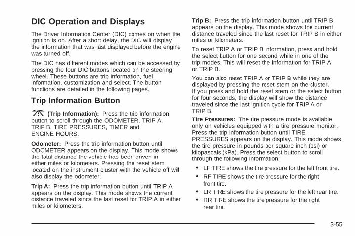
DIC Operation and DisplaysThe Driver Information Center (DIC) comes on when theignition is on. After a short delay, the DIC will displaythe information that was last displayed before the enginewas turned off.
The DIC has different modes which can be accessed bypressing the four DIC buttons located on the steeringwheel. These buttons are trip information, fuelinformation, customization and select. The buttonfunctions are detailed in the following pages.
Trip Information Button
3 (Trip Information): Press the trip informationbutton to scroll through the ODOMETER, TRIP A,TRIP B, TIRE PRESSURES, TIMER andENGINE HOURS.
Odometer: Press the trip information button untilODOMETER appears on the display. This mode showsthe total distance the vehicle has been driven ineither miles or kilometers. Pressing the reset stemlocated on the instrument cluster with the vehicle off willalso display the odometer.
Trip A: Press the trip information button until TRIP Aappears on the display. This mode shows the currentdistance traveled since the last reset for TRIP A in eithermiles or kilometers.
Trip B: Press the trip information button until TRIP Bappears on the display. This mode shows the currentdistance traveled since the last reset for TRIP B in eithermiles or kilometers.
To reset TRIP A or TRIP B information, press and holdthe select button for one second while in one of thetrip modes. This will reset the information for TRIP Aor TRIP B.
You can also reset TRIP A or TRIP B while they aredisplayed by pressing the reset stem on the cluster.If you press and hold the reset stem or the select buttonfor four seconds, the display will show the distancetraveled since the last ignition cycle for TRIP A orTRIP B.Tire Pressures: The tire pressure mode is availableonly on vehicles equipped with a tire pressure monitor.Press the trip information button until TIREPRESSURES appears on the display. This mode showsthe tire pressure in pounds per square inch (psi) orkilopascals (kPa). Press the select button to scrollthrough the following information:
• LF TIRE shows the tire pressure for the left front tire.• RF TIRE shows the tire pressure for the right
front tire.• LR TIRE shows the tire pressure for the left rear tire.• RR TIRE shows the tire pressure for the right
rear tire.
3-55

Timer: The DIC can be used as a timer. Press theselect button while TIMER is displayed to start the timer.The display will show the amount of time that haspassed since the timer was last reset, not including timethe ignition is off. Time will continue to be counted aslong as the ignition is on, even if another display is beingshown on the DIC. The timer will record up to 99 hours,59 minutes and 59 seconds (99:59:59) after whichthe display will roll back to zero.
To stop the counting of time, press the select buttonbriefly while TIMER is displayed.
To reset the timer to zero, press and hold the selectbutton while TIMER is displayed.
Engine Hours: Press the trip information button untilENGINE HOURS appears on the display. Thismode shows the total number of hours the engine hasrun. Pressing and holding the reset stem located onthe instrument cluster for about four seconds will alsodisplay the engine hour information after the odometer isdisplayed when the vehicle is off.
Fuel Information Button
t (Fuel Information): Press the fuel informationbutton to scroll through the range, fuel used, averagefuel economy and the engine oil life system.
Fuel Range: Press the fuel information button untilRANGE appears on the display. This mode shows theremaining distance you can drive without refueling.It is based on fuel economy and the fuel remaining inthe tank. The display will show LOW if the fuel levelis low.
The fuel economy data used to determine fuel range isan average of recent driving conditions. As yourdriving conditions change, this data is gradually updated.Fuel range cannot be reset.
Fuel Used: Press the fuel information button untilFUEL USED appears on the display. This mode showsthe number of gallons or liters of fuel used since thelast reset of this menu item. To reset the fuel usedinformation, press and hold the select button for onesecond while FUEL USED is displayed.
3-56

Average Fuel Economy: Press the fuel informationbutton until AVG ECON appears on the display.This mode shows how many miles per gallon (MPG) orliters per 100 kilometers (L/100 km) your vehicle isgetting based on current and past driving conditions.
Press and hold the select button for one secondwhile AVG ECON is displayed to reset the average fueleconomy. Average fuel economy will then be calculatedstarting from that point. If the average fuel economyis not reset, it will be continually updated each timeyou drive.
Engine Oil Life System: Press the fuel informationbutton until ENGINE OIL LIFE appears on the display.The engine oil life system shows an estimate of theoil’s remaining useful life. It will show 100% when thesystem is reset after an oil change. It will alert youto change your oil on a schedule consistent with yourdriving conditions.
Always reset the engine oil life system after an oilchange. To reset the engine oil life system, use thefuel button to reach the ENGINE OIL LIFE screen andthen press and hold the select button for five secondswhile ENGINE OIL LIFE is displayed. OIL LIFE RESETwill appear on the display for 10 seconds to let youknow that the system is reset. See Engine Oil LifeSystem on page 5-18 for more information.
In addition to the engine oil life system monitoring theoil life, additional maintenance is recommended inthe Maintenance Schedule in this manual. See EngineOil on page 5-15 and Scheduled Maintenance onpage 6-4.
Customization Button
4 (Customization): Press the customization button toaccess the VEHICLE SETTINGS menu and customizethe settings to your vehicle. See DIC VehicleCustomization on page 3-68 for more information.
Select Button
r (Select): Press the select button to reset certainDIC functions and set your customization settings.For example, this button will reset the trip odometersand scroll through the languages in which you can selectthe DIC to display information.
3-57
DIC Warnings and MessagesWarning messages are displayed on the DriverInformation Center (DIC) to notify the driver that thestatus of the vehicle has changed and that some actionmay be needed by the driver to correct the condition.If there is more than one message that needs tobe displayed, they will appear one after another. Somemessages may not require immediate action, butyou should press any of the four DIC buttons on thesteering wheel, if equipped, to acknowledge thatyou received the messages and clear them from thedisplay. If your vehicle is not equipped with DIC buttonson the steering wheel, press the trip odometer resetstem located on the instrument panel cluster toacknowledge messages and clear them from the display.Some messages cannot be cleared from the displaybecause they are more urgent. These messages requireaction before they can be removed from the DICdisplay. You should take any messages that appear onthe display seriously and remember that clearing themessages will only make the messages disappear, notcorrect the problem. The following are the possiblemessages that can be displayed and some informationabout them.
BATTERY NOT CHARGINGOn some vehicles, if the battery is not charging duringoperation, this message will appear on the DIC.Driving with this problem could drain your battery.Have the electrical system checked by your GM dealeras soon as possible. See Battery Warning Light onpage 3-42 and Voltmeter Gage on page 3-42.Pressing any of the four DIC buttons, if equipped, willacknowledge the message and clear it from theDIC display. If your vehicle is not equipped with thefour DIC buttons, pressing the trip odometer reset stemwill acknowledge the message and clear it from theDIC display.
BUCKLE PASSENGERIf your vehicle is equipped with the passenger sensingsystem, this message reminds you to buckle thepassenger’s seat belt. See Passenger Sensing Systemon page 1-75.
This message will display and a chime will soundwhen the ignition is on, the driver’s seat belt is buckled,the passenger’s seat belt is unbuckled with thepassenger airbag enabled and the vehicle is inmotion. You should have the passenger buckle theirseat belt.
3-58

This reminder will be repeated if the ignition is on, thevehicle is in motion, the driver is buckled and thepassenger is still unbuckled and the passenger airbagis enabled. If the passenger’s seat belt is alreadybuckled, this message and chime will not come on.
Pressing any of the four DIC buttons, if equipped, willacknowledge the message and clear it from theDIC display. If your vehicle is not equipped with thefour DIC buttons, pressing the trip odometer reset stemwill acknowledge the message and clear it from theDIC display.
BUCKLE SEATBELTIf your vehicle is equipped with the passenger sensingsystem, this message reminds you to buckle thedriver’s seat belt. See Passenger Sensing System onpage 1-75.
This message will display and a chime will sound whenthe ignition is on, the driver’s seat belt is unbuckledand the vehicle is in motion. You should buckleyour seat belt.
If the driver remains unbuckled when the ignition is onand the vehicle is in motion, the reminder will berepeated. If the driver’s seat belt is already buckled,this message and chime will not come on.
This message is an additional reminder to the SafetyBelt Reminder Light in the instrument panel cluster. SeeSafety Belt Reminder Light on page 3-39.
Pressing any of the four DIC buttons, if equipped, willacknowledge the message and clear it from theDIC display. If your vehicle is not equipped with the fourDIC buttons, pressing the trip odometer reset stemwill acknowledge the message and clear it from theDIC display.
CHANGE ENGINE OILThis message is displayed when the engine oil needs tobe changed.
When you change the engine oil, be sure to reset theCHANGE ENGINE OIL message. This messagewill clear itself after 10 seconds until the next ignitioncycle or until the message is reset. See Engine Oilon page 5-15 and Scheduled Maintenance on page 6-4for more information.
3-59

CHARGING SYSTEM FAILUREOn some vehicles, if there is a problem with thegenerator and battery charging system, this messagewill appear on the DIC, a chime will sound and thebattery warning light on the instrument panel cluster willcome on. Driving with this problem could drain yourbattery. Turn off all unnecessary accessories. Stop andturn off the vehicle as soon as it is safe to do so.Have the electrical system checked by your GM dealerimmediately. See Battery Warning Light on page 3-42and Voltmeter Gage on page 3-42 for more information.
CHECK OIL LEVELIf your vehicle is equipped with an oil level sensor andthe oil level in the vehicle is low, this message willappear on the DIC. Check the oil level and correct it asnecessary. You may need to let the vehicle cool orwarm up and cycle the ignition to be sure this messagewill clear. The message will clear itself after 10 seconds,until the next ignition cycle. Once the problem iscorrected, pressing any of the four DIC buttons, ifequipped, will acknowledge the message and clear itfrom the DIC display. If your vehicle is not equipped withthe four DIC buttons, pressing the trip odometer resetstem will acknowledge the message and clear it from theDIC display.
CHECK TIRE PRESSUREIf your vehicle is equipped with the Tire PressureMonitor System and a low tire pressure is detected inany of the vehicle’s tires, this message will appearon the DIC, along with a chime. Pressing any of the fourDIC buttons, if equipped, will acknowledge themessage and clear it from the DIC display. If yourvehicle is not equipped with the four DIC buttons,pressing the trip odometer reset stem will acknowledgethe message and clear it from the DIC display. It willappear at each ignition cycle until the tires are inflated tothe correct inflation pressure.
CHECK WASHER FLUIDIf the washer fluid level is low, this message will appearon the DIC. Adding washer fluid will clear the message.See Windshield Washer Fluid on page 5-36. Pressingany of the four DIC buttons, if equipped, willacknowledge the message and clear it from the DICdisplay. If your vehicle is not equipped with the four DICbuttons, pressing the trip odometer reset stem willacknowledge the message and clear it from the DICdisplay. The message will clear itself after 10 seconds oruntil the next ignition cycle.
3-60

DRIVER DOOR AJARIf the driver’s door is not fully closed, this message willappear on the display and you will hear a chime.Stop and turn off the vehicle, check the door forobstacles and close the door again. Check to see if themessage still appears on the DIC. Pressing any ofthe four DIC buttons, if equipped, will acknowledge themessage and clear it from the DIC display. If yourvehicle is not equipped with the four DIC buttons,pressing the trip odometer reset stem will acknowledgethe message and clear it from the DIC display.
ENGINE COOLANT HOTIf the cooling system temperature gets hot, this messagewill appear in the DIC. Turn off the air conditioning.If the message is still on, or if the engine coolanttemperature gage continues to rise, pull the vehicle overwhen it is safe to do so. See Engine CoolantTemperature Gage on page 3-46 for more information.Stop the vehicle and let the engine idle in PARK (P)to allow the coolant to reach a safe temperature. Thismessage will clear when the coolant temperaturedrops to safe operating temperature. Pressing any ofthe four DIC buttons, if equipped, will acknowledge themessage and clear it from the DIC display. If yourvehicle is not equipped with the four DIC buttons,pressing the trip odometer reset stem will acknowledgethe message and clear it from the DIC display.
ENGINE OVERHEATEDIf the engine cooling system reaches unsafetemperatures for operation, this message will appear inthe DIC and you will hear a chime. Stop and turn offthe vehicle as soon as it is safe to do so to avoid severedamage. The message will clear when the engine hascooled to a safe operating temperature.
Notice: If you drive your vehicle while the engineis overheating, severe engine damage may occur.If an overheat warning appears on the instrumentpanel cluster and/or DIC, stop the vehicle as soon aspossible. Do not increase the engine speed abovenormal idling speed. See Engine Overheatingon page 5-27 for more information.
FUEL LEVEL LOWIf the fuel level is low, this message will appear on theDIC and you will hear a chime. Refuel as soon aspossible. See Fuel Gage on page 3-53 and Fuel onpage 5-5. Pressing any of the four DIC buttons, ifequipped, will acknowledge the message and clear itfrom the DIC display. If your vehicle is not equipped withthe four DIC buttons, pressing the trip odometer resetstem will acknowledge the message and clear it from theDIC display.
3-61
KEYFOB X BATTERY LOWIf a remote keyless entry transmitter battery is low, thismessage will appear on the DIC. The battery needsto be replaced in the transmitter. See “BatteryReplacement” under Remote Keyless Entry SystemOperation on page 2-5. Pressing any of the fourDIC buttons, if equipped, will acknowledge the messageand clear it from the DIC display. If your vehicle isnot equipped with the four DIC buttons, pressing the tripodometer reset stem will acknowledge the messageand clear it from the DIC display.
LEFT REAR DOOR AJARIf the driver’s side rear door is not fully closed, thismessage will appear on the display and you will hear achime. Stop and turn off the vehicle, check the door forobstacles and close the door again. Check to see if themessage still appears on the DIC. Pressing any of thefour DIC buttons, if equipped, will acknowledge themessage and clear it from the DIC display. If your vehicleis not equipped with the four DIC buttons, pressing thetrip odometer reset stem will acknowledge the messageand clear it from the DIC display.
LOW COOLANT LEVELIf your vehicle is equipped with a low coolant level sensor,this message will appear on the DIC if the engine coolantlevel is low. Adding coolant will clear the message. SeeCooling System on page 5-29. Pressing any of the fourDIC buttons, if equipped, will acknowledge the messageand clear it from the DIC display. If your vehicle is notequipped with the four DIC buttons, pressing the tripodometer reset stem will acknowledge the message andclear it from the DIC display.
Notice: Engine damage from running your enginewithout coolant is not covered by your warranty. See“Overheated Engine Protection Operating Mode”in the Index for information on driving to a safeplace in an emergency.
OIL LIFE RESETThis message will appear on the DIC display for about10 seconds after the change engine oil message isreset. See “Engine Oil Life System” under DIC Operationand Displays on page 3-55 and Engine Oil onpage 5-15 for more information.
3-62

OIL PRESSURE LOWIf low oil pressure levels occur, this message will bedisplayed on the DIC and a chime will sound. Stop thevehicle as soon as safely possible and do not operateit until the cause of the low oil pressure has beencorrected. Check your oil as soon as possible and haveyour vehicle serviced by your GM dealer. See EngineOil on page 5-15.
Notice: If you drive your vehicle while the engineoil pressure is low, severe engine damage mayoccur. If a low oil pressure warning appears on theDriver Information Center (DIC), stop the vehicleas soon as possible. Do not drive the vehicle untilthe cause of the low oil pressure is corrected.See Engine Oil on page 5-15 for more information.
PASSENGER DOOR AJARIf the passenger’s door is not fully closed, this messagewill appear on the display and you will hear a chime.Stop and turn off the vehicle, check the door forobstacles and close the door again. Check to see if themessage still appears on the DIC. Pressing any ofthe four DIC buttons, if equipped, will acknowledge themessage and clear it from the DIC display. If yourvehicle is not equipped with the four DIC buttons,pressing the trip odometer reset stem will acknowledgethe message and clear it from the DIC display.
REAR ACCESS OPENIf the liftgate is open while the ignition is in RUN, thismessage will appear on the DIC display and youwill hear a chime. Turn the vehicle off and check theliftgate. Restart the vehicle and check for the messageon the DIC display. Pressing any of the four DICbuttons, if equipped, will acknowledge the message andclear it from the DIC display. If your vehicle is notequipped with the four DIC buttons, pressing the tripodometer reset stem will acknowledge the message andclear it from the DIC display.
REDUCED ENGINE POWERThis message is displayed when the cooling systemtemperature gets too hot and the engine further entersthe engine coolant protection mode. See EngineOverheating on page 5-27 for further information.
REPLACE LIFTGATE FUSEThis message will be displayed if the liftgate lockmalfunctions and/or the liftgate fuse blows. For moreinformation on fuses, see Fuses and Circuit Breakers onpage 5-105. If the message returns after replacing thefuse, see your GM dealer for service.
3-63

RIGHT REAR DOOR AJARIf the passenger’s side rear door is not fully closed, thismessage will appear on the display and you will heara chime. Stop and turn off the vehicle, check the door forobstacles and close the door again. Check to see ifthe message still appears on the DIC. Pressing any ofthe four DIC buttons, if equipped, will acknowledgethe message and clear it from the DIC display. If yourvehicle is not equipped with the four DIC buttons,pressing the trip odometer reset stem will acknowledgethe message and clear it from the DIC display.
SERVICE 4WDIf a problem occurs with the four-wheel-drive systemthis message will appear on the DIC. If this messageappears, stop as soon as possible and turn off thevehicle. Restart the vehicle and check for the messageon the DIC display. If the message is still displayedor appears again when you begin driving, thefour-wheel-drive system needs service. See yourGM dealer. Pressing any of the four DIC buttons, ifequipped, will acknowledge the message and clear itfrom the DIC display. If your vehicle is not equipped withthe four DIC buttons, pressing the trip odometer resetstem will acknowledge the message and clear it from theDIC display.
SERVICE 4 WHEEL STEERIf a problem occurs with the four-wheel steer system,this message will appear on the DIC. If the messageappears, stop as soon as possible and turn off thevehicle. Restart the vehicle and check for the messageon the DIC display. If the message is still displayedor appears again when you begin driving, the four-wheelsteer system needs service. See your GM dealer. SeeQUADRASTEER™ on page 4-15. Pressing any ofthe four DIC buttons, if equipped, will acknowledge themessage and clear it from the DIC display. If yourvehicle is not equipped with the four DIC buttons,pressing the trip odometer reset stem will acknowledgethe message and clear it from the DIC display.
SERVICE AIRBAGIf there is a problem with the airbag system, thismessage will be displayed on the DIC. Have yourGM dealer inspect the system for problems. See AirbagReadiness Light on page 3-39 and Airbag System onpage 1-66 for more information. Pressing any of the fourDIC buttons, if equipped, will acknowledge themessage and clear it from the DIC display. If yourvehicle is not equipped with the four DIC buttons,pressing the trip odometer reset stem will acknowledgethe message and clear it from the DIC display.
3-64

SERVICE BRAKE SYSTEMIf there is a problem with the brake system, this messagewill be displayed on the DIC. If this message appears,stop as soon as possible and turn off the vehicle. Restartthe vehicle and check for the message on the DICdisplay. If the message is still displayed or appears againwhen you begin driving, the brake system needs service.See your GM dealer. Pressing any of the four DICbuttons, if equipped, will acknowledge the message andclear it from the DIC display. If your vehicle is notequipped with the four DIC buttons, pressing the tripodometer reset stem will acknowledge the message andclear it from the DIC display.
SERVICE CHARGING SYSTEMOn some vehicles, if there is a problem with the batterycharging system, this message will appear on the DIC.Under certain conditions, the battery warning light mayalso turn on in the instrument panel cluster. See BatteryWarning Light on page 3-42. The battery will not becharging at an optimal rate and the vehicle will lose theability to enter the fuel economy mode. The vehicle issafe to drive, however you should have the electricalsystem checked by your GM dealer. Pressing any of thefour DIC buttons, if equipped, will acknowledge themessage and clear it from the DIC display. If your vehicleis not equipped with the four DIC buttons, pressing thetrip odometer reset stem will acknowledge the messageand clear it from the DIC display.
SERVICE RIDE CONTROLIf a problem occurs with the suspension system, thismessage will appear on the DIC. If the message appearsturn off the vehicle. Restart the vehicle and check for themessage on the DIC display. If the message is stilldisplayed or appears again when you begin driving, theride control needs service. See your GM dealer. Pressingany of the four DIC buttons, if equipped, will acknowledgethe message and clear it from the DIC display. If yourvehicle is not equipped with the four DIC buttons,pressing the trip odometer reset stem will acknowledgethe message and clear it from the DIC display.
SERVICE STABILITYIf you ever see the SERVICE STABILITY message,it means there may be a problem with yourStabiliTrak® system. If you see this message, try to resetthe system. Stop; turn off the engine; then start theengine again. If the SERVICE STABILITY message stillcomes on, it means there is a problem. You should seeyour GM dealer for service. The vehicle is safe to drive,however, you do not have the benefit of StabiliTrak®, soreduce your speed and drive accordingly. Pressing any ofthe four DIC buttons, if equipped, will acknowledge themessage and clear it from the DIC display. If your vehicleis not equipped with the four DIC buttons, pressing thetrip odometer reset stem will acknowledge the messageand clear it from the DIC display.
3-65

SERVICE TIRE MONITORIf your vehicle is equipped with the Tire Pressure MonitorSystem, this message will be displayed if one or more ofthe tire monitor sensors have malfunctioned or if all of thetire monitor sensors have not been programmedsuccessfully. See your GM dealer. Pressing any of thefour DIC buttons, if equipped, will acknowledge themessage and clear it from the DIC display. If your vehicleis not equipped with the four DIC buttons, pressing thetrip odometer reset stem will acknowledge the messageand clear it from the DIC display. The message willreappear at each ignition cycle until the system has beenserviced.
STABILITY SYS ACTIVEYou may see the STABILITY SYS ACTIVE message onthe DIC. It means that an advanced computer-controlledsystem has come on to help your vehicle continue togo in the direction in which you are steering.StabiliTrak® activates when the computer senses thatyour vehicle is just starting to spin, as it might if you hit apatch of ice or other slippery spot on the road. Whenthe system activates, you may hear a noise or feela vibration in the brake pedal. This is normal. When theSTABILITY SYS ACTIVE message is on, you shouldcontinue to steer in the direction you want to go.The system is designed to help you in bad weather orother difficult driving situations by making the mostof whatever road conditions will permit.
STABILITY SYS DISABLEDThe STABILITY SYS DISABLED message will turn onwhen you press the StabiliTrak® button or when thestability control has been automatically disabled. To limitwheel spin and realize the full benefits of the stabilityenhancement system, you should normally leaveStabiliTrak® on. However, you should turnStabiliTrak® off if your vehicle gets stuck in sand, mud,ice or snow and you want to “rock” your vehicle to attemptto free it, or if you are driving in extreme off-roadconditions and require more wheel spin. See If YourVehicle is Stuck in Sand, Mud, Ice or Snow on page 4-49.To turn the StabiliTrak® system back on, press theStabiliTrak® button again.
There are several conditions that can cause thismessage to appear.
• One condition is overheating, which could occur ifStabiliTrak® activates continuously for an extendedperiod of time.
• The message will also be displayed if the brakesystem warning light is on. See Brake SystemWarning Light on page 3-43.
• The message could be displayed if the stabilitysystem takes longer than usual to complete itsdiagnostic checks due to driving conditions.
3-66
• If an engine or vehicle related problem has beendetected and the vehicle needs service, themessage will appear. See your GM dealer.
• The message will also appear if the vehicle isshifted into 4LO.
The message will turn off as soon as the conditions thatcaused the message to be displayed are no longerpresent.
TIGHTEN FUEL CAPIf the vehicle’s fuel cap is not tightened properly, thismessage may appear along with the check engine lighton the instrument panel. See Malfunction Indicator Lampon page 3-48. Reinstall the fuel cap, making sure to fullyinstall the cap. See Filling the Tank on page 5-8. Thediagnostic system can determine if the fuel cap has beenleft off or improperly installed. A loose or missing fuel capwill allow fuel to evaporate into the atmosphere. A fewdriving trips with the cap properly installed should turn thelight and message off.
TRACTION ACTIVEWhen the traction control system has detected that anyof the vehicle’s wheels are spinning, the tractioncontrol system will activate and this message will appearon the DIC. For more information, see Traction AssistSystem (TAS) on page 4-8.
TRACTION SYS LIMITEDIf the brake traction control system activates constantlyor if the brakes have heated up due to high-speedbraking, brake traction control will be displayed and theTRACTION SYS LIMITED message will be displayed.The system will return to normal operation after thebrakes have cooled.
TRANS HOT IDLE ENGINEIf the transmission fluid in the vehicle gets hot, thismessage will appear on the DIC and you will hear achime. The chime will stop when the transmission fluidtemperature is less that 265°F (129°C). Driving withthe transmission fluid temperature high can causedamage to the vehicle. Stop the vehicle and let it idle toallow the transmission to cool. This message willclear when the fluid temperature reaches a safe level.See Transmission Temperature Gage on page 3-46.
Notice: If you drive your vehicle while thetransmission fluid is overheating and thetransmission temperature warning is displayed onthe instrument panel cluster and/or DIC, youcan damage the transmission. This could lead tocostly repairs that would not be covered byyour warranty. Do not drive your vehicle withoverheated transmission fluid or while transmissiontemperature warning is displayed.
3-67

TRANSMISSION HOTIf the transmission fluid temperature becomes high, thismessage will appear on the DIC.
When the transmission enters the protection mode, youmay notice a change in the transmission shiftingpatterns. When the transmission fluid temperaturereturns to normal, the display will turn off and thetransmission shifting patterns will return to normal.
Notice: If you drive your vehicle while thetransmission fluid is overheating and thetransmission temperature warning is displayed onthe instrument panel cluster and/or DIC, youcan damage the transmission. This could lead tocostly repairs that would not be covered byyour warranty. Do not drive your vehicle withoverheated transmission fluid or while transmissiontemperature warning is displayed.
The following situations can cause the transmission tooperate at higher temperatures:
• Towing a trailer
• Hot outside air temperatures
• Hauling a large or heavy load
• Over-loading
• Low transmission fluid level
• High transmission fluid level
• Restricted air flow to the radiator and the auxiliarytransmission oil cooler
A temporary solution to hotter transmission operatingtemperatures may be to let the transmission cool down. Ifthe transmission is operated at higher temperatures on afrequent basis, see Scheduled Maintenance on page 6-4for the proper transmission maintenance intervals.
TURN SIGNAL ONIf a turn signal is left on for 3/4 of a mile (1.2 km), thismessage will appear on the display and you will hear achime. Move the turn signal/multifunction lever to theoff position. Pressing any of the four DIC buttons,if equipped, will acknowledge the message and clear itfrom the DIC display. If your vehicle is not equippedwith the four DIC buttons, pressing the trip odometerreset stem will acknowledge the message and clear itfrom the DIC display.
DIC Vehicle CustomizationYour vehicle may have customization capabilities thatallow you to program some features to one settingbased on your preference. All of the customizableoptions listed may not be available on your vehicle. Onlythe options available will be displayed on your DriverInformation Center (DIC).
3-68

The default settings for the customization features wereset when your vehicle left the factory, but may havebeen changed from their default state since then.
To change feature preferences, make sure the ignitionis on and the vehicle is in PARK (P). Press thecustomization button to scroll through the availablecustomizable options.
After pressing the customization button, VEHICLESETTINGS will momentarily display before going to acustomization option.
Lock DoorsPress the customization button until LOCK DOORSappears in the display. To select your preferencefor automatic locking, press the select button whileLOCK DOORS is displayed on the DIC. Pressing theselect button will scroll through the following choices:
LOCK DOORS: IN GEAR (default): The doors will lockwhen the vehicle is shifted out of PARK (P).
LOCK DOORS: WITH SPEED: The doors will lockwhen the vehicle speed is above 8 mph (13 km/h) forthree seconds.
Choose one of the available options and press thecustomization button while it is displayed on the DIC toselect it and move on to the next feature. For moreinformation on automatic door locks, see ProgrammableAutomatic Door Locks on page 2-10.
Unlock DoorsPress the customization button until UNLOCK DOORSappears in the display. To select your preference forautomatic unlocking, press the select button whileUNLOCK DOORS is displayed on the DIC. Pressing theselect button will scroll through the following choices:
UNLOCK DOORS: IN PARK (default): All of the doorswill unlock when the vehicle is shifted into PARK (P).
UNLOCK DRIVER: IN PARK: The driver’s door will beunlocked when the vehicle is shifted into PARK (P).
UNLOCK DOORS: KEY OUT: All of the doorswill unlock when the key is taken out of the ignition.
UNLOCK DOORS: MANUALLY: The doors will not beunlocked automatically.
Choose one of the available options and press thecustomization button while it is displayed on the DIC toselect it and move on to the next feature. For moreinformation on automatic door locks, see ProgrammableAutomatic Door Locks on page 2-10.
3-69

Door Lock DelayIf your DIC does not have this feature, you can stillprogram the delayed locking feature. See DelayedLocking on page 2-10 for more information.
When locking the doors with the power lock switch orthe remote keyless entry transmitter and a door orthe liftgate is open, the delayed locking feature will delaylocking the doors and liftgate until five seconds afterthe last door is closed.
Press the customization button until DOOR LOCKDELAY appears in the display. To select yourpreference for delayed locking, press the select buttonwhile DOOR LOCK DELAY is displayed on the DIC.Pressing the select button will scroll through thefollowing choices:
DOOR LOCK DELAY: OFF (default): The doors willlock immediately when pressing the power lock switch orthe lock button on the remote keyless entry transmitter.
DOOR LOCK DELAY: ON: The doors will not lockuntil five seconds after the last door or the liftgateis closed. You will hear three chimes to signal that thedelayed locking feature is in use. You can temporarilyoverride delayed locking by pressing the lock button onthe door or the remote keyless entry transmitter asecond time.
Choose one of the available options and press thecustomization button while it is displayed on the DIC toselect it and move on to the next feature.
This feature will not operate if the key is in the ignition.
Lock FeedbackPress the customization button until LOCK FEEDBACKappears in the display. To select your preference forthe feedback you receive when locking the vehicle withthe remote keyless entry transmitter, press the selectbutton while LOCK FEEDBACK is displayed on the DIC.Pressing the select button will scroll through thefollowing choices:
LOCK FEEDBACK: BOTH (default): The parkinglamps will flash each time you press the button with thelock symbol on the remote keyless entry transmitterand the horn will chirp the second time you press thelock button.
LOCK FEEDBACK: LAMPS: The parking lamps willflash each time you press the button with the locksymbol on the remote keyless entry transmitter.
LOCK FEEDBACK: HORN: The horn will chirp thesecond time you press the button with the lock symbolon the remote keyless entry transmitter.
3-70

LOCK FEEDBACK: OFF: There will be no feedbackwhen locking the vehicle.
Choose one of the available options and press thecustomization button while it is displayed on the DIC toselect it and move on to the next feature.
Unlock FeedbackPress the customization button until UNLOCKFEEDBACK appears in the display. To select yourpreference for the feedback you will receive whenunlocking the vehicle with the remote keyless entrytransmitter, press the select button while UNLOCKFEEDBACK is displayed on the DIC. Pressing the selectbutton will scroll through the following choices:
UNLOCK FEEDBACK: LAMPS (default): The parkinglamps will flash each time you press the button withthe unlock symbol on the remote keyless entrytransmitter.
UNLOCK FEEDBACK: HORN: The horn will chirp thesecond time you press the button with the unlocksymbol on the remote keyless entry transmitter.
UNLOCK FEEDBACK: BOTH: The parking lamps willflash each time you press the button with the unlocksymbol on the remote keyless entry transmitter and thehorn will chirp the second time you press the unlockbutton.
UNLOCK FEEDBACK: OFF: There will be no feedbackwhen unlocking the vehicle.
Choose one of the available options and press thecustomization button while it is displayed on the DIC toselect it and move on to the next feature.
Headlamp DelayPress the customization button until HEADLAMPDELAY appears in the display. To select yourpreference for how long the headlamps will stay onwhen you turn off the vehicle, press the select buttonwhile HEADLAMP DELAY is displayed on the DIC.Pressing the select button will scroll through thefollowing choices:
• HEADLAMP DELAY: 10 SEC (default)
• HEADLAMP DELAY: 20 SEC
• HEADLAMP DELAY: 40 SEC
• HEADLAMP DELAY: 1 MIN
• HEADLAMP DELAY: 2 MIN
• HEADLAMP DELAY: 3 MIN
• HEADLAMP DELAY: OFF
The amount of time you choose will be the amount oftime that the headlamps stay on after you turn offthe vehicle. If you choose off, the headlamps will turnoff as soon as you turn off the vehicle.
3-71

Choose one of the available options and press thecustomization button while it is displayed on the DIC toselect it and move on to the next feature.
Perimeter LightsPress the customization button until PERIMETERLIGHTS appears in the display. To select yourpreference for perimeter lighting, press the select buttonwhile PERIMETER LIGHTS is displayed on the DIC.Pressing the select button will scroll through thefollowing choices:
PERIMETER LIGHTS: ON (default): The headlampsand back-up lamps will come on for 40 seconds, ifit is dark enough outside, when you unlock the vehiclewith the remote keyless entry transmitter.
PERIMETER LIGHTS: OFF: The perimeter lights willnot come on when you unlock the vehicle with theremote keyless entry transmitter.
Choose one of the available options and press thecustomization button while it is displayed on the DIC toselect it and move on to the next feature.
Easy Exit SeatPress the customization button until EASY EXIT SEATappears in the display. To select your preference forseat position exit, press the select button whileEASY EXIT SEAT is displayed on the DIC. Pressing theselect button will scroll through the following choices:
EASY EXIT SEAT: OFF (default): No seat exitrecall will occur.
EASY EXIT SEAT: ON: The driver’s seat will move tothe exit position when the key is removed from theignition.
Choose one of the available options and press thecustomization button while it is displayed on the DIC toselect it and move on to the next feature. For moreinformation on seat position exit, see Memory Seat onpage 2-61.
Curb ViewPress the customization button until CURB VIEWappears in the display. To select your preference forcurb view, press the select button while CURB VIEW isdisplayed on the DIC. Pressing the select button willscroll through the following choices:
CURB VIEW: OFF (default): Neither outside mirrorwill be tilted down when the vehicle is shifted intoREVERSE (R).
3-72

CURB VIEW: PASSENGER: The passenger’s outsidemirror will be tilted down when the vehicle is shiftedinto REVERSE (R).
CURB VIEW: DRIVER: The driver’s outside mirror willbe tilted down when the vehicle is shifted intoREVERSE (R).
CURB VIEW: BOTH: The driver’s and passenger’soutside mirrors will be tilted down when the vehicle isshifted into REVERSE (R).
Choose one of the available options and press thecustomization button while it is displayed on the DIC toselect it and move on to the next feature. For moreinformation on tilt mirror in reverse, see Outside CurbView Assist Mirrors on page 2-49.
Alarm WarningPress the customization button until ALARM WARNINGappears in the display. To select your preference foralarm warning, press the select button while ALARMWARNING is displayed on the DIC. Pressing the selectbutton will scroll through the following choices:
ALARM WARNING: BOTH (default): The headlampswill flash and the horn will chirp when the alarm isactive.
ALARM WARNING: OFF: There will be no alarmwarning on activation.
ALARM WARNING: HORN: The horn will chirp whenthe alarm is active.
ALARM WARNING: LAMPS: The headlamps will flashwhen the alarm is active.
Choose one of the available options and press thecustomization button while your choice is displayed onthe DIC to select it and move on to the next feature.For more information on alarm warning type, seeContent Theft-Deterrent on page 2-17.
LanguageTo select your preference for display language, pressthe select button while LANGUAGE is displayed on theDIC. Pressing the select button will scroll through thefollowing languages:
• ENGLISH
• FRANCAIS (French)
• ESPANOL (Spanish)
Choose one of the available options and press thecustomization button while it is displayed on the DIC toselect it.
3-73

If you accidentally choose a language that you do notwant or understand, press and hold the customizationbutton and the trip information button at the sametime. The DIC will begin scrolling through the languagesin their particular language. English will be in English,Francais will be in French and Espanol will be inSpanish. When you see the language that you wouldlike, release both buttons. The DIC will then display theinformation in the language you chose.
You can also scroll through the different languages bypressing and holding the trip reset stem for four seconds,as long as you are in the odometer mode.
Display UnitsPress the customization button until DISPLAY UNITSappears in the display. To select English or metric, pressthe select button while DISPLAY UNITS is displayedon the DIC. Pressing the select button will scroll throughthe following choices:
• DISPLAY UNITS: ENGLISH
• DISPLAY UNITS: METRIC
If you choose English, all information will be displayedin English units. For example, distance in miles and fueleconomy in miles per gallon.
Choose one of the available options and press thecustomization button while it is displayed on the DIC toselect it and end out of the customizable options.
Audio System(s)Notice: Before adding any sound equipment toyour vehicle, such as an audio system, CD player,CB radio, mobile telephone, or two-way radio, makesure that it can be added by checking with yourdealer. Also, check federal rules covering mobileradio and telephone units. If sound equipment canbe added, it is very important to do it properly.Added sound equipment may interfere withthe operation of your vehicle’s engine, radio, orother systems, and even damage them. Yourvehicle’s systems may interfere with the operationof sound equipment that has been added.
Notice: The chime signals related to seat belts,parking brake, and other functions of your vehicleoperate through the GM radio/entertainment system.If that equipment is replaced or additionalequipment is added to your vehicle, the chimes maynot work. Make sure that replacement or additionalequipment is compatible with your vehicle beforeinstalling it.
3-74

Figure out which audio system is in your vehicle, findout what your audio system can do, and how to operateall of its controls.
Your vehicle may have a feature called RetainedAccessory Power (RAP). With RAP, the audio systemcan be played even after the ignition is turned off.See Retained Accessory Power (RAP) on page 2-20 formore information.
Setting the Time for Radios withoutRadio Data Systems (RDS)Press and hold HR until the correct hour appears on thedisplay. Press and hold MIN until the correct minuteappears on the display. There is an initial two-seconddelay before the clock goes into time-set mode.Display the time with the ignition off, by pressing RCL,HR, or MIN.
Setting the Time for Radios withRadio Data Systems (RDS)The radio may have a button marked with an H orHR to represent hours and an M or MN to representminutes.
Press and hold the hour button until the correct hourappears on the display. Press and hold the minutebutton until the correct minute appears on the display.The time can be set with the ignition on or off.
To synchronize the time with an FM station broadcastingRadio Data System (RDS) information, press and holdthe hour and minute buttons at the same time until RDSTIME appears on the display. To accept this time, pressand hold the hour and minute buttons, at the same time,for another two seconds. If the time is not available fromthe station, NO UPDAT will appear on the display.
RDS time is broadcast once a minute. After tuning to anRDS broadcast station, it may take a few minutes forthe time to update.
3-75

AM-FM Radio
Playing the Radio
PWR (Power): Press this knob to turn the system onand off.
VOL (Volume): Turn this knob to increase or todecrease the volume.
RCL (Recall): Press this knob to switch the displaybetween the radio station frequency and the time. Whenthe ignition is off, press this knob to display the time.
Finding a Station
AM FM: Press this button to switch between FM1,FM2, or AM. The display will show the selection.
TUNE: Turn this knob to select radio stations.
o SEEK p: Press the right or the left arrow to go tothe next or to the previous station and stay there.
To scan stations, press and hold either SEEK arrow fortwo seconds until you hear a beep. The radio will goto a station, play for a few seconds, then go on tothe next station. Press either SEEK arrow again to stopscanning.
To scan preset stations, press and hold either SEEKarrow for more than four seconds until you heartwo beeps. The radio will go to the first preset stationstored on the pushbuttons, play for a few seconds, thengo on to the next preset station. Press either SEEKarrow again to stop scanning presets.
The radio will only seek and scan stations with a strongsignal that are in the selected band.
3-76

Setting Preset StationsUp to 18 stations (six FM1, six FM2, and six AM) can beprogrammed on the six numbered pushbuttons, byperforming the following steps:
1. Turn the radio on.
2. Press AM FM to select FM1, FM2, or AM.
3. Tune in the desired station.
4. Press and hold one of the six numberedpushbuttons until you hear a beep. Whenever thatnumbered pushbutton is pressed, the stationthat was set will return.
5. Repeat the steps for each pushbutton.
Setting the Tone (Bass/Treble)
AUDIO: To adjust bass and treble, press and releaseAUDIO until BAS or TRE appears on the display.Then press and hold the up or the down arrow toincrease or to decrease. If a station is weak or noisy,decrease the treble.
To adjust bass or treble to the middle position, selectBAS or TRE. Then press and hold AUDIO for more thantwo seconds until you hear a beep. B and a zero or Tand a zero will appear on the display.
To adjust both tone controls and both speaker controlsto the middle position, first end out of audio modeby pressing another button, causing the radio to performthat function or by waiting five seconds for the displayto return to time of day. Then press and hold AUDIO formore than two seconds until you hear a beep. CENwill appear on the display.
Adjusting the Speakers (Balance/Fade)
AUDIO: To adjust the balance between the rightand the left speakers, press and release AUDIO untilBAL appears on the display. Then press and hold the upor the down arrow to move the sound toward the rightor the left speakers.
To adjust the fade between the front and the rearspeakers, press and release AUDIO until FAD appearson the display. Then press and hold the up or thedown arrow to move the sound toward the front or therear speakers.
To adjust balance or fade to the middle position, selectBAL or FAD. Then press and hold AUDIO for morethan two seconds until you hear a beep. L (balance) anda zero or F and a zero will appear on the display.
3-77
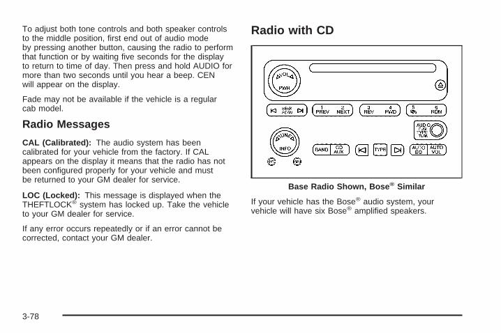
To adjust both tone controls and both speaker controlsto the middle position, first end out of audio modeby pressing another button, causing the radio to performthat function or by waiting five seconds for the displayto return to time of day. Then press and hold AUDIO formore than two seconds until you hear a beep. CENwill appear on the display.
Fade may not be available if the vehicle is a regularcab model.
Radio Messages
CAL (Calibrated): The audio system has beencalibrated for your vehicle from the factory. If CALappears on the display it means that the radio has notbeen configured properly for your vehicle and mustbe returned to your GM dealer for service.
LOC (Locked): This message is displayed when theTHEFTLOCK® system has locked up. Take the vehicleto your GM dealer for service.
If any error occurs repeatedly or if an error cannot becorrected, contact your GM dealer.
Radio with CD
If your vehicle has the Bose® audio system, yourvehicle will have six Bose® amplified speakers.
Base Radio Shown, Bose ® Similar
3-78

Radio Data System (RDS)The audio system has a Radio Data System (RDS).RDS features are available for use only on FM stationsthat broadcast RDS information.
With RDS, the radio can do the following:
• Seek to stations broadcasting the selected type ofprogramming
• Receive announcements concerning local andnational emergencies
• Display messages from radio stations
This system relies upon receiving specific informationfrom these stations and will only work when theinformation is available. In rare cases, a radio stationmay broadcast incorrect information that will causethe radio features to work improperly. If this happens,contact the radio station.
While the radio is tuned to an RDS station, the stationname or call letters will appear on the display instead ofthe frequency. RDS stations may also provide thetime of day, a program type (PTY) for currentprogramming, and the name of the program beingbroadcast.
XM™ Satellite Radio ServiceXM™ is a satellite radio service that is based inthe 48 contiguous United States. XM™ offers100 coast-to-coast channels including music, news,sports, talk, and children’s programming. XM™ providesdigital quality audio and text information that includessong title and artist name. A service fee is requiredin order to receive the XM™ service. For moreinformation, contact XM™ at www.xmradio.com or call1-800-852-XMXM (9696).
Playing the Radio
PWR (Power): Press this knob to turn the system onand off.
o VOL p (Volume): Turn this knob to increase or todecrease the volume.
INFO (Information): Press this knob to switch thedisplay between the radio station frequency andthe time. When the ignition is off, press this knob todisplay the time.
For RDS, press the INFO knob to change what appearson the display while using RDS. The display optionsare station name, RDS station frequency, PTY, and thename of the program (if available).
3-79

For XM™ (if equipped), press the INFO knob while inXM™ mode to retrieve four different categories ofinformation related to the current song or channel:Artist, Song Title, Category or PTY, ChannelNumber/Channel Name.
To change the default on the display, press the INFOknob until you see the display you want, then holdthe knob until you hear a beep. The selected display willnow be the default.
AUTO VOL (Automatic Volume): With automaticvolume, the audio system will adjust automatically tomake up for road and wind noise as you drive byincreasing the volume as vehicle speed increases.
Set the volume at the desired level. Press this button toselect LOW, MEDIUM, or HIGH. AVOL will appearon the display. Each higher setting will provide morevolume compensation at faster vehicle speeds. To turnautomatic volume off, press this button until AVOLOFF appears on the display.
Finding a Station
BAND: Press this button to switch between FM1, FM2,AM, or XM1 or XM2 (if equipped). The display willshow the selection.
o TUNE p: Turn this knob to select radio stations.
© SEEK ¨: Press either the SEEK or the TYPEarrows to go to the next or to the previous station andstay there.
The radio will only seek stations with a strong signalthat are in the selected band.
© SCAN ¨: Press and hold either the SCAN or theTYPE arrows for two seconds until SCAN appearson the display and you hear a beep. The radio will go toa station, play for a few seconds, then go on to thenext station. Press either the SCAN or the TYPE arrowsagain to stop scanning.
To scan preset stations, press and hold either theSCAN or the TYPE arrows for more than four seconds.PSCN will appear on the display and you will hear adouble beep. The radio will go to a preset station, playfor a few seconds, then go on to the next presetstation. Press either the SCAN or the TYPE arrowsagain to stop scanning presets.
The radio will only scan stations with a strong signalthat are in the selected band.
3-80

Setting Preset StationsUp to 30 stations (six FM1, six FM2, and six AM,six XM1 and six XM2 (if equipped)), can be programedon the six numbered pushbuttons, by performing thefollowing steps:
1. Turn the radio on.
2. Press BAND to select FM1, FM2, AM, orXM1 or XM2.
3. Tune in the desired station.
4. Press and hold one of the six numberedpushbuttons until you hear a beep. Whenever thatnumbered pushbutton is pressed, the stationthat was set will return for that pushbutton.
5. Repeat the steps for each pushbutton.
To store an equalization setting to a preset stationperform the following:
1. Tune to the preset station.
2. Press and release the AUTO EQ button to selectthe equalization setting.Once the equalization no longer appears on thedisplay, the equalization will be set for that presetstation.
Setting the Tone (Bass/Treble)
AUDIO: Push and release the AUDIO knob until BASSor TREB appears on the display. Turn the knob toincrease or to decrease. The display will show the bassor treble level. If a station is weak or noisy, decreasethe treble.
To adjust the bass and treble to the middle position, pushand hold the AUDIO knob. The radio will produce onebeep and adjust the display level to the middle position.
To adjust all tone and speaker controls to the middleposition, push and hold the AUDIO knob when no tone orspeaker control is displayed. ALL CENTERED will appearon the display, you will hear a beep, and the display levelwill be adjusted to the middle position.
AUTO EQ (Automatic Equalization): Press this buttonto select customized equalization settings designedfor country/western, jazz, talk, pop, rock, and classical.Selecting CUSTOM or changing bass or treble,returns the EQ to the manual bass and treble settings.
The radio will save separate AUTO EQ settings foreach preset and source.
If the radio is equipped with the Bose® audio system,the equalization settings are either CUSTOM or TALK.
3-81

Adjusting the Speakers (Balance/Fade)
AUDIO: To adjust the balance between the rightand the left speakers, push and release the AUDIOknob until BAL appears on the display. Turn the knob tomove the sound toward the right or the left speakers.
To adjust the fade between the front and the rearspeakers, push and release the AUDIO knob until FADEappears on the display. Turn the knob to move thesound toward the front or the rear speakers.
To adjust the balance and fade to the middle position,push the AUDIO knob, then push it again and holdit until the radio produces one beep. The balance andfade will be adjusted to the middle position and thedisplay will show the speaker balance.
To adjust all tone and speaker controls to the middleposition, push and hold the AUDIO knob when no toneor speaker control is displayed. ALL CENTERED willappear on the display, you will hear a beep, andthe display level will be adjusted to the middle position.
Finding a Program Type (PTY) Station(RDS and XM™)To select and find a desired PTY perform the following:
1. Press the TYPE button to activate program typeselect mode. TYPE and a PTY will appear on thedisplay.
2. Turn the TYPE knob or press and release theTYPE button to select a PTY.
3. Once the desired PTY is displayed, press andrelease either the TYPE or the SEEK arrows toselect and to take you to the PTY’s first station.
4. To go to another station within that PTY and thePTY is displayed, press either the TYPE or theSEEK arrows once. If the PTY is not displayed,go back to Step 1.
5. Press either the TYPE or the SEEK arrows to exitprogram type select mode.
If the radio cannot find the desired program type, NONEwill appear on the display and the radio will return tothe last station you were listening to.
3-82
SCAN: Scan the stations within a PTY by performingthe following:
1. Press the TYPE button to activate program typeselect mode. TYPE and the last selected PTY willappear on the display.
2. Turn the TYPE knob or press and release theTYPE button to select a PTY.
3. Once the desired PTY is displayed, pressand hold either the TYPE or the SCAN arrows fortwo seconds, and the radio will begin scanningthe stations in the PTY.
4. Press either the TYPE or the SCAN arrows to stopat a station.
BAND (Alternate Frequency): Alternate frequencyallows the radio to switch to a stronger station with thesame program type. To turn alternate frequency on,press and hold BAND for two seconds. AF ON willappear on the display. The radio may switch to stationswith a stronger frequency.
To turn alternate frequency off, press and hold BANDagain for two seconds. AF OFF will appear on thedisplay. The radio will not switch to other stations.
This function does not apply for XM™ Satellite RadioService.
Setting Preset PTYs (RDS Only)These buttons have factory PTY presets. Up to 12 PTYs(six FM1 and six FM2), can be programmed on thesix numbered pushbuttons, by performing the followingsteps:
1. Press BAND to select FM1 or FM2.
2. Press the TYPE button to activate program typeselect mode. TYPE and the last selected PTY willappear on the display.
3. Turn the TYPE knob or press and release theTYPE button to select a PTY.
4. Press and hold one of the six numberedpushbuttons until you hear a beep. Whenever thatnumbered pushbutton is pressed, the PTY thatwas set will return.
5. Repeat the steps for each pushbutton.
3-83
RDS Messages
INFO (Information): If the current station has amessage, the information symbol will appear on thedisplay. Press this button to see the message. Themessage may display the artist, song title, call in phonenumbers, etc.
If the entire message is not displayed, parts of themessage will appear every three seconds. To scrollthrough the message, press and release the INFObutton. A new group of words will appear on the displayafter every press of the button. Once the completemessage has been displayed, the information symbolwill disappear from the display until another newmessage is received. The last message can bedisplayed by pressing the INFO button. You can viewthe last message until a new message is receivedor a different station is tuned to.
Radio Messages
CAL ERR (Calibration Error): The audio system hasbeen calibrated for your vehicle from the factory. If CALERR appears on the display, it means that the radio hasnot been configured properly for the vehicle and must bereturned to your GM dealer for service.
LOCKED: This message is displayed when theTHEFTLOCK® system has locked up. Take the vehicleto your GM dealer for service.
If any error occurs repeatedly, or if an error cannot becorrected, contact your GM dealer.
3-84

XM™ Radio MessagesRadio Display
Message Condition Action Required
XL (Explicit LanguageChannels)
XL on the radio display,after the channel name,indicates content withexplicit language.
These channels, or any others, can be blocked at acustomer’s request, by calling 1-800-852-XMXM (9696).
Updating Updatingencryption code
The encryption code in the receiver is being updated, andno action is required. This process should take no longerthan 30 seconds.
No Signal Loss of signal The system is functioning correctly, but the vehicle is in alocation that is blocking the XM™ signal. When you moveinto an open area, the signal should return.
Loading XM Acquiring channel audio(after 4 second delay)
The audio system is acquiring and processing audio andtext data. No action is needed. This message shoulddisappear shortly.
CH Off Air Channel not in service This channel is not currently in service. Tune to anotherchannel.
CH Unavail Channel no longeravailable
This previously assigned channel is no longer assigned.Tune to another station. If this station was one of thepresets, choose another station for that preset button.
No Info Artist Name/Feature notavailable
No artist information is available at this time on thischannel. The system is working properly.
No Info Song/Program Title notavailable
No song title information is available at this time on thischannel. The system is working properly.
3-85

XM™ Radio Messages (cont’d)Radio Display
Message Condition Action Required
No Info Category Name notavailable
No category information is available at this time on thischannel. The system is working properly.
No Info No Text/Informationalmessage available
No text or informational messages are available at thistime on this channel. The system is working properly.
Not Found No channel available forthe chosen category
There are no channels available for the selected category.The system is working properly.
XM Locked Theft lock active The XM™ receiver in the vehicle may have previouslybeen in another vehicle. For security purposes, XM™receivers cannot be swapped between vehicles. If thismessage is received after having your vehicle serviced,check with your GM dealer.
Radio ID Radio ID label(channel 0)
If tuned to channel 0, this message will alternate with theXM™ Radio eight digit radio ID label. This label is neededto activate the service.
Unknown Radio ID not known(should only be ifhardware failure)
If this message is received when tuned to channel 0, theremay be a receiver fault. Consult with your GM dealer.
Chk XMRcvr Hardware failure If this message does not clear within a short periodof time, the receiver may have a fault. Consult with yourGM dealer.
3-86

Playing a CDInsert a CD part way into the slot, label side up. Theplayer will pull it in and the CD should begin playing.If you want to insert a CD with the ignition off, first pressthe eject button or the INFO knob.
If the ignition or radio is turned off with the CD in theplayer, it will stay in the player. When the ignitionor radio is turned on, the CD will start playing where itstopped, if it was the last selected audio source.
When a CD is inserted, the CD symbol will appear onthe display. As each new track starts to play, thetrack number will appear on the display.
The CD player can play the smaller 3 inch (8 cm) singleCDs with an adapter ring. Full-size CDs and thesmaller CDs are loaded in the same manner.
If playing a CD-R the sound quality may be reduceddue to CD-R quality, the method of recording, the qualityof the music that has been recorded, and the way theCD-R has been handled. There may be an increasein skipping, difficulty in finding tracks, and/or difficulty inloading and ejecting. If these problems occur try aknown good CD.
Do not add paper labels to CDs, they could get caughtin the CD player.
If an error appears on the display, see “CD Messages”later in this section.
1 PREV (Previous): Press this pushbutton to go to thebeginning of the current track if more than eightseconds have played. TRACK and the track number willappear on the display. If this pushbutton is held orpressed more than once, the player will continue movingbackward through the CD.
2 NEXT: Press this pushbutton to go to the next track.TRACK and the track number will appear on thedisplay. If this pushbutton is held or pressed more thanonce, the player will continue moving forward throughthe CD.
3 REV (Reverse): Press and hold this pushbutton toquickly reverse within a track. Press and hold thispushbutton for less than two seconds to reverse at sixtimes the normal playing speed. Press and hold itfor more than two seconds to reverse at 17 times thenormal playing speed. Release this pushbutton toplay the passage. ET and the elapsed time of the trackwill appear on the display.
3-87

4 FWD (Forward): Press and hold this pushbutton toquickly advance within a track. Press and hold thispushbutton for less than two seconds to advance atsix times the normal playing speed. Press and hold it formore than two seconds to advance at 17 times thenormal playing speed. Release this pushbutton to playthe passage. ET and the elapsed time of the trackwill appear on the display.
6 RDM (Random): Press this pushbutton to hear thetracks in random, rather than sequential, order. RDM ONwill appear on the display. RDM T and the tracknumber will appear on the display when each trackstarts to play. Press this pushbutton again to turnoff random play. RDM OFF will appear on the display.
© SEEK ¨: Press the left arrow to go to the startof the current or to the previous track. Press theright arrow to go to the start of the next track. If eitherarrow is held or pressed more than once, the player willcontinue moving backward or forward through the CD.
© SCAN ¨: Press and hold either the SCAN orthe TYPE arrows for more than two seconds until SCANappears on the display and you hear a beep. Theradio will go to the next track, play for 10 seconds, thengo on to the next track. Press either the SCAN or theTYPE arrows again, to stop scanning.
INFO (Information): Press this knob to see how longthe current track has been playing. ET and the elapsedtime will appear on the display. To change the defaulton the display, track or elapsed time, press theknob until you see the display you want, then hold theknob for two seconds. The radio will produce onebeep and the selected display will now be the default.
BAND: Press this button to listen to the radio whena CD is playing. The inactive CD will remain safelyinside the radio for future listening.
CD AUX (Auxiliary): Press this button to play a CDwhen listening to the radio. The inactive CD will remainsafely inside the radio for future listening.
Z (Eject): Press this button to stop a CD when it isplaying or to eject a CD when it is not playing. Ejectmay be activated with either the ignition or radio off.CDs may be loaded with the radio and ignition off if thisbutton is pressed first.
3-88
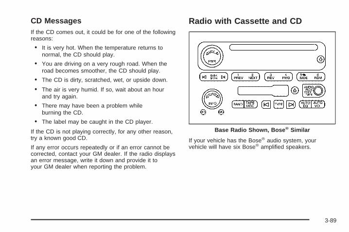
CD MessagesIf the CD comes out, it could be for one of the followingreasons:
• It is very hot. When the temperature returns tonormal, the CD should play.
• You are driving on a very rough road. When theroad becomes smoother, the CD should play.
• The CD is dirty, scratched, wet, or upside down.
• The air is very humid. If so, wait about an hourand try again.
• There may have been a problem whileburning the CD.
• The label may be caught in the CD player.
If the CD is not playing correctly, for any other reason,try a known good CD.
If any error occurs repeatedly or if an error cannot becorrected, contact your GM dealer. If the radio displaysan error message, write it down and provide it toyour GM dealer when reporting the problem.
Radio with Cassette and CD
If your vehicle has the Bose® audio system, yourvehicle will have six Bose® amplified speakers.
Base Radio Shown, Bose ® Similar
3-89
Radio Data System (RDS)The audio system has a Radio Data System (RDS).RDS features are available for use only on FM stationsthat broadcast RDS information.
With RDS, the radio can do the following:
• Seek to stations broadcasting the selected type ofprogramming
• Receive announcements concerning local andnational emergencies
• Display messages from radio stations
This system relies upon receiving specific informationfrom these stations and will only work when theinformation is available. In rare cases, a radio stationmay broadcast incorrect information that will causethe radio features to work improperly. If this happens,contact the radio station.
While the radio is tuned to an RDS station, the stationname or call letters will appear on the display instead ofthe frequency. RDS stations may also provide thetime of day, a program type (PTY) for currentprogramming, and the name of the program beingbroadcast.
XM™ Satellite Radio ServiceXM™ is a satellite radio service that is based inthe 48 contiguous United States. XM™ offers100 coast-to-coast channels including music, news,sports, talk, and children’s programming. XM™ providesdigital quality audio and text information that includessong title and artist name. A service fee is requiredin order to receive the XM™ service. For moreinformation, contact XM™ at www.xmradio.com or call1-800-852-XMXM (9696).
Playing the Radio
PWR (Power): Press this knob to turn the system onand off.
o VOL p (Volume): Turn this knob to increase or todecrease the volume.
INFO (Information): Press this knob to switch thedisplay between the radio station frequency andthe time. When the ignition is off, press this knob todisplay the time.
3-90

For RDS, press the INFO knob to change what appearson the display while using RDS. The display optionsare station name, RDS station frequency, PTY, and thename of the program (if available).
For XM™ (if equipped), press the INFO knob while inXM™ mode to retrieve four different categories ofinformation related to the current song or channel:Artist, Song Title, Category or PTY, ChannelNumber/Channel Name.
To change the default on the display, press the INFOknob until you see the display you want, then holdthe knob until the display flashes. The selected displaywill now be the default.
AUTO VOL (Automatic Volume): With automaticvolume, the audio system will adjust automatically tomake up for road and wind noise as you drive byincreasing the volume as vehicle speed increases.
Set the volume at the desired level. Press this button toselect LOW, MEDIUM, or HIGH. AVOL will appearon the display. Each higher setting will provide morevolume compensation at faster vehicle speeds. To turnautomatic volume off, press this button until AVOLOFF appears on the display.
Finding a Station
BAND: Press this button to switch between FM1, FM2,AM, or XM1 or XM2 (if equipped). The display willshow the selection.
o TUNE p: Turn this knob to select radio stations.
© SEEK ¨: Press either the SEEK or the TYPEarrows to go to the next or to the previous station andstay there.
The radio will only seek stations with a strong signalthat are in the selected band.
© SCAN ¨: Press and hold either the SCAN or theTYPE arrows for two seconds until SCAN appearson the display and you hear a beep. The radio will go toa station, play for a few seconds, then go on to thenext station. Press either the SCAN or the TYPE arrowsagain to stop scanning.
To scan preset stations, press and hold either theSCAN or the TYPE arrows for more than four seconds.PSCN will appear on the display and you will hear adouble beep. The radio will go to a preset station, playfor a few seconds, then go on to the next presetstation. Press either the SCAN or the TYPE arrowsagain to stop scanning presets.
The radio will only scan stations with a strong signalthat are in the selected band.
3-91

Setting Preset StationsUp to 30 stations (six FM1, six FM2, and six AM,six XM1 and six XM2 (if equipped)), can be programedon the six numbered pushbuttons, by performing thefollowing steps:
1. Turn the radio on.
2. Press BAND to select FM1, FM2, AM, orXM1 or XM2.
3. Tune in the desired station.
4. Press and hold one of the six numberedpushbuttons until you hear a beep. Whenever thatnumbered pushbutton is pressed, the stationthat was set will return for that pushbutton.
5. Repeat the steps for each pushbutton.
To store an equalization setting to a preset stationperform the following:
1. Tune to the preset station.
2. Press and release the AUTO EQ button to selectthe equalization setting.Once the equalization no longer appears on thedisplay, the equalization will be set for that presetstation.
Setting the Tone (Bass/Treble)
AUDIO: Push and release the AUDIO knob until BASSor TREB appears on the display. Turn the knob toincrease or to decrease. The display will show the bassor treble level. If a station is weak or noisy, decreasethe treble.
To adjust the bass and treble to the middle position,push and hold the AUDIO knob. The radio will produceone beep and adjust the display level to the middleposition.
To adjust all tone and speaker controls to the middleposition, push and hold the AUDIO knob when no toneor speaker control is displayed. ALL CENTERED willappear on the display, you will hear a beep, andthe display level will be adjusted to the middle position.
AUTO EQ (Automatic Equalization): Press this buttonto select customized equalization settings designed forcountry/western, jazz, talk, pop, rock, and classical.Selecting CUSTOM or changing bass or treble, returnsthe EQ to the manual bass and treble settings.
The radio will save separate AUTO EQ settings for eachpreset and source.
If the radio is equipped with the Bose® audio system, theequalization settings are either CUSTOM or TALK.
3-92
Adjusting the Speakers (Balance/Fade)
AUDIO: To adjust the balance between the rightand the left speakers, push and release the AUDIOknob until BAL appears on the display. Turn the knob tomove the sound toward the right or the left speakers.
To adjust the fade between the front and the rearspeakers, push and release the AUDIO knob until FADEappears on the display. Turn the knob to move thesound toward the front or the rear speakers.
To adjust the balance and fade to the middle position,push the AUDIO knob, then push it again and holdit until the radio produces one beep. The balance andfade will be adjusted to the middle position and thedisplay will show the speaker balance.
To adjust all tone and speaker controls to the middleposition, push and hold the AUDIO knob when no toneor speaker control is displayed. ALL CENTERED willappear on the display, you will hear a beep, andthe display level will be adjusted to the middle position.
Finding a Program Type (PTY) Station(RDS and XM™)To select and find a desired PTY perform the following:
1. Press the TYPE button to activate program typeselect mode. TYPE and a PTY will appear on thedisplay.
2. Turn the TYPE knob or press and release theTYPE button to select a PTY.
3. Once the desired PTY is displayed, press andrelease either the TYPE or the SEEK arrows toselect and to take you to the PTY’s first station.
4. To go to another station within that PTY and thePTY is displayed, press either the TYPE or theSEEK arrows once. If the PTY is not displayed, goback to Step 1.
5. Press either the TYPE or the SEEK arrows to exitprogram type select mode.
If the radio cannot find the desired program type, NONEwill appear on the display and the radio will return tothe last station you were listening to.
3-93

SCAN: Scan the stations within a PTY by performingthe following:
1. Press the TYPE button to activate program typeselect mode. TYPE and the last selected PTY willappear on the display.
2. Turn the TYPE knob or press and release theTYPE button to select a PTY.
3. Once the desired PTY is displayed, press and holdeither the TYPE or the SCAN arrows for twoseconds, and the radio will begin scanning thestations in the PTY.
4. Press either the TYPE or the SCAN arrows to stopat a station.
BAND (Alternate Frequency): Alternate frequencyallows the radio to switch to a stronger station with thesame program type. To turn alternate frequency on,press and hold BAND for two seconds. AF ON willappear on the display. The radio may switch to stationswith a stronger frequency.
To turn alternate frequency off, press and hold BANDagain for two seconds. AF OFF will appear on thedisplay. The radio will not switch to other stations.
This function does not apply for XM™ Satellite RadioService.
Setting Preset PTYs (RDS Only)These buttons have factory PTY presets. Up to 12 PTYs(six FM1 and six FM2), can be programmed on thesix numbered pushbuttons, by performing the followingsteps:
1. Press BAND to select FM1 or FM2.
2. Press the TYPE button to activate program typeselect mode. TYPE and the last selected PTY willappear on the display.
3. Turn the TYPE knob or press and release theTYPE button to select a PTY.
4. Press and hold one of the six numberedpushbuttons until you hear a beep. Whenever thatnumbered pushbutton is pressed, the PTY thatwas set will return.
5. Repeat the steps for each pushbutton.
3-94

RDS Messages
INFO (Information): If the current station has amessage, the information symbol will appear on thedisplay. Press this button to see the message. Themessage may display the artist, song title, call in phonenumbers, etc.
If the entire message is not displayed, parts of themessage will appear every three seconds. To scrollthrough the message, press and release the INFObutton. A new group of words will appear on the displayafter every press of the button. Once the completemessage has been displayed, the information symbolwill disappear from the display until another newmessage is received. The last message can bedisplayed by pressing the INFO button. You can viewthe last message until a new message is receivedor a different station is tuned to.
Radio Messages
CAL ERR (Calibration Error): The audio system hasbeen calibrated for your vehicle from the factory. IfCAL ERR appears on the display, it means that the radiohas not been configured properly for the vehicle andmust be returned to your GM dealer for service.
LOCKED: This message is displayed when theTHEFTLOCK® system has locked up. Take the vehicleto your GM dealer for service.
If any error occurs repeatedly, or if an error cannot becorrected, contact your GM dealer.
3-95

XM™ Radio MessagesRadio Display
Message Condition Action Required
XL (Explicit LanguageChannels)
XL on the radio display,after the channel name,indicates content withexplicit language.
These channels, or any others, can be blocked at acustomer’s request, by calling 1-800-852-XMXM (9696).
Updating Updatingencryption code
The encryption code in the receiver is being updated, andno action is required. This process should take no longerthan 30 seconds.
No Signal Loss of signal The system is functioning correctly, but the vehicle is in alocation that is blocking the XM™ signal. When you moveinto an open area, the signal should return.
Loading XM Acquiring channel audio(after 4 second delay)
The audio system is acquiring and processing audio andtext data. No action is needed. This message shoulddisappear shortly.
CH Off Air Channel not in service This channel is not currently in service. Tune to anotherchannel.
CH Unavail Channel no longeravailable
This previously assigned channel is no longer assigned.Tune to another station. If this station was one of thepresets, choose another station for that preset button.
No Info Artist Name/Feature notavailable
No artist information is available at this time on thischannel. The system is working properly.
No Info Song/Program Title notavailable
No song title information is available at this time on thischannel. The system is working properly.
3-96

XM™ Radio Messages (cont’d)Radio Display
Message Condition Action Required
No Info Category Name notavailable
No category information is available at this time on thischannel. The system is working properly.
No Info No Text/Informationalmessage available
No text or informational messages are available at thistime on this channel. The system is working properly.
Not Found No channel available forthe chosen category
There are no channels available for the selected category.The system is working properly.
XM Locked Theft lock active The XM™ receiver in the vehicle may have previouslybeen in another vehicle. For security purposes, XM™receivers cannot be swapped between vehicles. If thismessage is received after having your vehicle serviced,check with your GM dealer.
Radio ID Radio ID label(channel 0)
If tuned to channel 0, this message will alternate with theXM™ Radio eight digit radio ID label. This label is neededto activate the service.
Unknown Radio ID not known(should only be ifhardware failure)
If this message is received when tuned to channel 0, theremay be a receiver fault. Consult with your GM dealer.
Chk XMRcvr Hardware failure If this message does not clear within a short period of time,the receiver may have a fault. Consult with your GMdealer.
3-97

Playing a Cassette TapeThe tape player is built to work best with tapes that areup to 30 to 45 minutes long on each side. Tapeslonger than that are so thin they may not work well inthis player. The longer side with the tape visible shouldface to the right. If you hear nothing or hear a garbledsound, the tape may not be in squarely. Press the ejectbutton to remove the tape and start over.
If the ignition and radio are off, press the eject button orthe INFO knob to insert and to begin play of a tape.If the ignition is on and the radio is off, the tape can beinserted and will begin playing.
While the tape is playing, use the VOL, AUDIO, andSEEK controls just as you do for the radio. The cassettetape symbol will appear on the display and an arrowshowing which side of the tape is playing. The tapeplayer will play the other side of the tape when itreaches the end.
Cassette tape adapter kits for portable CD players willwork in the cassette tape player. See “CD Adapter Kits”later for more information.
The tape bias is set automatically when a metal orchrome tape is inserted.
If an error appears on the display, see “Cassette TapeMessages” later in this section.
1 PREV (Previous): The tape must have at leastthree seconds of silence between each selection forprevious to work. Press this pushbutton to go to theprevious selection on the tape if the current selection hasbeen playing for less than three seconds. If pressed whenthe current selection has been playing from three to13 seconds, it will go to the beginning of the previousselection or the beginning of the current selection,depending on the position on the tape. If pressed whenthe current selection has been playing for more than13 seconds, it will go to the beginning of the currentselection.
SEEK and a negative number will appear on the displaywhile the cassette player is in the previous mode.Pressing this pushbutton multiple times will increase thenumber of selections to be searched back, up to −9.
2 NEXT: The tape must have at least three seconds ofsilence between each selection for next to work.Press this pushbutton to go to the next selection on thetape. Pressing this pushbutton multiple times, in nextmode, will increase the number of selections to besearched forward. SEEK and a positive numberwill appear on the display.
3-98

3 REV (Reverse): Press this pushbutton to quicklyreverse the tape. The radio will play while the tapereverses. Press it again to return to playing speed. Thestation frequency and REV will appear on the display.Select stations during reverse operation by using TUNEand SEEK.
4 FWD (Forward): Press this pushbutton to quicklyadvance the tape. The radio will play while thetape advances. Press this pushbutton again to return toplaying speed. The station frequency and FWD willappear on the display. Select stations during forwardoperation by using TUNE and SEEK.
5 X SIDE: Press this pushbutton to play the other sideof the tape.
© SEEK ¨: The right arrow is the same as theNEXT pushbutton, and the left arrow is the same as thePREV pushbutton. If either arrow is held or pressedmore than once, the player will continue moving forwardor backward through the tape. SEEK and a positiveor negative number will appear on the display.
© SCAN ¨: Press and hold either the SCAN or theTYPE arrows for more than two seconds until SCANappears on the display and you hear a beep. The radiowill go to the next selection, play for 10 seconds,then go on to the next selection. Press either the SCANor the TYPE arrows again, to stop scanning. Thetape must have at least three seconds of silencebetween each selection for scan to work.
BAND: Press this button to listen to the radio when acassette tape or CD is playing. The inactive tape or CDwill remain safely inside the radio for future listening.
TAPE DISC: Press this button to play a cassette tape orCD when listening to the radio. The inactive tape orCD will remain safely inside the radio for future listening.
Z (Eject): Press this button to stop a tape when it isplaying or to eject a tape when it is not playing. Eject maybe activated with the radio off. Cassette tapes may beloaded with the radio off if this button is pressed first.
3-99

Cassette Tape Messages
CHK TAPE (Check Tape): If this message appears onthe display, the tape will not play due to one of thefollowing errors:
• The tape is tight and the player cannot turn thetape hubs. Remove the tape. Hold the tape withthe open end down and try to turn the righthub counterclockwise with a pencil. Turn the tapeover and repeat. If the hubs do not turn easily,the tape may be damaged and should not be usedin the player. Try a new tape to make sure yourplayer is working properly.
• The tape is broken. Try a new tape.
• The tape is wrapped around the tape head. Attemptto get the cassette out. Try a new tape.
CLEAN: If this message appears on the display, thecassette tape player needs to be cleaned. It will still playtapes, but it should be cleaned as soon as possible toprevent damage to the tapes and player. See Careof the Cassette Tape Player on page 3-133.
If the cassette tape is not playing correctly, forany other reason, try a known good cassette.
If any error occurs repeatedly or if an error cannot becorrected, contact your GM dealer. If the radio displaysan error message, write it down and provide it toyour GM dealer when reporting the problem.
CD Adapter KitsIt is possible to use a portable CD player with thecassette tape player after activating the bypass featureon your tape player.
To activate the bypass feature, perform the followingsteps:
1. Turn the ignition on.
2. Turn the radio off.
3. Press and hold the TAPE DISC button forfive seconds. READY will appear on the display andthe tape symbol on the display will flash, indicatingthe feature is active.
4. Insert the adapter into the cassette tape slot. It willpower up the radio and begin playing.
The override feature will remain active until the ejectbutton is pressed.
3-100

Playing a CDInsert a CD part way into the slot, label side up. Theplayer will pull it in and the CD should begin playing. Ifyou want to insert a CD with the ignition off, firstpress the eject button or the INFO knob.
If the ignition or radio is turned off with the CD in theplayer, it will stay in the player. When the ignitionor radio is turned on, the CD will start playing where itstopped, if it was the last selected audio source.
When a CD is inserted, the CD symbol will appear onthe display. As each new track starts to play, thetrack number will appear on the display.
The CD player can play the smaller 3 inch (8 cm) singleCDs with an adapter ring. Full-size CDs and thesmaller CDs are loaded in the same manner.
If playing a CD-R the sound quality may be reduceddue to CD-R quality, the method of recording, the qualityof the music that has been recorded, and the way theCD-R has been handled. There may be an increasein skipping, difficulty in finding tracks, and/or difficulty inloading and ejecting. If these problems occur try aknown good CD.
Do not add paper labels to CDs, they could get caughtin the CD player.
If an error appears on the display, see “CD Messages”later in this section.
1 PREV (Previous): Press this pushbutton to go to thebeginning of the current track if more than eight secondshave played. TRACK and the track number will appear onthe display. If this pushbutton is held or pressed morethan once, the player will continue moving backwardthrough the CD.
2 NEXT: Press this pushbutton to go to the next track.TRACK and the track number will appear on thedisplay. If this pushbutton is held or pressed more thanonce, the player will continue moving forward throughthe CD.
3 REV (Reverse): Press and hold this pushbutton toquickly reverse within a track. Press and hold thispushbutton for less than two seconds to reverse atsix times the normal playing speed. Press and hold it formore than two seconds to reverse at 17 times thenormal playing speed. Release this pushbutton to playthe passage. ET and the elapsed time of the trackwill appear on the display.
4 FWD (Forward): Press and hold this pushbutton toquickly advance within a track. Press and hold thispushbutton for less than two seconds to advance atsix times the normal playing speed. Press and hold it formore than two seconds to advance at 17 times thenormal playing speed. Release this pushbutton to playthe passage. ET and the elapsed time of the trackwill appear on the display.
3-101

6 RDM (Random): Press this pushbutton to hear thetracks in random, rather than sequential, order. RDM ONwill appear on the display. RDM and the track numberwill appear on the display when each track starts to play.Press this pushbutton again to turn off random play.RDM OFF will appear on the display.
© SEEK ¨: Press the left arrow to go to the start ofthe current or to the previous track. Press the rightarrow to go to the start of the next track. If either arrowis held or pressed more than once, the player willcontinue moving backward or forward through the CD.
© SCAN ¨: Press and hold either the SCAN orthe TYPE arrows for more than two seconds until SCANappears on the display and you hear a beep. Theradio will go to the next track, play for 10 seconds, thengo on to the next track. Press either the SCAN or theTYPE arrows again, to stop scanning.
INFO (Information): Press this knob to see how longthe current track has been playing. ET and the elapsedtime will appear on the display. To change the defaulton the display, track or elapsed time, press theknob until you see the display you want, then hold theknob for two seconds. The radio will produce onebeep and the selected display will now be the default.
BAND: Press this button to listen to the radio whena cassette tape or CD is playing. The inactive tape orCD will remain safely inside the radio for future listening.
TAPE DISC: Press this button to play a cassette tape orCD when listening to the radio. The inactive tape or CDwill remain safely inside the radio for future listening.
Z (Eject): Press this button to stop a CD when it isplaying or to eject a CD when it is not playing. Ejectmay be activated with either the ignition or radio off. CDsmay be loaded with the radio and ignition off if thisbutton is pressed first.
CD MessagesIf the CD comes out, it could be for one of the followingreasons:
• It is very hot. When the temperature returns tonormal, the CD should play.
• You are driving on a very rough road. When theroad becomes smoother, the CD should play.
• The CD is dirty, scratched, wet, or upside down.
• The air is very humid. If so, wait about an hourand try again.
• There may have been a problem whileburning the CD.
• The label may be caught in the CD player.
If the CD is not playing correctly, for any other reason,try a known good CD.
3-102

If any error occurs repeatedly or if an error cannot becorrected, contact your GM dealer. If the radio displaysan error message, write it down and provide it toyour GM dealer when reporting the problem.
Listening to a DVDIf your vehicle has the Rear Seat Entertainment (RSE)system and a DVD is playing, the DVD symbol willappear on the radio display indicating that the DVD isavailable and can be listened to through your vehicle’sspeakers. To listen to the DVD, press the TAPEDISC button until RSE appears on the radio display.The current radio source will stop and the DVD soundwill come through the speakers. To stop listening tothe DVD, press the TAPE DISC button, if a cassettetape or a CD is loaded, or press the BAND buttonto select a different source.
When the RSE system is turned off, the DVD symbolwill go off of the radio display and RSE OFF will appearon the radio display. The radio will return to the lastradio source that you were listening to.
See Rear Seat Entertainment System on page 3-118 formore information.
Radio with Six-Disc CD
If your vehicle has the Bose® audio system, yourvehicle will have six Bose® amplified speakers.
Base Radio Shown, Bose ® Similar
3-103

Radio Data System (RDS)The audio system has a Radio Data System (RDS).RDS features are available for use only on FM stationsthat broadcast RDS information.
With RDS, the radio can do the following:
• Seek to stations broadcasting the selected type ofprogramming
• Receive announcements concerning local andnational emergencies
• Display messages from radio stations
This system relies upon receiving specific informationfrom these stations and will only work when theinformation is available. In rare cases, a radio stationmay broadcast incorrect information that will causethe radio features to work improperly. If this happens,contact the radio station.
While the radio is tuned to an RDS station, the stationname or call letters will appear on the display instead ofthe frequency. RDS stations may also provide thetime of day, a program type (PTY) for currentprogramming, and the name of the program beingbroadcast.
XM™ Satellite Radio ServiceXM™ is a satellite radio service that is basedin the 48 contiguous United States. XM™ offers100 coast-to-coast channels including music, news,sports, talk, and children’s programming. XM™ providesdigital quality audio and text information that includessong title and artist name. A service fee is requiredin order to receive the XM™ service. For moreinformation, contact XM™ at www.xmradio.com orcall 1-800-852-XMXM (9696).
Playing the Radio
PWR (Power): Push this knob to turn the system onand off.
o VOLUME p: Turn this knob to increase or todecrease the volume.
INFO (Information): Press this knob to switch thedisplay between the radio station frequency andthe time. When the ignition is off, press this knob todisplay the time.
For RDS, press the INFO knob to change what appearson the display while using RDS. The display optionsare station name, RDS station frequency, PTY, and thename of the program (if available).
3-104

For XM™ (if equipped), press the INFO knob while inXM™ mode to retrieve four different categories ofinformation related to the current song or channel:Artist, Song Title, Category or PTY, ChannelNumber/Channel Name.
To change the default on the display, press the INFOknob until you see the display you want, then holdthe knob until you hear a beep. The selected display willnow be the default.
AUTO VOL (Automatic Volume): With automaticvolume, the audio system will adjust automatically tomake up for road and wind noise as you drive byincreasing the volume as vehicle speed increases.
Set the volume at the desired level. Press this button toselect MIN, MED, or MAX. AUTO VOL will appear onthe display. Each higher setting will provide morevolume compensation at faster vehicle speeds. To turnautomatic volume off, press this button until AUTOVOL OFF appears on the display.
Finding a Station
BAND: Press this button to switch between FM1, FM2,AM, or XM1 or XM2 (if equipped). The display willshow the selection.
o TUNE p: Turn this knob to select radio stations.
© SEEK ¨: Press either the SEEK or the TYPEarrows to go to the next or to the previous station andstay there.
The radio will only seek stations with a strong signalthat are in the selected band.
© SCAN ¨: Press and hold either the SCAN or theTYPE arrows for two seconds until SCN appears onthe display and you hear a beep. The radio will go to astation, play for a few seconds, then go on to thenext station. Press either the SCAN or the TYPE arrowsagain to stop scanning.
To scan preset stations, press and hold either theSCAN or the TYPE arrows for more than four seconds.PSC will appear on the display and you will hear adouble beep. The radio will go to a preset station, playfor a few seconds, then go on to the next presetstation. Press either the SCAN or the TYPE arrowsagain to stop scanning presets.
The radio will only scan stations with a strong signalthat are in the selected band.
3-105

Setting Preset StationsUp to 30 stations (six FM1, six FM2, and six AM,six XM1 and six XM2 (if equipped)), can be programedon the six numbered pushbuttons, by performing thefollowing steps:
1. Turn the radio on.
2. Press BAND to select FM1, FM2, AM, orXM1 or XM2.
3. Tune in the desired station.
4. Press and hold one of the six numberedpushbuttons until you hear a beep. Whenever thatnumbered pushbutton is pressed, the stationthat was set will return for that pushbutton.
5. Repeat the steps for each pushbutton.
To store an equalization setting to a preset stationperform the following:
1. Tune to the preset station.
2. Press and release the AUTO EQ button to selectthe equalization setting.Once the equalization no longer appears on thedisplay, the equalization will be set for that presetstation.
Setting the Tone (Bass/Treble)
AUDIO: Push and release the AUDIO knob until BASS,MID (without Bose®), or TREB appears on the display.Turn the knob to increase or to decrease. The display willshow the bass, midrange (without Bose®), or treble level.If a station is weak or noisy, decrease the treble.
To adjust the bass, midrange (without Bose®), and trebleto the middle position, push and hold the AUDIO knob.The radio will produce one beep and adjust the displaylevel to the middle position.
To adjust all tone and speaker controls to the middleposition, push and hold the AUDIO knob when no tone orspeaker controls are displayed. ALL CENTERED willappear on the display and you will hear a beep.
AUTO EQ (Automatic Equalization): Press this buttonto select customized equalization settings designedfor country/western, jazz, talk, pop, rock, and classical.
The radio will save separate AUTO EQ settings foreach preset and source.
If the radio is equipped with the Bose® audio system,the equalization settings are either CUSTOM or TALK.
3-106

Adjusting the Speakers (Balance/Fade)
AUDIO: To adjust the balance between the rightand the left speakers, push and release the AUDIOknob until BAL appears on the display. Turn the knob tomove the sound toward the right or the left speakers.
To adjust the fade between the front and rear speakers,push and release the AUDIO knob until FAD appearson the display. Turn the knob to move the sound towardthe front or the rear speakers.
To adjust the balance and fade to the middle position,push and hold the AUDIO knob. The radio will produceone beep and adjust the display level to the middleposition.
To adjust all tone and speaker controls to the middleposition, push and hold the AUDIO knob when no toneor speaker controls are displayed. ALL CENTEREDwill appear on the display and you will hear a beep.
Finding a Program Type (PTY) Station(RDS and XM™)To select and find a desired PTY perform the following:
1. Press the TYPE button to activate program typeselect mode. P-TYPE and the last selected PTYwill appear on the display.
2. Turn the TYPE knob or press and release theTYPE button to select a PTY.
3. Once the desired PTY is displayed, press either theTYPE or the SEEK arrows to select and to take youto the PTY’s first station.
4. To go to another station within that PTY and thePTY is displayed, press either the TYPE or theSEEK arrows once. If the PTY is not displayed, goback to Step 1.
5. Press either the TYPE or the SEEK arrows to exitprogram type select mode.
3-107
SCAN: Scan the stations within a PTY by performingthe following:
1. Press the TYPE button to activate program typeselect mode. P-TYPE and the last selected PTYwill appear on the display.
2. Turn the TYPE knob or press and release theTYPE button to select a PTY.
3. Once the desired PTY is displayed, press and holdeither the TYPE or the SCAN arrows for twoseconds, and the radio will begin scanning thestations in the PTY.
4. Press either the TYPE or the SCAN arrows to stopat a station.
BAND (Alternate Frequency): Alternate frequencyallows the radio to switch to a stronger station with thesame program type. To turn alternate frequency on,press and hold BAND for two seconds. AF ON willappear on the display. The radio may switch to stationswith a stronger frequency.
To turn alternate frequency off, press and hold BANDagain for two seconds. AF OFF will appear on thedisplay. The radio will not switch to other stations.
This function does not apply for XM™ Satellite RadioService.
Setting Preset PTYs (RDS Only)These pushbuttons have factory PTY presets. Up to12 PTYs (six FM1 and six FM2), can be programmed onthe six numbered pushbuttons, by performing thefollowing steps:
1. Press BAND to select FM1 or FM2.
2. Press the TYPE button to activate program typeselect mode. P-TYPE and the last selected PTYwill appear on the display.
3. Turn the TYPE knob or press and release theTYPE button to select a PTY.
4. Press and hold one of the six numberedpushbuttons until you hear a beep. Whenever thatnumbered pushbutton is pressed, the PTY thatwas set will return.
5. Repeat the steps for each pushbutton.
3-108

RDS Messages
INFO (Information): If the current station has amessage, INFO will appear on the display. Press thisbutton to see the message. The message may displaythe artist, song title, call in phone numbers, etc.
If the entire message is not displayed, parts of themessage will appear every three seconds. To scrollthrough the message, press and release the INFObutton. A new group of words will appear on the displayafter every press of this button. Once the completemessage has been displayed, INFO will disappear fromthe display until another new message is received.The last message can be displayed by pressingthe INFO button. You can view the last message until anew message is received or a different station istuned to.
Radio Messages
CAL ERR (Calibration Error): The audio system hasbeen calibrated for your vehicle from the factory. IfCAL ERR appears on the display, it means that the radiohas not been configured properly for the vehicle andmust be returned to your GM dealer for service.
LOCKED: This message is displayed when theTHEFTLOCK® system has locked up. Take the vehicleto your GM dealer for service.
If any error occurs repeatedly, or if an error cannot becorrected, contact your GM dealer.
3-109

XM™ Radio MessagesRadio Display
Message Condition Action Required
XL (Explicit LanguageChannels)
XL on the radio display,after the channel name,indicates content withexplicit language.
These channels, or any others, can be blocked at acustomer’s request, by calling 1-800-852-XMXM (9696).
Updating Updatingencryption code
The encryption code in the receiver is being updated, andno action is required. This process should take no longerthan 30 seconds.
No Signal Loss of signal The system is functioning correctly, but the vehicle is in alocation that is blocking the XM™ signal. When you moveinto an open area, the signal should return.
Loading XM Acquiring channel audio(after 4 second delay)
The audio system is acquiring and processing audio andtext data. No action is needed. This message shoulddisappear shortly.
CH Off Air Channel not in service This channel is not currently in service. Tune to anotherchannel.
CH Unavail Channel no longeravailable
This previously assigned channel is no longer assigned.Tune to another station. If this station was one of thepresets, choose another station for that preset button.
No Info Artist Name/Feature notavailable
No artist information is available at this time on thischannel. The system is working properly.
No Info Song/Program Title notavailable
No song title information is available at this time on thischannel. The system is working properly.
3-110

XM™ Radio Messages (cont’d)Radio Display
Message Condition Action Required
No Info Category Name notavailable
No category information is available at this time on thischannel. The system is working properly.
No Info No Text/Informationalmessage available
No text or informational messages are available at thistime on this channel. The system is working properly.
Not Found No channel available forthe chosen category
There are no channels available for the selected category.The system is working properly.
XM Locked Theft lock active The XM™ receiver in the vehicle may have previouslybeen in another vehicle. For security purposes, XM™receivers cannot be swapped between vehicles. If thismessage is received after having your vehicle serviced,check with your GM dealer.
Radio ID Radio ID label(channel 0)
If tuned to channel 0, this message will alternate with theXM™ Radio eight digit radio ID label. This label is neededto activate the service.
Unknown Radio ID not known(should only be ifhardware failure)
If this message is received when tuned to channel 0, theremay be a receiver fault. Consult with your GM dealer.
Chk XMRcvr Hardware failure If this message does not clear within a short period of time,your receiver may have a fault. Consult with your GMdealer.
3-111

Playing a CDIf the ignition or radio is turned off, with a CD in theplayer, it will stay in the player. When the ignitionor radio is turned on, the CD will start playing where itstopped, if it was the last selected audio source.
When a CD is inserted, the CD symbol will appear onthe display. As each new track starts to play, thetrack number will appear on the display.
The CD player can play the smaller 3 inch (8 cm) singleCDs with an adapter ring. Full-size CDs and thesmaller CDs are loaded in the same manner.
If playing a CD-R the sound quality may be reduceddue to CD-R quality, the method of recording, the qualityof the music that has been recorded, and the way theCD-R has been handled. There may be an increasein skipping, difficulty in finding tracks, and/or difficulty inloading and ejecting. If these problems occur try aknown good CD.
Do not add paper labels to CDs, they could get caughtin the CD player.
If an error appears on the display, see “CD Messages”later in this section.
LOAD: Press this button to load CDs into the CDplayer. This CD player will hold up to six CDs.
To insert one CD, do the following:
1. Turn the ignition on.
2. Press and release the LOAD button.
3. Wait for the indicator light, located to the right of theslot, to turn green.
4. Load a CD. Insert the CD part way into the slot,label side up. The player will pull the CD in.
3-112

To insert multiple CDs, do the following:
1. Turn the ignition on.
2. Press and hold the LOAD button for two seconds.You will hear a beep and the indicator light, locatedto the right of the slot, will begin to flash andMULTI LOAD # will appear on the display.
3. Once the light stops flashing and turns green,INSERT CD # will appear on the display, loada CD. Insert the CD part way into the slot, label sideup. The player will pull the CD in.Once the CD is loaded, the indicator light will beginflashing again. Once the light stops flashing andturns green, you can load another CD. TheCD player takes up to six CDs. Do not try to loadmore than six.
To load more than one CD but less than six, completeSteps 1 through 3. When finished loading CDs,press the LOAD button to cancel the loading function.The radio will begin to play the last CD loaded.
If more than one CD has been loaded, a number foreach CD will appear on the display.
Playing a Specific Loaded CDFor every CD loaded, a number will appear on thedisplay. To play a specific CD, first press the CD AUXbutton, then press the numbered pushbutton thatcorresponds to the CD. A small bar will appear underthe CD number that is playing and the track number willappear on the display.
If an error appears on the display, see “CD Messages”later in this section.
CDZ (Eject): Press this button to eject CD(s).
To eject the CD that is currently playing, press andrelease this button.
To eject multiple CDs, do the following:
1. Press and hold the CD eject button for five seconds.You will hear a beep and the indicator light, locatedto the right of the slot, will begin to flash andEJECT ALL will appear on the display.
2. Once the light stops flashing and turns green,REMOVE CD # will appear on the display. TheCD will eject and can be removed.Once the CD is removed, the indicator light willbegin flashing again and another CD will eject.To stop ejecting the CDs, press the LOAD or theeject button.
3-113

If the CD is not removed, after 25 seconds, the CD will beautomatically pulled back into the player. If CD is pushedback into the player, before the 25-second time period iscomplete, the player will sense an error and will try toeject the CD several times before stopping.
Do not repeatedly press the CD eject button to eject aCD after you have tried to push it in manually. Theplayer’s 25-second eject timer will reset at each press ofeject, causing the player to not eject the CD until the25-second time period has elapsed.
{ REV (Reverse): Press and hold this button toreverse quickly within a track. You will hear sound at areduced volume. Release the button to play thepassage. The elapsed time of the track will appear onthe display.
FWD | (Forward): Press and hold this button toadvance quickly within a track. You will hear soundat a reduced volume. Release the button to playthe passage. The elapsed time of the track will appearon the display.
RPT (Repeat): With repeat, one track or an entire CDcan be repeated.
To use repeat, do the following:
• To repeat the track you are listening to, press andrelease the RPT button. RPT will appear on thedisplay. Press RPT again to turn off repeat play.
• To repeat the CD you are listening to, press andhold the RPT button for two seconds. RPT willappear on the display. Press RPT again to turn offrepeat play.
RDM (Random): With random, you can listen to thetracks in random, rather than sequential, order, on oneCD or on all of the CDs. To use random, do one ofthe following:
• To play the tracks on the CD you are listening to inrandom order, press and release the RDM button.RANDOM ONE will appear on the display. PressRDM again to turn off random play.
• To play the tracks on all of the CDs that are loadedin random order, press and hold RDM for morethan two seconds. You will hear a beep andRANDOM ALL will appear on the display. PressRDM again to turn off random play.
3-114

AUTO EQ (Automatic Equalization): Press AUTO EQto select the equalization setting while playing a CD.The equalization will be stored whenever a CD is played.For more information on AUTO EQ, see “AUTO EQ”listed previously in this section.
©SEEK ¨: Press the left arrow to go to the start of thecurrent track, if more than ten seconds have played.Press the right arrow to go to the next track. If eitherarrow is held or pressed more than once, the player willcontinue moving backward or forward through the CD.
©SCAN ¨: To scan one CD, press and hold eitherSCAN arrow for more than two seconds until TRACKSCAN appears on the display and you hear a beep. Theradio will go to the next track, play for 10 seconds,then go on to the next track. Press either SCAN arrowagain, to stop scanning.
To scan all loaded CDs, press and hold either SCANarrow for more than four seconds until ALL CDSCAN appears on the display and you hear a beep.Use this feature to listen to 10 seconds of the first trackof each loaded CD. Press either SCAN arrow again,to stop scanning.
INFO (Information): Press this knob to see how longthe current track has been playing. To change thedefault on the display, track or elapsed time, press theknob until you see the display you want, then holdthe knob until you hear a beep. The selected display willnow be the default.
BAND: Press this button to listen to the radio when aCD is playing. The inactive CD(s) will remain safelyinside the radio for future listening.
Using Song List ModeThe six-disc CD changer has a feature called song list.This feature is capable of saving 20 track selections.
To save tracks into the song list feature, performthe following steps:
1. Turn the CD player on and load it with at least oneCD. See “LOAD CD” listed previously in this sectionfor more information.
2. Check to see that the CD changer is not in song listmode. S-LIST should not appear on the display.If S-LIST is present, press the SONG LIST button toturn it off.
3. Select the desired CD by pressing the numberedpushbutton and then use the SEEK or TYPE rightarrow to locate the track to be saved. The track willbegin to play.
4. Press and hold the SONG LIST button to save thetrack into memory. When SONG LIST is pressed,one beep will be heard immediately. After twoseconds of continuously pressing the SONG LISTbutton, two beeps will sound to confirm thetrack has been saved.
5. Repeat Steps 3 and 4 for saving other selections.
3-115
S-LIST FULL will appear on the display if you try tosave more than 20 selections.
To play the song list, press the SONG LIST button.One beep will be heard and S-LIST will appear on thedisplay. The recorded tracks will begin to play inthe order they were saved.
Seek through the song list by using the SEEK or TYPEarrows. Seeking past the last saved track will returnto the first saved track.
To delete tracks from the song list, perform the followingsteps:
1. Turn the CD player on.
2. Press the SONG LIST button to turn song list on.S-LIST will appear on the display.
3. Press either SEEK or TYPE arrow to select thedesired track to be deleted.
4. Press and hold the SONG LIST button fortwo seconds. When SONG LIST is pressed,one beep will be heard immediately. Aftertwo seconds of continuously pressing the SONGLIST button, two beeps will be heard to confirm thatthe track has been deleted.
After a track has been deleted, the remaining tracks aremoved up the list. When another track is added to thesong list, the track will be added to the end of the list.
To delete the entire song list, perform the following steps:
1. Turn the CD player on.
2. Press the SONG LIST button to turn song list on.S-LIST will appear on the display.
3. Press and hold the SONG LIST button for morethan four seconds. One beep will be heard,followed by two beeps after two seconds, and afinal beep will be heard after four seconds. S-LISTEMPTY will appear on the display indicating thesong list has been deleted.
If a CD is ejected, and the song list contains savedtracks from that CD, those tracks are automaticallydeleted from the song list. Any tracks saved to the songlist again are added to the bottom of the list.
To end song list mode, press the SONG LIST button.One beep will be heard and S-LIST will be removed fromthe display.
3-116

CD Messages
CHECK CD: If this message appears on the displayand/or the CD comes out, it could be for one of thefollowing reasons:
• It is very hot. When the temperature returns tonormal, the CD should play.
• You are driving on a very rough road. When theroad becomes smoother, the CD should play.
• The CD is dirty, scratched, wet, or upside down.
• The air is very humid. If so, wait about an hourand try again.
• There may have been a problem whileburning the CD.
• The label may be caught in the CD player.
If the CD is not playing correctly, for any other reason,try a known good CD.
If any error occurs repeatedly or if an error cannot becorrected, contact your GM dealer. If the radio displaysan error message, write it down and provide it toyour GM dealer when reporting the problem.
Listening to a DVDIf your vehicle has the Rear Seat Entertainment (RSE)system and a DVD is playing, the DVD symbol willappear on the radio display indicating that the DVD isavailable and can be listened to through your vehicle’sspeakers.
To listen to the DVD, press the CD AUX button untilRSE appears on the radio display. The currentradio source will stop and the DVD sound will comethrough the speakers.
To stop listening to the DVD, press the CD AUX button,if a CD is loaded, or press the BAND button to selecta different source.
When the RSE system is turned off, the DVD symbolwill go off of the radio display and RSE OFF will appearon the radio display. The radio will return to the lastradio source that you were listening to.
See Rear Seat Entertainment System on page 3-118 formore information.
3-117

Navigation/Radio SystemYour vehicle may have a navigation radio system thatincludes Radio Data System (RDS) information andXM™ Satellite Radio Service capabilities (if equipped).For information on how to use this system, see the“Navigation System” manual.
Rear Seat Entertainment SystemYour vehicle may have a DVD Rear Seat Entertainment(RSE) system. The RSE system includes a DVDplayer, a video display screen, two sets of wirelessheadphones, and a remote control.
Parental ControlThis button is located behind the video screen. Pressthis button while a DVD or CD is playing to freezethe video and mute the audio. The video screen willdisplay Parental Control ON and the power indicatorlight on the DVD player will flash. It will also disable allother button operations from the remote control andthe DVD player, with the exception of the eject button.Press this button again to restore operation of theDVD player.
This button may also be used to turn the DVD playerpower on and automatically resume play if the ignition isin RUN, ACCESSORY, or if RAP is active.
Before You DriveThe RSE system is for rear seat passengers only.The driver cannot safely view the video screen whiledriving and should not try to do so.
HeadphonesThe RSE system includes two sets of wirelessheadphones.
Each set of headphones has an ON/OFF control.An indicator light will illuminate on the headphones whenthey are on. If the light does not illuminate, thebatteries may need to be replaced. See “BatteryReplacement” following for more information.
Each set of headphones has a volume knob. To adjustthe volume, adjust this knob.
The transmitters are located below the video displayscreen. The headphones will shut off automaticallyif they lose the signal from the system after about fourminutes to save battery power. The signal may be lost ifthe system is turned off or if the headphones are outof range of the transmitters.
When using the wired headphones, if the front seatpassengers play a CD in the Radio with Six-Disc CD (ifequipped) or use XM™ Satellite Radio Service (ifequipped), you will hear the audio for these sources,instead of the DVD or CD that is currently playingthrough the RSE.
3-118

Notice: Do not store the headphones in heat ordirect sunlight. This could damage the headphonesand repairs would not be covered by your warranty.Keep the headphones stored in a cool, dry place.
Battery ReplacementTo change the batteries, do the following:
1. Loosen the screw on the battery compartment doorlocated on the left side of the headphone earpiece.
2. Replace the two AAA batteries in the compartment.Make sure that they are installed correctly, usingthe diagram on the inside of the batterycompartment.
3. Tighten the screw to close the compartment door.
If the headphones are to be stored for a long periodof time, remove the batteries and keep them in a cool,dry place.
Stereo RCA JacksThe RCA jacks are located behind the video screen.The RCA jacks allow audio and video signals tobe connected from an auxiliary device such as acamcorder or a video game unit to the RSE system.Standard RCA cables, not included, are neededto connect the auxiliary device to the RCA jacks. Theyellow connector inputs video and the red and white
connectors input right and left audio. Refer to themanufacturer’s instructions for proper connection of theauxiliary device.
To use the auxiliary inputs on the RSE system, connectan external auxiliary device to the color-coded RCAjacks and turn both the auxiliary device and theRSE system power on. If the RSE system had beenpreviously in the DVD player mode, pressing the SRCEbutton on the faceplate or the remote control willswitch the RSE system between the auxiliary deviceand the DVD player.
How to Change the Video Format when inthe Auxiliary ModeThe auxiliary input video format is preset to NTSC. Insome countries, the video format may be in thePAL system. To change the video format, perform thefollowing:
1. Press the display menu button.
2. Press the down arrow button to highlight the VideoFormat option.
3. Press the enter button to select Video Format.
4. Press the right or left arrow button to selectthe desired video format.
5. Press the enter button to accept the change.
3-119

Audio OutputAudio from the DVD player or auxiliary inputs may beheard through the following possible sources:
• Wireless Headphones
• Vehicle Speakers
• Vehicle wired headphone jacks on the Rear SeatAudio system (if equipped)
The RSE system will always transmit the audio signalby infrared to the wireless headphones, if there is audioavailable. See “Headphones” previously for moreinformation.The RSE system is capable of outputting audio to thevehicle speakers by using the radio. The RSEsystem may be selected as an audio source on theradio if the RSE system power is on. Once theRSE system is selected as an audio source on theradio, adjust the speaker volume on the radio, ifnecessary. If the RSE system power is not on, the RSEsystem will not be an available source on the radio.Refer to the radio information for the radio thatyour vehicle has for more information.The RSE system is capable of outputting audio to thewired headphone jacks on the rear seat audio system (ifequipped). The RSE system may be selected as anaudio source on the rear seat audio system if the RSEsystem power is on. Refer to Rear Seat Audio (RSA)on page 3-129 for more information.
Video ScreenThe video screen is located in the overhead console.To use the video screen, push forward on the releaselatch and the screen will fold down. Adjust the screen’sposition as desired. When the video screen is not inuse, push it up into its latched position.
The DVD player and display will continue to operatewhen the screen is in the up or the down position. Thevideo screen contains the transmitters for the wirelessheadphones and the remote control. If the screen is in theclosed position, the signals will not be available for theoperation of the headphones or the remote control.
Notice: Directly touching the video screen maydamage it. Do not touch the screen. See “Cleaningthe Video Screen” later in this section for moreinformation.
DVD PlayerThe DVD player is located in the overhead console. TheDVD player can be controlled by the buttons on the DVDplayer and/or by the buttons on the remote control. See“Remote Control” later in this section for moreinformation.
The DVD player power may be turned on when theignition is in RUN, ACCESSORY, or when RetainedAccessory Power (RAP) is active.
3-120

The RSE system DVD player is only compatible withDVDs of the appropriate region code for the country thatthe vehicle was sold in. The DVD region code isprinted on the jacket of most DVDs.
Standard audio CDs, CD-R, CD-RW, Video CD andPhoto CD/CD-R media are fully supported by this DVDplayer. DVD-R and DVD-RW media is supported ifformatted as DVD-Video. DVD+R and DVD+RW mediamay or may not be supported by the DVD player. TheDVD player does not support DVD-RAM, DVD-ROM, andDVD Audio media. An error message will appear on thedisplay if this type of media is inserted into the DVDplayer.
When using the wired headphones, not included, if thefront seat passengers play a CD in the Radio withSix-Disc CD (if equipped) or use XM™ Satellite RadioService (if equipped), you will hear the audio forthese sources, instead of the DVD or CD that is currentlyplaying through the RSE.
If an error message appears on the video screen, see“DVD Messages” later in this section.
DVD Player Buttons
O(Power): Press this button to turn the RSE systemon and off. The power indicator light will illuminatewhen the power is on.
X (Eject): Press this button to eject a DVD or CD.
SRCE (Source): Press this button to switch betweenthe DVD player and an auxiliary source.
c(Stop): Press this button to stop playing, rewinding,or fast forwarding a DVD or CD. Press this buttontwice to return to the beginning of the DVD.
s (Play/Pause): Press this button to start play of aDVD or CD. Press this button while a DVD or CD isplaying to pause it. Press this button again to continuethe play of the DVD or CD.
3-121

y (Main DVD Menu): Press this button to access theDVD menu. The DVD menu is different on everyDVD. Use the up, down, left, and right arrow buttons tomove the cursor around the DVD menu. After makinga selection press the enter button. This button onlyoperates when playing a DVD.
z (Set-up Menu): Press this button to adjust thecolor, tint, brightness, contrast, display mode, anddynamic range compression. The dynamic rangecompression feature can be used to reduce loud audioand increase low audio produced by some DVDs.
To change a feature back to the factory default setting,press this button to display the feature, then pressand hold this button. The default setting will appear onthe display.
While playing an Audio or DVD disc, press and hold thisbutton to display and to remove the track and timeinformation.
n, q, p, o (Menu Navigation Arrows): Use thearrow buttons to navigate through a menu.
r (Enter): Press this button to select the choicesthat are highlighted in any menu.
Playing a DiscTo play a disc, gently insert the disc with the label side upinto the loading slot. The DVD player will continue loadingthe disc and the player will automatically start, if thevehicle is in RUN, ACCESSORY, or when RAP is active.
If a disc is already in the player, press the play/pausebutton on the DVD player faceplate or on the remotecontrol.
Some DVDs will not allow fast forwarding or skipping ofthe copyright information or the previews. Some DVDswill begin playing after the previews have finished. If theDVD does not begin to play the main title, refer to theon-screen instructions.
Stopping and Resuming PlaybackTo stop playing a disc, press and release the stop buttonon the DVD player faceplate or the remote control.
To resume playback, press the play/pause button onthe DVD player faceplate or the remote control.The movie should resume play from where it was laststopped, if the disc has not been ejected and thestop button has not been pressed twice. If the disc hasbeen ejected or if the stop button has been pressedtwice, the disc will resume play at the beginning.
3-122

Ejecting a DiscPress the eject button on the DVD player faceplate toeject the disc. There is not an eject button on the remotecontrol.
If a disc is ejected from the player, but is not removed,the DVD player will reload the disc after a shortperiod of time. The disc will be stored in the DVD player.The DVD player will not resume play of the discautomatically.
Remote ControlTo use the remote control, aim it at the transmitterwindow below the video screen and press the desiredbutton. Direct sunlight or very bright light may affect theability of the RSE system to receive signals from theremote control. If the remote control does not seem tobe working, the batteries may need to be replaced.See “Battery Replacement” later in this section.
Objects blocking the line of sight may also affect thefunction of the remote control.
Notice: Storing the remote control in a hot area orin direct sunlight may damage it, and the repairswould not be covered by your warranty. Keepthe remote control stored in a cool, dry place.
To extend the life of the batteries, the remote controldoes not have a press and hold feature.
Remote Control Buttons
O (Power): Press this button to turn the DVD playeron and off.
v (Title): Press this button to return the DVD to themain menu of the DVD.
n, q, p, o (Menu Navigation Arrows): Use thearrow buttons to navigate through a menu.
3-123
z (Set-up Menu): Press this button to adjust thecolor, tint, brightness, contrast, display mode, anddynamic range compression. The dynamic rangecompression feature can be used to reduce loud audioand increase low audio produced by some DVDs.
e (Audio): Press this button to display a menu thatwill only appear when a DVD is being played. The formatand content of this function will vary for each disc.
r (Fast Reverse): Press this button to fast reversethe DVD or CD. To stop fast reversing, press this buttonagain. This button may not work when the DVD isplaying the copyright information or the previews.
SRCE (Source): Press this button to switch betweenthe DVD player and an auxiliary source.
c (Stop): Press this button to stop playing, rewinding,or fast forwarding a DVD or CD. Press this buttontwice to return to the beginning of the DVD.
t (Previous Track/Chapter): Press this button toreturn to the start of the current track or chapter. Pressthis button again to return to the previous track orchapter. This button may not work when the DVD isplaying the copyright information or the previews.
1 through 0 (Numeric Keypad): The numeric keypadprovides you with the capability of direct chapter,title, and track number selection.
}10 (Double Digit Entries): Press this button toselect chapter, title, and track numbers greater than 9.Press this button before inputting the number.
\ (Clear): Press this button within three seconds afterinputting a number to clear the number(s).
P (Illumination): Press this button to turn the remotecontrol backlight on. The backlight will time out afterabout 7 to 10 seconds if no other button is pressed whilethe backlight is on.
y (Main DVD Menu): Press this button to access theDVD menu. The DVD menu is different on everyDVD. Use the up, down, left, and right arrow buttons tomove the cursor around the DVD menu. After makinga selection press the enter button. This button onlyoperates when playing a DVD.
3-124

r (Enter): Press this button to select the choicesthat are highlighted in any menu.
q (Return): Press this button to exit the currentactive menu and return to the previous menu. Thisbutton will operate only when a DVD is playing and amenu is active.
| (Camera Angle): Press this button to changecamera angles on DVDs that have this feature when aDVD is playing. The format and content of thisfunction will vary for each disc.
{ (Subtitle): Press this button to turn on subtitles andto move through subtitle options when a DVD isplaying. The format and content of this function will varyfor each disc.
[ (Fast Forward): Press this button to fast forwardthe DVD or CD. To stop fast forwarding, press thisbutton again. This button may not work when the DVDis playing the copyright information or the previews.
s (Play/Pause): Press this button to start play of aDVD or CD. Press this button while a DVD or CD isplaying to pause it. Press this button again to continuethe play of the DVD or CD.
When the DVD is playing, press the pause button thenpress the fast forward button. The DVD will continueplaying in a slow play mode. To cancel slow play mode,press the play/pause button.
u (Next Track/Chapter): Press this button to advanceto the beginning of the next track or chapter. Thisbutton may not work when the DVD is playing thecopyright information or the previews.
3-125
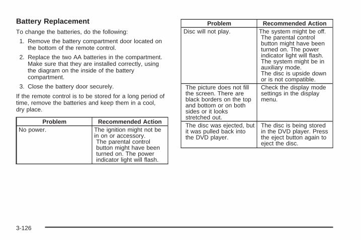
Battery ReplacementTo change the batteries, do the following:
1. Remove the battery compartment door located onthe bottom of the remote control.
2. Replace the two AA batteries in the compartment.Make sure that they are installed correctly, usingthe diagram on the inside of the batterycompartment.
3. Close the battery door securely.
If the remote control is to be stored for a long period oftime, remove the batteries and keep them in a cool,dry place.
Problem Recommended ActionNo power. The ignition might not be
in on or accessory.The parental controlbutton might have beenturned on. The powerindicator light will flash.
Problem Recommended ActionDisc will not play. The system might be off.
The parental controlbutton might have beenturned on. The powerindicator light will flash.The system might be inauxiliary mode.The disc is upside downor is not compatible.
The picture does not fillthe screen. There areblack borders on the topand bottom or on bothsides or it looksstretched out.
Check the display modesettings in the displaymenu.
The disc was ejected, butit was pulled back intothe DVD player.
The disc is being storedin the DVD player. Pressthe eject button again toeject the disc.
3-126

Problem Recommended ActionIn auxiliary mode, thepicture moves or scrolls.
Check the auxiliary inputconnections at bothdevices.Change the VideoFormat to PAL or NTSC.See “Stereo RCA Jacks”previously for how tochange the video format.
The language in theaudio or on the screen iswrong.
Check the audio orlanguage selection in themain DVD menu.
The remote control doesnot work.
Check to make surethere is no obstructionbetween the remotecontrol and thetransmitter window.Check the batteries tomake sure they are notdead or installedincorrectly.The parental controlbutton might have beenturned on. The powerindicator light will flash.
Problem Recommended ActionAfter stopping the player, Ipush Play but sometimesthe DVD starts where Ileft off and sometimes atthe beginning.
If the stop button waspressed one time, theDVD player will resumeplaying where the DVDwas stopped. If the stopbutton was pressed twotimes the DVD player willbegin to play from thebeginning of the DVD.
The auxiliary source isrunning but there is nopicture or sound.
Check that the DVDplayer is in the auxiliarysource mode.Check the auxiliary inputconnections at bothdevices.
My disc is stuck in theplayer. The Load/Ejectbutton does not work.
Turn the DVD power off,then on, then press theload/eject button on theDVD player.Do not attempt to forciblyremove the disc from theDVD player. This couldpermanently damage thedisc and DVD player.
3-127
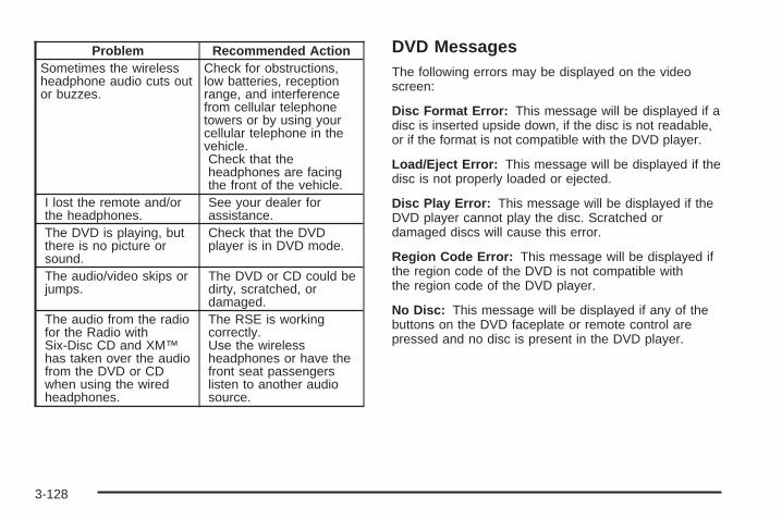
Problem Recommended ActionSometimes the wirelessheadphone audio cuts outor buzzes.
Check for obstructions,low batteries, receptionrange, and interferencefrom cellular telephonetowers or by using yourcellular telephone in thevehicle.Check that theheadphones are facingthe front of the vehicle.
I lost the remote and/orthe headphones.
See your dealer forassistance.
The DVD is playing, butthere is no picture orsound.
Check that the DVDplayer is in DVD mode.
The audio/video skips orjumps.
The DVD or CD could bedirty, scratched, ordamaged.
The audio from the radiofor the Radio withSix-Disc CD and XM™has taken over the audiofrom the DVD or CDwhen using the wiredheadphones.
The RSE is workingcorrectly.Use the wirelessheadphones or have thefront seat passengerslisten to another audiosource.
DVD MessagesThe following errors may be displayed on the videoscreen:
Disc Format Error: This message will be displayed if adisc is inserted upside down, if the disc is not readable,or if the format is not compatible with the DVD player.
Load/Eject Error: This message will be displayed if thedisc is not properly loaded or ejected.
Disc Play Error: This message will be displayed if theDVD player cannot play the disc. Scratched ordamaged discs will cause this error.
Region Code Error: This message will be displayed ifthe region code of the DVD is not compatible withthe region code of the DVD player.
No Disc: This message will be displayed if any of thebuttons on the DVD faceplate or remote control arepressed and no disc is present in the DVD player.
3-128
DVD DistortionThere may be an experience with audio distortion in thewireless headphones when operating cellular phones,scanners, CB radios, Global Positioning Systems(GPS)*, two-way radios, mobile fax, or walkie talkies.
It may be necessary to turn off the DVD playerwhen operating one of these devices in or near thevehicle.
* Excludes the OnStar® System.
Cleaning the Video ScreenPour some isopropyl or rubbing alcohol on a clean clothand gently wipe the video screen. Do not spraydirectly onto the screen and do not press too hard ortoo long on the video screen.
Rear Seat Audio (RSA)This feature allows rear seat passengers to listen to anyof the sources: radio, cassette tapes, CDs, or DVDs.However, the rear seat passengers can only control thesources that the front seat passengers are notlistening to. For example, rear seat passengers maylisten to and control cassette tapes, CDs, or DVDsthrough the headphones while the driver listens to theradio through the front speakers. The rear seatpassengers have control of the volume for each set ofheadphones.
The front seat audio controls always have priority overthe RSA controls. If the front seat passengers switch thesource for the main radio to a remote source, the RSA willnot be able to control the source. You can operate therear seat audio when the main radio is off.
3-129

P (Power): Press this button to turn the system on oroff. The rear speakers will be muted when the poweris turned on unless your vehicle is equipped withthe Bose® audio system.
u (Volume): Turn this knob to increase or todecrease the volume. The left knob controls the leftheadphones and the right knob controls the rightheadphones.
SRC (Source): Press this button to select a source:radio, cassette tapes, CDs, or DVDs.
x SEEK w: When listening to FM1, FM2, or AM pressthe up or the down arrow to go to the next or to theprevious station and stay there. This function is inactive ifthe front seat passengers are listening to the radio.
When a cassette tape is playing, press the up or thedown arrow to go to the next or the previous selection.This function is inactive if the front seat passengers arelistening to a cassette tape.
When a CD is playing, press the up arrow to go to thenext track on the CD. Press the down arrow to go to thestart of the current track if more than eight seconds haveplayed. This function is inactive if the front seatpassengers are listening to a CD.
RSA with HVAC Shown, RSA without HVAC Similar
3-130

PROG (Program): Press this button to go to the nextpreset radio station set on the pushbuttons on themain radio. This function is inactive if the front seatpassengers are listening to the radio.
When a cassette tape is playing, press this button to go tothe other side of the tape. This function is inactive if thefront seat passengers are listening to a cassette tape.
When a CD is playing, press this button to go to thebeginning of the CD. This function is inactive if the frontseat passengers are listening to a CD.
When a CD is playing in the six-disc CD changer, pressthis button to select the next CD, if multiple CDs areloaded. This function is inactive if the front seatpassengers are listening to a CD.
Theft-Deterrent FeatureTHEFTLOCK® is designed to discourage theft of yourvehicle’s radio. The feature works automatically bylearning a portion of the Vehicle Identification Number(VIN). If the radio is moved to a different vehicle, itwill not operate and LOCKED will appear on the display.
When the radio and vehicle are turned off, the blinkingred light indicates that THEFTLOCK® is armed.
With THEFTLOCK® activated, the radio will not operateif stolen.
Audio Steering Wheel Controls
If your vehicle has this feature, some audio controls canbe adjusted at the steering wheel. They include thefollowing:
g (OnStar/Mute): If your vehicle has OnStar®, pressthis button to interact with the OnStar® system. Seethe OnStar® manual provided with your vehicle for moreinformation.
If your vehicle does not have OnStar®, press this buttonto silence the system. Press it again, or any otherradio button, to turn on the sound.
3-131

PROG (Program): Press this button to play a stationyou have programmed on the radio preset pushbuttons.The radio will only seek preset stations with a strongsignal that are in the selected band.
When a cassette tape is playing, press this button toplay the other side of the tape.
When a CD is playing in the CD changer, press thisbutton to go to the next available CD, if multiple CDs areloaded.
Q SOURCE R: Press this button to switch betweenFM1, FM2, AM, or XM1 or XM2 (if equipped), or acassette tape or CD. The cassette or CD must be loadedto play. Available loaded sources are shown on thedisplay as a tape or a CD symbol.
Q SEEK R: Press the up or the down arrow to go tothe next or to the previous radio station and staythere. The radio will only seek stations with a strongsignal that are in the selected band.
When a cassette tape or CD is playing, press the up orthe down arrow to fast forward or reverse.
Q VOLR (Volume): Press the up or the down arrowto increase or to decrease the volume.
Radio Reception
AMThe range for most AM stations is greater than for FM,especially at night. The longer range can causestation frequencies to interfere with each other. Staticcan occur on AM stations caused by things likestorms and power lines. Try reducing the treble toreduce this noise.
FM StereoFM stereo will give the best sound, but FM signals willreach only about 10 to 40 miles (16 to 65 km). Tallbuildings or hills can interfere with FM signals, causingthe sound to fade in and out.
XM™ Satellite Radio ServiceXM™ Satellite Radio Service gives digital radioreception from coast to coast. Just as with FM, tallbuildings or hills can interfere with satellite radio signals,causing the sound to fade in and out. The radio maydisplay NO SIGNAL to indicate interference.
3-132

Care of the Cassette Tape PlayerA tape player that is not cleaned regularly can causereduced sound quality, ruined cassettes, or a damagedmechanism. Cassette tapes should be stored in theircases away from contaminants, direct sunlight, andextreme heat. If they are not, they may not operateproperly or may cause failure of the tape player.
The tape player should be cleaned regularly after every50 hours of use. The radio may display CLEAN toindicate that the tape player has been used for 50 hourswithout resetting the tape clean timer. If this messageappears on the display, the cassette tape playerneeds to be cleaned. It will still play tapes, but it shouldbe cleaned as soon as possible to prevent damageto the tapes and player. If there is a reduction in soundquality, try a known good cassette to see if the tapeor the tape player is at fault. If this other cassette has noimprovement in sound quality, clean the tape player.
For best results, use a scrubbing action, non-abrasivecleaning cassette with pads which scrub the tapehead as the hubs of the cleaner cassette turn. Therecommended cleaning cassette is available throughyour dealer.
When cleaning the cassette tape player with therecommended non-abrasive cleaning cassette, it ispossible that the cassette may eject, because the cuttape detection feature on the radio may recognize it as abroken tape, in error. To prevent the cleaning cassettefrom being ejected, use the following steps:
1. Turn the ignition on.
2. Turn the radio off.
3. Press and hold the TAPE DISC button for fiveseconds. READY will appear on the display andthe cassette symbol will flash for five seconds.
4. Insert the scrubbing action cleaning cassette.
5. Eject the cleaning cassette after the manufacturer’srecommended cleaning time.When the cleaning cassette has been ejected, thecut tape detection feature will be active again.
3-133

A non-scrubbing action, wet-type cleaner which uses acassette with a fabric belt to clean the tape headcan be used. This type of cleaning cassette will noteject on its own. A non-scrubbing action cleaner may notclean as thoroughly as the scrubbing type cleaner.The use of a non-scrubbing action, dry-type cleaningcassette is not recommended.
After the player is cleaned, press and hold the ejectbutton for five seconds to reset the CLEAN indicator.The radio will display --- or CLEANED to show theindicator was reset.
Cassettes are subject to wear and the sound qualitymay degrade over time. Always make sure the cassettetape is in good condition before the tape player isserviced.
Care of Your CDs and DVDsHandle discs carefully. Store them in their original casesor other protective cases and away from direct sunlightand dust. If the surface of a disc is soiled, dampena clean, soft cloth in a mild, neutral detergent solutionand clean it, wiping from the center to the edge.
Be sure never to touch the side without writing whenhandling discs. Pick up discs by grasping the outeredges or the edge of the hole and the outer edge.
Care of the CD and DVD PlayerThe use of CD lens cleaners for CDs is not advised,due to the risk of contaminating the lens of the CD opticswith lubricants internal to the CD mechanism.
3-134

Fixed Mast AntennaThe fixed mast antenna can withstand most car washeswithout being damaged. If the mast should everbecome slightly bent, straighten it out by hand. If themast is badly bent, replace it.
Check occasionally to make sure the mast is stilltightened to the cowl. If tightening is required, tighten byhand, then with a wrench one quarter turn.
XM™ Satellite Radio AntennaSystemThe XM™ Satellite Radio antenna is located on the roofof your vehicle. Keep this antenna clear of snow andice build up for clear radio reception.
The performance of the XM™ system may be affected ifthe sunroof is open.
Loading items onto the roof of your vehicle can interferewith the performance of the XM™ system. Make surethat the XM™ satellite antenna is not obstructed.
Chime Level AdjustmentThe radio is the vehicle chime producer. To change thevolume level, press and hold pushbutton 6 with theignition on and the radio power off. The chime volumelevel will change from the normal level to loud, andLOUD will appear on the radio display. To change backto the default or normal setting, press and holdpushbutton 6 again. The chime level will change fromthe loud level to normal, and NORMAL will appearon the radio display. Each time the chime volume ischanged, three chimes will sound as an example of thenew volume selected. Removing the radio and notreplacing it with a factory radio or chime module willdisable vehicle chimes.
3-135

✍ NOTES
3-136
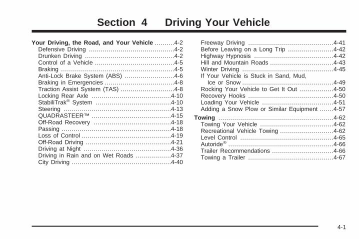
Your Driving, the Road, and Your Vehicle ..........4-2Defensive Driving ...........................................4-2Drunken Driving .............................................4-2Control of a Vehicle ........................................4-5Braking .........................................................4-5Anti-Lock Brake System (ABS) .........................4-6Braking in Emergencies ...................................4-8Traction Assist System (TAS) ...........................4-8Locking Rear Axle ........................................4-10StabiliTrak® System ......................................4-10Steering ......................................................4-13QUADRASTEER™ ........................................4-15Off-Road Recovery .......................................4-18Passing .......................................................4-18Loss of Control .............................................4-19Off-Road Driving ...........................................4-21Driving at Night ............................................4-36Driving in Rain and on Wet Roads ..................4-37City Driving ..................................................4-40
Freeway Driving ...........................................4-41Before Leaving on a Long Trip .......................4-42Highway Hypnosis ........................................4-42Hill and Mountain Roads ................................4-43Winter Driving ..............................................4-45If Your Vehicle is Stuck in Sand, Mud,
Ice or Snow ..............................................4-49Rocking Your Vehicle to Get It Out .................4-50Recovery Hooks ...........................................4-50Loading Your Vehicle ....................................4-51Adding a Snow Plow or Similar Equipment .......4-57
Towing ..........................................................4-62Towing Your Vehicle .....................................4-62Recreational Vehicle Towing ...........................4-62Level Control ...............................................4-65Autoride® .....................................................4-66Trailer Recommendations ...............................4-66Towing a Trailer ...........................................4-67
Section 4 Driving Your Vehicle
4-1

Your Driving, the Road, andYour Vehicle
Defensive DrivingThe best advice anyone can give about driving is: Drivedefensively.
Please start with a very important safety device in yourvehicle: Buckle up. See Safety Belts: They Are forEveryone on page 1-22.
Defensive driving really means “be ready for anything.”On city streets, rural roads, or freeways, it means“always expect the unexpected.”
Assume that pedestrians or other drivers are going tobe careless and make mistakes. Anticipate whatthey might do. Be ready for their mistakes.
Rear-end collisions are about the most preventable ofaccidents. Yet they are common. Allow enough followingdistance. It is the best defensive driving maneuver, inboth city and rural driving. You never know whenthe vehicle in front of you is going to brake or turnsuddenly.
Defensive driving requires that a driver concentrate onthe driving task. Anything that distracts from the drivingtask — such as concentrating on a cellular telephone call,reading, or reaching for something on the floor — makes
proper defensive driving more difficult and can evencause a collision, with resulting injury. Ask a passenger tohelp do things like this, or pull off the road in a safe placeto do them yourself. These simple defensive drivingtechniques could save your life.
Drunken DrivingDeath and injury associated with drinking and driving isa national tragedy. It is the number one contributorto the highway death toll, claiming thousands of victimsevery year.
Alcohol affects four things that anyone needs to drive avehicle:
• Judgment
• Muscular Coordination
• Vision
• Attentiveness
Police records show that almost half of all motorvehicle-related deaths involve alcohol. In most cases,these deaths are the result of someone who wasdrinking and driving. In recent years, more than16,000 annual motor vehicle-related deaths have beenassociated with the use of alcohol, with more than300,000 people injured.
4-2

Many adults — by some estimates, nearly half the adultpopulation — choose never to drink alcohol, so theynever drive after drinking. For persons under 21,it is against the law in every U.S. state to drink alcohol.There are good medical, psychological anddevelopmental reasons for these laws.
The obvious way to eliminate the leading highwaysafety problem is for people never to drink alcohol andthen drive. But what if people do? How much is“too much” if someone plans to drive? It is a lot lessthan many might think. Although it depends oneach person and situation, here is some generalinformation on the problem.
The Blood Alcohol Concentration (BAC) of someonewho is drinking depends upon four things:
• The amount of alcohol consumed
• The drinker’s body weight
• The amount of food that is consumed before andduring drinking
• The length of time it has taken the drinker toconsume the alcohol
According to the American Medical Association, a180 lb (82 kg) person who drinks three 12 ounce (355 ml)bottles of beer in an hour will end up with a BAC of about0.06 percent. The person would reach the same BAC by
drinking three 4 ounce (120 ml) glasses of wine orthree mixed drinks if each had 1-1/2 ounces (45 ml) ofliquors like whiskey, gin, or vodka.
It is the amount of alcohol that counts. For example, ifthe same person drank three double martinis (3 ouncesor 90 ml of liquor each) within an hour, the person’sBAC would be close to 0.12 percent. A personwho consumes food just before or during drinking willhave a somewhat lower BAC level.
4-3

There is a gender difference, too. Women generallyhave a lower relative percentage of body waterthan men. Since alcohol is carried in body water, thismeans that a woman generally will reach a higher BAClevel than a man of her same body weight will wheneach has the same number of drinks.
The law in most U.S. states, and throughout Canada,sets the legal limit at 0.08 percent. In some othercountries, the limit is even lower. For example, it is0.05 percent in both France and Germany. TheBAC limit for all commercial drivers in the United Statesis 0.04 percent.
The BAC will be over 0.10 percent after three tosix drinks (in one hour). Of course, as we have seen,it depends on how much alcohol is in the drinks,and how quickly the person drinks them.
But the ability to drive is affected well below a BAC of0.10 percent. Research shows that the driving skillsof many people are impaired at a BAC approaching0.05 percent, and that the effects are worse at night. Alldrivers are impaired at BAC levels above 0.05 percent.
Statistics show that the chance of being in a collisionincreases sharply for drivers who have a BAC of0.05 percent or above. A driver with a BAC level of0.06 percent has doubled his or her chance of having acollision. At a BAC level of 0.10 percent, the chanceof this driver having a collision is 12 times greater; at alevel of 0.15 percent, the chance is 25 times greater!
The body takes about an hour to rid itself of the alcohol inone drink. No amount of coffee or number of coldshowers will speed that up. “I will be careful” is not theright answer. What if there is an emergency, a need totake sudden action, as when a child darts into the street?A person with even a moderate BAC might not be able toreact quickly enough to avoid the collision.
There is something else about drinking and driving thatmany people do not know. Medical research showsthat alcohol in a person’s system can make crashinjuries worse, especially injuries to the brain, spinalcord, or heart. This means that when anyone who hasbeen drinking — driver or passenger — is in a crash,that person’s chance of being killed or permanentlydisabled is higher than if the person had not beendrinking.
4-4

{CAUTION:
Drinking and then driving is very dangerous.Your reflexes, perceptions, attentiveness, andjudgment can be affected by even a smallamount of alcohol. You can have aserious — or even fatal — collision if you driveafter drinking. Please do not drink and drive orride with a driver who has been drinking. Ridehome in a cab; or if you are with a group,designate a driver who will not drink.
Control of a VehicleYou have three systems that make your vehicle go whereyou want it to go. They are the brakes, the steering, andthe accelerator. All three systems have to do their work atthe places where the tires meet the road.
Sometimes, as when you are driving on snow or ice, it iseasy to ask more of those control systems than the tiresand road can provide. That means you can lose controlof your vehicle. See Traction Assist System (TAS)on page 4-8.
BrakingBraking action involves perception time andreaction time.
First, you have to decide to push on the brake pedal.That is perception time. Then you have to bring up yourfoot and do it. That is reaction time.
Average reaction time is about three-fourths of asecond. But that is only an average. It might be lesswith one driver and as long as two or three seconds ormore with another. Age, physical condition, alertness,coordination, and eyesight all play a part. So do alcohol,drugs, and frustration. But even in three-fourths of asecond, a vehicle moving at 60 mph (100 km/h) travels66 feet (20 m). That could be a lot of distance in anemergency, so keeping enough space betweenyour vehicle and others is important.
And, of course, actual stopping distances vary greatlywith the surface of the road, whether it is pavementor gravel; the condition of the road, whether it iswet, dry, or icy; tire tread; the condition of your brakes;the weight of the vehicle; and the amount of brakeforce applied.
4-5

Avoid needless heavy braking. Some people drive inspurts — heavy acceleration followed by heavybraking — rather than keeping pace with traffic. This isa mistake. Your brakes may not have time to coolbetween hard stops. Your brakes will wear out muchfaster if you do a lot of heavy braking. If you keep pacewith the traffic and allow realistic following distances,you will eliminate a lot of unnecessary braking.That means better braking and longer brake life.
If your engine ever stops while you are driving, brakenormally but do not pump your brakes. If you do,the pedal may get harder to push down. If your enginestops, you will still have some power brake assist.But you will use it when you brake. Once the powerassist is used up, it may take longer to stop andthe brake pedal will be harder to push.
Anti-Lock Brake System (ABS)Your vehicle has anti-lock brakes. ABS is an advancedelectronic braking system that will help prevent abraking skid.
When you start your engine and begin to drive away,your anti-lock brake system will check itself. Youmay hear a momentary motor or clicking noise whilethis test is going on. This is normal.
If there is a problem withthe anti-lock brake system,this warning light willstay on. See Anti-LockBrake System WarningLight on page 3-44.
Along with ABS, your vehicle has a Dynamic RearProportioning (DRP) system. If there is a DRP problem,both the brake and ABS warning lights will come onaccompanied by a 10-second chime. The lights andchime will come on each time the ignition is turned onuntil the problem is repaired. See your dealer for service.
4-6

Let us say the road is wet and you are driving safely.Suddenly, an animal jumps out in front of you. You slamon the brakes and continue braking. Here is whathappens with ABS:
A computer senses that wheels are slowing down.If one of the wheels is about to stop rolling, the computerwill separately work the brakes at each front wheeland at both rear wheels.
The anti-lock system can change the brake pressurefaster than any driver could. The computer isprogrammed to make the most of available tire and roadconditions. This can help you steer around the obstaclewhile braking hard.
As you brake, your computer keeps receiving updateson wheel speed and controls braking pressureaccordingly.
4-7
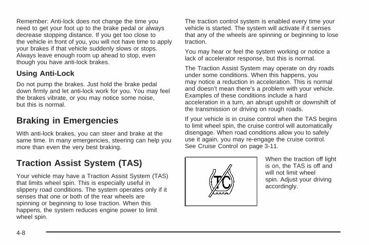
Remember: Anti-lock does not change the time youneed to get your foot up to the brake pedal or alwaysdecrease stopping distance. If you get too close tothe vehicle in front of you, you will not have time to applyyour brakes if that vehicle suddenly slows or stops.Always leave enough room up ahead to stop, eventhough you have anti-lock brakes.
Using Anti-LockDo not pump the brakes. Just hold the brake pedaldown firmly and let anti-lock work for you. You may feelthe brakes vibrate, or you may notice some noise,but this is normal.
Braking in EmergenciesWith anti-lock brakes, you can steer and brake at thesame time. In many emergencies, steering can help youmore than even the very best braking.
Traction Assist System (TAS)Your vehicle may have a Traction Assist System (TAS)that limits wheel spin. This is especially useful inslippery road conditions. The system operates only if itsenses that one or both of the rear wheels arespinning or beginning to lose traction. When thishappens, the system reduces engine power to limitwheel spin.
The traction control system is enabled every time yourvehicle is started. The system will activate if it sensesthat any of the wheels are spinning or beginning to losetraction.
You may hear or feel the system working or notice alack of accelerator response, but this is normal.
The Traction Assist System may operate on dry roadsunder some conditions. When this happens, youmay notice a reduction in acceleration. This is normaland doesn’t mean there’s a problem with your vehicle.Examples of these conditions include a hardacceleration in a turn, an abrupt upshift or downshift ofthe transmission or driving on rough roads.
If your vehicle is in cruise control when the TAS beginsto limit wheel spin, the cruise control will automaticallydisengage. When road conditions allow you to safelyuse it again, you may re-engage the cruise control.See Cruise Control on page 3-11.
When the traction off lightis on, the TAS is off andwill not limit wheelspin. Adjust your drivingaccordingly.
4-8

The traction off light will come on under the followingconditions:
• The Traction Assist System is turned off, either bypressing the TAS on/off button or turning off theautomatic engagement feature of the TAS.
• The transmission is in FIRST (1); TAS will notoperate in this gear. This is normal.
• The vehicle is driven on an extremely rough road.When the vehicle leaves the rough surface, slowsdown or stops, the light will go off and TAS willbe on again. This is normal.
• A Traction Assist System, Anti-Lock Brake Systemor engine-related problem has been detected andthe vehicle needs service.
• If the vehicle has been driven with the TAS systemon for long periods of time, or if the vehicle hasgone through many high speed braking maneuversthe system may be automatically disabled. Thesystem will automatically re-enable afterapproximately two minutes of not using the brakes.
The Traction Assist System, as delivered from thefactory, will automatically come on whenever you startyour vehicle. To limit wheel spin, especially inslippery road conditions, you should always leave thesystem on. But you can turn the TAS off if you ever needto. You should turn the TAS off if your vehicle ever
gets stuck in sand, mud or snow and rocking the vehicleis required. See Rocking Your Vehicle to Get It Outon page 4-50.
To turn the system on oroff, press the TAS on/offbutton located on theinstrument panel.
If you used the button to turn the system off, the tractionoff light will come on and stay on. You can turn thesystem back on at any time by pressing the buttonagain. The traction off light should go off.
If desired, you can change the TAS automaticengagement feature so that the system will not come onautomatically when the engine is started. To do so:
1. Park the vehicle with the ignition off and thetransmission in PARK (P).
2. Turn the ignition to RUN; do not start the engine.
4-9

3. Apply the brake pedal, shift into NEUTRAL (N),press the accelerator pedal to the floor and thenpress the TAS on/off button and hold it down for atleast six seconds.
4. Release the TAS button and both pedals.
5. Turn off the ignition and wait a few seconds.
The next time you start your vehicle, the TAS will notautomatically come on. You can restore the automaticfeature by using the same procedure. Whether the TAS isset to come on automatically or not, you can always turnthe system on or off by pressing the TAS on/off button.
Locking Rear AxleIf your vehicle has this feature, your locking rear axlecan give you additional traction on snow, mud, ice, sandor gravel. It works like a standard axle most of thetime, but when one of the rear wheels has no tractionand the other does, this feature will allow the wheel withtraction to move the vehicle.
StabiliTrak ® SystemYour vehicle may be equipped with the StabiliTrak®
system which combines antilock brake, tractionand stability control systems and helps the drivermaintain directional control of the vehicle in mostdriving conditions.
When you first start your vehicle and begin to drive away,the system performs several diagnostic checks to ensurethere are no problems. You may hear or feel the systemworking. This is normal and does not mean there is aproblem with your vehicle. The system should initializebefore the vehicle reaches 20 mph (32 km/h). In somecases, it may take approximately two miles of drivingbefore the system initializes.
If the system fails to turn on or activate, the STABILITYSYS DISABLED or SERVICE STABILITY messagewill be displayed. If the vehicle has gone through heavyacceleration or braking during the first two miles afterstarting your vehicle, the STABILITY SYS DISABLEDmessage may appear. If this is the case, yourvehicle does not need servicing. Turn your vehicle offand back on again to reset the system. If either messageappears on the Driver Information Center (DIC), andyour vehicle hasn’t gone through hard accelerationor braking in the first two miles, your vehicle should betaken in for service.
The STABILITY SYS ACTIVE message will appear onthe Driver Information Center (DIC) only when thesystem is both on and activated. You may also feel orhear the system working; this is normal. For moreinformation on the stability messages, see DriverInformation Center (DIC) on page 3-54.
4-10

The StabiliTrak® button islocated on the instrumentpanel.
StabiliTrak® and part of the traction control system canbe turned off or back on by pressing the StabiliTrak®
button. All-wheel drive vehicles must be in all-wheeldrive mode to turn the system on or off.Four-wheel-drive vehicles must be in 2HI, 4HIor AUTO 4WD to turn the system on or off.
When the system is turned off, the traction off light willilluminate, and the STABILITY SYS DISABLEDmessage will appear on the DIC to warn the driver thatboth the stability system and part of the tractioncontrol system are disabled. Your vehicle will still havebrake-traction control when StabiliTrak® is off, butwill not be able to use the engine speed managementsystem. See “Traction Control Operation” next formore information.
When the StabiliTrak® system has been turned off, youmay still hear system noises as a result of thebrake-traction control coming on.
It is recommended to leave the system on for normaldriving conditions, but it may be necessary to turn thesystem off if your vehicle is stuck in sand, mud, ice orsnow, and you want to “rock” your vehicle to attempt tofree it. It may also be necessary to turn off the systemwhen driving in extreme off-road conditions where highwheel spin is required. See If Your Vehicle is Stuck inSand, Mud, Ice or Snow on page 4-49.
When the transfer case is in 4LO, the stability system isautomatically disabled, and the STABILITY SYSDISABLED message will appear on the DIC. In 4LO,the StabiliTrak® button only turns the traction controlsystem on and off.
Traction Control OperationThe traction control system is part of the StabiliTrak®
system. Traction control limits wheel spin by reducingengine power to the wheels (engine speedmanagement) and by applying brakes to each individualwheel (brake-traction control) as necessary.
The traction control system is enabled automaticallywhen you start your vehicle, and it will activateand display the TRACTION ACTIVE message in theDriver Information Center (DIC) if it senses that any ofthe wheels are spinning or beginning to lose tractionwhile driving. If you turn off StabiliTrak®, only thebrake-traction control portion of traction control will work.
4-11

The engine speed management will be disabled. In thisstate, engine power is not reduced automatically andthe driven wheels can spin more freely. This can causethe brake-traction control to activate constantly. Formore information on the traction active message, seeDriver Information Center (DIC) on page 3-54.
Notice: If the traction off light comes on due toheavy braking and/or because the traction controlsystem has been continuously active, do notallow the wheel(s) of one axle to spin excessively.If you do, you may be causing damage to thetransfer case. This could lead to costly repairs notcovered by your warranty.
If the brake traction-control system activates constantlyor if the brakes have heated up due to high speedbraking, brake traction-control will be disabled and theTRACTION SYS LIMITED message will be displayed. Inthe limited mode, the traction-control system will onlyuse engine traction-control and is limited in it’s ability toprovide optimal performance since the system willnot utilize brake traction-control to control slip on thedrive wheels. The system will return to normal operationafter the brakes have cooled. This can take up to twominutes or longer depending on brake usage.
Notice: If you allow the wheel(s) of one axle to spinexcessively while the traction off, ABS and brakewarning lights and the SERVICE STABILITYmessage are displayed, you could damage thetransfer case. The repairs would not be covered byyour warranty. Reduce engine power and do notspin the wheel(s) excessively while these lights andthis message are displayed.
The traction control system may activate on dry orrough roads or under conditions such as heavyacceleration while turning or abrupt upshifts/downshiftsof the transmission. When this happens, you maynotice a reduction in acceleration, or may hear a noiseor vibration. This is normal.
If your vehicle is in cruise control when the systemactivates, the STABILITY SYS ACTIVE message willappear on the Driver Information Center (DIC), and thecruise control will automatically disengage. When roadconditions allow you to use cruise again, you mayre-engage the cruise control. See Cruise Control onpage 3-11.
StabiliTrak® may also turn off automatically if itdetermines that a problem exists with the system.If the problem does not clear itself after restartingthe vehicle, you should see your dealer for service.
4-12

Steering
Power SteeringIf you lose power steering assist because the enginestops or the system is not functioning, you can steer butit will take much more effort.
Steering TipsDriving on CurvesIt is important to take curves at a reasonable speed.
A lot of the “driver lost control” accidents mentioned onthe news happen on curves. Here is why:
Experienced driver or beginner, each of us is subject tothe same laws of physics when driving on curves. Thetraction of the tires against the road surface makes itpossible for the vehicle to change its path when you turnthe front wheels. If there is no traction, inertia will keepthe vehicle going in the same direction. If you haveever tried to steer a vehicle on wet ice, you willunderstand this.
The traction you can get in a curve depends on thecondition of your tires and the road surface, the angle atwhich the curve is banked, and your speed. Whileyou are in a curve, speed is the one factor youcan control.
Suppose you are steering through a sharp curve.Then you suddenly accelerate. Both controlsystems — steering and acceleration — have to do theirwork where the tires meet the road. Adding the suddenacceleration can demand too much of those places. Youcan lose control. See Traction Assist System (TAS) onpage 4-8.
What should you do if this ever happens? Ease up onthe accelerator pedal, steer the vehicle the way youwant it to go, and slow down.
Speed limit signs near curves warn that you shouldadjust your speed. Of course, the posted speedsare based on good weather and road conditions. Underless favorable conditions you will want to go slower.
If you need to reduce your speed as you approacha curve, do it before you enter the curve, while your frontwheels are straight ahead.
Try to adjust your speed so you can “drive” through thecurve. Maintain a reasonable, steady speed. Wait toaccelerate until you are out of the curve, and thenaccelerate gently into the straightaway.
4-13

Steering in EmergenciesThere are times when steering can be more effectivethan braking. For example, you come over a hill and finda truck stopped in your lane, or a car suddenly pullsout from nowhere, or a child darts out from betweenparked cars and stops right in front of you. You canavoid these problems by braking — if you can stop intime. But sometimes you cannot; there is not room.That is the time for evasive action — steering around theproblem.
Your vehicle can perform very well in emergencies likethese. First apply your brakes.
See Braking on page 4-5. It is better to remove as muchspeed as you can from a possible collision. Thensteer around the problem, to the left or right dependingon the space available.
An emergency like this requires close attention and aquick decision. If you are holding the steering wheel atthe recommended 9 and 3 o’clock positions, youcan turn it a full 180 degrees very quickly withoutremoving either hand. But you have to act fast, steerquickly, and just as quickly straighten the wheelonce you have avoided the object.
The fact that such emergency situations are alwayspossible is a good reason to practice defensive drivingat all times and wear safety belts properly.
4-14

QUADRASTEER™The QUADRASTEER™ System has a control anddiagnostic module that monitors and records currentsystem status and operational information.
If your vehicle is equipped with the 4-Wheel Steersystem, it has the ability to steer the vehicle withall four wheels.
Once the 4-Wheel Steer mode is selected, it isrecommended to leave the vehicle in this mode at alltimes, and during all driving and weather conditions.
You can select this mode at any speed, however, if youare turning, the system will not engage until the turnis complete.
The 4-Wheel Steer system is equipped with threedifferent driving modes:
2: Two-wheel steering
4: Four-wheel steering
_: Four-wheel steering with a trailer mode
The switch is located on the instrument panel.
2: In this mode, the vehicle will operate like any othervehicle with two-wheel steering. If you want to use2-wheel steer mode and your vehicle is not in this mode,press the button until the 2 indicator, located to theright of the 4-Wheel Steer button, lights up. If the2 indicator is flashing, you will have to center thesteering wheel by turning it to the left or right.
Your vehicle will return to 2 when the transmission isshifted into NEUTRAL (N), for example when entering acar wash.
4-15

If you want to use tire chains, the vehicle needs to bein 2-wheel steer mode. For more information seeTire Chains on page 5-75.
4: In this mode, all four wheels will help steer thevehicle. If you want to use 4, and your vehicle is not inthis mode, press the button, until the 4 indicator,located to the right of the 4-Wheel Steer button, comeson and stays on. If the 4 indicator is flashing, youwill have to center the steering wheel by turning it to theleft or right.
At slower speeds the front and rear wheels will turn inopposite directions. This helps the vehicle maketighter turns, such as during parking, cornering andturning into tight spaces.
At higher speeds the front and rear wheels will turn inthe same direction. This improves stability of the vehicleduring lane changes and sweeping turns.
_ (4-Wheel Steer Tow Mode): When towing atrailer, the 4-wheel steer tow mode provides enhancedstability allowing the trailer to follow the path of the towvehicle more closely, especially during lane changes.
In this mode the system operates much like the 4 mode,but is enhanced for trailer towing. It is recommendedfor all types and weights of trailers.
Slower Speeds (below 40 mph (64 km/h))
Higher Speeds (40 mph (64 km/h), and above)
4-16

To engage the 4-wheel steer tow mode, press thebutton until the 4 and tow mode indicators light up onthe instrument panel. If the tow indicator is flashing, youwill have to center the steering wheel by turning it tothe left or right. While in the 4-wheel steer tow mode, itis possible the steering wheel may be slightly offcenter. For more information, see Towing a Trailer onpage 4-67.
Car Washes for QUADRASTEER™Equipped Vehicles
Notice: Because your vehicle has a wider reartrack a small number of older car washes may betoo narrow for your vehicle. Conveyor systemson some automatic car washes may damage yourvehicle. Only use conveyor system car washes with13-inch (33 cm) wide conveyor rails and/orstationary washes with at least 82 inches (208 cm)between the rails. Before using the car washcheck with the manager.
A. 13 inches (33 cm)B. 82 inches (208 cm)
4-17

Off-Road RecoveryYou may find that your right wheels have dropped offthe edge of a road onto the shoulder while you aredriving.
If the level of the shoulder is only slightly below thepavement, recovery should be fairly easy. Ease off theaccelerator and then, if there is nothing in the way,steer so that your vehicle straddles the edge ofthe pavement. You can turn the steering wheel up toone-quarter turn until the right front tire contactsthe pavement edge. Then turn your steering wheel to gostraight down the roadway.
PassingThe driver of a vehicle about to pass another on atwo-lane highway waits for just the right moment,accelerates, moves around the vehicle ahead, thengoes back into the right lane again. A simple maneuver?
Not necessarily! Passing another vehicle on a two-lanehighway is a potentially dangerous move, since thepassing vehicle occupies the same lane as oncomingtraffic for several seconds. A miscalculation, an error injudgment, or a brief surrender to frustration or angercan suddenly put the passing driver face to face with theworst of all traffic accidents — the head-on collision.
So here are some tips for passing:
• Drive ahead. Look down the road, to the sides andto crossroads for situations that might affect yourpassing patterns. If you have any doubt whatsoeverabout making a successful pass, wait for abetter time.
• Watch for traffic signs, pavement markings andlines. If you can see a sign up ahead that mightindicate a turn or an intersection, delay your pass.A broken center line usually indicates it is allright to pass, providing the road ahead is clear.Never cross a solid line on your side of the lane ora double solid line, even if the road seems emptyof approaching traffic.
4-18

• Do not get too close to the vehicle you want topass while you are awaiting an opportunity. For onething, following too closely reduces your area ofvision, especially if you are following a largervehicle. Also, you will not have adequate space ifthe vehicle ahead suddenly slows or stops.Keep back a reasonable distance.
• When it looks like a chance to pass is coming up,start to accelerate but stay in the right lane anddo not get too close. Time your move so you will beincreasing speed as the time comes to move intothe other lane. If the way is clear to pass, youwill have a running start that more than makes upfor the distance you would lose by droppingback. And if something happens to cause you tocancel your pass, you need only slow downand drop back again and wait for anotheropportunity.
• If other vehicles are lined up to pass a slow vehicle,wait your turn. But take care that someone is nottrying to pass you as you pull out to pass the slowvehicle. Remember to glance over your shoulderand check the blind spot.
• Check your mirrors, glance over your shoulder andstart your left lane change signal before moving outof the right lane to pass. When you are farenough ahead of the passed vehicle to see its frontin your inside mirror, activate your right lane
change signal and move back into the right lane.Remember that if your right outside mirror is convex,the vehicle you just passed may seem to befarther away from you than it really is.
• Try not to pass more than one vehicle at a time ontwo-lane roads. Reconsider before passing thenext vehicle.
• Do not overtake a slowly moving vehicle too rapidly.Even though the brake lamps are not flashing, itmay be slowing down or starting to turn.
• If you are being passed, make it easy for thefollowing driver to get ahead of you. Perhapsyou can ease a little to the right.
Loss of ControlLet us review what driving experts say about whathappens when the three control systems — brakes,steering, and acceleration — do not have enough frictionwhere the tires meet the road to do what the driverhas asked.
In any emergency, do not give up. Keep trying to steerand constantly seek an escape route or area of lessdanger.
4-19

SkiddingIn a skid, a driver can lose control of the vehicle.Defensive drivers avoid most skids by taking reasonablecare suited to existing conditions, and by not overdrivingthose conditions. But skids are always possible.
The three types of skids correspond to your vehicle’sthree control systems. In the braking skid, your wheelsare not rolling. In the steering or cornering skid, too muchspeed or steering in a curve causes tires to slip and losecornering force. And in the acceleration skid, too muchthrottle causes the driving wheels to spin.
A cornering skid is best handled by easing your foot offthe accelerator pedal.
If you have the Traction Assist System (TAS),remember: It helps avoid only the acceleration skid. SeeTraction Assist System (TAS) on page 4-8. If you donot have this system, or if the system is off, thenan acceleration skid is also best handled by easing yourfoot off the accelerator pedal.
If your vehicle starts to slide, ease your foot off theaccelerator pedal and quickly steer the way you wantthe vehicle to go. If you start steering quickly enough,your vehicle may straighten out. Always be readyfor a second skid if it occurs.
Of course, traction is reduced when water, snow, ice,gravel, or other material is on the road. For safety, youwill want to slow down and adjust your driving tothese conditions. It is important to slow down on slipperysurfaces because stopping distance will be longer andvehicle control more limited.
While driving on a surface with reduced traction, tryyour best to avoid sudden steering, acceleration,or braking, including engine braking by shifting to alower gear. Any sudden changes could cause the tiresto slide. You may not realize the surface is slipperyuntil your vehicle is skidding. Learn to recognize warningclues — such as enough water, ice, or packed snowon the road to make a mirrored surface — andslow down when you have any doubt.
Remember: Any anti-lock brake system (ABS) helpsavoid only the braking skid.
4-20

Off-Road DrivingThis off-road guide is for vehicles that have four-wheeldrive or all-wheel drive. Also, see Braking on page 4-5.If your vehicle does not have four-wheel drive orall-wheel drive, you should not drive off-road unless youare on a level, solid surface.
Off-road driving can be great fun. But it does havesome definite hazards. The greatest of these isthe terrain itself.
“Off-roading” means you have left the great NorthAmerican road system behind. Traffic lanes are notmarked. Curves are not banked. There are noroad signs. Surfaces can be slippery, rough, uphill ordownhill. In short, you have gone right back to nature.
Off-road driving involves some new skills. And thatis why it is very important that you read this guide. Youwill find many driving tips and suggestions. Thesewill help make your off-road driving safer and moreenjoyable.
If you think you will need some more ground clearanceat the front of your vehicle, you can remove the frontbumper lower air dam.
The front bumper lower air dam is held in place by aseries of push-pins located around the lower edge of thefront bumper. The push-pins are accessible fromunderneath the front bumper.
4-21

The following steps must be performed on each of thepush-pins to remove the air dam:
1. Insert a tool into thepush-pin slot and pulldownward until thepush-pin snaps loose.
2. While continuing to pulldownward on thepush-pin, squeeze andturn the expandableend of the push-pinwith a tool until itreleases from theretainer.
3. Pull the push-pins andlower air dam assemblyaway from theretainers until the lowerair dam is free.
When you are back on roads, though, be sure toreplace the air dam.
Notice: Operating your vehicle for extendedperiods without the front bumper lower air daminstalled can cause improper air flow to the engineand may allow things like fog lamps or tow hookson the front of your vehicle to be damaged. Alwaysbe sure to replace the front bumper air dam whenyou are finished off-road driving.
4-22

To reinstall the lower air dam do the following:
1. Line up each push-pinwith its intendedretainer and push thewasher portion ofthe push-pin towardsthe retainer until it locksinto place.
2. Push the flat end of thepush-pin towards theretainer until itlocks into place,making sure each issecure.
Before You Go Off-RoadingThere are some things to do before you go out. Forexample, be sure to have all necessary maintenanceand service work done. Check to make sure allunderbody shields (if equipped) are properly attached.Be sure you read all the information about yourfour-wheel-drive or all-wheel-drive vehicle in this manual.Is there enough fuel? Is the spare tire fully inflated?Are the fluid levels up where they should be? What arethe local laws that apply to off-roading where youwill be driving? If you do not know, you should checkwith law enforcement people in the area. Will you be onsomeone’s private land? If so, be sure to get thenecessary permission.
4-23

Loading Your Vehicle for Off-RoadDrivingThere are some important things to remember abouthow to load your vehicle.
• The heaviest things should be on the load floor andforward of your rear axle. Put heavier items as farforward as you can.
• Be sure the load is secured properly, so driving onthe off-road terrain does not toss things around.
{CAUTION:
• Cargo on the load floor piled higher thanthe seatbacks can be thrown forwardduring a sudden stop. You or yourpassengers could be injured. Keep cargobelow the top of the seatbacks.
• Unsecured cargo on the load floor can betossed about when driving over roughterrain. You or your passengers can bestruck by flying objects. Secure the cargoproperly.
• Heavy loads on the roof raise the vehicle’scenter of gravity, making it more likely toroll over. You can be seriously or fatallyinjured if the vehicle rolls over. Put heavyloads inside the cargo area, not on theroof. Keep cargo in the cargo area as farforward and low as possible.
You will find other important information in this manual.See Loading Your Vehicle on page 4-51 and Tireson page 5-57.
4-24

Environmental ConcernsOff-road driving can provide wholesome and satisfyingrecreation. However, it also raises environmentalconcerns. We recognize these concerns and urge everyoff-roader to follow these basic rules for protectingthe environment:
• Always use established trails, roads and areas thathave been specially set aside for public off-roadrecreational driving; obey all posted regulations.
• Avoid any driving practice that could damage theenvironment — shrubs, flowers, trees, grasses — ordisturb wildlife (this includes wheel-spinning,breaking down trees or unnecessary driving throughstreams or over soft ground).
• Always carry a litter bag — make sure all refuse isremoved from any campsite before leaving.
• Take extreme care with open fires (where permitted),camp stoves and lanterns.
• Never park your vehicle over dry grass or othercombustible materials that could catch fire from theheat of the vehicle’s exhaust system.
Traveling to Remote AreasIt makes sense to plan your trip, especially when goingto a remote area. Know the terrain and plan yourroute. You are much less likely to get bad surprises.Get accurate maps of trails and terrain. Try to learn ofany blocked or closed roads.
It is also a good idea to travel with at least one othervehicle. If something happens to one of them, the othercan help quickly.
Does your vehicle have a winch? If so, be sure to readthe winch instructions. In a remote area, a winchcan be handy if you get stuck. But you will want to knowhow to use it properly.
Getting Familiar with Off-Road DrivingIt is a good idea to practice in an area that is safeand close to home before you go into the wilderness.Off-road driving does require some new and differentskills. Here is what we mean.
Tune your senses to different kinds of signals. Youreyes, for example, need to constantly sweep the terrainfor unexpected obstacles. Your ears need to listenfor unusual tire or engine sounds. With your arms,hands, feet and body, you will need to respond tovibrations and vehicle bounce.
4-25

Controlling your vehicle is the key to successful off-roaddriving. One of the best ways to control your vehicleis to control your speed. Here are some things to keepin mind. At higher speeds:
• you approach things faster and you have less timeto scan the terrain for obstacles.
• you have less time to react.
• you have more vehicle bounce when you drive overobstacles.
• you will need more distance for braking, especiallysince you are on an unpaved surface.
{CAUTION:
When you are driving off-road, bouncing andquick changes in direction can easily throwyou out of position. This could cause you tolose control and crash. So, whether you aredriving on or off the road, you and yourpassengers should wear safety belts.
Scanning the TerrainOff-road driving can take you over many different kindsof terrain. You need to be familiar with the terrainand its many different features. Here are some things toconsider.
Surface Conditions: Off-roading can take you overhard-packed dirt, gravel, rocks, grass, sand, mud, snowor ice. Each of these surfaces affects the steering,acceleration and braking of your vehicle in differentways. Depending upon the kind of surface you are on,you may experience slipping, sliding, wheel spinning,delayed acceleration, poor traction and longer brakingdistances.
Surface Obstacles: Unseen or hidden obstacles canbe hazardous. A rock, log, hole, rut or bump can startleyou if you are not prepared for them. Often theseobstacles are hidden by grass, bushes, snow or eventhe rise and fall of the terrain itself. Here are somethings to consider:
• Is the path ahead clear?
• Will the surface texture change abruptly up ahead?
• Does the travel take you uphill or downhill?There is more discussion of these subjects later.
• Will you have to stop suddenly or change directionquickly?
4-26

When you drive over obstacles or rough terrain, keep afirm grip on the steering wheel. Ruts, troughs orother surface features can jerk the wheel out of yourhands if you are not prepared.
When you drive over bumps, rocks, or other obstacles,your wheels can leave the ground. If this happens,even with one or two wheels, you cannot control thevehicle as well or at all.
Because you will be on an unpaved surface, it isespecially important to avoid sudden acceleration,sudden turns or sudden braking.
In a way, off-road driving requires a different kind ofalertness from driving on paved roads and highways.There are no road signs, posted speed limits orsignal lights. You have to use your own good judgmentabout what is safe and what is not.
Drinking and driving can be very dangerous on anyroad. And this is certainly true for off-road driving. At thevery time you need special alertness and drivingskills, your reflexes, perceptions and judgment can beaffected by even a small amount of alcohol. Youcould have a serious — or even fatal — accident if youdrink and drive or ride with a driver who has beendrinking. See Drunken Driving on page 4-2.
Driving on Off-Road HillsOff-road driving often takes you up, down or across ahill. Driving safely on hills requires good judgmentand an understanding of what your vehicle can andcannot do. There are some hills that simply cannot bedriven, no matter how well built the vehicle.
{CAUTION:
Many hills are simply too steep for any vehicle.If you drive up them, you will stall. If you drivedown them, you cannot control your speed. Ifyou drive across them, you will roll over. Youcould be seriously injured or killed. If you haveany doubt about the steepness, do not drivethe hill.
4-27
Approaching a HillWhen you approach a hill, you need to decide if it isone of those hills that is just too steep to climb, descendor cross. Steepness can be hard to judge. On a verysmall hill, for example, there may be a smooth, constantincline with only a small change in elevation whereyou can easily see all the way to the top. On a large hill,the incline may get steeper as you near the top, butyou may not see this because the crest of the hillis hidden by bushes, grass or shrubs.
Here are some other things to consider as youapproach a hill.• Is there a constant incline, or does the hill get
sharply steeper in places?• Is there good traction on the hillside, or will the
surface cause tire slipping?• Is there a straight path up or down the hill so you
will not have to make turning maneuvers?• Are there obstructions on the hill that can block your
path, such as boulders, trees, logs, or ruts?• What is beyond the hill? Is there a cliff, an
embankment, a drop-off, a fence? Get out and walkthe hill if you do not know. It is the smart way tofind out.
• Is the hill simply too rough? Steep hills often haveruts, gullies, troughs and exposed rocks becausethey are more susceptible to the effects of erosion.
Driving UphillOnce you decide you can safely drive up the hill, youneed to take some special steps.
• Use a low gear and get a firm grip on the steeringwheel.
• Get a smooth start up the hill and try to maintainyour speed. Do not use more power than youneed, because you do not want your wheels to startspinning or sliding.
• Try to drive straight up the hill if at all possible.If the path twists and turns, you might want tofind another route.
{CAUTION:
Turning or driving across steep hills can bedangerous. You could lose traction, slidesideways, and possibly roll over. You could beseriously injured or killed. When driving uphills, always try to go straight up.
• Ease up on your speed as you approach the topof the hill.
4-28

• Attach a flag to the vehicle to make you morevisible to approaching traffic on trails or hills.
• Sound the horn as you approach the top of the hillto let opposing traffic know you are there.
• Use your headlamps even during the day.They make you more visible to oncoming traffic.
{CAUTION:
Driving to the top (crest) of a hill at full speedcan cause an accident. There could be adrop-off, embankment, cliff, or even anothervehicle. You could be seriously injured orkilled. As you near the top of a hill, slow downand stay alert.
Q: What should I do if my vehicle stalls, or isabout to stall, and I cannot make it upthe hill?
A: If this happens, there are some things you shoulddo, and there are some things you must not do.First, here is what you should do:
• Push the brake pedal to stop the vehicle and keepit from rolling backwards. Also, apply the parkingbrake.
• If your engine is still running, shift the transmissionto REVERSE (R), release the parking brake, andslowly back down the hill in REVERSE (R).
• If your engine has stopped running, you will need torestart it. With the brake pedal pressed and theparking brake still applied, shift the transmission toPARK (P) and restart the engine. Then, shift toREVERSE (R), release the parking brake, andslowly back down the hill as straight as possible inREVERSE (R).
• As you are backing down the hill, put your left handon the steering wheel at the 12 o’clock position.This way, you will be able to tell if your wheels arestraight and maneuver as you back down. It isbest that you back down the hill with your wheelsstraight rather than in the left or right direction.Turning the wheel too far to the left or rightwill increase the possibility of a rollover.
4-29

Here are some things you must not do if you stall, orare about to stall, when going up a hill.
• Never attempt to prevent a stall by shifting intoNEUTRAL (N) to rev-up the engine and regainforward momentum. This will not work. Your vehiclewill roll backwards very quickly and you could goout of control.Instead, apply the regular brake to stop thevehicle. Then apply the parking brake. Shift toREVERSE (R), release the parking brake,and slowly back straight down.
{CAUTION:
Shifting the transfer case to NEUTRAL cancause your vehicle to roll even if thetransmission is in PARK (P). This is becausethe NEUTRAL position on the transfer caseoverrides the transmission. You or someoneelse could be injured. If you are going to leaveyour vehicle, set the parking brake and shiftthe transmission to PARK (P). But do not shiftthe transfer case to NEUTRAL.
• Never attempt to turn around if you are about tostall when going up a hill. If the hill is steepenough to stall your vehicle, it is steep enough tocause you to roll over if you turn around. If youcannot make it up the hill, you must back straightdown the hill.
Q: Suppose, after stalling, I try to back down thehill and decide I just cannot do it. Whatshould I do?
A: Set the parking brake, put your transmission inPARK (P) and turn off the engine. Leave thevehicle and go get some help. Exit on the uphillside and stay clear of the path the vehicle wouldtake if it rolled downhill. Do not shift the transfercase to NEUTRAL when you leave the vehicle.Leave it in some gear.
Driving DownhillWhen off-roading takes you downhill, you will want toconsider a number of things:
• How steep is the downhill? Will I be able to maintainvehicle control?
• What is the surface like? Smooth? Rough?Slippery? Hard-packed dirt? Gravel?
4-30

• Are there hidden surface obstacles? Ruts? Logs?Boulders?
• What is at the bottom of the hill? Is there a hiddencreek bank or even a river bottom with large rocks?
If you decide you can go down a hill safely, then try tokeep your vehicle headed straight down, and use alow gear. This way, engine drag can help your brakesand they will not have to do all the work. Descendslowly, keeping your vehicle under control at all times.
{CAUTION:
Heavy braking when going down a hill cancause your brakes to overheat and fade. Thiscould cause loss of control and a seriousaccident. Apply the brakes lightly whendescending a hill and use a low gear to keepvehicle speed under control.
Q: Are there some things I should not do whendriving down a hill?
A: Yes! These are important because if you ignorethem you could lose control and have a seriousaccident.
• When driving downhill, avoid turns that take youacross the incline of the hill. A hill that is not toosteep to drive down may be too steep to driveacross. You could roll over if you do not drivestraight down.
• Never go downhill with the transmission inNEUTRAL (N). This is called “free-wheeling.”Your brakes will have to do all the work and couldoverheat and fade.
Q: Am I likely to stall when going downhill?
A: It is much more likely to happen going uphill. But ifit happens going downhill, here is what to do.
1. Stop your vehicle by applying the regular brakes.Apply the parking brake.
2. Shift to PARK (P) and, while still braking, restart theengine.
3. Shift back to a low gear, release the parking brake,and drive straight down.
4. If the engine will not start, get out and get help.
4-31

Driving Across an InclineSooner or later, an off-road trail will probably go acrossthe incline of a hill. If this happens, you have todecide whether to try to drive across the incline.Here are some things to consider:
• A hill that can be driven straight up or down may betoo steep to drive across. When you go straight up ordown a hill, the length of the wheel base — thedistance from the front wheels to the rearwheels — reduces the likelihood the vehicle willtumble end over end. But when you drive across anincline, the much more narrow track width — thedistance between the left and right wheels — maynot prevent the vehicle from tilting and rolling over.Also, driving across an incline puts more weight onthe downhill wheels. This could cause a downhillslide or a rollover.
• Surface conditions can be a problem when you driveacross a hill. Loose gravel, muddy spots, or even wetgrass can cause your tires to slip sideways, downhill.If the vehicle slips sideways, it can hit something thatwill trip it — a rock, a rut, etc. — and roll over.
• Hidden obstacles can make the steepness of theincline even worse. If you drive across a rock with theuphill wheels, or if the downhill wheels drop into a rutor depression, your vehicle can tilt even more.
For reasons like these, you need to decide carefullywhether to try to drive across an incline. Just because thetrail goes across the incline does not mean you have todrive it. The last vehicle to try it might have rolled over.
{CAUTION:
Driving across an incline that is too steep willmake your vehicle roll over. You could beseriously injured or killed. If you have anydoubt about the steepness of the incline, donot drive across it. Find another route instead.
Q: What if I am driving across an incline that is nottoo steep, but I hit some loose gravel and startto slide downhill. What should I do?
A: If you feel your vehicle starting to slide sideways,turn downhill. This should help straighten out thevehicle and prevent the side slipping. However,a much better way to prevent this is to get out and“walk the course” so you know what the surfaceis like before you drive it.
4-32

Stalling on an InclineIf your vehicle stalls when you are crossing an incline,be sure you, and any passengers, get out on theuphill side, even if the door there is harder to open. Ifyou get out on the downhill side and the vehicle starts toroll over, you will be right in its path.
If you have to walk down the slope, stay out of the paththe vehicle will take if it does roll over.
{CAUTION:
Getting out on the downhill (low) side of avehicle stopped across an incline isdangerous. If the vehicle rolls over, you couldbe crushed or killed. Always get out on theuphill (high) side of the vehicle and stay wellclear of the rollover path.
Driving in Mud, Sand, Snow or IceWhen you drive in mud, snow or sand, your wheels willnot get good traction. You cannot accelerate asquickly, turning is more difficult, and you will need longerbraking distances.
It is best to use a low gear when you are in mud — thedeeper the mud, the lower the gear. In really deepmud, the idea is to keep your vehicle moving so you donot get stuck.
4-33

When you drive on sand, you will sense a change inwheel traction. But it will depend upon how looselypacked the sand is. On loosely packed sand, such ason beaches or sand dunes, your tires will tend tosink into the sand. This has an effect on steering,accelerating and braking. Drive at a reduced speed andavoid sharp turns or abrupt maneuvers.
Hard packed snow and ice offer the worst tire traction.On these surfaces, it is very easy to lose control.On wet ice, for example, the traction is so poor that youwill have difficulty accelerating. And if you do getmoving, poor steering and difficult braking can causeyou to slide out of control.
{CAUTION:
Driving on frozen lakes, ponds, or rivers canbe dangerous. Underwater springs, currentsunder the ice, or sudden thaws can weaken theice. Your vehicle could fall through the ice andyou and your passengers could drown. Driveyour vehicle on safe surfaces only.
Driving in WaterHeavy rain can mean flash flooding, and flood watersdemand extreme caution.
Find out how deep the water is before you drive throughit. If it is deep enough to cover your wheel hubs,axles or exhaust pipe, do not try it — you probably willnot get through. Also, water that deep can damageyour axle and other vehicle parts.
If the water is not too deep, drive slowly through it.At faster speeds, water splashes on your ignition systemand your vehicle can stall. Stalling can also occur ifyou get your tailpipe under water. And, as long as yourtailpipe is under water, you will never be able tostart your engine. When you go through water,remember that when your brakes get wet, it may takeyou longer to stop.
4-34

{CAUTION:
Driving through rushing water can bedangerous. Deep water can sweep your vehicledownstream and you and your passengerscould drown. If it is only shallow water, it canstill wash away the ground from under yourtires, and you could lose traction and roll thevehicle over. Do not drive through rushingwater.
See Driving in Rain and on Wet Roads on page 4-37 formore information on driving through water.
After Off-Road DrivingRemove any brush or debris that has collected on theunderbody, chassis or under the hood. Theseaccumulations can be a fire hazard.
After operation in mud or sand, have the brake liningscleaned and checked. These substances can causeglazing and uneven braking. Check the body structure,steering, suspension, wheels, tires and exhaustsystem for damage. Also, check the fuel lines andcooling system for any leakage.
Your vehicle will require more frequent service due tooff-road use. Refer to the Maintenance Schedulefor additional information.
4-35

Driving at Night
Night driving is more dangerous than day driving. Onereason is that some drivers are likely to be impaired — byalcohol or drugs, with night vision problems, or by fatigue.
Here are some tips on night driving.
• Drive defensively.
• Do not drink and drive.
• Adjust your inside rearview mirror to reduce theglare from headlamps behind you.
• Since you cannot see as well, you may need toslow down and keep more space between youand other vehicles.
• Slow down, especially on higher speed roads. Yourheadlamps can light up only so much road ahead.
• In remote areas, watch for animals.
• If you are tired, pull off the road in a safe placeand rest.
No one can see as well at night as in the daytime.But as we get older these differences increase.A 50-year-old driver may require at least twice as muchlight to see the same thing at night as a 20-year-old.
What you do in the daytime can also affect yournight vision. For example, if you spend the day in brightsunshine you are wise to wear sunglasses. Youreyes will have less trouble adjusting to night. But if youare driving, do not wear sunglasses at night. Theymay cut down on glare from headlamps, but they alsomake a lot of things invisible.
You can be temporarily blinded by approachingheadlamps. It can take a second or two, or even severalseconds, for your eyes to re-adjust to the dark. Whenyou are faced with severe glare, as from a driverwho does not lower the high beams, or a vehicle withmisaimed headlamps, slow down a little. Avoidstaring directly into the approaching headlamps.
4-36

Keep your windshield and all the glass on your vehicleclean — inside and out. Glare at night is made muchworse by dirt on the glass. Even the inside of the glasscan build up a film caused by dust. Dirty glass makeslights dazzle and flash more than clean glass would,making the pupils of your eyes contract repeatedly.
Remember that your headlamps light up far less of aroadway when you are in a turn or curve. Keepyour eyes moving; that way, it is easier to pick out dimlylighted objects. Just as your headlamps should bechecked regularly for proper aim, so should your eyesbe examined regularly. Some drivers suffer fromnight blindness — the inability to see in dim light — andare not even aware of it.
Driving in Rain and on Wet Roads
Rain and wet roads can mean driving trouble. On a wetroad, you cannot stop, accelerate, or turn as wellbecause your tire-to-road traction is not as good as ondry roads. And, if your tires do not have much treadleft, you will get even less traction. It is always wise togo slower and be cautious if rain starts to fall whileyou are driving. The surface may get wet suddenly whenyour reflexes are tuned for driving on dry pavement.
4-37
The heavier the rain, the harder it is to see. Even if yourwindshield wiper blades are in good shape, a heavyrain can make it harder to see road signs and trafficsignals, pavement markings, the edge of the road, andeven people walking.It is wise to keep your wiping equipment in good shapeand keep your windshield washer tank filled withwasher fluid. Replace your windshield wiper insertswhen they show signs of streaking or missing areas onthe windshield, or when strips of rubber start toseparate from the inserts.Driving too fast through large water puddles or even goingthrough some car washes can cause problems, too.The water may affect your brakes. Try to avoid puddles.But if you cannot, try to slow down before you hit them.
{CAUTION:
Wet brakes can cause accidents. They will notwork as well in a quick stop and may causepulling to one side. You could lose control ofthe vehicle.After driving through a large puddle of water ora car wash, apply your brake pedal lightly untilyour brakes work normally.
HydroplaningHydroplaning is dangerous. So much water can build upunder your tires that they can actually ride on thewater. This can happen if the road is wet enough andyou are going fast enough. When your vehicle ishydroplaning, it has little or no contact with the road.Hydroplaning does not happen often. But it can if yourtires do not have much tread or if the pressure in one ormore is low. It can happen if a lot of water is standing onthe road. If you can see reflections from trees, telephonepoles, or other vehicles, and raindrops dimple the water’ssurface, there could be hydroplaning.Hydroplaning usually happens at higher speeds.There just is not a hard and fast rule about hydroplaning.The best advice is to slow down when it is raining.
4-38

Driving Through Deep Standing Water
Notice: If you drive too quickly through deeppuddles or standing water, water can come inthrough your engine’s air intake and badly damageyour engine. Never drive through water that isslightly lower than the underbody of your vehicle.If you cannot avoid deep puddles or standing water,drive through them very slowly.
Driving Through Flowing Water
{CAUTION:
Flowing or rushing water creates strong forces.If you try to drive through flowing water, as youmight at a low water crossing, your vehicle canbe carried away. As little as six inches offlowing water can carry away a smaller vehicle.If this happens, you and other vehicleoccupants could drown. Do not ignore policewarning signs, and otherwise be very cautiousabout trying to drive through flowing water.
Some Other Rainy Weather Tips• Turn on your low-beam headlamps — not just your
parking lamps — to help make you more visibleto others.
• Besides slowing down, allow some extra followingdistance. And be especially careful when youpass another vehicle. Allow yourself more clearroom ahead, and be prepared to have yourview restricted by road spray.
• Have good tires with proper tread depth. See Tireson page 5-57.
4-39

City Driving
One of the biggest problems with city streets is theamount of traffic on them. You will want to watch out forwhat the other drivers are doing and pay attention totraffic signals.
Here are ways to increase your safety in city driving:
• Know the best way to get to where you aregoing. Get a city map and plan your trip intoan unknown part of the city just as you would for across-country trip.
• Try to use the freeways that rim and crisscrossmost large cities. You will save time and energy.See Freeway Driving on page 4-41.
• Treat a green light as a warning signal. A trafficlight is there because the corner is busy enoughto need it. When a light turns green, and just beforeyou start to move, check both ways for vehiclesthat have not cleared the intersection or maybe running the red light.
4-40

Freeway Driving
Mile for mile, freeways — also called thruways, parkways,expressways, turnpikes, or superhighways — are thesafest of all roads. But they have their own special rules.
The most important advice on freeway driving is: Keepup with traffic and keep to the right. Drive at thesame speed most of the other drivers are driving.Too-fast or too-slow driving breaks a smooth traffic flow.Treat the left lane on a freeway as a passing lane.
At the entrance, there is usually a ramp that leads to thefreeway. If you have a clear view of the freeway as youdrive along the entrance ramp, you should begin to checktraffic. Try to determine where you expect to blend withthe flow. Try to merge into the gap at close to theprevailing speed. Switch on your turn signal, check yourmirrors, and glance over your shoulder as often asnecessary. Try to blend smoothly with the traffic flow.Once you are on the freeway, adjust your speed to theposted limit or to the prevailing rate if it is slower.Stay in the right lane unless you want to pass.Before changing lanes, check your mirrors. Then useyour turn signal.Just before you leave the lane, glance quickly over yourshoulder to make sure there is not another vehicle inyour blind spot.Once you are moving on the freeway, make certain youallow a reasonable following distance. Expect to moveslightly slower at night.When you want to leave the freeway, move to theproper lane well in advance. If you miss your exit,do not, under any circumstances, stop and back up.Drive on to the next exit.The exit ramp can be curved, sometimes quite sharply.The exit speed is usually posted.Reduce your speed according to your speedometer, notto your sense of motion. After driving for any distanceat higher speeds, you may tend to think you aregoing slower than you actually are.
4-41

Before Leaving on a Long TripMake sure you are ready. Try to be well rested. If youmust start when you are not fresh — such as aftera day’s work — do not plan to make too many miles thatfirst part of the journey. Wear comfortable clothingand shoes you can easily drive in.
Is your vehicle ready for a long trip? If you keep itserviced and maintained, it is ready to go. If it needsservice, have it done before starting out. Of course,you will find experienced and able service experts inGM dealerships all across North America. They will beready and willing to help if you need it.
Here are some things you can check before a trip:
• Windshield Washer Fluid: Is the reservoir full?Are all windows clean inside and outside?
• Wiper Blades: Are they in good shape?
• Fuel, Engine Oil, Other Fluids: Have you checkedall levels?
• Lamps: Are they all working? Are the lenses clean?
• Tires: They are vitally important to a safe,trouble-free trip. Is the tread good enough forlong-distance driving? Are the tires all inflated to therecommended pressure?
• Weather Forecasts: What is the weather outlookalong your route? Should you delay your trip ashort time to avoid a major storm system?
• Maps: Do you have up-to-date maps?
Highway HypnosisIs there actually such a condition as highway hypnosis?Or is it just plain falling asleep at the wheel? Call ithighway hypnosis, lack of awareness, or whatever.
There is something about an easy stretch of road with thesame scenery, along with the hum of the tires on theroad, the drone of the engine, and the rush of the windagainst the vehicle that can make you sleepy. Do not let ithappen to you! If it does, your vehicle can leave the roadin less than a second, and you could crash and beinjured.
4-42

What can you do about highway hypnosis? First, beaware that it can happen.
Then here are some tips:
• Make sure your vehicle is well ventilated, with acomfortably cool interior.
• Keep your eyes moving. Scan the road ahead andto the sides. Check your mirrors and yourinstruments frequently.
• If you get sleepy, pull off the road into a rest,service, or parking area and take a nap, get someexercise, or both. For safety, treat drowsinesson the highway as an emergency.
Hill and Mountain Roads
Driving on steep hills or mountains is different fromdriving in flat or rolling terrain.
4-43

If you drive regularly in steep country, or if you areplanning to visit there, here are some tips that can makeyour trips safer and more enjoyable. See Off-RoadDriving on page 4-21 for information about drivingoff-road.
• Keep your vehicle in good shape. Check all fluidlevels and also the brakes, tires, cooling system,and transmission. These parts can work hardon mountain roads.
• Know how to go down hills. The most importantthing to know is this: let your engine do some ofthe slowing down. Shift to a lower gear when you godown a steep or long hill.
{CAUTION:
If you do not shift down, your brakes could getso hot that they would not work well. Youwould then have poor braking or even nonegoing down a hill. You could crash. Shift downto let your engine assist your brakes on asteep downhill slope.
{CAUTION:
Coasting downhill in NEUTRAL (N) or with theignition off is dangerous. Your brakes will haveto do all the work of slowing down. They couldget so hot that they would not work well. Youwould then have poor braking or even nonegoing down a hill. You could crash. Alwayshave your engine running and your vehicle ingear when you go downhill.
• Know how to go uphill. You may want to shift downto a lower gear. The lower gears help cool yourengine and transmission, and you can climb the hillbetter.
• Stay in your own lane when driving on two-laneroads in hills or mountains. Do not swing wideor cut across the center of the road. Drive at speedsthat let you stay in your own lane.
4-44

• As you go over the top of a hill, be alert. Therecould be something in your lane, like a stalled car oran accident.
• You may see highway signs on mountains thatwarn of special problems. Examples are longgrades, passing or no-passing zones, a falling rocksarea, or winding roads. Be alert to these and takeappropriate action.
Winter Driving
Here are some tips for winter driving:
• Have your vehicle in good shape for winter.
• You may want to put winter emergency supplies inyour vehicle.
Also see Tires on page 5-57.
Include an ice scraper, a small brush or broom, asupply of windshield washer fluid, a rag, some winterouter clothing, a small shovel, a flashlight, a redcloth, and a couple of reflective warning triangles. And,if you will be driving under severe conditions, includea small bag of sand, a piece of old carpet, or a couple ofburlap bags to help provide traction. Be sure youproperly secure these items in your vehicle.
4-45

Driving on Snow or IceMost of the time, those places where your tires meetthe road probably have good traction.
However, if there is snow or ice between your tires andthe road, you can have a very slippery situation. Youwill have a lot less traction, or grip, and will need to bevery careful.
What is the worst time for this? Wet ice. Very cold snowor ice can be slick and hard to drive on. But wet icecan be even more trouble because it may offer the leasttraction of all. You can get wet ice when it is aboutfreezing, 32°F (0°C), and freezing rain begins to fall. Tryto avoid driving on wet ice until salt and sand crewscan get there.
Whatever the condition — smooth ice, packed, blowing,or loose snow — drive with caution.
If you have the traction assist system (TAS), it willimprove your ability to accelerate when driving on aslippery road. But you can turn the TAS off if you everneed to. You should turn the TAS off if your vehicle evergets stuck in sand, mud, ice, or snow. See If YourVehicle is Stuck in Sand, Mud, Ice or Snow onpage 4-49. Even if your vehicle has TAS, you will wantto slow down and adjust your driving to the roadconditions. Under certain conditions, you may want toturn the TAS off, such as when driving through deepsnow and loose gravel, to help maintain vehicle motionat lower speeds. See Traction Assist System (TAS)on page 4-8.
If you do not have TAS, accelerate gently. Try not tobreak the fragile traction. If you accelerate too fast, thedrive wheels will spin and polish the surface underthe tires even more.
4-46

Your anti-lock brake system (ABS) improves yourvehicle’s stability when you make a hard stop on aslippery road. Even though you have ABS, you will wantto begin stopping sooner than you would on drypavement. See Anti-Lock Brake System (ABS) onpage 4-6.
• Allow greater following distance on any slippery road.
• Watch for slippery spots. The road might be fine untilyou hit a spot that is covered with ice. On anotherwise clear road, ice patches may appear inshaded areas where the sun cannot reach, such asaround clumps of trees, behind buildings, or underbridges. Sometimes the surface of a curve or anoverpass may remain icy when the surroundingroads are clear. If you see a patch of ice ahead ofyou, brake before you are on it. Try not to brake whileyou are actually on the ice, and avoid suddensteering maneuvers.
If You Are Caught in a BlizzardIf you are stopped by heavy snow, you could be in aserious situation. You should probably stay withyour vehicle unless you know for sure that you are nearhelp and you can hike through the snow. Here aresome things to do to summon help and keep yourselfand your passengers safe:
• Turn on your hazard flashers.
• Tie a red cloth to your vehicle to alert police thatyou have been stopped by the snow.
• Put on extra clothing or wrap a blanket around you.If you do not have blankets or extra clothing, makebody insulators from newspapers, burlap bags,rags, floor mats — anything you can wrap aroundyourself or tuck under your clothing to keep warm.
4-47

You can run the engine to keep warm, but be careful.
{CAUTION:
Snow can trap exhaust gases under yourvehicle. This can cause deadly CO (carbonmonoxide) gas to get inside. CO couldovercome you and kill you. You cannot see itor smell it, so you might not know it is in yourvehicle. Clear away snow from around thebase of your vehicle, especially any that isblocking your exhaust pipe. And check aroundagain from time to time to be sure snow doesnot collect there.
Open a window just a little on the side of thevehicle that is away from the wind. This willhelp keep CO out.
Run your engine only as long as you must. This savesfuel. When you run the engine, make it go a littlefaster than just idle. That is, push the acceleratorslightly. This uses less fuel for the heat that you get andit keeps the battery charged. You will need awell-charged battery to restart the vehicle, and possiblyfor signaling later on with your headlamps. Let theheater run for a while.
4-48

Then, shut the engine off and close the window almostall the way to preserve the heat. Start the engineagain and repeat this only when you feel reallyuncomfortable from the cold. But do it as little aspossible. Preserve the fuel as long as you can. To helpkeep warm, you can get out of the vehicle and dosome fairly vigorous exercises every half hour or so untilhelp comes.
If Your Vehicle is Stuck in Sand,Mud, Ice or SnowIn order to free your vehicle when it is stuck, you willneed to spin the wheels, but you do not want tospin your wheels too fast. The method known as rockingcan help you get out when you are stuck, but youmust use caution.
{CAUTION:
If you let your tires spin at high speed, they canexplode, and you or others could be injured.And, the transmission or other parts of thevehicle can overheat. That could cause anengine compartment fire or other damage.When you are stuck, spin the wheels as little aspossible. Do not spin the wheels above35 mph (55 km/h) as shown on thespeedometer.
Notice: Spinning your wheels can destroy parts ofyour vehicle as well as the tires. If you spin thewheels too fast while shifting your transmissionback and forth, you can destroy your transmission.
For more information about using tire chains on yourvehicle, see Tire Chains on page 5-75.
4-49

Rocking Your Vehicle to Get It OutFirst, turn your steering wheel left and right. Thatwill clear the area around your front wheels. If you havea four-wheel-drive vehicle, shift into 4HI or 4LO. Ifyour vehicle has the Traction Assist System (TAS), youshould turn it off by pressing the TAS on/off button. Ifyour vehicle has the StabiliTrak® System, turn theStabiliTrak® System off by pressing theStabiliTrak® button so that the STABILITY SYSTEMDISABLED and TRACTION OFF lights are illuminatedon the instrument panel cluster. Then shift back andforth between REVERSE (R) and a forward gear,spinning the wheels as little as possible. Release theaccelerator pedal while you shift, and press lightly on theaccelerator pedal when the transmission is in gear.By slowly spinning your wheels in the forward andreverse directions, you will cause a rocking motion thatmay free your vehicle. If that does not get you outafter a few tries, you may need to be towed out. Or, youcan use your recovery hooks if your vehicle hasthem. If you do need to be towed out, see Towing YourVehicle on page 4-62.
Recovery HooksYour vehicle may be equipped with recovery hooks. Thehooks are provided at the front of your vehicle. You mayneed to use them if you are stuck off-road and need to bepulled to some place where you can continue driving.
4-50

{CAUTION:
These hooks, when used, are under a lot offorce. Always pull the vehicle straight out.Never pull on the hooks at a sideways angle.The hooks could break off and you or otherscould be injured from the chain or cablesnapping back.
Notice: Never use recovery hooks to tow thevehicle. Your vehicle could be damaged and it wouldnot be covered by warranty.
Loading Your VehicleIt is very important to know how much weight yourvehicle can carry. This weight is called the vehiclecapacity weight and includes the weight of all occupants,cargo and all nonfactory-installed options. Two labelson your vehicle show how much weight it was designedto carry, the Tire and Loading Information label andthe Certification/Tire label.
{CAUTION:
Do not load your vehicle any heavier than theGross Vehicle Weight Rating (GVWR), or eitherthe maximum front or rear Gross Axle WeightRating (GAWR). If you do, parts on yourvehicle can break, and it can change the wayyour vehicle handles. These could cause youto lose control and crash. Also, overloadingcan shorten the life of your vehicle.
4-51

Tire and Loading Information Label
A vehicle specific Tire and Loading Information label isattached to the center pillar (B-pillar). With the driver’sdoor open, you will find the label attached belowthe door lock post (striker). The tire and loadinginformation label shows the number of occupant seatingpositions (A), and the maximum vehicle capacityweight (B) in kilograms and pounds.
The Tire and Loading Information label also shows thesize of the original equipment tires (C) and therecommended cold tire inflation pressures (D). For moreinformation on tires and inflation see Tires on page 5-57and Inflation - Tire Pressure on page 5-64.
There is also important loading information on thevehicle Certification/Tire label. It tells you the GrossVehicle Weight Rating (GVWR) and the GrossAxle Weight Rating (GAWR) for the front and rear axles.See “Certification/Tire Label” later in this section.
Steps for Determining Correct Load Limit1. Locate the statement “The combined weight of
occupants and cargo should never exceedXXX kg or XXX pounds” on your vehicle’s placard.
2. Determine the combined weight of the driver andpassengers that will be riding in your vehicle.
3. Subtract the combined weight of the driver andpassengers from XXX kilograms or XXX pounds.
Label Example
4-52

4. The resulting figure equals the available amount ofcargo and luggage load capacity. For example, ifthe “XXX” amount equals 1400 lbs and there will befive 150 lb passengers in your vehicle, the amountof available cargo and luggage load capacityis 650 lbs (1400 − 750 (5 x 150) = 650 lbs).
5. Determine the combined weight of luggage andcargo being loaded on the vehicle. That weightmay not safely exceed the available cargoand luggage load capacity calculated in Step 4.
6. If your vehicle will be towing a trailer, the load fromyour trailer will be transferred to your vehicle.Consult this manual to determine how this reducesthe available cargo and luggage load capacity ofyour vehicle. See Towing a Trailer on page 4-67 forimportant information on towing a trailer, towingsafety rules and trailering tips.
Item Description Total
A Vehicle Capacity Weightfor Example 1 = 1,000 lbs (453 kg)
BSubtractOccupant Weight150 lbs (68 kg) × 2 =
300 lbs (136 kg)
C Available Occupant andCargo Weight = 700 lbs (317 kg)
Example 1
4-53

Item Description Total
A Vehicle Capacity Weightfor Example 2 = 1,000 lbs (453 kg)
BSubtractOccupant Weight150 lbs (68 kg) × 5 =
750 lbs (136 kg)
C Available CargoWeight = 250 lbs (113 kg)
Item Description Total
A Vehicle Capacity Weightfor Example 3 = 1,000 lbs (453 kg)
BSubtractOccupant Weight200 lbs (91 kg) × 5 =
1,000 lbs (453 kg)
C Available CargoWeight = 0 lbs (0 kg)
Refer to your vehicle’s tire and loading information labelfor specific information about your vehicle’s capacityweight and seating positions. The combined weight ofthe driver, passengers and cargo should neverexceed your vehicle’s capacity weight.
Example 2 Example 3
4-54

Certification/Tire Label
A vehicle specific Certification/Tire label is found on therear edge of the driver’s door. The label shows thesize of your vehicle’s original tires and the inflationpressures needed to obtain the gross weight capacity ofyour vehicle. This is called Gross Vehicle WeightRating (GVWR). The GVWR includes the weight of thevehicle, all occupants, fuel and cargo.
The Certification/Tire label also tells you the maximumweights for the front and rear axles, called GrossAxle Weight Rating (GAWR). To find out the actual loadson your front and rear axles, you need to go to a
weigh station and weigh your vehicle. Your dealer canhelp you with this. Be sure to spread out your loadequally on both sides of the centerline.
Never exceed the GVWR for your vehicle, or the GAWRfor either the front or rear axle.
The Certification/Tire label also contains informationabout your Front Axle Reserve Capacity.
And, if you do have a heavy load, you shouldspread it out.
{CAUTION:
Do not load your vehicle any heavier than theGross Vehicle Weight Rating (GVWR), or eitherthe maximum front or rear Gross Axle WeightRating (GAWR). If you do, parts on yourvehicle can break, and it can change the wayyour vehicle handles. These could cause youto lose control and crash. Also, overloadingcan shorten the life of your vehicle.
Notice: Overloading your vehicle may causedamage. Repairs would not be covered by yourwarranty. Do not overload your vehicle.
4-55

The label will help you decide how much cargo andinstalled equipment your truck can carry.
Using heavier suspension components to get addeddurability might not change your weight ratings. Ask yourdealer to help you load your vehicle the right way.
If you put things inside your vehicle — like suitcases,tools, packages, or anything else — they go as fastas the vehicle goes. If you have to stop or turn quickly,or if there is a crash, they’ll keep going.
{CAUTION:
Things you put inside your vehicle can strikeand injure people in a sudden stop or turn, orin a crash.
• Put things in the cargo area of yourvehicle. Try to spread the weight evenly.
• Never stack heavier things, like suitcases,inside the vehicle so that some of themare above the tops of the seats.
• Do not leave an unsecured child restraintin your vehicle.
• When you carry something inside thevehicle, secure it whenever you can.
• Do not leave a seat folded down unlessyou need to.
There’s also important loading information for off-roaddriving in this manual. See “Loading Your Vehiclefor Off-Road Driving” under Off-Road Driving onpage 4-21.
4-56

Adding a Snow Plow or SimilarEquipmentBefore installing a snow plow on your vehicle, here aresome things you will need to know:
Notice: If your vehicle does not have the snowplow prep package, adding a plow can damage yourvehicle, and the repairs would not be covered bywarranty. Unless your vehicle was built to carrya snow plow, do not add one to your vehicle. If yourvehicle has the snow plow option called RPO VYU(snow plow prep package), then the payloadyour vehicle can carry will be reduced when a snowplow is installed. Your vehicle can be damaged ifeither the front or rear axle ratings or the grossvehicle weight (GVW) are exceeded.
Q: How do I know if my vehicle can handlea snow plow?
A: Some vehicles are built with a special package,called RPO VYU (snow plow prep package). Ifyour vehicle has this option, you can add a plow toit, provided certain weights, such as the weightson the vehicle’s axles and the GVW, are notexceeded.
Q: How heavy can a snow plow safely be?
A: The plow your vehicle can carry depends on manythings, such as:
• The options your vehicle came with, and the weightof those options.
• The weight and number of passengers you intendto carry.
• The weight of items you have added to yourvehicle.
• The total weight of any additional cargo you intendto carry.
Say, for example, you have a 700 lb (318 kg) snowplow. The total weight of all occupants and cargo insidethe cab should not exceed 300 lb (135 kg). Thismeans that you may only be able to carry onepassenger. But, even this may be too much if you havegot other equipment already adding to the weight ofyour vehicle.
4-57

Here are some guidelines for safely carrying a snowplow on your vehicle:
• Make sure the weight on the front and rear axlesdoes not exceed the axle rating for each.
• For the front axle, if more cargo or passengersmust be carried, appropriate counter ballast must beinstalled rear of the rear axle. Counter ballastmust be properly secured so it will not move duringdriving.
• Follow the snow plow manufacturer’srecommendations regarding rear ballast. Rearballast may be required to ensure a proper front andrear weight distribution ratio, even though theactual weight at the front axle may be less than thefront axle rating.
• The snow plow manufacturer or installer can assistyou in determining the amount of rear ballastrequired, to help make sure your snowplow/vehiclecombination does not exceed the GVW rating,the front and rear axle ratings, and the front andrear weight distribution ratio.
• The total vehicle must not exceed the GVW rating.
Q: What is front axle reserve capacity, and how doI calculate it?
A: Front axle reserve capacity is the differencebetween your front gross axle weight rating (GAWR)and the front axle weight of your vehicle with fullfuel and passengers. Basically, it is the amount ofweight you can add to your front axle beforereaching your front GAWR.
The front axle reserve capacity for your vehicle can befound in the lower right corner of the Certification/Tirelabel, as shown.
United States Canada
4-58

In order to calculate the amount of weight any frontaccessory, such as a snow plow, is adding to the frontaxle, use the following formula:
(W x (A + W.B.)) /W.B.= Weight the accessory is addingto the front axle.
Where:W = Weight of added accessoryA = Distance that the accessory isin front of the front axleW.B. = Vehicle Wheelbase
For example, adding a 700 lb (318 kg) snow plowactually adds more than 700 lbs (318 kg) to the frontaxle. Using the formula, if the snow plow is 4 ft (122 cm)in front of the front axle and the wheel base is10 ft (305 cm), then:W = 700 lb (318 kg)A = 4 ft (122 cm)W.B. = 10 ft (305 cm)
(W x (A + W.B.))/W.B. = (700 x (4 + 10))/10 =980 lbs (445 kg)
So, if your vehicle’s front axle reserve capacity is morethan 980 lbs (445 kg), you could add the snow plowwithout exceeding the front GAWR.
4-59

Q: What if I want to add heavier equipment to myvehicle?
A: You can add heavier equipment on the front of thevehicle if you compensate for it by carrying fewerpassengers, less cargo, or by positioning cargotowards the rear. This has the effect of reducing theload on the front. However, the front GAWR, rearGAWR and the gross vehicle weight rating (GVWR)must never be exceeded.
{CAUTION:
On some vehicles equipped with certain frontmounted equipment, such as a snow plow, itmay be possible to load the front axle to thefront GAWR but not have enough weight onthe rear axle to have proper brakingperformance. If your brakes can not workproperly, you could have a crash. To help yourbrakes work properly when a snow plow isinstalled, always follow the snow plowmanufacturer or installer’s recommendation forrear ballast to ensure a proper front and rearweight distribution ratio, even though theactual front weight may be less than the frontGAWR, and the total vehicle weight is lessthan the GVWR. Maintaining a proper front andrear weight distribution ratio is necessary toprovide proper braking performance.
4-60

Q: What is total vehicle reserve capacity?
A: This is the difference between your GVWR and theweight of your vehicle with full fuel and passengers.It is the amount of weight you can add to yourvehicle before reaching your GVWR. Keep in mindthat reserve capacity numbers are intended asa guide when selecting the amount of equipment orcargo your vehicle can carry. If you are unsureof your vehicle’s front, rear, or total weight, go to aweigh station and weigh your vehicle. Yourdealer can also help you with this.
The total vehicle reserve capacity for your vehiclecan be found in the lower right corner of theCertification/Tire label as shown previously.
See your dealer for additional advice and informationabout using a snow plow on your vehicle. Also,see Loading Your Vehicle on page 4-51.
Emergency Roof Lamp ProvisionsVehicles with the RPO VYU snow plow prep packagealso have an emergency roof lamp provision package,RPO TRW. Wiring for the emergency roof lamp isprovided in the B-pillar as shown. See Auxiliary RoofMounted Lamp on page 3-17 for switch location.
A. Body Side Inner PanelB. Emergency Roof Lamp Harness
4-61

Towing
Towing Your VehicleConsult your dealer or a professional towing service ifyou need to have your disabled vehicle towed. SeeRoadside Assistance Program on page 7-5.
If you want to tow your vehicle behind another vehiclefor recreational purposes (such as behind a motorhome),see “Recreational Vehicle Towing” following.
Recreational Vehicle TowingRecreational vehicle towing means towing your vehiclebehind another vehicle – such as behind a motorhome.The two most common types of recreational vehicletowing are known as dinghy towing, towing your vehiclewith all four wheels on the ground, and dolly towing,towing your vehicle with two wheels on the ground andtwo wheels up on a device known as a “dolly”.
With the proper preparation and equipment, manyvehicles can be towed in these ways. See “DinghyTowing” and “Dolly Towing”, following.
Here are some important things to consider before youdo recreational vehicle towing:
• What’s the towing capacity of the towing vehicle?Be sure you read the tow vehicle manufacturer’srecommendations.
• How far will you tow? Some vehicles haverestrictions on how far and how long they can tow.
• Do you have the proper towing equipment?See your dealer or trailering professional foradditional advice and equipment recommendations.
• Is your vehicle ready to be towed? Just as youwould prepare your vehicle for a long trip, you’llwant to make sure your vehicle is prepared to betowed. See Before Leaving on a Long Trip onpage 4-42.
Dinghy TowingTwo-Wheel-Drive Vehicles
Notice: If you tow a two-wheel-drive vehicle with allfour wheels on the ground, the transmission could bedamaged. The repairs would not be covered by yourwarranty. Do not tow a two-wheel-drive vehicle withall four wheels on the ground.
Two-wheel-drive vehicles should not be towed with allfour wheels on the ground. Two-wheel-drivetransmissions have no provisions for internal lubricationwhile being towed.
4-62

Four-Wheel-Drive Vehicles (NR4 and NP8)
Use the following procedure to tow your vehicle:
1. Shift the transmission to PARK (P).
2. Turn the engine off, but leave the ignition on.
3. Firmly set the parking brake.
4. Securely attach the vehicle being towed to the towvehicle.
{CAUTION:
Shifting a four-wheel-drive vehicle’s transfercase into NEUTRAL can cause your vehicle toroll even if the transmission is in PARK (P).You or others could be injured. Make sure theparking brake is firmly set before you shift thetransfer case to NEUTRAL.
5. Shift the transfer case to NEUTRAL (N). SeeFour-Wheel Drive on page 2-27 or All-WheelDrive with StabiliTrak® on page 2-31 for the properprocedure to select the NEUTRAL (N) positionfor your vehicle.
6. Release the parking brake only after the vehiclebeing towed is firmly attached to the towingvehicle.
7. Turn the ignition off.
4-63
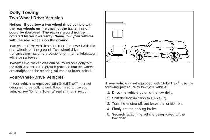
Dolly TowingTwo-Wheel-Drive Vehicles
Notice: If you tow a two-wheel-drive vehicle withthe rear wheels on the ground, the transmissioncould be damaged. The repairs would not becovered by your warranty. Never tow your vehiclewith the rear wheels on the ground.
Two-wheel-drive vehicles should not be towed with therear wheels on the ground. Two-wheel-drivetransmissions have no provisions for internal lubricationwhile being towed.
Two-wheel-drive vehicles can be towed on a dolly withthe front wheels on the ground provided that the wheelsare straight and the steering column has been locked.
Four-Wheel-Drive VehiclesIf your vehicle is equipped with StabiliTrak®, it is notdesigned to be dolly towed. If you need to tow yourvehicle, see “Dinghy Towing” earlier in this section.
If your vehicle is not equipped with StabiliTrak®, use thefollowing procedure to tow your vehicle:
1. Drive the vehicle up onto the tow dolly.
2. Shift the transmission to PARK (P).
3. Turn the engine off, but leave the ignition on.
4. Firmly set the parking brake.
5. Securely attach the vehicle being towed to thetow dolly.
4-64

{CAUTION:
Shifting a four-wheel-drive vehicle’s transfercase into NEUTRAL can cause your vehicle toroll even if the transmission is in PARK (P).You or others could be injured. Make sure theparking brake is firmly set before you shift thetransfer case to NEUTRAL.
6. Shift the transfer case to NEUTRAL. SeeFour-Wheel Drive on page 2-27 for the properprocedure to select the NEUTRAL position for yourvehicle.
7. Release the parking brake only after the vehiclebeing towed is firmly attached to the towing vehicle.
8. Turn the ignition off and lock the steering column.
Level Control
Automatic Level ControlThe automatic level control rear suspension is availableon C/K 1500 vehicles and comes as a part of theAutoride® suspension, if equipped.
This type of level control is fully automatic and willprovide a better leveled riding position as well as betterhandling under a variety of passenger and loadingconditions. An air compressor connected to the rearshocks will raise or lower the rear of the vehicleto maintain proper vehicle height. The system isactivated when the ignition key is turned to RUN andwill automatically adjust vehicle height thereafter.The system may exhaust (lower vehicle height) for up toten minutes after the ignition key has been turned off.You may hear the air compressor operating whenthe height is being adjusted.
If a self-equalizing hitch is being used, it isrecommended to allow the shocks to inflate, therebyleveling the vehicle prior to adjusting the hitch.
4-65

Autoride ®
If equipped, the Autoride® feature will provide a superiorvehicle ride and handling under a variety of passengerand loading conditions.
The system is fully automatic and uses a computercontroller to continuously monitor vehicle speed, wheelto body position, lift/dive and steering position of thevehicle. The controller then sends signals to each shockabsorber to independently adjust the damping level toprovide the optimum vehicle ride.
Autoride® also interacts with the tow/haul switch that,when engaged, will provide additional control of theshock absorbers. This additional control results in betterride and handling characteristics when the vehicle isloaded or towing a trailer. See Tow/Haul Mode Light onpage 3-53 for more information.
Trailer RecommendationsYou must subtract your hitch loads from the CargoWeight Rating (CWR) for your vehicle. CWR is themaximum weight of the load your vehicle can carry. Itdoesn’t include the weight of the people inside. But youcan figure about 150 lbs. (68 kg) for each seat. The totalcargo load must not be more than your vehicle’s CWR.
Weigh your vehicle with the trailer attached, so that youwon’t go over the GVWR or GAWR. If you are usinga weight-distributing hitch, weigh the vehicle without thespring bars in place.
You’ll get the best performance if you spread out theweight of your load the right way, and if you choose thecorrect hitch and trailer brakes.
For more information, see Towing a Trailer on page 4-67.
4-66

Towing a TrailerDo not tow a trailer during break-in. See New VehicleBreak-In on page 2-19 for more information.
{CAUTION:
If you do not use the correct equipment anddrive properly, you can lose control when youpull a trailer. For example, if the trailer is tooheavy, the brakes may not work well — or evenat all. You and your passengers could beseriously injured. Pull a trailer only if you havefollowed all the steps in this section. Ask yourdealer for advice and information about towinga trailer with your vehicle.
Notice: Pulling a trailer improperly can damageyour vehicle and result in costly repairs not coveredby your warranty. To pull a trailer correctly, followthe advice in this part, and see your dealer forimportant information about towing a trailer withyour vehicle.
To identify the vehicle trailering capacity of your vehicle,you should read the information in “Weight of theTrailer” that appears later in this section.
If yours was built with trailering options, as many are,it’s ready for heavier trailers. But trailering is differentthan just driving your vehicle by itself. Trailering meanschanges in acceleration, braking, handling, durabilityand fuel economy. Successful, safe trailering takescorrect equipment, and it has to be used properly.
That’s the reason for this part. In it are many time-tested,important trailering tips and safety rules. Many ofthese are important for your safety and that of yourpassengers. So please read this section carefully beforeyou pull a trailer.
4-67

If You Do Decide To Pull A TrailerIf you do, here are some important points:
• There are many different laws, including speed limitrestrictions, having to do with trailering. Make sureyour rig will be legal, not only where you livebut also where you’ll be driving. A good source forthis information can be state or provincial police.
• Consider using a sway control. See “Hitches” laterin this section.
• Don’t tow a trailer at all during the first 500 miles(800 km) your new vehicle is driven. Your engine,axle or other parts could be damaged.
• Then, during the first 500 miles (800 km) that youtow a trailer, don’t drive over 50 mph (80 km/h)and don’t make starts at full throttle. This helps yourengine and other parts of your vehicle wear in atthe heavier loads.
• You can tow in DRIVE (D). You may want to shiftthe transmission to THIRD (3) or, if necessary, alower gear selection if the transmission shiftstoo often (e.g., under heavy loads and/or hillyconditions). See “Tow/Haul Mode” later inthis section.
Three important considerations have to do with weight:
• The weight of the trailer
• The weight of the trailer tongue
• The weight on your vehicle’s tires
Tow/Haul ModeTow/Haul is a feature that assists when pulling a heavytrailer or a large or heavy load. The purpose of theTow/Haul mode is to:
• Reduce the frequency and improve the predictabilityof transmission shifts when pulling a heavy trailer ora large or heavy load.
• Provide the same solid shift feel when pulling aheavy trailer or a large or heavy load as whenthe vehicle is unloaded.
• Improve control of vehicle speed while requiringless throttle pedal activity when pulling a heavytrailer or a large or heavy load.
4-68

Your vehicle may be equipped with a button at the end ofthe shift lever which, when pressed, enables tow/haul.Your vehicle may be equipped with Autoride® whichfurther improves your vehicle’s ride while towing. SeeAutoride® on page 4-66 for more information. When thebutton is pressed, a light on the instrument panel willilluminate to indicate that Tow/Haul has been selected.Tow/Haul may be turned off by pressing the button again,at which time the indicator light on the instrument panelwill turn off. The vehicle will automatically turn off Tow/Haul every time it is started.
Tow/Haul is designed to be most effective when thevehicle and trailer combined weight is at least 75 percentof the vehicle’s Gross Combined Weight Rating (GCWR).See Weight of the Trailer later in this section. Tow/Haul ismost useful under the following driving conditions:
• When pulling a heavy trailer or a large or heavy loadthrough rolling terrain.
• When pulling a heavy trailer or a large or heavy loadin stop and go traffic.
• When pulling a heavy trailer or a large or heavy loadin busy parking lots where improved low speedcontrol of the vehicle is desired.
Operating the vehicle in tow/haul when lightly loaded orwith no trailer at all will not cause damage. However,there is no benefit to the selection of Tow/Haul when thevehicle is unloaded. Such a selection when unloadedmay result in unpleasant engine and transmission drivingcharacteristics and reduced fuel economy. Tow/Haulis recommended only when pulling a heavy trailer or alarge or heavy load.
Weight of the TrailerHow heavy can a trailer safely be?
It depends on how you plan to use your rig. Forexample, speed, altitude, road grades, outsidetemperature and how much your vehicle is used to pulla trailer are all important. And, it can also dependon any special equipment that you have on your vehicle.
Use one of the following charts to determine howmuch your vehicle can weigh, based upon your vehiclemodel and options.
Maximum trailer weight is calculated assuming only thedriver is in the tow vehicle and it has all the requiredtrailering equipment. The weight of additional optionalequipment, passengers and cargo in the tow vehiclemust be subtracted from the maximum trailer weight.
4-69
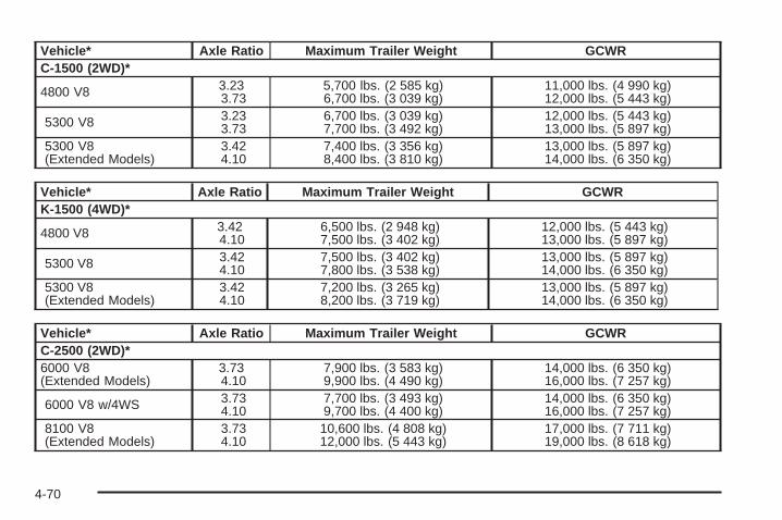
Vehicle* Axle Ratio Maximum Trailer Weight GCWRC-1500 (2WD)*
4800 V8 3.233.73
5,700 lbs. (2 585 kg)6,700 lbs. (3 039 kg)
11,000 lbs. (4 990 kg)12,000 lbs. (5 443 kg)
5300 V8 3.233.73
6,700 lbs. (3 039 kg)7,700 lbs. (3 492 kg)
12,000 lbs. (5 443 kg)13,000 lbs. (5 897 kg)
5300 V8(Extended Models)
3.424.10
7,400 lbs. (3 356 kg)8,400 lbs. (3 810 kg)
13,000 lbs. (5 897 kg)14,000 lbs. (6 350 kg)
Vehicle* Axle Ratio Maximum Trailer Weight GCWRK-1500 (4WD)*
4800 V8 3.424.10
6,500 lbs. (2 948 kg)7,500 lbs. (3 402 kg)
12,000 lbs. (5 443 kg)13,000 lbs. (5 897 kg)
5300 V8 3.424.10
7,500 lbs. (3 402 kg)7,800 lbs. (3 538 kg)
13,000 lbs. (5 897 kg)14,000 lbs. (6 350 kg)
5300 V8(Extended Models)
3.424.10
7,200 lbs. (3 265 kg)8,200 lbs. (3 719 kg)
13,000 lbs. (5 897 kg)14,000 lbs. (6 350 kg)
Vehicle* Axle Ratio Maximum Trailer Weight GCWRC-2500 (2WD)*6000 V8(Extended Models)
3.734.10
7,900 lbs. (3 583 kg)9,900 lbs. (4 490 kg)
14,000 lbs. (6 350 kg)16,000 lbs. (7 257 kg)
6000 V8 w/4WS 3.734.10
7,700 lbs. (3 493 kg)9,700 lbs. (4 400 kg)
14,000 lbs. (6 350 kg)16,000 lbs. (7 257 kg)
8100 V8(Extended Models)
3.734.10
10,600 lbs. (4 808 kg)12,000 lbs. (5 443 kg)
17,000 lbs. (7 711 kg)19,000 lbs. (8 618 kg)
4-70

Vehicle* Axle Ratio Maximum Trailer Weight GCWRK-2500 (4WD)*6000 V8(Extended Models)
3.734.10
7,600 lbs. (3 447 kg)9,600 lbs. (4 354 kg)
14,000 lbs. (6 350 kg)16,000 lbs. (7 257 kg)
6000 V8 w/4WS 3.734.10
7,400 lbs. (3 357 kg)9,400 lbs. (4 264 kg)
14,000 lbs. (6 350 kg)16,000 lbs. (7 257 kg)
8100 V8 3.734.10
10,300 lbs. (4 672 kg)12,000 lbs. (5 443 kg)
17,000 lbs. (7 711 kg)19,000 lbs. (8 618 kg)
The Gross Combination Weight Rating (GCWR) is thetotal allowable weight of the completely loadedvehicle and trailer including any passengers, cargo,equipment and conversions. The GCWR for your vehicleshould not be exceeded.You can ask your dealer for our trailering information oradvice, or you can write us at the address listed in yourWarranty and Owner Assistance Information Booklet.
In Canada, write to:General Motors of Canada LimitedCustomer Communication Centre, 163-0051908 Colonel Sam DriveOshawa, Ontario L1H 8P7
4-71

Weight of the Trailer TongueThe tongue load (A) of any trailer is an important weightto measure because it affects the total or gross weightof your vehicle. The Gross Vehicle Weight (GVW)includes the curb weight of the vehicle, any cargo youmay carry in it, and the people who will be riding inthe vehicle. If you have a lot of options, equipment,passengers or cargo in your vehicle, it will reduce thetongue weight your vehicle can carry, which willalso reduce the trailer weight your vehicle can tow. Andif you will tow a trailer, you must add the tongue loadto the GVW because your vehicle will be carryingthat weight, too. See Loading Your Vehicle for moreinformation about your vehicle’s maximum load capacity.
The trailer tongue weight (A) should be 10 percentto 15 percent of the total loaded trailer weight, up to amaximum or 600 lbs (272 kg) with a weight carryinghitch. The trailer tongue weight (A) should be 10 percentto 15 percent of the total loaded trailer weight, up to amaximum of 1,000 lbs (453 kg) for the 1500 seriesand up to a maximum of 1,500 lbs (680 kg) for the2500 series with a weight distributing hitch.
Do not exceed the maximum allowable tongue weightfor your vehicle. Choose the shortest hitch extensionthat will position the hitch ball closest to the vehicle. Thiswill help reduce the effect of trailer tongue weight onthe rear axle.
After you have loaded the trailer, weigh the trailer andthen the tongue separately, to see if the weightsare proper. If they are not, you may be able to get themright by moving some items around in the trailer.
Total Weight on Your Vehicle’s TiresBe sure your vehicle’s tires are inflated to the upper limitfor cold tires. You’ll find these numbers on theCertification label at the rear edge of the driver’s door orsee Loading Your Vehicle on page 4-51 for moreinformation. Then be sure you don’t go over the GVWlimit for your vehicle, or the GAWR, including the weightof the trailer tongue. If you use a weight distributinghitch, make sure you don’t go over the rear axlelimit before you apply the weight distribution spring bars.
4-72

HitchesIt’s important to have the correct hitch equipment.Crosswinds, large trucks going by and rough roads area few reasons why you will need the right hitch.
Weight-Distributing Hitches and WeightCarrying Hitches
When using a weight-distributing hitch, the hitch mustbe adjusted so the distance (A) remains the same bothbefore and after coupling the trailer to the tow vehicle.
If you use a step-bumper hitch, the bumper could bedamaged in sharp turns. Make sure there is ample roomwhen turning to avoid contact between the trailer andthe bumper.
If you will be pulling a trailer that, when loaded, willweigh more than 5,000 lbs (2 270 kg) be sure to use aproperly mounted weight-distributing hitch and swaycontrol of the proper size. This equipment is veryimportant for proper vehicle loading and good handlingwhen driving. Always use a sway control if the trailerwill weigh more than these limits. You can ask ahitch dealer about sway controls.
Safety ChainsYou should always attach safety chains between yourvehicle and your trailer. Cross the safety chains underthe tongue of the trailer to help prevent the tongue fromcontacting the road if it becomes separated fromthe hitch.
If you are towing a trailer up to 5,000 lbs (2 270 kg) with afactory-installed step bumper, you may attach the safetychains to the attaching points on the bumper. If you aretowing a trailer up to your vehicle’s trailer rating limit, youmay attach the safety chains to the attaching point onthe hitch platform. If you are towing with an aftermarkethitch, following the trailer or hitch manufacturer’srecommendation for attaching safety chains. Alwaysleave just enough slack so you can turn with your rig.Never allow safety chains to drag on the ground.
(A) Body to Ground Distance (B) Front of Vehicle
4-73

Trailer BrakesIf your trailer weighs more than 2,000 lbs (900 kg)loaded, then it needs its own brakes – and they must beadequate. Be sure to read and follow the instructionsfor the trailer brakes so you’ll be able to install,adjust and maintain them properly.
If your vehicle is equipped with StabiliTrak®, your trailercannot tap into the vehicle’s hydraulic brake system.
Your trailer brake system can tap into the vehicle’shydraulic brake system only if:
• The trailer parts can withstand 3,000 psi(20 650 kPa) of pressure.
• The trailer’s brake system will use less than0.02 cubic inches (0.3 cc) of fluid from your vehicle’smaster cylinder. Otherwise, both braking systemswon’t work well. You could even lose your brakes.
If everything checks out this far, make the brake tap atthe port on the master cylinder that sends the fluidto the rear brakes. But don’t use copper tubing for this.If you do, it will bend and finally break off. Use steelbrake tubing.
Driving with a Trailer
{CAUTION:
If you have a rear-most window open and youpull a trailer with your vehicle, carbonmonoxide (CO) could come into your vehicle.You cannot see or smell CO. It can causeunconsciousness or death. See EngineExhaust on page 2-39. To maximize your safetywhen towing a trailer:
• Have your exhaust system inspected forleaks, and make necessary repairs beforestarting on your trip.
• Keep the rear-most windows closed.• If exhaust does come into your vehicle
through a window in the rear or anotheropening, drive with your front, mainheating or cooling system on and with thefan on any speed. This will bring fresh,outside air into your vehicle. Do not usethe climate control setting for maximum airbecause it only recirculates the air insideyour vehicle. See Climate Control Systemon page 3-21.
4-74

Towing a trailer requires a certain amount of experience.Before setting out for the open road, you’ll want to getto know your rig. Acquaint yourself with the feel ofhandling and braking with the added weight of the trailer.And always keep in mind that the vehicle you aredriving is now a good deal longer and not nearly asresponsive as your vehicle is by itself.
Before you start, check all trailer hitch parts andattachments, safety chains, electrical connector, lamps,tires and mirror adjustment. If the trailer has electricbrakes, start your vehicle and trailer moving and thenapply the trailer brake controller by hand to be surethe brakes are working. This lets you check yourelectrical connection at the same time.
During your trip, check occasionally to be sure that theload is secure, and that the lamps and any trailerbrakes are still working.
Following DistanceStay at least twice as far behind the vehicle ahead asyou would when driving your vehicle without a trailer.This can help you avoid situations that requireheavy braking and sudden turns.
PassingYou’ll need more passing distance up ahead whenyou’re towing a trailer. And, because you’re a good deallonger, you’ll need to go much farther beyond thepassed vehicle before you can return to your lane.
Backing UpHold the bottom of the steering wheel with one hand.Then, to move the trailer to the left, just move that handto the left. To move the trailer to the right, move yourhand to the right. Always back up slowly and, if possible,have someone guide you.
If your vehicle is equipped with four-wheel steering andif you use it while backing your trailer the same rulesapply. However, with four-wheel steering your rigwill respond more quickly and it may take additionalpractice to get used to backing up with four-wheelsteering.
4-75

Making Turns
Notice: Making very sharp turns while traileringcould cause the trailer to come in contact with thevehicle. Your vehicle could be damaged. Avoidmaking very sharp turns while trailering.
When you’re turning with a trailer, make wider turns thannormal. Do this so your trailer won’t strike soft shoulders,curbs, road signs, trees or other objects. Avoid jerky orsudden maneuvers. Signal well in advance.
Turn Signals When Towing a TrailerThe arrows on your instrument panel will flash wheneveryou signal a turn or lane change. Properly hooked up,the trailer lamps will also flash, telling other driversyou’re about to turn, change lanes or stop.
When towing a trailer, the arrows on your instrumentpanel will flash for turns even if the bulbs on the trailerare burned out. Thus, you may think drivers behindyou are seeing your signal when they are not. It’simportant to check occasionally to be sure the trailerbulbs are still working.
Driving On GradesReduce speed and shift to a lower gear before you startdown a long or steep downgrade. If you don’t shiftdown, you might have to use your brakes so much thatthey would get hot and no longer work well.
You can tow in DRIVE (D). You may want to shift thetransmission to THIRD (3) or, if necessary, a lower gearselection if the transmission shifts too often (e.g., underheavy loads and/or hilly conditions).
You may also want to activate the tow/haul mode if thetransmission shifts too often. See “Tow/Haul Mode”earlier in this section for more information.
When towing at high altitude on steep uphill grades,consider the following: Engine coolant will boil at a lowertemperature than at normal altitudes. If you turn yourengine off immediately after towing at high altitudeon steep uphill grades, your vehicle may show signssimilar to engine overheating. To avoid this, let theengine run while parked (preferably on level ground)with the automatic transmission in PARK (P) for afew minutes before turning the engine off. If you do getthe overheat warning, see Engine Overheating onpage 5-27.
4-76

Parking on Hills
{CAUTION:
You really should not park your vehicle, with atrailer attached, on a hill. If something goeswrong, your rig could start to move. Peoplecan be injured, and both your vehicle and thetrailer can be damaged.
But if you ever have to park your rig on a hill, here’show to do it:
1. Apply your regular brake, but don’t shift intoPARK (P) yet.
2. Have someone place chocks under the trailerwheels.
3. When the wheel chocks are in place, release theregular brakes until the chocks absorb the load.
4. Reapply the regular brakes. Then apply yourparking brake and shift into PARK (P).
5. If you have a four-wheel-drive vehicle, be sure thetransfer case is in a drive gear and not inNEUTRAL.
6. Release the regular brakes.
{CAUTION:
It can be dangerous to get out of your vehicleif the shift lever is not fully in PARK (P) withthe parking brake firmly set. Your vehiclecan roll.
If you have left the engine running, the vehiclecan move suddenly. You or others could beinjured. To be sure your vehicle will not move,even when you are on fairly level ground, usethe steps that follow.
Always put the shift lever fully in PARK (P)with the parking brake firmly set.
If the transfer case on four-wheel-drivevehicles is in NEUTRAL, your vehicle will befree to roll, even if your shift lever is inPARK (P). So, be sure the transfer case is in adrive gear — not in NEUTRAL.
4-77

When You Are Ready to Leave AfterParking on a Hill
1. Apply your regular brakes and hold the pedal downwhile you:
• start your engine,
• shift into a gear, and
• release the parking brake.
2. Let up on the brake pedal.
3. Drive slowly until the trailer is clear of the chocks.
4. Stop and have someone pick up and store thechocks.
Maintenance When Trailer TowingYour vehicle will need service more often when you’repulling a trailer. See the Maintenance Schedule for moreon this. Things that are especially important in traileroperation are automatic transmission fluid (don’t overfill),engine oil, axle lubricant, belts, cooling system and brakesystem. Each of these is covered in this manual, and theIndex will help you find them quickly. If you’re trailering,it’s a good idea to review these sections before you startyour trip.
Check periodically to see that all hitch nuts and boltsare tight.
Trailer Wiring HarnessYour vehicle is equipped with the following wiringharnesses for towing a trailer.
4-78

Basic Trailer Wiring
The trailer wiring harness, with a seven-pin connector,is located at the rear of the vehicle and is tied tothe vehicle’s frame. The harness connector can beplugged into a seven-pin universal heavy-duty trailerconnector available through your dealer.
The seven-wire harness contains the following trailercircuits:
• Yellow: Left Stop/Turn Signal
• Dark Green: Right Stop/Turn Signal
• Brown: Taillamps
• White: Ground
• Light Green: Back-up Lamps
• Red: Battery Feed
• Dark Blue: Trailer Brake
4-79

Heavy-Duty Trailer Wiring HarnessPackage
Your vehicle is equipped with the seven-wire trailertowing harness. This harness with a seven-pin universaltrailer connector is attached to a bracket on the hitchplatform.
The seven-wire harness contains the following trailercircuits:
• Yellow: Left Stop/Turn Signal
• Dark Green: Right Stop/Turn Signal
• Brown: Taillamps
• White: Ground
• Light Green: Back-up Lamps
• Red: Battery Feed**
• Dark Blue: Trailer Brake
**If you are charging a remote (non-vehicle) battery,turn on the headlamps to boost the vehicle systemvoltage and properly charge the battery.
Electric Brake Control Jumper
{CAUTION:
Be sure to use only the correct trailer brakeharness, the one intended for use on yourvehicle. If you use some other trailer brakeharness, even if it seems to fit, your trailerbrakes may not work at all. You could have acrash in which you or others could be injured.Use only the trailer brake harness intended foryour vehicle. If it is no longer available to you,be sure to get a proper replacement from yourdealer.
4-80

This harness is included with your vehicle as part of theheavy-duty trailer wiring package.
This harness is for an electric brake controller andincludes a trailer battery feed fuse. It should be installedby your dealer or a qualified service center.
This harness is new for your vehicle, and you will not beable to use a harness from an earlier model year.
Four-Wire Harness Adapter
This adapter is includedwith your vehicle as part ofthe heavy-duty trailerwiring package.
Use this adapter to connect a standard four-way roundpin connector to the seven-wire harness on your vehicle.
4-81

Connect the adapter with the tab pointing up (see arrow).The flip cap on the vehicle’s seven-wire harness will lockonto the tab and help hold the adapter in place. Plug thefour-way round pin connector onto the adapter.
Power WinchesIf you wish to use a power winch on your vehicle, onlyuse it when your vehicle is stationary or anchored.
Step-Bumper PadYour vehicle has a rear step bumper with a rear steppad at the center of the bumper.
If you will be using thebumper to tow a trailer,and your step-bumper hasthree cutout circles youmust push out the centercutout circle to installthe trailer ball.
If your step-bumper has only one cutout circle, you willhave to cut out the circle, then remove it to installthe trailer ball.
4-82

Service ............................................................5-3Doing Your Own Service Work .........................5-4Adding Equipment to the Outside of Your
Vehicle ......................................................5-4Fuel ................................................................5-5
Gasoline Octane ............................................5-5Gasoline Specifications ....................................5-5California Fuel ...............................................5-5Additives .......................................................5-6Fuel E-85 (85% Ethanol) .................................5-6Fuels in Foreign Countries ...............................5-8Filling the Tank ..............................................5-8Filling a Portable Fuel Container .....................5-10
Checking Things Under the Hood ....................5-10Hood Release ..............................................5-11Engine Compartment Overview .......................5-12Engine Oil ...................................................5-15Engine Oil Life System ..................................5-18Engine Air Cleaner/Filter ................................5-19Automatic Transmission Fluid .........................5-21Engine Coolant .............................................5-24Coolant Surge Tank Pressure Cap ..................5-26Engine Overheating .......................................5-27
Overheated Engine Protection Operating Mode ...5-29Cooling System ............................................5-29Engine Fan Noise .........................................5-34Power Steering Fluid .....................................5-35Windshield Washer Fluid ................................5-36Brakes ........................................................5-37Battery ........................................................5-40Jump Starting ...............................................5-41
All-Wheel Drive ..............................................5-45Rear Axle .......................................................5-46Four-Wheel Drive ............................................5-47Front Axle ......................................................5-48Bulb Replacement ..........................................5-49
Halogen Bulbs ..............................................5-49Headlamps ..................................................5-50Front Turn Signal, Sidemarker and Daytime
Running Lamps .........................................5-51Side Identification Marker Lamps .....................5-52Roof Marker Lamps ......................................5-52Taillamps .....................................................5-54Replacement Bulbs .......................................5-56
Windshield Wiper Blade Replacement ..............5-56
Section 5 Service and Appearance Care
5-1

Tires ..............................................................5-57Tire Sidewall Labelling ...................................5-58Tire Terminology and Definitions .....................5-62Inflation - Tire Pressure .................................5-64Tire Pressure Monitor System .........................5-65Tire Inspection and Rotation ...........................5-68When It Is Time for New Tires .......................5-70Buying New Tires .........................................5-70Uniform Tire Quality Grading ..........................5-72Wheel Alignment and Tire Balance ..................5-73Wheel Replacement ......................................5-73Tire Chains ..................................................5-75If a Tire Goes Flat ........................................5-76Changing a Flat Tire .....................................5-76Removing the Spare Tire and Tools ................5-78Removing the Flat Tire and Installing the
Spare Tire ................................................5-81Secondary Latch System ...............................5-87Storing a Flat or Spare Tire and Tools ............5-91Spare Tire ...................................................5-95
Appearance Care ............................................5-95Cleaning the Inside of Your Vehicle .................5-96Fabric/Carpet ...............................................5-97Leather .......................................................5-98Instrument Panel, Vinyl, and Other Plastic
Surfaces ..................................................5-98
Care of Safety Belts ......................................5-99Weatherstrips ...............................................5-99Washing Your Vehicle ...................................5-99Cleaning Exterior Lamps/Lenses .....................5-99Finish Care ................................................5-100Windshield, Backglass, and Wiper Blades .......5-100Aluminum or Chrome-Plated Wheels ..............5-101Tires .........................................................5-102Sheet Metal Damage ...................................5-102Finish Damage ...........................................5-102Underbody Maintenance ...............................5-102Chemical Paint Spotting ...............................5-102Vehicle Care/Appearance Materials ................5-103
Vehicle Identification .....................................5-104Vehicle Identification Number (VIN) ................5-104Service Parts Identification Label ...................5-104
Electrical System ..........................................5-105Add-On Electrical Equipment .........................5-105Windshield Wiper Fuses ...............................5-105Power Windows and Other Power Options ......5-105Fuses and Circuit Breakers ..........................5-105Instrument Panel Fuse Block ........................5-106Center Instrument Panel Fuse Block ..............5-108Underhood Fuse Block ................................5-109
Capacities and Specifications ........................5-114
Section 5 Service and Appearance Care
5-2

ServiceYour dealer knows your vehicle best and wants you tobe happy with it. We hope you will go to your dealerfor all your service needs. You will get genuine GM partsand GM-trained and supported service people.
We hope you will want to keep your GM vehicle all GM.Genuine GM parts have one of these marks:
California Proposition 65 WarningMost motor vehicles, including this one, contain and/oremit chemicals known to the State of California tocause cancer and birth defects or other reproductiveharm. Engine exhaust, many parts and systems(including some inside the vehicle), many fluids, andsome component wear by-products contain and/or emitthese chemicals.
5-3

Doing Your Own Service WorkIf you want to do some of your own service work, youwill want to use the proper service manual. It tellsyou much more about how to service your vehicle thanthis manual can. To order the proper service manual,see Service Publications Ordering Information onpage 7-11.
Your vehicle has an airbag system. Before attempting todo your own service work, see Servicing YourAirbag-Equipped Vehicle on page 1-80.
You should keep a record with all parts receipts and listthe mileage and the date of any service work youperform. See Maintenance Record on page 6-16.
{CAUTION:
You can be injured and your vehicle could bedamaged if you try to do service work on avehicle without knowing enough about it.
• Be sure you have sufficient knowledge,experience, the proper replacement parts,and tools before you attempt any vehiclemaintenance task.
• Be sure to use the proper nuts, bolts, andother fasteners. English and metricfasteners can be easily confused. If youuse the wrong fasteners, parts can laterbreak or fall off. You could be hurt.
Adding Equipment to the Outside ofYour VehicleThings you might add to the outside of your vehicle canaffect the airflow around it. This may cause windnoise and affect windshield washer performance. Checkwith your dealer before adding equipment to theoutside of your vehicle.
5-4

FuelGasolineThe 8th digit of your vehicle identification number (VIN)shows the code letter or number that identifies yourengine. You will find the VIN at the top left of theinstrument panel. See Vehicle IdentificationNumber (VIN) on page 5-104.
If your vehicle has the 5.3L V8 engine (VIN Code Zonly), you may use either regular unleaded gasoline orethanol fuel containing up to 85% ethanol (E-85);also see Fuel E-85 (85% Ethanol) on page 5-6. In allother engines, use only regular unleaded gasoline.
Gasoline OctaneUse regular unleaded gasoline with a posted octane of 87or higher. If the octane is less than 87, you may get aheavy knocking noise when you drive. If this occurs, usea gasoline rated at 87 octane or higher as soon aspossible. Otherwise, you might damage your engine.A little pinging noise when you accelerate or drive uphill isconsidered normal. This does not indicate a problemexists or that a higher-octane fuel is necessary. If you areusing 87 octane or higher-octane fuel and hear heavyknocking, your engine needs service.
Gasoline SpecificationsIt is recommended that gasoline meet specificationswhich were developed by automobile manufacturersaround the world and contained in the World-Wide FuelCharter which is available from the Alliance of AutomobileManufacturers at www.autoalliance.org/fuel_charter.htm.Gasoline meeting these specifications could provideimproved driveability and emission control systemperformance compared to other gasoline.
California FuelIf your vehicle is certified to meet California EmissionStandards, it is designed to operate on fuels thatmeet California specifications. See the underhoodemission control label. If this fuel is not availablein states adopting California emissions standards, yourvehicle will operate satisfactorily on fuels meetingfederal specifications, but emission control systemperformance may be affected. The malfunction indicatorlamp may turn on and your vehicle may fail asmog-check test. See Malfunction Indicator Lamp onpage 3-48. If this occurs, return to your authorizedGM dealer for diagnosis. If it is determined thatthe condition is caused by the type of fuel used, repairsmay not be covered by your warranty.
5-5

AdditivesTo provide cleaner air, all gasolines in the United Statesare now required to contain additives that will helpprevent engine and fuel system deposits from forming,allowing your emission control system to work properly.In most cases, you should not have to add anything toyour fuel. However, some gasolines contain only theminimum amount of additive required to meet U.S.Environmental Protection Agency regulations. GeneralMotors recommends that you buy gasolines that areadvertised to help keep fuel injectors and intake valvesclean. If your vehicle experiences problems due to dirtyinjectors or valves, try a different brand of gasoline. Also,your GM dealer has additives that will help correct andprevent most deposit-related problems.
Gasolines containing oxygenates, such as ethers andethanol, and reformulated gasolines may be available inyour area to contribute to clean air. General Motorsrecommends that you use these gasolines, particularly ifthey comply with the specifications described earlier.
Notice: Your vehicle was not designed for fuel thatcontains methanol. Do not use fuel containingmethanol. It can corrode metal parts in your fuelsystem and also damage the plastic and rubberparts. That damage would not be covered underyour warranty.
Some gasolines that are not reformulated for lowemissions may contain an octane-enhancing additivecalled methylcyclopentadienyl manganesetricarbonyl (MMT); ask the attendant where you buygasoline whether the fuel contains MMT. General Motorsdoes not recommend the use of such gasolines. Fuelscontaining MMT can reduce the life of spark plugs andthe performance of the emission control system may beaffected. The malfunction indicator lamp may turn on.If this occurs, return to your authorized GM dealer forservice.
Fuel E-85 (85% Ethanol)The 8th digit of your vehicle identification number (VIN)shows the code letter or number that identifies yourengine. You will find the VIN at the top left of theinstrument panel. See Vehicle Identification Number(VIN) on page 5-104.
If your vehicle has the 5.3L V8 engine (VIN Code Z only),you may use either regular unleaded gasoline or ethanolfuel containing up to 85% ethanol (E-85); also see Fuelon page 5-5. In all other engines, including the 5.3L V8(VIN Code T), use only regular unleaded gasoline.
5-6
Only vehicles that have the 5.3L V8 engine (VIN Code Z)may use 85% ethanol fuel (E-85). General Motorsencourages the use of E-85 in vehicles that are designedto use it. The ethanol in E-85 is a “renewable” fuel,meaning it is made from renewable sources such as cornand other crops.
Many service stations will not have an 85% ethanolfuel (E-85) pump available. The U. S. Departmentof Energy has an alternative fuels website(http://www.afdc.doe.gov/refueling_mapsite.shtml) thatcan help you find E-85 fuel. Those stations that do haveE-85 should have a label indicating ethanol content.Do not use the fuel if the ethanol content is greater than85%. Your vehicle may not operate properly if theethanol content is greater than 85%.
At a minimum, E-85 should meet ASTMSpecification D 5798.
To ensure quick starts in the wintertime, the E-85 fuelmust be formulated properly for your climate accordingto ASTM specification D 5798. If you have troublestarting on E-85, it may be because your E-85 fuel isnot properly formulated for your climate. If this happens,switching to gasoline or adding gasoline to your fueltank may improve starting. Your vehicle is designed toaccommodate a mixture of gasoline and E-85 fuel.For good starting and heater efficiency below32°F (0°C), the fuel mix in the fuel tank should containno more than 70% ethanol.
E-85 has less energy per gallon than gasoline, so youwill need to refill your fuel tank more often whenusing E-85 than when you are using gasoline. Regularunleaded gasoline is recommended when pulling atrailer. For payload capacity with ethanol fuel, seeLoading Your Vehicle on page 4-51.
Notice: Some additives are not compatible withE-85 fuel and may harm your fuel system. Damagecaused by additives would not be covered byyour new vehicle warranty. Do not use additiveswith E-85 fuel.
Notice: Your vehicle was not designed for fuel thatcontains methanol. Do not use fuel containingmethanol. It can corrode metal parts in your fuelsystem and also damage the plastic and rubberparts. That damage would not be covered underyour warranty.
5-7

Fuels in Foreign CountriesIf you plan on driving in another country outside theUnited States or Canada, the proper fuel may be hardto find. Never use leaded gasoline or any other fuelnot recommended in the previous text on fuel. Costlyrepairs caused by use of improper fuel would notbe covered by your warranty.
To check the fuel availability, ask an auto club, orcontact a major oil company that does business in thecountry where you will be driving.
Filling the Tank
{CAUTION:
Fuel vapor burns violently and a fuel fire cancause bad injuries. To help avoid injuries toyou and others, read and follow all theinstructions on the pump island. Turn off yourengine when you are refueling. Do not smokeif you are near fuel or refueling your vehicle.Keep sparks, flames, and smoking materialsaway from fuel. Do not leave the fuel pumpunattended when refueling your vehicle — thisis against the law in some places. Keepchildren away from the fuel pump; never letchildren pump fuel.
The tethered fuel cap is located behind a hinged fueldoor on the driver’s side of the vehicle.
To remove the fuel cap, turn it slowly counterclockwise.It will require more effort to turn the fuel cap on thelast turn as you loosen it.
5-8

{CAUTION:
If you spill fuel and then something ignites it,you could be badly burned. Fuel can spray outon you if you open the fuel cap too quickly.This spray can happen if your tank is nearlyfull, and is more likely in hot weather. Openthe fuel cap slowly and wait for any hiss noiseto stop. Then unscrew the cap all the way.
Be careful not to spill fuel. Do not top off or overfill thetank and wait a few seconds after you have finishedpumping before removing the nozzle. Clean fuelfrom painted surfaces as soon as possible. SeeWashing Your Vehicle on page 5-99.
When replacing the fuel cap, turn it clockwise until itclicks. It will require more effort to turn the fuel cap onthe last turn as you tighten it. Make sure the cap isfully installed. The diagnostic system can determine ifthe fuel cap has been left off or improperly installed. Thiswould allow fuel to evaporate into the atmosphere.See Malfunction Indicator Lamp on page 3-48.
The TIGHTEN FUEL CAP message will be displayed onthe Driver Information Center (DIC) if the fuel cap isnot properly installed. See DIC Warnings and Messageson page 3-58 for more information.
{CAUTION:
If a fire starts while you are refueling, do notremove the nozzle. Shut off the flow of fuel byshutting off the pump or by notifying thestation attendant. Leave the area immediately.
Notice: If you need a new fuel cap, be sure to getthe right type. Your dealer can get one for you.If you get the wrong type, it may not fit properly.This may cause your malfunction indicator lamp tolight and may damage your fuel tank and emissionssystem. See Malfunction Indicator Lamp onpage 3-48.
5-9

Filling a Portable Fuel Container
{CAUTION:
Never fill a portable fuel container while it is inyour vehicle. Static electricity discharge fromthe container can ignite the gasoline vapor.You can be badly burned and your vehicledamaged if this occurs. To help avoid injury toyou and others:
• Dispense gasoline only into approvedcontainers.
• Do not fill a container while it is inside avehicle, in a vehicle’s trunk, pickup bed, oron any surface other than the ground.
• Bring the fill nozzle in contact with theinside of the fill opening before operatingthe nozzle. Contact should be maintaineduntil the filling is complete.
• Do not smoke while pumping gasoline.
Checking Things Underthe Hood
{CAUTION:
An electric fan under the hood can start upand injure you even when the engine is notrunning. Keep hands, clothing and tools awayfrom any underhood electric fan.
{CAUTION:
Things that burn can get on hot engine partsand start a fire. These include liquids like fuel,oil, coolant, brake fluid, windshield washer andother fluids, and plastic or rubber. You orothers could be burned. Be careful not to dropor spill things that will burn onto a hot engine.
5-10

Hood ReleaseTo open the hood do the following:
1. Pull the handle locatedinside the vehicle tothe lower left ofthe steering wheel.
2. Then go to the front of the vehicle and pull up onthe secondary hood release located near thecenter of the grille.
3. Lift the hood.Before closing the hood, be sure all the filler capsare on properly. Then pull down the hood and closeit firmly.
5-11

Engine Compartment OverviewWhen you open the hood on the VORTEC™ 5300 V8 engine (VORTEC™ 4800 and 6000 V8 engines similar), hereis what you will see:
5-12
A. Engine Air Cleaner/Filter. See Engine AirCleaner/Filter on page 5-19.
B. Coolant Surge Tank and Pressure Cap. See CoolingSystem on page 5-29 and Coolant Surge TankPressure Cap on page 5-26.
C. Air Filter Restriction Indicator (If Equipped). SeeEngine Air Cleaner/Filter on page 5-19.
D. Engine Oil Dipstick. See “Checking Engine Oil”under Engine Oil on page 5-15.
E. Automatic Transmission Dipstick. See “Checking theFluid Level” under Automatic Transmission Fluidon page 5-21.
F. Engine Oil Fill Cap. See “When to Add Engine Oil”under Engine Oil on page 5-15.
G. Engine Cooling Fan. See Cooling System onpage 5-29.
H. Remote Negative (−) Terminal (GND). See JumpStarting on page 5-41.
I. Power Steering Fluid Reservoir. See Power SteeringFluid on page 5-35.
J. Remote Positive (+) Terminal. See Jump Starting onpage 5-41.
K. Brake Master Cylinder Reservoir. See “Brake Fluid”under Brakes on page 5-37.
L. Underhood Fuse Block. See Underhood Fuse Blockon page 5-109.
M. Battery. See Battery on page 5-40.N. Windshield Washer Fluid Reservoir. See “Adding
Washer Fluid” under Windshield Washer Fluidon page 5-36.
5-13

When you open the hood on the VORTEC™ 8100 V8 engine, here is what you will see:
5-14

A. Engine Air Cleaner/Filter. See Engine AirCleaner/Filter on page 5-19.
B. Coolant Surge Tank and Pressure Cap. See CoolingSystem on page 5-29 and Coolant Surge TankPressure Cap on page 5-26.
C. Air Filter Restriction Indicator (If Equipped). SeeEngine Air Cleaner/Filter on page 5-19.
D. Engine Oil Dipstick. See “Checking Engine Oil”under Engine Oil on page 5-15.
E. Automatic Transmission Dipstick. See “Checking theFluid Level” under Automatic Transmission Fluidon page 5-21.
F. Engine Oil Fill Cap. See “When to Add Engine Oil”under Engine Oil on page 5-15.
G. Engine Cooling Fan. See Cooling System onpage 5-29.
H. Remote Negative (−) Terminal (GND). See JumpStarting on page 5-41.
I. Remote Positive (+) Terminal. See Jump Starting onpage 5-41.
J. Power Steering Fluid Reservoir. See Power SteeringFluid on page 5-35.
K. Brake Master Fluid Reservoir. See “Brake Fluid”under Brakes on page 5-37.
L. Underhood Fuse Block. See Underhood Fuse Blockon page 5-109.
M. Battery. See Battery on page 5-40.N. Windshield Washer Fluid Reservoir. See “Adding
Washer Fluid” under Windshield Washer Fluidon page 5-36.
Engine OilIf the CHECK OIL LEVEL message appears on theinstrument cluster, it means you need to checkyour engine oil level right away.
For more information, see CHECK OIL LEVEL underDIC Warnings and Messages on page 3-58.
You should check your engine oil level regularly; this isan added reminder.
Checking Engine OilIt is a good idea to check your engine oil every time youget fuel. In order to get an accurate reading, the oilmust be warm and the vehicle must be on level ground.
The engine oil dipstick handle is a yellow loop. SeeEngine Compartment Overview on page 5-12 forthe location of the engine oil dipstick.
1. Turn off the engine and give the oil several minutesto drain back into the oil pan. If you do not do this,the oil dipstick might not show the actual level.
5-15

2. Pull out the dipstick and clean it with a paper towelor cloth, then push it back in all the way. Remove itagain, keeping the tip down, and check the level.
When to Add Engine Oil
If the oil is at or below the cross-hatched area at the tipof the dipstick, then you will need to add at least onequart of oil. But you must use the right kind. This sectionexplains what kind of oil to use. For engine oilcrankcase capacity, see Capacities and Specificationson page 5-114.
Notice: Do not add too much oil. If the engine hasso much oil that the oil level gets above thecross-hatched area that shows the proper operatingrange, the engine could be damaged.
See Engine CompartmentOverview on page 5-12 forthe location of theengine oil fill cap.
Be sure to add enough oil to put the level somewhere inthe proper operating range. Push the dipstick all theway back in when you are through.
8.1L Engine
All Other Engines
5-16

What Kind of Engine Oil to Use
Look for two things:
• GM6094M
Your vehicle’s engine requires oil meeting GMStandard GM6094M. You should look for and useonly an oil that meets GM Standard GM6094M.
• SAE 5W-30
As shown in the viscosity chart, SAE 5W-30 is bestfor your vehicle.
These numbers on an oil container show itsviscosity, or thickness. Do not use other viscosityoils such as SAE 20W-50.
Oils meeting theserequirements should alsohave the starburstsymbol on the container.This symbol indicatesthat the oil has beencertified by the AmericanPetroleum Institute (API).
You should look for this information on the oil container,and use only those oils that are identified as meetingGM Standard GM6094M and have the starburst symbolon the front of the oil container.
Notice: Use only engine oil identified as meetingGM Standard GM6094M and showing the AmericanPetroleum Institute Certified For Gasoline Enginesstarburst symbol. Failure to use the recommendedoil can result in engine damage not covered byyour warranty.
GM Goodwrench® oil meets all the requirements foryour vehicle.
5-17

If you are in an area of extreme cold, where thetemperature falls below −20°F (−29°C), it isrecommended that you use either an SAE 5W-30synthetic oil or an SAE 0W-30 oil. Both will provideeasier cold starting and better protection for your engineat extremely low temperatures.
Engine Oil AdditivesDo not add anything to your oil. The recommended oilswith the starburst symbol that meet GM StandardGM6094M are all you will need for good performanceand engine protection.
Engine Oil Life System
When to Change Engine OilYour vehicle has a computer system that lets you knowwhen to change the engine oil and filter. This is based onengine revolutions and engine temperature, and not onmileage. Based on driving conditions, the mileage atwhich an oil change will be indicated can varyconsiderably. For the oil life system to work properly,you must reset the system every time the oil is changed.
When the system has calculated that oil life has beendiminished, it will indicate that an oil change is necessary.A CHANGE ENGINE OIL message will come on.
Change your oil as soon as possible within the next600 miles (1 000 km). It is possible that, if you are drivingunder the best conditions, the oil life system may notindicate that an oil change is necessary for over a year.However, your engine oil and filter must be changed atleast once a year and at this time the system must bereset. Your dealer has GM-trained service people whowill perform this work using genuine GM parts and resetthe system. It is also important to check your oil regularlyand keep it at the proper level.
If the system is ever reset accidentally, you mustchange your oil at 3,000 miles (5 000 km) since yourlast oil change. Remember to reset the oil life systemwhenever the oil is changed.
How to Reset the Engine Oil LifeSystemThe Engine Oil Life System calculates when to changeyour engine oil and filter based on vehicle use.Anytime your oil is changed, reset the system so it cancalculate when the next oil change is required. If asituation occurs where you change your oil prior to aCHANGE ENGINE OIL message being turned on, resetthe system.
5-18

To reset the CHANGE ENGINE OIL message, see“Engine Oil Life System” under DIC Operation andDisplays on page 3-55 for vehicles equipped with theDIC, or do the following:
1. Turn the ignition key to RUN with the engine off.
2. Fully press and release the accelerator pedal slowlythree times within five seconds.If the OIL LIFE RESET message flashes for10 seconds, the system is resetting.
3. Turn the key to LOCK.
If the CHANGE ENGINE OIL message comes back onwhen you start your vehicle, the engine oil life systemhas not reset. Repeat the procedure. If it still doesnot reset, see your dealer for service.
What to Do with Used OilUsed engine oil contains certain elements that may beunhealthy for your skin and could even cause cancer.Do not let used oil stay on your skin for very long. Cleanyour skin and nails with soap and water, or a goodhand cleaner. Wash or properly dispose of clothing orrags containing used engine oil. See the manufacturer’swarnings about the use and disposal of oil products.
Used oil can be a threat to the environment. If youchange your own oil, be sure to drain all the oil from thefilter before disposal. Never dispose of oil by putting it inthe trash, pouring it on the ground, into sewers, or into
streams or bodies of water. Instead, recycle it by taking itto a place that collects used oil. If you have a problemproperly disposing of your used oil, ask your dealer, aservice station or a local recycling center for help.
Engine Air Cleaner/Filter
See Engine CompartmentOverview on page 5-12for the location of theengine air cleaner/filter andthe air filter restrictionindicator, if equipped.
When to InspectIf your vehicle is equipped with an air filter restrictionindicator, it lets you know when the engine air cleaner/filter needs to be replaced. On vehicles with a restrictionindicator, you should inspect the air filter restrictionindicator at every oil change and replace the engine aircleaner/filter when the indicator tells you to.
5-19

On vehicles without an air filter restriction indicator,inspect the air cleaner/filter at the Maintenance IIintervals and replace it at the first oil change after50,000 miles (83 000 km). See Scheduled Maintenanceon page 6-4 for more information. If you are drivingin dusty/dirty conditions, inspect the filter at each engineoil change.
How to InspectVehicles with an Air Filter RestrictionIndicatorLocate the air filter restriction indicator on the engine aircleaner/filter cover. When the indicator turns black oris in the red/orange “change” zone, replace the filter andreset the indicator. See the steps following to replacethe engine air cleaner/filter and to reset the air filterrestriction indicator.
Vehicles without an Air Filter RestrictionIndicatorTo inspect the air cleaner/filter, remove the engine aircleaner/filter from the vehicle using the steps following.When you have the engine air cleaner/filter removed,lightly shake it to release loose dust and dirt. If theengine air cleaner/filter remains caked with dirt, a newfilter is required.
Replacing the Engine Air Cleaner/Filterand Resetting the Air Filter RestrictionIndicator
1. Locate the air cleaner/filter assembly on the frontcorner of the engine compartment on thepassenger’s side of the vehicle.
2. Loosen the screws on the cover of the housing andlift up the cover.
5-20
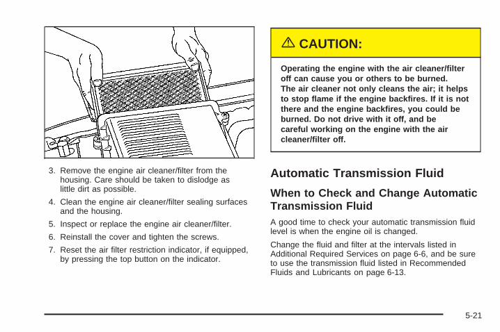
3. Remove the engine air cleaner/filter from thehousing. Care should be taken to dislodge aslittle dirt as possible.
4. Clean the engine air cleaner/filter sealing surfacesand the housing.
5. Inspect or replace the engine air cleaner/filter.
6. Reinstall the cover and tighten the screws.
7. Reset the air filter restriction indicator, if equipped,by pressing the top button on the indicator.
{CAUTION:
Operating the engine with the air cleaner/filteroff can cause you or others to be burned.The air cleaner not only cleans the air; it helpsto stop flame if the engine backfires. If it is notthere and the engine backfires, you could beburned. Do not drive with it off, and becareful working on the engine with the aircleaner/filter off.
Automatic Transmission Fluid
When to Check and Change AutomaticTransmission FluidA good time to check your automatic transmission fluidlevel is when the engine oil is changed.
Change the fluid and filter at the intervals listed inAdditional Required Services on page 6-6, and be sureto use the transmission fluid listed in RecommendedFluids and Lubricants on page 6-13.
5-21

How to Check Automatic TransmissionFluidBecause this operation can be a little difficult, you maychoose to have this done at the dealership servicedepartment.
If you do it yourself, be sure to follow all the instructionshere, or you could get a false reading on the dipstick.
Notice: Too much or too little fluid can damageyour transmission. Too much can mean that someof the fluid could come out and fall on hot enginepart or exhaust system parts, starting a fire.Too little fluid could cause the transmission tooverheat. Be sure to get an accurate reading if youcheck your transmission fluid.
Wait at least 30 minutes before checking thetransmission fluid level if you have been driving:
• When outside temperatures are above 90°F (32°C).
• At high speed for quite a while.
• In heavy traffic — especially in hot weather.
• While pulling a trailer.
To get the right reading, the fluid should be at normaloperating temperature, which is 180°F to 200°F(82°C to 93°C).
Get the vehicle warmed up by driving about15 miles (24 km) when outside temperatures are above50°F (10°C). If it is colder than 50°F (10°C), drivethe vehicle in THIRD (3) until the engine temperaturegage moves and then remains steady for 10 minutes.
A cold fluid check can be made after the vehiclehas been sitting for eight hours or more with the engineoff, but this is used only as a reference. Let theengine run at idle for five minutes if outsidetemperatures are 50°F (10°C) or more. If it is colderthan 50°F (10°C), you may have to idle the enginelonger. Should the fluid level be low during this coldcheck, you must check the fluid hot before adding fluid.Checking the fluid hot will give you a more accuratereading of the fluid level.
Checking the Fluid LevelPrepare your vehicle as follows:
• Park your vehicle on a level place. Keep the enginerunning.
• With the parking brake applied, place the shift leverin PARK (P).
• With your foot on the brake pedal, move the shiftlever through each gear range, pausing for aboutthree seconds in each range. Then, position the shiftlever in PARK (P).
• Let the engine run at idle for three minutes or more.
5-22

Then, without shutting off the engine, follow these steps:
The transmission dipstickhandle with this graphic islocated at the rear ofthe engine compartment,on the passenger’sside of the vehicle.
See Engine Compartment Overview on page 5-12 formore information on location.
1. Flip the handle up and then pull out the dipstickand wipe it with a clean rag or paper towel.
2. Push it back in all the way, wait three seconds andthen pull it back out again.
3. Check both sides of the dipstick, and read the lowerlevel. The fluid level must be in the COLD area,below the cross-hatched area, for a cold check or inthe HOT or cross-hatched area for a hot check.Be sure to keep the dipstick pointed down to get anaccurate reading.
4. If the fluid level is in the acceptable range, push thedipstick back in all the way; then flip the handledown to lock the dipstick in place.
Consistency of ReadingsAlways check the fluid level at least twice using theprocedure described previously. Consistency (repeatablereadings) is important to maintaining proper fluid level.If inconsistent readings persist, check the transmissionbreather hose to be sure it is clean and unclogged.If readings are still inconsistent, contact your dealer.
5-23

How to Add Automatic TransmissionFluidRefer to the Maintenance Schedule to determine whatkind of transmission fluid to use. See RecommendedFluids and Lubricants on page 6-13.
Add fluid only after checking the transmission fluid whileit is hot. A cold check is used only as a reference.If the fluid level is low, add only enough of the properfluid to bring the level up to the HOT area for a hotcheck. It does not take much fluid, generally less thanone pint (0.5 L). Do not overfill.
Notice: Use of the incorrect automatic transmissionfluid may damage your vehicle, and the damagesmay not be covered by your warranty. Alwaysuse the automatic transmission fluid listed inRecommended Fluids and Lubricants on page 6-13.
• After adding fluid, recheck the fluid level asdescribed under “How to Check AutomaticTransmission Fluid,” earlier in this section.
• When the correct fluid level is obtained, push thedipstick back in all the way; then flip the handledown to lock the dipstick in place.
Engine CoolantThe cooling system in your vehicle is filled withDEX-COOL® engine coolant. This coolant is designedto remain in your vehicle for five years or 150,000 miles(240 000 km), whichever occurs first, if you add onlyDEX-COOL® extended life coolant.
The following explains your cooling system and how toadd coolant when it is low. If you have a problem withengine overheating, see Engine Overheating onpage 5-27.
A 50/50 mixture of clean, drinkable water andDEX-COOL® coolant will:
• Give freezing protection down to −34°F (−37°C).
• Give boiling protection up to 265°F (129°C).
• Protect against rust and corrosion.
• Help keep the proper engine temperature.
• Let the warning lights and gages work as theyshould.
Notice: Using coolant other than DEX-COOL ® maycause premature engine, heater core or radiatorcorrosion. In addition, the engine coolant mayrequire changing sooner, at 30,000 miles (50 000 km)or 24 months, whichever occurs first. Any repairswould not be covered by your warranty. Always useDEX-COOL® (silicate-free) coolant in your vehicle.
5-24
What to UseUse a mixture of one-half clean, drinkable water andone-half DEX-COOL® coolant which will not damagealuminum parts. If you use this coolant mixture, you donot need to add anything else.
{CAUTION:
Adding only plain water to your coolingsystem can be dangerous. Plain water, orsome other liquid such as alcohol, can boilbefore the proper coolant mixture will. Yourvehicle’s coolant warning system is set for theproper coolant mixture. With plain water or thewrong mixture, your engine could get too hotbut you would not get the overheat warning.Your engine could catch fire and you or otherscould be burned. Use a 50/50 mixture of clean,drinkable water and DEX-COOL ® coolant.
Notice: If you use an improper coolant mixture,your engine could overheat and be badly damaged.The repair cost would not be covered by yourwarranty. Too much water in the mixture can freezeand crack the engine, radiator, heater core andother parts.
If you have to add coolant more than four times a year,have your dealer check your cooling system.
Notice: If you use the proper coolant, you do nothave to add extra inhibitors or additives which claimto improve the system. These can be harmful.
5-25

Checking CoolantThe coolant surge tank is located in the enginecompartment on the passenger’s side of the vehicle.See Engine Compartment Overview on page 5-12for more information on location.
{CAUTION:
Turning the surge tank pressure cap when theengine and radiator are hot can allow steamand scalding liquids to blow out and burn youbadly. Never turn the surge tank pressurecap — even a little — when the engine andradiator are hot.
The vehicle must be on a level surface. When yourengine is cold, the coolant level should be at the FULLCOLD mark.
If your vehicle is equipped with a low coolant sensor,and the LOW COOLANT LEVEL message comeson and stays on, it means you are low on enginecoolant. See “LOW COOLANT LEVEL” under DICWarnings and Messages on page 3-58.
Adding CoolantIf you need more coolant, add the proper DEX-COOL®
coolant mixture at the surge tank, but only when theengine is cool.
{CAUTION:
You can be burned if you spill coolant on hotengine parts. Coolant contains ethylene glycol,and it will burn if the engine parts are hotenough. Do not spill coolant on a hot engine.
When replacing the pressure cap, make sure it ishand-tight.
Coolant Surge Tank Pressure CapNotice: If the pressure cap is not tightly installed,coolant loss and possible engine damage mayoccur. Be sure the cap is properly and tightlysecured.
The coolant surge tank pressure cap must be fullyinstalled on the coolant surge tank. See EngineCompartment Overview on page 5-12 for moreinformation on location.
5-26

Engine OverheatingYou will find a coolant temperature gage on yourvehicle’s instrument panel. See Engine CoolantTemperature Gage on page 3-46.
In addition, you will find an ENGINE OVERHEATED,and a REDUCED ENGINE POWER message inthe Driver Information Center (DIC) on the instrumentpanel. See DIC Warnings and Messages on page 3-58.
If Steam Is Coming From Your Engine
{CAUTION:
Steam from an overheated engine can burnyou badly, even if you just open the hood.Stay away from the engine if you see or hearsteam coming from it. Just turn it off and get
CAUTION: (Continued)
CAUTION: (Continued)
everyone away from the vehicle until it coolsdown. Wait until there is no sign of steam orcoolant before you open the hood.
If you keep driving when your engine isoverheated, the liquids in it can catch fire.You or others could be badly burned. Stopyour engine if it overheats, and get out of thevehicle until the engine is cool.
See Overheated Engine Protection OperatingMode on page 5-29 for information on drivingto a safe place in an emergency.
Notice: If your engine catches fire because youkeep driving with no coolant, your vehicle canbe badly damaged. The costly repairs would not becovered by your warranty. See Overheated EngineProtection Operating Mode on page 5-29 forinformation on driving to a safe place in anemergency.
5-27

If No Steam Is Coming From YourEngineAn overheat warning, along with a low coolant condition,can indicate a serious problem.
If you get an engine overheat warning, but see or hearno steam, the problem may not be too serious.Sometimes the engine can get a little too hot when you:
• Climb a long hill on a hot day.
• Stop after high-speed driving.
• Idle for long periods in traffic.
• Tow a trailer. See Towing a Trailer on page 4-67.
If you get the overheat warning with no sign of steam, trythis for a minute or so:
1. If you have an air conditioner and it is on, turn it off.
2. Turn on your heater to full hot at the highest fanspeed and open the windows as necessary.
3. In heavy traffic, let the engine idle in NEUTRAL (N)while stopped. If it is safe to do so, pull off the road,shift to PARK (P) or NEUTRAL (N) and let theengine idle.
If you no longer have the overheat warning, you candrive. Just to be safe, drive slower for about 10 minutes.If the warning does not come back on, you can drivenormally.
If the warning continues, pull over, stop, and park yourvehicle right away.
If there is still no sign of steam and your vehicle isequipped with an engine-driven cooling fan, push downthe accelerator until the engine speed is about twiceas fast as normal idle speed for at least three minuteswhile you are parked.
If there is still no sign of steam and your vehicle isequipped with an electric cooling fan, idle the engine forthree minutes while you are parked.
If you still have the warning, turn off the engine and geteveryone out of the vehicle until it cools down. Also,see “Overheated Engine Protection Operating Mode”later in this section.
You may decide not to lift the hood but to get servicehelp right away.
5-28

Overheated Engine ProtectionOperating ModeIf an overheated engine condition exists and theREDUCED ENGINE POWER message is displayed, anoverheat protection mode which alternates firinggroups of cylinders helps prevent engine damage. Inthis mode, you will notice a loss in power and engineperformance. This operating mode allows your vehicle tobe driven to a safe place in an emergency. Drivingextended miles (km) and/or towing a trailer in theoverheat protection mode should be avoided.
Notice: After driving in the overheated engineprotection operating mode, to avoid engine damage,allow the engine to cool before attempting anyrepair. The engine oil will be severely degraded.Repair the cause of coolant loss, change the oil andreset the oil life system. See Engine Oil onpage 5-15.
Cooling SystemWhen you decide it is safe to lift the hood, here is whatyou will see:
A. Coolant Surge TankB. Coolant Surge Tank Pressure CapC. Engine Cooling Fan
8100 V8 Engines
5-29

A. Coolant Surge TankB. Coolant Surge Tank Pressure CapC. Engine Cooling Fan
{CAUTION:
An electric fan under the hood can start upand injure you even when the engine is notrunning. Keep hands, clothing and tools awayfrom any underhood electric fan.
If the coolant inside the coolant surge tank is boiling, donot do anything else until it cools down. The vehicleshould be parked on a level surface. Check the coolantlevel after the system cools down. Some amount ofcoolant may be lost due to overheating.
The coolant level shouldbe at or above the FULLCOLD mark. If it is not, youmay have a leak at thepressure cap or inthe radiator hoses, heaterhoses, radiator, waterpump or somewhere elsein the cooling system.
All Other Engines
5-30

{CAUTION:
Heater and radiator hoses, and other engineparts, can be very hot. Do not touch them.If you do, you can be burned.
Do not run the engine if there is a leak. If yourun the engine, it could lose all coolant. Thatcould cause an engine fire, and you could beburned. Get any leak fixed before you drive thevehicle.
If your vehicle is equipped with an electric enginecooling fan, check the coolant temperature gage. If thecoolant temperature is approximately 232°F (111°C),the electric cooling fan should be running. If it isnot, your vehicle needs service. Turn off the engine.
If your vehicle is equipped with an engine-driven coolingfan, start the engine again and see if the fan speedincreases when idle speed is doubled by pushing theaccelerator pedal down. If it does not, your vehicleneeds service. Turn off the engine.
Notice: Engine damage from running your enginewithout coolant is not covered by your warranty. SeeOverheated Engine Protection Operating Mode onpage 5-29 for information on driving to a safe placein an emergency.
Notice: Using coolant other than DEX-COOL ® maycause premature engine, heater core or radiatorcorrosion. In addition, the engine coolant mayrequire changing sooner, at 30,000 miles (50 000 km)or 24 months, whichever occurs first. Any repairswould not be covered by your warranty. Always useDEX-COOL® (silicate-free) coolant in your vehicle.
How to Add Coolant to the CoolantSurge TankIf you have not found a problem yet, check to see ifcoolant is visible in the surge tank. If coolant is visiblebut the coolant level is not at or above the FULL COLDmark, add a 50/50 mixture of clean, drinkable waterand DEX-COOL® coolant at the coolant surge tank,but be sure the cooling system, including the coolantsurge tank pressure cap, is cool before you do it.See Engine Coolant on page 5-24 for more information.
5-31

If no coolant is visible in the surge tank, add coolant asfollows:
{CAUTION:
Steam and scalding liquids from a hot coolingsystem can blow out and burn you badly. Theyare under pressure, and if you turn the coolantsurge tank pressure cap — even a little — theycan come out at high speed. Never turn thecap when the cooling system, including thecoolant surge tank pressure cap, is hot. Waitfor the cooling system and coolant surge tankpressure cap to cool if you ever have to turnthe pressure cap.
{CAUTION:
Adding only plain water to your coolingsystem can be dangerous. Plain water, orsome other liquid such as alcohol, can boilbefore the proper coolant mixture will. Yourvehicle’s coolant warning system is set for theproper coolant mixture. With plain water or thewrong mixture, your engine could get too hotbut you would not get the overheat warning.Your engine could catch fire and you or otherscould be burned. Use a 50/50 mixture of clean,drinkable water and DEX-COOL ® coolant.
Notice: In cold weather, water can freeze and crackthe engine, radiator, heater core and other parts.Use the recommended coolant and the propercoolant mixture.
5-32
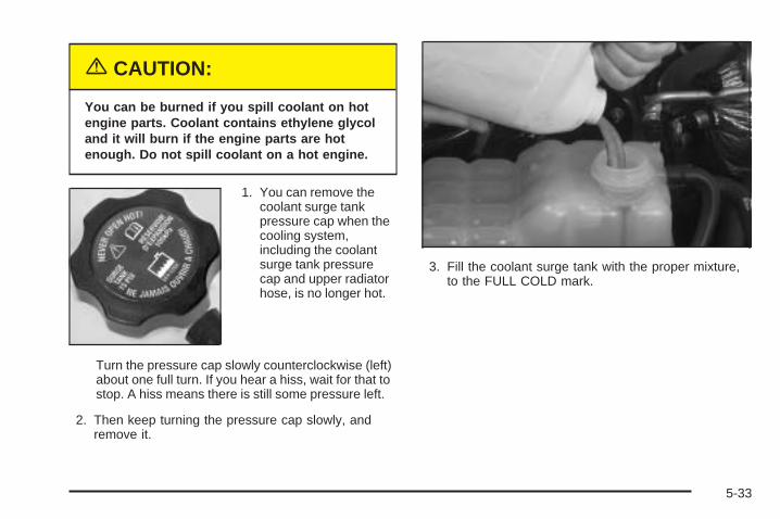
{CAUTION:
You can be burned if you spill coolant on hotengine parts. Coolant contains ethylene glycoland it will burn if the engine parts are hotenough. Do not spill coolant on a hot engine.
1. You can remove thecoolant surge tankpressure cap when thecooling system,including the coolantsurge tank pressurecap and upper radiatorhose, is no longer hot.
Turn the pressure cap slowly counterclockwise (left)about one full turn. If you hear a hiss, wait for that tostop. A hiss means there is still some pressure left.
2. Then keep turning the pressure cap slowly, andremove it.
3. Fill the coolant surge tank with the proper mixture,to the FULL COLD mark.
5-33

4. With the coolant surge tank pressure cap off, startthe engine and let it run until you can feel the upperradiator hose getting hot. Watch out for theengine cooling fan.By this time, the coolant level inside the coolantsurge tank may be lower. If the level is lower, addmore of the proper mixture to the coolant surge tankuntil the level reaches the FULL COLD mark.
5. Then replace the pressure cap. Be sure thepressure cap is hand-tight and fully seated.
Engine Fan NoiseIf your vehicle is equipped with a clutched engine coolingfan, when the clutch is engaged, the fan spins faster toprovide more air to cool the engine. In most everydaydriving conditions, the fan is spinning slower and theclutch is not fully engaged. This improves fuel economyand reduces fan noise. Under heavy vehicle loading,trailer towing, and/or high outside temperatures, the fanspeed increases as the clutch more fully engages, so youmay hear an increase in fan noise. This is normal andshould not be mistaken as the transmission slipping ormaking extra shifts. It is merely the cooling systemfunctioning properly. The fan will slow down whenadditional cooling is not required and the clutchdisengages.
You may also hear this fan noise when you start theengine. It will go away as the fan clutch partiallydisengages.
If your vehicle is equipped with electric cooling fans, youmay hear the fans spinning at low speed during mosteveryday driving. The fans may turn off if no cooling isrequired. Under heavy vehicle loading, trailer towing,and/or high outside temperatures, or if you are operatingyour air conditioning system, the fans change to highspeed and you may hear an increase in fan noise. Thisis normal and indicates that the cooling system isfunctioning properly. The fans will change to low speedwhen additional cooling is no longer required.
5-34

Power Steering Fluid
See Engine Compartment Overview on page 5-12 forreservoir location.
When to Check Power Steering FluidIt is not necessary to regularly check power steering fluidunless you suspect there is a leak in the system oryou hear an unusual noise. A fluid loss in this systemcould indicate a problem. Have the system inspectedand repaired.
8100 V8 engine
All other engines
5-35

How to Check Power Steering Fluid
Locate the cap with thissymbol. See EngineCompartment Overview onpage 5-12 for moreinformation on location.
To check the power steering fluid, do the following:
1. Turn the key off and let the engine compartmentcool down.
2. Wipe the cap and the top of the reservoir clean.
3. Unscrew the cap and wipe the dipstick witha clean rag.
4. Replace the cap and completely tighten it.
5. Remove the cap again and look at the fluid levelon the dipstick.
The level should be at the FULL COLD mark.If necessary, add only enough fluid to bringthe level up to the mark.
What to UseTo determine what kind of fluid to use, seeRecommended Fluids and Lubricants on page 6-13.Always use the proper fluid. Failure to use the properfluid can cause leaks and damage hoses and seals.
Windshield Washer Fluid
What to UseWhen you need windshield washer fluid, be sure to readthe manufacturer’s instructions before use. If you willbe operating your vehicle in an area where thetemperature may fall below freezing, use a fluid that hassufficient protection against freezing.
Adding Washer FluidYour vehicle has a low washer fluid message thatcomes on when the washer fluid is low. The message isdisplayed for 15 seconds at the start of each ignitioncycle. When the CHECK WASHER FLUID message isdisplayed, you will need to add washer fluid to thewindshield washer fluid reservoir.
5-36

Open the cap with thewasher symbol on it.Add washer fluid until thetank is full. See EngineCompartment Overview onpage 5-12 for reservoirlocation.
Notice:
• When using concentrated washer fluid, followthe manufacturer’s instructions for addingwater.
• Do not mix water with ready-to-use washer fluid.Water can cause the solution to freeze anddamage your washer fluid tank and other partsof the washer system. Also, water does notclean as well as washer fluid.
• Fill your washer fluid tank only three-quartersfull when it is very cold. This allows forexpansion if freezing occurs, which coulddamage the tank if it is completely full.
• Do not use engine coolant (antifreeze) in yourwindshield washer. It can damage your washersystem and paint.
Brakes
Brake Fluid
Your brake master cylinderreservoir is filled withDOT-3 brake fluid. SeeEngine CompartmentOverview on page 5-12 forthe location of thereservoir.
There are only two reasons why the brake fluid level inthe reservoir might go down. The first is that thebrake fluid goes down to an acceptable level duringnormal brake lining wear. When new linings are put in,the fluid level goes back up. The other reason isthat fluid is leaking out of the brake system. If it is, youshould have your brake system fixed, since a leakmeans that sooner or later your brakes will not workwell, or will not work at all.
5-37

So, it is not a good idea to top off your brake fluid.Adding brake fluid will not correct a leak. If you add fluidwhen your linings are worn, then you will have toomuch fluid when you get new brake linings. You shouldadd or remove brake fluid, as necessary, only whenwork is done on the brake hydraulic system.
{CAUTION:
If you have too much brake fluid, it can spill onthe engine. The fluid will burn if the engine ishot enough. You or others could be burned,and your vehicle could be damaged. Add brakefluid only when work is done on the brakehydraulic system. See “Checking Brake Fluid”in this section.
Refer to the Maintenance Schedule to determine whento check your brake fluid. See Scheduled Maintenanceon page 6-4.
Checking Brake FluidYou can check the brake fluid without taking off the cap.
Look at the brake fluidreservoir. The fluid levelshould be above MIN. If itis not, have your brakesystem checked tosee if there is a leak.
After work is done on the brake hydraulic system,make sure the level is above the MIN but not over theMAX mark.
What to AddWhen you do need brake fluid, use only DOT-3 brakefluid. Use new brake fluid from a sealed containeronly. See Recommended Fluids and Lubricants onpage 6-13.
5-38

Always clean the brake fluid reservoir cap and the areaaround the cap before removing it. This will helpkeep dirt from entering the reservoir.
{CAUTION:
With the wrong kind of fluid in your brakesystem, your brakes may not work well, orthey may not even work at all. This couldcause a crash. Always use the proper brakefluid.
Notice:
• Using the wrong fluid can badly damage brakesystem parts. For example, just a few drops ofmineral-based oil, such as engine oil, in yourbrake system can damage brake system parts sobadly that they will have to be replaced. Do notlet someone put in the wrong kind of fluid.
• If you spill brake fluid on your vehicle’s paintedsurfaces, the paint finish can be damaged. Becareful not to spill brake fluid on your vehicle. Ifyou do, wash it off immediately. See AppearanceCare on page 5-95.
Brake WearYour vehicle has four-wheel disc brakes.
Disc brake pads have built-in wear indicators that makea high-pitched warning sound when the brake padsare worn and new pads are needed. The soundmay come and go or be heard all the time your vehicleis moving, except when you are pushing on thebrake pedal firmly.
{CAUTION:
The brake wear warning sound means thatsoon your brakes will not work well. Thatcould lead to an accident. When you hear thebrake wear warning sound, have your vehicleserviced.
Notice: Continuing to drive with worn-out brakepads could result in costly brake repair.
Some driving conditions or climates may cause a brakesqueal when the brakes are first applied or lightlyapplied. This does not mean something is wrong withyour brakes.
5-39
Properly torqued wheel nuts are necessary to helpprevent brake pulsation. When tires are rotated, inspectbrake pads for wear and evenly tighten wheel nuts inthe proper sequence to GM torque specifications.
Brake linings should always be replaced as completeaxle sets.
Brake Pedal TravelSee your dealer if the brake pedal does not return tonormal height, or if there is a rapid increase inpedal travel. This could be a sign of brake trouble.
Brake AdjustmentEvery time you make a brake stop, your disc brakesadjust for wear.
Replacing Brake System PartsThe braking system on a vehicle is complex. Its manyparts have to be of top quality and work well togetherif the vehicle is to have really good braking. Your vehiclewas designed and tested with top-quality GM brakeparts. When you replace parts of your brakingsystem —for example, when your brake linings weardown and you need new ones put in — be sure youget new approved GM replacement parts. If you do
not, your brakes may no longer work properly. Forexample, if someone puts in brake linings that are wrongfor your vehicle, the balance between your front andrear brakes can change — for the worse. The brakingperformance you have come to expect can changein many other ways if someone puts in the wrongreplacement brake parts.
BatteryYour vehicle has a maintenance free battery. When it istime for a new battery, get one that has the replacementnumber shown on the original battery’s label. Werecommend an ACDelco® replacement battery. SeeEngine Compartment Overview on page 5-12 for batterylocation.Warning: Battery posts, terminals and relatedaccessories contain lead and lead compounds,chemicals known to the State of California to causecancer and reproductive harm. Wash hands afterhandling.
5-40

Vehicle StorageIf you are not going to drive your vehicle for 25 daysor more, remove the black, negative (−) cable fromthe battery. This will help keep your battery fromrunning down.
{CAUTION:
Batteries have acid that can burn you and gasthat can explode. You can be badly hurt if youare not careful. See Jump Starting onpage 5-41 for tips on working around a batterywithout getting hurt.
Jump StartingIf your battery (or batteries) has run down, you maywant to use another vehicle and some jumper cables tostart your vehicle. Be sure to use the following stepsto do it safely.
{CAUTION:
Batteries can hurt you. They can be dangerousbecause:
• They contain acid that can burn you.• They contain gas that can explode or
ignite.• They contain enough electricity to
burn you.
If you do not follow these steps exactly, someor all of these things can hurt you.
Notice: Ignoring these steps could result in costlydamage to your vehicle that would not be coveredby your warranty.
Trying to start your vehicle by pushing or pulling itwill not work, and it could damage your vehicle.
1. Check the other vehicle. It must have a 12-voltbattery with a negative ground system.
Notice: If the other vehicle’s system is not a 12-voltsystem with a negative ground, both vehicles canbe damaged. Only use vehicles with 12-volt systemswith negative grounds to jump start your vehicle.
5-41

2. Get the vehicles close enough so the jumper cablescan reach, but be sure the vehicles are not touchingeach other. If they are, it could cause a groundconnection you do not want. You would not be ableto start your vehicle, and the bad groundingcould damage the electrical systems.To avoid the possibility of the vehicles rolling, setthe parking brake firmly on both vehicles involved inthe jump start procedure. Put the automatictransmission in PARK (P) before setting the parkingbrake. If you have a four-wheel-drive vehicle, besure the transfer case is in a drive gear, notin NEUTRAL.
Notice: If you leave your radio or other accessorieson during the jump starting procedure, they couldbe damaged. The repairs would not be coveredby your warranty. Always turn off your radio andother accessories when jump starting your vehicle.
3. Turn off the ignition on both vehicles. Unplugunnecessary accessories plugged into the cigarettelighter or the accessory power outlets. Turn offthe radio and all the lamps that are not needed.This will avoid sparks and help save both batteries.And it could save the radio!
4. Open the hood on the other vehicle and locate thepositive (+) and negative (−) terminal locations onthat vehicle.Your vehicle has a remote positive (+) jump startingterminal and a remote negative (−) jump startingterminal. You should always use these remoteterminals instead of the terminals on the battery.The remote positive (+) terminal is located behind ared plastic cover, if equipped, near the engineaccessory drive bracket. To uncover the remotepositive (+) terminal, open the red plastic cover,if equipped.The remote negative (−) terminal is located on theengine drive bracket, or on the thermostathousing on the 8.1L engine. It is marked GND.See Engine Compartment Overview on page 5-12for more information on location.
{CAUTION:
An electric fan can start up even when theengine is not running and can injure you.Keep hands, clothing and tools away from anyunderhood electric fan.
5-42
{CAUTION:
Using a match near a battery can cause batterygas to explode. People have been hurt doingthis, and some have been blinded. Use aflashlight if you need more light.
Be sure the battery has enough water. You donot need to add water to the battery installedin your new vehicle. But if a battery has fillercaps, be sure the right amount of fluid is there.If it is low, add water to take care of that first.If you do not, explosive gas could be present.
Battery fluid contains acid that can burn you.Do not get it on you. If you accidentally get itin your eyes or on your skin, flush the placewith water and get medical help immediately.
{CAUTION:
Fans or other moving engine parts can injureyou badly. Keep your hands away from movingparts once the engine is running.
5. Check that the jumper cables do not have loose ormissing insulation. If they do, you could get ashock. The vehicles could be damaged too.Before you connect the cables, here are somebasic things you should know. Positive (+) will go topositive (+) or to a remote positive (+) terminal ifthe vehicle has one. Negative (−) will go to a heavy,unpainted metal engine part or to a remotenegative (−) terminal if the vehicle has one.Do not connect positive (+) to negative (−) or youwill get a short that would damage the batteryand maybe other parts too. And do not connect thenegative (−) cable to the negative (−) terminal onthe dead battery because this can cause sparks.
5-43

6. Connect the redpositive (+) cable to thepositive (+) terminalof the vehicle with thedead battery. Usea remote positive (+)terminal if thevehicle has one.
7. Do not let the other end touch metal. Connect it tothe positive (+) terminal of the good battery. Use aremote positive (+) terminal if the vehicle has one.
8. Now connect the black negative (−) cable to thenegative (−) terminal of the good battery. Use aremote negative (−) terminal if the vehicle has one.Do not let the other end touch anything until thenext step. The other end of the negative (−) cabledoes not go to the dead battery. It goes to aheavy, unpainted metal engine part or to the remotenegative (−) terminal on the vehicle with the deadbattery.
9. Connect the other endof the negative (−)cable to the remotenegative (−) terminal,marked GND, onthe vehicle with thedead battery.
10. Now start the vehicle with the good battery and runthe engine for a while.
11. Try to start the vehicle that had the dead battery.If it will not start after a few tries, it probably needsservice.
5-44

Notice: If the jumper cables are connected orremoved in the wrong order, electrical shorting mayoccur and damage the vehicle. The repairs wouldnot be covered by your warranty. Always connectand remove the jumper cables in the correctorder, making sure that the cables do not toucheach other or other metal.
A. Heavy, Unpainted Metal Engine Part or RemoteNegative (−) Terminal
B. Good Battery or Remote Positive (+) and RemoteNegative (−) Terminals
C. Dead Battery or Remote Positive (+) Terminal
To disconnect the jumper cables from both vehiclesdo the following:
1. Disconnect the black negative (−) cable from thevehicle that had the bad battery.
2. Disconnect the black negative (−) cable from thevehicle with the good battery.
3. Disconnect the red positive (+) cable from thevehicle with the good battery.
4. Disconnect the red positive (+) cable from the othervehicle.
5. Return the positive (+) remote terminal cover,if equipped, to its original position.
All-Wheel DriveLubricant checks in this section also apply to thesevehicles. However, there are two additional systems thatneed lubrication.
Transfer CaseWhen to Check LubricantRefer to the Maintenance Schedule to determine howoften to check the lubricant. See ScheduledMaintenance on page 6-4.
Jumper Cable Removal
5-45

How to Check Lubricant
To get an accurate reading, the vehicle should be on alevel surface.If the level is below the bottom of the filler plug hole,you’ll need to add some lubricant. Add enough lubricantto raise the level to the bottom of the filler plug hole.Use care not to overtighten the plug.
What to UseRefer to the Maintenance Schedule to determine whatkind of lubricant to use. See Recommended Fluidsand Lubricants on page 6-13.
Rear AxleWhen to Check LubricantIt is not necessary to regularly check rear axle fluidunless you suspect there is a leak or you hear anunusual noise. A fluid loss could indicate a problem.Have it inspected and repaired.
How to Check Lubricant
All-Wheel Drive Transfer Case(A) Fill Plug (B) Drain Plug
1500 Series shown, 2500 similar
5-46

To get an accurate reading, the vehicle should be on alevel surface.
• The proper level for the 1500 Series is from5/8 inch to 1 5/8 inch (15 mm to 40 mm) below thebottom of the filler plug hole.
• The proper level for the 2500 Series is from0 to 1/2 inch (0 to 13 mm) below the bottom of thefiller plug hole.
• The proper level for the 1500 and 2500 seriesvehicles with QUADRASTEER™ (4-Wheel Steer) isfrom 0 to 1/4 inch (0 to 6 mm) below the fillerplug hole.
Add only enough fluid to reach the proper level.
What to UseTo determine what kind of lubricant to use, seeRecommended Fluids and Lubricants on page 6-13.
Four-Wheel DriveLubricant checks in this section also apply to thesevehicles. There are two additional systems that needlubrication.
Transfer Case
When to Check LubricantIt is not necessary to regularly check transfer case fluidunless you suspect there is a leak, or you hear anunusual noise. A fluid loss could indicate a problem.Have it inspected and repaired.
How to Check Lubricant
To get an accurate reading, the vehicle should be on alevel surface.
Automatic Transfer Case
5-47

If the level is below the bottom of the filler plug hole,you’ll need to add some lubricant. Add enough lubricantto raise the level to the bottom of the filler plug hole.Use care not to overtighten the plug.
When to Change LubricantRefer to the Maintenance Schedule to determine howoften to change the lubricant. See ScheduledMaintenance on page 6-4.
What to UseRefer to the Maintenance Schedule to determine whatkind of lubricant to use. See Recommended Fluidsand Lubricants on page 6-13.
Front AxleWhen to Check LubricantIt is not necessary to regularly check front axle fluidunless you suspect there is a leak or you hear anunusual noise. A fluid loss could indicate a problem.Have it inspected and repaired.
How to Check Lubricant
To get an accurate reading, the vehicle should be on alevel surface.
5-48

If the level is below the bottom of the filler plug hole,you may need to add some lubricant:
• When the differential is cold, add enough lubricantto raise the level to 0 to 3/8 inch (9.5 mm) belowthe filler plug hole.
• When the differential is at operating temperature(warm), add enough lubricant to raise the levelto the bottom of the filler plug hole.
What to UseTo determine what kind of lubricant to use, seeRecommended Fluids and Lubricants on page 6-13.
Bulb ReplacementFor the proper type of replacement bulbs, seeReplacement Bulbs on page 5-56.
For any bulb changing procedure not listed in thissection, contact your dealer.
Halogen Bulbs
{CAUTION:
Halogen bulbs have pressurized gas inside andcan burst if you drop or scratch the bulb. You orothers could be injured. Be sure to read andfollow the instructions on the bulb package.
5-49

HeadlampsTo replace a headlamp bulb, do the following:
1. Open the hood. See Hood Release on page 5-11for more information.
2. Remove the two pins on the top of the headlampassembly. To remove them, turn the outer pinoutward and pull it straight up. To remove the innerpin, turn it inward and pull it straight up.
A. Low-Beam HeadlampB. High-Beam Headlamp
3. Pull the headlamp assembly out.
4. Unplug the electrical connector.
5. Turn the bulb counterclockwise and remove it fromthe headlamp assembly.
6. Put the new bulb into the headlamp assembly andturn it clockwise until it is tight. Use care not totouch the bulb with your fingers or hands.
7. Plug in the electrical connector.
8. Put the headlamp assembly back into the vehicle.
9. Install and turn the two pins into the locking feature.
5-50

Front Turn Signal, Sidemarker andDaytime Running Lamps
A. Sidemarker LampB. Retainer Clip
C. Front Turn Signal LampD. Daytime Running
Lamp (DRL)
To replace a front turn signal, sidemarker or DRL bulb,do the following:
1. Open the hood. See Hood Release on page 5-11for more information.
2. Remove the headlamp assembly as describedpreviously. See Headlamps on page 5-50 formore information.
3. Press the retainer clip (B), located behind the turnsignal assembly, towards the outside of the vehicle.
4. Pull the turn signal assembly out of the vehicle.
5. Press the locking release lever, turn the bulb socketcounterclockwise and remove it from the turn signalassembly.
6. Remove the old bulb from the bulb socket.
7. Install a new bulb into the bulb socket.
8. Insert the bulb socket into the turn signal assemblyand turn it clockwise until it locks.
5-51
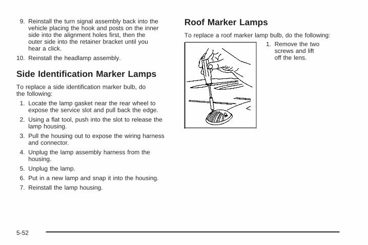
9. Reinstall the turn signal assembly back into thevehicle placing the hook and posts on the innerside into the alignment holes first, then theouter side into the retainer bracket until youhear a click.
10. Reinstall the headlamp assembly.
Side Identification Marker LampsTo replace a side identification marker bulb, dothe following:
1. Locate the lamp gasket near the rear wheel toexpose the service slot and pull back the edge.
2. Using a flat tool, push into the slot to release thelamp housing.
3. Pull the housing out to expose the wiring harnessand connector.
4. Unplug the lamp assembly harness from thehousing.
5. Unplug the lamp.
6. Put in a new lamp and snap it into the housing.
7. Reinstall the lamp housing.
Roof Marker LampsTo replace a roof marker lamp bulb, do the following:
1. Remove the twoscrews and liftoff the lens.
5-52

2. Remove the six screws on the center roof markerlamps.
3. Turn the old bulb counterclockwise to remove itfrom the socket.
4. Put a new bulb intothe socket and turnclockwise until itlocks in place.
5-53

5. Reinstall the lens and tighten the screws.
TaillampsA. Turn Signal LampB. Back-up LampC. Stoplamp
5-54

To replace a taillamp bulb, do the following:
1. Remove thetwo screws from thetaillamp assembly.
2. Remove the taillamp assembly.
3. Press the release tab and turn the bulb socketcounterclockwise to remove it from the taillamphousing.
4. Pull the old bulbstraight out fromthe socket.
5. Press a new bulb into the socket, insert the socketinto the taillamp housing and turn the socketclockwise into the taillamp housing until it clicks.
6. Reinstall the taillamp assembly.
5-55

Replacement BulbsExterior Lamp Bulb Number
Back-up Lamp 3157Daytime Running Lamps (DRL) 4114KFront Roof Marker Lamp 194Front Parking and Turn Lamp 3457AHeadlamps
High-Beam 9005Low-Beam 9006
Rear Marker Lamp, Taillamp andStoplamp 3157
Rear Turn Signal Lamp 3157
For replacement bulbs not listed here, contact yourdealer.
Windshield Wiper BladeReplacementWindshield wiper blades should be inspected at leasttwice a year for wear and cracking. See ScheduledMaintenance on page 6-4 for more information.
Replacement blades come in different types and areremoved in different ways. For proper type and length,see Normal Maintenance Replacement Parts onpage 6-15.
To replace the windshield wiper blade assembly do thefollowing:
1. Lift the wiper arm and turn the blade until it isfacing away from the windshield.
2. Push the release lever and slide the wiper assemblytoward the driver’s side of the vehicle.
3. Install a new blade by reversing Steps 1 and 2.
5-56

TiresYour new vehicle comes with high-quality tires made bya leading tire manufacturer. If you ever have questionsabout your tire warranty and where to obtain service,see your GM Warranty booklet for details. For additionalinformation refer to the tire manufacturer’s bookletincluded with your vehicle’s Owner Manual.
{CAUTION:
Poorly maintained and improperly used tiresare dangerous.
• Overloading your tires can causeoverheating as a result of too muchfriction. You could have an air-out and aserious accident. See Loading YourVehicle on page 4-51.
CAUTION: (Continued)
CAUTION: (Continued)
• Underinflated tires pose the same dangeras overloaded tires. The resulting accidentcould cause serious injury. Check all tiresfrequently to maintain the recommendedpressure. Tire pressure should be checkedwhen your tires are cold. See Inflation - TirePressure on page 5-64.
• Overinflated tires are more likely to be cut,punctured or broken by a suddenimpact — such as when you hit a pothole.Keep tires at the recommended pressure.
• Worn, old tires can cause accidents. If yourtread is badly worn, or if your tires havebeen damaged, replace them.
5-57
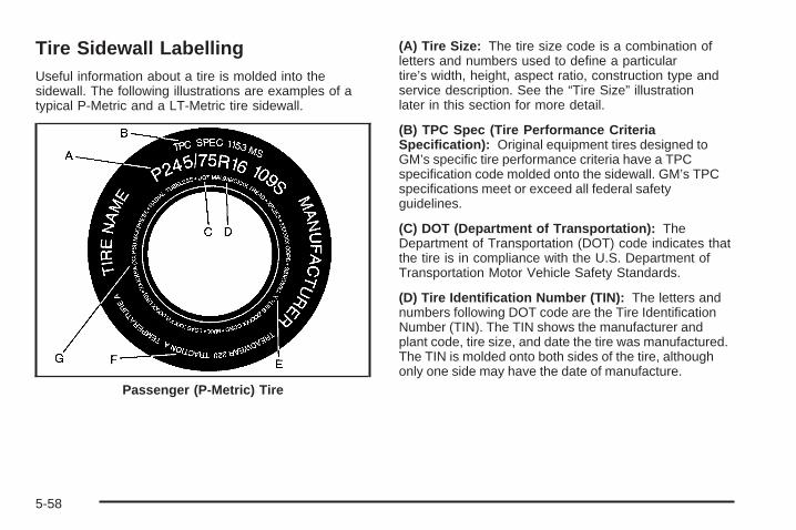
Tire Sidewall LabellingUseful information about a tire is molded into thesidewall. The following illustrations are examples of atypical P-Metric and a LT-Metric tire sidewall.
(A) Tire Size: The tire size code is a combination ofletters and numbers used to define a particulartire’s width, height, aspect ratio, construction type andservice description. See the “Tire Size” illustrationlater in this section for more detail.
(B) TPC Spec (Tire Performance CriteriaSpecification): Original equipment tires designed toGM’s specific tire performance criteria have a TPCspecification code molded onto the sidewall. GM’s TPCspecifications meet or exceed all federal safetyguidelines.
(C) DOT (Department of Transportation): TheDepartment of Transportation (DOT) code indicates thatthe tire is in compliance with the U.S. Department ofTransportation Motor Vehicle Safety Standards.
(D) Tire Identification Number (TIN): The letters andnumbers following DOT code are the Tire IdentificationNumber (TIN). The TIN shows the manufacturer andplant code, tire size, and date the tire was manufactured.The TIN is molded onto both sides of the tire, althoughonly one side may have the date of manufacture.
Passenger (P-Metric) Tire
5-58

(E) Tire Ply Material: The type of cord and number ofplies in the sidewall and under the tread.
(F) Uniform Tire Quality Grading (UTQG): Tiremanufacturers are required to grade tires based onthree performance factors: treadwear, traction andtemperature resistance. For more information, seeUniform Tire Quality Grading on page 5-72.
(G) Maximum Cold Inflation Load Limit: Maximumload that can be carried and the maximum pressureneeded to support that load. For information onrecommended tire pressure see Inflation - Tire Pressureon page 5-64 and Loading Your Vehicle on page 4-51.
(A) Tire Size: The tire size code is a combinationof letters and numbers used to define a particulartire’s width, height, aspect ratio, construction typeand service description. See the “Tire Size”illustration later in this section for more detail.
Light Truck (LT-Metric) Tire
5-59

(B) TPC Spec (Tire Performance CriteriaSpecification): Original equipment tires designed toGM’s specific tire performance criteria have a TPCspecification code molded onto the sidewall. GM’s TPCspecifications meet or exceed all federal safetyguidelines.
(C) Dual Tire Maximum Load: Maximum load that canbe carried and the maximum pressure needed tosupport that load when used in a dual configuration. Forinformation on recommended tire pressure seeInflation - Tire Pressure on page 5-64 and Loading YourVehicle on page 4-51.
(D) DOT (Department of Transportation): TheDepartment of Transportation (DOT) code indicates thatthe tire is in compliance with the U.S. Department ofTransportation Motor Vehicle Safety Standards.
(E) Tire Identification Number (TIN): The letters andnumbers following DOT code are the Tire IdentificationNumber (TIN). The TIN shows the manufacturerand plant code, tire size, and date the tire wasmanufactured. The TIN is molded onto both sides of thetire, although only one side may have the date ofmanufacture.
(F) Tire Ply Material: The type of cord and number ofplies in the sidewall and under the tread.
(G) Single Tire Maximum Load: Maximum load thatcan be carried and the maximum pressure neededto support that load when used as a single. Forinformation on recommended tire pressure seeInflation - Tire Pressure on page 5-64 and Loading YourVehicle on page 4-51.
5-60

Tire SizeThe following examples show the different partsof a tire size.
(A) Passenger (P-Metric) Tire: The United Statesversion of a metric tire sizing system. The letter P as thefirst character in the tire size means a passengervehicle tire engineered to standards set by the U.S. Tireand Rim Association.
(A) Light Truck (LT-Metric) Tire: The United Statesversion of a metric tire sizing system. The letters LT asthe first two characters in the tire size means a lighttruck tire engineered to standards set by the U.S. Tireand Rim Association.
(B) Tire Width: The three-digit number indicates thetire section width in millimeters from sidewall to sidewall.
(C) Aspect Ratio: A two-digit number that indicatesthe tire height-to-width measurements. For example, ifthe tire size aspect ratio is 75, as shown in item C of thelight truck (LT-Metric) tire illustration, it would meanthat the tire’s sidewall is 75% as high as it is wide.
(D) Construction Code: A letter code is used toindicate the type of ply construction in the tire. Theletter R means radial ply construction; the letterD means diagonal or bias ply construction; and theletter B means belted-bias ply construction.
(E) Rim Diameter: Diameter of the wheel in inches.
(F) Service Description: The service descriptionindicates the load range and speed rating of a tire.The load index can range from 1 to 279. Speed ratingsrange from A to Z.
Passenger (P-Metric) Tire
Light Truck (LT-Metric) Tire
5-61

Tire Terminology and Definitions
Air Pressure: The amount of air inside the tire pressingoutward on each square inch of the tire. Air pressureis expressed in pounds per square inch (psi) orkilopascal (kPa).
Accessory Weight: This means the combined weightof optional accessories. Some examples of optionalaccessories are, automatic transmission, power steering,power brakes, power windows, power seats, and airconditioning.
Aspect Ratio: The relationship of a tire’s height to itswidth.
Belt: A rubber coated layer of cords that is locatedbetween the plies and the tread. Cords may be madefrom steel or other reinforcing materials.
Bead: The tire bead contains steel wires wrapped bysteel cords that hold the tire onto the rim.
Bias Ply Tire: A pneumatic tire in which the plies arelaid at alternate angles less than 90 degrees to thecenterline of the tread.
Cold Inflation Pressure: The amount of air pressure ina tire, measured in pounds per square inch (psi) orkilopascals (kPa) before a tire has built up heatfrom driving. See Inflation - Tire Pressure on page 5-64.
Curb Weight: This means the weight of a motorvehicle with standard and optional equipment includingthe maximum capacity of fuel, oil and coolant, butwithout passengers and cargo.
DOT Markings: A code molded into the sidewall of atire signifying that the tire is in compliance with the U.S.Department of Transportation (DOT) motor vehiclesafety standards. The DOT code includes the TireIdentification Number (TIN), an alphanumeric designatorwhich can also identify the tire manufacturer, productionplant, brand and date of production.
GVWR: Gross Vehicle Weight Rating, see LoadingYour Vehicle on page 4-51.
GAWR FRT: Gross Axle Weight Rating for the frontaxle, see Loading Your Vehicle on page 4-51.
GAWR RR: Gross Axle Weight Rating for the rear axle,see Loading Your Vehicle on page 4-51.
5-62

Intended Outboard Sidewall: The side of anasymmetrical tire, that must always face outward whenmounted on a vehicle.
Kilopascal (kPa): The metric unit for air pressure.
Light Truck (LT-Metric) Tire: A tire used on light dutytrucks and some multipurpose passenger vehicles.
Load Index: An assigned number ranging from 1 to 279that corresponds to the load carrying capacity of a tire.
Maximum Inflation Pressure: The maximum airpressure to which a cold tire may be inflated. Themaximum air pressure is molded onto the sidewall.
Maximum Load Rating: The load rating for a tire at themaximum permissible inflation pressure for that tire.
Maximum Loaded Vehicle Weight: The sum of curbweight; accessory weight; vehicle capacity weight;and production options weight.
Normal Occupant Weight: The number of occupants avehicle is designed to seat multiplied by 150 lbs (68 kg).See Loading Your Vehicle on page 4-51.
Occupant Distribution: Designated seating positions.
Outward Facing Sidewall: The side of anasymmetrical tire that has a particular side that facesoutward when mounted on a vehicle. The side of the tire
that contains a whitewall, bears white lettering or bearsmanufacturer, brand, and/or model name moldingthat is higher or deeper than the same moldings on theother sidewall of the tire.
Passenger (P-Metric) Tire: A tire used on passengercars and some light duty trucks and multipurposevehicles.
Recommended Inflation Pressure: Vehiclemanufacturer’s recommended tire inflation pressure andshown on the tire placard. See Inflation - Tire Pressureon page 5-64 and Loading Your Vehicle on page 4-51.
Radial Ply Tire: A pneumatic tire in which the ply cordsthat extend to the beads are laid at 90 degrees to thecenterline of the tread.
Rim: A metal support for a tire and upon which the tirebeads are seated.
Sidewall: The portion of a tire between the tread andthe bead.
Speed Rating: An alphanumeric code assigned to atire indicating the maximum speed at which a tirecan operate.
Traction: The friction between the tire and the roadsurface. The amount of grip provided.
5-63

Tread: The portion of a tire that comes into contactwith the road.
Treadwear Indicators: Narrow bands, sometimescalled “wear bars,” that show across the tread of a tirewhen only 1/16 inch (1.6 mm) of tread remains. SeeWhen It Is Time for New Tires on page 5-70.
UTQGS (Uniform Tire Quality Grading Standards): Atire information system that provides consumers withratings for a tire’s traction, temperature, and treadwear.Ratings are determined by tire manufacturers usinggovernment testing procedures. The ratings are moldedinto the sidewall of the tire. See Uniform Tire QualityGrading on page 5-72.
Vehicle Capacity Weight: The number of designatedseating positions multiplied by 150 lbs (68 kg) plusthe rated cargo load. See Loading Your Vehicleon page 4-51.
Vehicle Maximum Load on the Tire: Load on anindividual tire due to curb weight, accessory weight,occupant weight, and cargo weight.
Vehicle Placard: A label permanently attached to avehicle showing the vehicle’s capacity weight andthe original equipment tire size and recommendedinflation pressure. See “Tire and Loading InformationLabel” under Loading Your Vehicle on page 4-51.
Inflation - Tire PressureTires need the correct amount of air pressure to operateeffectively.
Notice: Do not let anyone tell you thatunder-inflation or over-inflation is all right. It is not.If your tires do not have enough air (under-inflation),you can get the following:
• Too much flexing
• Too much heat
• Tire overloading
• Premature or irregular wear
• Poor handling
• Reduced fuel economy
If your tires have too much air (over-inflation), youcan get the following:
• Unusual wear
• Poor handling
• Rough ride
• Needless damage from road hazards
5-64

A Tire and Loading Information label is attached to thevehicle’s center pillar (B-pillar), below the driver’sdoor lock post (striker). This label lists your vehicle’soriginal equipment tires and their recommended cold tireinflation pressures. The recommended cold tireinflation pressure, shown on the label, is the minimumamount of air pressure needed to support your vehicle’smaximum load carrying capacity.
For additional information regarding how much weightyour vehicle can carry, and an example of the tireand loading information label, see Loading Your Vehicleon page 4-51.
When to CheckCheck your tires once a month or more. Do not forget tocheck the spare tire. For additional informationregarding the spare tire, see Spare Tire on page 5-95.
How to CheckUse a good quality pocket-type gage to check tirepressure. You cannot tell if your tires are properly inflatedsimply by looking at them. Radial tires may look properlyinflated even when they’re underinflated. Check the tire’sinflation pressure when the tires are cold. Cold meansyour vehicle has been sitting for at least three hours ordriven no more than 1 mile (1.6 km).
Remove the valve cap from the tire valve stem. Pressthe tire gage firmly onto the valve to get a pressuremeasurement. If the cold tire inflation pressure matchesthe recommended pressure on the Tire and LoadingInformation label, no further adjustment is necessary.If the inflation pressure is low, add air until you reach therecommended amount.If you overfill the tire, release air by pushing on themetal stem in the center of the tire valve. Recheck thetire pressure with the tire gage.Be sure to put the valve caps back on the valve stems.They help prevent leaks by keeping out dirt and moisture.
Tire Pressure Monitor SystemThe Tire Pressure Monitor (TPM) system uses radioand sensor technology to check tire pressure levels.If your vehicle has this feature, sensors are mounted oneach tire and wheel assembly, except the spare tire.The TPM sensors transmit tire pressure readingsto a receiver located in the vehicle.When a low tire pressure condition is detected, the TPMsystem will display the CHECK TIRE PRESSUREwarning message on the Driver Information Center (DIC);and at the same time illuminate the low tire pressurewarning symbol. For additional information and detailsabout the DIC operation and displays see DIC Operationand Displays on page 3-55 and DIC Warnings andMessages on page 3-58.
5-65

When the tire pressuremonitoring system warninglight is lit, one or moreof your tires is significantlyunder-inflated.
You should stop and check your tires as soon aspossible, and inflate them to the proper pressure asindicated on the vehicle’s tire information placard.
Driving on a significantly under-inflated tire causes thetire to overheat and can lead to tire failure.Under-inflation also reduces fuel efficiency and tire treadlife, and may affect the vehicle’s handling and stoppingability. Each tire, including the spare, should bechecked monthly when cold and set to therecommended inflation pressure as specified in thevehicle placard and owner’s manual.
The Tire and Loading Information label (tire informationplacard) shows the size of your vehicle’s original tires andthe correct inflation pressure for your vehicle’s tires whenthey are cold. See Inflation - Tire Pressure on page 5-64.For the location of the tire and loading information label,see Loading Your Vehicle on page 4-51.
Your vehicle’s TPM system can alert you about a lowtire pressure condition but it does not replace normal tiremaintenance. See Tire Inspection and Rotation onpage 5-68 and Tires on page 5-57.
Notice: Do not use a tire sealant if your vehicle isequipped with Tire Pressure Monitors. The liquidsealant can damage the tire pressure monitorsensors.
TPM Sensor Identification CodesEach TPM sensor has a unique identification code. Anytime you rotate your vehicle’s tires or replace one ormore of the TPM sensors, the identification codeswill need to be matched to the new tire/wheel position.Each tire/wheel position is matched to a sensor, byincreasing or decreasing the tire’s air pressure.The sensors are matched to the tire/wheel positions inthe following order: left front (LF), right front (RF),right rear (RR) and left rear (LR).
You will have one minute to match the first tire/wheelposition, and five minutes overall to match all fourtire/wheel positions. If it takes longer than one minute,to match the first tire and wheel, or more than fiveminutes to match all four tire and wheel positions thematching process stops and you will need to start over.
5-66

The TPM sensor matching process is outlined below:
1. Set the Parking brake.
2. Turn the ignition switch to RUN with the engine off.
3. Turn the exterior lamp switch from “Off” to “On”four times within 3 seconds. A double horn chirpwill sound and the TPM low tire warning lightwill begin to flash. The double horn chirp andflashing TPM warning light indicate that the TPMmatching process has started. The TPM warninglight should continue flashing throughout thematching procedure. The SERVICE TIREMONITOR message will be displayed on theDriver Information Center (DIC).
4. Start with the left (driver’s side) front tire.
5. Remove the valve cap from the valve cap stem.Activate the TPM sensor by increasing ordecreasing the tire’s air pressure for 10 seconds,then stop and listen for a single horn chirp.The single horn chirp should sound within15 seconds, confirming that the sensor identificationcode has been matched to this tire and wheelposition. If you do not hear the confirming singlehorn chirp, you will need to start over with stepnumber one. To let air-pressure out of a tire you canuse the pointy end of the valve cap, a pencil-styleair pressure gage or a key.
6. Proceed to the right (passenger’s side) front tire,and repeat the procedure in Step 5.
7. Proceed to the right (passenger’s side) rear tire,and repeat the procedure in Step 5.
8. Proceed to the left (driver’s side) rear tire, andrepeat the procedure in Step 5.
9. After hearing the confirming horn chirp for the leftrear tire, check to see if the TPM warning light isstill flashing. If yes, turn the ignition switch to LOCK.
10. Set all four tires to the recommended air pressurelevel as indicated on the Tire and LoadingInformation label.
11. Put the valve caps back on the valve stems
The spare tire does not have a TPM sensor. If youreplace one of the road tires with the spare, the CHECKTIRE PRESSURE message will be displayed on theDIC screen. This message should go off once youre-install the road tire containing the TPM sensor. TheSERVICE TIRE MONITOR message is displayedwhen the TPM system is malfunctioning. One or moremissing or inoperable TPM sensors will cause theservice tire monitor message to be displayed. See yourdealer for service.
5-67

Federal Communications Commission andIndustry and Science CanadaThe TPM system operates on a radio frequency subjectto Federal Communications Commission (FCC) Rulesand with Industry and Science Canada.
This device complies with Part 15 of the FCC Rules andwith RSS-210 of Industry and Science Canada.Operation is subject to the following two conditions:(1) This device may not cause harmful interference, and(2) this device must accept any interference receivedincluding interference that may cause undesiredoperation of the device.
Changes or modifications to this system by other thanan authorized service facility could void authorization touse this equipment.
Tire Inspection and RotationTires should be rotated every 5,000 to 8,000 miles(8 000 to 13 000 km).
Any time you notice unusual wear, rotate your tires assoon as possible and check wheel alignment. Alsocheck for damaged tires or wheels. See When It Is Timefor New Tires on page 5-70 and Wheel Replacementon page 5-73 for more information.
Make sure the spare tire is stored securely. Push,pull, and then try to rotate or turn the tire. If it moves,use the ratchet/wheel wrench to tighten the cable.See Changing a Flat Tire on page 5-76.
The purpose of regular rotation is to achieve moreuniform wear for all tires on the vehicle. The first rotationis the most important. See Scheduled Maintenanceon page 6-4.
5-68

When rotating your tires, always use the correct rotationpattern shown here.
Do not include the spare tire in your tire rotation.
After the tires have been rotated, adjust the front andrear inflation pressures as shown on the tire and loadinginformation label. See Loading Your Vehicle onpage 4-51 and Inflation - Tire Pressure on page 5-64,for more information. Make certain that all wheelnuts are properly tightened. See “Wheel Nut Torque”under Capacities and Specifications on page 5-114.
{CAUTION:
Rust or dirt on a wheel, or on the parts towhich it is fastened, can make wheel nutsbecome loose after a time. The wheel couldcome off and cause an accident. When youchange a wheel, remove any rust or dirt fromplaces where the wheel attaches to the vehicle.In an emergency, you can use a cloth or apaper towel to do this; but be sure to use ascraper or wire brush later, if needed, to get allthe rust or dirt off. See Changing a Flat Tire onpage 5-76.
5-69

When It Is Time for New TiresOne way to tell when it’stime for new tires is tocheck the treadwearindicators, which willappear when your tireshave only 1/16 inch(1.6 mm) or less of treadremaining. Somecommercial truck tires maynot have treadwearindicators.
You need a new tire if any of the following statementsare true:• You can see the indicators at three or more places
around the tire.• You can see cord or fabric showing through the
tire’s rubber.• The tread or sidewall is cracked, cut or snagged
deep enough to show cord or fabric.• The tire has a bump, bulge or split.• The tire has a puncture, cut or other damage that
can’t be repaired well because of the size orlocation of the damage.
Buying New TiresTo find out what kind and size of tires you need, look atthe Certification/Tire label or the Tire and LoadingInformation label. See Loading Your Vehicle onpage 4-51 for more information about these labels andwhere they can be found on your vehicle.
The tires installed on your vehicle when it was new hada Tire Performance Criteria Specifications (TPCSpec) number on each tire’s sidewall. When you getnew tires, GM recommends that you get tires with thatsame TPC Spec number. That way your vehicle willcontinue to have tires that are designed to give properendurance, handling, speed rating, load range,traction, ride, tire pressure monitoring systemperformance and other things during normal service onyour vehicle. If your tires have an all-season treaddesign, the TPC number will be followed by an “MS”(for mud and snow).
Whenever you replace your tires with those not havinga TPC Spec number, make sure they are the samesize, load range, speed rating and constructiontype (bias, bias-belted or radial) as your original tires.
5-70

If you replace your vehicle’s tires with those not havinga TPC Spec number, the tire pressure monitoringsystem may give an inaccurate low pressure warning.Non-TPC Spec tires may give a low pressure warningthat is higher or lower than the proper warning level youwould get with TPC Spec numbered tires.
{CAUTION:
Mixing tires could cause you to lose controlwhile driving. If you mix tires of different sizesor types (radial and bias-belted tires), thevehicle may not handle properly, and youcould have a crash. Using tires of differentsizes may also cause damage to your vehicle.Be sure to use the same size and type tires onall wheels.
CAUTION: (Continued)
CAUTION: (Continued)
Your vehicle may be equipped with a differentsize spare than the road tires (those originallyinstalled on your vehicle). When new, yourvehicle included a spare tire and wheelassembly with a similar overall diameter asyour vehicle’s road tires and wheels, so it is allright to drive on it. Because this spare wasdeveloped for use on your vehicle, it will notaffect vehicle handling.
{CAUTION:
If you use bias-ply tires on your vehicle, thewheel rim flanges could develop cracks aftermany miles of driving. A tire and/or wheelcould fail suddenly, causing a crash. Use onlyradial-ply tires with the wheels on your vehicle.
5-71
Uniform Tire Quality GradingQuality grades can be found where applicable on thetire sidewall between tread shoulder and maximumsection width. For example:
Treadwear 200 Traction AA Temperature AThe following information relates to the systemdeveloped by the United States National HighwayTraffic Safety Administration, which grades tires bytreadwear, traction and temperature performance.(This applies only to vehicles sold in the United States.)The grades are molded on the sidewalls of mostpassenger car tires. The Uniform Tire Quality Gradingsystem does not apply to deep tread, winter-typesnow tires, space-saver or temporary use spare tires,tires with nominal rim diameters of 10 to 12 inches(25 to 30 cm), or to some limited-production tires.
While the tires available on General Motors passengercars and light trucks may vary with respect to thesegrades, they must also conform to federal safetyrequirements and additional General Motors TirePerformance Criteria (TPC) standards.
TreadwearThe treadwear grade is a comparative rating based onthe wear rate of the tire when tested under controlledconditions on a specified government test course.For example, a tire graded 150 would wear one anda half (1.5) times as well on the government course asa tire graded 100. The relative performance of tiresdepends upon the actual conditions of their use,however, and may depart significantly from the normdue to variations in driving habits, service practices anddifferences in road characteristics and climate.
Traction – AA, A, B, CThe traction grades, from highest to lowest, are AA, A,B, and C. Those grades represent the tire’s abilityto stop on wet pavement as measured under controlledconditions on specified government test surfaces ofasphalt and concrete. A tire marked C may have poortraction performance. Warning: The traction gradeassigned to this tire is based on straight-ahead brakingtraction tests, and does not include acceleration,cornering, hydroplaning, or peak traction characteristics.
5-72
Temperature – A, B, CThe temperature grades are A (the highest), B, and C,representing the tire’s resistance to the generationof heat and its ability to dissipate heat when testedunder controlled conditions on a specified indoorlaboratory test wheel. Sustained high temperature cancause the material of the tire to degenerate andreduce tire life, and excessive temperature can lead tosudden tire failure. The grade C corresponds to alevel of performance which all passenger car tires mustmeet under the Federal Motor Vehicle Safety StandardNo. 109. Grades B and A represent higher levels ofperformance on the laboratory test wheel than theminimum required by law.
Warning: The temperature grade for this tire isestablished for a tire that is properly inflated and notoverloaded. Excessive speed, underinflation, orexcessive loading, either separately or in combination,can cause heat buildup and possible tire failure.
Wheel Alignment and Tire BalanceThe wheels on your vehicle were aligned and balancedcarefully at the factory to give you the longest tire lifeand best overall performance.
If you notice unusual tire wear or your vehicle pullingone way or the other, the alignment may need tobe reset. If you notice your vehicle vibrating when drivingon a smooth road, your wheels may need to berebalanced.
Wheel ReplacementReplace any wheel that is bent, cracked or badly rustedor corroded. If wheel nuts keep coming loose, thewheel, wheel bolts and wheel nuts should be replaced.If the wheel leaks air, replace it (except somealuminum wheels, which can sometimes be repaired).See your dealer if any of these conditions exist.
Your dealer will know the kind of wheel you need.
Each new wheel should have the same load-carryingcapacity, diameter, width, offset and be mountedthe same way as the one it replaces.
5-73
If you need to replace any of your wheels, wheel boltsor wheel nuts, replace them only with new GMoriginal equipment parts. This way, you will be sure tohave the right wheel, wheel bolts and wheel nutsfor your vehicle.
{CAUTION:
Using the wrong replacement wheels, wheelbolts or wheel nuts on your vehicle can bedangerous. It could affect the braking andhandling of your vehicle, make your tires loseair and make you lose control. You could havea collision in which you or others could beinjured. Always use the correct wheel, wheelbolts and wheel nuts for replacement.
Notice: The wrong wheel can also cause problemswith bearing life, brake cooling, speedometer orodometer calibration, headlamp aim, bumper height,vehicle ground clearance and tire or tire chainclearance to the body and chassis.
See Changing a Flat Tire on page 5-76 for moreinformation.
Used Replacement Wheels
{CAUTION:
Putting a used wheel on your vehicle isdangerous. You can’t know how it’s been usedor how far it’s been driven. It could failsuddenly and cause a crash. If you have toreplace a wheel, use a new GM originalequipment wheel.
5-74
Tire Chains
{CAUTION:
If your vehicle has P265/75R16, LT265/75R16,P265/70R16 or P265/70R17 size tires, don’t usetire chains. They can damage your vehiclebecause there’s not enough clearance. Tirechains used on a vehicle without the properamount of clearance can cause damage to thebrakes, suspension or other vehicle parts. Thearea damaged by the tire chains could causeyou to lose control of your vehicle and you orothers may be injured in a crash.
Use another type of traction device only if itsmanufacturer recommends it for use on yourvehicle and tire size combination and roadconditions. Follow that manufacturer’sinstructions. To help avoid damage to yourvehicle, drive slowly, readjust or remove thedevice if it’s contacting your vehicle, and don’tspin your wheels.
If you do find traction devices that will fit,install them on the rear tires.
Notice: If you have a tire size other than P265/75R16,LT265/75R16, P265/70R16 or P265/70R17 use tirechains only where legal and only when you must. Usechains that are the proper size for your tires. Installthem on the rear tires only.
Don’t use chains on the front tires.
Tighten them as tightly as possible with the endssecurely fastened. Drive slowly and follow the chainmanufacturer’s instructions. If you can hear thechains contacting your vehicle, stop and retightenthem. If the contact continues, slow down untilit stops. Driving too fast or spinning the wheels withchains on will damage your vehicle.
5-75
If a Tire Goes FlatIt is unusual for a tire to blowout while you’re driving,especially if you maintain your tires properly. If air goesout of a tire, it is much more likely to leak out slowly.But if you should ever have a blowout, here are afew tips about what to expect and what to do:
If a front tire fails, the flat tire will create a drag thatpulls the vehicle toward that side. Take your foot off theaccelerator pedal and grip the steering wheel firmly.Steer to maintain lane position, and then gently brake toa stop well out of the traffic lane.
A rear blowout, particularly on a curve, acts much like askid and may require the same correction you would;use in a skid. In any rear blowout, remove your foot fromthe accelerator pedal. Get the vehicle under controlby steering the way you want the vehicle to go. It maybe very bumpy and noisy, but you can still steer. Gentlybrake to a stop, well off the road if possible.
{CAUTION:
Lifting a vehicle and getting under it to domaintenance or repairs is dangerous withoutthe appropriate safety equipment and training.The jack provided with your vehicle isdesigned only for changing a flat tire. If it isused for anything else, you or others could bebadly injured or killed if the vehicle slips offthe jack. Use the jack provided with yourvehicle only for changing a flat tire.
If a tire goes flat, the next part shows how to use yourjacking equipment to change a flat tire safely.
Changing a Flat TireIf a tire goes flat, avoid further tire and wheel damageby driving slowly to a level place. Turn on your vehicle’shazard warning flashers. See Hazard Warning Flasherson page 3-6 for more information.
5-76

{CAUTION:
Changing a tire can be dangerous. The vehiclecan slip off the jack and roll over or fall on youor other people. You and they could be badlyinjured or even killed. Find a level place tochange your tire. To help prevent the vehiclefrom moving:
1. Set the parking brake firmly.
2. Put the shift lever in PARK (P).
3. Turn off the engine and do not restartwhile the vehicle is raised.
4. Do not allow passengers to remain in thevehicle.
To be even more certain the vehicle will notmove, you should put blocks at the front andrear of the tire farthest away from the onebeing changed. That would be the tire, on theother side, at the opposite end of the vehicle.
When your vehicle has a flat tire, use the followingexample as a guide to assist you in the placement ofwheel blocks.
The following information will tell you next how to usethe jack and change a tire.
5-77

Removing the Spare Tire and Tools
A. Retaining Bracket andWing Nut
B. Tool Kit with Jack ToolsC. Wing Nut Holding
Wheel Blocks
D. Wheel BlocksE. JackF. Knob
A. KnobB. Removable TrayC. Retaining HookD. Retaining Bracket
and Wing NutE. Tool Kit with
Jack Tools
F. Mounting BracketG. Wing Nut Holding
Wheel BlocksH. Wheel BlocksI. Jack
Yukon Rear Access PanelYukon XL
5-78

For Yukon, the equipment is located behind the left trimpanel in the rear of the vehicle. Unlatch the releaselever to open the trim panel door. Skip the first step andfollow the last three.
For Yukon XL, the equipment you’ll need is under thestorage tray in the left trim panel.
1. Remove the tray to access the tools.
2. Remove the wing nut used to retain the tool kit byturning it counterclockwise.
3. Release the jack from its holder by turning the knobon the jack counterclockwise to lower the jack head.
4. Remove the wheel blocks and the wheel blockretainer by turning the wing nut counterclockwise.
You’ll use the jack handle extensions and the wheelwrench to remove the underbody-mounted spare tire.
A. Spare Tire (ValveStem Pointed Down)
B. Hoist AssemblyC. Hoist CableD. Tire RetainerE. Hoist ShaftF. Hoist End of
Extension Tool
G. Hoist ShaftAccess Hole
H. Wheel WrenchI. Jack Handle
ExtensionsJ. Hoist Lock
(If Equipped)
5-79

1. Open the spare tire lock cover on the bumper anduse the ignition key to remove the lock if yourvehicle is equipped with a hoist lock (J).
2. Assemble the wheel wrench (H) and the two jackhandle extensions (I) as shown.
3. Insert the hoist end(open end) (F) of theextension throughthe hole (G) in therear bumper.
Be sure the hoist end of the extension connects tothe hoist shaft (E). The ribbed square end of theextension is used to lower the spare tire.
4. Turn the wheel wrench (H) counterclockwise tolower the spare tire to the ground. Continue toturn the wheel wrench until the spare tire can bepulled out from under the vehicle.If the spare tire does not lower to the ground, thesecondary latch is engaged causing the tirenot to lower. See Secondary Latch System onpage 5-87.
5-80

5. Use the wheel wrenchwhich has a hook thatallows you to pull thehoist cable towards youto assist in reaching thespare tire.
6. Tilt the retainer (D) atthe end of the cablewhen the tire has beenlowered, so it canbe pulled up throughthe wheel opening.
7. Put the spare tire near the flat tire.
Removing the Flat Tire andInstalling the Spare TireUse the following pictures and instructions to removethe flat tire and raise the vehicle.
The tools you’ll be using include the bottle jack (A), thewheel blocks (B), the jack handle (C), the jack handleextensions (D), and the wheel wrench (E).
5-81

1. Remove the center cap by placing the chisel end ofthe wheel wrench in the slot on the wheel andgently prying the cap out.If the wheel has bolt-on wheel covers, loosen theplastic nut caps by turning the wheel wrenchin a counterclockwise direction. If needed, finishloosening them by hand. The nut caps will not comeoff. Using the flat end of the wheel wrench, pryalong the edge of the cover until it comes off.
2. Use the wheel wrench to loosen all the wheel nuts.Turn the wheel wrench counterclockwise to loosenthe wheel nuts. Don’t remove the wheel nuts yet.
Notice: If your vehicle has QUADRASTEER™ andyou use a jack to raise the vehicle withoutpositioning it correctly, you could damage theQUADRASTEER™ system. When raising yourvehicle on a jack, avoid contact with tie rods andtie rod boots.
5-82

A. Front PositionB. Rear Position
{CAUTION:
Getting under a vehicle when it is jacked up isdangerous. If the vehicle slips off the jack youcould be badly injured or killed. Never getunder a vehicle when it is supported onlyby a jack.
{CAUTION:
Raising your vehicle with the jack improperlypositioned can damage the vehicle and evenmake the vehicle fall. To help avoid personalinjury and vehicle damage, be sure to fit thejack lift head into the proper location beforeraising the vehicle.
Jacking Locations (Overall View)
5-83

3. Position the jack under the vehicle as shown.
Front Tire Flat: If the flat tire is on a front tire ofthe vehicle, you’ll need to use the jack handle (C)and only one jack handle extension (D). Attachthe wheel wrench to the jack handle extension.Attach the jack handle to the jack. Position the jackon the frame behind the flat tire where the framesections overlap. Turn the wheel wrench clockwiseto raise the vehicle. Raise the vehicle far enoughoff the ground so there is enough room for the sparetire to clear the ground.
Rear Tire Flat: If the flat tire is on a rear tire of thevehicle, you’ll need to use the jack handle (C)and both jack handle extensions (D). Attach thewheel wrench to the jack handle extensions. Attachthe jack handle to the jack. Use the jacking padprovided on the rear axle. Turn the wheel wrenchclockwise to raise the vehicle. Raise the vehiclefar enough off the ground so there is enough roomfor the spare tire to clear the ground.
Front Position
Rear Position –1500 Series
Rear Position –2500 Series
5-84

4. Remove all the wheelnuts and take off theflat tire.
{CAUTION:
Rust or dirt on the wheel, or on the parts towhich it is fastened, can make the wheel nutsbecome loose after a time. The wheel couldcome off and cause an accident. When youchange a wheel, remove any rust or dirt fromthe places where the wheel attaches to thevehicle. In an emergency, you can use a clothor a paper towel to do this; but be sure to usea scraper or wire brush later, if you need to, toget all the rust or dirt off.
5. Remove any rust or dirtfrom the wheel bolts,mounting surfacesand spare wheel.
{CAUTION:
Never use oil or grease on studs or nuts.If you do, the nuts might come loose. Yourwheel could fall off, causing a seriousaccident.
5-85

6. Put the wheel nuts backon with the roundedend of the nuts towardthe wheel aftermounting the spare.
7. Tighten each wheel nut by hand. Then use thewheel wrench to tighten the nuts until the wheelis held against the hub.
8. Turn the wheel wrench counterclockwise to lowerthe vehicle. Lower the jack completely.
{CAUTION:
Incorrect wheel nuts or improperly tightenedwheel nuts can cause the wheel to come looseand even come off. This could lead to anaccident. Be sure to use the correct wheelnuts. If you have to replace them, be sure toget new GM original equipment wheel nuts.Stop somewhere as soon as you can and havethe nuts tightened with a torque wrench to theproper torque specification. See Capacitiesand Specifications on page 5-114 for wheel nuttorque specification.
Notice: Improperly tightened wheel nuts can leadto brake pulsation and rotor damage. To avoidexpensive brake repairs, evenly tighten the wheelnuts in the proper sequence and to the propertorque specification. See Capacities andSpecifications on page 5-114 for the wheel nuttorque specification.
5-86

9. Tighten the nuts firmly in a crisscross sequence asshown by turning the wheel wrench clockwise.
When you reinstall the regular wheel and tire, you mustalso reinstall the either the center cap, or bolt-on hubcap, depending on what your vehicle is equippedwith. For center caps, place the cap on the wheel andtap it into place until it seats flush with the wheel.The cap only goes on one way. Be sure to line up thetab on the center cap with the indentation on the wheel.For bolt-on hub caps, align the plastic nut caps withthe wheel nuts and then tighten by hand. Then use thewheel wrench to tighten.
Secondary Latch SystemYour vehicle has an underbody-mounted tire hoistassembly equipped with a secondary latch system. It isdesigned to stop the spare tire from suddenly fallingoff your vehicle. For the secondary latch to work,the spare must be installed with the valve stem pointingdown. See Storing a Flat or Spare Tire and Tools onpage 5-91.
{CAUTION:
Before beginning this procedure read all theinstructions. Failure to read and follow theinstructions could damage the hoist assemblyand you and others could get hurt. Read andfollow the instructions listed below.
5-87

To release the spare tire from the secondary latch,do the following:
1. Check under thevehicle to see if thecable end is visible.If the cable is notvisible proceedto Step 6.
2. If it is visible, first try to tighten the cable by turningthe wheel wrench clockwise until you hear two clicksor feel it skip twice. You cannot overtighten the cable.
3. Loosen the cable by turning the wrenchcounterclockwise three or four turns.
4. Repeat this procedure at least two times. If thespare tire lowers to the ground, continue withStep 5 of Removing the Spare Tire and Tools onpage 5-78.
5. If the spare does not lower, turn the wrenchcounterclockwise until approximately6 inches (15 cm) of cable is exposed.
6. Stand the wheel blocks on their shortest ends, withthe backs facing each other.
7. Place the bottom edgeof the jack (A) on thewheel blocks (B),separating them so thatthe jack is balancedsecurely.
5-88

8. Attach the jack handle, extension, and wheel wrenchto the jack and place it (with the wheel blocks) underthe vehicle toward the front of the rear bumper.
9. Position the center lift point of the jack under thecenter of the spare tire.
10. Turn the wrench clockwise to raise the jack untilit lifts the end fitting.
11. Continue raising the jack until the spare tire stopsmoving upward and is held firmly in place. Thesecondary latch has released and the spare tireis balancing on the jack.
5-89

12. Lower the jack by turning the wheel wrenchcounterclockwise. Keep lowering the jack untilthe spare tire slides off the jack or is hangingby the cable.
{CAUTION:
Someone standing too close during theprocedure could be injured by the jack.If the spare tire does not slide off the jackcompletely, make sure no one is behind you oron either side of you as you pull the jack outfrom the spare.
13. Disconnect the jack handle from the jack andcarefully remove the jack. Use one hand to pushagainst the spare while firmly pulling the jack outfrom under the spare tire with the other hand.If the spare tire is hanging from the cable, insert thehoist handle, extension and wheel wrench intothe hoist shaft hole in the bumper and turnthe wheel wrench counterclockwise to lower thespare the rest of the way.
14. Tilt the retainer (D) atthe end of the cableand pull it throughthe wheel opening.Pull the tire outfrom under the vehicle.
15. Turn the wheel wrench in the hoist shaft hole in thebumper clockwise to raise the cable back up if thecable is hanging under the vehicle.
Have the hoist assembly inspected as soon as you can.You will not be able to store a spare or flat tire usingthe hoist assembly until it has been replaced.
To continue changing the flat tire, see Removing theFlat Tire and Installing the Spare Tire on page 5-81.
5-90

Storing a Flat or Spare Tireand Tools
{CAUTION:
Storing a jack, a tire, or other equipment in thepassenger compartment of the vehicle couldcause injury. In a sudden stop or collision,loose equipment could strike someone.Store all these in the proper place.
Notice: Storing an aluminum wheel with a flat tireunder your vehicle for an extended period of time orwith the valve stem pointing up may damage thewheel. Always stow the wheel with the valvestem pointing down and have the wheel/tire repairedas soon as possible.
Store the tire under the rear of the vehicle in the spare tirecarrier. Use the art and text following to help you:
A. Spare Tire (ValveStem Pointed Down)
B. Hoist AssemblyC. Hoist CableD. Tire RetainerE. Hoist ShaftF. Hoist End of
Extension Tool
G. Hoist ShaftAccess Hole
H. Wheel WrenchI. Jack Handle
ExtensionsJ. Hoist Lock
(If Equipped)
5-91

1. Put the tire on the ground at the rear of the vehiclewith the valve stem pointed down, and to the rear.
2. Tilt the retainer (D)downward and throughthe wheel opening.Make sure the retaineris fully seated acrossthe underside ofthe wheel.
3. Attach the wheel wrench (H) and extensions (I)together.
4. Insert the hoist end (F)through the hole (G) inthe rear bumper andinto the hoist shaft.
5. Raise the tire part way upward. Make sure theretainer is seated in the wheel opening.
6. Raise the tire fully against the underside of thevehicle by turning the wheel wrench clockwiseuntil you hear two clicks or feel it skip twice.You cannot overtighten the cable.
5-92

7. Make sure the tire is stored securely. Push, pull (A),and then try to turn (B) the tire. If the tire moves,use the wheel wrench to tighten the cable. Reinstallthe spare tire lock (if equipped).
To store the tools, follow these procedures:
For Yukon, do the following:
1. Put the tool kit, with the jack tools, in the tool bagand place in the retaining clip above the jack.
2. Tighten down with the wing nut.
3. Then, assemble wheel chocks and jack togetherwith the wing nut and retaining hook.
4. Position behind the jack storage cover in the leftrear side panel and tighten, adjusting clockwiseuntil the jack is secured tight in the mountingbracket. Be sure to position the holes in the baseof the jack onto the pin in the mounting bracket.
For Yukon XL, do the following:
1. Return the tool kit, with the jack tools, to thetool bag.
2. Assemble wheel chocks and jack together with thewing nut and retaining hook.
3. Position under the jack storage tray in the left rearside panel below the wheelbase and tighten,adjusting clockwise until the jack is secured tight inthe mounting bracket. Be sure to position theholes in the base of the jack onto the pin in themounting bracket.
4. Use the retaining clip to fasten the tool kit on the studin the storage compartment in the rear left trim paneland turn the wing nut clockwise to secure.
5. Return the storage tray.
5-93

A. Retaining Bracketand Wing Nut
B. Tool Kit withJack Tools
C. Wing Nut HoldingWheel Blocks
D. Wheel BlocksE. JackF. Knob A. Jack
B. Wheel BlocksC. Wing Nut Holding
Tire BlocksD. Mounting BracketE. Removable Tray
F. Retaining HookG. Retaining Bracket
and Wing NutH. Tool Kit with
Jack ToolsI. Jack
Yukon Rear Access Panel
Yukon XL
5-94

Spare TireYour vehicle, when new, had a fully-inflated spare tire.A spare tire may lose air over time, so check itsinflation pressure regularly. See Inflation - Tire Pressureon page 5-64 and Loading Your Vehicle on page 4-51for information regarding proper tire inflation and loadingyour vehicle. For instruction on how to remove, installor store a spare tire, see Removing the Flat Tireand Installing the Spare Tire on page 5-81 and Storinga Flat or Spare Tire and Tools on page 5-91.
After installing the spare tire on your vehicle, you shouldstop as soon as possible and make sure the spare iscorrectly inflated. Have the damaged or flat roadtire repaired or replaced as soon as you can andinstalled back onto your vehicle. This way, a spare tirewill be available in case you need it again.
Your vehicle may have a different size spare tire thanthe road tires-those originally installed on your vehicle.This spare tire was developed for use on yourvehicle, so it is all right to drive on it. If your vehicle hasfour-wheel drive and the smaller spare is installed,keep the vehicle in two-wheel drive as much as possible.
If your vehicle has a spare tire that does not matchyour vehicle’s original road tires and wheels in size andtype, do not include the spare in the tire rotation.
Appearance CareCleaning products can be hazardous. Some are toxic.Other cleaning products can burst into flames if a matchis struck near them or if they get on a hot part of thevehicle. Some are dangerous if their fumes are inhaled inan enclosed space. When anything from a container isused to clean the vehicle, be sure to follow themanufacturer’s warnings and instructions. Always openthe doors or windows of the vehicle when cleaning theinside.
Never use these to clean the vehicle:
• Benzene
• Naphtha
• Carbon Tetrachloride
• Acetone
• Paint Thinner
• Turpentine
• Lacquer Thinner
• Nail Polish Remover
They can all be hazardous — some more thanothers — and they can all damage the vehicle, too.
5-95

Do not use any of these products unless this manualsays you can. In many uses, these will damagethe vehicle:
• Alcohol
• Laundry Soap
• Bleach
• Reducing Agents
Cleaning the Inside of Your VehicleYour vehicle’s interior will continue to look its best ifit is cleaned often. Although not always visible, dust anddirt can accumulate on your upholstery. Dirt candamage carpet, fabric, leather, and plastic surfaces.Regular vacuuming is recommended to remove particlesfrom your upholstery. It is important to keep yourupholstery from becoming and remaining heavily soiled.Soils should be removed as quickly as possible. Yourvehicle’s interior may experience extremes of heatthat could cause stains to set rapidly.
Lighter colored interiors may require more frequentcleaning. Use care because newspapers and garmentsthat transfer color to your home furnishings may alsotransfer color to your vehicle’s interior.
When cleaning your vehicle’s interior, only use cleanersspecifically designed for the surfaces being cleaned.Permanent damage may result from using cleaners onsurfaces for which they were not intended. Use glasscleaner only on glass. Remove any accidental over-sprayfrom other surfaces immediately. To prevent over-spray,apply cleaner directly to the cleaning cloth.
Notice: If you use abrasive cleaners when cleaningglass surfaces on your vehicle, you could scratchthe glass and/or cause damage to the rear windowdefogger. When cleaning the glass on yourvehicle, use only a soft cloth and glass cleaner.
Many cleaners contain solvents that may becomeconcentrated in your vehicle’s breathing space.Before using cleaners, read and adhere to all safetyinstructions on the label. While cleaning your vehicle’sinterior, maintain adequate ventilation by openingyour vehicle’s doors and windows.
Dust may be removed from small buttons and knobsusing a small brush with soft bristles.
Your GM dealer has a product for cleaning yourvehicle’s glass. Should it become necessary, you canalso obtain a product from your GM dealer to removeodors from your vehicle’s upholstery.
5-96

Do not clean your vehicle using the following cleanersor techniques:
• Never use a knife or any other sharp object toremove a soil from any interior surface.
• Never use a stiff brush. It can cause damage toyour vehicle’s interior surfaces.
• Never apply heavy pressure or rub aggressivelywith a cleaning cloth. Use of heavy pressurecan damage your interior and does not improve theeffectiveness of soil removal.
• Use only mild, neutral-pH soaps. Avoid laundrydetergents or dishwashing soaps with degreasers.Using too much soap will leave a residue thatleaves streaks and attracts dirt. For liquid cleaners,about 20 drops per gallon (3.78 L) of water is agood guide.
• Do not heavily saturate your upholstery whilecleaning.
• Damage to your vehicle’s interior may result fromthe use of many organic solvents such as naptha,alcohol, etc.
Fabric/CarpetUse a vacuum cleaner with a soft brush attachmentfrequently to remove dust and loose dirt. A canistervacuum with a beater bar in the nozzle may onlybe used on floor carpet and carpeted floor mats. Forsoils, always try to remove them first with plain water orclub soda. Before cleaning, gently remove as muchof the soil as possible using one of the followingtechniques:
• For liquids: gently blot the remaining soil with apaper towel. Allow the soil to absorb into thepaper towel until no more can be removed.
• For solid dry soils: remove as much as possibleand then vacuum.
To clean, use the following instructions:
1. Saturate a lint-free, clean white cloth with water orclub soda.
2. Wring the cloth to remove excess moisture.
3. Start on the outside edge of the soil and gently rubtoward the center. Continue cleaning, using a cleanarea of the cloth each time it becomes soiled.
5-97

4. Continue to gently rub the soiled area until thecleaning cloth remains clean.
5. If the soil is not completely removed, use a mildsoap solution and repeat the cleaning processthat was used with plain water.
If any of the soil remains, a commercial fabric cleaner orspot lifter may be necessary. When a commercialupholstery cleaner or spot lifter is to be used, test asmall hidden area for colorfastness first. If the locallycleaned area gives any impression that a ring formationmay result, clean the entire surface.
After the cleaning process has been completed, a papertowel can be used to blot excess moisture from thefabric or carpet.
LeatherA soft cloth dampened with water may be used toremove dust. If a more thorough cleaning is necessary,a soft cloth dampened with a mild soap solution canbe used. Allow the leather to dry naturally. Do not useheat to dry. Never use steam to clean leather. Neveruse spot lifters or spot removers on leather. Manycommercial leather cleaners and coatings that are soldto preserve and protect leather may permanentlychange the appearance and feel of your leather and arenot recommended. Do not use silicone or wax-basedproducts, or those containing organic solvents to clean
your vehicle’s interior because they can alter theappearance by increasing the gloss in a non-uniformmanner. Never use shoe polish on your leather.
Instrument Panel, Vinyl, and OtherPlastic SurfacesA soft cloth dampened with water may be used toremove dust. If a more thorough cleaning is necessary,a clean soft cloth dampened with a mild soap solutioncan be used to gently remove dust and dirt. Never usespot lifters or removers on plastic surfaces. Manycommercial cleaners and coatings that are sold topreserve and protect soft plastic surfaces maypermanently change the appearance and feel of yourinterior and are not recommended. Do not use siliconeor wax-based products, or those containing organicsolvents to clean your vehicle’s interior becausethey can alter the appearance by increasing the gloss ina non-uniform manner.
Some commercial products may increase gloss on yourinstrument panel. The increase in gloss may causeannoying reflections in the windshield and even make itdifficult to see through the windshield under certainconditions.
5-98
Care of Safety BeltsKeep belts clean and dry.
{CAUTION:
Do not bleach or dye safety belts. If you do,it may severely weaken them. In a crash,they might not be able to provide adequateprotection. Clean safety belts only with mildsoap and lukewarm water.
WeatherstripsSilicone grease on weatherstrips will make them lastlonger, seal better, and not stick or squeak. Applysilicone grease with a clean cloth. During very cold,damp weather frequent application may be required.See Recommended Fluids and Lubricants on page 6-13.
Washing Your VehicleThe paint finish on the vehicle provides beauty, depth ofcolor, gloss retention, and durability.
The best way to preserve the vehicle’s finish is to keep itclean by washing it often with lukewarm or cold water.
Do not wash the vehicle in the direct rays of the sun.Use a car washing soap. Do not use strong soapsor chemical detergents. Be sure to rinse the vehicle well,removing all soap residue completely. GM-approvedcleaning products can be obtained from your dealer.See Vehicle Care/Appearance Materials on page 5-103.Do not use cleaning agents that are petroleum based,or that contain acid or abrasives. All cleaning agentsshould be flushed promptly and not allowed to dry on thesurface, or they could stain. Dry the finish with a soft,clean chamois or an all-cotton towel to avoid surfacescratches and water spotting.
High pressure car washes may cause water to enterthe vehicle.
Cleaning Exterior Lamps/LensesUse only lukewarm or cold water, a soft cloth and acar washing soap to clean exterior lamps and lenses.Follow instructions under Washing Your Vehicle onpage 5-99.
5-99

Finish CareOccasional waxing or mild polishing of your vehicle byhand may be necessary to remove residue from thepaint finish. You can get GM-approved cleaning productsfrom your dealer. See Vehicle Care/AppearanceMaterials on page 5-103.
If your vehicle has a “basecoat/clearcoat” paint finish,the clearcoat gives more depth and gloss to the coloredbasecoat. Always use waxes and polishes that arenon-abrasive and made for a basecoat/clearcoatpaint finish.
Notice: Machine compounding or aggressivepolishing on a basecoat/clearcoat paint finish maydamage it. Use only non-abrasive waxes andpolishes that are made for a basecoat/clearcoatpaint finish on your vehicle.
Foreign materials such as calcium chloride and othersalts, ice melting agents, road oil and tar, tree sap, birddroppings, chemicals from industrial chimneys, etc.,can damage your vehicle’s finish if they remainon painted surfaces. Wash the vehicle as soon aspossible. If necessary, use non-abrasive cleaners thatare marked safe for painted surfaces to removeforeign matter.
Exterior painted surfaces are subject to aging, weatherand chemical fallout that can take their toll over aperiod of years. You can help to keep the paint finishlooking new by keeping your vehicle garaged or coveredwhenever possible.
Protecting Exterior Bright Metal PartsBright metal parts should be cleaned regularly to keeptheir luster. Washing with water is all that is usuallyneeded. However, you may use chrome polish onchrome or stainless steel trim, if necessary.
Use special care with aluminum trim. To avoid damagingprotective trim, never use auto or chrome polish,steam or caustic soap to clean aluminum. A coating ofwax, rubbed to high polish, is recommended for allbright metal parts.
Windshield, Backglass, andWiper BladesIf the windshield is not clear after using the windshieldwasher, or if the wiper blade chatters when running,wax, sap or other material may be on the blade orwindshield.
Clean the outside of the windshield with a full-strengthglass cleaning liquid. The windshield is clean if beads donot form when you rinse it with water.
5-100

Grime from the windshield will stick to the wiper bladesand affect their performance. Clean the blade bywiping vigorously with a cloth soaked in full-strengthwindshield washer solvent. Then rinse the bladewith water.
Check the wiper blades and clean them as necessary;replace blades that look worn.
Aluminum or Chrome-Plated WheelsThe vehicle may be equipped with either aluminum orchrome-plated wheels.
Keep the wheels clean using a soft clean cloth with mildsoap and water. Rinse with clean water. After rinsingthoroughly, dry with a soft clean towel. A wax may thenbe applied.
Notice: If you use strong soaps, chemicals,abrasive polishes, cleaners, brushes, or cleanersthat contain acid on aluminum or chrome-platedwheels, you could damage the surface of thewheel(s). The repairs would not be covered by yourwarranty. Use only GM-approved cleaners onaluminum or chrome-plated wheels.
The surface of these wheels is similar to the paintedsurface of your vehicle. Do not use strong soaps,chemicals, abrasive polishes, abrasive cleaners,cleaners with acid, or abrasive cleaning brushes onthem because you could damage the surface. Do notuse chrome polish on aluminum wheels.
Notice: Using chrome polish on aluminum wheelscould damage the wheels. The repairs would notbe covered by your warranty. Use chrome polish onchrome wheels only.
Use chrome polish only on chrome-plated wheels, butavoid any painted surface of the wheel, and buff offimmediately after application.
Notice: If you drive your vehicle through anautomatic car wash that has silicone carbide tirecleaning brushes, you could damage the aluminumor chrome-plated wheels. The repairs would notbe covered by your warranty. Never drive a vehicleequipped with aluminum or chrome-plated wheelsthrough an automatic car wash that uses siliconecarbide tire cleaning brushes.
Do not take your vehicle through an automatic car washthat has silicone carbide tire cleaning brushes. Thesebrushes can also damage the surface of these wheels.
5-101

TiresTo clean the tires, use a stiff brush with tire cleaner.
Notice: Using petroleum-based tire dressingproducts on your vehicle may damage the paintfinish and/or tires. When applying a tire dressing,always wipe off any overspray from all paintedsurfaces on your vehicle.
Sheet Metal DamageIf the vehicle is damaged and requires sheet metalrepair or replacement, make sure the body repair shopapplies anti-corrosion material to parts repaired orreplaced to restore corrosion protection.
Original manufacturer replacement parts will provide thecorrosion protection while maintaining the warranty.
Finish DamageAny stone chips, fractures or deep scratches in thefinish should be repaired right away. Bare metalwill corrode quickly and may develop into major repairexpense.
Minor chips and scratches can be repaired with touch-upmaterials available from your GM dealer. Larger areasof finish damage can be corrected in your GMdealer’s body and paint shop.
Underbody MaintenanceChemicals used for ice and snow removal and dustcontrol can collect on the underbody. If these are notremoved, corrosion and rust can develop on theunderbody parts such as fuel lines, frame, floor pan,and exhaust system even though they have corrosionprotection.
At least every spring, flush these materials from theunderbody with plain water. Clean any areas where mudand debris can collect. Dirt packed in close areas ofthe frame should be loosened before being flushed.Your dealer or an underbody car washing system cando this for you.
Chemical Paint SpottingSome weather and atmospheric conditions can create achemical fallout. Airborne pollutants can fall upon andattack painted surfaces on the vehicle. This damage cantake two forms: blotchy, ring-shaped discolorations,and small, irregular dark spots etched into thepaint surface.
Although no defect in the paint job causes this, GM willrepair, at no charge to the owner, the surfaces ofnew vehicles damaged by this fallout condition within12 months or 12,000 miles (20 000 km) of purchase,whichever occurs first.
5-102

Vehicle Care/Appearance MaterialsSee your GM dealer for more information on purchasingthe following products.
Description UsagePolishing ClothWax-Treated
Interior and exteriorpolishing cloth.
Tar and Road OilRemover
Removes tar, road oil,and asphalt.
Chrome Cleaner andPolish
Use on chrome orstainless steel.
White Sidewall TireCleaner
Removes soil and blackmarks from whitewalls.
Vinyl Cleaner Cleans vinyl.
Glass Cleaner Removes dirt, grime,smoke and fingerprints.
Chrome and Wire WheelCleaner
Removes dirt and grimefrom chrome wheels andwire wheel covers.
Finish Enhancer
Removes dust,fingerprints, and surfacecontaminants. Spray onand wipe off.
Description Usage
Swirl Remover PolishRemoves swirl marks, finescratches, and other lightsurface contamination.
Cleaner Wax Removes light scratchesand protects finish.
Foaming Tire Shine LowGloss
Cleans, shines, andprotects in one step.No wiping necessary.
Wash Wax Concentrate
Medium foamingshampoo. Cleans andlightly waxes.Biodegradable andphosphate free.
Spot Lifter
Quickly removes spotsand stains from carpets,vinyl, and clothupholstery.
Odor EliminatorOdorless spray odoreliminator used on fabrics,vinyl, leather and carpet.
See your General Motors parts department for theseproducts. See Recommended Fluids and Lubricantson page 6-13.
5-103

Vehicle Identification
Vehicle Identification Number (VIN)
This is the legal identifier for your vehicle. It appears ona plate in the front corner of the instrument panel, onthe driver’s side. You can see it if you look through thewindshield from outside your vehicle. The VIN alsoappears on the Vehicle Certification and Service Partslabels and the certificates of title and registration.
Engine IdentificationThe eighth character in your VIN is the engine code.This code will help you identify your engine,specifications and replacement parts.
Service Parts Identification LabelYou will find this label on the inside of the glove box.It is very helpful if you ever need to order parts.On this label, you will find the following:
• VIN
• Model designation
• Paint information
• Production options and special equipment
Be sure that this label is not removed from the vehicle.
5-104

Electrical System
Add-On Electrical EquipmentNotice: Don’t add anything electrical to yourvehicle unless you check with your dealer first.Some electrical equipment can damage your vehicleand the damage wouldn’t be covered by yourwarranty. Some add-on electrical equipment cankeep other components from working as theyshould.
Your vehicle has an airbag system. Before attempting toadd anything electrical to your vehicle, see ServicingYour Airbag-Equipped Vehicle on page 1-80.
Windshield Wiper FusesThe windshield wiper motor is protected by an internalcircuit breaker and a fuse. If the motor overheats due toheavy snow, etc., the wiper will stop until the motorcools. If the overload is caused by some electricalproblem and not snow, etc., be sure to get it fixed.
Power Windows and Other PowerOptionsCircuit breakers protect the power windows and otherpower accessories. When the current load is too heavy,the circuit breaker opens and closes, protecting thecircuit until the problem is fixed or goes away.
Fuses and Circuit BreakersThe wiring circuits in your vehicle are protected fromshort circuits by a combination of fuses, circuit breakersand fusible thermal links. This greatly reduces thechance of fires caused by electrical problems.
Look at the silver-colored band inside the fuse. If theband is broken or melted, replace the fuse. Be sure youreplace a bad fuse with a new one of the identicalsize and rating.
If you ever have a problem on the road and don’t havea spare fuse, you can borrow one that has the sameamperage. Just pick some feature of your vehiclethat you can get along without – like the radio orcigarette lighter – and use its fuse, if it is the correctamperage. Replace it as soon as you can.
5-105

Instrument Panel Fuse Block
The fuse block accessdoor is on the driver’s sideedge of the instrumentpanel. Pull off the cover toaccess the fuse block.
To remove fuses, hold the end of the fuse between yourthumb and index finger and pull straight out.
You may have spare fuses located behind the fuseblock access door. These can be used to replace a badfuse. However, make sure it is of the correct amperage.
Fuses UsageRR WPR Rear Window Wiper Switch
SEO ACCY Special Equipment OptionAccessory
WS WPR Windshield Wipers
TBC ACCY Truck Body ControllerAccessory
IGN 3 Ignition, Heated Seats
4WD Four-Wheel Drive System,Auxiliary Battery
5-106

Fuses UsageHTR A/C Climate Control System
LOCK Power Door Lock Relay(Lock Function)
HVAC 1 Inside Rearview Mirror,Climate Control System
L DOOR Driver’s Door HarnessConnection
CRUISE Cruise Control
UNLOCK Power Door Lock Relay(Unlock Function)
RR FOG LP Rear Fog Lamp (Export Only)BRAKE Anti-Lock Brake System
DRIVER UNLOCKPower Door Lock Relay(Driver’s Door UnlockFunction)
IGN 0 PCM, TCMTBC IGN 0 Truck Body Controller
VEH CHMSL Vehicle and Trailer HighMounted Stoplamp
LT TRLR ST/TRN Left Turn Signal/Stop Trailer
LT TRN Left Turn Signals andSidemarkers
Fuses Usage
VEH STOPVehicle Stoplamps, BrakeModule, Electronic ThrottleControl Module
RT TRLR ST/TRN Right Turn Signal/Stop Trailer
RT TRN Right Turn Signals andSidemarkers
BODY Harness ConnectorDDM Driver Door Module
AUX PWR 2 Rear Cargo Area PowerOutlets
LOCKS Power Door Lock System
ECC Rear Electronic ClimateControl, Liftgate
TBC 2C Truck Body ControllerFLASH Flasher Module
CB LT DOORS Left Power Window CircuitBreaker
TBC 2B Truck Body ControllerTBC 2A Truck Body Controller
5-107

Center Instrument Panel Fuse BlockThe center instrument panel utility block is locatedunderneath the instrument panel, to the left of thesteering column.
Device UsageSEO Special Equipment OptionTRAILER Trailer Brake WiringUPFIT Upfitter (Not Used)
SL RIDE Ride Control HarnessConnection
HDLR 2 Headliner Wiring ConnectorBODY Body Wiring ConnectorDEFOG Rear Defogger RelayHDLNR 1 Headliner Wiring Connector 1SPARE RELAY Not Used
CB SEAT Driver and Passenger SeatModule Circuit Breaker
CB RT DOOR Right Power Window CircuitBreaker
SPARE Not Used
INFO Infotainment HarnessConnection
5-108

Underhood Fuse Block The underhood fuse block in the engine compartmenton the driver’s side of the vehicle near the battery.Lift the cover for access to the fuse/relay block.
To remove fuses, hold the end of the fuse between yourthumb and index finger and pull straight out.
See Engine Compartment Overview on page 5-12 formore information on its location.
5-109

5-110

*1 — Gasoline Engine and Fuel Injection Rail #2.
*2 — Gasoline Engine and Fuel Injection Rail #1.
*3 — Gasoline Engine; Oxygen Sensors.
*4 — Gasoline Engine; Oxygen Sensors.
*5 — PCM Ignition
Fuses UsageGLOW PLUG Not UsedCUST FEED Gasoline Accessory PowerHYBRID Hybrid
STUD #1
Auxiliary Power (SingleBattery and DieselsOnly)/Dual Battery (TP2)Do not install fuse.
MBECMid Bussed Electrical CenterPower Feed, Front Seats,Right Doors
BLOWER Front Climate Control Fan
LBEC
Left Bussed Electrical Center,Door Modules, Door Locks,Auxiliary PowerOutlet — Rear Cargo Areaand Instrument Panel
STUD 2 Accessory Power/TrailerWiring Brake Feed
ABS Anti-Lock BrakesVSES/ECAS Vehicle Stability
Fuses UsageIGN A Ignition PowerIGN B Ignition Power
LBEC 1Left Bussed Electrical Center,Left Doors, Truck BodyController, Flasher Module
TRL PARK Parking Lamps Trailer Wiring
RR PARK Right Rear Parking andSidemarker Lamps
LR PARK Left Rear Parking andSidemarker Lamps
PARK LP Parking Lamps RelaySTRTR Starter RelayINTPARK Interior LampsSTOP LP Stoplamps
TBC BATT Truck Body Controller BatteryFeed
S/ROOF SunroofSEO B2 Off-Road Lamps
4WS Vent Solenoid Canister/Quadrasteer Module Power
RR HVAC Rear Climate Control
AUX PWR Auxiliary PowerOutlet — Console
IGN 1 Ignition Relay
5-111

Fuses UsagePCM 1 Powertrain Control Module
ETC/ECM Electronic Throttle Control,Electronic Brake Controller
IGN E
Instrument Panel Cluster,Air Conditioning Relay,Turn Signal/Hazard Switch,Starter Relay
RTD Ride ControlTRL B/U Backup Lamps Trailer Wiring
PCM B Powertrain Control Module,Fuel Pump
F/PMP Fuel Pump (Relay)
B/U LPBack-up Lamps, AutomaticTransmission Shift LockControl System
RR DEFOG Rear Window DefoggerHDLP-HI Headlamp High Beam RelayPRIME Not Used
AIRBAG Supplemental InflatableRestraint System
FRT PARK Front Parking Lamps,Sidemarker Lamps
DRL Daytime Running Lamps(Relay)
Fuses UsageSEO IGN Rear Defog RelayTBC IGN1 Truck Body Controller IgnitionHI HDLP-LT High Beam Headlamp-LeftLH HID Not UsedDRL Daytime Running LampsRVC Regulated Voltage Control
IPC/DICInstrument PanelCluster/Driver InformationCenter
HVAC/ECAS Climate Control ControllerCIG LTR Cigarette LighterHI HDLP-RT High Beam Headlamp-RightHDLP-LOW Headlamp Low Beam RelayA/C COMP Air Conditioning Compressor
A/C COMP Air Conditioning CompressorRelay
RR WPR Rear Wiper/WasherRADIO Audio System
SEO B1Mid Bussed Electrical Center,HomeLink, Rear HeatedSeats
LO HDLP-LT Headlamp Low Beam-Left
5-112
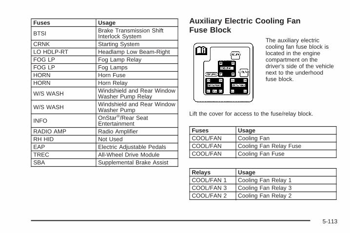
Fuses Usage
BTSI Brake Transmission ShiftInterlock System
CRNK Starting SystemLO HDLP-RT Headlamp Low Beam-RightFOG LP Fog Lamp RelayFOG LP Fog LampsHORN Horn FuseHORN Horn Relay
W/S WASH Windshield and Rear WindowWasher Pump Relay
W/S WASH Windshield and Rear WindowWasher Pump
INFO OnStar®/Rear SeatEntertainment
RADIO AMP Radio AmplifierRH HID Not UsedEAP Electric Adjustable PedalsTREC All-Wheel Drive ModuleSBA Supplemental Brake Assist
Auxiliary Electric Cooling FanFuse Block
The auxiliary electriccooling fan fuse block islocated in the enginecompartment on thedriver’s side of the vehiclenext to the underhoodfuse block.
Lift the cover for access to the fuse/relay block.
Fuses UsageCOOL/FAN Cooling FanCOOL/FAN Cooling Fan Relay FuseCOOL/FAN Cooling Fan Fuse
Relays UsageCOOL/FAN 1 Cooling Fan Relay 1COOL/FAN 3 Cooling Fan Relay 3COOL/FAN 2 Cooling Fan Relay 2
5-113
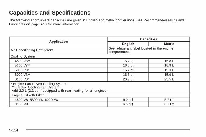
Capacities and SpecificationsThe following approximate capacities are given in English and metric conversions. See Recommended Fluids andLubricants on page 6-13 for more information.
ApplicationCapacities
English Metric
Air Conditioning Refrigerant See refrigerant label located in the enginecompartment.
Cooling System4800 V8** 16.7 qt 15.8 L5300 V8** 16.7 qt 15.8 L6000 V8* 16.2 qt 15.3 L6000 V8** 16.8 qt 15.9 L8100 V8* 26.9 qt 25.5 L
* Engine Fan Driven Cooling System** Electric Cooling Fan SystemAdd 2.0 L (2.1 qt) if equipped with rear heating for all engines.Engine Oil with Filter
4800 V8; 5300 V8; 6000 V8 6.0 qt† 5.7 L†8100 V8 6.5 qt† 6.1 L†
5-114

ApplicationCapacities
English MetricFuel Tank
Yukon 26.0 gal 98.4 LYukon XL (1500 Series) 31.0 gal 117.3 LYukon XL (2500 Series) 37.5 gal 140.0 L
Wheel Nut Torque 140 ft lb 190 Y†Oil filter should be changed at every oil change.After refill, the level must be rechecked. Add enough engine coolant so that the fluid is within the proper operatingrange.
Engine SpecificationsEngine VIN Code Transmission Spark Plug Gap
VORTEC™ 4800 V8 V Automatic 0.040 in (1.01 mm)
VORTEC™ 5300 V8 T Automatic 0.040 in (1.01 mm)
VORTEC™ 5300 V8 Z Automatic 0.040 in (1.01 mm)
VORTEC™ 6000 V8 U Automatic 0.040 in (1.01 mm)
VORTEC™ 8100 V8 G Automatic 0.060 in (1.52 mm)
5-115

✍ NOTES
5-116

Maintenance Schedule ......................................6-2Introduction ...................................................6-2Maintenance Requirements ..............................6-2Your Vehicle and the Environment ....................6-2Using the Maintenance Schedule ......................6-2Scheduled Maintenance ...................................6-4Additional Required Services ............................6-6Maintenance Footnotes ...................................6-7
Owner Checks and Services ............................6-9At Each Fuel Fill ............................................6-9At Least Once a Month .................................6-10At Least Once a Year ...................................6-10Recommended Fluids and Lubricants ...............6-13Normal Maintenance Replacement Parts ..........6-15Maintenance Record .....................................6-16
Section 6 Maintenance Schedule
6-1

Maintenance Schedule
IntroductionImportant: Keep engine oil at the proper level andchange as recommended.
Have you purchased the GM Protection Plan? The Plansupplements your new vehicle warranties. See yourWarranty and Owner Assistance booklet or your dealerfor details.
Maintenance RequirementsNotice: Maintenance intervals, checks, inspections,replacement parts, and recommended fluids andlubricants as prescribed in this manual arenecessary to keep your vehicle in good workingcondition. Any damage caused by failure to followscheduled maintenance may not be covered bywarranty.
Your Vehicle and the EnvironmentProper vehicle maintenance not only helps to keep yourvehicle in good working condition, but also helps theenvironment. All recommended maintenance isimportant. Improper vehicle maintenance can evenaffect the quality of the air we breathe. Improper fluidlevels or the wrong tire inflation can increase the level ofemissions from your vehicle. To help protect ourenvironment, and to keep your vehicle in good condition,be sure to maintain your vehicle properly.
Using the Maintenance ScheduleWe at General Motors want to help you keep yourvehicle in good working condition. But we do not knowexactly how you will drive it. You may drive veryshort distances only a few times a week. Or you maydrive long distances all the time in very hot, dustyweather. You may use your vehicle in making deliveries.Or you may drive it to work, to do errands or in manyother ways.
Because of all the different ways people use theirvehicles, maintenance needs vary. You may need morefrequent checks and replacements. So please readthe following and note how you drive. If you have anyquestions on how to keep your vehicle in good condition,see your GM Goodwrench® dealer.
6-2

This schedule is for vehicles that:
• carry passengers and cargo within recommendedlimits. You will find these limits on the tire andloading information label. See Loading Your Vehicleon page 4-51.
• are driven on reasonable road surfaces within legaldriving limits.
• are driven off-road in the recommended manner.See Off-Road Driving on page 4-21.
• use the recommended fuel. See Gasoline Octaneon page 5-5.
The services in Scheduled Maintenance on page 6-4should be performed when indicated. See AdditionalRequired Services on page 6-6 and MaintenanceFootnotes on page 6-7 for further information.
{CAUTION:
Performing maintenance work on a vehicle canbe dangerous. In trying to do some jobs, youcan be seriously injured. Do your ownmaintenance work only if you have therequired know-how and the proper tools andequipment for the job. If you have any doubt,see your GM Goodwrench ® dealer to have aqualified technician do the work.
Some maintenance services can be complex.So, unless you are technically qualified and havethe necessary equipment, you should have yourGM Goodwrench® dealer do these jobs.
When you go to your GM Goodwrench® dealer for yourservice needs, you will know that GM-trained andsupported service technicians will perform the workusing genuine GM parts.
If you want to purchase service information, see ServicePublications Ordering Information on page 7-11.
Owner Checks and Services on page 6-9 tells you whatshould be checked, when to check it and what youcan easily do to help keep your vehicle in goodcondition.
6-3

The proper replacement parts, fluids and lubricants touse are listed in Recommended Fluids and Lubricantson page 6-13 and Normal Maintenance ReplacementParts on page 6-15. When your vehicle is serviced,make sure these are used. All parts should be replacedand all necessary repairs done before you or anyoneelse drives the vehicle. We recommend the use ofgenuine GM parts.
Scheduled MaintenanceWhen the CHANGE ENGINE OIL message comes on, itmeans that service is required for your vehicle. Haveyour vehicle serviced as soon as possible within the next600 miles (1 000 km). It is possible that, if you aredriving under the best conditions, the engine oillife system may not indicate that vehicle service isnecessary for over a year. However, your engine oil andfilter must be changed at least once a year and atthis time the system must be reset. Your GMGoodwrench® dealer has GM-trained service technicianswho will perform this work using genuine GM partsand reset the system.
If the engine oil life system is ever reset accidentally,you must service your vehicle within 3,000 miles(5 000 km) since your last service. Remember to resetthe oil life system whenever the oil is changed. SeeEngine Oil Life System on page 5-18 for information onthe Engine Oil Life System and resetting the system.
When the CHANGE ENGINE OIL message appears,certain services, checks, and inspections are required.Required services are described in the following for“Maintenance I” and “Maintenance II.” Generally,it is recommended that your first service beMaintenance I, your second service be Maintenance II,and that you alternate Maintenance I and Maintenance IIthereafter. However, in some cases, Maintenance IImay be required more often.
Maintenance I — Use Maintenance I if the CHANGEENGINE OIL message comes on within 10 months sincethe vehicle was purchased or Maintenance II wasperformed.
Maintenance II — Use Maintenance II if the previousservice performed was Maintenance I. Always useMaintenance II whenever the message comes on10 months or more since the last service or if themessage has not come on at all for one year.
6-4

Scheduled MaintenanceService Maintenance I Maintenance II
Change engine oil and filter. See Engine Oil on page 5-15. Reset oil lifesystem. See Engine Oil Life System on page 5-18. An Emission ControlService.
• •
Lubricate chassis components. See footnote #. • •Visually check for any leaks or damage. See footnote (j). • •Inspect engine air cleaner filter or change indicator (if equipped). If necessary,replace filter. See Engine Air Cleaner/Filter on page 5-19. See footnote (l). •
Rotate tires and check inflation pressures and wear. See Tire Inspection andRotation on page 5-68 and “Tire Wear Inspection” in At Least Once a Month onpage 6-10.
• •
Inspect brake system. See footnote (a). • •Check engine coolant and windshield washer fluid levels and add fluid asneeded. • •
Perform any needed additional services. See “Additional Required Services” inthis section. • •
Inspect suspension and steering components. See footnote (b). •Inspect engine cooling system. See footnote (c). •Inspect wiper blades. See footnote (d). •Inspect restraint system components. See footnote (e). •Lubricate body components. See footnote (f). •Check transmission fluid level and add fluid as needed. •
6-5

Additional Required ServicesThe following services should be performed at the first maintenance service (I or II) after the indicated miles(kilometers) shown for each item.
Additional Required Services
Service and Miles (Kilometers) 25,000(41 500)
50,000(83 000)
75,000(125 000)
100,000(166 000)
125,000(207 500)
150,000(240 000)
Inspect fuel system for damageor leaks. • • • • • •
Inspect exhaust system for loose ordamaged components. • • • • • •
Vehicles without a filter restrictionindicator: Replace engine air cleanerfilter. See Engine Air Cleaner/Filter onpage 5-19.
• • •
Change automatic transmissionfluid and filter (severe service).See footnote (h).
• • •
Change automatic transmission fluidand filter (normal service). •
Four-wheel drive: Change transfer casefluid. See footnote (g). • • •
Inspect evaporative control system.An Emission Control Service. Seefootnotes † and (k).
• • •
6-6

Additional Required Services (cont’d)
Service and Miles (Kilometers) 25,000(41 500)
50,000(83 000)
75,000(125 000)
100,000(166 000)
125,000(207 500)
150,000(240 000)
Replace spark plugs and inspect sparkplug wires. An Emission ControlService.
•
Engine cooling system service (or everyfive years, whichever occurs first).An Emission Control Service. Seefootnote (i).
•
Inspect engine accessory drive belt.An Emission Control Service. •
Maintenance Footnotes† The U.S. Environmental Protection Agency or theCalifornia Air Resources Board has determined that thefailure to perform this maintenance item will not nullifythe emission warranty or limit recall liability prior tothe completion of the vehicle’s useful life. We, however,urge that all recommended maintenance services beperformed at the indicated intervals and themaintenance be recorded.
# Lubricate the front suspension, ball joints, steeringlinkage, transmission shift linkage, and parkingbrake cable guides. Ball joints should not be lubricatedunless their temperature is 10°F (-12°C) or higher,or they could be damaged.
(a) Visually inspect brake lines and hoses for properhook-up, binding, leaks, cracks, chafing, etc. Inspectdisc brake pads for wear and rotors for surfacecondition. Inspect other brake parts, including calipers,parking brake, etc.
6-7
(b) Visually inspect front and rear suspension andsteering system for damaged, loose, or missing parts,signs of wear, or lack of lubrication. Inspect powersteering lines and hoses for proper hook-up, binding,leaks, cracks, chafing, etc. Visually check constantvelocity joints, rubber boots, and axle seals for leaks.
(c) Visually inspect hoses and have them replaced if theyare cracked, swollen, or deteriorated. Inspect all pipes,fittings, and clamps; replace with genuine GM parts asneeded. To help ensure proper operation, a pressure testof the cooling system and pressure cap and cleaning theoutside of the radiator and air conditioning condenser isrecommended at least once a year.
(d) Visually inspect wiper blades for wear or cracking.Replace blade inserts that appear worn or damagedor that streak or miss areas of the windshield.
(e) Make sure the safety belt reminder light and all yourbelts, buckles, latch plates, retractors, and anchoragesare working properly. Look for any other loose ordamaged safety belt system parts. If you see anythingthat might keep a safety belt system from doing itsjob, have it repaired. Have any torn or frayed safety beltsreplaced. Also look for any opened or broken airbagcoverings, and have them repaired or replaced.The airbag system does not need regular maintenance.
(f) Lubricate all key lock cylinders, hood latch assembly,secondary latch, pivots, spring anchor, release pawl,rear compartment hinges, outer liftgate handle pivotpoints, rear door detent link, roller mechanism, liftgatehandle pivot points, latch bolt, fuel door hinge, cargodoor hinge, locks, and folding seat hardware. Morefrequent lubrication may be required when exposed to acorrosive environment. Applying silicone grease onweatherstrips with a clean cloth will make themlast longer, seal better, and not stick or squeak.
(g) Check vent hose at transfer case for kinks andproper installation.
(h) Change automatic transmission fluid and filter if thevehicle is mainly driven under one or more of theseconditions:
− In heavy city traffic where the outside temperatureregularly reaches 90°F (32°C) or higher.
− In hilly or mountainous terrain.− When doing frequent trailer towing.− Uses such as found in taxi, police, or delivery
service.
6-8

(i) Drain, flush, and refill cooling system. This servicecan be complex; you should have your dealer performthis service. See Engine Coolant on page 5-24 forwhat to use. Inspect hoses. Clean radiator, condenser,pressure cap, and filler neck. Pressure test thecooling system and pressure cap.
(j) A fluid loss in any vehicle system could indicate aproblem. Have the system inspected and repaired andthe fluid level checked. Add fluid if needed.
(k) Inspect system. Check all fuel and vapor lines andhoses for proper hook-up, routing, and condition. Checkthat the purge valve works properly, if equipped.Replace as needed.
(l) If you drive regularly under dusty conditions, inspectthe filter at each engine oil change.
Owner Checks and ServicesThese owner checks and services should be performedat the intervals specified to help ensure the safety,dependability and emission control performance of yourvehicle. Your GM Goodwrench® dealer can assistyou with these checks and services.
Be sure any necessary repairs are completed at once.Whenever any fluids or lubricants are added to yourvehicle, make sure they are the proper ones, as shownin Recommended Fluids and Lubricants on page 6-13.
At Each Fuel FillIt is important to perform these underhood checks ateach fuel fill.
Engine Oil Level CheckCheck the engine oil level and add the proper oil ifnecessary. See Engine Oil on page 5-15 for furtherdetails.
Notice: It is important to check your oil regularlyand keep it at the proper level. Failure to keep yourengine oil at the proper level can cause damageto your engine not covered by your warranty.
6-9

Engine Coolant Level CheckCheck the engine coolant level and addDEX-COOL® coolant mixture if necessary.See Engine Coolant on page 5-24 for further details.
Windshield Washer Fluid Level CheckCheck the windshield washer fluid level in the windshieldwasher tank and add the proper fluid if necessary.
At Least Once a Month
Tire Inflation CheckVisually inspect your vehicle’s tires and make sure theyare inflated to the correct pressures. Do not forget tocheck the spare tire. See Tires on page 5-57 for furtherdetails. Check to make sure the spare tire is storedsecurely. See Changing a Flat Tire on page 5-76.
Tire Wear InspectionTire rotation may be required for high mileage highwaydrivers prior to the Engine Oil Life System servicenotification. Check the tires for wear and, if necessary,rotate the tires. See Tire Inspection and Rotation onpage 5-68.
At Least Once a Year
Starter Switch Check
{CAUTION:
When you are doing this inspection, thevehicle could move suddenly. If the vehiclemoves, you or others could be injured.
1. Before you start, be sure you have enough roomaround the vehicle.
2. Firmly apply both the parking brake and the regularbrake. See Parking Brake on page 2-35.Do not use the accelerator pedal, and be ready toturn off the engine immediately if it starts.
3. Try to start the engine in each gear. The vehicleshould start only in PARK (P) or NEUTRAL (N).If the vehicle starts in any other position, contactyour GM Goodwrench® dealer for service.
6-10

Automatic Transmission Shift LockControl System Check
{CAUTION:
When you are doing this inspection, thevehicle could move suddenly. If the vehiclemoves, you or others could be injured.
1. Before you start, be sure you have enough roomaround the vehicle. It should be parked on a levelsurface.
2. Firmly apply the parking brake. See Parking Brakeon page 2-35.Be ready to apply the regular brake immediately ifthe vehicle begins to move.
3. With the engine off, turn the ignition to RUN, but donot start the engine. Without applying the regularbrake, try to move the shift lever out of PARK (P)with normal effort. If the shift lever moves outof PARK (P), contact your GM Goodwrench® dealerfor service.
Ignition Transmission Lock CheckWhile parked, and with the parking brake set, try to turnthe ignition to LOCK in each shift lever position.
• The ignition should turn to LOCK only when theshift lever is in PARK (P).
• The key should come out only in LOCK.
Contact your GM Goodwrench® dealer if service isrequired.
6-11

Parking Brake and AutomaticTransmission Park (P) Mechanism Check
{CAUTION:
When you are doing this check, your vehiclecould begin to move. You or others could beinjured and property could be damaged. Makesure there is room in front of your vehicle incase it begins to roll. Be ready to apply theregular brake at once should the vehicle beginto move.
Park on a fairly steep hill, with the vehicle facingdownhill. Keeping your foot on the regular brake, set theparking brake.
• To check the parking brake’s holding ability: Withthe engine running and transmission inNEUTRAL (N), slowly remove foot pressure fromthe regular brake pedal. Do this until the vehicle isheld by the parking brake only.
• To check the PARK (P) mechanism’s holding ability:With the engine running, shift to PARK (P). Thenrelease the parking brake followed by the regularbrake.
Contact your GM Goodwrench® dealer if service isrequired.
Underbody Flushing ServiceAt least every spring, use plain water to flush anycorrosive materials from the underbody. Take care toclean thoroughly any areas where mud and other debriscan collect.
6-12

Recommended Fluids andLubricantsFluids and lubricants identified below by name, partnumber or specification may be obtained from yourdealer.
Usage Fluid/Lubricant
Engine Oil
Engine oil which meets GM StandardGM6094M and displays theAmerican Petroleum InstituteCertified for GasolineEngines starburst symbol.GM Goodwrench® oil meets all therequirements for your vehicle. Todetermine the proper viscosity foryour vehicle’s engine, see Engine Oilon page 5-15
Engine Coolant
50/50 mixture of clean, drinkablewater and use onlyDEX-COOL® Coolant. See EngineCoolant on page 5-24
Hydraulic BrakeSystem
Delco Supreme 11 Brake Fluid orequivalent DOT-3 brake fluid.
WindshieldWasher Solvent GM Optikleen® Washer Solvent.
Usage Fluid/Lubricant
Power SteeringSystem
GM Power Steering Fluid(GM Part No. U.S. 89021184, inCanada 89021186).
AutomaticTransmission
DEXRON®-III AutomaticTransmission Fluid. Look for“Approved for the H-Specification”on the label.
Key LockCylinders
Multi-Purpose Lubricant, Superlube(GM Part No. U.S. 12346241, inCanada 10953474).
ChassisLubrication
Chassis Lubricant(GM Part No. U.S. 12377985, inCanada 88901242) or lubricantmeeting requirements of NLGI #2,Category LB or GC-LB.
Front Axle(Four-Wheel
Drive)
SAE 80W-90 Axle Lubricant(GM Part No. U.S. 1052271, inCanada 10950849).
Front Axle(All-Wheel
Drive)
SAE 75W-90 Synthetic AxleLubricant (GM Part No.U.S. 12378261, in Canada10953455) meeting GMSpecification 9986115.
6-13

Usage Fluid/Lubricant
Rear Axle
SAE 75W-90 Synthetic AxleLubricant (GM Part No.U.S. 12378261, in Canada10953455) meeting GMSpecification 9986115.
Rear Axle(Steerable)
Synthetic Axle Lubricant; use onlyGM Part No. U.S. 12378557, inCanada 88901362. Do not addfriction modifier.
Transfer Case(All-WheelDrive with
StabiliTrak®)
DEXRON®-III AutomaticTransmission Fluid. Look for“Approved for the H-Specification”on the label.
AutomaticTransfer Case(Four-Wheel
Drive)
AUTO-TRAK II Fluid(GM Part No. U.S. 12378508, inCanada 10953626).
Front AxlePropshaftSpline or
One-PiecePropshaft
Spline(Two-WheelDrive with
Auto. Trans.)
Spline Lubricant, Special Lubricant(GM Part No. U.S. 12345879, inCanada 10953511) or lubricantmeeting requirements of GM9985830.
Usage Fluid/Lubricant
Hood HingesMulti-Purpose Lubricant, Superlube(GM Part No. U.S. 12346241, inCanada 10953474).
Outer TailgateHandle Pivot
Points
Multi-Purpose Lubricant, Superlube(GM Part No. U.S. 12346241, inCanada 10953474).
WeatherstripConditioning
Dielectric Silicone Grease(GM Part No. U.S. 12345579, inCanada 992887).
WeatherstripSqueaks
Synthetic Grease with Teflon,Superlube(GM Part No. U.S. 12371287, inCanada 10953437).
6-14
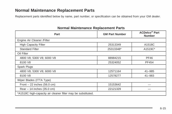
Normal Maintenance Replacement PartsReplacement parts identified below by name, part number, or specification can be obtained from your GM dealer.
Normal Maintenance Replacement Parts
Part GM Part Number ACDelco ® PartNumber
Engine Air Cleaner /Filter
High Capacity Filter 25313349 A1518C
Standard Filter 25313348* A1519C*
Oil Filter
4800 V8; 5300 V8; 6000 V8 88984215 PF46
8100 V8 25324052 PF454
Spark Plugs
4800 V8; 5300 V8; 6000 V8 12571164 41–985
8100 V8 12578277 41–983
Wiper Blades (ITTA Type)
Front – 22 inches (56.0 cm) 15153642 —
Rear – 14 inches (35.0 cm) 22121329 —
*A1518C high-capacity air cleaner filter may be substituted.
6-15

Maintenance RecordAfter the scheduled services are performed, record the date, odometer reading, who performed the service and thetype of services performed in the boxes provided. See Maintenance Requirements on page 6-2. Any additionalinformation from Owner Checks and Services on page 6-9 can be added on the following record pages. You shouldretain all maintenance receipts.
Maintenance Record
Date OdometerReading Serviced By Maintenance I or
Maintenance II Services Performed
6-16

Maintenance Record (cont’d)
Date OdometerReading Serviced By Maintenance I or
Maintenance II Services Performed
6-17

Maintenance Record (cont’d)
Date OdometerReading Serviced By Maintenance I or
Maintenance II Services Performed
6-18

Customer Assistance and Information ...............7-2Customer Satisfaction Procedure ......................7-2Online Owner Center ......................................7-3Customer Assistance for Text Telephone
(TTY) Users ...............................................7-4Customer Assistance Offices ............................7-4GM Mobility Reimbursement Program ................7-5Roadside Assistance Program ..........................7-5Courtesy Transportation ...................................7-7Vehicle Data Collection and Event Data
Recorders ..................................................7-8
Reporting Safety Defects ................................7-10Reporting Safety Defects to the United States
Government ..............................................7-10Reporting Safety Defects to the Canadian
Government ..............................................7-10Reporting Safety Defects to General Motors ........7-11Service Publications Ordering Information .........7-11
Section 7 Customer Assistance and Information
7-1

Customer Assistance andInformation
Customer Satisfaction ProcedureYour satisfaction and goodwill are important toyour dealer and to GMC. Normally, any concerns withthe sales transaction or the operation of the vehiclewill be resolved by your dealer’s sales or servicedepartments. Sometimes, however, despite the bestintentions of all concerned, misunderstandings canoccur. If your concern has not been resolved to yoursatisfaction, the following steps should be taken:
STEP ONE: Discuss your concern with a member ofdealership management. Normally, concerns canbe quickly resolved at that level. If the matter hasalready been reviewed with the sales, service or partsmanager, contact the owner of the dealership orthe general manager.
STEP TWO: If after contacting a member of dealershipmanagement, it appears your concern cannot beresolved by the dealership without further help, contactthe GMC Consumer Relations Manager by calling1-800-GMC-8782 (1-800-462-8782, CustomerAssistance prompt). In Canada, contact GM of CanadaCustomer Communication by calling 1-800-263-3777(English) or 1-800-263-7854 (French).
We encourage you to call the toll-free number in order togive your inquiry prompt attention. Please have thefollowing information available to give the CustomerAssistance Representative:
• Vehicle Identification Number (VIN). This is availablefrom the vehicle registration or title, or the plate at thetop left of the instrument panel and visible throughthe windshield.
• Dealership name and location.
• Vehicle delivery date and present mileage.
When contacting GMC, please remember that yourconcern will likely be resolved at a dealer’s facility. Thatis why we suggest you follow Step One first if youhave a concern.
STEP THREE: Both General Motors and your dealerare committed to making sure you are completelysatisfied with your new vehicle. However, if you continueto remain unsatisfied after following the procedureoutlined in Steps One and Two, you should file with theBBB Auto Line Program to enforce any additionalrights you may have. Canadian owners refer to yourWarranty and Owner Assistance Information booklet forinformation on the Canadian Motor Vehicle ArbitrationPlan (CAMVAP).
7-2

The BBB Auto Line Program is an out of court programadministered by the Council of Better BusinessBureaus to settle automotive disputes regarding vehiclerepairs or the interpretation of the New VehicleLimited Warranty. Although you may be required toresort to this informal dispute resolution program prior tofilling out a court action, use of the program is free ofcharge and your case will generally be heard within40 days. If you do not agree with the decision given inyour case, you may reject it and proceed with any othervenue for relief available to you.
You may contact the BBB Auto Line Program using thetoll-free telephone number or write them at thefollowing address:
BBB Auto Line ProgramCouncil of Better Business Bureaus, Inc.4200 Wilson BoulevardSuite 800Arlington, VA 22203-1838
Telephone: 1-800-955-5100
This program is available in all 50 states and the Districtof Columbia. Eligibility is limited by vehicle age,mileage, and other factors. General Motors reserves theright to change eligibility limitations and/or discontinueits participation in this program.
Online Owner CenterThe Owner Center is a resource for your GM ownershipneeds. Specific vehicle information can be found inone place.
The Online Owner Center allows you to:
• Get e-mail service reminders.
• Access information about your specific vehicle,including tips and videos and an electronicversion of this owner’s manual (United States only).
• Keep track of your vehicle’s service history andmaintenance schedule.
• Find GM dealers for service nationwide.
• Receive special promotions and privileges onlyavailable to members (United States only).
Refer to the web for updated information.
To register your vehicle, visit www.MyGMLink.com(United States) or My GM Canada withinwww.gmcanada.com (Canada).
7-3

Customer Assistance for TextTelephone (TTY) UsersTo assist customers who are deaf, hard of hearing, orspeech-impaired and who use the Text Telephones(TTYs), GMC has TTY equipment available at itsCustomer Assistance Center. Any TTY user cancommunicate with GMC by dialing: 1-800-GMC-8583(462-8583). (TTY users in Canada can dial1-800-263-3830.)
Customer Assistance OfficesGMC encourages customers to call the toll-free numberfor assistance. If a U.S. customer wishes to write toGMC, the letter should be addressed to GMC’sCustomer Assistance Center.
United StatesGMC Customer Assistance CenterP.O. Box 33172Detroit, MI 48232-5172
1-800-GMC-8782 (462-8782)1-800-GMC-8583 (462-8583)(For Text Telephone devices (TTYs))Roadside Assistance: 1-800-GMC-8782 (462-8782)Fax Number: 313-381-0022
From Puerto Rico1-800-496-9992 (English)1-800-496-9993 (Spanish)Fax Number: 313-381-0022
U.S. Virgin Islands:1-800-496-9994Fax Number: 313-381-0022
CanadaGeneral Motors of Canada LimitedCustomer Communication Centre, 163-0051908 Colonel Sam DriveOshawa, Ontario L1H 8P7
1-800-263-3777 (English)1-800-263-7854 (French)1-800-263-3830 (For TextTelephone devices (TTYs))Roadside Assistance: 1-800-268-6800
All Overseas LocationsPlease contact the local General Motors Business Unit.
7-4

Mexico, Central America and CaribbeanIslands/Countries (Except PuertoRico and U.S. Virgin Islands)
General Motors de Mexico, S. de R.L. de C.V.Customer Assistance CenterPaseo de la Reforma # 2740Col. Lomas de BezaresC.P. 11910, Mexico, D.F.01-800-508-0000Long Distance: 011-52-53 29 0 800
GM Mobility ReimbursementProgramThis program, available to qualified applicants, canreimburse you up to $1,000 toward eligible aftermarketdriver’s or passenger’s adaptive equipment you mayrequire for your vehicle, such as hand controls andwheelchair/scooter lifts.
The offer is available for a limited period of time from thedate of vehicle purchase/lease. For more details, or todetermine your vehicle’s eligibility, visit gmmobility.comor call the GM Mobility Assistance Center at1-800-323-9935. Text telephone (TTY) users, call1-800-833-9935.
GM of Canada also has a Mobility Program. Call1-800-GM-DRIVE (463-7483) for details. TTY users call1-800-263-3830.
Roadside Assistance ProgramAs the owner of a new GMC vehicle, you areautomatically enrolled in the GMC Roadside Assistanceprogram. This value-added service is intended toprovide you with peace of mind as you drive in the cityor travel the open road. Call 1-800-GMC-8782(1-800-462-8782) to speak with a GMC Road Assistancerepresentative 24 hours a day, 365 days a year.
We will provide the following services during theBumper-to-Bumper warranty period, at no expenseto you:
• Fuel Delivery: Delivery of enough fuel($5 maximum) for the customer to get tothe nearest service station.
• Lock-out Service (identification required):Replacement keys or locksmith service will becovered at no charge if you are unable to gain entryinto your vehicle. Delivery of the replacement key willbe covered within 10 miles (16 km).
• Emergency Tow: Tow to the nearest dealership forwarranty service or in the event of a vehicle-disablingaccident. Assistance provided when the vehicle ismired in sand, mud, or snow.
7-5
• Flat Tire Change: Installation of a spare tire will becovered at no charge. The customer is responsiblefor the repair or replacement of the tire if not coveredby a warrantable failure.
• Jump Start: No-start occurrences which require abattery jump start will be covered at no charge.
• Dealer Locator Service
• Trip Routing: Your Roadside AssistanceRepresentative can provide you with specificinformation regarding this feature.
• Trip Interruption Expense Benefits: YourRoadside Assistance Representative can provideyou with specific information regarding this feature.
In many instances, mechanical failures are coveredunder GMC’s Bumper-to-Bumper warranty. However,when other services are utilized, our RoadsideAssistance Representatives will explain any paymentobligations you might incur.
For prompt and efficient assistance when calling, pleaseprovide the following to the Roadside AssistanceRepresentative:
• Your name, home address, and home telephonenumber.
• Telephone number of your location.
• Location of the vehicle.
• Model, year, color, and license plate number of thevehicle.
• Mileage, Vehicle Identification Number (VIN) anddelivery date of the vehicle.
• Description of the problem.
While we hope you never have the occasion to use ourservice, it is added security while traveling for youand your family. Remember, we are only a phone callaway. GMC Roadside Assistance: 1-800-462-8782, texttelephone (TTY) users, call 1-888-889-2438.
GMC reserves the right to limit services orreimbursement to an owner or driver when, in GMC’sjudgement, the claims become excessive in frequency ortype of occurrence.
Roadside Assistance is not part of or included in thecoverage provided by the New Vehicle Limited Warranty.GMC reserves the right to make any changes ordiscontinue the Roadside Assistance program at anytime without notification.
Canadian Roadside AssistanceVehicles purchased in Canada have an extensiveroadside assistance program accessible from anywherein Canada or the United States. Please refer to theWarranty and Owner Assistance Information book.
7-6

Courtesy TransportationTo enhance your ownership experience, we and ourparticipating dealers are proud to offer CourtesyTransportation, a customer support program for newvehicles.
The Courtesy Transportation program is offered to retailpurchase/lease customers in conjunction with theBumper-to-Bumper coverage provided by the NewVehicle Limited Warranty. Several transportation optionsare available when warranty repairs are required. This willreduce your inconvenience during warranty repairs.
Scheduling Service AppointmentsWhen your vehicle requires warranty service, you shouldcontact your dealer and request an appointment.By scheduling a service appointment and advising yourservice consultant of your transportation needs, yourdealer can help minimize your inconvenience.
If your vehicle cannot be scheduled into the servicedepartment immediately, keep driving it until it can bescheduled for service, unless, of course, the problem issafety-related. If it is, please call your dealership, letthem know this, and ask for instructions.
If the dealer requests that you simply drop the vehicle offfor service, you are urged to do so as early in the workday as possible to allow for the same day repair.
Transportation OptionsWarranty service can generally be completed while youwait. However, if you are unable to wait, GM helpsto minimize your inconvenience by providing severaltransportation options. Depending on the circumstances,your dealer can offer you one of the following:
Shuttle ServiceParticipating dealers can provide you with shuttleservice to get you to your destination with minimalinterruption of your daily schedule. This includesone-way or round trip shuttle service to a destinationup to 10 miles (16 km) from the dealership.
Public Transportation or FuelReimbursementIf your vehicle requires overnight warranty repairs,reimbursement of public transportation expenses maybe available, for up to a maximum of five days. Inaddition, should you arrange transportation through afriend or relative, reimbursement for reasonablefuel expenses may be available, up to a five-daymaximum. Claim amounts should reflect actual costsand be supported by original receipts.
7-7

Courtesy Rental VehicleYour dealer may arrange to provide you with a courtesyrental vehicle or reimburse you for a rental vehiclethat you obtain if your vehicle is kept for a warrantyrepair. Reimbursement will be limited to a maximumamount per day and must be supported by receipts. Thisrequires that you sign and complete a rental agreementand meet state, local and rental vehicle providerrequirements. Requirements vary and may includeminimum age requirements, insurance coverage, creditcard, etc. You are responsible for fuel usage chargesand may also be responsible for taxes, levies,usage fees, excessive mileage or rental usage beyondthe completion of the repair.
Generally it is not possible to provide a like-vehicle as acourtesy rental.
Additional Program InformationCourtesy Transportation is available during theBumper-to-Bumper warranty coverage period, but it is notpart of the New Vehicle Limited Warranty. A separatebooklet entitled Warranty and Owner AssistanceInformation furnished with each new vehicle providesdetailed warranty coverage information.
Courtesy Transportation is available only at participatingdealers and all program options, such as shuttleservice, may not be available at every dealer.
Please contact your dealer for specific information aboutavailability. All Courtesy Transportation arrangementswill be administered by appropriate dealer personnel.
Canadian Vehicles: For warranty repairs duringthe Complete Vehicle Coverage period of the GeneralMotors of Canada New Vehicle Limited Warranty,alternative transportation may be available under theCourtesy Transportation Program. Please consultyour dealer for details.
General Motors reserves the right to unilaterally modify,change or discontinue Courtesy Transportation atany time and to resolve all questions of claim eligibilitypursuant to the terms and conditions describedherein at its sole discretion.
Vehicle Data Collection and EventData RecordersYour vehicle, like other modern motor vehicles, has anumber of sophisticated computer systems that monitorand control several aspects of the vehicle’s performance.Your vehicle uses on-board vehicle computers to monitoremission control components to optimize fuel economy,to monitor conditions for airbag deployment and, if soequipped, to provide anti-lock braking and to help thedriver control the vehicle in difficult driving situations.
7-8

Some information may be stored during regularoperations to facilitate repair of detected malfunctions;other information is stored only in a crash event bycomputer systems, such as those commonly called eventdata recorders (EDR).
In a crash event, computer systems, such as the AirbagSensing and Diagnostic Module (SDM) in your vehiclemay record information about the condition of the vehicleand how it was operated, such as data related to enginespeed, brake application, throttle position, vehicle speed,safety belt usage, airbag readiness, airbag performance,and the severity of a collision. If your vehicle is equippedwith Quadrasteer or StabiliTrak®, steering performance,including yaw rate, steering wheel angle, and lateralacceleration, is also recorded. This information has beenused to improve vehicle crash performance and may beused to improve crash performance of future vehicles anddriving safety. Unlike the data recorders on manyairplanes, these on-board systems do not record sounds,such as conversation of vehicle occupants.
To read this information, special equipment is neededand access to the vehicle or the device that storesthe data is required. GM will not access informationabout a crash event or share it with others other than:
• with the consent of the vehicle owner or, if thevehicle is leased, with the consent of the lessee,
• in response to an official request of police or similargovernment office,
• as part of GM’s defense of litigation through thediscovery process, or
• as required by law.
In addition, once GM collects or receives data, GM may:
• use the data for GM research needs,
• make it available for research where appropriateconfidentiality is to be maintained and need isshown, or
• share summary data which is not tied to a specificvehicle with non-GM organizations for researchpurposes.
Others, such as law enforcement, may have access tothe special equipment that can read the informationif they have access to the vehicle or the devicethat stores the data.
If your vehicle is equipped with OnStar®, please checkthe OnStar® subscription service agreement ormanual for information on its operations and datacollection.
7-9

Reporting Safety Defects
Reporting Safety Defects to theUnited States GovernmentIf you believe that your vehicle has a defect which couldcause a crash or could cause injury or death, youshould immediately inform the National Highway TrafficSafety Administration (NHTSA), in addition to notifyingGeneral Motors.
If NHTSA receives similar complaints, it may open aninvestigation, and if it finds that a safety defect exists ina group of vehicles, it may order a recall and remedycampaign. However, NHTSA cannot become involved inindividual problems between you, your dealer, orGeneral Motors.
To contact NHTSA, you may either call the Auto SafetyHotline toll-free at 1-800-424-9393 (or 366-0123 inthe Washington, D.C. area) or write to:
NHTSA, U.S. Department of TransportationWashington, D.C. 20590
You can also obtain other information about motorvehicle safety from the hotline.
Reporting Safety Defects to theCanadian GovernmentIf you live in Canada, and you believe that your vehiclehas a safety defect, you should immediately notifyTransport Canada, in addition to notifying GeneralMotors of Canada Limited. You may call them at1-800-333-0510 or write to:
Transport CanadaPlace de Ville Tower C330 Sparks StreetOttawa, Ontario K1A 0N5
7-10

Reporting Safety Defects toGeneral MotorsIn addition to notifying NHTSA (or Transport Canada) ina situation like this, we certainly hope you’ll notify us.Please call us at 1-800-GMC-8782 (1-800-462-8782),or write:
GMC Customer Assistance CenterP.O. Box 33172Detroit, MI 48232-5172
In Canada, please call us at 1-800-263-3777 (English)or 1-800-263-7854 (French). Or, write:
General Motors of Canada LimitedCustomer Communication Centre, 163-0051908 Colonel Sam DriveOshawa, Ontario L1H 8P7
Service Publications OrderingInformation
Service ManualsService Manuals have the diagnosis and repairinformation on engines, transmission, axle suspension,brakes, electrical, steering, body, etc.
Transmission, Transaxle, TransferCase Unit Repair ManualThis manual provides information on unit repair serviceprocedures, adjustments, and specifications forGM transmissions, transaxles, and transfer cases.
Service BulletinsService Bulletins give technical service informationneeded to knowledgeably service General Motors carsand trucks. Each bulletin contains instructions toassist in the diagnosis and service of your vehicle.
In Canada, information pertaining to Product ServiceBulletins can be obtained by contacting your GeneralMotors dealer or by calling 1-800-GM-DRIVE(1-800-463-7483).
7-11

Owner’s InformationOwner publications are written specifically for ownersand intended to provide basic operational informationabout the vehicle. The owner’s manual will includethe Maintenance Schedule for all models.
In-Portfolio: Includes a Portfolio, Owner’s Manual, andWarranty Booklet.
RETAIL SELL PRICE: $35.00
Without Portfolio: Owner’s Manual only.
RETAIL SELL PRICE: $25.00
Current and Past Model Order FormsService Publications are available for current andpast model GM vehicles. To request an order form,please specify year and model name of the vehicle.
ORDER TOLL FREE: 1-800-551-4123Monday-Friday 8:00 AM - 6:00 PMEastern TimeFor Credit Card Orders Only(VISA-MasterCard-Discover), visit Helm, Inc. on theWorld Wide Web at: www.helminc.com
Or you can write to:
Helm, IncorporatedP.O. Box 07130Detroit, MI 48207
Prices are subject to change without notice and withoutincurring obligation. Allow ample time for delivery.
Note to Canadian Customers: All listed prices arequoted in U.S. funds. Canadian residents are to makechecks payable in U.S. funds.
7-12

AAccessory Power Outlets ................................. 3-20Adding a Snow Plow or Similar Equipment ......... 4-57Adding Equipment to Your Airbag-Equipped
Vehicle ....................................................... 1-80Additives, Fuel ................................................. 5-6Add-On Electrical Equipment ........................... 5-105Adjustable Throttle and Brake Pedal .................. 2-22Air Cleaner/Filter, Engine ................................. 5-19Air Conditioning .............................. 3-21, 3-22, 3-24Airbag
Passenger Status Indicator ........................... 3-40Readiness Light .......................................... 3-39
Airbag Sensing and Diagnostic Module (SDM) ...... 7-8Airbag System ................................................ 1-66
Adding Equipment to Your Airbag-EquippedVehicle ................................................... 1-80
How Does an Airbag Restrain? ...................... 1-73Passenger Sensing System ........................... 1-75Servicing Your Airbag-Equipped Vehicle .......... 1-80What Makes an Airbag Inflate? ...................... 1-73What Will You See After an Airbag Inflates? .... 1-74When Should an Airbag Inflate? .................... 1-71Where Are the Airbags? ............................... 1-69
All-Wheel Drive ............................................... 5-45All-Wheel Drive with StabiliTrak® ....................... 2-31
AM-FM Radio ................................................. 3-76Antenna, Fixed Mast ...................................... 3-135Antenna, XM™ Satellite Radio Antenna System ... 3-135Anti-Lock Brake System (ABS) ........................... 4-6Anti-Lock Brake, System Warning Light .............. 3-44Appearance Care ............................................ 5-95
Aluminum or Chrome-Plated Wheels ............. 5-101Care of Safety Belts .................................... 5-99Chemical Paint Spotting .............................. 5-102Cleaning Exterior Lamps/Lenses .................... 5-99Cleaning the Inside of Your Vehicle ................ 5-96Fabric/Carpet .............................................. 5-97Finish Care ............................................... 5-100Finish Damage .......................................... 5-102Instrument Panel, Vinyl, and Other Plastic
Surfaces ................................................. 5-98Leather ...................................................... 5-98Sheet Metal Damage .................................. 5-102Tires ........................................................ 5-102Underbody Maintenance ............................. 5-102Vehicle Care/Appearance Materials ............... 5-103Washing Your Vehicle ................................... 5-99Weatherstrips .............................................. 5-99Windshield, Backglass, and Wiper Blades ...... 5-100
Ashtrays ........................................................ 3-20
1

Audio System(s) ............................................. 3-74AM-FM Radio ............................................. 3-76Audio Steering Wheel Controls .................... 3-131Care of Your Cassette Tape Player ............... 3-133Care of Your CD and DVD Player ................ 3-134Care of Your CDs and DVDs ....................... 3-134Chime Level Adjustment ............................. 3-135Fixed Mast Antenna ................................... 3-135Navigation/Radio System, see Navigation
Manual ................................................. 3-118Radio with Cassette and CD ......................... 3-89Radio with CD ............................................ 3-78Radio with Six-Disc CD .............................. 3-103Rear Seat Audio (RSA) ............................... 3-129Setting the Time for Radios with Radio Data
Systems (RDS) ........................................ 3-75Setting the Time for Radios without Radio
Data Systems (RDS) ................................ 3-75Theft-Deterrent Feature ............................... 3-131Understanding Radio Reception ................... 3-132XM™ Satellite Radio Antenna System ........... 3-135
Automatic Headlamp System ............................ 3-16Automatic Transmission
Fluid .......................................................... 5-21Operation ................................................... 2-23
Autoride®™ .................................................... 4-66Auxiliary Roof Mounted Lamp Switch ................. 3-17
BBattery .......................................................... 5-40
Run-Down Protection ................................... 3-19Battery Warning Light ...................................... 3-42Before Leaving on a Long Trip ......................... 4-42Bench Seat .................................................... 1-15Bench Seat Split (50/50) .................................. 1-11Bench Seat, Split (60/40) ................................... 1-8Brake
Anti-Lock Brake System (ABS) ........................ 4-6Emergencies ................................................ 4-8Parking ...................................................... 2-35System Warning Light .................................. 3-43
Brake Pedal, Throttle ....................................... 2-22Brakes .......................................................... 5-37Braking ........................................................... 4-5Braking in Emergencies ..................................... 4-8Break-In, New Vehicle ..................................... 2-19Bucket Seats, Rear ......................................... 1-19Bulb Replacement ........................................... 5-49
Front Turn Signal, Sidemarker and DaytimeRunning Lamps ........................................ 5-51
Halogen Bulbs ............................................ 5-49Headlamps ................................................. 5-50Replacement Bulbs ...................................... 5-56
2

Bulb Replacement (cont.)Roof Marker Lamps ..................................... 5-52Side Identification Marker Lamps ................... 5-52Taillamps .................................................... 5-54
Buying New Tires ........................................... 5-70
CCalifornia Fuel .................................................. 5-5Canadian Owners ................................................ iiCapacities and Specifications .......................... 5-114Carbon Monoxide ................... 2-13, 2-39, 4-45, 4-67Care of
Safety Belts ................................................ 5-99Your Cassette Tape Player .......................... 3-133Your CD and DVD Player ........................... 3-134Your CDs and DVDs .................................. 3-134
Cargo Cover .................................................. 2-58Center Console Storage Area ........................... 2-56Center Passenger Position, Safety Belts ............. 1-36Chains, Tire ................................................... 5-75Check
Engine Light ............................................... 3-48Checking Things Under the Hood ...................... 5-10Chemical Paint Spotting ................................. 5-102
Child RestraintsChild Restraint Systems ............................... 1-49Infants and Young Children ........................... 1-45Lower Anchorages and Top Tethers for
Children (LATCH System) .......................... 1-56Older Children ............................................. 1-43Securing a Child Restraint Designed for the
LATCH System ........................................ 1-58Securing a Child Restraint in a Center Rear
Seat Position ........................................... 1-61Securing a Child Restraint in a Rear Outside
Seat Position ........................................... 1-59Securing a Child Restraint in the Center Front
Seat Position ........................................... 1-62Securing a Child Restraint in the Right Front
Seat Position ........................................... 1-63Top Strap ................................................... 1-53Top Strap Anchor Location ............................ 1-54Where to Put the Restraint ........................... 1-52
Chime Level Adjustment ................................. 3-135Cigarette Lighter ............................................. 3-20Cleaning
Aluminum or Chrome-Plated Wheels ............. 5-101Exterior Lamps/Lenses ................................. 5-99Fabric/Carpet .............................................. 5-97Finish Care ............................................... 5-100
3

Cleaning (cont.)Inside of Your Vehicle .................................. 5-96Instrument Panel, Vinyl, and Other Plastic
Surfaces ................................................. 5-98Leather ...................................................... 5-98Tires ........................................................ 5-102Underbody Maintenance ............................. 5-102Washing Your Vehicle ................................... 5-99Weatherstrips .............................................. 5-99Windshield, Backglass, and Wiper Blades ...... 5-100
Climate Control System ................................... 3-21Dual .......................................................... 3-22Dual Automatic ............................................ 3-24Outlet Adjustment ........................................ 3-30Rear Air Conditioning and Heating System ...... 3-31Rear Air Conditioning and Heating System,
Electronic ................................................ 3-34Rear Air Conditioning System ........................ 3-30
Comfort Guides, Rear Safety Belt ..................... 1-40Content Theft-Deterrent .................................... 2-17Control of a Vehicle .......................................... 4-5Convenience Net ............................................ 2-58Coolant
Engine Temperature Gage ............................ 3-46Heater, Engine ............................................ 2-22Surge Tank Pressure Cap ............................. 5-26
Cooling System .............................................. 5-29Cruise Control ................................................ 3-11Cruise Control Light ........................................ 3-52Cupholder(s) .................................................. 2-56Customer Assistance Information
Courtesy Transportation .................................. 7-7Customer Assistance for Text Telephone (TTY)
Users ....................................................... 7-4Customer Assistance Offices ........................... 7-4Customer Satisfaction Procedure ..................... 7-2GM Mobility Reimbursement Program ............... 7-5Reporting Safety Defects to General Motors .... 7-11Reporting Safety Defects to the Canadian
Government ............................................ 7-10Reporting Safety Defects to the United States
Government ............................................ 7-10Roadside Assistance Program ......................... 7-5Service Publications Ordering Information ........ 7-11
DDaytime Running Lamps .................................. 3-15Defensive Driving ............................................. 4-2Delayed Locking ............................................. 2-10Doing Your Own Service Work ........................... 5-4Dome Lamp Override ...................................... 3-18Dome Lamps ................................................. 3-18
4

DoorDelayed Locking .......................................... 2-10Locks .......................................................... 2-8Power Door Locks ......................................... 2-9Programmable Automatic Door Locks ............. 2-10Rear Door Security Locks ............................. 2-12
DriverPosition, Safety Belt ..................................... 1-28
Driver Information Center (DIC) ......................... 3-54DIC Operation and Displays .......................... 3-55DIC Vehicle Customization ............................ 3-68DIC Warnings and Messages ........................ 3-58
DrivingAt Night ..................................................... 4-36City ........................................................... 4-40Defensive ..................................................... 4-2Drunken ....................................................... 4-2Freeway ..................................................... 4-41Hill and Mountain Roads .............................. 4-43In Rain and on Wet Roads ........................... 4-37Off-Road .................................................... 4-21Recovery Hooks .......................................... 4-50Rocking Your Vehicle to Get it Out ................. 4-50Winter ........................................................ 4-45
Dual Automatic Climate Control System ............. 3-24Dual Climate Control System ............................ 3-22DVD
Rear Seat Entertainment System .................. 3-118
EElectrical System
Add-On Equipment ..................................... 5-105Center Instrument Panel Fuse Block ............. 5-108Fuses and Circuit Breakers ......................... 5-105Instrument Panel Fuse Block ....................... 5-106Power Windows and Other Power Options .... 5-105Underhood Fuse Block ............................... 5-109Windshield Wiper Fuses ............................. 5-105
EngineAir Cleaner/Filter ......................................... 5-19Battery ....................................................... 5-40Check and Service Engine Soon Light ............ 3-48Coolant ...................................................... 5-24Coolant Heater ............................................ 2-22Coolant Temperature Gage ........................... 3-46Engine Compartment Overview ...................... 5-12Exhaust ..................................................... 2-39Fan Noise .................................................. 5-34Oil ............................................................. 5-15Oil Life System ........................................... 5-18Overheated Protection Operating Mode ........... 5-29Overheating ................................................ 5-27Starting ...................................................... 2-21
Entry Lighting ................................................. 3-18Event Data Recorders (EDR) ............................. 7-8Exit Lighting ................................................... 3-18Extender, Safety Belt ....................................... 1-42
5

FFilter
Engine Air Cleaner ...................................... 5-19Finish Damage ............................................. 5-102Fixed Mast Antenna ....................................... 3-135Flash-to-Pass ................................................... 3-9Flat Tire ........................................................ 5-76Flat Tire, Changing ......................................... 5-76Flat Tire, Storing ............................................. 5-91Fluid
Automatic Transmission ................................ 5-21Power Steering ........................................... 5-35Windshield Washer ...................................... 5-36
Fog Lamps .................................................... 3-17Four-Wheel Drive .................................... 2-27, 5-47Four-Wheel-Drive Light .................................... 3-52Front Axle ...................................................... 5-48Front Reading Lamps ...................................... 3-19Front Storage Area ......................................... 2-56Fuel ............................................................... 5-5
Additives ...................................................... 5-6California Fuel .............................................. 5-5E-85 (85% Ethanol) ....................................... 5-6Filling a Portable Fuel Container .................... 5-10Filling Your Tank ........................................... 5-8
Fuel (cont.)Fuels in Foreign Countries .............................. 5-8Gage ......................................................... 3-53Gasoline Octane ........................................... 5-5Gasoline Specifications .................................. 5-5Low Warning Light ....................................... 3-53
FusesCenter Instrument Panel Fuse Block ............. 5-108Fuses and Circuit Breakers ......................... 5-105Instrument Panel Fuse Block ....................... 5-106Underhood Fuse Block ............................... 5-109Windshield Wiper ....................................... 5-105
GGage
Engine Coolant Temperature ......................... 3-46Fuel .......................................................... 3-53Oil Pressure ............................................... 3-51Speedometer .............................................. 3-38Tachometer ................................................. 3-38Transmission Temperature ............................. 3-46Voltmeter Gage ........................................... 3-42
Garage Door Opener ....................................... 2-52
6

GasolineOctane ........................................................ 5-5Specifications ............................................... 5-5
Glove Box ..................................................... 2-56GM Mobility Reimbursement Program .................. 7-5
HHazard Warning Flashers ................................... 3-6Head Restraints ............................................... 1-7Headlamps ............................................ 3-14, 5-50
Automatic Headlamp System ......................... 3-16Bulb Replacement ....................................... 5-49Daytime Running Lamps ............................... 3-15Flash-to-Pass ............................................... 3-9Front Turn Signal, Sidemarker and Daytime
Running Lamps ........................................ 5-51Halogen Bulbs ............................................ 5-49High/Low Beam Changer ................................ 3-8On Reminder .............................................. 3-15Roof Marker Lamps ..................................... 5-52Side Identification Marker Lamps ................... 5-52
Heated Seats ................................................... 1-5Heater ................................................... 3-21, 3-22Heater ........................................................... 3-24
Highbeam On Light ......................................... 3-52Highway Hypnosis ........................................... 4-42Hill and Mountain Roads .................................. 4-43HomeLink® Wireless Control System ................. 2-52HomeLink® Wireless Control System Operation ..... 2-52Hood
Checking Things Under ................................ 5-10Release ..................................................... 5-11
Horn ............................................................... 3-6How to Use This Manual ...................................... iiHow to Wear Safety Belts Properly ................... 1-27
IIgnition Positions ............................................. 2-20Infants and Young Children, Restraints ............... 1-45Inflation -- Tire Pressure .................................. 5-64Instrument Panel
Overview ..................................................... 3-4Instrument Panel (I/P)
Brightness .................................................. 3-18Cluster ....................................................... 3-37
7

JJump Starting ................................................. 5-41
KKeyless Entry System ....................................... 2-4Keys ............................................................... 2-3
LLabelling, Tire Sidewall .................................... 5-58Lamps
Auxiliary Roof Mounted Lamp ........................ 3-17Battery Run-Down Protection ......................... 3-19Dome ........................................................ 3-18Dome Lamp Override ................................... 3-18Fog ........................................................... 3-17Front Reading ............................................. 3-19
LATCH SystemChild Restraints ........................................... 1-56Securing a Child Restraint Designed for the
LATCH System ........................................ 1-58
Level Control .................................................. 4-65Liftgate .......................................................... 2-13Light
Airbag Readiness ........................................ 3-39Anti-Lock Brake System Warning ................... 3-44Battery Warning .......................................... 3-42Brake System Warning ................................. 3-43Cruise Control ............................................. 3-52Four-Wheel-Drive ......................................... 3-52Highbeam On ............................................. 3-52Low Fuel Warning ....................................... 3-53Malfunction Indicator .................................... 3-48Passenger Airbag Status Indicator .................. 3-40Safety Belt Reminder ................................... 3-39Security ..................................................... 3-52Tire Pressure .............................................. 3-48Tow/Haul Mode ........................................... 3-53Traction Off ................................................ 3-45
LightingEntry ......................................................... 3-18Exit ........................................................... 3-18
Loading Your Vehicle ....................................... 4-51Locking Rear Axle ........................................... 4-10
8
Lockout Protection .......................................... 2-13Locks
Delayed Locking .......................................... 2-10Door ........................................................... 2-8Lockout Protection ....................................... 2-13Power Door .................................................. 2-9Programmable Automatic Door Locks ............. 2-10Rear Door Security Locks ............................. 2-12
Loss of Control ............................................... 4-19Low Fuel Warning Light ................................... 3-53Luggage Carrier .............................................. 2-56Lumbar
Power Controls ............................................. 1-5
MMaintenance Schedule
Additional Required Services ........................... 6-6At Each Fuel Fill ........................................... 6-9At Least Once a Month ................................ 6-10At Least Once a Year .................................. 6-10Introduction .................................................. 6-2Maintenance Footnotes .................................. 6-7Maintenance Record .................................... 6-16Maintenance Requirements ............................. 6-2Normal Maintenance Replacement Parts ......... 6-15
Maintenance Schedule (cont.)Owner Checks and Services ........................... 6-9Recommended Fluids and Lubricants ............. 6-13Scheduled Maintenance ................................. 6-4Using .......................................................... 6-2Your Vehicle and the Environment ................... 6-2
Malfunction Indicator Light ................................ 3-48Manual Seats ................................................... 1-3Manual Windows ............................................ 2-15Memory Seat ................................................. 2-61Message
DIC Warnings and Messages ........................ 3-58Mirrors
Automatic Dimming Rearview with Compassand Temperature Display ........................... 2-44
Automatic Dimming Rearview with OnStar®,Compass and Temperature Display ............. 2-41
Manual Rearview Mirror ................................ 2-41Outside Automatic Dimming Mirror ................. 2-49Outside Camper-Type Mirrors ........................ 2-47Outside Convex Mirror ................................. 2-49Outside Curb View Assist Mirrors ................... 2-49Outside Heated Mirrors ................................ 2-49Outside Manual Mirrors ................................ 2-46Outside Power Camper-Type ......................... 2-47Outside Power Foldaway Mirrors .................... 2-48Outside Power Mirrors .................................. 2-47
MyGMLink.com ................................................ 7-3
9

NNavigation/Radio System, see
Navigation Manual ..................................... 3-118New Vehicle Break-In ...................................... 2-19Normal Maintenance Replacement Parts ............ 6-15
OOdometer ...................................................... 3-38Odometer, Trip ............................................... 3-38Off-Road Driving ............................................. 4-21Off-Road Recovery .......................................... 4-18Oil
Engine ....................................................... 5-15Pressure Gage ............................................ 3-51
Oil, Engine Oil Life System .............................. 5-18Older Children, Restraints ................................ 1-43Online Owner Center ........................................ 7-3OnStar® System, see OnStar® Manual ............... 2-50Other Warning Devices ...................................... 3-6Outlet Adjustment ............................................ 3-30Outside
Automatic Dimming Mirror ............................. 2-49Camper-Type Mirrors .................................... 2-47Convex Mirror ............................................. 2-49Curb View Assist Mirrors .............................. 2-49
Outside (cont.)Heated Mirrors ............................................ 2-49Manual Mirrors ............................................ 2-46Power Foldaway Mirrors ............................... 2-48Power Mirrors ............................................. 2-47
Outside Power Camper-Type Mirror ................... 2-47Overheated Engine Protection Operating Mode ..... 5-29Owner Checks and Services .............................. 6-9Owners, Canadian ............................................... ii
PPark (P)
Shifting Into ................................................ 2-36Shifting Out of ............................................ 2-38
ParkingBrake ........................................................ 2-35Over Things That Burn ................................. 2-39
Passenger Airbag Status Indicator ..................... 3-40Passenger Sensing System .............................. 1-75Passing ......................................................... 4-18Passlock® ...................................................... 2-19Power
Accessory Outlets ........................................ 3-20Door Locks .................................................. 2-9Electrical System ....................................... 5-105
10

Power (cont.)Lumbar Controls ........................................... 1-5Retained Accessory (RAP) ............................ 2-20Seat ............................................................ 1-4Steering Fluid ............................................. 5-35Windows .................................................... 2-15
Programmable Automatic Door Locks ................. 2-10
QQUADRASTEER™ .......................................... 4-15Questions and Answers About Safety Belts ......... 1-26
RRadios .......................................................... 3-74
AM-FM Radio ............................................. 3-76Care of Your Cassette Tape Player ............... 3-133Care of Your CD and DVD Player ................ 3-134Care of Your CDs and DVDs ....................... 3-134Navigation/Radio System, see Navigation
Manual ................................................. 3-118Radio with Cassette and CD ......................... 3-89Radio with CD ............................................ 3-78Radio with Six-Disc CD .............................. 3-103
Radios (cont.)Rear Seat Audio ........................................ 3-129Setting the Time for Radios with Radio Data
Systems (RDS) ........................................ 3-75Setting the Time for Radios without Radio
Data Systems (RDS) ................................ 3-75Theft-Deterrent .......................................... 3-131Understanding Reception ............................ 3-132
Rear Air Conditioning and Heating System ......... 3-31Rear Air Conditioning and Heating System and
Electronic Climate Controls ........................... 3-34Rear Air Conditioning System ........................... 3-30Rear Axle ...................................................... 5-46
Locking ...................................................... 4-10Rear Door Security Locks ................................ 2-12Rear Safety Belt Comfort Guides ...................... 1-40Rear Seat Audio (RSA) .................................. 3-129Rear Seat Entertainment System ..................... 3-118Rear Seat Operation ......................................... 1-8Rear Seat Passengers, Safety Belts .................. 1-37Rear Storage Area .......................................... 2-57Rearview Mirror, Automatic Dimming with
Compass and Temperature Display ................ 2-44Rearview Mirror, Automatic Dimming with
OnStar®, Compass and Temperature Display ... 2-41Rearview Mirrors ............................................. 2-41
11

Reclining Seatbacks .......................................... 1-6Recommended Fluids and Lubricants ................. 6-13Recovery Hooks ............................................. 4-50Recreational Vehicle Towing ............................. 4-62Remote Keyless Entry System ............................ 2-4Remote Keyless Entry System, Operation ............ 2-5Removing the Flat Tire and Installing
the Spare Tire ............................................. 5-81Removing the Spare Tire and Tools ................... 5-78Replacement Bulbs ......................................... 5-56Reporting Safety Defects
Canadian Government .................................. 7-10General Motors ........................................... 7-11United States Government ............................ 7-10
Restraint System CheckChecking the Restraint Systems .................... 1-81Replacing Restraint System Parts
After a Crash .......................................... 1-82Retained Accessory Power (RAP) ...................... 2-20Right Front Passenger Position, Safety Belts ...... 1-36Roadside
Assistance Program ....................................... 7-5Rocking Your Vehicle to Get it Out .................... 4-50Running the Engine While Parked ..................... 2-40
SSafety Belt
Reminder Light ............................................ 3-39Safety Belts
Care of ...................................................... 5-99Center Passenger Position ............................ 1-36Driver Position ............................................ 1-28How to Wear Safety Belts Properly ................ 1-27Questions and Answers About Safety Belts ..... 1-26Rear Safety Belt Comfort Guides for Children
and Small Adults ...................................... 1-40Rear Seat Passengers ................................. 1-37Right Front Passenger Position ...................... 1-36Safety Belt Extender .................................... 1-42Safety Belt Use During Pregnancy ................. 1-35Safety Belts Are for Everyone ....................... 1-22
Safety Warnings and Symbols .............................. iiiScheduled Maintenance ..................................... 6-4Seats
50/50 Split Bench Seat ................................. 1-1160/40 Split Bench Seat .................................. 1-8Bench Seat ................................................ 1-15Bucket Seats, Rear ...................................... 1-19Head Restraints ............................................ 1-7Heated Seats ............................................... 1-5
12
Seats (cont.)Manual ........................................................ 1-3Memory ..................................................... 2-61Power Lumbar .............................................. 1-5Power Seats ................................................. 1-4Rear Seat Operation ...................................... 1-8Reclining Seatbacks ...................................... 1-6
Secondary Latch System ................................. 5-87Securing a Child Restraint
Center Front Seat Position ............................ 1-62Center Rear Seat Position ............................ 1-61Designed for the LATCH System ................... 1-58Rear Outside Seat Position ........................... 1-59Right Front Seat Position .............................. 1-63
Security Light ................................................. 3-52Service ........................................................... 5-3
Adding Equipment to the Outside of YourVehicle ..................................................... 5-4
Doing Your Own Work ................................... 5-4Engine Soon Light ....................................... 3-48Publications Ordering Information ................... 7-11
Servicing Your Airbag-Equipped Vehicle .............. 1-80Setting the Time
Radios with Radio Data Systems (RDS) ......... 3-75Radios without Radio Data Systems (RDS) ..... 3-75
Sheet Metal Damage ..................................... 5-102Shifting Into Park (P) ....................................... 2-36Shifting Out of Park (P) ................................... 2-38Signals, Turn and Lane-Change .......................... 3-8Snow Plow .................................................... 4-57Spare Tire ..................................................... 5-95
Installing .................................................... 5-81Removing ................................................... 5-78Storing ....................................................... 5-91
Specifications, Capacities ............................... 5-114Speedometer .................................................. 3-38Split Bench Seat (50/50) .................................. 1-11Split Bench Seat (60/40) .................................... 1-8StabiliTrak®, All-Wheel Drive ............................. 2-31StabiliTrak® System ......................................... 4-10Starting Your Engine ....................................... 2-21Steering ........................................................ 4-13Steering Wheel Controls, Audio ....................... 3-131Steering Wheel, Tilt Wheel ................................. 3-6Storage Areas
Center Console Storage Area ........................ 2-56Convenience Net ......................................... 2-58Cupholder(s) ............................................... 2-56Front Storage Area ...................................... 2-56Glove Box .................................................. 2-56Luggage Carrier .......................................... 2-56Rear Storage Area ....................................... 2-57
13

Stuck in Sand, Mud, Ice or Snow ...................... 4-49Sun Visors ..................................................... 2-16Sunroof ......................................................... 2-60
TTachometer .................................................... 3-38Taillamps ....................................................... 5-54Theft-Deterrent, Radio .................................... 3-131Theft-Deterrent Systems ................................... 2-17
Content Theft-Deterrent ................................ 2-17Passlock® ................................................... 2-19
Throttle, Adjustable .......................................... 2-22Tilt Wheel ........................................................ 3-6Tire
Pressure Light ............................................. 3-48Tires ............................................................. 5-57
Aluminum or Chrome-Plated Wheels,Cleaning ............................................... 5-101
Buying New Tires ........................................ 5-70Chains ....................................................... 5-75Changing a Flat Tire .................................... 5-76Cleaning ................................................... 5-102If a Tire Goes Flat ....................................... 5-76Inflation -- Tire Pressure ............................... 5-64Inspection and Rotation ................................ 5-68
Tires (cont.)Installing the Spare Tire ................................ 5-81Pressure Monitor System .............................. 5-65Removing the Flat Tire ................................. 5-81Removing the Spare Tire and Tools ............... 5-78Secondary Latch System .............................. 5-87Spare Tire .................................................. 5-95Storing a Flat or Spare Tire and Tools ............ 5-91Tire Sidewall Labelling .................................. 5-58Tire Terminology and Definitions .................... 5-62Uniform Tire Quality Grading ......................... 5-72Wheel Alignment and Tire Balance ................. 5-73Wheel Replacement ..................................... 5-73When It Is Time for New Tires ...................... 5-70
Top Strap ...................................................... 1-53Top Strap Anchor Location ............................... 1-54Tow/Haul Mode ............................................... 2-26Tow/Haul Mode Light ....................................... 3-53Towing
Recreational Vehicle ..................................... 4-62Towing a Trailer .......................................... 4-67Your Vehicle ............................................... 4-62
TractionAssist System (TAS) ...................................... 4-8Off Light ..................................................... 3-45StabiliTrak® System ..................................... 4-10
14

TrailerRecommendations ....................................... 4-66
TransmissionFluid, Automatic ........................................... 5-21Temperature Gage ....................................... 3-46
Transmission Operation, Automatic .................... 2-23Trip Odometer ................................................ 3-38Turn and Lane-Change Signals .......................... 3-8Turn Signal/Multifunction Lever ........................... 3-7
UUnderstanding Radio Reception ....................... 3-132Uniform Tire Quality Grading ............................ 5-72
VVehicle
Control ........................................................ 4-5Damage Warnings ........................................... ivLoading ...................................................... 4-51Symbols ......................................................... iv
Vehicle Customization, DIC .............................. 3-68Vehicle Data Collection and Event Data
Recorders .................................................... 7-8
Vehicle IdentificationNumber (VIN) ............................................ 5-104Service Parts Identification Label .................. 5-104
Vehicle PersonalizationMemory Seat .............................................. 2-61
Ventilation Adjustment ...................................... 3-30Visors ........................................................... 2-16Voltmeter Gage .............................................. 3-42
WWarning Lights, Gages and Indicators ................ 3-36Warnings
DIC Warnings and Messages ........................ 3-58Hazard Warning Flashers ............................... 3-6Other Warning Devices .................................. 3-6Safety and Symbols ......................................... iiiVehicle Damage .............................................. iv
WheelsAlignment and Tire Balance .......................... 5-73Replacement ............................................... 5-73
Where to Put the Restraint ............................... 1-52Windows ....................................................... 2-14
Manual ...................................................... 2-15Power ........................................................ 2-15
15

WindshieldBackglass, and Wiper Blades, Cleaning ........ 5-100
Windshield Washer ......................................... 3-10Fluid .......................................................... 5-36
Windshield WiperBlade Replacement ...................................... 5-56Fuses ...................................................... 5-105Windshield Wipers ......................................... 3-9
Winter Driving ................................................ 4-45
XXM™ Satellite Radio Antenna System .............. 3-135
YYour Vehicle and the Environment ....................... 6-2
16