Embed Size (px)
Citation preview

400 Commonwealth Drive, Warrendale, PA 15096-0001 U.S.A. Tel: (724) 776-4841 Fax: (724) 776-5760 Web: www.sae.org
SAE TECHNICALPAPER SERIES 2004-01-1252
Curtis M. Hill and Glenn D. MillerFord Motor Company
Robert C. GardnerRoush Industries, Inc.
2004 SAE World CongressDetroit, MichiganMarch 8-11, 2004
2005 Ford GT Powertrain – Supercharged Supercar

All rights reserved. No part of this publication may be reproduced, stored in a retrieval system, ortransmitted, in any form or by any means, electronic, mechanical, photocopying, recording, or otherwise,without the prior written permission of SAE.
For permission and licensing requests contact:
SAE Permissions400 Commonwealth DriveWarrendale, PA 15096-0001-USAEmail: [email protected]: 724-772-4891Tel: 724-772-4028
For multiple print copies contact:
SAE Customer ServiceTel: 877-606-7323 (inside USA and Canada)Tel: 724-776-4970 (outside USA)Fax: 724-776-1615Email: [email protected]
ISBN 0-7680-1319-4Copyright © 2004 SAE International
Positions and opinions advanced in this paper are those of the author(s) and not necessarily those of SAE.The author is solely responsible for the content of the paper. A process is available by which discussionswill be printed with the paper if it is published in SAE Transactions.
Persons wishing to submit papers to be considered for presentation or publication by SAE should send themanuscript or a 300 word abstract of a proposed manuscript to: Secretary, Engineering Meetings Board, SAE.
Printed in USA

2004-01-1252
2005 Ford GT Powertrain – Supercharged Supercar
Ford Motor Company
Robert C. Gardner Roush Industries, Inc.
Figure 1. Plan view of Ford GT powertrain
ABSTRACT
The Ford GT powertrain (see Figure 1) is an integrated system developed to preserve the heritage of the LeMans winning car of the past. A team of co-located engineers set out to establish a system that could achieve this result for today's supercar. Multiple variations of engines, transaxles, cooling systems, component locations and innovations were analyzed to meet the project objectives. This paper covers the results and achievements of that team.
INTRODUCTION
Research and analysis indicated that an engine output of 500hp and 500ft-lbs of torque would be required to
achieve the vehicle level performance targets for the program. Further it was required that 80% of peak torque be available at 2000rpm. Over thirty engine configurations were investigated, employing Bayesian methodology to capture uncertainties. Constrained by a need to use existing architectures and with less than 24 months to start of production, it was determined that a boosted 5.4L V8 was the most reliable choice to meet the target torque curve. Significant modifications would be necessary to meet durability requirements.
Transaxles of various configurations were evaluated for package, capability, and durability. It was determined that a unique unit would be required, providing some opportunity in gear ratio selection specific to the GT application.
The Powertrain engineering team faced new challenges given the unconventional mid-engine vehicle architecture. Cooling system loads would be very high and difficult to manage in a package that separates the
Copyright © 2004 SAE International
Curtis M. Hill and Glenn D. Miller

heat source from the heat exchanger by the occupant compartment. Fuel system challenges included not only the technical issues of package and high flow requirements, but also the regulatory requirement of LEV II evaporative emission standards. Induction and exhaust system designs would not only need to support horsepower requirements, they would play an essential role in developing sound quality, an attribute critical to the supercar driving experience.
A small, nimble engineering team was formed, empowered with the authority to deliver the design, development, calibration, and manufacturing/assembly of the entire powertrain system. Roush Industries was selected as the engineering source to work directly with Ford specialists to design, release, and deliver the finished product.
OBJECTIVE
Vehicle performance targets were selected based on the requirement to beat specific competitive supercars for both straight-line acceleration and racetrack lap time at a designated circuit.
The team's objective was to design and integrate all of the powertrain subsystems to provide maximum vehicle performance within the Design Studio's constraints on many vehicle design elements essential to the historic image of the Ford GT. Systems engineering principles would be critical to achieve appropriate balance of each subsystem's performance. The objective was not only performance based, but also required compliance with regulatory emission and safety requirements. Reliability and durability could not be compromised from the high standards that are now common in the marketplace.
TECHNICAL CHALLENGE
With less than 24 months to deliver an all new powertrain, it was necessary to manage technology selection carefully to avoid extended development efforts normally associated with invention or new application. Powertrain Control Module (PCM) selection was driven by development needs essential to calibration delivery inside of a one-year development timeframe. This precluded the team from using some desirable PCM features. Overcoming this disadvantage would require maximizing the capabilities of each individual system while optimizing the integration of the whole powertrain system.
The packaging challenge proved extremely difficult. Hardware structural requirements needed to support race level loads while encumbered by the requirements for a street legal road car. Aggressive program timing negated effective application of a hardware buck, causing all packaging work to be done in a virtual environment.
Durability and reliability metrics had to be completely rethought for an unconventional duty cycle. Standard design verification procedures would need modification, accordingly.
ENGINE PERFORMANCE
Not unlike the original 289 and 427 CID LeMans engines, the new GT engine is derived from production architecture. Unlike the originals, the current engine has to meet considerable regulatory and customer requirements, including emission compliance and driveability.
The average power of the LeMans engines was 380hp for the 1964 289 CID MK 1 and 485hp for the 1966 427 MK II. Whereas displacement provided the necessary power upgrade to win LeMans, boosting provides the modern equivalent. Macura, et al., reviews the 1966 LeMans engine in reference 1. The new Ford GT engine produces over 500hp.
ENGINE DETAILS
A 90º V8 engine configuration was chosen to maximize aftermarket hardware opportunities for GT componentry. 5.4L was the maximum displacement available in a V8 configuration and a compatible high flow cylinder head design had previously been developed for the 2001 Cobra R. A successful previous effort of supercharging the 4.6L Modular Engine validated the approach for a production application. Roback, et al., reviews the modular engine supercharging in reference 2. At 5.4L, the GT minimum power requirement of 96 HP/L significantly exceeds the 4.6L application specific output of 85 HP/L. This increased demand on engine subsystems led to significant upgrades for the GT engine. The cylinder block would have to be strengthened, coolant flow increased, and oil flow increased to support piston cooling. An ADAMS model of the engine was developed and executed to determine maximum dynamic engine loads. The loads calculated by the dynamic analysis were used in the block stress finite element analysis (FEA). Cylinder head combustion sealing would require refinements for increased cylinder pressures. It would also require improved exhaust valve cooling and added clearance for high lift cams. The induction system would need to provide more airflow and pressure from the supercharger. The fuel injection system would have to supply very high fuel flow for peak power demands while maintaining control at idle.
BASE ENGINE DESIGN
Working within the vehicle package and basic Modular Engine architectural constraints, an all-new aluminum cylinder block provided the foundation for a short-block assembly and provides piston cooling via integral oil squirters in the bulkheads. A dry sump lubrication

system was utilized to reduce crankshaft centerline to ground distance, to reduce windage, and to provide sufficient flow for piston cooling. The 0.85 bore/stroke ratio drives very high piston speeds, and when coupled with high IMEP, the resultant stress on the piston mandates cooling.
Subsystem level targets cascaded to the component level, driving a set of well balanced component designs.
CYLINDER BLOCK DESIGN
356T6 aluminum was selected as the block material for its superior fatigue and strength properties. A low pressure sand cast process was utilized to produce the block casting. Extensive solidification modeling was conducted to predict casting integrity. Over 30 iterations of the block casting model were completed before final design of the casting tools. First run castings correlated closely to the modeling results, validating the model’s effectiveness to predict effects of block design refinements.
The casting process employed chills at locations critical for the 356T6 aluminum to minimize shrink, porosity, and to provide required minimum strength. These locations included bulkheads and cylinder deck faces.
Cylinder block design constraints were primarily package driven. Low-volume manufacturing processing reduced many of the conventional feasibility constraints as did the overriding need to pass durability testing in as few iterations as possible. Durability and performance enhancing design features include:
• Valley webbing for improved torsional rigidity between bores. See Figure 2.
• The oil drain back passages were relocated and lengthened. They have been located on the external block wall and extended to match cast-in returns on the oil pan, eliminating windage from returned oil. See Figure 3.
• Increased cylinder head deck thickness.
• Increased bulkhead thickness
• Elimination of bulkhead windows
• NVH ribbing
• Extended China wall (valley end bulkheads)
• Coolant passages enlarged and designed for optimized coolant flow and balance.
Figure 2. Valley cross webbing
Figure 3. Oil Drain back passage

Engine Block Stress Analysis
Designing a durable aluminum cylinder block, supporting 100hp/L, and with little time for development, relied heavily on computer aided engineering (CAE) tools for design guidance. Large finite element models were created for two design iterations of the cylinder block assembly, the first for development of the structure and a second model to confirm the final design.
FEA was used to help select materials for the main bearing caps, as well as the specific aluminum alloy and heat treat to be used in the engine block casting. Models of the engine block assembly were solved for various engine speeds and angular positions in the crankshaft cycle. FEA stress results were post-processed in fatigue software to predict the expected life of the engine component.
Inputs to the engine block stress finite element models were: loads on the main bearings, piston side loads on the cylinder walls and forces at the cylinder head bolt attachment locations. Forces were calculated using an Adams multi-body dynamic model of the cranktrain; see Figure 4. The inputs to this cranktrain model were the predicted cylinder pressures, which were estimated using a commercially available engine simulation package. Figure 5 shows the estimated gas forces that were input to the multi-body dynamic model of the
cranktrain for a 6,000rpm steady-state engine speed simulation. Figure 6 shows a stress contour plot for the engine assembly at a steady-state engine speed of 6,000rpm and at a specific phase in the crankshaft cycle.
Figure 4. Adams multi-body dynamic model of cranktrain
Figure 5. Gas forces input to the multi-body dynamic model of the cranktrain, 6000 rpm steady state engine speed simulation
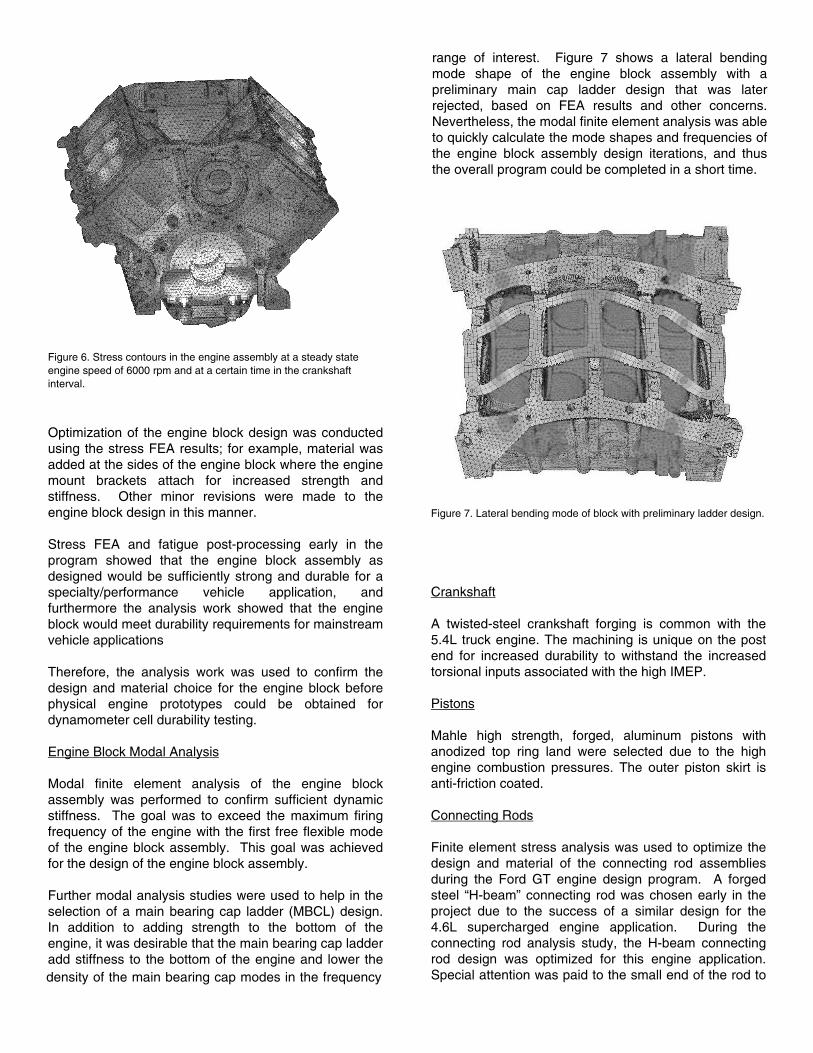
Figure 6. Stress contours in the engine assembly at a steady state engine speed of 6000 rpm and at a certain time in the crankshaft interval.
Optimization of the engine block design was conducted using the stress FEA results; for example, material was added at the sides of the engine block where the engine mount brackets attach for increased strength and stiffness. Other minor revisions were made to the engine block design in this manner.
Stress FEA and fatigue post-processing early in the program showed that the engine block assembly as designed would be sufficiently strong and durable for a specialty/performance vehicle application, and furthermore the analysis work showed that the engine block would meet durability requirements for mainstream vehicle applications
Therefore, the analysis work was used to confirm the design and material choice for the engine block before physical engine prototypes could be obtained for dynamometer cell durability testing.
Engine Block Modal Analysis
Modal finite element analysis of the engine block assembly was performed to confirm sufficient dynamic stiffness. The goal was to exceed the maximum firing frequency of the engine with the first free flexible mode of the engine block assembly. This goal was achieved for the design of the engine block assembly.
Further modal analysis studies were used to help in the selection of a main bearing cap ladder (MBCL) design. In addition to adding strength to the bottom of the engine, it was desirable that the main bearing cap ladder add stiffness to the bottom of the engine and lower the density of the main bearing cap modes in the frequency
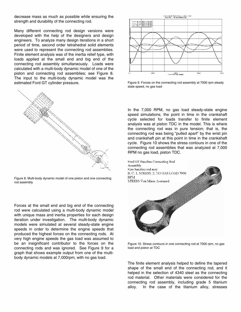
range of interest. Figure 7 shows a lateral bending mode shape of the engine block assembly with a preliminary main cap ladder design that was later rejected, based on FEA results and other concerns.
Nevertheless, the modal finite element analysis was able to quickly calculate the mode shapes and frequencies of the engine block assembly design iterations, and thus the overall program could be completed in a short time.
Figure 7. Lateral bending mode of block with preliminary ladder design.
Crankshaft
A twisted-steel crankshaft forging is common with the 5.4L truck engine. The machining is unique on the post end for increased durability to withstand the increased torsional inputs associated with the high IMEP.
Pistons
Mahle high strength, forged, aluminum pistons with anodized top ring land were selected due to the high engine combustion pressures. The outer piston skirt is anti-friction coated.
Connecting Rods
Finite element stress analysis was used to optimize the design and material of the connecting rod assemblies during the Ford GT engine design program. A forged steel “H-beam” connecting rod was chosen early in the project due to the success of a similar design for the 4.6L supercharged engine application. During the connecting rod analysis study, the H-beam connecting rod design was optimized for this engine application. Special attention was paid to the small end of the rod to
decrease mass as much as possible while ensuring the strength and durability of the connecting rod.
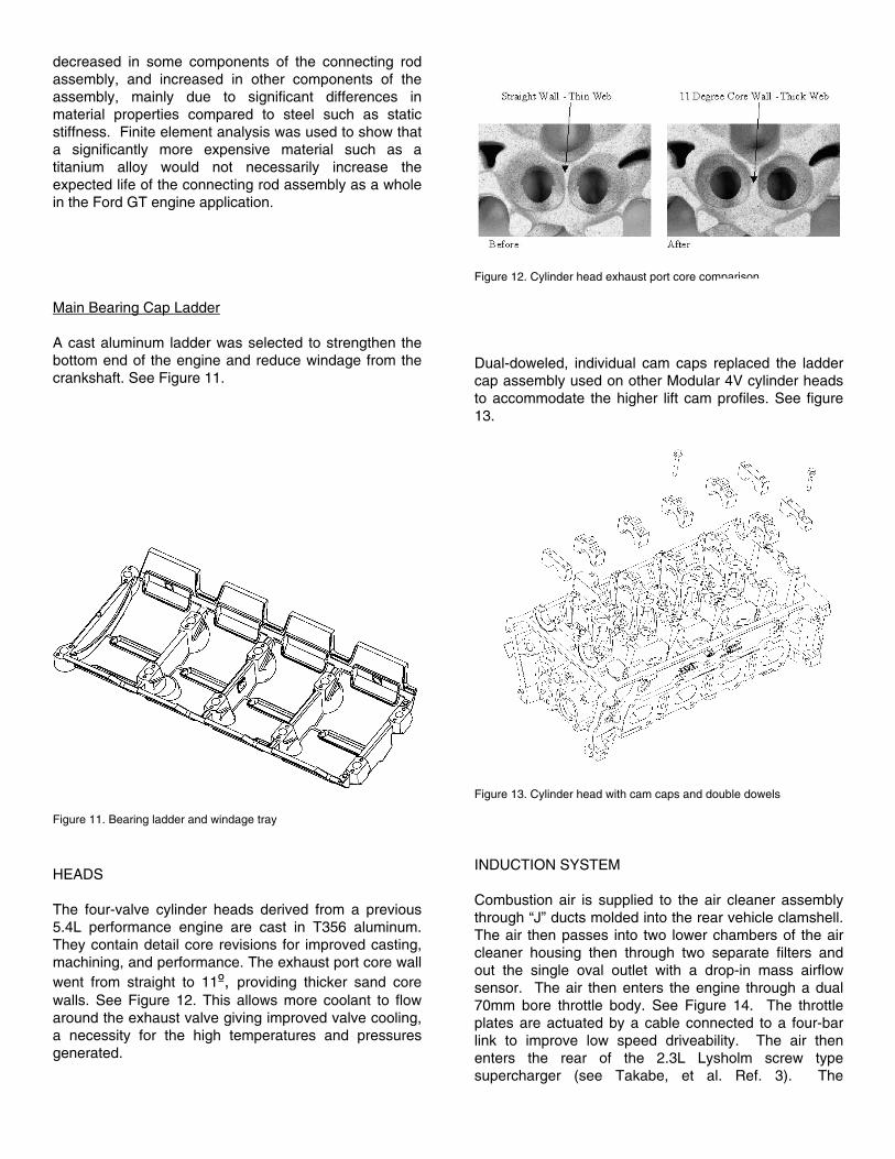
Many different connecting rod design versions were developed with the help of the designers and design engineers. To analyze many design iterations in a short period of time, second order tetrahedral solid elements were used to represent the connecting rod assemblies. Finite element analysis was of the inertia relief type, with loads applied at the small end and big end of the connecting rod assembly simultaneously. Loads were calculated with a multi-body dynamic model of one of the piston and connecting rod assemblies; see Figure 8. The input to the multi-body dynamic model was the estimated Ford GT cylinder pressure.
Figure 8. Multi-body dynamic model of one piston and one connecting rod assembly
Forces at the small end and big end of the connecting rod were calculated using a multi-body dynamic model with unique mass and inertia properties for each design iteration under investigation. The multi-body dynamic models were simulated at several steady-state engine speeds in order to determine the engine speeds that produced the highest forces on the connecting rods. At very high engine speeds the gas load was assumed to be an insignificant contributor to the forces on the connecting rods and was ignored. See Figure 9 for a graph that shows example output from one of the multi-body dynamic models at 7,000rpm, with no gas load.
Figure 9. Forces on the connecting rod assembly at 7000 rpm steady state speed, no gas load
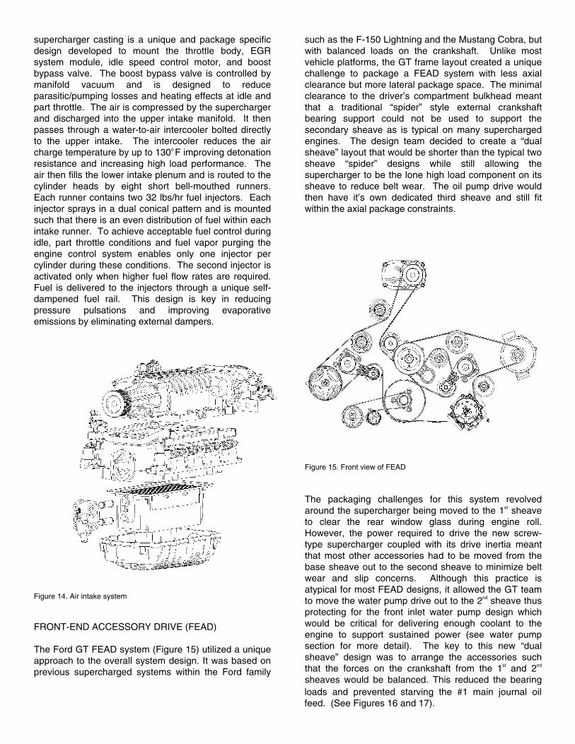
In the 7,000 RPM, no gas load steady-state engine speed simulations, the point in time in the crankshaft cycle selected for loads transfer to finite element analysis was at piston TDC in the model. This is where the connecting rod was in pure tension; that is, the connecting rod was being “pulled apart” by the wrist pin and crankshaft pin at this point in time in the crankshaft cycle. Figure 10 shows the stress contours in one of the connecting rod assemblies that was analyzed at 7,000 RPM no gas load, piston TDC.
Figure 10. Stress contours in one connecting rod at 7000 rpm, no gas load and piston at TDC
The finite element analysis helped to define the tapered shape of the small end of the connecting rod, and it helped in the selection of 4340 steel as the connecting rod material. Other materials were considered for the connecting rod assembly, including grade 5 titanium alloy. In the case of the titanium alloy, stresses
decreased in some components of the connecting rod assembly, and increased in other components of the assembly, mainly due to significant differences in material properties compared to steel such as static stiffness. Finite element analysis was used to show that a significantly more expensive material such as a titanium alloy would not necessarily increase the expected life of the connecting rod assembly as a whole in the Ford GT engine application.
Main Bearing Cap Ladder
A cast aluminum ladder was selected to strengthen the bottom end of the engine and reduce windage from the crankshaft. See Figure 11.
Figure 11. Bearing ladder and windage tray
HEADS
The four-valve cylinder heads derived from a previous 5.4L performance engine are cast in T356 aluminum. They contain detail core revisions for improved casting, machining, and performance. The exhaust port core wall went from straight to 11º, providing thicker sand core walls. See Figure 12. This allows more coolant to flow around the exhaust valve giving improved valve cooling, a necessity for the high temperatures and pressures generated.
Figure 12. Cylinder head exhaust port core comparison
Dual-doweled, individual cam caps replaced the ladder cap assembly used on other Modular 4V cylinder heads to accommodate the higher lift cam profiles. See figure 13.
Figure 13. Cylinder head with cam caps and double dowels
INDUCTION SYSTEM
Combustion air is supplied to the air cleaner assembly through “J” ducts molded into the rear vehicle clamshell. The air then passes into two lower chambers of the air cleaner housing then through two separate filters and out the single oval outlet with a drop-in mass airflow sensor. The air then enters the engine through a dual 70mm bore throttle body. See Figure 14. The throttle plates are actuated by a cable connected to a four-bar link to improve low speed driveability. The air then enters the rear of the 2.3L Lysholm screw type supercharger (see Takabe, et al. Ref. 3). The
supercharger casting is a unique and package specific design developed to mount the throttle body, EGR system module, idle speed control motor, and boost bypass valve. The boost bypass valve is controlled by manifold vacuum and is designed to reduce parasitic/pumping losses and heating effects at idle and part throttle. The air is compressed by the supercharger and discharged into the upper intake manifold. It then passes through a water-to-air intercooler bolted directly to the upper intake. The intercooler reduces the air charge temperature by up to 130o F improving detonation resistance and increasing high load performance. The air then fills the lower intake plenum and is routed to the cylinder heads by eight short bell-mouthed runners. Each runner contains two 32 lbs/hr fuel injectors. Each injector sprays in a dual conical pattern and is mounted such that there is an even distribution of fuel within each intake runner. To achieve acceptable fuel control during idle, part throttle conditions and fuel vapor purging the engine control system enables only one injector per cylinder during these conditions. The second injector is activated only when higher fuel flow rates are required. Fuel is delivered to the injectors through a unique self-dampened fuel rail. This design is key in reducing pressure pulsations and improving evaporative emissions by eliminating external dampers.
Figure 14. Air intake system
FRONT-END ACCESSORY DRIVE (FEAD)
The Ford GT FEAD system (Figure 15) utilized a unique approach to the overall system design. It was based on previous supercharged systems within the Ford family
such as the F-150 Lightning and the Mustang Cobra, but with balanced loads on the crankshaft. Unlike most vehicle platforms, the GT frame layout created a unique challenge to package a FEAD system with less axial clearance but more lateral package space. The minimal clearance to the driver’s compartment bulkhead meant that a traditional “spider” style external crankshaft bearing support could not be used to support the secondary sheave as is typical on many supercharged engines. The design team decided to create a “dual sheave” layout that would be shorter than the typical two sheave “spider” designs while still allowing the supercharger to be the lone high load component on its sheave to reduce belt wear. The oil pump drive would then have it’s own dedicated third sheave and still fit within the axial package constraints.
Figure 15. Front view of FEAD
The packaging challenges for this system revolved around the supercharger being moved to the 1st sheave to clear the rear window glass during engine roll.
However, the power required to drive the new screw-type supercharger coupled with its drive inertia meant that most other accessories had to be moved from the base sheave out to the second sheave to minimize belt wear and slip concerns. Although this practice is atypical for most FEAD designs, it allowed the GT team to move the water pump drive out to the 2nd sheave thus protecting for the front inlet water pump design which would be critical for delivering enough coolant to the engine to support sustained power (see water pump section for more detail). The key to this new “dual sheave” design was to arrange the accessories such that the forces on the crankshaft from the 1st and 2nd
sheaves would be balanced. This reduced the bearing loads and prevented starving the #1 main journal oil feed. (See Figures 16 and 17).

Figure 16. Force diagram of second sheave
After multiple layout iterations, the team was able to create a layout that not only created a favorable loading balance on the crank, but actually reduced the overall load on the crank compared to other benchmark programs. Functionally, the system allowed for standard or better belt wrap over nearly every single component in the system while making sure that neither drive belt would be trapped by the new lower coolant hose
connected to the water pump inlet. This maintained acceptable drive belt serviceability despite the 15 total pulleys contained in the system. No coolant hoses or wiring takeouts would need to be disconnected in order to service either drive belt.
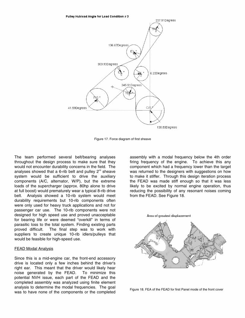
Figure 17. Force diagram of first sheave
The team performed several belt/bearing analyses throughout the design process to make sure that they would not encounter durability concerns in the field. The analyses showed that a 6-rib belt and pulley 2nd sheave system would be sufficient to drive the auxiliary components (A/C, alternator, W/P), but the extreme loads of the supercharger (approx. 80hp alone to drive at full boost) would prematurely wear a typical 8-rib drive belt. Analysis showed a 10-rib system would meet durability requirements but 10-rib components often were only used for heavy truck applications and not for passenger car use. The 10-rib components were not designed for high speed use and proved unacceptable for bearing life or were deemed “overkill” in terms of parasitic loss to the total system. Finding existing parts proved difficult. The final step was to work with suppliers to create unique 10-rib idlers/pulleys that would be feasible for high-speed use.
FEAD Modal Analysis
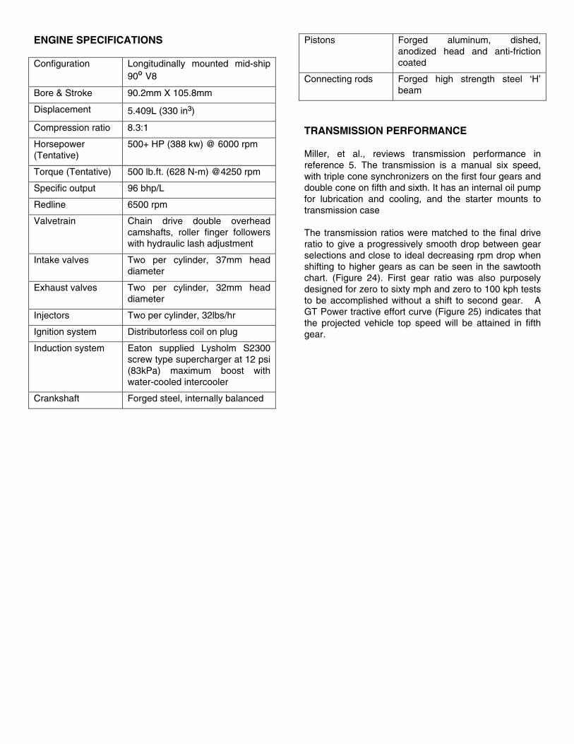
Since this is a mid-engine car, the front-end accessory drive is located only a few inches behind the driver's right ear. This meant that the driver would likely hear noise generated by the FEAD. To minimize this potential NVH issue, each part of the FEAD and the completed assembly was analyzed using finite element analysis to determine the modal frequencies. The goal was to have none of the components or the completed
assembly with a modal frequency below the 4th order firing frequency of the engine. To achieve this any component which had a frequency lower than the target was returned to the designers with suggestions on how to make it stiffer. Through this design iteration process the FEAD was made stiff enough so that it was less likely to be excited by normal engine operation, thus reducing the possibility of any resonant noises coming from the FEAD. See Figure 18.
Figure 18. FEA of the FEAD for first Panel mode of the front cover

LUBRICATION
The vehicle design and performance requirements forced changes and upgrades to the lubrication system. The engine would require more lubricant flow to aid in piston cooling and to dissipate the heat generated by the added power. The engine height was limited due to the desire to keep the vehicle center-of-gravity (CG) low. The engine was designed with piston cooling oil jets aimed at the underside of the piston. The oil jets reduced overall piston temperatures to improve durability and had the additional benefit of improving wear on the piston pin and connecting rod bushing. The oil jet however increased the oil flow requirement by approximately 16 l/min. The existing gerotor oil pump could not be modified to produce this flow without significant revisions to other major engine sub-systems and block architecture. A dry sump oiling system mounted inside the oil pan was then investigated but two major issues prevented further investigation. First, the vehicle package required the engine to drop 100mm to maintain the external body shape. Second, the 105.8mm stroke of the engine coupled with the lower engine position eliminated the package space required for an oil pump in the pan. Next, an externally mounted pump driven off the crankshaft was investigated. A three stage dry sump pump (two scavenge sections, one pressure section) is mounted on the structural oil pan (see Figure 19). It is doweled to maintain alignment between the pulley and the crankshaft. An external “helical offset tooth” (HOT) belt (see Fig. 20) drives the oil pump. This belt design smoothes out tooth engagement compared to other tooth profiles. This style belt is self-aligning, eliminating the need for sprocket flanges and reducing drive face width. The “HOT” belt also has a higher power capacity than traditional “toothed” drive belts, which reduces overall drive belt width and improves vehicle package in a critical area.
The oil is scavenged from the pan through two traditional screen and cover assemblies into the two scavenge sections of the pump. It then passes through an external line to the remote mounted oil reservoir where the oil is de-aerated. It next passes though another external line to the pressure section of the oil pump. From there the oil flows through a cast line on the front of the oil pan and into the oil filter adapter bracket. The oil filter adapter bracket (OFA) is a cast 356 Al component which mounts the A/C compressor, alternator, oil filter and oil cooler. A water-to-oil cooler cools flowing oil as it passes to cast passages in the OFA. It is then routed to the high-flow cartridge-style oil filter. The filter is located for easy serviceability and minimum captured used oil. It then exits the OFA to the cylinder block and the main oil gallery.
Figure 19. Dry sump pump and oil pan
The engine block has oil squirters aimed at the pistons to aid in lubricating the piston wall while cooling the piston. A cast oil pan mating the block and transmission helped the engine and the vehicle structurally. The twelve-quart (11.4L) oil reservoir is used to supply the vast amounts of oil required to circulate at any given moment.
Figure 20. Helical offset tooth oil pump drive
SEALING
Head bolts were upgraded by changing the material from SAE J404 4037 to SAE 4140 for greater yield strength. This revision improved the clamping force as indicated in the following table:
System
4.6L 4V
S/C 4.6L 4V
S/C 5.4L 4V
Clamp Load 54 kN 60 kN 68 kN

The upgraded multi-layer head gasket used on the supercharged 4.6L has proved to be adequate for the cylinder pressures generated.
WATER PUMP
The Ford GT water pump utilizes a front inlet design to achieve the flow rate required to maintain cooling capacity during extended maximum engine power conditions. Preliminary calculations indicated that the cooling system would require a coolant flow rate upwards of 100 gpm to support extended operation at maximum power output. The current Modular design is a rear inlet pump fed by a side inlet at the left front of the engine block (See Figure 21). While this design optimizes packaging, it creates a flow separation through the block prior to the pump as well as water temperature rise as the water passes in front of the #5 water jacket thus pre-heating the water. The front inlet GT design eliminates these restrictions with a gentle transitioning inlet neck that minimizes flow separation as it feeds water into the eye of the pump impeller for distribution to the water jackets (See Figure 22).
Figure 21. Coolant streamlines with side block entry
Figure 22. Coolant streamlines of front entry pump
The GT pump also utilizes a full-vane cast pump impeller with vanes designed to generate maximum pressure while minimizing power consumption (see Figure 23). While the existing pump uses a stamped steel “half vane” impeller, the GT team decided to utilize a cast impeller to reduce vane flexing while allowing for
a compound vane geometry over a flat, stamped vane. The GT pump generates up to 110 gallons per minute peak flow and approximately a 10 psi pressure increase over current designs at peak operation.
Figure 23. Water pump impeller
A computational fluid dynamics (CFD) study of the side inlet compared to the front inlet eliminated an inlet restriction where coolant passed around a head bolt boss and an oil passage before entering into the pump. See the following table for this comparison.
Design % Improvement
Cast Inlet in Current 5.4L V8 Block -
Cast Inlet Without Oil Line 10.7%
Front Inlet Water Pump 73.5%
Hill et al. in reference 4 covers an extensive review of the thermal management system.
Pump
Inlet
Inlet
Pump
ENGINE SPECIFICATIONS
Configuration Longitudinally mounted mid-ship 90º V8
Bore & Stroke 90.2mm X 105.8mm
Displacement 5.409L (330 in³)
Compression ratio 8.3:1
Horsepower (Tentative)
500+ HP (388 kw) @ 6000 rpm
Torque (Tentative) 500 lb.ft. (628 N-m) @4250 rpm
Specific output 96 bhp/L
Redline 6500 rpm
Valvetrain Chain drive double overhead camshafts, roller finger followers with hydraulic lash adjustment
Intake valves Two per cylinder, 37mm head diameter
Exhaust valves Two per cylinder, 32mm head diameter
Injectors Two per cylinder, 32lbs/hr
Ignition system Distributorless coil on plug
Induction system Eaton supplied Lysholm S2300 screw type supercharger at 12 psi (83kPa) maximum boost with water-cooled intercooler
Crankshaft Forged steel, internally balanced
Pistons Forged aluminum, dished, anodized head and anti-friction coated
Connecting rods Forged high strength steel ‘H’ beam
TRANSMISSION PERFORMANCE
Miller, et al., reviews transmission performance in reference 5. The transmission is a manual six speed, with triple cone synchronizers on the first four gears and double cone on fifth and sixth. It has an internal oil pump for lubrication and cooling, and the starter mounts to transmission case
The transmission ratios were matched to the final drive ratio to give a progressively smooth drop between gear selections and close to ideal decreasing rpm drop when shifting to higher gears as can be seen in the sawtooth chart. (Figure 24). First gear ratio was also purposely designed for zero to sixty mph and zero to 100 kph tests to be accomplished without a shift to second gear. A GT Power tractive effort curve (Figure 25) indicates that the projected vehicle top speed will be attained in fifth gear.
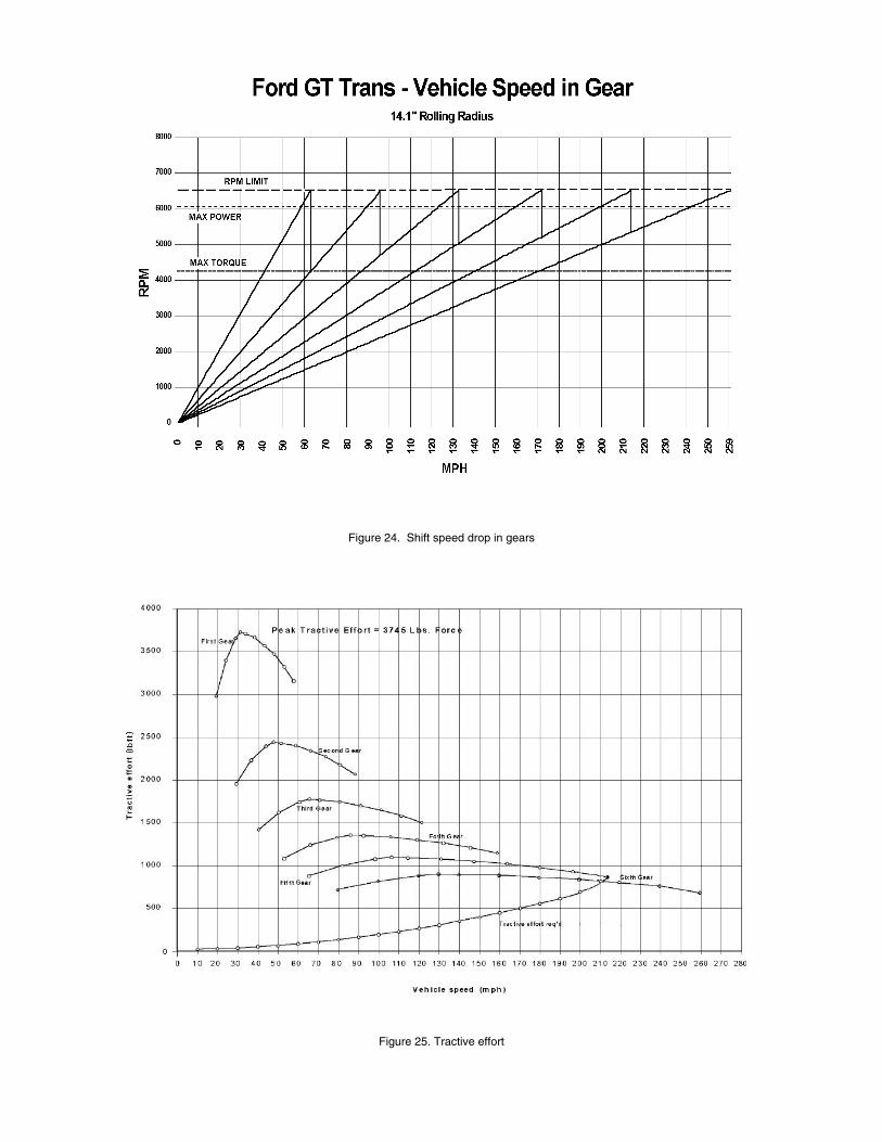
Figure 24. Shift speed drop in gears
Figure 25. Tractive effort

CLUTCH
A hydraulic controlled twin disc 240mm clutch with an integral starter ring gear mates to a 294.5mm flywheel. The clutch housing is LM25 aluminum and the flywheel is spherical nodular iron EN-GJS-500-7.
DIFFERENTIAL
A torque sensing helical gear driven limited slip differential (LSD) was selected for its characteristics of traction improvement and steering performance. This type of differential has less hysteresis and has quicker response time than disc type LSD’s. Its torque bias ratio is 2.3:1 (+/- 0.25) in drive and 2.0:1 (+/- 0.25) during coast.
HALF SHAFTS
Thirty-one spline hollow 35mm diameter half shafts are used to contain the torque generated throughout the drive range of the vehicle. They have a capacity of 5535 Nm (B10 UTS) and yield strength of 4100 Nm.
ENGINE AND TRANSMISSION ASSEMBLY
Modal FEA of the overall powertrain was conducted in order to confirm that the frequencies of the free flexible modes of the powertrain were above the target frequency. Figure 26 shows the first global lateral bending mode shape of the overall powertrain.
Figure 26. Top view of powertrain finite element model
Figure 27 shows the first global vertical bending mode shape of the overall Ford GT powertrain
Figure 27. Side view of powertrain finite element model
The powertrain modal FEA was used to validate structural attachment of the engine oil pan to the transmission housing. The first vertical bending mode frequency of the overall powertrain is increased by sixteen percent and the first lateral bending mode frequency of the overall powertrain is increased by five percent.
FUEL SYSTEM
The fuel storage and delivery system features the first usage in the industry of a capless fuel entry system and a ”ship in a bottle” (SIB) blow molded tank. These were developed to meet LEV II evaporative emissions requirements.
FUEL INLET
Hidden beneath the Ford GT’s race-inspired fuel inlet door is a direct fill capless fuel inlet. (See Figure 28). This is an auto industry first. It has as a spring-loaded self-sealing trapdoor that opens with insertion of the gas pump nozzle. This feature removes operator error from one of the ‘check engine’ light warning system paths.
With only two openings and the majority of the hose connections internal to the tank, this dramatically reduces potential permeation paths from the fuel system.
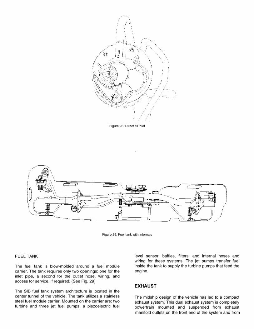
Figure 28. Direct fill inlet
.
Figure 29. Fuel tank with internals
FUEL TANK
The fuel tank is blow-molded around a fuel module carrier. The tank requires only two openings: one for the inlet pipe, a second for the outlet hose, wiring, and access for service, if required. (See Fig. 29)
The SIB fuel tank system architecture is located in the center tunnel of the vehicle. The tank utilizes a stainless steel fuel module carrier. Mounted on the carrier are: two turbine and three jet fuel pumps, a piezoelectric fuel
level sensor, baffles, filters, and internal hoses and wiring for these systems. The jet pumps transfer fuel inside the tank to supply the turbine pumps that feed the engine.
EXHAUST The midship design of the vehicle has led to a compact exhaust system. This dual exhaust system is completely powertrain mounted and suspended from exhaust manifold outlets on the front end of the system and from

the rear of the transmission housing by means of flexible bracketry system at the rear. This mounting method maintains the vertical position of the exhaust systems relative to the powertrain while allowing flexible fore-aft motion for exhaust system longitudinal growth.
MANIFOLDS
A cast iron (high Silicon- Molybdenum) exhaust manifold design was optimized for maximum flow given the limited packaging space. The exhaust manifolds include a new 2 ¾” Ford designed manifold outlet flange required to reduce flow restriction. Performing an FEA analysis and exhaust manifold cracking test validated the durability of the design. The manifolds are completely encapsulated in a multi-layered, manifold-mounted heat shield. The shield is required to protect surrounding components and aid in catalyst light off times.
CATALYSTS
Each bank of the engine has a typical three-way catalyst assembly that carries exhaust gases from the engine to the muffler. The light-off/underbody catalyst assemblies contain two 5.2” diameter round ceramic substrates each, with a mid-bed sensing strategy. Each converter assembly utilizes a tourniquet-style canning process for consistent and even support mat GBD for substrate stability. Converter inlet pipes match the exhaust manifold outlet of 2 ¾” and are thermally insulated and heat-shielded to protect surrounding components and aid in light-off times. The converter cans have 3” cone inlets and 2 ¼”outlets. This provides improved flow across the front face of the catalyst (increasing effectiveness) as well as increased gas flow.
MUFFLER
A single cross-car mounted muffler provides the volume necessary to tune the engine output sound to desired target. It also helps manage exhaust heat introduced to the engine compartment from the midship design (see Figure 30). The entire muffler assembly is manufactured from 304 stainless steel and is heat-insulated on its front, top, back and sides. This insulation helps maintain adequate surface temperatures of surrounding componentry. Internally the exhaust gas is diverted through 2 1/4” piping inside the muffler, passing it through several chambers separated by partitions, baffles and tuning links. Exhaust gases exit the bottom center of the muffler. The exhaust system exits at the center and rear of the vehicle through a bright, 304 stainless steel, oval-formed exhaust tip.
Figure 30 Muffler
COOLING
The cooling module located at the front contains the A/C condenser and the radiators for the intercooler and engine. Cooling the powertrain is significant since the system is designed to meet both extended low and high performance requirements. For more information on cooling see reference 5.
ENGINE RADIATOR
The radiator was based on the available air inlet of the vehicle. The maximum performance requirement that was projected was for airflow of 13,800 cfm, which would be adequate for any extended condition of vehicle performance. However, this projection was for a vehicle operated at maximum power for extended periods of time, long past its total fuel availability time. Therefore, the available airflow of 7,500 cfm would be sufficient for all but the most extreme conditions.
INTERCOOLER
To increase the air charge density, a separate air-to-water intercooler system was developed. It consists of a large radiator in the front of the vehicle, an electric coolant pump and supercharger intercooler in the intake manifold assembly.

Intercooler Radiator
The intercooler radiator was developed with the assumption that this vehicle may be run at extended high performance conditions, requiring prolonged intercooler performance. This requires increased cooling compared to ordinary supercharged muscle cars, where intercooler performance is only required intermittently. The core is 680 mm X 411mm X 32.25 mm.
Intercooler Pump
The intercooler 12V drive pump is capable of flowing 10 gallons (38L) per minute at 13.5 psi (93 kPa).
TRANSMISSION COOLER
An air-to-oil transmission cooler is packaged in the engine bay near the body side air duct.
CONCLUSION
Reliance on Computer Aided Engineering, including virtual packaging tools proved highly effective in delivering the program in unprecedented timing. Application of system engineering to balance and optimize the entire powertrain subsystems delivered vehicle level attributes exceeding targets, providing supercharged, supercar performance that meets the demanding quality requirements of today’s market.
ACKNOWLEDGMENTS
The authors would wish to thank those from within and outside of our companies for their invaluable assistance and donations to the success in designing and developing this powertrain. There have been numerous persons that made significant contributions. Those who have helped compile this record are; Mr. R. Grenkowitz, Ford Casting Technical Specialist, Ms. J. Bastian, Roush Industries CAE Senior Engineering Analyst, Mr. T. Wernholm, and Mr. J. Thomson.
REFERENCES
1. Macura, J.F., and Bowers, J. SAE Paper 670066 Mark II-427 GT Engine
2. Roback, B.J., Holl, M.R., Eble, M.L., and Thornton, D. SAE Paper 2003-01-3209 Supercharging Ford’s 4.6L for Affordable Performance
3. Takabe, S., Hatamura, K., Kanesaka, H., Kurata, H., Iguchi, Y., and Matsubara, H. SAE Paper 940843 Development of the High Performance Lysholm Compressor for Automotive Use
4. Hill, C.M., Miller, G.D., Evans, M.R., and Pollock, D.M, SAE Paper 2004-01-1257 2005 Ford GT – Maintaining Your Cool at 200MPH
5. Miller, G.D., Cropper, A., Janczak, R.M., and Nesbitt, S, SAE Paper 2004-01-1260 2005 Ford GT Transaxle – Tailor Made in Under Two Years