Embed Size (px)
Citation preview

www.SeaDooManuals.net

SAFETY WARNING
Disregarding any of the safety precautions and instructions contained inthis Operator’s Guide, the Safety Handbook, the Safety Videocassetteand on the on-product warning labels could cause injury, including thepossibility of death. The operator has the responsibility to informpassenger(s) of safety precautions.
This Operator’s Guide, the Safety Handbook and Safety Videocassetteshould remain with the craft at the time of resale.
GTX† is a trademark of Castrol Ltd. Used under license
The following trademarks are the property of Bombardier Inc. or its subsidiaries:
SEA-DOO®
BOMBARDIER-ROTAX®
ROTAX®
BOMBARDIER LUBE®
BOMBARDIER Formula XP-S DI Synthetic Injection Oil
Printed in Canada (smo2002-005a.fm SH)™®Trademarks of Bombardier Inc. or its subsidiaries.©2001 Bombardier Inc. All rights reserved.
smo2002-005a.book Page 0 Friday, September 7, 2001 11:34 AM
www.SeaDooManuals.net

1
NOTE
Dear 2002 GTX DI watercraft owner. Informations on the RX DI model in the2002 Operator’s Guide (P/N 219 000 145) apply to your GTX DI except forthe following.
smo2002-005a.book Page 1 Friday, September 7, 2001 11:34 AM
www.SeaDooManuals.net

2
TABLE OF CONTENTS
NOTE....................................................................................................... 1
TABLE OF CONTENTS ................................................................ 2LOCATION OF THE IMPORTANT LABELS ................................... 3LOCATION OF CONTROLS, COMPONENTS ANDINSTRUMENTS ........................................................................... 4FUNCTIONS OF CONTROLS, COMPONENTS ANDINSTRUMENTS ........................................................................... 5
4) Engine Start/Stop Button .................................................................. 55) Variable Trim System Button (VTS) ................................................... 56) Variable Trim System Gauge (VTS) ................................................... 5
12) Information Center Gauge/Buttons................................................... 513) Glove Box.......................................................................................... 617) Front Storage Compartment Cover................................................... 621) Tool Kit .............................................................................................. 724) Seat Latch ......................................................................................... 725) Seat Extension Latch ........................................................................ 727) Rear Storage Basket ......................................................................... 834) Boarding Step ................................................................................... 835) Cooling System Bleed Outlet............................................................ 942) Fuses ................................................................................................ 943) Battery .............................................................................................. 944) Side Vanes ........................................................................................ 9
OPERATING INSTRUCTIONS...................................................... 10SPECIAL PROCEDURES.............................................................. 10
Towing the Watercraft in Water .............................................................. 10MAINTENANCE .......................................................................... 11
Fuses ....................................................................................................... 11TRAILERING, STORAGE AND PRE-SEASON PREPARATION....... 13
Storage .................................................................................................... 13SPECIFICATIONS........................................................................ 17
smo2002-005aTOC.fm Page 2 Wednesday, September 26, 2001 11:39 AM
www.SeaDooManuals.net

3
LOCATION OF THE IMPORTANT LABELS
GTX DI Model
TYPICAL
GTX DI Model Only
The location of this label differs on theGTX DI model.
Label 6
Label 14
��
�������
�
���������
������������������� ������������
������
�����
smo2002-005a.book Page 3 Friday, September 7, 2001 11:34 AM
www.SeaDooManuals.net

4
LOCATION OF CONTROLS, COMPONENTS AND INSTRUMENTS
GTX DI Model
��
������
� ���
�� � �� � ��
��� � �
smo2002-005a.book Page 4 Friday, September 7, 2001 11:34 AM
www.SeaDooManuals.net
5
4. Engine Start/Stop Button12. Information Center Gauge/Buttons13. Glove Box17. Front Storage Compartment Cover21. Tool Kit24. Seat Latch25. Seat Extension Latch
27. Rear Storage Basket34. Boarding Step35. Cooling System Bleed Outlet42. Fuses43. Battery44. Side Vanes
NOTE: Some components shown in the 2002 Sea-Doo Operator’s Guide do notapply to this watercraft.
FUNCTIONS OF CONTROLS, COMPONENTS AND INSTRUMENTS
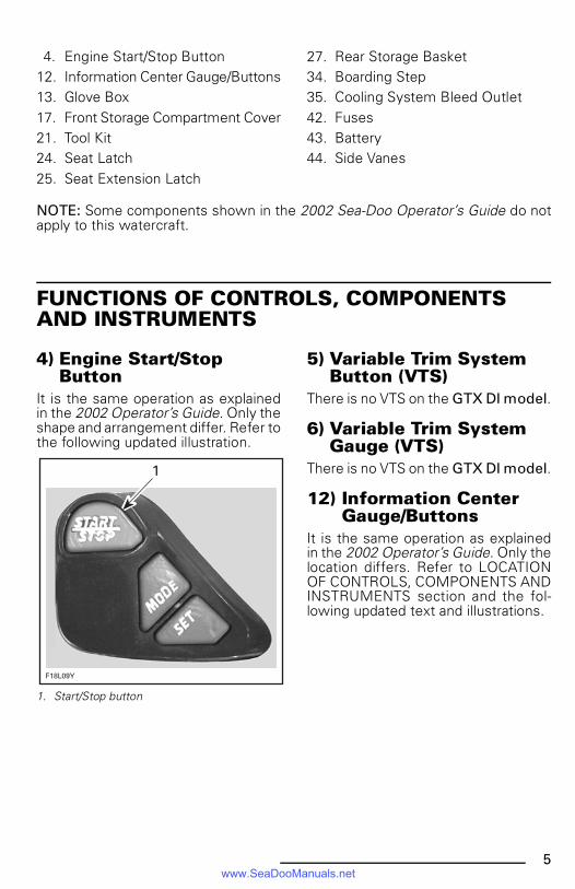
4) Engine Start/Stop Button
It is the same operation as explainedin the 2002 Operator’s Guide. Only theshape and arrangement differ. Refer tothe following updated illustration.
1. Start/Stop button
5) Variable Trim System Button (VTS)
There is no VTS on the GTX DI model.
6) Variable Trim System Gauge (VTS)
There is no VTS on the GTX DI model.
12) Information Center Gauge/Buttons
It is the same operation as explainedin the 2002 Operator’s Guide. Only thelocation differs. Refer to LOCATIONOF CONTROLS, COMPONENTS ANDINSTRUMENTS section and the fol-lowing updated text and illustrations.
�
�������
smo2002-005b.fm Page 5 Wednesday, September 26, 2001 11:49 AM
www.SeaDooManuals.net
6
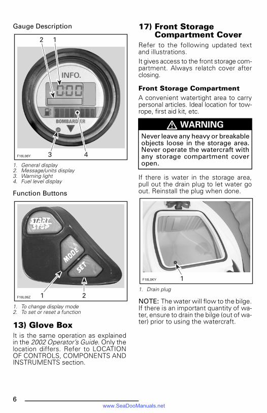
Gauge Description
1. General display2. Message/units display3. Warning light4. Fuel level display
Function Buttons
1. To change display mode2. To set or reset a function
13) Glove BoxIt is the same operation as explainedin the 2002 Operator’s Guide. Only thelocation differs. Refer to LOCATIONOF CONTROLS, COMPONENTS ANDINSTRUMENTS section.
17) Front Storage Compartment Cover
Refer to the following updated textand illustrations.It gives access to the front storage com-partment. Always relatch cover afterclosing.
Front Storage CompartmentA convenient watertight area to carrypersonal articles. Ideal location for tow-rope, first aid kit, etc.
If there is water in the storage area,pull out the drain plug to let water goout. Reinstall the plug when done.
1. Drain plug
NOTE: The water will flow to the bilge.If there is an important quantity of wa-ter, ensure to drain the bilge (out of wa-ter) prior to using the watercraft.
�������� �
�
��������
� WARNING
Never leave any heavy or breakableobjects loose in the storage area.Never operate the watercraft withany storage compartment coveropen.
������� �
smo2002-005a.book Page 6 Friday, September 7, 2001 11:34 AM
www.SeaDooManuals.net

7
The front storage area includes a latchto hold an approved fire extinguisher(sold separately).
1. Retaining straps2. Extinguisher (sold separately)
21) Tool KitIt is the same information as explainedin the 2002 Operator’s Guide. Only thelocation differs. Refer to LOCATIONOF CONTROLS, COMPONENTS ANDINSTRUMENTS section.
24) Seat LatchIt is the same operation as explainedin the 2002 Operator’s Guide for 3-upseat models. Refer to the followingupdated illustration.
1. Seat latch
25) Seat Extension LatchIt is the same operation as explainedin the 2002 Operator’s Guide for 3-upseat models. Refer to the followingupdated illustration.
1. Seat extension latch
� WARNING
Ensure to properly secure extin-guisher with the supplied retainingstraps.
�������
�
��������
�������
�
smo2002-005a.book Page 7 Friday, September 7, 2001 11:34 AM
www.SeaDooManuals.net

8
27) Rear Storage BasketIt is the same operation as explainedin the 2002 Operator’s Guide for 3-upseat models. Refer to the followingupdated illustration.
1. Rear storage basket
Spare Spark Plug HolderThe storage basket features a sparespark plug holder.To keep spare spark plugs dry and pre-vent shocks that might affect the ad-justment or break them, a holder isprovided.Unscrew cap counterclockwise to ex-pose the holder and insert spark plugin their holes. Reinstall cap.
1. Storage basket2. Spare spark plug holder cap3. Spark plug holder
NOTE: Adjust spare spark plug gap ac-cording to SPECIFICATIONS before in-stallation.NOTE: Spare spark plugs are not sup-plied with the watercraft.
34) Boarding StepIt is the same operation as explainedin the 2002 Operator’s Guide for somemodels. Refer to the following updat-ed illustrations.
1. Boarding step
��������
������� �
�
�������
�
smo2002-005a.book Page 8 Friday, September 7, 2001 11:34 AM
www.SeaDooManuals.net
9
35) Cooling System Bleed Outlet
It is the same operation as explainedin the 2002 Operator’s Guide. Only thelocation differs. Refer to LOCATIONOF CONTROLS, COMPONENTS ANDINSTRUMENTS section.
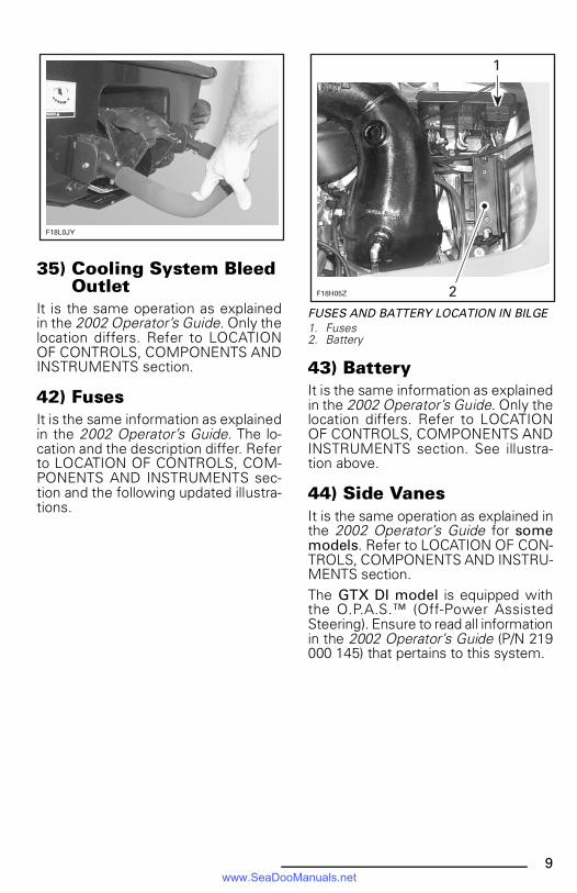
42) FusesIt is the same information as explainedin the 2002 Operator’s Guide. The lo-cation and the description differ. Referto LOCATION OF CONTROLS, COM-PONENTS AND INSTRUMENTS sec-tion and the following updated illustra-tions.
FUSES AND BATTERY LOCATION IN BILGE1. Fuses2. Battery
43) BatteryIt is the same information as explainedin the 2002 Operator’s Guide. Only thelocation differs. Refer to LOCATIONOF CONTROLS, COMPONENTS ANDINSTRUMENTS section. See illustra-tion above.
44) Side VanesIt is the same operation as explained inthe 2002 Operator’s Guide for somemodels. Refer to LOCATION OF CON-TROLS, COMPONENTS AND INSTRU-MENTS section. The GTX DI model is equipped withthe O.P.A.S.™ (Off-Power AssistedSteering). Ensure to read all informationin the 2002 Operator’s Guide (P/N 219000 145) that pertains to this system.
�������
����� �
�
smo2002-005b.fm Page 9 Wednesday, September 26, 2001 11:50 AM
www.SeaDooManuals.net
10
OPERATING INSTRUCTIONS
For the GTX DI model, follow the in-structions given for the GTX seriesand 3-up seat models in the 2002 Op-erator’s Guide (P/N 219 000 145).
SPECIAL PROCEDURES
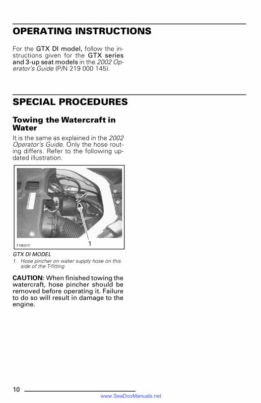
Towing the Watercraft in WaterIt is the same as explained in the 2002Operator’s Guide. Only the hose rout-ing differs. Refer to the following up-dated illustration.
GTX DI MODEL1. Hose pincher on water supply hose on this
side of the T-fitting
CAUTION: When finished towing thewatercraft, hose pincher should beremoved before operating it. Failureto do so will result in damage to theengine.
��������
smo2002-005a.book Page 10 Friday, September 7, 2001 11:34 AM
www.SeaDooManuals.net

11
MAINTENANCE
FusesIt is the same information as explainedin the 2002 Operator’s Guide exceptfor the following. Refer to the updatedtext and illustrations.
MPEMTo access fuses on the MPEM, removeseat. Locate MPEM besides engine.
1. MPEM2. Fuses location
Fuses are identified, look above andbesides the fuse holder.
FUSE IDENTIFICATION1. Fuse identification2. Fuse description
Fuse identification: The fuses (F) areidentified from 1 to 6.Fuse description: The fuses are de-scribed with abbreviation as follows:FP: Fuel pumpACC: Accessories (information center)REG: Regulator (charging system)VTS: Variable Trim System. Fuse is in-stalled but not in use on the GTX DImodelBAT: BatteryINJ: Injection systemThe fuse description is followed by theampere rating (A).
������
�
�������������������������������� ��������������������������������������������������
���������������������������
�������
�
smo2002-005a.book Page 11 Friday, September 7, 2001 11:34 AM
www.SeaDooManuals.net
12
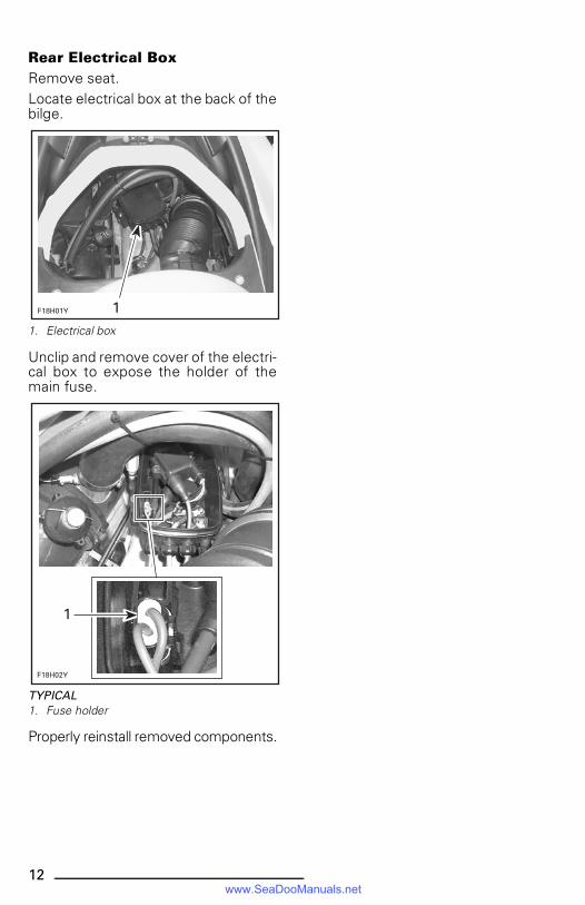
Rear Electrical BoxRemove seat.Locate electrical box at the back of thebilge.
1. Electrical box
Unclip and remove cover of the electri-cal box to expose the holder of themain fuse.
TYPICAL1. Fuse holder
Properly reinstall removed components.
��������
����� �
�
smo2002-005a.book Page 12 Friday, September 7, 2001 11:34 AM
www.SeaDooManuals.net
13
TRAILERING, STORAGEAND PRE-SEASON PREPARATION
It is the same information as explainedin the 2002 Operator’s Guide exceptfor the following updated illustrations.
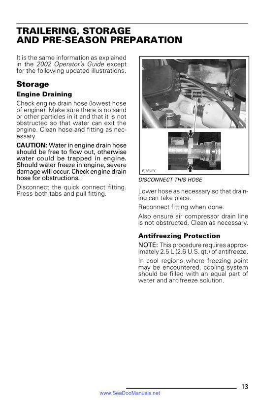
StorageEngine DrainingCheck engine drain hose (lowest hoseof engine). Make sure there is no sandor other particles in it and that it is notobstructed so that water can exit theengine. Clean hose and fitting as nec-essary.CAUTION: Water in engine drain hoseshould be free to flow out, otherwisewater could be trapped in engine.Should water freeze in engine, severedamage will occur. Check engine drainhose for obstructions.Disconnect the quick connect fitting.Press both tabs and pull fitting.
DISCONNECT THIS HOSE
Lower hose as necessary so that drain-ing can take place.Reconnect fitting when done.Also ensure air compressor drain lineis not obstructed. Clean as necessary.
Antifreezing ProtectionNOTE: This procedure requires approx-imately 2.5 L (2.6 U.S. qt.) of antifreeze.In cool regions where freezing pointmay be encountered, cooling systemshould be filled with an equal part ofwater and antifreeze solution.
����� �
smo2002-005a.book Page 13 Friday, September 7, 2001 11:34 AM
www.SeaDooManuals.net

14
CAUTION: Antifreeze mix must befed in cooling system. Otherwise re-maining water will freeze. This opera-tion requires a good technical knowl-edge of the cooling system path. Ifantifreezing is not performed ade-quately engine/exhaust system mayfreeze and cause severe engine dam-age. We strongly recommend this op-eration be performed by an autho-rized SEA-DOO dealer.CAUTION: Always use ethylene gly-col antifreeze containing corrosioninhibitors specifically recommendedfor aluminum engines.NOTE: When available, it is recom-mended to use biodegradable anti-freeze compatible with internal com-bustion aluminum engines. This willcontribute to protect the environment.NOTE: The engine will not have to runduring this operation but should havebeen ran before, to exhaust as muchwater as possible, from cooling sys-tem components.NOTE: It may be easier to reach hoseswhen you remove the seat openingbridge.
1. Seat opening bridge
Hose Pinchers InstallationSome hoses have to be plugged toprevent draining, before filling coolingsystem jackets with the antifreeze.Install hose pinchers at the followinglocation:
1. Water outlet hose
�������
�
�
������
smo2002-005a.book Page 14 Friday, September 7, 2001 11:34 AM
www.SeaDooManuals.net

15
1. Crankcase cooling cover outlet hose
1. Engine cylinder drain hose
Hose DisconnectionDisconnect water INLET hose at enginebetween T-fitting and cylinder head fit-ting.
1. Disconnect this side of the T-fitting
Temporarily install a short piece of hoseto replace the one removed.
AntifreezeInsert a funnel into the temporary hoseand pour antifreeze mix in engine untilthe colored solution appears at coolingsystem bleed outlet.
TYPICAL
�������
�
�������
�
�������
�
�������
smo2002-005a.book Page 15 Friday, September 7, 2001 11:34 AM
www.SeaDooManuals.net
16
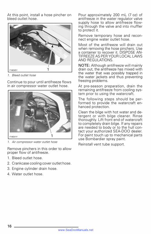
At this point, install a hose pincher onbleed outlet hose.
1. Bleed outlet hose
Continue to pour until antifreeze flowsin air compressor water outlet hose.
1. Air compressor water outlet hose
Remove pinchers in this order to allowproper flow of antifreeze.1. Bleed outlet hose.2. Crankcase cooling cover outlet hose.3. Engine cylinder drain hose.4. Water outlet hose.
Pour approximately 200 mL (7 oz) ofantifreeze in the water regulator valvesupply hose to allow antifreeze flow-ing through the valve and into mufflerto protect it. Remove temporary hose and recon-nect engine water outlet hose.Most of the antifreeze will drain outwhen removing the hose pinchers. Usea container to recover it. DISPOSE AN-TIFREEZE AS PER YOUR LOCAL LAWSAND REGULATIONS.NOTE: Although antifreeze will mainlydrain out, the antifreeze has mixed withthe water that was possibly trapped inthe water jackets and thus preventingfreezing problems.At pre-season preparation, drain theremaining antifreeze from cooling sys-tem prior to using the watercraft.The following steps should be per-formed to provide the watercraft en-hanced protection.Clean the bilge with hot water and de-tergent or with bilge cleaner. Rinsethoroughly. Lift front end of watercraftto completely drain bilge. If any repairsare needed to body or to the hull con-tact your authorized SEA-DOO dealer.For paint touch up to mechanical partsuse Bombardier spray paint.Reinstall vent tube support.
������� �
��������
smo2002-005a.book Page 16 Friday, September 7, 2001 11:34 AM
www.SeaDooManuals.net

17
SPECIFICATIONS
ENGINEGTX DI
(5563/5564/5595/5596)
Engine type Rotax® 947, 2-stroke
Induction type Reed valve
Exhaust system Water cooled/water injected
Exhaust valve Rotax Adjustable Variable Exhaust (RAVE)
Lubrication Type Oil injection
Oil type BOMBARDIER Formula XP-S DIsynthetic injection oil (or equivalent)
Number of cylinders 2
Displacement 951.2 cm3 (58 in3)
COOLING
Type Open circuit.Direct flow from propulsion unit
ELECTRICAL
Magneto generator output 200 W @ 6000 RPM
Ignition system type Digital CDI
Spark plugMake and type NGK, ZFR4F
Gap 1.1 mm (.043 in)
Starting system Electric starter with reduction gear
Battery 12 V, 19 A•h
Fuse
Battery 25 A
Main 30 A
Charging system (REG) 25 A
VTS system Installed but not in use
Information center (ACC) 2 A
Injection system (INJ) 15 A
Fuel pump (FP) 15 A
CARBURETION
Fuel type Regular gasoline with 87 octane minimum (R+M)/2
Fuel injection Orbital direct fuel injection, twin throttle body(46 mm (1.81 in))
smo2002-005b.fm Page 17 Friday, October 12, 2001 10:19 AM
www.SeaDooManuals.net
18
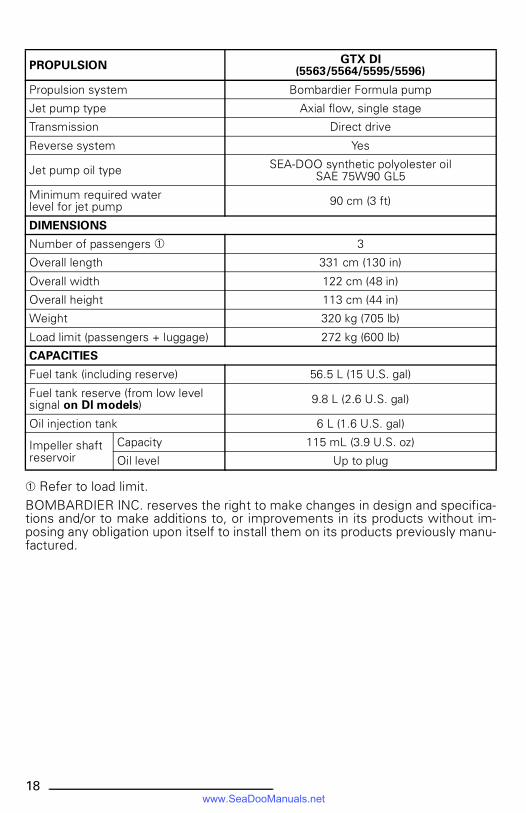
➀ Refer to load limit.BOMBARDIER INC. reserves the right to make changes in design and specifica-tions and/or to make additions to, or improvements in its products without im-posing any obligation upon itself to install them on its products previously manu-factured.
PROPULSIONGTX DI
(5563/5564/5595/5596)
Propulsion system Bombardier Formula pump
Jet pump type Axial flow, single stage
Transmission Direct drive
Reverse system Yes
Jet pump oil type SEA-DOO synthetic polyolester oilSAE 75W90 GL5
Minimum required waterlevel for jet pump 90 cm (3 ft)
DIMENSIONS
Number of passengers ➀ 3
Overall length 331 cm (130 in)
Overall width 122 cm (48 in)
Overall height 113 cm (44 in)
Weight 320 kg (705 lb)
Load limit (passengers + luggage) 272 kg (600 lb)
CAPACITIES
Fuel tank (including reserve) 56.5 L (15 U.S. gal)
Fuel tank reserve (from low level signal on DI models) 9.8 L (2.6 U.S. gal)
Oil injection tank 6 L (1.6 U.S. gal)
Impeller shaftreservoir
Capacity 115 mL (3.9 U.S. oz)
Oil level Up to plug
smo2002-005b.fm Page 18 Friday, October 12, 2001 10:19 AM
www.SeaDooManuals.net