Embed Size (px)
Citation preview

2002 IS Catalog
174 Pepperl+Fuchs® Inc. • Telephone (330) 486-0002 • FAX (330) 425-4607E-mail: [email protected] • www.am.pepperl-fuchs.com
Introduction ............................................................................................................................. 175Discrete Inputs (Switch Isolators)
KSD2-BI-Ex4 (Optional lead breakage and short circuit monitoring) ............................................... 176KSD2-BI-4 (Non-intrinsically safe inputs without LB and SC) .......................................................... 177KSD2-BI-4.2 (Non-intrinsically safe inputs with LB and SC) ............................................................ 178
Frequency CountersKSD2-FI-Ex (Single-channel, batch controller) ................................................................................ 179KSD2-FI (Single-channel, batch controller) ....................................................................................... 180
Discrete Outputs (Solenoid Drivers)KSD2-BO-Ex (Single-channel) ............................................................................................................ 181KSD2-BO-Ex2.2 (Dual-channel) ......................................................................................................... 182
Relay ModuleKSD2-RO-2 (Safe area, relay module) ............................................................................................... 183KSD2-RO-Ex2 (Hazardous area, relay module) ................................................................................. 184
Analog Inputs (Transmitter Power Supplies)KSD2-CI-2 (Safe area, dual-channel) ................................................................................................. 185KSD2-CI-Ex2 (Hazardous area, dual-channel) .................................................................................. 186KSD2-CI-S-Ex (Hazardous area, HART signal transfer) .................................................................... 187KSD2-CI-S (Safe area, HART signal transfer) .................................................................................... 188KSD2-CI-S-Ex.H (Hazardous area, HART signal transfer on bus) .................................................... 189KSD2-CI-S-H (Safe area, HART signal transfer on bus) .................................................................... 190
Universal Temperature ConverterKSD2-TI (Safe area temperature converter) ...................................................................................... 191KSD2-TI-Ex (Hazardous area temperature converter) ...................................................................... 192
Potentiometer InputsKSD2-PT2-Ex1 (Safe area, potentiometer input) ............................................................................... 193
Analog OutputsKSD2-CO (Safe area analog output) .................................................................................................. 194KSD2-CO-Ex (Hazardous area analog output) .................................................................................. 195KSD2-CO-S-Ex (Hazardous area, HART signal transfer) .................................................................. 196KSD2-CO-S (Safe area, HART signal transfer) .................................................................................. 197KSD2-CO-S-Ex.H (Hazardous area, HART signal transfer on bus) .................................................. 198KSD2-CO-S-H (Safe area, HART signal transfer on bus) .................................................................. 199
HART InterfaceKSD2-HC (HART control module) ...................................................................................................... 200
GatewaysKSD2-GW-PRO (Profibus with RS 232 programming interface) ....................................................... 201KSD2-GW-PRO.485 (Profibus with RS 485 programming interface) ................................................ 202KSD2-GW-MOD (Modbus with RS 232 programming interface) ...................................................... 203KSD2-GW-MOD.485 (Modbus with RS 485 programming interface) ............................................... 204KSD2-GW-CN (Control Net with RS 232 programming interface) .................................................... 205KSD2-GW-CN.485 (Control Net with RS 485 programming interface) ............................................. 206KSD2-GW-MPL (Modbus Plus with RS 232 programming interface) ............................................... 207KSD2-GW-MPL.485 (Modbus Plus with RS 485 programming interface) ........................................ 208
AccessoriesConfiguration Software ....................................................................................................................... 209
Page

2002 IS Catalog
175Pepperl+Fuchs® Inc. • Telephone (330) 486-0002 • FAX (330) 425-4607E-mail: [email protected] • www.am.pepperl-fuchs.com
Remote Process Interface (RPI) is an FM and CSA approved remote I/O platform that supports openfieldbus protocols such as PROFIBUS-DP, Modbus RTU, Modbus Plus and ControlNet. RPI is HARTcompatible allowing it to also support SMART transmitters and positioners. Its primary function isto monitor and control processes by transferring discrete and analog I/O signals between safe andhazardous areas.
The system’s hardware is easy to assemble and can be installed in Class I, Div. 2 areas. Power feedmodules, communication gateways and I/O modules quickly snap on a standard 35 mm DIN rail,greatly reducing installation and maintenance costs. The P+F PowerRail mounts inside the DIN railproviding power and communication for the I/O modules and the gateway. RPI also supportscommunication between gateways and I/O modules. One RPI communication gateway can controlup to 125 single, dual and quad-channel modules. All RPI components are powered by a standard24 V nominal source.
RPI features full redundancy through backup gateways and power supplies to ensure accuratesignal transfer, even during fault conditions. The user-friendly HMI (Human Machine Interface)software allows on-line or off-line configuration by PC or laptop. The software also offers on-linesignal monitoring and simulation, documentation and troubleshooting. Individual configurationsstored in the modules and gateways allow RPI components to be hot swapped, virtually eliminatingsystem downtime and minimizing maintenance. Other important RPI features are the elimination ofI/O cards increasing available cabinet space, the elimination of wire marshalling and the reductionof system side wiring resulting in overallsavings of up to 40% compared to con-ventional systems. RPI also offers im-proved diagnostics such as status feed-back, lead breakage and short circuitmonitoring and module fault indication.
Introduction
RPI revolutionizes your I/O system.
• No I/O cards!
• No wire marshalling!
• Increased functionality
• Remote mounting−Located in Div 2 environments
• Reduces hardware and installation cost
• Complete scalability
• Improves and reduces engineering documentation
Does your system look like this?

176
Technical Data
Connection Diagram
Model Number
2002 IS CatalogR
em
ote
Pro
cess
Inte
rface
Pepperl+Fuchs® Inc. • Telephone (330) 486-0002 • FAX (330) 425-4607E-mail: [email protected] • www.am.pepperl-fuchs.com
Safe Area or Div 2/Zone 2
The KSD2-BI-Ex4 transfers discrete inputsignals from hazardous areas to safe areasacross the Power Rail bus. NAMURproximity switches or dry contacts can beused as input devices.
The inputs have a common reference(positive) and are galvanically isolated fromthe output and power supply.
KSD2-BI-Ex4
Four-channel
24 VDC supply voltage
Optional lead breakage (LB)and short circuit (SC) monitoring
Power Rail bus
Suitable for EEx ia IIC andClass I, Div 1, Groups A-G
Discrete InputSwitch Isolator
Note: For information about programming, refer to page 209 or to ourwebsite at www.am.pepperl-fuchs.com
Power SupplyNominal voltage 20-30 VDCPower consumption 1 W
Output (not intrinsically safe) CAN protocol via Power Rail Bus
Input (intrinsically safe) Terminals 1-, 2+, 3-; 4-, 5+, 6-Nominal data per NAMUR, ≈ 8VDC, ≈ 8mAInput pulse length/interval > 20 ms / > 20 msLead monitoring Breakage I < 0.1 mA
Short circuit I > 6 mA
Transfer CharacteristicsMax. switching frequency ≤ 10 Hz
Entity Parameters Terminals 1-, 2+, 3-; 4-, 5+, 6-FM Control Drawing No. 116-0150Voltage Vt 10.6 VCurrent It 31.9 mAExplosion group A & B C & E D, F & GMax. external capacitance (Ca) 2.62 µF 7.86 µF 20.96 µFMax. external inductance (La) 33.75 mH 101.25 mH 270.00 mH
MechanicalHousing Type A3 (see page 387)Dimensions (mm) 115 x 20 x 100 mmWeight 100 g (3.5 oz.)Vibration/shock DIN-EN 60068-2-6/27Environmental ISA-S71.04 G3
Ambient Temperature -20ºC to +60ºC (-4ºF to +140ºF)
Class I, Div 1, Group A-G, Zone 0, IIC

Pepperl+Fuchs® Inc. • Telephone (330) 486-0002 • FAX (330) 425-4607E-mail: [email protected] • www.am.pepperl-fuchs.com 177
Technical Data
Connection Diagram
Model Number
2002 IS CatalogR
em
ote
Pro
cess In
terfa
ce
Safe Area or Zone 2
The KSD2-BI-4 transmits discrete inputsignals across the Power Rail bus. Drycontacts are used as the input devices.
The inputs have a common positivereference and are galvanically isolated fromthe output and power.
KSD2-BI-4
Four-channel
24 VDC supply voltage
Power Rail Bus
Non-intrinsically safe inputs
Discrete InputSwitch Isolator
Note: For information about programming, refer to page 209 or to ourwebsite at www.am.pepperl-fuchs.com
Power SupplyNominal voltage 20-30 VDCPower consumption 1.2 W
Output (not intrinsically safe) CAN protocol via Power Rail bus
Input (not intrinsically safe) Terminals 1-, 2+, 3-; 4-, 5+, 6-Nominal data 24 V / 1 mA
Transfer CharacteristicsMax. switching frequency ≤ 10 Hz
MechanicalHousing Type A3 (see page 387)Dimensions (mm) 115 x 20 x 100 mmWeight 100 g (3.5 oz.)Vibration/shock DIN-EN 60068-2-6/27Environmental ISA-S71.04 G3
Ambient Temperature -20ºC to +60ºC (-4ºF to +140ºF)
TUV

178
Technical Data
Connection Diagram
Model Number
2002 IS CatalogR
em
ote
Pro
cess
Inte
rface
Pepperl+Fuchs® Inc. • Telephone (330) 486-0002 • FAX (330) 425-4607E-mail: [email protected] • www.am.pepperl-fuchs.com
KSD2-BI-4.2
Safe Area or Zone 2
Discrete InputSwitch Isolator
The KSD2-BI-4.2 transfers discrete inputsignals across the Power Rail bus. NAMURProximity switches or mechanical contactscan be used as input devices.
The inputs have a common reference(positive) and are galvanically isolated fromthe output and power supply.
Four-channel
24 VDC supply voltage
Lead breakage (LB) and shortcircuit monitoring (SC)
Power Rail Bus
Note: For information about programming, refer to page 209 or to ourwebsite at www.am.pepperl-fuchs.com
Power SupplyNominal voltage 20-30 VDCPower consumption 1 W
Output (not intrinsically safe) CAN protocol via Power Rail Bus
Input (not intrinsically safe) Terminals 1-, 2+, 3-; 4-, 5+, 6-Nominal data per NAMUR, ≈ 8VDC, ≈ 8mAInput pulse length/interval > 20 ms / > 20 msLead monitoring Breakage I < 0.1 mA
Short circuit I > 6 mA
Transfer CharacteristicsMax. switching frequency ≤ 10 Hz
MechanicalHousing Type A3 (see page 387)Dimensions (mm) 115 x 20 x 100 mmWeight 100 g (3.5 oz.)Vibration/shock DIN-EN 60068-2-6/27Environmental ISA-S71.04 G3
Ambient Temperature -20ºC to +60ºC (-4ºF to +140ºF)
TUV

Pepperl+Fuchs® Inc. • Telephone (330) 486-0002 • FAX (330) 425-4607E-mail: [email protected] • www.am.pepperl-fuchs.com 179
Technical Data
Connection Diagram
Model Number
2002 IS CatalogR
em
ote
Pro
cess In
terfa
ce
KSD2-FI-Ex
Safe Area or Div 2/Zone 2
Frequency Counter
The KSD2-FI-Ex transfers digital input signalfrequencies from hazardous areas to safeareas via the Power Rail bus. NAMURproximity sensors or mechanical switchesare used as inputs, however, the module willalso allow optocoupler inputs. It can functionas a single channel frequency meter, a signalrate meter, a flow control gauge (for rotaryencoders), a rotation direction indicator, arotation speed monitor, a standstill monitoror a batch controller depending on itsconfiguration.
The KSD2-FI-Ex has a signal input (input 1)and an auxiliary input (input 2) for rotationand flow determination. Both signal input andauxiliary signal input leads are monitored. Theyellow IN/CHK LED indicates lead monitoringand operating mode.
Both inputs have a common reference (plus)and are galvanically isolated from the outputand power supply.
Single-channel
24 VDC power supply
Lead breakage (LB) and shortcircuit (SC) monitoring
Frequency, signal rate and flowmeasurement
Rotation direction
Rotation speed monitoring
Standstill monitoring
Up/down counter
Power Rail Bus
Suitable for EEx ia IIC andClass I, Div 1, Groups A-G
Note: For information about programming, refer to page 209 or to ourwebsite at www.am.pepperl-fuchs.com
Power SupplyNominal voltage 20-30 VDCPower consumption 1 W
Output (not intrinsically safe) CAN protocol via Power Rail Bus
Input (intrinsically safe) Terminals 2+, 3-; 5+, 6-Nominal data per NAMUR, ≈ 8VDC, ≈ 8mAInput pulse length/interval 40-60% of cycle duration at 1000 Hz;
10-90% of cycle duration at 250 HzLead monitoring Breakage I < 0.1 mA
Short circuit I > 6 mA
Transfer CharacteristicsAccuracy < 0.1%Switch frequency 0.3-1500 HzRotation direction detection < 350 Hz
Phase shift between input signal andauxiliary input signal min. 700 µs
Entity Parameters Terminals 2+, 3-; 5+, 6-FM control drawing no. 116-0150Voltage Vt 10.6 VCurrent It 31.9 mAExplosion group A&B C&E D, F & GMax. external capacitance (Ca) 2.62 µF 7.86 µF 20.96 µFMax external inductance (La) 33.75 mH 101.75 mH 270.00 mH
MechanicalHousing Type A3 (see page 387)Dimensions (mm) 115 x 20 x 100 mmWeight 100 g (3.5 oz.)Vibration/shock DIN-EN 60068-2-6/27
Ambient Temperature -20ºC to +60ºC (-4ºF to +140ºF)
Class I, Div 1, Group A-G, Zone 0, IIC
180
Technical Data
Connection Diagram
Model Number
2002 IS CatalogR
em
ote
Pro
cess
Inte
rface
Pepperl+Fuchs® Inc. • Telephone (330) 486-0002 • FAX (330) 425-4607E-mail: [email protected] • www.am.pepperl-fuchs.com
Safe Area or Zone 2
Note: For information about programming, refer to page 209 or to ourwebsite at www.am.pepperl-fuchs.com
Power SupplyNominal voltage 20-30 VDCPower consumption 1 W
Output (not intrinsically safe) CAN protocol via Power Rail Bus
Input (not intrinsically safe) Terminals 2+, 3-; 5+, 6-Nominal data per NAMUR, ≈ 8VDC, ≈ 8mAInput pulse length/interval 40-60% of cycle duration at 1000 Hz;
10-90% of cycle duration at 250 HzLead monitoring Breakage I < 0.1 mA
Short circuit I > 6 mA
Transfer CharacteristicsAccuracy < 0.1%Switch frequency 0.3-1500 HzRotation direction detection < 350 Hz
Phase shift between input signal andauxiliary input signal min. 700 µs
MechanicalHousing Type A3 (see page 387)Dimensions (mm) 115 x 20 x 100 mmWeight 100 g (3.5 oz.)Vibration/shock DIN-EN 60068-2-6/27Environmental ISA-S71.04 G3
Ambient Temperature -20ºC to +60ºC (-4ºF to +140ºF)
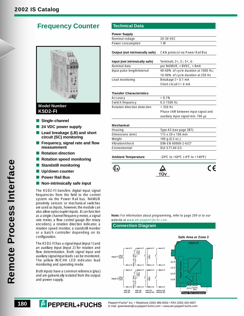
Frequency Counter
The KSD2-FI transfers digital input signalfrequencies from the field to the controlsystem via the Power Rail bus. NAMURproximity sensors or mechanical switchesare used as inputs, however, the module canalso allow optocoupler inputs. It can functionas a single channel frequency meter, a signalrate meter, a flow control gauge (for rotaryencoders), a rotation direction indicator, arotation speed monitor, a standstill monitoror a batch controller depending on itsconfiguration.
The KSD2-FI has a signal input (input 1) andan auxiliary input (input 2) for rotation andflow determination. Both signal input andauxiliary signal input leads can be monitored.The yellow IN/CHK LED indicates leadmonitoring and operating mode.
Both inputs have a common reference (plus)and are galvanically isolated from the outputand power supply.
Single-channel
24 VDC power supply
Lead breakage (LB) and shortcircuit (SC) monitoring
Frequency, signal rate and flowmeasurement
Rotation direction
Rotation speed monitoring
Standstill monitoring
Up/down counter
Power Rail Bus
Non-intrinsically safe input
KSD2-FI
TUV

181
Technical Data
Connection Diagram
Model Number
2002 IS CatalogR
em
ote
Pro
cess In
terfa
ce
Pepperl+Fuchs® Inc. • Telephone (330) 486-0002 • FAX (330) 425-4607E-mail: [email protected] • www.am.pepperl-fuchs.com
KSD2-BO-Ex
Safe Area or Div 2/Zone 2
Discrete OutputSolenoid Driver
The KSD2-BO-Ex supplies and switchesintrinsically safe solenoid valves in hazardousareas. A flashing red LED indicates leadbreakage or short circuited field circuits. Theoutput is galvanically isolated from the inputand the power supply.
Single channel
24 VDC supply voltage
Optional lead breakage (LB) andshort circuit (SC) monitoring
Power Rail Bus
Suitable for EEx ia IIC and Class I,Div 1, Groups A-G
Note: For information about programming, refer to page 209 or to ourwebsite at www.am.pepperl-fuchs.com
Power SupplyNominal voltage 20-30 VDCPower consumption 2.0 W
Input (not intrinsically safe) CAN protocol via Power Rail Bus
Output (intrinsically safe) Terminals 2-, 3+Current > 45 mAVoltage 23.8 V at 0 mA (open circuit)
12.5 V at 45 mASwitching frequency ≤ 10 HzLead monitoring Short circuit signal RB < 30 Ω
Lead breakage > 15 kΩ
Entity Parameters Terminals 2-, 3+FM Control Drawing No. 116-0150Voltage Voc 28.0 VCurrent Isc 110.0 mAExplosion group A&B C&E D, F&GMax. external capacitance (Ca) 0.1 µF 0.3 µF 0.8 µFMax. external inductance (La) 3.0 mH 9.0 mH 24.0 mH
MechanicalHousing Type A3 (see page 387)Dimensions (mm) 115 x 20 x 100 mmWeight 100 g (3.5 oz.)Vibration/shock DIN-EN 60068-2-6/27Environmental ISA-S71.04 G3
Ambient Temperature -20ºC to +60ºC (-4ºF to +140ºF)
Class I, Div 1, Group A-G,Zone 0, IIC

182
Technical Data
Connection Diagram
Model Number
2002 IS CatalogR
em
ote
Pro
cess
Inte
rface
Pepperl+Fuchs® Inc. • Telephone (330) 486-0002 • FAX (330) 425-4607E-mail: [email protected] • www.am.pepperl-fuchs.com
KSD2-BO-Ex2.2
Safe Area or Div 2/Zone 2
Discrete OutputSolenoid Driver
The KSD2-BO-Ex2.2 supplies andswitches the intrinsically safe solenoidvalves in hazardous areas. A flashingred LED indicates lead breakage or shortcircuited field circuits. The outputs aregalvanically isolated from the input and thepower supply.
Dual-channel
24 VDC supply voltage
Lead breakage (LB) and shortcircuit (SC) monitoring
Power Rail Bus
Suitable for EEx ia IIC andClass I, Div 1, Groups A-G
Note: For information about programming, refer to page 209 or to ourwebsite at www.am.pepperl-fuchs.com
Power SupplyNominal voltage 20-30 VDCPower consumption 2.8 W
Input (not intrinsically safe) CAN protocol via Power Rail Bus
Output (intrinsically safe)Output I Terminals 2-, 3+Output II Terminals 5-, 6+Current < 35 mAVoltage < 23.8 V at 0 mA (open circuit)
15 V at 35 mASwitching frequency ≤ 10 HzLead monitoring Short circuit signal RB < 30Ω
Lead breakage > 15 kΩ
Certificate of Conformity Peak ValuesCertificate number Zelm 00 ATEX0030U0 / I0 / P0 26 V / 110 mA / 715 mWAllowable circuit valuesIgnition protection method, cat. [EExia/ib]Explosion group IIC IIB IIAMax. external capacitance (Co) 0.099 µF 0.770 µF 2.600 µFMax. external inductance (Lo) 3 mH 12 mH 23 mH
MechanicalHousing Type A3 (see page 387)Dimensions (mm) 115 x 20 x 100 mmWeight / 100 g (3.5 oz.)Vibration/shock DIN-EN 60068-2-6/27Environmental ISA-S71.04 G3
Ambient Temperature -20ºC to +60ºC (-4ºF to +140ºF)
Class I, Div 1, Group A-G,Zone 0, IIC

183
Technical Data
Connection Diagram
Model Number
2002 IS CatalogR
em
ote
Pro
cess In
terfa
ce
Pepperl+Fuchs® Inc. • Telephone (330) 486-0002 • FAX (330) 425-4607E-mail: [email protected] • www.am.pepperl-fuchs.com
KSD2-RO-2
Safe Area or Zone 2
Relay OutputModule
The KSD2-RO-2 allows for switchingof two field devices. The output relaycontacts are galvanically isolated from eachother and from the input and power supply.
Dual-channel
Non-intrinsically safe output
Galvanic isolation of the relaycontacts from the input andpower circuits
24 VDC supply voltage
Power Rail Bus
Relay output suitable forgeneral circuts, control valvesor audible and visual alarms
Note: For information about programming, refer to page 209 or to ourwebsite at www.am.pepperl-fuchs.com
Power SupplyNominal voltage 20-30 VDCPower consumption 1 W
Input (not intrinsically safe) CAN protocol via Power Rail Bus
Output (not intrinsically safe)Output I Terminals 1, 2, 3Output II Terminals 4, 5, 6Contact load 250 VAC / 1 A / cosø > 0.7;
30 VDC / 2 A resistive loadMechanical life ≥ 106 OperationsEnergizing/de-energizing delay ≈ 10 ms / ≈ 10 ms
Transfer characteristicsSwitching frequency ≤ 10 Hz
MechanicalHousing Type A3 (see page 387)Dimensions (mm) 115 x 20 x 100 mmWeight 100 g (3.5 oz.)Vibration/shock DIN-EN 60068-2-6/27Environmental ISA-S71.04 G3
Ambient Temperature -20ºC to +60ºC (-4ºF to +140ºF)
TUV

184
Technical Data
Connection Diagram
Model Number
2002 IS CatalogR
em
ote
Pro
cess
Inte
rface
Pepperl+Fuchs® Inc. • Telephone (330) 486-0002 • FAX (330) 425-4607E-mail: [email protected] • www.am.pepperl-fuchs.com
KSD2-RO-Ex2
Safe Area or Div 2/Zone 2
Relay OutputModule
The KSD2-RO-Ex2 allows for switching oftwo intrinsically safe field devices in ahazardous area. The output relay contactsare galvanically isolated from each otherand from the input and power supply.
Dual-channel
Suitable for EEx ia IIC andClass I, Div 1, Groups A-G
Relay output also suitable forswitching general circuits
Galvanic isolation of the relaycontacts from the input and powercircuits
24 VDC supply voltage
Power Rail Bus
Note: For information about programming, refer to page 209 or to ourwebsite at www.am.pepperl-fuchs.com
Power SupplyNominal voltage 20-30 VDCPower consumption 1 W
Input (not intrinsically safe) CAN protocol via Power Rail Bus
Output (intrinsically safe)Output I Terminals 1, 2, 3Output II Terminals 4, 5, 6Contact load (hazardous area) 55 VContact load (safe area) 250 VAC / 1 A / cos ø > 0.7
30 VDC / 2 A resistive loadMechanical life ≥ 106 OperationsEnergizing/de-energizing delay ≈ 10 ms / ≈ 10 ms
Transfer characteristicsSwitching frequency ≤ 10 Hz
Entity Parameters Terminals 1, 2, 3; 4, 5, 6FM Control Drawing No. 116-0150Voltage-free contacts forconnection to I.S. circuits:Voltage Voc 0 VCurrent Isc 0 A
MechanicalHousing Type A3 (see page 387)Dimensions (mm) 115 x 20 x 100 mmWeight 100 g (3.5 oz.)Vibration/shock DIN-EN 60068-2-6/27Environmental ISA-S71.04 G3
Ambient Temperature -20ºC to +60ºC (-4ºF to +140ºF)
Class I, Div 1, Group A-G,Zone 0, IIC

185
Technical Data
Connection Diagram
Model Number
2002 IS CatalogR
em
ote
Pro
cess In
terfa
ce
Pepperl+Fuchs® Inc. • Telephone (330) 486-0002 • FAX (330) 425-4607E-mail: [email protected] • www.am.pepperl-fuchs.com
KSD2-CI-2
Analog InputTransmitterPower Supply
The KSD2-CI-2 is suitable for connecting2- or 3-wire transmitters. It can also beused as a repeater for 0/4-20 mA signalsfrom a current source. The transmitter issupplied with at least 15.0 V at 20 mA.The transmitter supply circuit (Terminals3+, 1- and 6+, 4-) is monitored for leadbreakage and short circuit.
2-wire transmitters are connected toterminals 3+, 2- and 6+, 5-. Terminal 2 or5 carries the input current signal.
3-wire transmitters are connected toterminals 3+, 2- and 1- or 6+, 5- and 4-.The transmitter is powered throughterminals 3+ and 1- or 6+ and 4-. Thesignal input is through terminal 2 or 5.
Current sources generating a currentsignal of 0/4-20 mA are connected toterminals 2+ and 1- or 5+ and 4-.Therefore, the current flows into the signalinput and is transferred to the output.
Dual-channel
24 VDC power supply
Lead breakage (LB) and shortcircuit (SC) monitoring
Four limit values per channel
Power Rail Bus
Non-intrinsically safe input
Safe Area or Zone 2
Note: For information about programming, refer to page 209 or to ourwebsite at www.am.pepperl-fuchs.com
Power SupplyNominal voltage 20-30 VDCPower consumption < 1.9 W
Output (not intrinsically safe) CAN protocol via Power Rail Bus
Input (not intrinsically safe) Terminals 1, 2, 3; 4, 5, 6Input signal 0/4-20 mAAvailable voltage at 20 mA > 15 VLead monitoring Breakage I ≤ 2 mA
Short circuit V < 4 V
Transfer characteristicsAccuracy 0.1% of the signal rangeTemperature drift 0.01% / ºC of the signal range
MechanicalHousing Type A3 (see page 387)Dimensions (mm) 115 x 20 x 100 mmWeight 100 g (3.5 oz.)Vibration/shock DIN-EN 60068-2-6/27Environmental ISA-S71.04 G3
Ambient Temperature -20ºC to +60ºC (-4ºF to +140ºF)
TUV

186
Technical Data
Connection Diagram
Model Number
2002 IS CatalogR
em
ote
Pro
cess
Inte
rface
Pepperl+Fuchs® Inc. • Telephone (330) 486-0002 • FAX (330) 425-4607E-mail: [email protected] • www.am.pepperl-fuchs.com
Safe Area or Div 2/Zone 2
Note: For information about programming, refer to pages 209 or to ourwebsite at www.am.pepperl-fuchs.com
Power SupplyNominal voltage 20-30 VDCPower consumption < 1.9 W
Output (not intrinsically safe) CAN protocol via Power Rail Bus
Input (intrinsically safe) Terminals 1, 2, 3; 4, 5, 6Input signal 0/4-20 mAAvailable voltage at 20 mA > 15 VLead monitoring Breakage I ≤ 2 mA
Short circuit U < 4 V
Transfer characteristicsAccuracy 0.1% of the signal rangeTemperature drift 0.01% / ºC of the signal range
Certificate of ConformityPeak valuesCertificate number PTB 00ATEX2010Uo/Io/Po 25.2 V / 93 mA / 585 mWAllowable circuit values ignitionProtection method category [EExia]Explosion group IIC IIBMax. external capacitance (Ca) 0.063 µF 0.390 µFMax. external inductance (La) 1 mH 2 mH
MechanicalHousing Type A3 (see page 387)Dimensions (mm) 115 x 20 x 100 mmWeight 100 g (3.5 oz.)Vibration/shock DIN-EN 60068-2-6/27Environmental ISA-S71.04 G3
Ambient Temperature -20ºC to +60ºC (-4ºF to +140ºF)
KSD2-CI-Ex2
Analog InputTransmitterPower Supply
The KSD2-CI-Ex2 is suitable forconnecting 2- or 3-wire transmitters. It canalso be used as a repeater for 0/4-20 mAsignals from a current source. Thetransmitter is supplied with at least 15 Vat 20 mA in hazardous areas. Thetransmitter supply circuit (Terminals 3+, 1-and 6+, 4-) is monitored for lead breakageand short circuit.
2-wire transmitters are connected toterminals 3+ and 2- or 6+ and 5-. The inputfor the signal current is terminal2 or 5.
3-wire transmitters are connected toterminals 3+, 2- and 1- or 6+, 5- and 4-.The transmitter is powered throughterminals 3+ and 1- or 6+ and 4-. Thesignal input is terminal 2 or 5.
Current sources generating a signalranging from 0/4-20 mA, are connectedto terminals 2+ and 1- or 5+ and 4-.Therefore, the current flows into the signalinput and is transferred to the output.
Dual-channel
Suitable for EEx ia IIC andClass I, Div 1, Groups A-G
24 VDC power supply
Lead breakage (LB) and shortcircuit (SC) monitoring
Four limit values per channel
Power Rail Bus
Class I, Div 1, Group A-G, Zone 0, IIC

187
Technical Data
Connection Diagram
Model Number
2002 IS CatalogR
em
ote
Pro
cess In
terfa
ce
Pepperl+Fuchs® Inc. • Telephone (330) 486-0002 • FAX (330) 425-4607E-mail: [email protected] • www.am.pepperl-fuchs.com
Analog InputSMART TransmitterPower Supply
KSD2-CI-S-Ex
Single-channel
24 VDC power supply
Optional lead breakage (LB) andshort circuit (SC) monitoring
Bidirectional transfer of SMARTsignals in the hazardous area
Power Rail Bus
Suitable for EEx ia IIC andClass I, Div. 1, Groups A-G
The KSD2-CI-S-Ex can connect 2- or3-wire transmitters. It can also be used asa repeater for 0/4-20 mA signals froma current source. The transmitter issupplied with at least 14.7 V at 20 mAin hazardous areas. Its supply circuit(terminals 3+, 1- ) is monitored for leadbreakage and short circuit.
2-wire transmitters are connected toterminals 3+ and 2-. The input for the signalcurrent is Terminal 2. The KSD2-CI-S-Ex hasscrew terminal blocks for connecting SMARTcommunicators. The KFD2-HMM-16 orKFD0-HMS-16 P+F HART Multiplexer canbe connected to terminals 11+ and 10-.
3-wire transmitters are connected toterminals 3+, 2-, and 1-. The transmitterpower is supplied through terminals 3+ and1-. The signal input is Terminal 2. Currentsources generating a 0/4-20 mA signal areconnected to terminals 2+ and 1-. Thecurrent then flows into the signal input andis transmitted to the safe area.
Current sources generating a 0/4-20 mAsignal are connected to terminals 2+ and 1-.Therefore, the current flows into the signalinput and can be transmitted to the safe area.
Safe Area or Div 2/Zone 2
Note: The KSD2-CI-S-Ex.H will replace the KSD2-CI-S-ExFor information about programming, refer to page 209 or to our websiteat www.am.pepperl-fuchs.com
Power SupplyNominal voltage 20-30 VDCPower consumption < 1.3 W
Output (not intrinsically safe) CAN protocol via Power Rail Bus
Input (intrinsically safe) Terminals 1, 2, 3Input signal 0/4-20 mAAvailable voltage at 20 mA > 14.7 VLead monitoring Breakage I ≤ 50 µΑ
Short circuit I > 25 mA
Transfer characteristicsAccuracy 0.1% of the output rangeTemperature drift 0.01% / ºC of the output range
Entity Parameters Terminals 2-, 3+FM Control Drawing No. 116-0150Voltage Voc 26.1 VCurrent Isc 92.0 mAExplosion group A&B C&E D, F&GMax. external capacitance (Ca) 0.17 µF 0.50 µF 1.35 µFMax. external inductance (La) 4.33 mH 17.3 mH 35.4 mH
MechanicalHousing Type A3 (see page 387)Dimensions (mm) 115 x 20 x 100 mmWeight 100 g (3.5 oz.)Vibration/shock DIN-EN 60068-2-6/27Environmental ISA-S71.04 G3
Ambient Temperature -20ºC to +60ºC (-4ºF to +140ºF)
Class I, Div 1, Group A-G, Zone 0, IIC

188
Technical Data
Connection Diagram
Model Number
2002 IS CatalogR
em
ote
Pro
cess
Inte
rface
Pepperl+Fuchs® Inc. • Telephone (330) 486-0002 • FAX (330) 425-4607E-mail: [email protected] • www.am.pepperl-fuchs.com
Safe Area or Zone 2
Power SupplyNominal voltage 20-30 VDCPower consumption < 1.3 W
Output (not intrinsically safe) CAN protocol via Power Rail Bus
Input (not intrinsically safe) Terminals 1, 2, 3Input signal 0/4-20 mAAvailable voltage at 20 mA > 14.7 VInput resistance (terminals 1, 2) ≈ 105 ΩLead monitoring Breakage I ≤ 50 µΑ
Short circuit I > 25 mA
Transfer characteristicsAccuracy 0.1% of the output rangeTemperature drift 0.01% / K of the output range
MechanicalHousing Type A4 (see page 387)Dimensions (mm) 115 x 20 x 107mmWeight 100 g (3.5 oz.)Vibration/shock DIN-EN 60068-2-6/27Environmental ISA-S71.04 G3
Ambient Temperature -20ºC to +60ºC (-4ºF to +140ºF)
Note: The KSD2-CI-S.H will replace the KSD2-CI-SFor information about programming, refer to page 209 or to our websiteat www.am.pepperl-fuchs.com
KSD2-CI-S
The KSD2-CI-S is suitable for connecting 2-or 3-wire transmitters. It can also be usedas a repeater for 0/4-20 mA signals from acurrent source. The transmitter is suppliedwith at least 14.7 V at 20 mA. Its supply circuit(Terminals 3+, 1- ) is monitored for leadbreakage and short circuit.
2-wire transmitters are connected toterminals 3+ and 2-. The input for the signalcurrent is Terminal 2. The KSD2-CI-S comeswith KF-STP-GN screw terminal blocks,which have 2.3 mm jacks for the connectionof SMART communicators. The KFD2-HMM-16 or KFD0-HMS-16 P+F HARTMultiplexer can be connected to terminals11+ and 10-.
3-wire transmitters are connected toterminals 3+, 2-, and 1-. The transmitterpower is supplied through terminals 3+ and1-. The signal input is Terminal 2.
Current sources generating a 0/4-20 mAsignal are connected to terminals 2+ and 1-.Therefore, the current flows into the signalinput and can be transmitted to the safe area.
Single-channel
24 VDC power supply
Optional lead breakage (LB) andshort circuit (SC) monitoring
Four limit values
Power Rail Bus
Bidirectional transfer ofSMART signals
Non-intrinsically safe input
Analog InputSMART TransmitterPower Supply
TUV

189
Technical Data
Connection Diagram
Model Number
2002 IS CatalogR
em
ote
Pro
cess In
terfa
ce
Pepperl+Fuchs® Inc. • Telephone (330) 486-0002 • FAX (330) 425-4607E-mail: [email protected] • www.am.pepperl-fuchs.com
The KSD2-CI-S-Ex.H is suitable for connecting2- or 3-wire transmitters. It can be used as arepeater for 0/4-20 mA signals from a currentsource. The transmitter is supplied with at least14.7 V at 20 mA in hazardous areas. Its supplycircuit (Terminals 3+, 1- ) is monitored for leadbreakage and short circuit.
2-wire transmitters are connected toterminals 3+ and 2-. The input for the signalcurrent is Terminal 2. The KSD2-CI-S-Ex.Hcomes with KF-STP-GN screw terminal blocks,which have 2.3 mm jacks for the connectionof HART communicators. A handheld terminalcan be connected to terminals 11+ and 10-.
3-wire transmitters are connected toterminals 3+, 2-, and 1-. The transmitter poweris supplied through terminals 3+ and 1-. Thesignal input is Terminal 2.
Current sources generating a 0/4-20 mAsignal are connected to terminals 2+ and1-. The current, therefore, flows into the signalinput and can be transmitted to the safe area.
Single-channel
Used in conjunction with HARTControl module KSD2-HC
24 VDC power supply
Lead breakage (LB) and shortcircuit (SC) monitoring
Transfer of HART signals fromPower Rail bus or handheldterminal to hazardous areas
Power Rail Bus
Suitable for EEx ia IIC andClass I, Div 1, Groups A-G
Analog InputHART TransmitterPower Supply
KSD2-CI-S-Ex.H
Safe Area or Div 2/Zone 2
Note: The KSD2-CI-S-Ex.H will replace the KSD2-CI-S-Ex.For information about programming, refer to pages 209 or to ourwebsite at www.am.pepperl-fuchs.com
Power Supply Power RailNominal voltage 20-30 VDCPower consumption < 1.3 W
Output (not intrinsically safe) CAN protocol via Power Rail Bus
Input (intrinsically safe) Terminals 1, 2, 3Input signal 0/4-20 mAAvailable voltage at 20 mA > 14.7 VInput resistance (terminals 1, 2) ≈ 105 ΩLead monitoring Breakage I ≤ 50 µΑ
Short circuit I > 25 mA
Transfer characteristicsAccuracy 0.1% of the input signal rangeTemperature drift 0.01% / ºC of the input signal range
Entity Parameters Terminals 2-, 3+FM Control Drawing No. 116-0150Voltage Voc 26.1 VCurrent Isc 92.0 mAExplosion group A&B C&E D, F & GMax. external capacitance (Ca) 0.17 µF 0.50 µF 1.35 µFMax. external inductance (La) 4.33 mH 17.3 mH 35.4 mH
MechanicalHousing Type A4 (see page 387)Dimensions (mm) 115 x 20 x 107mmWeight 100 g (3.5 oz.)Vibration/shock DIN-EN 60068-2-6/27Environmental ISA-S71.04 G3
Ambient Temperature -20ºC to +60ºC (-4ºF to +140ºF)
Class I, Div 1, Group A-G, Zone 0, IIC

190
Technical Data
Connection Diagram
Model Number
2002 IS CatalogR
em
ote
Pro
cess
Inte
rface
Pepperl+Fuchs® Inc. • Telephone (330) 486-0002 • FAX (330) 425-4607E-mail: [email protected] • www.am.pepperl-fuchs.com
Safe Area or Zone 2
Note: The KSD2-CI-S-H will replace the KSD2-CI-SFor information about programming, refer to page 209 or to our websiteat www.am.pepperl-fuchs.com
Power Supply Power RailNominal voltage 20-30 VDCPower consumption < 1.3 W
Output (not intrinsically safe) CAN protocol via Power Rail Bus
Input (not intrinsically safe) Terminals 1, 2, 3Input signal 0/4-20 mAAvailable voltage at 20 mA > 14.7 VInput resistance (terminals 1, 2) ≈105 ΩLead monitoring Breakage I ≤ 50 µΑ
Short circuit I > 25 mA
Transfer characteristicsAccuracy 0.1% of the input signal rangeTemperature drift 0.01% / ºC of the input signal range
MechanicalHousing Type A4 (see page 387)Dimensions (mm) 115 x 20 x 107mmWeight 100 g (3.5 oz.)Vibration/shock DIN-EN 60068-2-6/27Environmental ISA-S71.04 G3
Ambient Temperature -20ºC to +60ºC (-4ºF to +140ºF)
KSD2-CI-S-H
The KSD2-CI-S-H is suitable forconnecting 2- or 3-wire transmitters. It canbe used as a repeater for 0/4-20 mAsignals from a current source. Thetransmitter is supplied with at least 14.7 Vat 20 mA. Its supply circuit (Terminals 3+,1- ) is monitored for lead breakage andshort circuit.
2-wire transmitters are connected toterminals 3+ and 2-. The input for the signalcurrent is Terminal 2. The KSD2-CI-S-H hasKF-STP-GN terminal blocks, which have2.3 mm jacks for the connection of HARTcommunicators. A handheld terminal canbe connected to terminals 11+ and 10-.
3-wire transmitters are connected toterminals 3+, 2-, and 1-. The transmitterpower is supplied through terminals 3+and 1-. The signal input is Terminal 2.
Current sources generating a 0/4-20 mAsignal are connected to terminals 2+ and1-. The current therefore, flows into thesignal input and can be transmitted to thesafe area.
Single-channel
24 VDC power supply
Lead breakage (LB) and shortcircuit (SC) monitoring
Transfer of HART signals fromPower Rail bus or handheldterminal
Power Rail Bus
Used in conjunction with HARTControl module KSD2-HC
Non-intrinsically safe input
Analog InputSMART TransmitterPower Supply
TUV

191
Technical Data
Connection Diagram
Model Number
2002 IS CatalogR
em
ote
Pro
cess In
terfa
ce
Pepperl+Fuchs® Inc. • Telephone (330) 486-0002 • FAX (330) 425-4607E-mail: [email protected] • www.am.pepperl-fuchs.com
KSD2-TI
Single-channel
24 VDC power supply
Optional lead breakage (LB) orshort circuit (SC) monitoring
Connection of 2, 3 or 4-wire(Pt100 or Ni100) RTDs
Connection of types B, E, J, K,L, N, R, S or T thermocouples
Cold junction compensation
Connection of resistancerepeaters, mV-transmitters
Four limit values
Power Rail Bus
Non-intrinsically safe input
UniversalTemperatureConverter
The KSD2-TI is designed for the connectionof temperature measuring sensors. Itlinearizes the output signals of resistancethermometers and thermocouples, andtransmits the measured value to the PLC orDCS. It can be configured via the internalPower Rail bus. Burn-out detection isindicated by a flashing red LED and reportedvia the bus. When used with a resistancethermometer the device can be configuredfor 2-, 3- or 4-wire connections. Whenused with a thermocouple, cold junctioncompensation can be implementedexternally or with the K-CJC terminal blockwith built-in cold junction compensation. Allparameter and configuration data aretransmitted via the bus.
NOTE: The cold junction terminal block foruse with thermocouples, K-CJC must bepurchased separately.
Safe Area or Zone 2
Note: For additional certifications and entity parameters, refer to page397. For information about programming, refer to page 209 or to ourwebsite at www.am.pepperl-fuchs.com
Power SupplyNominal voltage 20-30 VDCPower consumption < 1.5 W
Output (not intrinsically safe) CAN protocol vial Power Rail Bus
Input (not intrinsically safe) Terminals 1, 2, 3, 6Max. lead resistor < 50 Ω per lead
Calibrated AccuracyPt 100, Nc100 ± 0.15ºCThermocouple (exc. Type B) ± 1.5ºCThermocouple (Type B) ± 3.5ºC (range ≤ 600ºC)
± 4.5ºC (entire range)Resistive, mV ± 0.1% of range
Temperature InfluencePt100, Nc100 ± (0.0015% of measured value
+ 0.006% of range) / ºCThermocouple ± (0.2ºC + 0.004% of measured value
+ 0.006% of range) / ºCResistive, mV ± 0.01% of range / ºC
MechanicalHousing Type A4 (see page 387)Dimensions (mm) 115 x 20 x 107 mmWeight 100 g (3.5 oz.)Vibration/shock DIN-EN 60068-2-6/27Environmental ISA-S71.04 G3
Ambient Temperature -20ºC to +60ºC (-4ºF to +140ºF)
TUV

192
Technical Data
Connection Diagram
Model Number
2002 IS CatalogR
em
ote
Pro
cess
Inte
rface
Pepperl+Fuchs® Inc. • Telephone (330) 486-0002 • FAX (330) 425-4607E-mail: [email protected] • www.am.pepperl-fuchs.com
Safe Area or Div 2/Zone 2
Note: For additional certifications and entity parameters, refer to page397. For information about programming, refer to page 209 or to ourwebsite at www.am.pepperl-fuchs.com
Power SupplyNominal voltage 20-30 VDCPower consumption < 1.5 W
Output (not intrinsically safe) CAN protocol vial Power Rail Bus
Input (intrinsically safe) Terminals 1, 2, 3, 6Max. lead resistance < 50Ω per lead
Calibrated AccuracyPt 100, Nc100 ± 0.15ºCThermocouple (exc. Type B) ± 1.5ºCThermocouple (Type B) ± 3.5ºC (range ≤ 600ºC)
± 4.5ºC (entire range)Resistive, mV ± 0.1% of range
Temperature InfluencePt100, Nc100 ± (0.0015% of measured value
+ 0.006% of range) / ºCThermocouple ± (0.2ºC + 0.004% of measured value
+ 0.006% of range) / ºCResistive, mV ± 0.01% of range / ºC
MechanicalHousing Type A4 (see page 387)Dimensions (mm) 115 x 20 x 107 mmWeight 100 g (3.5 oz.)Vibration/shock DIN-EN 60068-2-6/27Environmental ISA-S71.04 G3
Ambient Temperature -20ºC to +60ºC (-4ºF to +140ºF)
KSD2-TI-Ex
The KSD2-TI-Ex allows connection ofRTDs and thermocouples. It linearizes RTDand thermocouple output signals andtransmits the measured value to the PLCor DCS. It is configured via the internalPower Rail bus. Burn-out detection isindicated by a flashing red LED andreported via the bus. The unit can beconfigured for 2, 3, or 4-wire connectionwhen used with an RTD. When usedwith a thermocouple, cold junctioncompensation is implemented externally orusing the K-CJC terminal block with built-incold junction compensation. All parameterand configuration data is transmittedvia the bus.
NOTE: The cold junction terminal block foruse with thermocouples, K-CJC must bepurchased separately.
Single-channel
24 VDC power supply
Optional lead breakage (LB) andshort circuit (SC) monitoring
Connection of 2, 3 or 4-wire(PT100 or Ni100) RTDs
Connection of types B, E, J, K,L, N, R, S or T thermocouples
Cold junction compensation
Connection of resistancerepeaters or mV-transmitters
Adjustable linearizationthrough software
Power Rail Bus
Suitable for EEx ia IIC andClass I, Div 1, Groups A-G
UniversalTemperatureConverter
Class I, Div 1, Group A-G, Zone 0, IIC

193
Technical Data
Connection Diagram
Model Number
2002 IS CatalogR
em
ote
Pro
cess In
terfa
ce
Pepperl+Fuchs® Inc. • Telephone (330) 486-0002 • FAX (330) 425-4607E-mail: [email protected] • www.am.pepperl-fuchs.com
KSD2-PT2-Ex1
Single-channel
24 VDC power supply
Power Rail Bus
3-way isolation
Suitable for EEx ia IIC Class I,Div 1, Groups A-G
PotentiometerInput
Safe Area or Div 2
KSD2-PT2-EX1
4 5
321
Power SupplyNominal voltage 20-30 VDCPower consumption < 1.9 W
Output (not intrinsically safe) CAN protocol via Power Rail Bus
Input (not intrinsically safe) Terminals 1+, 2+, 3+, 4-, 5-Potentiometer resistance ≥ 800 ΩVoltage across potentiometer ≈ 4.7 VLead resistance ≤ 50 Ω at pot. resistance ≤ 1 kΩ
5% of pot. value ≥ 1 kΩ (customer)
Transfer CharacteristicsAccuracy 0.15% of output signal rangeTemperature drift 0.06% / ºC output signal range
Entity ParametersCSA Control Drawing No. 116-0149Voltage Voc 10.6 VCurrent Isc 31.7 mAExplosion Group A & B C & E D, F & GMax. external capacitance (Ca) 2.6 µF 7.8 µF 20.8 µFMax. external inductance (La) 34 mH 121 mH 291 mH
MechanicalHousing Type B3 (see page 387)Dimensions 100 x 40 x 115 mmWeight 220 g (7.7 oz.)Vibration/shock DIN-EN 60068-2-6/27Environmental ISA-S71.04 G3
Ambient Temperature -20ºC to +60ºC (-4ºF to +140ºF)
The KSD2-PT2-Ex1 is a single-channel,galvanically isolated intrinsic safety barrierwhich provides the source voltage to apotentiometer and transfers its wiper positionfrom hazardous areas to safe areas.
This unit can be used in a 3-, 4- or 5-wireconfiguration depending on the requiredmeasurement accuracy. Terminals 2and 5 are used as the sense line forthe potentiometer lead resistancecompensation in a 5-wire configuration. Ajumper must be used between terminals 4and 5 in 4-wire connections. Terminals 4, 5,1 and 2 must use jumpers in 3-wireconfigurations.
The barrier’s potentiometer can be used tocompensate for lead resistances up to 5%of the hazardous area potentiometer value,for potentiometer resistances greater than 1kΩ. The barrier’s potentiometer can also beused to compensate for a 50 Ω leadresistance for potentiometer values between800 Ω and 1000 Ω.
Class I, Div 1, Group A-G, Zone 0, IIC

194
Technical Data
Connection Diagram
Model Number
2002 IS CatalogR
em
ote
Pro
cess
Inte
rface
Pepperl+Fuchs® Inc. • Telephone (330) 486-0002 • FAX (330) 425-4607E-mail: [email protected] • www.am.pepperl-fuchs.com
KSD2-CO
Note: The KSD2-CO-S-H will replace the KSD2-COFor information about programming, refer to page 209 or to our websiteat www.am.pepperl-fuchs.com
Safe Area or Zone 2
Single-channel
24 VDC power supply
Optional lead breakage (LB) andshort circuit (SC) monitoring
Four limit values
Power Rail Bus
Non-intrinsically safe input
The KSD2-CO transmits a 0/4-20 mAcurrent signal. Loads between 30-750 Ω canbe connected. The output is galvanicallyisolated from the bus and power supply. Theoutput circuit is monitored for lead breakageand short circuit conditions.
Power SupplyNominal voltage 20-30 VDCPower consumption 1.3 W
Input (not intrinsically safe) CAN protocol via Power Rail Bus
Output (not intrinsically safe) Terminals 2-, 3+Current 0/4-20 mALoad 30-750ΩRipple < 0.25%Lead monitoring Breakage, load > 820Ω
Short circuit, load < 30Ω
Transfer CharacteristicsAccuracy 0.1% of output rangeTemperature drift 0.01% / ºC output range
MechanicalHousing Type A3 (see page 387)Dimensions 115 x 20 x 100 mmWeight 100 g (3.5 oz.)Vibration/shock DIN-EN 60068-2-6/27Environmental ISA-S71.04 G3
Ambient Temperature -20ºC to +60ºC (-4ºF to +140ºF)
Analog Output
TUV

195
Technical Data
Connection Diagram
Model Number
2002 IS CatalogR
em
ote
Pro
cess In
terfa
ce
Pepperl+Fuchs® Inc. • Telephone (330) 486-0002 • FAX (330) 425-4607E-mail: [email protected] • www.am.pepperl-fuchs.com
KSD2-CO-Ex
Analog Output
Single-channel
Suitable for EEx ia IIC andClass I, Div 1, Groups A-G
24 VDC power supply
Optional lead breakage (LB)and short circuit (SC) monitoring
Four limit values
Power Rail Bus
The KSD2-CO-Ex transmits a 0/4-20 mAcurrent signal to hazardous areas. Loadsbetween 30-750Ω can be connected. Theoutput is galvanically isolated from the busand power supply. The output circuit ismonitored for lead breakage and shortcircuit conditions.
Safe Area or Div 2/Zone 2
Note: The KSD2-CO-S-Ex.H will replace the KSD2-CO-ExFor information about programming, refer to page 209 or to our websiteat www.am.pepperl-fuchs.com
Power SupplyNominal voltage 20-30 VDCPower consumption 1.3 W
Input (not intrinsically safe) CAN protocol via Power Rail Bus
Output (intrinsically safe) Terminals 2-, 3+Current 0/4-20 mALoad 30-750ΩRipple < 0.25%Lead monitoring Breakage, load > 820Ω
Short circuit, load < 30Ω
Transfer CharacteristicsAccuracy 0.1% of output rangeTemperature drift 0.01% / ºC output range
Entity Parameters Terminals 2-, 3+FM Control Drawing No. 116-0150Voltage Voc 24.8 VCurrent Isc 92.0 mAExplosion group A&B C&E D, F&GMax. external capacitance (Ca) 0.19 µF 0.57 µF 1.54 µFMax. external inductance (La) 4.30 mH 17.2 mH 35.20 mH
MechanicalHousing Type A3 (see page 387)Dimensions 115 x 20 x 100 mmWeight 100 g (3.5 oz.)Vibration/shock DIN-EN 60068-2-6/27Environmental ISA-S71.04 G3
Ambient Temperature -20ºC to +60ºC (-4ºF to +140ºF)
Class I, Div 1, Group A-G,Zone 0, IIC

196
Technical Data
Connection Diagram
Model Number
2002 IS CatalogR
em
ote
Pro
cess
Inte
rface
Pepperl+Fuchs® Inc. • Telephone (330) 486-0002 • FAX (330) 425-4607E-mail: [email protected] • www.am.pepperl-fuchs.com
Safe Area or Div 2/Zone 2
Power SupplyNominal voltage 20-30 VDCPower consumption 1.3 W
Input (not intrinsically safe) CAN protocol via Power Rail Bus
Output (intrinsically safe) Terminals 2-, 3+Current 0/4-20 mALoad 30-750ΩRipple < 0.25%Lead breakage (LB) monitoring Breakage, load > 820Ω
Short circuit, load < 30Ω
Transfer CharacteristicsAccuracy 0.1% of output rangeTemperature drift 0.01% / ºC output range
Entity Parameters Terminals 2-, 3+FM Control Drawing No. 116-0150Voltage Voc 24.8 VCurrent Isc 92.0 mAExplosion group A&B C&E D, F&GMax. external capacitance (Ca) 0.19 µF 0.57 µF 1.54 µFMax. external inductance (La) 4.30 mH 17.20 mH 35.20 mH
MechanicalHousing Type A4 (see page 387)Dimensions 115 x 20 x 107 mmWeight 100 g (3.5 oz.)Vibration/shock DIN-EN 60068-2-6/27Environmental ISA-S71.04 G3
Ambient Temperature -20ºC to +60ºC (-4ºF to +140ºF)
Note: The KSD2-CO-S-Ex.H will replace the KSD2-CO-S-Ex.For information about programming, refer to pages 209 or to ourwebsite at www.am.pepperl-fuchs.com
KSD2-CO-S-Ex
SMARTAnalog Output
Single-channel
24 VDC power supply
Optional lead breakage (LB)and short circuit (SC) monitoring
Four limit values
Bidirectional transfer of SMARTsignals in hazardous areas
Power Rail Bus
Suitable for EEx ia IIC andClass I, Div 1, Groups A-G
The KSD2-CO-S-Ex transmits a 0/4-20 mAcurrent signal to hazardous areas. Loadsbetween 30-750 Ohm can be connected.The output is galvanically isolated from thebus and power supply. The output circuit(terminals 3+, 2-) is monitored for leadbreakage and short circuit.
This device allows the bidirectional transferof digital signals between hazardous andsafe areas on the 4-20 mA current signalof SMART positioners and control valves.The digital signals are available at terminalblocks on the safe area side of the module.
The KSD2-CO-S-Ex is supplied withKF-STP-GN screw terminal blocksincluding 2.3 mm plug connectors forconnection of HART communicators.
The KFD2-HMM-16 or KFD0-HMS-16HART multiplexer can be connected toterminals 11+ and 10-.
Class I, Div 1, Group A-G,Zone 0, IIC

197
Technical Data
Connection Diagram
Model Number
2002 IS CatalogR
em
ote
Pro
cess In
terfa
ce
Pepperl+Fuchs® Inc. • Telephone (330) 486-0002 • FAX (330) 425-4607E-mail: [email protected] • www.am.pepperl-fuchs.com
KSD2-CO-S
SMARTAnalog Output
Single-channel
24 VDC power supply
Optional lead breakage (LB) andshort circuit (SC) monitoring
Four limit values
Power Rail Bus
Non-intrinsically safe input
The KSD2-CO-S transmits a 0/4-20 mAcurrent signal. Loads between 30-750 Ohmcan be connected. The output is galvanicallyisolated from the bus and power supply. Theoutput circuit (terminals 3+, 2-) is monitoredfor lead breakage and short circuit.
This device allows the bidirectional transferof digital signals on the 4-20 mA currentsignal of SMART positioners and controlvalves. The digital signals are available atterminal blocks 10 and 11.
The KSD2-CO-S is supplied withKF-STP-GN screw terminal blocks including2.3 mm plug connectors for connection ofHART communicators.
The KFD2-HMM-16 or KFD0-HMS-16HART multiplexer can be connected toterminals 11+ and 10-.
Safe Area or Zone 2
Note: The KSD2-CO-S.H will replace the KSD2-CO-SFor information about programming, refer to page 209 or to our websiteat www.am.pepperl-fuchs.com
Power SupplyNominal voltage 20-30 VDCPower consumption 1.3 W
Input (not intrinsically safe) CAN protocol via Power Rail Bus
Output (not intrinsically safe) Terminals 2-, 3+Current 0/4-20 mALoad 30-750 ΩRipple < 0.25%Lead breakage (LB) monitoring Breakage, load > 820 Ω
Short circuit, load < 30 Ω
Transfer CharacteristicsAccuracy 0.1% of output rangeTemperature drift 0.01% / ºC output range
MechanicalHousing Type A4 (see page 387)Dimensions 115 x 20 x 107 mmWeight 100 g (3.5 oz.)Vibration/shock DIN-EN 60068-2-6/27Environmental ISA-S71.04 G3
Ambient Temperature -20ºC to +60ºC (-4ºF to +140ºF)
TUV

198
Technical Data
Connection Diagram
Model Number
2002 IS CatalogR
em
ote
Pro
cess
Inte
rface
Pepperl+Fuchs® Inc. • Telephone (330) 486-0002 • FAX (330) 425-4607E-mail: [email protected] • www.am.pepperl-fuchs.com
KSD2-CO-S-Ex.H
HARTAnalog Output
Safe Area or Div 2/Zone 2
Single-channel
Use in conjunction with HARTcontrol module KSD2-HC
24 VDC power supply
Optional lead breakage (LB)and short circuit (SC) monitoring
HART signal transmission viaPower Rail bus or handheldterminal in hazardous areas
Power Rail Bus
Suitable for EEx ia IIC andClass I, Div 1, Groups A-G
The KSD2-CO-S-Ex.H transfers a 0/4-20 mAcurrent signal to hazardous areas. Loadsof up to 30-750Ω can be connected. Theoutput is galvanically isolated from the busand the power supply.
The output circuit is monitored for leadbreakage (LB) and short circuit (SC)conditions. This unit allows monitoring andprogramming of positioners that supportthe HART protocol.
The KSD2-CO-S-Ex.H comes standardwith KF-STP-GN device terminals. Theseterminals have 2.3 mm jacks forconnecting HART communicators. Ahandheld terminal can be connected toterminals 11+ and 10-.
Note: The KSD2-CO-S-Ex.H will replace the KSD2-CO-S-Ex and theKSD2-CO-Ex. For information about programming, refer to page 209or to our website at www.am.pepperl-fuchs.com
Power SupplyNominal voltage 20-30 VDCPower consumption 1.3 W
Input (not intrinsically safe) CAN protocol via Power Rail Bus
Output (intrinsically safe) Terminals 2-, 3+Current 0/4-20 mALoad 30-750 ΩRipple < 0.25%Lead breakage (LB) monitoring Breakage, load < 3.6mA
Short circuit, load < 30 Ω
Certificate of Conformity Peak ValuesCertificate number Zelm 00ATEX0013U0 / I0 / P0 24.2 V / 91 mA / 547 mW
Allowable circuit values Ignitionprotection method, cat. [EExia]Explosion group IIC IIBMax. external capacitance (Co) 0.0425 µF 0.230 µFMax. external inductance (Lo) 1 mH 10 mH
Transfer CharacteristicsAccuracy 0.1% of output rangeTemperature drift 0.01% / ºC output range
MechanicalHousing Type A4 (see page 387)Dimensions 115 x 20 x 107 mmWeight 100 g (3.5 oz.)Vibration/shock DIN-EN 60068-2-6/27Environmental ISA-S71.04 G3
Ambient Temperature -20ºC to +60ºC (-4ºF to +140ºF)
Class I, Div 1, Group A-G,Zone 0, IIC

199
Technical Data
Connection Diagram
Model Number
2002 IS CatalogR
em
ote
Pro
cess In
terfa
ce
Pepperl+Fuchs® Inc. • Telephone (330) 486-0002 • FAX (330) 425-4607E-mail: [email protected] • www.am.pepperl-fuchs.com
HARTAnalog Output
KSD2-CO-S-H
Single-channel
Use in conjunction with HARTcontrol module KSD2-HC
24 VDC power supply
Optional lead breakage (LB)and short circuit (SC) monitoring
HART signal transmission viaPower Rail or handheld terminalin hazardous areas
Power Rail Bus
Non-intrinsically safe input
The KSD2-CO-S-H transfers a 0/4-20 mAcurrent signal. Loads of up to 30-750Wcan be connected. The output is galvanicallyisolated from the bus and the power supply.
The output circuit is monitored for leadbreakage (LB) and short circuit (SC)conditions. This unit allows monitoring andprogramming of positioners that supportthe HART protocol.
The KSD2-CO-S-H comes standard withKF-STP-GN device terminals. Theseterminals have 2.3 mm jacks for connectingHART communicators. A handheldterminal can be connected to terminals11+ and 10-.
Safe Area or Zone 2
Power Supply Power RailNominal voltage 20-30 VDCPower consumption 1.3 W
Input CAN protocol via Power Rail Bus
Output (intrinsically safe) Terminals 2-, 3+Current 0/4-20 mALoad 30-750 ΩRipple < 0.25%Lead breakage (LB) monitoring Breakage, load < 3.6mA
Short circuit, load < 30 Ω
Transfer CharacteristicsAccuracy 0.1% of output rangeTemperature drift 0.01% / ºC output range
MechanicalHousing Type A4 (see page 387)Dimensions 115 x 20 x 107 mmWeight 100 g (3.5 oz.)Vibration/shock DIN-EN 60068-2-6/27Environmental ISA-S71.04 G3
Ambient Temperature -20ºC to +60ºC (-4ºF to +140ºF)
Note: The KSD2-CO-S-H will replace the KSD2-CO-S and the KSD2-CO. For information about programming, refer to page 209 or to ourwebsite at www.am.pepperl-fuchs.com
TUV

200
Technical Data
Connection Diagram
Model Number
2002 IS CatalogR
em
ote
Pro
cess
Inte
rface
Pepperl+Fuchs® Inc. • Telephone (330) 486-0002 • FAX (330) 425-4607E-mail: [email protected] • www.am.pepperl-fuchs.com
Safe Area or Zone 2
Power Supply Power RailNominal voltage 20-30 VDCPower consumption 1.2 W
External connection KFD2-HMM-16 Master connectedwith 14 pin flat cable
Internal communication CAN protocol via Power Rail bus
MechanicalHousing Type A3 (see page 387)Dimensions 115 x 20 x 100 mmWeight 100 g (3.5 oz.)Vibration/shock DIN-EN 60068-2-6/27Environmental ISA-S71.04 G3
Ambient Temperature -20ºC to +60ºC (-4ºF to +140ºF)
For information about programming, refer to pages 209 or to our websiteat www.am.pepperl-fuchs.com
HARTControl Module
KSD2-HC
HART communication control ofup to 250 field devices
Reduced wiring for connectingKFD2-HMM-16 HART multiplexers
24 VDC power supply
Power Rail Bus
14 pin flat cable for connectingKFD2-HMM-16 HART multiplexers
HART communication is used to configure,program and monitor field devices, sensorsand actuators. The KFD2-HC HART controlmodule and KFD2-HMM-16 HARTmultiplexer allow data transmission throughHART communication, independent of theFieldbus.
The KSD2-HC HART control module andKFD2-HMM-16 HART multiplexer snaponto the Power Rail and are connectedwith a 14 pin flat cable. Up to 250 fielddevices can be connected through HARTcommunication to RPI’s KSD2-CI-S-Ex.Hor KSD2-CI-S-H transmitter power suppliesand KSD2-CO-S-Ex.H or KSD2-CO-S-Hanalog SMART outputs.
The HART multiplexer’s RS 485 interfaceallows PC connection and the use ofsoftware such as AMS (Fisher-Rosemount), Cornerstone (Astec) orPACTware (see HART multiplexer datasheet). RS 485 interfaces and RPIGateways can be connected. The samePC can be used to operate the RPI userinterface and PACTware or HART software.
TUV

201
Technical Data
Connection Diagram
Model Number
2002 IS CatalogR
em
ote
Pro
cess In
terfa
ce
Pepperl+Fuchs® Inc. • Telephone (330) 486-0002 • FAX (330) 425-4607E-mail: [email protected] • www.am.pepperl-fuchs.com
PROFIBUSGateway
KSD2-GW-PRO
Connects the Remote ProcessInterface with a PLC/DCS orPC via PROFIBUS-DP
Couples the internal CAN Busto the external PROFIBUS
Master function for the internalCAN Bus
External bus: PROFIBUS-DP
External baud rate up to 1.5 MBd
Separate RS 232 connectionon the front panel
24 VDC power supply
External bus redundancy with asecond Gateway
Power Rail bus
The KSD2-GW-PRO Gateway translatesthe protocols of the internal CAN Bus intothe PROFIBUS-DP protocol of the externalbus system and vice versa. Up to 125 I/Omodules can be connected to a Gatewayvia the Power Rail.
A separate RS 232 jack located on thefront panel is used for configuration andsystem monitoring. This jack is wired inparallel to a set of screw terminals to allowa hard-wired connection.
Safe Area or Div 2/Zone 2
Note: For information about programming, refer to page 209 or to ourwebsite at www.am.pepperl-fuchs.com
Power SupplyNominal voltage 20-30 VDCPower consumption 2.8 W
External Bus PROFIBUS per DIN 19 245Section 1, 2 and 3
Internal communication CAN protocol via Power Rail Bus withup to 125 I/O modules connected
Cycle time, internal bus 1 I/O 25 ms125 I/O w/discrete input 60 ms125 I/O w/discrete output 90 ms125 I/O w/analog input 75 ms125 I/O w/analog output 110 ms
MechanicalHousing Type B2 (see page 387)Dimensions 115 x 20 x 100 mmWeight 200 g (7.0 oz.)Vibration/shock DIN-EN 60068-2-6/27Environmental ISA-S71.04 G3
Ambient Temperature -20ºC to +60ºC (-4ºF to +140ºF)

202
Technical Data
Connection Diagram
Model Number
2002 IS CatalogR
em
ote
Pro
cess
Inte
rface
Pepperl+Fuchs® Inc. • Telephone (330) 486-0002 • FAX (330) 425-4607E-mail: [email protected] • www.am.pepperl-fuchs.com
Safe Area or Div 2/Zone 2
Note: For information about programming, refer to page 209 or to ourwebsite at www.am.pepperl-fuchs.com
Power SupplyNominal voltage 20-30 VDCPower consumption 2.8 W
External Bus PROFIBUS per DIN 19 245 Section 1, 2 and 3
Internal communication CAN protocol via Power Rail Bus with upto 125 I/O modules connected
Cycle time, internal bus 1 I/O 25 ms125 I/O w/discrete input 60 ms125 I/O w/discrete output 90 ms125 I/O w/analog input 75 ms125 I/O w/analog output 110 ms
MechanicalHousing Type B2 (see page 387)Dimensions 115 x 20 x 100 mmWeight 200 g (7.0 oz.)Vibration/shock DIN-EN 60068-2-6/27Environmental ISA-S71.04 G3
Ambient Temperature -20ºC to +60ºC (-4ºF to +140ºF)
PROFIBUSGateway
KSD2-GW-PRO.485
Connects the Remote ProcessInterface with a PLC/DCS orPC via PROFIBUS-DP
Couples the internal CAN Busto the external PROFIBUS
Master function for the internalCAN Bus
External bus: PROFIBUS-DP
External baud rate up to 1.5 MBd
24 VDC power supply
External bus redundancy with asecond Gateway
Power Rail bus
The KSD2-GW-PRO.485 translates theprotocol of the internal CAN Bus into thePROFIBUS-DP protocol of the externalbus system and vice versa. Up to 125I/O modules can be connected to aGateway across the Power Rail.
The Gateways of multiple RPI segmentscan be continuously networked with oneof the control system’s service levels overthe RS 485 program interface, independentof the PROFIBUS connection. The operatorhas access to the configuration data, theparameters of al l the connectedGateways and RPI devices by means ofa PC and RPI software.

203
Technical Data
Connection Diagram
Model Number
2002 IS CatalogR
em
ote
Pro
cess In
terfa
ce
Pepperl+Fuchs® Inc. • Telephone (330) 486-0002 • FAX (330) 425-4607E-mail: [email protected] • www.am.pepperl-fuchs.com
KSD2-GW-MOD
Connects the Remote ProcessInterface with a PLC/DCS or PCvia MODBUS
Couples the internal CAN Busto the external MODBUS
Master function for the internalCAN Bus
External bus: MODBUS SectionRTU (Remote Terminal Unit)
External baud rate up to 57.6 kBd
Separate RS 232 connection onthe front panel
24 VDC power supply
External bus redundancy with asecond Gateway
Power Rail bus
The KSD2-GW-MOD translates theprotocol of the internal CAN Bus into theMODBUS RTU protocol of the externalbus system and vice versa. Up to 125devices can be connected to a Gatewayvia the Power Rail.
A separate RS 232 jack located on thefront panel is used for configuration andsystem monitoring. This jack is wired inparallel to a set of screw terminals to allowa hard-wired connection.
MODBUSGateway
Safe Area or Div 2/Zone 2
Note: For information about programming, refer to page 209 or to ourwebsite at www.am.pepperl-fuchs.com
Power SupplyNominal voltage 20-30 VDCPower consumption 2.4 W
External Bus MODBUS Section RTUInterface RS 485
Internal communication CAN protocol via Power Rail Bus withup to 125 I/O modules connected
Cycle time, internal bus 1 I/O 25 ms125 I/O w/discrete input 60 ms125 I/O w/discrete output 90 ms125 I/O w/analog input 75 ms125 I/O w/analog output 110 ms
MechanicalHousing Type B2 (see page 387)Dimensions 115 x 20 x 100 mmWeight 200 g (7.0 oz.)Vibration/shock DIN-EN 60068-2-6/27Environmental ISA-S71.04 G3
Ambient Temperature -20ºC to +60ºC (-4ºF to +140ºF)

204
Technical Data
Connection Diagram
Model Number
2002 IS CatalogR
em
ote
Pro
cess
Inte
rface
Pepperl+Fuchs® Inc. • Telephone (330) 486-0002 • FAX (330) 425-4607E-mail: [email protected] • www.am.pepperl-fuchs.com
Safe Area or Div 2/Zone 2
Power SupplyNominal voltage 20-30 VDCPower consumption 2.4 W
External Bus MODBUS Section RTUInterface RS 485
Internal communication CAN protocol via Power Rail Bus withup to 125 I/O modules connected
Cycle time, internal bus 1 I/O 25 ms125 I/O w/discrete input 60 ms125 I/O w/discrete output 90 ms125 I/O w/analog input 75 ms125 I/O w/analog output 110 ms
MechanicalHousing Type B2 (see page 387)Dimensions 115 x 20 x 100 mmWeight 200 g (7.0 oz.)Vibration/shock DIN-EN 60068-2-6/27Environmental ISA-S71.04 G3
Ambient Temperature -20ºC to +60ºC (-4ºF to +140ºF)
Note: For information about programming, refer to page 209 or to ourwebsite at www.am.pepperl-fuchs.com
KSD2-GW-MOD.485
Connects the Remote ProcessInterface with a PLC/DCS or PCvia MODBUS
Couples the internal CAN Busto the external MODBUS
Master function for the internalCAN Bus
External bus: MODBUS sectionRTU (Remote Terminal Unit)
External baud rate up to 57.6 kBd
24 VDC power supply
External bus redundancy with asecond Gateway
The KSD2-GW-MOD.485 translates theCAN Bus protocols into the MODBUS RTUprotocol of the external bus system and viceversa. Up to 125 devices can be connectedto a Gateway across the Power Rail.
The Gateways of multiple RPI segments canbe continuously networked with one of thecontrol system’s service levels over the RS485 program interface independent of theMODBUS RTU. The operator has accessto the configuration data and parametersfor all connected Gateways and RPI devices.This is accomplished by means of a PCand the RPI software.
MODBUSGateway

205
Technical Data
Connection Diagram
Model Number
2002 IS CatalogR
em
ote
Pro
cess In
terfa
ce
Pepperl+Fuchs® Inc. • Telephone (330) 486-0002 • FAX (330) 425-4607E-mail: [email protected] • www.am.pepperl-fuchs.com
KSD2-GW-CN
Connects the Remote ProcessInterface with a PLC/DCS orPC via ControlNet
Couples the internal CAN Busto the external ControlNet
Master function for the internalCAN Bus
External bus: ControlNet
External baud rate up to 5 MBd
Separate RS 232 connectionon the front panel
24 VDC power supply
External bus redundancy witha second Gateway
Power Rail bus
The KSD2-GW-CN translates the internalCAN Bus protocol into the ControlNet pro-tocol of the external bus system and viceversa. Up to 125 I/O modules can be con-nected to a Gateway across the Power Rail.
A separate RS 232 jack located on the frontpanel is used for configuration and systemmonitoring. This jack is wired in parallel witha set of screw terminals to allow a hard-wired connection.
ControlNetGateway
Safe Area or Div 2/Zone 2
Note: For information about programming, refer to page 209 or to ourwebsite at www.am.pepperl-fuchs.com
Power SupplyNominal voltage 20-30 VDCPower consumption 3.6 W
External BusConnection BNC A, B
NAPInterface ControlNet
Internal communication CAN protocol via Power Rail Bus withup to 125 I/O modules connected
Cycle time, internal bus 1 I/O 25 ms125 I/O w/discrete input 60 ms125 I/O w/discrete output 90 ms125 I/O w/analog input 75 ms125 I/O w/analog output 110 ms
Programming InterfaceConnection Terminals 22, 23, 24 and 1 jackInterface RS 232
MechanicalHousing Type G (see page 387)DimensionsWeight 520 g (18.2 oz.)Vibration/shock DIN-EN 60068-2-6/27Environmental ISA-S71.04 G3
Ambient Temperature --20ºC to +60ºC (+4ºF to +140ºF)

206
Technical Data
Connection Diagram
Model Number
2002 IS CatalogR
em
ote
Pro
cess
Inte
rface
Pepperl+Fuchs® Inc. • Telephone (330) 486-0002 • FAX (330) 425-4607E-mail: [email protected] • www.am.pepperl-fuchs.com
Safe Area or Div 2/Zone 2
KSD2-GW-CN.485
Connects the Remote ProcessInterface with a PLC/DCS or aPC via ControlNet
Couples the internal CAN Busto the external ControlNet
Master function for the internalCAN Bus
External bus: ControlNet
External baud rate up to 5 MBd
24 VDC power supply
External bus redundancy with asecond Gateway
Power Rail bus
The KSD2-GW-CN.485 translates theinternal CAN Bus protocols into theControlNet protocol of the external bussystem and vice versa. Up to 125 I/Omodules can be connected to a Gatewayacross the Power Rail.
The Gateways of multiple RPI segmentscan be continuously networked to theservice level of a control system or PLCthrough the separate RS 485 programminginterface. A PC and the RPI user interfaceprovide the customer with access to theconfiguration data and parameters of allthe Gateways and connected RPI devices.
ControlNetGateway Power Supply
Nominal voltage 20-30 VDCPower consumption 3.6 W
External BusConnection BNC A, B
NAPInterface ControlNet
Internal Bus CAN protocol via Power Rail Bus withup to 125 I/O modules connected
Cycle time, internal bus 1 I/O 25 ms125 I/O w/discrete input 60 ms125 I/O w/discrete output 90 ms125 I/O w/analog input 75 ms125 I/O w/analog output 110 ms
Programming InterfaceConnection Terminals 22, 23, 24Interface RS 485
MechanicalHousing Type G (see page 387)DimensionsWeight 520 g (18.2 oz.)Vibration/shock DIN-EN 60068-2-6/27Environmental ISA-S71.04 G3
Ambient Temperature -20ºC to +60ºC (-4ºF to +140ºF)
Note: For information about programming, refer to page 209 or to ourwebsite at www.am.pepperl-fuchs.com

207
Technical Data
Connection Diagram
Model Number
2002 IS CatalogR
em
ote
Pro
cess In
terfa
ce
Pepperl+Fuchs® Inc. • Telephone (330) 486-0002 • FAX (330) 425-4607E-mail: [email protected] • www.am.pepperl-fuchs.com
Safe Area or Div 2/Zone 2
Power SupplyNominal voltage 20-30 VDCPower consumption 4.8 W
External BusConnection 9-pin Sub D connectorInterface Modbus Plus, RS 485 interface
Internal Bus CAN protocol via Power Rail Bus withup to 125 I/O modules connected
Cycle time, internal bus 1 I/O 25 ms125 I/O w/discrete input 60 ms125 I/O w/discrete output 90 ms125 I/O w/analog input 75 ms125 I/O w/analog output 110 ms
Programming InterfaceConnection Terminals 22, 23, 24 and 1 jackInterface RS 232
MechanicalHousing Type G (see page 387)DimensionsWeight 505 g (17.7 oz.)Vibration/shock DIN-EN 60068-2-6/27Environmental ISA-S71.04 G3
Ambient Temperature -20ºC to +60ºC (-4ºF to +140ºF)
Note: For information about programming, refer to page 209 or to ourwebsite at www.am.pepperl-fuchs.com
MODBUS PlusGateway
Connects the Remote ProcessInterface with a PLC/DCS orPC via MODBUS Plus
Couples the internal CAN Busto the external Modbus Plus
Master function for the internalCAN Bus
External bus: Modbus Plus
External baud rate up to 1 MBd
Separate RS 232 connectionon the front panel
External bus redundancy with asecond Gateway
Power Rail bus
The KSD2-GW-MPL translates the internalCAN Bus protocols into the Modbus Plusprotocol of the external bus system andvice versa. Up to 125 I/O modules can beconnected to a Gateway across thePower Rail.
A separate RS 232 jack located on the frontpanel is used for configuration and systemmonitoring. This jack is wired in parallelwith a set of screw terminals to allow ahard-wired connection.
KSD2-GW-MPL

208
Technical Data
Connection Diagram
Model Number
2002 IS CatalogR
em
ote
Pro
cess
Inte
rface
Pepperl+Fuchs® Inc. • Telephone (330) 486-0002 • FAX (330) 425-4607E-mail: [email protected] • www.am.pepperl-fuchs.com
Safe Area or Div 2/Zone 2
Power SupplyNominal voltage 20-30 VDCPower consumption 4.8 W
External BusConnection 9-pin Sub D connectorInterface Modbus Plus, RS 485 interface
Internal Bus CAN protocol via Power Rail Bus withup to 125 I/O modules connected
Cycle time, internal bus 1 I/O Device 25 ms125 I/O w/discrete input 60 ms125 I/O w/discrete output 90 ms125 I/O w/analog input 75 ms125 I/O w/analog output 110 ms
Programming InterfaceConnection Terminals 22, 23, 24Interface RS 485
MechanicalHousing Type G (see page 387)DimensionsWeight 505 g (17.7 oz.)
Ambient Temperature -20ºC to +60ºC (-4ºF to +140ºF)
Note: For information about programming, refer to page 209 or to ourwebsite at www.am.pepperl-fuchs.com
KSD2-GW-MPL.485
MODBUS PlusGateway
Connects the Remote ProcessInterface with a PLC/DCS or PCvia MODBUS Plus
Couples the internal CAN Busto the external Modbus Plus
Master function for the internalCAN Bus
External bus: Modbus Plus
External baud rate up to 1 MBd
Standard interface RS 485
24 VDC power supply
External bus redundancy with asecond Gateway
Power Rail bus
The KSD2-GW-MPL.485 translates theinternal CAN Bus protocols into theModbus Plus protocol of the external bussystem and vice versa. Up to 125 I/Omodules can be connected to a Gatewayacross the Power Rail.
The Gateways of multiple RPI segmentscan be continuously networked to the ser-vice level of a control system or PLCthrough the separate RS 485 programminginterface. A PC and the RPI user interfaceprovide the customer with access to theconfiguration data and parameters of allthe Gateways and connected RPI devices.

209
2002 IS CatalogR
em
ote
Pro
cess In
terfa
ce
Pepperl+Fuchs® Inc. • Telephone (330) 486-0002 • FAX (330) 425-4607E-mail: [email protected] • www.am.pepperl-fuchs.com
Configuration Software-PACTwareThe configuration software is used to plan, configure, program,document and monitor the Remote Process Interface (RPI). Itoffers access to all device and Gateway functions. It also allowsoff-line configuration and documentation by PC or laptopwithout having to be connected to the RPI system. When ready,the configuration can be downloaded into the RPI system fromthe PC or laptop via RS 232 or RS 485 interfaces. The KS-ADP2 (RS 232) and KS-ADP4 (RS 485) configuration cablesare used to connect the PC or laptop to the appropriateinterface. Configuration and documentation can be alsoperformed on-line with the PC or laptop connected directly tothe RPI system.
Configuration software features include:
Documentation- Comments saved in PC memory- Device information on individual I/Os
Lead breakage and short circuit monitoring
Malfunction output value- User defined- Minimum- Maximum- Hold last value
Simulation of- Measurement values- Device diagnostics- Process channel diagnostics
Limits- Upper alarm limit- Upper warning limit- Lower warning limit- Lower alarm limit- Adjustable hysteresis
Start value and end value of measurement range- For determining overflow and under flow range- For configuring the analog value monitor of the control display
KS-MANE1 System ManualThe KS-MANE1 System Manual is the primary guide for theRPI system. It includes important information and suggestionsfor planning, installation, configuration, operation, diagnosticsand safety.
The configuration software requires a PC with an RS 232 orRS 485 interface, a minimum 80486 processor, 8 MB of RAM(16 MB suggested) and a 3.5-inch disk drive. It also requiresWindows 3.1, 3.11, Windows 95/98/2000 or Windows NToperating systems to run. The software comes with optionalEnglish and German language settings.


![BCP Setting Tool B-EX4 series Operation Manualbusiness.toshiba.com/downloads/KB/f1Ulds/14807/[TEC]B-EX... · 2016. 12. 2. · TOSHIBA Label Printer BCP Setting Tool B-EX4 series Operation](https://img.dokumen.tips/doc/110x75/60266cb14df64d2113386fc8/bcp-setting-tool-b-ex4-series-operation-tecb-ex-2016-12-2-toshiba-label.jpg)