Embed Size (px)
Citation preview

2001 IMPREZA SERVICE MANUAL QUICK REFERENCE INDEX
TRANSMISSION SECTION
This service manual has been preparedto provide SUBARU service personnelwith the necessary information and datafor the correct maintenance and repairof SUBARU vehicles.This manual includes the proceduresfor maintenance, disassembling, reas-sembling, inspection and adjustment ofcomponents and diagnostics for guid-ance of experienced mechanics.Please peruse and utilize this manualfully to ensure complete repair work forsatisfying our customers by keepingtheir vehicle in optimum condition.When replacement of parts duringrepair work is needed, be sure to useSUBARU genuine parts.
All information, illustration and specifi-cations contained in this manual arebased on the latest product informationavailable at the time of publicationapproval.
FUJI HEAVY INDUSTRIES LTD.
CONTROL SYSTEMS CS
AUTOMATIC TRANSMISSION AT
AUTOMATIC TRANSMISSION (DIAGNOSTICS)
AT
MANUAL TRANSMISSION AND DIFFERENTIAL
MT
CLUTCH SYSTEM CL
G1830GE4

AUTOMATIC TRANSMISSION
AT
Page1. General Description ....................................................................................22. Automatic Transmission Fluid .....................................................................93. Differential Gear Oil...................................................................................114. Road Test..................................................................................................125. Stall Test ...................................................................................................136. Time Lag Test ...........................................................................................157. Line Pressure Test ....................................................................................168. Transfer Clutch Pressure Test ..................................................................189. Automatic Transmission Assembly ...........................................................19
10. Transmission Mounting System ................................................................2511. Extension Case Oil Seal ...........................................................................2712. Inhibitor Switch..........................................................................................2813. Front Vehicle Speed Sensor .....................................................................3114. Rear Vehicle Speed Sensor......................................................................3415. Torque Converter Turbine Speed Sensor .................................................3516. Control Valve Body ...................................................................................3617. Shift Solenoids, Duty Solenoids and ATF Temperature Sensor ...............3818. ATF Filter ..................................................................................................4319. Transmission Control Module (TCM) ........................................................4420. ATF Cooler Pipe and Hose .......................................................................45
AUTOMATIC TRANSMISSIONGENERAL DESCRIPTION
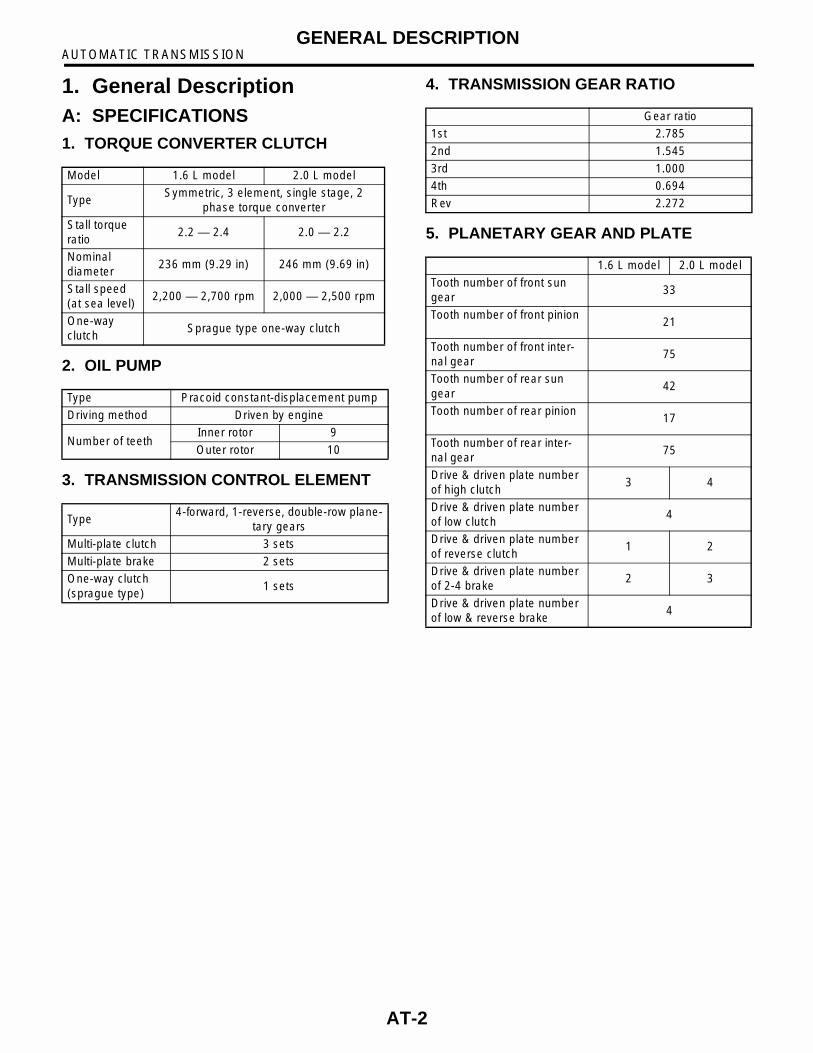
1. General DescriptionA: SPECIFICATIONS1. TORQUE CONVERTER CLUTCH
2. OIL PUMP
3. TRANSMISSION CONTROL ELEMENT
4. TRANSMISSION GEAR RATIO
5. PLANETARY GEAR AND PLATE
Model 1.6 L model 2.0 L model
TypeSymmetric, 3 element, single stage, 2
phase torque converter
Stall torque ratio
2.2 — 2.4 2.0 — 2.2
Nominal diameter
236 mm (9.29 in) 246 mm (9.69 in)
Stall speed (at sea level)
2,200 — 2,700 rpm 2,000 — 2,500 rpm
One-way clutch
Sprague type one-way clutch
Type Pracoid constant-displacement pump
Driving method Driven by engine
Number of teethInner rotor 9
Outer rotor 10
Type4-forward, 1-reverse, double-row plane-
tary gears
Multi-plate clutch 3 sets
Multi-plate brake 2 sets
One-way clutch (sprague type)
1 sets
Gear ratio
1st 2.785
2nd 1.545
3rd 1.000
4th 0.694
Rev 2.272
1.6 L model 2.0 L model
Tooth number of front sun gear
33
Tooth number of front pinion21
Tooth number of front inter-nal gear
75
Tooth number of rear sun gear
42
Tooth number of rear pinion17
Tooth number of rear inter-nal gear
75
Drive & driven plate number of high clutch
3 4
Drive & driven plate number of low clutch
4
Drive & driven plate number of reverse clutch
1 2
Drive & driven plate number of 2-4 brake
2 3
Drive & driven plate number of low & reverse brake
4
AT-2

AUTOMATIC TRANSMISSIONGENERAL DESCRIPTION
6. SELECTOR POSITION
7. HYDRAULIC CONTROL AND LUBRICA-TION
8. COOLING AND HARNESS
9. TRANSFER
10.FINAL REDUCTION
P (Park)Transmission in neutral, output member immov-
able, and engine start possible
R (Reverse)
Transmission in reverse for backing
N (Neu-tral)
Transmission in neutral and engine start possi-ble
D (Drive)Automatic gear change 1st ←
→ 2nd ←→ 3rd ←
→ 4th
3 (3rd)Automatic gear change 1st ←
→ 2nd ←→ 3rd ← 4th
2 (2nd)Automatic gear change 1st ←
→ 2nd ← 3rd ← 4th
1 (1st)1st gear locked (Deceleration possible 1st ←
2nd ← 3rd ← 4th)
Control method
Hydraulic remote control
Type
Electronic/hydraulic control [Four forward speed
changes by electrical signals of vehicle speed and accel-
erator (throttle) opening]
FluidDexron III type Automatic
transmission fluid
Fluid capac-ity
1.6 L model8.0 — 8.3 2 (8.5 — 8.8 US
qt, 7.0 — 7.3 Imp qt)
2.0 L model8.4 — 8.7 2 (8.9 — 9.2 US
qt, 7.4 — 7.7 Imp qt)
Lubrication systemForced feed lubrication with
oil pump
OilAutomatic transmission fluid
(above mentioned)
Model 1.6 L and 2.0 L models
Cooling systemLiquid-cooled cooler incorpo-
rated in radiator
ATF cooling system (Radi-ation capacity)
4.630 kW (3,981 kcal/h, 15,797 BTU/h)
Inhibitor switch 12 poles
Transmission harness 20 poles
Model 2.0 L model
Transfer clutch Hydraulic multi-plate clutch
Drive & driven plate number of transfer clutch
4
Control method Electronic, hydraulic type
LubricantThe same Automatic transmission fluid used in automatic transmis-
sion
1st reduction gear ratio 1.000 (53/53)
Model 1.6 L model 2.0 L model
Front final gear ratio 4.444 (40/9) 4.111 (37/9)
Lubrication oil
Front differential oil capacity 1.2 2 (1.3 US qt, 1.1 Imp qt)
H3M1235A
AT-3
AUTOMATIC TRANSMISSIONGENERAL DESCRIPTION
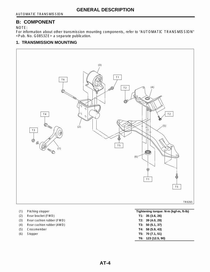
B: COMPONENTNOTE:For information about other transmission mounting components, refer to “AUTOMATIC TRANSMISSION”<Pub. No. G0853ZE> a separate publication.
1. TRANSMISSION MOUNTING
(1)
(2)
(3)
(4)
(5)
(6)
T4
T3
T5
T5
T2
T2
T1T6
T1
TR0265
(1) Pitching stopper Tightening torque: N·m (kgf-m, ft-lb)(2) Rear bracket (FWD) T1: 35 (3.6, 26)(3) Rear cushion rubber (FWD) T2: 39 (4.0, 29)(4) Rear cushion rubber (AWD) T3: 50 (5.1, 37)(5) Crossmember T4: 58 (5.9, 43)(6) Stopper T5: 70 (7.1, 51)
T6: 123 (12.5, 90)
AT-4
AUTOMATIC TRANSMISSIONGENERAL DESCRIPTION
C: CAUTION• Wear working clothing, including a cap, protec-tive goggles, and protective shoes during opera-tion.• Remove contamination including dirt and corro-sion before removal, installation, and disassembly.• Keep the disassembled parts in order and pro-tect them from dust or dirt. • Until the oil pan is removed, do not place with theoil pan side facing up to prevent foreign matter fromentering the valve body.• Before removal, installation or disassembly, besure to clarify the failure. Avoid unnecessary re-moval, installation, disassembly and replacement.• When disassembling the case and other light al-loy parts, use a plastic hammer to force it apart. Donot pry it apart with a screwdriver or other tool.• Be careful not to burn your hands, because eachpart on the vehicle is hot after running.
• Use SUBARU genuine gear oil, grease etc. orthe equivalent. Do not mix gear oil, grease etc. withthat of another grade or from other manufacturers.• Be sure to tighten fasteners including bolts andnuts to the specified torque.• Place shop jacks or safety stands at the specifiedpoints.• Apply gear oil onto sliding or revolution surfacesbefore installation.• Replace deformed or otherwise damaged snaprings with new ones.• Before installing O-rings or oil seals, apply suffi-cient amount of ATF fluid to avoid damage and de-formation.• Be careful not to incorrectly install or fail to installO-rings, snap rings and other such parts.• Before securing a part on a vice, place cushion-ing material such as wood blocks, aluminum plate,or shop cloth between the part and the vice.• Avoid damaging the mating surface of the case.• Before applying sealant, completely remove theold seal.
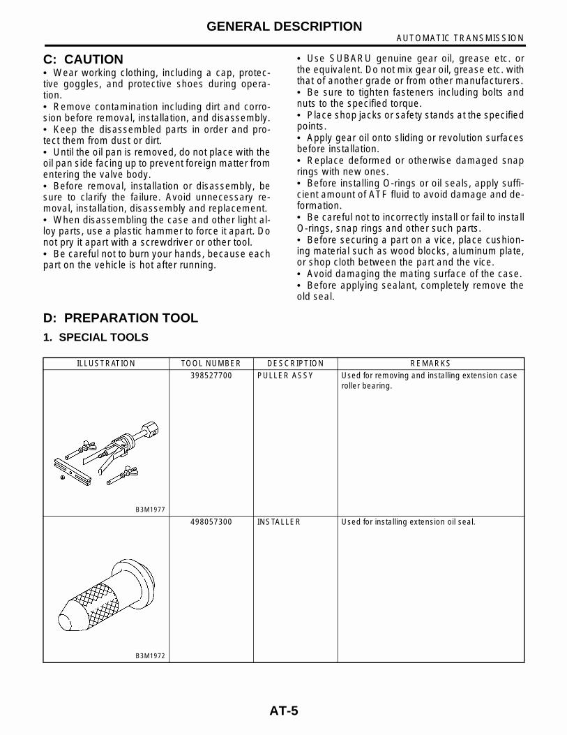
D: PREPARATION TOOL1. SPECIAL TOOLS
ILLUSTRATION TOOL NUMBER DESCRIPTION REMARKS
398527700 PULLER ASSY Used for removing and installing extension case roller bearing.
498057300 INSTALLER Used for installing extension oil seal.
B3M1977
B3M1972
AT-5
AUTOMATIC TRANSMISSIONGENERAL DESCRIPTION
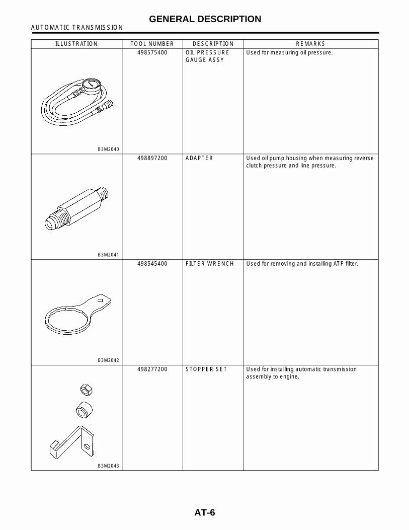
498575400 OIL PRESSURE GAUGE ASSY
Used for measuring oil pressure.
498897200 ADAPTER Used oil pump housing when measuring reverse clutch pressure and line pressure.
498545400 FILTER WRENCH Used for removing and installing ATF filter.
498277200 STOPPER SET Used for installing automatic transmission assembly to engine.
ILLUSTRATION TOOL NUMBER DESCRIPTION REMARKS
B3M2040
B3M2041
B3M2042
B3M2043
AT-6
AUTOMATIC TRANSMISSIONGENERAL DESCRIPTION
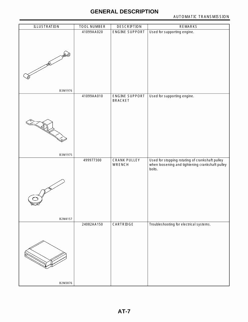
41099AA020 ENGINE SUPPORT Used for supporting engine.
41099AA010 ENGINE SUPPORT BRACKET
Used for supporting engine.
499977300 CRANK PULLEY WRENCH
Used for stopping rotating of crankshaft pulley when loosening and tightening crankshaft pulley bolts.
24082AA150 CARTRIDGE Troubleshooting for electrical systems.
ILLUSTRATION TOOL NUMBER DESCRIPTION REMARKS
B3M1976
B3M1975
B2M4157
B2M3876
AT-7
AUTOMATIC TRANSMISSIONGENERAL DESCRIPTION
2. GENERAL PURPOSE TOOLS
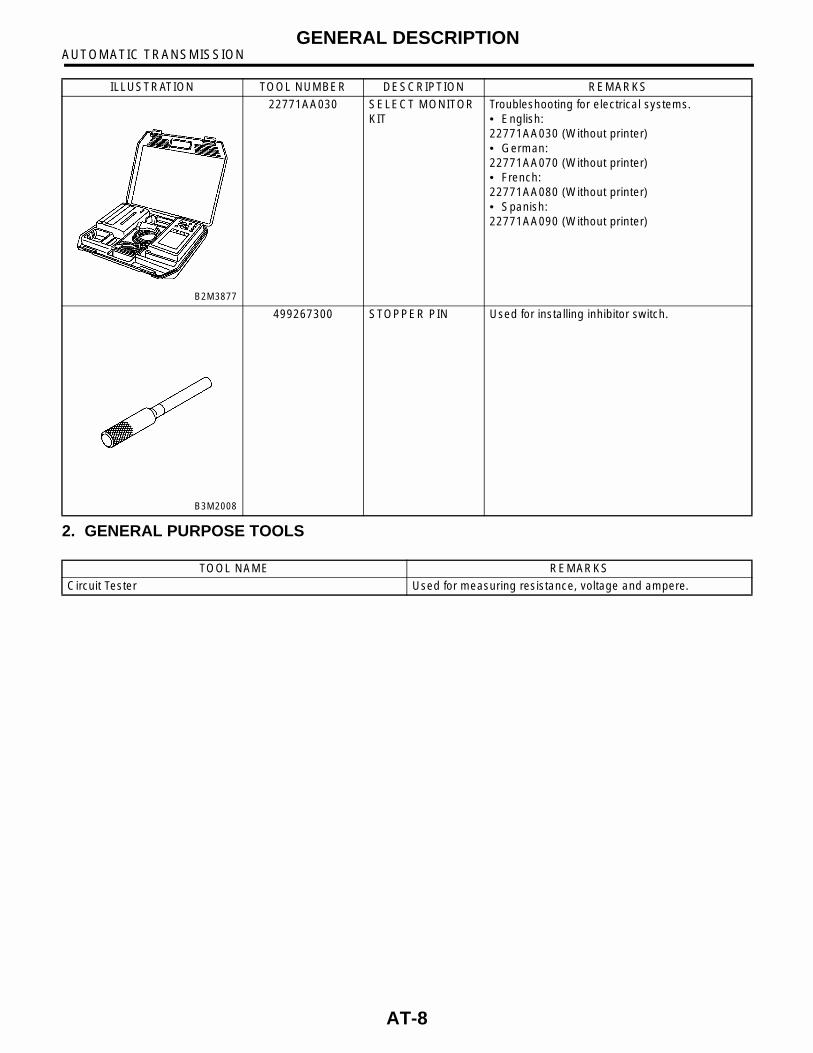
22771AA030 SELECT MONITOR KIT
Troubleshooting for electrical systems.• English:22771AA030 (Without printer)• German:22771AA070 (Without printer)• French:22771AA080 (Without printer)• Spanish:22771AA090 (Without printer)
499267300 STOPPER PIN Used for installing inhibitor switch.
ILLUSTRATION TOOL NUMBER DESCRIPTION REMARKS
B2M3877
B3M2008
TOOL NAME REMARKS
Circuit Tester Used for measuring resistance, voltage and ampere.
AT-8

AUTOMATIC TRANSMISSIONAUTOMATIC TRANSMISSION FLUID
2. Automatic Transmission Fluid
A: INSPECTION1) Check the level of the ATF.
(1) Raise ATF temperature to 60 to 80°C (140to 176°F) from 40 to 60°C (104 to 140°F) (whencold) by driving a distance of 5 to 10 km (3 to 6miles).
NOTE:The level of ATF varies with fluid temperature. Payattention to the fluid temperature when checking oillevel.
(2) Make sure the vehicle is level. After select-ing all positions (P, R, N, D, 3, 2, 1), set the se-lect leveler in “P” range. Measure fluid level withthe engine idling.
NOTE:After running, idle the engine for one or two min-utes before measurement.
(3) If the fluid level is below the center betweenupper and lower marks, add the recommendedATF until the fluid level is found within the spec-ified range (above the center between upperand lower marks). When the transmission is hot,the level should be above the center of upperand lower marks, and when it is cold, the levelshould be found below the center of these twomarks.
CAUTION:• Use care not to exceed the upper limit level.• ATF level varies with temperature. Remem-ber that the addition of fluid to the upper limitmark when the transmission is cold will resultin the overfilling of fluid.
(4) Fluid temperature rising speed• By idling the engineTime for temperature rise to 60°C (140°F) with at-mospheric temperature of 0°C (32°F): More than25 minutes<Reference>Time for temperature rise to 30°C (86°F) with atmo-spheric temperature of 0°C (32°F): Approx. 8 min-utes• By running the vehicleTime for temperature rise to 60°C (140°F) with at-mospheric temperature of 0°C (32°F): More than10 minutes
(5) Method for checking fluid level upon deliveryor at periodic inspectionCheck fluid level after a warm-up run of approx.10 minutes. During the warm-up period, the au-tomatic transmission functions can also bechecked.
2) Check the fluid for leaks.Check for leaks in the transmission. If there areleaks, it is necessary to repair or replace gasket, oilseals, plugs or other parts.
B: REPLACEMENT1) Lift-up the vehicle.2) Drain ATF completely.
CAUTION:Directly after the engine has been running, the ATF is hot. Be careful not to burn yourself.
NOTE:Tighten ATF drain plug after draining ATF.
Tightening torque:25 N·m (2.5 kgf-m, 18.1 ft-lb)
3) Lower the vehicle.4) Pour ATF into the oil charge pipe.
Recommended fluid:Dexron III type automatic transmission fluid
(A) ATF level gauge
(B) Upper level
(C) Lower level
B3M1020B
(A) Oil pan
(B) Drain plug
(C) Differential oil drain plug
B3M1036B
AT-9

AUTOMATIC TRANSMISSIONAUTOMATIC TRANSMISSION FLUID
Capacity:Fill the same amount of fluid drained from drain plug hole.
Capacity when transmission is overhauled:1.6 L model:
8.0 — 8.3 2 (8.5 — 8.8 US qt, 7.0 — 7.3 Imp qt)
2.0 L model:8.4 — 8.7 2 (8.9 — 9.2 US qt, 7.4 — 7.7 Imp qt)
5) Check the level and leaks of the ATF.<Ref. to AT-9, REPLACEMENT, Automatic Trans-mission Fluid.>
AT-10
AUTOMATIC TRANSMISSIONDIFFERENTIAL GEAR OIL
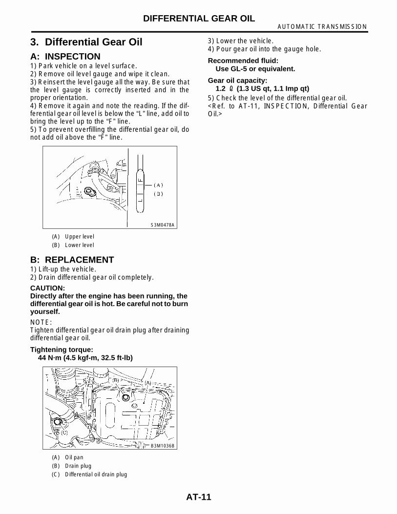
3. Differential Gear OilA: INSPECTION1) Park vehicle on a level surface.2) Remove oil level gauge and wipe it clean.3) Reinsert the level gauge all the way. Be sure thatthe level gauge is correctly inserted and in theproper orientation.4) Remove it again and note the reading. If the dif-ferential gear oil level is below the “L” line, add oil tobring the level up to the “F” line.5) To prevent overfilling the differential gear oil, donot add oil above the “F” line.
B: REPLACEMENT1) Lift-up the vehicle.2) Drain differential gear oil completely.
CAUTION:Directly after the engine has been running, the differential gear oil is hot. Be careful not to burn yourself.
NOTE:Tighten differential gear oil drain plug after drainingdifferential gear oil.
Tightening torque:44 N·m (4.5 kgf-m, 32.5 ft-lb)
3) Lower the vehicle.4) Pour gear oil into the gauge hole.
Recommended fluid:Use GL-5 or equivalent.
Gear oil capacity:1.2 2 (1.3 US qt, 1.1 Imp qt)
5) Check the level of the differential gear oil.<Ref. to AT-11, INSPECTION, Differential GearOil.>
(A) Upper level
(B) Lower level
(A) Oil pan
(B) Drain plug
(C) Differential oil drain plug
S3M0478A
B3M1036B
AT-11
AUTOMATIC TRANSMISSIONROAD TEST
4. Road TestA: INSPECTION1. GENERAL PRECAUTIONRoad tests should be conducted to properly diag-nose the condition of the automatic transmission.
CAUTION:When performing test, do not exceed posted speed limit.
2. D RANGE SHIFT FUNCTIONCheck shifting between 1st ⇔ 2nd ⇔ 3rd ⇔ 4thwhile driving on normal city streets.
3. D RANGE SHIFT SHOCKCheck the shock level when shifting up during nor-mal driving.
4. KICK-DOWN FUNCTIONCheck kick-down for each gear. Also check thekick-down shock level.
5. ENGINE BRAKE OPERATION• Check the 3rd gear engine brake when shiftingbetween D ⇔ 3rd range while driving in 4th gear ofD range [50 to 60 km/h (31 to 37 MPH)]. • Check the 2nd gear engine brake when shiftingbetween 3 ⇔ 2 range while driving in the 3 range3rd gear [40 to 50 km/h (25 to 31 MPH)].• Check the 1st gear engine brake when shiftingbetween 2 ⇔1 range while driving in the 2 range2nd gear [20 to 30 km/h ( 12 to 19 MPH)].
6. LOCK-UP FUNCTIONCheck that rpm does not change sharply when theaxle pedal is lightly depressed when driving on flatroads at normal speed in the lock-up range.
7. P RANGE OPERATIONStop the vehicle on an uphill grade of 5% or moreand shift to P range. Check that the vehicle doesnot move when the parking brake is released.
8. UNUSUAL SOUNDS AND VIBRATIONCheck for unusual sounds and vibration while driv-ing and during shifting.
9. CLIMBING CONTROL FUNCTION• Check that gear remains in 3rd when going up agrade.• Check that gear remains in 3rd when applyingthe brakes while going down a grade.
10.OIL LEAKSAfter the driving test, inspect for oil leaks.
AT-12
AUTOMATIC TRANSMISSIONSTALL TEST
5. Stall TestA: INSPECTION1. GENERAL INFORMATIONThe stall test is of extreme importance in diagnos-ing the condition of the automatic transmission andthe engine. It should be conducted to measure theengine stall speeds in R and 2 ranges.Purposes of the stall test:1) To check the operation of the automatic trans-mission clutch.2) To check the operation of the torque converterclutch.3) To check engine performance.
2. TEST METHODS1) Preparations before test:
(1) Check that throttle valve opens fully.(2) Check that engine oil level is correct.(3) Check that coolant level is correct.(4) Check that ATF level is correct.(5) Check that differential gear oil level is cor-rect.(6) Increase ATF temperature to 50 to 80°C(122 to 176°F) by idling the engine for approxi-mately 30 minutes (with select lever set to “N” or“P”).
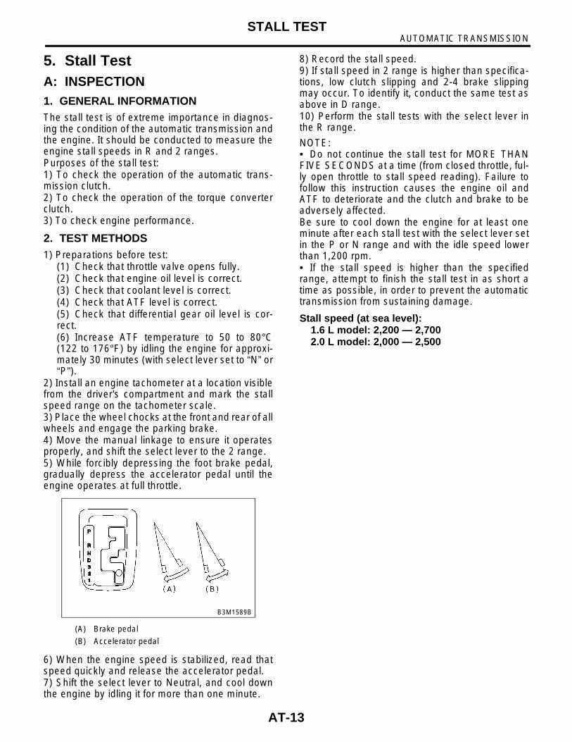
2) Install an engine tachometer at a location visiblefrom the driver's compartment and mark the stallspeed range on the tachometer scale.3) Place the wheel chocks at the front and rear of allwheels and engage the parking brake.4) Move the manual linkage to ensure it operatesproperly, and shift the select lever to the 2 range.5) While forcibly depressing the foot brake pedal,gradually depress the accelerator pedal until theengine operates at full throttle.
6) When the engine speed is stabilized, read thatspeed quickly and release the accelerator pedal.7) Shift the select lever to Neutral, and cool downthe engine by idling it for more than one minute.
8) Record the stall speed.9) If stall speed in 2 range is higher than specifica-tions, low clutch slipping and 2-4 brake slippingmay occur. To identify it, conduct the same test asabove in D range.10) Perform the stall tests with the select lever inthe R range.
NOTE:• Do not continue the stall test for MORE THANFIVE SECONDS at a time (from closed throttle, ful-ly open throttle to stall speed reading). Failure tofollow this instruction causes the engine oil andATF to deteriorate and the clutch and brake to beadversely affected.Be sure to cool down the engine for at least oneminute after each stall test with the select lever setin the P or N range and with the idle speed lowerthan 1,200 rpm.• If the stall speed is higher than the specifiedrange, attempt to finish the stall test in as short atime as possible, in order to prevent the automatictransmission from sustaining damage.
Stall speed (at sea level):1.6 L model: 2,200 — 2,7002.0 L model: 2,000 — 2,500
(A) Brake pedal
(B) Accelerator pedal
B3M1589B
AT-13
AUTOMATIC TRANSMISSIONSTALL TEST
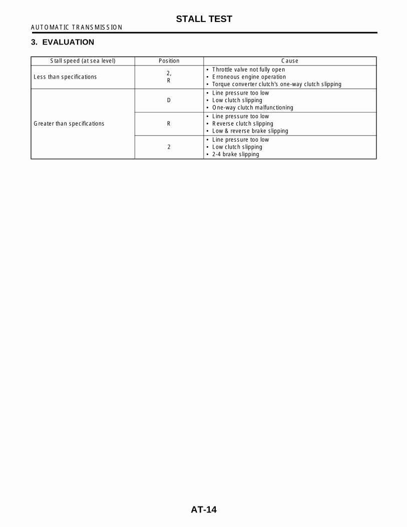
3. EVALUATION
Stall speed (at sea level) Position Cause
Less than specifications2,R
• Throttle valve not fully open• Erroneous engine operation • Torque converter clutch's one-way clutch slipping
Greater than specifications
D• Line pressure too low• Low clutch slipping• One-way clutch malfunctioning
R• Line pressure too low• Reverse clutch slipping• Low & reverse brake slipping
2• Line pressure too low• Low clutch slipping• 2-4 brake slipping
AT-14

AUTOMATIC TRANSMISSIONTIME LAG TEST
6. Time Lag TestA: INSPECTION1. GENERAL INFORMATIONIf the select lever is shifted while the engine isidling, there will be a certain time elapse or lag be-fore the shock can be felt. This is used for checkingthe condition of the low clutch, reverse clutch, low &reverse brake and one-way clutch.
CAUTION:• Perform the test at normal operation fluidtemperature 60 to 80°°°°C (140 to 176°°°°F).• Be sure to allow a one minute interval be-tween tests.• Make three measurements and take the aver-age value.
2. TEST METHODS1) Fully apply the parking brake.2) Start the engine.Check idling speed (A/C OFF). 3) Shift the select lever from “N” to “D” range.Using a stop watch, measure the time it takes fromshifting the lever until the shock is felt.
Time lag: Less than 1.2 seconds4) In same manner, measure the time lag for “N” →“R”.
Time lag: Less than 1.5 seconds
3. EVALUATION1) If “N” → “D” time lag is longer than specified:• Line pressure too low• Low clutch worn• One-way clutch not operating properly2) If “N” → “R” time lag is longer than specified:• Line pressure too low• Reverse clutch worn• Low & reverse brake worn
AT-15

AUTOMATIC TRANSMISSIONLINE PRESSURE TEST
7. Line Pressure TestA: MEASUREMENT1. GENERAL INFORMATIONIf the clutch or the brake shows a sign of slippage orshifting sensation is not correct, the line pressureshould be checked.• Excessive shocks during upshifting or shiftingtakes place at a higher point than under normal cir-cumstances, may be due to the line pressure beingtoo high.• Slippage or inability to operate the vehicle may,in most cases, be due to loss of oil pressure for theoperation of the clutch, brake or control valve.1) Line pressure measurement (under no load)
CAUTION:• Before measuring line pressure, jack-up allwheels.• Maintain temperature of ATF at approximate-ly 50°°°°C (122°°°°F) during measurement.(ATF will reach the above temperature afteridling the engine for approximately 30 minuteswith select lever in “N” or “P”.)2) Line pressure measurement (under heavy load)
CAUTION:• Before measuring line pressure, apply bothfoot and parking brakes with all wheelschocked (Same as for “stall” test conditions).• Measure line pressure when select lever is in“R”, “2” with engine under stall conditions.• Measure line pressure within 5 seconds aftershifting the select lever to each position. (If linepressure needs to be measured again, allow theengine to idle and then stop. Wait for at leastone minute before measurement.)• Maintain the temperature of ATF at approxi-mately 50°°°°C (122°°°°F) during measurement. (ATFwill reach the above temperature after idling theengine for approximately 30 minutes with theselect lever in “N” or “P”.)
2. TEST METHODS1) Temporarily attach the ST to a suitable place inthe driver's compartment, remove the blind plug lo-cated in front of the toe board and pass the hose ofthe ST to the engine compartment.ST 498575400 OIL PRESSURE GAUGE
ASSY
2) Remove the test plug and install ST instead.ST 498897200 OIL PRESSURE GAUGE
ADAPTER
3) Connect ST1 with ST2.ST1 498897200 OIL PRESSURE GAUGE
ADAPTERST2 498575400 OIL PRESSURE GAUGE
ASSY
(A) Pressure gauge hose
(B) Hole in toe board (blank cap hole)
(C) Brake pedal
(A) Test plug
B3M0568C
B3M1046C
AT-16

AUTOMATIC TRANSMISSIONLINE PRESSURE TEST
4) Check for duty ratio changes by opening andclosing throttle valve using Subaru Select Monitor.
(1) Insert the cartridge to Subaru Select Moni-tor. <Ref. to AT-5, PREPARATION TOOL, Gen-eral Description.>
(2) Connect Subaru Select Monitor to data linkconnector.
5) Check line pressure in accordance with the fol-lowing chart.
3. EVALUATION
Standard line pressure
Range posi-tion
Line pres-sure duty ratio (%)
Throttle position
Line pressurekPa (kg/cm2, psi)
2 5 Full open1,128 — 1,304 (11.5 — 13.3, 164 — 189)
R 5 Full open1,520 — 1,716(15.5 — 17.5, 220 — 249)
D 100 Full closed304 — 412
(3.1 — 4.2, 44 — 60)
S2M0286
AT-17
AUTOMATIC TRANSMISSIONTRANSFER CLUTCH PRESSURE TEST
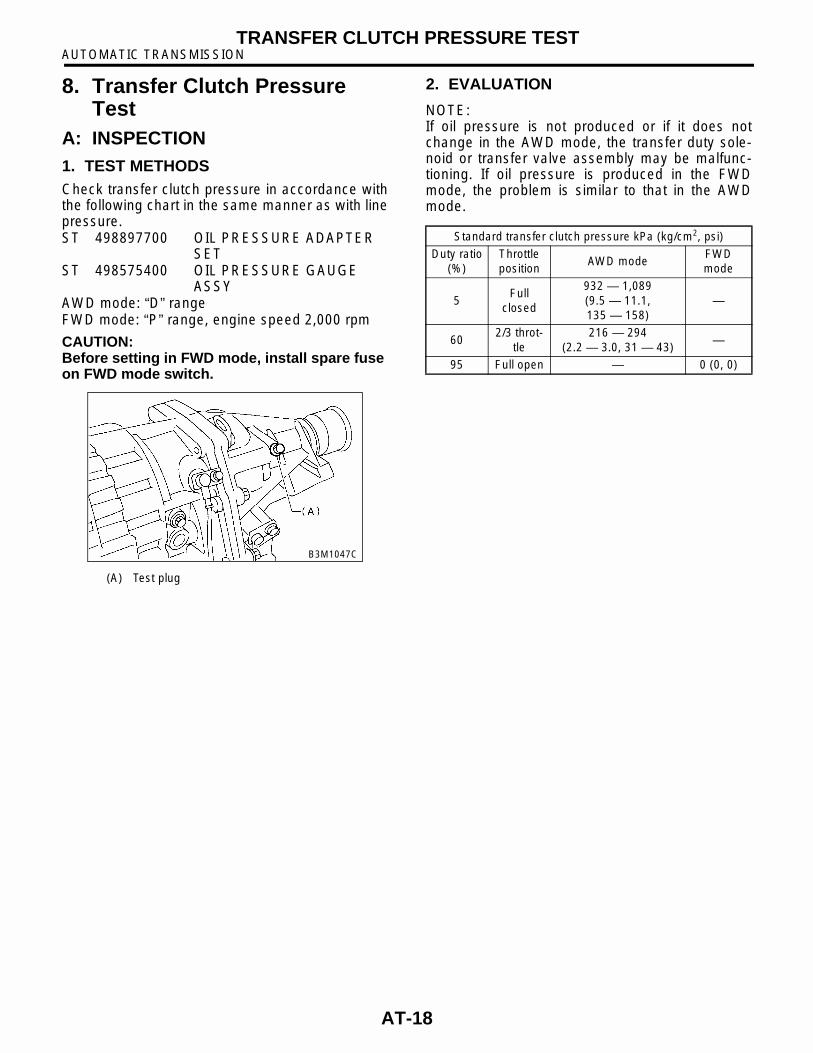
8. Transfer Clutch Pressure Test
A: INSPECTION1. TEST METHODSCheck transfer clutch pressure in accordance withthe following chart in the same manner as with linepressure.ST 498897700 OIL PRESSURE ADAPTER
SETST 498575400 OIL PRESSURE GAUGE
ASSYAWD mode: “D” rangeFWD mode: “P” range, engine speed 2,000 rpm
CAUTION:Before setting in FWD mode, install spare fuse on FWD mode switch.
2. EVALUATION
NOTE:If oil pressure is not produced or if it does notchange in the AWD mode, the transfer duty sole-noid or transfer valve assembly may be malfunc-tioning. If oil pressure is produced in the FWDmode, the problem is similar to that in the AWDmode.
(A) Test plug
B3M1047C
Standard transfer clutch pressure kPa (kg/cm2, psi)
Duty ratio(%)
Throttle position
AWD modeFWD mode
5Full
closed
932 — 1,089(9.5 — 11.1, 135 — 158)
—
602/3 throt-
tle216 — 294
(2.2 — 3.0, 31 — 43)—
95 Full open — 0 (0, 0)
AT-18
AUTOMATIC TRANSMISSIONAUTOMATIC TRANSMISSION ASSEMBLY
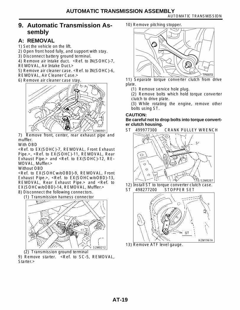
9. Automatic Transmission As-sembly
A: REMOVAL1) Set the vehicle on the lift.2) Open front hood fully, and support with stay.3) Disconnect battery ground terminal.4) Remove air intake duct. <Ref. to IN(SOHC)-7,REMOVAL, Air Intake Duct.>5) Remove air cleaner case. <Ref. to IN(SOHC)-6,REMOVAL, Air Cleaner Case.>6) Remove air cleaner case stay.
7) Remove front, center, rear exhaust pipe andmuffler.With OBD<Ref. to EX(SOHC)-7, REMOVAL, Front ExhaustPipe.>, <Ref. to EX(SOHC)-11, REMOVAL, RearExhaust Pipe.> and <Ref. to EX(SOHC)-12, RE-MOVAL, Muffler.>Without OBD<Ref. to EX(SOHCw/oOBD)-9, REMOVAL, FrontExhaust Pipe.>, <Ref. to EX(SOHCw/oOBD)-13,REMOVAL, Rear Exhaust Pipe.> and <Ref. toEX(SOHCw/oOBD)-14, REMOVAL, Muffler.>8) Disconnect the following connectors.
(1) Transmission harness connector
(2) Transmission ground terminal9) Remove starter. <Ref. to SC-5, REMOVAL,Starter.>
10) Remove pitching stopper.
11) Separate torque converter clutch from driveplate.
(1) Remove service hole plug.(2) Remove bolts which hold torque converterclutch to drive plate.(3) While rotating the engine, remove otherbolts using ST.
CAUTION:Be careful not to drop bolts into torque convert-er clutch housing.ST 499977300 CRANK PULLEY WRENCH
12) Install ST to torque converter clutch case.ST 498277200 STOPPER SET
13) Remove ATF level gauge.
S2M0901
S2M0212
TR0072
S2M0207
H2M1961A
AT-19

AUTOMATIC TRANSMISSIONAUTOMATIC TRANSMISSION ASSEMBLY
CAUTION:Plug opening to prevent entry of foreign parti-cles into transmission fluid.
14) Set ST.
NOTE:Also is available Part No. 927670000.ST 41099AA020 ENGINE SUPPORT ASSY
15) Remove bolt which holds right upper side oftransmission to engine.
16) Lift-up the vehicle.17) Remove under cover.18) Remove heat shield cover.
19) Drain ATF to remove ATF drain plug.
20) Disconnect ATF cooler hoses from pipes oftransmission side, and remove ATF level gaugeguide.
21) Remove propeller shaft.<Ref. to DS-16, REMOVAL, Propeller Shaft.>22) Remove shift select cable. <Ref. to CS-9, RE-MOVAL, Select Cable.>23) Disconnect stabilizer link from transverse link.24) Remove bolt securing ball joint of transverseloink to housing.
S2M0908
G2M0313
B3M2044
(A) Oil pan
(B) Drain plug
B3M1036C
S2M0909
S4M0090
AT-20
AUTOMATIC TRANSMISSIONAUTOMATIC TRANSMISSION ASSEMBLY
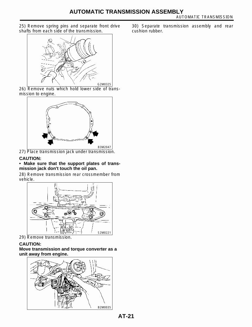
25) Remove spring pins and separate front driveshafts from each side of the transmission.
26) Remove nuts which hold lower side of trans-mission to engine.
27) Place transmission jack under transmission.
CAUTION:• Make sure that the support plates of trans-mission jack don't touch the oil pan.28) Remove transmission rear crossmember fromvehicle.
29) Remove transmission.
CAUTION:Move transmission and torque converter as a unit away from engine.
30) Separate transmission assembly and rearcushion rubber.
G2M0325
B3M2047
S2M0221
B2M0035
AT-21

AUTOMATIC TRANSMISSIONAUTOMATIC TRANSMISSION ASSEMBLY
B: INSTALLATION1) Install rear cushion rubber to transmission as-sembly.
Tightening torque:1.6L MODEL:
123 N·m (12.5 kgf-m, 90 ft-lb)2.0L MODEL:
38 N·m (3.9 kgf-m, 28 ft-lb)2) Install ST to torque converter clutch case.ST 498277200 STOPPER SET
3) Install transmission onto engine.(1) Gradually raise transmission with transmis-sion jack.
(2) Engage them at splines.4) Install transmission rear crossmember.
Tightening torque:T1: 35 N·m (3.6 kgf-m, 26 ft-lb)T2: 70 N·m (7.1 kgf-m, 51.4 ft-lb)
5) Take off transmission jack.
6) Tighten nuts and bolts which hold lower side oftransmission to engine.
Tightening torque:50 N·m (5.1 kgf-m, 36.9 ft-lb)
7) Lower the vehicle.8) Connect engine and transmission.
(1) Remove ST from torque converter clutchcase.
NOTE:Be careful not to drop the ST into the torque con-verter clutch case when removing ST.ST 498277200 STOPPER SET
(2) Install starter.<Ref. to SC-6, INSTALLATION, Starter.>(3) Tighten bolt which holds right upper side oftransmission to engine.
Tightening torque:50 N·m (5.1 kgf-m, 36.9 ft-lb)
H2M1961A
B2M0035
S2M0221A
B3M2047
B3M2044
AT-22
AUTOMATIC TRANSMISSIONAUTOMATIC TRANSMISSION ASSEMBLY
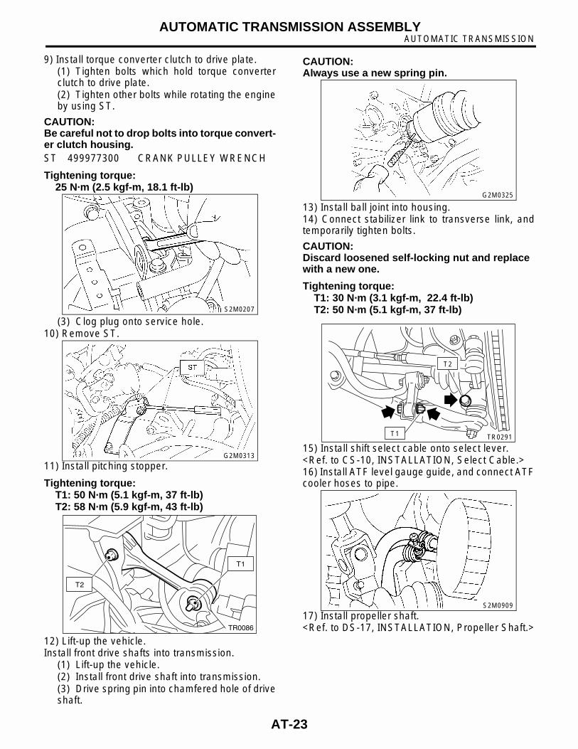
9) Install torque converter clutch to drive plate. (1) Tighten bolts which hold torque converterclutch to drive plate.(2) Tighten other bolts while rotating the engineby using ST.
CAUTION:Be careful not to drop bolts into torque convert-er clutch housing.ST 499977300 CRANK PULLEY WRENCH
Tightening torque:25 N·m (2.5 kgf-m, 18.1 ft-lb)
(3) Clog plug onto service hole.10) Remove ST.
11) Install pitching stopper.
Tightening torque:T1: 50 N·m (5.1 kgf-m, 37 ft-lb)T2: 58 N·m (5.9 kgf-m, 43 ft-lb)
12) Lift-up the vehicle.Install front drive shafts into transmission.
(1) Lift-up the vehicle.(2) Install front drive shaft into transmission.(3) Drive spring pin into chamfered hole of driveshaft.
CAUTION:Always use a new spring pin.
13) Install ball joint into housing.14) Connect stabilizer link to transverse link, andtemporarily tighten bolts.
CAUTION:Discard loosened self-locking nut and replace with a new one.
Tightening torque:T1: 30 N·m (3.1 kgf-m, 22.4 ft-lb)T2: 50 N·m (5.1 kgf-m, 37 ft-lb)
15) Install shift select cable onto select lever.<Ref. to CS-10, INSTALLATION, Select Cable.>16) Install ATF level gauge guide, and connect ATFcooler hoses to pipe.
17) Install propeller shaft.<Ref. to DS-17, INSTALLATION, Propeller Shaft.>
S2M0207
G2M0313
T1
T2
TR0086
G2M0325
T1
T2
TR0291
S2M0909
AT-23

AUTOMATIC TRANSMISSIONAUTOMATIC TRANSMISSION ASSEMBLY
18) Install heat shield cover.19) Install front, center, rear exhaust pipes andmuffler.With OBD<Ref. to EX(SOHC)-8, INSTALLATION, Front Ex-haust Pipe.>, <Ref. to EX(SOHC)-11, INSTALLA-TION, Rear Exhaust Pipe.> and <Ref. toEX(SOHC)-12, INSTALLATION, Muffler.>Without OBD<Ref. to EX(SOHCw/oOBD)-10, INSTALLATION,Front Exhaust Pipe.>, <Ref. to EX(SOHCw/oOBD)-13, INSTALLATION, Rear Exhaust Pipe.>and <Ref. to EX(SOHCw/oOBD)-14, INSTALLA-TION, Muffler.>20) Install under cover.21) Lower the vehicle.22) Install ATF level gauge.
23) Connect the following connectors.(1) Transmission harness connectors(2) Transmission ground terminal
24) Connect the following cables.(1) Cruise control cable (With cruise control ve-hicles)
25) Install air cleaner case stay.
Tightening torque:16 N·m (1.6 kgf-m, 11.6 ft-lb)
26) Install air cleaner case. <Ref. to IN(SOHC)-7,INSTALLATION, Air Intake Duct.>27) Install air intake duct. <Ref. to IN(SOHC)-7, IN-STALLATION, Air Intake Duct.>28) Connect battery ground cable.29) Fill ATF up to the middle of the “COLD” side onlevel gauge by using the gauge hole.
Recommended fluid:Dexron III type automatic transmission fluid
Fluid capacity:1.6 L model:
8.0 — 8.3 2 (8.5 — 8.8 US qt, 7.0 — 7.3 Imp qt)
2.0 L model:8.4 — 8.7 2 (8.9 — 9.2 USqt, 7.4 — 8.4 Imp qt)
30) Take off vehicle from lift arms.
31) Check select lever operation.<Ref. to AT-28, INSPECTION, Inhibitor Switch.>32) Check the ATF level. <Ref. to AT-9, AutomaticTransmission Fluid.>33) Check the vehicle on the road tester. <Ref. to AT-12, Road Test.>
S2M0214
AT-24

AUTOMATIC TRANSMISSIONTRANSMISSION MOUNTING SYSTEM
10.Transmission Mounting Sys-tem
A: REMOVAL1. PITCHING STOPPER1) Disconnect battery ground terminal.2) Remove the air intake duct. <Ref. to IN(SOHC)-7, REMOVAL, Air Intake Duct.>3) Remove the air cleaner case. <Ref. to IN(SO-HC)-6, REMOVAL, Air Cleaner Case.>4) Remove the pitching stopper.
2. CROSSMEMBER AND CUSHION RUB-BER1) Disconnect battery ground terminal.2) Jack-up vehicle and support it with sturdy racks.3) Remove the front, center, rear exhaust pipesand muffler.With OBD<Ref. to EX(SOHC)-7, REMOVAL, Front ExhaustPipe.>, <Ref. to EX(SOHC)-11, REMOVAL, RearExhaust Pipe.> and <Ref. to EX(SOHC)-12, RE-MOVAL, Muffler.>Without OBD<Ref. to EX(SOHCw/oOBD)-9, REMOVAL, FrontExhaust Pipe.>, <Ref. to EX(SOHCw/oOBD)-13,REMOVAL, Rear Exhaust Pipe.> and <Ref. toEX(SOHCw/oOBD)-14, REMOVAL, Muffler.>
CAUTION:When removing exhaust pipes, be careful each exhaust pipe does not drop out.4) Remove the heat shield cover.5) Set the transmission jack under the transmis-sion.
CAUTION:• Make sure that the support plates of trans-mission jack don't touch the oil pan.6) Remove the crossmember.
7) Remove the rear cushion rubber.
B: INSTALLATION1. PITCHING STOPPER1) Install the pitching stopper.
Tightening torque:T1: 50 N·m (5.1 kgf-m, 37 ft-lb)T2: 58 N·m (5.9 kgf-m, 43 ft-lb)
2) Install the air intake duct and cleaner case.
TR0072
S2M0221
T1
T2
TR0086
AT-25

AUTOMATIC TRANSMISSIONTRANSMISSION MOUNTING SYSTEM
2. CROSSMEMBER AND CUSHION RUB-BER1) Install the rear cushion rubber.
Tightening torque:1.6 L model:
123 N·m (12.5 kgf-m, 90 ft-lb)2.0 L model:
38 N·m (3.9 kgf-m, 28 ft-lb)2) Install the crossmember.
Tightening torque:T1: 35 N·m (3.6 kgf-m, 26 ft-lb)T2: 70 N·m (7.1 kgf-m, 51.4 ft-lb)
3) Remove the transmission jack.4) Install the heat shield cover.5) Install the front, center, rear exhaust pipes andthe muffler.With OBD<Ref. to EX(SOHC)-8, INSTALLATION, Front Ex-haust Pipe.>, <Ref. to EX(SOHC)-11, INSTALLA-TION, Rear Exhaust Pipe.> and <Ref. toEX(SOHC)-12, INSTALLATION, Muffler.>Without OBD<Ref. to EX(SOHCw/oOBD)-10, INSTALLATION,Front Exhaust Pipe.>, <Ref. to EX(SOHCw/oOBD)-13, INSTALLATION, Rear Exhaust Pipe.>and <Ref. to EX(SOHCw/oOBD)-14, INSTALLA-TION, Muffler.>
C: INSPECTIONRepair or replace parts if the results of the inspec-tion below are not satisfactory.
1. PITCHING STOPPERMake sure that the pitching stopper is not bent ordamaged. Make sure that the rubber is not stiff,cracked, or otherwise damaged.
2. CROSSMEMBER AND CUSHION RUB-BERMake sure that the crossmember is not bent ordamaged. Make sure that the cushion rubber is notstiff, cracked, or otherwise damaged.
S2M0221A
AT-26
AUTOMATIC TRANSMISSIONEXTENSION CASE OIL SEAL
11.Extension Case Oil SealA: INSPECTIONMake sure ATF does not leak from the joint of thetransmission and propeller shaft. If so, replace oilseal. <Ref. to AT-27, REPLACEMENT, ExtensionCase Oil Seal.>
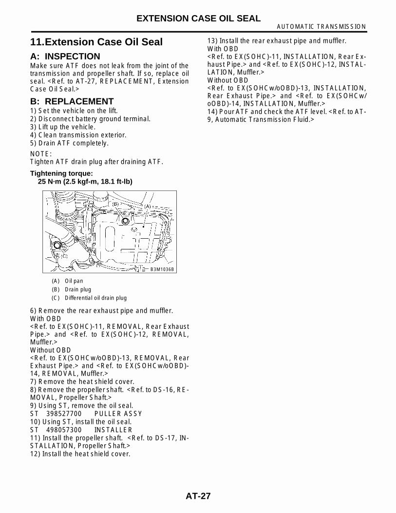
B: REPLACEMENT1) Set the vehicle on the lift.2) Disconnect battery ground terminal.3) Lift up the vehicle.4) Clean transmission exterior.5) Drain ATF completely.
NOTE:Tighten ATF drain plug after draining ATF.
Tightening torque:25 N·m (2.5 kgf-m, 18.1 ft-lb)
6) Remove the rear exhaust pipe and muffler.With OBD<Ref. to EX(SOHC)-11, REMOVAL, Rear ExhaustPipe.> and <Ref. to EX(SOHC)-12, REMOVAL,Muffler.>Without OBD<Ref. to EX(SOHCw/oOBD)-13, REMOVAL, RearExhaust Pipe.> and <Ref. to EX(SOHCw/oOBD)-14, REMOVAL, Muffler.>7) Remove the heat shield cover.8) Remove the propeller shaft. <Ref. to DS-16, RE-MOVAL, Propeller Shaft.>9) Using ST, remove the oil seal.ST 398527700 PULLER ASSY10) Using ST, install the oil seal.ST 498057300 INSTALLER11) Install the propeller shaft. <Ref. to DS-17, IN-STALLATION, Propeller Shaft.>12) Install the heat shield cover.
13) Install the rear exhaust pipe and muffler.With OBD<Ref. to EX(SOHC)-11, INSTALLATION, Rear Ex-haust Pipe.> and <Ref. to EX(SOHC)-12, INSTAL-LATION, Muffler.>Without OBD<Ref. to EX(SOHCw/oOBD)-13, INSTALLATION,Rear Exhaust Pipe.> and <Ref. to EX(SOHCw/oOBD)-14, INSTALLATION, Muffler.>14) Pour ATF and check the ATF level. <Ref. to AT-9, Automatic Transmission Fluid.>
(A) Oil pan
(B) Drain plug
(C) Differential oil drain plug
B3M1036B
AT-27
AUTOMATIC TRANSMISSIONINHIBITOR SWITCH
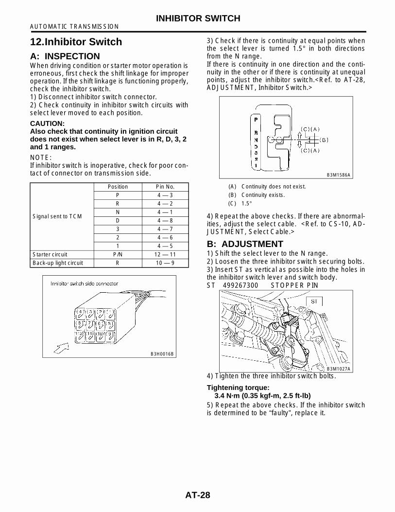
12.Inhibitor SwitchA: INSPECTION When driving condition or starter motor operation iserroneous, first check the shift linkage for improperoperation. If the shift linkage is functioning properly,check the inhibitor switch.1) Disconnect inhibitor switch connector.2) Check continuity in inhibitor switch circuits withselect lever moved to each position.
CAUTION:Also check that continuity in ignition circuit does not exist when select lever is in R, D, 3, 2 and 1 ranges.
NOTE:If inhibitor switch is inoperative, check for poor con-tact of connector on transmission side.
3) Check if there is continuity at equal points whenthe select lever is turned 1.5° in both directionsfrom the N range.If there is continuity in one direction and the conti-nuity in the other or if there is continuity at unequalpoints, adjust the inhibitor switch.<Ref. to AT-28,ADJUSTMENT, Inhibitor Switch.>
4) Repeat the above checks. If there are abnormal-ities, adjust the select cable. <Ref. to CS-10, AD-JUSTMENT, Select Cable.>
B: ADJUSTMENT 1) Shift the select lever to the N range.2) Loosen the three inhibitor switch securing bolts.3) Insert ST as vertical as possible into the holes inthe inhibitor switch lever and switch body.ST 499267300 STOPPER PIN
4) Tighten the three inhibitor switch bolts.
Tightening torque:3.4 N·m (0.35 kgf-m, 2.5 ft-lb)
5) Repeat the above checks. If the inhibitor switchis determined to be “faulty”, replace it.
Signal sent to TCM
Position Pin No.
P 4 — 3
R 4 — 2
N 4 — 1
D 4 — 8
3 4 — 7
2 4 — 6
1 4 — 5
Starter circuit P/N 12 — 11
Back-up light circuit R 10 — 9
B3H0016B
(A) Continuity does not exist.
(B) Continuity exists.
(C) 1.5°
B3M1586A
B3M1027A
AT-28

AUTOMATIC TRANSMISSIONINHIBITOR SWITCH
C: REMOVAL1) Set up the vehicle on the lift.2) Move select lever to neutral position.3) Remove air intake duct and cleaner case.4) Disconnect inhibitor switch connector.
5) Remove inhibitor switch connector from stay.6) Lift-up the vehicle.7) Remove front exhaust pipe with center exhaustpipe.With OBD<Ref. to EX(SOHC)-7, REMOVAL, Front ExhaustPipe.>Without OBD<Ref. to EX(SOHCw/oOBD)-9, REMOVAL, FrontExhaust Pipe.>8) Remove snap pin from range select lever.
9) Remove plate assembly from transmission case.
10) Remove bolts.
11) Move range select lever to parking position (leftside).
(A) Inhibitor switch
(A) Snap pin
(B) Select cable
(C) Range select lever
B3M1028B
B3M1029C
(A) Select cable
(B) Plate ASSY
(A) Inhibitor switch
(A) Range select lever
B3M1030H
B3M1031B
B3M1032B
AT-29
AUTOMATIC TRANSMISSIONINHIBITOR SWITCH
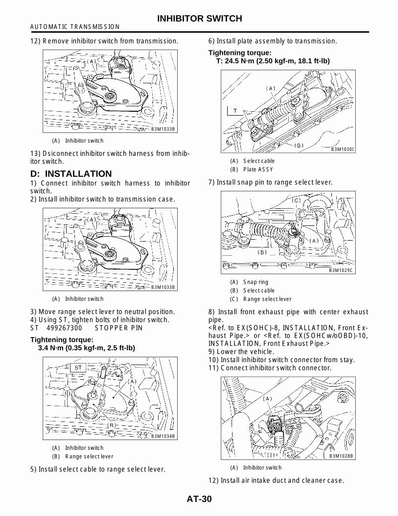
12) Remove inhibitor switch from transmission.
13) Dsiconnect inhibitor switch harness from inhib-itor switch.
D: INSTALLATION1) Connect inhibitor switch harness to inhibitorswitch.2) Install inhibitor switch to transmission case.
3) Move range select lever to neutral position.4) Using ST, tighten bolts of inhibitor switch.ST 499267300 STOPPER PIN
Tightening torque:3.4 N·m (0.35 kgf-m, 2.5 ft-lb)
5) Install select cable to range select lever.
6) Install plate assembly to transmission.
Tightening torque:T: 24.5 N·m (2.50 kgf-m, 18.1 ft-lb)
7) Install snap pin to range select lever.
8) Install front exhaust pipe with center exhaustpipe.<Ref. to EX(SOHC)-8, INSTALLATION, Front Ex-haust Pipe.> or <Ref. to EX(SOHCw/oOBD)-10,INSTALLATION, Front Exhaust Pipe.>9) Lower the vehicle.10) Install inhibitor switch connector from stay.11) Connect inhibitor switch connector.
12) Install air intake duct and cleaner case.
(A) Inhibitor switch
(A) Inhibitor switch
(A) Inhibitor switch
(B) Range select lever
B3M1033B
B3M1033B
B3M1034B
(A) Select cable
(B) Plate ASSY
(A) Snap ring
(B) Select cable
(C) Range select lever
(A) Inhibitor switch
B3M1030I
B3M1029C
B3M1028B
AT-30
AUTOMATIC TRANSMISSIONFRONT VEHICLE SPEED SENSOR
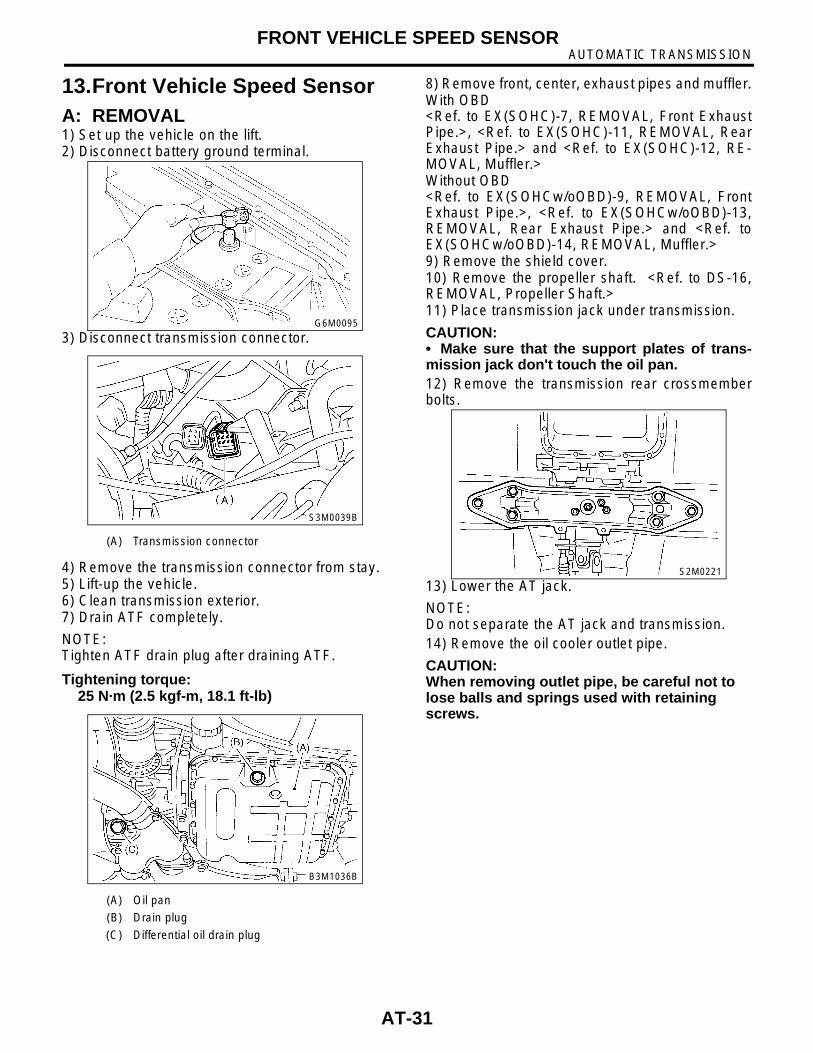
13.Front Vehicle Speed SensorA: REMOVAL1) Set up the vehicle on the lift.2) Disconnect battery ground terminal.
3) Disconnect transmission connector.
4) Remove the transmission connector from stay.5) Lift-up the vehicle.6) Clean transmission exterior.7) Drain ATF completely.
NOTE:Tighten ATF drain plug after draining ATF.
Tightening torque:25 N·m (2.5 kgf-m, 18.1 ft-lb)
8) Remove front, center, exhaust pipes and muffler.With OBD<Ref. to EX(SOHC)-7, REMOVAL, Front ExhaustPipe.>, <Ref. to EX(SOHC)-11, REMOVAL, RearExhaust Pipe.> and <Ref. to EX(SOHC)-12, RE-MOVAL, Muffler.>Without OBD<Ref. to EX(SOHCw/oOBD)-9, REMOVAL, FrontExhaust Pipe.>, <Ref. to EX(SOHCw/oOBD)-13,REMOVAL, Rear Exhaust Pipe.> and <Ref. toEX(SOHCw/oOBD)-14, REMOVAL, Muffler.>9) Remove the shield cover.10) Remove the propeller shaft. <Ref. to DS-16,REMOVAL, Propeller Shaft.>11) Place transmission jack under transmission.
CAUTION:• Make sure that the support plates of trans-mission jack don't touch the oil pan.12) Remove the transmission rear crossmemberbolts.
13) Lower the AT jack.
NOTE:Do not separate the AT jack and transmission.14) Remove the oil cooler outlet pipe.
CAUTION:When removing outlet pipe, be careful not to lose balls and springs used with retaining screws.
(A) Transmission connector
(A) Oil pan
(B) Drain plug
(C) Differential oil drain plug
G6M0095
S3M0039B
B3M1036B
S2M0221
AT-31

AUTOMATIC TRANSMISSIONFRONT VEHICLE SPEED SENSOR
15) Remove front and rear vehicle speed sensorand torque converter turbine speed sensor.• Front vehicle speed sensor and torqueconverter turbine speed sensor
• Rear vehicle speed sensor
16) Remove oil pan.
17) Disconnect duty solenoids and ATF tempera-ture sensor connectors. Remove connectors fromclip and disconnect connectors at 9 places.
18) Remove harness assembly.
B: INSTALLATION1) Pass the harness assembly through the hole inthe transmission case.
(A) Front vehicle speed sensor
(B) Torque converter turbine speed sensor
(A) Rear vehicle speed sensor
(B) Front vehicle speed sensor
B3M1066B
B3M1056B
(A) Lock-up duty solenoid (Blue)
(B) Low clutch timing solenoid (Gray)
(C) Line pressure duty solenoid (Red)
(D) Shift solenoid 2 (Yellow)
(E) Shift solenoid 1 (Green)
(F) 2-4 brake timing solenoid (Black)
(G) 2-4 brake duty solenoid (Red)
(H) ATF temperature sensor
(I) Transfer duty solenoid (Brown)
(J) Transmission ground
B2M2263I
B3M1067
AT-32
AUTOMATIC TRANSMISSIONFRONT VEHICLE SPEED SENSOR
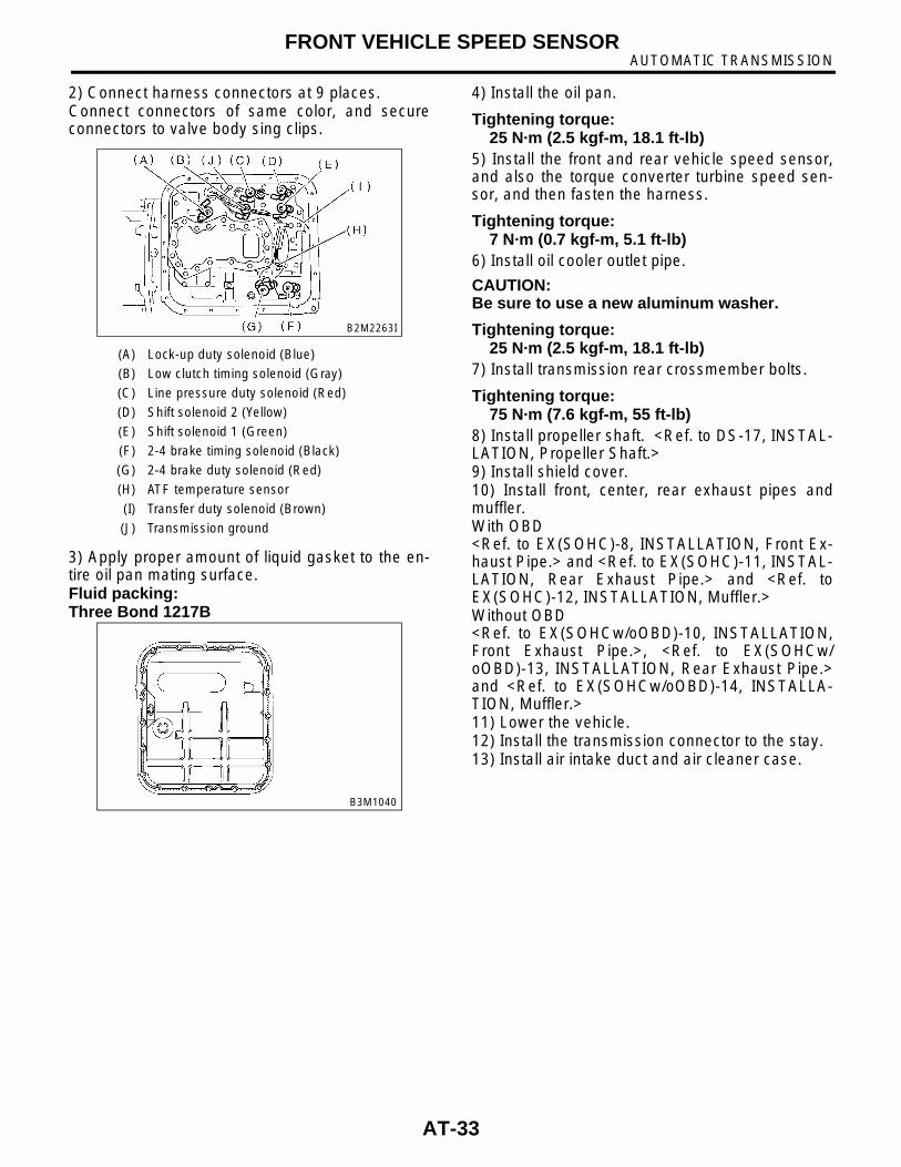
2) Connect harness connectors at 9 places.Connect connectors of same color, and secureconnectors to valve body sing clips.
3) Apply proper amount of liquid gasket to the en-tire oil pan mating surface.Fluid packing:Three Bond 1217B
4) Install the oil pan.
Tightening torque:25 N·m (2.5 kgf-m, 18.1 ft-lb)
5) Install the front and rear vehicle speed sensor,and also the torque converter turbine speed sen-sor, and then fasten the harness.
Tightening torque:7 N·m (0.7 kgf-m, 5.1 ft-lb)
6) Install oil cooler outlet pipe.
CAUTION:Be sure to use a new aluminum washer.
Tightening torque:25 N·m (2.5 kgf-m, 18.1 ft-lb)
7) Install transmission rear crossmember bolts.
Tightening torque:75 N·m (7.6 kgf-m, 55 ft-lb)
8) Install propeller shaft. <Ref. to DS-17, INSTAL-LATION, Propeller Shaft.>9) Install shield cover.10) Install front, center, rear exhaust pipes andmuffler.With OBD<Ref. to EX(SOHC)-8, INSTALLATION, Front Ex-haust Pipe.> and <Ref. to EX(SOHC)-11, INSTAL-LATION, Rear Exhaust Pipe.> and <Ref. toEX(SOHC)-12, INSTALLATION, Muffler.>Without OBD<Ref. to EX(SOHCw/oOBD)-10, INSTALLATION,Front Exhaust Pipe.>, <Ref. to EX(SOHCw/oOBD)-13, INSTALLATION, Rear Exhaust Pipe.>and <Ref. to EX(SOHCw/oOBD)-14, INSTALLA-TION, Muffler.>11) Lower the vehicle.12) Install the transmission connector to the stay.13) Install air intake duct and air cleaner case.
(A) Lock-up duty solenoid (Blue)
(B) Low clutch timing solenoid (Gray)
(C) Line pressure duty solenoid (Red)
(D) Shift solenoid 2 (Yellow)
(E) Shift solenoid 1 (Green)
(F) 2-4 brake timing solenoid (Black)
(G) 2-4 brake duty solenoid (Red)
(H) ATF temperature sensor
(I) Transfer duty solenoid (Brown)
(J) Transmission ground
B2M2263I
B3M1040
AT-33
AUTOMATIC TRANSMISSIONREAR VEHICLE SPEED SENSOR
14.Rear Vehicle Speed SensorA: REMOVALWhen removing the rear vehicle speed sensor, re-fer to “Front Vehicle Speed Sensor.” <Ref. to AT-31, REMOVAL, Front Vehicle Speed Sensor.>
B: INSTALLATIONWhen installing the rear vehicle speed sensor, referto “Front Vehicle Speed Sensor.” <Ref. to AT-32,INSTALLATION, Front Vehicle Speed Sensor.>
AT-34

AUTOMATIC TRANSMISSIONTORQUE CONVERTER TURBINE SPEED SENSOR
15.Torque Converter Turbine Speed Sensor
A: REMOVALWhen removing the torque converter turbine speedsensor, refer to “Front Vehicle Speed Sensor.”<Ref. to AT-31, REMOVAL, Front Vehicle SpeedSensor.>
B: INSTALLATIONWhen installing the torque converter turbine speedsensor, refer to “Front Vehicle Speed Sensor.”<Ref. to AT-32, INSTALLATION, Front VehicleSpeed Sensor.>
AT-35
AUTOMATIC TRANSMISSIONCONTROL VALVE BODY
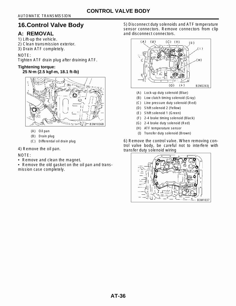
16.Control Valve BodyA: REMOVAL1) Lift-up the vehicle.2) Clean transmission exterior.3) Drain ATF completely.
NOTE:Tighten ATF drain plug after draining ATF.
Tightening torque:25 N·m (2.5 kgf-m, 18.1 ft-lb)
4) Remove the oil pan.
NOTE:• Remove and clean the magnet.• Remove the old gasket on the oil pan and trans-mission case completely.
5) Disconnect duty solenoids and ATF temperaturesensor connectors. Remove connectors from clipand disconnect connectors.
6) Remove the control valve. When removing con-trol valve body, be careful not to interfere withtransfer duty solenoid wiring
(A) Oil pan
(B) Drain plug
(C) Differential oil drain plug
B3M1036B
(A) Lock-up duty solenoid (Blue)
(B) Low clutch timing solenoid (Gray)
(C) Line pressure duty solenoid (Red)
(D) Shift solenoid 2 (Yellow)
(E) Shift solenoid 1 (Green)
(F) 2-4 brake timing solenoid (Black)
(G) 2-4 brake duty solenoid (Red)
(H) ATF temperature sensor
(I) Transfer duty solenoid (Brown)
B2M2263J
B3M1037
AT-36
AUTOMATIC TRANSMISSIONCONTROL VALVE BODY
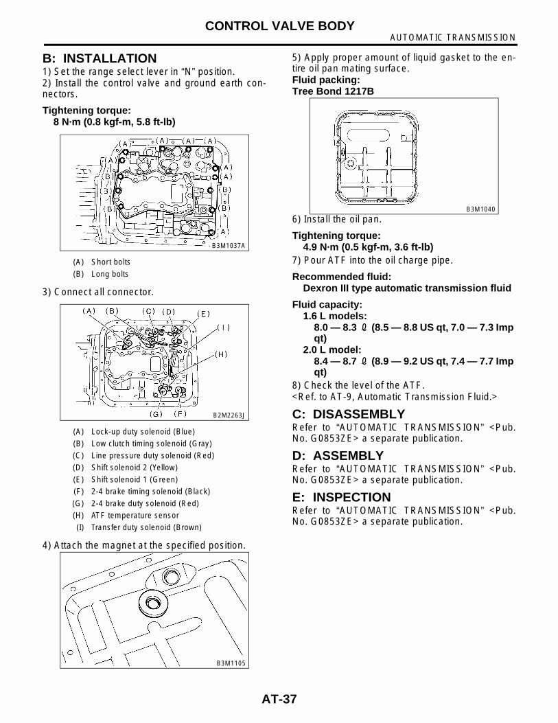
B: INSTALLATION1) Set the range select lever in “N” position.2) Install the control valve and ground earth con-nectors.
Tightening torque:8 N·m (0.8 kgf-m, 5.8 ft-lb)
3) Connect all connector.
4) Attach the magnet at the specified position.
5) Apply proper amount of liquid gasket to the en-tire oil pan mating surface.Fluid packing:Tree Bond 1217B
6) Install the oil pan.
Tightening torque:4.9 N·m (0.5 kgf-m, 3.6 ft-lb)
7) Pour ATF into the oil charge pipe.
Recommended fluid:Dexron III type automatic transmission fluid
Fluid capacity:1.6 L models:
8.0 — 8.3 2 (8.5 — 8.8 US qt, 7.0 — 7.3 Imp qt)
2.0 L model:8.4 — 8.7 2 (8.9 — 9.2 US qt, 7.4 — 7.7 Imp qt)
8) Check the level of the ATF.<Ref. to AT-9, Automatic Transmission Fluid.>
C: DISASSEMBLYRefer to “AUTOMATIC TRANSMISSION” <Pub.No. G0853ZE> a separate publication.
D: ASSEMBLYRefer to “AUTOMATIC TRANSMISSION” <Pub.No. G0853ZE> a separate publication.
E: INSPECTIONRefer to “AUTOMATIC TRANSMISSION” <Pub.No. G0853ZE> a separate publication.
(A) Short bolts
(B) Long bolts
(A) Lock-up duty solenoid (Blue)
(B) Low clutch timing solenoid (Gray)
(C) Line pressure duty solenoid (Red)
(D) Shift solenoid 2 (Yellow)
(E) Shift solenoid 1 (Green)
(F) 2-4 brake timing solenoid (Black)
(G) 2-4 brake duty solenoid (Red)
(H) ATF temperature sensor
(I) Transfer duty solenoid (Brown)
B3M1037A
B2M2263J
B3M1105
B3M1040
AT-37

AUTOMATIC TRANSMISSIONSHIFT SOLENOIDS, DUTY SOLENOIDS AND ATF TEMPERATURE SENSOR
17.Shift Solenoids, Duty Sole-noids and ATF Temperature Sensor
A: REMOVAL1) Lift-up the vehicle.2) Clean transmission exterior.3) Drain ATF completely.
NOTE:Tighten ATF drain plug after draining ATF.
Tightening torque:25 N·m (2.5 kgf-m, 18.1 ft-lb)
4) Remove oil pan.5) Disconnect solenoid and sensor connectors.Remove connectors from clip and disconnect con-nectors.
6) Remove solenoids, duty solenoids and ATF tem-perature sensor.
1. TRANSFER DUTY SOLENOID AND TRANSFER VALVE BODY1) Set up the vehicle on the lift.2) Disconnect battery ground terminal.3) Remove air intake duct. <Ref. to IN(SOHC)-7,REMOVAL, Air Intake Duct.>4) Remove air cleaner case. <Ref. to IN(SOHC)-6,REMOVAL, Air Cleaner Case.>5) Remove pitching stopper.
6) Remove front exhaust pipe with center exhaustpipe.With OBD<Ref. to EX(SOHC)-7, REMOVAL, Front ExhaustPipe.>Without OBD<Ref. to EX(SOHCw/oOBD)-9, REMOVAL, FrontExhaust Pipe.>
(A) Oil pan
(B) Drain plug
(A) Lock-up duty solenoid (Blue)
(B) Low clutch timing solenoid (Gray)
(C) Line pressure duty solenoid (Red)
(D) Shift solenoid 2 (Yellow)
(E) Shift solenoid 1 (Green)
(F) 2-4 brake timing solenoid (Black)
(G) 2-4 brake duty solenoid (Red)
(H) ATF temperature sensor
(I) Transfer duty solenoid (Brown)
B3M1036C
B2M2263J
(A) Lock-up duty solenoid (Blue)
(B) Low clutch timing solenoid (Gray)
(C) Line pressure duty solenoid (Red)
(D) Shift solenoid 2 (Yellow)
(E) Shift solenoid 1 (Green)
(F) 2-4 brake timing solenoid (Black)
(G) 2-4 brake duty solenoid (Red)
(H) ATF temperature sensor
B3M1039A
TR0072
AT-38
AUTOMATIC TRANSMISSIONSHIFT SOLENOIDS, DUTY SOLENOIDS AND ATF TEMPERATURE SENSOR
7) Raise vehicle and drain ATF.
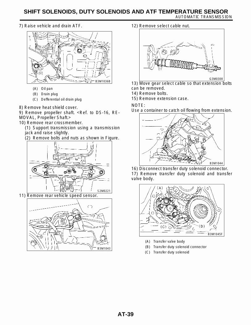
8) Remove heat shield cover.9) Remove propeller shaft. <Ref. to DS-16, RE-MOVAL, Propeller Shaft.>10) Remove rear crossmember.
(1) Support transmission using a transmissionjack and raise slightly.(2) Remove bolts and nuts as shown in Figure.
11) Remove rear vehicle speed sensor.
12) Remove select cable nut.
13) Move gear select cable so that extension boltscan be removed.14) Remove bolts.15) Remove extension case.
NOTE:Use a container to catch oil flowing from extension.
16) Disconnect transfer duty solenoid connector.17) Remove transfer duty solenoid and transfervalve body.
(A) Oil pan
(B) Drain plug
(C) Defferential oil drain plug
B3M1036B
S2M0221
B3M1043
(A) Transfer valve body
(B) Transfer duty solenoid connector
(C) Transfer duty solenoid
G3M0308
B3M1044
B3M1045F
AT-39
AUTOMATIC TRANSMISSIONSHIFT SOLENOIDS, DUTY SOLENOIDS AND ATF TEMPERATURE SENSOR
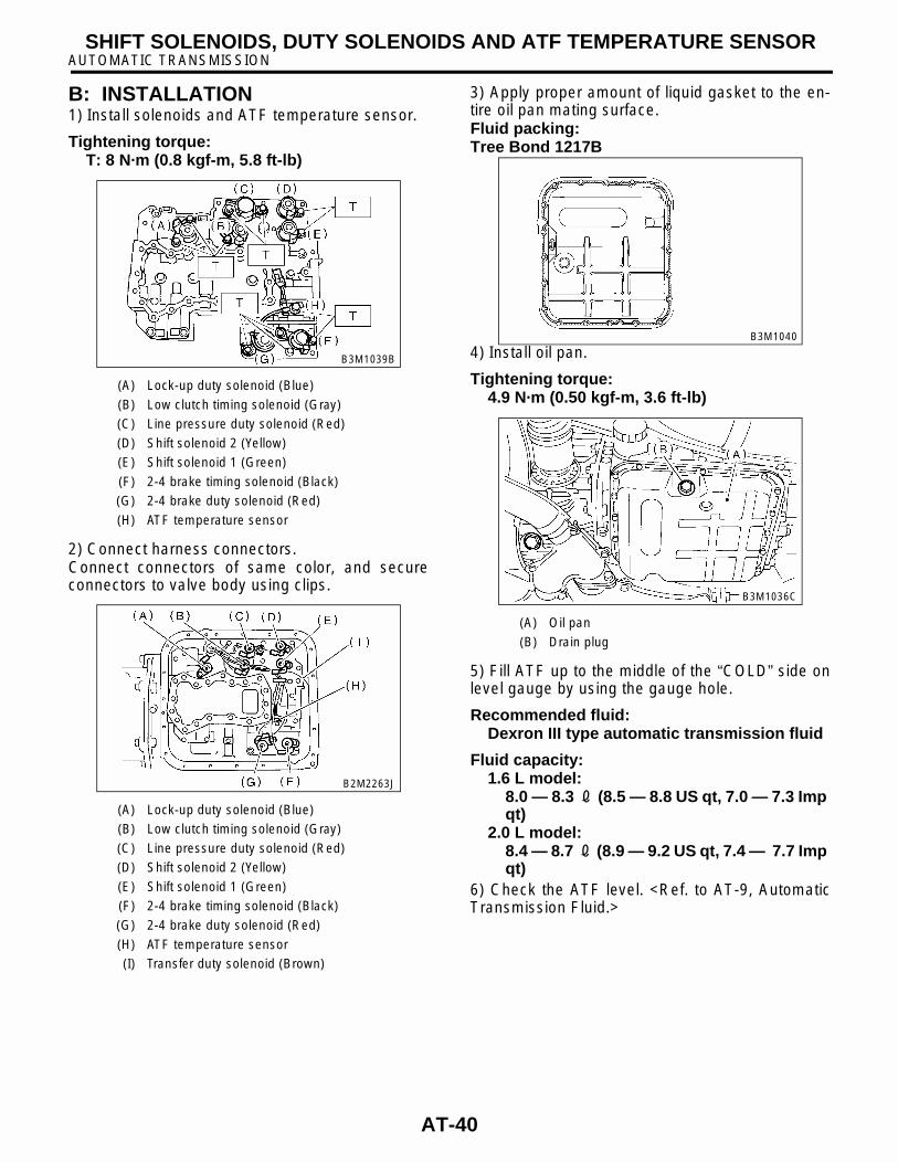
B: INSTALLATION1) Install solenoids and ATF temperature sensor.
Tightening torque:T: 8 N·m (0.8 kgf-m, 5.8 ft-lb)
2) Connect harness connectors.Connect connectors of same color, and secureconnectors to valve body using clips.
3) Apply proper amount of liquid gasket to the en-tire oil pan mating surface.Fluid packing:Tree Bond 1217B
4) Install oil pan.
Tightening torque:4.9 N·m (0.50 kgf-m, 3.6 ft-lb)
5) Fill ATF up to the middle of the “COLD” side onlevel gauge by using the gauge hole.
Recommended fluid:Dexron III type automatic transmission fluid
Fluid capacity:1.6 L model:
8.0 — 8.3 2 (8.5 — 8.8 US qt, 7.0 — 7.3 Imp qt)
2.0 L model:8.4 — 8.7 2 (8.9 — 9.2 US qt, 7.4 — 7.7 Imp qt)
6) Check the ATF level. <Ref. to AT-9, AutomaticTransmission Fluid.>
(A) Lock-up duty solenoid (Blue)
(B) Low clutch timing solenoid (Gray)
(C) Line pressure duty solenoid (Red)
(D) Shift solenoid 2 (Yellow)
(E) Shift solenoid 1 (Green)
(F) 2-4 brake timing solenoid (Black)
(G) 2-4 brake duty solenoid (Red)
(H) ATF temperature sensor
(A) Lock-up duty solenoid (Blue)
(B) Low clutch timing solenoid (Gray)
(C) Line pressure duty solenoid (Red)
(D) Shift solenoid 2 (Yellow)
(E) Shift solenoid 1 (Green)
(F) 2-4 brake timing solenoid (Black)
(G) 2-4 brake duty solenoid (Red)
(H) ATF temperature sensor
(I) Transfer duty solenoid (Brown)
B3M1039B
B2M2263J
(A) Oil pan
(B) Drain plug
B3M1040
B3M1036C
AT-40
AUTOMATIC TRANSMISSIONSHIFT SOLENOIDS, DUTY SOLENOIDS AND ATF TEMPERATURE SENSOR
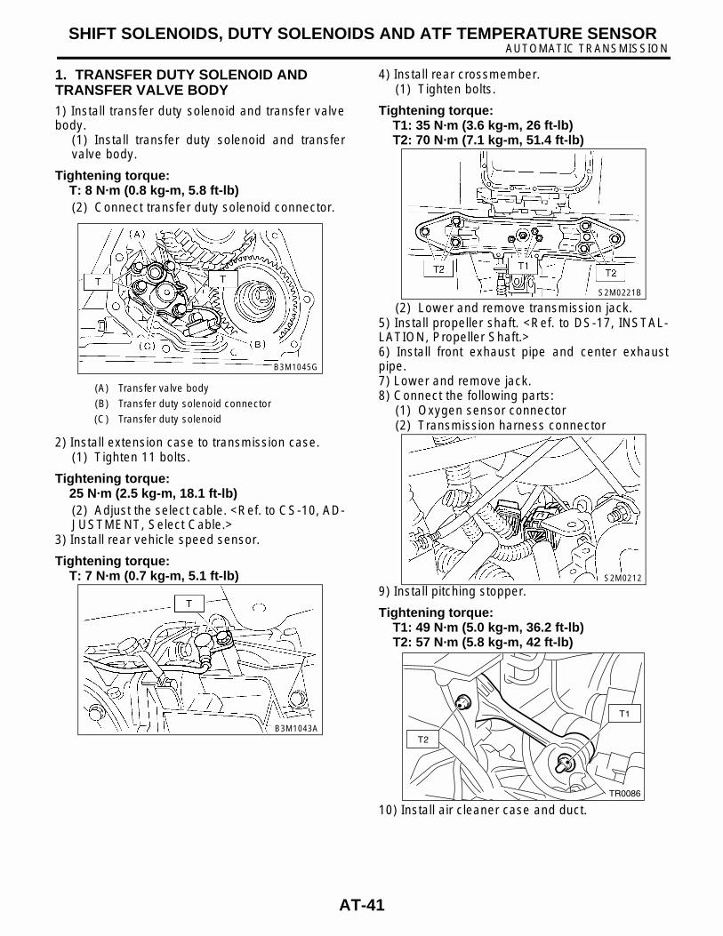
1. TRANSFER DUTY SOLENOID AND TRANSFER VALVE BODY1) Install transfer duty solenoid and transfer valvebody.
(1) Install transfer duty solenoid and transfervalve body.
Tightening torque:T: 8 N·m (0.8 kg-m, 5.8 ft-lb)(2) Connect transfer duty solenoid connector.
2) Install extension case to transmission case.(1) Tighten 11 bolts.
Tightening torque:25 N·m (2.5 kg-m, 18.1 ft-lb)(2) Adjust the select cable. <Ref. to CS-10, AD-JUSTMENT, Select Cable.>
3) Install rear vehicle speed sensor.
Tightening torque:T: 7 N·m (0.7 kg-m, 5.1 ft-lb)
4) Install rear crossmember.(1) Tighten bolts.
Tightening torque:T1: 35 N·m (3.6 kg-m, 26 ft-lb)T2: 70 N·m (7.1 kg-m, 51.4 ft-lb)
(2) Lower and remove transmission jack.5) Install propeller shaft. <Ref. to DS-17, INSTAL-LATION, Propeller Shaft.>6) Install front exhaust pipe and center exhaustpipe.7) Lower and remove jack.8) Connect the following parts:
(1) Oxygen sensor connector(2) Transmission harness connector
9) Install pitching stopper.
Tightening torque:T1: 49 N·m (5.0 kg-m, 36.2 ft-lb)T2: 57 N·m (5.8 kg-m, 42 ft-lb)
10) Install air cleaner case and duct.
(A) Transfer valve body
(B) Transfer duty solenoid connector
(C) Transfer duty solenoid
B3M1045G
B3M1043A
S2M0221B
S2M0212
T1
T2
TR0086
AT-41
AUTOMATIC TRANSMISSIONSHIFT SOLENOIDS, DUTY SOLENOIDS AND ATF TEMPERATURE SENSOR
11) Fill ATF up to the middle of the "COLD" side onlevel gauge by using the gauge hole.
Recommended fluid:Dexron III type automatic transmission fluid
Fluid capacity:1.6 L model; 8.0 - 8.3 L (8.5 - 8.8 US qt, 7.0 - 7.3 lmp qt)2.0 L model; 8.4 - 8.7 L (8.9 - 9.2 US qt, 7.4 - 7.3 lmp qt)
12) Check the ATF level. <Ref. to AT-9, AutomaticTransmission Fluid.>
AT-42
AUTOMATIC TRANSMISSIONATF FILTER
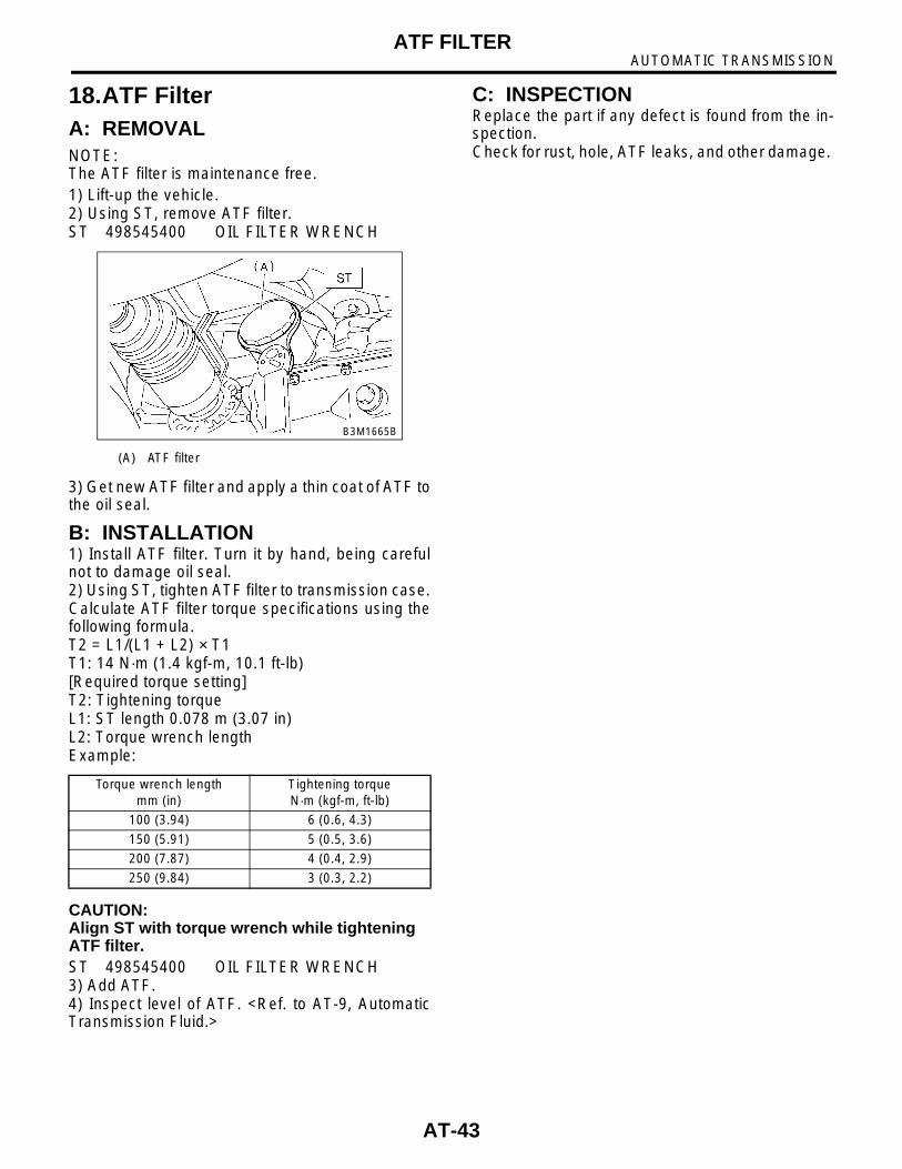
18.ATF FilterA: REMOVALNOTE:The ATF filter is maintenance free.1) Lift-up the vehicle.2) Using ST, remove ATF filter.ST 498545400 OIL FILTER WRENCH
3) Get new ATF filter and apply a thin coat of ATF tothe oil seal.
B: INSTALLATION1) Install ATF filter. Turn it by hand, being carefulnot to damage oil seal.2) Using ST, tighten ATF filter to transmission case.Calculate ATF filter torque specifications using thefollowing formula.T2 = L1/(L1 + L2) × T1T1: 14 N·m (1.4 kgf-m, 10.1 ft-lb)[Required torque setting]T2: Tightening torqueL1: ST length 0.078 m (3.07 in)L2: Torque wrench lengthExample:
CAUTION:Align ST with torque wrench while tightening ATF filter.ST 498545400 OIL FILTER WRENCH3) Add ATF.4) Inspect level of ATF. <Ref. to AT-9, AutomaticTransmission Fluid.>
C: INSPECTIONReplace the part if any defect is found from the in-spection.Check for rust, hole, ATF leaks, and other damage.
(A) ATF filter
Torque wrench lengthmm (in)
Tightening torqueN·m (kgf-m, ft-lb)
100 (3.94) 6 (0.6, 4.3)
150 (5.91) 5 (0.5, 3.6)
200 (7.87) 4 (0.4, 2.9)
250 (9.84) 3 (0.3, 2.2)
B3M1665B
AT-43
AUTOMATIC TRANSMISSIONTRANSMISSION CONTROL MODULE (TCM)
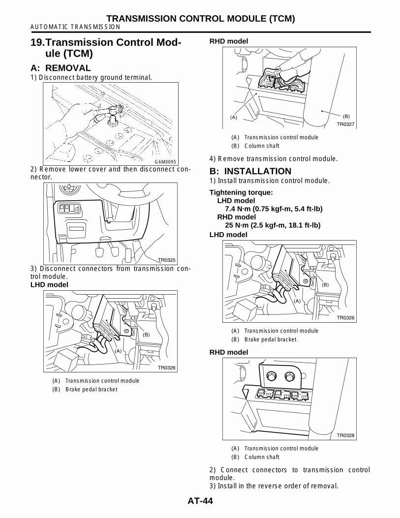
19.Transmission Control Mod-ule (TCM)
A: REMOVAL1) Disconnect battery ground terminal.
2) Remove lower cover and then disconnect con-nector.
3) Disconnect connectors from transmission con-trol module.LHD model
RHD model
4) Remove transmission control module.
B: INSTALLATION1) Install transmission control module.
Tightening torque:LHD model
7.4 N·m (0.75 kgf-m, 5.4 ft-lb)RHD model
25 N·m (2.5 kgf-m, 18.1 ft-lb)LHD model
RHD model
2) Connect connectors to transmission controlmodule.3) Install in the reverse order of removal.
(A) Transmission control module
(B) Brake pedal bracket
G6M0095
TR0325
(A)
(B)
TR0326
(A) Transmission control module
(B) Column shaft
(A) Transmission control module
(B) Brake pedal bracket
(A) Transmission control module
(B) Column shaft
(A) (B)
TR0327
(A)
(B)
TR0326
TR0328
AT-44

AUTOMATIC TRANSMISSIONATF COOLER PIPE AND HOSE
20.ATF Cooler Pipe and HoseA: REMOVAL1) Set the vehicle on the lift.2) Remove battery and washer tank.3) Lift-up the vehicle.4) Remove the under cover.5) Disconnect ATF cooler hose from radiator.
NOTE:• Do not remove with a screwdriver or other point-ed tools.• When the hose is difficult to remove, wrap a shopcloth around the hose to protect it. Turn it with pli-ers, and then pull directly out with your hand.
6) Disconnect ATF cooler hoses from pipes.
NOTE:• Do not remove with a screwdriver or other point-ed tools.• When the hose is difficult to remove, wrap a shopcloth around the hose to protect it. Turn it with pli-ers, and then pull directly out with your hand.
7) Remove ATF cooler pipe from frame.
8) Remove the oil cooler inlet and outlet pipes.
CAUTION:When removing outlet pipe, be careful not to lose ball and spring used with retaining screw.
TR0329
TR0330
(A) Inlet pipe
(B) Outlet pipe
TR0331
B3M1053B
AT-45

AUTOMATIC TRANSMISSIONATF COOLER PIPE AND HOSE
B: INSTALLATION1) Install the oil cooler outlet and inlet pipes.
CAUTION:Be sure to use a new aluminum washer.
Tightening torque:T1: 44 N·m (4.5 kgf-m, 32.5 ft-lb)T2: 25 N·m (2.5 kgf-m, 18.1 ft-lb)
2) Install ATF cooler pipe to frame.
3) Connect ATF cooler hose to pipe transmissionside.
NOTE:• Install so that the hose is not folded over, exces-sively bent, or twisted. • Be careful to insert the hose to the specified po-sition.
4) Connect ATF cooler hose to pipe of radiatorside.
NOTE:• Install so that the hose is not folded over, exces-sively bent, or twisted. • Be careful to insert the hose to the specified po-sition.
5) Install the under cover.6) Install battery and washer tank.7) Fill ATF. <Ref. to AT-9, Automatic TransmissionFluid.>
NOTE:Make sure there are no ATF leaks in joints betweenthe transmission, radiator, pipes, and hoses.
(A) Inlet pipe
(B) Outlet pipe
B3M1053C
TR0331
TR0330
TR0329
AT-46
AUTOMATIC TRANSMISSIONATF COOLER PIPE AND HOSE
C: INSPECTIONRepair or replace any defective hoses, pipes,clamps, and washers found from the inspection be-low.1) Check for ATF leaks in joints between the trans-mission, radiator, pipes, and hoses.2) Check for deformed clamps.3) Lightly bend the hose and check for cracks in thesurface and other damage.4) Pinch the hose with your fingers and check forpoor elasticity. Also check for poor elasticity in theparts where the clamp was by pressing with yourfingernail.5) Check for peeling, cracks, and deformation atthe tip of the hose.
AT-47

AUTOMATIC TRANSMISSIONATF COOLER PIPE AND HOSE
AT-48