Embed Size (px)
Citation preview

VEHICLE PROPULSION &ANCILLARY SUBSYSTEMS
2001
ANNUAL
PROGRESS
REPORT
U.S. Department of Energy
Energy Efficiency and Renewable Energy
Office of Transportation Technologies

A C K N O W L E D G E M E N T
We would like to express our sincere appreciation to ArgonneNational Laboratory and Computer Systems Management, Inc.,for their artistic and technical contributions in preparing andpublishing this report.
In addition, we would like to thank all our program participantsfor their contributions to the programs and all the authors whoprepared the project abstracts that comprise this report.
U.S. Department of EnergyOffice of Advanced Automotive Technologies1000 Independence Avenue, S.W.Washington, D.C. 20585-0121
FY 2001
Annual Progress Report for theVehicle Propulsion & Ancillary Subsystems Program
Submitted to:
Energy Efficiency and Renewable EnergyOffice of Transportation TechnologiesOffice of Advanced Automotive TechnologiesVehicle Systems Team
Robert Kost, Team LeaderVehicle Propulsion and Ancillary Subsystems
January 2002


Vehicle Propulsions & Ancillary Subsystems Program FY 2001 Annual Progress Report
iii
CONTENTS
Page
I. INTRODUCTION............................................................................................................................ 1
II. NATIONAL RENEWABLE ENERGY LABORATORY SUPPORT........................................ 3
A. Integrated Systems Approach for Energy-efficient Vehicle Design— Digital Functional Vehicle.................................................................................................... 3
B. Optimization Tools for Hybrid Vehicle Systems Analysis........................................................ 5C. ADVISOR Improvement, Validation, and Application............................................................. 8D. Saber/ADVISOR Co-simulation................................................................................................ 12E. Vehicle Auxiliary Load Reduction Project................................................................................ 14F. National Vehicle Air-Conditioning Fuel Use Analysis ............................................................. 18G. Integrated Numerical Modeling for Vehicle Auxiliary Load Reduction................................... 21H. Human Thermal comfort Model and Manikin........................................................................... 26I. Transient Air Conditioning System Analysis and Optimization ............................................... 30J. Exhaust Waste Heat Recovery System Analysis & Optimization............................................. 35K. Battery Thermal Characterization and Management ................................................................. 40L. Battery Electrical and Thermal Modeling for HEV simulations ............................................... 44
III. ARGONNE NATIONAL LABORATORY SUPPORT ............................................................... 47
A. Advanced Powertrain Test Facility (APTF) .............................................................................. 47B. Vehicle and Component Testing and Mapping ......................................................................... 49C. Predictive Control of Engines Using Neural Network Algorithms ........................................... 55D. Hardware-in-the-loop Testing and Rapid Prototyping of
Hybrid Powertrain Systems ....................................................................................................... 57E. Vehicle System Modeling and Analysis Using PSAT............................................................... 59F. Development of New Optimization and Control Tools............................................................. 62
III. OAK RIDGE NATIONAL LABORATORY SUPPORT............................................................. 65
A. Downstream Emissions Control (Aftertreatment) Modeling..................................................... 65B. Automotive System Cost Modeling........................................................................................... 67

Vehicle Propulsions & Ancillary Subsystems Program FY 2001 Annual Progress Report
iv
Vehicle Propulsions & Ancillary Subsystems Program FY 2001 Annual Progress Report
1
I. INTRODUCTION
Vehicle Propulsion and Ancillary Subsystems Program
On behalf of the U.S. Department of Energy’s Office of Advanced Automotive Technologies (OAAT), weare pleased to introduce the Fiscal Year (FY) 2001 Annual Progress Report for the Vehicle Propulsion andAncillary Subsystems Program. This introduction serves to briefly outline the nature, progress, and futuredirection of the program.
The mission of the Vehicle Propulsion and Ancillary Subsystems Program is to facilitate the development ofpropulsion and ancillary subsystems for light-duty vehicles (automobiles, light trucks, and SUV’s) that,(1) achieve significantly improved levels of fuel economy, (2) comply with projected emission regulationsand safety standards, and (3) are capable of operating on domestically produced fuels.
Program Goals and Objectives
The goal of the Vehicle Propulsion and Ancillary Subsystems Program is to support the OAAT goals by:• Development of component and subsystem performance targets for a range of vehicle platforms• Development and validation of models and simulation programs to predict the fuel economy of and
emissions from advanced light-duty passenger vehicles• Development and validation of vehicle propulsion subsystem and auxiliary subsystem technologies,• Benchmarking of commercially available components and vehicles to ensure that the OAAT-
developed technologies represent significant advances over commercially available technologies, and• Validation of the achievement of the OAAT vehicle-level objectives.
The Vehicle Propulsion and Ancillary Subsystems team reviews and evaluates the integration of componentsdeveloped by the Energy Conversion and Energy Management teams. The main challenge is to predict,through laboratory testing and computer simulation methods, how individual technology components willperform in a propulsion subsystem operating in a vehicle environment.
Through many of its technology research programs, the DOE Office of Advanced Automotive Technologies(OAAT) has supported the government/industry Partnership for a New Generation of Vehicles (PNGV), acooperative research and development (R&D) partnership between the federal government and the UnitedStates Council for Automotive Research, which comprises of Ford, General Motors, and DaimlerChrysler,since its inception. The PNGV leadership is now re-evaluating the partnership goals to identify changes thatwill maximize the potential national petroleum-savings benefit of the emerging PNGV technologies. Whenthese PNGV goal changes have been defined, the OAAT will adjust the focus of its technology researchprograms accordingly.
Future Directions
In FY 2002, the Vehicle Propulsion and Ancillary Subsystems program will focus on the development ofperformance targets for component technologies that will be applicable to the full range of light-duty vehicleplatforms. Propulsion subsystem component technologies will be validated for performance in simulatedvehicle platforms through hardware-in-the-loop testing and computer modeling. An integrated systemsapproach will be utilized to identify automotive applications with energy savings potential and providetechnological solutions that can be transferred to industry partners.

Vehicle Propulsions & Ancillary Subsystems Program FY 2001 Annual Progress Report
2
The abstracts in this volume summarize the work being conducted by the national laboratories in support ofthe program’s goals and objectives. The DOE program manager named with each abstract can be contactedfor further information.
Robert KostTeam Leader,Vehicle Propulsion and Ancillary SubsystemsOffice of Advanced Automotive Technologies

Vehicle Propulsions & Ancillary Subsystems Program FY 2001 Annual Progress Report
3
II. NATIONAL RENEWABLE ENERGY LABORATORY SUPPORT
IIA. Integrated Systems Approach for Energy-efficient Vehicle Design— Digital Functional Vehicle
Keith Wipke (principal investigator/project leader)National Renewable Energy Laboratory1617 Cole BoulevardGolden, CO 80401-3393(303) 275-4451, e-mail: [email protected]
DOE Program Manager: Patrick Sutton(202) 586-8058, e-mail: [email protected]
Objective
• Demonstrate an integrated systems approach to specific industry problems with a potential for energy savings.• Develop process and systems needed to solve specific real-world problems using math-based software to
integrate design of experiments, probabilistic designs, finite element modeling, optimization, and modeling ofsystem dynamics.
• Work directly with industry partners to include improved fuel economy and emissions considerations intofuture production components and vehicles.
Approach
• Work with industry and software partners to identify appropriate automotive applications with energy savingspotential.
• Work with technical contacts within industry to fully define the problem, specify the necessary engineeringtools, and gather the necessary data to solve and validate the problem.
• Develop integrated system of software tools and provide solutions to industry partner.• Report results to industry and DOE, and transfer process to industry.
Accomplishments
• Performed design of experiments to come up with a simplified yet accurate tire model in order to save weightby using the model to more accurately predict loads on the vehicle transmitted by the tire.
• Investigated weight savings, stiffness, and energy absorption capability using aluminum rather than steel on aB-pillar design.
• Developed a braking system model to allow investigation of alternatives in brake rotor cooling.• Demonstrated improved battery performance through simulation of battery thermal management strategies.• Body-in-white weight reduction via probabilistic durability modeling of manufacturing variations.
Future Directions
• Further quantify the energy savings associated with the application of Digital Functional Vehicle.• Identify new projects with Ford, General Motors, and DaimlerChrysler that will develop and apply the process
further with even stronger ties to the impact on energy consumption.• Investigate potential application of Digital Functional Vehicle process to fuel cell problems in industry.• Formulate results in terms of energy sensitivity.

Vehicle Propulsions & Ancillary Subsystems Program FY 2001 Annual Progress Report
4
Introduction
The National Renewable Energy Laboratory(NREL) started working in 1998 with theU.S. auto industry, suppliers, and majorengineering software companies to more fullyrealize the vision of the Digital Functional Vehicle(DFV) process. The DFV process involvesworking with industry to take a more integratedsystems approach to analyzing and making trade-offs of advanced vehicle concepts and designs,while pushing both energy efficiency andemissions to a higher level of visibility. This isaccomplished through creating a seamless processinvolving an exchange of information between theengineering software tools already used by theauto industry and suppliers, and putting thisintegration to the test on real applications withinindustry (see Figure 1).
This project was started with NREL,Parametric Technologies Corporation (PTC), anda few select suppliers in 1998. In FY00,Mechanical Dynamics Inc. (MDI) and neworiginal equipment manufacturer (OEM) partnersbecame active participants in the project. Theprocess was applied to the Ford Th!nkneighborhood electric vehicle to realize savings intime, mass, and cost. In FY01, five separateprojects were started and completed for the OEMs.All of these projects included using parametricmodels that are very flexible and are suitable formulti-disciplinary (such as structural and thermal,or thermal and fluids) and multi-platform analysis.
Figure 1. Digital Functional Vehicle Applications
Approach
The technical approach is to use auto industrysupported software tools, such as ANSYS,ADAMS, Saber, Fluent, iSIGHT, etc., as part ofan integrated analysis process. This leverages thesignificant experience and data already existingwithin industry in these tools, but provides us anopportunity to highlight the energy aspect of thedesign decisions being made. Additionally, wework directly with the auto industry softwaresuppliers so that the improvements the DFVprocess brings (in terms of highlighting the energyimpacts of decisions) will be carried through intotheir production software releases. The overallapproach is to work with the auto industry onspecific R&D projects with which industry isengaged, and then publicly present the process thatwas used (without proprietary data or results) sothat others may benefit from the processimprovements.
Results
The projects from FY01 included:• Performing design of experiments to
develop a simplified yet accurate tiremodel in order to save weight by using themodel to more accurately predict loads onthe vehicle transmitted by the tire.
• Investigating weight savings, stiffness,and energy absorption capability usingaluminum rather than steel on a B-pillardesign.
• Reducing weight of braking systemthrough investigating alternatives in brakerotor cooling.
• Demonstrating improved batteryperformance through simulation of batterythermal management strategies.
• Body-in-white weight reduction viaprobabilistic durability modeling ofmanufacturing variations.
FY02 activities will include demonstratingenergy savings from applying an integratedmodeling process to an OEM or supplier problem,then publishing the process publicly. This mayinvolve carrying probabilistic information aboutthe design (thickness- or density variability)throughout the design, analysis, and optimizationprocess to yield a more reliable and lighter design.

Vehicle Propulsions & Ancillary Subsystems Program FY 2001 Annual Progress Report
5
We will also work with an OEM and/or tiresupplier to finalize and validate the tire model,leading to more accurate load predictions andsubsequent weight/energy savings.
Conclusions
In FY01, NREL was able to successfullyintegrate key CAE tools and to demonstrate theapplication of the Digital Functional Vehicleprocess on multiple projects in partnership withindustry. The thrust in FY02 will be to focus theeffort on a smaller number of projects andemphasize fuel savings impact of the process oneach specific project.
Publications / Presentations
“Digital Functional Vehicle Status Update,”Wipke, K., Vlahinos, A., Peeples, J., Penney, T.,presented at DOE on October 18, 2001.
“ADVISOR and the Digital Functional VehicleProcess,” Wipke, K., presented at IAT Hybrid
Electric Vehicle Workshop, Austin, TX,September 2001.
“6-sigma quality level designs with ANSYSPDS,” Vlahinos, A., and Kelkar, S., presented atAutomotive CAE Seminar, Eaton InnovationCenter, November 2001.
“Using Behavioral Modeling to Build Smart Partsthat Design Themselves,” Vlahinos, A., presentedat 2001 Colorado Pro/E User Conference,Louisville Colorado, November 2001 (awardedthe best user presentation).
“Body-in-White Weight Reduction viaProbabilistic Modeling of ManufacturingVariations,” Vlahinos, A., Kelkar, S., SAEInternational Body Engineering Conference 2001paper # 01IBECA-6, October 2001 (awarded bestconference paper award).
“Digital Functional Vehicle,” Vlahinos, A.,presented at the SAE Colorado Section Meeting,March 2001.
IIB. Optimization Tools for Hybrid Vehicle Systems Analysis
Tony Markel (principal investigator), Keith Wipke (project leader)National Renewable Energy Laboratory1617 Cole BoulevardGolden, CO 80401-3393(303) 275-4478, e-mail: [email protected]
DOE Program Manager: Robert Kost(202) 586-2334, e-mail: [email protected]
Objective
• While working with commercial software vendors and academic groups, evaluate existing and developimproved optimization algorithms and methods geared towards hybrid vehicle systems analysis and evaluation
• Provide integrated advanced optimization capabilities to users of ADVISOR• Demonstrate the needs for and the applicability of advanced optimization methods on specific hybrid vehicle
analysis problems.
Approach
• Manage subcontract with Vanderplatts R&D to develop an application-programming interface (API) to provideadditional flexibility and integration between VisualDOC, MATLAB, and ADVISOR.

Vehicle Propulsions & Ancillary Subsystems Program FY 2001 Annual Progress Report
6
• Work with University of Michigan to review derivative-free optimization algorithms for hybrid vehicleanalysis.
• Apply optimization algorithms to specific hybrid vehicle configuration trade-off studies with an emphasis onfuel cell vehicles.
Accomplishments
• Completed the development of an application-programming interface (API) between VisualDOC 2.0 andMATLAB.
• Completed the review of derivative-free optimization methods and their effectiveness for hybrid vehiclesystems analysis.
• Created necessary files for linking ADVISOR with 4 different optimization tools including, VisualDOC,MATLAB Optimization Toolbox, DIRECT, and iSIGHT.
• Presented the results of a fuel cell hybrid SUV design study (8 design variables, 6 constraints) at the iSIGHTAutomotive User’s Conference.
Future Directions
• Apply appropriate optimization algorithms to multi-disciplinary analysis of hybrid vehicle systems includingthe areas of structural design and air conditioning systems.
• Disseminate lessons learned with regard to optimization algorithm applicability to hybrid vehicle analysis.• Present results of fuel cell vehicle application studies at EVS-18 and ASME IMECE conferences.• Explore the possibilities for improving efficiency of optimization methods by linking derivative-free and
gradient-based algorithms.
Introduction
Vehicle design and analysis by manualiteration can be a very time consuming and aninefficient process. Optimization tools provide theengineer with the ability to automate the iterativedesign process and to ensure some acceptability ofthe final solution using quantitative tolerances andconstraints. Conventional optimization methodsuse gradients based on sample data points todetermine search directions and step sizes. Thedetermination of fuel economy and performanceof a hybrid electric vehicle that can be comparedwith other vehicle designs requires state of charge(SOC) balancing. As a result, tolerances must beused and noise is introduced into the response.Conventional gradient-based tools can becomequite confused by the noise in the response values.They also only know information about their localsurroundings and thus cannot guarantee that thesolution is the globally optimum solution.Derivative-free and globally focused algorithmsseem to be undeterred by noise in the response andcan provide greater confidence in the globaloptimality of a solution.
Approach
Others have completed significant work in thearea of optimization techniques. Therefore, ourapproach has been to partner with those who haveextensive knowledge in this field and apply thetools to real analysis problems. During the pastyear we supported subcontracts with VanderplattsR&D and the University of Michigan.Vanderplatts R&D focused on developing anapplication programming interface for moreflexibility in accessing the optimization tools fromMATLAB and ADVISOR. The University ofMichigan was tasked with evaluating theeffectiveness of derivative-free optimizationalgorithms for hybrid vehicles. NREL’s primaryfocus in this area has been problem definition andapplication of the tools to generate solutions.
Results
Our first application of the tools was to asimple 2D surface with several local minima andone global optimum. This was used to improve ourunderstanding of how the various tools approachthe problem and which ones would be well suitedfor application to ADVISOR.

Vehicle Propulsions & Ancillary Subsystems Program FY 2001 Annual Progress Report
7
To link these tools to ADVISOR we use itsgui-free functionality. This allows the user toiteratively run ADVISOR without guiintervention. The optimization routines arewrapped around ADVISOR and iteratively call itto calculate both objective and constraintresponses for various input variable settings (seeFigure 1).
Figure 1. ADVISOR in an Optimization Loop
Based on our initial observations, we havebeen very impressed and pleased with theDIRECT derivative-free algorithm that washighlighted in the conclusions of the work with theUniversity of Michigan. We have applied itextensively to the optimization of a fuel cellhybrid SUV.
In our fuel cell hybrid SUV studies we havebeen focused on understanding the impacts ofvarious vehicle parameters on the resulting fueleconomy and performance attributes. We haveallowed the optimization routine to vary the sizesof components and the energy managementstrategy parameters with the objective ofmaximizing fuel economy, while providingacceleration and grade performance equivalent tothat of a comparable conventional SUV.
NREL also evaluated the impacts of the drivecycle over which the fuel economy is computed onthe resulting optimal vehicle design (see Figure 2).The study highlighted the fact that moreaggressive cycles like the US06 will move thevehicle design toward a smaller battery pack andlarger fuel cell while less aggressive cycles likethe NEDC (New European Drive Cycle) prefer
systems with larger battery packs and smaller fuelcells. Vehicles designed for less aggressive cyclesalso exhibited more thermostatically controlbehavior, while more aggressive cycles pushed thecontrol towards a more load-following strategy. Inthe end, it was observed that the NEDC cycleprovided a robust vehicle design.
Figure 2. Optimization of vehicle for drive cycleimpacts fuel economy
Conclusions
The development, evaluation, and applicationof optimization tools have highlighted theimportance of optimization in vehicle systemsanalysis. ADVISOR has been demonstrated as aneffective response-generating tool through its gui-free implementation. Various commercial andpublicly available algorithms have been linked toADVISOR using the gui-free connection. Recentapplications of the tools have been focused on theoptimization of a fuel cell hybrid SUV. We havelooked at the variation of both component sizesand the energy management strategy parameters toimprove fuel economy. Our analysis of thisvehicle configuration has demonstrated theinfluence of drive cycles on the resulting optimaldesign.
We intend to disseminate the results of thestudies completed thus far and to complete othervariations on the existing studies to providesignificant insight into the sensitivity of fuel cellhybrid vehicle systems configuration as a functionof various vehicle characteristics. To improve theefficiency of the derivative-free algorithms, wewill evaluate the possibilities performingoptimization in a distributed computing

Vehicle Propulsions & Ancillary Subsystems Program FY 2001 Annual Progress Report
8
environment and the linking of gradient-basedroutines with derivative-free routines.
Publications
“Optimization Techniques for Hybrid VehicleAnalysis Using ADVISOR,” Markel, T., Wipke,K, Nelson, D., ASME International MechanicalEngineering Congress and Exposition,Nov. 10-16, 2001. New York.
“Hybrid Vehicle Optimization Using iSIGHT andADVISOR,” Markel, T., iSIGHT User’sConference. May 2001.
“Development and Evaluation of OptimizationTools for Hybrid Vehicle Analysis,” Markel, T.,Wipke, K., Milestone Report, April 2001.
“Optimization of Hybridization and EnergyManagement Strategy” Wipke, K., Markel, T., 18th
Electric Vehicle Symposium. October 2001.
“University of Michigan Subcontract FinalReport,” Michelina N., Whitehead, J., June 2001.
“Application of Optimization Tools to ADVISORof Vehicle Systems Analysis ,” Sway-Tin, M., Li,J., Markel, T. Presented at 2001 JointADVISOR/PSAT User Conference. August 2001.
“Design and Performance of Derivative-FreeOptimization Algorithms Used with HybridElectric Vehicle Simulations,” Whitehead, J.,Master of Science in Mechanical EngineeringThesis. University of Michigan, July 2001.
“Vanderplatts R&D Subcontract Final Report,”Venter G. Vanderplatts, G., June 2001.
IIC. ADVISOR Improvement, Validation, and Application
Tony Markel (principal investigator), Keith Wipke (project leader)National Renewable Energy Laboratory1617 Cole BoulevardGolden, CO 80401-3393(303) 275-4478, e-mail: [email protected]
DOE Program Manager: Robert Kost(202) 586-2334, e-mail: [email protected]
Objective
• Apply flexible vehicle systems modeling tools to analysis problems that help guide the Office of AdvancedAutomotive Technologies (OAAT) research programs.
• Develop and support validated vehicle systems modeling tools.
Approach
• Use specifications from a variety of component suppliers, original equipment manufacturers, and the U.S.Department of Energy (DOE) subcontracted partners to expand ADVISOR databases.
• Continuously keep ADVISOR users informed of changes and improvements to the tool through the Web site,user group discussions, and simulation modeling conferences.
• Use data from vehicle and component testing at NREL, other national laboratories, and industry partners tounsure validity of model predictions.
• Determine relevant vehicle analysis problems and work with industry partners to generate possible solutionsand scenarios.

Vehicle Propulsions & Ancillary Subsystems Program FY 2001 Annual Progress Report
9
Accomplishments
• ADVISOR (versions 3.1 and 3.2) advanced vehicle simulator was released to the public through the NationalRenewable Energy Laboratory (NREL) Web site (www.ctts.nrel.gov/analysis). Over 4000 people from aroundthe world have now downloaded one or more versions of the ADVISOR software. Key improvements include:� Documented the GUI-free operation to make it easier for users� Added new two capacitor/three resistor battery model� Developed template scripts for linking ADVISOR with various optimization tools� Devised fuzzy logic controller for parallel hybrid vehicles� Revised Honda Insight control strategy� Implemented VSOLE for estimating vehicle solar load impacts� Added flexible grade and acceleration test routines� Developed interactive simulation capabilities� Enhanced ability to perform batch and multi-cycle analysis runs from the GUI� Added new configurations including an adaptive control strategy, parallel hybrids with automatic
transmissions� Enhanced ability to interpolate warm-up impacts on fuel consumption and emissions from empirical data or
equations− Included many new data files for components, drive cycles, and test procedures
• Held the 2001 Joint ADVISOR/PSAT Vehicle Systems Modeling User Conference on August 28-29, 2001 withmore than 70 attendees from around the world.
• Developed co-simulation linkages between ADVISOR and ADAMS/Car, Saber, and Sinda-Fluint.� Improved the correlation between the model predictions and true vehicle operation for the Honda Insight
and Toyota Prius based on collected vehicle test data.• Completed studies of power and battery requirements for Partnership for a New Generation of Vehicles
(PNGV)-type vehicles with both high voltage and 42 V voltage buss.• Incorporated emission control device models developed by Oak Ridge National Laboratory.• Developed ADVISORLite, and new Community Web site to foster interaction among users. Also surveyed
users to better understand their needs and why they value ADVISOR.
Future Directions
• Improve, validate, support, and apply ADVISOR to satisfy the needs of DOE, the auto industry, and the 4000ADVISOR users.
• Evaluate fuel cell hybrid vehicle system design trade-offs.• Develop and apply co-simulation linkage between ADVISOR and Saber for hybrid electric vehicles.• Develop and apply Target Cascading process to the generation of component technical requirements that will
provide significant national oil displacement.
Introduction
In 1994, NREL created the ADvanced VehIcleSimulatOR (ADVISOR) through the DOE Officeof Transportation Technologies (OTT).ADVISOR’s goal is to help the automotiveindustry model vehicle systems using computertools to supplement building and testing of vehiclesystems. NREL has expanded the tool’scapabilities over time, and now has an easy-to-useinterface, pull-down menus, improved resultsscreens, validated component information, andmany vehicle system designs to choose from.ADVISOR can be downloaded free of charge fromthe Vehicle Systems Analysis Web site
(www.ctts.nrel.gov/analysis). More than 4000users from around the world have downloaded thesoftware to evaluate vehicle systems and variousvehicle configurations (see Figure 1).
In the past, vehicles were designed and testedusing hundreds of hardware prototype vehicles.Complete vehicles were built early in the designprocess in order to gain initial data on the design,and this process was repeated multiple times.ADVISOR helps solve this problem and providesan opportunity to reduce time to production.
Vehicle Propulsions & Ancillary Subsystems Program FY 2001 Annual Progress Report
10
0
500
1000
1500
2000
2500
3000
3500
4000
4500
Apr-97 Jan-98 Nov-98 Aug-99 May-00 Feb-01 Nov-01
Nu
mb
er o
f D
ow
nlo
ads
v3.1(2/12/01)
v1.1(5/9/97)
v2.1.1(4/13/99)
v2.2.1(11/23/99)
v2.0(9/15/98)
v3.0(8/23/00)
v1.2.1(4/23/98)
v3.2(8/21/01)
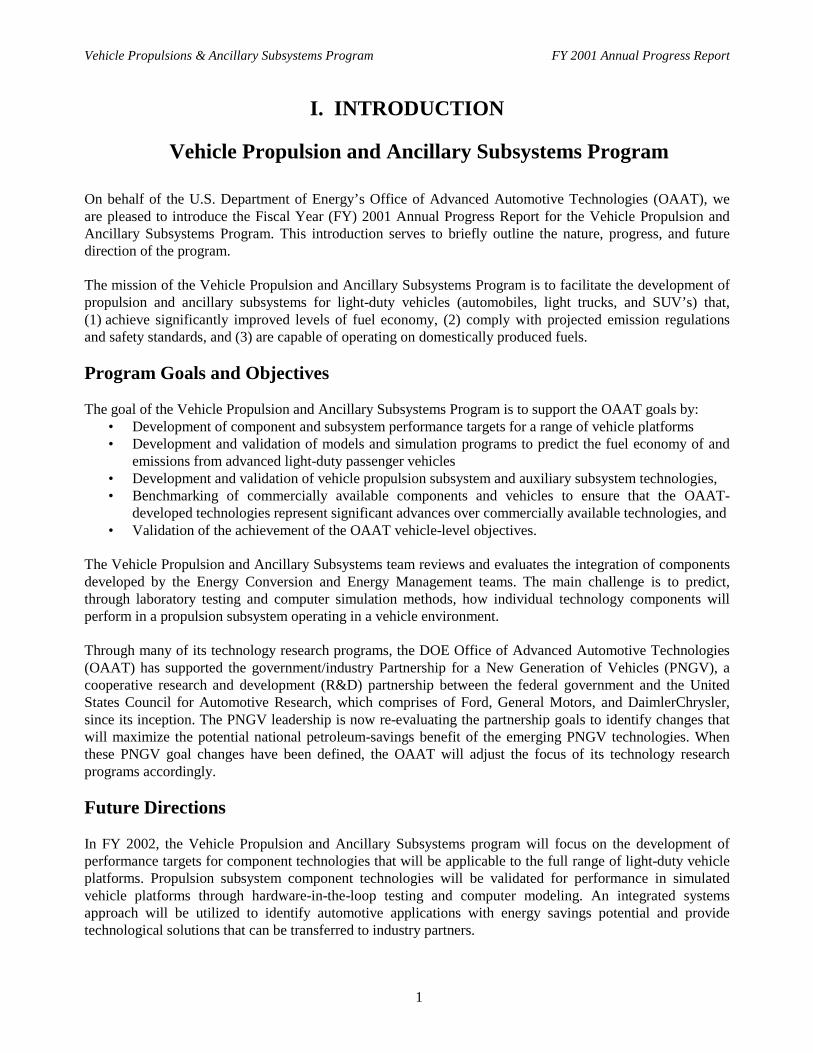
Figure 1. Number of downloads by ADVISORversion and release date.
Approach
Quickly gaining an understanding of anadvanced vehicle design’s sensitivity to change isa major benefit of using a tool like ADVISORearly in the vehicle design process. Improving thetime to production and saving money are bothimportant benefits to using simulation tools. Inaddition, ADVISOR uses specifications from avariety of component suppliers and originalequipment manufacturers. The information in theADVISOR component and vehicle database isvalidated by industry, NREL, and ADVISORusers. Although auto manufacturers have similarin-house tools, ADVISOR provides an objectivestandard through which the companies cansimulate vehicle performance and emissionsbenefits using components developed by manydifferent suppliers.
Results
Since ADVISOR was released to the publicthrough the NREL Web site, more than 4000people from around the world have downloadedthe software. This allows more people to have freeaccess to state-of-the-art hybrid vehicle data andan easy to use model to execute vehiclesimulations. This has a significant impact onincreasing the level of knowledge people haveabout hybrid vehicles in the auto industry OEMs,their suppliers, academia, and small businesses(that otherwise might not be able to afford to buysuch a model).
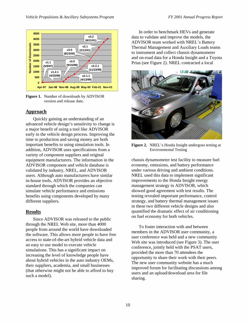
In order to benchmark HEVs and generatedata to validate and improve the models, theADVISOR team worked with NREL’s BatteryThermal Management and Auxiliary Loads teamsto instrument and collect chassis dynamometerand on-road data for a Honda Insight and a ToyotaPrius (see Figure 2). NREL contracted a local
Figure 2. NREL’s Honda Insight undergoes testing atEnvironmental Testing
chassis dynamometer test facility to measure fueleconomy, emissions, and battery performanceunder various driving and ambient conditions.NREL used this data to implement significantimprovements to the Honda Insight energymanagement strategy in ADVISOR, whichshowed good agreement with test results. Thetesting revealed important performance, controlstrategy, and battery thermal management issuesin these two different vehicle designs and alsoquantified the dramatic effect of air conditioningon fuel economy for both vehicles.
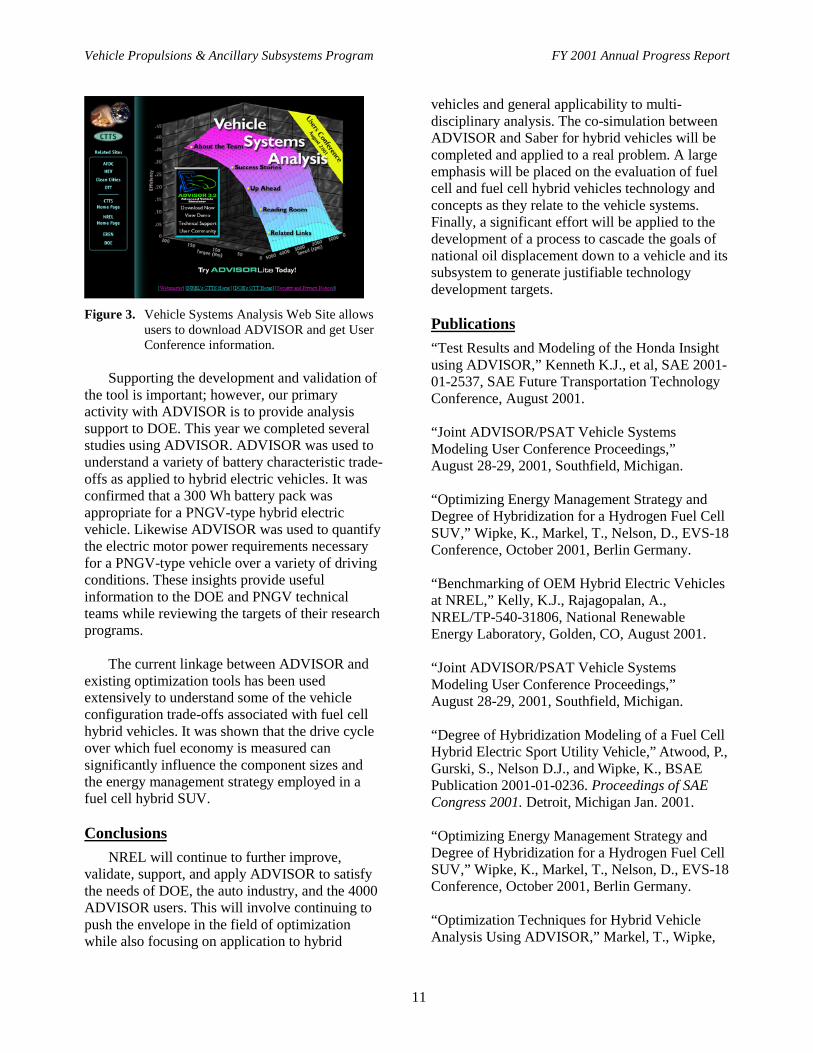
To foster interaction with and betweenmembers in the ADVISOR user community, auser conference was held and a new communityWeb site was introduced (see Figure 3). The userconference, jointly held with the PSAT users,provided the more than 70 attendees theopportunity to share their work with their peers.The new user community website has a muchimproved forum for facilitating discussions amongusers and an upload/download area for filesharing.
Vehicle Propulsions & Ancillary Subsystems Program FY 2001 Annual Progress Report
11
Figure 3. Vehicle Systems Analysis Web Site allowsusers to download ADVISOR and get UserConference information.
Supporting the development and validation ofthe tool is important; however, our primaryactivity with ADVISOR is to provide analysissupport to DOE. This year we completed severalstudies using ADVISOR. ADVISOR was used tounderstand a variety of battery characteristic trade-offs as applied to hybrid electric vehicles. It wasconfirmed that a 300 Wh battery pack wasappropriate for a PNGV-type hybrid electricvehicle. Likewise ADVISOR was used to quantifythe electric motor power requirements necessaryfor a PNGV-type vehicle over a variety of drivingconditions. These insights provide usefulinformation to the DOE and PNGV technicalteams while reviewing the targets of their researchprograms.
The current linkage between ADVISOR andexisting optimization tools has been usedextensively to understand some of the vehicleconfiguration trade-offs associated with fuel cellhybrid vehicles. It was shown that the drive cycleover which fuel economy is measured cansignificantly influence the component sizes andthe energy management strategy employed in afuel cell hybrid SUV.
Conclusions
NREL will continue to further improve,validate, support, and apply ADVISOR to satisfythe needs of DOE, the auto industry, and the 4000ADVISOR users. This will involve continuing topush the envelope in the field of optimizationwhile also focusing on application to hybrid
vehicles and general applicability to multi-disciplinary analysis. The co-simulation betweenADVISOR and Saber for hybrid vehicles will becompleted and applied to a real problem. A largeemphasis will be placed on the evaluation of fuelcell and fuel cell hybrid vehicles technology andconcepts as they relate to the vehicle systems.Finally, a significant effort will be applied to thedevelopment of a process to cascade the goals ofnational oil displacement down to a vehicle and itssubsystem to generate justifiable technologydevelopment targets.
Publications
“Test Results and Modeling of the Honda Insightusing ADVISOR,” Kenneth K.J., et al, SAE 2001-01-2537, SAE Future Transportation TechnologyConference, August 2001.
“Joint ADVISOR/PSAT Vehicle SystemsModeling User Conference Proceedings,”August 28-29, 2001, Southfield, Michigan.
“Optimizing Energy Management Strategy andDegree of Hybridization for a Hydrogen Fuel CellSUV,” Wipke, K., Markel, T., Nelson, D., EVS-18Conference, October 2001, Berlin Germany.
“Benchmarking of OEM Hybrid Electric Vehiclesat NREL,” Kelly, K.J., Rajagopalan, A.,NREL/TP-540-31806, National RenewableEnergy Laboratory, Golden, CO, August 2001.
“Joint ADVISOR/PSAT Vehicle SystemsModeling User Conference Proceedings,”August 28-29, 2001, Southfield, Michigan.
“Degree of Hybridization Modeling of a Fuel CellHybrid Electric Sport Utility Vehicle,” Atwood, P.,Gurski, S., Nelson D.J., and Wipke, K., BSAEPublication 2001-01-0236. Proceedings of SAECongress 2001. Detroit, Michigan Jan. 2001.
“Optimizing Energy Management Strategy andDegree of Hybridization for a Hydrogen Fuel CellSUV,” Wipke, K., Markel, T., Nelson, D., EVS-18Conference, October 2001, Berlin Germany.
“Optimization Techniques for Hybrid VehicleAnalysis Using ADVISOR,” Markel, T., Wipke,

Vehicle Propulsions & Ancillary Subsystems Program FY 2001 Annual Progress Report
12
K. Nelson, D., ASME International MechanicalEngineering Conference, November 2001,New York.
“Application of Optimization Tools to VehicleSystems Analysis,” Markel, T., Wipke, K. NRELMilestone Report. April 2001.
“ADVISOR-Saber Co-simulation for Single-Voltage and Dual-Voltage Conventional Vehicles”Johnson, V., Brooker, A., Wipke, K. NRELMilestone Report, June 2001.
“Completion of ADAMS/Car-ADVISOR LinkageMilestone Report,” Brooker, A. NREL MilestoneReport, June 2001.
“42 Volt Energy Storage System Targets for aDual Voltage System: Focusing on RequirementsDuring Engine off and Restart,” Brooker, A.,Presentation, Sept. 2001.
“Technology Roadmap for the 21st Century TruckProgram: A Government-Industry ResearchPartnership. Section 4.2: TRANSIT BUS,”Contributions by O’Keefe, M. ReportNo. 21CT-001. December 2000.
IID. Saber/ADVISOR Co-simulation
Aaron Brooker (principal investigator), Keith Wipke (project leader)National Renewable Energy Laboratory1617 Cole BoulevardGolden, CO 80401-3393(303) 275-4392, e-mail: [email protected]
DOE Program Manager: Robert Kost(202) 586-2334, e-mail: [email protected]
Objective
• Expand ADVISOR’s fuel economy prediction capability by creating a Saber co-simulation option.• Improve electrical component modeling.• Add new vehicle components and configurations to ADVISOR.
Approach
• Work with industry to leverage their Saber vehicle component models and vehicle expertise.• Modify ADVISOR to make co-simulation option transparent to the users.
� Create additional graphical user interfaces in ADVISOR to completely define the Saber portions of themodel.
� Develop the communication between ADVISOR and Saber to operate in the background.• Provide the option to use an industry standard tool, Saber, in conjunction with ADVISOR.
� Improves Advisor’s flexibility to allow industry to use their existing Saber models in ADVISOR.� Takes advantage of Saber’s electrical circuit solving capability.
• Improve ADVISOR’s component database by adding:� Saber’s component library to be used with ADVISOR.� An industry supplied database of 21 different types of auxiliary loads, each with typical load levels for
different vehicle types from sub-compact car to SUV.� Additional vehicle components, including a generator, DC/DC converter, and voltage regulator.

Vehicle Propulsions & Ancillary Subsystems Program FY 2001 Annual Progress Report
13
• Expand ADVISOR’s electrical modeling capability to use voltage and current based:� Auxiliary loads.� Vehicle components.
Accomplishments
• The communication method between ADVISOR and Saber for the co-simulation has been completed.• The co-simulation expanded ADVISOR to include:
� A dual-voltage configuration.� A single-voltage configuration with time varying electrical loads.� Saber’s component library.� Several industry provided models, including a generator, DC/DC converter, and a regulator.
• Electric vehicle component models are more accurately modeled.
Future Directions
• Work with industry to demonstrate and utilize the co-simulation.� Complete a dual voltage battery sizing project.� Publish a paper on the project model, method, and results.
• Expand the co-simulation with additional configurations including:� Series hybrid electric vehicle.� Parallel hybrid electric vehicle.
Introduction
The National Renewable Energy Laboratory(NREL) develops ADVISOR, an ADvancedVehIcle SimulatOR, to determine how differentvehicle components and configurations canimprove fuel economy. Saber is a software toolcommonly used for vehicle component modeling.Creating a co-simulation between ADVISOR andSaber leverages the benefits of both (see Figure 1).It creates more accurate electrical componentmodeling and adds a large number of availablevehicle components from Saber.
Approach
NREL worked with Delphi AutomotiveSystems to develop the Saber/ADVISOR co-simulation by means of a 50/50 cost-sharedcontract. Working with an industry partner todevelop the co-simulation provided two majorbenefits. One, it ensured the most relevant vehicleconfigurations would be developed. Two, itleveraged the industries’ existing Sabercomponent models.
Co-simulation offers several advantages. First,Saber is an industry standard tool. It is alreadycommonly used in the automotive industry forelectrical component modeling. By creating a co-
simulating between Saber and ADVISOR,industry can use their existing Saber models aspart of a full vehicle system analysis to determinethe impact their components have on fueleconomy. Second, it improves ADVISOR’scomponent database. Saber has its owncomponents to choose from, and industry canreadily provide many more. A third advantage tothe co-simulation is it improves ADVISOR’selectrical component modeling by using currentand voltage based models.
Co-simulation between ADVISOR and Saber
Figure 1. Saber/ADVISOR co-simulation
Results
The Saber/ADVISOR co-simulation has beensuccessfully completed. ADVISOR now includesadditional components, configurations, andanalysis detail.

Vehicle Propulsions & Ancillary Subsystems Program FY 2001 Annual Progress Report
14
The Saber/ADVISOR co-simulation expandedthe number of components usable in ADVISOR.ADVISOR can now use the Saber librarycomponents. It can also use the generator, DC/DCconverter, regulator and 21 auxiliary load modelsprovided by industry. With the addition of newcomponents, new configurations are also possible.
The co-simulation added two specificconfigurations and the capability for users tocreate any “custom” configuration. The twospecific configurations include a 42-volt/14-voltdual-voltage and a single voltage electricalarchitecture. The co-simulation not only addscomponents and configurations, but also greaterdetail to the model.
The co-simulation is setup to capitalize onSaber’s solver for the electrical portions of themodel. This allows for more detailed and accuratevoltage and current based models for the electricalportions of ADVISOR.
Conclusions
The Saber/ADVISOR co-simulation has addedvalue to ADVISOR. ADVISOR can now model
additional relevant components and configurationswith confidence and accuracy. Confidence ismaintained because the existing acceptance ofSaber as a modeling tool. Accuracy is improvedwith the change to a voltage and current basedelectrical systems model. With the co-simulation,ADVISOR now offers more components,configurations, and detail in modeling vehicle fueleconomy.
Publications
“Dual Voltage Electrical System Simulations,”MacBain, J., Conover, J., SAE PublicationTransitioning to 42-Volt Electrical Systems, SAESP-1556, pages 9-18, August, 2000.
“Co-Simulation of Automotive PropulsionSystems,” MacBain, J., and Conover, J., EVS 18Berlin, 2001.
“Co-Simulation of Electrical and PropulsionSystems,” MacBain, J., and Conover, J., SAEFFT, 2001.
“Simulation of Stop/Start Systems,” MacBain, J.,and Conover, J., EVS 18 Berlin, 2001.
IIE. Vehicle Auxiliary Load Reduction Project
Dr. Rob Farrington (principal investigator/project leader)National Renewable Energy Laboratory1617 Cole BoulevardGolden, CO 80401-3393(303) 275-4448, e-mail: [email protected]
DOE Program Manager: Robert Kost(202) 586-2334, e-mail: [email protected]
ObjectiveDevelop innovative techniques and technologies that will reduce the energy used for vehicle auxiliary loads,
manage peak loads, and optimize climate control systems and strategies. The short-term goal is to reduce theamount of fuel used for vehicle air-conditioning by 50% compared with today’s vehicles by developing cost-effective solutions in partnership with industry. The long-term goal is to work with industry to achieve a 75%reduction in air-conditioning fuel use through long-term R&D on technologies such as heat-generated cooling andcomponent miniaturization.

Vehicle Propulsions & Ancillary Subsystems Program FY 2001 Annual Progress Report
15
Approach
• Work with industry to research and develop innovative climate control strategies that will cost-effectivelyreduce the amount of fuel used for vehicle air-conditioning by 50% compared with today’s vehicles.
• Analyze, develop, and test advanced peak load reduction technologies including heat pipes, heat-generatedcooling systems, heat-generated electricity, and component miniaturization.
• Implement advanced cabin peak soak temperature reduction technologies on industry-collaborative vehicletesting projects.
• Use vehicle system level testing to validate integrated modeling methodology.
Accomplishments
• Completed vehicle testing of two Lincoln Navigators in a collaborative effort with Ford and Tier 1 suppliers tomeasure the impact of advanced technologies on reducing vehicle soak temperature, including solar infraredreflective glazings, visibly reflective glazings, reflective shades, gas-filled body insulation, reflective roofsurfaces, and active and passive parked car ventilation.
• Completed vehicle testing of Jeep Grand Cherokee in a collaborative effort with DaimlerChrysler to validateintegrated modeling techniques.
• Developed and tested passively cooled instrument panel using heat pipes.• Completed assessment of heat-generated cooling opportunities.• Completed review of state-of-the-art component miniaturization.• Completed optimization software for heat-generated electricity with thermoelectric devices.• Completed optimization software for transient air-conditioning systems.
Future Directions
• Validate integrated modeling tools in industry sponsored vehicle test.• Demonstrate heat-generated cooling concepts.• Demonstrate heat-generated electric concepts.• Optimize parked-car ventilation techniques.• Model and test climate control seats in collaboration with industry.• Investigate component miniaturization to improve overall system efficiency.
IntroductionNREL has the lead responsibility with DOE’s
Office of Transportation Technologies (OTT) toresearch, assess, and develop vehicle auxiliaryload reduction strategies.
The vehicles of today and tomorrow are inneed of systems that reduce vehicle auxiliaryloads. For mid-sized vehicles, air-conditioningsystems can increase NOx emissions by 80% andincrease CO emissions by 70% while increasingfuel consumption by 35%. Smaller and lighterclimate control systems will not only reduceemissions but also reduce fuel consumption. Each20-lb. reduction in weight leads to a 0.1-mpgincrease in fuel economy.
Reducing vehicle auxiliary loads will increasevehicle efficiency and reduce emissions. Vehiclesof the future, such as hybrid electric vehicles, will
need these innovations because they will havesmaller sized engines that will not be able tohandle peak air-conditioning loads or cabinheating requirements without serious fueleconomy impacts.
ApproachNREL is conducting research and
development with several industry partnersincluding DaimlerChrysler, Ford Motor Company,Johnson Controls, Delphi, Visteon, 3M,Southwall, Denso, Valeo, and PPG.
The team completed testing of a Jeep GrandCherokee (Figure 1) in conjunction withDaimlerChrysler and two Lincoln Navigators inpartnership with Ford. Advanced climate controlstrategies were implemented in these two types ofsport utility vehicles (SUV).

Vehicle Propulsions & Ancillary Subsystems Program FY 2001 Annual Progress Report
16
Figure 1. Jeep Grand Cherokee from DaimlerChrysler
being tested at NREL The test results provided data for validating
NREL�s integrated modeling process as well as measuring the effectiveness of different peak load reduction technologies.
Beyond reducing the cabin peak soak
temperature, an alternative power source for the climate control system is needed. More than twice as much thermal energy is rejected as heat than is produced in mechanical power (Figure 2). Using the engine waste heat to produce cooling and electricity is a prime opportunity to improve vehicle fuel economy.
Results
DaimlerChrysler provided a Jeep Grand Cherokee and PPG provided advanced solar-reflective windows to NREL for vehicle testing. Data were taken to evaluate the effect of the advanced glazing as well as parked car ventilation techniques. The temperatures predicted by the cabin/thermal fluid model correlated well with the test data.
Ford provided two Lincoln Navigators with thermo-electrically heated and cooled seats. Guardian International and PPG both provided sets of advanced solar reflective glazing. Solutia provided visibly reflective glazing, BOS provided reflective shades, LBL provided gas-filled insulation body panels, and 3M provided visibly reflective film. Aluminum foil was used to predict maximum solar energy rejected by surface treatments (Figure 3). Both active and passive
ventilation techniques to reduce cabin peak soak temperature were tested.
1000 1500 2000 2500 3000 3500 4000 45000
50
100
150
200
2030 40
50
60
70
80
90
100
125
15
175
200
300
400500
Engine Speed (rpm)E
ngin
e T
orqu
e (N
m)
Engine Waste Power (kW), Max Power 115 kW Based on 1991 Dodge Caravan 3.0-L (102 kW) SI Engine - transient data
Figure 2. Map of waste power (kW) of a 115-
kWengine with X�s showing engine operating points over the FTP drive cycle
Figure 3. Lincoln Navigators from Ford, baseline
vehicle and vehicle modified with foil The solar reflective glass cooled the interior
temperature of the vehicles by between 2°C to 5°C, permitting a smaller air-conditioning compressor to be used. The passive ventilation system reduced the difference between the cabin temperature and ambient by 35% while the active system (Figure 4) reduced the temperature difference by more than 40%.
NREL also tested a simulated instrument
panel with passive heat pipe cooling (Figure 5) in

Vehicle Propulsions & Ancillary Subsystems Program FY 2001 Annual Progress Report
17
an effort to reduce vehicle soak temperatures usingtechnologies that industry has identified aspromising. Test results show that heat pipescooled the instrument panel by nearly 20°C andthe air temperature by 9°C to 12°C whilemaintaining a uniform temperature across theinstrument panel during the day.
Figure 4. Active ventilation test on Lincoln Navigatorfrom Ford Motor Company
Figure 5. Simulated instrument panel with heat pipecooling
Conclusions
Our nation uses about 7.5 billion gallons ofgasoline per year for powering vehicle air-conditioning systems. This is equivalent to about10% of our crude oil imports.
Each degree Celsius reduction in cabin soaktemperature can lead to a 4% reduction incompressor power. A 10°C reduction in cabinsoak temperature would improve fuel economy byup to 1.5 miles per gallon for an SUV; or reduce
fuel use for air-conditioning in an SUV by about50%.
Vehicle air-conditioning systems are a primecandidate for reducing the amount of oil theU.S. imports. Near-term and longer-termtechnologies exist to reduce our nation’s fuel usefor vehicle air-conditioning.
Publications
“Advanced Porous Ceramic Heat Exchangers inAutomotive Thermal Management Systems,”Hendricks, T.J., Technical Paper presented atInternational Mechanical Engineering Congressand Exposition 2000, Nov. 6, 2000.
“Experimental Demonstration of Heat Pipe/Two-Phase-Flow Systems for Vehicle Passenger CabinCooling,” Hendricks, T.J., and Thoensen T.,Technical Paper presented at 2001 ASMEInternational Mechanical Engineering Congress &Exposition November 2001.
“Effect of Solar Reflective Glazing on FordExplorer Climate Control, Fuel Economy, andEmissions,” Rugh, J., Hendricks, T., and Koram,K., Technical Paper presented at InternationalBody Engineering Conference & Exposition 2001,October 2001.
“The Impact of Metal-Free Solar Reflective Filmon Vehicle Climate Control,” Rugh, J., Farrington,R., and Boettcher J., Technical Paper presented atFifth International Vehicle Thermal ManagementSystems Conference, May 2001.
“Component Miniaturization and Heat-GeneratedCooling Opportunities,” Hendricks, T.J., andJohnson, V., DOE Milestone Report, July 2001.
“Reduction in A/C Fuel Use Milestone,”Rugh, J., Milestone Report to DOE, September2001.
“Air-Conditioning Threat to HEV Fuel Economyand Emissions,” The Clean Fuels and ElectricVehicle Report January 2001.
“Air Condition Stresses HEV Performance,”Hybrid Vehicles, Vol. 3, Issue 1, January 2001.
Vehicle Propulsions & Ancillary Subsystems Program FY 2001 Annual Progress Report
18
“Advanced Vehicles: Are they a Dream of theFuture, or Today’s Reality?” Brodt-Giles, D.,Transportation for China, March 2001.
“Vehicle Cabin Cooling System for Capturing andExhausting Heated Boundary Layer Air fromInner Surface of Solar Heated Windows,”
Farrington, R., and Anderson, R., Patent Number6,186,886, February 13, 2001.
“Passive Cooling System for a Vehicle, ”Hendricks, T.J., and Thoensen, T., patent filedMay, 5, 2001.
IIF. National Vehicle Air-Conditioning Fuel Use Analysis
Valerie H. Johnson (principal investigator), Dr. Rob Farrington (project leader)National Renewable Energy Laboratory1617 Cole BoulevardGolden, CO 80401-3393(303) 275-4489, e-mail: [email protected]
DOE Program Manager: Roland Gravel(202) 586-9263, e-mail: [email protected]
Objective
• Determine the magnitude of energy used across the nation to create thermally comfortable cabins in light-dutyvehicles via air conditioning (AC). The results of this analysis help us determine the national fuel use impact ofadvanced climate control technologies.
Approach
• Use a bottoms-up approach to estimate the fuel used for AC in light-duty gasoline vehicles. A thermal comfortmodel using Fanger’s heat balance equations determined AC usage based on the premise that if a person weredissatisfied with the thermal environment (temperature and humidity), he or she would turn on the airconditioning.
• The thermal comfort results were then combined with transportation statistics on when people drive, where theylive, and how far they drive in a year.
• Vehicle simulations, supported by vehicle testing results with and without air conditioning, determined the fueluse penalty of using AC in cars and light-duty trucks.
Accomplishments
• This study estimated that up to 6% of U.S. annual petroleum consumption is used for vehicle air conditioning,equivalent to 10% of U.S. crude oil imports, or 0.5 million barrels of oil per day.
• NREL created a methodology to determine vehicle AC fuel usage. With varying modeling assumptions, ACfuel use ranged from 2% to 8% of the U.S. annual petroleum consumption.
• Optimization of vehicle cabins or AC systems now has an established metric of impact. Thus, reducing theamount of energy used for air conditioning in a vehicle by 75% could reduce the nation’s fuel consumption by5.6 billion gallons, or equivalently reduce the crude oil imports by 7.5%.
Future Directions
• Use the study to estimate fuel use impacts of vehicles with advanced cooling concepts.• Estimate the fuel saved through time as new vehicles are introduced into the U.S. market.
Vehicle Propulsions & Ancillary Subsystems Program FY 2001 Annual Progress Report
19
• Enhance the study and update the fuel impacts by including the advanced thermal comfort model for non-uniform thermal environments that is currently under development with University of California, Berkeley.
• Expand the study to include examining reduced tailpipe emissions seen with reduced air conditioning load.
Introduction
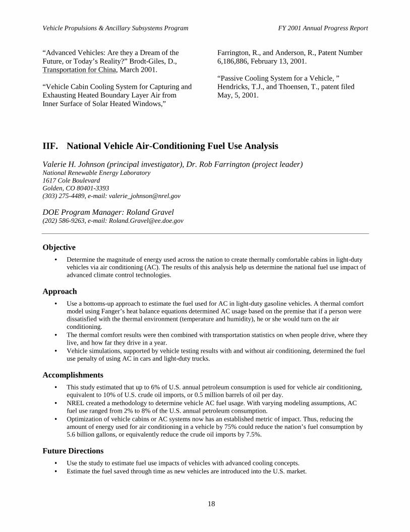
Vehicle air conditioning (AC) loads are themost significant auxiliary loads present in vehiclestoday. AC energy use even outweighs energy lossto rolling resistance, aerodynamic drag, ordriveline losses for a typical 27-miles per gallon(mpg) vehicle (Figure 1). The fuel economy of avehicle therefore drops substantially when the ACcompressor load is added to the engine. For aconventional 27-mpg vehicle, fuel consumptionincreases 35% with the AC on, and for a 80-mpghybrid, fuel consumption increases 128% with ACuse over the SC03 drive cycle.
Input 100%
Rolling 5.0%
Acc. 2.8%
Engine 79.3%
Aero.5.3%
Driveline 3.4%
Braking2.5%
21.3 city, 39 highway: 26.7 mpgge Energy Usage for Composite FTP & Highway
AC Load is an additional accessory
With AC10%
Figure 1. Percent vehicle energy uses/losses in aconventional 27-mpg Vehicle
Approach
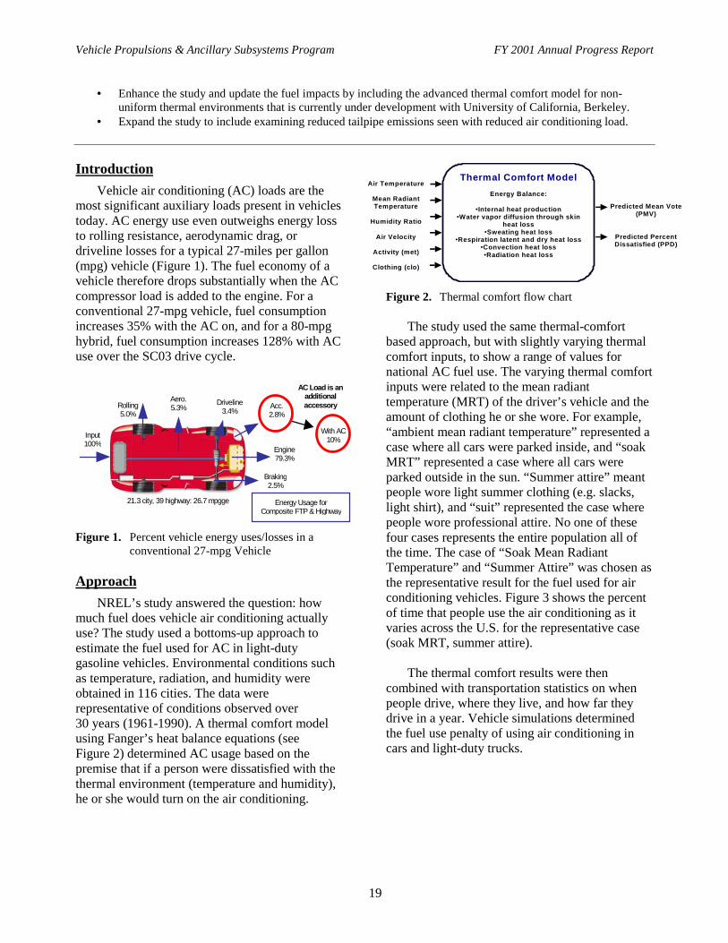
NREL’s study answered the question: howmuch fuel does vehicle air conditioning actuallyuse? The study used a bottoms-up approach toestimate the fuel used for AC in light-dutygasoline vehicles. Environmental conditions suchas temperature, radiation, and humidity wereobtained in 116 cities. The data wererepresentative of conditions observed over30 years (1961-1990). A thermal comfort modelusing Fanger’s heat balance equations (seeFigure 2) determined AC usage based on thepremise that if a person were dissatisfied with thethermal environment (temperature and humidity),he or she would turn on the air conditioning.
Figure 2. Thermal comfort flow chart
The study used the same thermal-comfortbased approach, but with slightly varying thermalcomfort inputs, to show a range of values fornational AC fuel use. The varying thermal comfortinputs were related to the mean radianttemperature (MRT) of the driver’s vehicle and theamount of clothing he or she wore. For example,“ambient mean radiant temperature” represented acase where all cars were parked inside, and “soakMRT” represented a case where all cars wereparked outside in the sun. “Summer attire” meantpeople wore light summer clothing (e.g. slacks,light shirt), and “suit” represented the case wherepeople wore professional attire. No one of thesefour cases represents the entire population all ofthe time. The case of “Soak Mean RadiantTemperature” and “Summer Attire” was chosen asthe representative result for the fuel used for airconditioning vehicles. Figure 3 shows the percentof time that people use the air conditioning as itvaries across the U.S. for the representative case(soak MRT, summer attire).
The thermal comfort results were thencombined with transportation statistics on whenpeople drive, where they live, and how far theydrive in a year. Vehicle simulations determinedthe fuel use penalty of using air conditioning incars and light-duty trucks.
Thermal Comfort Model
Energy Balance:
•Internal heat production •Water vapor diffusion through skin
heat loss •Sweating heat loss
•Respiration latent and dry heat loss •Convection heat loss •Radiation heat loss
Air Temperature
Mean Radiant Temperature
Humidity Ratio
Air Velocity
Activity (met)
Clothing (clo)
Predicted Mean Vote (PMV)
Predicted Percent Dissatisfied (PPD)
Vehicle Propulsions & Ancillary Subsystems Program FY 2001 Annual Progress Report
20
PPDPercent of
Time AC is On
0917263544526170
10
15
10
5
9
23
21
39
30
16
32
13
17
9
28
13
16
38
28
17
11
19
11
24
15
36
24
1411
8
20
10
40
1925
1916
16
18
70
27
47
19
14
171354
32
33
0
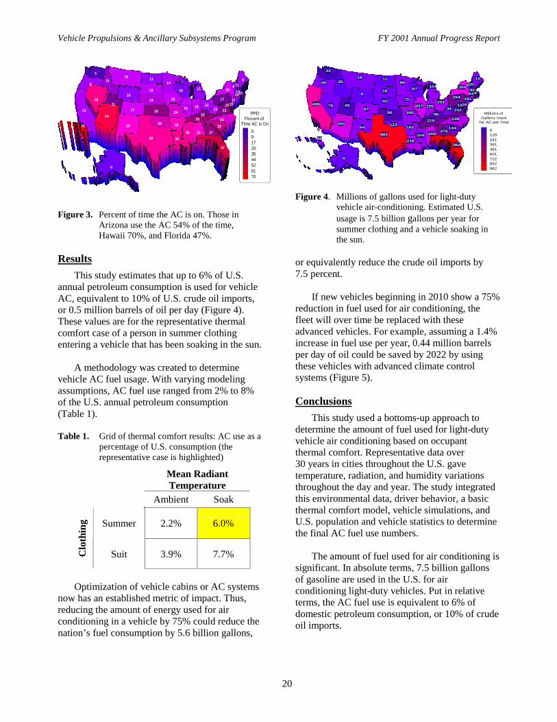
Figure 3. Percent of time the AC is on. Those inArizona use the AC 54% of the time,Hawaii 70%, and Florida 47%.
Results
This study estimates that up to 6% of U.S.annual petroleum consumption is used for vehicleAC, equivalent to 10% of U.S. crude oil imports,or 0.5 million barrels of oil per day (Figure 4).These values are for the representative thermalcomfort case of a person in summer clothingentering a vehicle that has been soaking in the sun.
A methodology was created to determinevehicle AC fuel usage. With varying modelingassumptions, AC fuel use ranged from 2% to 8%of the U.S. annual petroleum consumption(Table 1).
Table 1. Grid of thermal comfort results: AC use as apercentage of U.S. consumption (therepresentative case is highlighted)
Mean RadiantTemperature
Ambient Soak
Summer 2.2% 6.0%
Clo
thin
g
Suit 3.9% 7.7%
Optimization of vehicle cabins or AC systemsnow has an established metric of impact. Thus,reducing the amount of energy used for airconditioning in a vehicle by 75% could reduce thenation’s fuel consumption by 5.6 billion gallons,
Millions of Gallons Used
for AC per Year
0120241361481601722842962
6
34
67
33
8
21249
883
219
18
144
16254
39
123
203
304
79
64
191
20
43
11
238
18
104
166
86154
13
136
82
218
9686
155257
26
73
98
275
962
20
63
87498
291102
205
0
Figure 4. Millions of gallons used for light-dutyvehicle air-conditioning. Estimated U.S.usage is 7.5 billion gallons per year forsummer clothing and a vehicle soaking inthe sun.
or equivalently reduce the crude oil imports by7.5 percent.
If new vehicles beginning in 2010 show a 75%reduction in fuel used for air conditioning, thefleet will over time be replaced with theseadvanced vehicles. For example, assuming a 1.4%increase in fuel use per year, 0.44 million barrelsper day of oil could be saved by 2022 by usingthese vehicles with advanced climate controlsystems (Figure 5).
Conclusions
This study used a bottoms-up approach todetermine the amount of fuel used for light-dutyvehicle air conditioning based on occupantthermal comfort. Representative data over30 years in cities throughout the U.S. gavetemperature, radiation, and humidity variationsthroughout the day and year. The study integratedthis environmental data, driver behavior, a basicthermal comfort model, vehicle simulations, andU.S. population and vehicle statistics to determinethe final AC fuel use numbers.
The amount of fuel used for air conditioning issignificant. In absolute terms, 7.5 billion gallonsof gasoline are used in the U.S. for airconditioning light-duty vehicles. Put in relativeterms, the AC fuel use is equivalent to 6% ofdomestic petroleum consumption, or 10% of crudeoil imports.

Vehicle Propulsions & Ancillary Subsystems Program FY 2001 Annual Progress Report
21
2010 2015 2020 2025 2030 2035 20400
0.1
0.2
0.3
0.4
0.5
0.6
0.7
0.8
0.44 MMBD Saved by 2022
Ambient MRT, summer attireAmbient MRT, suitSoak MRT, summer attireSoak Mean Radiant Temp, suit
D B C A
A C B D
Assumptions: 75% reduction in new vehicles’ AC fuel use 16 million new vehicles/year 213 million vehicles in fleet 1.4% growth in fuel consumption
Time (year)
Mill
ion
Bar
rels
per
Day
Sav
ed
Figure 5. Millions of barrels per day (MMBD) savedthrough 2040 with a 75% reduction in fuelused for AC in vehicles after 2010
The range of fuel used for vehicle airconditioning based on different thermal comfortinputs was 2.7 to 9.7 billion gallons of gasoline.Optimization of vehicle cabins or air conditioningsystems now have an established metric of impact.
Thus, reducing the amount of energy used for airconditioning a vehicle by 75% could reduce thenation’s fuel consumption by 5.6 billion gallons,or equivalently reduce the crude oil imports by7.5%.
Ways to reduce the amount of energy used forcabin environment control are multiple andinclude optimized conventional AC systems,advanced window glazings for reduced peak cabinsoak temperatures, localized cooling, parked carventilation, or use of alternative cabin coolingsuch as heat generated cooling via exhaust gases.
Publications
“Impact of Vehicle Air-Conditioning on FuelEconomy, Tailpipe Emissions, and ElectricVehicle Range,” Farrington R., and Rugh, J,Technical Paper presented at Earth TechnologiesForum, October 2000.
“Fuel Used for Vehicle Air Conditioning: A State-by-State Thermal Comfort-Based Approach,”Johnson, V., Technical Paper written andsubmitted for Future Car Congress, June 2002.
IIG. Integrated Numerical Modeling for Vehicle Auxiliary Load Reduction
John P. Rugh (principal investigator), Dr. Rob Farrington (project leader)National Renewable Energy Laboratory1617 Cole BoulevardGolden, CO 80401-3393(303) 275-4413, e-mail: [email protected]
DOE Program Manager: Roland Gravel(202) 586-9263, e-mail: [email protected]
ObjectiveWork with the automotive industry to develop and validate an integrated modeling process that predicts fuel
economy, tail-pipe emissions, and human thermal comfort for advanced climate control systems. The automotivecompanies are under pressure to deliver vehicles to market more quickly and less expensively than ever. Numericalmodeling reduces time and costs. However, modeling climate control systems is a complex, multi-disciplinaryproblem beyond the capability of a single supplier. The goal is to use the integrated modeling process to investigatetechniques to reduce our nation’s fuel use for vehicle climate control.

Vehicle Propulsions & Ancillary Subsystems Program FY 2001 Annual Progress Report
22
Approach
• Identify requirements for a suite of software tools to perform a numerical model of a vehicle climate controlsystem including: solar radiation model, glazing optical thermal model, cabin thermal/fluid model, transienttwo-phase air-conditioning model, human physiological model, human psychological model and vehiclesimulation model.
• Develop tools that meet the design requirements if none are commercially available.• Link the numerical tools to allow quick and easy prediction of fuel economy, vehicle emissions, and human
thermal comfort.• Work with industry to analyze climate control strategies that will reduce the amount of fuel use for vehicle air-
conditioning.
Accomplishments
• Developed a solar radiation model that calculates the solar spectral irradiance incident on the vehicle as afunction of location, weather, and vehicle orientation. Model data are available for 239 locations in the UnitedStates and U.S. territories.
• Developed an interactive vehicle solar load estimator (VSOLE) to predict the transmitted, absorbed, andreflected energy of vehicle glazings for various light sources, vehicle types, vehicle orientation, and sunlocations.
• Validated the cabin thermal/fluid model through a collaborative project with DaimlerChrysler.
Future Directions
• Integrate a parametric modeling cabin tool into the modeling process.• Link the cabin thermal/fluid model to the transient A/C model.• Develop a human thermal comfort model and link it to the cabin thermal/fluid model.• Validate the integrated modeling process on an industry collaborative project.
Introduction
The air-conditioning compressor is the largestauxiliary load on today’s automobile engines andsignificantly impacts fuel economy and tailpipeemissions. Recent tests indicate that A/C useincreases emissions of NOx by about 80% and COby about 70% over the SCO3 drive cycle. It alsoreduces fuel economy by about 20%. However,research shows the potential to reduce the A/Cload on the engine and improve the real world fueleconomy without impacting comfort or safety.
Since A/C systems are typically sized for acooldown from a worst-case soak condition,NREL is investigating techniques to reduce thepeak soak temperature enabling the A/C systemsize to be reduced. NREL is also looking atimproved delivery systems and alternativemethods to cool the passenger compartment. It isimportant to understand how advanced coolingtechniques will impact human thermal comfortand fuel economy. We can predict the impact ofthese cooling techniques on the vehicle before
conducting tests by using a vehicle integratedmodeling process.
Predicting the impact of advanced climatecontrol technologies on occupant comfort, fueleconomy, and tailpipe emissions is challengingbecause of the many driving factors and complexinteractions. Occupant comfort is influenced bysolar inputs, glazing properties, A/C systemoperation, temperature, and velocity flow fields, aswell as an occupant’s physiological andpsychological responses to environmentalconditions. We have applied this process incollaboration with DaimlerChrysler, PPG, andJohnson Controls to evaluate advanced climatecontrol technologies.
Approach
The models used in the vehicle integratedmodeling process are diverse, complicated, andcover many engineering disciplines. We usedcommercial software when available, anddeveloped models when existing software do not
Vehicle Propulsions & Ancillary Subsystems Program FY 2001 Annual Progress Report
23
meet design requirements. The diverse modelswere then linked together to enable a smoothanalysis process. An overview of the vehiclemodeling process is shown in Figure 1.
The interior geometry of a vehicle is typicallydefined by CAD data or, in the case of vehiclesunder development, not defined. Using aparametric modeling tool, a generic vehicle ismorphed to the appropriate dimensions and meshis generated in preparation for cabin thermal/fluidmodeling using computation fluid dynamicsanalysis software (CFD).
A solar radiation model and vehicle solar loadtool provide solar boundary conditions for thecabin thermal/fluid model. A transient A/C modeldeveloped at NREL provides the conditioned airboundary condition for the CFD analysis and alink to the vehicle simulation software,ADVISOR, through the compressor load. Thecabin thermal/fluid model predicts the flow andtemperature field within the passengercompartment and passes this information to athermal comfort model to assess occupant thermalconfort.
Results
Glazing Model
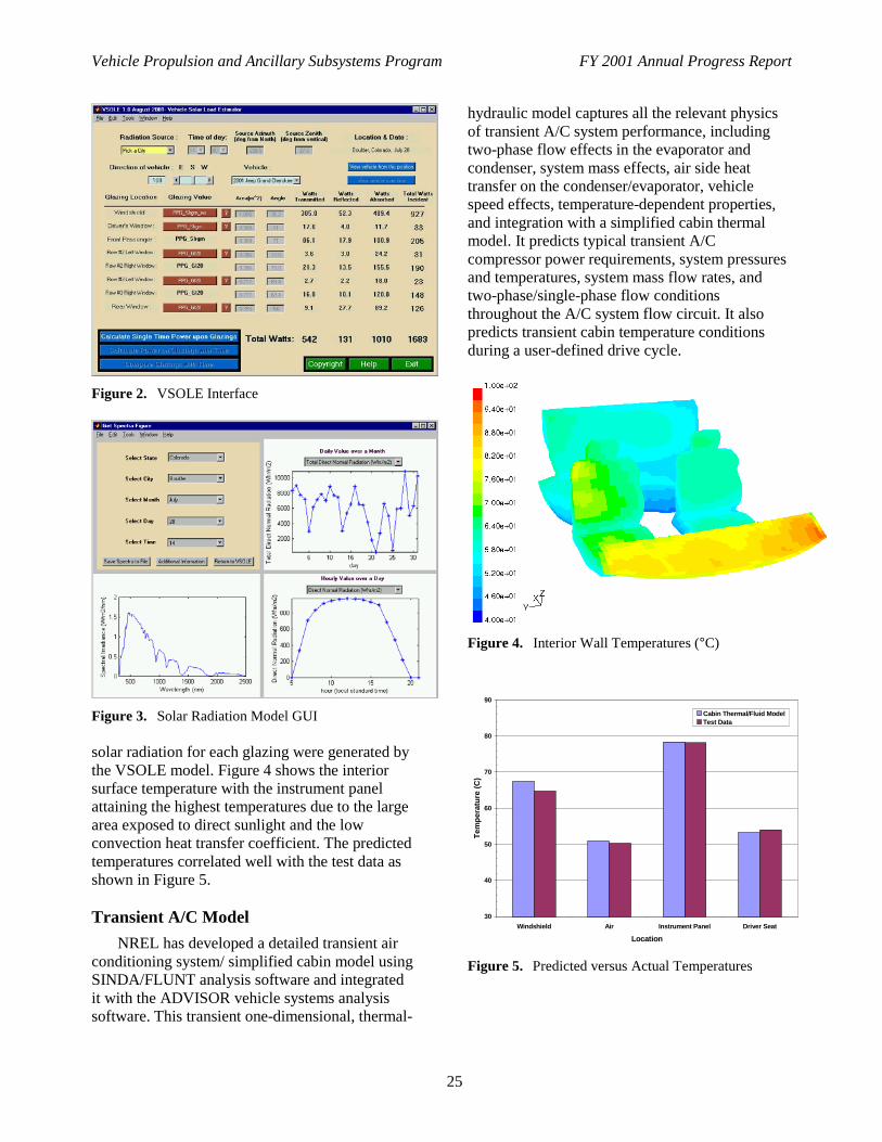
A key input to the cabin thermal/fluid modelthat ultimately determines the temperature riseabove ambient during a soak simulation is thesolar load. With today’s advanced solar reflectiveglazings, it is critical to understand the spectralproperties of the irradiance and the glazing inorder to perform accurate calculations. NREL hasdeveloped a vehicle solar load estimator (VSOLE)to predict the transmitted, absorbed, and reflectivepower of vehicle glazings. VSOLE also allows foreasy comparison of different types of glass,different solar sources such as indoor lamps, andthe ability to monitor solar load versus time.
VSOLE was written in Matlab and is easilyaccessed with a graphical user interface (GUI).The program takes into account the angle ofincidence and calculates the transmitted, reflected,
and absorbed power based on the radiation source,vehicle geometry, vehicle orientation, and glazingtype. All glazing surfaces are assumed to be flat,constant thickness, uniform properties, and ofregular shape. The calculation of the opticalproperties as a function of wavelength and angleuses a single-pane approximation for glass. Anexample of the VSOLE GUI is shown in Figure 2.
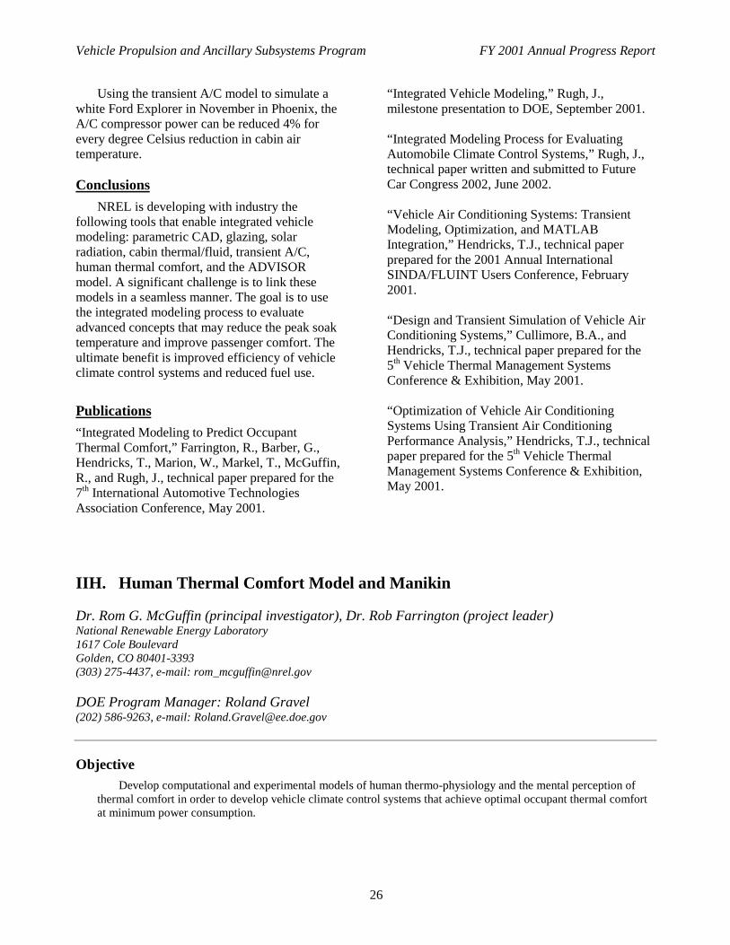
Solar Radiation Model
The solar radiation model developed atNREL provides radiation source data for VSOLEand is accessed from within the VSOLE GUIthrough the “pick a city” option in radiation-source pull-down menu. The solar radiation modelcalculates the solar spectral irradiance incident onthe vehicle as a function of location, weather, andvehicle orientation. Model data are available for239 locations in the United States and U.S.territories in the form of weather and sun positiondata. An example of the solar radiation model GUIis shown in Figure 3.
The spectral irradiance is calculated over arange of 300-2500 nm at 5 nm intervals. Theirradiance and corresponding weather data areavailable at one hour intervals. Plots of the dailyand hourly data assist in selecting the desiredenvironmental conditions. Weather data can beused to define boundary conditions for a CFDanalysis. After the city, month, day, and hour areselected, the spectral irradiance and sun positionare returned to VSOLE to enable calculation of thetransmitted, reflected, and absorbed power solarpower for a vehicle in the selected city. These datacan be used to define the solar loads for the cabinthermal/fluid model.
Cabin Thermal/Fluid Model
The purpose of the cabin thermal/fluid modelis to predict the flow field inside the passengercompartment, as well as the surface temperaturesand temperature and humidity of the air. As part ofa collaborative project with Daimler-Chrysler,NREL modeled a Jeep Grand Cherokee soak testusing environmental conditions from an actualColorado test day. The transmitted and absorbed

Vehicle Propulsions & Ancillary Subsystems Program FY 2001 Annual Progress Report
24
GlazingModel
Solar RadiationModel
ThermalComfort Model
Air ConditioningModel
Abs. & Trans.Radiation
CADModel
VehicleModel
CabinThermal/Fluid
Temp. & Vel.Fields (x,y,z;t)
CabinGeometry
OccupantThermal Comfort
Total SolarRadiation
A/C Output(T, v, RH;t)
A/C Load onEngine
FuelEconomy
TailpipeEmissions
VehicleOrientation
OpticalProperties
ComponentThermal
Properties
Radiant Loadon Occupants
Location,Time of Year
DriveCycle
EnvironmentalConditions
(v, T, Humidity)
A/C ComponentMaps
VehicleComponent Maps
Light SourceSpectrum
Legend
Inputs
ModelFinal
Results
VehicleDimensions
InterimResults
Vents, Return,Exhausters
YES ACCEPTABLE? NOImplement Design Change Model Inputs
EnvironmentalConditions(v, T, RH)
Figure 1. Overview of Integrated Modeling Process
Vehicle Propulsion and Ancillary Subsystems Program FY 2001 Annual Progress Report
25
Figure 2. VSOLE Interface
Figure 3. Solar Radiation Model GUI
solar radiation for each glazing were generated bythe VSOLE model. Figure 4 shows the interiorsurface temperature with the instrument panelattaining the highest temperatures due to the largearea exposed to direct sunlight and the lowconvection heat transfer coefficient. The predictedtemperatures correlated well with the test data asshown in Figure 5.
Transient A/C Model
NREL has developed a detailed transient airconditioning system/ simplified cabin model usingSINDA/FLUNT analysis software and integratedit with the ADVISOR vehicle systems analysissoftware. This transient one-dimensional, thermal-
hydraulic model captures all the relevant physicsof transient A/C system performance, includingtwo-phase flow effects in the evaporator andcondenser, system mass effects, air side heattransfer on the condenser/evaporator, vehiclespeed effects, temperature-dependent properties,and integration with a simplified cabin thermalmodel. It predicts typical transient A/Ccompressor power requirements, system pressuresand temperatures, system mass flow rates, andtwo-phase/single-phase flow conditionsthroughout the A/C system flow circuit. It alsopredicts transient cabin temperature conditionsduring a user-defined drive cycle.
Figure 4. Interior Wall Temperatures (°C)
30
40
50
60
70
80
90
Windshield Air Instrument Panel Driver Seat
Location
Tem
per
atu
re (
C)
Cabin Thermal/Fluid ModelTest Data
Figure 5. Predicted versus Actual Temperatures
Vehicle Propulsion and Ancillary Subsystems Program FY 2001 Annual Progress Report
26
Using the transient A/C model to simulate awhite Ford Explorer in November in Phoenix, theA/C compressor power can be reduced 4% forevery degree Celsius reduction in cabin airtemperature.
Conclusions
NREL is developing with industry thefollowing tools that enable integrated vehiclemodeling: parametric CAD, glazing, solarradiation, cabin thermal/fluid, transient A/C,human thermal comfort, and the ADVISORmodel. A significant challenge is to link thesemodels in a seamless manner. The goal is to usethe integrated modeling process to evaluateadvanced concepts that may reduce the peak soaktemperature and improve passenger comfort. Theultimate benefit is improved efficiency of vehicleclimate control systems and reduced fuel use.
Publications
“Integrated Modeling to Predict OccupantThermal Comfort,” Farrington, R., Barber, G.,Hendricks, T., Marion, W., Markel, T., McGuffin,R., and Rugh, J., technical paper prepared for the7th International Automotive TechnologiesAssociation Conference, May 2001.
“Integrated Vehicle Modeling,” Rugh, J.,milestone presentation to DOE, September 2001.
“Integrated Modeling Process for EvaluatingAutomobile Climate Control Systems,” Rugh, J.,technical paper written and submitted to FutureCar Congress 2002, June 2002.
“Vehicle Air Conditioning Systems: TransientModeling, Optimization, and MATLABIntegration,” Hendricks, T.J., technical paperprepared for the 2001 Annual InternationalSINDA/FLUINT Users Conference, February2001.
“Design and Transient Simulation of Vehicle AirConditioning Systems,” Cullimore, B.A., andHendricks, T.J., technical paper prepared for the5th Vehicle Thermal Management SystemsConference & Exhibition, May 2001.
“Optimization of Vehicle Air ConditioningSystems Using Transient Air ConditioningPerformance Analysis,” Hendricks, T.J., technicalpaper prepared for the 5th Vehicle ThermalManagement Systems Conference & Exhibition,May 2001.
IIH. Human Thermal Comfort Model and Manikin
Dr. Rom G. McGuffin (principal investigator), Dr. Rob Farrington (project leader)National Renewable Energy Laboratory1617 Cole BoulevardGolden, CO 80401-3393(303) 275-4437, e-mail: [email protected]
DOE Program Manager: Roland Gravel(202) 586-9263, e-mail: [email protected]
ObjectiveDevelop computational and experimental models of human thermo-physiology and the mental perception of
thermal comfort in order to develop vehicle climate control systems that achieve optimal occupant thermal comfortat minimum power consumption.

Vehicle Propulsion and Ancillary Subsystems Program FY 2001 Annual Progress Report
27
Approach
• Develop a numerical model of human thermal physiology and psychology.• Build a thermal manikin that can be placed in actual vehicles, which will respond to the transient and extremely
non-uniform thermal environments inside vehicle cabins.
Accomplishments
• A leg segment of a thermal manikin was fabricated demonstrating the following.− Realistic sweating rates using porous metal skin for the first time ever.− Fast transient thermal response times.− Fully wetted skin with high spatial resolution.
• A thermal physiological model consisting of a human body shape, tissues, and circulation system has beendeveloped.
• The apparatus to thermally condition local body segments for the thermal psychological model has been built.
Future Directions
• Develop a psychological model from a series of human subject tests that examine local thermal comfort.• Couple body segments to produce global comfort.• Couple the Human Thermal Comfort Model to models of external environmental conditions to evaluate. and
optimize the performance of climate control systems.
Introduction
Current vehicle climate control systems aredramatically overpowered because they aredesigned to heat/cool the entire cabin from anextreme condition to room temperature in aspecified period of time. Typical vehicle airconditioning systems require 4,000 Watts ofmechanical power, whereas the human body onlydissipates roughly 100 Watts.
NREL is developing a numerical model ofhuman thermal physiology and psychology, and athermal manikin that can be placed in actualvehicles, all of which will respond to the transientand extremely non-uniform thermal environmentsinside vehicle cabins. Industry can then use thesetools to develop climate control systems thatachieve optimal occupant thermal comfort but atminimum power consumption.
The computational tool under development isa Human Thermal Comfort Model. The purpose ofthis model is to predict the physiological andpsychological response of a human to a transientnon-uniform thermal environment. Thephysiological model is a finite element model ofthe human thermal physiological systems andthermoregulatory systems.
The experimental tool under development isan Advanced Thermal Manikin. The ThermalManikin is also being engineered to respond to atransient non-uniform thermal environment in thesame manner as a human.
Approach
The Thermal Comfort Project at NREL isorganized into the development of three predictivetools. These include a physiological model of thehuman thermal system, a psychological model ofhuman thermal comfort, and a thermal comfortmanikin for real vehicle testing.
Human Thermal Physiological Model
NREL has chosen to upgrade and improve theKansas State University (KSU) finite elementmodel for the NREL Human Thermal ComfortModel (see Figures 1 and 2). A finite elementmodel will allow a much more precise simulationof the detailed interface between the human bodyand complex geometry of the seats and vehiclecabin.

Vehicle Propulsion and Ancillary Subsystems Program FY 2001 Annual Progress Report
28
Psychological Thermal Comfort Model
A project is underway to develop apsychological model that can convert thedistribution of static and dynamic temperaturesinto local and global perceptions of thermalcomfort.
The project consists of three general tasks:• Task 1 is to develop an apparatus that can
control the static and dynamic temperatureof each body segment.
• Task 2 is to conduct the human subjecttests to determine the thermal comfortsensitivity of each body segment.
• Task 3 is to develop a mathematical modelthat can predict local and global thermalcomfort based on measurements from thetests.
Thermal Comfort Manikin
NREL has been working with an industrypartner, Management Technology Northwest(MTNW), to build a life-size manikin, which willsimulate how human passengers respond to non-uniform, transient thermal conditions (heat, cold,solar radiation, air velocity, and temperature) in anautomobile. The thermal comfort manikin will becontrolled by a finite element physiological model,which provides outputs to a psychological modelthat predicts the occupant’s perception of local andglobal thermal comfort.
Figure 1. Physiological model of arm and leg tissuemesh.
The manikin is expected to take two years tobuild. The first year consisted of research anddevelopment. The second year is building themanikin. The overall objective of the program is todevelop a thermal manikin that will respond to atransient non-uniform thermal environment similarto a human.
Results
Human Thermal Physiological Model
Improvements have been made to the existingKSU model to develop a model that can veryclosely simulate human thermal response. Thisimproved human thermal model will be coupled tothe external thermal field models for thermalcomfort testing.
Figure 2. Physiological model mesh, showing bone,muscle, fat, and skin in a limb.
The physiological model of the human bodynow incorporates limb and body shapes, which arescalable to any human body. It also incorporatesinternal tissue (bone, muscle, fat, skin) and afunctional convection circulation system, completewith simulated blood flow through big arteries andveins. A simulated torso has also been developedwhich includes a heart, lungs, and intestines.Blood profusion on a smaller scale is now in theworks.
Psychological Thermal Comfort Model
The University of California at Berkeley hascompleted its design of human subject tests relatedto the psychological model. The tests arescheduled to begin soon. The university has

Vehicle Propulsion and Ancillary Subsystems Program FY 2001 Annual Progress Report
29
developed an innovative way of measuring bodycore temperature, which involves the use of
“ingestible thermalmeter pills”(see Figure 3). The pills,swallowed by human subjects,contain crystals that transmittemperature information to awireless receiver.
Figure 3. Ingestiblethermalmeter pill
Thermal Comfort Manikin
A leg segment of the manikin was fabricated(see Figure 4) demonstrating the following:
• Realistic sweating rates using porousmetal skin for the first time ever
• Fast transient thermal response times• Fully wetted skin with high spatial
resolution• Simultaneous operation of 16 surface
segments, each with independent controlof heating, sweating, and temperaturesensation.
Figure 4. MTNW successfully fabricated a thermalcomfort manikin leg with sweatingcapabilities.
A recently developed prototype system for thethermal comfort manikin mimics humanbreathing. Room temperature air is pushed througha heated water chamber to create warm, fullysaturated air, which matches the volume,temperature, and humidity of human breath.MTNW is building the life-size manikin, whichwill simulate how a passenger responds to non-uniform, transient thermal conditions (heat, cold,
solar radiation, air velocity, and temperature) in anautomobile.
Conclusions
The vehicle Thermal Comfort Project atNREL consists of three main components, whichinclude the physiological model, a psychologicalcomfort model, and a thermal manikin. All threecomponents should be completed by January2003. These tools will then be available for use byindustry to develop more effective and efficientthermal comfort systems. The numerical thermalcomfort models and thermal manikin will be thefirst thermal comfort tools that can accuratelypredict the human physiological and psychologicalresponse in both actual and simulated non-uniformtransient thermal environments.
The manikin is an important tool for industrybecause it can be used to evaluate consumercomfort in vehicles while helping to evaluatetechnologies designed to reduce vehicle auxiliaryloads and downsize the air-conditioning systemsin vehicles.
Publications
“Modeling of Human Thermal Comfort,”McGuffin, R., 2001 SAE Digital Human ModelingConference, July 2001.
“Advanced Thermal Manikin,” McGuffin, R., 47th
International Instrumentation Symposium of theInstrument Society of America, June 2001.
“Modeling of Human Thermal Comfort,”McGuffin, R., 2001 SAE Vehicle ThermalManagement Conference, July 2001.
“NREL Thermal Comfort Models,” DOEMilestone Report, July 2001.
“Thermal Comfort Manikin,” DOE MilestoneReport, August 2001.
“Development of an Advanced Thermal Manikinfor Vehicle Climate Evaluation,” Burke, R., andMcGuffin, R., 4IMM Conference, September2001.

Vehicle Propulsion and Ancillary Subsystems Program FY 2001 Annual Progress Report
30
II-I. Transient Air Conditioning System Analysis & Optimization
Dr. Terry J. Hendricks (principal investigator), Dr. Rob Farrington (project leader)National Renewable Energy Laboratory1617 Cole BoulevardGolden, CO 80401-3393(303) 275-4419, e-mail: [email protected]
DOE Program Manager: Roland Gravel(202) 586-9263, e-mail: [email protected]
Objective
• Work with the automotive industry to develop and validate vehicle transient air conditioning system modelsthat predict A/C power requirements on the engine, cabin thermal/fluid boundary conditions, and impacts onhuman thermal comfort.
• Integrate those models with NREL’s ADVISOR vehicle analysis software to predict A/C system impacts onfuel economy, tail-pipe emissions, and human thermal comfort for advanced climate control systems.
• Conduct transient computational modeling of the A/C system allows capture of the important transientphenomenon (e.g., dynamic two-phase flow and temperature/pressure/quality effects) and their impacts onsystem design for more environmental conditions more quickly and less expensively than costly vehicle/systemtesting. Assist automotive companies that are under pressure to identify and fabricate optimized A/C systemsthat are effectively integrated with the entire vehicle’s energy management system more quickly and lessexpensively than ever.
• Model the vehicle A/C system as part of the entire vehicle climate control system in a sophisticated, multi-disciplinary analysis environment.
• Use the transient A/C modeling process to investigate design methodology, control strategies, and designtechniques to reduce our nation’s fuel use for vehicle A/C system operation.
• Work with the automotive industry to develop and validate vehicle transient air conditioning system modelsthat predict A/C power requirements on the engine, cabin thermal/fluid boundary conditions, and impacts onhuman thermal comfort. Integrate those models with NREL’s ADVISOR vehicle analysis software to predictA/C system impacts on fuel economy, tail-pipe emissions, and human thermal comfort for advanced climatecontrol systems. Vehicle A/C systems are controlled by and exposed to transient boundary and vehicle driveconditions. Transient computational modeling of the A/C system allows one to capture the important transientphenomenon (e.g., dynamic two-phase flow and temperature/pressure/quality effects) and their impacts onsystem design for more environmental conditions more quickly and less expensively than costly vehicle/systemtesting. Modeling the vehicle A/C system as part of the entire vehicle climate control system is a complex,multi-disciplinary problem beyond the capability of a single supplier. The goal is to use the transient A/Cmodeling process to investigate design methodology, control strategies, and design techniques to reduce ournation’s fuel use for vehicle A/C system operation.
Approach
• Identify the appropriate software tools capable of performing transient analyses of transient, two-phase, multi-constituent flow in a vehicle A/C system flow loop and capable of multi-variable optimization of the A/Csystem.
• Develop the transient A/C system model that is linked to both simplified (i.e., <10 volume elements) andsophisticated (i.e., > 500 volume elements) finite element cabin thermal/fluid models.
• Work with industry to analyze climate control strategies that will reduce the amount of fuel use for vehicle air-conditioning.

Vehicle Propulsion and Ancillary Subsystems Program FY 2001 Annual Progress Report
31
Accomplishments
• Developed a detailed transient, two-phase A/C model in SINDA/FLUINT analysis software that includesoptimization capability.
• Integrated the transient A/C model with a simplified, 2-node cabin thermal/fluid model to analyze transientcabin cool-down conditions in response to the dynamic A/C system thermal/fluid performance.
• Initiated multi-variable A/C system optimizations that included the effect of coupled, interdependentcomponent effects on A/C system design.
• Linked the transient A/C model and the ADVISOR (Advanced VehIcle SimulatOR ) software to determine thefuel use impact of a smaller A/C compressor.
• Integrated the SINDA/FLUENT transient A/C model and simplified the cabin thermal/fluid model with theVSOLE vehicle solar load estimator software.
• Optimized electric-driven A/C systems for advanced vehicle climate control.
Future Directions
• Integrate the transient A/C model with the cabin thermal/fluid model developed as part of the integratedmodeling task.
• Populate the transient A/C model with industry-specific component models to analyze A/C systems of interestto industry.
• Validate the transient air conditioning model with “real system” experimental data on an industry collaborativeproject.
• Continue system optimization studies of dynamically-controlled, electric-driven A/C systems for futureadvanced vehicle platforms.
Introduction
The air-conditioning (A/C) compressor is thelargest auxiliary load on today’s automobileengines and significantly impacts fuel economyand tailpipe emissions. Recent tests indicate thatA/C use increases emissions of NOx by about 80%and CO by about 70% over the SCO3 drive cycle.It also reduces fuel economy by about 20% inconventional vehicles. In addition, recent NRELtests have shown that A/C system operation in theToyota Prius and Honda Insight hybrid electricvehicles (HEV) reduces fuel economy byapproximately 35%. Research indicates that thereis significant potential to reduce A/C powerdemands on the engine and improve real worldfuel economy, without impacting comfort orsafety.
A/C systems are typically sized for transientcooldown from worst-case thermal soakconditions with little regard or emphasis on systemenergy usage and management. NREL isinvestigating techniques to 1) optimize vehicleA/C systems to reduce their power demands on thevehicle engine, and 2) optimize the vehicle A/Csystem within the overall vehicle optimization
process, while maintaining system performancerequirements important to human thermal comfort.
Predicting the impact of advanced A/Csystems and control strategies on occupantcomfort, fuel economy, and tailpipe emissions ischallenging because of the many critical factorsand complex interactions. A/C systemperformance is dictated by componentperformance specifications, cabin thermal(including solar) loads, dynamic two-phase flowconditions, vehicle drive cycle, front-end airvelocity and flow conditions, and ambienttemperature. We are working on a systemsanalysis and optimization process in collaborationwith DaimlerChrysler, General Motors, DelphiAutomotive Systems, Visteon Climate Control,and Valeo Climate Control to evaluate andintegrate advanced A/C systems and climatecontrol technologies.
Approach
NREL has developed a detailed transient airconditioning system/simplified cabin model usingSINDA/FLUNT analysis software and integratedit with the ADVISOR vehicle systems analysis

Vehicle Propulsion and Ancillary Subsystems Program FY 2001 Annual Progress Report
32
Figure 1. Typical Vehicle Air ConditioningSystem With Belt-DrivenCompressor
software. Figure 1 schematically shows the typicalvehicle A/C system (using R-134a) modeled bytransient A/C system analysis. This transient one-dimensional, thermal-hydraulic model captures allthe relevant physics of transient A/C systemperformance, including two-phase flow effects inthe evaporator and condenser, system masseffects, air side heat transfer on thecondenser/evaporator, vehicle speed effects,temperature-dependent properties, and integrationwith a simplified cabin thermal model. The modelpredicts typical transient A/C compressor powerrequirements, system pressures and temperatures,system mass flow rates, and two-phase/single-phase flow conditions throughout the A/C systemflow circuit. The transient A/C system model isalso integrated with a simplified vehicle cabinthermal/fluid model so we can predict cabinthermal response to the A/C system performance.This cabin model predicts transient cabintemperature conditions during a user-defined drivecycle. In the near future we will integrate thetransient A/C system model with a moresophisticated cabin thermal/fluid model developedin the integrated modeling task.
The transient A/C system model has also beenintegrated with the VSOLE solar load estimatormodel. VSOLE currently predicts transient solarthermal loads on a vehicle cabin, which in turn areused by the cabin thermal/fluid model within thetransient A/C system model to predict cabintemperature response. This shows the capability ofintegrating the transient A/C model with a cabinthermal/fluid model and the VSOLE solar loadestimator to predict integrated effects. VSOLE
was written in Matlab and is easily accessed with agraphical user interface (GUI). The program takesinto account the angle of incidence and calculatesthe transmitted, reflected, and absorbed powerbased on the radiation source, vehicle geometry,vehicle orientation, and glazing type. All glazingsurfaces are assumed to be flat, with constantthickness, uniform properties, and of regularshape. The calculation of the optical properties asa function of wavelength and angle uses a single-pane, no-wave-interference model for glass. Anexample of the VSOLE GUI available in theADVISOR / SINDAFLUINT co-simulation isshown in Figure 2. We will ultimately integratethis capability with a passenger thermal comfortmodel in the integrated modeling task.
Figure 2. VSOLE Interface
Results
System Transient Behavior
The transient A/C system research has givenNREL/DOE tremendous insights andunderstanding into the transient behavior ofcurrent A/C systems. Figure 3 shows the variationin compressor power with time for a vehicledriven in the SCO3 drive cycle. The compressorpower is shown to vary from 40% to 140% ofaverage compressor power over the SCO3 drivecycle. Figure 4 shows the variation in systempressures with time on the high pressure side andlow pressure side of the expansion device in atypical vehicle A/C system.
FrontFront--EndEndAir FlowAir Flow
Accumulator /Accumulator /DryerDryer
EngineEngine--DrivenDrivenCompressorCompressor
CondenserCondenser
Expansion DeviceExpansion Device(Orifice Tube)(Orifice Tube)
EvaporatorEvaporator
Evaporator Air FlowEvaporator Air Flow(Outside Air or (Outside Air or RecircRecirc.).)

Vehicle Propulsion and Ancillary Subsystems Program FY 2001 Annual Progress Report
33
Figure 3. Time-Dependent A/C Compressor PowerOver the SCO3 Drive Cycle.
Figure 4. Time-Dependent System Pressure ProfilesOver SC03 Drive Cycles.
This research has also shown that thecondensation and evaporation front locationswithin the condenser and evaporator move duringdynamic drive cycle conditions. Drive cycleeffects create dramatically variable heat transfercoefficients in both the condenser and evaporatoras exemplified in Figure 5 for the condenser. Thecondensation and evaporation front movementalso can be changed significantly by employingdifferent compressors and expansion devices.These system dynamics within any given vehicledrive cycle must be captured to truly optimize avehicle A/C system. The transient A/C modelallows us to account for and track these frontmovements within the condenser and evaporatorfor various system configurations and optimize thesystem performance while accounting for thehighly dynamic flow and heat transfer conditions.
Figure 5. Condenser and Evaporator Heat TransferCoefficients are Strong Functions of Timeand Location Within Flow Path
System Optimization
The truly transient behavior of the manycritical and interdependent A/C systemperformance parameters makes multi-variabledesign optimization imperative to improve systemperformance. Initial multi-variable optimization ofthe overall A/C system showed that a 50%increase in A/C system COP (Coefficient ofPerformance) was possible simply bysimultaneously optimizing system componentsand their interdependent effects. In oneoptimization study, the relationship between thecompressor displacement and expansion devicediameter was found to be critical for increasingsystem performance, as the optimum combinationcreated optimum high pressure profiles shown inFigure 6 over the SC03 drive cycle. The optimumcombination also created optimum flow qualityconditions in the condenser as shown in Figure 7.
Figure 6. Optimum Pressure Profiles During SC03Drive Cycle
Optimum Pressure Profile
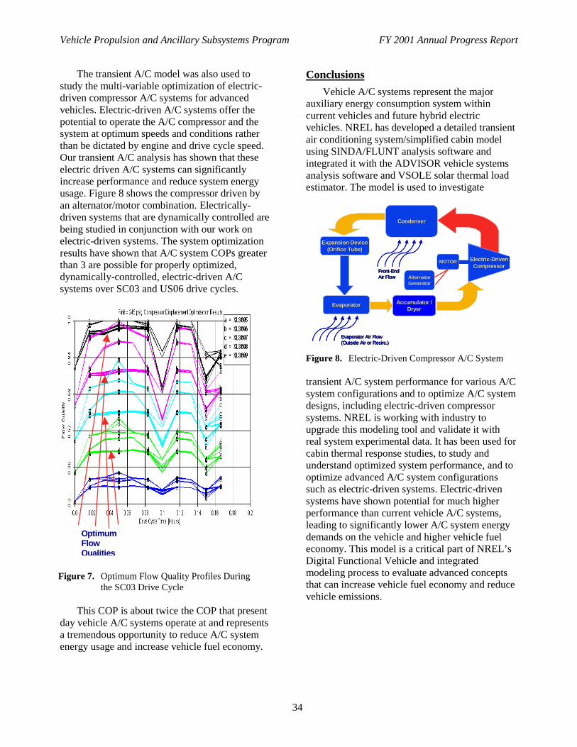
Vehicle Propulsion and Ancillary Subsystems Program FY 2001 Annual Progress Report
34
The transient A/C model was also used tostudy the multi-variable optimization of electric-driven compressor A/C systems for advancedvehicles. Electric-driven A/C systems offer thepotential to operate the A/C compressor and thesystem at optimum speeds and conditions ratherthan be dictated by engine and drive cycle speed.Our transient A/C analysis has shown that theseelectric driven A/C systems can significantlyincrease performance and reduce system energyusage. Figure 8 shows the compressor driven byan alternator/motor combination. Electrically-driven systems that are dynamically controlled arebeing studied in conjunction with our work onelectric-driven systems. The system optimizationresults have shown that A/C system COPs greaterthan 3 are possible for properly optimized,dynamically-controlled, electric-driven A/Csystems over SC03 and US06 drive cycles.
This COP is about twice the COP that presentday vehicle A/C systems operate at and representsa tremendous opportunity to reduce A/C systemenergy usage and increase vehicle fuel economy.
Conclusions
Vehicle A/C systems represent the majorauxiliary energy consumption system withincurrent vehicles and future hybrid electricvehicles. NREL has developed a detailed transientair conditioning system/simplified cabin modelusing SINDA/FLUNT analysis software andintegrated it with the ADVISOR vehicle systemsanalysis software and VSOLE solar thermal loadestimator. The model is used to investigate
FrontFront--EndEndAir FlowAir Flow
Accumulator /Accumulator /DryerDryer
ElectricElectric--DrivenDrivenCompressorCompressor
CondenserCondenser
Expansion DeviceExpansion Device(Orifice Tube)(Orifice Tube)
EvaporatorEvaporator
Evaporator Air FlowEvaporator Air Flow(Outside Air or (Outside Air or RecircRecirc.).)
MOTORMOTOR
AlternatorAlternatorGeneratorGenerator
Figure 8. Electric-Driven Compressor A/C System
transient A/C system performance for various A/Csystem configurations and to optimize A/C systemdesigns, including electric-driven compressorsystems. NREL is working with industry toupgrade this modeling tool and validate it withreal system experimental data. It has been used forcabin thermal response studies, to study andunderstand optimized system performance, and tooptimize advanced A/C system configurationssuch as electric-driven systems. Electric-drivensystems have shown potential for much higherperformance than current vehicle A/C systems,leading to significantly lower A/C system energydemands on the vehicle and higher vehicle fueleconomy. This model is a critical part of NREL’sDigital Functional Vehicle and integratedmodeling process to evaluate advanced conceptsthat can increase vehicle fuel economy and reducevehicle emissions.
OptimumFlowQualities
Figure 7. Optimum Flow Quality Profiles Duringthe SC03 Drive Cycle

Vehicle Propulsion and Ancillary Subsystems Program FY 2001 Annual Progress Report
35
Publications
“Vehicle Transient Air Conditioning Analysis:Model Development & System OptimizationInvestigations,” Hendricks, T.J., NREL TechnicalReport #NREL/TP-540-30715, June 2001.
“Integrated Modeling to Predict OccupantThermal Comfort,” Farrington, R., Barber, G.,Hendricks, T., Marion, W., Markel, T., McGuffin,R., and Rugh, J., technical paper prepared for the7th International Automotive TechnologiesAssociation Conference, May 2001.
“Integrated Vehicle Modeling,” Rugh, J.,milestone presentation to DOE, September 2001.
“Integrated Modeling Process for EvaluatingAutomobile Climate Control Systems,” Rugh, J.,technical paper written and submitted to FutureCar Congress 2002, June 2002.
“Vehicle Air Conditioning Systems: TransientModeling, Optimization, and MATLABIntegration,” Hendricks, T.J., technical paperprepared for the 2001 Annual InternationalSINDA/FLUINT Users Conference,February 2001.
“Design and Transient Simulation of Vehicle AirConditioning Systems,” Cullimore, B.A., andHendricks, T.J., technical paper prepared for the5th Vehicle Thermal Management SystemsConference & Exhibition, May 2001.
“Optimization of Vehicle Air ConditioningSystems Using Transient Air ConditioningPerformance Analysis,” Hendricks, T.J., technicalpaper prepared for the 5th Vehicle ThermalManagement Systems Conference & Exhibition,May 2001.
IIJ. Exhaust Waste Heat Recovery System Analysis & Optimization
Dr. Terry J. Hendricks (principal investigator), Dr. Rob Farrington (project leader)National Renewable Energy Laboratory1617 Cole BoulevardGolden, CO 80401-3393(303) 275-4419, e-mail: [email protected]
DOE Program Manager: Roland Gravel(202) 586-9263, e-mail: [email protected]
Objective
• Develop high-performance (HP) and cost-effective (CE) energy conversion technologies for automotiveapplications that can assist in reducing the nation’s reliance on imported foreign oil.
• Develop high-performance and cost effective energy conversion technologies that can recover and convert low-grade vehicle exhaust waste thermal energy into high-grade electrical energy useful for operating variousvehicle auxiliary electrical loads.
• Design and optimize performance of HP/CE energy conversion technologies to satisfy vehicle requirements inadvanced vehicle applications.
• Demonstrate HP/CE energy conversion technologies and quantify/characterize their performance in advancedvehicle systems including hybrid electric vehicle platforms.
Approach
• Identify and assess various energy conversion technologies for capability to meet automotive systemrequirements for performance, system location, cost/benefit, and system integration.
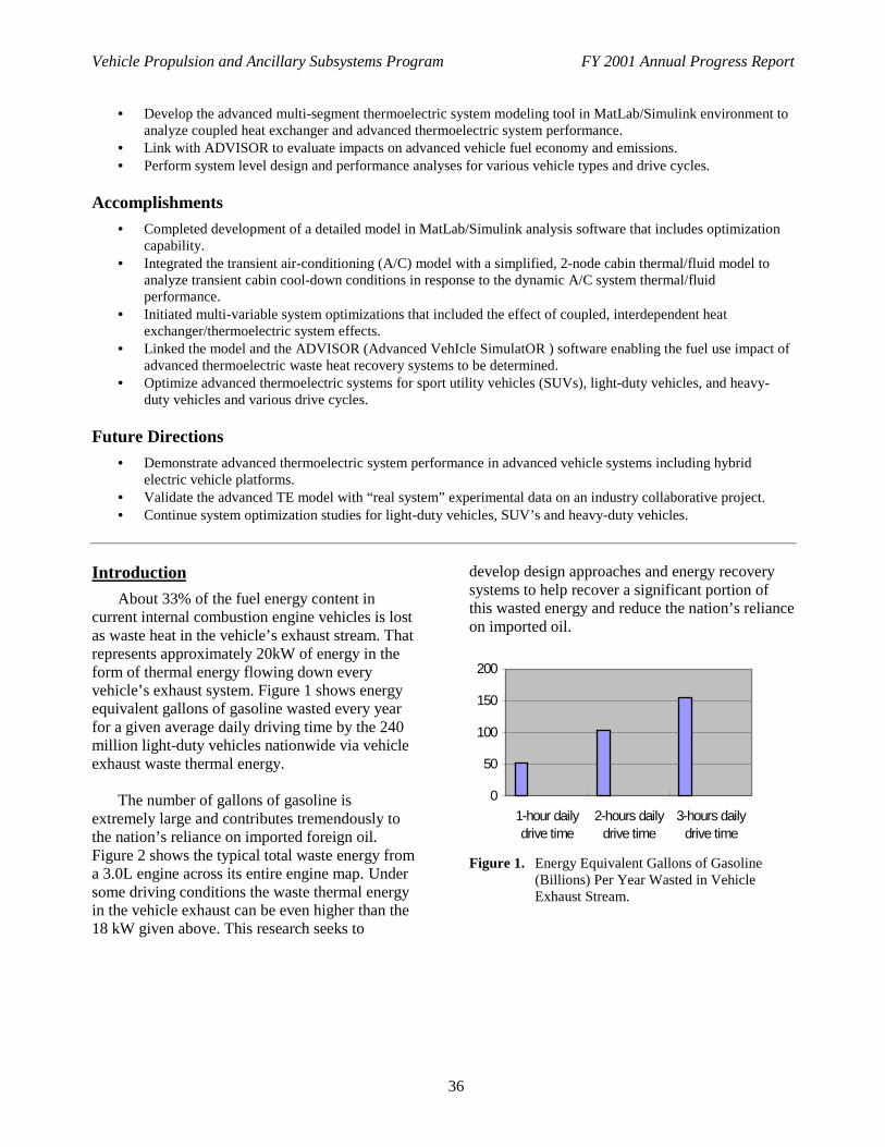
Vehicle Propulsion and Ancillary Subsystems Program FY 2001 Annual Progress Report
36
• Develop the advanced multi-segment thermoelectric system modeling tool in MatLab/Simulink environment toanalyze coupled heat exchanger and advanced thermoelectric system performance.
• Link with ADVISOR to evaluate impacts on advanced vehicle fuel economy and emissions.• Perform system level design and performance analyses for various vehicle types and drive cycles.
Accomplishments
• Completed development of a detailed model in MatLab/Simulink analysis software that includes optimizationcapability.
• Integrated the transient air-conditioning (A/C) model with a simplified, 2-node cabin thermal/fluid model toanalyze transient cabin cool-down conditions in response to the dynamic A/C system thermal/fluidperformance.
• Initiated multi-variable system optimizations that included the effect of coupled, interdependent heatexchanger/thermoelectric system effects.
• Linked the model and the ADVISOR (Advanced VehIcle SimulatOR ) software enabling the fuel use impact ofadvanced thermoelectric waste heat recovery systems to be determined.
• Optimize advanced thermoelectric systems for sport utility vehicles (SUVs), light-duty vehicles, and heavy-duty vehicles and various drive cycles.
Future Directions
• Demonstrate advanced thermoelectric system performance in advanced vehicle systems including hybridelectric vehicle platforms.
• Validate the advanced TE model with “real system” experimental data on an industry collaborative project.• Continue system optimization studies for light-duty vehicles, SUV’s and heavy-duty vehicles.
Introduction
About 33% of the fuel energy content incurrent internal combustion engine vehicles is lostas waste heat in the vehicle’s exhaust stream. Thatrepresents approximately 20kW of energy in theform of thermal energy flowing down everyvehicle’s exhaust system. Figure 1 shows energyequivalent gallons of gasoline wasted every yearfor a given average daily driving time by the 240million light-duty vehicles nationwide via vehicleexhaust waste thermal energy.
The number of gallons of gasoline isextremely large and contributes tremendously tothe nation’s reliance on imported foreign oil.Figure 2 shows the typical total waste energy froma 3.0L engine across its entire engine map. Undersome driving conditions the waste thermal energyin the vehicle exhaust can be even higher than the18 kW given above. This research seeks to
develop design approaches and energy recoverysystems to help recover a significant portion ofthis wasted energy and reduce the nation’s relianceon imported oil.
0
50
100
150
200
1-hour dailydrive time
2-hours dailydrive time
3-hours dailydrive time
Figure 1. Energy Equivalent Gallons of Gasoline(Billions) Per Year Wasted in VehicleExhaust Stream.

Vehicle Propulsion and Ancillary Subsystems Program FY 2001 Annual Progress Report
37
Figure 2. Engine Waste Power Available from a 3.0LSI Engine in 1991 Dodge Caravan
Several energy conversion technologies arebeing investigated to capture a portion of thiswaste thermal energy, including advancedthermoelectric (TE) systems, thermophotovoltaic(TPV) systems, and thermionic systems.Advanced thermoelectric systems currently appearto have the best potential for satisfying automotivesystem requirements for performance, systemlocation, cost/benefit, and system integration.Thermionic and TPV systems typically requireoperating temperatures higher than that availablein current light-duty and heavy-duty vehicles.Thermionic and TPV systems also are typicallyexpensive with no current avenue identified forachieving cost-efficient systems affordable to theautomotive industry. System reliability highenough to satisfy automotive systemsrequirements also have not been demonstrated bythermionic and TPV systems. TE systems havedemonstrated very high reliability in the spaceprogram, being used to reliably power suchspacecraft as the Galileo and Voyager spacecrafton deep-space missions for many years.
Past TE systems in all applications, includingspacecraft missions, have suffered from high-costand low performance due to the fundamentallimitations of their SiGe, PbTe and BiTe materialsystems. New opportunities exist to apply TEsystems to a number power system needs,
including automotive systems, because of recentdiscoveries of new, better performing TEmaterials.
Approach
The two most actively researched advancedTE systems are those based on (1) quantum-wellTE materials and (2) newly-characterizedadvanced segmented TE materials such asskutterudites and Zn4Sb3 alloys. Quantum-well TEmaterials have only recently been investigated,and will require many years and much researchinvestment to demonstrate long-term reliableperformance. The second TE material set above ismore mature and closer to achieving long-termreliable performance. Figure 3 shows themeasured ZT value of the newly-characterizedskutterudite and Zn4Sb3-alloys TE materials, and acomparison with older TE materials used in pastsystems.
These newly characterized TE materialsalong with the segmented TE element design areshowing strong potential to increase TE systemperformance to levels that can satisfy automotiverequirements sooner than quantum-well TEsystems.
Figure 3. ZT Performance of newly characterized TEmaterials is significantly higher and createsnew power system opportunities.
NREL has developed a detailed advancedthermoelectric system analysis model within theMatLab/Simulink mathematical analysis software.This model allows us to quickly evaluatenumerous TE system design configurations andsystem requirements. The model has also nowbeen linked with NREL’s ADVISOR vehicleanalysis software to allow us to evaluate impactson vehicle fuel economy and emissions. Industrypartners indicating interest in our advanced TE
New TE MaterialsNew TE Materials
1000 1500 2000 2500 3000 3500 4000 45000
50
100
150
200
2030
40
50
60
70 80
90
100
125
150
175
200
300
400
50
Engine S pe e d (rpm )
Eng
ine
Tor
que
(Nm
)
Engine Wa s te P owe r (kW), Ma x P owe r 115 kW Ba s ed on 1991 Dodge Ca ra va n 3.0L (102kW ) S I E ngine - tra ns ie nt da ta

Vehicle Propulsion and Ancillary Subsystems Program FY 2001 Annual Progress Report
38
system design and analysis work includeDaimlerChrysler, General Motors and VisteonCorporation. Industry in particular would like toproduce high-grade electrical power from the low-grade exhaust waste heat to power various vehicleauxiliary loads (i.e., pumps, fans, lights). Onceinitial system performance and design tradeoffstudies have been completed NREL will engage asupplier to help develop an advanced TE prototypesystem to demonstrate performance and validatethe analytic design models and predictedperformance.
Results
NREL’s TE system performance studies havebegun to quantify the system performanceparameters and potential power output available atvarious locations along the vehicle exhaust lineusing the segmented TE materials shown inFigure 3. Figure 4 shows the three prime candidatelocations, which have been identified fromdiscussions with our industry partners.
Figure 4. Prime Exhaust Line Locations for WasteHeat Recovery System.
Immediately out of the engine, the gas flowtemperatures are approximately 900°C or higherdepending on the drive cycle. At the catalyticconverter, the gas flow temperature isapproximately 700-800°C, while downstream ofthe catalytic converter the gas flow temperaturesdecrease to approximately 600°C. This researchhas quantified the system design tradeoffs of thevarious exhaust gas locations. It currently appearsthat the best location for such a advanced TEpower system is on the catalytic converter.
Initial system design results show the systempower output maximizes at certain TE hot sidetemperatures (i.e., approximately 400°C) for anexhaust gas temperature of 700°C because of thetradeoff between heat exchanger performance andTE device performance (Figure 5). The exhaustgas flow rates shown in Figure5 are typical ofthose in various light-duty vehicles and SUVs.Figure 6 shows the required cold side coolingmass flow rates required for various TE hot sideand cold side temperature combinations and anambient temperature of 27°C. As TE cold sidetemperature decreases to near ambient, therequired cold side cooling mass flow rates becomeprohibitively large. Consequently, these aretemperature regimes that must be avoided in finalsystem designs.
Figure 5. System power output is strongly dependenton TE hot side and cold side temperatureand exhaust mass flow rate.
Figure 7 shows the typical maximumefficiency / maximum power behavior for such anadvanced TE system using the advanced TEmaterials in Figure 2. Conversion efficienciesrange from 11-13.5% for system power outputs of1000-1100 watts and an exhaust gas temperatureof 800°C and an ambient temperature of 27°C.
The automotive industry, Daimler Chrysler,General Motors, and Visteon Corporation, are allinterested in systems producing 1000 watts ormore so these TE design studies apply directly tothe automotive industries requirements. Theseanalytic results show the important system
>900 >900 ooCC
700700--800 800 ooCC
600-650 600-650 ooCC

Vehicle Propulsion and Ancillary Subsystems Program FY 2001 Annual Progress Report
39
Figure 6. Cold side cooling flow rate can be a strongfunction of TE hot side and coldtemperature and exhaust mass flow rate.
Figure 7. Typical maximum efficiency / maximumpower behavior for an Advanced TE systemUsing the Advanced TE Materials.
tradeoffs and performance characteristics of such aTE power system.
Conclusions
NREL has developed a comprehensiveadvanced TE power system analysis tool inMatLab/Simlulink to evaluate the vehicle exhaustwaste heat recovery benefits and systemperformance characteristics. The analytic tool isnow linked with NREL’s ADVISOR vehiclesystem analysis software to evaluate the impactvehicle exhaust waste heat recovery on vehiclefuel economy. System investigations haverevealed some important system performancecharacteristics and critical system designinformation such as optimum location, poweroutput, and cold side cooling mass flow raterequirements. The opportunities for such advancedTE systems to reduce our nation’s reliance andaddiction to imported foreign oil is enormous.Current estimates indicate that the energyequivalent of at least 51 Billion gallons of gasolineare thrown away annually nationwide down ourvehicles’ exhaust streams.
Publications
“Advanced Thermoelectric Systems forAutomotive Thermal Energy Recovery”,Lustbader, J. and Hendricks, T.J., NREL InternalTechnical Seminar, August 2001.
700 800 900 1000 1100 1200 13000.09
0.1
0.11
0.12
0.13
0.14
0.15
Effic e nc y At Ma x im um Po w e r (3p-2n se g m e nts) Te x =1073(K), Mdo th=0.03(kg /s), UAh=90(W/K) (Effe c tive ne ss~ 0.95)
Ma x im um P o w e r(W)
Ma
xim
um
Eff
ice
nc
y
Tc old=325(K)Tc old=350(K)
Th=665(K)
Th=905(K) Th S te ps=10(K)
Th=785(K)
Vehicle Propulsion and Ancillary Subsystems Program FY 2001 Annual Progress Report
40
IIK. Battery Thermal Characterization and Management
Dr. Ahmad Pesaran (principal investigator/project leader)National Renewable Energy LaboratoryGolden, CO 80401-33931617 Cole Boulevard(303) 275-4441, e-mail: [email protected]
DOE Program Manager: Robert Kost(202) 586-2334, e-mail: [email protected]
Objective
• To characterize thermal performance of batteries to develop more effective and energy-efficient thermalmanagement strategies for battery packs in electric and hybrid electric vehicles.
• To improve the performance of battery packs and thus fuel economy of vehicles while avoiding prematurecalendar and life cycle of batteries. Extending battery life will result in saving energy and materials sincemanufacturers don’t need to produce as many batteries.
• To evaluate techniques for heating batteries quickly and efficiently in electric and hybrid vehicles during coldseasons.
Approach
• Collaborate with auto and battery industry for battery thermal characterization and analysis of prototype hybridvehicles.
• Use an integrated approach in thermal characterization, analysis, design, testing, and management of batterymodules and packs.
• Use a unique calorimeter to measure heat capacity and heat generation from batteries. Utilize infrared thermalimaging, battery cyclers, flow visualization, thermal testing and analysis, and computational fluid dynamics toassess batteries.
• Benchmark state-of-the-art production hybrid vehicle battery packs.• Analyze and demonstrate various battery heating techniques for cold seasons.
Accomplishments
• Obtained thermal characteristics (heat generation, heat capacity, and thermal images) of PolyStor lithium-ion(Li-Ion), Panasonic nickel-metal-hydride (NiMH), and Compact Power lithium-polymer (LiP) batteries.
• Collaborated with DaimlerChrysler to test and analyze thermal behavior of batteries in prototype hybridvehicles and provided energy-efficient thermal management strategies that enabled the use of a NiMH batterywithout exceeding specified temperature limits.
• Benchmarked the thermal management system in a North American version of Toyota Prius and found thatunder most testing conditions it does a good job in keeping the batteries within the specified temperature range.
• Evaluated four battery-heating techniques and found that electric internal core heating was the most effectivemethod and used less energy. We worked with University of Toledo to demonstrate the electric internal coreheating technique and found that a 60Hz alternating current (AC) through the battery terminals effectively heatsbatteries.
• Received an R&D 100 award from R&D Magazine for a charging algorithm that extends the life of electricvehicle lead-acid batteries by 300% to 400%.
Future Directions
• Continue to collaborate with auto and battery industries to test and analyze energy efficient battery thermalmanagement strategies in hybrid vehicles.

Vehicle Propulsion and Ancillary Subsystems Program FY 2001 Annual Progress Report
41
• Work with the Partnership for a New Generation of Vehicles (PNGV) battery developers to thermally characterize batteries by measuring heat capacity and heat generation and evaluating thermal imaging of batteries under development.
• Evaluate a prototype for heating batteries during cold seasons. Introduction
Over the past several years, the National Renewable Energy Laboratory (NREL) has had the lead responsibility for evaluating thermal characteristics of batteries and assisting the battery and auto industry with developing improved battery thermal management strategies. Proper thermal design and management of batteries in electric vehicles (EV) and hybrid electric vehicles (HEV) is an important task since it can affect the performance and life of the battery and thus the vehicle performance and fuel economy.
Understanding the thermal properties and
behavior of batteries and packs will lead to an improved understanding of how to develop modules and packs with better thermal performance. In addition to the improved vehicle fuel economy and performance, a properly designed thermal management system will extend the life of batteries and thus save energy because fewer batteries will be produced. NREL�s battery thermal management Web site (http://www.ctts.nrel.gov/BTM) provides further details about this project.
Approach
NREL�s Battery Thermal Management Project team works hand-in-hand with industry to evaluate batteries and offer design improvements for HEV and EV modules and packs.
As part of the U.S. Department of Energy�s
(DOE) Hybrid Electric Vehicle Propulsion Program, NREL assists the U.S. auto industry and battery developers in designing an integrated approach to thermal characterization, analysis, design, testing, and management of battery modules and packs (see Figure 1). NREL uses a unique calorimeter to measure heat capacity and heat generation from batteries. Infrared thermal imaging, flow visualization, thermal testing and analysis, and computational fluid dynamics are all used to assess and evaluate batteries. NREL uses
its capabilities to instrument and test battery packs from production HEVs, either out of vehicle or in vehicle (on-road and on dynamometer). NREL computer aided design tools are used for analyzing various methods for heating batteries in cold seasons. As part of a collaboration with industry, NREL uses battery cyclers and thermal imaging to investigate charging methods to extend the life of the EV lead acid batteries.
Results
The Battery Thermal Management Team collaborated with industry to measure thermal characteristics of the following batteries: Panasonic NiMH batteries for DaimlerChrysler, a PolyStor lithium-ion polymer gel battery for PNGV, and a new lithium-polymer from Compact Power. Using a unique battery calorimeter and cycler, NREL measured the heat capacity of each battery and the heat generation from each module under various driving cycles. NREL found that the lithium batteries generated the least amount of heat, and thus were more energy efficient.
Figure 1. Ahmad Pesaran and Mark Mihalic evaluate
batteries (donated by industry partners) at NREL�s Battery Thermal Management Test Facility

Vehicle Propulsion and Ancillary Subsystems Program FY 2001 Annual Progress Report
42
Thermal imaging indicated that lithium batterieshad very uniform temperature distribution.
Four power-conditioning units, two largeenvironmental chambers (all excess equipmentfrom a DOE/Ford HEV subcontract), and severaloverhead power trays and cables enhanced thecapabilities of the battery thermal managementlaboratory. The environmental chambers giveNREL the ability to test batteries at temperaturesbetween -60°C and +200°C. The power unitsenable NREL to test batteries, ultracapacitors, andfuel cells for DOE and industry projects.
NREL collaborated with DaimlerChrysler andits battery supplier to evaluate the effectiveness oftwo approaches (air and liquid cooling) tothermally manage battery packs installed atvarious locations in a HEV prototype. As part ofits efforts to benchmark production hybridvehicles and components, NREL tested a NorthAmerican version of the Toyota Prius. The batteryteam instrumented and tested the vehicle and itsbattery pack on a chassis dynamometer. Thebattery pack was also tested out of the vehicle inan environmental chamber to obtain its thermalcharacteristics (see Figure 2). The results indicatedthat the battery thermal management system in thePrius keeps the batteries within the specifiedtemperature range under most testing conditions.The information was shared with industry.
Figure 2. Toyota Prius NiMH battery pack underevaluation at NREL’s Battery ThermalManagement Laboratory.
The power and energy capabilities of today’sadvanced batteries are limited when temperaturesare cold because of increased internal resistance.As a result, HEV performance may suffer and thevehicles may not be widely accepted byconsumers. NREL analyzed various heatingmethods and found that electric heating of thebattery internal core is the most efficient approach.Core heating reached a much higher temperaturefaster than the other heating techniques for thesame amount of energy (see Figure 3). NREL,working with the University of Toledo, found that60Hz AC heating is an effective core heatingmethod to warm a non-operating battery at -40°Cwhile delivering acceptable battery performance.
1 1.2 1.4 1.6 1.8 2 2.2 2.4 2.6 2.8 3-45
-40
-35
-30
-25
-20
-15
-10Internal hea ting us ing ba ttery energy External heating us ing electric hea ters Interna l hea ting us ing e lectric heaters Interna l Airflow Heating 100% Effic iencyInternal Airflow Heating 20% Efficiency
Uniform Input Heat over 2 minutes (Whr)
Ave
rage
Tem
pera
ture
at 2
min
utes
(°C
)
Internal core heating
Other heating methods
Figure 3. Internal battery core heating was found to bethe most energy efficient method forincreasing average battery temperature.
Lead-acid batteries are less expensive, morerecyclable, and better-prepared for high-volumeproduction; however, their relatively short deeplife cycle has been a major hurdle for wider use—until now. NREL, working with Optima Batteriesand Recombination Technologies, developed acurrent interrupt charging technique that extendsthe cycle life of lead-acid batteries by three to fourtimes and makes them more competitive withnickel-metal hydride batteries (see Figure 4).Current interrupt charging (current a few secondson and few seconds off repeatedly) reduces highbattery temperature during charge. This year,NREL received a prestigious R&D 100 Awardfrom R&D Magazine for the technology.

Vehicle Propulsion and Ancillary Subsystems Program FY 2001 Annual Progress Report
43
Conclusions
NREL has been working on testing,characterizing, analyzing, and developingtechnologies to efficiently control the thermalperformance of batteries in electric and hybridvehicles. In addition to the improved vehicle fueleconomy and performance, a properly designedthermal management system will extend the life ofbatteries and thus lead to low production numbersof batteries. Several battery modules and aproduction HEV battery packs were tested andprovided insight for developing better thermalmanagement systems. An energy efficient methodto warm very cold batteries was identified andinvestigated.
Figure 4. Current interrupt charging extends the life oflead-acid batteries by as much as four timescompared to using standard constantcurrent/voltage charging.
NREL received a R&D award for developinga charging method to extend the life of EV lead-acid batteries by three-four times. Next year,NREL will continue to collaborate with industry tocharacterize thermal performance of batteries todevelop energy-efficient battery thermalmanagement systems. NREL will characterizethermal properties (heat capacity, heat generationrate, and thermal images) of batteries from PNGVsuppliers. NREL will evaluate a prototype electriccore heating element to see if it can warm upbatteries at very cold temperatures, whilemaintaining acceptable performance.
Publications/Presentations
“Charging Algorithms for Increasing Lead AcidBattery Life for Electric Vehicles,” M. Keyser, A.Pesaran, and Bob Nelson, 17th Electric VehicleSymposium, Montreal, Canada, October 16-18,2000.
“Battery Thermal Management in EVs and HEVs:Issues and Solutions,” A. Pesaran, Proceeding ofthe 1st Advanced Automotive Battery Conferencein Las Vegas, NV, February 6-8, 2001.
“Thermal Characteristics of Selected EV and HEVBatteries,” A. Pesaran, M. Keyser, M. Mihalic,Proceedings of the 17th Annual BatteryConference, Long Beach, CA, January 9 -12,2001.
“Thermal Chracterization of Plastic Lithium IonCells,” M. Keyser. A. Pesaran. D. Rivers, 18th
International Seminars on Primary and SecondaryBattereies, Fort Luaterdale, Florida, March 5-8,2001.
“Thermal Evaluation of a Toyota Prius HEVBattery Pack – out of vehicle testing,” M. Zolot,M. Kesyer, M.Mihalic, A. Pesaran, MilestoneReport, National Renewable Energy Laboratory,Golden, CO, May 2001.
“Thermal Charcterization of Advanced EV/HEVBatteries,” M. Kesyer, A. Pesaran, M. Mihalic, M.Zolot, Milestone Report, National RenewableEnergy Laboratory, Golden, CO, June 2001.
“Thermal Evaluation of Battery Pack in HondaInsight HEV,” M. Zolot, M. Kesyer, M.Mihalic,A. Pesaran, 36th Intersociety Energy ConversionEngineering Conference, Savannah, Georgia, July29-31, 2001.
“Data Sources and Needs – Battery ThermalCharacterization,” M. Keyser, Workshop:Development of Advanced Battery EngineeringModels, Crystal City, VA, August 14-16, 2001.
“Evaluation of Heating Methods for HEVBatteries for Cold Seasons,” A. Pesaran, A.Vlahinos, T. Stuart, Milestone Report, NationalRenewable Energy Laboratory, Golden, CO,August 2001.
Vehicle Propulsion and Ancillary Subsystems Program FY 2001 Annual Progress Report
44
IIL. Battery Electrical and Thermal Modeling for HEV Simulations
Dr. Ahmad Pesaran (principal investigator/project leader)National Renewable Energy LaboratoryGolden, CO 80401-33931617 Cole Boulevard(303) 275-4441, e-mail: [email protected]
DOE Program Manager: Robert Kost(202) 586-2334, e-mail: [email protected]
Objective
• To work with the battery industry to develop validated battery models for use in vehicle simulation toolssuch as ADVISOR and PSAT.
• To use an integrated approach to develop both electrical and thermal performance models for batteries invehicle simulation tools.
• To obtain data for validating developed battery models.
• To develop a complete battery pack model consisting of multiple modules with different behavior.
Approach
• Collaborate with battery developers and the Partnership for a New Generation of Vehicles (PNGV) onidentifying critical battery parameters that need to be modeled.
• Obtain data through collaboration with other national labs or through testing at the National RenewableEnergy Laboratory (NREL).
• Use an integrated approach in testing electrical and thermal models of batteries for ADVISOR vehiclesimulation software.
• Use the state-of-the-art software for simulating electrical systems for modeling different behaviors in abattery pack consisting of multiple modules.
Accomplishments
• Developed a new resistance plus capacitance model in the Matlab software environment for ADVISORbased on the PNGV Battery Test Manual.
• Obtained data on lithium-ion (Li-Ion) and nickel-metal-hydride (NiMH) batteries to generate and validatetemperature-dependent battery models.
• Obtained thermal characteristics (heat generation, heat capacity, and thermal images) of lithium-ion,NiMH, and lithium-polymer cells provided by battery developers for input to existing thermal models.
• Developed a pack model in Saber (the state-of-the-art software for simulating electrical systems) thatcaptures behavior of multiple modules in a pack.
Future Directions
• Continue to collaborate with auto and battery industry and other national labs to develop validated modelsfor new advanced batteries for use in vehicle simulations tools.
• Validate the complete Saber battery pack model with a NiMH battery pack. Improve the thermal model ofbatteries in ADVISOR and Saber.
• Co-simulate the Saber pack model with ADVISOR for evaluating the impact of pack imbalances andhybrid energy storage concepts on vehicle fuel economy.
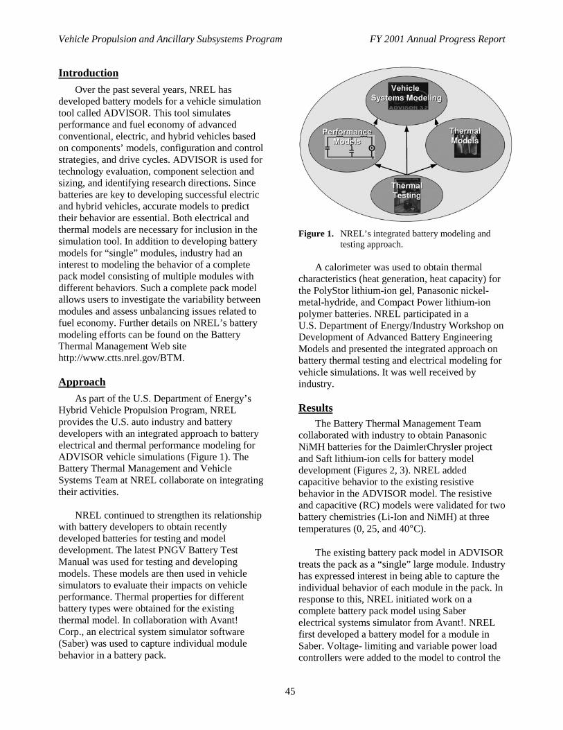
Vehicle Propulsion and Ancillary Subsystems Program FY 2001 Annual Progress Report
45
Introduction
Over the past several years, NREL hasdeveloped battery models for a vehicle simulationtool called ADVISOR. This tool simulatesperformance and fuel economy of advancedconventional, electric, and hybrid vehicles basedon components’ models, configuration and controlstrategies, and drive cycles. ADVISOR is used fortechnology evaluation, component selection andsizing, and identifying research directions. Sincebatteries are key to developing successful electricand hybrid vehicles, accurate models to predicttheir behavior are essential. Both electrical andthermal models are necessary for inclusion in thesimulation tool. In addition to developing batterymodels for “single” modules, industry had aninterest to modeling the behavior of a completepack model consisting of multiple modules withdifferent behaviors. Such a complete pack modelallows users to investigate the variability betweenmodules and assess unbalancing issues related tofuel economy. Further details on NREL’s batterymodeling efforts can be found on the BatteryThermal Management Web sitehttp://www.ctts.nrel.gov/BTM.
Approach
As part of the U.S. Department of Energy’sHybrid Vehicle Propulsion Program, NRELprovides the U.S. auto industry and batterydevelopers with an integrated approach to batteryelectrical and thermal performance modeling forADVISOR vehicle simulations (Figure 1). TheBattery Thermal Management and VehicleSystems Team at NREL collaborate on integratingtheir activities.
NREL continued to strengthen its relationshipwith battery developers to obtain recentlydeveloped batteries for testing and modeldevelopment. The latest PNGV Battery TestManual was used for testing and developingmodels. These models are then used in vehiclesimulators to evaluate their impacts on vehicleperformance. Thermal properties for differentbattery types were obtained for the existingthermal model. In collaboration with Avant!Corp., an electrical system simulator software(Saber) was used to capture individual modulebehavior in a battery pack.
Figure 1. NREL’s integrated battery modeling andtesting approach.
A calorimeter was used to obtain thermalcharacteristics (heat generation, heat capacity) forthe PolyStor lithium-ion gel, Panasonic nickel-metal-hydride, and Compact Power lithium-ionpolymer batteries. NREL participated in aU.S. Department of Energy/Industry Workshop onDevelopment of Advanced Battery EngineeringModels and presented the integrated approach onbattery thermal testing and electrical modeling forvehicle simulations. It was well received byindustry.
ResultsThe Battery Thermal Management Team
collaborated with industry to obtain PanasonicNiMH batteries for the DaimlerChrysler projectand Saft lithium-ion cells for battery modeldevelopment (Figures 2, 3). NREL addedcapacitive behavior to the existing resistivebehavior in the ADVISOR model. The resistiveand capacitive (RC) models were validated for twobattery chemistries (Li-Ion and NiMH) at threetemperatures (0, 25, and 40°C).
The existing battery pack model in ADVISORtreats the pack as a “single” large module. Industryhas expressed interest in being able to capture theindividual behavior of each module in the pack. Inresponse to this, NREL initiated work on acomplete battery pack model using Saberelectrical systems simulator from Avant!. NRELfirst developed a battery model for a module inSaber. Voltage- limiting and variable power loadcontrollers were added to the model to control the
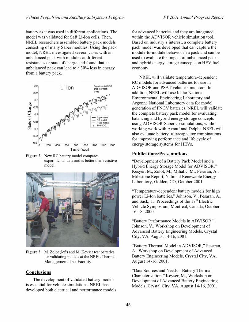
Vehicle Propulsion and Ancillary Subsystems Program FY 2001 Annual Progress Report
46
battery as it was used in different applications. The model was validated for Saft Li-Ion cells. Then, NREL researchers assembled battery pack models consisting of many Saber modules. Using the pack model, NREL investigated several cases with an unbalanced pack with modules at different resistances or state of charge and found that an unbalanced pack can lead to a 30% loss in energy from a battery pack.
Figure 2. New RC battery model compares
experimental data and is better than resistive model.
Figure 3. M. Zolot (left) and M. Keyser test batteries
for validating models at the NREL Thermal Management Test Facility.
Conclusions
The development of validated battery models is essential for vehicle simulations. NREL has developed both electrical and performance models
for advanced batteries and they are integrated within the ADVISOR vehicle simulation tool. Based on industry�s interest, a complete battery pack model was developed that can capture the module-to-module behavior in a pack and can be used to evaluate the impact of unbalanced packs and hybrid energy storage concepts on HEV fuel economy.
NREL will validate temperature-dependent
RC models for advanced batteries for use in ADVISOR and PSAT vehicle simulators. In addition, NREL will use Idaho National Environmental Engineering Laboratory and Argonne National Laboratory data for model generation of PNGV batteries. NREL will validate the complete battery pack model for evaluating balancing and hybrid energy storage concepts using ADVISOR-Saber co-simulations, while working work with Avant! and Delphi. NREL will also evaluate battery�ultracapacitor combinations for improving performance and life cycle of energy storage systems for HEVs.
Publications/Presentations �Development of a Battery Pack Model and a Hybrid Energy Storage Model for ADVISOR,� Kesyer, M., Zolot, M., Mihalic, M., Pesaran, A., Milestone Report, National Renewable Energy Laboratory, Golden, CO, October 2001. �Temperature-dependent battery models for high power Li-Ion batteries,� Johnson, V., Pesaran, A., and Sack, T., Proceedings of the 17th Electric Vehicle Symposium, Montreal, Canada, October 16-18, 2000. �Battery Performance Models in ADVISOR,� Johnson, V., Workshop on Development of Advanced Battery Engineering Models, Crystal City, VA, August 14-16, 2001. �Battery Thermal Model in ADVISOR,� Pesaran, A., Workshop on Development of Advanced Battery Engineering Models, Crystal City, VA, August 14-16, 2001. �Data Sources and Needs � Battery Thermal Characterization,� Keyser, M., Workshop on Development of Advanced Battery Engineering Models, Crystal City, VA, August 14-16, 2001.

Vehicle Propulsion and Ancillary Subsystems Program FY 2001 Annual Progress Report
47
III. ARGONNE NATIONAL LABORATORY SUPPORT
IIIA. Advanced Powertrain Test Facility (APTF)
Henry Ng (primary contact), Keith HardyArgonne National Laboratory9700 S. Cass AvenueArgonne, IL 60439(630) 252-3992, fax (630) 252-3443, e-mail [email protected]
DOE Program Manager: Patrick Sutton(202) 586-8058, fax (202) 586-1600, e-mail [email protected]
ObjectiveDesign, construct and commission a state-of-the-art facility for conducting energy efficiency and emission
tests on hybrid electric vehicles, sport utility vehicles, and future advanced-technology vehicles. The facilitywill include an electric four-wheel-drive chassis dynamometer with appropriate controls and instrumentation forhighly accurate emissions and fuel consumption measurements.
Approach
• Obtain professional engineering/architectural services to assist with the final design and constructiondocuments for a world-class facility capable of benchmarking and developing the most advancedpowertrains for future cars and trucks. The facility will be capable of gaseous-fuel operation (includinghydrogen) and will have the capability to add climate-controlled testing in the future.
• Complete construction of the extension to the current APTF to house the 4-wheel drive chassisdynamometer cell, control room, and a vehicle soak area.
• Install highly sensitive gasoline emissions measurement equipment capable of SULEV (super ultra lowemission vehicle) standards and a full dilution tunnel for diesel particulate matter measurement to enablecomplete diesel emissions measurement capability.
Accomplishments
• New building shell construction was completed and funded by internal ANL sources (>$1,000K).• State-of-the-art 4-WD chassis dynamometer built, delivered, and installed in pit.• SULEV emission/CVS benches delivered and commissioned.• Full-size dilution tunnel for both diesel/gasoline PM designed, built, and delivered• Advanced background air purification and dehumidification system designed for accurate and repeatable
measurement of extremely low exhaust emissions.
Future Directions
• Complete the Phase II construction of the 4-WD chassis dynamometer facility. Calibrate the 4-wheel drivedynamometer, install and calibrate equipment in the new facility. Build and optimize the climate controlchamber for 4-WD dynamometer facility.
Introduction
ANL has the lead responsibility for a PNGV-related program with DOE’s Office ofTransportation Technologies (OTT) to conduct
emission and energy efficiency tests on hybridelectric vehicles, sport utility vehicles, and futuretechnology vehicles. These tests require a state-of-the-art electric four-wheel-drive chassis
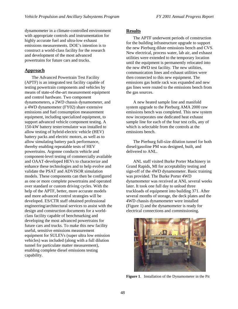
Vehicle Propulsion and Ancillary Subsystems Program FY 2001 Annual Progress Report
48
dynamometer in a climate-controlled environmentwith appropriate controls and instrumentation forhighly accurate fuel and ultra-low exhaustemissions measurements. DOE’s intention is toconstruct a world-class facility for the researchand development of the most advancedpowertrains for future cars and trucks.
Approach
The Advanced Powertrain Test Facility(APTF) is an integrated test facility capable oftesting powertrain components and vehicles bymeans of state-of-the-art measurement equipmentand control hardware. Two componentdynamometers, a 2WD chassis dynamometer, anda 4WD dynamometer (FY02) share extensiveemissions and fuel consumption measurementequipment, including specialized equipment, tosupport advanced vehicle component testing. A150-kW battery tester/emulator was installed toallow testing of hybrid-electric vehicle (HEV)battery packs and electric motors, as well as toallow simulating battery pack performance,thereby enabling repeatable tests of HEVpowertrains. Argonne conducts vehicle andcomponent-level testing of commercially availableand OAAT-developed HEVs to characterize andenhance these technologies and to help evolve andvalidate the PSAT and ADVISOR simulationmodels. These components can then be configuredas one or more complete powertrains and operatedover standard or custom driving cycles. With thehelp of the APTF, better, more accurate modelsand more advanced control strategies will bedeveloped. ES/CTR staff obtained professionalengineering/architectural services to assist with thedesign and construction documents for a world-class facility capable of benchmarking anddeveloping the most advanced powertrains forfuture cars and trucks. To make this new facilityuseful, sensitive emissions measurementequipment for SULEVs (super ultra low emissionvehicles) was included (along with a full dilutiontunnel for particulate matter measurement),enabling complete diesel emissions testingcapability.
Results
The APTF underwent periods of constructionfor the building infrastructure upgrade to supportthe new Pierburg dilute emissions bench and CVS.New electrical, process water, lab air, and exhaustutilities were extended to the temporary locationuntil the equipment is permanently relocated intothe new 4WD test facility. The new utilities,communication lines and exhaust utilities werethen connected to this new equipment. Theemissions gas bottle rack was expanded and newgas lines were routed to the emissions bench fromthe gas sources.
A new heated sample line and manifoldsystem upgrade to the Pierburg AMA 2000 rawemissions bench was completed. This new systemnow incorporates one dedicated heat exhaustsample line for each of the four test cells, any ofwhich is selectable from the controls at theemissions bench.
The Pierburg full-size dilution tunnel for bothdiesel/gasoline PM was designed, built, anddelivered to ANL.
ANL staff visited Burke Porter Machinery inGrand Rapids, MI for acceptability testing andsign-off of the 4WD dynamometer. Basic trainingwas provided. The Burke Porter 4WDdynamometer was received at ANL several weekslater. It took one full day to unload threetruckloads of equipment into building 371. Afterseveral months of storage, the deck plates and the4WD chassis dynamometer were installed(Figure 1) and the dynamometer is ready forelectrical connections and commissioning.
Figure 1. Installation of the Dynamometer in the Pit

Vehicle Propulsion and Ancillary Subsystems Program FY 2001 Annual Progress Report
49
The new building shell construction wasfunded and completed from internal ANL sources(Figure 2). Advanced Mechanical Systems, Inc.was awarded the contract for the 4-Wheel-DrivePhase II construction. The majority of theconstruction will take place in FY 02.
Figure 2. New 4-Wheel Drive Chassis DynamometerBuilding
An experienced subcontractor was selected tobuild the largest air-handling unit (25,000 cfm) ata plant in Virginia. Once the unit is built, tested,and signed off by ANL, it will be disassembledand shipped to ANL for installation.
The APTF team wrote, revised, and receivedapproval on safety and quality assurance (QA)plans to ensure safe operation of facility andequipment.
Conclusions
Phase II Construction of the 4-Wheel DriveDynamometer facility will be completed inSpring 2002. The chassis dynamometer andemissions equipment to support the currentfacilities and the 4WD chassis dynamometer,including a SULEV-capable Pierburg EmissionsBench and CVS and a full dilution tunnel forparticulate will be installed and commissioned.Cross facility validation will continue bycomparing the results of tests performed at APTFwith those of identical tests performed atestablished auto industry test facilities. BeyondFY02, ANL plans to build a climate controlchamber for the 4-wheel drive dynamometerfacility, as requested by the Systems AnalysisTech Team, to extend its usefulness to DOE andindustry.
IIIB. Component and Vehicle Testing and Mapping
Michael Duoba (primary contact), Keith HardyArgonne National Laboratory9700 S. Cass AvenueArgonne, IL 60439(630) 252-6245, fax (630) 252-3443, e-mail [email protected]
DOE Program Manager: Patrick Sutton(202) 586-8058, fax (202) 586-1600, e-mail [email protected]
Objective
• Determine the performance, efficiency and emissions (where appropriate) of existing advanced HEVpowertrain technology.
• Design test procedures, acquire and analyze test data in a manner suitable for the development and validation ofcomponent, subsystem and vehicle simulation models.

Vehicle Propulsion and Ancillary Subsystems Program FY 2001 Annual Progress Report
50
Approach
• Design test procedures and utilize ANL’s extensive test equipment that is uniquely suited for extracting vehiclesystem data for model parameter inputs and validating systems simulation models (PSAT).
• Use two component dynamometers and the 2WD vehicle chassis dynamometer with ANL’s data acquisitionand control hardware and software.
• Utilize ANL’s state-of-the-art Pierburg-based fuel measurement system and both ANL’s raw and dilute(tailpipe) Pierburg emissions benches.
• In the case of the Prius engine testing, use ANL’s in-situ engine torque cell design to provide accurate enginedata.
• Develop custom software and hardware testing tools that will efficiently couple measured energy efficiency anddetailed performance data with very accurate (and rapid response) fuel measurements and emissionsmeasurements for each test “cell” in the APTF.
Accomplishments
Component Testing:
• NGM Motor - ANL has mapped and assessed the efficiency and performance of an axial-flux motormanufactured by New Generations Motor. Because the motor has an adjustable gap, comprehensive data(including efficiency) was mapped for various speeds, torques, voltages, and gap widths.
• Siemens AC Electric Motor - This spare equipment from the Ford HEV contract was installed on a fixture andmapped using ANL’s 300HP transient dynamometer.
Vehicle Testing:
• Japan Prius - ANL performed over 70 test cycles of ANL’s fully instrumented Japan Prius on the 2WD chassisdynamometer to acquire data for model validation and build a diverse database of transient engine fuel,emissions, and performance data for the artificial neural network-based engine emissions predictor.
• Honda Insight - ANL performed over 60 chassis dynamometer test cycles of ANL’s fully instrumented HondaInsight.
• Ford P2000 - ANL performed about one dozen chassis dynamometer test cycles of ANL’s fully instrumented(simultaneous analog sensor and CAN data) Ford P2000 prototype vehicle.
• CVT Honda Insight - ANL performed 17 chassis dynamometer test cycles of a partially instrumented CVTHonda Insight (vehicle loaned to ANL by Honda).
• SIDI CVT Toyota Opa - ANL began testing a partially instrumented Toyota SIDI CVT Opa vehicle.
Future Directions
• Continue testing high-efficiency electric motors, engines, transmissions, batteries and vehicles while payingparticular attention to powertrain control strategy development for increased fuel economy and reducedemissions.
Introduction
The Advanced Powertrain Test Facility(APTF) at ANL is an integrated test facilitycapable of testing powertrain components andvehicles by using state-of-the-art measurementequipment and control hardware. The APTF is theprincipal DOE technology validating facility forresearch prototypes and commercially availablelight-duty propulsion components, systems, andvehicles.
Objective
The objectives of the program are to testcomponents, powertrains, and vehicles to assessthe outcomes of technology developmentactivities, support the validation of simulationtools, and develop powertrain systems that canmeet the objectives of lower emissions anddramatically improved fuel economy.
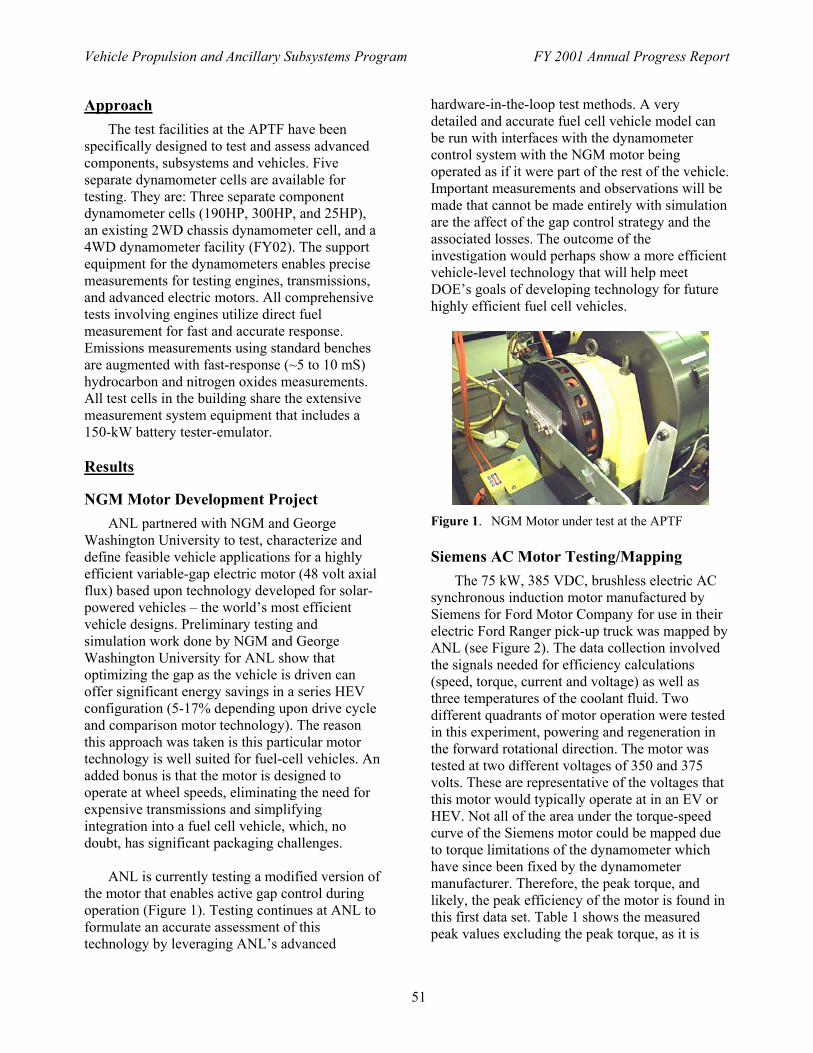
Vehicle Propulsion and Ancillary Subsystems Program FY 2001 Annual Progress Report
51
Approach
The test facilities at the APTF have been specifically designed to test and assess advanced components, subsystems and vehicles. Five separate dynamometer cells are available for testing. They are: Three separate component dynamometer cells (190HP, 300HP, and 25HP), an existing 2WD chassis dynamometer cell, and a 4WD dynamometer facility (FY02). The support equipment for the dynamometers enables precise measurements for testing engines, transmissions, and advanced electric motors. All comprehensive tests involving engines utilize direct fuel measurement for fast and accurate response. Emissions measurements using standard benches are augmented with fast-response (~5 to 10 mS) hydrocarbon and nitrogen oxides measurements. All test cells in the building share the extensive measurement system equipment that includes a 150-kW battery tester-emulator.
Results
NGM Motor Development Project
ANL partnered with NGM and George Washington University to test, characterize and define feasible vehicle applications for a highly efficient variable-gap electric motor (48 volt axial flux) based upon technology developed for solar-powered vehicles � the world�s most efficient vehicle designs. Preliminary testing and simulation work done by NGM and George Washington University for ANL show that optimizing the gap as the vehicle is driven can offer significant energy savings in a series HEV configuration (5-17% depending upon drive cycle and comparison motor technology). The reason this approach was taken is this particular motor technology is well suited for fuel-cell vehicles. An added bonus is that the motor is designed to operate at wheel speeds, eliminating the need for expensive transmissions and simplifying integration into a fuel cell vehicle, which, no doubt, has significant packaging challenges.
ANL is currently testing a modified version of
the motor that enables active gap control during operation (Figure 1). Testing continues at ANL to formulate an accurate assessment of this technology by leveraging ANL�s advanced
hardware-in-the-loop test methods. A very detailed and accurate fuel cell vehicle model can be run with interfaces with the dynamometer control system with the NGM motor being operated as if it were part of the rest of the vehicle. Important measurements and observations will be made that cannot be made entirely with simulation are the affect of the gap control strategy and the associated losses. The outcome of the investigation would perhaps show a more efficient vehicle-level technology that will help meet DOE�s goals of developing technology for future highly efficient fuel cell vehicles.
Figure 1. NGM Motor under test at the APTF
Siemens AC Motor Testing/Mapping
The 75 kW, 385 VDC, brushless electric AC synchronous induction motor manufactured by Siemens for Ford Motor Company for use in their electric Ford Ranger pick-up truck was mapped by ANL (see Figure 2). The data collection involved the signals needed for efficiency calculations (speed, torque, current and voltage) as well as three temperatures of the coolant fluid. Two different quadrants of motor operation were tested in this experiment, powering and regeneration in the forward rotational direction. The motor was tested at two different voltages of 350 and 375 volts. These are representative of the voltages that this motor would typically operate at in an EV or HEV. Not all of the area under the torque-speed curve of the Siemens motor could be mapped due to torque limitations of the dynamometer which have since been fixed by the dynamometer manufacturer. Therefore, the peak torque, and likely, the peak efficiency of the motor is found in this first data set. Table 1 shows the measured peak values excluding the peak torque, as it is
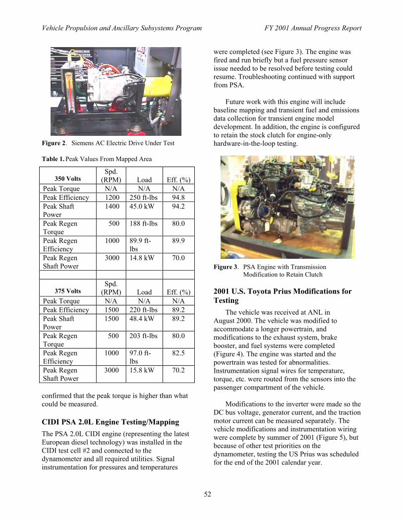
Vehicle Propulsion and Ancillary Subsystems Program FY 2001 Annual Progress Report
52
Figure 2. Siemens AC Electric Drive Under Test
Table 1. Peak Values From Mapped Area
confirmed that the peak torque is higher than what could be measured. CIDI PSA 2.0L Engine Testing/Mapping
The PSA 2.0L CIDI engine (representing the latest European diesel technology) was installed in the CIDI test cell #2 and connected to the dynamometer and all required utilities. Signal instrumentation for pressures and temperatures
were completed (see Figure 3). The engine was fired and run briefly but a fuel pressure sensor issue needed to be resolved before testing could resume. Troubleshooting continued with support from PSA.
Future work with this engine will include
baseline mapping and transient fuel and emissions data collection for transient engine model development. In addition, the engine is configured to retain the stock clutch for engine-only hardware-in-the-loop testing.
Figure 3. PSA Engine with Transmission
Modification to Retain Clutch 2001 U.S. Toyota Prius Modifications for Testing
The vehicle was received at ANL in August 2000. The vehicle was modified to accommodate a longer powertrain, and modifications to the exhaust system, brake booster, and fuel systems were completed (Figure 4). The engine was started and the powertrain was tested for abnormalities. Instrumentation signal wires for temperature, torque, etc. were routed from the sensors into the passenger compartment of the vehicle.
Modifications to the inverter were made so the
DC bus voltage, generator current, and the traction motor current can be measured separately. The vehicle modifications and instrumentation wiring were complete by summer of 2001 (Figure 5), but because of other test priorities on the dynamometer, testing the US Prius was scheduled for the end of the 2001 calendar year.
350 Volts
Spd. (RPM)
Load
Eff. (%)
Peak Torque N/A N/A N/A Peak Efficiency 1200 250 ft-lbs 94.8 Peak Shaft Power
1400 45.0 kW 94.2
Peak Regen Torque
500 188 ft-lbs 80.0
Peak Regen Efficiency
1000 89.9 ft-lbs
89.9
Peak Regen Shaft Power
3000 14.8 kW 70.0
375 Volts Spd.
(RPM)
Load
Eff. (%) Peak Torque N/A N/A N/A Peak Efficiency 1500 220 ft-lbs 89.2 Peak Shaft Power
1500 48.4 kW 89.2
Peak Regen Torque
500 203 ft-lbs 80.0
Peak Regen Efficiency
1000 97.0 ft-lbs
82.5
Peak Regen Shaft Power
3000 15.8 kW 70.2
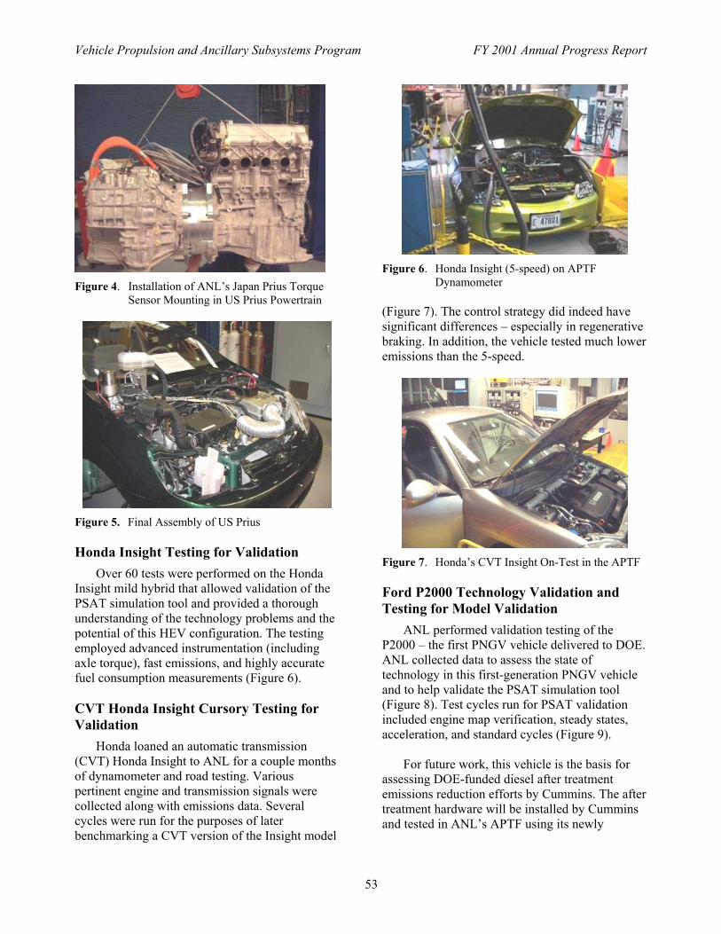
Vehicle Propulsion and Ancillary Subsystems Program FY 2001 Annual Progress Report
53
Figure 4. Installation of ANL�s Japan Prius Torque
Sensor Mounting in US Prius Powertrain
Figure 5. Final Assembly of US Prius
Honda Insight Testing for Validation
Over 60 tests were performed on the Honda Insight mild hybrid that allowed validation of the PSAT simulation tool and provided a thorough understanding of the technology problems and the potential of this HEV configuration. The testing employed advanced instrumentation (including axle torque), fast emissions, and highly accurate fuel consumption measurements (Figure 6).
CVT Honda Insight Cursory Testing for Validation
Honda loaned an automatic transmission (CVT) Honda Insight to ANL for a couple months of dynamometer and road testing. Various pertinent engine and transmission signals were collected along with emissions data. Several cycles were run for the purposes of later benchmarking a CVT version of the Insight model
Figure 6. Honda Insight (5-speed) on APTF
Dynamometer
(Figure 7). The control strategy did indeed have significant differences � especially in regenerative braking. In addition, the vehicle tested much lower emissions than the 5-speed.
Figure 7. Honda�s CVT Insight On-Test in the APTF
Ford P2000 Technology Validation and Testing for Model Validation
ANL performed validation testing of the P2000 � the first PNGV vehicle delivered to DOE. ANL collected data to assess the state of technology in this first-generation PNGV vehicle and to help validate the PSAT simulation tool (Figure 8). Test cycles run for PSAT validation included engine map verification, steady states, acceleration, and standard cycles (Figure 9).
For future work, this vehicle is the basis for
assessing DOE-funded diesel after treatment emissions reduction efforts by Cummins. The after treatment hardware will be installed by Cummins and tested in ANL�s APTF using its newly

Vehicle Propulsion and Ancillary Subsystems Program FY 2001 Annual Progress Report
54
Figure 8. CVT Insight and 5-Speed Insight Tested atNearby Route 66 Raceway
Figure 9. Ford P2000 Prototype Vehicle Being Testedat the APTF
commissioned EPA certifiable full dilutionparticulate measurement system.
Preliminary Benchmark Testing of SIDIToyota Opa
Before the vehicle was modified forinstallation of an in-situ torque sensor, the Opawas tested on the dynamometer to ensure themodifications did not adversely affect vehicleoperation (Figure 10). The Opa fuel economyresults are: 30 MPG city, 41MPG highway.
Conclusions
ANL’s investment of dynamometers and dataacquisition hardware and the development ofcustom-built time-saving post processing code hasmade it possible to receive components andvehicles and quickly instrument, accurately testthem in-house, and report data. Techniques and
Figure 10. Benchmark Testing of Toyota Opa on ANLAPTF Dynamometer
special procedures have been developed andoptimized through interaction with ANL’s PSATdevelopment staff to provide a much higher levelof model validation for DOE simulation tools thanever before.
No specific components or vehicles have beenidentified for benchmarking in 2002 and nospecific tasks are planned. However, the need forin-situ component testing to validate models offersthe opportunity to extract vehicle data of interestto DOE or the other national laboratories (withinbudget and schedule constraints). FY02 activitiesinclude in-situ powertrain testing of the ToyotaPrius (US version) and Opa plus additional testingof the Ford P2000 with experimental after-treatment devices. Component testing includesvalidation testing of the lithium-ion battery andvalidation testing of the Lynx SEMA motor.
Publications/Presentations
Ng, H.K., Anderson, J.A., Duoba, M.J. andLarsen, R.P., “Engine Start Characteristics of TwoHybrid Electric Vehicles (HEVs) - Honda Insightand Toyota Prius”, SAE 2001-01-2492, August2001.
Duoba, M.J., Ng, H.K., Larsen, R.P.,“Characterization and Comparison of Two HybridElectric Vehicles (HEVs) – Honda Insight andToyota Prius”, SAE 2001-01-1335, Feb. 2001.

Vehicle Propulsion and Ancillary Subsystems Program FY 2001 Annual Progress Report
55
IIIC. Predictive Control of Engines Using Neural Network Algorithms
Michael Duoba (primary contact), Keith HardyArgonne National Laboratory9700 S. Cass AvenueArgonne, IL 60439(630) 252-6398, fax (630) 252-3443, e-mail: [email protected]
DOE Program Manager: Patrick Sutton(202) 586-8058, fax (202) 586-1600, e-mail: [email protected]
Objective
• Develop advanced transient engine emissions predictor based upon trained artificial neural network (NN)algorithms for more accurate vehicle simulation studies.
• Investigate predictive control possibilities with the application of neural networks.
ApproachTraining a NN requires an engine to be run through a comprehensive learning profile by using actual test data.
Model inputs and outputs required by the model are measured throughout the test. These inputs and outputs are fedinto a neural network optimization structure designed specifically for engines, and a “best-fit” model is generated.Once the NN is established, test data never before exposed to the NN are fed into the model for validation.
Accomplishments
• A principal challenge of NN development is the defining the training data set that will ultimately provide themost accurate NN model with the least amount of resources expended in dyno testing, ANL has developedspecial software tools specifically designed to prescribe transient dynamometer operation in parametric fashionto more easily define all areas of operation.
• Preliminary validation results from a CIDI engine show a >95% correlation coefficient in predicting engine-outNO from fast (10Hz) transient emissions instruments.
Future Directions
• ANL will continue to develop NN models of engines and after-treatment devices to predict fuel usage,emissions, and accurately predict transient conditions during warm-up phases not easily characterized by 1st
order thermal techniques.• These component models will be coded to be used in PSAT to show impact of transient control and reduction of
cycle emissions in simulation studies.• ANL will continue investigation and development of system-level neural and fuzzy logic control and
optimization techniques.
Introduction
Current engine modeling techniques are not asrobust as they should be to predict emissions andfuel consumption, especially for transient andwarm-up operation. The application of artificialneural network algorithms in a transient enginemodel allows prediction of highly complex, non-linear, multi-dimensional associations betweenselected input parameters and outputs. This
method offers a solution to the problem ofinherent accuracy limitations in current look-uptable-based engine models.
ANL has developed a process to test enginesand generate transient emissions predictors thatcan be used in vehicle system simulation studieswith models such as PSAT. The models are basedupon trained neural networks that are fed with

Vehicle Propulsion and Ancillary Subsystems Program FY 2001 Annual Progress Report
56
moderately fast (10Hz) emissions data from fastresponse emissions measurement systems. Thestrengths of this modeling method are the rapidgeneration of an accurate predictor and the abilityto predict transient emissions. The neural networkengine model outperforms map-based modelsespecially during warm-up and during transientswhere highly non-linear responses are observed.
Approach
ANL will acquire sufficient engine data sets,define NN structures, and train the models. Theengines involved in FY01 were the Mercedes-Benz 1.7 L common-rail CIDI engine provided byDOE/ANL, and the Prius 1.5 L port fuel-injected,spark-ignition engine. Data was collected with fastmeasurements of fuel (100mS), Nitrogen Oxide(NO), and particulates. The NO is measured usinga fast NO (~5mS) Cambustion analyzer.Particulates were measured using the taperedelement oscillating microbalance (TEOM)instrument – the current state-of-the-art intransient particulate measurements (future workwill utilize ANL’s unique and 10Hz in-house-developed Laser Induced Incandescence (LII) PMmeasurement device).
ANL will also investigate by using NN enginemodels to actively control various engine-operating parameters in real-time. Ultimately, theneural network can be expanded to encompass thecontrol of an entire HEV powertrain, a much moredifficult task, but one that has the potential ofbeing able to actively optimize HEV systemperformance over a wide range of operatingprofiles. We will endeavor to implement both themodeling and engine control applications forneural net technology.
ANL’s CIDI transient dynamometer controlswere configured to allow testing of any predefinedengine command vs. speed trace. A few tests wererepeated more than once to quantify therepeatability of the dynamometer, engine, andmeasurement systems.
Two different types of training files weredeveloped. One was based upon simple algebraicfunctions selected to provide fundamentaltransient with a well-controlled frequency
spectrum. Various functions were superimposedtogether to generate the engine and dynamometercommand files fed into dynamometer controlsystem. Square wave functions were used toprovide insight into engine slew rates. The othertransient set types were based upon point-to-pointtorque and speed targets taken from vehicle modelsimulation results with vehicle parameters similarto the A-Class vehicle for which the engine isdesigned. Discrete-gear and CV transmissionswere also selected.
Also performed in FY00 were dedicated testson the Japan Prius that will be the trainingdatabase for a 10Hz NN SI engine-out emissionspredictor. Testing during warm-up was taken aspart of the data set. More work in FY01 will resultin a completed 10Hz Japan Prius engine modelthat predicts emissions during and after warm-up.
Results
The results indicate that the dynamometerresponse is very repeatable (indistinguishablevariations), the engine torque response is alsorepeatable, and under similar warm-up conditions,the emissions correlate within 5% from test to test(Figure 1). The degree of test-to-test variabilitywill determine the tolerance we should expect theNN model to be accurate within.
Figure 1. Validation Results Comparison of Measuredvs. Predicted Transient NO for Mercedes1.7L CIDI engine

Vehicle Propulsion and Ancillary Subsystems Program FY 2001 Annual Progress Report
57
The network was trained and optimized toachieve the lowest prediction errors and validatedwith data sets not originally used in the trainingdata set. Final vehicle-level validation using theMB A-Class vehicle will show how effective thismodel can be to predict vehicle emissions inPSAT on a vehicle grams per mile basis.
Conclusion
Pioneering transient emissionsinstrumentation, testing procedures, andsimulation of advanced compression-ignitiondirect-injection (CIDI) engines are used at ANLfor DOE technology development and modelingefforts. ANL developed unique capabilities tosimultaneously measure oxides of nitrogen (NOx)and particulate matter (PM) with data taken 10times per second. The importance of developingthis capability is to identify the precise conditions
under which diesel emissions occur. These uniqueANL-developed measurement capabilities,coupled with our extensive experience andadvanced neural network prediction technology,give DOE a much greater chance of findingsolutions to the seemingly intractable problems ofdiesel exhaust emissions.
ANL will continue NN development projectsand possibly expand the work by incorporatingNN-based adjustments to other componentmodels. Applications of NN in component andsystem-level control will be explored.
ANL will continue NN development projectsand apply them to PSAT as well as expand effortsto include engines of interest, such as a SIDIengine.
IIID. Hardware-in-the-loop Testing and Rapid Prototyping of HybridPowertrain Systems
Maxime Pasquier (primary contact), Keith HardyArgonne National Laboratory9700 S. Cass AvenueArgonne, IL 60439(630) 252-9717, fax (630) 252-3443, e-mail: [email protected]
DOE Program Manager: Patrick Sutton(202) 586-8058, fax (202) 586-1600, e-mail: [email protected]
ObjectiveDevelop a toolkit capable of going from modeling to prototyping by developing an integrated toolkit by using
PSAT (PNGV System Analysis Toolkit), the modeling software, and PSAT-PRO, its companion prototypingsoftware.
Approach
• Develop the best control strategy by using PSAT and incorporate it into a vehicle controller by using PSAT-PRO. With PSAT-PRO, users are able to control their prototypes in real time by using their own controlstrategy developed in PSAT.
• PSAT-PRO has been designed to calibrate component models. In fact, our test methodology is based ondifference analysis between simulation results and test data. Since we use an integrated toolkit, we can go backin simulation and improve the model until simulation results match test data.

Vehicle Propulsion and Ancillary Subsystems Program FY 2001 Annual Progress Report
58
• With PSAT-PRO, we have the ability to control a dynamometer to simulate vehicle behavior. In this way, wecan test only one component of the hybrid powertrain in the same configuration and conditions as if it were in avehicle.
AccomplishmentsDeveloped software that is highly linked to PSAT, while generic enough to go from modeling to prototyping
for any kind of hybrid configuration. PSAT-PRO prototyping software gives the opportunity to analyze a hybridsystem in different ways: Real Time Simulation, Hardware In the Loop (HIL), and Rapid Prototyping.
Future Directions
• Control a hybrid configuration on a test stand composed of a motor, an engine, and a CVT by using PSAT-PRO.
• Test an engine on a test stand, using HIL to control a low-inertia dynamometer to simulate an HEV’s behavior.• Improve post-processing tools and maximize the linkage with PSAT.
Introduction
Hybrid electric vehicles (HEVs) offer thepotential to increase propulsion system efficiencyand decrease exhaust emissions relative toconventional vehicles. The U.S. Department ofEnergy (DOE) and the auto industry aredeveloping HEV technology as part of thePartnership for a New Generation of Vehicles(PNGV) program. Argonne National Laboratory(ANL) supports DOE and the PNGV program byevaluating new technologies in a vehicle systemscontext. Central to this ability to test and assessthe performance of propulsion system componentsand subsystems is establishing a hardware-in-the-loop (HIL) capability. HIL testing allowsindividual components or groups of components tobe operated and controlled on the test bench as ifthey were in a vehicle.
Approach
HIL capability enables quick and accurateassessment of the performance potential ofadvanced technology components developed as aresult of R&D contracts or provided by suppliers.Current OATT R&D plans call for all componentsto be tested on the ANL HIL test bench to measuretheir performance, validate componentsimulations, and assess their performance in avehicle system context.
In FY01, ANL began to assemble an entireHEV drivetrain to perform confirmatory HILtesting. ANL connected a drivetrain comprisinginnovative components and a pretransmission
parallel hybrid with a continuously variabletransmission (CVT) to a dynamometer. Thedynamometer was modified to accurately simulatethe mechanical and aerodynamic losses of avehicle. The layout of this configuration is shownin Figure 1.
Figure 1. HIL Test Configuration for a CVT
The CVT offers opportunities for enginecontrol that far surpass the capabilities ofconventional multi-speed transmissions. This HEVconfiguration, using a CVT and parallel electricmotor, allows the engine to be isolated from thedemands by the vehicle on the powertrain. Thismeans that the engine can be kept in the optimumRPM range for any driving demand and be moreeffectively used to maintain an optimum state ofcharge in the battery. The engine selected is a1.7L Mercedes common rail, direct-injectiondiesel. Its size is roughly comparable to what maybe used in a full-size PNGV HEV. For this reason,DOE is focusing several experimental projects atANL and other national laboratories andcontractors on this particular engine. Thepretransmission parallel with the CVTconfiguration chosen for the first HIL drivetraintests allows us to maintain the greatest amount of

Vehicle Propulsion and Ancillary Subsystems Program FY 2001 Annual Progress Report
59
control of the engine and motor in order to meetCIDI vehicle-level emission standards for an HEVwhile significantly improving fuel economy.
Results
The torque converter and the reverse planetarygear of the CVT were removed to improve theefficiency of the conventional CVT. The oil pumpwas also removed – dramatically improving theCVT’s efficiency by using a dedicated on-demand,off-board pump. To measure the CVT inputswithout modifying the behavior of this component,we integrated a flat torque sensor into thetransmission case. In order to have full control ofthe ultra-wide gear ratio (>6:1), the stockcomponent was modified to add a ratio steppermotor control unit.
The dynamometer was modified to act like avehicle. The dynamometer is controlled byapplying the resisting torque that would be appliedto the drive shaft in a real vehicle. To simulate thevehicle’s inertia, a mass was added on thedynamometer shaft. A disk brake was added to thedynamometer shaft to apply the vehicle brakingtorque. With the modifications to thedynamometer, vehicles between 1,500 to 6,500 lb.can be simulated.
The drivetrain has been instrumented withthree torque and speed sensors. The 1.7 L dieselengine came from a Mercedes-Benz A170. The
motor, a permanent-magnet, traction-drive systemfrom UQM was upgraded to produce 45 kWinstead of 32 kW. The assembly employsaluminum in nearly all the coupling flanges andpulleys to lower the inertia of the entire rotatingsystem.
The control strategy plays a crucial role inreducing emissions and increasing fuel economy.To apply an optimal level of control, input/output(I/O) hardware as well as software is needed. Toachieve this control, ANL staff developed PSAT-PRO control software. PSAT-PRO makes it easyto explore real-world system behavior. It can beused to test and validate control designs in a real-time environment and make the necessary changesto optimize the control strategy. Thus, we are ableto fine-tune a control strategy focused onemissions reduction and study whetherhybridization with an optimal control strategy canovercome the current emissions using dieselengines in passenger car applications.
Conclusions
ES/CTR plans to control a hybridconfiguration on a test stand consisting of a motor,an engine, and a CVT by using PSAT-PRO. Usingthe HIL principle, we plan to test an engine on atest stand controlling a low-inertia dynamometerto simulate a HEV’s behavior. We also want toimprove our post-processing tools and maximizethe linkage with PSAT.
IIIE. VEHICLE SYSTEM MODELING AND ANALYSIS USING PSAT
Aymeric Rousseau (primary contact), Keith HardyArgonne National Laboratory9700 S. Cass AvenueArgonne, IL 60439(630) 252-7261, fax (630) 252-3443, e-mail: [email protected]
DOE Program Manager: Patrick Sutton(202) 586-8058, fax (202) 586-1600, e-mail: [email protected]
Objective
• Develop flexible, reusable simulation tool to represent transient, develop realistic control strategiesand simulate emissions.
Vehicle Propulsion and Ancillary Subsystems Program FY 2001 Annual Progress Report
60
• Support Hardware-In-the-Loop (HIL) work with PSAT-PRO by providing seamless bridge betweenmodeling and prototyping through transient modeling and realistic controls.
• Perform vehicle system studies to provide guidance to DOE.• Further develop the PNGV System Analysis Toolkit (PSAT) under the direction and contributions of
Ford, GM, and Daimler-Chrysler.
Approach
• The model architecture is “forward-looking,” meaning that component interactions are “real world.”• This method is computationally more intensive than “backward-looking” architecture; however, the
result is a tool that will allow the advanced powertrain designer(s) to develop realistic controlstrategies and assess component behaviors in a system environment by using realistic models.
• These models are developed using Matlab and Simulink
Accomplishments
• Released PSAT V4.0 and 4.1 (Figure 1).• Refined, validated, and integrated PSAT to allow the users to simulate more than 150 configurations
(including new 2*2WD and 4WD), develop control strategies, implement directly and test at thebench scale or in a vehicle, and run several simulations in a row in a short amount of time usingcompiled version.
• Enhanced PSAT GUI including new design, improved user-friendliness (i.e., easy implementation ofnew component models and data set), animation, test data import, post-processing…
• Validation of the Japan Prius and the Honda Insight within 5% fuel economy and 3% SOC• Identified PSAT Customers, developed and performed a customer needs survey, evaluated the survey
results, and adjusted plans.
Future Directions
• ES/CTR plans to not only extend PSAT capabilities by adding new drivetrain configurations, newcontrol strategies, and new transient models, but also increase its flexibility and reusability, which aretwo key characteristics of PSAT.
• The number of users will be increased through use in universities and with key suppliers.• A public version of PSAT will be released on the Internet.
Introduction
ANL has developed and utilized models insupport of DOE’s advanced automotive R&D forseveral decades, addressing all aspects of avehicle’s life cycle, from design andmanufacturing through recycling. Advancedbatteries, fuel cells, engines, control systems andadvanced vehicles have been modeled, developedand tested in DOE’s facilities at ANL. Thiscombination of analytical, development andtesting experience has been applied to the latestversion of the PNGV Systems Analysis Toolkit(PSAT), the forward looking model that simulatesvehicle fuel economy, emission and performancein a realistic manner - taking into account transientbehavior and control system characteristics. It is
this realistic behavior that supports an ambitioussoftware development goal for PSAT – to betransportable from the virtual world of componentmodeling and simulation to the emulatedenvironment of component control in hardware-in-the-loop (HIL) testing and the physicalenvironment of full powertrain control in avehicle.
This capability, when combined with theengineering, development and testing resources atANL, will substantially enhance DOE’s ability torealistically assess the potential of advancedautomotive technologies and streamline thedevelopment process for promising technologies.
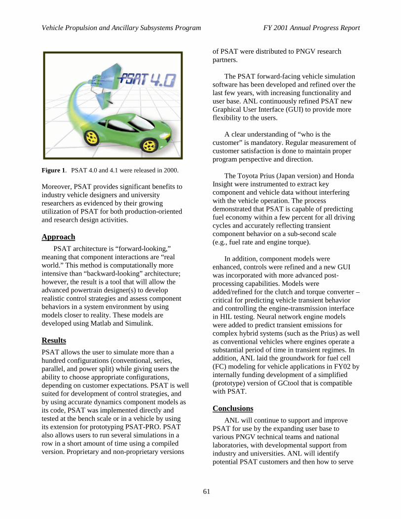
Vehicle Propulsion and Ancillary Subsystems Program FY 2001 Annual Progress Report
61
Figure 1. PSAT 4.0 and 4.1 were released in 2000.
Moreover, PSAT provides significant benefits toindustry vehicle designers and universityresearchers as evidenced by their growingutilization of PSAT for both production-orientedand research design activities.
Approach
PSAT architecture is “forward-looking,”meaning that component interactions are “realworld.” This method is computationally moreintensive than “backward-looking” architecture;however, the result is a tool that will allow theadvanced powertrain designer(s) to developrealistic control strategies and assess componentbehaviors in a system environment by usingmodels closer to reality. These models aredeveloped using Matlab and Simulink.
Results
PSAT allows the user to simulate more than ahundred configurations (conventional, series,parallel, and power split) while giving users theability to choose appropriate configurations,depending on customer expectations. PSAT is wellsuited for development of control strategies, andby using accurate dynamics component models asits code, PSAT was implemented directly andtested at the bench scale or in a vehicle by usingits extension for prototyping PSAT-PRO. PSATalso allows users to run several simulations in arow in a short amount of time using a compiledversion. Proprietary and non-proprietary versions
of PSAT were distributed to PNGV researchpartners.
The PSAT forward-facing vehicle simulationsoftware has been developed and refined over thelast few years, with increasing functionality anduser base. ANL continuously refined PSAT newGraphical User Interface (GUI) to provide moreflexibility to the users.
A clear understanding of “who is thecustomer” is mandatory. Regular measurement ofcustomer satisfaction is done to maintain properprogram perspective and direction.
The Toyota Prius (Japan version) and HondaInsight were instrumented to extract keycomponent and vehicle data without interferingwith the vehicle operation. The processdemonstrated that PSAT is capable of predictingfuel economy within a few percent for all drivingcycles and accurately reflecting transientcomponent behavior on a sub-second scale(e.g., fuel rate and engine torque).
In addition, component models wereenhanced, controls were refined and a new GUIwas incorporated with more advanced post-processing capabilities. Models wereadded/refined for the clutch and torque converter –critical for predicting vehicle transient behaviorand controlling the engine-transmission interfacein HIL testing. Neural network engine modelswere added to predict transient emissions forcomplex hybrid systems (such as the Prius) as wellas conventional vehicles where engines operate asubstantial period of time in transient regimes. Inaddition, ANL laid the groundwork for fuel cell(FC) modeling for vehicle applications in FY02 byinternally funding development of a simplified(prototype) version of GCtool that is compatiblewith PSAT.
Conclusions
ANL will continue to support and improvePSAT for use by the expanding user base tovarious PNGV technical teams and nationallaboratories, with developmental support fromindustry and universities. ANL will identifypotential PSAT customers and then how to serve

Vehicle Propulsion and Ancillary Subsystems Program FY 2001 Annual Progress Report
62
the specific customers of the PSAT vehiclesimulation programs best. While much progresshas been made in these areas, more work is neededto more fully integrate optimization into theanalysis tools used by the systems analysis team.
Publications/Presentations
Rousseau, A., Deville, B., Zini, G., Kern, J.,Anderson, J. and Duoba, M., “Honda InsightValidation Using PSAT,” Future TransportationTechnology Conference, Costa-Mesa, SAE paper2001-01-2538
Deville, B., and Rousseau, A., “Validation of theHonda Insight Using PSAT,” report to DOEsponsor, September, 2001.
Rousseau, A. and Pasquier, M., “Validation of aHybrid Modeling Software (PSAT) Using ItsExtension for Prototyping (PSAT-PRO)”, GlobalPowertrain Congress, Detroit, June 06-08, 2001.
Rousseau, A., and Pasquier, M., “ValidationProcess of a System Analysis Model: PSAT,”SAE paper 2001-01-P183, SAE World Congress,Detroit, March 4-8, 2001.
Sharer, P., and Rousseau, A., “Validation of theJapan Toyota Prius Using PSAT,” report to DOEsponsor, March, 2001.
An, F., and Rousseau, A., “Integration of a ModalEnergy and Emission Model into the PNGVVehicle Simulation Model: PSAT,” 2001-01-0954SAE World Congress, Detroit, March 4-8, 2001.
IIIF. Development of New Optimization and Control Tools
Aymeric Rousseau (primary contact), Keith HardyArgonne National Laboratory9700 S. Cass AvenueArgonne, IL 60439(630) 252-7261, fax (630) 252-3443, e-mail: [email protected]
DOE Program Manager: Patrick Sutton(202) 586-8058, fax (202) 586-1600, e-mail: [email protected]
Objective
• Investigate existing optimization algorithms, develop new robust and efficient optimizationalgorithms, and evaluate their effectiveness for PSAT.
• Continue investigating several control and energy management strategies, taking into account thedynamic behavior of the subsystems.
Approach
• Revisit the different optimization algorithms that have already been used and investigated for PSAT.• Survey different optimization methods that have the greatest potential for robust and efficient search
for the global optimum.• Investigate and test global optimization algorithms in terms of efficient computation and robustness.• Change the different available controllers in PSAT to digital controllers.• Incorporate the effect of the transients in the components to help evaluate driveability issues.

Vehicle Propulsion and Ancillary Subsystems Program FY 2001 Annual Progress Report
63
Accomplishments
• Evaluated previous optimization and control work and selected future algorithms.• Formulated an optimization and control problem for a specific vehicle configuration.• Integrated the optimization algorithms with PSAT for the parallel configuration.• Developed and integrated the control system with PSAT.• Tested the optimization and control, and generated results.• Optimized the fuzzy logic parameters using DIRECT algorithm developed by University of
Michigan.• Demonstrated the possibility to reduce NOx by 50% with almost no loss in fuel economy
Future Directions
• Further investigate existing optimization algorithms and develop new robust and efficientoptimization algorithms (as necessary) and evaluate their effectiveness for PSAT.
• Tune the fuzzy logic parameters for the drivetrain configuration chosen for HIL and validate trade-offbetween fuel economy and emissions obtained from modeling.
Introduction
Since 1996, the PNGV System AnalysisTechnical Team has been working with Universityof Michigan (UM) and Oakland University (OU)in the area of optimization and control. Whilemuch progress has been made in these areas, morework is needed to more fully integrateoptimization into the analysis tools used by thesystems analysis team.
OU developed different energy managementstrategies for series and parallel hybrid vehicles.Those strategies were the basis for the energymanagement strategies that are currently in PSAT.The work at OU also helped in debugging andtesting of the software. Phase II of the project isconcentrating on using fuzzy control for theenergy management strategies of parallel hybridvehicles. The energy management strategiescurrently being developed are implemented as adiscrete control system. In future work, we arelooking to continue devising combinedoptimization of energy management and sizing ofhybrid vehicles. The energy management andcontrol strategies will also take into considerationthe dynamic behavior of the components duringcontrol evaluation. Digital controllers will bedesigned and evaluated in the OU strategy tosupport hardware-in-the-loop activities.
The objectives of this project are to investigateexisting optimization algorithms, develop new
robust and efficient optimization algorithms (asnecessary), and evaluate their effectiveness forPSAT. Another objective of this task is to continueinvestigating several control and energymanagement strategies, taking into account thedynamic behavior of the subsystems. Discretecontrol systems that will support the hardware-in-the–loop activities will be emphasized.
Approach
In the technical approach, the differentoptimization algorithms that have already beenused and investigated for PSAT will be revisited.The advantages and disadvantages of eachapproach will be discussed. A survey of differentoptimization methods that have the greatestpotential for robust and efficient search for theglobal optimum will be developed. Globaloptimization algorithms, in particular, will beinvestigated and tested in terms of efficientcomputation and robustness. Candidates for globaloptimizations are DIRECT, generic algorithms,and simulated annealing. The optimization toolshould allow the user to choose parameters for theseveral components and control. The user can alsodefine a fuel economy objective function withemission and performance constraints.
In the technical approach for the control andenergy management strategies, the differentavailable controllers in PSAT will be changed todigital controllers. This improvement will give

Vehicle Propulsion and Ancillary Subsystems Program FY 2001 Annual Progress Report
64
more realistic performance and it will support thehardware-in-the loop activities. The controller’sevaluation will also incorporate the effect of thetransients in the components, which will help inthe evaluation of driveability issues.
Results
ANL and OU evaluated the previousoptimization and control work and selected futurealgorithms, formulated an optimization andcontrol problem for a specific vehicleconfiguration, integrated the optimizationalgorithms with PSAT for the parallelconfiguration, developed and integrated thecontrol system with PSAT, tested the optimizationand control, and generated results. Preliminary
analyses indicated that engine out NOx can bereduced by up to 50% with no loss in fueleconomy for a CI engine in a hybrid powertrain byusing fuzzy logic to minimize emissions (versusthe previous PSAT control strategy targetingminimum fuel consumption).
Conclusions
OU developed a control strategy andincorporated it into PSAT on the basis of fuzzylogic to optimize the drivetrain, while the UMteam developed a generic global optimizationalgorithm. Tests at the ANL Advanced PowertrainTest Facility (APTF) using PSAT-PRO will allowANL to validate and improve the algorithm.

Vehicle Propulsion and Ancillary Subsystems Program FY 2001 Annual Progress Report
65
IV. OAK RIDGE NATIONAL LABORATORY SUPPORT
IVA. Downstream Emissions Control (Aftertreatment) Modeling
Scott Sluder, Robert Wagner, Katey E. Lenox, Stuart Daw, Johney GreenOak Ridge National Laboratory2360 Cherahala BoulevardKnoxville, TN 37932(865) 946-1235, e-mail: [email protected]
DOE Program Manager: Robert Kost(202) 586-2334, e-mail: [email protected]
ObjectiveTo provide low-level models of advanced emissions control technologies that will facilitate inclusion of the benefits
of these technologies in vehicle system-level models.
Approach
• Develop low-level, physically-based models of emissions control devices.• Utilize industry-developed prototype emissions control devices in a laboratory to generate calibration and
verification data for the models.
Accomplishments
• Completed a low-level model of a Catalyzed Diesel Particle Filter, including laboratory characterization of anearly prototype device.
• Completed a low-level model of a diesel oxidation catalyst, including laboratory characterization of aproduction device.
• Began a low-level model of a NOx storage and reduction catalyst. Acquired prototype device forcharacterization at ORNL.
Future Directions
• Complete laboratory characterization of prototype NOx storage catalyst and finalize model for use in vehicle-system models.
• Re-visit model of catalyzed diesel particle filter to investigate and improve upon the model to add regenerationmodeling capability.
• Produce a low-level model for a urea-selective catalytic reduction system.
Introduction
Achieving ultra-low emissions levels fromlean-burn engines remains as perhaps the mostdifficult technical barrier to be overcome beforethese fuel-efficient engines can be incorporatedinto advanced vehicles for public use. Althoughhybridization can provide benefits in terms ofdecreased pollutant emissions (as well as fuel
efficiency gains), it is unlikely that advanced,highly efficient vehicles can meet the stringentEPA Tier 2 emissions requirements without usingone or more advanced emissions controltechnologies.
These technologies (NOX adsorbers, Urea-selective catalytic reduction systems, dieselparticle filters, plasma-assisted catalysis, and

Vehicle Propulsion and Ancillary Subsystems Program FY 2001 Annual Progress Report
66
perhaps others) are presently emerging andimproving, but do show the potential to allowlean-burn engines to achieve emissions levelsconsistent with the Tier 2 rule. Although technicalissues remain that currently prevent thesetechnologies from commercialization, they are ofcritical importance to the future of fuel-efficientpowertrains. Hence, it is important to include thepotential benefits (and drawbacks) of thesetechnologies in models aimed at investigatingadvanced vehicle design.
Approach
Although these technologies are still maturingfor vehicle usage, prototype devices are in use forresearch and development. While athermochemically exhaustive model of one ofthese devices remains a computationally intensiveactivity, simplified, low-order models can now bedeveloped to operate on a desktop PC. Thesesimplified models must, necessarily, not includeexhaustive treatment of the complex chemistryinvolved, but can provide estimates of thepotential benefits and limitations of advancedemissions control technologies. This activityfocuses on developing low-order physically-basedmodels of emissions control devices, followed bylaboratory characterization of prototype devicesprovided by industry partners. The laboratorycharacterization provides performance data tocalibrate and “anchor” the physical models.
Results
Previous work in this area focused ondeveloping a model for a catalyzed diesel particlefilter and for a diesel oxidation catalyst. Thesemodels have been distributed and are currently inuse. During early work with the particle filter, itwas not possible to model the regenerationbehavior of the filter, which is the task of anupcoming study to improve upon the initial model.
Current research focuses on development of amodel for a NOX adsorber. This technology posesmany issues for developing a model. The deviceoperates in three steps: adsorbing NOX from theexhaust stream during lean engine operation,releasing stored NOX during the early stages ofregeneration, and chemically reducing the releasedNOX during regeneration. The model must
therefore take all three steps into account.Uncertainty in the chemical kinetics involved withthese devices and application-specificcharacteristics complicate the model as well.
A low-order model made up of severalalgorithms to replicate the three steps mentionedabove has been devised and is being calibratedwith laboratory data from several sources. AThomas model has been included in the NOXadsorber model to describe the storage of NOX inthe device. Results from one calibration exerciseare shown in Figure 1.
Figure 1. Thomas model for NOX storage comparedwith laboratory data using a prototype.
As indicated, the model must also reproducethe NOX release and reduction steps. Figure 2shows the NOX release and reduction during aregeneration pulse. At present the modeloverpredicts the chemical reduction taking place,but further calibration is expected to produceimproved results. Overall, however, the model’sperformance is as expected.
Conclusions
Highly efficient vehicle designs are likely torequire the use of advanced emissions controltechnologies in order to meet future emissionsrequirements put forward by the EPA. With this inmind, it is obvious that these technologies shouldbe included in vehicle models aimed atdiscovering avenues for improvement in vehicleefficiency.

Vehicle Propulsion and Ancillary Subsystems Program FY 2001 Annual Progress Report
67
Figure 2. Model prediction of NOX pulse duringregeneration compared with laboratory datausing a prototype.
It is possible to devise low-order models foremissions control technologies that faithfullyreproduce the effects of these technologies for usein systems-level models of vehicles. Althoughthese low-order models are not replacements formore computationally-intensive models aimed atdevice design, they are nonetheless important forincluding the beneficial effects of thesetechnologies in vehicle-systems modeling andplanning.
IVB. Automotive System Cost Modeling
Sujit DasOak Ridge National LaboratoryOak Ridge, TN 37831-6073(865) 574-5182, fax: (865) 574-3851, e-mail: [email protected]
DOE Program Manager: Robert Kost(202) 586-2334, fax: (202) 586-1600, e-mail: [email protected]
Objective
• Develop a stand-alone, system-level cost model for generic production-cost estimation of advanced classvehicles and systems to facilitate progress toward PNGV affordability objectives
• Enable relative production-cost estimation via a uniform estimation methodology, allowing a comparison ofalternative technologies under consideration by the PNGV community
• Develop a repository of cost data about various component-level technologies being developed today for newgeneration vehicles
Approach
• A bottom-up approach defining the vehicle as five major subsystems consisting of total 36+ components• Performance and system interrelationships are considered to estimate system and subsystem costs for
calculating total vehicle production cost• A spreadsheet-based modular structure to provide “open” design and allow for future expansion
AccomplishmentsModeling framework enhancements include logic, new definition of vehicle subsystems, and functionalinterrelationships among subsystems in joint collaboration with Argonne National Laboratory (ANL) and PNGVvehicle engineering technical team (VETT)
Vehicle Propulsion and Ancillary Subsystems Program FY 2001 Annual Progress Report
68
− Implementation of ANL powertrain sizing routine consisting of seven specific vehicle configurations− Inclusion of technology cost information of some subsystems from the PNGV tech teams and the industry
Future Directions
• Develop a credible database of a limited number of technologies of interest to PNGV to facilitate baselinemodel calibration and “Cost Roll-Ups” for a few generic vehicle configurations of interest to PNGV
• Calibrate model through a baseline vehicle and perform relative production cost sensitivity for a selectednumber of technologies of interest to PNGV
Introduction
With support available since late last yearfrom the PNGV vehicle engineering technicalteam (VETT), ORNL and ANL jointly continuedthe two-year automotive system cost modeldevelopment, with some support from IBISAssociates, Inc. The focus of work has shifted torelative production cost estimation via a uniformmethodology, allowing a comparison ofalternative technologies under consideration by thePNGV community. The target vehicle initially inthe model is a year 2010 production-volumepassenger sedan (250,000 units) comparable insize/performance to a Ford Taurus, which is alsothe baseline for the PNGV program’s target forimproving the fuel efficiency by three times.
Approach
It is important that the cost assessment ofadvanced vehicle designs be performed at thevehicle system/subsystem level to examine how itsimpacts of a specific technology translates to atthe vehicle level. This approach provides thesystem synergism effect by taking intoconsideration the interrelationships among varioussystems/subsystems of a vehicle. The total cost ofadvanced vehicles is based on cost estimates madeat the level of five major subsystems consisting ofa total of 30+ components, where each componentrepresents a specific design and/or manufacturingtechnology. A spreadsheet based modularstructure provides the “open” design allowing forfuture expansion particularly the information onadvanced technologies of subsystems as theybecome available.
Results
The cost model now incorporates a newdefinition of vehicle subsystems along with theANL powertrain-sizing routine. The ANLpowertrain-sizing routine provides the capabilityto estimate the power and mass of typical hybridelectric (HEV) and fuel cell vehicle (FCV)configurations. The power and mass projections ofvarious components are based on componentspecific power and efficiency values, with thecapability to evaluate alternative HEVconfigurations and performance strategies. Sevenspecific vehicle configurations have been initiallyconsidered for the analysis: conventional, parallelpower-assist charge sustaining HEV, seriescharge-sustaining HEV, battery-assisted charge-sustaining FCV with and without a reformer, andfull hydrogen FCV with and without a reformer.Under the new definition of vehicle subsystems, alarger number of vehicle components wereincluded under the powertrain subsystem, whereasthe interior components were aggregated into asmaller number of groups due to invariant natureof the system. Implementation of the relativelysimpler ANL powertrain sizing algorithm used inits hybrid electric vehicle cost model (HEVCOST)provides the standalone, system-level, vehicle-costestimation capability, with the component-sizingand cost-estimation capability in a single model.
Figure 1 shows the modeling frameworkdeveloped for the vehicle production costestimation. The revised modeling frameworkprovides the capability to sum up the cost ofvarious vehicle subsystems and components afterthese have been properly sized through an iterative

Vehicle Propulsion and Ancillary Subsystems Program FY 2001 Annual Progress Report
69
algorithm. Using the user-defined vehicle and theinitial assumption of non-powertrain componentmass, the powertrain components are sized. Non-powertain components are then sized based ontheir functional relationships with powertraincomponents. The scaling of various vehiclesubsystems depends on their functionality in thevehicle, i.e., either fixed or variable with eithervehicle weight, powertrain and material type orwith all or some combination of these. Theiterative sizing procedure continues until thevehicle performance and mass criteria for bothpowertrain and non-powertrain components aremet. The estimated assembly cost is added to theestimated powertrain and non-powertrain costs tocalculate the vehicle production cost.
Conclusions
It is important that the system levelautomotive cost modeling framework be continuedto satisfy the needs of DOE. During the coming
year, it is suggested that the automotive systemcost model development be continued working incollaboration with the PNGV technical teams whoare involved at the specific system level costmodeling. The focus of this work will be todevelop a credible database on a selected numberof technologies, making use of the cost dataavailable on specific technologies from variousPNGV technical teams. The model will becalibrated to a baseline vehicle in addition toconsideration of a limited number of “Cost Roll-Ups” for several generic vehicle configurations ofinterest to PNGV. Cost Roll-Ups will bedeveloped to demonstrate the relative costsensitivity of the model due to a change intechnology either for motors, batteries, engines, ormaterials in the body. These model enhancementssuggested during this year will enable technologytrade-offs and the assessment of the impact oftechnology goals on a vehicle and fleet basis in thefuture.
New Non-P/T Com pone nt
M ass
Are Performance
and M ass Criter ia Met?
Vehicle Production Cos t
Yes
No
De fine Global Vehicle Des ign &
Performance Parameters
P/T Com pone nt
Siz ing
Es tim ate P/T and Non-P/T Com pone nt Costs
Ve hicle ConfigurationConve ntional,
M ild & Full HEV
Body/Chass is Options
Stee l, Alum inum Com pos ites , e tc.
HEVCOST Pe rform ance Cons trained Component
Sizing Algor ithm Impleme ntation & (Pass ing)
Re finement
Es tim ate Assembly Cos t
Powe rplantOptions
SI, CIDI, FC, e tc.
Body/Chass is Siz ing
Body....Chass is....
Pick trial value
Figure 1. Modeling framework for vehicle production cost estimation.

This document highlights work sponsored by agencies of the U.S. Government. Neither the U.S.Government nor any agency thereof, nor any of their employees, makes any warranty, express or implied,or assumes any legal liability or responsibility for the accuracy, completeness, or usefulness of any infor-mation, apparatus, product, or process disclosed, or represents that its use would not infringe privatelyowned rights. Reference herein to any specific commercial product, process, or service by trade name,trademark, manufacturer, or otherwise does not necessarily constitute or imply its endorsement, recom-mendation, or favoring by the U.S. Government or any agency thereof. The views and opinions of authorsexpressed herein do not necessarily state or reflect those of the U.S. Government or any agency thereof.
Printed on recycled paper
www.cartech.doe.gov
DOE/EERE/OTT/OAAT - 2001/002
Office of Transportation TechnologiesSeries of 2001 Annual Progress Reports
• Office of Advanced Automotive Technologies FY 2001 Program Highlights
• Vehicle Propulsion and Ancillary Subsystems
• Automotive Lightweighting Materials
• Automotive Propulsion Materials
• Fuels for Advanced CIDI Engines and Fuel Cells
• Spark Ignition, Direct Injection Engine R&D
• Combustion and Emission Control for Advanced CIDI Engines
• Fuel Cells for Transportation
• Advanced Technology Development (High-Power Battery)
• Batteries for Advanced Transportation Technologies (High-Energy Battery)
• Vehicle Power Electronics and Electric Machines
• Vehicle High-Power Energy Storage
• Electric Vehicle Batteries R&D