Embed Size (px)
Citation preview
2000 Watt Power Inverter
Model No.: PKC0AX
Owner’s Manual and Warranty Information
Read these instructions completely before using this product.Retain this Owner’s Manual for future reference.
9/131© 2013

2
CONTENTS
SAFETY PRECAUTIONS ................................................................................................................2Power Inverter Safety ..............................................................................................................2
INTRODUCTION .............................................................................................................................3FEATURES ......................................................................................................................................3OPERATION (USING YOUR INVERTER) .......................................................................................3
Determining Power Consumption (Current Draw of Equipment) ............................................4Power Source ..........................................................................................................................4Determining Battery Capacity and Operating Time ................................................................4Positioning of Power Inverter ..................................................................................................5Marine Installation ...................................................................................................................5Connecting to Power Source ..................................................................................................5Hard Wire to Power Source .....................................................................................................6USB Power Outlet Operation ..................................................................................................7Remote Switch Operation .......................................................................................................7Power Output Wattage Indicator .............................................................................................8Connecting a Load to the Power Inverter ................................................................................8Protective Features .................................................................................................................8Common Problems .................................................................................................................9
CARE AND MAINTENANCE ...........................................................................................................9Storage ...................................................................................................................................9Cleaning ..................................................................................................................................9Disposal ..................................................................................................................................9
FREQUENTLY ASKED QUESTIONS ............................................................................................10SPECIFICATIONS .........................................................................................................................11TROUBLESHOOTING ...................................................................................................................12LIMITED WARRANTY ...................................................................................................................13
To Obtain Service .................................................................................................................13
SAFETY PRECAUTIONS
This safety alert symbol indicates that a potential personal injury hazard is present. The symbol is usually used with a signal word (e.g., WARNING) which designates the degree or level of hazard seriousness.The signal word WARNING indicates a hazardous situation which, if not avoided, could result in death or serious injury.The signal word NOTICE indicates a situation which can cause damage to the product, other personal property and/or to the environment, or cause the product to operate improperly.The combination of the safety alert symbol and signal word is used in safety messages throughout this manual and on safety labels on this product.
All safety messages that follow have WARNING level hazards. Failure to comply could result in death or serious injury.
Power Inverter Safety• This product contains lead and/or lead compounds, chemicals known to the state of California to
cause cancer and reproductive harm. Wash hands after handling.• KEEP THE POWER INVERTER AND ITS ACCESSORIES OUT OF THE REACH OF CHILDREN.• Do not use the Power Inverter with medical devices. It is not tested for medical applications.• Do not leave the vehicle unattended while using the Power Inverter.• Do not operate the Power Inverter if the battery cables are damaged. Replace damaged battery
cables immediately.• Keep the Power Inverter, battery cables and remote switch cable away from the vehicle’s
mechanical controls and rotating components when using the Inverter.• Do not attempt to connect the Power Inverter to the battery of the vehicle while the engine is
operating.• Do not modify the Inverter’s battery cables in any way.• Do not operate the Power Inverter if it has received a sharp blow, been dropped or been damaged
in any other way.
3
• Do not disassemble the Power Inverter. There are no serviceable components within the Inverter.• Do NOT install or operate the Power Inverter in areas designated as IGNITION PROTECTED. The
Inverter is NOT APPROVED for ignition protected areas.• Always turn the Inverter ON/OFF switch and remote switch ON/OFF button to the OFF position
and disconnect the battery cables from the battery or power source when not in use to avoiddraining the battery.
• Do not expose the Inverter to flammables, water, rain or snow.• Use the Inverter in properly ventilated areas only.• Always remove the appliance plug from the AC receptacle before working on the appliance.• Do not insert foreign objects into the AC receptacles.
INTRODUCTIONThis Power Inverter can be used to supply power and emergency backup power for household appliances and power recreational equipment with a normal power requirement of up to 2000 continuous watts using a 12-volt power connection.• When using the Power Inverter in a vehicle, check the vehicle’s owner’s manual for maximum
power rating and recommended output. • Read and understand this Instruction Manual before using the Power Inverter.• Install and operate the Power Inverter only as described in this Instruction Manual.
FEATURES• Remote switch• Cooling fan• Positive and negative screw connectors• Battery cables• Power output wattage indicator• Standard 110/120-volt AC receptacle(s)• On/off switch• Usb power outlet• Fault/power indicator• Compact design for safer use, transport and storage• Connects to a 12-volt battery or power source• Mounting brackets for hard wire installation
OPERATION (USING YOUR INVERTER)The Power Inverter converts 12-volt DC (direct current) input voltage to 110/120-volt, 60 Hz AC (alternating current) power. The Inverter produces a “modified sine wave.” The modified sine wave is suitable for most AC powered appliances and personal electronic devices. The following devices may not work with a modified sine wave:• Photocopiers, laser printers, magneto-optical hard drives• Some laptops• Metal halide arc (MHI) lights• Some fluorescent lights with electronic ballasts• Power tools that use solid-state power• Fans and power tools that use variable speed controls• Some new furnaces and pellet stoves with microprocessor control• Digital radios and clocks• Sewing machines with speed/microprocessor control• Electronics that modulate radio frequency signals on the AC line• X-10 home automation systems• Oxygen concentrators and other medical equipment
Most battery chargers can be connected to the AC receptacle. Battery chargers that use separate transformers or chargers that plug into the AC receptacle to supply a low-voltage DC-to-AC output should work. However, battery chargers for small nickel-cadmium batteries can be damaged if plugged into the Inverter.
4
The following appliances or devices could be damaged if plugged into the Inverter:• Small battery operated appliances that can be plugged directly into the AC receptacle such as
flashlights, cordless razors and toothbrushes.
• Certain battery chargers for cordless tool battery packs. These chargers can be identified by awarning label stating dangerous voltages are present at the battery terminals.
Monitor the temperature of the battery charger for about 10 minutes. If the battery charger becomes abnormally warm, disconnect it from the Power Inverter immediately.If you are unsure about powering any appliance or device with the Inverter, contact the manufacturer or consult the owner’s manual of the device.
Determining Power Consumption (Current Draw of Equipment)
FIRE HAZARDDo not operate high wattage appliances or equipment that will produce heat, such as hair dryers, irons, heaters and toasters, with this Inverter.
Ensure that total power consumption of the device being used is less than the rating of the Inverter.The manufacturer provides a label with power consumption information in watts or amps for their product. If the item’s power consumption is not indicated in watts, but in amps AC, multiply the amp AC value by 120 (AC volts) to determine the wattage.
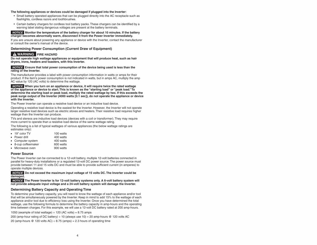
When you turn on an appliance or device, it will require twice the rated wattage of the appliance or device to start. This is known as the “starting load” or “peak load.” To determine the starting load or peak load, multiply the rated wattage by two. If this exceeds the peak surge output of the Inverter (4000 watts [0.1 sec]), do not operate the appliance or device with the Inverter.The Power Inverter can operate a resistive load device or an inductive load device.Operating a resistive load device is the easiest for the Inverter. However, the Inverter will not operate larger resistive load devices such as electric stoves and heaters. Their resistive load requires higher wattage than the Inverter can produce.TVs and stereos are inductive load devices (devices with a coil or transformer). They may require more current to operate than a resistive load device of the same wattage rating. The following is a list of typical wattages of various appliances (the below wattage ratings are estimates only):• 19" color TV 100 watts• Power drill 400 watts• Computer system 400 watts• 8-cup coffeemaker 600 watts• Microwave oven 900 watts
Power SourceThe Power Inverter can be connected to a 12-volt battery, multiple 12-volt batteries connected in parallel for heavy-duty installations or a regulated 12-volt DC power source. The power source must provide between 11 and 15 volts DC and must be able to provide sufficient current (in amperes) to operate multiple devices.
Do not exceed the maximum input voltage of 15 volts DC. The Inverter could be damaged.
The Power Inverter is for 12-volt battery systems only. A 6-volt battery system will not provide adequate input voltage and a 24-volt battery system will damage the Inverter.
Determining Battery Capacity and Operating TimeTo determine your battery capacity, you will need to know the wattage of each appliance and/or tool that will be simultaneously powered by the Inverter. Keep in mind to add 15% to the wattage of each appliance and/or tool due to efficiency loss using the Inverter. Once you have determined the total wattage, use the following formula to determine the battery capacity in amp-hours and the operating time between charges. For this example, we will use a 12-volt DC battery rated at 200 amp-hours.
1050 (example of total wattage) ÷ 120 (AC volts) = 8.75 amps200 (amp-hour rating of DC battery) ÷ 10 (always use 10) = 20 amp-hours @ 120 volts AC20 (amp-hours @ 120 volts AC) ÷ 8.75 (amps) = 2.3 hours of operating time

5
To increase the operating time, the amp-hour rating must be increased. Either choose a battery with a higher amp-hour rating, or connect multiple batteries together in parallel. If the 12-volt DC battery has a rating of 200 amp-hours, connecting two 12-volt DC batteries, each having a 200 amp-hour rating in a parallel arrangement, would increase the amp-hour rating to 400 amp-hours, doubling the time of operation.
Use conservative estimates when selecting a battery. The number of amp-hours you expect to use should be 50% of the battery’s rated amp-hours.
There is no accurate conversion formula for converting CCA (cold cranking amps) into battery amp-hours. There are too many variations between battery manufacturers to have a standard formula. To determine the amp-hours for your battery, contact the battery manufacturer.
Positioning of Power InverterPosition the Power Inverter on a reasonably flat surface. DO NOT place on or under the vehicle seats. Allow at least 3 in. (76 mm) of clearance around the Inverter to allow for airflow. Always use the Inverter where there is adequate ventilation. Do not block ventilation slots or the cooling fan. Install the Inverter as close to the DC power source as possible. It is more efficient to use longer AC wiring than DC wiring.If desired, the Power Inverter can be solidly mounted to a base using the mounting brackets.
If installed in a vehicle, it is recommended that the Inverter be shock mounted using a rubber isolation pad between the Inverter and the base.The Inverter can be mounted on a vertical surface, on a horizontal surface or under a horizontal surface. Install the Inverter so that the receptacles and the ON/OFF switch are accessible.
Do not install the Inverter on a vertical surface where the cooling fan is facing up or down.
FIRE HAZARDS• Do not place the Inverter near flammable materials or in any location that may accumulate
flammable fumes or gases such as the battery compartment of your vehicle or enginecompartment of your boat.
• Do not expose the Inverter to extreme heat or flames. The surrounding air temperatureshould be between 32° and 104°F (0° and 40°C). Do not place the Inverter on or near aheating vent or any equipment which is generating heat above room temperature. Do notplace the Inverter in direct sunlight.
ELECTROCUTION HAZARD Do not operate the Inverter if it is wet. Do not allow water, moisture or other liquids to come in contact with the Inverter, the device being operated or the power source.
Marine Installation
Marine installations are subject to additional vibration and stress on the cables. Marine installations require tight, water-resistant electrical connections with slack in both the cables and appliance wiring. Use the appropriate cable insulation for the environment.Install the Power Inverter away from moisture and water. Install the Inverter above the waterline, as high as possible. The Inverter must not be installed below or near the waterline.The Inverter’s DC input must be connected to approved marine wiring using non-corrosive marine fasteners and fittings.
Connecting to Power Source
FIRE HAZARD Do not connect the Inverter to RV or household AC distribution wiring, to an AC load circuit or where the neutral conductor is connected to the negative terminal of a DC power source. Connecting to these circuits could cause damage to the Inverter and/or create a spark.
Do not use with positive ground electrical systems. Connecting the Inverter to a positive ground electrical system will damage the Inverter. Only use the Power Inverter on negative ground electrical systems. If in doubt, check with your vehicle dealer or consult the vehicle’s owner’s manual. Connecting to 12-volt Battery or 12-volt DC Using Supplied CablesThe Power Inverter is equipped with two screw connectors to attach the cable leads to the Inverter. The red is positive (+) and the black is negative (-).1. Press the ON/OFF switch and remote switch ON/OFF button to the OFF position.2. Remove the red positive (+) screw connector cap, the flat washer and the lock washer.

6
3. Slide the lock washer, then the red positive (+) cable lead, then the flat washer, onto the redpositive (+) screw connector stud. Tighten the screw connector cap securely.
4. Remove the black negative (-) screw connector cap, the flat washer and the lock washer.5. Slide the lock washer, then the black negative (-) cable lead, then the flat washer, onto the black
negative (-) screw connector stud. Tighten the screw connector cap securely.6. Securely connect the red positive (+) cable lead to the positive (+) terminal of the battery or
power source.7. Securely connect the black negative (-) cable lead to the negative (-) terminal of the battery or
power source.
Hard Wire to Power SourceThe Power Inverter can be hard wired to the DC power source. A 300-amp ANL fuse or DC circuit breaker should be installed to protect the circuit.
Determining Proper Cable Length and GaugeMeasure the distance between the Power Inverter and the power source. See SPECIFICATIONS for the proper cable gauge to use. Using excessively long or insufficient gauge cables will cause low battery power. Also, using improper cables will reduce battery operation time.
Only use copper cables to connect the Power Inverter to the power source. Do not use aluminum cables. Aluminum cables have approximately 1/3 more resistance than copper cables of the same size.
Only use proper size cable connectors to connect the cables to the Inverter and power source. Be sure the cable connectors are properly installed onto the ends of the cables.
Installing Cables1. Press the ON/OFF switch and remote switch ON/OFF button to the OFF position.2. Install the 300-amp ANL fuse or DC circuit breaker onto the positive (+) terminal of the power
source. Remove the fuse from the fuse holder before installing the fuse holder or turn off thecircuit breaker. If the fuse holder or circuit breaker cannot be installed onto the terminal, use ashort length of the recommended cable gauge to connect the fuse holder or circuit breaker to theterminal. Identify this cable as positive (+).
3. Secure the remaining end of the fuse holder or circuit breaker to the positive (+) cable. Connectthe positive (+) cable to the red positive screw connector on the Inverter. Position the washersbetween the cable connector and the screw connector. Tighten the screw connector securely.
4. Connect the negative cable between the negative (-) terminal of the power source and the blacknegative (-) screw connector on the Inverter. Position the washers between the cable connectorand the screw connector. Tighten the screw connector securely.
FIRE HAZARD Verify that all connections are secured. A loose connection may cause damage to the Inverter and/or create a spark.5. Verify that the positive (+) cable is connected between the positive (+) terminal of the power
source and the red positive (+) screw connector on the Inverter. Also, verify that the negative (-)cable is connected between the negative (-) terminal of the power source and the blacknegative (-) screw connector on the Inverter.
If the cables are not connected correctly, the Power Inverter will be damaged.6. Install the fuse in the fuse holder or turn on the circuit breaker.

7
1
3
4
2
5
6
2
2
7
Legend1. Battery Charging Source2. 12-volt Batteries3. 300-amp ANL Fuse4. Power Inverter5. Negative (-) Cable (see SPECIFICATIONS for cable requirements)6. Positive (+) Cable (see SPECIFICATIONS for cable requirements)7. Additional Batteries Connected in Parallel Circuit
USB Power Outlet Operation
The USB power outlet does not support data communications. The outlet has a maximum of 5 volts/2.1 A.1. Plug the USB-powered device into the USB power outlet.2. Make sure the Inverter is correctly connected to the battery.3. Turn on the USB-powered device.4. When shutting down, turn off the USB device first, then disconnect the Inverter.5. Unplug the USB device from the USB power outlet.
The USB power outlet is an unswitched outlet. Whenever the Inverter is connected to a battery, there will be power to the USB outlet. The ON/OFF switch or the remote switch ON/OFF button does not need to be turned on to have power at the USB outlet.
Remote Switch Operation
The Inverter ON/OFF switch must be in the OFF position when using the remote switch. If the Inverter ON/OFF switch is in the ON position, the remote switch will not operate. 1. Make sure the Inverter ON/OFF switch is in the OFF position.2. Plug in the remote switch connector into the remote switch outlet connection on the Inverter.3. Press the remote switch ON/OFF button. The green light on the remote switch and on the
Inverter should be lit.4. Once the Inverter is turned on using the remote switch, the Inverter operation will be controlled
using the remote switch.5. Turn the Inverter off using the remote switch before disconnecting the remote switch connector
from the Inverter.

8
Power Output Wattage IndicatorThe Inverter is equipped with a power output wattage indicator which displays how much wattage is currently being used. The output indicator has ten separate red lights, with each one representing approximately 200 watts of output when lit. If the device you are powering requires approximately 1000 watts, five of the red indicator lights will be lit.Use these lights as a reference so you do not overload the Inverter. This Inverter can be easily overloaded when using all the 110/120-volt AC outlets. If the first device you are powering shows seven lights on the indicator are lit (approximately 1400 watts) and the next device you want to power requires approximately 1000 watts, you cannot plug that device in because it will overload the Inverter. Use this output indicator as a guide when powering your devices.
Connecting a Load to the Power InverterOnly connect appliances to the Power Inverter after the Inverter is properly connected to the power source.1. Press the ON/OFF switch or remote switch ON/OFF button to the ON position. The green LED
power indicator on the Inverter and/or remote switch will light continuously, indicating that the unitis functioning.
2. Plug the appliance or device into the 110/120-volt AC receptacle.3. Switch on the device. If an audible alarm sounds or the red LED fault indicator lights up for a
protracted period of time, then either the power source voltage is too low or the current beingdrawn by the device is too great.
Monitor the temperature of the device for the first 10 minutes of operation to determine its temperature. If the temperature of the device becomes excessively hot, it is an indication that the device should not be used with this Inverter.4. When shutting down, first turn the power of the appliance or device off.5. Remove the power plug from the Inverter’s 110/120-volt AC receptacle.6. Turn the Inverter’s ON/OFF switch or remote switch ON/OFF button to the OFF position. 7. Disconnect the Inverter from the battery or power source.8. Disconnect the cable leads from the screw connectors.
Battery UseIt is recommended that, if you are using a vehicle battery, you run the engine for 15 minutes every hour in order to recharge the battery.The Power Inverter may be used with the engine on or off. However, it may not operate while the engine is being started, as battery voltage can drop substantially during starting.The Inverter draws little current from the battery when it is not supplying power to a load. Typically, this Power Inverter draws less than 1.0 amps at 12.8 volts. It is recommended that you disconnect the Inverter from the battery when not in use.
Protective FeaturesLow Voltage Alarm (Red LED on Inverter and remote switch will light) - This state is not harmful to the Inverter, but could damage the power source. An audible alarm sounds when the input voltage drops to 10.5 volts and the Inverter shuts off when the input voltage drops to 10.0 volts. When ample power is supplied, the Inverter may then be turned back on.Over-Voltage Protection (Red LED on Inverter and remote switch will light) - The Inverter will automatically shut down when the input voltage exceeds 15 volts DC.
Overload Protection (Red LED on Inverter and remote switch will light) The Inverter will automatically shut down if the continuous draw exceeds its maximum wattage rating. When the Inverter is at or near maximum output, an alarm will sound. When the alarm sounds you need to disconnect the device(s) from the Inverter to bring the Inverter output down to an acceptable level. If you continue to use the Inverter at or near the maximum output, it will eventually overheat and shut down.If you exceed the maximum Inverter output, the alarm will sound and the Inverter will automatically shut down. The red fault indicator on the Inverter will light. The Inverter must be reset after an overload condition.

9
To Reset the Inverter1. Turn off the Inverter using the ON/OFF switch on the Inverter or the remote switch ON/OFF
button, depending upon how the Inverter was controlled.2. Unplug all the devices from the Inverter.3. Turn the Inverter back on using the ON/OFF switch on the Inverter or the remote switch ON/OFF
button.4. Before devices are reconnected to the Inverter, verify the total wattage of the devices to ensure
they are less than the rating of the Inverter.
Temperature ProtectionThe Inverter is equipped with a cooling fan. Depending upon the load output and the temperature of the Inverter, the cooling fan will turn on and off as required to cool the Inverter if needed.If the temperature reaches approximately 149°F (65°C) the Inverter will shut down automatically. Turn off the Inverter and allow it to cool for a minimum of 15 minutes. Before starting up again verify the total wattage of the devices being powered.
Common ProblemsPower tools will start but will not continue to run - Some induction motors (motors without brushes) may require 2 to 6 times their wattage rating in order to start up. If the power tool runs only momentarily when power is applied, try to leave the power tool on while quickly and repeatedly turning the Inverter on and off.Buzzing in audio systems - Some inexpensive stereo systems will emit a buzzing sound from their speakers when operating from the Inverter. This is because the power supply in the device does not adequately filter the modified sine wave produced by the Inverter.Television interference - The Inverter is shielded and filtered to minimize interference with TV signals. In some cases, especially with weak TV signals, some interference may be visible. Try the following corrective measures:• Position the Inverter as far away as possible from the television, the antenna and the antenna
cable.• Adjust the orientation of the Inverter, the antenna cable and the TV power cable to minimize
interference.• Use high-quality, shielded antenna cable.Operating a microwave - The power rating used with microwave ovens is the “cooking power” which qualifies as the power being “delivered” to the food being microwaved. The actual operating power requirement rating is higher than the cooking power rating. This is usually referenced on the back of the microwave. If the operating power requirement cannot be found on the back of the microwave, check the owner’s manual or contact the manufacturer.
CARE AND MAINTENANCE
StorageStore this Power Inverter in a cool, dry area and keep it away from direct sunlight, heat, excessive humidity and dampness. Storage temperature should be between -4°F and 185°F (-20°C and 85°C) with the humidity between 10% and 90%.
CleaningDo not clean or wipe the Power Inverter with solvents or chemical materials. If necessary, remove dirt or stains using a soft cloth dampened with a mild detergent solution.
DisposalThe Power Inverter is designed to provide years of service. Because the Inverter and cables may contain lead, they should be recycled or safely disposed of at a local recycling center. Examples of places that will accept items like this are: county or municipal recycling drop-off centers or scrap metal dealers.

10
FREQUENTLY ASKED QUESTIONSWhat issues can cause my mobile power outlet to stop working?
Overheating, incorrect input voltage, and overloading are some basic symptoms. The unit is equipped with self-protection features that help prevent damage to the mobile power outlet and accessories being powered by it. There are no replaceable fuses in the mobile power outlet nor do we recommend or advise opening the unit to repair it. Please follow the proper procedures for resetting the mobile power outlet which can be found in the owner’s manual for each symptom.
My mobile power outlet does not seem to have the power that I expect from it. Does the age of the battery or its condition affect the operation of the mobile power outlet?
Yes. Ensure the vehicle battery connections and terminals are free from corrosion and that the battery is in good working order. If necessary, test the battery to ensure it is producing the proper voltage level. Clean the terminals with baking soda, water, and a wire brush before connecting the mobile power outlet to the vehicle battery. Please use all precautions necessary to ensure safety in addition to wearing rubber gloves and eye protection.
My mobile power outlet is extremely warm during operation. Is this normal?
Under normal operating conditions, the mobile power outlet will be warm but heat should not be excessive where the case is hot to the touch. If the internal temperature of the mobile power outlet exceeds its upper limit, the temperature protection feature will engage and the unit will shut off. Allow the unit to cool, cycle the power switch, and begin using the unit again. Also, do not have the mobile power outlet in direct sunlight and make sure it is in a well-ventilated area. For adequate performance, operate the mobile power outlet from 32°F to 104°F (0°C to 40°C).
I plugged a device into my mobile power outlet and it will not power it. The mobile power outlet began to make a screeching sound and the red LED light is on. What is wrong?
First, test to see if the power source being supplied at the mobile power outlet connection is between 10.5 volts and 14.5 volts (low battery or over-voltage alarm has sounded with red LED light). There may be adequate voltage coming from the power source but there will be a voltage drop due to the length and thickness of the wires going to the mobile power outlet connection. If possible, use thicker gauge wires from the power source to the mobile power outlet or reduce the length of the cables. If the voltage is not within range, the red FAULT/POWER light will illuminate and the unit will sound an alarm. The mobile power outlet will have to be reset. Also, it may be necessary to run the vehicle in order to power the appliance or device upon initial startup and/or during continuous use.
Second, the mobile power outlet may have been overloaded by powering a device requiring more that the rated power output of the mobile power outlet. Make sure the accessory you are trying to power is within the rated wattage range of the mobile power outlet (overload alarm has sounded with red LED light). Use accessories requiring less power. When you turn on some accessories, they may require two to six times the rated wattage for that appliance or device for startup. If the wattage limitation is exceeded, the mobile power outlet will not power the accessory. This is known as “peak load,” “inductive load,” or “starting load.”
There are four power wires and two connections for the positive (+) and negative (–) terminals on my mobile power outlet. Do I need to use both terminal connections and all four wires?
Yes, connecting the wires using all four terminal connections on the mobile power outlet will ensure less voltage drop throughout the circuit powering the mobile power outlet from the vehicle’s battery.
Why is the 12-volt accessory plug option only available on some PEAK mobile power outlets?
The 12-volt accessory plug option is available on PEAK mobile power outlets up to 400 watts. Above this rating, the mobile power outlet’s current draw is higher than what the vehicle’s circuitry is designed to handle for an accessory plug.
In an effort to extend the run time of the mobile power outlet, is it possible to connect multiple batteries together?
Yes, but only in a parallel circuit. We recommend you consult the vehicle owner’s manual and the mobile power outlet instruction manual for proper installation procedures.

11
I accidentally connected the wires from the mobile power outlet to my vehicle in reverse and the mobile power outlet will not work. Is the unit damaged?
It is dependent on testing the unit afterwards. There are no replaceable fuses in the mobile power outlet nor is it recommended to open or service the unit. Reconnect the unit to the vehicle correctly and try to operate the mobile power outlet. If the unit does not operate after reconnecting it, the mobile power outlet suffered damage that is beyond repair.
How long can I use the mobile power outlet without the vehicle’s engine on?
The greater the rated amp hours of the vehicle battery, the longer the mobile power outlet will supply power to the accessories. To determine the battery capacity, you will need to know the wattage of the accessory the mobile power outlet will power. Add 15% to the wattage of the accessory due to efficiency loss. Once you have determined the wattage, use the following formula to determine the battery capacity in amp-hours and the operating time between charges. Use conservative estimates; the number of amp-hours you expect to use should be 50% of the battery’s rated amp-hours. For this example, we will use a 12-volt battery rated at 400 amp hours as follows:
2400 (example of total wattage) / 120 (AC volts) = 20 amps
400 (amp-hour rating of DC battery) / 10 (always use 10) = 40 amp-hours @ 120 volts AC
40 (amp-hours @ 120 volts AC) / 20 (amps) = 2 hours of operating time
SPECIFICATIONS
1. Max output continuous power 2000 W2. Max output peak surge 4000 W (0.1 sec)3. North American Standard AC receptacles 34. Max output current ≤19 A5. AC output voltage range 105 - 125 V6. AC output frequency range 60 ± 3 Hz7. DC input voltage range 11 - 15 V8. Max no load current draw (12.8V) ≤1.0 A9. Max input current consumption (12.8V) ≤200 A at 2,000 W10. Over voltage protection range 15.75 ± 0.75 V11. Under voltage warning range 10.5 ± 0.5 V12. Under voltage protection range 10.0 ± 0.5 V13. Output overload protection range 2100 - 2600 W14. Efficiency ≥80%15. USB output 5 V, 2.1 A16. Signal format Modified sine wave17. Working temperature 32°F to 104°F (0°C to 40°C)18. Storage temperature -4°F to 185°F (-20°C to 85°C)19. Storage air humidity 10%-90%20. Remote switch cord length 10 ft21. DC fuse requirement for hard wire installation 300-amp ANL22. Cable requirement @ 6 ft (1.8 m) #2 AWG23. Cable requirement @ 10 ft (3.0 m)* 00 AWG24. Dimensions (L x W x H) 10.5 x 9 x 3.5 in. 25. Weight 7.1 lb / 3.22 kg
* For cable requirements greater than 10 ft, consult a licensed electrician.

TROUBLESHOOTING
Problem Situation Action
No power output
Faulty connection Turn the Inverter power switch off, verify cables are tightly connected to the Inverter and the power source.
Battery voltage below 10 volts
Recharge or replace battery.
Equipment being operated draws too much power
Reduce the output load; DO NOT exceed maximum rating for the Inverter.
Inverter in thermal shutdown condition
Allow Inverter to cool down. Ensure there is adequate ventilation around the Inverter. Ensure that load is no more than its maximum rating for continuous operation.
Low voltage alarm turns on immediately
The input voltage at the input of the Inverter needs to be raised
Recharge/replace battery or add additional batteries. Turn on the vehicle when using a 12V DC plug.
Low voltage alarm is on all the time
Poor battery condition with low input voltage
Replace battery.
Inadequate power or voltage drops
Check condition of battery cables and cable leads. Clean or replace as necessary.
Low power output
Battery condition may be poor
Recharge or replace battery.
Faulty connection Make sure the battery and Inverter terminals are clean.
Inverter does not work after connecting the cables in reverse
The internal protection has disabled the Inverter
Contact Old World Industries.