Embed Size (px)
Citation preview

2.0 Natural Gas Processing• natural gas is gaseous form of petroleum
mostly methane (C1), some ethane(C2), propane (C3), butanes (C4), pentanes (C5), hexanes (C6) and C7+
as of year-end 2005Canada + US proved natural gas reserves = 7.43*1012 m3
(262.3 Tcf) 5.78 Tcm (204.4 Tcf) in US and 1.64 Tcm (57.9 Tcf) in Canada.
• Gas transported via pipeline, LNG, and in future as CNG or transformed via GTL
Pipeline – advantageous when infrastructure in place and close to market
Remote or “stranded gas” better served by LNG, CNG, and GTL

• LNG – proven technology, reduction 600 times volume, can meet pipeline specs BUT contaminants (e.g. water) must be removed prior to liquefaction (T<- 160C), liquefaction plant (large and expensive $0.75-1.25 billion), regasifcation unit required, requires proven reserves 20 years, NIMBY• CNG –200 times volume reduction, smaller reserves possible, limited contaminant removal required, less expensive as no plant required BUT limited knowledge on “quality of gas”, no commercial apps, heating/cooling• GTL (gas to liquids)
CH4 + 2 O2 = CO2 + 2 H2 OCH4 + ½ O2 = CO + 2 H2
low temp Fischer TropschnCO + (2n+1)H2 = Cn H(2n+2) + nH2 Ohigh temp Fischer TropschnCO + 2nH2 = Cn H2n + nH2 OnCO + 2nH2 = C(n-1) H(2n-1) CH2 OH + (n-1)H2 O
- Resulting “liquid fuel” has good combustion efficiency and easy to transport BUT taking high H;C fuel and converting to low H;C fuel and process requires severe operating conditions and many unit operations

North American Natural Gas Supply/demand
2006 2006
Bcf Bcm
Gulf Onshore1 6,631 188
Gulf Offshore2 2,717 77
Total Gulf 9,348 265
Wyoming 1,659 47
New Mexico 1,512 43
Oklahoma 1,683 48
Alaska 426 12
Other US3 3,881 110
Total US Production 18,509 524
Western Canada4 5,936 168
Scotian Shelf 125 4
Total Canada Production5 6,061 172
Total N.A. Production 24,570 696
US Gross LNG Imports 584 17
US Gross Mexican Imports 12 0
US Supplementals6 62 2
Total N.A. Supply 25,228 714
Total N.A. Demand (20% residental,14% commercial, 59% industrial/electricity) 24,264 687
Sources: EIA , StatsCan, NRCan estimates.

Inlet Separators
Condensate Stabilization
Acid Gas Removal
Sulphur Recovery
Dehydration/ Compression
Propane/Butane Processing
e.g. deep cut, turboexpansion
C5 +
C3 , C4
condensate (C2 -C5+ )
C1 , C2 , H2 S, CO2 etc..
C1 , C2 , H2 O
H2 S, CO2 HC, SO2 , CO2
S
Simplified PFD for Sour Gas Processing Plant
gas from wells
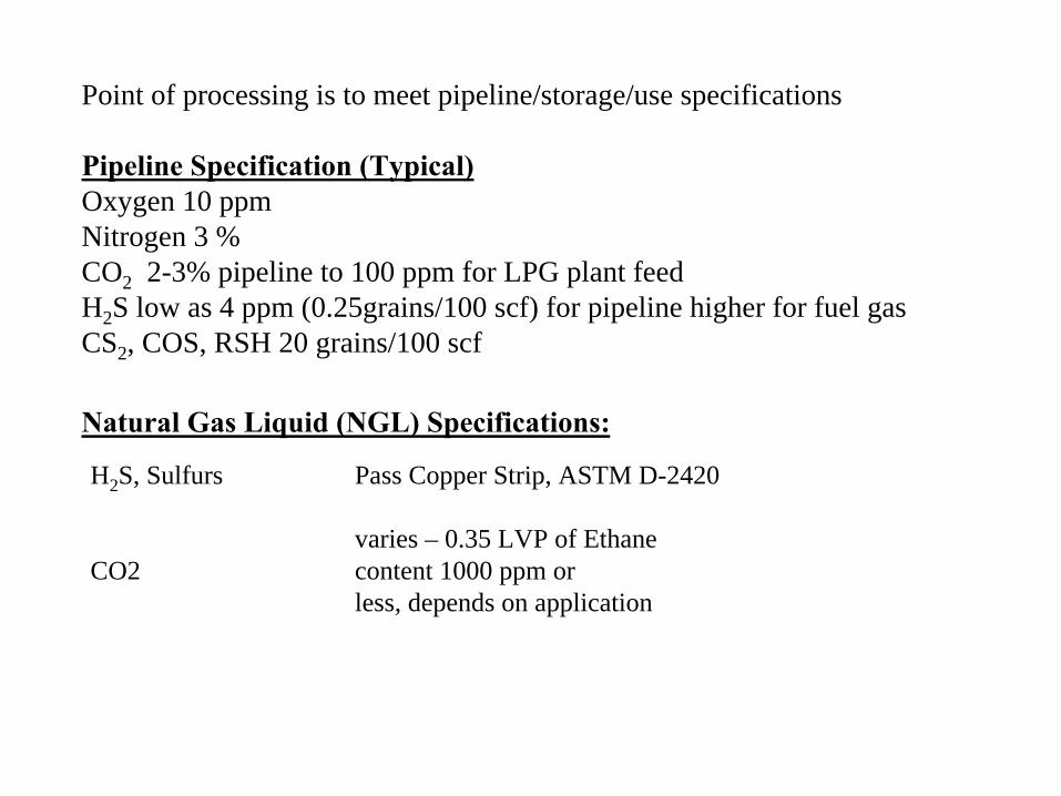
Point of processing is to meet pipeline/storage/use specifications
Pipeline Specification (Typical)Oxygen 10 ppmNitrogen 3 %CO2 2-3% pipeline to 100 ppm for LPG plant feedH2 S low as 4 ppm (0.25grains/100 scf) for pipeline higher for fuel gasCS2 , COS, RSH 20 grains/100 scf
H2 S, Sulfurs Pass Copper Strip, ASTM D-2420
CO2varies – 0.35 LVP of Ethanecontent 1000 ppm or less, depends on application
Natural Gas Liquid (NGL) Specifications:

Inlet Separation
Gas Sweetening
Dehydration
Acid Gas Injection
Condensate Stabilization
Dewpoint Control and
Compression
gasfromwells
C2
-C5
+
light gases
C5
+
natural gasto market
acid gas
Simplified PFD for Sable Island

Inlet Sep
Condensate stabilization/ fractionation
Amine plant
dehy comp
Claus Plant
C1 , C2some C3 -C4+contaminants
acid gas
C1 , C2some C3 -C4+H2 O
C1 , C2some C3 -C4
SO2 , CO2 , CO etc..
S
C5 +,C3 -C4C3 -C4
C5 +
Sour Gas Plant in AB

2.1 Auxiliary Equipmenta) fired equipment- heat exchangers throughout plant, furnaces used in utility and SRU2 typesi. direct fired- combustion gases heat process stream which is contained in pipesii. fire tube- combustion gases are surrounded by a liquid that either is used as a heat transfer
medium or is the process stream itself
application characteristicsdirect fired regeneration gas heaters
more equip/controlsamine reboilers
higher ηthermallower space
forced/natural combust
firetube line heaters
low heat dutyC3+ vaporizers
skid mountgly/am reboilers
forced/natural combustlow P steam gen
less hot spot

b) HE- discussed in section 1.3
c) cooling towers- detail in section 1.3- purpose cool process water by ambient air achieved by maximize
evaporation of H2O in droplets exposed to maximum air flow over longest time (picture)
- mech draft – fans move air and natural draft – use density
d) pumps/turbines- mostly centrifugal type due to lower cost, smaller space, and low
maintenance
e) compressors/expanders- compressors used inlet and sales gas to boost pressure
+ displacementdynamicthermal
f) refrigeration- used in:
NGL/LPG recoveryHC dewpoint controlreflux condensation for light HC fractionsLNG plants
- refrigerant type selected by T requirements, availability, economics, previous experiencee.g. natural gas plant may use C2 and C3 while due availability and economics olefin plant may use ethylene and propylene
i. mech refrigeration- most common- simple cycle of expansion, evaporation, compression, condensationii. Absorption Refrigeration- if low cost of n.gas, low level heat source, and electricity rates

from GPSA Handbooks
A
B
CD

2.2 Inlet Separators• discussed fractionators in general, separator is like one stage of a fractionator
where adjust P of incoming gas to separate v and la) 4 major sections
A. primary section – sep main portion of free l by abrupt change in momentum or direction (nozzle)
B. secondary or gravity sectn – use gravity to enhance sep of entrained droplets
• gas moves at low velocity w/ little turbulenceC. coalescing sectn – coalescer (wire, mesh, vane elements, cyclonic
passage) or mist extractor• removes droplets can’t be sep by gravity by impingement on surface• limits l carryover into gas (<0.013 mL/m3)D. sump/l collection – recover l from ii and iii – provides surge V for
degassing a slug catchingb) orientation•vertical – high v:l ratio or total gas V low•horizontal – used large V total fluids and large amounts of dissolved gas in l•spherical – occasionally used where high P and compact size needed, l volumes are small
•new are small valve types on platforms

from GPSA Handbooks

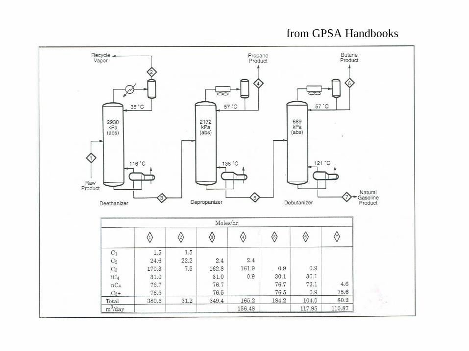
2.5 Fractionation•separate gas mixtures into individual products•in next section discuss bulk separation of NGLs from gas which differs from this discussion
•absorption type units also used use trays/packinga)types of fractionators at gas plants•demethanizer – product bottom is C2+ , OH is C1•deethanizer - product bottom is C3+ , OH is C1 /C2
•commercial C3 , C3 /C4 (LPG), C4 , C4 /gasoline, natural gasoline
e.g. at gas plant in AB deethan run depending price butane•depropanizer•debutanizer

from GPSA Handbooks
from GPSA Handbooks

b) Product specs• material balance around column is 1st step in design calcs need to
assume product stream compositions• defined in terms of
% recovery of component in OH or bottom OR composition of component in either product ORspecify physical properties (Pvap) in either product
c) design• in fractionation there usually 2 components which are key in separation
lightest component in bottom (LK)heaviest component in OH (HK)
• these components are adjacent to each other in volatility• in hand calcs make the assumption all components heavier than than
heaviest in OH are in bottoms

2.3 dehydration•
dehydration or removal of water from gas stream is necessary to prevent hydrate formation and increase the heating value of the gas
a)
water content of gas•
f(T,P,composition)
•
amount gas can “hold”
increases with pressure•
sour and acid gases can hold more water (increased solubility of water)
e.g. 100% C1 @37.8C 500 kPa
1000 mg/Sm3
wet gas30% C1 60% CO2 10% H2S
1500 mg/Sm3
wet gas100 % CO2
1700 mg/Sm3
wet gas-
to determine H2O content requires experiment/gas analysis

b)Hydrates•
crystalline “ice-like”
structures, water lattice where CO2, HC, N2, H2S occupy cavities (diagram)
•
crystalline molecular complexes formed from mixtures of water and suitably sized gas molecules
•
water (host) molecules, upon hydrogen bonding, form unstable lattice structures with several interstitial cavities gas (guest) molecules occupy lattice cavities and when minimum number cavities occupied crystalline structure becomes stable
solid gas hydrates forms even at temperatures well above the ice point.•
3 recognized structures (so far)i.
structure I –
body centred cubic w/ smaller molecules (C1, C2, CO2, H2S)ii.
II –
diamond lattice, larger molecules (C3,C4)iii.
III –
most HC>C4 don’t form hydrates or stable lattice but some isoparrafins and cycloalkanes > C5 can form stable
-
gas composition determines structure, e.g. mixed gases typically form II
-
structure doesn’t affect appearance or properties of hydrate but does affect T and P where hydrates occur
e.g. S II more stable than I –
C3/C4 form hydrates at higher T than light
H2S –
shifts hydrate formation to higher T at given P

•
in general hydrate formation is time dependent and the rate is f(gas comp, presence nucleation sites in l phase, degree of agitation)
•
primary considerations effect hydrate formation (pt @ which first l forms)
1. gas or l @ or below dew pt2. T, P, composition
•
secondary considerations•mixing, kinetics, physical site for nucleation (pipe elbow, orifice, dead space), salinity
•
in general hydrates prone to form at high P or low T own figures
0
2000
4000
6000
8000
10000
12000
-180 -150 -120 -90 -60 -30 0 30 60
Temperature (C)
Pres
sure
(kPa
)

Phase Envelope (inlet gas mixture of 62% C1, 15% C2, 16% C3+, 4% H20, balance
H2S/CO2/N2)
0
2000
4000
6000
8000
10000
12000
-180 -150 -120 -90 -60 -30 0 30
Temperature (C)
Pres
sure
(kPa
)
hydrate line
bubble pt curve
dew pt
curv
e

c) Hydrate inhibition•
options to gas dehydration if not practical or feasible try to inhibit the formation of hydrate by adding chemical which shifts the phase diagram away from hydrate (think adding salt to roads) or decrease Thyd form
•
inject glycols or methanol-
combines w/ condensed aqueous phase decreases Thyd form-
chemical recovered with aqueous phase at separators
d)Gas Dehydrationi.
glycol units•
glycol is a l (DEG, TEG most common, tetraethylene glycol TREG)•
applications where TDP
depression of 30-70 C required•
usually preceded by inlet gas scrubber to prevent slugging (H2O,
HC, treatment chem)
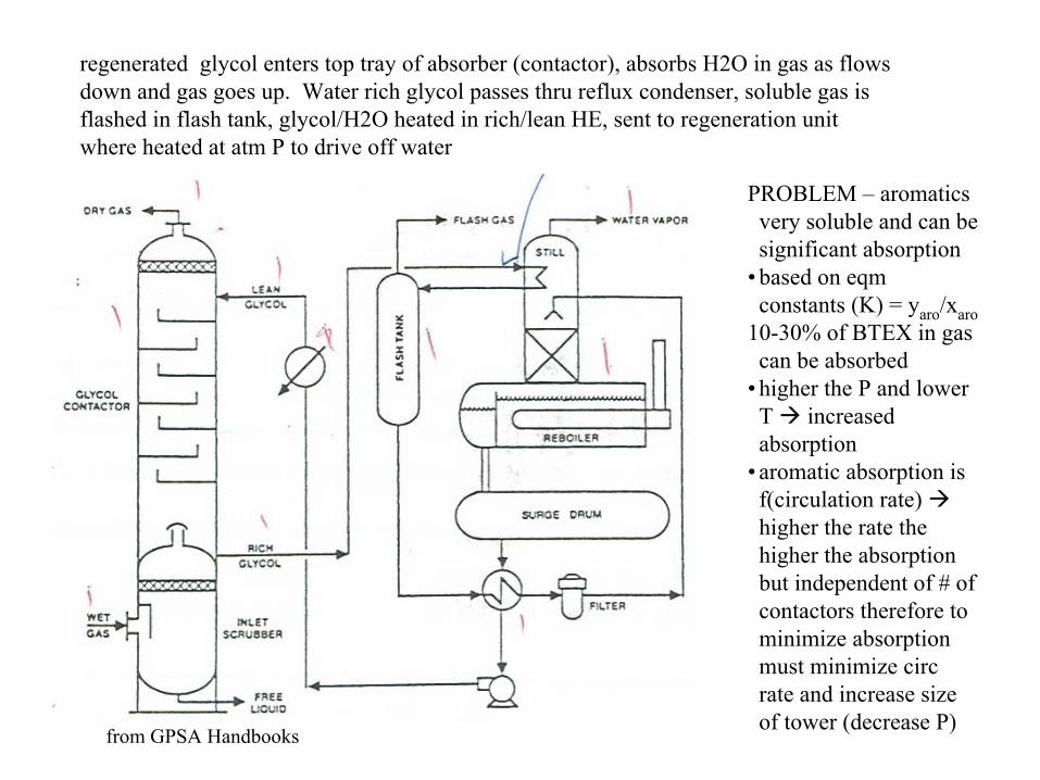
regenerated glycol enters top tray of absorber (contactor), absorbs H2O in gas as flows down and gas goes up. Water rich glycol passes thru reflux condenser, soluble gas is flashed in flash tank, glycol/H2O heated in rich/lean HE, sent to regeneration unit where heated at atm P to drive off water
PROBLEM –
aromatics very soluble and can be significant absorption
•
based on eqm constants (K) = yaro
/xaro10-30% of BTEX in gas can be absorbed
•
higher the P and lower T increased absorption
•
aromatic absorption is f(circulation rate) higher the rate the higher the absorption but independent of # of contactors therefore to minimize absorption must minimize circ rate and increase size of tower (decrease P)
from GPSA Handbooks
•
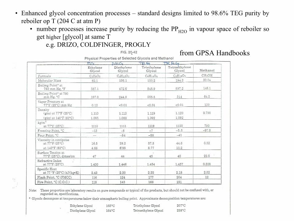
Enhanced glycol concentration processes –
standard designs limited to 98.6% TEG purity by reboiler op T (204 C at atm P)
•
number processes increase purity by reducing the PPH2O
in vapour space of reboiler so get higher
[glycol] at same T e.g. DRIZO, COLDFINGER, PROGLY
from GPSA Handbooks

•
general considerations for glycol unitsif inhibitor present 40-60% absorbed in glycol which
increases duty on reboiler and added volume loadglycol losses – mechanical carryover from contactor
(13 L/106 Sm3), vapours from contactor/regenerator, foaming in absorber/regen, low P and high T (40 L/106
Sm3), losses glycol of gas w/ CO2 is higher than n.gas at P>6200 kPa
becomes corrosive w/ prolonged exposure to O2
@ high T (>200C) decompositionlow pH decomposition

ii.
Solid Dehys•
comprise of 2 or more towers (one on, one off) -
more expensive than glycol units therefore used when:
high H2Slower dew pt regssimultaneous control of H2O and HC dew ptO2 containing gaseswhere CH3OH not favouredboth dry/sweeten NGL
from Norwegian University of Science and Technology (NTNU)
•
bed on line 8-24 hours•
regenerated by heating to 230-
320C (w/ waste heat)
•
gas enters top (down flow) prevent fluidization, regen gas is up flow
•
general 3-5 yr life, regen cycle is depressure/repressure
•
sometimes see CaCl2 (consumable) for dehy n.gas remote gas well

3 types1.
gels –
alumina or silica gels (SiO2) v and l dehydrated and HC recovered for natural gas (iC5+) hydrocarbon recovery units (HRU), outlet dew pts ~-60C
2.
Alumina –
hydrated form Al2O3 (alumina oxide), TDP~-70C, less heat required than mol sieve and Tregnerator
lower3.
molecular sieve –
aluminosilicates, high H2O capacity and produces lowest TDP
~-100C , can sweeten and dry gases and liquids (fig 20-69)•
H2O capacity less dependent on ambient T and relative humidity•
expensive•
commonly used ahead NGL plants to recover C2
from GPSA Handbooks

iii.
Membranes•
separate gas from H2
O, CO2
, HC according to permeability where dissolve/diffuse through membrane
•
driving force is differential PP across membrane
•
CO2
/H2
O permeate thru membrane permeate at reduced P while
nonpermeate @ P slightly<Pfeed•
C1+
in permeate f(∆P, SA membrane), 5-10% carryover
•
only applicable to plants use low P natural gas fuels

e)
Dehydration of Liquid Phase HC•
typically amount of water in HC l is low, even at saturationi.
gas stripper•
counter current stripper w/ dry gas, used offshore, trayed contactor and stripper
•
low cost, simple•
need dry n.gas stream, waste stream of VHC from condensateii.
solid desiccant•
activated alumina, Tdp
~-70C, absorbs heavy HC•
CaCl2
–
brine has neg effect•
MS too expensive for H2
O removaliii.distillation•
fractionation columns for use in dehy of NGLs•
higher energy requirements