Embed Size (px)
Citation preview

Version 2.0English
50403020
Getting Started with Real-Time Surveys
GPS System 500

2 Getting Started with Real-Time Surveys-2.0.0en
Congratulations on your purchase of anew Leica System GPS500.
System GPS500

3Getting Started with Real-Time Surveys-2.0.0en
Contents
Contents
Introduction to this book .............................................. 5Centimeter-accuracy RTK ............................................................... 5
30cm-accuracy code only or DGPS with RTCM............................ 5
The equipment ............................................................. 6Real-time reference ......................................................................... 6
Real-time rover ................................................................................ 7Real-time rover with mini-pack ..................................................... 7Real-time rover all-on-the-pole ..................................................... 8
Getting to know the terminal ...................................... 9Keyboard and display ..................................................................... 9
Status icons ................................................................................... 10
List boxes ...................................................................................... 11
Configuration - setting the receiver for the radiomodem .........................................................................12
Preparing for exercises ..............................................13Prepare an exercise field ............................................................. 13
Preparing the equipment ............................................................... 13Formatting PCMCIA cards ........................................................... 13Setting time zone and initial position ........................................... 13Setting the units for the display .................................................. 14
Exercise 1 - Real-time surveying in WGS84 .............15Starting the real-time reference .................................................... 15
Introduction to surveying with the real-time rover ...................... 17
Introduction to stake out with the real-time rover ....................... 20
Summary of exercise 1 ................................................................. 23
Exercise 2 � Real-time surveying in local coordinates......................................................................................24
Real-time surveying in local coordinates ..................................... 24
Local coordinates of exercise field ............................................. 24
Fast access in menus and list boxes .......................................... 24
Starting the real-time reference .................................................... 25
Entering the local coordinates into the real-time rover ............... 26
Measuring control points with the real-time rover and computing
transformation parameters ........................................................... 27Measuring the control points ...................................................... 27Computing transformation parameters between WGS84 and localcoordinates ................................................................................. 27
Surveying in local coordinates ..................................................... 29To see the active coordinate system .......................................... 29Surveying new points ................................................................ 30
Staking out from local coordinates ............................................... 32
Summary of exercise 2 ................................................................. 33

4 Getting Started with Real-Time Surveys-2.0.0enContents
System 500 operating system....................................34Introduction .................................................................................... 34
Main Menu ...................................................................................... 34
Configuration sets ......................................................................... 36Exercise 3 - Create a new configuration set to use whenbrowsing through panels ........................................................... 36Main Menu > 6 Configure ........................................................... 37The CONFIG key ......................................................................... 37Standard and Advanced Operation Mode ................................... 39The difference between �Main Menu > 6 Configure� and theCONFIG key ................................................................................ 39To make temporary changes to a configuration set using theCONFIG key ................................................................................ 39To store changes made to a configuration set using the CONFIGkey .............................................................................................. 40
User-definable hot keys ................................................................ 40
Summary of System 500 operating system ................................. 41
Transferring coordinates from the PC to the receiver......................................................................................42
Transferring coordinates from SKI-Pro to the card .................... 42
Exercise 4 - Transferring coordinates directly from the PC to the
card ................................................................................................ 42On the PC .................................................................................... 42On the receiver - Example for stake out ................................... 43Stake out from ASCII file .............................................................. 44
5Getting Started with Real-Time Surveys-2.0.0en
Introduction to this book
Introduction to this book
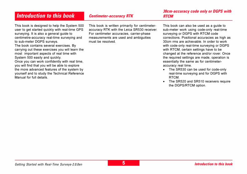
This book is designed to help the System 500user to get started quickly with real-time GPSsurveying. It is also a general guide tocentimetre-accuracy real-time surveying andto sub-meter DGPS surveys.The book contains several exercises. Bycarrying out these exercises you will learn themost important aspects of real time withSystem 500 easily and quickly.Once you can work confidently with real time,you will find that you will be able to explorethe more advanced features of the system byyourself and to study the Technical ReferenceManual for full details.
Centimeter-accuracy RTK
This book is written primarily for centimeter-accuracy RTK with the Leica SR530 receiver.For centimeter accuracies, carrier-phasemeasurements are used and ambiguitiesmust be resolved.
30cm-accuracy code only or DGPS withRTCM
This book can also be used as a guide tosub-meter work using code-only real-timesurveying or DGPS with RTCM codecorrections. Positional accuracies as high as30cm rms are achievable. In order to workwith code-only real-time surveying or DGPSwith RTCM, certain settings have to bechanged at the reference and/or rover. Oncethe required settings are made, operation isessentially the same as for centimeter-accuracy real time.· The SR530 can be used for code-only
real-time surveying and for DGPS withRTCM.
· The SR520 and SR510 receivers requirethe DGPS/RTCM option.

6 Getting Started with Real-Time Surveys-2.0.0en
The equipment
The equipment
This book assumes that you have two setsof equipment, one for a real-time referenceand one for a real-time rover. Setting up theequipment is easy. If necessary refer tosection 2 of the Technical Reference Manualand/or to the Equipment List.
Charge the batteries.
Real-time reference
Set up the real-time reference on a tripod asshown in the diagram.
1. GPS antenna2. Carrier3. Tribrach4. GPS receiver5. Terminal6. Cable to GPS antenna
7. Tripod8. Radio antenna9. Arm for radio antenna10. Cable to radio antenna11. Height hook12. Radio modem in housing13. PCMCIA flash card14. Two plug-in batteries15. Container

7Getting Started with Real-Time Surveys-2.0.0en
Real-time rover
The equipment
Set up the real-time rover either using themini-pack or all-on-the-pole.
Real-time rover with mini-pack
Set up the real-time rover with mini-pack asshown in the diagram.
1. GPS antenna2. Pole upper part3. Grip for pole4. Holder for terminal5. Pole lower part6. 1.2m cable to GPS antenna7. 1.6m extension cable8. Terminal9. Plug-in batteries10. GPS receiver11. Radio modem in housing12. PCMCIA flash card13. Cable receiver to terminal14. 1.2m cable to radio antenna15. Radio antenna16. 3cm arm for radio antenna17. Telescopic rod18. Mini-pack

8 Getting Started with Real-Time Surveys-2.0.0en
Real-time rover all-on-the-pole
2. The equipment
Set up the real-time rover all-on-the-pole asshown in the diagram.
1. GPS antenna2. Pole upper part3. Grip for pole4. Holder for GPS receiver5. Pole lower part6. Radio antenna7. Arm for radio antenna8. 1.2m cable to radio antenna9. Plug-in batteries10. Terminal11. GPS receiver12. Radio modem in housing13. PCMCIA flash card14. 1.2m cable to GPS antenna

9Getting Started with Real-Time Surveys-2.0.0en
Note the following:· F1 to F6 are softkeys· SHIFT + F1 = HELP· SHIFT + F6 exits to main menu· ESC steps back one screen· CE clears last character entered· ENTER confirms an entry· STATUS accesses the status menu
Note the following although you will not need them initially:· CONFIG allows you to change configurations· F7 to F10 are user definable keys
· Additional softkeys arrow:
Arrow in bottom right-hand corner of display indicates that additionalsoftkey options are available. Touch SHIFT to view additional softkeyoptions. Touch SHIFT again to revert to original softkey options.
· Use up and down arrows to scroll through menus and list boxes torequired item.
Getting to know the terminal
Getting to know the terminal
Touch F4 HIDE/SHOW to hide and recall main-menu selections4 to 7.
This section provides a short introduction to the terminal. For fulldetails see section 4 of the Technical Reference Manual.
Keyboard and display
Plug the terminal and two charged batteries into the receiver. Insert aPCMCIA card into the slot in the receiver and close the door.Switch ON. The Main Menu appears.

10 Getting Started with Real-Time Surveys-2.0.0enGetting to know the terminal
Status icons
Accuracy Status
High Precision Navigation (cm level)
Precision Navigation (0.5 - 5m level)
Navigation (<100m)
Position Mode
Static - the GPS Antenna should beheld stationary.
Moving - The GPS Antenna maymove.
Radio Status
Radio Transmitting (blinks)
Radio Receiving (blinks)
Memory Status
Internal Memory selected
PC-Card selected
Safe to remove PC-Card
Memory level Indicator. Has 12 levelsbetween:
Memory Empty and
Memory Full
Observation Recording Status
The Receiver is recording raw GPSobservations in Stationary mode. TheReceiver should be held stationary.
The Receiver is recording raw GPSobservations in Moving mode. TheReceiver may move.
Auto Position Recording Status
Positions are being recordedaccording to distance.
Positions are being recordedaccording to time.
Battery Status
Battery Voltage OK
Battery supplying 2/3 peak voltage
Battery supplying 1/3 peak voltage
Battery empty
Acc
urac
y S
tatu
s
Pos
ition
Mod
e
No.
vis
ible
Sat
ellit
es
No.
S
atte
lites
used
on
L1/L
2
Rad
io S
tatu
s
GS
M S
tatu
sM
emor
y S
tatu
sA
uto
Pos
ition
Log
. S
tatu
sO
bser
vatio
nLo
g. S
tatu
sLo
cal T
ime
Bat
tery
Sta
tus

11Getting Started with Real-Time Surveys-2.0.0en
List boxes
When using the terminal you will find two types of list boxes, full-screen list boxes and drop-down list boxes.
Full-screen list boxes
Use the up and down arrow keys to highlight your selection then pressENTER. A scroll bar at the right of the display indicates that there aremore lines (selections) than fit on the screen. Scroll with the up anddown arrow keys.
Getting to know the terminal
Drop-down list boxes
A small arrow at the right of an input field indicates that there is adrop-down list box. Press ENTER to access the list box. Use thearrow keys to highlight your selection then press ENTER.

12 Getting Started with Real-Time Surveys-2.0.0en
Your receiver will have been delivered with a radio modem. YourLeica representative should have defined two CONFIGURATIONSETS, one for a real-time reference and one for a real-time rover.Assume that these are called:
· MY-R-REF �My real-time reference�· MY-R-ROV �My real-time rover�
To see the configuration sets defined in your receiver:ON > Main MenuPress the CONFIG keyPress CONF F5Panel CONFIG SET\ lists the configuration sets in receiverPress ESC to return one panelPress ESC to return to Main MenuSwitch OFF
Only view the list of configuration sets. Please do not carry out anymanipulations on configuration sets at this stage.
Configuration - setting the receiver for the radio modem
MY-R-REF should be a copy of the factory-default configurationRT_REF but modified to make your SR530 operate with your radiomodem as a real-time reference in standard mode.
MY-R-ROV should be a copy of the factory-default configurationRT_ROV but modified to make your SR530 operate with your radiomodem as a real-time rover in standard mode.
If your representative has not defined the required configuration setsfor a real-time reference and real-time rover for your radio modem,ask him to do so.
Otherwise, you will have to define the two configuration setsyourself as explained sections 5.3 and 5.4 of the TechnicalReference Manual. The configuration sets should be defined beforeyou use real time and continue further with this book.
Configuration - setting the receiver for the radio modem

13Getting Started with Real-Time Surveys-2.0.0en
Preparing for exercises
Setting time zone and initial position
Preparing the equipment
Formatting PCMCIA cards
Plug two fully-charged batteries into each receiver. Insert a PCMCIAcard into the PCMCIA slot of each receiver and close the door. Whenstarting with the equipment it is easiest if there is no data on thecards.
Format the cards as follows:
ON > Main Menu4 UtilitiesCONT F1Panel UTILITIES\ Menu2 Format Memory ModuleCONT F1Panel UTILITIES\ Format Memory ModuleDevice: PC-Card Quick format: YESCONT F1 > Main MenuCard is formatted. Switch OFF.
Preparing for exercises
REF 1 2 3
4 5 6
7 8 9
Prepare an exercise field
Select a small, open area such as a parking lot, sports field, park orflat roof. Mark ten points. Call them REF and 1, 2, 3 � to 9. Thepoints need not be more than about 10m apart.
When you receive the receiver it should have the correct GPS dateand time. You have to input the time zone so that it displays local dateand time.
Setting the time zone
ON > Main MenuPress the CONFIG key3 GeneralCONT F14 Time and Initial PositionCONT F1Panel CONFIGURE\ Time & Initial PosScroll to Time Zone. Press ENTER to open box. Scroll to select timezone, e.g -3. Press ENTER.CONT F1 > Main MenuTime zone is set. Switch OFF.

14 Getting Started with Real-Time Surveys-2.0.0en
Initial position: using the receiver for the first time
The receiver always stores its last position as an initial position. Theinitial position helps the receiver to acquire satellites very quickly.
If you move a very long distance (1000km or more) to anotherlocation, the initial position will be wrong and the receiver may takelonger to acquire satellites and calculate a new position. If the initialposition is totally wrong (other side of world) it may need up to about 5minutes.
When you use the receiver for the very first time, remember that itmay have a wrong initial position (possibly Switzerland) and that youmay have to wait for a few minutes for it to acquire satellites.
Setting the units for the display
You can determine in which units information is displayed.To set the units
ON > Main MenuPress the CONFIG key.3 GeneralCONT F11 UnitsCONT F1Panel CONFIGURE \ UnitsToggle with up and down arrowsSet required units. Example:
Angle: Press ENTER to open box.Select �360o � � �. Press ENTER.Press ANGLE F6Panel CONFIGURE \ Angle FormatsDirection Ref: Press ENTER to open box.Select �North Azimuth�. Press ENTER.Direction Base: Press ENTER to open box.Select �True�. Press ENTER.CONT F1
Panel CONFIGURE \ UnitsCONT F1 > Main Menu
5. Preparing for exercises

15Getting Started with Real-Time Surveys-2.0.0en Exercise 1 - Real-time surveying in WGS84
Set up the real-time reference at point REF as shown in section"Real-time reference".Centre and level up.
Switch ON > Main MenuSelect 1 SurveyPress CONT F1
Panel SURVEY\BeginConfig set: Press ENTER to open list box.Select config set "MY-R-REF". Press ENTER.Job: Press ENTER to open list box.Select job "Default". Press ENTER.Coord sys: "WGS84 Geodetic", cannot change.Antenna: "AT502 Tripod". Correct, do not change.Press CONT F1.
Exercise 1 - Real-time surveying in WGS84
Panel SURVEY\Default (default is job)You now have to input point id, antenna height and coordinates. Dothis in the following order:Ant. Height: Input height hook reading, e.g. 1.335. ENTER.Lat, Lon, EHgt: Press HERE F4. Last navigation position coordinatesare accepted.Point Id: Type in REF. Press ENTER.Press STORE F1.Press CONT F1.
You have now started the real-time reference. The panel shows:
Navigation position icon
Static mode icon
Number of satellites tracked
Radio-transmitting arrow, blinking
Point Id: REFAnt Height: 1.335mStatic Obs: 0 (not recording)GDOP: Will usually be <5
Starting the real-time reference

16 Getting Started with Real-Time Surveys-2.0.0enExercise 1 - Real-time surveying in WGS84
The real-time reference will continue transmitting until you pressSTOP. However, as you want to work with the real-time reference,please do NOT press STOP now!
Note on antenna height
In panel SURVEY\Begin the antenna is defined as AT502 on Tripod.You have only to input the height hook reading, e.g. 1.335m. Thevertical offset 0.360m from the white line of the height hook to themechanical reference plane (bottom of antenna mount) will be addedautomatically. Thus the total height of the antenna above the groundwill be 1.335 + 0.360 = 1.695m. For more details see section 2.11 ofthe Technical Reference Manual.
The STATUS key
Press the STATUS key to explore the status panels while thereference is transmitting. The status panels provide information only.You can look through them without affecting the real-time reference.
Press the STATUS key.Toggle with the up and down arrows.Use CONT F1 to continue.Use ESC to step back one panel.Use SHIFT + F6 to return to the SURVEY\Default panel.
STATUS panels
1 Survey1 Real Time: information on real-time output.2 Stop & Go Indicator: not required for real-time reference. Forrover and rapid static.
3 Position: navigation position.4 Logging: you are not logging data.5 Satellite: satellite status, note SKY plot.
2 Logs1 Point Log: Information on points.2 Code Log: you are not using codes.3 Message Log: list of messages.
3 General1 Memory/Battery: memory and battery status.2 Sensor: information on receiver.3 Software Version: information on firmware.
4 InterfacesLists all interfaces and devices.
The CONFIG key
Do not use at this stage!
Configuration sets can be changed via the CONFIG key. Configurationset MY-R-REF is set to make your SR530 operate with your radiomodem as a real-time reference. Do not change it.
Removing the terminal
You can remove the terminal and attach it again while the receiver isoperating. You do not need to switch off and on.
The real-time reference is transmitting. If you have only one terminal,remove it from the reference for use with the rover. The SR530 willcontinue to operate and transmit as a real-time reference.

17Getting Started with Real-Time Surveys-2.0.0en Exercise 1 - Real-time surveying in WGS84
Panel SURVEY\BeginConfig set: Press ENTER to open list box.Select config set "MY-R-ROV". Press ENTER.Job: Press ENTER to open list box.Select job "JOB 1". Press ENTER.Coord sys: "WGS84 Geodetic", cannot change.Antenna: "AT502 Pole". Correct, do not change.CONT F1
You are now in panel SURVEY \ JOB 1. You have started the real-time rover. The antenna height is set automatically to 2.000m.
The panel shows:
Number of satellites Radio receiving arrow, blinks Moving mode icon
Wait for a minute or so. The position mode icon will change from:
Navigation to Precise Navigation to High Precision
Introduction to surveying with the real-time rover
® ®
Set up the real-time rover as shown in section "Real-time rover". Holdthe pole in your hand.
Switch ON > Main MenuSelect 5 JobCONT F1Panel JOB \ PC-Card lists jobsPress NEW F2 for new jobPanel JOB \ New JobName: input name "JOB 1". Press ENTER(Ignore Description and Creator)CONT F1 (JOB 1 now in list)CONT F1 > Main Menu
You have created a new job.
Main MenuSelect 1 SurveyCONT F1

18 Getting Started with Real-Time Surveys-2.0.0enExercise 1 - Real-time surveying in WGS84
When the high precision icon appears, the coordinate Quality shouldbe between 0.01 and 0.05m. You can now start centimeter-accuracyreal-time surveying. Proceed as follows:
Hold pole steady on point 1:Panel SURVEY \ JOB 1Point Id: Input 1. ENTERPress OCUPY F1Wait for about 5 secondsSTOP F1STORE F1You have recorded real-time WGS coordinates of point 1.
Hold pole steady on point 2:Point Id: Input 2. ENTEROCUPY F1Wait for about 5 secondsSTOP F1STORE F1
Measure the other points 3, 4, � to 9 in the same way.
Note the sequence at each point:· Input Point Identifier· OCUPY > STOP > STORENumber of positions between OCUPY and STOP is shown .
When you press OCUPY the icon changes to "static".You should hold the pole steady on the point.
When you press STOP the icon changes to "moving".You can move.
As the position update rate is set to 1 second in configuration setMY-R-ROV, you must stay on a point for at least 1 second betweenOCUPY and STOP. If you stay longer on a point, the result (recordedcoordinates) will be the mean of all real-time positions betweenOCUPY and STOP.
Now measure points 1, 2, 3, 4 again
Use exactly the same point identifiers: 1, 2, 3, 4.After measuring a point twice, the message "2 measurements onpoint" appears.This shows that the two results agree to within setthreshold values (0.05m in position and 0.07m in height inconfiguration set MY-R-ROV).
Take a third measurement to point 4 but place the pole about 20cmfrom the point. A box "MANAGE \ Average" appears showing thethree results, e.g.
Two measurements are flagged Y = use. One measurement is flaggedN = do not use. (You can override with USE F5). Press CONT F1 toaccept the two Y measurements. The N measurement is notaccepted.
Summary: if you measure a point two or more times the system willcheck that the results agree. Average coordinates are calculated.
Time Date DPos DheightUse
14:26 03.01 0.203 -0.008N *
14:20 03.01 0.008 -0.007Y
14:10 03.01 0.008 +0.007 Y
19Getting Started with Real-Time Surveys-2.0.0en Exercise 1 - Real-time surveying in WGS84
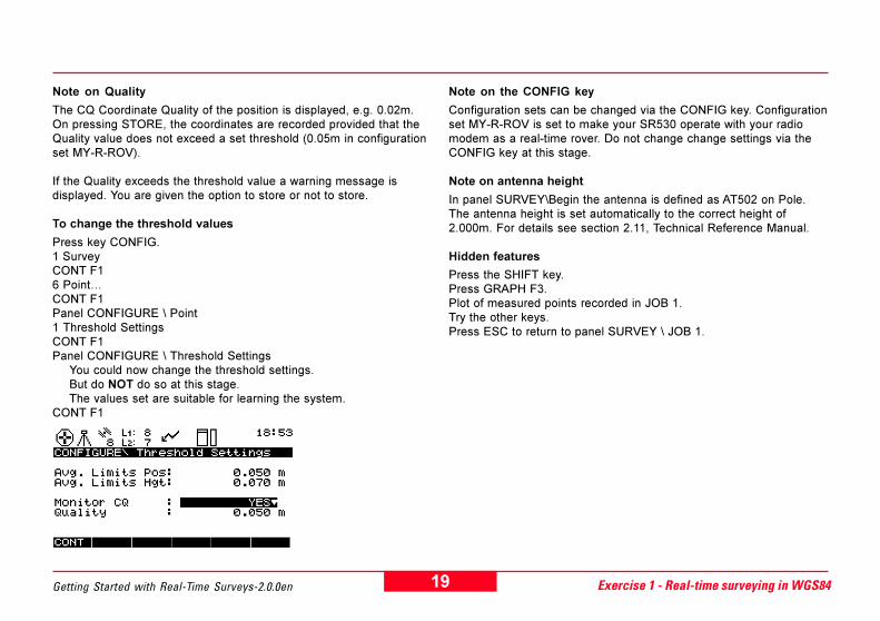
Note on Quality
The CQ Coordinate Quality of the position is displayed, e.g. 0.02m.On pressing STORE, the coordinates are recorded provided that theQuality value does not exceed a set threshold (0.05m in configurationset MY-R-ROV).
If the Quality exceeds the threshold value a warning message isdisplayed. You are given the option to store or not to store.
To change the threshold values
Press key CONFIG.1 SurveyCONT F16 Point�CONT F1Panel CONFIGURE \ Point1 Threshold SettingsCONT F1Panel CONFIGURE \ Threshold Settings
You could now change the threshold settings.But do NOT do so at this stage.The values set are suitable for learning the system.
CONT F1
Note on the CONFIG key
Configuration sets can be changed via the CONFIG key. Configurationset MY-R-ROV is set to make your SR530 operate with your radiomodem as a real-time rover. Do not change change settings via theCONFIG key at this stage.
Note on antenna height
In panel SURVEY\Begin the antenna is defined as AT502 on Pole.The antenna height is set automatically to the correct height of2.000m. For details see section 2.11, Technical Reference Manual.
Hidden features
Press the SHIFT key.Press GRAPH F3.Plot of measured points recorded in JOB 1.Try the other keys.Press ESC to return to panel SURVEY \ JOB 1.

20 Getting Started with Real-Time Surveys-2.0.0enExercise 1 - Real-time surveying in WGS84
The real-time reference should continue to operate. In section"Introduction to surveying with the real-time rover" you surveyed withthe real-time rover. Now try to stake out.
ON > Main MenuSelect 5 JobCONT F1NEW F2 for new jobCreate new job �JOB 2�. ENTERCONT F1CONT F1 > Main Menu
Main MenuSelect 2 Stake-OutCONT F1
Introduction to stake out with the real-time rover
Look at the STATUS panels
1 Survey1 Real Time: real-time input and rover status.2 Stop & Go Indicator: not used.3 Position: real-time position.4 Logging: number of points occupied (positions recorded)5 Satellite: satellite status
2 Logs � look at the point log1 Point LogCONT F1Panel STATUS \ Point LogList of measured points, scroll through.Press INFO F5
Shows time, coordinate source, CQ quality, class.MEAS = 1 measurement. AVRG = averaged.
CONT F1 > return to SURVEY panel
Return to Main Menu
SHIFT + F6 to return to Main MenuSwitch OFF
Panel STAKE-OUT \ BeginConfig Set: Press ENTER to open box.Select �MY-R-ROV�. Press ENTER.Stake Pts: Press ENTER to open box.Select job �JOB 1�. Press ENTER.Store Pts: Press ENTER to open box.Select job �JOB 2�. Press ENTER.Stake Type: Press ENTER to open box.Select �Point�. Press ENTER.Antenna: AT502 PoleAnt Height: 2.000mCONT F1
21Getting Started with Real-Time Surveys-2.0.0en Exercise 1 - Real-time surveying in WGS84
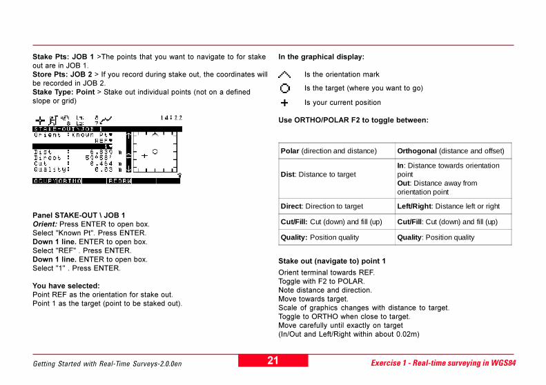
Stake Pts: JOB 1 >The points that you want to navigate to for stakeout are in JOB 1.Store Pts: JOB 2 > If you record during stake out, the coordinates willbe recorded in JOB 2.Stake Type: Point > Stake out individual points (not on a definedslope or grid)
Panel STAKE-OUT \ JOB 1Orient: Press ENTER to open box.Select "Known Pt". Press ENTER.Down 1 line. ENTER to open box.Select "REF" . Press ENTER.Down 1 line. ENTER to open box.Select "1" . Press ENTER.
You have selected:Point REF as the orientation for stake out.Point 1 as the target (point to be staked out).
In the graphical display:
Is the orientation mark
Is the target (where you want to go)
Is your current position
Use ORTHO/POLAR F2 to toggle between:
Stake out (navigate to) point 1
Orient terminal towards REF.Toggle with F2 to POLAR.Note distance and direction.Move towards target.Scale of graphics changes with distance to target.Toggle to ORTHO when close to target.Move carefully until exactly on target(In/Out and Left/Right within about 0.02m)
Polar (direction and distance) Orthogonal (distance and offset)
Dist: Distance to targetIn: Distance towards orientationpointOut: Distance away fromorientation point
Direct: Direction to target Left/Right: Distance left or right
Cut/Fill: Cut (down) and fill (up) Cut/Fill: Cut (down) and fill (up)
Quality: Position quality Quality: Position quality

22 Getting Started with Real-Time Surveys-2.0.0enExercise 1 - Real-time surveying in WGS84
To record staked-out position of point 1
Assume that you would now mark the point (place a marker)Set up on markPress OCUPY > STOP > STORECoordinates are recorded in JOB2
Stake out point 2
Target has changed automatically to 2.Stake out point 2OCUPY > STOP > STORE
Stake out other points
Open target box to select points.Try different orientations: North, Sun, Last Point.
Hidden features
Press the SHIFT key.Press GRAPH F3.Plot of staked-out points recorded in JOB 2.Try other keys.Press ESC to return to panel STAKE-OUT \ JOB 1.
Exit stake out
SHIFT + F6 to exit to Main Menu
Look at the point log
Main Menu5 JobCONT F1Select JOB 1CONT F1Main Menu
Press STATUS key2 LogsCONT F11 Point LogCONT F1List of points in JOB 1CONT F1Main Menu
Similarly, look at point log for JOB 2.
Switch OFF.
Stop the real-time reference
You can now STOP and switch OFF the real-time reference.

23Getting Started with Real-Time Surveys-2.0.0en Exercise 1 - Real-time surveying in WGS84
Summary of exercise 1
In exercise 1 you did the following:
� Worked in WGS84.
� Started a real-time reference with HERE (single navigationposition).
� Created jobs.
� Surveyed with a real-time rover.
� Saw how threshold values work for two or more measurements toa point.
� Saw how the threshold value works for coordinate quality.
� Staked out points with a real-time rover.
� Noted the various icons.
� Noted how the antenna height is set.
� Used the STATUS key to look at various status displays.
� Looked at some hidden features
You can now operate the real-time system at a basic level.
24 Getting Started with Real-Time Surveys-2.0.0enExercise 1 - Real-time surveying in WGS84Exercise 2 - Real-time surveying in local coordinates
Real-time surveying in local coordinates
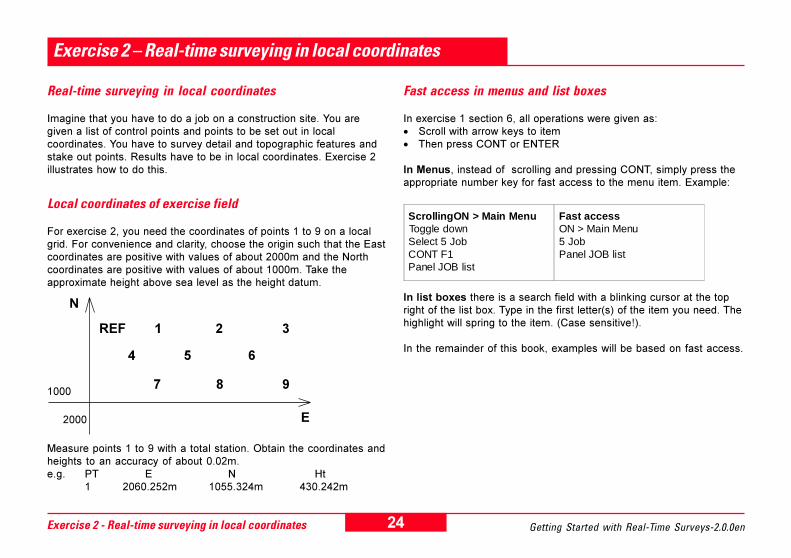
Imagine that you have to do a job on a construction site. You aregiven a list of control points and points to be set out in localcoordinates. You have to survey detail and topographic features andstake out points. Results have to be in local coordinates. Exercise 2illustrates how to do this.
Local coordinates of exercise field
For exercise 2, you need the coordinates of points 1 to 9 on a localgrid. For convenience and clarity, choose the origin such that the Eastcoordinates are positive with values of about 2000m and the Northcoordinates are positive with values of about 1000m. Take theapproximate height above sea level as the height datum.
Measure points 1 to 9 with a total station. Obtain the coordinates andheights to an accuracy of about 0.02m.e.g. PT E N Ht
1 2060.252m 1055.324m 430.242m
Exercise 2 � Real-time surveying in local coordinates
REF 1 2 3
4 5 6
7 8 91000
2000
N
E
Fast access in menus and list boxes
In exercise 1 section 6, all operations were given as:· Scroll with arrow keys to item· Then press CONT or ENTER
In Menus, instead of scrolling and pressing CONT, simply press theappropriate number key for fast access to the menu item. Example:
In list boxes there is a search field with a blinking cursor at the topright of the list box. Type in the first letter(s) of the item you need. Thehighlight will spring to the item. (Case sensitive!).
In the remainder of this book, examples will be based on fast access.
ScrollingON > Main MenuToggle downSelect 5 JobCONT F1Panel JOB list
Fast accessON > Main Menu5 JobPanel JOB list

25Getting Started with Real-Time Surveys-2.0.0en Exercise 2 - Real-time surveying in local coordinates
OCUPY F1Panel SURVEY\ Single Pt PositionPoint Id: REF SPTime at Pt: Still to go out of 10mins.
After 10 minutes Panel SURVEY\ Default appears.You have startedthe real-time reference. The radio transmitting arrow blinks.
Note: The receiver would not accept REF as the point id. because apoint REF with coordinates already exists in the data base. Thus youhad to input REF SP.
Note: A single-point position SSP is calculated over a period of time(10 mins). This is more accurate than a navigation position obtainedwith HERE.
Starting the real-time reference
Set up the real-time reference again at point REF. Use the samereceiver and PCMCIA card. Do NOT format the card. This time youwill use the SPP (Single Point Position) key instead of the HERE keyto obtain coordinates for the reference. Enter the point id. as REF SP.
ON > Main Menu1 SurveyPanel SURVEY\ BeginConfig Set: MY-R-REFJob: DefaultCoord Sys.: WGS84 GeodeticAntenna: AT502 TipodCONT
Panel SURVEY\ DefaultInput information as follows:Ant Height: Height hook reading. ENTER.Press SPP F6Panel SURVEY\ Single Pt PositionPoint Id: (Random number shown)Type in REF SP. ENTER.(Note: will not accept REF)Time: Input 10. ENTER.

26 Getting Started with Real-Time Surveys-2.0.0enExercise 2 - Real-time surveying in local coordinates
Format the card
As this is a learning exercise, first format the card as explained insection "Formatting PCMCIA cards". This will prevent any confusionwith old jobs and data.
Create a job
Create a new job � JOB A LOCCDS� for the local coordinates.
ON >. Main Menu5 JobNEW F2Name: Input �JOB A LOCCDS�. ENTER.CONT > List of jobsCONT > Main Menu
Input the local coordinates
Input the local coordinates with point identifiers PT01, PT02, �.toPTO9.
Main Menu3 Applications02 Point Management
Panel: MANAGE\ JOB A LOCCDSNEW F2Panel: MANAGE \ New PointPoint Id.: Input �PT01�.ENTERToggle with COORD F2 to E, N, HgtInput E coordinate. ENTER.N coord. ENTER. Hgt ENTER.STORE F1 > PT01 in list
NEWPoint Id.: Input �PT02�.ENTERInput E, N, Hgt. ENTER.STORE > PT02 in list
Input coordinates for PT03 to PT09After all points are enteredCONT F1 > Main Menu
Entering the local coordinates into the real-time rover

27Getting Started with Real-Time Surveys-2.0.0en Exercise 2 - Real-time surveying in local coordinates
Panel: SURVEY\ JOB B MEASDAt each pointInput Point Id.(PT01, PT03, PT07, PT09)OCUPY > STOP > STORE
The WGS84 coordinates of the 4 points are recorded in �JOB BMEASD�.
Computing transformation parameters between WGS84 and localcoordinates
�JOB A LOCCDS� contains the local coordinates of PT01 to PT09.�JOB B MEASD� contains the WGS84 coordinates of four of thesepoints, e.g. PT01, PT03, PT07 and PT09. Transformation parametersbetween the WGS84 and local coordinates can now be calculated.
You have to enter two names, one for the Coordinate System and onefor the Transformation. Always use meaningful names that you willunderstand later. For this exercise use the following names:· �CS1 ONE STEP� for the Coordinate System.· �TS1 ONE STEP� for the Transformation
Main Menu3 Applications01 Determine Coord System
Measuring the control points
Create a job
Create a new job �JOB B MEASD� for the measured points.
Measure four control points
Measure 4 of the points on the outside of the area, e.g. 1, 3, 7 and 9.
REF 1 2 3
4 5 6
7 8 9
Use the same point ids.
Use exactly the same point ids - PT01, PT03, PT07, PT09 - as youused when entering local coordinates (section "Entering the localcoordinates into the real-time rover"). Point ids. are case sensitive.Thus if you used capital letters (or lower case) for point ids. whenentering local coordinates, please make sure that you also use capitalletters (or lower case) when measuring.
Measuring the four control points:
Main Menu1 SurveyPanel: SURVEY\ BeginConfig Set: �MY-R-ROV�. ENTER.Job: �JOB B MEASD�. ENTER.Coord Sys : �WGS 84 Geodetic�Antenna: �AT502 Pole�CONT
Measuring control points with the real-time rover and computing transformation parameters

28 Getting Started with Real-Time Surveys-2.0.0enExercise 2 - Real-time surveying in local coordinates
Panel: COORDSYS\ Determination BeginCoord Sys: Input �CS1 ONE STEP�. ENTER.WGS84 Pts: Press ENTER to open box.Select �JOB B MEASD�.ENTER.Local Pts: Press LOCAL F4.
Panel: COORDSYS\ Local Point FormatLocal Pts: Press ENTER to open boxChoice of Job or ASCII. Select �Job�. ENTER.CONT
Panel: COORDSYS\ Determination BeginLocal Pts: : Press ENTER to open box.Select �JOB A LOCCDS�.ENTER.Panel now shows
Coord Sys: �CS1 ONE STEP�WGS84 PTS: �JOB B MEASD�Local Pts: �JOB A LOCCDS�
CONT
Panel COORDSYS\ Type SelectionCoord Sys: �CS1 ONE STEP�Transform: Input �TS1 ONE STEP�. ENTER.Trans Type: Press ENTER to open box.Select �1-Step�. ENTER.Geoid Model: Ignore, leave blank.CONT
Panel COORDSYS\ Determine 1-StepThe points will be matched automatically for Position and Height if younumbered them correctly. (If not use EDIT F3 to match points).CONT

29Getting Started with Real-Time Surveys-2.0.0en Exercise 2 - Real-time surveying in local coordinates
Panel COORDSYS\ ResidualsUse INFO F5 for N, E, Hgt residualsUse RESLT F3 and RMS F5 for resultsPanel COORD SYS\ ParametersCONTCONTPanel COORDSYS\ ResidualsCONT
Panel COORDSYS\ Save Coord SystemCoord Sys: �CS1 ONE STEP�Information on coordinate system shownCONT to save (store) coordinate system
Main Menu
You have computed a one-step transformation and stored acoordinate system.
Surveying in local coordinates
To see the active coordinate systemIn section "Computing transformation parameters between WGS84and local coordinates" you determined a coordinate system �CS1ONE STEP� for local coordinates. As �CS1 ONE STEP� is the lastdetermined coordinate system, it automatically becomes the activecoordinate system and will be used by the configuration set MY-R-ROV that you use for surveying and setting out. You can now work inlocal coordinates and the terminal can display in local coordinates.
The active coordinate system is used by the active configuration setand is attached to the active job. To look at the various coordinatesystems and to see which one is active do the following:
Press the CONFIG key1 Survey1 Position
Panel: CONFIGURE\ PositionUpdate rate: 1.0s. Do not change.Coord Sys: �CS1 ONE STEP� shown.This is the active coord. system.Press ENTER for list of systems.Select CS1 ONE STEP.(Do not select another system)ENTERCONT > Main Menu

30 Getting Started with Real-Time Surveys-2.0.0enExercise 2 - Real-time surveying in local coordinates
Surveying new points
Measure about 10 new points as if you would be doing a detail ortopo survey. Any random points will do.
ON > Main Menu
Main Menu1 Survey
Panel SURVEY\BeginConfig set: �MY-R-ROV�Job: ENTER to open box.Select �JOB B MEASD�. ENTER.Coord sys: �CS1 ONE STEP�.(The active coordinate system)Antenna: �AT502 PoleCONT
You are now in panel SURVEY \ JOB B MEASD.Point ID: Input "PT51". ENTER.
The antenna height is set to 2.000m. When the high precision iconappears and the quality shows between 0.01 and 0.05, you can startcentimeter-accuracy surveying.
Hold pole on first point.
Point Id: Input �PT51�. ENTER.OCUPY > STOP > STORE
Note how the point id. increments automatically. Second point PT 52OCUPY > STOP > STORE
Third point PT 53OCUPY > STOP > STORE
Measure about 10 new points as if you would be doing a detail ortopo survey. Any random points will do.

31Getting Started with Real-Time Surveys-2.0.0en Exercise 2 - Real-time surveying in local coordinates
Look at the displayed position
Press the STATUS key1 Survey3 Position
Panel STATUS \ PositionPress COORD F2 to see:
E N Hgt / Lat Lon Hgt / X Y Z
SHIFT + F6 to quitMain Menu
Look at the recorded points
Main Menu3 Applications02 Point ManagementPanel\ JOB B MEASD
List of points in JOB B MEASDEDIT F3 to view coordinates
COORD F2 to seeE N Hgt / Lat Lon Hgt / X Y Z
SHIFT + F6 to quitMain Menu
32 Getting Started with Real-Time Surveys-2.0.0enExercise 2 - Real-time surveying in local coordinates
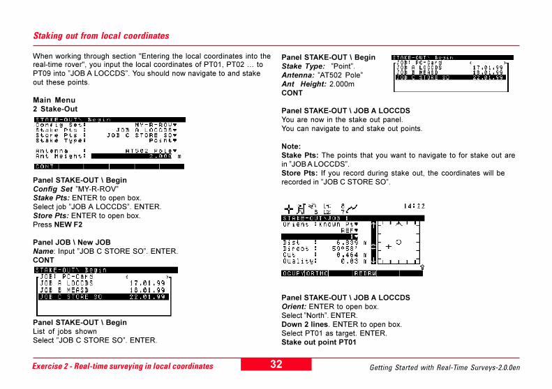
Panel STAKE-OUT \ BeginStake Type: �Point�.Antenna: �AT502 Pole�Ant Height: 2.000mCONT
Panel STAKE-OUT \ JOB A LOCCDSYou are now in the stake out panel.You can navigate to and stake out points.
Note:Stake Pts: The points that you want to navigate to for stake out arein �JOB A LOCCDS�.Store Pts: If you record during stake out, the coordinates will berecorded in �JOB C STORE SO�.
Panel STAKE-OUT \ JOB A LOCCDSOrient: ENTER to open box.Select �North�. ENTER.Down 2 lines. ENTER to open box.Select PT01 as target. ENTER.Stake out point PT01
Staking out from local coordinates
When working through section "Entering the local coordinates into thereal-time rover", you input the local coordinates of PT01, PT02 � toPT09 into �JOB A LOCCDS�. You should now navigate to and stakeout these points.
Main Menu2 Stake-Out
Panel STAKE-OUT \ BeginConfig Set �MY-R-ROV�Stake Pts: ENTER to open box.Select job �JOB A LOCCDS�. ENTER.Store Pts: ENTER to open box.Press NEW F2
Panel JOB \ New JOBName: Input �JOB C STORE SO�. ENTER.CONT
Panel STAKE-OUT \ BeginList of jobs shownSelect �JOB C STORE SO�. ENTER.

33Getting Started with Real-Time Surveys-2.0.0en Exercise 2 - Real-time surveying in local coordinates
Navigate to target.When exactly on point.OCUPY > STOP > STORECoordinates are recorded in �JOB C STORE SO�.
Stake out point PT02Target changes to next point PT02OCUPY > STOPPress DIFF F2 to see differences between position and requiredcoordinates.STORE
Stake out the other points PT03 to PT09
Note that:
· You can change the orientation· Target changes automatically to next point· Press DIFF to see differences between position and required
coordinates.· Press SHIFT then GRAPH to see plot of staked-out points
recorded in �JOB C STORE SO�.
SHIFT + F6 to quitMain Menu
To look at recorded points
3 Applications02 Point ManagementList of points recorded in �JOB C STORE SO�.
Summary of exercise 2
In exercise 2 you did the following:· Started the real-time reference with SSP Single Point Position.· Entered local coordinates manually.· Created a coordinate system containing a one-step
transformation between WGS84 and local grid.· Viewed the list of coordinate systems and noted which
coordinate system is active.· Set the point id. template.· Surveyed new points in local coordinates.· Looked at the position display.· Used Point Management to view the recorded points.· Staked out points from local coordinates.· Saw the difference between �required� and �staked-out�
coordinates.
In exercise 2 you entered coordinates manually. For productionwork, you will usually transfer coordinates and other data digitallyas follows:· On an ASCII file from the PC to the card.· In a job from SKI-Pro software to the card.
In exercise 2 you created a coordinate system with a one-steptransformation.
· You can also create coordinate systems with ellipsoids,projections, 7-parameter Helmert transformations, and geoidalmodels.
You now know the system in more detail and can carry out asurvey or stake-out job in local coordinates.
34 Getting Started with Real-Time Surveys-2.0.0enSystem 500 operating system
System 500 operating system
Introduction
System 500 is very easy to use for surveying and stake-out work yet itis also extremely powerful with a huge range of features andfunctions. These special features, functions and operations arenecessary to meet the individual requirements of users carrying out alltypes of applications all over the world.
Most users will use System 500 real time for surveying and stake out.Although a user may need some of the special features, it is veryunlikely that any user will need them all.
The receiver can be configured (set) to operate in any way. Settingsand outputs can be selected and functions activated or deactivated asrequired. Once configured (set), the receiver is very easy to use.
This book has been written to help the user to get started as quicklyas possible with real time. It covers only those features andoperations that most users are likely to need. After working throughthe exercises in this book, you will find that you can explore thesystem further by yourself and study the Technical Reference Manual.
Sections "Introduction" to "Summary of System 500 operating system"provide an introduction to the operating system.
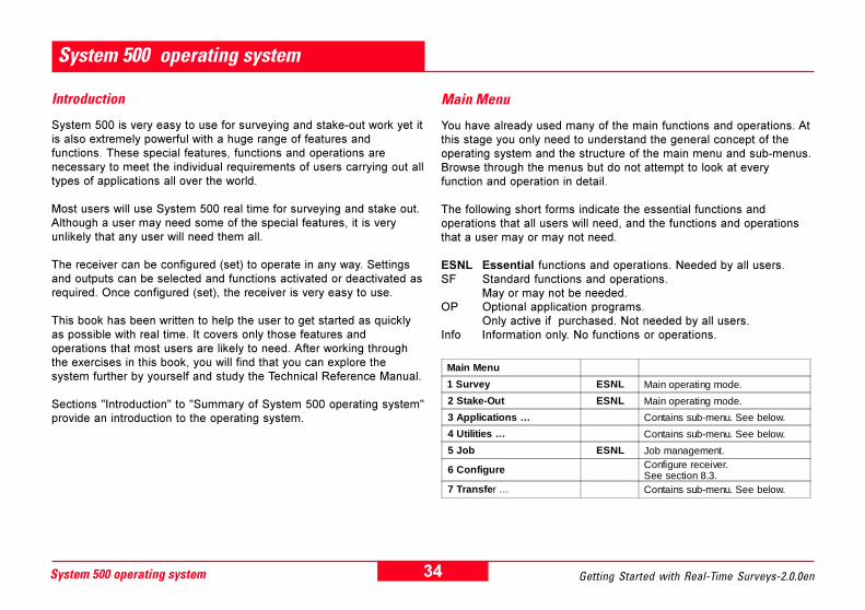
Main Menu
You have already used many of the main functions and operations. Atthis stage you only need to understand the general concept of theoperating system and the structure of the main menu and sub-menus.Browse through the menus but do not attempt to look at everyfunction and operation in detail.
The following short forms indicate the essential functions andoperations that all users will need, and the functions and operationsthat a user may or may not need.
ESNL Essential functions and operations. Needed by all users.SF Standard functions and operations.
May or may not be needed.OP Optional application programs.
Only active if purchased. Not needed by all users.Info Information only. No functions or operations.
Main Menu
1 Survey ESNL Main operating mode.
2 Stake-Out ESNL Main operating mode.
3 Applications … Contains sub-menu. See below.
4 Utilities … Contains sub-menu. See below.
5 Job ESNL Job management.
6 Configure Configure receiver.See section 8.3.
7 Transfe r … Contains sub-menu. See below.

35Getting Started with Real-Time Surveys-2.0.0en System 500 operating system
7 Transfer …
01 Job SF Transfer a job from card to internalmemory or vice versa.
02 Config Set SF Transfer a configuration set fromcard to system RAM or vice versa.
03 Coordinate System SF Transfer a coordinate system fromcard to system RAM or vice versa.
04 Antenna Info SF Transfer antenna information fromcard to system RAM or vice versa.
05 Code list SF Transfer a code list from card tosystem RAM or vice versa.
06 ASCII/GSI8 to Job SF Transfer an ASCII or GSI8 file to ajob.
07 GSI/User File SF
To create GSI, or user-defined data-exchange files on card. Also totransfer format files from card tosystem RAM.
08 Geoid Field File SF To transfer geoidal-model file fromcard to system RAM or vice versa.
09 Any File Type SF Transfer a file from card to internalmemory or vice versa.
10 Firmware SF Transfer receiver firmware from cardto system RAM.
11 Firmware TR500 SF Transfer terminal firmware from cardto system RAM to terminal.
12 Language Version SFTransfer language-version text (forreceiver operation) from card tosystem RAM.
13 Application Text SF
Transfer text for COGO, Area,optional Application Programs etc.from card to system RAM. Forlanguage versions.
14 Almanac SF Transfer almanac from card tosystem RAM or vice versa.
3 Applications …01 Determine Coord System ESNL Ellipsoids, projections, geoidal
models, transformations.
02 Point Management ESNL View and edit recorded points.Create new points.
03 Calculator SF Calculator similar to HP.Reversed Polish Notation.
04 Wake-up Sessions SF Start and stop receiver automaticallyat pre-set times.
05 COGO SF Various coordinate geometrycalculations.
06 Area SF Area calculation.Uses points in data base.
07 DTM Stakeout OP Stake out digital terrain model.Must be purchased.
08 QuickSlope OP Stake out slopes.Must be purchased.
09 RoadPlus OP Stake out road alignments. (USA).Must be purchased.
10 RoadX OP Stake out road alignments.(Scandinavia). Must be purchased.
11 Multipiste OP Stake out road alignments.(France). Must be purchased.
12 GIS Data Collection OP GS50 GIS data collection. Must bepurchased.
13 GIS Navigation/Update OP GS50 GIS navigation software Mustbe purchased.
4 U tilities …1 D irecto ry o f M em ory D evice Info D irectory info rm ation.
2 F o rm at M em ory M odule E S N L F orm at ca rd /inte rna l m em ory.
3 E nte r S ecurity C ode OP A ctiva tes op tiona l app lica tionp rog ram s. M ust be purchased .
4 S e lf Tes t S F S e lf test m em ory devices

36 Getting Started with Real-Time Surveys-2.0.0enSystem 500 operating system
Configuration sets
A configuration set is a series of commands, parameters and settingsthat makes the receiver operate, display, output, record, receive andtransmit in a defined manner. A configuration set may also causecertain functions to be active or not active.
The receiver is delivered with four (4) factory-default configurationsets.
· PP_STAT - for static and rapid-static post-processing operation.· PP_KIS - for kinematic post-processing operation.· RT_REF - for real-time reference operation.· RT_ROV - for real-time rover operation.
If RT_REF and RT_ROV cannot be used directly with your radiomodem, your Leica representative should have defined two additionalconfiguration sets, MY-R-REF and MY-R-ROV.
MY-R-REF should be a copy of the factory-default configurationRT_REF but modified to make your SR530 operate with your radiomodem as a real-time reference in standard mode.
MY-R-ROV should be a copy of the factory-default configurationRT_ROV but modified to make your SR530 operate with your radiomodem as a real-time rover in standard mode.
When starting with System 500, you should find it sufficient to useMY-R-REF and MY-R-ROV for real-time work, and PP_STAT andPP_KIS for post-processing applications.
When starting with System 500 it should not be necessary for you todefine new configuration sets.
Exercise 3 - Create a new configuration set to use when browsingthrough panels
When starting to work with System 500, use the configuration setsthat are provided with the receiver. Do NOT modify or delete theseconfiguration sets.
As you may want to browse through the various menus and panelswhen reading sections "Exercise 3 - create a new configuration set touse when browsing through panels" to "The difference between "MainMenu > 6 Configure" and the CONFIG key", create a newconfiguration set �BROWSING� that you can use for exercisepurposes. Do this as follows:
Press CONFIG keyPanel CONFIGURE\ xxxxx.cnfPress CONFG F5Panel: CONFIG SET\List of configuration setsPress NEW F2
Panel: CONFIGURE\ New Configuration SetName: Input �BROWSING�. ENTER.CONT F1List of configuration setsSelect �BROWSING�CONT F1

37Getting Started with Real-Time Surveys-2.0.0en System 500 operating system
List of configuration setsSelect "BROWSING"CONT F1
Panel: CONFIGURE\ Browsing.cnfBROWSING is now the active configuration set
Press ESCMain Menu
Use �BROWSING� when trying out any of the possibilities describedin sections "Main Menu > 6 Configure" to "The difference between"Main Menu > 6 Configure" and the CONFIG key". This will ensurethat you do not change any of the configuration sets supplied withthe receiver.
Main Menu > 6 Configure
By using 6 Configure of the Main Menu you can:· Define new configuration sets· Change user-defined configuration sets· Delete user-defined configuration sets.· View the settings in configuration sets.
Note that only user-defined configuration sets can be changed anddeleted. The four factory-default configuration sets cannot bechanged and deleted.
When starting to work with System 500, use the configuration setsthat are provided with the receiver. Do NOT modify or delete theseconfiguration sets.
If you browse through the panels under 6 Configure, make surethat you select configuration set �BROWSING�.
The CONFIG key
Press the CONFIG key:· 1 Survey· 2 Operation· 3 General· 4 Interfaces
If you browse through these menus, make sure that �BROWSING� isthe active configuration set.
Press CONFIG keyPress CONFG F5Select �BROWSING�CONT�BROWSING� is now active.

38 Getting Started with Real-Time Surveys-2.0.0enSystem 500 operating system
The CONFIG key
(If you browse through these menus, make sure that �BROWSING� isthe active configuration set)
1 SurveyImportant settings.Form part of configuration set.Can also be set via Main Menu 6 Configure.
1 Position Settings for displayed position.
2 Satellites Set elevation mask and satellite health
3 Coding Select coding system.Allows manual entry of codes.
4 Stake-Out Settings for stake out.
5 Id Templates Define point id. templates
6 Point...
1 Threshold settings > For averaging and quality.2 Hidden point > Settings for hidden point routine.3 Seismic > Seismic record (For seismic/USA only)
2 OperationImportant settings.Form part of configuration set.Can also be set via Main Menu 6 Configure.
1 Operation Mode Select Standard or Advanced operation
2 Occupation Settings Settings for occupying points
3 Logging Settings for logging data
4 Formats Settings for coordinates, quality, point-occupycounter
5 Antenna Antenna management.Settings for offset and height
3 General
Settings that are less likely to be changed.Form part of a configuration set.But can only be set via the CONFIG key.Cannot be set via Main Menu 6 Configure.
1 Units Settings for display and inputs
2 Language Language selection
3 Hot-Keys Assign functions to keys F7, F8, F9, F10
4 Time & Initial Position Set time, time zone, and initial position
5 Start-Up Select panel in which receiver starts at ON
6 TR500 Settings for terminal: illumination, alarm,keyclick, alphabet
7 Sensor Identification Serial number
4 InterfacesImportant settings.Some form part of configuration set and mayalso be set via Main Menu 6 Configure.
No further menus
Settings for all interfaces, ports and devices.Configure real-time, hidden point, NMEAoutput, remote operation, PPS and eventinput devices.

39Getting Started with Real-Time Surveys-2.0.0en System 500 operating system
Standard and Advanced Operation Mode
· With Operation Mode set to Standard you will see the functionsand settings that most users will need.
· With Operation Mode set to Advanced you will have access toadditional functions and settings.
· MY-R-REF, MY-R-ROV and the four factory-default configurationsets are all set for Standard mode.
· When starting with System 500 real-time, use MY-R-REF andMY-R-ROV in standard mode.
· Once you have used and are familiar with System 500, you maywant to define your own configuration sets and to use Advancedmode.
The difference between �Main Menu > 6 Configure� and the CONFIG key
A configuration set makes the receiver operate in a defined way.When surveying or setting out, you select the required configurationset in the first panel, SURVEY\ Begin or STAKE-OUT\ Begin. Theselected configuration set is then active.
Main Menu > 6 Configure is used to define new configuration sets,as well as to change, delete and view configuration sets. Any changesare stored.
The CONFIG key is used mainly to make temporary changes to theactive configuration set while surveying or setting out. The changeswill not be stored, i.e. they will be lost on switching OFF or changingto another configuration set.
Example: While surveying in real-time, you will often need tochange the point id. template. Simply press CONFIG and changethe settings.
To make temporary changes to a configuration set using the CONFIG key
If you try to do this, make sure that you select configuration set�BROWSING�.
Press CONFIG keyActive configuration set is shown in panel title bar.Press CONFG F5List of configuration sets.Select �BROWSING�.CONT
�BROWSING� is now active.Make the required changes.Then press CONT
Main Menu

40 Getting Started with Real-Time Surveys-2.0.0enSystem 500 operating system
To store changes made to a configuration set using the CONFIG key
Although the CONFIG key is used mainly to make temporary changesto a configuration set, it is possible to store these changes so that thenew settings will not be lost on switching OFF or changing to anotherconfiguration set.
If you try to do this, make sure that you select configuration set�BROWSING�.
Press CONFIG key againActive configuration set is shown in panel title bar.Press CONFG F5List of configuration sets.Select �BROWSING�.CONT�BROWSING� is now active.Press STORE F3 to store any changes made.Main Menu
User-definable hot keys
Using CONFIG key > 3 General > 3 Hot-Keys, you can assignCONFIGURE functions, STATUS displays, SURVEY operations, andAPPLICATION programs directly to keys F7, F8, F9 and F10.
This allows fast, direct access without stepping through menus.
Once you have worked with System 500 for some time, you will find itvery convenient to be able to assign those operations and functionsthat you need often to the four hot keys.
When working with configuration set MY-R-ROV, you will probably findthat the hot keys have been assigned as follows:
F7 STATUS\ SatellitesF8 APPLICATION\ Point ManagementF9 STATUS\ PositionF10 CONFIGURE\ Hot-Keys

41Getting Started with Real-Time Surveys-2.0.0en System 500 operating system
Summary of System 500 operating system
Section "System 500 operating system" provided an introduction tothe operating system.
System 500 real time is extremely powerful with many functions,operations and settings. This huge range of possibilities is necessaryto meet the requirements of users carrying out all types ofapplications all over the world.
Most users will use System 500 real time for surveying and stake out.Although a user may need some of the special functions, it is veryunlikely that any one user will need them all.
The receiver can be configured (set) to operate, display, output,record, receive and transmit in almost any way. Once it is set(configured) it is extremely easy to use.
Operating the real-time rover is very easy and almost a one-keyoperation. Even relatively unskilled operators can be used.
Most users will not need to define configuration sets, at least notinitially. Most users will find it sufficient to use MY-R-REF andMY-R-ROV when starting with real-time surveying.
Once you are familiar with the system, you can define your ownconfiguration sets if you need to and even switch to advanced modefor more demanding applications. For detailed information onconfiguring the receiver, see sections 5 and 9 of the TechnicalReference Manual.
When getting started, it is not necessary to try to understand everydetail of the operating system. The system is intuitive, and as youwork, you will soon become familiar with it. Full details are inTechnical Reference Manual.
Summary:
· The receiver is extremely powerful.
· It can be set to operate in any way.
· Once set (configured), it is very easy to use.

42 Getting Started with Real-Time Surveys-2.0.0enTransfering coordinates from the PC to the receiver
In exercise 2, section "Entering the local coordinates into the real-time rover", you input local coordinates by hand into the receiver. Inproduction work, you will normally transfer coordinate lists from thePC to the card. This can be done in two ways:
· In a coordinate set or project from SKI-Pro to the card.
· In an ASCII file or text file from the PC to the card.
Transferring coordinates from SKI-Pro to the card
Transferring a list of coordinates in a coordinate set or project fromSKI-Pro to a card is straightforward. A job with the coordinate list iscreated automatically on the card.
When staking out with the receiver, you have to specify that will �stakeout from a job�. You did stake out from a job in exercise 2, section"Staking out from local coordinates".
When determining a coordinate system / transformation with thereceiver, you have to specify that the �local coordinates are in a job�.You did this in exercise 2, section "Computing transformationparameters between WGS84 and local coordinates".
Exercise 4 - Transferring coordinates directly from the PC tothe card
This section explains how to transfer coordinates in a file directly fromthe PC to the card. Local coordinates on a card are used for stake-outwork and for determining a coordinate system / transformation.
On the PC
In exercise 2, section "Local coordinates of exercise field", youdetermined local coordinates with a total station. Use Notepad tocreate a text file with these coordinates. Enter in the sequence PointId, Northing, Easting, Height . Use commas as separating characters.Save the file under a suitable name, e.g. �crd-grd.txt� or �crd-grd.asc�(the filetype does not matter).
Example:
Insert a card that has been used or formatted in the receiver into thePC. Copy the file �crd-grd.txt� from the PC into the directory DATA onthe card.
Transferring coordinates from the PC to the receiver

43Getting Started with Real-Time Surveys-2.0.0en Transfering coordinates from the PC to the receiver
On the receiver - Example for stake out
Press the CONFIG keyCONFG F5List of configuration setsSelect �MY-R-ROV�CONT �MY-R-ROV� now active.
Press the CONFIG key1 Survey4 StakeoutPanel: CONFIGURE\ Stake-OutStake from: Press ENTER to open box.
Select �ASCII file�. ENTER.Press ASCII F4
Panel: CONFIGURE\ Pt ASCII Format(You have to set for file �crd-grd.txt�)Delimeter: CommaId Pos: 1East Pos: ENTER to open box.Select 3. ENTER.North Pos: ENTER to open box.Select 2. ENTER.Height Pos: 4(You have set mask for �crd-grd.txt�)CONT
Panel: CONFIGURE\ Stake-Out(Other settings should be in order)(See below for STORE > Job) ***CONT
Main Menu
Press CONFIG againPanel: CONFIGURE\ My-R-ROV.cnfMY-R-ROV is activeSTORE F3Main Menu

44 Getting Started with Real-Time Surveys-2.0.0enTransfering coordinates from the PC to the receiver
You can now switch OFF. The settings that you have just made willbe retained.
*** Note on STORE > Job
As explained in section "Introduction to stake out with the real-timerover", you can record the coordinates of the �staked-out points� in ajob.
If you select STORE > JOB NO, only the coordinates of the �staked-out points� will be recorded in a job.
If you select STORE > JOB YES, the coordinates of the �staked-outpoints� plus the �coordinates to-be-staked out� (from ASCII file) willbe recorded in a job.
Stake out from ASCII file
Now repeat the stake-out exercise described in section "Staking outfrom local coordinates".
Main Menu2 Stake-Out
Panel STAKE-OUT\ BeginConfig Set: �MY-R-ROV�Stake Pts: �Crd-grd.txt�Store Pts: Create a new job�JOB D SO ASC�Stake Type: �Point�Antenna: �AT502 Pole�Ant Height: �2.000�CONT
Panel STAKE-OUT\ Crd-grd.txtYou can now stake out the points in file �crd-grd.txt�.

Leica Geosystems AG, Heerbrugg,Switzerland, has been certified as beingequipped with a quality system whichmeets the International Standards ofQuality Management and QualitySystems (ISO standard 9001) and Envi-ronmental Management Systems (ISOstandard 14001).
Total Quality Management-Our commitment to total customersatisfaction
Ask your local Leica agent for moreinformation about our TQM program
Leica Geosystems AGGeodesy
CH-9435 Heerbrugg(Switzerland)
Phone +41 71 727 31 31Fax +41 71 727 46 73
www.leica-geosystems.com
Printed in Switzerland - Copyright Leica Geosystems AG,Heerbrugg, Switzerland 1999Original text
712176-2.0.0en