Embed Size (px)
Citation preview

™
2-Wire SystemOwner’s Manual
™
®
STATUS
ZONE
PGM
SELECTMODE
RUN
PROGRAMZONE
MASTER VALVEPOWER 1
R B2
R B3
R B
SLM48DM 2-Wire Module
PROGRAMPORT
R B
SLM48DM 48-zone2-wire decoder module

2-Wire System Owner’s Manual ®™
STATUS
ZONE
PGM
SELECTMODE
RUN
PROGRAMZONE
MASTER VALVEPOWER 1
R B2
R B3
R B
SLM48DM 2-Wire Module
PROGRAMPORT
R B
Master valve 2-wire path terminalsR=Red wireB=Black wirePower from
“Hot” post
Switchesbetweenprogram andrun modes
DecoderProgrammingPorts
Programstatus light(green=success,red=error)
Programselectedzone numberto connecteddecoder/clear errors
Zone numberup/down
SLM48DM 48-zone2-wire decoder module
Top light=program modeBottom light=run mode
2
Contents1.1SystemComponents............................................................. 3
1.2HowItWorks...................................................................... 3
1.3InstallingtheSLM48DM2-WireDecoderModule.................... 4
1.4ProgrammingtheDecoders................................................... 4
1.5PlanningYour2-WireLayout................................................. 6
1.6LightningProtection.............................................................. 8
1.7Troubleshooting..................................................................11
1.8SpecialSystemFeatures..................................................... 12
1.9ElectricalSpecifications...................................................... 12

2-Wire System Owner’s Manual® ™
1.1 System ComponentsSLM48DM 48-zone2-wiredecodermodule
SLDEC1 Single-zonedecoder
SLDEC2 Two-zonedecoder
SLDEC4 Four-zonedecoder
SLGDT Lightningarrestorforsurgeprotection
SLCAM Clamp-onAmpMeter
SLCONN SpecialtyWireConnector
SLWIRE 2-conductor,jacketedUL/UFapprovedfordirectburial
1.2 How it WorksAdecoderisinstalledateachvalveboxtoactivatethevalves.EachdecoderhasauniqueaddresswhichidentifiesittotheWeathermaticSLM48DM2-wireprogrammingmoduleinstalledinanySL1600Smar-tLine®controller.TheSLM48DM2-wiredecodermodulebroadcastsacommandtoactivateonacertainaddress.Allthedecodersonthe2-wiresystem“decode”themessagebutonlytheappropriatedecoderrespondsandturnstheattachedvalveonoroff.Thedecoderrespondsbacktothedecodermodulewithastatusmessage.
TheadvantagesofaSmartWire™systemincludecostsavingsfromreductionincopperwireusageandcorrespondingtrenching,simplicityofwiringandtroubleshootingandeaseofexpansionwhenadditionalzonesareneeded.WeathermaticSmartWire™2-Wireallowsforconnectionofupto3separate2-wirepathstosimplifyinstallationonlargerprojects.SmartWire™isamemberoftheSmartLine®familyofwatermanagementproductsofferingautomated,on-sitewatermanage-ment.
3
1.3 Installing the SLM48DM 2-Wire Decoder ModuleTheSLM48DM2-WireDecoderModulepermitsuseofanySL1600controllerfor2-wireinstallation.TheSL1600willdisplay48program-mablezoneswhentheSLM48DMisinstalled.Youcannotexceedatotalof48zones.
• Step1:TurnoffthepowertotheSmartLine®Controller.
• Step2:RemoveanypreviouslyinstalledzonemodulesandinserttheSLM48DMintothefarleftsidemoduleslotsinyourcontroller.
• Step3:Disconnectthetransformer’sgreengroundingwirefromtheterminalstripandcoverexposedwirewithawirenut.ThisstepisREQUIREDforSmartWirelightningprotectiontoworkproperly.
• Step4:ConnecttheprovidedpowerwirefromthePowerterminalontheSLM48DMtothecontrollerHotPost.
• Step5(optional):Ifyouareusingamastervalveorpumpstartrelay,anditismoreconvenienttowiretothesedevicesatalocationnotnearthecontroller,youcanconnectawire(provided)fromthemastervalveterminalontheSLM48DMtotheP/MVterminalontheSL1600controllerasshownintheillustration.Ifyouchoosethismethodofwiring,youwillneedtoprogramadecoderasZone99forusewiththepumpstartrelayormastervalve.IfitisconvenienttowirethedevicesdirectlytotheP/MVterminalonthecontroller,nowirelinkisneededbetweentheP/MVterminalandSLM48DM.
• Step6:Re-connectpowertothecontroller.Youarereadytoprogramyourdecoders.TheSLM48DMwillperforma“power-upselftest”atinitialpower-up.Thepower-upselftestwillconfirmtheintegrityoftheprocessorandwilltestthedisplayandallLEDstomakesuretheyareworking.Asuccessfultestwillterminatewithtwodashes“––”inthedisplay.
2-Wire System Owner’s Manual ®™
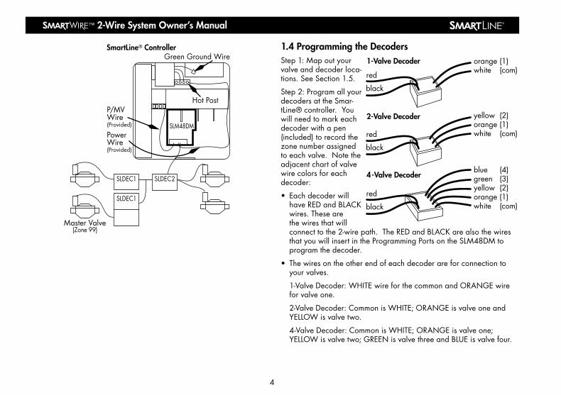
1.4 Programming the DecodersStep1:Mapoutyourvalveanddecoderloca-tions.SeeSection1.5.
Step2:ProgramallyourdecodersattheSmar-tLine®controller.Youwillneedtomarkeachdecoderwithapen(included)torecordthezonenumberassignedtoeachvalve.Notetheadjacentchartofvalvewirecolorsforeachdecoder:
• EachdecoderwillhaveREDandBLACKwires.Thesearethewiresthatwillconnecttothe2-wirepath.TheREDandBLACKarealsothewiresthatyouwillinsertintheProgrammingPortsontheSLM48DMtoprogramthedecoder.
• Thewiresontheotherendofeachdecoderareforconnectiontoyourvalves.
1-ValveDecoder:WHITEwireforthecommonandORANGEwireforvalveone.
2-ValveDecoder:CommonisWHITE;ORANGEisvalveoneandYELLOWisvalvetwo.
4-ValveDecoder:CommonisWHITE;ORANGEisvalveone;YELLOWisvalvetwo;GREENisvalvethreeandBLUEisvalvefour.
4
red
black
red
black
red
black
1-Valve Decoder
2-Valve Decoder
4-Valve Decoder
orange (1)white (com)
yellow (2)orange (1)white (com)
blue (4)green (3)yellow (2)orange (1)white (com)
SLM48DM
SLDEC1 SLDEC2
SLDEC1
SmartLine® Controller
PowerWire(Provided)
P/MVWire(Provided)
Master Valve(Zone 99)
Hot Post
Green Ground Wire

2-Wire System Owner’s Manual® ™
Decoder Programming Steps:
• UsetheSLM48DMmodebuttontoselectthePGMprogrammingposition.
• InserttheREDandBLACKwiresonthedecoderintheProgrammingPortsontheSLM48DM(REDtoRED,BLACKtoBLACK).
• Useup/downarrowbuttonstoselectthezonenumbertobepro-grammed.
• PushProgramZonebuttontoselectthezoneshowinginthedisplaywindow.Note:Whenyouareprogrammingamulti-valvedecoder,thedisplaywillonlyshowthezonenumberforthefirstzonetobeassignedtothatdecoder.The remaining zones in the decoder are automatically assigned in sequential numerical order.
• AGREENstatuslightwillconfirmyourselection.
• Ifprogrammingisnotsuccessful,aREDstatuslightwillflashandanerrorcodewillbeshownonthedisplay.SeeTroubleshootingfordescriptionoferrorcodes.
• Markthezonenumberprogrammedonthedecoder.Note:Ifyouareusingamulti-valvedecoder,thedecoderwillrecordthezoneselectedintheorderpreviouslynotedforwirecolors.Forexample,ifyouareusingthe4-valvedecoder,thefirstzoneprogrammedwillbeOrange,thesecondYellowandsoon.Markthezonenumberonthedecoderforreferenceduringfieldinstallation.Youshouldalsomarkallzonenumbersonyourvalvelayoutplanforreferenceduringinstallationofthedecoders.
• Afterthedecodersareconnectedtothevalves,usetheModebuttonontheSLM48DMtoplacethedecoderprogrammerintheRunposi-tion.TheGreenstatuslightwillconfirmthatthesystemisreadyforoperation.IfthelightisRed,refertotheTroubleshootingguide.
• Ifyouareusingamastervalveonyoursystem,besuretoprogramitaszone99intheSLM48DMusinga1-valvedecoder.
SLM48DM RUN Mode
• TheprogramstatusLEDwillbeGREEN.
• Afteraprogramiscomplete,theSLM48DMdisplaywillshowanymal-functioningzones.Ifmorethanonezoneismalfunctioning,eachzonealongwiththecorrespondingerrorcodewillbedisplayedsequentiallyinarepeatingloop.TheProgramZonebuttonwillcleareacherrorcodeasitisdisplayed.SeeTroubleshootingforfaultcodedescriptions.
Programming Zones on your SmartLine® Controller
Afterthe2-wireinstallationanddecoderprogrammingiscomplete,youcanusetheSmartLine®controllertoestablishthewateringscheduleforallzones.ThenormalSL1600programmingconventionappliestotheSmartWire™system.
5
2-Wire System Owner’s Manual ®™
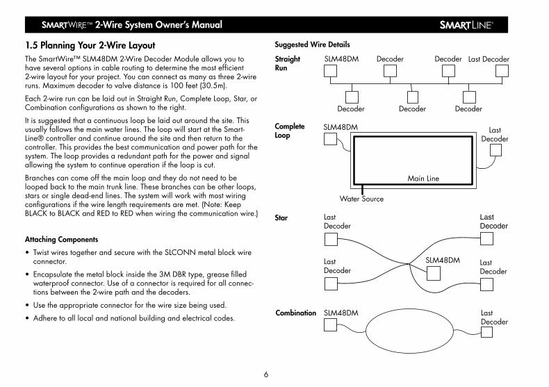
1.5 Planning Your 2-Wire LayoutTheSmartWire™SLM48DM2-WireDecoderModuleallowsyoutohaveseveraloptionsincableroutingtodeterminethemostefficient2-wirelayoutforyourproject.Youcanconnectasmanyasthree2-wireruns.Maximumdecodertovalvedistanceis100feet(30.5m).
Each2-wireruncanbelaidoutinStraightRun,CompleteLoop,Star,orCombinationconfigurationsasshowntotheright.
Itissuggestedthatacontinuousloopbelaidoutaroundthesite.Thisusuallyfollowsthemainwaterlines.TheloopwillstartattheSmart-Line®controllerandcontinuearoundthesiteandthenreturntothecontroller.Thisprovidesthebestcommunicationandpowerpathforthesystem.Theloopprovidesaredundantpathforthepowerandsignalallowingthesystemtocontinueoperationiftheloopiscut.
Branchescancomeoffthemainloopandtheydonotneedtobeloopedbacktothemaintrunkline.Thesebranchescanbeotherloops,starsorsingledead-endlines.Thesystemwillworkwithmostwiringconfigurationsifthewirelengthrequirementsaremet.(Note:KeepBLACKtoBLACKandREDtoREDwhenwiringthecommunicationwire.)
Attaching Components
• TwistwirestogetherandsecurewiththeSLCONNmetalblockwireconnector.
• Encapsulatethemetalblockinsidethe3MDBRtype,greasefilledwaterproofconnector.Useofaconnectorisrequiredforallconnec-tionsbetweenthe2-wirepathandthedecoders.
• Usetheappropriateconnectorforthewiresizebeingused.
• Adheretoalllocalandnationalbuildingandelectricalcodes.
6
StraightRun
DecoderDecoderDecoder
Decoder Last DecoderDecoderSLM48DM
CompleteLoop
SLM48DM
Water Source
Main Line
LastDecoder
Star
LastDecoder
LastDecoder
LastDecoder
LastDecoder
SLM48DM
Combination SLM48DM LastDecoder
Suggested Wire Details
2-Wire System Owner’s Manual® ™
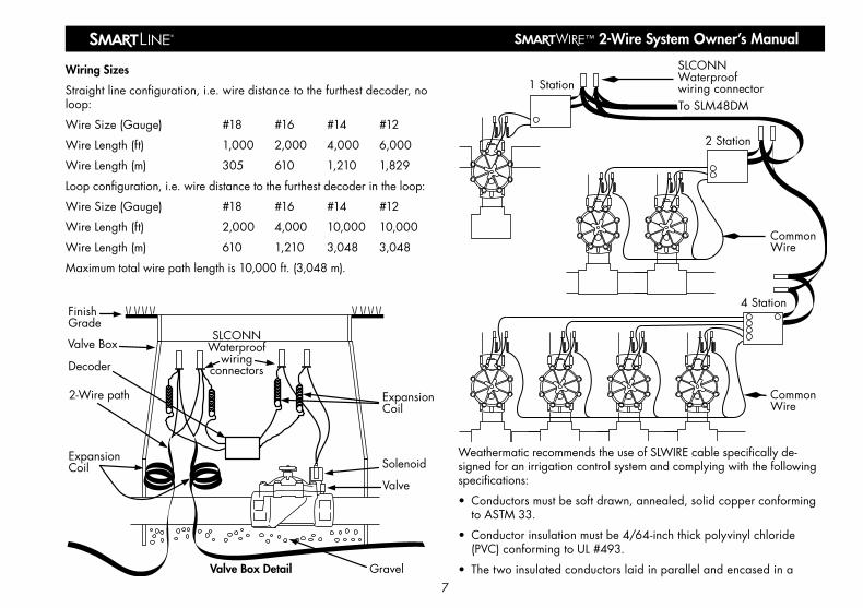
Wiring Sizes
Straightlineconfiguration,i.e.wiredistancetothefurthestdecoder,noloop:
WireSize(Gauge) #18 #16 #14 #12
WireLength(ft) 1,000 2,000 4,000 6,000
WireLength(m) 305 610 1,210 1,829
Loopconfiguration,i.e.wiredistancetothefurthestdecoderintheloop:
WireSize(Gauge) #18 #16 #14 #12
WireLength(ft) 2,000 4,000 10,000 10,000
WireLength(m) 610 1,210 3,048 3,048
Maximumtotalwirepathlengthis10,000ft.(3,048m).
WeathermaticrecommendstheuseofSLWIREcablespecificallyde-signedforanirrigationcontrolsystemandcomplyingwiththefollowingspecifications:
• Conductorsmustbesoftdrawn,annealed,solidcopperconformingtoASTM33.
• Conductorinsulationmustbe4/64-inchthickpolyvinylchloride(PVC)conformingtoUL#493.
• Thetwoinsulatedconductorslaidinparallelandencasedina7
1 Station
To SLM48DM
SLCONNWaterproofwiring connector
CommonWire
2 Station
4 Station
CommonWire
SLCONNWaterproof
wiringconnectors
ExpansionCoil
Solenoid
Valve
FinishGrade
Valve Box
ExpansionCoil
2-Wire path
Decoder
GravelValve Box Detail
2-Wire System Owner’s Manual ®™
singleouterjacketof3/64-inchthick,high-density,sunlightresistantpolyethyleneconformingtoICEAS-61-402andNEMAWC5,hav-ingaminimumwallthicknessof.045-inch.
• Thetwoconductorsmustbecolor-coded:normallyoneconductorredandtheotherblack.Bothconductorsshallbethesamesize.
• Thefollowingmodelsmeettheabovespecificationsfordirectburialcable:WeathermaticSLWIRE12;WeathermaticSLWIRE14.
1.6 Lightning ProtectionWeathermaticSLGDTgasdischargetubelightningarrestorsmustbeusedonall2-wiregrids.TheSLGDTlightningarrestorattachesdirectlytothe2-wiresystemandhelpsdissipatestaticelectricitygeneratedbyanearbylightningstrike.WhileWeathermaticcomponentshavelightningarrestingfeatures,theSLGDTprovidesanextrameasureofprotection.
Features
• Protectsthe2-wiresystemfromexcessivestaticchargescreatedbyalightningstrike.
• Sealedandimpervioustomoisture,salts,fertilizersandmildchemicals.Canbeburieddirectlyinthesoil.
• Shockresistant
• Freeze/heatresistant(-20°to60°C)
• Noelectricalcontactwiththesoil
• EachLightningArrestorprotectsa300footradius
Electrical Specifications
• Requiresnopowerfromthe2-wiresystem
• CanonlybeconnectedtoSmartWire™2-wiresystems
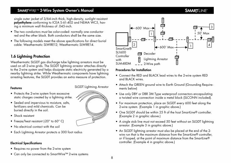
Procedures for Installation
• ConnecttheREDandBLACKleadwirestothe2-wiresystemREDandBLACKwires.
• AttachtheGREENgroundwiretoEarthGround(GroundingRequire-mentsbelow)
• UseonlyDBYorDBR3MTypewaterproofconnectorsencapsulatingatwistedwireconnectioninsideametalblock(SLCONNincluded).
• Formaximumprotection,placeanSLGDTevery600feetalongthe2-wiresystem.(Example1ingraphicabove.)
• OneSLGDTshouldbewithin25ftofthehostSmartLine®controller.(Example2ingraphicabove.)
• Asinglestublinemustnotexceed50feetwithoutanSLGDTlightningarrestor.(Example3ingraphicabove.)
• AnSLGDTlightningarrestormustalsobeplacedattheendofthe2-wirerunthatisthemaximumdistancefromtheSmartLine®controller,oriflooped,atthepointofmaximumdistancefromtheSmartLine®controller.(Example4ingraphicabove.)
8
SmartLine®SL1600ControllerwithSLM48DM
Decoder
Lightning Arrestor2-Wire path
600’ Max
1
3
4
1
2600’ Max
50’ Max
SLGDT Lightning Arrestor
2-Wire System Owner’s Manual® ™
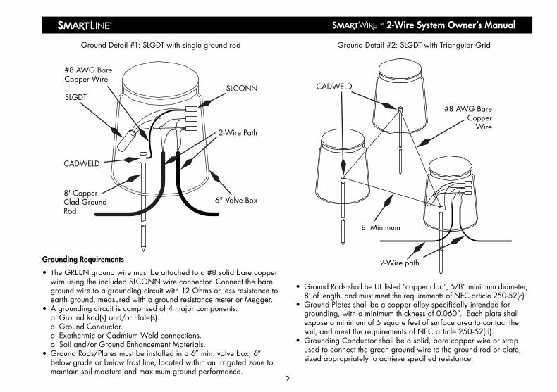
Grounding Requirements
• TheGREENgroundwiremustbeattachedtoa#8solidbarecopperwireusingtheincludedSLCONNwireconnector.Connectthebaregroundwiretoagroundingcircuitwith12Ohmsorlessresistancetoearthground,measuredwithagroundresistancemeterorMegger.
• Agroundingcircuitiscomprisedof4majorcomponents: o GroundRod(s)and/orPlate(s). o GroundConductor. o ExothermicorCadmiumWeldconnections. o Soiland/orGroundEnhancementMaterials.• GroundRods/Platesmustbeinstalledina6”min.valvebox,6”
belowgradeorbelowfrostline,locatedwithinanirrigatedzonetomaintainsoilmoistureandmaximumgroundperformance.
• GroundRodsshallbeULlisted“copperclad”,5/8”minimumdiameter,8’oflength,andmustmeettherequirementsofNECarticle250-52(c).
• GroundPlatesshallbeacopperalloyspecificallyintendedforgrounding,withaminimumthicknessof0.060”.Eachplateshallexposeaminimumof5squarefeetofsurfaceareatocontactthesoil,andmeettherequirementsofNECarticle250-52(d).
• GroundingConductorshallbeasolid,barecopperwireorstrapusedtoconnectthegreengroundwiretothegroundrodorplate,sizedappropriatelytoachievespecifiedresistance.
9
SLCONN
2-Wire Path
6" Valve Box
SLGDT
8' CopperClad GroundRod
CADWELD
#8 AWG BareCopper Wire
GroundDetail#1:SLGDTwithsinglegroundrod
8' Minimum
2-Wire path
CADWELD
#8 AWG BareCopper
Wire
GroundDetail#2:SLGDTwithTriangularGrid
2-Wire System Owner’s Manual ®™
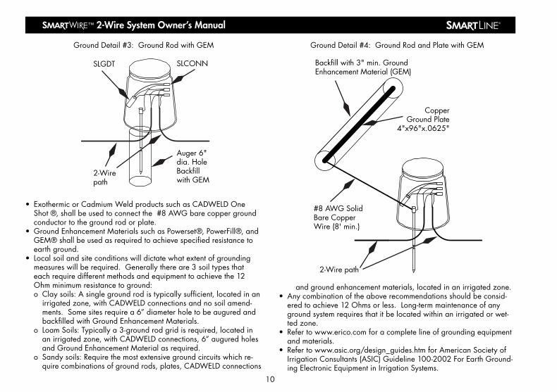
• ExothermicorCadmiumWeldproductssuchasCADWELDOneShot®,shallbeusedtoconnectthe#8AWGbarecoppergroundconductortothegroundrodorplate.
• GroundEnhancementMaterialssuchasPowerset®,PowerFill®,andGEM®shallbeusedasrequiredtoachievespecifiedresistancetoearthground.
• Localsoilandsiteconditionswilldictatewhatextentofgroundingmeasureswillberequired.Generallythereare3soiltypesthateachrequiredifferentmethodsandequipmenttoachievethe12Ohmminimumresistancetoground:o Claysoils:Asinglegroundrodistypicallysufficient,locatedinan
irrigatedzone,withCADWELDconnectionsandnosoilamend-ments.Somesitesrequirea6”diameterholetobeauguredandbackfilledwithGroundEnhancementMaterials.
o LoamSoils:Typicallya3-groundrodgridisrequired,locatedinanirrigatedzone,withCADWELDconnections,6”auguredholesandGroundEnhancementMaterialasrequired.
o Sandysoils:Requirethemostextensivegroundcircuitswhichre-quirecombinationsofgroundrods,plates,CADWELDconnections
andgroundenhancementmaterials,locatedinanirrigatedzone.• Anycombinationoftheaboverecommendationsshouldbeconsid-
eredtoachieve12Ohmsorless.Long-termmaintenanceofanygroundsystemrequiresthatitbelocatedwithinanirrigatedorwet-tedzone.
• Refertowww.erico.comforacompletelineofgroundingequipmentandmaterials.
• Refertowww.asic.org/design_guides.htmforAmericanSocietyofIrrigationConsultants(ASIC)Guideline100-2002ForEarthGround-ingElectronicEquipmentinIrrigationSystems.
10
CopperGround Plate
4"x96"x.0625"
#8 AWG SolidBare CopperWire (8' min.)
2-Wire path
Backfill with 3" min. GroundEnhancement Material (GEM)
GroundDetail#4:GroundRodandPlatewithGEM
Auger 6"dia. HoleBackfillwith GEM
SLCONN
2-Wirepath
SLGDT
GroundDetail#3:GroundRodwithGEM

2-Wire System Owner’s Manual® ™
Fault Code
Description Cause/Action
E1 Nodecoderfound
Cause:wiringerror,defectivedecoder,defectiveSLM48DMprogrammer.
Action:checkwiring,movedecoderclosertotheSLM48DM,replace.
E2 2-wireovercurrent
Cause:shortedwiring,wireconnectedtodirt,improperconnections,faileddecoder(shorted),valveconnecteddirectlyto2-wire.
Action:troubleshootwiringproblemsbyundoingthelastthingyoudidwhen itworkedbefore,and/orbybreakingthe2-wiresysteminhalftoisolatetheproblem,theninhalfagainasneeded.
E3 Opencircuitatsolenoid
Cause:thedecoderdetectsnosolenoidcur-rentwhenactivated:opensolenoid,poorconnections/wiringbetweendecoderandsolenoid,brokendecoder.
Action:checkdecodertosolenoidcon-nections,ohmsolenoid,replacesolenoid,replacedecoder.
E4 ShortCircuitatsolenoid
Cause:poorqualitywiringbetweenSLM-48DManddecoder(length,connections,highresistance,2-wireconnectedtodirt),failingdecoder,failingSLM48DM(giveserrorson“all”decoders),multipledecoderswithsameaddress.
Action:test2-wirequality(end-to-endresis-tance,resistancetoearthground,isolatedecoderinerror(testclosetodecodermanager),checkforduplicateaddresses.
11
1.7 Troubleshooting
TheSLM48DMprovidesspecialkeycombinationsthatcanbeusedtoaccessspecialfeaturesandinformationthatcanbehelpfulduringthediagnosticprocess.Thesekeycombinationsareasfollows:
o PushUpArrowandDownArrowsimultaneouslytoviewthesoft-wareversionforyourSLM48DM.
o PushSelectModeandUpArrowbuttonssimultaneously,thenreleaseanduseUpandDownArrowstoselectazone,thenpushtheProgramZonebuttontoviewthesoftwareversionforthatparticulardecoder.
o HolddownSelectModebuttonfor5secondsandreleasetoinitiateaquicktestofallzones.Whenusingthetestmode,zoneaddresseswillbedisplayedwhilethezoneisoperating.Ifmultiplezonesareoperating,thezoneaddresseswillbedisplayedrotat-ingeverythreesecondsuntilthezoneisturnedoff.
o PushProgramZoneandUpArrowsimultaneouslytoviewtheSLM48DMtemperature.
IfanovercurrentorovertemperatureissensedbytheSLM48DMdecoderprogrammer,itwillcauseaFAULTmessagetoappearonthedisplayoftheSmartLine®controller.OpentheSmartLine®panelandchecktheFAULTonthedisplayoftheSLM48DMdecoderprogram-mer.AftertheFAULTisrepaired,presstheProgramZonebuttonontheSLM48DMtocleartheerrormessage.RefertothetablebelowforSLM48DMerrormessagesandcorrespondingcorrectiveactions.
• DecoderLocating:Tousea521locatortofindadecoder,thedecodershouldbeturnedonbythecontrollerandlocatedusingthe521wand(patentpending).
• ValveLocating:UsetheSL1600controllerAdvancedFunctionsmenuoptionsforthevalvelocatortofindthevalve.Thisfeaturewillcreatea“chatter”foraselectedvalveasaconvenientmethodoflocatingburiedvalves.UseNEXTandBACKbuttonstoscrolltothevalveyouwantto“chatter.”

2-Wire System Owner’s Manual ®™
®
1.8 Special System Features • Auniqueaddressisconfiguredineachdecoderduringtheconfigu-
rationprocess.
• Valvesareactuatedbyacommandfromthedecoder.
• Diagnosticfeatures—TheSLM48DMreportsfailingsolenoids.
• Ifasolenoidhasfailed,thedecodersensesanopencircuitand/orovercurrentconditionandshutsdownthevalve.
• EachdecoderwillshutdownifcommunicationislosttotheSLM-48DMdecodermoduleintheSmartLine®controller.
• Valvescanbelocatedupto100feetfromthedecoder.
• Decoderelectronicsarepottedinchemicalandwaterproofcom-poundsforimperviousprotectionfrommoistureanddirt.
1.9 Electrical Specifications • Inputvoltage24-28VACoverthe2-wiresystem.
• TheWeathermaticSLM48DMcansupportatotalof48valvesplusamastervalve.Amaximumof3valvesincludingmastervalveorpumprelaycanbeoperatedconcurrently.
• Noelectricalcontactwithsoil.
• Shockresistant.
• Freeze/heatresistant(-20°to60°C).
• Allconnectingwiresare14gaugecoatedPVCandmustbeinstalledwithindustrystandardwaterproofconnectorssuchasthe3MDBYorDBR.
Fault Code
Description Cause/Action
E5 DecoderCommunica-tionError
Cause:poorqualitywiringbetweenSLM-48DManddecoder(length,connections,highresistance,2-wireconnectedtodirt),failingdecoder,failingSLM48DM(giveserrorson“all”decoders),multipledecoderswithsameaddress.
Action:test2-wirequality(end-to-endresis-tance,resistancetoearthground,isolatedecoderinerror(testclosetodecodermanager),checkforduplicateaddresses.
E6 HighTem-peratureShutDown
Cause:hightemperature,excessive2-wiredutycycleattemperature.
Action:shadecontroller,replaceSLM48DM.
E7 DecoderProgrammingFailure
Cause:multipledecodersatonetime,de-coderremovedbeforeprogramcyclecom-pletes,faileddecoder,failingSLM48DM.
Action:retry,replacedecoder,replaceSLM48DM.
1.7 Troubleshooting Continued
12ADSL48DM