Embed Size (px)
Citation preview

Project Description2


SECTION 2 Project Description
Queensland Coke and Power Plant Project – Environmental Impact Statement 2-1
2 Project Description
2.1 Location and General Description
The proposed Queensland Coke and Power Plant Project (the Project) is to be situated adjacent to the existing Stanwell Power Station (SPS) within the Stanwell Energy Park (SEP), located approximately 25 km south-west of Rockhampton City Centre and 129 km by rail from Gladstone in Central Queensland (Figure 1.1). The SEP is situated on Power Station Road, immediately south of the township of Stanwell and occupies an approximate area of 3,800 hectares (ha). A general layout of the proposed project site is presented in Figure 1.2 (aerial photo base) and Figure 2.1. The Project is proposed to be constructed primarily on land within the SEP that was significantly cleared for the former AMC project (Dames & Moore, 1999) (Figure 6.2).
The real property description of the project site is Lot 1/SP140242 and Lots 1 and 44/SP140243, County of Livingstone, Parish of Stanwell. These lots are held in freehold ownership by SCL and cover a total area of approximately 1,411 ha. Detailed land tenure information is provided on Figure 3.4 and discussed further in Section 3 - Land Characteristics.
The predominant land use in the area is agriculture with the majority of land surrounding and within the SEP having been cleared and developed for grazing and irrigated cropping (Fitzroy Basin Association, 2004a). Natural bushland has been cleared or modified in much of this area and the development of the Project is restricted to the east by steep topography and the presence of vine thicket vegetation on Flagstaff Hill. Within the SEP, the Project is expected to occupy an area of approximately 106 ha of land (represented as the Proposed Development Footprint on EIS figures herein) which is zoned by Fitzroy Shire Council as Special Industry Precinct I for industrial activities that have some synergy with the SPS (Fitzroy Basin Association, 2005). This area currently comprises disused grazing land. Detailed land use information is provided in Section 3 - Land Characteristics.
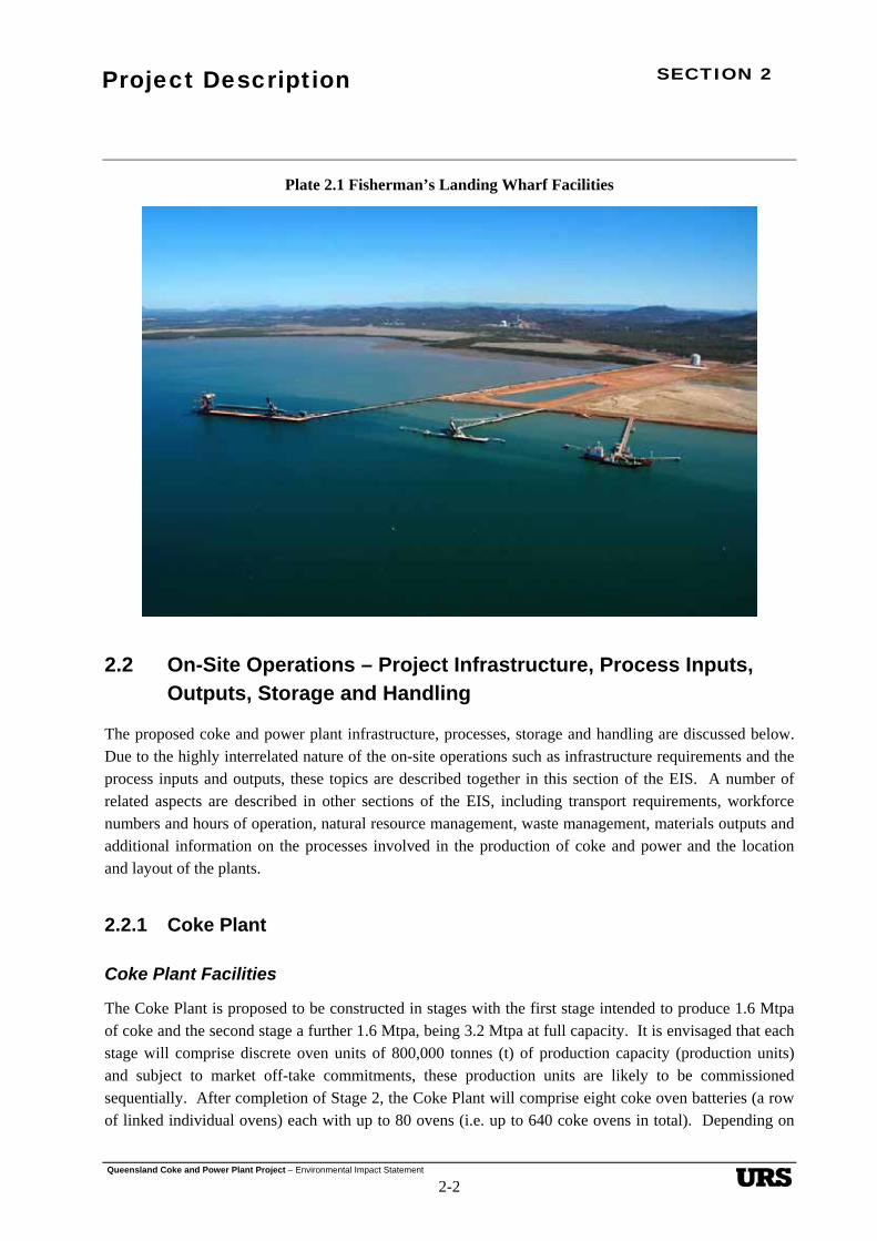
The coke produced at the proposed plant will be transported by rail to Fisherman’s Landing at the Port of Gladstone for export to markets in Asia, Europe and the Americas. Plate 2.1 provides an aerial view of the Fisherman’s Landing facility and the infrastructure currently in place. The proposed port site is Crown Land controlled by the CQPA located approximately 129 km from the SEP and approximately 15 km to the north-west of the RG Tanner coal handling facility at Gladstone. The port facility is to be a new multi-user wharf export facility established on reclaimed land between the Cement Australia and Comalco wharves, and on disturbed land associated with the Cement Australia rail loop (Figure 3.5). The area of land surrounding the proposed wharf is to be developed as part of the continuing development of the Port of Gladstone.
Comprehensive detail on the location and general description of the site is provided in Section 3 - Land Characteristics. Section 14 - Transport Infrastructure addresses regional infrastructure such as rail and road access arrangements relevant to the Project. Existing infrastructure for the Project and the affect of the Project on adjacent areas are discussed in numerous sections throughout the EIS.

SECTION 2 Project Description
Queensland Coke and Power Plant Project – Environmental Impact Statement 2-2
Plate 2.1 Fisherman’s Landing Wharf Facilities
2.2 On-Site Operations – Project Infrastructure, Process Inputs, Outputs, Storage and Handling
The proposed coke and power plant infrastructure, processes, storage and handling are discussed below. Due to the highly interrelated nature of the on-site operations such as infrastructure requirements and the process inputs and outputs, these topics are described together in this section of the EIS. A number of related aspects are described in other sections of the EIS, including transport requirements, workforce numbers and hours of operation, natural resource management, waste management, materials outputs and additional information on the processes involved in the production of coke and power and the location and layout of the plants.
2.2.1 Coke Plant
Coke Plant Facilities
The Coke Plant is proposed to be constructed in stages with the first stage intended to produce 1.6 Mtpa of coke and the second stage a further 1.6 Mtpa, being 3.2 Mtpa at full capacity. It is envisaged that each stage will comprise discrete oven units of 800,000 tonnes (t) of production capacity (production units) and subject to market off-take commitments, these production units are likely to be commissioned sequentially. After completion of Stage 2, the Coke Plant will comprise eight coke oven batteries (a row of linked individual ovens) each with up to 80 ovens (i.e. up to 640 coke ovens in total). Depending on

SECTION 2 Project Description
Queensland Coke and Power Plant Project – Environmental Impact Statement 2-3
the technology chosen for the Project, each oven will be approximately 13 m long, 3.6 m wide and 3 m high. Each battery of ovens will be serviced by coal charging, pushing and coke receival machines. Centralised water quenching facilities will cool the coke prior to conveying to a coke stockpile. Figure 1.3 provides a conceptual representation of the proposed Coke Plant.
Support infrastructure for the Coke Plant will include permanent administration buildings (including a control room and employee amenities) and ancillary facilities such as workshops, materials storage areas, water and waste management structures and drainage, laydown areas and other minor operational buildings. Sealed roads will provide access to the site from Power Station Road and around the operational areas of the plant. A sealed employee and visitor carpark will be located adjacent to the administration facilities. Less frequently accessed areas such as areas around water management infrastructure and construction lay down areas will have unsealed roads. Areas surrounding the administration facilities and the car park will be landscaped. Some landscaping will also be completed around the operational areas where appropriate. Plates 2.2 to 2.6 below provide an indication of the proposed coke plant elements and facilities.
Coke Plant Operation
QCE proposes that at full production approximately 5 Mtpa of coal (wet) would be delivered to the project site via the existing SPS rail loop and coal unloading system, which is connected to the main Blackwater Rail System by a dedicated spur line. A new transfer chute is proposed to be installed on the existing SPS coal conveyor, which will enable coal deliveries to the coke plant coal stockpiles via a transfer conveyor and coal stacker machine. Coal will then be reclaimed by front-end loaders from the stockpiles into hoppers and transferred by conveyor to the coke plant surge bin.
The proposed coal stockpile area will comprise five separate 22,000 t stockpiles that are 70 m long, 60 m wide and 23 m high. These stockpiles can each be pushed out by dozer to dimensions of 70 m long, 130 m wide and 15 m high (approximately 70,000 t capacity each) if required, to provide total on-site coal storage capacity of 350,000 t. Figure 2.2 shows the proposed coal receival, storage and reclaim system.

SECTION 2 Project Description
Queensland Coke and Power Plant Project – Environmental Impact Statement 2-4
Plate 2.2 Example of Coke Ovens and Heat Recovery Units
Plate 2.3 Example of Coke Ovens and Coal Charging Facilities

SECTION 2 Project Description
Queensland Coke and Power Plant Project – Environmental Impact Statement 2-5
Plate 2.4 Example of Lining the Coke Ovens
Plate 2.5 Example of the Construction of Coke Ovens

SECTION 2 Project Description
Queensland Coke and Power Plant Project – Environmental Impact Statement 2-6
Plate 2.6 Example of Coke Oven Layout

SECTION 2 Project Description
Queensland Coke and Power Plant Project – Environmental Impact Statement 2-7
Figure 2.2 Stanwell Coal Receival, Storage and Reclaim System
Coke Ovens
Stanwell Coal Stockpiles
Coal Unloader
Coking Coal Stockpiles
Stockpiled coal will be blended and conveyed to a surge bin, discharged in a batch mode and transferred via a conveyor to the coke plant coal charging system. A coke pusher and coal charging machine that operates on the outside of the ovens will service each coke oven battery. The coke ovens will be charged with between 55 and 60 t of coal that has been crushed to 85% - 3 mm and stamp charged. The coal bed absorbs heat from the refractory bricks and combustible volatile matter is liberated. The carbonisation process will maintain the operating temperature of the coke ovens at approximately 1,200 ºC.
A portion of the liberated gas will be combusted in the top section of the oven, and the partially combusted gas will then be drawn down though ducts in the oven walls to the sole flue below the charge where it is further combusted with the addition of air via lower air inlets. The heat from the secondary combustion will be used to carbonise the coal charge at the base of the oven chamber. The oxidised flue gas then exits the oven chamber and enters a common tunnel that links each oven in the battery where a third stage of flue gas combustion occurs and delivers the hot gas to the heat recovery boilers via ductwork. Figures 2.3 and 2.4 show the movement of the gas throughout the coke oven. The coal charge will undergo carbonisation for approximately 60 hours.

SECTION 2 Project Description
Queensland Coke and Power Plant Project – Environmental Impact Statement 2-8
Figure 2.3 Coke Oven Cross Section
Figure 2.4 Coke Oven Combustion

SECTION 2 Project Description
Queensland Coke and Power Plant Project – Environmental Impact Statement 2-9
After carbonisation has been completed, a pusher car will be positioned in front of the pusher side oven door and a flat bed hot coke-receiving car positioned in front of the coke side door. The doors will be partially lifted and the pusher car will slowly move the pusher ram and push the coke bed onto a waiting flat bed coke-receiving car. The flat bed coke-receiving car will operate on the inside of the coke oven battery and this will transfer hot coke via rail tracks to the water quenching towers. The coke oven batteries will share a coke quenching system.
The coke will be flood-quenched at the coke quenching tower to cool the coke and then delivered to the screening and sizing station where fine coke material will be removed from the sized product. After sizing, the coke will either be loaded directly onto a train or stockpiled on the product coke stockpile. The coke will be placed onto the stockpile by a rail mounted stacker. The product coke will be stored on two stockpiles, each 540 m long, 55 m wide and 15 m high (135,000 t each). The total stockpile pad dimensions will be 540 m long and 150 m wide. Figure 2.5 presents the coke receival, storage and loadout system for the Coke Plant.
Figure 2.5 Stanwell Coke Receival, Storage and Loadout System
Coke Ovens
Emergency
Stockpile
Coke Breeze
Bin
Train Loadout
Bin
-6mm
-100mm
+100mmStacker/Reclaimer
Screening Station
Coke Stockpiles
Stockpile Bypass
The coke will then be loaded into trains for transportation by rail to a new ship loading facility located at Fisherman’s Landing. It is estimated that approximately 16 trains to transport 4,200 t of coke per week will be required for the Coke Plant at full production during Stage 2 operations and approximately half this for Stage 1 operations.
At the Fisherman’s Landing site a coke unloader will be constructed on a second spur line of the Cement Australia rail loop at the site. Coke will be conveyed to a stockpile area located on the reclaimed Fisherman’s Landing site. A coke stockyard and reclaim facility will be constructed adjacent to the loop on land controlled by the CQPA. This stockpile system will consist of two parallel 50,000 t capacity stockpiles, with stockpile pad dimensions of 210 m long and 150 m wide. In the event that a ship is

SECTION 2 Project Description
Queensland Coke and Power Plant Project – Environmental Impact Statement 2-10
docked and available for loading, the coke will bypass the stockpile system and load directly on to the ship (Figure 2.6). The coke will be conveyed to the new wharf and ship loader after being screened to remove fines generated during transport and handling. The fines may be sold to Cement Australia or other local markets as a fuel feedstock.
Figure 2.6 Gladstone Port Handling Facility
Coke Stockpiles
Stockpile Bypass
Ship LoaderStacker/Reclaimer
Coke Unloader
2.2.2 Power Plant
Power Plant Facilities
The new power generation facility will comprise a stand-alone power plant which will have a capacity of up to 370 Mega Watts (MW). The electricity produced would be supplied to the grid and the Coke Plant, as well as being used for power plant process and electrical requirements.
Permanent buildings and structures for the Power Plant will comprise a turbine hall, cooling towers, an administration building (including a plant start-up/control room, a meal room and amenities), and minor ancillary structures such as a fire pump house and water treatment chemical storage and dosing facilities. A switchyard will be located adjacent to the turbine hall. Ancillary infrastructure will include on-site drainage systems and waste water infrastructure such as oil separators and settlement/evaporation ponds (Figure 2.7).
Depending on supply and treatment options, a water treatment plant and sewage treatment facilities to service both the Coke Plant and Power Plant may be located at or adjacent to the Power Plant. Sealed roads will provide access from the SPS to the Power Plant and to facilities within the Power Plant, including the turbine hall, cooling towers and administration building. An employee and visitor car park

SECTION 2 Project Description
Queensland Coke and Power Plant Project – Environmental Impact Statement 2-11
will be located adjacent to the administration building. Unsealed gravel roads will be provided for less frequently accessed areas such as the settlement/evaporation ponds and construction and maintenance lay down areas. Areas adjacent to the administration building and car park will be landscaped. Accessible areas adjacent to other plant structures will generally be paved or gravelled. The balance of the site will have a combination of landscaped, paved and unpaved areas as appropriate.
The Power Plant will be constructed on the SPS side of the proposed Coke Plant to provide better access from the SPS and reduce the transmission line distance from the power plant switchyard to the Powerlink substation. Transmission lines from the switchyard (proposed to be located south-west of the turbine hall) will follow a south/south-westerly direction towards Power Station Road and follow that road to the existing Powerlink substation. A services corridor is proposed from the SPS to the Coke Plant and Power Plant to provide services such as water.
Figure 2.7 Power Plant Block Diagram
Make-Up Water
Cold Gas
Coke
Power Plant Block Diagram
Steam Turbine
Coking Coal
Heat Recovery Boilers
Power to National Electricity Market
Generator
Cooling Towers
Blow Down Water
Heat Recovery Coke Ovens
Hot Gas
Stack
Induced Draft Fans
Superheated Steam
Feed HeatingCondensate Extraction Pumps
Boiler Feed Pumps
Feed Water
Condenser
Hot Gas Bypass
Power Generation Process
Hot gas captured in the coke ovens will be collected and delivered to Heat Recovery Steam Generators (HRSGs) (also known as heat recovery boilers). The high pressure super heated steam produced from the HRSGs will be ducted to the Power Plant and used to drive the steam turbine generator. The possibility of using air cooling instead of water cooling in the Power Plant as a more economic cooling method is also being investigated.

SECTION 2 Project Description
Queensland Coke and Power Plant Project – Environmental Impact Statement 2-12
The steam turbine cycle involves high pressure super heated steam being expanded through a turbine and exhausted into a water cooled condenser where condensate will be removed by condensate extraction pumps to the feedwater system. The feedwater system will employ low pressure feed water heaters to improve cycle efficiency. The low pressure feedwater heaters will receive heating steam from extraction points in the turbine. Low pressure heated feedwater is piped to a deaerator where the feedwater is deaerated and further heated to increase temperature. Feedwater is then piped from the outlet of the deaerator to the boiler feed pumps where the water pressure is increased to high pressure and piped to the inlet of the HRSGs.
2.2.3 Modes of Operation – Heat Recovery
Once fully commissioned, the project will operate in heat recovery mode. In this mode, waste heat will be used to produce steam for electricity generation as shown in Figure 2.7. There will be occasions when the waste heat is not used to produce steam. In this mode heated gases will bypass the HRSGs and be vented direct to the main stacks.
2.3 Construction
Construction activities are expected to commence in 2006 and take up to five years to complete. Construction hours will ultimately be determined by the principal contactors selected to build the Project. It is anticipated that typical construction hours will be from 6.00 am to 6.00 pm, Monday to Saturday. Some extended hours and weekend work maybe required on occasions. The commissioning phases will require some personnel to be on site 24 hours per day.
Transportation of plant components within Australia will be primarily based on a combination of road and rail. Equipment and material not available in Australia will be shipped via commercial freighter in containers via the sea/port network. Transport requirements are discussed further in Section 14 - Transport Infrastructure. A transport route survey will be undertaken during the detailed feasibility study for the Project to identify any clearance issues once the exact dimensions of vehicles and loads are known. The construction of the existing SPS, however, has demonstrated that such loads can be accommodated on the road system.
2.3.1 Coke Plant
The proposed site for the coke ovens has already been substantially cleared and will initially require earthworks to be undertaken on a cut to fill balance for the coke oven structural base. A small fleet of dozers, excavators, compactors and haul trucks will systematically move the soil to the final design location. Detailed excavation for the civil works will continue with excavators and backhoes. Pre-bent reinforcing steel will be transported to site and fixed in position. A concrete batch plant will be established on the site to minimise the concrete haulage distance. Aggregate and cement will be transported to site via trucks along the Capricorn Highway and Power Station Road. The repetitive nature

SECTION 2 Project Description
Queensland Coke and Power Plant Project – Environmental Impact Statement 2-13
of the coke oven design allows for simple formwork design and this can be reused continuously in the concrete walls and base structure.
A sub-base of castable refractory will sit over the concrete base. Steelwork columns and sections including oven doors will be prefabricated off-site and installed in a traditional stick build approach. The structural steelwork will be the frame for the oven brickwork and ductwork support. There is no building required to house the ovens.
Lattice boom and hydraulic cranes up to 100 t capacity will be utilised to install the steelwork. The oven bricks will be sourced internationally. On arrival in Brisbane they will be railed to Rockhampton and transported to site via semi-trailers in shipping containers. On site the bricks will be off-loaded and placed in a dedicated storage area. Container forklifts will be utilised to minimise handling from the semi-trailers and 5 t rough terrain forklifts will be used to load the bricks to the oven work fronts. Shipping containers will be returned on the empty trucks to ensure no build up of containers on site. The estimated quantity of the major project commodities for the construction of the Coke Plant discussed above are presented in Table 2.1.
Table 2.1 Estimated Major Commodities required for the Coke Plant1
Commodity Summary Quantity 1.6 Mtpa Summary Quantity 3.2 Mtpa Total Quantity
Bulk earthworks 750,000 m³ 750,000 m³ 1,500,000 m3
Reinforced concrete 50,000 m³ 50,000 m³ 100,000 m3
Refractory bricks 200,000 t 200,000 t 400,000 t
Structural/Misc Steel/Stacks 30,000 t 40,000 t 70,000 t
Conveyors 5,000 m 2,500 m 7,500 m
HRSG units 16 each 16 each 32 each
Cabling (electrical and control)
300,000 m 300,000 m 600,000 m
Note: 1 Estimates do not include commodities required for the coal or coke stockpiles, the Power Plant or the works at Fisherman’s Landing.
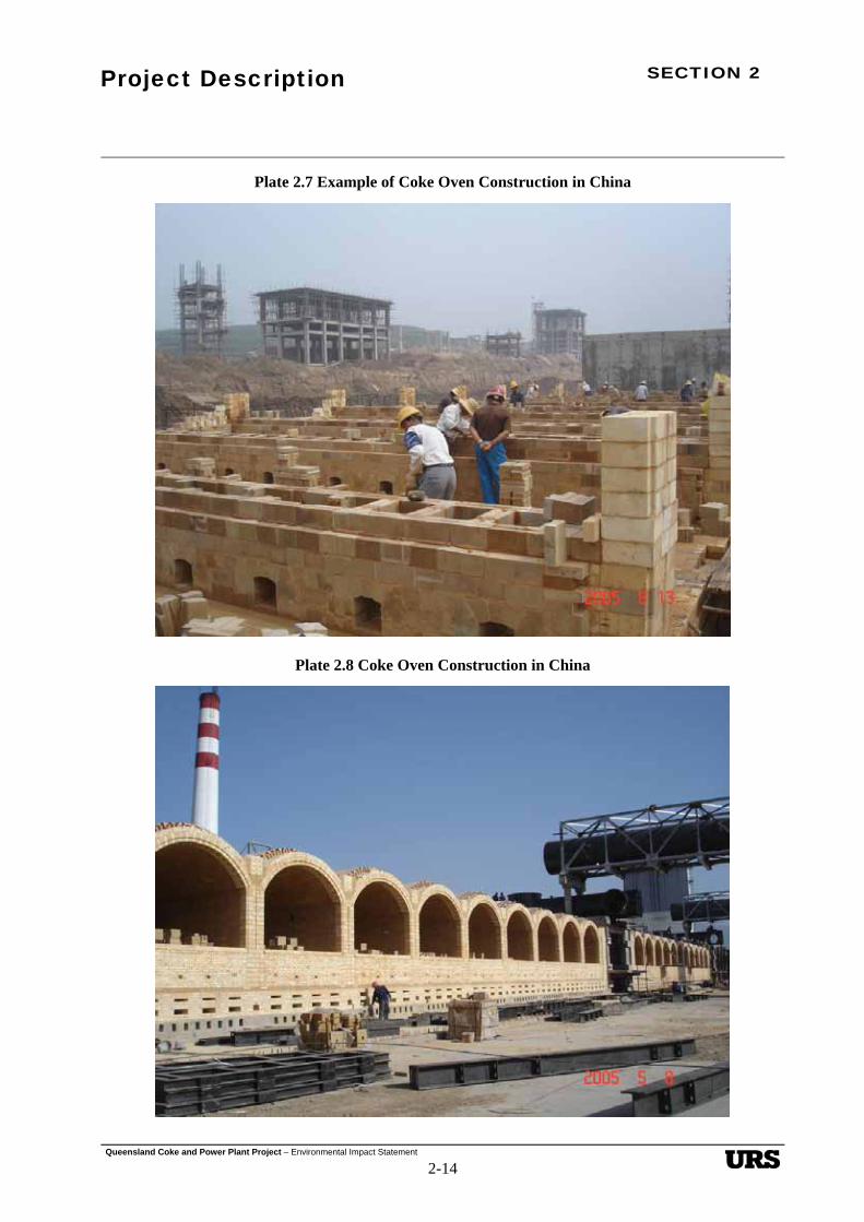
The workforce will predominantly consist of bricklayers and trades assistants during this phase. Small manual conveyors will be utilised to deliver the bricks to the final position. Once the oven walls are completed, temporary wooden supports will be placed to enable the oven roof to be finalised. Once the oven installation is complete, the maintenance platforms, walkways and stairs will be installed with hydraulic cranes. Hot air ductwork will then be positioned together with the steel piperacks located into their final position. Plates 2.7 and 2.8 show the construction of a heat recovery coke plant in China.
SECTION 2 Project Description
Queensland Coke and Power Plant Project – Environmental Impact Statement 2-14
Plate 2.7 Example of Coke Oven Construction in China
Plate 2.8 Coke Oven Construction in China

SECTION 2 Project Description
Queensland Coke and Power Plant Project – Environmental Impact Statement 2-15
The ovens require several pieces of mechanical equipment such as the pusher/charger machine, hot side door machine and the flat bed hot coke receiving car. These items will be prefabricated off-site, test assembled and pre-commissioned at the manufacturer’s fabrication facility before dismantling into transportable sections for shipment and then reassembly on site. Heavy lift cranes of up to 150 t capacity will be required for lifting and placing the HRSGs. Otherwise, small to medium sized mobile cranes will suffice for construction of other elements such as structural steel and piping.
The construction timetable is dependant on the number of ovens to be constructed with the first battery taking approximately 14 months from start of construction to commencement of the refractory dry-out and then commissioning. The remaining batteries will be progressively commissioned after the first battery and this will take 3-6 months to establish full production for each battery.
In terms of landscaping, roadside tree and shrub planting will be undertaken during the construction phase to provide visual screening of the project structures from Power Station Road. This planting will take account of the proposed 275 kV transmission line which will result in a large angle pylon being constructed near the entrance to SPS. Any lighting associated with the Project will be designed to avoid light spill on to Brickworks Road and to prevent direct views of lights on the stacks that may be visible from the Capricorn Highway. Screen planting is proposed alongside the southern edge of Brickworks Road to block potential views of the coke stockpiles, including the emergency stockpile at the northern end of the Coke Plant (Section 3 - Land Characteristics).
2.3.2 Power Plant
The timing of the construction of the Power Plant will be determined by the expected availability of sufficient waste heat to enable the efficient operation of the Power Plant.
Contemporary construction methods will be employed for the Power Plant, as specified by the codes and standards defined by engineering and regulatory requirements, and by safety and environmental plans. The appointed principal contractor will determine the detail of the construction methods, however, typically development will proceed as described below.
The selected power plant site is already cleared and earthworks and foundation construction undertaken as a result of activities associated with the former AMC project. Subject to further investigations, the site may be reshaped and old AMC foundation works removed prior to the construction of the power plant buildings and facilities. Earth moving and concrete breaking machinery (if required) will be employed to undertake these tasks.
Following reshaping of the contours (if required), the major earthworks associated with the Power Plant will be those undertaken for the power block area, the access road and permanent underground utilities and services. Infrastructure construction will involve the erection of a turbine hall to house the steam turbine generators, condensers, feedwater heaters, feed pumps and associated auxiliaries, a switchyard, cooling towers, and an administration building. The construction of stormwater settlement/evaporation ponds, services pipework, a 275 kV transmission line connecting to the existing Powerlink substation, steam and feedwater piping between the Coke Plant and the Power Plant, a construction power supply and

SECTION 2 Project Description
Queensland Coke and Power Plant Project – Environmental Impact Statement 2-16
on-site roads will also be undertaken. Structures for such facilities as chemical dosing and fire fighting pumps will also be required.
The turbine hall will be a steel-frame, steel-clad building, with substantial concrete foundations designed to provide a base for the heavy machinery to be housed in the structure. It is expected that the steel frame will be assembled on site using components prefabricated off-site. Other site buildings will generally be steel-framed and steel-clad or of concrete block construction. Heavy lift cranes and special gantries will be utilised to place heavy plant items into position. Lattice boom cranes will be used to erect steel work.
Once the basic structures are essentially complete the major components (turbo alternator, condenser, feedheaters and boiler feed pumps) are installed. Electrical switchgear, transformers, system control equipment, instrumentation and cabling are then installed. During this phase the construction workforce on site will reach its peak, and then begin to decline as systems are completed.
Once these systems are complete, commissioning of the equipment and processes will be commenced with the energisation of the Power Plant’s high voltage and medium voltage power systems. This is followed by individual testing of electrical components within the plant. Following electrical and control testing and the pressure testing and cleaning of steam lines, steam is applied to the turbine. The turbo alternator is then checked and synchronised with the electrical grid. The Power Plant then undergoes final commissioning activities, fine tuning and testing as a complete power plant system.
Site cleanup, road completion, clean-up of temporary lay down areas, and site rehabilitation will be undertaken at the end of commissioning. The Power Plant construction will take place over a period of up to 27 months, including a 6 month start-up and commissioning period.
2.4 Support Infrastructure Requirements
2.4.1 Transport - Road, Rail and Shipping
Roads
The project site will be accessed primarily via Power Station Road which is an existing single access road. It is likely that vehicle traffic generated during construction will result in the majority of traffic arriving and departing site outside road peak times.
As outlined in Section 14 - Transport Infrastructure, material inputs to the construction phase of Stage 1 are likely to approximate 560 vehicle trips per week (280 in/280 out) with deliveries proposed to be made by B-double vehicles. It is expected that traffic volumes during the construction of Stage 2 will be lower than for Stage 1 due to minimal construction set-up requirements. Construction personnel for the Coke Plant are likely to be transported to the site via 45-seat passenger buses or private vehicle with parking to be provided on site.
Inputs to the operational process are not likely to generate significant heavy vehicle traffic volumes on the road network as coking coal is to be transported via rail to the site from the Bowen Basin.
SECTION 2 Project Description
Queensland Coke and Power Plant Project – Environmental Impact Statement 2-17
In terms of intersection and road capacity upgrade requirements, the Project will not add traffic to the critical movement at the Gladstone Road/Port Curtis Road/Lower Dawson Road intersection. The addition of project traffic to the roundabout located at the intersection of the Bruce Highway and Capricorn Highway will bring forward the year at which the intersection would exceed the desirable Degree of Saturation (DOS). An assessment of all other intersections has indicated no significant impacts will arise from the proposed development.
The Project will increase the annual Equivalent Standard Axle (ESA) loading on a number of links between Power Station Road and the Bruce Highway, particularly during the construction phase. During the operational phases of the Project, heavy vehicle traffic volumes will decrease markedly and will not be so significant as to require pavement impact assessment or contribution. As such, the significant pavement impacts on the road network will occur only during the construction phases. This increase in heavy vehicle traffic is expected to bring forward the need for pavement rehabilitation on a number of sections of the road network. A full assessment of traffic generated by the construction and operation of the Project and road infrastructure upgrade requirements is discussed in Section 14 – Transport Infrastructure.
Rail
Stage 1 of the Project will produce up to 1.6 Mtpa of coke for export, requiring approximately 2.5 Mtpa (wet) of Bowen Basin coking coal. Stage 2 of the Project will increase production up to a total combined throughput of 3.2 Mtpa of coke for export, requiring approximately 5 Mtpa (wet) of Bowen Basin coking coal. This coal is proposed to be railed from mines within the Blackwater Rail System to the SPS rail loop. Stage 1 transport of approximately 2.5 Mtpa of wet coking coal to the unloading facility at the project site will result in an additional eight coal trains per week (or 16 train movements) operating on the Blackwater Rail Corridor. Stage 2 will require an additional 16 train movements per week. The additional train services for the Stage 1 coal supply will be operated under existing corridor operating parameters.
A new eastern angle connection from the SPS rail loop to the central Blackwater line is proposed to be constructed. This connection will allow the transportation of product coke from the loading facility on the SPS rail loop to the Fisherman’s Landing unloading facility. It is estimated that the Stage 1 coke product (1.6 Mtpa) will require approximately eight loaded trains per week (or 16 train movements) and an additional 16 train movements per week for Stage 2. The increase in rail traffic due to the Project will result in approximately 7% of the growth for the main east-west line.
It is anticipated that mainline rail infrastructure enhancements will be required for both stages of operation to provide rail infrastructure capacity in the Blackwater Rail System for the required tonnages of coal to be transported to Stanwell and also for coke to be transported to the Fisherman’s Landing wharf. Infrastructure capacity and enhancement works required for the Project are discussed in detail in Section 14 – Transport Infrastructure.
SECTION 2 Project Description
Queensland Coke and Power Plant Project – Environmental Impact Statement 2-18
Shipping
The coke produced by the Project will be transported by rail to Fisherman’s Landing. A new facility at Fisherman’s Landing is proposed to be constructed for the unloading of coke from the trains, the temporary storage of coke product and the loading of product onto ships for export. The details of the facility are described in Section 14 – Transport Infrastructure.
An elevated wharf conveyor will direct the coke to a custom designed shiploader on Fisherman’s Landing Berth 3, at a rate of 2,000 t/hr. The shiploader will be designed to load panamax and post panamax vessels suitable for that berth. These ships have a loading capacity of 45,000 t, requiring approximately one day for loading. For Stage 1 operations it is anticipated that 35 ships per year, or approximately three ships per month, would be required for the export of 1.6 Mtpa of coke. Stage 2 coke export will require approximately 70 ships per year which approximates 6 ships per month.
2.4.2 Energy Requirements
Power will be required for construction administration facilities, lighting, and construction equipment. Construction power supplies for the Project may be sourced from the Powerlink transmission network, the Ergon distribution network, or the SPS. An investigation of supply options will be undertaken prior to construction and will take into account requirements such as construction demand, reliability of supply and operational phase power supply requirements. Upon commissioning of the Power Plant, its permanent high and medium voltage systems will be energised from the Powerlink transmission network. At that time, construction power supplies may progressively be transferred to the Power Plant’s permanent distribution system. Temporary diesel generators may be used for construction activities remote from construction supply distribution boards or in the event that normal construction supplies are unavailable.
Energy supply for the construction of the Fisherman’s Landing facilities will be required for minor employee facilities, lighting and construction equipment. Grid power exists in the area and this may be used as the power supply during construction. Alternatively, temporary diesel generators will be used to ensure a constant and reliable source of power. Permanent power supply facilities during the operation of the coke handling facilities will be sourced from the local power grid.
The Coke Plant will operate continuously and is expected to have an average electrical demand of 26 MW (or 228 GWh/annum for Stage 1 and 2) for the operation of the coke plant service equipment, water pumps, fans, conveyor belts, lighting, air-conditioning and other operational equipment. The Power Plant will require 15 MW (or 131 GWh /annum) to power its own auxiliaries. Power plant auxiliaries will either be supplied from the Power Plant’s steam turbine generator via unit auxiliary transformers, or back fed from the Powerlink network when the steam turbine generator is off-line. The primary supply for the Coke Plant will be sourced from the Power Plant or directly from the Powerlink or Ergon networks. Standby power supply arrangements for the Project may be entered into with Powerlink, Ergon or SCL. It is proposed that stand-by power for the Coke Plant will be sourced directly from Powerlink or Ergon networks to assure continuous operation of the key elements of the Coke Plant. An assessment of standby supply options will be undertaken prior to commencement of construction and will take into account

SECTION 2 Project Description
Queensland Coke and Power Plant Project – Environmental Impact Statement 2-19
factors such as cost and reliability. The Project will have emergency power supply systems including emergency diesel generators and battery systems if required to ensure continuity of supply to critical drives, lighting and control systems. Power easements are presented in Section 14 - Transport Infrastructure.
A fuel source will be required for the initial pre-heating of the coke ovens. Should gas be used for pre-heating, it may be sourced and delivered via a temporary gas pipeline to the site under agreement with a supplier to be confirmed closer to Stage 1 construction and operation. Should the gas pipeline not be available, gas will be transported to site by road. It is anticipated that approximately 550,000 GJ of gas will be required for the initial heating of the Stage 1 ovens and a total gas requirement 1,100,000 GJ to complete heating of Stage 1 and Stage 2 ovens. As an alternative to gas heating of the ovens, a diesel fuel source may be used.
The coke production during Stage 1 and 2 will use various heavy earthmoving and materials handling equipment which are estimated to use approximately 14,000 L of diesel fuel per year. Petrol consumption on site will be very minor and therefore considered insignificant.
The Commonwealth Government’s energy policy is presented in the National Greenhouse Strategy (Commonwealth of Australia, 1998) and has three broad initiatives: education about greenhouse issues; limiting greenhouse gas emissions; and laying foundations for adapting to climate change. This policy was developed by the Commonwealth and all State and Territory Governments and demonstrates commitment to combat global climate change while recognising that the national interest lies in protecting jobs and maintaining industry competitiveness. The Module of the Strategy relevant in the context of the Project is that related to “Efficient and Sustainable Energy Use and Supply”.
The Queensland Energy Policy (Department of Energy, 2000) identifies key initiatives that the Queensland Government will support for the development of energy supply in the State. The key initiatives cover incentives for gas-fired or renewable energy sources, facilitation of the gas supply infrastructure and gas-fired power stations, restriction on development of coal-fired power stations, support for renewable and innovative energy technologies and energy efficiency programs. The Project proposes an innovative use of a strategic mineral resource in Queensland and meets a key objective of overall Queensland Government policy – building upon the commodities that Queensland has by adding value to create new industries and new jobs for a growing State. By developing a coke plant with heat recovery and power generation, the Project represents a smart and efficient use of available resources.
In the examination of project technology, the proponents will evaluate energy efficiency and conservation opportunities through process designs and operational efficiencies. Opportunities will include the use of high efficiency motors and equipment such as compressors, specifying high efficiency lighting with appropriate lighting control and the use of low emission fuels in vehicles such as biodiesel. To ensure energy efficient opportunities are implemented, the proponents will develop processes to ensure energy efficiency is considered during all stages of detailed design, equipment selection and construction. Additional detail on energy conservation is provided in Section 8 - Greenhouse Gas Emissions.

SECTION 2 Project Description
Queensland Coke and Power Plant Project – Environmental Impact Statement 2-20
2.4.3 Water Supply and Management
The Project may require a considerable water supply for the following processes:
• Demineralised water for use in the power plant steam cycle;
• The power plant cooling system;
• Quench water for dousing hot coke output;
• Dust suppression at the coke and coal stockpiles and operational areas;
• Service water for washdown and other miscellaneous uses;
• Fire system make-up water; and
• Potable water for the project workforce.
The maximum annual water use for Stage 2 production with the Power Plant fully operational will be approximately 10,740 ML/year. In order to reduce the Project’s use of raw water, opportunities for water re-use and recycling will be explored and implemented wherever possible. Water re-use options include sourcing dust suppression water from site settlement/evaporation ponds, re-use of blowdown water from the Power Plant’s steam cycle and cooling processes for coke quenching water and sourcing some quench water from the SPS blowdown. Stormwater re-use through the system of settlement/evaporation ponds will be implemented wherever possible. In addition, the option of air cooling instead of water cooling in the power station is being investigated.
As a result of the water used, the Project will create a number of waste streams which are discussed in Section 5 – Water Resources and Section 10 – Waste Impacts. These waste streams will include sewage effluent, blowdown and cooling water, and stormwater runoff from operational and materials storage and handling areas. Wherever possible, the quantity of stored waste water will be reduced through site re-use options.
The water supply is proposed to be sourced from some of the available resource in the Fitzroy Basin either through existing or new water allocations. The “Fitzroy Basin Water Resource Plan” (FBWRP) (Fitzroy Basin Association, 2004a) indicates that up to 300,000 ML of unallocated mean annual diversion may be available from the Fitzroy Basin. In line with the requirements of the “Fitzroy Basin Resource Operations Plan” (ROP) (Department of Natural Resources and Mines, 2004c), the most sustainable and reliable raw water supply will be pursued. Options for obtaining access to existing water allocations include entering into water supply arrangements with existing water service providers such as Fitzroy River Water and SunWater, and the purchase of tradable water allocations under the ROP.
Detailed information on the Project’s expected water requirements, site water re-use options, stormwater management, project discharge requirements, raw water supply alternatives and infrastructure requirements are provided in Section 5 - Water Resources.

SECTION 2 Project Description
Queensland Coke and Power Plant Project – Environmental Impact Statement 2-21
In line with the Environmental Protection (Water) Policy 1997, environmental values for all Queensland waters will be identified in order that they be protected and/or enhanced. All site activities at the SEP and at Fisherman’s Landing will be carried out by such practicable means to prevent or minimise the contact of rainfall or stormwater runoff with wastes or other contaminants and prevent the release of contaminated runoff. In addition, the proponents will take all reasonable and practicable measures to prevent and/or to minimise the likelihood of environmental harm being caused and will install all measures, plant and equipment necessary to ensure compliance with any conditions of an environmental authority.
2.4.4 Telecommunications
Existing telecommunications infrastructure on the project site comprises a Remote Integrated Multiplexer (RIM) located at the corner of Power Station Road and the old Coombs Road. The RIM was installed for the former AMC project and connects to two Main Distribution Frames (MDF). One MDF is located at the southern end of the existing AMC hardstand and the other towards the northern end of the AMC site. The MDFs can be relocated depending on project infrastructure location and design. Leading from the MDFs, copper wiring will be installed in buildings proposed for the Project for telecommunications access via use of phone sockets.
Currently, the RIM has capacity for 60 Public Switched Telephone Network (PSTN) services (phone only) or for 24 Integrated Services Digital Network (ISDN) connections. ISDN is an international communications standard for sending voice, video, and data (e.g. via email) over digital telephone lines or normal telephone wires. PSTN refers to the international telephone system based on copper wires carrying analogue voice data. The addition of panels into the existing RIM would increase the number of services available for the Project. Alternatively, the RIM can be easily modified to provide for all Project requirements.
The RIM also provides ISDN and mobile access to SPS. The telecommunications services to SPS comprise ISDN, PSTN, Multiprotocol Label Switching (MPLS) via fibre, and a GSM/CDMA phone tower. GSM/CDMA stands for Global System for Mobile Communications (one of the leading digital cellular systems) and Code-Division Multiple Access (a digital cellular technology that uses spread-spectrum techniques). This infrastructure is owned by Telstra. SCL owns a microwave link between their Rockhampton office and the SPS.
Once installed for the Project, Telstra will remain owners of the RIM, MDFs and all other infrastructure except for the wiring between the MDFs and the phone sockets which will be owned by the proponents. The proponents will discuss with Telstra the exact requirement for telecommunications infrastructure following finalisation of the project design and enter into a cost agreement on that basis.
2.4.5 Workforce, Accommodation and Support Infrastructure
Modelling for purposes of the EIS was undertaken at a maximum construction rate for the Project. Subsequent investigations by the proponents have indicated that shortfalls in the ability to obtain the

SECTION 2 Project Description
Queensland Coke and Power Plant Project – Environmental Impact Statement 2-22
necessary workforce may necessitate a revision of the construction timetable for the Project. This may include construction of the Coke Plant (which is the major employer element of the Project) over a longer period, thereby reducing the demand for large numbers of construction personnel.
For the purposes of modelling in the EIS a peak Stage 1 construction workforce has been taken as approximately 1,100 workers for the Coke Plant, 250 for the Power Plant and 300 workers for materials handling infrastructure (approximately 1,450 labour workforce and 200 staff). Stage 2 would employ approximately 90% of the Stage 1 workforce. At the reduced construction timetable, an average 800 construction workers will be required over a five year construction schedule for both stages of the Coke Plant. The workforce under this arrangement would peak at approximately 1,000.
The operational phase will involve some 100 and 145 full-time equivalent workers for full production in Stages 1 and 2 respectively. The Stage 1 operational workforce would comprise 81 workers for the Coke Plant, 15 for the Power Plant and 4 workers for materials handling. The Stage 2 operational workforce would comprise 116 workers for the Coke Plant, 23 for the Power Plant and 6 workers for materials handling. The Coke Plant will operate 365 days per year, 7 days per week and 3 shifts per day on a 4-panel roster with three, 8-hour shifts per day. Operational staff will also work on a panel roster arrangement.
Of the full-time workers, it is estimated that approximately eight positions (approximately 12 workers) will be located at the Fisherman’s Landing facility. These will comprise one supervisor and one operator for the rail receival operation, one supervisor and three operators for the ship loading operation (and combined ship loading and rail receival) and two tradesmen for maintenance. It is likely that the operation of the rail receival of product will be manned 5 days per week at 1 shift per day. The ship loading facility will be manned on average once per week for Stage 1 operations and twice per week for Stage 2 with two, 12-hour shifts per ship. Maintenance personnel will be employed on a 5-day week roster with one shift per day.
The occupation of workers and approximate numbers required for construction of Stage 1 are presented in Table 2.2. Figure 2.8 depicts anticipated hours for construction of Stage 1 of the Project.

SECTION 2 Project Description
Queensland Coke and Power Plant Project – Environmental Impact Statement 2-23
Table 2.2 Workforce Occupations and Approximate Peak Numbers for Stage 1 Construction
Worker Occupation Approximate Peak Number
Coke Plant
Bricklayers – tradespersons 200
Plant/crane operators 120
Carpenters 50
Concrete workers/steel fixers 120
Electricians – tradespersons 50
Instrument tradespersons 20
Metal trades/welders/pipefitters 120
Riggers/dogmen/scaffolders 70
Trades assistants/labourers – bricklaying 100
Trades assistants/labourers – general 150
Engineers, managers, foreman, office staff 100
Total 1100
Power Plant
Managers and Administrators 3
Professionals 25
Associate Professionals 26
Tradespersons & Related Workers 108
Advanced Clerical & Service Workers 3
Intermediate Production & Transport Workers 30
Elementary Clerical & Service Workers 5
Labourers & Related Works 50
Total 250
Materials Handling
Plant/Crane Operators 40
Concrete workers/steel fixers 40
Electricians – tradespersons 18
Instrument tradespersons 8
Metal trades/welders/pipefitters 40
Riggers/dogmen/scaffolders 22
Trades assistants/labourers – bricklaying 32
Trades assistants/labourers – general 50
Engineers, managers, foreman, office staff 50
Total 300
Overall Total Number of Workers 1,650

SECTION 2 Project Description
Queensland Coke and Power Plant Project – Environmental Impact Statement 2-24
Figure 2.8 Predicted Hours for Stage 1 Construction of the Coke Plant
The construction workforce required for the project site at Stanwell is likely to be drawn in the first instance from the Rockhampton region. However, it is anticipated that additional labour from outside the region will be required. It is anticipated that the construction workforce will be accommodated locally in facilities to be constructed in Gracemere. The facilities will be designed to house approximately 900 workers and will use existing Gracemere services such as town water supply and sewage treatment facilities. The final decision on accommodating the workforce will be subject to commercial arrangements and consultation with local residents, Fitzroy Shire Council and other stakeholders. The construction workforce for the Fisherman’s Landing site will more than likely be sourced from the resident labour pool. Workers employed from outside this area are likely to be housed in existing short-term accommodation in the Gladstone area. Full details on accommodation requirements are provided in Section 12 - Social Environment.
For the operational phase of the Project, it is probable that the majority of the full-time equivalent workforce will be privately housed in the Rockhampton and Gladstone region with buses and private vehicles used to transport the SEP site workforce.
The Project intends to support, where practicable, the implementation of a number of key Queensland and Local Government policies and strategies. In addition, it will also support community based development initiatives in the Rockhampton and Gladstone communities. These policies and strategies comprise:
• Key Priorities of the Queensland Government including “managing urban growth and building Queensland’s regions” (specifically regional jobs creation and building on the strengths of Queensland’s diverse regions) and “growing a diverse economy and creating jobs” (State of Queensland (Department of the Premier and Cabinet), 2005);

SECTION 2 Project Description
Queensland Coke and Power Plant Project – Environmental Impact Statement 2-25
• Queensland Energy Policy: A Cleaner Energy Strategy (Department of Energy, 2000);
• Smart State Strategy (State of Queensland (Department of the Premier and Cabinet), 2005a);
• Export Solutions - Queensland Government’s Trade Strategy (Department of State Development, Trade and Innovation, 2005);
• The Local Industry Policy - A Fair Go for Local Industry (Department of State Development, 1999);
• The Draft Indigenous Economic Development and Participation Strategy (IEDPS) (Department of State Development, Trade and Innovation, 2005a);
• The Central Queensland Training and Employment Strategy: A Smart State Initiative (Department of Employment and Training, 2002); and
• Community based economic development initiatives of Rockhampton Regional Development Ltd and the Gladstone Area Promotion and Development Ltd.
2.5 Waste Management
The waste streams associated with the Project will include solid and liquid wastes, air emissions, and various sources of waste water including site drainage and sewage effluent. These streams are discussed briefly below, with more detail provided in Section 10 – Waste Impacts, Section 5 – Water Resources and Section 7 – Air.
2.5.1 Solid and Liquid Wastes
The solid and liquid wastes to be produced during the construction and operational phases of the Project are detailed in Section 10 – Waste Impacts. Operational solid wastes will include coal and coke fines, coal ash and general waste. Liquid waste generated by the Project will include oily wastes, blowdown from the cooling water system, effluent from the demineralisation plant, stormwater runoff from operational and process areas, waste oil from plant and equipment and sewage.
The major solid waste streams likely to be generated during construction include numerous bulky construction materials such as timber, scrap steel, concrete, insulation, oven bricks, plastic conduit and pipework, packing materials, paint residues, lubricants, batteries, etc. General office wastes will also be generated during the construction phase.
The amount of material brought on site for the Project will be minimised through careful consideration of what is needed and any excess materials and used chemical containers will, where practical, be returned to the supplier or other local users. This will also reduce the volume of waste going to landfill.
Hazardous waste materials will be segregated and stored in designated areas in accordance with regulatory requirements such as Australian Standards. These wastes will then be removed off site by

SECTION 2 Project Description
Queensland Coke and Power Plant Project – Environmental Impact Statement 2-26
licensed waste collection contractors. Under the Environmental Protection (Waste Management) Regulation 2000 (EP Regulation), trackable waste movements off-site will include the completion of waste tracking certificates for the collection, transport and management of these wastes.
As highlighted in the above discussion on water management (and discussed further in Section 5 - Water Resources and Section 10 – Waste Impacts), process water and stormwater will be re-used on site wherever possible to reduce the demand for raw water and manage the amount of potentially contaminated water stored on-site. Any discharges off-site will be conducted in accordance with environmental licence conditions for the Project.
Under the Environmental Protection Act 1994, the proponents will implement a waste management strategy to comply with the requirements of the Environmental Protection (Waste Management) Policy 2000 (EPP (Waste)) and the EP Regulation. As outlined in Section 10 – Waste Impacts, a waste management hierarchy with a preferred order of adoption of waste management practices will form the basis of this strategy. The adoption of the waste management principles will be achieved through recycling of coal and coke fines, recycling waste oil and scrap metal, recycling of general wastes and the re-use of site water wherever possible.
The proponents will implement a Waste Management Plan (Section 16 – Environmental Management Plan) which will be developed in accordance with the relevant legislation and will address both the construction and operational phases of the Project. This plan will take into consideration international best practice management for project wastes and include opportunities and actions to be taken to implement the waste management hierarchy and life-cycle assessment recommendations.
2.5.2 Air and Noise Emissions
Sources of air emissions in the production of coke comprise the coal handling, charging, coking process, pushing, quenching and coke handling operations. The emissions expected from the Coke Plant comprise sulphur dioxide, nitrogen dioxide, particulate matter, carbon dioxide, carbon monoxide, volatile organic compounds, poly aromatic hydrocarbons and metals. The Power Plant will not produce any air emissions during operation. Specific sources, rates, physical and chemical attributes of the emissions and their comparisons/relevance in terms of applicable standards are discussed in detail in Section 7 – Air.
The design of the Project will incorporate features that minimise air quality impacts, such as the use of stamp charging to reduce emissions during charging and pushing and operation of the coke ovens under negative pressure to control gas combustion and eliminate air emissions. In addition, operational emissions of dust will be controlled through sprays and regular watering of dust generating areas. The coke handling and ship loading activities at Fisherman’s Landing may generate low levels of dust. However, due to the screening of the coke at Stanwell, the coarse grained nature of the coke and the distance to sensitive receptors these activities are not considered to be the source of significant air emissions. Control strategies at Fisherman’s Landing will include the application of water during materials handling.

SECTION 2 Project Description
Queensland Coke and Power Plant Project – Environmental Impact Statement 2-27
Noise sources from the Project will include construction noise (such as from machinery movements and infrastructure building activities), minor coke oven noise, materials handling machinery movements and piping steam blows. Operational noise will be emitted from pusher charger machines, earthmoving equipment, coke and coal handling equipment, infrastructure such as fans, conveyors, quench car movement and coke quenching, steam and feedwater piping including safety and bypass valves, and power generation noise including fans, pumps, transformers and turbines. Noise modelling indicated that the Project complies with noise level goals at noise sensitive receptors for most of the relevant criteria. A full description of potential noise emissions, control strategies and the relevant goals, including principal noise sources for construction, routine operations and any atypical circumstances is included in Section 9 – Noise and Vibration.
The Project is not a source of vibration to the surrounding community, with operation and construction activities being limited to vibration sources that will produce only localised impacts. The proposed industrial activities do not involve vibration type sources such as heavy vehicles close to residences, falling weights or hammers, compressed gases, explosions and pile driving. The combined effect of minimal vibration sources, relatively soft soils and the considerable distance to potential receivers results in the conclusion that vibration will not cause any significant impact.
2.6 Decommissioning
The Project evaluation has been based on a life of 40 years, however, it is probable that the facility will remain in operation well beyond this period. The proposed use of the site once the Project has been decommissioned has not yet been determined, however, numerous planning and environmental issues will be considered before a final decision is made. The process of preparing the decommissioning plan will be extensive and will include consultation with all relevant authorities and project stakeholders. Decommissioning of site infrastructure and rehabilitation of land is discussed in Section 3 – Land Characteristics. A comprehensive Environmental Management Plan will be prepared, in consultation with the appropriate regulatory authorities, prior to the commencement of decommissioning activities.