Embed Size (px)
Citation preview

2. Over Current Protection of Transmission line
Shital Patel, EE Department Switch Gear and Protection (2170908) 1
2.1. Over current relay time-current characteristics
Over current relay operates when load current exceeds pre-set value i.e. pick up value.
Distribution lines, large power equipment and industrial systems uses over current
protection as it offers cheapest and simplest protection.
A wide variety of time-current characteristics are available for overcurrent relays.
(a) Definite time overcurrent relay
This relay operates after a predetermined time when the current exceeds its pick-up
value
The operating time is constant, irrespective of the magnitude of the current above the
pick-up value.
The desired definite operating time is set with the help of an intentional time-delay
mechanism provided in the relaying unit.
(b) Instantaneous overcurrent relay
This relay operates in a definite time when the current exceeds its pick-up value.
The operating time is constant, irrespective of the magnitude of the current above the
pick-up value.
There is no intentional time-delay. It operates in 0.1s or less. Sometimes the term like
high set or high speed is used for very fast relays having operating times less than 0.1s.
(c) Inverse time overcurrent relay
This relay operates when the current exceeds its pick-up value. The operating time
depends on the magnitude of the operating current.
The operating time decreases as the current increases.
(d) Inverse definite minimum time overcurrent (IDMT) relay
This type of a relay has inverse-time current characteristic at lower values of the fault
current and definite-time characteristic at higher values of the fault current.
Inverse-time characteristic is obtained when plug setting multiplier is below 10 and for
values of plug setting multiplier between 10 and 20, the characteristic tends to become a
straight line, i.e. towards the definite time.
IDMT relays are used for the protection of distribution lines.
(e) Very inverse-time overcurrent relay
This relay gives more inverse characteristic than IDMT relay and it gives better
selectivity.
General time-current characteristic of over current relay is
1n
Kt
I
Value of n for very inverse characteristic lies between 1.02 and 2.
It is recommended where there is a substantial reduction of fault current as the distance
from the power source increases. They are particularly effective with ground faults

2. Over Current Protection of Transmission line
Shital Patel, EE Department Switch Gear and Protection (2170908) 2
because of their steep characteristic.
(f) Extremely inverse-time overcurrent relay
This relay gives a time-current characteristic more inverse than that of the very inverse
and IDMT relays
Time-current characteristic of an extremely inverse relay is
2
2
Kt K I t
I
Time-current characteristics of enclosed fuse is
3.5
3.5
Kt K I t
I
Hence, electromechanical relay with extremely inverse time over current characteristic
is used to grade with fuses.
An extremely inverse relay is preferred for the protection of alternators, transformers,
motors, cables etc. against overheating i.e. heating characteristics of machines is I2t = K.
By adjusting the time and current settings, a suitable characteristic of the relay is
obtained for a particular machine to be protected.
For example
o It is difficult for IDMT relay to distinguish between momentary overloads on
sustained short circuit current. An extremely inverse relay is quite suitable for such
situation.
o After long outages, when the circuit breaker is reclosed there is a heavy inrush current
that is comparable to a fault current. An IDMT relay is not able to distinguish between
the rapidly decaying inrush current and the persistent high fault current. Hence, IDMT
relay trips again after reclosing. On other hand an extremely inverse relay is able to
distinguish between a fault current and inrush current due to its steep time-current
characteristic.
According to the British Standard, characteristics of overcurrent relays are.
Definite time t K
Instantaneous t < 0.1
Inverse time ----
IDMT
0.02
0.14
1t
I
Very inverse-time
13.5
1t
I
Extremely inverse-time
2
80
1t
I

2. Over Current Protection of Transmission line
Shital Patel, EE Department Switch Gear and Protection (2170908) 3
2.2. Over current relay time-current characteristics implementation
Magnetic circuit of an overcurrent relay is designed to saturate above a certain value of
the actuating current.
Below the value of the actuating current, the relay gives an inverse characteristic and
above the saturation value of the current, the relay gives a straight line characteristic i.e.
for the value of the current above saturation value the operating time remains constant.
If the core is designed to saturate at
o Pick-up value of current, relay gives definite time characteristics
o Later stage, relay gives IDMT characteristics
o Still later stage, relay gives very inverse characteristics
o Very later stage, relay gives very extremely inverse characteristics
(a) Current setting (plug setting)
It is the value of current above which relay operates. For example if relay is set at 1 A, it
operates when current exceeds 1 A.
A number of tappings are provided on relay current coil that is used to alter number of
turns of coil by means of plugs for current setting.
Current setting (plug setting) is either be given in ampere or as percentages of rated
current.
An over current relay used for line-to-line fault is set at 50% to 200% of rated current in
steps of 25% and for earth fault, it is set at 20% to 80% of rated current in steps of 10%.
For 1 A relay current rating, plug settings are
Line-to-line fault 50% 75% 100% 125% 150% 200%
0.5 A 0.75 A 1 A 1.25 A 1.5 A 2 A
Earth fault 20% 30% 40% 50% 60% 70% 80%
0.2 A 0.3 A 0.4 A 0.5 A 0.6 A 0.7 A 0.8 A
If relay is set at 75% for line-to-line fault, it operates when current exceeds 0.75 A.
If relay is set at 40% for earth fault, it operates when current exceeds 0.4 A.
A time current characteristics is drawn by taking current on x-axis for each plug setting
i.e. six curves for line-to-line fault over current relay and seven curves for earth fault
relay.
To avoid this complication, actual RMS current flowing in relay coil is expressed as a
multiple of the setting current that is known as plug setting multiplier (PSM).
For example
Relay rating is 1 A and it is set at 200%, i.e. at 2 A. When current flowing through the relay
is 100 A, then PSM = 50.
Hence, plug setting multiplier is defined as
CT primary currentCT secondary current Fault currentCT ratioPSM= =Relay current setting Relay current setting Relay current setting CT ratio

2. Over Current Protection of Transmission line
Shital Patel, EE Department Switch Gear and Protection (2170908) 4
For time-current characteristic PSM is taken on the X-axis i.e. only one curve for all the
settings of the relay.
(b) Time setting
The operating time of the relay is set at a desired value.
In electromechanical type relay, distance traveled by moving contact of the relay for
closing the contacts is adjusted to get different operating time i.e. can be set in 10 steps.
The term time multiplier setting (TMS) is used for these steps of time settings and its
values are 0.1, 0.2, 0.3, 0.4, 0.5, 0.6, 0.7, 0.8, 0.9 and 1.
For example
Suppose that at a particular value of the current or plug setting multiplier (PSM), the
operating time is 4 s with TMS = 1.
The operating time for the same current with TMS = 0.2 is 4 0.2 = 0.8 s.
2.3. Overcurrent protective schemes
Power distribution system i.e. radial feeders uses overcurrent protection scheme. Feeder
is divided in two or more section and one over current relay for each section is used.
A B C
If a fault occurs beyond C, the circuit breaker of section C trips and circuit breakers of
section A and B must not trip in case of normal operation. But if the relay of section C fails
to operate, the circuit breaker of section B should trip as a back-up protection.
Similarly, if a fault occurs between B and C, the circuit breaker of section B should trip
and circuit breaker of section A should not trip. But if the relay of section B fails to operate,
the circuit breaker of section A should trip.
Hence, it is clear that the relays must be selective with each other. For proper selectivity
of the relays, different schemes are employed, depending on the system conditions.
(a) Time graded protection scheme
0.5 s1.0 s
1.5 s
A B C
Definite time overcurrent relays are used by adjusting the operating time of relay in
increasing order from the far end of the feeder to the source.
When fault occurs, it starts a timing unit that trips the circuit breaker after a preset time
independent of the fault current.

2. Over Current Protection of Transmission line
Shital Patel, EE Department Switch Gear and Protection (2170908) 5
The difference in the time setting of two adjacent relays is usually kept at 0.5 s. This
difference is to cover the operating time of the circuit breaker.
When a fault occurs beyond C, relays of all section come into action i.e. fault current flows
through all of them.
Relay placed in section C has least time setting, so it operates after 0.5 s and the fault is
cleared. Once fault is cleared relays of section A and B are reset.
When relay or circuit breaker of section C fails i.e. fault remains uncleared. In this
situation, after 1 s, the relay of section B operates that trips the circuit breaker of section
B will trip.
Somehow if the circuit breaker of section B also fails to operate, after 1.5 s, circuit breaker
of section A trip.
Time graded over current protection scheme is preferred where the impedance
(distance) between two substations is low i.e. fault current practically remains constant
when fault occurs on any section of the feeder.
(b) Current graded protection scheme
A B C
80%
High speed instantaneous overcurrent relays are used by adjusting the pickup of relay in
increasing order from the far end of the feeder to the source. Operating time of relay is
kept same.
Based on relay pickup setting, relay of section B trips for faults between section B and
section C but does not trip for fault beyond section C. This is theoretical presumption, in
actual practice it may not happen because of several reasons such as
o It is difficult to determine amount of fault current accurately.
o Relay may not perform correctly during transient condition.
o Relay may not be able to discriminate the fault current when location of fault is end
of section one and beginning of section two i.e. minute difference in magnitude of
fault current.
Hence to get correct discrimination in current graded protection scheme, relays are set
to protect about 80% of part of feeder. As this scheme does not protect entire feeder, it is
used with IDMT relays.
Current graded over current protection scheme is preferred where the impedance
(distance) between two substations is sufficient to create a margin difference in fault
current.

2. Over Current Protection of Transmission line
Shital Patel, EE Department Switch Gear and Protection (2170908) 6
(c) Combination of Current and Time-grading
Inverse definite minimum time overcurrent (IDMT) relay has got time setting and current
setting arrangement so they are the best suitable option for combined current and time
graded scheme.
Relay current setting is carried out based on fault current level of equipment or section
needs to be protected and set to pick up progressively at higher fault current levels
towards the source.
Rely time setting is carried out progressively increasing order towards the source. The
difference in operating times of two adjacent relays is kept 0.5 s.
Inverse time-current graded characteristics is required when source impedance and line
impedance values have comprehensive difference. In this case when fault occurs at near
end of line i.e. source magnitude of current is very high and when fault occurs at tail end
i.e. feeder magnitude of current is low. For such situation, relay with inverse time-current
characteristics trips faster for near end fault compared to fault at tail end.
Combined current and time graded scheme is used for distribution lines protection.
2.4. Directional overcurrent protective schemes
A radial feeder fed from one end protected by overcurrent relay, fails to maintain
uninterrupted supply when circuit breaker near to source trips and disconnects all the
consequent substations fed by source.
R1 R2 R3
A B C D
For example, tripping of circuit breaker due to relay R1 at section A, interrupts the power
for section B, section C and section D.
Uninterrupted supply at all load point is possible if radial feeder is fed from both ends.
R1 R3 R5
A B C D
R2 R4 R6F
G1 G2
When fault occurs between section B and section C, relay R3 and R4 trip the circuit
breakers of that section only. Section A, B, C and D are uninterrupted and continue to feed
the power.
The setting of the relays for such arrangement is carried out on the time-discrimination
principle applied to radial feeders.
Let,
o Relays R1, R3 and R5 are alongside the generator G1

2. Over Current Protection of Transmission line
Shital Patel, EE Department Switch Gear and Protection (2170908) 7
o Relays R6, R4 and R2 are alongside the generator G2
R1 R3 R5
A B C D
F
G1
0.2 s0.4 s0.7 s
A B C D
R2 R4 R6F
G2
0.7 s0.4 s0.2 s
R1 R3 R5
A B C D
R2 R4 R6F
G1 G2
0.7 s0.4 s0.2 s 0.2 s0.4 s0.7 s
When fault occurs at F, relays R2 and R5 operates to isolate section B and C, but also misses
supply from both end. The remedy of this situation is the integration of directional
feature in relay.
A directional overcurrent protection operates when the current exceeds the pickup value
in specified direction.
Fault currents ABF and DCF flow towards the bus for relays R2 and R5 and away from the
bus for relays R3 and R4. All these relays are provided with a directional feature whereby
they operate only for the direction for which they are meant to operate. The direction of
operation is indicated by an arrowhead.
For a fault at F the operation of relays R2 and R5 is restrained because the direction of the
fault current is inoperative for both of them while relays R3 and R4 will operate after 0.4
s second isolating the fault.
Relays nearest to the generators R1 and R6, are generally kept non-directional, by
indicating double-headed arrows.
Directional relays are used for the protection of parallel feeder and ring main system.
R1 R3
A B
C D
R2 R4 LoadF

2. Over Current Protection of Transmission line
Shital Patel, EE Department Switch Gear and Protection (2170908) 8
When fault occurs at F for parallel feeder, relay R2 and R4 of line CD should trip the circuit
breaker of that section and full load power must flow via line AB for short duration. If
directional feature is not added in relay R3 then relay R3, R4 and R1 trips.
To discriminate the selective operation, relays R3 and R4 are added with directional. The
relays R1 and R2 are non-directional overcurrent relays.
Relay R1 is to be graded with the relay R4 such that the former acts as a backup relay to
the latter if the latter fails to clear the faults as at F. Similarly, R2 is to be coordinated with
R3.
2.5. Directional or reverse power relay
Directional feature is realized by comparing the direction of flow of line current with
reference to the bus voltage i.e. directional relay measures phase angle between voltage
and current.
Hence it is dual input and a phase comparator type relay. Voltage input signal is fed
through bus potential transformer (PT) to relay voltage coil and current input signal is
fed through line current transformer (CT) to relay current coil.
Directional over current relay operates only when current in relay coil is greater than its
plug setting and flowing through the relay coil in its correct direction.
Working principle of directional relay is same as that of an induction disc relay i.e. torque
produced by relay coils are due to the iteration of flux produced by one coil with current
of second coil.
Let flux Φ1 is setup by voltage coil and Φ2 is setup by current coil, induces eddy current
in disc that further produces torque and rotates the disc.
Voltage
DiscTo TripCircuit
Lower Magnet
Upper Magnet
Current
Φ
V
I
IV
90
,
i v
i
v v
v
T Sin
VISin
VICos
Where
I
I
I V
When angle Φ<+90° and Φ>-90°, the torque produced is positive i.e. when angle between
voltage and current decreases, torque increase.
For angle Φ>+90° and Φ<-90°, the torque produced is negative that tries to rotate
induction disc or cup in reverse direction but this movement is hindered by backstop.

2. Over Current Protection of Transmission line
Shital Patel, EE Department Switch Gear and Protection (2170908) 9
Relay continuously measures angle between voltage and current irrespective of its
magnitude.
When fault occurs, the value of fault current is sufficiently high but the value of voltage
depends upon location of fault.
The actuating mechanism of the relay has to compensate for frictional torque and slight
spring bias to avoid mal-operation due to vibration. Some minimum amount of torque is
required for this compensation. A certain minimum value of voltage i.e. certain minimum
distance of fault from the relay requires. If fault occurs up to this distance even if the
direction is correct, relay does not operate. This region is known as dead zone.
Φ=0Maximum Torque
Line
I
Φ=90Zero Torque
Line
V
Tripping Zone
De
ad Z
on
e
When angle Φ=0°, the torque produced is maximum. The line at which Φ=0° is called
maximum torque line (MT line). But maximum torque angle at Φ=0° has no meaning
because when fault occurs angle between voltage and current varies between Φ=70° to
Φ=90° depending on location of fault.
At a particular relay location, for power flows in the normal direction, the relay is
connected to produce negative torque i.e. angle between voltage and current of relay coils
is kept (180 – Φ) to produce negative torque.
At the time of fault the power flows in the reverse direction then the relay produces a
positive torque and it operates. In this condition, angle between voltage and current of
relay coils is kept less than 90° to produce a positive torque.
For normal flow of power, the relay is supplied with V and – I but when reverse power
flows due to fault, relay is supplied with V and I i.e. torque becomes positive. It is achieved
easily by reversing the current coil.
Directional Relay Connections
At the time of fault, voltage and power factor at fault point becomes low so directional
relay cannot develop sufficient torque for its operation and if relay is designed to develop
torque proportional to VI cosΦ, than this problem can never be overcome.
Hence to develop sufficient torque during all types of faults, irrespective of their locations,

2. Over Current Protection of Transmission line
Shital Patel, EE Department Switch Gear and Protection (2170908) 10
the relay connections are to be modified.
Each relay is energized by current from its respective phase and voltage from the other
two phases.
Two methods of connections are being carried out as
o 30° connection
VA
VBVC
VAC
VBA
VCB
IA
IBIC
IA
IBIC
VAC
VBA
VCB
30 30
For phase A, current coil of the relay is energized by phase current IA and voltage coil
is energized by line voltage VAC
For phase B, current coil of the relay is energized by phase current IB and voltage coil
is energized by line voltage VBA
For phase C, current coil of the relay is energized by phase current IC and voltage coil
is energized by line voltage VCB
The relay is designed to develop maximum torque when its current and voltage are in
phase i.e. system power factor is 0.866 (lag).
o 90° connection
VA
VBVC
VCA
VAB
VBC
IA
IBIC
IA
IBIC
30
VCA
VAB
VBC
90
For phase A, current coil of the relay is energized by phase current IA and voltage coil
is energized by line voltage VBC
For phase B, current coil of the relay is energized by phase current IB and voltage coil
is energized by line voltage VCA
For phase C, current coil of the relay is energized by phase current IC and voltage coil
is energized by line voltage VAB

2. Over Current Protection of Transmission line
Shital Patel, EE Department Switch Gear and Protection (2170908) 11
The relay is designed to develop maximum torque when relay current leads voltage
by 45°.
2.6. Earth fault protective schemes
Earth fault relay is used to sense ground or earth-faults i.e. L-G faults and L-L-G faults. The
operating principles and constructional features of earth fault relays and phase fault
relays are the same i.e. inverse definite minimum time overcurrent (IDMT).
A separate earth fault relay is provided that senses residual current rather than phase
current. Under normal conditions the residual current is zero and in case of earth fault,
the residual current attains some magnitude. When it exceeds pick-up value, the earth
fault relay operates.
Earth fault relay pickup with residual current is much below the load current value i.e.
20% - 80% of the rated current in steps of 10%.
BusCT
E/FRelay
E/FRelay
In case of earth fault, the value of maximum fault current depends upon the system
impedance and the type of neutral earthing i.e.
3
3s
F
S F
EI
Z Z. The neutral may be solidly
grounded, grounded through resistance or reactance.
As fault impedance for earth faults is much higher than that for phase faults, earth fault
current is low compared to the phase fault currents.
When L-G fault occurs near the source, the value of maximum fault current is
2
1 2 0
3s
F
s s s
EI
Z Z Z and for the radial system with all sequence impedance of the same
magnitude, it becomes 2
1
sF
s
EI
Z i.e. almost identical to bolted three phase L-L-L-G fault.
R1 R2
A B
F2
G
F1
A bolted L-G fault current has higher magnitude than L-L-L fault current if value of zero

2. Over Current Protection of Transmission line
Shital Patel, EE Department Switch Gear and Protection (2170908) 12
sequence impedance is less than positive sequence impedance.
Moving from source towards the tail end, value of bolted fault current reduces due to
increase in total system impedance. Practically zero sequence impedance of feeder is
much higher than positive or negative sequence impedance. Hence value of bolted fault
current reduces significantly from source to tail end.
Thus, value of bolted three phase fault current is higher than corresponding ground fault
current when travelling from source to tail end i.e. it is independent of zero sequence
impedance of feeder.
In addition, if L-G fault has an impedance ZF, then the fault current falls even below the
bolted L-G fault to a value 2
1 2 0
3
3s
F
s s s F
EI
Z Z Z Z
Hence it observed that value of earth fault current varies significantly depending on fault
location and fault impedance. Its value may be even below load current in case of large
ground impedance. So over current relays used for phase fault may not be able to detect
the earth fault.
A separate earth fault relay is provided that senses zero sequence current rather than
phase current. Under normal conditions the zero sequence current is zero and in case of
earth fault, the zero sequence current attains some magnitude. When it exceeds pick-up
value, the earth fault relay operates.
Usually transmission line protection is carried out by
o Two overcurrent and one earth fault scheme
o Three overcurrent and one earth fault scheme
Two overcurrent and one earth fault scheme
BusCT
E/FRelay
O/CRelay
O/CRelay
In two over current and one earth fault scheme, all the phase relays carry equivalent value
of full load current reflected to CT secondary under normal load condition.
Earth relay does not carry any current under normal load condition as well as in case of
phase faults i.e. L-L fault and L-L-L faults.
2. Over Current Protection of Transmission line
Shital Patel, EE Department Switch Gear and Protection (2170908) 13
When L-G fault occurs, residual current passes through the earth fault relay coil and
operates the earth relay. In case of L-L-G fault, both phase relays and earth fault relay
senses the fault and operates.
In case of two over current and one earth relay scheme, when fault occurs over current
relay and earth fault relay comes in series connection that increases the burden on CT i.e.
CT may saturate.
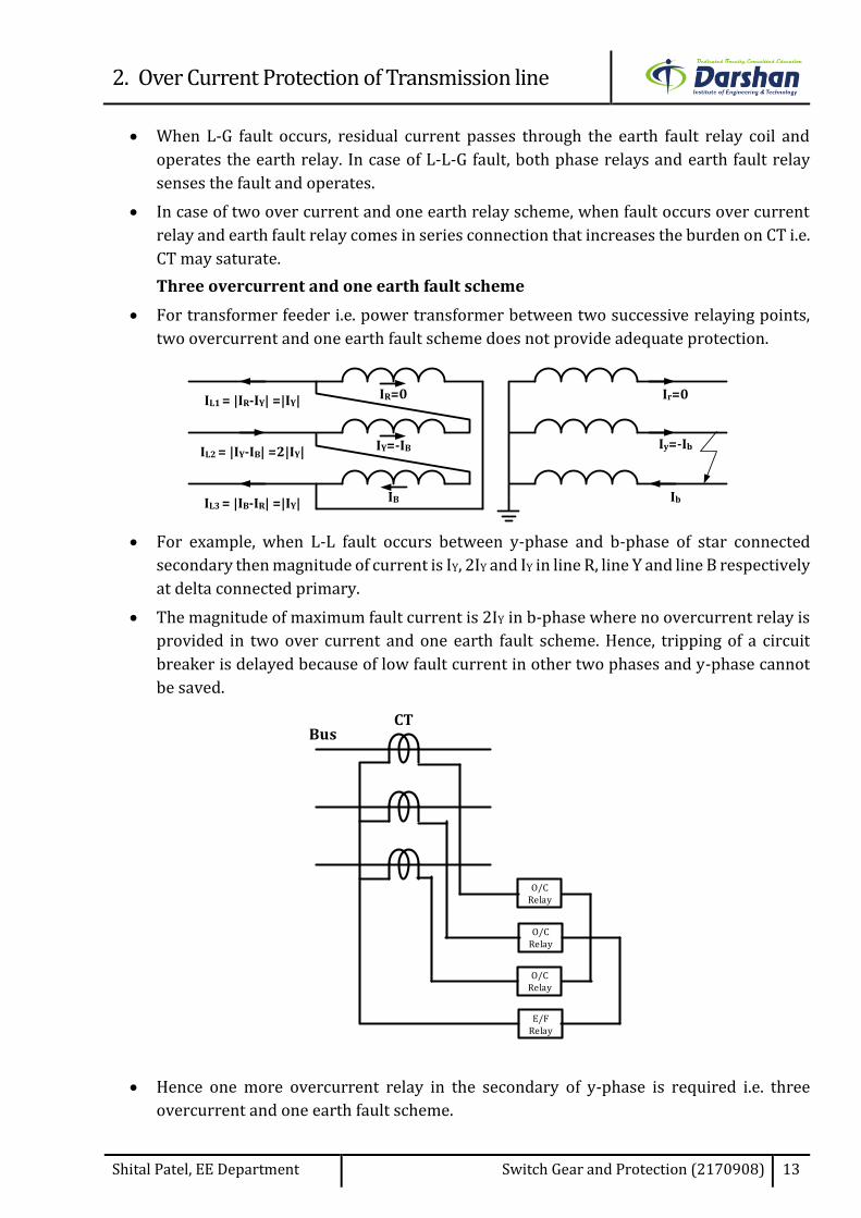
Three overcurrent and one earth fault scheme
For transformer feeder i.e. power transformer between two successive relaying points,
two overcurrent and one earth fault scheme does not provide adequate protection.
Ir=0
Iy=-Ib
Ib
IL1 = |IR-IY| =|IY| IR=0
IY=-IB
IB
IL2 = |IY-IB| =2|IY|
IL3 = |IB-IR| =|IY|
For example, when L-L fault occurs between y-phase and b-phase of star connected
secondary then magnitude of current is IY, 2IY and IY in line R, line Y and line B respectively
at delta connected primary.
The magnitude of maximum fault current is 2IY in b-phase where no overcurrent relay is
provided in two over current and one earth fault scheme. Hence, tripping of a circuit
breaker is delayed because of low fault current in other two phases and y-phase cannot
be saved.
BusCT
E/FRelay
O/CRelay
O/CRelay
O/CRelay
Hence one more overcurrent relay in the secondary of y-phase is required i.e. three
overcurrent and one earth fault scheme.