Embed Size (px)
Citation preview

2 MW 130 kWh Flywheel Energy Storage System Matthew Caprio, John Herbst,1 and Robert Thelen
The University of Texas at Austin
Abstract The Center for Electromechanics has developed and is currently testing a 2 MW, 130 kWh (480 MJ) flywheel energy storage system (FESS) designed as a load leveling energy management device. The flywheel energy storage system consists of the energy storage flywheel, a high speed induction motor/generator, and a bi-directional power converter. The FESS is a key element of the Advanced Locomotive Propulsion System (ALPS), an advanced high speed passenger locomotive power supply being developed for use on existing (non-electrified) track to provide speed and acceleration performance comparable to modern electric trains currently in service on electrified routes. This paper describes the electrical and physical characteristics of the FESS, the application requirements that shaped the design of the FESS, and the internal details of the major components: the flywheel, motor / generator, and power converter. Safety of the flywheel is addressed in terms of the designed probability against a ring burst and the ability of the internal containment structure to controllably manage an unlikely burst event. Finally, the current status of the flywheel component development, testing, and planned future demonstrations are described.
Figure 1. FESS Main components
ALPS Flywheel System Overview The ALPS flywheel energy storage system (FESS) serves as an electrical load leveling device for a hybrid electric locomotive propulsion system. The FESS reduces load fluctuations of the prime generator by providing supplemental power to the dc bus during periods of peak acceleration, and recharging during periods of deceleration or excess generation capacity. The nominal continuous duty cycle of the FESS is 3 minutes charging, 3 minutes discharging at a 2 MW power level, equating to a deliverable energy rating of 360 MJ (100 kWh). The response bandwidth of the FESS to power demand changes or dc bus power quality disturbances is adjusted to 5 Hz (200 ms) for this application. Electrical ratings of the FESS are summarized in Table 1.
Mobile Flywheel Electrical RatingsPower Continuous 2 MW
Intermittent 3 MWCurrent 0-2200 ADCVoltage 0-2000 VDCEnergy Total Stored 130 kWh
Deliverable 100 kWhResponse Bandwith 0.003 to 5 Hz
The main components of the FESS are the energy storage flywheel, the motor generator which charges and discharges the flywheel by converting electrical power to mechanical power, and the bi-directional electrical power converter which adapts the three phase ac power of the motor generator to the dc electrical distribution bus of the locomotive. An energy management algorithm, controls, and auxiliary equipment complete the integration of the components into a functioning energy storage system. A block diagram of the ALPS FESS can be seen in Figure 1. The individual components are described in detail in their respective sections of this paper.
Table 1. FESS electrical ratings
Application-Specific Design Requirements The ALPS FESS is tailored to meet the unique requirements of its hybrid electric locomotive propulsion system application in the areas of electrical performance, system duty cycle, safety and reliability, packaging, and environmental exposure in the mobile installation. In a conventional diesel electric power system topology, a diesel engine prime power source drives an electric generator to charge the dc bus. Electric power is distributed to individual traction motors through bi-directional

motor drives. During deceleration, traction motors regenerate electric energy and dissipate the power in a dynamic braking resistor grid. The ALPS system replaces the diesel electric generator set with a lightweight, compact, high-power turbine driven alternator package. The ALPS FESS then allows the conservative recovery of braking energy for later reuse, and provides load leveling for the minimized prime power turbine. Employed in this manner, the FESS allows the turbine to operate at near-constant power while the transient power demands of acceleration or grade changes are supplied by the flywheel. The power flow diagram of the ALPS components (shown in yellow) integrated into a locomotive power system can be seen in Figure 2. The ALPS system is designed for direct integration into an existing Bombardier locomotive with an Alstom 1960 V dc electrical system. This requirement determined the dc interface voltage of the FESS electrical power converter, and set a theoretical upper design limit for the three-phase ac voltage of the motor generator at 1200 Vrms line-to-line [1]. The prime power generator of the ALPS is sized at 3 MW to match tcapability of commercially available power turbines such as the Honeywell TF40 or Pratt & Whitney ST40
he
Figure 2. ALPS power system block diagram engines [2]. Given the 5 MW maximum traction load capacity of the exiting drive motors, the ALPS FESS power rating was sized at 2 MW continuous to fully supplement the prime power, providing maximum propulsion utilization. Detailed time-marching train route simulations were performed to ascertain the expected RMS charge / discharge duty, implying the necessary stored energy of the ALPS FESS, and resulting in the 130 kWh rating [3].
Table 2. FESS physical characteristics Physically and mechanically, the FESS has been designed to meet the rigorous requirements of the mobile application. The ALPS FESS physical characteristics can be seen in Table 2. As installed volume and system weight are significant parameters for the FESS on board a locomotive, a high system energy density was targeted. With a total system mass of approximately 13000 kg and volume of 16 m3, including auxiliary equipment, the ALPS FESS achieves densities of 7.7 Wh/kg and 6.3 kWh/m3, based on the 100 kWh delivered
energy rating. The packaging and form factor of the FESS components are designed to be conveniently integrated into the available space on board the chassis of the flywheel tender car. The power converter and system auxiliaries are distributed throughout the tender car to suit personnel access and proximity to cooling air
exchange, as shown in Figure 3. The flywheel is oriented vertically to isolate the structure from gyroscopic loads associated with track curvature and to make use of the tall, narrow space of the railcar. The flywheel is mounted in a two-axis gimbal accommodating up to 20° of relative motion in the roll and pitch axes, further isolating the structure from gyroscopic reaction forces, as depicted in Figure 4.
ALPS FESS Physical DataMass Flywheel 11000 kg
Total System 13000 kgVolume Flywheel 4.2 m^3
Total System 16 m^3Footprint Flywheel 2.6 m^2
Total System 12 m^2
Figure 3. FESS integration into locomotive tender car
The passenger locomotive application also demands high safety and reliability of the large energy store. To meet these requirements, a defense-in-depth process was implemented including all phases of
FESS development including rotor design, material and component fabrication quality assurance, and a two stage burst containment system [4]. This safety suite results in a very low risk of flywheel rotor ring burst
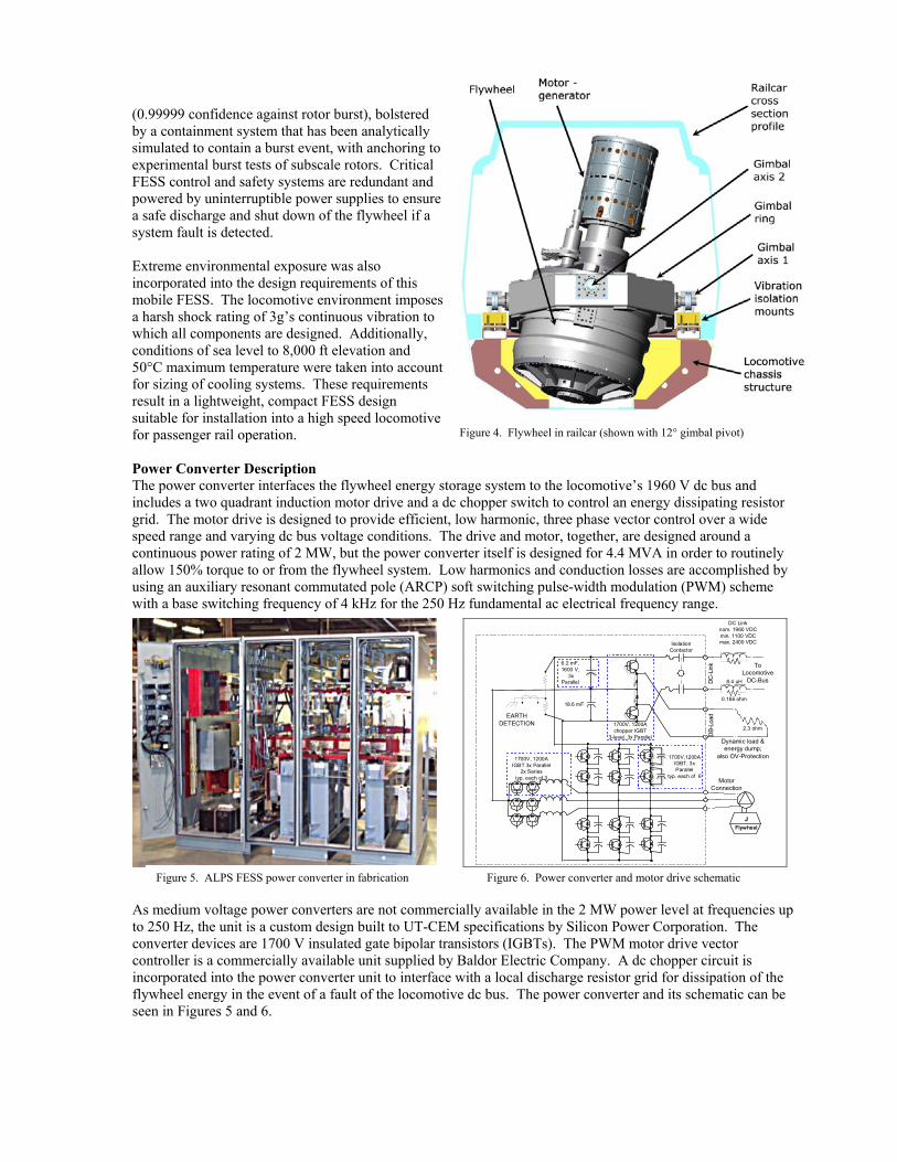
(0.99999 confidence against rotor burst), bolstered by a containment system that has been analytically simulated to contain a burst event, with anchoring to experimental burst tests of subscale rotors. Critical FESS control and safety systems are redundant and powered by uninterruptible power supplies to ensure a safe discharge and shut down of the flywheel if a system fault is detected. Extreme environmental exposure was also incorporated into the design requirements of this mobile FESS. The locomotive environment ia harsh shock rating of 3g’s continuous vibration which all components are designed. Additionallyconditions of sea level to 8,000 ft elevation and 50°C maximum temperature were taken into accoufor sizing of cooling systems. These requirementsresult in a lightweight, compact FESS design suitable for installation into a high speed locomofor passenger rail operation.
mposes to ,
nt
tive Figure 4. Flywheel in railcar (shown with 12° gimbal pivot)
Figure 4. Flywheel in railcar (shown with 12° gimbal pivot)
Power Converter Description The power converter interfaces the flywheel energy storage system to the locomotive’s 1960 V dc bus and includes a two quadrant induction motor drive and a dc chopper switch to control an energy dissipating resistor grid. The motor drive is designed to provide efficient, low harmonic, three phase vector control over a wide speed range and varying dc bus voltage conditions. The drive and motor, together, are designed around a continuous power rating of 2 MW, but the power converter itself is designed for 4.4 MVA in order to routinely allow 150% torque to or from the flywheel system. Low harmonics and conduction losses are accomplished by using an auxiliary resonant commutated pole (ARCP) soft switching pulse-width modulation (PWM) scheme with a base switching frequency of 4 kHz for the 250 Hz fundamental ac electrical frequency range.
IsolationContactor
6.2 mF,1600 V,
3xParallel DC
-Lin
kD
B-Lo
ad
MotorConnection
8.4 uH
ToLocomotive
DC-Bus
0.166 ohm
2.3 ohm
EARTHDETECTION
18.6 mF
1700V, 1200Achopper IGBT
3-level, 3x Parallel
DC Linknom. 1960 VDCmin. 1100 VDCmax. 2400 VDC
Dynamic load &energy dump;
also OV-Protection
JFlywheel
1700V,1200AIGBT, 3xParallel
typ. each of 6
1700V, 1200AIGBT 3x Parallel
2x Seriestyp. each of 3
Figure 5. ALPS FESS power converter in fabrication Figure 6. Power converter and motor drive schematic As medium voltage power converters are not commercially available in the 2 MW power level at frequencies up to 250 Hz, the unit is a custom design built to UT-CEM specifications by Silicon Power Corporation. The converter devices are 1700 V insulated gate bipolar transistors (IGBTs). The PWM motor drive vector controller is a commercially available unit supplied by Baldor Electric Company. A dc chopper circuit is incorporated into the power converter unit to interface with a local discharge resistor grid for dissipation of the flywheel energy in the event of a fault of the locomotive dc bus. The power converter and its schematic can be seen in Figures 5 and 6.

Flywheel Component Description and Safety Design The ALPS flywheel is designed in a “non-integrated” topology in which the motor generator is a separate component, directly coupled to the rotor shaft. The flywheel is therefore a relatively simple component comprised of two main parts: the rotor, and the housing. The flywheel and its cross section can be seen in Figures 7 and 8. The rotor of the flywheel (that stores the kinetic energy) is constructed of high strength graphite and fiberglass epoxy composite rings designed for the spin stress of high rotational speed operation. Since stored energy increases with the square of rotational speed, high spin velocity translates into dramatically higher storage density, and a maximum rotor speed of 15,000 rpm was thus selected for the ALPS flywheel. The design speed cycling range of the flywheel in FESS operation is 7,500 rpm (considered 0% state of charge) to 15,000 rpm (100% soc), translating into a deliverable-to-stored energy ratio of 0.75.
Figure 7. Internal view of ALPS flywheel components Figure 8. ALPS flywheel in spin testing bunker facility The rotor is supported on a robust 5-axis active magnetic bearing system designed to manage the harsh dynamic environment of the locomotive application. The frictionless magnetic bearing system allows for low parasitic losses, maintenance-free operation, and long service life. The bearing system includes auxiliary “touchdown” bearings consisting of conventional high precision ceramic rolling element bearings to support the rotor during storage or in the event of a system fault or loss of power to the magnetic bearing system. The auxiliary bearings are mounted in sealed squeeze film dampers to reduce the impact loading of the rotor during a touchdown event at operating speeds. To reduce aerodynamic drag on the rotor spinning inside the housing, the enclosure is evacuated to a level of 0.001 Torr using conventional rotary vane vacuum pumps.
Inside the stainless steel flywheel vacuum housing, a composite containment liner encapsulates the rotto dissipate the energy of an outer ring burst in a controlled fashion in the unlikely event of a catastrophic failure. Simulations show that the bstructure absorbs the radial debris from an outer rburst event, and begins to rotate independenthe rotor and housing as it converts the angulmomentum of the failed ring into a lower speed angular momentum of the more massive liner. The liner then dissipates its energy slowly through a limited area of frictional contact with the lower endplate of the flywheel housing. The composite containment structure can be seen in Figure 9. As a secondary line of defense for the prototype unit, th304 stainless steel forged housing and end plaalso designed to be capable of handling the highstrain rate and impact loading of a burst.
or
urst ing
tly of ar
e tes are
Figure 9. Flywheel composite burst containment liner

M
Figure 10. Flywheel motor internal components Figure 11. Flywheel motor completed stator core
otor Generator Component Description flywheel shaft through a unique rotating vacuum seal and flexible
0 Hz.
he simplicity and robustness of an induction machine was selected for this application in place of a permanent
he motor/generator is rated for 2 MW continuous power cycling over the operating speed range of 7,500-he
esting Status
g of the flywheel with a partially assembled rotor (6 of the 15 composite rings are installed) is
abrication and assembly of the motor/generator is nearing completion. The motor will be tested to full speed
he
r in
The motor/generator is directly coupled to thecoupling. As the motor operates at speeds up to 15,000 rpm to match the flywheel, a two-pole induction machine design was selected to minimize the maximum electrical operating frequency to a manageable 25The design is based on a conventional induction motor topology, supplemented with advanced materials and design features to adapt it to this higher speed, higher power density application. Tmagnet (PM) synchronous machine because of the complexity in managing magnet spin stresses at the required tip speed. As an additional motor selection consideration in this high-energy application, in contrast to the PM machine, the induction machine is not self-exciting by nature, and therefore its use eliminates the possibility of uncontrolled electrical discharge in the event of certain types of electrical system faults. T15,000 rpm. Thermal management for the compact design is accomplished by dual mode air/oil cooling. Tvertical motor shaft is supported on rolling element bearings mounted in squeeze-film dampers for vibration attenuation. The internal components of the flywheel motor generator can be seen in Figures 10 and 11.
TInitial spin testincurrently in progress at the UT-CEM facility in Austin, Texas. This phase of testing is intended to commission and tune the magnetic bearing system and demonstrate the operation of the auxiliary systems of the flywheel while at reduced energy levels, in parallel with fabrication of the remaining composite rotor rings. At the timeof this writing, the flywheel has been successfully operated to a maximum speed of 6500 rpm, corresponding (in this partial rotor configuration) to 4.7 kWh (16.9 MJ). Figure 12 shows the control station of the CEM-ALPS flywheel laboratory spin testing. Fbefore being coupled to the completed flywheel for full power testing. Construction and testing of the power converter by Silicon Power Corporation is nearing completion at the time of this writing. After initial laboratory testing of the components, operation of the complete flywheel energy storage system will bedemonstrated in the UT-CEM laboratory. The propulsion system is then scheduled for installation into tlocomotive and a rolling demonstration on the high speed test track at the Transportation Technology CentePueblo, Colorado in the 4th quarter of 2005.

Figure 12. Flywheel control room during laboratory testing at 6500 RPM
Acknowledgements This material is based upon work supported by the USDOT Federal Railroad Administration cooperative agreement, DTFR53-99-H-00006 Modification 4, dated April 30, 2003. Any opinions, findings, and conclusions or recommendations expressed in this publication are those of the authors and do not necessarily reflect the view of the Federal Railroad Administration and/or U.S. DOT. References [1] N. Mohan, T. Undeland, W. Robbins, Power Electronics Converters Applications and Design, 2nd Ed.
John Wiley & Sons, 1995. [2] J.D. Herbst, M.T. Caprio, R.F. Thelen, “Advanced Locomotive Propulsion System (ALPS) Project
Status 2003”, 2003 ASME International Mechanical Engineering Congress & Exposition (IMECE ’03), November 16-21, 2003, Washington D.C.
[3] J.D. Herbst, R.F. Thelen, W.A. Walls, “Status of the Advanced Locomotive Propulsion System
(ALPS) Project”, High Speed Ground Transportation Association (HSGTA) Conference 2000, Philadelphia, PA, May 10-13, 2000.Status of the ALPS 2000.
[4] M. Pichot, J. Kramer, R.J. Hayes, R.C. Thompson, and J.H. Beno, “The Flywheel Battery Containment
Problem”, Society of Automotive Engineers, SAE publication # 970242, February 1997.